- Manuals
- Brands
- Simrad Manuals
- Compass
- GC80 Compact Gyro
- Instruction manual
-
Contents
-
Table of Contents
-
Bookmarks
Quick Links
INSTRUCTION MANUAL
SIMRAD GC80/85
COMPACT
Gyro Compass
20221511D
English
Related Manuals for Simrad GC80 Compact Gyro
Summary of Contents for Simrad GC80 Compact Gyro
-
Page 1
INSTRUCTION MANUAL SIMRAD GC80/85 COMPACT Gyro Compass 20221511D English… -
Page 2
Simrad GC80/GC85 Compact Gyro Compass Document revisions Date Written by Checked by Approved by 19.12.03 17.02.05 05.12.05 09.05.07 Document history Rev. A First issue. Rev. B Updated for new software release (Master compass: V.1.03, Control unit: V.1.04). Rev. C New procedure for how to adjust true heading, updated dimensions for remote panel, other minor updates to text throughout the manual. -
Page 3
About this manual This manual is intended as a reference guide for installing, operating and maintaining Simrad GC80 and GC85 Compact Gyro compasses. The manual assumes that the operator is a qualified ship officer, or is under supervision of a qualified person. -
Page 4
Simrad GC80/GC85 Compact Gyro Compass This manual is divided in the following sections: 1. System overview An overview of the GC80/GC85 Compact gyro system and it’s components. 2. User interface Overview of GC80 Compact Control unit and the user interface. -
Page 5: Table Of Contents
INSTRUCTION MANUAL Contents SYSTEM OVERVIEW…………1 Introduction……………2 Precaution in use …………..3 System components…………4 Bearing repeaters ……………4 USER INTERFACE …………..5 GC80 Compact Control unit……….6 OPERATION……………9 System Start-up and Shut-down……… 10 Start-Up …………..10 Turning the Gyro compass OFF……..11 Selecting active compass ……….. 12 Adjusting dimming level …………
-
Page 6
Simrad GC80/GC85 Compact Gyro Compass Verifying the element’s tilt angle ……..29 Parameter updates …………30 Balancing the Horizontal ring ……..31 Replacing the Fuses …………32 Master Compass…………32 Compact Control unit ……….. 32 Power Supply Unit (Option) ………. 34 INSTALLATION…………..35… -
Page 7
GC80/85 Master Compass ……….70 GC80 Compact Control unit ………. 70 DRAWINGS …………..71 Drawings included …………72 SPARE PART LIST…………79 GC80 Compact Gyro system……….80 GC85 Compact Gyro system……….80 GC80/GC85 Optional equipment ……… 81 10 TERMINAL LAYOUT …………83 10.1 ITERM board …………..84 TB1 ……………. -
Page 8
Simrad GC80/GC85 Compact Gyro Compass 12.2 Acknowledging an alarm ………… 99 12.3 Fault finding …………..100 Main power failure …………. 100 Internal power failure in Control unit……101 Inverter failure …………101 Zero cross failure …………101 System communication failure ……..102 GPS communication or data failure …… -
Page 9: System Overview
SYSTEM OVERVIEW SYSTEM OVERVIEW This section provides an overview of GC80 and GC85 Compact Gyro compasses and their components. 20221511 / D…
-
Page 10: Introduction
— A GC80 Compact gyro is designed for vessels with speed up to 30 knots. The system complies with IMO A.424 (11) and Wheel Mark Specifications.
-
Page 11: Precaution In Use
— If any unusual behavior is observed during daily inspection, the cause should be found and corrected. If necessary, the local Simrad dealer should be contacted — If any alarm is generated, verify the reason for the alarm 20221511 / D…
-
Page 12: System Components
Simrad GC80/GC85 Compact Gyro Compass 1.3 System components A GC80/GC85 Compact Gyro compass includes the following units: — Master Compass with Sensitive Element — Compact Control unit — Power Supply unit (Option) COMPACT CONTROL UNIT SPEED 24V DC POWER INPUT EXTERNAL HEADING SENSOR from Ship’s Supply or…
-
Page 13: User Interface
USER INTERFACE USER INTERFACE This section gives an overview of the GC80 Compact Control unit and the user interface. 20221511 / D…
-
Page 14: Gc80 Compact Control Unit
The Control unit includes the control panel for the gyro compass. A flush mount kit (part number 27101757) may be ordered from Simrad for remote installation of the control panel. Refer Flush mounting the control panel, page 37. ^i^oj dvol…
-
Page 15
USER INTERFACE DISP Button Used for displaying data on the LCD. Refer Displaying present afpm settings, page 13. SET Button Used for changing data and input sources. Refer System start-up and software configuration, page 49 onwards. ACK/ENT Button Used for confirming a change in data and input sources. Refer System start-up and software configuration, page 49 onwards. -
Page 16
Simrad GC80/GC85 Compact Gyro Compass THIS PAGE INTENTIONALLY LEFT BLANK 20221511 / D… -
Page 17: Operation
OPERATION OPERATION This section describes the main operating procedure used when operating the GC80/GC85 Compact Gyro compass. 20221511 / D…
-
Page 18: System Start-Up And Shut-Down
Simrad GC80/GC85 Compact Gyro Compass 3.1 System Start-up and Shut-down A GC80/GC85 Compact gyro system is usually left with power on. If the system has to be shut down and restarted, the procedures in the following sections should be followed.
-
Page 19: Turning The Gyro Compass Off
OPERATION The indicated start bearing is accepted by pressing the button, or increased/decreased by using the ACK/ENT dvol arrow buttons and then pressing the button. If ACK/ENT no action is taken within 3 minutes, the start-up process will continue with the indicated start bearing. The bearing indication stops flashing when the start bearing is accepted, while the lamp remains flashing.
-
Page 20: Selecting Active Compass
Simrad GC80/GC85 Compact Gyro Compass 3.2 Selecting active compass If an external heading sensor is connected to GC80/GC85, it is possible to switch between gyro and external heading sensor as active steering sensor. The gyro system will normally be used with the gyro compass selected as active compass.
-
Page 21: Displaying Present Settings
OPERATION 3.4 Displaying present settings When pressing the button on the GC80 Control unit, the DISP system will loop through a display sequence showing present settings for the system. The sequence will be depend on whether an external compass is connected or not.
-
Page 22: Displaying Settings With External Sensor Connected
Simrad GC80/GC85 Compact Gyro Compass Display state Display Description — Rate of turn in °/min afpm — Rate of turn indication press on DISP button — Error codes (up to 4) afpm — Error indication press on DISP button afpm…
-
Page 23
OPERATION Display state Display Description — Gyro compass bearing without afpm correction press on — Active speed input source indication DISP button (GPS, Manual, Log or Serial Log) — Latitude afpm — Latitude indication: North (LA.n) or press on South (LA.s) DISP button — Vessel speed afpm… -
Page 24: Confirming Present Settings
Simrad GC80/GC85 Compact Gyro Compass 3.5 Confirming present settings After the GC80 is configured according to the System start-up and software configuration, described in page 49 onwards, it should not be necessary to adjust any settings when operating the gyro compass.
-
Page 25: Speed
OPERATION Speed The GC80/GC85 gyro compass calculates bearing based on the speed and latitude information that is input to the gyro as speed source. Any error in speed input will therefore cause incorrect true bearing from the gyro compass. Press the button until the vessel’s speed information is DISP displayed.
-
Page 26
Simrad GC80/GC85 Compact Gyro Compass VESSEL HEADING (degree) 20 10 LATITUDE (degrees) 20221511 / D… -
Page 27: Pendulum Function
OPERATION 3.6 Pendulum function GC80/85 software includes a pendulum function that enables the heading to be changed by 180°. The heading change is activated by closing a potential free contact connected between TB1, pin 25 and 26 in GC80/85 control unit. Note! To enable the function, S2-4 on the ICIF board has to be set to ON.
-
Page 28: Alarm Messages
Simrad GC80/GC85 Compact Gyro Compass 3.7 Alarm messages The GC80/GC85 system will continually check for faults while the system is running. If a fault occurs, an alarm code will be displayed in the LCD, the Alarm lamp will be flashing, and an audible alarm will be activated.
-
Page 29: Acknowledging An Alarm
OPERATION Acknowledging an alarm An alarm is acknowledged by pressing the button. ACK/ENT — The audible alarm will be silenced — If the alarm situation has disappeared, the alarm lamp will be switched off, and the alarm code will be removed from the LCD — If the alarm situation continues, the alarm lamp will switch from flashing to steady light.
-
Page 30
Simrad GC80/GC85 Compact Gyro Compass THIS PAGE INTENTIONALLY LEFT BLANK 20221511 / D… -
Page 31: Maintenance
MAINTENANCE MAINTENANCE This section holds descriptions for maintenance procedures that should be performed by the system operator. The section also includes a detailed description for how to replace the sensitive element and the fuses. 20221511 / D…
-
Page 32: General
If any strange motion, smell, sound or heat is generated from any unit, a Simrad dealer shall be contacted. 4.2 Precautions Touching internal parts may cause electric chock if power is…
-
Page 33: Preventive Maintenance Intervals
The Sensitive element should only be replaced by authorized Simrad personnel. Note! A special tool is required when installing the Sensitive element. This tool is optional and must be ordered from Simrad (part no. 44174449). Mechanical installation Caution Use extreme caution when handling the Sensitive element! Do not tilt the element.
-
Page 34
Simrad GC80/GC85 Compact Gyro Compass Loosen the screw on the plug-holder on the Sensitive element, and disconnect the plug. Remove the four screws securing the Sensitive element. Tilt the Horizontal ring to the side where the plug is located, and carefully remove the element from the compass. -
Page 35
MAINTENANCE Tilt the Horizontal ring to the side where the plug is located, and carefully put the sensitive element into the ring. — The socket on the Sensitive element should be located right above the plug attached to the Horizontal ring. Position the Sensitive element on the Horizontal ring by putting the assembly jigs into the holes as indicated on the figure below. -
Page 36
Simrad GC80/GC85 Compact Gyro Compass Replace the assembly jigs with the two remaining screws after placing the ground wire as shown on the figure. Loosen the screw on the plug holder on the Sensitive element, and lift the holder 2-3 mm upwards. -
Page 37: Verifying The Element’s Tilt Angle
MAINTENANCE Verifying the element’s tilt angle Tilt the Sensitive element by hand towards the level tool on the Horizontal ring and keep it tilted for approximately 1 minute. Remove the pressure and observe that the tilt angle remains at: — GC80: 15° to 19° — GC85: 18°…
-
Page 38: Parameter Updates
Simrad GC80/GC85 Compact Gyro Compass If the tilt angle is incorrect, weight disks must be adjusted by moving weights from one side to the other. After adjustments, wait for 2 minutes for the oil to set before the tilt angle verification is repeated.
-
Page 39: Balancing The Horizontal Ring
MAINTENANCE Exit the sub-category by pressing the button, and then exit the Extension main category by pressing and holding buttons simultaneously for appr. 3 ACK/ENT seconds. For more information about the Extension menu, see ADVANCED SETTINGS, page 57 onwards. Balancing the Horizontal ring After the Sensitive element has been replaced, the gyro compass should be started as described on page 10.
-
Page 40: Replacing The Fuses
Simrad GC80/GC85 Compact Gyro Compass 4.8 Replacing the Fuses WARNING Before a fuse is replaced, disconnect the respective power for the damaged fuse. Use the procedures described in the following pages when replacing the fuses. Master Compass Fuse F1 is located inside the fuse holder in the front of the Master compass.
-
Page 41
MAINTENANCE F1 – F5 (1A) (6.3A) F6, F7 AND F9 WARNING Make sure that power is disconnected from pin 1-4 on TB3 before any fuse is replaced! Note! The fuses in the Compact Control unit are open glass type and may be damaged if handles with force. -
Page 42: Power Supply Unit (Option)
Simrad GC80/GC85 Compact Gyro Compass Power Supply Unit (Option) FUSE NO CAPACITY TB-NO SIGNAL DESCRIPTION F201 6.3A TB201 2AC1/2 Main power supply F202 TB201 2B+/- Emergency power supply F201 F202 F201 (6.3A) – TB201 F202 (20A) Caution Make sure that power is disconnected from TB201 before any fuses are replaced.
-
Page 43: Installation
INSTALLATION INSTALLATION This section is a reference guide for correctly installing and configuring the GC80/85 Gyro Compasses. 20221511 / D…
-
Page 44: Unpacking And Handling
Simrad GC80/GC85 Compact Gyro Compass 5.1 Unpacking and handling A GC80/85 Gyro compass consists of the following units: — Master compass — Sensitive element — Control unit — Power Supply unit (Option) — Spare part kit — Documentation The sensitive element is shipped from the factory packed separately in a carton box to protect it from excessive shock and vibration.
-
Page 45: Control Unit
INSTALLATION Control unit The Control unit is bulkhead mounted by using 4 bolts as shown in the illustration. Flush mounting the control panel The control panel may be removed from the Control unit and mounted in a remote location by using the optional flush mounting kit (part number 27101757).
-
Page 46
Simrad GC80/GC85 Compact Gyro Compass Loosen the 4 nuts holding the control panel, and remove the panel. These nuts are to be re-used when fastening the control panel to the flush mounting panel. Insert the control panel in the flush-mounting kit from the front side as shown on the figure. -
Page 47: Power Supply Unit (Option)
INSTALLATION Power supply unit (Option) Refer mounting description for the Control unit above. Dimensional drawings for the optional Power supply unit are found on page 75. Jumper settings in Compact Control unit When the optional Power supply unit is included in the GC80/85 compact gyro system, jumper settings in the GC80/85 Control unit have to be modified as follows: Remove J6…
-
Page 48: Master Compass
Simrad GC80/GC85 Compact Gyro Compass Master compass Select a mounting location where the deck is horizontally, flat and with little vibration, and where the pitch/roll motion is as small as possible. It is also important to select a mounting location with sufficient space for installation and service.
-
Page 49: Cabling
INSTALLATION Remove strips and foam rubber from the chock absorbers, together with all strips used for securing moving parts during transportation. Note! The foam rubber should be kept for re-use if the Master compass has to be sent to factory for service! 5.3 Cabling Note! No cables are included when the gyro system is delivered from…
-
Page 50: Grounding The Units
Simrad GC80/GC85 Compact Gyro Compass 5.4 Grounding the units All units in the GC80/GC85 system should have a proper ground connection from the unit’s ground terminal. The wires should be as short as possible and have a cross section of at least AWG13 (2.5mm…
-
Page 51: Activating The Control Unit For Gc80 Or Gc85 System
INSTALLATION Activating the control unit for GC80 or GC85 system When the gyro system is shipped from factory, all dip switches in the Control unit are set as for a standard GC80 system. Before the system is started, the switch settings described below have to be changed to match a GC85 system.
-
Page 52: Activating An External Heading Sensor
Simrad GC80/GC85 Compact Gyro Compass Activating an external heading sensor If an external heading sensor is connected to the GC80/GC85, dip switch no.5 on S1 on the ICIF board has to be set to enable the external heading sensor. No external sensor…
-
Page 53: Installing The Sensitive Element
INSTALLATION 5.6 Installing the Sensitive element The Sensitive element is shipped from the factory packed separately, and the element has to be installed in the Master compass according to the description below. Note! A special tool (part no. 44174449) is required when installing the Sensitive element.
-
Page 54
Simrad GC80/GC85 Compact Gyro Compass Position the Sensitive element on the Horizontal ring by putting the assembly jigs into the holes as indicated on the figure below. Observe the labelling and the diameter on the jigs. Fasten two screws in the other two holes. -
Page 55: Verifying The Element’s Tilt Angle
INSTALLATION Verifying the element’s tilt angle Tilt the Sensitive element by hand towards the level tool on the Horizontal ring and keep it tilted for approximately 1 minute. Remove the pressure and observe that the tilt angle remains at: — GC80: 15° to 19° — GC85: 18°…
-
Page 56
Simrad GC80/GC85 Compact Gyro Compass If the tilt angle is incorrect, weight disks must be adjusted by moving weights from one side to the other. After adjustments, wait for 2 minutes for the oil to set before the tilt angle verification is repeated. -
Page 57: System Start-Up And Software Configuration
INSTALLATION 5.7 System start-up and software configuration When all GC80 units are installed and the cables connected according to the procedures described in previous chapters, the system is ready for the first time start-up procedure. System Start-up Turn ON the gyro system by pressing the button on the POWER mltbo…
-
Page 58: Configuring The Gyro System
Simrad GC80/GC85 Compact Gyro Compass The indicated start bearing is accepted by pressing the button, or increased/decreased by using the ACK/ENT dvol arrow buttons and then pressing the button. If ACK/ENT no action is taken within 3 minutes, the start-up process will continue with the indicated start bearing.
-
Page 59
INSTALLATION Confirm the entry by pressing the button. The ACK/ENT display will return to sub-category 1.1.U, and the data will be transferred to the gyro immediately. Press the button again to select sub-category 1.2.F, DISP and use the arrow buttons to increase or decrease the parameter value until the value corresponds with the parameter for the new sensitive element. -
Page 60: Setting The Latitude Input Source
Simrad GC80/GC85 Compact Gyro Compass Setting the Latitude input source When the system is configured as described in Configuring the gyro system page 50 onwards, the latitude input source can be changed as described below. Press the button until the display shows latitude DISP value.
-
Page 61: Setting The Speed Input Source
INSTALLATION Setting the Speed input source When the system is configured as described in Configuring the gyro system page 50 onwards, the speed input source can be changed as described below. Press the button until the display shows speed value DISP and speed input source.
-
Page 62: Balancing The Horizontal Ring
Simrad GC80/GC85 Compact Gyro Compass 5.8 Balancing the Horizontal ring After the compass has been running continuously for at least 2 hours, the horizontal ring should be adjusted. Locate the reference level tool on the horizontal ring, and check that the level bubble is within +/-10 minutes from the center.
-
Page 63
INSTALLATION Press the button once to display main category A-2. DISP Press the button to enter the sub-category 2.1.o. Use the arrow buttons to increase or decrease the offset parameter value. Note! To correct for +1.5°, press the Arrow Up button until the display shows 1.5°. -
Page 64
Simrad GC80/GC85 Compact Gyro Compass THIS PAGE INTENTIONALLY LEFT BLANK 20221511 / D… -
Page 65: Advanced Settings
ADVANCED SETTINGS ADVANCED SETTINGS This section gives an overview of the Extension menu, how to enter the menu and how to change parameter values. 20221511 / D…
-
Page 66: General
Simrad GC80/GC85 Compact Gyro Compass 6.1 General The Extension menu holds internal parameters and communication parameters required to achieve the best possible heading accuracy on the GC80/GC85 Gyro compass. The Extension menu is grouped in 8 main categories, named A- 1 through A-8.
-
Page 67: The Extension Menu Overview
ADVANCED SETTINGS MAIN MENU CHANGE / CLEAR PARA- METER VALUE afpm afpm afpm afpm NEXT MAIN NEXT SUB CATEGORY CATEGORY 6.3 The Extension menu overview Main Default Parameter/description Range Category Category value 1.1.U Damping gain 1.00 0.00 – 2.00 Determines the damping (damping operation in north- seeking motion = half cycle attenuation) and actually represents a coefficient (ratio) to the standard value stored in the software.
-
Page 68
Simrad GC80/GC85 Compact Gyro Compass Main Default Parameter/description Range Category Category value 1.5.L (φ) Phi offset (°) 0.00 -3.00 – 3.00 A-1 cont. Offset value (°) around the vertical axis of gyro sphere (rotor axis) and the sensitive element. 1.6.t (θ) Theta offset (°) -
Page 69
ADVANCED SETTINGS Main Default Parameter/description Range Category Category value 2.1.o Bearing offset A (°) 0.0 – 359.9 Offset value included in the “master bearing” and used for correction of fixed error (°). If the master compass not can be mounted parallel to the vessel’s fore-after line, this parameter is used to compensate for a small mounting error. -
Page 70
Simrad GC80/GC85 Compact Gyro Compass Main Default Parameter/description Range Category Category value 2.9.G Display/setting of GPS connection bE or Non A-2 cont. The following abbreviations are used: GPS connected Non: No GPS connected NOTE: When this value is set to “Non”, GPS can not be selected as the vessel’s input for speed and… -
Page 71
ADVANCED SETTINGS Main Default Parameter/description Range Category Category value 4.1.C GPS serial data character length 8 or 7 4.2.P GPS serial data parity bit Non, Even, 4.3.S GPS serial data stop bits 1 or 2 5.1.C LOG serial data character length 8 or 7 5.2.P LOG serial data parity bit… -
Page 72
Simrad GC80/GC85 Compact Gyro Compass THIS PAGE INTENTIONALLY LEFT BLANK 20221511 / D… -
Page 73: Technical Specification
TECHNICAL SPECIFICATION TECHNICAL SPECIFICATION This section lists all specifications for GC80/85 gyro compass. 20221511 / D…
-
Page 74: Accuracy
Simrad GC80/GC85 Compact Gyro Compass 7.1 Accuracy Settling time:…………within 3 hours (if startup heading is within +/-5° of actual heading) Settle point error: ……….. less than ±0.1º RMS value of the difference:……..less than 0.1º Repeatability of settle point error: ……less than ±0.1°…
-
Page 75: Input Specification
TECHNICAL SPECIFICATION 7.3 Input specification Serial input signal (GPS) Circuits:…………..1 Electrical: ….RS422/MNEA0183/Current loop Baud rate: …………. 4800 bps Data bits: …………8 bits Parity:…………..None Stop bits: …………..1 Freq.: ………….. 1 – 5Hz Input format: $—GGA,x,xxxx.xx,N,xx.x,E,x,~*hh<CR><LF> $—GLL,xxxx.xx,N,xxxx.xx,E,*hh<CR><LF> $—VTG,xx,T,xx,M,xx.x,N,xx,K*hh<CR><LF> Serial input signal (External heading) Circuits:…………..1 Electrical: ……..RS422/NMEA0183 Baud rate: ……….
-
Page 76: Output Specification
Simrad GC80/GC85 Compact Gyro Compass 7.4 Output specification Serial output signal 1 Circuits:…………..4 Electrical: ……….RS422/485 When Gyro Baud rate: is selected GC80: ……….. 4800/38400 bps GC85 …………. 38400 bps Note! Baud Rate for GC85, refer Jumper settings on ICIF board, output serial signal selection, page 93.
-
Page 77: Physical Dimensions
TECHNICAL SPECIFICATION STEP signal Circuits:…………..4 Electrical: ……..24V DC – 6 step/° Alarm output Potential free ……….NO/NC Running contact Potential free ……….NO/NC Refer Jumper settings on ICIF board, page 91. 7.5 Physical Dimensions GC80 Master Compass Height: …………..438 mm (17.2”) Width: …………..
-
Page 78: Gc80 Compact Control Unit
Simrad GC80/GC85 Compact Gyro Compass GC80 Compact Control Unit Voltage input: …………..24V DC Backup voltage: …………… 24V DC Power consumption, including Master compass: Starting……….3.3A at 24V DC Running:……….. 2.6A at 24V DC GC80 Power Supply unit (option) Voltage input: ……….110/220 V AC ±10% Frequency: ………….
-
Page 79: Drawings
DRAWINGS DRAWINGS This section contains outline drawings showing mechanical dimensions of the different GC80/GC85 units, together with wiring diagrams for the gyro system. 20221511 / D…
-
Page 80: Drawings Included
The following wiring diagrams are enclosed: Name Drw. no Rev. GC80/85 Gyro Compass, Compact system. N3-710181 Wiring diagram GC80/85 Gyro Compass, Compact system with N3-710182 Power supply unit. Wiring diagram Note! The original signed drawings are recorded at Simrad Egersund. 20221511 / D…
-
Page 81
DRAWINGS 20221511 / D… -
Page 82
Simrad GC80/GC85 Compact Gyro Compass 20221511 / D… -
Page 83
DRAWINGS 20221511 / D… -
Page 84
Simrad GC80/GC85 Compact Gyro Compass 20221511 / D… -
Page 85
DRAWINGS 20221511 / D… -
Page 86
Simrad GC80/GC85 Compact Gyro Compass 20221511 / D… -
Page 87: Spare Part List
SPARE PART LIST SPARE PART LIST This section includes part numbers for all standard and optional units that may be included in a GC80 and GC85 gyro system. 20221511 / D…
-
Page 88: Gc80 Compact Gyro System
Simrad GC80/GC85 Compact Gyro Compass 9.1 GC80 Compact Gyro system PART NO DESCRIPTION 27101674 GC80 Master compass 44174027 GC80 Sensitive element 27101690 GC80 Compact Control unit 20221511 GC80/GC85 Compact gyro compass Instruction manual 44174449 Special tool required when installing the Sensitive element 9.2 GC85 Compact Gyro system…
-
Page 89: Gc80/Gc85 Optional Equipment
9.3 GC80/GC85 Optional equipment PART NO DESCRIPTION 27101724 GC80/GC85 Power supply unit GC80 Flush mounting kit in Simrad design for remote 27101757 installation of operating panel GC80 Extension cable 5 meter for remote installation of 44170736 operating panel normally mounted in Control unit…
-
Page 90
Simrad GC80/GC85 Compact Gyro Compass THIS PAGE INTENTIONALLY LEFT BLANK 20221511 / D… -
Page 91: Terminal Layout
TERMINAL LAYOUT TERMINAL LAYOUT This section includes tables which list all terminal pins and terminal labelling on pcbs in the GC80 Control unit. The tables include detailed description for each terminal. 20221511 / D…
-
Page 92: Iterm Board
Simrad GC80/GC85 Compact Gyro Compass 10.1 ITERM board PIN NO NAME DETAILS Master compass power supply (24V DC) Master compass power supply (24V DC common) Master compass inverter alarm (over current) Master compass inverter alarm (over voltage) Master compass inverter alarm (common) Control unit –…
-
Page 93: Tb2
4TX- 4TSC Serial signal common 4R24- Serial repeater power supply (24V DC common) 4R24+ Serial repeater power supply (24V DC) When used with Simrad Power supply unit (OPTION): PIN NO NAME DETAILS 24R+ Power unit 24R input 24R- Power unit 24RC input…
-
Page 94: Tb3
NAME DETAILS 24M+ External power supply input 24M- 24B+ Not used 24B- 24BT+ Battery backup 24BT- When used with non Simrad Power supply unit: PIN NO NAME DETAILS 24M+ 24M- External power supply input 24B+ 24B- 24BT+ Battery backup 24BT-…
-
Page 95: Iopt Board
TERMINAL LAYOUT 10.2 IOPT board PIN NO NAME DETAILS ESSC ESTX- ESTX+ Not connected PRSC PRRX- PRRX+ Log serial signal input common LRX- Log serial signal input (NMEA) LRX+ TKSC Not connected TKTX- TKTX+ PIN NO NAME DETAILS ESRX+ External sensor serial signal input ESRX- External sensor serial signal common RNCN1…
-
Page 96
Simrad GC80/GC85 Compact Gyro Compass THIS PAGE INTENTIONALLY LEFT BLANK 20221511 / D… -
Page 97: Dip Switch Settings
DIP SWITCH SETTINGS DIP SWITCH SETTINGS This section includes drawings for the different printed circuits boards in the Control unit that include jumpers and dip switches. 20221511 / D…
-
Page 98: Compact Control Unit
Simrad GC80/GC85 Compact Gyro Compass 11.1 Compact control unit Three different boards in the Compact control unit have jumpers and/or dip switches that may be used for configuring the GC80/85 system. Only a few of these jumpers/dip switches are used in installation and pre-running procedure for the gyro compass.
-
Page 99: Icif Board
DIP SWITCH SETTINGS ICIF board DEFAULT SETTINGS J6 J5 DIP switch settings on ICIF board SWITCH DEFAULT FUNCTION DESCRIPTION S1-1 Control unit type OFF = Expanded, ON =Compact S1-2 Master compass type OFF = Standard, ON =High Speed S1-3 Control unit type OFF = Expanded, ON =Dual S1-4 2 gyros used…
-
Page 100
(standard) selection. S3-5 “ROT” sentence output OFF = Disabled, ON = Enabled OFF = Not used ON = Simrad GC type (80 or 85) shown in S3-6 For Simrad use display at start-up according to S1-2 setting. S3-7 Not used… -
Page 101
DIP SWITCH SETTINGS Jumper settings on ICIF board JUMPER DEFAULT FUNCTION DESCRIPTION Short Software installation Open = Software may be installed on ICIF board NOTE: Make sure that also J1 on the IOPT board is set to “Open” NOTE: Control unit will be damages if new software is installed with this jumper Open CUP reset… -
Page 102: Iopt Board
Simrad GC80/GC85 Compact Gyro Compass JUMPER DEFAULT FUNCTION DESCRIPTION 1-2 short LOG pulse selection Input port: ITERM board, TB2 “SL” 1-2 short = 200p.p.n.m. 3-4 short = 400p.p.n.m. NOTE: Never use both jumpers at the same time! 3-4 short Alarm contact output Output port: ITERM board, TB1 “ALCN”…
-
Page 103
DIP SWITCH SETTINGS Jumper settings on IOPT board JUMPER DEFAULT FUNCTION DESCRIPTION 1-2 short Software installation Open = Software may be installed in ICIF board NOTE: Control unit will be damages if new software is installed with this jumper ON! 1-2 short Running contact output Output port: IOPT board TB4… -
Page 104: Iterm Board
Simrad GC80/GC85 Compact Gyro Compass ITERM board Jumper settings without Power supply unit JUMPER DEFAULT FUNCTION DESCRIPTION 1-3 short 2-4 short No Power supply unit J5-3 to System used without Power supply unit TB2-16 short 1-3 short No Power supply…
-
Page 105: Alarm Messages And Corrective Actions
ALARM MESSAGES AND CORRECTIVE ACTIONS ALARM MESSAGES AND CORRECTIVE ACTIONS This section provides a description which system errors that are displayed, and which corrective actions that could be performed by the system operator. 20221511 / D…
-
Page 106: The Alarm System
Simrad GC80/GC85 Compact Gyro Compass 12.1 The alarm system The GC80/GC85 system will continually check for faults while the system is running. If a fault occurs, an alarm code will be displayed in the LCD, the Alarm lamp will be flashing, and an audible alarm will be activated.
-
Page 107: Acknowledging An Alarm
ALARM MESSAGES AND CORRECTIVE ACTIONS 12.2 Acknowledging an alarm An alarm is acknowledged by pressing the button. ACK/ENT — The audible alarm will be silenced — If the alarm situation has disappeared, the alarm lamp will be switched off, and the alarm code will be removed from the LCD — If the alarm situation continues, the alarm lamp will switch from flashing to steady light.
-
Page 108: Fault Finding
If none of these procedures correct the problem, contact the local Simrad dealer for advice or for requesting on board service. Before any fault finding procedure is started, the following…
-
Page 109: Internal Power Failure In Control Unit
ACK/ENT If the bearing input was accepted by the system, the LCD will display current bearing without flashing. Report the error to Simrad even if the bearing is accepted and the alarm removed. 20221511 / D…
-
Page 110: System Communication Failure
Simrad GC80/GC85 Compact Gyro Compass System communication failure Alarms generated when there is a failure in communication from the Master compass to the Control unit. Turn OFF the power by pressing the button, and POWER repress the button after 20 seconds.
-
Page 111: Internal Communication Failure
ALARM MESSAGES AND CORRECTIVE ACTIONS Internal communication failure Generated when the communication from the external bearing sensor has stopped ( ), or when a failure is detected in the communication ( ). Caution When these alarms are generated, the bearing information from the external bearing sensor may have large error.
-
Page 112: Repeater Failure
Simrad GC80/GC85 Compact Gyro Compass Repeater failure No output on single repeaters Check that the repeater is connected to the gyro according to the repeater’s documentation. Each repeater output has a separate fuse in the Control unit. Disconnect the power to the Control unit, and check…
-
Page 113: Complete Alarm Code List
ALARM MESSAGES AND CORRECTIVE ACTIONS 12.4 Complete alarm code list Alarm Detailed Alarm content Possible cause code code Main power is When the main power (AC power source) is lost. abnormal Power supply unit in the control box becomes over current.
-
Page 114
Simrad GC80/GC85 Compact Gyro Compass Alarm Detailed Alarm content Possible cause code code MAG/EHS data EHS data abnormal. (timeout is 17 sec.) abnormal EXT. sensor When EXT. sensor system is stopped or serial signal communication off from EXT. sensor is cut. (timeout is 15 sec.) EXT.
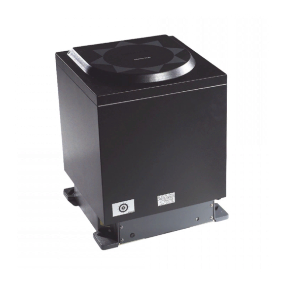
Simrad GC80 / GC85 — гирокомпас производства Navico, одобренный РМРС и прошедший испытания. Гирокомпас Simrad GC80 / GC85 может быть составлен из нескольких основных и дополнительных блоков в зависимости от необходимости. Основные блоки — компас, два контрольных блока и датчик. Возможно доукомплектование репитерами, аналоговым конвертером, блоком питания, расширенной панелью управления.
Гироскопический компас Simrad GC80 / GC85 подходит для высокоскоростных судов, имея погрешность до трех десятых градуса и скорость обработки до семидесяти пяти градусов в секунду. Настройка гирокомпаса на меридиан составляет до трех часов.
Причины купить Simrad GC80 / GC85:
- Сертификат РМРС.
- Отработка до 75 градусов/сек..
- Погрешность до 0,3 градусов.
- Варианты комплектования.
- Подходит для высокоскоростных судов.
Чтобы купить гирокомпас Simrad GC80 / GC85 или уточнить стоимость оборудования, обращайтесь к менеджерам нашего магазина по телефонам, указанным на сайте.
Цена, характеристики, внешний вид и комплектация товара могут быть изменены без предварительного уведомления.
Гирокомпасы GC80 и GC85 являются портативными системами высокой надежности.
Система GC80 — компактный гирокомпас для судов, скорость движения которых не превышает 30 узлов. Система удовлетворяет техническим требованиям IMO A.424 (11) и «Wheel Mark»
Система GC85 компактный гирокомпас для скоростных судов, со скоростью движения до 70 узлов. Система удовлетворяет техническим требованиям IMOA.821 (19) HSC
Гирокомпасы GC80 и GC85 имеют различные элементы чувствительности, но используют один и тот же портативный блок управления . Системы имеют идентичные установки переключателей DIP-корпуса в основном компасе и в портативном блоке управления.
Гирокомпасы могут оборудоваться целым рядом цифровых и аналоговых репитеров. Все поставляемые репитеры имеют водонепроницаемые корпуса и могут использоваться в условиях открытого мостика.
Гирокомпасы могут комплектоваться панелью дистанционного управления.
Новейшие технологии, использованные в разработке гирокомпасов устраняют необходимость ежегодного сервисного обслуживания.
Простота в подключении и обслуживании значительно снижает стоимость установки и позволяет обеспечивать передачу сигнала большому количеству потребителей.
200, 400 импульсов на милю с лага
NMEA 0183 (RS232 или RS422) с лага
NMEA 0183 (RS232 или RS422) с GPS
Внимание!
Тип и количество репитеров определяется при заказе.
Simrad GC80/GC85 Expanded Gyro Compass
Rev
A
B
C
Rev. A
First issue.
Rev. B
Updated for new software release (Master compass: V.1.03, Control
unit: V.1.04).
Rev. C
New procedure for how to adjust true heading, updated dimensions for
remote panel, other minor updates to text throughout the manual.
ii
Document revisions
Date
Written by
08.01.04
17.02.05
05.12.05
Document history
Checked by
Approved by
20221529
/ C


- Описание
- Характеристики
Гирокомпасы Simrad GC80
/ GC85 — идеальное решение для скоростных, торговых,
пассажирских судов и судов специального назначения с системами динамического
позиционирования . Максимальная точность и стабильность измерений
обеспечивается новой технологией, с помощью усовершенствованного и полностью
закрытого чувствительного элемента. Одобрены
IMO и Российским Морским Регистром Судоходства.
Гирокомпасы Simrad GC80 / GC85 имеют несколько вариантов системы : Compact ( ГК и
блок управления ) , Dual ( два ГК и
двойной блок управления,: только для системы ГК GS80 ) и Expanded (ГК и
расширенный блок управления). Широкий диапазон блоков управления обеспечивают
гибкость конфигурации для установки на новострой или модернизацию в
существующие системы .
Простая и быстрая установка, вывод сигнала
по NMEA0183 для непосредственного подключения к репитерам ,
аналоговым устройствам, РЛС, ЭКНИС и прочим навигационным системам, а также
отсутствие необходимости в ежегодном обслуживании благодаря наличию полностью
герметичных чувствительных элементов , делает
гирокомпасы Simrad наилучшим решением для
бесперебойной работы .
Simrad GC80 / GC85 идеально подходят для высокоскоростных судов, имея
погрешность до трех десятых градуса и скорость обработки до семидесяти пяти
градусов в секунду. Настройка гирокомпаса на меридиан составляет до трех часов.
Особенности:
- Одобрено IMO и РМРС.
- Отработка до 75 градусов/сек..
- Погрешность до 0,3 градусов.
- Не нуждаются в ежегодном обслуживании
| Тех. Характеристики | |
| Вес | 23 кг |
| Время приведения в меридиан | Менее 3-х часов |
| Динамическая погрешность | < ±0.4° |
| Интерфейсы | Значение курса : выходы 4x NMEA 0183, 1x stepper (Compact), 10x NMEA 0183, 4x stepper (Dual/Expanded) Значение скорости поворота ( ROT) : выходы 3 аналоговых (только для Dual/Expanded : Двойных/ Расширенных блоков управления ) |
| Потребляемая мощность | до 290 Вт |
| Размеры | Высота — 438 мм; Ширина — 340 мм; Глубина — 340 мм |
| Сертификат одобрения РМРС | Да |
| Статистическая погрешность | < ±0.1° |
| Углы килевой и бортовой качки | ±45° |
| Установившаяся погрешность | < ±0.1° |
| Рабочая температура | от –10°C до +50°C |
| Напряжение питания | 24 В постоянного тока ( все блоки управления) 110/220 В ( двойная/ расширенная система ) |
| Максимальная скорость отработки следящей системы | 75° в секунду |
- : 13415
- Производитель: Simrad
- Код товара: 27101617
- Доступность: Под заказ
0 Product(s) Sold
- 2,993,390.00руб.
Теги:
GC80,
Gyrocompass,
Гирокомпас,
27101617,
Simrad,
компас,
навигационное оборудование,
судовое оборудование