-
Contents
-
Table of Contents
-
Bookmarks
Quick Links
NG280 — NG350 — NG400
NGX280 — NGX350 — NGX400
LG280 — LG350 — LG400
Microprocessor-controlled
gas burners
MANUAL OF INSTALLATION — USE — MAINTENANCE
BURNERS — BRUCIATORI — BRULERS — BRENNER — QUEMADORES — ГОРЕЛКИ
M039233CA Rel. 0.1 09/2010
Related Manuals for Unigas NG280
Summary of Contents for Unigas NG280
-
Page 1
NG280 — NG350 — NG400 NGX280 — NGX350 — NGX400 LG280 — LG350 — LG400 Microprocessor-controlled gas burners MANUAL OF INSTALLATION — USE — MAINTENANCE BURNERS — BRUCIATORI — BRULERS — BRENNER — QUEMADORES — ГОРЕЛКИ M039233CA Rel. 0.1 09/2010… -
Page 2: Table Of Contents
TABLE OF CONTENTS WARNINGS …………………………..3 PART I: INSTALLATION ……………………….5 GENERAL FEATURES …………………………….. 5 How to interpret the burner’s “Performance curve” ……………………. 6 BURNER FEATURES …………………………….7 Burner model identification …………………………..7 Technical specifications ……………………………. 7 Low NOx burners Technical specifications ……………………….. 9 Country and usefulness gas categories ……………………….
-
Page 3: Warnings
WARNINGS THIS MANUAL IS SUPPLIED AS AN INTEGRAL AND ESSENTIAL PART OF THE PRODUCT AND MUST BE DELIVERED TO THE USER. INFORMATION INCLUDED IN THIS SECTION ARE DEDICATED BOTH TO THE USER AND TO PERSONNEL FOLLOWING PRO- DUCT INSTALLATION AND MAINTENANCE. THE USER WILL FIND FURTHER INFORMATION ABOUT OPERATING AND USE RESTRICTIONS, IN THE SECOND SECTION OF THIS MANUAL.
-
Page 4
DIRECTIVES AND STANDARDS 3b) FIRING WITH GAS, LIGHT OIL OR OTHER FUELS Gas burners GENERAL European directives: The burner shall be installed by qualified personnel and in com- — Directive 2009/142/EC — Gas Appliances; pliance with regulations and provisions in force; wrong installation Directive 2006/95/EC on low voltage;… -
Page 5: Part I: Installation
PART I: INSTALLATION GENERAL FEATURES The control system is made of the Siemens LMV central unit that performs all the burner control functions and of the Siemens AZL local programming unit that interfaces the system with the user. Fig. 1 Keys Burner AZL2..
-
Page 6: How To Interpret The Burner’s «Performance Curve
How to interpret the burner’s “Performance curve” To check if the burner is suitable for the boiler to which it must be installled, the following parameters are needed: furnace input, in kW or kcal/h (kW = kcal/h / 860); backpressure (data are available on the boiler’s ID plate or in the user’s manual).
-
Page 7: Burner Features
32 = Rp1 ¼ 40 = Rp1 ½ 50 = Rp2 (8) GAS CONNECTION EA = micro-processor controlled burner (LMV2x) (9) GAS CONNECTION EB = micro-processor controlled burner (LMV3x) Technical specifications NG280 NG280 NG280 LG280 LG280 LG280 BURNER TYPE M-.xx…x.25 M-.xx…x.32…
-
Page 8
NG400 NG400 NG400 NG400 BURNER TYPE M-.xx…x.25 M-.xx…x.32 M-.xx…x.40 M-.xx…x.50 min.- max. kW 115 — 420 Output Natural gas Fuel (see next paragraph) Category 12 — 44.5 min.- max. (Stm Gas rate min.- max. mbar (Note2) Gas pressure 230V — 50Hz Power supply 0,67/0,75 Total power consumption… -
Page 9: Low Nox Burners Technical Specifications
Low NOx burners Technical specifications NGX280 NGX280 NGX280 BURNER TYPE M-.xx…x.25 M-.xx…x.32 M-.xx…x.40 min.- max. kW 60 — 190 Output Natural gas Fuel (see next paragraph) Category min.- max. (Stm 6,4 — 20 Gas rate min.- max. mbar (Note2) Gas pressure 230V — 50Hz Power supply 0,55…
-
Page 10: Country And Usefulness Gas Categories
NGX400 NGX400 NGX400 NGX400 BURNER TYPE M-.xx…x.25 M-.xx…x.32 M-.xx…x.40 M-.xx…x.50 min.- max. kW 90 — 350 Output Natural gas Fuel (see next paragraph) Category 9.5 — 37 min.- max. (Stm Gas rate min.- max. mbar (Note2) Gas pressure 230V — 50Hz Power supply 0,67/0,75 Total power consumption…
-
Page 11: Performance Curves
Performance Curves Gas burners NG280 NG350 NG400 L.P.G. Burners LG280 LG350 LG400…
-
Page 12
Low NOx burners NGX280 NGX350 NGX400 NOTE: The performance curve is a diagram that represents the burner performance in the type approval phase or in the laboratory tests, but does not represent the regulation range of the machine. On this diagram the maximum output point is usually reached by adj- suting the combustion head to its “MAX”… -
Page 13: Pressure In The Network — Gas Flow Rate Curves
Pressure in the network — gas flow rate curves Gas burners NG280 M-.AB… NG350 M-.PR/MD… 1 00 Rp ½ » (15) Rp ½» (1 5) Rp ¾» (20) Rp ¾ » (20) Rp 1 » (25) Rp 1″ (25) Rp 1 «¼…
-
Page 14
Low NOx burners NGX280 NGX350 R p ½ » (1 5 ) R p ¾» ( 2 0 ) R p 1″ ( 2 5 ) R p ¾ » (2 0 ) R p 1″¼ ( 3 2 ) R p 1 «… -
Page 15: Combustion Head Pressure Curves Vs. The Gas Flow Rate
Combustion head pressure curves vs. the gas flow rate Curves are referred to pressure= 0mbar in the combustion head! The curves referred to the gas pressure in the combustion head, depending on the gas flow rate, are referred to the burner in the com- bustion stage (percentage of residual O in the flues as shown in the “Recommended combustion values”…
-
Page 16: Pressure In The Combustion Head Vs. Gas Flow Rate Curves
Pressure in the combustion head vs. gas flow rate curves Natural gas burners NG280 Gas rate Stm NG350 NG400 Gas rate Stm Gas rate Stm L.P.G. Burners LG280 Gas rate Stm LG350 LG400 Gas rate Stm Gas rate Stm…
-
Page 17
Low NOx burners NGX280 Gas rate Stm NGX350 NGX400 Gas rate Stm Gas rate Stm… -
Page 18: Overall Dimensions
A(S*) A(L*) B(S*) B(L*) ±5mm E ±5mm K1 K2 Omin Omax NG280 M-..PR..Ex 0.25 (1″) 308 570 396 113 164 108 215 223 348 M10 219 131 155 459 366 93 128 508 491 NG280 M-..PR..Ex 0.32 (1″1/4) 733…
-
Page 19
A(S*) A(L*) B(S*) B(L*) C D ±5mmE ±5mm F Y K1 K2 L N OminOmax P Q R S T W X NG400 M-..PR..Ex 0.25 (1″) 768 898 198 328 570 396144164144215223348M10219 131 179 1554593669389508496 NG400 M-..PR..Ex 0.32 (1″1/4) 768 898 198 328 570 396144164144215223348M10219 131 179 1554593669389508496 NG400 M-..PR..Ex 0.40 (1″1/2) 768 898 198 328 570… -
Page 20: Mountings And Connections
MOUNTINGS AND CONNECTIONS Packing The burners are despatched in cardboard packages whose dimensions are: 795mm x 490mm x 550mm (L x P x H) Packing cases of this type are affected by humidity; the maximum number of cases to be stacked is indicated outside the packing. The following are placed in each packing case.
-
Page 21: How To Modify The Blast Tube Length
How to modify the blast tube length (NG/LG350-NG/LG400) To modify blast tube length please read the following instructions. Remove combustion head (See “Removing the combustion head” — Part III of this user’s guide). Remove the flanged piece T by removing the 4 socket head screws VTF (Fig. 8). Remove the 4 screws which hold the blast tube to the flanged piece (Fig.
-
Page 22: Gas Train Reversal
Fig. 16 Fig. 14 Fig. 15 Gas Train Reversal The gas train can be fit either on the left and on the right. Follow these instruction.. Remove the plastic hook G to release the rod T (Fig. 17) . Take the screws V1, V2, V3, V4, VT1 and VT2 off (Fig. 17). Take the ignition cable CA off of the transformer .
-
Page 23
Fig. 21 Fig. 20 Unscrew the V, rotate the head of 180 ° along its axis as shown in Fig. 20), until the hole F is found. Fit the screw again (Fig. 20 — Fig. 21). Insert again the flange and the combustion head together Rotate the disc D following the instructions below. -
Page 24: Gas Train Connections
GAS TRAIN CONNECTIONS This paragraph shows the gas train components which are included in the delivery and those which must be fitted by the customer. The diagram complies with regulations in force ATTENTION: BEFORE EXECUTING THE CONNECTIONS TO THE GAS PIPE NETWORK, BE SURE THAT THE MANUAL CUTOFF VALVES ARE CLOSED.
-
Page 25
MULTIBLOC DUNGS MB-DLE 405..412 Mounting 1. Mount flange onto tube lines: use appropriate sealing agent (see Fig. 30); 2. insert MB-DLE: note position of O rings (see Fig. 30); 3. tighten screws A, B, C and D (Fig. 28 — Fig. 29), accordind to the mounting positions (Fig. 31); 4. -
Page 26: Electrical Connections
ELECTRICAL CONNECTIONS RESPECT THE BASIC SAFETY RULES. MAKE SURE OF THE CONNECTION TO THE EARTHING SYSTEM. DO NOT REVERSE THE PHASE AND NEUTRAL CONNECTIONS. FIT A DIFFERENTIAL THERMAL MAGNET SWITCH ADE- QUATE FOR CONNECTION TO THE MAINS. ATTENTION: before executing the electrical connections, pay attention to turn the plant’s switch to OFF and be sure that the burner’s main switch is in 0 position (OFF) too.
-
Page 27: Connectors Wiring Diagrams
Connectors wiring diagrams Fig. 35 — 7-pins connector Fig. 36 — Electric motor’s 3-pins connector NG/LG/NGX400 Progressive burners’ connectors: Fig. 38Electric motor’s 3-pin connector for Fig. 37 — 7-pin and 4-pin connectors NG/LG/NGX400 BURNER IN LOW FLAME SIGNALLING LAMP LOW FLAME TIME METER FAN MOTOR HIGH FLAME TIME METER…
-
Page 28
Fully-modulating burners’ connectors: Fig. 39 — 7-pin connector Fig. 41 — Probes connectiion Fig. 40 — Electric motor’s 3-pin connector for NG/LG/NGXG400 BURNER LOCKOUT SIGNALLING LAMP BURNER IN LOW FLAME SIGNALLING LAMP FAN MOTOR LOW FLAME TIME METER SD-0÷10V VOLTAGE SIGNAL LINE FUSE FOR FAN MOTOR SD-0/4÷20mA… -
Page 29: User Interface
User interface The AZL2x.. display is shown below: The keys functions are the following: h min s Key F Used to adjust the “fuel” actuator position (Fuel): : While pressing the F key, the “fuel” actuator position can be changed by means of the + and — keys. Key A Used to adjust the “air”…
-
Page 30: Setting Menu
The display will show these data: Lock+unlock codes Flame Open valves Ignition transformers energised Fan motor energised Oil pre-heater energised Plant heat request Parametere setting mode Info mode Service mode h min s Closing actuator Opening actuator Unit measure The display will show these data: Setting menu The setting menu is divided into different blocks: Bloc.
-
Page 31: Phase List
PHASES LIST During operation, the following program phases are shown. The meaning for each phase is quoted in the table below Phase Funzione Function Ph00 Fase blocco Lockout phase Ph01 Fase di sicurezza Safety phase Ph10 t10 = tempo raggiungimento posizione riposo t10 = home run Ph12 Pausa…
-
Page 32: Info Level
The burner and consequently the LMV2x.. are factory set; the air and fuel curves as set as well. Info level To enter the Info level, proceed as follows: in any menu position, press keys + and — at the same time, then the program will start again: the display will show OFF. until the display will show InFo, Press the enter (InFo) key then il will show the first code (167) flashing, on the right side it will show the data entered.
-
Page 33
The Info level shows some basic parameters as: Parameter Description Cubic meters of fule (resettable) Operating hours (resettable) Device operating hours Burners start-ups (resettable) Total number of start-ups Burner number (i.e. serial number) Software version Software date Device serial number Parameter set preassignment: Customer code Parameter set preassignment: Version Free… -
Page 34: Service Level
If a message like the one below is shown during operation, it means that the burner is locked out and the Errore code is shown (in the example “error code:4”); this message is alternating with another message Diagnostic code (in the example “diagnostic code:3”). Record the codes and find out the fault in the Error table. To perform the reset, press InFo for one second: The unit displays an event which does not lead to shutdown.
-
Page 35
Parameter Description Flame intensity % output, if set = automatic operation Actuators position, 00=combustibile; 01= aria Lock-outs number 701..725 Lock-outs History (see chapter 23 in the LMV2x manual) the first parameter will be “954”: the percentage of flame is shown on the right. By pressinf + or — it is possible to scroll up/down the parameter list. -
Page 36: Setting Gas And Air Flow Rate
SETTING GAS AND AIR FLOW RATE ATTENTION: before starting the burner up, be sure that the manual cutoff valves are open and check that the pres- sure upstream the gas train complies the value quoted on paragraph “Technical specifications”. Be sure that the mains switch is closed.
-
Page 37: Adjusting Procedure
Adjusting procedure To change the burner setting during the testing in the plant, follows the next procedure, according to the burner operation. DUNGS MB-DLE gas valves group: Before starting the burner up, adjust the valves group slow opening: to set the slow opening remove cover T, reverse it upside down and use it as a toolto rotate screw VR.
-
Page 38: Adjusting The Combustion Head
Adjusting the combustion head The burner is adjusted in the factory with the combustion head in the position that refers to the «MAX» output. The maximum output set- ting refers to the “fully-ahead” position of the combustion head, as far as standard models (Fig. 44), and to “fully-backward” position for low NOx burners (Fig.
-
Page 39: Calibration Of Air And Gas Pressure Switches
Calibration of air and gas pressure switches The air pressure switch locks the control box if the air pressure is not the one requested. If it happens, unlock the burner by means of the control box unlock pushbutton, placed on the burner control panel. The gas pressure switches check the pressure to avoid the burner operate when the pressure value is not in the requested pressure range.
-
Page 40: Part Ii: Operation
PART II: OPERATION LIMITATIONS OF USE THE BURNER IS AN APPLIANCE DESIGNED AND CONSTRUCTED TO OPERATE ONLY AFTER BEING CORRECTLY CONNEC- TED TO A HEAT GENERATOR (E.G. BOILER, HOT AIR GENERATOR, FURNACE, ETC.), ANY OTHER USE IS TO BE CONSIDE- RED IMPROPER AND THEREFORE DANGEROUS.
-
Page 41
OPERATION ATTENTION: BEFORE STARTING THE BURNER UP, BE SURE THAT THE MANUAL CUTOFF VALVES ARE OPEN AND CHECK THAT THE PRESSURE VALUE UPSTREAM THE GAS TRAIN MATCHES THE VALUE ON PARAGRAPH “TECHNICAL SPECIFICATIONS”). CHECK THAT THE MAINS SWITCH IS CLOSED. CAREFULLY READ THE “WAR- NINGS”… -
Page 42: Part Iii: Maintenance
PART III: MAINTENANCE At least once a year carry out the maintenance operations listed below. In the case of seasonal servicing, it is recommended to carry out the maintenance at the end of each heating season; in the case of continuous operation the maintenance is carried out every 6 months.
-
Page 43: Removing The Filter In Themultibloc Dungs Mb-Dle 415 — 420
Removing the filter in theMULTIBLOC DUNGS MB-DLE 415 — 420 B01 1” 1/2 — 2” Check the filter at least once a year! Change the filter if the pressure difference between pressure connection 1 and 2 (Fig. 51-Fig. 52) Dp> 10 mbar. …
-
Page 44
Removing and cleaning the combustion head By means of the plastic hook G, unlock the rod T (Fig. 54) which drives the butterfly valve (Fig. 54 and Fig. 55), to disconnect it from its seat. Remove the screws V1, V2, V3, V4 and the screws S1 and S2 (Fig. 54). Disconnect the ignition cable CA from the ignition transformer (Fig. -
Page 45: Adjusting The Electrodes Position
Adjusting the electrodes position ATTENTION: avoid the ignition and detection electrodes to get in touch with metallic parts (blast tube, head, etc.), otherwise the boi- ler’s operation would be compromised. Check the electrodes position after any intervention on the combustion head. The gap between the ignition electrode and the ground is 4÷5 mm.
-
Page 46: Burner Exploded View
BURNER EXPLODED VIEW…
-
Page 47
POS. DESCRIPTION POS. DESCRIPTION COVER 24.5 O RING FAIRLEAD 24.6 FAIRLEAD 24.7 BUSH FAIRLEAD 24.8 INDEX LABEL FAIRLEAD 24.9 INDEX BURNER HOUSING 25.1 GAS MANIFOLD MOTOR SUPPORT PLATE 25.2 HEAD EXTENSION FLANGED PIPE 25.3.1 DETECTION ELECTRODE GENERATOR GASKET 25.3.2 IGNITION ELECTRODE THREADED GAS PIPE 25.3.3 COMBUSTION HEAD… -
Page 48: Spare Parts
SPARE PARTS Desription Code LG/NG280 LG/NG350 LG/NG400 COVER 1011803 1011803 1011803 BURNER MANAGEMENT SYSTEM — SIEMENS LMV2.. 2020474 2020474 2020474 BURNER MANAGEMENT SYSTEM — SIEMENS LMV3.. 2020477 2020477 2020477 USER INTERFACE/DISPLAY — SIEMENS AZL2.. 2022115 2022115 2022115 DETECTION ELECTRODE 2080108…
-
Page 49: Electrical Wiring Diagrams
ELECTRICAL WIRING DIAGRAMS See the attached wiring diagrams. Wiring diagram SE04-755 — Progressive burners Wiring diagram SE04-753 — Fully-modulating burners…
-
Page 52
C.I.B. UNIGAS S.p.A. Via L.Galvani, 9 — 35011 Campodarsego (PD) — ITALY Tel. +39 049 9200944 — Fax +39 049 9200945/9201269 web site: www.cibunigas.it — e-mail: cibunigas@cibunigas.it Note: Specifications and and data subject to change. Errors and omissions excepted.
Сертификат соответстветствия горелок CIB UNIGAS NG 280
Инструкция по эксплуатации горелок CIB UNIGAS NG 280
| ТЕХНИЧЕСКИЕ ХАРАКТЕРИСТИКИ | Показатель | Значение |
| Полезная мощность | кВт | 95 — 300 |
| Расход топлива | м3/ч | 10,0 -32,0 |
| Высота | мм | 508 |
| Ширина | мм | 596 |
| Длина стандарт / удлиненное сопло | мм | 733 / 878 |
Подробные технические характеристики горелки CIB UNIGAS NG 280
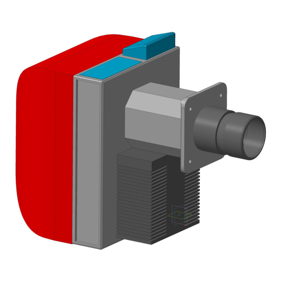
Горелка газовая одноступенчатая Cib Unigas NG 280 с современной газовой автоматикой в комплекте, настроенной на заводе.
Это горелка большой мощности новой серии IDEA. Это надежное и энергоэффективное решение для коммерческих и производстенных нужд.
Особенная геометрическая форма дроссельного клапана специально разработана для достижения линейной пропорции между углом раскрытия и расходом, способствует нормальному и эффективному по всему полезному объему горения.
Горелка, во всех своих модификациях, характеризуется некоторыми полезными функциональными доработками:
— быстро подключаемые к линии питания штепсельные вилки,
— механические компоненты, установленные на съемной опорной плите горелки,
— возможность отбора давления в камере сгорания,
— присоединительный фланец уменьшенной толщины, позволяющий уложиться в определенные габаритные размеры.
Положение головки сгорания регулируется с помощью градуированного штифта. Кроме того, газовая рампа, с соответствующими соединительными терминалами, может быть смонтирована как с левой стороны горелки, так и с правой.
Габаритные размеры:

Рабочее поле горелки:

Условия доставки:
- Доставка в пределах МКАД при заказе от 50000 рублей – бесплатно.
- Доставка в пределах МКАД при заказе менее 50000 рублей – 2500 рублей.
- Доставка за пределы МКАД – 35 рублей за км + Доставка в пределах МКАД.
- Доставка в регионы России до транспортной компании – бесплатно.
- Доставка в регионы России при заказе от 200000 рублей – бесплатно до Вашего города.
Варианты оплаты:
- Наличными курьеру при получении.
- Банковской картой при получении.
- Безналичным банковским переводом от частного или юридического лица.
Опыт
С 2009 года оказываем комплекс услуг и оборудования широкого спектра
Профессионалы
Сертифицированные специалисты
Объем
1950 отгрузок за 2021 год
Доверие
Более 1000 выигранных тендеров
Клиенты
Более 100 постоянных клиентов
Сертификаты и лицензии
Сертификат Вектор-ПМ
Сертификат OILON
Информационное письмо
Сертификат CIB UNIGAS S.p.A
Свидетельство специалистов
Сертификат РАЦИОНАЛ
Свидетельство BALTUR
Сертификат «Завод Вентилятор»
Сертификат ООО «Волгатерм»
Свидетельство ООО «КИП Еврвзия»
Услуги
Оплата и доставка
Способы оплаты
Оплата товара производится по выставленному счету от нашей организации.
Доставка до курьерских и транспортных компаний бесплатная.
Этапы заказа
- звонок/заявка на сайте
- выставление счета
- оплата
- после оплаты — самовывоз или отгрузка любой транспортной компанией или курьерской службой.
Доставка
Самовывоз.
г. Асбест, ул. Октябрьской революции, 32/1,
время работы: 8:00-17:00
Отгрузка курьерскими службами СДЭК, DPD и др.
Отгрузка транспортными компаниями Деловые Линии, КИТ и др.
Сотрудники компании
Коптелов Андрей Павлович
Директор
Кокарева Елена Сергеевна
Коммерческий директор
Самсонова Галина Анатольевна
Ведущий специалист тендерного отдела
Машковцева Светлана Александровна
Ведущий специалист коммерческого отдела
тел: +7 (34365) 2-45-52
email: td@azteo.ru
Производители продукции
Видео о товаре
x
Контакты
Карточка учета основных сведений
ООО Торговый дом «Асбестовский завод тепло-энергетического оборудования» :
|
Полное наименование предприятия (юридического лица) (покупатель) |
Общество с ограниченной ответственностью Торговый дом «Асбестовский завод тепло-энергетического оборудования» |
|
Сокращенное наименование юридического лица |
ООО ТД «АЗТЭО» |
|
Юридический адрес |
624260, Российская Федерация, Свердловская область, город Асбест, ул. Октябрьской революции, 32/1 |
|
Фактический адрес |
624260, Российская Федерация, Свердловская область, город Асбест, ул. Октябрьской революции, 32/1 |
|
Почтовый адрес |
624273, г. Асбест, а/я 17 |
|
Тел./факс |
(34365) 2-45-52, 2-87-74 |
|
ОГРН |
1096603000636 |
|
ОКПО |
62570009 |
Платежные реквизиты:
|
ИНН |
6603022774 |
|
КПП |
668301001 |
|
р/с |
407 028 106 165 400 086 23 |
|
Банк |
Уральский банк ПАО «Сбербанк» |
|
Кор./счет |
30101810500000000674 |
|
ИНН банка |
7707083893 |
|
БИК |
046577674 |
Задайте вопрос
Наши специалисты ответят на любой интересующий Вас вопрос
Задать вопрос
Мы на карте: