-
Contents
-
Table of Contents
-
Troubleshooting
-
Bookmarks
Quick Links
R75A — RX75 — RX75R
LMV2x
Microprocessor controlled
gas burners
MANUAL OF INSTALLATION — USE — MAINTENANCE
BURNERS — BRUCIATORI — BRULERS — BRENNER — QUEMADORES — ГОРЕЛКИ
M039318CD Rel 0.3 02/2015
Related Manuals for Unigas R75A
Summary of Contents for Unigas R75A
-
Page 1
R75A — RX75 — RX75R LMV2x Microprocessor controlled gas burners MANUAL OF INSTALLATION — USE — MAINTENANCE BURNERS — BRUCIATORI — BRULERS — BRENNER — QUEMADORES — ГОРЕЛКИ M039318CD Rel 0.3 02/2015… -
Page 2: General Introduction
DANGERS, WARNINGS AND NOTES OF CAUTION THIS MANUAL IS SUPPLIED AS AN INTEGRAL AND ESSENTIAL PART OF THE PRODUCT AND MUST BE DELIVERED TO THE USER. INFORMATION INCLUDED IN THIS SECTION ARE DEDICATED BOTH TO THE USER AND TO PERSONNEL FOLLOWING PRO- DUCT INSTALLATION AND MAINTENANCE.
-
Page 3: Directives And Standards
DIRECTIVES AND STANDARDS do not leave the equipment exposed to weather (rain, sun, etc.) unless expressly required to do so; Gas burners European directives: do not allow children or inexperienced persons to use equipment; — Directive 2009/142/EC — Gas Appliances; The unit input cable shall not be replaced by the user.
-
Page 4: Symbols Used
-EN 55014-1Electromagnetic compatibility — Requirements for household appliances, electric tools and similar apparatus. -UNI EN 676 (Gas Burners; -CEI EN 60335-1(Household and similar electrical appliances — Safety. Part 1: General requirements; — EN 50165 Electrical equipment of non-electric appliances for household and similar purposes.
-
Page 5
PART I: SPECIFICATIONS PART I: SPECIFICATIONS 1.0 BURNERS FEATURES Note: the figure is indicative only Control panel with startup switch Gas valve group Cover Flange Blast tube-Combustion head group Head adjusting ring nut Air tank Electrical panel Gas operation: the gas coming from the supply line, passes through the valves group provided with filter and governor. This one for- ces the pressure in the utilisation limits. -
Page 6: Gas Connection
Burners are identified by burner type and model. Burner model identification is described as follows. Type Model RX75R MD. S. BURNER TYPE RX75 — RX75R — R75A FUEL M — Natural gas L — LPG OPERATION (Available versions) PR — Progressive…
-
Page 7
PART I: SPECIFICATIONS BURNER TYPE R75A M-.. R75A L-.. 320 — 2050 Output min. — max. kW Natural gas Fuel Category see next paragraph 3B/P 34 — 217 12 — 77 Gas flow rate min.-max. Stm (see Note 2) Gas pressure min.-max. -
Page 8
1.6 Overall dimensions (mm) Burner: RX75 Reccomended counterflange Burner flange Boiler recommended drilling template A COUNTERFLANGE IS MANDATORY DN = gas valves size A (A A (A ) AA AD B (B ) B (BL) BB Omin Omax 1.50 1162 1287 374 770 352 618 361 270 290 235 330 453 M10… -
Page 9
RX75R, R75A O min. O max. Boiler recommended drilling template and burner flange DN A (A ) A (A ) AA AD B (B ) B (B ) BB Omin Omax 1.40 1162 1287 69 374 750 352 618 361 250 270 235 300 453 M10 233 452 127 325 525 608 210 155 1.50 1162 1287 69… -
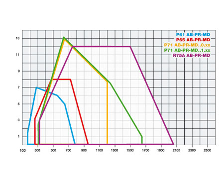
Page 10: Performance Curves
1000 1400 1800 R75A To get the input in kcal/h, multiply value in kW by 860. Data are referred to standard conditions: atmospheric pressure at 1013mbar, ambient temperature at 15°C NOTE: The performance curve is a diagram that represents the burner performance in the type approval phase or in the laboratory tests, but does not represent the regulation range of the machine.
-
Page 11
1.10 Pressure in the Network / gas flow rate curves(natural gas) RX75 RX75R Gas rate Stm Gas rate Stm R75A M-.. Gas rate Stm WARNING: the diagrams refers to natural gas. For different type of fuel please refer to the paragraph “Fuel” at the beginning of this chapter. -
Page 12
PART I: SPECIFICATIONS 1.11 Pressure in the Network / gas flow rate curves(LPG) R75A L-.. Gas rate Stm Caution: the gas rate value is quoted on the x-axis, the related network pressure is quoted on the y-axis (pressure value in the combustion chamber is not included). To know the minimum pressure at the gas train inlet, necessary to get the requested gas rate, add the pressure value in the combustion chamber to the value read on the y-axis. -
Page 13
ATTENTION: THE BURNED GAS RATE MUST BE READ AT THE GAS FLOW METER. WHEN IT IS NOT POSSIBLE, THE USER CAN REFERS TO THE PRESSURE-RATE CURVES AS GENERAL INFORMATION ONLY. 1.14 Pressure — rate in combustion head curves Curves are referred to pressure = 0mbar in the combustion chamber! RX75 RX75R R75A M-.. -
Page 14
PART I: SPECIFICATIONS 1.15 Pressure — rate in combustion head curves (LPG) Curves are referred to pressure = 0mbar in the combustion chamber! R75A L-.. -
Page 15
PART II: INSTALLATION PART II: INSTALLATION 2.0 MOUNTING AND CONNECTING THE BURNER 2.1 Packing The burners are despatched in wooden crates whose dimensions are: 1636mm x 1036mm x 1016mm (L x P x H). Packing cases of this type are affected by humidity and are not suitable for stacking. The following are placed in each packing case: burner with gas train;… -
Page 16
PART II: INSTALLATION 2.3 Fitting the burner to the boiler To install the burner into the boiler, proceed as follows: make a hole on the closing door of the combustion chamber as described on paragraph “Overall dimensions”) place the burner to the boiler: lift it up and handle it according to the procedure described on paragraph “Handling the burner”; place the 4 stud bolts (5) on boiler’s door, according to the burner drilling template described on paragraph “Overall dimensions”;… -
Page 17
PART II: INSTALLATION 2.4 Matching the burner to the boiler The burners described in this manual have been tested with combustion chambers that comply with EN676 regulation and whose dimensions are described in the diagram . In case the burner must be coupled with boilers with a combustion chamber smaller in dia- meter or shorter than those described in the diagram, please contact the supplier, to verify that a correct matching is possible, with respect of the application involved. -
Page 18
PART II: INSTALLATION 3.0 GAS TRAIN CONNECTIONS The diagrams show the components of the gas trai included in the delivery and which must be fitted by the installer.The diagrams are in compliance with the current laws. ATTENTION: BEFORE EXECUTING THE CONNECTIONS TO THE GAS PIPE NETWORK, BE SURE THAT THE MANUAL CUTOFF VALVES ARE CLOSED. -
Page 19
PART II: INSTALLATION 3.1 Assembling the gas grain gas supply network ”direction” arrows for installation Keys 1A..1E Gasket Gas filter Gas valves group Bellows unit Manual valve Fig. 6 — Example of gas train To mount the gas train, proceed as follows: 1-a) in case of threaded joints: use proper seals according to the gas used;… -
Page 20: Mounting Positions
PART II: INSTALLATION 3.2 MULTIBLOC DUNGS MB-DLE 405..412 Mounting 1. Mount flange onto tube lines: use appropriate sealing agent (see Fig. 9); 2. insert MB-DLE: note position of O rings (see Fig. 9); 3. tighten screws A, B, C and D (Fig. 7 — Fig. 8), accordind to the mounting positions (Fig. 10); 4.
-
Page 21
PART II: INSTALLATION 3.4 Siemens VGD20.. and VGD40.. gas valves — with SKP2.. (pressure governor) Mounting When mounting the VGD.. double gas valve, two flanges are required (as for VGD20.. model, the flanges are threaded); to prevent cuttings from falling inside the valve, first fit the flanges to the piping and then clean the associated parts; install the valve;… -
Page 22
PART II: INSTALLATION 3.5 Gas Filter (if provided) The gas filters remove the dust particles that are present in the gas, and prevent the elements at risk (e.g.: burner valves, counters and regulators) from becoming rapidly blocked. The filter is normally installed upstream from all the control and on-off devices. ATTENTION: it is reccomended to install the filter with gas flow parallel to the floor in order to prevent dust fall on the safety valve during maintenance operation. -
Page 23: Electrical Connections
PART II: INSTALLATION 4.0 ELECTRICAL CONNECTIONS WARNING! Respect the basic safety rules. make sure of the connection to the earthing system. do not reverse the phase and neutral connections. fit a differential thermal magnet switch adequate for connection to the mains.
-
Page 24
PART III: OPERATION PART III: OPERATION WARNING: before starting the burner up, be sure that the manual cutoff valves are open and check that the pres- sure upstream the gas train complies the value quoted on paragraph “Technical specifications”. Be sure that the mains switch is closed. -
Page 25: Gas Operation
PART III: OPERATION Fig. 19 — Burner front panel RWF50.X h min s Keys Lock-out LED Hi-flame operation LED Lo-flame operation LED “Ignition transformer operation” LED “Fan motor overload tripped” LED “EV2 opening” LED “EV1 opening” LED “Gas pressure switch signal ” LED Main switch Operation selector MAN — AUTO (operation in manual or automatic mode): MIN = operation with minimum output…
-
Page 26: User Interface
PART III: OPERATION 5.0 ADJUSTING AIR AND GAS FLOW RATES WARNING! During commissioning operations, do not let the burner operate with insufficient air flow (danger of formation of carbon monoxide); if this should happen, make the fuel decrease slowly until the normal combustion values are achieved.
-
Page 27
PART III: OPERATION Key F + A While pressing the two keys contemporarly, the code message will appear: by entering the proper password it is possible to access the Service mode. Info and Enter keys Used for Info and Service menues Used as Enter key in the setting modes Used as Reset key in the burner operation mode Used to enter a lower level menu… -
Page 28
PART III: OPERATION User level (info): no password needed Service level (Service) Manifacturer level (OEM) PHASES LIST During operation, the following program phases are shown. The meaning for each phase is quoted in the table below Fase /Phase Funzione Function Ph00 Fase blocco Lockout phase… -
Page 29
PART III: OPERATION The burner and consequently the LMV2x.. are factory set; the air and fuel curves as set as well. Info level To enter the Info level, proceed as follows: in any menu position, press keys + and — at the same time, then the program will start again: the display will show OFF. until the display will show InFo, Press the enter (InFo) key then il will show the first code (167) flashing, on the right side it will show the data entered. -
Page 30
PART III: OPERATION The Info level shows some basic parameters as: Parameter Description Cubic meters of fule (resettable) Operating hours (resettable) Device operating hours Burners start-ups (resettable) Total number of start-ups Burner number (i.e. serial number) Software version Software date Device serial number Customer code Version… -
Page 31
PART III: OPERATION If a message like the one below is shown during operation, it means that the burner is locked out and the Errore code is shown (in the example “error code:4”); this message is alternating with another message Diagnostic code (in the example “diagnostic code:3”). -
Page 32
PART III: OPERATION Parameter Description Flame intensity % output, if set = automatic operation Actuators position, 00=combustibile; 01= aria Lock-outs number 701..725 Lock-outs History (see chapter 23 in the LMV2x manual) the first parameter will be “954”: the percentage of flame is shown on the right. By pressinf + or — it is possible to scroll up/down the parameter list. -
Page 33
PART III: OPERATION 5.3 Adjusting the gas valves group 5.4 Multibloc MB-DLE VS T(VR) The multibloc unit is a compact unit consisting of two valves, gas pressure switch, pres- sure stabilizer and gas filter. The valve is adjusted by means of the RP regulator after slackening the locking screw VB by a number of turns. -
Page 34
Adjusting the combustion head CAUTION: perform these adjustments once the burner is turned off and cooled. R75A The burner is factory-adjusted with the combustion head in the «MAX» position, accordingly to the maximum power. To operate the bur- ner at a lower power, progressively shift back the combustion head, towards the «MIN» position, screwing the screw VRT. The ID index shows how much the combustion head moved. -
Page 35
PART III: OPERATION 5.7 (R75A M-..) Center head holes gas flow regulation To adjust the gas flow, partially close the holes, as follows: loosen the three V screws that fix the adjusting plate D; insert a screwdriver on the adjusting plate notches and let it move CW/CCW as to open/close the holes;… -
Page 36
PART III: OPERATION 5.10 Adjusting the maximum gas pressure switch (when provided) To calibrate the maximum pressure switch, proceed as follows according to its mounting position: remove the pressure switch plastic cover; if the maximum pressure switch is mounted upstreaam the gas valves: measure the gas pressure in the network, when flame is off; by means of the adjusting ring nut VR, set the value read, increased by the 30%. -
Page 37
PART III: OPERATION 5.13 Adjusting the maximum gas pressure switch (when provided) To calibrate the maximum pressure switch, proceed as follows according to its mounting position: remove the pressure switch plastic cover; if the maximum pressure switch is mounted upstreaam the gas valves: measure the gas pressure in the network, when flame is off; by means of the adjusting ring nut VR, set the value read, increased by the 30%. -
Page 38: Routine Maintenance
PART IV: MAINTENANCE PART IV: MAINTENANCE At least once a year carry out the maintenance operations listed below. In the case of seasonal servicing, it is recommended to carry out the maintenance at the end of each heating season; in the case of continuous operation the maintenance is carried out every 6 months.
-
Page 39
PART IV: MAINTENANCE Fig. 26 6.2 Removing the filter in the MULTIBLOC DUNGS MB-DLE 415 — 420 B01 1” 1/2 — 2” Check the filter at least once a year! Change the filter if the pressure difference between pressure connection 1 and 2 (Fig. 28-Fig. 29) Δp> 10 mbar. Change the filter if the pressure difference between pressure connection 1 and 2 (Fig. -
Page 40
PART IV: MAINTENANCE 6.3 Replacing the spring in the gas valve group To replace the spring in the gas valve group,proceed as follows: Carefully twist the protection cap 1 and the O-ring 2. remove the “set value” spring 3 from housing 4. Replace spring 3. -
Page 41: Replacing The Electrodes
EA — Ignition electrode The detection electrode must be aligned to the centre, as shown in the figure. Electrodes position settings R75A 6.7 Replacing the electrodes ATTENTION: avoid the ignition and detection electrodes to contact metallic parts (blast tube, head, etc.), other- wise the boiler’s operation would be compromised.
-
Page 42
PART IV: MAINTENANCE RX75, RX75R Detection electrode Fig. 32 R75A Fig. 33… -
Page 43: Seasonal Stop
PART IV: MAINTENANCE 6.8 Checking the detection current (natural gas) To check the detection signal follow the scheme in the picture below. If the signal is less than the value indicated, check the position of the detection electrode or detector, the electrical contacts and, if necessary, replace the electrode or the detector. Device Flame detector Minimum detection signal…
-
Page 44: Wiring Diagrams
PART IV: MAINTENANCE 7.0 WIRING DIAGRAMS Refer to the attached wiring diagrams. WARNING 1 — Electrical supply 230V 50Hz 1 a.c./400V 50Hz 3N a.c. 2 — Do not reverse phase with neutral 3 — Ensure burner is properly earthed…
-
Page 45: Troubleshooting
8.0 TROUBLESHOOTING TROUBLE CAUSE MAIN SWITCH OPEN LACK OF GAS MAXIMUM GAS PRESSURE SWITCH DEFECTIVE THERMOSTATS/PRESSURE SWITCHES DEFECTIVES OVERLOAD TRIPPED INTERVENTION AUXILIARIES FUSE INTERRUPTED DEFECTIVE CONTROL BOX DEFECTIVE ACTUATOR AIR PRESSURE SWITCH FAULT OR BAD SETTING MINIMUM GAS PRESSURE SWITCH DEFECTIVE OR GAS FILTER DIRTY IGNITION TRANSFORMER FAULT IGNITION ELECTRODES BAD POSITION…
-
Page 48
C.I.B. UNIGAS S.p.A. Via L.Galvani, 9 — 35011 Campodarsego (PD) — ITALY Tel. +39 049 9200944 — Fax +39 049 9200945/9201269 web site: www.cibunigas.it — e-mail: cibunigas@cibunigas.it Note: specifications and data subject to change. Errors and omissions exceptd.
CIB UNIGAS R75A M-.PR.S.RU.A.8.50 газовая горелка серии TECNOPRESS 2 МВт
Прогрессивная газовая горелка для использования в отопительном оборудовании: котлах, в парогенераторах.
Комплекта поставки:
Горелочное устройство R75A. Блочная горелка, в комплект поставки которой включены:
- электродвигатель с вентилятором;
- магнитный пускатель э/двигателя;
- термореле э/двигателя;
- голова сгорания с горелочной трубой;
- дроссельный газовый клапан;
- воздушная коробка с заслонками;
- электронный блок контроля пламени;
- трансформатор с запальными электродами;
- контрольный электрод;
- электрощит с мнемосхемой и печатной платой.
Тип топлива (M)
- природный газ (ГОСТ 5542-2014).
Тип регулировки горелки (PR)
- плавно — двухступенчатое (прогрессивное): горелка может работать в модулируемом режиме при наличии внешнего ПИД-регулятора.
Сопло (S)
- стандартное.
Страна назначения (RU)
- Россия.
Исполнение горелки (A)
- стандартное.
Комплектация (8)
- реле минимального давления газа «Dungs»;
- функция контроля герметичности (с помощью VPS504);
- реле максимального давления газа «Dungs».
Диаметр газовой рампы (50)
В состав газовой рампы с Ду50, входит мультиблок «Dungs», состоящий из:
- отсечного электромагнитного клапана;
- газового клапана со стабилизатором давления газа;
- фильтра.
Максимальное давление газа перед данным мультиблоком не должно превышать 360 мбар.
Давление в камере сгорания:
Производитель: C.I.B. Unigas S.p.A. ![]()

| Производитель | Италия |
| Сборка | Италия (IT)/Россия (RU) |
| Исполнение | Навесное |
| Место установки | Котел |
| Тип | Газовый |
| Режим работы | Прерывный |
| Количество фаз: | 3 |
| Количество ступеней | Плавно — двухступенчатое (Прогрессивное регулирование) |
| Класс защиты | IP40 |
| Напряжение, В | 380 |
| Частота тока, Гц | 50 |
| Тип топлива | Природный газ |
| Мощность двигателя, кВт | 3 |
| Расход топлива | 34 — 217 Стм3/ч |
| Тип горелки | Наддувная |
| Минимальная тепловая мощность, кВт | 320 |
| Максимальная тепловая мощность, кВт | 2050 |
| Длина, мм | 1429 |
| Ширина, мм | 1062 |
| Высота, мм | 608 |
| Вес, кг | 140 |
C.I.B. UNIGAS S.P.A. ФИРМА, КОТОРАЯ ОПЕРЕЖАЕТ ВРЕМЯ.
Основанная в 1972 году в предместье г. Падуя (Италия), за последние 40 лет заняла достаточно серьёзную позицию среди самых передовых производителей горелочных устройств в мире.
1972
по идее своего основателя и настоящего президента инженера Клаудио Панколини, рождается “Unigas” – маленькая фирма, кустарного типа, которая начинает разрабатывать и производить газовые горелки.
1973
производство переезжает из простого гаража в Лоредже (Падуя) в небольшой производственный корпус. Площадью в 300 м2 в Лимене.
1975
фирма преобразуется и меняет свое название на “CIB Unigas S.r.l”, постоянно растущее производство, на котором незаурядные креативные и конструкторские способности президента позволили осуществить быстрое и эффективное внедрение собственной продукции на рынок. Новое головное предприятие в Лимене площадью 2000 м2.
1976
проектируется и выпускается первая серия дизельных горелок, но оказывается побеждающим и более прагматичным выбор продвижения газовых горелок в тот исторический момент, когда начал применяться широкомасштабно природный газ.
1979
в конце 70-х, фирма начинает отвоевывать свое пространство внутри рынка, становится на виду у всех, значительно увеличивает приверженную ей клиентуру; это происходит, прежде всего, после принятия решения перейти с настоящей юридической формы на другую, то есть на “CIB Unigas S.p.A”.
1980
завершение линейки горелок, предлагаемых на рынке, начало производства горелок на мазутном топливе, а также комбинированных;
1982
серьезное сотрудничество в исследованиях с американской фирмой “Peabody Gordon-Piatt”, в целях разработки промышленных горелок мощностью до 12 Mватт.
1984
перенос головного предприятия и производства в Камподарсего, в производственный корпус площадью 4500 м2.
1990
Регулярное присутствие на международных семинарах и выставках, укрепление капиллярной сети по обслуживанию горелок, через надежные агентства, торговые точки и центры техобслуживания, разбросанные не только по Италии, но и по всему миру, что позволяет фирме занять место среди наиболее серьезных промышленных производителей в этой области
1994
CIB Unigas получает сертификат качества ISO 9001 на само предприятие, а также на продукцию (марка CE), выданный самым авторитетным европейским институтом по сертификации ТЮФ (TUV).
1995
Разработка и начало производства первых горелок с низкими выбросами NOx, мощностью до 3-х Mватт.
2000
Наработанные инновационный и технологический опыт, связанный с «ноу-хау», который в состоянии гарантировать стабильное и неуклонное развитие во времени, позволил фирмеCIB Unigas принимать адекватные и наилучшие решения для удовлетворения различны потребностей рынков разных стран, в то же время, в соответствии с директивами по сохранению окружающей среды и шумовому загрязнению, не говоря уже о надежности и качестве продукции;
2003
благодаря партнерству с голландской фирмой, выпускается новая голова сгорания, которая позволяет разработать горелки с низкими выбросами NOx, мощностью до 12 MВатт;
2009
CIB Unigas, не меняя территориальной привязанности, переезжает в более крупный и функциональный корпус (15000 м2). Расширение персонала и области исследований Отдела по Развитию Производства.
2010
Реорганизация производства, с применением английской системы “Lean production”, что означает минимизацию запасов на полках, размещение практически всех запасов на рабочих местах, для придания производству большей гибкости и эффективности.
2011
Открытие новой фирмы в Англии “G.P. BURNERS”
2012
Разработка промышленных горелок типа “URB” , с максимальной мощностью до 80 MВатт.
2013
Новая подконтрольная фирма в Китае CIB Unigas Energy, Science&Technology Co. LTD для увеличения объема продаж на восточном рынке.
2015
Реализация новой фирмы в России, под названием “CIB Unigas S.R.L” и региональных филиалов для укрепления коммерческой организации.
CIB UNIGAS выпускает множество модификаций горелок, которые работают на любом виде топлива. Правильное определение модели горелки на фазе ее выбора к любому виду котла позволяет достичь очень хороших результатов в работе горелки, экономного расхода топлива и низкого уровня выбросов продуктов сгорания.
CIB UNIGAS надежный партнер, везде, где требуется энергия в больших или малых размерах. Бытовые и промышленные горелки CIB UNIGAS эксплуатируются в экстремальных условиях и пользуются отличной репутацией.
Газовые горелки
Idea: NG35 NG70 NG90 NG120 NG140 NG200
Tecnopress: P61 P66 P71 P75
Novanta: R91 R92 R93
Cinquecento: R512 R515 R520 R525
Mille: RG1025 RG1030 RG1040
Miniflam: Chef S60 Tecnopan S5 S10 S18
Дизельные горелки
Idea: LO35 LO65 LO90 LO140 LO200 LO280 LO400 LO550
Tecnopress: PG30 PG60 PG70 PG81
Novanta: RG91 RG92 RG93
Cinquecento: RG510 RG515 RG520 RG525
Mille: RG1030 RG1040
Miniflam: Chef LO60 Tecnopan LO60 G10 G18
Комбинированные горелки газ/дизель
Miniflam: HS5 HS10 HS18
Tecnopress: HP20 HP30 HP60 HP65 HP72 HP75
Мазутные горелки
Miniflam: Мiniflam N18
Tecnopress: PN30 PN60 PN70 PN81
Cinquecento: RN510 RN515 RN520 RN525
ОФИЦИАЛЬНЫЙ ДИЛЕР — ООО «УРАЛЬСКАЯ СТРОИТЕЛЬНАЯ ТЕПЛОЭНЕРГЕТИЧЕСКАЯ КОМПАНИЯ»

Уточните ваш запрос, если товар не подходит
Цена с НДС за товар
Цена не указана
Условия поставки:
ТК по России и Казахстану
Горелка газовая GIB UNIGAS R75A M-.PR.S.RU.A.8.50 .
Технические характеристики
Дополнительно потребуются
Отзывы
| Бренд | C.I.B. Unigas | Количество ступеней | 2 |
|---|---|---|---|
| Вид горелки | Горелка водогрейного котла | Класс защиты | IP40 |
| Производитель | Италия | Топливо | Газ |
| Сборка | Италия (IT)/ Россия (RU) | Тип горелки | Наддувная |
| Исполнение | Навесное | Габаритные размеры, длина*ширина*высота, мм | 812 х 1169 х 464 |
| Место установки | Котел | Масса, кг | 60 |
| Режим работы | Прерывный | Мощность горелки, КВт | 160-2060 |
| Количество фаз | 3 |
Это устройство работает со вспомогательным оборудованием, которое приобретается отдельно.
Если вы хотите сразу узнать стоимость всей установки, добавьте заинтересовавшие вас позиции в корзину.
Чтобы точно расчитать стоимость доставки до вашего объекта, укажите его адрес в корзине и оправьте нам заявку.
Обычно мы отвечаем в течение дня.

Котел 1500 КВт газовый
Максимальная тепловая мощность, кВт
1500
Отапливаемая площадь, м²
12500-16500
Отапливаемый объем, м³
37500-49300
Вид топки
Газовая горелка
680 000

Паровой котел КПа 1600 ГН
Паропроизводительность, кг/час
1600
Температура пара, °C
95, 110, 115
Избыточное давление пара, не более, МПа
0.07
1 445 000
Паровой котел Е 1.6 0.9 ГН
Паропроизводительность, кг/час
1600
Температура пара, °C
120, 130, 140, 150, 160, 170
Избыточное давление пара, не более, МПа
0.9
1 598 000

Паровой котел КПа 2000 ГН
Паропроизводительность, кг/час
2000
Температура пара, °C
95, 110, 115
Избыточное давление пара, не более, МПа
0.07
1 378 000
Паровой котел Е 2.0 0.9 ГН
Паропроизводительность, кг/час
2000
Температура пара, °C
120, 130, 140, 150, 160, 170
Избыточное давление пара, не более, МПа
0.9
1 920 000
Об этом товаре еще нет отзывов. Будьте первым!
Газовая горелка Cib Unigas R75A M-.PR.S.RU.A.8.50 EA. Описание
Газовая горелка Unigas Cib Unigas R75A M-.PR.S.RU.A.8.50 EA используются в водогрейных и паровых котлах, устанавливаются в модульных котельных.
Данная модель горелочного устройства работает с водогрейным котлом КВа 1.5 МВт.
В качестве топлива для горелки Cib Unigas R75A M-.PR.S.RU.A.8.50 EA используется природный или сжиженный газ.
Газовая горелка Cib Unigas R75A M-.PR.S.RU.A.8.50 EA мощностью от 160 до 2060 кВт, имеет только двухступенчатый, плавно-двухступенчатый и модулирующий тип регулирования.
Модель оснащена электрическим сервоприводом для контроля соотношения газ/воздух. Горелка Cib Unigas R75A M-.PR.S.RU.A.8.50 EA способна работать на котлах с разряжением в камере сгорания, а также с избыточным сопротивлением. Особенности конструкции горелки способствуют образованию рассеянного пламени с высокой степенью излучения, что приводит к повышению КПД устройства.
Панель управления позволяет просматривать выполняемые функции и возможные неполадки системы.
Вы можете купить газовую горелку R75A M-.PR.S.RU.A.8.50 EA на нашем котельном заводе. Поставляем полный перечень комплектующих для котлов и котельных.
Маркировка горелки R75A M-.PR.S.RU.A.8.50 EA Unigas:
- R75A — тип горелки
- M-.PR.S.RU.A.8.50 — модель горелки, где:
- М — топливо: природный газ;
- PR — исполнение: прогрессивное;
- S — сопло: — стандартная;
- XX — страна назначения (RU-Россия, IT-Италия, UA-Украина, BY-Беларусь, KZ-Казахстан, GE-Грузия);
- А — исполнение горелки: стандарт;
- 1 — комплектация: 2 клапана + блок контроля герметичности + реле максимального давления газа;
- 50 — размер газовой рампы: Rp2;
- EA — электронное регулирование: горелка, оснащенная менеджером горения LMV2.
Гарантии изготовителя
Гарантийное обслуживание включает в себя бесплатное устранение скрытых заводских дефектов, замену деталей и узлов вышедших из строя в период гарантийного срока при условии монтажа и эксплуатации оборудования Покупателем в соответствии с его назначением, технической документацией, техническими нормами, правилами ввода в эксплуатацию и эксплуатации данного оборудования.
Для получения консультации укажите номер вашего телефона
Патенты на котельное оборудование
Патенты


Сертификаты Завода
Сертификаты


Членство в СРО
Допуски


Отзывы о продукции котельного завода
Отзывы о продукции котельного завода

Аттестованная технология сварки
Аттестованная технология сварки

Прогрессивная промышленная газовая горелка Чиб Унигаз котла отопления до 2500 кВт.
Комплект поставки газовой горелки Cib Unigas:
— Моноблочное горелочное устройство.
— Газовый клапан (рампа).
— Крепежный фланец, позволяющий установить горелку на любой универсальный котел отопления.
— Семиштырьковый электрический разъём.
Газовые горелки Cib Unigas TECNOPRESS производятся на заводе в Италии. В качестве топлива для горелок серии Tecnopress может использоваться природный или сжиженный газ. Горелки этой серии могут иметь стандартное или длинное сопло, если есть необходимость установить более короткое сопло, чем стандартное, можно использовать распорные вставки для регулировки степени ввода сопла в топочную камеру.
Купить газовые горелки Cib Unigas в Москве.
Специализированный магазин Gorelki.ru. Мы находимся в Москве, но доставка горелок Cib Unigas возможна во все регионы страны. Купить газовые горелки у нас можно со скидкой, по выгодной цене. При желании покупателя, мы можем осуществить установку горелочного устройства на котел отопления.
Отзывы о товаре
Отзывов об этом товаре еще нет. Вы можете стать первым, кто оставит отзыв!
THIS MANUAL IS SUPPLIED AS AN INTEGRAL AND ESSENTIAL PART OF THE PRODUCT AND MUST BE DELIVERED TO THE
USER.
INFORMATION INCLUDED IN THIS SECTION ARE DEDICATED BOTH TO THE USER AND TO PERSONNEL FOLLOWING PRO-
DUCT INSTALLATION AND MAINTENANCE.
THE USER WILL FIND FURTHER INFORMATION ABOUT OPERATING AND USE RESTRICTIONS, IN THE SECOND SECTION
OF THIS MANUAL. WE HIGHLY RECOMMEND TO READ IT.
CAREFULLY KEEP THIS MANUAL FOR FUTURE REFERENCE.
1)
The equipment must be installed in compliance with the regulations
in force, following the manufacturer’s instructions, by qualified per-
sonnel.
Qualified personnel means those having technical knowledge in the
field of components for civil or industrial heating systems, sanitary
hot water generation and particularly service centres authorised by
the manufacturer.
Improper installation may cause injury to people and animals, or
damage to property, for which the manufacturer cannot be held lia-
ble.
Remove all packaging material and inspect the equipment for inte-
grity.
In case of any doubt, do not use the unit — contact the supplier.
The packaging materials (wooden crate, nails, fastening devices, plastic
bags, foamed polystyrene, etc), should not be left within the reach of chil-
dren, as they may prove harmful.
Before any cleaning or servicing operation, disconnect the unit from
the mains by turning the master switch OFF, and/or through the cut-
out devices that are provided.
Make sure that inlet or exhaust grilles are unobstructed.
In case of breakdown and/or defective unit operation, disconnect the
unit. Make no attempt to repair the unit or take any direct action.
Contact qualified personnel only.
Units shall be repaired exclusively by a servicing centre, duly authorised
by the manufacturer, with original spare parts.
Failure to comply with the above instructions is likely to impair the unit’s
safety.
To ensure equipment efficiency and proper operation, it is essential that
maintenance operations are performed by qualified personnel at regular
intervals, following the manufacturer’s instructions.
When a decision is made to discontinue the use of the equipment,
those parts likely to constitute sources of danger shall be made har-
mless.
In case the equipment is to be sold or transferred to another user, or
in case the original user should move and leave the unit behind,
make sure that these instructions accompany the equipment at all
times so that they can be consulted by the new owner and/or the
installer.
For all the units that have been modified or have options fitted then
original accessory equipment only shall be used.
This unit shall be employed exclusively for the use for which it is
meant. Any other use shall be considered as improper and, there-
fore, dangerous.
The manufacturer shall not be held liable, by agreement or otherwise, for
damages resulting from improper installation, use and failure to comply
with the instructions supplied by the manufacturer.The occurrence of any
of the following circustances may cause explosions, polluting unburnt
gases (example: carbon monoxide CO), burns, serious harm to people,
animals and things:
— Failure to comply with one of the WARNINGS in this chapter
— Incorrect handling, installation, adjustment or maintenance of the burner
— Incorrect use of the burner or incorrect use of its parts or optional supply
2)
SPECIAL INSTRUCTIONS FOR BURNERS
The burner should be installed in a suitable room, with ventilation
openings complying with the requirements of the regulations in force,
and sufficient for good combustion.
Only burners designed according to the regulations in force should
be used.
This burner should be employed exclusively for the use for which it
DANGERS, WARNINGS AND NOTES OF CAUTION
was designed.
Before connecting the burner, make sure that the unit rating is the
same as delivery mains (electricity, gas oil, or other fuel).
Observe caution with hot burner components. These are, usually,
near to the flame and the fuel pre-heating system, they become hot
during the unit operation and will remain hot for some time after the
burner has stopped.
When the decision is made to discontinue the use of the burner, the user
shall have qualified personnel carry out the following operations:
a
Remove the power supply by disconnecting the power cord from the
mains.
b) Disconnect the fuel supply by means of the hand-operated shut-off
valve and remove the control handwheels from their spindles.
Special warnings
Make sure that the burner has, on installation, been firmly secured to
the appliance, so that the flame is generated inside the appliance
firebox.
Before the burner is started and, thereafter, at least once a year,
have qualified personnel perform the following operations:
a
set the burner fuel flow rate depending on the heat input of the
appliance;
b
set the flow rate of the combustion-supporting air to obtain a combu-
stion efficiency level at least equal to the lower level required by the
regulations in force;
c
check the unit operation for proper combustion, to avoid any harmful
or polluting unburnt gases in excess of the limits permitted by the
regulations in force;
d
make sure that control and safety devices are operating properly;
e
make sure that exhaust ducts intended to discharge the products of
combustion are operating properly;
f
on completion of setting and adjustment operations, make sure that
all mechanical locking devices of controls have been duly tightened;
g
make sure that a copy of the burner use and maintenance instruc-
tions is available in the boiler room.
In case of a burner shut-down, reser the control box by means of the
RESET pushbutton. If a second shut-down takes place, call the
Technical Service, without trying to RESET further.
The unit shall be operated and serviced by qualified personnel only,
in compliance with the regulations in force.
3)
GENERAL INSTRUCTIONS DEPENDING ON FUEL USED
3a) ELECTRICAL CONNECTION
For safety reasons the unit must be efficiently earthed and installed
as required by current safety regulations.
It is vital that all saftey requirements are met. In case of any doubt,
ask for an accurate inspection of electrics by qualified personnel,
since the manufacturer cannot be held liable for damages that may
be caused by failure to correctly earth the equipment.
Qualified personnel must inspect the system to make sure that it is
adequate to take the maximum power used by the equipment shown
on the equipment rating plate. In particular, make sure that the
system cable cross section is adequate for the power absorbed by
the unit.
No adaptors, multiple outlet sockets and/or extension cables are per-
mitted to connect the unit to the electric mains.
An omnipolar switch shall be provided for connection to mains, as
required by the current safety regulations.
The use of any power-operated component implies observance of a
few basic rules, for example:
do not touch the unit with wet or damp parts of the body and/or with
—
bare feet;
do not pull electric cables;
—
2