-
Contents
-
Table of Contents
-
Bookmarks
Quick Links
No. S1006
OPERATING INSTRUCTION
Prior to use, please read this manual thoroughly.
Keep this manual in a convenient place for quick and easy reference.
Related Manuals for GRAUPNER mz-24 HOTT
Summary of Contents for GRAUPNER mz-24 HOTT
-
Page 1
No. S1006 OPERATING INSTRUCTION Prior to use, please read this manual thoroughly. Keep this manual in a convenient place for quick and easy reference. -
Page 2: Table Of Contents
Contents 8. S.Limit • Before Use 9. S.MIX 43~45P • Introduction 10. THR.MIX 45~46P • Support and Service 11. PRO.MIX 46~50P • Openhobby A/S Center 12. Trainer 50~51P 1. Box Contents 13. PIT >> RUDD 2. Flying Safety 52~53P 14. Telemetry 3.
-
Page 3: Introduction
Do not attempt disassembly, use with incompatible components or augment product in any way without the approval of Graupner/SJ. This manual contains instructions for Graupner/SJ mz-24 HoTT radio system is used to airplane, helicopter and glider and safety, operation and maintenance.
-
Page 4: Specification
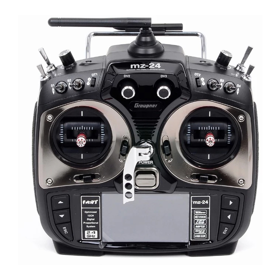
6. TRANSMITTER CONTROL IDENTIFICATION 4. SPECIFICATION ANTENNA Transmitter mz-24 Receiver GR-24L S3 SWITCH Frequency band 2.4~2.4835GHz 2.4~2.4835GHz S5 SWITCH S2 SWITCH Modulation FHSS FHSS S4 SWITCH S1 SWITCH Output power 100mW Current drain approx 125mA approx 70mA POWER SWITCH Operating voltage 3.4V~6V 3.6V~8.4V NECKSTRAP LUG…
-
Page 5: Binding
7. BINDING CAUTION We strongly recommend that you wouldn’t use throttle limit function in Helicopter type since You must bind the receiver to the transmitter before the receiver will operate. Binding throttle limit function restricts the travel amount of throttle with DV1 volume. teaches the receiver the specific code of the transmitter so that it will only connect to it’s In order to cancel throttle limit function, touch “BASE”…
-
Page 6: Warning Alarm Function For Telemetry Data
8.WARNING ALARM FUNCTION FOR TELEMETRY DATA BACK AUTO LOAD TX VOLT RX VOLT Touch RX 05.5V This function consists of 5 different warning types so that users can easily check each of warn- 3.7V 00.0V ings from transmitter screen. When one of 5 warnings happens, the warning screen is displayed STRENGTH and voice alarm is activated.
-
Page 7: Transmitter Programming Setup
9. TRANSMITTER PROGRAMMING SETUP 1-1. SET BASE MENU Touch and activate “MODEL NAME” icon in blue for your purpose and touch SEL icon. Select Turn on transmitter’s power and touch B icon on the main page to access to BASE menu. YES in “MODEL CHANGE”…
-
Page 8: New(New Model)
1-2. NEW This function is use to create the new model or exchange the current model to others. There is 2 methods of Manual setting and Wizard setting. You may program the basic function sequen- Touch tially in Manual setting. Here is the example for airplane IMP.M IMP.M Touch…
-
Page 9
Touch Touch Touch “Wizard setup” is used to set the basic function of a model and the essential function of flight one Touch by one. Please refer to the example of helicopter type as below. Touch the icon of desired model you want to program Wizard setup in the model list and touch “NEW”… -
Page 10
Touch IMP.M IMP.M Touch Touch EXP.M EXP.M Touch Touch IMP.M EXP.M Touch Touch Touch Touch Touch Touch Touch Touch Touch Touch Touch… -
Page 11: Imp.m (Imp. Model)
Touch Touch 1-3. IMP.M (IMP. Model) It is used to copy the model memory in SD Card into the model list of transmitter. To make use of IMP.M function, you need SD Card that has the programmed model file. If you put SD Card into SD Touch Touch Card slot on the back of transmitter, “SD Card”…
-
Page 12: Exp.m (Exp Model)
Check Check IMP.M IMP.M Touch EXP.M EXP.M Touch Touch Touch IMP.M IMP.M IMP.M Touch EXP.M EXP.M EXP.M Touch IMP.M IMP.M IMP.M EXP.M EXP.M EXP.M Touch Touch 1-4. EXP.M (EXP Model) This function is used to copy the model in transmitter into SD Card. In order to use EXP.M function, you need to plug SD Card into SD Card slot on the back of transmitter.
-
Page 13: Cpy(Model Copy)
1-6. CPY(Model Copy) 1-5. RES(RESET) The Copy function is used to copy the programmed values of a model into the other model. It allows you to remove the selected models in model list. Refer to the example of Model 01 Touch the source model to copy, it is activated in blue.
-
Page 14: Model Type 3. E
2. Model type It is used to reset the model type. Please note that all the value, excepting for model name, is reset when “Model type” is set again. Touch “Model type” icon on base menu page to call the model type setup page, the preset “model type”, “swash type”…
-
Page 15: Reverse
Touch Touch 4. Reverse It is used to reverse the operation of an individual servo. Touch the “Reverse” icon in the base menu page to call the Reverse setup page. In “Reverse” page, you are able to reverse the oper- ation of a servo.
-
Page 16: Sub-Trim
Touch Touch Touch Touch Touch Touch 5. Sub-Trim It is used to set the servo neutral position, and may be used to make fine adjustments to Touch control surface without hooking linkages and pushrods up. The trim for transmitter stick should be in center position at the first and then Sub-Trim should be set.
-
Page 17: Thr.cut
Touch Touch 6. THR.CUT This function is used to stop the operation of engine. THR.CUT function works from below one-third position of the full movement range of throttle stick. Touch “THR.CUT” icon in the base menu page to call the “THR.CUT” setup page. When touching “INH” icon in “ACT” line, you may change the value to “OFF”.
-
Page 18: Tx Ctl
To make use of this function, a receiver should be bound first. Bind receiver and transmitter 7. TX ctl and then touch “Set” icon in “TX OUT SET” to call “TX OUT SET” setup page. In the page, the It consists of the multiple functions for a transmitter. It includes “BIND ON/OFF”, “TX OUT SET”, different number of channel is displayed according to the bound receiver.
-
Page 19
Touch Touch Touch — RF ON/OFF It is used to turn on or off transmitter’s “RF” function. If you are not flying a model but programming transmitter only, you are able to save the battery of the transmitter by setting RF to turn off. -
Page 20: Timer
8. TIMER — DSC OUTPUT Timer function may be set for any desired time ,i.e. model time, date, time, etc. Two independ- It is used to set the number of channel when Trainer function is used with DSC jack. If 5 channels ent timers, TIMER1 and TIMER2, are provided for each model.
-
Page 21
Touch Touch Touch the value in “MODE” line to select “UP” or “DOWN”. Timer may be counted down or counted up with your choice. Count-up timer is to count from zero to the setup time and Count-down timer is to count from the setup time to zero. Touch After “ALARM”… -
Page 22
Touch Touch After RESET SW is set, you may set “LAP SW” function. Touch “NULL” icon in “LAP SW” to call “select” message popup. Now, move the switch with your choice then this switch is set on/ off switch for “LAP SW” and the switch direction setup page appears. You may change ON/OFF by touching icons. -
Page 23
Touch Touch Touch Touch Touch Touch Touch Touch “NEXT” icon on the right in Timer 1 setup page, you may call Timer 2 setup page. You are able to set Timer 2 as the same as explained above. Timer 2 don’t have the function of the flight data saving so it can calculate the time only. -
Page 24: Failsafe
Touch Touch Touch Touch Touch Touch Touch 9. FAILSAFE When you bind your transmitter, you are programming the receiver with failsafe defaults. If con- nection is lost between the transmitter and receiver, the receiver immediately operates in those preprogrammed default positions. The default value is “Hold”…
-
Page 25
Touch Touch Touch Touch Touch Touch Touch Touch Touch Touch Touch Touch Touch Touch Touch Touch… -
Page 26: Trim Step
10. TRIM STEP It allows you to check all values of “Digital trim step”, “DT1”, “DT2”, ‘Digital volume”, and “Side slide”. Touch “Trim Step” icon in base menu page to call Trim Step setup page. The step values in T1, T2, T3, T4 indicate servo movement per click of trim. “4” is set by default, which means that trim will travel as much as 4 by each click of trim Touch and activate the step values and then adjust them with INC”…
-
Page 27: Servo
Touch Touch Touch Touch Touch Touch Touch Touch 11. SERVO It is used to test a servo and check the servo movement in a graph. You are able to test the servo movement from 0.5sec to 5 sec with your choice. Touch “Servo” icon in the base page to call the servo setup page.
-
Page 28: Ch Set
12. CH Set It is used to set the channel of a transmitter. The basic setup of the transmitter’s channel is set T:CO T:CO differently depending on 3 different types (“model type”, “wing type”, and “swash type”) and mz- Touch 24 offers AUX channel to set the switch, volume, and side lever for your purpose.
-
Page 29: Function Menu (Helicopter)
Touch Touch Touch Touch Touch Touch FUNCTION MENU (Helicopter) 1. Q.LINK This function is used to set Q.LINK and assign all switches including sticks, switches, trim levers and trim switches as Q.LINK selection switches to cope with various flight conditions such as 3D flight.
-
Page 30: New
1-1 NEW This function is used to create new Q.LINK. Touch the value in “Q.LINK” line to activate it in blue and touch “NEW” icon in the right to call “CTRL” and “DELAY” options. In “CTRL” setup, touch “NULL” icon to call “Select” message popup and move the switch or stick with your choice then the Hold Hold switch or stick is set to Q.LINK switch.
-
Page 31: Cpy
Hold Hold Hold Touch ldle-up1 ldle-up2 ldle-up3 Touch 1-4 Del It is used to delete the unused Q.LINK. Touch the entry in Q.LINIK line that you want to delete to Touch activate in blue and touch “DEL” icon. Now, the selected Q.LINK entry is deleted in Q.LINK list. If Hold you touch “NEXT”…
-
Page 32
2. D/R, EXP Dual Rates and exponentials are available on all channels including aileron, elevator and rudder channels. This adjusts control rates for servos. Adjust the throws (Dual Rate) and center sensitivity (Expo) of the control’s range independently. You may assign a switch for moving between control rates for a servo channel and Dual Rates and exponentials are available on each Q.LINK as well Dual rate is a percentage of the Travel Adjust. -
Page 33
Touch Touch Touch Touch Touch Touch Touch Touch Touch Touch Touch Touch… -
Page 34: Pit.crv
Touch Touch Telemetry In FUNCTION page, touch “PIT.CRV” icon to call PIT.CRV setup page. You need to mark the point on graph first and then adjust the operation curve with “DEC”, “INC”, X-axis and Y-axis buttons. Touch “ST OFF” to change to “ST ON” then the throttle position line appears on graph.
-
Page 35
TRIM TRIM TRIM TRIM Touch Touch Touch Touch TRIM TRIM TRIM TRIM Touch Touch Touch TRIM TRIM TRIM TRIM Touch Touch Touch Touch TRIM TRIM TRIM TRIM Touch Touch… -
Page 36
Q.LINK (idel-up2) TRIM TRIM TRIM Touch Touch Q.LINK (Hold) TRIM Touch Touch Telemetry If you touch OFF icon in Curve line, it is switched to ON and the operation curve is smoother. After setup, touch “TRIM” icon in the top right to call the pitch, throttle curve trim setup page. TRIM TRIM Touch… -
Page 37: Thr.crv
TRIM Touch +076% +076% Telemetry In FUNCTION page, touch “THR.CRV” icon to call THR.CRV setup page. You need to mark the point on graph first and then adjust the operation curve with “DEC”, “INC”, X-axis and Y-axis but- tons. Touch “ST OFF” to switch to “ST ON” then the throttle position line appears on graph. Move throttle stick and place the line at the desired position between point “L”…
-
Page 38
TRIM TRIM TRIM TRIM Touch Touch Touch :63P TRIM TRIM TRIM TRIM 63-5W Touch Touch Touch TRIM TRIM TRIM TRIM Touch Touch TRIM TRIM TRIM TRIM Touch Touch… -
Page 39: Gyr/Gover
TRIM Touch Touch Touch Telemetry If you touch OFF icon in Curve line, it is changed to ON and the operation curve is smoother. NORMAL MODEL NAME 1 You may set the pitch, throttle curve trim by touching “TRIM” icon in the top right. The setup TRIM Touch method is explained at PIT.CRV…
-
Page 40
Touch Touch Gyro Suppression Gyro Suppression TRIM TRIM Telemetry Gyro Gain, Governor, Governor RATE, Gyro Suppression are available in this function — Gyro Gain is used to adjust the sensitivity of gyro. “00%” is basically set and heading lock gyro is operated at over 40% of sensitivity. -
Page 41: Thr.hold
Touch Touch Gyro Suppression Gyro Suppression TRIM TRIM Telemetry Touch Touch Gyro Suppression TRIM Telemetry 6. THR.HOLD Touch This function is for powering down an engine or motor using a designated switch. Throttle hold has higher authority than any other flight mode. When you activate THR.HOLD, the throttle channel is driven to its programmed value.
-
Page 42: Swash
Touch Touch Touch Telemetry Touch Touch 7. SWASH The swash function supports adjustment of the travel amount and direction of the aileron, eleva- Touch tor and pitch in Helicopter mode. Bind a helicopter to a receiver and set the travel amount and direction of the swash channels desirably Touch “SWASH”…
-
Page 43
8. S.Limt (Swash Limit) This function makes transmitter recognized the square stick travel to a circular stick travel. Even the channels of PITCH, AILE and ELEV which controls the swash plate are driven to out of circle, servos are operated in the setup circle only. -
Page 44
(RATE) (RATE) Touch Touch Touch Telemetry Touch Touch (RATE) (RATE) Touch Touch Touch (RATE) (RATE) Touch Touch Touch Touch Touch (RATE) (RATE) Touch Touch… -
Page 45: Thr.mix
(RATE) Touch Touch Telemetry 10. THR.MIX THR.MIX function prevents RPM decay when PITCH, AILE and ELEV inputs are given. This mix advances the throttle position with mix control to maintain RPM. This function can be adjusted for each condition of Q.LINK and three types is available (AILE>>THRO, (RATE) (RATE) ELEV>>THRO, RUDD>>THRO)
-
Page 46
— CTL setup with a switch Touch “NULL” icon in CTL line to call “Select” message popup then move the switch with your choice then that switch is designated as on/ off switch and then the switch direction setup Touch page appears. -
Page 47
Touch Touch Touch Touch Touch Touch Touch Touch Touch Touch Touch Touch Touch… -
Page 48
Touch Touch Touch Touch Touch Touch Telemetry 11-2. Curve mixing type In the prog.mix page, touch “NEXT” icon to call the next page. Number 6~8 are used for PRO. MIX curve mixing. Touch any of them to switch to ON in ACT line. If so, mixing is available to use. -
Page 49
— CTL setup with a stick Hoping that you would refer the explanation as explained above Touch Here, you need to set the operation value, “L” and “H” points are set by default and you need to mark 5 points between “L” and “H” on graph first and then adjust the operation curve with Touch “DEC”, “INC”, X-axis and Y-axis buttons. -
Page 50: Trainer
Touch Touch Touch Touch Touch Touch Touch Touch Touch 12. Trainer (Helicopter, Airplane, Gilder) mz-24 features a programmable trainer function. Two transmitters must be connected by Wireless or an optional DSC code. This function makes it possible for the instructor to choose which functions and channels are to be used for instruction.
-
Page 51
Assigned the desired channel to Pupil transmitter by touching “TEACH” icon to switch to PU- PIL and touch “NULL” icon in CTL line to call “Select” message popup. Move the switch with your choice then that switch is designated as on/ off switch, but we recommend to use S8 as the trainer switch. -
Page 52: Pit >>Rudd
13. PIT >>RUDD This function is used to correct the unintended movement of rudder during the flight of a helicop- ter. It is not necessary when you make use of heading lock gyro Touch “PITT >> RUDD” icon in the function page to call PIT >> RUDD setup page. You need to mark the point on graph first and then adjust the operation curve with “DEC”, “INC”, X-axis and Y-axis buttons.
-
Page 53: Telemetry
Touch Touch Touch Touch Touch Touch Telemetry Touch 14. Telemetry It is used to perform the programming setup and check HoTT telemetry functions. Touch “Telem- etry” icon to call the Telemetry page. You may program 5 types of “RX SELECT”, “SETTING & DATA VIEW”…
-
Page 54: Setting & Data Viwe
Touch • OUTPUT CH The receiver’s out channel is programmed in OUTPUT CH line. Touch “SET” icon to activate 14-2. SETTING & DATA VIEW the value in red and select the desired channel with INC and DEC buttons. Touch “SET” icon It is used to program or check telemetry data of a receiver and telemetry sensors.
-
Page 55
• REVERSE It is used to reverse the operation of an individual servo. Touch “SET” icon to activate “OFF” in red and touch INC and DEC buttons to switch to “ON”. Touch “SET” icon again to deactivate the value and touch INC buttons to move the cursor to “CENTER”. -
Page 56
Touch Touch Touch Touch Touch • LIMIT -, + The function supports the adjustment of servo’s maximum travel amount for +,- direction. 150% is set by default. Since LIMIT -, + function is regulated by SERVO EPA of transmitter, you need to adjust SERVO EPA of transmitter to 150% to use 150% of LIMIT -, + Touch “SET”… -
Page 57
Touch INC button to move the cursor to “INPUT CH” and touch “SET” icon to activate the value in red then select the channel to be connected to “OUTPUT CH” with INC and DEC buttons. Touch “SET” icon again to deactivate the value. Touch INC button to move the cursor to “MODE” Touch Touch Touch… -
Page 58
Touch Touch Touch Touch Touch Touch Touch • DELAY It is used to set the time delay. The failsafe will delay for the setup time. Touch “SET” icon to activate the value in red and adjust the value with INC and DEC buttons. Touch “SET”… -
Page 59
— RX FREE MIXER This function is used to correct the unintended movement of airplane during the flight by mixing master channel and slave channel. • MIXER You may decide MIXER number that you want to set. Touch “SET” icon to activate the value in red and select MIXER number with INC and DEC buttons. -
Page 60
• MASTER CH You may set the master channel of FREE MIXER. Touch “SET” icon to activate the value in red and select the master channel number with INC and DEC buttons. Touch “SET” icon again to deactivate the value. Touch INC button to move the cursor to “SLAVE CH”… -
Page 61
Touch Touch • TAIL TYPE You may select the appropriate tail type for the airplane that you use Touch “SET” icon to activate the value in red and select the appropriate tail type with INC and DEC buttons. Touch “SET” icon again to deactivate the value. Touch “ENT” icon on the right to access to the next page, “RX CURVE”, Touch Touch… -
Page 62
— RX CURVE It is used to set the curve of CH2, CH3, and CH4 and 3 types of A, B, and C are selectable. > A type: Sensitive operating > B type: Normal operating > C type: smooth operating The default, B type is set and it is very similar with “EXP”… -
Page 63
Touch Touch Touch Touch Touch Touch Touch Touch Touch Touch Touch Touch Touch Touch… -
Page 64
• ALARM VOLT It is the low voltage alarm setup for receiver power battery. Transmitter sounds an alarm throughout telemetry technology when the battery of receiver reaches the low voltage limit. Touch “SET” icon to activate the value in red and adjust the value with INC and DEC buttons. Touch “SET”… -
Page 65
Touch Touch — CH OUT TYPE It is used to set the type of receiver’s signal output and it consists of ONCE, SAME, SUMO 12, SUMI, and SUMD HD12. > ONCE: This type is applied to the analog servo. “20msec” is automatically set to PERIOD in RX SERVO setup >… -
Page 66: Sensor Select
14-4. RF STATUS VIEW It shows RF status between transmitter and receiver throughout telemetry function Touch “>>” icon in RF STATUS VIEW line then the indication to show the RF connection status is displayed by graph. Touch Touch 14-3. SENSOR SELECT This function is used to program telemetry sensor that is connected to HoTT receiver.
-
Page 67
— TRIG You may designate the transmitter control for the voice options of transmitter, receiver and sensor. The next voice option is came in turn whenever the control is on/off Touch To set TRIGGER, touch “NULL” icon to call the “Select” message popup. Move the switch or volume with your choice then that switch or volume is designated as on/ off key and then the key direction setup page appears. -
Page 68
— TRANSMITTER — VARIO You may designate the transmitter control for the voice options of Vario module. You may select the Voice options to use or not to use. 6 Voice options, TX VOLT, MODEL TIME, BATT TIME, TIMER1, TIMER2, and CURRENT TIME, are available Touch “NULL”… -
Page 69
Touch Touch Touch — ELEC MOD You may decide the Voice options of ELEC MOD to use or not to use. 22 Voice options, C1L, Touch C2L, C3L, C4L, C5L, C6L, C7L, C1H, C2H, C3H, C4H, C5H, C6H, C7H, BV1, BV2, BT1, BT2, ALT, CUR, POW, CAP, are available. -
Page 70
— VARIO MOD You may decide the Voice options of VARIO MOD to use or not to use. 3 Voice options, ALTI- TUD, MAX ALT and MIN ALT, are available. Touch “>>” icon to call the VARIO MOD setup page. All the functions are marked with red dot by default in the page. -
Page 71: Display Setup For Telemetry Sensor
Touch Touch Touch 14-6. DISPLAY SETUP FOR TELEMETRY SENSOR Touch All telemetry indication of the sensors are displayed at the receiver telemetry page. Connect option sensors to receiver and access to the sensor select setup page by course of page transfer. Touch “OFF”…
-
Page 72: Function Menu (Airplane, Gilder)
FUNCTION MENU (Airplane, Gilder) Touch 1. Q.LINK This function is used to set Q.LINK and assign all switches including sticks, switches, trim levers and trim switches as Q.LINK selection switches to cope with various flight conditions such as 3D flight. Since the adjusted value is activated by moving the switch and you can cope with special tasks with switch, it makes you operating the flight much easier.
-
Page 73: Nam
Touch Touch 1-2 NAM It is used when to revise the name of “Q.LINK”. Touch the target value in “Q.LINK” to activate in blue. Now touch “NAM” icon to call NAM setup page. In the page, enter the desired name using the keypad.
-
Page 74: Cpy
Touch Touch Touch Touch Touch 1-4 DEL It is used to delete the unused Q.LINK. Touch the entry in Q.LINIK line that you want to delete to 1-3 CPY activate in blue and touch “DEL” icon. Now, the selected Q.LINK entry is deleted in Q.LINK list mz-24 supports copying the preset Q.LINK setup data into another Q.LINK.
-
Page 75
1-5 NEXT If you touch “NEXT” icon, you may call the next page Touch Touch Touch 2. D/R, EXP Dual Rates and exponentials are available on all channels including aileron, elevator and Touch rudder channels. This adjusts control rates for servos. Adjust the throws (Dual Rate) and center sensitivity (Expo) of the control’s range independently. -
Page 76
After “D/R”, “EXP” setup, perform CTL setup. It is used to assign the switch to D/R, EXP function Touch “NULL” icon in CTL line to call “Select” message popup and move the switch that you want to use then that switch is set on/ off switch and the switch direction setup page appears. You may select ON or OFF by touching icons. -
Page 77: Wing Mix
3. Wing MIX Wing MIX consists of various mixing functions which are essential to fly. There are three types mix, RUDD>>AILE”, “AILE>>RUDD”, and “RUDD>>ELEV” In FUNCTION page, touch “Wing MIX” icon to call “Wing MIX” setup page. Touch “INH” icon in “ACT”…
-
Page 78
(RATE) (RATE) Touch Touch Touch Touch (RATE) (RATE) Touch Touch Touch Touch Touch Touch Touch Touch Touch… -
Page 79: Thr.crv
In FUNCTION page, touch “THR.CRV” icon to call THR.CRV setup page. You need to mark the point on graph first and then adjust the operation curve with “DEC”, “INC”, X-axis and Y-axis buttons. Touch “ST OFF” to switch to “ST ON” then the throttle position line appears on graph.
-
Page 80
Touch Touch Touch Touch Touch Touch Touch Touch Touch Telemetry… -
Page 81: Prog.mix
5. Idle LOW It is used to lower the idle speed of the engine temporarily when airplane lands In FUNCTION page, touch “Idle LOW” icon to call “Idle LOW” setup page and touch and switch “INH” in ACT line to “ON” then Idle LOW function is activated. Touch “ON” in CTL line to call “Select”…
-
Page 82
6-1. Liner mixing type In FUNCTION page, touch “Prog.MIX” icon to call the prog.mix page. Touch “INH” icon in ACT line to switch to “ON” and touch “NONE” in MST line to call the mixing channel setup page. Touch and activate “NONE”… -
Page 83
Touch Touch Touch Touch Touch Touch Touch Touch Touch Touch Touch Touch Touch Touch… -
Page 84
6-2. Curve mixing type In the prog.mix page, touch “NEXT” icon to call the next page and touch “INH” icon in the Touch cross line of NO7 and ACT to switch to “ON”. Touch “NONE” in MST line to access the channel selection page and touch and activate “NONE”… -
Page 85
Touch Touch Touch Touch Touch Touch Touch Touch Touch Touch Touch Touch Touch Touch… -
Page 86: Snap Roll
Touch Touch 7. Snap roll It is used to select the switch and adjust the value of AILE, ELEV, RUDD channels for the snap roll function. Four snap roll directions can be set for your convenience. In function page, touch “Snap roll” icon to call the snap roll setup page. Touch “INH” icon in ACT line to switch to ON.
-
Page 87: Aile Diff
Touch Touch Telemetry Touch 8. Aile diff This function decreases the amount an aileron moves down without affecting the amount the other aileron moves up. This can decrease adverse yaw (right or left movement of the aircraft nose) tendencies during roll maneuvers. Touch “Aile diff”…
-
Page 88: Flap Mix
9. Flap MIX It consists of 4 mixing types, “FLAP”, ”AILE>>FLAP”, “ELEV>>FLAP”, and “FLAP>>ELEV”. All of 4 mixing types are closely related with Q.LINK setup and the different values can be set to each individual Q.Link for 4 mixing types 9-1.
-
Page 89
Touch OFFSET OFFSET Touch Touch Touch Touch OFFSET OFFSET Touch Touch Touch Touch Touch OFFSET OFFSET Touch Touch Touch Touch OFFSET Telemetry… -
Page 90: Aile >> Flap
Touch Touch 9-2. AILE >> FLAP This mixing allows the entire trailing edge of the wing (aileron and flap) to operate as ailerons. When active, as aileron is applied the flaps also move so that the airplane rolls faster. In FLAP MIX page, touch “INH”…
-
Page 91: Elev >> Flap
Touch Touch Touch Touch Touch 9-3. ELEV >> FLAP This mixing creates more lift of airplane, allowing a tighter turn. The entire trailing edge of the wing (aileron and flap) operates as flaps when elevator is applied. Touch INH icon in ACT line to switch to “ON”…
-
Page 92: Flap >> Elev
Touch Touch Touch Touch Touch 9-4. FLAP >> ELEV This mixer is used to set elevator (pitch-trim) compensation when a flap command is given. This typically enables you to adjust the model’s airspeed automatically when flaps are lowered. In FLAP MIX page, touch “INH” icon in ACT line to switch to “ON” then FLAP >> ELEV function is activated.
-
Page 93: Flap Sett (Airplane, Gilder)
Touch Touch Touch Touch Touch Touch Touch Touch Touch 10. Flap sett (Airplane, Gilder) This mixing allows that the aileron, flap and elevator setups are applied at the same time by operating a switch. It can be also applied to Camber mix, Launch mode and Speed mode. Touch “Flap sett”…
-
Page 94
When the key is moved to the direction of ON, the function is operated. Touch “BACK” icon to the previous page. Now, you may set the operation value. Touch and activate the values in blue and adjust them with “INC” and “DEC” buttons. FLAP and ELEV can be programmed in the same way after accessing the next page. -
Page 95: Airbrake (Airplane)
11. Airbrake (Airplane) This mixing is used when the airplane is need to land or descent vertically. Airbrake can be set by AILE, FLAP and ELEV. Touch “Airbrake” icon in the function setup page to call the airbrake setup page. The first Touch page is AILE setup and you may access to FLAP, ELEV and AIRBRAKE DELAY setup page Touch…
-
Page 96
Touch Touch Touch Touch Touch Touch Touch Touch Touch Touch Touch Touch Touch… -
Page 97: Butterfly (Gilder)
Touch “ST OFF” to change to “ST ON” then the throttle position line appears on graph. Move throttle stick and place the line at the desired position between point “L” and “H” then touch Touch “ENT” icon on the bottom right. Now the new point is marked in graph. You can mark five points between point “L”…
-
Page 98
Touch Touch Touch Touch Touch Touch Touch Touch Touch Touch Touch Touch Touch Touch… -
Page 99: System(Helicopter, Airplane, Gilder)
Touch Touch Touch SYSTEM (Helicopter, Airplane, Gilder) 1. ST mode There are 4 fundamental options for assigning the four control functions (aileron, elevator, rudder and throttle/brake flap) for a winged aircraft model to the two sticks. Just which of these options is Etc.Set chosen depends on the individual preferences of the individual model pilot.
-
Page 100: Etc.set
Etc.Set Touch Touch Power on Melody Touch Speaker Volume Touch Power on Melody Power on Melody Touch Touch Speaker Volume Speaker Volume Touch Etc.Set Power on Melody Power on Melody Speaker Volume Speaker Volume Touch Touch 3. Etc. set It is used to select the battery type and set battery warning voltage, Power on melody and 4.5V 4.5V Speaker volume.
-
Page 101: Display
4.5V 4.5V Power on Melody Power on Melody Touch Touch Touch Logo color Speaker Volume Speaker Volume Logo color DEFAULT DEFAULT Glaring sun Glaring sun Touch Touch Etc.Set 4.5V Power on Melody Touch Logo color Logo color Speaker Volume DEFAULT DEFAULT Touch Glaring sun…
-
Page 102
Touch Etc.Set Touch Logo color Logo color BLUE BLUE Touch Glaring sun Glaring sun Touch Etc.Set Touch Touch 5. Stick Cali It is used to calibrate the stick’s neutral position Touch “Stick Cali” icon in the system menu page to call “Stick Cali’ page. The right stick and the left stick of transmitter are calibrated in turn and the stick position is indicated on VERTI, HORIZ with percentage Touch… -
Page 103: Firmware Update
Touch Touch Etc.Set Etc.Set Touch FIRMWARE UPDATE Touch For more information on the latest firmware and the related software, please refer to the Touch download menu on our website www.openhobby.com, www.graupner-sj.com NOTICE: The optional USB adapter is needed to update.
-
Page 104: Safety Approval
— Contains FCC ID: SNL-36204410 — FCC 47 CFR PART 15B • KC Information Product(s) : Graupner/SJ HoTT GR-24L(12 channels) Receiver — FCC ID : ZKZ-33512 Product(s) : Graupner /SJ mz-24 Transmitter — FCC 47 CFR PART 15C — KCC인증번호: KCC-RRM-sjr-16005200, KCC-CRM-sjr-36204410…
-
Page 105
Product(s) : Graupner/SJ HoTT GR-24L(12 channels) Receiver KCC인증번호: KCC-CRM-sjr-16003210 — 방송통신위원회고시 제2013-01호 — 방송통신위원회고시 제2012-102호 “신고하지 아니하고 개설할 수 있는 무선기기” • Caution — This equipment’s aerial must be at least 20 cm from any person when the system is in use. We therefore do not recommend using the equipment at a closer range than 20cm. -
Page 106
No. S1006…
-
Maksim
- Ответов>100
- Сообщения: 113
- Зарегистрирован: Вс дек 22, 2013 7:27 pm
- Фамилия: Васенков
- Имя: Максим
- Отчество: Валерьевич
- Страна, город: Россия,Пермь
- Дата рождения: 01.01.1988
- Дата начала занятий спортом: 01.01.1988
- Класс моделей: F-2B Кордовые пилотажные модели самолетов
- Класс моделей 2: F-3A Радиоуправляемые пилотажные модели
- Номер лицензии FAI: Отсутствует
- Спортивное звание: Без разряда
- Ваш пол: Мужской
- Откуда: Пермь
ИНСТРУКЦИЯ Graupner/SJ HOTT MZ-24 .
ИНСТРУКЦИЯ Graupner/SJ HOTT MZ-24 НА РУССКОМ ЯЗЫКЕ в формате pdf !!! Меню для вертолётов я не переводил ,так как я ими не занимаюсь . Сейчас многие приобретают эту аппаратуру — разобраться в ней будет проще ! Пишите мне на VASENKOV.MAKSIM@MAIL.RU — после того как я получу чек об оплате и деньги придут на карту я отправлю вам переведённую инструкцию ! Цена перевода всего 1500 р . Реквизиты сообщу по почте .
- Вложения
-
-
 2954 просмотра")
-
Maksim
- Ответов>100
- Сообщения: 113
- Зарегистрирован: Вс дек 22, 2013 7:27 pm
- Фамилия: Васенков
- Имя: Максим
- Отчество: Валерьевич
- Страна, город: Россия,Пермь
- Дата рождения: 01.01.1988
- Дата начала занятий спортом: 01.01.1988
- Класс моделей: F-2B Кордовые пилотажные модели самолетов
- Класс моделей 2: F-3A Радиоуправляемые пилотажные модели
- Номер лицензии FAI: Отсутствует
- Спортивное звание: Без разряда
- Ваш пол: Мужской
- Откуда: Пермь


Цена:
Цена без скидки: 549,99 €
Цена на продажу: 470,00 €
Скидка: -79,99 €
Описание
Graupner mz-24,12 Kanal engl.GR-24 PRO +3xG +3A
Graupner / MZ -24 HOTT 2,4 GHz 12 канальный передатчик — разработка инженеров фирмы Граупнер, предназначенная как для продвинутых пилотов, так и для начинающих моделистов. 12-канальная аппаратура изготовлена с использованием технологии передачи 2.4 ГГц HoTT Graupner, что гарантирует большую функциональную надежность посредством двунаправленной связи между передатчиком и приемником на расстоянии до 4 км, с уже встроенной телеметрией, звуковым оповещением через встроенный динамик или наушники, имеет ультрабыстрое время отклика. Передатчик имеет память на 30 моделей. Удобное меню позволяет легко осуществлять программирование при помощи сенсорных клавиш. 3.5″ большой цветной TFT ЖК-дисплей со специализированной сенсорной панелью гарантирует прекрасный показ всех параметров настройки и данных телеметрии. Приемник передает с борта на передатчик (или подключенный к нему компьютер) такие параметры, как напряжение бортового аккумулятора, температуру приемника, мощность сигнала, а при наличие датчиков: обороты двигателя, температуру двигателя и аккумуляторов, ток в цепях силового двигателя, количество топлива, высоту полета и координаты модели по GPS датчику. Данные телеметрии и дополнительные параметры полета могут быть, как записаны на компьютер (через USB соединитель), так и сохранены на карте памяти micro-SD. Высокое разрешение канала сигнала 12 бит в 4096 шагах обеспечивает чрезвычайно чувствительный контроль.
ОСОБЕННОСТИ СИСТЕМЫ Graupner HoTT:
- Fast binding — простое, чрезвычайно быстрое соединение передатчика с приемником.
- Тест диапазона и предупреждение о помехе.
- Предупреждение о низком напряжении бортового аккумулятора.
- Чрезвычайно широкий диапазон питающего приемник напряжения от 3.6В к 8.4В (функционирует до 2.5В).
- Функция Fail/safe и все параметры настройки сервопривода могут быть запрограммированы просто с HoTT-Smartbox (передатчика).
- Закрепление любого числа приемников за одним передатчиком.
- До 4 сервоприводов можно управлять одновременно со временем повторения сигнала 10 миллисекунд (только цифровые сервоприводы!).
- Максимальная помехозащищенность системы, благодаря прыгающей частоте канала в широком диапазоне.
- Интеллектуальная передача данных с функцией исправления.
- Чрезвычайно быстрый захват сигнала снова, даже на максимальном расстоянии.
- Анализ телеметрии в режиме реального времени.
- Более чем 200 моделей могут использоваться одновременно.
- Возможность обновления программ в будущем через интерфейс USB.
ОСОБЕНHОСТИ АППАРАТУРЫ:
- Цветной 3.5″ большой цветной TFT ЖК-дисплей со специализированной сенсорной панелью
- Микрокомпьютерная система дистанционного управления с самыми современными технологиями HoTT Graupner на 2.4 ГГц.
- Двунаправленная связь между передатчиком и приемником.
- 5 различных языков (немецкий, английский, французский, итальянский и испанский язык) возможно через обновление программного обеспечения.
- Время цикла сервомотора 10 миллисекунд может быть выбрано для цифровых сервомоторов.
- Ультрабыстрое время отклика через прямую передачу данных от главного процессора до приемопередатчика на 2.4 ГГц с надежной передачей.
- Короткая складная антенна.
- Удобное меню с использованием цветного сенсорного дисплея со специальными понятными значками 12 каналов управления.
- Память на 30 моделей. (возможно расширение памяти с помощью карты памяти SD)
- Свободное назначение всех выключателей.
- Моды с 1 по 4 свободно выбираются.
- Имеется блокировка сенсорной клавиатуры, чтобы предотвратить несанкционированную операцию.
- Сенсорные клавиши главного меню и телеметрии.
- Данные телеметрии, программирования, и анализ показаны непосредственно на дисплее передатчика.
- 7 полетных уровней могут быть запрограммированы.
- Анализ данных в реальном времени от дополнительных датчиков (GPS, топливо, температура, напряжение, ток) и платы датчиков (основной модуль управления, главный модуль двигателя)
- Анализ телеметрических данных в реальном времени для регулятора двигателя, таких как количество оборотов, ток потребления, напряжение, температура регулятора, предупреждения
- Улучшенная тренерская система HoTT (проводная/беспроводная)
- Возможность привязки 2 приемников для подключения дополнительных сервоприводов
- Высокоточные подвесы стиков на шарикоподшипниках для плавного и удобного движения
- Подключение стандартной карты памяти формата micro SD для обмена настройками моделей, расширения памяти на модели и записи параметров полета для дальнейшего их изучения.
- Функция копирования настроек моделей из памяти
- Возможность обновления прошивки от Graupner/SJ до новейшей версии
Возможности программирования: 3 типа моделей (вертолет, самолет, планер)
Функции для вертолетов:
- 6 функций Q.link
- 6 типов автомата перекоса (1 сервопривод, 2 сервопривода 180, 3 сервопривода 120, 3 сервопривода 140, 3 сервопривода (руль высоты), 4 сервопривода 90)
- Кривая шага (7 точек)
- Кривая газа (7 точек)
- Функции триммирования шага, газа x 6
- Функция ограничения движения автомата перекоса
- Функция микширования ограничения автомата перекоса
- Программное микширование x 8 (Линейное микширование x 5, микширование с кривыми x 3).
Функции для самолетов:
- Функция Q.link x 6
- 8 типов крыла (включая Delta-крыло)
- 3 типа хвостового оперения
- Микширование для крыла (руль направления>>элероны, элероны>>руль направления, руль направления>>руль высоты)
- Программные миксы x 8 (линейное микширование x 5, микширование с кривыми x 3)
- Функция «Snap roll»
- Функция дифференциала элеронов
- Функция микширования закрылков (закрылки, элероны>>закрылки, руль высоты>>закрылки, закрылки>>руль высоты)
- Функция регулировки закрылков
- Функция воздушного тормоза Функция холостого хода
Функции для планеров:
- Функция Q.link x 6
- 14 типов крыла (включая дельта-крыло)
- 3 типа хвостового оперения
- Микширование для крыла (руль направления>>руль высоты, элероны>>руль направления, руль направления>>руль высоты)
- Функция дифференциала элеронов
- Функция микширования закрылков (закрылки, элероны>>закрылки, руль высоты>>закрылки, закрылки>>руль высоты)
- Функция регулировки закрылков
- Функция «бабочка»
Технические данные:
- Размеры (ДxШxВ): 194 x 287 x 112 мм
- Напряжение питания: 3,4…6,0 В
- Рабочие частоты: 2400…2483,5 MГц
- Вес: 840 г.
- Модуляция: FHSS
- Дальность действия: до 4 км
- Каналов управления: 12
- Рабочие температуры: -10…+55 °C
- Длина антенны: 120 мм
- Частота: 2400… 2483,5 МГц
Комплектация:
- Передатчик Graupner МZ-24 HoTT 2,4гГц со встроенной батареей передатчика 5000 мА/ч Li — Io
- Приемник GR-24 PRO+3xG+3A
- Кейс-металлический чемодан
- Ремень для передатчика
- Зарядное устройство
- Карта памяти micro-SD.
- USB кабель для подключения передатчика к компьютеру
- Кабель для перепрошивки приемника
- Адаптер

-
Contents
-
Table of Contents
-
Bookmarks
Quick Links
No. S1006
OPERATING INSTRUCTION
Prior to use, please read this manual thoroughly.
Keep this manual in a convenient place for quick and easy reference.
Related Manuals for GRAUPNER mz-24 HoTT
Summary of Contents for GRAUPNER mz-24 HoTT
-
Page 1
No. S1006 OPERATING INSTRUCTION Prior to use, please read this manual thoroughly. Keep this manual in a convenient place for quick and easy reference. -
Page 2: Table Of Contents
Contents 8. S.Limit 9. S.MIX 41~43P • Before Use 10. THR.MIX • Introduction 43~44P 11. PRO.MIX • Support and Service 44~48P 12. Trainer • Openhobby A/S Center 48~49P 1. Box Contents 13. PIT >> RUDD 49~51P 2. Flying Safety 14. Telemetry 3.
-
Page 3: Introduction
Do not attempt disassembly, use with incompatible INTRODUCTION components or augment product in any way without the approval of Graupner/SJ. This manual contains instructions for safety, operation and maintenance. It is essential to read and follow all the instructions…
-
Page 4: Specification
4. SPECIFICATION 6. TRANSMITTER CONTROL IDENTIFICATION ANTENNA Transmitter mz-24 Receiver GR-24 Frequency band 2.4~2.4835GHz 2.4~2.4835GHz Modulation S3 SWITCH FHSS FHSS S5 SWITCH Output power 100mW S2 SWITCH Current drain approx 125mA approx 70mA S1 SWITCH S4 SWITCH Operating voltage 3.4V~6V 3.6V~8.4V…
-
Page 5: Binding
7. BINDING You must bind the receiver to the transmitter before the receiver will operate. Binding teaches the receiver the specific code of the transmitter so that it will only connect to it’s corresponding transmitter. If you turn on transmitter’s power before binding, the warning message appears on transmitter LCD page, which announce transmitter is not bound.
-
Page 6: Base Menu (Helicopter, Airplane, Gilder)
BASE MENU (Helicopter, Airplane, Gilder) 1. Model select It is used to add or select model. Touch Model Sel icon in base menu to access Model sel menu 1-2. NEW Touch This function is use to create the new model or exchange the current model to others. There is 2 methods of Manual setting and Wizard setting.
-
Page 7
Touch Touch Touch Touch Touch Touch Touch Touch Touch Touch Touch Touch Touch Touch Touch Touch… -
Page 8
Touch Touch Touch “Wizard setup” is used to set the basic function of a model and the essential function of flight one by one. Please refer to the example of helicopter type as below. Touch the icon of desired model you want to program Wizard setup in the model list and touch “NEW”… -
Page 9
Touch Touch Touch Touch Touch Touch Touch Touch Touch Touch Touch Touch Touch Touch… -
Page 10
1-3. INT.M (Internal Model) It is used to copy the model memory in SD Card into the model list of transmitter. To make use of INT.M function, you need SD Card that has the programmed model file. If you put SD Card into SD Card slot on the back of transmitter, “SD Card”… -
Page 11: Cpy(Model Copy)
Touch Touch Touch Touch INITIALIZE MODEL SURE CHANGE Touch Touch Touch 1-6. CPY(Model Copy) 1-5. RES(RESET) The Copy function is used to copy the programmed values of a model into the other model. Touch It allows you to remove the selected models in model list. Refer to the example of Model 01 the source model to copy, it is activated in blue.
-
Page 12: Model Type 3. E
Touch Touch Touch Touch Touch Touch Touch Touch Touch Touch 2. Model type It is used to reset the model type. Please note that all the value, excepting for model name, is reset when “Model type” is set again. Touch “Model type” icon on base menu page to call the model type setup page, the preset “model type”, “swash type”…
-
Page 13
3. E.P.A E.P.A is used to adjust the end point and limitation of servo travel for each channel. Touch “E.P.A” icon on the base menu page to call E.P.A setup page. “Limit” and “travel” can be set individually. When you touch each icon, it is activated in blue and you may adjust the values with “INC”… -
Page 14: Reverse
4. Reverse It is used to reverse the operation of an individual servo. Touch the “Reverse” icon in the base menu page to call the Reverse setup page. In “Reverse” page, you are able to reverse the oper- ation of a servo. When you touch the “NOR” icon, “NOR” is changed to REV” and the operation of an individual servo is reversed.
-
Page 15: Thr.cut
6. THR.CUT This function is used to stop the operation of engine. THR.CUT function works from below one- third position of the full movement range of throttle stick. Touch “THR.CUT” icon in the base menu page to call the “THR.CUT” setup page. When touching “INH” icon in “ACT” line, you may change the value to “OFF”.
-
Page 16: Tx Ctl
— BIND ON/OFF It is used to bind a transmitter to a receiver. In “TX ctl” setup page, turn on a receiver and press & hold “Setup” button of a receiver for over 3 seconds until a receiver is entered the binding mode.
-
Page 17
Touch — RF TYPE mz-24 offers 2 RF types, NORMAL and FRANCE, to comply with country regulation. “NORMAL” type is usually used in most countries, but you need France RF setting to comply with France regulations in FANCE. France RF setting should only be turned on when operating your transmitter in France outdoors. -
Page 18: Timer
— RANGE TEST “Range Test” function reduces the power output. This allows for a range test to confirm the RF link is operating correctly. Perform a range check at the beginning of each flying session to confirm system operation. If the servo connected to receiver is operated normally within 50m or 70m of the distance from the receiver, you may fly a model, if not, you need do range test again.
-
Page 19
Timer consists of TIMER1 and TIMER2. The flight data is saved to SD card on transmitter After “MODE” setup, you need to set “ALARM”. The alarm sounds from the last 20 seconds in the during the flight time is operating in TIMER1 mode but TIMER2 don’t have the storing function setup time. -
Page 20
Touch Touch Touch Touch Touch After RESET SW is set, you may set “LAP SW” function. Touch “NULL” icon in “LAP SW” to call “select” message popup. Now, move the switch with your choice then this switch is set on/ off switch for “LAP SW” and the switch direction setup page appears. You may change ON/OFF by touching icons. -
Page 21
After Timer 2 setup, touch “NEXT” icon on the right. You may call the page of the date/ time setup. Touch and activate “SET” icon in blue first. All options can be activated in blue by touching icon. Now, you may adjust the values for the date and time with “INC” and “DEC” buttons as the picture Touch shown below. -
Page 22: Failsafe
Touch Touch Touch Touch Touch Touch Touch 9. FAILSAFE When you bind your transmitter, you are programming the receiver with failsafe defaults. If connection is lost between the transmitter and receiver, the receiver immediately operates in those preprogrammed default positions. The default value is “Hold”…
-
Page 23
Touch Touch Touch Touch Touch Touch Touch Touch Touch Touch Touch Touch Touch Touch Touch Touch… -
Page 24: Trim Step
10. TRIM STEP It allows you to check all values of “Digital trim step”, “DT1”, “DT2”, ‘Digital volume”, and “Side slide”. Touch “Trim Step” icon in base menu page to call Trim Step setup page. The step values in T1, T2, T3, T4 indicate servo movement per click of trim. “4” is set by default, which means that trim will travel as much as 4 by each click of trim Touch and activate the step values and then adjust them with INC”…
-
Page 25: Servo
Touch Touch Touch Touch Touch Touch Touch Touch 11. SERVO It is used to test a servo and check the servo movement in a graph. You are able to test the servo movement from 0.5sec to 5 sec with your choice. Touch “Servo” icon in the base page to call the servo setup page.
-
Page 26: Ch Set
12. CH Set It is used to set the channel of a transmitter. The basic setup of the transmitter’s channel is set differently depending on 3 different types (“model type”, “wing type”, and “swash type”) and mz-12 Touch offers AUX channel to set the switch, volume, and side lever for your purpose. Touch “CH set” icon on base menu page to call to “CH set”…
-
Page 27: Function Menu (Helicopter)
Touch Touch FUNCTION MENU (Helicopter) 1. Q.LINK This function is used to set Q.LINK and assign the corresponding switch to cope with the unex- pected trouble situation. Since the adjusted value is activated by moving the switch and you can cope with the crisis with just one switch.
-
Page 28: Nam
Touch Hold Hold Hold ldle-up1 ldle-up1 ldle-up1 Touch ldle-up2 ldle-up2 ldle-up2 ldle-up3 ldle-up3 ldle-up3 1-2 NAM It is used when to revise the name of “Q.LINK”. Touch the target value in “Q.LINK” to activate in blue. Now touch “NAM” icon to call NAM setup page. In the page, enter the desired name Hold Hold using the keypad.
-
Page 29: Cpy
“DEL” icon. Now, the selected Q.LINK entry is deleted in Q.LINK list. If you touch “NEXT” icon, you may call the next page mz-24 supports copying the preset Q.LINK setup data into another Q.LINK. Touch and activate the source Q.LINK in blue and touch “CPY” icon to call “COPY” message popup.
-
Page 30
2. D/R, EXP Dual Rates and exponentials are available on all channels including aileron, elevator and rudder channels. This adjusts control rates for servos. Adjust the throws (Dual Rate) and center sensitivity (Expo) of the control’s range independently. You may assign a switch for moving between control rates for a servo channel and Dual Rates and exponentials are available on each Q.LINK as well Dual rate is a percentage of the Travel Adjust. -
Page 31
Touch Touch Touch Touch Touch Touch Touch Touch Touch Touch Touch Touch… -
Page 32: Pit.crv
Touch Touch Telemetry In FUNCTIOPN page, touch “PIT.CRV” icon to call PIT.CRV setup page. You need to mark the point on graph first and then adjust the operation curve with “DEC”, “INC”, X-axis and Y-axis buttons. Touch “ST OFF” to change to “ST ON” then the throttle position line appears on graph.
-
Page 33
TRIM TRIM TRIM TRIM Touch Touch Touch Touch TRIM TRIM TRIM TRIM Touch Touch Touch TRIM TRIM TRIM TRIM Touch Touch Touch Touch TRIM TRIM TRIM TRIM Touch Touch… -
Page 34
Q.LINK (idel-up2) TRIM TRIM TRIM Touch Touch Q.LINK (Hold) TRIM Touch Touch Telemetry If you touch OFF icon in Curve line, it is switched to ON and the operation curve is smoother. After setup, touch “TRIM” icon in the top right to call the pitch, throttle curve trim setup page. TRIM TRIM Touch… -
Page 35: Thr.crv
TRIM Touch +076% +076% Telemetry In FUNCTIOPN page, touch “THR.CRV” icon to call THR.CRV setup page. You need to mark the point on graph first and then adjust the operation curve with “DEC”, “INC”, X-axis and Y-axis buttons. Touch “ST OFF” to switch to “ST ON” then the throttle position line appears on graph.
-
Page 36
TRIM TRIM TRIM TRIM Touch Touch Touch 워드:63P TRIM TRIM TRIM TRIM 63-5W 이미지 수정 Touch Touch Touch TRIM TRIM TRIM TRIM Touch Touch TRIM TRIM TRIM TRIM Touch Touch… -
Page 37: Gyr/Gover
TRIM Touch Touch Touch Telemetry If you touch OFF icon in Curve line, it is changed to ON and the operation curve is smoother. NORMAL You may set the pitch, throttle curve trim by touching “TRIM” icon in the top right. The setup MODEL NAME 1 method is explained at PIT.CRV TRIM…
-
Page 38
Touch Touch Gyro Suppression Gyro Suppression TRIM TRIM Telemetry Gyro Gain, Governor, Governor RATE, Gyro Suppression are available in this function — Gyro Gain is used to adjust the sensitivity of gyro. “00%” is basically set and heading lock gyro is operated at over 40% of sensitivity. -
Page 39: Thr.hold
Touch Touch Gyro Suppression Gyro Suppression TRIM TRIM Telemetry Touch Touch Gyro Suppression TRIM Telemetry 6. THR.HOLD Touch This function is for powering down an engine or motor using a designated switch. Throttle hold has higher authority than any other flight mode. When you activate THR.HOLD, the throttle channel is driven to its programmed value.
-
Page 40: Swash
Touch Touch Touch Telemetry Touch Touch 7. SWASH The swash function supports adjustment of the travel amount and direction of the aileron, eleva- Touch tor and pitch in Helicopter mode. Bind a helicopter to a receiver and set the travel amount and direction of the swash channels desirably Touch “SWASH”…
-
Page 41
100% Touch Touch The Swash rotation function in the bottom is used to make the swash that mz-24 doesn’t Touch support available by rotating the swash angle In the Function page, touch “S.Limit” icon to call “S.Limit” setup page. Touch “INH” icon in “ACT”… -
Page 42
(RATE) (RATE) Touch Touch Touch Telemetry Touch Touch (RATE) (RATE) Touch Touch Touch (RATE) (RATE) Touch Touch Touch Touch Touch (RATE) (RATE) Touch Touch… -
Page 43: Thr.mix
(RATE) Touch Touch Telemetry 10. THR.MIX THR.MIX function prevents RPM decay when PITCH, AILE and ELEV inputs are given. This mix advances the throttle position with mix control to maintain RPM. This function can be adjusted for each condition of Q.LINK and three types is available (AILE>>THRO, (RATE) (RATE) ELEV>>THRO, RUDD>>THRO)
-
Page 44
— CTL setup with a stick Touch “SW6” icon in CTL line to call “Select” message popup then move the stick with your Touch choice then that stick is designated as on/ off stick and then the stick direction setup page appears. -
Page 45
Touch Touch Touch Touch Touch Touch Touch Touch Touch Touch Touch Touch Touch… -
Page 46
Touch Touch Touch Touch Touch Touch Telemetry 11-2. Curve mixing type In the prog.mix page, touch “NEXT” icon to call the next page. Number 6~8 are used for PRO. MIX curve mixing. Touch any of them to switch to ON in ACT line. If so, mixing is available to Touch use. -
Page 47
— CTL setup with a stick Hoping that you would refer the explanation as explained above Touch Here, you need to set the operation value, “L” and “H” points are set by default and you need to mark 5 points between “L” and “H” on graph first and then adjust the operation curve with “DEC”, “INC”, X-axis and Y-axis buttons. -
Page 48: Trainer
Touch 12. Trainer (Helicopter, Airplane, Gilder) mz-24 features a programmable trainer function. Two transmitters must be connected by Wireless or an optional DSC code. This function makes it possible for the instructor to choose which functions and channels are to be used for instruction.
-
Page 49: Pit >>Rudd
Now, you need to bind teacher transmitter and pupil transmitter. Turn on pupil’s transmitter and receiver. Touch “OFF” icon in BIND line to switch to ON and touch “OFF” icon in Teacher trans- mitter to switch to “ON” then Teacher transmitter is bound to pupil transmitter. Pupil transmitter Touch can control the channels only if Teacher trainer switch is on.
-
Page 50
Touch Telemetry Touch Touch Touch Touch Touch Touch Touch Touch Touch Touch Touch Touch… -
Page 51: Telemetry
14. Telemetry It is used to perform the programming setup and check HoTT telemetry functions. Touch “Teleme- try” icon to call the Telemetry page. You may program 5 types of “RX SELECT”, “SETTING & DATA VIEW” “SENSOR SELECT”, ”RF STATUS VIEW”, and “VOCIE TRIGGER”. 14-1.
-
Page 52
Touch Touch Touch — RX SERVO The servo functions, “REVERSE”, “CENTER”, “TRIM”,” LIMIT-“, LIMIT+, and “PERIOD”, can be programmed throughout receiver when servo is connected to each channel of receiver. In “RX DATA VIEW” page, touch “ENT” icon to call RX SERVO page. You may move the cursor “>” to other category with INC button and select the category that you want to program. -
Page 53
Touch Touch • CENTER It is used to set the “center position” of servo. Touch “SET” icon to activate the value in red. Move and hold the throttle stick to the desired position for the servo center and touch “SET” icon then that position is assigned to the servo center and the relevant value is displayed. -
Page 54
• PERIOD It is used to set the speed of receiver’s output signal. Touch “SET” icon to activate the default value, 20msec, in red and set the value to 10msec with INC and DEC buttons. Touch “SET” icon again to deactivate the value and touch ENT button to call “RX FAIL SAFE”… -
Page 55
Touch INC button to move the cursor to “INPUT CH” and touch “SET” icon to activate the value in red then select the channel to be connected to “OUTPUT CH” with INC and DEC buttons. Touch “SET” icon again to deactivate the value. Touch INC button to move the cursor to “MODE”… -
Page 56
Touch Touch • FAIL SAFE ALL This function allows that all failsafe position for every channel can be set at a time without the use of F.S.POS function. Notice that MODE of all channels should be set to FAIL SAFE. Touch “SET”… -
Page 57
• MASTER CH — RX FREE MIXER You may set the master channel of FREE MIXER. This function is used to correct the unintended movement of airplane during the flight by mixing Touch “SET” icon to activate the value in red and select the master channel number with INC and master channel and slave channel. -
Page 58
• SLAVE CH You may set the salve channel of FREE MIXER. Touch “SET” icon to activate the value in red and select the slave channel number with INC and DEC buttons. Touch “SET” icon again to deactivate the value. Touch INC button to move the cursor to “S-TRAVEL-”… -
Page 59
— RX CURVE It is used to set the curve of CH2, CH3, and CH4 and 3 types of A, B, and C are selectable. > A type: Sensitive operating > B type: Normal operating > C type: smooth operating The default, B type is set and it is very similar with “EXP”… -
Page 60
Touch Touch Touch Touch Touch Touch — RX SERVO TEST This function allows servo operation to be tested and program the receiver’s power voltage, the alarm for the maximum/minimum temperature of receiver and the channel out type of receiver. • ALL-MAX/ ALL-MIN/ TEST Touch The travel amount for servo test is decided for the setup value of ALL-MAX and ALL-MIN Touch… -
Page 61
• ALARM VOLT It is the low voltage alarm setup for receiver power battery. Transmitter sounds an alarm throughout telemetry technology when the battery of receiver reaches the low voltage limit. Touch “SET” icon to activate the value in red and adjust the value with INC and DEC buttons. Touch “SET”… -
Page 62
Touch Touch — CH OUT TYPE It is used to set the type of receiver’s signal output and it consists of ONCE, SAME, SUMO 12, SUMI, and SUMD HD12. > ONCE: This type is applied to the analog servo. “20msec” is automatically set to PERIOD in RX SERVO setup Touch >… -
Page 63: Sensor Select
Touch Touch Touch 14-3. SENSOR SELECT This function is used to program telemetry sensor that is connected to HoTT receiver. You should select the sensor first to use and program the function such as voice function, warning and the telemetry data information. Touch “>>”…
-
Page 64: Rf Status View
14-4. RF STATUS VIEW It shows RF status between transmitter and receiver throughout telemetry function Touch “>>” icon in RF STATUS VIEW line then the indication to show the RF connection status is Touch displayed by graph. Touch Touch Touch Touch Touch 14-5.
-
Page 65: Voice Trigger
— TRIG — VARIO You may designate the transmitter control for the voice functions of transmitter, receiver and You may designate the transmitter control for the voice functions of Vario module. sensor. The next voice function is came in turn whenever the control is on/off Touch “NULL”…
-
Page 66
— TRANSMITTER You may select the voice functions to use or not to use. 6 voice functions, TX VOLT, MODEL TIME, BATT TIME, TIMER1, TIMER2, and CURRENT TIME, are available Touch “>>” icon to call the transmitter setup page. All the functions are marked with red dot by Touch default in the page. -
Page 67
— VARIO MOD You may decide the voice functions of VARIO MOD to use or not to use. 3 voice functions, Touch ALTITUD, MAX ALT and MIN ALT, are available. Touch “>>” icon to call the VARIO MOD setup page. All the functions are marked with red dot by default in the page. -
Page 68: Display Setup For Telemetry Sensor
Touch Touch Touch 14-6. DISPLAY SETUP FOR TELEMETRY SENSOR Touch All telemetry indication of the sensors are displayed at the receiver telemetry page. Connect option sensors to receiver and access to the sensor select setup page by course of page transfer. Touch “OFF”…
-
Page 69
Touch Touch Touch Touch Touch Touch Touch Touch Touch Touch Telemetry Touch Touch… -
Page 70: Function Menu (Airplane, Gilder)
FUNCTION MENU (Airplane, Gilder) 1. Q.LINK This function is used to set Q.LINK and assign the corresponding switch to cope with the unex- pected trouble situation. Since the adjusted value is activated by moving the switch and you can Touch cope with the crisis with just one switch.
-
Page 71: Nam
Q.LINK. 1-3 CPY mz-24 supports copying the preset Q.LINK setup data into another Q.LINK. Touch and activate the source Q.LINK in blue and touch “CPY” icon to call “COPY” message popup. Whenever touching Touch Q.LINK in TARGET line in the popup, all entries in TARGET are displayed in turn.
-
Page 72: Del
2. D/R, EXP Dual Rates and exponentials are available on all channels including aileron, elevator and rudder channels. This adjusts control rates for servos. Adjust the throws (Dual Rate) and center sensitivity (Expo) of the control’s range independently. You may assign a switch for moving between control rates for a servo channel and Dual Rates and exponentials are available on each Q.LINK as well Dual rate is a percentage of the Travel Adjust.
-
Page 73
Touch Touch Touch Touch Touch Touch After “D/R”, “EXP” setup, perform CTL setup. It is used to assign the switch to D/R, EXP function Touch “NULL” icon in CTL line to call “Select” message popup and move the switch that you want to use then that switch is set on/ off switch and the switch direction setup page appears. -
Page 74: Wing Mix
Touch Touch Touch Telemetry 3. Wing MIX Wing MIX consists of various mixing functions which are essential to fly. There are three types mix, RUDD>>AILE”, “AILE>>RUDD”, and “RUDD>>ELEV” In FUNCTION page, touch “Wing MIX” icon to call “Wing MIX” setup page. Touch “INH” icon in “ACT”…
-
Page 75
Touch Touch Touch Telemetry Touch (RATE) Touch Touch Touch (RATE) (RATE) Touch Touch Touch Touch (RATE) (RATE) Touch Touch Touch… -
Page 76: Thr.crv
Touch Touch Touch Telemetry Touch Touch Telemetry In FUNCTIOPN page, touch “THR.CRV” icon to call THR.CRV setup page. You need to mark the point on graph first and then adjust the operation curve with “DEC”, “INC”, X-axis and Y-axis buttons. Touch “ST OFF” to switch to “ST ON” then the throttle position line appears on graph.
-
Page 77
Touch Touch Touch Touch Touch Touch Touch Touch Touch Touch Touch… -
Page 78
Touch Touch Touch Telemetry Touch 5. Idle LOW It is used to lower the idle speed of the engine temporarily when airplane lands In FUNCTIOPN page, touch “Idle LOW” icon to call “Idle LOW” setup page and touch and switch “INH”… -
Page 79: Prog.mix
is operated. The value of set position is displayed in POS. If you touch REVERSE in “DIR” line, all setup is reversed. To set “ON” or “OFF” at the both end of stick operation range, touch “SINGLE” icon to switch to “DUAL” then Prog.MIX function is on or off at the both end of stick operation range.
-
Page 80
Touch Touch Touch Touch Touch Touch Touch Touch Touch Touch Touch Touch Touch… -
Page 81
Touch Touch Touch Touch Touch Touch Telemetry 6-2. Curve mixing type In the prog.mix page, touch “NEXT” icon to call the next page and touch “INH” icon in the cross line of NO7 and ACT to switch to “ON”. Touch “NONE” in MST line to access the channel selection Touch page and touch and activate “NONE”… -
Page 82
Touch Touch Touch Touch Touch Touch Touch Touch Touch Touch Touch Touch Touch Touch… -
Page 83: Snap Roll
Touch Touch Touch Touch Touch Touch 7. Snap roll It is used to select the switch and adjust the value of AILE, ELEV, RUDD channels for the snap roll function. Four snap roll directions can be set for your convenience. In function page, touch “Snap roll”…
-
Page 84: Aile Diff
Touch Touch Touch Touch Telemetry Touch 8. Aile diff This function decreases the amount an aileron moves down without affecting the amount the other aileron moves up. This can decrease adverse yaw (right or left movement of the aircraft nose) tendencies during roll maneuvers. Touch “Aile diff”…
-
Page 85: Flap Mix
Telemetry Touch Touch 9. Flap MIX It consists of 4 mixing types, “FLAP”, ”AILE>>FLAP”, “ELEV>>FLAP”, and “FLAP>>ELEV”. All of 4 mixing types are closely related with Q.LINK setup and the different values can be set to each individual Q.Link for 4 mixing types 9-1.
-
Page 86
Touch Touch Touch Telemetry Telemetry Touch Touch OFFSET OFFSET Touch Touch Touch Touch OFFSET OFFSET Touch Touch Touch Touch Touch OFFSET OFFSET… -
Page 87: Aile >> Flap
Touch Touch OFFSET Touch Touch Touch 9-2. AILE >> FLAP This mixing allows the entire trailing edge of the wing (aileron and flap) to operate as ailerons. When active, as aileron is applied the flaps also move so that the airplane rolls faster. In FLAP MIX page, touch “INH”…
-
Page 88: Elev >> Flap
Touch Touch Touch Touch Touch Touch Touch Touch 9-3. ELEV >> FLAP This mixing creates more lift of airplane, allowing a tighter turn. The entire trailing edge of the wing (aileron and flap) operates as flaps when elevator is applied. Touch INH icon in ACT line to switch to “ON”…
-
Page 89: Flap >> Elev
Touch Touch Touch Touch Touch Touch Touch Touch 9-4. FLAP >> ELEV This mixer is used to set elevator (pitch-trim) compensation when a flap command is given. This typically enables you to adjust the model’s airspeed automatically when flaps are lowered. In FLAP MIX page, touch “INH”…
-
Page 90
Touch Touch Touch Touch Touch Touch Touch Touch Touch Touch Touch Touch Touch… -
Page 91: Flap Sett (Airplane, Gilder)
10. Flap sett (Airplane, Gilder) This mixing allows that the aileron, flap and elevator setups are applied at the same time by Touch operating a switch. It can be also applied to Camber mix, Launch mode and Speed mode. Touch “Flap sett” icon to access to the “Flap sett” setup page. The first page is AILE setup and you may access to FLAP and ELEV setup page by touching “NEXT”…
-
Page 92: Airbrake (Airplane)
Touch Touch Telemetry 11. Airbrake (Airplane) This mixing is used when the airplane is need to land or descent vertically. Airbrake can be set by AILE, FLAP and ELEV. Touch “Airbrake” icon in the function setup page to call the airbrake setup page. The first page is AILE setup and you may access to FLAP, ELEV and AIRBRAKE DELAY setup page by touching “NEXT”…
-
Page 93
Touch Touch Touch Touch Touch Touch Touch Touch Touch Touch Touch Touch Touch… -
Page 94: Butterfly (Gilder)
If you touch OFF icon in Curve line, it is changed to ON and the operation curve is smoother. Now touch “NEXT” icon to call “BUTTERFLY OFF” setup page. This function is used to decide the throttle stick position where the butterfly function is off. Move and hold the throttle stick to Touch the desired position for the function off and touch the value then the stick position is decided and the assigned value is displayed.
-
Page 95
Touch Touch Touch Touch Touch Touch Touch Touch Touch Touch Touch Touch Touch Touch… -
Page 96: System(Helicopter, Airplane, Gilder)
SYSTEM (Helicopter, Airplane, Gilder) 1. ST mode There are 4 fundamental options for assigning the four control functions (aileron, elevator, rudder Etc.Set and throttle/brake flap) for a winged aircraft model to the two sticks. Just which of these options is chosen depends on the individual preferences of the individual model pilot.
-
Page 97: Etc.set
Touch Power on Melody Power on Melody Touch Touch Speaker Volume Speaker Volume Touch Etc.Set Power on Melody Power on Melody Speaker Volume Speaker Volume Touch Touch 3. Etc. set It is used to select the battery type and set battery warning voltage, Power on melody and Speaker volume.
-
Page 98: Display
Touch Etc.Set 4.5V Power on Melody Touch Speaker Volume Logo color Logo color DEFAULT DEFAULT Touch Glaring sun Glaring sun 4. Display It is used to adjust TFT LCD’s contrast, back light off time, the sensitivity of Touch sense, Logo color and Glaring sun.
-
Page 99: Stick Cali 99P
Etc.Set Touch Touch 5. Stick Cali It is used to calibrate the stick’s neutral position Touch “Stick Cali” icon in the system menu page to call “Stick Cali’ page. The right stick and the left stick of transmitter are calibrated in turn and the stick position is indicated on VERTI, HORIZ with percentage Touch Touch…
-
Page 100: Firmware Update
Touch FIRMWARE UPDATE For more information on the latest firmware and the related software, please refer to the down- Touch load menu on our website www.openhobby.com, www.graupner-sj.com NOTICE: The optional USB adapter is needed to update. Touch SAFETY APPROVAL Declaration of Conformity…
-
Page 101
• FCC Information • KC Information — Graupner /SJ mz-24 Transmitter — Graupner /SJ mz-24 Transmitter Contains FCC ID: SNL-36204410 FCC 47 CFR PART 15C — KCC인증번호: KCC-CRM-sjr-16005200, KCC-CRM-sjr-36204410 FCC 47 CFR PART 15B — 방송통신위원회고시 제2013-01호 “무선설비규칙” — 방송통신위원회고시 제2012-102호 “신고하지 아니하고 개설할 수 있는 무선기기”… -
Page 102
No. S1006…
16/11/2010
Graupner- 80 лет для моделизма
Автор: По материалам журнала Моделiст
Graupner- 80 лет для моделизма
По материалам журнала Моделiст
Виктор Ходеев
при участии Владимира Махницкого
Главный офис фирмы Граупнер в городе Кирхайм. фото Михаил Махницкий
Многие, кто имеет хоть какое-то отношение к моделизму слышали название «Graupner». Это известная во всем мире немецкая фирма, которая многие десятилетия производит и поставляет всевозможную технику для моделизма. Взяв в руки толстый красочный каталог «Граупнер» вы найдете в нем все, что можно только представить. От набора для постройки простой модели планера до современной авиамодели с газотурбинным двигателем, разнообразные авто- и судомодели, моторы, аккумуляторы, инструменты и принадлежности, аппаратуру управления.
История фирмы Graupner начиналась в далеком 1930 году. Во времена массовой безработицы и экономического кризиса в тогдашней Германии 35-летний мастеровой Йоханес Граупнер основал в арендуемом помещении деревообрабатывающей мастерской, небольшую фирму по выпуску наборов фанерных заготовок для выпиливания лобзиком различных фигурок, полочек и подвижных игрушек. Фирма «Johannes GRAUPNER» сделала свой первый шаг. Любителей помастерить, сделать своими руками абажур или полочку оказалось немало. На фоне общего интереса в стране к авиации и технике, Граупнер решил начать производство наборов для постройки авиамоделей. Модель свободнолетающего планера Graubele-2 была удачной конструкции и стала очень популярной, ее массово строили в школьных кружках и любители авиамоделизма.
С 1938 года Йоханес Граупнер стал производить и комплекты материалов для судомоделистов. Все эти наборы хорошо продавались в Германии и пользовались успехом среди любителей мастерить. С началом Второй мировой войны Граупнер был вынужден свернуть свое производство, распустить персонал и, очевидно, перестроиться на другую работу.
В трудные послевоенные годы Граупнер восстановил свои мастерские и возобновил выпуск продукции для моделизма. После денежной реформы 1949-50 годов в Германии значительно улучшилась экономическая ситуация, стали доступнее материалы и инструменты для работы, и фирма «Граупнер» начала бесперебойно производить наборы для моделизма. Уже в 1952 году в ассортимент фирмы были включены импортные британские компрессионные моторчики, а позже освоено производство микродвигателей „TAIFUN“. Это, во многом дало толчок дальнейшему развитию массового моделизма в Германии, фирма стала производить наборы кордовых и свободнолетающих моторных моделей.
В 1953 году основатель фирмы Йоханес Граупнер ушел из жизни, и его сын Ханс, с помощью матери, взял на себя управление делами фирмы. Хансу удалось быстрыми темпами развить уровень производства и наладить сбыт продукции.
В результате внедрения эффективного «плана Маршала», направленного на послевоенное экономическое развитие европейских стран, стремительно развивающаяся мирная, хорошо организованная западная Германия избавленная тоталитарного прошлого, породила «экономическое чудо». Сокращался рабочий день, повысилось благосостояние, у населения появилось больше свободного времени, люди хотели хорошо отдыхать. У пытливого, высокоразвитого народа, с традиционным интересом к технике всегда было желание мастерить, проводить свободное время в техническом творчестве. Это была очень благотворная ситуация для Йоханеса Граупнера. Он расширяет ассортимент производимой продукции, появляются новые модели самолетов, планеров, интересные наборы для самых юных. Модельная техника была доступна всем желающим и не являлась чем-то особенным, элитарным.
В это время по всей Германии во многих магазинах игрушек открываются специализированные отделы для продажи моделей. В таких условиях, продукция, производимая фабрикой Граупнера в городке Кирхайм, практически не залеживалась на складах и сразу поставлялась продавцам.
Изделия с маркой Graupner стали с успехом продаваться в Австрии, Франции и других странах Европы.
В результате сотрудничества с фирмой Grundig была выпущена первая система дистанционного управления моднлями Standard-10, ее Граупнер представил в 1954 году на Нюрнбергской торговой ярмарке игрушек будучи первый раз ее участником.
Трудно представить, что всего через 10 лет после Второй мировой войны был достигнут такой уровень.
В конце 50-х годов, продукция Граупнер продавалась уже в 68 странах мира.
В 1962 году фирма была вынуждена значительно расширить свои производственные площади. Были построены новые цеха, склады и офис. Дальнейшее расширение последовало, также, в 1969 году. В ассортимент товаров были включены более сложные модели, аппаратура управления Varioprop, заключены долгосрочные контракты на сотрудничество с японскими фирмами OS-Max (двигатели для моделей) и JR (Japan Radio, аппаратура управления).
Производство моделей вертолетов с механикой Graupner/Heim породили вертолетный бум во всей Европе, значительно способствовали развитию этого вида моделизма.
Фирмой было отлажена непосредственная обработка бальзовой древесины в Эквадоре и доставка ее в Европу. Там на отдельных лесных участках выращиваются бальзовые деревья, из которых получают тысячи кубометров первоклассной легкой древесины для постройки авиамоделей.
Как нам рассказал Владимир Махницкий, сегодня в мастерских фирмы идет работа по проектированию, изготовлению и тестированию образцов модельной техники. Здесь же производят некоторые модели с применением современных компьютерных технологий. Конечно-же много продукции выпускается за пределами Германии, но все это осуществляется под контролем качества конструкторами и технологами Graupner.
В больших автоматизированных складских помещениях постоянно идет работа по упаковке и отгрузке заказов дилерам и магазинам-партнерам по всей Европе и в разные части Мира.
Ассортимент техники пополняется с каждым годом, увеличивается ряд простых моделей, предназначенных для юных моделистов. Фирма Graupner одна из первых стала продавать модели самолетов и вертолетов с турбореактивными двигателями. Ежегодно фирма проводит ряд соревнований для взрослых и юных моделистов, спонсирует работу школьных кружков. К примеру, популярные соревнования для детей возрастом от девятити лет, «Der kleine UHU» проводятся в Германии регулярно с 1955 года.
Без преувеличения можно сказать, что сегодня модельная техника с маркой Graupner является эталоном безупречного качества и престижа.

Выставочный зал Graupner Show Room, в котором размещена постоянная экспозиция продукции, поставляемой фирмой за многие годы своей истории

Стенд посвященный моделям вертолетов в выставочном зале

На выставке представлены авиамодели, среди которых сохранившиеся первые модели планеров, производимых фирмой Граупнер

На комппьютеризированом складе хранится и сортируется сотни наименований продукции

Модель планера Graubele-2 и обложка руководства по сборке ,1936 год. Эта популярная в прошлом модель получила «вторую жизнь» и производится сегодня в радиоуправляемом варианте.

Компрессионный мотор Taifun Hurrikan- один из первых двигателей в программе фирмы Граупнер. Моторы серии Taifun конструкции Ханса Хорляйна, благодаря своему высокому качеству и надежности, снискали большую популярность среди моделистов и за пределами Германии.

Ламповая система управления Standard-10/Graupner, 1954 год

Страница рекламного проспекта системы управления Standard-10/Graupner

Обложка каталога продукции Graupner, 1958 год

Продукция сегодняшнего дня- новейшая 16-ти канальная система управления моделями Graupner МС-32

Популярные соревнования для детей возрастом от девятити лет, «Der kleine UHU» проводятся в Германии регулярно с 1955 года
———————————————————————————————————————————————-
Статья 2010 года взята с http://www.modelka.com.ua/publictions/foto/205.html
12-канальная радио система Graupner/SJ mz-24 HoTT 2.4GHz оснащена большим цветным сенсорным экраном и обладает поддежкой телеметрии. С учетом 2.4GHz HoTT скачкообразной перестройки несущей частоты и 30-модельной памяти, и возможности расширения при помощи micro-SD, данная система является свежим глотком воздуха на рынке.

Graupner/SJ выпустили 12-канальную систему радиопередачи mz-24 HoTT 2.4GHz с полноцветным 3.5-дюймовым сенсорным экраном. Отметим, что присутствие цветного экрана является редкостью в системах этого ценового диапазона. Программирование при помощи такого экрана экономит время и энергию, позволяя пользователю менять данные прямо на экране. Сам дисплей является очень четким и ярким.
Новинка также поддерживает систему телеметрии с двунаправленной технологией скачкообразного изменения несущей частоты (HoTT). Эта уникальная технология поддерживает двунаправленную передачу данных, что позволяет получать информацию в режиме реального времени без использования внешних приемников или других устройств.
Основные характеристики
- Двунаправленная технология скачкообразного изменения несущей частоты телеметрии;
- Возможность использования до 75 каналов;
- 3.5-дюймовых цветной сенсорный экран;
- Интеллектуальная система голосовых сообщений;
- Данные в режиме реального времени с датчиками телеметрии;
- Наличие SUMO и SUMD, предназначенных для удобного использования гироскопа;
- Продвинутая беспроводная система тренировок;
- Возможность использования стандартных карт памяти micro SD.
Имеющийся набор функций не ограничивается этим списком. В жагглм устройстве вы сможете найти очень много особенностей, которые, обязательно, придутся вам по вкусу.
Передатчик
Передатчик обладает современным внешним видом и оснащен ярким цветным сенсорным дисплеем, который находится в его нижней части. Корпус у mz-24 был черным с приятной хромовой окантовкой.


Управляющие элементы оказались самыми плавными из всех, которые я когда-либо использовал. Они установлены на легконатянутых пружинах, которые, в случае необходимости, можно отрегулировать.

Очередным большим плюсом системы стало то, что функции всех переключателей являются на 100% перепрограммируемыми и настраиваемыми пользователем. Mz-24 имеет восемь переключателей, семь из которых обладают тремя позициями в управлении. Также здесь есть два отдельных цифровых трим переключателя DT1 и DT2, и четыре поворотные ручки DV1, DV2, DV3 и DV4.


На задней части передатчика находится отсек для аккумуляторов, скрытая панель с портом для обновлений, 3.5 мм аудио разъемом, слотом для карты Micro SD и мини-USB.


Кнопка включения/выключения расположена вдали от всех переключателей. Рычаги трима являются цифровыми, и специально размещены немного вдали от самих управляющих элементов. Большой 3.5-дюймовый цветной дисплей расположен в нижней части mz-24.


Как и в случае с любым другим новым программным обеспечением, знакомство с навигацией при помощи сенсорного экрана данной системы может занять у вас какое-то время. Отметим также наличие стилуса, который крепится к задней рукоятке.
Экран оснащен дополнительной подсветкой, которая может понадобиться в условиях низкой освещенности. Настройки данной функции можно регулировать, что может положительно сказаться на длительности работы аккумуляторов.
Металлический чемоданчик
Очередной отличной особенностью Graupner/SJ mz-24 является поставляемый в комплекте с передатчиком металлический чемоданчик. В нем предусмотрено много дополнительного места, которое можно использовать для размещения зарядного устройства, приемника, телеметрических устройств и кабелей.


Обновление прошивки
Для хранения данных, с mz-24 поставляется карта micro SD на 4 Гб и стандартная SD.


Система также оснащена мини портом USB для обновления системы. При помощи данного интерфейса вы можете подключить mz-24 к студии обновлений Graupner Firmware Upgrade Studio, которая устанавливается на персональный компьютер.
Процесс обновления у меня прошел без каких-либо проблем и занял совсем немного времени. Студия обновлений от Graupner легка в использовании и интуитивно понятна. Отмечу лишь, что вам может понадобиться обновить драйвер USB, который тоже входит в комплект.


Интеллектуальная система голосовых сообщений
Система Graupner/SJ включает в себя голосовые напоминания и оповещения. Все они являются настраиваемыми и особенно полезными во время полетов с телеметрией для отслеживания основных полетных данных.
Телеметрия
Телеметрия в Graupner/SJ — это основная часть системы. По факту, система HoTT полностью интегрирована в передатчик.
Приемники передают данные о напряжении и сигнале прямо на передатчик и/или на имеющийся смарт бокс. Никаких ручных настроек не требуется.
Модуль Vario
Модуль Vario Graupner/SJ используется для контроля высоты полета в режиме реального времени. Функции сенсора можно запрограммировать при помощи передатчика HoTT или смарт бокса.


Все данные отображаются на цветном ЖК-дисплее. Для себя я сделал дополнительное голосовое оповещение, которое сообщало мне максимальную высоту полета, что очень удобно.
ESC
Бесколлекторный +T 60 ESC с BEC полностью показывает то, насколько Graupner любят телеметрию. Среди особенностей этой системы можно выделить легкую настройку всех данных телеметрии, интегрированных с ядром HoTT.
+T ESC предоставляет информацию в режиме реального времени о:
- количестве оборотов двигателя;
- напряжении;
- потреблении тока;
- температуре ESC;
- предупреждениях и голосовых оповещениях.
Отметим, что в ESC включены и стандартные функции, такие как автоматическое отключение при перегрузках и прочих неполадках.


Аккумулятор и зарядка
В стандартную комплектацию mz-24 включен аккумулятор 4000 мАч LiPo. Подключение происходит при помощи одного коннектора, который также позволяет внешнюю зарядку со стандартными коннекторами.
Зарядное устройство в моем комплекте было с вилкой US AC и выдавало 500 мАч.


Среди недостатков я отметил для себя полное отсутствие индикаторов, из-за чего невозможно понять, происходит в данный момент времени зарядка или нет.
Программирование
12-канальная система Graupner/SJ mz-24 обладает возможностью программирования. На освоение mz-24 вам придется потратить немало времени, однако это того стоит, поскольку программирование при помощи сенсорного экрана значительно ускоряет навигацию в меню и другие возможности системы.
Приемник
В настоящее время, система Graupner/SJ mz-24 поставляется в комплекте с двумя приемниками, одним 6-ти канальным, и одним 12-ти канальным. Это, конечно же, акционные условия, которые вряд ли долго продлятся.
6-канальный приемник 12L HoTT


6-ти канальный приемник Graupner/SJ 2.4GHz HoTT имеет технологию телеметрии, поддерживающей двунаправленную передачу данных, которая позволяет пользователю получить информацию в режиме реального времени. Это устройство включает опцию для крепления дополнительных модулей телеметрии.
12-канальный приемник 24L HoTT


12-ти канальный приемник Graupner/SJ 2.4GHz HoTT имеет технологию телеметрии, поддерживающей двунаправленную передачу данных, которая позволяет пользователю получить информацию в режиме реального времени. Ожидается, что устройство может использовать до 75 каналов в пределах 2.4 ГГц, благодаря чему, с целью поиска лучшего сигнала оно способно перескакивать от одного канала к другому.
Летные испытания
Я протестировал mz-24 на целом ряде различных моделей: от маленьких самолетов до больших электромоделей. Также я решил попробовать свой новый гаджет в связке со старым глайдером Skimmer 400. Эта полутораметровая модель легко добралась до пиковой высоты, и ни разу не приблизилась к границе рабочего диапазона.
Запись данных телеметрии
Как известно, во время полета не рекомендуется часто проводить проверку данных телеметрии. Тут-то нам и приходит на помощь замечательный функционал mz-24, который позволяет производить запись абсолютно всех данных полета, которую, затем, можно просмотреть дома.


Вывод
Я был очень впечатлен возможностями системы Graupner/SJ mz-24. Она показала себя только с лучшей стороны, и у меня не было абсолютно никаких проблем ни с сигналом, ни с задержками.
Мощное программное обеспечение устройства сочетается с большим и функциональным 3.5-дюймовым ЖК-экраном. Благодаря сенсорному дисплею программирование системы оказалось совсем несложной задачей.
Обновление программного обеспечения можно выполнять при помощи специального компьютерного ПО Graupner Firmware Update Studio. Интуитивно понятный интерфейс сделает этот процесс легким и быстрым.
За последнее время мне посчастливилось “опробовать” не одну подобную систему, и с уверенностью могу сказать, что Graupner/SJ mz-24 — одна из лучших, и вы просто обязаны дать ей шанс!