Внимание к мелочам — черта профессионалов
![]()
Заказать
Данные каталога MGE90LD
| Наименование продукции | MGE90LD |
| Производственный номер | 98190193 |
| EAN номер | 5711491196251 |
Описание MGE90LD
Основные данные MGE90LD
| Данные на табличке электродвигателя | CE,C-TICK |
| Модель | I |
| Охлаждение | IC 411 |
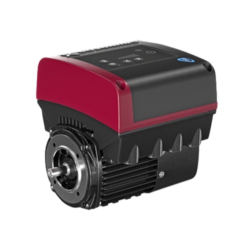
Изображение MGE90LD

Примечание к изображению: Внимание! Фотография продукта может отличаться от существующего.
Данные электрооборудования MGE90LD
| Тип электродвигателя | 90LD |
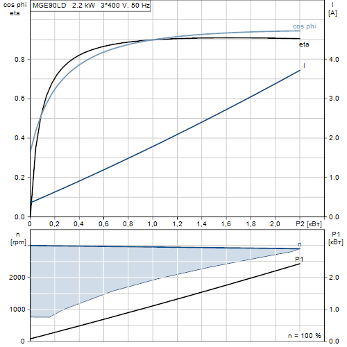
| Номинальная мощность — P2 | 2.2 кВт |
| Промышленная частота | 50 Hz |
| Номинальное напряжение | 3 x 380-500 V |
| Номинальный ток | 4,15-3,40 A |
| Cos фи — характеристика мощности | 0,93-0,87 |
| Номинальная скорость | 360-4000 об/м |
| Номинальный вращающий момент при полной нагрузке | 7.2 Нм |
| Момент инерции | 0.0007 кг м2 |
| Энергоэффективность | 89,0% |
| Класс защиты (IEC 34-5) | IP55 |
| Класс изоляции (IEC 85) | F |
| Защита электродвигателя | Да |
| Тепловая защита | ELEC |
| Направление вращения | CW |
| Монтажн. обозначение по IEC 34-7 | IM B14/V18 |
Характеристика двигателя MGE90LD
Монтаж MGE90LD
| Диапазон температуры окружающей среды | -20 .. 50 °C |
| Размер фланца электродвигателя | FT115 |
Устр-ва управл-ия MGE90LD
| Панель управления | HMI200 — Стандарт |
| Общ.модуль | НЕТ |
| Функциональный модуль | FM300 — Advanced (Расширенный) |
Другое MGE90LD
| Маркировка | Grundfos Blueflux |
| Нетто вес | 15 кг |
| № структурного файла | 98373207 |
Габаритный чертеж MGE90LD
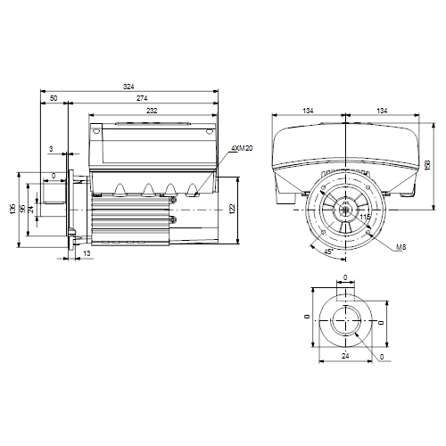
| Примечание | Правовая оговорка |
| Внимание! Все величины даны в [мм], если не указано иное. | На данном упрощённом габаритном чертеже представлены не все компоненты. |
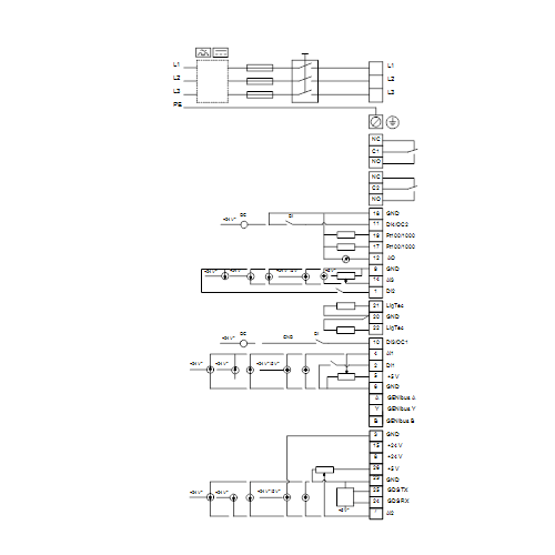
Схема подключений MGE90LD


Перейти к контенту
-
Bookmarks
Quick Links
GRUNDFOS INSTRUCTIONS
MGE
Antenna
Service kit instructions
Related Manuals for Grundfos MGE Series
Summary of Contents for Grundfos MGE Series
-
Page 1
GRUNDFOS INSTRUCTIONS Antenna Service kit instructions… -
Page 3
English (GB) Service kit instructions CONTENTS Page 1. Dismantling 2. Assembly English (GB) Warning Before starting service work, read the safety instructions supplied with the product. Always use an antistatic service kit when handling electronic components. This will prevent static electricity from damaging components. -
Page 4
Deutsch (DE) Warnung Vor der Durchführung irgendwelcher Reparaturarbeiten ist die mit dem Produkt mitgelieferte Serviceanleitung sorgfältig durchzulesen. Bei m Umgang mit elektronischen Bauteilen ist immer ein antistatischer Erdungsreparatursatz zu verwenden. Dadurch wird verhindert, dass die Bauteile durch statische Entladung beschädigt werden. Siehe nachfolgende Abbil- Caution dung. -
Page 5
Français (FR) Avertissement Avant toute intervention, consulter les consignes de mainte- nance fournies avec le produit. Toujours utiliser un kit de maintenance antistatique lors de la manipulation de composants électroniques. Cela évite que l’électricité statique n’endommage les composants. Caution Voir figure ci-dessous. Lorsqu’il n’est pas protégé, le composant doit être placé… -
Page 6
Português (PT) Aviso Antes de iniciar o serviço de manutenção, leia as instruções de segurança fornecidas com o produto. Utilize sempre um kit de manutenção antiestático quando lidar com componentes electrónicos. Isto irá prevenir que a electricidade estática danifique os componentes. Caution Observe a figura abaixo. -
Page 7
Svenska (SE) Varning Läs de säkerhetsanvisningar som medföljer produkten innan servicearbetet inleds. Använd alltid antistatservicesats vid hantering av elektronik- komponenter. Det förhindrar att komponenter skadas av sta- Caution tisk elektricitet. Se figur nedan. Oskyddade komponenter ska placeras på antistatduk. -
Page 8
1. Dismantling DK: Demontering NL: Demontage DE: Demontage PT: Desmontagem GR: Αποσυναρμολόγηση RU: Демонтаж ES: Desmontaje FI: Purkaminen FR: Démontage SE: Demontering IT: Smontaggio TX25 x 4 Fig. 1… -
Page 9
Fig. 2 Fig. 3… -
Page 10
2. Assembly DK: Montering NL: Montage DE: Montage PT: Montagem GR: Συναρμολόγηση RU: Подключение ES: Montaje FI: Kokoaminen FR: Montage SE: Montering IT: Montaggio 27 mm Size Torque [Nm] 1 — 1.5 Fig. 4… -
Page 11
27 mm Size Torque [Nm] Fig. 5 Fig. 6… -
Page 12
Fig. 7… -
Page 13
Fig. 8… -
Page 14
TX25 x 4 Size Torque [Nm] Fig. 9… -
Page 18
Argentina China Germany Bombas GRUNDFOS de GRUNDFOS Pumps GRUNDFOS GMBH Argentina S.A. (Shanghai) Co. Ltd. Tel.: +49-(0) 211 929 69-0 Phone: +54-3327 414 444 Phone: +86-021-612 252 22 e-mail: infoservice@grund- Telefax: +54-3327 411 111 Telefax: +86-021-612 253 fos.de Service in Deutschland:… -
Page 19
Telefax: +386 1 568 0619 Telefax: +31-88-478 6332 s U.S.A. South Africa New Zealand GRUNDFOS Pumps Corpo- GRUNDFOS (PTY) LTD GRUNDFOS Pumps NZ Ltd. ration Phone: (+27) 11 579 4800 Phone: +64-9-415 3240 Phone: +1-913-227-3400 Fax: (+27) 11 455 6066 Telefax: +64-9-415 3250… -
Page 20
98273054 0213 ECM: 1109804 www.grundfos.com www.grundfos.com…
Внимание к мелочам — черта профессионалов
![]()
Заказать
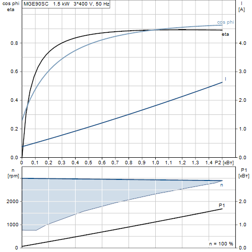
Данные каталога MGE90SC
| Наименование продукции | MGE90SC |
| Производственный номер | 98190189 |
| EAN номер | 5711491196213 |
Описание MGE90SC
Основные данные MGE90SC
| Данные на табличке электродвигателя | CE,C-TICK |
| Модель | I |
| Охлаждение | IC 411 |
Изображение MGE90SC
Примечание к изображению: Внимание! Фотография продукта может отличаться от существующего.
Данные электрооборудования MGE90SC
| Тип электродвигателя | 90SC |
| Номинальная мощность — P2 | 1.5 кВт |
| Промышленная частота | 50 Hz |
| Номинальное напряжение | 3 x 380-500 V |
| Номинальный ток | 2,90-2,40 A |
| Cos фи — характеристика мощности | 0,92-0,84 |
| Номинальная скорость | 360-4000 об/м |
| Номинальный вращающий момент при полной нагрузке | 5 Нм |
| Момент инерции | 0.0005 кг м2 |
| Энергоэффективность | 88,0% |
| Класс защиты (IEC 34-5) | IP55 |
| Класс изоляции (IEC 85) | F |
| Защита электродвигателя | Да |
| Тепловая защита | ELEC |
| Направление вращения | CW |
| Монтажн. обозначение по IEC 34-7 | IM B14/V18 |
Характеристика двигателя MGE90SC
Монтаж MGE90SC
| Диапазон температуры окружающей среды | -20 .. 50 °C |
| Размер фланца электродвигателя | FT115 |
Устр-ва управл-ия MGE90SC
| Панель управления | HMI200 — Стандарт |
| Общ.модуль | НЕТ |
| Функциональный модуль | FM300 — Advanced (Расширенный) |
Другое MGE90SC
| Маркировка | Grundfos Blueflux |
| Нетто вес | 14 кг |
| № структурного файла | 98373206 |
Габаритный чертеж MGE90SC

| Примечание | Правовая оговорка |
| Внимание! Все величины даны в [мм], если не указано иное. | На данном упрощённом габаритном чертеже представлены не все компоненты. |
Схема подключений MGE90SC

You can identify the motor by means of the
nameplate on the terminal box.
4.1 Nameplate
The motor nameplate is located on the side of the
terminal box. See fig. 1, pos. A.
Type :
P.C. :
INPUT
P.N. :
Serial no :
U
in
:
~
DE :
Env.Type :
TEFC
NDE :
SF
:
CL:
f
:
in
Wgt :
kg
T
amb
:
F
PF:
I
SF Amp
:
A
Fig. 1
Nameplate location
Figure
2
shows the nameplate. The position
numbers refer to the table below.
1
2
3
4
Type :
P.C. :
P.N. :
— V
DE :
Env.Type :
NDE :
PF
:
o
Wgt :
kg
T
:
amb
27
26
25
24
Fig. 2
Nameplate, MGE motors
Pos.
Description
1
Type designation
2
Product number
3
Drive-end bearing
4
Version number
5
Environmental type
6
Production code (year and week)
7
Supply voltage [V]
8
Rated power output [kW]
9
Power board
10
Functional module type
11
CE mark and approvals
12
Part number of nameplate
13
Grundfos logo
14
Grundfos company address
OUTPUT
VARIANT
P2
:
Hp
PB
:
V
n max:
rpm
FM
:
Hz
Eff
:
HMI
:
Made in Hungary
I
1/1
:
A
CIM
:
DK — 8850 Bjerringbro, Denmark
A
5
6
7
INPUT
U in
:
IP:
~
CL:
f in
:
C
I
:
1/1
23
22
21
20
8
9
10
OUTPUT
VARIANT
P2
:
kW
PB
:
V
n max:
rpm
FM
:
Hz
Eff
:
HMI
:
:
A
CIM
19
18
17
16
Pos.
Description
15
Country of origin
16
Human Machine Interface type
17
CIM module type
18
Motor efficiency
19
Maximum motor speed [min
20
Maximum input current [A]
21
Mains frequency [Hz]
Enclosure class according to IEC
22
60034-5
23
Insulation class according to IEC 62114
24
Maximum ambient temperature [°C]
25
Power factor
26
Weight [kg]
27
Non-drive-end bearing
11
12
Made in Hungary
DK — 8850 Bjerringbro, Denmark
15
14
13
-1
]
5
|
Detail Specifications: 1508/1508045-mge_series.pdf file (19 May 2023) |
Accompanying Data:
Grundfos MGE Series Engine, Touch terminals PDF Installation And Operating Instructions Manual (Updated: Friday 19th of May 2023 02:52:06 PM)
Rating: 4.8 (rated by 80 users)
Compatible devices: MGE 112, ML Series, MG, MG 71A2, RADIOMODULE 2G4, MGE 71, MMS 12000, MMS Series.
Recommended Documentation:
Text Version of Installation And Operating Instructions Manual
(Ocr-Read Summary of Contents, UPD: 19 May 2023)
-
55, English (GB) 55 17. Changing the position of the control panel You can turn the control panel 180 °. Follow the instructions below. 1. Loosen the four screws (TX25) of the terminal box cover. Fig. 57 Loosening the screws 2. Remove the terminal box cover. Fig. 58 Removing the terminal box cover 3. Press and hold in the two locking tabs (A) while gently lifting th…
-
31, English (GB) 31 Status «Actual setpoint and external setpoint» «Operating mode» «Actual controlled value» «Analog input 1, 2 and 3» «Pt100/1000 input 1 and 2» «Speed» «Power input and power consumption» «Operating hours» «Replace motor bearings» «Motor current» R100 remote control …
-
39, English (GB) 39 • «»Inverse with Stop»» and «»Inverse with Min.»» – «»Inverse with Stop»» In the input signal range from 0 to 80 %, the setpoint is influenced inversely. If the input signal is above 90 %, the motor changes to operating mode «»Stop»». If the input signal is reduced below 8…
-
9, Grundfos MGE Series English (GB) 9 7.2 Cable requirements 7.2.1 Cable cross-section Single-phase supply Three-phase supply 7.2.2 Conductors Type Stranded or solid copper conductors. Temperature rating Temperature rating for conductor insulation: 60 °C (140 °F). Temperature rating for outer cable sheath: 75 °C (167 °F). 7.3 Mains supply 7.3.1 Single-phase supply voltage Single-phase motors …
-
47, English (GB) 47 10.42.1 «Alternating operation» Alternating operation functions as a duty/standby operating mode and is possible with two motors of same size and type connected in parallel. The main purpose of the function is to ensure an even amount of running hours and to ensure that the other motor starts if the duty motor stops due to an alarm. You can choose between two …
-
42, English (GB) 42 10.16 «Ramps» The ramps determine how quickly the motor can accelerate and decelerate during start/stop or setpoint changes. You can set the following: • acceleration time, 0.1 to 300 s • deceleration time, 0.1 to 300 s. The times apply to the acceleration from 0 rpm to maximum (fixed) speed and the deceleration from maximum (fi…
-
8, English (GB) 8 6.5 Outdoor installation If you install the motor outdoors, provide the motor with a suitable cover and open the drain holes to avoid condensation on the electronic components. See figures 4 and 5. The cover must be sufficiently large to ensure that the motor is not exposed to direct sunlight, rain or snow. Grundfos does not supply covers. We therefor…
-
22, Grundfos MGE Series English (GB) 22 9.3.1 «Home» display Fig. 24 Example of «»Home»» display 9.3.2 Startup guide The motor incorporates a startup guide which is started at the first startup. See section 10.35 «»Run start-up guide»». After the startup guide, the main menus appear in the display. TM06 4516 2415 Pos. Symbol Description 1 «&qu…
-
41, English (GB) 41 10.15 «»Limit-exceeded function»» This function can monitor a measured parameter or one of the internal values such as speed, motor load or motor current. If a set limit is reached, a selected action can take place. You can set two limit-exceeded functions meaning that you can monitor two parameters or two limits of the same paramet…
-
53, English (GB) 53 4. Fit the CIM module by aligning it with the three plastic holders (fig. 51, A) and the connecting plug (fig. 51, B). Press home the module using your fingers. Fig. 51 Fitting the CIM module 5. Fit and tighten the securing screw (fig. 50, A) to 1.3 Nm. 6. Make the electrical connections to the CIM module as described in the instructions delivered with the…
-
57, Grundfos MGE Series English (GB) 57 20. Signal relays The motor has two outputs for potential-free signals via two internal relays. You can set the signal outputs to «Operation», «Running», «Ready», «Alarm» and «Warning». The functions of the two signal relays appear from the table below: Description Grundfos Eye Contact position of signa…
Recommended Instructions:
Power Pack Systems, CZ-RD514C, 35778, 14PT2002, U.S. Range THE SUMMIT, PSC-124000A


-
Engine Guide and Maintenance Manual BlackHawk Paramotors USA Inc. Phone: (209) 418-5990 Email: [email protected] Address: 8591 Hogan Dam Road Valley Springs CA 95252 Engine Manual Version 1.00 – Last Updated Apr 12, 2019 …
Talon 190 3.0 60
-
1 Serve with whole heart Satisfaction accompanies the whole way Maintenance manual Model CYQD32 Series Diesel Engine Dongfeng Chaoyang Diesel engine Co. LTD. PDF 文件使用 «pdfFactory Pro» 试用版本创建 www.fineprint.cn …
CYQD 32 Series CYQD32 60
-
for OperationQuick Reference GuideQuick Reference GuideGXE2.0HGXE2.0HQ3,Q4,S2,S3 typeQ3,Q4,S2,S3 typeRead and understand the Owner’s Manual before operating the DC Power Unit.©2021 Honda Motor Co., Ltd.S28A03104321Safety PrecautionPre-operation check!Pre-operation check!Press STOPPress STOPPress STOPPress STOPPress STARTPress STARTChangeSpeedChangeSpeed2 3 41 …
GXE2.0H 2