 Free — Fast — Easy For Automation ^^

Like PLC Mitsubishi, its HMI is also used quite a lot in the market. The current popular Mitsubishi HMI lines are GOT 1000, GOT 2000. To design the interface for these HMIs, you need to use GT Designer 3 software.
Today plc4me.com would like to share with you the software GT Works3, GT Designer3 version 1,260W. This is a new version that supports interface design for all Mitsubishi HMIs such as GOT-A800, GOT-A900, GOT-F900, GOT-1000, GOT-2000. (including GS Series: GS2107-WTBD, GS2110-WTBD…) with only 1 step installation.

GT-Designer 3 Functions
+ GT Designer 3 software included in the GT Works3 software package is used to design interfaces for Mitsubishi HMI series such as: GOT-A800, GOT-A900, GOT-F900, GOT-1000, GOT-2000.
+ The interface is designed to be intuitive and easy to see.
+ Provide many features to help reduce interface design time such as: Can reuse the old design of the Project made, automatically resize objects to fit the screen size when changing the screen model.
+ Image library, sample screen, diverse icons.
+ Supports offline simulation and connection to PLC program through GX Works2 or GX Works3 even without HMI and PLC.
GT-Designer 3 Installation Guide
+ Step 1: Download the GT-Designer 3 Software Installation file (Link at the end of the article) and extract it with the password “plc4me.com”

+ Step 2: Run file “autorun.exe”

+ Step 3: Click on “GT Works3”

+ Step 4: At this step select “OK”

+ Step 5: At this step enter the Product ID for GT-Designer 3: 095-394462924

+ Step 6: Create shortcut on Desktop


Done! We have GT-Designer 3 software that supports all Mitsubishi HMI Models

Software Download Link (GoogleDrive Link)
+ Mitsubishi GT Designer 3 Software Download
Backup Link:
+ Mitsubishi GT Designer-3 Software Free Download
Password Extract: plc4me.com
Thanks for Reading!
You may also like
About the author

admin
GT-Designer3 / GT-Works3 software is a specialized software package for Mitsubishi’s HMI design. Today plc247.com would like to share to you this software for free, including the latest updates for GS2000 and GOT2000
- Download GX-Works3 for Mitsubishi PLC Programming
Model Support
+ GOT1000-Series
+ GT2710-VTBA, GT2710-VTBD, GT2710-VTWA, GT2710-VTWD, GT2708-VTBA, GT2708-VTBD, GT2712-STBA, GT2712-STBD, GT2712-STWA, GT2712-STWD, GT2710-STBA, GT2710-STBD, GT2708-STBA, GT2708-STBD, GT2310-VTBA, GT2310-VTBD, GT2308-VTBA, GT2308-VTBD,
+ GS2000-Series
Operating system support
+ Windows 7 (32/64bits)
+ Windows 8/8.1 (32/64bits)
+ Windows 10 (32/64bits)
+ Windows Server (32/64bits)
+ Windows XP
Instructions for installing GT-Designer3 with detailed images
+ Step 1: We need to install GT-Designer3 software first
Download GT-Works3 software and Upgrade packages, then extract with password plc247.com

Go to GT-Works3 folder

Run the autorun.exe file

Environment install for GT-Works software
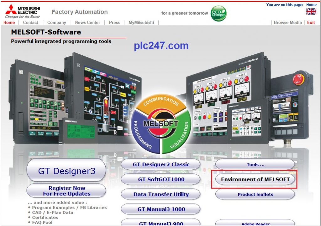
Click on GT Designer3
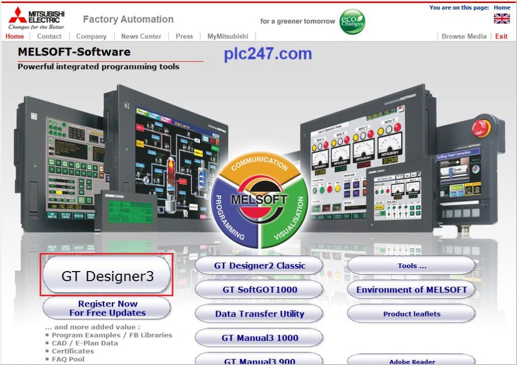
Click OK to continue the installation

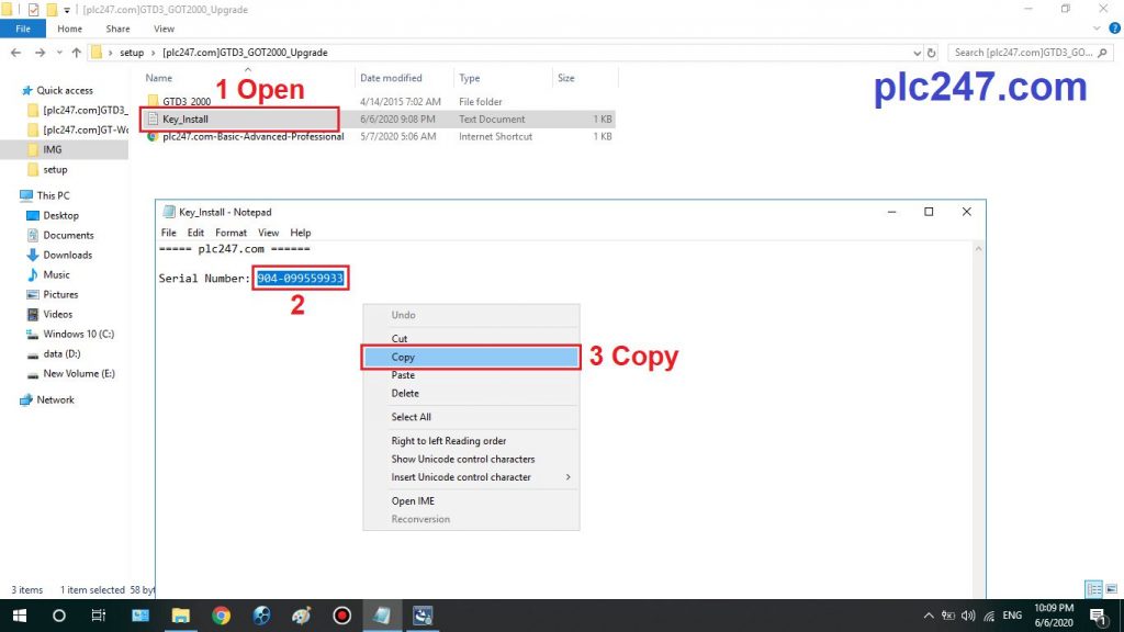
Proceed to import Key from Key_Install file


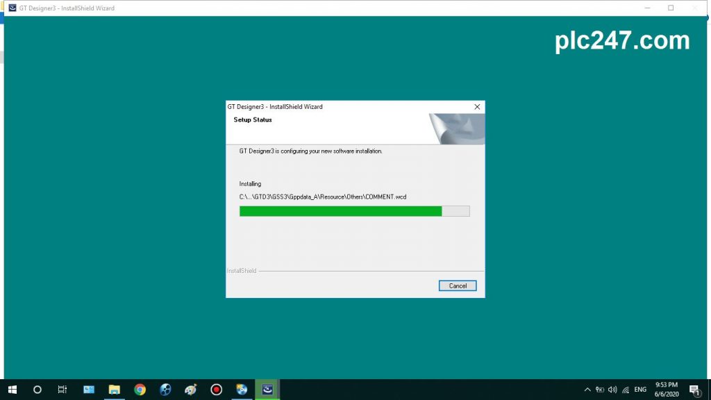
Continue to select Next to begin the installation of GT-Designer3

Wait for the software to install for more than 10 minutes depending on your computer configuration
Choose Install Divice Software

OK! GT-Designer3 software has been installed

+ Step 2: Proceed to Upgrade GT-Designer3 GOT2000
Go to GTD3_GOT2000_Upgrade folder

And run the setup file

Proceed to enter the Key for the GOT2000 Upgrade version

>>> The process of Upgrade GT-Designer3 Software (GOT2000) has been completed

+ Step 3: Install the GS-Series upgrade
Go to GTW3-GS-Upgrade folder

Run the setup file and the upgrade process will complete immediately

At the end of the installation, we have GT-Designer3 and GT-Simulator3

GT-Designer3 software supports HMI GOT1000, GOT2000, GS2000 Series

Video on installing GT-Designer3
https://youtube.com/watch?v=w1VwklGDJGk
Link Download GT-Designer3 / GT-Works3
>>> Download GT-Designer3 with GoogleDrive 
>>> Download GTD3_GOT2000_Upgrade with GoogleDrive
>>> Download GTW3-GS-Upgrade with GoogleDrive
Password Extract: plc247.com
Please Like, Comment and share the article to support the website plc247.com! Thank you all
Created by
fautigifast1985
2017-08-28
———————————————————
>>> СКАЧАТЬ ФАЙЛ <<<
———————————————————
Проверено, вирусов нет!
———————————————————

.
.
.
.
.
.
.
.
.
.
.
.
.
.
.
.
.
.
.
.
.
.
.
.
.
.
.
.
.
.
.
.
.
.
.
GT Works3 is truly triggering a revolution in screen design. Professional. Manual operation (6 patterns). Counter. Procedure: [Help] ➡ [GT Designer3 Help]. E-Designer и Windows Vista (E1000) — KS01499. К сожалению, использовать GT Simulator в комбинации с GX Simulator. Описание: Можно загрузить проект в новую панель оператора (ни один проект не. Максимальная длина составляет 30 м для моделей на 24 В постоянного тока и 3 м для. Então, o “MELSOFT GT Works3”, com seus intuitivos modelos flexíveis, é a resposta perfeita. Manual de Design de Tela GT Designer3 Versão1 ( Fundamentos) 1/2, 2/2. Mitsubishi Electric Europe B.V. Russian Branch Moscow Office. Поддержка — GT-1 Инструкции пользователя. GT-1_parameter . Список параметров GT-1 на русском языке в формате PDF. iQ Platform. 17. Визуализация и производительность. 18. Your solution partner. 19. 3. Содержание. обеспечение GT Designer позволяет легко и быстро. граммное обеспечение GT Designer позволяет. твую- усам. 3. Дисплеи высокого разрешения с широким углом обзора обеспечивают яркое и четкое. Roland Boss GT-10 Manual . 18 МБ. 3 МБ. Fender Mustang I-II Manual . 7 МБ. LINE 6 POD X3 Live на русском.pdf. Основные характеристики дисплеи от монохромного STN–дисплея 3,7 с поддержкой 3 цветов до. GT Designer2, позволяет легко и быстро создавать экранные страницы. Характеристики, Тех. документация, Примеры применения, Изображения / Видео. GT Designer V2 2[1].90U Russian 290531.21 KB. MELSOFT GT Works3. 3. Intuitive engineering software covering the product development cycle. Graphic-. HMI Programming Software: MELSOFT GT Works3. MITSUBISHI ELECTRIC EUROPE B.V. Russian Branch St. Petersburg office. No longer create device lists with manual inputs. Output CSV. each GX Works2, MT Works2 or GT Works3 project. Screen Design Software [MELSOFT GT Works 3]. Mitsubishi Electric Europe B.V. Russian Branch St. Petersburg office. The Maserati 3200 GT (Tipo 338) is a 2+2 grand tourer produced by Maserati from 1998 to. Designer · Italdesign Giugiaro. This manual transmission version was produced until 2002. Limited to 259 units of which 3 were special orders, it was available in three standard colours: Grigio Touring, Grigio Alfieri and Rosso. The Toyota 2000GT is a limited-production, front-engine, rear-wheel drive, two- seat, hardtop. 1 Background; 2 Styling; 3 Technical details; 4 Production; 5 Racing. Many credit the German-American designer Albrecht Goertz, a protégé of. considering the interior suited to a luxurious GT and calling the 2000GT an. GT Designer2 V2.90U: 904-099559933. GT designer3 1.31h: 570-986818410 or 570-996818410. GT designer 3 1.40S 64bit: 085-3704016 Язык интерфейса: Английский + Русский. Описание: GT Works2 является программным пакетом. а GT Designer 3 нету случайно ? ).
Comments ()
You can clone a snippet to your computer for local editing.
Learn more.
 Screen Owner's Manual | Manualzz")
GT Designer3 (GOT2000)
Screen Design Manual
-SW1DND-GTWK3-E
0
SAFETY PRECAUTIONS
Always read the precautions before using this product.
Also read this manual and the relevant manuals mentioned in this manual carefully, and use the product properly while
paying full attention to safety.
Note that the precautions in this manual apply only to this product.
The safety precautions are divided into the following levels: warnings and cautions.
WARNING
Indicates that incorrect handling may cause hazardous conditions,
resulting in death or severe injury.
CAUTION
Indicates that incorrect handling may cause hazardous conditions,
resulting in minor or moderate injury or property damage.
Note that failure to observe
CAUTION may lead to a serious accident depending on the circumstances.
Make sure to observe both warnings and cautions to ensure personal safety.
Ensure that this manual is easily accessible to all users of this product.
0
[Test Operation Precautions]
WARNING
0
● Before a test operation (such as turning on or off a bit device, changing the current value
of a word device, changing the set value or current value of a timer or counter, and
changing the current value of a buffer memory), thoroughly read the manual to fully
understand the operating procedures.
During the test operation, never change the data of the devices which are used to perform
significant operation for the system.
Doing so may cause an accident due to an incorrect output or malfunction.
[Precautions for Using a Data Storage]
WARNING
● Do not remove the SD card from drive A while the SD card is being accessed by the GOT,
or the GOT may stop processing for about 20 seconds.
During this stop, you cannot operate the GOT, and the functions running in the
background, including the screen refresh, alarm, logging, and script, also stop.
This stop may affect the system operation, causing an accident.
Before removing the SD card, check that the SD card access LED is off.
● Do not remove the data storage from the file server (drive N) that is being accessed by the
GOT, or the system operation may be affected.
Before removing the data storage, check the relevant system signal to make sure that the
data storage is not being accessed.
CAUTION
0
● Do not remove the data storage from the GOT while the data storage is being accessed
by the GOT, or the data storage and files may be damaged.
Before removing the data storage, check the SD card access LED, relevant system signal,
or others to make sure that the data storage is not being accessed.
[Precautions for Remote Control]
A-1
WARNING
● Remote control is available through a network by using GOT functions, including the
SoftGOT-GOT link function, the remote personal computer operation function, the VNC
server function, and the GOT Mobile function.
If you remotely operate control equipment using such functions, the field operator may not
notice the remote operation, leading to an accident.
In addition, a communication delay or interruption may occur depending on the network
environment, and remote control of control equipment cannot be performed normally in
some cases.
Before using the above functions to perform remote control, fully grasp the circumstances
of the field site and ensure safety.
● When operating the server (GOT) of the GOT Mobile function to disconnect a client, notify
the operator of the client about the disconnection beforehand.
Not doing so may cause an accident.
[Design Precautions]
0
WARNING
● To maintain the security (confidentiality, integrity, and availability) of the GOT and the
system against unauthorized access, DoS*1 attacks, computer viruses, and other
cyberattacks from unreliable networks and devices via network, take appropriate
measures such as firewalls, virtual private networks (VPNs), and antivirus solutions.
Mitsubishi Electric shall have no responsibility or liability for any problems involving GOT
trouble and system trouble by unauthorized access, DoS attacks, computer viruses, and
other cyberattacks.
*1 DoS: A denial-of-service (DoS) attack disrupts services by overloading systems or
exploiting vulnerabilities, resulting in a denial-of-service (DoS) state.
[Precautions for Exclusive Authorization Control]
0
WARNING
A-2
● Before using the GOT network interaction function to prevent simultaneous operations
from multiple pieces of equipment, make sure you understand the function.
You can enable or disable the exclusive authorization control of the GOT network
interaction function for each screen. (For all screens, the exclusive authorization control is
disabled by default.)
Properly determine the screens for which the exclusive authorization control is required,
and set the control by screen.
A screen for which the exclusive authorization control is disabled is operable
simultaneously from multiple pieces of equipment. Make sure to determine the operation
period for each operator, fully grasp the circumstances of the field site, and ensure safety
to perform operations.
0
CAUTIONS FOR USING THIS SOFTWARE
■1 Memory capacity and hard disk space of your personal computer
For the required memory capacity and hard disk space, refer to the following.
➟1.1.1 Operating environment
■2 Error massage displayed at this software startup or during data editing
[Operation will be terminated because of insufficient memory. Would you like to stop?]
If the above message appears, exit some running applications or restart Windows to free up memory.
■3 Changing device types
If a word device and any bit of the device are specified, changing the device type from the bit data type to a word data
type may display [??] as the device.
In such a case, specify the device again.
Example) D0.b0 → D0, D0.b5 → ??
■4 Windows settings
If you change the Windows font size from the default, the panes and other items in GT Designer3 will appear improperly.
Use this software with the default Windows font size.
A-3
CONTENTS
SAFETY PRECAUTIONS
[Test Operation Precautions] .............................................................................................................. A - 1
[Precautions for Using a Data Storage] .............................................................................................. A - 1
[Precautions for Remote Control]........................................................................................................ A - 1
[Design Precautions]........................................................................................................................... A - 2
[Precautions for Exclusive Authorization Control] ............................................................................... A - 2
CAUTIONS FOR USING THIS SOFTWARE
INTRODUCTION
How to Use Help ............................................................................................................................... A - 28
Manuals for GT Works3 .................................................................................................................... A - 30
Abbreviations, Generic Terms, and Model Icons .............................................................................. A - 31
Graphics Mode Icons ........................................................................................................................ A - 39
Terminology ...................................................................................................................................... A - 40
FUNDAMENTALS OF GT Designer3
1.1
Basic Description of GT Designer3.........................................................................................
1.1.1
Operating environment ...................................................................................................
1.1.2
Supported models ..........................................................................................................
1.1.3
List of the supported models for each function...............................................................
1.2
Checking the Followings before Drawing .............................................................................
1.2.1
BootOS, CoreOS and package data ............................................................................
1.2.2
Project ..........................................................................................................................
1.2.3
Screen types and the specifications .............................................................................
1.2.4
Specifications of drawing..............................................................................................
1.2.5
Font specifications........................................................................................................
1.2.6
Character codes supported by the GOT.......................................................................
1.2.7
Specifications of available devices ...............................................................................
1.2.8
Drive configuration of the target GOT for data transfer ................................................
1-2
1-3
1-5
1-7
1 - 14
1 - 14
1 - 15
1 - 17
1 - 33
1 - 34
1 - 43
1 - 43
1 - 47
CREATING A PROJECT
2.1
Startup and Exit of GT Designer3...........................................................................................
2.1.1
Starting GT Designer3....................................................................................................
2.1.2
Exiting GT Designer3 .....................................................................................................
2.1.3
Switching the display language of GT Designer3 ...........................................................
2-2
2-2
2-3
2-3
2.2
Screen Layout of GT Designer3 ............................................................................................. 2 - 5
2.2.1
Menus............................................................................................................................. 2 - 7
2.2.2
Toolbar and shortcut keys ............................................................................................ 2 - 29
2.2.3
Editor tab, work window................................................................................................ 2 - 41
2.2.4
Work tree ...................................................................................................................... 2 - 43
2.2.5
Status bar ..................................................................................................................... 2 - 50
2.3
Creating and Editing a Project ..............................................................................................
2.3.1
Creating a project .........................................................................................................
2.3.2
Opening a project .........................................................................................................
2.3.3
Closing a project...........................................................................................................
A-4
2 - 51
2 - 51
2 - 60
2 - 66
CONTENTS
2.3.4
2.3.5
Deleting a project.......................................................................................................... 2 - 66
Giving a title to a project ............................................................................................... 2 - 67
2.4
Setting a Screen Design .......................................................................................................
2.4.1
Selecting a screen design ............................................................................................
2.4.2
Precautions...................................................................................................................
2.4.3
[Screen Design] dialog .................................................................................................
2 - 69
2 - 70
2 - 73
2 - 74
2.5
Creating, Opening, and Closing a Screen ............................................................................ 2 - 77
2.5.1
Creating a screen ......................................................................................................... 2 - 77
2.5.2
Opening and closing screens ....................................................................................... 2 - 81
2.6
Basic Operations of the Drawing Screen..............................................................................
2.6.1
Selecting a screen editor to be edited ..........................................................................
2.6.2
Switching the display status of objects to be displayed on the screen editor ...............
2.6.3
Redisplaying a selected screen editor..........................................................................
2.6.4
Setting information to be displayed on the screen editor..............................................
2.6.5
Displaying the grid ........................................................................................................
2.6.6
Displaying the two-point press inactive area ................................................................
2.6.7
Displaying the scroll bar areas for editing the expanded base screens .......................
2.6.8
Switching the layer display ...........................................................................................
2.6.9
Displaying guidelines....................................................................................................
2.6.10
Scaling the size of items on the screen editor ..............................................................
2.6.11
Cascading or arranging open screen editors................................................................
2.6.12
Copying the image of a screen editor to the clip board ...............................................
2.7
Changing Screen Property .................................................................................................
2.7.1
Property of base screens............................................................................................
2.7.2
Properties of window screens.....................................................................................
2.7.3
Property of report screens ..........................................................................................
2 - 86
2 - 89
2 - 89
2 - 90
2 - 91
2 - 93
2 - 93
2 - 94
2 - 95
2 - 96
2 - 98
2 - 99
2 - 99
2 - 100
2 - 100
2 - 112
2 - 124
2.8
Managing the Created Screen............................................................................................ 2 - 134
2.8.1
[Screen Image List] window........................................................................................ 2 - 134
2.9
Viewing the Image of the Created Screen .......................................................................... 2 - 136
2.9.1
Displaying a preview................................................................................................... 2 - 136
2.9.2
Displaying the preview of a window screen on the screen editor of a base screen ... 2 - 140
2.10 Copying and Deleting Screens ........................................................................................... 2 - 142
2.10.1
Copying screens......................................................................................................... 2 - 142
2.10.2
Deleting screens......................................................................................................... 2 - 143
2.11 Performing a Data Check ...................................................................................................
2.11.1
[Data Check List] window ...........................................................................................
2.11.2
[Check Item Setting] dialog.........................................................................................
2.11.3
Details of the exported file ..........................................................................................
2 - 144
2 - 145
2 - 146
2 - 148
2.12 Protecting a Project with a Security Key.............................................................................
2.12.1
Specifications of the security key authentication ........................................................
2.12.2
How to use the security key authentication ................................................................
2.12.3
Precautions.................................................................................................................
2.12.4
[Security Key Setting] dialog.......................................................................................
2.12.5
[Security Key Management] dialog.............................................................................
2 - 149
2 - 151
2 - 153
2 - 161
2 - 162
2 - 165
2.13 Protecting a Project by Registering Users .......................................................................... 2 - 168
2.13.1
Specifications of the project security .......................................................................... 2 - 169
2.13.2
How to use the project security .................................................................................. 2 - 174
A-5
CONTENTS
2.13.3
2.13.4
2.13.5
2.13.6
2.13.7
2.13.8
Precautions.................................................................................................................
[User Addition] dialog .................................................................................................
[User Management] dialog .........................................................................................
[Change User Data] dialog .........................................................................................
[Setup Access Authority] dialog..................................................................................
[Change Password] dialog..........................................................................................
2 - 176
2 - 177
2 - 178
2 - 179
2 - 180
2 - 181
2.14 Printing or Outputting a Project to a File.............................................................................
2.14.1
Specifications for printing and outputting files ............................................................
2.14.2
How to print and output files .......................................................................................
2.14.3
Precautions.................................................................................................................
2.14.4
[Page Settings] dialog.................................................................................................
2.14.5
[Print Preview] window ...............................................................................................
2.14.6
[Print] dialog................................................................................................................
2 - 182
2 - 182
2 - 186
2 - 186
2 - 187
2 - 190
2 - 192
2.15 Saving a Project..................................................................................................................
2.15.1
Overwriting a project...................................................................................................
2.15.2
Saving a project in the workspace or the single file format (*.GTX) ...........................
2.15.3
Saving a project in the single file format (*.GTXS) with system applications .............
2 - 199
2 - 199
2 - 199
2 - 202
SIMULATION
3.1
Specifications.......................................................................................................................... 3 - 2
3.1.1
Simulation-supported GOTs ........................................................................................... 3 - 2
3.1.2
Monitoring-supported Controllers ................................................................................... 3 - 4
3.1.3
Available devices for monitoring ................................................................................... 3 - 11
3.1.4
Simulation-supported/unsupported functions ............................................................... 3 - 32
3.1.5
Destination to save data ............................................................................................... 3 - 41
3.2
Connecting............................................................................................................................
3.2.1
Connecting with the controller simulators.....................................................................
3.2.2
Connecting with Mitsubishi Electric products ...............................................................
3.2.3
Connecting with non-Mitsubishi Electric products ........................................................
3 - 43
3 - 43
3 - 44
3 - 63
3.3
Precautions...........................................................................................................................
3.3.1
Precautions for using GT Simulator3............................................................................
3.3.2
Precautions for connecting with the controller simulators ............................................
3.3.3
Precautions for connecting with PLC CPU ...................................................................
3.3.4
Version of the project data to be simulated ..................................................................
3 - 64
3 - 64
3 - 66
3 - 68
3 - 68
3.4
Simulation Procedure ........................................................................................................... 3 - 69
3.4.1
Simulating the project being edited .............................................................................. 3 - 69
3.4.2
Simulating a saved project ........................................................................................... 3 - 71
A-6
3.5
Screen Layout of GT Simulator3 ..........................................................................................
3.5.1
Menus...........................................................................................................................
3.5.2
Toolbar .........................................................................................................................
3.5.3
Screen for simulation....................................................................................................
3.5.4
Status bar .....................................................................................................................
3 - 74
3 - 75
3 - 76
3 - 77
3 - 78
3.6
Basic Operations of GT Simulator3 ......................................................................................
3.6.1
Setting options..............................................................................................................
3.6.2
Opening a project .........................................................................................................
3.6.3
Starting or exiting simulation ........................................................................................
3.6.4
Updating the project to be simulated ............................................................................
3.6.5
Operations of the screen for simulation........................................................................
3 - 79
3 - 80
3 - 89
3 - 91
3 - 92
3 - 92
CONTENTS
3.6.6
Exiting GT Simulator3................................................................................................... 3 - 92
3.7
Useful Functions of GT Simulator3....................................................................................... 3 - 93
3.7.1
Taking snap shots ........................................................................................................ 3 - 93
3.7.2
Printing the screen being simulated ............................................................................. 3 - 94
3.7.3
Displaying the information of the project being simulated ............................................ 3 - 96
3.7.4
Operating the numerical input or text input with a keyboard ........................................ 3 - 97
3.7.5
Using the device monitor .............................................................................................. 3 - 98
3.7.6
Referring to resource data.......................................................................................... 3 - 105
3.7.7
Displaying a script error.............................................................................................. 3 - 106
3.7.8
Displaying an object script error ................................................................................. 3 - 107
3.7.9
Displaying scroll bars.................................................................................................. 3 - 108
3.7.10
Displaying the simulation screen in full screen mode................................................. 3 - 109
3.8
Troubleshooting .................................................................................................................. 3 - 111
3.8.1
Error messages (GOT2000 Series simulator) ............................................................ 3 - 111
3.8.2
Troubleshooting for saving files.................................................................................. 3 - 114
COMMUNICATING WITH GOT
4.1
Data Transfer.......................................................................................................................... 4 - 2
4.1.1
Route for the data transfer.............................................................................................. 4 - 3
4.1.2
Types of the data to be transferred to the GOT.............................................................. 4 - 6
4.2
Setting a System Application to be Written to the GOT........................................................ 4 - 10
4.2.1
Specifications of the application setting........................................................................ 4 - 10
4.2.2
How to use the application setting................................................................................ 4 - 11
4.3
Transferring the Data between the Personal Computer and the GOT ................................. 4 - 14
4.3.1
Connecting the personal computer to the GOT............................................................ 4 - 14
4.3.2
Transferring data .......................................................................................................... 4 - 19
4.4
Transferring the Data between the Personal Computer and the GOT via PLC CPU ........... 4 - 29
4.4.1
Connecting the personal computer and PLC CPU ....................................................... 4 - 34
4.4.2
Transferring data .......................................................................................................... 4 - 44
4.5
Transferring the Data with Data Storage ..............................................................................
4.5.1
Writing a package data into the GOT ...........................................................................
4.5.2
Starting up the package data from data storage ..........................................................
4.5.3
Installing the BootOS or the CoreOS to the GOT.........................................................
4 - 45
4 - 45
4 - 47
4 - 48
4.6
Transferring Data between the Personal Computer and GT01-RS4-M................................ 4 - 51
4.7
Precautions........................................................................................................................... 4 - 52
4.8
Data Transfer Setting............................................................................................................
4.8.1
[PC (Data Transfer)] dialog...........................................................................................
4.8.2
[Communicate with GOT] dialog...................................................................................
4.8.3
[Write Option] dialog (for writing data to one GOT) ......................................................
4.8.4
[Application Selection] dialog........................................................................................
4.8.5
[Select Resource Data] dialog ......................................................................................
4.8.6
[Resource Data Write Result] dialog ............................................................................
4.8.7
[GOT Information - Detail] dialog..................................................................................
4.8.8
[Communication Configuration] dialog..........................................................................
4.8.9
[Batch Write to multiple GOTs] dialog ..........................................................................
4.8.10
[Write Option] dialog (for writing data to multiple GOTs in one go) ..............................
4.8.11
[Communication Status] dialog.....................................................................................
4.8.12
[Communicate with Memory Card] dialog.....................................................................
4 - 55
4 - 55
4 - 56
4 - 65
4 - 68
4 - 71
4 - 72
4 - 73
4 - 74
4 - 81
4 - 83
4 - 84
4 - 85
A-7
CONTENTS
4.9
Troubleshooting .................................................................................................................... 4 - 88
COMMON SETTING
5.1
Changing the GOT Type of the Project ([GOT Type Setting]) ................................................ 5 - 2
5.1.1
Specifications of the GOT type change .......................................................................... 5 - 2
5.1.2
Graphics mode ([Graphics Setting]) ............................................................................. 5 - 12
5.1.3
Base screen size expansion ([Expand base screen sizes]) ......................................... 5 - 16
5.1.4
Precautions................................................................................................................... 5 - 23
5.1.5
[Type Setting] dialog..................................................................................................... 5 - 25
5.1.6
[Output] window............................................................................................................ 5 - 33
5.2
Setting the GOT Basic Operations ([GOT Environmental Setting]) ...................................... 5 - 34
5.2.1
Setting for switching screens to be displayed on the GOT
([Screen Switching/Window]) ........................................................................................ 5 - 35
5.2.2
Setting for switching the language displayed on the GOT ([Language Switching])...... 5 - 49
5.2.3
Setting dialog windows ([Dialog Window]).................................................................... 5 - 55
5.2.4
Setting key windows ([Key Window])............................................................................ 5 - 60
5.2.5
Setting a device which controls the GOT operations or notifies the GOT status
([System Information]) .................................................................................................. 5 - 78
5.2.6
Configuring the security settings for the GOT screen ([Screen Security]) .................... 5 - 98
5.2.7
Configuring the security settings for the GOT screen ([Screen Security]
(Operator authentication)) .......................................................................................... 5 - 103
5.2.8
Configuring the security settings for the GOT screen ([Screen Security]
(Level authentication)) ................................................................................................ 5 - 124
5.2.9
Configuring the security settings for operations in the utility
([Functional Operation Security]) ................................................................................ 5 - 126
5.2.10
Configuring the security setting for transferring data ([Data Transfer Security]) ........ 5 - 135
5.2.11
Configuring the settings for creating the operation history of the GOT
([Operation Log]) ........................................................................................................ 5 - 139
5.2.12
Configuring the settings for retaining GOT internal device data at power failure
([Internal Device Retention]) ....................................................................................... 5 - 191
5.2.13
Configuring the settings for converting the text to Kanji character on the GOT
([KANA KANJI Conversion]) ....................................................................................... 5 - 194
5.2.14
Setting a screen to be displayed on the GOT at startup ([Startup Logo])................... 5 - 199
5.3
Setting the Utility Function ([GOT Setup]) .......................................................................... 5 - 201
5.3.1
Configuring the settings of the display of the GOT
([Display Setting/Language Setting]) .......................................................................... 5 - 202
5.3.2
Setting the identification information to the GOT ([GOT ID No.]) ............................... 5 - 206
5.3.3
Configuring the settings for the touch operation on the GOT
([Operation Setting/Utility Call Key]) ........................................................................... 5 - 212
5.3.4
Configuring the settings for a mouse and a keyboard used with the GOT
([USB Host]) ............................................................................................................... 5 - 215
5.3.5
Setting the GOT time setting method ([Time Setting])................................................ 5 - 220
Setting the FA transparent function ([Transparent Mode Setting]) ............................. 5 - 227
5.3.6
5.3.7
Configuring the settings of the GOT internal device monitor
([GOT Internal Device Monitor]) ................................................................................. 5 - 228
5.3.8
Configuring the settings of the SoftGOT-GOT link function ([SoftGOT-GOT Link]) ... 5 - 229
5.3.9
Configuring the settings of the VNC server function ([VNC Server]) .......................... 5 - 230
5.3.10
Configuring the settings of the sequence program monitor
([Sequence Program Monitor]) ................................................................................... 5 - 231
A-8
CONTENTS
5.3.11
5.3.12
5.3.13
5.3.14
5.3.15
Configuring the settings of the backup/restoration function ([Backup/Restore]).........
Configuring the settings for a wireless LAN ([Wireless LAN Setting]) ........................
Configuring the settings of the system launcher function ([System Launcher])..........
Configuring the settings of the iQSS utility function ([iQSS Utility]) ............................
Configuring the network drive settings ([Network Drive]) ...........................................
5 - 233
5 - 237
5 - 246
5 - 247
5 - 255
5.4
Setting the GOT Ethernet Interface ([GOT Ethernet Setting]) ............................................
5.4.1
Setting the GOT IP address .......................................................................................
5.4.2
Configuring the settings common to Ethernet interfaces............................................
5.4.3
Setting the IP filter ......................................................................................................
5 - 263
5 - 263
5 - 267
5 - 268
5.5
Configuring the Communication Method between the GOT and the Controller
([Controller Setting]) 5 - 273
5.5.1
Setting channels ......................................................................................................... 5 - 273
5.5.2
Setting the routing information.................................................................................... 5 - 279
5.5.3
Configuring the setting of the MELSEC redundant function ....................................... 5 - 282
5.5.4
Configuring the settings for switching the target station No. for monitoring ............... 5 - 285
5.5.5
Configuring the settings for switching the buffer memory unit No. of
the monitoring target ...................................................................................................... 5 - 293
5.6
Setting the Interaction Function for Equipment on Ethernet
([GOT Network Interaction]) ................................................................................................ 5 - 299
5.6.1
Specifications of the GOT network interaction function.............................................. 5 - 300
5.6.2
How to use the GOT network interaction function ...................................................... 5 - 302
5.6.3
Precautions................................................................................................................. 5 - 306
5.6.4
[GOT Network Interaction] dialog ............................................................................... 5 - 307
5.7
Checking the Interface Settings of the GOT ([I/F Communication Setting]) .......................
5.7.1
Specifications of the I/F communication setting .........................................................
5.7.2
How to use the I/F communication setting..................................................................
5.7.3
[I/F Communication Setting] dialog.............................................................................
5 - 309
5 - 309
5 - 310
5 - 311
5.8
Comment Setting ([Comment]) ...........................................................................................
5.8.1
Specifications of comments........................................................................................
5.8.2
How to use comment..................................................................................................
5.8.3
Precautions.................................................................................................................
5.8.4
Setting comments.......................................................................................................
5 - 313
5 - 313
5 - 315
5 - 324
5 - 325
5.9
Registering Parts ([Parts]) ..................................................................................................
5.9.1
Outline of parts ...........................................................................................................
5.9.2
Specifications of parts ................................................................................................
5.9.3
How to use parts ([Parts])...........................................................................................
5.9.4
Precautions.................................................................................................................
5.9.5
[Parts Image List] window...........................................................................................
5.9.6
[Parts Setting] dialog ..................................................................................................
5 - 343
5 - 343
5 - 344
5 - 345
5 - 354
5 - 355
5 - 356
BASIS OF SETTING AND EDITING
6.1
Device Settings....................................................................................................................... 6 - 2
6.1.1
Formats of devices, labels, and tags .............................................................................. 6 - 4
6.1.2
How to set devices ......................................................................................................... 6 - 6
6.1.3
How to set system labels................................................................................................ 6 - 8
6.1.4
How to set global labels................................................................................................ 6 - 18
6.1.5
How to set labels (GT Designer3) ................................................................................ 6 - 40
6.1.6
Using device comments and device definitions............................................................ 6 - 60
A-9
CONTENTS
6.1.7
6.1.8
6.1.9
6.1.10
6.1.11
How to set OMRON NJ/NX tags...................................................................................
Using RSLogix 5000 tags .............................................................................................
How to set AB native tags ............................................................................................
How to set OPC UA tags ..............................................................................................
Offset ............................................................................................................................
6.2
Setting Trigger Types .........................................................................................................
6.2.1
Specifications of the trigger type ................................................................................
6.2.2
Setting Trigger Types .................................................................................................
6.2.3
Precautions.................................................................................................................
6 - 66
6 - 75
6 - 80
6 - 89
6 - 99
6 - 103
6 - 104
6 - 112
6 - 120
6.3
Date/Time Format Settings................................................................................................. 6 - 121
6.3.1
Specifications of date/time formats............................................................................. 6 - 121
6.3.2
Date/time format settings............................................................................................ 6 - 123
6.4
Color Settings .....................................................................................................................
6.4.1
Specifications of colors...............................................................................................
6.4.2
Color settings..............................................................................................................
6.4.3
Precautions.................................................................................................................
6 - 126
6 - 126
6 - 126
6 - 130
6.5
Placing and Editing Figures and Objects............................................................................
6.5.1
Placing figures and objects.........................................................................................
6.5.2
Selecting figures and objects on the screen editor.....................................................
6.5.3
Editing figures and objects .........................................................................................
6.5.4
Common setting for figures ........................................................................................
6.5.5
Common setting for objects........................................................................................
6 - 131
6 - 131
6 - 134
6 - 137
6 - 144
6 - 145
6.6
Editing Operations ..............................................................................................................
6.6.1
[Undo], [Redo] ............................................................................................................
6.6.2
[Cut], [Copy], [Paste] ..................................................................................................
6.6.3
[Duplicate]...................................................................................................................
6.6.4
[Consecutive Copy] ....................................................................................................
6.6.5
[Select All]...................................................................................................................
6.6.6
[Delete] .......................................................................................................................
6.6.7
[Object of Selection] ...................................................................................................
6.6.8
[Group], [Ungroup]......................................................................................................
6.6.9
[Stacking Order]..........................................................................................................
6.6.10
[Align]..........................................................................................................................
6.6.11
[Rotate/Flip] ................................................................................................................
6.6.12
[Edit Vertices] .............................................................................................................
6.6.13
[Edit Objects with Fixed Frame Width] .......................................................................
6.6.14
[Edit Touch Area]........................................................................................................
6.6.15
[Adjust Direct Text Size] .............................................................................................
6.6.16
[Template Registration] ..............................................................................................
6.6.17
[Edit Template Attribute] .............................................................................................
6.6.18
[Set to Default]............................................................................................................
6.6.19
[Add to Category]........................................................................................................
6.6.20
[Shape Change]..........................................................................................................
6.6.21
[Display Template Property] .......................................................................................
6.6.22
[Setting] ......................................................................................................................
6 - 170
6 - 171
6 - 172
6 - 173
6 - 174
6 - 177
6 - 177
6 - 178
6 - 179
6 - 181
6 - 183
6 - 187
6 - 188
6 - 189
6 - 192
6 - 193
6 - 194
6 - 194
6 - 194
6 - 195
6 - 195
6 - 195
6 - 196
FIGURES
7.1
Drawing a Text........................................................................................................................ 7 - 2
7.1.1
[Text] dialog .................................................................................................................... 7 - 2
A - 10
CONTENTS
7.2
Drawing a Logo Text............................................................................................................... 7 - 6
7.2.1
[Logo Text] dialog ........................................................................................................... 7 - 6
7.3
Drawing a Line...................................................................................................................... 7 - 11
7.3.1
[Line] dialog .................................................................................................................. 7 - 12
7.4
Drawing a Line Freeform ...................................................................................................... 7 - 15
7.4.1
[Line Freeform] dialog................................................................................................... 7 - 16
7.5
Drawing a Rectangle ............................................................................................................ 7 - 19
7.5.1
[Rectangle] dialog......................................................................................................... 7 - 20
7.6
Drawing a Polygon................................................................................................................ 7 - 24
7.6.1
[Polygon] dialog ............................................................................................................ 7 - 25
7.7
Drawing a Circle ................................................................................................................... 7 - 28
7.7.1
[Circle] dialog................................................................................................................ 7 - 29
7.8
Drawing an Arc or a Sector................................................................................................... 7 - 32
7.8.1
[Arc/Sector] dialog ........................................................................................................ 7 - 32
7.9
Drawing a Table.................................................................................................................... 7 - 34
7.9.1
[Table] dialog ................................................................................................................ 7 - 34
7.10 Drawing a Scale.................................................................................................................... 7 - 38
7.10.1
[Scale] dialog ................................................................................................................ 7 - 38
7.11 Drawing a Piping................................................................................................................... 7 - 40
7.11.1
[Piping] dialog ............................................................................................................... 7 - 41
7.12 Painting Figures.................................................................................................................... 7 - 44
7.12.1
[Paint] dialog................................................................................................................. 7 - 45
7.13 Pasting an Image File ........................................................................................................... 7 - 47
7.13.1
[Transparent Setting] dialog ......................................................................................... 7 - 52
7.14
Pasting DXF Data ................................................................................................................. 7 - 53
7.15
Pasting IGES Data ............................................................................................................... 7 - 57
7.16
Capturing and Pasting an Image File ................................................................................... 7 - 60
OBJECT FUNCTION
8.1
Using Objects in the Library.................................................................................................... 8 - 2
8.1.1
Specifications of the library............................................................................................. 8 - 2
8.1.2
How to use the library..................................................................................................... 8 - 3
8.1.3
Precautions for libraries................................................................................................ 8 - 19
8.1.4
[Library] window............................................................................................................ 8 - 19
8.2
Placing a Touch Switch ........................................................................................................ 8 - 24
8.2.1
Specifications of touch switch....................................................................................... 8 - 27
8.2.2
How to use touch switch............................................................................................... 8 - 31
8.2.3
Precautions for a touch switch...................................................................................... 8 - 33
8.2.4
[Switch] dialog .............................................................................................................. 8 - 41
8.2.5
[Bit Switch] dialog ......................................................................................................... 8 - 63
8.2.6
[Word Switch] dialog..................................................................................................... 8 - 79
8.2.7
[Go To Screen Switch] dialog ....................................................................................... 8 - 94
8.2.8
[Change Station No. Switch] dialog ............................................................................ 8 - 110
8.2.9
[Special Function Switch] dialog................................................................................. 8 - 125
8.2.10
[Key Window Display Switch] dialog........................................................................... 8 - 162
8.2.11
[Key Code Switch] dialog............................................................................................ 8 - 175
A - 11
CONTENTS
8.2.12
Relevant settings ........................................................................................................ 8 - 188
8.3
Placing a Lamp ...................................................................................................................
8.3.1
Specifications of lamps...............................................................................................
8.3.2
How to use lamp.........................................................................................................
8.3.3
Precautions for a lamp................................................................................................
8.3.4
[Bit Lamp] dialog.........................................................................................................
8.3.5
[Word Lamp] dialog ....................................................................................................
8.3.6
[Lamp Area] dialog .....................................................................................................
8.3.7
Relevant settings ........................................................................................................
8 - 190
8 - 191
8 - 191
8 - 191
8 - 193
8 - 203
8 - 216
8 - 218
8.4
Placing a Numerical Display and Numerical Input..............................................................
8.4.1
Specifications of the numerical display and numerical input ......................................
8.4.2
How to use the numerical display and numerical input ..............................................
8.4.3
Precautions for a numerical display object and a numerical input object ...................
8.4.4
[Numerical Display] dialog ..........................................................................................
8.4.5
[Numerical Input] dialog..............................................................................................
8.4.6
Relevant settings ........................................................................................................
8 - 219
8 - 220
8 - 221
8 - 224
8 - 227
8 - 239
8 - 256
8.5
Placing a Text Display and Text Input ................................................................................
8.5.1
Specifications of the text display and text input..........................................................
8.5.2
How to use the text display and text input ..................................................................
8.5.3
Precautions for a text display object and a text input object.......................................
8.5.4
[Text Display] dialog ...................................................................................................
8.5.5
[Text Input] dialog .......................................................................................................
8.5.6
Relevant settings ........................................................................................................
8 - 259
8 - 260
8 - 263
8 - 267
8 - 269
8 - 275
8 - 284
8.6
Placing a Date Display and Time Display...........................................................................
8.6.1
Specifications of the date display and time display ....................................................
8.6.2
How to use the date display and time display ............................................................
8.6.3
[DateDisplay] dialog....................................................................................................
8.6.4
[Time Display] dialog ..................................................................................................
8.6.5
Relevant settings ........................................................................................................
8 - 287
8 - 287
8 - 288
8 - 289
8 - 295
8 - 300
8.7
Placing a Comment Display................................................................................................
8.7.1
Specifications of the comment display .......................................................................
8.7.2
How to use the comment display................................................................................
8.7.3
Precautions for a comment display object..................................................................
8.7.4
[Bit Comment Display] dialog .....................................................................................
8.7.5
[Word Comment Display] dialog .................................................................................
8.7.6
[Simple Comment Display] dialog...............................................................................
8.7.7
Relevant settings ........................................................................................................
8 - 301
8 - 301
8 - 302
8 - 303
8 - 304
8 - 313
8 - 324
8 - 326
8.8
Placing a Parts Display.......................................................................................................
8.8.1
Specifications of the parts display ..............................................................................
8.8.2
How to use the parts display ......................................................................................
8.8.3
Precautions for a parts display object.........................................................................
8.8.4
[Bit Parts Display] dialog.............................................................................................
8.8.5
[Word Parts Display] dialog ........................................................................................
8.8.6
[Fixed Parts Display] dialog ........................................................................................
8.8.7
Relevant settings ........................................................................................................
8 - 327
8 - 328
8 - 329
8 - 335
8 - 337
8 - 345
8 - 354
8 - 360
8.9
Placing a Parts Movement.................................................................................................. 8 - 361
8.9.1
Specifications of the parts movement......................................................................... 8 - 362
8.9.2
How to use the parts movement................................................................................. 8 - 363
A - 12
CONTENTS
8.9.3
8.9.4
8.9.5
8.9.6
8.9.7
8.9.8
Precautions for a parts movement object ...................................................................
[Bit Parts Movement] dialog........................................................................................
[Word Parts Movement] dialog ...................................................................................
[Fixed Parts Movement] dialog ...................................................................................
[Parts Move Route] dialog ..........................................................................................
Relevant settings ........................................................................................................
8 - 372
8 - 373
8 - 381
8 - 391
8 - 398
8 - 399
8.10 Placing a Historical Data List Display .................................................................................
8.10.1
Specifications of the historical data list display...........................................................
8.10.2
How to use the historical data list display...................................................................
8.10.3
Precautions for a historical data list display object .....................................................
8.10.4
[Historical Data List Display] dialog ............................................................................
8.10.5
Relevant settings ........................................................................................................
8 - 400
8 - 400
8 - 401
8 - 406
8 - 408
8 - 418
8.11
Placing an Alarm Display.................................................................................................... 8 - 419
8.12 Placing a Simple Alarm Display..........................................................................................
8.12.1
Specifications of the simple alarm display..................................................................
8.12.2
How to use the simple alarm display ..........................................................................
8.12.3
Precautions for a simple alarm display object ............................................................
8.12.4
[Simple Alarm Display] dialog.....................................................................................
8.12.5
Relevant settings ........................................................................................................
8 - 420
8 - 420
8 - 420
8 - 430
8 - 430
8 - 438
8.13 Placing a System Alarm Display.........................................................................................
8.13.1
Specifications of the system alarm display.................................................................
8.13.2
How to use the system alarm display .........................................................................
8.13.3
Precautions for a system alarm display object ...........................................................
8.13.4
[System Alarm Display] dialog....................................................................................
8.13.5
Relevant settings ........................................................................................................
8 - 439
8 - 439
8 - 440
8 - 441
8 - 442
8 - 443
8.14 Placing a Recipe Display (Record List) ..............................................................................
8.14.1
Specifications of the recipe display (record list) .........................................................
8.14.2
How to use the recipe display (record list)..................................................................
8.14.3
Precautions for a recipe display (record list) object....................................................
8.14.4
[Recipe Display (Record List)] dialog .........................................................................
8.14.5
Relevant settings ........................................................................................................
8 - 444
8 - 445
8 - 446
8 - 452
8 - 454
8 - 464
8.15 Placing a Line Graph ..........................................................................................................
8.15.1
Specifications of the line graph...................................................................................
8.15.2
How to use the line graph...........................................................................................
8.15.3
Precautions for a line graph........................................................................................
[Line Graph] dialog .....................................................................................................
8.15.4
8.15.5
Relevant settings ........................................................................................................
8 - 465
8 - 465
8 - 466
8 - 468
8 - 469
8 - 480
8.16 Placing a Trend Graph........................................................................................................
8.16.1
Specifications of the trend graph ................................................................................
8.16.2
How to use the trend graph ........................................................................................
8.16.3
Precautions for a trend graph .....................................................................................
8.16.4
[Trend Graph] dialog...................................................................................................
8.16.5
Relevant settings ........................................................................................................
8 - 481
8 - 481
8 - 482
8 - 487
8 - 489
8 - 505
8.17 Placing a Bar Graph ...........................................................................................................
8.17.1
Specifications of the bar graph ...................................................................................
8.17.2
How to use the bar graph ...........................................................................................
8.17.3
Precautions for a bar graph ........................................................................................
8.17.4
[Bar Graph] dialog ......................................................................................................
8 - 506
8 - 506
8 - 507
8 - 509
8 - 510
A - 13
CONTENTS
8.17.5
Relevant settings ........................................................................................................ 8 - 520
8.18 Placing a Statistics Bar Graph ............................................................................................
8.18.1
Specifications of the statistics bar graph ....................................................................
8.18.2
How to use the statistics bar graph ............................................................................
8.18.3
Precautions for a statistics bar graph .........................................................................
8.18.4
[Statistics Bar Graph] dialog .......................................................................................
8.18.5
Relevant settings ........................................................................................................
8 - 521
8 - 521
8 - 522
8 - 523
8 - 524
8 - 533
8.19 Placing a Statistics Pie Graph ............................................................................................
8.19.1
Specifications of the statistics pie graph.....................................................................
8.19.2
How to use the statistics pie graph.............................................................................
8.19.3
Precautions for a statistics pie graph..........................................................................
8.19.4
[Statistics Pie Graph] dialog .......................................................................................
8.19.5
Relevant settings ........................................................................................................
8 - 534
8 - 534
8 - 535
8 - 536
8 - 537
8 - 546
8.20 Placing a Scatter Graph......................................................................................................
8.20.1
Specifications of the scatter graph .............................................................................
8.20.2
How to use the scatter graph......................................................................................
8.20.3
Precautions for a scatter graph ..................................................................................
8.20.4
[Scatter Graph] dialog.................................................................................................
8.20.5
Relevant settings ........................................................................................................
8 - 547
8 - 548
8 - 548
8 - 554
8 - 556
8 - 568
8.21 Placing a Historical Trend Graph........................................................................................
8.21.1
Specifications of the historical trend graph .................................................................
8.21.2
How to use the historical graph ..................................................................................
8.21.3
Precautions for a historical trend graph......................................................................
8.21.4
[Historical Trend Graph] dialog...................................................................................
8.21.5
Relevant settings ........................................................................................................
8 - 569
8 - 569
8 - 576
8 - 582
8 - 583
8 - 602
8.22 Placing a Graphical Meter ..................................................................................................
8.22.1
Specifications of the graphical meter..........................................................................
8.22.2
How to use the graphical meter..................................................................................
8.22.3
Precautions for a graphical meter...............................................................................
8.22.4
[Graphical Meter] dialog .............................................................................................
8.22.5
Relevant settings ........................................................................................................
8 - 603
8 - 603
8 - 606
8 - 612
8 - 613
8 - 633
8.23 Placing a Level Object ........................................................................................................
8.23.1
Specifications of the level object ................................................................................
8.23.2
How to use the level object (GOT Graphic Ver.2) ......................................................
8.23.3
How to use the level object (GOT Graphic Ver.1) ......................................................
8.23.4
Precautions for a level object .....................................................................................
8.23.5
[Level] dialog ..............................................................................................................
8.23.6
Relevant settings ........................................................................................................
8 - 634
8 - 635
8 - 636
8 - 639
8 - 643
8 - 645
8 - 652
8.24 Placing a Panelmeter..........................................................................................................
8.24.1
Specifications of the panelmeter ................................................................................
8.24.2
How to use the panelmeter.........................................................................................
8.24.3
Precautions for a panelmeter .....................................................................................
8.24.4
[Panelmeter] dialog.....................................................................................................
8.24.5
Relevant settings ........................................................................................................
8 - 653
8 - 653
8 - 654
8 - 655
8 - 655
8 - 670
8.25 Placing a Slider...................................................................................................................
8.25.1
Specifications of the slider..........................................................................................
8.25.2
How to use the slider ..................................................................................................
8.25.3
[Slider] dialog..............................................................................................................
8 - 671
8 - 671
8 - 671
8 - 673
A - 14
CONTENTS
8.25.4
Relevant settings ........................................................................................................ 8 - 680
8.26 Placing a Document Display...............................................................................................
8.26.1
Specifications of the document display ......................................................................
8.26.2
How to use the document display (for PDF files) .......................................................
8.26.3
How to use the document display (for Document Converter output files) ..................
8.26.4
Operating the document display.................................................................................
8.26.5
Precautions for a document display object.................................................................
8.26.6
[Document Display] dialog..........................................................................................
8.26.7
Relevant settings ........................................................................................................
8 - 681
8 - 681
8 - 682
8 - 685
8 - 694
8 - 705
8 - 707
8 - 713
8.27 Placing a Video/RGB Display Object..................................................................................
8.27.1
Specifications of the video/RGB display object ..........................................................
8.27.2
How to use the video/RGB display object ..................................................................
8.27.3
Precautions for a video/RGB display object ...............................................................
8.27.4
[Video/RGB Display] dialog ........................................................................................
8.27.5
Relevant settings ........................................................................................................
8 - 714
8 - 715
8 - 720
8 - 723
8 - 725
8 - 729
8.28
Placing a Script Parts Object .............................................................................................. 8 - 730
8.29 Placing Another Screen on a Screen..................................................................................
8.29.1
Specifications of the set overlay screen .....................................................................
8.29.2
How to use the set overlay screen .............................................................................
8.29.3
Precautions for a set overlay screen object................................................................
8.29.4
[Set Overlay Screen] dialog........................................................................................
8.29.5
Relevant settings ........................................................................................................
8 - 731
8 - 733
8 - 735
8 - 736
8 - 738
8 - 740
8.30 Specifying the Display Position of a Window Screen .........................................................
8.30.1
Specifications of the window position .........................................................................
8.30.2
How to use the window position .................................................................................
8.30.3
Precautions for a window position object ...................................................................
8 - 741
8 - 741
8 - 741
8 - 742
8.31 Placing an Object to Display the Input Information.............................................................
8.31.1
Specifications of key window objects .........................................................................
8.31.2
How to use key window objects..................................................................................
8.31.3
Precautions for a key window object ..........................................................................
8.31.4
[Input Value Area Setting] dialog ................................................................................
8.31.5
[Input Range Area Setting] dialog...............................................................................
8.31.6
[Input Maximum Value Area Setting] dialog ...............................................................
8.31.7
[Input Minimum Value Area Setting] dialog ................................................................
8.31.8
[Previous Value Area Setting] dialog ..........................................................................
8.31.9
Relevant settings ........................................................................................................
8 - 743
8 - 743
8 - 744
8 - 744
8 - 745
8 - 746
8 - 748
8 - 749
8 - 750
8 - 751
8.32 Placing a Print Object on a Report Screen .........................................................................
8.32.1
Specifications of the print object.................................................................................
8.32.2
How to use the print object .........................................................................................
8.32.3
Precautions for a print object......................................................................................
8.32.4
[Numerical Print] dialog ..............................................................................................
8.32.5
[Text Print] dialog........................................................................................................
8.32.6
[Bit Comment Print] dialog..........................................................................................
8.32.7
[Word Comment Print] dialog .....................................................................................
8.32.8
Relevant settings ........................................................................................................
8 - 752
8 - 753
8 - 756
8 - 756
8 - 757
8 - 760
8 - 761
8 - 762
8 - 764
8.33 Placing a Hyperlink on a Mobile Screen ............................................................................. 8 - 765
8.33.1
Specifications of the hyperlink object ......................................................................... 8 - 766
8.33.2
How to use the hyperlink object.................................................................................. 8 - 766
A - 15
CONTENTS
8.33.3
8.33.4
Precautions for a hyperlink object .............................................................................. 8 - 766
[Hyperlink] dialog ........................................................................................................ 8 - 767
FUNCTIONS RUNNING IN THE BACKGROUND
9.1
Collecting Alarms by Monitoring Devices or the System ([Alarm]) ......................................... 9 - 2
9.1.1
Overview of the alarm function ....................................................................................... 9 - 2
9.1.2
Collecting alarms by monitoring devices ...................................................................... 9 - 11
9.1.3
Collecting alarms by monitoring the system ................................................................. 9 - 52
9.1.4
Enabling the popup display for when an alarm occurs ................................................. 9 - 74
9.1.5
Viewing alarm events (Alarm display) ........................................................................ 9 - 102
9.2
Collecting Device Data ([Logging]) .....................................................................................
9.2.1
Overview of the logging function ................................................................................
9.2.2
Specifications of the logging.......................................................................................
9.2.3
How to use the logging ...............................................................................................
9.2.4
Precautions.................................................................................................................
9.2.5
[Logging List] dialog....................................................................................................
9.2.6
[Logging] dialog ..........................................................................................................
9.2.7
[Logging] dialog (traditional display) ...........................................................................
9.2.8
[Logging File Conversion] dialog ................................................................................
9.2.9
Relevant settings ........................................................................................................
9 - 158
9 - 158
9 - 159
9 - 160
9 - 178
9 - 183
9 - 184
9 - 189
9 - 197
9 - 198
9.3
Executing the Batch Write or Batch Read on Multiple Devices ([Recipe])..........................
9.3.1
Overview of the recipe function ..................................................................................
9.3.2
Specifications of the recipe........................................................................................
9.3.3
How to use the recipe.................................................................................................
9.3.4
Precautions.................................................................................................................
9.3.5
[Recipe Common Setting] dialog ................................................................................
9.3.6
[Recipe List] dialog .....................................................................................................
9.3.7
[Recipe] dialog............................................................................................................
9.3.8
[Recipe File Conversion] dialog..................................................................................
9.3.9
Relevant settings ........................................................................................................
9 - 199
9 - 199
9 - 200
9 - 208
9 - 246
9 - 251
9 - 255
9 - 256
9 - 266
9 - 267
9.4
Transferring Data between Devices ([Device Data Transfer]) ............................................
9.4.1
Overview of the device data transfer function ............................................................
9.4.2
Specifications of device data transfer.........................................................................
9.4.3
How to use device data transfer .................................................................................
9.4.4
Precautions.................................................................................................................
9.4.5
[Device Data Transfer List] dialog ..............................................................................
9.4.6
[Device Data Transfer] dialog .....................................................................................
9.4.7
Relevant settings ........................................................................................................
9 - 269
9 - 269
9 - 270
9 - 274
9 - 280
9 - 282
9 - 283
9 - 287
9.5
Operating a Device as a Trigger ([Trigger Action]) .............................................................
9.5.1
Overview of the trigger action function .......................................................................
9.5.2
Specifications of trigger action....................................................................................
9.5.3
How to use trigger action............................................................................................
9.5.4
Precautions.................................................................................................................
9.5.5
[Trigger Action] dialog.................................................................................................
9.5.6
[Trigger/Action] dialog.................................................................................................
9.5.7
[Sound Setting] dialog ................................................................................................
9 - 288
9 - 288
9 - 288
9 - 289
9 - 292
9 - 293
9 - 295
9 - 302
9.6
Operating the Set Time as a Trigger ([Time Action]) .......................................................... 9 - 303
9.6.1
Overview of the time action function........................................................................... 9 - 303
9.6.2
Specifications of the time action ................................................................................. 9 - 303
A - 16
CONTENTS
9.6.3
9.6.4
9.6.5
9.6.6
How to use the time action .........................................................................................
Precautions.................................................................................................................
[Time Action List] dialog .............................................................................................
[Time Action Attribute] dialog......................................................................................
9 - 304
9 - 308
9 - 309
9 - 311
9.7
Capturing the Operating Screen of the GOT ([Hard Copy])................................................
9.7.1
Overview of the hard copy function ............................................................................
9.7.2
Specifications of the hard copy...................................................................................
9.7.3
How to use the hard copy function (Image file output) ...............................................
9.7.4
How to use the hard copy function (Printer output) ....................................................
9.7.5
Precautions.................................................................................................................
9.7.6
[Hard Copy] dialog......................................................................................................
9.7.7
Relevant settings ........................................................................................................
9 - 313
9 - 313
9 - 313
9 - 315
9 - 316
9 - 321
9 - 324
9 - 328
9.8
Controlling Operations with Scripts ([Script]) ......................................................................
9.8.1
Overview of the script function ...................................................................................
9.8.2
Features of the script function ....................................................................................
9.8.3
Script types.................................................................................................................
9 - 329
9 - 329
9 - 329
9 - 331
9.9
Project Script, Screen Script, and Script Part .....................................................................
9.9.1
Overview of a project script, screen script, and script part .........................................
9.9.2
Specifications of a project script, screen script, and script part..................................
9.9.3
How to use a project script, screen script, or script part.............................................
9.9.4
Examples of project scripts, screen scripts, and the scripts of script parts objects ....
9.9.5
[Script] dialog..............................................................................................................
9.9.6
[Script Edit] dialog (for project scripts and screen scripts)..........................................
9.9.7
[Edit Script(script name)] dialog..................................................................................
9.9.8
[Script File List] dialog ................................................................................................
9.9.9
[Script Symbol] dialog.................................................................................................
9.9.10
[Script Parts] dialog ....................................................................................................
9.9.11
[Script Edit] dialog (for script parts) ............................................................................
9.9.12
Precautions.................................................................................................................
9.9.13
Relevant settings ........................................................................................................
9.9.14
Troubleshooting..........................................................................................................
9 - 332
9 - 332
9 - 334
9 - 367
9 - 372
9 - 383
9 - 391
9 - 393
9 - 395
9 - 397
9 - 400
9 - 403
9 - 405
9 - 418
9 - 419
9.10 Object Script .......................................................................................................................
9.10.1
Overview of the object script ......................................................................................
9.10.2
Specifications of the object script ...............................................................................
9.10.3
How to use object scripts............................................................................................
9.10.4
Program examples of object scripts ...........................................................................
9.10.5
[Object Script Symbol] dialog .....................................................................................
9.10.6
How to set object scripts.............................................................................................
9.10.7
Precautions.................................................................................................................
9.10.8
Relevant settings ........................................................................................................
9.10.9
Troubleshooting..........................................................................................................
9 - 431
9 - 431
9 - 431
9 - 445
9 - 448
9 - 452
9 - 455
9 - 461
9 - 468
9 - 469
FUNCTIONS USED WITH PERIPHERAL DEVICES
10.1 Using a Barcode Reader with the GOT (Barcode Function).................................................
10.1.1
Overview of the barcode function .................................................................................
10.1.2
Specifications of the barcode function..........................................................................
10.1.3
Basic use of the barcode function ................................................................................
10.1.4
Advanced use of the barcode function .........................................................................
10.1.5
[Bar Code] dialog..........................................................................................................
10 - 2
10 - 2
10 - 3
10 - 4
10 - 5
10 - 6
A - 17
CONTENTS
10.1.6
10.1.7
10.1.8
10.1.9
System information settings .......................................................................................
Action of the barcode function ....................................................................................
Precautions.................................................................................................................
Relevant settings ........................................................................................................
10 - 11
10 - 12
10 - 17
10 - 18
10.2 Using an RFID with the GOT (RFID Function) ...................................................................
10.2.1
Overview of the RFID function....................................................................................
10.2.2
Specifications of the RFID function ............................................................................
10.2.3
Basic use of the RFID function ...................................................................................
10.2.4
Applicative use of the RFID function ..........................................................................
10.2.5
[RFID] dialog...............................................................................................................
10.2.6
System information settings .......................................................................................
10.2.7
Action of an RFID .......................................................................................................
10.2.8
Precautions.................................................................................................................
10.2.9
Relevant settings ........................................................................................................
10 - 19
10 - 19
10 - 20
10 - 21
10 - 22
10 - 23
10 - 26
10 - 27
10 - 35
10 - 36
10.3
Operating a Personal Computer by Using the GOT
(Remote Personal Computer Operation (Ethernet)) ........................................................... 10 - 37
10.3.1
Overview of the remote personal computer operation function (Ethernet) ................. 10 - 37
10.3.2
Specifications of the remote personal computer operation (Ethernet) ....................... 10 - 38
10.3.3
How to use the remote personal computer operation (Ethernet)................................ 10 - 41
10.3.4
[PC Remote Operation] dialog.................................................................................... 10 - 43
10.3.5
Installation of the software.......................................................................................... 10 - 44
10.3.6
Personal computer screen on the GOT ...................................................................... 10 - 48
10.3.7
Operation on the personal computer screen
on the GOT in the window display mode .................................................................... 10 - 48
10.3.8
Operation on the personal computer screen
on the GOT in the full screen mode ............................................................................ 10 - 50
10.3.9
Precautions................................................................................................................. 10 - 52
10.3.10 Relevant settings ........................................................................................................ 10 - 53
10.4
Operating a Personal Computer by Using the GOT
(Remote Personal Computer Operation (Serial)) ............................................................... 10 - 54
10.4.1
Overview of the remote personal computer operation function (Serial) ..................... 10 - 54
10.4.2
Specifications of the remote personal computer operation (Serial) ............................ 10 - 55
10.4.3
How to use the remote personal computer operation (Serial) .................................... 10 - 57
10.4.4
[PC Remote Operation] dialog.................................................................................... 10 - 58
10.4.5
Settings of Remote Personal Computer Operation Driver.......................................... 10 - 59
10.4.6
Action of the remote personal computer operation (Serial) ........................................ 10 - 62
10.4.7
Precautions................................................................................................................. 10 - 63
10.4.8
Relevant settings ........................................................................................................ 10 - 64
10.5 Viewing the GOT from a Personal Computer (VNC Server Function)................................
10.5.1
Overview of the VNC server function .........................................................................
10.5.2
Specifications of the VNC server function ..................................................................
10.5.3
How to use the VNC server function ..........................................................................
10.5.4
[VNC Server] dialog....................................................................................................
10.5.5
Personal computer setting..........................................................................................
10.5.6
Precautions.................................................................................................................
10.5.7
Relevant settings ........................................................................................................
10 - 65
10 - 65
10 - 65
10 - 72
10 - 73
10 - 75
10 - 77
10 - 78
10.6 Displaying an Image Taken by a Video Camera on the GOT (Video Display Function) .... 10 - 80
10.6.1
Overview of the video display function ....................................................................... 10 - 80
10.6.2
Specifications of the video display function ................................................................ 10 - 81
A - 18
CONTENTS
10.6.3
10.6.4
10.6.5
10.6.6
10.6.7
Basic use of the video display function.......................................................................
Applicative use of the video display function ..............................................................
[Video/RGB Input] dialog ............................................................................................
Precautions.................................................................................................................
Relevant settings ........................................................................................................
10.7 Displaying Image from a Personal Computer on the GOT (RGB Display Function) ........
10.7.1
Overview of the RGB display function ......................................................................
10.7.2
Specifications of the RGB display function...............................................................
10.7.3
Basic use of the RGB display function .....................................................................
10.7.4
Advanced use of the RGB display function ..............................................................
10.7.5
[Video/RGB Input] dialog ..........................................................................................
10.7.6
Precautions...............................................................................................................
10.7.7
Relevant settings ......................................................................................................
10 - 82
10 - 83
10 - 96
10 - 98
10 - 99
10 - 100
10 - 100
10 - 100
10 - 101
10 - 102
10 - 105
10 - 105
10 - 106
10.8
Recording or Playing Images Taken by a Video Camera on the GOT
(Multimedia Function) ....................................................................................................... 10 - 107
10.8.1
Overview of the multimedia function......................................................................... 10 - 107
10.8.2
Specifications of the multimedia function ................................................................. 10 - 107
10.8.3
Basic use of the multimedia function ........................................................................ 10 - 111
10.8.4
Advanced use of the multimedia function................................................................. 10 - 114
10.8.5
Multimedia Interaction Tool ...................................................................................... 10 - 125
10.8.6
[Multimedia] dialog.................................................................................................... 10 - 137
10.8.7
Precautions............................................................................................................... 10 - 145
10.8.8
Relevant settings ...................................................................................................... 10 - 146
10.9
Using an External I/O Device on the GOT
(External I/O Function and Operation Panel Function) ..................................................... 10 - 147
10.9.1
Overview of the external I/O function and the operation panel function ................... 10 - 147
10.9.2
Specifications of the external I/O function and the operation panel function............ 10 - 148
10.9.3
How to use the external I/O function and the operation panel function .................... 10 - 149
10.9.4
[External I/O / Operation Panel] dialog ..................................................................... 10 - 152
10.9.5
[Action/Key Code Setting] dialog .............................................................................. 10 - 154
10.9.6
Relevant settings ...................................................................................................... 10 - 157
10.10 Displaying the GOT Screen on an External Display (Video Output Function)..................
10.10.1 Overview of the video output function ......................................................................
10.10.2 Specifications of the video output function ...............................................................
10.10.3 How to use the video output function .......................................................................
10.10.4 [HDMI/RGB Output] dialog .......................................................................................
10.10.5 Precautions...............................................................................................................
10.10.6 Relevant settings ......................................................................................................
10 - 158
10 - 158
10 - 159
10 - 161
10 - 162
10 - 162
10 - 163
10.11 Outputting the Collected Data as a Report (Report Function) ..........................................
10.11.1 Overview of the report function.................................................................................
10.11.2 Specifications of the report function .........................................................................
10.11.3 How to use the report function..................................................................................
10.11.4 Precautions...............................................................................................................
10.11.5 [Report Setting] dialog ..............................................................................................
10.11.6 [Edit Page Header/Page Footer] dialog....................................................................
10.11.7 [Header/Footer/Repeat] dialog .................................................................................
10.11.8 [Printer] dialog ..........................................................................................................
10.11.9 Relevant settings ......................................................................................................
10 - 164
10 - 164
10 - 165
10 - 175
10 - 185
10 - 188
10 - 191
10 - 192
10 - 193
10 - 195
A - 19
CONTENTS
10.12 Outputting Sound with the GOT (Sound Output Function) ...............................................
10.12.1 Overview of the sound output function .....................................................................
10.12.2 Specifications of the sound output function ..............................................................
10.12.3 How to use the sound output function ......................................................................
10.12.4 Registration of the speech synthesis license............................................................
10.12.5 [Sound Output] dialog...............................................................................................
10.12.6 [Sound File List] dialog .............................................................................................
10.12.7 [Create New Sound File] or [Edit Sound File] dialog ................................................
10.12.8 [Touch Key Sound Setting] dialog ............................................................................
10.12.9 Precautions...............................................................................................................
10.12.10 Relevant settings ......................................................................................................
10.12.11 Speech synthesis software license...........................................................................
10 - 197
10 - 197
10 - 197
10 - 199
10 - 200
10 - 201
10 - 201
10 - 203
10 - 204
10 - 205
10 - 205
10 - 206
10.13 Monitoring a Controller through a GOT (Server/Client Function) .....................................
10.13.1 Overview of the server/client function.......................................................................
10.13.2 Specifications of the server/client function ...............................................................
10.13.3 How to use the gateway devices ..............................................................................
10.13.4 How to use the server/client function........................................................................
10.13.5 [Communication Setting] ..........................................................................................
10.13.6 [Gateway Server]......................................................................................................
10.13.7 [Gateway Client] .......................................................................................................
10.13.8 Server/client function application example ...............................................................
10.13.9 Using the server/client function efficiently ................................................................
10.13.10 Precautions...............................................................................................................
10.13.11 Relevant settings ......................................................................................................
10.13.12 Troubleshooting........................................................................................................
10 - 207
10 - 207
10 - 210
10 - 212
10 - 215
10 - 219
10 - 220
10 - 221
10 - 222
10 - 225
10 - 227
10 - 230
10 - 231
10.14 Sending a Mail from the GOT (Mail Send Function).........................................................
10.14.1 Overview of the mail send function...........................................................................
10.14.2 Specifications of the mail send function ...................................................................
10.14.3 How to use the mail send function............................................................................
10.14.4 [Mail] .........................................................................................................................
10.14.5 Procedure of the mail send function .........................................................................
10.14.6 Precautions...............................................................................................................
10.14.7 Relevant settings ......................................................................................................
10.14.8 Troubleshooting........................................................................................................
10 - 234
10 - 234
10 - 235
10 - 236
10 - 238
10 - 240
10 - 242
10 - 242
10 - 243
10.15 Transferring a File between the GOT and Peripheral Device (FTP Server Function) ......
10.15.1 Overview of the FTP server function ........................................................................
10.15.2 Specifications of the FTP server function .................................................................
10.15.3 How to use the FTP server function .........................................................................
10.15.4 [FTP Server] .............................................................................................................
10.15.5 Procedures of the FTP server function .....................................................................
10.15.6 Precautions...............................................................................................................
10.15.7 Relevant settings ......................................................................................................
10.15.8 Troubleshooting........................................................................................................
10 - 245
10 - 245
10 - 247
10 - 249
10 - 250
10 - 251
10 - 258
10 - 260
10 - 261
10.16 Transferring a File between the GOT and Peripheral Device (File Transfer Function
(FTP Transfer)) ................................................................................................................. 10 - 264
10.16.1 Overview of the file transfer function (FTP transfer) ................................................. 10 - 264
10.16.2 Specifications of the file transfer function (FTP transfer).......................................... 10 - 265
10.16.3 How to use the file transfer function (FTP transfer) .................................................. 10 - 267
10.16.4 [File Transfer] (FTP transfer) .................................................................................... 10 - 268
A - 20
CONTENTS
10.16.5
10.16.6
10.16.7
10.16.8
10.16.9
10.16.10
[Destination FTP Server Setting] dialog ...................................................................
[File Transfer Setting] dialog.....................................................................................
Operation of the file transfer function (FTP transfer) ................................................
Precautions...............................................................................................................
Relevant settings ......................................................................................................
Troubleshooting........................................................................................................
10 - 270
10 - 271
10 - 275
10 - 279
10 - 282
10 - 283
10.17 Transferring a File between the Drives (File Transfer Function
(GOT Internal Transfer)) ................................................................................................... 10 - 285
10.17.1 Overview of the file transfer function (GOT internal transfer) ................................... 10 - 285
10.17.2 Specifications of the file transfer function (GOT internal transfer)............................ 10 - 285
10.17.3 How to use the file transfer function (GOT internal transfer) .................................... 10 - 286
10.17.4 [File Transfer] (GOT internal transfer) ...................................................................... 10 - 287
10.17.5 [File Transfer Setting] dialog..................................................................................... 10 - 288
10.17.6 Operation of the file transfer function (GOT internal transfer) .................................. 10 - 292
10.17.7 Precautions............................................................................................................... 10 - 296
10.17.8 Relevant settings ...................................................................................................... 10 - 297
10.17.9 Troubleshooting........................................................................................................ 10 - 297
10.18 Monitoring a Controller from Tablets or Other Clients (GOT Mobile Function).................
10.18.1 Overview of the GOT Mobile function.......................................................................
10.18.2 Specifications of the GOT Mobile function ...............................................................
10.18.3 How to use the GOT Mobile function........................................................................
10.18.4 ANDON function .......................................................................................................
10.18.5 Precautions...............................................................................................................
10.18.6 [GOT Mobile Setting] window ...................................................................................
10.18.7 Mobile screen properties ..........................................................................................
10.18.8 Relevant settings ......................................................................................................
10.18.9 Troubleshooting........................................................................................................
10 - 298
10 - 298
10 - 301
10 - 318
10 - 324
10 - 327
10 - 330
10 - 343
10 - 345
10 - 346
USEFUL FUNCTIONS
11.1 Searching for Utilizable Data (Utilize Data) .......................................................................... 11 - 2
11.1.1
Specifications for the utilize data .................................................................................. 11 - 2
11.1.2
How to use the utilize data ........................................................................................... 11 - 3
11.1.3
Precautions................................................................................................................... 11 - 8
11.1.4
[Utilize Data (Project)] dialog and [Search] dialog ...................................................... 11 - 10
11.1.5
[Utilize Data (Screen)] window ................................................................................... 11 - 12
11.1.6
[Utilize] dialog ............................................................................................................. 11 - 15
11.1.7
[Detail Screen Setting] dialog ..................................................................................... 11 - 23
11.1.8
Registering the add-on license ................................................................................... 11 - 24
11.2 Registering the Labels (GT Designer3) Created from Profile Data ....................................
11.2.1
Conditions to register the labels (GT Designer3) created from profile data ...............
11.2.2
Specifications of the labels (GT Designer3) created from profile data .......................
11.2.3
How to register the labels (GT Designer3) created from profile data .........................
11.2.4
[Project Specification] dialog ......................................................................................
11.2.5
[Label (GT Designer3) Auto Registration] dialog........................................................
11 - 25
11 - 25
11 - 26
11 - 27
11 - 28
11 - 29
11.3 Setting Devices from Device Comments (Input Assist) ......................................................
11.3.1
Specifications of the input assist ................................................................................
11.3.2
How to use the input assist.........................................................................................
11.3.3
Input assist window ....................................................................................................
11.3.4
[Input Assist Setting] dialog ........................................................................................
11 - 32
11 - 33
11 - 34
11 - 40
11 - 42
A - 21
CONTENTS
11.4 Utilizing Other Project Data ................................................................................................
11.4.1
Specifications of the project utilization........................................................................
11.4.2
How to use the project utilization................................................................................
11.4.3
Precautions.................................................................................................................
11.4.4
[Utilize Project] dialog .................................................................................................
11.4.5
[Detail Setting] dialog..................................................................................................
11.4.6
[Select Project] dialog.................................................................................................
11 - 43
11 - 43
11 - 48
11 - 52
11 - 53
11 - 56
11 - 58
11.5 Verifying Project being Edited with Other Projects .............................................................
11.5.1
Specification of verification .........................................................................................
11.5.2
How to use verification ...............................................................................................
11.5.3
Precautions.................................................................................................................
11.5.4
[Verify Project] dialog..................................................................................................
11.5.5
[Verify Result] window ................................................................................................
11.5.6
[Verify Result] dialog...................................................................................................
11.5.7
Details of the exported file ..........................................................................................
11 - 59
11 - 60
11 - 61
11 - 61
11 - 62
11 - 62
11 - 64
11 - 75
11.6 Efficient Drawing with Templates........................................................................................
11.6.1
Specifications of the template.....................................................................................
11.6.2
How to use the template.............................................................................................
11.6.3
Precautions.................................................................................................................
11.6.4
[Edit Template Attribute] dialog ..................................................................................
11.6.5
[Register to Template] dialog......................................................................................
11.6.6
[Property] window (when the template property is displayed) ....................................
11 - 76
11 - 77
11 - 78
11 - 89
11 - 90
11 - 94
11 - 95
11.7 Managing figures and objects by category ......................................................................... 11 - 98
11.7.1
Specifications of the category..................................................................................... 11 - 98
11.7.2
How to use the category............................................................................................. 11 - 99
11.7.3
Precautions............................................................................................................... 11 - 102
11.7.4
[Category List] window ............................................................................................. 11 - 103
11.8 Searching for and Editing Settings of Projects .................................................................
11.8.1
Searching for a device (Device search)....................................................................
11.8.2
Listing devices (Device list) ......................................................................................
11.8.3
Listing strings (Text list) ............................................................................................
11.8.4
Changing the set values in a batch (Batch Edit).......................................................
11.8.5
Searching for and editing a specific setting (Data Browser) .....................................
Checking the IP addresses in the list (IP address list) .............................................
11.8.6
11 - 105
11 - 105
11 - 110
11 - 117
11 - 121
11 - 142
11 - 155
11.9 Checking and Editing Settings of Screens and Objects (Property Sheet) ........................
11.9.1
Specifications of the property sheet .........................................................................
11.9.2
How to use the property sheet..................................................................................
11.9.3
Precautions...............................................................................................................
11.9.4
[Property] window .....................................................................................................
11 - 160
11 - 161
11 - 161
11 - 162
11 - 163
11.10 Customizing GT Designer3...............................................................................................
11.10.1 Customizing the toolbar............................................................................................
11.10.2 Customizing the docking window .............................................................................
11.10.3 Customizing the operation........................................................................................
11.10.4 Customizing the settings related to editing operations .............................................
11.10.5 Customizing the display............................................................................................
11.10.6 Customizing the default value ..................................................................................
11.10.7 Interaction with iQ Works..........................................................................................
11 - 165
11 - 165
11 - 170
11 - 173
11 - 175
11 - 178
11 - 181
11 - 184
11.11 Checking Data Size .......................................................................................................... 11 - 186
A - 22
CONTENTS
11.11.1
11.11.2
Checking the data size of a screen .......................................................................... 11 - 186
Checking data size of project ................................................................................... 11 - 187
11.12 Zooming and Scrolling the Monitor Screen of the GOT (Screen Gesture Function) ........
11.12.1 Specification of the screen gesture function.............................................................
11.12.2 How to use the screen gesture function (setting with GT Designer3) ......................
11.12.3 How to use the screen gesture function (operating with the GOT)...........................
11.12.4 Relevant settings ......................................................................................................
11.12.5 Precautions...............................................................................................................
11 - 188
11 - 188
11 - 193
11 - 195
11 - 197
11 - 197
11.13 Operating Objects by the Gesture (Object Gesture Function)..........................................
11.13.1 Specifications of the object gesture function ............................................................
11.13.2 How to use the object gesture function (setting with GT Designer3)........................
11.13.3 How to use the object gesture function (operation with the GOT)............................
11.13.4 Relevant settings ......................................................................................................
11 - 198
11 - 198
11 - 200
11 - 201
11 - 206
11.14 Checking the Causes and Corrective Actions for an Error in the GOT
(GOT Diagnostics) ............................................................................................................ 11 - 207
11.14.1 Specifications of the GOT diagnostics...................................................................... 11 - 207
11.14.2 How to use the GOT diagnostics.............................................................................. 11 - 209
11.14.3 GOT internal device monitor..................................................................................... 11 - 211
11.14.4 Precautions............................................................................................................... 11 - 215
11.14.5 [GOT Diagnostics] dialog.......................................................................................... 11 - 216
11.14.6 [GOT Internal Device Monitor] window..................................................................... 11 - 218
11.15 Offline Reproduction and Monitoring of Operation (GOT Offline Monitor)........................
11.15.1 Specifications of the GOT offline monitor .................................................................
11.15.2 How to use the GOT offline monitor .........................................................................
11.15.3 Precautions for the GOT offline monitor ...................................................................
11.15.4 Screen layout of the GOT offline monitor .................................................................
11.15.5 [Setting] dialog (GOT offline monitor) .......................................................................
11.15.6 [Resource File Viewer Setting]/[Resource File Viewer Operation] dialog.................
11.15.7 How to use a Resource File Viewer module.............................................................
11.15.8 Screen layout of a Resource File Viewer module.....................................................
11 - 222
11 - 223
11 - 229
11 - 246
11 - 249
11 - 252
11 - 255
11 - 257
11 - 262
11.16 Viewing an operation log file (Resource File Viewer) .......................................................
11.16.1 Specifications of Resource File Viewer (at independent startup) .............................
11.16.2 How to use Resource File Viewer (at independent startup) .....................................
11.16.3 Screen layout of Resource File Viewer (at independent startup) .............................
11 - 269
11 - 269
11 - 270
11 - 271
APPENDICES
12.1 GOT Internal Device .............................................................................................................
12.1.1
GOT bit register (GB) ...................................................................................................
12.1.2
GOT data register (GD) ................................................................................................
12.1.3
GOT special register (GS) ............................................................................................
12.2
12 - 2
12 - 3
12 - 5
12 - 7
Correspondence between the setting of [Controller Type] and the controller used.......... 12 - 103
12.3 Device Range and Settings of Mitsubishi Electric Equipment .......................................... 12 - 140
12.3.1
Device setting dialog (Mitsubishi Electric equipment) .............................................. 12 - 141
12.3.2
[MELSEC iQ-R, RnMT/NC/RT, CR800-D],
[MELSEC iQ-R, RnMT/RT, CR800-D] ...................................................................... 12 - 149
12.3.3
[MELSEC iQ-L] ......................................................................................................... 12 - 215
12.3.4
[MELSEC iQ-F]......................................................................................................... 12 - 226
A - 23
CONTENTS
12.3.5
12.3.6
12.3.7
12.3.8
12.3.9
12.3.10
12.3.11
12.3.12
12.3.13
12.3.14
12.3.15
12.3.16
12.3.17
12.3.18
12.3.19
12.3.20
12.3.21
12.3.22
12.3.23
12.3.24
12.3.25
12.3.26
[MELSEC-Q/QS, Q17nD/M/NC/DR/DSR, CRnD-700],
[MELSEC-Q, Q17nD/M/DR/DSR, CRnD-700] .......................................................... 12 - 236
[MELSEC QnA, MELDAS C6*]................................................................................. 12 - 253
[MELSEC-L].............................................................................................................. 12 - 257
[MELSEC-A] ............................................................................................................. 12 - 270
[MELSEC-FX] ........................................................................................................... 12 - 274
[MELSEC-WS].......................................................................................................... 12 - 280
[MELIPC] .................................................................................................................. 12 - 285
[MELSERVO-J2M-P8A]............................................................................................ 12 - 287
[MELSERVO-J2M-*DU] ............................................................................................ 12 - 293
[MELSERVO-J2S-*A] ............................................................................................... 12 - 300
[MELSERVO-J2S-*CP]............................................................................................. 12 - 307
[MELSERVO-J2S-*CL] ............................................................................................. 12 - 316
[MELSERVO-J3-*A].................................................................................................. 12 - 325
[MELSERVO-J3-*T].................................................................................................. 12 - 334
[MELSERVO-J4-*A, -JE-*A] ..................................................................................... 12 - 346
[MELSERVO-J4-*A-RJ] ............................................................................................ 12 - 362
[MELSERVO-JE-*C] ................................................................................................. 12 - 383
[MELSERVO-J5(W)-*G(-RJ), -JET-*G] .................................................................... 12 - 400
[FREQROL 500/700/800, SENSORLESS SERVO] ................................................. 12 - 426
[FREQROL 800] ....................................................................................................... 12 - 433
[FREQROL 800/E700NE(Batch monitor)] ................................................................ 12 - 440
[Laser Displacement Sensor MH11]......................................................................... 12 - 458
12.4 Device Range and Settings of Each Controller ................................................................
12.4.1
IAI equipment ([IAI X-SEL Controller])......................................................................
12.4.2
IAI equipment ([IAI ROBO CYLINDER])...................................................................
12.4.3
AZBIL equipment ([Azbil SDC/DMC]) .......................................................................
12.4.4
AZBIL equipment ([Azbil DMC50]) ...........................................................................
12.4.5
OMRON equipment ([OMRON SYSMAC])...............................................................
12.4.6
OMRON equipment ([OMRON NJ/NX]) ...................................................................
12.4.7
OMRON equipment ([OMRON THERMAC/INPANEL NEO]) ...................................
12.4.8
OMRON equipment ([OMRON Digital Temperature Controller])..............................
12.4.9
KEYENCE equipment ([KEYENCE KV-700/1000/3000/5000/7000/8000]) ..............
12.4.10 KOYO EI equipment ([KOYO KOSTAC/DL])............................................................
12.4.11 JTEKT equipment ([JTEKT TOYOPUC-PC]) ...........................................................
12.4.12 SHARP equipment ([SHARP JW]) ...........................................................................
12.4.13 SHINKO equipment ([Shinko Technos Controller]) ..................................................
12.4.14 CHINO equipment ([CHINO MODBUS device]) .......................................................
12.4.15 TOSHIBA equipment ([TOSHIBA PROSEC T/V]) ....................................................
12.4.16 TOSHIBA equipment ([TOSHIBA Unified Controller nv]) .........................................
12.4.17 SHIBAURA MACHINE equipment ([SHIBAURA MACHINE TCmini]) ......................
12.4.18 PANASONIC equipment ([Panasonic MINAS A4])...................................................
12.4.19 PANASONIC equipment ([Panasonic MINAS A5])...................................................
12.4.20 PANASONIC IDS equipment ([Panasonic MEWNET-FP]).......................................
12.4.21 PANASONIC IDS equipment ([Panasonic FP7])......................................................
12.4.22 HITACHI IES equipment ([HITACHI IES EHV])........................................................
12.4.23 HITACHI IES equipment ([HITACHI IES HIDIC H])..................................................
12.4.24 HITACHI equipment ([HITACHI S10VE]) .................................................................
12.4.25 HITACHI equipment ([HITACHI S10mini/S10V]) ......................................................
12.4.26 HIRATA equipment ([Hirata HNC]) ...........................................................................
A - 24
12 - 460
12 - 462
12 - 483
12 - 493
12 - 495
12 - 499
12 - 502
12 - 503
12 - 506
12 - 511
12 - 516
12 - 521
12 - 526
12 - 530
12 - 532
12 - 535
12 - 539
12 - 543
12 - 549
12 - 553
12 - 558
12 - 561
12 - 567
12 - 573
12 - 578
12 - 589
12 - 596
CONTENTS
12.4.27
12.4.28
12.4.29
12.4.30
12.4.31
12.4.32
12.4.33
12.4.34
12.4.35
12.4.36
12.4.37
12.4.38
12.4.39
12.4.40
12.4.41
12.4.42
12.4.43
12.4.44
12.4.45
12.4.46
12.4.47
12.4.48
12.4.49
12.4.50
12.4.51
12.4.52
12.4.53
12.4.54
12.4.55
12.4.56
12.4.57
12.4.58
12.4.59
FUJI equipment ([FUJI Temperature Controller/Digital Controller]) ......................... 12 - 596
FUJI equipment ([FUJI MICREX-F])......................................................................... 12 - 599
FUJI equipment ([FUJI MICREX-SX SPH]).............................................................. 12 - 604
MURATEC equipment ([Muratec MPC/MCR]) ......................................................... 12 - 607
YASKAWA equipment ([YASKAWA GL/PROGIC8])................................................ 12 - 607
YASKAWA equipment ([YASKAWA CP9200(H)]).................................................... 12 - 610
YASKAWA equipment ([YASKAWA CP9300MS(MC compatible)]) ......................... 12 - 612
YASKAWA equipment ([YASKAWA MP2000/MP900/CP9200SH]) ......................... 12 - 614
YASKAWA equipment ([YASKAWA MP3000]) ........................................................ 12 - 617
YOKOGAWA equipment ([YOKOGAWA STARDOM/FA500/FA-M3]) ..................... 12 - 620
YOKOGAWA equipment
([YOKOGAWA GREEN/UT100/UT2000/UTAdvanced]) ........................................... 12 - 624
RKC equipment ([RKC SR Mini HG]) ....................................................................... 12 - 627
ALLEN-BRADLEY equipment ([AB SLC500]) .......................................................... 12 - 629
ALLEN-BRADLEY equipment ([AB MicroLogix])...................................................... 12 - 632
ALLEN-BRADLEY equipment ([AB MicroLogix (Extended)]) ................................... 12 - 636
ALLEN-BRADLEY equipment ([AB Control/CompactLogix]).................................... 12 - 636
ALLEN-BRADLEY equipment ([AB Control/CompactLogix(Tag)]) ........................... 12 - 639
GE equipment ([GE Series 90])................................................................................ 12 - 640
LS IS equipment ([LS Industrial Systems MASTER-K]) ........................................... 12 - 643
MITSUBISHI INDIA equipment ([MEI Nexgenie])..................................................... 12 - 647
SICK equipment ([SICK Flexi Soft]).......................................................................... 12 - 650
SIEMENS equipment ([SIEMENS S7-200] or [SIEMENS S7-200(CN/SMART)]) .... 12 - 651
SIEMENS equipment ([SIEMENS S7-300/400]) ...................................................... 12 - 655
SIEMENS equipment ([SIEMENS S7(Ethernet)])..................................................... 12 - 659
SIEMENS equipment ([SIEMENS OP(Ethernet)]).................................................... 12 - 663
CLPA ([CC-Link IE Field Network Basic])................................................................. 12 - 669
CLPA ([SLMP]) ......................................................................................................... 12 - 672
MODBUS ([MODBUS Master])................................................................................. 12 - 677
MODBUS ([MODBUS Slave])................................................................................... 12 - 682
ODVA ([DeviceNet]) ................................................................................................. 12 - 684
OPC ([OPC UA])....................................................................................................... 12 - 686
PROFIBUS ([PROFIBUS DP]) ................................................................................. 12 - 687
Microcomputer ([Computer])..................................................................................... 12 - 689
12.5 [Unit Type] in [Connected Ethernet Controller Setting]..................................................... 12 - 691
12.5.1
Selectable items for [Unit Type]................................................................................ 12 - 692
12.5.2
Correspondence between the selection for [Unit Type] and the equipment used .... 12 - 694
12.6
ASCII Code List ................................................................................................................ 12 - 699
12.7
Restrictions for Folder Names and File Names used in GOT........................................... 12 - 700
12.8
Precautions for Using Unicode Text File .......................................................................... 12 - 701
12.9 Data Transferred to the GOT and Storage Destination .................................................... 12 - 702
12.9.1
Data transferred to the GOT and capacity of the destination drive .......................... 12 - 703
12.9.2
Transferred data size list .......................................................................................... 12 - 707
12.10 Specifications of Resource Data....................................................................................... 12 - 724
12.10.1 Common specifications of CSV files and Unicode text files ..................................... 12 - 724
12.10.2 Size of the resource data file .................................................................................... 12 - 724
12.11 Specifications of the SRAM user area .............................................................................. 12 - 733
12.11.1 Functions that use the SRAM user area................................................................... 12 - 733
A - 25
CONTENTS
12.11.2
Size of data stored in the SRAM user area .............................................................. 12 - 734
12.12 Compatibility with Conventional Products.........................................................................
12.12.1 Compatibility of projects ...........................................................................................
12.12.2 Specifications of the project conversion from GOT1000 to GOT2000 .....................
12.12.3 Specifications of the project conversion from GOT2000 to GOT2000 .....................
12.12.4 Data copy between drawing software.......................................................................
12 - 736
12 - 736
12 - 737
12 - 739
12 - 739
12.13 Data Compatibility between the Graphics Modes............................................................. 12 - 740
12.13.1 Project conversion specifications when the graphics mode is changed to
GOT Graphic Ver.2 ................................................................................................... 12 - 740
12.13.2 Project conversion specifications when the graphics mode is changed to
GOT Graphic Ver.1 ................................................................................................... 12 - 742
12.14 Common Dialog ................................................................................................................
12.14.1 [Password Setting] dialog .........................................................................................
12.14.2 [Edit Password] dialog ..............................................................................................
12.14.3 [Delete Password] dialog..........................................................................................
12.14.4 [Edit Comment] dialog ..............................................................................................
12.14.5 [Detail Setting] dialog................................................................................................
12 - 743
12 - 743
12 - 744
12 - 744
12 - 745
12 - 745
12.15 Open Source Software ..................................................................................................... 12 - 748
12.15.1 PDFium..................................................................................................................... 12 - 748
12.16 Upgraded Additional Function List....................................................................................
12.16.1 Supported hardware .................................................................................................
12.16.2 Supported controller .................................................................................................
12.16.3 Functions of GT Designer3.......................................................................................
12.16.4 Drawing Setting ........................................................................................................
12.16.5 GOT functions ..........................................................................................................
Warranty
Trademarks
Copyright Notice
A - 26
12 - 749
12 - 756
12 - 758
12 - 786
12 - 790
12 - 800
0
INTRODUCTION
Thank you for choosing Mitsubishi Electric Graphic Operation Terminal (GOT).
Before using the product, read this manual carefully and make sure you understand the functions and performance of the
GOT for correct use.
How to Use Help . . . . . . . . . . . . . . . . . . . . . . . . . . . . . . . . . . . . . . . . . . . . A - 28
Manuals for GT Works3. . . . . . . . . . . . . . . . . . . . . . . . . . . . . . . . . . . . . . . A - 30
Abbreviations, Generic Terms, and Model Icons. . . . . . . . . . . . . . . . . . . . A - 31
Graphics Mode Icons. . . . . . . . . . . . . . . . . . . . . . . . . . . . . . . . . . . . . . . . . A - 39
Terminology . . . . . . . . . . . . . . . . . . . . . . . . . . . . . . . . . . . . . . . . . . . . . . . . A - 40
A - 27
How to Use Help
0
➟0 Displaying Help
0 Using Help
Displaying Help
0
■1 Displaying Help from the menu
To display Help, select [Help] → [GT Designer3 Help] from the menu.
■2 Displaying the help page that corresponds to your current location within GT Designer3
To display the help page that corresponds to your current location within GT Designer3, press the [F1] key.
Press the [F1] key while the [Style] tab is open in the [Switch] dialog.
The help page that corresponds to the [Style] tab
in the [Switch] dialog is displayed.
■3 Displaying a help page from a link
Click a link in a window or dialog to view the relevant help page.
Click the link.
The relevant help page is displayed.
■4 Precautions for displaying Help
(1) Relationship between a screen design software module and its Help
The GT Designer3 (GOT2000) module has its own Help.
To view Help for the GT Designer3 (GOT1000) module, change the screen design software module to GT Designer3
(GOT1000).
To change the module, perform one of the following operations.
• Create a project.
• Open a GOT1000 project.
• Select [Project] → [Start GT Designer3 (GOT1000)] from the menu.
(2) Changing the screen design software module while Help is displayed
While Help is displayed, changing the screen design software module cannot switch Help.
To switch Help, change the screen design software module and then display Help.
A - 28
(3) Starting GT Designer3
Starting GT Designer3 activates the screen design software module used last time.
(The first startup of GT Designer3 activates GT Designer3 (GOT2000).)
To change the screen design software module, perform one of the following operations.
• Create a project.
• Open a GOT1000 project.
• Select [Project] → [Start GT Designer3 (GOT1000)] from the menu.
0
Using Help
Help is viewable using e-Manual Viewer.
For information on how to use e-Manual Viewer, refer to the following.
➟e-Manual Viewer Help
A - 29
Manuals for GT Works3
0
The electronic manuals related to this product are installed together with the screen design software.
If you need the printed manuals, consult your local sales office.
■1 Manuals for GT Designer3 (GOT2000)
e-Manual
e-Manual refers to the Mitsubishi Electric FA electronic book manuals that can be browsed using a dedicated
tool.
e-Manual has the following features:
• Required information can be cross-searched in multiple manuals.
• Other manuals can be accessed from the links in the manual.
• Hardware specifications of each part can be found from the product figures.
• Pages that users often browse can be bookmarked.
(1) Screen design software-related manuals
Manual name
Manual number
(Model code)
Format
GT Works3 Installation Instructions
-
PDF
GT Designer3 (GOT2000) Screen Design Manual
SH-081220ENG
(1D7ML9)
PDF
e-Manual
GT Converter2 Version3 Operating Manual for GT Works3
SH-080862ENG
(1D7MB2)
PDF
e-Manual
GOT2000 Series MES Interface Function Manual for GT Works3 Version1
SH-081228ENG
PDF
e-Manual
Manual name
Manual number
(Model code)
Format
GOT2000 Series Connection Manual (Mitsubishi Electric Products) For GT Works3
Version1
SH-081197ENG
(1D7MJ8)
PDF
e-Manual
GOT2000 Series Connection Manual (Non-Mitsubishi Electric Products 1) For GT Works3
Version1
SH-081198ENG
PDF
e-Manual
GOT2000 Series Connection Manual (Non-Mitsubishi Electric Products 2) For GT Works3
Version1
SH-081199ENG
PDF
e-Manual
GOT2000 Series Connection Manual (Microcomputers, MODBUS/Fieldbus Products,
Peripherals) For GT Works3 Version1
SH-081200ENG
PDF
e-Manual
GOT2000 Series Handy GOT Connection Manual For GT Works3 Version1
SH-081867ENG
(1D7MS9)
PDF
e-Manual
Manual name
Manual number
(Model code)
Format
GT SoftGOT2000 Version1 Operating Manual
SH-081201ENG
PDF
e-Manual
MELSOFT GT OPC UA Client Operating Manual
SH-082174ENG
PDF
Manual name
Manual number
(Model code)
Format
GOT2000 Series User's Manual (Hardware)
SH-081194ENG
(1D7MJ5)
PDF
e-Manual
GOT2000 Series User's Manual (Utility)
SH-081195ENG
(1D7MJ6)
PDF
e-Manual
(2) Connection manuals
(3) GT SoftGOT2000 manuals
(4) GOT2000 series user's manuals
A - 30
Manual name
Manual number
(Model code)
Format
GOT2000 Series User's Manual (Monitor)
SH-081196ENG
(1D7MJ7)
PDF
e-Manual
Manual name
Manual number
Format
GOT SIMPLE Series User's Manual
JY997D52901
PDF
e-Manual
Manual name
Manual number
(Model code)
Format
GT Works3 Add-on License for GOT2000 Enhanced Drive Control (Servo) Project Data
Manual (Fundamentals)
SH-082072ENG
(1D7MV1)
PDF
e-Manual
GT Works3 Add-on License for GOT2000 Enhanced Drive Control (Servo) Project Data
Manual (Screen Details)
SH-082074ENG
(1D7MV3)
PDF
e-Manual
(5) GOT SIMPLE series user's manuals
(6) Manuals related to GT Works3 add-on projects
■2 Manuals for GT Designer3 (GOT1000)
Refer to the Help and manuals for GT Designer3 (GOT1000).
0
Abbreviations, Generic Terms, and Model Icons
The following shows the abbreviations, generic terms, and model icons used in Help.
■1 GOT
(1) GOT2000 series
Abbreviations and generic terms
GT27-X
Description
GT2715-X
GT2715-XTBA
GT2715-XTBD
GT2712-S
GT2712-STBA
GT2712-STWA
GT2712-STBD
GT2712-STWD
GT2710-S
GT2710-STBA
GT2710-STBD
GT2708-S
GT2708-STBA
GT2708-STBD
GT2710-V
GT2710-VTBA
GT2710-VTWA
GT2710-VTBD
GT2710-VTWD
GT2708-V
GT2708-VTBA
GT2708-VTBD
GT2705-V
GT2705-VTBD
GT27-S
GT27
GT27-V
Meaning of icon
Available
Unavailable
A - 31
Abbreviations and generic terms
Description
All GT25 models
GT25-W
GT2512-WX
GT2512-WXTBD
GT2512-WXTSD
GT2510-WX
GT2510-WXTBD
GT2510-WXTSD
GT2507-W
GT2507-WTBD
GT2507-WTSD
GT2507T-W
GT2507T-WTSD
GT2512-S
GT2512-STBA
GT2512-STBD
GT2512F-S
GT2512F-STNA
GT2512F-STND
GT2510-V
GT2510-VTBA
GT2510-VTWA
GT2510-VTBD
GT2510-VTWD
GT2510F-V
GT2510F-VTNA
GT2510F-VTND
GT2508-V
GT2508-VTBA
GT2508-VTWA
GT2508-VTBD
GT2508-VTWD
GT2508F-V
GT2508F-VTNA
GT2508F-VTND
GT2505-V
GT2505-VTBD
GT2506HS-V
GT2506HS-VTBD
GT2505HS-V
GT2505HS-VTBD
GT2310-V
GT2310-VTBA
GT2310-VTBD
GT2308-V
GT2308-VTBA
GT2308-VTBD
GT25-S
GT25
GT25-V
GT25HS-V
Handy GOT
GT23
A - 32
GT23-V
Meaning of icon
Available
Unavailable
Abbreviations and generic terms
Description
Meaning of icon
Available
Unavailable
All GT21 models
GT21-W
GT2107-W
GT2107-WTBD
GT2107-WTSD
GT21-Q
GT2105-Q
GT2105-QTBDS
GT2105-QMBDS
GT21-R
GT2104-R
GT2104-RTBD
GT2104-PMBD
GT2104-PMBDS
GT21
GT2104-P
GT2104-PMBDS2
GT2104-PMBLS
GT21-P
GT2103-PMBD
GT2103-PMBDS
GT2103-P
GT2103-PMBDS2
GT2103-PMBLS
GT SoftGOT2000
GT SoftGOT2000 Version1
(2) GOT SIMPLE series
Abbreviations and generic terms
Description
GS21-W-N
GS2110-WTBD-N
GS2107-WTBD-N
GS21-W
GS2110-WTBD
GS2107-WTBD
GS21
Meaning of icon
Available
Unavailable
(3) GOT1000 series, GOT900 series, and GOT800 series
Meaning of icon
Abbreviations and generic terms
Description
GOT1000 Series
GOT1000 Series
-
GOT900 Series
GOT-A900 Series
GOT-F900 Series
-
GOT800 Series
GOT-800 Series
-
Available
Unavailable
A - 33
■2 Communication unit
Abbreviations and generic terms
Description
Bus connection unit
GT15-QBUS
GT15-QBUS2
GT15-ABUS
GT15-ABUS2
GT15-75QBUSL
GT15-75QBUS2L
GT15-75ABUSL
GT15-75ABUS2L
Serial communication unit
GT15-RS2-9P
GT15-RS4-9S
GT15-RS4-TE
MELSECNET/H communication unit
GT15-J71LP23-25
GT15-J71BR13
CC-Link IE TSN communication unit
GT25-J71GN13-T2
CC-Link IE Controller Network communication unit
GT15-J71GP23-SX
CC-Link IE Field Network communication unit
GT15-J71GF13-T2
CC-Link communication unit
GT15-J61BT13
Wireless LAN communication unit
GT25-WLAN
Serial multi-drop connection unit
GT01-RS4-M
Connection conversion adapter
GT10-9PT5S
Field network adapter unit
GT25-FNADP
Ethernet communication unit
GT25-J71E71-100
RS-232/485 signal conversion adapter
GT14-RS2T4-9P
■3 Option unit
Abbreviations and generic terms
Description
Printer unit
GT15-PRN
Video input unit
GT27-V4-Z (A set of GT16M-V4-Z and GT27-IF1000)
RGB input unit
GT27-R2
GT27-R2-Z (A set of GT16M-R2-Z and GT27-IF1000)
Video/RGB input unit
GT27-V4R1-Z (A set of GT16M-V4R1-Z and GT27-IF1000)
RGB output unit
GT27-ROUT
GT27-ROUT-Z (A set of GT16M-ROUT-Z and GT27-IF1000)
Digital video output unit
GT27-VHOUT
Multimedia unit
GT27-MMR-Z (A set of GT16M-MMR-Z and GT27-IF1000)
Video signal conversion unit
GT27-IF1000
External I/O unit
GT15-DIO
GT15-DIOR
Sound output unit
GT15-SOUT
SD card unit
GT21-03SDCD
■4 Option
Abbreviations and generic terms
Description
SD card
NZ1MEM-2GBSD
NZ1MEM-4GBSD
NZ1MEM-8GBSD
NZ1MEM-16GBSD
L1MEM-2GBSD
L1MEM-4GBSD
Battery
GT11-50BAT
GT15-BAT
A - 34
Abbreviations and generic terms
Description
Protective sheet
GT27-15PSGC
GT25-12WPSGC
GT25-12PSGC
GT25-10WPSGC
GT25-10PSGC
GT25-08PSGC
GT21-07WPSGC
GT25T-07WPSVC
GT25-05PSGC
GT25-05PSGC-2
GT21-05PSGC
GT21-04RPSGC-UC
GT21-03PSGC-UC
GT21-04PSGC-UC
GT27-15PSCC
GT25-12WPSCC
GT25-12PSCC
GT25-10WPSCC
GT25-10PSCC
GT25-08PSCC
GT25-05PSCC
GT25-05PSCC-2
GT25-12PSCC-UC
GT25-10PSCC-UC
GT25-08PSCC-UC
GT21-07WPSCC
GT21-05PSCC
GT21-04RPSCC-UC
GT21-04PSCC-UC
GT21-03PSCC-UC
GT16H-60PSC
GT14H-50PSC
Antibacterial/antiviral protective sheet
GT25-12PSAC
GT25-10PSAC
GT25-08PSAC
Environmental protection sheet
GT25F-12ESGS
GT25F-10ESGS
GT25F-08ESGS
Protective cover for oil
GT20-15PCO
GT20-12PCO
GT20-10PCO
GT20-08PCO
GT21-12WPCO
GT21-10WPCO
GT21-07WPCO
GT25T-07WPCO
GT25-05PCO
GT25-05PCO-2
GT05-50PCO
GT21-04RPCO
GT10-30PCO
GT10-20PCO
USB environmental protection cover
GT25-UCOV
GT25-05UCOV
GT21-WUCOV
Stand
GT15-90STAND
GT15-80STAND
GT15-70STAND
GT05-50STAND
GT25-10WSTAND
GT21-07WSTAND
GT25T-07WSTAND
A - 35
Abbreviations and generic terms
Description
Attachment
GT15-70ATT-98
GT15-70ATT-87
GT15-60ATT-97
GT15-60ATT-96
GT15-60ATT-87
GT15-60ATT-77
GT21-04RATT-40
Panel-mounted USB port extension
GT14-C10EXUSB-4S
GT10-C10EXUSB-5S
Connector conversion box
GT16H-CNB-42S
GT16H-CNB-37S
GT11H-CNB-37S
Emergency stop switch guard cover
GT16H-60ESCOV
GT14H-50ESCOV
Wall-mounting attachment
GT14H-50ATT
■5 Software
(1) Software related to GOT
Abbreviations and generic terms
Description
GT Works3
SW1DND-GTWK3-J, SW1DND-GTWK3-E, SW1DND-GTWK3-C
GT Designer3 Version1
Screen design software GT Designer3 for GOT2000 and GOT1000 series
GT Designer3
GT Designer3 (GOT2000)
GT Designer3 (GOT1000)
Screen design software for GOT2000 series included in GT Works3
Screen design software for GOT1000 series included in GT Works3
Speech synthesis license
GT Works Text to Speech License (SW1DND-GTVO-M)
Add-on license
GT Works3 add-on license for GOT2000 enhanced drive control (servo) project
data (SW1DND-GTSV-MZ)
GT Simulator3
Screen simulator GT Simulator3 for GOT2000, GOT1000, and GOT900 series
GT SoftGOT2000
GOT2000 compatible HMI software GT SoftGOT2000
GT OPC UA Client
MELSOFT GT OPC UA Client (SW1DNN-GTOUC-MD)
GT Converter2
Data conversion software GT Converter2 for GOT1000 and GOT900 series
GT Designer2 Classic
Screen design software GT Designer2 Classic for GOT900 series
GT Designer2
Screen design software GT Designer2 for GOT1000 and GOT900 series
DU/WIN
Screen design software FX-PCS-DU/WIN for GOT-F900 series
(2) Software related to iQ Works
Abbreviations and generic terms
Description
iQ Works
iQ Platform compatible engineering environment MELSOFT iQ Works
MELSOFT Navigator
Integrated development environment software included in SW □ DND-IQWK
(iQ Platform compatible engineering environment MELSOFT iQ Works)
( □ represents a version.)
MELSOFT iQ AppPortal
SW □ DND-IQAPL-M type integrated application management software
( □ represents a version.)
(3) Other software
Abbreviations and generic terms
Description
GX Works3
SW □ DND-GXW3-E (-EA, -EAZ) type programmable controller engineering
software
( □ represents a version.)
GX Works2
SW □ DNC-GXW2-E (-EA, -EAZ) type programmable controller engineering
software
( □ represents a version.)
A - 36
Abbreviations and generic terms
Description
GX Simulator3
Simulation function of GX Works3
GX Simulator2
Simulation function of GX Works2
GX Simulator
SW □ D5C-LLT-E (-EV) type ladder logic test tool function software package
(SW5D5C-LLT (-V) or later versions)
( □ represents a version.)
Controller simulator
GX Developer
SW □ D5C-GPPW-E (-EV)/SW □ D5F-GPPW (-V) type software package
( □ represents a version.)
GX LogViewer
SW □ DNN-VIEWER-E type software package
( □ represents a version.)
MI Configurator
Configuration and monitor tool for Mitsubishi Electric industrial computers (SW
□ DNNMICONF-M)
( □ represents a version.)
PX Developer
SW □ D5C-FBDQ-E type FBD software package for process control
( □ represents a version.)
MT Works2
Motion controller engineering environment MELSOFT MT Works2 (SW □ DNDMTW2-E)
( □ represents a version.)
MT Developer
SW □ RNC-GSV type integrated start-up support software for motion controller
Q series
( □ represents a version.)
CW Configurator
C Controller module configuration and monitor tool (SW □ DND-RCCPU-E)
( □ represents a version.)
MR Configurator2
SW □ DNC-MRC2-E type servo configuration software
( □ represents a version.)
MR Configurator
MRZJW □ -SETUP type servo configuration software
( □ represents a version.)
FR Configurator2
Inverter setup software (SW □ DND-FRC2-E)
( □ represents a version.)
FR Configurator
Inverter setup software (FR-SW □ -SETUP-WE)
( □ represents a version.)
NC Configurator2
CNC parameter setting support tool (FCSB1221)
NC Configurator
CNC parameter setting support tool
FX Configurator-FP
Parameter setting, monitoring, and testing software package for FX3U-20SSCH (SW □ D5CFXSSCE)
( □ represents a version.)
FX3U-ENET-L Configuration tool
FX3U-ENET-L type Ethernet module setting software (SW1D5-FXENETL-E)
RT ToolBox2
Robot program creation software (3D-11C-WINE)
RT ToolBox3
Robot program creation software (3F-14C-WINE)
MX Component
MX Component Version □ (SW □ D5C-ACT-E, SW □ D5C-ACT-EA)
( □ represents a version.)
MX Sheet
MX Sheet Version □ (SW □ D5C-SHEET-E, SW □ D5C-SHEET-EA)
( □ represents a version.)
CPU Module Logging Configuration Tool
CPU module logging configuration tool (SW1DNN-LLUTL-E)
■6 License key (for GT SoftGOT2000)
Abbreviations and generic terms
License key
Description
GT27-SGTKEY-U
■7 Others
Abbreviations and generic terms
Description
IAI
IAI Corporation
AZBIL
Azbil Corporation
OMRON
OMRON Corporation
KEYENCE
KEYENCE CORPORATION
KOYO EI
KOYO ELECTRONICS INDUSTRIES CO., LTD.
A - 37
Abbreviations and generic terms
Description
JTEKT
JTEKT Corporation
SHARP
Sharp Corporation
SHINKO
Shinko Technos Co., Ltd.
CHINO
CHINO CORPORATION
TOSHIBA
TOSHIBA CORPORATION
SHIBAURA MACHINE
SHIBAURA MACHINE CO., LTD.
PANASONIC
Panasonic Corporation
PANASONIC IDS
Panasonic Industrial Devices SUNX Co., Ltd.
HITACHI IES
Hitachi Industrial Equipment Systems Co., Ltd.
HITACHI
Hitachi, Ltd.
HIRATA
Hirata Corporation
FUJI
FUJI ELECTRIC CO., LTD.
MURATEC
Muratec products manufactured by Murata Machinery, Ltd.
YASKAWA
YASKAWA Electric Corporation
YOKOGAWA
Yokogawa Electric Corporation
RKC
RKC INSTRUMENT INC.
ALLEN-BRADLEY
Allen-Bradley products manufactured by Rockwell Automation, Inc.
CLPA
CC-Link Partner Association
GE
GE Intelligent Platforms, Inc.
HMS
HMS Industrial Networks
LS IS
LS Industrial Systems Co., Ltd.
MITSUBISHI INDIA
Mitsubishi Electric India Pvt. Ltd.
ODVA
Open DeviceNet Vendor Association, Inc.
SCHNEIDER
Schneider Electric SA
SICK
SICK AG
SIEMENS
Siemens AG
SCHNEIDER EJH
Schneider Electric Japan Holdings Ltd.
PLC
Programmable controller manufactured by its respective company
Control equipment
Control equipment manufactured by its respective company
Temperature controller
Temperature controller manufactured by its respective company
Indicating controller
Indicating controller manufactured by its respective company
Controller
Controller manufactured by its respective company
TSN hub
An authentication Class B hub authorized by CC-Link Partner Association
General-purpose hub
An authentication Class A hub authorized by CC-Link Partner Association
A - 38
0
Graphics Mode Icons
The following explains the graphics mode icons used in this manual.
Example) To indicate the available graphics mode
Graphics mode available
for the described function or setting
Example) To indicate the difference between graphics modes
Details of each graphics mode
Icon
Without graphics mode icons
Description
Both GOT Graphic Ver.2 and GOT Graphic Ver.1 are available.
GOT Graphic Ver.2
GOT Graphic Ver.2 is available.
Details of GOT Graphic Ver.2 are given under its icon.
GOT Graphic Ver.1
GOT Graphic Ver.1 is available.
Details of GOT Graphic Ver.1 are given under its icon.
A - 39
Terminology
0
The following shows the terms used in Help.
Term
Description
Object
Function that operates on the screen according to the value of the specified device
Input object
Touch switch object, numerical input object, text input object, or alarm display object
Attribute
Setting item of a figure or object
Example) Monitor device, font, and text color
Label
System label, global label, or label (GT Designer3)
Window
Modeless window, which permits user operations on the other windows while it is open.
Example) [Environmental Setting] window
Dialog
Modal window, which does not permit user operations on the other windows while it is open.
Example) [Type Setting] dialog
Data storage
SD card, USB memory, CF card in a card reader, or other storage media
Ethernet interface
GOT interface for Ethernet communication:
• Ethernet standard port
• Ethernet standard port 1
• Ethernet standard port 2
• Ethernet extended port
GT SoftGOT2000 (Single channel)
GT SoftGOT2000 capable of monitoring channel No. 1 only
GT SoftGOT2000 (Multiple channels)
GT SoftGOT2000 capable of monitoring channels No. 1 to No. 4
A - 40
1.1
Basic Description of GT Designer3. . . . . . . . . . . . . . . . . . . . . . . . . . .1 - 2
1.2
Checking the Followings before Drawing . . . . . . . . . . . . . . . . . . . . .1 - 14
1. FUNDAMENTALS OF GT Designer3
1
FUNDAMENTALS OF GT Designer3
1. FUNDAMENTALS OF GT Designer3
1-1
1.1
Basic Description of GT Designer3
27 GT25 GT23 GT21 SoftGOT2000 GS
GT
#
GT Designer3 is software to create screens for GOT2000 series and GOT1000 series.
This software enables you to create and simulate a project, and transfer data between the GOT and a personal computer.
Project creation
Simulation
Data transfer
Personal computer (GT Designer3)
GOT
GT Designer3 consists of the following drawing software.
• GT Designer3(GOT2000): Drawing software for GOT2000 series
• GT Designer3(GOT1000): Drawing software for GOT1000 series
For the project which cannot be edited or the operation in the drawing software in operation, the supported drawing
software is started.
The title bar of the window indicates which drawing software you are operating.
The name of the drawing software in operation is displayed.
Each drawing software has own Help.
Pressing [F1] key will display Help for the drawing software you are operating.
■1
Project creation
GT Designer3 manages the data used to operate the GOT for each project.
Set screens to be displayed on the GOT and functions which operate with the GOT for the created project.
➟2. CREATING A PROJECT
■2
Simulation
You can simulate the operations of the GOT set in the project being created with GT Designer3 on a personal computer
using GT Simulator3.
You can simulate the project created with GT Designer3 using only GT Simulator3.
Projects for GOT2000 series, GOT1000 series, and GOT-A900 series GOTs can be simulated using only GT Simulator3.
➟3. SIMULATION
■3
Data transfer
Created projects and the data required for operating the GOT are written into the GOT from GT Designer3.
The resource data stored in the GOT can be read from the GOT to GT Designer3.
For the data transfer between GT Designer3 and the GOT, use a communication cable, network, or the data storage.
➟4. COMMUNICATING WITH GOT
1-2
1. FUNDAMENTALS OF GT Designer3
1.1 Basic Description of GT Designer3
1.1.1
1
Operating environment
27 GT25 GT23 GT21 SoftGOT2000 GS
GT
The following shows the operating environment for GT Designer3.
Item
Model
Description
Personal computer that Windows runs on.
• Microsoft Windows 10 Enterprise (32 bit, 64 bit) *4*6*7*8
• Microsoft Windows 10 Pro (32 bit, 64 bit) *4*6*7*8
• Microsoft Windows 10 Home (32 bit, 64 bit) *4*7*8
• Microsoft Windows 10 IoT Enterprise 2016 LTSB (64 bit) (English OPK, or English OPK and a language pack for localization)
*4*6*7*8
• Microsoft Windows 8.1 Enterprise (32 bit, 64 bit) *4*5*6
OS (English, Simplified
Chinese, Traditional Chinese,
Korean, German, or Italian
version)*1*2
• Microsoft Windows 8.1 Pro (32 bit, 64 bit) *4*5*6
• Microsoft Windows 8.1 (32 bit, 64 bit) *4*5
• Microsoft Windows 8 Enterprise (32 bit, 64 bit) *4*5*6
• Microsoft Windows 8 Pro (32 bit, 64 bit) *4*5*6
• Microsoft Windows 8 (32 bit, 64 bit) *4*5
• Microsoft Windows 7 Enterprise (32 bit, 64 bit) *3*4
• Microsoft Windows 7 Ultimate (32 bit, 64 bit) *3*4
• Microsoft Windows 7 Professional (32 bit, 64 bit) *3*4
• Microsoft Windows 7 Home Premium (32 bit, 64 bit) *4
• Microsoft Windows 7 Starter (32 bit)
CPU
Intel Core 2 Duo Processor 2.0 GHz or more recommended
Memory
• For a 64-bit OS: 2 GB or more recommended
• For a 32-bit OS: 1 GB or more recommended
Display
Resolution XGA (1024 × 768 dots) or higher
Hard disk space
• For installation: 5 GB or more recommended
• For execution: 512 MB or more recommended
Display color
High Color (16 bits) or higher
1. FUNDAMENTALS OF GT Designer3
1.1 Basic Description of GT Designer3
1-3
FUNDAMENTALS OF GT Designer3
#
Item
Description
To use the simulation function on a personal computer, one of the following software applications must be installed.
• GX Simulator3 (included in GX Works3 Version1.007H or later)
• GX Simulator2 (included in GX Works2 Version1.12N or later)
• GX Simulator Version5.00A or later
• MT Simulator2 (included in MT Works2 Version1.70Y or later)
The required software version depends on the controller to be simulated.
➟3. SIMULATION
To import tag information of an OPC UA server to GT Designer3, the following software must be installed.
• GT OPC UA Client
To use the document display function, the following software must be installed.
• Document Converter
• Ghostscript GPL8.50 to 9.50 (Free software)*9
To use the files of Microsoft Word, Microsoft Excel, or Microsoft PowerPoint, the following software also must be installed.
• PostScript printer driver supplied with Windows
• Microsoft Office 2003, Microsoft Office XP, Microsoft Office 2000 (Required only when the files of Microsoft Word, Microsoft
Excel, or Microsoft PowerPoint are used)
Other software
To use the remote personal computer operation function (Ethernet), the following software must be installed.
• VNC server software (UltraVNC 1.0.5, 1.0.5.6, 1.1.9.6, 1.2.1.1, or 1.2.2.3)
• Windows terminal server function (Windows Server 2003)
• Terminal service function software (RDPGateway(rdp2vnc))
To use the remote personal computer operation function (Serial), one of the following software must be installed.
• Remote Personal Computer Operation Driver (DMT-DD)
• Remote Personal Computer Operation Driver (TSC-DD)
• Remote Personal Computer Operation Driver (MES_2X)
Use the software compatible with the personal computer OS used for the remote personal computer operation function (Serial).
➟10.4.2 Specifications of the remote personal computer operation (Serial)
To use the VNC server function, the following software must be installed.
• VNC client software (UltraVNC1.1.9.6, 1.0.9.6.2, or 1.0.8.2)
To use the multimedia function, the following software must be installed.
• Multimedia Interaction Tool
• Multimedia Interaction FTP Service
• Quick Time Player or QuickTime 7 Pro
To display Help, the following software must be installed.
• e-Manual Viewer
To display PDF manuals, the following software must be installed.
• Adobe Reader7 or later recommended
Other hardware
Use the hardware compatible with the above OS.
• For installation: mouse, keyboard, DVD-ROM drive
• For execution: mouse, keyboard
• For printing: printer
Use the following hardware when required.
• For simulation (Only when outputting the buzzer sound): Sound card, speaker
*1 For installation, administrator privileges are required.
For startup, the standard user or administrator account is required.
To use GT Designer3 with another MELSOFT application that runs with administrator privileges, run GT Designer3 with
administrator privileges.
If you change any setting of the personal computer while GT Designer3 is running, the change will not be applied to GT
Designer3.
*2 The following functions are not supported.
• Application start in Windows compatibility mode
• Fast user switching
• Change your desktop themes (fonts)
• Remote desktop
• Setting the size of text and illustrations on the screen to any size other than [Small-100%]
*3 Windows XP Mode is not supported.
*4 The touch feature is not supported.
*5 Modern UI Style is not supported.
*6 Hyper-V is not supported.
*7 Tablet mode is not supported.
*8 Unified Write Filter is not supported.
*9 Versions 8.50, 8.71, 9.15, and 9.50 of the software are validated by our company.
1-4
1. FUNDAMENTALS OF GT Designer3
1.1 Basic Description of GT Designer3
1
When starting GT Designer3 from MELSOFT Navigator, the operating environment of GT Designer3 is same as
that of MELSOFT Navigator.
➟iQ Works Installation Instructions
1.1.2
Supported models
27 GT25 GT23 GT21 SoftGOT2000 GS
GT
#
GT Designer3 is compatible with the following GOTs.
GOT
GOT type
GT27**-X (1024x768)
GT27**-S (800x600)
GT2712-STBA
GT2712-STWA
GT2712-STBD
GT2712-STWD
GT2710-STBA
GT2710-STBD
GT2708-STBA
GT2708-STBD
GT27**-V (640x480)
GT2710-VTBA
GT2710-VTWA
GT2710-VTBD
GT2710-VTWD
GT2708-VTBA
GT2708-VTBD
GT2705-V (640x480)
GT2705-VTBD
GT25**-WX (1280x800)
GT2512-WXTBD
GT2512-WXTSD
GT2510-WXTBD
GT2510-WXTSD
GT25**-W (800x480)
GT2507-WTBD
GT2507-WTSD
GT2507T-WTSD
GT25**-S (800x600)
GT2512-STBA
GT2512-STBD
GT2512F-STNA
GT2512F-STND
GT25**-V (640x480)
GT2510-VTBA
GT2510-VTWA
GT2510-VTBD
GT2510-VTWD
GT2510F-VTNA
GT2510F-VTND
GT2508-VTBA
GT2508-VTWA
GT2508-VTBD
GT2508-VTWD
GT2508F-VTNA
GT2508F-VTND
GT2506HS-VTBD
GT2505-V (640x480)
GT2505-VTBD
GT2505HS-VTBD
GT23**-V (640×480)
GT2310-VTBA
GT2310-VTBD
GT2308-VTBA
GT2308-VTBD
GT27
GT25
GT23
Model
GT2715-XTBA
GT2715-XTBD
1. FUNDAMENTALS OF GT Designer3
1.1 Basic Description of GT Designer3
1-5
FUNDAMENTALS OF GT Designer3
Operating environment on iQ Works
GOT
GOT type
GT2107-W (800x480)
GT2105-Q (320x240)
GT2105-QTBDS
GT2105-QMBDS
GT2104-R (480x272)
GT2104-RTBD
GT2104-P (384x128)
GT2104-PMBD
GT2104-PMBDS
GT2104-PMBDS2
GT2104-PMBLS
GT2103-P (320x128)
GT2103-PMBD
GT2103-PMBDS
GT2103-PMBDS2
GT2103-PMBLS
GS21**-W-N (800x480)
GS2110-WTBD-N
GS2107-WTBD-N
GS21**-W (800x480)
GS2110-WTBD
GS2107-WTBD
GT SoftGOT2000
GT SoftGOT2000 Version1
GT21
GS21
GT SoftGOT2000
1-6
Model
GT2107-WTBD
GT2107-WTSD
1. FUNDAMENTALS OF GT Designer3
1.1 Basic Description of GT Designer3
1.1.3
1
List of the supported models for each function
27 GT25 GT23 GT21 SoftGOT2000 GS
GT
The following shows the supported models for each function.
■1
Simulation
Function
Supported
models
Description
27 GT25 GT23
21 GS
SoftGOT2000
GT
Simulation
■2
Simulates the project you are editing.
GT
#
Common setting
Function
Supported
models
Description
Screen Switching
Switches the screen displayed on the GOT.
Language Switching
Switches the language displayed on the GOT.
Operation Log
Only available to GT2107-W for GT21.
Only available to GS21-W-N for GS21.
Logs the operation performed on the GOT.
27 GT25 GT23
GT
21 GS
SoftGOT2000
GT
#
27 GT25 GT23
21 GS
SoftGOT2000
GT
GT
#
27 GT25 GT23
GT
21 GS
SoftGOT2000
GT
KANA-KANJI Conversion
Converts texts to kanji on the GOT
#
27 GT25 GT23
GT
21 GS
SoftGOT2000
GT
Startup Logo
Sets the logo displayed at the GOT startup.
USB Mouse/Keyboard Function
Not available to GT25HS-V.
Only available to GT2107-W for GT21.
Operates the GOT with a USB mouse or USB keyboard.
Time Setting
Sets the GOT time setting method.
FA Transparent Function
Transfers data between the personal computer and a PLC CPU via
the GOT.
SoftGOT-GOT Link Function
Monitors the GOT by using the personal computer (GT
SoftGOT2000).
Station No. Switching
Switches the station number of the GOT monitoring target.
#
27 GT25 GT23
GT
21 GS
SoftGOT2000
GT
#
27 GT25 GT23
21 GS
SoftGOT2000
GT
GT
#
27 GT25 GT23
GT
21 GS
SoftGOT2000
GT
#
27 GT25 GT23
GT
21 GS
SoftGOT2000
GT
#
27 GT25 GT23
21 GS
SoftGOT2000
GT
GT
Buffer memory unit No. switching
Switches the buffer memory unit No. of the GOT monitoring target.
1. FUNDAMENTALS OF GT Designer3
1.1 Basic Description of GT Designer3
#
1-7
FUNDAMENTALS OF GT Designer3
#
Function
Supported
models
Description
27 GT25 GT23
GT
21 GS
SoftGOT2000
GT
GOT Network Interaction
Controls pieces of equipment on the same network to prevent
simultaneous operations.
Comment
Register a character string to be displayed on an object.
#
27 GT25 GT23
21 GS
SoftGOT2000
GT
GT
Parts
Register a figure or image to be displayed on the object.
#
Figure
■3
Function
Draws a text.
The drawn text is fixed.
Text
Supported
models
Description
Logo Text
Draws a logo text.
The drawn text is fixed.
Line
Draws a line.
Line Freeform
Draws a freeform line.
27 GT25 GT23
21 GS
SoftGOT2000
GT
GT
Rectangle
Draws a rectangle.
Polygon
Draws a polygon.
Circle
Draws a circle.
Arc
Draws an arc.
Sector
Draws a sector.
Scale
Draws a scale.
Piping
Draws a piping.
Paint
Fills the framed area of the figure on the screen.
Import Image
Imports an image file into the screen.
Import DXF data
Imports a DXF data into the screen.
Import IGES data
Imports an IGES data into the screen.
Capture
Specifies a rectangle range or a window to be captured, and places
it on the screen.
#
Object function
■4
Function
Touch Switch
Lamp
Numerical Display/Input
1-8
Supported
models
Description
Switch
Touch switch with multiple functions
Bit Switch
Touch switch to switch ON/OFF of a bit device
Word Switch
Touch switch to change the value of a word device
Go To Screen Switch
Touch switch to switch the screen
Change Station No. Switch
Touch switch to switch the station No. of the GOT monitor target
Special Function Switch
Touch switch to display the utility or the screen for the monitor
function
Key window display switch
Touch switch to display a key window
Key Code Switch
Touch switch to enter a key code
Bit Lamp
Lamp controlled by the bit device
Word Lamp
Lamp controlled by the word device
Lamp Area
Lamp area controlled by the bit device
Numerical Display
Object to display a device value (numeric value)
27 GT25 GT23
21 GS
SoftGOT2000
GT
GT
27 GT25 GT23
21 GS
SoftGOT2000
GT
GT
1. FUNDAMENTALS OF GT Designer3
1.1 Basic Description of GT Designer3
Object to input the device value (numeric value)
#
27 GT25 GT23
21 GS
SoftGOT2000
GT
GT
Numerical input
#
#
Text Display/Input
Date/Time Display
Comment Display
Parts Display
Parts Movement
Text Display
Object to display the device value (text)
Text Input
Object to input the device value (text)
Date Display
Object to display the date
Time Display
Object to display the time
Bit Comment
Object to display the comments
The bit device controls the displayed comments.
1
Supported
models
Description
27 GT25 GT23
GT
21 GS
SoftGOT2000
GT
#
27 GT25 GT23
GT
21 GS
SoftGOT2000
GT
#
Word Comment
Object to display the comments
The word device controls the displayed comments.
Simple Comment
Object to display the comments
The displayed comments are fixed.
Bit Parts
Object to display the parts
The bit device controls the displayed parts.
Word Parts
Object to display the parts
The word device controls the displayed parts.
Fixed Parts
Object to display the parts
The displayed parts are fixed.
Bit Parts
Object to move the parts
The bit device controls the displayed parts.
Word Parts
Object to move the parts
The word device controls the displayed parts.
Fixed Parts
Object to move the parts
The displayed parts are fixed.
27 GT25 GT23
21 GS
SoftGOT2000
GT
GT
#
27 GT25 GT23
GT
21 GS
SoftGOT2000
GT
#
27 GT25 GT23
GT
21 GS
SoftGOT2000
GT
#
27 GT25 GT23
21 GS
SoftGOT2000
GT
Object to display the history of the device values collected by the
logging function
Historical Data List Display
Alarm Display (User)
Object to display the alarms collected by the user alarm
observation.
Set the monitored alarm per project.
Alarm Display (System)
Object to display the alarms collected by the system alarm
observation.
Set the monitored alarm per project.
Simple Alarm Display
Object to display the alarms collected by monitoring the device
Set the monitored alarm per object.
System Alarm Display
Object to display the alarms collected by monitoring the system
Set the monitored alarm per object.
GT
#
27 GT25 GT23
21 GS
SoftGOT2000
GT
GT
#
27 GT25 GT23
21 GS
SoftGOT2000
GT
GT
#
Alarm Display
27 GT25 GT23
GT
21 GS
SoftGOT2000
GT
#
27 GT25 GT23
21 GS
SoftGOT2000
GT
GT
#
27 GT25 GT23
GT
21 GS
SoftGOT2000
GT
Recipe Display (Record List)
Place an object to list the records of a recipe.
This object must be used in combination with the recipe function.
1. FUNDAMENTALS OF GT Designer3
1.1 Basic Description of GT Designer3
#
1-9
FUNDAMENTALS OF GT Designer3
Function
Function
Graph
Graphical Meter
Supported
models
Description
Line Graph
Object to indicate the device values as a line graph.
Trend Graph
Object to indicate the device values in chronological order as a
graph.
Bar Graph
Object to indicate the device values as a bar graph.
Statistics Bar Graph
Object to indicate the ratio of each device value compared to the
total value of multiple devices as a bar graph.
Statistics Pie Graph
Object to indicate the ratio of each device value compared to the
total value of multiple devices as a pie graph.
Scatter Graph
Object to indicate the device values as a scatter graph with the X
and Y coordinates representing two devices, respectively.
Historical Trend Graph
Object to indicate, in chronological order as a graph, the device
values collected by the logging function.
Sector Meter
Place an object to display a device value on a sector meter.
Semicircle Meter
Place an object to display a device value on a semicircle meter.
Bar (Vertical) Meter
Place an object to display a device value on a vertical bar meter.
Bar (Horizontal) Meter
Place an object to display a device value on a horizontal bar meter.
Level
Place an object to display a device value by filling the specified
area.
Meter
27 GT25 GT23
GT
21 GS
SoftGOT2000
GT
#
27 GT25 GT23
21 GS
SoftGOT2000
GT
GT
27 GT25 GT23
21 GS
SoftGOT2000
GT
GT
Panelmeter
Place an object to display a device value on a meter.
#
#
27 GT25 GT23
21 GS
SoftGOT2000
GT
Object to specify the device value (numeric value) by sliding the
knob along the bar.
Slider
GT
#
27 GT25 GT23
GT
21 GS
SoftGOT2000
GT
Document Display
Displays a document on the screen.
Video/RGB display object
Not available to GT2705-V.
Displays an RGB image on the screen.
Script parts
Place an object to create a script.
When the GOT displays the screen on which this object is placed, if
the trigger condition for the created script is satisfied, the script runs.
#
27 GT25 GT23
21 GS
SoftGOT2000
GT
GT
#
27 GT25 GT23
GT
21 GS
SoftGOT2000
GT
#
27 GT25 GT23
GT
21 GS
SoftGOT2000
GT
Set Overlay Screen
Overlays a screen on another screen.
Window Position
Specifies the display position for overlap windows, superimpose
windows, or key windows.
#
27 GT25 GT23
21 GS
SoftGOT2000
GT
Key Window Object
1 - 10
Input Value Area Setting
Object to display the value you are inputting.
Input Range Area Setting
Object to display the available range for inputting values.
Input Maximum Value Area
Setting
Object to display the available range for inputting the maximum
value.
Input Minimum Value Area
Setting
Object to display the available range for inputting the minimum
value.
Previous Value Area Setting
Object to display the previous value.
1. FUNDAMENTALS OF GT Designer3
1.1 Basic Description of GT Designer3
GT
#
27 GT25 GT23
GT
21 GS
SoftGOT2000
GT
#
Print
Numerical Print
Place an object to print a device value (numerical value).
Text Print
Place an object to print a device value (text).
Bit Comment Print
Place an object to print a comment.
A bit device controls the comment to be printed.
Word Comment Print
Place an object to print a comment.
A word device controls the comment to be printed.
1
Supported
models
Description
27 GT25 GT23
GT
21 GS
SoftGOT2000
GT
#
27 GT25 GT23
GT
21 GS
SoftGOT2000
GT
Place an object to access a website or a file in the GOT public
folder, or make a phone call.
Hyperlink
■5
#
Functions performed on the background of the GOT
Function
Supported
models
Description
27 GT25 GT23
21 GS
SoftGOT2000
GT
User Alarm Observation
Collects the alarms by monitoring the device.
GT
#
27 GT25 GT23
GT
21 GS
SoftGOT2000
GT
Alarm
System Alarm Observation
Collects the alarms by monitoring the system.
#
27 GT25 GT23
21 GS
SoftGOT2000
GT
Alarm Popup Display
Displays the collected alarms in a popup window.
Logging
Collects device values.
Recipe
Executes the batch write or batch read on multiple devices.
Device Data Transfer
Transfers data between devices.
Trigger Action
Executes the selected action by using the set device or sampling
cycle as a trigger.
Time Action
Executes the selected action by using the set time as the trigger.
Hard Copy
Captures the operating screen of the GOT.
Script
Controls the set action by using the script.
GT
#
27 GT25 GT23
GT
21 GS
SoftGOT2000
GT
1. FUNDAMENTALS OF GT Designer3
1.1 Basic Description of GT Designer3
#
1 - 11
FUNDAMENTALS OF GT Designer3
Function
Functions used with peripheral devices
■6
Function
Supported
models
Description
27 GT25 GT23
21 GS
SoftGOT2000
GT
Barcode
Not available to GT25HS-V.
Uses a barcode reader on the GOT.
RFID
Not available to GT25HS-V.
Uses a RFID controller on the GOT.
GT
#
27 GT25 GT23
21 GS
SoftGOT2000
GT
GT
#
27 GT25 GT23
GT
21 GS
SoftGOT2000
GT
Remote Personal Computer Operation (Ethernet)
Operates the personal computer on the GOT via Ethernet.
Remote Personal Computer Operation (Serial)
Not available to GT2705-V.
Operates the personal computer on the GOT by using the RGB
display function.
VNC Server
Only available to GT2107-W for GT21.
Only available to GS21-W-N for GS21.
Monitors the GOT by using the personal computer.
Video Display
Not available to GT2705-V.
Displays the images, which are taken with a video camera, on the
GOT.
RGB Display
Not available to GT2705-V.
Displays the images, which are sent from the personal computer, on
the GOT.
Multimedia
Not available to GT2705-V.
Records or plays the images, which are taken with the video
camera, on the GOT.
External I/O function / Operation Panel function
Not available to GT25-W, GT2505-V, and GT25HS-V.
Uses an external I/O device, or an operation panel on the GOT.
Video output function
Not available to GT2705-V.
Outputs the GOT screen or a specified overlap window to an
external display.
Report function
Not available to GT25HS-V.
Collects and prints device values.
Sound Output
Not available to GT2505-V and GT25HS-V.
Outputs the sound on the GOT.
Server / Client
Monitors the device of the controller, which the GOT is monitoring,
by using other personal computers or the GOTs.
#
27 GT25 GT23
21 GS
SoftGOT2000
GT
GT
#
27 GT25 GT23
GT
21 GS
SoftGOT2000
GT
#
27 GT25 GT23
21 GS
SoftGOT2000
GT
GT
#
27 GT25 GT23
GT
21 GS
SoftGOT2000
GT
#
27 GT25 GT23
21 GS
SoftGOT2000
GT
GT
#
27 GT25 GT23
GT
21 GS
SoftGOT2000
GT
#
27 GT25 GT23
21 GS
SoftGOT2000
GT
GT
#
27 GT25 GT23
21 GS
SoftGOT2000
GT
1 - 12
1. FUNDAMENTALS OF GT Designer3
1.1 Basic Description of GT Designer3
GT
#
Function
1
Supported
models
Description
27 GT25 GT23
GT
21 GS
SoftGOT2000
GT
Mail Send
Sends a mail from the GOT.
FTP Server
Transfers a file between the GOT (FTP server) and the peripheral
device (FTP client).
27 GT25 GT23
GT
21 GS
SoftGOT2000
GT
FTP transfer
Not available to GT2105-Q.
Transfers a file between the GOT (FTP client) and a peripheral (FTP
server).
#
27 GT25 GT23
21 GS
SoftGOT2000
GT
GT
#
File transfer function
Copies or moves a file to another drive or folder within the GOT.
27 GT25 GT23
GT
21 GS
SoftGOT2000
Monitors a controller through the GOT from tablets or other
information devices.
GT
GT
GOT internal transfer
GOT Mobile function
MES Interface function
Sends an SQL statement from the GOT to a personal computer
database.
➟GOT2000 Series MES Interface Function Manual for GT Works3
Version1
#
27 GT25 GT23
21 GS
SoftGOT2000
GT
1. FUNDAMENTALS OF GT Designer3
1.1 Basic Description of GT Designer3
#
1 - 13
FUNDAMENTALS OF GT Designer3
#
1.2
Checking the Followings before Drawing
27 GT25 GT23 GT21 SoftGOT2000 GS
GT
#
➟1.2.1 BootOS, CoreOS and package data
1.2.2 Project
1.2.3 Screen types and the specifications
1.2.4 Specifications of drawing
1.2.5 Font specifications
1.2.6 Character codes supported by the GOT
1.2.7 Specifications of available devices
1.2.8 Drive configuration of the target GOT for data transfer
1.2.1
BootOS, CoreOS and package data
27 GT25 GT23 GT21 SoftGOT2000 GS
GT
#
To activate the GOT, the following data are required.
BootOS and CoreOS
■1
The BootOS and the CoreOS are used to activate the GOT.
They are installed on the GOT by factory default.
To use additional functions, upgrading the BootOS and the CoreOS are required.
For the additional functions mentioned above, refer to the following.
➟12.16 Upgraded Additional Function List
Package data
■2
The package data consists of a project, system applications (standard functions and extended functions), and
communication drivers.
Package data
Project
System application
(standard function)
System application
(extended function)
Communication driver
• Project
Data of screens and settings that is configured with GT Designer3
➟1.2.2 Project
• System application (standard function)
Application that is required for operating the GOT and displaying the utility
• System application (extended function)
Application that is required for using some functions, such as the system monitor function and the logging function
• Communication driver
Driver that is required for the GOT to communicate with controllers
1 - 14
1. FUNDAMENTALS OF GT Designer3
1.2 Checking the Followings before Drawing
1.2.2
1
Project
27 GT25 GT23 GT21 SoftGOT2000 GS
GT
FUNDAMENTALS OF GT Designer3
#
Project is the data of the screen and setting configured with GT Designer3.
Each created project is managed individually.
The project has two types: workspace format project, a single file format project.
➟ ■ 1 Workspace format project
■ 2 A single file format project
When you save the project on GT Designer3, select the format.
For the compatibility between GT Designer3 Version2 and other existing software, refer to the following.
➟12.12.1 Compatibility of projects
■1
Workspace format project
27 GT25 GT23 GT21 SoftGOT2000 GS
GT
#
The workspace format project is the file format to manage multiple projects in the workspace.
Workspace 1
Workspace 2
Workspace 3
· Project 1-1
· Project 2-1
· Project 3-1
· Project 1-2
· Project 2-2
· Project 3-2
· Project 1-3
· Project 2-3
· Project 3-3
The workspace format project consists of multiple folders and files as the figure below.
Storage folder
Workspace folder 2
Workspace folder 1
Workspace
Project
management file
management file
Project
folder 1-1
Project
management file
Project
folder 1-2
workspacelist.xml
projectlist.xml
Project
folder 2-1
Project
folder 2-2
projectlist.xml
• Workspace management file (workspacelist.xml)
This is the management information of the workspace in a storage folder.
• Project management file (projectlist.xml)
This is the management information of the projects in the workspace.
• Project folder
This folder stores the project.
Migration, renaming, or deletion of the workspace format project
If you operate (migrate, rename, or delete) the folders or files in the workspace by using Windows Explorer or
others, the project may not be opened.
Operate the project by using GT Designer3.
1. FUNDAMENTALS OF GT Designer3
1.2 Checking the Followings before Drawing
1 - 15
A single file format project
■2
27 GT25 GT23 GT21 SoftGOT2000 GS
GT
#
A single file format project is the file format to manage the project as a single file.
Copy, migrate, or rename the files by using Windows Explorer or others.
A single file format project has the following extensions.
• GTX
File format that the project only is stored in a single file.
• GTXS
File format that the package data consisting of the project, the system applications and communication driver related
to the project is stored in a single file.
With the fixed version of the project, system applications, and communication driver, they can be used on the GOT
without any downgrade of their functions which are set in the project, regardless of the old version of GT Designer3
which is used to transfer GTXS project to the GOT.
This provides the convenience when you save the project as a completed data.
• G2
File format which is used to store the project in the GOT or a data storage.
• GTCNV
File format which is used to convert the GOT800 project and others into the GOT2000 project with GT Converter2.
1 - 16
1. FUNDAMENTALS OF GT Designer3
1.2 Checking the Followings before Drawing
1.2.3
1
Screen types and the specifications
27 GT25 GT23 GT21 SoftGOT2000 GS
GT
➟ ■ 1 Screen types
■ 2 Screen specifications
■ 3 Functions arrangeable on the screen
■1
Screen types
27 GT25 GT23 GT21 SoftGOT2000 GS
GT
#
The following shows the relation between the screens created by GT Designer3 and screens displayed on the GOT.
➟(1) Screens created with GT Designer3
(2) Display order
(3) Overlap-display specifications
(1) Screens created with GT Designer3
27 GT25 GT23 GT21 SoftGOT2000 GS
GT
#
The following screen types can be created with GT Designer3.
(a) Base screen
A screen that becomes the base of the GOT screen display.
The control of displaying a base screen is performed with a screen switching device.
(b) Window screen
A screen displayed as an overlap window , superimpose window, a key window, and a dialog window on the GOT.
Screens created with GT Designer3
Base screen
Screen displayed
on the GOT
Overlap window
Superimpose window
Production status
screen 1
A1254 B 348
Production status
screen 1
A1254 B 348
Window screen
Key window
Dialog window
Base screen
• Superimpose window
A window superimposed on a base screen and displayed as a part of the base screen.
Up to two superimpose windows (superimpose window 1 and 2) can be displayed simultaneously.
The control of displaying the window screen is performed with a screen switching device.
• Overlap window
A pop-up window displayed over a base screen.
Up to five overlap windows (overlap window 1 to 5) can be displayed simultaneously.
1. FUNDAMENTALS OF GT Designer3
1.2 Checking the Followings before Drawing
1 - 17
FUNDAMENTALS OF GT Designer3
#
(GT23, GT21, and GS21 can display up to two overlap windows (overlap window 1 and 2) simultaneously.)
The display position of an overlap window can be moved with a touch operation or a display position specification
device.
The control of displaying the window screen is performed with a screen switching device.
• Key window
A pop-up window displayed on a base screen for the input by the numerical input function.
The display position of the key window can be moved by the touch operation.
Two types of key windows are provided: standard key window and user-created key window.
• Dialog window
A window displaying error or warning messages, and the GOT system messages in the foreground.
While a dialog window is displayed, other screens cannot be operated.
For GT21 and GS21, even while a dialog window is displayed, other screens are operable.
The control of displaying the window screen is performed with a screen switching device.
(c) Report screen
A window for outputting the data by the report function.
This screen is not displayed on the GOT.
(d) Mobile Screen(GT27, GT25)
A screen to be displayed on information devices, such as a tablet, when the GOT Mobile function is used.
This screen is not displayed on the GOT.
(2) Display order
27 GT25 GT23 GT21 SoftGOT2000 GS
GT
#
The following shows the order of the screens displayed on the GOT.
Display order on the GOT
Base screen
tus
tion sta
Produc 1
n
e
scre
48
A 1254
B 3
Superimpose window 1, 2
tus
tion sta
Produc 1
screen
48
A 1254
Production status
screen 1
A1254 B 348
B 3
Overlap window 1 to 5
Back
Key window
Dialog window
System message
Front
• Base screen
Displayed at the back.
• Superimpose window 1, 2
Superimposed on a base screen and displayed as a part of the base screen.
• Overlap window 1 to 5
Displayed on the front of a base screen.
When multiple overlap windows are displayed, a later displayed or the last operated window is displayed on the front.
The stacking order of overlap windows is settable in the [Environmental Setting] window ([Screen Switching/
Windows]) as well.
• Key window
Displayed on the front of a base screen and an overlap window.
• Dialog window
Displayed in the foreground of the displayed windows.
1 - 18
1. FUNDAMENTALS OF GT Designer3
1.2 Checking the Followings before Drawing
(3) Overlap-display specifications
1
27 GT25 GT23 GT21 SoftGOT2000 GS
GT
#
Overlapping figures and objects are displayed according to the order of layers they belong to.
The display order of objects between a base screen and superimposed window depends on the settings.
➟5.1.5 [Type Setting] dialog
(b) A base screen and a superimpose window
An input object on a base screen operates even when the object overlaps a superimpose window.
For GT21 and GS21, the input object that overlaps a superimpose window does not operate.
When input objects on a superimpose window and a base window overlap each other, both of the objects operate by
touching.
(If you touch the input objects too quickly, only the input object on the superimpose window may operate.)
(c) An overlap window and a key window
• When hidden behind an overlap window or a key window, the figures and the objects are not displayed and the input
objects do no work.
To check or operate the figures and the objects behind the overlap window, close or move the overlap window.
• A touch operation is invalid in the surrounding area of 16 dots from an overlap window or a key window with a title
bar displayed.
(When the title bar is hidden, the touch operation is valid in all the areas.)
Overlap window 1
Object for input (touch switch)
Touch operation is invalid in this area.
■2
Overlap window 2
Screen specifications
27 GT25 GT23 GT21 SoftGOT2000 GS
GT
#
The following shows the specifications of the screens created with GT Designer3.
➟(1) Base screen specifications
(2) Window screen specifications
(3) Report screen specifications
(4) Mobile screen specifications
(5) Layer
1. FUNDAMENTALS OF GT Designer3
1.2 Checking the Followings before Drawing
1 - 19
FUNDAMENTALS OF GT Designer3
(a) Display order of overlapping figures and objects
(1) Base screen specifications
27 GT25 GT23 GT21 SoftGOT2000 GS
GT
#
Screen size (width × height) (dots)
Model
Base screen size expansion
disabled
Base screen size expansion
enabled *1
GT27**-X (1024×768)
Horizontal display: 1024 × 768
Vertical display: 768 × 1024
Horizontal display: 1024 × 768 to
3000 × 3000
Vertical display: 768 × 1024 to
3000 × 3000
GT27**-S (800×600)
Horizontal display: 800 × 600
Vertical display: 600 × 800
Horizontal display: 800 × 600 to
3000 × 3000
Vertical display: 600 × 800 to
3000 × 3000
GT27**-V (640×480)
Horizontal display: 640 × 480
Vertical display: 480 × 640
Horizontal display: 640 × 480 to
3000 × 3000
Vertical display: 480 × 640 to
3000 × 3000
GT2705-V (640×480)
Horizontal display: 640 × 480
Vertical display: 480 × 640
Horizontal display: 640 × 480 to
3000 × 3000
Vertical display: 480 × 640 to
3000 × 3000
GT25**-WX (1280×800)
Horizontal display: 1280 × 800
Vertical display: 800 × 1280
Horizontal display: 1280 × 800 to
3000 × 3000
Vertical display: 800 × 1280 to
3000 × 3000
GT25**-W (800×480)
Horizontal display: 800 × 480
Vertical display: 480 × 800
Horizontal display: 800 × 480 to
3000 × 3000
Vertical display: 480 × 800 to
3000 × 3000
GT25**-S (800×600)
Horizontal display: 800 × 600
Vertical display: 600 × 800
Horizontal display: 800 × 600 to
3000 × 3000
Vertical display: 600 × 800 to
3000 × 3000
GT25**-V (640×480)
Horizontal display: 640 × 480
Vertical display: 480 × 640
Horizontal display: 640 × 480 to
3000 × 3000
Vertical display: 480 × 640 to
3000 × 3000
GT2505-V (640×480)
Horizontal display: 640 × 480
Vertical display: 480 × 640
Horizontal display: 640 × 480 to
3000 × 3000
Vertical display: 480 × 640 to
3000 × 3000
GT23**-V (640×480)
Horizontal display: 640 × 480
Vertical display: 480 × 640
-
GT2107-W (800×480)
Horizontal display: 800 × 480
Vertical display: 480 × 800
-
GT2105-Q (320×240)
Horizontal display: 320 × 240
Vertical display: 240 × 320
-
GT2104-R (480×272)
Horizontal display: 480 × 272
Vertical display: 272 × 480
-
GT2104-P (384×128)
Horizontal display: 384 × 128
Vertical display: 128 × 384
-
GT2103-P (320×128)
Horizontal display: 320 × 128
Vertical display: 128 × 320
-
GS21**-W-N (800×480)
Horizontal display: 800 × 480
Vertical display: 480 × 800
-
GS21**-W (800×480)
Horizontal display: 800 × 480
Vertical display: 480 × 800
-
GT SoftGOT2000
640 × 480 to 1920 × 1200
(The maximum size depends on
set resolution.)
-
Registrable number of
screen
Registrable screen
number
4096
0 to 32767
2048
4096
*1 For GT27 and GT25, you can create base screens that are larger than the GOT screen by enabling the base screen size
expansion.
1 - 20
1. FUNDAMENTALS OF GT Designer3
1.2 Checking the Followings before Drawing
To enable the base screen size expansion, select [Expand base screen sizes] in [Basic setting] in the [Type setting] dialog.
➟5.1.5 ■ 1 [Basic Setting]
1
(2) Window screen specifications
27 GT25 GT23 GT21 SoftGOT2000 GS
GT
Model
Screen size (width × height) (dots)
GT27**-X (1024×768)
Horizontal display: 16 × 2 to 1024 × 768
Vertical display: 16 × 2 to 768 × 1024
GT27**-S (800×600)
Horizontal display: 16 × 2 to 800 × 600
Vertical display: 16 × 2 to 600 × 800
GT27**-V (640×480)
Horizontal display: 16 × 2 to 640 × 480
Vertical display: 16 × 2 to 480 × 640
GT2705-V (640×480)
Horizontal display: 16 × 2 to 640 × 480
Vertical display: 16 × 2 to 480 × 640
GT25**-WX (1280×800)
Horizontal display: 16 × 2 to 1280 × 800
Vertical display: 16 × 2 to 800 × 1280
GT25**-W (800×480)
Horizontal display: 16 × 2 to 800 × 480
Vertical display: 16 × 2 to 480 × 800
GT25**-S (800×600)
Horizontal display: 16 × 2 to 800 × 600
Vertical display: 16 × 2 to 600 × 800
GT25**-V (640×480)
Horizontal display: 16 × 2 to 640 × 480
Vertical display: 16 × 2 to 480 × 640
GT2505-V (640×480)
Horizontal display: 16 × 2 to 640 × 480
Vertical display: 16 × 2 to 480 × 640
GT23**-V (640×480)
Horizontal display: 16 × 2 to 640 × 480
Vertical display: 16 × 2 to 480 × 640x
GT2107-W (800×480)
Horizontal display: 16 × 2 to 800 × 480
Vertical display: 16 × 2 to 480 × 800
GT2105-Q (320×240)
Horizontal display: 16 × 2 to 320 × 240
Vertical display: 16 × 2 to 240 × 320
GT2104-R (480×272)
Horizontal display: 16 × 2 to 480 × 272
Vertical display: 16 × 2 to 272 × 480
GT2104-P (384×128)
Horizontal display: 16 × 2 to 384 × 128
Vertical display: 16 × 2 to 128 × 384
GT2103-P (320×128)
Horizontal display: 16 × 2 to 320 × 128
Vertical display: 16 × 2 to 128 × 320
GS21**-W-N (800×480)
Horizontal display: 16 × 2 to 800 × 480
Vertical display: 16 × 2 to 480 × 800
GS21**-W (800×480)
Horizontal display: 16 × 2 to 800 × 480
Vertical display: 16 × 2 to 480 × 800
GT SoftGOT2000
16 × 2 to 1920 × 1200
(The maximum size depends on set resolution.)
Registrable number of
screen
1024
FUNDAMENTALS OF GT Designer3
#
Registrable screen
number
0 to 32767
The display size of window screens depends on the window types.
The following shows the specifications for each window type.
1. FUNDAMENTALS OF GT Designer3
1.2 Checking the Followings before Drawing
1 - 21
(a) Superimpose window
27 GT25 GT23 GT21 SoftGOT2000 GS
GT
#
Model
1 - 22
Screen size (width × height) (dots)
GT27**-X (1024×768)
Horizontal display: 16 × 2 to 1024 × 768
Vertical display: 16 × 2 to 768 × 1024
GT27**-S (800×600)
Horizontal display: 16 × 2 to 800 × 600
Vertical display: 16 × 2 to 600 × 800
GT27**-V (640×480)
Horizontal display: 16 × 2 to 640 × 480
Vertical display: 16 × 2 to 480 × 640
GT2705-V (640×480)
Horizontal display: 16 × 2 to 640 × 480
Vertical display: 16 × 2 to 480 × 640
GT25**-WX (1280×800)
Horizontal display: 16 × 2 to 1280 × 800
Vertical display: 16 × 2 to 800 × 1280
GT25**-W (800×480)
Horizontal display: 16 × 2 to 800 × 480
Vertical display: 16 × 2 to 480 × 800
GT25**-S (800×600)
Horizontal display: 16 × 2 to 800 × 600
Vertical display: 16 × 2 to 600 × 800
GT25**-V (640×480)
Horizontal display: 16 × 2 to 640 × 480
Vertical display: 16 × 2 to 480 × 640
GT2505-V (640×480)
Horizontal display: 16 × 2 to 640 × 480
Vertical display: 16 × 2 to 480 × 640
GT23**-V (640×480)
Horizontal display: 16 × 2 to 640 × 480
Vertical display: 16 × 2 to 480 × 640
GT2107-W (800×480)
Horizontal display: 16 × 2 to 800 × 480
Vertical display: 16 × 2 to 480 × 800
GT2105-Q (320×240)
Horizontal display: 16 × 2 to 320 × 240
Vertical display: 16 × 2 to 240 × 320
GT2104-R (480×272)
Horizontal display: 16 × 2 to 480 × 272
Vertical display: 16 × 2 to 272 × 480
GT2104-P (384×128)
Horizontal display: 16 × 2 to 384 × 128
Vertical display: 16 × 2 to 128 × 384
GT2103-P (320×128)
Horizontal display: 16 × 2 to 320 × 128
Vertical display: 16 × 2 to 128 × 320
GS21**-W-N (800×480)
Horizontal display: 16 × 2 to 800 × 480
Vertical display: 16 × 2 to 480 × 800
GS21**-W (800×480)
Horizontal display: 16 × 2 to 800 × 480
Vertical display: 16 × 2 to 480 × 800
GT SoftGOT2000
16 × 2 to 1920 × 1200
(The maximum size depends on set resolution.)
1. FUNDAMENTALS OF GT Designer3
1.2 Checking the Followings before Drawing
Number of displayable screens on one base screen
2
1
(b) Overlap window
27 GT25 GT23 GT21 SoftGOT2000 GS
GT
The maximum size of a window screen differs depending on the design selected in the [Screen Design] dialog and the
display state of the screen title bar.
Example) When a basic-type screen design is selected
With a title bar
Without a title bar
Example) When a classic-type screen design is selected
With a title bar
Model
Without a title bar
Screen size (width × height) (dots)
With a title bar
Number of displayable
screens on one base
screen
Without a title bar
GT27**-X (1024×768)
• For screen designs other than the
classic-type ones
Horizontal display: 16 × 2 to 1024 × 725
Vertical display: 16 × 2 to 768 × 981
• For classic-type screen designs
Horizontal display: 16 × 2 to 1022 × 751
Vertical display: 16 × 2 to 766 × 1007
Horizontal display: 16 × 2 to 1024 × 768
Vertical display: 16 × 2 to 768 × 1024
GT27**-S (800×600)
• For screen designs other than the
classic-type ones
Horizontal display: 16 × 2 to 800 × 557
Vertical display: 16 × 2 to 600 × 757
• For classic-type screen designs
Horizontal display: 16 × 2 to 798 × 583
Vertical display: 16 × 2 to 598 × 783
Horizontal display: 16 × 2 to 800 × 600
Vertical display: 16 × 2 to 600 × 800
GT27**-V (640×480)
• For screen designs other than the
classic-type ones
Horizontal display: 16 × 2 to 640 × 437
Vertical display: 16 × 2 to 480 × 597
• For classic-type screen designs
Horizontal display: 16 × 2 to 638 × 463
Vertical display: 16 × 2 to 478 × 623
Horizontal display: 16 × 2 to 640 × 480
Vertical display: 16 × 2 to 480 × 640
GT2705-V (640×480)
• For screen designs other than the
classic-type ones
Horizontal display: 16 × 2 to 640 × 437
Vertical display: 16 × 2 to 480 × 597
• For classic-type screen designs
Horizontal display: 16 × 2 to 638 × 463
Vertical display: 16 × 2 to 478 × 623
Horizontal display: 16 × 2 to 640 × 480
Vertical display: 16 × 2 to 480 × 640
5
1. FUNDAMENTALS OF GT Designer3
1.2 Checking the Followings before Drawing
1 - 23
FUNDAMENTALS OF GT Designer3
#
Model
Screen size (width × height) (dots)
With a title bar
GT25**-WX (1280×800)
• For screen designs other than the
classic-type ones
Horizontal display: 16 × 2 to 1280 × 757
Vertical display: 16 × 2 to 800 × 1237
• For classic-type screen designs
Horizontal display: 16 × 2 to 1278 × 783
Vertical display: 16 × 2 to 798 × 1263
Horizontal display: 16 × 2 to 1280 × 800
Vertical display: 16 × 2 to 800 × 1280
GT25**-W (800×480)
• For screen designs other than the
classic-type ones
Horizontal display: 16 × 2 to 800 × 437
Vertical display: 16 × 2 to 480 × 757
• For classic-type screen designs
Horizontal display: 16 × 2 to 798 × 463
Vertical display: 16 × 2 to 478 × 783
Horizontal display: 16 × 2 to 800 × 480
Vertical display: 16 × 2 to 480 × 800
GT25**-S (800×600)
• For screen designs other than the
classic-type ones
Horizontal display: 16 × 2 to 800 × 557
Vertical display: 16 × 2 to 600 × 757
• For classic-type screen designs
Horizontal display: 16 × 2 to 798 × 583
Vertical display: 16 × 2 to 598 × 783
Horizontal display: 16 × 2 to 800 × 600
Vertical display: 16 × 2 to 600 × 800
GT25**-V (640×480)
• For screen designs other than the
classic-type ones
Horizontal display: 16 × 2 to 640 × 437
Vertical display: 16 × 2 to 480 × 597
• For classic-type screen designs
Horizontal display: 16 × 2 to 638 × 463
Vertical display: 16 × 2 to 478 × 623
Horizontal display: 16 × 2 to 640 × 480
Vertical display: 16 × 2 to 480 × 640
GT2505-V (640×480)
• For screen designs other than the
classic-type ones
Horizontal display: 16 × 2 to 640 × 437
Vertical display: 16 × 2 to 480 × 597
• For classic-type screen designs
Horizontal display: 16 × 2 to 638 × 463
Vertical display: 16 × 2 to 478 × 623
Horizontal display: 16 × 2 to 640 × 480
Vertical display: 16 × 2 to 480 × 640
GT23**-V (640×480)
Horizontal display: 16 × 2 to 638 × 463
Vertical display: 16 × 2 to 478 × 623
Horizontal display: 16 × 2 to 640 × 480
Vertical display: 16 × 2 to 480 × 640
GT2107-W (800×480)
Horizontal display: 16 × 2 to 800 × 448
Vertical display: 16 × 2 to 480 × 768
Horizontal display: 16 × 2 to 800 × 480
Vertical display: 16 × 2 to 480 × 800
GT2105-Q (320×240)
Horizontal display: 16 × 2 to 320 × 224
Vertical display: 16 × 2 to 240 × 304
Horizontal display: 16 × 2 to 320 × 240
Vertical display: 16 × 2 to 240 × 320
GT2104-R (480×272)
Horizontal display: 16 × 2 to 480 × 240
Vertical display: 16 × 2 to 272 × 448
Horizontal display: 16 × 2 to 480 × 272
Vertical display: 16 × 2 to 272 × 480
GT2104-P (384×128)
Horizontal display: 16 × 2 to 384 × 108
Vertical display: 16 × 2 to 128 × 364
Horizontal display: 16 × 2 to 384 × 128
Vertical display: 16 × 2 to 128 × 384
GT2103-P (320×128)
Horizontal display: 16 × 2 to 320 × 96
Vertical display: 16 × 2 to 128 × 288
Horizontal display: 16 × 2 to 320 × 128
Vertical display: 16 × 2 to 128 × 320
GS21**-W-N (800×480)
Horizontal display: 16 × 2 to 800 × 448
Vertical display: 16 × 2 to 480 × 768
Horizontal display: 16 × 2 to 800 × 480
Vertical display: 16 × 2 to 480 × 800
GS21**-W (800×480)
Horizontal display: 16 × 2 to 800 × 448
Vertical display: 16 × 2 to 480 × 768
Horizontal display: 16 × 2 to 800 × 480
Vertical display: 16 × 2 to 480 × 800
GT SoftGOT2000
• For screen designs other than the
classic-type ones
16 × 2 to 1920 × 1157
• For classic-type screen designs
16 × 2 to 1918 × 1183
(The maximum size depends on set
resolution.)
16 × 2 to 1920 × 1200
(The maximum size depends on set
resolution.)
1 - 24
1. FUNDAMENTALS OF GT Designer3
1.2 Checking the Followings before Drawing
Number of displayable
screens on one base
screen
Without a title bar
5
2
5
1
(c) Key window
27 GT25 GT23 GT21 SoftGOT2000 GS
GT
The maximum size of a window screen differs depending on the design selected in the [Screen Design] dialog and the
display state of the screen title bar.
Example) When a basic-type screen design is selected
With a title bar
Without a title bar
Example) When a classic-type screen design is selected
With a title bar
Model
Without a title bar
Screen size (width × height) (dots)
Screen size (width × height) (dots)
Without a title bar
GT27**-X (1024×768)
• For screen designs other than the classic-type ones
Horizontal display: 16 × 2 to 1024 × 725
Vertical display: 16 × 2 to 768 × 981
• For classic-type screen designs
Horizontal display: 16 × 2 to 1022 × 751
Vertical display: 16 × 2 to 766 × 1007
Horizontal display: 16 × 2 to 1024 × 768
Vertical display: 16 × 2 to 768 × 1024
GT27**-S (800×600)
• For screen designs other than the classic-type ones
Horizontal display: 16 × 2 to 800 × 557
Vertical display: 16 × 2 to 600 × 757
• For classic-type screen designs
Horizontal display: 16 × 2 to 798 × 583
Vertical display: 16 × 2 to 598 × 783
Horizontal display: 16 × 2 to 800 × 600
Vertical display: 16 × 2 to 600 × 800
GT27**-V (640×480)
• For screen designs other than the classic-type ones
Horizontal display: 16 × 2 to 640 × 437
Vertical display: 16 × 2 to 480 × 597
• For classic-type screen designs
Horizontal display: 16 × 2 to 638 × 463
Vertical display: 16 × 2 to 478 × 623
Horizontal display: 16 × 2 to 640 × 480
Vertical display: 16 × 2 to 480 × 640
GT2705-V (640×480)
• For screen designs other than the classic-type ones
Horizontal display: 16 × 2 to 640 × 437
Vertical display: 16 × 2 to 480 × 597
• For classic-type screen designs
Horizontal display: 16 × 2 to 638 × 463
Vertical display: 16 × 2 to 478 × 623
Horizontal display: 16 × 2 to 640 × 480
Vertical display: 16 × 2 to 480 × 640
GT25**-WX (1280×800)
• For screen designs other than the classic-type ones
Horizontal display: 16 × 2 to 1280 × 757
Vertical display: 16 × 2 to 800 × 1237
• For classic-type screen designs
Horizontal display: 16 × 2 to 1278 × 783
Vertical display: 16 × 2 to 798 × 1263
Horizontal display: 16 × 2 to 1280 × 800
Vertical display: 16 × 2 to 800 × 1280
Number of displayable
screens on one base
screen
1
1. FUNDAMENTALS OF GT Designer3
1.2 Checking the Followings before Drawing
1 - 25
FUNDAMENTALS OF GT Designer3
#
Model
Screen size (width × height) (dots)
Screen size (width × height) (dots)
GT25**-W (800×480)
• For screen designs other than the classic-type ones
Horizontal display: 16 × 2 to 800 × 437
Vertical display: 16 × 2 to 480 × 757
• For classic-type screen designs
Horizontal display: 16 × 2 to 798 × 463
Vertical display: 16 × 2 to 478 × 783
Horizontal display: 16 × 2 to 800 × 480
Vertical display: 16 × 2 to 480 × 800
GT25**-S (800×600)
• For screen designs other than the classic-type ones
Horizontal display: 16 × 2 to 800 × 557
Vertical display: 16 × 2 to 600 × 757
• For classic-type screen designs
Horizontal display: 16 × 2 to 798 × 583
Vertical display: 16 × 2 to 598 × 783
Horizontal display: 16 × 2 to 800 × 600
Vertical display: 16 × 2 to 600 × 800
GT25**-V (640×480)
• For screen designs other than the classic-type ones
Horizontal display: 16 × 2 to 640 × 437
Vertical display: 16 × 2 to 480 × 597
• For classic-type screen designs
Horizontal display: 16 × 2 to 638 × 463
Vertical display: 16 × 2 to 478 × 623
Horizontal display: 16 × 2 to 640 × 480
Vertical display: 16 × 2 to 480 × 640
GT2505-V (640×480)
• For screen designs other than the classic-type ones
Horizontal display: 16 × 2 to 640 × 437
Vertical display: 16 × 2 to 480 × 597
• For classic-type screen designs
Horizontal display: 16 × 2 to 638 × 463
Vertical display: 16 × 2 to 478 × 623
Horizontal display: 16 × 2 to 640 × 480
Vertical display: 16 × 2 to 480 × 640
GT23**-V (640×480)
Horizontal display: 16 × 2 to 638 × 463
Vertical display: 16 × 2 to 478 × 623
Horizontal display: 16 × 2 to 640 × 480
Vertical display: 16 × 2 to 480 × 640
GT2107-W (800×480)
Horizontal display: 16 × 2 to 800 × 448
Vertical display: 16 × 2 to 480 × 768
Horizontal display: 16 × 2 to 800 × 480
Vertical display: 16 × 2 to 480 × 800
GT2105-Q (320×240)
Horizontal display: 16 × 2 to 320 × 224
Vertical display: 16 × 2 to 240 × 304
Horizontal display: 16 × 2 to 320 × 240
Vertical display: 16 × 2 to 240 × 320
GT2104-R (480×272)
Horizontal display: 16 × 2 to 480 × 240
Vertical display: 16 × 2 to 272 × 448
Horizontal display: 16 × 2 to 480 × 272
Vertical display: 16 × 2 to 272 × 480
GT2104-P (384×128)
Horizontal display: 16 × 2 to 384 × 108
Vertical display: 16 × 2 to 128 × 364
Horizontal display: 16 × 2 to 384 × 128
Vertical display: 16 × 2 to 128 × 384
GT2103-P (320×128)
Horizontal display: 16 × 2 to 320 × 96
Vertical display: 16 × 2 to 128 × 288
Horizontal display: 16 × 2 to 320 × 128
Vertical display: 16 × 2 to 128 × 320
GS21**-W-N (800×480)
Horizontal display: 16 × 2 to 800 × 448
Vertical display: 16 × 2 to 480 × 768
Horizontal display: 16 × 2 to 800 × 480
Vertical display: 16 × 2 to 480 × 800
GS21**-W (800×480)
Horizontal display: 16 × 2 to 800 × 448
Vertical display: 16 × 2 to 480 × 768
Horizontal display: 16 × 2 to 800 × 480
Vertical display: 16 × 2 to 480 × 800
GT SoftGOT2000
• For screen designs other than the classic-type ones
16 × 2 to 1920 × 1157
• For classic-type screen designs
16 × 2 to 1918 × 1183
(The maximum size depends on set resolution.)
16 × 2 to 1920 × 1200
(The maximum size depends on set
resolution.)
1 - 26
1. FUNDAMENTALS OF GT Designer3
1.2 Checking the Followings before Drawing
Number of displayable
screens on one base
screen
Without a title bar
1
1
(d) Dialog window
27 GT25 GT23 GT21 SoftGOT2000 GS
GT
#
Screen size (width × height) (dots)
GT27**-X (1024×768)
Horizontal display: 16 × 2 to 320 × 240
Vertical display: 16 × 2 to 240 × 320
GT27**-S (800×600)
Horizontal display: 16 × 2 to 320 × 240
Vertical display: 16 × 2 to 240 × 320
GT27**-V (640×480)
Horizontal display: 16 × 2 to 320 × 240
Vertical display: 16 × 2 to 240 × 320
GT2705-V (640×480)
Horizontal display: 16 × 2 to 320 × 240
Vertical display: 16 × 2 to 240 × 320
GT25**-WX (1280×800)
Horizontal display: 16 × 2 to 320 × 240
Vertical display: 16 × 2 to 240 × 320
GT25**-W (800×480)
Horizontal display: 16 × 2 to 320 × 240
Vertical display: 16 × 2 to 240 × 320
GT25**-S (800×600)
Horizontal display: 16 × 2 to 320 × 240
Vertical display: 16 × 2 to 240 × 320
GT25**-V (640×480)
Horizontal display: 16 × 2 to 320 × 240
Vertical display: 16 × 2 to 240 × 320
GT2505-V (640×480)
Horizontal display: 16 × 2 to 320 × 240
Vertical display: 16 × 2 to 240 × 320
GT23**-V (640×480)
Horizontal display: 16 × 2 to 320 × 240
Vertical display: 16 × 2 to 240 × 320
GT2107-W (800×480)
Horizontal display: 16 × 2 to 320 × 240
Vertical display: 16 × 2 to 240 × 320
GT2105-Q (320×240)
Horizontal display: 16 × 2 to 320 × 224
Vertical display: 16 × 2 to 240 × 304
GT2104-R (480×272)
Horizontal display: 16 × 2 to 320 × 240
Vertical display: 16 × 2 to 240 × 320
GT2104-P (384×128)
Horizontal display: 16 × 2 to 320 × 128
Vertical display: 16 × 2 to 128 × 320
GT2103-P (320×128)
Horizontal display: 16 × 2 to 320 × 128
Vertical display: 16 × 2 to 128 × 320
GS21**-W-N (800×480)
Horizontal display: 16 × 2 to 320 × 240
Vertical display: 16 × 2 to 240 × 320
GS21**-W (800×480)
Horizontal display: 16 × 2 to 320 × 240
Vertical display: 16 × 2 to 240 × 320
GT SoftGOT2000
16 × 2 to 320 × 240
Number of displayable screens on one base screen
FUNDAMENTALS OF GT Designer3
Model
1
(3) Report screen specifications
27 GT25 GT23 GT21 SoftGOT2000 GS
GT
#
The report window is for outputting the data by the report function.
For the specifications of the report screen, refer to the following.
➟10.11.2 Specifications of the report function
(4) Mobile screen specifications
27 GT25 GT23 GT21 SoftGOT2000 GS
GT
#
The mobile screen is displayed on information devices, such as a tablet, when the GOT Mobile function is used.
For the specifications of the mobile screen, refer to the following.
➟10.18.2 ■ 3 Mobile screen
1. FUNDAMENTALS OF GT Designer3
1.2 Checking the Followings before Drawing
1 - 27
(5) Layer
27 GT25 GT23 GT21 SoftGOT2000 GS
GT
#
A base screen and a window screen created with GT Designer3 consist of a front layer and a back layer.
Placing the figures and objects separately on the front layer and the back layer ensures that the GOT displays the figures
and objects in the superimposition order created with GT Designer3.
A 1254
B 348
Front layer
A 1254
B 348
Front layer + Back layer
Back layer
• Front layer
The front layer is displayed as a transparent sheet. In the area where no figure or object is placed, the back layer is
visible.
GOT Graphic Ver.2
The transparent color setting is not available.
GOT Graphic Ver.1
Set the transparent color of the front layer.
The part of the figures and objects, whose color is the same as the transparent color of the front layer, also becomes
transparent.
• Back layer
1 - 28
1. FUNDAMENTALS OF GT Designer3
1.2 Checking the Followings before Drawing
The back layer is displayed behind the front layer.
1
The layer specifications for window screens depend on the window screen display on the GOT.
Specifications
• Superimpose windows, overlap windows, and key windows
Figures and objects are arranged on the front layer and back layer. The display order on the
GOT conforms to the overlap order on GT Designer3.
• Dialog windows
The front layer and back layer are combined into one layer on the GOT, and the object
stacking order adjustment is applied.
GT27, GT25, GT SoftGOT2000
GOT Graphic Ver.2
The object stacking order adjustment is always enabled.
GOT Graphic Ver.1
To enable the object stacking order adjustment, select [Adjust object display order in GOT
to the one in GT Designer3] in the [Type Setting] dialog.
➟5.1.5 [Type Setting] dialog
• Superimpose windows
Figures and objects are arranged on the front layer and back layer. The display order on the
GOT conforms to the overlap order on GT Designer3.
• Overlap windows, key windows, and dialog windows
The front layer and back layer are combined into one layer on the GOT, and the object
stacking order adjustment is applied.
GT23
GOT Graphic Ver.2
The object stacking order adjustment is always enabled.
GOT Graphic Ver.1
To enable the object stacking order adjustment, select [Adjust object display order in GOT
to the one in GT Designer3] in the [Type Setting] dialog.
➟5.1.5 [Type Setting] dialog
For how to superimpose the figures and objects by using the layers or the screens for which superimposition by using
the layer is enabled, refer to the following.
➟6.5.5 ■ 3 Superimposition
■3
Functions arrangeable on the screen
27 GT25 GT23 GT21 SoftGOT2000 GS
GT
#
➟(1) Figure
(2) Object
(3) Functions performed on the background of the GOT
(1) Figure
27 GT25 GT23 GT21 SoftGOT2000 GS
GT
#
The following figures can be drawn.
• Text
• Logo Text
• Line
• Line Freeform
• Rectangle
• Polygon
• Circle
• Arc
• Sector
• Scale
• Piping
• Paint
• Import Image
• Import DXF data
• Import IGES data
• Capture
Figures with the lamp attribute are processed as a lamp object.
1. FUNDAMENTALS OF GT Designer3
1.2 Checking the Followings before Drawing
1 - 29
FUNDAMENTALS OF GT Designer3
Model
(2) Object
27 GT25 GT23 GT21 SoftGOT2000 GS
GT
#
The maximum number of objects on one screen depends on the screen type.
If many objects are placed on a screen, refreshing the GOT screen may be delayed.
(a) Base screen
Up to 1024 objects can be placed.
Objects placed 1025th or later are not displayed on the GOT.
(For GT21 and GS21, up to 100 input objects can be placed, including the ones on the window screen currently
displayed.)
(b) Window screen
Up to 512 objects can be arranged.
Objects arranged after the 513th objects are not displayed on the GOT.
(c) Report screen
For the specifications of the report screen, refer to the following.
➟10.11.2 Specifications of the report function
(d) Mobile screen
For the specifications of the mobile screen, refer to the following.
➟10.18.2 ■ 3 Mobile screen
The following shows the arrangeable objects and the maximum number of objects that can be set.
Function
Maximum number of objects per screen
Switch
Bit switch
Word switch
Touch Switch
Go to screen switch
Change station No. switch
• Base screen: 1024 objects per screen
• Window screen: 512 objects per screen
Special function switch
Key window display switch
Key code switch
Bit Lamp
Lamp
Word Lamp
Lamp Area
Numerical display/input
Text display/input
Date/Time display
Numerical display
Numerical input
Text display
Text input
Date display
Time display
• Base screen: 1024 objects per screen
• Window screen: 512 objects per screen
Figures with the lamp attribute are included.
• Base screen: 1024 objects per screen
• Window screen: 512 objects per screen
• Base screen: 1024 objects per screen
• Window screen: 512 objects per screen
• Base screen: 1024 objects per screen
• Window screen: 512 objects per screen
Bit comment
Comment display
Word comment
• Base screen: 1024 objects per screen
• Window screen: 512 objects per screen
Simple comment
Bit parts
Parts display
Word Parts
• Base screen: 1024 objects per screen
• Window screen: 512 objects per screen
Fixed Parts
Bit parts
Parts Movement
Word parts
Fixed parts
1 - 30
1. FUNDAMENTALS OF GT Designer3
1.2 Checking the Followings before Drawing
• Base screen: 1024 objects per screen
• Window screen: 512 objects per screen
Function
Alarm display (user)
• 33 objects per screen (GT27, GT25, GT23, and GT SoftGOT2000)
• 1 object per screen (GT21 and GS21)
Alarm display (system)
• 8 objects per screen (GT27, GT25, GT23, and GT SoftGOT2000)
• 1 object per screen (GT21 and GS21)
Simple alarm display
• 24 objects per screen (GT27, GT25, GT23, and GT SoftGOT2000)
• 1 object per screen (GT21 and GS21)
System alarm display
1 object per screen
Line graph
32 objects per screen
Trend graph
• 32 objects per screen (GT27, GT25, GT23, and GT SoftGOT2000)
(Any object from among trend graphs and historical trend graphs)
• 1 object per screen (GT21 and GS21)
(Any object from among a historical data list display, trend graph,
scatter graph, and historical trend graph)
Bar graph
• Base screen: 1024 objects per screen
• Window screen: 512 objects per screen
Statistics bar graph
32 objects per screen
Statistics pie graph per screen
32 objects per screen
Scatter graph
• 24 objects per screen (GT27, GT25, GT23, and GT SoftGOT2000)
• 1 object per screen (GT21 and GS21)
(Any object from among a historical data list display, trend graph,
scatter graph, and historical trend graph)
Historical trend graph
• 32 objects per screen (GT27, GT25, GT23, and GT SoftGOT2000)
(Any object from among trend graphs and historical trend graphs)
• 1 object per screen (GT21 and GS21)
(Any object from among a historical data list display, trend graph,
scatter graph, and historical trend graph)
Recipe display (record list)
Graph
FUNDAMENTALS OF GT Designer3
Historical data list display
Alarm display
1
Maximum number of objects per screen
• 8 objects per screen (GT27, GT25, GT23, and GT SoftGOT2000)
• 1 object per screen (GT21 and GS21)
(Any object from among a historical data list display, trend graph,
scatter graph, and historical trend graph)
1 object per screen
Sector meter
Graphical meter
Semicircle meter
Vertical bar meter
32 objects per screen
Horizontal bar meter
Level
• Base screen: 1024 objects per screen
• Window screen: 512 objects per screen
Panelmeter
• Base screen: 1024 objects per screen
• Window screen: 512 objects per screen
Meter
Slider
• Base screen: 1024 objects per screen
• Window screen: 512 objects per screen
Document display
1 object per screen
Video/RGB display object
4 objects per screen
Script parts
32 objects per screen
Set overlay screen
• 2047 objects per screen (GT27, GT25, GT23, and GT SoftGOT2000)
• 5 objects per screen (GT21 and GS21)
Window Position
Overlap window 1
1 object per screen
Overlap window 2
1 object per screen
Overlap window 3
1 object per screen
Overlap window 4
1 object per screen
Overlap window 5
1 object per screen
Superimpose window 1
1 object per screen
Superimpose window 2
1 object per screen
Key window
1 object per screen
1. FUNDAMENTALS OF GT Designer3
1.2 Checking the Followings before Drawing
1 - 31
Function
Key window object
Maximum number of objects per screen
Input value area setting
1 object per screen
Input range area setting
1 object per screen
Input maximum value area setting
1 object per screen
Input minimum value area Setting
1 object per screen
Previous value area setting
1 object per screen
Numerical Print
Text print
Print
Bit Comment Print
➟10.11.2 Specifications of the report function
Word Comment Print
Hyperlink
1024 objects per screen
(3) Functions performed on the background of the GOT
27 GT25 GT23 GT21 SoftGOT2000 GS
GT
#
Function
Maximum number of actions per screen
Alarm popup display-
1 object per screen
Trigger action (screen)
600 objects per screen
Screen script
256 objects per screen
1 - 32
1. FUNDAMENTALS OF GT Designer3
1.2 Checking the Followings before Drawing
1.2.4
1
Specifications of drawing
27 GT25 GT23 GT21 SoftGOT2000 GS
GT
Screen and coordinate
The horizontal direction on the screen is regarded as the X coordinate, and the vertical direction the Y coordinate. The
coordinate (X, Y) indicates the distance from the origin (0, 0) at the top-left of the screen.
The unit of the coordinate is dot.
Example 1) When GT27-S (800 × 600) is installed horizontally
(400, 0)
(0, 0)
(0, 300)
X-axis
(400, 300)
(799. 599)
Y-axis
Example 2) When GT27-S (800 × 600) is installed vertically
(0,0)
(0,400)
(300,0)
X-axis
(300,400)
(599,799)
Y-axis
1. FUNDAMENTALS OF GT Designer3
1.2 Checking the Followings before Drawing
1 - 33
FUNDAMENTALS OF GT Designer3
■1
#
1.2.5
Font specifications
27 GT25 GT23 GT21 SoftGOT2000 GS
GT
#
Available fonts differ depending on the figures and objects.
Check the available fonts in the setting of each figure and object.
You can also specify the character code for the text display, text input, and others.
For the Shift JIS code, the GOT can only display the JIS level 1 and level 2 characters.
The following shows available fonts with GT Designer3.
Classification
Font type
Font image
6 × 8 dots
Supported
models
KANJI region
Not supported
27 GT25 GT23
21 GS
SoftGOT2000
GT
GT
12-dot Standard
Supported
16-dot Standard (Mincho)*1
Supported
16-dot Standard (Gothic)*1
Supported
12-dot HQ Mincho
Supported
12-dot HQ Gothic
Supported
16-dot HQ Mincho
Supported
16-dot HQ Gothic
Supported
TrueType Mincho
Not supported
TrueType Gothic
Not supported
TrueType Numerical (Gothic)
Not supported
TrueType Numerical (7Segment)
Not supported
Outline Square style*2
Supported
Standard font
#
HQ font
TrueType font
27 GT25 GT23
GT
21 GS
SoftGOT2000
GT
#
Outline font
Outline Gothic*2
Windows font
TrueType font and OpenType
font of Windows installed in a
personal computer
*1 For GT23, GT21, and GS21, the font type is set to the 16-dot standard font.
Set a typeface (Gothic or Mincho) by project.
➟5.1.5 [Type Setting] dialog
*2 For GT2107-W and GS21-W-N, the font type is specified as the outline font.
Set a typeface (Kaisho or Gothic) by project.
1 - 34
1. FUNDAMENTALS OF GT Designer3
1.2 Checking the Followings before Drawing
Supported
(Only available
to GT2107-W
for GT21, only
available to
GS21-W-N for
GS21)
27 GT25 GT23
21 GS
SoftGOT2000
GT
Not supported
GT
#
➟5.1.5 [Type Setting] dialog
KANJI region
Language
Japan
Font image
Japanese
Chinese (Simplified)
China
Chinese (Traditional)
If the KANJI regions are specified for individual figure or object, Chinese characters of different KANJI regions can be
displayed on the single screen, and comments for each KANJI region can be displayed by language switching.
Detailed font specifications
■1
27 GT25 GT23 GT21 SoftGOT2000 GS
GT
#
The following shows detailed specifications of available fonts with GT Designer3.
○ : Supported , ×: Unsupported
Classification
Standard font
Font type
Basic size and how to specify size
Character
pitch*1
Characte
r color*2
Character
effect*3
Easilydistinguishable
font*6
6 × 8 dots
Fixed to 6 × 8 dots
Fixed
65536
colors
• Bold
• Shadow
• Engrave
×
12-dot Standard
• One-byte: 6 × 12 dots
• Two-byte: 12 × 12 dots
1 to 8 (integral multiple) for height and width
Fixed
65536
colors
• Bold
• Shadow
• Engrave
○
• One-byte: 8 × 16 dots
• Two-byte: 16 × 16 dots
0.5 times or 1 to 8 times (integral multiple) for
height and width
Fixed
65536
colors
• Bold
• Shadow
• Engrave
○
• One-byte: 8 × 16 dots
• Two-byte: 16 × 16 dots
0.5 times or 1 to 8 times (integral multiple) for
height and width
Fixed
65536
colors
• Bold
• Shadow
• Engrave
○
12-dot HQ Mincho
• One-byte: 6 × 12 dots
• Two-byte: 12 × 12 dots
2 to 8 times (even multiple) for height and width
Fixed
65536
colors
• Bold
• Shadow
• Engrave
○
12-dot HQ Gothic
• One-byte: 6 × 12 dots
• Two-byte: 12 × 12 dots
2 to 8 times (even multiple) for height and width
Fixed
65536
colors
• Bold
• Shadow
• Engrave
○
16-dot HQ Mincho
• One-byte: 8 × 16 dots
• Two-byte: 16 × 16 dots
2 to 8 times (even multiple) for height and width
Fixed
65536
colors
• Bold
• Shadow
• Engrave
○
16-dot HQ Gothic
• One-byte: 8 × 16 dots
• Two-byte: 16 × 16 dots
2 to 8 times (even multiple) for height and width
Fixed
65536
colors
• Bold
• Shadow
• Engrave
○
16-dot Standard
(Mincho)*5
16-dot Standard (Gothic)
HQ font
*5
1. FUNDAMENTALS OF GT Designer3
1.2 Checking the Followings before Drawing
1 - 35
FUNDAMENTALS OF GT Designer3
1
KANJI region is a region where Chinese characters are used (such as Japan and China).
Some Chinese characters look different depending on the region where Chinese characters are used.
The font that supports the specification of KANJI region can display Chinese characters of Unified CJK Ideographs of
Unicode in the style of the specified region.
Unified CJK Ideographs are Chinese characters that consist of Chinese (Simplified), Chinese (Traditional), Japanese,
and Korean, all of which are standardized in Unicode.
GT Designer3 is compatible with the following KANJI regions.
Classification
TrueType font
Font type
Character
pitch*1
Basic size and how to specify size
Characte
r color*2
Character
effect*3
Easilydistinguishable
font*6
TrueType Mincho
8 to 240 dots (set in 1 dot unit) for height and
width
Proportional
65536
colors
• Bold
• Shadow
• Engrave
×
TrueType Gothic
8 to 240 dots (set in 1 dot unit) for height and
width
Proportional
65536
colors
• Bold
• Shadow
• Engrave
×
Fixed
65536
colors
-
×
Fixed
65536
colors
-
×
65536
colors
• Bold
• Shadow
• Engrave
×
65536
colors
• Bold
• Shadow
• Engrave
×
TrueType Numerical
(Gothic)
16 to 240 dots (set in 4 dot units) for height and
TrueType Numerical (7segment)
16 to 240 dots (set in 4 dot units) for height and
width*7
width*7
Outline Square style*9
8 to 240 dots (set in 1 dot unit) for height and
width
Fixed or
Outline Gothic*9
8 to 240 dots (set in 1 dot unit) for height and
width
Fixed or
proportional*4
Outline font
8 to 240 dots (set in 1 dot unit) for height and
width
Windows font
proportional*4
Proportional
65536
colors
• Bold
• Shadow
• Engrave
• Italic*8
×
• Underline*8
*1 A character pitch is the width of character.
A proportional font is a font type that has different character widths for each character.
*2 For GT2104-P and GT2103-P, 32-level monochrome is used.
*3 The following shows an example of a style.
No character effect
Shadow
Italic
Engrave
Bold
Italic + Underline
Underline
*4 The character pitch differs depending on the object on which the outline font is used.
*5 For GT23, GT21, and GS21, the font type is set to the 16-dot standard font.
Set a font (Gothic/Mincho) for each project.
➟5.1.5 [Type Setting] dialog
*6 The slashed zero and the crossbar I are used in this font, which distinguish themselves easily from other characters.
The following shows an example image when this setting is enabled.
*7 For GT21, the setting range for the height and width is 16 dots to 128 dots (in 4-dot units).
*8 Not available when Windows fonts are used for comment groups.
*9 For GT2107-W and GS21-W-N, the font type is specified as the outline font.
Set a typeface (Kaisho or Gothic) by project.
➟5.1.5 [Type Setting] dialog
(1) Standard font
27 GT25 GT23 GT21 SoftGOT2000 GS
GT
#
The font specifications applied to 12-dot Standard, 16-dot Standard (Mincho), and 16-dot Standard (Gothic) differ
depending on the combination of the following settings.
• [Standard language] in the [GOT Type Setting] dialog
Specify a language used as the standard language.
➟5.1.5 [Type Setting] dialog
• [16dot Standard Font] of the [GOT Type Setting] dialog
1 - 36
1. FUNDAMENTALS OF GT Designer3
1.2 Checking the Followings before Drawing
Available to GT23, GT21, and GS21.
Specifies the font of [16dot Standard].
• [KANJI Region] for figures, objects and comments
Specify KANJI regions per unit such as figures, objects, and comments.
(a) 6 × 8 dots
A font that the ASCII code supports (0x20 to 0x7E).
Characters which the ASCII code does not support are displayed in one-byte rectangle.
On the GOT, characters in one-byte rectangle in a character string are not displayed.
(b) 12-dot Standard, 16-dot Standard (Mincho), and 16-dot Standard (Gothic) (12-dot Standard and 16-dot
Standard for GT23, GT21, and GS21)
Fonts that Unicode 2.1 supports.
Unicode surrogate pairs (character code: 0xD800 to 0xDBFF and 0xDC00 to 0xDFFF) are not supported.
Characters of the Latin-1 Supplement or the Latin Extended-A are displayed in one-byte characters.
The fonts differ depending on the standard language setting.
Font type
Supported
model
[Standard language] and font
[12dot Standard]
• [Japanese], [English], [Korean(Hangul)]
The font is Gothic.
• [Chinese(Simplified)]
The font is Mincho.
• [Chinese(Traditional)]
The font is Gothic.
[16dot Standard Mincho]
• [Japanese], [English], [Korean(Hangul)]
The font is Mincho.
• [Chinese(Simplified)]
The font is Mincho.
• [Chinese(Traditional)]
The font is Gothic.
[16dot Standard Gothic]
• [Japanese], [English], [Korean(Hangul)]
The font is Gothic.
• [Chinese(Simplified)]
The font is Mincho.
• [Chinese(Traditional)]
The font is Gothic.
[16dot Standard]
The font varies depending on the setting of [16dot Standard Font] in the [GOT Type Setting]
dialog.
• [Japanese], [English], [Korean(Hangul)]
The font is Gothic when [16dot Standard Font] is [Gothic].
The font is Mincho when [16dot Standard Font] is [Mincho].
• [Chinese(Simplified)]
The font is Mincho.
• [Chinese(Traditional)]
The font is Gothic.
27 GT25 GT23
21 GS
SoftGOT2000
GT
GT
#
27 GT25 GT23
21 GS
SoftGOT2000
GT
GT
#
27 GT25 GT23
GT
21 GS
SoftGOT2000
GT
#
27 GT25 GT23
GT
21 GS
SoftGOT2000
GT
#
If the standard language and the KANJI region are specified, Unified CJK Ideographs can be displayed in Chinese
characters of the specified KANJI region.
[Standard language]
Display of kanji
[Japanese],
[English],
[Korean(Hangul)]
Characters of Unified CJK Ideographs are displayed in Chinese characters of Japanese (Shift-JIS).
When the following KANJI regions are specified for figures or objects, characters of Unified CJK Ideographs
are displayed in Chinese characters of a specified KANJI region.
• [China(GB)-Mincho]: Chinese (Simplified) (GB2312)
• [China(Big5)-Gothic]: Chinese (Traditional) (Big5)
[Chinese(Simplified)]
Characters of Unified CJK Ideographs are displayed in Chinese characters of Chinese (Simplified) (GB2312).
When the following KANJI regions are specified for figures or objects, characters of Unified CJK Ideographs
are displayed in Chinese characters of a specified KANJI region.
• [Japanese]: Chinese characters of Japanese (Shift-JIS)
• [China(Big5)-Gothic]: Chinese (Traditional) (Big5)
[Chinese(Traditional)]
Characters of Unified CJK Ideographs are displayed in Chinese characters of Chinese (Traditional) (Big5).
When the following KANJI regions are specified for figures or objects, characters of Unified CJK Ideographs
are displayed in Chinese characters of a specified KANJI region.
• [Japanese]: Chinese characters of Japanese (Shift-JIS)
• [China(GB)-Mincho]: Chinese (Simplified) (GB2312)
1. FUNDAMENTALS OF GT Designer3
1.2 Checking the Followings before Drawing
1 - 37
FUNDAMENTALS OF GT Designer3
1
(2) HQ font
27 GT25 GT23 GT21 SoftGOT2000 GS
GT
#
A font with higher resolution than a standard font.
Standard font (12-dot Standard)
HQ font (12-dot HQ Gothic)
The font specifications applied to an HQ font differ depending on the following settings.
• [Standard language] in the [GOT Type Setting] dialog
Specify a language used as the standard language.
➟5.1.5 [Type Setting] dialog
• [KANJI Region] for figures, objects and comments
Specify KANJI regions per unit such as figures, objects, and comments.
(a) 12-dot HQ Mincho, 12-dot HQ Gothic, 16-dot HQ Mincho, 16-dot HQ Gothic
Fonts that Unicode 2.1 supports.
Unicode surrogate pairs (character code: 0xD800 to 0xDBFF and 0xDC00 to 0xDFFF) are not supported.
Characters of the Latin-1 Supplement or the Latin Extended-A are displayed in one-byte characters.
The fonts differ depending on the standard language setting.
• [Japanese], [English], [Korean(Hangul)]
The font for 12-dot HQ Mincho and 16-dot HQ Mincho is Mincho.
The font for 12-dot HQ Gothic and 16-dot HQ Gothic is Gothic.
• [Chinese(Simplified)]
The characters are displayed in Mincho.
• [Chinese(Simplified)]
The characters are displayed in Gothic.
If the standard language and the KANJI region are specified, Unified CJK Ideographs can be displayed in Chinese
characters of the specified KANJI region.
Standard font
Display of kanji
[Japanese],
[English],
[Korean(Hangul)]
Characters of Unified CJK Ideographs are displayed in Chinese characters of Japanese (Shift-JIS).
When the following KANJI regions are specified for figures or objects, characters of Unified CJK Ideographs
are displayed in Chinese characters of a specified KANJI region.
• [China(GB)-Mincho]: Chinese (Simplified) (GB2312)
• [China(Big5)-Gothic]: Chinese (Traditional) (Big5)
[Chinese(Simplified)]
Characters of Unified CJK Ideographs are displayed in Chinese characters of Chinese (Simplified) (GB2312).
When the following KANJI regions are specified for figures or objects, characters of Unified CJK Ideographs
are displayed in Chinese characters of a specified KANJI region.
• [Japanese]: Chinese characters of Japanese (Shift-JIS)
• [China(Big5)-Gothic]: Chinese (Traditional) (Big5)
[Chinese(Traditional)]
Characters of Unified CJK Ideographs are displayed in Chinese characters of Chinese (Traditional) (Big5).
When the following KANJI regions are specified for figures or objects, characters of Unified CJK Ideographs
are displayed in Chinese characters of a specified KANJI region.
• [Japanese]: Chinese characters of Japanese (Shift-JIS)
• [China(GB)-Mincho]: Chinese (Simplified) (GB2312)
(3) TrueType font
27 GT25 GT23 GT21 SoftGOT2000 GS
GT
#
(a) TrueType Mincho, TrueType Gothic
Fonts that Unicode 2.1 supports.
Unicode surrogate pairs (character code: 0xD800 to 0xDBFF and 0xDC00 to 0xDFFF) are not supported.
Characters of the Latin-1 Supplement or the Latin Extended-A are displayed in one-byte characters.
Characters of Unified CJK Ideographs are displayed in Chinese characters of Japanese.
(b) TrueType Numerical (Gothic), TrueType Numerical (7-Segment)
Fonts that the ASCII code supports (0x2B to 0x3A, 0x41 to 0x46, 0x4E, 0x6F).
These fonts are available only for displaying numerical values.
1 - 38
1. FUNDAMENTALS OF GT Designer3
1.2 Checking the Followings before Drawing
(4) Outline font
1
27 GT25 GT23 GT21 SoftGOT2000 GS
GT
Only available to GT2107-W for GT21.
Only available to GS21-W-N for GS21.
A font with higher resolution than a standard font.
Standard font (12-dot Standard)
Outline font (Outline Gothic)
Fonts that Unicode 2.1 supports.
Unicode surrogate pairs (character code: 0xD800 to 0xDBFF and 0xDC00 to 0xDFFF) are not supported.
The outline font supports the display of Thai.
In addition, many curves are used in each character. Hence, if a small size is applied to a character, you may find difficulty
in reading the character.
The recommended character size for displaying Thai is 20 dots or more.
When a standard language and a KANJI region are specified, Unified CJK ideographs can be displayed in Chinese
characters or Japanese kanji characters according to the specified KANJI region.
[Standard language]
Display of kanji
[Japanese],
[English],
[Korean(Hangul)]
Unified CJK ideographs are displayed in Japanese kanji characters (Shift-JIS).
When one of the following KANJI regions is specified for a figure or object, Unified CJK ideographs are displayed
in Chinese characters.
• [China(GB)-Mincho]: Simplified Chinese (GB2312 or GBK)
• [China(Big5)-Gothic]: Traditional Chinese (Big5)
[Chinese(Simplified)]
Unified CJK ideographs are displayed in Simplified Chinese characters (GB2312 or GBK).
When one of the following KANJI regions is specified for a figure or object, Unified CJK ideographs are displayed
in Japanese kanji characters or Traditional Chinese characters.
• [Japanese]: Japanese kanji (Shift-JIS)
• [China(Big5)-Gothic]: Traditional Chinese (Big5)
[Chinese(Traditional)]
Unified CJK ideographs are displayed in Traditional Chinese characters (Big5).
When one of the following KANJI regions is specified for a figure or object, Unified CJK ideographs are displayed
in Japanese kanji characters or Simplified Chinese characters.
• [Japanese]: Japanese kanji (Shift-JIS)
• [China(GB)-Mincho]: Simplified Chinese (GB2312 or GBK)
Antialiasing smooths out the jagged text on the screen.
GOT Graphic Ver.2
Antialiasing is always enabled.
GOT Graphic Ver.1
To enable antialiasing, select [Enable the antialiasing to smooth jagged text edges] in the [Type Setting] dialog.
GT23 does not support antialiasing.
➟5.1.5 [Type Setting] dialog
(5) Windows font
27 GT25 GT23 GT21 SoftGOT2000 GS
GT
#
The TrueType font and OpenType font of Windows installed to a personal computer.
Vertical fonts are unavailable.
Displayable characters, fonts, and character pitches differ depending on Windows fonts used.
When using Windows fonts, note the following points.
(a) Opening a created project with another personal computer
When Windows font used in the project has not been installed to the personal computer, and if a set text is changed, a
different font is applied.
If the computer to open the project does not have the used Windows font , install the font to the computer.
(b) Using the Windows fonts installed during an operation of GT Designer3.
Restart GT Designer3 to use the Windows fonts installed during an operation of GT Designer3.
1. FUNDAMENTALS OF GT Designer3
1.2 Checking the Followings before Drawing
1 - 39
FUNDAMENTALS OF GT Designer3
#
Applications and the recommended fonts
■2
27 GT25 GT23 GT21 SoftGOT2000 GS
GT
#
A font has individual imaging speed and the way of specifying the character size. Therefore, appropriate fonts differ
depending on the applications.
The following shows the applications and the recommended fonts. Refer to the table as rough guides.
Recommended fonts*1
Application
Specifying character size by 1 dot unit.
Specifying character size by magnification
• TrueType Mincho
• TrueType Gothic
• Outline Square style
• Outline Gothic
• Windows font
• 6 × 8 dots
• 12-dot Standard
• 16-dot Standard (Mincho)
• 16-dot Standard (Gothic)
• 12-dot HQ Mincho
• 12-dot HQ Gothic
• 16-dot HQ Mincho
• 16-dot HQ Gothic
• Outline Square style
• Outline Gothic
• 12-dot Standard
• 16-dot Standard (Mincho)
• 16-dot Standard (Gothic)
• 12-dot HQ Mincho
• 12-dot HQ Gothic
• 16-dot HQ Mincho
• 16-dot HQ Gothic
Objects (numerical display, numerical input)
• Outline Square style
• Outline Gothic
• 6 × 8 dots
• 12-dot Standard
• 16-dot Standard (Mincho)
• 16-dot Standard (Gothic)
• 12-dot HQ Mincho
• 12-dot HQ Gothic
• 16-dot HQ Mincho
• 16-dot HQ Gothic
• TrueType Numerical (Gothic)
• TrueType Numerical (7-Segment)
Objects (text display, text input)
• Outline Square style
• Outline Gothic
• 6 × 8 dots
• 12-dot Standard
• 16-dot Standard (Mincho)
• 16-dot Standard (Gothic)
Not switching a displayed text
(figures (characters), comment display (simple))
Switching and displaying a text with a comment
(comment display, alarm observation)
*1 [16dot Standard Mincho] and [16dot Standard Gothic] are replaced with [16dot Standard] for GT23.
■3
Displaying text on the GOT
27 GT25 GT23 GT21 SoftGOT2000 GS
GT
#
➟(1) Project and font data
(2) Utility language
1 - 40
1. FUNDAMENTALS OF GT Designer3
1.2 Checking the Followings before Drawing
1
(1) Project and font data
27 GT25 GT23 GT21 SoftGOT2000 GS
GT
To display characters arranged with GT Designer3 on the screen of the GOT, install the font data of the font of the
characters to the GOT together with the project (screen data).
Package data
Project
+ Font data
Data transfer
Personal computer (GT Designer3)
GOT
When package data is written to the GOT, necessary font data is automatically incorporated into package data according
to the standard language setting and the KANJI region setting.
The following shows the required settings for each font.
Classification
Settings
Standard font
The font data is automatically incorporated into package data by configuring one of the following
settings.
• Set [Standard Language] in the [Type Setting] dialog.
• Set [16dot Standard Font] (for GT23 only) in the [Type Setting] dialog.
• Set [KANJI Region] for a figure, object, or comment.
HQ font
The font data is automatically incorporated into package data by configuring one of the following
settings.
• Set the HQ font for a figure or object.
• Select the HQ font in the comment attribute setting.
TrueType font
The font data is automatically incorporated into package data when the TrueType font is set for an
object or others.
The alphanumeric/kana font data is automatically incorporated into package data by configuring one
of the following settings.
• Select [Alphanumeric/Kana] in [Outline Font] in the [Type Setting] dialog.
• Set the outline font for a figure or object.
Outline font*1*2
The font data of Japanese kanji or Chinese characters is automatically incorporated into package
data by configuring one of the following settings.
• Select [Kanji] in [Outline Font] in the [Type Setting] dialog.
• Set the outline font for a figure or object.
• Set [KANJI Region] for a figure or object.
The font data of Hangul is automatically incorporated into package data by configuring one of the
following settings.
• Select [Hangul] in [Outline Font] in the [Type Setting] dialog.
• Set the outline font for a figure or object.
Windows font
The font data is automatically incorporated into package data when the Windows font is set for an
object or others.
*1 Only available to GT2107-W for GT21.
Only available to GS21-W-N for GS21.
*2 For GT2107-W and GS21-W-N, restrictions are placed on the typeface data and KANJI region data in the GOT as shown
below.
• Multiple typefaces of data cannot coexist in the GOT.
• Three or more KANJI regions of data cannot coexist in the GOT.
1. FUNDAMENTALS OF GT Designer3
1.2 Checking the Followings before Drawing
1 - 41
FUNDAMENTALS OF GT Designer3
#
(2) Utility language
27 GT25 GT23 GT21 SoftGOT2000 GS
GT
#
The following shows the relationship between the displayable languages in the utility and the required font data.
Displayable language in the utility
Required font data
One of the following system applications is required.
• [Standard Function]-[Standard Font]-[Japanese]
• [Extended Function]-[Standard Font]-[Japanese]
Japanese
English
The language can be selected regardless of the standard font installed on the GOT.
Chinese (Simplified)
One of the following system applications is required.
• [Standard Function]-[Standard Font]-[Chinese(Simplified)]
• [Extended Function]-[Standard Font]-[Chinese(Simplified)]
Chinese (Traditional)*1
One of the following system applications is required.
• [Standard Function]-[Standard Font]-[Chinese(Traditional)]
• [Extended Function]-[Standard Font]-[Chinese(Traditional)]
Korean*1
The language can be selected regardless of the standard font installed on the GOT.
*1 Not supported by GT21 and GS21.
For how to add a system application to be installed on the GOT, refer to the following.
➟4.2 Setting a System Application to be Written to the GOT
Precautions
■4
27 GT25 GT23 GT21 SoftGOT2000 GS
GT
#
(1) Chinese characters which cannot be displayed with a specified KANJI region
If a specified KANJI region does not have Chinese character to be displayed, the character is displayed in Chinese
character of another KANJI region that has the corresponding Chinese character.
The system finds the alternative KANJI region in order of Japanese, Chinese (Simplified), and Chinese (Traditional).
(2) Precautions for enabling antialiasing
GOT Graphic Ver.1
(a) Text width change
Enabling or disabling antialiasing may change the text width.
The set text may not appear entirely on a figure or object, or the margin of a figure or object may be increased.
Check the sizes of figures and objects after changing the antialiasing setting.
(b) Layers on which objects are placed
When antialiasing is enabled, place the object using an outline font on the back layer.
If you place such an object on the front layer, antialiasing may not be processed properly.
(3) Timing for reflecting the font setting on GT SoftGOT2000 or GT Simulator3
The following settings of the [Type Setting] dialog are reflected at the start of monitoring or simulation.
• [Graphics Setting]
• [Enable the antialiasing to smooth jagged text edges] in the [Type Setting] dialog
➟5.1.5 [Type Setting] dialog
If you change the setting after the start of monitoring or simulation, restart the relevant software.
If you open the project data without restarting the software, the characters cannot be displayed correctly in the specified
font.
1 - 42
1. FUNDAMENTALS OF GT Designer3
1.2 Checking the Followings before Drawing
1.2.6
1
Character codes supported by the GOT
27 GT25 GT23 GT21 SoftGOT2000 GS
GT
FUNDAMENTALS OF GT Designer3
#
The GOT supports the following character codes.
• ASCII
• Unicode (UTF-16) *1
• Shift JIS
• GB (GB2312, GBK)
• Big5
• KS *2
*1 If any Unicode data other than UTF-16 data is used, the GOT converts the character code to UTF-16.
There are restrictions depending on the data used.
*2 Not available to GT21 and GS21.
1.2.7
Specifications of available devices
27 GT25 GT23 GT21 SoftGOT2000 GS
GT
#
➟ ■ 1 Available devices and setting ranges
■ 2 Data type of devices
■1
Available devices and setting ranges
27 GT25 GT23 GT21 SoftGOT2000 GS
GT
#
The following shows the devices that GT Designer3 can set and the setting ranges of the devices.
Device
GOT internal device
Setting range
GOT bit register (GB)
GB0 to GB65535 (GB0 to GB2047 for GT21 and
GS21)
GOT data register (GD)
GD0 to GD65535 (GD0 to GD2047 for GT21 and
GS21)
GOT special register (GS)
GS0 to GS2047
SoftGOT2000 internal
SoftGOT bit register (SGB)
SGB0 to SGB65535
device *4
SoftGOT data register (SGD)
SGD0 to SGD65535
Gateway device (EG) *2
GOT Mobile device *1*2
Device No. representation
Decimal number
EG0 to EG32767
GOT Mobile bit register
(VGB)
VGB0 to VGB32767
GOT Mobile data register
(VGD)
VGD0 to VGD32767
Controller device
Depends on the controller.
Depends on the controller.
System label
Depends on the setting.
-
Global label *2
Depends on the setting.
-
Label (GT Designer3)
Depends on the setting.
-
OMRON NJ/NX tag *1*3
Depends on the setting.
-
RSLogix 5000 tag *1*3
Depends on the setting.
-
AB native tag *1*2
Depends on the setting.
-
OPC UA Tag *4
Depends on the setting.
-
*1 Not available to GT SoftGOT2000.
*2 Not available to GT23, GT21, and GS21.
*3 Not available to GT2105-Q.
*4 Only available to GT SoftGOT2000.
1. FUNDAMENTALS OF GT Designer3
1.2 Checking the Followings before Drawing
1 - 43
(1) GOT internal devices (GB, GD, and GS)
Devices that the GOT has in itself.
The devices can be used regardless of a connection type of the GOT. However, they cannot be controlled in sequence
programs by a controller.
If the GOT is powered off or reset, the GOT sets the GOT internal device values to 0.
The GOT internal device includes the GOT bit register, GOT data register, and GOT special register.
Device
Description
GOT bit register (GB)
Can be used as bit devices.
The devices come in useful if they are used in processing that does not need connection
by way of a controller, such as the following.
• Screen switching device
• Work area for the script function
• Read value storage area for bar codes.
GOT data register (GD)
Can be used as word devices.
The devices come in useful if they are used in processing that does not need connection
by way of a controller, such as the following.
• Screen switching device
• Work area for the script function
• Read value storage area for bar codes.
GOT special register (GS)
Special register that the GOT has in itself.
Internal information, communication status, and error information of the GOT are stored.
By monitoring the GOT special register, various GOT information can be checked and the
GOT can be operated.
The GOT internal devices have the area where functions are assigned or use prohibited areas used by the system.
For details of the devices and use prohibited areas, refer to the following.
➟12.1 GOT Internal Device
(2) SoftGOT2000 internal devices (SGB and SGD)
SoftGOT2000 internal device refers to a data storage area used by GT SoftGOT2000.
SoftGOT2000 internal devices are usable for any connection type, but they cannot be controlled by the sequence
program of a controller.
When you exit GT SoftGOT2000, these devices are reset to 0.
The SoftGOT2000 internal devices are classified into two types: SoftGOT bit registers and SoftGOT data registers.
Device
Description
SoftGOT bit register (SGB)
Can be used as bit devices.
The devices come in useful if they are used in processing that does not need connection
by way of a controller, such as the following.
• Screen switching device
• Work area for the script function
• Read value storage area for bar codes.
SoftGOT data register (SGD)
Can be used as word devices.
The devices come in useful if they are used in processing that does not need connection
by way of a controller, such as the following.
• Screen switching device
• Work area for the script function
• Read value storage area for bar codes.
The SoftGOT2000 internal devices are also usable to monitor the data collected by the data collector of Edgecross.
To monitor the collected data, assign the data to SoftGOT2000 internal devices in the Edgecross interaction function
setting on GT SoftGOT2000.
For the Edgecross interaction function setting, refer to the following.
➟GT SoftGOT2000 Version1 Operating Manual
(3) Gateway device (EG)
Virtual devices used by the server/client function.
Controller devices can be assigned and the device values can be stored to the gateway devices.
The gateway devices can be monitored from other GOTs and personal computers. You can monitor the controller devices
via the GOT indirectly.
➟10.13.3 How to use the gateway devices
1 - 44
1. FUNDAMENTALS OF GT Designer3
1.2 Checking the Followings before Drawing
The GOT Mobile device is a virtual device usable for a client.
Assign GOT internal devices (GB and GD) to GOT Mobile devices for a client. The GOT Mobile devices are used as
internal devices for the client.
Multiple clients are controllable individually by assigning different GOT internal devices for each client.
The virtual device is not initialized at the start of monitoring a mobile screen. Therefore, the device holds the value that
is stored immediately before the monitoring.
➟10.18.2 ■ 4 GOT Mobile device (VGB and VGD)
(5) Controller device
Devices a controller has.
The GOT can monitor the controller devices.
The devices that GT Designer3 can set differ depending on the controller.
➟12.4 Device Range and Settings of Each Controller
(6) System label
Label used commonly to each project in the workspace for iQ Works.
Assign a controller device to a system label before using the system label.
For setting the system label, refer to the following.
➟6.1.3 How to set system labels
(7) Global label
This label is used for connection to the following controllers.
• RCPU
• Motion CPU (MELSEC iQ-R series)
• Motion module
• LHCPU
To use global labels of GX Works3, MT Developer2, and Motion Control Setting Function, import them to GT Designer3.
For setting the global labels, refer to the following.
➟6.1.4 How to set global labels
(8) Label (GT Designer3)
This label is used on GT Desinger3 only.
To use labels (GT Designer3), assign devices to them on GT Designer3.
For setting the labels (GT Designer3), refer to the following.
➟6.1.5 How to set labels (GT Designer3)
(9) OMRON NJ/NX tag
This tag is created with OMRON programming software.
To use OMRON NJ/NX tags, import them to GT Designer3.
For information on how to set the OMRON NJ/NX tags, refer to the following.
➟6.1.7 How to set OMRON NJ/NX tags
(10)RSLogix 5000 tag
This is a tag created with ALLEN-BRADLEY programming software.
To use RSLogix5000 tags, import them to GT Designer3.
For setting the RSLogix5000 tags, refer to the following.
➟6.1.8 Using RSLogix 5000 tags
(11)AB native tag
This is a tag created with ALLEN-BRADLEY programming software.
To use AB native tags, import them to GT Designer3.
For setting the AB native tags, refer to the following.
➟6.1.9 How to set AB native tags
(12)OPC UA Tag
This tag is created on an OPC UA server.
To use OPC UA tags, import them to GT Designer3.
For information on setting the OPC UA tags, refer to the following.
➟6.1.10 How to set OPC UA tags
1. FUNDAMENTALS OF GT Designer3
1.2 Checking the Followings before Drawing
1 - 45
1
FUNDAMENTALS OF GT Designer3
(4) GOT Mobile device (VGB, VGD)
Data type of devices
■2
27 GT25 GT23 GT21 SoftGOT2000 GS
GT
#
The following shows the data types that are available for GT Designer3.
Data type
Description
Signed BIN8
Data length
Data range
8 bits
-128 to 127
16 bits
-32768 to 32767
32 bits
-2147483648 to 2147483647
Signed BIN64
64 bits
-9223372036854775808 to 9223372036854775807
Unsigned BIN8
8 bits
0 to 255
16 bits
0 to 65535
32 bits
0 to 4294967295-
Signed BIN16
Signed binary value
Signed BIN32
Unsigned BIN16
Unsigned binary value
Unsigned BIN32
Unsigned BIN64
64 bits
0 to 18446744073709551615
BCD16
16 bits
0 to 9999-
32 bits
0 to 99999999-
64 bits
0 to 9999999999999999
Single-precision floating-point number
32 bits
±(0, 1.17550e-38 to 3.40282e+38)*2
Double-precision floating-point number
64 bits
±(0, 2.2250738585073e-308 to 1.7976931348623e+308)*3
BCD32
Binary coded decimal
BCD64
Real numbers (32 bits)
*1
Real numbers (64 bits)*1
*1 When a value exceeding the number of digits to which a real number is accurate is set, the set value and the operating
value differ.
For a real number, set the number of digits not exceeding the number of digits to which the real number is accurate.
*2 The real number precision is given to 6-digit.
*3 The real number precision is given to 14-digit.
1 - 46
1. FUNDAMENTALS OF GT Designer3
1.2 Checking the Followings before Drawing
1.2.8
1
Drive configuration of the target GOT for data transfer
27 GT25 GT23 GT21 SoftGOT2000 GS
GT
FUNDAMENTALS OF GT Designer3
#
➟ ■ 1 GT27
■ 2 GT25
■ 3 GT23
■ 4 GT21 and GS21
GT27
■1
27 GT25 GT23 GT21 SoftGOT2000 GS
GT
#
(1) Drive configuration
The following shows the drive configuration of the GOT.
Built-in RAM
Built-in flash memory
Drive V
Drive C
GOT
Drive A
+
+
Data storage
File server
Drive B
Drive E
Drive F
Drive G
Drive N
Drive X
Drive
Name
Description, Condition of use
Drive A
Standard SD card
An area where projects, system applications (extended functions), and resource data are
stored.
Insert an SD card to the SD card interface to use.
Drive B
USB Drive
An area where projects, system applications (extended functions), and resource data are
stored.
Install data storage to the USB interface (host) of the GOT.
➟(2) Installing the data storage and assigning the drive to GT27
Drive C
Built-in flash memory (user area)
An area where projects and system applications (extended functions) are stored.
Always available.
Drive E
USB Drive
Drive F
USB Drive
Drive G
USB Drive
Drive N
Network drive
An area where projects, system applications (extended functions), and resource data are
stored.
The following models do not have drive E.
• GT2712-STWA
• GT2712-STWD
• GT2710-VTWA
• GT2710-VTWD
Install data storage to the USB interface (host) of the GOT.
➟(2) Installing the data storage and assigning the drive to GT27
Folder on the file server (such as a personal computer) that is connected to the GOT by
Ethernet.
➟5.3.15 Configuring the network drive settings ([Network Drive])
1. FUNDAMENTALS OF GT Designer3
1.2 Checking the Followings before Drawing
1 - 47
Drive
Name
Description, Condition of use
Drive V
Built-in RAM (user work memory area)
An area where the image files written using the FTP server function are stored
Install data storage to the USB interface (host) of the GOT.
➟8.8.2 ■ 5 Switching the image on a parts display object automatically
Drive X
Current drive
A drive that is running a project. *1
*1 When drive C is running the project, the current drive is drive A.
For the specifications of the USB interface of the GOT or data storage, refer to the following.
➟GOT2000 Series User's Manual (Hardware)
(2) Installing the data storage and assigning the drive to GT27
The specifications of the drive assignment depend on the GOT model.
When multiple data storages are connected to a USB interface through a USB hub or card reader, drives are assigned
to the storages in the order they are recognized.el.
Drive assignment
GOT
The second or later data
storage to each USB
interface (host)
Maximum number of
connectable data storages
First data storage to the front
USB interface (host)
First data storage to the rear
USB interface (host)
GT2715-XTBA
GT2715-XTBD
GT2712-STBA
GT2712-STBD
GT2710-STBA
GT2710-STBD
GT2710-VTBA
GT2710-VTBD
GT2708-STBA
GT2708-STBD
GT2708-VTBA
GT2708-VTBD
GT2705-VTBD
Drive E
Drive B
Drive F
Drive G
4
(Up to three data storages
to each USB interface)
GT2712-STWA
GT2712-STWD
GT2710-VTWA
GT2710-VTWD
-
Drive B
Drive F
Drive G
3
Connect the data storages in the order in which the drives are assigned to the storages as intended.
1 - 48
1. FUNDAMENTALS OF GT Designer3
1.2 Checking the Followings before Drawing
1
GT25
■2
27 GT25 GT23 GT21 SoftGOT2000 GS
GT
#
FUNDAMENTALS OF GT Designer3
(1) Drive configuration
The following shows the drive configuration of the GOT.
Built-in RAM
Built-in flash memory
Drive V
Drive C
GOT
Drive A
+
+
Data storage
File server
Drive B
Drive E
Drive F
Drive G
Drive N
Drive X
Drive
Name
Description, Condition of use
Standard SD card
An area where projects, system applications (extended functions), and resource data are
stored.
Insert an SD card to the SD card interface to use.
Drive B
USB Drive
An area where projects, system applications (extended functions), and resource data are
stored.
The following models do not have drive B.
• GT2505-V
• GT25HS-V
Install data storage to the USB interface (host) of the GOT.
➟(2) Installing the data storage and assigning the drive to GT25
Drive C
Built-in flash memory (user area)
An area where projects and system applications (extended functions) are stored.
Always available.
Drive A
Drive E
USB Drive
Drive F
USB Drive
Drive G
USB Drive
Drive N
Network drive
An area where projects, system applications (extended functions), and resource data are
stored.
The following models do not have drive E.
• GT2512F-STNA
• GT2512F-STND
• GT2510-VTWA
• GT2510-VTWD
• GT2510F-VTNA
• GT2510F-VTND
• GT2508-VTWA
• GT2508-VTWD
• GT2508F-VTNA
• GT2508F-VTND
• GT2507T-WTSD
Install data storage to the USB interface (host) of the GOT.
➟(2) Installing the data storage and assigning the drive to GT25
Folder on the file server (such as a personal computer) that is connected to the GOT by
Ethernet.
➟5.3.15 Configuring the network drive settings ([Network Drive])
1. FUNDAMENTALS OF GT Designer3
1.2 Checking the Followings before Drawing
1 - 49
Drive
Name
Description, Condition of use
Drive V
Built-in RAM (user work memory area)
An area where the image files written using the FTP server function are stored
Install data storage to the USB interface (host) of the GOT.
➟8.8.2 ■ 5 Switching the image on a parts display object automatically
Drive X
Current drive
A drive that is running a project. *1
*1 When drive C is running the project, the current drive is drive A.
For the specifications of the USB interface of the GOT or data storage, refer to the following.
➟GOT2000 Series User's Manual (Hardware)
(2) Installing the data storage and assigning the drive to GT25
The specifications of the drive assignment depend on the GOT model.
When multiple data storages are connected to a USB interface through a USB hub or card reader, drives are assigned
to the storages in the order they are recognized.el.
Drive assignment
GOT
The second or later data
storage to each USB
interface (host)
Maximum number of
connectable data storages
First data storage to the front
USB interface (host)
First data storage to the rear
USB interface (host)
GT2512-STBA
GT2512-STBD
GT2510-VTBA
GT2510-VTBD
GT2508-VTBA
GT2508-VTBD
Drive E
Drive B
Drive F
Drive G
4
(Up to three data storages
to each USB interface)
GT2512-WXTBD
GT2512-WXTSD
GT2510-WXTBD
GT2510-WXTSD
GT2507-WTBD
GT2507-WTSD
-
Drive B
Drive E
Drive F
Drive G
3
GT2512F-STNA
GT2512F-STND
GT2510-VTWA
GT2510-VTWD
GT2510F-VTNA
GT2510F-VTND
GT2508-VTWA
GT2508-VTWD
GT2508F-VTNA
GT2508F-VTND
GT2507T-WTSD
-
Drive B
Drive F
Drive G
3
GT2505-VTBD
GT2506HS-VTBD
GT2505HS-VTBD
-
Drive E
Drive F
Drive G
3
Connect the data storages in the order in which the drives are assigned to the storages as intended.
1 - 50
1. FUNDAMENTALS OF GT Designer3
1.2 Checking the Followings before Drawing
1
GT23
■3
27 GT25 GT23 GT21 SoftGOT2000 GS
GT
#
FUNDAMENTALS OF GT Designer3
(1) Drive configuration
The following shows the drive configuration of the GOT.
Built-in flash memory
Drive C
GOT
+
Drive A
Drive B
Drive E
Drive F
Drive G
Data storage
Drive X
Drive
Name
Description, Condition of use
Drive A
Standard SD card
An area where projects, system applications (extended functions), and resource data are
stored.
Insert an SD card to the SD card interface to use.
Drive B
USB Drive
An area where projects, system applications (extended functions), and resource data are
stored.
Install data storage to the USB interface (host) of the GOT.
➟(2) Installing the data storage and assigning the drive to GT23
Drive C
Built-in flash memory (user area)
An area where projects and system applications (extended functions) are stored.
Always available.
Drive E
USB Drive
Drive F
USB Drive
Drive G
USB Drive
An area where projects, system applications (extended functions), and resource data are
stored.
Install data storage to the USB interface (host) of the GOT.
➟(2) Installing the data storage and assigning the drive to GT23
Drive X
Current drive
A drive that is running a project. *1
*1 When drive C is running the project, the current drive is drive A.
For the specifications of the USB interface of the GOT or data storage, refer to the following.
➟GOT2000 Series User's Manual (Hardware)
(2) Installing the data storage and assigning the drive to GT23
Up to four types of USB drives can be installed by using a USB hub or a card reader.
The installed data storage is assigned in order of drive B, drive E, drive F, and drive G according to the order of the
installation to the GOT.
1. FUNDAMENTALS OF GT Designer3
1.2 Checking the Followings before Drawing
1 - 51
GT21 and GS21
■4
27 GT25 GT23 GT21 SoftGOT2000 GS
GT
#
(1) Drive configuration
The following shows the drive configuration of the GOT.
Built-in flash memory
Built-in SRAM
Drive C
Drive D
Drive A
Drive E
GOT
Data storage
Drive X
Drive
Name
Description, Condition of use
Drive A
Standard SD card
An area where projects, system applications, and resource data are stored.
To use an SD card on GT2103-P, mount the SD card unit (GT21-03SDCD) on the GOT.
Drive C
Built-in flash memory (user area)
An area where projects are stored.
Always available.
Drive D
Built-in SRAM
Not available to GT2103-P and GS21.
An area where the resource data is stored.
Always available.
Drive E
USB Drive
The following models do not have drive E.
• GT2105-Q
• GT2104-R
• GT2104-P
• GT2103-P
• GS21
An area where projects, system applications, and resource data are stored.
Connect data storage to the USB interface (host) of the GOT.
Drive X
Current drive
A drive that is running a project. *1
*1 When drive C is running the project, the current drive is drive A.
For the specifications of the USB interface of the GOT or data storage, refer to the following.
➟GOT2000 Series User's Manual (Hardware)
(2) Installing the data storage to GT21
To use drive A of GT2103-P, insert an SD card into the SD card unit.
1 - 52
1. FUNDAMENTALS OF GT Designer3
1.2 Checking the Followings before Drawing
2. CREATING A PROJECT
Startup and Exit of GT Designer3. . . . . . . . . . . . . . . . . . . . . . . . . . . .2 - 2
2.2
Screen Layout of GT Designer3 . . . . . . . . . . . . . . . . . . . . . . . . . . . . .2 - 5
2.3
Creating and Editing a Project . . . . . . . . . . . . . . . . . . . . . . . . . . . . .2 - 51
2.4
Setting a Screen Design . . . . . . . . . . . . . . . . . . . . . . . . . . . . . . . . . .2 - 69
2.5
Creating, Opening, and Closing a Screen . . . . . . . . . . . . . . . . . . . .2 - 77
2.6
Basic Operations of the Drawing Screen . . . . . . . . . . . . . . . . . . . . .2 - 86
2.7
Changing Screen Property . . . . . . . . . . . . . . . . . . . . . . . . . . . . . . .2 - 100
2.8
Managing the Created Screen . . . . . . . . . . . . . . . . . . . . . . . . . . . .2 - 134
2.9
Viewing the Image of the Created Screen . . . . . . . . . . . . . . . . . . .2 - 136
2.10
Copying and Deleting Screens . . . . . . . . . . . . . . . . . . . . . . . . . . . .2 - 142
2.11
Performing a Data Check . . . . . . . . . . . . . . . . . . . . . . . . . . . . . . . .2 - 144
2.12
Protecting a Project with a Security Key. . . . . . . . . . . . . . . . . . . . .2 - 149
2.13
Protecting a Project by Registering Users . . . . . . . . . . . . . . . . . . .2 - 168
2.14
Printing or Outputting a Project to a File. . . . . . . . . . . . . . . . . . . . .2 - 182
2.15
Saving a Project . . . . . . . . . . . . . . . . . . . . . . . . . . . . . . . . . . . . . . .2 - 199
2. CREATING A PROJECT
2
CREATING A PROJECT
2.1
2-1
2.1
Startup and Exit of GT Designer3
27 GT25 GT23 GT21 SoftGOT2000 GS
GT
#
➟2.1.1 Starting GT Designer3
2.1.2 Exiting GT Designer3
2.1.3 Switching the display language of GT Designer3
2.1.1
Starting GT Designer3
27 GT25 GT23 GT21 SoftGOT2000 GS
GT
#
The following shows the procedure for starting GT Designer3.
Step 1
From the Windows start menu, select [MELSOFT] → [GT Works3] → [GT Designer3] to start GT Designer3.
*1*2
*1 How to open the start menu differs depending on the Windows version.
Check how to operate Windows.
*2 For GT Works3 version 1.136S or earlier, [MELSOFT Application] appears instead of [MELSOFT].
Step 2
Select an operation in the [Select Project] dialog.
(1) Drawing software to be started
GT Designer3 consists of the following drawing software.
• GT Designer3(GOT2000): Drawing software for GOT2000 series
• GT Designer3(GOT1000): Drawing software for GOT1000 series
GT Designer3 startup will activate the drawing software used at the previous time.
For the project which cannot be edited or the operation in the drawing software in operation, the supported
drawing software is started.
(2) Operating on iQ Works
Part of the function of iQ Works cannot be used with GT Designer3 when GT Designer3 is not started from
MELSOFT Navigator.
Start GT Designer3 from MELSOFT Navigator.
■1
[Select Project] dialog
1)
2)
3)
4)
1) [New] button
Creates a new project.
➟2.3.1 Creating a project
2) [Utilize Data] button
Utilizes a sample project or existing project to create a new project.
➟11.1 Searching for Utilizable Data (Utilize Data)
3) [Open] button
Opens a saved project.
➟2.3.2 Opening a project
4) [Show this dialog when starting GT Designer3]
Displays the [Select Project] dialog at startup of GT Designer3.
Whether to display or hide the [Select Project] dialog at startup of GT Designer3 can be also selected in the
[Operation] tab of the [Option] dialog.
➟11.10.3 Customizing the operation
2-2
2. CREATING A PROJECT
2.1 Startup and Exit of GT Designer3
Exiting GT Designer3
27 GT25 GT23 GT21 SoftGOT2000 GS
GT
#
2
Exit GT Designer3 by performing either of the following operations.
• Select [Project] → [Exit] from the menu.
• Click the [×] button on the title bar of GT Designer3.
2.1.3
Switching the display language of GT Designer3
27 GT25 GT23 GT21 SoftGOT2000 GS
GT
#
By switching the display language of GT Designer3, you can use GT Designer3 in multiple languages on one personal
computer.
The following shows how to switch the display language.
Step 1
Select [View] → [Switch Display Language] from the menu to display the [Switch Display Language] dialog.
Step 2
Select a language to be switched to in [Display Language], and click the [OK] button.
Step 3
Exit GT Designer3.
Step 4
Start GT Designer3 again to switch the display language.
➟ ■ 1 [Switch Display Language] dialog
The display language of the Help and sample projects is also switched accordingly.
If you need the latest Help and sample projects, contact your local sales office.
■1
[Switch Display Language] dialog
1)
1) [Switch Display Language]
Select a language to be switched to.
■2
Precautions
(1) Languages supported on the personal computer
When the personal computer does not support a language to be switched to, screen layouts collapse and characters
become garbled on GT Designer3.
Install a language pack or others on the personal computer as needed.
(2) Restrictions on the display language switching
(a) Items to which the display language switching is not applied
The display language switching is not applied to the following items.
Item
Display specifications
Some right-click context menu items
The display language depends on the OS language.
Setting items and buttons in some dialogs
The display language depends on the OS language.
Manuals
The display language depends on the language version of the manual installed.
(b) Display language for importing files
After exporting a file using the following functions, you cannot import the file to GT Designer3 whose display language is
different.
• Wireless LAN setting
• Label group
• Comment group
• User alarm observation
• Logging
• Recipe
2. CREATING A PROJECT
2.1 Startup and Exit of GT Designer3
2-3
CREATING A PROJECT
2.1.2
• Device data transfer
(c) File format of exported files
When display languages differ between GT Designer3 and the OS, export files in the Unicode text format.
CSV files may not be exported properly.
(d) MES interface function
When display languages differ between GT Designer3 and the OS, the [MES Interface] dialog is displayed in English.
(e) Data browser
When starting multiple modules of GT Designer3, you cannot copy data between the modules whose display languages
are different.
(f) Adding the supplemental fonts for each language on Windows 10
To perform the display language switching on Windows 10, add the supplemental fonts for the target language.
For information on how to add the supplemental fonts for each language, refer to the manual of your personal computer
or Windows Help.
(3) Operation when multiple modules of GT Designer3 are started
The display language is shared among all modules of GT Designer3.
When the display language setting is changed, the setting change is reflected by exiting GT Desinger3 where the setting
change is made.
The display language of the last exited GT Designer3 is applied when you newly start a GT Designer3 module.
Example) When exiting GT Designer3 (A) ([Display Language]: [English]), and then exiting GT Designer3 (B) ([Display
Language]: [Japanese])
Japanese is applied as the display language when GT Designer3 (D) is newly started.
GT Designer3 (A)
GT Designer3 (B)
[Display Language]: [English]
[Display Language]: [Japanese]
1.
2. Exit
Exit
Update
Update
Display language applied
on the new startup
Japanese
1.
→
English
2.
→
Japanese
Apply
GT Designer3 (C)
GT Designer3 (D)
[Display Language]: [Japanese]
[Display Language]: [Japanese]
For the already started module of GT Designer3,
its display language is not changed.
2-4
2. CREATING A PROJECT
2.1 Startup and Exit of GT Designer3
3. Startup
2.2
Screen Layout of GT Designer3
27 GT25 GT23 GT21 SoftGOT2000 GS
GT
#
2
The following shows the screen layout of GT Designer3.
5)
4)
3)
3)
4)
6)
7)
4)
3)
8)
1) Title bar
Displays the software name.
The title bar displays a project name (workspace format) and a file name with a full path (single file format) according
to the format in which the project is being edited.
2) Menu bar
GT Designer3 can be operated from pull-down menus.
➟2.2.1 Menus
3) Toolbar
GT Designer3 can be operated by buttons.
➟2.2.2 Toolbar and shortcut keys
4) Docking window
A window that can be docked with the screen of GT Designer3.
The docking location can be customized.
➟11.10.2 Customizing the docking window
The following shows the types of windows that can be docked.
Item
Description
[Utilize Data (Screen)] window
Searches a screen of another project which can be utilized.
➟11.1 Searching for Utilizable Data (Utilize Data)
[Project] window
Displays the list of the settings of the whole project.
➟2.2.4 ■ 1 [Project] window
[System] window
Displays the list of settings such as the GOT type settings, environmental settings, and
controller settings.
➟2.2.4 ■ 2 [System] window
[Screen] window
Lists created base screens, window screens, report screens, and mobile screens.
You can create or edit a base screen, window screen, report screen, or mobile screen.
➟2.2.4 ■ 3 [Screen] window
2. CREATING A PROJECT
2.2 Screen Layout of GT Designer3
2-5
CREATING A PROJECT
1)
2)
Item
Description
[Property] window
Displays the list of settings of a selected screen, figure, or object.
You can edit the settings without opening the setting dialog of a figure, object and others.
➟11.9 Checking and Editing Settings of Screens and Objects (Property Sheet)
[Library] window
Displays the list of figures and objects registered in the library.
You can utilize or edit the figures and objects and create a new figure or object in the
library.
➟8.1 Using Objects in the Library
[Device Search] window
Search the project for matching devices, labels, or tags.
➟11.8.1 Searching for a device (Device search)
[Data Browser] window
Displays the list of the settings in the project.
You can search or edit the settings of a figure, object and others.
➟11.8.5 Searching for and editing a specific setting (Data Browser)
[Data Check List] window
Displays the list of data check results.
➟2.11.1 [Data Check List] window
[Output] window
Displays the list of the change history when the project is converted because of change of
the GOT type or other reasons.
➟5.1.6 [Output] window
[Controller Type List] window
Displays the connection status of each channel.
➟5.5.1 ■ 6 [Controller Type List] window
[Data View] window
Displays the list of the figures and objects on the screen editor.
You can select a figure or object on the [Data View] window.
➟6.5.2 ■ 3 [Data View] window
[Screen Image List] window
Displays the icons of base screens, window screens, and mobile screens.
You can create or edit a base screen, window screen, or mobile screen.
➟2.8.1 [Screen Image List] window
[Category List] window
Displays the list of categories and figures and objects classified in each category.
You can edit a category and execute batch change to the settings of devices by the
category.
➟11.7.4 [Category List] window
[Parts Image List] window
Displays the list of the images of registered parts.
You can create a new part or edit the existing parts.
➟5.9.5 [Parts Image List] window
[IP Address List] window
Displays the list of the IP addresses registered in the project.
➟11.8.6 Checking the IP addresses in the list (IP address list)
5) Editor tab
Displays the tabs of the windows and screen editors which are displayed on the work window.
➟2.2.3 Editor tab, work window
6) Work window
Displays screen editors, the [Environmental Setting] window, the [GOT Setup] window, and other windows.
➟2.2.3 Editor tab, work window
7) Screen editor
Creates a screen to be displayed on the GOT by arranging figures and objects on the screen editor.
➟2.5 Creating, Opening, and Closing a Screen
8) Status bar
Displays the following contents according to the position of the mouse cursor, a selected figure, or object.
• Description of the item over which the mouse cursor is moved.
• The GOT type, color settings, and controller settings of the project being edited.
• Coordinates of a selected figure or object
2-6
2. CREATING A PROJECT
2.2 Screen Layout of GT Designer3
2.2.1
Menus
27 GT25 GT23 GT21 SoftGOT2000 GS
GT
#
2
CREATING A PROJECT
➟ ■ 1 [Project]
■ 2 [Edit]
■ 3 [Search/Replace]
■ 4 [View]
■ 5 [Screen]
■ 6 [Common]
■ 7 [Figure]
■ 8 [Object]
■ 9 [Communication]
■ 10 [Diagnostics]
■ 11 [Tools]
■ 12 [Window]
■ 13 [Help]
[Project]
■1
27 GT25 GT23 GT21 SoftGOT2000 GS
GT
#
Menu
Supported
models
Description
[New]
Creates a new project.
[Utilize Data]
Searches projects that can be utilized.
[Open]
Opens a saved project.
[Close]
Closes the project being edited.
[Save]
Overwrites the project being edited.
[Save As]
Names and saves the project being edited.
[Delete]
Deletes workspace format projects.
[Verify]
Compares the project being edited with a saved
project.
27 GT25 GT23
21 GS
SoftGOT2000
GT
GT
#
27 GT25 GT23
21 GS
SoftGOT2000
GT
GT
#
27 GT25 GT23
21 GS
SoftGOT2000
GT
[Project information]
Sets a project title and a creator's name.
GT
2. CREATING A PROJECT
2.2 Screen Layout of GT Designer3
#
2-7
Menu
Supported
models
Description
[Utilize Project]
Utilizes data of saved projects.
[Device Comment/Device Definition]
Reads device comments.
27 GT25 GT23
GT
21 GS
SoftGOT2000
GT
#
27 GT25 GT23
GT
21 GS
SoftGOT2000
GT
[Global Label]
Reads global labels.
[OMRON NJ/NX Tag]
[RSLogix 5000Tag]
Not available to GT2105-Q.
Reads tag files created with ALLEN-BRADLEY
programming software.
[AB Native Tag]
Reads tag files created with ALLEN-BRADLEY
programming software.
[OPC UA Tag]
Reads tag information files exported from GT OPC
UA Client.
[Label (GT Designer3)
Auto Registration]
Registers the labels (GT Designer3) created from
profile data automatically.
[Import Other Data]
[Tag]
Not available to GT2105-Q.
Reads tag files created with OMRON programming
software.
#
27 GT25 GT23
21 GS
SoftGOT2000
GT
GT
#
27 GT25 GT23
21 GS
SoftGOT2000
GT
GT
#
27 GT25 GT23
GT
21 GS
SoftGOT2000
GT
#
27 GT25 GT23
GT
21 GS
SoftGOT2000
GT
[Profile (CSP+)]
[Save As Single File Format Project]
Saves the project in the single file format (*.GTX).
To be displayed only when GT Designer3 is started
from MELSOFT Navigator.
[Save Package Data]
Saves the project in the single file format (*.GTXS).
#
27 GT25 GT23
GT
21 GS
SoftGOT2000
GT
#
27 GT25 GT23
21 GS
SoftGOT2000
GT
GT
#
27 GT25 GT23
GT
21 GS
SoftGOT2000
GT
[Security]
[Security Key Setting]
Assign a security key to the project or the GOT.
[Security Key Management]
Manage security keys.
[User Management]
Manage the user information registered with the
project.
[Setup Access Authority]
Set the access authority of each access level.
[Change Password]
Change the password of the logged-in user.
[Page Settings]
Adjusts the page layout for printing.
[Print Preview]
Displays a print preview.
[Print]
Prints out the contents of the settings of the project
or outputs them into a file.
#
27 GT25 GT23
21 GS
SoftGOT2000
GT
GT
#
27 GT25 GT23
GT
21 GS
SoftGOT2000
GT
#
27 GT25 GT23
21 GS
SoftGOT2000
GT
[Recent Projects]
2-8
2. CREATING A PROJECT
2.2 Screen Layout of GT Designer3
Lists up to five recently-used projects.
GT
#
Menu
Supported
models
Description
27 GT25 GT23
GT
21 GS
SoftGOT2000
GT
[Start GT Designer3 (GOT1000)]
Starts GT Designer3 (GOT1000).
#
27 GT25 GT23
GT
21 GS
SoftGOT2000
2
[Exit]
Exits GT Designer3.
#
[Edit]
■2
27 GT25 GT23 GT21 SoftGOT2000 GS
GT
#
Menu
Supported
models
Description
[Undo]
Cancels the immediately preceding operation.
[Redo]
Redoes the operation canceled by [Undo].
[Cut]
Cuts a selected target.
[Copy]
Copies a selected target.
[Paste]
Pastes a copied or cut target to a selected area.
[Duplicate]
Pastes a copy of a figure or object selected on the
screen editor.
[Consecutive Copy]
Pastes multiple copies of a figure or object selected
on the screen editor.
[Select All]
Selects all figures and objects arranged on the
screen editor.
[Delete]
Deletes a selected target.
27 GT25 GT23
GT
21 GS
SoftGOT2000
GT
#
27 GT25 GT23
21 GS
SoftGOT2000
GT
GT
#
27 GT25 GT23
GT
21 GS
SoftGOT2000
GT
#
[Figure]
[Figure + Object]
[Object of Selection]
27 GT25 GT23
GT
21 GS
SoftGOT2000
GT
[Object]
#
Changes the target for selecting on the screen
editor.
27 GT25 GT23
21 GS
SoftGOT2000
GT
[Report Line]
[Overlay Screen]
GT
Switches between setting and canceling set overlay
screens as the targets for selecting.
[Group]
Groups selected figures and objects.
[Ungroup]
Cancels the grouping of a selected group.
#
27 GT25 GT23
GT
21 GS
SoftGOT2000
GT
2. CREATING A PROJECT
2.2 Screen Layout of GT Designer3
#
2-9
CREATING A PROJECT
GT
Menu
[Move to the Front of Front Layer]
27 GT25 GT23
GT
21 GS
SoftGOT2000
GT
[Move to the Back of Back Layer]
#
[Move to the Front of Layer]
[Move to the Back of Layer]
[Stacking Order]
[Move to the Foreground]
Supported
models
Description
Changes the order of the layers of selected figures
and objects.
27 GT25 GT23
GT
21 GS
SoftGOT2000
GT
#
[Move to the Background]
[Move to the Front]
27 GT25 GT23
GT
21 GS
SoftGOT2000
GT
[Move to the Back]
#
[Left]
[Center (Horizontal)]
[Right]
[Top]
[Align]
[Center (Vertical)]
Aligns the positions of selected figures and objects.
[Bottom]
[Align Sideways]
[Align Lengthways]
[Custom]
[Flip Vertical]
[Flip Horizontal]
[Rotate/Flip]
[Rotate Left]
Rotates or flips a selected figure.
[Rotate Right]
Switches between changing and fixing the positions
of the vertexes of a figure.
[Edit Vertex]
[Edit Objects with Fixed
Frame Width]
[Edit Touch Area]
[Always Fix the Width]
Fixes or does not fix the frame width of the object
shape when the object is resized.
[Collective Edit]
Changes the shape frame widths of all objects that
satisfy the frame width fixing conditions.
After the change, the frame widths become fixed.
[Edit Manually]
Switches between separately setting and
simultaneously setting the touch area and the
displayed area of a touch switch.
[Adjust Automatically]
Matches the touch area of a selected touch switch
with the displayed area.
[Always Adjust Automatically]
Switches between automatically matching and
leaving unmatched the touch area of a touch switch
with the displayed area.
[Register to Template]
Registers a selected figure or object as a template.
[Deregister from Template]
Deletes a selected figure or object from the template
list.
[Edit Template Attribute]
Edits the template attribute of a selected template.
[Set as Default]
Changes the settings of a selected figure or an
object to the default values.
[Switch]
[Add to Category]
[Lamp]
[Other]
[User Definition Category]
2 - 10
#
Switches between changing and fixing text size by
scaling the object size.
[Adjust Direct Text Size]
[Template Registration]
27 GT25 GT23
GT
21 GS
SoftGOT2000
GT
2. CREATING A PROJECT
2.2 Screen Layout of GT Designer3
Changes the category of a selected figure or an
object.
27 GT25 GT23
GT
21 GS
SoftGOT2000
GT
#
Menu
[Shape Change]
Changes the shape of a selected object.
[Display Template Property]
Displays the settings of a selected template.
[Open Setting Dialog]
Displays the setting dialog of a selected figure or an
object.
27 GT25 GT23
GT
21 GS
SoftGOT2000
GT
#
2
[Search/Replace]
27 GT25 GT23 GT21 SoftGOT2000 GS
GT
#
Menu
[Device Search]
Search the project for matching devices, labels, or
tags.
[Screen]
[Device List]
[Project]
Supported
models
Description
27 GT25 GT23
GT
21 GS
SoftGOT2000
GT
#
Displays the list of the devices used in the project.
[Script Text]
[Text List]
[Batch Edit]
Displays the list of the texts used in the project.
[Device]
Changes the device settings in the project
collectively.
[Unit No./Axis No.]
Changes the unit numbers and axis numbers in the
project collectively.
[Network]
Changes the network settings in the project
collectively.
[CH No.]
Changes the channel number settings in the project
collectively.
[Color]
Changes the color settings in the project collectively.
[Figure]
Changes the shape settings in the project
collectively.
[Data Browser]
Displays the [Data Browser] window.
[IP Address List]
Displays the [IP Address List] window.
2. CREATING A PROJECT
2.2 Screen Layout of GT Designer3
2 - 11
CREATING A PROJECT
■3
Supported
models
Description
■4
[View]
27 GT25 GT23 GT21 SoftGOT2000 GS
GT
#
Menu
[Preview]
Displays the preview of the project being edited.
[Window Preview]
Supported
models
Description
[Apply to All Base Screens]
Switches between applying window preview settings
to all base screens and configuring the settings for
each base screen.
[Overlap Window1]
Displays the preview of overlap window 1.
[Overlap Window2]
Displays the preview of overlap window 2.
[Overlap Window3]
Displays the preview of overlap window 3.
[Overlap Window4]
Displays the preview of overlap window 4.
[Overlap Window5]
Displays the preview of overlap window 5.
[Superimpose 1]
Displays the preview of superimpose window 1.
[Superimpose 2]
Displays the preview of superimpose window 2.
[Key Window]
Displays the preview of the key window.
[Dialog Window]
Displays the preview of the dialog window.
[PC Remote Operation]
Displays the preview of the remote screen of the
remote personal computer operation function
(Ethernet).
27 GT25 GT23
21 GS
SoftGOT2000
GT
GT
#
27 GT25 GT23
21 GS
SoftGOT2000
GT
GT
#
27 GT25 GT23
GT
21 GS
SoftGOT2000
GT
#
27 GT25 GT23
GT
21 GS
SoftGOT2000
GT
#
27 GT25 GT23
21 GS
SoftGOT2000
GT
[Setting]
[ON/OFF Display Switching]
Switches the display status of objects on screen
editors between ON and OFF.
GT
[Previous State]
Switches the states of objects to be displayed on
screen editors in descending order.
[Next State]
Switches the states of objects to be displayed on
screen editors in ascending order.
[State No.]
[Refresh]
2 - 12
Sets a window screen to be displayed.
GT
Redisplays a selected screen editor.
2. CREATING A PROJECT
2.2 Screen Layout of GT Designer3
#
27 GT25 GT23
GT
21 GS
SoftGOT2000
#
Menu
Supported
models
Description
[Standard]
Switches between displaying and hiding the
[Standard] toolbar.
[Window Display]
Switches between displaying and hiding the
[Window Display] toolbar.
[Display]
Switches between displaying and hiding the
[Display] toolbar.
[Screen]
Switches between displaying and hiding the
[Screen] toolbar.
[Edit]
Switches between displaying and hiding the [Edit]
toolbar.
[Figure]
Switches between displaying and hiding the [Figure]
toolbar.
[Object]
Switches between displaying and hiding the [Object]
toolbar.
[Align]
Switches between displaying and hiding the [Align]
toolbar.
[Draw Figure]
Switches between displaying and hiding the [Draw
Figure] toolbar.
[Communication]
Switches between displaying and hiding the
[Communication] toolbar.
[Diagnostics]
Displays or hides the [Diagnostics] toolbar.
[Simulator]
Switches between displaying and hiding the
[Simulator] toolbar.
[GOT Offline Monitor]
Switches between displaying and hiding the [GOT
Offline Monitor] toolbar.
27 GT25 GT23
GT
21 GS
SoftGOT2000
[Report]
Switches between displaying and hiding the [Report]
toolbar.
GT
#
27 GT25 GT23
GT
21 GS
SoftGOT2000
GT
#
GT
[Coordinate/Size]
Switches between displaying and hiding the
[Coordinate/Size] toolbar.
[My Favorites]
Switches between displaying and hiding the [My
Favorites] toolbar.
[Customize]
Customizes the toolbar.
➟11.10.1 Customizing the toolbar
2
CREATING A PROJECT
[Toolbar]
27 GT25 GT23
GT
21 GS
SoftGOT2000
GT
#
27 GT25 GT23
21 GS
SoftGOT2000
GT
2. CREATING A PROJECT
2.2 Screen Layout of GT Designer3
#
2 - 13
Menu
[Docking Window]
[Project Tree]
Switches between displaying and hiding the
[Project] window.
[Screen Tree]
Switches between displaying and hiding the
[Screen] window.
[System Tree]
Switches between displaying and hiding the
[System] window.
[Device Search]
Displays or hides the [Device Search] window.
[Data Browser]
Displays the [Data Browser] window.
[Propertysheet]
Switches between displaying and hiding the
[Property] window.
[IP Address List]
Switches between displaying and hiding the [IP
Address List] window.
[Library List]
Displays the [Library] window.
[Library List (Template)]
Displays the [Library] window with displaying the
template screen in tree view.
[Controller Type List]
Switches between displaying and hiding the
[Controller Type List] window.
[Data View]
Switches between displaying and hiding the [Data
View] window.
[Screen Image List]
Switches between displaying and hiding the [Screen
Image List] window.
[Category List]
Switches between displaying and hiding the
[Category List] window.
[Parts Image List]
Switches between displaying and hiding the [Parts
Image List] window.
[Utilize (Screen)]
Displays the [Utilize (Screen)] window.
[Data Check List]
Displays the [Data Check List] window.
[Output]
Displays the [Output] window.
[Verify Result]
Displays the [Verify Result] window.
[Editor Tab]
Switches between displaying and hiding the editor
tab.
[Status bar]
Switches between displaying and hiding the status
bar.
[Device]
[Display Items]
Switches between displaying and hiding devices on
screen editors.
[Device of Label]
Displays or hides the devices that are assigned to
system labels and labels (GT Designer3) on screen
editors.
[Object ID]
Switches between displaying and hiding object IDs
on screen editors.
[Paint]
Switches between displaying and hiding paints on
screen editors.
[Object]
Switches between displaying and hiding objects on
screen editors.
[Object Frame]
Switches between displaying and hiding object
frames on screen editors.
[Template Information]
Switches between displaying and hiding template
information on screen editors.
[Touch Area]
Switches between displaying and hiding the touch
areas of touch switches on screen editors.
[Frame]
Switches between displaying and hiding the frames
of screen editors.
[Option]
Displays the [Display] tab in the [Option] dialog to set
information to be displayed on screen editors.
[Front]
[Grid]
[Back]
[None]
2 - 14
2. CREATING A PROJECT
2.2 Screen Layout of GT Designer3
Supported
models
Description
27 GT25 GT23
GT
21 GS
SoftGOT2000
GT
#
27 GT25 GT23
GT
21 GS
SoftGOT2000
GT
#
27 GT25 GT23
21 GS
SoftGOT2000
GT
GT
#
27 GT25 GT23
GT
21 GS
SoftGOT2000
GT
Displays the grids of screen editors.
#
Menu
[Front]
Displays the two-point press inactive area on the
screen editor.
[None]
[Front]
[Scroll Bar Area]
[All screens]
27 GT25 GT23
21 GS
SoftGOT2000
GT
#
27 GT25 GT23
GT
21 GS
SoftGOT2000
GT
[Front]
Sets layers to be displayed.
[Back]
[Front and Back]
[Display]
#
27 GT25 GT23
GT
21 GS
SoftGOT2000
GT
[Figure]
[Guidelines (auxiliary line)]
#
#
[Object]
Sets guidelines to be displayed for placing a figure
or object.
[Figure and Object]
[Same Type]
[Custom]
Switches between applying a magnification setting
to all screen editors and configuring the setting for
each screen editor.
[All Screens]
[400%]
27 GT25 GT23
21 GS
SoftGOT2000
GT
GT
#
[300%]
[200%]
[150%]
[Zoom]
[100%]
Changes the magnification of screen editors.
[75%]
[50%]
[25%]
[Custom]
[Whole Screen]
27 GT25 GT23
21 GS
SoftGOT2000
GT
[Switch Display Language]
■5
Switches the display language of GT Designer3.
GT
#
[Screen]
27 GT25 GT23 GT21 SoftGOT2000 GS
GT
2
GT
Displays the scroll bar areas on the screen editor for
editing the expanded base screens.
[Back]
[None]
[Display with Layer]
27 GT25 GT23
GT
21 GS
SoftGOT2000
GT
[Back]
#
2. CREATING A PROJECT
2.2 Screen Layout of GT Designer3
2 - 15
CREATING A PROJECT
[Two-point Press Inactive
Area]
Supported
models
Description
Menu
[Base Screen]
Create a base screen.
[Window Screen]
Create a window screen.
[Report Screen]
Create a report screen.
[New]
27 GT25 GT23
GT
21 GS
SoftGOT2000
GT
#
27 GT25 GT23
GT
21 GS
SoftGOT2000
GT
[Mobile Screen]
Create a mobile screen.
[Dialog Window Wizard]
Create a window screen for a dialog window.
[Utilize Data]
Search other projects for screens that can be
utilized.
[Open]
Open a selected window.
[Close]
Closes a window being edited.
[Close All]
Closes all windows.
[Copy]
Copy a selected window.
[Delete]
Delete a selected window.
[Screen Design]
Displays the [Screen Design] dialog.
[Screen Image List]
Displays the [Screen Image List] window.
[Previous Screen]
Opens a screen whose screen number is one
smaller than that of the screen being edited.
[Next Screen]
Opens a screen whose screen number is one
greater than that of the screen being edited.
[Open Closed Screens]
Sets or cancels a closed screen as the target for the
operation of [Previous Screen] or [Next Screen].
[Screen Script]
Set screen scripts.
[Screen Trigger Action]
Set screen trigger actions.
[Resize Screen]
Resizes the following screens.
• Base screen (when the base screen size
expansion is enabled)
• Window screen
• Mobile screen
[Copy Screen Image to the Clipboard]
Captures a screen editor being edited.
[Report Setting]
Configure the settings for the report function.
[Header/Footer/Repeat]
Set the header, footer, and repeat row.
[Screen Property]
Configure the settings for the screen being edited.
2 - 16
Supported
models
Description
2. CREATING A PROJECT
2.2 Screen Layout of GT Designer3
#
27 GT25 GT23
21 GS
SoftGOT2000
GT
GT
#
27 GT25 GT23
GT
21 GS
SoftGOT2000
GT
#
■6
[Common]
27 GT25 GT23 GT21 SoftGOT2000 GS
GT
#
Menu
Supported
models
Description
27 GT25 GT23
21 GS
SoftGOT2000
2
[GOT Type Setting]
Change the GOT model setting of the project.
[Screen Switching/Window]
Configure the settings of screen switching.
[Language Switching]
Configure the settings of language switching.
[Dialog Window]
Configure the settings of the system message dialog
window.
[Key Window]
Configure the settings of key windows in the project.
[System Information]
Set devices that handle the system information.
[Security]
Set a password for operating the GOT and reading
the data from the GOT.
[Operation Log]
Only available to GT2107-W for GT21.
Only available to GS21-W-N for GS21.
Configure the settings for collecting operation
history events of the GOT.
[Internal Device Retention]
Not available to GT2103-P.
Configure the settings for retaining GOT internal
device values.
[KANA KANJI Conversion]
Configure the settings for converting characters into
kanji in the GOT.
[GOT Environmental
Setting]
GT
#
27 GT25 GT23
GT
21 GS
SoftGOT2000
GT
#
27 GT25 GT23
21 GS
SoftGOT2000
GT
GT
#
27 GT25 GT23
GT
21 GS
SoftGOT2000
GT
#
27 GT25 GT23
21 GS
SoftGOT2000
GT
[Startup Logo]
[GOT Setup]
Set the initial screen displayed at the GOT startup.
GT
[Display Setting/Language
Setting]
Configure the display settings of the GOT.
GT
[GOT ID No.]
Set unique information to the GOT.
[Operation Setting/Utility
Call Key]
Set a buzzer sound and the utility call key for the
GOT.
[USB Host]
Not available to GT25HS-V.
Only available to GT2107-W of GT21 models.
Configure the settings for using a mouse and
keyboard on the GOT.
[Basic Setting]
#
27 GT25 GT23
GT
21 GS
SoftGOT2000
#
27 GT25 GT23
21 GS
SoftGOT2000
GT
GT
#
[Time Setting]
Set the GOT time setting method.
27 GT25 GT23
GT
21 GS
SoftGOT2000
[Transparent Mode
Setting]
Set the target channel for the FA transparent
function.
GT
GT
#
27 GT25 GT23
21 GS
SoftGOT2000
GT
[GOT Internal Device
Monitor]
Set whether to use the GOT internal device monitor
of the GOT diagnostics function.
2. CREATING A PROJECT
2.2 Screen Layout of GT Designer3
#
2 - 17
CREATING A PROJECT
GT
Menu
Supported
models
Description
27 GT25 GT23
GT
21 GS
SoftGOT2000
GT
[SoftGOT-GOT Link]
Configure the settings for the SoftGOT-GOT link
function.
[VNC Server]
Only available to GT2107-W for GT21.
Only available to GS21-W-N for GS21.
Configure the settings for the VNC server function.
[Sequence Program
Monitor]
Configure the settings for the sequence program
monitor.
[Backup/Restoration]
Configure the settings for the backup/restoration
function.
[Wireless LAN Setting]
Not available to GT2505-V and GT25HS-V.
Configure the wireless LAN settings.
#
27 GT25 GT23
21 GS
SoftGOT2000
GT
GT
#
27 GT25 GT23
GT
21 GS
SoftGOT2000
GT
#
27 GT25 GT23
21 GS
SoftGOT2000
GT
[GOT Setup]
GT
#
[Advanced Setting]
27 GT25 GT23
GT
21 GS
SoftGOT2000
GT
#
27 GT25 GT23
GT
21 GS
SoftGOT2000
GT
[System Launcher]
Configure the system launcher settings.
#
27 GT25 GT23
21 GS
SoftGOT2000
GT
[iQSS Utility]
Configure the iQSS utility settings.
GT
#
Configure the network drive settings.
27 GT25 GT23
GT
21 GS
SoftGOT2000
Not available to GT2105-Q.
Set the IP address of the GOT.
GT
GT
[Network Drive]
[GOT IP Address Setting]
[GOT Ethernet Setting]
[GOT Ethernet Common Setting]
Not available to GT2105-Q.
Configure the GOT Ethernet setting.
[IP filter Setting]
Not available to GT2105-Q.
Configure the IP filter setting.
#
27 GT25 GT23
21 GS
SoftGOT2000
GT
#
27 GT25 GT23
21 GS
SoftGOT2000
GT
[Controller Setting]
2 - 18
2. CREATING A PROJECT
2.2 Screen Layout of GT Designer3
Configure the settings for communicating with
controllers.
GT
#
Menu
Supported
models
Description
27 GT25 GT23
GT
21 GS
SoftGOT2000
GT
[Bar Code]
Not available to GT25HS-V.
Configure the settings for using a barcode reader on
the GOT.
[RFID]
Not available to GT25HS-V.
Configure the settings for using a RFID controller on
the GOT.
[PC Remote Operation]
Configure the settings for operating the personal
computer from the GOT.
[VNC Server]
Only available to GT2107-W for GT21.
Only available to GS21-W-N for GS21.
Configure the settings for viewing the GOT display
contents from the personal computer.
[Video/RGB Input]
Not available to GT2705-V.
Configure the settings for displaying the video data
taken with a video camera on the GOT.
[Multimedia]
Not available to GT2705-V.
Configure the settings for recording or playing the
video data taken with a video camera on the GOT.
[External I/O / Operation Panel]
Not available to GT25-W, GT2505-V, and GT25HSV.
Configure the settings for using an external I/O
device and operation panel with the GOT.
[HDMI/RGB Output]
Not available to GT2705-V.
Configure the settings for outputting the GOT screen
data to an external display.
[Printer]
Configure the settings for using a printer on the
GOT.
[Sound Output]
Not available to GT2505-V and GT25HS-V.
Configure the setting for outputting sounds from the
GOT.
[GOT (Extended Computer)]
Set the interface for the connection to the GOT
(Extended Computer).
#
27 GT25 GT23
GT
21 GS
SoftGOT2000
GT
#
27 GT25 GT23
21 GS
SoftGOT2000
GT
GT
#
27 GT25 GT23
GT
21 GS
SoftGOT2000
GT
[Peripheral Setting]
#
27 GT25 GT23
21 GS
SoftGOT2000
GT
GT
#
27 GT25 GT23
GT
21 GS
SoftGOT2000
GT
#
27 GT25 GT23
GT
21 GS
SoftGOT2000
GT
#
27 GT25 GT23
21 GS
SoftGOT2000
GT
GT
#
27 GT25 GT23
GT
21 GS
SoftGOT2000
GT
#
27 GT25 GT23
21 GS
SoftGOT2000
GT
GT
#
27 GT25 GT23
21 GS
SoftGOT2000
GT
[GOT Network Interaction]
Configure the settings for controlling pieces of
equipment on the same network to prevent
simultaneous operations.
2
GT
#
27 GT25 GT23
GT
21 GS
SoftGOT2000
GT
2. CREATING A PROJECT
2.2 Screen Layout of GT Designer3
#
2 - 19
CREATING A PROJECT
[PC (Data Transfer)]
Set the interface for connecting GT Designer3
(personal computer) with the GOT.
Menu
Supported
models
Description
27 GT25 GT23
GT
21 GS
SoftGOT2000
GT
Configure the settings for using the GOT as the
server in the GOT Mobile function.
[GOT Mobile Setting]
#
27 GT25 GT23
GT
21 GS
SoftGOT2000
GT
[I/F Communication Setting]
[Label]
[Comment]
Lists the interface settings of the GOT.
[Open]
Lists label groups.
[New Label Group]
Create a label group.
[Label Group Property]
Change the number and title of a label group.
[Open]
Lists comment groups.
[New Comment Group]
Create a comment group.
[Comment Group Property]
Change the number and title of a comment group.
[New Row]
Create a row at the bottom of the comment group
being edited.
[Insert Row]
Insert a new row into a comment group being edited.
[Insert Column]
Insert a new column into a comment group being
edited.
[Import]
Imports a comment group from a file.
[Export]
Outputs a comment group to a file.
[Search]
Searches a comment in a comment group.
[Jump]
Displays the row of a specified comment No.
[Attribute Setting]
Changes the attribute of a selected row.
[Attribute Display/Non-Display]
Switches between displaying and hiding the
attribute of a comment group.
[Alarm Common Setting]
Sets devices which convert alarm files.
[User Alarm Observation]
Configures the settings for collecting alarms by
monitoring target devices.
[System Alarm Observation]
Configures the settings for collecting alarms by
monitoring the system.
[Alarm Popup Display]
Configures the setting for displaying collected
alarms in a popup window when the alarms are
collected.
27 GT25 GT23
21 GS
SoftGOT2000
GT
GT
#
27 GT25 GT23
GT
21 GS
SoftGOT2000
GT
#
27 GT25 GT23
GT
21 GS
SoftGOT2000
GT
#
27 GT25 GT23
21 GS
SoftGOT2000
GT
[Alarm]
[Logging]
[Recipe]
#
Configures the settings for collecting device values.
[Recipe Common Setting]
Sets devices for control used by the recipe function.
[Recipe]
Configures the settings for executing batch write or
batch read on multiple devices.
[Script]
Sets scripts.
[Script List]
Displays the list of scripts.
[Script Symbol]
Sets script symbols.
[Script]
GT
#
27 GT25 GT23
21 GS
SoftGOT2000
GT
GT
#
27 GT25 GT23
21 GS
SoftGOT2000
GT
[Object Script Symbol]
2 - 20
2. CREATING A PROJECT
2.2 Screen Layout of GT Designer3
Sets object script symbols.
GT
#
Supported
models
Description
[Device Data Transfer]
Configures the settings for transferring data
between devices.
[Trigger Action]
Sets actions with the devices or sampling cycle that
trigger the actions.
[Time Action]
Sets actions with time that triggers the actions.
[Hard Copy]
Captures the operating screen of the GOT.
[MES Interface]
Configures the settings for sending SQL statements
from the GOT to the personal computer database.
27 GT25 GT23
GT
21 GS
SoftGOT2000
GT
#
27 GT25 GT23
GT
21 GS
SoftGOT2000
GT
#
27 GT25 GT23
GT
21 GS
SoftGOT2000
GT
[Application in Use Setup]
Sets a system application to be written to the GOT.
#
27 GT25 GT23
21 GS
SoftGOT2000
GT
[Parts Image List]
Displays the list of part images.
GT
#
27 GT25 GT23
GT
21 GS
SoftGOT2000
GT
[Parts]
[Parts Setting]
Configures the part settings.
#
27 GT25 GT23
21 GS
SoftGOT2000
GT
[New]
Creates a new part.
GT
[Sound Files]
Not available to GT2505-V and GT25HS-V.
Lists the sound files to register or edit the files.
GT
[Sound]
Not available to GT2505-V and GT25HS-V.
Configure the setting to use a specified sound file for
the touch key sound.
[Touch Key Sound Setting]
■7
#
27 GT25 GT23
21 GS
SoftGOT2000
GT
#
[Figure]
27 GT25 GT23 GT21 SoftGOT2000 GS
GT
#
2. CREATING A PROJECT
2.2 Screen Layout of GT Designer3
2 - 21
2
CREATING A PROJECT
Menu
Menu
Supported
models
Description
[Text]
Draws a text.
GT
[Logo Text]
Draws a logo text.
GT
[Line]
Draws a line.
[Line Freeform]
Draws a freeform line.
[Rectangle]
Draws a rectangle.
[Polygon]
Draws a polygon.
[Circle]
Draws a circle.
[Arc]
Draws an arc.
[Sector]
Draws a sector.
[Table]
Draws a table.
[Scale]
Draws a scale.
[Piping]
Draws a piping.
[Paint]
Fills the framed area of the figure on the screen.
[Import Image Data]
Imports an image file into the screen.
[Import DXF Data]
Imports a DXF data into the screen.
[Import IGES Data]
Imports an IGES data into the screen.
[Specify Rectangle Range]
[Capture]
[Specify Window]
2 - 22
2. CREATING A PROJECT
2.2 Screen Layout of GT Designer3
[Capture as JPEG data]
[Capture as Bitmap]
[Capture as JPEG data]
[Capture as Bitmap]
Specifies a rectangle range to be captured, and
places it on the screen.
Specifies a window to be captured, and places it on
the screen.
27 GT25 GT23
21 GS
SoftGOT2000
#
■8
[Object]
27 GT25 GT23 GT21 SoftGOT2000 GS
GT
#
[Select Library]
[Switch]
[Lamp]
[Library List]
Displays the [Library] window.
[System Library]
Displays the [Library] window with data of [System
Library] shown in the tree view.
[My Favorites]
Displays the [Library] window with data of [My
Favorites] shown in the tree view.
[Switch]
Place a touch switch with multiple functions.
[Bit Switch]
Place a touch switch to switch ON/OFF of a bit
device.
[Word Switch]
Place a touch switch to change the value of a word
device.
[Go To Screen Switch]
Place a touch switch to switch a screen.
[Change Station No. Switch]
Place a touch switch to switch the station number of
the GOT monitoring target.
[Special Function Switch]
Place a touch switch to display the utility or the
screen for a monitor function.
[Key Window Display Switch]
Place a touch switch to display a key window.
[Key Code Switch]
Place a touch switch to enter a key code.
[Bit Lamp]
Place a lamp controlled by a bit device.
[Word Lamp]
Place a lamp controlled by a word device.
[Lamp Area]
Place a lamp area object controlled by a bit device.
[Numerical Display]
Place an object to display a device value (numerical
value).
[Numerical Input]
Place an object to input a device value (numerical
value).
[Numerical Display/Input]
[Text Display/Input]
[Date/Time Display]
[Comment Display]
[Parts Display]
[Parts Movement]
[Text Display]
Place an object to display a device value (text).
[Text Input]
Place an object to input a device value (text).
[Date Display]
Place an object to display the date.
[Time Display]
Place an object to display the time.
[Bit Comment]
Place an object to display a comment. A bit device
controls the displayed comment.
[Word Comment]
Place an object to display a comment. A word device
controls the displayed comment.
[Simple Comment]
Place an object to display a comment. The displayed
comment is fixed.
[Bit Parts]
Place an object to display parts. A bit device controls
the displayed parts.
[Word Parts]
Place an object to display parts. A word device
controls the displayed parts.
[Fixed Parts]
Place an object to display parts. The displayed parts
are fixed.
[Bit Parts]
Place an object to move parts. A bit device controls
the displayed parts.
[Word Parts]
Place an object to move parts. A word device
controls the displayed parts.
[Fixed Parts]
Place an object to move parts. The displayed parts
are fixed.
[Parts Move Route]
[Historical Data List Display]
Supported
models
Description
27 GT25 GT23
21 GS
SoftGOT2000
2
GT
GT
#
27 GT25 GT23
21 GS
SoftGOT2000
GT
GT
#
Set a route to move parts.
Place an object to display the history of device
values collected by the logging function.
2. CREATING A PROJECT
2.2 Screen Layout of GT Designer3
2 - 23
CREATING A PROJECT
Menu
Menu
Supported
models
Description
27 GT25 GT23
GT
21 GS
SoftGOT2000
GT
[Alarm Display (User)]
Place an object to display the alarms collected by
the user alarm observation.
[Alarm Display (System)]
Place an object to display the alarms collected by
the system alarm observation.
[Simple Alarm Display]
Place an object to display the alarms collected by
monitoring devices. Set the alarms to be monitored
by object.
[System Alarm Display]
Place an object to display the alarms collected by
monitoring the system. Set the alarms to be
monitored by object.
#
27 GT25 GT23
GT
21 GS
SoftGOT2000
GT
#
[Alarm Display]
[Recipe Display (Record List)]
[Line Graph]
[Graph]
Place an object to list the records of a recipe.
This object must be used in combination with the
recipe function.
Place an object to display device values in line
graph.
[Trend Graph]
Place an object to display device values in
chronological order in graph.
[Bar Graph]
Place an object to display device values in bar
graph.
[Statistics Bar Graph]
Place an object to display the ratio of each device
value to the total device values in bar graph.
[Statistics Pie Graph]
Place an object to display the ratio of each device
value to the total device values in pie graph.
[Scatter Graph]
Place an object to display two device values as a
point in scatter graph by assigning the two devices
to the X and Y coordinates respectively.
[Historical Trend Graph]
Place an object to display the device values
collected by the logging function in chronological
order in graph.
[Sector Meter]
Place an object to display a device value on a sector
meter.
[Semicircle Meter]
Place an object to display a device value on a
semicircle meter.
[Bar (Vertical) Meter]
Place an object to display a device value on a
vertical bar meter.
[Bar (Horizontal) Meter]
Place an object to display a device value on a
horizontal bar meter.
[Level]
Place an object to display a device value by filling
the specified area.
[Panelmeter]
Place an object to display a device value on a meter.
[Graphical Meter]
[Meter]
27 GT25 GT23
21 GS
SoftGOT2000
GT
GT
#
27 GT25 GT23
GT
21 GS
SoftGOT2000
GT
#
27 GT25 GT23
21 GS
SoftGOT2000
GT
GT
#
27 GT25 GT23
21 GS
SoftGOT2000
GT
GT
#
27 GT25 GT23
GT
21 GS
SoftGOT2000
GT
#
27 GT25 GT23
GT
21 GS
SoftGOT2000
GT
#
27 GT25 GT23
21 GS
SoftGOT2000
GT
Place an object to specify a device value (numeric
value) by sliding the knob along the bar.
[Slider]
2 - 24
2. CREATING A PROJECT
2.2 Screen Layout of GT Designer3
GT
#
Menu
Supported
models
Description
27 GT25 GT23
GT
21 GS
SoftGOT2000
GT
[Document Display]
Place an object to display a document on a screen.
[Video/RGB display]
Not available to GT2705-V. Place an object to
display an RGB image. Displaying video images will
be supported soon.
[Script Parts]
Place an object to create a script.
GT
[Set Overlay Screen]
Place an object to overlay a called screen on a base
screen.
GT
#
27 GT25 GT23
GT
21 GS
SoftGOT2000
#
27 GT25 GT23
21 GS
SoftGOT2000
Place an object to specify the display position of
overlap window 1.
[Overlap2]
Place an object to specify the display position of
overlap window 2.
[Overlap3]
Place an object to specify the display position of
overlap window 3.
[Overlap4]
Place an object to specify the display position of
overlap window 4.
[Overlap5]
Place an object to specify the display position of
overlap window 5.
[Superimpose1]
Place an object to specify the display position of
superimpose window 1.
[Superimpose2]
Place an object to specify the display position of
superimpose window 2.
[Key Window]
Place an object to specify the display position of the
key window.
[Input Value Area Setting]
Place an object to display the value being input.
[Input Range Area Setting]
Place an object to display the range of values that
can be input.
[Input Maximum Value Area Setting]
Place an object to display the maximum value that
can be input.
[Input Minimum Value Area Setting]
Place an object to display the minimum value that
can be input.
[Previous Value Area Setting]
Place an object to display the value that is input
previously.
[Project Setting]
Configure the settings of key windows in the project.
[Numerical Print]
Place an object to print a device value (numerical
value).
[Window Position]
[Key Window Object]
[Print]
[Text Print]
Place an object to print a device value (text).
[Bit Comment Print]
Place an object to print a comment. A bit device
controls the comment to be printed.
[Word Comment Print]
Place an object to print a comment. A word device
controls the comment to be printed.
#
27 GT25 GT23
GT
21 GS
SoftGOT2000
#
27 GT25 GT23
GT
21 GS
SoftGOT2000
GT
#
27 GT25 GT23
GT
21 GS
SoftGOT2000
GT
#
27 GT25 GT23
GT
21 GS
SoftGOT2000
GT
#
27 GT25 GT23
21 GS
SoftGOT2000
GT
GT
#
27 GT25 GT23
GT
21 GS
SoftGOT2000
GT
[Hyperlink]
Place an object to access a website or a file in the
GOT public folder, or make a phone call.
[My Favorites]
Displays objects registered in [My Favorites] in the
library.
#
27 GT25 GT23
GT
21 GS
SoftGOT2000
GT
2. CREATING A PROJECT
2.2 Screen Layout of GT Designer3
#
2 - 25
CREATING A PROJECT
GT
GT
[Overlap1]
2
■9
[Communication]
27 GT25 GT23 GT21 SoftGOT2000 GS
GT
#
Menu
Supported
models
Description
Writes data from the personal computer (GT
Designer3) to the GOT.
[Write to GOT]
[Read from GOT]
Reads data from the GOT to the personal computer
(GT Designer3).
[Verify GOT]
Compares the project being edited with the project in
the GOT.
[Communication Configuration]
Sets the method of the communication between the
personal computer (GT Designer3) and the GOT.
[Batch Write to multiple GOTs]
Not available to GT2105-Q.
Writes data to multiple GOTs in one go with a
personal computer (GT Designer3).
27 GT25 GT23
21 GS
SoftGOT2000
GT
GT
#
27 GT25 GT23
21 GS
SoftGOT2000
GT
GT
#
27 GT25 GT23
GT
21 GS
SoftGOT2000
GT
[Write to Memory Card]
Writes data to data storage.
#
27 GT25 GT23
21 GS
SoftGOT2000
GT
[CSP+ for iQSS Data Write]
Writes iQSS data (CSP+) to a data storage.
[Communicate with GT01-RS4-M]
Transfers data between the personal computer (GT
Designer3) and GT01-RS4-M.
27 GT25 GT23
GT
21 GS
SoftGOT2000
Description
Supported
models
GT
#
GT
#
■10 [Diagnostics]
27 GT25 GT23 GT21 SoftGOT2000 GS
GT
#
Menu
27 GT25 GT23
GT
21 GS
SoftGOT2000
GT
[GOT Diagnostics]
2 - 26
2. CREATING A PROJECT
2.2 Screen Layout of GT Designer3
Displays the GOT error information.
#
■11 [Tools]
27 GT25 GT23 GT21 SoftGOT2000 GS
GT
#
[Check]
[Data Check]
[System Label Update/
Check]
Supported
models
Description
Checks if no error exists in the project.
27 GT25 GT23
21 GS
SoftGOT2000
GT
GT
[Item Setting]
Sets the targets for the data check function.
[Update/Check]
Updates system labels and checks them.
[Setting]
Configures the settings of iQ Works interaction.
#
27 GT25 GT23
GT
21 GS
SoftGOT2000
GT
#
27 GT25 GT23
GT
21 GS
SoftGOT2000
GT
[Label Check]
Updates labels (GT Designer3) and checks them.
[Screen]
[Data Size]
[Project]
[Activate]
[Simulator]
[Update]
[Setting]
Simulates the project you are editing.
[Activate]
[GOT Offline Monitor]
[Exit]
[Operation Log File]
[Resource Data
Conversion]
27 GT25 GT23
21 GS
SoftGOT2000
GT
#
27 GT25 GT23
GT
21 GS
SoftGOT2000
GT
[Exit]
[Set]
#
GT
Displays the data size of the screen and the project.
Monitors the project running on the GOT by
establishing connection with the GX Works3 offline
monitor on a personal computer.
Only available to GT2107-W for GT21.
Only available to GS21-W-N for GS21.
Converts the file format of the operation log file.
[Alarm File]
Converts the file format of the alarm file.
[Logging File]
Converts the file format of the logging file.
[Recipe File]
Converts the file format of the recipe file.
[Edit]
#
27 GT25 GT23
GT
21 GS
SoftGOT2000
GT
#
27 GT25 GT23
GT
21 GS
SoftGOT2000
GT
#
Sets the preset values of figures and objects.
27 GT25 GT23
GT
21 GS
SoftGOT2000
[Customize]
Customizes the toolbar.
➟11.10.1 Customizing the toolbar
GT
[Option]
Customizes operations and displayed contents of
GT Designer3.
[Default Setting]
[Export]
GT
[Import]
2
#
27 GT25 GT23
GT
21 GS
SoftGOT2000
2. CREATING A PROJECT
2.2 Screen Layout of GT Designer3
#
2 - 27
CREATING A PROJECT
Menu
■12 [Window]
27 GT25 GT23 GT21 SoftGOT2000 GS
GT
#
Menu
Supported
models
Description
[Cascade]
Aligns screen editors and windows on the work
window.
[Vertical]
[Horizontal]
[Align Icons]
Aligns minimized screens.
[Close All Windows]
Closes all screens on the work window.
List of windows being opened
Up to nine screens being opened on the work
window are displayed in the pull-down menu.
[Other Windows]
Select a screen to be operated on the [Window
Selection] dialog.
27 GT25 GT23
21 GS
SoftGOT2000
GT
GT
#
■13 [Help]
27 GT25 GT23 GT21 SoftGOT2000 GS
GT
#
Menu
[GT Designer3 Help]
Displays Help.
[Manual List]
Lists the manuals.
[Connection to MITSUBISHI ELECTRIC FA Global Website]
Connects to the MITSUBISHI ELECTRIC FA Global
Website.
[About GT Designer3]
Displays the version of GT Designer3.
➟(1) [About GT Designer3] dialog
(1) [About GT Designer3] dialog
27 GT25 GT23 GT21 SoftGOT2000 GS
GT
#
Version of GT Designer3
1.225K
Minor version
Major version
2 - 28
2. CREATING A PROJECT
2.2 Screen Layout of GT Designer3
Supported
models
Description
27 GT25 GT23
GT
21 GS
SoftGOT2000
GT
#
2.2.2
Toolbar and shortcut keys
27 GT25 GT23 GT21 SoftGOT2000 GS
GT
#
2
CREATING A PROJECT
➟ ■ 1 [Main]
■ 2 [Window Display]
■ 3 [View]
■ 4 [Screen]
■ 5 [Edit]
■ 6 [Figure]
■ 7 [Object]
■ 8 [Align]
■ 9 [Draw Figure]
■ 10 [Communication]
■ 11 [Diagnostics]
■ 12 [Simulator]
■ 13 [GOT Offline Monitor]
■ 14 [Report]
■ 15 [Coordinate/Size]
■ 16 [My Favorites]
• You can switch between displaying and hiding the toolbar items of GT Designer3 with the [Display] menu.
Indicates whether each toolbar
is displayed or hidden.
: Displays the toolbar.
• Some buttons may not be displayed on the toolbar.
Select the hidded buttons from the toolbar to display them on the pull-down menu.
Displays hidden switches.
Displays a selected button on the toolbar.
Example) When the [Word Switch] button is selected
• You can check shortcut keys on each pull-down menu.
2. CREATING A PROJECT
2.2 Screen Layout of GT Designer3
2 - 29
Shortcut key
■1
[Main]
27 GT25 GT23 GT21 SoftGOT2000 GS
GT
#
1)
2)
3)
4)
5)
6)
7)
8)
9)
1) [New] button
Creates a new project.
Shortcut key: [Ctrl] + [N]
Item
[Utilize]
Description
Searches projects that can be utilized.
2) [Open] button
Opens a saved project.
Shortcut key: [Ctrl] + [O]
3) [Save] button
Overwrites the project being edited.
Shortcut key: [Ctrl] + [S]
4) [Cut] button
Cuts a selected target.
Shortcut key: [Ctrl] + [X]
5) [Copy] button
Copies a selected target.
Shortcut key: [Ctrl] + [C]
6) [Paste] button
Pastes a copied or cut target to a selected area.
Shortcut key: [Ctrl] + [V]
7) [Undo] button
Cancels the last operation.
Shortcut key: [Ctrl] + [Z]
8) [Redo] button
Redoes the operation canceled by [Undo].
Shortcut key: [Ctrl] + [Y]
9) [Figure or Object Selection] button
Enables the mouse cursor to select a figure and object.
10) [GT Designer3 Help] button
Displays GT Designer3 Help.
Shortcut key: [F1]
2 - 30
2. CREATING A PROJECT
2.2 Screen Layout of GT Designer3
10)
[Window Display]
27 GT25 GT23 GT21 SoftGOT2000 GS
GT
#
2
1)
2)
3)
4)
5)
6)
7)
8)
9) 10) 11) 12) 13) 14) 15) 16) 17) 18) 19) 20)
21) 22) 23)
CREATING A PROJECT
■2
1) [Docking Window: Project Tree] button] button
Displays or hides the [Project] window.
Shortcut key: [Alt] + [0]
2) [Docking Window: Screen Tree] button] button
Displays or hides the [Screen] window.
3) [Docking Window: System Tree] button] button
Displays or hides the [System] window.
4) [Docking Window: Data Browser] button
Displays or hides the [Data Browser] window.
Shortcut key: [Ctrl] + [E]
5) [Docking Window: Property Sheet] button
Displays or hides the [Property] window.
Shortcut key: [Alt] + [1]
6) [Docking Window: IP Address List] button
Displays or hides the [IP Address List] window.
7) [Docking Window: Library List] button
Displays or hides the [Library] window.
Shortcut key: [F9]
8) [Docking Window: Library List (Template)] button
Displays the [Library] window with displaying the template screen in tree view.
Shortcut key: [Alt] + [F9]
9) [Docking Window: Data View] button
Displays or hides the [Data View] window.
10) [Docking Window: Utilize Creation (Screen)] button
Displays or hides the [Utilize Creation (Screen)] window.
11) [Docking Window: Data Check List] button
Displays or hides the [Data Check List] window.
12) [Docking Window: Output] button
Displays or hides the [Output] window.
13) [Docking Window: Verify Result] button
Displays or hides the [Verify Result] window.
14) [GOT Type Setting] button
Displays the [GOT Type Setting] dialog.
15) [GOT Environmental Setting: Screen Switching/Window] button
Displays the [Environmental Setting] window.
16) [GOT Setup: Basic Setting: Display Setting/Language Setting] button
Displays the [GOT Setup] window.
17) [GOT Ethernet Setting] button
Displays the [GOT Ethernet Setting] window.
18) [Controller Setting] button
Displays the [Controller Setting] window.
19) [Label: Open] button
Displays the [Label Group List] dialog.
20) [Comment: Open] button
Displays the [Open Comment Group] dialog.
21) [Docking Window: Device Search] button
Displays or hides the [Device Search] window.
2. CREATING A PROJECT
2.2 Screen Layout of GT Designer3
2 - 31
Shortcut key: [Ctrl] + [F]
22) [Device List: Screen] button
Displays the [Device List] window.
23) [Text List] button
Displays the [Text List] window.
■3
[View]
27 GT25 GT23 GT21 SoftGOT2000 GS
GT
#
1)
2)
3)
4)
5)
6)
7)
8)
9) 10)
11)
12) 13) 14)
15)
16)
1) [Snap]
Sets the moving distance of a figure and an object on the screen editor.
2) [Zoom]
Sets the magnification of the screen editor.
3) [Expansion] button
Increases the magnification of the screen editor in increments of 10%.
Shortcut key: [Ctrl] + [Num+]
4) [Reduction] button
Reduces the magnification of the screen editor in decrements of 10%.
Shortcut key: [Ctrl] + [Num-]
5) [Whole Screen] button
Resizes the screen display area of the screen editor according to the editor window size.
This item is unavailable when [All Screens] is selected in [Zoom] on the [View] menu.
6) [Grid Interval]
Sets the distance between the lines of the grid on the screen editor.
7) [Grid Color]
Sets the grid color of the screen editor.
8) [ON] button, [OFF] button
Switches the display status of objects on screen editors between ON and OFF.
Shortcut key: [F7] (The display of devices can be off by [F8] as well.)
9) [Previous State] button
Switches the states of objects to be displayed on screen editors in descending order.
10) [Next State] button
Switches the states of objects to be displayed on screen editors in ascending order.
11) [State No.]
Switches the states of objects to be displayed on screen editors by selecting the state No.
12) [Display Items: Device] button
Switches between displaying and hiding devices on screen editors.
13) [Display Items: Device of Label] button
Displays or hides the devices that are assigned to system labels and labels (GT Designer3) on screen editors.
14) [Display Items: Object ID] button
Switches between displaying and hiding object IDs on screen editors.
15) [Layer Display: Front] button, [Layer Display: Back] button, [Layer Display: Front+Back] button
Switches layers to be displayed.
Not available to GT21 and GS21.
16) [Language Switching Preview Column No.]
Sets a comment column No. to be displayed on the screen editor.
The setting range is [1] to [30].
2 - 32
2. CREATING A PROJECT
2.2 Screen Layout of GT Designer3
[Screen]
27 GT25 GT23 GT21 SoftGOT2000 GS
GT
#
2
1)
2)
3)
4)
5)
6)
7)
10)
8)
9)
CREATING A PROJECT
■4
7)
1) [New] button
Creates a new screen.
Item
Description
[Base Screen]
Creates a new base screen.
[Window Screen]
Create a new window screen.
[Report Screen]
Creates a new report screen.
[Mobile Screen]
Creates a mobile screen.
Available to GT27 and GT25.
[Dialog Window Wizard]
Creates a window screen for a dialog window.
[Utilize]
Searches a screen of another project which can be utilized.
2) [Open] button
Opens a selected window.
3) [Screen Image List] button
Displays the [Screen Image List] window.
4) [Previous Screen] button
Opens a screen whose screen number is one smaller than that of a screen being edited.
Shortcut key: [Ctrl] + [Alt] + [P]
5) [Next Screen] button
Opens a screen whose screen number is one greater than that of a screen being edited.
Shortcut key: [Ctrl] + [Alt] + [N]
6) [Open Closed Screens] button
Switches between setting and canceling screens that are closed as the target for the operation of [Previous Screen]
or [Next Screen].
7) [Screen Background Color] button
GOT Graphic Ver.2
Select a background color, gradient, and pattern for the screen.
GOT Graphic Ver.1
Select a background color for the screen.
8) [Screen Color Pattern] button
GOT Graphic Ver.1
Select a pattern for the screen background.
9) [Screen Color Pattern Color] button
GOT Graphic Ver.1
Select a pattern color for the screen background.
10) [Preview] button
Displays the preview of the screen being edited.
Shortcut key: [Ctrl] + [I]
2. CREATING A PROJECT
2.2 Screen Layout of GT Designer3
2 - 33
■5
[Edit]
27 GT25 GT23 GT21 SoftGOT2000 GS
GT
#
1)
2)
3)
4)
5)
6)
7)
8)
9)
10)
11)
12)
13)
14)
15)
1) [Stacking Order: Moves to front] button
Moves selected figures and objects to the front.
2) [Stacking Order: Moves to back] button
Moves selected figures and objects to the back.
3) [Group] button
Groups selected figures and objects.
Shortcut key: [Ctrl] + [G]
4) [Ungroup] button
Cancels the grouping of selected figures and objects.
Shortcut key: [Ctrl] + [U]
5) [Template Registration: Register to Template] button
Registers a selected figure or object to the template.
6) [Template Registration: Register from Template] button
Deletes a selected figure or object from the template list.
7) [Edit Template Attribute] button
Edits the template attribute of selected template information.
8) [Turn/Invert: Flip Horizontal] button
Flips a selected figure horizontally.
Shortcut key: [Ctrl] + [H]
9) [Turn/Invert: Flip Vertical] button
Flips a selected figure vertically.
Shortcut key: [Ctrl] + [J]
10) [Turn/Invert: Rotate Left] button
Rotates a selected figure 90 degrees counterclockwise.
Shortcut key: [Ctrl] + [L]
11) [Turn/Invert: Rotate Right] button
Rotates a selected figure 90 decrees clockwise.
Shortcut key: [Ctrl] + [R]
12) [Edit Vertex] button
Changes the length of a freeform line or a polygon line.
13) [Align: Custom] button
Aligns selected figures and objects.
14) [Object of Selection: Shape] button
Sets only figures as the targets for selecting.
15) [Object of Selection: Object] button
Sets only objects as the targets for selecting.
16) [Object of Selection: Shape + Object] button
Sets figures and objects as the targets for selecting.
17) [Object of Selection: Overlay Screen] button
Switches between setting and canceling set overlay screens as the targets for selecting.
2 - 34
2. CREATING A PROJECT
2.2 Screen Layout of GT Designer3
16)
17)
[Figure]
27 GT25 GT23 GT21 SoftGOT2000 GS
GT
#
2
1)
2)
4)
3)
5)
6)
7)
8)
9)
10)
11)
12)
13)
14)
15)
16)
17)
CREATING A PROJECT
■6
18)
1) [Text] button
Draws a text.
2) [Logo Text] button
Draws a logo text.
3) [Line] button
Draws a line.
4) [Line Freeform] button
Draws a freeform line.
5) [Rectangle] button
Draws a rectangle.
6) [Polygon] button
Draws a polygon.
7) [Circle] button
Draws a circle.
8) [Arc] button
Draws an arc.
9) [Sector] button
Draws a sector.
10) [Table] button
Draws a table.
11) [Scale] button
Draws a scale.
12) [Piping] button
Draws a piping.
13) [Paint] button
Fills the framed area of the figure on the screen.
14) [Import Image Data] button
Imports an image file into the screen.
15) [Import DXF Data] button
Imports a DXF data into the screen.
16) [Import IGES Data] button
Imports an IGES data into the screen.
17) [Capture: Specify Rectangle Range] button
Item
Description
[Import as JPEG Data]
Specifies a rectangle range to be captured in the JPEG format, and places it on the screen.
[Import as Bit Map]
Specifies a rectangle range to be captured in the BMP format, and places it on the screen.
18) [Capture: Window Specification] button
Item
Description
[Import as JPEG Data]
Specifies a window to be captured in the JPEG format, and places it on the screen.
[Import as Bit Map]
Specifies a window to be captured in the BMP format, and places it on the screen.
2. CREATING A PROJECT
2.2 Screen Layout of GT Designer3
2 - 35
■7
[Object]
27 GT25 GT23 GT21 SoftGOT2000 GS
GT
#
1)
2)
3)
4)
5)
6)
7)
8)
9)
10)
11)
12)
1) [Switch] button
Item
Description
[Switch] button
Touch switch with multiple functions
[Bit Switch] button
Touch switch to switch ON/OFF of a bit device
[Word Switch] button
Touch switch to change the value of a word device
[Go To Screen Switch] button
Touch switch to switch the screen
[Change Station No. Switch] button
Touch switch to switch the station No. of the GOT monitor target
[Special Function Switch] button
Touch switch to display the utility or the screen for the monitor function
[Key Window Display Switch] button
Touch switch to display a key window
[Key Code Switch] button
Touch switch to enter a key code
2) [Lamp] button
Item
Description
[Bit Lamp]
Lamp controlled by the bit device
[Word Lamp]
Lamp controlled by the word device
[Lamp Area]
Lamp area controlled by the bit device
3) [Numerical Display/Input] button
Item
Description
[Numerical Display]
Object to display a device value (numeric value)
[Numerical Input]
Object to input the device value (numeric value)
4) [ASCII Display/Input] button
Item
Description
[ASCII Display]
Object to display the device value (text)
[ASCII Input]
Object to input the device value (text).
5) [Date/Time Display] button
Item
Description
[Date Display]
Object to display the date
[Time Display]
Object to display the time
6) [Comment Display] button
Item
Description
[Bit Comment]
Object to display the comments The bit device controls the displayed comments.
Word comment
Object to display the comments The word device controls the displayed comments.
[Simple Comment]
Object to display the comments The displayed comments are fixed.
7) [Parts Display] button
Item
2 - 36
Description
[Bit Parts]
Object to display the parts The bit device controls the displayed parts.
[Word Parts]
Object to display the parts The word device controls the displayed parts.
2. CREATING A PROJECT
2.2 Screen Layout of GT Designer3
Item
Description
[Fixed Parts]
Object to display the parts The displayed parts are fixed.
8) [Alarm Display] button
2
Description
[Alarm Display (User)]
Object to display the alarms collected by the user alarm observation.
[Alarm Display (System)]
Object to display the alarms collected by the system alarm observation.
[Simple Alarm Display]
Object to display the alarms collected by monitoring the device Sets the monitored alarm
per object.
[System Alarm Display]
Object to display the alarms collected by monitoring the system Sets the monitored alarm
per object.
CREATING A PROJECT
Item
9) [Recipe Display (Record List)] button
Places an object to list the records of a recipe.
This object must be used in combination with the recipe function.
10) [Graph] button
Item
Description
[Line Graph]
Object to indicate the device values as a line graph.
[Trend Graph]
Object to indicate the device values in chronological order as a graph.
[Bar Graph]
Object to indicate the device values as a bar graph.
[Statistics Bar Graph]
Object to indicate the ratio of each device value compared to the total value of multiple
devices as a bar graph.
[Statistics Pie Graph]
Object to indicate the ratio of each device value compared to the total value of multiple
devices as a pie graph.
[Scatter Graph]
Object to indicate the device values as a scatter graph with the X and Y coordinates
representing two devices, respectively.
[Historical Trend Graph]
Object to indicate, in chronological order as a graph, the device values collected by the
logging function.
11) [Graphical Meter] button
Item
Description
[Sector Meter]
Places an object to display a device value on a sector meter.
[Semicircle Meter]
Places an object to display a device value on a semicircle meter.
[Bar (Vertical) Meter]
Places an object to display a device value on a vertical bar meter.
[Bar (Horizontal) Meter]
Places an object to display a device value on a horizontal bar meter.
12) [Slider] button
Object to specify the device value (numeric value) by sliding the knob along the bar.
■8
[Align]
27 GT25 GT23 GT21 SoftGOT2000 GS
GT
#
1)
2)
3)
4)
5)
6)
7)
8)
9)
1) [Align: Align left] button
Aligns the left sides of all selected figures and objects with the left side of the leftmost figure or object.
2) [Align: Center(left and right)] button
Horizontally centers all selected figures and objects.
3) [Align: Align right] button
Aligns the right sides of all selected figures and objects with the right side of the rightmost figure or object.
4) [Align: Align top] button
Aligns the top sides of all selected figures and objects with the top side of the topmost figure or object.
2. CREATING A PROJECT
2.2 Screen Layout of GT Designer3
2 - 37
5) [Align: Center(top and down)] button
Vertically centers all selected figures and objects.
6) [Align: Align bottom] button
Aligns the bottoms of all selected figures and objects with the bottom of the lowest figure or object.
7) [Align: Align equally to X] button
Evenly and horizontally aligns all selected figures and objects.
8) [Align: Align equally to Y] button
Evenly and vertically aligns all selected figures and objects.
9) [Align: Custom] button
Displays the [Align] dialog.
■9
[Draw Figure]
27 GT25 GT23 GT21 SoftGOT2000 GS
GT
#
1)
2)
4)
3)
6)
5)
7)
1) [Line Style] button
Sets the line type of a selected figure.
2) [Line Width] button
Sets the line width of a selected figure.
3) [Line Color] button
Sets the line color of a selected figure.
4) [Pattern] button
Sets the pattern of a selected figure.
5) [Shape Color] button
Sets the pattern color of a selected figure.
6) [Background Color] button
Sets the pattern background color of a selected figure.
7) [Text Color] button
Sets a text color.
8) [Style] button
Sets a character effect.
9) [Text Solid Color] button
Sets the color of the shade of a text.
■10 [Communication]
27 GT25 GT23 GT21 SoftGOT2000 GS
GT
#
1)
2)
3)
4)
5)
1) [Write to GOT] button
Writes data from the personal computer (GT Designer3) to the GOT.
Shortcut key: [Shift] + [F11]
2) [Read from GOT] button
Reads data from the GOT to the personal computer (GT Designer3).
3) [Verify GOT] button
Compares the project being edited with the project in the GOT.
2 - 38
2. CREATING A PROJECT
2.2 Screen Layout of GT Designer3
8)
9)
4) [Communication Configuration] button
Sets the method of the communication between the personal computer (GT Designer3) and the GOT.
5) [Batch Write to multiple GOTs] button
Not available to GT2105-Q.
Writes data to multiple GOTs in one go with a personal computer (GT Designer3).
2
■11 [Diagnostics]
27 GT25 GT23 GT21 SoftGOT2000 GS
GT
CREATING A PROJECT
#
1)
1) [GOT Diagnostics] button
Displays the GOT error information.
■12 [Simulator]
27 GT25 GT23 GT21 SoftGOT2000 GS
GT
#
1)
2)
4)
3)
1) [Simulator: Start] button
Starts GT Simulator3 and executes a simulation.
Shortcut key: [Ctrl] + [F10]
2) [Simulator: Update] button
Updates the project in simulation with the project being edited.
Shortcut key: [Alt] + [F10]
3) [Simulator: Setting] button
Configures the communication settings and other settings of GT Simulator3.
4) [Simulator: End] button
Exits GT Simulator3.
■13 [GOT Offline Monitor]
27 GT25 GT23 GT21 SoftGOT2000 GS
GT
#
1)
2)
3)
1) [GOT Offline Monitor: Activate] button
Activates the GOT offline monitor.
Shortcut key: [Ctrl] + [F12]
2) [GOT Offline Monitor: Set] button
Configures the settings of the GOT offline monitor.
3) [GOT Offline Monitor: Exit] button
Exits the GOT offline monitor.
2. CREATING A PROJECT
2.2 Screen Layout of GT Designer3
2 - 39
■14 [Report]
27 GT25 GT23 GT21 SoftGOT2000 GS
GT
#
1)
2)
4)
3)
5)
6)
7)
8)
9)
10)
1) [Line] button
Arranges a line.
2) [Text] button
Arranges a text.
3) [Print:Numerical Print] button
Place an object to print a device value (numerical value).
4) [Print:Text Print] button
Place an object to print a device value (text).
5) [Print:Bit Comment Print] button
Place an object to print a comment.
A bit device controls the comment to be printed.
6) [Print:Word Comment Print] button
Place an object to print a comment.
A word device controls the comment to be printed.
7) [Set for Header] button
Sets the selected row as the header.
8) [Set for Footer] button
Sets the selected row as the footer.
9) [Set for Repeat] button
Sets the selected row to be repeatedly printed.
10) [Object of Selection:Report Line] button
Sets only report lines as the targets for selecting.
■15 [Coordinate/Size]
27 GT25 GT23 GT21 SoftGOT2000 GS
GT
#
1)
2)
3)
4)
1) [X]
Sets the X coordinate of the upper left vertex of a selected figure or object in dots.
2) [Y]
Sets the Y coordinate of the upper left vertex of a selected figure or object in dots.
3) [Width]
Sets the width of a selected figure or object in dots.
4) [Height]
Sets the height of a selected figure or object in dots.
■16 [My Favorites]
27 GT25 GT23 GT21 SoftGOT2000 GS
GT
#
Displays figures and objects registered in the favorite of the [Library] window.
2 - 40
2. CREATING A PROJECT
2.2 Screen Layout of GT Designer3
2.2.3
Editor tab, work window
27 GT25 GT23 GT21 SoftGOT2000 GS
GT
#
2
The following shows what are displayed in the editor tab and work window.
CREATING A PROJECT
2)
1)
1) Work window
Area where screen editors and other windows are displayed.
The following shows the screens to be displayed in the work window.
• Screen editor
• [Environmental Setting] window
• [GOT Setup] window
• [Controller Setting] window
• [Comment List] window
• [Device List] window
• [Text List] window
2. CREATING A PROJECT
2.2 Screen Layout of GT Designer3
2 - 41
2) Editor tab
Displays the tabs of the windows and screen editors which are displayed on the work window.
When a tab is selected, the corresponding window is displayed in the topmost position in the work window.
Scroll button
Close button
Pull-down menu button
• Scroll button
Scrolls the position of a selected tab sideways.
The button can be used when tabs are too many to be displayed in
the editor tab.
• Pull-down menu button
Displays the list of screen editors and windows being displayed in
the work window.
This button displays a screen editor or window selected from the
pull-down menu in the topmost position.
• Close button
Closes a selected tab.
Right-click a tab to display menus to operate the tab.
• [Close this Tab]
Closes the right-clicked tab.
• [Close All Tab on the Left]
Closes all the tabs on the left side of the right-clicked tab.
• [Close All Tab on the Right]
Closes all the tabs on the right side of the right-clicked tab.
• [Close All Other]
Closes all the tabs except the right-clicked tab.
• [Close All]
Closes all the displayed tabs.
To switch between displaying and hiding the editor tab, select [Display] → [Editor tab] from the menu.
2 - 42
2. CREATING A PROJECT
2.2 Screen Layout of GT Designer3
2.2.4
Work tree
27 GT25 GT23 GT21 SoftGOT2000 GS
GT
#
2
■1
CREATING A PROJECT
The work tree refers to the [Project] window, [System] window, or [Screen] window.
➟ ■ 1 [Project] window
■ 2 [System] window
■ 3 [Screen] window
[Project] window
27 GT25 GT23 GT21 SoftGOT2000 GS
GT
#
The [Project] window lists the settings of the whole project.
Double-click an item to display the setting dialog.
1)
3)
2)
4)
5)
6)
7)
8)
9)
10)
11)
12)
14)
16)
13)
15)
17)
18)
1) [System]
Displays the [System] window.
➟ ■ 2 [System] window
2) [Screen]
Displays the [Screen] window.
➟ ■ 3 [Screen] window
3) [Project Information]
Set a project title and a creator's name.
4) [Label (GT Designer3)]
Displays the list of set label groups.
Each one can be copied and pasted with the [Edit] menu.
Item
[Label Check]
Description
Updates labels (GT Designer3) and checks them.
2. CREATING A PROJECT
2.2 Screen Layout of GT Designer3
2 - 43
Item
[New]
Description
Create a label group.
5) [Global Label]
Not available to GT21 and GS21.
Lists the imported global labels.
Item
Description
Displays the [Global Label List] dialog.
➟6.1.4 ■ 2 Importing global labels
6.1.4 ■ 7 [Global Label List] dialog
[Import/Setting]
6) [Comment]
Lists the set comment groups.
Each one can be copied and pasted with the [Edit] menu.
Item
[New]
Description
Create a comment group.
7) [Alarm]
Item
Description
[Alarm Common Setting]
Set devices that convert alarm files.
[User Alarm Observation]
Lists the settings of placed user alarm observation. Each one can be copied and pasted
with the [Edit] menu. Double-click [New] to configure the settings for collecting alarms by
monitoring devices.
[System Alarm Observation]
Configure the settings for collecting alarms by monitoring the system.
[Alarm Popup Display]
Configure the settings for displaying collected alarms in a popup window when the alarms
are collected.
8) [Logging]
Lists the set logging settings.
Each one can be copied and pasted with the [Edit] menu.
Item
[New]
Description
Configure the settings for collecting device values.
9) [Recipe]
Item
Description
[Recipe Common Setting]
Set control devices for the recipe function.
[Recipe]
Lists the set recipe settings. Each one can be copied and pasted with the [Edit] menu.
Double-click [New] to configure the settings for executing batch write or batch read on
multiple devices.
10) [Script]
Item
Description
[Script]
Set scripts.
[Script List]
Lists the scripts.
[Script Symbol]
Set script symbols.
[Object Script Symbol]
Set object script symbols.
11) [Device Data Transfer]
Lists the set device data transfer settings.
Each one can be copied and pasted with the [Edit] menu.
Item
[New]
Description
Configure the settings for transferring data between devices.
12) [Trigger Action]
Set actions triggered by devices or sampling.
13) [Time Action]
2 - 44
2. CREATING A PROJECT
2.2 Screen Layout of GT Designer3
Set actions triggered by time.
14) [Hard Copy]
Configure the settings for capturing the active screen on the GOT.
15) [MES Interface]
2
Configure the settings for sending SQL statements from the GOT to the personal computer database.
16) [Application Selection]
Select system applications to be written to the GOT.
Item
CREATING A PROJECT
17) [Parts]
Description
[Parts Image List]
Lists the part images. Each one can be copied and pasted with the [Edit] menu.
[Parts Setting]
Configure the part settings.
[New]
Create a part.
18) [Sound]
Item
Description
[Sound File List]
Lists the sound files to register or edit the files.
[Touch Key Sound Setting]
Configure the setting to use a specified sound file for the touch key sound.
2. CREATING A PROJECT
2.2 Screen Layout of GT Designer3
2 - 45
[System] window
■2
27 GT25 GT23 GT21 SoftGOT2000 GS
GT
#
The [System] window lists the settings, including the GOT type settings, environmental settings, and controller settings.
Double-click an item to display the setting dialog.
1)
2)
3)
4)
5)
6)
7)
8)
9)
10)
11)
1) [Type Setting]
Change the model setting of the project.
2) [Environmental Setting]
Item
2 - 46
Description
[Screen Switching/Window]
Configure the settings of screen switching.
[Language Switching]
Configure the settings of language switching.
2. CREATING A PROJECT
2.2 Screen Layout of GT Designer3
Description
Configure the settings of the system message dialog window.
[Key Window]
Configure the settings of key windows in the project.
[System Information]
Set devices that handle the system information.
[Security]
Configure the security settings for the GOT operations.
[Operation Log]
Configure the settings for collecting operation history events of the GOT.
[Internal Device Retention]
Configure the settings for retaining GOT internal device values.
[KANA KANJI Conversion]
Configure the settings for converting characters into kanji on the GOT.
[Startup Logo]
Set the initial screen displayed at the GOT startup.
2
CREATING A PROJECT
Item
[Dialog Window]
3) [GOT Setup]
Item
Description
[Basic Setting]
• [Display Setting/Language Setting]
Configure the display settings of the GOT.
• [GOT ID No.]
Set unique information to the GOT.
• [Operation Setting/Utility Call Key]
Set a buzzer sound and the utility call key for the GOT.
• [USB Host]
Configure the settings for using a mouse and keyboard on the GOT.
• [Time Setting]
Set the GOT time setting method.
• [Transparent Mode Setting]
Set the target channel for the FA transparent function.
• [GOT Internal Device Monitor]
Set whether to use the GOT internal device monitor of the GOT diagnostics function.
[Advanced Setting]
• [SoftGOT-GOT Link]
Configure the settings for the SoftGOT-GOT link function.
• [VNC Server]
Configure the settings for the VNC server function.
• [Sequence Program Monitor]
Configure the settings for the sequence program monitor.
• [Backup/Restoration]
Configure the settings for the backup/restoration function.
• [Wireless LAN Setting]
Configure the wireless LAN settings.
• [System Launcher]
Configure the system launcher settings.
• [iQSS Utility]
Configure the iQSS utility settings.
• [Network Drive]
Configure the network drive settings.
4) [GOT Ethernet Setting]
Item
Description
[GOT IP Address Setting]
Set the IP address of the GOT.
[GOT Ethernet Common Setting]
Configure the GOT Ethernet setting.
[IP filter Setting]
Configure the IP filter setting.
5) [Controller Setting]
Configure the settings for communicating with controllers.
The number of channels depends on the GOT model.
6) [Network/Duplex Setting]
Item
[Routing Information]
Description
Configure the settings for monitoring other networks.
2. CREATING A PROJECT
2.2 Screen Layout of GT Designer3
2 - 47
Item
Description
[Gateway]
• [Communication Setting]
Configure the communication settings for the server/client function.
• [Gateway Server]
Configures the settings of the server function.
• [Gateway Client]
Configure the settings for the server function.
• [Mail]
Configure the settings for the mail send function.
• [FTP Server]
Configure the settings for the FTP server function.
• [File Transfer]
Configure the settings for the file transfer function (FTP transfer or GOT internal transfer).
[MELSEC Redundant]
Configure the settings for monitoring the MELSEC redundant system.
[Station No. Switching]
Configure the settings for switching the station number of the monitoring target.
7) [Buffer Memory Unit No. Switching]
Configure the settings for switching the buffer memory unit No. of the monitoring target.
8) [Peripheral Unit Setting]
Item
Description
[PC (Data Transfer)]
Set the interface for connecting GT Designer3 (personal computer) with the GOT.
[Bar Code]
Configure the settings for using a barcode reader on the GOT.
[RFID]
Configure the settings for using a RFID controller on the GOT.
[PC Remote Operation]
Configure the settings for operating the personal computer from the GOT.
[VNC Server]
Configure the settings for viewing the GOT display contents from the personal computer.
[Video/RGB Input]
Configure the settings for displaying the video data taken with a video camera on the GOT.
[Multimedia]
Configure the settings for recording or playing the video data taken with a video camera on
the GOT.
[External I/O / Operation Panel]
Configure the settings for using an external I/O device and operation panel with the GOT.
[HDMI/RGB Output]
Configure the settings for outputting the GOT screen data to an external display.
[Printer]
Configure the settings for using a printer on the GOT.
[Sound Output]
Configure the setting for outputting sounds from the GOT.
[GOT (Extended Computer)]
Set the interface for the connection to the GOT (Extended Computer).
9) [GOT Network Interaction]
Configure the settings for controlling pieces of equipment on the same network to prevent simultaneous operations.
10) [GOT Mobile Setting]
Configure the settings for using the GOT as the server in the GOT Mobile function.
11) [I/F Communication Setting]
Lists the interface settings of the GOT.
2 - 48
2. CREATING A PROJECT
2.2 Screen Layout of GT Designer3
[Screen] window
27 GT25 GT23 GT21 SoftGOT2000 GS
GT
#
2
The [Screen] window lists the created base screens, window screens, report screens, and mobile screens.
Double-click an item to display the setting dialog.
1)
2) 3)
4)
5)
CREATING A PROJECT
■3
6)
7)
1) [Unfold All] button
Expands the tree.
2) [Fold All] button
Collapses the tree.
3) [Overlay Screen] button
Displays or hides the hierarchy of set overlay screens in the tree.
4) [Script (Screen)] button
Displays or hides the screen script settings in the tree.
5) [Trigger Action (Screen)] button
Displays or hides the screen trigger action settings in the tree.
6) [Screen Design]
Displays the [Screen Design] dialog.
Screen designs are copied or pasted from the right-click menu.
7) [Base Screen], [Window Screen], [Report Screen], and [Mobile Screen]
Lists the created base screens, window screens, report screens, and mobile screens.
Each one can be copied and pasted with the [Edit] menu.
The copied screen appears after it is pasted in the list.
When displaying and editing the screens are prohibited by the project security, the list is displayed as shown below.
Edit-disabled screen
Display-disabled screen
Item
Description
[New]
Create a base screen, window screen, report screen, or mobile screen.
[Report Setting]
Configure the settings for the report function.
[GOT Mobile Setting]
Configure the settings for using the GOT as the server in the GOT Mobile function.
2. CREATING A PROJECT
2.2 Screen Layout of GT Designer3
2 - 49
2.2.5
Status bar
27 GT25 GT23 GT21 SoftGOT2000 GS
GT
#
Displays the following contents according to the position of the mouse cursor, a selected figure, or object.
• Description of the item over which the mouse cursor is moved.
• The GOT type, color settings, and controller settings of the project being edited.
• Coordinates of a selected figure or object
Switch between displaying and hiding the status bar by selecting [Display] → [Status bar] from the menu.
If system labels or global labels are used, the icon notifying the change appears when there is a change in the labels.
➟6.1.3 ■ 4 (4) System label update notification
6.1.4 ■ 2 (3) Notifying and updating a change in the global labels
2 - 50
2. CREATING A PROJECT
2.2 Screen Layout of GT Designer3
2.3
Creating and Editing a Project
27 GT25 GT23 GT21 SoftGOT2000 GS
GT
#
2
2.3.1
CREATING A PROJECT
➟2.3.1 Creating a project
2.3.2 Opening a project
2.3.3 Closing a project
2.3.4 Deleting a project
2.3.5 Giving a title to a project
Creating a project
27 GT25 GT23 GT21 SoftGOT2000 GS
GT
#
The following shows how to create a project.
• Creating a new project
Create a new project.
By using the wizard, you can configure required settings accordingly.
At the default setting, the wizard is displayed.
➟ ■ 1 Using the wizard
You can also create a project without using the wizard.
➟ ■ 2 Without using the wizard
• Creating a project utilizing a saved project
Search a project that can be utilized from stored projects by specifying conditions such as a keyword.
You can create a project based on the searched project.
➟11.1 Searching for Utilizable Data (Utilize Data)
Operating on iQ Works
A new project cannot be created with GT Designer3 when GT Designer3 is started from MELSOFT Navigator.
Create a new project with MELSOFT Navigator.
2. CREATING A PROJECT
2.3 Creating and Editing a Project
2 - 51
Using the wizard
■1
27 GT25 GT23 GT21 SoftGOT2000 GS
GT
#
The following shows an example of creating a GT27 project.
Step 1
Either of the following operations displays the [New Project Wizard] dialog.
• Click the [New] button in the [Select Project] dialog.
• Select [Project] → [New] from the menu.
Step 2
Click the [Next] button.
1)
1) [Display New Project Wizard]
Select this item to display the wizard when creating a new project.
You can display or hide the wizard also in the [Operation] tab of the [Option] dialog.
➟11.10.3 ■ 1 [Option] dialog ([Operation] tab)
Step 3
Set [Series] and [Type] then click the [Next] button.
1)
2)
3)
4)
For GT SoftGOT2000
5)
6)
7)
8)
10)
9)
1) [Series]
Select the GOT series.
• [GOT2000]:
Creates a project for the GOT2000 series.
• [GS Series]:
Creates a project for the GS series.
• [GOT1000]:
Creates a project for the GOT1000 series by starting GT Designer3 (GOT1000).
Click the [OK] button, and then the confirmation message appears.
2 - 52
2. CREATING A PROJECT
2.3 Creating and Editing a Project
2) [GOT Type]
Select the GOT model.
The following shows the items to be selected.
• When [GOT2000] is selected for [Series]
[GT27**-X (1024×768)]
[GT27**-S (800×600)]
[GT27**-V (640×480)]
[GT2705-V (640×480)]
[GT25**-WX (1280x800)]
[GT25**-W (800x480)]
[GT25**-S (800×600)]
[GT25**-V (640×480)]
[GT2505-V (640×480)]
[GT23**-V (640×480)]
[GT2107-W (800x480)]
[GT2105-Q (320×240)]
[GT2104-R (480×272)]
[GT2104-P (384×128)]
[GT2103-P (320×128)]
[GT SoftGOT2000]
• When [GS Series] is selected for [Series]
[GS21**-W-N (800x480)]
[GS21**-W (800x480)]
In [Name], you can check the model names of the GOTs that belong to the selected model.
➟1.1.2 Supported models
If you select [GT SoftGOT2000], set the resolution.
Item
[Resolution]
CREATING A PROJECT
2
Description
Select the resolution of GT SoftGOT2000.
The following shows the items to be selected.
• [MI3315G-W (1024x768)]
Select [Full Screen Mode] or [Window Mode].
• [MI3321G-W (1920x1080)]
Select [Full Screen Mode] or [Window Mode].
• [VGA (640x480)]
• [SVGA (800x600)]
• [XGA (1024x768)]
• [HD (1280x720)]
• [WXGA (1280x800)]
• [FWXGA (1366x768)]
• [Full HD (1920x1080)]
• [WUXGA (1920x1200)]
To customize the resolution, set [X] and [Y].
When [X] or [Y] is set, [Resolution] is set to [Custom].
3) [Name]
Names of the GOT models that belong to the selected model in [GOT Type].
4) [Setup Direction]
Not available to GT SoftGOT2000.
Set the installation direction of the GOT.
The following shows the items to be selected.
• [Horizontal]
• [Vertical]
5) [Color Setting]
Displays the number of display colors of the GOT type selected in [Type].
When [GT2105-Q (320x240)] is selected for [Type], select the number of display colors.
The following shows the items to be selected.
• [65536 Colors]
• [32(Grayscale)]
2. CREATING A PROJECT
2.3 Creating and Editing a Project
2 - 53
6) [Graphics Setting]
Not available to GT23 because the setting is fixed to [GOT Graphic Ver.1].
The following shows the items to be selected.
• [GOT Graphic Ver.2]
• [GOT Graphic Ver.1]
For the details of the graphics modes, refer to the following.
➟5.1.2 Graphics mode ([Graphics Setting])
7) [Package Folder Name]
Set the name of the folder that stores the package data.
Use up to 32 alphanumeric characters and symbols for the folder name.
For the character strings available and unavailable for folder names, refer to the following.
➟12.7 Restrictions for Folder Names and File Names used in GOT
This item is required for project creation. Always set this item.
8) [Use the gesture function]
Only available to GT27.
Enables the GOT operation by gesture.
➟11.12 Zooming and Scrolling the Monitor Screen of the GOT (Screen Gesture Function)
11.13 Operating Objects by the Gesture (Object Gesture Function)
9) [Enable the graphics accelerator to smooth the screen gesture and document display operations]
Only available to GT27.
GOT Graphic Ver.1
Enables the graphics accelerator for the screen gesture function and the document display.
When the graphics accelerator is enabled, the operations of the screen gesture function and the document
displaybecome smooth.
➟5.1.5 [Type Setting] dialog
Note that the GOT startup time becomes long.
➟11.12 Zooming and Scrolling the Monitor Screen of the GOT (Screen Gesture Function)
8.26.3 How to use the document display (for Document Converter output files)
To use the graphics accelerator, install the CoreOS version E or later to the GOT.
➟4.5.3 Installing the BootOS or the CoreOS to the GOT
For how to check the CoreOS version, refer to the following.
➟GOT2000 Series User's Manual (Utility)
10) [Expand base screen sizes]
Available to GT27 and GT25.
GOT Graphic Ver.2
Enables you to set a larger base screen by setting higher resolution than the original GOT resolution.
For details on the base screen size expansion, refer to the following.
➟5.1.3 Base screen size expansion ([Expand base screen sizes])
Click the [Display Setting] button to display the [Display Setting] dialog.
Configure the settings for displaying the scroll bars and navigation window on the GOT.
➟5.1.5 ■ 1 (1) [Display Setting] dialog (Base screen size expansion)
Step 4
2 - 54
Check the settings made in step 3, and click the [Next] button.
2. CREATING A PROJECT
2.3 Creating and Editing a Project
Step 5
Set [Manufacturer] and [Controller Type] then click the [Next] button.
(For GT SoftGOT2000, proceed to step 8.)
2
1)
CREATING A PROJECT
2)
1) [Manufacturer]
Select the manufacturer of the controller connected to the GOT.
2) [Controller Type]
Select the controller type connected to the GOT.
For the controllers that belong to the type selected with [Controller Type], refer to the following.
➟12.2 Correspondence between the setting of [Controller Type] and the controller used
Step 6
Select [I/F] then click the [Next] button.
1)
1) [I/F]
Select the interface of the GOT that connects the controller.
Step 7
Set [Communication Driver] and click the [Next] button.
1)
2. CREATING A PROJECT
2.3 Creating and Editing a Project
2 - 55
1) [Communication Driver]
Select the communication driver according to the connection type of the GOT and controller.
Selectable communication driver differs depending on the settings of [Manufacturer], [Controller Type], and [I/F].
Configure the setting according to the controller and the connection type used.
➟GOT2000 Series Connection Manual for a controller used
Item
[Detail Setting] button
Step 8
Description
Click this button to display the [Detail Setting] dialog.
The setting items differ depending on the [Communication Driver] setting.
➟GOT2000 Series Connection Manual for a controller used
When the settings for the controller are complete, click the [Next] button.
(If an Ethernet interface of the GOT is deselected, or if GT SoftGOT2000 is used, proceed to step 10.)
To add other controllers, click the [Add] button.
(Proceed to step 5.)
You can change or add the controller settings in the [Controller Setting] window.
➟5.5.1 ■ 4 [Controller Setting]
Step 9
Configure the GOT Ethernet setting, and click the [Next] button.
1)
2)
3)
4)
5)
1) [GOT IP Address]
Set the IP address of the GOT.
The setting range is [0].[0].[0].[0] to [255].[255].[255].[255].
2) [Subnet Mask]]
Set the subnet mask for the GOT.
The setting range is [0].[0].[0].[0] to [255].[255].[255].[255].
3) [Default Gateway]
Set the default gateway.
The setting range is [0.0.0.0] to [255.255.255.255].
4) [Peripheral S/W Communication Port No.]
Set the port No. used for the communication with GT Designer3.
2 - 56
2. CREATING A PROJECT
2.3 Creating and Editing a Project
The setting range is [1024] to [65534].
Do not set the port number used for the other settings.
Duplication of the port number disables communication.
5) [Transparent Port No.]
Step 10
Set screen switching devices for the base screen and other necessary windows then click the [Next] button.
You can also set the screen switching devices in the [Environmental Setting] window.
➟5.2.1 ■ 5 [Screen Switching/Window]
1)
2)
3)
4)
1) [Base Screen]
Set a screen switching device for a base screen.
2) Overlap window
Set screen switching devices for overlap window 1 to 5.
For GT23, GT21, and GS21, you can set the screen switching devices for overlap window 1 and 2 only.
3) Superimpose window
Set screen switching devices for superimpose window 1 and 2.
4) [Dialog Window]
Set a screen switching device for a dialog window.
Step 11
Select a screen design, and click the [Next] button.
The selected design is applied to all target screens in the project.
The selectable designs differ depending on the selection for [Graphics Setting] in the [Type Setting] dialog.
➟5.1.5 [Type Setting] dialog
Design list
You can also select a screen design in the [Screen Design] dialog.
➟2.4.3 [Screen Design] dialog
2. CREATING A PROJECT
2.3 Creating and Editing a Project
2 - 57
CREATING A PROJECT
2
Set the port number used for the FA transparent function.
The setting range is [1024] to [65534].
Do not set the port number used for the other settings.
Duplication of the port number disables communication.
Step 12
Check the settings with the wizard then click the [Finish] button to complete the settings.
Without using the wizard
■2
27 GT25 GT23 GT21 SoftGOT2000 GS
GT
#
You can set whether to display or not the wizard when creating a new project in the [Operation] tab of the [Option] dialog.
At the default setting, the wizard is displayed.
➟11.10.3 ■ 1 [Option] dialog ([Operation] tab)
(1) Setting a model when creating a new project
If the settings of the [Operation] tab of the [Option] dialog are configured as described below, the [GOT Type Setting]
dialog and the [Controller Setting] window appear when a new project is created.
• [Display New Project Wizard] is cleared.
• [Perform type setting at the time of creating a new project] is selected.
Step 1
Either of the following operations displays the [GOT Type Setting] dialog.
• Click the [New] button in the [Select Project] dialog.
• Select [Project] → [New] from the menu.
Step 2
Click the [OK] button after the required settings.
➟5.1.5 [Type Setting] dialog
Step 3
A project is created and the [Controller Setting] window appears.
Step 4
Select the manufacturer, model, GOT interface, and communication driver for the controller to be connected
then click the [OK] button.
➟5.5.1 ■ 4 [Controller Setting]
2 - 58
2. CREATING A PROJECT
2.3 Creating and Editing a Project
CREATING A PROJECT
2
Step 5
Select [Common] → [GOT Environmental Setting] → [Screen Switching/Window] from the menu to display
the [Screen Switching/Window] window of the [Environmental Setting] window.
Step 6
Set screen switching devices for the base screen and other necessary windows then click the [OK] button.
➟5.2.1 ■ 5 [Screen Switching/Window]
2. CREATING A PROJECT
2.3 Creating and Editing a Project
2 - 59
(2) Creating a new project without setting a model
If the settings of the [Operation] tab of the [Option] dialog are configured as described below, the project is created with
the model setting of the last edited project.
• [Display New Project Wizard] is cleared.
• [Perform type setting at the time of creating a new project] is cleared.
Searching a utilizable project
■3
27 GT25 GT23 GT21 SoftGOT2000 GS
GT
#
Search a project that can be utilized from sample projects or saved projects with a keyword.
You can create a project efficiently by utilizing an existing project.
➟11.1 Searching for Utilizable Data (Utilize Data)
2.3.2
Opening a project
27 GT25 GT23 GT21 SoftGOT2000 GS
GT
#
In GT Designer3, you can open projects of the following formats.
GOT
Available project format
GOT2000 Series
• Workspace format
• Single file format (*.GTX, *.GTXS, *.G2, *.GTCNV)
You can transfer a project with a system application (package data) to the GOT without opening the project.
You cannot open a project that has the workspace format if another user has opened the project.
A single file format project (*.GTX, *.GTXS) opens in a read-only mode if another user has opened the project.
You cannot save the read-only project.
➟ ■ 1 Opening a project for GOT2000
GOT1000 Series
• Workspace format
• Single file format (*.GTW, *.GTE, *.G1)
There are two alternatives: convert a project into the GOT2000 equivalent, or start GT Designer3 (GOT1000) to edit the project
with keeping a GOT1000 project.
➟ ■ 2 Opening a project for GOT1000
GOT900 Series
• Single file format (*.GTD)
Converts the project into the GOT1000 equivalent by starting GT Designer3 (GOT1000).
To edit the project as a GOT900 project, use GT Designer2 Classic.
To convert the project into the GOT2000 equivalent, convert the project into the GOT1000 equivalent in advance.
➟ ■ 3 Opening a project for GOT900
(1) Project to which a security key is assigned
To open a project to which a security key is assigned, GT Designer3 must have the matched security key.
➟2.12 Protecting a Project with a Security Key
(2) Project for which project security is set
When a project for which project security is set is about to be opened, the system requires user
authentication.
➟2.13 Protecting a Project by Registering Users
(3) Operating on iQ Works
(a) Opening a project
A project cannot be opened with GT Designer3 when GT Designer3 is started from MELSOFT
Navigator.
Open a project with MELSOFT Navigator.
(b) Project format
When GT Designer3 is started from MELSOFT Navigator, the project format that can be handled with
GT Designer3 is the workspace format project only.
When using a single file format project, save the project in the workspace created with MELSOFT
Navigator with the following procedure.
Step 1. Start only GT Designer3, and then open the single file format project.
Step 2. Select [Project] → [Save As] from the menu, and save the project in a workspace of MELSOFT
Navigator as a workspace format project.
2 - 60
2. CREATING A PROJECT
2.3 Creating and Editing a Project
■1
Opening a project for GOT2000
27 GT25 GT23 GT21 SoftGOT2000 GS
GT
#
Step 1
Select [Project] → [Open] from the menu to display the [Open Project] dialog.
2
[Open Project] dialog (workspace format)
[Open Project] dialog (single file format)
Switching to the [Open Project] dialog (single file format)
Switching to the [Open Project] dialog (workspace format)
Step 2
CREATING A PROJECT
Switch the screens according to the format of the project.
• Workspace format: Open the project from the [Open Project] dialog (workspace format).
➟ ■ 4 [Open Project] dialog (workspace format)
• Single file format: Open the project from the [Open Project] dialog (single file format).
➟ ■ 5 [Open Project] dialog (single file format)
In the [Open Project] dialog, select the project , and then click the [Open] button to open the project.
When the project with a system application (package data) is opened, the following dialog appears.
By clicking the [Write to the GOT without Open] button, you can transfer the project to the GOT without
opening the project.
To write package data to multiple GOTs without opening the relevant project, click the [Batch Write to
multiple GOTs without opening] button.
➟4. COMMUNICATING WITH GOT
■2
Opening a project for GOT1000
27 GT25 GT23 GT21 SoftGOT2000 GS
GT
#
Step 1
Select [Project] → [Open] from the menu to display the [Open Project] dialog.
Switch the screens according to the format of the project.
• Workspace format: Open the project from the [Open Project] dialog (workspace format).
➟ ■ 4 [Open Project] dialog (workspace format)
• Single file format: Open the project from the [Open Project] dialog (single file format).
➟ ■ 5 [Open Project] dialog (single file format)
2. CREATING A PROJECT
2.3 Creating and Editing a Project
2 - 61
[Open Project] dialog (workspace format)
[Open Project] dialog (single file format)
Switching to the [Open Project] dialog (single file format)
Switching to the [Open Project] dialog (workspace format)
Step 2
In the [Open Project] dialog, select the project , and then click the [Open] button to display the following
dialog.
Step 3
Select the editing method of the project and click the [OK] button.
• [Start GT Designer3 (GOT1000) and edit the GOT1000 data as is]
GT Designer3 (GOT1000) is started then the project is opened.
• [Convert the project to GOT2000 data and edit it in GT Designer3 (GOT2000)]
A project is converted to the GOT2000 equivalent.
The [GOT Type Setting] dialog appears.
Proceed to the step 4.
Step 4
Set the GOT type that the project belongs to after the conversion and click the [OK] button. The project is
converted then opens.
➟5.1.5 [Type Setting] dialog
2 - 62
2. CREATING A PROJECT
2.3 Creating and Editing a Project
Step 5
The conversion operation is listed in the [Output] window.
➟5.1.6 [Output] window
Opening a project for GOT900
2
27 GT25 GT23 GT21 SoftGOT2000 GS
GT
#
Step 1
Select [Project] → [Open] from the menu to display the [Open Project] dialog.
When the [Open Project] dialog (workspace format) appears, switch the dialog to the [Open Project] dialog
(single file format).
➟ ■ 5 [Open Project] dialog (single file format)
[Open Project] dialog (workspace format)
[Open Project] dialog (single file format)
Switching to the [Open Project] dialog (single file format)
Step 2
In the [Open Project] dialog (single file format), select the project , and then click the [Open] button to display
the following dialog.
Step 3
Click the [Yes] button to switch the screen design software to GT Designer3 (GOT1000).
Convert the project into the GOT1000 equivalent by using GT Designer3 (GOT1000).
2. CREATING A PROJECT
2.3 Creating and Editing a Project
2 - 63
CREATING A PROJECT
■3
■4
[Open Project] dialog (workspace format)
27 GT25 GT23 GT21 SoftGOT2000 GS
GT
#
1)
2)
3)
4)
5)
1) [Save Folder Path]
Set the destination path to save the project.
The path can be set from the [Browse] button.
2) [Workspace/Project List]
The workspaces and projects in the path set in the [Save Folder Path] are displayed.
If a workspace is double-clicked, the projects in the workspace are displayed.
If the [Open] button is clicked, a selected project opens.
Item
[Display]
Description
Select the target projects to be displayed in [Workspace/Project List].
• [All Folder]: Displays GOT2000 projects and GOT1000 projects.
• [GOT2000 Project]: Displays GOT2000 projects.
• [GOT1000 Project]: Displays GOT1000 projects.
3) [Workspace Name]
Displays the workspace name selected in [Workspace/Project List].
4) [Project Name]
Displays the project name selected in [Workspace/Project List].
Up to 200 characters can be used for the total number of the characters of [Save Folder Path], [Workspace Name],
and [Project Name].
"" at the end of the project name is not counted as a character.
5) [Open single file format project] button
Switches the dialog to the [Open Project] dialog (single file format).
➟ ■ 5 [Open Project] dialog (single file format)
Project not displayed in [Workspace/Project List]
The following workspace and project are not displayed in [Workspace/Project List].
• Workspace that does not have the workspace management file
• Project that does not have the project management file
• Workspace that has not been registered to the workspace management file
• Project that has not been registered to the workspace management file
Do not operate (migrate, rename, or delete) the folders or files in the workspace by using Windows Explorer or
others.
Otherwise, the states listed above and thus they cannot be opened.
2 - 64
2. CREATING A PROJECT
2.3 Creating and Editing a Project
[Open Project] dialog (single file format)
27 GT25 GT23 GT21 SoftGOT2000 GS
GT
#
2
1)
CREATING A PROJECT
■5
2)
3)
4)
5)
1) [Look in]
Select a location where the project has been saved.
2) File list
Lists the files saved in the location specified in [Look in].
3) [File name]
Input the file name of the project to be opened.
Click the [Open] button to open the project having the input file name.
4) [Files of type]
Select the file type of the files to be displayed in the file list.
• [All file (*.GTX;*.GTXS;*.G2;*.GTCNV;*.GTW;*.GTE;*.G1;*.GTD)]
• [GOT2000 File (*.GTX;*GTXS;*.G2;*.GTCNV)]
• [GOT1000 File (*.GTW;*.GTE;*.G1)]
• [GOT900 File (*.GTD)]
5) [Open workspace format project] button
Switches the dialog to the [Open Project] dialog (workspace format).
➟ ■ 4 [Open Project] dialog (workspace format)
Opening a single file format project (*.G2) in which a system label has been set
When a single file format project (*.G2) is opened, the system label set in the project cannot be used if the project
in the original workspace format does not exist.
If the project in the original workspace format does not exist, save the project with the G2 format as the
workspace format with the following procedure.
Step 1 Use GT Designer3 to open a G2 format project in which a system label is set. The following dialog
appears.
Step 2 Click the [Yes] button.
Step 3 Select [Project] → [Save as] from the menu and save the G2 format project in the original workspace.
You can use the system label properly.
2. CREATING A PROJECT
2.3 Creating and Editing a Project
2 - 65
2.3.3
Closing a project
27 GT25 GT23 GT21 SoftGOT2000 GS
GT
#
Select [Project] → [Close] from the menu to close the project.
When GT Designer3 is started from MELSOFT Navigator, [Close] cannot be selected from the menu.
2.3.4
Deleting a project
27 GT25 GT23 GT21 SoftGOT2000 GS
GT
#
➟ ■ 1 Deleting a workspace format project
■ 2 Deleting a single file format project
■1
Deleting a workspace format project
27 GT25 GT23 GT21 SoftGOT2000 GS
GT
#
Step 1
Select [Project] → [Delete] from the menu to display the [Delete Project] dialog.
Step 2
Select a project to be deleted from [Workspace/Project List] and click the [Delete] button. The selected
project is deleted.
(1) [Delete Project] dialog
1)
2)
3)
4)
1) [Save Folder Path]
Set the destination path to save the project.
The path can be set from the [Browse] button.
2) [Workspace/Project List]
The workspaces and projects in the path set in the [Save Folder Path] are displayed.
If a workspace is double-clicked, the projects in the workspace are displayed.
Click the [Delete] button to delete the selected project.
Item
[Display]
Description
Select the target projects to be displayed in [Workspace/Project List].
The following shows the items to be selected.
• [GOT2000 Project]
• [GOT1000 Project]
3) [Workspace Name]
Displays the workspace name selected in [Workspace/Project List].
4) [Project Name]
Displays the project name selected in [Workspace/Project List].
2 - 66
2. CREATING A PROJECT
2.3 Creating and Editing a Project
Deleting a single file format project
■2
27 GT25 GT23 GT21 SoftGOT2000 GS
GT
#
Delete files of the project using Windows Explorer or other methods.
2.3.5
2
Giving a title to a project
27 GT25 GT23 GT21 SoftGOT2000 GS
GT
CREATING A PROJECT
#
Set a title, a creator's name, and other information for a project.
■1
Step 1
Select [Project] → [Project Information] from the menu to display the [Project Information] dialog.
Step 2
Set each item, and then click the [OK] button to complete the settings.
[Project Information] dialog
1)
2)
3)
4)
5)
6)
7)
1) [Project Title]
Set the title for the project.
Up to 32 characters can be set.
2) [Project ID]
Set a project ID.
A project ID is automatically given to the project when a project is created.
The setting range is [1] to [4294967295].
3) [Detailed Description]
Set text information for the project.
Up to 512 characters can be set.
A line feed is counted as two characters.
4) [Created By]
Set the creator's name of the project.
Up to 64 characters can be set.
5) [Last Update]
Displays the latest date and time at which the project was saved and the GT Designer3 version.
2. CREATING A PROJECT
2.3 Creating and Editing a Project
2 - 67
Click the [Detail] button to display the [Edit Version History] dialog.
Edit history
• Edit history
The edit history of the project is displayed.
• [Delete Edit History] button
Deletes the edit history.
6) [Include projects for the function of Utilize Data]
Enables the following.
• The current project is included in the search targets for creating a project based on another project.
• The display of screen images in the [Screen Image List] window or [Screen Image List] dialog is sped up.
7) [MELSOFT iQ AppPortal information file output when saving project]
Select the setting to output a MELSOFT iQ AppPortal information file when a workspace format project or a single
file format project (*.GTX or *.GTXS) is saved.
The following shows the items to be selected.
• [Always output]
Outputs a MELSOFT iQ AppPortal information file each time the project is saved.
• [Output only when information file exists]
Overwrites an existing MELSOFT iQ AppPortal information file when the project is saved.
• [Not output (delete information file)]
Does not output a MELSOFT iQ AppPortal information file when the project is saved.
Deletes an existing MELSOFT iQ AppPortal information file.
For the details of MELSOFT iQ AppPortal, refer to the following.
➟iQ AppPortal Operating Manual
2 - 68
2. CREATING A PROJECT
2.3 Creating and Editing a Project
Setting a Screen Design
27 GT25 GT23 GT21 SoftGOT2000 GS
GT
#
You can collectively configure the settings such as the background color for base screens, windows screens, and mobile
screens of a screen design.
The following settings are available for a screen design.
• Pre-installed screen designs
Select one of the screen designs pre-installed in GT Designer3.
You can easily set a screen design without paying attention to the setting items.
• Customized screen designs
Customize a screen design.
You can customize the background color, design of window screens, and other settings of a screen design selected
from the pre-installed screen designs.
Setting a design
Pre-installed screen designs
Base screen
Customized screen designs
Mobile screen
Window screen
A screen design is composed of the following settings.
Screen
Setting item
Base screen
• Background color
• Gradation
• Pattern
Window screen
• Background color
• Gradation
• Pattern
• Transparency
• Screen contours
• Radius
• Window design
• Shadow
Mobile screen
• Background color
• Gradation
• Pattern
2. CREATING A PROJECT
2.4 Setting a Screen Design
2 - 69
2
CREATING A PROJECT
2.4
2.4.1
Selecting a screen design
27 GT25 GT23 GT21 SoftGOT2000 GS
GT
#
In the following locations, select a screen design that is applied to all target screens in the project.
• New project wizard
➟2.3.1 ■ 1 Using the wizard
• [Screen Design] dialog
➟ ■ 1 Changing the screen design of all screens
To customize the screen design of each screen, configure the settings in the [Screen Property] dialog.
➟ ■ 2 Customizing the screen design for each screen
Changing the screen design of all screens
■1
A newly selected screen design is applied to all base screens, window screens, and mobile screens in the project.
➟(1) Selecting a pre-installed screen design
(2) Customizing a screen design
(1) Selecting a pre-installed screen design
The following shows how to set a screen design when [Preset] is selected in the [Screen Design] dialog.
Step 1
Select [Screen] → [Screen Design] from the menu to display the [Screen Design] dialog.
➟2.4.3 [Screen Design] dialog
Step 2
Select a design from the design list to preview the selected design on the screen editor.
Step 3
Click the [OK] button to apply the design to all target screens.
Select a design to
preview the design
on the screen editor.
Selected design
(2) Customizing a screen design
Selected design
The following shows how to set a screen design when [Custom] is selected in the [Screen Design] dialog.
Step 1
Select [Screen] → [Screen Design] from the menu to display the [Screen Design] dialog.
➟2.4.3 [Screen Design] dialog
2 - 70
Step 2
Select [Custom], and change each setting.
Step 3
The change is applied to the preview of the screen editor.
Click the [OK] button to apply the design to all target screens.
2. CREATING A PROJECT
2.4 Setting a Screen Design
2
Setting to be changed
CREATING A PROJECT
The new setting is
applied to the preview
of the screen editor.
Setting to be changed
2. CREATING A PROJECT
2.4 Setting a Screen Design
2 - 71
Customizing the screen design for each screen
■2
Customize the screen design for each screen in the [Screen Property] dialog.
For the [Screen Property] dialog for each screen type, refer to the following.
➟2.7.1 Property of base screens
2.7.2 Properties of window screens
10.18.7 Mobile screen properties
The following shows the procedure for setting an individual screen design for base screen 1 as an example.
Step 1
Select base screen 1.
Step 2
Select [Screen] → [Screen Property] from the menu to display the [Screen Property] dialog.
1.
2.
Step 3
Select [Individually set the screen design] to enable the individual screen design setting.
Step 4
Set [Screen Design] and click the [OK] button to apply the setting to base screen 1.
[Screen Design]
2 - 72
2. CREATING A PROJECT
2.4 Setting a Screen Design
2.4.2
Precautions
27 GT25 GT23 GT21 SoftGOT2000 GS
GT
■1
#
2
Precautions for drawing
(1) Project for which project security is set
CREATING A PROJECT
When editing the project is prohibited, you cannot perform the following operations.
• Changing the screen designs in the [Screen Design] dialog
• Pasting a copied screen design
(2) Behavior when the [Reflect the setting in all screens] button is clicked
The specified design is not applied to the screens satisfying all the following conditions.
• Editing a screen is prohibited by the project security.
• [Individually set the screen design] is selected in the [Screen Property] dialog.
■2
Precautions for use
(1) Display of a screen with a gradient background on the GOT
As the screen display method differs between the GOT and a personal computer, a screen with a gradient background
may look different on the GOT.
2. CREATING A PROJECT
2.4 Setting a Screen Design
2 - 73
2.4.3
[Screen Design] dialog
27 GT25 GT23 GT21 SoftGOT2000 GS
GT
#
Select [Screen] → [Screen Design] from the menu to display the [Screen Design] dialog.
The set design is applied to all base screens, window screens, and mobile screens in the project.
The screen design setting is saved when the project is saved.
The saved screen design setting is retained upon exit from GT Designer3 and applied at the next GT Designer3 startup.
1)
2)
3)
4)
1) [Preset]
Displays screen designs.
Select a design.
➟ ■ 1 [Preset]
2) [Custom]
Displays customizable settings for base screens, window screens, and mobile screens.
Customize the settings of the screen design selected from the pre-installed screen designs.
➟ ■ 2 [Custom]
3) [Reflect the setting in all screens] button
Applies the set design to all screens.
The design is also applied to a screen for which [Individually set the screen design] is selected in the [Screen
Property] dialog.
Upon the application of the design, [Individually set the screen design] is deselected in the [Screen Property] dialog.
After clicking this button, you cannot restore the screens to their former design.
4) [OK] button
Applies the set design to all screens.
The design is not applied to a screen for which [Individually set the screen design] is selected in the [Screen
Property] dialog.
2 - 74
2. CREATING A PROJECT
2.4 Setting a Screen Design
■1
[Preset]
1)
CREATING A PROJECT
2
Pull-down menu button
1) Design list
Select a screen design.
Click the pull-down menu button to display all designs.
The selectable designs differ depending on the selection for [Graphics Setting] in the [Type Setting] dialog.
➟5.1.5 [Type Setting] dialog
■2
[Custom]
Customize the settings for base screens, window screens, and mobile screens.
Customize the background color, transparency, and other settings based on the screen design setting selected in
[Preset].
Customizable setting items vary according to the screen type.
When you select a screen design in [Preset] while changing the settings in [Custom], the changes in [Custom] are
canceled and the screen design selected in [Preset] is set.
1)
2)
4)
3)
1) [Base Screen]
Select a background color for base screens.
For the color setting, refer to the following.
➟6.4.2 Color settings
2) [Window Screen]
Set the design for window screens.
Item
[Background Color]
Description
Select a background color.
For the color setting, refer to the following.
➟6.4.2 Color settings
2. CREATING A PROJECT
2.4 Setting a Screen Design
2 - 75
Item
Description
GOT Graphic Ver.2
[Transparency]
Set the transparency of the window screen.
The setting range is [0]% to [100]%.
GOT Graphic Ver.2
[Screen Contour]
Set the contours of the window screen.
The following shows the items to be selected.
• [Rectangle]
• [Rounded]
GOT Graphic Ver.2
[Radius]
When [Rounded] is selected for [Screen Contour], set the circle radius.
The setting range is [0] to [599].
The radius may be adjusted automatically depending on the size of the window screen.
GOT Graphic Ver.2
[Window Design]
Set a design for the title bar of window screens and the standard key window.
The following shows the items to be selected.
• [Basic]
• [Stylish]
• [Dark Tone Flat]
• [Light Tone Flat]
• [Classic]
GOT Graphic Ver.2
[Shadow]
Set a shadow to window screens and the standard key window.
The following shows the items to be selected.
• [Outer]
• [Bottom Right]
• [None]
3) [Mobile Screen]
Select a background color for mobile screens.
For the color setting, refer to the following.
➟6.4.2 Color settings
4) [Preview]
Previews a base screen, window screen, mobile screen, and standard key window.
2 - 76
2. CREATING A PROJECT
2.4 Setting a Screen Design
Creating, Opening, and Closing a Screen
27 GT25 GT23 GT21 SoftGOT2000 GS
GT
#
2
➟2.5.1 Creating a screen
2.5.2 Opening and closing screens
2.5.1
Creating a screen
27 GT25 GT23 GT21 SoftGOT2000 GS
GT
#
The following shows how to create a screen.
• Creating a screen
Create a base screen, window screen, or report screen.
➟ ■ 1 Creating a base screen
■ 2 Creating a window screen
■ 3 Creating a report screen
Create a mobile screen.
➟10.18.7 Mobile screen properties
You can create a window screen to be displayed on the GOT as a dialog window efficiently by using the wizard.
➟ ■ 4 Creating a window screen for a dialog window
• Creating a screen utilizing a saved project
Search sample projects and saved projects for a screen to be utilized with keywords.
You can create a screen efficiently by utilizing.
➟11.1 Searching for Utilizable Data (Utilize Data)
Editing a project for which project security is set
If a login user has access on which project editing is banned, the user cannot create any screen.
➟2.13 Protecting a Project by Registering Users
■1
Creating a base screen
27 GT25 GT23 GT21 SoftGOT2000 GS
GT
#
Step 1
Either of the following operations displays the [Screen Property] dialog.
• Select [Screen] → [New] → [Base Screen] from the menu.
• Double-click [Base Screen] → [New] on the tree in the [Screen] window.
2. CREATING A PROJECT
2.5 Creating, Opening, and Closing a Screen
2 - 77
CREATING A PROJECT
2.5
Step 2
Click the [OK] button after the required settings.
Step 3
A base screen is created and a screen editor appears on the work window.
➟2.7.1 Property of base screens
How to expand the base screen size
For GT27 and GT25, you can create base screens that are larger than the GOT screen by enabling the base
screen size expansion.
For details on the base screen size expansion, refer to the following.
➟5.1.3 Base screen size expansion ([Expand base screen sizes])
■2
Creating a window screen
27 GT25 GT23 GT21 SoftGOT2000 GS
GT
#
Step 1
Either of the following operations displays the [Screen Property] dialog.
• Select [Screen] → [New] → [Window Screen] from the menu.
• Double-click [Window Screen] → [New] on the tree in the [Screen] window.
Step 2
Click the [OK] button after the required settings.
➟2.7.2 Properties of window screens
Step 3
2 - 78
A window screen is created and a screen editor appears on the work window.
2. CREATING A PROJECT
2.5 Creating, Opening, and Closing a Screen
■3
Creating a report screen
27 GT25 GT23 GT21 SoftGOT2000 GS
GT
#
2
Not available to GT25HS-V.
Step 1
Either of the following operations displays the [Screen Property] dialog.
CREATING A PROJECT
• Select [Screen] → [New] → [Report Screen] from the menu.
• Double-click [Report Screen] → [New] on the tree in the [Screen] window.
Step 2
Click the [OK] button after the required settings.
Step 3
A report screen is created and a screen editor appears on the work window.
➟2.7.3 Property of report screens
■4
Creating a window screen for a dialog window
27 GT25 GT23 GT21 SoftGOT2000 GS
GT
#
Step 1
Select [Screen] → [New] → [Dialog Window Wizard] to display the [Dialog Window Wizard] dialog.
Step 2
Click the [OK] button after the required settings.
Step 3
A window screen is created and a screen editor appears on the work window.
➟(1) [Dialog Window Wizard] dialog
Example)
• [Set the dialog title and the Close button]: selected
• [Type]: [!]
• [Button]: [Yes or No]
(1) [Dialog Window Wizard] dialog
2. CREATING A PROJECT
2.5 Creating, Opening, and Closing a Screen
2 - 79
1)
2)
3)
4)
5)
6)
1) [Screen No.]
Set a screen number.
The setting range is [1] to [32767].
2) [Title]
Set the title of the screen.
Up to 32 characters can be set.
3) [Screen Background]
Select a pattern, pattern color, and pattern background color of the screen.
The pattern is displayed over the background color.
Example)
Pattern
:
Pattern color
:
Pattern
:
background color
Pattern + Pattern color
Pattern background color
4) [Set the dialog title and the Close button]
Select this item to arrange the dialog title and a close button on the window screen.
5) [Type]
Select an icon to be arranged on the window screen.
When an icon is selected, the image of the icon is displayed on the [Dialog Window Wizard] dialog.
6) [Button]
Select the type of a button to be arranged on the window screen.
Searching a screen to be utilized
■5
27 GT25 GT23 GT21 SoftGOT2000 GS
GT
#
Search sample projects and saved projects for a screen to be utilized with keywords.
You can create a screen efficiently by utilizing.
➟11.1 Searching for Utilizable Data (Utilize Data)
2 - 80
2. CREATING A PROJECT
2.5 Creating, Opening, and Closing a Screen
2.5.2
Opening and closing screens
27 GT25 GT23 GT21 SoftGOT2000 GS
GT
#
2
➟ ■ 1 Opening screens
■ 2 Closing screens
Opening screens
CREATING A PROJECT
■1
27 GT25 GT23 GT21 SoftGOT2000 GS
GT
#
➟(1) Opening screens from the [Screen] window
(2) Opening screens from the [Screen Image List] window
(3) Opening screens from the menu
Up to 25 screens can be opened.
A number smaller than 25 can be set as the maximum number of screens that can be opened.
➟11.10.3 ■ 1 [Option] dialog ([Operation] tab)
Project for which project security is set
When project security is set for each screen, displaying or editing screens is disabled according to the access
level set for each screen.
➟2.13 Protecting a Project by Registering Users
(1) Opening screens from the [Screen] window
27 GT25 GT23 GT21 SoftGOT2000 GS
GT
#
(a) Opening screens one by one.
Double-click the screen to be opened on the [Screen] window to display a screen editor on the work window.
Double-click
(b) Opening multiple screens simultaneously
Step 1
Select multiple screens to be opened while pressing the [Ctrl] or [Shift] key.
2. CREATING A PROJECT
2.5 Creating, Opening, and Closing a Screen
2 - 81
Step 2
Either of the following operations displays a screen editor on the work window.
• Press the [Enter] key.
• Right-click on the selected screen and select [Open] from the menu.
(2) Opening screens from the [Screen Image List] window
27 GT25 GT23 GT21 SoftGOT2000 GS
GT
#
Base screens, window screens, and mobile screens are displayable from the [Screen Image List] window.
Step 1
Select [Display] → [Docking Window] → [Screen Image List] from the menu to display the [Screen Image
List] window.
➟2.8.1 [Screen Image List] window
Step 2
2 - 82
Double-click the image of a screen to be opened to display a screen editor on the work window.
2. CREATING A PROJECT
2.5 Creating, Opening, and Closing a Screen
(3) Opening screens from the menu
27 GT25 GT23 GT21 SoftGOT2000 GS
GT
#
2
(a) Opening a screen specifying the screen number
Step 1
Select [Screen] → [Open] from the menu to display the [Open Screen] dialog.
CREATING A PROJECT
➟ ■ 3 [Open Screen] dialog
Step 2
Click the [Number Specification] button to display the [Number Specification] dialog.
Step 3
Set [Screen Type] and [Screen No.] then click the [Open] button to display a screen editor on the work
window.
(b) Opening a screen checking the corresponding screen image
Step 1
Select [Screen] → [Open] from the menu to display the [Open Screen] dialog.
➟ ■ 3 [Open Screen] dialog
Step 2
Click the [Specify Image] button to display the [Screen Image List] dialog.
2. CREATING A PROJECT
2.5 Creating, Opening, and Closing a Screen
2 - 83
Step 3
Select a screen and click the [OK] button to display a screen editor on the work window.
Closing screens
■2
27 GT25 GT23 GT21 SoftGOT2000 GS
GT
#
(1) Closing a single screen
Either of the following operations closes a screen being edited.
• Select [Screen] → [Close] from the menu.
• Click the [×] button on the title bar on the screen editor.
(2) Closing all screens
Select [Screen] → [Close All] from the menu to close all screens.
■3
[Open Screen] dialog
27 GT25 GT23 GT21 SoftGOT2000 GS
GT
#
1)
2)
3)
1) List of screens
Lists the created base screens, window screens, report screens, and mobile screens.
2) [Number Specification] button
Displays the [Number Specification] dialog.
2 - 84
2. CREATING A PROJECT
2.5 Creating, Opening, and Closing a Screen
Specify a screen number to open the corresponding screen.
• [Screen Type]
Select the type of a screen to be opened.
• [Screen No.]
Set the screen number of a screen to be opened.
CREATING A PROJECT
2
3) [Specify Image] button
Displays the [Screen Image List] dialog.
You can open a screen by selecting the corresponding screen image.
Screen image list
• [Screen Type]
Select the type of a screen to be opened.
• Screen image list
Displays screen images.
• Jump
Specify a screen number and click the [Jump] button to select the
screen in the screen image list.
Jump
2. CREATING A PROJECT
2.5 Creating, Opening, and Closing a Screen
2 - 85
2.6
Basic Operations of the Drawing Screen
27 GT25 GT23 GT21 SoftGOT2000 GS
GT
#
The following shows the layout of the screen editor.
1)
3)
2)
1) Screen display area
This area is displayed on the GOT.
Figures and objects can be arranged on this area.
The [+] sign indicates the center of the screen.
On an expanded base screen with its base point at the upper left corner, this sign indicates the center of the GOT
screen.
2) Blank area
This area is not displayed on the GOT.
Figures and objects cannot be arranged on this area.
3) Temporary area
This area is not displayed on the GOT.
Figures and objects can be temporarily arranged on this area.
The data size of a screen includes the size of the figures and objects arranged on the temporary area.
Before writing package data to the GOT, delete the figures and objects on the temporary area.
The size of the temporary area depends on the screen type.
• Base screen or mobile screen: 3000 dots × 3000 dots
• Window screen, parts editor, or library editor: 2000 dots × 1600 dots
• Report screen: 2048 dots × 2048 dots
The following operations are available for up to 2000 dots × 1600 dots of figures and objects placed on base
screens or mobile screens.
• Copying a figure or object to a window screen, parts editor, or library editor
• Registering a figure or object as a part
• Registering a figure or object to the library
For how to arrange and set figures and objects, refer to the following.
➟6.5 Placing and Editing Figures and Objects
For the operations of the screen editor, refer to the following.
➟2.6.1 Selecting a screen editor to be edited
2.6.2 Switching the display status of objects to be displayed on the screen editor
2.6.3 Redisplaying a selected screen editor
2.6.4 Setting information to be displayed on the screen editor
2.6.5 Displaying the grid
2.6.6 Displaying the two-point press inactive area
2.6.7 Displaying the scroll bar areas for editing the expanded base screens
2 - 86
2. CREATING A PROJECT
2.6 Basic Operations of the Drawing Screen
2.6.8 Switching the layer display
2.6.9 Displaying guidelines
2.6.10 Scaling the size of items on the screen editor
2.6.11 Cascading or arranging open screen editors
2.6.12 Copying the image of a screen editor to the clip board
How a figure and an object arranged on the boundary between areas are dealt with.
To display a figure and an object on the GOT, arrange them in the screen display area.
Perform a data check to check if some figures or objects have a part extending to the temporary area.
➟2.11 Performing a Data Check
When figures or objects are arranged on the boundary between the screen display area and temporary area, they are
displayed on the GOT as described below.
(1) How a figure is displayed
The GOT displays only the part that lies in the screen display area.
Displayed on the GOT.
Not displayed on the GOT.
(2) How the paint on a figure is displayed
Only when a paint mark is placed in the screen display area, the marked figure is painted.
Painting is enabled.
Painting is disabled.
(3) How an object is displayed
The GOT displays only the part that lies in the screen display area.
If the object frame is in the screen display area, it can be displayed on the GOT.
2. CREATING A PROJECT
2.6 Basic Operations of the Drawing Screen
2 - 87
CREATING A PROJECT
■1
2
Shape frame
Displayed on the GOT.
Object frame
Not displayed on the GOT.
(4) How a superimpose window is displayed
When a window, on which an arranged figure or object extends to the temporary area, is displayed as a superimpose
window on the GOT, the extending part is displayed on the GOT.
When the superimpose window is hidden, the extending part is left on the base screen.
Switching the base screen updates the screen to remove the left extending part.
Superimpose window 1
Characters of the object
Shape frame
Switch is on.
When the superimpose window is displayed.
2 - 88
2. CREATING A PROJECT
2.6 Basic Operations of the Drawing Screen
The extending part out of the screen display area is left.
Switch is on.
When the superimpose window is hidden.
2.6.1
Selecting a screen editor to be edited
27 GT25 GT23 GT21 SoftGOT2000 GS
GT
#
2
To select a screen editor to be edited, click any part of the screen editor displayed on the work window.
The selected screen editor is displayed at the topmost position.
When multiple screen editors are displayed, the followings are more useful.
CREATING A PROJECT
Selecting a screen editor with the editor tab
■1
Select a screen editor with the editor tab to display the selected editor at the topmost position.
➟2.2.3 Editor tab, work window
Selecting a screen editor in the [Window Selection] dialog
■2
2.6.2
Step 1
Select [Window] → [Select Windows] from the menu to display the [Window Selection] dialog.
Step 2
Select a screen editor to be edited and click the [OK] button to display the selected editor at the topmost
position.
Switching the display status of objects to be displayed on the screen editor
27 GT25 GT23 GT21 SoftGOT2000 GS
GT
■1
#
Switching the display status between ON and OFF
Select [View] → [ON/OFF Display Switching] from the menu to switch between the on status image and off status image
of each object on the screen editor.
If a condition is set to an object, the image of the object switches between OFF with the condition No.0 and ON with the
condition No.1.
■2
Switching the display status by specifying the state No.
Select [View] → [State No.] → [Previous State] or [Next State] from the menu to switch between displaying and hiding
the objects on the screen editor according to the state No.
If the display status of an object is switched between ON and OFF, the display of the object switches between OFF with
state No.0 and ON with state No.1 or more.
...
State No.0
State No.1
State No.2
State No.63
2. CREATING A PROJECT
2.6 Basic Operations of the Drawing Screen
2 - 89
2.6.3
Redisplaying a selected screen editor
27 GT25 GT23 GT21 SoftGOT2000 GS
GT
#
When the paint is used for a figure, a part of the figure may be left unpainted.
To display the screen correctly, redisplay the screen editor.
Step 1
Select a screen editor to be redisplayed.
Step 2
Select [View] → [Refresh] from the menu to redisplay the selected screen editor.
Example) When an object on a painted figure is moved
An object on a painted figure is moved.
Some area remains unpainted on the figure.
To redisplay the object, select [Display]
→ [Refresh] from the menu.
2 - 90
2. CREATING A PROJECT
2.6 Basic Operations of the Drawing Screen
2.6.4
Setting information to be displayed on the screen editor
27 GT25 GT23 GT21 SoftGOT2000 GS
GT
#
2
■1
CREATING A PROJECT
You can switch between displaying and hiding the following items on the screen editor.
• Device
• Device of label (device assigned to a system label or a label (GT Designer3))
• Object ID
• Paint
• Object
• Object frame
• Template information
• Touch area
• Frame
[Device]
Select [View] → [Display Items] → [Device] from the menu to display or hide devices on the screen editor.
■2
[Device of Label]
Select [View] → [Display Items] → [Device of Label] from the menu to display or hide the devices assigned to system
labels and labels (GT Designer3) on the screen editor.
■3
[Object ID]
Select [View] → [Display Items] → [Object ID] from the menu to display or hide object IDs on the screen editor.
The object ID is displayed only for objects.
■4
[Paint]
Select [View] → [Display Items] → [Paint] from the menu to display or hide paints on the screen editor.
■5
[Object]
Select [View] → [Display Items] → [Object] from the menu to display or hide objects on the screen editor.
2. CREATING A PROJECT
2.6 Basic Operations of the Drawing Screen
2 - 91
[Object Frame]
■6
Select [View] → [Display Items] → [Object Frame] from the menu to display or hide object frames on the screen editor.
[Template Information]
■7
Select [View] → [Display Items] → [Template Information] from the menu to display or hide the template information on
the screen editor.
[Touch Area]
■8
Select [View] → [Display Items] → [Touch area] from the menu to display or hide the touch area on the screen editor.
[Frame]
■9
The item is not displayed for expanded base screens.
Select [View] → [Display Items] → [Frame] from the menu to display or hide the GOT frame on the screen editor.
■10 [Option]
Select [View] → [Display Items] → [Option] from the menu to display the [Option] dialog.
In this dialog, you can configure the settings displayed on the screen editor.
➟11.10.5 ■ 1 [Options] dialog ([View] tab)
2 - 92
2. CREATING A PROJECT
2.6 Basic Operations of the Drawing Screen
2.6.5
Displaying the grid
27 GT25 GT23 GT21 SoftGOT2000 GS
GT
#
[Front]
2.6.6
[Back]
[None]
Displaying the two-point press inactive area
27 GT25 GT23 GT21 SoftGOT2000 GS
GT
#
You can display the two-point press inactive area on the screen editor.
The item is not displayed for expanded base screens.
Select [View] → [Two-point Press Inactive Area] → [Front], [Back], or [None] from the menu to display or hide the twopoint press inactive area on the screen editor.
[Front]
[Back]
[None]
To enable the two-point touch on the GOT, the touched points must be in different two-point press inactive areas.
Place the points for the two-point touch in different two-point press inactive areas.
➟8.2.3 ■ 2 (1) Simultaneous 2-point press
2. CREATING A PROJECT
2.6 Basic Operations of the Drawing Screen
2
CREATING A PROJECT
You can display the screen editor with equally-spaced points (a grid) which give an indication to arrange figures and
objects.
Select [View] → [Grid] → [Front], [Back], or [None] from the menu to display or hide the grid on the screen editor.
2 - 93
2.6.7
Displaying the scroll bar areas for editing the expanded base screens
27 GT25 GT23 GT21 SoftGOT2000 GS
GT
#
GOT Graphic Ver.2
The following lines are displayable on screen editors.
Line type
Description
Solid line
Appears when either the vertical or horizontal size of the base screen is larger than the vertical or horizontal
size of the GOT screen.
Represents the areas of the scroll bars to appear on the GOT.
Appears 40 dots from the right or bottom edge of the screen display area.
Place figures and objects so that they do not overlap the scroll bar areas.
Dotted line
Represents a partition for one GOT screen.
Represents partitions for multiple GOT screens.
The lines are usable as guidelines to specify the size of a base screen to an integral multiple of the GOT
screen size.
Example) Displaying an expanded base screen (1600 × 960) on GT27-V (640 × 480)
The scroll bar areas are not displayed because the base screen is vertically and horizontally expanded.
Dotted lines representing partitions for GOT screens
View on the GOT
View on the screen editor
Scroll bar
Example) Displaying an expanded base screen (1600 × 480) on GT27-V (640 × 480)
A solid line representing the scroll bar area is displayed in the lower part of the base screen because the screen is
horizontally expanded.
A scroll bar appears in the scroll bar area when the base screen is displayed on the GOT.
Dotted lines representing partitions for GOT screens
View on the GOT
View on the screen editor
Scroll bar area
Solid lines representing the scroll bar areas
Scroll bar
Select [View] → [Scroll Bar Area] → [Front], [Back], or [None] from the menu to display or hide the lines on the screen
editors.
2 - 94
2. CREATING A PROJECT
2.6 Basic Operations of the Drawing Screen
2
[Back]
[None]
In the following cases, no scroll bar is displayed on the GOT, and no lines representing the scroll bar areas and partitions
for GOT screens are displayed on the screen editors.
• The base screen is smaller than the GOT screen.
• The scroll bars are set to be hidden.
For details on the base screen size expansion, refer to the following.
➟5.1.3 Base screen size expansion ([Expand base screen sizes])
2.6.8
Switching the layer display
27 GT25 GT23 GT21 SoftGOT2000 GS
GT
#
Select [View] → [Layer] → [All screens], [Front], [Back], or [Front+Back] from the menu to switch the layers to be
displayed.
• [All screens]
Switches between all screen editors and individual screen editor as the target for the layer switching.
• [Front], [Back], [Front+Back]
Switches the layers to be displayed.
[Front]
[Back]
[Front and Back]
2. CREATING A PROJECT
2.6 Basic Operations of the Drawing Screen
2 - 95
CREATING A PROJECT
[Front]
2.6.9
Displaying guidelines
27 GT25 GT23 GT21 SoftGOT2000 GS
GT
#
When moving a figure or object, you can display guidelines to indicate a position relation between other figures and
objects.
Guidelines
Select [View] → [Guidelines (auxiliary line)] → [Display], [Shape], [Object], [Shape+Object], [Same Type], or [Custom]
from the menu to change the display of guidelines.
• [Display]
Displays or hides guidelines.
• [Figure]
Displays guidelines in relation to existing figures.
• [Object]
Displays guidelines in relation to existing objects.
• [Figure and Object]
Displays guidelines in relation to existing figures and objects.
• [Same Type]
Displays guidelines in relation to the same type of existing figures or objects as those being moved.
• [Custom]
[Displays the Guidelines (auxiliary line)] dialog.
You can customize guidelines such as where they are displayed.
➟ ■ 1 [Guidelines (auxiliary line) setting] dialog
(1) Guidelines displayed for grouped figures or objects
When you group figures or objects, the guidelines are displayed for the figure or object group.
(2) Cases in which guidelines are not displayed
Guidelines are not displayed in the following cases.
• In the touch area of a touch switch
• When performing operations with a keyboard
2 - 96
2. CREATING A PROJECT
2.6 Basic Operations of the Drawing Screen
[Guidelines (auxiliary line) setting] dialog
27 GT25 GT23 GT21 SoftGOT2000 GS
GT
#
2
1)
CREATING A PROJECT
■1
2)
3)
1) [Line Display]
Set where to display guidelines.
Item
Description
[Left], [Right], [Center of Width], [Center of
Height], [Up], [Down]
Set the position of guidelines displayed on a figure or an object being moved.
Select each item to display the image of corresponding guideline in the [Guidelines
(auxiliary line)] dialog.
[Show guidelines on the boundaries between
the center of screen and temporary area]
Displays the guidelines at the center of the screen ([+]) and the boundary of the temporary
area.
[Borders of Table]
Displays the guidelines for table borders.
[Scroll Bar Area]
Displays the guidelines for the following items on the expanded base screens.
• Solid lines representing the scroll bar areas
• Dotted lines representing partitions for GOT screens
2) [Display Target]
Select targets for guidelines.
• [Figure]
Displays guidelines in relation to existing figures.
• [Object]
Displays guidelines in relation to existing objects.
• [Figure and Object]
Displays guidelines in relation to existing figures and objects.
• [Same Type]
Displays guidelines in relation to the same type of existing figures or objects as those being selected.
3) [Display Application Range]
A figure or object can be automatically in alignment with an existing figure or object. Select the distance (in dot)
between a figure/object to be moved and existing figures/objects.
The available value is [0], [2], [4], and [8].
Moving an existing figure or object while pressing the [Alt] key disables the setting for [Display Application Range].
Example) Correcting a vertical position
• [Display Application Range]: [8]
Drag the figure or object, which should be vertically aligned, within 8 dots from the target for the alignment.
Doing so horizontally aligns the figure or object being moved with the target figure or object.
Before correction (away more than 8 dots)
After correction (moved within 8 dots)
2. CREATING A PROJECT
2.6 Basic Operations of the Drawing Screen
2 - 97
2.6.10
Scaling the size of items on the screen editor
27 GT25 GT23 GT21 SoftGOT2000 GS
GT
#
Select [View] → [Zoom] → one of the following items from the menu to change the display magnification of the screen
editor.
• [All Screens]
Applies a specified display magnification to all screen editors.
• [400%], [300%], [200%], [150%], [100%], [75%], [50%], [25%]
Changes the display magnification of the screen editor to the selected magnification.
• [Custom]
Displays the [Zoom] dialog.
The display magnification of the screen editor is customizable.
➟ ■ 1 [Zoom] dialog
• [Whole Screen]
Resizes the screen display area of the screen editor according to the editor window size.
This item is not selectable when [All Screens] is selected.
■1
[Zoom] dialog
27 GT25 GT23 GT21 SoftGOT2000 GS
GT
#
1)
2)
3)
1) [All screens]
Applies the display magnification setting to all screen editors.
2) Display magnification
Select the display magnification of a selected screen editor.
3) Custom magnification
Specify the display magnification in units of 1%.
The setting range is [25] to [400].
2 - 98
2. CREATING A PROJECT
2.6 Basic Operations of the Drawing Screen
2.6.11
Cascading or arranging open screen editors
27 GT25 GT23 GT21 SoftGOT2000 GS
GT
#
[Cascade]
2.6.12
[Arrange Lengthways]
[Arrange Sideways]
Copying the image of a screen editor to the clip board
27 GT25 GT23 GT21 SoftGOT2000 GS
GT
#
Select [Screen] → [Copy Screen Image to the Clipboard] from the menu to copy the image of a screen editor being edited
to the clip board.
Only the image within the screen display area is copied.
2. CREATING A PROJECT
2.6 Basic Operations of the Drawing Screen
2
CREATING A PROJECT
Select [Window] → [Cascade], [Arrange Sideways], or [Arrange Lengthways] from the menu to cascade or arrange
screen editors and windows which are displayed on the work window.
2 - 99
2.7
Changing Screen Property
27 GT25 GT23 GT21 SoftGOT2000 GS
GT
#
You can change the screen properties including the screen number, background color, and the key window setting that
can be enabled per screen.
➟2.7.1 Property of base screens
2.7.2 Properties of window screens
2.7.3 Property of report screens
For information on how to set the mobile screen properties, refer to the following.
➟10.18.7 Mobile screen properties
2.7.1
Property of base screens
27 GT25 GT23 GT21 SoftGOT2000 GS
GT
#
Step 1
By either of the following operations, select a base screen whose screen property is to be changed.
• Clicking any part of the screen editor
• Selecting a screen in the [Screen] window
(If you select multiple screens with the [Ctrl] key or [Shift] key, you can change the properties of the screens
at a time.)
➟2.2.4 ■ 3 [Screen] window
Step 2
Select [Screen] → [Screen Property] from the menu to display the [Screen Property] dialog (for base
screen).
➟ ■ 1 [Basic] tab
■ 2 [Key Window Basic Setting] tab
■ 3 [Key Window Advanced Setting] tab
■ 4 [Dialog Window] tab
■ 5 [Option Selection Window] tab
Step 3
Click the [OK] button after the required settings to reflect the setting.
When you select multiple screens in the [Screen] tree, the settings are reflected to all the selected screens.
2 - 100
2. CREATING A PROJECT
2.7 Changing Screen Property
[Basic] tab
27 GT25 GT23 GT21 SoftGOT2000 GS
GT
#
2
7)
1)
CREATING A PROJECT
■1
2)
3)
4)
5)
6)
8)
9)
11)
13)
10)
12)
14)
15)
16)
1) [Screen No.]
Set a screen number.
The setting range is [0] to [32767].
If you display the [Screen Property] dialog selecting multiple screens, this value cannot be changed.
2) [Title]
Set the title of the screen.
Up to 32 characters can be set.
3) [Screen Type]
Displays the screen type.
4) [Detailed Description]
Set the explanation for the screen.
Up to 512 characters can be set.
A line feed is counted as two characters.
5) [Security]
Set the security level.
The setting range is [0] to [15].
If you do not use the security function of the GOT, select [0].
➟5.2.6 Configuring the security settings for the GOT screen ([Screen Security])
6) [Screen Size] button
Available to GT27 and GT25.
GOT Graphic Ver.2
This item is available when [Expand base screen sizes] is selected in [Basic Setting] in the [Type Setting] dialog.
The [Change Base Screen Size] dialog appears.
2. CREATING A PROJECT
2.7 Changing Screen Property
2 - 101
You can enter values to change the base screen size.
• [X Range]
Setting range of the horizontal size
• [X]
Set the horizontal size (dot).
• [Y Range]
Setting range of the vertical size
• [Y]
Set the vertical size (dot).
• [Edit] button
This button is not displayed when the screen is newly created.
Changes the size of window screens on the screen editor.
Drag the handles to change the screen size.
Change the screen size and click any part other than the handles to
confirm the change.
7) [Front Layer Transparent]
Not available to GT21 and GS21.
GOT Graphic Ver.1
Set the transparent color of the object arranged on the front layer.
➟6.5.5 ■ 3 (2) Using layers
The parts of the objects whose colors are set to the transparent color become transparent, and the back layer can
be seen through them.
➟6.4.2 Color settings
8) [Individually set the screen design]
Enables the individual screen design (including the background color), instead of the design selected in the [Screen
Design] dialog.
9) [Background Color]
GOT Graphic Ver.2
Select a background color.
For the color setting, refer to the following.
➟6.4.2 Color settings
GOT Graphic Ver.1
Select a background color, pattern, and pattern color for the screen.
The pattern is displayed on the background color.
Example)
Pattern
:
Pattern + Pattern color
:
Pattern color
Background Color :
Background Color
For the color setting, refer to the following.
➟6.4.2 Color settings
10) [Switch Station No.]
Enables the station No. switching by screen.
➟5.5.4 Configuring the settings for switching the target station No. for monitoring
2 - 102
2. CREATING A PROJECT
2.7 Changing Screen Property
11) [Switch buffer memory unit No.]
Enables the buffer memory unit No. switching by screen.
➟5.5.5 Configuring the settings for switching the buffer memory unit No. of the monitoring target
12) [Pop up alarms]
2
An alarm pops up when an alarm occurs.
Item
Description
[Display Position]
CREATING A PROJECT
Select the position to display an alarm to be popped up.
The following shows the items to be selected.
• [Up]
• [Center]
• [Down]
Configure the following settings additionally.
• User alarm settings or system alarm settings
➟9.1.2 ■ 7 [User Alarm Observation] dialog
9.1.3 ■ 5 [System Alarm Observation] dialog
• Alarm popup display setting
➟9.1.4 ■ 4 [Alarm Popup Display] dialog
13) [Target for exclusive control of operational authority]
Not available to GT21 and GS21.
Enables the authorization control for the base screen.
➟5.6 Setting the Interaction Function for Equipment on Ethernet ([GOT Network Interaction])
14) [Screen Gesture Inactive Area]
Only available to GT27.
This item is not available when [Expand base screen sizes] is selected in [Basic Setting] in the [Type Setting] dialog.
Set an area (screen gesture inactive area) where object operations are enabled even in the screen gesture mode.
➟11.12.1 ■ 1 Screen gesture mode
Item
Description
[Position]
Select a position to arrange the screen gesture inactive area.
The following shows the items to be selected.
• [Top]: Specifies the area from the top edge of the base screen to the position specified
with [Size].
• [Bottom]: Specifies the area from the bottom edge of the base screen to the position
specified with [Size].
[Size]
Set the height of the screen gesture inactive area.
The setting range is [16] dots to [100] dots.
Displays the box indicating the screen gesture inactive area on the screen editor.
Arrange the switch for switching to the screen gesture mode in the screen gesture inactive
area.
➟11.12 Zooming and Scrolling the Monitor Screen of the GOT (Screen Gesture Function)
Screen gesture inactive area
[Display the screen gesture inactive area]
15) [Backlight Color]
Only available to GT21-P.
The following shows the items to be selected.
• [White]
• [Green]
• [Red]
• [Pink]
2. CREATING A PROJECT
2.7 Changing Screen Property
2 - 103
• [Orange]
16) [Blink Backlight]
Only available to GT21-P.
The following shows the items to be selected.
• [None]
• [Blink]
■2
[Key Window Basic Setting] tab
27 GT25 GT23 GT21 SoftGOT2000 GS
GT
#
The following shows the basic settings of key windows for each screen.
For the settings for each project, configure the settings in the [Environmental Setting] window.
➟5.2.4 ■ 4 [Key Window]
1)
2)
3)
4)
5)
1) [Prioritize screen setting over project setting]
Does not apply the settings made in the [Environmental Setting] window, and enables setting in [Key Window
Setting] for each screen.
2) [Key Window]
Select the type of a key window to be used.
The following shows the items to be selected.
• [Standard]
Uses the standard key window pre-installed in the GOT.
• [User-created (individual setting)]
Uses the standard key window or the user-created key window.
Set the key window to be used in [Individual Setting].
3) [Individual Setting]
Set the key window to be used for each input target.
Item
[Change display screen in conjunction with
Language Switching]
2 - 104
2. CREATING A PROJECT
2.7 Changing Screen Property
Description
Changes the key windows to be used in conjunction with the value of the language
switching device.
Item
Description
Select the value of the language switching device.
The setting range is [1] to [30].
➟5.2.2 Setting for switching the language displayed on the GOT ([Language Switching])
For each value of the language switching device, you can set a key window to be used.
If you select [User-created] in [Key Window Type], [*] is added to the value of the selected
range.
Example)
• If the value of the language switching device is 1, the standard key window is used for
text input.
• If the value of the language switching device is 2, the user-created key window is used
for text input.
CREATING A PROJECT
2
Select [1] for [Language] and select [Standard] for
[Key Window Type] in [Text].
[Language]
Select [2] for [Language] and select [User-created] for
[Key Window Type] in [Text].
[Key Window]
The use of each key window
[Key Window Type]
Select the type of key windows according to their uses.
The following shows the items to be selected.
• [Standard]
Uses the standard key window.
• [User-created]
Uses the created window screen as a key window.
Set the window screen to be used in [Window Screen No.].
If you select [User-created] in [Key Window Type], set the window screen number to be
displayed as a key window.
Click the [...] button to display the [Screen Image List] dialog.
You can check the image on the screen when selecting a window screen.
Screen image list
[Window Screen No.]
Jump
• [Screen Type]
Displays the screen type.
• Screen image list
Displays screen images.
• Jump
Specify a screen number and click the [Jump] button to select the screen in the screen
image list.
2. CREATING A PROJECT
2.7 Changing Screen Property
2 - 105
Item
[Number of used screens]
Description
This can be set only to [Text].
Set the number of key windows used for text input.
With the window screen set in [Window Screen No.] as the first on the list, window screens
are used for the set number as key windows.
To switch key windows, arrange key code switches to which the following operations are
set.
• [Window Screen Switching for Text (next)]
• [Window Screen Switching for Text (previous)]
• [Window Screen Switching for Text (specified screen No.)]
➟8.2.11 [Key Code Switch] dialog
4) [Display the standard key window for text]
Not available to GT21 and GS21.
Uses the standard key window for text input.
5) [Prioritize screen setting over project setting]
Not available to GT21 and GS21.
Does not apply the settings made in the [Environmental Setting] window, and enables setting in [Key Window Type]
for each screen.
Item
■3
Description
[Display value during input]
Displays the value being input in the key window.
To display the value in the user-created key window, arrange the input value area setting
on the window screen.
➟8.31 Placing an Object to Display the Input Information
[Display previous value]
Displays the previous value in the key window.
To display the previous value in the user-created key window, arrange the previous value
area setting on the window screen.
➟8.31 Placing an Object to Display the Input Information
[Display input function range]
Displays the valid input range in the key window.
To display the valid input range in the user-created key window, arrange the input range
area setting on the window screen.
➟8.31 Placing an Object to Display the Input Information
[Key Window Advanced Setting] tab
27 GT25 GT23 GT21 SoftGOT2000 GS
GT
#
The following shows the advanced settings of key windows for each screen.
For the settings for each project, configure the settings in the [Environmental Setting] window.
➟5.2.4 ■ 4 (2) [Advanced Setting] tab
1)
2)
3)
4)
5)
6)
7)
8)
9)
10)
11)
2 - 106
2. CREATING A PROJECT
2.7 Changing Screen Property
1) [Prioritize screen setting over project setting]
Does not apply the settings made in the [Environmental Setting] window, and enables setting in [Key Window/
Cursor Display Setting] for each screen.
2) [When operating conditions are satisfied]
Configure the display settings of the key window and cursor for when the operating conditions of the objects for
input are satisfied.
Description
[Key Window]
Configure the display settings of the key window for when the operating conditions of the
objects for input are satisfied.
The following shows the items to be selected.
• [Display at any time] (Not available to GT21 and GS21)
• [Display when touched]
• [Hide]
[Cursor]
Not available to GT21 and GS21.
Configure the display settings of the cursor for when the operating conditions of the object
for input are satisfied.
The following shows the items to be selected.
• [Display at any time]
• [Display when touched]
CREATING A PROJECT
Item
2
3) [When screens are switched]
Configure the display settings of the key window and cursor to switch screens for when the operating conditions of
the object for input are satisfied.
Item
Description
[Display the key window]
Displays a key window when the screen is switched.
[Display the cursor]
Displays a cursor when the screen is switched.
Set the position to display the cursor in [Cursor Position].
[Cursor Position]
Select the position to display the cursor when the screen is switched.
The following shows the items to be selected.
• [Upper left]
Displays the cursor at the object nearest to the upper left corner of the screen.
• [User ID minimum]
Displays the cursor at the object with the smallest user ID.
• [User ID specification]
Displays the cursor at the object with the specified user ID.
Set the user ID of the object on which the cursor is displayed in [User ID].
[User ID]
Sets the user ID of the object on which the cursor is displayed.
The setting range is [1] to [65535].
4) [When operating conditions are not satisfied]
Not available to GT21 and GS21.
Configure the display settings of the key window and cursor for when the operating conditions of the objects for
input are not satisfied.
Item
Description
[Clear the key window and the cursor]
Deletes the key window and cursor when the operating conditions of the objects for input
are not satisfied.
[Clear the input object]
Deletes the key window, the cursor, and the objects for input when the operating conditions
of the objects for input are not satisfied.
5) [Key Window Advanced Setting]
2. CREATING A PROJECT
2.7 Changing Screen Property
2 - 107
Click the [Setting] button to display the [Display Detail Setting] dialog.
• [Cursor Type]
Select the action of the cursor to be displayed on the input area.
• [1-character blink]
Blinks the area for one character in the input area.
• [Highlight all + 1-character blink]
Highlights the characters displayed in the input area, and blinks
the area for one character.
• [Display the cursor with a touch on the Enter/arrow key when the
cursor is hidden]
Not available to GT21 and GS21.
Displays the cursor when the enter key or an arrow key is touched
while the cursor is hidden.
• [Display the valid input range when an invalid value is input in
Numerical Input]
Not available to GT21 and GS21.
Displays the dialog indicating the valid input range when an invalid
value is input in numerical input.
• [Display the input confirmation dialog when setting the function of
Numerical/Text Input]
Displays the confirmation dialog when numerical values or text are
input.
• [Check the input range while entering numerical values]
Not available to GT21 and GS21.
Checks the range while numerical values are input.
• [Display the title bar on the user-created key window]
Not available to GT2104-P and GT2103-P.
Displays the title bar of a user-created key window.
For the precautions on hiding the title bar, refer to the following.
➟5.2.4 ■ 3 (2) Setting to close the key window whose title bar is
hidden
6) [Prioritize screen setting over project setting]
Does not apply the settings made in the [Environmental Setting] window, and enables setting in [Key Window/
Cursor Movement] for each screen.
7) [Defined key action]
Select the action of the key window and cursor when the enter key is touched.
The following shows the items to be selected.
• [Clear the key window and the cursor]
Deletes the key window and cursor.
• [Control the cursor]
Moves the cursor to the specified position.
Select a position to move the cursor in [Cursor Move Destination].
8) [Cursor Move Destination]
Select a position to move the cursor.
The following shows the items to be selected.
Item
Description
Moves the cursor using the specified coordinate point of the active object as a reference.
Specify the reference coordinate point with [Reference for determining cursor destination].
The cursor moves as shown below.
[Same operation as the right arrow key]
1
2
3
2 - 108
2. CREATING A PROJECT
2.7 Changing Screen Property
2
Object A
Object B
Object C
Object D
3
1
Item
Description
Moves the cursor using the specified coordinate point of the active object as a reference.
Specify the reference coordinate point with [Reference for determining cursor destination].
The cursor moves as shown below.
1
2
[Same operation as the down arrow
key]
2
3
Object B
Object A
Object D
2
3
CREATING A PROJECT
Object C
1
Moves the cursor to the object that has the same user ID number as the move destination ID
number of the active object.
If the destination object is hidden due to unsatisfied conditions, the cursor does not move.
To control the cursor movement, set [User ID] and [Move Destination ID] of the relevant objects.
Object B
Object A
・[User ID]: 1
・[Move Destination ID]: 2
[In order of user ID]
・[User ID]: 2
・[Move Destination ID]: 3
Object C
Object D
・[User ID]: 3
・[Move Destination ID]: 4
・[User ID]: 4
・[Move Destination ID]: 5
The cursor does not move to this object
because the object is hidden due to unsatisfied conditions.
Moves the cursor to the object that has the same user ID number as the move destination ID
number of the active object.
If the destination object is hidden due to unsatisfied conditions, the cursor moves to the object
specified with [Move Destination ID] of the hidden destination object.
To control the cursor movement, set [User ID] and [Move Destination ID] of the relevant objects.
Object B
Object A
[Subsequently valid user ID]
(Not available to GT21 and GS21)
・[User ID]: 1
・[Move Destination ID]: 2
・[User ID]: 2
・[Move Destination ID]: 3
Object C
Object D
・[User ID]: 3
・[Move Destination ID]: 4
・[User ID]: 4
・[Move Destination ID]: 5
The cursor does not move
to this object because the object
is hidden due to unsatisfied conditions.
[Not move]
The cursor moves to this object.
Does not move the cursor even after the entry is confirmed.
9) [When the cursor cannot shift]
This item is displayed when [Cursor Move Destination] is set to [In order of user ID] or [Subsequently valid user ID].
Select how the cursor moves when no destination object exists.
The following shows the items to be selected.
• [Not move]
• [Clear]
10) [Reference for determining cursor destination]
Select the standard to determine a position to move the cursor.
The following shows the items to be selected.
• [Upper left]
• [Lower right]
11) [Key Window Position Correction]
Select an action of the key window when it overlaps the input target object.
The following shows the items to be selected.
2. CREATING A PROJECT
2.7 Changing Screen Property
2 - 109
• [Not move]
Keeps the key window displayed even if it overlaps the input target object.
• [To the four corners of the screen]
Displays the key window at one of the four corners so that it does not overlap the input target object.
Displays the key window on the lower right of the screen if it overlaps the input target object wherever it is.
• [Around the object]
Displays the key window according to the position of the input target object.
■4
[Dialog Window] tab
27 GT25 GT23 GT21 SoftGOT2000 GS
GT
#
The following shows the settings of the dialog window for each screen.
For the settings for each project, configure the settings in the [Environmental Setting] window.
➟5.2.3 ■ 4 [Dialog Window...]
1)
2)
3)
4)
5)
1) [Prioritize screen setting over project setting]
Prioritizes the settings of [Dialog Window] in the [Screen Property] dialog over the settings for each project in the
[Environmental Setting] window.
2) [System message to be replaced in Dialog Window]
Select a system message to be replaced by the dialog window.
Replaces the selected system message with the window screen set in [Window Screen No.].
The following shows the items to be selected.
• [Input Digits Overflow (Integer Part)]
• [Input Digits Overflow (Decimal Part)]
• [Input Condition Failure]
• [Input Digits Overflow]
• [Out of Input Range]
• [Input Confirmation]
• [Barcode/RFID Data invalid]
For the system messages of each item, refer to the following.
➟5.2.3 ■ 2 How to use dialog windows
3) [Window Screen No.]
Set a screen number of the window screen to be displayed instead of the system message.
The setting range is [0] to [32767].
Click the [Browse] button to display the [Screen Image List] dialog.
2 - 110
2. CREATING A PROJECT
2.7 Changing Screen Property
You can check the image on the screen when selecting a window screen.
Screen image list
2
CREATING A PROJECT
• [Screen Type]
Displays the screen type.
• Screen image list
Displays screen images.
• Jump
Specify a screen number and click the [Jump] button to select the
screen in the screen image list.
Jump
4) [Screen Switching] button
Displays the [Environmental Setting] dialog.
➟5.2.3 ■ 4 [Dialog Window...]
5) [Dialog window Switching Device]
The currently set screen switching device for a dialog window
■5
[Option Selection Window] tab
27 GT25 GT23 GT21 SoftGOT2000 GS
GT
#
The following shows the settings of the KANA-KANJI conversion for each screen.
For the settings for each project, configure the settings in the [Environmental Setting] window.
➟5.2.13 ■ 4 [KANA KANJI Conversion]
1)
2)
3)
4)
5)
1) [Prioritize screen setting over project setting]
Prioritizes the settings of [Option Selection Window] in the [Screen Property] dialog over the settings for each
project in the [Environmental Setting] window.
2) [Use the option selection window]
Uses the option selection window to convert hiragana to kanji.
3) [Background Color]
Select the background color of the option selection window.
2. CREATING A PROJECT
2.7 Changing Screen Property
2 - 111
4) [Scroll]
Select the key to be displayed in the option selection window.
• [Page + Line Scroll]: Displays the key to scroll the screen by page and line.
• [Page Scroll]: Displays the key to scroll the screen by page.
5) [Preview]
Displays the preview of the option selection window which the settings of [Background Color] and [Scroll] are
reflected.
2.7.2
Properties of window screens
27 GT25 GT23 GT21 SoftGOT2000 GS
GT
#
Step 1
By either of the following operations, select a window screen whose properties are to be changed.
• Clicking any part of the screen editor
• Selecting a screen in the [Screen] window
(If you select multiple screens with the [Ctrl] key or [Shift] key, you can change the properties of the screens
at a time.)
➟2.2.4 ■ 3 [Screen] window
Step 2
Select [Screen] → [Screen Property] from the menu to display the [Screen Property] dialog (for window
screen).
➟ ■ 1 [Basic] tab
■ 2 [Key Window Basic Setting] tab
■ 3 [Key Window Advanced Setting] tab
■ 4 [Dialog Window] tab
■ 5 [Option Selection Window] tab
Step 3
Click the [OK] button after the required settings to reflect the setting.
When you select multiple screens in the [Screen] tree, the settings are reflected to all the selected screens.
■1
[Basic] tab
27 GT25 GT23 GT21 SoftGOT2000 GS
GT
#
6)
1)
2)
3)
4)
5)
7)
8)
9)
10)
11)
12)
14)
13)
15)
9)
1) [Screen No.]
Set a screen number.
The setting range is [0] to [32767].
2 - 112
2. CREATING A PROJECT
2.7 Changing Screen Property
If you display the [Screen Property] dialog selecting multiple screens, this value cannot be changed.
2) [Title]
Set the title of the screen.
Up to 32 characters can be set.
2
3) [Screen Type]
Displays the screen type.
4) [Detailed Description]
CREATING A PROJECT
Set the explanation for the screen.
Up to 512 characters can be set.
A line feed is counted as two characters.
5) [Security]
Set the security level.
The setting range is [0] to [15].
If you do not use the security function of the GOT, select [0].
➟5.2.6 Configuring the security settings for the GOT screen ([Screen Security])
6) [Front Layer Transparent]
Not available to GT23, GT21, and GS21.
GOT Graphic Ver.1
Set the transparent color of the object arranged on the front layer.
➟6.5.5 ■ 3 (2) Using layers
The parts of the objects whose colors are set to the transparent color become transparent, and the back layer can
be seen through them.
➟6.4.2 Color settings
7) [Screen Size] button
Displays the [Change Window Size] dialog.
Specify a numerical value to change the size of the window screen.
• [X Range]
Setting range of the horizontal size
• [X]
Set the horizontal size (dot).
• [Y Range]
Setting range of the vertical size
• [Y]
Set the vertical size (dot).
• [Edit] button
This button is not displayed when the screen is newly created.
Changes the size of window screens on the screen editor.
Drag the handles to change the screen size.
Change the screen size and click any part other than the handles to
confirm the change.
8) [Individually set the screen design]
Enables the individual screen design (including the background color), instead of the design selected in the [Screen
Design] dialog.
9) [Background Color]
GOT Graphic Ver.2
Select a background color.
For the color setting, refer to the following.
➟6.4.2 Color settings
For a window screen, if [Screen Contour] is set to [Rounded], the gradient area of the window screen varies
2. CREATING A PROJECT
2.7 Changing Screen Property
2 - 113
depending on whether its title bar is displayed.
Position the window screen on the screen editor of the base screen, and check the window screen image in the
[Screen Preview] window.
➟2.9.1 Displaying a preview
GOT Graphic Ver.1
Select a background color, pattern, and pattern color for the screen.
The pattern is displayed on the background color.
Example)
Pattern
:
Pattern color
:
Background Color :
Pattern + Pattern color
Background Color
For the color setting, refer to the following.
➟6.4.2 Color settings
10) [Transparency]
GOT Graphic Ver.2
Set the transparency of the window screen.
The setting range is [0]% to [100]%.
11) [Screen Contour]
GOT Graphic Ver.2
Set the contours of the window screen.
The following shows the items to be selected.
• [Rectangle]
• [Rounded]
12) [Radius]
GOT Graphic Ver.2
When [Rounded] is selected for [Screen Contour], set the circle radius.
The following shows the items to be selected.
[0] dots to (n - 1) / 2 dots
n: Window screen height or width, whichever is smaller (dots)
The fractional portion of the result is rounded off.
13) [Switch Station No.]
Enables each screen to swtich station No.
➟5.5.4 Configuring the settings for switching the target station No. for monitoring
14) [Switch buffer memory unit No.]
Enables the buffer memory unit No. switching by screen.
➟5.5.5 Configuring the settings for switching the buffer memory unit No. of the monitoring target
15) [Target for exclusive control of operational authority]
Not available to GT21 and GS21.
Enables the authorization control for the base screen.
➟5.6 Setting the Interaction Function for Equipment on Ethernet ([GOT Network Interaction])
2 - 114
2. CREATING A PROJECT
2.7 Changing Screen Property
[Key Window Basic Setting] tab
27 GT25 GT23 GT21 SoftGOT2000 GS
GT
#
2
The following shows the basic settings of key windows for each screen.
For the settings for each project, configure the settings in the [Environmental Setting] window.
➟5.2.4 ■ 4 (1) [Basic] tab
2)
CREATING A PROJECT
■2
1)
3)
4)
5)
6)
7)
1) [Key Window Setting]
Type settings of the key window to be used
2) [Prioritize screen setting over project setting]
Does not apply the settings made in the [Environmental Setting] window, and enables setting in [Key Window
Setting] for each screen.
3) [Key Window Setting]
Select the type of a key window to be used.
The following shows the items to be selected.
• [Standard Key Window]
Uses the standard key window pre-installed in the GOT.
• [User-created screen Key window (individual)]
Uses the standard key window or the user-created key window.
Set the key window to be used in [Individual Setting].
4) [Individual Setting]
Set the key window to be used for each input target.
Item
[Change display screen in conjunction with
Language Switching]
Description
Changes the key windows to be used in conjunction with the value of the language
switching device.
2. CREATING A PROJECT
2.7 Changing Screen Property
2 - 115
Item
Description
Select the value of the language switching device.
The setting range is [1] to [30].
For each value of the language switching device, you can set a key window to be used.
If you select [User-created] in [Key Window Type], [*] is added to the value of the selected
range.
Example)
• If the value of the language switching device is 1, the standard key window is used for
text input.
• If the value of the language switching device is 2, the user-created key window is used
for text input.
Select [1] for [Language] and select [Standard] for
[Key Window Type] in [Text].
[Language]
Select [2] for [Language] and select [User-created] for
[Key Window Type] in [Text].
[Key Window]
The use of each key window
[Key Window Type]
Select the type of key windows according to their uses.
The following shows the items to be selected.
• [Standard]
Uses the standard key window.
• [User-created]
Uses the created window screen as a key window.
Set the window screen to be used in [Window Screen No.].
If you select [User-created] in [Key Window Type], set the window screen number to be
displayed as a key window.
Click the [...] button to display the [Screen Image List] dialog.
You can check the image on the screen when selecting a window screen.
Screen image list
[Window Screen No.]
Jump
• [Screen Type]
Displays the screen type.
• Screen image list
Displays screen images.
• Jump
Specify a screen number and click the [Jump] button to select the screen in the screen
image list.
2 - 116
2. CREATING A PROJECT
2.7 Changing Screen Property
Description
This can be set only to [Text].
Set the number of key windows used for text input.
With the window screen set in [Window Screen No.] as the first on the list, window screens
are used for the set number as key windows.
To switch key windows, arrange key code switches to which the following operations are
set.
• [Window Screen Switching for Text (next)]
• [Window Screen Switching for Text (previous)]
• [Window Screen Switching for Text (specified screen No.)]
➟8.2.11 [Key Code Switch] dialog
[Used Screen No.]
2
5) [Display the standard key window for text]
Not available to GT21 and GS21.
Uses the standard key window for text input.
6) [Key Window Type]
Not available to GT21 and GS21.
Settings of the information displayed on the key window.
7) [Prioritize screen setting over project setting]
Not available to GT21 and GS21.
Does not apply the settings made in the [Environmental Setting] window, and enables setting in [Key Window Type]
for each screen.
Item
Description
[Display value during input]
Displays the value being input in the key window.
To display the value in the user-created key window, arrange the input value area setting
on the window screen.
➟8.31 Placing an Object to Display the Input Information
[Display previous value]
Displays the previous value in the key window.
To display the previous value in the user-created key window, arrange the previous value
area setting on the window screen.
➟8.31 Placing an Object to Display the Input Information
[Display input function range]
Displays the valid input range in the key window.
To display the valid input range in the user-created key window, arrange the input range
area setting on the window screen.
➟8.31 Placing an Object to Display the Input Information
2. CREATING A PROJECT
2.7 Changing Screen Property
2 - 117
CREATING A PROJECT
Item
■3
[Key Window Advanced Setting] tab
27 GT25 GT23 GT21 SoftGOT2000 GS
GT
#
The following shows the advanced settings of key windows for each screen.
For the settings for each project, configure the settings in the [Environmental Setting] window.
➟5.2.4 ■ 4 (2) [Advanced Setting] tab
2)
1)
3)
4)
5)
6)
7)
8)
9)
10)
11)
12)
1) [Key Window Display Setting]
Display settings of the key window and cursor
2) [Prioritize screen setting over project setting]
Does not apply the settings made in the [Environmental Setting] window, and enables setting in [Key Window/
Cursor Display Setting] for each screen.
3) [When operating conditions are satisfied]
Configure the display settings of the key window and cursor for when the operating conditions of the objects for
input are satisfied.
Item
Description
[Key Window]
Configure the display settings of the key window for when the operating conditions of the
objects for input are satisfied.
The following shows the items to be selected.
• [Display at any time] (Not available to GT21 and GS21)
• [Display when touched]
• [Hide]
[Cursor]
Not available to GT21 and GS21.
Configure the display settings of the cursor for when the operating conditions of the object
for input are satisfied.
The following shows the items to be selected.
• [Display at any time]
• [Display when touched]
4) [When screens are switched]
Configure the display settings of the key window and cursor to switch screens for when the operating conditions of
the object for input are satisfied.
Item
2 - 118
Description
[Display the key window]
Displays a key window when the screen is switched.
[Display the cursor]
Displays a cursor when the screen is switched.
Set the position to display the cursor in [Cursor Position].
2. CREATING A PROJECT
2.7 Changing Screen Property
Description
[Cursor Position]
Select the position to display the cursor when the screen is switched.
The following shows the items to be selected.
• [Upper left]
Displays the cursor at the object nearest to the upper left corner of the screen.
• [User ID minimum]
Displays the cursor at the object with the smallest user ID.
• [User ID specification]
Displays the cursor at the object with the specified user ID.
Set the user ID of the object on which the cursor is displayed in [User ID].
[User ID]
Sets the user ID of the object on which the cursor is displayed.
The setting range is [1] to [65535].
2
5) [When operating conditions are not satisfied]
Not available to GT21 and GS21.
Configure the display settings of the key window and cursor for when the operating conditions of the objects for
input are not satisfied.
Item
Description
[Clear the key window and the cursor]
Deletes the key window and cursor when the operating conditions of the objects for input
are not satisfied.
[Clear the input object]
Deletes the key window, the cursor, and the objects for input when the operating conditions
of the objects for input are not satisfied.
6) [Key Window Advanced Setting]
Click the [Setting] button to display the [Display Detail Setting] dialog.
• [Cursor Type]
Select the action of the cursor to be displayed on the input area.
• [1-character blink]
Blinks the area for one character in the input area.
• [Highlight all + 1-character blink]
Highlights the characters displayed in the input area, and blinks
the area for one character.
• [Display the cursor with a touch on the Enter/arrow key when the
cursor is hidden]
Not available to GT21 and GS21.
Displays the cursor when the enter key or an arrow key is touched
while the cursor is hidden.
• [Display the valid input range when an invalid value is input in
Numerical Input]
Not available to GT21 and GS21.
Displays the dialog indicating the valid input range when an invalid
value is input in numerical input.
• [Display the input confirmation dialog when setting the function of
Numerical/Text Input]
Displays the confirmation dialog when numerical values or text are
input.
• [Check the input range while entering numerical values]
Not available to GT21 and GS21.
Checks the range while numerical values are input.
• [Display the title bar on the user-created key window]
Not available to GT2104-P and GT2103-P.
Displays the title bar of a user-created key window.
For the precautions on hiding the title bar, refer to the following.
➟5.2.4 ■ 3 (2) Setting to close the key window whose title bar is
hidden
7) [Prioritize screen setting over project setting]
Does not apply the settings made in the [Environmental Setting] window, and enables setting in [Key Window/
Cursor Movement] for each screen.
8) [Defined key action]
Set the action of the key window and cursor when the enter key is touched.
The following shows the items to be selected.
• [Clear the key window and the cursor]
Deletes the key window and cursor.
• [Control the cursor]
Deletes the key window and cursor.
Select a position to move the cursor in [Cursor Move Destination].
2. CREATING A PROJECT
2.7 Changing Screen Property
2 - 119
CREATING A PROJECT
Item
9) [Cursor Move Destination]
Select a position to move the cursor.
The following shows the items to be selected.
Item
Description
Moves the cursor using the specified coordinate point of the active object as a reference.
Specify the reference coordinate point with [Reference for determining cursor destination].
The cursor moves as shown below.
[Same operation as the right arrow key]
1
2
Object A
2
Object B
3
3
Object C
1
Object D
Moves the cursor using the specified coordinate point of the active object as a reference.
Specify the reference coordinate point with [Reference for determining cursor destination].
The cursor moves as shown below.
1
2
[Same operation as the down arrow
key]
3
Object B
Object A
Object D
Object C
2
3
1
Moves the cursor to the object that has the same user ID number as the move destination ID
number of the active object.
If the destination object is hidden due to unsatisfied conditions, the cursor does not move.
To control the cursor movement, set [User ID] and [Move Destination ID] of the relevant objects.
Object B
Object A
[In order of user ID]
・[User ID]: 1
・[Move Destination ID]: 2
・[User ID]: 2
・[Move Destination ID]: 3
Object C
Object D
・[User ID]: 3
・[Move Destination ID]: 4
・[User ID]: 4
・[Move Destination ID]: 5
The cursor does not move to this object
because the object is hidden due to unsatisfied conditions.
Moves the cursor to the object that has the same user ID number as the move destination ID
number of the active object.
If the destination object is hidden due to unsatisfied conditions, the cursor moves to the object
specified with [Move Destination ID] of the hidden destination object.
To control the cursor movement, set [User ID] and [Move Destination ID] of the relevant objects.
Object B
Object A
[Subsequently valid user ID]
(Not available to GT21 and GS21)
・[User ID]: 1
・[Move Destination ID]: 2
・[User ID]: 2
・[Move Destination ID]: 3
Object C
Object D
・[User ID]: 3
・[Move Destination ID]: 4
・[User ID]: 4
・[Move Destination ID]: 5
The cursor does not move
to this object because the object
is hidden due to unsatisfied conditions.
[In order of user ID]
2 - 120
2. CREATING A PROJECT
2.7 Changing Screen Property
Does not move the cursor even after the entry is confirmed.
The cursor moves to this object.
10) [When the cursor cannot shift]
This item is displayed when [Cursor Move Destination] is set to [In order of user ID] or [Subsequently valid user ID].
Select how the cursor moves when no destination object exists.
• [Not move]
• [Clear]
2
Select the standard to determine a position to move the cursor.
The following shows the items to be selected.
• [Upper left]
• [Lower right]
12) [Key Window Position Correction]
Set the action of the key window when it overlaps the input target object.
The following shows the items to be selected.
• [Not move]
Keeps the key window displayed even if it overlaps the input target object.
• [To the four corners of the screen]
Displays the key window at one of the four corners so that it does not overlap the input target object.
Displays the key window on the lower right of the screen if it overlaps the input target object wherever it is.
• [Around the object]
Displays the key window according to the position of the input target object.
■4
[Dialog Window] tab
27 GT25 GT23 GT21 SoftGOT2000 GS
GT
#
The following shows the settings of the dialog window for each screen.
For the settings for each project, configure the settings in the [Environmental Setting] window.
➟5.2.3 ■ 4 [Dialog Window...]
1)
2)
5)
3)
4)
1) [Prioritize screen setting over project setting]
Prioritizes the settings of [Dialog Window] in the [Screen Property] dialog over the settings for each project in the
[Environmental Setting] window.
2) [System message to be replaced in Dialog Window]
Select a system message to be replaced by the dialog window.
Replaces the selected system message with the window screen set in [Window Screen No.].
The following shows the items to be selected.
• [Input Digits Overflow (Integer Part)]
• [Input Digits Overflow (Decimal Part)]
• [Input Condition Failure]
• [Input Digits Overflow]
2. CREATING A PROJECT
2.7 Changing Screen Property
2 - 121
CREATING A PROJECT
11) [Reference for determining cursor destination]
• [Out of Input Range]
• [Input Confirmation]
• [Barcode/RFID Data invalid]
For the system messages of each item, refer to the following.
➟5.2.3 ■ 2 How to use dialog windows
3) [Window Screen No.]
Set a screen number of the window screen to be displayed instead of the system message.
The setting range is [0] to [32767].
Click the [Browse] button to display the [Screen Image List] dialog.
You can check the image on the screen when selecting a window screen.
Screen image list
• [Screen Type]
Displays the screen type.
• Screen image list
Displays screen images.
• Jump
Specify a screen number and click the [Jump] button to select the
screen in the screen image list.
Jump
4) [Screen Switching] button
Displays the [Environmental Setting] dialog.
➟5.2.3 ■ 4 [Dialog Window...]
5) [Dialog window Switching Device]
The currently set screen switching device for a dialog window
2 - 122
2. CREATING A PROJECT
2.7 Changing Screen Property
[Option Selection Window] tab
27 GT25 GT23 GT21 SoftGOT2000 GS
GT
#
2
The following shows the settings of the KANA-KANJI conversion for each screen.
For the settings for each project, configure the settings in the [Environmental Setting] window.
➟5.2.13 ■ 4 [KANA KANJI Conversion]
CREATING A PROJECT
■5
1)
2)
3)
4)
5)
1) [Prioritize screen setting over project setting]
Prioritizes the settings of [Option Selection Window] in the [Screen Property] dialog over the settings for each
project in the [Environmental Setting] window.
2) [Use the option selection window]
Uses the option selection window to convert hiragana to kanji.
3) [Background Color]
Select the background color of the option selection window.
4) [Scroll]
Select the key to be displayed in the option selection window.
• [Page + Line Scroll]: Displays the key to scroll the screen by page and line.
• [Page Scroll]: Displays the key to scroll the screen by page.
5) [Preview]
Displays the preview of the option selection window which the settings of [Background Color] and [Scroll] are
reflected.
2. CREATING A PROJECT
2.7 Changing Screen Property
2 - 123
2.7.3
Property of report screens
27 GT25 GT23 GT21 SoftGOT2000 GS
GT
#
Step 1
By either of the following operations, select a report screen whose screen property is to be changed.
• Clicking any part of the screen editor
• Selecting a screen in the [Screen] window
(If you select multiple screens with the [Ctrl] key or [Shift] key, you can change the properties of the screens
at a time.)
➟2.2.4 ■ 3 [Screen] window
Step 2
Select [Screen] → [Screen Property] from the menu to display the [Screen Property] dialog (for report
screen).
➟ ■ 1 [Basic] tab
■ 2 [Action] tab
■ 3 [Format] tab
■ 4 [File Save] tab
Step 3
Click the [OK] button after the required settings to reflect the setting.
When you select multiple screens in the [Screen] tree, the settings are reflected to all the selected screens.
■1
[Basic] tab
27 GT25 GT23 GT21 SoftGOT2000 GS
GT
#
1)
2)
3)
4)
1) [Screen No.]
Set a screen number.
The setting range is [1] to [99].
If you display the [Screen Property] dialog selecting multiple screens, this value cannot be changed.
2) [Screen Name]
Set the title of the screen.
Up to 32 characters can be set.
3) [Screen Type]
Displays the screen type.
4) [Detailed Description]
Set the explanation for the screen.
Up to 512 characters can be set.
A line feed is counted as two characters.
2 - 124
2. CREATING A PROJECT
2.7 Changing Screen Property
[Action] tab
27 GT25 GT23 GT21 SoftGOT2000 GS
GT
#
2
1)
2)
3)
CREATING A PROJECT
■2
4)
5)
When [Output Destination] is set to [Printer]
When [Output Destination] is set to [File]
1) [Output Destination]
Set the destination to which a report is output.
The following shows selectable items.
• [Printer]
• [File] (GT27, GT25, and GT23)
2) [Output Timing]
Set the timing for outputting data to a report.
The following shows selectable items.
• [At the time of data collection]
This item appears when [Printer Type] is set to [Serial] in the [Printer] dialog.
➟10.11.8 [Printer] dialog
Outputs the collected data to a report simultaneously with data collection.
• [When trigger condition is satisfied]
Stores the collected data into a temporary file, and collectively outputs the data to a report when the output
trigger condition is satisfied.
• [When one page's worth of data is collected] (GT21 and GS21)
This item appears when [Printer Type] is set to [PCL5] in the [Printer] dialog.
➟10.11.8 [Printer] dialog
Outputs data to a report when one page's worth of data has been collected.
3) [Collection Setting]
Item
[Collection Trigger]
Description
Select a trigger to collect the data.
The following shows selectable items.
• [Rise]
Collects the data at the rise of the bit device.
Specify a bit device.
• [Fall]
Collects the data at the fall of the bit device.
Specify a bit device.
• [Sampling]
This item is selectable when [Output Timing] is set to [When trigger condition is satisfied].
Collects the data at a constant period.
The setting range is [3] to [3600] seconds.
2. CREATING A PROJECT
2.7 Changing Screen Property
2 - 125
Item
Description
This item appears when [Output Timing] is set to [When trigger condition is satisfied].
Select this item to use the trigger that clears the data stored in the data storage.
The following shows selectable items.
• [Rise]
Deletes the data at the rise of the bit device.
Specify a bit device.
• [Fall]
Deletes the data at the fall of the bit device.
Specify a bit device.
• [Power-on]
Deletes the data at the GOT startup.
• [Output]
Deletes the data upon its output.
[Delete Trigger]
4) [Output Setting]
Item
Description
[Output Trigger]
This item appears when [Output Timing] is set to [When trigger condition is satisfied] or
[When one page's worth of data is collected].
Select a trigger to output the collected data.
The following shows selectable items.
• [Rise]
Outputs the data on the rising edge of a bit device.
Specify a bit device.
• [Fall]
Outputs the data on the falling edge of a bit device.
Specify a bit device.
[Abort Trigger]
This item appears when [Output Destination] is set to [Printer], and [Output Timing] is set
to [When trigger condition is satisfied] or [At the time of data collection].
Select a trigger to abort an output.
The following shows selectable items.
• [None]
Does not use the abort trigger.
• [Rise]
Aborts an output on the rising edge of a bit device.
Specify a bit device.
• [Fall]
Aborts an output on the falling edge of a bit device.
Specify a bit device.
5) [Detail Setting]
This item appears when [Output Timing] is set to [When trigger condition is satisfied].
Set the details of a temporary file that stores the collected data until the data is output.
Item
2 - 126
Description
[Temporary File Name]
Name a temporary file.
A temporary file will be created per report screen.
Up to eight one-byte alphabetic characters (uppercase) and numbers (0 to 9) can be
entered.
Specify a unique temporary file name.
[Limit of Collection]
Set the maximum number of collections of data to be stored into a temporary file.
The setting range is [1] to [10000].
If you display the [Screen Property] dialog selecting multiple screens, this value cannot be
changed.
[Behavior when it exceeds the limit]
Select how data will be collected and stored into a temporary file if the maximum number
of collections of data in the file is exceeded.
The following shows selectable items.
• [Abort]
Aborts the data collection.
The data collection will resume after the data in the temporary file is deleted by the delete
trigger.
• [Overwrite]
Continues the data collection, and overwrites the temporary file.
2. CREATING A PROJECT
2.7 Changing Screen Property
[Format] tab
27 GT25 GT23 GT21 SoftGOT2000 GS
GT
#
2
1)
2)
2)
3)
3)
4)
4)
5)
5)
8)
9)
6)
CREATING A PROJECT
■3
7)
When [Output Destination] is set to [Printer]
When [Output Destination] is set to [File]
1) [Output page header]
Not available to GT21, GT SoftGOT2000, and GS21.
This item appears when [Specification] is set to [Direct] or [Device] in the [File Save] tab.
Outputs the page header.
For the page header, refer to the following.
➟10.11 Outputting the Collected Data as a Report (Report Function)
2) [Set header]
Set the header.
Make sure that the number of lines to be output does not exceed the set value of [Page Lines] in the [Report Setting]
dialog.
➟10.11 Outputting the Collected Data as a Report (Report Function)
The header lines are not settable as the footer or repeat lines.
• [Start]
Specify the start line of the header.
• [End]
Specify the end line of the header.
3) [Body Setting]
Item
Description
[Output Target]
Select an item to be output.
The following shows selectable items.
• [Repeat]
• [Alarm]
• [Operation Log] (GT27, GT25, GT23, and GT SoftGOT2000)
For the settings required to output an alarm line, refer to the following.
➟10.11.3 ■ 4 Settings to output alarm lines
For the settings required to output an operation log line, refer to the following.
➟10.11.3 ■ 5 Settings to output operation log lines
[Output Order]
Not available to GT21 and GS21.
This item appears when [Output Timing] is set to [When trigger condition is satisfied] in the
[Action] tab.
Select the order in which data is output from a temporary file.
The following shows selectable items.
• [Chronological]
• [Reverse chronological]
2. CREATING A PROJECT
2.7 Changing Screen Property
2 - 127
Item
Description
Not available to GT21 and GS21.
This item appears when [Output Timing] is set to [When trigger condition is satisfied] in the
[Action] tab.
Specify the number of times that the specified lines are repeated.
The setting range is [0] to [9999].
To output the data of all temporary files in the data storage, specify the following value: the
set value of [Limit of Collection] in the [Action] tab - 1.
If you display the [Screen Property] dialog selecting multiple screens, this value cannot be
changed.
[Number of repeats]
4) [Repeat]
Specify lines to be output repeatedly.
Make sure that the number of lines to be output does not exceed the set value of [Page Lines] in the [Report Setting]
dialog.
The repeat lines are not settable as the header or footer lines.
Item
Description
[Start]
Specify the start line to be output repeatedly.
[End]
Specify the end line to be output repeatedly.
5) [Set footer]
Set the footer.
Make sure that the number of lines to be output does not exceed the set value of [Page Lines] in the [Report Setting]
dialog.
The footer lines are not settable as the header or repeat lines.
• [Start]
Specify the start line of the footer.
• [End]
Specify the end line of the footer.
6) [Output page No.]
This item appears when [Output Destination] is set to [Printer] in the [Action] tab.
Outputs page numbers.
Select where the page number will be output with [Position].
The setting is fixed to [Top right].
7) [Output date/time]
This item appears when [Output Destination] is set to [Printer] in the [Action] tab.
Outputs the date and time on which a report is printed.
Select where the date and time will be output with [Position].
The following shows selectable items.
• [Top left]
• [Top center]
• [Top right]
The year, month, day, hour, minute, and second will appear in that order.
Example) 18/07/01 16:53:41
8) [Output page footer]
Not available to GT21, GT SoftGOT2000, and GS21.
This item appears when [Specification] is set to [Direct] or [Device] in the [File Save] tab.
Outputs the page footer.
For the page footer, refer to the following.
➟10.11 Outputting the Collected Data as a Report (Report Function)
9) [Insert a page break at the end of a report screen]
Not available to GT21, GT SoftGOT2000, and GS21.
This item appears when [Output Destination] is set to [File] and [Output Timing] is set to [When trigger condition is
satisfied] in the [Action] tab.
Inserts a page break after a report screen section.
If you output the data of multiple report screens to one report file, you can insert a page break after the section of
your preferred report screen.
Example) Inserting a page break after the section of report screen 3 when outputting the data of report screens 1
to 3 repeatedly
2 - 128
2. CREATING A PROJECT
2.7 Changing Screen Property
The following shows how the data of report screens 1 to 3 are output.
Settings
Report screen 1
• [Specification] in the [File Save] tab: [Direct]
• [File Name] in the [File Save] tab: REPORT01
• [Insert a page break at the end of a report screen]: Not selected
Report screen 2
• [Specification] in the [File Save] tab: [Add to other report file]
• [Screen No.] in the [File Save] tab: 1
• [Insert a page break at the end of a report screen]: Not selected
Report screen 3
• [Specification] in the [File Save] tab: [Add to other report file]
• [Screen No.] in the [File Save] tab: 1
• [Insert a page break at the end of a report screen]: Selected
REPORT01_0000.G2R
Page 1
Page 2
Header
Header
Section of
report screen 1
Section of
report screen 1
2
CREATING A PROJECT
Report screen
Section of
report screen 2
Section of
report screen 3
Footer
A footer will be inserted after the
section of report screen 3.
Screen data will be output to a
new page at the next output.
2. CREATING A PROJECT
2.7 Changing Screen Property
2 - 129
■4
[File Save] tab
27 GT25 GT23 GT21 SoftGOT2000 GS
GT
#
The [File Save] tab appears when [Output Destination] is set to [File] in the [Action] tab.
1)
When [Specification] is set to [Device]
2)
3)
When [Specification] is
set to [Add to other report file]
When [Specification] is set to [Direct]
1) [Destination]
Item
2 - 130
Description
[Specification]
Select how to specify a destination report file.
The following shows selectable items.
• [Direct]
Saves the screen data to the user-specified file.
The specified file will be created when the screen data is output to the file.
• [Device]
Saves the screen data to the file that is specified with the user-specified devices.
The specified file will be created when the screen data is output to the file.
• [Add to other report file]
Adds the screen data to the report file created for another report screen.
For information on how to specify a report file, refer to the following.
➟10.11.2 ■ 7 (1) Specifying a report file
[Drive Name]
This item appears when [Specification] is set to [Direct].
Select the drive to which a report file will be saved.
The following shows selectable items.
• [A:Standard SD Card]
• [B:USB Drive]
• [E:USB Drive]
• [F:USB Drive]
• [G:USB Drive]
• [N:Network Drive]
• [X:Current Drive]
For the available drives by GOT model, refer to the following.
➟1.2.8 Drive configuration of the target GOT for data transfer
[Folder Name]
This item appears when [Specification] is set to [Direct].
Specify the folder to which a report file will be saved.
For the restrictions on the folder name used in the GOT, refer to the following.
➟12.7 Restrictions for Folder Names and File Names used in GOT
[File Name]
This item appears when [Specification] is set to [Direct].
Set the name of a report file.
For the restrictions of the file name used in the GOT, refer to the following.
➟12.7 Restrictions for Folder Names and File Names used in GOT
Specify a unique report file name.
For the details of a report file, refer to the following.
➟10.11 Outputting the Collected Data as a Report (Report Function)
[Add date information to the file name]
This item appears when [Specification] is set to [Direct].
Appends the creation date (year, month, and day) to the name of the report file.
2. CREATING A PROJECT
2.7 Changing Screen Property
Description
[Separate destinations for each GOT]
Available to GT27 and GT25.
This item appears when [Drive Name] is set to [N:Network Drive].
Automatically creates a folder for each GOT to save report files.
Each folder is named as the IP address of each GOT.
➟5.3.15 ■ 4 Creating a folder for each GOT
[Device]
This item appears when [Specification] is set to [Device].
Specify the start device of consecutive devices that store the path to the report file.
➟6.1.2 How to set devices
Unicode is supported.
Data will be read from the specified devices starting from the lower-order bits.
NULL (0x00) is supported as the termination character.
[Maximum number of characters]
This item appears when [Specification] is set to [Device].
Specify the maximum number of characters in the name of a report file.
The setting range is [4] to [74].
[Screen No.]
This item appears when [Specification] is set to [Add to other report file].
Specify a screen number or screen name to add the screen data to an existing report file.
The setting range of the screen number is [1] to [99].
2
CREATING A PROJECT
Item
2) [File Management]
Item
[Behavior when the capacity is insufficient]
Description
This item appears when [Specification] is set to [Direct] or [Device].
Select how screen data will be saved to a report file when the destination drive does not
have enough free space.
The following shows selectable items.
• [Delete old files]
• [Output no files]
2. CREATING A PROJECT
2.7 Changing Screen Property
2 - 131
Item
Description
This item appears when [Output Timing] is set to [When trigger condition is satisfied] in the
[Action] tab.
Write-protects the destination report file once report screen data is output to the file.
The destination report file will be switched to a new one at the next output.
If you output the data of multiple report screens to one report file, you can set when the
destination file switching will occur.
Example) Switching the destination report file after the data of report screen 3 is output
when outputting the data of report screens 1 to 3 repeatedly
The following shows how the data of report screens 1 to 3 are output.
• Report screen
[Specification] in the [File Save] tab: [Direct]
[File Name] in the [File Save] tab: REPORT01
[Switch files after an output]: Not selected
• Report screen 2
[Specification] in the [File Save] tab: [Add to other report file]
[Screen No.] in the [File Save] tab: 1
[Switch files after an output]: Not selected
• Report screen 3
[Specification] in [Destination]: [Add to other report file]
[Screen No.] in the [File Save] tab: 1
[Switch files after an output]: Selected
[Switch files after an output]
REPORT01_0000.G2R
REPORT01_0001.G2R
Section of
report screen 1
Section of
report screen 1
Section of
report screen 2
Section of
report screen 3
The destination report file will be
switched to a new one at the
next output.
The report file will be write-protected
after the data of report screen 3 is output.
3) [Option]
This item appears when [Specification] is set to [Direct] or [Device].
Item
2 - 132
Description
[Control Device]
Specify a device to control the output of a report file.
➟6.1 Device Settings
A word device is settable.
For the function of each bit of the device, refer to the following.
➟(1) [Control Device]
[Notification Device]
Specify a device to notify the output status of a report file.
➟6.1 Device Settings
A word device is settable.
For the function of each bit of the device, refer to the following.
➟(2) [Notification Device]
2. CREATING A PROJECT
2.7 Changing Screen Property
(1) [Control Device]
The following shows the function of each bit of the set device.
Function
b0
When this bit is turned on, b0 of the notification device turns off and the destination report
file is write-protected.
The destination report file will be switched to a new one at the next output.
b1
When this bit is turned on while GS524.b0 is on, a page break is inserted.
If the footer is set in the previously output report screen, the footer will be output and then
a page break will be inserted.
This function is valid for the report screens where the output destination is set to a file.
For GS524, refer to the following.
➟12.1.3 GOT special register (GS)
2
CREATING A PROJECT
Bit number
(2) [Notification Device]
The following shows the function of each bit of the set device.
Bit number
Function
b0
Turns on when a report file is created.
Turns off when the destination report file becomes write-protected under the following
conditions.
• B0 of the control device is turned on.
• The data of a report screen is output when [Switch files after an output] is enabled for the
screen.
b1
Turns on when an output is aborted due to data storage anomalies.
Turns off after the data storage recovers from the anomalies and the output is complete.
When [Output Timing] is set to [At the time of data collection], up to 200 files of alarm and
operation log data collected during the output interruption will be held.
Any files over the 200 file limit will be discarded.
The held data will be output upon resumption of output.
b2
Turns on when the output is aborted because the report file name is unspecified, duplicate,
or invalid.
Turns off after the report file name is specified correctly and the output is complete.
When [Output Timing] is set to [At the time of data collection], up to 200 files of alarm and
operation log data collected during the output interruption will be held.
Any files over the 200 file limit will be discarded.
The held data will be output upon resumption of output.
b3
Turns on when any files of alarm and operation log data over the 200 file limit are discarded
due to the causes mentioned above.
Turns off after the causes are eliminated and the output is complete.
2. CREATING A PROJECT
2.7 Changing Screen Property
2 - 133
2.8
Managing the Created Screen
27 GT25 GT23 GT21 SoftGOT2000 GS
GT
#
The created screen is displayed on the [Screen] window and [Screen Image List] window.
You can copy or delete the screen on each window.
• [Screen] window
Displays the screen view tree with the screen number and title of the created screens.
Whether the script and trigger action is set for each screen can be displayed.
➟2.2.4 ■ 3 [Screen] window
• [Screen Image List] window
The mobile screen is available to GT27 and GT25.
Displays the icons of created base screens, window screens, and mobile screens.
➟2.8.1 [Screen Image List] window
2.8.1
[Screen Image List] window
27 GT25 GT23 GT21 SoftGOT2000 GS
GT
#
Either of the following operations displays the [Screen Image List] window.
• Select [Display] → [Docking Window] → [Screen Image List] from the menu.
• Select [Screen] → [Screen Image List] from the menu.
Display speed of screen images
To speed up the display of screen images, select [Include projects for the function of Utilize Data] in the [Project
information] dialog.
3)
1)
2)
5)
4)
7)
6)
11)
1) Screen types
Select the type of the screen to be displayed in the screen image list.
The following shows the items to be selected.
• [Base Screen]
Displays base screens.
• [Window Screen]
Displays window screens.
• [Mobile Screen] (GT27 and GT25)
Displays the icons of mobile screens.
• [An image of set overlay screen(Base Screen)]
Displays the icons of base screens for the set overlay screen function.
• [An image of set overlay screen(Window Screen)]
Displays the icons of window screens for the set overlay screen function.
• [An image of set overlay screen(Mobile Screen)] (GT27 and GT25)
Displays the icons of mobile screens for the set overlay screen function.
2) [Register] button
Creates a new screen utilizing the figure or object selected on the screen editor.
2 - 134
2. CREATING A PROJECT
2.8 Managing the Created Screen
9)
8)
10)
3) [New] button
Creates a new screen of the type selected in the screen types.
4) [Edit] button
Opens the screen selected in the screen image list.
2
5) [Name] button
Switches between displaying and hiding screen numbers and titles in the screen image list.
6) [Cut] button
Cuts the screen selected in the screen image list.
CREATING A PROJECT
7) [Copy] button
Copies the screen selected in the screen image list.
8) [Paste] button
Pastes the screen cut or copied in the screen image list.
The screen appears after the paste.
9) [Delete] button
Deletes the screen selected in the screen image list.
10) [Property] button
Displays the [Screen Property] dialog of the screen selected in the screen image list.
11) Screen image list
Lists the images of the created screens.
When the display or edit of a screen is disabled by the project security, the screen image is displayed as shown
below.
Edit-disabled screen
Display-disabled screen
2. CREATING A PROJECT
2.8 Managing the Created Screen
2 - 135
2.9
Viewing the Image of the Created Screen
27 GT25 GT23 GT21 SoftGOT2000 GS
GT
#
➟2.9.1 Displaying a preview
2.9.2 Displaying the preview of a window screen on the screen editor of a base screen
2.9.1
Displaying a preview
27 GT25 GT23 GT21 SoftGOT2000 GS
GT
#
Step 1
Select the screen editor of the base screen or window screen to display the preview.
Step 2
Select [Display] → [Preview] from the menu to display the [Screen preview] window.
➟2.6.1 Selecting a screen editor to be edited
Edit the screen editor to apply the edit contents to the [Screen Preview] window.
➟ ■ 1 [Screen preview] window
■ 2 Precautions
■1
[Screen preview] window
27 GT25 GT23 GT21 SoftGOT2000 GS
GT
#
1)
2)
3)
4)
6)
5)
1) Title bar
Screen number and title of the previewed screen
2) Menu bar
Operate the [Screen Preview] window from the pull-down menu.
➟(1) Menu bar
3) Toolbar
Use the buttons and other items to operate the [Screen Preview] window.
➟(2) Toolbar
4) Display section
Displays the preview of the screen editor.
The scroll bars appear on the expanded base screens.
Each time you click the superimposed part of objects while holding down the [Ctrl] key, the selected object is shifted
in order from the topmost object.
Right-click the display section to display the menu.
The available items are the same as those in [Display] in the menu.
➟2.9.1 ■ 1 (1) (b) [Display]
Click a Go To Screen switch for which an option other than [Fixed] is selected in [Next Station] to display the [Screen
2 - 136
2. CREATING A PROJECT
2.9 Viewing the Image of the Created Screen
No.Specification] dialog.
In this dialog, you can set the destination screen number.
Click the numerical display, numerical input, text display, or text input to display the [Preview Value] dialog.
In this dialog, you can change the value to be displayed.
• [Preview Value]
Set the value to be displayed.
5) Description bar
Displays the operation description of the [Screen Preview] window.
6) Status bar
The following are displayed according to the position of the mouse cursor and setting of the preview.
• Type and condition of an object which the mouse cursor is pointed to
• Condition in preview
• Number of colors being previewed
(1) Menu bar
27 GT25 GT23 GT21 SoftGOT2000 GS
GT
#
(a) [File]
Menu
Description
[Save]
Saves the image of the display section in the BMP format.
Shortcut key: [Ctrl] + [Shift] + [S]
[Print]
Prints the image of the display section.
[Printer Setting]
Sets the printer for printing.
[Output in reverse]
Switches between reversing the color and leaving the color unreversed when an
image is output to a printer or file.
[Fill Black at Text BG]
Outputs an image with the text in white and background in black to a printer or file.
[Dithering]
Outputs an image with the intermediated color added to the two-tone monochrome
to a printer or file.
[Copy Screen Image to Clip Board]
Captures the image of the display section.
[Close]
Closes the [Screen Preview] window.
(b) [Display]
Menu
Description
[Menu and Title]
Switches between displaying and hiding the menu bar and title bar.
[Toolbar]
Switches between displaying and hiding the toolbar.
[Status bar]
Switches between displaying and hiding the status bar.
[Description Bar]
Switches between displaying and hiding the description bar.
[Next Screen]
Switches to a screen whose screen number is one greater than that of the currently
displayed screen.
[Previous Screen]
Switches to a screen whose screen number is one smaller than that of the currently
displayed screen.
2. CREATING A PROJECT
2.9 Viewing the Image of the Created Screen
2 - 137
CREATING A PROJECT
2
• [Screen Type]
Displays the screen type.
• [Screen No.]
Set the destination screen number.
The setting range is [0] to [32767].
Menu
Description
[Use Preview No.]
Switches between enabling and disabling the preview number as the column No. of
the comment group.
[ON Image]
Switches between on and off of the object to be displayed.
[Next State]
Switches the states of objects to be displayed on screen editors in ascending order.
[Previous State]
Switches the states of objects to be displayed on screen editors in descending order.
[Overlap Window1]
Switches between displaying and hiding the overlap window 1.
[Overlap Window2]
Switches between displaying and hiding the overlap window 2.
[Overlap Window3]
Switches between displaying and hiding the overlap window 3.
[Overlap Window4]
Switches between displaying and hiding the overlap window 4.
[Overlap Window5]
Switches between displaying and hiding the overlap window 5.
[Superimpose 1]
Switches between displaying and hiding the superimpose window 1.
[Superimpose 2]
Switches between displaying and hiding the superimpose window 2.
[Key Window]
Switches between displaying and hiding the key window.
[Dialog Window]
Switches between displaying and hiding the dialog window.
[PC Remote Operation]
Switches between displaying and hiding the remote screen.
[65536 Colors]
Previews a screen in 65536 colors.
[32(Grayscale)]
Previews a screen in 32-level grayscale.
[Show the entire base screen]
Switches between the view modes of the expanded base screens.
The following shows the view modes.
• The area of the base screen for the GOT to display
• The entire expanded base screen
[Show the Screen Only]
Deletes the menu bar and other bars to display only the image of the display section.
Double-clicking the display section also switches the display.
Shortcut key: [Shift] + [F4]
(c) [Option]
Menu
Description
[Open the editing screen in conjunction with Screen
Preview]
Switches between displaying and hiding the screen editor of the screen displayed on
the [Screen Preview] window.
[Display the frame around the selected item]
Switches between displaying and hiding the frame of the target which mouse cursor
is pointed to.
2 - 138
2. CREATING A PROJECT
2.9 Viewing the Image of the Created Screen
(2) Toolbar
27 GT25 GT23 GT21 SoftGOT2000 GS
GT
#
1)
2)
3) 4) 5) 6) 7)
9) 10)
8)
11)
12)
13)
2
14)
CREATING A PROJECT
1) [Screen Type]
Select the type of the screen to be displayed.
2) [Screen No.]
Select the screen number of the screen to be displayed.
3) [Previous Screen]
Switches to a screen whose screen number is one smaller than that of the currently displayed screen.
4) [Next Screen]
Switches to a screen whose screen number is one greater than that of the currently displayed screen.
5) [Open the editing screen]
Displays the screen editor of the screen displayed on the [Screen Preview] window.
6) [Save]
Saves the image of the display section in the BMP format.
7) [Print]
Prints the image of the display section.
8) [ON], [OFF]
Switches between on and off of the object to be displayed.
9) [Previous State]
Switches the states of objects to be displayed on screen editors in descending order.
10) [Next State]
Switches the states of objects to be displayed on screen editors in ascending order.
11) [State No.]
Switches the states of objects to be displayed on screen editors by selecting the state No.
12) [Language Switching]
Select the column No. for a comment group to be displayed.
13) [Security]
Select the security level.
Only the objects which can be displayed in the selected security level are displayed.
14) [Color Setting]
Only available to GT2105-Q.
Select the number of colors for previewing a screen.
■2
Precautions
27 GT25 GT23 GT21 SoftGOT2000 GS
GT
#
(1) Object which cannot be displayed on the preview window
The parts movement is not displayed on the [Screen Preview] window.
2. CREATING A PROJECT
2.9 Viewing the Image of the Created Screen
2 - 139
2.9.2
Displaying the preview of a window screen on the screen editor of a base screen
27 GT25 GT23 GT21 SoftGOT2000 GS
GT
#
When arranging a window position in the screen editor of the base screen, you can display the preview of the window
screen.
Step 1
Select [Display] → [Window Preview] → [Setting] from the menu to display the [Window Preview] dialog.
Step 2
Set the window screen to be displayed in the preview of each screen. Then click the [OK] button.
➟ ■ 1 [Window Preview] dialog
■1
[Window Preview] dialog
27 GT25 GT23 GT21 SoftGOT2000 GS
GT
#
1)
2)
3)
1) Window preview
Set the window screens, such as an overlap window, to be displayed on the screen editor.
Set the screen number of window screens to be displayed.
The setting range is [0] to [32767].
Click the [Browse] button to display the [Screen Image List] dialog.
You can check the image on the screen when selecting a window screen.
Screen image list
• [Screen Type]
Displays the screen type.
• Screen image list
Displays screen images.
• Jump
Specify a screen number and click the [Jump] button to select the
screen in the screen image list.
Jump
Item
2 - 140
Description
[Overlap Window1]
Displays the preview of overlap window 1.
[Overlap Window2]
Displays the preview of overlap window 2.
[Overlap Window3]
Displays the preview of overlap window 3.
Not available to GT23, GT21, and GS21.
2. CREATING A PROJECT
2.9 Viewing the Image of the Created Screen
Description
[Overlap Window4]
Displays the preview of overlap window 4.
Not available to GT23, GT21, and GS21.
[Overlap Window5]
Displays the preview of overlap window 5.
Not available to GT23, GT21, and GS21.
[Superimpose Window1]
Displays the preview of superimpose window 1.
[Superimpose Window2]
Displays the preview of superimpose window 2.
[Key Window]
Displays the preview of the key window.
Select a standard key window to be displayed.
The following shows the items to be selected.
• [Dec Key Window]
• [Hex Key Window]
• [Text Key Window]
[Dialog Window]
Displays the preview of the dialog window.
2
2) [PC Remote Operation(Ethernet)]
Displays the preview of the remote screen of the remote personal computer operation function (Ethernet).
Not available to GT23, GT21, GT SoftGOT2000, and GS21.
Displays the preview of the overlap window used as a system window, instead of the preview of the personal
computer screen.
Example) Using overlap window 4 as a system window
Place a window position object for overlap window 4 to display the preview of the personal computer screen.
Item
[Preview Size]
Description
Set the size of the window.
3) [Apply to All Base Screens]
Applies the settings in the [Window Preview] dialog to all the base screens.
2. CREATING A PROJECT
2.9 Viewing the Image of the Created Screen
2 - 141
CREATING A PROJECT
Item
2.10
Copying and Deleting Screens
27 GT25 GT23 GT21 SoftGOT2000 GS
GT
#
➟2.10.1 Copying screens
2.10.2 Deleting screens
2.10.1
Copying screens
27 GT25 GT23 GT21 SoftGOT2000 GS
GT
#
Screens can be copied from the [Screen] window, [Screen Image List] window, and menu.
For the operation of the [Screen] window and [Screen Image List] window, refer to the following.
➟2.2.4 ■ 3 [Screen] window
2.8.1 [Screen Image List] window
The following shows how to copy screens from the menu.
Step 1
Select [Screen] → [Copy] from the menu to display the [Copy Screen] dialog.
Step 2
Select the screen to be copied in the screen list and set [Destination No.] and [Number of Copy].
Step 3
Click the [Copy] button to create a screen.
➟ ■ 2 [Copy Screen] dialog
■1
Specifications on how screen data is copied
(1) Setting of the screen trigger action and screen script
When the trigger action or script is set to the screen to be copied, the setting of the trigger action or script is also copied.
(2) Project for which project security is set
For operating the project for which project security is set, refer to the following.
➟2.13 Protecting a Project by Registering Users
(3) Settings that are not migrated when report screens are copied
Some settings of report screens are not migrated, but their default values are set.
The following settings in the [Screen Property] dialog are not migrated.
• [Temporary File Name] in the [Action] tab
• [File Name] in the [File Save] tab
■2
[Copy Screen] dialog
27 GT25 GT23 GT21 SoftGOT2000 GS
GT
#
2)
1)
3)
1) List of screens
List of the created screens
Select a screen to be copied.
Use the [Ctrl] key or [Shift] key to select up to 25 screens of the same type.
2) [Destination No.]
Set the screen number of the screen to be created.
The setting range depends on the screen type.
2 - 142
2. CREATING A PROJECT
2.10 Copying and Deleting Screens
• Base screen, window screen, or mobile screen: [0] to [32767]
• Report screen: [1] to [99]
3) [Number of Copy]
2.10.2
Deleting screens
27 GT25 GT23 GT21 SoftGOT2000 GS
GT
#
Screens can be deleted from the [Screen] window, [Screen Image List] window, and the menu.
For the operation of the [Screen] window and [Screen Image List] window, refer to the following.
➟2.2.4 ■ 3 [Screen] window
2.8.1 [Screen Image List] window
The following shows how to delete screens from the menu.
Step 1
Select [Screen] → [Delete] from the menu to display the [Delete Screen] dialog.
Step 2
Select the screen to be deleted in the screen list and click the [Delete] button to delete the screen.
➟ ■ 1 [Delete Screen] dialog
Project for which project security is set
The screen for which editing is prohibited cannot be deleted.
■1
[Delete Screen] dialog
27 GT25 GT23 GT21 SoftGOT2000 GS
GT
#
1)
1) List of screens
List of the created screens
Select a screen to be deleted.
Use [Ctrl] key or [Shift] key to select multiple screens of the same type.
2. CREATING A PROJECT
2.10 Copying and Deleting Screens
2 - 143
2
CREATING A PROJECT
Set the number of copies.
The setting range depends on the screen type.
• Base screen, window screen, or mobile screen: [1] to [100]
• Report screen: [1] to [99]
The screen numbers after the second copied screen are set sequentially from the number set in [Destination No.].
If you copy the screens exceeding the number of the maximum number of the screen setting or range of the screen
number, the screens cannot be copied.
2.11
Performing a Data Check
27 GT25 GT23 GT21 SoftGOT2000 GS
GT
■1
#
Checking that no error exists in the project
Select [Tool] → [Data Check] → [Check] from the menu to display the check result in the [Data Check List] window.
➟2.11.1 [Data Check List] window
To narrow the check items, change the setting in the [Check Item Setting] dialog.
To display the [Check Item Setting] dialog, perform one of the following operations.
• Select [Tool] → [Data Check] → [Item Setting] from the menu.
• Click the [Option] button in [Data Check List] to select [Check Item Setting] from the pull-down menu.
➟2.11.2 [Check Item Setting] dialog
■2
Exporting the check result
You can export the check result in a CSV format or Unicode text format.
Step 1
Click the [Option] button in the [Data Check List] window and select [Export] from the pull-down menu to
display the [Save As] dialog.
Step 2
Set [File name] and [Files of type] and click the [OK] button to export the check result.
➟2.11.3 Details of the exported file
2 - 144
2. CREATING A PROJECT
2.11 Performing a Data Check
2.11.1
[Data Check List] window
27 GT25 GT23 GT21 SoftGOT2000 GS
GT
#
2)
3)
2
4)
5)
6)
CREATING A PROJECT
1)
7)
1) [Check] button
Checks the items selected in the [Check Item Setting] dialog.
2) [Option] button
Operates the [Data Check List] window from the pull-down menu.
Item
Description
[Check Item Setting]
Displays the [Check Item Setting] dialog.
In this dialog, you can set the check target and check item.
➟2.11.2 [Check Item Setting] dialog
[Export]
Exports the check result as a CSV file or Unicode text file.
Set [File name] and [Files of type] in the displayed dialog and click the [Save] button.
➟2.11.3 Details of the exported file
3) [Refinement]
Narrow the displayed contents of the check result by keywords.
Up to 128 characters can be set.
To narrow the contents using multiple keywords, separate each keyword with one-byte spaces.
4) [Range]
Range selected in [Object No.] of the [Check Item] dialog
5) Number of errors
Number of settings which do not perform operation
6) Number of warnings
Number of settings which cause unintentional operation
7) List of check results
Displays the check result.
Double-click a result to jump to the position which causes an error or warning.
Item
Description
[Massage No.]
Message No. of an error or warning
[Type]
Type of a detected event
• [Error]: Setting which does not perform operation
• [Warning]: Setting which causes unintentional operation
[Screen]
Screen with the cause of an error or warning
• [B-n]: Base screen ("n" indicates the screen number.)
• [W-n]: Window screen ("n" indicates the screen number.)
• [R-n]: Report screen ("n" indicates the screen number.)
• [M-n]: Mobile screen ("n" indicates the screen number.)
[Contents]
Message which shows the description of an error or warning
[Object ID]
Object ID of the cause of an error or warning
2. CREATING A PROJECT
2.11 Performing a Data Check
2 - 145
2.11.2
[Check Item Setting] dialog
27 GT25 GT23 GT21 SoftGOT2000 GS
GT
#
1)
4)
5)
2)
3)
6)
7)
8)
1) [Object No.]
Select the check target.
The following shows the items to be selected.
• [All screens]
Select this item to check all the screens in the project and common settings.
• [Open Screen]
Select this item to check all the opened screens and common settings.
• [Editing screen]
Select this item to check the screen whose screen editor is displayed at the topmost position and common
settings.
2) [Error Check Item]
Items for checking whether any setting which does not perform operation exists
Select the items to check.
Item
2 - 146
Description
[Key Count]
Checks whether 1024 or more touch switches are arranged in one screen.
[Memory Store Object]
Checks whether 16 or more scatter graphs (when [Store Memory] is set) are arranged in
one screen.
[Historical Trend Graph Device]
Checks whether a mismatch exists in the logging setting and device setting in the historical
trend graph.
[Historical Data List Display Device]
Checks whether a mismatch exists in the following settings.
• Logging setting and device setting in the historical data list display
• Device format in the historical data list display and device display
[Report Data]
Checks the following settings of the [Screen Property] dialog (report screen).
Settings in the [Action] tab
• Checks whether the setting of [Temporary File Name] in [Detail Setting] is duplicated with
other report screens.
Settings in the [Format] tab
• Checks whether the total number of header, footer, and repeat lines exceeds the set
value of [Page Lines] in the [Report Setting] dialog.
Settings in the [File Save] tab
• Checks whether the save destination setting is duplicated with other report screens.
• Checks whether the specified report screen exists and [Output Destination] is set to
[Printer] when [Specification] is set to [Add to other report file].
Checks the following settings in the [Report Setting] dialog.
• Checks whether the total number of characters specified for [Text] and [Device] in the
[Edit Page Header/Page Footer] dialog exceeds the set value of [Page Columns] in the
[Report Setting] dialog.
2. CREATING A PROJECT
2.11 Performing a Data Check
Item
Description
Checks the following for the setting in the [Screen Property] dialog of the base screen and
window screen or [Dialog Window] in the [Environmental Setting] window.
• Checks whether the screen number of a window screen which does not exist is set to a
dialog window.
• Checks whether the screen size of the window screen is 320 × 240 or more.
[Comment File Name]
Not available to GT23, GT21, and GS21.
Checks the comment group settings for duplicate comment text file paths.
For comment text files, refer to the following.
➟5.8.2 ■ 5 Importing or exporting comments
[Alarm Device]
Checks that the alarm device and alarm range are set correctly in the user alarm
observation.
[Recipe (Device/Alarm name)]
Checks the following for the setting in the [Recipe Common Setting] dialog and [Recipe]
dialog.
• Checks that the common control device and external notification device are not
duplicated with the screen switching device or station No. switching device.
• Checks that the recipe files (file path) in each recipe setting are not duplicated.
[Logging File Name]
Checks that the settings(file path) of the destination to save files in each logging setting are
not duplicated.
[CH No. Settings]
Checks that any channel which is not used is not set to the following settings.
• [CH No. for Station No. Switching] in [Station No. Switching] in the [Controller Setting]
window
• [Adjust CH No.] in the [Adjust] tab in [Time Setting] in the [GOT Setup] window
• [Broadcast CH No.] in the [Broadcast] tab in [Time Setting] in the [GOT Setup] window
• [Controller CH No.] in [Transparent Mode Setting] in the [GOT Setup] window
[Number of the retains data in the SRAM user
area under power failure]
Not available to GT21 and GS21.
Checks the following.
• The SRAM power-failure backup function is enabled for a maximum of 10 alarm
observation settings.
• The SRAM power-failure backup function is enabled for a maximum of 20 logging
settings.
[GOT Mobile Setting]
Not available to GT23, GT21, GT SoftGOT2000, and GS21.
Checks the following.
• Checks that GOT Mobile devices (VGB and VGD) are only specified in the mobile
screens and in the [GOT Mobile Setting] window.
• Checks that specified GOT Mobile devices (VGB and VGD) are within the setting ranges.
• Checks that [Use GOT Mobile function] is selected when a mobile screen is used.
[OPC UA Setting]
Only available to GT SoftGOT2000.
Checks that no invalid OPC UA tag is set in device settings.
2
CREATING A PROJECT
[Dialog Window]
3) [Alarm Check Item]
Items for checking that any setting which causes unintentional operation does not exist.
Select the items to check.
Item
Description
[Key Overlap]
Checks whether the following objects are overlapped.
• Touch switch
• Numerical input
• Text input
• Historical data list (when [Single Touch Operation] is set)
• Trend graph (when [Single Touch Operation] is set)
• Historical trend graph (when [Single Touch Operation] is set)
• Alarm display
• Simple alarm display (when [Operation] is selected in [Touch Mode])
• Slider
• Recipe Display (Record List)
Objects in the temporary area are not checked.
The overlap of an object on a screen opened using the set overlay screen and an object
on the basic screen is not checked.
[Valid Screen Area]
Checks that objects are not arranged out of the screen display area.
[Invalid Device]
Checks that any device for which [??] is set does not exist.
[Data Size]
Checks the total size of the project size and SRAM user area to be used.
[GOT Mobile Setting (device range)]
Not available to GT23, GT21, GT SoftGOT2000, and GS21.
Checks that the GOT internal devices (GB and GD) assigned to GOT Mobile devices (VGB
and VGD) are not specified for other settings.
[Script Syntax (Script Parts)]
Checks the script parts for possible errors in their scripts.
2. CREATING A PROJECT
2.11 Performing a Data Check
2 - 147
4) [Select All] button
Checks all the items in the check item.
5) [Deselect] button
Unchecks all the items in the check item.
6) [Data Checking at Save or Communication]
Performs a data check when a project is saved and package data is transferred.
7) [Continue Save Processing even with Error]
Saves a project even if an error is found when the project is saved.
8) [Maximum number of display items]
Set the maximum number of errors and warnings displayed in the [Data Check List] window.
The setting range is [1] to [1000].
2.11.3
Details of the exported file
27 GT25 GT23 GT21 SoftGOT2000 GS
GT
#
The following shows the details of the exported file of a check result.
1)
2)
3)
4)
5)
1) [Target Screen]
Target screens which are selected in [Target screen] of the [Check Item Setting] dialog
2) [Massage No.]
Message No. of a detected error or warning
3) [Type]
Type of a detected event
• [Error]: Setting which does not perform operation
• [Warning]: Setting which causes unintentional operation
4) [Screen]
Screen with the cause of a detected error or warning
• [B-n]: Base screen ("n" indicates the screen number.)
• [W-n]: Window screen ("n" indicates the screen number.)
• [R-n]: Report screen ("n" indicates the screen number.)
• [M-n]: Mobile screen ("n" indicates the screen number.)
5) [Contents]
Message which shows the description of a detected error or warning
6) [Object ID]
Object ID of the cause of a detected error or warning
2 - 148
2. CREATING A PROJECT
2.11 Performing a Data Check
6)
Protecting a Project with a Security Key
27 GT25 GT23 GT21 SoftGOT2000 GS
GT
#
2
➟2.12.1 Specifications of the security key authentication
2.12.2 How to use the security key authentication
2.12.3 Precautions
2.12.4 [Security Key Setting] dialog
2.12.5 [Security Key Management] dialog
The security key authentication restricts project operations by using a security key.
When assigning a security key to GT Designer3, a project, and the GOT, you can operate the project only by using the
matched security key.
Key A
Key A
Key A
Authentication
Project
Authentication
GT Designer3
GOT
Security key assignment target
Operation
GT Designer3
Viewing a project to which the security key is assigned is available.
Project
The following operations are restricted.
• Viewing the project on GT Designer3
• Executing the project on the GOT
GOT
Executing a project to which the security key is assigned is available.
■1
Operations restricted with a security key
(1) Viewing a project on GT Designer3
A project protected with a security key can only be viewed on GT Designer3 that has the matched security key.
Viewing the project is available.
Key A
Matched
Key A
Project
Viewing the project is not available.
Key B
Not matched
Key A
Project
(2) Executing a project on the GOT
A project protected with a security key can only be executed on the GOT that has the matched security key.
2. CREATING A PROJECT
2.12 Protecting a Project with a Security Key
2 - 149
CREATING A PROJECT
2.12
Executing the project is available.
Key A
Key A
Matched
Project
Executing the project is not available.
Key B
■2
Key A
Not matched
Project
Copying a security key
A security key can be assigned to multiple personal computers by exporting and importing the key.
Operation authority restrictions and the expiration date are settable for the security key to be exported.
Writing a security key to the GOT
Writing a security key to the GOT
Key A
View
Export
2 - 150
2. CREATING A PROJECT
2.12 Protecting a Project with a Security Key
Project
Key A
View
Import
2.12.1
Specifications of the security key authentication
27 GT25 GT23 GT21 SoftGOT2000 GS
GT
#
2
■1
CREATING A PROJECT
➟ ■ 1 Operations restricted by the security key authentication
■ 2 Security key specifications
■ 3 Project-related specifications
■ 4 GOT-related specifications
Operations restricted by the security key authentication
27 GT25 GT23 GT21 SoftGOT2000 GS
GT
#
The security key authentication restricts the following operations.
• Viewing a project on GT Designer3
• Executing a project on the GOT
To restrict operations other than the above, use the following security functions.
Using multiple security functions in combination further strengthens the security.
(1) Function restricting project operations
Function
Description
Restricts unregistered users to view or edit a project by registering users with the project.
Also restricts operations by screen according to the access level of each user.
➟2.13 Protecting a Project by Registering Users
Project security
(2) Function restricting communication with the GOT
Function
Description
Data transfer security
Restricts data transfer between the personal computer (GT Designer3) and the GOT with a password.
➟5.2.10 Configuring the security setting for transferring data ([Data Transfer Security])
IP filter
Restricts access to the GOT by Ethernet by registering IP addresses with the filtering list.
➟5.4.3 Setting the IP filter
(3) Function restricting the GOT operations
Function
■2
Description
Screen security
Restricts the display of screens and objects on the GOT by registering users with the GOT.
➟5.2.6 Configuring the security settings for the GOT screen ([Screen Security])
Functional operation security
Restricts the display of the utility, and operations of some monitor functions.
➟5.2.9 Configuring the security settings for operations in the utility ([Functional Operation Security])
Security key specifications
27 GT25 GT23 GT21 SoftGOT2000 GS
GT
#
(1) Number of registrable security keys
Security keys registered on GT Designer3 are shared among all of the MELSOFT applications, such as GX Works3.
Up to 128 security keys are registrable by user account on the personal computer.
(2) Name of a security key
You cannot create a security key with the same name as an existing security key.
Even if you delete the existing security key and then create a new one with the same name, the new one is recognized
as a different security key.
(3) Deletion of a security key
Even if GT Designer3 is uninstalled, security keys still remain in the personal computer.
To delete security keys, use GT Designer3.
➟2.12.2 ■ 1 (1) Creating a security key
(4) Authority of a security key
The operation authority and the expiration date are settable for a security key to be exported.
Security key
New security key
Operation authority
Not restricted
Expiration date
Not set
2. CREATING A PROJECT
2.12 Protecting a Project with a Security Key
2 - 151
Security key
Operation authority
Security key to be exported
■3
Expiration date
Whether to allow the following operations after
the security key is imported is settable.
• Exporting the security key
• Assigning the security key to a project
• Writing the security key to the GOT
The expiration date for using the security key is
settable.
Project-related specifications
27 GT25 GT23 GT21 SoftGOT2000 GS
GT
#
(1) Project to which a security key can be assigned
The following shows the formats of projects to which a security key can be assigned.
• Workspace format for the GOT2000 series
• Single file format (*.GTX, *.GTXS)
(2) Number of security keys that can be assigned to a project
One security key can be assigned to one project.
Assigning a security key to the project again overwrites the already assigned security key.
(3) Project viewing availability according to security key assignment
The following shows the project viewing availability according to the security key assignment.
GT Designer3
Security key assigned
No security key assigned
Project
View of project
Security key assigned (The security key matches the
one on GT Designer3.)
Available
Security key assigned (The security key does not match
the one on GT Designer3.)
Not available
No security key assigned
Available
Security key assigned
Not available
No security key assigned
Available
(4) Transferring data containing a protected project
Package data containing a protected project is written to drive C of the GOT only.
The package data cannot be directly opened from the data storage.
■4
GOT-related specifications
27 GT25 GT23 GT21 SoftGOT2000 GS
GT
#
(1) Version of the BootOS
To enable the security key authentication on the GOT, install version J or later of BootOS.
➟4.5.3 Installing the BootOS or the CoreOS to the GOT
(2) Number of security keys writable to the GOT
One security key can be written to one GOT.
(3) Project execution availability according to security key assignment
The following shows the project execution availability according to the security key assignment.
GOT
Security key assigned
No security key assigned
Project
Execution of project
Security key assigned (The security key matches the
one on the GOT.)
Available
Security key assigned (The security key does not match
the one on the GOT.)
Not available
No security key assigned
Available
Security key assigned
Not available
No security key assigned
Available
(4) Communication method for writing/deleting a security key to/from the GOT
To write/delete a security key to/from the GOT, connect the personal computer to the GOT.
The security key cannot be written to the GOT via a data storage.
2 - 152
2. CREATING A PROJECT
2.12 Protecting a Project with a Security Key
2.12.2
How to use the security key authentication
27 GT25 GT23 GT21 SoftGOT2000 GS
GT
#
2
The following shows how to set the security key authentication to protect a project.
Step 1
To use the security key authentication, prepare a security key at first.
Step 2
CREATING A PROJECT
Create or import a security key.
➟2.12.2 ■ 1 (1) Creating a security key
2.12.2 ■ 4 (2) Importing a security key
Assign the security key to a project to be protected.
➟2.12.2 ■ 2 (1) Assigning a security key to a project
Step 3
Write the security key to the GOT that executes the protected project.
➟2.12.2 ■ 3 (1) Writing a security key to the GOT
1. Create
3. Write
2.
Assign
Key A
Key A
Key A
Project
GOT
GT Designer3
For how to delete, export, or import a security key, refer to the following.
➟ ■ 1 Creating or deleting a security key
■ 2 Assigning/deleting a security key to/from a project
■ 3 Writing/deleting a security key to/from the GOT
■ 4 Copying a security key
■1
Creating or deleting a security key
27 GT25 GT23 GT21 SoftGOT2000 GS
GT
#
Key A
Key B
Create
Key C
Delete
(1) Creating a security key
Step 1
Select [Project] → [Security] → [Security Key Management] from the menu to display the [Security Key
Management] dialog.
➟2.12.5 [Security Key Management] dialog
2. CREATING A PROJECT
2.12 Protecting a Project with a Security Key
2 - 153
Step 2
Click the [New] button to display the [New Security Key] dialog.
➟2.12.5 ■ 1 [New Security Key] dialog
Step 3
Set [Name], and click the [OK] button to create a security key.
(2) Deleting a security key from GT Designer3
You cannot delete a security key, which is assigned to the project being edited.
When deleting a security key, you cannot view a project protected with the security key.
The deleted security key cannot be restored.
Even if you create a security key with the same name, the new one is recognized as a different security key.
If you need to restore the security key in case of a deletion, export the security key in advance.
Step 1
Select [Project] → [Security] → [Security Key Management] from the menu to display the [Security Key
Management] dialog.
➟2.12.5 [Security Key Management] dialog
Step 2
2 - 154
Select a security key, and click the [Delete] button to delete the security key.
2. CREATING A PROJECT
2.12 Protecting a Project with a Security Key
■2
Assigning/deleting a security key to/from a project
27 GT25 GT23 GT21 SoftGOT2000 GS
GT
#
2
Delete
Key C
Key A
Key A
Key B
Key C
CREATING A PROJECT
Security key
Project1
Project2
Assign
(1) Assigning a security key to a project
Step 1
Prepare a security key on GT Designer3.
➟2.12.2 ■ 1 Creating or deleting a security key
2.12.2 ■ 4 (2) Importing a security key
Step 2
Open a project to which the security key is assigned.
Step 3
Select [Project] → [Security] → [Security Key Setting] from the menu to display the [Security Key Setting]
dialog.
➟2.3.2 ■ 1 Opening a project for GOT2000
➟2.12.4 [Security Key Setting] dialog
Step 4
Select a security key in [Name], and click the [Register] button on the [Project] tab.
Step 5
The project is protected, and the assigned security key name appears in [Security Key Set in Project].
(2) Deleting a security key from a project
Step 1
Open a project from which a security key is deleted.
To open the project to which a security key is assigned, GT Designer3 must have the matched security key.
➟2.3.2 ■ 1 Opening a project for GOT2000
2. CREATING A PROJECT
2.12 Protecting a Project with a Security Key
2 - 155
Step 2
Select [Project] → [Security] → [Security Key Setting] from the menu to display the [Security Key Setting]
dialog.
➟2.12.4 [Security Key Setting] dialog
■3
Step 3
Click the [Delete] button on the [Project] tab.
Step 4
The project is unprotected, and the field of [Security Key Set in Project] is blank.
Writing/deleting a security key to/from the GOT
27 GT25 GT23 GT21 SoftGOT2000 GS
GT
#
Delete
Security key
Key A
Key A
Key B
Key C
Write
(1) Writing a security key to the GOT
Step 1
Connect the personal computer with the GOT.
➟4.3 Transferring the Data between the Personal Computer and the GOT
4.4 Transferring the Data between the Personal Computer and the GOT via PLC CPU
Step 2
Prepare a security key on GT Designer3.
➟2.12.2 ■ 1 Creating or deleting a security key
2.12.2 ■ 4 (2) Importing a security key
Step 3
Select [Project] → [Security] → [Security Key Setting] from the menu to display the [Security Key Setting]
dialog.
➟2.12.4 [Security Key Setting] dialog
2 - 156
2. CREATING A PROJECT
2.12 Protecting a Project with a Security Key
CREATING A PROJECT
2
Step 4
Click the [Communication Configuration] button to display the [Communication Configuration] dialog.
➟4.8.8 [Communication Configuration] dialog
Step 5
Set the data transfer path, and click the [OK] button.
Step 6
On the [GOT] tab of the [Security Key Setting] dialog, click the [Get GOT Information] button to display the
GOT information.
Step 7
Select a security key in [Name], and click the [Write] button.
Step 8
The security key is written to the GOT, and its name appears in [Security Key Written in GOT].
(2) Deleting a security key from the GOT
To delete a security key from the GOT, use GT Designer3 which does not need a security key matching the one on the
GOT.
When the GOT has a project protected with a security key, deleting the security key from the GOT deletes data except
the following ones from drive C of the GOT.
• BootOS
• Individual identification information (that is required for data transfer by Ethernet, such as the GOT IP address)
Read necessary data from the GOT in advance.
Step 1
Connect the personal computer to the GOT.
➟4.3 Transferring the Data between the Personal Computer and the GOT
4.4 Transferring the Data between the Personal Computer and the GOT via PLC CPU
Step 2
Select [Project] → [Security] → [Security Key Setting] from the menu to display the [Security Key Setting]
dialog.
➟2.12.4 [Security Key Setting] dialog
2. CREATING A PROJECT
2.12 Protecting a Project with a Security Key
2 - 157
Step 3
Click the [Communication Configuration] button to display the [Communication Configuration] dialog.
➟4.8.8 [Communication Configuration] dialog
2 - 158
Step 4
Set the data transfer path, and click the [OK] button.
Step 5
On the [GOT] tab of the [Security Key Setting] dialog, click the [Get GOT Information] button to display the
GOT information.
Step 6
Click the [Delete] button.
Step 7
The security key is deleted from the GOT, and the field of [Security Key Written in GOT] goes blank.
2. CREATING A PROJECT
2.12 Protecting a Project with a Security Key
■4
Copying a security key
27 GT25 GT23 GT21 SoftGOT2000 GS
GT
#
2
Export
Key A
CREATING A PROJECT
Key A
Import
Key A
Key A
Import
Key A
Import
(1) Exporting a security key
Step 1
Select [Project] → [Security] → [Security Key Management] from the menu to display the [Security Key
Management] dialog.
➟2.12.5 [Security Key Management] dialog
Step 2
Select a security key, and click the [Export] button to display the [Export] dialog.
➟2.12.5 ■ 3 [Export] dialog
Step 3
Set [Detail Setting], [Password], and [Re-enter Password]. Then, click the [Export] button to display the
[Save As] dialog.
2. CREATING A PROJECT
2.12 Protecting a Project with a Security Key
2 - 159
Step 4
Set [File name], and click the [Save] button to export the security key (*.ity).
(2) Importing a security key
Step 1
Select [Project] → [Security] → [Security Key Management] from the menu to display the [Security Key
Management] dialog.
➟2.12.5 [Security Key Management] dialog
Step 2
Click the [Import] button to display the [Open] dialog.
Step 3
Select a file, and click the [Open] button to display the [Password Authentication] dialog.
➟2.12.5 ■ 2 [Password Authentication] dialog
Step 4
2 - 160
Enter the password, and click the [OK] button to import the security key.
2. CREATING A PROJECT
2.12 Protecting a Project with a Security Key
2.12.3
Precautions
27 GT25 GT23 GT21 SoftGOT2000 GS
GT
2
Loss of a security key
If losing a security key due to a deletion operation, personal computer failures, or others, you cannot view the protected
project.
The lost security key cannot be restored by creating a new one with the same name.
Take enough measures, such as exporting security keys and backing up them on another personal computer.
■2
Management of a personal computer that has security keys
If a personal computer having security keys is stolen, it is difficult to prevent the unauthorized view and falsification of
projects.
To prevent the unauthorized use of the personal computer including data, take theft-prevention measures and other
measures enough, such as deleting unnecessary user accounts.
■3
Writing/deleting a security key to/from the GOT
(1) Data in the GOT when a security key is deleted
When the GOT has a project protected with a security key, deleting the security key from the GOT deletes data except
the following ones from drive C of the GOT.
• BootOS
• Individual identification information (that is required for data transfer by Ethernet, such as the GOT IP address)
Read necessary data from the GOT in advance.
(2) Operation in the utility
When the GOT has a project protected with a security key in drive C, the following operations are disabled in the utility.
• [Package management]: Uploading data from drive C to the other drives
• [GOT data pkg. acquisition]: Copying data while the project in drive C is executed
2. CREATING A PROJECT
2.12 Protecting a Project with a Security Key
2 - 161
CREATING A PROJECT
■1
#
2.12.4
[Security Key Setting] dialog
27 GT25 GT23 GT21 SoftGOT2000 GS
GT
#
1)
2)
3)
1) [Security Key Management] button
Displays the [Security Key Management] dialog.
➟2.12.5 [Security Key Management] dialog
2) [Communication Configuration] button
Displays the [Communication Configuration] dialog.
➟4.8.8 [Communication Configuration] dialog
3) [Name]
Select a security key to be assigned to a project or the GOT.
To create a security key, select [New].
➟2.12.5 ■ 1 [New Security Key] dialog
Configure the security key setting for a project or the GOT by switching the tabs according to the assignment target.
➟ ■ 1 [Project] tab
■ 2 [GOT] tab
2 - 162
2. CREATING A PROJECT
2.12 Protecting a Project with a Security Key
[Project] tab
27 GT25 GT23 GT21 SoftGOT2000 GS
GT
#
2
CREATING A PROJECT
■1
1)
2)
3)
4)
1) [Project Name]
Name of the project being edited
2) [Security Key Set in Project]
Name and creation date of the security key assigned to the project
3) [Register] button
Assigns a security key to the project.
4) [Delete] button
Deletes the security key assigned to the project.
2. CREATING A PROJECT
2.12 Protecting a Project with a Security Key
2 - 163
■2
[GOT] tab
27 GT25 GT23 GT21 SoftGOT2000 GS
GT
#
1)
2)
3)
5)
4)
6)
7)
1) [GOT Type]
GOT type information acquired from the GOT
When the GOT type information cannot be acquired, writing/deleting a security key to/from the GOT is disabled.
2) [GOT Name]
GOT name information acquired from the GOT
3) [Communication Path]
Communication path between the personal computer and the GOT
4) [Get GOT information] button
Acquires information from the GOT, and enables writing/deleting a security key to/from the GOT.
5) [Security Key Written in GOT]
Name and creation date of the security key written to the GOT
6) [Write] button
Writes a security key to the GOT.
7) [Delete] button
Deletes the security key from the GOT.
When the GOT has a project protected with a security key, deleting the security key from the GOT deletes data
except the following ones from drive C of the GOT.
• BootOS
• Individual identification information (that is required for data transfer by Ethernet, such as the GOT IP address)
Read necessary data from the GOT in advance.
2 - 164
2. CREATING A PROJECT
2.12 Protecting a Project with a Security Key
2.12.5
[Security Key Management] dialog
27 GT25 GT23 GT21 SoftGOT2000 GS
GT
#
CREATING A PROJECT
2
1)
2)
3)
4)
5)
1) [Registered Security Key List]
Lists security keys that can be used on GT Designer3, including the ones created with GX Works3.
Item
[Name]
Description
Name of the security key
[Creation Date]
Creation date and time of the security key
[Expiration Date]
Expiration date of the security key
Upon expiry of the date, [Expired] is displayed.
[Export]
Displays the status whether exporting the security key is enabled.
[Key Registration to Project]
Displays the status whether assigning the security key to a project is enabled.
[Key Registration to GOT]
Displays the status whether writing the security key to the GOT is enabled.
2) [Import] button
Displays the [Open] dialog.
Import a security key.
3) [Export] button
Displays the [Export] dialog.
Export the security key selected in [Registered Security Key].
➟ ■ 3 [Export] dialog
4) [New] button
Displays the [New Security Key] dialog.
Create a security key.
➟ ■ 1 [New Security Key] dialog
5) [Delete] button
Deletes the security key selected in [Registered Security Key].
You cannot delete a security key, which is assigned to the project being edited.
When deleting a security key, you cannot view a project protected with the security key.
The deleted security key cannot be restored.
Even if you create a security key with the same name, the new one is recognized as a different security key.
If you need to restore the security key in case of a deletion, export the security key in advance.
2. CREATING A PROJECT
2.12 Protecting a Project with a Security Key
2 - 165
■1
[New Security Key] dialog
27 GT25 GT23 GT21 SoftGOT2000 GS
GT
#
1)
1) [Name]
Specify the name for the security key.
Up to 128 characters can be set.
Spaces at the beginning or end of the name are deleted.
You cannot specify a name already used for another security key.
■2
[Password Authentication] dialog
27 GT25 GT23 GT21 SoftGOT2000 GS
GT
#
2)
1)
1) [Password]
Enter the password for the security key to be imported.
2) Password display switching button
Hides or displays the characters entered in [Password].
■3
[Export] dialog
27 GT25 GT23 GT21 SoftGOT2000 GS
GT
#
1)
2)
3)
4)
6)
7)
8)
1) [Name]
Name of the security key to be exported
2) [Creation Date]
Creation date of the security key to be exported
3) [Detail Setting]
2 - 166
2. CREATING A PROJECT
2.12 Protecting a Project with a Security Key
5)
Set restrictions on the security key to be exported.
Item
[Restriction]
Description
Select whether to restrict the authority of the security key to be exported.
The following shows the items to be selected.
• [Restricted]
• [Not Restricted]
2
CREATING A PROJECT
Set the expiration date of the security key in year/month/day format.
Enter a date directly, or select a date from the popup calendar as shown below.
Click
[Expiration Date]
You cannot set a past date.
When exporting an imported security key that has the expiration date, you cannot set a
new expiration date later than the already set one.
[Export]
Select the authority to export the security key.
The following shows the items to be selected.
• [Enable]
• [Disable]
[Key Registration to Project]
Select the authority to assign the security key to a project.
The following shows the items to be selected.
• [Enable]
• [Disable]
[Key Registration to GOT]
Select the authority to write the security key to the GOT.
The following shows the items to be selected.
• [Enable]
• [Disable]
4) [Password]
Set the password for importing the security key.
The password must be between 6 to 32 characters.
Numeric characters, A to Z, a to z, a one-byte space, and the following symbols are available.
!"#$%&'()*+,-./:;<=>[email protected][]^_`{|}~
Capital letters and small letters are distinguished.
It is recommended to make a complicated password by combining alphanumeric characters (capital letters and
small letters) and symbols.
5) Password display switching button
Hides or displays the characters entered in [Password].
6) [Re-enter Password]
Input the same password as the one input in [Password].
When the password is not hidden, no re-entry is required.
7) [Password Strength]
Displays the strength of the password.
To export a security key, a medium or strong strength password is required.
Strong
Medium
Weak
8) [Export] button
Displays the [Save As] dialog.
Set the file name and the storage destination, and then click the [Save] button to store the security key.
2. CREATING A PROJECT
2.12 Protecting a Project with a Security Key
2 - 167
2.13
Protecting a Project by Registering Users
27 GT25 GT23 GT21 SoftGOT2000 GS
GT
#
Setting the project security restricts displaying and editing a project.
For specifications and settings of the project security, refer to the following.
➟2.13.1 Specifications of the project security
2.13.2 How to use the project security
■1
Preventing a project from being browsed by unauthorized people
For the project which users are registered to, the user authentication is required for opening the project.
Only registered users can open the project.
User
authentication
User name
Registered user
+
Password
Non-registered user
■2
Restricting for displaying and editing a project according to the access level of users
You can set restriction for displaying and editing the settings of the project according to the user's access level.
You can set restriction for displaying and editing specific screens and scripts individually besides the whole project.
User name: User 1
Access level: Administrators
User name: User 2
Access level: Developers (Level 3)
Whole project : Display-enabled, edit-enabled
Base screen 1 : Display-enabled, edit-enabled
: Display-enabled, edit-enabled
Script
Whole project : Display-enabled, edit-enabled
Base screen 1 : Display-enabled, edit-disabled
: Display-disabled, edit-disabled
Script
Whole project
Base screen 1
Display: Users at the level Developers (Level 3)
or higher are allowed.
Edit: Users only at the level Administrators are allowed.
Script
Display: Users at the level Users
or higher are allowed.
Edit: Users at the level Developers (Level 2) Display: Users only at the level Administrators
are allowed.
or higher are allowed.
Edit: Users only at the level Administrators are allowed.
Whole project : Display-enabled, edit-enabled
Base screen 1 : Display-disabled, edit-disabled
: Display-disabled, edit-disabled
Script
User name: User 3
Access level: Developers (Level 2)
2 - 168
2. CREATING A PROJECT
2.13 Protecting a Project by Registering Users
Whole project : Display-enabled, edit-disabled
Base screen 1 : Display-disabled, edit-disabled
: Display-disabled, edit-disabled
Script
User name: User 4
Access level: Users
2.13.1
Specifications of the project security
27 GT25 GT23 GT21 SoftGOT2000 GS
GT
#
2
■1
CREATING A PROJECT
➟ ■ 1 Operation restricted by the project security
■ 2 Concept of the project security
■ 3 Operating the project to which the project security is set
■ 4 Restricting the project operation by the access authority
Operation restricted by the project security
The project security restricts the following operations.
• Viewing and editing a project on GT Designer3
• Viewing and editing a project by screen according to the user access level
To restrict operations other than the above, use the following security functions.
Using multiple security functions in combination further strengthens the security.
(1) Function restricting project operations
Function
Security key authentication
Description
Restricts a project to be viewed on GT Designer3 or executed on the GOT by protecting the project with a
security key.
➟2.12 Protecting a Project with a Security Key
(2) Function restricting communication with the GOT
Function
Description
Data transfer security
Restricts data transfer between the personal computer (GT Designer3) and the GOT with a password.
➟5.2.10 Configuring the security setting for transferring data ([Data Transfer Security])
IP filter
Restricts access to the GOT by Ethernet by registering IP addresses with the filtering list.
➟5.4.3 5.4.3 Setting the IP filter
(3) Function restricting the GOT operations
Function
Description
Screen security
Restricts the display of screens and objects on the GOT by registering users with the GOT.
➟5.2.6 Configuring the security settings for the GOT screen ([Screen Security])
Functional operation security
Restricts the display of the utility, and operations of some monitor functions.
➟5.2.9 Configuring the security settings for operations in the utility ([Functional Operation Security])
2. CREATING A PROJECT
2.13 Protecting a Project by Registering Users
2 - 169
■2
Concept of the project security
27 GT25 GT23 GT21 SoftGOT2000 GS
GT
#
When registering users to the project, set their user names and passwords for authentication and their access level.
The access privilege set for the project, screens, or others and the user's access level determine whether the user can
display and edit the project or not.
Access is granted if the user access level is higher than
that allowed to display or edit the target for the protection.
Protection
target
Example) Whole project
User
User name
+
Password
+
Access level
Setting access privileges
Set the levels allowed to display and
edit each target in the project.
(1) Number of registrable users
Up to 128 users can be registered.
(2) Access level
The following five access levels are provided.
High
· Administrators
· Developers (Level 3)
· Developers (Level 2)
· Developers (Level 1)
Low
(3) Access privilege type
· Users
The following two access privileges are provided.
• Display
Allows the user to display the project or screen settings.
The users whose access levels do not allow them to display the project or settings cannot display the setting dialog
or screen images.
• Edit
Allows the user to edit, delete, and save the project or screen settings.
The users whose access levels do not allow them to edit the project or settings can display the setting dialog or
screen images, but cannot change the settings.
If displaying is disabled, editing is always disabled.
2 - 170
2. CREATING A PROJECT
2.13 Protecting a Project by Registering Users
(4) Setting access privileges
You can set a bottom access level for displaying and editing each target in the project.
If displaying is disabled, editing is always disabled.
Access Privilege
Display
2
Edit
Administrators
Enable (fixed)
Enable (fixed)
Developers(Level3)
Select Enable or Disable.
Select Enable or Disable.
Developers(Level2)
Select Enable or Disable.
Select Enable or Disable.
Developers(Level1)
Select Enable or Disable.
Select Enable or Disable.
Users
Select Enable or Disable.
Disable (fixed)
(5) Protection target
The following shows the targets which you can set the access privileges for.
• Whole project
• Base screen, window screen, report screen, and mobile screen
• Script
Always set an access privilege for the whole project.
You can also set the access privilege for each base screen, window screen, report screen and mobile screen, or those
screens by screen type, and the whole of scripts. This allows specific users to display or edit the relevant screens or
scripts.
(a) Whole project
You can collectively protect all settings in a project (such as the screen setting and common setting).
(b) Base screen, window screen, report screen, and mobile screen
Setting restriction stronger than the access privilege set for the whole project to the screens allows specific users to
display or edit the screens.
Access privileges can be set per screen.
(c) Script
Setting restriction stronger than the access privilege set for the whole project to the scripts allows specific users to display
or edit the scripts.
The same access privilege is set for the project scripts, the screen scripts, the script symbols and the script list.
The scripts of script parts objects, object scripts, and object script symbols are not protected.
If access privileges are set for the scripts individually, the script data is always stored in the project (internal data).
■3
Operating the project to which the project security is set
27 GT25 GT23 GT21 SoftGOT2000 GS
GT
#
(1) Logging in to a project
To open the project to which the project security is set, the user authentication is required.
Input the registered user name and password to log in to the project.
To log in to the project with another user name, close the project and open it again.
If any password or user information is changed, the changes are effective in the next login.
(2) Package data transfer and the project security
(a) Writing the package data
The setting of the project security is written to the GOT with the package data.
If a project with the project security in the GOT is overwritten by writing package data with different project security into
the GOT, the project security in the GOT is overwritten as well.
The project security can be set even after the package data is written to the GOT.
(b) Reading the package data
If the project security is set to a project in the GOT and the project is read from the GOT, the project security is read as
well.
To open the project read from the GOT, the user authentication is required.
To restrict reading a project from the GOT, set a password for the data transfer beside the one for the project security.
➟5.2.6 Configuring the security settings for the GOT screen ([Screen Security])
2. CREATING A PROJECT
2.13 Protecting a Project by Registering Users
2 - 171
CREATING A PROJECT
Access Level
(3) Canceling the project security
Deleting all the registered users cancels the project security.
➟2.13.2 ■ 3 (2) Deleting a user
■4
Restricting the project operation by the access authority
27 GT25 GT23 GT21 SoftGOT2000 GS
GT
#
The following shows available operations and unavailable operations according to the user's access privilege.
(1) Operations for the project
(a) Display-allowed and edit-allowed users
The users can open the project to add, change, or delete screens or settings including the common setting and save the
project.
The access privilege for the screen that has been newly added or overwritten is set as follows.
• The screen that has been newly added
The same access privilege set for the whole project is applied to the screen that has been newly added.
• The screen that has been overwritten
The same access privilege set for the screen that has been overwritten is applied to the target screen to be
overwritten.
If the access authority is set for screens or scripts individually, the following operations are restricted.
Operation
Restriction
Changing the GOT type
In the [GOT Type Setting] dialog, the change
of [Type] cannot be determined.
Changing the communication settings
In the [Controller Setting] window, the
changes of [Manufacturer] and [Type] cannot
be determined.
Verifying projects between the GOT and GT
Designer3
The project in GT Designer3 cannot be
verified with the one in the GOT.
Verifying the project being opened with the
saved project
The project being opened cannot be verified
with the saved project.
Condition
The project includes a screen or a script that
cannot be edited by the user who is logging in.
The project includes a screen or a script that
cannot be displayed by the user who is
logging in.
(b) Display-allowed and edit-prohibited users
The users can open the project, but cannot add, change, and delete the settings and save the project.
Only the following operations are allowed for those users.
• Deleting a project
• Writing the package data to the GOT or the data storage
• Verifying projects between the GOT and GT Designer3
• Verifying the project being opened with the saved project
• Setting the project security
• Printing (Display-disabled screens or scripts cannot be printed.)
If the access authority is set for screens or scripts individually, the following operations are restricted.
Operation
Restriction
Verifying projects between the GOT and GT
Designer3
The project in GT Designer3 cannot be
verified with the one in the GOT.
Verifying the project being opened with the
saved project
The project being opened cannot be verified
with the saved project.
Condition
The project includes a screen or a script that
cannot be displayed by the user who is
logging in.
(c) Display-prohibited and edit-prohibited users
The users cannot open the project.
The users cannot write the package data to the GOT or the data storage.
(2) Operations for the screens
(a) Display-allowed and edit-allowed users
The users can display, copy, change, and delete the screens.
If a screen to be displayed by the set overlay screen or in the window preview is display-disabled, a dummy screen will
be displayed.
(b) Display-allowed and edit-prohibited users
The users can display and copy the screens, but cannot change or delete them.
2 - 172
2. CREATING A PROJECT
2.13 Protecting a Project by Registering Users
The users can copy figures and objects on the screens, but cannot arrange, move, change, and delete them.
If a screen to be displayed by the set overlay screen or in the window preview is display-disabled, a dummy screen will
be displayed.
The users cannot display, change, and delete the screens.
The information of the display-disabled screens is not displayed in the windows where the list of the settings is displayed
such as the data browser.
The display-disabled screens are displayed when simulation is executed.
(3) Operations for the scripts
(a) Display-allowed and edit-allowed users
The users can display and change the script setting.
Even when the users are allowed to edit scripts, they cannot edit the screen script set on an edit-disabled screen.
(b) Display-allowed and edit-prohibited users
The user can display the script setting, but cannot add, change or delete the setting.
(c) Display-prohibited and edit-prohibited users
The user cannot display the script setting.
The information of the scripts is not displayed in the windows where the list of the settings is displayed such as the data
browser.
(4) Operations for the libraries
Even the users who are not allowed to edit the project can register, change, and delete the library data.
2. CREATING A PROJECT
2.13 Protecting a Project by Registering Users
2 - 173
2
CREATING A PROJECT
(c) Display-prohibited and edit-prohibited users
2.13.2
How to use the project security
27 GT25 GT23 GT21 SoftGOT2000 GS
GT
#
➟ ■ 1 For the first setting of the project security
■ 2 Logging in to the project
■ 3 User management (addition, deletion, and change)
■ 4 Setting an access privilege
■ 5 Changing a password
■1
For the first setting of the project security
27 GT25 GT23 GT21 SoftGOT2000 GS
GT
#
First, register a user whose access level is Administrators.
Step 1
Select [Project] → [Security] → [User Management] from the menu to display the [User Addition] dialog.
(After the first user is registered, the [User Management] dialog is displayed by the operation above.)
Step 2
Set [User Name], [Access Level], [Password], [Re-enter Password] and click the [OK] button.
Step 3
The set user is registered and the user is logged in the project.
Step 4
Overwrite the project.
➟2.13.4 [User Addition] dialog
➟2.15.1 Overwriting a project
Step 5
Add other users and set the access privilege of them.
➟ ■ 3 User management (addition, deletion, and change)
■ 4 Setting an access privilege
User name and password management
Do not forget the user name and the password for Administrators.
If you do so, you cannot open the project.
■2
Logging in to the project
27 GT25 GT23 GT21 SoftGOT2000 GS
GT
#
Step 1
Open the project with GT Designer3.
➟2.3.2 Opening a project
Step 2
The [User Authentication] dialog is displayed.
Input the user name and the password for logging in and click the [OK] button.
Step 3
When the user is authorized, the project opens.
The name of the user who is logged in the project is displayed on the status bar of GT Designer3.
2 - 174
2. CREATING A PROJECT
2.13 Protecting a Project by Registering Users
■3
User management (addition, deletion, and change)
27 GT25 GT23 GT21 SoftGOT2000 GS
GT
#
(1) Adding a user
Step 1
Select [Project] → [Security] → [User Management] from the menu to display the [User Management] dialog.
Step 2
Click the [Add] button to display the [User Addition] dialog.
➟2.13.5 [User Management] dialog
➟2.13.4 [User Addition] dialog
Step 3
Set [User Name], [Access Level], [Password], [Re-enter Password] and click the [OK] button to register the
set user.
Step 4
Click the [OK] button in the [User Management] dialog to determine the setting.
(2) Deleting a user
Step 1
Select [Project] → [Security] → [User Management] from the menu to display the [User Management] dialog.
Step 2
Select a user to be deleted and click the [Delete] button to delete the user.
Step 3
Click the [OK] button in the [User Management] dialog to determine the change.
➟2.13.5 [User Management] dialog
(3) Changing the user information
Step 1
Select [Project] → [Security] → [User Management] from the menu to display the [User Management] dialog.
Step 2
Select a user to be changed and click the [Replace] button to display the [Change User Data] dialog.
➟2.13.5 [User Management] dialog
➟2.13.6 [Change User Data] dialog
■4
Step 3
Set [User Name] and [Access Level] and click the [OK] button to change the user information.
Step 4
Click the [OK] button in the [User Management] dialog to determine the change.
Setting an access privilege
27 GT25 GT23 GT21 SoftGOT2000 GS
GT
#
Only the users who are allowed to edit the whole project can set the access privilege.
Step 1
Select [Project] → [Security] → [Setup Access Authority] from the menu to display the [Setup Access
Authority] dialog.
➟2.13.7 [Setup Access Authority] dialog
Step 2
Set the access privilege and click the [OK] button to determine the setting.
2. CREATING A PROJECT
2.13 Protecting a Project by Registering Users
2 - 175
2
CREATING A PROJECT
Only the users who are allowed to edit the whole project can manage the user information.
The manageable range of users differs depending on the access level of the user who is logged in.
• Administrators
The user can add other users and change the user information over the full range of the access levels.
• Developers(Level3), Developers(Level2), or Developers(Level1)
The user can add other users or change the user information. However, the access level of the users to be added or
changed must be lower than that of the user who is logged in.
• Users
The user cannot add other users and change the user information.
■5
Changing a password
27 GT25 GT23 GT21 SoftGOT2000 GS
GT
#
Only the users who are allowed to edit the whole project can change the passwords.
(1) Changing the password of the user currently logging in
Step 1
Select [Project] → [Security] → [Change Password] from the menu to display the [Change Password] dialog.
➟2.13.8 [Change Password] dialog
Step 2
Set [Old Password], [New Password], and [Re-enter Password] and click the [OK] button to change the
password.
(2) Changing the password of the user who is managed by the project
Step 1
Select [Project] → [Security] → [User Management] from the menu to display the [User Management] dialog.
Step 2
Select the user whose password is to be changed and click the [Password change] button to display the
[Change Password] dialog.
➟2.13.5 [User Management] dialog
➟2.13.8 [Change Password] dialog
2.13.3
Step 3
Set [New Password] and [Re-enter Password] and click the [OK] button to change the password.
Step 4
Click the [OK] button in the [User Management] dialog to determine the change.
Precautions
27 GT25 GT23 GT21 SoftGOT2000 GS
GT
■1
#
Protecting the script data
If the script data is stored to another file (external data), the script data is not protected.
To protect the script, store the script data in the project (internal data).
➟9.9.5 ■ 4 [Option] tab
■2
Protecting parts and scripts set for an edit-disabled screen
Even if users are disallowed to edit a screen, an edit-enabled part, script, or others set for the screen is not protected.
■3
Screen display for simulation
When simulation is executed, even the display-disabled screens are displayed.
■4
Converting the project security set by the old version of GT Designer3
If you convert a project in which the project security is set by GT Designer3 Version1.43V or older for GOT2000 series,
the read-disabled setting is converted into the display-disabled setting, and the write-enabled setting into the editdisabled setting.
■5
When you forget a user name and a password
When you forget a password, log in to the project as the user whose access level is Administrators and change the
password.
If you forget the user name and the password for the user whose access level is Administrators, you cannot open the
project.
Delete the project and create a new project.
2 - 176
2. CREATING A PROJECT
2.13 Protecting a Project by Registering Users
2.13.4
[User Addition] dialog
27 GT25 GT23 GT21 SoftGOT2000 GS
GT
#
CREATING A PROJECT
2
1)
2)
3)
4)
1) [User Name]
Set a user name for authentication.
Up to 20 characters can be set.
Numeric characters, A to Z, a to z, a one-byte space, and the following symbols are available.
!"#$%&()*+,-./:;<=>[email protected][]^_`{|}~
Capital letters and small letters are distinguished.
You cannot place a one-byte space at the end of a user name.
You cannot set a user name which is already registered.
2) [Access Level]
Select an access level for the user to be set.
The following shows the items to be selected.
High
· Administrators
· Developers (Level 3)
· Developers (Level 2)
· Developers (Level 1)
Low
· Users
For the first setting of the project security, the user access level is fixed to [Administrators].
The selectable range of the access levels differs depending on the access level of the user who is logged in.
• Administrators
The user can select one from all the access levels.
• Developers(Level3), Developers(Level2), or Developers(Level1)
The user can select an access level which is lower than that of the user who is logged in.
3) [Password]
Set a password for authentication.
The password must be between 6 to 32 characters.
Numeric characters, A to Z, a to z, a one-byte space, and the following symbols are available.
!"#$%&'()*+,-./:;<=>[email protected][]^_`{|}~
Capital letters and small letters are distinguished.
The input password is displayed as asterisks.
4) [Re-enter Password]
Input the same password as the one input in [Password].
The input password is displayed as asterisks.
2. CREATING A PROJECT
2.13 Protecting a Project by Registering Users
2 - 177
2.13.5
[User Management] dialog
27 GT25 GT23 GT21 SoftGOT2000 GS
GT
#
2)
1)
3)
3)
1) User list
Displays the user names and the access levels of the registered users.
2) [Number of User Registrations]
The number of the registered users
3) Management button
Use these buttons to manage the users.
The manageable range of users differs depending on the access level of the user who is logged in.
• Administrators
The user can add other users and change the user information over the full range of the access levels.
• Developers(Level3), Developers(Level2), or Developers(Level1)
The user can add other users or change the user information. However, the access level of the users to be
added or changed must be lower than that of the user who is logged in.
Item
2 - 178
Description
[Add] button
Displays the [User Addition] dialog.
Click this button to add a user.
➟2.13.4 [User Addition] dialog
[Delete] button
Deletes the user selected in the user list.
Deleting all the registered users cancels the security setting.
[Replace] button
Displays the [Change User Data] dialog.
You can change the access level and the password of the user selected in the user list.
➟2.13.6 [Change User Data] dialog
[Password Setup] button
Displays the [Change Password] dialog.
You can change the password of the user selected in the user list.
➟2.13.8 [Change Password] dialog
2. CREATING A PROJECT
2.13 Protecting a Project by Registering Users
2.13.6
[Change User Data] dialog
27 GT25 GT23 GT21 SoftGOT2000 GS
GT
#
CREATING A PROJECT
2
1)
2)
1) [User Name]
Set a user name for authentication.
Up to 20 characters can be set.
Numeric characters, A to Z, a to z, a one-byte space, and the following symbols are available.
!"#$%&()*+,-./:;<=>[email protected][]^_`{|}~
Capital letters and small letters are distinguished.
You cannot place a one-byte space at the end of a user name.
You cannot set a user name which is already registered.
2) [Access Level]
Select an access level for the user to be set.
The following shows the items to be selected.
High
· Administrators
· Developers (Level 3)
· Developers (Level 2)
· Developers (Level 1)
Low
· Users
The selectable range of the access levels differs depending on the access level of the user who is logged in.
• Administrators
The user can select one from all the access levels.
• Developers(Level3), Developers(Level2), or Developers(Level1)
The user can select an access level which is lower than that of the user who is logged in.
2. CREATING A PROJECT
2.13 Protecting a Project by Registering Users
2 - 179
2.13.7
[Setup Access Authority] dialog
27 GT25 GT23 GT21 SoftGOT2000 GS
GT
#
1)
3)
2)
Project
1) [Set per Target]
Allows you to set the access privilege for the base screens, window screens, report screens, mobile screens, or the
whole of scripts.
Displays the targets for which the access privilege are set in the tree view in the access target list.
2) Access target list
Select a target for which the access privilege is set.
Item
Description
Project
Set an access privilege for the whole project.
The display style of the project name differs depending on the project format.
• Workspace format: Project name
• Single file format: File name
[Base Screen], [Window Screen], [Report
Screen], and [Mobile Screen]
Lists the base screens, window screens, report screens, and mobile screens.
The access privilege is settable for each screen.
To set the access privilege by screen type, select [Base Screen], [Window Screen], [Report
Screen], or [Mobile Screen].
[Script]
Sets the same access privilege for the project scripts, screen scripts, script lists, and the
whole script symbols.
This setting is not applied to script parts, object scripts, and object script symbols.
3) [Access Privilege]
Move each slider up and down to set an access privilege for a target selected from the access target list.
Item
Description
[Display]
Set a bottom access level for displaying the target selected in the access target list.
[Edit]
Set a bottom access level for editing the target selected in the access target list.
The settable range of the access privilege differs depending on the access level of the user who is logged in.
• Administrators
2 - 180
2. CREATING A PROJECT
2.13 Protecting a Project by Registering Users
The setting range is Developers (Level 2) or lower.
If the access privilege is set for the screens and scripts individually, only the user who is allowed to edit the screens
or the scripts can change their access levels.
2.13.8
[Change Password] dialog
27 GT25 GT23 GT21 SoftGOT2000 GS
GT
#
1)
2)
2)
3)
3)
When the password of a login user is changed
When the password of a user
who is not logged in is changed
1) [Old Password]
Input the current password for authentication.
The input password is displayed as asterisks.
2) [New Password]
Set a new password.
The password must be between 6 to 32 characters.
Numeric characters, A to Z, a to z, a one-byte space, and the following symbols are available.
!"#$%&'()*+,-./:;<=>[email protected][]^_`{|}~
Capital letters and small letters are distinguished.
The input password is displayed as asterisks.
3) [Re-enter Password]
Input the same password as the one input in [New Password].
The input password is displayed as asterisks.
2. CREATING A PROJECT
2.13 Protecting a Project by Registering Users
2 - 181
2
CREATING A PROJECT
The user can set an access privilege for each target over the full range of the access levels.
• Developers(Level3), Developers(Level2), or Developers(Level1)
The user can set an access privilege for each target within the range of the access level of the user who is
logged in or the lower level.
Example) For the user whose access level is Developers(Level2)
2.14
Printing or Outputting a Project to a File
27 GT25 GT23 GT21 SoftGOT2000 GS
GT
#
The settings and screen images of the created project can be printed or output to a file.
The data output to a file can be edited and used for each type of documents.
File output
Text file
Image file
Output of paper documents
by a printer
Print
➟2.14.1 Specifications for printing and outputting files
2.14.2 How to print and output files
2.14.3 Precautions
2.14.4 [Page Settings] dialog
2.14.5 [Print Preview] window
2.14.6 [Print] dialog
2.14.1
Specifications for printing and outputting files
27 GT25 GT23 GT21 SoftGOT2000 GS
GT
#
➟ ■ 1 Specifications for printing
■ 2 Specifications for outputting files
■1
Specifications for printing
27 GT25 GT23 GT21 SoftGOT2000 GS
GT
#
The following shows the contents to be printed.
[Items for Print]
Content to be printed
[Cover]
Outputs the title, date, and/or other items set in the [Print] dialog.
[Screen Name]
Outputs the screen title.
[Screen Image List]
Outputs the list of the screen images.
[Screen Image/Setting]
Outputs the screen properties and designs, the settings of the objects on the screens, and the startup logo
image.
[Common]
Outputs the project information and common settings (including type setting and controller setting).
[Recipe Setting]
Outputs the recipe common setting and recipe setting.
[Logging Setting]
Outputs the logging setting.
[Device Data Transfer]
Outputs the device data transfer setting.
[Device]
Outputs the list of the devices used in the project and the positions of each device.
[Label (GT Designer3)]
Outputs the list of registered label groups, or the list of labels (GT Designer3) registered in a label group.
[Comment]
Outputs the registered comments and attributes.
[Parts]
Outputs the parts settings and details of the registered parts (part numbers, names, and images).
[Script]
Outputs the script settings (script settings, script symbols, and script options).
[Sound]
Outputs the sound file list and the touch key sound setting.
[Category]
Outputs shapes, objects, and screen numbers and coordinates where each shape or object is arranged for
each category.
[My Library]
Outputs screen numbers, names, and images of the shapes and objects registered for each folder in my
library.
2 - 182
2. CREATING A PROJECT
2.14 Printing or Outputting a Project to a File
■2
Specifications for outputting files
27 GT25 GT23 GT21 SoftGOT2000 GS
GT
#
(1) File formats for output
The settings of the project can be output in the following formats.
• CSV format
• Unicode text format
(b) Screen image
The images of base screens, window screens, report screens, and mobile screens can be output in the following formats.
• BMP format
• JPEG format
(2) Files to be output
(a) Text file
The following table lists the targets to be output to a text file and those file names.
When [Add project name to the file name] is selected, the following is prepended to a file name.
• For a workspace format project: Project name
• For a single file format project: Project file name (excluding its extension .GTX)
Example) When [Cover] is selected for [Items for Print] and the project file name is "Project1.GTX"
In this case, the file name is "Project1-Cover.CSV" or "Project1-Cover.TXT".
[Items for Print]
Files to be output
Content to be printed
Outputs the title, date, and other items set in the
[Print] dialog.
[Cover]
Cover.CSV/TXT
[Screen Name]
Screen Name.CSV/TXT
Outputs the screen title.
[Screen Image/Setting]
Screen Image Setting.CSV/TXT
Outputs the screen properties and designs, and the
settings of the objects on the screens.
[Common]
Common Setting.CSV/TXT
Outputs the project information and common settings
(including type setting and controller setting).
Recipe Common.CSV/TXT
Outputs the recipe common setting.
Recipe Setting-*****.CSV/TXT
Outputs the recipe setting.
[*****] indicates the recipe No. to be output.
[Logging Setting]
Logging Setting-*****.CSV/TXT
Outputs the logging setting.
[*****] indicates the logging ID to be output.
[Device Data Transfer]
Device Data Transfer-*****.CSV/TXT
Outputs the device data transfer setting.
[*****] indicates the device data transfer ID to be
output.
Device List-CH*.CSV/TXT
Outputs the controller devices used in the project for
each channel.
[*] indicates CH No. to be output.
[Recipe Setting]
[Device] ([List])
Device List-GOT.CSV/TXT
Outputs the GOT internal devices used in the project.
Device Detail-CH*.CSV/TXT
Outputs the controller devices used in the project and
the positions of each device for each channel.
[*] indicates CH No. to be output.
Device Detail-GOT.CSV/TXT
Outputs the GOT internal devices used in the project
and the positions of each device.
Label Group List.CSV/TXT
Outputs the list of registered label groups.
Label Group-***.CSV/TXT
Outputs the list of labels (GT Designer3) registered in
a label group.
[***] indicates the label group number.
Comment List-***.CSV/TXT
Outputs the registered comments.
[***] indicates group No. to be output.
Comment List-***Attribute.CSV/TXT
Outputs the comment attributes.
[***] indicates group No. to be output.
[Parts]
Parts.CSV/TXT
Outputs the parts settings and details of the
registered parts (part numbers and names).
[Script]
Script.CSV/TXT
Outputs the script settings (script settings, script
symbols, and script options).
[Device]([Detail])
[Label (GT Designer3)]
[Comment]
2. CREATING A PROJECT
2.14 Printing or Outputting a Project to a File
2 - 183
CREATING A PROJECT
2
(a) Setting
[Items for Print]
Files to be output
Content to be printed
[Sound]
Sound Files.CSV/TXT
Outputs the sound file list and the touch key sound
setting.
[Category]
Category.CSV/TXT
Outputs shapes, objects, and screen numbers and
coordinates where each shape or object is arranged
for each category.
[My Library]
My Library.CSV/TXT
Outputs screen numbers and names of the shapes
and objects registered for each folder in my library.
(b) Image file
The following table lists the targets to be output to an image file and those file names.
[Items for Print]
[Screen Image/Setting]
(Base screen)
[Screen Image/Setting]
(Window screen)
[Screen Image/Setting]
(Report screen)
2 - 184
Files to be output
Content to be printed
Base ON-*****.BMP/JPEG
Outputs the image of the ON-state base screen.
[*****] indicates the screen number.
Base OFF-*****.BMP/JPEG
Outputs the image of the OFF-state base screen.
[*****] indicates the screen number.
Base ON Object ID-*****.BMP/JPEG
Outputs the image of the ON-state base screen with
the object IDs visible.
[*****] indicates the screen number.
Base OFF Object ID-*****.BMP/JPEG
Outputs the image of the OFF-state base screen with
the object IDs visible.
[*****] indicates the screen number.
Base ON Device-*****.BMP/JPEG
Outputs the image of the ON-state base screen with
the devices visible.
[*****] indicates the screen number.
Base OFF Device -*****.BMP/JPEG
Outputs the image of the OFF-state base screen with
the devices visible.
[*****] indicates the screen number.
Window ON-*****.BMP/JPEG
Outputs the image of the ON-state window screen.
[*****] indicates the screen number.
Window OFF-*****.BMP/JPEG
Outputs the image of the OFF-state window screen.
[*****] indicates the screen number.
Window ON Object ID-*****.BMP/JPEG
Outputs the image of the ON-state window screen
with the object IDs visible.
[*****] indicates the screen number.
Window OFF Object ID-*****.BMP/JPEG
Outputs the image of the OFF-state window screen
with the object IDs visible.
[*****] indicates the screen number.
Window ON Device-*****.BMP/JPEG
Outputs the image of the ON-state window screen
with the devices visible.
[*****] indicates the screen number.
Window OFF Device-*****.BMP/JPEG
Outputs the image of the OFF-state window screen
with the devices visible.
[*****] indicates the screen number.
Report-*****.BMP/JPEG
Outputs the screen images of report screens.
[*****] indicates the screen number.
Report Object ID-*****.BMP/JPEG
Outputs the image of a report screen with the object
IDs visible.
[*****] indicates the screen number.
Report Device-*****.BMP/JPEG
Outputs the image of a report screen with the devices
visible.
[*****] indicates the screen number.
2. CREATING A PROJECT
2.14 Printing or Outputting a Project to a File
Files to be output
Content to be printed
Mobile ON-*****.BMP/JPEG
Outputs the image of the ON-state mobile screen.
[*****] indicates the screen number.
Mobile OFF-*****.BMP/JPEG
Outputs the image of the OFF-state mobile screen.
[*****] indicates the screen number.
Mobile ON Object ID-*****.BMP/JPEG
Outputs the image of the ON-state mobile screen
with the object IDs visible.
[*****] indicates the screen number.
Mobile OFF Object ID-*****.BMP/JPEG
Outputs the image of the OFF-state mobile screen
with the object IDs visible.
[*****] indicates the screen number.
Mobile ON Device-*****.BMP/JPEG
Outputs the image of the ON-state mobile screen
with the devices visible.
[*****] indicates the screen number.
Mobile OFF Device-*****.BMP/JPEG
Outputs the image of the OFF-state mobile screen
with the devices visible.
[*****] indicates the screen number.
[Screen Image/Setting]
(Startup logo)
Startup Logo.BMP or JPEG
Outputs the image of the startup logo.
[Parts]
Parts-*****.BMP/JPEG
Outputs the images of the registered parts.
[*****] indicates the parts number.
[My Library]
My Library-***-***.BMP/JPEG
Outputs the images of the shape and objects
registered in my library.
[***-***] indicates [the library folder number - the
library data number].
[Screen Image/Setting]
(Mobile screen)
2. CREATING A PROJECT
2.14 Printing or Outputting a Project to a File
2
CREATING A PROJECT
[Items for Print]
2 - 185
2.14.2
How to print and output files
27 GT25 GT23 GT21 SoftGOT2000 GS
GT
■1
#
Setting the page layout or color tone
Step 1
Select [Project] → [Page Settings] from the menu to display the [Page Settings] dialog.
➟2.14.4 [Page Settings] dialog
Step 2
■2
Click the [OK] button after the required settings to complete the setting.
Outputting
Step 1
Select [Project] → [Print] from the menu to display the [Print] dialog.
➟2.14.6 [Print] dialog
Step 2
Click the [Print] button after setting output targets in [Items for Print] to display a dialog according to the
setting of the output destination.
• For the printer output, the setting dialog to be displayed depends on the printer driver of the OS used.
• For the file output, the [Save Specified Folder] dialog is displayed.
Step 3
Output the pages by the following operations in the setting dialog.
• For the printer output, click the [OK] button after the required settings.
• For the file output, click the [Save] button after specifying the destination to save the file.
2.14.3
Precautions
27 GT25 GT23 GT21 SoftGOT2000 GS
GT
■1
#
Outputting a project for which the project security is set
The screen for which displaying is prohibited cannot be output.
2 - 186
2. CREATING A PROJECT
2.14 Printing or Outputting a Project to a File
2.14.4
[Page Settings] dialog
27 GT25 GT23 GT21 SoftGOT2000 GS
GT
#
2
➟ ■ 1 [Page Settings] tab
■ 2 [Screen Image] tab
[Page Settings] tab
CREATING A PROJECT
■1
27 GT25 GT23 GT21 SoftGOT2000 GS
GT
#
2)
5)
1)
3)
4)
1) [Margin (mm)]
Set page margins for each direction (up/down/left/right).
The setting range is [0] mm to [100] mm.
2) [Frame]
Select this item to display a frame in the page.
Click the [...] button to display the [Frame List] dialog.
Select a frame pattern.
Frame list
• Frame list
Displays frame images.
• [Import] button
Imports frame images.
The following shows available file formats for importing frame
images.
• WMF format
• EMF format
The imported files are displayed in the frame list.
• [Delete] button
Deletes the selected frame from the frame list.
• [Replace Name] button
Changes the name of the selected frame in the frame list.
3) [Initial Page No.]
Set an initial value of the page number.
The setting range is [1] to [9999].
4) [Header] tab, [Footer] tab
2. CREATING A PROJECT
2.14 Printing or Outputting a Project to a File
2 - 187
Switches the target to be set (header or footer).
Item
Description
Set text to be displayed in the left side, center, or right side of the header or footer.
Up to 512 characters including two lines can be set. A line feed is counted as two
characters.
A line feed is counted as two characters.
You can also select and input text from the auto-text list.
Click the button to display the auto-text list.
[Left], [Center], [Right]
Set a font name, text size, and an effect for the text displayed in the header or footer. The
same font setting is applied to all the texts in [Left], [Center], and [Right].
• [Font Name]
Select a font.
• [Size]
Select a text size.
• Effect button
Set an effect for the text.
Effect button
[Font]
[Underline] button
[Italic] button
[Bold] button
• [Bold] button
Boldifies the text.
• [Italic] button
Leans the text.
• [Underline] button
Underlines the text.
[Image]
Select this item to set an image file to be displayed in the header or footer.
The image is displayed behind the text set in [Left], [Center], and [Right].
Click the [...] button to display the [Screen Selection] dialog.
The BMP, JPEG, WMF, and EMF file formats can be read.
• [Position-Left]
Set the display position of the image in the horizontal direction with the origin at the left
edge of the header area.
The setting range is [-999.9mm] to [999.9mm].
• [Position-Up]
Set the display position of the image in the vertical direction with the origin at the top edge
of the header area.
The setting range is [-999.9mm] to [999.9mm].
• [Magnification-Width], [Magnification-Height]
Set the display magnification of the image.
The setting range is [0%] to [100%].
You can set whether to set the same value for both [Magnification-Width] and
[Magnification-Height] or not.
Switches between setting the same value and accepting individual value.
If set
If not set
• [Centering] button
Sets the display position of the image in the center of the header or footer.
5) [Preview]
2 - 188
2. CREATING A PROJECT
2.14 Printing or Outputting a Project to a File
Displays a preview of the settings.
[Screen Image] tab
27 GT25 GT23 GT21 SoftGOT2000 GS
GT
#
2
1)
CREATING A PROJECT
■2
2)
3)
4)
1) [Rev Setting]
Select the reverse processing of color tones of the screen image.
The following shows the items to be selected.
• [No Invert]
• [Invert]
• [Tone Invert]
2) [Fill the background of text in black]
Sets the text color to white and the background color to black for outputting the screen image.
View on the screen editor
Preview
3) [Dithering]
Sets the screen image to monochrome with the neutral color tone for outputting the screen image.
4) [Display comments with Preview No.]
Displays the comment of the comment column No. which is set as the preview number for outputting the screen
image..
2. CREATING A PROJECT
2.14 Printing or Outputting a Project to a File
2 - 189
2.14.5
[Print Preview] window
27 GT25 GT23 GT21 SoftGOT2000 GS
GT
#
4)
2)
3)
7)
5)
6)
8)
9)
1)
10)
11)
1) Print button
Displays the [Print] dialog.
➟2.14.6 [Print] dialog
2) [Page Settings] button
Displays the [Page Settings] dialog.
➟2.14.4 [Page Settings] dialog
3) [First Page] button
Moves to the top page.
4) [Previous Page] button
Moves to the previous page.
5) [Page specification]
Displays the page whose preview image is currently displayed.
Press the [Enter] key after setting the page number to move to the set page.
6) [Next Page] button
Moves to the next page.
7) [Final Page] button
Moves to the last page.
8) [Size Specification]
Select a display size or display method of the pages.
The following shows the items to be selected.
• [400%]
• [300%]
• [200%]
• [150%]
• [100%]
• [75%]
• [50%]
• [25%]
• [10%]
• [Display All Page]
• [Adjust Width]
• [1Page display]
• [2Page display]
2 - 190
2. CREATING A PROJECT
2.14 Printing or Outputting a Project to a File
• [4Page display]
• [8Page display]
9) [Close] button
Closes the [Print Preview] window.
2
10) Preview
A preview of the print image.
11) Status bar
CREATING A PROJECT
Displays the GOT type and channel settings of the project.
2. CREATING A PROJECT
2.14 Printing or Outputting a Project to a File
2 - 191
2.14.6
[Print] dialog
27 GT25 GT23 GT21 SoftGOT2000 GS
GT
#
1)
3)
2)
4)
5)
6)
7)
1) [Items for Print]
Set targets to be output.
For the details of the contents to be output, refer to the following.
➟2.14.1 Specifications for printing and outputting files
2) [Destination]
Select an output destination.
Item
Description
[Printer]
Sets the output destination to the printer.
Click the [Printer Settings] button to configure the printer settings.
The contents of the printer setting depend on the printer driver of the OS used.
[File]
Sets the output destination to the file.
Select an output format of the settings of the project in [File Type].
The following shows the setting range.
• [CSV]: Outputs the settings in the CSV format.
• [TXT]: Outputs the settings in the Unicode text format.
Select an output format of the screen image in [Screen Type].
The following shows the setting range.
• [BMP]: Outputs the settings in the BMP format.
• [JPEG]: Outputs the settings in the JPEG format.
[Add project name to the file name]
Adds a project file name at the beginning of the file name.
3) Setting of the print items
Setting items depend on the setting of [Items for Print].
For details, refer to the following.
➟ ■ 1 [Cover]
■ 2 [Base Screen], [Window Screen], [Report Screen], and [Mobile Screen] of [Screen Image List]
■ 3 [Base Screen], [Window Screen], [Report Screen], and [Mobile Screen] of [Screen Image/Setting]
■ 4 [Recipe Setting], [Logging Setting], [Device Data Tansfer], [Label (GT Designer3)], [Comment], and
[Category]
■ 5 [Device]
2 - 192
2. CREATING A PROJECT
2.14 Printing or Outputting a Project to a File
4) [Page Settings] button
Displays the [Page Settings] dialog.
➟2.14.4 [Page Settings] dialog
5) [Print Preview] button
2
Displays the [Print Preview] window.
➟2.14.5 [Print Preview] window
6) [Print] button
Outputs the settings.
CREATING A PROJECT
7) [Close] button
Closes the [Print] dialog.
■1
[Cover]
27 GT25 GT23 GT21 SoftGOT2000 GS
GT
#
1)
2)
3)
4)
5)
7)
6)
8)
9)
11)
10)
1) [Print Target]
Set targets to be output.
2) Text
Input character strings to be displayed as the item selected in [Print Target].
Up to 512 characters including three lines can be set. A line feed is counted as two characters.
A line feed is counted as two characters.
3) [Today's Date] button
Displayed when [Date] is selected in [Print Target].
Input today's date.
4) [Font Name]
Select a font of the item selected in [Print Target].
5) [Size]
Set a text size of the item selected in [Print Target].
6) Effect button
Set an effect for the text.
[Underline] button
[Italic] button
[Bold] button
• [Bold] button
Boldifies the text.
• [Italic] button
Leans the text.
• [Underline] button
Underlines the text.
7) [Position-Up]
Set the display position of the text in the vertical direction with the origin at the top edge of the print area.
The setting range is [0.0mm] to [999.9mm].
2. CREATING A PROJECT
2.14 Printing or Outputting a Project to a File
2 - 193
8) [Position-Horizontal]
Set the horizontal position of the text.
9) [Frame]
Displays a frame on the cover.
Click the [...] button to display the [Frame List] dialog.
Select a frame pattern.
Frame list
• Frame list
Displays frame images.
• [Import] button
Imports frame images.
The following shows available file formats for importing frame
images.
• WMF format
• EMF format
The imported files are displayed in the frame list.
• [Delete] button
Deletes the selected frame from the frame list.
• [Replace Name] button
Changes the name of the selected frame in the frame list.
10) [Image]
Set an image file to be displayed on the cover.
Click the [...] button to display the [Screen Selection] dialog.
The BMP, JPEG, WMF, and EMF file formats can be read.
• [Position-Left]
Set the display position of the image in the horizontal direction with the origin at the left edge of the print area.
The setting range is [-999.9mm] to [999.9mm].
• [Position-Up]
Set the display position of the image in the vertical direction with the origin at the top edge of the print area.
The setting range is [-999.9mm] to [999.9mm].
• [Magnification-Width], [Magnification-Height]
Set the display magnification of the image.
The setting range is [0%] to [100%].
You can set whether to set the same value for both [Magnification-Width] and [Magnification-Height] or not.
Switches between setting the same value and accepting individual value.
If set
If not set
• [Centering] button
Sets the display position of the image in the center of the print area.
11) [Cover Preview]
Displays a preview of the settings.
2 - 194
2. CREATING A PROJECT
2.14 Printing or Outputting a Project to a File
■2
[Base Screen], [Window Screen], [Report Screen], and [Mobile Screen] of [Screen Image List]
27 GT25 GT23 GT21 SoftGOT2000 GS
GT
#
2
CREATING A PROJECT
1)
2)
1) [ON]
Sets the images of when the devices of each screen are on as the targets to be output.
This item can be set only when [Printer] is selected in [Destination].
2) [OFF]
Sets the images of when the devices of each screen are off as the targets to be output.
This item can be set only when [Printer] is selected in [Destination].
■3
[Base Screen], [Window Screen], [Report Screen], and [Mobile Screen] of [Screen Image/Setting]
27 GT25 GT23 GT21 SoftGOT2000 GS
GT
#
1)
2)
3)
4)
5)
6)
1) [Print Target]
2. CREATING A PROJECT
2.14 Printing or Outputting a Project to a File
2 - 195
Set targets to be output.
Item
Description
[Select All] button
Selects all the items in [Print Target].
[Unselect] button
Deselects all the items in [Print Target].
2) [Screen Seting]
Select this item to set the screen setting as the target to be output.
3) [Screen Image]
Select this item to set the screen image as the target to be output.
4) [Screen Size]
Select a size of the screen image to be output.
This item can be selected only when [Printer] is selected in [Destination].
The following shows the items to be selected.
• [Large]
• [Medium]
• [Small]
• [Based Upon Base Screen]:
Outputs the screen image in the same size as that of the setting of [Screen Size] in [Base Screen].
[Based Upon Base Screen] can be set only in [Window Screen] of [Screen Image / Setting].
When [Base Screen] in [Screen Image / Setting] is not selected, the screen image is output in the size of [Large].
5) [ON], [OFF]
Select these items to set the settings of when the devices of each screen are on or off as the targets to be output.
Item
Description
[Print Object ID]
Displays object IDs on the screen image.
[Print Devices]
Displays devices on the screen image.
[Print Window Preview]
Displays a preview of the window screen on the screen image.
This item can be selected only for base screens.
6) [Object Setting]
Select this item to set the object setting as the target to be output.
• [List]: Outputs the list of objects arranged on each screen.
• [Detail]: Outputs the detail settings of the objects and the figures (having the device setting) arranged on each
screen.
2 - 196
2. CREATING A PROJECT
2.14 Printing or Outputting a Project to a File
[Recipe Setting], [Logging Setting], [Device Data Tansfer], [Label (GT Designer3)], [Comment],
and [Category]
27 GT25 GT23 GT21 SoftGOT2000 GS
GT
#
2
CREATING A PROJECT
■4
1)
1) [Print Target]
Set targets to be output.
Item
Description
[Select All] button
Selects all the items in [Print Target].
[Deselect] button
Deselects all the items in [Print Target].
2. CREATING A PROJECT
2.14 Printing or Outputting a Project to a File
2 - 197
■5
[Device]
27 GT25 GT23 GT21 SoftGOT2000 GS
GT
#
1)
2)
3)
1) [Print Target]
Set targets to be output.
2) [List]
Select this item to set the device list as the target to be output.
3) [Detail]
Select this item to set the details of the devices as the targets to be output.
2 - 198
2. CREATING A PROJECT
2.14 Printing or Outputting a Project to a File
Saving a Project
27 GT25 GT23 GT21 SoftGOT2000 GS
GT
#
2
GT Designer3 saves a project in the following formats.
• Workspace format
• A single file format (*.GTX, *.GTXS)
➟2.15.1 Overwriting a project
2.15.2 Saving a project in the workspace or the single file format (*.GTX)
2.15.3 Saving a project in the single file format (*.GTXS) with system applications
2.15.1
Overwriting a project
27 GT25 GT23 GT21 SoftGOT2000 GS
GT
#
Select [Project] → [Save] from the menu to overwrite a project.
However, when the currently edited project is in any of the following conditions, the [Save As Project] dialog is displayed.
• A project which has never been saved
• A single file format (*.GTXS, *.G2) project
• A project for the GOT1000 series which opened after converted to a project for the GOT2000 series
➟2.15.2 ■ 1 [Save As Project] dialog (workspace format)
2.15.2 ■ 2 [Save As Project] dialog (single file format)
2.15.2
Saving a project in the workspace or the single file format (*.GTX)
27 GT25 GT23 GT21 SoftGOT2000 GS
GT
#
Step 1
Select [Project] → [Save As] from the menu to display the [Save As Project] dialog.
Switch the screens according to the saving format of the project.
• Workspace format: Save the project in the [Save As Project] dialog (workspace format).
➟ ■ 1 [Save As Project] dialog (workspace format)
• Single file format : Save the project in the [Save As Project] dialog (single file format).
➟ ■ 2 [Save As Project] dialog (single file format)
[Save As Project] dialog (workspace format)
[Save As Project] dialog (single file format)
Switching to [Save As Project] dialog (single file format)
Switching to [Save As Project] dialog (workspace format)
Step 2
Click the [Save] button after the required settings to save the project.
(1) Manipulation of the setting file for calling the PX Developer function
When you save the project for GT SoftGOT2000 in the single file format (*.GTX), a setting file (*.dat) for
calling the PX Developer function is created in the same folder.
Do not delete the setting file (*.dat).
2. CREATING A PROJECT
2.15 Saving a Project
2 - 199
CREATING A PROJECT
2.15
If you copy or move the project to another folder, also copy or move the setting file (*.dat) to the folder.
(2) Operating on iQ Works
Save a project with a different name, a project cannot be saved with a different name.
Only overwriting is available.
To save a project with a different name, save the project with the workspace from MELSOFT Navigator.
■1
[Save As Project] dialog (workspace format)
27 GT25 GT23 GT21 SoftGOT2000 GS
GT
#
1)
2)
3)
4)
5)
1) [Save Folder Path]
Set the destination path to save the project.
The path can be set from the [Browse] button.
Do not save the project in the following path.
• <Installation path>GTD3_2000App
• <Installation path>GTD3
2) [Workspace/Project List]
Displays a workspace and project which exist in the destination path to save the project.
If a workspace is double-clicked, the projects in the workspace are displayed.
3) [Workspace Name]
Set a workspace name to save the project.
When the set workspace does not exist in [Workspace/Project List], a workspace with the set name is created when
the project is saved.
4) [Project Name]
Set a project name to be saved.
Up to 200 characters can be used for the total number of the characters of [Save Folder Path], [Workspace Name],
and [Project Name].
"" at the end of the project name is not counted as a character.
Click the [Save] button to save the project with the set project name.
5) [Switch to single file format project] button
Switches the dialog to the [Save As Project] dialog (single file format).
➟ ■ 2 [Save As Project] dialog (single file format)
2 - 200
2. CREATING A PROJECT
2.15 Saving a Project
[Save As Project] dialog (single file format)
27 GT25 GT23 GT21 SoftGOT2000 GS
GT
#
2
1)
CREATING A PROJECT
■2
2)
3)
4)
5)
1) [Save in]
Select the destination to save the project.
Do not save the project in the following path.
• <Installation path>GTD3_2000App
• <Installation path>GTD3
2) File list
Lists files in the destination to save the project.
3) [File name]
Set a file name of the project to be saved.
Click the [Save] button to save the project with the set file name.
4) [Files of type]
Select a file type of the project to be saved.
• [Project Data(*.GTX)]
Saves a file in the single file format (*.GTX).
The single file format (*.GTX) files are displayed in the file list.
The file is displayed only when the [Save As Project] dialog (single file format) is opened by selecting [Project]
→ [Save As] from the menu.
• [Package Data(*.GTXS)]
Saves a file in the single file format (*.GTXS).
The single file format (*.GTXS) files are displayed in the file list.
The file is displayed only when the [Save As Project] dialog (single file format) is opened by selecting [Project]
→ [Save As Single File Format Project (Package Data)] from the menu.
5) [Switch to workspace format project] button
Switches the dialog to the [Save As Project] (workspace format) dialog.
➟ ■ 1 [Save As Project] dialog (workspace format)
The file is displayed only when the [Save As Project] dialog (workspace format) is opened by selecting [Project] →
[Save As] from the menu.
2. CREATING A PROJECT
2.15 Saving a Project
2 - 201
■3
Folder and file operations of the workspace format project
27 GT25 GT23 GT21 SoftGOT2000 GS
GT
#
If you operate (migrate, rename, or delete) the folders or files in the workspace by using Windows Explorer or others, the
project cannot be opened.
Operate a workspace format project by the following procedures on GT Designer3.
(1) Moving a project
Step 1
Open a project to be moved.
Step 2
Select [Project] → [Save As] from the menu to save the project in the destination folder.
Step 3
Delete the original project.
(2) Changing a project name
Step 1
Open the project to change the name.
Step 2
Select [Project] → [Save As] from the menu to save the project after changing the name.
Step 3
Delete the original project.
(3) Copying a project
Step 1
Open the project to be copied.
Step 2
Select [Project] → [Save As] from the menu to save the project after changing the name.
(4) Deleting a project
➟2.3.4 ■ 1 Deleting a workspace format project
2.15.3
Saving a project in the single file format (*.GTXS) with system applications
27 GT25 GT23 GT21 SoftGOT2000 GS
GT
#
Step 1
Select [Project] → [Save Package Data] from the menu to display the [Save As Package] dialog.
Step 2
Set [File name] and click the [Save] button after the required settings to save the project.
(1) Saving the package data
The project in the single file format (*.GTXS) is saved as the package data with the system application and
communication driver of GT Designer3 in which the project is saved.
When the project which was saved as the package data is edited and saved, the system application and
communication driver of the package data are updated with the information of the system application and
communication driver of the GT Designer3 which is used to save the project.
The functions which are not compatible with the GT Designer3 which is used to save the project are deleted.
2 - 202
2. CREATING A PROJECT
2.15 Saving a Project
3. SIMULATION
Specifications . . . . . . . . . . . . . . . . . . . . . . . . . . . . . . . . . . . . . . . . . . .3 - 2
3.2
Connecting . . . . . . . . . . . . . . . . . . . . . . . . . . . . . . . . . . . . . . . . . . . .3 - 43
3.3
Precautions. . . . . . . . . . . . . . . . . . . . . . . . . . . . . . . . . . . . . . . . . . . .3 - 64
3.4
Simulation Procedure . . . . . . . . . . . . . . . . . . . . . . . . . . . . . . . . . . . .3 - 69
3.5
Screen Layout of GT Simulator3 . . . . . . . . . . . . . . . . . . . . . . . . . . .3 - 74
3.6
Basic Operations of GT Simulator3 . . . . . . . . . . . . . . . . . . . . . . . . .3 - 79
3.7
Useful Functions of GT Simulator3. . . . . . . . . . . . . . . . . . . . . . . . . .3 - 93
3.8
Troubleshooting . . . . . . . . . . . . . . . . . . . . . . . . . . . . . . . . . . . . . . .3 - 111
3. SIMULATION
3
SIMULATION
3.1
3-1
3.1
Specifications
27 GT25 GT23 GT21 SoftGOT2000 GS
GT
#
➟3.1.1 Simulation-supported GOTs
3.1.2 Monitoring-supported Controllers
3.1.3 Available devices for monitoring
3.1.4 Simulation-supported/unsupported functions
3.1.5 Destination to save data
For the overview of the simulation function, refer to the following.
➟1.1 ■ 2 Simulation
GT Simulator3 requires the same operating environment as GT Designer3.
For details, refer to the following.
➟1.1.1 Operating environment
3.1.1
Simulation-supported GOTs
27 GT25 GT23 GT21 SoftGOT2000 GS
GT
#
The following lists the GOTs that are compatible with simulation by GT Simulator3 Version1.
Display color
The actual display color on the GOT may differ from the display color on GT Simulator3.
Check the actual display color on the GOT by [Preview] in GT Designer3.
➟2.9.1 Displaying a preview
■1
GOT2000 series (GT27) simulator
Name
Resolution (dot)
Memory capacity *1
Display color
GT27**-X
1024 × 768
65536 colors *2
57 MB
GT27**-S
800 × 600
65536 colors *2
57 MB
640 × 480
65536 colors
*2
57 MB
65536 colors
*2
32 MB
GT27**-V
GT2705-V
640 × 480
*1 Capacity of the GOT user area where package data is stored.
*2 The following items are displayed in 16777216 colors.
• Parts display
• Parts movement
• Image file
■2
GOT2000 series (GT25) simulator
Name
GT25**-WX
GT25**-W
Resolution (dot)
1280 × 800
800 × 480
65536 colors
*2
32 MB
65536 colors
*2
32 MB
*2
32 MB
GT25**-S
800 × 600
65536 colors
GT25**-V
640 × 480
65536 colors *2
32 MB
640 × 480
*2
32 MB
GT2505-V
65536 colors
*1 Capacity of the GOT user area where package data is stored.
*2 The following items are displayed in 16777216 colors.
• Parts display
• Parts movement
• Image file
3-2
Memory capacity *1
Display color
3. SIMULATION
3.1 Specifications
■3
GOT2000 series (GT23) simulator
Name
GT23**-V
Resolution (dot)
640 × 480
Memory capacity *1
Display color
65536 colors *2
10 MB
*1 Capacity of the GOT user area where package data is stored.
*2 The following items are displayed in 16777216 colors.
• Parts display
• Parts movement
• Image file
GOT2000 series (GT21) simulator
Name
Resolution (dot)
Memory capacity *1
Display color
GT2107-W
800 × 480
65536 colors *2
15 MB
GT2105-Q
320 × 240
65536 colors *2 or 32-level
monochrome
9 MB
GT2104-R
480 × 272
65536 colors *2
9 MB
GT2104-P
384 × 128
32-level monochrome
6 MB
GT2103-P
320 × 128
32-level monochrome
3 MB
SIMULATION
■4
3
*1 Capacity of the GOT user area where package data is stored.
*2 The following items are displayed in 16777216 colors.
• Parts display
• Parts movement
• Image file
■5
GOT SIMPLE series (GS21) simulator
Name
Resolution (dot)
Memory capacity *1
Display color
GS21**-W-N
800 × 480
65536 colors *2
15 MB
GS21**-W
800 × 480
65536 colors *2
9 MB
*1 Capacity of the GOT user area where package data is stored.
*2 The following items are displayed in 16777216 colors.
• Parts display
• Parts movement
• Image file
3. SIMULATION
3.1 Specifications
3-3
3.1.2
Monitoring-supported Controllers
27 GT25 GT23 GT21 SoftGOT2000 GS
GT
#
➟ ■ 1 Controller simulator
■ 2 Mitsubishi Electric products
■ 3 Non-Mitsubishi Electric products
Controller simulator
■1
27 GT25 GT23 GT21 SoftGOT2000 GS
GT
#
In this section, the controller simulator refers to the following software.
• GX Simulator
• GX Simulator2
• GX Simulator3
• MT Simulator2
GT Simulators3 connecting to the controller simulator enables monitoring the following virtual controllers.
Non-Mitsubishi Electric PLCs are handled as A4UCPU, and their specific devices cannot be monitored.
Non-Mitsubishi Electric PLCs are not supported by GX Simulator2 or GX Simulator3.
➟(1) Mitsubishi Electric products
(2) Non-Mitsubishi Electric PLCs
For the devices that can be monitored by GT Simulator3, refer to the following.
➟3.1.3 Available devices for monitoring
(1) Mitsubishi Electric products
27 GT25 GT23 GT21 SoftGOT2000 GS
GT
#
Type
Model
R00CPU
R01CPU
R08CPU
R08PCPU
RCPU*5
R02CPU
R16CPU
*11
R16PCPU
R32CPU
*11
R32PCPU
3. SIMULATION
3.1 Specifications
R120PCPU *11
R16SFCPU
R32SFCPU
R120SFCPU
R08PSFCPU
R16PSFCPU
R32PSFCPU
R120PSFCPU
R04ENCPU
R08ENCPU
R16ENCPU
R32ENCPU
L08HCPU
L16HCPU
R12CCPU-V *8
3-4
R120CPU
*11
R08SFCPU
R120ENCPU
LHCPU *5
R04CPU
L04HCPU
Model
Q00JCPU
Q00CPU
Q02HCPU
Q06HCPU
*2
Q02PHCPU
QCPU (Q Mode)
*7
QCPU
Q01CPU
Q06PHCPU
Q02CPU
Q12HCPU
*2
Q12PHCPU
Q25HCPU
*2
Q25PHCPU *2
Q12PRHCPU *2
Q25PRHCPU *2
Q00UJCPU
Q00UJCPU(-S8)
Q00UCPU
Q01UCPU
Q02UCPU
Q03UDCPU
Q04UDHCPU
Q06UDHCPU
Q10UDHCPU
Q13UDHCPU
Q20UDHCPU
Q26UDHCPU
Q03UDECPU
Q04UDEHCPU
Q06UDEHCPU
Q10UDEHCPU
Q13UDEHCPU
Q20UDEHCPU
Q26UDEHCPU
Q50UDEHCPU
Q04UDVCPU*1
Q06UDVCPU*1
Q13UDVCPU*1
Q04UDPVCPU*1
Q06UDPVCPU*1
Q13UDPVCPU*1
Q26UDPVCPU*1
Q02CPU-A
Q02HCPU-A
Q06HCPU-A
L02CPU
L02CPU-P
L02SCPU
L02SCPU-P
L06CPU
L06CPU-P
L26CPU
L26CPU-BT
L26CPU-P
L26CPU-PBT
Q2ACPU
Q2ACPU-S1
Q3ACPU
Q4ACPU
3
SIMULATION
Type
Q100UDEHCPU
Q03UDVCPU*1
Q26UDVCPU*1
QCPU(A
Mode)*2
LCPU*1*7
QnACPU type
QnACPU*2*7
QnASCPU type
Q2ASCPU
Q2ASCPU-S1
Q2ASHCPU
Q2ASHCPU-S1
AnUCPU
A2UCPU
A2UCPU-S1
A3UCPU
A4UCPU
A2ACPU
A2ACPUP21
A2ACPUR21
A2ACPU-S1
A2ACPUP21-S1
A2ACPUR21-S1
A3ACPU
A3ACPUP21
A1NCPU
A1NCPUP21
A1NCPUR21
A2NCPU
A2NCPUP21
A2NCPUR21
A2NCPU-S1
A2NCPUP21-S1
A2NCPUR21-S1
A3NCPU
A3NCPUP21
A3NCPUR21
A2USCPU
A2USCPU-S1
A2USHCPU-S1
A1SCPU
A1SCPU-S1
A1SCPUC24-R2
A1SHCPU
A2SHCPU
A1SJCPU
A1SJCPU-S3
A1SJHCPU
AnACPU
AnCPU type
A3ACPUR21
AnNCPU
ACPU*2*7
AnUS(H)CPU
AnSCPU type
AnS(H)CPU
A1SJ(H)CPU
MELSEC
A1FXCPU
A1FXCPU
A0J2HCPU
A0J2HCPU
A2CCPU
A2CCPU
A2CCPUC24
A2CJCPU
FX5U
FX5UC
FX5UJ
iQ-F*5
FXCPU*7
MELSECNET/H remote I/O station*7
Q series*1*2
Motion CPU*7
A series*2*3
MELIPC *5*8
Q4ARCPU
FX0 series
FX0N series
FX0S series
FX1 series
FX1N series
FX1NC series
FX2 series
FX2C series
FX3GC series
FX3U series
FX3UC series
FX3S series*1
QJ72LP25-25
QJ72LP25G
QJ72BR15
Q170MCPU
Q170MSCPU
FX1S series
FX2N series
*1
FX3G series
*3*4*6
A2SCPU
*3*4*6
Q172DSCPU
Q173DSCPU
A171SHCPU
A172SHCPU
A273UHCPU
A273UHCPU-S3
FX3GE series
FX2NC series
*1*2*9
Q170MSCPU-S*3*4*6
A173UHCPU
A173UHCPU-S1
MI5122-VW
3. SIMULATION
3.1 Specifications
3-5
Type
CNC*12
Model
CNC C80*5*8
R16NCCPU-S1
CNC C70*5*7
Q173NCCPU
MELDAS C6/
C64*2*7*10
FCA C6
CR800-R
Robot controller
(R16RTCPU)*5*8
FCA C64
CR800-D*5*8
CRnQ-700
CR800-Q
(Q172DRCPU)*7
(Q172DSRCPU) *5*7
*1 GX Simulator does not support the CPU.
*2 GX Simulator2 does not support the CPU.
*3 MT Simulator2 does not support the CPU.
*4 Only the PLC CPU area (CPU No.1) can be connected.
*5 To perform a simulation using GX Simulator or GX Simulator2, set the CPU as a QCPU. In this case, only the devices of
QCPU can be simulated.
*6 To perform a simulation using GX Simulator or GX Simulator2, set the CPU as a Q03UDCPU.
*7 GX Simulator3 does not support the CPU.
*8 To perform a simulation using GX Simulator3, set the CPU as an RCPU. In this case, only the devices of RCPU can be
simulated.
*9 To perform a simulation using GX Simulator or GX Simulator2, set the CPU as an FX3GCPU.
*10 To perform a simulation using GX Simulator, set the controller as a Q4ACPU.
*11 The MELSEC redundant system is configurable by mounting the redundant function module (R6RFM).
*12 Not available to GT21 and GS21.
The following shows the versions of the controller simulators or the software applications in which controller simulators
are included.
(a) GX Simulator
PLC CPU compatible with simulation
Version of GX Simulator
QCPU (A mode), ACPU, Motion CPU (A series)
Version5.00A or later
QnACPU
Version5.40E or later
FX0 series, FX0N series, FX0S series, FX1 series, FX1N series, FX1NC series,
FX1S series, FX2 series, FX2C series, FX2N series, FX2NC series
Version5.40E or later
QCPU (Q mode) (except for Q00J, Q00, and Q01CPU)
Version5.40E or later
Q00JCPU, Q00CPU, Q01CPU
Version6.00A or later
Q02PHCPU, Q06PHCPU
Version7.20W or later
Q12PHCPU, Q25PHCPU
Version6.10L or later
Q12PRHCPU, Q25PRHCPU
Version6.20W or later
FX3U series, FX3UC series
Version7.08J or later
FX3G series
Version7.22Y or later
Q00UJCPU, Q00UCPU, Q01UCPU, Q02UCPU, Q03UDCPU, Q04UDHCPU,
Q06UDHCPU, Q10UDHCPU, Q13UDHCPU, Q20UDHCPU, Q26UDHCPU,
Q03UDECPU, Q04UDEHCPU, Q06UDEHCPU, Q10UDEHCPU, Q13UDEHCPU,
Q20UDEHCPU, Q26UDEHCPU
Version7.23Z or later
(b) GX Simulator2
PLC CPU compatible with simulation
3-6
Version of GX Works2
FX0 series, FX0N series, FX0S series, FX1 series, FX1N series, FX1NC series,
FX1S series, FX2 series, FX2C series, FX2N series, FX2NC series
Version1.24A or later
QCPU (Q mode) (except for Q00J, Q00, and Q01CPU)
Version1.12N or later
Q00JCPU, Q00CPU, Q01CPU
Version1.12N or later
QnPHCPU
Version1.87R or later
FX3U , FX3UC, FX3G series
Version1.24A or later
FX3GC series
Version1.77F or later
FX3S series
Version1.492N or later
Q00UJCPU, Q00UCPU, Q01UCPU, Q02UCPU, Q03UDCPU, Q04UDHCPU,
Q06UDHCPU, Q10UDHCPU, Q13UDHCPU, Q20UDHCPU, Q26UDHCPU,
Q03UDECPU, Q04UDEHCPU, Q06UDEHCPU, Q10UDEHCPU, Q13UDEHCPU,
Q20UDEHCPU, Q26UDEHCPU
Version1.12N or later
Q03UDVCPU, Q04UDVCPU, Q06UDVCPU, Q13UDVCPU, Q26UDVCPU
Version1.492N or later
3. SIMULATION
3.1 Specifications
PLC CPU compatible with simulation
Version of GX Works2
L02CPU, L26CPU-BT
Version1.24A or later
L02CPU-P, L26CPU-PBT
Version1.62Q or later
L06CPU
Version1.98C or later
L02SCPU, L26CPU
Version1.98C or later
L02SCPU-P, L06CPU-P, L26CPU-P
Version1.492N or later
Q50UDEHCPU, Q100UDEHCPU
Version1.31H or later
3
(c) GX Simulator3
Version of GX Works3
Version1.045X or later
R04CPU, R08CPU, R16CPU, R32CPU, R120CPU
Version1.007H or later*1
R08PCPU, R16PCPU, R32PCPU, R120PCPU
Version1.010L or later*1
R08SFCPU, R16SFCPU, R32SFCPU, R120SFCPU
Version1.020W or later*1
R08PSFCPU, R16PSFCPU, R32PSFCPU, R120PSFCPU
Version1.045X or later
R04ENCPU, R08ENCPU, R16ENCPU, R32ENCPU, R120ENCPU
Version1.020W or later*1
L04HCPU, L08HCPU, L16HCPU
Version1.065T or later
FX5U series, FX5UC series
Version1.025B or later
FX5UJ
Version1.065T or later
SIMULATION
PLC CPU compatible with simulation
R00CPU, R01CPU, R02CPU
*1 When global labels are set, use GX Works3 version 1.040S or later.
(d) MT Simulator2
Motion CPU compatible with simulation
Q172DSCPU, Q173DSCPU
Version of MT Works2
Version1.70Y or later
(2) Non-Mitsubishi Electric PLCs
27 GT25 GT23 GT21 SoftGOT2000 GS
GT
#
The following lists available PLCs.
• OMRON PLC
• KEYENCE PLC
• KOYO EI PLC*2
• JTEKT PLC*2
• SHARP PLC*2
• TOSHIBA PLC*2
• SHIBAURA MACHINE PLC
• Panasonic IDS PLC
• HITACHI IES PLC*2
• HITACHI PLC*2*4
• FUJI PLC
• YASKAWA PLC
• YOKOGAWA PLC*2*3
• ALLEN-BRADLEY PLC*1
• GE PLC*2
• LS IS PLCS
• SICK PLC
• SIEMENS PLC
*1 When simulated by GX Simulator, bit devices and word devices cannot be monitored.
Only internal devices can be monitored.
*2 The GT21 and GS21 simulators cannot monitor the devices of the PLC.
*3 The multiple CPU system cannot be monitored.
*4 S10VE cannot be monitored.
3. SIMULATION
3.1 Specifications
3-7
Mitsubishi Electric products
■2
27 GT25 GT23 GT21 SoftGOT2000 GS
GT
#
The following shows Mitsubishi Electric products that can be monitored by GT Simulator3.
Type
Model
R00CPU
R01CPU
R08CPU
R08PCPU
R16CPU
*6
R16PCPU
R08SFCPU
RCPU
R02CPU
R08PSFCPU
R32CPU
*6
R32PCPU
R16SFCPU
*11
R04ENCPU
R04CPU
R16PSFCPU
R120CPU
*6
R120PCPU *6
R32SFCPU
*11
R32PSFCPU
R08ENCPU
R16ENCPU
L08HCPU
L16HCPU
R120SFCPU
*11
R120PSFCPU *11
R32ENCPU
R120ENCPU
R12CCPU-V *4
LHCPU
L04HCPU
QCPU (Q mode)
QCPU
Q00JCPU
Q00CPU
Q01CPU
Q02CPU
Q02HCPU
Q06HCPU
Q12HCPU
Q25HCPU
Q02PHCPU
Q06PHCPU
Q12PHCPU
Q25PHCPU
Q12PRHCPU
Q25PRHCPU
Q00UJCPU
Q00UJCPU(-S8)
Q00UCPU
Q01UCPU
Q02UCPU
Q03UDCPU
Q04UDHCPU
Q06UDHCPU
Q10UDHCPU
Q13UDHCPU
Q20UDHCPU
Q26UDHCPU
Q03UDECPU
Q04UDEHCPU
Q06UDEHCPU
Q10UDEHCPU
Q13UDEHCPU
Q20UDEHCPU
Q26UDEHCPU
Q50UDEHCPU
Q04UDVCPU
Q06UDVCPU
Q13UDVCPU
Q26UDPVCPU
Q100UDEHCPU
Q03UDVCPU
Q26UDVCPU
QCPU (A mode)
LCPU
QnACPU type
QnACPU
QnASCPU type
AnUCPU
AnACPU
AnCPU type
ACPU
AnUS(H)CPU
AnS(H)CPU
A1SJ(H)CPU
A1FXCPU
MELSEC iQ-F
3-8
3. SIMULATION
3.1 Specifications
Q06UDPVCPU
Q13UDPVCPU
Q02HCPU-A
Q06HCPU-A
L02CPU
L02CPU-P
L02SCPU
L02SCPU-P
L06CPU
L06CPU-P
L26CPU
L26CPU-BT
L26CPU-P
L26CPU-PBT
Q2ACPU
Q2ACPU-S1
Q3ACPU
Q4ACPU
Q2ASCPU-S1
Q2ASHCPU
Q2ASHCPU-S1
Q4ARCPU
Q2ASCPU
A2UCPU
A2UCPU-S1
A3UCPU
A4UCPU
A2ACPU
A2ACPUP21
A2ACPUR21
A2ACPU-S1
A2ACPUP21-S1
A2ACPUR21-S1
A3ACPU
A3ACPUP21
A1NCPU
A1NCPUP21
A1NCPUR21
A2NCPU
A2NCPUP21
A2NCPUR21
A2NCPU-S1
A2NCPUP21-S1
A2NCPUR21-S1
A3NCPU
A3NCPUP21
A3NCPUR21
A2USCPU
A2USCPU-S1
A2USHCPU-S1
A1SCPU
A1SCPU-S1
A1SCPUC24-R2
A1SHCPU
A2SHCPU
A1SJCPU
A1SJCPU-S3
A1SJHCPU
A0J2HCPU
A2CCPU
A2CCPUC24
FX5U
FX5UC
FX5UJ
A3ACPUR21
AnNCPU
AnSCPU type
Q04UDPVCPU
Q02CPU-A
A2SCPU
A1FXCPU
A2CJCPU
Type
Model
FX0 series
FX0N series
FX0S series
FX1 series
FX1N series
FX1NC series
FX1S series
FX2 series
FX2C series
FX2N series
FX2NC series
FX3G series
FX3GC series
FX3GE series
FX3U series
FX3UC series
FX3S series
MELSECNET/H remote I/O station
QJ72LP25-25
QJ72LP25G
QJ72BR15
CC-Link IE Field Network head unit
RJ72GF15-T2
LJ72GF15-T2
MELSEC iQ-R
series
R16MTCPU
R32MTCPU
Q series
Q170MCPU *1
Motion CPU
A series
CNC*9
Robot controller
A171SHCPU
*2
A273UHCPU *3
R64MTCPU
Q170MSCPU *1
A172SHCPU
*2
Q170MSCPU-S1 *1
A173UHCPU *3
R16NCCPU-S1
CNC C70 *5
Q173NCCPU
MELDAS C6/C64
FCA C6
FCA C64
CR800-R
CRnQ-700
CR800-Q
(R16RTCPU) *4
(Q172DRCPU) *10
(Q172DSRCPU) *5
MR-J4(W)-*B(-RJ)
MELSERVO-JE *8
MR-JE-*B
A173UHCPU-S1 *3
A273UHCPU-S3 *3
CNC C80 *4
MELSERVO-J4 *7*8
3
SIMULATION
FXCPU
MR-JE-*BF
*1 Only the PLC CPU area (CPU No.1) can be connected.
*2 Only the devices of A2SHCPU can be monitored.
*3 Only the devices of A3UCPU can be monitored.
*4 Monitor the module via an RCPU in the multiple CPU system.
*5 Monitor the module via a QCPU in the multiple CPU system.
*6 The MELSEC redundant system is configurable by mounting the redundant function module (R6RFM).
*7 Monitor the controller via a Motion CPU in the multiple CPU system.
Use a MELSEC iQ-R series Motion CPU.
*8 Monitor the controller via a MELSEC iQ-R or MELSEC iQ-F series simple motion module.
*9 Not available to GT21.
*10 For the direct CPU connection (serial), use the serial port of the QCPU in a multiple CPU system.
*11 To monitor the module, a SIL2 function module and a redundant function module are required.
For the devices that can be monitored by GT Simulator3, refer to the following.
➟3.1.3 Available devices for monitoring
3. SIMULATION
3.1 Specifications
3-9
Non-Mitsubishi Electric products
■3
27 GT25 GT23 GT21 SoftGOT2000 GS
GT
#
The following shows the PLC CPUs that can be monitored by GT Simulator3.
➟(1) OMRON PLC CPU
(1) OMRON PLC CPU
Type
Model
CPM2A
PLC CPU*1*2
C200HX
C200HG
C200HE
CQM1
CQM1H
CS1H
CS1G
CS1D
CJ1H
CJ1G
CJ1M
CV1000
CV2000
CJ2H
CJ2M
CP1E
CV500
CVM1
*1 Simulation is available only by using the direct CPU connection (RS-232).
*2 GX Simulator can be used instead of GT Simulator3.
However, when GX Simulator is used, the set devices are handled as the ones of A4UCPU, and OMRON original devices
are ignored.
To connect the PLC CPU to GT Simulator3, set the PLC CPU as follows.* 1
Item
Set value
Baud rate
9600 bps
Data length
7 bits
Stop bit
2 bits
Parity
Even number
Communicating condition format
Individual setting
Host link station No.
00
*1 For the setting of the PLC CPU, refer to the following.
➟GOT2000 Series Connection Manual (Non-Mitsubishi Electric Products 1) For GT Works3 Version1
For the devices that can be monitored by GT Simulator3, refer to the following.
➟3.1.3 Available devices for monitoring
3 - 10
3. SIMULATION
3.1 Specifications
3.1.3
Available devices for monitoring
➟ ■ 1 When connected to the controller simulator
■ 2 Connecting with Mitsubishi Electric products
■ 3 Connecting with non-Mitsubishi Electric products
When connected to the controller simulator
3
27 GT25 GT23 GT21 SoftGOT2000 GS
GT
#
This section explains the devices that can be monitored by GT Simulator3 when the GOT is connected to a controller
simulator.
For the PLCs that can be monitored by GT Simulator3, refer to the following.
➟3.1.2 Monitoring-supported Controllers
(1) Mitsubishi Electric products
Devices that satisfy all of the following conditions can be monitored.
Condition
Reference
Devices supported by the controller simulator
➟GX Simulator Version □ Operating Manual
GX Works2 Version □ Operating Manual (Common)
GX Works3 Operating Manual
MT Developer2 Help
Devices that can be monitored by the GOT
(Except the timer set value (TS) and counter set value (CS) of the
Mitsubishi Electric PLC)
➟12.3 Device Range and Settings of Mitsubishi Electric Equipment
(2) OMRON PLC (OMRON SYSMAC)
Device name
Bit device
Word device
GT Simulator3 monitoring available range
(operable range on GX Simulator or GX
Simulator2)
GOT monitoring available range*1
I/O relay/Internal auxiliary
relay (..)
..000000 to ..614315
..000000 to ..008115
Data link relay (LR)
LR00000 to LR19915
LR00000 to LR08115
Auxiliary memory relay (AR)
AR00000 to AR95915
-
Holding relay (HR)
HR00000 to HR51115
HR00000 to HR08115
Internal auxiliary relay/Work
relay (WR)
WR00000 to WR51115
WR00000 to WR08115
Timer contact (TIM)
TIM0000 to TIM4095
TIM0000 to TIM0255
Counter contact (CNT)
CNT0000 to CNT4095
CNT0000 to CNT0255
Bit-specified word device*2
Monitoring available range of each word
device
Monitoring available range of each word device
I/O relay/Internal auxiliary
relay (..)
..0000 to ..6143
..0000 to ..0081
Data link relay (LR)
LR000 to LR199
LR000 to LR081
Auxiliary memory relay (AR)
AR000 to AR959
-
Holding relay (HR)
HR000 to HR511
HR000 to HR081
Internal auxiliary relay/Work
relay (WR)
WR000 to WR511
WR000 to WR081
Data memory (DM)
DM00000 to DM32767
DM0000 to DM8191
Timer (current value) (TIM)
TIM0000 to TIM4095
TIM0000 to TIM0255
Counter (current value)
(CNT)
CNT0000 to CNT4095
CNT0000 to CNT0255
Extended data memory (EM
current bank)
EM00000 to EM32767
-
Extended data memory (EM
banks 0 to 13)
E000000 to E032767
-
*1 For the precautions for using devices that can be monitored with the GOT, refer to the following.
➟12.4 Device Range and Settings of Each Controller
*2 Except for the data link relay, auxiliary memory relay, holding relay, and internal auxiliary relay
3. SIMULATION
3.1 Specifications
3 - 11
SIMULATION
■1
(3) OMRON PLC (OMRON SYSMAC CS/CJ)
Device name
Bit device
Word device
GT Simulator3 monitoring available range
(operable range on GX Simulator or GX
Simulator2)
GOT monitoring available range*1
I/O relay/Internal auxiliary
relay (..)
..000000 to ..614315
..000000 to ..008115
Data link relay (LR)
LR00000 to LR19915
LR00000 to LR08115
Auxiliary memory relay (AR)
AR00000 to AR147115 AR1000000 to
AR1153515
-
Holding relay (HR)
HR00000 to HR51115
HR00000 to HR08115
Internal auxiliary relay/Work
relay (WR)
WR00000 to WR51115
WR00000 to WR08115
Timer contact (TIM)
TIM0000 to TIM4095
TIM0000 to TIM0255
Counter contact (CNT)
CNT0000 to CNT4095
CNT0000 to CNT0255
Bit-specified word device*2
Monitoring available range of each word
device
Monitoring available range of each word device
I/O relay/Internal auxiliary
relay (..)
..0000 to ..6143
..0000 to ..0081
Data link relay (LR)
LR000 to LR199
LR000 to LR081
Auxiliary memory relay (AR)
AR000 to AR959
-
Holding relay (HR)
HR000 to HR511
HR000 to HR081
Internal auxiliary relay/Work
relay (WR)
WR000 to WR511
WR000 to WR081
Data memory (DM)
DM00000 to DM32767
DM0000 to DM8191
Timer (current value) (TIM)
TIM0000 to TIM4095
TIM0000 to TIM0255
Counter (current value)
(CNT)
CNT0000 to CNT4095
CNT0000 to CNT0255
Extended data memory (EM
current bank)
EM00000 to EM32767
-
Extended data memory (EM
banks 0 to 13)
E000000 to E032767
-
*1 For the precautions for using devices that can be monitored with the GOT, refer to the following.
➟12.4 Device Range and Settings of Each Controller
*2 Except for the data link relay, auxiliary memory relay, holding relay, and internal auxiliary relay
(4) KEYENCE PLC (KEYENCE KV-700/1000/3000/5000/7000/8000)
Device name
Bit device
3 - 12
GT Simulator3 monitoring available range
(operable range on GX Simulator or GX
Simulator2)
GOT monitoring available range*2
Relay (..)
..000000 to ..199915
..00000 to ..51115
Internal AUX relay (MR)
MR000000 to MR399915
MR00000 to MR51115
Latch relay (LR)
LR00000 to LR99915
LR00000 to LR51115
Control relay (CR)
CR0000 to CR8915
CR0000 to CR1515
Link relay (B)
B0000 to B7FFF
-
Work relay (VB)
VB0000 to VBF9FF
-
Timer (contact) (T)
T0000 to T3999
T0000 to T0255
Counter (contact) (C)
C0000 to C3999
C0000 to C0255
High-speed counter
comparators (contact) (CTC)
CTC0 to CTC7
-
Bit-specified word device*1
Monitoring available range of each word
device
Monitoring available range of each word device
3. SIMULATION
3.1 Specifications
Data memory (DM)
DM00000 to DM65534
DM0000 to DM8191
Extension data memory (EM)
EM00000 to EM65534
-
Extension data memory 2
(FM)
FM00000 to FM32767
-
File register (ZF)
ZF000000 to ZF032767
ZF032768 to ZF065535
ZF065536 to ZF098303
ZF098304 to ZF131071
ZF131072 to ZF163839
ZF163840 to ZF196607
ZF196608 to ZF229375
ZF229376 to ZF262143
ZF262144 to ZF294911
ZF294912 to ZF327679
ZF327680 to ZF360447
ZF360448 to ZF393215
ZF393216 to ZF425983
ZF425984 to ZF458751
ZF458752 to ZF491519
ZF491520 to ZF524287
-
Link register (W)
W0000 to W7FFF
-
Control memory (CM)
CM00000 to CM11998
-
Temporary data memory
(TM)
TM000 to TM511
-
Work memory (VM)
VM00000 to VM63999
-
Index register (Z)
Z01 to Z12
Z01 to Z06
Timer (current value) (TC)
TC0000 to TC3999
TC0000 to TC0254
Timer (set value) (TS)
TS0000 to TS3999
-
Counter (current value) (CC)
CC0000 to CC3999
CC0000 to CC0254
Counter (set value) (CS)
CS0000 to CS3999
-
High-speed counter (current
value) (CTH)
CTH0 to CTH3
-
High-speed counter
comparators (set value)
(CTC)
CTC0 to CTC7
-
Index register (DZ)
DZ01 to DZ12
-
Digital trimmer (TRM)
TRM0 to TRM7
-
Word device
Double word
device
GT Simulator3 monitoring available range
(operable range on GX Simulator or GX
Simulator2)
GOT monitoring available range*2
3
SIMULATION
Device name
*1 Except for the timer (current value), timer (set value), counter (current value), counter (set value), high-speed counter
(current value), high-speed counter comparators (set value), control memory, temporary data memory, index register, and
digital trimmer
*2 For the precautions for using devices that can be monitored with the GOT, refer to the following.
➟12.4 Device Range and Settings of Each Controller
3. SIMULATION
3.1 Specifications
3 - 13
(5) KOYO EI PLC (KOYO KOSTAC/DL)
Not available to GT21 and GS21.
Device name
Bit device
Word device
GT Simulator3 monitoring available range
(operable range on GX Simulator or GX
Simulator2)
GOT monitoring available range*1
Input (I)
I0 to I1777
I0 to I1777
Output (Q)
Q0 to Q1777
Q0 to Q1777
Link relay (GI)
GI0 to GI3777
GI0 to GI3777
Link output (GQ)
GQ0 to GQ3777
-
Internal relay (M)
M0 to M3777
M0 to M3777
Stage (S)
S0 to S1777
-
Timer (T)
T0 to T377
T0 to T377
Counter (C)
C0 to C377
C0 to C377
Special relay (SP)
SP0 to SP777
-
Timer (current value) (R)
R0 to R377
R0 to R377
Preparatory register (R)
R400 to R677
R400 to R677
Special register 1 (R)
R700 to R777
R700 to R777
Counter (current value) (R)
R1000 to R1377
R1000 to R1377
Data register 1 (R)
R1400 to R7377
R1400 to R7377
Special register 2 (R)
R7400 to R7777
R7400 to R7777
Data register 2 (R)
R10000 to R36777
R10000 to R36777
Special register 3 (R)
R37000 to R37777
R37000 to R37777
Link relay (R)
R40000 to R40177
R40000 to R40177
Link output (R)
R40200 to R40377
R40200 to R40377
Input (R)
R40400 to R40477
R40400 to R40477
Output (R)
R40500 to R40577
R40500 to R40577
Internal relay (R)
R40600 to R40777
R40600 to R40777
Stage (R)
R41000 to R41077
R41000 to R41077
Timer (R)
R41100 to R41117
R41100 to R41117
Counter (R)
R41140 to R41157
R41140 to R41157
Special relay (R)
R41200 to R41237
R41200 to R41237
*1 For the precautions for using devices that can be monitored with the GOT, refer to the following.
➟12.4 Device Range and Settings of Each Controller
3 - 14
3. SIMULATION
3.1 Specifications
(6) JTEKT PLC (JTEKT TOYOPUC-PC)
Not available to GT21 and GS21.
Device name
Bit device
Word device
GT Simulator3 monitoring available range
(operable range on GX Simulator or GX
Simulator2)
GOT monitoring available range*2
Input (X)
X000 to X7FF
X000 to X7FF
Output (Y)
Y000 to Y7FF
Y000 to Y7FF
Link relay (L)
L000 to L7FF
L000 to L7FF
Internal relay (M)
M000 to M7FF
M000 to M7FF
Keep relay (K)
K000 to K2FF
-
Edge detection (P)
P000 to P1FF
-
Timer (T)
T000 to T1FF
T000 to T1FF
Counter (C)
C000 to C1FF
C000 to C1FF
Special relay (V)
V000 to V0FF
-
Extended input (EX)
EX000 to EX7FF
-
Extended output (EY)
EY000 to EY7FF
-
Extended internal relay (EM)
EM0000 to EM1FFF
-
Extended keep-relay (EK)
EK000 to EKFFF
-
Extended special relay (EV)
EV000 to EVFFF
-
Extended timer (ET)
ET000 to ET7FF
-
Extended counter (EC)
EC000 to EC7FF
-
Extended link relay (EL)
EL0000 to EL1FFF
-
Extended edge detection
(EP)
EP000 to EPFFF
-
Extended input 2 (GX)
GX0000 to GXFFFF
-
Extended output 2 (GY)
GY0000 to GYFFFF
-
Extended internal relay (GM)
GM0000 to GMFFFF
-
Bit-specified word device*1
Monitoring available range of each word
device
Monitoring available range of each word device
Data register (D)
D0000 to D2FFF
D0000 to D2FFF
SIMULATION
3
Link register (R)
R0000 to R07FF
R0000 to R07FF
Setup value register (N)
N0000 to N01FF
N0000 to N01FF
Special register (S)
S0000 to S03FF
-
File register (B)
B0000 to B1FFF
B0000 to B1FFF
Extended present value
register (EN)
EN0000 to EN07FF
-
Extended setup value
register (H)
H0000 to H07FF
-
Extended special register
(ES)
ES0000 to ES07FF
-
Extended data register (U)
U0000 to U7FFF
-
Extended buffer register (EB)
EB00000 to EB07FFF EB08000 to
EB0FFFF EB10000 to EB17FFF
EB18000 to EB1FFFF
-
Setup value register (TCS)
TCS0000 to TCS01FF
-
Word-specified bit devices
Monitoring available range of each bit
device
Monitoring available range of each bit device
*1 Except for the extended buffer register and setup value register
*2 For the precautions for using devices that can be monitored with the GOT, refer to the following.
➟12.4 Device Range and Settings of Each Controller
3. SIMULATION
3.1 Specifications
3 - 15
(7) SHARP PLC (SHARP JW)
Not available to GT21 and GS21.
Device name
Bit device
GT Simulator3 monitoring available range
(operable range on GX Simulator or GX
Simulator2)
GOT monitoring available range*2
I/O relay
..00000 to ..15777 ..20000 to ..75777
..00000 to ..15777
Timer (contact) (T)
T0000 to T1777
T0000 to T0377
Counter (contact)
C0000 to C1777
C0000 to C0377
Bit-specified word device
Monitoring available range of each word
device
Monitoring available range of each word device
Timer (present value) (T)
T0000 to T1777
T0000 to T0377
Counter (current value) (C)
C0000 to C1777
C0000 to C0377
09000 to 09776
09000 to 09776
19000 to 19776
19000 to 19776
29000 to 29776
29000 to 29776
39000 to 39776
39000 to 39776
49000 to 49776
49000 to 49776
59000 to 59776
59000 to 59776
69000 to 69776
69000 to 69776
79000 to 79776
79000 to 79776
89000 to 89776
89000 to 89776
Register (09 to E7)
Word device
99000 to 99776
99000 to 99776
E0000 to E0776
E0000 to E0776
E1000 to E1776
E1000 to E1776
E2000 to E2776
E2000 to E2776
E3000 to E3776
E3000 to E3776
E4000 to E4776
E4000 to E4776
E5000 to E5776
E5000 to E5776
E6000 to E6776
-
E7000 to E7776
E7450 to E7776
File register (1 to 7)
1000000 to 1177776 2000000 to 2177776
3000000 to 3177776 4000000 to 4177776
5000000 to 5177776 6000000 to 6177776
7000000 to 7177776
-
Word-specified bit devices*1
Monitoring available range of each bit
device
Monitoring available range of each bit device
*1 Except for the timer and counter.
*2 For the precautions for using devices that can be monitored with the GOT, refer to the following.
➟12.4 Device Range and Settings of Each Controller
(8) TOSHIBA PLC
Not available to GT21 and GS21.
3 - 16
3. SIMULATION
3.1 Specifications
(a) TOSHIBA PROSEC T/V
Bit device
Word device
GT Simulator3 monitoring available range
(operable range on GX Simulator or GX
Simulator2)
GOT monitoring available range*2
External input (X)
X0000 to X511F
X0000 to X511F
External output (Y)
Y0000 to Y511F
Y0000 to Y511F
Internal relay (R)
R0000 to R4095F
R0000 to R0511F
Special relay (S)
S0000 to S511F
-
Link register relay (Z)
Z0000 to Z999F
Z0000 to Z511F
Link relay (L)
L0000 to L255F
-
Timer (contact) (T)
T0 to T999
T0 to T255
Counter (contact) (C)
C0 to C511
C0 to C255
Bit-specified word device*1
Monitoring available range of each word
device
Monitoring available range of each word device
External input (XW)
XW0 to XW511
XW0 to XW511
External output (YW)
YW0 to YW511
YW0 to YW511
Internal relay (RW)
RW0 to RW4095
RW0 to RW4095
Special relay (SW)
SW0 to SW511
-
Link relay (LW)
LW0 to LW255
-
Timer (present value) (T)
T0 to T999
T0 to T255
Counter (current value) (C)
C0 to C511
C0 to C255
Data register (D)
D0 to D8191
D0 to D8191
Link register (W)
W0 to W2047
W0 to W2047
File register (F)
F0 to F32767
-
3
SIMULATION
Device name
*1 Except for the data register (D), link register (W), and file register (F)
*2 For the precautions for using devices that can be monitored with the GOT, refer to the following.
➟12.4 Device Range and Settings of Each Controller
(b) TOSHIBA Unified Controller nv
Device name
Bit device
Word device
GT Simulator3 monitoring available range
(operable range on GX Simulator or GX
Simulator2)
GOT monitoring available range*2
External input (X)
X000000 to X16383F
X0000 to X511F
External output (Y)
Y000000 to Y16383F
Y0000 to Y511F
Internal relay (R)
R00000 to R8191F
R0000 to R2047F
Input variable (I)
I000000 to I16383F
-
Output variable (Q)
Q000000 to Q16383F
-
Special relay (S)
S00000 to S1023F
S00000 to S000000FF
Bit-specified word device*1
Monitoring available range of each word
device
Monitoring available range of each word device
External input (XW)
XW0 to XW16383
-
External output (YW)
YW0 to YW16383
-
Internal relay (RW)
RW0 to RW8191
-
Special relay (SW)
SW0 to SW1023
SW0 to SW255
Data register (D)
D0 to D8191
D0 to D8191
File register (F)
F0 to F32767
F0 to F32767
Input variable (IW)
IW0 to IW16383
IW0 to IW1
Output variable (QW)
QW0 to QW16383
-
User global (UG)
UG0 to UG262143
-
*1 Except the external input (XW), external output (YW), internal relay (RW), special relay (SW), input variable
(IW), and output variable (QW)
*2 For the precautions for using devices that can be monitored with the GOT, refer to the following.
➟12.4 Device Range and Settings of Each Controller
3. SIMULATION
3.1 Specifications
3 - 17
(9) SHIBAURA MACHINE PLC (SHIBAURA MACHINE TCmini)
Device name
Bit device
Word device
GT Simulator3 monitoring available range
(operable range on GX Simulator or GX
Simulator2)
GOT monitoring available range*1
Input relay 1 (X)
X0000 to X511F
X0000 to X511F
Input relay 2 (I)
I000 to IF7F
-
Output relay 1 (Y)
Y000 to YF7F
Y000 to YF7F
Output relay 2 (O)
O000 to OF7F
-
Internal relay (R)
R000 to R77F
R000 to R77F
Extended internal relay 1
(GR)
GR000 to GRF7F
-
Extended internal relay 2 (H)
H000 to HF7F
-
Extended internal relay 3 (J)
J000 to JF7F
-
Extended internal relay 4 (K)
K000 to KF7F
-
Timer (contact) (T)
T000 to T77F
T000 to T17F
Counter (contact) (C)
C000 to C77F
C000 to C17F
Shift relay (S)
S000 to S07F
-
Latch relay (L)
L000 to L07F
L000 to L07F
Edge relay (E)
E000 to E77F
E000 to E77F
Special aux relay (A)
A000 to A16F
A000 to A16F
Input register 1 (XW)
XW00 to XWF7
XW00 to XWF7
Input register 2 (IW)
IW00 to IWF7
-
Output register 1 (YW)
YW00 to YWF7
YW00 to YWF7
Output register 2 (OW)
OW00 to OWF7
Internal register (RW)
RW00 to RW77
RW00 to RW77
Extended internal register 1
(GW)
GW00 to GWF7
-
Extended internal register 2
(HW)
HW00 to HWF7
-
Extended internal register 3
(JW)
JW00 to JWF7
-
Extended internal register 4
(KW)
KW00 to KWF7
-
Timer contact register (TW)
TW00 to TW77
TW00 to TW17
Counter contact register
(CW)
CW00 to CW77
CW00 to CW17
Shift register (SW)
SW00 to SW07
-
Latch register (LW)
LW00 to LW07
LW00 to LW07
Edge register (EW)
EW00 to EW77
EW00 to EW77
Special aux register (AW)
AW00 to AW16
AW00 to AW16
Generic register 1 (D)
D000 to DF7F
D000 to DF7F
Generic register 2 (B)
B000 to BF7F
-
Generic register 3 (U)
U000 to UF7F
-
Generic register 4 (M)
M000 to MF7F
-
Generic register 5 (Q)
Q000 to QF7F
-
Timer/Counter current value
(P)
P000 to P77F
P000 to P17F
Timer/Counter set value (V)
V000 to V77F
-
*1 For the precautions for using devices that can be monitored with the GOT, refer to the following.
➟12.4 Device Range and Settings of Each Controller
3 - 18
3. SIMULATION
3.1 Specifications
(10)PANASONIC PLC (Panasonic MEWNET-FP)
Bit device
Word device
GT Simulator3 monitoring available range
(operable range on GX Simulator or GX
Simulator2)
GOT monitoring available range*2
Input relay (X)
X0000 to X511F
X0000 to X511F
Output relay (Y)
Y0000 to Y511F
Y0000 to Y511F
Internal relay (R)
R0000 to R886F
R0000 to R511F
Special relay (R)
R9000 to R951F
R9000 to R910F
Link relay (L)
L0000 to L639F
L0000 to L511F
Timer contact (T)
T0 to T3071
T0 to T255
Counter contact (C)
C0 to C3071
C0 to C255
Bit-specified word device*1
Monitoring available range of each word
device
Monitoring available range of each word device
Input relay (WX)
WX000 to WX511
WX000 to WX511
Output relay (WY)
WY000 to WY511
WY000 to WY511
Internal relay (WR)
WR000 to WR886
WR000 to WR511
Special relay (WR)
WR900 to WR951
WR900 to WR910
Link relay (WL)
WL000 to WL639
WL000 to WL511
Timer/counter (elapsed
value) (EV)
EV0 to EV3071
EV0 to EV255
Counter contact (set value)
(SV)
SV0 to SV3071
-
Data register (DT)
DT0 to DT65532
DT0 to DT8191
Special data register (DT)
DT90000 to DT90999
-
Link register (LD)
LD0 to LD8447
LD0 to LD8191
File register (FL)
FL0 to FL32764
-
3
SIMULATION
Device name
*1 Except for the input relay (WX), output relay (WY), internal relay (WR), special relay (WR), and link relay (WL)
*2 For the precautions for using devices that can be monitored with the GOT, refer to the following.
➟12.4 Device Range and Settings of Each Controller
3. SIMULATION
3.1 Specifications
3 - 19
(11)HITACHI IES PLC (HITACHI HIDIC H series)
Not available to GT21 and GS21.
Device name
Bit device
Word device
GT Simulator3 monitoring available range
(operable range on GX Simulator or GX
Simulator2)
GOT monitoring available range*2
External input (X)
X00000 to X05A95
X00000 to X05A95
External output (Y)
Y00000 to Y05A95
Y00000 to Y05A95
Remote external input (X)
X10000 to X49995
-
Remote external output (Y)
Y10000 to Y49995
-
First CPU link (L)
L0000 to L3FFF
L0000 to L3FFF
Second CPU link (L1)
L10000 to L13FFF
-
Data area (M)
M0000 to M3FFF
M0000 to M3FFF
On-delay timer (TD)
TD0 to TD1023
-
Single-shot timer (SS)
SS0 to SS1023
-
Watchdog timer (WDT)
WDT0 to WDT1023
-
Monostable timer (MS)
MS0 to MS1023
-
Retentive timer (TMR)
TMR0 to TMR1023
-
Up counter (CU)
CU0 to CU2047
-
Ring counter (RCU)
RCU0 to RCU2047
-
Up/down counter (CT)
CT0 to CT2047
CT0 to CT2047
Bit internal output (R)
R0 to R7BF
R0 to R7BF
Leading edge detection (DIF)
DIF0 to DIF511
-
Trailing edge detection
(DFN)
DFN0 to DFN511
-
Bit-specified word device*1
Monitoring available range of each word
device
Monitoring available range of each word device
External input (WX)
WX0000 to WX05A7
-
External output (WY)
WY0000 to WY05A7
-
Remote external input (WX)
WX1000 to WX4997
-
Remote external output (WY)
WY1000 to WY4997
-
First CPU link (WL)
WL000 to WL3FF
WL000 to WL3FF
Second CPU link (WL1)
WL1000 to WL13FF
-
Data area (WM)
WM000 to WM3FF
WM000 to WM1FF
Timer/counter (elapsed
value) (TC)
TC0 to TC2047
TC0 to TC2047
Word internal output (WR)
WR000 to WRC3FF
WR000 to WRC3FF
*1 Only for timer/counter (elapsed value) (TC) and word internal output (WR)
*2 For the precautions for using devices that can be monitored with the GOT, refer to the following.
➟12.4 Device Range and Settings of Each Controller
3 - 20
3. SIMULATION
3.1 Specifications
(12)HITACHI IES PLC (HITACHI EHV series)
Not available to GT21 and GS21.
Bit device
GOT monitoring available range*2
GT Simulator3 monitoring available range
(operable range on GX Simulator or GX Simulator2)
External input (X)
X00000 to X05A95
X00000 to X01FFF
External output (Y)
Y00000 to Y05A95
Y00000 to Y01FFF
Remote external input (X)
X10000 to X49A95
-
Remote external output (Y)
X10000 to X49A95
-
Extended external input
EX00000 to EX5A7FF
-
Extended external output
EY00000 to EY5A7FF
-
First CPU link (L)
L0000 to L3FFF
L0000 to L1FFF
Second CPU link (L1)
L10000 to L13FFF
-
3rd CPU link (L2)
L20000 to L23FFF
-
4th CPU link (L3)
L30000 to L33FFF
-
5th CPU link (L4)
L40000 to L43FFF
-
6th CPU link (L5)
L50000 to L53FFF
-
7th CPU link (L6)
L60000 to L63FFF
-
8th CPU link (L7)
L70000 to L73FFF
-
Data area (M)
M00000 to M7FFFF
M00000 to M01FFF
3
SIMULATION
Device name
On-delay timer (TD)
TD0 to TD2559
TD0 to TD255
Off-delay timer (TDN)
TDN0 to TDN2559
-
Single-shot timer (SS)
SS0 to SS2559
-
Watchdog timer (WDT)
WDT0 to WDT2559
-
Monostable timer (MS)
MS0 to MS2559
-
Retentive timer (TMR)
TMR0 to TMR2559
-
Up counter (CU)
CU0 to CU511
-
Ring counter (RCU)
RCU0 to RCU511
-
Up/down counter (CT)
CT0 to CT511
-
Up coil up/down counter
(CTU)
CTU0 to CTU511
-
Down coil up/down counter
(CTD)
CTD0 to CTD511
-
Counter clear (CL)
CL0 to CL2559
-
Bit internal output (R)
R000 to R7BF
-
Bit-specified word device*1
Monitoring available range of each word
device
Monitoring available range of each word device
3. SIMULATION
3.1 Specifications
3 - 21
Device name
Word device
GOT monitoring available range*2
GT Simulator3 monitoring available range
(operable range on GX Simulator or GX Simulator2)
External input (WX)
WX0000 to WX05A7
-
External output (WY)
WY0000 to WY05A7
-
Remote external input (WX)
WX1000 to WX49A7
-
Remote external output (WY)
WY1000 to WY49A7
-
Extended external input
WEX0000 to WEX5A7F
-
Extended external output
WEY0000 to WEY5A7F
-
First CPU link (WL)
WL000 to WL3FF
-
Second CPU link (WL1)
WL1000 to WL13FF
-
3rd CPU link (WL2)
WL2000 to WL23FF
-
4th CPU link (WL3)
WL3000 to WL33FF
-
5th CPU link (WL4)
WL4000 to WL43FF
-
6th CPU link (WL5)
WL5000 to WL53FF
-
7th CPU link (WL6)
WL6000 to WL63FF
-
8th CPU link (WL7)
WL7000 to WL73FF
-
Data area (WM)
WM0000 to WM7FFF
-
Timer/counter (elapsed
value) (TC)
TC0 to TC2559
TC0 to TC255
Word internal output (WR)
WR0000 to WREFFF
WR0000 to WR8191
Internal output (WN)
WN00000 to WN1FFFF
-
*1 Only for word internal output (WR) and internal output (WN)
*2 For the precautions for using devices that can be monitored with the GOT, refer to the following.
➟12.4 Device Range and Settings of Each Controller
(13)HITACHI PLC (Hitachi S10mini/S10V)
Not available to GT21 and GS21.
Device name
Bit device
3 - 22
GT Simulator3 monitoring available range
(operable range on GX Simulator or GX
Simulator2)
GOT monitoring available range*2
External input (X)
X000 to XFFF
X000 to XFFF
External output (Y)
Y000 to YFFF
Y000 to YFFF
Internal register (R)
R000 to RFFF
R000 to RFFF
Keep relay (K)
K000 to KFFF
K000 to KFFF
Extended internal register
(M)
M000 to MFFF
-
Extended internal register
(A)
A000 to AFFF
-
On-delay timer (T)
T000 to T1FF
T000 to T0FF
One-shot timer (U)
U000 to U0FF
-
Up-down counter (C)
C00 to CFF
C00 to CFF
Global link register (G)
G000 to GFFF
G000 to GFFF
Event register (E)
E000 to EFFF
E000 to E7FF
System register (S)
S000 to SBFF
S000 to S0FF
Transfer register (J)
J000 to JFFF
-
Receive register (Q)
Q000 to QFFF
-
Bit-specified word device*1
Monitoring available range of each word
device
Monitoring available range of each word device
3. SIMULATION
3.1 Specifications
Word device
GT Simulator3 monitoring available range
(operable range on GX Simulator or GX
Simulator2)
GOT monitoring available range*2
External input (XW)
XW000 to XWFF0
XW000 to XWFF0
External output (YW)
YW000 to YWFF0
YW000 to YWFF0
Internal register (RW)
RW000 to RWFF0
RW000 to RWFF0
Extended internal register
(MW)
MW000 to MWFF0
-
Extended internal register
(AW)
AW000 to AWFF0
-
Keep relay (KW)
KW000 to KWFF0
KW000 to KWFF0
On-delay timer (TW)
TW000 to TW1F0
TW000 to TW0F0
One-shot timer (UW)
UW000 to UW0F0
-
Up-down counter (CW)
CW00 to CWF0
CW00 to CWF0
Global link register (GW)
GW000 to GWFF0
GW000 to GWFF0
Event register (EW)
EW000 to EWFF0
EW000 to EW7F0
System register (SW)
SW000 to SWBF0
SW000 to SW0F0
Transfer register (JW)
JW000 to JWFF0
-
Receive register (QW)
QW000 to QWFF0
-
On-delay timer (current
value) (TC)
TC000 to TC1FF
TC000 to TC0FF
On-delay timer (current
value) (TS)
TS000 to TS1FF
-
One-shot timer (current
value) (UC)
UC000 to UC0FF
-
One-shot timer (current
value) (US)
US000 to US0FF
-
Up-down counter (current
value) (CC)
CC00 to CCFF
CC00 to CCFF
Up-down counter (current
value) (CS)
CS00 to CSFF
-
Function data register (DW)
DW000 to DWFFF
DW000 to DWFFF
Function work register (FW)
FW000 to FWBFF
-
Extended function work
register (LWW)
LWW0000 to LWWFFFF
-
Backup work register (LXW)
LXW0000 to LXW3FFF
-
Long-word work register
(LLL)
LLL0000 to LLL1FFF
-
Backup long-word work
register (LML)
LML0000 to LML1FFF
-
Floating-point work register
(LF)
LF0000 to LF1FFF
-
Backup single-precision
floating-point work register
(LG)
LG0000 to LG1FFF
-
3
SIMULATION
Device name
*1 Except for the external input (XW), external output (YW), internal register (RW), extended internal register (MW), extended
internal register (AW), keep relay (KW), on-delay timer (TW), one-shot timer (UW), up-down counter (CW), global link
register (GW), event register (EW), system register (SW), transfer register (JW), receive register (QW), long-word work
register (LLL), floating-point work register (LF), backup single-precision floating-point work register (LG)
*2 For the precautions for using devices that can be monitored with the GOT, refer to the following.
➟12.4 Device Range and Settings of Each Controller
3. SIMULATION
3.1 Specifications
3 - 23
(14)FUJI PLC (FUJI MICREX-F series)
Device name
Bit device
Word device
GT Simulator3 monitoring available range
(operable range on GX Simulator or GX
Simulator2)
GOT monitoring available range*2
I/O relay (B)
B0000 to B511F
B0000 to B511F
Auxiliary relay (M)
M0000 to M511F
M0000 to M511F
Keep relay (K)
K0000 to K063F
K0000 to K063F
Special relay (F)
F0000 to F125F
F0000 to F015F
Annunciator relay (A)
A0000 to A045F
A0000 to A045F
Differential relay (D)
D0000 to D036F
-
Link memory (L)
L0000 to L511F
L0000 to L511F
Timer output (0.01second)
(T)
T000 to T511
T000 to T255
Timer output (0.1second) (T)
T512 to T999
-
Counter output (C)
C000 to C511
C000 to C255
Bit-specified word device*1
Monitoring available range of each word
device
Monitoring available range of each word device
I/O relay (WB)
WB000 to WB511
WB000 to WB511
Auxiliary relay (WM)
WM000 to WM511
WM000 to WM511
Keep relay (WK)
WK000 to WK063
WK000 to WK063
Special relay (WF)
WF000 to WF125
WF000 to WF015
Annunciator relay (WA)
WA000 to WA045
WA000 to WA045
Differential relay (WD)
WD000 to WD063
-
Link memory (WL)
WL000 to WL511
WL000 to WL511
Direct access (W24)
W24: 0000 to W24: 0255
-
User file (W30) User file
(W31) : User file (W108)
User file (W109)
W30: 0000 to W30: 4095 W31: 0000 to
W31: 4095 W108: 0000 to W108: 4095
W109: 0000 to W109: 4095
-
Data memory (BD)
BD0 to BD4095
BD0 to BD4095
Timer set value (0.01second)
(TS)
TS0 to TS511
-
Timer current value
(0.01second) (TR)
TR0 to TR511
TR000 to TR254
Timer current value
(0.1second) (W9)
W9: 0000 to W9: 0487
-
Counter set value (CS)
CS0 to CS511
-
Counter current value (CR)
CR0 to CR511
CR0 to CR254
*1 Except for the I/O relay (WB), auxiliary relay (WM), keep relay (WK), special relay (WF), annunciator relay (WA), differential
relay (WD), link memory (WL), data memory (BD), timer set value (0.01second) (TS), timer current value (0.01second)
(TR), timer current value (0.1second) (W9), counter set value (CS), and counter current value (CR)
*2 For the precautions for using devices that can be monitored with the GOT, refer to the following.
➟12.4 Device Range and Settings of Each Controller
(15)YASKAWA PLC
(a) YASKAWA GL/PROGIC8
Device name
Bit device
Coil (O)
O1 to O63424
O1 to O8176
Input relay (I)
I1 to I63424
I1 to I8176
D1 to D2048
D1 to D2048
D10001 to D12048 D20001 to
D22048
-
Monitoring available range of each
word device
Monitoring available range of each word device
Link coil (D)
Bit-specified word device
3 - 24
GT Simulator3 monitoring available range
(operable range on GX Simulator or GX
Simulator2)
GOT monitoring available range*2
3. SIMULATION
3.1 Specifications
Input register (Z)
Z1 to Z31840
Z1 to Z8192 Z9000 to Z9256
W1 to W28291
-
SW1 to SW28291
-
R1 to R2048
R1 to R2048
R10001 to R12048 R20001 to
R22048
-
SR1 to SR2048
-
SR10001 to SR12048 SR20001 to
SR22048
-
Constant register (K)
K1 to K4096
K1 to K6
Word-specified bit devices*1
Monitoring available range of each bit
device
Monitoring available range of each bit device
Holding register (W)
Word device
GT Simulator3 monitoring available range
(operable range on GX Simulator or GX
Simulator2)
GOT monitoring available range*2
Link register (R, SR)
3
SIMULATION
Device name
*1 Except for the coil (O) and input relay (I)
*2 For the precautions for using devices that can be monitored with the GOT, refer to the following.
➟12.4 Device Range and Settings of Each Controller
(b) YASKAWA CP-9200SH/MP900 series
Device name
Coil (MB)
Bit device
Word device
GT Simulator3 monitoring available range
(operable range on GX Simulator or GX
Simulator2)
GOT monitoring available range*2
MB000000 to MB32767F
MB000000 to MB00511F
Input relay (IB)
IB0000 to IBFFFF
IB0000 to IB1FFF
Bit-specified word device*1
Monitoring available range of each
word device
Monitoring available range of each word device
Input register (IW)
IW0000 to IW7FFF
IW0000 to IW1FFF
Holding register (MW)
MW0 to MW32767
-
Coil (MB)
MB0 to MB32767
MB0 to MB511
Input relay (IB)
IB000 to IBFFF
IB000 to IBFFF
*1 Except for the coil (MB) and input relay (IB)
*2 For the precautions for using devices that can be monitored with the GOT, refer to the following.
➟12.4 Device Range and Settings of Each Controller
(c) YASKAWA CP-9200(H)
Device name
Bit device
Word device
GT Simulator3 monitoring available range
(operable range on GX Simulator or GX
Simulator2)
GOT monitoring available range*1
Coil (OB)
MB000000 to MB32767F
MB000000 to MB00511F
Input relay (IB)
IB0000 to IBFFFF
IB0000 to IB1FFF
Bit-specified word device
Monitoring available range of each
word device
Monitoring available range of each word device
Input register (IW)
IW00 to IW7F
-
Output register (OW)
OW00 to OW7F
-
DW0 to DW2047
-
ZD0 to ZD2047
ZD0 to ZD6
Common register (MW)
MW0 to MW7694
-
Word-specified bit devices
Monitoring available range of each bit
device
Monitoring available range of each bit device
Data register (DW, ZD)
*1 For the precautions for using devices that can be monitored with the GOT, refer to the following.
➟12.4 Device Range and Settings of Each Controller
3. SIMULATION
3.1 Specifications
3 - 25
(d) YASKAWA CP-9300MS (MC compatible)
Device name
Bit device
Word device
GT Simulator3 monitoring available range
(operable range on GX Simulator or GX
Simulator2)
GOT monitoring available range*1
Coil (OB)
OB0 to OB1023
OB0 to OB1023
Input relay (IB)
IB0 to IB1023
IB0 to IB1023
Bit-specified word device
Monitoring available range of each
word device
Monitoring available range of each word device
Input register (I)
I0 to I63
-
Data register (M)
M0 to M2047
-
Output register (O)
O0 to O63
-
Word-specified bit devices
Monitoring available range of each bit
device
Monitoring available range of each bit device
*1 For the precautions for using devices that can be monitored with the GOT, refer to the following.
➟12.4 Device Range and Settings of Each Controller
(16)YOKOGAWA PLC
Not available to GT21 and GS21.
(a) FA500/FA-M3
Device name
Bit device
Word device
GT Simulator3 monitoring available range
(operable range on GX Simulator or GX
Simulator2)
GOT monitoring available range*3
Input relay (X)
X00201 to X71664
X00201 to X71664
Output relay (Y)
Y00201 to Y71664
Y00201 to Y71664
Internal relay (I)
I1 to I65535
-
Link relay (L)
L1 to L71024
L1 to L71024
Shared relay (E)
E1 to E4096
-
Special relay (M)
M1 to M9984
M1 to M256
Timer (TU)
TU1 to TU3072
TU1 to TU256
Counter (CU)
CU1 to CU3072
CU1 to CU256
Bit-specified word device*1
Monitoring available range of each
word device
Monitoring available range of each word device
Timer (TP)
TP1 to TP3072
TP1 to TP256
Timer (TS)
TS1 to TS3072
-
Counter (CP)
CP1 to CP3072
CP1 to CP256
Counter (CS)
CS1 to CS3072
-
File register (B)
B1 to B262144
-
Data register (D)
D1 to D8192
D1 to D8192
Shared register (R)
R1 to R4096
-
Index register (V)
V1 to V256
-
Link register (W)
W1 to W71024
W1 to W71024
Special register (Z)
Z1 to Z512
Z1 to Z256
Word-specified bit devices*2
Monitoring available range of each bit
device
Monitoring available range of each bit device
*1 Except for the timer (TP), timer (TS), counter (CP), and counter (CS)
*2 Except for the timer (TU) and counter (CU)
*3 For the precautions for using devices that can be monitored with the GOT, refer to the following.
➟12.4 Device Range and Settings of Each Controller
(17)ALLEN-BRADLEY PLC
3 - 26
3. SIMULATION
3.1 Specifications
(a) AB SLC500
GT Simulator3 monitoring available range
(operable range on GX Simulator or GX
Simulator2)
GOT monitoring available range*1
Bit (B)
B3: 0/0 to B3: 255/15 B10: 0/0 to B255:
255/15
-
Timer (timing bit) (T)
T4: 0/14 (TT) to T4: 255/14 (TT) T10: 0/
14 (TT) to T255: 255/14 (TT)
-
Timer (timing bit) (T)
T4: 0/13 (DN) to T4: 255/13 (DN) T10: 0/
13 (DN) to T255: 255/13 (DN)
-
Counter (up counter) (C)
C5: 0/15 (CU) to C5: 255/15 (CU) C10:
0/15 (CU) to C255: 255/15 (CU)
-
Counter (down counter)
(C)
C5: 0/14 (CD) to C5: 255/14 (CD) C10:
0/14 (CD) to C255: 255/14 (CD)
-
Counter (completion bit)
(C)
C5: 0/13 (DN) to C5: 255/13 (DN) C10:
0/13 (DN) to C255: 255/13 (DN)
-
Integer (N)
N7: 0 to N7: 255 N10: 0 to N255: 255
-
Bit (B)
B3: 0 to B3: 255 B10: 0 to B255: 255
-
Timer (set value) (T)
T4: 0.1 (PRE) to T4: 255.1 (PRE) T10:
0.1 (PRE) to T255: 255.1 (PRE)
-
Timer (present value) (T)
T4: 0.2 (ACC) to T4: 255.2 (ACC) T10:
0.2 (ACC) to T255: 255.2 (ACC)
-
Counter (set value) (C)
C5: 0.1 (PRE) to C5: 255.1 (PRE) C10:
0.1 (PRE) to C255: 255.1 (PRE)
-
Counter (current value) (C)
C5: 0.2 (ACC) to C5: 255.2 (ACC) C10:
0.2 (ACC) to C255: 255.2 (ACC)
-
Integer (N)
N7: 0 to N7: 255 N10: 0 to N255: 255
-
Bit device
Word device
3
SIMULATION
Device name
*1 For the precautions for using devices that can be monitored with the GOT, refer to the following.
➟12.4 Device Range and Settings of Each Controller
(b) AB MicroLogix
Device name
Bit (B)
Bit device
Word device
GT Simulator3 monitoring available range
(operable range on GX Simulator or GX
Simulator2)
GOT monitoring available range*1
B3: 0/0 to B255: 255/15
-
Timer (timing bit) (T)
T3: 0/14 (TT) to T255: 255/14 (TT)
-
Counter (completion bit) (C)
T3: 0/13 (DN) to T255: 255/13 (DN)
-
Counter (up counter) (C)
C3: 0/15 (CU) to C255: 255/15 (CU)
-
Counter (down counter) (C)
C3: 0/14 (CD) to C255: 255/14 (CD)
-
Counter (completion bit) (C)
C3: 0/13 (DN) to C255: 255/13 (DN)
-
Integer (N)
N3: 0/0 to N255: 255/15
-
Bit (B)S
B3: 0 to B255: 255
-
Timer (set value) (T)
T3: 0.1 (PRE) to T255: 255.1 (PRE)
-
Timer (present value) (T)
T3: 0.2 (ACC) to T255: 255.2 (ACC)
-
Counter (set value) (C)
C3: 0.1 (PRE) to C255: 255.1 (PRE)
-
Counter (current value) (C)
C3: 0.2 (ACC) to C255: 255.2 (ACC)
-
Integer (N)
N3: 0 to N255: 255
-
*1 For the precautions for using devices that can be monitored with the GOT, refer to the following.
➟12.4 Device Range and Settings of Each Controller
(c) AB MicroLogix (Extended)
For the details of the communication drivers, contact our company.
3. SIMULATION
3.1 Specifications
3 - 27
(d) AB Control/CompactLogix
Device name
Bit device
Word device
GT Simulator3 monitoring available range
(operable range on GX Simulator or GX
Simulator2)
GOT monitoring available range*1
BOOL
BOOL0[0] to BOOL999[31999]
-
INT
INT0[0] to INT999[999]
-
DINT
DINT0[0] to DINT999[999]
-
REAL
REAL0[0] to REAL999[999]
-
*1 For the precautions for using devices that can be monitored with the GOT, refer to the following.
➟12.4 Device Range and Settings of Each Controller
(18)GE PLC (GE Series 90)
Not available to GT21 and GS21.
Device name
Bit device
Word device
GT Simulator3 monitoring available range
(operable range on GX Simulator or GX
Simulator2)
GOT monitoring available range*1
input(I)
I00001 to I12288
I00001 to I08192
output(Q)
Q00001 to Q12288
Q00001 to Q08192
internal(M)
M00001 to M12288
M00001 to M08192
temporary(T)
T001 to T256
-
system status(S)
S001 to S128
-
system status(SA)
SA001 to SA128
-
system status(SB)
SB001 to SB128
-
system status(SC)
SC001 to SC128
-
global data(G)
G0001 to G7680
-
system register(R)
R00001 to R32640
R00001 to R08192
analog input register(AI)
AI0001 to AI32640
-
analog output register(AQ)
AQ0001 to AQ32640
-
*1 For the precautions for using devices that can be monitored with the GOT, refer to the following.
➟12.4 Device Range and Settings of Each Controller
3 - 28
3. SIMULATION
3.1 Specifications
(19)LS IS PLC (LS Industrial Systems MASTER-K)
Bit device
Word device
GT Simulator3 monitoring available range
(operable range on GX Simulator or GX
Simulator2)
GOT monitoring available range*1
I/O relay (P)
P0000 to P063F
P0000 to P063F
Auxiliary relay (M)
M0000 to M191F
M0000 to M191F
Keep relay (K)
K0000 to K031F
K0000 to K031F
Link relay (L)
L0000 to L063F
L0000 to L063F
Special relay (F)
F0000 to F063F
F0000 to F015F
Timer contact (T)
T0 to T255
T0 to T255
Counter contact (C)
C0 to C255
C0 to C255
I/O relay (P)
P000 to P063
P000 to P063
Auxiliary relay (M)
M000 to M191
M000 to M191
Keep relay (K)
K000 to K031
K000 to K031
Link relay (L)
L000 to L063
L000 to L063
Special relay (F)
F000 to F063
F000 to F015
Timer current value (T)
T0 to T255
T0 to T255
Counter current value (C)
C0 to C255
C0 to C255
Step controller (S)
S0 to S99
-
Data register (D)
D0 to D9999
D0 to D8191
3
SIMULATION
Device name
*1 For the precautions for using devices that can be monitored with the GOT, refer to the following.
➟12.4 Device Range and Settings of Each Controller
(20)SICK safety controller (SICK Flexi Soft)
Device name
Bit device
Word device
GT Simulator3 monitoring available range
(operable range on GX Simulator or GX
Simulator2)
GOT monitoring available range*1
Input (I)
I1.1 to I12.8
I1.1 to I12.8
Output (Q)
Q1.1 to Q12.8
Q1.1 to Q12.8
Logic result (LQ)
LQ0.0 to LQ3.7
LQ0.0 to LQ3.7
Logic input (LI)
LI0.0 to LI3.7
LQ0.0 to LQ3.7
Bit-specified word device
Monitoring available range of each word
device
Monitoring available range of each word device
Data (byte) (D)
D0 to D99
D0 to D99
Data (word) (W)
W0 to W49
W0 to W49
EFI input (byte) (EI)
EI110 to EI233
EI110 to EI133
EFI output (byte) (EQ)
EQ10 to EQ22
EQ10 to EQ12
Logic input (byte) (LD)
LD0 to LD3
-
Logic input (word) (LW)
LW0 to LW1
-
*1 For the precautions for using devices that can be monitored with the GOT, refer to the following.
➟12.4 Device Range and Settings of Each Controller
3. SIMULATION
3.1 Specifications
3 - 29
(21)SIEMENS PLC
(a) SIEMENS S7-300/400 series
Device name
Bit device
Word device
GT Simulator3 monitoring available range
(operable range on GX Simulator or GX
Simulator2)
GOT monitoring available range*2
Input relay (I)
I0000 to I5117
I0000 to I5117
Output relay (Q)
Q0000 to Q5117
Q0000 to Q5117
Bit memory (M)
M00000 to M20477
M00000 to M10237
Bit-specified word
device*1
Monitoring available range of each word
device
Monitoring available range of each word device
Input relay (IW)
IW0 to IW510
IW0 to IW510
Output relay (QW)
QW0 to QW510
QW0 to QW510
Bit memory (MW)
MW0 to MW2046
MW0 to MW1022
Timer (present value) (T)
T0 to T511
T0 to T255
Counter (current value)
(C)
C0 to C511
C0 to C255
Data register (DB)
DB1.DBW0 to DB1.DBW65534
DB2.DBW0 to DB2.DBW65534 :
DB4094.DBW0 to DB4094.DBW65534
DB4095.DBW0 to DB4095.DBW65534
-
*1 Except for the input relay (IW), output relay (QW), bit memory (MW), timer (present value) (T), and counter
(present value) (C)
*2 For the precautions for using devices that can be monitored with the GOT, refer to the following.
➟12.4 Device Range and Settings of Each Controller
(b) SIEMENS S7-200 series
Device name
Bit device
Word device
GT Simulator3 monitoring available range
(operable range on GX Simulator or GX
Simulator2)
GOT monitoring available range*1
Variable memory (V)
V0 to V51197
-
Input relay (I)
I00 to I77
I00 to I77
Output relay (Q)
Q00 to Q77
Q00 to Q77
Bit memory (M)
M000 to M317
M000 to M317
Special memory (SM)
SM0000 to SM1947
-
Timer (T)
T0 to T255
T0 to T255
Counter (C)
C0 to C255
C0 to C255
Sequence control relay (S)
S000 to S317
-
Variable memory (VW)
VW0 to VW5118
VW0 to VW1022
Input relay (IW)
IW0 to IW6
IW0 to IW6
Output relay (QW)
QW0 to QW6
QW0 to QW6
Analog input (AIW)
AIW0 to AIW30
-
Analog output (AQW)
AQW0 to AQW30
-
Bit memory (MW)
MW0 to MW30
MW0 to MW30
Special memory (SMW)
SMW0 to SMW192
-
Timer (T)
T0 to T255
T0 to T255
Counter (C)
C0 to C255
C0 to C255
High speed counter (HC)
HC0 to HC2
-
Sequence control relay (SW)
SW0 to SW30
-
*1 For the precautions for using devices that can be monitored with the GOT, refer to the following.
➟12.4 Device Range and Settings of Each Controller
3 - 30
3. SIMULATION
3.1 Specifications
■2
Connecting with Mitsubishi Electric products
27 GT25 GT23 GT21 SoftGOT2000 GS
GT
#
GT Simulator3 can monitor the devices that are monitored by the GOT.
For the devices that can be monitored with the GOT, refer to the following.
➟12.4 Device Range and Settings of Each Controller
For the following controllers, some of their devices cannot be monitored through a motion controller, simple motion
module, or PLC.
• MR-J4-GF(-RJ)
Motion controller
Simple motion module
Monitoring target
MR-J4-GF(-RJ)
Devices that cannot be monitored
PF49 to PF64, PF1049 to PF1064
PC65 to PC80, PC1065 to PC1080
MD11 to MD18
PT1 to PT80, PT1001 to PT1080
PN1 to PN32, PN1001 to PN1032
POS1 to POS255, POS1001 to POS1255
SPD1 to SP255, SPD1001 to SP1255
ACT1 to ACT255, ACT1001 to ACT1255
DCT1 to DCT255, DCT1001 to DCT1255
DWL1 to DWL255, DWL1001 to DWL1255
AUX1 to AUX255, AUX1001 to AUX1255
SIMULATION
Controller to be routed
• Inverter
Controller to be routed
PLC
Monitoring target
Devices that cannot be monitored
IOST0 to IOST127
CMD0 to CMD47
AL0 to AL899
LPr0 to LPr1500
OP0 to OP4
PV1 to PV143
Inverter
For the PLC CPUs that can be monitored by GT Simulator3, refer to the following.
➟3.1.2 Monitoring-supported Controllers
■3
Connecting with non-Mitsubishi Electric products
27 GT25 GT23 GT21 SoftGOT2000 GS
GT
3
#
GT Simulator3 can monitor the devices that are monitored by the GOT.
For the devices that can be monitored with the GOT, refer to the following.
➟12.4 Device Range and Settings of Each Controller
For the non-Mitsubishi Electric equipment that can be monitored with GT Simulator3, refer to the following.
➟ ■ 3 Non-Mitsubishi Electric products
3. SIMULATION
3.1 Specifications
3 - 31
3.1.4
Simulation-supported/unsupported functions
27 GT25 GT23 GT21 SoftGOT2000 GS
GT
#
The following shows the functions that are compatible and incompatible with simulation by GT Simulator3 Version1.
GT27
■1
(1) Common function
○ : Supported, -: Unsupported
Function
System font display
3 - 32
Supported/
Unsupport
ed
○
Function
Supported/
Unsupport
ed
Multi-channel connection
-
Option font display
○
Vertical display
○
Superimposition of objects
○
Touch panel and touch key
○
Base screen display
○
Numerical display/input
○
Overlap window display
○
Text display/input
○
Superimpose window display
○
Historical data list display
○
Key window display
○
Clock display
○
Set overlay screen
○
Comment display
○
Screen Switching
○
Alarm display
○
Station No. Switching
○
Alarm popup display
○
Buffer Memory Unit No. Switching
○
Recipe display (record list)
○
Language Switching
○
Graphical meter
○
System information
○
Panelmeter
○
Security authentication
○
Historical trend graph
○
Status observation
○
Line graph
○
Time action
○
Bar graph
○
Hard copy function
○
Scatter graph
○
Comment
○
Statistics graph
○
Figure
○
Level display
○
Internal device
○
Touch switch
○
Cursor movement
○
Slider
○
Operation Log
○
Video/RGB display object
-
Logging
○
Script parts
○
Recipe
○
Mobile screen display
-
Script
○
Hyperlink
-
3. SIMULATION
3.1 Specifications
(2) Utility function
○ : Supported, -: Unsupported
[GOT basic set]
[Ext. func. Set]
[Maintenance]
[Monitor]
[Data mng.]
Function
Supported/
Unsupport
ed
Supported/
Unsupport
ed
Function
[Display]
○
[Time]
-
[Language]
○
[Controller]
-
[Specific Information]
-
[Ethernet Communication]
-
[IP Address]
-
[Transparent Mode]
-
[IP filter setting]
-
[GOT Internal Device Monitor]
-
[Operation]
○
[Security]
○
[Utility Call Key]
○
[Operator Authentication]
○
[USB Host]
-
[SoftGOT-GOT Link Function]
-
[Wireless LAN Setting]
-
[VNC Server Function]
-
[System launcher]
-
[Sequence Program Monitor]
-
[iQSS utility]
-
[Backup Restoration]
-
[ANDON Setting]
-
[License Management]
-
[Ethernet printer]
-
[Video/RGB]
-
[Network Drive]
-
[Multimedia]
-
[Batch Self Check]
-
[Font check]
-
[USB Device Management]
-
[Touch panel check]
-
[Clean/Display Screen]
-
[I/O check]
-
[Touch panel calibration]
-
[Ethernet Status Check]
-
[System Alarm]
○
[GOT Information]
-
[Drawing check]
-
[GOT Mobile information]
-
[System launcher]
-
[Q Motion SFC monitor]
-
[Device monitor]
-
[Log viewer]
-
[Seq. program monitor(Ladder)]
-
[Network status display]
-
[Seq. program mon.(iQ-R/iQ-L Ladder)]
-
[FX list editor]
-
[Seq. program mon.(iQ-F Ladder)]
-
[CNC Machining Program Edit]
-
[FX Ladder monitor]
-
[CNC data I/O]
-
[Network monitor]
-
[Motion program editor]
-
[Intelligent module monitor]
-
[Motion program I/O]
-
[Servo amp Monitor]
-
[MELSEC-L Troubleshooting]
-
[Q Motion monitor]
-
[iQSS utility]
-
[R Motion monitor]
-
[Drive recorder]
-
[CNC monitor]
-
[CC-Link IE Field Network diagnostics]
-
[CNC monitor2]
-
[Servo amplifier graph]
-
[Seq. program monitor(SFC)]
-
[Vision sensor monitor]
-
[R Motion SFC monitor]
-
[Alarm information]
○
[Package Management]
○ *1
[Image File Management]
○
[Backup Restoration]
-
[Recipe Information]
○
[SRAM control]
○ *2
[Logging information]
○
[Memory card format]
-
[Operation log information]
○
[Memory check]
-
[File manager]
-
[GOT Pkg. acquisition]
-
[File print]
○
3
SIMULATION
Category
*3
3. SIMULATION
3.1 Specifications
3 - 33
*1 [Delete all labels] and [Sort out labels] are supported.
*2 [Initialize all] and [Initialize selected area] are supported.
*3 Only [Preview] is supported.
(3) Extended function
○ : Supported, -: Unsupported
Function
Supported/
Unsupport
ed
Function
Screen gesture
-
MES Interface
-
Object gesture
-
Device monitor
-
KANA-KANJI Conversion
○
Network monitor
-
Wireless LAN
-
Log viewer
-
SoftGOT-GOT Link Function
-
iQSS Utility
-
System Launcher
-
Intelligent module monitor
-
Sequence Program Monitor(Ladder)
-
Servo amplifier monitor
-
Sequence Program Monitor (iQ-R/iQ-L Ladder)
-
Drive Recorder
-
Sequence Program Monitor (iQ-F Ladder)
-
R motion monitor
-
Sequence Program Monitor(SFC)
-
Q motion monitor
-
FX Ladder Monitor
-
CNC Monitor
-
Backup/restore
-
CNC Data I/O
-
Gateway(Server, Client)
-
CNC Manufacturing Program Editor
-
Gateway(Mail)
-
CNC Monitor 2
-
Gateway(FTP Server)
-
Motion Program Editor
-
File Transfer
-
Motion Program Input/Output
-
Barcode
-
R Motion SFC Monitor
-
RFID
-
Q Motion SFC Monitor
-
Remote personal computer operation (Serial)
-
FX list editor
-
Remote personal computer operation (Ethernet)
-
Vision sensor monitor
-
VNC server
-
CC-Link IE Field Network diagnostics
-
Video display
-
Recipe Operation
○
RGB display
-
Recipe Display (Record List)
○
Multimedia
-
Operation log screen image
-
Operation panel
-
Operator authentication
○
External I/O
-
File Manager
-
Report
○
File print
○ *1
Printer
-
Document Display
○
Sound Output
○
MELSEC-L Troubleshooting Function
-
GOT Network Interaction
-
Video/RGB display object
-
GOT Mobile Setting
-
GOT Platform Library
-
Device Data Transfer
○
Network Drive
○ *2
Servo amplifier graph
-
Base screen size expansion
○
*1 Only [Preview] is supported.
*2 In the simulation, files can be saved into virtual drives only.
3 - 34
Supported/
Unsupport
ed
3. SIMULATION
3.1 Specifications
■2
GT25
(1) Common function
○ : Supported, -: Unsupported
System font display
○
Option font display
Supported/
Unsupport
ed
Function
Multi-channel connection
○
3
-
Vertical display
○
Superimposition of objects
○
Touch panel and touch key
○
Base screen display
○
Numerical display/input
○
Overlap window display
○
Text display/input
○
Superimpose window display
○
Historical data list display
○
Key window display
○
Clock display
○
Set overlay screen
○
Comment display
○
Screen Switching
○
Alarm display
○
Station No. Switching
○
Alarm popup display
○
Buffer Memory Unit No. Switching
○
Recipe display (record list)
○
Language Switching
○
Graphical meter
○
System information
○
Panelmeter
○
Security authentication
○
Historical trend graph
○
Status observation
○
Line graph
○
Time action
○
Bar graph
○
Hard copy function
○
Scatter graph
○
Comment
○
Statistics graph
○
Figure
○
Level display
○
Internal device
○
Touch switch
○
Cursor movement
○
Slider
○
Operation Log
○
Script parts
○
Logging
○
Mobile screen display
-
Recipe
○
Hyperlink
-
Script
○
*1
SIMULATION
Supported/
Unsupport
ed
Function
*1 In simulation of GT2505-V, the utility screen is displayed in inversed orientation as compared with the utility screen
displayed on the physical GT2505-V.
(2) Utility function
○ : Supported, -: Unsupported
Category
[GOT basic set]
Function
Supported/
Unsupport
ed
Function
Supported/
Unsupport
ed
[Display]
○
[Time]
-
[Language]
○
[Controller]
-
[Specific Information]
-
[Ethernet Communication]
-
[IP Address]
-
[Transparent Mode]
-
[IP filter setting]
-
[GOT Internal Device Monitor]
-
[Operation]
○
[Security]
○
[Utility Call Key]
○
[Operator Authentication]
○
[USB Host]
-
3. SIMULATION
3.1 Specifications
3 - 35
Category
[Ext. func. Set]
[Maintenance]
[Monitor]
[Data mng.]
Supported/
Unsupport
ed
Function
Supported/
Unsupport
ed
Function
[SoftGOT-GOT Link Function]
-
[Wireless LAN Setting]
-
[VNC Server Function]
-
[System launcher]
-
[Sequence Program Monitor]
-
[iQSS utility]
-
[Backup Restoration]
-
[ANDON Setting]
-
[License Management]
-
[Ethernet printer]
-
[Video/RGB]
-
[Network Drive]
-
[Multimedia]
-
[Batch Self Check]
-
[Font check]
-
[USB Device Management]
-
[Touch panel check]
-
[Clean/Display Screen]
-
[I/O check]
-
[Touch panel calibration]
-
[Ethernet Status Check]
-
[System Alarm]
○
[GOT Information]
-
[Drawing check]
-
[GOT Mobile information]
-
[System launcher]
-
[Q Motion SFC monitor]
-
[Device monitor]
-
[Log viewer]
-
[Seq. program monitor(Ladder)]
-
[Network status display]
-
[Seq. program mon.(iQ-R/iQ-L Ladder)]
-
[FX list editor]
-
[Seq. program mon.(iQ-F Ladder)]
-
[CNC Machining Program Edit]
-
[FX Ladder monitor]
-
[CNC data I/O]
-
[Network monitor]
-
[Motion program editor]
-
[Intelligent module monitor]
-
[Motion program I/O]
-
[Servo amp Monitor]
-
[MELSEC-L Troubleshooting]
-
[Q Motion monitor]
-
[iQSS utility]
-
[R Motion monitor]
-
[Drive recorder]
-
[CNC monitor]
-
[CC-Link IE Field Network diagnostics]
-
[CNC monitor2]
-
[Servo amplifier graph]
-
[Seq. program monitor(SFC)]
-
[Vision sensor monitor]
-
[R Motion SFC monitor]
-
[Alarm information]
○
[Package Management]
○ *1
[Image File Management]
○
[Backup Restoration]
-
[Recipe Information]
○
[SRAM control]
○ *2
[Logging information]
○
[Memory card format]
-
[Operation log information]
○
[Memory check]
-
[File manager]
-
[GOT Pkg. acquisition]
-
[File print]
○
*3
*1 [Delete all labels] and [Sort out labels] are supported.
*2 [Initialize all] and [Initialize selected area] are supported.
*3 Only [Preview] is supported.
(3) Extended function
○ : Supported, -: Unsupported
Function
3 - 36
Supported/
Unsupport
ed
Function
Supported/
Unsupport
ed
KANA-KANJI Conversion
○
Network monitor
-
Wireless LAN
-
Log viewer
-
SoftGOT-GOT Link Function
-
iQSS Utility
-
3. SIMULATION
3.1 Specifications
Supported/
Unsupport
ed
Function
Supported/
Unsupport
ed
System Launcher
-
Intelligent module monitor
-
Sequence Program Monitor(Ladder)
-
Servo amplifier monitor
-
Sequence Program Monitor (iQ-R/iQ-L Ladder)
-
Drive Recorder
-
Sequence Program Monitor (iQ-F Ladder)
-
Servo amplifier graph
-
Sequence Program Monitor(SFC)
-
R motion monitor
-
FX Ladder Monitor
-
Q motion monitor
-
Backup/restore
-
CNC Monitor
-
Gateway(Server, Client)
-
CNC Data I/O
-
Gateway(Mail)
-
CNC Manufacturing Program Editor
-
Gateway(FTP Server)
-
CNC Monitor 2
-
File Transfer
-
Motion Program Editor
-
Barcode
-
Motion Program Input/Output
-
RFID
-
R Motion SFC Monitor
-
Remote personal computer operation (Serial)
-
Q Motion SFC Monitor
-
Remote personal computer operation (Ethernet)
-
FX list editor
-
VNC server
-
CC-Link IE Field Network diagnostics
-
Video display
-
Vision sensor monitor
-
RGB display
-
Recipe Operation
○
Multimedia
-
Recipe Display (Record List)
○
Operation panel
-
Operation log screen image
-
Report
○
Operator authentication
○
External I/O
-
File Manager
-
Printer
-
File print
○ *2
Sound Output
○ *1
Document Display
○
GOT Network Interaction
-
MELSEC-L Troubleshooting Function
-
GOT Mobile Setting
-
GOT Platform Library
-
Device Data Transfer
○
Network Drive
○ *3
MES Interface
-
Base screen size expansion
○
Device monitor
-
3
SIMULATION
Function
*1 Not available to GT2505-V and GT25HS-V.
*2 Only [Preview] is supported.
*3 In the simulation, files can be saved into virtual drives only.
■3
GT23
(1) Common function
○ : Supported, -: Unsupported
Function
Supported/
Unsupport
ed
Function
Supported/
Unsupport
ed
System font display
○
Script
○
Option font display
○
Multi-channel connection
-
Superimposition of objects
○
Vertical display
○
Base screen display
○
Touch panel and touch key
○
Overlap window display
○
Numerical display/input
○
Superimpose window display
○
Text display/input
○
Key window display
○
Historical data list display
○
Set overlay screen
○
Clock display
○
3. SIMULATION
3.1 Specifications
3 - 37
Supported/
Unsupport
ed
Function
Function
Supported/
Unsupport
ed
Screen Switching
○
Comment display
○
Station No. Switching
○
Alarm display
○
Buffer Memory Unit No. Switching
○
Alarm popup display
○
Language Switching
○
Recipe display (record list)
○
System information
○
Graphical meter
○
Security authentication
○
Panelmeter
○
Status observation
○
Historical trend graph
○
Time action
○
Line graph
○
Hard copy function
○
Bar graph
○
Comment
○
Scatter graph
○
Figure
○
Statistics graph
○
Internal device
○
Level display
○
Cursor movement
○
Touch switch
○
Operation Log
○
Slider
○
Logging
○
Script parts
○
Recipe
○
(2) Utility function
○ : Supported, -: Unsupported
Category
[GOT basic set]
[Ext. func. Set]
[Maintenance]
[Monitor]
[Data mng.]
Function
Supported/
Unsupport
ed
○
[Time]
-
[Language]
○
[Controller]
-
[Specific Information]
-
[Ethernet Communication]
-
[IP Address]
-
[Transparent Mode]
-
[IP filter setting]
-
[GOT Internal Device Monitor]
-
[Operation]
○
[Security]
○
[Utility Call Key]
○
[Operator Authentication]
○
[USB Host]
-
[Backup Restoration]
-
[Ethernet printer]
-
[System launcher]
-
[Batch Self Check]
-
[Font check]
-
[USB Device Management]
-
[Touch panel check]
-
[Clean/Display Screen]
-
[I/O check]
-
[Touch panel calibration]
-
[Ethernet Status Check]
-
[System Alarm]
○
[GOT Information]
-
[Drawing check]
-
[System launcher]
-
[Device monitor]
-
[Alarm information]
○
[Package Management]
○ *1
[Image File Management]
○
[Backup Restoration]
-
[Recipe Information]
○
[SRAM control]
○ *2
[Logging information]
○
[Memory card format]
-
[Operation log information]
○
[Memory check]
-
[File manager]
-
[GOT data pkg. acquisition]
-
○
*1 [Delete all labels] and [Sort out labels] are supported.
3. SIMULATION
3.1 Specifications
Supported/
Unsupport
ed
[Display]
[File print]
3 - 38
Function
*3
*2 [Initialize all] and [Initialize selected area] are supported.
*3 Only [Preview] is supported.
(3) Extended function
○ : Supported, -: Unsupported
Supported/
Unsupport
ed
Function
Supported/
Unsupport
ed
System Launcher
-
Device monitor
-
Backup/restore
-
FX list editor
-
Gateway(FTP Server)
-
Recipe Operation
○
File Transfer
-
Recipe Display (Record List)
○
Barcode
-
Operation log screen image
-
RFID
-
Operator authentication
-
Report
○
File Manager
-
Printer
-
File print
○ *1
GOT Network Interaction
-
GOT Platform Library
-
Device Data Transfer
○
3
SIMULATION
Function
*1 Only [Preview] is supported.
■4
GT21 and GS21
(1) Common function
○ : Supported, -: Unsupported
Function
Supported/
Unsupport
ed
Function
Supported/
Unsupport
ed
System font display
○
Numerical display/input
○
Option font display
○
Text display/input
○
Superimposition of objects
○
Historical data list display
○
Base screen display
○
Clock display
○
Overlap window display
○
Comment display
○
Superimpose window display
○
Alarm display
○
Key window display
○
Alarm popup display
○
Set overlay screen
○
Panelmeter
○
Screen Switching
○
Historical trend graph
○
Station No. Switching
○
Line graph
○
Buffer Memory Unit No. Switching
○
Bar graph
○
Language Switching
○
Scatter graph
○
System information
○
Statistics graph
○
Security authentication
○
Level display
○
Status observation
○
Touch switch
○
Time action
○
Slider
○
Hard copy function
○
Script parts
○
Comment
○
Gateway(FTP Server)
-
Figure
○
File Transfer
-
Internal device
○
Backup/restore
-
Cursor movement
○
Barcode
-
RFID
-
*1
Operation Log
○
Script
○
Report
○
Recipe
○
Printer
-
3. SIMULATION
3.1 Specifications
3 - 39
Function
Supported/
Unsupport
ed
Function
Supported/
Unsupport
ed
Multi-channel connection
-
Device Data Transfer
○
Vertical display
○
Operator authentication
○
Touch panel and touch key
○
*1 [Shift to GOT offline mode] is not supported.
(2) Utility function
○ : Supported, -: Unsupported
Function
[Language]
[Comm. Setting]
-
Supported/
Unsupport
ed
Function
Supported/
Unsupport
ed
○
[Standard I/F]
-
[Ethernet check]
-
[GOT IP Address]
-
[Transparent mode]
-
[Comm. Monitor]
-
[Keyword]
-
[IP filter setting]
[GOT setup]
[Security setting]
[Time setting]
[Data]
[Debug]
[Maintenance]
3 - 40
3. SIMULATION
3.1 Specifications
[Display]
○
[Unique info]
-
[Operation]
○
[GOT Internal Device Monitor]
-
[Security level]
○
[Login/Logout]
○
[Operator]
○
[Time setting]
-
[OS information]
-
[SD card access]
-
[Alarm info.]
-
[Memory card format]
-
[Recipe info.]
-
[Clear data]
-
[Logging info.]
-
[Backup/Restore Function]
-
[Device monitor]
-
[FX3U-ENET-ADP]
-
[FX list editor]
-
[Calibration]
-
[Panel check]
-
[Clean]
-
3.1.5
Destination to save data
27 GT25 GT23 GT21 SoftGOT2000 GS
GT
#
GT Simulator3 uses the folders on the hard drive of the personal computer as virtual drives.
For functions saving data into a data storage or file server
When a data storage or file server is specified to save the files for functions including object functions and extended
functions, data is saved onto the hard drive of the personal computer.
The files for each function are saved into the folders as shown below.
3
(Working folder) *1
GT2
SIMULATION
■1
A folder corresponding to the selected GOT is created.
00
Drive
A folder is created for each drive.
Standard SD card
A
Folder name set in GT Designer3
Folder storing files for each function
G2GssUsr
Print image of the hard copy
HARDCOPY.BMP
Regardless of the folder name or file name set in GT Designer3,
the file shown on the left is stored in the [G2GssUsr] folder.
Print image of the report
REP*****.CSV
[*****] indicates the screen number.
B, E, F, G
Folder name set in GT Designer3
USB drive
Folder storing files for each function
Network drive
N
Folder name set in GT Designer3
Folder storing files for each function *²
Built-in RAM *³
V
The drive unavailable to the simulation target GOT is not usable.
*1 For the working folder, refer to the following.
➟ ■ 3 Working folder
*2 In the simulation, files can be saved into virtual drives only.
*3 For details on drive V, refer to the following.
➟3.3.1 ■ 12 Virtual drive V
3. SIMULATION
3.1 Specifications
3 - 41
For functions requiring the user to save data into a data storage
■2
When registering BMP files or JPEG files used as parts or data for document display, save them in the hard disk of the
personal computer.
Store each data in the following (user-created) folders.
(The drive to be used depends on the specifications of the object or setting.)
(Working folder)
GT2
*1
A folder corresponding to the selected GOT is created.
00
Drive
A
Docimg
Stores the JPEG files for the document display.
PDFDAT
Image
Stores the PDF files for the document display.
B
*1 For the working folder, refer to the following.
➟ ■ 3 Working folder
*2 You can change the file name.
For how to use BMP files or JPEG files, refer to the following.
➟5.9.3 How to use parts ([Parts])
Working folder
■3
The following shows a working folder.
Users(user name)AppDataLocalMITSUBISHIGSS3
3 - 42
3. SIMULATION
3.1 Specifications
*2
Stores BMP or JPEG files.
3.2
Connecting
27 GT25 GT23 GT21 SoftGOT2000 GS
GT
#
➟3.2.1 Connecting with the controller simulators
3.2.2 Connecting with Mitsubishi Electric products
3.2.3 Connecting with non-Mitsubishi Electric products
3.2.1
3
Connecting with the controller simulators
27 GT25 GT23 GT21 SoftGOT2000 GS
#
SIMULATION
GT
GT Works3 Version
Controller simulator
Windows-compatible printer
Printer cable
(Required for using the printer function)
Personal computer
Install a controller simulator to be connected.
■1
When connecting with GX Simulator
• GX Developer
• GX Simulator
For how to install GX Developer or GX Simulator, refer to the following.
➟GX Developer Version □ Operating Manual (Startup)
■2
When connecting with GX Simulator2
• GX Works2
For how to install GX Works2, refer to the following.
➟GX Works2 Installation Procedure Manual
■3
When connecting with GX Simulator3
• GX Works3
For how to install GX Works3, refer to the following.
➟GX Works3 Installation Instructions
■4
When connecting with MT Simulator2
• MT Developer2
For how to install MT Developer2, refer to the following.
➟MELSOFT MT Works2 Installation Instructions
3. SIMULATION
3.2 Connecting
3 - 43
3.2.2
Connecting with Mitsubishi Electric products
27 GT25 GT23 GT21 SoftGOT2000 GS
GT
#
➟ ■ 1 Connecting with RCPU or MELSEC iQ-R series Motion CPU
■ 2 Connecting with LHCPU
■ 3 Connecting with QCPU or Q series Motion CPU
■ 4 Connecting with LCPU
■ 5 Connecting with QnACPU, ACPU, Motion CPU (A series), or FXCPU
■ 6 Connecting with MELSEC iQ-F
■ 7 Connecting with the MELSECNET/H remote I/O station
■ 8 Connecting with CC-Link IE Field Network head unit
■ 9 Connecting with MELDAS C6/C64
Connecting with RCPU or MELSEC iQ-R series Motion CPU
■1
27 GT25 GT23 GT21 SoftGOT2000 GS
GT
#
GT Works3 Version
GX Works3 *1
Connection cable
Personal computer
Printer cable
PLC CPU *2
Windows-compatible printer
*1 For how to install GX Works3, refer to the following.
➟GX Works3 Installation Instructions
*2 For the PLCs that can be monitored by GT Simulator3, refer to the following.
➟3.1.2 Monitoring-supported Controllers
(1) Access range
The following shows the access range for the direct CPU connection (serial) in the following configuration.
Connected
station CPU
Relay module 1
Relay network 1
Relay station
CPU 1
Relay
module 1
Relay
module 2
Relay network 2
Personal computer
3 - 44
3. SIMULATION
3.2 Connecting
Relay station
CPU 2
Relay
module 2
(a) Single network
○ : Accessible, -: Inaccessible
Connected
station
○
Relay CPU
Relay
network 1
RCPU
LHCPU
LCPU
QnCPU
QSCPU*1
QCPU (A mode)
QnACPU
ACPU
FX5CPU
3
Mnet/10(H)
-
-
-
-
-
-
-
-
-
Ethernet
○
-
○
○
○
-
-
-
-
CC IE Cont
○
-
-
○
○
-
-
-
-
CC IE Field
○
-
○
○
○
-
-
-
○ *2
*1 The routing parameter cannot be set for a QSCPU, and therefore the GOT cannot access the networks on which
the CPU is not located.
*2 Use an intelligent function module (FX5-CCLIEF) as an intelligent device station to connect to the CC-Link IE
Field Network.
(b) Multiple networks
○ : Accessible, -: Inaccessible
Connected
station
RCPU
○
○
Relay station
Relay
network 1
Mnet/10(H)
Ethernet
○
CC IE Field*1
LHCPU
LCPU
QnCPU
QSCPU*1
QCPU (A
mode)
QnACPU
ACPU
FX5CPU
-
-
-
-
-
-
-
-
-
Ethernet
-
-
-
-
-
-
-
-
-
CC IE Cont
-
-
-
-
-
-
-
-
-
CC IE Field
-
-
-
-
-
-
-
-
-
Mnet/10(H)*3
-
-
-
○
○
-
-
-
-
Ethernet
○
-
○
○
○
-
-
-
-
○
-
-
○
○
-
-
-
-
○
-
○
○ *2
○
-
-
-
-
-
-
-
○
○
-
-
-
-
○
-
○
○
○
-
-
-
-
CC IE Cont
Mnet/10(H)
CC IE Cont
RCPU
Mnet/10(H)
*4
CC IE Field
○
Relay CPU
Relay
network 2
*3
Ethernet
Cont*4
○
-
-
○
○
-
-
-
-
CC IE Field
○
-
○
○ *2
○
-
-
-
-
Mnet/
10(H)*3*5
-
-
-
○
○
-
-
-
-
Ethernet*5
○
-
○
○
○
-
-
-
-
CC IE
Cont*4*5
○
-
-
○
○
-
-
-
-
CC IE Field*5
○
-
○
○ *2
○
-
-
-
-
CC IE
*1 The routing parameter cannot be set for a QSCPU, and therefore the GOT cannot access the networks on which
the CPU is not located.
*2 Only the universal model is applicable.
*3 This network is inaccessible when an RCPU or LCPU is used in relay station No. 1.
*4 This network is inaccessible when an LCPU is used in relay station No. 1.
*5 This network is inaccessible when an FX5CPU is used in relay station No. 1.
3. SIMULATION
3.2 Connecting
3 - 45
SIMULATION
RCPU
Relay station
(2) Connection cable
The following shows the converters and cables whose operations have been validated by Mitsubishi Electric Corporation.
(a) When using a USB cable manufactured by Mitsubishi Electric Corporation or Mitsubishi Electric System &
Service Co., Ltd.
USB cable
Personal computer side: USB TYPE-A
Controller side: USB Mini-B
MR-J3USBCBL3M (3 m) (Mitsubishi Electric Corporation)
Personal computer side: USB TYPE-A
Controller side: USB Mini-B
GT09-C30USB-5P (3 m) (Mitsubishi Electric System & Service Co., Ltd.)
(b) When using a USB cable manufactured by BUFFALO KOKUYO SUPPLY INC.
USB cable/USB conversion adapter
Controller side: USB Mini-B
Personal computer side: USB TYPE-A
+
AU2-30 (3 m) + AUXUBM5
(c) When using a USB cable manufactured by SANWA SUPPLY INC.
USB cable/USB conversion adapter
Personal computer side: USB TYPE-A
Controller side: USB Mini-B
KU-AMB530 (3 m) or KU-AMB550 (5 m)
Connecting with LHCPU
■2
27 GT25 GT23 GT21 SoftGOT2000 GS
GT
#
GT Works3 Version
GX Works3 *1
Connection cable
Personal computer
Printer cable
PLC CPU *2
Windows-compatible printer
*1 For how to install GX Works3, refer to the following.
➟GX Works3 Installation Instructions
*2 For the PLCs that can be monitored by GT Simulator3, refer to the following.
➟3.1.2 Monitoring-supported Controllers
(1) Access range
The following shows the access range for the direct CPU connection (serial) in the following configuration.
3 - 46
3. SIMULATION
3.2 Connecting
Connected
station CPU
Relay module 1
Relay network 1
Relay
module 1
Relay
module 2
Relay network 2
Relay station
CPU 2
Personal computer
3
Relay
module 2
(a) Single network
For the direct CPU connection (serial), the CPUs on relay network 1 are inaccessible.
(b) Multiple networks
For the direct CPU connection (serial), the CPUs on relay network 1 and relay network 2 are inaccessible.
(2) Connection cable
The following shows the converters and cables whose operations have been validated by Mitsubishi Electric Corporation.
(a) When using a USB cable manufactured by Mitsubishi Electric Corporation or Mitsubishi Electric System &
Service Co., Ltd.
USB cable
Personal computer side: USB TYPE-A
Controller side: USB Mini-B
MR-J3USBCBL3M (3 m) (Mitsubishi Electric Corporation)
Personal computer side: USB TYPE-A
Controller side: USB Mini-B
GT09-C30USB-5P (3 m) (Mitsubishi Electric System & Service Co., Ltd.)
(b) When using a USB cable manufactured by SANWA SUPPLY INC.
USB cable/USB conversion adapter
Personal computer side: USB TYPE-A
Controller side: USB Mini-B
KU-AMB530 (3 m) or KU-AMB550 (5 m)
3. SIMULATION
3.2 Connecting
3 - 47
SIMULATION
Relay station
CPU 1
Connecting with QCPU or Q series Motion CPU
■3
27 GT25 GT23 GT21 SoftGOT2000 GS
GT
#
GT Works3 Version
PLC CPU *2
Connection cable
Personal computer
GX Developer *1
GX Works2 *1
Printer cable
Windows-compatible printer
*1 For how to install GX Developer or GX Works2, refer to the following.
➟GX Developer Version □ Operating Manual (Startup)
GX Works2 Installation Procedure Manual
*2 For the PLCs that can be monitored by GT Simulator3, refer to the following.
➟3.1.2 Monitoring-supported Controllers
(1) Access range
The following shows the access range for the direct CPU connection (serial) in the following configuration.
Connected
station CPU
Relay module 1
Relay network 1
Relay station
CPU 1
Relay
module 1
Relay
module 2
Relay network 2
Relay station
CPU 2
Personal computer
Relay
module 2
(a) Single network
○ : Accessible, -: Inaccessible, ▲ : Accessible when the connected CPU is the control station
Connected
station
QCPU,
QSCPU*3
○
Relay station
Relay CPU
Relay
network 1
RCPU
LHCPU
LCPU
QnCPU
QSCPU
QCPU (A mode)
QnACPU*2
ACPU*4
Mnet/10(H)
-
-
-
○
○
○
○
○
-
Ethernet
-
-
○
○
○
-
○
-
-
CC IE Cont
-
-
-
○
○
-
-
-
-
CC IE
Field*1
-
-
○
○ *1
○
-
-
-
-
*1 Only the universal model is applicable.
*2 MELDAS C6* is not applicable.
*3 When QSCPU is connected by USB, access to other stations or other PLCs is unavailable.
*4 Depending on the CPU type, the access range is different.
Refer to the following table.
Connected station
QnCPU
3 - 48
FX5CPU
3. SIMULATION
3.2 Connecting
Relay network 1
AnA(AnN)CPU
▲
AnUCPU
○
Relay network 2
AnA(AnN)CPU
-
AnUCPU
○
(b) Multiple networks
○ : Accessible, -: Inaccessible, ▲ : Accessible when the connected CPU is the control station
Connected
station
○
○
○
○
Relay
network 1
Relay CPU
Relay
network 2
Mnet/10(H)
Ethernet
CC IE Cont
CC IE Field*1
RCPU
QnCPU
QSCPU
QCPU (A
mode)
QnACPU
ACPU*4
FX5CPU
-
○
○
○
○
○
-
LHCPU
LCPU
*2
Mnet/10(H)
-
-
Ethernet
-
-
○
○
○
-
○
-
-
CC IE Cont
-
-
-
○
○
-
-
-
-
CC IE Field
-
-
○
○
○
-
-
-
-
Mnet/10(H)
-
-
-
○
○
-
○
-
-
Ethernet
-
-
○
○
○
-
○
-
-
CC IE Cont
-
-
-
○
○
-
-
-
-
CC IE Field
-
-
○
○
○
-
-
-
-
Mnet/10(H)
-
-
-
○
○
-
-
-
-
Ethernet
-
-
○
○
○
-
-
-
-
CC IE Cont
-
-
-
○
○
-
-
-
-
CC IE Field
-
-
○
○
○
-
-
-
-
Mnet/10(H)
-
-
-
○
○
-
-
-
-
Ethernet
-
-
○
○
○
-
-
-
-
CC IE Cont
-
-
-
○
○
-
-
-
-
○
-
-
-
-
CC IE Field
-
-
○
○
*1
*1 Only the universal model is applicable.
*2 MELDAS C6* is not applicable.
*3 When QSCPU is connected by USB, access to other stations or other PLCs is unavailable.
*4 Depending on the CPU type, the access range is different.
Refer to the following table.
Connected station
QnCPU
Relay network 1
AnA(AnN)CPU
▲
AnUCPU
○
Relay network 2
AnA(AnN)CPU
-
AnUCPU
○
(2) Connection cable
The following shows the converters and cables whose operations have been validated by Mitsubishi Electric Corporation.
(a) When using an RS-232 cable manufactured by Mitsubishi Electric Corporation or Mitsubishi Electric System
& Service Co., Ltd.
RS-232 cable*1
Personal computer side: 9-pin D-sub connector
Controller side: MINI-DIN6-pin
GT01-C30R2-6P (3 m) (Mitsubishi Electric System & Service Co., Ltd.)
*1 Only the PLC CPU area (CPU No. 1) of Q170MCPU, Q170MSCPU, and Q170MSCPU-S1 (Q series Motion
CPU) can be connected.
3. SIMULATION
3.2 Connecting
3
SIMULATION
QCPU,
QSCPU*3
Relay station
3 - 49
(b) When using a USB cable manufactured by Mitsubishi Electric Corporation or Mitsubishi Electric System &
Service Co., Ltd.
• When using a Universal model QCPU
USB cable
Personal computer side: USB TYPE-A
Controller side: USB Mini-B
MR-J3USBCBL3M (3 m) (Mitsubishi Electric Corporation)
Personal computer side: USB TYPE-A
Controller side: USB Mini-B
GT09-C30USB-5P (3 m) (Mitsubishi Electric System & Service Co., Ltd.)
(c) When using a USB cable manufactured by ELECOM CO., LTD.
• When using a Universal model QCPU
USB cable/USB conversion adapter
Personal computer side: USB TYPE-A
Controller side: USB Mini-B
USB-M53 (3 m)
Controller side: USB Mini-B
Personal computer side: USB TYPE-A
+
USB2-30 (3 m) + AD-USBBFTM5M
• When using a Basic model QCPU, High Performance model QCPU, Process CPU, or Redundant CPU
USB cable
Personal computer side: USB TYPE-A
Controller side: USB Mini-B
USB2-30 (3 m)
(d) When using a USB cable manufactured by BUFFALO KOKUYO SUPPLY INC.
• When using a Universal model QCPU
USB cable/USB conversion adapter
Controller side: USB Mini-B
Personal computer side: USB TYPE-A
+
AU2-30 (3 m) + AUXUBM5
• When using a Basic model QCPU, High Performance model QCPU, Process CPU, or Redundant CPU
USB cable
Personal computer side: USB TYPE-A
USB2-30 (3 m)
(e) When using a LOAS USB cable
3 - 50
3. SIMULATION
3.2 Connecting
Controller side: USB Mini-B
• When using a Universal model QCPU
USB cable
Controller side: USB Mini-B
Personal computer side: USB TYPE-A
ZUM-430 (3 m)
■4
3
Connecting with LCPU
27 GT25 GT23 GT21 SoftGOT2000 GS
GT
GT Works3 Version
PLC CPU *2
Connection cable
Personal computer
GX Developer *1
GX Works2 *1
SIMULATION
#
Printer cable
Windows-compatible printer
*1 For how to install GX Developer, GX Simulator, or GX Simulator2, refer to the following.
➟GX Developer Version □ Operating Manual (Startup)
GX Works2 Installation Procedure Manual
*2 For the PLCs that can be monitored by GT Simulator3, refer to the following.
➟3.1.2 ■ 2 Mitsubishi Electric products
(1) Access range
The following shows the access range for the direct CPU connection (serial) in the following configuration.
Connected
station CPU
Relay module 1
Relay network 1
Relay station
CPU 1
Relay
module 1
Relay
module 2
Relay network 2
Relay station
CPU 2
Personal computer
Relay
module 2
(a) Single network
○ : Accessible, -: Inaccessible
Connected
station
LCPU
Relay station
Relay CPU
Relay
network 1
RCPU
LHCPU
LCPU
QnCPU
QSCPU
QCPU (A mode)
QnACPU
ACPU
FX5CPU
○
Ethernet
-
-
○
○
○
-
-
-
-
○
CC IE Field
-
-
○
○ *1
○
-
-
-
-
*1 Only the universal model is applicable.
3. SIMULATION
3.2 Connecting
3 - 51
(b) Multiple networks
○ : Accessible, -: Inaccessible
Connected
station
LCPU
○
Relay station
Relay
network 1
Ethernet
○
Relay CPU
Relay
network 2
CC IE Field*1
RCPU
QnCPU
QSCPU
QCPU (A
mode)
QnACPU
-
○
○
-
-
-
-
LHCPU
Mnet/10(H)
-
-
LCPU
ACPU
FX5CPU
Ethernet
-
-
○
○
○
-
-
-
-
CC IE Cont
-
-
-
○
○
-
-
-
-
CC IE Field
-
-
○
○ *1
-
-
-
-
-
Mnet/10(H)
-
-
-
○
○
-
-
-
-
Ethernet
-
-
○
○
○
-
-
-
-
CC IE Cont
-
-
-
○
○
-
-
-
-
CC IE Field
-
-
○
○ *1
-
-
-
-
-
*1 Only the universal model is applicable.
(2) Connection cable
The following shows the converters and cables whose operations have been validated by Mitsubishi Electric Corporation.
(a) When using an RS-232 cable manufactured by Mitsubishi Electric System & Service Co., Ltd.
RS-232 cable*1
Personal computer side: 9-pin D-sub connector
Controller side: MINI-DIN6-pin
GT01-C30R2-6P (3 m) (Mitsubishi Electric System & Service Co., Ltd.)
*1 The adapter L6ADP-R2 (manufactured by Mitsubishi Electric Corporation) is required for the direct CPU
connection.
(b) When using a USB cable manufactured by Mitsubishi Electric Corporation or Mitsubishi Electric System &
Service Co., Ltd.
• When using a Universal model QCPU
USB cable
Personal computer side: USB TYPE-A
Controller side: USB Mini-B
MR-J3USBCBL3M (3 m) (Mitsubishi Electric Corporation)
Personal computer side: USB TYPE-A
Controller side: USB Mini-B
GT09-C30USB-5P (3 m) (Mitsubishi Electric System & Service Co., Ltd.)
(c) When using a USB cable manufactured by ELECOM CO., LTD.
USB cable
Personal computer side: USB TYPE-A
USB-M53 (3 m)
3 - 52
3. SIMULATION
3.2 Connecting
Controller side: USB Mini-B
(d) When using a LOAS USB cable
USB cable
Controller side: USB Mini-B
Personal computer side: USB TYPE-A
ZUM-430 (3 m)
■5
3
Connecting with QnACPU, ACPU, Motion CPU (A series), or FXCPU
27 GT25 GT23 GT21 SoftGOT2000 GS
GT
GT Works3 Version
PLC CPU *2
Connection cable
Personal computer
GX Developer *1
GX Works2 *1
SIMULATION
#
Printer cable
Windows-compatible printer
*1 For how to install GX Developer, GX Simulator, or GX Simulator2, refer to the following.
➟GX Developer Version □ Operating Manual (Startup)
GX Works2 Installation Procedure Manual
*2 For the PLCs that can be monitored by GT Simulator3, refer to the following.
➟3.1.2 ■ 2 Mitsubishi Electric products
(1) Access range
The following shows the access range for the direct CPU connection (serial) in the following configuration.
Connected
station CPU
Relay module 1
Relay network 1
Relay station
CPU 1
Relay
module 1
Relay
module 2
Relay network 2
Relay station
CPU 2
Personal computer
Relay
module 2
(a) Single network (connection with QnACPU)
○ : Accessible, -: Inaccessible
Connected
station
Relay station
Relay CPU
QnACPU,
MELDAS C6*
○
Relay
network 1
RCPU
LHCPU
LCPU
QnCPU
QCPU (A
mode)
QSCPU
QnACPU,
MELDAS
C6*
ACPU
FX5CPU
Mnet/10(H)
-
-
-
-
-
-
○
-
-
Mnet(II)*1*2
-
-
-
-
-
-
○ *2
-
-
Ethernet
-
-
-
-
-
-
○
-
-
*1 Only the link relay device or link register device assigned by the link parameter can be monitored.
Depending on the type of the connected station, the access range is different.
3. SIMULATION
3.2 Connecting
3 - 53
• Master station: Local stations can be monitored.
• Local station: Only the master station can be monitored.
• Master station on the third hierarchy: The master station on the second hierarchy and local stations on the third
hierarchy can be monitored.
*2 MELDAS C6* is inaccessible.
(b) Multiple networks (connection with QnACPU)
○ : Accessible, -: Inaccessible
Connected
station
Relay station
Relay CPU
QnACPU,
MELDAS C6*
Relay
network 1
○
Mnet/10(H)
○
Ethernet
Relay
network 2
RCPU
LHCPU
LCPU
QnCPU
QSCPU
QCPU (A
mode)
QnACPU,
MELDAS
C6*
ACPU
FX5CPU
Mnet/10(H)
-
-
-
-
-
-
○
-
-
Ethernet
-
-
-
-
-
-
○
-
-
Mnet/10(H)
-
-
-
-
-
-
○
-
-
Ethernet
-
-
-
-
-
-
○
-
-
*1 Only the link relay device or link register device assigned by the link parameter can be monitored.
Depending on the type of the connected station, the access range is different.
• Master station: Local stations can be monitored.
• Local station: Only the master station can be monitored.
• Master station on the third hierarchy: The master station on the second hierarchy and local stations on the third
hierarchy can be monitored.
*2 MELDAS C6* is inaccessible.
(c) Single network (connection with ACPU or Motion CPU (A series))
○ : Accessible, -: Inaccessible, ▲ : Accessible when the connected CPU is the control station,
access destination CPU is the control station
Connected
station
: Accessible when the
Relay station
Relay CPU
ACPU, QCPU
(A mode)
○
Relay
network 1
RCPU
LHCPU
LCPU
QnCPU
QnACPU,
MELDAS
C6*
QCPU (A
mode)
QSCPU
ACPU
FX5CPU
Mnet/
10(H)*1
-
-
-
-
-
○
-
○
-
Mnet(II)*2
-
-
-
-
-
○
○ *3
○
-
*1 Depending on the CPU type, the access range is different.
Refer to the following table.
Connected station
Relay network 1
AnA(AnN)CPU
AnA(AnN)CPU
-
AnUCPU
▲
AnUCPU
○
Relay network 2
AnA(AnN)CPU
AnUCPU
-
-
-
○
*2 Only the link relay device or link register device assigned by the link parameter can be monitored.
Depending on the type of the connected station, the access range is different.
• Master station: Local stations can be monitored.
• Local station: Only the master station can be monitored.
• Master station on the third hierarchy: The master station on the second hierarchy and local stations on the third
hierarchy can be monitored.
*3 MELDAS C6* is inaccessible.
3 - 54
3. SIMULATION
3.2 Connecting
(d) Multiple networks (connection with ACPU or Motion CPU (A series))
○ : Accessible, -: Inaccessible, ▲ : Accessible when the connected CPU is the control station,
access destination CPU is the control station
Connected
station
: Accessible when the
Relay station
Relay CPU
ACPU, QCPU
(A mode)
○
Relay
network 1
Relay
network 2
Mnet/10(H)
Mnet/10(H)
RCPU
-
LHCPU
-
LCPU
QnCPU
-
-
QSCPU
-
QCPU (A
mode)
QnACPU,
MELDAS
C6*
○
-
ACPU
○
FX5CPU
-
Relay network 1
AnA(AnN)CPU
AnA(AnN)CPU
-
AnUCPU
▲
AnUCPU
○
SIMULATION
*1 Depending on the CPU type, the access range is different.
Refer to the following table.
Connected station
Relay network 2
AnA(AnN)CPU
AnUCPU
-
-
-
○
*2 Only the link relay device or link register device assigned by the link parameter can be monitored.
Depending on the type of the connected station, the access range is different.
• Master station: Local stations can be monitored.
• Local station: Only the master station can be monitored.
• Master station on the third hierarchy: The master station on the second hierarchy and local stations on the third
hierarchy can be monitored.
*3 MELDAS C6* is inaccessible.
(e) Single network (connection with FXCPU)
For the direct CPU connection (serial), the CPUs on relay network 1 are inaccessible.
(f) Multiple networks (connection with FXCPU)
For the direct CPU connection (serial), the CPUs on relay network 1 and relay network 2 are inaccessible.
3. SIMULATION
3.2 Connecting
3
3 - 55
(2) Connection cable
The following shows the converters and cables whose operations have been validated by Mitsubishi Electric Corporation.
(a) When using an RS-232 cable or RS-422 cable manufactured by Mitsubishi Electric Corporation
RS-232/RS-422
converter*3
For personal computer (RS-232 cable)
F2-232CAB (Mitsubishi Electric Corporation) *1*2
(For the 25-pin D-sub connector of the personal
computer)
FX-232AW
(Mitsubishi Electric
Corporation)
F2-232CAB-1 (Mitsubishi Electric Corporation) *2
(For the 9-pin D-sub connector of the personal
computer)
AC30N2A (Mitsubishi Electric Corporation) *1
(For the 25-pin D-sub connector of the personal
computer)
For PLC CPU (RS-422 cable)
FX-422CAB (0.3 m) (Mitsubishi Electric Corporation)
FX-422CAB-150 (1.5 m) (Mitsubishi Electric
Corporation)
(For connecting to QnACPU, ACPU, Motion CPU (A
series), FX1CPU, FX2CPU, or FX2CCPU)
FX-422CAB0 (1.5 m) (Mitsubishi Electric Corporation)
(for connection with FX0/FX0S/FX0N/FX1S/FX1N/
FX2N/FX1NC/FX2NC/FX3G/FX3GC/FX3GE/FX3U/
FX3UC/FX3SCPU/AC30N2A)
FX-232AWC
(Mitsubishi Electric
Corporation)
FX-232AWC-H
(Mitsubishi Electric
Corporation)
(FX series
only)(Mitsubishi)
*1 When using this cable for a DOS/V personal computer, a straight cable for conversion between 9-pin D-sub and
25-pin D-sub is required separately.
*2 To check whether the cable is compatible with QnACPU or ACPU or not, check the model name label on the
cable. (The incompatible product cannot be used.)
Incompatible product
Compatible product
(with the description of (F/FX/A))
F2-232CAB
Y990C*****
F2-232CAB (F/FX/A)
Y990C*****
F2-232CAB-1
Y990C*****
F2-232CAB-1 (F/FX/A)
Y990C*****
*3 When FX3UC or FX3UCPU is connected to FX-232AWC-H, the transmission speeds of 9600, 19200, 38400,
57600, and 115200 bps are available.
When FX-232AWC or FX-232AW is connected, the transmission speeds of 9600 and 19200 bps are available.
(b) When using an RS-232 cable manufactured by Mitsubishi Electric Corporation
The following cables are usable to connect the function extension board or special adapter of FXCPU.
RS-232 cable*1*2
GT01-C30R2-9S (Mitsubishi Electric Corporation)
3 - 56
3. SIMULATION
3.2 Connecting
RS-232 cable*1*2
GT01-C30R2-25P (Mitsubishi Electric Corporation)
*1 The following shows connection types that can be used with GT01-C30R2-9S.
Special adapter
Connector for personal
computer
FX3U-232-BD
-
FX3U-232-BD, FX3U485-BD, FX3U-422-BD,
FX3U-USB-BD, FX3UCNV-BD
FX3U-232ADP
-
FX3U-232ADP
FX3G-232-BD
-
-
FX3S-CNV-ADP
+
FX3U-232ADP
FX3G-232-BD
-
FX3G-CNV-BD
FX3U-232ADP
FX3GC series
-
FX3U-232ADP
9-pin D-sub
FX3GE series
FX3G-232-BD
FX3U-232ADP
9-pin D-sub
FX2N-232-BD
-
FX2N-CNV-BD
FX2NC-232ADP
-
FX2NC-232ADP
FX1N-232-BD
-
FX1N-CNV-BD
FX2NC-232ADP
FX3U series, FX3UC
series (FX3UC- □ □ -LT)
FX3UC series (FX3UC□ □ /D, FX3UC- □ □ /
DSS)
FX3S series
FX3G series
FX2N series
FX1NC, FX2NC series
FX1S, FX1N series
3
9-pin D-sub
SIMULATION
Function extension
board
Model
9-pin D-sub
9-pin D-sub
9-pin D-sub
9-pin D-sub
9-pin D-sub
9-pin D-sub
*2 The following shows connection types that can be used with GT01-C30R2-25P.
Function extension
board
Model
FX3U series, FX3UC
series (FX3UC- □ □ -LT)
FX3UC series (FX3UC□ □ /D, FX3UC- □ □ /
DSS)
FX3S series
FX3G series
FX3GC series
FX3GE series
FX2N series
FX1NC, FX2NC series
FX1S, FX1N series
Special adapter
FX3U-232-BD
-
FX3U-232-BD, FX3U485-BD, FX3U-422-BD,
FX3U-USB-BD, FX3UCNV-BD
FX3U-232ADP
-
FX3U-232ADP
FX3G-232-BD
-
-
FX3S-CNV-ADP
+
FX3U-232ADP
FX3G-232-BD
-
FX3G-CNV-BD
FX3U-232ADP
-
FX3U-232ADP
Connector for the
personal computer
25-pin D-sub
25-pin D-sub
25-pin D-sub
25-pin D-sub
25-pin D-sub
FX3G-232-BD
FX3U-232ADP
25-pin D-sub
FX2N-CNV-BD
FX0N-232ADP
9-pin D-sub
FX2N-232-BD
-
FX2N-CNV-BD
FX2NC-232ADP
-
FX0N-232ADP
9-pin D-sub
-
FX2NC-232ADP
25-pin D-sub
FX1N-CNV-BD
FX0N-232ADP
9-pin D-sub
FX1N-232-BD
-
FX1N-CNV-BD
FX2NC-232ADP
25-pin D-sub
25-pin D-sub
3. SIMULATION
3.2 Connecting
3 - 57
(c) When using a USB cable manufactured by Mitsubishi Electric Corporation or Mitsubishi Electric System &
Service Co., Ltd.
The following cables can be used when the built-in USB port of the FX3G or FX3GC or FX3GE or FX3S series is used
for connection.
USB cable
Controller side: USB Mini-B
Personal computer side: USB TYPE-A
MR-J3USBCBL3M (3 m) (Mitsubishi Electric Corporation)
Controller side: USB Mini-B
Personal computer side: USB TYPE-A
GT09-C30USB-5P (3 m) (Mitsubishi Electric System & Service Co., Ltd.)
For other USB cables that can be used with FXCPU, refer to the following.
➟FX3U SERIES HARDWARE MANUAL
For the precautions on converters and cables, refer to the following.
➟3.3.3 ■ 2 When connecting GT Simulator3 with a PLC CPU
Connecting with MELSEC iQ-F
■6
27 GT25 GT23 GT21 SoftGOT2000 GS
GT
#
GT Works3 Version
GX Works3 *1
Connection cable
Personal computer
Printer cable
PLC CPU *2
Windows-compatible printer
*1 For how to install GX Works3, refer to the following.
➟GX Works3 Installation Instructions
*2 For the PLCs that can be monitored by GT Simulator3, refer to the following.
➟3.1.2 Monitoring-supported Controllers
(1) Access range
The following shows the access range for the direct CPU connection (serial) in the following configuration.
Connected
station CPU
Relay module 1
Relay network 1
Relay station
CPU 1
Relay
module 1
Relay
module 2
Relay network 2
Personal computer
3 - 58
3. SIMULATION
3.2 Connecting
Relay station
CPU 2
Relay
module 2
(2) Single network (connection with MELSEC iQ-F)
○ : Accessible, -: Inaccessible
Connected
station
Relay station
Relay CPU
○
RCPU
CC IE Field
-
LHCPU
-
LCPU
QnCPU
-
-
-
QnACPU,
MELDAS
C6*
QCPU (A
mode)
QSCPU
-
ACPU
-
-
FX5CPU
*1 Use an intelligent function module (FX5-CCLIEF) as an intelligent device station to connect to the CC-Link IE
Field Network.
(3) Multiple networks (connection with MELSEC iQ-F)
For the direct CPU connection (serial), the CPUs on relay network 2 are inaccessible.
(4) Connection cable
The following shows the converters and cables whose operations have been validated by Mitsubishi Electric Corporation.
(5) When using an RS-232 cable manufactured by Mitsubishi Electric Corporation
The following cable is usable to connect the function extension board or special adapter of MELSEC iQ-F.
RS-232 cable*1
GT01-C30R2-9S (Mitsubishi Electric Corporation)
*1 The following shows connection types that can be used with GT01-C30R2-9S.
Function extension
board
Model
Special adapter
Connector for personal
computer
FX5U
FX5UJ
FX5-232-BD
-
9-pin D-sub
FX5U
FX5UC
FX5UJ
-
FX5-232ADP
9-pin D-sub
For the precautions on converters and cables, refer to the following.
➟3.3.3 ■ 2 When connecting GT Simulator3 with a PLC CPU
(6) When using a USB cable manufactured by Mitsubishi Electric Corporation or Mitsubishi Electric System &
Service Co., Ltd.
The following cables can be used when the built-in USB port of FX5UJ is used for connection.
USB cable
Personal computer side: USB TYPE-A
Controller side: USB Mini-B
MR-J3USBCBL3M (3 m) (Mitsubishi Electric Corporation)
Personal computer side: USB TYPE-A
Controller side: USB Mini-B
GT09-C30USB-5P (3 m) (Mitsubishi Electric System & Service Co., Ltd.)
3. SIMULATION
3.2 Connecting
3
○ *1
3 - 59
SIMULATION
FX5CPU
Relay
network 1
(7) When using a USB cable manufactured by SANWA SUPPLY INC.
The following cables can be used when the built-in USB port of FX5UJ is used for connection.
USB cable/USB conversion adapter
Personal computer side: USB TYPE-A
Controller side: USB Mini-B
KU-AMB530 (3 m) or KU-AMB550 (5 m)
(8) When using a USB adapter manufactured by ELECOM CO., LTD.
The following cables can be used when the built-in USB port of FX5UJ is used for connection.
USB cable/USB conversion adapter
Controller side: USB Mini-B
Personal computer side: USB TYPE-A
+
USB2-30 (3 m) + AD-USBBFTM5M
Connecting with the MELSECNET/H remote I/O station
■7
27 GT25 GT23 GT21 SoftGOT2000 GS
GT
#
GT Works3 Version
Personal computer
GX Developer *1
GX Works2 *1
PLC CPU *2
Connection cable
Printer cable
Windows compatible printer
*1 For how to install GX Developer, GX Simulator, or GX Simulator2, refer to the following.
➟GX Developer Version □ Operating Manual (Startup)
GX Works2 Installation Procedure Manual
*2 For the PLCs that can be monitored by GT Simulator3, refer to the following.
➟3.1.2 ■ 2 Mitsubishi Electric products
(1) Connection cable
The following shows converters and cables whose operations have been validated by Mitsubishi Electric Corporation.
(a) When using an RS-232 cable manufactured by Mitsubishi Electric Corporation or Mitsubishi Electric System
& Service Co., Ltd.
RS-232 cable
Personal computer side: 9-pin D-sub connector
Controller side: MINI-DIN6-pin
GT01-C30R2-6P (3 m) (Mitsubishi Electric System & Service Co., Ltd.)
3 - 60
3. SIMULATION
3.2 Connecting
■8
Connecting with CC-Link IE Field Network head unit
27 GT25 GT23 GT21 SoftGOT2000 GS
GT
#
(1) Connection cable
The following shows converters and cables whose operations have been validated by Mitsubishi Electric Corporation.
(a) When using a USB cable manufactured by Mitsubishi Electric Corporation or Mitsubishi Electric System &
Service Co., Ltd.
3
USB cable
Controller side: USB Mini-B
SIMULATION
Personal computer side: USB TYPE-A
MR-J3USBCBL3M (3 m) (Mitsubishi Electric Corporation)
Personal computer side: USB TYPE-A
Controller side: USB Mini-B
GT09-C30USB-5P (3 m) (Mitsubishi Electric System & Service Co., Ltd.)
(b) When using a USB cable manufactured by ELECOM CO., LTD.
USB cable
Personal computer side: USB TYPE-A
Controller side: USB Mini-B
USB-M53 (3 m)
(c) When using a USB cable manufactured by LOAS CO., LTD.
USB cable
Personal computer side: USB TYPE-A
Controller side: USB Mini-B
ZUM-430 (3 m)
3. SIMULATION
3.2 Connecting
3 - 61
Connecting with MELDAS C6/C64
■9
27 GT25 GT23 GT21 SoftGOT2000 GS
GT
#
The conversion cable to connect GT Simulator3 and MELDAS C6/C64 must be configured by the user.
The following shows the connection diagram and specifications of the connector.
(1) Connection diagram
Personal computer
(GT Simulator3) side
Cable connection and signal direction
MELDAS C6/C64 (TERMINAL) side
Signal name
Pin No.
Signal name
GND
1
GND
RD (RXD)
-
SD (TXD)
-
GND
-
DR (DSR)
6
CS (CTS)
(2) Specifications of the connector
(a) Connector for the personal computer
Use a connector applicable to the personal computer.
(b) Connector for MELDAS C6/C64
Use a connector applicable to MELDAS C6/C64.
For details, refer to the following manuals.
➟Manual of MELDAS C6/C64
(c) Precautions for configuring a cable
The length of the conversion cable must be 15 m or shorter.
3 - 62
3. SIMULATION
3.2 Connecting
SD (TXD)
-
11
GND
16
RD (RXD)
18
ER (DTR)
3.2.3
Connecting with non-Mitsubishi Electric products
27 GT25 GT23 GT21 SoftGOT2000 GS
GT
■1
#
Connecting with OMRON PLCs
(1) When using an RS-232 cable manufactured by Mitsubishi Electric System & Service Co., Ltd.
3
SIMULATION
RS-232 cable
GT09-C30R20101-9P (For the 9-pin D-sub connector for the personal computer)
(2) When configuring an RS-232 cable
The following shows the connection diagram and specifications of the connector.
(a) Connection diagram
Personal computer
(GT Simulator3) side
Cable connection and signal direction
OMRON-PLC side
Signal name
Pin No.
Signal name
CD
1
FG
RD (RXD)
2
SD
SD (TXD)
3
RD
ER (DTR)
4
RS
SG
5
CS
DR (DSR)
6
-
RS (RTS)
7
FR
CS (CTS)
8
ER
-
9
SG
(b) Specifications of the connector
• Connector for the personal computer
Use a connector applicable to the personal computer.
• Connector for OMRON PLC
Use a connector applicable to the OMRON PLC.
For details, refer to the following manuals.
➟Manual of the OMRON PLC
(c) Precautions for configuring a cable
The length of the RS-232 cable must be 15 m or shorter.
3. SIMULATION
3.2 Connecting
3 - 63
3.3
Precautions
27 GT25 GT23 GT21 SoftGOT2000 GS
GT
#
➟3.3.1 Precautions for using GT Simulator3
3.3.2 Precautions for connecting with the controller simulators
3.3.3 Precautions for connecting with PLC CPU
3.3.4 Version of the project data to be simulated
3.3.1
Precautions for using GT Simulator3
27 GT25 GT23 GT21 SoftGOT2000 GS
GT
#
Display of GT Simulator3 and the GOT
■1
The display of GT Simulator3 may differ from the display of the GOT.
Check the actual display of the GOT.
Numerical display
■2
If an invalid numerical value is stored when [Real] is selected for [Display Format] of [Numerical Display], the invalid
numerical value is displayed in GT Simulator3. ([non] is displayed on the GOT.)
Clock display
■3
The clock display at simulation by GT Simulator3 depends on the clock data of the personal computer. (The GOT reads
the clock data of the PLC CPU to use it.)
The setting [Automatically adjust clock for daylight saving changes] in the personal computer is not applicable. Do not
enable [Automatically adjust clock for daylight saving changes].
Hard copy function
■4
The settings of [Invert], [Writing Notification Device], and [Writing Error Notification Device] of the hard copy function
cannot be simulated.
The system information about the hard copy function cannot be simulated.
Printer output
■5
(1) Printer output
The data cannot be output directly by the report function or hard copy function.
Data will be output to a file (TXT, CSV, or BMP format) on the hard disk of the personal computer.
Output the file to a printer.
➟3.3.1 3.3.1 Precautions for using GT Simulator3
(2) When creating a table with the report function
Create a table as shown in example 1.
If a table is created as shown in example 2, the table will appear incorrectly in the output CSV file.
Example 1) Table created with
GT Designer3
CSV file table
A
B
A
B
X
1
2
X
1
2
Y
3
4
Y
3
4
Example 2) Table created with
GT Designer3
CSV file table
A
B
A
B
X
1
2
X
1
2
Y
3
4
Y
3
4
(3) When outputting the characters specified with a text print object by using the report function
Store characters in the specified devices according to the setting of [Display in order of High -> Low].
If the characters are not stored in the specified byte order, the characters are displayed incorrectly in the output CSV file.
➟8.32.5 [Text Print] dialog
3 - 64
3. SIMULATION
3.3 Precautions
(4) When using a project where the output trigger is set to turn on frequently
Make sure that your personal computer has enough free hard disk space, and delete the output files as necessary.
The output files will not be deleted automatically even upon exit from GT Simulator3.
(5) When opening an output file on the personal computer
If you open an output TXT file by using a text editor such as WordPad or Notepad, character spacing may be misaligned
on display.
If the character spacing is misaligned, adjust the character font or font size.
3
(6) System alarm when the hard copy is executed
■6
SIMULATION
GT21 and GS21 do not support the system alarm function.
The system alarm is not displayed when the hard copy is executed.
For the troubleshooting for the hard copy, refer to the following.
➟3.8.2 Troubleshooting for saving files
Sound output
(1) Inapplicable simulator
The GT21 and GS21 simulators do not support the sound output function.
(2) Personal computer conditions
The sound output function is executed with the sound function (sound card) or speaker of the personal computer.
If the personal computer to be used cannot output sound, the sound output function is unavailable.
(3) Unmuting of GT Simulator3 at its startup
If you mute GT Simulator3 in Windows sound settings, GT Simulator3 is automatically unmuted at its startup.
However, if you mute all sounds on Windows, GT Simulator3 remains mute.
■7
Connecting with FXCPU
When setting an odd value of [Counter (current value)(C)] (16 bits) for the start device in the recipe function, use C199
or earlier.
■8
When the project data has multi-channel
Only channel 1 can be simulated.
The other channels are ignored.
To monitor a device of other than channel 1, select [Search/Replace] → [Batch Edit] → [CHNo.] from the menu and set
channel 1 for the debug target channel in GT Designer3.
Example) When channel 1 and 2 are used and channel 2 is to be simulated
Step 1
Change channel 1 to channel 3 in a batch.
Step 2
Change channel 2 to channel 1 in a batch.
For the batch edit of the channels, refer to the following.
➟11.8.4 Changing the set values in a batch (Batch Edit)
3. SIMULATION
3.3 Precautions
3 - 65
Showing hidden folders
■9
The following folders are hidden folders.
Users(user name)AppDataLocal
To display the hidden folders, configure the setting in Windows.
Example) Windows 7
■10 Recipe information
Not available to GT21 and GS21.
Clicking a special function switch to which [Recipe Information] is set displays the recipe operation window, regardless
of the setting of [Enable recipe file operation on the monitor] in the [Recipe Common Setting] dialog.
To display the recipe information, click the [Recipe Information] button in the simulation utility.
■11 Solutions when forgetting the administrator password for the operator authentication
Delete the operator management information file (AUTHINF.G2U) and register all operator management information
again.
You can delete the operator management information file in the following procedure.
Step 1
Select [Delete operator information when starting] on the [Action setup] tab in the [Option] dialog.
Step 2
Start GT Simulator3.
The operator information file (AUTHINF.G2U) is deleted once, and a new file is created.
■12 Virtual drive V
To store image files in drive V and use them for parts displays, satisfy all the following conditions.
• Store the image files directly under drive V using the FTP server function that can run on Windows.
• Use IMG1.jpg, IMG2.jpg, IMG3.jpg, and IMG4.jpg only for the file name and extension.
• Limit the total file size to less than 6 MB.
• Do not store any file other than IMG1.jpg, IMG2.jpg, IMG3.jpg, and IMG4.jpg.
The files in drive V are deleted when a simulation is started, refreshed, or ended.
For details on parts displays, refer to the following.
➟8.8 Placing a Parts Display
3.3.2
Precautions for connecting with the controller simulators
27 GT25 GT23 GT21 SoftGOT2000 GS
GT
#
When starting GX Simulator from GT Simulator3
■1
While GT Simulator3 is monitoring GX Simulator, GX Simulator cannot be started from GX Developer.
After exiting GT Simulator3, start GX Simulator from GX Developer again.
When starting the controller simulator from GX Developer or others
■2
(1) Using the activated controller simulator
When a controller simulator has been started from GX Developer or others, GT Simulator3 connects to the activated
controller simulator.
3 - 66
3. SIMULATION
3.3 Precautions
(2) Starting the controller simulator in advance
GX Simluator2 is not started automatically at the simulation of GT Simulator3.
Start GX Simluator2 from GX Works2 in advance.
GX Simulator and MT Simlator2 are started automatically at the simulation of GT Simulator3.
Starting them from GX Developer or MT Developer2 in advance is not required.
(3) Exiting GX Simulator
After exiting GT Simulator3, exit GX Simulator.
If you exit GX Simulator before GT Simulator3, a communication error occurs in GT Simulator3.
■3
3
When using MT Simulator2
■4
When simulating the project data that has the setting of a non-Mitsubishi Electric PLC
(1) When simulating project data using [Default] in [GX Simulator setting]
When the CPU type in [Option] is set to [MELSEC-A] in GT Simulator3, the data can be simulated in the device range of
A4UCPU.
➟3.6.1 Setting options
For the device range in which the data can be simulated, refer to the following.
➟3.1.3 Available devices for monitoring
(2) When simulating project data using [Specify a GX Developer project] in [GX Simulator setting]
Specify a GX Developer project whose PLC series is [ACPU].
When the CPU type in [Option] is set to [MELSEC-A] in GT Simulator3, the data can be simulated in the device range of
ACPU (specified PLC type).
➟3.6.1 Setting options
For the device range in which the data can be simulated, refer to the following.
➟3.1.3 Available devices for monitoring
■5
When simulating project data whose PLC type is [LCPU] in GX Simulator
When the CPU type in [Option] is set to [MELSEC-Q] in GT Simulator3, the data can be simulated in the device range of
Q26UDHCPU.
➟3.6.1 Setting options
For the device range in which the data can be simulated, refer to the following.
➟3.1.3 Available devices for monitoring
■6
When simulating project data whose PLC type is [FX3UC]
When [GX Simulator setting] is [Option] in GT Simulator3 is set to [Specify a GX Developer project], the GX Developer
project whose PLC type is [FX3UC] cannot be simulated.
Set [GX Simulator setting] in [Option] in GT Simulator3 to [Default], and simulate the project in the device range of the
FX2N series.
➟3.6.1 Setting options
■7
When simulating the buffer memory
The buffer memory can be simulated by setting [GX Simulator setting] in [Option] to [Specify a GX Developer project] in
GT Simulator3 and specifying the GX Developer project to which I/O has been assigned.
➟3.6.1 Setting options
If [GX Simulator setting] in [Option] in GT Simulator3 is set to [Default], the buffer memory cannot be simulated because
I/O has not been assigned.
■8
When simulating a project having the MELSEC redundant setting
GX Simulator does not support the simulation of the project having the MELSEC redundant setting.
To simulate such a project, establish a physical connection with a target CPU in the redundant system instead of GX
Simulator.
Otherwise, system alarm occurs and the project is simulated incorrectly.
■9
When accessing a servo amplifier simultaneously with a GOT or software application
Do not monitor or write a device value to a servo amplifier simultaneously from a GOT, GT Simulator3, GT SoftGOT2000,
and other MELSOFT applications (such as MR Configurator2).
Doing so may cause the incorrect display of parameters and others on the GOT and software applications, or a servo
amplifier malfunction.
3. SIMULATION
3.3 Precautions
3 - 67
SIMULATION
GT Simulator3 monitors MT Simulator2 as one of the PLC CPUs of GX Simulator2.
To monitor MT Simulator2, also start GX Simulator2.
3.3.3
Precautions for connecting with PLC CPU
27 GT25 GT23 GT21 SoftGOT2000 GS
GT
#
When connecting GT Simulator3 with the function extension board of FXCPU
■1
When connecting GT Simulator3 with the function extension board of FXCPU, configure the setting in GX Developer as
follows.
Step 1
Disable [Operate communication setting] in the [PLC system(2)] tab of [PLC parameter].
Step 2
Set 0 in the special register (D8120) of FXCPU.
When connecting GT Simulator3 with a PLC CPU
■2
When connecting GT Simulator3 with a PLC CPU, note the following.
(1) Specifications and precautions for converters and cables
For the specifications and precautions for converters and cables, refer to the following.
➟Manual of each product
(2) When connecting or disconnecting the converter or cable that receives a 5 V DC power
Turn off the power on the PLC side, and then connect or disconnect the converter or cable that receives a 5 V DC power
from the PLC side.
(3) When connecting or disconnecting the converter or cable that does not receive a 5 V DC power
Use the following procedure to connect or disconnect the converter or cable that receives an external power instead of
the 5 V DC power from the PLC side.
Step 1
Touch an earth band or grounded metal to discharge static electricity of the cable and human body before
operation.
Step 2
Turn off the personal computer.
Step 3
Turn off the converter.
Ground the FG terminal if provided.
3.3.4
Step 4
Connect or disconnect the converter or cable between the personal computer and the PLC.
Step 5
Turn on the converter.
Step 6
Turn on the personal computer.
Step 7
Start the software package.
Version of the project data to be simulated
27 GT25 GT23 GT21 SoftGOT2000 GS
GT
#
Use GT Simulator3 of the same version as that of GT Designer3.
When using project data created in GT Designer3 of the version earlier than that of GT Simulator3, open the project data
in GT Designer3 of the version same as that of GT Simulator3, and then save the data.
3 - 68
3. SIMULATION
3.3 Precautions
3.4
Simulation Procedure
27 GT25 GT23 GT21 SoftGOT2000 GS
GT
#
➟3.4.1 Simulating the project being edited
3.4.2 Simulating a saved project
3.4.1
Simulating the project being edited
3
27 GT25 GT23 GT21 SoftGOT2000 GS
GT
#
■1
SIMULATION
Simulate the project data being edited in GT Designer3.
➟ ■ 1 Connecting the controller simulator with GT Simulator3
■ 2 Connecting a PLC CPU with GT Simulator3
Simulators for different series can be used simultaneously.
However, simulators for the following series combinations cannot be used simultaneously.
• GOT2000 series and GOT SIMPLE series
• GOT1000 series and GOT-A900 series
Connecting the controller simulator with GT Simulator3
Step 1
Start the controller simulator by the following operations.
• When using GX Simulator
GX Simulator is started automatically at the simulation of GT Simulator3.
Starting GX Simulator in advance is not required.
GT Simulator3 connects to GX Simulator which has been started from GX Developer.
For the details of GX Simulator, refer to the following.
➟GX Developer Version □ Operating Manual (Startup)
• When using GX Simulator2
Open project data on GX Works2, and start GX Simulator2.
For the details of GX Simulator2, refer to the following.
➟GX Works2 Version □ Operating Manual (Common)
• When using GX Simulator3
Open project data on GX Works3, and start GX Simulator3.
For the details of GX Simulator3, refer to the following.
➟GX Works3 Operating Manual
• When using MT Simulator2
Start GX Simulator2 in advance.
Open project data on GX Works2, and start GX Simulator2.
MT Simulator2 is started automatically at the simulation of GT Simulator3.
Starting MT Simulator2 in advance is not required.
For the details of MT Simulator2, refer to the following.
➟MT Developer2 Help
3.3.2 Precautions for connecting with the controller simulators
Step 2
Select [Tools] → [Simulator] → [Set] from the menu in GT Designer3.
The [Option] dialog appears in GT Simulator3.
Configure the option settings in GT Simulator3.*1
Some items cannot be set by this operation.
➟3.6.1 Setting options
*1 To simulate the project data that was simulated last time, select [Simulate] → [Start] from the menu.
For details, refer to the following.
➟3.6.3 Starting or exiting simulation
Step 3
Select [Tools] → [Simulator] → [Activate] from the menu in GT Designer3.
The simulation in GT Simulator3 starts.
When GT Simulator3 is in operation, simulation cannot be started in GT Designer3.
Step 4
Debug the project in GT Simulator3.
Step 5
Update the project data in GT Designer3, and then check the update in GT Simulator3.
➟3.6.5 Operations of the screen for simulation
3. SIMULATION
3.4 Simulation Procedure
3 - 69
Check the update in GT Simulator3.
➟3.6.4 Updating the project to be simulated
Step 6
Select [Tools] → [Simulator] → [Exit] from the menu in GT Designer3.
GT Simulator3 exits.
➟3.6.6 Exiting GT Simulator3
■2
Connecting a PLC CPU with GT Simulator3
Step 1
Connect a PLC CPU with the personal computer.
➟3.1.2 Monitoring-supported Controllers
Step 2
Set the option of GT Simulator3*1.
Select [Tools] → [Simulator] → [Set] from the menu in GT Designer3.
The [Option] dialog appears in GT Simulator3.
Configure the option settings in GT Simulator3. *1
Some items cannot be set by this operation.
➟3.6.1 Setting options
*1 To simulate the project data that was simulated last time, select [Simulate] → [Start] from the menu.
For details, refer to the following.
➟3.6.3 Starting or exiting simulation
Step 3
Power on the PLC CPU.
Step 4
Select [Tools] → [Simulator] → [Activate] from the menu in GT Designer3.
The simulation in GT Simulator3 starts.
When GT Simulator3 is in operation, simulation cannot be started in GT Designer3.
Step 5
Debug the project in GT Simulator3.
➟3.6.5 Operations of the screen for simulation
Step 6
Update the project data in GT Designer3, and then check the update in GT Simulator3.
➟3.6.4 Updating the project to be simulated
Step 7
Select [Tools] → [Simulator] → [Exit] from the menu in GT Designer3.
GT Simulator3 exits.
➟3.6.6 Exiting GT Simulator3
(1) When [Connection] is set to [RS232] or [USB]
The setting of [Connection] is not retained after GT Designer3 is exited.
When you newly start GT Designer3, set [Connection] according to the connection type.
(2) When the controller setting is changed on GT Designer3
The setting of [Connection] is automatically switched to the default one that corresponds to the new
controller setting.
Change the setting of [Connection] according to the connection type as necessary.
3 - 70
3. SIMULATION
3.4 Simulation Procedure
3.4.2
Simulating a saved project
27 GT25 GT23 GT21 SoftGOT2000 GS
GT
#
Simulate the saved project data.
➟ ■ 1 Connecting the controller simulator with GT Simulator3
■ 2 Connecting a PLC CPU with GT Simulator3
Simulators for different series can be used simultaneously.
However, simulators for the following series combinations cannot be used simultaneously.
• GOT2000 series and GOT SIMPLE series
• GOT1000 series and GOT-A900 seri
SIMULATION
■1
3
Connecting the controller simulator with GT Simulator3
Step 1
Start the controller simulator by the following operations.
• When using GX Simulator
GX Simulator is started automatically at the simulation of GT Simulator3.
Starting GX Simulator in advance is not required.
GT Simulator3 connects to GX Simulator which has been started from GX Developer.
For the details of GX Simulator, refer to the following.
➟GX Developer Version □ Operating Manual (Startup)
• When using GX Simulator2
Open project data on GX Works2, and start GX Simulator2.
For the details of GX Simulator2, refer to the following.
➟GX Works2 Version □ Operating Manual (Common)
• When using GX Simulator3
Open project data on GX Works3, and start GX Simulator3.
For the details of GX Simulator3, refer to the following.
➟GX Works3 Operating Manual
• When using MT Simulator2
Start GX Simulator2 in advance.
Open project data on GX Works2, and start GX Simulator2.
MT Simulator2 is started automatically at the simulation of GT Simulator3.
Starting MT Simulator2 in advance is not required.
For the details of MT Simulator2, refer to the following.
➟MT Developer2 Help
3.3.2 Precautions for connecting with the controller simulators
Step 2
From the Windows start menu*1, select [MELSOFT]*2 → [GT Works3] → [GT Simulator3] to start GT
Simulator3.
*1 Select [All Programs] on the [Start] screen, or select [Start] → [All Programs].
*2 [MELSOFT Application] appears for a version of GT Works3 earlier than 1.136S.
Step 3
The [GT Simulator3 Main Menu] dialog appears.
Configure the following settings, and click the [Activate] button.
1)
2)
3)
1) [Select the simulator to be started]
Select the simulator to be started.
The following shows the items to be selected.
• When [GOT2000 series] is selected
3. SIMULATION
3.4 Simulation Procedure
3 - 71
[GT27 Simulator]
[GT25 Simulator]
[GT23 Simulator]
[GT21 Simulator]
• When [GS series] is selected
[GS21 Simulator]
• When [GOT1000 series] is selected
[GT16 Simulator]
[GT15 Simulator]
[GT14 Simulator]
[GT12 Simulator]
[GT11 Simulator]
[GT10 Simulator]
• When [GOT-A900 series] is selected
[A900 Simulator]
When [GOT1000 series] or [GOT-A900 series] is selected for simulating the project data, refer to the
following.
➟GT Simulator3 Version1 Operating Manual for GT Works3
2) [Show this dialog at startup]
Select whether to display [GT Simulator3 Main Menu] dialog at next startup.
This setting can be configured from the option as well.
➟3.6.1 ■ 3 [Environmental Setting] tab
3) [Activate] button
Activates GT Simulator3.
Step 4
Configure the option settings in GT Simulator3.*1
➟3.6.1 Setting options
*1 To simulate the project data that was simulated last time, select [Simulate] → [Start] from the menu.
For details, refer to the following.
➟3.6.3 Starting or exiting simulation
Step 5
Open the project data, and start a simulation.
➟3.6.2 Opening a project
3.6.3 Starting or exiting simulation
Step 6
Exit GT Simulator3 after the simulation.
➟3.6.6 Exiting GT Simulator3
■2
Connecting a PLC CPU with GT Simulator3
Step 1
Connect a PLC CPU with the personal computer.
➟3.1.2 Monitoring-supported Controllers
Step 2
From the Windows start menu*1, select [MELSOFT]*2 → [GT Works3] → [GT Simulator3] to start GT
Simulator3.
*1 Select [All Programs] on the [Start] screen, or select [Start] → [All Programs].
*2 [MELSOFT Application] appears for a version of GT Works3 earlier than 1.136S.
Step 3
The [GT Simulator3 Main Menu] dialog appears.
Configure the following settings, and click the [Activate] button.
1)
2)
3)
1) [Select the simulator to be started]
Select the simulator to be started.
3 - 72
3. SIMULATION
3.4 Simulation Procedure
2) [Show this dialog at startup]
Select whether to display [GT Simulator3 Main Menu] dialog at next startup.
This setting can be configured from the option as well.
➟3.6.1 ■ 3 [Environmental Setting] tab
3) [Activate] button
Activates GT Simulator3.
Step 4
Configure the option settings in GT Simulator3.*1
➟3.6.1 Setting options
*1 To simulate the project data that was simulated last time, select [Simulate] → [Start] from the menu.
For details, refer to the following.
➟3.6.3 Starting or exiting simulation
Step 5
Power on the PLC CPU.
Step 6
Open the project data, and start a simulation.
➟3.6.2 Opening a project
3.6.3 Starting or exiting simulation
Step 7
Exit GT Simulator3 after the simulation.
➟3.6.6 Exiting GT Simulator3
When [Connection] is set to [RS232] or [USB]
When you newly start GT Designer3, [Connection] is set to [GX Simulator2] automatically.
Change the setting of [Connection] according to the connection type as necessary.
3. SIMULATION
3.4 Simulation Procedure
3 - 73
3
SIMULATION
The following shows the items to be selected.
• When [GOT2000 series] is selected
[GT27 Simulator]
[GT25 Simulator]
[GT23 Simulator]
[GT21 Simulator]
• When [GS series] is selected
[GS21 Simulator]
• When [GOT1000 series] is selected
[GT16 Simulator]
[GT15 Simulator]
[GT14 Simulator]
[GT12 Simulator]
[GT11 Simulator]
[GT10 Simulator]
• When [GOT-A900 series] is selected
[A900 Simulator]
When [GOT1000 series] or [GOT-A900 series] is selected for simulating the project data, refer to the following.
➟GT Simulator3 Version1 Operating Manual for GT Works3
3.5
Screen Layout of GT Simulator3
27 GT25 GT23 GT21 SoftGOT2000 GS
GT
#
This section describes the screen layout of GT Simulator3.
1)
2)
3)
4)
5)
1) Title bar
Displays the software name and the project name.
2) Menu bar
GT Simulator3 can be operated from pull-down menus.
➟3.5.1 Menus
3) Toolbar
GT Simulator3 can be operated by buttons.
➟3.5.2 Toolbar
4) Screen for simulation
The simulation contents are displayed on this screen.
5) Status bar
The GT Simulator3 status is displayed.
➟3.5.4 Status bar
3 - 74
3. SIMULATION
3.5 Screen Layout of GT Simulator3
3.5.1
Menus
27 GT25 GT23 GT21 SoftGOT2000 GS
GT
#
The following shows the configurations of the menu bar.
➟ ■ 1 [Project]
■ 2 [Display]
■ 3 [Set]
■ 4 [Simulate]
■ 5 [Tools]
■ 6 [Help]
[Project]
Menu
Description
Reads workspace format projects.
➟3.4.2 Simulating a saved project
Ctrl + O
[File]
Reads single file format projects.
➟3.4.2 Simulating a saved project
Ctrl + E
[Snap Shot]
Saves a screen as a file.
(BMP format and JPEG format)
➟3.7.1 Taking snap shots
Ctrl + H
[Printer Settings]
Set a printer.
➟3.7.2 ■ 4 Configuring the printer setting
-
[Page Settings]
Adjusts the page layout for printing.
➟3.7.2 ■ 3 Page setting
-
[Print Preview]
Displays a print preview.
➟3.7.2 ■ 2 Previewing print image
-
[Print]
Outputs the contents of the settings of the project into a file.
➟3.7.2 ■ 1 Printing
Ctrl + P
[Property]
Displays the project information.
-
[End]
Exits GT Simulator3.
Alt + F4
[Display]
Menu
■3
Description
Switches display or non-display of a scroll bar.
➟3.7.9 Displaying scroll bars
-
[Full Screen Mode]
Sets and cancels the full screen mode.
➟3.7.10 Displaying the simulation screen in full screen mode
Alt + F9
[Set]
Description
Shortcut key
Enables or disables the keyboard input.
➟3.7.4 Operating the numerical input or text input with a
keyboard
[Keyboard]
-
[Simulate]
Menu
■5
Shortcut key
[Scroll Bar]
Menu
■4
Shortcut key
[Project]
[Open]
■2
SIMULATION
■1
3
Description
Shortcut key
[Start]
Starts a simulation.
F3
[End]
Exits a simulation.
Alt + F3
[Option]
Displays the [Option] dialog.
➟3.6.1 Setting options
-
[Tools]
Menu
Description
Shortcut key
[Start of Device Monitor], [End of Device Monitor]
Starts or ends the device monitor.
➟3.7.5 Using the device monitor
-
[Resource Data]
Refer to resource data.
➟3.7.6 Referring to resource data
Ctrl + R
3. SIMULATION
3.5 Screen Layout of GT Simulator3
3 - 75
Menu
Description
Shortcut key
[Script Error]
Not available to GT21 and GS21.
Displays the script error information.
➟3.7.7 Displaying a script error
-
[Object Script Error]
Displays the object script information.
➟3.7.8 Displaying an object script error
-
[Help]
■6
Menu
3.5.2
Description
[GT Designer3 Help]
F1
[Manual List]
Lists the manuals.
-
[Connection to MITSUBISHI ELECTRIC FA
Global Website]
Connects to the MITSUBISHI ELECTRIC FA Global Website.
-
[About GT Simulator3]
Check the version of GT Simulator3.
➟2.2.1 ■ 13 (1) [About GT Designer3] dialog
-
Toolbar
27 GT25 GT23 GT21 SoftGOT2000 GS
GT
#
3)
1)
2)
1) [Opening a project] button
Reads workspace format projects.
2) [Opening a file] button
Reads single file format projects.
3) [Starting simulation] button
Starts a simulation.
4) [Exit simulation] button
Exits a simulation.
5) [Device Monitor] button
Starts or ends the device monitor.
6) [Resource Data] button
Refer to resource data.
7) [Option setting] button
Displays the [Option] dialog.
8) [Keyboard] button
Enables or disables the keyboard input.
3 - 76
Shortcut key
Displays GT Designer3 Help.
➟0 How to Use Help
3. SIMULATION
3.5 Screen Layout of GT Simulator3
5)
4)
7)
6)
8)
3.5.3
Screen for simulation
27 GT25 GT23 GT21 SoftGOT2000 GS
GT
#
Right-click the simulate screen to display the following popup menu.
1)
2)
4)
6)
3
3)
5)
7)
SIMULATION
8)
1) [Open]
• [Project]
Reads workspace format projects.
• [File]
Reads single file format projects.
2) [Start]
Starts a simulation.
3) [End]
Exits a simulation.
4) [Option]
Displays the [Option] dialog.
5) [Scroll Bar]
Switches display or non-display of a scroll bar.
6) [Full Screen Mode]
Not available to GT21 and GS21.
Sets and cancels the full screen mode.
7) [Set]
• [Keyboard]
Enables or disables the keyboard input.
8) [Tools]
• [Start of Device Monitor], [End of Device Monitor]
Starts or ends the device monitor.
• [Resource Data]
Refer to resource data.
• [Script Error]
Displays the script error information.
• [Object Script Error]
Not available to GT21 and GS21.
Displays the object script information.
3. SIMULATION
3.5 Screen Layout of GT Simulator3
3 - 77
3.5.4
Status bar
27 GT25 GT23 GT21 SoftGOT2000 GS
GT
#
1)
2)
1) Operation explanations
Displays the operation explanation.
2) How to connect the communication setting
Displays how to connect the communication setting.
3) Communication port of the communication setting
Displays the communication port or the communication setting.
This item is displayed only for the direct CPU connection.
4) Baud rate of the communication setting
Displays the baud rate or the communication setting.
This item is displayed only for the direct CPU connection.
3 - 78
3. SIMULATION
3.5 Screen Layout of GT Simulator3
3)
4)
3.6
Basic Operations of GT Simulator3
27 GT25 GT23 GT21 SoftGOT2000 GS
#
➟3.6.1 Setting options
3.6.2 Opening a project
3.6.3 Starting or exiting simulation
3.6.4 Updating the project to be simulated
3.6.5 Operations of the screen for simulation
3.6.6 Exiting GT Simulator3
3
SIMULATION
GT
3. SIMULATION
3.6 Basic Operations of GT Simulator3
3 - 79
3.6.1
Setting options
27 GT25 GT23 GT21 SoftGOT2000 GS
GT
#
➟ ■ 1 [Communication settings] tab
■ 2 [Action Setup] tab
■ 3 [Environmental Setting] tab
■1
[Communication settings] tab
27 GT25 GT23 GT21 SoftGOT2000 GS
GT
#
➟(1) When [GX Simulator] is selected for [Connection]
(2) When [GX Simulator2] is selected for [Connection]
(3) When [GX Simulator2/MT Simulator2] is selected for [Connection]
(4) When [GX Simulator3] is selected for [Connection]
(5) When [RS232] is selected for [Connection]
(6) When [USB] is selected for [Connection]
(1) When [GX Simulator] is selected for [Connection]
1)
2)
3)
4)
5)
6)
1) Connection configuration tree
Displays connection methods and connection settings for each channel of the GOT.
2) Description
Displays a controller name to be connected to each channel of the GOT.
3) [Connection]
Select a connection method for each channel of the GOT.
4) [Type]
Select a controller type to be connected.
The following shows the items to be selected.
• [MELSEC-A]
• [MELSEC-QnA]
• [MELSEC-Q]
• [MELSEC-Q(A-Mode)]
• [MELSEC-FX]
5) [Default]
Executes a simulation with a sequence program with the END instruction only.
6) [Specify a GX Developer project]
Select this item to execute a simulation with any sequence program.
To specify a sequence program, click the [Browse] button to select a GX Developer project.
3 - 80
3. SIMULATION
3.6 Basic Operations of GT Simulator3
(2) When [GX Simulator2] is selected for [Connection]
2)
1)
3)
3
SIMULATION
4)
1) Connection configuration tree
Displays connection methods and connection settings for each channel of the GOT.
2) Description
Displays a controller name to be connected to each channel of the GOT.
3) [Connection]
Select a connection method for each channel of the GOT.
4) Connection setting
Item
Description
[Connect to activated GX Simulator2 (one of
the projects)]
Enables connecting to one module of GX Simulator2.
[Connect to activated GX Simulator2 (multiple
projects)]
Enables connecting to multiple modules of GX Simulator2.
When you select [Connect to activated GX Simulator2 (multiple projects)], configure the
following settings.
Detail setting table
• Checkbox Select corresponding checkbox to enable the setting.
• [Connecting simulator] Select a simulator to be connected.
• [Host] Select a simulator to be set as a host.
• [NW No.] Set the network number. The setting range is [0] to [239].
• [PC No.] Set the station number. The setting range is [0] to [255].
• [CPU No.] Set a CPU No. The setting range is [0] to [4].
• [Type] Displays the controller type.
• [Project Name] Set the project name for GX Simulator2. The following shows the
available project formats.
• Workspace format project (*.gd2)
• Single file format project (*.GXW)
3. SIMULATION
3.6 Basic Operations of GT Simulator3
3 - 81
(3) When [GX Simulator2/MT Simulator2] is selected for [Connection]
1)
2)
3)
4)
1) Connection configuration tree
Displays connection methods and connection settings for each channel of the GOT.
2) [Connection]
Select a connection method for each channel of the GOT.
3) [GX Simulator2 Setting]
Set the connection method for GX Simulator2.
Item
Detail setting table
[About the valid simulator setting] button
• Checkbox Select corresponding checkbox to enable the setting.
• [NW No.] Set the network number. The setting range is [0] to [239].
• [PC No.] Set the station number. The setting range is [0] to [255].
• [CPU No.] Set a CPU No. The setting range is [0] to [4].
• [Project Name] Set the project name for GX Simulator2. The following shows the
available project formats.
• Workspace format project (*.gd2)
• Single file format project (*.GXW)
Displays the description dialog of the valid simulator setting.
[Add Row]
Adds a detail setting row in the detail setting table. Up to four rows can be added.
[Delete Row]
Deletes the detail setting row that is selected in the detail setting table.
4) [MT Simulator2 Setting]
3 - 82
Description
3. SIMULATION
3.6 Basic Operations of GT Simulator3
Set the connection method for MT Simulator2.
Item
Description
• Checkbox Select corresponding checkbox to enable the setting.
• [NW No.] Set the network number. The setting range is [0] to [239].
• [PC No.] Set the station number. The setting range is [0] to [255].
• [CPU No.] Set a CPU No. The setting range is [2] to [4].
• [Type] Select the model of the controller.
• [OS Type] Select the type of the OS.
• [Project Name] Set the project name for MT Simulator2. The following shows the
available project formats.
• Workspace format project (*.mt2)
• Single file format project (*.MTW)
• [User Name] Set the user name for the project.
• [Password] Set the password for the project.
[About the valid simulator setting] button
Displays the description dialog of the valid simulator setting.
[Add Row]
Adds a detail setting row in the detail setting table. Up to three rows can be added.
[Delete Row]
Deletes the detail setting row that is selected in the detail setting table.
3
SIMULATION
Detail setting table
(4) When [GX Simulator3] is selected for [Connection]
1)
2)
3)
1) Connection configuration tree
Displays connection methods and connection settings for each channel of the GOT.
2) [Connection]
Select a connection method for each channel of the GOT.
3) [GX Simulator3 Setting]
3. SIMULATION
3.6 Basic Operations of GT Simulator3
3 - 83
Set the connection details for GX Simulator3.
Item
Description
• Checkbox
Enables a setting.
• [Host]
Set a simulator as the host station.
• [NW No.]
Set a network number.
The setting range is [0] to [239].
• [PC No.]
Set a station number.
The setting range is [0] to [255].
• [CPU No.]
Set a CPU number.
The setting range is [0] to [4].
• [Connecting Simulator No.]
Set a system number and a CPU number appearing in GX Simulator3.
Enter a system number, a period (.), and a CPU number in that order.
The setting range of the system number is [1] to [64].
The setting range of the CPU number is [1] to [4].
Detail setting table
[About the valid simulator setting] button
Displays the description dialog of the valid simulator setting.
[Add Row]
Adds a detail setting row in the detail setting table. Up to 32 rows can be added.
[Delete Row]
Deletes a detail setting row selected in the detail setting table.
(5) When [RS232] is selected for [Connection]
1)
2)
3)
4)
5)
6)
7)
8)
9)
10)
1) Connection configuration tree
Displays connection methods and connection settings for each channel of the GOT.
2) Description
Displays a controller name to be connected to each channel of the GOT.
3) [Connection]
Select a connection method for each channel of the GOT.
4) [Type]
Select a PLC type to be connected.
The following shows the items to be selected.
• [MELSEC iQ-F]
• [MELSEC-A]
• [MELSEC-QnA]
• [MELSEC-Q]
• [MELSEC-Q(A-Mode)]
• [MELSEC-L]
3 - 84
3. SIMULATION
3.6 Basic Operations of GT Simulator3
• [MELSEC-FX]
• [MELDAS C6*]
• [OMRON SYSMAC]
5) [Communication port]
Select a communication port.
The setting range is [COM1] to [COM63].
6) [Baud rate]
Select a communication baud rate.
The following shows the items to be selected.
Baud rate
In the normal mode
In the high-speed mode
SIMULATION
PLC type
3
[MELSEC iQ-F]
[MELSEC-Q]
[9.6Kbps]
[9.6Kbps] [19.2Kbps] [38.4Kbps]
[57.6Kbps] [115.2Kbps]
[MELSEC-A]
[9.6Kbps]
[9.6Kbps]
[MELSEC-QnA]
[9.6Kbps]
[9.6Kbps] [19.2Kbps] [38.4Kbps]
[MELDAS C6*]
[19.2Kbps]
[19.2Kbps]
[9.6Kbps]
[9.6Kbps] [19.2Kbps] [38.4Kbps]
[57.6Kbps] [115.2Kbps]
[MELSEC-Q(A-Mode)]
[MELSEC-L]
[MELSEC-FX]
[OMRON SYSMAC]
7) [High-speed mode]
Select this item to use the high-speed mode.
In the high-speed mode, the continuous simulation time is two hours.
When you select [MELSEC-A] or [MELDAS C6*] in the [Controller Type], this item is not be displayed.
8) [CPU No. switching GD device first No. (3 points)]
Set this item when selecting [MELSEC-Q] for [Type].
Set the start device number of the GOT data registers (GD) to specify a CPU number.
The following shows the items to be selected.
• GT27, GT25, and GT23: [0] to [65520]
• GT21 and GS21: [0] to [2032]
Specify the value of [CPU No. switching GD device first No. (3 points)] set in the [Controller Setting] window in GT
Designer3.
If you set a different number on GT Simulator3, the simulation is not performed properly.
9) [Module No. switching GD device first No. (16 points)]
Set this item when selecting [MELSEC iQ-F] for [Type].
Set the start device number of the GOT data registers (GD) to specify module numbers.
The following shows the items to be selected.
• GT27, GT25, and GT23: [0] to [65520]
• GT21 and GS21: [0] to [2032]
Specify the value of [Module No. switching GD device first No. (16 points)] set in the [Controller Setting] window in
GT Designer3.
If you set a different number on GT Simulator3, the simulation is not performed properly.
10) [Servo axis switching GD device first No. (16 points)]
Set this item when selecting [MELSEC iQ-F] for [Type].
Set the start device number of the GOT data registers (GD) to specify an axis number.
The following shows the items to be selected.
• GT27, GT25, and GT23: [0] to [65520]
• GT21 and GS21: [0] to [2032]
Specify the value of [Servo axis switching GD device first No. (16 points)] set in the [Controller Setting] window in
GT Designer3.
If you set a different number on GT Simulator3, the simulation is not performed properly.
3. SIMULATION
3.6 Basic Operations of GT Simulator3
3 - 85
(6) When [USB] is selected for [Connection]
1)
2)
3)
4)
5)
6)
7)
8)
1) Connection configuration tree
Displays connection methods and connection settings for each channel of the GOT.
2) Description
Displays a controller name to be connected to each channel of the GOT.
3) [Connection]
Select a connection method for each channel of the GOT.
4) [Type]
Select a PLC type to be connected.
The following shows the items to be selected.
• [MELSEC iQ-R]
• [MELSEC iQ-L]
• [MELSEC iQ-F]
• [MELSEC-Q]
• [MELSEC-L]
• [MELSEC-FX]
5) [High-speed mode]
Select this item to use the high-speed mode.
In the high-speed mode, the continuous simulation time is two hours.
When you select [MELSEC-A] or [MELDAS C6*] in the [Controller Type], this item is not be displayed.
6) [CPU No. switching GD device first No. (3 points)]
Set this item when selecting [MELSEC iQ-R] or [MELSEC-Q] for [Type].
Set the start device number of the GOT data registers (GD) to specify a CPU number.
The following shows the items to be selected.
• GT27, GT25, and GT23: [0] to [65520]
• GT21 and GS21: [0] to [2032]
Specify the value of [CPU No. switching GD device first No. (3 points)] set in the [Controller Setting] window in GT
Designer3.
If you set a different number on GT Simulator3, the simulation is not performed properly.
7) [Module No. switching GD device first No. (16 points)]
Set this item when selecting [MELSEC iQ-R] or [MELSEC iQ-F] for [Type].
Set the start device number of the GOT data registers (GD) to specify module numbers.
The following shows the items to be selected.
• GT27, GT25, and GT23: [0] to [65520]
• GT21 and GS21: [0] to [2032]
Specify the value of [Module No. switching GD device first No. (16 points)] set in the [Controller Setting] window in
GT Designer3.
If you set a different number on GT Simulator3, the simulation is not performed properly.
3 - 86
3. SIMULATION
3.6 Basic Operations of GT Simulator3
8) [Servo axis switching GD device first No. (16 points)]
Set this item when selecting [MELSEC iQ-R] or [MELSEC iQ-F] for [Type].
Set the start device number of the GOT data registers (GD) to specify an axis number.
The following shows the items to be selected.
• GT27, GT25, and GT23: [0] to [65520]
• GT21 and GS21: [0] to [2032]
Specify the value of [Servo axis switching GD device first No. (16 points)] set in the [Controller Setting] window in
GT Designer3.
If you set a different number on GT Simulator3, the simulation is not performed properly.
[Action Setup] tab
27 GT25 GT23 GT21 SoftGOT2000 GS
GT
#
1)
SIMULATION
■2
3
2)
3)
4)
For GT21 and GS21
5)
6)
7)
1) [GOT Type]
Displays the GOT model to be simulated.
2) [Zoom]
Available to GT21 and GS21.
Select the display magnification of the simulation screen.
3) [Standard Language]
Displays the standard language.
4) [Security]
Item
Description
[Authentication Method]
Displays the authentication method.
[Delete operator information when starting]
Deletes the operator information when starting a simulation.
5) [Internal Device Retention Setting]
Item
Description
[Retain internal device values in the
embedded memory in cycles]
Saves the values of GOT internal devices to the SRAM user area at the specified intervals.
If this item is deselected, the values will be saved when GT Simulator3 exits.
[Cycle]
Set a time interval to save the values of GOT internal devices to the SRAM user area.
The setting range is [1] minute to [60] minutes.
6) [Initialize SRAM user area when starting]
Not available to GT21 and GS21.
Initializes the SRAM user area when starting a simulation.
The following functions save data to the SRAM user area.
• User alarm observation
• System alarm observation
3. SIMULATION
3.6 Basic Operations of GT Simulator3
3 - 87
• Logging function
• Recipe function
• Internal device retention
7) [Delete all resource data after reading project data]
Deletes all user data in the following folders when starting a simulation.
Folder A, B, E, F, G or lower hierarchies in the working folders
For the working folder, refer to the following.
➟3.1.5 ■ 3 Working folder
■3
[Environmental Setting] tab
27 GT25 GT23 GT21 SoftGOT2000 GS
GT
#
1)
2)
3)
1) [Display a project title in the title bar]
Displays the project name in the title bar.
2) [A dialog is displayed when ending GT Simulator3]
Displays a dialog when GT Simulator3 exits.
3) [Show the simulator selection dialog at startup]
Displays the [GT Simulator3 Main Menu] dialog at GT Simulator3 startup.
3 - 88
3. SIMULATION
3.6 Basic Operations of GT Simulator3
3.6.2
Opening a project
27 GT25 GT23 GT21 SoftGOT2000 GS
GT
#
➟ ■ 1 Opening a workspace format project
■ 2 Opening a single file format project
Opening a workspace format project
3
27 25 23 21 SoftGOT2000 GS
GT
GT
Step 1
GT
GT
#
Perform one of the following operations.
SIMULATION
■1
• Click the [Open Project] button on the toolbar.
• Select [Project] → [Open] → [Project] from the menu.
• Right-click the mouse and select [Open] → [Project] from the menu.
Step 2
The [Open Project] dialog (workspace format) appears.
Configure the following settings and click the [Open] button.
1)
2)
3)
4)
5)
1) [Save Folder Path]
Select a location where the project data has been saved.
2) [Workspace/Project List]
Workspaces or projects which are saved are displayed.
If a workspace is double-clicked, the projects in the workspace are displayed.
Select a project to be opened.
3) [Workspace Name]
The selected workspace name is displayed.
4) [Project Name]
The selected project name is displayed.
5) [Open a Single File Format Project]
Click this button to switch the screen to the one for selecting a single file format project.
Step 3
The confirmation dialog is displayed.
Confirm the display and click the [Yes] button or the [OK] button,
Step 4
The simulation starts.
3. SIMULATION
3.6 Basic Operations of GT Simulator3
3 - 89
■2
Opening a single file format project
27 GT25 GT23 GT21 SoftGOT2000 GS
GT
#
Step 1
Perform one of the following operations.
• Click the [Open a File] button on the toolbar.
• Select [Project] → [Open] → [File] from the menu.
• Right-click the mouse and select [Open] → [File] from the menu.
Step 2
The [Open Project] dialog (single file format) appears.
Configure the following settings and click the [Open] button.
1)
2)
3)
4)
1) [Look in]
Select a location where the project data has been saved.
2) [File name]
Set a name for the project data to be simulated.
3) [Files of type]
Select a file format of the project data. GTX formant or GTXS format)
4) [Open workspace format project]
Switches the dialog to the one for selecting a workspace format project.
Step 3
The confirmation dialog is displayed.
Confirm the display and click the [Yes] button or the [OK] button,
Step 4
3 - 90
The simulation starts.
3. SIMULATION
3.6 Basic Operations of GT Simulator3
3.6.3
Starting or exiting simulation
27 GT25 GT23 GT21 SoftGOT2000 GS
GT
■1
#
Starting simulation
Step 1
Perform one of the following operations.
3
• Click the [Start] button on the toolbar.
• Select the [Simulate] → [Start] from the menu.
• Right-click the mouse and select [Start] from the menu.
The confirmation dialog is displayed.
SIMULATION
Step 2
Confirm the display and click the [Yes] button or the [OK] button,
When GX Simulator is connected
Step 3
■2
Direct CPU connection (serial)
The simulation starts.
Exiting simulation
Step 1
Perform one of the following operations.
• Click the [END] button on the toolbar.
• Select [Project] → [END] from the menu.
• Select the [Simulate] → [END] from the menu.
• Right-click the mouse and select [END] from the menu.
• Click the [Close] button on the title bar.
Step 2
■3
Simulation exits.
Switching the display language of GT Simulator3
The display language of GT Simulator3 is switched according to that of GT Designer3.
The following shows how to switch the display language.
Step 1
Exit GT Simulator3.
Step 2
Switch the display language of GT Designer3.
For how to switch the display language of GT Designer3 and precautions, refer to the following.
➟2.1.3 Switching the display language of GT Designer3
Step 3
Start GT Simulator3 again to switch the display language.
In the following cases, the display language of GT Simulator3 is not switched.
• GT Simulator3 is not exited before the display language of GT Designer3 is switched.
• After the display language of GT Designer3 is switched, GT Simulator3 is started before GT Designer3 is exited.
3. SIMULATION
3.6 Basic Operations of GT Simulator3
3 - 91
3.6.4
Updating the project to be simulated
27 GT25 GT23 GT21 SoftGOT2000 GS
GT
#
When you start GT Simulator3 from GT Designer3, you can confirm the contents edited with GT Designer3 with GT
Simulator3 without starting GT Designer3 again.
Step 1
Select [Tools] → [Simulator] → [Activate] from the menu in GT Designer3.
Step 2
Edit a project data with GT Designer3.
Step 3
Select [Tools] → [Simulator] → [Update] from the menu in GT Designer3.
Step 4
The project data of GT Simulator3 is updated.
Starting GT Simulator3 associating with GT Designer3
Updating the program to be updated can be available only when GT Simulator3 is started from GT Designer3.
When you start GT Simulator3 alone, updating the project is unavailable.
3.6.5
Operations of the screen for simulation
27 GT25 GT23 GT21 SoftGOT2000 GS
GT
#
In GT Simulator3, use the mouse instead of touching the screen.
The input range is narrower than that of the GOT. Check the input by buzzer.
3.6.6
Exiting GT Simulator3
27 GT25 GT23 GT21 SoftGOT2000 GS
GT
#
Step 1
Perform one of the following operations.
• Click the [END] button on the toolbar.
• Select [Project] → [END] from the menu.
• Select the [Simulate] → [END] from the menu.
• Right-click the mouse and select [END] from the menu.
• Click the [Close] button on the title bar.
Step 2
3 - 92
GT Simulator3 exits.
3. SIMULATION
3.6 Basic Operations of GT Simulator3
3.7
Useful Functions of GT Simulator3
27 GT25 GT23 GT21 SoftGOT2000 GS
GT
#
➟3.7.1 Taking snap shots
3.7.2 Printing the screen being simulated
3.7.3 Displaying the information of the project being simulated
3.7.4 Operating the numerical input or text input with a keyboard
3.7.5 Using the device monitor
3.7.6 Referring to resource data
3.7.7 Displaying a script error
3.7.8 Displaying an object script error
3.7.9 Displaying scroll bars
3.7.10 Displaying the simulation screen in full screen mode
SIMULATION
3.7.1
3
Taking snap shots
27 GT25 GT23 GT21 SoftGOT2000 GS
GT
#
Save a screen image of the simulation as a BMP format file or a JPEG format file.
Step 1
Select [Project] → [Snap Shot] from the menu.
Step 2
The [Save As] dialog appears.
Configure the following settings and click the [Save] button.
1)
2)
3)
1) [Save in]
Select a location for saving a file.
2) [File name]
Set a file name of the screen image to be saved.
3) [Save as type]
Select the BMP format or the JPEG format.
3. SIMULATION
3.7 Useful Functions of GT Simulator3
3 - 93
3.7.2
Printing the screen being simulated
Output a screen image of the simulation to a printer.
27 GT25 GT23 GT21 SoftGOT2000 GS
GT
#
➟ ■ 1 Printing
■ 2 Previewing print image
■ 3 Page setting
■ 4 Configuring the printer setting
■1
Printing
27 GT25 GT23 GT21 SoftGOT2000 GS
GT
#
Step 1
Select [Project] → [Print] from the menu.
Step 2
The [Print] dialog of Windows is displayed.
Click the [OK] button to start printing.
■2
Previewing print image
27 GT25 GT23 GT21 SoftGOT2000 GS
GT
#
Step 1
Select [Project] → [Print Preview] from the menu.
Step 2
The print preview is displayed.
Precautions for using the print preview
The print preview of the simulator screen may look smaller than the actual simulator screen depending on the
paper type or size, and the screen resolution.
Therefore, what is printed may not match the print preview.
Check what has been printed.
3 - 94
3. SIMULATION
3.7 Useful Functions of GT Simulator3
■3
Page setting
27 GT25 GT23 GT21 SoftGOT2000 GS
GT
#
Step 1
Select [Project] → [Page Setup] from the menu.
Step 2
The [Page Setup] dialog is displayed.
Configure the following settings and click the [OK] button.
3
SIMULATION
1)
2)
3)
1) [Margin]
Set margins for the page to be printed.
2) [Reverse screen image]
Select this item to reverse colors of the screen image at printing.
3) [Reverse Mode]
Set a reverse method for the screen image.
The following shows the items to be selected.
• [Color]: Reverses whole colors of the screen image to be printed.
• [Black and White]: Reverses white to black of the screen image to be printed.
■4
Configuring the printer setting
27 GT25 GT23 GT21 SoftGOT2000 GS
GT
#
Step 1
Select [Project] → [Print Setup] from the menu.
Step 2
The [Print] dialog of Windows is displayed.
Configure the settings for the printer (selecting a printer, paper size, direction of printing).
(1) Precautions for the printer used
GT Simulator3 retains the print settings by GOT model.
However, when you perform one of the following operations, the printer selected for [Set as default printer]
in Windows is specified.
• Deleting the selected printer
• Selecting a printer whose name contains 31 characters or more
(2) Precautions for the print settings
Depending on the printer used, some print settings are not retained.
3. SIMULATION
3.7 Useful Functions of GT Simulator3
3 - 95
3.7.3
Displaying the information of the project being simulated
27 GT25 GT23 GT21 SoftGOT2000 GS
GT
#
The project title, project ID, and the data size of the project data that is being simulated are displayed.
Step 1
Select [Project] → [Properties] from the menu.
Step 2
The [Properties] dialog appears.
1)
2)
3)
1) [Project Title]
Displays the title for the project.
2) [Project ID]
Displays the project ID.
3) [Data Size]
Displays the data size of the project data.
When the properties dialog box is displayed before executing the simulation
When the [Properties] dialog is displayed before executing the simulation, the project title, the project ID, and the
data size of the previous simulation are displayed.
When the project data is not read, the project title, the project ID, and the data size are not displayed.
3 - 96
3. SIMULATION
3.7 Useful Functions of GT Simulator3
3.7.4
Operating the numerical input or text input with a keyboard
27 GT25 GT23 GT21 SoftGOT2000 GS
GT
#
Operate the numerical input or text input with the keyboard of a personal computer.
Perform one of the following operations to enable or disable the keyboard input.
• Select [Set] → [Keyboard] from the menu.
• Click the [Keyboard] button on the toolbar.
• Select [Set] → [Keyboard] from the right-click context menu.
The following shows how to operate the numerical input or text input with a keyboard.
Keyboard operation
[Back space]
GOT key code
Operation on the numerical input
Operation on the text input
0008h
Delete the character on the cursor.
[Enter]*1
000Dh
Write the entry to a specified device, display the cursor on the target object, move the cursor
to a different object, or close the key window.
[Esc]
001Bh
Cancel the entry.
[-] (Hyphen)
002Dh
Reverse the sign of the value.
-
[.] (Period)
002Eh
Enter a decimal point.
-
[0] to [9]
0030h to 0039h
Enter a numeric character.
[A] to [Z], [a] to [z]
0041h to 005Ah, 0061h to
007Ah
Enter a numeric character in hexadecimal ([A]
to [F], [a] to [f]).
Symbol keys
Character codes (ASCII)
-
Enter text (such as hiragana
or kanji characters).
Character codes (Unicode)
[ → ], [ ← ], [ ↑ ], [ ↓ ]
0080h, 0081h, 0082h, 0083h
Move the cursor to a different object.
[Home]
0084h
-
Convert the entry to kanji characters.
[Page Up]
0085h
-
Select the previous candidate.
[Page Down]
0086h
-
Select the next candidate.
[End]
0087h
-
Confirm the entry, or select the next group of
hiragana characters to be converted to kanji
characters.
[Delete]
0088h
Delete all the entered characters.
[Ctrl] + [ → ], [Ctrl] + [ ← ]
0090h, 0091h
Move the cursor on the target object.
[Ctrl] + [ ↑ ], [Ctrl] + [ ↓ ]
FFFAh, FFFBh
Increment or decrement the value.
-
Enter a character. (ASCII or Unicode 2.1compatible)
Enter text. (Unicode 2.1-compatible)
-
*1 The operation on the target object varies depending on the setting in the [Environmental Setting] window ([Key Windows]).
For the details, refer to the following.
➟5.2.4 ■ 4 [Key Window]
3. SIMULATION
3.7 Useful Functions of GT Simulator3
3 - 97
SIMULATION
3
3.7.5
Using the device monitor
27 GT25 GT23 GT21 SoftGOT2000 GS
GT
#
The device monitor function monitors the devices of a controller connected to GT Simulator3.
You can change the current values of devices, checking the project operations efficiently.
Specifications of the device monitor
■1
27 GT25 GT23 GT21 SoftGOT2000 GS
GT
#
(1) Starting the device monitor
When connection is established between GT Simulator3 and a controller simulator or Mitsubishi Electric equipment, you
can start the device monitor during simulation only.
If connection is established between GT Simulator3 and non-Mitsubishi Electric equipment by using the direct CPU
connection, you cannot start the device monitor.
(2) Devices that can be monitored
The device monitor function monitors GOT internal devices and controller devices.
For the devices that can be monitored by GT Simulator3, refer to the following.
➟3.1.3 Available devices for monitoring
(3) Specifications of the free registration list
A created free registration list is retained after GT Simulator3 exits.
Up to 32 free registration lists can be created.
Up to 32 characters are available for a free registration list name.
The following characters cannot be used in a free registration list name.
/:;*?"<>|.
Up to 6 free registration windows can be open simultaneously.
Up to 256 devices are registrable in one free registration list.
How to use the device monitor
■2
27 GT25 GT23 GT21 SoftGOT2000 GS
GT
#
➟(1) Starting or ending the device monitor
(2) Creating or editing a free registration list
(5) Deleting a free registration list
(1) Starting or ending the device monitor
27 GT25 GT23 GT21 SoftGOT2000 GS
GT
#
(a) Starting the device monitor
While GT Simulator3 is performing a simulation, perform one of the following operations to start the device monitor.
• Select [Tool] → [Start of Device Monitor] from the menu.
• Click the [Device Monitor] button on the toolbar.
• Select [Tool] → [Start of Device Monitor] from the right-click context menu.
(b) Ending the device monitor
Perform one of the following operations to end the device monitor.
• Select [Tool] → [End of Device Monitor] from the menu of GT Simulator3.
• Select [File] → [Exit] from the menu of the device monitor.
• Click the [Close] button on the title bar of the device monitor.
• On the GT Simulator3 screen, select [Tool] → [End of Device Monitor] from the right-click context menu.
• Exit GT Simulator3.
(2) Creating or editing a free registration list
27 GT25 GT23 GT21 SoftGOT2000 GS
GT
#
Register a device in a free registration list to test the device for correct operation.
After changing the device value, you can check the project operations.
3 - 98
3. SIMULATION
3.7 Useful Functions of GT Simulator3
(a) Creating or editing a free registration list
The following shows the procedure for creating or editing a free registration list.
Step 1
Perform one of the following operations to display a free registration window.
• Select [Window] → [New Free Registration List] from the menu.
• Double-click [New] under [Free Reg] in the [Project] window.
• Double-click a target free registration list under [Free Reg] in the [Project] window.
For information on how to import a free registration list and add it as a new list, refer to the following.
➟3.7.5 ■ 2 (3) Importing a free registration list
Step 2
Register, edit or delete a device in the free registration window.
3
➟3.7.5 ■ 4 (3) Free registration window
SIMULATION
(b) Changing the name of a free registration list
Select a free registration list, and click it again or press the [F2] key on the keyboard to edit its name.
(c) Deleting a device
Select a device and press the [Delete] key on the keyboard to delete the device.
(3) Importing a free registration list
27 GT25 GT23 GT21 SoftGOT2000 GS
GT
#
Import a free registration list file in the CSV or Unicode text format.
The following shows the procedure for importing a free registration list.
Step 1
Perform one of the following operations in the [Project] window according to the import method.
• To import a free registration list and add it as a new list, select [New].
• To overwrite an existing free registration list with an imported list, select the target existing free
registration list.
• To import multiple free registration lists, select [Free Reg] at the top of the tree.
Step 2
Perform one of the following operations to display the [Open] dialog.
• Select [File] → [Import Free Registration List] from the menu.
• In the [Project] window, click the [Im] button.
• Right-click the item selected in step 1, and select [Import] from the menu.
Step 3
Select a free registration list file and click the [Open] button to import the file.
When importing multiple files, you can import CSV files and Unicode text files together.
For the precautions for using Unicode text files, refer to the following.
➟12.8 Precautions for Using Unicode Text File
(4) Exporting a free registration list
27 GT25 GT23 GT21 SoftGOT2000 GS
GT
#
Export a free registration list to a CSV or Unicode text file.
You can export one free registration list, or export all free registration lists collectively.
The following shows the procedure for exporting one free registration list.
Step 1
In the [Project] window, select a free registration list to be exported.
Step 2
Perform one of the following operations to display the [Save As] dialog.
• Select [File] → [Export Free Registration List] from the menu.
• In the [Project] window, click the [Ex] button.
• Right-click the free registration list to be exported, and select [Export] from the menu.
Step 3
Set [File name] and [Save as type], and click the [Save] button to export the free registration list.
The following shows the procedure for exporting all free registration lists collectively.
Step 1
In the [Project] window, select [Free Reg] at the top of the tree.
Step 2
Perform one of the following operations to display a dialog where you can select a file format.
• Select [File] → [Export Free Registration List] from the menu.
• In the [Project] window, click the [Ex] button.
• Right-click [Free Reg] at the top of the tree, and select [Export] from the menu.
Step 3
Select a file format and click the [OK] button to display the [Browse For Folder] dialog.
3. SIMULATION
3.7 Useful Functions of GT Simulator3
3 - 99
Step 4
Select an export destination and click the [OK] button to export the free registration lists.
The exported free registration lists are editable with spreadsheet software or others.
The following shows the layout of an exported free registration list.
1)
2)
3)
4)
5)
6)
7)
8)
1) Version
Version of the free registration list.
2) List type
Type of a list.
• 0: Free registration list
3) List name
Name of the free registration list.
For the name specifications, refer to the following.
➟3.7.5 ■ 1 (3) Specifications of the free registration list
4) Number of devices
Number of the registered devices.
Up to 256 devices are registrable in one free registration list.
5) No.
Registered device number.
6) Device
Registered device.
7) Data type
Data type of a device
• BIT: [Bit]
• BIN8: [Byte [Signed]]
• BIN8_Unsigned: [Byte [Unsigned]/Bit String [8-bit]]
• BIN16: [Word [Signed]]
• BIN16_Unsigned: [Word [Unsigned]/Bit String [16-bit]]
• BIN32: [Double Word [Signed]]
• BIN32_Unsigned: [Double Word [Unsigned]/Bit String [32-bit]]
• BIN64: [Quad Word [Signed]]
• BIN64_Unsigned: [Quad Word [Unsigned]/Bit String [64-bit]]
8) Display format
Display format of a device.
• BIN: [Binary]
• OCT: [Octal]
• DEC: [Decimal]
• HEX: [Hexadecimal]
9) Comment
Comment set for a device.
Up to 255 characters can be set for one comment.
3 - 100
3. SIMULATION
3.7 Useful Functions of GT Simulator3
9)
(5) Deleting a free registration list
27 GT25 GT23 GT21 SoftGOT2000 GS
GT
#
The following shows the procedure for deleting a free registration list.
Step 1
In the [Project] window, select a free registration list to be deleted.
Step 2
Perform one of the following operations to display a confirmation dialog.
• Press the [Delete] key on the keyboard.
• Right-click the free registration list to be deleted, and select [Delete] from the menu.
Click the [Yes] button to delete the list.
Step 3
Precautions
SIMULATION
■3
3
27 GT25 GT23 GT21 SoftGOT2000 GS
GT
#
(1) Monitoring performance of GT Simulator3
An increase in the number of monitored devices causes monitoring performance degradation in GT Simulator3.
(2) Precautions for exporting a free registration list
When a free registration list contains characters that cannot be represented in ASCII or Shift JIS code, export the list to
a Unicode text file.
If you export the list to a CSV file, such characters are not output properly.
For the precautions for using Unicode text files, refer to the following.
➟12.8 Precautions for Using Unicode Text File
■4
[Device Monitor] window
27 GT25 GT23 GT21 SoftGOT2000 GS
GT
#
1)
2)
3)
4)
6)
5)
7)
1) Title bar
Displays the device monitor operation status.
2) Menu bar
Displays the operation menus of the device monitor.
➟(1) Menus
3) Toolbar
Displays the operation buttons of the device monitor.
➟(2) Toolbar
3. SIMULATION
3.7 Useful Functions of GT Simulator3
3 - 101
4) [Project] window
Expand all button, collapse all button
• Expand all button, collapse all button
Expands or collapses all items in the tree.
• [Im] button
Import a free registration list file in the CSV or Unicode text format.
For the procedure for importing a free registration list, refer to the
following.
➟3.7.5 ■ 2 (3) Importing a free registration list
• [Ex] button
Export a free registration list to a CSV or Unicode text file.
For the procedure for exporting a free registration list, refer to the
following.
➟3.7.5 ■ 2 (4) Exporting a free registration list
• [Free Reg]
Displays created free registration list names.
• [New]
Creates a free registration list.
5) Work window
An area in which free registration windows appear
➟(3) Free registration window
6) Editor tab
Displays the tabs corresponding to the windows opened in the work window.
To bring an open window to the foreground in the work window, select its tab.
Pull-down menu button
• Pull-down menu button
Lists the open windows in the work window.
To bring an open window to the foreground in the work window,
select it from the pull-down menu.
7) Status bar
Displays the description of a selected menu.
(1) Menus
(a) [File]
Menu
Description
Shortcut key
[Import Free Registration List]
Import a free registration list file in the CSV or Unicode text format.
For the procedure for importing a free registration list, refer to the
following.
➟3.7.5 ■ 2 (3) Importing a free registration list
Alt + I
[Export Free Registration List]
Export a free registration list to a CSV or Unicode text file.
For the procedure for exporting a free registration list, refer to the
following.
➟3.7.5 ■ 2 (4) Exporting a free registration list
Alt + E
[Exit]
Ends the device monitor.
-
(b) [View]
Menu
Description
Shortcut key
[Toolbar]
Displays or hides the toolbar.
-
[Status Bar]
Displays or hides the status bar.
-
(c) [Online]
Menu
Description
Shortcut key
[Start]
Starts the device monitor.
F3
[Stop]
Stops the device monitor.
Alt+F3
(d) [Window]
Menu
[New Free Registration List]
Description
Shortcut key
Create a free registration list.
-
[Cascade]
Displays open windows in a stack in the work window.
-
[Arrange Sideways]
Tiles open windows side by side in the work window.
-
[Arrange Lengthways]
Tiles open windows horizontally in the work window.
-
3 - 102
3. SIMULATION
3.7 Useful Functions of GT Simulator3
Menu
Description
Shortcut key
[Close Inactive Windows]
Closes all open windows except the selected one in the work
window.
-
[New Horizontal Tab Group]
Splits the work window into panes horizontally.
Puts the free registration window corresponding to a selected tab in
a pane immediately underneath the current pane.
Tabs are movable between the editor tabs of panes.
-
[New Vertical Tab Group]
Splits the work window into panes vertically.
Puts the free registration window corresponding to a selected tab in
the immediately right pane.
Tabs are movable between the editor tabs of panes.
-
3
(e) [Help]
[GT Designer3 Help]
Description
Displays GT Designer3 Help.
Shortcut key
SIMULATION
Menu
F1
(2) Toolbar
1)
3)
2)
5)
4)
7)
6)
9)
8)
1) [Start the communication] button
Starts the device monitor.
2) [Stop the communication] button
Stops the device monitor.
3) [Display all open windows in a stack (cascade)] button
Displays open windows in a stack in the work window.
4) [Display all open windows in a horizontal direction] button
Tiles open windows side by side in the work window.
5) [Display all open windows in a vertical direction] button
Tiles open windows horizontally in the work window.
6) [Close all the inactive windows] button
Closes all open windows except the selected one in the work window.
7) [Create a new horizontal tab group] button
Splits the work window into panes horizontally.
Puts the free registration window corresponding to a selected tab in a pane immediately underneath the current
pane.
Tabs are movable between the editor tabs of panes.
8) [Create a new vertical tab group] button
Splits the work window into panes vertically.
Puts the free registration window corresponding to a selected tab in the immediately right pane.
Tabs are movable between the editor tabs of panes.
9) [Display GT Designer3 Help] button
Displays GT Designer3 Help.
3. SIMULATION
3.7 Useful Functions of GT Simulator3
3 - 103
(3) Free registration window
1)
2)
3)
1) [Device]
Set a device to be monitored.
➟6.1.2 How to set devices
2) [Data Type]
Select the data type of a device.
The following shows the items to be selected.
• [Bit]
• [Byte [Unsigned]/Bit String [8-bit]]
• [Word [Unsigned]/Bit String [16-bit]]
• [Double Word [Unsigned]/Bit String [32-bit]]
• [Quad Word [Unsigned]/Bit String[64-bit]]
• [Byte [Signed]]
• [Word [Signed]]
• [Double Word [Signed]]
• [Quad Word [Signed]]
3) [Current Value]
Displays the current value of a device.
The set value is changeable.
If a communication error occurs, [--] is displayed.
The setting range of [Current Value] depends on the device.
4) [Display Format]
Select the display format of a device.
The following shows the items to be selected.
• [Binary]
• [Octal]
• [Decimal]
• [Hexadecimal]
5) [Comment]
Set a comment for a device.
Up to 255 characters can be set for one comment.
3 - 104
3. SIMULATION
3.7 Useful Functions of GT Simulator3
4)
5)
3.7.6
Referring to resource data
27 GT25 GT23 GT21 SoftGOT2000 GS
GT
#
Refer to alarm log files, recipe files, data log files, operation log files, and image files (such as hard copies) saved in a
personal computer.
Step 1
Perform one of the following operations to display the [Refer To Resource Data] dialog.
3
• Select [Tool] → [Resource Data] from the menu.
• Click the [Resource Data] button on the toolbar.
• Select [Tool] → [Resource Data] from the right-click context menu.
Configure the following settings and click the [Open] button to display the resource data.
SIMULATION
Step 2
1)
2)
3)
1) [Look in]
Select the storage location of resource data.
2) [File name]
Select resource data to be referred to.
3) [Files of type]
Select the file type of resource data.
• CSV Files (*.csv): CSV format
• Unicode Text Files (*.txt): Unicode text format
• Bitmap Files (*.bmp): BMP format
• JPEG Files (*.jpg): JPEG format
3. SIMULATION
3.7 Useful Functions of GT Simulator3
3 - 105
3.7.7
Displaying a script error
27 GT25 GT23 GT21 SoftGOT2000 GS
GT
#
Displays the script error information.
For the script function, refer to the following.
➟9.9 Project Script, Screen Script, and Script Part
Step 1
Perform one of the following operations.
• Select [Tool] → [Script Error] from the menu.
• Select [Tool] → [Script Error] from the right-click context menu.
Step 2
The [Script Error Info.] dialog is displayed.
2)
1)
3)
4)
5)
1) [Script No.]
The script No. of the script in which an error occurs is displayed.
2) [Error No.]
The error code of the error is displayed.
3) [Error message]
Displays the error contents.
4) [Retry flag] button
Retries the script.
If a screen in which no script runs is displayed on the simulator screen, the retry is not performed.
5) [Clear] button
Clears the displayed error message by performing the following.
If a screen in which no script runs is displayed on the simulator screen, the error message is not cleared.
• GS14.b0, b7, b8, and b12 store 0
• GS15 stores -1
• GS16 to GS47 store 0
For the details of the GOT internal devices, refer to the following.
➟12.1.3 GOT special register (GS)
When the error has not been cleared, the error message is displayed again.
3 - 106
3. SIMULATION
3.7 Useful Functions of GT Simulator3
3.7.8
Displaying an object script error
27 GT25 GT23 GT21 SoftGOT2000 GS
GT
#
Displays the object script information.
For the object script function, refer to the following.
➟9.10 Object Script
Step 1
3
Perform one of the following operations.
• Select [Tool] → [Object Script Error] from the menu.
• Select [Tool] → [Object Script Error] from the right-click context menu.
The [Object Script Error Info.] dialog is displayed.
1)
SIMULATION
Step 2
2)
3)
4)
5)
1) [Script User ID]
The user ID of the script in which an error occurs is displayed.
2) [Error No.]
The error code of the error is displayed.
3) [Error message]
Displays the error contents.
4) [Retry Flag] button
Retries the object script.
If a screen in which no script runs is displayed on the simulator screen, the retry is not performed.
5) [Clear] button
Clears the displayed error message by performing the following.
If a screen in which no script runs is displayed on the simulator screen, the error message is not cleared.
• GS80.b0, b7, b8, and b12 store 0
• GS81 stores -1
• GS82 to GS113 store 0
For the details of the GOT internal devices, refer to the following.
➟12.1.3 GOT special register (GS)
When the error has not been cleared, the error message is displayed again.
3. SIMULATION
3.7 Useful Functions of GT Simulator3
3 - 107
3.7.9
Displaying scroll bars
27 GT25 GT23 GT21 SoftGOT2000 GS
GT
#
Step 1
Perform one of the following operations.
• Select [Display] → [Scroll bar] from the menu.
• Right-click the mouse and select [Scroll bar] from the menu.
Step 2
A scroll bar appears.
(1) Displaying the scroll bar
When resolutions of the GOT model to be simulated are lower than the window size, the scroll bar is not
displayed.
(2) Scrolling the screen
When GT Simulator3 is activated, the screen can be scrolled by a wheel of a mouse.
The vertical scroll is prioritized.
Scrolling with the [PageUp] key and the [PageDown] key is unavailable.
3 - 108
3. SIMULATION
3.7 Useful Functions of GT Simulator3
3.7.10
Displaying the simulation screen in full screen mode
27 GT25 GT23 GT21 SoftGOT2000 GS
GT
#
The simulation screen can be displayed on the personal computer in a full screen.
➟ ■ 1 Executing the full screen display
■ 2 Canceling the full screen display
3
Executing the full screen display
Step 1
Perform one of the following operations.
• Press the [Alt] key and the [F9] key.
• Select the [View] → [Full Screen Mode] from the menu.
• Right-click the mouse and select [Full Screen Mode] from the menu.
Step 2
SIMULATION
■1
The confirmation dialog for switching the full screen display appears.
Click the [OK] button, and then GT Simulator3 is displayed in a full screen.
3. SIMULATION
3.7 Useful Functions of GT Simulator3
3 - 109
■2
Canceling the full screen display
Step 1
Perform one of the following operations.
• Press the [Alt] key and the [F9] key.
• Right-click the mouse and select [Full-screen display] from the menu.
Step 2
The confirmation dialog for switching the full screen display appears.
Click the [OK] button, and a full screen display is canceled.
(1) Operation during the full screen display
During the full screen display, operations for [Open], [Start], [END], and [Option] are available.
To execute an operation other than above, cancel the full screen display.
(2) Display during the full screen display
If a screen is switched to a full screen when resolutions of a personal computer are different from that of the
project data, the display of GT Simulator3 is fixed to the upper left of the display of the personal computer.
The screen cannot be moved.
3 - 110
3. SIMULATION
3.7 Useful Functions of GT Simulator3
3.8
Troubleshooting
27 GT25 GT23 GT21 SoftGOT2000 GS
GT
#
➟3.8.1 Error messages (GOT2000 Series simulator)
3.8.2 Troubleshooting for saving files
3.8.1
Error messages (GOT2000 Series simulator)
3
27 GT25 GT23 GT21 SoftGOT2000 GS
GT
The following shows error messages displayed when using GOT2000 Series simulator, details of error, error causes and
corrective actions.
Error message
Details of error and cause
Corrective action
The Adobe Reader is not installed properly.
Install the Adobe Reader.
• The Adobe Reader is not installed.
• The Adobe Reader is not installed properly.
Uninstall the Adobe Reader and install again.
The manual file does not exist.
Install the manual.
• The GT Manual is not installed.
• The GT Manual is not installed properly.
Uninstall the GT Manual and install again.
GT Simulator3 is not installed properly.
The product registry for GT Simulator3 does not
exist.
Uninstall GT Simulator3 and install again.
The project file cannot be accessed.
The specified project data cannot be accessed.
Check the access privileges of the project data.
The project file does not exist.
The project data does not exist in the location with
specified path.
Specify the path for a location where project data
exists.
The PLC type of the project differs from the GT
Simulator3 setting.
The PLC type of the read project differs from the GT
Simulator3 setting.
Set the same PLC type for the project data created
with GT Designer3 and GT Simulator3.
The GOT type of the project differs from the GT
Simulator3 setting.
The GOT type of the read project differs from the
GT Simulator3 setting.
Set the same GOT type for the project data created
with GT Designer3 and GT Simulator3.
The size of the screen data is too large.
Check the data size of the screen.
➟3.1.1 Simulation-supported GOTs
Hard disk space is insufficient.
Prepare 200MB or more for the hard disk space.
The project data cannot be accessed.
Check the access privileges of the project data.
The project settings are incorrect.
Check the settings with GT Designer3.
• The project data is not the one for GOT.
• The project data is damaged.
Use the correct project data or the project data that
is not damaged.
A message such as [This function is unavailable.] is
displayed on the screen and reading is unavailable.
Select the [OK] button on the dialog to delete the
message, then retry reading.
Internal processing other than the above is waited
to be completed.
Retry reading after a while.
Hard disk space is insufficient.
Prepare 200MB or more for the hard disk space.
Files required for the GT Simulator3 operations
cannot be accessed.
Check that GT Simulator3 already has been
activated.
GT Simulator3 may not be installed properly.
Uninstall GT Simulator3 and install again.
Failed to delete the user data.
• Close the opened user data.
• Check the access privilege for a file.
Deleting the user data after reading the screen data
has failed.
• When the user data is opened by other software,
close the file.
• Check the access privilege for a file.
Specified project is incorrect or is not a readable
format.
Specify the project again.
• The GT Designer2 project is not in the workspace.
• The project is not saved in GT Designer2 (the
project is not registered in the [*.GTE] format).
• Specify the GT Designer2 project in the
workspace.
• Specify the project saved in GT Designer2 (the
project that is registered in the [*.GTE] format).
A message such as [This function is unavailable.] is
displayed on the screen and GT Simulator3 cannot
be closed normally.
Select the [OK] button on the dialog to delete the
message, then close GT Simulator3 again.
Problems occur internally and GT Simulator3
cannot be closed.
Select the [OK] button on the dialog and close GT
Simulator3 after a while.
GT Simulator3 cannot be closed.
Close all dialogs and print previews that are being
displayed.
• Dialogs or pint previews are displayed.
• Waiting for completion of internal process.
Close all dialogs and print previews that are being
displayed.
Log off or shut down Windows after closing GT
Simulator3.
Log-off or shut-off processing was executed before
closing GT Simulator3.
Log off or shut-off processing after closing GT
Simulator3.
Reading has failed.
Check the followings and retry.
• Data size of screen and number of data points
• Available space of the disk
• Access privilege for the project file
• The project file is incorrect or damaged<CODE:
%d-%d>
Reading preparation has failed.
Check the followings and retry.
• Dialog display
• Waiting for offline mode
Configuring the operating environment has failed.
Check the followings and retry.
• Available space of the disk
• Access privilege for a file
The simulation cannot be closed.
Close the simulate screen and retry.
3. SIMULATION
3.8 Troubleshooting
3 - 111
SIMULATION
#
Error message
Details of error and cause
Corrective action
This function is unavailable.
A function that is unusable in GT Simulator3 has
been selected.
Click the [OK] button.
Taking snap shots has failed.
• GT Simulator3 was closed in an incorrect status
previously.
• Incorrect processing is activated.
• Restart GT Simulator3.
• Restart the personal computer and restart GT
Simulator3.
The GX Developer project file is not correct.
The project specified in [GX Developer Project] of
the [Option] dialog does not exist.
Check that the specified GX Developer project
exists.
The path name is too long.
The GX Developer project saved in a folder of deep
hierarchy is set.
Set the GX Developer project again in the [Option]
dialog.
A communication error has occurred.
• Retry: Retries the communication.
• Cancel: All the future communications are not
executed.
To execute the simulation, restart GT Simulator3
(GT**).
<ES:xxxxxxxx>
• A cable is disconnected.
• A cable is broken.
Check the causes on the left and select the
corresponding button on the dialog box.
[Retry]
Retries the communication.
[Cancel]
All the future communications are not executed.
To execute the simulation, restart GT Simulator3.
The transmission speed (baud rate) is incorrect.
The PLC type of the destination PLC CPU differs
from that of the project.
This version of Easysocket is incorrect!
GT Simulator3 may not be installed properly.
Uninstall GT Simulator3 and install again.
Easysocket is not installed!
GT Simulator3 may not be installed properly.
Uninstall GT Simulator3 and install again.
GX Simulator is not installed!
• GX Simulator is not installed.
• GX Simulator is not installed properly.
Install GX Simulator.
This version of GX Simulator cannot operate!
The version of installed GX Simulator is old.
Install GX Simulator Version 5.40E or later.
GT Simulator3 cannot work, since language version
for GT Simulator3 is different from one for GX
Simulator!
GT Simulator3 cannot work, since language version
for GT Simulator3 is different from one for GX
Simulator.
Install GX Simulator with the same language
version as GT Simulator3.
Project path of GX Developer cannot be acquired.
Cause
• GT Simulator3 is not installed properly.
• Unsupported CPU type is specified.
• Registry is corrupted.
• Registry information related to the project path of
GX Developer is corrupted.
• Unsupported CPU type is specified.
Set the GX Developer project again in the [Option]
dialog.
GT Simulator3 is not installed properly.
Uninstall GT Simulator3 and install again.
The CPU type settings are incorrect.
Change the CPU type of the GX Developer project.
Easysocket may not be installed properly.
Reinstall the latest version of MELSOFT
application.
• MELSOFT application was closed incorrectly.
• Incorrect processing is activated.
• Restart the personal computer and restart GT
Simulator3.
• Reinstall the latest version of GT Simulator3, GX
Simulator, and GX Developer.
Easysocket may not be installed properly.
Reinstall the latest version of MELSOFT
application.
The CPU type specified in GT Simulator3 differs
from the one specified in GX Developer.
Change the CPU type in the Option setting or check
the settings in the GX Developer project.
Failed to start Shared memory server (Vlinks.exe).
<ES:****>
********************
Failed to initialize GX Simulator.
<ES:****>
******************** error
GX Simulator may not be installed properly.
Uninstall GX Simulator and install again.
• MELSOFT application was closed incorrectly.
• Incorrect processing is activated.
• Restart the personal computer and restart GT
Simulator3.
• Reinstall the latest version of GT Simulator3, GX
Simulator, and GX Developer.
Failed to start GX Simulator.
<ES:****>
********************
Easysocket may not be installed properly.
Reinstall the latest version of MELSOFT
application.
GX Simulator may not be installed properly.
Uninstall GX Simulator and install again.
Install path of GT Simulator3 cannot be acquired.
GT Simulator3 may not be installed properly.
Uninstall GT Simulator3 and install again.
GT Simulator3 may not be installed properly.
Uninstall GT Simulator3 and install again.
An incorrect GX Developer project may be set.
Create a new GX Developer project.
GT Simulator3 may not be installed properly.
Uninstall GT Simulator3 and install again.
Parameter file does not exist.
Program file does not exist.
An incorrect GX Developer project may be set.
Create a new GX Developer project.
The memory for starting GX Simulator is
insufficient.
Dynamic memory is insufficient.
Reserve the enough memory capacity.
• Close unnecessary applications.
• Check the hard disk space.
The project (GX Developer) is incorrect.
Project cannot be transferred to GX Simulator.
Incorrect program exists in the GX Developer
project folder.
Create a new GX Developer project.
3 - 112
3. SIMULATION
3.8 Troubleshooting
Details of error and cause
Corrective action
Unsupported CPU type is selected.
Unsupported CPU type is set for the CPU type of
GT Simulator3.
Change the CPU type and restart monitoring.
No response from GX Simulator for termination
request.
GX Simulator is closed forcibly.
Exit GT Simulator3 immediately and shutdown the
personal computer.
• MELSOFT application was closed incorrectly.
• Incorrect processing is activated.
Restart the personal computer and restart GT
Simulator3.
An SFC program cannot be written to GX Simulator.
Specify a program other than the SFC program.
An SFC type GX Developer project is specified.
Set the GX Developer project again in the [Option]
dialog.
Project information of GX Developer cannot be
acquired.
Gppw.gps or Gppw.gpj cannot be found.
An incorrect GX Developer project may be set.
Set the GX Developer project again in the [Option]
dialog.
An incorrect CPU type.
Unsupported CPU type is specified in the GX
Developer project.
Change the CPU type of the GX Developer project.
GX Works2 is not installed properly.
Install GX Works2.
• GX Works2 (GX Simulator2) is not installed.
• GX Works2 (GX Simulator2) may not be installed
properly.
Reinstall GX Works2 (GX Simulator2).
'GX Works3' is not properly installed.
Install 'GX Works3'.
• GX Works3 (GX Simulator3) is not installed.
• GX Works3 (GX Simulator3) may not be installed
properly.
Reinstall GX Works3 (GX Simulator3).
MT Developer2 is not installed properly.
Install MT Developer2.
• MT Developer2 (MT Simulator2) is not installed.
• MT Developer2 (MT Simulator2) may not be
installed properly.
Reinstall MT Developer2 (MT Simulator2).
This version of GX Works2 is not supported.
Install GX Works2 with supported version.
The version of installed GX Works2 (GX
Simulator2) is old.
Install version 1.03D or later of GX Works2 (GX
Simulator2).
''GX Works3' of this version does not support the
simulator function.
Please use 'GX Works3' of the version 1.007H or
later.
The version of the installed GX Works3 (GX
Simulator3) is old.
Install version 1.007H or later of GX Works3 (GX
Simulator3).
This version of MT Developer2 is not supported.
Install MT Developer2 with supported version.
The version of the installed MT Developer2(MT
Simulator2) is old.
Install version 1.70Y or later of MT Developer2 (MT
Simulator2).
Failed to connect since GX Simulator2 is not
started.
Start GX Simulator2 and retry.
The simulation function of GX Works2 (GX
Simulator2) is not started.
Start the simulation function of GX Works2 (GX
Simulator2) and retry the operation.
Failed to connect to GX Simulator2.
<ES:0x******>
********************
• An application was closed incorrectly.
• Incorrect processing is activated.
• Restart GT Simulator3 and GX Works2.
• Restart the personal computer and start GT
Simulator3.
Failed to connect to GX Simulator2.
Workspace name: ********************
Project name: ********************
Check the project name of started GX Simulator2
and the one set in GT Simulator3.
GX Simulator2 that is operating in the GX Works2
project set with GT Simulator3 does not exist.
Check the GX Works2 project specification of GT
Simulator3 and started GX Simulator2 project, then
change the settings.
No response from GX Simulator2 for termination
request.
GX Simulator2 is closed forcibly.
Exit GT Simulator3 immediately and shutdown the
personal computer.
• An application was closed incorrectly.
• Incorrect processing is activated.
Exit GT Simulator3 and shutdown the personal
computer.
Unable to connect to 'GT Simulator3' since 'GX
Simulator3' is not running.
Activate 'GX Simulator3' and retry.
The simulation function of GX Works3 (GX
Simulator3) is not started.
Start the simulation function of GX Works3 (GX
Simulator3) and retry the operation.
Failed to connect with 'GX Simulator3'.
<ES:0x******>
********************
• An application was closed incorrectly.
• Incorrect processing is activated.
• Restart GT Simulator3 and GX Works3.
• Restart the personal computer and start GT
Simulator3.
This project data cannot be opened with the
security key registered in the PC.
• The personal computer does not have the security
key that matches the one assigned to the project.
• The security key in the personal computer expires.
Import the valid security key using GT Designer3,
and then start a simulation again.
3. SIMULATION
3.8 Troubleshooting
3 - 113
3
SIMULATION
Error message
3.8.2
Troubleshooting for saving files
27 GT25 GT23 GT21 SoftGOT2000 GS
GT
#
Symptom
No files are output when the hard copy command is
executed from the monitor screen of GT
Simulator3.
3 - 114
3. SIMULATION
3.8 Troubleshooting
Details of error and cause
Corrective action
The file cannot be saved due to problems with the
output destination disk.
• Check that the folder specified as the virtual drive
exists.
• Check the access privilege for the folder specified
as the virtual drive.
• Check the disk space of the folder specified as the
virtual drive.
The file cannot be saved since the file No. external
control device value is not set within 1 to 9999.
Check that the file No. external control device value
is set within 1 to 9999.
4. COMMUNICATING WITH GOT
Data Transfer . . . . . . . . . . . . . . . . . . . . . . . . . . . . . . . . . . . . . . . . . . .4 - 2
4.2
Setting a System Application to be Written to the GOT . . . . . . . . . .4 - 10
4.3
Transferring the Data between the Personal Computer and the GOT
. . . . . . . . . . . . . . . . . . . . . . . . . . . . . . . . . . . . . . . . . . . . . . . . . . . . .4 - 14
4.4
Transferring the Data between the Personal Computer and the GOT via
PLC CPU . . . . . . . . . . . . . . . . . . . . . . . . . . . . . . . . . . . . . . . . . . . . .4 - 29
4.5
Transferring the Data with Data Storage . . . . . . . . . . . . . . . . . . . . .4 - 45
4.6
Transferring Data between the Personal Computer and GT01-RS4-M
. . . . . . . . . . . . . . . . . . . . . . . . . . . . . . . . . . . . . . . . . . . . . . . . . . . . .4 - 51
4.7
Precautions. . . . . . . . . . . . . . . . . . . . . . . . . . . . . . . . . . . . . . . . . . . .4 - 52
4.8
Data Transfer Setting . . . . . . . . . . . . . . . . . . . . . . . . . . . . . . . . . . . .4 - 55
4.9
Troubleshooting . . . . . . . . . . . . . . . . . . . . . . . . . . . . . . . . . . . . . . . .4 - 88
4. COMMUNICATING WITH GOT
4
COMMUNICATING WITH GOT
4.1
4-1
4.1
Data Transfer
27 GT25 GT23 GT21 SoftGOT2000 GS
GT
#
➟4.1.1 Route for the data transfer
4.1.2 Types of the data to be transferred to the GOT
The data transfer function writes, reads, or verifies various data, such as package data, special data, and resource data,
between the GOT and the personal computer (GT Designer3).
• Write
Package data or resource data is written or BootOS is installed to the GOT from the personal computer.
Write
Personal computer
(GT Designer3)
GOT
You can write package data from a personal computer to multiple GOTs on the same Ethernet network in one go.
This enables you to update the project in each GOT efficiently.
Since data is written to multiple GOTs simultaneously, the processing time becomes shorter.
GOT
Write
Ethernet
Personal computer
(GT Designer3)
GOT
GOT
• Read
Project data, package data, resource data, or drive information is read to the personal computer from the GOT.
Read
Personal computer
(GT Designer3)
GOT
• Verification
The running project data in GT Designer3 and the project data in the GOT are verified.
The data is verified based on the data or the modified date.
Verify
Personal computer
(GT Designer3)
4-2
4. COMMUNICATING WITH GOT
4.1 Data Transfer
GOT
4.1.1
Route for the data transfer
27 GT25 GT23 GT21 SoftGOT2000 GS
GT
■1
#
Direct communication with the GOT and the personal computer (GT Designer3)
27 GT25 GT23 GT21 SoftGOT2000 GS
GT
#
Data is transferred by the direct communication of the GOT and the personal computer.
The communication has the following routes.
4
(1) Communication using USB cable
The GOT and the personal computer are connected with a USB cable to communicate directly.
Personal computer
(GT Designer3)
COMMUNICATING WITH GOT
USB cable
GOT
(2) Communication by Ethernet
The personal computer communicates directly with the GOT on the Ethernet network.
Ethernet
Personal computer
(GT Designer3)
GOT
Using the wireless LAN communication unit allows wireless communication through a wireless LAN access point.
Personal computer
(GT Designer3)
Wireless LAN
access point
GOT
4. COMMUNICATING WITH GOT
4.1 Data Transfer
4-3
■2
Communication via a PLC
27 GT25 GT23 GT21 SoftGOT2000 GS
GT
#
The personal computer communicates with the GOT via a PLC that is connected to the same Ethernet network, CC-Link
IE TSN, or CC-Link IE Field Network as the GOT.
GT25-W, GT2505-V, and GT25HS-V do not support the CC-Link IE Field Network connection.
GT23 does not support the CC-Link IE TSN and CC-Link IE Field Network connections.
The personal computer can communicate with the GOT over multiple networks through multiple PLCs as well.
Up to eight networks can be routed.
To communicate with the GOT over multiple networks, the routing parameters must be set for the routed PLCs.
For the details of PLCs and networks to be routed, refer to the following.
➟4.4 Transferring the Data between the Personal Computer and the GOT via PLC CPU
For the connecting method of the GOT and a PLC, refer to the following.
➟GOT2000 Series Connection Manual (Mitsubishi Electric Products) For GT Works3 Version1
• Example of communication via a PLC
Personal computer
(GT Designer3)
PLC to be routed
GOT
• Example of communication via the network
MELSECNETNET/H or
others (Network No. 1)
Personal computer
(GT Designer3)
Ethernet (Network No. 2)
Network to be routed
PLC to be routed
PLC to be routed
Ethernet (Network No. 3)
GOT
The following shows the communication route via a PLC.
4-4
4. COMMUNICATING WITH GOT
4.1 Data Transfer
GOT
(1) Connection using RS-232 cable
Connect the personal computer and a PLC with an RS-232 cable to communicate with the GOT via the PLC.
Ethernet, CC-Link IE TSN, or CC-Link IE Field Network
RS-232 cable
PLC
Personal computer
(GT Designer3)
4
GOT
(2) Connection using USB cable
COMMUNICATING WITH GOT
Connect the personal computer and a PLC with a USB cable to communicate with the GOT via the PLC.
Ethernet, CC-Link IE TSN, or CC-Link IE Field Network
USB cable
PLC
Personal computer
(GT Designer3)
GOT
(3) Connection using Ethernet cable
(a) Connecting directly to the Ethernet port
Connect the personal computer and a PLC with an Ethernet cable to communicate with the GOT via the PLC.
Ethernet, CC-Link IE TSN, or CC-Link IE Field Network
Ethernet cable
PLC
Personal computer
(GT Designer3)
GOT
(b) Connecting by a hub
Connect the personal computer and a PLC with an Ethernet cable through a hub to communicate with the GOT via the
PLC.
Ethernet cable
Hub
(Ethernet)
Network to be routed
Ethernet, CC-Link IE TSN,
or CC-Link IE Field Network
Ethernet
Personal computer
(GT Designer3)
PLC
PLC
GOT
To connect a PLC and a hub, use an Ethernet interface module (RJ71EN71, QJ71E71 series, or LJ71E71 series).
4. COMMUNICATING WITH GOT
4.1 Data Transfer
4-5
Using the data storage
■3
27 GT25 GT23 GT21 SoftGOT2000 GS
GT
#
The package data, BootOS, or CoreOS is transferred by using the data storage such as a USB memory and SD card.
Package data,
BootOS, CoreOS
Write
4.1.2
Types of the data to be transferred to the GOT
27 GT25 GT23 GT21 SoftGOT2000 GS
GT
#
The following shows the types of data to be transferred between GT Designer3 and the GOT.
■1
Data to be written to the GOT
27 GT25 GT23 GT21 SoftGOT2000 GS
GT
#
The following shows data to be written to the GOT.
Data
Description
Communication route
BootOS
For the BootOS, refer to the following.
➟1.2.1 BootOS, CoreOS and package data
• Direct connection using a USB cable
➟4.1.1 ■ 1 (1) Communication using USB
cable
• Writing using the data storage
➟4.1.1 ■ 3 Using the data storage
CoreOS
For the CoreOS, refer to the following.
➟1.2.1 BootOS, CoreOS and package data
• Writing using the data storage
➟4.1.1 ■ 3 Using the data storage
Package data
For the package data, refer to the following.
➟1.2.1 BootOS, CoreOS and package data
The data is writable to the GOT through any
communication route.
➟4.1.1 Route for the data transfer
Resource data
Data to be used for GOT functions, including data collected by the
recipe function and image files stored by the hard copy function
For the target resource data, refer to the following.
➟4.1.2 ■ 3 Transferable resource data
Files of 0 MB or more than 256 MB cannot be written to the GOT.
The data is writable to the GOT through any
communication route.
➟4.1.1 Route for the data transfer
For the size of each data and the storage destination in the GOT, refer to the following.
➟12.9 Data Transferred to the GOT and Storage Destination
4-6
4. COMMUNICATING WITH GOT
4.1 Data Transfer
■2
Data to be read from the GOT
27 GT25 GT23 GT21 SoftGOT2000 GS
GT
#
The following shows data to be read from the GOT.
Description
Communication route
Project data
For the project data, refer to the following.
➟1.2.2 Project
The data is readable from the GOT through any
communication route.
➟4.1.1 Route for the data transfer
Package data
For the package data, refer to the following.
➟1.2.1 BootOS, CoreOS and package data
The data is readable from the GOT through any
communication route.
➟4.1.1 Route for the data transfer
Resource data
Data to be used for GOT functions, including data collected by the
recipe function and image files stored by the hard copy function
For the target resource data, refer to the following.
➟4.1.2 ■ 3 Transferable resource data
The data is readable from the GOT through any
communication route.
➟4.1.1 Route for the data transfer
Drive information
Use status of each drive in the GOT
The data is readable from the GOT through any
communication route.
➟4.1.1 Route for the data transfer
4
COMMUNICATING WITH GOT
Data
For the size of each data and the storage destination in the GOT, refer to the following.
➟12.9 Data Transferred to the GOT and Storage Destination
■3
Transferable resource data
27 GT25 GT23 GT21 SoftGOT2000 GS
GT
#
The following shows the resource data that can be transferred between GT Designer3 and the GOT.
○ : Available, ×: Not available
File name*1
Write
Read
AAMxxxxx.csv
○
○
AAMxxxxx.txt
○
○
AAMxxxxx.G2A
×
○
ARPxxxxx.csv
○
○
ARPxxxxx.txt
○
○
ARPxxxxx.G2P
○
○
LOGxxx.csv
○
○
LOGxxx.txt
○
○
LOGxxx.G2L
×
○
OPELOGYYYYMMDD_xxxx.csv
○
○
OPELOGYYYYMMDD_xxxx.txt
○
○
OPELOGYYYYMMDD_xxxx.G2O
×
○
Supported
models
Description
Alarm log file.
The file is used for the user alarm observation or the system alarm
observation.
27 GT25 GT23
21 GS
SoftGOT2000
GT
GT
#
27 GT25 GT23
GT
21 GS
SoftGOT2000
GT
Recipe file.
The file is used for the recipe function.
#
27 GT25 GT23
21 GS
SoftGOT2000
GT
Logging file.
The file is used for the logging function.
GT
#
27 GT25 GT23
21 GS
SoftGOT2000
Only available to GT2107-W for GT21.
Only available to GS21-W-N for GS21.
Operation log file.
The file is used for the operation log.
GT
GT
#
27 GT25 GT23
21 GS
SoftGOT2000
GT
SYSBK_YYMMDDHHMMSS.G2S
○
○
Backup file of the data in the SRAM user area.
The file is used for the SRAM management.
27 GT25 GT23
GT
21 GS
SoftGOT2000
GT
GT
#
GT
#####.G2R
○
○
Report file.
This file is used for the file print function.
#####.gpf2
○
○
Graphical waveform data file.
The file is used for the drive recorder.
#####.amo2
○
○
File of the data at the occurrence of an alarm.
The file is used for the drive recorder.
#
27 GT25 GT23
GT
21 GS
SoftGOT2000
4. COMMUNICATING WITH GOT
4.1 Data Transfer
#
4-7
File name*1
Write
Read
Supported
models
Description
27 GT25 GT23
GT
21 GS
SoftGOT2000
GT
SNAPxxxx.bmp
○
○
Image file.
The file is used for the parts display or the parts movement.
#
27 GT25 GT23
GT
21 GS
SoftGOT2000
GT
SNAPxxxx.jpg
○
○
#
Image file.
The file is used for the parts display, the parts movement, or the
document display.
#####.jpeg
○
○
27 GT25 GT23
21 GS
SoftGOT2000
GT
GT
#
27 GT25 GT23
GT
21 GS
SoftGOT2000
GT
#####.png
○
○
Image file.
The file is used for the parts display or the parts movement.
#
27 GT25 GT23
21 GS
SoftGOT2000
GT
#####.gif
○
○
#####.3gp
○
○
#####.mp4
○
○
#####.mov
○
○
#####.rm
○
○
#####.divx
○
○
#####.flv
○
○
#####.f4v
○
○
Image file.
GT
#
27 GT25 GT23
21 GS
SoftGOT2000
GT
GT
Video file.
#
27 GT25 GT23
21 GS
SoftGOT2000
GT
#####.pdf
○
○
#####.wav
○
○
#####.wma
○
○
#####.mp3
○
○
#####.m4a
○
○
#####.wmv
○
○
#####.f4a
○
○
PDF file.
GT
#
27 GT25 GT23
GT
21 GS
SoftGOT2000
GT
#
Sound file.
27 GT25 GT23
21 GS
SoftGOT2000
GT
#####.swf
○
○
#####.ttf
○
○
#####.ttc
○
○
#####.htm
○
○
#####.html
○
○
4-8
4. COMMUNICATING WITH GOT
4.1 Data Transfer
Flash file.
GT
#
27 GT25 GT23
21 GS
SoftGOT2000
GT
Font file.
GT
#
27 GT25 GT23
GT
21 GS
SoftGOT2000
GT
HTML file.
#
File name*1
Write
Read
Supported
models
Description
27 GT25 GT23
GT
21 GS
SoftGOT2000
GT
#####.xml
○
○
XML file.
#
27 GT25 GT23
GT
21 GS
SoftGOT2000
GT
○
○
XSL file.
#####.chm
○
○
Help file.
#
27 GT25 GT23
21 GS
SoftGOT2000
4
27 GT25 GT23
GT
21 GS
SoftGOT2000
COMMUNICATING WITH GOT
#####.xsl
GT
GT
#
GT
#####.js
○
○
JavaScript file.
#
27 GT25 GT23
21 GS
SoftGOT2000
GT
#####.css
○
○
#####.doc
○
○
#####.docx
○
○
#####.docm
○
○
#####.xls
○
○
#####.xlsx
○
○
#####.xlsm
○
○
#####.ppt
○
○
#####.pptx
○
○
#####.pptm
○
○
Cascading Style Sheet.
GT
#
27 GT25 GT23
21 GS
SoftGOT2000
GT
Microsoft Word file.
GT
#
27 GT25 GT23
GT
21 GS
SoftGOT2000
GT
Microsoft Excel file.
#
27 GT25 GT23
21 GS
SoftGOT2000
GT
Microsoft PowerPoint file.
GT
#
27 GT25 GT23
GT
21 GS
SoftGOT2000
GT
#####.json
○
○
JavaScript Object Notation.
#
*1 The file name is set by default.
The name can be changed by the user.
"xxxxx" indicates the serial number of a file.
4. COMMUNICATING WITH GOT
4.1 Data Transfer
4-9
4.2
Setting a System Application to be Written to the GOT
27 GT25 GT23 GT21 SoftGOT2000 GS
GT
#
➟4.2.1 Specifications of the application setting
4.2.2 How to use the application setting
At the data transfer, GT Designer3 selects the required system application, communication driver, and special data
automatically from the project setting and adds them to the package data.
However, the system application of the function which is not set in the project is not added to the package data.
Also, the user is required to add the writing data according to the function to use or the method of creating a project.
In the following cases, add the writing data using the application setting.
• When using the intelligent module monitor, the motion monitor, or the servo amplifier monitor
The special data (intelligent module monitor data, the motion monitor data, or the servo amplifier monitor data) are
required to be added by the user.
• When using system applications (extended functions) for the sequence program monitors and others
You can configure and start the monitor functions, such as the sequence program monitors, in the utility without
setting a special function switch or the GOT setup in the project.
However, unless you configure the functions in the project, necessary system applications are not incorporated into
the package data.
Add necessary system applications to the package data in the application selection setting.
For the size of the system applications (extended functions) and the special data, refer to the following.
➟12.9.2 Transferred data size list
4.2.1
Specifications of the application setting
27 GT25 GT23 GT21 SoftGOT2000 GS
GT
#
Writing data the user can select
■1
In the application setting, the following transfer data can be selected.
• System applications (extended functions)
• Communication driver
• Special data
For the details of each data, refer to the following.
➟12.9 Data Transferred to the GOT and Storage Destination
Method to hold the data when the project is saved
■2
The transfer data which the user has selected manually are held in the project when the project is saved.
The method to hold the transfer data depends on the saving format.
Method to hold transfer data
Saving format of project data
User selected item
System application, special data
A single file format project (GTXS, G2)
The selected item is held.
The data is saved to the package data with the
project data.
A single file format project (GTX)
Workspace format project
The selected item is held.
The data is not saved to the package data.
4 - 10
4. COMMUNICATING WITH GOT
4.2 Setting a System Application to be Written to the GOT
4.2.2
How to use the application setting
27 GT25 GT23 GT21 SoftGOT2000 GS
GT
Setting in the [Application Selection] dialog
The following shows an example of writing package data to GT27.
Step 1
Select [Common] → [Application Selection] from the menu.
Step 2
The [Application Selection] dialog appears.
Set the data to transfer to the GOT.
➟4.8.4 [Application Selection] dialog
4
COMMUNICATING WITH GOT
■1
#
4. COMMUNICATING WITH GOT
4.2 Setting a System Application to be Written to the GOT
4 - 11
■2
Setting when the data is written to the GOT
Step 1
Select [Communication] → [Write to GOT] from the menu.
Step 2
The [Communication Configuration] dialog appears.
Set the communication method with the GOT and click the [OK] button.
➟4.8.8 [Communication Configuration] dialog
Step 3
The [GOT Write] tab of the [Communicate with GOT] dialog appears.
Click the [Write Option] button.
➟4.8.2 ■ 1 [GOT Write] tab
[Write Option] button
Step 4
The [Write Option] dialog appears.
Click the [Application Selection] button.
➟4.8.3 [Write Option] dialog (for writing data to one GOT)
4 - 12
4. COMMUNICATING WITH GOT
4.2 Setting a System Application to be Written to the GOT
4
[Application Selection] button
The [Application Selection] dialog appears.
COMMUNICATING WITH GOT
Step 5
Set the data to transfer to the GOT.
➟4.8.4 [Application Selection] dialog
4. COMMUNICATING WITH GOT
4.2 Setting a System Application to be Written to the GOT
4 - 13
4.3
Transferring the Data between the Personal Computer and the GOT
27 GT25 GT23 GT21 SoftGOT2000 GS
GT
#
➟4.3.1 Connecting the personal computer to the GOT
4.3.2 Transferring data
Directly connect the personal computer and the GOT with a cable for the communication.
For the details of the data which can be transferred, refer to the following.
➟4.1.2 Types of the data to be transferred to the GOT
4.3.1
Connecting the personal computer to the GOT
27 GT25 GT23 GT21 SoftGOT2000 GS
GT
#
➟ ■ 1 Connection using USB cable
■ 2 Connection using Ethernet cable
■ 3 Connection using Wireless LAN
A personal computer and GOT are connectable via USB, Ethernet, or wireless LAN.
To write package data to multiple GOTs in one go, connect a personal computer and the GOTs via Ethernet or wireless
LAN.
➟ ■ 2 Connection using Ethernet cable
■ 3 Connection using Wireless LAN
The following shows each connection method.
Connection using USB cable
■1
27 GT25 GT23 GT21 SoftGOT2000 GS
GT
#
(1) Connecting a personal computer to the GOT
Use the following cable to connect a personal computer to the GOT.
Cable type
USB cable
Step 1
Connector
A-mini B type
Connect the A-type connector of a USB cable to the USB port of the personal computer, and the mini B type
connector of the cable to the USB interface (Device) of the GOT.
For the location of the USB interface (Device) on the GOT, refer to the following.
➟GOT2000 Series User's Manual (Hardware)
A type connector
mini B type connector
USB cable
Personal computer
(GT Designer3)
Step 2
Power on the GOT.
Step 3
Only at the first connection, the USB driver is installed to the personal computer automatically.
(For Windows XP, install the USB driver manually.)
4 - 14
GOT
4. COMMUNICATING WITH GOT
4.3 Transferring the Data between the Personal Computer and the GOT
(2) Configuring the communication settings
Perform one of the following operations according to your purpose.
• To write data, select [Communication] → [Write to GOT] from the menu.
• To read data, select [Communication] → [Read from GOT] from the menu.
• To verify data, select [Communication] → [Verify GOT] from the menu.
The [Communication Configuration] dialog appears.
This dialog is displayable by selecting [Communication] → [Communication Configuration] from the menu as well.
➟4.8.8 ■ 1 Writing the data into the GOT directly
Configure the settings as shown below, and click the [OK] button.
4
1.
COMMUNICATING WITH GOT
2.
3.
Step 1
Select [Direct] for [Connection to GOT].
Step 2
Select [USB] for [PC side I/F].
Step 3
Set [Timeout (Sec)] and [Retry Times].
Step 4
Click the [OK] button to display the [Communicate with GOT] dialog.
For the operations of the [Communicate with GOT] dialog, refer to the following.
➟4.3.2 Transferring data
4. COMMUNICATING WITH GOT
4.3 Transferring the Data between the Personal Computer and the GOT
4 - 15
Connection using Ethernet cable
■2
27 GT25 GT23 GT21 SoftGOT2000 GS
GT
#
Not available to GT2105-Q.
(1) Connecting a personal computer to the GOT
To connect by Ethernet, connect the personal computer and the GOT to the same network.
Ethernet (Network No. 2)
Ethernet (Network No. 1)
Personal computer
(GT Designer3)
GOT
GOT
GOT
Use the following Ethernet cables.
Cable type
Ethernet cable
Step 1
Description
• 10BASE-T
Shielded twisted pair cable (STP) or unshielded twisted pair cable (UTP): Category 3, 4,
and 5
• 100BASE-TX
Shielded twisted pair cable (STP): Category 5 and 5e
Connect the Ethernet port of the personal computer and the Ethernet interface of the GOT using an Ethernet
cable.
For the position of the Ethernet interface of the GOT, refer to the following.
➟GOT2000 Series User's Manual (Hardware)
Step 2
Power on the GOT.
To transfer data to one GOT, set the communication method in the [Communication Configuration] dialog.
➟(2) Configuring the communication settings
To write package data to multiple GOTs in one go, perform the operation in the [Batch Write to multiple GOTs] dialog.
➟4.3.2 ■ 2 Writing package data to multiple GOTs in one go
4 - 16
4. COMMUNICATING WITH GOT
4.3 Transferring the Data between the Personal Computer and the GOT
(2) Configuring the communication settings
Perform one of the following operations according to your purpose.
• To write data, select [Communication] → [Write to GOT] from the menu.
• To read data, select [Communication] → [Read from GOT] from the menu.
• To verify data, select [Communication] → [Verify GOT] from the menu.
The [Communication Configuration] dialog appears.
This dialog is displayable by selecting [Communication] → [Communication Configuration] from the menu as well.
➟ ■ 1 Writing the data into the GOT directly
Configure the settings as shown below, and click the [OK] button.
4
1.
COMMUNICATING WITH GOT
2.
3.
4.
Step 1
Select [Direct] for [Connection to GOT].
Step 2
Select [Ethernet] for [PC side I/F].
Step 3
Set [GOT IP Address] and [Peripheral S/W Communication Port No.].
Step 4
Set [Timeout (Sec)] and [Retry Times].
Step 5
Click the [OK] button to display the [Communicate with GOT] dialog.
For the operations of the [Communicate with GOT] dialog, refer to the following.
➟4.3.2 Transferring data
4. COMMUNICATING WITH GOT
4.3 Transferring the Data between the Personal Computer and the GOT
4 - 17
Connection using Wireless LAN
■3
Wireless LAN connection is available for use only in Japan.
27 GT25 GT23 GT21 SoftGOT2000 GS
GT
#
(1) Connection using the GOT as a station
Set the GOT as a station to communicate with a personal computer via a wireless LAN access point.
To establish connection with the GOT, a wireless LAN access point (commercial product) is required.
For usable wireless LAN access points, refer to the following Technical News.
➟List of Valid Devices Applicable for GOT2000 Series (GOT-A-0064)
Before establishing connection, check the SSID, security authentication method, and WEP key or passphrase of the
wireless LAN access point to be used.
For the check method, refer to the following.
➟Manual of the wireless LAN access point used
Personal computer
(GT Designer3)
Step 1
Wireless LAN
access point
GOT
Connect the personal computer and a wireless LAN access point on an Ethernet network.
For information on how to connect the wireless LAN access point, refer to the following.
➟Manual of the wireless LAN access point used
Step 2
Power on the GOT.
Step 3
Configure the following settings, and write the package data to the GOT.
• Wireless LAN setting ([GOT Setup])
➟5.3.12 Configuring the settings for a wireless LAN ([Wireless LAN Setting])
• IP address setting for the wireless LAN interface
➟5.4.1 ■ 3 (3) [Wireless LAN] tab
To transfer data to one GOT, set the communication method in the [Communication Configuration] dialog.
➟4.3.1 ■ 2 (2) Configuring the communication settings
To write package data to multiple GOTs in one go, perform the operation in the [Batch Write to multiple GOTs] dialog.
➟4.3.2 ■ 2 Writing package data to multiple GOTs in one go
(2) Connection using the GOT as a wireless LAN access point
Set the GOT as a wireless LAN access point to communicate with a personal computer.
Personal computer
(GT Designer3)
GOT
Step 1
Power on the GOT.
Step 2
Configure the following settings, and write the package data to the GOT.
• Wireless LAN setting ([GOT Setup])
➟5.3.12 Configuring the settings for a wireless LAN ([Wireless LAN Setting])
• IP address setting for the wireless LAN interface
➟5.4.1 ■ 3 (3) [Wireless LAN] tab
To transfer data to one GOT, set the communication method in the [Communication Configuration] dialog.
➟4.3.1 ■ 2 (2) Configuring the communication settings
To write package data to multiple GOTs in one go, perform the operation in the [Batch Write to multiple GOTs] dialog.
➟4.3.2 ■ 2 Writing package data to multiple GOTs in one go
4 - 18
4. COMMUNICATING WITH GOT
4.3 Transferring the Data between the Personal Computer and the GOT
4.3.2
Transferring data
27 GT25 GT23 GT21 SoftGOT2000 GS
GT
#
➟ ■ 1 Writing data to one GOT
■ 2 Writing package data to multiple GOTs in one go
■ 3 Reading the data from the GOT
■ 4 Verifying projects between the GOT and GT Designer3
■1
Writing data to one GOT
27 GT25 GT23 GT21 SoftGOT2000 GS
GT
4
#
COMMUNICATING WITH GOT
For writing package data to multiple GOTs in one go, refer to the following.
➟ ■ 2 Writing package data to multiple GOTs in one go
The transfer data is written in the [Communicate with GOT] dialog.
For the procedure of displaying this dialog, refer to the following.
➟4.3.1 ■ 1 (2) Configuring the communication settings
4.3.1 ■ 2 (2) Configuring the communication settings
For the details of the settings, refer to the following.
➟4.8.2 ■ 1 [GOT Write] tab
(1) Writing the package data
1.
2.
3.
4.
Step 1
Select [Package Data] for [Write Data].
The capacity of the transfer data is displayed in [Data Size]. Check that the destination drive has the
sufficient available space.
For the capacity and the storage destination of the data, refer to the following.
➟12.9 Data Transferred to the GOT and Storage Destination
Step 2
Select [Destination Drive].
Step 3
When the system application or the special data is required to be added to the package data or deleted, click
the [Write Option] button and configure the setting in the [Write Option] dialog.
➟4.8.3 [Write Option] dialog (for writing data to one GOT)
Step 4
Click the [GOT Write] button.
Step 5
If data transfer security has been set for the target GOT, the dialog for entering the data transfer password
is displayed.
Input the data transfer password.
4. COMMUNICATING WITH GOT
4.3 Transferring the Data between the Personal Computer and the GOT
4 - 19
Step 6
The package data is written to the GOT.
(1) Execution of parameter verification (iQ Works only)
Before writing a project data to the GOT, execute [Verification of System Configuration Information and
Parameters] by MELSOFT Navigator to check whether the system configuration diagram and the GT
Designer3 controller setting are matched.
When the system configuration diagram does not match the GT Designer3 controller setting, the GOT may
not monitor a controller correctly.
For MELSOFT Navigator operation, refer to the following.
➟Help for MELSOFT Navigator
(2) Precautions when selecting write data (iQ Works only)
When system labels are written and [System Label] is cleared for target data, system labels are deleted from
a target project, and the labels are changed to devices.
The system labels changed to devices cannot be restored.
To hold the system label settings, do not clear [System Label] for the write target data.
When clearing [System Label] for the write target data, check the device setting.
(2) Writing the resource data
2.
1.
Step 1
Select [Resource Data] for [Write Data].
Step 2
Click the [Select Resource Data] button to display the [Select Resource Data] dialog.
➟4.8.5 [Select Resource Data] dialog
4 - 20
4. COMMUNICATING WITH GOT
4.3 Transferring the Data between the Personal Computer and the GOT
3.
Step 3
COMMUNICATING WITH GOT
4
Click the [Add File] button in [PC] to display the [Open] dialog.
4.
Step 4
Select a target file and click the [Open] button to display the file in the [Select Resource Data] dialog.
5.
6.
7.
4. COMMUNICATING WITH GOT
4.3 Transferring the Data between the Personal Computer and the GOT
4 - 21
Step 5
Select the write destination drive of the GOT for [Drive] in [GOT].
Step 6
Click the [Get Drive Information] button to list the contents of the selected drive in the tree.
Step 7
In the tree, select a write destination folder and click the [OK] button to reflect the settings to the display of
the [Communicate with GOT] dialog ([GOT Write] tab).
Check that the write destination drive has enough free space to store the target file according to the file size
displayed in [Data Size].
8.
Step 8
Click the [GOT Write] button in the [GOT Write] tab.
Upon completion of writing, the [Resource Data Write Result] dialog appears.
Check the write result.
➟4.8.6 [Resource Data Write Result] dialog
4 - 22
4. COMMUNICATING WITH GOT
4.3 Transferring the Data between the Personal Computer and the GOT
(3) Installing the BootOS
When the BootOS is installed, all the data in the GOT are deleted.
When the data in the GOT is required, read the data in advance.
Also, the BootOS can be installed only by the following method.
• Direct connection using a USB cable
• Data transfer using the data storage
When the personal computer and the GOT are connected by the method other than the direct connection using a USB
cable, click the [Communication Configuration] button and change the setting, so that the direct connection using a USB
cable is available.
4
COMMUNICATING WITH GOT
1.
2.
3.
[Communication Configuration] button
■2
Step 1
Select [BootOS] for [Write Data].
Step 2
Select [GOT Type] of the destination GOT for writing.
Step 3
Click the [GOT Write] button to install the BootOS to the GOT.
Writing package data to multiple GOTs in one go
27 GT25 GT23 GT21 SoftGOT2000 GS
GT
#
Not available to GT2105-Q.
In the [Batch Write to multiple GOTs] dialog, write package data to multiple GOTs in one go.
Select [Communication] → [Batch Write to multiple GOTs] from the menu to display the [Batch Write to multiple GOTs]
dialog.
For the setting details, refer to the following.
➟4.8.9 [Batch Write to multiple GOTs] dialog
Connect a personal computer and multiple GOTs by Ethernet.
The package data cannot be written to the GOT whose type is different from the one set in the project of the package data.
The following settings cannot be written to multiple GOTs in one go.
• [GOT ID No.] in the [GOT Setup] window
➟5.3.2 ■ 4 [GOT ID No.]
• [I/F Communication Setting] dialog
➟5.7.3 [I/F Communication Setting] dialog
• [I/F] and [Driver] set for each channel in the [Controller Setting] window
➟5.5.1 ■ 4 [Controller Setting]
• [GOT Ethernet Setting] window
➟5.4 Setting the GOT Ethernet Interface ([GOT Ethernet Setting])
After writing package data to multiple GOTs in one go, if you verify the current project against the project stored in each
GOT, inconsistencies in the above settings may be detected.
In the [Write Option] dialog, set whether to write the following settings to the target GOTs.
➟4.8.10 [Write Option] dialog (for writing data to multiple GOTs in one go)
• [Screen Switching/Windows] in the [Environmental Setting] window
• [System Information] in the [Environmental Setting] window
4. COMMUNICATING WITH GOT
4.3 Transferring the Data between the Personal Computer and the GOT
4 - 23
• [Station No. Switching] in the [Controller Setting] window
• [Connected Ethernet Controller Setting] in the [Controller Setting] window
1.
4.
2.
3.
5.
6.
7.
Step 1
Check the package data size with [Data Size], and make sure that the destination drive has enough free
space for storing the data.
Step 2
To add or delete a system application or special data to/from the package data, click the [Write Option]
button to display the [Write Option] dialog and configure the setting.
➟12.9 Data Transferred to the GOT and Storage Destination
➟4.8.3 [Write Option] dialog (for writing data to one GOT)
Step 3
Set [Destination Drive].
Step 4
Set [IP Address] and [Port No.] of target GOTs by one of the following methods.
• Automatic acquisition
Not available to GT21 and GS21.
Click the [Auto Acquisition] button to acquire the information of the GOTs on the same network.
The information existing in the list is deleted.
• Data entry
Enter [IP Address] and [Port No.].
You can copy data from a spreadsheet file or others as well.
• File import
Click the Import button to import the information of the GOTs.
A CSV file or Unicode text file can be imported.
Step 5
Select a checkbox in the [Target] column for the GOT to which the package data is written.
Step 6
If the data transfer security has been set for the project in the target GOT, enter the data transfer password.
➟4.7 Precautions
5.2.10 Configuring the security setting for transferring data ([Data Transfer Security])
Step 7
Click the [GOT Write] button.
The [Communication Status] dialog appears, starting the writing of the package data.
➟4.8.11 [Communication Status] dialog
After the writing is complete, check the result in the [Communication Status] dialog.
4 - 24
4. COMMUNICATING WITH GOT
4.3 Transferring the Data between the Personal Computer and the GOT
■3
Reading the data from the GOT
27 GT25 GT23 GT21 SoftGOT2000 GS
GT
#
The transfer data is read in the [Communicate with GOT] dialog.
For the procedure of displaying this dialog, refer to the following.
➟4.3.1 ■ 1 (2) Configuring the communication settings
4.3.1 ■ 2 (2) Configuring the communication settings
For the details of the setting procedure, refer to the following.
➟4.8.2 ■ 2 [GOT Read] tab
(1) Reading the project data or the package data
4
COMMUNICATING WITH GOT
1.
2.
3.
Step 1
Set [GOT Side] as follows.
• Select [Project Data] or [Package Data] for [Read Data].
• Select the drive where the project data or the package data is stored for [Source Drive].
Step 2
Set [PC Side].
Set the reading destination of the project for [Destination].
To read the project data to GT Designer3, select [GT Designer3].
(When [Read Data] is [Package Data], the project data cannot be read to GT Designer3.)
To read the project data as a file, click the [...] button to set the saving format and the saving destination of
the file.
Step 3
Click the [GOT Read] button.
Step 4
If data transfer security has been set for the target GOT, the dialog for entering the data transfer password
is displayed.
Input the data transfer password.
Step 5
The project is read.
4. COMMUNICATING WITH GOT
4.3 Transferring the Data between the Personal Computer and the GOT
4 - 25
(2) Reading the resource data
1.
2.
3.
Step 1
Set [GOT Side] as follows.
• Select [Resource Data] for [Read Data].
• Select the drive where the resource data is stored for [Source Drive].
• Set a resource file to be read for [Resource File].
Click the [...] button to set a resource file to be read in the [Path Specification] dialog.
Step 2
Set [PC Side].
Set the reading destination of the resource data for [Destination].
Click the [...] button to set the saving destination of the file to be read in the [Browse For Folder] dialog.
Step 3
Click the [GOT Read] button.
Step 4
If data transfer security has been set for the target GOT, the dialog for entering the data transfer password
is displayed.
Input the data transfer password.
Step 5
4 - 26
The resource data is read.
4. COMMUNICATING WITH GOT
4.3 Transferring the Data between the Personal Computer and the GOT
(3) Reading the drive information
1.
2.
Step 1
COMMUNICATING WITH GOT
4
Set [GOT Side] as follows.
• Select [Drive Information] for [Read Data].
• Select the read target drive for [Source Drive].
Step 2
Click the [Importing Drive Information] button.
Step 3
The folders in the specified drive appear in the tree.
4. COMMUNICATING WITH GOT
4.3 Transferring the Data between the Personal Computer and the GOT
4 - 27
Verifying projects between the GOT and GT Designer3
■4
27 GT25 GT23 GT21 SoftGOT2000 GS
GT
#
The project is verified in the [Communicate with GOT] dialog.
For the procedure of displaying this dialog, refer to the following.
➟4.3.1 ■ 2 (2) Configuring the communication settings
4.3.1 ■ 2 (2) Configuring the communication settings
For the details of the setting procedure, refer to the following.
➟4.8.2 ■ 3 [GOT Verification] tab
1.
2.
Step 1
Configure the setting as follows.
• Select the verification method in [Verification Method].
[Data Contents Check]: The descriptions of the data such as setting item are compared.
[Time Stamp Check]: The time stamps of the files are compared.
• Select the drive where the project data is stored in [Target Drive].
Step 2
Click the [GOT Verification] button.
Step 3
If data transfer security has been set for the target GOT, the dialog for entering the data transfer password
is displayed.
Input the data transfer password.
Step 4
The [Verify Result] dialog displays the verification results.
➟11.5.6 [Verify Result] dialog
4 - 28
4. COMMUNICATING WITH GOT
4.3 Transferring the Data between the Personal Computer and the GOT
4.4
Transferring the Data between the Personal Computer and the GOT via
PLC CPU
27 GT25 GT23 GT21 SoftGOT2000 GS
GT
#
Ethernet, CC-Link IE TSN, or CC-Link IE Field Network
PLC to be routed
Personal computer
(GT Designer3)
GOT
• Example of communication via the network
Ethernet
Personal computer
(GT Designer3)
Network to be routed
(MELSECNET/H or others)
PLC to be routed
Ethernet, CC-Link IE TSN,
or CC-Link IE Field Network
PLC to be routed
GOT
4. COMMUNICATING WITH GOT
4.4 Transferring the Data between the Personal Computer and the GOT via PLC CPU
4 - 29
4
COMMUNICATING WITH GOT
➟4.4.1 Connecting the personal computer and PLC CPU
4.4.2 Transferring data
The personal computer communicates with the GOT via a PLC that is connected to the same Ethernet network, CC-Link
IE TSN, or CC-Link IE Field Network as the GOT.
GT25-W, GT2505-V, and GT25HS-V do not support the CC-Link IE Field Network connection.
GT23 does not support the CC-Link IE TSN and CC-Link IE Field Network connections.
The personal computer can communicate with the GOT over multiple networks through multiple PLCs as well.
For the details of the data which can be transferred, refer to the following.
➟4.1.2 Types of the data to be transferred to the GOT
For the connecting method of the GOT and a PLC, refer to the following.
➟GOT2000 Series Connection Manual (Mitsubishi Electric Products) For GT Works3 Version1
• Example of communication via a PLC
PLCs and networks to be routed
■1
(1) Connection type between the GOT and a PLC
The following shows the applicable PLCs and the connection type between the GOT and the PLC.
Ethernet, CC-Link IE TSN, or CC-Link IE Field Network
PLC
Personal computer
(GT Designer3)
GOT
○ : Available, ×: Not available
Connection type between the GOT and a PLC
Ethernet connection
Applicable PLC
RCPU
CC-Link IE TSN
connection
CC-Link IE Field
Network connection
○ *6
○
○
○
○ *7
○
○
R08PCPU, R16PCPU,
R32PCPU, R120PCPU
○
×
×
○
R08SFCPU, R16SFCPU,
R32SFCPU, R120SFCPU
○
×
×
○
R04ENCPU, R08ENCPU,
R16ENCPU, R32ENCPU,
R120ENCPU
○
○ *1*7
○
○
○ *2
×
×
○
○
×
×
○
PLC side: Ethernet
module
PLC side: Built-in
Ethernet port
R00CPU, R01CPU,
R02CPU
○
R04CPU, R08CPU,
R16CPU, R32CPU,
R120CPU
R12CCPU-V
Motion CPU (MELSEC iQR series)
4 - 30
R16MTCPU, R32MTCPU
4. COMMUNICATING WITH GOT
4.4 Transferring the Data between the Personal Computer and the GOT via PLC CPU
Connection type between the GOT and a PLC
Ethernet connection
Applicable PLC
LCPU
CC-Link IE Field Network
remote head module
CC-Link IE Field Network
Ethernet adapter module
CC-Link IE Field
Network connection
×
×
×
○
×
×
×
○
×
×
×
PLC side: Built-in
Ethernet port
Q00JCPU, Q00CPU,
Q01CPU, Q02CPU
○
Q02HCPU, Q06HCPU,
Q12HCPU, Q25HCPU
Q02PHCPU, Q06PHCPU,
Q12PHCPU, Q25PHCPU
Q12PRHCPU (Main base
unit), Q25PRHCPU (Main
base unit), Q12PRHCPU
(Remote extension base
unit), Q25PRHCPU
(Remote extension base
unit), Q12PRHCPU
(Extension base unit),
Q25PRHCPU (Extension
base unit)
×
×
×
×
Q00UJCPU, Q00UCPU,
Q01UCPU, Q02UCPU,
Q03UDCPU,
Q04UDHCPU,
Q06UDHCPU,
Q10UDHCPU,
Q13UDHCPU,
Q20UDHCPU,
Q26UDHCPU
○
×
×
○
Q03UDECPU,
Q04UDEHCPU,
Q06UDEHCPU,
Q10UDEHCPU,
Q13UDEHCPU,
Q20UDEHCPU,
Q26UDEHCPU,
Q50UDEHCPU,
Q100UDEHCPU
○
×
×
○
Q03UDVCPU,
Q04UDVCPU,
Q06UDVCPU,
Q13UDVCPU,
Q26UDVCPU,
Q04UDPVCPU,
Q06UDPVCPU,
Q13UDPVCPU,
Q26UDPVCPU
○
○ *3
×
○
Q12DCCPU-V,
Q24DHCCPU-V,
Q24DHCCPU-LS,
Q24DHCCPU-VG,
Q26DHCCPU-LS
○
×
×
○ *4
L02CPU, L06CPU,
L26CPU-BT, L02CPU-P,
L06CPU-P, L26CPU-P,
L26CPU-PBT
○
×
×
○ *5
L02SCPU-P
○
×
×
○ *5
RJ72GF15-T2
×
×
×
○
LJ72GF15-T2
×
×
×
○
NZ2GF-ETB
×
×
×
○
4
COMMUNICATING WITH GOT
QCPU
CC-Link IE TSN
connection
PLC side: Ethernet
module
*1 Use port P1 of the network part. (The port must be enabled for Ethernet connection.)
*2 Use the Ethernet module in the multiple CPU system.
*3 For the conditions and settings to establish connection through the Ethernet port built in the QnUD(P)VCPU, refer to the
following.
➟4.4.1 ■ 3 (3) Settings required for connection through the built-in Ethernet port of the QnUD(P)VCPU
*4 For Q12DCCPU-V (Basic mode), the serial number must start with 12042 or later.
For Q12DCCPU-V (Extended mode), the serial number must start with 15102 or later.
*5 Use a PLC CPU having a serial number stating with 13012 or later in the first 5 digits.
Use GT Works2 with version 1.50C or later.
*6 Use a PLC CPU with firmware version 08 or later.
*7 Use a PLC CPU with firmware version 40 or later.
4. COMMUNICATING WITH GOT
4.4 Transferring the Data between the Personal Computer and the GOT via PLC CPU
4 - 31
(2) Connection type between the personal computer and a PLC
The following shows the applicable PLCs and the connection type between the personal computer and the PLC.
Ethernet, CC-Link IE TSN, or CC-Link IE Field Network
Personal computer
(GT Designer3)
PLC
GOT
○ : Available, ×: Not available
Connection type between the personal computer and a PLC
Available PLC
RCPU
Motion CPU (MELSEC iQ-R
series)
QCPU
LCPU
Connection using an
Ethernet cable
Connection using a
USB cable
Connection using an
RS-232 cable
R00CPU, R01CPU, R02CPU, R04CPU,
R08CPU, R16CPU, R32CPU, R120CPU
○
○
×
R08PCPU, R16PCPU, R32PCPU,
R120PCPU
○
○
×
R08SFCPU, R16SFCPU, R32SFCPU,
R120SFCPU
○
○
×
R04ENCPU, R08ENCPU, R16ENCPU,
R32ENCPU, R120ENCPU
○
○
×
R12CCPU-V
○
×
×
R16MTCPU, R32MTCPU
○
○
×
Q00JCPU, Q00CPU, Q01CPU, Q02CPU
○ *1
×
○
Q02HCPU, Q06HCPU, Q12HCPU,
Q25HCPU
○ *1
○
○
Q02PHCPU, Q06PHCPU, Q12PHCPU,
Q25PHCPU
○ *1
○
○
Q12PRHCPU (Main base unit),
Q25PRHCPU (Main base unit),
Q12PRHCPU (Remote extension base unit),
Q25PRHCPU (Remote extension base unit),
Q12PRHCPU (Extension base unit),
Q25PRHCPU (Extension base unit)
○ *1
○
○
Q00UJCPU, Q00UCPU, Q01UCPU,
Q02UCPU, Q03UDCPU, Q04UDHCPU,
Q06UDHCPU, Q10UDHCPU,
Q13UDHCPU, Q20UDHCPU,
Q26UDHCPU
○ *1
○
○
Q03UDECPU, Q04UDEHCPU,
Q06UDEHCPU, Q10UDEHCPU,
Q13UDEHCPU, Q20UDEHCPU,
Q26UDEHCPU, Q50UDEHCPU,
Q100UDEHCPU
○
○
○ *2
Q03UDVCPU, Q04UDVCPU,
Q06UDVCPU, Q13UDVCPU,
Q26UDVCPU, Q04UDPVCPU,
Q06UDPVCPU, Q13UDPVCPU,
Q26UDPVCPU
○
○
○ *2
Q12DCCPU-V, Q24DHCCPU-V,
Q24DHCCPU-LS, Q24DHCCPU-VG,
Q26DHCCPU-LS
○
○
○ *2
L02CPU, L06CPU, L26CPU-BT, L02CPU-P,
L06CPU-P, L26CPU-P, L26CPU-PBT
○
○
○ *3
○ *1
○
○
RJ72GF15-T2
×
○
×
LJ72GF15-T2
×
○
×
L02SCPU-P
CC-Link IE Field Network head
module
*1 Since the CPU has no Ethernet port, it cannot be connected with an Ethernet cable.
Use an Ethernet module and a hub to connect the CPU.
*2 Connect the CPU via a QCPU in the multiple CPU system.
4 - 32
4. COMMUNICATING WITH GOT
4.4 Transferring the Data between the Personal Computer and the GOT via PLC CPU
*3 An adapter (L6ADP-R2 or L6ADP-R4) is required.
(3) Network through which data can pass
The data can be transferred via the following network.
• MELSECNET/10
• MELSECNET/H
• CC-Link IE TSN
• CC-Link IE Controller Network
• CC-Link IE Field Network
• Ethernet
COMMUNICATING WITH GOT
4
4. COMMUNICATING WITH GOT
4.4 Transferring the Data between the Personal Computer and the GOT via PLC CPU
4 - 33
4.4.1
Connecting the personal computer and PLC CPU
27 GT25 GT23 GT21 SoftGOT2000 GS
GT
#
➟ ■ 1 Connection using RS-232 cable
■ 2 Connection using USB cable
■ 3 Connection to the Ethernet port built in the PLC using an Ethernet cable
■ 4 Connection to the Ethernet port built in the PLC via a hub
■ 5 Connection to the Ethernet interface module via a hub
Connection using RS-232 cable
■1
27 GT25 GT23 GT21 SoftGOT2000 GS
GT
#
(1) Connecting the personal computer and a PLC
Use the following cable to connect with a PLC.
PLC to be routed
QCPU
Cable type
Cable model
RS-232 cable
LCPU
GT01-C30R2-6P (3m)
For the PLCs connectable to the personal computer, refer to the following.
➟4.3.2 ■ 1 (2) Connection type between the personal computer and a PLC
Step 1
Check the connection type between the PLC to be routed and the GOT.
For the PLCs connectable to the GOT, refer to the following.
➟4.3.2 ■ 1 (1) Connection type between the GOT and a PLC
Step 2
Connect the RS232 ports of the personal computer and the PLC using an RS-232 cable.
For the position of the RS232 port of the PLC, refer to the following.
➟User's Manual of the PLC used
Ethernet, CC-Link IE TSN,
or CC-Link IE Field Network
RS-232 cable
Personal computer
(GT Designer3)
Step 3
4 - 34
PLC
Power on the PLC and the GOT.
4. COMMUNICATING WITH GOT
4.4 Transferring the Data between the Personal Computer and the GOT via PLC CPU
GOT
(2) Configuring the communication settings
Perform one of the following operations according to your purpose.
• To write data, select [Communication] → [Write to GOT] from the menu.
• To read data, select [Communication] → [Read from GOT] from the menu.
• To verify data, select [Communication] → [Verify GOT] from the menu.
The [Communication Configuration] dialog appears.
This dialog is displayable by selecting [Communication] → [Communication Configuration] from the menu as well.
➟4.8.8 ■ 2 ■ 2 Writing the data via PLC CPU
Configure the settings as shown below, and click the [OK] button.
4
COMMUNICATING WITH GOT
1.
3.
2.
Step 1
Select [Via PLC] for [Connection to GOT].
Step 2
Set [Connection Image].
Select [RS232] for [PC side I/F].
Select the type of the PLC to be routed for [PLC side I/F].
Set [Timeout (Sec)] and [Retry Times].
Step 3
Set [Detail Setting].
Set the RS232 port and the transmission speed of the personal computer in [PC side I/F].
Set the network No. and the station number of the destination GOT in [GOT].
Step 4
Click the [OK] button to display the [Communicate with GOT] dialog.
For the operations of the [Communicate with GOT] dialog, refer to the following.
➟4.3.2 Transferring data
4. COMMUNICATING WITH GOT
4.4 Transferring the Data between the Personal Computer and the GOT via PLC CPU
4 - 35
Connection using USB cable
■2
27 GT25 GT23 GT21 SoftGOT2000 GS
GT
#
(1) Connecting the personal computer and a PLC
Use the following cable to connect with a PLC.
PLC to be routed
Cable type
RCPU
QCPU
Connector
USB cable
A-mini B type
High Performance
model QCPU
USB cable
A-B type
Universal model
QCPU
USB cable
A-mini B type
USB cable
A-mini B type
LCPU
For the PLCs connectable to the personal computer, refer to the following.
➟4.3.2 ■ 1 (2) Connection type between the personal computer and a PLC
Step 1
Check the connection type between the PLC to be routed and the GOT.
For the PLCs connectable to the GOT, refer to the following.
➟4.3.2 ■ 1 (1) Connection type between the GOT and a PLC
Step 2
Connect the A type connector of a USB cable to the USB port of the personal computer and the B type
connector or the mini B type connector to the USB port of the PLC.
For the position of the USB port of the PLC, refer to the following.
➟User's Manual of the PLC used
B type connector,
mini B type connector
A type connector
Ethernet, CC-Link IE TSN,
or CC-Link IE Field Network
USB cable
Personal computer
(GT Designer3)
Step 3
4 - 36
PLC
Power on the PLC and the GOT.
4. COMMUNICATING WITH GOT
4.4 Transferring the Data between the Personal Computer and the GOT via PLC CPU
GOT
(2) Configuring the communication settings
Perform one of the following operations according to your purpose.
• To write data, select [Communication] → [Write to GOT] from the menu.
• To read data, select [Communication] → [Read from GOT] from the menu.
• To verify data, select [Communication] → [Verify GOT] from the menu.
The [Communication Configuration] dialog appears.
This dialog is displayable by selecting [Communication] → [Communication Configuration] from the menu as well.
➟4.8.8 ■ 2 ■ 2 Writing the data via PLC CPU
Configure the settings as shown below, and click the [OK] button.
4
2.
COMMUNICATING WITH GOT
1.
3.
Step 1
Select [Via PLC] for [Connection to GOT].
Step 2
Set [Connection Image].
Select [USB] for [PC side I/F].
Select the type of the PLC to be routed for [PLC side I/F].
Set [Timeout (Sec)] and [Retry Times].
Step 3
Set [Detail Setting].
Set the network No. and the station number of the destination GOT in [GOT].
Step 4
Click the [OK] button to display the [Communicate with GOT] dialog.
For the operations of the [Communicate with GOT] dialog, refer to the following.
➟4.3.2 Transferring data
4. COMMUNICATING WITH GOT
4.4 Transferring the Data between the Personal Computer and the GOT via PLC CPU
4 - 37
Connection to the Ethernet port built in the PLC using an Ethernet cable
■3
27 GT25 GT23 GT21 SoftGOT2000 GS
GT
#
Use the following cable to connect the personal computer and the PLC.
Cable type
Description
• 10BASE-T
Shielded twisted pair cable (STP) or unshielded twisted pair cable (UTP): Category 3, 4,
and 5
• 100BASE-TX
Shielded twisted pair cable (STP): Category 5 and 5e
Ethernet cable
For the PLCs connectable to the personal computer, refer to the following.
➟4.3.2 ■ 1 (2) Connection type between the personal computer and a PLC
To establish connection through the Ethernet port built in the QnUD(P)VCPU, configure the MELSOFT connection
extended setting.
➟(3) Settings required for connection through the built-in Ethernet port of the QnUD(P)VCPU
To establish connection through the Ethernet port built in the RCPU, enable communication based on the network
number and station number.
➟(4) Settings required for connection through the built-in Ethernet port of the RCPU
(1) Connecting the personal computer and a PLC
Step 1
Check the connection type between the PLC to be routed and the GOT.
For the PLCs connectable to the GOT, refer to the following.
➟4.3.2 ■ 1 (1) Connection type between the GOT and a PLC
Step 2
Connect the Ethernet port of the personal computer and the Ethernet port of the PLC to be routed using an
Ethernet cable.
For the position of the Ethernet port of the PLC, refer to the following.
➟User's Manual of the PLC to be used
Ethernet cable
Personal computer
(GT Designer3)
Step 3
Ethernet, CC-Link IE TSN,
or CC-Link IE Field Network
PLC
GOT
Power on the PLC and the GOT.
(2) Configuring the communication settings
Perform one of the following operations according to your purpose.
• To write data, select [Communication] → [Write to GOT] from the menu.
• To read data, select [Communication] → [Read from GOT] from the menu.
• To verify data, select [Communication] → [Verify GOT] from the menu.
The [Communication Configuration] dialog appears.
This dialog is displayable by selecting [Communication] → [Communication Configuration] from the menu as well.
➟4.8.8 ■ 2 ■ 2 Writing the data via PLC CPU
Configure the settings as shown below, and click the [OK] button.
4 - 38
4. COMMUNICATING WITH GOT
4.4 Transferring the Data between the Personal Computer and the GOT via PLC CPU
1.
3.
2.
4
Step 1
Select [Via PLC] for [Connection to GOT].
Step 2
Set [Connection Image].
COMMUNICATING WITH GOT
4.
Select [Ethernet] for [PC side I/F].
Select the type of the routed PLC ([RCPU], [QCPU], or [LCPU]) for [PLC side I/F].
Set [Timeout (Sec)] and [Retry Times].
Step 3
Set [PLC side I/F] in [Detail Setting].
Select [Connecting directly to the Ethernet port] for [Connection].
Step 4
Set [GOT] in [Detail Setting].
Set the network No. and the station number of the destination GOT.
Step 5
Click the [OK] button to display the [Communicate with GOT] dialog.
For the operations of the [Communicate with GOT] dialog, refer to the following.
➟4.3.2 Transferring data
(3) Settings required for connection through the built-in Ethernet port of the QnUD(P)VCPU
Configure the settings on the PLC and GOT sides as shown below.
Required setting
Setting contents
Requirements
PLC side setting
On GX Works2, configure the MELSOFT connection
extended setting and write the parameter to the PLC.
For the MELSOFT connection extended setting, refer to
the following.
➟QnUCPU User's Manual (Communication via Built-in
Ethernet Port)
Use the QnUD(P)VCPU and GX Works2 that satisfy the
following requirements.
• QnUD(P)VCPU: The serial number contains 17052 or
later in the first 5 digits.
• GX Works2: Version 1.535H or later
GOT side setting
In GT Designer3, register the QnUD(P)VCPU in
[Connected Ethernet Controller Setting] and write the
package data to the GOT.
Set [Network No.], [Station No.], and [Port No.] as
shown below.
• [Network No.]: [Network No.] set in the MELSOFT
connection extended setting on GX Works2
• [Station No.]: [Station No.] set in the MELSOFT
connection extended setting on GX Works2
• [Port No.]: 5001
For [Connected Ethernet Controller Setting], refer to the
following.
➟5.5.1 ■ 4 [Controller Setting]
-
4. COMMUNICATING WITH GOT
4.4 Transferring the Data between the Personal Computer and the GOT via PLC CPU
4 - 39
(4) Settings required for connection through the built-in Ethernet port of the RCPU
Configure the settings on the PLC and GOT sides as shown below.
Required setting
Setting contents
Requirements
PLC side setting
In GX Works3, set [Communications by Network No./
Station No.] to [Enable], set the network number and
station number, and then write the parameter to the
PLC.
For [Communications by Network No./Station No.], refer
to the following.
➟MELSEC iQ-R Ethernet User's Manual (Application)
For the firmware version of the applicable RCPU, refer to
the following.
➟4.4 ■ 1 PLCs and networks to be routed
GOT side setting
In GT Designer3, register the RCPU in [Connected
Ethernet Controller Setting] and write the package data
to the GOT.
Set [Network No.], [Station No.], and [Port No.] as
shown below.
• [Net No.]: [Network No.] set on GX Works3
• [Station No.]: [Station No.] set on GX Works3
• [Port No.]: 5001
For [Connected Ethernet Controller Setting], refer to the
following.
➟5.5.1 ■ 4 [Controller Setting]
-
Connection to the Ethernet port built in the PLC via a hub
■4
27 GT25 GT23 GT21 SoftGOT2000 GS
GT
#
Use the following cable to connect the personal computer and the PLC.
Cable type
Description
• 10BASE-T
Shielded twisted pair cable (STP) or unshielded twisted pair cable (UTP): Category 3, 4,
and 5
• 100BASE-TX
Shielded twisted pair cable (STP): Category 5 and 5e
Ethernet cable
For the PLCs connectable to the GOT, refer to the following.
➟4.3.2 ■ 1 (2) Connection type between the personal computer and a PLC
To establish connection through the Ethernet port built in the QnUD(P)VCPU, configure the MELSOFT connection
extended setting.
➟4.4.1 ■ 3 (3) Settings required for connection through the built-in Ethernet port of the QnUD(P)VCPU
To establish connection through the Ethernet port built in the RCPU, enable communication based on the network
number and station number.
➟4.4.1 ■ 3 (4) Settings required for connection through the built-in Ethernet port of the RCPU
(1) Connecting the personal computer and a PLC
Step 1
Use a hub to connect the personal computer and the PLC on the same Ethernet network.
Connect the hub and the Ethernet port of the PLC with an Ethernet cable.
For the position of the Ethernet port of the PLC, refer to the following.
➟User's Manual of the PLC or the Ethernet interface module to be used
Hub
(Ethernet)
Personal computer
(GT Designer3)
Step 2
4 - 40
Ethernet, CC-Link IE TSN,
Network to be routed
or CC-Link IE Field Network
(MELSECNET/H or others)
PLC
PLC
Power on the PLC and the GOT.
4. COMMUNICATING WITH GOT
4.4 Transferring the Data between the Personal Computer and the GOT via PLC CPU
GOT
(2) Configuring the communication method
According to the purpose, perform either of the following operations.
• For writing, select [Communication] → [Write to GOT] from the menu.
• For reading, select [Communication] → [Read from GOT] from the menu.
• For verifying, select [Communication] → [Verify GOT] from the menu.
The [Communication Configuration] dialog appears.
Select [Communication] → [Communication Configuration] from the menu to display this dialog.
➟4.8.8 ■ 2 (1) Connection using RS-232 cable and USB cable
Set the communication method as follows and click the [OK] button.
4
1.
COMMUNICATING WITH GOT
3.
4.
2.
5.
Step 1
Select [Via PLC] for [Connection to GOT].
Step 2
Set [Connection Image].
Select [Ethernet] for [PC side I/F].
Select the type of the routed PLC ([RCPU], [QCPU], or [LCPU]) for [PLC side I/F].
Set [Timeout (Sec)] and [Retry Times].
Step 3
Set [PC side I/F] in [Detail Setting].
Select the communication protocol to be used ([UDP] or [TCP]) in [Protocol].
Step 4
Set [PLC side I/F] in [Detail Setting].
Set [Connecting by the hub] for [Connection].
After selecting, set [IP Address] or [Host Name] of the PLC to be routed in [Destination].
Step 5
Set [GOT] in [Detail Setting].
Set the network No. and the station number of the destination GOT.
Step 6
Click the [OK] button to display the [Communicate with GOT] dialog.
For the operations of the [Communicate with GOT] dialog, refer to the following.
➟4.3.2 Transferring data
4. COMMUNICATING WITH GOT
4.4 Transferring the Data between the Personal Computer and the GOT via PLC CPU
4 - 41
Connection to the Ethernet interface module via a hub
■5
27 GT25 GT23 GT21 SoftGOT2000 GS
GT
#
Use the following cable to connect the personal computer and the PLC.
Cable type
Description
• 10BASE-T
Shielded twisted pair cable (STP) or unshielded twisted pair cable (UTP): Category 3, 4,
and 5
• 100BASE-TX
Shielded twisted pair cable (STP): Category 5 and 5e
Ethernet cable
For the PLCs connectable to the GOT, refer to the following.
➟4.3.2 ■ 1 (2) Connection type between the personal computer and a PLC
(1) Connecting the personal computer and a PLC
Step 1
Use a hub to connect the personal computer and the PLC on the same Ethernet network.
Connect the hub and the Ethernet interface module with an Ethernet cable.
Hub
(Ethernet)
Personal computer
(GT Designer3)
Step 2
4 - 42
Network to be routed
(MELSECNET/H or others)
PLC
PLC
Power on the PLC and the GOT.
4. COMMUNICATING WITH GOT
4.4 Transferring the Data between the Personal Computer and the GOT via PLC CPU
Ethernet, CC-Link IE TSN,
or CC-Link IE Field Network
GOT
(2) Configuring the communication method
According to the purpose, perform either of the following operations.
• For writing, select [Communication] → [Write to GOT] from the menu.
• For reading, select [Communication] → [Read from GOT] from the menu.
• For verifying, select [Communication] → [Verify GOT] from the menu.
The [Communication Configuration] dialog appears.
Select [Communication] → [Communication Configuration] from the menu to display this dialog.
➟4.8.8 ■ 2 (1) Connection using RS-232 cable and USB cable
Set the communication method as follows and click the [OK] button.
4
1.
COMMUNICATING WITH GOT
3.
4.
2.
5.
Step 1
Select [Via PLC] for [Connection to GOT].
Step 2
Set [Connection Image].
Select [Ethernet] for [PC side I/F].
Select the type of the Ethernet interface module to be routed ([RJ71EN71], [QJ71E71] or [LJ71E71]) for
[PLC side I/F].
Set [Timeout (Sec)] and [Retry Times].
Step 3
Set [PC side I/F] in [Detail Setting].
Set [Network No.] and [Station No.].
Select the communication protocol to be used ([UDP] or [TCP]) in [Protocol].
Step 4
Set [PLC side I/F] in [Detail Setting].
Set [Station No.] of the PLC to be routed.
Set [IP Address] or [Host Name] of the PLC to be routed in [Destination].
Select the response method of the PLC in [Station No.<->IP information].
Step 5
Set [GOT] in [Detail Setting].
Set the network No. and the station number of the destination GOT.
Step 6
Click the [OK] button to display the [Communicate with GOT] dialog.
For the operations of the [Communicate with GOT] dialog, refer to the following.
➟4.3.2 Transferring data
4. COMMUNICATING WITH GOT
4.4 Transferring the Data between the Personal Computer and the GOT via PLC CPU
4 - 43
4.4.2
Transferring data
27 GT25 GT23 GT21 SoftGOT2000 GS
GT
#
To transfer data to the GOT via a PLC, use the same method as when the personal computer and the GOT are connected
directly.
You cannot write package data to multiple GOTs in one go via a PLC.
For the transfer method, refer to the following.
➟4.3.2 Transferring data
However, the data transfer via a PLC differs in the following points.
• Transfer of the BootOS or the CoreOS
The BootOS and the CoreOS cannot be transferred by the data transfer via a PLC.
To install the BootOS to the GOT, connect the personal computer and the GOT using a USB cable or use the data
storage.
➟4.3.1 ■ 1 Connection using USB cable
4.5.3 Installing the BootOS or the CoreOS to the GOT
To install the CoreOS to the GOT, use the data storage.
➟4.5.3 Installing the BootOS or the CoreOS to the GOT
• Remote password of the PLC to be routed
When the remote password is set for the PLC to be routed, the setting must be canceled at the communication with
the GOT.
When the following dialog appears, input the remote password of the PLC to be routed.
4 - 44
4. COMMUNICATING WITH GOT
4.4 Transferring the Data between the Personal Computer and the GOT via PLC CPU
4.5
Transferring the Data with Data Storage
27 GT25 GT23 GT21 SoftGOT2000 GS
GT
#
➟4.5.1 Writing a package data into the GOT
4.5.2 Starting up the package data from data storage
4.5.3 Installing the BootOS or the CoreOS to the GOT
Use the data storage such as SD card to transfer the data.
For the details of the data which can be transferred by this method, refer to the following.
➟4.1.2 Types of the data to be transferred to the GOT
For the details of the available data storage, refer to the following.
➟Technical News
COMMUNICATING WITH GOT
4
Package data,
BootOS, CoreOS
Write
4.5.1
Writing a package data into the GOT
27 GT25 GT23 GT21 SoftGOT2000 GS
GT
#
Use the data storage to write the package data to the GOT.
Package data
Package data
Start
Capacity check of the package data and the destination drive
Before writing the package data, check the data size of the package data to be transferred and the available
space of the destination drive.
For how to check the available space of the destination drive, refer to the following.
➟GOT2000 Series User's Manual (Utility)
The following shows the procedure to write the package data.
Step 1
Connect the data storage to the personal computer.
Step 2
Open the project to be written in GT Designer3.
Step 3
Select [Communication] → [Write to Memory card] from the menu.
The [Transfer to Memory Card] dialog appears.
➟4.8.12 [Communicate with Memory Card] dialog
4. COMMUNICATING WITH GOT
4.5 Transferring the Data with Data Storage
4 - 45
4.
5.
6.
7.
Step 4
Select the [Memory Card Write] tab.
Step 5
Set [PC Side].
The capacity of the transfer data is displayed in [Data Size]. Check that the destination drive has the
sufficient available space.
When the system application or the special data is required to be added to the package data or deleted, click
the [Write Option] button and configure the setting in the [Write Option] dialog.
➟4.8.3 [Write Option] dialog (for writing data to one GOT)
Step 6
Set [Memory Card].
Set the drive name of the data storage for [Destination Memory Card].
Select [Startup after installing data to specified drive] for [Startup Operation].
Select the write destination drive of the GOT for [Destination Drive].
Step 7
Click the [Memory Card Write] button.
Step 8
After the writing to the data storage is completed, remove the data storage from the personal computer.
Step 9
Install the data storage that has been removed from the personal computer to the GOT.
For how to install each data storage, refer to the following.
➟GOT2000 Series User's Manual (Hardware)
4 - 46
Step 10
Write the package data according to the GOT model.
Step 11
• For GT27, GT25 (excluding GT2505-V), and GT23
While pressing the S.MODE switch, power on the GOT.
When the GOT is powered on, the package data is written to the GOT.
• For GT2505-V, GT21, and GS21
While touching the GOT screen lower-right corner, power on the GOT.
When the GOT is powered on, the package data is written to the GOT.
After the writing of the package data is completed, touch the screen to restart the GOT.
4. COMMUNICATING WITH GOT
4.5 Transferring the Data with Data Storage
4.5.2
Starting up the package data from data storage
27 GT25 GT23 GT21 SoftGOT2000 GS
GT
#
Start the GOT using the package data stored in the data storage.
Package data
4
Start
Capacity check of the package data and the destination drive
Before writing the package data, check the data size of the package data to be transferred and the available
space of the data storage.
Step 1
Connect the data storage to the personal computer.
Step 2
Open the project to be written in GT Designer3.
Step 3
Select [Communication] → [Write to Memory card] from the menu.
The [Transfer to Memory Card] dialog appears.
➟4.8.12 [Communicate with Memory Card] dialog
4.
5.
6.
7.
Step 4
Select the [Memory Card Write] tab.
Step 5
Set [PC Side].
The capacity of the transfer data is displayed in [Data Size]. Check that the data storage has the sufficient
available space.
When the system application or the special data is required to be added to the package data or deleted, click
the [Write Option] button and configure the setting in the [Write Option] dialog.
➟4.8.3 [Write Option] dialog (for writing data to one GOT)
Step 6
Set [Memory Card].
Set the drive name of the data storage for [Destination Memory Card].
Select [Direct startup from memory card] for [Startup Operation].
Step 7
Click the [Memory Card Write] button.
4. COMMUNICATING WITH GOT
4.5 Transferring the Data with Data Storage
4 - 47
COMMUNICATING WITH GOT
Package data
Step 8
After the writing to the data storage is completed, remove the data storage from the personal computer.
Step 9
Install the data storage that has been removed from the personal computer to the GOT.
For how to install each data storage, refer to the following.
➟GOT2000 Series User's Manual (Hardware)
Step 10
4.5.3
Power on the GOT.
Installing the BootOS or the CoreOS to the GOT
27 GT25 GT23 GT21 SoftGOT2000 GS
GT
#
Use the data storage to install the BootOS or the CoreOS to the GOT.
For the version of the BootOS or the CoreOS supported by each version of GT Designer3, refer to the following.
➟12.16 Upgraded Additional Function List
BootOS, CoreOS
BootOS, CoreOS
Start
(1) Capacity check for the BootOS/CoreOS and the destination drive
Before installing the BootOS or the CoreOS, check the data size of the Boot OS or the CoreOS and the
available space of the data storage.
(2) Data in the GOT
When the BootOS or the CoreOS is installed, all the data in the GOT are deleted.
When the data in the GOT is required, read the data in advance.
(3) Installing the CoreOS and the BootOS simultaneously
The BootOS is installed simultaneously at the installation of the CoreOS.
Reinstalling the BootOS is not required.
(4) Data storage for installing the CoreOS
The CoreOS is installed in drive A (standard SD card) only.
4 - 48
4. COMMUNICATING WITH GOT
4.5 Transferring the Data with Data Storage
■1
Writing the BootOS or the CoreOS to the data storage
Step 1
To install the BootOS, connect a data storage to the personal computer, and start GT Designer3.
To install the CoreOS, connect an SD card to the personal computer, and start GT Designer3.
Step 2
Select [Communication] → [Write to Memory card] from the menu.
The [Transfer to Memory Card] dialog appears.
➟4.8.12 [Communicate with Memory Card] dialog
3.
5.
6.
When [CoreOS] is selected for [Write Data]
When [BootOS] is selected for [Write Data]
Step 3
Select the [BootOS/CoreOS Write] tab.
Step 4
Set [PC Side].
Select the type of the destination GOT for [GOT Type].
The capacity of the transfer data is displayed in [Data Size]. Check that the data storage has the sufficient
available space.
Step 5
Set [Memory Card].
Set the drive name of the data storage for [Destination Memory Card].
Step 6
Click the [Memory Card Write] button.
Step 7
After the writing to the data storage is completed, remove the data storage from the personal computer.
Step 8
Refer to the following to install the BootOS or the CoreOS to the GOT.
• Installing the BootOS
➟4.5.3 ■ 2 (1) Installing the BootOS
• Installing the CoreOS
➟4.5.3 ■ 2 (2) Installing the CoreOS
■2
Installing the BootOS or the CoreOS to the GOT from the data storage
(1) Installing the BootOS
Step 1
Install the data storage that has been removed from the personal computer to the GOT.
For how to install each data storage, refer to the following.
➟GOT2000 Series User's Manual (Hardware)
Step 2
The procedure for installing the BootOS to the GOT depends on the GOT models.
Step 3
• For GT27, GT25 (excluding GT2505-V), and GT23
While pressing the S.MODE switch, power on the GOT.
When the GOT is powered on, the BootOS is installed to the GOT.
• For GT2505-V, GT21, and GS21
While touching the GOT screen lower-right corner, power on the GOT.
When the GOT is powered on, the BootOS is installed to the GOT.
After the installation of the BootOS is completed, power off the GOT.
Step 4
Remove the data storage from the GOT.
Step 5
Power on the GOT again.
Step 6
After powering on the GOT, write the required package data to the GOT.
4. COMMUNICATING WITH GOT
4.5 Transferring the Data with Data Storage
4 - 49
COMMUNICATING WITH GOT
4
4.
(2) Installing the CoreOS
Step 1
Insert the SD card removed from the personal computer to the GOT.
For how to insert an SD card, refer to the following.
➟GOT2000 Series User's Manual (Hardware)
Step 2
Power on the GOT.
Step 3
The confirmation message for installing the CoreOS appears.
To install the CoreOS, touch the screen for two seconds or longer.
To abort the installation of the CoreOS, power off the GOT.
Step 4
When the installation of the CoreOS is completed, the completion message appears.
Touch the screen to restart the GOT.
Step 5
4 - 50
Write the required package data to the restarted GOT.
4. COMMUNICATING WITH GOT
4.5 Transferring the Data with Data Storage
4.6
Transferring Data between the Personal Computer and GT01-RS4-M
27 GT25 GT23 GT21 SoftGOT2000 GS
GT
#
Directly connect the personal computer with GT01-RS4-M using a USB cable for communication.
Transferring data between the personal computer and GT01-RS4-M
The following shows the data transfer procedure.
To transfer data, GT Designer3 (GOT1000) must be installed on the personal computer in advance.
For the details of the connection method and settings on GT Designer3 (GOT1000), refer to the following.
➟GT Designer3 Version1 Screen Design Manual (Fundamentals)
4
1. Connection using a USB cable
Configuring the communication setting on
GT Designer3 (GOT1000)
OS
OS
Standard monitor OS
Communication driver
Standard monitor OS
Communication driver
Communication parameter
Communication parameter
Data to be transferred
Step 1
Connect the personal computer with GT01-RS4-M using a USB cable.
Step 2
On GT Designer3 (GOT2000), select [Communication] → [Communicate with GT01-RS4-M] from the menu
to start GT Designer3 (GOT1000) and display the [Communicate with GT01-RS4-M] dialog.
Perform the rest of the procedure on GT Designer3 (GOT1000).
➟GT Designer3 Version1 Screen Design Manual (Fundamentals)
4. COMMUNICATING WITH GOT
4.6 Transferring Data between the Personal Computer and GT01-RS4-M
4 - 51
COMMUNICATING WITH GOT
■1
4.7
Precautions
27 GT25 GT23 GT21 SoftGOT2000 GS
GT
#
Precautions for writing to the GOT
■1
(1) Canceling writing the package data
When writing the package data is canceled during the process, the data in the GOT may be corrupt.
When writing the package data has been canceled during the process, write the package data again.
(2) Data in the GOT before the BootOS or the CoreOS is installed
When the BootOS or the CoreOS is installed, all the data in the GOT are deleted.
When the data in the GOT is required, read the data in advance.
(3) Precautions for the utilize data and the input assist information
When [Utilize data/Input assist information] is excluded from the package data at writing, the project read from the GOT
operates as follows.
• The accumulated input assist information return to the initial status.
• The project data is not searched for when a new project is to be created using another project.
(4) Precautions for writing a project in the single file format (*.GTXS)
When the existing package data in the GOT contains the following setting, you cannot write even a later version of
package data from GT designer3 whose version is earlier than 1.122C.
[Restrict write from GT Designer3 of the older versions] is selected in [GOT ID No.] in the GOT setup.
Install the latest version of GT Designer3, and then rewrite the package data.
For the settings of the GOT setup ([GOT ID No.]), refer to the following.
➟5.3.2 ■ 4 [GOT ID No.]
(5) Message at startup of the GOT that uses an earlier version of the BootOS
If the following message appears on the GOT that uses version S or earlier of the BootOS, update the BootOS to version
T or later.
[The number of system applications installed exceeds the limitation. Please reduce the number of system applications to
install.]
(6) Password for writing data to multiple GOTs in one go
In the [Batch Write to multiple GOTs] dialog, you can enter one data transfer password only.
If the entered password differs from the one set on a destination GOT, data cannot be written to the GOT.
In this case, enter the password which is set on the destination GOT and perform the writing again.
Precautions for reading from the GOT
■2
(1) Precautions for the utilize data
When the project data is saved to the personal computer directly at the reading from the GOT, the project data is not the
target to search for the utilize data.
When the utilize data is used, open the project in GT Designer3 and save the project again after reading.
Common precautions for reading and writing
■3
(1) When the data storage stores a large number of folders or files
A large number of folders or files in the data storage may decrease file access performance, resulting in a much longer
communication time than usual or a communication timeout.
Reduce the number of folders or files in the data storage as necessary.
(2) Precautions for the data transfer by Ethernet
(a) Advance preparation for the data transfer
For the data transfer by Ethernet, configure the following settings to the GOT in advance to enable the communication
by Ethernet.
• Writing of the system application (basic function and communication driver)
• Communication settings
For how to check the setting, refer to the following.
➟GOT2000 Series User's Manual (Utility)
4 - 52
4. COMMUNICATING WITH GOT
4.7 Precautions
(b) Advance notification for the writing of the package data
When the package data is written by Ethernet, set a rule in advance, such as notifying the operator of the change of the
package data.
When the package data is changed without a notice, the operation of the GOT may be affected.
(c) Securing a recovering method
Changing the communication settings when the project data is written may disable the communication with GT
Designer3.
Save the data for recovering to the data storage or perform other methods, so that the GOT can recover.
(3) Power saving function of the personal computer
To transfer the data by connecting with the GOT, disable the power saving function of the personal computer and
Windows.
For the details of the power saving function setting, refer to the manual of the personal computer or Windows Help.
4
When the USB driver of other products is installed, the confirmation message for overwriting the USB driver file
(windrvr6.sys) may appear.
If a new file already exists, click the [No] button and do not overwrite the file.
When the file is overwritten, the USB communication of GT Designer3 and the GOT may not be properly executed.
Checking the file overwrite
Copy source: C:...............windrvr6.sys
Copy destination: C:.......................windrvr6.sys
A file newer than the source file exists in the copy destination.
Are you sure you want to overwrite the new file?
Yes (Y)
No (N)
Not all (A)
(5) Precautions for using a USB cable
To transfer the data by connecting the personal computer and the GOT using a USB cable, do not set the resume
function, the suspending function, the power saving function, or the standby mode of the personal computer.
For the details of the resume function, the suspending function, the power saving function, or the standby mode, refer to
the manual of the personal computer or the Help of Windows.
If the USB cable is removed or the GOT is reset or powered off/on, the communication may not be recovered from an
error.
In this case, perform either of the following operations.
• Checking if the personal computer recognizes a USB
Check that [MITSUBISHI GOT2000 USB Controller] is displayed in [USB(Universal Serial Bus) Controller] in the
device manager.
• Restart the GOT.
Remove the USB cable from the GOT and power off the GOT.
After the GOT is powered off, restart the GOT and connect a cable to communicate again.
4. COMMUNICATING WITH GOT
4.7 Precautions
4 - 53
COMMUNICATING WITH GOT
(4) USB driver of other products
(6) Communication error when the PLC is not connected
If the GOT is not connected to a PLC with the connection setting to the PLC, the GOT fails to communicate with the PLC
and retries the communication.
When the following operations are performed in GT Designer3 with this status, a communication error (error No.
8011000a) may occur.
• Writing the package data
• Deleting the system application, the advanced application, the project data, and the resource data
• Drive format
For the corrective actions, refer to the following.
➟4.9 Troubleshooting
(7) Communication error by the firewall
The setting of the communication port of the personal computer may cause a communication error, such as timeout error.
When the port for the Ethernet communication is blocked by the firewall, a communication error occurs.
Disable the firewall or set the port to be opened.
For the details of the checking and the setting of the communication port, refer to the Help of Windows.
(8) Precautions for transferring data to the GOT via a PLC
For transferring data to the GOT via an RCPU and RJ71EN71, the GOT is connectable to Ethernet ports (P1 and P2) of
the RJ71EN71.
If you set the same network number for both Ethernet ports (P1 and P2) of the RJ71EN71, connect the GOT to Ethernet
port P1.
An error occurs if all the following conditions are satisfied.
• Both Ethernet ports (P1 and P2) of the RJ71EN71 are in use.
• The same network number is set for both Ethernet ports (P1 and P2).
• The GOT (data transfer destination) is connected to Ethernet port P2 of the RJ71EN71.
(9) Transferring data while firmware update is in progress
While firmware update of the communication unit mounted on the GOT is in progress, transferring data is not available.
To transfer data, make sure that firmware update is not executed.
(10)Transferring data while the FA transparent function is used
While the controller programming software communicates with a controller by using the FA transparent function,
transferring data may not be available.
To transfer data, make sure that the FA transparent function is not in use.
4 - 54
4. COMMUNICATING WITH GOT
4.7 Precautions
4.8
Data Transfer Setting
27 GT25 GT23 GT21 SoftGOT2000 GS
GT
#
➟4.8.1 [PC (Data Transfer)] dialog
4.8.2 [Communicate with GOT] dialog
4.8.3 [Write Option] dialog (for writing data to one GOT)
4.8.4 [Application Selection] dialog
4.8.5 [Select Resource Data] dialog
4.8.6 [Resource Data Write Result] dialog
4.8.7 [GOT Information - Detail] dialog
4.8.8 [Communication Configuration] dialog
4.8.9 [Batch Write to multiple GOTs] dialog
4.8.10 [Write Option] dialog (for writing data to multiple GOTs in one go)
4.8.11 [Communication Status] dialog
4.8.12 [Communicate with Memory Card] dialog
[PC (Data Transfer)] dialog
27 GT25 GT23 GT21 SoftGOT2000 GS
GT
#
In the [PC (Data Transfer)] dialog, set the communication interface to be used for the data transfer between the personal
computer and the GOT.
Select [Common] → [Peripheral Setting] → [PC (Data Transfer)] from the menu to display this dialog.
1)
2)
1) [Host (PC)]
Set the destination interface for the direct connection using a USB cable.
2) [Ethernet Download]
Set the destination interface for the connection by Ethernet.
Item
[Destination I/F]
Description
Set the destination interface to be used for Ethernet download. The following shows the
setting range.
• [Ethernet:Multi]
Connects to an Ethernet interface of the GOT.
• [Not connected]
Does not use an Ethernet interface of the GOT.
4. COMMUNICATING WITH GOT
4.8 Data Transfer Setting
4 - 55
COMMUNICATING WITH GOT
4.8.1
4
4.8.2
[Communicate with GOT] dialog
27 GT25 GT23 GT21 SoftGOT2000 GS
GT
#
In the [Communicate with GOT] dialog, the data is transferred and verified between the personal computer and the GOT.
This dialog can be displayed in the following method.
Step 1
According to the purpose, perform either of the following operations.
• For writing, select [Communication] → [Write to GOT] from the menu.
• For reading, select [Communication] → [Read from GOT] from the menu.
• For verifying, select [Communication] → [Verify GOT] from the menu.
Step 2
The [Communication Configuration] dialog appears.
Configure the communication setting between the personal computer and the GOT.
➟4.8.8 [Communication Configuration] dialog
Step 3
The [Communicate with GOT] dialog appears.
Click each tab to switch the display as required.
Tab
For the settings in each tab, refer to the following.
➟4.8.2 ■ 1 [GOT Write] tab
4.8.2 ■ 2 [GOT Read] tab
4.8.2 ■ 3 [GOT Verification] tab
■1
[GOT Write] tab
27 GT25 GT23 GT21 SoftGOT2000 GS
GT
#
➟(1) Writing the package data
(2) Writing the resource data
(3) Installing the BootOS
(1) Writing the package data
27 GT25 GT23 GT21 SoftGOT2000 GS
GT
#
1)
4)
2)
5)
3)
4 - 56
4. COMMUNICATING WITH GOT
4.8 Data Transfer Setting
1) [PC]
Set the data to be written to the GOT.
Item
Description
[Write Data]
Select [Package Data].
[Write Option] button
Set the details of the package data to be written to the GOT.
➟4.8.3 [Write Option] dialog (for writing data to one GOT)
[Data Size]
Data size of the package data to be written to the GOT.
2) [GOT]
Set the destination to transfer the package data.
4
Description
Select the destination drive to which the data is written.
• [A:Standard SD Card]
• [B:USB Drive]
• [C:Built-in Flash Memory]
• [E:USB Drive]
• [F:USB Drive]
• [G:USB Drive]
For the available drives by GOT model, refer to the following.
➟1.2.8 Drive configuration of the target GOT for data transfer
[Destination Drive]
3) [Communication Configuration] button
Displays the [Communication Configuration] dialog.
➟4.8.8 [Communication Configuration] dialog
4) [GOT Information]
The information on the target GOT, including the GOT type and the capacity of the specified drive, is displayed.
Item
Description
[Get GOT information] button
Acquires the information from the target GOT, including the GOT type and the free space
of the specified drive.
[GOT Type]
Type of the target GOT
[GOT Name]
Name of the target GOT
[Drive of package data in execution]
Drive that stores the package data being used in the target GOT
[Free Space/Capacity]
Free space and capacity of the drive selected for [Destination Drive]
[Detail] button
Displays the [GOT Information - Detail] dialog.
➟4.8.7 [GOT Information - Detail] dialog
5) [GOT Write] button
Starts the data writing to the GOT.
4. COMMUNICATING WITH GOT
4.8 Data Transfer Setting
4 - 57
COMMUNICATING WITH GOT
Item
(2) Writing the resource data
27 GT25 GT23 GT21 SoftGOT2000 GS
GT
#
1)
4)
2)
5)
3)
1) [PC]
Set the data to be written to the GOT.
Item
Description
[Write Data]
Select [Resource Data].
[Select Resource Data] button
Select the resource data to be written to the GOT.
➟4.8.5 [Select Resource Data] dialog
[Resource File]
Resource data file to be written to the GOT
[Data Size]
Size of the resource data file to be written to the GOT
2) [GOT]
Transfer destination for the resource data.
Configure the setting in the [Select Resource Data] dialog.
➟4.8.5 [Select Resource Data] dialog
Item
Description
[Destination Drive]
Write destination drive for the resource data
[Destination Folder]
Write destination folder for the resource data
3) [Communication Configuration] button
Displays the [Communication Configuration] dialog.
➟4.8.8 [Communication Configuration] dialog
4) [GOT Information]
The information on the target GOT, including the GOT type and the capacity of the specified drive, is displayed.
Item
[Get GOT information] button
4 - 58
Description
Acquires the information from the target GOT, including the GOT type and the free space
of the specified drive.
[GOT Type]
Type of the target GOT
[GOT Name]
Name of the target GOT
[Drive of package data in execution]
Drive that stores the package data being used in the target GOT
[Free Space/Capacity]
Free space and capacity of the drive selected for [Destination Drive]
[Detail] button
Displays the [GOT Information - Detail] dialog.
➟4.8.7 [GOT Information - Detail] dialog
4. COMMUNICATING WITH GOT
4.8 Data Transfer Setting
5) [GOT Write] button
Starts the data writing to the GOT.
Upon completion of writing, the [Resource Data Write Result] dialog appears.
➟4.8.6 [Resource Data Write Result] dialog
(3) Installing the BootOS
27 GT25 GT23 GT21 SoftGOT2000 GS
GT
#
4
1)
2)
3)
4)
COMMUNICATING WITH GOT
6)
7)
5)
1) [Write Data]
Select [BootOS].
2) [GOT Type]
Type of the target GOT
3) [Version]
Version of the BootOS to be installed to the GOT.
4) [BootOS Size]
Data size of the BootOS to be installed to the GOT.
5) [Communication Configuration] button
Displays the [Communication Configuration] dialog.
➟4.8.8 [Communication Configuration] dialog
6) [GOT Information]
The information on the target GOT, including the GOT type and the capacity of the specified drive, is displayed.
Item
[Get GOT information] button
Description
Acquires the information from the target GOT, including the GOT type and the free space
of the specified drive.
[GOT Type]
Type of the target GOT
[GOT Name]
Name of the target GOT
[Drive of package data in execution]
Drive that stores the package data being used in the target GOT
[Free Space/Capacity]
Free space and capacity of the drive selected for [Destination Drive]
7) [GOT Write] button
Starts the data writing to the GOT.
4. COMMUNICATING WITH GOT
4.8 Data Transfer Setting
4 - 59
■2
[GOT Read] tab
27 GT25 GT23 GT21 SoftGOT2000 GS
GT
#
(1) Reading the project data or the package data
1)
4)
2)
5)
3)
1) [GOT]
Set the type of the data to be read from the GOT, and select the source drive.
Item
Description
[Read Data]
Select [Project Data] or [Package Data].
When GT Designer3 is started from MELSOFT Navigator, [Package Data] cannot be
selected.
[Source Drive]
Select the source drive from which the data is read.
• [A:Standard SD Card]
• [B:USB Drive]
• [C:Built-in Flash Memory]
• [E:USB Drive]
• [F:USB Drive]
• [G:USB Drive]
For the available drives by GOT model, refer to the following.
➟1.2.8 Drive configuration of the target GOT for data transfer
2) [PC]
Set the destination of the project read from the GOT.
Item
[Destination]
Description
Set the destination of the read project or package data.
When GT Designer3 is started from MELSOFT Navigator, the reading destination is fixed
to [GT Designer3] if [Package Data] is selected for [Read Data].
• When [GT Designer3] is selected
The read project is opened in GT Designer3.
The project cannot be selected when the package data is read.
• When the path of the save destination folder is input
The project or the package data are read as a file in the specified folder.
Click the [...] button to display the [Save As Project] dialog.
The save destination folder and the saving format of the read project can be set in the
displayed dialog.
3) [Communication Configuration] button
Displays the [Communication Configuration] dialog.
➟4.8.8 [Communication Configuration] dialog
4 - 60
4. COMMUNICATING WITH GOT
4.8 Data Transfer Setting
4) [GOT Information]
The information on the target GOT, including the GOT type and the capacity of the specified drive, is displayed.
Item
Description
[Get GOT information] button
Acquires the information from the target GOT, including the GOT type and the free space
of the specified drive.
[GOT Type]
GOT type of the reading source GOT.
[GOT Name]
Name of the reading source GOT.
[Drive of package data in execution]
Drive that stores the package data being used in the target GOT
[Free Space/Capacity]
Free space and capacity of the drive selected for [Source Drive]
[Detail] button
Displays the [GOT Information - Detail] dialog.
➟4.8.7 [GOT Information - Detail] dialog
4
5) [GOT Read] button
Starts the data reading from the GOT.
COMMUNICATING WITH GOT
(2) Reading the resource data
1)
4)
2)
5)
3)
1) [GOT]
Set the type of the data to be read from the GOT, the read source drive, and the resource file name.
Item
Description
[Read Data]
Select [Resource Data].
[Source Drive]
Select the source drive from which the data is read.
• [A:Standard SD Card]
• [B:USB Drive]
• [C:Built-in Flash Memory]
• [D:Built-in SRAM]
• [E:USB Drive]
• [F:USB Drive]
• [G:USB Drive]
For the available drives by GOT model, refer to the following.
➟1.2.8 Drive configuration of the target GOT for data transfer
4. COMMUNICATING WITH GOT
4.8 Data Transfer Setting
4 - 61
Item
Description
Set the saving path and the file name of the resource data.
Click the [...] button to display the [Path Setting] dialog.
The read source drive and the resource file can be set by selecting the one in the displayed
dialog.
[Resource File]
• [Drive]
Select the read source drive.
• [Get Drive Information] button
Acquires the drive information of the read source drive.
• [Browse for resource file]
The file configuration of the read source drive is displayed in the tree.
The resource file to be read can be selected from the tree.
2) [PC]
Set the destination of the resource data read from the GOT.
Item
Description
Set the path for the destination of the resource data read from the GOT.
Click the [...] button to display the [Browse For Folder] dialog.
You can specify the destination folder to save the read resource data in the displayed
dialog as well.
[Destination]
3) [Communication Configuration] button
Displays the [Communication Configuration] dialog.
➟4.8.8 [Communication Configuration] dialog
4) [GOT Information]
The information on the target GOT, including the GOT type and the capacity of the specified drive, is displayed.
Item
Description
[Get GOT information] button
Acquires the information from the target GOT, including the GOT type and the free space
of the specified drive.
[GOT Type]
GOT type of the reading source GOT.
[GOT Name]
Name of the reading source GOT.
[Drive of package data in execution]
Drive that stores the package data being used in the target GOT
[Free Space/Capacity]
Free space and capacity of the drive selected for [Source Drive]
[Detail] button
Displays the [GOT Information - Detail] dialog.
➟4.8.7 [GOT Information - Detail] dialog
5) [GOT Read] button
Starts the data reading from the GOT.
4 - 62
4. COMMUNICATING WITH GOT
4.8 Data Transfer Setting
(3) Reading the drive information
3)
1)
COMMUNICATING WITH GOT
4
2)
1) GOT-side setting
Set the type of the data to be read from the GOT, and select the source drive.
Item
Description
[Read Data]
Select [Drive Information].
[Source Drive]
Select the source drive from which the data is read.
• [A:Standard SD Card]
• [B:USB Drive]
• [C:Built-in Flash Memory]
• [D:Built-in SRAM]
• [E:USB Drive]
• [F:USB Drive]
• [G:USB Drive]
For the available drives by GOT model, refer to the following.
➟1.2.8 Drive configuration of the target GOT for data transfer
[Get Drive Information] button
Acquires the drive information of the drive selected in [Source Drive].
Drive information tree
The file configuration of the read source drive is displayed in the tree.
• [Delete] button
Collectively deletes folders and files selected in the tree.
Individually deleting the folder or file is not available.
• [Format] button
Formats the drive selected in [Source Drive].
2) [Communication Configuration] button
Displays the [Communication Configuration] dialog.
➟4.8.8 [Communication Configuration] dialog
3) [GOT Information]
The information on the target GOT, including the GOT type and the capacity of the specified drive, is displayed.
Item
Description
[Get GOT information] button
Acquires the information from the target GOT, including the GOT type and the free space
of the specified drive.
[GOT Type]
GOT type of the reading source GOT.
[GOT Name]
Name of the reading source GOT.
[Drive of package data in execution]
Drive that stores the package data being used in the target GOT
[Free Space/Capacity]
Free space and capacity of the drive selected for [Source Drive]
[Detail] button
Displays the [GOT Information - Detail] dialog.
➟4.8.7 [GOT Information - Detail] dialog
4. COMMUNICATING WITH GOT
4.8 Data Transfer Setting
4 - 63
■3
[GOT Verification] tab
27 GT25 GT23 GT21 SoftGOT2000 GS
GT
#
1)
3)
4)
2)
1) GOT-side setting
Specify the verification method and the GOT drive in which the project to be verified is stored.
Item
Description
[Verification Method]
Select the method to verify the project.
• [Data Contents Check]
The verification is performed according to the description of the project.
• [Time Stamp Check]
The verification is performed according to the time stamp of the project data.
[Target Drive]
Select the drive which stores the project data to be verified.
• [A:Standard SD Card]
• [B:USB Drive]
• [C:Built-in Flash Memory]
• [E:USB Drive]
• [F:USB Drive]
• [G:USB Drive]
For the available drives by GOT model, refer to the following.
➟1.2.8 Drive configuration of the target GOT for data transfer
2) [Communication Configuration] button
Displays the [Communication Configuration] dialog.
➟4.8.8 [Communication Configuration] dialog
3) [GOT Information]
The information on the target GOT, including the GOT type and the capacity of the specified drive, is displayed.
Item
Description
[Get GOT information] button
Acquires the information from the target GOT, including the GOT type and the free space
of the specified drive.
[GOT Type]
Type of the target GOT
[GOT Name]
Name of the target GOT
[Drive of package data in execution]
Drive that stores the package data being used in the target GOT
[Free Space/Capacity]
Free space and capacity of the drive selected for [Target Drive]
[Detail] button
Displays the [GOT Information - Detail] dialog.
➟4.8.7 [GOT Information - Detail] dialog
4) [GOT Verification] button
Starts the verification with the GOT.
4 - 64
4. COMMUNICATING WITH GOT
4.8 Data Transfer Setting
4.8.3
[Write Option] dialog (for writing data to one GOT)
27 GT25 GT23 GT21 SoftGOT2000 GS
GT
#
In the [Write Option] dialog, set the details of the package data to be written to one GOT.
The method for displaying the dialog differs depending on the writing destination.
■1
Displaying the dialog when writing data into the GOT
Display the dialog in the following method when writing data into the GOT.
Step 1
Select [Communication] → [Write to GOT] from the menu.
Step 2
The [Communication Configuration] dialog appears.
4
Configure the communication setting between the personal computer and the GOT.
➟4.8.8 [Communication Configuration] dialog
Step 3
The [Communicate with GOT] dialog appears.
COMMUNICATING WITH GOT
Select [Package Data] for [Write Data] and click the [Write Option] button.
➟4.8.2 ■ 1 [GOT Write] tab
Select [Package Data] and
click the [Write Option] button.
■2
Displaying the dialog when writing data into data storage
Display the dialog in the following method when writing data into data storage.
Step 1
Select [Communication] → [Write to Memory card] from the menu.
Step 2
The [Communicate with Memory Card] dialog appears.
Click the [Write Option] button.
➟4.8.12 ■ 1 [Memory Card Write] tab
Click the [Write Option] button.
4. COMMUNICATING WITH GOT
4.8 Data Transfer Setting
4 - 65
■3
[Write Option] dialog
5)
1)
6)
For GT25-W
2)
3)
4)
7)
For the models other than GT25-W
1) [Package Data Information]
Item
Description
[Project Title]
Title of the project
[Project ID]
ID number of the project
[Package Folder Name]
Name of the folder that stores the package data
[GOT Type]
GOT type of the project
[Ethernet Standard Port]
This item is not displayed for GT25-W.
GOT IP address set for the Ethernet standard port.
[Ethernet Standard Port1]
This item is displayed only for GT25-W.
GOT IP address set for Ethernet standard port 1.
[Ethernet Standard Port2]
GOT IP address set for Ethernet standard port 2.
[Ethernet Extended Port]
GOT IP address set for the Ethernet extended port.
[Wireless LAN]
GOT IP address set for the wireless LAN interface.
[GOT IP Address]
[System Version]
System application version in the package data
2) [Data Size]
Item
Description
[Project Data]
Project data size (ROM and RAM)
[System Application]
Size of the system applications included in the package data (ROM and RAM)
[Special Data]
Size of the special data included in the package data (ROM and RAM)
[Buffering Area]
Size of the buffering area in the operation memory (RAM)
3) [Initialize SRAM user area when writing project data/OS]
Not available to GT21 and GS21.
Initialize the SRAM user area when the package data is written to the GOT.
4) [Not restart automatically after writing (required to restart manually)]
The GOT does not restart automatically after the package data is written to the GOT.
When this item is selected, the GOT is required to be restarted manually after writing.
5) [Write Mode]
Select the write mode of the package data.
• [Synchronize]
Only the required data is written according to the difference with the package data which has already been
written to the GOT.
The data which is not related to the package in the GOT is deleted.
• [Selection]
Only the data selected in the package data tree is written.
The write mode is fixed to [Synchronize] in the following cases.
4 - 66
4. COMMUNICATING WITH GOT
4.8 Data Transfer Setting
• The [Write Option] dialog is displayed from the [Communicate with Memory Card] dialog.
• Package data is written to the GOT without opening a single file format project (*.GTXS).
• System labels Ver.2, global labels, OMRON NJ/NX tags, or AB native tags are set in the common settings or
object settings.
• The project contains a label group.
• The project is protected with a security key.
• The project contains a mobile screen.
• [Use GOT Mobile function] is selected in [Basic Setting] in the [GOT Mobile Setting] window.
6) Package data tree
The data included in the package data is displayed in the tree.
When [Selection] is selected for [Write Mode], the data can be added or deleted.
4
7) [Application Selection] button
COMMUNICATING WITH GOT
This button is displayed only when [Synchronize] is selected for [Write Mode].
Clicking this button displays the [Application Selection] dialog.
➟4.8.4 [Application Selection] dialog
4. COMMUNICATING WITH GOT
4.8 Data Transfer Setting
4 - 67
4.8.4
[Application Selection] dialog
27 GT25 GT23 GT21 SoftGOT2000 GS
GT
#
In the [Application Selection] dialog, system applications (extended functions), communication drivers, and special data
are selectable, and the selected items are held in the project data.
Select [Common] → [Application Selection] from the menu to display this dialog.
Configure the settings by switching the tabs according to the target data.
Tab
➟ ■ 1 [System Application] tab
■ 2 [Communication Driver] tab
■ 3 [Special Data] tab
■1
[System Application] tab
27 GT25 GT23 GT21 SoftGOT2000 GS
GT
#
1)
2)
3)
1) [Extended Function] tree
Lists the system applications (Extended Function) which can be installed to the GOT in a tree view.
The application selected in the tree is written to the GOT regardless of whether to use or not use the function.
The application required for the GOT operation is displayed in light-blue.
The selection of the application displayed in light-blue cannot be canceled.
2) [Total size of system applications (Extended Function)]
Displays the total size of the system applications (Extended Function) selected in the tree.
3) [Total size of selected applications]
Displays the total size of all the items selected in the [System Application] tab, the [Communication driver] tab, and
the [Special Data] tab.
4 - 68
4. COMMUNICATING WITH GOT
4.8 Data Transfer Setting
[Communication Driver] tab
27 GT25 GT23 GT21 SoftGOT2000 GS
GT
#
4
1)
2)
3)
1) [Communication driver] tree
Lists the system applications (Extended Function) which can be installed to the GOT in a tree view.
The communication driver selected in the tree is installed to the GOT regardless of whether to use or not use the
function.
The communication driver required for the GOT operation is displayed in light-blue.
The selection of the communication driver displayed in light-blue cannot be canceled.
2) [Total size of system applications (Extended Function)]
Displays the total size of the system applications (Extended Function) selected in the tree.
3) [Total size of selected applications]
Displays the total size of all the items selected in the [System Application] tab, the [Communication driver] tab, and
the [Special Data] tab.
4. COMMUNICATING WITH GOT
4.8 Data Transfer Setting
4 - 69
COMMUNICATING WITH GOT
■2
■3
[Special Data] tab
27 GT25 GT23 GT21 SoftGOT2000 GS
GT
#
1)
2)
3)
4)
1) [Language]
Select the language of the special data.
• [Japanese]
• [English]
2) [Special Data] tree
The list of the special data which can be written to the GOT is displayed in the tree.
The special data selected in the tree is written to the GOT regardless of whether to use or not use the function.
3) [Total size of special data]
The total size of the special data selected in the tree is displayed.
4) [Total size of selected applications]
Displays the total size of all the items selected in the [System Application] tab, the [Communication driver] tab, and
the [Special Data] tab.
4 - 70
4. COMMUNICATING WITH GOT
4.8 Data Transfer Setting
4.8.5
[Select Resource Data] dialog
27 GT25 GT23 GT21 SoftGOT2000 GS
GT
#
In the [Select Resource Data] dialog, set the resource data to be written to the GOT, and set the write destination.
To display this dialog, click the [Select Resource Data] button on the [GOT Write] tab in the [Communicate with GOT] dialog.
5)
6)
1) 2) 3)
4
4)
COMMUNICATING WITH GOT
8) 9)
10)
7)
1) [Add File] button
Displays the [Open] dialog.
Select a resource data file to be written to the GOT.
2) [Delete] button
Deletes a selected resource data file from the write target list.
3) [Delete All] button
Deletes all resource data files from the write target list.
4) Write target list
Lists the resource data files to be written to the GOT.
5) [Drive]
Select the destination drive to which the resource data is written.
The following shows the items to be selected.
• [A:Standard SD Card]
• [B:USB Drive]
• [E:USB Drive]
• [F:USB Drive]
• [G:USB Drive]
For the available drives by GOT model, refer to the following.
➟1.2.8 Drive configuration of the target GOT for data transfer
6) [Get Drive Information] button
Reads the contents of a specified drive from the GOT.
The read data is displayed in the drive information tree.
7) [Folder Path]
Path to the write destination folder for the resource data
The path to the folder selected in the drive information tree is displayed.
8) [New Folder] button
Adds a new folder under the drive or folder selected in the drive information tree.
The new folder name is displayed in red.
4. COMMUNICATING WITH GOT
4.8 Data Transfer Setting
4 - 71
The new folder is created upon completion of resource data writing.
9) [Delete] button
Deletes a newly-added folder that is selected in the drive information tree.
10) Drive information tree
Displays the folders and files in the drive that is selected for [Drive] in the tree view.
The folder selected in the tree is set as the write destination folder.
4.8.6
[Resource Data Write Result] dialog
27 GT25 GT23 GT21 SoftGOT2000 GS
GT
#
The [Resource Data Write Result] dialog displays the result of resource data writing.
This dialog appears only after resource data writing is performed on the [GOT Write] tab in the [Communicate with GOT]
dialog.
1)
2)
1) Write result list
Result of resource data writing
Item
[No.]
File number
[File]
Resource data file
[Status]
Write result
• [Succeeded]
• [Failed]
2) [Export] button
Displays the [Save As] dialog.
Save the write result to a file.
4 - 72
Description
4. COMMUNICATING WITH GOT
4.8 Data Transfer Setting
4.8.7
[GOT Information - Detail] dialog
27 GT25 GT23 GT21 SoftGOT2000 GS
GT
#
In the [GOT Information - Detail] dialog, data is written or read and the detailed information on the verification target GOT
is displayed.
1)
2)
3)
4)
5)
7)
COMMUNICATING WITH GOT
6)
4
8)
9)
10)
1) [GOT Type]
GOT type.
2) [GOT Name]
Name to identify the GOT.
3) [GOT ID]
ID number to identify the GOT
4) [GOT Description]
Detailed description for the GOT.
5) [Drive of package data in execution]
Drive that stores the package data being used in the GOT
6) [Drive]
Select the GOT drive whose detailed information is to be displayed.
7) [Get GOT information] button
Acquires the information from the GOT, including the GOT type and the free space of the specified drive.
8) [Storage Memory (ROM) Information]
Free space and capacity of the GOT storage memory (ROM)
9) [Operation Memory (RAM) Information]
Free space and capacity of the GOT operation memory (RAM)
10) [About ROM/RAM Information] button
Displays explanations of ROM and RAM in the GOT.
ROM and RAM in the GOT
The system applications and project data in the storage memory (ROM) are expanded to the operation memory
(RAM) to run the GOT.
If the expanded data size exceeds the capacity of the operation memory (RAM), reduce the data size by deleting
unnecessary project data or system applications, or other methods.
4. COMMUNICATING WITH GOT
4.8 Data Transfer Setting
4 - 73
4.8.8
[Communication Configuration] dialog
27 GT25 GT23 GT21 SoftGOT2000 GS
GT
#
In the [Communication Configuration] dialog, the communication with the GOT is set.
Select [Communication] → [Communication Configuration] from the menu to display this dialog.
The settings differ according to the connection method of the personal computer and the GOT.
When the personal computer and the GOT are connected directly, select [Direct] for the [Connection to GOT].
➟ ■ 1 Writing the data into the GOT directly
When the personal computer and the GOT are connected via a PLC, select [Via PLC] for the [Connection to GOT].
➟ ■ 2 Writing the data via PLC CPU
[Connection to GOT]
■1
Writing the data into the GOT directly
27 GT25 GT23 GT21 SoftGOT2000 GS
GT
#
1)
2)
3)
4)
5)
6)
1) [Connection to the GOT]
Select the connection method of the personal computer and the GOT.
• [GOT directly]
Connect the personal computer and the GOT directly using a cable.
• [Via PLC]
Connect the personal computer and the GOT via a PLC.
2) [Connection Image]
Set the interface to be used or the device to be routed for the connection of the personal computer and the GOT.
Item
[PC side I/F]
4 - 74
4. COMMUNICATING WITH GOT
4.8 Data Transfer Setting
Description
Select the type of the interface of the personal computer.
• [USB]
• [Ethernet]
Item
Description
[Timeout (Sec)]
Set the time period for the communication between the personal computer and the GOT to
time out.
The setting range is [1] to [9999] seconds.
If you set a time less than 30 seconds, a communication error may occur.
Set 30 seconds or more.
[Retry Times]
Set the number of retries to be performed when a communication error occurs. The setting
range is [0] time to [5] times.
3) [GOT]
Set the details of the interface of the GOT.
The details are set only when the GOT is connected by Ethernet.
4
Description
[GOT IP Address]
Set the IP address of the GOT. The setting range is [0].[0].[0].[0] to [255].[255].[255].[255].
[Peripheral S/W Communication Port No.]
Set the port No. used for the communication with GT Designer3. The setting range is
[1024] to [65534].
[Select from setting/list]
Select the interface setting of the GOT from the GOT identification information registered
in the project.
[List] button
Displays the [GOT Setting List] dialog. The interface setting of the GOT can be selected
from the list.
➟5.3.2 ■ 5 [GOT Setting List] dialog
4) [Communication Test] button
Performs the communication test of the personal computer and the GOT.
5) [Acquire GOT information and open the dialog]
Acquires the GOT identification information from a target GOT, and then displays the [Communicate with GOT]
dialog or the [GOT Diagnostics] dialog.
For the details of the GOT identification information, refer to the following.
➟5.3.2 ■ 1 Specifications
6) [Display the dialog of [Communication Configuration] the next time as well]
Displays the [Communication Configuration] dialog before displaying the [Communicate with GOT] dialog or the
[GOT Diagnostics] dialog.
If this item is deselected, the [Communication Configuration] dialog and this item do not appear from the next time.
To display the [Communication Configuration] dialog again, select [Display the dialog of Communication Setting
before displaying the dialog of Communicate with GOT/GOT Diagnostics] in the [Operation] tab in the [Options]
dialog.
➟11.10.3 ■ 1 [Option] dialog ([Operation] tab)
Settings of [Timeout (Sec)] and [Retry Times]
After setting [Timeout (Sec)] and [Retry Times] in a project on GT Designer3 version 1.122C or later, if you open
the project on GT Designer3 whose version is earlier than 1.122C, the setting items do not appear.
Upon the writing of the project, the GOT operates using the values of [Timeout (Sec)] and [Retry Times] set on
GT Designer3 version 1.122C or later.
4. COMMUNICATING WITH GOT
4.8 Data Transfer Setting
4 - 75
COMMUNICATING WITH GOT
Item
■2
Writing the data via PLC CPU
27 GT25 GT23 GT21 SoftGOT2000 GS
GT
#
(1) Connection using RS-232 cable and USB cable
1)
3)
2)
4)
5)
6)
7)
1) [Connection to GOT]
Select the connection method of the personal computer and the GOT.
• [Direct]
Connect the personal computer and the GOT directly using a cable.
• [Via PLC]
Connect the personal computer and the GOT via a PLC.
2) [Connection Image]
Set the interface to be used or the device to be routed for the connection of the personal computer and the GOT.
Item
4 - 76
Description
[PC side I/F]
Select the type of the interface of the personal computer.
• [RS232]
• [USB]
• [Ethernet]
[PLC side I/F]
Select a PLC type to be routed.
• [RCPU] (This item is not selectable when [RS232] is selected for [PC side I/F].)
• [QCPU]
• [LCPU]
[Ethernet/CC-Link IE TSN/CC-Link IE Field]
Network to be routed which the GOT is connected.
[Timeout (Sec)]
Set the time period for the communication between the personal computer and the GOT to
time out.
The setting range is [1] to [9999] seconds.
If you set a time less than 30 seconds, a communication error may occur.
Set 30 seconds or more.
[Retry Times]
Set the number of retries to be performed when a communication error occurs. The setting
range is [0] time to [5] times.
4. COMMUNICATING WITH GOT
4.8 Data Transfer Setting
3) [PC side I/F]
Set the details of the interface of the personal computer.
The details are set only when the GOT is connected using RS-232 cable.
Item
Description
[Communication port]
Select the RS232 communication port of the personal computer. The setting range
depends on the personal computer to be used.
[Baud Rate]
Select the transmission speed of the communication between the personal computer and
the PLC.
• [115200] bps
• [57600] bps
• [38400] bps
• [19200] bps
• [9600] bps
4
4) [GOT]
Item
Description
[Network No.]
Set the network No. of the network to which the GOT is connected. The setting range is [1]
to [239].
[Station No.]
Set the GOT's station number. The setting range is [1] to [64].
5) [Test] button
Performs the communication test of the personal computer and the GOT.
6) [Acquire GOT information and open the dialog]
Acquires the GOT identification information from a target GOT, and then displays the [Communicate with GOT]
dialog or the [GOT Diagnostics] dialog.
For the details of the GOT identification information, refer to the following.
➟5.3.2 ■ 1 Specifications
7) [Display the dialog of [Communication Configuration] the next time as well]
Displays the [Communication Configuration] dialog before displaying the [Communicate with GOT] dialog or the
[GOT Diagnostics] dialog.
If this item is deselected, the [Communication Configuration] dialog and this item do not appear from the next time.
To display the [Communication Configuration] dialog again, select [Display the dialog of Communication Setting
before displaying the dialog of Communicate with GOT/GOT Diagnostics] in the [Operation] tab in the [Options]
dialog.
➟11.10.3 ■ 1 [Option] dialog ([Operation] tab)
4. COMMUNICATING WITH GOT
4.8 Data Transfer Setting
4 - 77
COMMUNICATING WITH GOT
Set the details of the interface of the GOT.
(2) Connecting by Ethernet
1)
3)
2)
4)
5)
6)
7)
8)
9)
When connecting with a PLC
When connecting with the Ethernet interface module
1) [Connection to the GOT]
Select the connection method of the personal computer and the GOT.
• [GOT directly]
Connect the personal computer and the GOT directly using a cable.
• [Via PLC]
Connect the personal computer and the GOT via a PLC.
2) [Connection Image]
Set the interface to be used or the device to be routed for the connection of the personal computer and the GOT.
Item
4 - 78
Description
[PC side I/F]
Select the type of the interface of the personal computer.
• [RS232]
• [USB]
• [Ethernet]
[PLC side I/F]
Select the type of the PLC or the Ethernet interface module to be routed.
• [RCPU]
• [RJ71EN71]
• [QCPU]
• [QJ71E71]
• [LCPU]
• [LJ71E71]
To use port CPU P1 of the RnENCPU, select [RCPU]. To use port P1 of the RnENCPU,
select [RJ71EN71]. (Port P2 does not support the Ethernet connection.)
[Ethernet/CC-Link IE TSN/CC-Link IE Field]
Network to be routed which the GOT is connected.
[Timeout (Sec)]
Set the time period for the communication between the personal computer and the GOT to
time out.
The setting range is [1] to [9999] seconds.
If you set a time less than 30 seconds, a communication error may occur.
Set 30 seconds or more.
[Retry Times]
Set the number of retries to be performed when a communication error occurs. The setting
range is [0] time to [5] times.
4. COMMUNICATING WITH GOT
4.8 Data Transfer Setting
3) [PC side I/F]
Set the details of the interface of the personal computer.
Item
Description
[Network No.]
Set the network No. of the Ethernet network to which the personal computer is connected.
The setting range is [1] to [239]. The network No. is set only when the Ethernet interface
module is connected.
[Station No.]
Set the station number of the personal computer.
To connect the personal computer with the Ethernet interface module, set the station
number which does not overlap with other station numbers in the same network.
The following shows the setting range.
• When [PLC side I/F] is set to [QJ71E71] or [LJ71E71]: [1] to [64]
• When [PLC side I/F] is set to [RJ71EN71]: [1] to [120]
[Protocol]
Select the communication protocol to be used for the communication between the personal
computer and the PLC.
• [TCP]
• [UDP]
4
COMMUNICATING WITH GOT
4) [PLC side I/F] (when the destination is the PLC)
Configure the interface setting on the PLC side when the PLC (RCPU, QCPU, or LCPU) is connected.
Item
Description
[Connection]
Select the connecting method of the personal computer and the PLC.
• [Connecting directly to the Ethernet port]
• [Connecting by the hub]
[Destination]
When [Connecting by the hub] is selected in [Connection], set the IP address or the host
name of the destination PLC.
• [IP Address]
Specify the destination PLC by the IP address.
After selecting, set the IP address of the destination PLC.
The setting range is [0].[0].[0].[0] to [255].[255].[255].[255].
• [Host Name]
Specify the host name by the destination PLC.
Up to 64 characters can be set for the host name. A one-byte character is counted as one
character, and a two-byte character is counted as two characters.
5) [PLC side I/F] (when the destination is the Ethernet interface module)
Configure the interface setting on the PLC side when the Ethernet interface module (RJ71EN71, QJ71E71, or
LJ71E71) is connected.
Item
Description
[Network No.]
Network No. of the Ethernet network to which the PLC is connected. The setting range is
[1] to [239].
[Station No.]
Set the station number of the PLC.
The following shows the setting range.
• When [PLC side I/F] is set to [QJ71E71] or [LJ71E71]: [1] to [64]
• When [PLC side I/F] is set to [RJ71EN71]: [1] to [120]
[Destination]
When [Connecting by the hub] is selected in [Connection], set the IP address or the host
name of the destination PLC.
• [IP Address]
Specify the destination PLC by the IP address.
After selecting, set the IP address of the destination PLC.
The setting range is [0].[0].[0].[0] to [255].[255].[255].[255].
• [Host Name]
Specify the host name by the destination PLC.
Up to 64 characters can be set for the host name. A one-byte character is counted as one
character, and a two-byte character is counted as two characters.
[Station No.<->IP information]
When the PLC connected to the GOT communicates with a PLC of another station, select
the method to acquire the network No., the station number, and the IP address of the PLC
of another station. Select the item according to the network parameter of the destination
PLC.
• [Automatic Response Method]
• [IP Address Calculation Method/Table Convert Method/Combination Method]
6) [GOT]
Set the details of the interface of the GOT.
Item
[Network No.]
Description
Set the network No. of the network to which the GOT is connected. The setting range is [1]
to [239].
4. COMMUNICATING WITH GOT
4.8 Data Transfer Setting
4 - 79
Item
[Station No.]
Description
Set the GOT's station number. The setting range is [1] to [64].
7) [Communication Test] button
Performs the communication test of the personal computer and the GOT.
8) [Acquire GOT information and open the dialog]
Acquires the GOT identification information from a target GOT, and then displays the [Communicate with GOT]
dialog or the [GOT Diagnostics] dialog.
For the details of the GOT identification information, refer to the following.
➟5.3.2 ■ 1 Specifications
9) [Display the dialog of [Communication Configuration] the next time as well]
Displays the [Communication Configuration] dialog before displaying the [Communicate with GOT] dialog or the
[GOT Diagnostics] dialog.
If this item is deselected, the [Communication Configuration] dialog and this item do not appear from the next time.
To display the [Communication Configuration] dialog again, select [Display the dialog of Communication Setting
before displaying the dialog of Communicate with GOT/GOT Diagnostics] in the [Operation] tab in the [Options]
dialog.
➟11.10.3 ■ 1 [Option] dialog ([Operation] tab)
4 - 80
4. COMMUNICATING WITH GOT
4.8 Data Transfer Setting
4.8.9
[Batch Write to multiple GOTs] dialog
27 GT25 GT23 GT21 SoftGOT2000 GS
GT
#
Not available to GT2105-Q.
In the [Batch Write to multiple GOTs] dialog, set the details of the data to be written, the write destination, and others.
To display this dialog, select [Communication] → [Batch Write to multiple GOTs] from the menu.
1)
COMMUNICATING WITH GOT
4
2)
7)
3)
4)
6)
5)
1) [PC]
View or set the details of the package data to be written to target GOTs.
Item
Description
[Write Data]
Type of the data to be written. ([Package Data])
[Data Size]
Data size of the package data.
[Write Option] button
Displays the dialog to set the details of the package data.
➟4.8.3 [Write Option] dialog (for writing data to one GOT)
2) [GOT]
View or set the details of the destination to which the package data is written.
Item
[Destination Drive]
Description
Set the drive to which the data is written.
• [A:Standard SD Card]
• [B:USB Drive]
• [C:Built-in Flash Memory]
• [E:USB Drive]
• [F:USB Drive]
• [G:USB Drive]
For the available drives by GOT model, refer to the following.
➟1.2.8 Drive configuration of the target GOT for data transfer
[Auto Acquisition] button
Automatically acquires the GOT identification information, including the GOT IP address.
Delete All button
Deletes all rows.
Import button
Imports the communication target setting, IP address, port number, and other GOT
settings.
The following shows the available file formats.
• CSV format
• Unicode text format
4. COMMUNICATING WITH GOT
4.8 Data Transfer Setting
4 - 81
Item
Description
Export button
Exports the communication target setting, GOT settings, and communication result to a
file.
The following shows the available file formats.
• CSV format
• Unicode text format
[Skip unselected settings]
Only displays the rows marked with a checkmark in the [Target] column.
[Select All] button
Selects all GOTs in the list as the communication target.
[Deselect All] button
Deselects all the GOTs selected as the communication target.
[Target]
Select a target GOT.
This item is not settable for the GOT whose type is different from the one set in the project
of the package data to be written.
[No.]
Number for each GOT in the list.
The number ranges from [1] to [256].
[IP Address]
Set the IP address of each GOT.
The setting range is [0].[0].[0].[0] to [255].[255].[255].[255].
[Port No.]
Set the port number of each GOT.
The setting range is [1024] to [65534].
[Status]
Displays the communication result.
[Start Time]
Displays the start time of a communication test or data write.
[End Time]
Displays the end time of a communication test or data write.
[GOT ID]
Displays the ID number to identify each GOT.
[GOT Name]
Displays the name to identify each GOT.
[GOT Type]
Displays the type of each GOT.
[I/F]
Displays the interface type for each GOT IP address.
[Password for data transfer]
If the data transfer security has been set for the project in the target GOT, enter the data
transfer password.
➟4.7 Precautions
3) [Timeout (Sec)]
Set the timeout period for communication between the personal computer and each GOT.
The setting range is [1] second to [9999] seconds.
If you set a time less than 30 seconds, a communication error may occur.
Set 30 seconds or more.
4) [Retry Times]
Set the number of retries to be performed when a timeout occurs.
The setting range is [0] to [5].
5) [Test] button
Executes a communication test between the personal computer and each GOT.
6) [Apply] button
Confirms the new settings, and saves them in the current project.
This item is displayed only when this dialog has been brought up from the [Communication] menu.
The following shows the settings to be saved.
• [Destination Drive]
• [Skip unselected settings]
• [Target]
• [No.]
• [IP Address]
• [Port No.]
• [GOT ID]
• [GOT Name]
• [GOT Type]
• [I/F]
• [Timeout (Sec)]
• [Retry Times]
7) [GOT Write] button
Writes the data to the target GOT.
4 - 82
4. COMMUNICATING WITH GOT
4.8 Data Transfer Setting
4.8.10
[Write Option] dialog (for writing data to multiple GOTs in one go)
27 GT25 GT23 GT21 SoftGOT2000 GS
GT
#
Not available to GT2105-Q.
In the [Write Option] dialog, set the details of the package data to be written to multiple GOTs in one go.
To display this dialog, click the [Write Option] button in the [Batch Write to multiple GOTs] dialog.
4
5)
1)
COMMUNICATING WITH GOT
2)
3)
4)
1) [Screen Switching/Window, System Information, Station No. Switching]
Set whether to write the following settings to the target GOTs.
• [Screen Switching/Windows] in the [Environmental Setting] window
• [System Information] in the [Environmental Setting] window
• [Station No. Switching] in the [Controller Setting] window
The following shows selectable items.
• [Write]
• [Not write]
If [Not write] is selected, the above settings in each target GOT will remain unchanged.
2) [[Controller Setting]-[Connected Ethernet Controller Setting] (each CH)]
Set whether to write the settings of [Connected Ethernet Controller Setting] in the [Controller Setting] window to the
target GOTs.
The following shows selectable items.
• [Write]
• [Not write]
If [Not write] is selected, the above settings in each target GOT will remain unchanged.
3) [Initialize SRAM user area when writing project data/OS]
Not available to GT21 and GS21.
Initialize the SRAM user area when the package data is written to the GOT.
4) [Not restart automatically after writing (required to restart manually)]
The GOT does not restart automatically after the package data is written to the GOT.
When this item is selected, the GOT is required to be restarted manually after writing.
5) [Package Data Information]
Item
Description
[Project Title]
Title of the project
[Project ID]
ID number of the project
[Package Folder Name]
Name of the folder that stores the package data
[GOT Type]
GOT type of the project
[System Version]
System application version in the package data
4. COMMUNICATING WITH GOT
4.8 Data Transfer Setting
4 - 83
4.8.11
[Communication Status] dialog
27 GT25 GT23 GT21 SoftGOT2000 GS
GT
#
Not available to GT2105-Q.
The [Communication Status] dialog displays the communication status or result of a simultaneous write or a
communication test.
To display this dialog, click the [Test] button or the [GOT Write] button in the [Batch Write to multiple GOTs] dialog.
Communication completed
1)
2)
3)
5)
4)
Communication in progress
1) Communication status list
Lists the IP addresses and communication status of target GOTs.
Item
Description
[No.]
Displays the number for each GOT.
[IP Address]
Displays the IP address of each GOT.
[Status]
Displays the communication status or result.
[Data Size]
Displays the transferred data size and/or the total data size.
The data size is displayed according to [Status] shown below.
• Writing in progress: Transferred data size and total data size
• [Completed]: Total data size
• [Waiting]: • [Error]: For communication tests, the data size is not displayed.
2) [Show error details] button
Displays the details of an error in the GOT selected in the communication status list.
3) Progress bar
Shows the overall communication progress.
4) [Cancel] button
Cancels communication with the GOTs being in the waiting status.
The communication in progress cannot be canceled.
The data in the GOTs in the completion status cannot be reset to the state before the data write.
5) [Close] button
This item is displayed upon completion of communication.
Closes the [Communication Status] dialog, and updates [Start Time], [End Time], and [Status] in the [Batch Write
to multiple GOTs] dialog.
4 - 84
4. COMMUNICATING WITH GOT
4.8 Data Transfer Setting
4.8.12
[Communicate with Memory Card] dialog
27 GT25 GT23 GT21 SoftGOT2000 GS
GT
#
In the [Communicate with Memory Card] dialog, the information to be written to the data storage or the destination to write
the data is set.
Select [Communication] → [Write to Memory Card] from the menu to display this dialog.
Configure the settings by switching the tabs according to the target data.
Tab
COMMUNICATING WITH GOT
4
➟4.8.12 ■ 1 [Memory Card Write] tab
4.8.12 ■ 2 [BootOS/CoreOS Write] tab
■1
[Memory Card Write] tab
27 GT25 GT23 GT21 SoftGOT2000 GS
GT
#
3)
1)
2)
4)
1) [PC Side]
The information related to the package data which is written to the data storage is displayed and set.
Item
Description
[Write Data]
Type of the writing data. ([Package Data])
[Data Size]
Data size of the package data.
[Writing Option] button
Set the details of the package data.
➟4.8.3 [Write Option] dialog (for writing data to one GOT)
2) [Memory Card Side]
Set the information related to the destination data storage of the package data.
Item
[Destination Memory Card]
Description
Select the drive of the destination data storage.
The drive which is displayed in [Hard Disk Drive] or [Device with Removable Storage] of
Windows can be used in [My Computer].
(The available drive depends on the personal computer.)
4. COMMUNICATING WITH GOT
4.8 Data Transfer Setting
4 - 85
Item
Description
[Startup Operation]
Set the startup operation of the GOT of when the package data in the data storage is
written to the GOT.
• [Startup after installing data to specified drive]
• [Direct startup from memory card]
[Destination Drive]
Set the destination drive of when the package data is written to the GOT.
• [A:Standard SD Card]
• [B:USB Drive]
• [C:Built-in Flash Memory]
• [E:USB Drive]
• [F:USB Drive]
• [G:USB Drive]
For the available drives by GOT model, refer to the following.
➟1.2.8 Drive configuration of the target GOT for data transfer
3) [Write Memory Card Information]
Information of destination data storage capacity.
4) [Memory Card Write] button
Writes the package data to the data storage.
■2
[BootOS/CoreOS Write] tab
27 GT25 GT23 GT21 SoftGOT2000 GS
GT
#
3)
1)
2)
4)
1) [PC Side]
Set the information related to the BootOS or CoreOS to be stored in a data storage.
Item
[Write Data]
4 - 86
4. COMMUNICATING WITH GOT
4.8 Data Transfer Setting
Description
Select the type of the writing data.
• [BootOS]
• [CoreOS]
Item
Description
Select the GOT type for the BootOS or the CoreOS.
When [CoreOS] is selected for [Write Data], GT21 and GS21 models are not selectable.
• [GT27**-X(1024x768)]
• [GT27**-S(800x600)]
• [GT27**-V(640x480)]
• [GT2705-V(640x480)]
• [GT25**-WX(1280x800)]
• [GT25**-W(800x480)]
• [GT25**-S(800x600)]
• [GT25**-V(640x480)]
• [GT2505-V(640x480)]
• [GT23**-V(640x480)]
• [GT2107-W(800x480)]
• [GT2105-Q(320x240)]
• [GT2104-R(480x272)]
• [GT2104-P(384x128)]
• [GT2103-P(320x128)]
• [GS21**-W-N(800x480)]
• [GS21**-W(800x480)]
For the correspondence between the GOT types and GOT models, refer to the following.
➟1.1.2 Supported models
[Version]
Version of the BootOS or the CoreOS
[Data Size]
Data size of the Boot OS or the CoreOS
4
COMMUNICATING WITH GOT
[GOT Type]
2) [Memory Card Side]
Set the information related to the data storage in which the BootOS or CoreOS is stored.
Item
[Destination Memory Card]
Description
Select the drive of the destination data storage.
The drive which is displayed in [Hard Disk Drive] or [Device with Removable Storage] of
Windows can be used in [My Computer].
(The available drive depends on the personal computer.)
3) [Write Memory Card Information]
Information of destination data storage capacity.
4) [Memory Card Write] button
Writes the BootOS or the CoreOS to the data storage.
4. COMMUNICATING WITH GOT
4.8 Data Transfer Setting
4 - 87
4.9
Troubleshooting
27 GT25 GT23 GT21 SoftGOT2000 GS
GT
#
When an error occurs during the data transfer, check the following items.
If an error occurs after the following actions are taken or an error which is not described in the following list occurs, consult
a service representative.
Error code
Error message
Description
Corrective action
80100005
An error occurred.
The file in the p.c. cannot be written.
Failed to write to the file in the personal
computer.
Check that the drive to which the file is
written can be written or has enough
available space in the disk capacity.
80110003
An error occurred.
Please check Port No..
The set port No. is out of the range.
Check the port No.
80110004
An error occurred.
Time out error
Communication time error
Check the communication cable and the
power of the device.
80110006
An error occurred.
The GOT is being accessed by another
application.
The GOT is being accessed by another
application.
Wait until another application ends.
80110007
An error occurred.
Quality of communication signal error.
Please check communication settings.
Error by the quality of the communication line
Decrease the baud rate and perform the
communication.
80110008
An error occurred.
Please check Baud rate.
The controller does not support the set baud
rate.
Check the baud rate which the controller
supports.
801fa303
An error occurred.
GOT restricts the communication with
Ethernet.
Unable to communicate with GOT via
Ethernet.
Communication via an Ethernet network is
not allowed.
Disable the Ethernet Access Control
(GS454) and the Processing Security
Control via Wireless LAN (GS1840).
80112401
An error occurred.
Unable to communicate with GOT via
Ethernet.
The possible causes are shown below.
(1) Basic system application is not written in
the GOT
(2) The GOT is not turned on
(3) Communication Settings are not properly
set
(4) GOT IP address is not properly set
(5) Incorrect wiring
The GOT does not exist on the network.
Check the followings.
• The basic system application is written to
the GOT.
• The GOT is powered on.
• The communication settings are set
correctly.
• [GOT IP Address] is set correctly in the
[Communication Configuration] dialog.
• The wiring is correct.
80112402
An error occurred.
Unable to communicate with GOT via
Ethernet.
The possible causes are shown below.
(1) The GOT is communicating with another
computer
(2) GOT IP address is not properly set
(3) GOT Port No. is not properly set
Socket line open error
(Failed to generate a socket.)
Check the followings.
• The GOT is not communicating with
another computer.
• The communication target is not the
network device excluding the GOT.
• [Peripheral S/W Communication Port No.]
in the [Communication Configuration]
dialog matches with the port No. set to the
GOT.
80112405
An error occurred.
Please check if both GOT and PC are
properly connected together via Ethernet
cabling.
Network error
Check the GOT is connected to the network
correctly.
80112406
An error occurred.
Unable to communicate with GOT via
Ethernet.
The possible causes are shown below.
(1) The GOT is communicating via USB/
RS232
(2) The GOT is not turned on
The connecting socket is disconnected
forcibly.
Check the followings.
• The GOT is not communicating using the
USB or RS232.
• The GOT is powered on.
801fa000
An error occurred.
Routing parameter is insufficient in the GOT
of the relay station.
Please set routing parameter for the GOT.
The routing parameter set for the relay
station (GOT) is incorrect.
Check the routing parameter setting of the
relay station.
4 - 88
4. COMMUNICATING WITH GOT
4.9 Troubleshooting
Error message
Description
801fa080
An error occurred.
Information is insufficient in the GOT of the
relay station Ethernet setting.
Please set the Ethernet setting of the GOT.
The Ethernet setting configured for the relay
station (GOT) is incorrect.
Check the routing parameter and the IP
address.
801fa200
An error occurred.
Communication driver is not booted in the
GOT of the relay station.
Please check the GOT setting.
One of the following is the cause.
• No communication driver is installed on the
GOT.
• The package data is corrupt.
• The communication driver does not support
the relay function.
Install the package data on the GOT again.
801fa304
An error occurred.
The basic system application to be written is
not valid for the H/W version of the GOT.
Please prepare the new drawing software.
The hardware versions of the BootOS and
the GOT do not match.
Install the BootOS from the appropriate
version of GT Designer3.
801fa305
An error occurred.
SD card cannot be accessed.
The possible causes are shown below.
• SD card cover of the GOT is open.
• SD card access switch of the GOT is turned
off.
The possible causes are as follows.
• The SD card cover is open.
• The SD card access switch is turned off.
Close the SD card cover of the GOT.
Turn on the SD card access switch of the
GOT.
801fa306
An error occurred.
Project data, system application, and
resource data cannot be written/deleted
since the write-protect switch is activated.
Please deactivate the write-protect switch.
The write protection switch of the data
storage is on.
Cancel the write protection switch of the data
storage.
801fa309
An error occurred.
The package data/resource data cannot be
written due to the shortage of free space on
the drive.
The available space of the drive is not
sufficient.
Acquire the free space by deleting
unnecessary files or others.
Or, reduce the size of the package data or
resource data to be written.
An error occurred.
The following drive is not mounted.
X: XXXXXXXXX
Check the drive.
The data storage is not connected to the
specified drive.
Check the data storage is connected
correctly to the specified drive.
801fa311
An error occurred.
The specified file cannot be found.
Update the information.
(Click on the "Get Drive Information" button.)
The specified file does not exist.
Check if the specified file name is correct.
801fa315
An error occurred.
The specified drive cannot be formatted.
The drive is used for the GOT direct startup
and therefore cannot be formatted.
Select a drive that is not used for the GOT
direct startup.
An error occurred.
The cable is disconnected/unconnected or
the GOT is in communication with another
application.
The possible causes are shown below.
• GOT write is in process
• GOT read is in process
• GOT verification is in process
• GOT information acquisition is in process
• GOT diagnostics is in process
The possible causes are as follows.
• The communication cable is broken or
disconnected.
• The GOT is in communication with another
application.
• Check that the communication cable is
connected correctly.
• Check that the GOT is not in
communication with another application.
801fa31f
An error occurred.
The password is wrong.
The input password is incorrect.
Input the correct password.
801fa326
An error occurred.
The package data cannot be written due to
the shortage of free space on the buffering
area.
The free space in the buffering area is
insufficient.
Reduce the size of the package data by
decreasing the number of incorporated
functions and others.
801fa327
An error occurred.
The package data cannot be written due to
the shortage of free space on the project
data area.
The free space in the project data area is
insufficient.
Reduce the size of the package data by
decreasing the number of incorporated
functions and others.
801fa328
An error occurred.
The security key of the GOT is deleted.
Update the information.
(Click on the "Get GOT Information" button.)
The GOT is requested to delete a security
key that has already been deleted.
Click the [Get GOT Information] button on
the [GOT] tab in the [Security Key Setting]
dialog to update the GOT information.
801fa30c
801fa30d
801fa317
801fa318
Corrective action
4. COMMUNICATING WITH GOT
4.9 Troubleshooting
4 - 89
4
COMMUNICATING WITH GOT
Error code
Error code
Error message
Description
Corrective action
801fa32a
An error occurred.
This function cannot be executed since the
GOT does not support security key function.
The possible causes are shown below.
• Version of the BootOS in the GOT does not
support security key function.
The following operations are performed to
the GOT whose BootOS does not support
the security key function.
• Writing a security key to the GOT
• Deleting a security key from the GOT
• Acquiring the GOT information
Install the latest version of GT Designer3 on
the personal computer, and then install the
latest BootOS on the GOT.
801fa32b
An error occurred.
The security key is set for the GOT.
Please delete the security key and then write
again.
Writing of the security key is performed to the
GOT that already has a security key.
Delete the current security key from the
GOT, and then write a new one to the GOT.
801fa32f
An Error occurred
This function cannot be executed since the
GOT does not support data write of the
selected resource data.
The possible causes are shown below.
• The resource data that the destination GOT
does not support is selected.
• Version of the basic system application in
the GOT does not support data write of the
selected resource data.
The write destination GOT does not support
the file format of the selected resource data.
Or, the target GOT has an older version of
the standard system application, and
therefore the resource data file cannot be
written.
Delete the unsupported resource data file
from the write target list.
Or, install the latest version of GT Designer3,
and then write the package data to the GOT.
The number of files and folders has
exceeded the storage limit for the root
directory of the FAT16 formatted data
storage on the write destination drive.
Reduce the number of the files and folders in
the data storage on the write destination
drive.
801fa330
An Error occurred
Failed to access the file.
Perform the following operations.
• Reduce the number of files in the
destination.
• Check if the selected file in the GOT exists.
• Check if the selected file in the GOT can be
overwritten.
The selected file is nonexistent or writeprotected in the GOT.
Check the following.
• The selected file exists.
• The selected file is not write-protected.
An Error occurred
Communication with the GOT is
disconnected during monitoring.
Check the state of the GOT and retry.
Communication with the GOT has been lost
due to a setting change in the utility or other
causes.
Wait for some time, and then execute the
GOT diagnostics again.
An error occurred.
Please confirm whether a remote password
is set in the relay station.
It is not possible to establish communication
when a remote password is set in the relay
station.
When the GOT accesses another station,
the remote password authentication fails.
Do not set a remote password in the relay
station and other stations, or exclude the
GOT from the remote password
authentication.
80110009
Packet send error
Check the line is connected.
8011000a
Communication time error
Check the GOT operates normally and
perform the communication again.
80112208
USB line error (Cable is disconnected
halfway.)
Check the USB cable connected to the GOT.
801fa332
801fc202
801fc205
Socket line close error
Perform the communication again.
Easysocket generate error
Check the followings.
• Easysocket is installed.
• The GOT is in communication process of
another connection type.
• The GOT is connected correctly.
The GOT is processing data and no interrupt
is available.
After the GOT completes the current
process, perform the operation again.
The specified file is read-only.
Check the destination data storage.
The specified path does not exist.
Check the specified path is correct.
The specified path is incorrect.
Check the input path.
• The reserved word is not used.
• A dot is not used at the top.
• A dot is not used at the end.
• The path and the file name are not too long.
801fa32c
Writing data from GT Designer3 whose
version is earlier than version 1.122C is
restricted in the GOT.
Install the latest version of GT Designer3,
and then perform the operation again.
801fa331
The GOT diagnostics cannot be executed
due to IP address duplication, security key
authentication failure, or other causes.
Check that the relevant settings are
configured properly, and then execute the
GOT diagnostics again.
80112403
80112501
801fa302
801fa307
801fa30f
801fa310
4 - 90
An error occurred.
Communication error
The possible causes are shown below.
• The communication port settings are
incorrect.
• The cable is disconnected or broken.
• The GOT is turned off.
• The communication setting of each
controller or routing parameter setting is
incorrect.
• Dialog window is displayed in the GOT.
• Remote password is set for unsupported
PLC/unit.
• It is not connected with GOT2000.
• The time set for "Timeout (Sec)" is short.
4. COMMUNICATING WITH GOT
4.9 Troubleshooting
Error message
Description
Corrective action
a
An error occurred.
The software installation file is damaged or
incomplete.
Please reinstall.
Failed to generate the object of EZSocket.
Reinstall GT Designer3.
c9
Memory Card error
Failed to create the folder.
Check if the destination memory card exists.
Folder creating error
Check the destination data storage.
ca
Memory Card error
Failed to delete the folder.
Folder deleting error
Check either of the following operations.
• The specified folder exists.
• The specified folder is not read-only.
cc
Memory Card error
Failed to copy the file.
The capacity of the destination memory card
is full.
Reduce the capacity.
*The specified drive may be write protected.
File copy error
Check the followings.
• Capacity of the data storage
• Access privilege of the destination drive
When the user account control is valid, set a
destination drive other than drive C.
dc
Memory Card error
Failed to delete the file.
File deleting error
Check either of the following operations.
• The specified file exists.
• The specified file is not read-only.
132
An error occurred.
The BootOS cannot be written if its version is
older than the one of the BootOS written in
the GOT.
Version of the BootOS in the GOT: BB
Version of the BootOS to be written: AA
A later version of the BootOS is already
installed on the GOT.
Install the BootOS version that is newer than
the one installed to the GOT to the GOT.
133
An error occurred.
The GOT type is different or unsupported.
The GOT type acquired from the GOT and
the one of the package data do not match.
Or, the type of the GOT to communicate with
is not supported.
Check the GOT type of the project and the
destination GOT.
134
An error occurred.
Package data is not written.
Write the package data.
The BootOS was started when the following
processing is performed.
• Installing the BootOS
• Writing the package data
• Writing or acquiring the GOT identification
information
• Performing the processing other than
writing or acquiring of the security
Write the package data again.
13a
An error occurred.
Functions to be written and already written
functions conflict with each other.
Selected function: %s
Written function: %s
*Select "Synchronize" for Write Mode in the
dialog of Write Option or delete the package
data from the drive information in the [GOT
Read] tab, and then write the package data.
Since the function which is written and the
one which is already written are competing,
the system application cannot be written.
Write the package data after performing
either of the following operations.
• Selecting [Synchronize] in [Write Mode] of
[Write Option]
• Deleting the package data in [Drive
Information] of [GOT Read]
13d
(GT27, GT25 and
GT23)
An error occurred.
There are more than 4 communication
drivers that are already written in the GOT
and those to be written.
(Up to 4 communication drivers can be
written in GOT.)
Delete the already written communication
drivers and write the items again.
*Select "Synchronize" for Write Mode in the
dialog of Write Option or delete the package
data from the drive information in the [GOT
Read] tab, and then write the package data.
Four communication drivers have already
been installed on the GOT.
Therefore, the communication driver cannot
be installed.
Write the package data after performing
either of the following operations.
• Selecting [Synchronize] in [Write Mode] of
[Write Option]
• Deleting the package data in [Drive
Information] of [GOT Read]
4. COMMUNICATING WITH GOT
4.9 Troubleshooting
4 - 91
4
COMMUNICATING WITH GOT
Error code
Error code
Error message
Description
Corrective action
13d
(GT21 and
GS21)
An error occurred.
There are more than 2 communication
drivers that are already written in the GOT
and those to be written.
(Up to 2 communication drivers can be
written in GOT.)
Delete the already written communication
drivers and write the items again.
*Select "Synchronize" for Write Mode in the
dialog of Write Option or delete the package
data from the drive information in the [GOT
Read] tab, and then write the package data.
Two communication drivers have already
been installed on the GOT.
Therefore, the communication driver cannot
be installed.
Write the package data after performing
either of the following operations.
• Selecting [Synchronize] in [Write Mode] of
[Write Option]
• Deleting the package data in [Drive
Information] of [GOT Read]
190
An error occurred.
The package data in the memory card is
directly started.
The following operations cannot be
performed.
• Deleting directly-started package data
• Formatting the drive of package data in
execution
• Writing another package data to the drive of
package data in execution
• Writing package data to the destination
other than the drive of package data in
execution
*Take out the memory card from the GOT to
perform these operations.
When the package data is started from the
data storage directly, the following
operations cannot be performed.
• Deleting the package data during the direct
startup
• Formatting the startup drive
• Writing another package data to the startup
drive
• Writing package data to a drive other than
the startup drive
Do not perform the following operations.
• Deleting the package data during the direct
startup
• Formatting the startup drive
• Writing another package data to the startup
drive
• Writing package data to a drive other than
the startup drive
191
An error occurred.
Failed to create the file.
Failed to create a file when the resource data
is read.
Check the destination folder is not read only.
192
An error occurred.
Failed to create the folder.
Failed to create a folder when the resource
data is read.
Check the destination folder is not read only.
193
An error occurred.
The processing is not properly completed
since the data may be broken.
The data is broken.
194
An error occurred.
The processing is not properly completed
since the file may be broken.
The processing may recover if the
processing is redone after GT Designer3 is
installed again.
However, the processing cannot recover
when the data in the saving file is broken.
195
An error occurred.
The package data to be written is insufficient.
Change the write mode to "Synchronize" and
retry.
The basic system application is not included
in the package data.
Add the basic system application and the
project data in the package data.
196
An error occurred.
The system major version of the package
data in the GOT is different from the one of
the package data to be written.
The project data and special data will be
deleted since they do not work properly if the
major versions are different.
Package data without project data and basic
system application cannot be written.
This error occurs when the package data is
written without selecting the project data in
the [Write Option] dialog, the same package
data exists in the GOT, and the system
application of the different major version is
written.
Write the package data after performing
either of the following operations.
• Selecting [Synchronize] in [Write Mode] of
[Write Option]
• Deleting the package data in [Drive
Information] of [GOT Read]
197
An error occurred.
Multiple package data are written in the
drive.
In the current software, data cannot be
written to the drive where multiple package
data exist.
Please update the software version.
Multiple package data exist in the destination
drive of the package data.
Write the package data from GT Designer3
of the latest version or write the package
data to other drives.
198
An error occurred.
There is no package data in the specified
drive.
The package data does not exist in the
specified drive.
Specify the drive in which the package data
is stored.
199
An error occurred.
The package data cannot be written with the
write mode "Select" since project security is
set for the project.
Change the write mode to "Synchronize" and
retry.
The package data with the project security is
written to the GOT.
Therefore, the data cannot be written by
setting [Write Mode] to [Selection] in the
[Write Option] dialog.
Write the data by setting [Write Mode] to
[Synchronize] in the [Write Option] dialog.
4 - 92
4. COMMUNICATING WITH GOT
4.9 Troubleshooting
Error message
Description
Corrective action
19a
An error occurred.
Unsupported GOT security is set.
Please update the software version.
The GOT does not support the security
setting to be written.
Install the latest version of GT Designer3,
and then write the package data to the GOT.
19b
An error occurred.
Soft security key is set for the project in the
GOT.
This function cannot be executed since the
current GT Designer3 does not support the
soft security key function.
Update the application and retry.
The project in the GOT is protected with a
security key. Therefore, the following
operations are not available.
• Verify GOT
• Read from GOT
Install the latest version of GT Designer3,
and then perform the operation again.
19d
An error occurred.
It is necessary to update the BootOS written
in the GOT to make the current package data
work in the GOT.
Update the BootOS and write the package
data again.
*Please check "Procedures and precautions
for GOT Write" before updating the BootOS.
The package data containing the following
items cannot be written to the GOT because
the BootOS on the GOT does not support the
items.
• [Wireless LAN]
• [MES Interface]
• [Printer(ESC/P-R)]
• [Network Drive]
Install the latest version of GT Designer3 on
the personal computer, install the latest
BootOS on the GOT, and then rewrite the
package data to the GOT.
19e
An error occurred.
The write processing cannot be executed
since the setting to restrict write from GT
Designer3 of the older versions is in effect.
Check the version of GT Designer3 in which
the editing is executed.
The setting, which restricts writing data from
earlier versions of GT Designer3, is enabled
on the GOT.
The GT Designer3 version is old.
Install the latest version of GT Designer3,
and then perform the operation again.
1a0
An error occurred.
The package data cannot be written with the
write mode "Select" since security key is set
for the project.
Change the write mode to "Synchronize" and
retry.
The package data to be written to the GOT
contains a project protected with a security
key.
Therefore, the data cannot be written when
[Write Mode] is set to [Select] in the [Write
Option] dialog.
Select [Synchronize] for [Write Mode] in the
[Write Option] dialog.
1a1
An error occurred.
This function cannot be executed since the
GOT does not support security key function.
The possible causes are shown below.
• Version of the basic system application in
the GOT does not support security key
function.
• Version of the BootOS in the GOT does not
support security key function.
The following operations are performed to
the GOT that does not support the security
key function.
• Writing a security key to the GOT
• Deleting a security key from the GOT
• Acquiring the GOT information
Install the latest version of GT Designer3 on
the personal computer, install the latest
BootOS on the GOT, and then rewrite the
package data to the GOT.
1a2
An error occurred.
This function cannot be executed since the
GOT does not support GOT diagnostics
function.
The possible cause is shown below.
• Version of the basic system application in
the GOT does not support GOT
diagnostics function.
The GOT diagnostics function that monitors
occurring errors is not supported.
Install the latest version of GT Designer3,
and then write the package data to the GOT.
1a5
An error occurred.
Functions to be written and already written
functions conflict with each other.
Either GB2312 or GBK of Chinese
(simplified) outline font can be written.
*Select "Synchronize" for Write Mode in the
dialog of Write Option or delete the package
data from the drive information in the [GOT
Read] tab, and then write the package data.
The system application cannot be written
because the application conflicts with the
existing one in the GOT.
Write the package data after performing
either of the following operations.
• Selecting [Synchronize] in [Write Mode] of
[Write Option]
• Deleting the package data in [Drive
Information] of [GOT Read]
An error occurred.
FA transparent function is used in other
MELSOFT applications for the GOT.
Terminate the function and retry.
Another MELSOFT application is using the
FA transparent function, and therefore the
following processes cannot be executed.
• Writing package data
• Installing the BootOS
• Deleting package data
• Formatting a drive
• Starting the GOT internal device monitor of
the GOT diagnostics function
Wait 30 seconds after the application ends
the FA transparent function, and then
execute the process again.
1a6
4. COMMUNICATING WITH GOT
4.9 Troubleshooting
4 - 93
4
COMMUNICATING WITH GOT
Error code
Error code
Error message
Description
Corrective action
1a7
An error occurred.
Functions to be written and already written
functions conflict with each other.
Either high-quality version (with antialiasing)
or normal version (without antialiasing) of
outline font can be written.
*Select "Synchronize" for Write Mode in the
dialog of Write Option or delete the package
data from the drive information in the [GOT
Read] tab, and then write the package data.
The system application cannot be written
because the application conflicts with the
existing one in the GOT.
Write the package data after performing
either of the following operations.
• Selecting [Synchronize] in [Write Mode] of
[Write Option]
• Deleting the package data in [Drive
Information] of [GOT Read]
1a8
An Error occurred
This function cannot be executed since the
GOT does not support resource file write.
The possible cause is shown below.
• Version of the basic system application in
the GOT does not support resource file
write.
The target GOT has an older version of the
standard system application, and therefore
the resource data file cannot be written.
Install the latest version of GT Designer3,
and then write the package data to the GOT.
1a9
An Error occurred
The resource file that does not exist is
specified.
Check the file to be written.
The selected resource data file is
nonexistent.
Check that the file exists.
1b0
An Error occurred
The resource file that cannot be read is
specified.
Check the file to be written.
Another software application is using the
selected resource data file, and therefore the
file cannot be opened.
Check that the file is not being used by the
other software applications.
1b1
An Error occurred
Memory capacity in the PC is insufficient.
Check the size of the resource file to be
written.
The personal computer does not have
enough memory, and therefore the selected
resource data file cannot be opened.
Perform the following operations on the
personal computer to free up the hard disk
space and memory, and then write the
resource data file.
• Exit unnecessary applications.
• Delete unnecessary files.
1b2
An error occurred.
There are more than 2 kanji regions of the
outline font that is already written in the GOT
and the outline font to be written.
(Up to 2 kanji regions can be written in
GOT.)Delete the kanji regions of the already
written outline font and write the font again.
*Select "Synchronize" for Write Mode in the
dialog of Write Option or delete the package
data from the drive information in the [GOT
Read] tab, and then write the package data.
The GOT has the outline font and two KANJI
regions of data.
Therefore, different KANJI region data
cannot be written additionally.
Write the package data after performing
either of the following operations.
• Selecting [Synchronize] in [Write Mode] of
[Write Option]
• Deleting the package data in [Drive
Information] of [GOT Read]
1b3
An error occurred.
The style of the outline font that is already
written in the GOT is different from the one of
the outline font to be written.
(Only 1 style can be written in GOT.)
Delete the style of the already written outline
font and write the font again.
*Select "Synchronize" for Write Mode in the
dialog of Write Option or delete the package
data from the drive information in the [GOT
Read] tab, and then write the package data.
The typeface data of the outline font to be
written differs from the one in the GOT.
Therefore, the typeface data cannot be
written.
Write the package data after performing
either of the following operations.
• Selecting [Synchronize] in [Write Mode] of
[Write Option]
• Deleting the package data in [Drive
Information] of [GOT Read]
1b4
An Error occurred
The following function to be written conflicts
with the function that is already written in the
GOT.
• Key Window Design Information
*Select "Synchronize" for Write Mode in the
dialog of Write Option or delete the package
data from the drive information in the [GOT
Read] tab, and then write the package data.
Since the function which is written and the
one which is already written are competing,
the system application cannot be written.
Write the package data after performing
either of the following operations.
• Selecting [Synchronize] in [Write Mode] of
[Write Option]
• Deleting the package data in [Drive
Information] of [GOT Read]
4 - 94
4. COMMUNICATING WITH GOT
4.9 Troubleshooting
1b5
Error message
Description
Corrective action
An error occurred.
The package data cannot be written since
the communication via Ethernet will be
disabled if it is written in the following cases.
Write the package data from
[Communication] -> [Write to GOT].
• Package data does not exist in the
destination
• The package folder is different from the one
of the package data in the destination drive
• The project ID is different from the one of
the package data in the destination drive
• The major version of the package data in
the destination drive is different from the
one of the system application
• Security key is set for the write target
package data
• Security key is set for the package data in
the destination
• Free space of the destination drive is
insufficient
As the individual identification information
and the communication interface setting data
are not written to multiple GOTs in one go,
the following result will occur under the
conditions shown left.
Ethernet communications become
unavailable and the package data cannot be
written accordingly.
Write the package data to each GOT
individually by selecting [Communication] →
[Write to GOT] or [Write to Memory Card]
from the menu.
When [Not write] is selected for [Screen
Switching/Window, System Information,
Station No. Switching] in the [Write Option]
dialog, you cannot write package data to
multiple GOTs in one go if any of the GOTs
has the setting of labels or tags.
Perform one of the following operations.
• Select [Write] for [Screen Switching/
Window, System Information, Station No.
Switching] in the [Write Option] dialog, and
then rewrite the package data.
• Select [Communication] → [Write to GOT]
or [Write to Memory Card] from the menu
to write the package data to the target
GOTs separately.
4
1b6
An error occurred.
The package data cannot be written since
the data in the GOT contains the following
settings.
• System Label Ver.2
• Global Label
• Label (GT Designer3)
• OMRON NJ/NX Tag
• AB Native Tag
*Change the setting of "Screen Switching/
Windows, System Information, Station No.
Switching" to "Write" in the dialog of Write
Option, and then write the package data.
1b8
An error occurred.
Functions to be written and already written
functions conflict with each other.
Either GOT Graphic Ver.1 or GOT Graphic
Ver.2 of PC Remote Operation (Ethernet)
can be written.
*Select "Synchronize" for Write Mode in the
dialog of Write Option or delete the package
data from the drive information in the [GOT
Read] tab, and then write the package data.
The system application cannot be written
because the application conflicts with the
existing one in the GOT.
Write the package data after performing
either of the following operations.
• Selecting [Synchronize] in [Write Mode] of
[Write Option]
• Deleting the package data in [Drive
Information] of [GOT Read]
1b9
An error occurred.
The data cannot be written with the write
mode "Select" since the package data that
contains expanded base screens is written.
Change the write mode to "Synchronize" and
retry.
The package data to be written to the GOT
contains the project in which the base screen
size expansion is enabled.
Therefore, the data cannot be written when
[Write Mode] is set to [Select] in the [Write
Option] dialog.
Select [Synchronize] for [Write Mode] in the
[Write Option] dialog, and then write the
package data.
4. COMMUNICATING WITH GOT
4.9 Troubleshooting
4 - 95
COMMUNICATING WITH GOT
Error code
Error code
Error message
1bb
1bc
4 - 96
An error occurred.
The data cannot be written since the
operation memory (RAM) size of the write
data exceeds 128 MB, the capacity of the
GOT.
Write data to the following GOT whose
operation memory (RAM) capacity is 256
MB.
• Function version on the rating plate on the
GOT rear face: "C" or later
• Version of the basic system application:
"01.39.000" or later
Check the following data sizes and write the
package data again when writing the data to
the GOT other than the above.
• Package data to be written
• CSP+ for iQSS data in the GOT
4. COMMUNICATING WITH GOT
4.9 Troubleshooting
Description
Corrective action
The RAM capacity required for the package
data to be written to and the size of the iQSS
data (CSP+) used in the GOT exceed the
capacity of the GOT operation memory
(RAM). Therefore, the data cannot be written
to the GOT.
Write the package data after performing
either of the following operations.
• Reduce the RAM capacity required for the
package data.
• Write the data to a GOT with function
version C or later and standard system
application version 01.39.000 or later.
• Reduce the number of devices set for the
iQSS data (CSP+) in the GOT and rewrite
the data.
The RAM capacity required for the package
data to be written to and the size of the iQSS
data (CSP+) used in the GOT exceed the
capacity of the GOT operation memory
(RAM). Therefore, the data cannot be written
to the GOT.
(The function version is earlier than C, or the
standard system application version is
earlier than 01.39.000.)
Write the package data after performing
either of the following operations.
• Reduce the RAM capacity required for the
package data.
• Write the data to a GOT with function
version C or later and standard system
application version 01.39.000 or later.
• Reduce the number of devices set for the
iQSS data (CSP+) in the GOT and rewrite
the data.
When the data is written to a GOT with
function version C or later, update the
standard system application according to
one of the following procedures.
• Select [Select] for [Write Mode] and write
the standard system application.
• Obtain the drive information on the [GOT
Read] screen, delete the package data in
the GOT, and rewrite the package data.
• While pressing the S.MODE switch on the
GOT rear face, turn on the GOT and write
the package data.
5. COMMON SETTING
Changing the GOT Type of the Project ([GOT Type Setting]) . . . . . .5 - 2
5.2
Setting the GOT Basic Operations ([GOT Environmental Setting]) .5 - 34
5.3
Setting the Utility Function ([GOT Setup]) . . . . . . . . . . . . . . . . . . .5 - 201
5.4
Setting the GOT Ethernet Interface ([GOT Ethernet Setting]) . . . .5 - 263
5.5
Configuring the Communication Method between the GOT and the
Controller ([Controller Setting]) . . . . . . . . . . . . . . . . . . . . . . . . . . . .5 - 273
5.6
Setting the Interaction Function for Equipment on Ethernet ([GOT Network
Interaction]). . . . . . . . . . . . . . . . . . . . . . . . . . . . . . . . . . . . . . . . . . .5 - 299
5.7
Checking the Interface Settings of the GOT ([I/F Communication Setting])
. . . . . . . . . . . . . . . . . . . . . . . . . . . . . . . . . . . . . . . . . . . . . . . . . . . .5 - 309
5.8
Comment Setting ([Comment]) . . . . . . . . . . . . . . . . . . . . . . . . . . . .5 - 313
5.9
Registering Parts ([Parts]) . . . . . . . . . . . . . . . . . . . . . . . . . . . . . . .5 - 343
5. COMMON SETTING
5
COMMON SETTING
5.1
5-1
5.1
Changing the GOT Type of the Project ([GOT Type Setting])
27 GT25 GT23 GT21 SoftGOT2000 GS
GT
#
➟5.1.1 Specifications of the GOT type change
5.1.2 Graphics mode ([Graphics Setting])
5.1.3 Base screen size expansion ([Expand base screen sizes])
5.1.4 Precautions
5.1.5 [Type Setting] dialog
5.1.6 [Output] window
The available functions depend on the GOT model.
Thus, set the GOT type of the project according to the GOT model.
Write
Package data
for GT27 (SVGA)
Personal computer
GOT type change
GT2712-S
Write
Package data
for GT27 (VGA)
5.1.1
GT2710-V
Specifications of the GOT type change
27 GT25 GT23 GT21 SoftGOT2000 GS
GT
#
If you change the GOT type in the [Type Setting] dialog, some settings may be deleted or changed, or the shape and
shape frame settings may be changed.
■1
Setting to be held when the GOT type is changed
The setting of the changed GOT that is available in the newly set GOT is held after the GOT type change.
(1) Screen size
When the GOT type is changed to one with the same screen resolution, the screens are not resized.
The figures and objects on the screens are also not resized.
(2) Channel No. setting
When the GOT type after the change has the same channel No. and interface as those of the GOT type before the
change, the channel No. is assigned to the same interface before the change.
(3) Library
The user-created library is not changed.
The parts and templates in the library can be used in the newly set GOT.
However, the library data containing figures or objects incompatible with the new GOT is not displayed on the library
image list.
■2
Setting to be deleted when the GOT type is changed
Functions, settings, or screens that the newly set GOT does not have are deleted.
■3
Setting to be changed when the GOT type is changed
If the originally-selected GOT does not support some settings of the newly-selected GOT, the default values are applied
according to the other related settings of the newly-selected GOT.
For some of the unsupported settings, the default values may not be applied depending on the combination of the
originally-selected GOT and the newly-selected GOT.
5-2
5. COMMON SETTING
5.1 Changing the GOT Type of the Project ([GOT Type Setting])
(1) Screen size
Screen type
Original-size base screen
Expanded base screen
Window screen
Description
When the GOT type is changed to one with a different screen resolution, the base screens are resized
to the screen size of the newly-selected GOT.
Select whether to reposition and resize the figures and objects on the screens.
For information on how the screen data is converted, refer to the following.
➟5.1.1 ■ 4 Resizing the screens, figures, and objects
Select whether to resize the screens.
For information on how the screen data is converted, refer to the following.
➟5.1.1 ■ 4 Resizing the screens, figures, and objects
(2) Channel No. setting
When the newly set GOT does not have the channel No. that the changed GOT has, the default value is set in the channel
No.
When a channel No. with the default value is already used in another interface, the channel No. is set to 0.
When the newly set GOT does not have the communication driver set for the channels of the changed GOT, the default
communication driver is set.
5
(3) Device settings
COMMON SETTING
The incompatible device range with the newly set GOT is shown as [??] in GT Designer3.
In this case, set the device again.
The devices with device types (BCD, real number) that the newly set GOT does not support are deleted.
(4) Project security
When the project security is set, the following user cannot change the GOT type.
• Users who are restricted to edit the project by the project security
• Users who are restricted to display or edit a screen
➟2.13 Protecting a Project by Registering Users
(5) Channel No. setting of the special function switch
When the GOT type is changed, if the channel No. set for the special function switch does not exist, the channel No. is
automatically changed.
When either of the following functions is set for the special function switch, check the channel No. of the special function
switch.
• [System Launcher]
• [Device Monitor]
• [Backup/Restoration]
(6) Image data (BMP)
(a) Changing 16-tone monochrome to 256 or 65536 colors
When the GOT type is changed, the number of bits per pixel of 16-tone monochrome image data cannot be held.
The image data is converted to the image data with either 8 bits or 16 bits.
Thus, the data size of the image data is increased.
(b) Restriction due to the arrangement method
When using image data of BMP files (256 colors), use the same method to display all the image data.
The color of the image data of BMP files (256 colors) may be changed depending on the arrangement method at the GOT
type change.
• Importing the BMP file by selecting [Figure] → [Import Image Data] from the menu
The image data is displayed in 8-bit color.
• Copying the BMP file to the clipboard and pasting it on the screen
The image data is displayed in 16-bit color.
(7) Startup logo setting
When the screen size of the newly set GOT does not correspond to that of the changed GOT, the size of the startup logo
may be changed.
When the screen size has been changed, set the startup logo again.
5. COMMON SETTING
5.1 Changing the GOT Type of the Project ([GOT Type Setting])
5-3
■4
Resizing the screens, figures, and objects
In the [Type Setting] dialog, change the GOT type to one with a different screen resolution and click the [OK] button to
display the dialog prompting you to specify the method of changing the figures and objects on the screens.
How the screen data is converted depends on the types of the base screens before the GOT type change and the method
of changing the figures and objects on the screens.
For more details, refer to the following.
➟(1) How the original-size base screen data is converted
(2) How the expanded base screen data is converted (when enabling the base screen size expansion for
the newly-selected GOT)
(3) How the expanded base screen data is converted (when disabling the base screen size expansion for
the newly-selected GOT)
(4) How the window screen data is converted
1)
2)
3)
1) Method of changing the figures and objects
Select whether to reposition and resize the figures and objects according to the screen size of the newly-selected
GOT.
The following shows selectable items.
Item
Description
Resizes the screens, and does not reposition and resize the figures and objects on the screens.
If the screen size of the newly-selected GOT is smaller than the screen size of the originally-selected
GOT, some of the figures and objects may enter the temporary area.
In this case, move such figures and objects to the screen display area.
If the screen size of the newly-selected GOT is larger than the screen size of the originally-selected
GOT, click the [OK] button to display the following dialog.
[Retain the positions/sizes]
Position of the figures and objects
• Position of the figures and objects
Select where to place the figures and objects on the base screens after the GOT type change.
The following items are selectable: [Top Left], [Top Right], [Center], [Bottom Left], [Bottom Right],
[Top], [Bottom], [Left], and [Right].
[Perform automatic scaling on the
positions/sizes to fit the screen sizes]
Repositions and resizes the figures and objects according to the new screen size.
How they are repositioned and resized depends on them.
➟(5) How the figures and objects are changed
The setting of [Resize objects in the fixed frame width edit mode] determines whether to fix the
object shape frame widths after the GOT type change.
2) [Option]
This item appears when [Perform automatic scaling on the positions/sizes to fit the screen sizes] is selected as the
5-4
5. COMMON SETTING
5.1 Changing the GOT Type of the Project ([GOT Type Setting])
method of changing the figures and objects.
Description
[Apply to expanded base screens]
Available to GT27 and GT25.
This item is displayed when the base screen size expansion is available for both the originallyselected GOT and newly-selected GOT.
Resizes the figures and objects on the expanded base screens.
Resizes the expanded base screens.
For information on how the expanded base screen data is converted, refer to the following.
➟(2) How the expanded base screen data is converted (when enabling the base screen size
expansion for the newly-selected GOT)
(3) How the expanded base screen data is converted (when disabling the base screen size
expansion for the newly-selected GOT)
[Apply to Window Screen]
Resizes the figures and objects on the window screens.
Resizes the window screens.
For information on how the window screen data is converted, refer to the following.
➟(4) How the window screen data is converted
[Resize objects in the fixed frame width
edit mode]
Resizes the applicable objects with their shape frame widths fixed. The objects must satisfy the
frame width fixing conditions.
For the frame width fixing conditions, refer to the following.
➟6.6.13 [Edit Objects with Fixed Frame Width]
The shape frame widths are fixed after the GOT type change.
5
3) [About Automatic Scaling] button
This item appears when [Perform automatic scaling on the positions/sizes to fit the screen sizes] is selected as the
method of changing the figures and objects.
Displays precautions for the automatic scaling.
5. COMMON SETTING
5.1 Changing the GOT Type of the Project ([GOT Type Setting])
5-5
COMMON SETTING
Item
(1) How the original-size base screen data is converted
The original-size base screen data is converted as shown below.
Method of changing the figures and objects
Conversion specifications
The base screens are resized to the screen size of the newly-selected GOT.
The figures and objects on the screens are not repositioned and resized.
Example) Changing the GOT type from GT27-V (640 × 480) to GT27-S (800 × 600)
Base screen (640 × 480)
Base screen (800 × 600)
[Retain the positions/sizes]
Original screen size (640 × 480)
The base screens are resized to the screen size of the newly-selected GOT.
The figures and objects on the screens are repositioned and resized in proportion to the
screen resolution of the originally-selected GOT.
Example) Changing the GOT type from GT27-V (640 × 480) to GT27-S (800 × 600)
Base screen (640 × 480)
Base screen (800 × 600)
[Perform automatic scaling on the positions/sizes to fit the
screen sizes]
Original screen size (640 × 480)
(2) How the expanded base screen data is converted (when enabling the base screen size expansion for the
newly-selected GOT)
If you enable the base screen size expansion for the newly-selected GOT, the expanded base screen data will be
converted as shown below.
Method of changing the
figures and objects
[Apply to expanded base
screens]
Conversion specifications
The base screens are not resized, and the figures and objects on the screens are not
repositioned and resized.
Example) Changing the GOT type from GT27-V (640 × 480) to GT27-S (800 × 600)
Expanded base screen
(1280 × 960)
[Retain the positions/sizes]
Expanded base screen
(1280 × 960)
-
Note that the screens are resized under the following condition.
• The vertical or horizontal size of the screens is smaller than the vertical or horizontal
screen size of the newly-selected GOT.
The screens are resized to the screen size of the newly-selected GOT.
5-6
5. COMMON SETTING
5.1 Changing the GOT Type of the Project ([GOT Type Setting])
Method of changing the
figures and objects
[Apply to expanded base
screens]
Conversion specifications
The base screens are resized and the figures and objects on the screens are repositioned
and resized in proportion to the screen resolution of the originally-selected GOT.
The base screen expanded to an integral multiple of the original size is resized
proportionally.
Example) Changing the GOT type from GT27-V (640 × 480) to GT27-S (800 × 600)
Expanded base screen
(1280 × 960)
Expanded base screen
(1600 × 1200)
Selected
Note that the specifications vary under the following conditions.
• Even after the screens are resized in proportion to the screen resolution of the originallyselected GOT, the vertical or horizontal size of the screens is smaller than the vertical or
horizontal screen size of the newly-selected GOT.
The screens are resized to the screen size of the newly-selected GOT.
The figures and objects on the screens are repositioned and resized based on the ratio
of the base screen sizes before and after the GOT type change.
• Even after the screens are resized in proportion to the screen resolution of the originallyselected GOT, the vertical or horizontal size of the screens exceeds 3000 dots.
The base screens are not resized, and the figures and objects on the screens are not
repositioned and resized.
[Perform automatic scaling on
the positions/sizes to fit the
screen sizes]
The base screens are not resized, and the figures and objects on the screens are not
repositioned and resized.
Example) Changing the GOT type from GT27-V (640 × 480) to GT27-S (800 × 600)
Expanded base screen
(1280 × 960)
Expanded base screen
(1280 × 960)
Deselected
Note that the screens are resized and the figures and objects on the screens are
repositioned and resized under the following conditions.
• The vertical or horizontal size of the screens is smaller than the vertical or horizontal
screen size of the newly-selected GOT.
The screens are resized to the screen size of the newly-selected GOT.
The figures and objects on the screens are repositioned and resized based on the ratio
of the base screen sizes before and after the GOT type change.
5. COMMON SETTING
5.1 Changing the GOT Type of the Project ([GOT Type Setting])
5-7
5
COMMON SETTING
Original screen size (1280 × 960)
(3) How the expanded base screen data is converted (when disabling the base screen size expansion for the
newly-selected GOT)
The base screen size expansion is disabled under the following conditions.
• The newly-selected GOT does not support the base screen size expansion.
• The setting of [Graphics Setting] has been changed from [GOT Graphic Ver.2] to [GOT Graphic Ver.1].
• [Expand base screen sizes] is deselected.
If you disable the base screen size expansion for the newly-selected GOT, the expanded base screen data will be
converted as shown below.
Method of changing the figures and objects
Conversion specifications
The base screens are resized to the screen size of the newly-selected GOT.
The figures and objects on the screens are not repositioned and resized.
Example) Changing the GOT type from GT27-V (640 × 480) to GT2104-R (480 × 272)
Expanded base screen
(1280 × 960)
Base screen (480 × 272)
[Retain the positions/sizes]
Original screen size (1280 × 960)
The base screens are resized to the screen size of the newly-selected GOT.
The figures and objects on the screens are repositioned and resized based on the ratio of
the base screen sizes before and after the GOT type change.
Example) Changing the GOT type from GT27-V (640 × 480) to GT2104-R (480 × 272)
Expanded base screen
(1280 × 960)
Base screen (480 × 272)
[Perform automatic scaling on the positions/sizes to fit the
screen sizes]
Original screen size (1280 × 960)
5-8
5. COMMON SETTING
5.1 Changing the GOT Type of the Project ([GOT Type Setting])
(4) How the window screen data is converted
The window screen data is converted as shown below.
Method of changing the
figures and objects
[Apply to Window Screen]
Conversion specifications
The window screens are not resized, and the figures and objects on the screens are not
repositioned and resized.
Example) Changing the GOT type from GT27-V (640 × 480) to GT27-S (800 × 600)
Window screen (320 × 240)
-
Note that the screens are resized under the following condition.
• The vertical or horizontal size of the screens is larger than the vertical or horizontal screen
size of the newly-selected GOT.
The screens are resized to the screen size of the newly-selected GOT.
The window screens are resized and the figures and objects on the screens are
repositioned and resized in proportion to the screen resolution of the originally-selected
GOT.
Example) Changing the GOT type from GT27-V (640 × 480) to GT27-S (800 × 600)
Window screen (320 × 240)
Window screen (400 × 300)
Selected
Original screen size (320 × 240)
[Perform automatic scaling on
the positions/sizes to fit the
screen sizes]
The window screens are not resized, and the figures and objects on the screens are not
repositioned and resized.
Example) Changing the GOT type from GT27-V (640 × 480) to GT27-S (800 × 600)
Window screen (320 × 240)
Window screen (320 × 240)
Deselected
Note that the screens are resized and the figures and objects on the screens are
repositioned and resized under the following condition.
• The vertical or horizontal size of the screens is larger than the vertical or horizontal screen
size of the newly-selected GOT.
The screens are resized to the screen size of the newly-selected GOT.
The figures and objects on the screens are repositioned and resized based on the ratio
of the base screen sizes before and after the GOT type change.
5. COMMON SETTING
5.1 Changing the GOT Type of the Project ([GOT Type Setting])
5-9
5
COMMON SETTING
[Retain the positions/sizes]
Window screen (320 × 240)
(5) How the figures and objects are changed
The figures and objects are repositioned and resized based on the ratio of the base screen sizes before and after the
GOT type change.
How the figures and objects are changed depends on them.
○ : Changed, ×: Not changed
Specifications
Function
Other than size
○
For the text and the logo text, the setting of [Size] is changed.
The setting of [Font] is changed as shown below.
• [12dot Standard] is changed to [16dot Standard Gothic] ([16dot Standard] for GT21
and GS21).
• [16dot Standard Gothic] ([16dot Standard] for GT21 and GS21) is changed to [12dot
Standard].
○
The setting of [Text Size] is changed.
When [Adjust Text Size] is selected, the setting of [Minimum Size] is also changed.
The setting of [Font] is changed as shown below.
• [12dot Standard] is changed to [16dot Standard Gothic] ([16dot Standard] for GT21
and GS21).
• [16dot Standard Gothic] ([16dot Standard] for GT21 and GS21) is changed to [12dot
Standard].
○
The setting of [Text Size] is changed.
When [Adjust Text Size] of the bit lamp or word lamp is selected, the setting of
[Minimum Size] is also changed.
The setting of [Font] is changed as shown below.
• [12dot Standard] is changed to [16dot Standard Gothic] ([16dot Standard] for GT21
and GS21).
• [16dot Standard Gothic] ([16dot Standard] for GT21 and GS21) is changed to [12dot
Standard].
○
The setting of [Number Size] is changed according to the object size.
The setting of [Font] is changed as shown below.
• [12dot Standard] is changed to [16dot Standard Gothic] ([16dot Standard] for GT21
and GS21).
• [16dot Standard Gothic] ([16dot Standard] for GT21 and GS21) is changed to [12dot
Standard].
When [Font] is set to [6x8dot], the object size is not changed.
○
The setting of [Text Size] is changed according to the object size.
The setting of [Font] is changed as shown below.
• [12dot Standard] is changed to [16dot Standard Gothic] ([16dot Standard] for GT21
and GS21).
• [16dot Standard Gothic] ([16dot Standard] for GT21 and GS21) is changed to [12dot
Standard].
When [Font] is set to [6x8dot], the object size is not changed.
Date/Time Display
○
The setting of [Number Size] is changed according to the object size.
The setting of [Font] is changed as shown below.
• [12dot Standard] is changed to [16dot Standard Gothic] ([16dot Standard] for GT21
and GS21).
• [16dot Standard Gothic] ([16dot Standard] for GT21 and GS21) is changed to [12dot
Standard].
When [Font] is set to [6x8dot], the object size is not changed.
Comment Display
○
The setting of [Text Size] is changed.
Parts Display
○
-
Parts Movement
○
When [Move Way] is set to any other than [Line], the object size is not changed.
Historical Data List Display
○
The setting of [Text Size] is changed.
Alarm Display
○
The setting of [Text Size] is changed.
When [Font] is set to [6x8dot], the following items are not changed.
• Object size
• Setting of [Space] of the alarm display (user) or the alarm display (system)
Recipe Display (Record List)
○
The setting of [Text Size] and the scroll bar width are changed.
When [Font] is set to [6x8dot], the following items are not changed.
• Object size
• [Space]
Graph
○
The setting of [Number Size] is not changed.
Figure
Touch Switch
Lamp
Numerical Display/Input
Text Display/Input
5 - 10
Size
5. COMMON SETTING
5.1 Changing the GOT Type of the Project ([GOT Type Setting])
Specifications
Other than size
○
The setting of [Text Size] is changed.
When [Adjust Text Size] is selected, the setting of [Minimum Size] is also changed.
The setting of [Font] is changed as shown below.
• [12dot Standard] is changed to [16dot Standard Gothic] ([16dot Standard] for GT21
and GS21).
• [16dot Standard Gothic] ([16dot Standard] for GT21 and GS21) is changed to [12dot
Standard].
The setting of [Numerical Size] is not changed.
Meter
○
For the panelmeter, the setting of [Text Size] is changed.
The setting of [Font] is changed as shown below.
• [12dot Standard] is changed to [16dot Standard Gothic] ([16dot Standard] for GT21
and GS21).
• [16dot Standard Gothic] ([16dot Standard] for GT21 and GS21) is changed to [12dot
Standard].
The setting of [Number Size] is not changed.
Slider
○
The setting of [Number Size] is not changed.
Document Display
○
-
Script parts
×
-
Video/RGB display object
○
-
Window Position
×
-
Key Window Object
○
The setting of [Text Size] is changed according to the object size.
When [Font] is set to [6x8dot], the object size is not changed.
Hyperlink
×
-
Graphical Meter
■5
Size
5
Project data for GOT1000 series
When project data for GOT1000 series is opened, the data is converted for GOT2000 series.
For the compatibility between project data for GOT1000 series and project data for GOT2000 series, refer to the following.
➟12.12 Compatibility with Conventional Products
5. COMMON SETTING
5.1 Changing the GOT Type of the Project ([GOT Type Setting])
5 - 11
COMMON SETTING
Function
5.1.2
Graphics mode ([Graphics Setting])
27 GT25 GT23 GT21 SoftGOT2000 GS
GT
#
The following shows the graphics modes of the GOT.
• GOT Graphic Ver.2
• GOT Graphic Ver.1
For GT23, only GOT Graphic Ver.1 is available.
GOT Graphic Ver.2 is optimized for the GOT2000 series, and it supports the following graphics.
• Screen background color gradient
• Semitransparent window screen
• Selectable contours of the window screen
GOT Graphic Ver.2
5 - 12
5. COMMON SETTING
5.1 Changing the GOT Type of the Project ([GOT Type Setting])
GOT Graphic Ver.1
■1
Specifications of the graphics modes
The following shows the specifications of GOT Graphic Ver.2 and GOT Graphic Ver.1.
(Some items may not be available depending on the GOT type.)
(1) Screen
Graphics mode
Base screen
Window screen
Mobile screen
GOT Graphic Ver.2
GOT Graphic Ver.1
Screen background color
gradient
Available
Not available
Screen background pattern
The specified pattern is cut off at the edges
of the relevant screen.
The relevant screen is outlined in the
pattern color.
Transparent color setting for
the front layer
Not available
Available
Size expansion
Available
Not available
Screen background color
gradient
Available
Not available
Screen background pattern
The specified pattern is cut off at the edges
of the relevant screen.
The relevant screen is outlined in the
pattern color.
Transparent color setting for
the front layer
Not available
Available
Changing the title bar design
of the overlap window
Available
Not available
Changing the standard key
window design
Available
Not available
Changing the title bar design
of the user-created key
window
Available
Not available
Setting the transparency of
the window screen
Available
Not available
Setting the contours of the
window screen
[Rectangle] or [Rounded] is selectable.
When [Rounded] is selected, [Radius] can
be set.
[Rectangle] (fixed)
Display of a moving window
The window becomes semitransparent.
The color of the title bar changes.
Cursor on the key window
A semitransparent rectangle cursor
appears.
A white rectangle cursor appears.
Display of a user-created
dialog window
All screens are refreshed.
The screens other than the dialog window
appear dark.
The screens other than the dialog window
are not refreshed.
Behavior when a dialog
window is displayed
Available
Not available
Screen background pattern
The specified pattern is cut off at the edges
of the relevant screen.
The relevant screen is outlined in the
pattern color.
5. COMMON SETTING
5.1 Changing the GOT Type of the Project ([GOT Type Setting])
5
COMMON SETTING
Item
5 - 13
(2) Common setting
Item
Graphics mode
GOT Graphic Ver.2
GOT Graphic Ver.1
Graphics accelerator
Not available
Available
Antialiasing
Always enabled.
The following shows the targets to which
antialiasing is applied.
• Outline font
• Basic figure in the library
• Line
• Freeform line
• Rectangle
• Polygon
• Circle
• Arc
• Sector
• Piping
• Lines plotted on a line graph
• Points plotted on a trend graph (excluding
the plotted straight lines)
• Outline and demarcation lines of a
statistics pie graph
• Points plotted on a scatter graph
• Points plotted on a historical trend graph
(excluding the plotted straight lines)
• Needle (whose shape is not set to
[Straight Line]), meter frame, meter panel,
core of a panelmeter
• Figure drawn with a free figure drawing
function (other than the d_line, d_textout,
and d_commentout functions)
Antialiasing is applied when the above
targets are displayed on the GOT.
Antialiasing is not applied when the above
targets are displayed on GT Designer3.
Enabled or disabled by the user
Antialiasing is applied to outline fonts.
Object stacking order adjustment
Always enabled.
Enabled or disabled by the user
(3) Figure
Item
Paint
Graphics mode
GOT Graphic Ver.2
GOT Graphic Ver.1
Not available
Available
(4) Object
Item
Graphics mode
GOT Graphic Ver.2
GOT Graphic Ver.1
Inverting the colors in the touch switch area ([Shape]:
[None])
Not available
Available
Lamp area
Not available
Available
Display mode of the numerical display and the
numerical input
[Transparent] (fixed)
[Transparent] or [XOR] is selectable.
Cursor on the numerical input or the text input
A semitransparent rectangle cursor blinks.
A white rectangle cursor blinks.
Display mode of the comment display
[Transparent] (fixed)
[Transparent] or [XOR] is selectable.
Display mode of the parts display (bit, word, or fixed
parts)
[Replace] (fixed for all types of parts)
[Replace], [XOR], or [Overwrite] is
selectable.
Display mode of the parts movement (bit, word, or
fixed parts)
[Movement] (fixed)
[Movement] or [Locus] is selectable.
Movement methods for the parts movement (bit,
word, or fixed parts)
Available for [Circle]
Not available for [Circle]
Available
If the number of the plotted points or lines
exceeds 1000, the oldest point or line is
deleted and a new one is plotted.
Available
Scatter graph ([Graph Type]: [Sample], [Store
Memory]: Deselected)
Scatter graph ([Graph Type]: [Batch], [Display Mode]:
[Locus], [Store Memory]: Deselected)
5 - 14
5. COMMON SETTING
5.1 Changing the GOT Type of the Project ([GOT Type Setting])
Graphics mode
Item
GOT Graphic Ver.2
GOT Graphic Ver.1
Level object
Available
[Boundary Color] cannot be set.
Available
Display order when an object is superimposed on a
level object (Object stacking order adjustment:
enabled)
The display order conforms to the object
stacking order.
The level object is displayed behind the
other object regardless of the object
stacking order.
Video/RGB display object
Available
If a semitransparent window is displayed
directly in front of the video/RGB display
object, the screen background color
becomes visible through the object.
Available
(5) Function running in the background on the GOT
Graphics mode
GOT Graphic Ver.2
GOT Graphic Ver.1
Color of the text selected on the alarm display (user
or system)
[XOR] (fixed)
[Reverse] or [XOR] is selectable.
Alarm popup display
A semitransparent popup window appears.
An opaque popup window appears.
Free figure drawing function of the object script
The maximum number of the text figures
drawn with the d_textout or d_commentout
function differs depending on the number of
lines in the text figure.
Example)
• One-line text: 1280 figures
• Two-line text: 640 figures
Up to 1280 figures can be drawn.
5
COMMON SETTING
Item
(6) Function using peripheral devices
Graphics mode
Item
Remote personal
computer operation
(Ethernet)
GOT Graphic Ver.2
GOT Graphic Ver.1
Window display mode
Available
Available
Full screen mode
Available
Not available
Available
If a semitransparent window is displayed
directly in front of the video window, the
background color of the user-created
screen becomes visible through the video
window.
Available
Displaying the video images of the multimedia
function on a user-created screen
5. COMMON SETTING
5.1 Changing the GOT Type of the Project ([GOT Type Setting])
5 - 15
5.1.3
Base screen size expansion ([Expand base screen sizes])
27 GT25 GT23 GT21 SoftGOT2000 GS
GT
#
GOT Graphic Ver.2
Create a base screen that is larger than the GOT screen.
You can scroll the screen by using swipe gestures or the scroll bars.
Example) Displaying an expanded base screen (1600 × 960) on GT27-V (640 × 480)
Expanded base screen (1600 × 960)
View on the GOT
Scroll
Settings of the base screen size expansion
■1
To enable the base screen size expansion, select [Expand base screen sizes] in [Basic Setting] in the [Type Setting]
dialog.
➟5.1.5 ■ 1 [Basic Setting]
To change the size of each base screen, open the [Basic] tab in the [Screen Property] dialog for the screen.
➟2.7.1 ■ 1 [Basic] tab
To change the size of multiple base screens in one go, select base screens in the [Screen] window and display the
[Screen Property] dialog.
➟2.2.4 ■ 3 [Screen] window
5 - 16
5. COMMON SETTING
5.1 Changing the GOT Type of the Project ([GOT Type Setting])
Screen editors for editing the expanded base screens
When you edit an expanded base screen, the following lines appear on the screen editor.
The lines are invisible on the GOT.
Line type
Description
Solid line
Appears when either the vertical or horizontal size of the base screen is larger than the vertical or horizontal
size of the GOT screen.
Represents the areas of the scroll bars to appear on the GOT.
Appears 40 dots from the right or bottom edge of the screen display area.
Place figures and objects so that they do not overlap the scroll bar areas.
Dotted line
Represents a partition for one GOT screen.
Represents partitions for multiple GOT screens.
The lines are usable as guidelines to specify the size of a base screen to an integral multiple of the GOT
screen size.
Example) Displaying an expanded base screen (1600 × 960) on GT27-V (640 × 480)
The scroll bar areas are not displayed because the base screen is vertically and horizontally expanded.
Dotted lines representing partitions for GOT screens
5
View on the GOT
View on the screen editor
COMMON SETTING
■2
Scroll bar
Example) Displaying an expanded base screen (1600 × 480) on GT27-V (640 × 480)
A solid line representing the scroll bar area is displayed in the lower part of the base screen because the screen is
horizontally expanded.
A scroll bar appears in the scroll bar area when the base screen is displayed on the GOT.
Dotted lines representing partitions for GOT screens
View on the GOT
View on the screen editor
Scroll bar area
Solid lines representing the scroll bar areas
Scroll bar
Whether to display the lines and the color of the lines are selectable.
➟2.6.7 Displaying the scroll bar areas for editing the expanded base screens
11.10.5 Customizing the display
The scroll bars are viewable in the screen preview.
➟2.9.1 Displaying a preview
The design of the scroll bars depends on the screen design selected.
➟2.4.3 [Screen Design] dialog
In the following cases, no scroll bar is displayed on the GOT, and no lines representing the scroll bar areas and partitions
for GOT screens are displayed on the screen editors.
• The base screen is smaller than the GOT screen.
• The scroll bars are set to be hidden.
5. COMMON SETTING
5.1 Changing the GOT Type of the Project ([GOT Type Setting])
5 - 17
Operation of the GOT displaying an expanded base screen
■3
(1) Refreshing the display of the objects while the screen is being scrolled
The display of the objects are refreshed while the screen is being scrolled.
(2) Movements of the windows while the screen is being scrolled
The following shows how the windows move while the screen is being scrolled.
Window type
Operation
The window as well as the figures and objects on the screen move along the screen while the screen is being
scrolled.
Example) When displaying superimpose window 1
View on the GOT
View on the screen editor
Superimpose window 1
Superimpose window 1
Superimpose window
Scroll
The window keeps its current position on the GOT screen while the screen is being scrolled.
Example) When displaying overlap window 1
View on the GOT
View on the screen editor
Overlap window 1
Overlap window 1
Other windows
Scroll
For the precautions for specifying the display positions of the overlap windows and key windows, refer to the following.
➟5.1.3 ■ 5 (4) Specifying the display positions of the overlap windows and key windows
(3) Switching the current screen to an expanded base screen
When the current screen switches to an expanded base screen, the upper-left corner of the expanded base screen
appears on the GOT.
To specify any other area of the base screen to appear on the GOT, use GS635.b0, GS636, and GS637.
➟12.1.3 GOT special register (GS)
The position of the area displayed before screen switching is retained.
The position will be cleared if the following events occur.
• The GOT is turned off.
• The GOT is restarted by writing project data to the GOT.
(4) Size of images displayable on the expanded base screens
The size of images displayable on the GOT screen depends on the image file format.
Image file format
Displayable size on the GOT screen
BMP *1
JPEG
PNG
Up to the size of the GOT screen with the base point at the upper left corner of the image
BMP *2
Up to 2000 dots × 1600 dots with the base point at the upper left corner of the image
*1 For using a BMP file stored in the data storage as a part
*2 For pasting an image on a screen editor or parts editor in GT Designer3
5 - 18
5. COMMON SETTING
5.1 Changing the GOT Type of the Project ([GOT Type Setting])
■4
Scrolling the expanded base screens
To scroll the expanded base screens on the GOT, perform the following operations.
• Swiping the GOT screen
• Using the scroll bars
• Using the navigation window
(1) Swiping the GOT screen
Swipe somewhere on the GOT screen where no object is displayed to scroll the base screen.
To disable swiping to scroll the screen, turn on GS635.b1.
(2) Using the scroll bars
Touch the scroll keys or drag the handle to scroll the screen.
The scroll bars are displayed at the right and bottom edges of the GOT screen.
5
Scroll key
Handle
Item
COMMON SETTING
Scroll key
Track
Description
Handle
Drag the handle to scroll the screen.
Track
Touch somewhere on the track to scroll the screen one page.
Scroll key
Touch the scroll key to scroll the screen one dot.
Each scroll bar is displayed when the vertical or horizontal size of the base screen is larger than the vertical or horizontal
size of the GOT screen.
Example) Displaying an expanded base screen (1280 × 480) on GT27-V (640 × 480)
A scroll bar is displayed only at the bottom edge of the GOT screen.
View on the screen editor
View on the GOT
1280 dots
480 dots
Whether to display the scroll bars is selectable.
➟5.1.5 ■ 1 (1) [Display Setting] dialog (Base screen size expansion)
5. COMMON SETTING
5.1 Changing the GOT Type of the Project ([GOT Type Setting])
5 - 19
(3) Using the navigation window
The navigation window shows your current location within the base screen.
The window is semi-transparent and one-ninth the size of the GOT screen.
Touch or swipe anywhere in the window to bring that point to the center of the GOT screen.
Red frame
Blue frame
Objects behind the window are inoperable.
The following items appear in the window.
Item
Description
Red frame
Indicates the area of the base screen currently displayed on the GOT.
Blue frame
(The area enclosed in the frame blinks in
yellow.)
Indicates the position of the object where the cursor is located.
The frame appears when the cursor moves to any object that is hidden from view.
You can specify the display timing and position of the navigation window.
➟5.1.5 ■ 1 (1) [Display Setting] dialog (Base screen size expansion)
When the cursor moves to any object that is hidden from view, the navigation window appears for two seconds,
regardless of the display timing setting.
For the precautions for the navigation window, refer to the following.
➟5.1.3 ■ 5 (7) Displaying the navigation window and the comment window
5.1.3 ■ 5 (14) Display of the navigation window while a switch is being touched
Precautions for the base screen size expansion
■5
(1) Scrolling the screen and operating the objects on the screen
While scrolling the base screen, you cannot operate the objects on the screen.
You also cannot scroll the screen while operating any of the objects.
(2) Placing objects and the navigation window
Objects behind the navigation window are displayed but inoperable.
When placing an object to be operated on a base screen, make one of the following settings.
• Position the object so that it will not be overlapped by the navigation window.
• Select [While swiping/touching the screen] or [Not display] for [Display Timing].
For setting the timing to display the navigation window, refer to the following.
➟5.1.5 ■ 1 (1) [Display Setting] dialog (Base screen size expansion)
(3) Screen gesture function
You cannot enlarge or reduce the size of the base screen using the screen gesture function.
5 - 20
5. COMMON SETTING
5.1 Changing the GOT Type of the Project ([GOT Type Setting])
(4) Specifying the display positions of the overlap windows and key windows
When the following setting is configured, specify the display positions of the overlap windows and key windows so that
the windows fit in the GOT screen.
• Setting of [Display windows beyond the screen area] for [Screen Switching/Window] in the [Environmental Setting]
window
➟5.2.1 ■ 5 [Screen Switching/Window]
The overlap windows and key windows outside the GOT screen cannot be displayed on the GOT even the GOT screen
is scrolled.
The following shows how to specify the display positions of the overlap windows and key windows.
Window type
Method
Place a window position object on the screen.
➟8.30 Specifying the Display Position of a Window Screen
Overlap window
Specify the overlap window display position with a display position specification device.
Select [Display Position] in [Screen Switching/Windows] of the [Environmental Setting] window to
enable the display position specification device setting.
➟5.2.1 ■ 5 [Screen Switching/Window]
5
Place a window position object on the screen.
➟8.30 Specifying the Display Position of a Window Screen
COMMON SETTING
Key window
Configure either of the following settings to display a key window near an object.
• In the [Environmental Setting] window ([Key Window]), [Key Window Position Correction] is set to
[Around the object] on the [Advanced Setting] tab.
➟5.2.4 ■ 4 (2) [Advanced Setting] tab
• In the [Screen Property] dialog for the base screen, [Key Window Position Correction] is set to
[Around the object] on the [Key Window Advanced Setting] tab.
➟2.7.1 ■ 3 [Key Window Advanced Setting] tab
Specify the display position of a key window with the key window display switch.
➟8.2.10 ■ 1 [Key Input] tab
(5) Displaying images on the expanded base screens
If the following images (including figures and logo text) are displayed on a GOT screen, refreshing the screen may be
delayed.
• Images (JPEG or PNG) that are larger than the size of the GOT screen
• Two or more images (JPEG or PNG) that are almost the same size as the GOT screen
• Large images (JPEG or PNG) that are displayed on the parts display objects and the parts movement objects
(6) Setting a shape for an object
When an object filled with a pattern is placed on an expanded base screen, the start point of the pattern may be different
from the start point of the pattern of the object placed on an unexpanded base screen.
Note that the screen tends to flicker while scrolled.
(7) Displaying the navigation window and the comment window
The navigation window cannot be displayed simultaneously with the comment window for the following functions.
• Alarm display (user)
• Simple alarm display
If the navigation window is set to always be displayed, the comment window will not appear.
(8) Calling the expanded base screens using the set overlay screen function
When you use the set overlay screen function, you can call the expanded base screens.
The screen size settings of the calling base screen are applied to the expanded base screens called.
You can scroll the called screens within the calling base screen.
(9) Object scripts
Object scripts run even when the objects that correspond to the scripts are hidden from view on the GOT.
The free figure drawing function draws figures even in the hidden area of the expanded base screens.
5. COMMON SETTING
5.1 Changing the GOT Type of the Project ([GOT Type Setting])
5 - 21
(10)Functions that use popup displays
When a popup display overlaps the scroll bar at the bottom edge of the GOT screen, switch the position of the popup
display by touching the popup display.
The following shows the functions that use popup displays.
• SoftGOT-GOT link function
• GOT network interaction function
• Alarm popup display
• VNC server function
In the [Alarm Popup Display] dialog, if you set [Display Position Switching] to [None] on the [Basic] tab, you cannot switch
the position of the popup display.
You are recommended to select [Switch] for [Display Position Switching].
➟9.1.4 ■ 4 [Alarm Popup Display] dialog
(11)Screenshots captured by using the hard copy function
The hard copy function captures only the area of the expanded base screen currently displayed on the GOT.
The scroll bars and navigation window are captured in screenshots.
(12)Screen image display for the operation log information
If you select the log event that a user has operated any object on the expanded base screen, the image window for the
event will not display the image of the entire base screen.
The window displays the image of the area which is centered around the object. The area fits with the GOT screen.
(13)Unintended object operation by swiping on the GOT screen
To avoid an unintended object operation by swiping on the GOT screen, turn on GS635.b1 to disable swiping to scroll
the screen, and use the scroll bar or the navigation window to scroll the screen.
(14)Display of the navigation window while a switch is being touched
Although [While swiping/touching the screen] is set for the display timing of the navigation window, the window is not
displayed while a switch is being touched.
During that time, the displayed objects are not refreshed.
Settings relevant to the base screen size expansion
■6
Set the relevant settings other than the specific settings for the base screen size expansion as required.
The following shows the functions that are available by configuring the relevant settings.
(1) GOT internal devices
➟12.1.3 GOT special register (GS)
Function
Specifying the upper-left coordinates of the area of the expanded base screen to be displayed on the GOT
Setting item
GS635.b0
GS636
GS637
Disabling swiping to scroll the screen
GS635.b1
Notifying the upper-left coordinates of the area of the expanded base screen currently displayed on the GOT
GS696
GS697
5 - 22
5. COMMON SETTING
5.1 Changing the GOT Type of the Project ([GOT Type Setting])
5.1.4
Precautions
27 GT25 GT23 GT21 SoftGOT2000 GS
GT
#
For the precautions for the base screen size expansion, refer to the following.
➟5.1.3 ■ 5 Precautions for the base screen size expansion
■1
Settings before the GOT type change
The settings that have been changed through the GOT type change cannot be restored.
The operation history of [Undo] is deleted at the GOT type change.
Saving the project before the GOT type change is recommended.
■2
Exiting GT Simulator3
Check that GT Simulator3 is not started before the GOT type change.
If the GOT type or the language of the standard font has been changed, the running GT Simulator3 is terminated.
■3
Operation when the GOT is installed vertically
5
When you install the GOT vertically, the GOT operates as follows.
■4
Operation at GOT vertical installation
The contents appear horizontally.
Monitor screen, data screen, or other screens called
up from the utility
The screen appears horizontally. However, the following screens appear vertically.
• Recipe operation window
User-created screen
The screen created according to the vertical installation is displayed. The key window and
dialog window on the user-created screen are also displayed according to the vertical
installation.
Startup logo
The startup logo appears according to the vertical installation.
Utility call key
The key is positioned according to the vertical installation. When the key is set to the upper left
corner, the key is positioned on the upper left corner according to the vertical installation.
Remote Personal Computer Operation (Ethernet)
The remote personal computer operation function (Ethernet) cannot be used.
Remote Personal Computer Operation (Serial)
The touched position on the GOT is notified by using the upper left corner as the origin (0, 0) of
coordinates according to the vertical installation.
VNC Server
The contents appear on the VNC client according to the vertical installation.
SoftGOT-GOT link function
The contents appear on GT SoftGOT2000 according to the vertical installation.
Video Display
The images taken with a video camera do not rotate, and appear horizontally. For the video
window, the width and height of the display size and clip area are specified according to the
horizontal installation. The video window display position is specified with the coordinates of the
window upper left corner. The origin (0, 0) is on the GOT upper left corner according to the
vertical installation.
RGB Display
The images of a personal computer are displayed in the resolution according to the vertical
installation. For the RGB screen, the width and height of the display size and clip area are
specified according to the horizontal installation. The RGB screen display position is specified
with the coordinates of the screen upper left corner. The origin (0, 0) is on the GOT upper left
corner according to the vertical installation.
Video output function
The screens displayed on the GOT are output regardless of the GOT installation orientation.
Multimedia
The images taken with a video camera do not rotate, and appear horizontally. The multimedia
screen of the utility appears horizontally.
Popup window
The popup window appears according to the vertical installation. However, the popup window
does not support the scrolling display. When text extends off the screen, you cannot check the
portions of text lying offscreen.
Hard Copy
Capturing images is performed according to the vertical installation.
USB mouse
The mouse pointer is displayed according to the vertical installation.
Touch status external notification (Xcoordinate)(GS654), Touch status external
notification (Y-coordinate)(GS655)
The coordinates are notified by using the upper left corner as the origin (0, 0) according to the
vertical installation.
Renaming the package folder
If you change the setting of [Package Folder Name] in the [Type Setting] dialog, the path to the public folder of the GOT
Mobile function is automatically changed accordingly.
With the change of the package folder name, if the path to a file in the public folder contains more than 78 characters,
the file becomes inaccessible.
For the details of the public folder in the GOT Mobile function, refer to the following.
➟10.18.2 ■ 7 Public folder
5. COMMON SETTING
5.1 Changing the GOT Type of the Project ([GOT Type Setting])
5 - 23
COMMON SETTING
Item
Utility
Precautions for the object stacking order adjustment setting
■5
GOT Graphic Ver.2
The object stacking order adjustment is always enabled.
GOT Graphic Ver.1
To enable the object stacking order adjustment, select [Adjust object display order in GOT to the one in GT Designer3]
in [Option Setting] of the [Type Setting] dialog.
The following shows the functions to which the object stacking order adjustment is not applied.
(1) Objects for which the set stacking order is invalid
The following objects always appear in the front on a layer under specific conditions.
The object stacking order may not match between GT Designer3 and the GOT accordingly.
GOT Graphic Ver.2
Object
Scatter graph (Points on the graph only)
Condition
[Graph Type] is set to [Sample] on the [Data] tab, and [Store Memory] is not selected on the
[Extended] tab.
[Graph Type] is set to [Batch], and [Display Mode] is set to [Locus] on the [Data] tab. [Store
Memory] is not selected on the [Extended] tab.
GOT Graphic Ver.1
Object
Scatter graph (Points on the graph only)
Condition
[Graph Type] is set to [Sample] on the [Data] tab, and [Store Memory] is not selected on the
[Extended] tab.
[Graph Type] is set to [Batch], and [Display Mode] is set to [Locus] on the [Data] tab. [Store
Memory] is not selected on the [Extended] tab.
Parts display
[Display Mode] is set to [Overwrite].
Parts movement
[Display Mode] is set to [Locus].
Alarm display (user)
The scrolling display setting is made.
Alarm display (system)
The scrolling display setting is made.
(2) Free figure drawing function of the object script
GOT Graphic Ver.2
The figure drawn by the free figure drawing function of the object script is designed to appear in the front on a layer.
Even if the blink is set for the object using the free figure drawing function, the figure drawn by the function does not blink.
GOT Graphic Ver.1
The figure drawn by the free figure drawing function of the object script is designed to appear in the front on a layer.
Therefore, the object stacking order may not match between GT Designer3 and the GOT under the following conditions.
• The figure drawn by the function overlaps an object for which the set stacking order is invalid.
• The figure drawn by the function overlaps stacked objects on a layer.
Even if the blink is set for the object using the free figure drawing function, the figure drawn by the function does not blink.
(3) Object display color
GOT Graphic Ver.1
If you set the screen transparent color ([Screen Property]) for an object for which the set stacking order is invalid, the
object is invisible because of the transparent processing. (Regardless of the layer on which the object is placed)
When you select [Adjust object display order in GOT to the one in GT Designer3], specify a color different from the screen
transparent color for such an object.
5 - 24
5. COMMON SETTING
5.1 Changing the GOT Type of the Project ([GOT Type Setting])
5.1.5
[Type Setting] dialog
27 GT25 GT23 GT21 SoftGOT2000 GS
GT
#
In the [Type Setting] dialog, set the model of the GOT to be used and the standard font.
Select [Common] → [GOT Type Setting] from the menu to display this dialog.
COMMON SETTING
5
➟ ■ 1 [Basic Setting]
■ 2 [Language and Font Setting]
■ 3 [Option Setting]
5. COMMON SETTING
5.1 Changing the GOT Type of the Project ([GOT Type Setting])
5 - 25
■1
[Basic Setting]
27 GT25 GT23 GT21 SoftGOT2000 GS
GT
#
1)
2)
When a GOT1000 project is converted to a GOT2000 project
3)
4)
5)
7)
8)
9)
10)
11)
13)
12)
6)
For GT SoftGOT2000
1) [Original GOT Type]
Displays the GOT type before the type is changed.
This item is active only when the project for GOT1000 series is to be converted forGOT2000 series.
2) [Backlight]
This item appears only when the GOT type is converted from GT1030 or GT1020 toGOT2000 series.
Select the display color of the backlight for the GOT type before the change.
The following shows the items to be selected.
• [Green/Red/Orange]
• [White/Red/Pink]
3) [Series]
Select the GOT series.
The following shows the items to be selected.
• [GOT2000]
• [GS Series]
4) [Type]
Set the GOT type.
The following shows the items to be selected.
• When [GOT2000] is selected for [Series]
[GT27**-X(1024x768)]
[GT27**-S (800x600)]
[GT27**-V (640x480)]
[GT2705-V (640x480)]
[GT25**-WX (1280x800)]
5 - 26
5. COMMON SETTING
5.1 Changing the GOT Type of the Project ([GOT Type Setting])
[GT25**-W (800x480)]
[GT25**-S (800x600)]
[GT25**-V (640x480)]
[GT2505-V(640x480)]
[GT23**-V (640x480)]
[GT2107-W (800x480)]
[GT2105-Q (320x240)]
[GT2104-R (480x272)]
[GT2104-P (384x128)]
[GT2103-P (320x128)]
[GT SoftGOT2000]
• When [GS Series] is selected for [Series]
[GS21**-W-N (800x480)]
[GS21**-W (800x480)]
When this item has been changed, the confirmation dialog for the change appears.
➟5.1.1 ■ 4 Resizing the screens, figures, and objects
5
5) [Model]
Displays the models of the GOT type selected in [Type].
6) [Resolution]
COMMON SETTING
Only available to GT SoftGOT2000.
Select the resolution of GT SoftGOT2000.
The following shows the items to be selected.
• [MI3315G-W (1024x768)]
Select [Full Screen Mode] or [Window Mode].
• [MI3321G-W (1920x1080)]
Select [Full Screen Mode] or [Window Mode].
• [VGA (640x480)]
• [SVGA (800x600)]
• [XGA (1024x768)]
• [HD (1280x720)]
• [WXGA (1280x800)]
• [FWXGA (1366x768)]
• [Full HD (1920x1080)]
• [WUXGA (1920x1200)]
To customize the resolution, set [X] and [Y].
When [X] or [Y] is set, [Resolution] is set to [Custom].
7) [Setup Direction]
Not available to GT SoftGOT2000.
Set the installation orientation of the GOT.
• [Horizontal]
• [Vertical]
Some operations of the GOT differ according to the GOT installation orientation.
➟5.1.4 ■ 3 Operation when the GOT is installed vertically
8) [Color Setting]
Displays the number of display colors of the GOT type selected in [Type].
When [GT2105-Q (320x240)] is selected for [Type], select the number of display colors.
The following shows the items to be selected.
• [65536 Colors]
• [32(Grayscale)]
9) [Graphics Setting]
Not available to GT23 because the setting is fixed to [GOT Graphic Ver.1].
Select a graphics mode.
The following shows the items to be selected.
• [GOT Graphic Ver.2]
• [GOT Graphic Ver.1]
For the details of the graphics modes, refer to the following.
➟5.1.2 Graphics mode ([Graphics Setting])
10) [Package Folder Name]
5. COMMON SETTING
5.1 Changing the GOT Type of the Project ([GOT Type Setting])
5 - 27
Set the name of the folder that stores the package data.
Use up to 32 alphanumeric characters and symbols for the folder name.
For the character strings available and unavailable for folder names, refer to the following.
➟12.7 Restrictions for Folder Names and File Names used in GOT
This item is required for project creation. Always set this item.
11) [Use the gesture function]
Only available to GT27.
Enables the GOT operation by gesture.
➟11.12 Zooming and Scrolling the Monitor Screen of the GOT (Screen Gesture Function)
11.13 Operating Objects by the Gesture (Object Gesture Function)
12) [Enable the graphics accelerator to smooth the screen gesture and document display operations]
Only available to GT27.
GOT Graphic Ver.1
Enables the graphics accelerator for the screen gesture function and the document display.
When the graphics accelerator is enabled, the operations of the screen gesture function and the document
displaybecome smooth.
Note that the GOT startup time becomes long.
➟11.12 Zooming and Scrolling the Monitor Screen of the GOT (Screen Gesture Function)
8.26.3 How to use the document display (for Document Converter output files)
To use the graphics accelerator, install the CoreOS version E or later to the GOT.
➟4.5.3 Installing the BootOS or the CoreOS to the GOT
For how to check the CoreOS version, refer to the following.
➟GOT2000 Series User's Manual (Utility)
13) [Expand base screen sizes]
Available to GT27 and GT25.
GOT Graphic Ver.2
Enables you to set a larger base screen by setting higher resolution than the original GOT resolution.
For details on the base screen size expansion, refer to the following.
➟5.1.3 Base screen size expansion ([Expand base screen sizes])
Click the [Display Setting] button to display the [Display Setting] dialog.
Configure the settings for displaying the scroll bars and navigation window on the GOT.
➟(1) [Display Setting] dialog (Base screen size expansion)
(1) [Display Setting] dialog (Base screen size expansion)
27 GT25 GT23 GT21 SoftGOT2000 GS
GT
#
GOT Graphic Ver.2
1)
2)
3)
1) [Display the scroll bars]
Displays the scroll bars on the expanded base screens.
Deselecting this item hides the scroll bars and the following items on the screen editors.
• Solid lines representing the scroll bar areas
• Dotted lines representing partitions for GOT screens
2) [Display Timing]
Select the timing for displaying the navigation window.
The navigation window shows your current location within the base screen.
The window is semi-transparent and one-ninth the size of the GOT screen.
For the details of the window, refer to the following.
➟5.1.3 Base screen size expansion ([Expand base screen sizes])
5 - 28
5. COMMON SETTING
5.1 Changing the GOT Type of the Project ([GOT Type Setting])
• [Always]
Always displays the navigation window.
• [While swiping/touching the screen]
Displays the navigation window when you touch somewhere on the screen where no object is displayed or the
scroll bars.
The window will be hidden one second after you release your finger from the GOT screen.
• [Not display]
Does not display the navigation window.
3) [Display Position]
Set this item when [Display Timing] is set to [Always] or [While swiping/touching the screen].
Select the display position of the navigation window.
The following shows selectable items.
• [Top Left]
• [Top Right]
• [Bottom Left]
• [Bottom Right]
[Language and Font Setting]
27 GT25 GT23 GT21 SoftGOT2000 GS
GT
#
COMMON SETTING
■2
5
1)
2)
5)
6)
7)
3)
4)
For GT21-W and GS21-W-N
1) [Standard Language]
Select the language used in the whole project.
The following shows the items to be selected for GT27, GT25, GT23, and GT SoftGOT2000.
• [Japanese]
• [English]
• [Chinese (Simplified)]
• [Chinese (Traditional)]
• [Korean (Hangul)]
The following shows selectable items for GT21 and GS21.
• [Japanese]
5. COMMON SETTING
5.1 Changing the GOT Type of the Project ([GOT Type Setting])
5 - 29
• [English]
• [Chinese (Simplified)]
2) [Use easily-distinguishable font for 0 (zero) and I]
Use a font having the slashed zero and the crossbar I.
➟1.2.5 ■ 1 Detailed font specifications
3) [16dot Standard Font]
Available to GT23, GT21, and GS21.
When [Standard Language] is set to [Japanese], [English], or [Korean (Hangul)], select a font of [16dot Standard
Font].
The following shows the items to be selected.
• [Gothic]
• [Mincho]
4) [Style]
Available to GT2107-W and GS21-W-N.
Select a typeface for the outline font.
The following shows the items to be selected.
• [Gothic]
• [Kaisho]
5) Outline font type
Only available to GT2107-W for GT21.
Only available to GS21-W-N for GS21.
Select the type of an outline font to be used.
The following shows the items to be selected.
• [Alphanumeric/Kana]
• [Kanji]
• [Hangul]
6) [Chinese (Simplified) Character Code]
Only available to GT2107-W for GT21.
Only available to GS21-W-N for GS21.
Select a character code used for Chinese (simplified) in the outline font.
The following shows the items to be selected.
• [GB2312]
• [GBK] (fixed for GT SoftGOT2000)
7) [Enable the antialiasing to smooth jagged text edges]
Not available to GT23.
Only available to GT2107-W for GT21.
Only available to GS21-W-N for GS21.
Enables antialiasing for outline fonts.
Antialiasing smooths out the jagged text on the screen.
GOT Graphic Ver.2
As antialiasing is always enabled, no additional setting is required accordingly.
GOT Graphic Ver.1
To enable antialiasing, select this item.
5 - 30
5. COMMON SETTING
5.1 Changing the GOT Type of the Project ([GOT Type Setting])
[Option Setting]
27 GT25 GT23 GT21 SoftGOT2000 GS
GT
#
1)
3)
5
COMMON SETTING
■3
2)
1) [Check for overlapping objects in the GOT]
Not available to GT21 and GS21.
If objects are overlapped each other, the GOT displays a massage.
If [Adjust object display order in GOT to the one in GT Designer3] is selected, this setting is unavailable.
2) [Adjust object display order in GOT to the one in GT Designer3]
Not available to GT21 and GS21.
Select this item to adjust the display order of the overlapped objects on the GOT to the one in GT Designer3.
If [Check for overlapping objects in the GOT] is selected, this setting is unavailable.
This setting is available for the following screens: base screen, overlap window 1 to 5, superimpose window 1 to
2,dialog window, and key window.
Example) Displaying the objects overlapped on the same layer with GT Designer3 on the GOT
Display on GT Designer3
2
3
3
Third placed object (Top)
2
Second placed object (Middle)
1
First placed object (Bottom)
1
• When the display order of the objects is adjusted to the one in GT Designer3
2
2
3
3
1
1
: The object is
updated.
1
The objects are redrawn.
The display order of the overlapped objects
on the GOT is adjusted to that of the overlapped
objects on GT Designer3.
• When the display order of the objects is not adjusted to the one in GT Designer3
2
2
3
1
3
1
: The object is
updated.
1
Only the updated object is redrawn and
displayed at the top.
(The display order of the overlapped objects
on the GOT differs from that of the overlapped
objects on GT Designer3.)
5. COMMON SETTING
5.1 Changing the GOT Type of the Project ([GOT Type Setting])
5 - 31
Even if this item is selected, the setting becomes invalid for some objects.
For such objects, refer to the following.
➟5.1.4 ■ 5 Precautions for the object stacking order adjustment setting
For the details of superimposition of objects or figures, refer to the following.
➟6.5.4 Common setting for figures
GOT Graphic Ver.2
As the object stacking order adjustment is always enabled, no additional setting is required accordingly.
GOT Graphic Ver.1
To enable the object stacking order adjustment, select this item.
3) [Use system labels in conjunction with MELSOFT Navigator]
System labels can be used according to device settings of GT Designer3.
For the system label setting, refer to the following.
➟6.1.3 How to set system labels
Clear this item when a system label is not used.
When this item is cleared, the system label update/check is executed.
When no error occurs, a system label is converted to a device name to which the system label is assigned.
When any error occurs, a system label is not converted to a device name to which the system label is assigned.
Therefore, this item is not cleared.
Check or modify the system label setting, and clear this item again.
5 - 32
5. COMMON SETTING
5.1 Changing the GOT Type of the Project ([GOT Type Setting])
5.1.6
[Output] window
27 GT25 GT23 GT21 SoftGOT2000 GS
GT
#
This window displays operation histories that significantly affect the project in a list.
This window appears at the GOT type change.
To display this window manually, select [View] → [Docking Window] → [Output] from the menu.
1)
2)
3)
5
1) [Option] button
Item
Export
Description
Exports the history list as a CSV file or Unicode text file. After clicking the item, specify the
storage folder, file name, and file type.
2) [Refinement]
Use this field to refine the messages displayed on the history list by keywords.
3) History list
Displays the history of operations that significantly affect the project, such as the GOT type change or import of
other projects, in a list.
➟12.12.2 Specifications of the project conversion from GOT1000 to GOT2000
5. COMMON SETTING
5.1 Changing the GOT Type of the Project ([GOT Type Setting])
5 - 33
COMMON SETTING
Displays the option operations for the history list.
5.2
Setting the GOT Basic Operations ([GOT Environmental Setting])
27 GT25 GT23 GT21 SoftGOT2000 GS
GT
#
➟5.2.1 Setting for switching screens to be displayed on the GOT ([Screen Switching/Window])
5.2.2 Setting for switching the language displayed on the GOT ([Language Switching])
5.2.3 Setting dialog windows ([Dialog Window])
5.2.4 Setting key windows ([Key Window])
5.2.5 Setting a device which controls the GOT operations or notifies the GOT status ([System Information])
5.2.6 Configuring the security settings for the GOT screen ([Screen Security])
5.2.7 Configuring the security settings for the GOT screen ([Screen Security] (Operator authentication))
5.2.8 Configuring the security settings for the GOT screen ([Screen Security] (Level authentication))
5.2.9 Configuring the security settings for operations in the utility ([Functional Operation Security])
5.2.10 Configuring the security setting for transferring data ([Data Transfer Security])
5.2.11 Configuring the settings for creating the operation history of the GOT ([Operation Log])
5.2.12 Configuring the settings for retaining GOT internal device data at power failure ([Internal Device
Retention])
5.2.13 Configuring the settings for converting the text to Kanji character on the GOT ([KANA KANJI
Conversion])
5.2.14 Setting a screen to be displayed on the GOT at startup ([Startup Logo])
5 - 34
5. COMMON SETTING
5.2 Setting the GOT Basic Operations ([GOT Environmental Setting])
5.2.1
Setting for switching screens to be displayed on the GOT ([Screen Switching/
Window])
27 GT25 GT23 GT21 SoftGOT2000 GS
GT
#
➟ ■ 1 Specifications of the screen switching
■ 2 How to use the screen switching
■ 3 Moving an overlap window
■ 4 Precautions
■ 5 [Screen Switching/Window]
The GOT displays or switches the screens with screen switching devices.
The screens to be displayed on the GOT are switched by changing a value (screen number) of the screen switching
device.
Example 1) Setting D100 for the screen switching device of a base screen
Base screen
(screen number: 10)
The GOT displays a base screen
whose screen No. is the same as
the value of the screen switching device.
The device value of D100
is changed. (10 to 20)
COMMON SETTING
Line A status
D100: 20
D100: 10
Example 2) Setting D200 for the screen switching device of the overlap window 1
Window screen: 10
Window screen: 20
The GOT displays a window screen
whose screen No. is the same as
the value of the screen switching device.
The value of D200 is
changed. (10 to 20)
The value of D200 is
changed. (0 to 10)
D200: 10
Window screen
(screen number: 10)
D200: 0
Window screen
(Not displayed)
■1
D200: 20
Window screen
(screen number: 20)
Specifications of the screen switching
27 GT25 GT23 GT21 SoftGOT2000 GS
GT
5
Base screen
(screen number: 20)
#
(1) Target screens of the screen switching device
Set a screen switching device for each of the following screens.
• Base screen
• Overlap window 1 to 5
(Overlap window 1 and 2 for GT23, GT21, and GS21)
• Superimpose window 1, 2
• Dialog window
• Mobile screen (GT27 and GT25)
For switching mobile screens, refer to the following.
➟10.18 Monitoring a Controller from Tablets or Other Clients (GOT Mobile Function)
5. COMMON SETTING
5.2 Setting the GOT Basic Operations ([GOT Environmental Setting])
5 - 35
(2) Screen switching of base screens
The GOT displays a base screen whose screen No. is the same as the value of the screen switching device.
Example) Storing 20 in the screen switching device (D100) while displaying the base screen whose screen No. is 10
Base screen
(screen number: 10)
Line A status
Base screen
(screen number: 20)
The GOT displays a base screen
whose screen No. is the same as
the value of the screen switching device.
The device value of D100
is changed. (10 to 20)
D100: 20
D100: 10
When the screen switching device stores 0, the response differs depending on the setting of [Retain the displayed screen
when the base screen No. changes to 0 (GT10 series compatible function)] in the [Environmental Setting] window.
➟ ■ 5 [Screen Switching/Window]
If [Retain the displayed screen when the base screen No. changes to 0 (GT10 series compatible function)] is deselected,
the GOT displays the lowest numbered base screen.
Example) Storing 0 in the screen switching device (D100) when the lowest screen No. is 1
Base screen
(screen number: 10)
Line A status
Base screen
(screen number: 1)
The GOT displays a base screen
whose screen No. is the minimum.
The device value of D100
is changed. (10 to 0)
D100: 0
D100: 10
If this item is selected, the base screen is not switched.
Example) Storing 0 in the screen switching device (D100) while the GOT displays base screen No.10
Base screen
(screen number: 10)
Line A status
Base screen
(screen number: 10)
The device value of D100
is changed. (10 to 0)
Line A status
The base screen is not switched.
D100: 0
D100: 10
If the screen number which does not exist is stored in the screen switching device, the system alarm is displayed.
In that case, the screen is not switched.
Example) Storing the screen No.50 of the base screen which does not exist in the screen switching device (D100)
Base screen
(screen number: 10)
Line A status
Base screen
(screen number: 10) The GOT displays the
system alarm.
The device value of D100
The base screen is not
Line A status
is changed. (10 to 50)
switched.
D100: 10
5 - 36
5. COMMON SETTING
5.2 Setting the GOT Basic Operations ([GOT Environmental Setting])
D100: 50
(3) Screen switching of overlap windows and superimpose windows
The GOT displays the window screen whose screen No. is the same as the value of the screen switching device as an
overlap window or a superimpose window.
Example 1) Setting D100 for the screen switching device of an overlap window
Window screen: 10
Window screen: 20
The GOT displays a window screen
whose screen No. is the same as
the value of the screen switching device.
The value of D200 is
changed. (10 to 20)
5
D200: 20
Window screen
(screen number: 20)
D200: 10
Window screen
(screen number: 10)
D200: 0
Window screen
(Not displayed)
When the screen switching device stores the value set to [Screen No. of the window screen to be hidden] in [Environment
Setting] dialog, the GOT closes the target overlap window or superimpose window.
➟ ■ 5 [Screen Switching/Window]
Example)
Storing 0 in the screen switch device (D200) while displaying the overlap window 1
([Screen No. of the window screen to be hidden]: 0)
Overlap window 1
(screen number: 10)
The GOT closes
the overlap window 1.
The device value of D200
is changed. (10 to 0)
D200: 0
D200: 10
If the screen number which does not exist is stored in the screen switching device, the system alarm is displayed.
In that case, the screen is not switched and the window which has been displayed remains displayed.
Example)
Storing the screen No.50 of the window screen which does not exist in the screen switching device (D200)
The GOT displays
the system alarm.
The device value of D200
is changed. (10 to 50)
D200: 10
The window which has
been displayed remains
displayed.
Window screen 10
D200: 50
Window screen 10
(4) Screen switching of dialog windows
For the details of dialog windows, refer to the following.
➟5.2.3 Setting dialog windows ([Dialog Window])
5. COMMON SETTING
5.2 Setting the GOT Basic Operations ([GOT Environmental Setting])
5 - 37
COMMON SETTING
The value of D200 is
changed. (0 to 10)
How to use the screen switching
■2
27 GT25 GT23 GT21 SoftGOT2000 GS
GT
#
(1) Switching screens with the screen switching device
When a screen number is stored in the screen switching device, the corresponding screen is displayed on the GOT.
Example) Storing 5 in the screen switching device (D100)
D100: 0 → 5
The GOT displays
the base screen
with the screen number 5.
Production status screen 1
A1254 B 348
Set the screen switching device in the [Screen Switching/Window] dialog.
➟5.2.1 ■ 5 [Screen Switching/Window]
(2) Switching screens with touch switches (Go To Screen switch)
The screen is switched to another screen when you touch the Go To Screen switch placed on the screen.
The destination screen depends on the setting of the touch switch.
For how to set the Go To Screen switch, refer to the following.
➟8.2.7 [Go To Screen Switch] dialog
(a) Switching screens by specifying a screen number
The screen can be switched to the base screen or the window screen which is set for the touch switch.
Touch the Go To Screen
switch with the screen
number 5.
Production status screen 1
The GOT displays
the base screen with
the screen number 5.
A1254 B 348
(b) Switching screens according to the hierarchy or history of the screens
The screens can be switched according to the operation (hierarchy mode/history mode) which is set for the touch switch.
• Hierarchy mode
This mode is for returning to a screen in the upper hierarchy according to the screen hierarchy based on the relation
of a source screen and a destination screen.
Upper hierarchy
Lower hierarchy
1.
2.
Line No. 1
A 1254 A 1254
B
348 B
348
Base screen 1
4.
5.
Base screen 2
3.
Base screen 3
• History mode
This mode is for returning to the previously displayed screen according to the history of the screen switching.
5 - 38
5. COMMON SETTING
5.2 Setting the GOT Basic Operations ([GOT Environmental Setting])
2.
1.
Line No. 1
3.
A 1254 A 1254
B
348 B
4.
348
5.
Base screen 1
Base screen 2
Base screen 1
(3) Selecting a screen switching device
To select a device used as the screen switching device, refer to the following depending on the method of screen
switching.
(a) GOT internal device
Recommended for performing the screen switching by touch switches.
To control the screen switching by a controller, you need to use scripts or the device data transfer.
5
(b) Controller device
(4) Display position of an overlap window or a superimpose window
You can specify the display position of an overlap window or a superimpose window by setting [Window Position] on a
base screen.
However, when you switch a base screen on which a window screen is being displayed, note the following: Even if you
configure different [Window Position] settings on the destination base screen, the window screen remains in the same
position after the base screen switching.
On the base screen having no [Window Position] setting, the display position of a window screen is as follows.
• A window screen initially appears in the center of the GOT screen.
• When a window screen has been displayed before, the window screen appears at the previously displayed position.
For how to set [Window Position], refer to the following.
➟8.30 Specifying the Display Position of a Window Screen
(5) Using an overlap window as the system window
System window includes test windows, remote screens of the remote personal computer operation (Ethernet), and
window screens which are used for system applications.
Use the system window by assigning any overlap window.
You can also display the window screen with an overlap window for which the system window is assigned when the
system window is not used.
If the system window is called while a window screen is displayed with the overlap window, the GOT closes that window
screen and opens that system window.
After the system window is closed, the window screen whose screen No. is the same as the value of the screen switching
device is displayed again.
Example) Switching between a system window and a window screen
(Overlap window 1 is used as the system window and D200 is set for the screen switching device.)
Touch the touch switch for
starting the test window.
The GOT closes the displayed window
screen and opens the system window.
After the system window is closed,
the GOT opens the overlap window 1
of the screen switching device value.
ChNo.[1]NetNo.[ 0]ST [FF]CPUNo.[0]
SET/RST
SET VAL
D200: 10
Window screen 10
(overlap window 1)
VALUE16
BM VAL16
VALUE32
BM VAL32
D200: 10
Test window
(overlap window 1)
D200: 10
Window screen 10
(overlap window 1)
Assign system windows in the [Screen Switching/Window] dialog.
➟5.2.1 ■ 5 [Screen Switching/Window]
5. COMMON SETTING
5.2 Setting the GOT Basic Operations ([GOT Environmental Setting])
5 - 39
COMMON SETTING
Recommended for controlling the screen switching by a controller.
You can also switch the screens with touch switches.
(6) Displaying an overlap window off-screen
Not available to GT21 and GS21.
To display an overlap window off the GOT screen, select [Display windows beyond the screen area] in the [Screen
Switching/Window] dialog.
Note that dialog windows cannot be displayed off the GOT screen.
The overlap window can be displayed off the right side or the bottom of the screen.
➟5.2.1 ■ 5 [Screen Switching/Window]
Moving an overlap
window
When [Display windows beyond the screen area]
is selected
When [Display windows beyond the screen area]
is deselected
This setting also allows the following windows to be displayed off the GOT screen.
○ : Displayable, ×: Not displayable
Window type
Key window
GOT Graphic Ver.2
GOT Graphic Ver.1
○
○
Comment window
○
○
Recipe operation window
○
○
[Bookmark] window
○
○
Screen image of the operation log
○
○
Personal computer screen on the GOT during remote personal computer
operation (Ethernet)
○
×
Window used for each function
5 - 40
Graphics mode
iQSS Utility
○
○
Drive recorder
○
○
CC-Link IE Field Network diagnostics
○
○
System launcher
○
○
System Launcher (Servo Network)
○
○
Servo amplifier graph
○
○
File Manager
○
○
File Print
○
○
Network drive setting
○
○
5. COMMON SETTING
5.2 Setting the GOT Basic Operations ([GOT Environmental Setting])
(7) Specifying the stacking order of overlap windows
Not available to GT21 and GS21.
To specify the stacking order of overlap windows, set [Specify the display order] in the detail setting for each overlap
window.
The detail setting for the overlap window is configurable in the [Environmental Setting] window ([Screen Switching/
Windows]).
➟ ■ 5 [Screen Switching/Window]
The stacking order number for an overlap window is settable ranging from 1 (Front) to 5 (Back).
The same stacking order number is settable for multiple overlap windows.
When an overlap window is set to be used as a system window, the user-specified stacking order number is invalid.
User-specified
stacking order group
Overlap window
having no user-specified
stacking order number
User-specified
stacking order group
Stacking order
number: 1
Overlap window
having no user-specified
stacking order number
Stacking order
number: 1
Stacking order
number: 2
Touch
Stacking order
number: 2
The user-specified stacking order
group appears in the front while
the overlap windows in the group
are stacked in the specified order.
• Example 2) When touching an overlap window having no user-specified stacking order number
Overlap window 1
Non-user-specified
stacking order group
Non-user-specified
stacking order group
Overlap window 2
Overlap window 2
User-specified
stacking order
group
Touch
overlap window 1.
Overlap window 1
User-specified
stacking order
group
The non-user-specified stacking order group
appears in the front, and the stacking order
within the group is also changed.
5. COMMON SETTING
5.2 Setting the GOT Basic Operations ([GOT Environmental Setting])
5 - 41
5
COMMON SETTING
When you specify the stacking order number for some overlap windows, all overlap windows are classified into groups
below.
• User-specified stacking order group (Overlap windows having a user-specified stacking order number)
• Non-user-specified stacking order group (Overlap windows having no user-specified stacking order number)
• Group of overlap windows used as system windows
Within the user-specified stacking order group, the overlap windows always appear in the specified stacking order.
Within the other groups, the stacking order of the overlap windows varies with the user operation or GOT behavior.
The following shows examples where the overlap windows in the multiple groups are

Hi Friends!, Software GT-Works3 or GT Designer 3 is the specialized program Editing/Screen Design Software for Mitsubishi GOT1000, GOT-2000 Series, and Mitsubishi GS Series HMIs. However, we will describe the [Download] GT Designer3 GOT2000 Mitsubishi HMI Software Real and how to download and install the software, also as programming.
So today I would like to share GTWorks3 and GD3 software with you, This Software will be Helpful for Beginner Engineers or All Automation Engineers.

Supported Series GT Designer 3 Software
+GOT- 1000/2000 Series
+GS 2000 Series
+GT2710-VTBA/BD, GT2710-VTWA/WD, GT2708-VTBA/BD, GT2712-STBA/BD, GT2712-STWA/WD, GT2710-STBA/BD, GT2708-STBA/ BD, GT2310-VTBA/BD, GT2308-VTBA/ BD
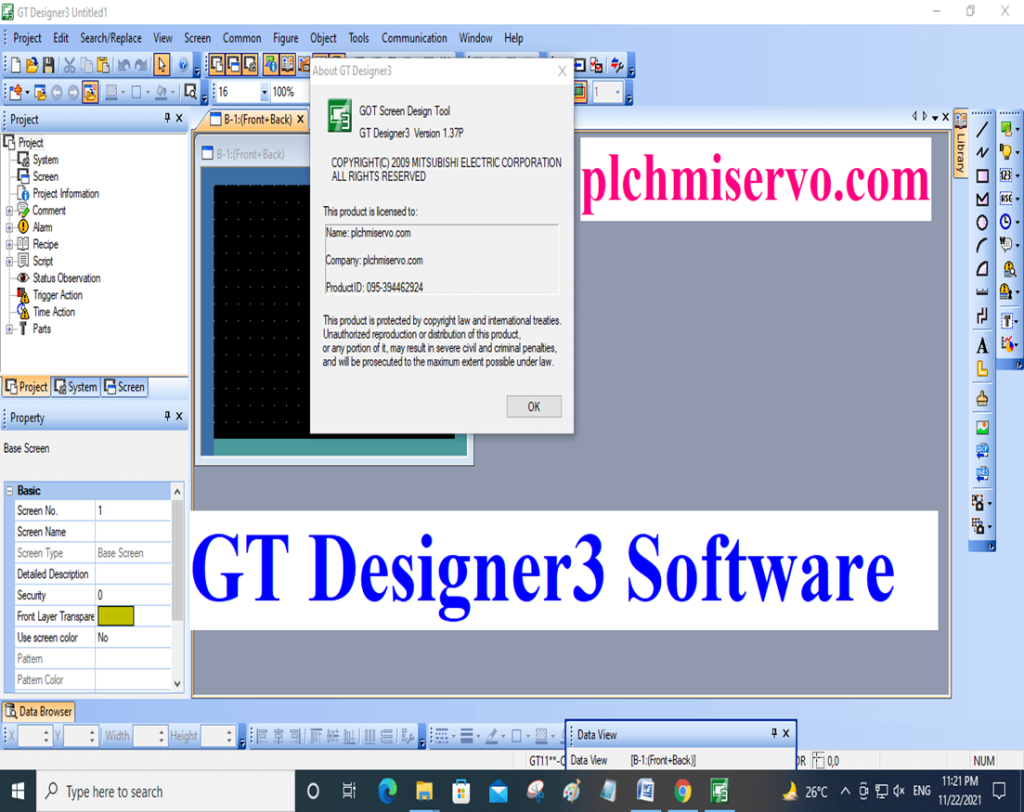
Supported “OS of GT-Designer3
+ Microsoft Windows/7 – (32 Bit/64 Bit)
+ Microsoft Wind… 8 – (32 Bit/64 Bit)
+ Microsoft Wind… 8.1- (32 Bit/64 Bit)
+ Microsoft Wind… 10 – (32 Bit/64 Bit)
+ Microsoft Wind… XP
Software GT Designer3 Mitsubishi HMI Software ‘Setup Process
+Step 01: First of all we need to install GT Designer 3 Then install Upgrade and setup GS, Extract file then click AutoRun Then Click GT Designer3

+Step 02: Then Click on OK, then click Next
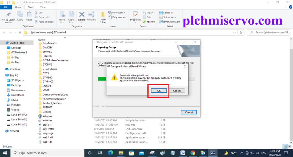

+Step 03: Edit the user information Name & “Company name then type Serial Number 095…………and next
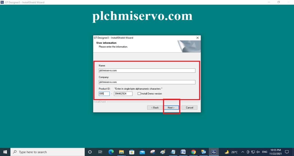
+Step 04: Select the “Installation Location” the next Two times and wait for the installation
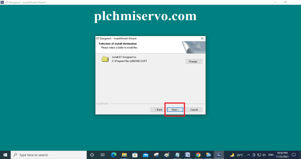

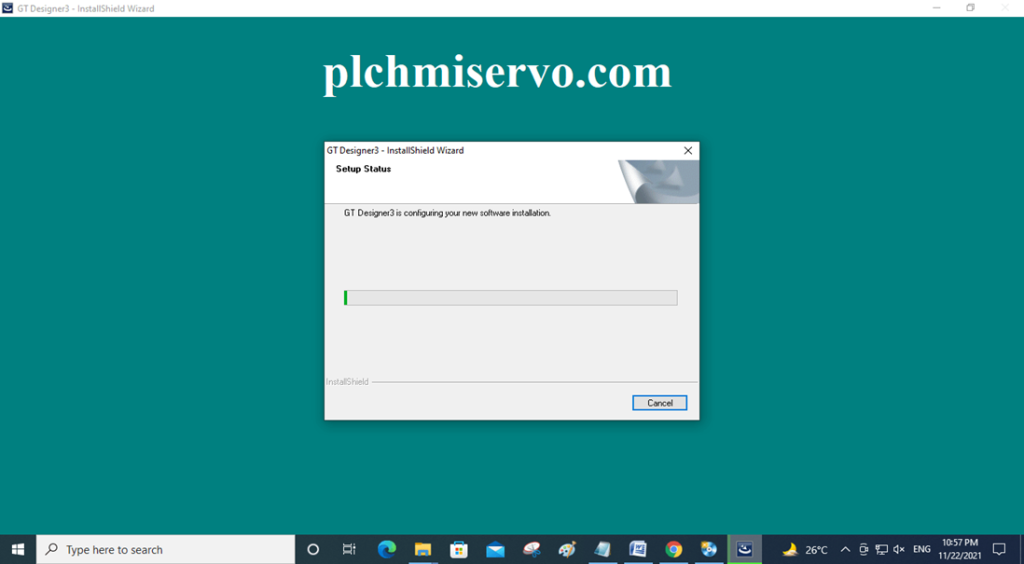
+Step 05: Then click yes Click Ok and Click on Finish
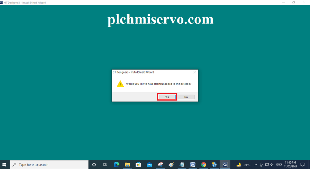
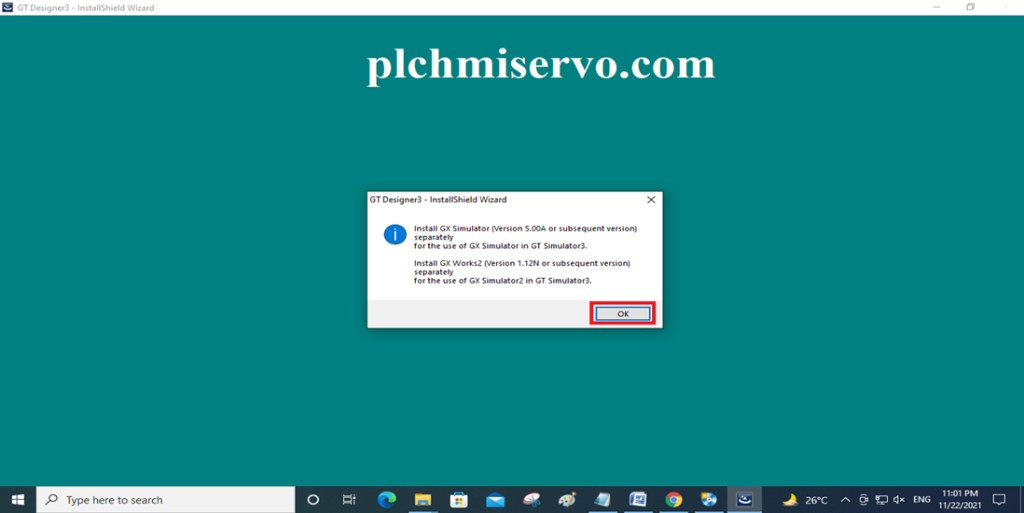

Step 02 Setup Process
+Step 1: Extract the file and Click on Setup
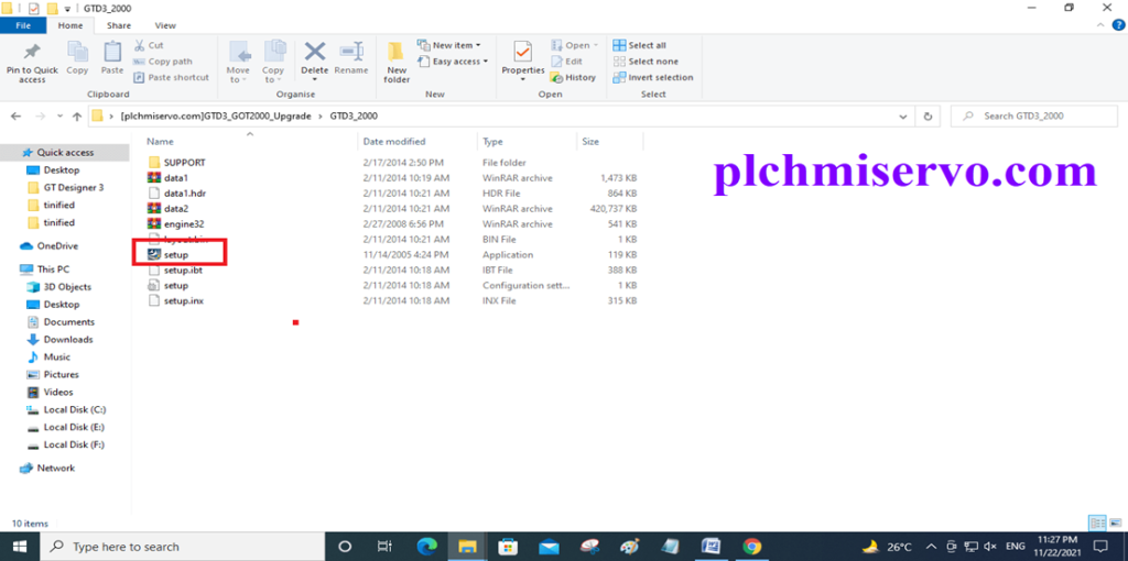
+Step 2: Then Click Ok two times.
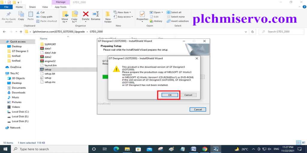
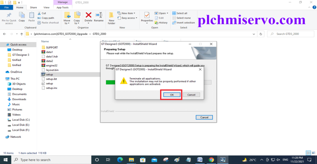
+Step 3: Then Next…
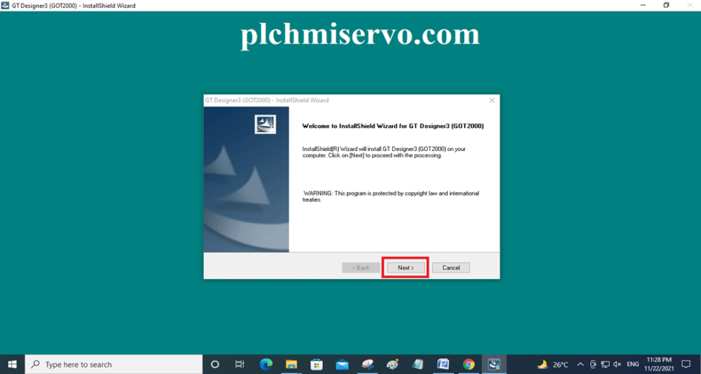
+Step 4: Enter User information and Serial key then Next

+Step 5: Then Click “Next and Yes”


+Step 6: Then Click Ok & Finish
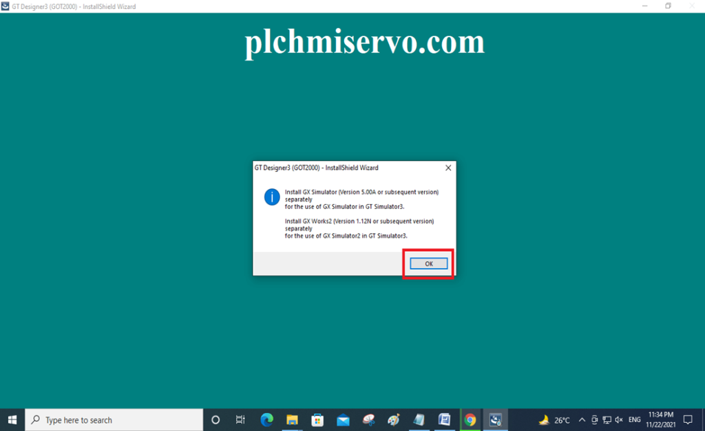
Step 03 GS Setup Upgrade
Extract the GS File then Install the software
>>>> Download Google Drive Link GT Designer3>>>>
we have given the [Download] GT Designer3 GOT2000 Mitsubishi HMI Software Real google drive link to download the required software Also how to buy the PLC and HMI.
+ [Download] GT Designer3 “Mitsubishi HMI Software”
Link: https://drive.google.com/file/d/1wW7dxjVyhEniiBcudN6k46_WKHUe_VN4/view?usp=sharing
+GTD3_GOT2000_Upgrade
Link:
https://drive.google.com/file/d/1MgHyWNp–W6vWsqtXut_8ss7Zz37dubm/view?usp=sharing
+GTWorks3 GS Upgrade
If any problems For Software installation, Programming, Upload, Download, or any query please contact plchmiservo.com via email or WhatsApp at +8804713722455 Thanks and Best Regards
+GX Developer Mitsubishi PLC Software
+MR Configurator2 Mitsubishi servo software