Instructions for transporting the machine at the port (Harvester)
1. Instructions for transporting the machine at the port (harvester)
1.1 For port personnel
1.1.1 Contact information
EuropeThese times are Finnish time (UTC+2) Mo — Fr 08.00–21.00 (8:00 am — 9:00 pm) Tel. +358 20 7688400 |
North AmericaCentral time Mo-Fr 7:00 am — 5:00 pm Tel. +1 715 369 4833 |
ChinaZhao Rujin |
BrazilThese times are UTC-3 |
1.1.2 For port personnel
IMPORTANT: Before moving the machine at a port, closely watch the video instructions presented on these pages. The language of the subtitles for the video instructions can be changed from “subtitles” in the “settings” menu at the bottom of the video.
IMPORTANT: Ensure that there are no persons within the machine’s danger area.
IMPORTANT: In case of problems, contact an authorised PONSSE service.
1.2 Lifting and fastening the machine for transportation
WARNING: Verify the machine’s actual weight before lifting!
| Machine Model | Machine weights starting from without optional equipment: |
| Ergo 8W | 20 500 kg |
| Ergo Active Frame | 21 500 kg |
| Beaver | 16 700 kg |
| Bear | 23,800 kg |
| Cobra | 19 800 kg |

Centre of gravity, sliding boom crane

Centre of gravity, parallel crane
2. Engine heater (optional equipment)

When the temperature is below -10 °C, it is recommended that the engine heater is used before starting the engine. The heater is to be used for 30–60 minutes depending on the ambient temperature.
- Starting the heater: press button 1, and the heater will start in a few seconds
- Heater shutdown: press button 1 again, and the heater will stop in a few seconds
Start the engine (see the next chapter) and allow the engine to run idle for as long as the engine heater was on in order to recharge the batteries.
IMPORTANT: If the engine heater is different from the heater in the image, please contact an authorised PONSSE service.
3. Before starting engine and starting engine
WARNING: Make sure that there is nobody in the danger area of the machine.
IMPORTANT: If the machine needs auxiliary starting current, see section 6.3.
ATTENTION: Do not let the engine speed exceed 1,200 rpm before the hydraulic oil warms up; higher running speed of the engine may damage the hydraulic system.
4. Lights

2 Emergency light
3 Turning signal indicator
4 Turning signals
5 Parking lights and headlights
- 0 = OFF
- 1 = parking lights and switch background light
- 2 = parking lights and headlights
6 Low/high beam: low beam / high beam
7 Cabin interior lights
- 0 = OFF
- 1 = interior lights with door switch to activate the lights
- 2 = interior lights (all on)
8 Working lights ON/OFF
9 Working light selector buttons
5. Driving the machine
DANGER: When the seat is turned toward the crane and the crane control switch (13) is on, the crane movements are functional. Do not move the control handles unless you know how to control the crane. Do not use the switches in the control handle or switch panel unless stated otherwise in the instructions.
IMPORTANT: When transporting a machine with a parallel crane, the tip of the crane boom must be lifted from the ground. See section 5.1 first.
5.1 Moving a machine with a parallel crane by driving

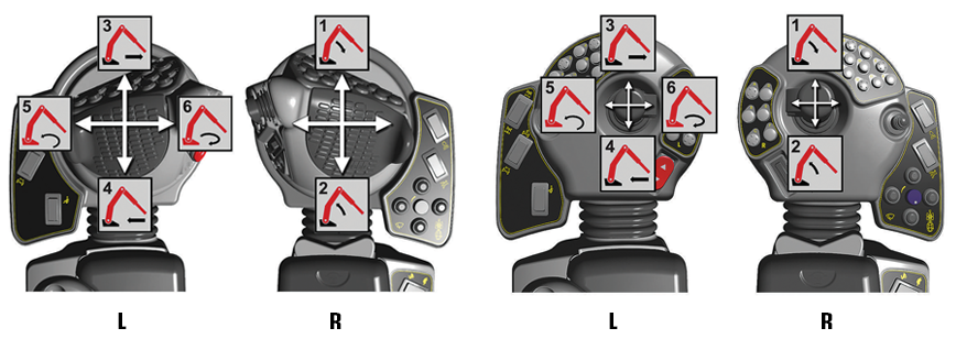
L Left control handle
R Right control handle
1 Booms down
2 Booms up
The following crane movements do not normally need to be operated when moving a machine:
3 Luffing boom out
4 Luffing boom in
5 Turning the crane to the left
6 Turning the crane to the right

14 Crane base tilt with the pedal
- A forward
- B backward
1. Remove the transportation supports for PONSSE handles before using the handles (for driving the machine).
2. Switch on the crane control switch (13).
3. Lift the booms so that the crane head is approximately one (1) metre above the ground.
4. See section Driving the machine.
5. When driving, monitor that the crane remains aligned with the machine centreline. Otherwise the harvester head saw box can touch the tyre and damage both the tyre and the harvester head.
6. Switch off the crane control switch (13).
6 Stopping the engine
6.1 Normal engine stop
6.2 Emergency engine stop

The engine stops by pressing the emergency stop push button (10/12) until it bottoms. The parking brake is activated automatically (the parking brake switch (11) remains in the OFF position), the steps are lowered. The hydraulic operations stop. The power and electric functions remain active.
The engine cannot be started when the emergency stop button is down. Release the button by turning it clockwise.
Before restarting the engine, switch the parking brake switch to the ON position.
6.3 Auxiliary start-up of the engine
ATTENTION: If auxiliary current is needed, be careful with the short circuiting and sparking of the batteries. Explosion hazard!
ATTENTION: When the machine is equipped with an extinguishing system, note that the extinguishing system does not work if any of the battery cables are disconnected or the extinguishing system fuse has been removed.
IMPORTANT: If you are uncertain about what to do, contact a person who can help you with auxiliary starting or contact an authorised PONSSE service.
|
ЧЕБУРЕЧНИЦА ЭЛЕКТРИЧЕСКАЯ СЕРИЯ EF ERGO Руководство по эксплуатации ВНИМАТЕЛЬНО изучите данное руководство и храните его в доступном месте |

СОДЕРЖАНИЕ
| 1. ВВЕДЕНИЕ | |
| 2. НАЗНАЧЕНИЕ | |
| 3. ТЕХНИЧЕСКИЕ ХАРАКТЕРИСТИКИ | |
| 4. КОМПЛЕКТАЦИЯ | |
| 5. ПОРЯДОК РАБОТЫ | |
| 6. ОБСЛУЖИВАНИЕ И УХОД | |
| 7. ТЕХНИКА БЕЗОПАСНОСТИ | |
| 8. ГАРАНТИЙНЫЕ ОБЯЗАТЕЛЬСТВА | |
| 9. КОНТАКТНАЯ ИНФОРМАЦИЯ | |
| 10. СЕРТИФИКАТ СООТВЕТСТВИЯ | |
| 11. САНИТАРНО-ЭПИДЕМИОЛОГИЧЕСКОЕ ЗАКЛЮЧЕНИЕ |
1. ВВЕДЕНИЕ
1.1. Настоящий паспорт и руководство по эксплуатации предназначены для ознакомления с конструкцией, принципом действия, техническим обслуживанием и эксплуатацией электрической чебуречницы серии EF ERGO.
1.2. Прежде чем приступить к работе, внимательно ознакомьтесь с настоящим руководством.
2. НАЗНАЧЕНИЕ
2.1. Чебуречница электрическая серии EF ERGO предназначена для приготовления различных видов продуктов в разогретом масле (фритюре).
3. ТЕХНИЧЕСКИЕ ХАРАКТЕРИСТИКИ
Модель |
EF-201V ERGO | EF-331V ERGO |
Объем масляного бака |
20л. | 33л. |
Диапазон регулировки температуры, оС |
60-200 | 60-200 |
Параметры электросети |
220/50/1 | 220/50/1 |
Мощность, кВт |
3 | 6 |
Габариты, мм |
350х700х380 | 400х880х380 |
4. КОМПЛЕКТАЦИЯ
| НАИМЕНОВАНИЕ | КОЛИЧЕСТВО (шт.) |
| Паспорт | 1 |
| Чебуречница | 1 |
5. ПОРЯДОК РАБОТЫ

1- регулятор температуры
2- индикатор питания (зелёный)
3- индикатор температуры (оранжевый)
4- основная емкость
5- кран для сливания масла
5.1. Залейте масло в емкость в соответствии с делениями (не ниже минимального уровня и не выше максимального). При этом ТЭНы должны быть полностью закрыты маслом.
5.2. Установите регулятор температуры в положение «0».
5.3. Включите чебуречницу в сеть, при этом контрольная лампа загорится зелёным цветом.
5.4. Установите регулятор температуры в требуемое положение (по часовой стрелке!), при этом загорится оранжевый индикатор, и ТЭНы начнут нагреваться.
5.5. По достижении заданной температуры оранжевый свет погаснет и нагревание прекратится.
5.6. При снижении температуры, происходит автоматическое включение питания, при этом вновь загорится оранжевый индикатор, и трубы будут нагреваться. Эта процедура циклически повторяется, обеспечивая поддержание температуры в заданных параметрах.
6. ОБСЛУЖИВАНИЕ И УХОД
6.1. Все работы по обслуживанию выполняются на оборудовании, отключенном от электросети.
6.2. До и после каждого использования оборудования необходимо тщательно вымыть нейтральным моющим средством все рабочие части, соприкасающиеся с продуктами питания.
Для очистки оборудования нужно:
- Снять ТЭН
- Вынуть емкость
6.3. Для очистки контрольного блока запрещено применение воды.
6.4. Если оборудование не будет использоваться в течение длительного времени (выходные, каникулы и т.п.), необходимо отключить его от электросети и тщательно очистить.
7. ТЕХНИКА БЕЗОПАСНОСТИ
7.1. Не допускается заливать воду в чебуречницу.
7.2. Включать только при наличии масла!
7.3. Не допускается оставлять включенное оборудование без присмотра.
7.4. Запрещается проводить работы по обслуживанию оборудования, не отключив его от электросети.
7.5. При возникновении любых неисправностей следует обращаться к специалистам службы сервиса.
7.6. Оборудование предназначено для приготовления различных видов продуктов во фритюре. Использование оборудования не по назначению не допускается.
7.7. Запрещается перегревать нагревательную трубку.
7.8. При работе с оборудованием рекомендуется носить специальную рабочую одежду. Рукава должны быть застегнуты. Волосы должны быть забраны косынкой.
8. ГАРАНТИЙНЫЕ ОБЯЗАТЕЛЬСТВА
8.1. Фирма-производитель оборудования гарантирует надежное качество изделия при условии соблюдения технических и эксплуатационных требований, изложенных в настоящем Паспорте.
8.2. Гарантия на оборудование действует в течение 6 (шести) месяцев.
8.3.
Заводские дефекты в течение гарантийного срока устраняются бесплатно специалистами службы сервиса тел. 8(495)230-64-89. Ремонт оборудования проводится в сервисном центре компании «Клён».
8.4.
Негарантийный ремонт производится по расценкам фирмы-поставщика оборудования.
8.5.
Условия гарантии указаны в гарантийном талоне, выдаваемом Покупателю вместе с актом монтажа и пусконаладки оборудования.
8.6. Изготовитель не несет ответственности за неисправности оборудования, возникшие по вине пользователя.
- КОНТАКТНАЯ ИНФОРМАЦИЯ
| ООО «Клен» | г. Москва, ул. Академика Челомея, д.3
Телефон: (495) 105-00-87, 8-800-200-00-87 |
| Сервисный центр ООО «Клен-Сервис» | г. Москва, ул. Большая Очаковская, д.5
Телефон: (495) 901-91-73 Факс: (495) 230-64-89 |
10. СЕРТИФИКАТ СООТВЕТСТВИЯ

11. САНИТАРНО-ЭПИДЕМИОЛОГИЧЕСКОЕ ЗАКЛЮЧЕНИЕ


- Manuals
- Brands
- PONSSE Manuals
- Saw
- H73
- Service training
-
Contents
-
Table of Contents
-
Bookmarks
Quick Links
S e r v i c e t r a i n i n g
Summary of Contents for PONSSE H73
-
Page 1
S e r v i c e t r a i n i n g… -
Page 2
Safety regulations S e r v i c e t r a i n i n g Technical data Electrical equipment Adjustment and service instructions Testing instructions Hydraulics Pressure adjustments Extra equipments Scheduled maintenance… -
Page 3
Safety regulations S e r v i c e t r a i n i n g Safety while servicing and repairing: Use caution and patience Danger to life! when servicing the harvester When servicing the head, head. make definitely sure that nobody starts the harvester! Immediately report any If the harvester is started, the… -
Page 4
Safety regulations S e r v i c e t r a i n i n g When testing the functioning Be aware of the danger of of the saw: slipping when working on top of the harvester head. — The harvester head must be in a horizontal position If oil gets on your skin, re- — Nobody is to be in line with… -
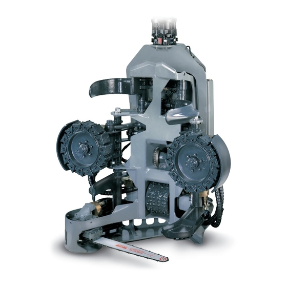
Page 5
H73001 Technical data S e r v i c e t r a i n i n g Chain lubricating oil container Saw motor Saw bar Rotator Feed rollers Serial number Reaction bar (Give the serial number when Delimbing knives (front) ordering spare parts or otherwise Delimbing knife cylinder (front) contacting the manufacturer) -
Page 6
0-4 m/s Delimbing unit: One fixed ond four movable knives. Delimbing diameter 670 mm Delimbing knives and feed rollers separately controllable Measuring and control automation: PONSSE 1000 or PONSSE OPTI system Automatic volume measurement with data storage and printer output. 28022000… -
Page 7: Electrical Equipment
S e r v i c e t r a i n i n g Electrical equipment Electrical harness / sensoring Harvester connector Valve connectors Saw sensor Length measure sensor Diameter sensor Tilt sensor Colour marking connectors 28022000…
-
Page 8
S e r v i c e t r a i n i n g Electrical equipment Optinet To pivot frame Computer To crane 02052000… -
Page 9
S e r v i c e t r a i n i n g Electric diagram (IPS) Directional valve Location number of pin connector box solenoids+diodes Saw rotation Saw feed Slow forward Slow reverse Rollers open Front knives open Fast forward Fast reverse brown… -
Page 10
S e r v i c e t r a i n i n g Electric diagram, Knutsson Location number of pin connector box Directional valve solenoids+diodes Saw rotation Saw feed Slow forward Slow reverse Rollers open Front knives open Fast forward Fast reverse Lubrication oil pump… -
Page 11
S e r v i c e t r a i n i n g Adjustment and service instructions Length measuring device Sensor casing Sensor Metering Rubber wheel coupling 29022000… -
Page 12
S e r v i c e t r a i n i n g Adjustment and service instructions Length measuring device Testing the length measurement Lift the harvester head so that you can rotate the measuring roller. Shut the engine off. Turn on the measurement system, switch on the power to the harvester head by pulling the knob out on the main switch (moto-switch). -
Page 13
S e r v i c e t r a i n i n g Adjustment and service instructions Diameter measuring Before calibrating of the diameter, you should check the following: The tree travels in the centre of the harvester head. If necessary, adjust the tree (a round one) to the centre using the reaction brace . -
Page 14
S e r v i c e t r a i n i n g Adjustment and service instructions Saw sensor replacement 1 mm Turn the engine off and make sure no one is able to start the machine. Turn the saw bar to its upper position and remove the old sensors. -
Page 15
S e r v i c e t r a i n i n g Adjustment and service instructions Saw sensor replacement Adjustment of sensors Sensors Adjustment plate 29022000… -
Page 16
S e r v i c e t r a i n i n g Adjustment and service instructions, saw Adjustment of sensors Saw bar limit screw 29022000… -
Page 17
S e r v i c e t r a i n i n g Adjustment and service instructions Delimbing knife sharpening The condition of the delimbing knives has a major effect on the pruning result and pruning resistance (especially in the summer). The recommended shape of the delimbing knives is shown in the °… -
Page 18
S e r v i c e t r a i n i n g Testing instructions Pulse sensor testing 1. Turn on the power by turning the switch to the ON position. 2. Switch the NPN/PNP switch to the correct position, depending on which type of inductive sensor you are going to test. -
Page 19
S e r v i c e t r a i n i n g Testing instructions Using a digital multimeter Resistance measurement NOTE! The measured object has to be without a voltage. E.g., Checking the diameter sensor: 1. Connect the wires as in the adjacent figure. 10.0 2. -
Page 20
S e r v i c e t r a i n i n g Testing instructions Using a digital multimeter Voltage measurement NOTE! AC/DC switch in position DC Connect the black measuring cable to the COM terminal and the frame of the machine. Connect the red measuring cable to the V terminal and the 24.0 other end to the wire or connector you want to… -
Page 21
S e r v i c e t r a i n i n g Feed hydraulics Restrictors Feed valve (fast) Feed valve (slow) Feed pressure relief valve Restrictor 29022000… -
Page 22
S e r v i c e t r a i n i n g Saw rotation hydraulics valve Saw motor Anticavitation valve Casing line check valve 29022000… -
Page 23
S e r v i c e t r a i n i n g Saw motor hydraulics Cooling option Tank line Resistor check valve 29022000… -
Page 24
S e r v i c e t r a i n i n g Saw rotation hydraulics F12-30 Casing line check valve Restrictor Main spindle Pilot -operated valve F12-30 Anticavitation valve 29022000… -
Page 25
S e r v i c e t r a i n i n g Saw feed hydraulics Directional valve Pressure reducer T-line check valve Resistor check valve Saw cylinder 29022000… -
Page 26
S e r v i c e t r a i n i n g Lubrication pump Screen + check valve Check valve Lubrication oil pump 29022000… -
Page 27
S e r v i c e t r a i n i n g Lubrication pump Opti oil control Lubrication pump Directional valve Lubrication pump valve From measuring Adapter block device T-line check valve Pressure reducer 29022000… -
Page 28
Hydraulic diagram H73001-H73202 S e r v i c e t r a i n i n g 2-power, F11-19 Feed (fast) Feed (slow) Rear knives Feed rollers Saw feed Front knives Tilting Rotator pressing Saw feed 20032000… -
Page 29
Hydraulic diagram H73203 S e r v i c e t r a i n i n g 1-power, F11-19 Feed (fast) Feed (slow) Rear knives Feed rollers Saw feed Front knives Tilting Rotator pressing Saw feed 20032000… -
Page 30
Hydraulic diagram H73203 S e r v i c e t r a i n i n g 1-power, cooling, F11-19 Feed (fast) Feed (slow) Rear knives Feed rollers Saw feed Front knives Tilting Rotator pressing Saw feed 6.10 20032000… -
Page 31
Hydraulic diagram H73211 S e r v i c e t r a i n i n g 1-power, F12-30 Feed (fast) Feed (slow) Rear knives Feed rollers Saw feed Front knives Tilting Rotator pressing Saw feed 6.11 20032000… -
Page 32
Hydraulic diagram S e r v i c e t r a i n i n g Excavator, 1-power Feed (fast) Feed (slow) Rear knives Feed rollers Saw feed Front knives Tilting Rotator pressing Saw feed 6.12 20032000… -
Page 33
S e r v i c e t r a i n i n g Pressure adjustments A. SAW (rotate) 10. Saw check valve B. SAW (feed) 11. Saw pressure reducer valve C. TRUNK FEED ROLLERS 12. Saw direction valve D. -
Page 34
S e r v i c e t r a i n i n g Pressure adjustments Harvester head pressure relief valve adjustment THE PRESSURE OF THE BASE MACHINE MUST BE ADJUSTED BEFORE THE FOLLOWING ADJUSTMENTS ARE MADE. The measurement connector is on the opposite side of the pressure reducing valve. -
Page 35
S e r v i c e t r a i n i n g Pressure adjustments Saw cylinder feed pressure Disconnect the electric cable from the harvester head. Connect a pressure gauge to the measurement connector. Start the engine and set the constant pressure: — engage the working brake and constant rpms — turn on the harvester head main switch Open the lock and adjust the pressure reducer valve by turning… -
Page 36
S e r v i c e t r a i n i n g Pressure adjustments Feed roller cylinder pinch pressure NOTE! BE ESPECIALLY CAREFUL NOT TO ADJUST THE PINCH PRESSURE TOO HIGH. Disconnect the electric cable from the harvester head. Connect a pressure gauge to measurement connector. -
Page 37
S e r v i c e t r a i n i n g Pressure adjustments Front delimbing knife cylinder pressure adjustment Disconnect the electric cable from the harvester head. Connect a pressure gauge to the measurement connector. Start the engine and set the constant pressure: — engage the working brake and constant rpms — turn on the harvester head main switch Open the lock and adjust the pressure reducer valve by turning adjustment… -
Page 38
S e r v i c e t r a i n i n g Pressure adjustments Rear delimbing knife cylinder pressure adjustment Disconnect the electric cable from the harvester head. Connect a pressure gauge to the measurement connector. Start the engine and set the constant pressure: — engage the working brake and constant rpms — turn on the harvester head main switch Open the lock and adjust the pressure reducer valve by turning adjustment… -
Page 39
S e r v i c e t r a i n i n g Pressure adjustments Harvester head tilt cylinder pressure adjustment (tilt) Disconnect the electric cable from harvester head. Tilt the harvester head to a horizontal position. Connect a pressure gauge to the measurement connector. Start the engine and set the constant pressure: — engage the working brake and constant rpms — turn on the harvester head main switch… -
Page 40
S e r v i c e t r a i n i n g Pressure adjustments Rotator pressure relief valve adjustment (Indexator) ATTENTION! MAKE SURE THAT YOUR HELPER IS FAMILIAR WITH THE MACHINE AND KNOWS HOW TO OPERATE IT. Disconnect the rotator hoses and connect pressure gauges to them. -
Page 41
S e r v i c e t r a i n i n g Extra equipments Color marking device Crane Shut-off cock Electric valve Nozzles 22032000… -
Page 42
S e r v i c e t r a i n i n g Extra equipments Stump treatment system Electric valve Crane boom head 22032000… -
Page 43
Pressure reducer valve of saw feed Pressure relief valve of front knives Pressure reducer valve of front knives Pressure reducer valve of rear knives (H53, H73) Pressure relief valve of rear knives (H53, H73) Tilt cylinder pressure of multi-function unit…
Table of Contents for PONSSE H73:
-
Service training 000 04052000 7.1 Pressure adjustments A. SAW (rotate) B. SAW (feed) C. TRUNK FEED ROLLERS D. FRONT DELIMBING KNIVES E. TILT F. ROTATOR G. REAR DELIMBING KNIVES T. Tank line P. Pressure line 2. Fast feed direction valve 3. Slow feed direction valve 4. Rear delimbing knife pressure reducer valve 5. Rear delimbing knife pressure relief valve 6. Rear delimbing knife check valve 7. Rear delimbing knife direction valve 8. Tilt pressure reducer valve 9. Tilt dire
-
Service training 000 29022000 6.4 F12-30 Saw rotation hydraulics F12-30 Casing line check valve Restrictor Anticavitation valve Pilot -operated valve Main spindle
-
Service training 000 04052000 7.3 23 Pressure adjustments Saw cylinder feed pressure 1. Disconnect the electric cable from the harvester head. 2. Connect a pressure gauge to the measurement connector. 3. Start the engine and set the constant pressure: — engage the working brake and constant rpms — turn on the harvester head main switch 4. Open the lock and adjust the pressure reducer valve by turning adjustment screw no. 23 to obtain 30 bar / 435 psi. (25-30 bar / 363-435 psi.).
-
Service training 000 04052000 5.1 Testing instructions Pulse sensor testing 1. Turn on the power by turning the switch to the ON position. 2. Switch the NPN/PNP switch to the correct position, depending on which type of inductive sensor you are going to test. In the new harvester heads all inductive sensors are NPN type. In the older harvester heads the saw sensor is PNP type if the saw sensors diameter is 8 mm.
-
Service training 000 20032000 6.12 Saw Feed (fast) Feed (slow) Rear knives Feed rollers pressing Saw feed Front knives Tilting Rotator Saw feed Hydraulic diagram Excavator, 1-power
-
Service training SCHEDULED MAINTENANCE, NEW HARVESTER HEADS I = Inspect or check R = Replace C = Clean VI = Visual inspection T = Tightening A = Adjustment G = Greasing WHITE — END USER BLUE — PONSSE OYJ RED — DEALER N:o Item Maintenance interval (hours) HARVESTER HEAD 50 200 1000 1 2 3 4 5 6 7 8 9 10 11 12 13 14 15 16 17 18 19 20 21 22 23 24 25 I, T I, T Rotator mounting bolts Hydraulic motor mountings Feed roller mounting Measurement roller mounting Valve block mounting Bearing pin tightness and locking Hydraulic l
-
Service training
-
Service training 000 04052000 1.2 Safety regulations 10. When testing the functioning of the saw: — The harvester head must be in a horizontal position — Nobody is to be in line with the saw — Keep the harvester head as near to the ground as possible 11. Never raise the harvester head near the cab windows while testing the saw. 12. When servicing indoors, the saw must only be tested with the chain removed. 13. Remove the pressure from the hydraulic system before beginn
-
Service training 000 20032000 6.8 H73001-H73202 Saw Feed (fast) Feed (slow) Rear knives Feed rollers pressing Saw feed Front knives Tilting Rotator Saw feed Hydraulic diagram 2-power, F11-19
-
Service training 000 29022000 4.5 Adjustment and service instructions Saw sensor replacement Sensors Adjustment plate Adjustment of sensors
-
Service training 000 04052000 1.1 Safety regulations 1. Use caution and patience when servicing the harvester head. 2. Immediately report any malfunctions in the head to your foreman or the person responsible for servicing. 3. The engine should be shut off during servicing. 4. Avoid working alone. Keep a mobile phone near you when you service the harvester outside the cab. Store an emergency alarm number in one of th
-
Service training 000 29022000 6.2 Saw rotation hydraulics Saw valve Saw motor Casing line check valve Anticavitation valve
Questions, Opinions and Exploitation Impressions:
You can ask a question, express your opinion or share our experience of PONSSE H73 device using right now.