-
Contents
-
Table of Contents
-
Bookmarks
Quick Links
TNC 426
TNC 430
NC Software
280 476-xx
280 477-xx
User’s Manual
HEIDENHAIN Conversational
Format
10/2001
Related Manuals for HEIDENHAIN TNC 426
Summary of Contents for HEIDENHAIN TNC 426
-
Page 1
TNC 426 TNC 430 NC Software 280 476-xx 280 477-xx User’s Manual HEIDENHAIN Conversational Format 10/2001… -
Page 2
Controls on the visual display unit Programming path movements Split screen layout Approach/depart contour Switch between machining or FK free contour programming programming modes Soft keys for selecting functions in screen Straight line Switching the soft-key rows Circle center/pole for polar coordinates Changing the screen settings Circle with center (only BC 120) -
Page 5
TNC users. Touch Probe Cycles User’s Manual: All of the touch probe functions are described in a separate manual. Please contact HEIDENHAIN if you require a copy of this User’s Manual. ID number: 329 203-xx. Location of use… -
Page 6
New features of the NC software 280 476-xx Thread milling cycles 262 to 267 (see “Fundamentals of thread milling” on page 235) Tapping Cycle 209 with chip breaking (see “TAPPING WITH CHIP BREAKING (Cycle 209)” on page 233) Cycle 247(see “DATUM SETTING (Cycle 247)” on page 324) Cycle run by means of point tables (see “Point Tables”… -
Page 7
Summary of input formats (see “Technical Information” on page 465) Mid-program startup of pallet tables (see “Mid-program startup (block scan)” on page 412) Exchanging the buffer battery (see “Exchanging the Buffer Battery” on page 469) HEIDENHAIN TNC 426, TNC 430… -
Page 9: Table Of Contents
Programming: Fundamentals of File Management, Programming Aids Programming: Tools Programming: Programming Contours Programming: Miscellaneous Functions Programming: Cycles Programming: Subprograms and Program Section Repeats Programming: Q Parameters Test Run and Program Run MOD Functions Tables and Overviews HEIDENHAIN TNC 426, TNC 430…
-
Page 11
1.4 Status Displays ..9 “General” status display ..9 Additional status displays ..10 1.5 Accessories: HEIDENHAIN 3-D Touch Probes and Electronic Handwheels ..13 3-D Touch Probes ..13 HR electronic handwheels ..14 2 Manual Operation and Setup ..15 2.1 Switch-on, Switch-off .. -
Page 12
Data transfer to or from an external data medium ..44 Selecting one of the last 10 files selected ..46 Renaming a file ..46 Converting an FK program into HEIDENHAIN conversational format ..47 Protect file / Cancel file protection ..48 VIII… -
Page 13
The TNC in a network (applies only for Ethernet interface option) ..61 4.5 Creating and Writing Programs ..63 Organization of an NC program in HEIDENHAIN conversational format..63 Defining the blank form–BLK FORM ..63 Creating a new part program ..64 Programming tool movements in conversational format .. -
Page 14
4.8 Adding Comments ..73 Function ..73 Entering comments during programming ..73 Inserting comments after program entry ..73 Entering a comment in a separate block ..73 4.9 Creating Text Files ..74 Function ..74 Opening and exiting text files ..74 Editing texts .. -
Page 15
Data required for the tool table ..123 Working with automatic speed/feed rate calculation ..124 Changing the table structure ..124 Data transfer from cutting data tables ..126 Configuration file TNC.SYS ..126 HEIDENHAIN TNC 426, TNC 430… -
Page 16
6 Programming: Programming Contours ..127 6.1 Tool movements ..128 Path functions ..128 FK Free Contour Programming ..128 Miscellaneous functions M ..128 Subprograms and Program Section Repeats ..128 Programming with Q parameters ..128 6.2 Fundamentals of Path Functions ..129 Programming tool movements for workpiece machining .. -
Page 17
Free programming of circular arcs ..161 Input possibilities ..162 Auxiliary points ..164 Relative data ..165 Converting FK programs ..167 6.7 Path Contours — Spline Interpolation ..173 Function ..173 HEIDENHAIN TNC 426, TNC 430 XIII… -
Page 18
7 Programming: Miscellaneous functions ..175 7.1 Entering Miscellaneous Functions M and STOP ..176 Fundamentals ..176 7.2 Miscellaneous Functions for Program Run Control, Spindle and Coolant ..177 Overview ..177 7.3 Miscellaneous Functions for Coordinate Data ..178 Programming machine-referenced coordinates: M91/M92 .. -
Page 19
CIRCULAR POCKET FINISHING (Cycle 214) ..266 CIRCULAR STUD FINISHING (Cycle 215) ..268 SLOT MILLING (Cycle 3) ..270 SLOT (oblong hole) with reciprocating plunge-cut (Cycle 210) ..272 CIRCULAR SLOT (oblong hole) with reciprocating plunge-cut (Cycle 211) ..274 HEIDENHAIN TNC 426, TNC 430… -
Page 20
8.5 Cycles for Machining Hole Patterns ..278 Overview ..278 CIRCULAR PATTERN (Cycle 220) ..279 LINEAR PATTERN (Cycle 221) ..281 8.6 SL cycles ..285 Fundamentals ..285 Overview of SL cycles ..286 CONTOUR GEOMETRY (Cycle 14) ..287 Overlapping contours .. -
Page 21
Calling any program as a subprogram ..345 9.5 Nesting ..346 Types of nesting ..346 Nesting depth ..346 Subprogram within a subprogram ..346 Repeating program section repeats ..347 Repeating a subprogram ..348 HEIDENHAIN TNC 426, TNC 430 XVII… -
Page 22
10 Programming: Q Parameters ..355 10.1 Principle and Overview ..356 Programming notes ..356 Calling Q parameter functions ..357 10.2 Part Families – Q Parameters in Place of Numerical Values ..358 Example NC blocks ..358 Example .. -
Page 23
Mid-program startup (block scan) ..412 Returning to the contour ..413 11.5 Automatic Program Start ..414 Function ..414 11.6 Optional Block Skip ..415 Function ..415 11.7 Optional Program Run Interruption ..416 Function ..416 HEIDENHAIN TNC 426, TNC 430… -
Page 24
12 MOD Functions ..417 12.1 MOD functions ..418 Selecting the MOD functions ..418 Changing the settings ..418 Exiting the MOD functions ..418 Overview of MOD functions ..418 12.2 Software Numbers and Option Numbers ..420 Function .. -
Page 25
Ethernet interface BNC socket (option) ..464 13.3 Technical Information ..465 13.4 Exchanging the Buffer Battery ..469 TNC 426 CB/PB, TNC 430 CA/PA ..469 TNC 426 M, TNC 430 M ..469 HEIDENHAIN TNC 426, TNC 430… -
Page 27: Introduction
Introduction…
-
Page 28
They are designed for milling, drilling and boring machines, as well as for machining centers. The TNC 426 can control up to 5 axes; the TNC 430 can control up to 9 axes. You can also change the angular position of the spindle under program control. -
Page 29
In the submenu: Increase value or move picture to the right or upward In the main menu: Select submenu In the submenu: Exit submenu 1 1 4 Main menu dialog Function BRIGHTNESS Adjust brightness CONTRAST Adjust contrast H-POSITION Adjust horizontal position HEIDENHAIN TNC 426, TNC 430… -
Page 30
Main menu dialog Function V-POSITION Adjust vertical position V-SIZE Adjust picture height SIDE-PIN Correct barrel-shaped distortion TRAPEZOID Correct trapezoidal distortion ROTATION Correct tilting COLOR TEMP Adjust color temperature R-GAIN Adjust strength of red color B-GAIN Adjust strength of blue color RECALL No function The BC 120 is sensitive to magnetic and electromagnetic noise, which… -
Page 31
Arrow keys and GOTO jump command Numerical input and axis selection The functions of the individual keys are described on the inside front cover. Machine panel buttons, e.g. NC START, are described in the manual for your machine tool. HEIDENHAIN TNC 426, TNC 430… -
Page 32
1.3 Modes of Operation Manual Operation and Electronic Handwheel The Manual Operation mode is required for setting up the machine tool. In this operating mode, you can position the machine axes manually or by increments, set the datums, and tilt the working plane. The Electronic Handwheel mode of operation allows you to move the machine axes manually with the HR electronic handwheel. -
Page 33
This simulation is supported graphically in different display modes. Soft keys for selecting the screen layout: see “Program Run, Full Sequence and Program Run, Single Block,” page 8. HEIDENHAIN TNC 426, TNC 430… -
Page 34
Program Run, Full Sequence and Program Run, Single Block In the Program Run, Full Sequence mode of operation the TNC executes a part program continuously to its end or to a manual or programmed stop. You can resume program run after an interruption. In the Program Run, Single Block mode of operation you execute each block separately by pressing the machine START button. -
Page 35
Spindle speed S, feed rate F and active M functions Program run started Axis locked Axis can be moved with the handwheel Axes are moving in a tilted working plane Axes are moving under a basic rotation HEIDENHAIN TNC 426, TNC 430… -
Page 36
Additional status displays The additional status displays contain detailed information on the program run. They can be called in all operating modes, except in the Programming and Editing mode of operation. To switch on the additional status display: Call the soft-key row for screen layout. Select the layout option for the additional status display. -
Page 37
Coordinate transformations Name of main program Active datum shift (Cycle 7) Active rotation angle (Cycle 10) Mirrored axes (Cycle Active scaling factor(s) (Cycles 11 / 26) Scaling datum See “Coordinate Transformation Cycles” on page 319. HEIDENHAIN TNC 426, TNC 430…
 -
Page 38
Tool measurement Number of the tool to be measured Display whether the tool radius or the tool length is being measured MIN and MAX values of the individual cutting edges and the result of measuring the rotating tool (DYN = dynamic measurement) Cutting edge number with the corresponding measured value. -
Page 39
1.5 Accessories: HEIDENHAIN 3-D Touch Probes and Electronic Handwheels 3-D Touch Probes With the various HEIDENHAIN 3-D touch probe systems you can: Automatically align workpieces Quickly and precisely set datums Measure the workpiece during program run Digitize 3-D surfaces (option), and… -
Page 40
Electronic handwheels facilitate moving the axis slides precisely by hand. A wide range of traverses per handwheel revolution is available. Apart from the HR 130 and HR 150 integral handwheels, HEIDENHAIN also offers the HR 410 portable handwheel (see figure at center right). 1 Introduction… -
Page 41: Manual Operation And Setup
Manual Operation and Setup…
-
Page 42
2.1 Switch-on, Switch-off Switch-on Switch-on and traversing the reference points can vary depending on the individual machine tool. Refer to your machine manual. Switch on the power supply for control and machine. The TNC automatically initiates the following dialog MEMORY TEST The TNC memory is automatically checked. -
Page 43
When the TNC displays the message Now you can switch off the TNC in a superimposed window, you may cut off the power supply to the TNC. Inappropriate switch-off of the TNC can lead to data loss. HEIDENHAIN TNC 426, TNC 430… -
Page 44
2.2 Moving the Machine Axes Note Traversing with the machine axis direction buttons is a machine-dependent function. The machine tool manual provides further information. To traverse with the machine axis direction buttons: Select the Manual Operation mode. Press the machine axis-direction button and hold it as long as you wish the axis to move, or Move the axis continuously: Press and hold the machine axis direction button, then press the… -
Page 45
To move an axis: Select the Electronic Handwheel operating mode. Press and hold the permissive button. Select the axis. Select the feed rate. Move the active axis in the positive or negative direction. HEIDENHAIN TNC 426, TNC 430… -
Page 46
Incremental jog positioning With incremental jog positioning you can move a machine axis by a preset distance. Select Manual or Electronic Handwheel mode of operation. Select incremental jog positioning: Switch the INCREMENT soft key to ON JOG INCREMENT = Enter the jog increment in millimeters, i.e. 8 mm. Press the machine axis direction button as often as desired. -
Page 47
With the override knobs you can vary the spindle speed S and feed rate F from 0% to 150% of the set value. The override dial for spindle speed is only functional on machines with infinitely variable spindle drive. HEIDENHAIN TNC 426, TNC 430… -
Page 48
2.4 Datum Setting(Without a 3-D Touch Probe) Note For datum setting with a 3-D touch probe, refer to the new Touch Probe Cycles Manual. You fix a datum by setting the TNC position display to the coordinates of a known position on the workpiece. Preparation Clamp and align the workpiece. -
Page 49
In the tool axis, offset the tool radius. Repeat the process for the remaining axes. If you are using a preset tool, set the display of the tool axis to the length L of the tool or enter the sum Z=L+d. HEIDENHAIN TNC 426, TNC 430… -
Page 50
2.5 Tilting the working plane Application, function The functions for tilting the working plane are interfaced to the TNC and the machine tool by the machine tool builder. With some swivel heads and tilting tables, the machine tool builder determines whether the entered angles are interpreted as coordinates of the tilt axes or as angular components of a tilted plane. -
Page 51
The actual positions of one or several rotary axes must match the entry. Otherwise the TNC will calculate an incorrect datum. HEIDENHAIN TNC 426, TNC 430… -
Page 52
Datum setting on machines with rotary tables The behavior of the TNC during datum setting depends on the machine. Refer to your machine manual. The TNC automatically shifts the datum if you rotate the table and the tilted working plane function is active: MP 7500, bit 3=0 To calculate the datum, the TNC uses the difference between the REF coordinate during datum setting and the REF coordinate of the… -
Page 53
If you are using Cycle 19 WORKING PLANE in the part program, the angular values defined in the cycle (starting at the cycle definition) are effective. Angular values entered in the menu will be overwritten. HEIDENHAIN TNC 426, TNC 430… -
Page 55: Positioning With Manual Data Input (Mdi)
Positioning with Manual Data Input (MDI)
-
Page 56
The operating mode Positioning with Manual Data Input is particularly convenient for simple machining operations or pre-positioning of the tool. It enables you to write a short program in HEIDENHAIN conversational programming or in ISO format, and execute it immediately. You can also call TNC cycles. The program is stored in the file $MDI. -
Page 57
Select the axis of the rotary table, enter the rotation angle you wrote down previously and set the feed rate.For example: L C+2.561 F50 Conclude entry. Press the machine START button: The rotation of the table corrects the misalignment. HEIDENHAIN TNC 426, TNC 430… -
Page 58
Protecting and erasing programs in $MDI The $MDI file is generally intended for short programs that are only needed temporarily. Nevertheless, you can store a program, if necessary, by proceeding as described below: Select the Programming and Editing mode of operation To call the file manager, press the PGM MGT key (program management). -
Page 59: Programming: Fundamentals Of File
Programming: Fundamentals of NC, File Management, Programming Aids, Pallet Management…
-
Page 60
4.1 Fundamentals Position encoders and reference marks The machine axes are equipped with position encoders that register the positions of the machine table or tool. When a machine axis moves, the corresponding position encoder generates an electrical signal. The TNC evaluates this signal and calculates the precise actual X (Z,Y) position of the machine axis. -
Page 61
X direction, and the index finger in the positive Y direction. The TNC 426 can control a machine tool in up to 5 axes; the TNC 430 controls up to 9 axes. The axes U, V and W are secondary linear axes parallel to the main axes X, Y and Z, respectively. -
Page 62
Polar coordinates If the production drawing is dimensioned in Cartesian coordinates, you also write the part program using Cartesian coordinates. For parts containing circular arcs or angles it is often simpler to give the dimensions in polar coordinates. While the Cartesian coordinates X, Y and Z are three-dimensional and can describe points in space, polar coordinates are two-dimensional and describe points in a plane. -
Page 63
Y = 10 mm Absolute and incremental polar coordinates Absolute polar coordinates always refer to the pole and the reference axis. Incremental coordinates always refer to the last programmed nominal position of the tool. +IPR +IPA +IPA 0° HEIDENHAIN TNC 426, TNC 430… -
Page 64
The fastest, easiest and most accurate way of setting the datum is by using a 3-D touch probe from HEIDENHAIN. See the new Touch Probe Cycles User’s Manual, chapter “Setting the Datum with a 3-D Touch Probe.”… -
Page 65
When you store programs, tables and texts as files, the TNC adds an extension to the file name, separated by a point. This extension indicates the file type. PROG20 File name File type Maximum Length See table “Files in the TNC.” HEIDENHAIN TNC 426, TNC 430… -
Page 66
We recommend saving newly written programs and files on a PC at regular intervals. You can do this with the free backup program TNCBACK.EXE from HEIDENHAIN. Your machine tool builder can provide you with a copy of TNCBACK.EXE. In addition, you need a floppy disk on which all machine-specific data, such as PLC program, machine parameters, etc., are stored. -
Page 67
Program is selected in the Programming and Editing mode of operation. Program is selected in the Test Run mode of operation. Program is selected in a program run operating mode. File is protected against editing and erasure. HEIDENHAIN TNC 426, TNC 430… -
Page 68
Selecting a file Call the file manager. Use the arrow keys or the arrow soft keys to move the highlight to the file you wish to select: Moves the highlight up or down file by file in the window. Moves the highlight up or down page by page in the window. -
Page 69
If you wish to copy very long programs, enter the new file name and confirm with the PARALLEL EXECUTE soft key. The file will now be copied in the background, so you can continue to work while the TNC is copying. HEIDENHAIN TNC 426, TNC 430… -
Page 70
Data transfer to or from an external data medium Before you can transfer data to an external data medium, you must setup the data interface(see “Setting the Data Interfaces” on page 422). Call the file manager. Activate data transfer: Press the EXT soft key. In the left half of the screen the TNC shows all files saved on its hard disk. -
Page 71
If you wish to transfer more than one file or longer files, press the PARALLEL EXECUTE soft key. The TNC then copies the file in the background. To stop transfer, press the TNC soft key. The standard file manager window is displayed again. HEIDENHAIN TNC 426, TNC 430… -
Page 72
Selecting one of the last 10 files selected Call the file manager. Display the last 10 files selected: Press the LAST FILES soft key. Use the arrow keys to move the highlight to the file you wish to select: Move the highlight up or down. To select the file: Press the SELECT soft key or the ENT key. -
Page 73
Converting an FK program into HEIDENHAIN conversational format Call the file manager. Use the arrow keys or the arrow soft keys to move the highlight to the file you wish to convert: Moves the highlight up or down file by file in the window. -
Page 74
Protect file / Cancel file protection Call the file manager. Use the arrow keys or arrow soft keys to move the highlight to the file you wish to protect or whose protection you wish to cancel: Moves the highlight up or down file by file in the window. -
Page 75
AUFTR1 the directory NCPROG was created and the part program PROG1.H was copied into it. The part program now has the A35K941 following path: TNC:AUFTR1NCPROGPROG1.H ZYLM The chart at right illustrates an example of a directory display with TESTPROG different paths. HUBER KAR25T HEIDENHAIN TNC 426, TNC 430… -
Page 76
Display the last 10 files that were selected Erase a file or directory Tag a file Renaming a file Convert an FK program into HEIDENHAIN conversational format Protect a file against editing and erasure Cancel file protection Network drive management (Ethernet option… -
Page 77
Program is selected in the Test Run mode of operation. Program is selected in a program run operating mode. File is protected against editing and erasure. DATE Date the file was last changed TIME Time the file was last changed HEIDENHAIN TNC 426, TNC 430… -
Page 78
Selecting drives, directories and files Call the file manager. With the arrow keys or the soft keys, you can move the highlight to the desired position on the screen: Move the highlight from the left to the right window, and vice versa. Moves the highlight up and down within a window Moves the highlight one page up or down within a window… -
Page 79
Move the highlight in the left window to the directory in which you want to create a subdirectory. Enter the new file name, and confirm with ENT. Create NEW directory? Press the YES soft key to confirm, or Abort with the NO soft key. HEIDENHAIN TNC 426, TNC 430… -
Page 80
Copying a single file Move the highlight to the file you wish to copy. Press the COPY soft key to select the copying function. Enter the name of the destination file and confirm your entry with the ENT key or EXECUTE soft key: The TNC copies the file into the active directory. -
Page 81
Use the arrow keys to move the highlight to the file you wish to select: Moves the highlight up and down within a window Select a drive: Press the SELECT soft key or the ENT key. HEIDENHAIN TNC 426, TNC 430… -
Page 82
Deleting a file Move the highlight to the file you want to delete. To select the erasing function, press the DELETE soft key. The TNC inquires whether you really intend to erase the file. To confirm, press the YES soft key; To abort erasure, press the NO soft key. -
Page 83
You can tag several files in this way, as desired. To copy the tagged files, press the COPY TAG soft key, or Delete the tagged files by pressing END to end the marking function, and then the DELETE to delete the tagged files. HEIDENHAIN TNC 426, TNC 430… -
Page 84
The file now has status P. To cancel file protection, proceed in the same way using the UNPROTECT soft key. Converting an FK program into HEIDENHAIN conversational format Move the highlight to the file you want to convert. To select the additional functions, press the MORE FUNCTIONS soft key. -
Page 85
Transfer a single file: Press the COPY soft key, or Transfer several files: Press the TAG soft key (in the second soft-key row, see “Tagging files,” page 57), Transfer all files: Press the TNC => EXT soft key. HEIDENHAIN TNC 426, TNC 430… -
Page 86
Confirm with the EXECUTE or with the ENT key. A status window appears on the TNC, informing about the copying progress, or If you wish to transfer more than one file or longer files, press the PARALLEL EXECUTE soft key. The TNC then copies the file in the background. -
Page 87
Automatically establish network connection whenever the TNC is switched on. The TNC shows an A in the Auto column if the connection is established automatically. Do not establish network connection automatically when the TNC is switched on. HEIDENHAIN TNC 426, TNC 430… -
Page 88
It may take some time to mount a network device. At the upper right of the screen the TNC displays[READ DIR] to indicate that a connection is being established. The maximum data transmission rate lies between 200 and 1000 kilobaud, depending on the file type being transmitted. -
Page 89
4.5 Creating and Writing Programs Organization of an NC program in HEIDENHAIN conversational format. A part program consists of a series of program blocks. The figure at right illustrates the elements of a block. The TNC numbers the blocks in ascending sequence. -
Page 90
Creating a new part program You always enter a part program in the Programming and Editing mode of operation. Program initiation in an example: Select the Programming and Editing mode of operation. To call the file manager, press the PGM MGT key. Select the directory in which you wish to store the new program File name = OLD.H Enter the new program name and confirm your entry… -
Page 91
Working spindle axis X/Y/Z by pressing the DEL key! The TNC can display the graphic only if the ratio of the short side to the long sides of the BLK FORM is greater than 1:64! HEIDENHAIN TNC 426, TNC 430… -
Page 92
Programming tool movements in conversational format To program a block, initiate the dialog by pressing a function key. In the screen headline, the TNC then asks you for all the information necessary to program the desired function. Example of a dialog Dialog initiation Coordinates ? Enter the target coordinate for the X axis. -
Page 93
Move from one block to the next Select individual words in a block Function Set the selected word to zero Erase an incorrect number Clear a (non-blinking) error message Delete the selected word Delete the selected block HEIDENHAIN TNC 426, TNC 430… -
Page 94
Function Erase cycles and program sections: First select the last block of the cycle or program section to be erased, then erase with the DEL key. Inserting blocks at any desired location Select the block after which you want to insert a new block and initiate the dialog. -
Page 95
To insert the block: Press the INSERT BLOCK soft key. Function Soft key Switch on marking function Switch off marking function Delete marked block Insert block that is stored in the buffer memory Copy marked block HEIDENHAIN TNC 426, TNC 430… -
Page 96
4.6 Interactive Programming Graphics To generate/not generate graphics during programming: While you are writing the part program, you can have the TNC generate a 2-D pencil-trace graphic of the programmed contour. To switch the screen layout to displaying program blocks to the left and graphics to the right, press the SPLIT SCREEN key and PGM + GRAPHICS soft key. -
Page 97
Enlarge the frame overlay — press and hold the soft key to magnify the detail Confirm the selected area with the WINDOW DETAIL soft key. With the WINDOW BLK FORM soft key, you can restore the original section. HEIDENHAIN TNC 426, TNC 430… -
Page 98
4.7 Structuring Programs Definition and applications This TNC function enables you to comment part programs in structuring blocks. Structuring blocks are short texts with up to 244 characters and are used as comments or headlines for the subsequent program lines. With the aid of appropriate structuring blocks, you can organize long and complex programs in a clear and comprehensible way. -
Page 99
Select the block after which the comment is to be inserted. Initiate the programming dialog with the semicolon key “;” on the alphabetic keyboard. Enter your comment and conclude the block by pressing the END key. HEIDENHAIN TNC 426, TNC 430… -
Page 100
4.9 Creating Text Files Function You can use the TNC’s text editor to write and edit texts. Typical applications: Recording test results Documenting working procedures Creating formularies Text files are type .A files (ASCII files). If you want to edit other types of files, you must first convert them into type .A files. -
Page 101
The line in which the cursor is presently located is depicted in a different color. A line can have up to 77 characters. To start a new line, press the RET key or the ENT key. HEIDENHAIN TNC 426, TNC 430… -
Page 102
Erasing and inserting characters, words and lines With the text editor, you can erase words and even lines, and insert them at any desired location in the text. Move the cursor to the word or line you wish to erase and insert at a different place in the text. -
Page 103
To select the search function, press the FIND soft key. The TNC displays the dialog prompt Find text: Enter the text that you wish to find. To find the text, press the EXECUTE soft key. To leave the search function, press the END soft key. HEIDENHAIN TNC 426, TNC 430… -
Page 104
4.10 Integrated Pocket Calculator Operation The TNC features an integrated pocket calculator with the basic mathematical functions. With the CALC key you can open and close an additional window for calculations. You can move the window to any desired location on the TNC screen with the arrow keys. -
Page 105
The TNC displays the Help text automatically if the error message is flashing. The TNC needs to be restarted after blinking error messages. To restart the TNC, press the END key and hold for two seconds. HEIDENHAIN TNC 426, TNC 430… -
Page 106
4.12 Pallet Management Application Pallet table management is a machine-dependent function. The standard functional range will be described in the following. Refer to your machine manual for more information. Pallet tables are used for machining centers with pallet changer: The pallet table calls the part programs that are required for the different pallets, and activates datum shifts or datum tables. -
Page 107
Delete the last line in the table Go to the beginning of the next line Add the entered number of lines to the end of the table Copy the highlighted field (2nd soft-key row) Insert the copied field (2nd soft-key row) HEIDENHAIN TNC 426, TNC 430… -
Page 108
Selecting a pallet table Call the file manager in the Programming and Editing or Program Run mode: Press the PGM MGT key. Display all type .P files: Press the soft keys SELECT TYPE and SHOW .P. Select a pallet table with the arrow keys, or enter a new file name to create a new table. -
Page 109
Press the OPEN PGM soft key: The TNC displays the selected program on the screen. You can now page through the program with the arrow keys. To return to the pallet table, press the END PGM soft key. HEIDENHAIN TNC 426, TNC 430… -
Page 110
4.13 Pallet Operation with Tool- Oriented Machining Application Pallet management in combination with tool-oriented machining is a machine-dependent function. The standard functional range will be described in the following. Refer to your machine manual for more information. Pallet tables are used for machining centers with pallet changer: The pallet table calls the part programs that are required for the different pallets, and activates datum shifts or datum tables. -
Page 111
FN18 ID510 NR 5 can be used to determine if a value was programmed in the column. The positions entered are only approached if these values are read and correspondingly programmed in the NC macros. HEIDENHAIN TNC 426, TNC 430… -
Page 112
CTID (entered by the TNC): The context ID number is assigned by the TNC and contains instructions about the machining progress. Machining cannot be resumed if the entry is deleted or changed. Editing function in table mode Soft key Select beginning of table Select end of table Select previous page in table Select next page in table… -
Page 113
Select standard workpiece view Select detailed workpiece view Insert pallet Insert fixture Insert workpiece Delete pallet Delete fixture Delete workpiece Copy all fields to clipboard Copy highlighted field to clipboard Insert the copied field Delete clipboard contents HEIDENHAIN TNC 426, TNC 430… -
Page 114
Editing function in entry-form mode Soft key Tool-optimized machining Workpiece-optimized machining Connecting or separating the types of machining Mark plane as being empty Mark plane as being unmachined 4 Programming: Fundamentals of NC, File Management, Programming Aids, Pallet Management… -
Page 115
The current plane is highlighted in the status line of the entry form. When you switch to table view with the screen layout button, the cursor is placed in the same plane as it was in the form view. HEIDENHAIN TNC 426, TNC 430… -
Page 116
Setting up the pallet plane Pallet Id: The pallet name is displayed Method: You can choose between the WORKPIECE ORIENTED and TOOL ORIENTED machining methods. The selected method is assumed for the workpiece plane and overwrites any existing entries. In tabular view, WORKPIECE ORIENTED appears as WPO, and TOOL ORIENTED appears as TO. -
Page 117
NC macros. SYSREAD FN18 ID510 NR 5 can be used to determine if a value was programmed in the column. The positions entered are only approached if these values are read and correspondingly programmed in the NC macros. HEIDENHAIN TNC 426, TNC 430… -
Page 118
Setting up the workpiece plane Workpiece: The number of the workpiece is displayed. The number of workpieces within this fixture plane is shown after the slash. Method: You can choose between the WORKPIECE ORIENTED and TOOL ORIENTED machining methods. In tabular view, entry WORKPIECE ORIENTED appears as WPO, and TOOL ORIENTED appears as TO. -
Page 119
The entry in the CTID field is updated after every machining step. If an END PGM or M02 is executed in an NC program, then an existing entry is deleted and ENDED is entered in the Machining Status field. HEIDENHAIN TNC 426, TNC 430… -
Page 120
If the entries TO or CTO for all workpieces within a group contain the status ENDED, the next lines in the pallet file are run. In mid-program startup, only one tool-oriented machining is possible. Following pieces are machined according to the method entered. -
Page 121
Press the OPEN PGM soft key: The TNC displays the selected program on the screen. You can now page through the program with the arrow keys. To return to the pallet table, press the END PGM soft key. HEIDENHAIN TNC 426, TNC 430… -
Page 123: Programming: Tools
Programming: Tools…
-
Page 124
5.1 Entering Tool-Related Data Feed rate F The feed rate F is the speed (in millimeters per minute or inches per minute) at which the tool center moves. The maximum feed rates can be different for the individual axes and are set in machine parameters. Input You can enter the feed rate in the TOOL CALL block and in every positioning block (see “Creating the program blocks with the path… -
Page 125
Determining the length L with a tool presetter Enter the determined value directly in the TOOL DEF tool definition block or in the tool table without further calculations. Tool radius R You can enter the tool radius R directly. HEIDENHAIN TNC 426, TNC 430… -
Page 126
Delta values for lengths and radii Delta values are offsets in the length and radius of a tool. A positive delta value describes a tool oversize (DL, DR, DR2>0). If you are programming the machining data with an allowance, enter the oversize value in the TOOL CALL block of the part program. -
Page 127
Number of a replacement tool (RT), if available (see also TIME2) Replacement tool? TIME1 Maximum tool life in minutes. This function can vary depending Maximum tool age? on the individual machine tool. Your machine manual provides more information on TIME1. HEIDENHAIN TNC 426, TNC 430… -
Page 128
Abbr. Input Dialog TIME2 Maximum tool life in minutes during TOOL CALL: If the current Maximum tool age for TOOL CALL? tool age exceeds this value, the TNC changes the tool during the next TOOL CALL (see also CUR.TIME). CUR.TIME Time in minutes the tool has been in use: The TNC automatically Current tool life? counts the current tool age. -
Page 129
.T . To open the tool table TOOL.T: Select any machine operating mode. To select the tool table, press the TOOL TABLE soft key. Set the EDIT soft key to ON. HEIDENHAIN TNC 426, TNC 430… -
Page 130
To open any other tool table: Select the Programming and Editing mode of operation. Call the file manager. To select the file type, press the SELECT TYPE soft key. To show type .T files, press the SHOW .T soft key. Select a file or enter a new file name. -
Page 131
The file to be copied must contain only the columns (or lines) you want to replace. To copy individual columns or lines, press the REPLACE FIELDS soft key(see “Copying a single file” on page 54). HEIDENHAIN TNC 426, TNC 430… -
Page 132
Pocket table for tool changer For automatic tool changing you need the pocket table TOOL_P.TCH. The TNC can manage several pocket tables with any file names. To activate a specific pocket table for program run you must select it in the file management of a Program Run mode of operation (status M). -
Page 133
TNC to calculate the spindle speed if you are working with cutting data tables. Press the S CALCULATE AUTOMAT. soft key. The TNC limits the spindle speed to the maximum value set in MP 3515. HEIDENHAIN TNC 426, TNC 430… -
Page 134
Feed rate F: Enter the feed rate directly or allow the TNC to calculate the feed rate if you are working with cutting data tables. Press the F CALCULATE AUTOMAT. soft key. The TNC limits the feed rate to the maximum feed rate of the longest axis (set in MP 1010). -
Page 135
TOOL CALL block. If DR is positive, the TNC displays an error message and does not replace the tool. You can suppress this message with the M function M107, and reactivate it with M108. HEIDENHAIN TNC 426, TNC 430… -
Page 136
5.3 Tool Compensation Introduction The TNC adjusts the spindle path in the tool axis by the compensation value for the tool length. In the working plane, it compensates the tool radius. If you are writing the part program directly on the TNC, the tool radius compensation is effective only in the working plane. -
Page 137
(not taken into account by the position display). is the oversize for radius DR in the tool table Contouring without radius compensation: R0 The tool center moves in the working plane to the programmed path or coordinates. Applications: Drilling and boring, pre-positioning. HEIDENHAIN TNC 426, TNC 430… -
Page 138
Tool movements with radius compensation: RR and RL The tool moves to the right of the programmed contour The tool moves to the left of the programmed contour The tool center moves along the contour at a distance equal to the radius. -
Page 139
Machining corners without radius compensation If you program the tool movement without radius compensation, you can change the tool path and feed rate at workpiece corners with the miscellaneous function M90, See “Smoothing corners: M90,” page 181. HEIDENHAIN TNC 426, TNC 430… -
Page 140
5.4 Three-Dimensional Tool Compensation Introduction The TNC can carry out a three-dimensional tool compensation (3-D compensation) for straight-line blocks. Apart from the X, Y and Z coordinates of the straight-line end point, these blocks must also contain the components NX, NY and NZ of the surface-normal vector (see figure above right and explanation further down on this page). -
Page 141
The ratio of R to R2 determines the shape of the tool: R2 = 0: End mill R2 = R: ball-nose cutter. 0 < R2 < R: Toroid cutter These data also specify the coordinates of the tool datum PT. HEIDENHAIN TNC 426, TNC 430… -
Page 142
Using other tools: Delta values If you want to use tools that have different dimensions than the ones you originally programmed, you can enter the difference between the tool lengths and radii as delta values in the tool table or TOOL CALL: Positive delta value DL, DR, DR2: The tool is larger than the original tool (oversize). -
Page 143
The feed rate F and miscellaneous function M can be entered and changed in the Programming and Editing mode of operation. The coordinates of the straight-line end point and the components of the surface-normal vectors are to be defined by the CAD system. HEIDENHAIN TNC 426, TNC 430… -
Page 144
Peripheral milling: 3-D radius compensation with workpiece orientation The TNC displaces the tool perpendicular to the direction of movement and perpendicular to the tool direction by the sum of the delta values DR (tool table and TOOL CALL). Determine the compensation direction with radius compensation RL/RR (see figure at upper right, traverse direction Y+). -
Page 145
1 L X+31.737 Y+21.954 Z+33.165 B+12.357 C+5.896 F1000 M128 Straight line X, Y, Z: Compensated coordinates of the straight-line end point B, C: Coordinates of the rotary axes for tool orientation Feed rate Miscellaneous function HEIDENHAIN TNC 426, TNC 430… -
Page 146
5.5 Working with Cutting Data Tables Note The TNC must be specially prepared by the machine tool builder for the use of cutting data tables. Some functions or additional functions described here may not be provided on your machine tool. Refer to your machine manual. -
Page 147
Otherwise your changes will be overwritten during a software update by the HEIDENHAIN standard data. Define the path in the TNC.SYS file with the code word WMAT= (see “Configuration file TNC.SYS,” page 126). -
Page 148
Otherwise your changes will be overwritten during a software update by the HEIDENHAIN standard data. Define the path in the TNC.SYS file with the code word TMAT= (see “Configuration file TNC.SYS,” page 126). -
Page 149
CDT In the tool table, select the tool type, tool cutting material and the name of the cutting data table via soft key (see “Tool table: Tool data for automatic speed/feed rate calculations.,” page 103). HEIDENHAIN TNC 426, TNC 430… -
Page 150
Working with automatic speed/feed rate calculation 1 If it has not already been entered, enter the type of workpiece material in the file WMAT.TAB 2 If it has not already been entered, enter the type of cutting material in the file TMAT.TAB. 3 If not already entered, enter all of the required tool-specific data in the tool table: Tool radius… -
Page 151
N: Numerical input C: Alphanumeric input WIDTH Width of column For type Nincluding algebraic sign, comma, and decimalplaces Number of decimal places (max. 4, effective only for type N) ENGLISH Language-dependent dialogs (max. 32 characters) HUNGARIAN HEIDENHAIN TNC 426, TNC 430… -
Page 152
Data transfer from cutting data tables If you output a file type .TAB or .CDT via an external data interface, the TNC also transfers the structural definition of the table. The structural definition begins with the line #STRUCTBEGIN and ends with the line #STRUCTEND. -
Page 153: Programming: Programming Contours
Programming: Programming Contours…
-
Page 154
6.1 Tool movements Path functions A workpiece contour is usually composed of several contour elements such as straight lines and circular arcs. With the path functions, you can program the tool movements for straight lines and circular arcs. FK Free Contour Programming If a production drawing is not dimensioned for NC and the dimensions given are not sufficient for creating a part program, you can program the workpiece contour with the FK free contour programming and… -
Page 155
The tool retains the Z coordinate and moves in the XY plane to the position X=70, Y=50 (see figure at center right). Three-dimensional movement The program block contains three coordinates. The TNC thus moves the tool in space to the programmed position. Example: L X+80 Y+0 Z-10 HEIDENHAIN TNC 426, TNC 430… -
Page 156
Entering more than three coordinates The TNC can control up to 5 axes simultaneously. Machining with 5 axes, for example, moves 3 linear and 2 rotary axes simultaneously. Such programs are too complex to program at the machine, however, and are usually created with a CAD system. Example: L X+20 Y+10 Z+2 A+15 C+6 R0 F100 M3 The TNC graphics cannot simulate movements in more… -
Page 157
ENT. For programming in inches, enter 100 for a feed rate of 10 ipm. Move at rapid traverse: press the FMAX soft key, or Move at automatically calculated speed (cutting data table): press the FAUTO soft key. HEIDENHAIN TNC 426, TNC 430… -
Page 158
Miscellaneous function M ? Enter a miscellaneous function (here, M3), and terminate the dialog with ENT. The part program now contains the following line: L X+10 Y+5 RL F100 M3 6 Programming: Programming Contours… -
Page 159
If the APPR block also contains a Z axis coordinate, the TNC will first move the tool to P in the working plane, and then move it to the entered depth in the tool axis. HEIDENHAIN TNC 426, TNC 430… -
Page 160
End point P The position P lies outside of the contour and results from your input in the DEP block. If the DEP block also contains a Z axis coordinate, the TNC will first move the tool to P in the working plane, and then move it to the entered depth in the tool axis. -
Page 161
7 L X+40 Y+10 RO FMAX M3 with radius comp. RR 8 APPR LN X+10 Y+20 Z-10 LEN15 RR F100 9 L X+20 Y+35 End point of the first contour element 10 L … Next contour element HEIDENHAIN TNC 426, TNC 430… -
Page 162
Approaching on a circular path with tangential connection: APPR CT The tool moves on a straight line from the starting point P to an auxiliary point P . It then moves to the first contour point P following a circular arc that is tangential to the first contour element. The arc from P to P is determined through the radius R and the… -
Page 163
23 L Y+20 RR F100 Last contour element: P with radius compensation 24 DEP LN LEN+20 F100 Depart perpendicular to contour by LEN=20 mm 25 L Z+100 FMAX M2 Retract in Z, return to block 1, end program HEIDENHAIN TNC 426, TNC 430… -
Page 164
Departure on a circular path with tangential connection: DEP CT The tool moves on a circular arc from the last contour point P to the end point P . The arc is tangentially connected to the last contour element. Program the last contour element with the end point P and radius compensation. -
Page 165
Circular arc with tangential connection to the preceding and subsequent contour elements FK Free Contour Straight line or circular path with see “Path Contours—FK Free Programming any connection to the preceding Contour Programming,” page contour element HEIDENHAIN TNC 426, TNC 430… -
Page 166
Straight line L The TNC moves the tool in a straight line from its current position to the straight-line end point. The starting point is the end point of the preceding block. Coordinates of the end point of the straight line Further entries, if necessary: Radius compensation RL/RR/R0 Feed rate F… -
Page 167
The corner point is cut off by the chamfer and is not part of the contour. A feed rate programmed in the CHF block is effective only in that block. After the CHF block, the previous feed rate becomes effective again. HEIDENHAIN TNC 426, TNC 430… -
Page 168
Corner rounding RND The RND function is used for rounding off corners. The tool moves on an arc that is tangentially connected to both the preceding and subsequent contour elements. The rounding arc must be large enough to accommodate the tool. Rounding-off radius: Enter the radius Further entries, if necessary: Feed rate F (only effective in RND block) -
Page 169
The only effect of CC is to define a position as circle center: The tool does not move to this position. The circle center is also the pole for polar coordinates. HEIDENHAIN TNC 426, TNC 430… -
Page 170
Circular path C around circle center CC Before programming a circular path C, you must first enter the circle center CC. The last programmed tool position before the C block is used as the circle starting point. Move the tool to the circle starting point. Coordinates of the circle center Coordinates of the arc end point Direction of rotation DR… -
Page 171
10 L X+40 Y+40 RL F200 M3 11 CR X+70 Y+40 R+20 DR- (arc 1) 11 CR X+70 Y+40 R+20 DR+ (arc 2) 11 CR X+70 Y+40 R-20 DR- (arc 3) 11 CR X+70 Y+40 R-20 DR+ (arc 4) HEIDENHAIN TNC 426, TNC 430… -
Page 172
The distance from the starting and end points of the arc diameter cannot be greater than the diameter of the arc. The maximum radius is 99.9999 m. You can also enter rotary axes A, B and C. Circular path CT with tangential connection The tool moves on an arc that starts at a tangent with the previously programmed contour element. -
Page 173
Move to last contour point 1, second straight line for corner 4 L X+5 Depart the contour on a straight line with tangential connection DEP LT LEN10 F1000 Retract in the tool axis, end program L Z+250 R0 F MAX M2 END PGM LINEAR MM HEIDENHAIN TNC 426, TNC 430… -
Page 174
Example: Circular movements with Cartesian coordinates BEGIN PGM CIRCULAR MM BLK FORM 0.1 Z X+0 Y+0 Z-20 Define blank form for graphic workpiece simulation BLK FORM 0.2 X+100 Y+100 Z+0 TOOL DEF 1 L+0 R+10 Define tool in the program TOOL CALL 1 Z S4000 Call tool in the spindle axis and with the spindle speed S L Z+250 R0 F MAX… -
Page 175
Move to last contour point 1 DEP LCT X-20 Y-20 R5 F1000 Depart the contour on a circular arc with tangential connection L Z+250 R0 F MAX M2 Retract in the tool axis, end program END PGM CIRCULAR MM HEIDENHAIN TNC 426, TNC 430… -
Page 176
Example: Full circle with Cartesian coordinates BEGIN PGM C-CC MM BLK FORM 0.1 Z X+0 Y+0 Z-20 Define the workpiece blank BLK FORM 0.2 X+100 Y+100 Z+0 TOOL DEF 1 L+0 R+12.5 Define the tool TOOL CALL 1 Z S3150 Tool call CC X+50 Y+50 Define the circle center… -
Page 177
CC. You can only define the pole CC in Cartesian coordinates. The pole CC remains in effect until you define a new pole CC. Example NC blocks 12 CC X+45 Y+25 HEIDENHAIN TNC 426, TNC 430… -
Page 178
Straight line LP The tool moves in a straight line from its current position to the straight-line end point. The starting point is the end point of the preceding block. Polar coordinates radius PR: Enter the distance from the pole CC to the straight-line end point. 60°… -
Page 179
Incremental total Number of revolutions times 360° + angle for angle IPA beginning of thread + angle for thread overrun Starting coordinate Z Pitch P times (thread revolutions + thread overrun at start of thread) HEIDENHAIN TNC 426, TNC 430… -
Page 180
Shape of the helix The table below illustrates in which way the shape of the helix is determined by the work direction, direction of rotation and radius compensation. Work Radius Internal thread Direction direction comp. Right-handed Left-handed DR– Right-handed Z– Left-handed Z–… -
Page 181
LP PA+180 Depart the contour on a circular arc with tangential connection DEP PLCT PR+60 PA+180 R5 F1000 Retract in the tool axis, end program L Z+250 R0 F MAX M2 END PGM LINEARPO MM HEIDENHAIN TNC 426, TNC 430… -
Page 182
Example: Helix BEGIN PGM HELIX MM BLK FORM 0.1 Z X+0 Y+0 Z-20 Define the workpiece blank BLK FORM 0.2 X+100 Y+100 Z+0 TOOL DEF 1 L+0 R+5 Define the tool TOOL CALL 1 Z S1400 Tool call L Z+250 R0 F MAX Retract the tool L X+50 Y+50 R0 F MAX Pre-position the tool… -
Page 183
Identify beginning of program section repeat CP IPA+360 IZ+1.5 DR+ F200 Enter the thread pitch as an incremental IZ dimension CALL LBL 1 REP 24 Program the number of repeats (thread revolutions) DEP CT CCA180 R+2 HEIDENHAIN TNC 426, TNC 430… -
Page 184
FK programming is the most convenient programming method. If you wish to run FK programs on old TNC models, use the conversion function (see “Converting an FK program into HEIDENHAIN conversational format,” page 47). The following prerequisites for FK programming… -
Page 185
EDIT soft key to continue the FK dialog. The machine tool builder may use other colors for the FK graphics. NC blocks from a program that you called with PGM CALL are displayed in another color. HEIDENHAIN TNC 426, TNC 430… -
Page 186
Initiating the FK dialog If you press the gray FK button, the TNC displays the soft keys you can use to initiate an FK dialog: See the following table. Press the FK button a second time to deselect the soft keys. If you initiate the FK dialog with one of these soft keys, the TNC shows additional soft-key rows that you can use for entering known coordinates, directional data and data regarding the course of the… -
Page 187
FCT soft key: To display the soft keys for free contour programming, press the FK key. To initiate the dialog, press the FCT soft key. Enter all known data in the block by using the soft keys. HEIDENHAIN TNC 426, TNC 430… -
Page 188
Input possibilities End point coordinates Known data Soft keys Cartesian coordinates X and Y 30° Polar coordinates referenced to FPOL Example NC blocks 7 FPOL X+20 Y+30 8 FL IX+10 Y+20 RR F100 9 FCT PR+15 IPA+30 DR+ R15 Direction and length of contour elements Known data Soft keys Length of a straight line… -
Page 189
Circle center in polar coordinates Rotational direction of the arc Radius of the arc Example NC blocks 10 FC CCX+20 CCY+15 DR+ R15 11 FPOL X+20 Y+15 12 FL AN+40 13 FC DR+ R15 CCPR+35 CCPA+40 HEIDENHAIN TNC 426, TNC 430… -
Page 190
Closed contours You can identify the beginning and end of a closed contour with the CLSD soft key. This reduces the number of possible solutions for the last contour element. Enter CLSD as an addition to another contour data entry in the first and last blocks of an FK section. -
Page 191
N Polar coordinates relative to block N Example NC blocks 12 FPOL X+10 Y+10 13 FL PR+20 PA+20 14 FL AN+45 15 FCT IX+20 DR– R20 CCA+90 RX 13 16 FL IPR+35 PA+0 RPR 13 HEIDENHAIN TNC 426, TNC 430… -
Page 192
Data relative to block N: Direction and distance of the contour element Known data Soft key Angle between a straight line and another element or between the entry tangent of the arc and another element Straight line parallel to another contour element 220°… -
Page 193
Converting FK programs You can convert an FK program into HEIDENHAIN conversational format by using the file manager: Call the file manager and display the files. Move the highlight to the file you wish to convert. Press the soft keys MORE FUNCTIONS and then CONVERT FK->H. -
Page 194
Example: FK programming 1 BEGIN PGM FK1 MM BLK FORM 0.1 Z X+0 Y+0 Z-20 Define the workpiece blank BLK FORM 0.2 X+100 Y+100 Z+0 TOOL DEF 1 L+0 R+10 Define the tool TOOL CALL 1 Z S500 Tool call L Z+250 R0 F MAX Retract the tool L X-20 Y+30 R0 F MAX… -
Page 195
L Z+250 R0 F MAX Retract the tool L X+30 Y+30 R0 F MAX Pre-position the tool L Z+5 R0 F MAX M3 Pre-position the tool in the tool axis L Z-5 R0 F100 Move to working depth HEIDENHAIN TNC 426, TNC 430… -
Page 196
APPR LCT X+0 Y+30 R5 RR F350 Approach the contour on a circular arc with tangential connection FPOL X+30 Y+30 FK contour: FC DR- R30 CCX+30 CCY+30 Program all known data for each contour element FL AN+60 PDX+30 PDY+30 D10 FSELECT 3 FC DR- R20 CCPR+55 CCPA+60 FSELECT 2… -
Page 197
Define the tool TOOL CALL 1 Z S4500 Tool call L Z+250 R0 F MAX Retract the tool L X-70 Y+0 R0 F MAX Pre-position the tool L Z-5 R0 F1000 M3 Move to working depth HEIDENHAIN TNC 426, TNC 430… -
Page 198
APPR CT X-40 Y+0 CCA90 R+5 RL F250 Approach the contour on a circular arc with tangential connection FC DR- R40 CCX+0 CCY+0 FK contour: Program all known data for each contour element FCT DR- R10 CCX+0 CCY+50 FCT DR+ R6 CCX+0 CCY+0 FCT DR+ R24 FCT DR+ R6 CCX+12 CCY+0 FSELECT 2… -
Page 199
Spline parameters for Y axis K3Z+0.0015 K2Z-0.9549 K1Z+3.0875 Spline parameters for Z axis K3A+0.1283 K2A-0.141 K1A-0.5724 Spline parameters for A axis K3B+0.0083 K2B-0.413 E+2 K1B-1.5724 E+1 F10000 Spline parameters for B axis with exponential notation 9 … HEIDENHAIN TNC 426, TNC 430… -
Page 200
The TNC executes the spline block according to the following third- degree polynomials: X(t) = K3X · t + K2X · t + K1X · t + X Y(t) = K3Y · t + K2Y · t + K1Y · t + Y Z(t) = K3Z ·… -
Page 201: Programming: Miscellaneous Functions
Programming: Miscellaneous functions…
-
Page 202
7.1 Entering Miscellaneous Functions M and STOP Fundamentals With the TNC’s miscellaneous functions – also called M functions – you can affect: Program run, e.g., a program interruption Machine functions, such as switching spindle rotation and coolant supply on and off Contouring behavior of the tool The machine tool builder may add some M functions that are not described in this User’s Manual. -
Page 203
Spindle ON clockwise Spindle ON counterclockwise Spindle STOP Tool change Spindle STOP Program run stop (dependent on machine parameter 7440) Coolant ON Coolant OFF Spindle ON clockwise Coolant ON Spindle ON counterclockwise Coolant ON Same as M02 HEIDENHAIN TNC 426, TNC 430… -
Page 204
7.3 Miscellaneous Functions for Coordinate Data Programming machine-referenced coordinates: M91/M92 Scale reference point On the scale, a reference mark indicates the position of the scale reference point. Machine datum The machine datum is required for the following tasks: X (Z,Y) Defining the limits of traverse (software limit switches) Moving to machine-referenced positions (such as tool change positions) -
Page 205
In order to be able to graphically simulate M91/M92 movements, you need to activate working space monitoring and display the workpiece blank referenced to the set datum see “Showing the workpiece in the working space,” page 435. HEIDENHAIN TNC 426, TNC 430… -
Page 206
Activating the most recently entered datum: M104 Function When processing pallet tables, the TNC may overwrite your most recently entered datum with values from the pallet table. With M104 you can reactivate the original datum. Effect M104 is effective only in the blocks in which it is programmed. M104 becomes effective at the end of block. -
Page 207
Example application: Surface consisting of a series of straight line segments. Effect M90 is effective only in the blocks in which it is programmed with M90. M90 becomes effective at the start of block. Operation with servo lag must be active. HEIDENHAIN TNC 426, TNC 430… -
Page 208
Compatibility For reasons of compatibility, the M112 function is still available. However, to define the tolerance for fast contour milling, HEIDENHAIN recommends the use of the TOLERANCE cycle, see “Special Cycles,” page 337. Machining small contour steps: M97 Standard behavior The TNC inserts a transition arc at outside corners. -
Page 209
If you enter M103 in a positioning block, the TNC continues the dialog by asking you the factor F. Effect M103 becomes effective at the start of block. To cancel M103, program M103 once again without a factor. HEIDENHAIN TNC 426, TNC 430… -
Page 210
Example NC blocks The feed rate for plunging is to be 20% of the feed rate in the plane. Actual contouring feed rate (mm/min): 17 L X+20 Y+20 RL F500 M103 F20 18 L Y+50 19 L IZ–2.5 20 L IY+5 IZ–5 21 L IX+50 22 L Z+5 Feed rate in millimeters per spindle revolution:… -
Page 211
Use LA (Look Ahead) behind M120 to define the number of blocks (maximum: 99) that you want the TNC to calculate in advance. Note that the larger the number of blocks you choose, the higher the block processing time will be. HEIDENHAIN TNC 426, TNC 430… -
Page 212
Input If you enter M120 in a positioning block, the TNC continues the dialog for this block by asking you the number of blocks LA that are to be calculated in advance. Effect M120 must be located in an NC block that also contains radius compensation RL or RR. -
Page 213
M118 is always effective in the original coordinate system, even if the working plane is tilted! M118 also functions in the Positioning with MDI mode of operation! If M118 is active, the MANUAL OPERATION function is not available after a program interruption! HEIDENHAIN TNC 426, TNC 430… -
Page 214
Retraction from the contour in the tool-axis direction: M140 Standard behavior In the program run modes, the TNC moves the tool as defined in the part program. Behavior with M104 With M140 MB (move back) you can enter a path in the direction of the tool axis for departure from the contour. -
Page 215
M141 functions only for movements with straight-line blocks. Effect M141 is effective only in the block in which it is programmed. M141 becomes effective at the start of the block. HEIDENHAIN TNC 426, TNC 430… -
Page 216
Delete modal program information: M142 Standard behavior The TNC resets modal program information in the following situations: Select a new program Execute a miscellaneous function M02, M30, or an END PGM block (depending on machine parameter 7300) Defining cycles for basic behavior with a new value Behavior with M142 All modal program information except for basic rotation, 3-D rotation and Q parameters are reset. -
Page 217
TNC should consider the difference between nominal and actual position, or whether the TNC should always (even without M126) choose the shortest path traverse to the programmed position. Examples: Actual position Nominal position Traverse 350° 10° –340° 10° 340° +330° HEIDENHAIN TNC 426, TNC 430… -
Page 218
Behavior with M126 With M126, the TNC will move the axis on the shorter path of traverse if you reduce display of a rotary axis to a value less than 360°. Examples: Actual position Nominal position Traverse 350° 10° +20° 10°… -
Page 219
M114 is not effective when tool radius compensation is active. To cancel M114, enter M115. At the end of program, M114 is automatically canceled. The machine geometry must be entered in machine parameters 7510 ff. by the machine tool builder. HEIDENHAIN TNC 426, TNC 430… -
Page 220
Maintaining the position of the tool tip when positioning with tilted axes (TCPM*): M128 Standard behavior The TNC moves the tool to the positions given in the part program. If the position of a tilted axis changes in the program, the resulting offset in the linear axes must be calculated and traversed in a positioning block (see figure with M114). -
Page 221
The machine geometry must be entered in machine parameters 7510 ff. by the machine tool builder. Example NC blocks Moving at 1000 mm/min to compensate a radius. L X+0 Y+38.5 RL F125 M128 F1000 HEIDENHAIN TNC 426, TNC 430… -
Page 222
Exact stop at corners with nontangential transitions: M134 Standard behavior The standard behavior of the TNC during positioning with rotary axes is to insert a transitional element in nontangential contour transitions. The contour of the transitional element depends on the acceleration, the rate of acceleration (jerk), and the defined tolerance for contour deviation. -
Page 223
The machine geometry must be entered in machine parameters 7502 and following by the machine tool builder. The machine tool builder determines the behavior in the automatic and manual operating modes. Refer to your machine manual. HEIDENHAIN TNC 426, TNC 430… -
Page 224
7.6 Miscellaneous Functions for Laser Cutting Machines Principle The TNC can control the cutting efficiency of a laser by transferring voltage values through the S-analog output. You can influence laser efficiency during program run through the miscellaneous functions M200 to M204. Entering miscellaneous functions for laser cutting machines If you enter an M function for laser cutting machines in a positioning block, the TNC continues the dialog by asking you the required… -
Page 225
The TNC outputs a programmed voltage as a pulse with a programmed duration TIME. Input range Voltage V: 0 to 9.999 Volt TIME: 0 to 1.999 seconds Effect M204 remains in effect until a new voltage is output through M200, M201, M202, M203 or M204. HEIDENHAIN TNC 426, TNC 430… -
Page 227: Programming: Cycles
Programming: Cycles…
-
Page 228
8.1 Working with Cycles Frequently recurring machining cycles that comprise several working steps are stored in the TNC memory as standard cycles. Coordinate transformations and other special cycles are also provided as standard cycles (see table on next page). Fixed cycles with numbers 200 and over use Q parameters as transfer parameters. -
Page 229
(e.g. Q210) directly in such cases. In order to be able to run cycles 1 to 17 on older TNC models, you must program an additional negative sign before the values for safety clearance and plunging depth. HEIDENHAIN TNC 426, TNC 430… -
Page 230
Calling a cycle Prerequisites The following data must always be programmed before a cycle call BLK FORM for graphic display (needed only for test graphics) Tool call Direction of spindle rotation (M functions M3/M4) Cycle definition (CYCL DEF). For some cycles, additional prerequisites must be observed. -
Page 231
X, Y or Z. Exceptions: You program secondary axes for the side lengths in cycles 3 SLOT MILLING and 4 POCKET MILLING. You program secondary axes in the contour geometry subprogram of an SL cycle. HEIDENHAIN TNC 426, TNC 430… -
Page 232
8.2 Point Tables Function You should create a point table whenever you want to run a cycle, or several cycles in sequence, on an irregular point pattern. If you are using drilling cycles, the coordinates of the working plane in the point table represent the hole centers. -
Page 233
Enter the name of the point table and confirm your entry with the ENT key. If the point table is not stored in the same directory as the NC program, you must enter the complete path. Example NC block SEL PATTERN “TNC:DIRKT5MUST35.PNT” HEIDENHAIN TNC 426, TNC 430… -
Page 234
Calling a cycle in connection with point tables With CYCL CALL PAT the TNC runs the points table that you last defined (even if you have defined the point table in a program that was nested with CALL PGM. The TNC uses the coordinate in the spindle axis as the clearance height, where the tool is located during cycle call. -
Page 235
204 BACK BORING With automatic pre-positioning, 2nd set-up clearance 205 UNIVERSAL PECKING With automatic pre-positioning, 2nd set-up clearance, chip breaking, and advanced stop distance 208 BORE MILLING With automatic pre-positioning, 2nd set-up clearance HEIDENHAIN TNC 426, TNC 430… -
Page 236
Cycle Soft key 2 TAPPING With a floating tap holder 17 RIGID TAPPING Without a floating tap holder 18 THREAD CUTTING 206 TAPPING NEW With a floating tap holder, with automatic pre- positioning, 2nd set-up clearance 207 RIGID TAPPING NEW Without a floating tap holder, with automatic pre- positioning, 2nd set-up clearance 209 TAPPING W/ CHIP BRKG… -
Page 237
L X+30 Y+20 FMAX M3 Feed rate F: Traversing speed of the tool during L Z+2 FMAX M99 drilling in mm/min L X+80 Y+50 FMAX M99 L Z+100 FMAX M2 HEIDENHAIN TNC 426, TNC 430… -
Page 238
DRILLING (Cycle 200) 1 The TNC positions the tool in the tool axis at rapid traverse FMAX to the set-up clearance above the workpiece surface. Q206 2 The tool drills to the first plunging depth at the programmed feed rate F. 3 The TNC returns the tool at FMAX to the setup clearance, dwells there (if a dwell time was entered), and then moves at FMAX to Q210… -
Page 239
2nd set-up clearance Q204 (incremental value): Coordinate in the tool axis at which no collision between tool and workpiece (clamping devices) can occur. Dwell time at depth Q211: Time in seconds that the tool remains at the hole bottom HEIDENHAIN TNC 426, TNC 430… -
Page 240
REAMING (Cycle 201) 1 The TNC positions the tool in the tool axis at rapid traverse FMAX to the programmed setup clearance above the workpiece surface. 2 The tool reams to the entered depth at the programmed feed rate F. Q206 3 If programmed, the tool remains at the hole bottom for the entered dwell time. -
Page 241
13 CYCL CALL 2nd set-up clearance Q204 (incremental value): 14 L X+80 Y+50 FMAX M9 Coordinate in the tool axis at which no collision between tool and workpiece (clamping devices) can 15 L Z+100 FMAX M2 occur. HEIDENHAIN TNC 426, TNC 430… -
Page 242
BORING (Cycle 202) Machine and control must be specially prepared by the machine tool builder for use of this cycle. Q206 1 The TNC positions the tool in the tool axis at rapid traverse FMAX to the set-up clearance above the workpiece surface. 2 The tool drills to the programmed depth at the feed rate for Q204 plunging. -
Page 243
Positioning with Manual Data Input mode of operation). Set the angle so that the tool tip is parallel to a coordinate axis. Angle for spindle orientation Q336 (absolute value): Angle at which the TNC positions the tool before retracting it. HEIDENHAIN TNC 426, TNC 430… -
Page 244
UNIVERSAL DRILLING (Cycle 203) 1 The TNC positions the tool in the tool axis at rapid traverse FMAX to the programmed setup clearance above the workpiece surface. 2 The tool drills to the first plunging depth at the programmed feed Q206 Q208 rate F. -
Page 245
If you enter Q208 = 0, the tool retracts at the feed rate in Q206. Retraction rate for chip breaking Q256 (incremental value): Value by which the TNC retracts the tool during chip breaking HEIDENHAIN TNC 426, TNC 430… -
Page 246
BACK BORING (Cycle 204) Machine and control must be specially prepared by the machine tool builder for use of this cycle. Special boring bars for upward cutting are required for this cycle. This cycle allows holes to be bored from the underside of the workpiece. -
Page 247
Positioning with Manual Data Input mode of operation). Set the angle so that the tool tip is parallel to a coordinate axis. Select a disengaging direction in which the tool moves away from the edge of the hole. HEIDENHAIN TNC 426, TNC 430… -
Page 248
Angle for spindle orientation Q336 (absolute value): Angle at which the TNC positions the tool before it is plunged into or retracted from the bore hole. UNIVERSAL PECKING (Cycle 205) 1 The TNC positions the tool in the tool axis at rapid traverse FMAX to the programmed setup clearance above the workpiece surface. -
Page 249
Retraction rate for chip breaking Q256 (incremental value): Value by which the TNC retracts the tool during chip breaking Dwell time at depth Q211: Time in seconds that the tool remains at the hole bottom HEIDENHAIN TNC 426, TNC 430… -
Page 250
BORE MILLING (Cycle 208) 1 The TNC positions the tool in the tool axis at rapid traverse FMAX to the programmed set-up clearance above the workpiece surface and then moves the tool to the bore hole circumference on a rounded arc (if enough space is available). 2 The tool mills in a helix from the current position to the first plunging depth at the programmed feed rate. -
Page 251
CYCL DEF 208 BORE MILLING as large as the tool diameter. Q200=2 ;SET-UP CLEARANCE Q201=-80 ;DEPTH Q206=150 ;FEED RATE FOR PLUNGING Q334=1.5 ;PLUNGING DEPTH Q203=+100 ;SURFACE COORDINATE Q204=50 ;2ND SET-UP CLEARANCE Q335=25 ;NOMINAL DIAMETER Q342=0 ;ROUGHING DIAMETER HEIDENHAIN TNC 426, TNC 430… -
Page 252
TAPPING with a floating tap holder (Cycle 2) 1 The tool drills to the total hole depth in one movement. 2 Once the tool has reached the total hole depth, the direction of spindle rotation is reversed and the tool is retracted to the starting position at the end of the dwell time. -
Page 253
The feed rate override knob is active only within a limited range, which is defined by the machine tool builder (refer to your machine manual). For tapping right-hand threads activate the spindle with M3, for left-hand threads use M4. HEIDENHAIN TNC 426, TNC 430… -
Page 254
Set-up clearance Q200 (incremental value): Distance between tool tip (at starting position) and workpiece surface. Standard value: approx. 4 times the thread pitch Total hole depth Q201 (thread length, incremental value): Distance between workpiece surface and end of thread Feed rate F Q206: Traversing speed of the tool during tapping Dwell time at bottom Q211: Enter a value between 0 and 0.5 seconds to avoid wedging of the tool during… -
Page 255
TNC will display the soft key MANUAL OPERATION. If you press the MANUAL OPERATION key, you can retract the tool under program control. Simply press the positive axis direction button of the active tool axis. HEIDENHAIN TNC 426, TNC 430… -
Page 256
RIGID TAPPING without a floating tap holder TAPPING (Cycle 207) Machine and control must be specially prepared by the machine tool builder for use of this cycle. The TNC cuts the thread without a floating tap holder in one or more passes. -
Page 257
If you press the MANUAL OPERATION key, you can retract the tool Q201=-20 ;DEPTH under program control. Simply press the positive axis direction button Q239=+1 ;THREAD PITCH of the active tool axis. Q203=+25 ;SURFACE COORDINATE Q204=50 ;2ND SET-UP CLEARANCE HEIDENHAIN TNC 426, TNC 430… -
Page 258
THREAD CUTTING (Cycle 18) Machine and control must be specially prepared by the machine tool builder for use of this cycle. Cycle 18 THREAD CUTTING is performed by means of spindle control. The tool moves with the active spindle speed from its current position to the entered depth. -
Page 259
If the spindle speed override is used during tapping, the feed rate is automatically adjusted. The feed-rate override knob is disabled. At the end of the cycle the spindle comes to a stop. Before the next operation, restart the spindle with M3 (or M4). HEIDENHAIN TNC 426, TNC 430… -
Page 260
Set-up clearance Q200 (incremental value): Distance between tool tip (at starting position) and workpiece surface Thread depth Q201 (incremental value): Distance between workpiece surface and end of thread Pitch Q239 Pitch of the thread. The algebraic sign differentiates between right-hand and left-hand threads: += right-hand thread –= left-hand thread Workpiece surface coordinate Q203 (absolute… -
Page 261
Internal thread Pitch Work direction Right-handed +1(RL) Left-handed – –1(RR) Right-handed –1(RR) Z– Left-handed – +1(RL) Z– Climb/Up- External thread Pitch Work direction Right-handed +1(RL) Z– Left-handed – –1(RR) Z– Right-handed –1(RR) Left-handed – +1(RL) HEIDENHAIN TNC 426, TNC 430… -
Page 262
Danger of collision Always program the same algebraic sign for the infeeds: Cycles comprise several sequences of operation that are independent of each other. The order of precedence according to which the work direction is determined is described with the individual cycles. If you want to repeat specific machining operation of a cycle, for example with only the countersinking process, enter 0 for the thread depth. -
Page 263
0 = one 360° helical path to the depth of thread 1 = continuous helical path over the entire length of the thread >1 = several helical paths with approach and departure; between them, the TNC offsets the tool by Q355, multiplied by the pitch HEIDENHAIN TNC 426, TNC 430… -
Page 264
Example: NC blocks Feed rate for pre-positioning Q253: Traversing speed of the tool when moving in and out of the 25 CYCL DEF 262 THREAD MILLING workpiece, in mm/min Q335=10 ;NOMINAL DIAMETER Climb or up-cut Q351: Type of milling operation with Q239=+1.5 ;PITCH +1 = climb milling Q201=-20… -
Page 265
9 Then the tool moves tangentially on a helical path to the thread diameter and mills the thread with a 360° helical motion. 10 After this, the tool departs the contour tangentially and returns to the starting point in the working plane. HEIDENHAIN TNC 426, TNC 430… -
Page 266
11 At the end of the cycle, the TNC retracts the tool in rapid traverse to set-up clearance or, if programmed, to the 2nd set-up clearance Before programming, note the following: Program a positioning block for the starting point (hole center) in the working plane with radius compensation R0. -
Page 267
Countersinking offset at front Q359 (incremental value): Distance by which the TNC moves the tool center away from the hole center HEIDENHAIN TNC 426, TNC 430… -
Page 268
Example: NC blocks Workpiece surface coordinate Q203 (absolute value): Coordinate of the workpiece surface 25 CYCL DEF 263 THREAD MILLING/ 2nd set-up clearance Q204 (incremental value): COUNTERSINKING Coordinate in the tool axis at which no collision Q335=10 ;NOMINAL DIAMETER between tool and workpiece (clamping devices) can occur. -
Page 269
If you program a depth parameter to be 0, the TNC does not execute that step. Program the thread depth as a value smaller than the total hole depth by at least one-third the thread pitch. HEIDENHAIN TNC 426, TNC 430… -
Page 270
Nominal diameter Q335: Nominal thread diameter Thread pitch Q239: Pitch of the thread. The algebraic sign differentiates between right-hand and left-hand threads: += right-hand thread – = left-hand thread Thread depth Q201 (incremental value): Distance between workpiece surface and root of thread Total hole depth Q356 (incremental value): Distance between workpiece surface and bottom of hole Feed rate for pre-positioning Q253: Traversing… -
Page 271
;DEPTH FOR CHIP BRKNG Q256=0:2 ;DIST FOR CHIP BRKNG Q358=+0 ;DEPTH AT FRONT Q359=+0 ;OFFSET AT FRONT Q200=2 ;SET-UP CLEARANCE Q203=+30 ;SURFACE COORDINATE Q204=50 ;2ND SET-UP CLEARANCE Q206=150 ;FEED RATE FOR PLUNGING Q207=500 ;FEED RATE FOR MILLING HEIDENHAIN TNC 426, TNC 430… -
Page 272
HELICAL THREAD DRILLING/MILLING (Cycle 265) 1 The TNC positions the tool in the tool axis at rapid traverse FMAX to the programmed setup clearance above the workpiece surface. Countersinking at front 2 If countersinking is before thread milling, the tool moves at the feed rate for countersinking to the sinking depth at front. -
Page 273
Distance by which the TNC moves the tool center away from the hole center Countersink Q360: Execution of the chamfer 0 = before thread machining 1 = after thread machining Set-up clearance Q200 (incremental value): Distance between tool tip and workpiece surface HEIDENHAIN TNC 426, TNC 430… -
Page 274
Example: NC blocks Workpiece surface coordinate Q203 (absolute value): Coordinate of the workpiece surface CYCL DEF 265 HEL. THREAD DRLG/MLG 2nd set-up clearance Q204 (incremental value): Q335=10 ;NOMINAL DIAMETER Coordinate in the tool axis at which no collision between tool and workpiece (clamping devices) can Q239=+1.5 ;PITCH occur. -
Page 275
10 After this, the tool departs the contour tangentially and returns to the starting point in the working plane. HEIDENHAIN TNC 426, TNC 430… -
Page 276
11 At the end of the cycle, the TNC retracts the tool in rapid traverse to set-up clearance, or — if programmed — to the 2nd set-up clearance. Before programming, note the following: Program a positioning block for the starting point (stud center) in the working plane with radius compensation R0. -
Page 277
Feed rate for pre-positioning Q253: Traversing speed of the tool when moving in and out of the workpiece, in mm/min Climb or up-cut Q351: Type of milling operation with +1 = climb milling –1 = up-cut milling HEIDENHAIN TNC 426, TNC 430… -
Page 278
Example: NC blocks Set-up clearance Q200 (incremental value): Distance between tool tip and workpiece surface CYCL DEF 267 OUTSIDE THREAD MLLNG Depth at front Q358 (incremental value): Distance Q335=10 ;NOMINAL DIAMETER between tool point and the top surface of the workpiece for countersinking at the front of the tool Q239=+1.5 ;PITCH Countersinking offset at front Q359 (incremental… -
Page 279
6 CYCL DEF 200 DRILLING Define cycle Q200=2 ;SET-UP CLEARANCE Q201=-15 ;DEPTH Q206=250 ;FEED RATE FOR PLNGNG Q202=5 ;PLUNGING DEPTH Q210=0 ;DWELL TIME AT TOP Q203=-10 ;SURFACE COORDINATE Q204=20 ;2ND SET-UP CLEARANCE Q211=0.2 ;DWELL TIME AT BOTTOM HEIDENHAIN TNC 426, TNC 430… -
Page 280
L X+10 Y+10 R0 F MAX M3 Approach hole 1, spindle ON CYCL CALL Call the cycle L Y+90 R0 F MAX M99 Approach hole 2, call cycle L X+90 R0 F MAX M99 Approach hole 3, call cycle L Y+10 R0 F MAX M99 Approach hole 4, call cycle L Z+250 R0 F MAX M2 Retract in the tool axis, end program… -
Page 281
L X+20 Y+20 R0 F MAX Call subprogram 1 CALL LBL 1 Approach hole 2 L X+70 Y+70 R0 F MAX Call subprogram 1 CALL LBL 1 Retract tool, end of main program L Z+250 R0 F MAX M2 HEIDENHAIN TNC 426, TNC 430… -
Page 282
LBL 1 Subprogram 1: Thread cutting CYCL DEF 13.0 ORIENTATION Define the spindle angle (makes it possible to cut repeatedly) CYCL DEF 13.1 ANGLE 0 L M19 Orient the spindle (machine-specific M function) L IX-2 R0 F1000 Tool offset to prevent collision during tool infeed (dependent on core diameter and tool) L Z+5 R0 F MAX Pre-position in rapid traverse… -
Page 283
3 SLOT MILLING Roughing/finishing cycle without automatic pre- positioning, vertical depth infeed 210 SLOT RECIP. PLNG Roughing/finishing cycle with automaticpre- positioning, with reciprocating plunge infeed 211 CIRCULAR SLOT Roughing/finishing cycle with automaticpre- positioning, with reciprocating plunge infeed HEIDENHAIN TNC 426, TNC 430… -
Page 284
POCKET MILLING (Cycle 4) 1 The tool penetrates the workpiece at the starting position (pocket center) and advances to the first plunging depth. 2 The cutter begins milling in the positive axis direction of the longer side (on square pockets, always starting in the positive Y direction) and then roughs out the pocket from the inside out. -
Page 285
If Radius = 0 is entered, the pocket corners will be rounded with the radius of the cutter. Calculations: Stepover factor k = K x R is the overlap factor, preset in machine parameter 7430, and is the cutter radius HEIDENHAIN TNC 426, TNC 430… -
Page 286
POCKET FINISHING (Cycle 212) 1 The TNC automatically moves the tool in the tool axis to set-up clearance, or — if programmed — to the 2nd set-up clearance, and subsequently to the center of the pocket. 2 From the pocket center, the tool moves in the working plane to the starting point for machining. -
Page 287
TNC assumes that the corner radius is equal to the tool radius. Allowance in 1st axis Q221 (incremental value): Allowance for pre-positioning in the reference axis of the working plane referenced to the length of the pocket. HEIDENHAIN TNC 426, TNC 430… -
Page 288
STUD FINISHING (Cycle 213) 1 The TNC moves the tool in the tool axis to set-up clearance, or — if programmed — to the 2nd set-up clearance, and subsequently to the center of the stud. 2 From the stud center, the tool moves in the working plane to the starting point for machining. -
Page 289
Corner radius Q220: Radius of the stud corner Allowance in 1st axis Q221 (incremental value): Allowance for pre-positioning in the reference axis of the working plane referenced to the length of the stud HEIDENHAIN TNC 426, TNC 430… -
Page 290
CIRCULAR POCKET MILLING (Cycle 5) 1 The tool penetrates the workpiece at the starting position (pocket center) and advances to the first plunging depth. 2 The tool subsequently follows a spiral path at the feed rate F — see figure at right. For calculating the stepover factor k, see Cycle 4 POCKET MILLING.see “POCKET MILLING (Cycle 4),”… -
Page 291
19 CYCL DEF 5.2 DEPTH -12 20 CYCL DEF 5.3 PLNGNG 6 F80 21 CYCL DEF 5.4 RADIUS 35 22 CYCL DEF 5.5 F100 DR+ 23 L X+60 Y+50 FMAX M3 24 L Z+2 FMAX M99 HEIDENHAIN TNC 426, TNC 430… -
Page 292
CIRCULAR POCKET FINISHING (Cycle 214) 1 The TNC automatically moves the tool in the tool axis to set-up clearance, or — if programmed — to the 2nd set-up clearance, and subsequently to the center of the pocket. 2 From the pocket center, the tool moves in the working plane to the starting point for machining. -
Page 293
Enter the workpiece blank diameter to be less than the diameter of the finished part Finished part diameter Q223: Diameter of the finished pocket. Enter the diameter of the finished part to be greater than the workpiece blank diameter. HEIDENHAIN TNC 426, TNC 430… -
Page 294
CIRCULAR STUD FINISHING (Cycle 215) 1 The TNC automatically moves the tool in the tool axis to set-up clearance, or — if programmed — to the 2nd set-up clearance, and subsequently to the center of the stud. 2 From the stud center, the tool moves in the working plane to the starting point for machining. -
Page 295
Enter the workpiece blank diameter to be greater than the diameter of the finished part Diameter of finished part Q223: Diameter of the finished stud. Enter the diameter of the finished part to be less than the workpiece blank diameter. HEIDENHAIN TNC 426, TNC 430… -
Page 296
SLOT MILLING (Cycle 3) Roughing process 1 The TNC moves the tool inward by the milling allowance (half the difference between the slot width and the tool diameter). From there it plunge-cuts into the workpiece and mills in the longitudinal direction of the slot. -
Page 297
14 CYCL DEF 3.2 DEPTH -15 15 CYCL DEF 3.3 PLNGNG 5 F80 16 CYCL DEF 3.4 X50 17 CYCL DEF 3.5 Y15 18 CYCL DEF 3.6 F120 19 L X+16 Y+25 R0 FMAX M3 20 L Z+2 M99 HEIDENHAIN TNC 426, TNC 430… -
Page 298
SLOT (oblong hole) with reciprocating plunge- cut (Cycle 210) Before programming, note the following: The TNC automatically pre-positions the tool in the tool axis and working plane. During roughing the tool plunges into the material with a sideward reciprocating motion from one end of the slot to the other. -
Page 299
Angle of rotation Q224 (absolute value): Angle by which the entire slot is rotated. The center of rotation lies in the center of the slot. Infeed for finishing Q338 (incremental value): Infeed per cut. Q338=0: Finishing in one infeed. HEIDENHAIN TNC 426, TNC 430… -
Page 300
CIRCULAR SLOT (oblong hole) with reciprocating plunge-cut (Cycle 211) Roughing process 1 At rapid traverse, the TNC positions the tool in the tool axis to the 2nd set-up clearance and subsequently to the center of the right circle. From there, the tool is positioned to the programmed set-up clearance above the workpiece surface. -
Page 301
Starting angle Q245 (absolute value): Enter the polar angle of the starting point Angular length Q248 (incremental value): Enter the angular length of the slot Infeed for finishing Q338 (incremental value): Infeed per cut. Q338=0: Finishing in one infeed. HEIDENHAIN TNC 426, TNC 430… -
Page 302
Example: Milling pockets, studs and slots 90° 45° 0 BEGIN PGM C210 MM 1 BLK FORM 0.1 Z X+0 Y+0 Z-40 Define the workpiece blank 2 BLK FORM 0.2 X+100 Y+100 Z+0 3 TOOL DEF 1 L+0 R+6 Define the tool for roughing/finishing 4 TOOL DEF 2 L+0 R+3 Define slotting mill 5 TOOL CALL 1 Z S3500… -
Page 303
20 FN 0: Q245 = +225 New starting angle for slot 2 Call cycle for slot 2 21 CYCL CALL Retract in the tool axis, end program 22 L Z+250 R0 F MAX M2 23 END PGM C210 MM HEIDENHAIN TNC 426, TNC 430… -
Page 304
8.5 Cycles for Machining Hole Patterns Overview The TNC provides two cycles for machining hole patterns directly: Cycle Soft key 220 CIRCULAR PATTERN 221 LINEAR PATTERN You can combine Cycle 220 and Cycle 221 with the following fixed cycles: If you have to machine irregular hole patterns, use CYCL CALL PAT (see “Point Tables”… -
Page 305
Q241=8 ;NR OF REPETITIONS will be clockwise. Q200=2 ;SET-UP CLEARANCE Q203=+30 ;SURFACE COORDINATE Q204=50 ;2ND SET-UP CLEARANCE Q301=1 ;TRAVERSE TO CLEARANCE HEIGHT HEIDENHAIN TNC 426, TNC 430… -
Page 306
Stepping angle Q247 (incremental value): Angle between two machining operations on a pitch circle. If you enter an angle step of 0, the TNC will calculate the angle step from the starting and stopping angles and the number of pattern repetitions. If you enter a value other than 0, the TNC will not take the stopping angle into account. -
Page 307
7 This process (6) is repeated until all machining operations in the second line have been executed. Q225 8 The tool then moves to the starting point of the next line. 9 All subsequent lines are processed in a reciprocating movement. Q204 Q200 Q203 HEIDENHAIN TNC 426, TNC 430… -
Page 308
Example: NC blocks Starting point 1st axis Q225 (absolute value): Coordinate of the starting point in the reference axis CYCL DEF 221 CARTESIAN PATTRN of the working plane Q225=+15 ;STARTNG PNT 1ST AXIS Starting point 2nd axis Q226 (absolute value): Coordinate of the starting point in the minor axis of Q226=+15 ;STARTNG PNT 2ND AXIS… -
Page 309
CYCL DEF 200 DRILLING Cycle definition: drilling Q200=2 ;SET-UP CLEARANCE Q201=-15 ;DEPTH Q206=250 ;FEED RATE FOR PLNGNG Q202=4 ;PLUNGING DEPTH Q210=0 ;DWELL TIME AT TOP Q203=+0 ;SURFACE COORDINATE Q204=0 ;2ND SET-UP CLEARANCE Q211=0.25 ;DWELL TIME AT BOTTOM HEIDENHAIN TNC 426, TNC 430… -
Page 310
CYCL DEF 220 POLAR PATTERN Define cycle for circular pattern 1, CYCL 200 is called automatically, Q216=+30 ;CENTER IN 1ST AXIS Q200, Q203 and Q204 are effective as defined in Cycle 220. Q217=+70 ;CENTER IN 2ND AXIS Q244=50 ;PITCH CIRCLE DIA. Q245=+0 ;STARTING ANGLE Q246=+360 ;STOPPING ANGLE… -
Page 311
With MP7420 you can determine where the tool is positioned at the end of Cycles 21 to 24. The machining data (such as milling depth, finishing allowance and setup clearance) are entered as CONTOUR DATA in Cycle 20. HEIDENHAIN TNC 426, TNC 430… -
Page 312
Overview of SL cycles Cycle Soft key 14 CONTOUR GEOMETRY (essential) 20 CONTOUR DATA (essential) 21 PILOT DRILLING (optional) 22 ROUGH-OUT (essential) 23 FLOOR FINISHING (optional) 24 SIDE FINISHING (optional) Enhanced cycles: Cycle Soft key 25 CONTOUR TRAIN 27 CYLINDER SURFACE 28 CYLINDER SURFACE slot milling 8 Programming: Cycles… -
Page 313
Subprograms: Overlapping pockets The subsequent programming examples are contour subprograms that are called by Cycle 14 CONTOUR GEOMETRY in a main program. Pockets A and B overlap. HEIDENHAIN TNC 426, TNC 430… -
Page 314
The TNC calculates the points of intersection S1 and S2 (they do not have to be programmed). The pockets are programmed as full circles. Subprogram 1: Pocket A 51 LBL 1 52 L X+10 Y+50 RR 53 CC X+35 Y+50 54 C X+10 Y+50 DR- 55 LBL 0 Subprogram 2: Pocket B… -
Page 315
52 L X+60 Y+50 RR 53 CC X+35 Y+50 54 C X+60 Y+50 DR- 55 LBL 0 Surface B: 56 LBL 2 57 L X+90 Y+50 RR 58 CC X+65 Y+50 59 C X+90 Y+50 DR- 60 LBL 0 HEIDENHAIN TNC 426, TNC 430… -
Page 316
CONTOUR DATA (Cycle 20) Machining data for the subprograms describing the subcontours are entered in Cycle 20. Before programming, note the following: Cycle 20 is DEF active which means that it becomes effective as soon as it is defined in the part program. The algebraic sign for the cycle parameter DEPTH determines the working direction. -
Page 317
CYCL DEF 21.0 PILOT DRILLING Feed rate for plunging Q11: Traversing speed in Q10=+5 ;PLUNGING DEPTH mm/min during drilling Q11=100 ;FEED RATE FOR PLUNGING Rough-out tool number Q13: Tool number of the Q13=1 ;ROUGH-OUT TOOL roughing mill HEIDENHAIN TNC 426, TNC 430… -
Page 318
ROUGH-OUT (Cycle 22) 1 The TNC positions the tool over the cutter infeed point, taking the allowance for side into account. 2 In the first plunging depth, the tool mills the contour from inside outward at the milling feed rate Q12. 3 The island contours (here: C/D) are cleared out with an approach toward the pocket contour (here: A/B). -
Page 319
Feed rate for plunging: Traversing speed of the tool during penetration Feed rate for milling Q12: Traversing speed for milling Example: NC blocks CYCL DEF 23.0 FLOOR FINISHING Q11=100 ;FEED RATE FOR PLUNGING Q12=350 ;FEED RATE FOR MILLING HEIDENHAIN TNC 426, TNC 430… -
Page 320
SIDE FINISHING (Cycle 24) The subcontours are approached and departed on a tangential arc. Each subcontour is finish-milled separately. Before programming, note the following: The sum of allowance for side (Q14) and the radius of the finish mill must be smaller than the sum of allowance for side (Q3, Cycle 20) and the radius of the rough mill. -
Page 321
Position for tool retraction at the end of the cycle. Plunging depth Q10 (incremental value): Dimension by which the tool plunges in each infeed Feed rate for plunging Q11: Traversing speed of the tool in the tool axis HEIDENHAIN TNC 426, TNC 430… -
Page 322
Feed rate for milling Q12: Traversing speed of the tool in the working plane Climb or up-cut ? Up-cut = –1 Q15: Climb milling: Input value = +1 Up-cut milling: Input value = –1 To enable climb milling and up-cut milling alternately in several infeeds:Input value = 0 8 Programming: Cycles… -
Page 323
The TNC checks whether the compensated and non- compensated tool paths lie within the display range of the rotary axis, which is defined in Machine Parameter 810.x. If the error message “Contour programming error” is output, set MP 810.x = 0. HEIDENHAIN TNC 426, TNC 430… -
Page 324
Example: NC blocks Milling depth Q1 (incremental value): Distance between the cylindrical surface and the floor of the CYCL DEF 27.0 CYLINDER SURFACE contour Q1=-8 ;MILLING DEPTH Finishing allowance for side Q3 (incremental value): Finishing allowance in the plane of the unrolled Q3=+0 ;ALLOWANCE FOR SIDE cylindrical surface. -
Page 325
The TNC checks whether the compensated and non- compensated tool paths lie within the display range of the rotary axis, which is defined in Machine Parameter 810.x. If the error message “Contour programming error” is output, set MP 810.x = 0. HEIDENHAIN TNC 426, TNC 430… -
Page 326
Example: NC blocks Milling depth Q1 (incremental value): Distance between the cylindrical surface and the floor of the CYCL DEF 28.0 CYLINDER SURFACE contour Q1=-8 ;MILLING DEPTH Finishing allowance for side Q3 (incremental value): Finishing allowance in the plane of the unrolled Q3=+0 ;ALLOWANCE FOR SIDE cylindrical surface. -
Page 327
Define general machining parameters Q1=-20 ;MILLING DEPTH Q2=1 ;TOOL PATH OVERLAP Q3=+0 ;ALLOWANCE FOR SIDE Q4=+0 ;ALLOWANCE FOR FLOOR Q5=+0 ;WORKPIECE SURFACE COORD. Q6=2 ;SET-UP CLEARANCE Q7=+100 ;CLEARANCE HEIGHT Q8=0.1 ;ROUNDING RADIUS Q9=-1 ;DIRECTION OF ROTATION HEIDENHAIN TNC 426, TNC 430… -
Page 328
CYCL DEF 22.0 ROUGH-OUT Cycle definition: Coarse roughing Q10=5 ;PLUNGING DEPTH Q11=100 ;FEED RATE FOR PLUNGING Q12=350 ;FEED RATE FOR MILLING Q18=0 ;COARSE ROUGHING TOOL Q19=150 ;RECIPROCATION FEED RATE CYCL CALL M3 Cycle call: Coarse roughing L Z+250 R0 F MAX M6 Tool change TOOL CALL 2 Z S3000 Tool call: fine roughing tool… -
Page 329
Define general machining parameters Q1=-20 ;MILLING DEPTH Q2=1 ;TOOL PATH OVERLAP Q3=+0.5 ;ALLOWANCE FOR SIDE Q4=+0.5 ;ALLOWANCE FOR FLOOR Q5=+0 ;WORKPIECE SURFACE COORD. Q6=2 ;SET-UP CLEARANCE Q7=+100 ;CLEARANCE HEIGHT Q8=0.1 ;ROUNDING RADIUS Q9=-1 ;DIRECTION OF ROTATION HEIDENHAIN TNC 426, TNC 430… -
Page 330
10 CYCL DEF 21.0 PILOT DRILLING Cycle definition: Pilot drilling Q10=5 ;PLUNGING DEPTH Q11=250 ;FEED RATE FOR PLUNGING Q13=2 ;ROUGH-OUT TOOL 11 CYCL CALL M3 Cycle call: Pilot drilling 12 L Z+250 R0 F MAX M6 Tool change 13 TOOL CALL 2 Z S3000 Call the tool for roughing/finishing 14 CYCL DEF 22.0 ROUGH-OUT Cycle definition: Rough-out… -
Page 331
37 LBL 0 38 LBL 4 Contour subprogram 4: triangular right island 39 L X+65 Y+42 RL 40 L X+57 41 L X+65 Y+58 42 L X+73 Y+42 43 LBL 0 44 END PGM C21 MM HEIDENHAIN TNC 426, TNC 430… -
Page 332
Example: Contour train 0 BEGIN PGM C25 MM 1 BLK FORM 0.1 Z X+0 Y+0 Z-40 Define the workpiece blank 2 BLK FORM 0.2 X+100 Y+100 Z+0 3 TOOL DEF 1 L+0 R+10 Define the tool 4 TOOL CALL 1 Z S20004 Tool call 5 L Z+250 R0 F MAX Retract the tool… -
Page 333
LBL 1 Contour subprogram L X+0 Y+15 RL L X+5 Y+20 CT X+5 Y+75 L Y+95 RND R7.5 L X+50 RND R7.5 L X+100 Y+80 LBL 0 END PGM C25 MM HEIDENHAIN TNC 426, TNC 430… -
Page 334
Example: Cylinder surface Note: Cylinder centered on rotary table. Datum at center of rotary table 0 BEGIN PGM C27 MM 1 TOOL DEF 1 L+0 R+3.5 Define the tool 2 TOOL CALL 1 Y S2000 Call tool, tool axis is Y 3 L Y+250 R0 FMAX Retract the tool 4 L X+0 R0 FMAX… -
Page 335
L C+40 Z+20 RL Data for the rotary axis are entered in mm (Q17=1) L C+50 RND R7.5 L Z+60 RND R7.5 L IC-20 RND R7.5 L Z+20 RND R7.5 L C+40 LBL 0 END PGM C27 MM HEIDENHAIN TNC 426, TNC 430… -
Page 336
8.7 Cycles for multipass milling Overview The TNC offers three cycles for machining the following surface types: Created by digitizing or with a CAD/CAM system Flat, rectangular surfaces Flat, oblique-angled surfaces Surfaces that are inclined in any way Twisted surfaces Cycle Soft key 30 RUN DIGITIZED DATA… -
Page 337
CYCL DEF 30.3 X+100 Y+100 Z+0 in mm/min while milling. CYCL DEF 30.4 SET UP Miscellaneous function M: Optional entry of a miscellaneous function, for example M13 CYCL DEF 30.5 PLNGNG +5 F100 CYCL DEF 30.6 F350 M8 HEIDENHAIN TNC 426, TNC 430… -
Page 338
MULTIPASS MILLING (Cycle 230) 1 From the current position in the working plane, the TNC positions the tool in rapid traverse FMAX to the starting point 1; the TNC moves the tool by its radius to the left and upward. 2 The tool then moves in FMAX in the tool axis to set-up clearance. -
Page 339
;STARTNG PNT 2ND AXIS Q227=+2.5 ;STARTNG PNT 2ND AXIS Q218=150 ;FIRST SIDE LENGTH Q219=75 ;SECOND SIDE LENGTH Q240=25 ;NUMBER OF CUTS Q206=150 ;FEED RATE FOR PLUNGING Q207=500 ;FEED RATE FOR MILLING Q209=200 ;STEPOVER FEED RATE Q200=2 ;SET-UP CLEARANCE HEIDENHAIN TNC 426, TNC 430… -
Page 340
RULED SURFACE (Cycle 231) 1 From the current position, the TNC positions the tool in a linear 3- D movement to the starting point 1. 2 The tool subsequently advances to the stopping point at the feed rate for milling. 3 From this point, the tool moves in rapid traverse FMAX by the tool diameter in the positive tool axis direction, and then back to starting point 1. -
Page 341
3rd point in 2nd axis Q232 (absolute value): Q226 Coordinate of point in the minor axis of the working Q207 plane 3rd point in 3rd axis Q233 (absolute value): Coordinate of point in the tool axis HEIDENHAIN TNC 426, TNC 430… -
Page 342
Example: NC blocks 4th point in 1st axis Q234 (absolute value): Coordinate of point in the reference axis of the CYCL DEF 231 RULED SURFACE working plane Q225=+0 ;STARTNG PNT 1ST AXIS 4th point in 2nd axis Q235 (absolute value): Coordinate of point in the minor axis of the working Q226=+5… -
Page 343
;STARTNG PNT 2ND AXIS Q227=+35 ;STARTNG PNT 3RD AXIS Q218=100 ;FIRST SIDE LENGTH Q219=100 ;SECOND SIDE LENGTH Q240=25 ;NUMBER OF CUTS Q206=250 ;FEED RATE FOR PLNGNG Q207=400 ;FEED RATE FOR MILLNG Q209=150 ;STEPOVER FEED RATE Q200=2 ;SET-UP CLEARANCE HEIDENHAIN TNC 426, TNC 430… -
Page 344
L X+-25 Y+0 R0 F MAX M3 Pre-position near the starting point CYCL CALL Call the cycle L Z+250 R0 F MAX M2 Retract in the tool axis, end program END PGM C230 MM 8 Programming: Cycles… -
Page 345
Define cycles for basic behavior with a new value, such as scaling factor 1.0 Execute a miscellaneous function M02, M30, or an END PGM block (depending on machine parameter 7300) Select a new program Program miscellaneous function M142 Erasing modal program information HEIDENHAIN TNC 426, TNC 430… -
Page 346
DATUM SHIFT (Cycle 7) A datum shift allows machining operations to be repeated at various locations on the workpiece. Effect When the DATUM SHIFT cycle is defined, all coordinate data is based on the new datum. The TNC displays the datum shift in each axis in the additional status display. -
Page 347
77 CYCL DEF 7.0 DATUM SHIFT Call a datum shift to the coordinates X=0; Y=0 etc. from a datum table 78 CYCL DEF 7.1 #5 Execute a datum shift to the coordinates X=0; Y=0 etc. directly with a cycle definition. HEIDENHAIN TNC 426, TNC 430… -
Page 348
Selecting a datum table in the part program With the SEL TABLE function you select the table from which the TNC takes the datums: To select the functions for program call, press the PGM CALL key. Press the TOOL TABLE soft key. Enter the complete path name of the datum table and confirm your entry with the END key. -
Page 349
The actual position values are referenced to the active (shifted) datum. All of the position values shown in the additional status display are referenced to the machine datum, whereby the TNC accounts for the manually set datum. HEIDENHAIN TNC 426, TNC 430… -
Page 350
DATUM SETTING (Cycle 247) With the cycle DATUM SETTING, you can activate a datum defined in a datum table as the new datum. Effect After a DATUM SETTING cycle definition, all of the coordinate inputs and datum shifts (absolute and incremental) are referenced to the new datum. -
Page 351
“jumps” to another location. If you mirror only one axis, the machining direction is reversed for the new machining cycles (cycles 2xx). The machining direction remains the same for older machining cycles, such as Cycle 4 POCKET MILLING. HEIDENHAIN TNC 426, TNC 430… -
Page 352
Mirrored axis?: Enter the axis to be mirrored. You can mirror all axes, including rotary axes, except for the spindle axis and its auxiliary axes. You can enter up to three axes. Reset Program the MIRROR IMAGE cycle once again with NO ENT. Example: NC blocks CYCL DEF 8.0 MIRROR IMAGE CYCL DEF 8.1 X Y U… -
Page 353
Example: NC blocks 12 CALL LBL1 13 CYCL DEF 7.0 DATUM SHIFT 14 CYCL DEF 7.1 X+60 15 CYCL DEF 7.2 Y+40 16 CYCL DEF 10.0 DREHUNG 17 CYCL DEF 10.1 ROT+35 18 CALL LBL1 HEIDENHAIN TNC 426, TNC 430… -
Page 354
SCALING FACTOR (Cycle 11) The TNC can increase or reduce the size of contours within a program, enabling you to program shrinkage and oversize allowances. Effect The SCALING FACTOR becomes effective as soon as it is defined in the program. It is also effective in the Positioning with MDI mode of operation. -
Page 355
Program the SCALING FACTOR cycle once again with a scaling factor of 1 for the same axis. Example: NC blocks 25 CALL LBL1 26 CYCL DEF 26.0 AXIS-SPEC. SCALING 27 CYCL DEF 26.1 X 1.4 Y 0.6 CCX+15 CCY+20 28 CALL LBL1 HEIDENHAIN TNC 426, TNC 430… -
Page 356
WORKING PLANE (Cycle 19) The functions for tilting the working plane are interfaced to the TNC and the machine tool by the machine tool builder. With some swivel heads and tilting tables, the machine tool builder determines whether the entered angles are interpreted as coordinates of the tilt axes or as mathematical angles of a tilted plane. -
Page 357
11 L X+25 Y+10 R0 FMAX Position the axis of rotation 12 L B+15 R0 F1000 Define the angle for calculation of the compensation 13 CYCL DEF 19.0 WORKING PLANE 14 CYCL DEF 19.1 B+15 HEIDENHAIN TNC 426, TNC 430… -
Page 358
15 L Z+80 R0 FMAX Activate compensation for the tool axis 16 L X-7.5 Y-10 R0 FMAX Activate compensation for the working plane Position display in the tilted system On activation of Cycle 19, the displayed positions (ACTL and NOML) and the datum indicated in the additional status display are referenced to the tilted coordinate system. -
Page 359
Reset Cycle 19 WORKING PLANE; program 0° for all tilt axes. Disable the WORKING PLANE function; redefine Cycle 19 and answer the dialog question with NO ENT. Reset datum shift if required. Position the tilt axes to the 0° position, if required. HEIDENHAIN TNC 426, TNC 430… -
Page 360
Manually by touching the workpiece with the tool in the untilted coordinate system see “Datum Setting(Without a 3-D Touch Probe),” page 22 Automatically by using a HEIDENHAIN 3-D touch probe (see the new Touch Probe Cycles Manual, chapter 2) Automatically by using a HEIDENHAIN 3-D touch probe (see the… -
Page 361
Return jump to LBL 10; execute the milling operation six times CALL LBL 10 REP 6/6 Reset the rotation CYCL DEF 10.0 DREHUNG CYCL DEF 10.1 ROT+0 Reset the datum shift CYCL DEF 7.0 DATUM SHIFT CYCL DEF 7.1 X+0 CYCL DEF 7.2 Y+0 HEIDENHAIN TNC 426, TNC 430… -
Page 362
L Z+250 R0 F MAX M2 Retract in the tool axis, end program LBL 1 Subprogram 1: L X+0 Y+0 R0 F MAX Define milling operation L Z+2 R0 F MAX M3 L Z-5 R0 F200 L X+30 RL L IY+10 RND R5 L IX+20 L IX+10 IY-10… -
Page 363
55 CYCL DEF 12.0 PGM CALL Call the program with 56 CYCL DEF 12.1 PGM TNC:KLAR35FK150.H CYCL CALL (separate block) or 57 L X+20 Y+50 FMAX M99 M99 (blockwise) or M89 (executed after every positioning block) HEIDENHAIN TNC 426, TNC 430… -
Page 364
The control can control the machine tool spindle and rotate it to a given angular position. Oriented spindle stops are required for Tool changing systems with a defined tool change position Orientation of the transmitter/receiver window of HEIDENHAIN 3-D touch probes with infrared transmission Example: NC blocks Effect CYCL DEF 13.0 ORIENTATION… -
Page 365
CYCL DEF 32.1 T0.05 You can reset Cycle 32 by defining it again and confirming the dialog question after the tolerance value with NO ENT. Resetting Cycle 32 reactivates the pre-set tolerance: Tolerance value: Permissible contour deviation in HEIDENHAIN TNC 426, TNC 430… -
Page 367: Programming: Subprograms And Program Section Repeats
Programming: Subprograms and Program Section Repeats…
-
Page 368
9.1 Labeling Subprograms and Program Section Repeats Subprograms and program section repeats enable you to program a machining sequence once and then run it as often as desired. Labels The beginnings of subprograms and program section repeats are marked in a part program by labels. A label is identified by a number between 1 and 254. -
Page 369
Repeat REP: Ignore the dialog question with the NO ENT key. Repeat REP is used only for program section repeats. CALL LBL 0 is not permitted (label 0 is only used to mark the end of a subprogram). HEIDENHAIN TNC 426, TNC 430… -
Page 370
9.3 Program Section Repeats Label LBL The beginning of a program section repeat is marked by the label LBL. 0 BEGIN PGM … The end of a program section repeat is identified by CALL LBL /REP. Operating sequence LBL1 1 The TNC executes the part program up to the end of the program section (CALL LBL /REP). -
Page 371
TNC:ZW35ROUGHPGM1.H If you want to call an ISO program, enter the file type .I after the program name. You can also call a program with Cycle 12 PGM CALL. HEIDENHAIN TNC 426, TNC 430… -
Page 372
9.5 Nesting Types of nesting Subprograms within a subprogram Program section repeats within a program section repeat Subprograms repeated Program section repeats within a subprogram Nesting depth The nesting depth is the number of successive levels in which program sections or subprograms can call further program sections or subprograms. -
Page 373
4 Program section between block 35 and block 15 is repeated once (including the program section repeat between 20 and block 27). 5 Main program REPS is executed from block 36 to block 50 (end of program). HEIDENHAIN TNC 426, TNC 430… -
Page 374
Repeating a subprogram Example NC blocks 0 BEGIN PGM SUBREP MM Beginning of program section repeat 1 10 LBL 1 Subprogram call 11 CALL LBL 2 12 CALL LBL 1 REP 2/2 The program section between this block and LBL1 (block 10) is repeated twice 19 L Z+100 R0 FMAX M2 Last block of the main program with M2… -
Page 375
Tool call 5 L Z+250 R0 F MAX Retract the tool 6 L X-20 Y+30 R0 F MAX Pre-position in the working plane 7 L Z+0 R0 F MAX M3 Pre-position to the workpiece surface HEIDENHAIN TNC 426, TNC 430… -
Page 376
LBL 1 Set label for program section repeat L IZ-4 R0 F MAX Infeed depth in incremental values (in the open) APPR CT X+2 Y+30 CCA90 R+5 RL F250 Approach contour FC DR- R18 CLSD+ CCX+20 CCY+30 Contour FCT DR- R15 CCX+50 CCY+75 FCT DR- R15 CCX+75 CCY+20 FCT DR- R18 CLSD- CCX+20 CCY+30 Depart contour… -
Page 377
SET-UP CLEARANCE Q201=-10 ; DEPTH Q206=250 ; FEED RATE FOR PLNGNG Q202=5 ; PLUNGING DEPTH Q210=0 ; DWELL TIME AT TOP Q203=+0; SURFACE COORDINATE Q204=10 ; 2ND SET-UP CLEARANCE Q211=0.25 ; DWELL TIME AT BOTTOM HEIDENHAIN TNC 426, TNC 430… -
Page 378
L X+15 Y+10 R0 F MAX M3 Move to starting point for group 1 CALL LBL 1 Call the subprogram for the group L X+45 Y+60 R0 F MAX Move to starting point for group 2 CALL LBL 1 Call the subprogram for the group L X+75 Y+10 R0 F MAX Move to starting point for group 3 CALL LBL 1… -
Page 379
PLUNGING DEPTH Q210=0 ; DWELL TIME AT TOP Q203=+0 ; SURFACE COORDINATE Q204=10 ; 2ND SET-UP CLEARANCE Q211=0.25 ; DWELL TIME AT BOTTOM Call subprogram 1 for the entire hole pattern 9 CALL LBL 1 HEIDENHAIN TNC 426, TNC 430… -
Page 380
10 L Z+250 R0 F MAX M6 Tool change 11 TOOL CALL 2 Z S4000 Call the drilling tool 12 FN 0: Q201 = -25 New depth for drilling 13 FN 0: Q202 = +5 New plunging depth for drilling 14 CALL LBL 1 Call subprogram 1 for the entire hole pattern 15 L Z+250 R0 F MAX M6… -
Page 381: Programming: Q Parameters
Programming: Q Parameters…
-
Page 382
10.1 Principle and Overview You can program an entire family of parts in a single part program. You do this by entering variables called Q parameters instead of fixed numerical values. Q parameters can represent information such as: Coordinate values Feed rates Cycle data Q parameters also enable you to program contours that are defined… -
Page 383
–/+ key). The TNC then displays the following soft keys: Function group Soft key Basic arithmetic (assign, add, subtract, multiply, divide, square root) Trigonometric functions Function for calculating circles If/then conditions, jumps Other functions Entering formulas directly HEIDENHAIN TNC 426, TNC 430… -
Page 384
10.2 Part Families – Q Parameters in Place of Numerical Values The Q parameter function FN0: ASSIGN assigns numerical values to Q parameters. This enables you to use variables in the program instead of fixed numerical values. Example NC blocks 15 FNO: Q10=25 Assign Q10 contains the value 25… -
Page 385
To the right of the “=” character you can enter the following: Two numbers Two Q parameters A number and a Q parameter The Q parameters and numerical values in the equations can be entered with positive or negative signs. HEIDENHAIN TNC 426, TNC 430… -
Page 386
Programming fundamental operations Example: Program blocks in the TNC Example: 16 FN0: Q5 = +10 To select Q parameter functions, press the Q key. 17 FN3: Q12 = +Q5 * +7 To select the mathematical functions: Press the BASIC ARITHMETIC soft key. To select the Q parameter function ASSIGN, press the FN0 X = Y soft key. -
Page 387
= 25 mm b = 50 mm α = arc tan (a / b) = arc tan 0.5 = 26.57° Furthermore: a² + b² = c² (where a² = a x a) (a² + b²) HEIDENHAIN TNC 426, TNC 430… -
Page 388
Programming trigonometric functions Press the TRIGONOMETRY soft key to call the trigonometric functions. The TNC then displays the soft keys that are listed in the table below. Programming: Compare “Example: Programming fundamental operations.” Function Soft key FN6: SINE Example: FN6: Q20 = SIN–Q5 Calculate the sine of an angle in degrees (°) and assign it to a parameter. -
Page 389
Z) in Parameter Q20, the circle center of the minor axis (Y with spindle axis Z) in Parameter Q21 and the circle radius in Parameter Q22. Note that FN23 and FN24 beside the resulting parameter also overwrite the two following parameters. HEIDENHAIN TNC 426, TNC 430… -
Page 390
10.6 If-Then Decisions with Q Parameters Function The TNC can make logical If-Then decisions by comparing a Q parameter with another Q parameter or with a numerical value. If the condition is fulfilled, the TNC continues the program at the label that is programmed after the condition (for information on labels, see “Labeling Subprograms and Program Section Repeats,”… -
Page 391
Abbreviations used: Equals Not equal Greater than Less than GOTO Go to HEIDENHAIN TNC 426, TNC 430… -
Page 392
10.7 Checking and changing Q parameters Procedure During a program run or test run, you can check or change Q parameters if necessary. If you are in a program run, interrupt it (for example by pressing the machine STOP button and the INTERNAL STOP soft key). If you are doing a test run, interrupt it. -
Page 393
Transfer values to the PLC FN20:WAIT FOR Synchronize NC and PLC FN25:PRESET Set datum during program run FN26:TABOPEN Open a freely definable table FN27:TABWRITE Write to a freely definable table FN28:TABREAD Read from a freely definable table HEIDENHAIN TNC 426, TNC 430… -
Page 394
Error number Text program control. The messages were preprogrammed by the machine 1000 Spindle ? tool builder or by HEIDENHAIN. The program must then be restarted. 1001 Tool axis is missing The error number are listed in the table below. -
Page 395
Enter direction Q351 unequal 0 1070 Thread depth too large 1071 Missing calibration data 1072 Tolerance exceeded 1073 Block scan active 1074 ORIENTATION not permitted 1075 3DROT not permitted 1076 Activate 3DROT 1077 Enter depth as a negative value HEIDENHAIN TNC 426, TNC 430… -
Page 396
FN15: PRINT: Output of texts or Q parameter values Setting the data interface: In the menu option PRINT or PRINT-TEST, you must enter the path for storing the texts or Q parameters. See “Assign,” page 423. The function FN15: PRINT transfers Q parameter values and error messages through the data interface, for example to a printer. -
Page 397
%5.3LF Define format for Q parameter: 5 places before and 4 places behind the decimal point; long, floating (decimal number) Format for text variable Separation character between output format and parameter End of block character HEIDENHAIN TNC 426, TNC 430… -
Page 398
The following functions allow you to include the following additional information in the protocol log file: Code word Function CALL_PATH Gives the path for the NC program where you will find the FN16 function. Example: “Measuring program: %S”,CALL_PATH; M_CLOSE Closes the file to which you are writing with FN16. Example: M_CLOSE;… -
Page 399
0=X, 1=Y, 2=Z, 6=U, 7=V, 8=W Programmed spindle rpm Active spindle status: -1=undefined, 0=M3 active, 1=M4 active, 2=M5 after M3, 3=M5 after M4 Coolant status: 0=off, 1=on Active feed rate Index of the prepared tool HEIDENHAIN TNC 426, TNC 430… -
Page 400
Group name, ID No. Number Index Meaning Index of the active tool Cycle parameter, 30 Setup clearance of active fixed cycle Drilling depth / milling depth of active fixed cycle Plunging depth of active fixed cycle Feed rate for pecking in active fixed cycle 1st side length for rectangular pocket cycle 2nd side length for rectangular pocket cycle 1st side length for slot cycle… -
Page 401
Programmed feed rate (-1: no feed rate programmed) Active tool compensation, 200 Tool radius (including delta values) Tool length (including delta values) Active transformations, 210 Basic rotation in MANUAL OPERATION mode Programmed rotation with Cycle 10 Active mirror axis HEIDENHAIN TNC 426, TNC 430… -
Page 402
Group name, ID No. Number Index Meaning 0: mirroring not active +1: X axis mirrored +2: Y axis mirrored +4: Z axis mirrored +64: U axis mirrored +128: V axis mirrored +256: W axis mirrored Combinations = sum of individual axes Active scaling factor in X axis Active scaling factor in Y axis Active scaling factor in Z axis… -
Page 403
Effective ball radius Effective length Radius setting ring Center misalignment in ref. axis Center misalignment in minor axis Direction of center misalignment compared with 0° position Tool touch probe 130 Center point X-axis (REF system) HEIDENHAIN TNC 426, TNC 430… -
Page 404
Group name, ID No. Number Index Meaning Center point Y-axis (REF system) Center point Z axis (REF system) Probe contact radius Measuring touch probe, 350 Calibrated stylus length Stylus radius 1 Stylus radius 2 Setting ring diameter Center misalignment in ref. axis Center misalignment in minor axis Compensation factor for 1st axis Compensation factor for 2nd axis… -
Page 405
32 to 62 (first PL 401 B) 64 to 94 (second PL 401 B) Counter 48 to 79 Timer 0 to 95 Byte 0 to 4095 Word 0 to 2047 Double word 2048 to 4095 HEIDENHAIN TNC 426, TNC 430… -
Page 406
The following conditions are permitted in the FN 20 block: Condition Abbreviation Equals Less than < Greater than > Less than or equal <= Greater than or equal >= Example: Stop program run until the PLC sets marker 4095 to 1 32 FN20: WAIT FOR M4095==1 FN 25: PRESET: Setting a new datum This function can only be programmed if you have entered… -
Page 407
5 of the presently opened table. The values to be written in the table must be saved in the Q parameters Q5, Q6 and Q7. 53 FN0: Q5 = 3.75 54 FN0: Q6 = -5 55 FN0: Q7 = 7.5 56 FN27: TABWRITE 5/“radius,depth,D” = Q5 HEIDENHAIN TNC 426, TNC 430… -
Page 408
FN28: TABREAD: Reading a Freely Definable Table After you have opened a table with FN 26 TABOPEN, you can use function FN 28: TABREAD to read from it. You can define, i.e. read in, up to 8 column names in a TABREAD block. -
Page 409
Example: Q10 = ASIN 0.75 Arc cosine Inverse of the cosine. Determine the angle from the ratio of the adjacent side to the hypotenuse. Example: Q11 = ACOS Q40 HEIDENHAIN TNC 426, TNC 430… -
Page 410
Mathematical function Soft key Arc tangent Inverse of the tangent. Determine the angle from the ratio of the opposite to the adjacent side. Example: Q12 = ATAN Q50 Powers of values Example: Q15 = 3^3 Constant “pi” (3.14159) Example: Q15 = PI Natural logarithm (LN) of a number Base 2.7183 Example: Q15 = LN Q11… -
Page 411
Shift the soft-key row and select the arc tangent function. Shift the soft-key row and open the parentheses. Enter Q parameter number 12. Select division. Enter Q parameter number 13. Close parentheses and conclude formula entry. Example NC block Q25 = ATAN (Q12/Q13) HEIDENHAIN TNC 426, TNC 430… -
Page 412
10.10 Preassigned Q Parameters The Q parameters Q100 to Q122 are assigned values by the TNC. These values include: Values from the PLC Tool and spindle data Data on operating status, etc. Values from the PLC: Q100 to Q107 The TNC uses the parameters Q100 to Q107 to transfer values from the PLC to an NC program. -
Page 413
Manual operating mode. The length and radius of the probe tip are not compensated in these coordinates. Coordinate axis Parameter value X axis Q115 Y axis Q116 Z axis Q117 HEIDENHAIN TNC 426, TNC 430… -
Page 414
Coordinate axis Parameter value IVth axis Q118 dependent on MP100 Vth axis Q119 dependent on MP100 Deviation between actual value and nominal value during automatic tool measurement with the TT 130 Actual-nominal deviation Parameter value Tool length Q115 Tool radius Q116 Tilting the working plane with mathematical angles: Rotary axis coordinates calculated by the… -
Page 415
Width of pocket Q165 Measured length Q166 Position of the center line Q167 Measured solid angle Parameter value Rotation about the A axis Q170 Rotation about the B axis Q171 Rotation about the C axis Q172 HEIDENHAIN TNC 426, TNC 430… -
Page 416
Workpiece status Parameter value Good Q180 Re-work Q181 Scrap Q182 Measured deviation with cycle 440 Parameter value X axis Q185 Y axis Q186 Z axis Q187 Reserved for internal use Parameter value Markers for cycles (point patterns) Q197 Status during tool measurement with TT Parameter value Tool within tolerance Q199 = 0.0… -
Page 417
16 TOOL CALL 1 Z S4000 Retract the tool 17 L Z+250 R0 F MAX Call machining operation 18 CALL LBL 10 Retract in the tool axis, end program 19 L Z+100 R0 F MAX M2 HEIDENHAIN TNC 426, TNC 430… -
Page 418
20 LBL 10 Subprogram 10: Machining operation 21 CYCL DEF 7.0 DATUM SHIFT Shift datum to center of ellipse 22 CYCL DEF 7.1 X+Q1 23 CYCL DEF 7.2 Y+Q2 24 CYCL DEF 10.0 DREHUNG Account for rotational position in the plane 25 CYCL DEF 10.1 ROT+Q8 26 Q35 = (Q6 — Q5) / Q7 Calculate angle increment… -
Page 419
15 TOOL DEF 1 L+0 R+3 Tool call 16 TOOL CALL 1 Z S4000 Retract the tool 17 L Z+250 R0 F MAX Call machining operation 18 CALL LBL 10 Reset allowance 19 FN 0: Q10 = +0 HEIDENHAIN TNC 426, TNC 430… -
Page 420
20 CALL LBL 10 Call machining operation 21 L Z+100 R0 F MAX M2 Retract in the tool axis, end program 22 LBL 10 Subprogram 10: Machining operation 23 Q16 = Q6 — Q10 — Q108 Account for allowance and tool, based on the cylinder radius 24 FN 0: Q20 = +1 Set counter 25 FN 0: Q24 = +Q4… -
Page 421
Define the workpiece blank 14 BLK FORM 0.2 X+100 Y+100 Z+0 Define the tool 15 TOOL DEF 1 L+0 R+7.5 Tool call 16 TOOL CALL 1 Z S4000 Retract the tool 17 L Z+250 R0 F MAX HEIDENHAIN TNC 426, TNC 430… -
Page 422
18 CALL LBL 10 Call machining operation 19 FN 0: Q10 = +0 Reset allowance 20 FN 0: Q18 = +5 Angle increment in the X/Y plane for finishing 21 CALL LBL 10 Call machining operation 22 L Z+100 R0 F MAX M2 Retract in the tool axis, end program 23 LBL 10 Subprogram 10: Machining operation… -
Page 423
55 CYCL DEF 7.0 DATUM SHIFT Reset the datum shift 56 CYCL DEF 7.1 X+0 57 CYCL DEF 7.2 Y+0 58 CYCL DEF 7.3 Z+0 59 LBL 0 End of subprogram 60 END PGM BALL MM HEIDENHAIN TNC 426, TNC 430… -
Page 425: Test Run And Program Run
Test run and Program Run…
-
Page 426
11.1 Graphics Function In the program run modes of operation as well as in the Test Run mode, the TNC provides the following three display modes: Using soft keys, select whether you desire: Plan view Projection in 3 planes 3-D view The TNC graphic depicts the workpiece as if it were being machined with a cylindrical end mill. -
Page 427
At the bottom of the graphics window, the TNC displays the coordinates of the line of intersection, referenced to the workpiece datum. Only the coordinates of the working plane are shown. This function is activated with machine parameter 7310. HEIDENHAIN TNC 426, TNC 430… -
Page 428
3-D view The workpiece is displayed in three dimensions, and can be rotated about the vertical axis. The workpiece is displayed in three dimensions, and can be rotated about the vertical axis. The shape of the workpiece blank can be depicted by a frame overlay at the beginning of the graphic simulation. -
Page 429
If the workpiece blank cannot be further enlarged or reduced, the TNC displays an error message in the graphics window. To clear the error message, reduce or enlarge the workpiece blank. HEIDENHAIN TNC 426, TNC 430… -
Page 430
Repeating graphic simulation A part program can be graphically simulated as often as desired, either with the complete workpiece or with a detail of it. Function Soft key Restore workpiece blank to the detail magnification in which it was last shown Reset detail magnification so that the machined workpiece or workpiece blank is displayed as it was programmed with BLK FORM… -
Page 431
Function Soft key Go back in the program by one screen Go forward in the program by one screen Go to the beginning of the program Go to the end of the program HEIDENHAIN TNC 426, TNC 430… -
Page 432
11.3 Test run Function In the Test Run mode of operation you can simulate programs and program sections to prevent errors from occurring during program run. The TNC checks the programs for the following: Geometrical incompatibilities Missing data Impossible jumps Violation of the machine’s working space The following functions are also available: Blockwise test run… -
Page 433
Repetitions: If N is located in a program section repeat, enter the number of repeats that you want to run. To test a program section, press the START soft key. The TNC will test the program up to the entered block. HEIDENHAIN TNC 426, TNC 430… -
Page 434
11.4 Program run Application In the Program Run, Full Sequence mode of operation the TNC executes a part program continuously to its end or up to a program stop. In the Program Run, Single Block mode of operation you must start each block separately by pressing the machine START button. -
Page 435
You can interrupt a program that is being run in the Program Run, Full Sequence mode of operation by switching to Program Run, Single Block. The TNC interrupts the machining process at the end of the current block. HEIDENHAIN TNC 426, TNC 430… -
Page 436
Moving the machine axes during an interruption You can move the machine axes during an interruption in the same way as in the Manual Operation mode. Danger of collision If you interrupt program run while the working plane is tilted, you can change from a tilted to a non-tilted coordinate system, and vice versa, by pressing the 3-D ON/OFF soft key. -
Page 437
Press and hold the END key for two seconds. This induces a TNC system restart. Remove the cause of the error. Start again. If you cannot correct the error, write down the error message and contact your repair service agency. HEIDENHAIN TNC 426, TNC 430… -
Page 438
Mid-program startup (block scan) The RESTORE POS AT N feature must be enabled and adapted by the machine tool builder. Refer to your machine manual. With the RESTORE POS AT N feature (block scan) you can start a part program at any block you desire. The TNC scans the program blocks up to that point. -
Page 439
START button. To move the axes in any sequence, press the soft keys RESTORE X, RESTORE Z, etc., and activate each axis with the machine START key. To resume machining, press the machine START key. HEIDENHAIN TNC 426, TNC 430… -
Page 440
11.5 Automatic Program Start Function The TNC must be specially prepared by the machine tool builder for use of the automatic program start function. Refer to your machine manual. In a Program Run operating mode, you can use the soft key AUTOSTART (see figure at upper right) to define a specific time at which the program that is currently active in this operating mode is to be started:… -
Page 441
To run or test the program with the blocks preceded by a slash, set the soft key to OFF. This function does not work for TOOL DEF blocks. After a power interruption the TNC returns to the most recently selected setting. HEIDENHAIN TNC 426, TNC 430… -
Page 442
11.7 Optional Program Run Interruption Function The TNC optionally interrupts the program or test run at blocks containing M01. If you use M01 in the Program Run mode, the TNC does not switch off the spindle or coolant. Do not interrupt program run or test run at blocks containing M01: Set soft key to OFF Interrupt program run or test run at blocks containing M01: Set soft key to ON… -
Page 443
MOD Functions… -
Page 444: 12.1 Mod Functions
12.1 MOD functions The MOD functions provide additional displays and input possibilities. The available MOD functions depend on the selected operating mode. Selecting the MOD functions Call the mode of operation in which you wish to change the MOD function. To select the MOD functions, press the MOD key.
-
Page 445
Unit of measurement (mm/inches) Programming language for MDI Select the axes for actual position capture Set the axis traverse limits Display the datums Displaying Operating Time HELP files (if provided) Activate Teleservice functions (if provided) HEIDENHAIN TNC 426, TNC 430… -
Page 446
12.2 Software Numbers and Option Numbers Function The software numbers of the NC, PLC and the SETUP floppy disks appear in the TNC screen after the MOD functions have been selected. Directly below them are the code numbers for the installed options (OPT:): No option OPT 00000000… -
Page 447
12.3 Code Number Function The TNC requires a code number for the following functions: Function Code number Select user parameters Configuring an Ethernet card NET123 Enabling special functions for Q 555343 parameter programming HEIDENHAIN TNC 426, TNC 430… -
Page 448
Operating mode Symbol PC with HEIDENHAIN software LSV2 TNCremo for remote operation of the TNC PC with HEIDENHAIN data transfer software TNCremo HEIDENHAIN floppy disk units FE 401 B FE 401 from prog. no. 230 626 03 HEIDENHAIN floppy disk unit FE 401 up to prog. -
Page 449
File name Surface data Program run Defined in the RANGE cycle Values with FN15 Program run %FN15RUN.A Values with FN15 Test run %FN15SIM.A Values with FN16 Program run %FN16RUN.A Values with FN16 Test run %FN16SIM.A HEIDENHAIN TNC 426, TNC 430… -
Page 450
Software for data transfer For transfer of files to and from the TNC, we recommend using one the HEIDENHAIN TNCremo data transfer software products for data transfer, such as TNCremo or TNCremoNT. With TNCremo/ TNCremoNT, data transfer is possible with all HEIDENHAIN controls via serial interface. -
Page 451
1. Using the menu items <File>, <Change directory>, you can change the active directory or select another directory on your PC. HEIDENHAIN TNC 426, TNC 430… -
Page 452
If you want to control data transfer from the PC, establish the connection with your PC in the following way: Select <File>, <Setup connection>. TNCremoNT now receives the file and directory structure from the TNC and displays this at the bottom left of the main window 2. -
Page 453
TNC to a PC network. For the operating systems Windows 95, Windows 98 and Windows NT 4.0, HEIDENHAIN recommends the network software CimcoNFS for HEIDENHAIN which you can order separately or together with the Ethernet card for the TNC.: Item… -
Page 454
Configuring the TNC Make sure that the person configuring your TNC is a network specialist. In the Programming and Editing mode of operation, press the MOD key. Enter the code word NET123. The TNC will then display the main screen for network configuration. General network settings Press the DEFINE NET soft key to enter the general network settings and enter the following information:… -
Page 455
Here you enter the rights of access to the NFS server (see figure at center right). Enter a binary coded value. Example: 111101000 0: Access not permitted 1: Access permitted HEIDENHAIN TNC 426, TNC 430… -
Page 456
Setting Meaning Here you enter the rights of access to files on the NFS server (see figure at upper right). Enter a binary coded value. Example: 111101000 0: Access not permitted 1: Access permitted Definition of whether the TNC upon switch-on should automatically connect with the network. -
Page 457
The TNC sets RS to 4096 bytes. NFS2: <Device name> (W) WRITESIZE SMALLER THEN x SET TO x The value that you entered for DEFINE MOUNT, WS is too small. The TNC sets WS to 512 bytes. HEIDENHAIN TNC 426, TNC 430… -
Page 458
Error message Cause NFS2: <Device name> (W) WRITESIZE LARGER THEN x SET TO x The value that you entered for DEFINE MOUNT, WS is too large. The TNC sets WS to 4096 bytes. NFS2: <Device name> (E) MOUNTPATH TO LONG The value that you entered for DEFINE MOUNT, PATH is too long. -
Page 459
Select the MOD function: Press the MOD key Select the PGM MGT setting: using the arrow keys, move the highlight onto the PGM MGT setting and use the ENT key to switch between STANDARD and ENHANCED. HEIDENHAIN TNC 426, TNC 430… -
Page 460
12.7 Machine-Specific User Parameters Function To enable you to set machine-specific functions, your machine tool builder can define up to 16 machine parameters as user parameters. This function is not available on every TNC. Refer to your machine manual. 12 MOD Functions… -
Page 461
Move workpiece blank to the left Move workpiece blank to the right Move workpiece blank forward Move workpiece blank backward Move workpiece blank upward Move workpiece blank downward Show workpiece blank referenced to the set datum HEIDENHAIN TNC 426, TNC 430… -
Page 462
Function Soft key Show the entire traversing range referenced to the displayed workpiece blank Show the machine datum in the working space Show a position determined by the machine tool builder (e.g. tool change position) in the working space Show the workpiece datum in the working space. Enable (ON) or disable (OFF) work space monitoring 12 MOD Functions… -
Page 463
(only position display 2) With the MOD function Position display 1 you can select the position display in the status display. With Position display 2 you can select the position display in the additional status display. HEIDENHAIN TNC 426, TNC 430… -
Page 464
12.10 Select the unit of measurement Function This MOD function determines whether the coordinates are displayed in millimeters (metric system) or inches. To select the metric system (e.g. X = 15.789 mm) set the Change mm/inches function to mm. The value is displayed to 3 decimal places. -
Page 465
Language for $MDI Function The Program input mod function lets you decide whether to program the $MDI file in HEIDENHAIN conversational dialog or in ISO format. To program the $MDI.H file in conversational dialog, set the Program input function to HEIDENHAIN To program the $MDI.I file according to ISO,… -
Page 466
12.12 Selecting the Axes for Generating L Blocks Function The axis selection input field enables you to define the current tool position coordinates that are transferred to an L block. To generate a separate L block, press the ACTUAL-POSITION-CAPTURE soft key. The axes are selected by bit-oriented definition similar to programming the machine parameters: Axis selection %11111Transfer the X, Y, Z, IV and V axes… -
Page 467
Datum display The values shown at the lower left of the screen are the manually set datums referenced to the machine datum. They cannot be changed in the menu. HEIDENHAIN TNC 426, TNC 430… -
Page 468
12.14 Displaying HELP Files Function Help files can aid you in situations in which you need clear instructions before you can continue (for example, to retract the tool after an interruption of power). The miscellaneous functions may also be explained in a help file. The figure at right shows the screen display of a help file. -
Page 469
The MACHINE TIME soft key enables you to show different operating time displays: Operating time Meaning Control ON Operating time of the control since its commissioning Machine ON Operating time of the machine tool since commissioning Program run Duration of controlled operation since initial setup HEIDENHAIN TNC 426, TNC 430… -
Page 470
TNC should be equipped with an Ethernet card which achieves a higher data transfer rate than the serial RS232-C interface. With the HEIDENHAIN TeleService software, your machine tool builder can then establish a connection to the TNC via an ISDN modem and carry out diagnostics. -
Page 471
The TNC.SYS file must be stored in the root directory TNC:. If you only supply one entry for the password, then the entire drive TNC: is protected. You should use the updated versions of the HEIDENHAIN software TNCremo or TNCremoNT to transfer the data. Entries in TNC.SYS Meaning REMOTE.TNCPASSWORD=… -
Page 473: Tables And Overviews
Tables and Overviews…
-
Page 474
13.1 General User Parameters General user parameters are machine parameters affecting TNC settings that the user may want to change in accordance with his requirements. Some examples of user parameters are: Dialog language Interface behavior Traversing speeds Sequence of machining Effect of overrides Input possibilities for machine parameters Machine parameters can be programmed as… -
Page 475
Probing feed rate for triggering touch MP6120 probes 1 to 3 000 [mm/min] Maximum traverse to first probe point MP6130 0.001 to 99 999.9999 [mm] Safety clearance to probing point during MP6140 automatic measurement 0.001 to 99 999.9999 [mm] HEIDENHAIN TNC 426, TNC 430… -
Page 476
3-D touch probes and digitizing Rapid traverse for triggering touch probes MP6150 1 to 300 000 [mm/min] Measure center misalignment of the stylus MP6160 when calibrating a triggering touch probe No 180° rotation of the 3-D touch probe during calibration: 0 M function for 180°… -
Page 477
With machine parameter MP6390 you can define a square target window within which the end point must lie after the touch probe has orbited the model. Enter half the side length of the target window for the side length. HEIDENHAIN TNC 426, TNC 430… -
Page 478
3-D touch probes and digitizing Radius measurement with the TT 130 touch MP6505.0 (traverse range 1) to 6505.2 (traverse range 3) probe: Probing direction Positive probing direction in the angle reference axis (0° axis): 0 Positive probing direction in the +90° axis: 1 Negative probing direction in the angle reference axis (0°… -
Page 479
All file types selectable via soft key: +0 Disable selection of HEIDENHAIN programs (soft key SHOW .H): +1 Disable selection of ISO programs (soft key SHOW .I): +2 Disable selection of tool tables (soft key SHOW .T): +4 Disable selection of datum tables (soft key SHOW .D): +8… -
Page 480
Disabling the editor for MP7224.1 certain file types Do not disable editor: +0 Disable editor for Note: HEIDENHAIN programs: +1 If a particular file type is ISO programs: +2 inhibited, the TNC will erase all files of this type. Tool tables: +4… -
Page 481
Maximum tool life – TIME1: 0 to 31; column width: 5 characters MP7266.10 Maximum tool life for TOOL CALL – TIME2: 0 to 31; column width: 5 characters MP7266.11 Current tool life – CUR. TIME: 0 to 31; column width: 8 characters HEIDENHAIN TNC 426, TNC 430… -
Page 482
TNC displays, TNC editor Configure tool table MP7266.12 (To omit from the Tool comment – DOC: 0 to 31; column width: 16 characters table: enter 0); Column MP7266.13 number in the tool Number of teeth – CUT.: 0 to 31; column width: 4 characters table for MP7266.14 Tolerance for wear detection in tool length –… -
Page 483
Disable datum setting in the 8th axis: 128 Disable datum setting in the 9th axis: +256 Disable datum setting MP7296 with the orange axis Do not disable datum setting: 0 keys Disable datum setting with the orange axis keys: 1 HEIDENHAIN TNC 426, TNC 430… -
Page 484
TNC displays, TNC editor Reset status display, Q MP7300 parameters and tool Reset them all when a program is selected: 0 data Reset them all when a program is selected and with M02, M30, END PGM: 1 Reset only status display and tool data when a program is selected: 2 Reset only status display and tool data when a program is selected and with M02, M30, END PGM: 3 Reset status display and Q parameters when a program is selected: 4… -
Page 485
Function inactive: +0 Reduce the feed rate in the tool axis with M103 F.. Function active: +16 Exact stop for positioning with rotary axes inactive: +0 Exact stop for positioning with rotary axes active: +32 HEIDENHAIN TNC 426, TNC 430… -
Page 486
Machining and program run Error message during cycle call MP7441 Error message when M3/M4 not active: 0 Suppress error message when M3/M4 not active: +1 reserved: +2 Suppress error message when positive depth programmed: +0 Output error message when negative depth programmed: +4 M function for spindle orientation in the MP7442 fixed cycles… -
Page 487
RS-232-C/V.24 Interface HEIDEHAIN devices External RS-422 Adapter HEIDENHAIN HEIDENHAIN device connecting cable block standard cable max. 17 m The connector pin layout on the adapter block differs from that on the TNC logic unit (X21). HEIDENHAIN TNC 426, TNC 430… -
Page 488
Non-HEIDENHAIN devices The connector pin layout of a non-HEIDENHAIN device may differ considerably from that on a HEIDENHAIN device. This often depends on the unit and type of data transfer. The figure below shows the connector pin layout on the adapter block. -
Page 489
RS-422/V.11 Interface Only non-HEIDENHAIN devices are connected to the RS-422 interface. The pin layouts on the TNC logic unit (X22) and on the adapter block are identical. External RS-422 Adapter HEIDENHAIN connecting cable device block max. 1000 m HEIDENHAIN TNC 426, TNC 430… -
Page 490
Ethernet interface RJ45 socket (option) Maximum cable length:Unshielded: 100 m Shielded: 400 m Signal Description Transmit Data TX– Transmit Data REC+ Receive Data Vacant Vacant REC– Receive Data Vacant Vacant Ethernet interface BNC socket (option) Maximum cable length: 180 m Signal Description Data (RXI, TXO) -
Page 491
Description Contouring control for machines with up to 9 axes plus oriented spindle stop. The TNC 426 CB and TNC 430 CA feature analog speed control, the TNC 426 PB and TNC 430 PB feature digital speed control and integrated current controller. -
Page 492
TNC features Tool definitions Up to 254 tools in the program or any number in tables Programming support Functions for approaching and departing the contour On-screen pocket calculator Structuring programs Comment blocks Direct help on output error messages (context-sensitive) Programmable functions Contour elements Straight line Chamfer… -
Page 493
Logical comparisons (greater than, less than, equal to, not equal to) TNC Specifications Block processing time 4 ms/block Control loop cycle time TNC 426 CB, TNC 430 CA: Contouring interpolation: 3 ms Fine interpolation: 0.6 ms (contour) TNC 426 PB, TNC 430 PB: Contouring interpolation: 3 ms Fine interpolation: 0.6 ms (speed) -
Page 494
TNC Specifications Input range Minimum 0.1µm (0.00001 in.) or 0.0001° Maximum 99 999.999 mm (3.937 in.) or 99 999.999° Input format and unit of TNC functions Positions, coordinates, circle radii, chamfer -99 999.9999 to +99 999.9999 lengths (5.4: places before decimal point, places after decimal point) [mm] Tool numbers 0 to 32 767.9 (5.1) Tool names… -
Page 495
To exchange the buffer battery, first switch off the TNC! The buffer battery must be exchanged only by trained service personnel! TNC 426 CB/PB, TNC 430 CA/PA Battery type:Three AA-size cells, leak-proof, IEC designation “LR6” 1 Open the logic unit: The buffer batteries are located next to the power supply unit. -
Page 497
Definable Table … 381 HEIDENHAIN conversational Introduction … 427 FN 28: TABREAD: Reading a Freely format … 167 Network printer … 62, 430 Definable Table … 382 External Access … 445 FN xx: See Q parameter programming HEIDENHAIN TNC 426, TNC 430… -
Page 498
FN14: ERROR: Displaying error M functions: See Miscellaneous Pallet table messages … 368 functions Entering coordinates … 80, 85 FN18: SYSREAD: Read system Machine parameters Function … 80, 84 data … 373 For 3-D touch probes … 449 Run … 82, 94 FN20: WAIT FOR NC and PLC For external data transfer … -
Page 499
Calculating Circles … 363 Software number … 420 Guide … 333 If/then decisions … 364 Sphere … 395 TNC 426, TNC 430 … 2 Programming notes … 356 Spline interpolation … 173 TNC Error Messages … 79 Trigonometric functions … 361 Block format … -
Page 500
Tool change … 108 Universal drilling … 218, 222 Tool Compensation User parameters … 448 Tool compensation general Length … 110 For 3-D touch probes and Radius … 111 digitizing … 449 Three-dimensional … 114 For external data transfer … 449 Tool Data For machining and program Tool data… -
Page 501
Overview of Miscellaneous Functions Effect Effective at block — start Page Stop program/Spindle STOP/Coolant OFF page 177 Optional program STOP page 416 Stop program/Spindle STOP/Coolant OFF/Clear status display page 177 (depending on machine parameter)/Go to block 1 Spindle ON clockwise page 177 Spindle ON counterclockwise Spindle STOP… -
Page 502
Effect Effective at block — start Page M109 Constant contouring speed at tool cutting edge page 185 (increase and decrease feed rate) M110 Constant contouring speed at tool cutting edge (feed rate decrease only) M111 Reset M109/M110 M114 Automatic compensation of machine geometry when working with tilted axes page 193 M115 Reset M114…
This manual is also suitable for:
Tnc 430
Инструкция и руководство для
Heidenhain TNC 426 ISO Programming на русском

314 страниц подробных инструкций и пользовательских руководств по эксплуатации
 53:52
53:52
Heidenhain | TNC | CAM Generated Programs for HEIDENHAIN TNC Controls
 15:06
15:06
Heidenhain | TNC | Erstellung eines NC Programmes mit DIN ISO Programmierung
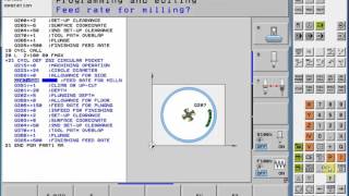 20:05
20:05
Heidenhain CNC iTNC 530 Programming part 1
 04:40
04:40
Heidenhain Programming TNC 430 .I iso CNC Program
 03:58
03:58
3853 — MTE Kompakt Plus TNC 426 Bj 1999
 01:52
01:52
Heidenhain | TNC 640 | Programming with G-CODE ISO — CYCL DEF — LBL SET — LBL CALL
 03:42
03:42
Heidenhain Face milling — CYCLE 232 — Lesson 3 — Tutorial #1
 04:59
04:59
Tnc 430 Q parameter bohren
TNC 410
TNC 426
TNC 430
ЧУ-программное обеспечение
286 060-xx
286 080-xx
280 476-xx
280 477-xx
Руководство для оператора
ДИН-ИСО-программирование
Russkij (ru)
5/2003

Элементы обслуживания дисплея Выбор распределения экрана …
Страница 2
- Изображение
- Текст
Элементы обслуживания дисплея
Выбор распределения экрана
Выбирать экран между режимом работы
станка и режимом работы программирования
Softkeys (программированные клавиши)
Выбор функции на дисплее
Переключение линеек программируемых
клавиш
Изменение настройки дисплея
(только BC 120)
Aлфавитная клавиатура: ввод букв и знаков
Имя файла:
Kомментарии
ДИН/ИСО-
Программы
Выбор режима работы станка
РУЧНОЕ УПРАВЛЕНИЕ
ЭЛ. МАХОВИЧЕК
ПОЗИЦИОНИРОВАНИЕ С РУЧНЫМ ВВОДОМ
ПРОГОН ПРОГРАММЫ ОТДЕЛЬНЫМИ
ПРЕДЛОЖЕНИЯМИ
ПРОГОН ПРОГРАММЫ ПОСЛЕДОВАТЕЛЬНОСТЬ
ПРЕДЛОЖЕНИЙ
Выбор режимов работы программирования
ВВЕСТИ ПРОГРАММУ В ПАМЯТЬ/
РЕДАКТИРОВАТЬ
ТЕСТ ПРОГРАММЫ
Управление програмами/файлами, функции УЧПУ
Выбор программ/файлов и стирание
Внешняя передача данных
Ввод вызова программы в программу
Выбор MOD-функции
Непосредственная помощь при ЧУ-сообщениях
об ошибках
Высветить калькулятор
Перемещение ясного поля и предложений, циклов и
непосредственный выбор функции
перемещение ясного поля
предложения, циклы и функции параметров
непосредственно выбирать
Override ручки для подачи/числа оборотов шпинделя
150
0
50
100
F %
150
0
50
100
S %
Программирование движений по траектории
Наезд и отъезд от контура
Свободное программирование контура FK
Прямая
Центр окружности/полюс для полярных координат
Kруговая траектория вокруг центра окружности
Круговая траектория с радиусом
Круговая траектория с тангенциальным
примыканием
Фаска
Закругление уголков
Данные о инструментах
Длина инструмента и его радиус ввести и
вызвать
Циклы, подпрограммы и повторения
части программы
Определение и вызов циклов
Подпрограммы и повторения части
программы ввести и вызвать
Ввод задержания программы в программу
Ввод функций импульсной системы в программу
Ввод осей координат и цифр, редактирование
. . .
Выбор осей координат или
ввести в программу
. . .
Цифры
Десятичная точка
Инверсия знака числа
Ввод полярных координат
Инкрементные значения
Q-параметры
Перенос фактической позиции
Игнорирование вопросов диалога и стирание слов
Окончение ввода и продолжение диалога
Окончение предложения
Zначения числовые сбросить или УЧПУ
сообщения об ошибках стирать
Прервать диалог, сброс части программы

HEIDENHAIN TNC 410, TNC 426, TNC 430
I
УЧПУ-тип, программное обеспечение и
функции
Настоящая инструкция для потребителя описывает функции,
которые находятся в распоряжении в ЧПУ, начиная со следующих
номеров ЧУ-программного обеспечения.
Буквы обозначения E и F означают экспортные версии ЧПУ. Для
экспортных версий ЧПУ действует следующее ограничение:
Движения по прямой одновременно по 4 осям
Производитель станков приспособливает полезный обьём
мощности ЧПУ посредством параметров станка к нужному станку.
Поэтому в этом руководстве описаны также функции, которые не
находятся в распоряжении в каждом ЧПУ.
Функции ЧПУ, не находящиеся в распоряжении на каждом станке,
это на пример:
Функция контактирования для 3-координатной измерительной
импульсной системы
Опция оцифровывания (преобразования в цифровую форму)
Измерение инструмента с помощью TT 130
Нарезание внутренней резьбы без зажимного патрона
Повторный подвод к контуру после перерывов в обработке
Наладите пожалуйста контакт с производителем станков, для того
чтобы лучше познакомиться с действительным обьёмом функций
Вашего станка.
УЧПУ-тип
ЧУ-программное
обеспечение-№
TNC 426 CB, TNC 426 PB
280 476-xx
TNC 426 CF, TNC 426 PF
280 477-xx
TNC 426 M
280 476-xx
TNC 426 ME
280 477-xx
TNC 430 CA, TNC 430 PA
280 476-xx
TNC 430 CE, TNC 430 PE
280 477-xx
TNC 430 M
280 476-xx
TNC 430 ME
280 477-xx
TNC 410
286 060-xx
TNC 410
286 080-xx

II Многие производители станков и фирма HEIDENHAIN предос…
Страница 6
- Изображение
- Текст
II
Многие производители станков и фирма HEIDENHAIN
предоставляют курсы программирования для устройств ЧПУ.
Участие в этих курсах рекомендуется, для того чтобы интенсивно
познакомиться с функциями ЧПУ.
Предусмотренное место эксплуатации
УЧПУ соответствует классу А, согласно европейской норме EN
55022 и предусмотрено для эксплуатации главным образом в
промышленных центрах.
Новые функции ЧУ-программного
обеспечения 280 476-xx
Цикли фрезерования внутренней резьбы 262 до 267 (смотри
“Основы к фрезеровании резьбы” на странице 212)
Цикл нарезания внутренней резбы 209 с ломанием стружки
(смотри “НАРЕЗАНИЕ РЕЗЬБЫ ЛОМАНИЕ СТРУЖКИ (цикл
G209, нет TNC 410)” на странице 210)
Цикл 247 (смотри “УСТАНОВЛЕНИЕ ОПОРНОЙ ТОЧКИ (цикл
G247) нет на TNC 410” на странице 308)
Ввод двух дополнительных функций М (смотри “Ввод
дополнительных функций M” на странице 150)
Приостановление прогона программы с помощью М01 (смотри
“Задержание прогона программы на выбор” на странице 395)
Автоматический пуск ЧУ-программ (смотри “автоматический
старт программы (нет на TNC 410)” на странице 392)
Распределение экрана в случае таблиц палет (смотри
“Распределение экрана при отработке таблицы палет” на
странице 96)
Новые графы в таблицы инструментов для управления TS-
данными калибровки (смотри “Данные инструментов ввести в
таблицу” на странице 101)
Управление любым количеством данных калибровки при
переключающей системе измерения TS (смотри Инструкция
для потребителя: циклы системы измерения)
Циклы для автоматического измерения инструментов с
помощью настольной системы измерения ТТ в ДИН/ИСО
(смотри инструкция для потребителя Циклы системы
измерения)
Новый цикл 440 для измерения перемещения осей станка с
помощью настольной системы измерения TT (смотри
инструкция для потребителя Циклы системы измерения)
Вспомогание функций телесервиса (смотри “Tелесервис (нет на
TNC 410)” на странице 429)
Инструкция для потребителя Циклы импульсной
системы:
Все функции импульсной системы описаны в
отдельной инструкции для пользователя.
Обращайтесь пожалуйста в данном случае к фирме
HEIDENHAIN, если Вы нуждаетесь в этой инструкции.
Ident-Nr.: 329 203-xx


Комментарии
Page 1 — HEIDENHAIN Conversational
NC Software280 476-xx280 477-xxUser’s ManualHEIDENHAIN ConversationalFormat10/2001TNC 426TNC 430
Page 3
HEIDENHAIN TNC 426, TNC 430 734.8 Adding Comments4.8 Adding CommentsFunctionYou can add comments to any desired block in the part program to explain p
Page 4
74 4 Programming: Fundamentals of NC, File Management, Programming Aids, Pallet Management4.9 Creating Text Files4.9 Creating Text FilesFunctionYou ca
Page 5
HEIDENHAIN TNC 426, TNC 430 754.9 Creating Text FilesEditing textsThe first line of the text editor is an information headline which displays the file
Page 6
76 4 Programming: Fundamentals of NC, File Management, Programming Aids, Pallet Management4.9 Creating Text FilesErasing and inserting characters, wor
Page 7
HEIDENHAIN TNC 426, TNC 430 774.9 Creating Text FilesIf necessary, you can now insert the temporarily stored block at a different location7777 Move th
Page 8
78 4 Programming: Fundamentals of NC, File Management, Programming Aids, Pallet Management4.10 Integrated Pocket Calculator4.10 Integrated Pocket Calc
Page 9 — Contents
HEIDENHAIN TNC 426, TNC 430 794.11 Immediate Help for NC Error Messages4.11 Immediate Help for NC Error MessagesDisplaying error messagesThe TNC autom
Page 10
80 4 Programming: Fundamentals of NC, File Management, Programming Aids, Pallet Management4.12 Pallet Management4.12Pallet ManagementApplicationPallet
Page 11 — 1 Introduction … 1
HEIDENHAIN TNC 426, TNC 430 814.12 Pallet ManagementWith the arrow keys and ENT, select the position that you wish to confirm. Then press the ALL VALU
Page 12 — Pallet Management … 33
82 4 Programming: Fundamentals of NC, File Management, Programming Aids, Pallet Management4.12 Pallet ManagementSelecting a pallet table7777 Call the
Page 13
HEIDENHAIN TNC 426, TNC 430 VII1.1 The TNC 426, the TNC 430 … 2Programming: HEIDENHAIN conversational and ISO formats … 2Compatibility … 2
Page 14
HEIDENHAIN TNC 426, TNC 430 834.12 Pallet ManagementScreen layout for executing pallet tablesYou can have the TNC display the program contents and pal
Page 15 — 5 Programming: Tools … 97
84 4 Programming: Fundamentals of NC, File Management, Programming Aids, Pallet Management4.13 Pallet Operation with Tool-Oriented Machining4.13Pallet
Page 16
HEIDENHAIN TNC 426, TNC 430 854.13 Pallet Operation with Tool-Oriented Machiningn DATUM (entry optional):Name of the datum table. The datum table must
Page 17
86 4 Programming: Fundamentals of NC, File Management, Programming Aids, Pallet Management4.13 Pallet Operation with Tool-Oriented Machiningn CTID (en
Page 18
HEIDENHAIN TNC 426, TNC 430 874.13 Pallet Operation with Tool-Oriented MachiningSwitch to pallet planeSwitch to fixture planeSwitch to workpiece plane
Page 19
88 4 Programming: Fundamentals of NC, File Management, Programming Aids, Pallet Management4.13 Pallet Operation with Tool-Oriented MachiningTool-optim
Page 20
HEIDENHAIN TNC 426, TNC 430 894.13 Pallet Operation with Tool-Oriented MachiningSelecting a pallet file7777 Call the file manager in the Programming a
Page 21
90 4 Programming: Fundamentals of NC, File Management, Programming Aids, Pallet Management4.13 Pallet Operation with Tool-Oriented MachiningSetting up
Page 22
HEIDENHAIN TNC 426, TNC 430 914.13 Pallet Operation with Tool-Oriented MachiningSetting up the fixture planen Fixture: The number of the fixture is di
Page 23
92 4 Programming: Fundamentals of NC, File Management, Programming Aids, Pallet Management4.13 Pallet Operation with Tool-Oriented MachiningSetting up
Page 24 — 12 MOD Functions … 417
VIII 2.5 Tilting the working plane … 24Application, function … 24Traversing the reference points in tilted axes … 25Setting the datum in
Page 25
HEIDENHAIN TNC 426, TNC 430 934.13 Pallet Operation with Tool-Oriented MachiningSequence of tool-oriented machiningn The entry TO or CTO in the Method
Page 26
94 4 Programming: Fundamentals of NC, File Management, Programming Aids, Pallet Management4.13 Pallet Operation with Tool-Oriented Machiningn If the e
Page 27 — Introduction
HEIDENHAIN TNC 426, TNC 430 954.13 Pallet Operation with Tool-Oriented MachiningScreen layout for executing pallet tablesYou can have the TNC display
Page 30 — Screen layout
98 5 Programming: Tools5.1 Entering Tool-Related Data5.1 Entering Tool-Related DataFeed rate FThe feed rate F is the speed (in millimeters per minute
Page 31
HEIDENHAIN TNC 426, TNC 430 995.2 Tool Data5.2 Tool DataRequirements for tool compensation You usually program the coordinates of path contours as the
Page 32 — 1.3 Modes of Operation
100 5 Programming: Tools5.2 Tool DataDelta values for lengths and radiiDelta values are offsets in the length and radius of a tool.A positive delta va
Page 33
HEIDENHAIN TNC 426, TNC 430 1015.2 Tool DataEntering tool data in tablesYou can define and store up to 32767 tools and their tool data in a tool table
Page 34
102 5 Programming: Tools5.2 Tool DataTool table: Tool data required for automatic tool measurementTIME2 Maximum tool life in minutes during TOOL CALL:
Page 35 — 1.4 Status Displays
HEIDENHAIN TNC 426, TNC 430 IX4.4 Advanced File Management … 49Note … 49Directories … 49Paths … 49Overview: Functions of the expanded
Page 36
HEIDENHAIN TNC 426, TNC 430 1035.2 Tool DataTool table: Tool data for automatic speed/feed rate calculations.Tool table: Tool data for 3-D touch trigg
Page 37
104 5 Programming: Tools5.2 Tool DataTo open any other tool table:7777 Select the Programming and Editing mode of operation.7777 Call the file manager
Page 38
HEIDENHAIN TNC 426, TNC 430 1055.2 Tool DataAdditional notes on tool tablesMachine parameter 7266.x defines which data can be entered in the tool tabl
Page 39 — Handwheels
106 5 Programming: Tools5.2 Tool DataPocket table for tool changerFor automatic tool changing you need the pocket table TOOL_P.TCH. The TNC can manage
Page 40 — HR electronic handwheels
HEIDENHAIN TNC 426, TNC 430 1075.2 Tool DataCalling tool dataA TOOL CALL block in the part program is defined with the following data:7777 Select the
Page 41
108 5 Programming: Tools5.2 Tool Data7777 Feed rate F: Enter the feed rate directly or allow the TNC to calculate the feed rate if you are working wit
Page 42 — Manual Operation and Setup
HEIDENHAIN TNC 426, TNC 430 1095.2 Tool DataManual tool changeTo change the tool manually, stop the spindle and move the tool to the tool change posit
Page 43 — 2.1 Switch-on, Switch-off
110 5 Programming: Tools5.3 Tool Compensation5.3 Tool CompensationIntroductionThe TNC adjusts the spindle path in the tool axis by the compensation va
Page 44
HEIDENHAIN TNC 426, TNC 430 1115.3 Tool CompensationTool radius compensationThe NC block for programming a tool movement contains:n RL or RR for radiu
Page 45 — 2.2 Moving the Machine Axes
112 5 Programming: Tools5.3 Tool CompensationTool movements with radius compensation: RR and RLThe tool center moves along the contour at a distance e
Page 46
X 4.8 Adding Comments … 73Function … 73Entering comments during programming … 73Inserting comments after program entry … 73Entering a
Page 47
HEIDENHAIN TNC 426, TNC 430 1135.3 Tool CompensationRadius compensation: Machining cornersn Outside cornersIf you program radius compensation, the TNC
Page 48 — Entering values
114 5 Programming: Tools5.4 Three-Dimensional Tool Compensation5.4 Three-Dimensional Tool CompensationIntroductionThe TNC can carry out a three-dimens
Page 49 — Touch Probe)
HEIDENHAIN TNC 426, TNC 430 1155.4 Three-Dimensional Tool CompensationDefinition of a normalized vectorA normalized vector is a mathematical quantity
Page 50 — Datum setting
116 5 Programming: Tools5.4 Three-Dimensional Tool CompensationUsing other tools: Delta valuesIf you want to use tools that have different dimensions
Page 52
118 5 Programming: Tools5.4 Three-Dimensional Tool CompensationPeripheral milling: 3-D radius compensation with workpiece orientationThe TNC displaces
Page 53
HEIDENHAIN TNC 426, TNC 430 1195.4 Three-Dimensional Tool CompensationExample: Block format with rotary axes 1 L X+31.737 Y+21.954 Z+33.165 B+12.357
Page 54
120 5 Programming: Tools5.5 Working with Cutting Data Tables5.5 Working with Cutting Data Tab lesNoteApplicationsIn cutting data tables containing var
Page 55
HEIDENHAIN TNC 426, TNC 430 1215.5 Working with Cutting Data TablesTable for workpiece materialsWorkpiece materials are defined in the table WMAT.TAB
Page 56 — Manual Data Input (MDI)
122 5 Programming: Tools5.5 Working with Cutting Data TablesTable for tool cutting materialsTool cutting materials are defined in the TMAT.TAB table.
Page 58
HEIDENHAIN TNC 426, TNC 430 1235.5 Working with Cutting Data TablesCreating a new cutting data table.7777 Select the Programming and Editing mode of o
Page 59
124 5 Programming: Tools5.5 Working with Cutting Data TablesWorking with automatic speed/feed rate calculation1 If it has not already been entered, en
Page 60 — Aids, Pallet Management
HEIDENHAIN TNC 426, TNC 430 1255.5 Working with Cutting Data TablesExiting the structure editorPress the END key. The TNC changes data that was alread
Page 61 — 4.1 Fundamentals
126 5 Programming: Tools5.5 Working with Cutting Data TablesData transfer from cutting data tablesIf you output a file type .TAB or .CDT via an extern
Page 62
6Programming:Programming Contours
Page 63
128 6 Programming: Programming Contours6.1 Tool movements6.1 Tool movementsPath functionsA workpiece contour is usually composed of several contour el
Page 64
HEIDENHAIN TNC 426, TNC 430 1296.2 Fundamentals of Path Functions6.2 Fundamentals of Path FunctionsProgramming tool movements for workpiece machiningY
Page 65
130 6 Programming: Programming Contours6.2 Fundamentals of Path FunctionsEntering more than three coordinatesThe TNC can control up to 5 axes simultan
Page 66 — Fundamentals
HEIDENHAIN TNC 426, TNC 430 1316.2 Fundamentals of Path FunctionsRadius compensationThe radius compensation must be in the block in which you move to
Page 67 — Data security
132 6 Programming: Programming Contours6.2 Fundamentals of Path FunctionsEnter a miscellaneous function (here, M3), and terminate the dialog with ENT.
Page 69
HEIDENHAIN TNC 426, TNC 430 1336.3 Contour Approach and Departure6.3 Contour Approach and DepartureOverview: Types of paths for contour approach and d
Page 70
134 6 Programming: Programming Contours6.3 Contour Approach and Departuren End point PN The position PN lies outside of the contour and results from y
Page 71
HEIDENHAIN TNC 426, TNC 430 1356.3 Contour Approach and DepartureApproaching on a straight line with tangential connection: APPR LTThe tool moves on a
Page 72
136 6 Programming: Programming Contours6.3 Contour Approach and DepartureApproaching on a circular path with tangential connection: APPR CTThe tool mo
Page 73
HEIDENHAIN TNC 426, TNC 430 1376.3 Contour Approach and DepartureExample NC blocksDeparting on a straight line with tangential connection: DEP LTThe t
Page 74
138 6 Programming: Programming Contours6.3 Contour Approach and DepartureDeparture on a circular path with tangential connection: DEP CTThe tool moves
Page 75
HEIDENHAIN TNC 426, TNC 430 1396.4 Path Contours — Cartesian Coordinates6.4 Path Contours — Cartesian CoordinatesOverview of path functionsFunction Pa
Page 77
HEIDENHAIN TNC 426, TNC 430 1416.4 Path Contours — Cartesian CoordinatesInserting a chamfer CHF between two straight linesThe chamfer enables you to c
Page 78
142 6 Programming: Programming Contours6.4 Path Contours — Cartesian CoordinatesCorner rounding RNDThe RND function is used for rounding off corners.T
Page 79
HEIDENHAIN TNC 426, TNC 430 XIII6.5 Path Contours — Polar Coordinates … 151Overview … 151Polar coordinate origin: Pole CC … 151Straight li
Page 80
HEIDENHAIN TNC 426, TNC 430 1436.4 Path Contours — Cartesian CoordinatesCircle center CCYou can define a circle center CC for circles that are program
Page 81
144 6 Programming: Programming Contours6.4 Path Contours — Cartesian CoordinatesCircular path C around circle center CCBefore programming a circular p
Page 82
HEIDENHAIN TNC 426, TNC 430 1456.4 Path Contours — Cartesian CoordinatesCircular path CR with defined radiusThe tool moves on a circular path with the
Page 83
146 6 Programming: Programming Contours6.4 Path Contours — Cartesian CoordinatesCircular path CT with tangential connectionThe tool moves on an arc th
Page 84
HEIDENHAIN TNC 426, TNC 430 1476.4 Path Contours — Cartesian CoordinatesExample: Linear movements and chamfers with Cartesian coordinates0 BEGIN PGM
Page 85
148 6 Programming: Programming Contours6.4 Path Contours — Cartesian CoordinatesExample: Circular movements with Cartesian coordinates0 BEGIN PGM CIR
Page 86
HEIDENHAIN TNC 426, TNC 430 1496.4 Path Contours — Cartesian Coordinates16 L X+5Move to last contour point 117 DEP LCT X-20 Y-20 R5 F1000Depart the
Page 87
150 6 Programming: Programming Contours6.4 Path Contours — Cartesian CoordinatesExample: Full circle with Cartesian coordinates0 BEGIN PGM C-CC MM1
Page 88
HEIDENHAIN TNC 426, TNC 430 1516.5 Path Contours — Polar Coordinates6.5 Path Contours — Polar CoordinatesOverviewWith polar coordinates you can define
Page 89
152 6 Programming: Programming Contours6.5 Path Contours — Polar CoordinatesStraight line LPThe tool moves in a straight line from its current positio
Page 90
XIV 7.1 Entering Miscellaneous Functions M and STOP … 176Fundamentals … 1767.2 Miscellaneous Functions for Program Run Control, Spindle and C
Page 91 — Creating a new part program
HEIDENHAIN TNC 426, TNC 430 1536.5 Path Contours — Polar CoordinatesCircular path CTP with tangential connectionThe tool moves on a circular path, sta
Page 92
154 6 Programming: Programming Contours6.5 Path Contours — Polar CoordinatesShape of the helixThe table below illustrates in which way the shape of th
Page 93
HEIDENHAIN TNC 426, TNC 430 1556.5 Path Contours — Polar CoordinatesExample: Linear movement with polar coordinates0 BEGIN PGM LINEARPO MM1 BLK FORM
Page 94 — Editing a program
156 6 Programming: Programming Contours6.5 Path Contours — Polar CoordinatesTo cut a thread with more than 16 revolutionsExample: Helix0 BEGIN PGM HE
Page 95
HEIDENHAIN TNC 426, TNC 430 1576.5 Path Contours — Polar Coordinates10 LBL 1Identify beginning of program section repeat11 CP IPA+360 IZ+1.5 DR+ F20
Page 96
158 6 Programming: Programming Contours6.6 Path Contours—FK Free Contour Programming6.6 Path Contours—FK Free Contour ProgrammingFundamentalsWorkpiece
Page 97 — Graphics
HEIDENHAIN TNC 426, TNC 430 1596.6 Path Contours—FK Free Contour ProgrammingGraphics during FK programmingIncomplete coordinate data often are not suf
Page 98 — To erase the graphic:
160 6 Programming: Programming Contours6.6 Path Contours—FK Free Contour ProgrammingInitiating the FK dialogIf you press the gray FK button, the TNC d
Page 99 — 4.7 Structuring Programs
HEIDENHAIN TNC 426, TNC 430 1616.6 Path Contours—FK Free Contour ProgrammingFree programming of circular arcsCircular arc without tangential connectio
Page 100 — 4.8 Adding Comments
162 6 Programming: Programming Contours6.6 Path Contours—FK Free Contour ProgrammingInput possibilitiesEnd point coordinatesExample NC blocksDirection
Page 101 — 4.9 Creating Text Files
HEIDENHAIN TNC 426, TNC 430 XV8.1 Working with Cycles … 202Defining a cycle using soft keys … 202Defining a cycle using the GOTO function …
Page 102
HEIDENHAIN TNC 426, TNC 430 1636.6 Path Contours—FK Free Contour ProgrammingCircle center CC, radius and direction of rotation in the FC/FCT blockThe
Page 103
164 6 Programming: Programming Contours6.6 Path Contours—FK Free Contour ProgrammingClosed contoursYou can identify the beginning and end of a closed
Page 104
HEIDENHAIN TNC 426, TNC 430 1656.6 Path Contours—FK Free Contour ProgrammingExample NC blocksRelative dataData whose values are based on another conto
Page 105 — Operation
166 6 Programming: Programming Contours6.6 Path Contours—FK Free Contour ProgrammingData relative to block N: Direction and distance of the contour el
Page 106 — Messages
HEIDENHAIN TNC 426, TNC 430 1676.6 Path Contours—FK Free Contour ProgrammingConverting FK programsYou can convert an FK program into HEIDENHAIN conver
Page 107 — 4.12Pallet Management
168 6 Programming: Programming Contours6.6 Path Contours—FK Free Contour ProgrammingExample: FK programming 10 BEGIN PGM FK1 MM1 BLK FORM 0.1 Z X+0
Page 108
HEIDENHAIN TNC 426, TNC 430 1696.6 Path Contours—FK Free Contour ProgrammingExample: FK programming 20 BEGIN PGM FK2 MM1 BLK FORM 0.1 Z X+0 Y+0 Z-20
Page 109
170 6 Programming: Programming Contours6.6 Path Contours—FK Free Contour Programming9 APPR LCT X+0 Y+30 R5 RR F350Approach the contour on a circular
Page 110
HEIDENHAIN TNC 426, TNC 430 1716.6 Path Contours—FK Free Contour ProgrammingExample: FK programming 30 BEGIN PGM FK3 MM1 BLK FORM 0.1 Z X-45 Y-45 Z-
Page 111 — Oriented Machining
172 6 Programming: Programming Contours6.6 Path Contours—FK Free Contour Programming8 APPR CT X-40 Y+0 CCA90 R+5 RL F250Approach the contour on a cir
Page 112
Controls on the visual display unit Split screen layout Switch between machining or programming modes Soft keys for selecting functions in screen Swit
Page 113
XVI 8.5 Cycles for Machining Hole Patterns … 278Overview … 278CIRCULAR PATTERN (Cycle 220) … 279LINEAR PATTERN (Cycle 221) … 2818.6 S
Page 114
HEIDENHAIN TNC 426, TNC 430 1736.7 Path Contours — Spline Interpolation6.7 Path Contours — Spline InterpolationFunctionIf you wish to machine contours
Page 115
174 6 Programming: Programming Contours6.7 Path Contours — Spline InterpolationThe TNC executes the spline block according to the following third-degr
Page 117
176 7 Programming: Miscellaneous functions7.1 Entering Miscellaneous Functions M and STOP7.1 Entering Miscellaneous Functions M and STOPFundamentalsWi
Page 118
HEIDENHAIN TNC 426, TNC 430 1777.2 Miscellaneous Functions for Program Run Control, Spindle and Coolant7.2 Miscellaneous Functions for Program Run Con
Page 119
178 7 Programming: Miscellaneous functions7.3 Miscellaneous Functions for Coordinate Data7.3 Miscellaneous Functions for Coordinate DataProgramming ma
Page 120
HEIDENHAIN TNC 426, TNC 430 1797.3 Miscellaneous Functions for Coordinate DataEffectM91 and M92 are effective only in the blocks in which they are pro
Page 121 — Executing the pallet file
180 7 Programming: Miscellaneous functions7.3 Miscellaneous Functions for Coordinate DataActivating the most recently entered datum: M104FunctionWhen
Page 122
HEIDENHAIN TNC 426, TNC 430 1817.4 Miscellaneous Functions for Contouring Behavior7.4 Miscellaneous Functions for Contouring BehaviorSmoothing corners
Page 123
182 7 Programming: Miscellaneous functions7.4 Miscellaneous Functions for Contouring BehaviorInsert rounding arc between straight lines: M112Compatibi
Page 124 — Programming: Tools
HEIDENHAIN TNC 426, TNC 430 XVII9.1 Labeling Subprograms and Program Section Repeats … 342Labels … 3429.2 Subprograms … 343Operating seque
Page 125 — Spindle speed S
HEIDENHAIN TNC 426, TNC 430 1837.4 Miscellaneous Functions for Contouring BehaviorMachining open contours: M98Standard behaviorThe TNC calculates the
Page 126 — 5.2 Tool Data
184 7 Programming: Miscellaneous functions7.4 Miscellaneous Functions for Contouring BehaviorExample NC blocksThe feed rate for plunging is to be 20%
Page 127
HEIDENHAIN TNC 426, TNC 430 1857.4 Miscellaneous Functions for Contouring BehaviorFeed rate at circular arcs: M109/M110/M111Standard behaviorThe TNC a
Page 128
186 7 Programming: Miscellaneous functions7.4 Miscellaneous Functions for Contouring BehaviorInputIf you enter M120 in a positioning block, the TNC co
Page 129
HEIDENHAIN TNC 426, TNC 430 1877.4 Miscellaneous Functions for Contouring BehaviorSuperimposing handwheel positioning during program run: M118Standard
Page 130
188 7 Programming: Miscellaneous functions7.4 Miscellaneous Functions for Contouring BehaviorRetraction from the contour in the tool-axis direction: M
Page 131
HEIDENHAIN TNC 426, TNC 430 1897.4 Miscellaneous Functions for Contouring BehaviorSuppressing touch probe monitoring: M141Standard behaviorWhen the st
Page 132
190 7 Programming: Miscellaneous functions7.4 Miscellaneous Functions for Contouring BehaviorDelete modal program information: M142Standard behaviorTh
Page 133
HEIDENHAIN TNC 426, TNC 430 1917.5 Miscellaneous Functions for Rotary Axes7.5 Miscellaneous Functions for Rotary AxesFeed rate in mm/min on rotary axe
Page 134
192 7 Programming: Miscellaneous functions7.5 Miscellaneous Functions for Rotary AxesBehavior with M126With M126, the TNC will move the axis on the sh
Page 135
XVIII 10.1 Principle and Overview … 356Programming notes … 356Calling Q parameter functions … 35710.2 Part Families – Q Parameters in Pla
Page 136
HEIDENHAIN TNC 426, TNC 430 1937.5 Miscellaneous Functions for Rotary AxesAutomatic compensation of machine geometry when working with tilted axes: M1
Page 137 — 5.3 Tool Compensation
194 7 Programming: Miscellaneous functions7.5 Miscellaneous Functions for Rotary AxesMaintaining the position of the tool tip when positioning with ti
Page 138
HEIDENHAIN TNC 426, TNC 430 1957.5 Miscellaneous Functions for Rotary AxesM128 with 3-D tool compensationIf you carry out a 3-D tool compensation with
Page 139
196 7 Programming: Miscellaneous functions7.5 Miscellaneous Functions for Rotary AxesExact stop at corners with nontangential transitions: M134Standar
Page 140
HEIDENHAIN TNC 426, TNC 430 1977.5 Miscellaneous Functions for Rotary AxesCompensating the machine’s kinematic configuration for ACTUAL/NOMINAL positi
Page 141 — Compensation
198 7 Programming: Miscellaneous functions7.6 Miscellaneous Functions for Laser Cutting Machines7.6 Miscellaneous Functions for Laser Cutting Machines
Page 142
HEIDENHAIN TNC 426, TNC 430 1997.6 Miscellaneous Functions for Laser Cutting MachinesOutput voltage as a function of speed: M202Behavior with M202The
Page 145
202 8 Programming: Cycles8.1 Working with Cycles8.1 Working with CyclesFrequently recurring machining cycles that comprise several working steps are s
Page 146
HEIDENHAIN TNC 426, TNC 430 XIX10.10 Preassigned Q Parameters … 386Values from the PLC: Q100 to Q107 … 386Active tool radius: Q108 … 386To
Page 147 — Applications
HEIDENHAIN TNC 426, TNC 430 2038.1 Working with CyclesExample NC blocks7 CYCL DEF 200 DRILLING Q200=2 ;SET-UP CLEARANCE Q201=-20 ;DEPTH
Page 149 — Table for cutting data
HEIDENHAIN TNC 426, TNC 430 2058.1 Working with CyclesWorking with the secondary axes U/V/WThe TNC performs infeed movements in the axis that was defi
Page 150
206 8 Programming: Cycles8.2 Point Tables8.2 Point TablesFunctionYou should create a point table whenever you want to run a cycle, or several cycles i
Page 152
208 8 Programming: Cycles8.2 Point TablesCalling a cycle in connection with point tablesIf you want the TNC to call the last defined fixed cycle at th
Page 153 — Configuration file TNC.SYS
HEIDENHAIN TNC 426, TNC 430 2098.3 Cycles for Drilling, Tapping and Thread Milling8.3 Cycles for Drilling, Tapping and Thread MillingOverviewThe TNC o
Page 154 — Programming Contours
210 8 Programming: Cycles8.3 Cycles for Drilling, Tapping and Thread Milling2 TAPPING With a floating tap holder17 RIGID TAPPINGWithout a floating tap
Page 155 — 6.1 Tool movements
HEIDENHAIN TNC 426, TNC 430 2118.3 Cycles for Drilling, Tapping and Thread MillingPECKING (Cycle 1)1 The tool drills from the current position to the
Page 156 — Functions
212 8 Programming: Cycles8.3 Cycles for Drilling, Tapping and Thread MillingDRILLING (Cycle 200)1 The TNC positions the tool in the tool axis at rapid
Page 157
XX 12.1 MOD functions … 418Selecting the MOD functions … 418Changing the settings … 418Exiting the MOD functions … 418Overview of MOD
Page 158
HEIDENHAIN TNC 426, TNC 430 2138.3 Cycles for Drilling, Tapping and Thread Milling7777 Set-up clearance Q200 (incremental value): Distance between too
Page 159
214 8 Programming: Cycles8.3 Cycles for Drilling, Tapping and Thread MillingREAMING (Cycle 201)1 The TNC positions the tool in the tool axis at rapid
Page 160 — Departure
HEIDENHAIN TNC 426, TNC 430 2158.3 Cycles for Drilling, Tapping and Thread Milling7777 Set-up clearance Q200 (incremental value): Distance between too
Page 161
216 8 Programming: Cycles8.3 Cycles for Drilling, Tapping and Thread MillingBORING (Cycle 202)1 The TNC positions the tool in the tool axis at rapid t
Page 162
HEIDENHAIN TNC 426, TNC 430 2178.3 Cycles for Drilling, Tapping and Thread Milling7777 Set-up clearance Q200 (incremental value): Distance between too
Page 163
218 8 Programming: Cycles8.3 Cycles for Drilling, Tapping and Thread MillingUNIVERSAL DRILLING (Cycle 203)1 The TNC positions the tool in the tool axi
Page 164
HEIDENHAIN TNC 426, TNC 430 2198.3 Cycles for Drilling, Tapping and Thread Milling7777 2nd set-up clearance Q204 (incremental value): Coordinate in th
Page 165
220 8 Programming: Cycles8.3 Cycles for Drilling, Tapping and Thread MillingBACK BORING (Cycle 204)This cycle allows holes to be bored from the unders
Page 166 — Coordinates
HEIDENHAIN TNC 426, TNC 430 2218.3 Cycles for Drilling, Tapping and Thread Milling7777 Set-up clearance Q200 (incremental value): Distance between too
Page 167 — Straight line L
222 8 Programming: Cycles8.3 Cycles for Drilling, Tapping and Thread Milling7777 Angle for spindle orientation Q336 (absolute value): Angle at which t
Page 168
HEIDENHAIN TNC 426, TNC 430 XXI12.13 Enter the axis traverse limits, datum display … 441Function … 441Working without additional traverse limi
Page 169 — Corner rounding RND
HEIDENHAIN TNC 426, TNC 430 2238.3 Cycles for Drilling, Tapping and Thread Milling7777 Set-up clearance Q200 (incremental value): Distance between too
Page 170 — Circle center CC
224 8 Programming: Cycles8.3 Cycles for Drilling, Tapping and Thread MillingBORE MILLING (Cycle 208)1 The TNC positions the tool in the tool axis at r
Page 171
HEIDENHAIN TNC 426, TNC 430 2258.3 Cycles for Drilling, Tapping and Thread Milling7777 Set-up clearance Q200 (incremental value): Distance between too
Page 172
226 8 Programming: Cycles8.3 Cycles for Drilling, Tapping and Thread MillingTAPPING with a floating tap holder (Cycle 2)1 The tool drills to the total
Page 173
HEIDENHAIN TNC 426, TNC 430 2278.3 Cycles for Drilling, Tapping and Thread MillingTAPPING NEW with floating tap holder (Cycle 206)1 The TNC positions
Page 174
228 8 Programming: Cycles8.3 Cycles for Drilling, Tapping and Thread Milling7777 Set-up clearance Q200 (incremental value): Distance between tool tip
Page 175
HEIDENHAIN TNC 426, TNC 430 2298.3 Cycles for Drilling, Tapping and Thread MillingRIGID TAPPING (Cycle 17)The TNC cuts the thread without a floating t
Page 176
230 8 Programming: Cycles8.3 Cycles for Drilling, Tapping and Thread MillingRIGID TAPPING without a floating tap holder TAPPING (Cycle 207)The TNC cut
Page 177
HEIDENHAIN TNC 426, TNC 430 2318.3 Cycles for Drilling, Tapping and Thread Milling7777 Set-up clearance Q200 (incremental value): Distance between too
Page 178 — 6.5 Path Contours — Polar
232 8 Programming: Cycles8.3 Cycles for Drilling, Tapping and Thread MillingTHREAD CUTTING (Cycle 18)Cycle 18 THREAD CUTTING is performed by means of
Page 180 — Helical interpolation
HEIDENHAIN TNC 426, TNC 430 2338.3 Cycles for Drilling, Tapping and Thread MillingTAPPING WITH CHIP BREAKING (Cycle 209)The tool machines the thread i
Page 181
234 8 Programming: Cycles8.3 Cycles for Drilling, Tapping and Thread Milling7777 Set-up clearance Q200 (incremental value): Distance between tool tip
Page 182
HEIDENHAIN TNC 426, TNC 430 2358.3 Cycles for Drilling, Tapping and Thread MillingFundamentals of thread millingPrerequisitesn Your machine tool shoul
Page 183 — Example: Helix
236 8 Programming: Cycles8.3 Cycles for Drilling, Tapping and Thread MillingDanger of collisionAlways program the same algebraic sign for the infeeds:
Page 184
HEIDENHAIN TNC 426, TNC 430 2378.3 Cycles for Drilling, Tapping and Thread MillingTHREAD MILLING (Cycle 262)1 The TNC positions the tool in the tool a
Page 185 — Contour Programming
238 8 Programming: Cycles8.3 Cycles for Drilling, Tapping and Thread Milling7777 Feed rate for pre-positioning Q253: Traversing speed of the tool when
Page 186
HEIDENHAIN TNC 426, TNC 430 2398.3 Cycles for Drilling, Tapping and Thread MillingTHREAD MILLING/COUNTERSINKING (Cycle 263)1 The TNC positions the too
Page 187 — Initiating the FK dialog
240 8 Programming: Cycles8.3 Cycles for Drilling, Tapping and Thread Milling11 At the end of the cycle, the TNC retracts the tool in rapid traverse to
Page 188
HEIDENHAIN TNC 426, TNC 430 2418.3 Cycles for Drilling, Tapping and Thread Milling7777 Nominal diameter Q335: Nominal thread diameter7777 Thread pitch
Page 189 — Input possibilities
242 8 Programming: Cycles8.3 Cycles for Drilling, Tapping and Thread Milling7777 Workpiece surface coordinate Q203 (absolute value): Coordinate of the
Page 191 — Auxiliary points
HEIDENHAIN TNC 426, TNC 430 2438.3 Cycles for Drilling, Tapping and Thread MillingTHREAD DRILLING/MILLING (Cycle 264)1 The TNC positions the tool in t
Page 192 — Relative data
244 8 Programming: Cycles8.3 Cycles for Drilling, Tapping and Thread Milling7777 Nominal diameter Q335: Nominal thread diameter7777 Thread pitch Q239:
Page 193
HEIDENHAIN TNC 426, TNC 430 2458.3 Cycles for Drilling, Tapping and Thread Milling7777 Set-up clearance Q200 (incremental value): Distance between too
Page 194 — Converting FK programs
246 8 Programming: Cycles8.3 Cycles for Drilling, Tapping and Thread MillingHELICAL THREAD DRILLING/MILLING (Cycle 265)1 The TNC positions the tool in
Page 195 — Example: FK programming 1
HEIDENHAIN TNC 426, TNC 430 2478.3 Cycles for Drilling, Tapping and Thread Milling7777 Nominal diameter Q335: Nominal thread diameter7777 Thread pitch
Page 196 — Example: FK programming 2
248 8 Programming: Cycles8.3 Cycles for Drilling, Tapping and Thread Milling7777 Workpiece surface coordinate Q203 (absolute value): Coordinate of the
Page 197
HEIDENHAIN TNC 426, TNC 430 2498.3 Cycles for Drilling, Tapping and Thread MillingOUTSIDE THREAD MILLING (Cycle 267)1 The TNC positions the tool in th
Page 198 — Example: FK programming 3
250 8 Programming: Cycles8.3 Cycles for Drilling, Tapping and Thread Milling11 At the end of the cycle, the TNC retracts the tool in rapid traverse to
Page 199
HEIDENHAIN TNC 426, TNC 430 2518.3 Cycles for Drilling, Tapping and Thread Milling7777 Nominal diameter Q335: Nominal thread diameter7777 Thread pitch
Page 200 — Interpolation
252 8 Programming: Cycles8.3 Cycles for Drilling, Tapping and Thread Milling7777 Set-up clearance Q200 (incremental value): Distance between tool tip
Page 201
2 1 Introduction1.1 The TNC 426, the TNC 4301.1 The TNC 426, the TNC 430HEIDENHAIN TNC controls are workshop-oriented contouring controls that enable
Page 202 — Miscellaneous functions
HEIDENHAIN TNC 426, TNC 430 2538.3 Cycles for Drilling, Tapping and Thread MillingExample: Drilling cycles0 BEGIN PGM C200 MM1 BLK FORM 0.1 Z X+0 Y+0
Page 203 — Functions M and STOP
254 8 Programming: Cycles8.3 Cycles for Drilling, Tapping and Thread Milling7 L X+10 Y+10 R0 F MAX M3Approach hole 1, spindle ON8 CYCL CALLCall the
Page 205 — Coordinate Data
256 8 Programming: Cycles8.3 Cycles for Drilling, Tapping and Thread Milling14 LBL 1Subprogram 1: Thread cutting15 CYCL DEF 13.0 ORIENTATIONDefine t
Page 206
HEIDENHAIN TNC 426, TNC 430 2578.4 Cycles for milling pockets, studs and slots8.4 Cycles for milling pockets, studs and slotsOverviewCycle Soft key4 P
Page 207
258 8 Programming: Cycles8.4 Cycles for milling pockets, studs and slotsPOCKET MILLING (Cycle 4)1 The tool penetrates the workpiece at the starting po
Page 208 — Contouring Behavior
HEIDENHAIN TNC 426, TNC 430 2598.4 Cycles for milling pockets, studs and slots7777 Rounding off radius: Radius for the pocket corners.If Radius = 0 is
Page 209
260 8 Programming: Cycles8.4 Cycles for milling pockets, studs and slotsPOCKET FINISHING (Cycle 212)1 The TNC automatically moves the tool in the tool
Page 211
262 8 Programming: Cycles8.4 Cycles for milling pockets, studs and slotsSTUD FINISHING (Cycle 213)1 The TNC moves the tool in the tool axis to set-up
Page 212
HEIDENHAIN TNC 426, TNC 430 31.2 Visual Display Unit and Keyboard1.2 Visual Display Unit and KeyboardVisual display unitThe TNC is available with eith
Page 213
HEIDENHAIN TNC 426, TNC 430 2638.4 Cycles for milling pockets, studs and slots7777 Set-up clearance Q200 (incremental value): Distance between tool ti
Page 214
264 8 Programming: Cycles8.4 Cycles for milling pockets, studs and slotsCIRCULAR POCKET MILLING (Cycle 5)1 The tool penetrates the workpiece at the st
Page 215
HEIDENHAIN TNC 426, TNC 430 2658.4 Cycles for milling pockets, studs and slots7777 Feed rate for plunging: Traversing speed of the tool during penetra
Page 216
266 8 Programming: Cycles8.4 Cycles for milling pockets, studs and slotsCIRCULAR POCKET FINISHING (Cycle 214)1 The TNC automatically moves the tool in
Page 218 — Rotary Axes
268 8 Programming: Cycles8.4 Cycles for milling pockets, studs and slotsCIRCULAR STUD FINISHING (Cycle 215)1 The TNC automatically moves the tool in t
Page 219
HEIDENHAIN TNC 426, TNC 430 2698.4 Cycles for milling pockets, studs and slots7777 Set-up clearance Q200 (incremental value): Distance between tool ti
Page 220
270 8 Programming: Cycles8.4 Cycles for milling pockets, studs and slotsSLOT MILLING (Cycle 3)Roughing process1 The TNC moves the tool inward by the m
Page 221
HEIDENHAIN TNC 426, TNC 430 2718.4 Cycles for milling pockets, studs and slots7777 Set-up clearance 1 (incremental value): Distance between tool tip (
Page 222
272 8 Programming: Cycles8.4 Cycles for milling pockets, studs and slotsSLOT (oblong hole) with reciprocating plunge-cut (Cycle 210)Roughing process1
Page 224 — display
4 1 Introduction1.2 Visual Display Unit and KeyboardThe BC 120 is sensitive to magnetic and electromagnetic noise, which can distort the position and
Page 225 — Laser Cutting Machines
HEIDENHAIN TNC 426, TNC 430 2738.4 Cycles for milling pockets, studs and slots7777 Set-up clearance Q200 (incremental value): Distance between tool ti
Page 226
274 8 Programming: Cycles8.4 Cycles for milling pockets, studs and slotsCIRCULAR SLOT (oblong hole) with reciprocating plunge-cut (Cycle 211)Roughing
Page 227
HEIDENHAIN TNC 426, TNC 430 2758.4 Cycles for milling pockets, studs and slots7777 Set-up clearance Q200 (incremental value): Distance between tool ti
Page 228 — Programming: Cycles
276 8 Programming: Cycles8.4 Cycles for milling pockets, studs and slotsExample: Milling pockets, studs and slots0 BEGIN PGM C210 MM1 BLK FORM 0.1 Z X
Page 229 — 8.1 Working with Cycles
HEIDENHAIN TNC 426, TNC 430 2778.4 Cycles for milling pockets, studs and slots Q220=0 ;CORNER RADIUS Q221=5 ;ALLOWANCE8 CYCL CALL M3Call c
Page 230
278 8 Programming: Cycles8.5 Cycles for Machining Hole Patterns8.5 Cycles for Machining Hole PatternsOverviewThe TNC provides two cycles for machining
Page 231
HEIDENHAIN TNC 426, TNC 430 2798.5 Cycles for Machining Hole PatternsCIRCULAR PATTERN (Cycle 220)1 At rapid traverse, the TNC moves the tool from its
Page 232
280 8 Programming: Cycles8.5 Cycles for Machining Hole Patterns7777 Stepping angle Q247 (incremental value): Angle between two machining operations on
Page 233 — 8.2 Point Tables
HEIDENHAIN TNC 426, TNC 430 2818.5 Cycles for Machining Hole PatternsLINEAR PATTERN (Cycle 221)1 The TNC automatically moves the tool from its current
Page 234
282 8 Programming: Cycles8.5 Cycles for Machining Hole Patterns7777 Starting point 1st axis Q225 (absolute value): Coordinate of the starting point in
Page 235
HEIDENHAIN TNC 426, TNC 430 51.2 Visual Display Unit and KeyboardKeyboardThe figure at right shows the keys of the keyboard grouped according to their
Page 236 — Thread Milling
HEIDENHAIN TNC 426, TNC 430 2838.5 Cycles for Machining Hole PatternsExample: Circular hole patterns0 BEGIN PGM HOLEPAT MM1 BLK FORM 0.1 Z X+0 Y+0 Z
Page 237
284 8 Programming: Cycles8.5 Cycles for Machining Hole Patterns7 CYCL DEF 220 POLAR PATTERNDefine cycle for circular pattern 1, CYCL 200 is called au
Page 238 — PECKING (Cycle 1)
HEIDENHAIN TNC 426, TNC 430 2858.6 SL cycles8.6 SL cyclesFundamentalsSL cycles enable you to form complex contours by combining up to 12 subcontours (
Page 239 — DRILLING (Cycle 200)
286 8 Programming: Cycles8.6 SL cyclesOverview of SL cyclesEnhanced cycles:Cycle Soft key14 CONTOUR GEOMETRY (essential)20 CONTOUR DATA (essential)21
Page 240
HEIDENHAIN TNC 426, TNC 430 2878.6 SL cyclesCONTOUR GEOMETRY (Cycle 14)All subprograms that are superimposed to define the contour are listed in Cycle
Page 241 — REAMING (Cycle 201)
288 8 Programming: Cycles8.6 SL cyclesThe TNC calculates the points of intersection S1 and S2 (they do not have to be programmed).The pockets are prog
Page 242
HEIDENHAIN TNC 426, TNC 430 2898.6 SL cyclesArea of exclusionSurface A is to be machined without the portion overlapped by Bn Surface A must be a pock
Page 243 — BORING (Cycle 202)
290 8 Programming: Cycles8.6 SL cyclesCONTOUR DATA (Cycle 20)Machining data for the subprograms describing the subcontours are entered in Cycle 20.777
Page 244
HEIDENHAIN TNC 426, TNC 430 2918.6 SL cyclesREAMING (Cycle 21)ProcessSame as Cycle 1, Pecking; see “Cycles for Drilling, Tapping and Thread Milling,”
Page 245
292 8 Programming: Cycles8.6 SL cyclesROUGH-OUT (Cycle 22)1 The TNC positions the tool over the cutter infeed point, taking the allowance for side int
Page 246
6 1 Introduction1.3 Modes of Operation1.3 Modes of OperationManual Operation and Electronic HandwheelThe Manual Operation mode is required for setting
Page 247
HEIDENHAIN TNC 426, TNC 430 2938.6 SL cyclesFLOOR FINISHING (Cycle 23)The tool approaches the machining plane smoothly (in a vertically tangential arc
Page 248
294 8 Programming: Cycles8.6 SL cyclesSIDE FINISHING (Cycle 24)The subcontours are approached and departed on a tangential arc. Each subcontour is fin
Page 250
296 8 Programming: Cycles8.6 SL cycles7777 Feed rate for milling Q12: Traversing speed of the tool in the working plane7777 Climb or up-cut ? Up-cut
Page 251 — BORE MILLING (Cycle 208)
HEIDENHAIN TNC 426, TNC 430 2978.6 SL cyclesCYLINDER SURFACE (Cycle 27)This cycle enables you to program a contour in two dimensions and then roll it
Page 252
298 8 Programming: Cycles8.6 SL cycles7777 Milling depth Q1 (incremental value): Distance between the cylindrical surface and the floor of the contour
Page 253
HEIDENHAIN TNC 426, TNC 430 2998.6 SL cyclesCYLINDER SURFACE slot milling (Cycle 28)This cycle enables you to program a guide notch in two dimensions
Page 254 — (Cycle 206)
300 8 Programming: Cycles8.6 SL cycles7777 Milling depth Q1 (incremental value): Distance between the cylindrical surface and the floor of the contour
Page 255
HEIDENHAIN TNC 426, TNC 430 3018.6 SL cyclesExample: Roughing-out and fine-roughing a pocket0 BEGIN PGM C20 MM1 BLK FORM 0.1 Z X-10 Y-10 Z-402 BLK FOR
Page 257 — TAPPING (Cycle 207)
HEIDENHAIN TNC 426, TNC 430 71.3 Modes of OperationProgramming and EditingIn this mode of operation you can write your part programs. The FK free prog
Page 258
HEIDENHAIN TNC 426, TNC 430 3038.6 SL cyclesExample: Pilot drilling, roughing-out and finishing overlapping contours0 BEGIN PGM C21 MM1 BLK FORM 0.1 Z
Page 260
HEIDENHAIN TNC 426, TNC 430 3058.6 SL cycles21 LBL 1Contour subprogram 1: left pocket22 CC X+35 Y+5023 L X+10 Y+50 RR24 C X+10 DR-25 LBL 026 LBL 2Cont
Page 261
306 8 Programming: Cycles8.6 SL cyclesExample: Contour train0 BEGIN PGM C25 MM1 BLK FORM 0.1 Z X+0 Y+0 Z-40Define the workpiece blank2 BLK FORM 0.2 X+
Page 262
HEIDENHAIN TNC 426, TNC 430 3078.6 SL cycles11 LBL 1Contour subprogram12 L X+0 Y+15 RL13 L X+5 Y+2014 CT X+5 Y+7515 L Y+9516 RND R7.517 L X+501
Page 263
308 8 Programming: Cycles8.6 SL cyclesExample: Cylinder surfaceNote:n Cylinder centered on rotary table.n Datum at center of rotary table0 BEGIN PGM C
Page 264 — THREAD MILLING (Cycle 262)
HEIDENHAIN TNC 426, TNC 430 3098.6 SL cycles11 LBL 1Contour subprogram12 L C+40 Z+20 RLData for the rotary axis are entered in mm (Q17=1)13 L C+501
Page 265
310 8 Programming: Cycles8.7 Cycles for multipass milling8.7 Cycles for multipass millingOverviewThe TNC offers three cycles for machining the followi
Page 266 — (Cycle 263)
HEIDENHAIN TNC 426, TNC 430 3118.7 Cycles for multipass millingRUN DIGITIZED DATA (Cycle 30)1 From the current position, the TNC positions the tool in
Page 267
312 8 Programming: Cycles8.7 Cycles for multipass millingMULTIPASS MILLING (Cycle 230)1 From the current position in the working plane, the TNC positi
Page 268 — Q359 (incremental
8 1 Introduction1.3 Modes of OperationProgram Run, Full Sequence and Program Run, Single BlockIn the Program Run, Full Sequence mode of operation the
Page 269
HEIDENHAIN TNC 426, TNC 430 3138.7 Cycles for multipass milling7777 Starting point in 1st axis Q225 (absolute value): Minimum point coordinate of the
Page 270
314 8 Programming: Cycles8.7 Cycles for multipass millingRULED SURFACE (Cycle 231)1 From the current position, the TNC positions the tool in a linear
Page 271
HEIDENHAIN TNC 426, TNC 430 3158.7 Cycles for multipass milling7777 Starting point in 1st axis Q225 (absolute value): Starting point coordinate of the
Page 272
316 8 Programming: Cycles8.7 Cycles for multipass milling7777 4th point in 1st axis Q234 (absolute value): Coordinate of point 4 in the reference axis
Page 273 — (Cycle 265)
HEIDENHAIN TNC 426, TNC 430 3178.7 Cycles for multipass millingExample: Multipass milling0 BEGIN PGM C230 MM1 BLK FORM 0.1 Z X+0 Y+0 Z+0Define the w
Page 274
318 8 Programming: Cycles8.7 Cycles for multipass milling7 L X+-25 Y+0 R0 F MAX M3Pre-position near the starting point8 CYCL CALLCall the cycle9 L
Page 275
HEIDENHAIN TNC 426, TNC 430 3198.8 Coordinate Transformation Cycles8.8 Coordinate Transformation CyclesOverviewOnce a contour has been programmed, you
Page 276
320 8 Programming: Cycles8.8 Coordinate Transformation CyclesDATUM SHIFT (Cycle 7)A datum shift allows machining operations to be repeated at various
Page 277
HEIDENHAIN TNC 426, TNC 430 3218.8 Coordinate Transformation CyclesDATUM SHIFT with datum tables (Cycle 7)FunctionDatum tables are used forn frequentl
Page 279
HEIDENHAIN TNC 426, TNC 430 91.4 Status Displays1.4 Status Displays“General” status displayThe status display 1 informs you of the current state of th
Page 280 — Example: Drilling cycles
HEIDENHAIN TNC 426, TNC 430 3238.8 Coordinate Transformation CyclesEdit a pocket table in a Program Run operating mode.In a program run mode you can s
Page 281
324 8 Programming: Cycles8.8 Coordinate Transformation CyclesDATUM SETTING (Cycle 247)With the cycle DATUM SETTING, you can activate a datum defined i
Page 282
HEIDENHAIN TNC 426, TNC 430 3258.8 Coordinate Transformation CyclesMIRROR IMAGE (Cycle 8)The TNC can machine the mirror image of a contour in the work
Page 283 — infeed (dependent
326 8 Programming: Cycles8.8 Coordinate Transformation Cycles7777 Mirrored axis?: Enter the axis to be mirrored. You can mirror all axes, including ro
Page 284 — Overview
HEIDENHAIN TNC 426, TNC 430 3278.8 Coordinate Transformation CyclesROTATION (Cycle 10)The TNC can rotate the coordinate system about the active datum
Page 285 — POCKET MILLING (Cycle 4)
328 8 Programming: Cycles8.8 Coordinate Transformation CyclesSCALING FACTOR (Cycle 11)The TNC can increase or reduce the size of contours within a pro
Page 286
HEIDENHAIN TNC 426, TNC 430 3298.8 Coordinate Transformation CyclesAXIS-SPECIFIC SCALING (Cycle 26)EffectThe SCALING FACTOR becomes effective as soon
Page 288
HEIDENHAIN TNC 426, TNC 430 3318.8 Coordinate Transformation CyclesIf you set the function TILTING program run to ACTIVE in the Manual Operation mode
Page 289 — STUD FINISHING (Cycle 213)
332 8 Programming: Cycles8.8 Coordinate Transformation CyclesPosition display in the tilted systemOn activation of Cycle 19, the displayed positions (
Page 290
10 1 Introduction1.4 Status DisplaysAdditional status displaysThe additional status displays contain detailed information on the program run. They can
Page 291
HEIDENHAIN TNC 426, TNC 430 3338.8 Coordinate Transformation CyclesCombining coordinate transformation cyclesWhen combining coordinate transformation
Page 292
334 8 Programming: Cycles8.8 Coordinate Transformation Cycles2 Clamp the workpiece3 Preparations in the operating modePositioning with Manual Data Inp
Page 293
HEIDENHAIN TNC 426, TNC 430 3358.8 Coordinate Transformation CyclesExample: Coordinate transformation cyclesProgram sequencen Program the coordinate t
Page 294
336 8 Programming: Cycles8.8 Coordinate Transformation Cycles20 L Z+250 R0 F MAX M2Retract in the tool axis, end program21 LBL 1Subprogram 1:22 L X
Page 295
HEIDENHAIN TNC 426, TNC 430 3378.9 Special Cycles8.9 Special CyclesDWELL TIME (Cycle 9)This causes the execution of the next block within a running pr
Page 296
338 8 Programming: Cycles8.9 Special CyclesExample: Program callA callable program 50 is to be called into a program via a cycle call.ORIENTED SPINDLE
Page 297 — SLOT MILLING (Cycle 3)
HEIDENHAIN TNC 426, TNC 430 3398.9 Special CyclesTOLERANCE (Cycle 32)The TNC automatically smoothens the contour between two path elements (whether co
Page 299
9Programming:Subprograms and Program Section Repeats
Page 300
342 9 Programming: Subprograms and Program Section Repeats9.1 Labeling Subprograms and Program Section Repeats9.1 Labeling Subprograms and Program Sec
Page 301
HEIDENHAIN TNC 426, TNC 430 111.4 Status Displays Positions and coordinates Information on tools Coordinate transformationsSee “Coordinate Transformat
Page 302
HEIDENHAIN TNC 426, TNC 430 3439.2 Subprograms9.2 SubprogramsOperating sequence1 The TNC executes the part program up to the block in which a subprogr
Page 303
344 9 Programming: Subprograms and Program Section Repeats9.3 Program Section Repeats9.3 Program Section RepeatsLabel LBLThe beginning of a program se
Page 304
HEIDENHAIN TNC 426, TNC 430 3459.4 Separate Program as Subprogram9.4 Separate Program as SubprogramOperating sequence1 The TNC executes the part progr
Page 305 — Patterns
346 9 Programming: Subprograms and Program Section Repeats9.5 Nesting9.5 NestingTypes of nestingn Subprograms within a subprogramn Program section rep
Page 307
348 9 Programming: Subprograms and Program Section Repeats9.5 NestingRepeating a subprogramExample NC blocksProgram execution1 Main program SUBREP is
Page 308 — N = Q243
HEIDENHAIN TNC 426, TNC 430 3499.6 Programming ExamplesExample: Milling a contour in several infeedsProgram sequencen Pre-position the tool to the wor
Page 309
350 9 Programming: Subprograms and Program Section Repeats9.6 Programming Examples8 LBL 1Set label for program section repeat9 L IZ-4 R0 F MAXInfeed
Page 310
HEIDENHAIN TNC 426, TNC 430 3519.6 Programming ExamplesExample: Groups of holesProgram sequencen Approach the groups of holes in the main programn Cal
Page 311
352 9 Programming: Subprograms and Program Section Repeats9.6 Programming Examples7 L X+15 Y+10 R0 F MAX M3Move to starting point for group 18 CALL
Page 312 — 8.6 SL cycles
12 1 Introduction1.4 Status Displays Tool measurement Active miscellaneous functions M23411 Number of the tool to be measured2 Display whether the too
Page 313
HEIDENHAIN TNC 426, TNC 430 3539.6 Programming ExamplesExample: Groups of holes with several toolsProgram sequencen Program the fixed cycles in the ma
Page 314
354 9 Programming: Subprograms and Program Section Repeats9.6 Programming Examples10 L Z+250 R0 F MAX M6Tool change11 TOOL CALL 2 Z S4000Call the dril
Page 316
356 10 Programming: Q Parameters10.1 Principle and Overview10.1 Principle and OverviewYou can program an entire family of parts in a single part progr
Page 317
HEIDENHAIN TNC 426, TNC 430 35710.1 Principle and OverviewCalling Q parameter functionsWhen you are writing a part program, press the “Q” key (in the
Page 318
358 10 Programming: Q Parameters10.2 Part Families – Q Parameters in Place of Numerical Values10.2 Part Families – Q Parameters in Place of Numerical
Page 319
HEIDENHAIN TNC 426, TNC 430 35910.3 Describing Contours through Mathematical Operations10.3 Describing Contours through Mathematical OperationsFunctio
Page 320
360 10 Programming: Q Parameters10.3 Describing Contours through Mathematical OperationsProgramming fundamental operationsExample:To select Q paramete
Page 321
HEIDENHAIN TNC 426, TNC 430 36110.4 Trigonometric Functions10.4 Trigonometric FunctionsDefinitionsSine, cosine and tangent are terms designating the r
Page 322
362 10 Programming: Q Parameters10.4 Trigonometric FunctionsProgramming trigonometric functionsPress the TRIGONOMETRY soft key to call the trigonometr
Page 323
HEIDENHAIN TNC 426, TNC 430 131.5 Accessories: HEIDENHAIN 3-D Touch Probes and Electronic Handwheels1.5 Accessories: HEIDENHAIN 3-D Touch Probes and E
Page 324
HEIDENHAIN TNC 426, TNC 430 36310.5 Calculating Circles10.5 Calculating CirclesFunctionThe TNC can use the functions for calculating circles to calcul
Page 325
364 10 Programming: Q Parameters10.6 If-Then Decisions with Q Parameters10.6 If-Then Decisions with Q ParametersFunctionThe TNC can make logical If-Th
Page 326
HEIDENHAIN TNC 426, TNC 430 36510.6 If-Then Decisions with Q ParametersAbbreviations used:IF :IfEQU : EqualsNE : Not equalGT : Greater thanLT : Less t
Page 327
366 10 Programming: Q Parameters10.7 Checking and changing Q parameters10.7 Checking and changing Q parametersProcedureDuring a program run or test ru
Page 328
HEIDENHAIN TNC 426, TNC 430 36710.8 Additional Functions10.8 Additional FunctionsOverviewPress the DIVERSE FUNCTION soft key to call the additional f
Page 329
368 10 Programming: Q Parameters10.8 Additional FunctionsFN14: ERROR: Displaying error messagesWith the function FN14: ERROR you can call messages und
Page 330
HEIDENHAIN TNC 426, TNC 430 36910.8 Additional FunctionsError number Te xt 1042 Traverse direction not defined1043 No datum table active1044 Position
Page 331
370 10 Programming: Q Parameters10.8 Additional FunctionsFN15: PRINT: Output of texts or Q parameter valuesThe function FN15: PRINT transfers Q parame
Page 332
HEIDENHAIN TNC 426, TNC 430 37110.8 Additional FunctionsFN16: F-PRINT: Formatted output of texts or Q parameter valuesThe function FN16: F-PRINT trans
Page 333
372 10 Programming: Q Parameters10.8 Additional FunctionsThe following functions allow you to include the following additional information in the prot
Page 335
14 1 Introduction1.5 Accessories: HEIDENHAIN 3-D Touch Probes and Electronic HandwheelsTT 130 tool touch probe for tool measurementThe TT 130 is a tri
Page 336
HEIDENHAIN TNC 426, TNC 430 37310.8 Additional FunctionsIn the part program, program FN 16: F-PRINT, to activate the output:The TNC then outputs the f
Page 337
374 10 Programming: Q Parameters10.8 Additional Functions11 — Index of the active toolCycle parameter, 30 1 — Setup clearance of active fixed cycle2 —
Page 340
HEIDENHAIN TNC 426, TNC 430 37710.8 Additional FunctionsNominal position in the REF system, 2401 1 X axis2 Y axis3 Z axis4 A axis5 B axis6 C axis7 U a
Page 341 — RULED SURFACE (Cycle 231)
378 10 Programming: Q Parameters10.8 Additional Functions2 Center point Y-axis (REF system)3 Center point Z axis (REF system)21 — Probe contact radius
Page 342
HEIDENHAIN TNC 426, TNC 430 37910.8 Additional FunctionsExample: Assign the value of the active scaling factor for the Z axis to Q25. FN19: PLC: Trans
Page 343
380 10 Programming: Q Parameters10.8 Additional FunctionsThe following conditions are permitted in the FN 20 block:Example: Stop program run until the
Page 344 — Example: Multipass milling
HEIDENHAIN TNC 426, TNC 430 38110.8 Additional FunctionsExample: Set a new datum at the current coordinate X+100Example: The current coordinate Z+50 w
Page 345
382 10 Programming: Q Parameters10.8 Additional FunctionsFN28: TABREAD: Reading a Freely Definable TableAfter you have opened a table with FN 26 TABOP
Page 346
HEIDENHAIN TNC 426, TNC 430 151.5 Accessories: HEIDENHAIN 3-D Touch Probes and Electronic Handwheels
Page 347 — DATUM SHIFT (Cycle 7)
HEIDENHAIN TNC 426, TNC 430 38310.9 Entering Formulas Directly10.9 Entering Formulas DirectlyEntering formulasYou can enter mathematical formulas that
Page 348
384 10 Programming: Q Parameters10.9 Entering Formulas DirectlyRules for formulasMathematical formulas are programmed according to the following rules
Page 349
HEIDENHAIN TNC 426, TNC 430 38510.9 Entering Formulas Directlyor1st step 10 squared = 1002nd step 3 to the powers 3 = 273rd step 100 – 27 = 73Distribu
Page 350
386 10 Programming: Q Parameters10.10 Preassigned Q Parameters10.10 Preassigned Q ParametersThe Q parameters Q100 to Q122 are assigned values by the T
Page 351 — DATUM SETTING (Cycle 247)
HEIDENHAIN TNC 426, TNC 430 38710.10 Preassigned Q ParametersCoolant on/off: Q111Overlap factor: Q112The overlap factor for pocket milling (MP7430) is
Page 352 — MIRROR IMAGE (Cycle 
388 10 Programming: Q Parameters10.10 Preassigned Q ParametersDeviation between actual value and nominal value during automatic tool measurement with
Page 353
HEIDENHAIN TNC 426, TNC 430 38910.10 Preassigned Q ParametersResults of measurements with touch probe cycles(see also Touch Probe Cycles User’s M
Page 354 — ROTATION (Cycle 10)
390 10 Programming: Q Parameters10.10 Preassigned Q ParametersWorkpiece status Parameter valueGood Q180Re-work Q181Scrap Q182Measured deviation with c
Page 355 — SCALING FACTOR (Cycle 11)
HEIDENHAIN TNC 426, TNC 430 39110.11 Programming ExamplesExample: EllipseProgram sequencen The contour of the ellipse is approximated by many short li
Page 356
392 10 Programming: Q Parameters10.11 Programming Examples20 LBL 10Subprogram 10: Machining operation21 CYCL DEF 7.0 DATUM SHIFTShift datum to center
Page 358
HEIDENHAIN TNC 426, TNC 430 39310.11 Programming ExamplesExample: Concave cylinder machined with spherical cutterProgram sequencen Program functions o
Page 359
394 10 Programming: Q Parameters10.11 Programming Examples20 CALL LBL 10Call machining operation21 L Z+100 R0 F MAX M2Retract in the tool axis, end pr
Page 360
HEIDENHAIN TNC 426, TNC 430 39510.11 Programming ExamplesExample: Convex sphere machined with end millProgram sequencen This program requires an end m
Page 361
396 10 Programming: Q Parameters10.11 Programming Examples18 CALL LBL 10Call machining operation19 FN 0: Q10 = +0Reset allowance20 FN 0: Q18 = +5Angle
Page 362
HEIDENHAIN TNC 426, TNC 430 39710.11 Programming Examples40 LBL 241 LP PR+Q6 PA+Q24 R0 FQ12Move upward in an approximated “arc”42 FN 2: Q24 = +Q24 — +
Page 365
400 11 Test run and Program Run11.1 Graphics11.1 GraphicsFunctionIn the program run modes of operation as well as in the Test Run mode, the TNC provid
Page 366
HEIDENHAIN TNC 426, TNC 430 40111.1 GraphicsLimitations during program runA graphical representation of a running program is not possible if the micro
Page 367
402 11 Test run and Program Run11.1 Graphics3-D viewThe workpiece is displayed in three dimensions, and can be rotated about the vertical axis.The wor
Page 368 — Section Repeats
16 2 Manual Operation and Setup2.1 Switch-on, Switch-off2.1 Switch-on, Switch-offSwitch-onSwitch on the power supply for control and machine. The TNC
Page 369 — Program Section Repeats
HEIDENHAIN TNC 426, TNC 430 40311.1 GraphicsShift the soft-key row in the Test Run mode of operation until the following soft keys appear:To change th
Page 370 — 9.2 Subprograms
404 11 Test run and Program Run11.1 GraphicsRepeating graphic simulationA part program can be graphically simulated as often as desired, either with
Page 372 — Subprogram
406 11 Test run and Program Run11.3 Test run11.3 Test runFunctionIn the Test Run mode of operation you can simulate programs and program sections to p
Page 373 — 9.5 Nesting
HEIDENHAIN TNC 426, TNC 430 40711.3 Test runRun a program test up to a certain blockWith the STOP AT N function the TNC does a test run up to the bloc
Page 374
408 11 Test run and Program Run11.4 Program run11.4 Program runApplicationIn the Program Run, Full Sequence mode of operation the TNC executes a part
Page 375
HEIDENHAIN TNC 426, TNC 430 40911.4 Program runInterrupting machiningThere are several ways to interrupt a program run:n Programmed interruptionsn Mac
Page 376 — 9.6 Programming Examples
410 11 Test run and Program Run11.4 Program runMoving the machine axes during an interruptionYou can move the machine axes during an interruption in t
Page 377
HEIDENHAIN TNC 426, TNC 430 41111.4 Program runResuming program run after an interruptionIf you interrupt a program run during execution of a subprogr
Page 378
412 11 Test run and Program Run11.4 Program runMid-program startup (block scan)With the RESTORE POS AT N feature (block scan) you can start a part pro
Page 379
HEIDENHAIN TNC 426, TNC 430 172.1 Switch-on, Switch-offThe TNC is now ready for operation in the Manual Operation mode.Traversing the reference point
Page 380
HEIDENHAIN TNC 426, TNC 430 41311.4 Program run7777 To go to the first block of the current program to start a block scan, enter GOTO “0”.7777 To sele
Page 381
414 11 Test run and Program Run11.5 Automatic Program Start11.5 Automatic Program StartFunctionIn a Program Run operating mode, you can use the soft k
Page 382 — Programming: Q Parameters
HEIDENHAIN TNC 426, TNC 430 41511.6 Optional Block Skip11.6 Optional Block SkipFunctionIn a test run or program run, the TNC can skip over blocks that
Page 385 — Example NC blocks
418 12 MOD Functions12.1 MOD functions12.1 MOD functionsThe MOD functions provide additional displays and input possibilities. The available MOD funct
Page 386 — Mathematical Operations
HEIDENHAIN TNC 426, TNC 430 41912.1 MOD functionsTest Run:n Display software numbersn Enter code numbern Setting the data interfacen Showing the w
Page 387
420 12 MOD Functions12.2 Software Numbers and Option Numbers12.2 Software Numbers and Option NumbersFunctionThe software numbers of the NC, PLC and th
Page 389
422 12 MOD Functions12.4 Setting the Data Interfaces12.4 Setting the Data InterfacesFunctionTo setup the data interfaces, press the RS 232- / RS 422 —
Page 390 — 10.5 Calculating Circles
18 2 Manual Operation and Setup2.2 Moving the Machine Axes2.2 Moving the Machine AxesNoteTo traverse with the machine axis direction buttons:Select t
Page 391 — Parameters
HEIDENHAIN TNC 426, TNC 430 42312.4 Setting the Data InterfacesAssignThis function sets the destination for the transferred data.Applications:n Transf
Page 392 — Abbreviations used:
424 12 MOD Functions12.4 Setting the Data InterfacesSoftware for data transferFor transfer of files to and from the TNC, we recommend using one the HE
Page 394 — 10.8 Additional Functions
426 12 MOD Functions12.4 Setting the Data InterfacesIf you want to control data transfer from the PC, establish the connection with your PC in the fol
Page 395
HEIDENHAIN TNC 426, TNC 430 42712.5 Ethernet Interface12.5 Ethernet InterfaceIntroductionAs an option, you can equip the TNC with an Ethernet card to
Page 396
428 12 MOD Functions12.5 Ethernet InterfaceConfiguring the TNC7777 In the Programming and Editing mode of operation, press the MOD key. Enter the code
Page 397
HEIDENHAIN TNC 426, TNC 430 42912.5 Ethernet InterfaceNetwork settings specific to the device7777 Press the soft key DEFINE MOUNT to enter the network
Page 398
430 12 MOD Functions12.5 Ethernet InterfaceDefining the network printer7777 Press the DEFINE PRINT soft key if you wish to print the files on the netw
Page 399
HEIDENHAIN TNC 426, TNC 430 43112.5 Ethernet InterfaceDisplaying the error log7777 Press the SHOW ERROR soft key if you would like to see the error lo
Page 400
432 12 MOD Functions12.5 Ethernet InterfaceNFS2: <Device name> (W) WRITESIZE LARGER THEN x SET TO x The value that you entered for DEFINE MOUNT,
Page 401
HEIDENHAIN TNC 426, TNC 430 192.2 Moving the Machine AxesTraversing with the HR 410 electronic handwheelThe portable HR 410 handwheel is equipped with
Page 402
HEIDENHAIN TNC 426, TNC 430 43312.6 Configuring PGM MGT12.6 Configuring PGM MGTFunctionWith this function you can determine the features of the file m
Page 403
434 12 MOD Functions12.7 Machine-Specific User Parameters12.7 Machine-Specific User ParametersFunctionTo enable you to set machine-specific functions,
Page 404
HEIDENHAIN TNC 426, TNC 430 43512.8 Showing the workpiece in the working space12.8 Showing the workpiece in the working spaceFunctionThis MOD function
Page 405
436 12 MOD Functions12.8 Showing the workpiece in the working spaceShow the entire traversing range referenced to the displayed workpiece blankShow th
Page 406
HEIDENHAIN TNC 426, TNC 430 43712.9 Position Display Types12.9 Position Display TypesFunctionIn the Manual Operation mode and in the program run modes
Page 407
438 12 MOD Functions12.10 Select the unit of measurement12.10 Select the unit of measurementFunctionThis MOD function determines whether the coordinat
Page 408
HEIDENHAIN TNC 426, TNC 430 43912.11 Select the programming Language for $MDI12.11 Select the programming Language for $MDIFunctionThe Program input m
Page 409
440 12 MOD Functions12.12 Selecting the Axes for Generating L Blocks12.12Selecting the Axes for Generating L BlocksFunctionThe axis selection input fi
Page 410 — Entering formulas
HEIDENHAIN TNC 426, TNC 430 44112.13 Enter the axis traverse limits, datum display12.13Enter the axis traverse limits, datum displayFunctionThe AXIS L
Page 411 — Rules for formulas
442 12 MOD Functions12.14 Displaying HELP Files12.14Displaying HELP FilesFunctionHelp files can aid you in situations in which you need clear instruct
Page 412 — Programming example
20 2 Manual Operation and Setup2.2 Moving the Machine AxesIncremental jog positioningWith incremental jog positioning you can move a machine axis by a
Page 413 — Spindle status: Q110
HEIDENHAIN TNC 426, TNC 430 44312.15 Displaying Operating Time12.15Displaying Operating TimeFunctionThe MACHINE TIME soft key enables you to show diff
Page 414
444 12 MOD Functions12.16 Teleservice12.16TeleserviceFunctionThe TNC allows you to carry out Teleservice. To be able to use this feature, your TNC sho
Page 415
HEIDENHAIN TNC 426, TNC 430 44512.17 External Access12.17External AccessFunctionThe soft key SERVICE can be used to grant or restrict access through t
Page 418 — 10.11 Programming Examples
448 13 Tables and Overviews13.1 General User Parameters13.1General User ParametersGeneral user parameters are machine parameters affecting TNC setting
Page 419
HEIDENHAIN TNC 426, TNC 430 44913.1 General User ParametersExternal data transferIntegrating TNC interfaces EXT1 (5020.0) and EXT2 (5020.1) to an exte
Page 420
450 13 Tables and Overviews13.1 General User ParametersRapid traverse for triggering touch probes MP61501 to 300 000 [mm/min]Measure center misalignm
Page 421
HEIDENHAIN TNC 426, TNC 430 45113.1 General User ParametersAssign touch probe axis to machine axis for a measuring touch probeNote:Ensure that the tou
Page 422
452 13 Tables and Overviews13.1 General User ParametersRadius measurement with the TT 130 touch probe: Probing directionMP6505.0 (traverse range 1) to
Page 423
HEIDENHAIN TNC 426, TNC 430 212.3 Spindle Speed S, Feed Rate F and Miscellaneous Functions M2.3 Spindle Speed S, Feed Rate F and Miscellaneous Functio
Page 424
HEIDENHAIN TNC 426, TNC 430 45313.1 General User ParametersCoordinates of the TT 120 stylus center relative to the machine datumMP6580.0 (traverse ran
Page 425
454 13 Tables and Overviews13.1 General User ParametersDisabling the editor for certain file typesNote:If a particular file type is inhibited, the TNC
Page 426 — Test run
HEIDENHAIN TNC 426, TNC 430 45513.1 General User ParametersConfigure tool tables MP7260Inactive: 0Number of tools generated by the TNC when a new tool
Page 427 — 11.1 Graphics
456 13 Tables and Overviews13.1 General User ParametersConfigure tool table (To omit from the table: enter 0); Column number in the tool table forMP72
Page 428
HEIDENHAIN TNC 426, TNC 430 45713.1 General User ParametersManual Operation mode: Display of feed rateMP7270Display feed rate F only if an axis direct
Page 429
458 13 Tables and Overviews13.1 General User ParametersReset status display, Q parameters and tool dataMP7300Reset them all when a program is selected
Page 430
HEIDENHAIN TNC 426, TNC 430 45913.1 General User ParametersMachining and program runCycle 17: Oriented spindle stop at beginning of cycleMP7160Oriente
Page 431
460 13 Tables and Overviews13.1 General User ParametersError message during cycle call MP7441Error message when M3/M4 not active: 0Suppress error mess
Page 432
HEIDENHAIN TNC 426, TNC 430 46113.2 Pin Layout and Connecting Cable for the Data Interfaces13.2Pin Layout and Connecting Cable for the Data Interfaces
Page 433 — 11.3 Test run
462 13 Tables and Overviews13.2 Pin Layout and Connecting Cable for the Data InterfacesNon-HEIDENHAIN devicesThe connector pin layout of a non-HEIDENH
Page 434
22 2 Manual Operation and Setup2.4 Datum Setting(Without a 3-D Touch Probe)2.4 Datum Setting(Without a 3-D Touch Probe)NoteYou fix a datum by setting
Page 435 — 11.4 Program run
HEIDENHAIN TNC 426, TNC 430 46313.2 Pin Layout and Connecting Cable for the Data InterfacesRS-422/V.11 InterfaceOnly non-HEIDENHAIN devices are connec
Page 436
464 13 Tables and Overviews13.2 Pin Layout and Connecting Cable for the Data InterfacesEthernet interface RJ45 socket (option)Maximum cable length:Uns
Page 437
HEIDENHAIN TNC 426, TNC 430 46513.3 Technical Information13.3Technical InformationTNC featuresDescription Contouring control for machines with up to 9
Page 438
466 13 Tables and Overviews13.3 Technical InformationTool definitions Up to 254 tools in the program or any number in tablesProgramming support n Func
Page 439
HEIDENHAIN TNC 426, TNC 430 46713.3 Technical Information3-D touch probe applications n Touch probe functions for compensating workpiece misalignmentn
Page 440
468 13 Tables and Overviews13.3 Technical InformationInput range n Minimum 0.1µm (0.00001 in.) or 0.0001°n Maximum 99 999.999 mm (3.937 in.) or 99 999
Page 443 — Interruption
HEIDENHAIN TNC 426, TNC 430 IIndexSymbole3-D compensation … 114Delta values … 116Face milling … 116Normalized vector … 115Peripheral milling .
Page 444 — MOD Functions
II IndexFFN14: ERROR: Displaying error messages … 368FN18: SYSREAD: Read system data … 373FN20: WAIT FOR NC and PLC synchronization … 379FN26:
Page 445 — 12.1 MOD functions
HEIDENHAIN TNC 426, TNC 430 ITNC Models, Software and FeaturesThis manual describes functions and features provided by the TNCs as of the following NC
Page 446
HEIDENHAIN TNC 426, TNC 430 232.4 Datum Setting(Without a 3-D Touch Probe)Datum settingSelect the Manual Operation mode.Move the tool slowly until it
Page 447 — Function
HEIDENHAIN TNC 426, TNC 430 IIIIndexPProgramEditing … 67Open new … 64Structure … 63Structuring … 72Program callProgram as subprogram … 345Vi
Page 448 — 12.3 Code Number
IV IndexTTool change … 108Tool CompensationTool compensationLength … 110Radius … 111Three-dimensional … 114Tool DataTool dataCalling … 107D
Page 449
Overview of Miscellaneous FunctionsM Effect Effective at block — start end PageM00 Stop program/Spindle STOP/Coolant OFF n page 177M01 Optional prog
Page 450
M109M110M111Constant contouring speed at tool cutting edge(increase and decrease feed rate)Constant contouring speed at tool cutting edge (feed rate
Page 451 — Software for data transfer
Ve 0 0340 135-22 · 10/2002 · pdf · Subject to change without noticeDR. JOHANNES HEIDENHAIN GmbHDr.-Johannes-Heidenhain-Straße 583301 Traunreut, German
Page 452
24 2 Manual Operation and Setup2.5 Tilting the working plane2.5 Tilting the working planeApplication, functionThe TNC supports the tilting functions o
Page 453
HEIDENHAIN TNC 426, TNC 430 252.5 Tilting the working planen Machines with swivel headsn You must bring the tool into the desired position for machini
Page 454 — 12.5 Ethernet Interface
26 2 Manual Operation and Setup2.5 Tilting the working planeDatum setting on machines with rotary tablesThe TNC automatically shifts the datum if you
Page 455
HEIDENHAIN TNC 426, TNC 430 272.5 Tilting the working planeTo activate manual tilting:To select manual tilting, press the 3-D ROT soft key. You can no
Page 457
3Positioning with Manual Data Input (MDI)
Page 458
30 3 Positioning with Manual Data Input (MDI)3.1 Programming and Executing Simple Machining Operations3.1 Programming and Executing Simple Machining O
Page 459
HEIDENHAIN TNC 426, TNC 430 313.1 Programming and Executing Simple Machining OperationsStraight-line function L (see “Straight line L” on page 140), P
Page 460 — 12.6 Configuring PGM MGT
32 3 Positioning with Manual Data Input (MDI)3.1 Programming and Executing Simple Machining OperationsProtecting and erasing programs in $MDIThe $MDI
Page 461 — 12.7 Machine-Specific User
II New features of the NC software 280 476-xxn Thread milling cycles 262 to 267 (see “Fundamentals of thread milling” on page 235)n Tapping Cycle 209
Page 462
4Programming:Fundamentals of NC, File Management, Programming Aids, Pallet Management
Page 463
34 4 Programming: Fundamentals of NC, File Management, Programming Aids, Pallet Management4.1 Fundamentals4.1 FundamentalsPosition encoders and refere
Page 465 — 12.10 Select the unit of
36 4 Programming: Fundamentals of NC, File Management, Programming Aids, Pallet Management4.1 FundamentalsPolar coordinatesIf the production drawing i
Page 466 — Language for $MDI
HEIDENHAIN TNC 426, TNC 430 374.1 FundamentalsAbsolute and incremental workpiece positionsAbsolute workpiece positionsAbsolute coordinates are positio
Page 467 — Generating L Blocks
38 4 Programming: Fundamentals of NC, File Management, Programming Aids, Pallet Management4.1 FundamentalsSetting the datumA production drawing identi
Page 468 — Datum display
HEIDENHAIN TNC 426, TNC 430 394.2 File Management: Fundamentals4.2 File Management: FundamentalsFilesWhen you write a part program on the TNC, you mus
Page 469 — 12.14Displaying HELP Files
40 4 Programming: Fundamentals of NC, File Management, Programming Aids, Pallet Management4.2 File Management: FundamentalsData securityWe recommend s
Page 470
HEIDENHAIN TNC 426, TNC 430 414.3 Standard File Management4.3 Standard File ManagementNoteCalling the file managerPress the PGM MGT key: The TNC displ
Page 471 — 12.16Teleservice
42 4 Programming: Fundamentals of NC, File Management, Programming Aids, Pallet Management4.3 Standard File ManagementSelecting a fileCall the file ma
Page 472 — 12.17External Access
HEIDENHAIN TNC 426, TNC 430 IIIn External access with the LSV-2 interface (see “Permitting/Restricting external access” on page 445)n Tool-oriented ma
Page 473
HEIDENHAIN TNC 426, TNC 430 434.3 Standard File ManagementCopying a fileCall the file manager.Use the arrow keys or the arrow soft keys to move the hi
Page 474 — Tables and Overviews
44 4 Programming: Fundamentals of NC, File Management, Programming Aids, Pallet Management4.3 Standard File ManagementData transfer to or from an exte
Page 476
46 4 Programming: Fundamentals of NC, File Management, Programming Aids, Pallet Management4.3 Standard File ManagementSelecting one of the last 10 fil
Page 477
HEIDENHAIN TNC 426, TNC 430 474.3 Standard File ManagementConverting an FK program into HEIDENHAIN conversational formatCall the file manager.Use the
Page 478
48 4 Programming: Fundamentals of NC, File Management, Programming Aids, Pallet Management4.3 Standard File ManagementProtect file / Cancel file prote
Page 479
HEIDENHAIN TNC 426, TNC 430 494.4 Advanced File Management4.4 Advanced File ManagementNoteDirectoriesTo ensure that you can easily find your files, we
Page 480
50 4 Programming: Fundamentals of NC, File Management, Programming Aids, Pallet Management4.4 Advanced File ManagementOverview: Functions of the expan
Page 481
HEIDENHAIN TNC 426, TNC 430 514.4 Advanced File ManagementCalling the file managerPress the PGM MGT key: The TNC displays the file management window (
Page 482
52 4 Programming: Fundamentals of NC, File Management, Programming Aids, Pallet Management4.4 Advanced File ManagementSelecting drives, directories an
Page 484
HEIDENHAIN TNC 426, TNC 430 534.4 Advanced File Management3rd step: select a filePress the SELECT TYPE soft key.Press the soft key for the desired fil
Page 485
54 4 Programming: Fundamentals of NC, File Management, Programming Aids, Pallet Management4.4 Advanced File ManagementCopying a single file7777 Move t
Page 486
HEIDENHAIN TNC 426, TNC 430 554.4 Advanced File ManagementCopying a directoryMove the highlight in the left window onto the directory you want to copy
Page 487
56 4 Programming: Fundamentals of NC, File Management, Programming Aids, Pallet Management4.4 Advanced File ManagementDeleting a file7777 Move the hig
Page 489 — RS-422 Adapter
58 4 Programming: Fundamentals of NC, File Management, Programming Aids, Pallet Management4.4 Advanced File ManagementRenaming a file7777 Move the hig
Page 490
HEIDENHAIN TNC 426, TNC 430 594.4 Advanced File ManagementData transfer to or from an external data mediumCall the file manager.Select the screen layo
Page 491
60 4 Programming: Fundamentals of NC, File Management, Programming Aids, Pallet Management4.4 Advanced File ManagementConfirm with the EXECUTE or with
Page 492 — 13.3Technical Information
HEIDENHAIN TNC 426, TNC 430 614.4 Advanced File ManagementOverwriting filesIf you copy files into a directory in which other files are stored under th
Page 493
62 4 Programming: Fundamentals of NC, File Management, Programming Aids, Pallet Management4.4 Advanced File ManagementIt may take some time to mount a
Page 494
HEIDENHAIN TNC 426, TNC 430 VContentsIntroduction1Manual Operation and Setup2Positioning with Manual Data Input (MDI)3Programming: Fundamentals of Fil
Page 495
HEIDENHAIN TNC 426, TNC 430 634.5 Creating and Writing Programs4.5 Creating and Writing ProgramsOrganization of an NC program in HEIDENHAIN conversati
Page 496 — TNC 426 M, TNC 430 M
64 4 Programming: Fundamentals of NC, File Management, Programming Aids, Pallet Management4.5 Creating and Writing ProgramsCreating a new part program
Page 497
HEIDENHAIN TNC 426, TNC 430 654.5 Creating and Writing ProgramsExample: Display the BLK form in the NC program.The TNC automatically generates the blo
Page 498
66 4 Programming: Fundamentals of NC, File Management, Programming Aids, Pallet Management4.5 Creating and Writing ProgramsProgramming tool movements
Page 499
HEIDENHAIN TNC 426, TNC 430 674.5 Creating and Writing ProgramsEditing a programWhile you are creating or editing a part program, you can select any d
Page 500
68 4 Programming: Fundamentals of NC, File Management, Programming Aids, Pallet Management4.5 Creating and Writing ProgramsInserting blocks at any des
Page 501
HEIDENHAIN TNC 426, TNC 430 694.5 Creating and Writing ProgramsMarking, copying, deleting and inserting program sectionsThe TNC provides certain funct
Page 502
70 4 Programming: Fundamentals of NC, File Management, Programming Aids, Pallet Management4.6 Interactive Programming Graphics4.6 Interactive Programm
Page 503
HEIDENHAIN TNC 426, TNC 430 714.6 Interactive Programming GraphicsBlock number display ON/OFF7777 Shift the soft-key row (see figure at upper right).7
Page 504
72 4 Programming: Fundamentals of NC, File Management, Programming Aids, Pallet Management4.7 Structuring Programs4.7 Structuring ProgramsDefinition a
|
Detail Specifications: 1410/1410410-tnc_426_pbm.pdf file (09 Feb 2023) |
Accompanying Data:
HEIDENHAIN TNC 426 PB/M Control Unit, Inverter PDF Technical Manual (Updated: Thursday 9th of February 2023 02:44:45 PM)
Rating: 4.4 (rated by 53 users)
Compatible devices: TNC 620 Programming Station, TNC 620, ND 1200 QUADRA-CHEK, ITNC 530 — CONVERSATIONAL PROGRAMMING, TNC 410 M, TNC 320, PWT 101, TNC 370.
Recommended Documentation:
Text Version of Technical Manual
(Ocr-Read Summary of Contents, UPD: 09 February 2023)
-
595, December 2001 Display and Operation 6 – 265 You can enter data in the input field through the ASCII keyboard and the numerical keys. The following keys have special functions: Function Meaning CE Deletes a displayed error message or the input field. ENT Takes the input value as the variable and sets the highlight on the next input field. If the input value is syntactically incor…
-
46, 2 – 36 HEIDENHAIN Technical Manual TNC 426, TNC 430 7 77 7 On the PC, enter the command SETUP or SETUP32 to copy the NC dialogs, HEIDENHAIN cycles etc. from the provided setup disks. After setup the control carries out a RESET. • DOS and Windows in the DOS window: Use the SETUP command, followed by the number of the PC’s serial port (e.g., SETUP 2 for the …
-
435, December 2001 Reference Marks 6 – 105 Function when MP1350.x = 0. This setting is used only to ensure compatibility. Do not use for new installations. If during automatic referencing the trip dog is not closed until it is in the reference end position range, the contouring control will ignore this signal. It is therefore necessary that there be at least two reference marks in the …
-
234, HEIDENHAIN TNC 426 PB/M December 2001 3 – 152 3.26.5 Cable Overview for TNC 426 M, TNC 430 M with HEIDENHAIN Regenerative Compact Inverter UR 2xxB — Basic Configuration
… -
658, 6 – 328 HEIDENHAIN Technical Manual TNC 426, TNC 430 6.13.31 Operating Times The TNC can measure up to 11 operating times and store them in a file in the SYS partition: For all operating modes except PROGRAMMING AND EDITING: The operating times are displayed in the MOD function “Machine Time”: 7 77 7 Press the MOD key and press the MACHINE TIME soft key. 7 77 7 Wit…
-
528, 6 – 198 HEIDENHAIN Technical Manual TNC 426, TNC 430 7 77 7 Decrease the value entered in MP236x until the braking time is as short as possible and the mechanics of the machine are not stressed too much. MP2191 Braking the first spindle in an emergency stop with monitoring of the maximum braking current Input: 0: Braking with monitoring of the maximum br…
-
276, HEIDENHAIN TNC 426 PB/M 4 – 38 HEIDENHAIN Technical Manual TNC 426, TNC 430 MP5040 Data transfer rate in operating mode EXT3 (data transfer through PLC) Input: 0: 110 bps 1: 150 bps 2: 300 bps 3: 600 bps 4: 1200 bps 5: 2400 bps 6: 4800 bps 7: 9600 bps 8: 19200 bps 9: 38400 bps 10: 57600 bps 11: 115 200 bps PLC RUN 8 – 30 MP Function and input Software version and behavior Page
… -
1096, December 2001 DSP Error Messages NC Software 280 470-xx, 280 472-xx, 280 474-xx 10 – 3 10 Error Messages 10.1 DSP Error Messages NC Software 280 470-xx, 280 472-xx, 280 474-xx 10.1.1 Non-Axis-Specific DSP Error Messages with Error Code Error message Cause of error, corrective action As of NC SW DSP ERROR FF01 Undefined error, no traceable cause (data processi…
-
1027, HEIDENHAIN TNC 426 PB/M 7 – 178 HEIDENHAIN Technical Manual TNC 426, TNC 430 Module 9010/9011/9012 Read in the word range From the specified location in the word memory the TNC reads a byte, word or double word and returns it as an output quantity to the stack. Indexed reading is possible by specifying a variable as designation of the memory location. Call: PS B/W/D/K <Address of the byte to be rea…
-
359, December 2001 PLC Axes 6 – 29 Module 9120 Starting a PLC axis This module starts positioning a PLC axis regardless of other processes in the control. Conditions: n Status changes through a PLC positioning command are not detected until the next PLC scan. n The axis must be activated in MP10 and identified in MP100 as a PLC axis. n Traverse over the software limit switc…
Recommended Instructions:
MV-370, 202P70, 00062770, Baby Bear GK301


-
TT6EN — Instructions and warnings forinstallation and useIT — Istruzioni ed avvertenze perl’installazione e l’usoFR — Instructions et avertissementspour l’installation et l’utilisationES — Instrucciones y advertenciaspara la instalación y el usoDE — Installierungs-und Gebrauchsan-leitungen und Hinweise PL — Instrukcje i ostrzeżenia doinstalacji i użytkowaniaNL …
TT6 120
-
Explosionsgeschützte LED-Rettungszeichenleuchte Serie: EXIT 2 N Explosion protected LED-luminaire Series: EXIT 2 NPanneau de signalisation de sortie de secours lumineux antidéflagrant à diodes électroluminescentes Série: EXIT 2 NBetriebsanleitungOperating instructionsMode d’emploiZone 2/22CROUSE-HIN DSSERIES300 8000 2223 D/GB/F (c)CZ: «Tento …
Crouse-hinds series 16
-
User ManualPRODUCT NAME : RF ModuleMODEL NAME : LGSBWAC95(00)-0073The information contained herein is the exclusive property of LG Innotekand shall not be distributed, reproduced or disclosed in whole or no in partwithout prior written permission of LG Innotek. …
LGSBWAC95 14
Additional Information:
Popular Right Now:
Operating Impressions, Questions and Answers:
HEIDENHAIN TNC 426 TNC 430
Циклы для автоматического измерения инструментов с помощью настольной системы измерения ТТ в ДИН/ИСО
(смотри инструкция для потребителя Циклы системы измерения)
Новый цикл 440 для измерения перемещения осей станка с помощью настольной системы измерения TT (смотри инструкция для потребителя Циклы системы измерения)
Вспомогание функций телесервиса (смотри “Телесервис” на странице 461)
Определение способа индикации для многострочной записи как нпр определения циклов (смотри “MP7281.0 Режим работы
Программу ввести в память/редактировать” на странице 474)
Новая SYSREAD-функция 501 для отчёта REF-значений из таблицы нулевых точек (смотри “FN18: SYS-DATUM READ:
Считывание данных системы” на странице 387)
M140 (смотри “Отвод от контура в направлении осей инструмента: M140” на странице 194)
M141 (смотри “Подавление контроля импульсной системы:
M141” на странице 195)
M142 (смотри “Сброс модальной программной информации
M142” на странице 196)
M143 (смотри “Сброс основного поворота M143” на странице 196)
M144 (смотри “Учёт кинематики станка в ФАКТ/ЗАДАННАЯ-
позиции в конце предложения: M144” на странице 203)
Внешний доступ через интерфейс LSV-2 (смотри “Внешний доступ разрешить/блокировать” на странице 462)
Обработка сориентированная на инструмент (смотри “Режим работы с палетами с сориентированной на инструмент обработкой” на странице 84)
Изменнённые функции программного обеспечения 280 476-xx n
PGM CALL программировать (смотри “Любая программа как подпрограмма” на странице 357)
CYCL CALL программировать (смотри “Вызов цикла” на странице 210)
Единицу подачи для M136 изменили с µm/об на mm/об (смотри
“Подача в милиметрах оборот шпинделя: M136 M136” на странице 190)
Ёмкость контурной памяти при SL-циклах удвоили (смотри “SL-
циклы” на странице 293)
M91 и M92 возможно сейчас также при наклонённой плоскости обработки (смотри “Позиционирование в наклонённой системе” на странице 343)
Индикация ЧУ-программы при отработке таблиц палет (смотри
“Прогон программы согласно последовательности блоков и пробег программы отдельными блоками” на странице и (смотри “Распределение экрана при отработке таблицы палет” на странице 83)