
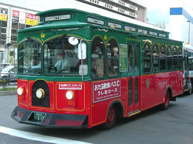
Руководство по техническому обслуживанию и ремонту + каталог расходных запчастей грузовых автомобилей Hino 300, Hino Dutro и Toyota Dyna/Toyoace с 2011 года выпуска с дизельным двигателем N04C объемом 4 литра.
- Автор: —
- Издательство: Легион-Автодата
- Год издания: —
- Страниц: 558
- Формат: —
- Размер: —

Руководство по техническому обслуживанию и ремонту Hino Dutro и Toyota Toyoace с 1999 года выпуска с дизельными двигателями.
- Автор: —
- Издательство: Легион-Автодата
- Год издания: —
- Страниц: 412
- Формат: —
- Размер: —

- Manuals
- Brands
- Hino Motors Manuals
- Trucks
- 300 Series
- Mounting manual
-
Contents
-
Table of Contents
-
Bookmarks
Quick Links
KK-XZU215C
HINO 300 SERIES
Body Mounting Manual
TRUCK CHASSIS
TRUCK CHASSIS
X Z U
&
MODEL
XK U
SERIES
(Hybrid vehicle)
Related Manuals for Hino Motors 300 Series

Summary of Contents for Hino Motors 300 Series
-
Page 1
KK-XZU215C HINO 300 SERIES Body Mounting Manual TRUCK CHASSIS TRUCK CHASSIS X Z U & MODEL XK U SERIES (Hybrid vehicle) -
Page 2
No part of this manual may be reproduced or transmitted in any form without the express written permission of Hino Motors, Ltd. © 2010, All rights reserved. Printed in Japan. PRODUCT PLANNING DIVISION 3-1-1, HINO-DAI, HINO-SHI, TOKYO, 191-8660 JAPAN Telephone… -
Page 3
RECORD OF CHANGES We have published the new revised edition of Body Mounting Manual with the following changes. Consequently, please discard the current Body Mounting Manual CD-ROM NO.KK-XZU215B, and use the new CD-ROM NO.KK-XZU215C from now on. CONTENTS OF CHANGES The information about XKU417L-HKFQB3 (Hybrid vehicle) has been added. -
Page 4
WARNING Request for alteration to make when reading MODEL NAME. • The MODEL NAME in this manual of BODY MOUNTING MANUAL is described according to the “PRODUCTION CODE” name. • When making use of the BODY MOUNTING MANUAL, use the MODEL NAME after replacing it in accordance with the following table. -
Page 5
(hereinafter collectively referred to as Hino Chassis), or modify or alter a Hino Chassis. Content This manual contains chassis specifications and instructions particular to model 300 series with US-04 emission control in the Hino light duty trucks. Important This instruction manual must be used in combination with the Common Manual, No. -
Page 6
• Hino Motors, Ltd. does not assume any liability whatsoever for any injury to persons or damage to property caused as a result of the utilization of this manual. -
Page 7
CONTENTS 1. VEHICLE SUMMARY 2. GENERAL PRECAUTIONS 3. CHASSIS MASS & FRAME SECTION MODULUS 4. SPRING & REAR AXLE 5. PTO AND CONTROL 6. ELECTRICAL SYSTEMS 7. PAINTING 8. CHASSIS DRAWINGS 9. CHASSIS FRAME DRAWINGS 10. MOUNTING OF CHASSIS EQUIPMENT KK-XZU215C… -
Page 8
1. VEHICLE SUMMARY PRODUCTION CODE ・・・・・・・・・・・・・・・・・・・・・・・・・・・・・・・・・・・・・・・・・・ 1 — 1 IDENTIFICATION NUMBER ・・・・・・・・・・・・・・・・・・・・・・・・・・・・・・・・・・・・ 1 — 2 CHASSIS SPECIFICATIONS・・・・・・・・・・・・・・・・・・・・・・・・・・・・・・・・・・・・ 1 — 3 KK-XZU215C… -
Page 9
CAB TYPE CODE N04C-TR/TS/TT, N04C-TP/TW, N04C-TU/TV SINGLE W04D, W04D-TM, W04D-TN DOUBLE N04C-TN/TU (N04C-H1) BODY DECK HEIGHT CODE VEHICLE MODEL CODE HIGH FLOOR 300 SERIES LOW FLOOR MODEL SERIES CODE DUMP CODE WHEEL BASE DRIVE TRANSMISSION CODE 2525 6 SPEEDS (MECH.) -
Page 10
1 — 2 IDENTIFICATION NUMBER CHASSIS Located at the side member of chassis frame. FXZ1 C No ENGINE KK-XZU215C… -
Page 11
1 — 3 CHASSIS SPECIFICATIONS Cab type STANDARD CAB SERIES WIDE CAB SERIES Chassis model XZU307L-HKMLB3 XZU307L-HKMMB3 XZU347L-HKMMB3 XZU407L-HKMMD3 XZU407L-HKMQD3 XZU407L-HKFQD3 XZU407L-HKFRD3 XZU417L-HKMMD3 XZU417L-HKFQD3 XZU417L-HKFRD3 XZU427L-HKFQD3 XZU427L-HKFRD3 XKU417L-HKFQB3 Item Drive system (number of wheels) 4×2 (4) 4×2 (6) 4×2 (6) 4×2 (6) 4×2 (6) 4×2 (6) -
Page 12
2. GENERAL PRECAUTIONS FIRE SHIELD ・・・・・・・・・・・・・・・・・・・・・・・・・・・・・・・・・・・・・・・・・・・・・・・・ 2 — 1 CLEARANCE BETWEEN CAB AND REAR BODY OR ・・・・・・・・・・・・ 2 — 2 EQUIPMENT RECOMMENDED POSITIONS OF U-BOLTS ・・・・・・・・・・・・・・・・・・・・ 2 — 3 RECOMMENDED POSITIONS OF REAR FENDERS AND・・・・・・・・・・ 2 — 4 MUDGUARDS ELECTRIC WELDING WORK ・・・・・・・・・・・・・・・・・・・・・・・・・・・・・・・・・・ 2 — 5 NOTES ON ADDITIONAL WIRING IN THE ENGINE ・・・・・・・・・・・・・・… -
Page 13
2. GENERAL PRECAUTIONS 2 — 1 FIRE SHIELD 1) Gap Between Cab Rear End and Body When a flat bed or similar body has been mounted, a fire shield should be fitted across the gap between the cab rear end and the front end of the load platform frame to prevent fires that may be caused by flammable materials falling off from the load platform onto the exhaust pipe (see figure below). -
Page 14
2 — 2 — 1 CLEARANCE BETWEEN CAB AND REAR BODY OR EQUIPMENT The rear part of the cab contains the cab lock mechanism or stack exhaust pipe as well as the engine cylinder block. When mounting the rear body or equipment, allow at least the minimum clearance between the rear end of the cab or stack exhaust pipe and the front end of the rear body, to avoid obstructing the operation of cab lock mechanism or avoiding… -
Page 15
2 — 2 — 2 2) Measurement of the Engine Air Intake Port • STANDARD CAB series Unit : mm SIDE VIEW ( LEFT SIDE ) REAR VIEW ( LEFT SIDE ) KK-XZU215C… -
Page 16
2 — 2 — 3 • WIDE CAB series Unit : mm SIDE VIEW ( LEFT SIDE ) REAR VIEW ( LEFT SIDE ) Caution The blocking of the smooth flow of air into the air intake pipe caused by any materials such as ropes, pieces of cloth, etc. -
Page 17
2 — 2 — 4 3) Minimum Clearance with Cab Outer Shell • Even under normal driving conditions, when the cab is not tilted, it moves back and front, right and left, and up and down. The body or equipment must not interfere with cab movement. -
Page 18
2 — 2 — 5 4) Contained Equipment of Cab Rear End The rear part of the cab contains the cab lock mechanism and the tilt mechanism, as well as the engine cylinder block or other various equipment. When mounting the body or equipment, allow at least the minimum clearance between the rear end of the cab and the front end of the rear body or equipment, to avoid obstructing the operation and maintenance of these mechanisms or… -
Page 19
2 — 3 RECOMMENDED POSITIONS OF U-BOLTS [NOTES] (1) The details of setting positions of the U-bolt are shown in following figure. Fasten the U-bolt as much as possible to the positions described in following figure when a body or equipment are going to be mounted to the chassis. -
Page 20
2 — 4 — 1 RECOMMEND POSITIONS OF REAR FENDERS AND MUDGUARDS When mounting rear fenders and mudguards, determine required clearances with reference to the following table and figures of «MAXIMUM VERTICAL DEFLECTION OF REAR WHEEL» in 4-2. 1) Rear Fender Unit : mm CAB TYPE MODEL… -
Page 21
2 — 4 — 2 2) Mudguards KK-XZU215C… -
Page 22
2 — 5 — 1 ELECTRIC WELDING WORK Electrical components such as the alternator and tachograph are directly connected to the battery and one end is grounded to the chassis frame. Under these conditions, welding current will flow back along the ground circuit if electric welding is carried out and damage may be caused to the alternator, tachograph, electrical components, etc. -
Page 23
2 — 5 — 2 DETAILS, RELAY & FUSE BLOCK DC-DC E/G CONTROL ECU CONVERTER ABS ECU PASSENGER SEAT SIDE AUSXZU201 02D006 KK-XZU215C… -
Page 24
2 — 5 — 3 WIRE HARNESS OF SIGNAL CIRCUIT CHASSIS CENTER SIGNAL CIRCUIT CONNECTOR FRONT UNDER COVER KK-XZU215C… -
Page 25
2 — 5 — 4 (2) Ground of the Welding Equipment Connect the ground of the welding equipment near the place where to be welded. Welding to the chassis frame • Connect the ground to the bolt (plating bolt) or chassis frame near the place where to be welded. -
Page 26
2 — 5 — 5 (4) After Welding • Make sure to connect all signal circuit connectors in PCU. • Put back fuses as original condition. • Make sure to connect the DC-DC Converter. • Make sure to connect the negative terminal of the battery. And the terminal should be horizontally setting. -
Page 27
2 — 6 NOTES ON ADDITIONAL WIRING IN THE ENGINE COMPARTMENT Since the engines in HINO trucks are covered with sound arrest plates, the engine compartment tends to heat up. Avoid wiring in the engine compartment if possible. Additional wiring harness or cable should be kept away from heated elements, and should be wired along the main harness. -
Page 28
2 — 7 NOTES ON ENGINE CONTROL, BRAKE ABS SYSTEM COMPUTERS AND DC-DC CONVERTER Engine control and brake ABS computers are installed center part, inside of the instrument panel, and DC-DC converter is installed on right side of the cab back panel as described following figure. -
Page 29
2 — 8 HANDLING OF PARTS FOR MEETING THE EXTERNAL NOISE CONTROL REGULATION To comply with the external noise control regulation, parts for external noise reduction, such as sound-insulating materials (cover, rubber) sound-absorbing materials, muffler etc., are equipped on the cab, the engine and the chassis. Since the parts for external noise reduction and their fitting locations are depending on the vehicle model, refer to the corresponding explanatory example drawing shown in the following. -
Page 30
2 — 9 — 1 PRECAUTION ON BODY MOUNTING WORK Installation position of hybrid related equipment. BATTERY MOTOR GENERATOR COOLING DUCT NICKEL METAL HYDRIDE (Ni-MH) COOLING FAN BATTERY FOR BATTERY SERVICE PLUG INVERTER RADIATOR ECU BOX FOR INVERTER (HV-ECU, BATTERY ECU, KINDS OF RELAIES) INNER STRUCTURE OF PCU KK-XZU215C… -
Page 31
2 — 9 — 2 Precaution on body mounting work. Before starting to mount a body please make sure to contact a distributor and receive suitable advice. Carry out mounting a body paying attention to following precautions. • Make sure to always wear the electric insulation equipment (insulation rubber gloves .etc) while working. -
Page 32
2 — 9 — 3 • Pay attention to handle high voltage harness wires which are rolled by orange color tape. • Never get on the hybrid system equipment such as the battery and the inverter. You might get an electric shock or damage a equipment. -
Page 33
2 — 10 -1 THE NOISE MEASURES OF THE AM RADIO Make sure to connect 2 earth wires between body and / or equipment(hereinafter termed body) and chassis frame for the noise preventing of the AM radio by the hybrid system. •… -
Page 34
2 — 10 -2 • Between body and motor generator Connect one side of the earth wire to the center part of front end body and the other side to the grounding terminal of the motor generator together with the earth wire of the motor generator with the existing bolt.(See the following figure) Tightening torque of bolt : 24±7.2N·m Tie the additional earth wire to the nearby cable with tie-rap. -
Page 35
3. CHASSIS MASS & FRAME SECTION MODULUS CHASSIS MASS ・・・・・・・・・・・・・・・・・・・・・・・・・・・・・・・・・・・・・・・・・・・・・・ 3 — 1 FRAME SECTION MODULUS ・・・・・・・・・・・・・・・・・・・・・・・・・・・・・・・・・・ 3 — 2 KK-XZU215C… -
Page 36
3. CHASSIS MASS & FRAME SECTION MODULUS 3 — 1 — 1 CHASSIS MASS MODEL XZU307L-HKMLB3 XZU307L-HKMMB3 XZU347L-HKMMB3 XZU407L-HKMMD3 XZU407L-HKMQD3 GRAVITY GRAVITY GRAVITY GRAVITY GRAVITY MOMENT MOMENT MOMENT MOMENT MOMENT MASS POSITION FROM MASS POSITION FROM MASS POSITION FROM MASS POSITION FROM MASS… -
Page 37
3 — 1 — 2 MODEL XZU407L-HKFQD3 XZU407L-HKFRD3 XZU417L-HKMMD3 XZU417L-HKFQD3 XZU417L-HKFRD3 GRAVITY GRAVITY GRAVITY GRAVITY GRAVITY MOMENT MOMENT MOMENT MOMENT MOMENT MASS POSITION FROM MASS POSITION FROM MASS POSITION FROM MASS POSITION FROM MASS POSITION FROM ITEMS F.A.C F.A.C F.A.C F.A.C F.A.C FROM F.A.C… -
Page 38
3 — 1 — 3 MODEL XZU427L-HKFQD3 XZU427L-HKFRD3 XKU417L-HKFQB3 GRAVITY GRAVITY GRAVITY MOMENT MOMENT MOMENT MASS POSITION FROM MASS POSITION FROM MASS POSITION FROM ITEMS F.A.C F.A.C F.A.C FROM F.A.C FROM F.A.C FROM F.A.C (kg) (kg·m) (kg) (kg·m) (kg) (kg·m) FRONT BUMPER -0.970 -12.610… -
Page 39
3 — 2 — 1 FRAME SECTION MODULUS (MAIN FRAME ON BOTH SIDE) KK-XZU215C… -
Page 40
3 — 2 — 2 FRAME SECTION MODULUS (MAIN FRAME ON BOTH SIDE) KK-XZU215C… -
Page 41
3 — 2 — 3 FRAME SECTION MODULUS (MAIN FRAME ON BOTH SIDE) KK-XZU215C… -
Page 42
3 — 2 — 4 FRAME SECTION MODULUS (MAIN FRAME ON BOTH SIDE) KK-XZU215C… -
Page 43
3 — 2 — 5 FRAME SECTION MODULUS (MAIN FRAME ON BOTH SIDE) KK-XZU215C… -
Page 44
3 — 2 — 6 FRAME SECTION MODULUS (MAIN FRAME ON BOTH SIDE) KK-XZU215C… -
Page 45
4. SPRINGS & REAR AXLES SPRING CHARACTERISTICS ・・・・・・・・・・・・・・・・・・・・・・・・・・・・・・・・・・ 4 — 1 MAXIMUM VERTICAL DEFLECTION OF REAR WHEELS ・・・・・・・・ 4 — 2 TRAVEL RANGE OF REAR SPRING ・・・・・・・・・・・・・・・・・・・・・・・・・・・・ 4 — 3 KK-XZU215C… -
Page 46
4 — 1 — 1 4. SPRINGS & REAR AXLES SPRING CHARACTERISTICS 1) SPRING COMBINATION Refer to SPRING CHARACTERISTICS CHART based on following table. SPRING CHARACTERISTICS MODEL FRONT REAR XZU307L-HKMLB3 XZU307L-HKMMB3 XZU347L-HKMMB3 XZU407L-HKMMD3 XZU407L-HKMQD3 XZU407L-HKFQD3 XZU407L-HKFRD3 XZU417L-HKMMD3 XZU417L-HKFQD3 XZU417L-HKFRD3 XZU427L-HKFQD3 XZU427L-HKFRD3 XKU417L-HKFQB3 AUSXZU201 04T001… -
Page 47
4 — 1 — 2 2) FRONT LEAF SPRING (1) SPRING CHARACTERISTICS CHART «F1» (2) SPRING CHARACTERISTICS CHART «F2» KK-XZU215C… -
Page 48
4 — 1 — 3 (3) SPRING CHARACTERISTICS CHART «F3» (4) SPRING CHARACTERISTICS CHART «F4» KK-XZU215C… -
Page 49
4 — 1 — 4 (5) SPRING CHARACTERISTICS CHART «F5» (6) SPRING CHARACTERISTICS CHART «F6» KK-XZU215C… -
Page 50
4 — 1 — 5 (7) SPRING CHARACTERISTICS CHART «F7» (8) SPRING CHARACTERISTICS CHART «F8» KK-XZU215C… -
Page 51
4 — 1 — 6 3) REAR LEAF SPRING (1) SPRING CHARACTERISTICS CHART «R1» KK-XZU215C… -
Page 52
4 — 1 — 7 (2) SPRING CHARACTERISTICS CHART «R2» KK-XZU215C… -
Page 53
4 — 1 — 8 (3) SPRING CHARACTERISTICS CHART «R3» KK-XZU215C… -
Page 54
4 — 1 — 9 (4) SPRING CHARACTERISTICS CHART «R4» KK-XZU215C… -
Page 55
4 — 1 — 10 (5) SPRING CHARACTERISTICS CHART «R5» KK-XZU215C… -
Page 56
4 — 1 — 11 (6) SPRING CHARACTERISTICS CHART «R6» KK-XZU215C… -
Page 57
4 — 2 MAXIMUM VERTICAL DEFLECTION OF REAR WHEELS Measurements for the maximum deflection for on tire and for simultaneous left and right deflection are shown below. When you mount the body, allow a clearance of at least 30mm so as not to obstruct tire deflection. -
Page 58
4 — 3 TRAVEL RANGE OF REAR SPRING During driving, the shackle of the main spring slides beyond the end of the rear bracket. Do not mount any parts of body inside of the this range. FRONT REAR SHACKLE REAR LEAF SPRING Unit : mm MODEL A (min.) -
Page 59
5. PTO AND CONTROL LAYOUT OF POWER LINE ・・・・・・・・・・・・・・・・・・・・・・・・・・・・・・・・・・・・ 5 — 1 TRANSMISSION SIDE POWER TAKE OFF (OPT) ・・・・・・・・・・・・・・・・ 5 — 2 ENGINE CONTROL FOR BODY OR EQUIPMENT ・・・・・・・・・・・・・・・・ 5 — 3 REAR BODY CONTROL LEVER (OPT) ・・・・・・・・・・・・・・・・・・・・・・・・ 5 — 4 KK-XZU215C… -
Page 60
5 — 1 5. PTO AND CONTROL LAYOUT OF POWER LINE REAR BODY MODEL MODEL MODEL CONTROL (OPT) XZU307L-HKMLB3 N04C-TU M550 3° 0° – – DUMP XZU307L-HKMMB3 N04C-TU M550 3° 0° LEVER DUMP XZU347L-HKMMB3 N04C-TU M550 3° 0° LEVER DUMP XZU407L-HKMMD3 N04C-TV M550… -
Page 61
5 — 2 — 1 TRANSMISSION SIDE POWER TAKE OFF (OPT) When the body require transmission Power Take Off (PTO), genuine PTO equipment and related parts should be supplied as shown below. [T/M PTO No.1] 1) Transmission Series by Vehicle Model Model Transmission series XZU307L-HKMMB3… -
Page 62
5 — 2 — 2 4) PTO Installation Procedure (1) Drain the transmission oil. (Do not remove the drain plug while the oil is hot, or you will scaled yourself.) (2) Remove the PTO cover which is at the left of the transmission. ( Do not reuse the bolts and gasket that you remove at this time.) (3) Clean the PTO mounting surface on the transmission side. -
Page 63
5 — 2 — 3 6) Detail of M550 Transmission Unit : mm MAINSHAFT CENTER LINE 124 ±0.1 DRIVE GEAR 6-M10x1.25 DEPTH 24 TO T/M CASE FRONT SURFACE 149 AUSXZU201 05F001 DRIVE GEAR SPECIFICATION (T/M SIDE /3rd COUNTER GEAR) Tooth profile Helical gear Normal circular thickness 3.9171… -
Page 64
5 — 2 — 4 7) Transmission PTO mounting (M550) Vacuum control type Unit : mm KK-XZU215C… -
Page 65
5 — 2 — 5 • Detail of PTO Flange Unit : mm • Detail of PTO Output Shaft KK-XZU215C… -
Page 66
5 — 2 — 6 [T/M PTO No.2] 1) Transmission Series by Vehicle Model Model Transmission series XZU407L-HKFQD3 XZU407L-HKFRD3 XZU417L-HKFQD3 MYY6S XZU417L-HKFRD3 XZU427L-HKFQD3 XZU427L-HKFRD3 AUSXZU201 05T012 2) Data of the PTO Output Shaft Transmission Permissible torque PTO control Direction of series (N·m{kgf·m} at r/min) type… -
Page 67
5 — 2 — 7 4) PTO Installation Procedure (1) Drain the transmission oil. (Do not remove the drain plug while the oil is hot, or you will scaled yourself.) (2) Remove the PTO cover which is at the left of the transmission. ( Do not reuse the bolts and gasket that you remove at this time.) (3) Clean the PTO mounting surface on the transmission side. -
Page 68
5 — 2 — 8 6) Detail of MYY6S Transmission KK-XZU215C… -
Page 69
5 — 2 — 9 7) Transmission PTO mounting (MYY6S) Electronic control type Unit : mm KK-XZU215C… -
Page 70
5 — 2 — 10 • Detail of PTO Flange Unit : mm • Detail of PTO Output Shaft Unit : mm KK-XZU215C… -
Page 71
5 — 3 — 1 ENGINE CONTROL FOR BODY OR EQUIPMENT 1) Fuel Injection Pump Governor • DUTRO vehicles use the following fuel injection pump governor. GOVERNOR TYPE MODEL MANUFACTURER MODEL PUMP GOVERNOR COMMON-RAIL XZU307L-HKMLB3 N04C-TU ELECTRONIC CONTROL TYPE DENSO TYPE COMMON-RAIL XZU307L-HKMMB3… -
Page 72
5 — 3 — 2 2) Engine Accelerator • Engine accelerator and extension harness for body control are packed in cabin as optional equipment. • Connect the connector of Engine accelerator with spare connector which is provided behind the No.3 crossmember at chassis frame LH side member. -
Page 73
5 — 3 — 3 KK-XZU215C… -
Page 74
5 — 3 — 4 3) HOW TO INSTALL ENGINE ACCELERATOR FOR BODY OR EQUIPMENT (1) Be sure to provide the body controller with the full speed stopper for controlling the stroke of the sensor. In that case, adjust the body side stroke in such a way that the body side stopper comes in contact earlier than the sensor side stopper. -
Page 75
5 — 3 — 5 (2) When fitting the cable on the sensor lever, define the direction by pulling the cable parallelly to the direction of lever stroke so that an imbalanced load may not be imposed on the sensor shaft. -
Page 76
5 — 4 REAR BODY CONTROL LEVER (OPT) 1) Mounting position of dump body control lever Unit : mm KK-XZU215C… -
Page 77
6. ELECTRICAL SYSTEM FUSE BLOCK AND RELAY PANEL ・・・・・・・・・・・・・・・・・・・・・・・・・・・・ 6 — 1 ALTERNATOR OUTPUT CHARACTERISTIC ・・・・・・・・・・・・・・・・・・・・ 6 — 2 SPARE POWER TERMINALS ・・・・・・・・・・・・・・・・・・・・・・・・・・・・・・・・・・ 6 — 3 ADDITIONAL LAMPS ・・・・・・・・・・・・・・・・・・・・・・・・・・・・・・・・・・・・・・・・・・ 6 — 4 REAR COMBINATION LAMP ・・・・・・・・・・・・・・・・・・・・・・・・・・・・・・・・・・ 6 — 5 LICENSE PLATE BRACKET AND LICENSE PLATE LAMP ・・・・・・・・ 6 — 6 BACK-UP BUZZER ・・・・・・・・・・・・・・・・・・・・・・・・・・・・・・・・・・・・・・・・・・・・… -
Page 78
6. ELECTRICAL SYSTEM 6 — 1 — 1 FUSE BLOCK AND RELAY PANEL 1) LOCATION The fuse block and relay panel are located inside the instrument panel as shown below. KK-XZU215C… -
Page 79
6 — 1 — 2 2) FUSE BLOCK KK-XZU215C… -
Page 80
6 — 1 — 3 3) RELAY PANEL (Except XKU417L-HKFQB3) NAME AND FORM OF RELAY FORM OF RELAY AUXILIARY SYMBOL FORM OF RELAY BLOCK TERMINAL SYMBOL NAME OF RELAY HORN ENGINE (N04C) HEAD LAMP ENGINE(N04C) A/C COMP HEATER HORN POWER WINDOW FOG LAMP ACCESSORY… -
Page 81
6 — 1 — 4 RELAY PANEL (XKU417L-HKFQB3 only) NAME AND FORM OF RELAY FORM OF RELAY AUXILIARY SYMBOL FORM OF RELAY BLOCK TERMINAL SYMBOL NAME OF RELAY HORN ENGINE-3 HEAD LAMP ENGINE-2 A/C COMP HEATER HORN POWER WINDOW FOG LAMP ACCESSORY IGNITION1-2 FUSE… -
Page 82
6 — 2 ALTERNATOR OUTPUT CHARACTERISTIC • Except XKU417L-HKFQB3 • XKU417L-HKFQB3 only • The maximum power available for the whole vehicle is defined by the capacity of the alternator. Therefore, the electric power that is not consumed by electrical equipments such as head lamps etc. -
Page 83
6 — 3 — 1 SPARE POWER TERMINALS If you must take an electrical power supply for the body from the chassis, take it from the spare power supply. Spare power supplies and positions KK-XZU215C… -
Page 84
6 — 3 — 2 1) Outlet Position Inside the Cab KK-XZU215C… -
Page 85
6 — 3 — 3 2) Outlet Position on Chassis Side HOW TO TAKE ELECTRICITY FROM POWER SUPPLY CIRCUIT a. USING SUB-HARNESS TYPE b. DIRECT CONNECTING TYPE [NOTE] • As far as possible take power using sub-harness type. • If you must take power using direct connecting type, be sure to observe the precautions in described item «ELECTRICAL EQUIPMENT AND WIRING». -
Page 86
6 — 3 — 4 3) Detail of Connector (Parts no. & pole arrangement) • INSIDE THE CAB • CHASSIS SIDE [NOTE] FOR COUPLING CONNECTOR PROVIDED AS AN OPTIONAL PARTS. • Parts number of coupling connector is shown in parenthesis. •… -
Page 87
6 — 4 — 1 ADDITIONAL LAMPS • The lamps installed to the chassis has already been complied with the laws or regulations. Alteration and modification are therefore strictly prohibited. • If you must install additional lamps, be sure to observe the following precautions. -
Page 88
6 — 4 — 2 1) Drawing in the Wire Harness into the Cab Penetration Hole of Wire Harness • The penetration hole to draw the wire harness into the cab is provided at the floor of cab as following figure. •… -
Page 89
6 — 4 — 3 2) Installation of Additional Equipment and Switches Layout of Equipment and Switches (1) Installing space of additional equipment • Have been provided the installing space (H:150mm x W:180 mm ) at the center cluster which can be installed three kind of additional equipment as a wireless radio, electrical equipment and etc. -
Page 90
6 — 4 — 4 LEFT HAND DRIVE DESCRIPTION APPLICATION A TRAY TACHOGRAPH (OPT) AUDIO (OPT) OPT (1DIN SPACE) B TRAY AUDIO (OPT) (WHEN TACHOGRAPH IS OPT.) OPT (1DIN SPACE) C TRAY (1DIN SPACE) a FRONT FOG LAMP SWITCH b —- —- c COIN HOLDER d —-… -
Page 91
6 — 4 — 5 Additional Switches • If you intend to install the switch to the instrument panel, use the switch mentioned hereinafter which is provided as a spare parts. KK-XZU215C… -
Page 92
6 — 4 — 6 3) Method of Taking Electrical Power (1) Taking power directly from the battery If you intend to take electrical power for the body or equipment directly from the battery, secure the battery cable and the body power supply connector together with the same nut. -
Page 93
6 — 5 — 1 REAR COMBINATION LAMP When chassis with cab are shipped, the rear combination lamp assembly is temporarily installed onto the end of the frame. Therefore, when installing it regularly, attach the combination lamp assembly directly such that the direction indicator lamp (umber) is outside and the back-up lamp (white) is inside of the vehicle. -
Page 94
6 — 5 — 2 LIGHT EMISSION PORTION OF REAR COMBINATION LAMP KK-XZU215C… -
Page 95
6 — 6 — 1 LICENSE PLATE BRACKET AND LICENSE PLATE LAMP (1) Use the bracket supplied with the chassis to install the license plate and license plate lamp. (2) The license plate must be installed so as to be clearly visible from the rear of the vehicle. -
Page 96
6 — 6 — 2 EXTERNAL ASPECT OF LICENSE PLATE BRACKET Unit : mm EXTERNAL ASPECT OF LICENSE PLATE LAMP Unit : mm KK-XZU215C… -
Page 97
6 — 7 BACK-UP BUZZER (OPTION EQUIPMENT) • If you move the back-up buzzer or modify the surrounding parts of the chassis, observe the precautions as followings. 1) Installation angle • Must be kept the permissible range of installing angles shown in the figure below. -
Page 98
6 — 8 ELECTRICAL WIRING DIAGRAMS This manual does not contain electrical wiring diagrams. The electrical wiring diagrams are in the WORKSHOP MANUAL. For more details, please consult your nearest Hino sales dealer or distributor. KK-XZU215C… -
Page 99
7. PAINTING TOP COAT PAINTING・・・・・・・・・・・・・・・・・・・・・・・・・・・・・・・・・・・・・・・・・・ 7 — 1 PRECAUTION OF TOP COAT PAINTING FOR CAB ・・・・・・・・・・・・・・ 7 — 2 HANDLING OF LAMINATED WINDSHIELD ・・・・・・・・・・・・・・・・・・・・・・ 7 — 3 HOW TO REMOVE THE RADIATOR GRILLE ・・・・・・・・・・・・・・・・・・・・ 7 — 4 THE KIND AND THE ATTACHING POSITION ・・・・・・・・・・・・・・・・・・・・ 7 — 5 OF MARK AND ORNAMENT PRECAUTIONS FOR FITTING AND STORING ・・・・・・・・・・・・・・・・・・… -
Page 100
7. PAINTING 7 — 1 TOP COAT PAINTING Take a care to the following points, when required to repaint it by a customer. 1) Sanding When repainting, perform to sand the original coat carefully not to be left any part no-sanded, in order to improve the adhesion of top coat paint. -
Page 101
7 — 2 — 1 PRECAUTION OF TOP COAT PAINTING FOR CAB 1) Cautions for Cab Painting When painting the cab, take a caution to the following points, other than above. (1) The place and parts to be omitted from painting for cab and mounting body as well as adhesion of all kinds of oil: •… -
Page 102
7 — 2 — 2 • When removing off a air-cleaner assy, seal completely the inlet port side of engine to prevent any penetration of dirt, paint or etc. Also, install hoses securely and clamp them firmly when mounting them. •… -
Page 103
7 — 3 HANDLING OF LAMINATED WINDSHIELD A laminated glass is produced in such order that polyvinyl butyral film is inserted between 2 glasses and pressed with heat. Under driving general condition, there is no problem. But under a hot temperature and a high moisture when painting, intermediate film is fallen off or such defective occur as foaming may be caused. -
Page 104
7 — 4 HOW TO REMOVE THE RADIATOR GRILLE Upper side Right side Front side Grommet screw X 2 piece (Wide cab) For wide cab only Radiator grille Bolt X 1 piece (Narrow cab) Clip X 9 pieces (Narrow cab) Tapping screw X 2 pieces (Wide cab) Clip X 13 pieces (Wide cab) AUSXZU201 07D003… -
Page 105
7 — 5 — 1 THE KIND AND THE ATTACHING POSITION OF MARK AND ORNAMENT The kind and the position to be attached of marks and ornaments on the cab as well as the chassis are specified in the chart below. Implement masking them completely when repainting the cab or the body. -
Page 106
7 — 5 — 2 DOOR <HYBRID AND EMISSION CONTROL MARK> ATTACHING NAME OF MARK KIND OF MARK PARTS No. PLACE HYBRID MARK 75427-37140 75427-37150 75428-37020 75427-37160 DOOR EMISSION 75428-37030 CONTROL 75427-37170 MARK 75428-37040 75427-37180 75428-37050 <MODEL SERIES MARK> ATTACHING NAME OF MARK PARTS No. -
Page 107
7 — 5 — 3 1) Attaching Place and Procedure for Each Mark and Ornament Refer to the detailed figure of the attaching position for 1 to 6 of the attachments on the cab. (FRONT VIEW OF CAB) (SIDE VIEW OF CAB) KK-XZU215C… -
Page 108
7 — 5 — 4 2) Detail of Each Mark and Ornament attaching position (1) NAME : SYMBOL MARK PLACE : Radiator grille Radiator grille SECTION AA (2) NAME : MODEL and HINO MARK PLACE : Cab front panel CAB FRONT VIEW (RIGHT SIDE) CAB FRONT VIEW (LEFT SIDE) KK-XZU215C… -
Page 109
7 — 5 — 5 (3) NAME : HYBRID, EMISSION CONTROL and MODEL SERIES MARK PLACE : Door DRAWING SHOWS CAB LEFT SIDE VIEW, RIGHT SIDE IS SAME AS OPPOSITE. KK-XZU215C… -
Page 110
7 — 6 PRECAUTIONS FOR FITTING AND STORING THE CAUTION PLATE 1) How to Stick It a. Stick the caution plate to a dry place which is free from dust and dirt after the paint has completely dried up. b. Clean your hand and don’t use cotton work gloves, etc.. c. -
Page 111
8. CHASSIS DRAWINGS CAB DRAWING ・・・・・・・・・・・・・・・・・・・・・・・・・・・・・・・・・・・・・・・・・・・・・・ 8 — 1 DETAIL OF THE CAB BACK DIMENSIONS ・・・・・・・・・・・・・・・・・・・・・・ 8 — 2 CHASSIS DRAWING ・・・・・・・・・・・・・・・・・・・・・・・・・・・・・・・・・・・・・・・・・・ 8 — 3 KK-XZU215C… -
Page 112
8. CHASSIS DRAWINGS 8 — 1 — 1 CAB DRAWING 1) STANDARD CAB SCALE : 1/20 (XZU307L-HKMLB3 ONLY) Unit : mm KK-XZU215C… -
Page 113
8 — 1 — 2 2) STANDARD CAB SCALE : 1/20 Unit : mm KK-XZU215C… -
Page 114
8 — 1 — 3 3) WIDE CAB SCALE : 1/20 Unit : mm KK-XZU215C… -
Page 115
8 — 2 — 1 DETAIL OF THE CAB BACK DIMENSIONS 1) STANDARD CAB . T/M MODEL M550 LEFT VIEW Unit : mm KK-XZU215C… -
Page 116
8 — 2 — 2 RIGHT VIEW Unit : mm KK-XZU215C… -
Page 117
8 — 2 — 3 UPPER VIEW Unit : mm KK-XZU215C… -
Page 118
8 — 2 — 4 2) WIDE CAB . T/M MODEL M550 LEFT VIEW Unit : mm KK-XZU215C… -
Page 119
8 — 2 — 5 RIGHT VIEW Unit : mm KK-XZU215C… -
Page 120
8 — 2 — 6 UPPER VIEW Unit : mm KK-XZU215C… -
Page 121
8 — 2 — 7 3) WIDE CAB . T/M MODEL MYY6S LEFT VIEW Unit : mm KK-XZU215C… -
Page 122
8 — 2 — 8 RIGHT VIEW Unit : mm KK-XZU215C… -
Page 123
8 — 2 — 9 UPPER VIEW Unit : mm KK-XZU215C… -
Page 124
8 — 2 — 10 4) HYBRID . T/M MODEL MYY6S LEFT VIEW Unit : mm KK-XZU215C… -
Page 125
8 — 2 — 11 RIGHT VIEW Unit : mm KK-XZU215C… -
Page 126
8 — 2 — 12 UPPER VIEW Unit : mm KK-XZU215C… -
Page 127
8 — 3 — 1 SCALE : 1/20 CHASSIS DRAWING Unit : mm [NOTE] • The dimensions described above are designed figure under the chassis condition. • When selected or fitted optional equipment or local parts such as tire, leaf spring, fuel tank and etc., should be examined the frame height from ground by body manufacturer. -
Page 128
8 — 3 — 2 SCALE : 1/20 Unit : mm [NOTE] • The dimensions described above are designed figure under the chassis condition. • When selected or fitted optional equipment or local parts such as tire, leaf spring, fuel tank and etc., should be examined the frame height from ground by body manufacturer. -
Page 129
8 — 3 — 3 SCALE : 1/20 Unit : mm [NOTE] • The dimensions described above are designed figure under the chassis condition. • When selected or fitted optional equipment or local parts such as tire, leaf spring, fuel tank and etc., should be examined the frame height from ground by body manufacturer. -
Page 130
8 — 3 — 4 SCALE : 1/30 Unit : mm [NOTE] • The dimensions described above are designed figure under the chassis condition. • When selected or fitted optional equipment or local parts such as tire, leaf spring, fuel tank and etc., should be examined the frame height from ground by body manufacturer. -
Page 131
8 — 3 — 5 SCALE : 1/30 Unit : mm [NOTE] • The dimensions described above are designed figure under the chassis condition. • When selected or fitted optional equipment or local parts such as tire, leaf spring, fuel tank and etc., should be examined the frame height from ground by body manufacturer. -
Page 132
8 — 3 — 6 SCALE : 1/30 Unit : mm [NOTE] • The dimensions described above are designed figure under the chassis condition. • When selected or fitted optional equipment or local parts such as tire, leaf spring, fuel tank and etc., should be examined the frame height from ground by body manufacturer. -
Page 133
8 — 3 — 7 SCALE : 1/30 Unit : mm [NOTE] • The dimensions described above are designed figure under the chassis condition. • When selected or fitted optional equipment or local parts such as tire, leaf spring, fuel tank and etc., should be examined the frame height from ground by body manufacturer. -
Page 134
9. CHASSIS FRAME DRAWINGS CHASSIS FRAME DRAWINGS・・・・・・・・・・・・・・・・・・・・・・・・・・・・・・・・・・ 9 — 1 KK-XZU215C… -
Page 135
9. CHASSIS FRAME DRAWINGS 9 — 1 — 1 SCALE : 1/20 CHASSIS FRAME DRAWINGS Unit : mm KK-XZU215C… -
Page 136
9 — 1 — 2 SCALE : 1/20 Unit : mm KK-XZU215C… -
Page 137
9 — 1 — 3 SCALE : 1/20 Unit : mm KK-XZU215C… -
Page 138
9 — 1 — 4 SCALE : 1/20 Unit : mm KK-XZU215C… -
Page 139
9 — 1 — 5 SCALE : 1/20 Unit : mm KK-XZU215C… -
Page 140
9 — 1 — 6 SCALE : 1/20 Unit : mm KK-XZU215C… -
Page 141
9 — 1 — 7 SCALE : 1/20 Unit : mm KK-XZU215C… -
Page 142
9 — 1 — 8 SCALE : 1/20 Unit : mm KK-XZU215C… -
Page 143
9 — 1 — 9 SCALE : 1/20 Unit : mm KK-XZU215C… -
Page 144
9 — 1 — 10 SCALE : 1/20 Unit : mm KK-XZU215C… -
Page 145
9 — 1 — 11 SCALE : 1/20 Unit : mm KK-XZU215C… -
Page 146
9 — 1 — 12 SCALE : 1/20 Unit : mm KK-XZU215C… -
Page 147
9 — 1 — 13 SCALE : 1/20 Unit : mm KK-XZU215C… -
Page 148
9 — 1 — 14 SCALE : 1/20 Unit : mm KK-XZU215C… -
Page 149
10. MOUNTING OF CHASSIS EQUIPMENT FUEL TANK ・・・・・・・・・・・・・・・・・・・・・・・・・・・・・・・・・・・・・・・・・・・・・・・・・・ 10 — 1 BATTERY ・・・・・・・・・・・・・・・・・・・・・・・・・・・・・・・・・・・・・・・・・・・・・・・・・・・・ 10 — 2 EXHAUST SYSTEM ・・・・・・・・・・・・・・・・・・・・・・・・・・・・・・・・・・・・・・・・・・ 10 — 3 KK-XZU215C… -
Page 150
10 — 1 — 1 10. MOUNTING OF CHASSIS EQUIPMENT FUEL TANK Refer to FUEL TANK based on following table. STD/OPT CAPACITY 100L 100L 100L+70L FILLING PORT SIZE STANDARD XZU307L-HKMLB3 – – – – XZU307L-HKMMB3 – – – – XZU347L-HKMMB3 –… -
Page 151
10 — 1 — 2 1) FUEL TANK CHART «FT1» Unit : mm CAPACITY : 70L KK-XZU215C… -
Page 152
10 — 1 — 3 2) FUEL TANK CHART «FT2» Unit : mm CAPACITY : 100L KK-XZU215C… -
Page 153
10 — 1 — 4 3) FUEL TANK CHART «FT3» Unit : mm CAPACITY : 100L KK-XZU215C… -
Page 154
10 — 1 — 5 4) FUEL TANK CHART «FT4» Unit : mm CAPACITY : 100L MODEL XZU417L 1945 XZU427L 2385 AUSXZU201 10T002 KK-XZU215C… -
Page 155
10 — 1 — 6 5) FUEL TANK CHART «FT5» Unit : mm CAPACITY : 100L KK-XZU215C… -
Page 156
10 — 1 — 7 6) FUEL TANK CHART «FT6» Unit : mm CAPACITY : 100L MODEL XZU417L 1945 XZU427L 2385 AUSXZU201 10T002 KK-XZU215C… -
Page 157
10 — 1 — 8 7) FUEL TANK CHART «FT7» Unit : mm CAPACITY : 100L+70L KK-XZU215C… -
Page 158
10 — 1 — 9 FUEL TANK CHART «FT8» Unit : mm CAPACITY : 100L+70L KK-XZU215C…
 -
Page 159
10 — 1 — 10 9) FUEL TANK CHART «FT9» Unit : mm CAPACITY : 100L+70L KK-XZU215C… -
Page 160
10 — 1 — 11 10) FUEL TANK CHART «FT10» Unit : mm CAPACITY : 100L+70L KK-XZU215C… -
Page 161
10 — 1 — 12 11) FUEL TANK CHART «FT11» Unit : mm CAPACITY : 100L KK-XZU215C… -
Page 162
10 — 2 — 1 BATTERY CAPACITY : 216kC { 60AH } STD (Except XKU417L-HKFQB3) Unit : mm VEHICLE’S FRONT KK-XZU215C… -
Page 163
10 — 2 — 2 CAPACITY : 288kC { 80AH } OPT (Except XKU417L-HKFQB3) STD (XKU417L-HKFQB3 only) Unit : mm VEHICLE’S FRONT KK-XZU215C… -
Page 164
10 — 3 — 1 EXHAUST SYSTEM Unit : mm KK-XZU215C… -
Page 165
10 — 3 — 2 Unit : mm KK-XZU215C… -
Page 166
10 — 3 — 3 Unit : mm KK-XZU215C… -
Page 167
10 — 3 — 4 Unit : mm KK-XZU215C… -
Page 168
10 — 3 — 5 Unit : mm MODEL XKU417L-HKFQB3 KK-XZU215C…
 FUEL TANK CHART «FT8» Unit : mm CAPACITY : 100L+70L KK-XZU215C…
 Welcome to ManualMachine
You have been successfully registered
We have sent a verification link to to complete your registration.
If you can’t find the email, check your Junk/Spam folder.


- Buy Points
- How it Works
- FAQ
- Contact Us
- Questions and Suggestions
- Users
 Loading…
You can only view or download manuals with
Sign Up and get 5 for free
Upload your files to the site. You get 1 for each file you add
Get 1 for every time someone downloads your manual
Buy as many as you need
View and download manuals available only for
Register and get 5 for free
Upload manuals that we do not have and get 1 for each file
Get 1 for every download of your manual
Buy as much as you need
|
Title |
File Size |
Download Links |
|
Hino 155DC 2019 Technical Specifications [PDF] |
2.3Mb |
Download |
|
Hino 195 2017 Technical Specifications [PDF] |
4.2Mb |
Download |
|
Hino 195h 2016 Technical Specifications [PDF] |
4.6Mb |
Download |
|
Hino 195h 2020 Technical Specifications [PDF] |
2.3Mb |
Download |
|
Hino 238 2017 Technical Specifications [PDF] |
2.5Mb |
Download |
|
Hino 238 2020 Technical Specifications [PDF] |
1.9Mb |
Download |
|
Hino 238, 258LP, 268, 338, 358 Workshop Manual [PDF] |
21.8Mb |
Download |
|
Hino 258 ALP 2020 Technical Specifications [PDF] |
1.7Mb |
Download |
|
Hino 258LP 2016 Technical Specifications [PDF] |
3.2Mb |
Download |
|
Hino 268a 2020 Technical Specifications [PDF] |
2.5Mb |
Download |
|
Hino 338 2017 Technical Specifications [PDF] |
3.4Mb |
Download |
|
Hino 338 2020 Technical Specifications [PDF] |
1.8Mb |
Download |
|
HINO Accessories Catalog / V18 [PDF] |
1.3Mb |
Download |
|
Hino Diagnostico y Cod. Fallas Sistema Tics 500-600 [PDF] |
2.6Mb |
Download |
|
Hino Diesel Trucks 1984-1997 Quick Reference Parts Catalog |
9Mb |
Download |
|
Hino Diesel Trucks 1998-2004 Quick Reference Parts Catalog |
1.6Mb |
Download |
|
Hino Dx Activation Users Manual [PDF] |
396.1kb |
Download |
|
Hino Electrical Wiring Diagram [PDF] |
12.5Mb |
Download |
|
Hino Engine Hand Book Parts Catalog [PDF] |
5.2Mb |
Download |
|
Hino FC 1022 ProShift 6 Service Manual [PDF] |
867.2kb |
Download |
|
Hino FC 1022 Service Manual [PDF] |
867.2kb |
Download |
|
Hino Manual Book [PDF] |
10.8Mb |
Download |
|
Hino Parts Torque Summer2012 [PDF] |
4.1Mb |
Download |
|
Hino Quick Reference Parts Catalog 1998 – 2004 Model Year Edition |
1.7Mb |
Download |
|
Hino RB14 Bus Workshop Manual [PDF] |
16.5Mb |
Download |
|
Hino S5-LJ05E04A, S5-LJ05E05A Workshop Manual [PDF] |
45.5Mb |
Download |
|
Hino Series 155, 155H, 195, 195H Workshop Manual [PDF] |
23.2Mb |
Download |
|
Hino Truck 2005-2010 Quick Reference Guide [PDF] |
640.3kb |
Download |
|
Hino Trucks 2005 — 2010 Quick Reference Parts Catalog [PDF] |
640.4kb |
Download |
|
Hino Trucks 2011 — 2013MY NAPS Vin Setup [PDF] |
5.8Mb |
Download |
|
HINO Trucks 2011-2013 Quick Reference Chart [PDF] |
5.8Mb |
Download |
|
Hino Trucks Accessories Catalog [PDF] |
8.6Mb |
Download |
|
Hino Trucks M-Series Technical Specifications [PDF] |
3.3Mb |
Download |
|
HINO VIN Code — LT-0013 Quick Reference Counter Card [PDF] |
1.3Mb |
Download |
|
Hino XL8 2020 Technical Specifications [PDF] |
1.4Mb |
Download |
|
Hino-ePc System Operating Manual [PDF] |
5.7Mb |
Download |
|
Title |
File Size |
Download Links |
|
HINO Dutro Fault Codes list (PDF) [PDF] |
156.9kb |
Download |
|
Hino J05dJ08e Engine ECU Fault Codes List (PDF) [PDF] |
291kb |
Download |
![]()
HINO V18 Accessories Catalog
HINO AccessoriesCatalog_V18.pdf
Adobe Acrobat Document
1.9 MB
![]()
HINO E13C Type Engine Service Manual
HINO E13C Type Engine Service Manual.pdf
Adobe Acrobat Document
968.4 KB
![]()
Hino Dutro Service Repair Manual
Hino Dutro Service Manual.pdf
Adobe Acrobat Document
1.4 MB
![]()
Hino FC 1022 ProShift 6 Service Manual
Hino FC 1022 ProShift 6 Service Manual.p
Adobe Acrobat Document
945.4 KB
![]()
Hino FC 1022 Service Manual
Hino FC 1022 Service Manual.pdf
Adobe Acrobat Document
945.4 KB
![]()
Hino Motors W04C-T Workshop Manual
Hino Motors W04C-T Workshop Manual.pdf
Adobe Acrobat Document
5.2 MB
![]()
Hino Motors W04D Workshop Manual
Hino Motors W04D Workshop Manual.pdf
Adobe Acrobat Document
5.2 MB
![]()
Hino RB145 Motors WO4D/W04C-T Workshop Manual
Hino RB145 Motors Workshop Manual WO4D W
Adobe Acrobat Document
4.4 MB
![]()
HINO Trucks 2011-2013 Quick Reference Chart
HINO Trucks 2011-2013 Quick Reference Ch
Adobe Acrobat Document
5.9 MB
![]()
HINO LT-0013 Quick Reference Counter Card
HINO LT-0013 Quick Reference Counter Car
Adobe Acrobat Document
1.4 MB
![]()
Hino Motors W04C-TI Workshop Manual
Hino Motors W04C-TI Workshop Manual.pdf
Adobe Acrobat Document
5.2 MB
![]()
Hino Motors W06D-TI Workshop Manual
Hino Motors W06D-TI Workshop Manual.pdf
Adobe Acrobat Document
3.4 MB
![]()
Hino Truck 2005-2010 Quick Reference Guide
Hino Truck 2005-2010 Quick Reference Gui
Adobe Acrobat Document
900.1 KB
![]()
HINO_Engine Manual W04_W06
HINO_Engine Manual W04_W06.rar
compressed file archive
9.4 MB
Automobile concern HINO at the moment is one of the largest automobile factories in Japan for the production of trucks of medium and large tonnazhnosti. The thread of the history
of the automobile plant stretches from the first manufacturers of trucks — Japan: the Tokyo Shipyard «Tokyo Ishikawajima Shipbuilding — Engineering Co» and the Tokyo Gas and Electric Company —
«Tokyo Gas Electric Industry Co». These firms produced almost identical trucks bearing the «Sumida» and «Chiyoda» brands.
And in 1937 when the enterprises united themselves, the produced trucks were given a different name, «Isuzu» (look: ISUZU truck PDF
Manuals). But in 1941, after another regrouping of its forces, the company again changed its name to «Diesel Motor Industry Co.» A little later in 1942, a reconstruction took place
in which the company, which belonged to the company TGE, separated and at the same time took the name «Hino Heavy Industry Co». In the separated company continued work on the production of 7-ton
trucks with 6-cylinder diesel engines with air cooling capacity of 125 hp.
In 1946, at the automobile plant «HINO«, they developed and built their first diesel-powered tractors with a load capacity of 15 tons and a pneumatic brake drive. In 1948, the
company, renamed «Hino Diesel Industry Co», chose as its main direction the creation of a wide range of diesel engines for heavy trucks. Only in 1953 began assembling a 13.5-tonne dump truck «ZG»
with a 1-seater cabin, a 6-cylinder diesel engine in 175 hp. And 6-speed gearbox.
Only by the end of the 50’s there were basic 2 and 3 axle hood cars «HINO» with a carrying capacity of 4-10 tons («TE», «TN», «ZC»). They were equipped with unified 6-cylinder engines (7014 and
7690 cm3, 125-150 hp), 4-speed gearbox, dual main gears, spring suspension and pneumatic brake drive. In the early 60’s, the automobile company Hino Motors Ltd laid the foundation of its truck
program. Since 1961, the first 35-strong Brisca pickup truck with a load capacity of 750 kg was offered on the chassis of the Contessa passenger car.
A year later, there appeared 3-wheel trucks «Orient» and «Hustler» with a capacity of 12 horsepower with all-metal cabs and bodywork. Interest in such cars was soon lost and the company started
creating new larger trucks. In the 60-ies. The launch of a family of middle class «Ranger» with a cabin above the engine, which included 2-axle 90-strong models «KL», «KM» (4 × 2) and «WB» (4 ×
4) with a carrying capacity of 3-4.5 Tons, 7,5-ton «KS», heavy hood 14 ton dump trucks «ZM» (6 × 4) with a 10-liter diesel engine with a power of 190 horsepower, beskapotnye 200-strong trucks
«TS» (6 × 2) with two front driven bridges.
A feature of heavy vehicles was a 4-step demultiplikator, increasing the total number of transmission transmissions to 16 — 20. In March 1967, the company «HINO» became a part of the automobile
company «Toyota», turning into its subsidiary for the production of medium and heavy trucks. In the seventies, «HINO» was engaged in improving its program and introducing a new range of diesel
engines with direct fuel injection.
In 1980-81, a new range of middle-class Ranger cars was introduced with a gross weight of up to 16.5 tons with an improved cabin above the engine. A year later appeared a heavy scale «Super
Dolphin». Machines equipped with new more economical motors, had the name «Econo Diesel».

The first series included numerous models FB, FC, FD, FE, FF, FG, FT (4 × 2) and all-wheel drive models «FB», «FC», » GD «and» GT «(4 × 4) with a total weight of 7.5-16.5 tons. They were equipped
with economical 4-and 6-cylinder diesel engines (3660-7412 cm3, 113-195 hp) with a new system of HMMS mixture formation. They used a spiral pipe to supply air to the cylinders and three
hemispherical grooves in the head of each piston, which contributed to the appearance of microscopic vortices. This created better mixing of air with fuel, improved temperature conditions,
ensured more complete combustion, reduced fuel consumption and toxicity.

Simultaneously, their simplified hood analogs «NH», «KY» (4 × 2) and «NZ» (4 × 4) were produced. The heavy gamut included the new boneless models «FR» (6 × 2) and «FS» (6 × 4) with a total weight
of 23-26 tons, as well as traditional «ZM», «ZY» (6 × 4), «ZC «(6 × 6) and 16-ton log carriers» WG «(6 × 6) with a total weight of up to 35 tons. They were equipped with naturally aspirated
inline 6-cylinder diesel engines or V8 and V10 engines (9419-24610 cm3, 215-520 hp). The company also offered trunk tractors with a cab above the engine models «SH» (4 × 2) and «SS» (6 × 4) for
road trains with a gross mass of 38-55 tons, capable of speeds of 90-112 km / h.
They were equipped with the most powerful engine options, 9-speed gearboxes and the HIMR energy recovery system (an electric motor built into the flywheel, which acted as a starter, generator and
retarder brake). At that time, «HINO» had a broad program, consisting of 20 basic models, each of which hid a dozen options. On models for Japan since 1981 the first in practice
«HINO» diesel with a turbo-supercharging and intermediate cooling, automatic transmissions, a pneumatic suspension bracket and forward disk brakes was established.
In 1982, the company celebrated the production of a 1 millionth car. By the end of the decade, having produced 27942 trucks with a gross tonnage of more than 15 tons, HINO came in seventh in the
world. In the nineties, trucks HINO received more modern comfortable, safe and streamlined cabins and lightweight low-frame chassis, which allowed the maximum use of the permitted length of a
single car in the country of 12 meters. The new series of the middle class began to be called «Space Ranger».
It included 14 basic models, including on-board FC, FD, FE, GD, FJ (4 × 2), FT, FX, GX (4 × 4 ) «FG» and «GK» (6 × 4) with a carrying capacity of 4-11.5 tons and a total weight of 8.5-17.8 tons.
They were equipped with 4 and 6-cylinder diesel engines without a charge (4899 — 7961 cm3, 140-235 hp) and one version of an 8-liter engine with a turbocharger and intermediate cooling with a
power of 260 horsepower, 5 or 6- Th stepped gearboxes. A number of models were offered with pneumatic suspension and disc brakes with ABS.
In 1999, the new lightweight model «FB» was replaced by a new delivery range «Dutro» with a payload capacity of 2-4 tons, developed jointly with the firms «Toyota» and «Daihatsu». Cars with a
total mass of 4.5-7.5 tons were equipped with diesel engines with a capacity of 130-150 horsepower and a manual transmission. In 1992, the formation of the most complete heavy low-frame series
«Super Dolphin Profia» began. The basic steels were trucks and vans FH (4 × 2), FN, FP, FR, GN (6 × 2), FS and FQ (6 × 4) FW «(8 × 4) with a lifting capacity of 8.9-16.2 tons and at the same time
with a gross mass of 15.7-25.9 tons with engines with a capacity of 300-520 horsepower and a body capacity of up to 66 cubic meters.
The main novelties were variants of «Prophia» and «Profia Teravi» (Teravie) with less toxic motors with variable geometry of the inlet branch pipe of the turbocharger, a mechanical 7-step or
automatic 16-speed gearbox, the predominant use of a pneumatic suspension with electronic chassis level control, With short cabins with a berth over the driver’s seat. In 1999, a 13.7-ton truck,
the Profia Teravi FN, appeared with a long base, with its middle steering bridge moved to the middle of the cargo platform. The series «Super-Dolphin» also included mainline tractors «SH» and
«SS», as well as a 30-ton dump truck «WR».
The cars of this range are used as previous aspirated diesel engines (13267-25977 cm3, 270-480 hp), and new 6-cylinder 24-valve engines with high-pressure injection and turbocharged with
intercooling (10520-12882 cm3, 330 -400 hp), working with mechanical boxes with the number of gears 5-8. Some models are equipped with environmentally friendly engines that run on compressed
natural gas, ABS, electronic brake-force regulation on wheels, electromagnetic retarder brakes, air suspension of cabins and a radar safety device.
In 1996, the company «HINO» released its 2 millionth car. In Japan, it owns 8 plants with a staff of about 10 thousand people, including the largest robotic complex in Hamur near
Tokyo, where all units and parts for cars are manufactured. In addition, the company has several assembly plants in the US, Ireland, Thailand, Egypt, Malaysia, the Philippines. By the end of the
twentieth century, all of them produced annually 80-90 thousand trucks and buses, including machines with a gross mass of more than 6 tons, about 33 thousand pieces. In terms of production, the
company ranks 16th in the world and the third in Japan. HINO trucks are delivered to more than 100 countries. But not so long ago the concern decided to try its truck on Dakar.