![]()
HIND
HINO K13D T WORKSHOP MANUAL
NDEX: ENGINE GROUP
GENERAL INTRODUCTION
ENGINE
TURBOCHARGER
INJECTION PUMP
INJECTION PUMP GOVERNOR
GENERATOR
STARTER
I INJECTION PUMP
CALIBRATION
IELECTRICAL
EQUIPMENT

FOREWORD
This workshop manual has been prepared to provide information regarding repair procedures on Hino Indus trial Engine.
Applicable models: K13C-T and K13D-T engine
When making any repairs on your engine, be careful not to be injured through improper procedures. As for maintenance items, refer to the Operation Hand Book.
All information and specifications in this manual are based upon the latest product information available at the time of printing.
Hino Motors reserves the right to make changes at any time without prior notice.
HinoMotors.Ltd.

|
GENERAL INTRODUCTION |
Gl-1 |
|
Hino K13C |
GI-V259E-01 |
|
Hino K13D |
CHAPTER GI
GENERAL INTRODUCTION
|
GENERAL PRECAUTION ………………………………………………….. |
GI- 2 |
|
HOW TO USE THIS WORKSHOP MANUAL ……………………….. |
GI- 2 |
|
IDENTIFICATION INFORMATION ……………………………………… |
GI- 4 |
|
SPECIFICATIONS ……………………………………………………………. |
GI- 5 |
|
SPECIFIED TORQUE FOR STANDARD BOLTS …………………… |
Gl-11 |
|
PROCEDURE FOR INSTALLING JOINTS AND |
|
|
GASKETS OF ENGINE PIPE ………………………………………………. |
Gl-12 |
|
RECOMMENDED LUBRICANTS FOR ALL HINO ENGINE ……. |
Gl-14 |

|
Gl-2 |
GENERAL INTRODUCTION |
GENERAL PRECAUTION
Some recommended and standard maintenance services for your engine are included in this section.
When performing maintenance on your engine, be careful not to get injured by using improper work proce dures.
Improper or incomplete work can cause a malfunction of the engine, which may result in personal injury and/or property damage. If you have any question about performing maintenance, please consult your Hino dealer.
WARNING
When working on your engine, observe the following general precautions to prevent personal injury and/or property damage, in addition to the particular NOTES or WARNINGS in each chapter.
oAlways wear safety glasses or goggles to protect your eyes.
oRemove rings, watches, ties, loose hanging jewelry and loose clothing before starting work on the en gine.
oBind long hair securely behind the head.
oAlways stop the engine and turn off the starter switch, unless the operation requires the engine running. Removing the key from the switch is recommended.
oTo avoid serious burns, keep yourself away from hot metal parts such as the engine, exhaust manifold, radiator, muffler, exhaust pipe and tail pipe.
oDo not smoke while working on the engine, since engine fuel and gas from battery are flammable.
oTake utmost care when working on the battery. It contains corrosive sulfuric acid.
oLarge electric current flows through the battery cable and starter cable. Be careful not to cause a short, which can result in personal injury and/or property damage.
oRun the engine only in a well-ventilated area to avoid inhaling of carbon monoxide.
oKeep yourself, your clothing and your tools away from moving parts such as the cooling fan and V-belt when the engine is running.
oBe careful not to leave any tool in the engine compartment. Tools may be hit by moving parts and can cause personal injury.
HOW TO USE THIS WORKSHOP MANUAL
SLIDING HAMMER DESCRIPTION
09420-1442 ◄…—-PART NUMBER
SMI-J001
This workshop manual is designed as a guide for servicing the engine.
An INDEX is provided on the first page of each chap ter.
TROUBLESHOOTING is dealt with in each chapter. When beginning operations, refer to the TROUBLE SHOOTING section for a guide to appropriate diag noses.
SPECIAL TOOLS are dealt with in each chapter. When ordering a special tool, confirm the part num ber with the applicable parts catalog.

|
GENERAL INTRODUCTION |
Gl-3 |
REPAIR PROCEDURES
Repairprocedureswhenself-explanatory,suchas simpleinstallationandremovalofparts,havebeen omitted. Illustrations, suchastheone below,have beenprovidedtomakesuchsimpleproceduresclear. Only essentialproceduresrequiringspecificdirec tionshavebeendealtwithexplicitly.
EXAMPLE:
TIMING GEAR AND CAMSHAFT
OVERHAUL
|
T = 18.64-25.49 {190-260, |
1 4-1 8} |
1 |
‘( |
||||||||||||||||||||||||||
|
j |
—· — |
||||||||||||||||||||||||||||
|
{]5)v-‘ |
|||||||||||||||||||||||||||||
|
I |
1 |
« w |
12 |
||||||||||||||||||||||||||
|
1 |
1 |
•-<t- c; |
|||||||||||||||||||||||||||
|
2 |
— |
‘ |
7 |
||||||||||||||||||||||||||
|
T = 107.8827.48 |
&<- |
||||||||||||||||||||||||||||
|
{ , 00-1,300, 80-94} |
. |
||||||||||||||||||||||||||||
|
/ |
|||||||||||||||||||||||||||||
|
(: |
‘<)'{. r./3 |
||||||||||||||||||||||||||||
|
‘;:_/ |
|||||||||||||||||||||||||||||
|
‘CV ,, |
/ |
||||||||||||||||||||||||||||
|
L |
G—.;_ |
||||||||||||||||||||||||||||
|
:’¼ |
|||||||||||||||||||||||||||||
|
6 |
‘J |
4 |
(. ,. / |
||||||||||||||||||||||||||
|
0 |
1 |
||||||||||||||||||||||||||||
|
5 |
-s.-. |
/ |
11 |
||||||||||||||||||||||||||
|
.tf<jW,· |
‘l’K»¾- |
||||||||||||||||||||||||||||
|
….. ,.,., |
T = |
8.64-25.49 |
|||||||||||||||||||||||||||
|
,-,/ |
G,»J |
||||||||||||||||||||||||||||
|
,._.‘. |
,,,::J‘-‘.,< |
J- 10 |
{190-260, |
4-18} |
|||||||||||||||||||||||||
|
.— |
7 |
‘_ |
9 |
1 |
|||||||||||||||||||||||||
|
<‘»?’- |
|||||||||||||||||||||||||||||
|
< |
|||||||||||||||||||||||||||||
|
T = 107.88-127.48 |
T |
= Tightening torque: N-m {kgf-cm, lbf-ft} |
|||||||||||||||||||||||||||
|
_ ,; 0 ‘ |
8 |
||||||||||||||||||||||||||||
|
{1,100-1,300, 80-94} |
|||||||||||||||||||||||||||||
|
1 |
Idler gear thrust plate |
1 |
SMl-091 |
||||||||||||||||||||||||||
|
Thrust bearing |
6 |
Idler gear thrust plate |
|||||||||||||||||||||||||||
|
2 |
Camshaft gear |
7 |
Straight pin |
2 |
Camshaft |
te gasket |
|||||||||||||||||||||||
|
4. |
Oil pump drive gear |
8 |
Idler gear shaft |
3. |
|||||||||||||||||||||||||
|
5. |
Idler gear |
Crankshaft gear |
14. |
Front end plate |
|||||||||||||||||||||||||
|
3 |
Bushing |
9 |
Injection pump drive gear |
||||||||||||||||||||||||||
|
10. |
Insomecases,illustrationsmaybeofpartswhichdif ferinsomenonessentialwayfromthepartsfoundon yourparticularengine. Insuchcases,theprincipleor procedurebeingillustratedappliesregardlessofsuch nonessentialdifferences.

|
Gl-4 |
GENERAL INTRODUCTION |
||||||||
|
IDENTIFICATION INFORMATION |
|||||||||
|
ENGINE SERIAL NUMBERS |
|||||||||
|
K13C, K13D |
|||||||||
|
1ND3 |
D |
D GD UD SAD |
GDU |
CD |
KUE |
3 D |
|||
|
3 |
D |
LUEDBIULB3NS3 |
D |
DBDL D |
S |
||||
|
D |
LBD3 |
DU |
L U, |
||||||
|
1ID |
DUELUD D |
L3RUSAD L DUE |
3 |
DCU |
GDUEKUD |
||||
|
B |
RLUCDAR BM, |
MIDACFEN

|
GENERAL INTRODUCTION |
Gl-5 |
||||||||||
|
HINO K13C T ENGINE SPECIFICATIONS |
|||||||||||
|
DIESEL ENGINE FOR INDUSTRIAL USE |
|||||||||||
|
HINO |
K13C-T |
6-cyl., water-cooled |
|||||||||
|
12.882 liters, 4-cycle |
|||||||||||
|
turbocharged |
|||||||||||
|
e PERFORMANCE (STD. specs.) |
|||||||||||
|
GENERAL USE (SAE J1349 Gross) |
GENERATOR USE (SAE J1349 Gross) |
||||||||||
|
Stand-by Power |
Prime Power |
||||||||||
|
Output, |
Output, |
Max. torque |
Min. fuel |
Output at |
Output at |
Output at |
Output at |
||||
|
Intermittent rating |
Continuous rating |
N•m(lbfoft) |
consumption |
1,500 r/min |
1,800 r/min |
1,500 r/min |
1,800 r/min |
||||
|
kW(HP) at r/min |
kW(HP) at r/min |
at r/min. |
g/kWh(lb/HPh) kW(HP) |
kW(HP) |
kW(HP) |
kW(HP) |
|||||
|
237 {317} at 2,000· |
213 {286} at 2,000 |
1,265 {933} at 1,200 |
222 {0.364} |
212 {288} |
245 {333} |
196 {262} |
226 {303} |
||||
e ENGINE DESCRIPTION (STD. specs.)
Ambient conditions: Intake air temperature
Barometric pressure
Water Vapor pressure
eENGINE DESCRIPTION
1.Type
2.Combustion chamber 3. Cylinder
Bore x Stroke
4. Piston displacement
5.Compression ratio
6.Direction of rotation
7.Dimensions (L x W x HJ
8.Dry weight
eFEATURES
1.Cylinder block
2.Cylinder head
3.Crankshaft
4.Piston and rings
5.Camshaft
6.Valves
SAE 25° C
100kPa
1.0kPa
Diesel, 4-cycle, 6cyl., in-line, overhead valve, water-cooled
Turbocharged
Direct injection type
135 x 150 mm {5.31 x 5.91 in.}
12.882 liters {786.0 cu. in.}
17. 6
Counterclockwise viewed from flywheel
Approx. 1,586 x 858x 1,178mm
{62.4x 33.8x 4 6.4 in.} Approx. 1,050 kg {2,315 lb}
Mono block cast iron with replaceable wet liner
In two blocks, each one for three cylinders, cast iron Induction-hardened, die forged special steel with counter weights Heat-resistance aluminum alloy
Three compression rings, chrome plated
One oil ring , chrome plated with coil expander
Induction hardened carbon steel Heat resistance steel

Gl-6
eSTANDARD EQUIPMENT
1.Flywheel housing
2.Flywheel
3.Fuel injection pump type
4.Governor
|
5. |
Fuel injection nozzle type |
6.Fuel filter
7.Water separator
8.Cooling system
9.Lubricating system
10.Oil filter
11.Intake manifold
12.Exhaust manifold with flange plate
13.Generator
14.Starter
15.Safety relay
16.Connectors of electrical
equipments
GENERAL INTRODUCTION
HINO own (SAE No. 1 type)
HINO own (SAE 14 in. type)
BOSCH «P» type
Mechanical, all speed control type
BOSCH hole type
Paper element type
Forced-circulation by volute pump
Full forced pressure feed by gear pump Paper element type (Full flow & By-pass flow) Inlet position at rear
Upward exhaust
Alternator with integral regulator 24V, 20A
24V, 7 kW
eOPTIONAL EQUIPMENT
1.Cooling fan (suction or blowout)
2.Main switch
|
3. |
Battery switch |
|
4. |
Battery relay |
|
5. Starter switch with key |
|
|
6. |
Ammeter |
|
7. |
Fuse box |
|
8. |
Engine shut off solenoid |
|
9. |
Emergency relay |
|
10. |
Coolant temperature switch |
|
11. |
Coolant temperature gauge sender |
|
12. |
Coolant temperature gauge |
|
13. |
Oil pressure switch |
|
14. |
Oil pressure gauge sender |
|
15. |
Oil pressure gauge |
|
16. |
Intake heater |
|
17. |
Intake heater relay |
|
18. |
Intake heater indicator |
|
19. |
Tachometer with hour-meter |
|
20. |
Tachometer cable |
|
21. |
Muffler |
|
22. |
Air cleaner |
|
23. |
Air cleaner cap |
|
24. |
Radiator with cooling fan shroud |

|
GENERAL INTRODUCTION |
Gl-7 |
Hino K13C
Hino K13D
SM1-131
SM1-132
NOTE : 1) These specifications are subject to change without notice.
2)These specifications are for export models.
3)All specifications of the products are with normal manufacturing allowances and tolerances.
4)The performance and drawings are for standard specifications.
HineMotors.Ltd.

|
Gl-8 |
GENERAL INTRODUCTION |
||||||||
|
HINO K13D T ENGINE SPECIFICATIONS |
|||||||||
|
DIESEL ENGINE FOR INDUSTRIAL USE |
|||||||||
|
HINO |
K13D-T |
6-cyl., water-cooled |
|||||||
|
13.267 liters, 4-cycle |
|||||||||
|
turbocharged |
|||||||||
|
e PERFORMANCE (STD. specs.) |
|||||||||
|
GENERAL USE (SAE J1349 Gross) |
GENERATOR USE (SAE J1349 Gross) |
||||||||
|
Stand-by Power |
Prime Power |
||||||||
|
Output, |
Output, |
Max. torque |
Min. fuel |
Output at |
Output at |
Output at |
Output at |
||
|
Intermittent rating |
Continuous rating |
N•m(lbf-ft) |
consumption |
1,500 r/min |
1,800 r/min |
1,500 r/min |
1,800 r/min |
||
|
kW(HP) at r/min |
kW(HP) at r/min |
at r/min. |
g/kWh(lb/HPh) |
kW(HP) |
kW(HP) |
kW(HP) |
kW(HP) |
||
|
199 {266} at 2,000· |
179 {240} at 2,000 |
1,098 {810} at 1,200 |
218 {0.358} |
186 {253} |
210 {285} |
171 {230} |
193 {259} |
||
|
e ENGINE DESCRIPTION (STD. specs.) |
|||||||||
|
Ambient conditions: |
SAE |
||||||||
|
Intake air temperature |
25° |
C |
|||||||
|
Barometric pressure |
100 kPa |
||||||||
|
Water Vapor pressure |
1.0 kPa |
eENGINE DESCRIPTION
1.Type
2.Combustion chamber 3. Cylinder
Bore x Stroke
4.Piston displacement 5. Compression ratio
6.Direction of rotation
7.Dimensions (L x W x H)
8.Dry weight
Diesel, 4-cycle, 6cyl., in-line, overhead valve, water-cooled Turbocharged
Direct injection type
137 x 150 mm {5.39 x 5.91 in.}
13.267 liters {809.6 cu. in.}
16.5
Counterclockwise viewed from flywheel Approx. 1,544 x 885 x 1,187 mm
{60.8x 34.8 x 46.7 in.} Approx. 1,050 kg {2,315 lb}
e FEATURES
|
1. |
Cylinder block |
Mono block cast iron with replaceable wet liner |
|
2. |
Cylinder head |
In two blocks, each one for three cylinders, cast iron |
|
3. |
Crankshaft |
Induction-hardened, die forged special steel with counter weights |
|
4. |
Piston and rings |
Heat-resistance aluminum alloy |
|
Three compression rings, chrome plated |
||
|
One oil ring , chrome plated with coil expander |
||
|
5. |
Camshaft |
Induction hardened carbon steel |
|
6. |
Valves |
Heat resistance steel |
|
Hino K13D Engine Parts Contact: email |
EngineParts@HeavyEquipmentRestorationParts.com |
|
Phone: 269 673 1638 |
Website: www.HeavyEquipmentRestorationParts.com |
![]()
|
GENERAL INTRODUCTION |
Gl-9 |
eSTANDARD EQUIPMENT
1.Flywheel housing
2.Flywheel
3.Fuel injection pump type
4.Governor
|
5. |
Fuel injection nozzle type |
6.Fuel filter
7.Water separator
8.Cooling system
9.Lubricating system
10.Oil filter
11.Intake manifold
12.Exhaust manifold with flange plate
13.Generator
14.Starter
15.Safety relay
16.Connectors of electrical
equipments
HINO own (SAE No. 1 type)
HINO own (SAE 14 in. type)
BOSCH «P» type
Mechanical, all speed control type
BOSCH hole type
Paper element type
Forced-circulation by volute pump
Full forced pressure feed by gear pump Paper element type (Full flow & By-pass flow) Inlet position at rear
Upward exhaust
Alternator with integral regulator 24V, 20A
24V, 7 kW
eOPTIONAL EQUIPMENT
1.Cooling fan (suction or blowout)
2.Main switch
|
3. |
Battery switch |
|
4. |
Battery relay |
|
5. Starter switch with key |
|
|
6. |
Ammeter |
|
7. |
Fuse box |
|
8. |
Engine shut off solenoid |
|
9. |
Emergency relay |
|
10. |
Coolant temperature switch |
|
11. |
Coolant temperature gauge sender |
|
12. |
Coolant temperature gauge |
|
13. |
Oil pressure switch |
|
14. |
Oil pressure gauge sender |
|
15. |
Oil pressure gauge |
|
16. |
Intake heater |
|
17. |
Intake heater relay |
|
18. |
Intake heater indicator |
|
19. |
Tachometer with hour-meter |
|
20. |
Tachometer cable |
|
21. |
Muffler |
|
22. |
Air cleaner |
|
23. |
Air cleaner cap |
|
24. |
Radiator with cooling fan shroud |

|
Gl-10 |
GENERAL INTRODUCTION |
Hino K13C
Hino K13D
SM1-133
SM1-134
NOTE : 1) These specifications are subject to change without notice.
2)These specifications are for export models.
3)All specifications of the products are with normal manufacturing allowances and tolerances.
4)The performance and drawings are for standard specifications.
HineMotors.Ltd.

|
GENERAL INTRODUCTION |
Gl-11 |
||||||||
|
Hino K13C |
SPECIFIED TORQUE FOR STANDARD BOLTS |
||||||||
|
Hino K13D |
|||||||||
|
1. FLANGE BOLT |
Unit: N-m {kgf-cm, lbf-ft} |
||||||||
|
Class |
7T |
9T |
|||||||
|
h |
0 |
(SJ |
0 |
||||||
|
M8X1.25 |
28.5 {290, 21.0} |
36 {370, 26.8} |
|||||||
|
M10X1.25 |
60 {610, 44.1} |
74.5 {760, 55.0} |
|||||||
|
M10X1.5 |
55 {560, 40.5} |
68.5 {700, 50.6} |
|||||||
|
M12X1.25 |
108 {1,100, 79.6} |
136 {1,390, 100.5} |
|||||||
|
M12X1.75 |
97 {990, 71.6} |
125 {1,280, 92.6} |
|||||||
|
M14X1.5 |
171.5 {1,750, 126.6} |
216 {2,210, 159.8} |
|||||||
|
M14X2 |
154 {1,570, 113.6} |
199 {2,030, 146.8} |
|||||||
|
2. BOLT WITH WASHER |
Unit: N-m {kgf-cm, lbf-ft} |
||||||||
|
Class |
4T |
7T |
9T |
||||||
|
Representation |
0 |
0 8 |
0 |
||||||
|
DiameterXPitch |
No Mark |
||||||||
|
M6X1 |
6 {60, 4.3} |
10 {100, 7.2} |
13 {130, 9.4} |
||||||
|
M8X1.25 |
14 {140, 10.1} |
25 {250, 18.1} |
31 {320, 23.1} |
||||||
|
M10X1.25 |
29 {300, 21.7} |
51 {520, 37.6} |
64 {650, 47.O} |
||||||
|
M10X1.5 |
26 {270, 19.5} |
47 {480, 34.7} |
59 {600, 43.4} |
||||||
|
M12X1.25 |
54 {550, 39.8} |
93 {950, 68.7} |
118 {1,200, 86.8} |
||||||
|
M12X1.75 |
49 {500, 36.2} |
83 {850, 61.5} |
108 {1,100, 79.6} |
||||||
|
M14X1.5 |
83 {850, 61.5} |
147 {1,500, 108.5} |
186 {1,900, 137.4} |
||||||
|
M14X2 |
74 {750, 54.2} |
132 {1,350, 97.6} |
172 {1,750, 126.6} |
||||||
|
Gl-12 |
GENERAL INTRODUCTION |
|
Hino K13C |
PROCEDURE FOR INSTALLING JOINTS AND |
|
Hino K13D |
|
|
GASKETS OF ENGINE PIPE |
1. Gasket seal type (aluminum + rubber, asbestos or copper).
Location of gasket seal
GASKET
SMI-J017
SMI-J019
|
Tightening torque chart |
||
|
Clamping screw size |
Tightening torque N-m |
|
|
(Diameter) mm{in.} |
{kgf-cm, lbf-ft} |
|
|
8{0.315} |
13{130,9} |
|
|
10{0.394} |
20{200,14} |
|
|
12{0.472} |
25{250,18} |
|
|
14{0.551} |
25{250,18} |
|
|
16{0.630} |
29{300, 22} |
|
|
18{0.709} |
39{400,29} |
|
|
20{0.787} |
*39{400,29} |
|
|
24{0.945} |
69{700, 51} |
|
|
28{1.102} |
127{1,300, 94} |
|
2. Metal seal type (Flare connector type).
Location of metal seal
CONNECTOR FLARE NUT
SMI-J020
Tightening torque chart
|
Clamping screw size |
Tightening torque N-m |
|
(Diameter) mm{in.} |
{kgf-cm, lbf-ft} |
|
12{0.472} |
20{200, 14} |
|
14{0.551} |
31{320,23} |
|
16{0.630} |
39{400,29} |
|
18{0.709} |
59{600,43} |
|
20{0.787} |
64{650,47} |
LOCK WASHER SMI-J022

|
GENERAL INTRODUCTION |
Gl-13 |
Hino K13C
Hino K13D
3. Metal seal type (Nipple connector type)
Location of metal seal
GASKET NUT
FLARE cdNNECTOR FL NECTOR CONNECTOR SMIJ023- CONNECTOR SMI-J024
Tightening torque chart
|
Clamping screw size |
Tightening torque |
|
(Diameter) |
N-m{kgf-cm, lbf-ft} |
|
mm{in.} |
|
|
10{0.394} |
11{110,8} |
|
20{0.787} |
20{200, 14} |
NOTE: o Before installing the joints, ensure that there is no dirt or burrs adhering to the various seat faces (pipe joints, gaskets, etc.)
oBecause the pipes can move relatively freely during installation and the seat faces are liable to tilt, first temporarily tighten the pipes, then tighten them to the specified torque and ensure that there is no leakage from them.
oWhen tightening two pipes together, be very careful that they do not rotate together.
oAfter installing the pipes, apply the correct pressure to each pipe joint and ensure that there is no leakage.
oEnsure that the various tightening torques conform to the above table.
*If a soft washer #4840 FR-N (aluminum + rubber and carbon press fit part) is loosened or removed subsequent to being installed, be sure and replace it with a new one.
There is no need to replace it, however, for normal retightening.

|
HIND |
RECOMMENDED LUBRICANTS FOR ALL HINO ENGINE |
HINO MOTORS LTD. |
|||||||||||||||||||||
|
TOKYO, JAPAN |
|||||||||||||||||||||||
|
LUBRICANTS |
POSITIONS |
ATMOSPHERIC |
S.A.E. |
BP |
CALTEX |
CASTROL |
ESSO |
GULF |
MOBIL |
SHELL |
TOTAL |
||||||||||||
|
TEMP. |
NO. |
||||||||||||||||||||||
|
Above |
RPM DELO 400 Oil |
Castrol or Deusol |
Essolube |
Mobil Delvac 1340 |
Myrina Oil 40, |
TOTAL |
|||||||||||||||||
|
40 |
Vanellus C—3 |
SAE 40, Or 15W/40 |
CRD 40 Turbomax |
Gulf Super Duty |
20W—40, 15W-40 |
Rubia S 40 |
|||||||||||||||||
|
32″ C |
D-3 40. |
Mobil Delvac Super |
|||||||||||||||||||||
|
40 |
RPM DELO 300 Oil |
Castrol or Deusol |
Motor Oil 40, 15W-40 |
Aimura X Oil 40 |
TOTAL |
||||||||||||||||||
|
(90″ Fl |
XD—3 40 |
15W—40 |
|||||||||||||||||||||
|
SAE 40 |
RX Super 40. 15W/40 |
Rimura CT 40 |
Rubia TM 15W40 |
||||||||||||||||||||
|
ENGINE OIL |
RPM DELO 400 Oil |
Castrol or Deusol |
Myrina Oil 30, |
TOTAL |
|||||||||||||||||||
|
(AP.I. CDJ |
32• |
-o· |
Vanellus C-3 |
Essolube |
Mobil Delvac 1330 |
20W-40, 15W-40 |
|||||||||||||||||
|
30 |
SAE 30, or 15W/40 |
CAD 30 |
Gulf Super Duty |
Rubia S 30 |
|||||||||||||||||||
|
Previous Classification |
D-3 30, |
Mobil Delvac Super |
Rimura X Oil 30, |
||||||||||||||||||||
|
(90″ -32′ Fi |
30 |
RPM DELO 300 Oil |
Castrol or Deusol |
Motor Oil 30, 15W-40 |
TOTAL |
||||||||||||||||||
|
(AP.I. OS) |
XD-3 30 |
15W-40 |
10W-30 |
||||||||||||||||||||
|
SAE 30 |
AX Super 30, 15W/40 |
Rubia TM 15W40 |
|||||||||||||||||||||
|
IMIL-L-2104CJ |
Rimura CT 30 |
||||||||||||||||||||||
|
(Mll·l·45199B) |
° |
RPM DELO 400 Oil |
Castrol or Deusol |
Essolube |
Mobil Delvac 1310 |
Myrina Oil 20, |
TOTAL |
||||||||||||||||
|
CRD 20W/20 |
|||||||||||||||||||||||
|
o• ~·12 C |
Vanellus C—3 |
SAE ‘l0/20W, 15W/40 |
Gulf Super Duty |
20W—40, 15W-40 |
i |
a S 20 |
|||||||||||||||||
|
20 |
Castrol or Deusol |
D-3 20W, |
Mobil Delvac Super |
Rub |
|||||||||||||||||||
|
(32″ ~10’F) |
20W |
RPM DELO 300 Oil |
Motor Oil 20, 15W-40 |
Rimura X Oil 20 |
TOTAL |
||||||||||||||||||
|
RX Super 20W/20 |
XD·3 15W•40 |
15W•40 |
|||||||||||||||||||||
|
Cylinder Block |
SAE 20/20W |
Rimura CT 20 |
Rubia TM 15W40 |
||||||||||||||||||||
|
15W/40 |
|||||||||||||||||||||||
|
Injection Pump |
|||||||||||||||||||||||
|
Ai r Cleaner |
Above |
RPM DELO 200 Oil |
Castrol or Deusol |
Essolube |
Rotella TX40, 20W-50 |
TOTAL |
|||||||||||||||||
|
Vanellus M |
SAE 40 |
CRX 40 |
Gulflube Mater Oil |
Mobil Delvac 1240 |
|||||||||||||||||||
|
32’C |
40 |
HDX 40, |
Rotella SX Oil 40, |
||||||||||||||||||||
|
40 |
RPM DELO 100 Oil |
Castrol or Deusol |
XHD 40, 1SW-40 |
Mobil Delvac1140 |
Rubia H 40 |
||||||||||||||||||
|
(90′ Fl |
HDX Plus 40 |
20W—40 |
|||||||||||||||||||||
|
SAE 40 |
RX Super 40.15W/40 |
||||||||||||||||||||||
|
ENGINE OIL |
RPM DELO 200 Oil |
Castrol or Deusol |
|||||||||||||||||||||
|
tA.P.I. CCI |
32″ -o• C |
Vanellus M |
Essolube |
Gulflube Mater Oil |
Mobil Delvac 1230 |
Rotella TX30, 20W—50 |
TOTAL |
||||||||||||||||
|
30 |
SAE 30 |
CRX 30 |
|||||||||||||||||||||
|
Previous Classification |
(90″ ~32″ F) |
30 |
RPM DELO 100 Oil |
Castrol or Deusol |
HDX 30, |
XHD 30, 15W•40 |
Mobil Delvac 1130 |
Rotella sx Oil 30, |
Rubia H 30 |
||||||||||||||
|
(AP.I. DMJ |
SAE 30 |
RX Super 30, 15W/40 |
HDX Plus 30 |
20W-40 |
|||||||||||||||||||
|
(Mll·l-46152) |
|||||||||||||||||||||||
|
(MIL-L-2104B) |
RPM DELO 200 Oil |
Castrol or Deusol |
|||||||||||||||||||||
|
o· |
CRX 20W/20 |
Essolube |
Rotella TX20, 20W-50 |
TOTAL |
|||||||||||||||||||
|
—12· |
Vanellus M |
SAE 20/20W |
Gulflube Motor Oil |
Mobil Delvac 1220 |
|||||||||||||||||||
|
20 |
Castrol or Deusol |
HDX 20, |
RoteIla SX OiI |
||||||||||||||||||||
|
(32″ ~10’F) |
20W |
i |
XHD 20, 1SW—40 |
i |
Rubia H 20 |
||||||||||||||||||
|
RPM DELO 100 O l |
RX Super 20W/20, |
HDX Plus 20W-20 |
Mob l Delvac 1120 |
20/20W, 20W-40 |
|||||||||||||||||||
|
SAE 20/20W |
|||||||||||||||||||||||
|
15W/40 |
|||||||||||||||||||||||
|
COOLANT PUMP |
Marfak |
Esso |
TOTAL |
||||||||||||||||||||
|
BEARING GREASE |
Coolant Pump Bearing |
Energrease |
Multipurpose 2 |
Castrol LM |
Multipurpose |
Gulflex Poly |
Mobilgrease |
Retinax A |
|||||||||||||||
|
L-2 |
or Marfak |
Grease |
MP, 77, MS |
Alvania Grease R2 |
MULTIS 2 |
||||||||||||||||||
|
(Mll-G-109248) |
Grease |
||||||||||||||||||||||
|
All Purpose 2 |
|||||||||||||||||||||||
|
g iii utch, |
Molytex |
||||||||||||||||||||||
|
STARTER GREASE |
i |
a . |
— |
— |
— |
— |
i |
Aero Shell Grease 17 |
— |
||||||||||||||
|
Pinion Shift Lever |
Grease EP2 |
Mob lgrease 29 |
|||||||||||||||||||||
|
& Reduction Gear |
|||||||||||||||||||||||
|
GENERATOR & STARTER |
Generator Bearing |
Energrease |
RPM Grease |
— |
— |
— |
Mobilgrease 28 |
Aero Shell Grease 7 |
— |
||||||||||||||
|
BEARING GREASE |
i |
LT2 |
SRI 2 |
||||||||||||||||||||
|
Starter Bear ng |
|||||||||||||||||||||||
|
INJECTION PUMP |
Marfak |
Esso |
TOTAL |
||||||||||||||||||||
|
TIMER GREASE |
Injection Pump Timer |
Energrease |
Multipurpose 2 |
Castrol LM |
Multipurpose |
Gulflex Poly |
Mobilgrease |
Retinax A |
|||||||||||||||
|
L-2 |
or Marfak |
Grease |
MP, 77, MS |
Alvania Grease R2 |
Mullis EP 1 |
||||||||||||||||||
|
(MIL·G-109248) |
Grease |
||||||||||||||||||||||
|
All Purpose 2 |
|||||||||||||||||||||||
|
Cruise Master |
Shellzone (U.S.A.) |
||||||||||||||||||||||
|
i |
Esso |
Glycoshell Plus |
|||||||||||||||||||||
|
ANTI FREEZE |
Anti Frost |
AF Engine |
Castrol Ant -Freeze |
Antifreeze |
Mobil |
(Europian Countries) |
TOTAL |
||||||||||||||||
|
Engine, Radiator |
Castrol Long Life |
Anti-Freeze |
|||||||||||||||||||||
|
(Mll—A—53009) |
Coolant |
And Summer |
Parmazone |
Shellsafe |
ANTIGEL |
||||||||||||||||||
|
Coolant |
Coolant |
||||||||||||||||||||||
|
Coolant |
Anti-Freeze P281 |
||||||||||||||||||||||
|
Coolguard |
C’)…‘
«»»
C’)l’TI
=2
l’TI
:r::,, rz—
=
C C, C:
:::!
C 2
|
NOTE: Lubricants were amended according to new classification by AP I (American Petroleum Institute) |
’82 •12 •200 |

EN-Y271E-01
Hino K13C
Hino K13D
|
CHAPTER EN |
||
|
ENGINE |
||
|
Models K13C-T AND K13D-T |
||
|
DATA AND SPECIFICATION…………………………………………. |
EN — |
3 |
|
TROUBLESHOOTING ………………………………………………….. |
EN — |
7 |
|
ENGINE OVERHAUL CRITERIA ……………………………………. |
EN — 12 |
|
|
ENGINE MOVING PARTS ……………………………………………. |
EN — 14 |
|
|
CYLINDER HEAD …………………………………………………. |
EN — 16 |
|
|
CRANKSHAFT PULLEY………………………………………… |
EN — 31 |
|
|
FLYWHEEL AND FLYWHEEL HOUSING ………………… |
EN — 33 |
|
|
TIMING GEAR AND CAMSHAFT ………………………….. |
EN — 36 |
|
|
INJECTION PUMP DRIVE …………………………………….. |
EN — 42 |
|
|
PISTON, CRANKSHAFT, CYLINDER BLOCK |
||
|
AND OIL PAN………………………………………………………. |
EN — 44 |
|
|
LIQUID GASKET AND APPLICATION POINTS……….. |
EN — 61 |
|
|
LUBRICATING SYSTEM ………………………………………………. |
EN — 62 |
|
|
OIL PUMP …………………………………………………………… |
EN — 66 |
|
|
OIL COOLER AND OIL FILTER ……………………………… |
EN — 69 |
|
|
FUEL SYSTEM ……………………………………………………………. |
EN — 71 |
|
|
INJECTION NOZZLE ……………………………………………. |
EN — 73 |
|
|
FUEL INJECTION PUMP………………………………………. |
EN — 76 |
|
|
COOLING SYSTEM……………………………………………………… |
EN — 78 |
|
|
COOLANT PUMP…………………………………………………. |
EN — 79 |
|
|
THERMOSTAT …………………………………………………….. |
EN — 82 |
|
|
RADIATOR ………………………………………………………….. |
EN — 83 |
|
|
COOLING FAN…………………………………………………….. |
EN — 84 |
|
|
AIR INTAKE AND EXHAUST SYSTEM………………………….. |
EN — 87 |
|
|
ELECTRICAL PARTS ……………………………………………………. |
EN — 90 |
|
|
GENERATOR……………………………………………………….. |
EN — 90 |
|
|
STARTER…………………………………………………………….. |
EN — 91 |
|
|
ENGINE TUNE-UP ………………………………………………………. |
EN — 92 |
|
|
ENGINE TUNE-UP ON TEST BENCH…………………….. |
EN — 97 |


|
Model |
HINO K13CTB-NSZA, K13CTB-HAJA, K13CTJ-NSAC, K13CTB-EWAA |
||
|
K13CUC-EWBA, K13CUC-EVBA |
|||
|
Type |
Diesel 4 cycle, vertical, 6 cylinder, in-line overhead valve, water-cooled, |
||
|
direct injection. |
|||
|
Aspiration |
Turbocharged |
||
|
Bore and stroke |
135 x 150 mm {5.31 x 5.91 in.} |
||
|
Piston displacement |
12.882 L {786.1 cu.in.} |
||
|
Compression ratio |
16.5: 1 (K13CTB-NSZA/HAJA/EWAA/EVBA) |
||
|
17.6: 1 (K13CTJ-NSAC, K13CUC-EWBA) |
|||
|
Firing order |
1-4-2-6-3-5 (The cylinder numbers are counted in order from the timing gear |
||
|
side.) |
|||
|
Direction of rotation |
Counterclockwise viewed from flywheel |
||
|
Compression pressure |
2.85-3.04 MPa {29-31 kgf/cm2, 413-440 lbf/in2.} at 200 r/min. |
||
|
Idling revolution |
700 — 750 r/min. |
||
|
Dry weight |
Approximately 1,050 kg {2,315 lb} (K13TB-NSZA/HAJA/EWAA, K13CTJ- |
||
|
NSAC, K13CUC-EWBA) |
|||
|
Approximately 1,040 kg {2,293 lb} (K13CUC-EVBA) |
|||
|
Intake |
30° |
||
|
Valve seat angle |
|||
|
Exhaust |
45° |
||
|
Intake |
30° |
||
|
Valve face angle |
Exhaust |
||
|
45° |
|||
|
Valve timing |
Intake opens |
14° before top dead center |
|
|
(flywheel travel) |
Intake closes |
42° after bottom dead center |
|
|
Exhaust opens |
48° before bottom dead center |
||
|
Exhaust closes |
16° after top dead center |
||
|
Valve clearance |
Intake |
0.40 mm {0.0157 in.} |
|
|
(when cold) |
Exhaust |
0.50 mm {0.0197 in.} |
|
|
Engine oil pump |
|||
|
Type |
Full forced pressure feed by gear pump |
||
|
Drive |
By gear |
||
|
Engine oil cooler |
Multi-plate type, water cooled |
||
|
Injection nozzle |
|||
|
Type |
Multi-hole nozzle type |
||
|
Valve opening pressure |
21.57 MPa {220 kgf/cm2, 3,128 lbf/in2.} |
||
|
Coolant pump |
|||
|
Type |
Forced circulation by volute pump |
||
|
Drive |
By gear |
||
|
Thermostat |
|||
|
Type |
Wax type, bottom bypass system |
||
|
Hino K13D Engine Parts Contact: |
email EngineParts@HeavyEquipmentRestorationParts.com |
|
Phone: 269 673 1638 |
Website: www.HeavyEquipmentRestorationParts.com |

Hino K13C
Hino K13D
|
14° before top dead center for No.1 cylinder of the compression stroke |
||
|
(K13CTJ-NSAC. K13CUC-EVBA) |
||
|
18° before top dead center for No.1 cylinder of the compression stroke |
||
|
Injection timing (flywheel travel) |
(K13CTB-EWAA, K13CUC-EWBA) |
|
|
19° before top dead center for No.1 cylinder of the compression stroke |
||
|
(K13CTB-NSZA) |
||
|
21° before top dead center for No.1 cylinder of the compression stroke |
||
|
(K13CTB-HAJA) |
||
|
Injection pump No. |
22020-3641 (K13CTB-NSZA/HAJA). 22020-4931 (K13CTJ-NSAC) |
|
|
22020-5240 (K13CTB-EWAA), 22020-5320 (K13CUC-EWBA/EVBA) |
||
|
Engine oil volume (L) |
L: 16 H: 20 TOTAL: 27 (K13CTB-NSZA/HAJA, K13CTJ-NSAC) |
|
|
L: 20 H: 40 TOTAL: 45 (K13CTB-EWAA. K13CUC-EWBA/EVBA) |
||
![]()
Hino K13C
Hino K13D
|
Model |
HINO K13DTA-NSAA, K13DTB-EUAA, K13DTB-EWBB, K13DTB-EWBA, |
||
|
K13DTB-EVBA |
|||
|
Type |
Diesel 4 cycle, vertical, 6 cylinder, in-line overhead valve, water-cooled, |
||
|
direct injection. |
|||
|
Aspiration |
Turbocharged |
||
|
Bore and stroke |
137 x 150 mm {5.39 x 5.91 in.} |
||
|
Piston displacement |
13.267 L {809.6 cu.in.} |
||
|
Compression ratio |
16.5: 1 |
||
|
Firing order |
1-4-2-6-3-5 (The cylinder numbers are counted in order from the timing gear |
||
|
side.) |
|||
|
Direction of rotation |
Counterclockwise viewed from flywheel |
||
|
Compression pressure |
2.8-3.0 MPa {29-31 kgf/cm2, 412-440 lbf/in.2} at 200 r/min. |
||
|
Idling revolution |
700 — 750 r/min. |
||
|
Dry weight |
Approximately 1,050 kg {2,315 lb} (K13DTA-NSAA) |
||
|
Approximately 1,065 kg {2,348 lb} (K13DTB-EUAA, K13DTB-EWBB/EWBA) |
|||
|
Approximately 1,067 kg {2,352 lb} (K13DTB-EVBA) |
|||
|
Intake |
30° |
||
|
Valve seat angle |
|||
|
Exhaust |
45° |
||
|
Valve face angle |
Intake |
30° |
|
|
Exhaust |
|||
|
45° |
|||
|
Valve timing |
Intake opens |
14° before top dead center |
|
|
(flywheel travel) |
Intake closes |
42° after bottom dead center |
|
|
Exhaust opens |
48° before bottom dead center |
||
|
Exhaust closes |
16° after top dead center |
||
|
Valve clearance |
Intake |
0.40 mm {0.0157 in.} |
|
|
(when cold) |
Exhaust |
0.40 mm {0.0157 in.} |
|
|
Engine oil pump |
|||
|
Type |
Full forced pressure feed by gear pump |
||
|
Drive |
By gear |
||
|
Engine oil cooler |
Multi-plate type, water cooled |
||
|
Injection nozzle |
|||
|
Type |
Multi-hole nozzle type |
||
|
Valve opening pressure |
19.6 MPa {200 kgf/cm2, 2,844 lbf/in.21 |
||
|
Coolant pump |
|||
|
Type |
Forced circulation by volute pump |
||
|
Drive |
By gear |
||
|
Thermostat |
Wax type, bottom bypass system |
||
|
Type |
|||
|
Hino K13D Engine Parts Contact: |
email EngineParts@HeavyEquipmentRestorationParts.com |
|
Phone: 269 673 1638 |
Website: www.HeavyEquipmentRestorationParts.com |

Hino K13C
Hino K13D
|
16° before top dead center for No.1 cylinder of the compression stroke |
||
|
Injection timing (flywheel travel) |
(K13DTA-NSAA, K13DTB-EUAA, K13DTB-EWBA/EVBAI |
|
|
18° before top dead center for No.1 cylinder of the compression stroke |
||
|
(K13DTB-EWBB) |
||
|
Injection pump No. |
22020-4920 (K13DTA-NSAA), 22020-5450 (K13DTB-EUAA, K13DTB-EVBA), |
|
|
22020-5800 (K13DTB-EWBB), 22020-5480 (K13DTB-EWBA) |
||
|
L: 20 H: 40 TOTAL: 47 (K13DTA-NSAA), |
||
|
Engine oil volume (LI |
L: 16 H: 20 TOTAL: 25 (K13DTB-EUAA), |
|
|
L: 20 H: 40 TOTAL: 45 (K13DTB-EWBB/EWBA) |
||
|
L: 16 H: 20 TOTAL: 27 (K13DTB-EVBA) |
||

|
ENGINE |
EN-7 |
|||||||||||
|
Hino K13C |
||||||||||||
|
Hino K13D |
||||||||||||
|
TROUBLESHOOTING |
||||||||||||
|
Symptom |
Possible cause |
Remedy/Prevention |
||||||||||
|
Engine overheating _ _ _ ___, |
Coolant |
|||||||||||
|
• |
…………………………………….Insufficient coolant |
Add coolant. |
||||||||||
|
• |
Defective thermostat …………………………………. |
Replace the thermostat. |
||||||||||
|
• |
Overflow of coolant due to leakage of ………… |
Repair. |
||||||||||
|
exhaust into cooling system |
||||||||||||
|
• |
Coolant leakage from cylinder head gasket … |
Replace gasket. |
||||||||||
|
• |
Defective coolant pump …………………………….. |
Repair or replace. |
||||||||||
|
Radiator |
||||||||||||
|
• |
Clogged with rust and scale ……………………….. |
Clean radiator. |
||||||||||
|
• Clogged with iron oxide due to leakage ……… |
Clean coolant passage and |
|||||||||||
|
of exhaust into cooling system |
correct exhaust leakage. |
|||||||||||
|
• Clogged radiator core due to mud ……………… |
Clean radiator. |
|||||||||||
|
or other debris |
||||||||||||
|
• Defective radiator cap pressure valve …………. |
Replace radiator cap. |
|||||||||||
|
Abnormal combustion |
||||||||||||
|
• |
Incorrect injection timing …………………………… |
Adjust injection timing. |
||||||||||
|
• |
Reduced injection pressure ………………………… |
Adjust injection pressure. |
||||||||||
|
• |
Poor fuel …………………………………………………… |
Use good quality fuel. |
||||||||||
|
• |
Poor nozzle spray ………………………………………. |
Adjust or replace nozzle. |
||||||||||
|
• Unsatisfactory automatic timer advance angle .Repair or replace timer. |
||||||||||||
|
Other problems |
||||||||||||
|
• Defective or deteriorated engine oil ……………. |
Change engine oil. |
|||||||||||
|
• |
Unsatisfactory operation of oil pump …………. |
Replace or repair. |
||||||||||
|
• |
Insufficient oil ……………………………………………. |
Add oil. |
||||||||||
Excessive oil consumption— -, Pistons, cylinder liners, and piston rings
|
• |
Wear of piston ring and cylinder liner …………. |
Replace piston rings and |
|
cylinder liner. |
||
|
• Worn, sticking or broken piston rings …………. |
Replace piston rings and |
|
|
cylinder liner. |
||
|
• |
Insufficient tension on piston rings …………….. |
Replace piston rings and |
|
cylinder liner. |
||
|
• |
Unsatisfactory break-in of piston rings ……….. |
Replace piston rings and |
|
cylinder liner. |
||
|
• |
Unsuitable oil (viscosity too low) ……………….. |
Change oil as required and |
|
replace piston rings and cylin |
||
|
der liners. |
||
|
• |
Incorrectly fitted piston rings ……………………… |
Replace piston rings. |
|
(upside down) |
||
|
• Gaps of piston rings in line with each other … |
Reassemble piston rings. |
Hino K13C
Hino K13D
|
Symptom |
Possible cause |
Remedy/Prevention |
||||||||||||
|
Excessive oil consumption— -1 Valve and valve guides |
||||||||||||||
|
• |
Worn valve steam ……………………………………… |
Replace valve and valve guide. |
||||||||||||
|
• |
Worn valve guide ………………………………………. |
Replace valve guide. |
||||||||||||
|
• |
Incorrectly fitted valve stem seal ………………… |
Replace the stem seal. |
||||||||||||
|
• Excessive lubricant on rocker arm ……………… |
Check clearance of rocker arm |
|||||||||||||
|
and shaft. |
||||||||||||||
|
Excess oil feed |
||||||||||||||
|
• |
Defective oil level gauge ……………………………. |
Replace oil level gauge. |
||||||||||||
|
• |
Oil level too high ……………………………………….. |
Drain excess oil. |
||||||||||||
|
Other problems |
||||||||||||||
|
• |
Overcooled engine (low temperature wear) … |
Warm up engine. Check cool |
||||||||||||
|
ing system. |
||||||||||||||
|
• |
Oil leakage from miscellaneous parts …………. |
Repair. |
||||||||||||
|
———-Piston seizure |
,—-, |
Operation |
||||||||||||
|
• Abrupt stoppage of engine ………………………… |
Operate engine properly. |
|||||||||||||
|
• |
Insufficient oil ……………………………………………. |
Add oil. |
||||||||||||
|
• |
Dirty oil …………………………………………………….. |
Change oil. |
||||||||||||
|
• |
Poor quality oil ………………………………………….. |
Replace with proper engine oil. |
||||||||||||
|
• |
High oil temperature………………………………….. |
Repair. |
||||||||||||
|
• |
Low oil pressure ………………………………………… |
Repair. |
||||||||||||
|
• |
Defective oil pump …………………………………….. |
Repair oil pump. |
||||||||||||
|
• |
Reduced performance due to worn oil ……….. |
Replace oil pump. |
||||||||||||
|
pump |
||||||||||||||
|
• Suction strainer sucking air ……………………….. |
Add oil and/or repair strainer. |
|||||||||||||
|
Abnormal combustion ………………………………. |
See Symptom: «Engine over |
|||||||||||||
|
heating». |
||||||||||||||
|
Coolant ……………………………………………………. |
See Symptom: «Engine over |
|||||||||||||
|
heating». |
||||||||||||||
|
Lack of power——- -1 Injection pump ………………………………………….. |
Refer to CHAPTER IP, FUEL |
|||||||||||||
|
INJECTION PUMP. |
||||||||||||||
|
Intake |
||||||||||||||
|
• |
Clogged air cleaner ……………………………………. |
Clean element or replace |
||||||||||||
|
element. |
||||||||||||||
|
Overheating …………………………………………….. |
See Symptom: «Engine over |
|||||||||||||
|
heating». |

|
ENGINE |
EN-9 |
||||
|
Hino K13C |
|||||
|
Hino K13D |
|||||
|
Symptom |
Possible cause |
Remedy/Prevention |
|||
|
Lack of power——- |
-1 Fuel and nozzle |
|||||||||||
|
• |
Poor nozzle spray ………………………………………. |
Adjust or replace injection |
||||||||||
|
nozzle. |
||||||||||||
|
• |
Clogged nozzle with carbon ……………………….. |
Clean nozzle. |
||||||||||
|
• |
Wear or seizure of nozzle …………………………… |
Replace nozzle. |
||||||||||
|
• Air in fuel system ………………………………………. |
Repair and bleed air from fuel |
|||||||||||
|
system. |
||||||||||||
|
• |
Clogged fuel filter ……………………………………… |
Replace element. |
||||||||||
|
• Use of poor fuel ………………………………………… |
Use good quality fuel. |
|||||||||||
|
………………………………..Abnormal combustion |
See Symptom: «Engine over |
|||||||||||
|
heating». |
||||||||||||
|
Piston, cylinder liners, and piston rings |
……… See Symptom: «Engine over |
|||||||||||
|
heating». |
||||||||||||
|
Other problems |
||||||||||||
|
• |
Breakage of turbine or blower ……………………. |
Refer to CHAPTER TU, |
||||||||||
|
TURBOCHAGER. |
||||||||||||
|
Difficult starting engine _____ |
, Electrical system |
|||||||||||
|
• |
Discharged battery…………………………………….. |
Charge battery. |
||||||||||
|
• Defective wiring in starter circuit………………… Repair wiring of starter. |
||||||||||||
|
• |
Loose or open-circuit battery cable …………….. |
nghten battery terminal |
||||||||||
|
connections or replace battery |
||||||||||||
|
cable. |
||||||||||||
|
• |
Breakdown of starter …………………………………. |
Replace starter. |
||||||||||
|
• Break of intake air heater …………………………… |
Replace. |
|||||||||||
|
(If so equipped) |
||||||||||||
|
Injection pump |
Refer to CHAPTER IP, FUEL |
|||||||||||
|
INJECTION PUMP. |
||||||||||||
|
Air cleaner |
||||||||||||
|
• |
Clogged element ……………………………………….. |
Clean the element or replace |
||||||||||
|
the element. |
||||||||||||
|
Fuel system |
||||||||||||
|
• No fuel in tank …………………………………………… |
Supply fuel and bleed air from |
|||||||||||
|
fuel system. |
||||||||||||
|
• |
Clogged fuel line ……………………………………….. |
Clean fuel line. |
||||||||||
|
• Air sucked into fuel system through …………… |
Tighten fuel line connections. |
|||||||||||
|
fuel line connections |
||||||||||||
|
• |
Clogged fuel filter ……………………………………… |
Replace element. |
||||||||||
|
• Loose connection in high-pressure line ………. |
Tighten sleeve nut of high |
|||||||||||
|
pressure line. |
||||||||||||
|
• |
Water in fuel ……………………………………………… |
Drain and clean fuel system. |

Hino K13C
Hino K13D
|
Symptom |
Possible cause |
Remedy/Prevention |
||||||||||||||
|
Difficulty starting engine— -j Nozzles.. |
||||||||||||||||
|
• |
Seized nozzle …………………………………………….. |
Replace nozzle. |
||||||||||||||
|
• |
Broken or fatigued nozzle spring ………………… |
Replace spring. |
||||||||||||||
|
Oil system |
||||||||||||||||
|
• Oil viscosity too high …………………………………. |
Use proper viscosity oil, or |
|||||||||||||||
|
install an oil immersion heater |
||||||||||||||||
|
and warm up oil. |
||||||||||||||||
|
Other problems |
||||||||||||||||
|
• |
Seized piston …………………………………………….. |
Replace piston, piston rings, |
||||||||||||||
|
and liner. |
||||||||||||||||
|
• |
Seized bearing …………………………………………… |
Replace bearing and/or crank |
||||||||||||||
|
shaft. |
||||||||||||||||
|
• |
Reduced compression pressure …………………. |
Overhaul engine. |
||||||||||||||
|
• |
Ring gear damaged or worn ………………………. |
Replace the ring gear and/or |
||||||||||||||
|
starter pinion. |
||||||||||||||||
|
• |
Improperly adjusted or broken …………………… |
Adjust or replace the |
||||||||||||||
|
accelerator cable |
accelerator cable. |
|||||||||||||||
|
Rough idling——- —< Injection pump ………………………………………….. |
Refer to CHAPTER IP, FUEL |
|||||||||||||||
|
INJECTION PUMP. |
||||||||||||||||
|
Nozzles |
||||||||||||||||
|
• |
Uneven injection pressure …………………………. |
Adjust. |
||||||||||||||
|
• |
Poor nozzle spray ………………………………………. |
Adjust or replace nozzle. |
||||||||||||||
|
• |
Carbon deposit on nozzle tip ……………………… |
Remove carbon. |
||||||||||||||
|
• |
Seized needle valve …………………………………… |
Replace nozzle. |
||||||||||||||
|
Engine proper |
||||||||||||||||
|
• |
Improper valve clearance …………………………… |
Adjust valve clearance. |
||||||||||||||
|
• |
Improper contact of valve seal …………………… |
Replace or repair valve and |
||||||||||||||
|
valve seat. |
||||||||||||||||
|
• Idling speed too low ………………………………….. |
Adjust idling speed. |
|||||||||||||||
|
• |
Coolant temperature too low ……………………… |
Warm up engine. |
||||||||||||||
|
• |
Compression pressure of cylinders…………….. |
Overhaul engine. |
||||||||||||||
|
markedly different from one another |
||||||||||||||||
|
Leakage of exhaust gas |
— 1 Cylinder head gasket— |
|||||||||||||||
|
• |
Fatigued gasket (aging) ……………………………… |
Replace gasket. |
||||||||||||||
|
• |
Damage…………………………………………………….. |
Replace gasket. |
||||||||||||||
|
• |
Improper installation …………………………………. |
Replace gasket. |

Hino K13C
Hino K13D
|
Symptom |
Possible cause |
Remedy/ Prevention |
||||||||||
|
Leakage of exhaust—— |
.,……… |
Cylinder head bolts |
||||||||||
|
• |
………………………………………………..Loose bolts |
Tighten bolt. |
||||||||||
|
• |
Elongated bolts …………………………………………. |
Replace bolt. |
||||||||||
|
• |
Improper tightening torque or ……………………. |
Tighten properly. |
||||||||||
|
tightening sequence |
||||||||||||
|
Cylinder block |
||||||||||||
|
• |
Cracking ……………………………………………………. |
Replace cylinder block. |
||||||||||
|
• |
Surface distortion ……………………………………… |
Repair or replace. |
||||||||||
|
• Fretting of cylinder liner insertion ………………. |
Replace cylinder liner or |
|||||||||||
|
portion (insufficient projection of |
cylinder block. |
|||||||||||
|
cylinder liner) |
||||||||||||
|
Cylinder head |
||||||||||||
|
• |
Cracking ……………………………………………………. |
Replace cylinder head. |
||||||||||
|
• |
Surface distortion ……………………………………… |
Repair or replace. |
||||||||||
|
Cylinder liners |
||||||||||||
|
• |
Cracking ……………………………………………………. |
Replace cylinder liner. |
||||||||||
|
• |
Corrosion ………………………………………………….. |
Replace cylinder liner. |
||||||||||
|
• |
Insufficient projection of cylinder liner ……….. |
Replace cylinder liner. |
||||||||||
|
Other problems |
||||||||||||
|
• |
Incorrect injection timing …………………………… |
Adjust injection timing. |
||||||||||

|
EN-12 |
ENGINE |
|
Hino K13C |
ENGINE OVERHAUL CRITERIA |
|
Hino K13D |
SPECIAL TOOL
Prior to starting an engine overhaul, it is necessary to have these special tools.
|
COMPRESSION GAUGE |
COMPRESSION GAUGE |
|
ADAPTER |
ADAPTER |
09552-1030 , 09552-1060
|
FACTORS TO DETERMINE THE ENGINE OVERHAUL |
||
|
LOW COMPRESSION PRESSURE |
||
|
a. |
Before measurement |
|
|
a) Set the valve clearance to the correct value. |
||
|
b) Idle the engine (Water temperature at 80° C {176° F}). |
||
|
c) |
Charge the battery fully. |
|
|
d) Remove the air cleaner. |
||
|
b. |
Measurement |
|
|
SM3-F0001 |
a) Remove the nozzle holders. |
|
|
b) Install the gauge adapter in the nozzle holder hole. |
||
|
Special Tools: Compression Gauge Adapter (09508-10301 |
||
|
(09552-10301 |
||
|
(09552-10601 |
||
|
c) |
Disconnect the engine stop link rod from engine stop lever |
|
|
of the injection pump and secure it to the engine stop |
||
|
position with tape or string. |
d) Connect a compression gauge to the gauge adapter.
e) Drive the engine with the starter and read the compression pressure.
NOTE: Do not continuously operate the starter for more than 15 seconds at a time.
f)Measure the compression pressure for each cylinder. If the compression pressure is low, be sure to repeat the measur ing.
NOTE: Be sure not to leak through sealing face.
Unit: MPa {kgf/cm’, lbf/in’.}
|
Engine models |
Compression pressure |
Difference between |
Engine speed |
||
|
Standard |
Limit |
each cylinder |
Ir/min) |
||
|
K13C-T, K13D-T |
2.85-3.04 {29-31, 413-440} |
2.65 {27, 384} |
Less than |
200 |
|
|
0.34 {3.43, 48.77} |
|||||

|
Hino K13C |
||
|
Hino K13D |
ENGINE |
EN-13 |
r—-7
|
6 |
I |
|
|
lI I |
||
|
I |
OIL |
I |
|
I |
I |
L ____ _J
SM3-F0002
|
ATMOSPHERIC TEMPERATURE |
||||||
|
S.A.E. |
||||||
|
GRADE -10 O |
32 |
50 |
70 |
90 100 |
°F |
|
|
-23-18 |
0 |
10 |
21 |
32 39 |
°C |
|
|
40 |
30
20W-20
15W-40
DECREASED OIL PRESSURE
Check the oil pressure warning lamp when the oil and cool ant temperature is hot [about 80°C {176° F}J.
a.If the warning lamp is lighted, check the oil level.
b.Check oil deterioration.If oil quality is poor, replace with a suitable grade oil.
c.Remove the oil pressure switch and install the oil pressure gauge.
d.Measure the oil pressure at coolant temperature 80°C {176°F} or more.
Standard oil pressure: 49-490 kPa
{0.5-5.0 kgf/cm2, 7.11-71.10 lbf/in.2} Service limit: Less than 49 kPa {0.5 kgf/cm2, 7.11 lbf/in.2}
OTHER FACTORS
a.The blowby gas increases.
b.The engine does not start easily. C. Engine output decreases.
d.Fuel consumption increases.
e.Engine make greater noise.
f.Excessive oil consumption.
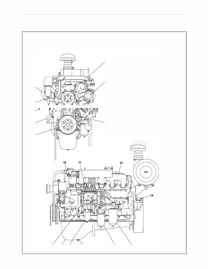
DESCRIPTION
Model: K13C-T
1
2
5
6
7
 3
3
9
1.
2.
3. 4. 5. 6. 7. 8. 9. 10. 11. 12. 13. 14. 15. 16.
17.
18.
19.
Fuel injection nozzle Generator
Engine oil filler cap Tension pulley Turbocharger Exhaust manifold Cooling fan pulley Coolant pump Crankshaft pulley Fuel filter
Fuel injection pump Intake manifold Inspection hole Engine oil level gauge Oil pan
Water separator (If so equipped)
Engine oil drain plug Oil filter (Fuel flow) Oil filter (Bypass)
S6-K13-0001A

Hino K13C
Hino K13D
DESCRIPTION
Model: K13D-T
1.
2. 3.
4. 5. 6. 7. 8. 9.
10.
11.
12.
13.
14.
15.
16.
17.
18.
19.
Fuel injection nozzle Generator
Engine oil filler cap Tension pulley Turbocharger Exhaust manifold Cooling fan pulley Coolant pump Crankshaft pulley Fuel filter
Fuel injection pump Intake manifold Inspection hole Engine oil level gauge Oil pan
Water separators (If so equipped) Engine oil drain plug Oil filter (Fuel flow) Oil filter (Bypass)
13

HINO K13C T CYLINDERHEAD PARTS
OVERHAUL
Model: K13C-T
2 4
12
8
6
{150-180, 10.5-13}
|
S6-K13-003A |
|||
|
T:Tightening torque:N-m {kgf-cm, lfb-ft} |
|||
|
1. |
0-ring |
10. |
Cylinder head additional bolt |
|
2. |
Plate |
Diameter 12 mm {0.47 in.} |
|
|
3. |
Ventilator |
11. |
Clip |
|
4. |
Cylinder head cover |
12. |
Hose |
|
5. |
Cylinder head cover gasket |
13. |
Nozzle holder gasket |
|
6. |
Engine hanger |
14. |
Nozzle holder adapter |
|
7. |
Cylinder head |
15. |
Packing ring |
|
8. |
Cylinder head gasket |
16. |
Nozzle holder |
|
9. |
Cylinder head bolt |
17. |
Nozzle |
|
Diameter 16 mm {0.63 in.} |
18. |
Nozzle holder gauge |
|
|
19. |
Baffle plate |
|
Hino K13D Engine Parts Contact: |
email EngineParts@HeavyEquipmentRestorationParts.com |
|
Phone: 269 673 1638 |
Website: www.HeavyEquipmentRestorationParts.com |

OVERHAUL
Model: K13C-T
T:39-49 {400-500, 28-36}
5
10
11
I
I -!.-‘
Jl) I‘ ,.
I
I
12
1.Cylinder head
2.Retainer ring
|
3. |
Plain washer |
|
4. |
Bushing |
5.Rocker arm
6.Rocker arm support
7.Valve stem cap
8.Valve cotter
1
16
|
S6-K13-0004 |
|||
|
T = Tightening torque: N-m {kgf-cm, lbf-ft} |
|||
|
9. |
Valve spring upper seat |
17. |
Valve guide |
|
10. |
Valve spring |
18. |
Pipe |
|
11. |
Valve spring lower seat |
19. |
Spacer |
|
12. |
Valve |
20. |
Exhaust manifold fitting nut |
|
13. |
Valve clearance adjusting screw |
21. |
plug |
|
14. |
Push rod |
22. |
Valve seat |
|
15. |
Valve lifter |
23. |
Intake manifold fitting nut |
|
16. |
Valve stem oil seal |
24. |
Straight pin |
|
Hino K13D Engine Parts Contact: |
email EngineParts@HeavyEquipmentRestorationParts.com |
|
Phone: 269 673 1638 |
Website: www.HeavyEquipmentRestorationParts.com |

HINO K13D T CYLINDER HEAD PARTS
OVERHAUL Model: K13D-T
T: 13-18 {130-190, 10-13}
T: 265-284 {2,700-2,900, 196-209} for 0 16
|
T: 45-49 |
3 — |
—z |
|||||||
|
{450-500, 33-36} |
2 |
! I |
{800-900, 58-65} |
||||||
|
for 0 12 |
|||||||||
|
14 |
1 |
||||||||
|
J————1, |
|||||||||
|
13 |
|||||||||
|
10 |
{150-180, 10.5-13} |
||||||||
|
12 |
T: 19-26 |
|
/ |
{190-270, 14-19} |
1.Cylinder head cover gasket
2.Cylinder head cover
3.Ventilator
4.Flange
5.Valve stem oil seal
6.Cylinder head bolt
|
7. |
Cylinder head additional bolt |
|
S6-K13-0005 |
|||
|
T = Tightening torque: N-m {kgf-cm, lbf-ft} |
|||
|
8. |
Cylinder head |
15. |
Nozzle holder gasket |
|
9. |
Cylinder head gasket |
16. |
0-ring |
|
10. |
Engine hanger |
17. |
Nozzle holder adapter |
|
11. |
Straight pin |
18. |
Packing ring |
|
12. |
Intake manifold fitting bolt |
19. |
Nozzle holder |
|
13. |
Spacer |
20. |
Nozzle |
|
14. |
Exhaust manifold fitting bolt |
21. |
Nozzle holder gauge |
Hino K13D Engine Parts Contact: email EngineParts@HeavyEquipmentRestorationParts.com Phone: 269 673 1638 Website: www.HeavyEquipmentRestorationParts.com

OVERHAUL
Model: K13D-T
|
T—40-49 |
T:148-166 {1,500-1,700 |
109-122) |
|
{400-500 29-36) |
11
1
S6-K13-0006
|
. |
|||||
|
T = Tightening torque. N-m {kgf-cm, lbf-ft} |
|||||
|
1. |
Cylinder h_ead |
8. |
valve cotter |
15. |
Valve lifter |
|
2 |
Retainer rmg |
9 |
. |
16. |
Valve st m oil seaI |
|
Valve sprmg upper seat |
|||||
|
3: Plain washer |
10.• |
Va1ve spring |
17. |
Valve guide |
|
|
4_ |
Bushing |
11. |
. |
18. |
Pipe |
|
Valve sprmg lower seat |
|||||
|
5. |
Rocker arm |
12. |
Valve |
19. |
Plug |
|
6. |
Roeker arm support |
13. |
Valve clearance adjusting screw |
20. |
Valve seat |
|
7_ |
vaIve stem cap |
14. |
Push rod |
Hino K13D Engine Parts Contact: email EngineParts@HeavyEquipmentRestorationParts.com Phone: 269 673 1638 Website: www.HeavyEquipmentRestorationParts.com

|
Hino K13C |
||
|
EN-20 |
Hino K13D |
ENGINE |
SPECIAL TOOL
Prior to starting an engine overhaul, it is necessary to have these special tools.
|
NOZZLE HOLDER ADAPTER |
CYLINDER HEAD BOLT |
|
WRENCH |
SOCKET WRENCH |
|
ST-0295 |
||
|
09503-1010 |
09621-1090 (Width across flats: |
|
|
22 mm {0.866 in.I) |
||
|
09621-1120 (Width across flats: |
||
|
24 mm {0.945 in.I) |
||
|
VALVE SPRING PRESS |
VALVE LAPPING TOOL |
|
ST-0298 |
ST-0007 |
|
|
09470-1022 |
09431-1010 |
WIRE
ST-0005
09491-1020 Dia. 12 mm {0.47 in.}
09491-1030 Dia. 9 mm {0.35 in.}
ADAPTER
(Used with 09621-1090, 09621-1120)
ST-0297
09621-1020
VALVE STEM SEAL PRESS
ST-0299
09472-1041 (K13C-T)
09472-1570 (K13D-TI

|
Hino K13C T |
||
|
Hino K13D T |
ENGINE |
EN-21 |
IMPORTANT POINTS — DISMOUNTING
CLEAN OFF SURROUNDING AREA OF THE NOZZLES AND THE
FUEL LINE CONNECTORS.
NOTE: If foreign matter is allowed to enter the combustion chamber, engine trouble may result.
REMOVE THE FUEL INJECTION PIPES.
Cover open ends of pipes and fuel injection pump to pre vent entry of dirt.
SM3-886
REMOVE THE NOZZLE HOLDER.
1.Remove the nozzle holder gauge and nozzle holders.
NOTE: Be carefulwhen handling the gauge so that it is not bent or broken.
|
2. |
Remove the nozzle holder adapter from the cylinder head |
|
using the adapter wrench, if needs. |
|
|
Special Tool: Nozzle Holder Adapter Wrench (09503-1010) |
|
|
3. |
Cover open ends of the nozzle holder connectors to prevent |
|
S6-K13—0009 |
of dirt. |
REMOVE THE CYLINDER HEAD ADDITIONAL BOLT.
NOTE: Additional bolt is 12 mm {0.47 in} dia.
S6-K13—0010
REMOVE THE ROCKER ARM ASSEMBLY.
Loosen the rocker arm support bolts and remove the rocker arm assembly.
NOTE: o Attention should be paid to the fact that the rocker arms of the intake and exhaust valves are mounted different directions.
o Keep the components in their disassembly order for easy reassembly.
S6-K13-0011

|
Hino K13C T |
|
|
EN-22 Hino K13D T |
ENGINE |
SM3-K0026
|
CYLINDER HEAD |
PRY UP AND |
|
DOWN |
D □ □ □
SM3-F0013
LOOSE THE CYLINDER HEAD BOLTS AND REMOVE THEM.
Using special tools, loosen the cylinder head bolts little by little in three stages and in the numerical order as shown in the figure.
Special Tool: Socket Wrench (09621-1090, 09621-1120) Adapter (009621-1020)
LIFT THE CYLINDER HEAD FROM THE DOWELS ON THE CYLIN DER BLOCK AND PLACE IT ON WOODEN BLOCKS.
1.If it is difficult to lift off the cylinder head, pry with a chisel between the cylinder head and block.
NOTE: Do not damage the machined surface of the cylinder head or block when removing the cylinder head.
IMPORTANT POINT-DISASSEMBLING
REMOVE THE VALVE SPRINGS.
1. Remove the valve cotters, valve spring upper seats, and valve springs from the cylinder head.
Special Tool: Valve Spring Press (09470-1022)
2.Remove the intake and exhaust valves.
3.Attaching tags to the valves (giving corresponding cylinder Nos.) will eliminate time required for lapping the valve seats on reassembly.
IMPORTANT POINTS-ASSEMBLY
CLEAN THE CYLINDER HEAD THOROUGHLY WITH A SUITABLE SOLVENT.
NOTE: Be careful not to damage the cylinder head surface.
SM3-825
IF NECESSARY, HAND-LAP THE VALVE AND VALVE SEAT.
Apply lapping compound lightly to the contact surfaces of the valve and valve seat. Turn the valve using the special tool and tap the valve lightly.
Special Tool: Valve Lapping Tool (09431-1010)
SM3-364

|
Hino K13C T |
||
|
Hino K13D T |
ENGINE |
EN-23 |
|
SM3-J507A |
=:,——o—c, |
|
SM3-J507 |
u u
|
30• |
V |
,· |
‘J4s• |
|
|
INTAKE |
EXHAUST |
SM3-F0045
HAMMER-
VALVE SEAT
VALVE
IF NECESSARY, GRIND THE VALVES AND VALVE SEATS.
NOTE: o Grinding of valves and valve seats should only be performed when hand-lapping doesnot result inproper seating.
o After grinding, always recheck the valve sink.
Valve face angle and valve seat angle:
|
K13C-T |
K13D-T |
|
|
Valve seat (Intake) |
30°-30°15′ |
30°-30°30′ |
|
Valve face (Intake) |
29°45′-30′ |
29’30’-30′ |
|
Valve seat (Exhaust) |
45°-45°15′ |
45°-45°30′ |
|
Valve face (Exhaust) |
44°15′-45° |
45°30′-45° |
IF NECESSARY, REPLACE THE VALVE SEAT.
1.When replacing the valve seat, cut three places on the cir cumference of an unwanted valve and weld it to the valve seat. Place a brass block at the top of the valve stem and strike it with a hammer to remove the valve seat.
|
30‘ |
A |
|
|
EXHAUST |
||
|
jD |
c- |
|
|
30°jlNTAKE |
45,..,7x:usT |
S6-K13-0013
SM3-826
Dimensions of Hino K13C K13D valve seat machining
|
Unit: mm {in.} |
|||||
|
Intake |
Exhaust |
||||
|
Cylinder |
A |
61.000-61.019 |
55.000-55.019 |
||
|
{2.4016-2.4023} |
{2.1654-2.1661} |
||||
|
head |
11.2-11.3 |
11.2-11.3 |
|||
|
dimension |
B |
||||
|
{0.4410-0.4448} |
{0.4410-0.4448} |
||||
|
C |
61.085-61.100 |
55.085-55.100 |
|||
|
Valve seat |
{2.4050-2.4055} |
{2.1688-2.1692} |
|||
|
dimension |
D |
9.80-10.0 |
8.80-9.00 |
||
|
{0.3859-0.3937} |
{0.3465-0.3543} |
||||
2.Heat the cylinder head to about 80°-100°C {176-212°F} in hot water. On the other hand, cool the valve seat with dry ice or ice water for about 15 minutes. Hold the seat with pincers and place it into the heated cylinder head.

|
Hino K13C T |
||
|
EN-24 |
Hino K13D T |
ENGINE |
(A)
SM3-K0002
L-7 SPECIAL
P·fl.,/TOOL
. VALVE STEM OIL SEAL
SPRING
COAT OIL
RUBBER
S6-K13-0014
PAINT
SM3-1986
IF NECESSARY, REPLACE THE HINO K13C VALVE GUIDES.
1.Remove the valve stem oil seal.
2.Using a brass rod and hammer, install the valve guide as shown in the figure.
Valve Guide Height (Al: 22.1-23.1 mm {0.871-0.909 in.}
NOTE: Apply engine oil lightly to the valve guide outer circum ference before installation.
IF NECESSARY, REPLACE THE VALVE STEM OIL SEAL.
After removing the valve stem oil seal, install the valve spring lower seat and valve, then apply engine oil to the oil seal lip. Strike the valve stem oil seal into the valve guide with the special tool.
Special Tool: Valve Stem Seal Press (09472-1570)
NOTE: o After installing of the oil seal, check for deformation or cracking of the rubber.
oDo not use the special tool if its tip (surface contacting valve spring lower seat) is worn or deformed.
INSTALL THE VALVE AND VALVE SPRING .
NOTE: o Apply engine oil to the contact surfaces of each parts.
oMake sure that the valves are installed in the correct cylinders.
oSince this valve spring is evenly pitched, it can be installed either end up.
Press valve spring upper seats, then install the valve cotters securely in the valve spring upper seats.
Special Tool: Valve Spring Press (09470-1022)
NOTE: o When the valve spring is compressed, be careful of damage to the valve stem oil seals due to contact of the valve spring upper seats.
oStrike the valve stem lightly with a hammer to assure proper fit the valve cotter.
![]()
Tightening torque
50% of specified torque
75% of specified torque
100% of specified torque
|
Hino K13C T |
||
|
Hino K13D T |
ENGINE |
EN-25 |
ROCKER ARM (INTAKE)
SM3-K0003
SM3-K0004
w
0
Cf)
er:
<{ w
(9
(9z
i==
SM3-K0005
HINO K13C T HEAD BOLT
TIGHTENING SEQUENCE
HINO K13D T HEAD BOLT
TIGHTENING SEQUENCE
ASSEMBLE THE ROCKER ARM.
Lubricate the rocker arm shaft and bushing, then assemble the rocker arms and shaft as shown in the figure.
INSTALL THE CYLINDER HEAD.
1.Install the cylinder head gasket.
NOTE: Always use new cylinder head gasket after cleaning the surfaces of the cylinder head, cylinder brock and head gasket free of all dirt, water and grease.
2.Using special tools, tighten the cylinder head bolts in three stage following the tightening order as shown.
NOTE: o Apply engine oil to the bolt threads and under the bolt head.
o No.15 is 12 mm {0.47 in.} dia. bolt and others are 16
—-mm {0.63 in.} dia. bolts for K13D-T, 18 mm {0.70 in.} dia. bolts for K13C-T.
Special tools: Socket Wrench (09621-1090, 09621-1120) Adapter (09621-1020)
1st step
2nd step
3rd step
|
Hino K13D Engine Parts Contact: email |
EngineParts@HeavyEquipmentRestorationParts.com |
|
Phone: 269 673 1638 |
Website: www.HeavyEquipmentRestorationParts.com |

|
Hino K13C T |
||
|
EN-26 |
Hino K13D T |
ENGINE |
S6-K13-0016
SM3-427
O-RING
GROOVE
S6-K13-0019
|
—•-•—•- |
||
|
DIRECTION OF THE ADAPTER |
||
|
‘ |
I |
I |
|
I |
I |
I |
|
AXIS OF THE |
||
|
CRANKSHAFT |
S6-K13-0020 |
|
|
GAUGE |
||
|
! : |
NOZZLE HOLDER |
—
S6-K13-0021
INSTALL THE ROCKER ARM.
1.Install the valve stem caps.
NOTE: o Make sure that both the end of the valve stem and the inside of the valve stem cap are free from dust.
oApply engine oil to the valve stem ends and put the valve stem caps on the valve stem ends.
oDo not drop the valve stem cap into the engine.
2.Apply engine oil to both ends of push rod and insert the push rods in correct order.
3.Mount the rocker arm assembly on the cylinder head, make sure that the push rods interlock with the adjusting screws.
NOTE: Always loosen the lock nut and raise the adjusting screws fully to the top.
4.Tighten the rocker arm support fitting bolts.
INSTALL THE NOZZLE HOLDER ADAPTER.
1.Insert the new 0-ring to the nozzle holder adapter.
2.Using a special tool, screw-in into the cylinder head until it is stopped.
Special Tool: Nozzle Holder Adapter Wrench (09503-1010)
NOTE: When the adapter is removed, replace the O-ring with a new one and apply engine oil.
3.Loosen and adjust the adapter within 1/2 turns so the line connecting the tapped holes on the nozzle holder adapter flange meets the crankshaft at a right angle.
INSTALL THE NOZZLE HOLDER.
1.Insert a packing ring to the underside of the nozzle holder flange, fit a new nozzle holder gasket to the tip of the nozzle holder and insert the nozzle holder into the adapter.
NOTE: o When mounting the nozzle holder, direct the high pressure inlet connector towards the engine front side (timing gear side).
oThe projection of the packing ring towards the ex haust manifold side.

|
Hino K13C T |
ENGINE |
EN-27 |
|
|
Hino K13D T |
|||
NOZZLE HOLDER GAUGE
PACKING RING
4.5-5.5 mm {0.1772-0.2165 in.l=?,1,
S6-K13-0019
2.Place the nozzle holder gauge on the upper surface of the nozzle holder flange, align holes of the gauge, holder flange and adapter, and tighten the bolt.
NOTE: After tightening the bolt, confirm that the clearance be tween the upper surface of the nozzle holder adapter and lower surface of the holder flange is 4.5-5.5 mm {0.1772-0.2165 in.}, and the nozzle holder gauge is free from deflection and bending. (The nozzle holder gauge is used for locating to the nozzle holes).
|
Hino K13D Engine Parts Contact: |
email EngineParts@HeavyEquipmentRestorationParts.com |
|
Phone: 269 673 1638 |
Website: www.HeavyEquipmentRestorationParts.com |

|
EN-28 |
ENGINE |
||||||||||||||||||||||||||||||||
|
Hino K13C T |
INSPECTION AND REPAIR |
||||||||||||||||||||||||||||||||
|
Hino K13D T |
|||||||||||||||||||||||||||||||||
|
Unit: mm {in.} |
|||||||||||||||||||||||||||||||||
|
Inspection Item |
Standard |
R |
Limit |
Remedy |
Inspection Procedure |
||||||||||||||||||||||||||||
|
Cylinder Head Flatness |
0.05 {0.0019} |
li |
i |
t |
Regrind. |
||||||||||||||||||||||||||||
|
or less |
___ __ |
_ |
|||||||||||||||||||||||||||||||
|
_:: o 8_: |
|||||||||||||||||||||||||||||||||
|
— |
__ |
— |
__ _, |
: |
|||||||||||||||||||||||||||||
|
Service limit |
|||||||||||||||||||||||||||||||||
|
Replace. |
|||||||||||||||||||||||||||||||||
|
,. |
0.30 |
,.,- |
|||||||||||||||||||||||||||||||
|
Cylinder Head: |
{0.011 8} |
Replace, |
V sual check |
,Y |
|||||||||||||||||||||||||||||
|
SM3-F0050 |
|||||||||||||||||||||||||||||||||
|
Cranks and Damage |
if necessary. |
ill |
|||||||||||||||||||||||||||||||
|
(Dye penetrate check) |
|||||||||||||||||||||||||||||||||
|
c:;Jo OJ::Yb |
|||||||||||||||||||||||||||||||||
|
Valve Seating Condition |
There should be |
Hand-lap with |
Visual check |
SM3—F0052 |
|||||||||||||||||||||||||||||
|
the lapping |
|||||||||||||||||||||||||||||||||
|
(Use of red lead marking |
good contact around |
compound. |
|||||||||||||||||||||||||||||||
|
compound) |
entire circumference |
b |
|||||||||||||||||||||||||||||||
|
of valve head. |
|||||||||||||||||||||||||||||||||
|
Intake |
29°45′-30° (K13C-T) |
Regrind or |
Measure. |
SM3—F0053 |
|||||||||||||||||||||||||||||
|
Hino K13C |
|||||||||||||||||||||||||||||||||
|
Hino K13D |
29 |
° |
30′-30 |
° |
(K13D-T) |
replace the valve |
|||||||||||||||||||||||||||
|
Valve Face Angle |
t——-+ |
and/or the valve |
|||||||||||||||||||||||||||||||
|
44°15′-45° |
(K13C-T) |
seat. |
|||||||||||||||||||||||||||||||
|
————1 |
|||||||||||||||||||||||||||||||||
|
Exhaust |
44°30′-45° (K13D-T) |
uwu |
|||||||||||||||||||||||||||||||
|
Hino K13D |
30 -30 15′ (K13C-T) |
||||||||||||||||||||||||||||||||
|
Hino K13C |
1— |
In |
ake |
° |
° |
30· |
V |
,· |
«‘)45· |
||||||||||||||||||||||||
|
INTAKE |
EXHAUST |
||||||||||||||||||||||||||||||||
|
Valve Seat Angle |
|||||||||||||||||||||||||||||||||
|
° |
° |
||||||||||||||||||||||||||||||||
|
t |
-+ |
30 |
-30 30′ (K13D-TI |
||||||||||||||||||||||||||||||
|
— |
——- |
—1 |
|||||||||||||||||||||||||||||||
|
Exhaust |
45°-45°15′ (K13C-T) |
||||||||||||||||||||||||||||||||
|
44°-45°30′ (K13D-TI |
Replace, |
Visual check |
SM3-F0045 |
||||||||||||||||||||||||||||||
|
Adjusting Screws and |
|||||||||||||||||||||||||||||||||
|
if necessary. |
|||||||||||||||||||||||||||||||||
|
Push Rods: |
|||||||||||||||||||||||||||||||||
|
Damage |
|||||||||||||||||||||||||||||||||
|
Rocker Arm and Valve Stem |
Resurface or |
Visual check |
SM3-1066 |
||||||||||||||||||||||||||||||
|
Cap: |
replace. |
||||||||||||||||||||||||||||||||
|
Wear and Damage |
|||||||||||||||||||||||||||||||||
|
SM3-1103 |
|||||||||||||||||||||||||||||||||
|
Hino K13D Engine Parts Contact: |
email EngineParts@HeavyEquipmentRestorationParts.com |
|
Phone: 269 673 1638 |
Website: www.HeavyEquipmentRestorationParts.com |

|
ENGINE |
EN-29 |
||||||||||||
|
Hino K13C |
|||||||||||||
|
Hino K13D |
Unit: mm {in.} |
||||||||||||
|
Inspection Item |
Standard |
Limit |
Remedy |
Inspection Procedure |
|||||||||
|
Upper Spring Seats and |
A |
3.0 {0.118} |
(Wear of A+ |
Replace. |
Measure. |
||||||||
|
Lower Spring Seats: |
wear of CJ |
||||||||||||
|
Wear and Damage |
and/or |
||||||||||||
|
B |
6.0 {0.236} |
(wear of B + |
|||||||||||
|
wear of CJ is |
|||||||||||||
|
more than |
LOWER |
||||||||||||
|
C |
1.0 {0.039} |
µ SEAT |
_ |
||||||||||
|
1.0 {0.039} |
|||||||||||||
|
Nozzle Protrusion from |
4.75-5.25 |
Replace the |
|||||||||||
|
Cylinder Head Surface |
{0.1871-0.2066} |
nozzle holder |
|||||||||||
|
gasket. |
|||||||||||||
|
S6-K13-0091 |
|||||||||||||
|
Intake Valve Sink |
0.75-1.00 |
0.25 |
Replace the valve |
Measu e. |
|||||||||
|
{0.0296-0.0393} |
{0.0098} |
and/or the valve |
«O» IS CYLINDER |
C+) |
|||||||||
|
seat. |
HEAD SURFACE«‘- ‘j |
||||||||||||
|
1 : |
|||||||||||||
|
Exhaust Valve Sink |
0.45-0.70 |
-0.05 |
|||||||||||
|
{0.0178-0.0276} |
{-0.0019} |
r. |
|||||||||||
|
Intake Valve Stem Outside |
12.0 {0.4724} |
11.85 |
Replace the valve |
Measure. |
|||||||||
|
Diameter |
{0.4665} |
guide and/or |
|||||||||||
|
the valve seat. |
|||||||||||||
|
Exhaust Valve Stem Outside |
12.0 {0.4724} |
11.80 |
|||||||||||
|
Diameter |
{0.4645} |
||||||||||||
|
A: 10 {0.394} |
|||||||||||||
|
Intake Valve Guide Inside |
12.0 {0.4724} |
||||||||||||
|
B: 30 {1.181} |
|||||||||||||
|
Diameter |
|||||||||||||
|
C: 67 {2.638} |
|||||||||||||
|
Exhaust Valve Guide Inside |
12.0 {0.4724} |
||||||||||||
|
Diameter |
|||||||||||||
|
Clearance between Valve |
0.050-0.080 |
0.30 |
|||||||||||
|
{0.0020-0.0031} |
|||||||||||||
|
Stem and Valve Guide |
{0.0118} |
||||||||||||
|
(Intake) |
|||||||||||||
|
SM3-F0042 |
|||||||||||||
|
Clearance between Valve |
0.070-0.113 |
0.35 |
|||||||||||
|
Stem and Valve Guide |
{0.0028-0.0044} |
{0.0137} |
|||||||||||
(Exhaustl
|
Hino K13D Engine Parts Contact: |
email EngineParts@HeavyEquipmentRestorationParts.com |
|
Phone: 269 673 1638 |
Website: www.HeavyEquipmentRestorationParts.com |

|
EN-30 |
ENGINE |
|||||||||||
|
Hino K13C |
||||||||||||
|
Hino K13D |
||||||||||||
|
Unit: mm {in.} |
||||||||||||
|
Inspection Item |
Standard |
Limit |
Remedy |
Inspection Procedure |
||||||||
|
Rocker Arm Shaft Outside |
28.0 {1.1024} |
27.92 |
Replace. |
Measure. |
||||||||
|
Diameter |
{1.0092} |
|||||||||||
|
Rocker Arm BushingInside |
28.0 {1.1024} |
28.08 |
Replace. |
|||||||||
|
Diameter |
{1.1055} |
|||||||||||
|
K13C-T |
0.044-0.112 |
0.15 |
Replace. |
|||||||||
|
Clearance between |
{0.0017-0.0044} |
{0.0059} |
||||||||||
|
Rocker Arm Shaft |
||||||||||||
|
and Rocker Arm |
0.020-0.054 |
|||||||||||
|
Bushing |
K13D-T |
|||||||||||
|
{0.008-0.0021} |
||||||||||||
|
S6-K13-0098 |
||||||||||||
|
Valve Spring Setting Load |
438 N |
397 N |
Replace. |
Measure. |
||||||||
|
{44.7 kgf, 99 lbf} |
{40.5 kgf, |
|||||||||||
|
at |
89Ibf} |
|||||||||||
|
57.5(2.264) |
||||||||||||
|
SM3-F0046 |
||||||||||||
|
Valve Spring Squareness |
2.0 |
Replace. |
Measure. |
|||||||||
|
{0.0787} |
||||||||||||
|
or less |
||||||||||||
|
-=- |
||||||||||||
|
J,l |
||||||||||||
|
Push Rod Bend |
0.5 |
Replace. |
Measure. / |
|||||||||
|
{0.0196} |
« |
|||||||||||
|
‘ |
||||||||||||
|
….._,____ SM3-292 |
|
Hino K13D Engine Parts Contact: |
email EngineParts@HeavyEquipmentRestorationParts.com |
|
Phone: 269 673 1638 |
Website: www.HeavyEquipmentRestorationParts.com |

|
OVERHAUL |
||||
|
7 |
||||
|
1. |
Collar |
|||
|
2. |
Torsional dumper |
|||
|
3. |
Coupling |
|||
|
— |
4. |
Crankshaft pulley |
||
|
5. |
Sleeve |
|||
|
6. |
0-ring |
|||
|
7. |
Dust slinger |
|||
|
T:98-117 |
/ |
|||
|
/’ |
||||
|
{1,000-1,200, 73-86} |
||||
|
®—1 |
||||
|
T:823 {8,400, 607} |
SM6-K13-0023 |
|||
|
T = Tightening torque: N-m {kgf-cm, lbf-ft} |
||||
SPECIAL TOOL
Prior to starting an engine overhaul, it is necessary to have these special tools.
|
ST-0088 |
ST-0108 |
|
|
09402-1250 |
9851-70101 |
|
Hino K13D Engine Parts Contact: email |
EngineParts@HeavyEquipmentRestorationParts.com |
|
Phone: 269 673 1638 |
Website: www.HeavyEquipmentRestorationParts.com |

EN-32
Hino K13C
Hino K13D
ENGINE
IMPORTANT POINT-DISMOUNTING
REMOVE THE CRANKSHAFT PULLEY.
NOTE: o Use a puller if necessary.
oDo not remove the crankshaft gear unless it consid ered absolutely necessary.
IMPORTANT POINT-ASSEMBLY
REPLACE THE DUST SLINGER.
1. Remove the dust slinger with lever.
SM3-1059
|
TSLINGER |
Special tools: Press (09402-1250) |
|||||
|
2. |
Using the special tools, install the dust slinger. |
|||||
|
SPECIAL TOOL |
||||||
|
r |
J |
O-ring (9851-70101) |
||||
|
NOTE: |
To prevent wear of the side lip of the oil seal, inject |
|||||
|
, : :,::24 |
about 0.5-1 cm3 {0.03-0.061 cu•in.} of grease (lithium |
|||||
|
based) into the «U» groove of the dust slinger. |
||||||
|
IMPORTANT POINT-MOUNTING |
||||||
|
INSTALL THE CRANKSHAFT PULLEY. |
||||||
|
NOTE: |
Apply engine oil to thread of the crankshaft. |

|
FLYWHEEL AND FLYWHEEL HOUSING |
Hino K13C T |
|
Hino K13D T |
OVERHAUL
45
T=128-137 {1,300-1,400, 94-101}
T=o16 mm {0.630 in}: 125-135 {1,300-1,400, 94-100} T:020 mm {0.787 in}: 215-235 {2,200-2,400, 155-170}
1.Stay
2.Shim
3.Flywheel housing
4.Inspection hole cover
5.Oil seal retainer
6.Oil seal
7.Ring gear
8.Flywheel
S6-K13-0025
T = Tightening torque: N-m {kgf-cm, lbf-ft}
SPECIAL TOOL
Prior to starting an engine overhaul, it is necessary to have this special tool.
PRESS
ST-0288
09420-1050
PRESS
OIL SEAL RETAINER
APPLY OIL ON CIRCUMFERENCE S6-K13-0026
IMPORTANT POINTS — MOUNTING
IF NECESSARY, REPLACE THE OIL SEAL.
1.Remove the oil seal.
2.Insert the oil seal to the oil seal retainer, ensuring that it is
flush with the end of the oil seal retainer.
NOTE: Ensure that the lip of the oil seal is coated with oil seal lubricating grease (lithium-based).
Special tool: Press (09482-1050)

|
Hino K13C |
|
|
EN-34 Hino K13D |
ENGINE |
EXAMPLE EXAMPLE
EXAMPLE
EXAMPLE
|
SM3-2600 |
||
|
TIGHTENING |
«O» MARK |
|
|
ORDER |
(01 |
COLLAR |
|
CRANKSHAFT |
,…
0 ,.}’0
0Q0
000
IF NECESSARY, REPLACE THE RING GEAR.
1.Remove the ring gear.
a. Heat the ring gear evenly to about 200° C {392° F} with a torch.
NOTE: Be careful not to overheat the ring gear.
b.Strike the ring gear periphery lightly using a metal rod as a pad to remove the ring gear.
WARNING
Never touch the ring gear or flywheel while they are hot with your bare hands.
2.Install the ring gear.
a.Heat the ring gear evenly to about 200° C {392° F} with a torch.
NOTE: Be careful not to overheat the ring gear.
b.Insert the ring gear into the flywheel so that the chamfered side is upward.
WARNING
Never touch the ring gear or flywheel while they are hot with your bare hands.
INSTALL THE FLYWHEEL.
Install the flywheel and tighten the bolts through a tighten ing order with several repetition so as to reach specified torque evenly and gradually, then slacken to tighten them securely one by one with the specified torque.
WARNING
The flywheel is too heavy. When installing, be careful not to drop it on your feet.
NOTE: o Align the «O» mark on the flywheel and crankshaft collar knock-pin.
oWhen tightening the bolt, apply engine oil to the threads and flywheel surface of the bolts.
SM3-J128
|
Hino K13D Engine Parts Contact: |
email EngineParts@HeavyEquipmentRestorationParts.com |
|
Phone: 269 673 1638 |
Website: www.HeavyEquipmentRestorationParts.com |
 Loading…
|
Title |
File Size |
Download Links |
|
Hino 155DC 2019 Technical Specifications [PDF] |
2.3Mb |
Download |
|
Hino 195 2017 Technical Specifications [PDF] |
4.2Mb |
Download |
|
Hino 195h 2016 Technical Specifications [PDF] |
4.6Mb |
Download |
|
Hino 195h 2020 Technical Specifications [PDF] |
2.3Mb |
Download |
|
Hino 238 2017 Technical Specifications [PDF] |
2.5Mb |
Download |
|
Hino 238 2020 Technical Specifications [PDF] |
1.9Mb |
Download |
|
Hino 238, 258LP, 268, 338, 358 Workshop Manual [PDF] |
21.8Mb |
Download |
|
Hino 258 ALP 2020 Technical Specifications [PDF] |
1.7Mb |
Download |
|
Hino 258LP 2016 Technical Specifications [PDF] |
3.2Mb |
Download |
|
Hino 268a 2020 Technical Specifications [PDF] |
2.5Mb |
Download |
|
Hino 338 2017 Technical Specifications [PDF] |
3.4Mb |
Download |
|
Hino 338 2020 Technical Specifications [PDF] |
1.8Mb |
Download |
|
HINO Accessories Catalog / V18 [PDF] |
1.3Mb |
Download |
|
Hino Diagnostico y Cod. Fallas Sistema Tics 500-600 [PDF] |
2.6Mb |
Download |
|
Hino Diesel Trucks 1984-1997 Quick Reference Parts Catalog |
9Mb |
Download |
|
Hino Diesel Trucks 1998-2004 Quick Reference Parts Catalog |
1.6Mb |
Download |
|
Hino Dx Activation Users Manual [PDF] |
396.1kb |
Download |
|
Hino Electrical Wiring Diagram [PDF] |
12.5Mb |
Download |
|
Hino Engine Hand Book Parts Catalog [PDF] |
5.2Mb |
Download |
|
Hino FC 1022 ProShift 6 Service Manual [PDF] |
867.2kb |
Download |
|
Hino FC 1022 Service Manual [PDF] |
867.2kb |
Download |
|
Hino Manual Book [PDF] |
10.8Mb |
Download |
|
Hino Parts Torque Summer2012 [PDF] |
4.1Mb |
Download |
|
Hino Quick Reference Parts Catalog 1998 – 2004 Model Year Edition |
1.7Mb |
Download |
|
Hino RB14 Bus Workshop Manual [PDF] |
16.5Mb |
Download |
|
Hino S5-LJ05E04A, S5-LJ05E05A Workshop Manual [PDF] |
45.5Mb |
Download |
|
Hino Series 155, 155H, 195, 195H Workshop Manual [PDF] |
23.2Mb |
Download |
|
Hino Truck 2005-2010 Quick Reference Guide [PDF] |
640.3kb |
Download |
|
Hino Trucks 2005 — 2010 Quick Reference Parts Catalog [PDF] |
640.4kb |
Download |
|
Hino Trucks 2011 — 2013MY NAPS Vin Setup [PDF] |
5.8Mb |
Download |
|
HINO Trucks 2011-2013 Quick Reference Chart [PDF] |
5.8Mb |
Download |
|
Hino Trucks Accessories Catalog [PDF] |
8.6Mb |
Download |
|
Hino Trucks M-Series Technical Specifications [PDF] |
3.3Mb |
Download |
|
HINO VIN Code — LT-0013 Quick Reference Counter Card [PDF] |
1.3Mb |
Download |
|
Hino XL8 2020 Technical Specifications [PDF] |
1.4Mb |
Download |
|
Hino-ePc System Operating Manual [PDF] |
5.7Mb |
Download |
|
Title |
File Size |
Download Links |
|
HINO Dutro Fault Codes list (PDF) [PDF] |
156.9kb |
Download |
|
Hino J05dJ08e Engine ECU Fault Codes List (PDF) [PDF] |
291kb |
Download |
![]()
HINO V18 Accessories Catalog
HINO AccessoriesCatalog_V18.pdf
Adobe Acrobat Document
1.9 MB
![]()
HINO E13C Type Engine Service Manual
HINO E13C Type Engine Service Manual.pdf
Adobe Acrobat Document
968.4 KB
![]()
Hino Dutro Service Repair Manual
Hino Dutro Service Manual.pdf
Adobe Acrobat Document
1.4 MB
![]()
Hino FC 1022 ProShift 6 Service Manual
Hino FC 1022 ProShift 6 Service Manual.p
Adobe Acrobat Document
945.4 KB
![]()
Hino FC 1022 Service Manual
Hino FC 1022 Service Manual.pdf
Adobe Acrobat Document
945.4 KB
![]()
Hino Motors W04C-T Workshop Manual
Hino Motors W04C-T Workshop Manual.pdf
Adobe Acrobat Document
5.2 MB
![]()
Hino Motors W04D Workshop Manual
Hino Motors W04D Workshop Manual.pdf
Adobe Acrobat Document
5.2 MB
![]()
Hino RB145 Motors WO4D/W04C-T Workshop Manual
Hino RB145 Motors Workshop Manual WO4D W
Adobe Acrobat Document
4.4 MB
![]()
HINO Trucks 2011-2013 Quick Reference Chart
HINO Trucks 2011-2013 Quick Reference Ch
Adobe Acrobat Document
5.9 MB
![]()
HINO LT-0013 Quick Reference Counter Card
HINO LT-0013 Quick Reference Counter Car
Adobe Acrobat Document
1.4 MB
![]()
Hino Motors W04C-TI Workshop Manual
Hino Motors W04C-TI Workshop Manual.pdf
Adobe Acrobat Document
5.2 MB
![]()
Hino Motors W06D-TI Workshop Manual
Hino Motors W06D-TI Workshop Manual.pdf
Adobe Acrobat Document
3.4 MB
![]()
Hino Truck 2005-2010 Quick Reference Guide
Hino Truck 2005-2010 Quick Reference Gui
Adobe Acrobat Document
900.1 KB
![]()
HINO_Engine Manual W04_W06
HINO_Engine Manual W04_W06.rar
compressed file archive
9.4 MB
Automobile concern HINO at the moment is one of the largest automobile factories in Japan for the production of trucks of medium and large tonnazhnosti. The thread of the history
of the automobile plant stretches from the first manufacturers of trucks — Japan: the Tokyo Shipyard «Tokyo Ishikawajima Shipbuilding — Engineering Co» and the Tokyo Gas and Electric Company —
«Tokyo Gas Electric Industry Co». These firms produced almost identical trucks bearing the «Sumida» and «Chiyoda» brands.
And in 1937 when the enterprises united themselves, the produced trucks were given a different name, «Isuzu» (look: ISUZU truck PDF
Manuals). But in 1941, after another regrouping of its forces, the company again changed its name to «Diesel Motor Industry Co.» A little later in 1942, a reconstruction took place
in which the company, which belonged to the company TGE, separated and at the same time took the name «Hino Heavy Industry Co». In the separated company continued work on the production of 7-ton
trucks with 6-cylinder diesel engines with air cooling capacity of 125 hp.
In 1946, at the automobile plant «HINO«, they developed and built their first diesel-powered tractors with a load capacity of 15 tons and a pneumatic brake drive. In 1948, the
company, renamed «Hino Diesel Industry Co», chose as its main direction the creation of a wide range of diesel engines for heavy trucks. Only in 1953 began assembling a 13.5-tonne dump truck «ZG»
with a 1-seater cabin, a 6-cylinder diesel engine in 175 hp. And 6-speed gearbox.
Only by the end of the 50’s there were basic 2 and 3 axle hood cars «HINO» with a carrying capacity of 4-10 tons («TE», «TN», «ZC»). They were equipped with unified 6-cylinder engines (7014 and
7690 cm3, 125-150 hp), 4-speed gearbox, dual main gears, spring suspension and pneumatic brake drive. In the early 60’s, the automobile company Hino Motors Ltd laid the foundation of its truck
program. Since 1961, the first 35-strong Brisca pickup truck with a load capacity of 750 kg was offered on the chassis of the Contessa passenger car.
A year later, there appeared 3-wheel trucks «Orient» and «Hustler» with a capacity of 12 horsepower with all-metal cabs and bodywork. Interest in such cars was soon lost and the company started
creating new larger trucks. In the 60-ies. The launch of a family of middle class «Ranger» with a cabin above the engine, which included 2-axle 90-strong models «KL», «KM» (4 × 2) and «WB» (4 ×
4) with a carrying capacity of 3-4.5 Tons, 7,5-ton «KS», heavy hood 14 ton dump trucks «ZM» (6 × 4) with a 10-liter diesel engine with a power of 190 horsepower, beskapotnye 200-strong trucks
«TS» (6 × 2) with two front driven bridges.
A feature of heavy vehicles was a 4-step demultiplikator, increasing the total number of transmission transmissions to 16 — 20. In March 1967, the company «HINO» became a part of the automobile
company «Toyota», turning into its subsidiary for the production of medium and heavy trucks. In the seventies, «HINO» was engaged in improving its program and introducing a new range of diesel
engines with direct fuel injection.
In 1980-81, a new range of middle-class Ranger cars was introduced with a gross weight of up to 16.5 tons with an improved cabin above the engine. A year later appeared a heavy scale «Super
Dolphin». Machines equipped with new more economical motors, had the name «Econo Diesel».
The first series included numerous models FB, FC, FD, FE, FF, FG, FT (4 × 2) and all-wheel drive models «FB», «FC», » GD «and» GT «(4 × 4) with a total weight of 7.5-16.5 tons. They were equipped
with economical 4-and 6-cylinder diesel engines (3660-7412 cm3, 113-195 hp) with a new system of HMMS mixture formation. They used a spiral pipe to supply air to the cylinders and three
hemispherical grooves in the head of each piston, which contributed to the appearance of microscopic vortices. This created better mixing of air with fuel, improved temperature conditions,
ensured more complete combustion, reduced fuel consumption and toxicity.

Simultaneously, their simplified hood analogs «NH», «KY» (4 × 2) and «NZ» (4 × 4) were produced. The heavy gamut included the new boneless models «FR» (6 × 2) and «FS» (6 × 4) with a total weight
of 23-26 tons, as well as traditional «ZM», «ZY» (6 × 4), «ZC «(6 × 6) and 16-ton log carriers» WG «(6 × 6) with a total weight of up to 35 tons. They were equipped with naturally aspirated
inline 6-cylinder diesel engines or V8 and V10 engines (9419-24610 cm3, 215-520 hp). The company also offered trunk tractors with a cab above the engine models «SH» (4 × 2) and «SS» (6 × 4) for
road trains with a gross mass of 38-55 tons, capable of speeds of 90-112 km / h.
They were equipped with the most powerful engine options, 9-speed gearboxes and the HIMR energy recovery system (an electric motor built into the flywheel, which acted as a starter, generator and
retarder brake). At that time, «HINO» had a broad program, consisting of 20 basic models, each of which hid a dozen options. On models for Japan since 1981 the first in practice
«HINO» diesel with a turbo-supercharging and intermediate cooling, automatic transmissions, a pneumatic suspension bracket and forward disk brakes was established.
In 1982, the company celebrated the production of a 1 millionth car. By the end of the decade, having produced 27942 trucks with a gross tonnage of more than 15 tons, HINO came in seventh in the
world. In the nineties, trucks HINO received more modern comfortable, safe and streamlined cabins and lightweight low-frame chassis, which allowed the maximum use of the permitted length of a
single car in the country of 12 meters. The new series of the middle class began to be called «Space Ranger».
It included 14 basic models, including on-board FC, FD, FE, GD, FJ (4 × 2), FT, FX, GX (4 × 4 ) «FG» and «GK» (6 × 4) with a carrying capacity of 4-11.5 tons and a total weight of 8.5-17.8 tons.
They were equipped with 4 and 6-cylinder diesel engines without a charge (4899 — 7961 cm3, 140-235 hp) and one version of an 8-liter engine with a turbocharger and intermediate cooling with a
power of 260 horsepower, 5 or 6- Th stepped gearboxes. A number of models were offered with pneumatic suspension and disc brakes with ABS.
In 1999, the new lightweight model «FB» was replaced by a new delivery range «Dutro» with a payload capacity of 2-4 tons, developed jointly with the firms «Toyota» and «Daihatsu». Cars with a
total mass of 4.5-7.5 tons were equipped with diesel engines with a capacity of 130-150 horsepower and a manual transmission. In 1992, the formation of the most complete heavy low-frame series
«Super Dolphin Profia» began. The basic steels were trucks and vans FH (4 × 2), FN, FP, FR, GN (6 × 2), FS and FQ (6 × 4) FW «(8 × 4) with a lifting capacity of 8.9-16.2 tons and at the same time
with a gross mass of 15.7-25.9 tons with engines with a capacity of 300-520 horsepower and a body capacity of up to 66 cubic meters.
The main novelties were variants of «Prophia» and «Profia Teravi» (Teravie) with less toxic motors with variable geometry of the inlet branch pipe of the turbocharger, a mechanical 7-step or
automatic 16-speed gearbox, the predominant use of a pneumatic suspension with electronic chassis level control, With short cabins with a berth over the driver’s seat. In 1999, a 13.7-ton truck,
the Profia Teravi FN, appeared with a long base, with its middle steering bridge moved to the middle of the cargo platform. The series «Super-Dolphin» also included mainline tractors «SH» and
«SS», as well as a 30-ton dump truck «WR».
The cars of this range are used as previous aspirated diesel engines (13267-25977 cm3, 270-480 hp), and new 6-cylinder 24-valve engines with high-pressure injection and turbocharged with
intercooling (10520-12882 cm3, 330 -400 hp), working with mechanical boxes with the number of gears 5-8. Some models are equipped with environmentally friendly engines that run on compressed
natural gas, ABS, electronic brake-force regulation on wheels, electromagnetic retarder brakes, air suspension of cabins and a radar safety device.
In 1996, the company «HINO» released its 2 millionth car. In Japan, it owns 8 plants with a staff of about 10 thousand people, including the largest robotic complex in Hamur near
Tokyo, where all units and parts for cars are manufactured. In addition, the company has several assembly plants in the US, Ireland, Thailand, Egypt, Malaysia, the Philippines. By the end of the
twentieth century, all of them produced annually 80-90 thousand trucks and buses, including machines with a gross mass of more than 6 tons, about 33 thousand pieces. In terms of production, the
company ranks 16th in the world and the third in Japan. HINO trucks are delivered to more than 100 countries. But not so long ago the concern decided to try its truck on Dakar.
Модератор: RANGER
-
Автор темы
DIESEL
- На орбите

- Всего сообщений: 524
- Зарегистрирован: 12.04.2011
- Авто: ND MK251НN FE6ТА 95 год. UNIC 343
- Откуда: 18RUS

Re: Литература и информация по Hino Ranger
Зип на TADANO. UNIC . КМУ
-

Кардан
- На орбите
- Всего сообщений: 939
- Зарегистрирован: 23.03.2012
- Авто: ГАЗ-АА
- Откуда: Россия
- Возраст: 109

Re: Мануал!
Сообщение
Кардан » 19 фев 2013, 13:59
-

MAZDA BONGO
- Модератор
- Всего сообщений: 2233
- Зарегистрирован: 28.05.2009
- Авто: Nissan Vanette Largo 1990, NA20S, 4WD
- Откуда: Ангарск


Re: Руководство по ремонту Hino Ranger
Сообщение
MAZDA BONGO » 03 янв 2014, 17:07
Кардан:Может кому пригодится
того же мнения
-
- Teikin_Catalog_HINO.pdf
- (1.24 МБ) 3757 скачиваний
MAZDA BONGO BONDY N-BA2S8 1984 (минигрузовик-термос) дизель S2 ПРОДАН
NISSAN VANNET LARGO, Q-KUGNC22, 1990, 03ZWUNC22BGFTR, рама, LD20-TII -> NA20S), 5-МКП RS5W71C CA46, 4WD(TX11A) MT (PART-TIME)
whatsapp 79086507313
-

Дед
- Полёт нормальный
- Всего сообщений: 3590
- Зарегистрирован: 16.02.2013
- Авто: Canter
- Откуда: ростов-дон


Нарыл
Сообщение
Дед » 10 янв 2014, 21:11
-
Автор темы
DIESEL
- На орбите
- Всего сообщений: 524
- Зарегистрирован: 12.04.2011
- Авто: ND MK251НN FE6ТА 95 год. UNIC 343
- Откуда: 18RUS
Re: Литература и информация по Hino Ranger
Сообщение
DIESEL » 13 янв 2014, 07:54
Тоже самое только в оригинале и более доступнее: http://hinoshop.sumotori.ru/
Зип на TADANO. UNIC . КМУ
-

иванов иван02
- Полёт нормальный
- Всего сообщений: 1007
- Зарегистрирован: 03.11.2014
- Авто: Hyundai HD78, D4DD (CRDI), МКПП
- Откуда: РФ, Белгород
Re: Литература и информация по Hino Ranger
Сообщение
иванов иван02 » 23 мар 2015, 20:42
Мануал по двигателям HINO моделей W04 и W06
-
Sashka
- Новичок
- Всего сообщений: 5
- Зарегистрирован: 19.08.2015
- Авто: Hino Ranger
Re: Литература и информация по Hino Ranger
Сообщение
Sashka » 19 авг 2015, 05:58
Этот Мануал не распечатывантся. Есть какая-нибудь нормальная литература, которую можно распечатать.
-
иванов иван02
- Полёт нормальный
- Всего сообщений: 1007
- Зарегистрирован: 03.11.2014
- Авто: Hyundai HD78, D4DD (CRDI), МКПП
- Откуда: РФ, Белгород
Re: Литература и информация по Hino Ranger
Сообщение
иванов иван02 » 19 авг 2015, 12:03
Sashka, это нормальная литература, просто видимо вы слабый пользователь ПК.
На всякий случай положите в закладки этот сервис smallpdf.com/ru/unlock-pdf
Файл был под защитой, теперь можете скачать по ссылке ниже и распечатать.
 [attachment=0]HINO_Engine+Manual+W04_W06.pdf[/attachment]
 ![]()
-
- HINO_Engine+Manual+W04_W06.pdf
- (10.2 МБ) 2845 скачиваний
-
Sashka
- Новичок
- Всего сообщений: 5
- Зарегистрирован: 19.08.2015
- Авто: Hino Ranger
Re: Литература и информация по Hino Ranger
Сообщение
Sashka » 20 авг 2015, 01:22
Видать ![]()
![]() . Спасибо, скачал
. Спасибо, скачал ![]()
-
Sashka
- Новичок
- Всего сообщений: 5
- Зарегистрирован: 19.08.2015
- Авто: Hino Ranger
Re: Re: Литература и информация по Hino Ranger
Сообщение
Sashka » 04 сен 2015, 04:13
А есть что нибудь про сцепление, снятие постановка регулировка?
-
иванов иван02
- Полёт нормальный
- Всего сообщений: 1007
- Зарегистрирован: 03.11.2014
- Авто: Hyundai HD78, D4DD (CRDI), МКПП
- Откуда: РФ, Белгород
Re: Re: Литература и информация по Hino Ranger
Сообщение
иванов иван02 » 04 сен 2015, 11:31
Sashka: А есть что нибудь про сцепление, снятие постановка регулировка?
Есть здесь Hino RB145 Manuals, насколько я понимаю этот автобус сделан на базе Hino Ranger и соответственно мануалы те же самые.
-

vasiliy.pushkov
- Новичок
- Всего сообщений: 1
- Зарегистрирован: 06.08.2022
- Авто: Hino Ranger FE1J, 1999г.
- Откуда: Комсомольск-на-Амуре
- Возраст: 55

Re: Re: Литература и информация по Hino Ranger
Сообщение
vasiliy.pushkov » 06 авг 2022, 06:57
Уважаемые форумчане! Есть у кого сканированная книжка по ремонту Hino Ranger двигатель J08C. У нас в регионе в продаже ее нет нигде в наличии, а заказывать с Москвы аж целый месяц доставка. Надо срочно ремонтировать — нет возможности столько ждать.
Заранее благодарю всех откликнувшихся.
Для отправки ответа, комментария или отзыва вам необходимо авторизоваться
-
- 2 Ответы
- 8356 Просмотры
-
Последнее сообщение kos-serebryakov
22 июл 2011, 17:56
-
- 3 Ответы
- 2956 Просмотры
-
Последнее сообщение Гость
13 янв 2011, 05:38
-
- 1 Ответы
- 1150 Просмотры
-
Последнее сообщение Гость
22 ноя 2011, 16:25
-
- 1 Ответы
- 6724 Просмотры
-
Последнее сообщение DIESEL
19 мар 2013, 20:11
-
- 3 Ответы
- 8318 Просмотры
-
Последнее сообщение RANGER
01 июл 2014, 15:11
Руководство на английском языке по техническому обслуживанию и ремонту двигателей Hino моделей W06D-TI и W06D-TI-II.
- Автор: —
- Издательство: Hino Motors
- Год издания: —
- Страниц: 236
- Формат: PDF
- Размер: 3,4 Mb
Руководство на английском языке по техническому обслуживанию и ремонту двигателей Hino моделей W04C-T, W04C-TI, W04D.
- Автор: —
- Издательство: Hino Motors
- Год издания: —
- Страниц: 216
- Формат: PDF
- Размер: 5,2 Mb
Руководство на английском языке по техническому обслуживанию и ремонту двигателей Hino модели W04D.
- Автор: —
- Издательство: Hino Motors
- Год издания: —
- Страниц: 205
- Формат: PDF
- Размер: 4,4 Mb
Руководство по техническому обслуживанию и ремонту двигателей Hino моделей H06, H06C-T, H06C, H07C-T, H07D, EH700, EH700-TI, EP100-TI.
- Автор: —
- Издательство: Легион-Автодата
- Год издания: —
- Страниц: 144
- Формат: —
- Размер: —

Руководство по техническому обслуживанию и ремонту двигателей Hino моделей J08C-TP, J08C-TR, J05C, J05C-TD, J05D, J05E-TE, J05E-TC, J05E-TD, S05C, S05C-B, S05C-TA, S05C-TB, S05D.
- Автор: —
- Издательство: Легион-Автодата
- Год издания: —
- Страниц: 190
- Формат: —
- Размер: —

Руководство по техническому обслуживанию и ремонту двигателей Hino моделей J05C, S05C, S05C-B, S05C-TA, S05C-TB, S05D.
- Автор: —
- Издательство: Легион-Автодата
- Год издания: —
- Страниц: 120
- Формат: —
- Размер: —

Руководство по техническому обслуживанию и ремонту двигателей Hino моделей W04 и W06.
- Автор: —
- Издательство: Легион-Автодата
- Год издания: —
- Страниц: 134
- Формат: —
- Размер: —

Главная Двс Хино профия двс к13с руководство по ремонту и эксплуатации
Электросхемы моделей HINO 300 — Автозапчасти и автоХитрости
Перейти к контенту
Главное меню:
- Начнем…
- Хитрости…
- — ALL —
- Autocom
- Буквари
- Knorr — Bremse
- WABCO
- Авт. отопители
- Двигатели
- КП
- ЭБУ
- Cummins
- BOSCH
- Тормозные системы
- Тахограф
- АКБ
- MAN
- Хитрости
- ЦРУ
- ЭПБ
- MAN EURO 6
- Тренинг персонала
- Рем. зона
- OBD
- Электросхемы
- EDC
- EDC MS 5
- EDC MS 6.1
- EDC MS 6.4
- EDC 7
- EBS 5 KNORR
- EBS 2 KNORR
- EBS 2 WABCO
- AdBlue
- FFR
- ZBR 2
- ECAS 2
- AS-TRONIC
- Климат TGA
- Климат TGX
- Приборы
- Кондиционер TGS-TGX
- Кондиционер TG
- Курсовой контроль
- Модуль двери TGX
- Модуль двери TGA
- Отопители
- EST 48
- ECAM
- HydroDrive TGA
- CAN
- EHLA — ALA
- RAS-EC1
- F_L_M 2000
- DAF
- MERCEDES
- IVECO
- SCANIA
- VOLVO
- RENAULT
- FOTON
- FORD
- HINO
- HOWO
- ISUZU
- SHACMAN (SHAANXI)
- HYUNDAI
- MITSUBISHI
- Canter EURO 3
- Canter EURO 4
- FREIGHTLINER
- KENWORTH
- МАЗ
- КАМАЗ
- Электросхемы
- Топливная система
- Неисправности
- Диагностика
- Коды неисправностей
- Тормозная система
- KAMAZ (mercedes)
- 5490
- Комментарии к кодам
- Электросхемы
- ТП и ЭСУД-1
- МНЭ
- Регул. клапанов
- 65116
- УРАЛ
- Автобусы
- Спецтехника
- — ALL —
autogeriko.com
profia | Диагностика и ремонт грузовиков.
Грузовик Hino FR 1991г. Грузоподьемность 13тн. Грузовик 3-х осный. 2 оси сзади. Одна ведущая.
Кабина со спальником. Дополнительно установлена автономочка (микуня) для обогрева салона зимой. Для нее есть отдельный бачок на 10литров. Его хватает на 2 суток работы автономочки.
Микуня работает от одного аккумулятора 12В. Радиатор кондиционера в кабине подключен к тосолу, т.е. печка стала греть в 2 раза лучше. Очень тепло! Преобразователь на 12В, 220В (30А)
Двигатель: К13С дизельный, рядный, 6 цилиндров. Объем двигателя: 12882 см3 Турбо. Расход топлива — 30 -32л на 100км. Механическая коробка переключения передач — 7 ступеней.
Будка ( бабочка, термос, фургон) обшитая, утепленная. Длинна 9,45 м, Ширина 2,20м. Высота 2,20м. Объем 50м3.
3 топливных бака на 760литров.
Диски R22,5 на 8 шпилек. Китайская бескамерная резина 295*80 R 22,5
 1991г 10тн ( бабочка , фургон ) Автосервис \"Первый\". Владивосток.")
Видео обзор грузовика Хино FR ( Hino FR ) 1991г 10тн ( бабочка , фургон ) Автосервис «Первый». Владивосток.
Грузовик Хино 12лет в России, а посмотрите какая хорошее состояние! Водитель Владимир Николаевич — молодец! Видно, что любит свою машину.
Удачи на дорогах!
Посмотрите еще видео обзор грузовика Хино Рейнджер ( Hino Ranger ). Нажимайте на ссылку!
Вам нужна помощь отремонтировать грузовик или найти для него запчасти?
Автосервис «Первый» г. Владивосток работает с 9:00 до 18:00 без выходных.
Стоимость работ и запчастей Вы можете узнать прямо сейчас.
Позвоните 8-914-680-32-50. Наш мастер назовет ориентировочную цену сразу по телефону.
2775040.ru
Руководство по ремонту двигателей Hino
Сокращения и условные обозначения 3 Идентификация 3 Общие инструкции по ремонту двигателей Хино 3 Технические характеристики двигателей, устанавливавшихся на автомобили Hino и Toyota 4 Техническое обслуживание и общие процедуры проверки и регулировки 5Интервалы обслуживания 5Правила выполнения работ в моторном отсеке 5Таблица. Периодичность технического обслуживания 5Моторное масло и фильтр 7Охлаждающая жидкость 8Топливный фильтр 8Проверка воздушного фильтра 9Проверка состояния аккумуляторной батареи 9Проверка давления конца такта сжатия 10Проверка зазоров в приводе клапанов 10Проверка смазки коромысел 10Проверка и регулировка ремней привода навесных агрегатов 10Угол опережения впрыска топлива 11Проверка минимально устойчивой и максимальной частоты вращения холостого хода 12 Двигатель — механическая часть (J05C, S05#) 13Описание 13Регулировка зазоров в приводе клапанов 13Привод механизма газораспределения 15Головка блока цилиндров 17Двигатель в сборе 20Блок цилиндров 26 Двигатель — механическая часть (J08C) 29Описание 29Регулировка зазоров в приводе клапанов 29Головка блока цилиндров 30Привод механизма газораспределения 33Двигатель в сборе 35Регулировка двигателя 42Блок цилиндров 42 Общие процедуры ремонта двигателя 46Головка блока цилиндров 46Блок цилиндров 52 Система охлаждения 61Общая информация 61Проверка охлаждающей жидкости 62Замена охлаждающей жидкости 62Проверки на автомобиле 62Вентилятор 62Насос охлаждающей жидкости 63Термостат 63 Система смазки 65Общая информация 65Масло и масляный фильтр 66Проверка давления масла 66Масляный насос 66Маслоохладитель 67Масляные форсунки 68 Система турбонаддува 69Система турбонаддува 69Предупреждения 69Проверки на автомобиле 69Турбокомпрессор (S05C-TA, S05C-TB) 70Турбокомпрессор (J05C-TD, J08C-TP, J08C-TR) 71Проверка 72 Топливная система двигателя Хино 75Топливный фильтр 75Форсунки 76ТНВД 82Система Common Rail (S05C-TB) 101 Система снижения токсичности (J05C) 104Описание системы снижения токсичности 104Самодиагностика системы управления двигателем 104Считывание кодов неисправностей 104Диагностические коды неисправностей системы снижения токсичности 104Поиск неисправностей вольт/омметром 105Напряжения на выводах электронного блока системы снижения токсичности 105Проверка элементов системы снижения токсичности 106 Проверка системы рециркуляции ОГ на автомобиле 106Электропневмоклапан системы рециркуляции ОГ 106Электропневмоклапан отсечки клапана системы рециркуляции ОГ 106Датчик температуры охлаждающей жидкости 106Проверка электропневмоклапана шумоподавителя 106Датчик положения коленчатого вала 107Датчик положения дроссельной заслонки 107Система рециркуляции отработавших газов 107Общая информация 107Проверка элементов системы рециркуляции ОГ 108 Система Common Rail 110Общая информация 110Элементы системы Common Rail 110Описание работы системы Common Rail 110Описание работы топливного насоса 110Перепускной клапан 111Топливный коллектор, ограничитель давления, демпферы 112Форсунка 113Работа форсунки 113 Электронная система управления (S05C, S05D, S05C-TB) 114Меры предосторожности при работе с электронной системой управления 114Система электронного управления 114Общее описание 114Электронное управление рециркуляцией отработавших газов (S05C, S05D) 114Система самодиагностики 114Считывание кодов неисправностей 115Стирание кодов неисправностей 115Диагностические коды неисправностей системы управления двигателем 115Поиск неисправностей вольт/омметром 120Выводы электронного блока управления двигателем 120Проверка напряжения на выводах электронного блока управления двигателем 120Проверка элементов системы электронного управления (S05C, S05D) 122Датчик температуры охлаждающей жидкости 122Датчик положения коленчатого вала 122Датчик частоты вращения (положения) вала ТНВД 122Электромагнитный клапан регулировки угла опережения впрыска 123Главное реле системы впрыска (ECD) и реле перепускного клапана 123Датчик температуры топлива 123Датчик положения педали акселератора 123Проверка электропневмоклапана шумоподавителя 124Проверка электропневмоклапана привода дроссельной заслонки 124Проверка с помощью осциллографа 124Проверка элементов системы электронного управления (S05C-TB с «Common Rail») 124Датчик положения распределительного вала 124Датчик положения коленчатого вала 124Датчик положения педали акселератора 126Датчик температуры топлива 126Датчик давления топлива 126Реле перепускного клапана (PCV) 126Система рециркуляции (S05C, S05D) 127Общая информация 127Проверка элементов системы рециркуляции ОГ 128 Электронная система управления (J05C-TD, J08C-TP, J08C-TR) 129Меры предосторожности при работе с электронной системой управления 129Система электронного управления 129Общее описание 129Топливный насос высокого давления с регулирующей втулкой 129Система самодиагностики 132Считывание кодов неисправностей 132Стирание кодов неисправностей 132Стирание «LEARNING VALUE DATA» ТНВД 132Диагностика с помощью сканера 132Диагностические коды неисправностей системы управления двигатепем 132Выводы электронного блока управления двигателем 133Проверка элементов системы электронного управления 134Датчик температуры охлаждающей жидкости 134Датчик положения распределительного вала 134Датчик положения рейки ТНВД 134Привод управляющего штока 134Электромагнитный клапан управления воздухом на впуске (J08C) 134Реле привода управляющего штока 134 Система запуска 135Общая информация 135Стартер (тип 1) 135Стартер (тип 2) 138 Система зарядки 143Общая информация 143Меры предосторожности 143Проверки на автомобиле 143Генератор (тип 1) 143Генератор (тип 2) 147 Компрессор 151Компрессор 151Разборка 151Сборка 153 Схемы электрооборудования (электросхемы) 158Обозначения, применяемые на схемах электрооборудования 158Коды цветов проводов 158Схема 1. Система управления двигателем (модели с двигателями S05C, S05D) и горный тормоз 159Схема 2. Система управления двигателем (модели с двигателями S05C, S05D) и горный тормоз (продолжение) 160Схема 3. Система управления двигателем (модели с двигателями S05C, S05D) и горный тормоз (продолжение) 161Схема 4. Система управления двигателем (модели с двигателями S05C, S05D) и горный тормоз (продолжение). Система зарядки 162Схема 5. Система управления двигателем (модели с двигателем J05C) и горный тормоз 163Схема 6. Система управления двигателем (модели с двигателем J05C) и горный тормоз (продолжение) 164Схема 7. Система управления двигателем (модели с двигателем J05C) и горный тормоз (продолжение). Система запуска 165Схема 8. Электронная система управления (J05C-TD, J08C-TP, J08C-TR) 166
avtoliteratura.ru
Руководства по ремонту и эксплуатации автомобилей
HINO RANGER (Хино Рейнджер) 1989-2002 дизель Книга по ремонту и эксплуатации
Подробное иллюстрированное справочно-информационное издание Руководство по ремонту Hino Ranger, а также руководство по эксплуатации и техническому обслуживанию, устройство Hino Ranger. Эта модель производилась в период с 1989 по 2002 годы. Автомобили оборудовались дизельными двигателями H06C (6,5 л.), H07C (6,8 л.), H07D (7,4 л.), J05C (5,3 л.), J08C (8,0 л.), W06 (6,0 л.).
Сокращения и условные обозначения 3Сокращения 3Условные обозначения 3Идентификация 3Номер двигателя 3 Общие инструкции по ремонту 3 Руководство по эксплуатации 4Блокировка дверей 4Одометр и счетчик пробега 5Тахограф (модификации) 5Тахометр 5Указатель температуры охлаждающей жидкости 6Указатель давления воздуха в ресивере пневматической тормозной системы (модели FC) 6Указатель количества топлива 6Индикаторы комбинации приборов 6Часы на панели магнитолы 8Стеклоподъемники 8Световая сигнализация на автомобиле 9Капот 9Откидывание и опускание кабины 9Управление стеклоочистителем и омывателем 11Регулировка положения рулевого колеса 12Управление боковым зеркалом заднего вида 12Сиденья 12Ремни безопасности 12Управление частотой вращения холостого хода (модификации) 13Управление отопителем и кондиционером 13Антиблокировочная тормозная система (ABS) 14Противобуксовочная система (ASR) 14Стояночный тормоз 15Горный тормоз 15Тормоз-замедлитель (модификации) 15Пневматическая блокировка тормозов (модификации) 16Подъем и опускание грузового кузова (автомобили-самосвалы) 16Коробка отбора мощности (модификации) 17Управление автомобилем с АКПП 17Управление автомобилем с МКПП 18Запуск двигателя 18Остановка двигателя (модели с турбонаддувом) 20Неисправности двигателя во время движения 20Советы по вождению в различных условиях 21Буксировка автомобиля 22Запасное колесо 22Поддомкрачивание автомобиля 22Замена колеса 23Рекомендации по выбору шин 23Проверка давления и состояния шин 24Замена шин 24Проверка и замена предохранителей 24Замена ламп 25 Техническое обслуживание и общие процедуры проверки и регулировки 28Интервалы обслуживания 28Правила выполнения работ в моторном отсеке 28Моторное масло и фильтр 30Охлаждающая жидкость 32Топливная система 32Проверка воздушного фильтра 33Проверка состояния аккумуляторной батареи 33Проверка давления конца такта сжатия 34Проверка зазоров в приводе клапанов 35Проверка смазки коромысел 35Ремни привода навесных агрегатов 35Угол опережения впрыска топлива 36Салонный фильтр 36Проверка и замена масла в МКПП 37Проверка и замена масла в редукторе заднего моста 37Слив конденсата из ресиверов 38Проверка и регулировка хода рычага стояночного тормоза 38Замена колодок трансмиссионного стояночного тормоза 38Проверка и регулировка зазора тормозных колодок и толщины накладки колодки (модели FD, FF и FD) 39Замена тормозных колодок 40Проверка и регулировка высоты расположения педали тормоза 40Проверка осушителя воздуха 40Прокачка гидравлической части тормозной системы 41Регулировка педали сцепления 41Автоматический регулятор сцепления (модификация) 41Проверка уровня жидкости гидропривода тормозной системы 42Гидропривод выключения сцепления 42Проверка уровня рабочей жидкости усилителя рулевого управления 42Прокачка системы усилителя рулевого управления 43Гидроцилиндр подъема кабины 43Карта смазки 43 Двигатели серий W06, Н06 и Н07. Механическая часть 47Регулировки двигателя 48Проверка и регулировка зазоров в механизме газораспределения (клапанных зазоров) 48Способ определения положения поршней цилиндров №1 или №6 в ВМТ такта сжатия 48Проверка угла опережения впрыска топлива 49Регулировка угла опережения впрыска топлива 49Регулировка органов управления двигателя 49Приводные ремни 50Термостат 50Пробка радиатора 50Критерии необходимости проведения капитального ремонта двигателя 50Головка блока цилиндров 51Привод механизма газораспределения, распределительный вал и масляный поддон 60Блок цилиндров, маховик, поршень и коленчатый вал 69 Двигатель J05C. Механическая часть 80Описание 80Регулировка зазоров в приводе клапанов 80Привод механизма газораспределения 81Головка блока цилиндров 83Двигатель в сборе 86Блок цилиндров 92 Двигатель J08C. Механическая часть 94Описание 94Регулировка зазоров в приводе клапанов 94Головка блока цилиндров 95Привод механизма газораспределения 98 Двигатель в сборе 100Регулировка двигателя 107Блок цилиндров 107 Двигатель — общие процедуры ремонта (J0C) 111Головка блока цилиндров 111Блок цилиндров 116 Система охлаждения 126Проверка уровня и замена охлаждающей жидкости 126Насос охлаждающей жидкости (Н06, Н07 и W06) 126Термостат и корпус термостата (Н06, Н07 и W06) 128Насос охлаждающей жидкости (J05C, J08C) 129Термостат (J05C, J08C) 129 Система смазки 130Меры предосторожности при работе с маслами 130Моторное масло и фильтр 130Масляный насос и маслоприемник (Н06, Н07 и W06) 130Маслоохладитель и масляный фильтр (Н06, Н07 и W06) 130Масляный насос (J05C, J08C) 135Маслоохладитель (J05C, J08C) 137Масляные форсунки 137 Топливная система (W06) 138Форсунки 138Топливный насос высокого давления (ТНВД) 139Топливоподкачивающий насос 145Муфта опережения впрыска топлива 146Регулятор частоты вращения (модель RLD-E) 148Регулятор частоты вращения (модель RSV) 157Корректор по давлению наддува 160 Топливная система (Н06, Н07) 162Форсунки 162Топливный насос высокого давления (ТНВД тип А) 163Топливный насос высокого давления (ТНВД тип Р) 169Топливоподкачивающий насос 175Муфта опережения впрыска топлива (SCDM) 176Муфта опережения впрыска топлива (SCZ) 178Муфта опережения впрыска топлива (SA) 179Регулятор частоты вращения (модель RSV) 179Регулятор частоты вращения (модель R801) 184Регулятор частоты вращения (модель RLD-E) 186 Топливная система (J05C, J08C) 192Топливный фильтр 192Форсунки 192ТНВД 196 Система турбонаддува 198Предупреждения 198Оценка состояния турбокомпрессора (W06, Н06, Н07) 198Турбокомпрессор 198 Система запуска 204Общая информация 204Стартер (12 В/3 кВт, 4 кВт, 5 кВт) 204Стартер (24 В/5,5 кВт) 209Стартер (24 В/4,5 кВт) 215 Система зарядки 222Общая информация 222Меры предосторожности 222Проверки на автомобиле 222Генератор (24 В, 35А/40А) 222Генератор (12 В, 80 А) 226Генератор (24 В, 35А) 230 Компрессор 236Сцепление 243Диск сцепления 243Кожух сцепления 247Главный цилиндр привода выключения сцепления 249Усилитель привода выключения сцепления (модель FG1J) 250Рабочий цилиндр привода выключения сцепления (модели FD, FE, FF, SG) 252Регулировки сцепления 252 Механическая коробка передач 254Общая информация 254Снятие — основные моменты 254Разборка — основные моменты 254Сборка — основные моменты 256Проверка 259Установка — основные моменты 260Тяги и рычаги переключения передач 262Механизм переключения передач 263Усилитель переключения передач 268Дополнения по механическим коробкам передач LF05S, MG05S, MG06S 271Основные моменты проверки (LF05S) 277 Карданный вал 278Снятие — основные моменты 278Разборка — основные моменты 279Сборка и регулировка — основные моменты 280Установка — основные моменты 281Карданный вал (модели до 1992 года выпуска) 282Разборка и сборка 282Проверка и ремонт 282 Редуктор заднего моста 285Снятие — основные моменты 286Замена бокового сальника заднего моста 286Разборка — основные моменты 286Проверка 287Сборка — основные моменты 288Установка — основные моменты 292Редуктор (модели до 1992 года выпуска) 293Снятие, разборка, сборка и установка — основные моменты 293Проверка 293 Подвеска 297Описание подвески 297Предварительные проверки 297Проверка и регулировка углов установки передних колес 299Рессоры 300Передняя подвеска 303Передний мост 303Задняя подвеска 310Задняя пневматическая подвеска 310Ступица заднего колеса 312Подвеска (дополнения к моделям до 1992 года выпуска) 315Предварительные проверки 315Рессора 316Задний мост 319Рулевое управление 321Проверка 321Рулевое колесо 321Рулевая колонка и рулевой вал 322Рулевой механизм 325Насос усилителя рулевого управления 333Бачок насоса усилителя рулевого управления 335 Рулевое управление (дополнения к моделям до 1992 года выпуска) 336Тормозная пневмогидравлическая система (модели FD, FE и FF) 339Проверка и регулировка 340Тормозной кран 341Передний и задний тормозной механизм 346Пневмоусилитель тормозного механизма переднего колеса 350Пневмоусилитель тормозного механизма заднего колеса 352Клапан быстрого сброса 355Регулятор давления 356Предохранительный клапан 357Обратный клапан 358Защитный клапан 358Конечная проверка и регулировка тормозной системы 358Прокачка гидравлической части тормозной системы 358Тормозная пневматическая система (FG1J) 360Введение 360Осушитель воздуха 361Регулятор давления 361Обратный клапан 362Тормозной кран (Sanwa Seiki MFG) 363Клапан нагрузки 366Рычаги управления клапаном 367Защитный клапан 369Предохранительный клапан 369Релейный клапан 370Клапан управления тормозом прицепа 371Клапан управления пружинным тормозом 372Тормозная камера (переднее колесо) 373Камера пружинного тормоза 374Передний и задний тормозной механизм 376Регулировка колесного тормоза 380 Трансмиссионный стояночный тормоз 381Проверка и регулировка 381Снятие и установка — основные моменты 381Разборка — основные моменты 383Проверка 383Сборка — основные моменты 384Рычаг стояночного тормоза 384Горный тормоз (FG1J) 385Снятие — основные моменты 385Разборка — основные моменты 385Сборка — основные моменты 386Проверка 386Регулировка 386Регулировка выключателя акселератора 386. Регулировка выключателя сцепления 386Горный тормоз (модели до 1992 года выпуска) 387Снятие, разборка, сборка и установка — основные моменты 387Проверка 387Регулировка 387Регулировка выключателя акселератора 387Тормозная пневмогидравлическая система (дополнения к моделям до 1992 года выпуска)) 389Регулятор давления 389Тормозной кран 390Бачок для тормозной жидкости 391Пневмоусилитель колеса 391Клапан нагрузки 391Клапан управления пружинным тормозом 392Камера пружинного тормоза 393Передний и задний тормозной механизм 395 Кузов 400Кабина 400Дверь 403Приборная панель 405Ветровое стекло 405Отопитель 406Сидение 407Электрооборудование кузова 408Общая информация 408Меры предосторожности 408Включение тепловых предохранителей 408Замена предохранителей 408Идентификация разъемов 409Замок зажигания 410Проверка замка зажигания 410Проверка реле стартера 410Комбинация приборов 410Проверка спидометра 410Проверка тахометра 410Проверка указателя и датчика температуры охлаждающей жидкости 410Проверка указателя давления воздуха 411Проверка указателя и датчика уровня топлива 411Проверка индикаторов 412Фары и освещение 413Меры предосторожности при замене ламп 413Проверка комбинированного переключателя 413Проверка выключателя аварийной сигнализации (модели до 1996 г.) 414Проверка датчика включения стояночного тормоза 414Проверка силового реле №1 и реле фонарей заднего хода 414Проверка реле фар и реле габаритов 414Проверка выключателя стоп-сигналов 414Проверка реле стоп-сигналов 414Проверка выключателя фонарей заднего хода (модели с МКПП) 415Проверка концевого выключателя двери 415Проверка выключателя противотуманных фар 415Проверка реле противотуманных фар 415Регулировка фар 415Стеклоочистители и стеклоомыватели 415Проверка переключателя управления стеклоочистителями и омывателями 415Проверка электродвигателя очистителей 415Проверка электронасоса омывателей 415Электропривод стеклоподъемников (модели с 2000 г.) 415Проверка работы стеклоподъемников 415Проверка главного переключателя управления стеклоподъемниками 416Проверка переключателя управления стеклоподъемником двери пассажира 416Проверка реле стеклоподъемников 416Звуковой сигнал 416Аудиосистема (модификации) 416 Схемы электрооборудования 417 Содержание 455
avtoknigi.autolatcars.ru
Руководства по ремонту и эксплуатации HINO RANGER
ТЕХНИЧЕСКАЯ ДОКУМЕНТАЦИЯ HINO RANGER БЕСПЛАТНО
Руководство по ремонту, эксплуатации и техническому обслуживанию HINO RANGER

— полные технические характеристики- особенности эксплуатации- устранение неисправностей- цветные электросхемы
скачать
ИНФОРМАЦИЯ О ФАЙЛЕ
Автор: Коллектив механиковГод: 2013Язык: русский/английскийФормат:RARКачество: хорошееРазмер: 173 Мб
Руководство по ремонту в фотографиях HINO RANGER

— полные технические характеристики- особенности эксплуатации- устранение неисправностей- более 2000 фотографийСКАЧАТЬ
ИНФОРМАЦИЯ О ФАЙЛЕ
Автор: Коллектив механиковГод: 2014Язык: русскийФормат:RARКачество: хорошее
Каталог деталей и сборочных единиц HINO RANGER

— полное технические описание- предназначен для работников СТО и владельцев автомобилей- каталог деталейскачать
ИНФОРМАЦИЯ О ФАЙЛЕ
Автор: ОО САГУГод: 2013Язык: русскийФормат:PDFКачество: отличноеРазмер: 11 Мб
Подробная электросхема HINO RANGER

— полное описание электрооборудования- подробно описан алгоритм поиска неисправностей- подробная схема электрооборудования ( электро схема )скачат ь
ИНФОРМАЦИЯ О ФАЙЛЕ
Автор:ОО ГИАГод: 2013Язык: русский/английскийФормат:RARКачество: хорошееРазмер: 37 Мб
Руководство по ремонту двигателя HINO RANGER

-полные технические характеристики двигателя- особенности конструкции и ремонта двигателя- устранение неисправностей- подробное описание процессов разборки, дефектовки и сборки двигателя сфотографиями
скачать
ИНФОРМАЦИЯ О ФАЙЛЕ
Автор: ОО ГИАГод: 2013Язык: русский/английскийФормат:RARКачество: отличноеРазмер: 93 Мб
Руководство по ремонту коробок передач КПП HINO RANGER

— полные технические характеристики КПП- особенности конструкции и ремонта КПП- устранение неисправностей КПП- подробное описание процессов разборки, дефектовки и сборки КПП с фотографиями
скачать
ИНФОРМАЦИЯ О ФАЙЛЕ
Автор: Коллектив механиковГод: 2013Язык: русскийФормат:7ZIPКачество: отличноеРазмер: 99 Мб
ivecoman.at.ua
Литература по ремонту японских грузовиков
Название:
Артикул:
Текст:
Выберите категорию:Все Двигателя в разборе: Характеристики ДВС: Запчасти для ДВИГАТЕЛЕЙ (общее, ниже по модели)» MITSUBISHI»» MITSUBISHI FUSO»»» 6D17»»» 6M60-T»»» 6M61»» MITSUBISHI CANTER»»» 4D30»»» 4D33»»» 4D35»»» 4D36»»» 4M51»»» 4M50T» TOYOTA»» TOYOTA DYNA,TOYOACE»»» 4B BU306»»» J05C»»» S05C»»» 15B атмосферный»»» 15B турбо»»» 14B»»» B»»» 3L»»» N04C-T»» TOYOTA LITEACE, TOWNACE»»» 2C»» 1KZTE Hiace, Prado, Surf» NISSAN»» NISSAN ATLAS,CONDOR»»» FD46 атмосферный.»»» NA20 карбюратор»»» FD42»»» TD25»» NISSAN DIESEL»»» FE6 12 клапанов.»»» FE6 12 клапанов ТУРБО»»» FE6 24 клапана.» ISUZU»» ISUZU ELF»»» 4HF1 механич.тнвд»»» 4HF1 электрон. тнвд»»» 4HG1 механич. тнвд»»» 4HG1 электрон. тнвд»»» 4HL1»»» 4HK1»»» 4HJ1»»» 4HE1»»» 4BE1»»» 4JB1»»» 4JG2»» ISUZU FORWARD»»» 6HL1 common rail»»» 6HE1-T»»» 6Hh2»»» 6HE1 атмосферный» MAZDA»» MAZDA TITAN»»» TM»»» VS»» MAZDA BONGO»»» R2»»» WL-T»»» WL атм.» HINO»» HINO RANGER, DUTRO»»» J08C атмосферный»»» J08C — TURBO механич. ТНВД + CR»»» J05C»»» S05C»»» H06C-T»»» H07C»»» H07C-T»»» H07D»» HINO PROFIA»»» P11C»»» F17D Запчасти КОРОБОК ПЕРЕДАЧ (общее, ниже — по модели мотора, коробки)» MITSUBISHI»» MITSUBISHI CANTER»»» 4D33»»»» до 93 года»»»» после 93г.»»» 4D34»»» 4D35»»»» 5 ступеней»»»» 6 ступеней»»» 4D36»»» 4M40»»» 4M50»»»» 4M50 5 ступ.»»»» 4M50 6 ступ.»»» 4M51»»»» 4M51 5 ступ.»»»» 4M51 6 ступ.»» MMC FUSO M050S6»» MMC FUSO M5S6 FK4…»» MMC Fuso Canter, 6 ступеней EURO 4.» ISUZU FORWARD»» 6HE1 MBG6U 6 ступ»» 6Hh2 MBJ6U 6 ступ»» 6HE1 MBG5G 5ступ»» 6HE1-T MLD6V»» 6HL1 6 ступ MZZ6 2003 механика» ISUZU ELF»» 4HF1»»» 5 ступ.»»» 6 ступ.»» 4HG1»»» 5 ступ.»»» 6 ступ»» 4HJ1»»» 5 ступ.»»» 6 ступ.»» 4BE1»» 4JG2»» 4HL1 6 ступеней механическая.» TOYOTA»» 2L ручник 88-95 LY51»» 3L ручник 95-99 LY211»» 5L ручник 95-02 LY212»» 3L шлицы 95—»» 5L шлицы»» J05C»» 15B»» 1KD»» 1KZ 5 ступеней»» S05C 6 ступеней»» 1HZ HZJ105» HINO»» HINO 300 EURO 4 мкпп 6 ступеней»» J05C»» 15B»» HINO H06C, H07C, H07D 6 ступеней»» МКПП HINO J08C, J08CT»» K13C-T 7 ступеней» MAZDA»» TM 5 ступеней. (4HG1)»» TF 5 ступеней (4HF1)»» Mazda Bongo WL»» R2 задний привод механика»» Mazda Titan SL» NISSAN»» FD42, FD46»» TD25, TD27 Сцепление (диски, корзины, вилки, выжимные) Спецоборудование Электрооборудование (моторчики, свечи, реле, стартеры, генераторы) Редуктора мостов, рулевые. Двигатель контрактный Коробка передач контрактная Клипсы Карданы, подвесные, крестовины
Производитель:ВсеAISINCortecoDENSOEver PowerEXEDYHINOHKTISUZUKibiKOYOMashumaMAZDAMITSUBISHIMobisMusashiNACHINISSANNOKNSKNTNTOYOTA
Новинка: Всенетда
Спецпредложение: Всенетда
Результатов на странице: 5203550658095
Найти
krasd24.ru
Электросхемы и руководства по ремонту автомобилей
HINO RANGER (Хино Рейнджер) 1989-2002 дизель Книга по ремонту и эксплуатации
Подробное иллюстрированное справочно-информационное издание Руководство по ремонту Hino Ranger, а также руководство по эксплуатации и техническому обслуживанию, устройство Hino Ranger. Эта модель производилась в период с 1989 по 2002 годы. Автомобили оборудовались дизельными двигателями H06C (6,5 л.), H07C (6,8 л.), H07D (7,4 л.), J05C (5,3 л.), J08C (8,0 л.), W06 (6,0 л.).
Сокращения и условные обозначения 3Сокращения 3Условные обозначения 3Идентификация 3Номер двигателя 3 Общие инструкции по ремонту 3 Руководство по эксплуатации 4Блокировка дверей 4Одометр и счетчик пробега 5Тахограф (модификации) 5Тахометр 5Указатель температуры охлаждающей жидкости 6Указатель давления воздуха в ресивере пневматической тормозной системы (модели FC) 6Указатель количества топлива 6Индикаторы комбинации приборов 6Часы на панели магнитолы 8Стеклоподъемники 8Световая сигнализация на автомобиле 9Капот 9Откидывание и опускание кабины 9Управление стеклоочистителем и омывателем 11Регулировка положения рулевого колеса 12Управление боковым зеркалом заднего вида 12Сиденья 12Ремни безопасности 12Управление частотой вращения холостого хода (модификации) 13Управление отопителем и кондиционером 13Антиблокировочная тормозная система (ABS) 14Противобуксовочная система (ASR) 14Стояночный тормоз 15Горный тормоз 15Тормоз-замедлитель (модификации) 15Пневматическая блокировка тормозов (модификации) 16Подъем и опускание грузового кузова (автомобили-самосвалы) 16Коробка отбора мощности (модификации) 17Управление автомобилем с АКПП 17Управление автомобилем с МКПП 18Запуск двигателя 18Остановка двигателя (модели с турбонаддувом) 20Неисправности двигателя во время движения 20Советы по вождению в различных условиях 21Буксировка автомобиля 22Запасное колесо 22Поддомкрачивание автомобиля 22Замена колеса 23Рекомендации по выбору шин 23Проверка давления и состояния шин 24Замена шин 24Проверка и замена предохранителей 24Замена ламп 25 Техническое обслуживание и общие процедуры проверки и регулировки 28Интервалы обслуживания 28Правила выполнения работ в моторном отсеке 28Моторное масло и фильтр 30Охлаждающая жидкость 32Топливная система 32Проверка воздушного фильтра 33Проверка состояния аккумуляторной батареи 33Проверка давления конца такта сжатия 34Проверка зазоров в приводе клапанов 35Проверка смазки коромысел 35Ремни привода навесных агрегатов 35Угол опережения впрыска топлива 36Салонный фильтр 36Проверка и замена масла в МКПП 37Проверка и замена масла в редукторе заднего моста 37Слив конденсата из ресиверов 38Проверка и регулировка хода рычага стояночного тормоза 38Замена колодок трансмиссионного стояночного тормоза 38Проверка и регулировка зазора тормозных колодок и толщины накладки колодки (модели FD, FF и FD) 39Замена тормозных колодок 40Проверка и регулировка высоты расположения педали тормоза 40Проверка осушителя воздуха 40Прокачка гидравлической части тормозной системы 41Регулировка педали сцепления 41Автоматический регулятор сцепления (модификация) 41Проверка уровня жидкости гидропривода тормозной системы 42Гидропривод выключения сцепления 42Проверка уровня рабочей жидкости усилителя рулевого управления 42Прокачка системы усилителя рулевого управления 43Гидроцилиндр подъема кабины 43Карта смазки 43 Двигатели серий W06, Н06 и Н07. Механическая часть 47Регулировки двигателя 48Проверка и регулировка зазоров в механизме газораспределения (клапанных зазоров) 48Способ определения положения поршней цилиндров №1 или №6 в ВМТ такта сжатия 48Проверка угла опережения впрыска топлива 49Регулировка угла опережения впрыска топлива 49Регулировка органов управления двигателя 49Приводные ремни 50Термостат 50Пробка радиатора 50Критерии необходимости проведения капитального ремонта двигателя 50Головка блока цилиндров 51Привод механизма газораспределения, распределительный вал и масляный поддон 60Блок цилиндров, маховик, поршень и коленчатый вал 69 Двигатель J05C. Механическая часть 80Описание 80Регулировка зазоров в приводе клапанов 80Привод механизма газораспределения 81Головка блока цилиндров 83Двигатель в сборе 86Блок цилиндров 92 Двигатель J08C. Механическая часть 94Описание 94Регулировка зазоров в приводе клапанов 94Головка блока цилиндров 95Привод механизма газораспределения 98 Двигатель в сборе 100Регулировка двигателя 107Блок цилиндров 107 Двигатель — общие процедуры ремонта (J0C) 111Головка блока цилиндров 111Блок цилиндров 116 Система охлаждения 126Проверка уровня и замена охлаждающей жидкости 126Насос охлаждающей жидкости (Н06, Н07 и W06) 126Термостат и корпус термостата (Н06, Н07 и W06) 128Насос охлаждающей жидкости (J05C, J08C) 129Термостат (J05C, J08C) 129 Система смазки 130Меры предосторожности при работе с маслами 130Моторное масло и фильтр 130Масляный насос и маслоприемник (Н06, Н07 и W06) 130Маслоохладитель и масляный фильтр (Н06, Н07 и W06) 130Масляный насос (J05C, J08C) 135Маслоохладитель (J05C, J08C) 137Масляные форсунки 137 Топливная система (W06) 138Форсунки 138Топливный насос высокого давления (ТНВД) 139Топливоподкачивающий насос 145Муфта опережения впрыска топлива 146Регулятор частоты вращения (модель RLD-E) 148Регулятор частоты вращения (модель RSV) 157Корректор по давлению наддува 160 Топливная система (Н06, Н07) 162Форсунки 162Топливный насос высокого давления (ТНВД тип А) 163Топливный насос высокого давления (ТНВД тип Р) 169Топливоподкачивающий насос 175Муфта опережения впрыска топлива (SCDM) 176Муфта опережения впрыска топлива (SCZ) 178Муфта опережения впрыска топлива (SA) 179Регулятор частоты вращения (модель RSV) 179Регулятор частоты вращения (модель R801) 184Регулятор частоты вращения (модель RLD-E) 186 Топливная система (J05C, J08C) 192Топливный фильтр 192Форсунки 192ТНВД 196 Система турбонаддува 198Предупреждения 198Оценка состояния турбокомпрессора (W06, Н06, Н07) 198Турбокомпрессор 198 Система запуска 204Общая информация 204Стартер (12 В/3 кВт, 4 кВт, 5 кВт) 204Стартер (24 В/5,5 кВт) 209Стартер (24 В/4,5 кВт) 215 Система зарядки 222Общая информация 222Меры предосторожности 222Проверки на автомобиле 222Генератор (24 В, 35А/40А) 222Генератор (12 В, 80 А) 226Генератор (24 В, 35А) 230 Компрессор 236Сцепление 243Диск сцепления 243Кожух сцепления 247Главный цилиндр привода выключения сцепления 249Усилитель привода выключения сцепления (модель FG1J) 250Рабочий цилиндр привода выключения сцепления (модели FD, FE, FF, SG) 252Регулировки сцепления 252 Механическая коробка передач 254Общая информация 254Снятие — основные моменты 254Разборка — основные моменты 254Сборка — основные моменты 256Проверка 259Установка — основные моменты 260Тяги и рычаги переключения передач 262Механизм переключения передач 263Усилитель переключения передач 268Дополнения по механическим коробкам передач LF05S, MG05S, MG06S 271Основные моменты проверки (LF05S) 277 Карданный вал 278Снятие — основные моменты 278Разборка — основные моменты 279Сборка и регулировка — основные моменты 280Установка — основные моменты 281Карданный вал (модели до 1992 года выпуска) 282Разборка и сборка 282Проверка и ремонт 282 Редуктор заднего моста 285Снятие — основные моменты 286Замена бокового сальника заднего моста 286Разборка — основные моменты 286Проверка 287Сборка — основные моменты 288Установка — основные моменты 292Редуктор (модели до 1992 года выпуска) 293Снятие, разборка, сборка и установка — основные моменты 293Проверка 293 Подвеска 297Описание подвески 297Предварительные проверки 297Проверка и регулировка углов установки передних колес 299Рессоры 300Передняя подвеска 303Передний мост 303Задняя подвеска 310Задняя пневматическая подвеска 310Ступица заднего колеса 312Подвеска (дополнения к моделям до 1992 года выпуска) 315Предварительные проверки 315Рессора 316Задний мост 319Рулевое управление 321Проверка 321Рулевое колесо 321Рулевая колонка и рулевой вал 322Рулевой механизм 325Насос усилителя рулевого управления 333Бачок насоса усилителя рулевого управления 335 Рулевое управление (дополнения к моделям до 1992 года выпуска) 336Тормозная пневмогидравлическая система (модели FD, FE и FF) 339Проверка и регулировка 340Тормозной кран 341Передний и задний тормозной механизм 346Пневмоусилитель тормозного механизма переднего колеса 350Пневмоусилитель тормозного механизма заднего колеса 352Клапан быстрого сброса 355Регулятор давления 356Предохранительный клапан 357Обратный клапан 358Защитный клапан 358Конечная проверка и регулировка тормозной системы 358Прокачка гидравлической части тормозной системы 358Тормозная пневматическая система (FG1J) 360Введение 360Осушитель воздуха 361Регулятор давления 361Обратный клапан 362Тормозной кран (Sanwa Seiki MFG) 363Клапан нагрузки 366Рычаги управления клапаном 367Защитный клапан 369Предохранительный клапан 369Релейный клапан 370Клапан управления тормозом прицепа 371Клапан управления пружинным тормозом 372Тормозная камера (переднее колесо) 373Камера пружинного тормоза 374Передний и задний тормозной механизм 376Регулировка колесного тормоза 380 Трансмиссионный стояночный тормоз 381Проверка и регулировка 381Снятие и установка — основные моменты 381Разборка — основные моменты 383Проверка 383Сборка — основные моменты 384Рычаг стояночного тормоза 384Горный тормоз (FG1J) 385Снятие — основные моменты 385Разборка — основные моменты 385Сборка — основные моменты 386Проверка 386Регулировка 386Регулировка выключателя акселератора 386. Регулировка выключателя сцепления 386Горный тормоз (модели до 1992 года выпуска) 387Снятие, разборка, сборка и установка — основные моменты 387Проверка 387Регулировка 387Регулировка выключателя акселератора 387Тормозная пневмогидравлическая система (дополнения к моделям до 1992 года выпуска)) 389Регулятор давления 389Тормозной кран 390Бачок для тормозной жидкости 391Пневмоусилитель колеса 391Клапан нагрузки 391Клапан управления пружинным тормозом 392Камера пружинного тормоза 393Передний и задний тормозной механизм 395 Кузов 400Кабина 400Дверь 403Приборная панель 405Ветровое стекло 405Отопитель 406Сидение 407Электрооборудование кузова 408Общая информация 408Меры предосторожности 408Включение тепловых предохранителей 408Замена предохранителей 408Идентификация разъемов 409Замок зажигания 410Проверка замка зажигания 410Проверка реле стартера 410Комбинация приборов 410Проверка спидометра 410Проверка тахометра 410Проверка указателя и датчика температуры охлаждающей жидкости 410Проверка указателя давления воздуха 411Проверка указателя и датчика уровня топлива 411Проверка индикаторов 412Фары и освещение 413Меры предосторожности при замене ламп 413Проверка комбинированного переключателя 413Проверка выключателя аварийной сигнализации (модели до 1996 г.) 414Проверка датчика включения стояночного тормоза 414Проверка силового реле №1 и реле фонарей заднего хода 414Проверка реле фар и реле габаритов 414Проверка выключателя стоп-сигналов 414Проверка реле стоп-сигналов 414Проверка выключателя фонарей заднего хода (модели с МКПП) 415Проверка концевого выключателя двери 415Проверка выключателя противотуманных фар 415Проверка реле противотуманных фар 415Регулировка фар 415Стеклоочистители и стеклоомыватели 415Проверка переключателя управления стеклоочистителями и омывателями 415Проверка электродвигателя очистителей 415Проверка электронасоса омывателей 415Электропривод стеклоподъемников (модели с 2000 г.) 415Проверка работы стеклоподъемников 415Проверка главного переключателя управления стеклоподъемниками 416Проверка переключателя управления стеклоподъемником двери пассажира 416Проверка реле стеклоподъемников 416Звуковой сигнал 416Аудиосистема (модификации) 416 Схемы электрооборудования 417 Содержание 455
avtoliteratura.auto777club.ru