 |
HMI 211 — интерфейс управления и мониторинга ДГУ, информацию получает от контроллера управления Power Command Control 1301. С помощью него возможно задавать настройки и регулировки выходного напряжения ДГУ, отслеживать частоту вращения, температуру охлаждающей жидкости, а также запускать-останавливать ДГУ в ручном режиме, и ставить-снимать ДГУ на автоматический режим. Интерфейс HMI211 обычно установлен на лицевой панели ДГУ, рядом расположена кнопка экстренного останова. С задней стороны блока 2 разъема. К одному подключается разъем от Power Command Control 1301, второй может использоваться для подключения второго (удаленного) модуля HMI211. |
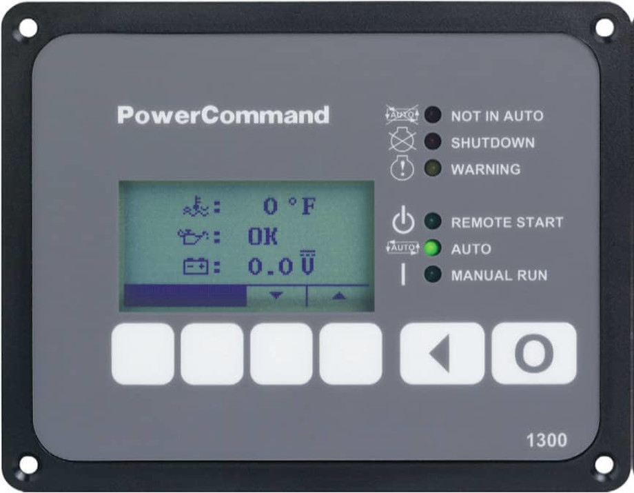
Ниже приведем фото модуля с описанием кнопок и индикаторов.

Перевод ДГУ в режим «АВТО»
- перевод ДГУ в автоматический режим осуществляется кнопкой, над которой на дисплее надпись «auto» или рисунок эллипса (цикла). После ее нажатия надо нажать кнопку над которой будет мигать стрелка (подтверждение). Загорится зеленый индикатор «auto». Рисунок цикла («auto») закрасится черным, как на рисунке выше.
- перевод ДГУ в ручной из авто режима или останов ДГУ производится нажатием кнопки «О» (самая левая)
Запуск и останов ДГУ в ручном режиме
- запуск ДГУ в ручном режиме осуществляется кнопкой, над которой на дисплее надпись «manual» или рисунок руки. После ее нажатия надо нажать кнопку над которой будет мигать стрелка (подтверждение). ДГУ заведется или сразу или через время таймаута (если установлено). Загорится зеленый индикатор «manual run»
- Останов ДГУ осуществляется кнопкой «О».
- Если нажата кнопка экстренного останова (красный «грибок») ДГУ индицирует 61 ошибку и не запустится ни в каком режиме.
![]() ВНИМАНИЕ!!! Если светится красный индикатор «Shutdown» ДГУ не заведется до устранения ошибки. Не рекомендуется заводить ДГУ при горящем желтом индикаторе «Warning» до устранения некритичной ошибки
ВНИМАНИЕ!!! Если светится красный индикатор «Shutdown» ДГУ не заведется до устранения ошибки. Не рекомендуется заводить ДГУ при горящем желтом индикаторе «Warning» до устранения некритичной ошибки
-
Краткая несложная инструкция по запуску ДГУ в ручном режиме
Ниже приведем несколько более подробных руководств по работе с меню и ошибками интерфейса HMI211.
-
Данные на ЖК-дисплее, что они означают
-
Настройка яркость-контрастность-единицы измерения ЖК-дисплея
-
Установки задержек на запуск и на охлаждение работающего ДГУ
-
Значения кодов ошибок
 Панель управления Power Command PCC 1301 Панель управления PCC 1301 включает в себя все, что необходимо для пуска, установки и управления ДГУ. Это устройство отличают высокие показатели надежности, удобство эксплуатации, широкий диапазон температур эксплуатации, полностью защищенное от воздействия внешней среды исполнение. • Разработана для использования с опциональной панелью удаленного мониторинга или переключателем «Авто/Выкл. /Ручн. » • Способность полного мониторинга ДГУ • Система полной защиты двигателя • Измерение напряжения и тока по 3 -м фазам • Управление запуском двигателя • По два входных и выходных сигнала пользователя • Встроенный AVR (автоматический регулятор напряжения) • Температурный режим от -40° С до +70° С • Компактные размеры 224 х149 х65 мм (Шх. Гх. В) • Универсальный сервис-инструментарий
 система индикации и управления • Возможность использования нескольких панелей с одной ДГУ путем коммуникации через встроенный RS 485 • Возможность удаления панели на расстоянии до 300 м от ДГУ • Отсутствие наружных переключателей • Мгновенное отображение статусных и аварийных сообщений • Полное отображение состояния ДГУ: 3 -х фазное напряжение и ток, температура ОЖ, давление масла, напряжение батарей, частота, история ошибок • Возможность настройки и • регулировки ДГУ • Компактные размеры 141 х111 х33, 5 мм (Шх. Гх. В) • Защита дисплея IP
 Компоненты системы управления Система управления PCC 1301 модульной конструкции, состоит из следующих элементов: – PCC 1301 (Основное устройство) – HMI 211 (Интерфейс человек-машина) – HMI 113 (Универсальный сигнализатор — Опция) – Aux 101 и Aux 102 (Модули Входа / Выхода – Опция) В данном курсе рассмотрим функции контроллера PCC 1301 и функции дисплея оператора HMI
 Информационная сеть (4") Структура системы управления PCC 1301 HMI 211 HMI 113 (Опция) Информационная сеть (4 кабеля) Шина Modbus. Двигатель Генератор AUX 101 (Опция) (Service Tool) Конвертер. На некоторых моделях
Структура системы управления PCC 1301 HMI 211 HMI 113 (Опция) Информационная сеть (4 кабеля) Шина Modbus. Двигатель Генератор AUX 101 (Опция) (Service Tool) Конвертер. На некоторых моделях
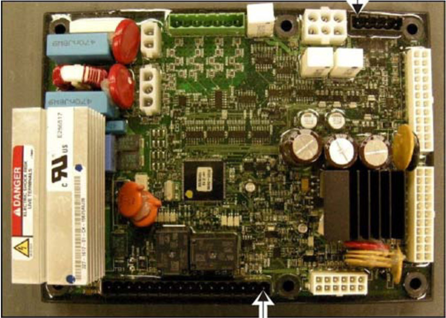
: Эта плата является “сердцем” системы управления. Плата") Функции компонентов Контроллер PCC 1301 (Основной элемент): Эта плата является “сердцем” системы управления. Плата содержит все логические элементы и устройства ввода/вывода для работы ДГУ.
Функции компонентов Контроллер PCC 1301 (Основной элемент): Эта плата является “сердцем” системы управления. Плата содержит все логические элементы и устройства ввода/вывода для работы ДГУ.
 Функции панели управления PCC 1301 – Защита двигателя • давление масла, • температура двигателя, • превышение оборотов двигателя, • проблемы с пуском, • неисправность датчика оборотов. – Защита генератора • пониженное напряжение, • повышенное напряжение, • пониженная частота тока, • превышение силы тока – требуются трансформаторы тока. – Задержка времени пуска/останова – Режим энергосбережения • пониженное энергопотребление в режимах Off и Auto – Программируемые I/O пользователя • (2 входа и 2 выхода) – Интерфейс Modbus (RS 485 RTU) – Взаимодействие с сервисным ПО – Защита от воздействий окружающей среды (NEMA 3 R/IP 53)
: Модуль HMI используется") HMI 211 Дисплей оператора HMI 211 (Интерфейс взаимодействия человек — машина): Модуль HMI используется для измерения параметров работы генератора и двигателя. Поддерживается режим оповещения о неисправностях (коды неисправностей и описание) облегченный вариант системы управления без сервисного ПО.
HMI 211 Дисплей оператора HMI 211 (Интерфейс взаимодействия человек — машина): Модуль HMI используется для измерения параметров работы генератора и двигателя. Поддерживается режим оповещения о неисправностях (коды неисправностей и описание) облегченный вариант системы управления без сервисного ПО.
 Функции дисплея HMI 211 Свойства Дисплей оператора HMI 211 : • Подсвечиваемый ЖК дисплей • Символьный или текстовый экран оператора поддерживает только английский язык • Встроенный переключатель Пуск/Выключение/Авто с программируемым кодом доступа (key switch) Показания : • Двигатель – Давление масла , температура ОЖ , – заряд батареи, скорость вращения • Генератор – напряжение, ток, частота, – KVA – полная мощность • Может быть дополнительно установлен дистанционно
 Дисплей оператора
 Дисплей оператора Органы управления дисплея Светодиоды: – 1 не в автоматическом режиме – 2 останов – 3 внимание – 4 дистанционный пуск – 5 автоматический режи – 6 ручной режим Кнопки: – 7 режим генераторной установки «Окл» (переход в главное меню) – 8 предыдущий экран – 9 кнопки с функциями определяемыми символами на дисплее Дисплей: – 10 строка меню (4 символа кнопок) – 11 графический ЖК дисплей
 режимы дисплея Текстовый режим Символьный режим
 Отображаемые символы в символьном режиме
 Дисплей — системные сообщения Системные сообщения отображаются при включении напряжения питания или при сбое обмена данными с контроллером РСС 1301. При потери связи с контроллером сообщение отображается до восстановления связи с контроллером Когда индицируются коммуникационные сообщения, можно выбрать режим работы автоматический / ручной. При подаче питания Если на экране остаётся любое коммуникационное сообщение (и другие меню просмотреть невозможно), то значит связь между дисплеем и контроллером РСС 1301 утеряна. Обратитесь за помощью к официальному дистрибьютору. При потери связи
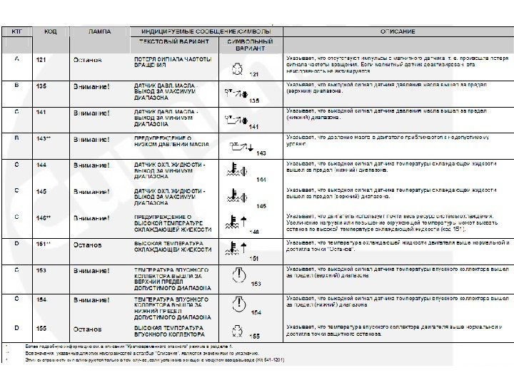
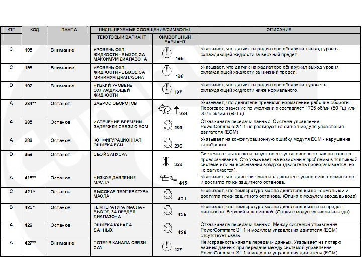
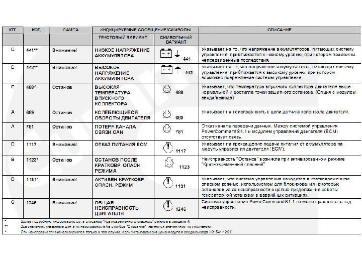
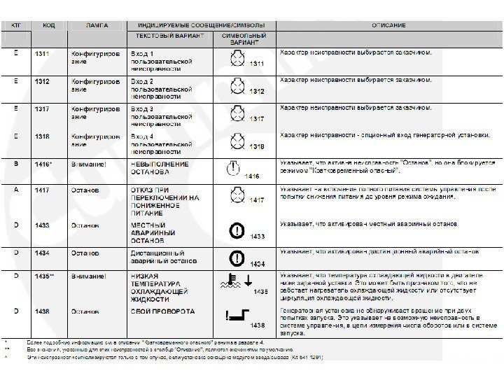
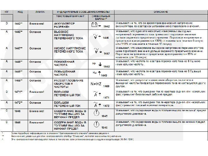
, индицируются") Дисплей — Сообщения о событиях Когда активируются запрограммированные события (пуск или останов), индицируются сообщения о событиях, показывающие время, остающееся до завершения события. Сообщение о неисправности является индикатором состояния «Внимание!» или «Останов», еще одним индикатором которого является включения лампы. Текстовое сообщение о неисправности содержит номер кода неисправности, краткое описание и время возникновения неисправности ( текстовом режиме ) Символьные сообщения о неисправностях содержат номер кода неисправности и символы, указывающие на тип неисправности ( символьном режиме дисплея) Подтверждение приема неисправности. Для подтверждения приема сигнала неисправности/останова следует нажать кнопку «Откл. » на панели дисплея или кнопки стрелок, при этом сообщение о неисправности удаляется с дисплея. Сообщение о неисправности появляется повторно если сигнал неисправности не устранен.
Дисплей — Сообщения о событиях Когда активируются запрограммированные события (пуск или останов), индицируются сообщения о событиях, показывающие время, остающееся до завершения события. Сообщение о неисправности является индикатором состояния «Внимание!» или «Останов», еще одним индикатором которого является включения лампы. Текстовое сообщение о неисправности содержит номер кода неисправности, краткое описание и время возникновения неисправности ( текстовом режиме ) Символьные сообщения о неисправностях содержат номер кода неисправности и символы, указывающие на тип неисправности ( символьном режиме дисплея) Подтверждение приема неисправности. Для подтверждения приема сигнала неисправности/останова следует нажать кнопку «Откл. » на панели дисплея или кнопки стрелок, при этом сообщение о неисправности удаляется с дисплея. Сообщение о неисправности появляется повторно если сигнал неисправности не устранен.
 Меню оператора дисплея Состояние двигателя • напряжение АКБ, температуру ОЖ, давление масла, моточасы. Состояние генератора переменного тока • нагрузку генератора (КВА), частоту (Гц), обороты двигателя (об/мин). Линейные напряжения • линейные напряжения L 1 -L 2, L 2 -L 3, L 3 -L 1 только для 3 -фазных систем. Фазные напряжения • фазные напряжения L 1, L 2, L 3 только в конфигурации звезда, • В конфигурации «треугольник» это меню не показывается, • напряжения L 1 -N, L 2 -N и L 1 -L 2 только для однофазных систем. Токи генератора • показываются результаты измерений токов L 1, L 2 и L 3.
 блок-схема меню оператора
 автоматический и ручной режимы ВНИМАНИЕ! ПРИ ИЗМЕНЕНИИ РЕЖИМОВ ГЕНЕРАТОРНАЯ УСТАНОВКА МОЖЕТ ЗАПУСТИТЬСЯ ИЛИ ОСТАНОВИТЬСЯ БЕЗ ПРЕДУПРЕЖДЕНИЯ. УБЕДИТЕСЬ, ЧТО ИЗМЕНЕНИИ РЕЖИМА НЕ СОЗДАДУТ ОПАСНОСТИ ДЛЯ ПЕРСОНАЛА ИЛИ ОБОРУДОВАНИЯ. Смена режима автоматический / ручной из режима «Откл. » можно произвести следующим образом: • из любого меню оператора, • при сообщении «Установление связи» , • при сообщении «Восстановление связи» . Если при наладке пульта управления была активирована функция пароля для изменения режимов «Авт. » , «Ручн. » или «Откл. » , то необходимо ввести пароль в субменю «Изменение режима» с помощью кнопок «>» , «+» , «-» . Пароль оператора 121. По окончании ввода нажать кнопку с символом «>» .
 Выбор Режима «АВТ. »
 Выбор Режима «РУЧН. »
 Выбор Режима «ОТКЛ. »
Cummins Power Command HMI-211 Remote Generator Panel
The Cummins Power Command HMI211 Remote Generator Controller is a remote generator control panel with similar functionality as the standard generator mounted HMI211 controller. The Human Machine Interface (HMI211) with the multi-line LCD display and tactile function keys mounts inside the home or building up to 4000 feet (3/4 Mile) from the generator set. The Controller is compatible with Cummins Quiet Connect Series generators.
PCC 1302 Fault Code—The Cummins HMI211 connects to the generator PCC 1302 control board and displays fault codes. Some fault codes are warnings, others cause the generator to shutdown or prevent it from starting.
When the generator experiences a fault, the displayed error code provides insight to the problem for troubleshooting or relaying information to the service dealer. Most fault codes are generated by the Cummins PCC 1302 Controller or by the Engine Control Module (ECM.)
Cummins Power Command HMI 211
Engine Won’t Start or Difficult to Start
A difficult to start engine often indicates a problem that gradually gets worse over time. Possible causes include a failing or failed battery, problems with the fuel system, or a blocked / partially blocked air intake.
Check the battery connections. A loose battery cable makes a poor connection and reduces the battery power available to the starter and controls. Loose cable connections can prevent a good charge. Also check the fuses and replace as necessary. Check the battery with a battery tester or multimeter. Battery testers have more functions than a regular multimeter, but the multimeter can point you in the right direction.
A fully charged battery should have at least 12.6 Volts. If it’s low than 12.4 volts, the battery could be failing. Below 12 volts it no longer holds a charge and should be replaced.
The fuel supply must be open. On a gas line, the valve lever should be parallel to the pipe and not at a right angle. An empty or near empty propane tank is an obvious but sometimes overlooked problem with the same results. Fill the tank.
Dirty air filters reduce the amount of air available to the engine. Replace dirty a dirty filter with a clean filter. Air intakes blocked with debris, litter, or ice/snow can make starting hard, reduce efficiency, or cause a failed start.
Cummins Power 22kW to 40kW Quiet Connect Liquid Cooled Generators
Cummins Power Command HMI211 Fault Codes and Troubleshooting
Cummins PCC 1302 Controller Board
These are the most commonly searched Fault Codes and the methods used to troubleshoot the problem. Most are within the capability of a knowledgeable DIY homeowner. The Cummins Service Manual is a good resource for troubleshooting and repair of the less common fault codes the homeowner may find on their display.
Some troubleshooting and Repairs require additional knowledge or specialized software and connections. Refer to the Cummins Service Manual and related literature for additional information and methods.
Cummins Generator Fault Code 143 – Low Oil Pressure Warning
Low oil pressure generally causes a warning condition instead of a full shutdown. Possible causes include low oil level or an oil leak that prevents the engine from maintaining the correct oil pressure. Diagnosis is relatively simple in most cases.
Shut the generator down and follow all procedures for disabling the generator. Check the oil level. If it is low, add enough oil to bring it up to full, but do not overfill. Use the recommended viscosity oil for the current weather conditions.
Inspect the generator for a leak. An oil leak is obvious with stains or puddles of oil. A loose oil-change plug or improperly tightened filter could be the cause. Any other leaks should be handled by the local service dealer.
Cummins 50kW to 150kW Generators
Cummins Generator Fault Code 415 – Low Engine Oil Pressure Shutdown
Code 415 indicates that oil pressure fell below minimum (26 psig) for more than 10 seconds. Engine shutdown prevents catastrophic damage to the engine.
Disable the generator from starting and allow it to cool. Check the oil level. Add oil as necessary, but do not overfill. Inspect the generator for oil leaks. Contact your dealer if the engine is leaking oil.
Cummins Generator Fault Code 151 – High Coolant Temperature Shutdown
High coolant temperature causes an automatic engine shutdown to prevent damage. Causes include extreme ambient temperature, blocked enclosure air intake or discharge, low coolant level, blocked radiator, broken or loose fan belt.
Disable the generator engine according to Cummins procedure. Allow the engine to cool. Do not open the radiator of a hot engine.
Check the coolant level once the engine has cooled. If the coolant is low, this is the likely cause. Add coolant in the proper mix to bring it to full, but do not overfill.
Inspect the radiator for litter or leaves or debris that blocks air from passing through the generator. This is a good time to inspect the fan belt for wear. Broken belts must be replaced.
A blocked air intake for the generator enclosure prevents cool air from reaching the radiator. Blocked air discharge prevents hot air from exiting the generator enclosure. Clear the air intake and discharge of any debris, snow, ice, or litter.
Cummins Generator Fault Code 155 – High Intake Manifold Temperature Shutdown
A high intake manifold temperature causes engine shutdown to prevent damage. Call your local dealer for troubleshooting and diagnosis information or consult the troubleshooting procedure detailed in DTC 127 in the EControls Manual.
Cummins Generator Fault Code 488 – High Intake Manifold Temperature Warning
A warning fault code 488 indicates the manifold temperature exceeded specifications for more than 90 seconds. Probable causes include high ambient air temperature, blocked air intake or discharge, low coolant level, blocked radiator, broken or loose fan belt.
Disable the generator and allow it to cool before diagnosis and repair.
If the ambient temperature is high and the generator provides this warning code, reduce the electrical load on the generator to between 50 percent and 75 percent. Running the generator near maximum load in extreme temperatures can trigger this warning.
Clear the air intakes and discharge louvers of debris, litter, snow, or ice.
Check the coolant level. Allow the generator to cool before opening the radiator. Disable the generator from starting before checking / replacing coolant.
Clear the radiator of debris or litter.
Replace a worn or broken fan belt. Tighten loose belts for proper operation.
Cummins Power Generation Air Cooled and Liquid Cooled Standby Generator
Cummins Generator Fault Code 197 – Coolant Level Low Warning
This warning allows the generator to continue operating but should be corrected as soon as possible. A sensor has detected a low coolant level.
Shut the generator down and disable it from starting according to Cummins procedure. Allow the engine to cool. Do not remove the radiator cap while the engine is hot.
Remove the radiator cap after the engine cools. Add coolant to bring the coolant level to full. Do not overfill.
Cummins Generator Code 441 – Low Battery Voltage Warning
This warning code indicates the battery is failing, a cable is loose or damaged, or the battery needs recharging.
Check the battery cables for loose connections. Replace damaged cables or connectors. Clean corroded connectors or replace them.
Check the battery charger for connection to the AC supply. Make sure the charger is connected to the battery.
If battery voltage is below 11 volts, recharge the battery. If charging does not restore the battery to 12.0 volts or more, the battery is weak or dead and must be replaced.
Cummins Quiet Connect Air Cooled Features and Benefits
Cummins Generator Code 427 – CAN Data Link Degraded
Cummins Generator Fault Code 781 – ECM CAN Data Link Has Failed
The Engine Control Module cannot communicate with the Generator Controller. Causes include a failed CAN data link. The Engine Control Module (ECM) lost power or failed.
Checking the ECM
An emergency stop button has a relay that opens and closes. The normal state is closed. The open state disables power to the ECM keyswitch input. Pull out the switch to inactivate the emergency stop. Reset the emergency stop button. Press Off on the operator panel. Press Reset. Select Manual or Auto.
Make sure the emergency stop button is functioning. Measure the emergency stop outputs in the open and closed states. Verify the outputs switch states when the button is activated (pushed in) and deactivated (pulled out). Replace the switch if it doesn’t change states.
Check baseboard wiring.
Measure battery power at the keyswitch relay input and output. If battery power is present at both the input and output, the relay is functioning properly. If battery power is present at the input, but not the output, replace the relay.
Checking the CAN data link
Check the Datalink harness and connector pins between J11-20 to J1939+ and between J11-19 to J1939-. Check the shield ground connection at J11-17.
Disconnect the J11 Connector from the baseboard. Disconnect the EMC Datalink Connection. Measure the resistance between J11-19 and J11-20. The resistance should read 60 Ohms.
If the resistance is not 60 Ohms, check the terminating resistors. Each resistor should be 120 Ohms. Replace defective resistors.
Cummins Generator Fault Code 1438 – Fail to Crank Shutdown
The engine failed to crank when instructed to start. A fault 1438 Fail to Crank indicates the engine cannot start because it won’t turn. Possible causes include a dead or weak battery or a failed starter.
Verify the battery voltage is at least 12 volts (24 Volts on a 24-volt system). Charge a low battery or replace a battery that won’t charge above 12 volts.
Press the “Reset / Fault Acknowledge” Button on the display. Test the battery voltage at the starter B+ connection while the generator attempts to start. A correct voltage reading could indicate a defective starter. Fail to Crank 1438 Cummins Fault Code
Best Natural Gas Generator for Whole House Power
Cummins Generator Fault Code 1472 – High AC Current Shutdown
Generator output current exceeded 150 percent of generator rated current capacity. The most likely cause is an overloaded generator.
Remove unnecessary loads from the generator starting with loads that draw the most current such as electric dryers, electric range, electric water heater, or central air conditioning.
Cummins Generator Fault Code 5134 – Unknown Shutdown at Idle
The fuel supply is inadequate. Either the gas shut off or the fuel pressure was insufficient to run the engine.
Check the fuel supply for the correct fuel pressure and pipe size for fuel delivery. The engine must have an adequate supply of fuel for the engine to run.
Cummins Generator Fault Code 1246 – CAN Unknown Engine Fault
PCC 1302 Fault Code 1246 indicates the control board received an unknown message from the Engine Control Module (ECM.) The reason is unknown and may be an ECM fault for and Engine Fault.
Diagnosis of Cummins Fault Code 1246 requires the E-Controls Service Tool.
Best Backup Generators for Hot Climates
-
Page 1
Service Service Manual Manual Controller ® PowerCommand English Original Instructions 3-2020 0900-0670 (Issue 23) -
Page 3: Table Of Contents
3. GLOSSARY……………………..4. SYSTEM OVERVIEW ……………………4.1 About this Manual ……………………. 4.2 PowerCommand 3.3 ………………….4.2.1 PowerCommand 3.3 Masterless Load Demand …………4.3 Controller Area Network………………….4.4 Components (Applications with Engine Control Modules)………… 4.5 Components (Applications with Hydromechanical Engines) ……….
-
Page 4
5.5.3 J18 Connections ………………….5.5.4 J19 Connections ………………….5.6 AUX104……………………..5.6.1 Connections ………………….. 5.6.2 J1 Connections ………………….5.7 AUX105……………………..5.7.1 LEDs …………………….. 5.7.2 Connections ………………….. 5.7.3 J11 Connections ………………….5.7.4 J17 Connections ………………….Copyright © 2020 Cummins Inc. 0900-0670 (Issue 23) -
Page 5
6.4.4 Additional Steps for Hydromechanical Engines …………6.5 Rated Speed and Voltage………………..6.5.1 Speed Reference ………………… 6.5.2 Voltage Setpoint………………….. 6.6 Stop Sequences……………………6.6.1 Controlled Shutdown………………..6.6.2 Shutdown with Cooldown………………6.6.3 Manual Stop………………….0900-0670 (Issue 23) Copyright © 2020 Cummins Inc. -
Page 6
7.5.2 Ramp Load Unload ………………..7.6 Masterless Load Demand ………………..7.6.1 MLD s-CAN Network (PCC3300 with MLD Controls ONLY) ……..7.6.2 Load Demand (LD) Type ………………7.6.3 Load Demand Threshold Method …………….Copyright © 2020 Cummins Inc. 0900-0670 (Issue 23) -
Page 7
8.24.4 Load Dump Overload and Underfrequency Protection………. 8.25 Paralleling Setup………………….. 8.25.1 Paralleling Setup — Basic………………8.25.2 Power Transfer Control (Paralleling/PTC Setup) ……….. 8.26 Genset (OEM Genset Setup)……………….. 8.26.1 Generator Set Frequency ………………0900-0670 (Issue 23) Copyright © 2020 Cummins Inc. -
Page 8
10.5.1 Enable Battle Short Mode in the ECM …………..10.5.2 Enable Battle Short Mode in the PCC …………..10.5.3 Map a Configurable Input to Battle Short Switch……….. 10.5.4 Activate Battle Short Mode ………………10.6 Delayed Shutdown………………….Copyright © 2020 Cummins Inc. 0900-0670 (Issue 23) -
Page 9
10.8.39 Code 1226 — Genset Frequency Error …………..10.8.40 Code 1243 — Engine Derated …………….10.8.41 Code 1244 — Engine Normal Shutdown …………… 10.8.42 Code 1245 — Engine Shutdown Fault…………..10.8.43 Code 1246 — Unknown Engine Fault…………..0900-0670 (Issue 23) Copyright © 2020 Cummins Inc. -
Page 10
10.8.85 Code 1475 — First Start Backup Fail…………..10.8.86 Code 1483 — Common Alarm …………….10.8.87 Code 1540 — Common Warning …………….10.8.88 Code 1541 — Common Shutdown ……………. 10.8.89 Code 1573 — Config Input #1 Fault…………… Copyright © 2020 Cummins Inc. viii 0900-0670 (Issue 23) -
Page 11
10.8.132 Code 2822 — Utility PT Ratio High…………..10.8.133 Code 2895 — PCCNet Device Failed …………..10.8.134 Code 2896 — Critical PCCNet Dev Fail…………… 10.8.135 Code 2912 — Reconnection Switch Operated 1 ……….0900-0670 (Issue 23) Copyright © 2020 Cummins Inc. -
Page 12
10.8.177 Code 2985 — Non-Drive End Bearing Temp OOR Low……..10.8.178 Code 2986 — High Non-Drive End Bearing Temperature……..10.8.179 Code 2992 — Intake Manifold Temp 1 OOR High……….10.8.180 Code 2993 — Battery Charger Failed…………..Copyright © 2020 Cummins Inc. 0900-0670 (Issue 23) -
Page 13
10.8.223 Code 5288 – Starter Air Tank Volume Low …………10.8.224 Code 5377 – AUX101-3 Communication Lost Fault………. 10.8.225 Code 5378 – AUX101-4 Communication Lost Fault………. 10.8.226 Code 5397 – L-N Short Circuit Shutdown…………0900-0670 (Issue 23) Copyright © 2020 Cummins Inc. -
Page 14
10.9 CAN Network Troubleshooting Recommendation …………10.9.1 CAN Network Visual Inspection and Installation Validation Recommendation ..10.9.2 CAN Network Resistance Measurement and Troubleshooting Recommendations………………… 10.9.3 Isolated Ground Voltage Measurement Test Recommendation……10.10 How to Obtain Service ………………..Copyright © 2020 Cummins Inc. 0900-0670 (Issue 23) -
Page 15
B.4 MLD Example 4: Run Hours Equalization …………….APPENDIX C. SEQUENCE DIAGRAMS ………………APPENDIX D. PARTS LIST………………….APPENDIX E. AMBIENT, ENGINE OIL, INTAKE MANIFOLD TEMPERATURE SENSOR DETAILS ……………………….APPENDIX F. EXHAUST STACK TEMPERATURE SENSOR DETAILS ……..0900-0670 (Issue 23) xiii Copyright © 2020 Cummins Inc. -
Page 16
Table of Contents 3-2020 This page is intentionally blank. Copyright © 2020 Cummins Inc. 0900-0670 (Issue 23) -
Page 17: Important Safety Instructions
Indicates information considered important, but not hazard-related (e.g., messages relating to property damage). General Information This manual should form part of the documentation package supplied by Cummins with specific generator sets. In the event that this manual has been supplied in isolation, please contact your authorized distributor.
-
Page 18: General Safety Precautions
Do not store fuel, cleaners, oil, etc., near the generator set. WARNING High Noise Level Generator sets in operation emit noise, which can cause hearing damage. Wear appropriate ear protection at all times. Copyright © 2020 Cummins Inc. 0900-0670 (Issue 23)
-
Page 19
Accumulated grease and oil are a fire hazard. Fire can cause severe burns or death. Keep the generator set and the surrounding area clean and free from obstructions. Repair oil leaks promptly. 0900-0670 (Issue 23) Copyright © 2020 Cummins Inc. -
Page 20
Class B fires involve combustible and flammable liquid fuels and gaseous fuels. Class C fires involve live electrical equipment. (Refer to NFPA No. 10 in the applicable region.) Copyright © 2020 Cummins Inc. 0900-0670 (Issue 23) -
Page 21: Generator Set Safety Code
NOTICE Access or service doors must be closed and locked before repositioning, and they must remain locked during transportation and siting. 0900-0670 (Issue 23) Copyright © 2020 Cummins Inc.
-
Page 22: Positioning Of Generator Set — Open Sets
Guidelines to follow when working on energized electrical systems: NOTICE It is the policy of Cummins Inc. to perform all electrical work in a de-energized state. However, employees or suppliers may be permitted to occasionally perform work on energized electrical…
-
Page 23: Ac Supply And Isolation
AC input to the terminal box; these must comply with local electrical codes and regulations. Refer to the wiring diagram supplied with the generator set. The disconnecting device is not provided as part of the generator set, and Cummins accepts no responsibility for providing the means of isolation.
-
Page 24: Fuel And Fumes Are Flammable
1.5.3 Fluid Containment NOTICE Where spillage containment is not part of a Cummins supply, it is the responsibility of the installer to provide the necessary containment to prevent contamination of the environment, especially water courses and sources. If fluid containment is incorporated into the bedframe, it must be inspected at regular intervals. Any liquid present should be drained out and disposed of in line with local health and safety regulations.
-
Page 25: Exhaust Precautions
To minimize the risk of fire, make sure the following steps are observed: • Make sure that the engine is allowed to cool thoroughly before performing maintenance or operation tasks. • Clean the exhaust pipe thoroughly. 0900-0670 (Issue 23) Copyright © 2020 Cummins Inc.
-
Page 26
1. IMPORTANT SAFETY INSTRUCTIONS 3-2020 This page is intentionally blank. Copyright © 2020 Cummins Inc. 0900-0670 (Issue 23) -
Page 27: Schedule Of Abbreviations
European Standard Permanent Magnet Generator Engine Protection System Personal Protective Equipment E-Stop Emergency Stop Potential Transformer Full Authority Electronic Power Transfer Control Failure Mode Identifier Pulse-width Modulation Fault Ride Through Radio Frequency Interference 0900-0670 (Issue 23) Copyright © 2020 Cummins Inc.
-
Page 28
Human-machine Interface Suspect Parameter Number Integrated Circuit Safe Working Load International Organization for SW_B+ Switched B+ Standardization LBNG Lean-burn Natural Gas Underwriters Laboratories Liquid Crystal Display Uninterruptible Power Supply Valve Proving System Copyright © 2020 Cummins Inc. 0900-0670 (Issue 23) -
Page 29: Glossary
The PCC generates a fault when the conditions indicate a more serious problem; the PCC generates an event only for information purposes. Low-side driver When this output is active, it provides a path to ground. When this output is inactive, it blocks the path to ground. 0900-0670 (Issue 23) Copyright © 2020 Cummins Inc.
-
Page 30
In some cases, this may refer to a physical switch (similar to a light switch) instead. Trim Refers to the subset of parameters that can be adjusted, as opposed to parameters that can only be monitored. Copyright © 2020 Cummins Inc. 0900-0670 (Issue 23) -
Page 31: System Overview
The PCC should be installed where it can be accessed only by authorized service representatives. Unauthorized personnel, including an operator, should not have access to it. 4.2.1 PowerCommand 3.3 Masterless Load Demand ® The PowerCommand 3.3 controller with Masterless Load Demand (MLD) control baseboard provides all ®…
-
Page 32: Controller Area Network
2-wire with a shield ground. Isolated Ground CAN networks (i.e. s-CAN) are typically 3- wire (CAN H, CAN L, and Isolated Ground) with a shielded ground. The Isolated Ground connection is required for reliable communications. Copyright © 2020 Cummins Inc. 0900-0670 (Issue 23)
-
Page 33: Components (Applications With Engine Control Modules)
TABLE 3. VOLTAGE DIFFERENTIAL WHEN CAN DATA SIGNAL = 1 (SEE SAE J1939-11 FOR FULL SIGNAL SPECIFICATIONS) Nominal 1.2 V Components (Applications with Engine Control Modules) The PowerCommand 3.3 Control System consists of the following parts: 0900-0670 (Issue 23) Copyright © 2020 Cummins Inc.
-
Page 34: Components (Applications With Hydromechanical Engines)
4. System Overview 3-2020 FIGURE 2. POWERCOMMAND 3.3 CONTROL SYSTEM (APPLICATIONS WITH ENGINE CONTROL MODULES) TABLE 4. POWERCOMMAND 3.3 CONTROL SYSTEM (APPLICATIONS WITH ENGINE CONTROL MODULES) PART DESCRIPTION PART NUMBER 1: HMI320 («Operator Panel») 0300-6315-02 2: PCC3300 Control («PCC») Table 7…
-
Page 35: Operator Panel
3-2020 4. System Overview FIGURE 3. POWERCOMMAND 3.3 CONTROL SYSTEM (APPLICATIONS WITH HYDROMECHANICAL ENGINES) TABLE 5. POWERCOMMAND 3.3 CONTROL SYSTEM (APPLICATIONS WITH HYDROMECHANICAL ENGINES) PART DESCRIPTION PART NUMBER 1: HMI320 («Operator Panel») 0300-6315-02 2: PCC3300 Control («PCC») Table 7 4: AUX105 HM ECM and AVR power stage…
-
Page 36: Aux103
In this manual, “PCC» may refer to “PCC and AUX105″ without explicitly stating this. Distinction is made when necessary. NOTICE The AUX105 should be installed where it can be accessed only by authorized service representatives. Unauthorized personnel, including an operator, should not have access to it. Copyright © 2020 Cummins Inc. 0900-0670 (Issue 23)
-
Page 37: Remote Hmi Operator Panel (Optional)
110-600 VAC line-to-line (PCC input from generator set; if the generator set voltage is 600- 45,000 VAC line-to-line, potential transformers are required) 5-10,000 A (external CTs required) Alternator Reconnectable or non-reconnectable alternator (voltage selectable) PMG or self-excitation 0900-0670 (Issue 23) Copyright © 2020 Cummins Inc.
-
Page 38: Certifications
Diesel or lean-burn natural gas (LBNG) 12-V or 24-V battery (operating range: 8-30 VDC) Battery-charging alternator (IC type and non-IC type) Controlled Area Network (CAN) J1939 communication (limited) Power Generation Interface (PGI)-compliant engine control module (ECM). PGI is Cummins’ implementation of SAE J1939. Hydromechanical Communication…
-
Page 39: Hardware
WARNING AC power presents a shock hazard that can cause severe personal injury or death. Before servicing the generator set, disconnect all power when multiple disconnection sources are used. 0900-0670 (Issue 23) Copyright © 2020 Cummins Inc.
-
Page 40: Pcc 3300 Control Base Board
The control base board is potted to provide resistance to dust and moisture. It is specifically designed and tested for resistance to RFI/EMI, and it also includes transient voltage surge suppression to provide compliance with referenced standards. FIGURE 5. PCC 3300 CONTROL BASE BOARD Copyright © 2020 Cummins Inc. 0900-0670 (Issue 23)
-
Page 41: Leds
• If the PCC is using Modbus on TB15, this LED is on when the PCC is receiving or transmitting data through the Modbus connection. • If the PCC is using MON on TB15, this LED is off. FIGURE 6. PCC BASE BOARD LEDS 0900-0670 (Issue 23) Copyright © 2020 Cummins Inc.
-
Page 42: S1 S-Can Terminating Resistor Switch
Generator set bus/utility L2 or generator set neutral current sensing Generator set bus/utility L3 current sensing Engine input and output 0323-2161 0323-2466 CT input 0323-1932 0323-1200 PC-based service tool interface (no calibrations) AVR control 0323-2098 0323-1200 Copyright © 2020 Cummins Inc. 0900-0670 (Issue 23)
-
Page 43
TB3-9, TB3-1 Configurable Input #21 TB3-10, TB3-12 Configurable Input #23 TB10-4, TB10-1 Configurable Input #24 TB10-5, TB10-1 Configurable Input #25 TB10-6, TB10-9 Configurable Input #26 TB10-8, TB10-2 Configurable Input #27 TB10-10, TB10-2 0900-0670 (Issue 23) Copyright © 2020 Cummins Inc. -
Page 44
Configurable Output #10 TB8-3 Configurable Output #11 TB8-11 Configurable Output #20 TB3-5 Configurable Output #21 TB3-6 Configurable Output #22 TB3-8 Configurable Analog Outputs Table 14 identifies all of the configurable analog outputs. Copyright © 2020 Cummins Inc. 0900-0670 (Issue 23) -
Page 45: Ct1 Connections
Current OR Generator Set Neutral Current neutral current measurement. Route external CT secondary wiring through CT such that current flows through the onboard CT entering at 1 when the measured source is providing power. 0900-0670 (Issue 23) Copyright © 2020 Cummins Inc.
-
Page 46: Ct3 Connections
CT1-X2/X3 J12-5 CT2 COMMON CT2-X2/X3 J12-6 CT3 COMMON CT3-X2/X3 Genset Delta/Wye Connection and Single/3 Phase Connection specify the alternator configuration. See Appendix for detailed examples of these connections with various alternator configurations. Copyright © 2020 Cummins Inc. 0900-0670 (Issue 23)
-
Page 47
Three-terminal CTs (X1, X2, X3) are used on reconnectable alternators, and, in some cases, also on non- reconnectable alternators. X1 and X2 are used for line to line voltages greater than 300 volts. X1 and X3 are used for line to line voltages less than 300 volts. 0900-0670 (Issue 23) Copyright © 2020 Cummins Inc. -
Page 48: J14 Connections
PC-based service tools should use harness 0338-3277 to connect to this RS-232 connection. A female-to- female adapter is also required. 5.2.8.1 DB9 Connections The standard DB9 connections are shown below: FIGURE 13. DB9 CONNECTIONS Copyright © 2020 Cummins Inc. 0900-0670 (Issue 23)
-
Page 49: J20 Connections
B+ Return Battery (-) negative J20-13 Relay Coil B+ Supply Switched B+ J20-14 FSO Relay Driver Low side of Fuel Shutoff Relay Coil J20-15 Starter Relay Driver Low side of Starter Relay Coil 0900-0670 (Issue 23) Copyright © 2020 Cummins Inc.
-
Page 50
J20-14 is a low-side driver. Its specifications are shown in Table J20-14 should be connected with Emergency Stop B+ Power (Appendix A) so that the starter is physically interrupted when an emergency stop button is pressed. Copyright © 2020 Cummins Inc. 0900-0670 (Issue 23) -
Page 51: J22 Connections
Nominal Voltage is less than 600 VAC. Potential Transformer (PT) Sizing Rules The PT primary connections should be connected to the alternator. The PT primary voltage must be 601- 45,000 VAC line-to-line. 0900-0670 (Issue 23) Copyright © 2020 Cummins Inc.
-
Page 52: J25 Connections
TABLE 21. J25 PIN ASSIGNMENTS: DISPLAY CONNECTIONS Description Function / Connects to J25-1 Local Status For future J25-2 Local E-Stop Local E-Stop Switch J25-3 PCCNet B Network Data B J25-4 PCCNet A Network Data A J25-5 System Wakeup Copyright © 2020 Cummins Inc. 0900-0670 (Issue 23)
-
Page 53
For example, if a customer PCCNet device is set up incorrectly on TB1, the Operator Panel on J25 stops working. PCCNet devices that are connected to J25 should connect to Fused B+ (Appendix A) for power. 0900-0670 (Issue 23) Copyright © 2020 Cummins Inc. -
Page 54: J26 Connections
Common for J26-2, active open or active close J26-9 AVR Fused B+ Power for AUX103 AVR powerstage J26-10 J1939 (-) CAN Datalink J26-11 J1939 (+) CAN Datalink J26-12 J26-13 J26-14 Field + Alternator Field X+ (F1) Copyright © 2020 Cummins Inc. 0900-0670 (Issue 23)
-
Page 55: Tb1 Connections
Relay contacts of rating 3.5 A @ 30 VDC TB1-10 Remote Start Return Works with TB1-11, active open or active close TB1-11 Remote Start Works with TB1-10, active open or active close 0900-0670 (Issue 23) Copyright © 2020 Cummins Inc.
-
Page 56
Operator Panel, see Parameters table) to set up the active state of the connection between TB1-16 and TB1-15. If LBNG Genset Enable is set to Enable, this connection is active-closed. Copyright © 2020 Cummins Inc. 0900-0670 (Issue 23) -
Page 57: Tb3 Connections
PCC 3300 with MLD ONLY TB3 — 4 s-CAN CAN H s-CAN data line for control-to-control communications Connect to TB3-4 of other PCC3300 controls on the s-CAN Network PCC 3300 with MLD ONLY 0900-0670 (Issue 23) Copyright © 2020 Cummins Inc.
-
Page 58
TB3-2, 3, or 4 s-CAN Network Connections (PCC 3300 with MLD ONLY) FIGURE 22. S-CAN NETWORK DIAGRAM s-CAN cable requirements: Twisted pair (shielded) cable meets SAE J1939-11 standards, 200m maximum network length. Copyright © 2020 Cummins Inc. 0900-0670 (Issue 23) -
Page 59: Tb5 Connections
Synchronize TB5 — 2 Generator Set CB Close Control Return TB5 — 3 TB5 — 4 Generator Set CB Open Control Contact for opening generator set breaker; ratings 5A 30VDC inductive L/R=7msec. 0900-0670 (Issue 23) Copyright © 2020 Cummins Inc.
-
Page 60: Tb7 Connections
600VAC line to line direct connect. If delta voltage connection leave unconnected. This connector is the same as J22, except that TB7 is used to measure the bus voltage instead of the generator set voltage. Copyright © 2020 Cummins Inc. 0900-0670 (Issue 23)
-
Page 61: Tb8 Connections
TB8-2 and TB8-6 are Configurable Input #11. If LBNG Genset Enable is set to Disable, you can specify the active state of this input. If LBNG Genset Enable is set to Enable, this connection is active-closed. 0900-0670 (Issue 23) Copyright © 2020 Cummins Inc.
-
Page 62: Tb9 Connections
TB9 — 4 Voltage Bias Output / Configurable Analog output Analog Output which allows for sharing of kVAR #2 Output Predictor load between generator sets when paralleling to non-PCC based generator sets. Copyright © 2020 Cummins Inc. 0900-0670 (Issue 23)
-
Page 63
The PCC generates warning fault 1324 (kVAR Load Setpoint OOR High) if these conditions are met for kVAR Load Setpoint OOR Time: • kVAR Load Setpoint OOR Check Enable is set to Enabled. • The input voltage is greater than kVAR Load Setpoint OOR High Limit. 0900-0670 (Issue 23) Copyright © 2020 Cummins Inc. -
Page 64
Speed Bias Output / Configurable Analog output #1 Engineering In Low Function Setpoint x Configurable Analog Output #1 Engineering Units Function Scaling Speed Bias Output / Configurable Analog output #1 Engineering In High Setpoint x Configurable Analog Output #1 Engineering Units Function Scaling Copyright © 2020 Cummins Inc. 0900-0670 (Issue 23) -
Page 65
The generator sets are connected by two sets of load share lines: the kW load share lines and the kVAR load share lines. Both sets of load share lines behave the same way. Figure 29 shows the basic hardware setup for one set of load share lines. 0900-0670 (Issue 23) Copyright © 2020 Cummins Inc. -
Page 66
PCC Current Drivers for Load Share Lines NOTICE The PCC drives the load share lines the same way that Cummins’ PCC 3xxx or PowerCommand 3.x controllers do. The PCC uses pulse-width modulation (PWM) to control the currents the genset drives into each set of load share lines. -
Page 67: Tb10 Connections
Control will consider source unavailable for PTC applications. TB10 — 11 Generator Set CB Inhibit/Configurable Input #28 Opens generator set breaker if closed; inhibits Switch closure if generator set breaker is open. 0900-0670 (Issue 23) Copyright © 2020 Cummins Inc.
-
Page 68
TB10-4 and TB10-1 are Configurable Input #23. If LBNG Genset Enable is set to Disable, you can specify the active state of this input. If LBNG Genset Enable is set to Enable, this connection is active-closed. Copyright © 2020 Cummins Inc. 0900-0670 (Issue 23) -
Page 69: Tb15 Connections
• When the retransfer inhibit signal is active. • When it determines whether or not certain circuit breaker events/faults are active. 5.2.20 TB15 Connections FIGURE 31. TB15 PINS This connector is oriented as shown in Figure 0900-0670 (Issue 23) Copyright © 2020 Cummins Inc.
-
Page 70
Modbus field wiring must be installed according to the Modbus Standard and local electrical codes. The TB15 supports the following baud rates: • 9600 • 19,200 (default) • 38,400 The parity and stop bit can be one of the following: • Even parity, 1 stop bit Copyright © 2020 Cummins Inc. 0900-0670 (Issue 23) -
Page 71: Aux101
5.3.3 AUX101 Outputs Each AUX101 output is associated with a fault code. When the fault is active, the output is active. When the fault is inactive, the output is inactive. 0900-0670 (Issue 23) Copyright © 2020 Cummins Inc.
-
Page 72: Aux101 Board
1. Press and hold S1 for at least five seconds. On the AUX101 device number indicator, a small dot should appear next to the current device number. 2. Press and release S1 until the desired number is displayed. Copyright © 2020 Cummins Inc. 0900-0670 (Issue 23)
-
Page 73
5.3.4.4 AUX101 Connectors TABLE 38. AUX101 CONNECTORS Connector Description Connection to controller AUX101 outputs 1-4 AUX101 outputs 5-6 AUX101 outputs 7-8 Connection to AUX102 Voltage sources, current sources AUX101 inputs 1-8 Power supply 0900-0670 (Issue 23) Copyright © 2020 Cummins Inc. -
Page 74
AUX101 output 1, common contact J2-3 AUX101 output 1, normally-closed contact J2-4 AUX101 output 2, normally-open contact J2-5 AUX101 output 2, common contact J2-6 AUX101 output 2, normally-closed contact J2-7 AUX101 output 3, normally-open contact Copyright © 2020 Cummins Inc. 0900-0670 (Issue 23) -
Page 75
AUX101 output 5, normally-open contact J3-2 AUX101 output 5, common contact J3-3 AUX101 output 5, normally-closed contact J3-4 AUX101 output 6, normally-open contact J3-5 AUX101 output 6, common contact J3-6 AUX101 output 6, normally-closed contact 0900-0670 (Issue 23) Copyright © 2020 Cummins Inc. -
Page 76
TABLE 45. AUX101 OUTPUT 1-8 SPECIFICATIONS Description Value Output Type Non-latching relay Maximum Output Voltage 250 VAC or 30 VDC Maximum Output Current from Normally-open Contact Maximum Output Current from Normally-closed Contact Copyright © 2020 Cummins Inc. 0900-0670 (Issue 23) -
Page 77
J10-9 Ground for current source or voltage source J10-10 Ground for current source or voltage source J10-11 Ground for current source or voltage source J10-12 Ground for current source or voltage source 0900-0670 (Issue 23) Copyright © 2020 Cummins Inc. -
Page 78
AUX101 input 4, switch input J11-9 AUX101 input 5, reference input J11-10 AUX101 input 5, switch input J11-11 AUX101 input 6, reference input J11-12 AUX101 input 6, switch input J11-13 AUX101 input 7, reference input Copyright © 2020 Cummins Inc. 0900-0670 (Issue 23) -
Page 79
5.3.4.4.7.3 AUX101 Input 7-8 Specifications TABLE 52. AUX101 INPUT 7-8 SPECIFICATIONS Description Value Input Type Discrete or analog Maximum Input Voltage 40 VDC Differential Voltage Range 0~38 VDC 5.3.4.4.8 AUX101 J14 FIGURE 40. AUX101 J14 0900-0670 (Issue 23) Copyright © 2020 Cummins Inc. -
Page 80: Pin Connections For Aux101 Inputs 1-8
Pin Connections for AUX101 Outputs 1-8 TABLE 56. PIN CONNECTIONS FOR AUX101 OUTPUTS 1-8 Output Pins J2-1, J2-2, J2-3 J2-4, J2-5, J2-6 J2-7, J2-8, J2-9 J2-10, J2-11, J2-12 J3-1, J3-2, J3-3 J3-4, J3-5, J3-6 Copyright © 2020 Cummins Inc. 0900-0670 (Issue 23)
-
Page 81: Aux102
AUX102 inputs and outputs at 9 instead of 1. For example, AUX102 output 1 may be referred to as AUX102 output 9, output 9, or even AUX101 output 9. All of these expressions refer to the same output. 0900-0670 (Issue 23) Copyright © 2020 Cummins Inc.
-
Page 82: Aux102 Board
This is on if AUX102 output 16 is active. 5.4.5.2 AUX102 Connectors TABLE 59. AUX102 CONNECTORS Connector Description AUX102 outputs 1-8, normally-open contacts AUX102 outputs 1-8, common contacts AUX102 outputs 1-8, normally-closed contacts Copyright © 2020 Cummins Inc. 0900-0670 (Issue 23)
-
Page 83
AUX102 output 12, normally-open contact J1-5 AUX102 output 13, normally-open contact J1-6 AUX102 output 14, normally-open contact J1-7 AUX102 output 15, normally-open contact J1-8 AUX102 output 16, normally-open contact 5.4.5.2.2 AUX102 J2 FIGURE 43. AUX102 J2 0900-0670 (Issue 23) Copyright © 2020 Cummins Inc. -
Page 84
AUX102 output 11, normally-closed contact J3-4 AUX102 output 12, normally-closed contact J3-5 AUX102 output 13, normally-closed contact J3-6 AUX102 output 14, normally-closed contact J3-7 AUX102 output 15, normally-closed contact J3-8 AUX102 output 16, normally-closed contact Copyright © 2020 Cummins Inc. 0900-0670 (Issue 23) -
Page 85
5.4.5.2.5 AUX102 J5 J5 is connected to a good earth ground. 5.4.5.2.6 AUX102 J6 This is connected to J5 on the AUX101. FIGURE 46. AUX102 J6 There is no pin description for AUX102 J6. 0900-0670 (Issue 23) Copyright © 2020 Cummins Inc. -
Page 86: Pin Connections For Aux102 Inputs 9-12
J1-6, J2-6, J3-6 J1-7, J2-7, J3-7 J1-8, J2-8, J3-8 AUX103 TABLE 66. AUX103 PART NUMBERS Part Description Part Number AUX103 AVR Power Stage 0327-1593 This circuit board is the AVR power stage. Copyright © 2020 Cummins Inc. 0900-0670 (Issue 23)
-
Page 87: Connections
TABLE 67. AUX103 CONNECTIONS OVERVIEW Connection Description Housing Pins AVR control 0323-2098 0323-1200 AVR input 0323-2444 0323-1200 Interconnect (PCC base board) 0323-2453 0323-2466 0900-0670 (Issue 23) Copyright © 2020 Cummins Inc.
-
Page 88: J17 Connections
A PMG provides better performance than self-excitation does when one or more of these circumstances apply: • There are nonlinear loads. (For example, the generator set is starting motors.) • The generator set has to have better transient performance in voltage regulation. Copyright © 2020 Cummins Inc. 0900-0670 (Issue 23)
-
Page 89: J19 Connections
J19-6 J19-7 J19-8 B+ Return PCC base board J19-9 AVR PWM — PCC base board J19-10 Field Current — PCC base board J19-11 J19-12 J19-13 J19-14 Ground Chassis Connect to chassis ground 0900-0670 (Issue 23) Copyright © 2020 Cummins Inc.
-
Page 90: Aux104
TABLE 72. AUX104 CONNECTIONS OVERVIEW Connection Description Housing Pins All connections 0323-2216 0323-1200 5.6.2 J1 Connections FIGURE 52. J1 PINS This connector is oriented the same way it is oriented in Figure Copyright © 2020 Cummins Inc. 0900-0670 (Issue 23)
-
Page 91: Aux105
Battery (-) negative AUX105 TABLE 74. AUX105 PART NUMBERS Part Description Part Number AUX105 Control Assembly A028T766 This circuit board is the hydromechanical engine control module (ECM) and automatic voltage regulator (AVR) power stage. 0900-0670 (Issue 23) Copyright © 2020 Cummins Inc.
-
Page 92: Leds
This LED blinks faster (four times per second) when downloading information to the AUX105 or if the AUX105 is unable to boot. If the AUX105 is unable to boot, it may require another download to fix it. Copyright © 2020 Cummins Inc. 0900-0670 (Issue 23)
-
Page 93: Connections
Coil of Glow Plug Relay J11-7 Glow Plug / Ignition Control Relay Driver Low side of the relay coil J11-8 Magnetic Pick Up Shield Magnetic pick-up shield connection J11-9 Magnetic Pick Up Supply Magnetic pick-up 0900-0670 (Issue 23) Copyright © 2020 Cummins Inc.
-
Page 94: J17 Connections
If the field windings are connected backwards, the genset does not produce any voltage. If you make these connections and disable the automatic voltage regulator (AVR), the genset does not produce any voltage. Copyright © 2020 Cummins Inc. 0900-0670 (Issue 23)
-
Page 95: J18 Connections
240 VAC but less than 480 VAC, connect the PCC to the alternator center taps or a potential transformer. If the line-to-line voltage is greater than 480 VAC, connect the PCC to a potential transformer. See Appendix A for wiring diagrams. 0900-0670 (Issue 23) Copyright © 2020 Cummins Inc.
-
Page 96: J21 Connections
Network Data A J21-9 ECM Fused B+ J21-10 B+ Input (Fused B+) Battery (+) positive J21-11 Keyswitch in (wake-up) J21-12 PCCNet B Network Data B The AUX105 leaves power-down mode if J21-11 is closed. Copyright © 2020 Cummins Inc. 0900-0670 (Issue 23)
-
Page 97: Tb15 Connections
Function / Connects to TB15-1 RS-485 Shield Network Shield TB15-2 TB15-3 RS-485 DATA A Network Data A TB15-4 RS-485 DATA B Network Data B TB15-5 System Wakeup TB15-5 is a System Wakeup pin. 0900-0670 (Issue 23) Copyright © 2020 Cummins Inc.
-
Page 98: Hmi113
• A signal from the connected PCC3.3 control via PCCNet, when the parameter «Genset CB Position Status» is «Closed». • A signal from the connected PCC3.3 control via PCCNet, when the generator set current is above the parameter value of «Breaker Closed Current Threshold» (Default of 5%). Copyright © 2020 Cummins Inc. 0900-0670 (Issue 23)
-
Page 99: Pcc Support For Hmi113
Part Number No enclosure 0300-5929-01 Enclosure 0300-5929-02 HMI114 The HMI114 is the Bargraph Meter. It provides visible indication of generator set voltage, generator set current, and generator set power. FIGURE 60. HMI114 0900-0670 (Issue 23) Copyright © 2020 Cummins Inc.
-
Page 100: Pcc Support For Hmi114
-40 ~ 70 C (-40 ~ 158 °F) Operating humidity 0 ~ 85% (non-condensing) Storage humidity 0 ~ 95% (non-condensing) Vibration tolerance … at 20 ~ 100 Hz 0.15 mm displacement at 100 ~ 500 Hz Copyright © 2020 Cummins Inc. 0900-0670 (Issue 23)
-
Page 101: Leds
5.10.2 Connections Table 87 provides an overview of the connections for this module. TABLE 87. OPERATOR PANEL CONNECTIONS OVERVIEW Connection Description Housing Pins Power 0323-2091 0323-2466 Local installations 0323-2456 0323-2466 Power-down mode disable 0900-0670 (Issue 23) Copyright © 2020 Cummins Inc.
-
Page 102: J28 Connections
J28-2 J28-3 B+ Return Return / GND to HMI J28-4 5.10.4 J29 Connections FIGURE 63. J29 PINS This connector is oriented the same way it is oriented in the Operator Panel Connections. Copyright © 2020 Cummins Inc. 0900-0670 (Issue 23)
-
Page 103
J29-10 is active when the Reset button is pushed. System Wakeup Connections J29-3 is a System Wakeup pin. Ground any System Wakeup pin on the Operator Panel to prevent the Operator Panel and any connected devices from entering power-down mod. 0900-0670 (Issue 23) Copyright © 2020 Cummins Inc. -
Page 104: J36 Connections
NOTICE Internally, J29 and TB15 use the same connection, so J29 must be disconnected to connect the PC-based service tool on TB15. System Wakeup Connections TB15-5 is a System Wakeup pin. Copyright © 2020 Cummins Inc. 0900-0670 (Issue 23)
-
Page 105: Circuit Board Replacement Procedure
Follow these steps to use the CT ratio calculator in InPower. 1. Connect to the PCC and highlight any of the folders under the PCC connection (such as Advanced Status). Right click on the folder, and click on Genset OEM Setup… 0900-0670 (Issue 23) Copyright © 2020 Cummins Inc.
-
Page 106
5. Hardware 3-2020 FIGURE 66. INPOWER — GENSET OEM SETUP SELECTION Copyright © 2020 Cummins Inc. 0900-0670 (Issue 23) -
Page 107
3. Enter the generator set information under Genset Power Ratings, Frequency Range, and Nominal Frequency. 4. Click on Save/Discard Adjustments and Disable Setup Mode in order to save the generator set settings. This step is required. 0900-0670 (Issue 23) Copyright © 2020 Cummins Inc. -
Page 108
FIGURE 68. GENSET OEM SETUP WINDOW — ENABLE SETUP MODE 5. Open the Genset OEM Setup again. 6. Click on the Alternator OEM (1 of 2) tab to display the settings below. Copyright © 2020 Cummins Inc. 0900-0670 (Issue 23) -
Page 109
The CTs and the CT ratio setting in the PCC require a primary CT ratio between the CT Calculated Upper Range and the CT Calculated Lower Range. The alternator CT ratio is required to have a secondary CT Ratio equal to the setting under the CT Ratio – Secondary. 0900-0670 (Issue 23) Copyright © 2020 Cummins Inc. -
Page 110
9. To exit the setup mode and save changes, click on Save / Discard Adjustments and Disable Setup Mode. To exit the setup mode without saving changes, click on Disable Setup Mode and Exit. Then, click on Discard when the Save Adjustments Screen pops up. Copyright © 2020 Cummins Inc. 0900-0670 (Issue 23) -
Page 111: Rtds — About Four-Wire Connections
In this case, a four-wire connection can provide a more accurate measurement. FIGURE 72. FOUR-WIRE CONNECTION 0900-0670 (Issue 23) Copyright © 2020 Cummins Inc.
-
Page 112: How To Convert A Four-Wire Connection Into A Two-Wire Connection
If you want to make a three-wire connection, connect a jumper between one pair of pins. The accuracy of a three-wire connection is better than that of a two-wire connection but worse than that of a four-wire connection. Copyright © 2020 Cummins Inc. 0900-0670 (Issue 23)
-
Page 113: Control Operation
Stop button twice. • If the generator set is not running or in any other mode, press the Stop button once. • Do not push the Start button after pressing the Manual button. 0900-0670 (Issue 23) Copyright © 2020 Cummins Inc.
-
Page 114: Auto Mode
(for example, if the remote start signal was active). NOTICE This signal does not become active if the PCC is not in Auto mode when this change occurs. Copyright © 2020 Cummins Inc. 0900-0670 (Issue 23)
-
Page 115
When this signal becomes inactive, the PCC initiates a Shutdown with Cooldown sequence if the exercise signal is inactive too. 6.1.2.3 Start Type Signal This signal has no effect until the PCC starts the generator set because the remote start signal becomes active. 0900-0670 (Issue 23) Copyright © 2020 Cummins Inc. -
Page 116: Manual Mode
«Manual» was pressed and then «Start» was not pressed in ten seconds, the PCC would go back to OFF. Press the Stop button to initiate a Manual Stop sequence. When the Manual Stop sequence is done, the Operator Panel puts the PCC in Mode. Copyright © 2020 Cummins Inc. 0900-0670 (Issue 23)
-
Page 117: Sequences Of Operation
Other devices in the generator set consume additional current when the PCC and the Operator Panel are in power-down mode. 6.3.1.1 PCC Power-down Mode The following table shows how much current the PCC consumes in normal operation and in power-down mode. 0900-0670 (Issue 23) Copyright © 2020 Cummins Inc.
-
Page 118
Reset button on the Operator Panel. • Configurable Input #12 is closed. By default, this is the PCC’s Rupture Basin Switch connection. • Any System Wakeup connection is active. • Any shutdown fault is active. Copyright © 2020 Cummins Inc. 0900-0670 (Issue 23) -
Page 119
• The PCC base board is not in power-down mode. (If the PCC base board is in power-down mode, it stops providing power to the AUX105.) • The generator set is not running. 0900-0670 (Issue 23) Copyright © 2020 Cummins Inc. -
Page 120: Setup Mode
This feature is active if these conditions are met: • The generator set is not running. • Prelube Function Enable is set to Enabled. • Prelube Cycle Enable is set to Enabled. Copyright © 2020 Cummins Inc. 0900-0670 (Issue 23)
-
Page 121: Start Sequences
If Prelube Function Enable is Enabled, the PCC turns on the oil-priming pump. The PCC turns off the oil- priming pump when one of these conditions is met: • Prelube Timeout Period expires. 0900-0670 (Issue 23) Copyright © 2020 Cummins Inc.
-
Page 122
If all of these conditions are met, the PCC starts driving the field windings in the exciter when the engine speed reaches Governor Enable Engine Speed. Then, it raises the voltage to rated voltage linearly during Voltage Ramp Time. Copyright © 2020 Cummins Inc. 0900-0670 (Issue 23) -
Page 123: Non-Emergency Start
If Starter Owner is set to GCS (Genset Control System), the starter follows these rules: • If Cycle / Cont Crank Select is Continuous, the starter remains on for Continuous Crank Engage Time. 0900-0670 (Issue 23) Copyright © 2020 Cummins Inc.
-
Page 124
6.4.2.2.1.1 Start Delay Timer The Start Delay Timer indicates the time remaining before the next generator set is allowed to start. The Start Delay Timer is set by Load Demand Start Delay. Copyright © 2020 Cummins Inc. 0900-0670 (Issue 23) -
Page 125
6.4.2.2.5 Start Automatic Voltage Regulator (AVR) The automatic voltage regulator (AVR) is enabled when all of these conditions are met: • AVR Enable is set to Enable. (This parameter is not available in the Operator Panel.) 0900-0670 (Issue 23) Copyright © 2020 Cummins Inc. -
Page 126: Manual Start
The PCC waits indefinitely for the engine to start. 6.4.3.1.3 Crank Engine This step begins when the engine speed becomes greater than zero. Copyright © 2020 Cummins Inc. 0900-0670 (Issue 23)
-
Page 127
If Prelube Function Enable is Enabled, the PCC turns on the oil-priming pump. The PCC turns off the oil- priming pump when one of these conditions is met: • Prelube Timeout Period expires. 0900-0670 (Issue 23) Copyright © 2020 Cummins Inc. -
Page 128
Governor Enable Engine Speed. Then, it raises the voltage to rated voltage linearly during Voltage Ramp Time. If any of these conditions is not met, the PCC does not drive the field windings in the exciter. Copyright © 2020 Cummins Inc. 0900-0670 (Issue 23) -
Page 129: Additional Steps For Hydromechanical Engines
Each time it runs the start sequence, the PCC stops turning on the glow plugs once the glow plugs have been on for Max Preheat Glow Time. 0900-0670 (Issue 23) Copyright © 2020 Cummins Inc.
-
Page 130: Rated Speed And Voltage
Then, the electronic governor raises the engine speed to idle speed (if the engine is going to warm up in idle) or rated speed linearly during Governor Ramp Time. Rated Speed and Voltage Rated speed is based on the speed reference. Rated voltage is based on the voltage setpoint. Copyright © 2020 Cummins Inc. 0900-0670 (Issue 23)
-
Page 131: Speed Reference
150% of its rated value or the PCC generates a shutdown fault. Stop Sequences The PCC follows different stop sequences depending on the current conditions, including the current value of certain parameters. 0900-0670 (Issue 23) Copyright © 2020 Cummins Inc.
-
Page 132: Controlled Shutdown
• Genset Application Type is set to Standalone or Synchronize Only. • The open signal for the generator set circuit breaker is active, and Genset CB Position Status is set to Open. • The PCC returns to rated speed and voltage. Copyright © 2020 Cummins Inc. 0900-0670 (Issue 23)
-
Page 133
The PCC stops the engine when the engine has finished running at rated speed and idle speed. 6.6.1.2 Without Idle Cooldown The PCC runs this sequence if Genset Idle Enable is set to Disabled. 0900-0670 (Issue 23) Copyright © 2020 Cummins Inc. -
Page 134
The PCC stops driving the field windings in the exciter when the PCC stops running the engine at rated speed. 6.6.1.2.4 Stop Engine The PCC stops the engine when the engine has finished running at rated speed and idle speed. Copyright © 2020 Cummins Inc. 0900-0670 (Issue 23) -
Page 135: Shutdown With Cooldown
• Genset Application Type is set to Standalone or Synchronize Only. • The open signal for the generator set circuit breaker is active, and Genset CB Position Status is set to Open. • The PCC returns to rated speed and voltage. 0900-0670 (Issue 23) Copyright © 2020 Cummins Inc.
-
Page 136
If there is no active shutdown with cooldown fault, the PCC runs the generator set at rated speed and voltage until the generator set runs at less than 10% of the rated load for Rated Cooldown Time. Copyright © 2020 Cummins Inc. 0900-0670 (Issue 23) -
Page 137: Manual Stop
If Rated Cooldown Time is greater than zero, the PCC waits indefinitely for the load to drop below 10%. If the PCC is in Load Govern paralleling state, the PCC runs the load govern ramp unload processes simultaneously. 0900-0670 (Issue 23) Copyright © 2020 Cummins Inc.
-
Page 138
If the PCC is in Load Govern paralleling state, the PCC runs the load govern ramp unload processes simultaneously. The PCC remains in this step indefinitely until one of these conditions is met: • Genset Application Type is set to Standalone or Synchronize Only. Copyright © 2020 Cummins Inc. 0900-0670 (Issue 23) -
Page 139: Shutdown Without Cooldown
If Prelube Function Enable is Enabled, the PCC turns on the oil-priming pump. The PCC turns off the oil- priming pump when one of these conditions is met: • Prelube Timeout Period expires. • The oil pressure is greater than or equal to Prelube Oil Pressure Threshold. 0900-0670 (Issue 23) Copyright © 2020 Cummins Inc.
-
Page 140: Idle Speed To Stop
If Rated to Idle Transition Delay is greater than zero, event 1122 (Rated to Idle Delay) is active until the PCC finishes Idle Cooldown Time. (If this is an idle request, this event is active until the PCC finishes Idle Warmup.) Copyright © 2020 Cummins Inc. 0900-0670 (Issue 23)
-
Page 141: Idle Speed To Rated Speed
6.7.5.1 Glow Plugs The PCC controls the glow plugs if the following conditions are met: • Engine Application Type is Hydro-Mechanical. • Glow Plug Enable is Enable. • Fuel System is Diesel. 0900-0670 (Issue 23) Copyright © 2020 Cummins Inc.
-
Page 142
Initial Crank Fueling Period FIGURE 76. CRANK FUELING During cranking, the AUX105 controls the rate of fueling as follows: 1. The rate of fueling is Initial Crank Fuel Duty Cycle for Initial Crank Fueling Period. Copyright © 2020 Cummins Inc. 0900-0670 (Issue 23) -
Page 143: Ampsentry Protective Relay
Governor Ramp Time. AmpSentry Protective Relay The AmpSentry protective relay protects the alternator from thermal damage caused by overloads and short circuits. The AmpSentry protective relay is shown in Figure 0900-0670 (Issue 23) Copyright © 2020 Cummins Inc.
-
Page 144
• If one or more phases is greater than 175% of its rated standby current, the PCC generates shutdown fault 1445 (Short Circuit). • If one or more phases is between 110% and 175% of its rated standby current, the PCC generates shutdown fault 1472 (Over Current). Copyright © 2020 Cummins Inc. 0900-0670 (Issue 23) -
Page 145: Ampsentry Maintenance Mode
PCC generates shutdown fault 1447 (Low AC Voltage) to protect the engine. 6.10 PCC-ECM Communication This communication is based on PGI (Power Generation Interface). PGI is Cummins’ implementation of SAE J1939. In PGI, the generator set has two controllers, the ECM and the PCC. The ECM manages fueling, engine protection, and other engine-specific tasks.
-
Page 146: Ecm Keyswitch
ECM), and connect this end to the open end of the PCC’s engine harness. The termination resistor in the PCC’s engine harness completes the new CAN datalink. 6.10.3 PGI Generator Set Cable and Signals The cable for PGI generator sets is shown in Figure Copyright © 2020 Cummins Inc. 0900-0670 (Issue 23)
-
Page 147: Parameter Group Numbers
PGN input messages in InPower. TABLE 97. PGN INPUT FUNCTIONS FUNCTION 61419 Aux 101 Information PGN 61420 Aux 101 Information PGN 61421 Aux 101 Information PGN 0900-0670 (Issue 23) Copyright © 2020 Cummins Inc.
-
Page 148
Barometric Absolute Pressure 65271 Net Battery Current Alternator Current Charging System Potential (Voltage) Battery Potential / Power Input 1 Keyswitch Battery Potential 65279 Water In Fuel Indicator 65288 Post-Filter Oil Pressure 65295 Keep Alive Copyright © 2020 Cummins Inc. 0900-0670 (Issue 23) -
Page 149: Witness Testing Procedure Menus
These procedures require this equipment: • InPower service tool (PC-based service tool) • Inline 4 / Inline 5 adapter or newer (Cummins Inc. Part number 0491-8416). • Inline 4 / Inline 5 drivers (available via kit or online at www.cumminspower.com).
-
Page 150
Charger AC Failure Under Setup > Configurable I/O, set the Configurable Input Function Pointer that is configured to Battery Charger Failed Switch to Active Open to activate the Charger AC Failure alarm. Copyright © 2020 Cummins Inc. 0900-0670 (Issue 23) -
Page 151
Start the generator set by putting the generator set in Manual mode and pressing Start. Low Fuel Level Under Setup > Configurable I/O, set the Low Fuel/Configurable Input #6 Active State Selection to Active Open to activate the Low Fuel Level alarm. 0900-0670 (Issue 23) Copyright © 2020 Cummins Inc. -
Page 152
Under Setup > Configurable I/O, set the Coolant Level/Configurable Input #5 Active State Selection to Active Open in order to activate the Low Coolant Level alarm. High Battery Voltage Take note of the following battery voltage setting under Setup > OEM Setup > OEM Engine Setup. Copyright © 2020 Cummins Inc. 0900-0670 (Issue 23) -
Page 153
5. Patiently wait for the amount of time that is set in the High Battery Voltage Set Time to allow FC442 High Battery Voltage alarm to activate. Click on Save, and wait. 0900-0670 (Issue 23) Copyright © 2020 Cummins Inc. -
Page 154
4. (Optional) Set the Low Battery Voltage Set Time to 5 seconds (Default: 60 seconds). 5. Patiently wait for the amount of time that is set in the Low Battery Voltage Set Time to allow FC441 Low Battery Voltage alarm to activate. Copyright © 2020 Cummins Inc. 0900-0670 (Issue 23) -
Page 155
Note the following parameters: • Nominal Battery Voltage (12 or 24 VDC) • 24 V Weak Battery Voltage Threshold • 12 V Weak Battery Voltage Threshold • Weak Battery Voltage Set Time 0900-0670 (Issue 23) Copyright © 2020 Cummins Inc. -
Page 156
Value to a number that is less than the 24 V Weak Battery Voltage Threshold value. 3. Set the Weak Battery Voltage Set Time to 1 second. 4. Start the generator set by putting the generator set in Manual mode and pressing Start. Copyright © 2020 Cummins Inc. 0900-0670 (Issue 23) -
Page 157: Ecm Alarms
Connect to the ECM with InPower through the Inline 4 or 5 adapter, and click on the CORE II ECS connection. Click on the Engine Protection Witness Test folder as shown below. 0900-0670 (Issue 23) Copyright © 2020 Cummins Inc.
-
Page 158
6. Control Operation 3-2020 Click on the runWitness Test parameter to highlight it. Then, double-click on <Operation> in the runWitness Test row. The following screen should appear. Copyright © 2020 Cummins Inc. 0900-0670 (Issue 23) -
Page 159
2. Follow the instructions under ECM Alarms to open the Operation runWitness Test screen. 3. Select TIS_ENGINE_OVERSPEED, and click on the Green Check mark, as shown below. 4. Select TIS_MOST_SEVERE_RESPONSE, and click on the Green Check mark. 0900-0670 (Issue 23) Copyright © 2020 Cummins Inc. -
Page 160
Start the generator set by putting the generator set in Manual mode and pressing Start. Select the following parameters in the Operation runWitness Test to simulate a Low Oil Pressure alarm: • _witness_test_channel_command: TIS_OIL_PRESSURE • _witness_test_severity_command: TIS_MOST_SEVERE_RESPONSE • _test_state: _START Copyright © 2020 Cummins Inc. 0900-0670 (Issue 23) -
Page 161
Select the following parameters in the Operation runWitness Test to simulate a Pre-Low Oil Pressure alarm: • _witness_test_channel_command: TIS_OIL_PRESSURE • _witness_test_severity_command: (50 or 60) Hz Oil Pressure Warning (choose the operating frequency of the generator set; 50 or 60 Hz) • _test_state: _START 0900-0670 (Issue 23) Copyright © 2020 Cummins Inc. -
Page 162
Start the generator set by putting the generator set in Manual mode and pressing Start. Select the following parameters in the Operation runWitness Test to simulate a High Engine Temperature alarm: • _witness_test_channel_command: TIS_COOLANT_TEMP • _witness_test_severity_command: TIS_MOST_SEVERE_RESPONSE Copyright © 2020 Cummins Inc. 0900-0670 (Issue 23) -
Page 163
Start the generator set by putting the generator set in Manual mode and pressing Start. Select the following parameters in the Operation runWitness Test to simulate a Pre-High Engine Temperature alarm: • _witness_test_channel_command: TIS_COOLANT_TEMP • _witness_test_severity_command: TIS_MODERATELY_SEVERE_RESPONSE • _test_state: _START Then click on Execute. 0900-0670 (Issue 23) Copyright © 2020 Cummins Inc. -
Page 164: Additional Generator Set Alarms (Hydromechanical Applications)
12. Disable Speed Reference Override Enable. 13. Enable Setup Mode, and restore the previous value of «Overspeed Trip Level». 14. Save the parameters, and disable Setup mode. Low Oil Pressure 1. Connect to the AUX105 using InPower. Copyright © 2020 Cummins Inc. 0900-0670 (Issue 23)
-
Page 165
2. Set Coolant Temp Override Enable to Enable. 3. Wait for High Coolant Temperature Shutdown Set Time. The PCC should generate a shutdown fault. 4. Set Coolant Temp Override Enable to Disable. 0900-0670 (Issue 23) Copyright © 2020 Cummins Inc. -
Page 166
5. Set Coolant Temp Override Enable to Enable. 6. Wait for High Coolant Temperature Warning Set Time. The PCC should generate a warning fault. 7. Set Coolant Temp Override Enable to Disable. 8. Reset the fault. Copyright © 2020 Cummins Inc. 0900-0670 (Issue 23) -
Page 167: Paralleling Operation
Parallel with utility Parallel with other generator sets Paralleling States: Standby Dead Bus/First Start Synchronize Load Share Load Govern Masterless Load Demand (MLD) Genset CB trip Genset CB control Utility CB control 0900-0670 (Issue 23) Copyright © 2020 Cummins Inc.
-
Page 168: Standalone
7.1.2 Synchronizer Only NOTICE Appendix A for a sequence diagram that summarizes the behavior of the PCC in this generator set application type. This generator set application type is shown in Figure Copyright © 2020 Cummins Inc. 0900-0670 (Issue 23)
-
Page 169: Isolated Bus Only
When this signal becomes active, the PCC synchronizes with the (live) bus if the synchronizer condition are met. When this signal becomes inactive, the PCC does not synchronize with the bus. 7.1.3 Isolated Bus Only This generator set application type is shown in Figure 0900-0670 (Issue 23) Copyright © 2020 Cummins Inc.
-
Page 170
• There is a generator set CB close request. Closed The PCC is in the Load Share paralleling state. Open the generator set circuit breaker if there are any generator set CB open requests. Copyright © 2020 Cummins Inc. 0900-0670 (Issue 23) -
Page 171: Utility Single
The PCC is in the Standby paralleling state until event 1465 (Ready to Load) is active. Then, the PCC considers the current position of the generator set circuit breaker and the utility circuit breaker, as shown Table 100. 0900-0670 (Issue 23) Copyright © 2020 Cummins Inc.
-
Page 172: Utility Multiple
7.1.5 Utility Multiple NOTICE Appendix A for a sequence diagram that summarizes the behavior of the PCC in this generator set application type. This generator set application type is shown in Figure Copyright © 2020 Cummins Inc. 0900-0670 (Issue 23)
-
Page 173
• There is a generator set CB close request. Closed Open The PCC is in the Load Share paralleling state. Open the generator set circuit breaker if there are any generator set CB open requests. 0900-0670 (Issue 23) Copyright © 2020 Cummins Inc. -
Page 174: Power Transfer Control
The PTC operating mode is related to the mode of operation. The following table provides a summary of the relationships between the mode of operation and the PTC operating mode. Copyright © 2020 Cummins Inc. 0900-0670 (Issue 23)
-
Page 175
In this PTC operating mode, the PCC considers the current position of the generator set circuit breaker and the utility circuit breaker. See Section 7.3.3 for more information about circuit breaker control. 0900-0670 (Issue 23) Copyright © 2020 Cummins Inc. -
Page 176
PTC operating mode. If they are not in parallel when the PCC enters this PTC operating mode, the PCC synchronizes the generator set with the utility and closes the appropriate circuit breaker(s) until they are in parallel. Copyright © 2020 Cummins Inc. 0900-0670 (Issue 23) -
Page 177
• The PTC mode switch signal is active. • The PCC is in Manual mode. When the PCC enters this PTC operating mode, it may start or stop the generator set. See Manual Mode. 0900-0670 (Issue 23) Copyright © 2020 Cummins Inc. -
Page 178
If the utility becomes unavailable while the generator set and the utility are in parallel, the PCC opens the utility circuit breaker in this PTC operating mode. Copyright © 2020 Cummins Inc. 0900-0670 (Issue 23) -
Page 179
Note: Synchronization requires an external signal. The PCC does not automatically synchronize the generator set and the utility, and it does not close the utility circuit breaker until the generator set and the utility are synchronized. 0900-0670 (Issue 23) Copyright © 2020 Cummins Inc. -
Page 180
CIRCUIT BREAKER CONTROL IN NORMAL MODE As illustrated in the figure above, the PCC tries to connect the utility to the load in this PTC operating mode. If it succeeds, it shuts down the generator set. Copyright © 2020 Cummins Inc. 0900-0670 (Issue 23) -
Page 181
• There is a shutdown fault. • Utility CB Position Status is set to Open when the generator set becomes unavailable. • Genset CB Position Status is set to Closed, and the generator set is unavailable. 0900-0670 (Issue 23) Copyright © 2020 Cummins Inc. -
Page 182
A: Close the utility circuit breaker if Programmed Transition Delay has expired. Open Closed Initiate a Shutdown with Cooldown sequence if the generator set is running. The PCC is in the Standby paralleling state. Copyright © 2020 Cummins Inc. 0900-0670 (Issue 23) -
Page 183
• Single/3 Phase Connection is set to Three Phase. • The PTC mode switch signal is inactive. • The PCC is in Auto mode. • The remote start signal is active. • The utility is available. 0900-0670 (Issue 23) Copyright © 2020 Cummins Inc. -
Page 184
In this PTC operating mode, the PCC considers the current position of the generator set circuit breaker and the utility circuit breaker. See Section 7.3.3 for more information about circuit breaker control. Copyright © 2020 Cummins Inc. 0900-0670 (Issue 23) -
Page 185
FIGURE 91. CIRCUIT BREAKER CONTROL IN TEST MODE AND IN EXERCISE MODE As illustrated in the figure above, the PCC’s behavior depends on Test With Load Enable and Transition Type in this PTC operating mode. 0900-0670 (Issue 23) Copyright © 2020 Cummins Inc. -
Page 186
PCC does not open or close either circuit breaker, even if Test with Load Enable is set to Disabled. Transition Type determines the way the PCC controls the circuit breakers to connect the desired source to the load. Copyright © 2020 Cummins Inc. 0900-0670 (Issue 23) -
Page 187
F: Open the utility circuit breaker if one of these conditions is met: • Utility Total kW is less than or equal to Utility Unloaded Level. • Transition Type is set to Hard Closed Transition. 0900-0670 (Issue 23) Copyright © 2020 Cummins Inc. -
Page 188
As illustrated in the figure above, the PCC tries to connect the generator set to the load in this PTC operating mode. If the generator set is not running when the PCC enters this PTC operating mode, the PCC starts the generator set. Copyright © 2020 Cummins Inc. 0900-0670 (Issue 23) -
Page 189
• Genset Loss of Phase Sensor Enable is set to Enable, and Genset Loss of Phase Sensor Status is set to Dropped Out. • Genset Phase Rotation Sensor Enable is set to Enable, and Genset Phase Rotation Sensor Status is set to Dropped Out. 0900-0670 (Issue 23) Copyright © 2020 Cummins Inc. -
Page 190
• The PCC sets the parameter to Dropped Out if the sensor value is outside the specified range for a specified amount of time. This table identifies the range and amount of time required for each generator set sensor status parameter. Copyright © 2020 Cummins Inc. 0900-0670 (Issue 23) -
Page 191
When this signal becomes active, the PCC may enter Extended Parallel PTC operating mode. NOTICE Other conditions are required for the PCC to enter Extended Parallel PTC operating mode. 0900-0670 (Issue 23) Copyright © 2020 Cummins Inc. -
Page 192
This signal has no effect unless all of these conditions are met: • The transfer/retransfer inhibit override signal is inactive. • Warning fault 1455 (Utility Breaker Position Contact) is active, and Utility Current Based Breaker Position is set to Closed. Copyright © 2020 Cummins Inc. 0900-0670 (Issue 23) -
Page 193: Paralleling States
The parameter ES State indicates which paralleling state the PCC is in. Genset Bus parameters refer to the bus shared with other generator sets. The PCC uses these parameters when Genset Application Type is Isolated Bus Only or Utility Multiple. 0900-0670 (Issue 23) Copyright © 2020 Cummins Inc.
-
Page 194: Dead Bus Close
The winner of the arbitration gets permission to close to the dead bus. The other generator sets then have to wait for the bus to go live and synchronize to it. Copyright © 2020 Cummins Inc. 0900-0670 (Issue 23)
-
Page 195: Synchronize
• Warning fault 1452 (Genset Breaker Fail To Close) is active. 7.2.2 Synchronize The PCC uses this to determine whether or not to close the generator set circuit breaker onto a live bus. 0900-0670 (Issue 23) Copyright © 2020 Cummins Inc.
-
Page 196
The initial value of the paralleling frequency reference offset is the difference between Bus Frequency and the speed reference divided by Frequency to Speed Gain Select. This ensures that there is a minimal transient when the PCC enters this paralleling state. Copyright © 2020 Cummins Inc. 0900-0670 (Issue 23) -
Page 197
The PCC adjusts the voltage setpoint to make the generator set voltage match the bus voltage. This adjustment is the paralleling voltage reference offset. The PCC uses one of these methods to calculate the paralleling voltage reference offset. 0900-0670 (Issue 23) Copyright © 2020 Cummins Inc. -
Page 198
• The difference between Bus L1L2 Voltage% and Genset L1L2 Voltage% is less than or equal to Permissive Voltage Window. • The difference between Bus L2L3 Voltage% and Genset L2L3 Voltage% is less than or equal to Permissive Voltage Window. Copyright © 2020 Cummins Inc. 0900-0670 (Issue 23) -
Page 199
• If the PCC is in Manual mode, the CB Close button is pressed on the Operator Panel. • Permissive Close Allowed is set to Allowed. • There are no genset CB open requests or PTC genset CB open requests, depending on Genset Application Type. 0900-0670 (Issue 23) Copyright © 2020 Cummins Inc. -
Page 200: Load Share
This method is used when one of these conditions is met: • The speed droop enable signal is active. • Isolated Bus Speed Control Method is Droop. The PCC uses speed droop to calculate the paralleling frequency reference offset. Copyright © 2020 Cummins Inc. 0900-0670 (Issue 23)
-
Page 201
• Genset % Standby Total kW is less than or equal to Load Share Ramp kW Unload Level. • The PWM on the kW load share lines is greater than or equal to 100% PWM. Then, the PCC initiates the Shutdown with Cooldown sequence. 0900-0670 (Issue 23) Copyright © 2020 Cummins Inc. -
Page 202
NOTICE The PCC adds these parameters when it calculates the percentage of rated load at which the generator set is running. If these parameters increase, the generator set takes on less load. Copyright © 2020 Cummins Inc. 0900-0670 (Issue 23) -
Page 203: Load Govern
This method is similar to base load except that it prevents the generator set from sending power to the utility or tripping the utility reverse-power relay. • Utility kW NOTICE This method is also called peak shave. 0900-0670 (Issue 23) Copyright © 2020 Cummins Inc.
-
Page 204
Speed droop enable signal Inactive Inactive Inactive Inactive Active Utility Parallel Speed Control Method Load Govern Load Govern Load Govern Droop Load Govern kW Method Generator set Generator set Utility kW kW w/Utility Constraint Copyright © 2020 Cummins Inc. 0900-0670 (Issue 23) -
Page 205
Invalid kW Load Setpoint kW Load Setpoint is invalid if Load Govern kW Setpoint Source is set to Analog Input and one of these conditions is met: • There is a hardware failure. 0900-0670 (Issue 23) Copyright © 2020 Cummins Inc. -
Page 206
When the PCC starts running this process, Load Govern kW Reference is set to Genset % Standby Total kW. Then, the PCC reduces Load Govern kW Reference from Genset % Standby Total kW to zero in increments of 100%kW divided by Load Govern kW Ramp Unload Time. Copyright © 2020 Cummins Inc. 0900-0670 (Issue 23) -
Page 207
Utility Power Voltage kVAR Power Factor Factor Droop Voltage droop enable signal Inactive Inactive Inactive Inactive Inac Acti tive Utility Parallel Voltage Control Load Govern* Load Govern* Load Govern* Load Govern* Method 0900-0670 (Issue 23) Copyright © 2020 Cummins Inc. -
Page 208
Standby kVA. Then, the PCC reduces Load Govern kW Reference from Genset Total kVARs per Standby kVA to zero in increments of 60%kVAR divided by Load Govern kVAR Ramp Unload Time. Copyright © 2020 Cummins Inc. 0900-0670 (Issue 23) -
Page 209: Circuit Breaker Control
• The engine is running at rated speed in one of the stop sequences; the PCC is running the load govern kW ramp unload process; and Load Govern kW Reference is zero. • There is an idle request. • There is an active shutdown fault. 0900-0670 (Issue 23) Copyright © 2020 Cummins Inc.
-
Page 210: Power Transfer Control
If the PCC is in Exercise or Test PTC operating mode, the PCC also opens the utility circuit breaker when the utility is unloaded. Transition Type has no effect in Extended Parallel, Off, and Utility Fail PTC operating modes. Copyright © 2020 Cummins Inc. 0900-0670 (Issue 23)
-
Page 211
PCC senses that the circuit breaker is in the desired position. The open signal is active and the close signal is inactive when there is a PTC utility CB open request. 0900-0670 (Issue 23) Copyright © 2020 Cummins Inc. -
Page 212: Paralleling Modes
PCC is using to adjust the paralleling frequency reference offset and the paralleling voltage reference offset. As a result, the PCC is in one paralleling mode for the speed reference and in one paralleling mode for the voltage setpoint at any given time. Copyright © 2020 Cummins Inc. 0900-0670 (Issue 23)
-
Page 213: Droop
Bus Speed Control Method is set to Droop. • The PCC is running in the Synchronize paralleling state, Synchronizer Speed Control Method is set to External, and Isolated Bus Speed Control Method is set to Droop. 0900-0670 (Issue 23) Copyright © 2020 Cummins Inc.
-
Page 214
The generator set kVAR output depends on how much the PCC reduces the generator set voltage when it runs at the utility voltage. In this case, use Voltage Adjust to adjust the amount of kVAR the generator set provides. Copyright © 2020 Cummins Inc. 0900-0670 (Issue 23) -
Page 215: Paralleling Operation Signals
• The PCC is using speed droop to control the paralleling speed reference offset. If this signal becomes inactive before the end of the ramp unload process, the PCC runs the appropriate ramp load process. 0900-0670 (Issue 23) Copyright © 2020 Cummins Inc.
-
Page 216: Ramp Load Unload
200 meters. When connected this network allows the generator sets to share information to allow load demand operation. s-CAN physical requirements comply with the SAE J1939-11 standard, the same standards used for ECMs, and the same operating, Copyright © 2020 Cummins Inc. 0900-0670 (Issue 23)
-
Page 217: Load Demand (Ld) Type
Genset ID, for example Gen3 is higher priority than Gen4. Theory of Operation: • All running generator sets are considered as a higher priority than all stopped generator sets. 0900-0670 (Issue 23) Copyright © 2020 Cummins Inc.
-
Page 218: Load Demand Threshold Method
Load Demand Start Threshold (%kW) (Start Thresh %kW) by at least 5% 7.6.3.2 Load Demand Threshold Method (kW) The Load Demand Threshold Method (kW) start and stop operation is as follows: • See examples in Appendix B Copyright © 2020 Cummins Inc. 0900-0670 (Issue 23)
-
Page 219: Spare Capacity Request Value
7.6.6.1 Load Demand System Settings The Load Demand (LD) System Settings page includes all setup parameters for load demand that are shared across the network. System settings can be modified while the system is in operation 0900-0670 (Issue 23) Copyright © 2020 Cummins Inc.
-
Page 220
Threshold (%kW) needs to be greater than the Load Demand Stop Threshold (%kW). This is different than when the Threshold Method is set to kW where the Load Demand Stop Method (kW) is greater than the Load Demand Start Method (kW). Copyright © 2020 Cummins Inc. 0900-0670 (Issue 23) -
Page 221
Before running load demand, make sure that the system settings are indicated as InSync. To save synchronize system settings, change Synchronize System Settings (Sync System Settings) to Yes. Once system settings have been saved, Synchronize System Settings (Sync System Settings) will return to No. 0900-0670 (Issue 23) Copyright © 2020 Cummins Inc. -
Page 222
The load demand local settings page includes all setup parameters for load demand that are specific to the generator set itself, not system wide settings. The generator set must be stopped to modify some parameters in this section. Copyright © 2020 Cummins Inc. 0900-0670 (Issue 23) -
Page 223
Load Demand Spare Capacity Request Input is Active, see Section 8.33 Req) Note: To configure Load Demand Spare Capacity Request Value in the InPower service tool, Setup Mode Enable must be set to ENABLE. 0900-0670 (Issue 23) Copyright © 2020 Cummins Inc. -
Page 224: Masterless Load Demand Status Screens
The load demand system status page displays a summary of the load demand system, including the summation of data for all connected generator sets and details to indicate which generator set will start and stop next. FIGURE 98. PARALLELING STATUS (7/9) Copyright © 2020 Cummins Inc. 0900-0670 (Issue 23)
-
Page 225
This timer is set by Load Demand Stop Delay Load Demand Inhibit Local (LD Indicates the status of the Load Demand Inhibit input Inhibit) When ACTIVE all the generator sets will start 0900-0670 (Issue 23) Copyright © 2020 Cummins Inc. -
Page 226
7.6.7.2 Load Demand (LD) System Overview The load demand system overview page indicates which generator sets are connected to the network, their assigned priority, and the current status of each generator set. FIGURE 99. PARALLELING STATUS (8/9) Copyright © 2020 Cummins Inc. 0900-0670 (Issue 23) -
Page 227
• Genset CB Inhibit Input/Modbus Command: Inactive Online Pending (Pending) The generator set is in the process of starting, synchronizing, or ramping load to the generator AC bus and will soon be online System network Datalink Status: Active 0900-0670 (Issue 23) Copyright © 2020 Cummins Inc. -
Page 228
Genset Does Not Exist, and will change the datalink status for all generator sets still communicating on the network from Failed to Inactive. 7.6.7.3 Load Demand (LD) Local Status Load demand local status page displays status information pertaining only to the local generator set. Copyright © 2020 Cummins Inc. 0900-0670 (Issue 23) -
Page 229
Indicates the status of the Load Demand Spare Capacity Request input, Request Status (Spare Cap Configurable I/O, see Section 8.33 Req Status) When Active additional spare capacity (set by Load Demand Spare Capacity Request Value) is requested 0900-0670 (Issue 23) Copyright © 2020 Cummins Inc. -
Page 230: Mld Service Procedures
• Set Load Demand System Enable (LD Sys Enable) to DISABLE and then set Synchronize System Settings (Sync System Settings) to Yes (if system was running in MLD mode, all generator sets will start). Copyright © 2020 Cummins Inc. 0900-0670 (Issue 23)
-
Page 231
Network. 7.6.8.3 How to Restore a Generator Set to the MLD Network This process describes how to return a generator set back to the active MLD network. 0900-0670 (Issue 23) Copyright © 2020 Cummins Inc. -
Page 232
12. If Disabled in step 1, set Load Demand System Enable (LD Sys Enable) to Enable and Synchronize System Settings (Sync System Settings) to Yes. 13. The system is now operating in MLD mode. Generator sets will start and stop based on priority and load on the system. Copyright © 2020 Cummins Inc. 0900-0670 (Issue 23) -
Page 233: Setup And Calibration
Even with the power removed, improper handling of components can cause electrostatic discharge and damage to circuit components. Read Safety Precautions, and carefully observe all of the instructions and precautions in this manual. 0900-0670 (Issue 23) Copyright © 2020 Cummins Inc.
-
Page 234: Operator Panel
FIGURE 101. OPERATOR PANEL (POWER COMMAND 3.3) AND OPERATOR PANEL (REMOTE) 8.2.1 Operator Panel Description This section introduces the Operator Panel. NOTICE The examples in this section use the remote Operator Panel. Copyright © 2020 Cummins Inc. 0900-0670 (Issue 23)
-
Page 235
Use the graphical display to look at event/fault information, status, screens, and parameters. Use the Display Options screen to adjust display settings, such as contrast, language, or unit of measure. Section 1 in Figure 102 displays the status of the PCC. 0900-0670 (Issue 23) Copyright © 2020 Cummins Inc. -
Page 236
If you press the Reset button, the Operator Panel stops displaying active warning faults, even if the condition(s) that caused the fault(s) has not been corrected. The Warning LED remains on, however. The Operator Panel always displays any active shutdown faults, even if you press the Reset button. Copyright © 2020 Cummins Inc. 0900-0670 (Issue 23) -
Page 237
For example, if the graphical display is not big enough to display the screen at one time, press the appropriate selection button to look at the previous or next page of information in that screen. FIGURE 103. MENU NAVIGATION BUTTONS 0900-0670 (Issue 23) Copyright © 2020 Cummins Inc. -
Page 238
Lamp Test button. If the PCCNet connection between the PCC and the Operator Panel is not active, the LEDs in Table 132 remain off (unless you press the Lamp Test button). Copyright © 2020 Cummins Inc. 0900-0670 (Issue 23) -
Page 239
If Mode Change is Enabled in the Display Options screen , you have to enter the password 121 when you use these buttons to change the mode of operation. If there is a keyswitch, the LEDs in Table 133 still work properly. 0900-0670 (Issue 23) Copyright © 2020 Cummins Inc. -
Page 240
Note: This button has no effect unless the bus is dead or the generator set is synchronized with the other source(s). This button has no effect in other modes of operation. Copyright © 2020 Cummins Inc. 0900-0670 (Issue 23) -
Page 241: Passwords
Mode Change Password If Mode Change is Enabled in the Display Options screen, you have to enter the password 121 when you use the Operator Panel to change the mode of operation. 0900-0670 (Issue 23) Copyright © 2020 Cummins Inc.
-
Page 242: Capture File
Use this screen to look at pressures, temperatures, and other detailed engine information Note: This screen is available only if LBNG Genset Enable is set to ENABLE. Help Use this screen to get more information about each component in the Operator Panel Copyright © 2020 Cummins Inc. 0900-0670 (Issue 23)
-
Page 243: History-About (History/About)
Controller On Time (Control Controller ON time in hours, Upper limit is 136 years Hours) Allowed values: 0~4294967291 hours Generator Set Total Net (Kw Generator set total net kWh accumulation Hours) Allowed values: -2147483648~2147483643 kWh 0900-0670 (Issue 23) Copyright © 2020 Cummins Inc.
-
Page 244: Shutdown Faults (Active Shutdowns)
This is the time the fault was generated Response This is the type of fault that was generated The name of the fault appears below the rest of the information Copyright © 2020 Cummins Inc. 0900-0670 (Issue 23)
-
Page 245: Warning Faults (Active Warnings)
The name of the fault appears below the rest of the information 8.11 Paralleling Status This screen depends on Genset Application Type. There is no screen if Genset Application Type is set to Standalone. 0900-0670 (Issue 23) Copyright © 2020 Cummins Inc.
-
Page 246: Isolated Bus Only
Indicates when permissive sync check conditions have been met Allowed values: Not Allowed, Allowed Phase Matched Sync check phase match status Allowed values: Inactive, Active Voltage Matched Sync check voltage match status Allowed values: Inactive, Active Copyright © 2020 Cummins Inc. 0900-0670 (Issue 23)
-
Page 247
Generator set bus L1 current Allowed values: 0~65530 amps Genset Bus L2 Current Generator set bus L2 current Allowed values: 0~65530 amps Genset Bus L3 Current Generator set bus L3 current Allowed values: 0~65530 amps 0900-0670 (Issue 23) Copyright © 2020 Cummins Inc. -
Page 248
Generator set bus total negative kWh accumulation Genset Bus Total Net kWh Generator set bus total net kWh accumulation Genset Bus L1 Positive kVARh Generator set bus L1 positive kVARh accumulation Allowed values: 0~4294967290 kVARh (Default: 0 kVARh) Copyright © 2020 Cummins Inc. 0900-0670 (Issue 23) -
Page 249
Generator set bus L1L2 voltage phase angle Difference Genset Bus L2L3 Phase Generator set bus L2L3 voltage phase angle Difference Genset Bus L3L1 Phase Generator set bus L3L1 voltage phase angle Difference 0900-0670 (Issue 23) Copyright © 2020 Cummins Inc. -
Page 250
Indicates the time remaining before generator sets are allowed to stop after initial Timer start or after resuming from halted load demand This timer is set by Load Demand Initial Delay PCC3300 MLD controls only Copyright © 2020 Cummins Inc. 0900-0670 (Issue 23) -
Page 251: Utility Single
Generator set line-to-line average voltage Genset Frequency Generator set frequency Genset Total kW Generator set total kW Genset Total kVAR Generator set total kVAR Genset Total Power Factor Generator set L1 power factor 0900-0670 (Issue 23) Copyright © 2020 Cummins Inc.
-
Page 252
Indicates analog input power factor set point derived from kVAR analog input Paralleling Speed Control Mode Indicates which speed control algorithm is in effect Allowed values: Isochronous, Droop, Synchronize, Load Share, Load Govern. Copyright © 2020 Cummins Inc. 0900-0670 (Issue 23) -
Page 253
Utility L3 power factor Utility Total kW Utility total kW Utility Total kVA Utility total kVA Utility Total Power Factor Utility total power factor Utility Frequency Utility line frequency Bus Energy Metering 0900-0670 (Issue 23) Copyright © 2020 Cummins Inc. -
Page 254
Time stamp of when energy meters were last reset Timestamp — Second Allowed values: 0~59. (Default: 0.) Utility Reset All Energy Meters Time stamp of when energy meters were last reset Timestamp — Day Allowed values: 1~31. (Default: 1.) Copyright © 2020 Cummins Inc. 0900-0670 (Issue 23) -
Page 255: Utility Multiple
PARAMETER DESCRIPTION ES State Internal paralleling status variable Allowed values: Standby, Dead Bus, Synchronize, Load Share, Load Govern Genset LL Average Voltage Generator set line-to-line average voltage Genset Frequency Generator set frequency 0900-0670 (Issue 23) Copyright © 2020 Cummins Inc.
-
Page 256
Load Govern kVAR Target Indicates the final target set point for generator set kVAR output when paralleled to utility Power Factor Setpoint Indicates analog input power factor set point derived from kVAR analog input Copyright © 2020 Cummins Inc. 0900-0670 (Issue 23) -
Page 257
Generator set bus total kW Genset Bus L1 kVA Generator set bus L1 kVA Genset Bus L2 kVA Generator set bus L2 kVA Genset Bus L3 kVA Generator set bus L3 kVA 0900-0670 (Issue 23) Copyright © 2020 Cummins Inc. -
Page 258
Generator set bus L2 negative kVARh accumulation kVARh Allowed values: 0~4294967290 kVARh (Default: 0 kVARh) Genset Bus L3 Negative Generator set bus L3 negative kVARh accumulation kVARh Allowed values: 0~4294967290 kVARh (Default: 0 kVARh) Copyright © 2020 Cummins Inc. 0900-0670 (Issue 23) -
Page 259
Genset Bus Phase Rotation Generator set bus phase rotation Allowed values: L1-L2-L3, L1-L3-L2, Not Available System Network Termination Indicates the status of the on-board CAN termination resistor switch (S1) Resistor Switch Status 0900-0670 (Issue 23) Copyright © 2020 Cummins Inc. -
Page 260
PCC3300 MLD controls only Load Demand Genset Status Indicates the load demand priorities and status of all load demand system network Table connected generator sets Table 124 Shown in PCC3300 MLD control only Copyright © 2020 Cummins Inc. 0900-0670 (Issue 23) -
Page 261: Synchronizer Only
Utility LL Average Voltage Utility line-to-line average voltage Utility Frequency Utility line frequency Utility Total kW Utility total kW Utility Total kVAR Utility total kVAR Utility Total Power Factor Utility total power factor 0900-0670 (Issue 23) Copyright © 2020 Cummins Inc.
-
Page 262
Utility L2 power factor Utility L3L1 Voltage Utility L3L1 voltage Utility L3N Voltage Utility L3N voltage Utility L3 Current Utility L3 current Utility L3 kW Utility L3 kW Utility L3 kVA Utility L3 kVA Copyright © 2020 Cummins Inc. 0900-0670 (Issue 23) -
Page 263
Utility total positive kVARh accumulation Utility Total Negative kVARh Utility total negative kVARh accumulation Utility Total Net kWh Utility total net kWh accumulation Utility Total Net kVARh Utility total net kVARh accumulation 0900-0670 (Issue 23) Copyright © 2020 Cummins Inc. -
Page 264: Power Transfer Control
Utility Total kVAh Utility total kVAh accumulation Utility Phase Rotation Utility phase rotation Allowed values: L1-L2-L3, L1-L3-L2, Not Available. 8.11.5 Power Transfer Control Each parameter is described in the following table : Copyright © 2020 Cummins Inc. 0900-0670 (Issue 23)
-
Page 265
Allowed values: Synchronizer Off, Synchronizer On. Bus Status Indicates status of the bus Allowed values: Unavailable, Dead, Live. Sync Check Permissive Close Allowed Indicates when permissive sync check conditions have been met Allowed values: Not Allowed, Allowed. 0900-0670 (Issue 23) Copyright © 2020 Cummins Inc. -
Page 266
PTC Operating Transition Type Indicates the transition type currently in effect Allowed values: Open Transition, Hard Closed Transition, Soft Closed Transition. Genset Sensor Status Genset Frequency Sensor Indicates generator set frequency sensor status Status Allowed values: Unknown, Picked Up, Dropped Out. Copyright © 2020 Cummins Inc. 0900-0670 (Issue 23) -
Page 267
Utility L2N Voltage Utility L2N voltage Utility L2 Current Utility L2 current Utility L2 kW Utility L2 kW Utility L2 kVA Utility L2 kVA Utility L2 Power Factor Utility L2 power factor 0900-0670 (Issue 23) Copyright © 2020 Cummins Inc. -
Page 268
Utility L3 Negative kVARh Utility L3 negative kVARh accumulation Allowed values: 0~4294967295 kVARh. (Default: 0 kVARh.) Utility Total Positive kWh Utility total positive kWh accumulation Utility Total Negative kWh Utility total negative kWh accumulation Copyright © 2020 Cummins Inc. 0900-0670 (Issue 23) -
Page 269
Utility L3 kVAh Utility L3 kVAh accumulation Allowed values: 0~4294967295 kVAh. (Default: 0 kVAh.) Utility Total kVAh Utility total kVAh accumulation Utility Phase Rotation Utility phase rotation Allowed values: L1-L2-L3, L1-L3-L2, Not Available. 0900-0670 (Issue 23) Copyright © 2020 Cummins Inc. -
Page 270: Generator Set Data
Genset Application kW rating The generator set KW rating. Genset Application kVA rating The generator set KVA rating. Genset Application Nominal The value of the generator set application nominal current. Current Genset Standby Copyright © 2020 Cummins Inc. 0900-0670 (Issue 23)
-
Page 271: Alternator Data
Generator set L3N voltage Genset L3 Current Generator set L3 current Genset L3 kW Generator set L3 kW Allowed values: -32768~32762 kW. Genset L3 KVA Generator set L3 kVA Allowed values: 0~4294967.29 kVA. 0900-0670 (Issue 23) Copyright © 2020 Cummins Inc.
-
Page 272: Engine Data
TABLE 147. ENGINE DATA (LBNG GENSET ENABLE IS SET TO DISABLE) NAME DESCRIPTION Pressure Oil Pressure Monitor point for the Oil Pressure Allowed values: 0~145 psi. Boost Pressure Monitor point for the Boost Absolute Pressure Allowed values: 0~148 psi. Copyright © 2020 Cummins Inc. 0900-0670 (Issue 23)
-
Page 273: Gas Engine Data
TABLE 148. GAS ENGINE DATA (LBNG GENSET ENABLE IS SET TO ENABLE) NAME DESCRIPTION Average Engine Speed Monitor point for the Average Engine Speed Engine Running Time Total engine run time Coolant Temperature Monitor point for the Coolant Temperature 0900-0670 (Issue 23) Copyright © 2020 Cummins Inc.
-
Page 274
Exhaust Port 11 Temperature Monitor point for the Exhaust Port 11 Temperature Allowed values: -460~3155 °F. Exhaust Port 12 Temperature Monitor point for the Exhaust Port 12 Temperature Allowed values: -460~3155 °F. Copyright © 2020 Cummins Inc. 0900-0670 (Issue 23) -
Page 275: Genset Status (Advanced Genset Status)
Monitors the generator set application L2 KW percentage output. Genset % Application L2 Monitors the generator set application L2 KVA percentage output. Genset L3L1 Voltage% Generator set L3L1 voltage% Allowed values: 0~655.3 %. 0900-0670 (Issue 23) Copyright © 2020 Cummins Inc.
-
Page 276
Genset L3 Negative kWh Generator set L3 negative kWh accumulation Allowed values: 0~4294967290 kWh. (Default: 0 kWh.) Genset L3 Positive kVARh Generator set L3 positive kVARh accumulation Allowed values: 0~4294967290 kVARh. (Default: 0 kVARh.) Copyright © 2020 Cummins Inc. 0900-0670 (Issue 23) -
Page 277
Monitors the generator set standby L1 current percentage output. Current Genset % Standby L2 Monitors the generator set standby L2 current percentage output. Current Genset % Standby L3 Monitors the generator set standby L3 current percentage output. Current 0900-0670 (Issue 23) Copyright © 2020 Cummins Inc. -
Page 278
Monitor point for the Alternator Temp 3 input from the Aux 101 I/O Module. (Aux101) Allowed values: -32767~32762 degF. Drive End Bearing Monitor point for the Drive End Bearing Temp input from the I/O Module. Temperature (Aux101) Allowed values: -32767~32762 degF. Copyright © 2020 Cummins Inc. 0900-0670 (Issue 23) -
Page 279
Monitor point for controller output logic for outputs 9-16 on expansion I/O module 1. Signal Status High LTA Temperature High LTA Temperature threshold for the IO Module fault. Threshold (Aux101) Allowed Values: -40~300 degF (Default: 158 degF) 0900-0670 (Issue 23) Copyright © 2020 Cummins Inc. -
Page 280: Controller Status (Advanced Control Status)
This is the status of the Configurable Input #11. #11 Switch Allowed values: Inactive, Active. Rupture Basin/Configurable This is the status of the Configurable Input #12. Input #12 Switch Allowed values: Inactive, Active. Copyright © 2020 Cummins Inc. 0900-0670 (Issue 23)
-
Page 281
Indicates if the output’s status is Inactive or Active Output #5 Status Allowed values: Inactive, Active. Oil Priming Pump / Indicates if the output’s status is Inactive or Active Configurable Output #6 Status Allowed values: Inactive, Active. 0900-0670 (Issue 23) Copyright © 2020 Cummins Inc. -
Page 282
This is the status of the Configurable Input #32. Input #32 Switch Allowed values: Inactive, Active. Backup Start This is the status of the Configurable Input #33. Disconnect/Configurable Input Allowed values: Inactive, Active. #33 Switch Analog Inputs Copyright © 2020 Cummins Inc. 0900-0670 (Issue 23) -
Page 283: Engine Status (Advanced Engine Status)
TABLE 151. ADVANCED ENGINE STATUS NAME DESCRIPTION Water in Fuel Indicator Water in Fuel Indication Allowed values: No, Yes. Turbocharger 1 Speed Monitor point for the Turbocharger 1 Speed Allowed values: 0~257000 rpm. 0900-0670 (Issue 23) Copyright © 2020 Cummins Inc.
-
Page 284
Exhaust Port 8 Temperature Monitor point for the Exhaust Port 8 Temperature Allowed values: -460~3155 degF. Exhaust Port 9 Temperature Monitor point for the Exhaust Port 9 Temperature Allowed values: -460~3155 degF. Copyright © 2020 Cummins Inc. 0900-0670 (Issue 23) -
Page 285: Auxiliary Status
Status of the engine coolant before start (Pre-Heated or Not) Allowed values: Heated, Cold, Not Available. Coolant Temperature Monitor point for the Coolant Temperature Engine Coolant Pump Ctrl Engine coolant circulating pump status Status Allowed values: Closed, Open. 0900-0670 (Issue 23) Copyright © 2020 Cummins Inc.
-
Page 286
Allowed values: No, Yes. Start Inhibit No3 (Aux101) Start Inhibit No3 monitor point. Allowed values: No, Yes. Start Inhibit Text No1 (Aux101) Start Inhibit Text No2 (Aux101) Start Inhibit Text No3 (Aux101) Copyright © 2020 Cummins Inc. 0900-0670 (Issue 23) -
Page 287: Gas Engineer Data (Engineer Data)
Knock Level for cylinder 15 Knock Level Cylinder 17 Knock Level for cylinder 17 Knock Level Cylinder 12 Knock Level for cylinder 12 Knock Level Cylinder 14 Knock Level for cylinder 14 0900-0670 (Issue 23) Copyright © 2020 Cummins Inc.
-
Page 288
Knock count value for Cylinder 2 Allowed values: 0~65530. Knock Count Cyl 3 Knock count value for Cylinder 3 Allowed values: 0~65530. Knock Count Cyl 4 Knock count value for Cylinder 4 Allowed values: 0~65530. Copyright © 2020 Cummins Inc. 0900-0670 (Issue 23) -
Page 289: Gas System Data (Gas System)
Knock count value for Cylinder 18 Allowed values: 0~65530. Exhaust Back Pressure Monitor point for exhaust back pressure value 8.21 Gas System Data (Gas System) Each label is described in the following table. 0900-0670 (Issue 23) Copyright © 2020 Cummins Inc.
-
Page 290
Compressor Outlet Pressure Absolute Pressure at the outlet of the compressor Turbocharger 1 Speed Monitor point for the Turbocharger 1 Speed Allowed values: 0~257000 rpm Compressor Bypass Position Engine turbocharger compressor bypass actuator position Copyright © 2020 Cummins Inc. 0900-0670 (Issue 23) -
Page 291: Help
A trim that allows the user to modify the overall gains of the AVR. Allowed values: 0.05~10. (Default: 1.) Governor Gain Adjust A trim that allows the user to modify the overall gain of the governor Allowed values: 0.05~10. (Default: 1.) 0900-0670 (Issue 23) Copyright © 2020 Cummins Inc.
-
Page 292: Genset Setup (Setup/Genset)
Allowed values: Awake in Auto, Sleep in Auto. Genset Exercise Time Sets the total exercise time not including warmup at idle or idle cooldown time (Password level: 1.) Allowed values: 0~25 hours. (Default: 0 hours.) Copyright © 2020 Cummins Inc. 0900-0670 (Issue 23)
-
Page 293
(Password level: 1.) Allowed values: 2~20 seconds. (Default: 15 seconds.) Cycle Crank Rest Time Rest time between start attempts for cycle crank mode. (Password level: 1.) Allowed values: 0~60 seconds. (Default: 30 seconds.) 0900-0670 (Issue 23) Copyright © 2020 Cummins Inc. -
Page 294
Enables Or Disables the cyclic mode of prelube operation (Password level: 1.) Allowed values: Disabled, Enabled. (Default: Disabled.) Prelube Cycle Time Sets the period of the Prelube Cycle Iteration (Password level: 1.) Allowed values: 1~10000 hours. (Default: 168 hours.) Copyright © 2020 Cummins Inc. 0900-0670 (Issue 23) -
Page 295
Allowed values: 0~20 seconds. (Default: 3 seconds.) Overload Warning Overload Warning Threshold Sets the Overload Warning fault trip threshold as percentage of generator set application kW rating. (Password level: 1.) Allowed values: 80~140 %. (Default: 105 %.) 0900-0670 (Issue 23) Copyright © 2020 Cummins Inc. -
Page 296
Scheduler Program Select Used to select a program to adjust. Allowed values: 1~12. (Default: 1.) Scheduler Program x Enable Used to enable or disable the selected program. Allowed values: Disable, Enable. (Default: Disable.) Copyright © 2020 Cummins Inc. 0900-0670 (Issue 23) -
Page 297
Used to adjust the length in minutes for the selected exception. Minutes Allowed values: 0~59. (Default: 0.) Scheduler Exception x Repeat Used to adjust the repeat interval for the selected exception. Allowed values: Once Only, Every Year. (Default: Once Only.) 0900-0670 (Issue 23) Copyright © 2020 Cummins Inc. -
Page 298
High Drive End Bearing The time delay until the High Drive End Bearing Temp fault becomes active, from Temperature Time (Aux101) the I/O Module. (Password level: 1.) Allowed values: 1~30 seconds. (Default: 5.0 seconds.) Copyright © 2020 Cummins Inc. 0900-0670 (Issue 23) -
Page 299
(Password level: 1.) Allowed values: 1~30 seconds. (Default: 5.0 seconds.) High Fuel Level Threshold High Fuel Level Threshold for the I/O Module fault. (Password level: 1.) (Aux101) Allowed values: 50~100 %. (Default: 90.0 %.) 0900-0670 (Issue 23) Copyright © 2020 Cummins Inc. -
Page 300: Application Rating
Some non-linear loads demand high current when they start up or when they take on a large block load. This demand can cause significant voltage drops and frequency dips. The PCC can reduce the voltage setpoint proportionally with engine speed to reduce underspeed conditions or undervoltage conditions but not both. Copyright © 2020 Cummins Inc. 0900-0670 (Issue 23)
-
Page 301
• V/Hz Rolloff Slope: This specifies how quickly (V/Hz) the PCC reduces the voltage setpoint once the frequency drops below the knee frequency. (This parameter is not available in the Operator Panel). This behavior is illustrated in the following figure. FIGURE 106. V/HZ CURVE 0900-0670 (Issue 23) Copyright © 2020 Cummins Inc. -
Page 302: Exercise Scheduler
You can set up 12 scheduler programs. For each program, specify the day of the week and the time the PCC starts the generator set, how long the PCC runs the generator set, and how often the program repeats. Each scheduler program has these parameters: • Scheduler Program Enable Copyright © 2020 Cummins Inc. 0900-0670 (Issue 23)
-
Page 303
4. If a scheduler exception begins before a scheduler program ends, the PCC ignores the scheduler exception, even after the scheduler program ends. 0900-0670 (Issue 23) Copyright © 2020 Cummins Inc. -
Page 304: Load Dump Overload And Underfrequency Protection
Used to select how generator set circuit breaker delay will be measured Method Targeted Phase Angle The targeted phase angle difference between bus and the oncoming generator set Difference at the point of breaker closure Copyright © 2020 Cummins Inc. 0900-0670 (Issue 23)
-
Page 305
Allowed values: Single Contact, Dual Contact (Default: Dual Contacts) Genset CB Fail To Close Time Sets generator set breaker fail to close time delay (Password level: 1) Delay Allowed values: 0.1~1 seconds (Default: 0.26 seconds) 0900-0670 (Issue 23) Copyright © 2020 Cummins Inc. -
Page 306
Sets overall gain for the phase matching control (Password level: 1) Allowed values: 10~1500 (Default: 150) Fail To Sync Lockout Enable If enabled synchronizer will turn off on a fail to sync (Password level: 1) Allowed values: Disable, Enable (Default: Disable) Copyright © 2020 Cummins Inc. 0900-0670 (Issue 23) -
Page 307
Allowed values: -1~1 PF (Default: 1 PF) Load Govern kW Kp Sets the proportional gain for kW load governing control (Password level: 1) This is the former K1 gain Allowed values: 0~1000 (Default: 60) 0900-0670 (Issue 23) Copyright © 2020 Cummins Inc. -
Page 308
Speed Droop Percentage Sets the speed droop percent from no load to full load (Password level: 1) Allowed values: 0~15 % (Default: 5 %) Setup Mode Enable Volatile to allow entry into Setup Mode Copyright © 2020 Cummins Inc. 0900-0670 (Issue 23) -
Page 309
Allowed values: 0~10 seconds (Default: 1 seconds) Voltage Bias Input Scaling XY scaling table for the Voltage Bias input Table External Bias Commands Enables the external bias (speed and voltage commands) to the hardware outputs Enable 0900-0670 (Issue 23) Copyright © 2020 Cummins Inc. -
Page 310
Sets the time delay before generator sets are allowed to stop after initial start or after resuming from halted load demand Allowed Values: 60~1500 seconds (Default: 300 seconds) PCC3300 MLD controls only Copyright © 2020 Cummins Inc. 0900-0670 (Issue 23) -
Page 311
Used when Load Demand Type is set to Fixed Sequence Allowed Values: Gen1, Gen2, Gen3, Gen4, Gen5, Gen6, Gen7, Ge8, Gen9, Gen10, Gen11, Gen12, Gen13, Gen14, Gen15, Gen16 (Default: Gen5) PCC3300 MLD controls only 0900-0670 (Issue 23) Copyright © 2020 Cummins Inc. -
Page 312
Used when Load Demand Type is set to Fixed Sequence Allowed values: Gen1, Gen2, Gen3, Gen4, Gen5, Gen6, Gen7, Ge8, Gen9, Gen10, Gen11, Gen12, Gen13, Gen14, Gen15, Gen16 (Default: Gen13) PCC3300 MLD controls only Copyright © 2020 Cummins Inc. 0900-0670 (Issue 23) -
Page 313
When set to disable the generator set is not included in the load demand system and can be removed without triggering a com error Allowed Values: Disable, Enable (Default: Disable) PCC3300 MLD controls only 0900-0670 (Issue 23) Copyright © 2020 Cummins Inc. -
Page 314: Power Transfer Control (Paralleling/Ptc Setup)
8. Setup and Calibration 3-2020 8.25.2 Power Transfer Control (Paralleling/PTC Setup) NOTICE This menu item is available only in the PowerCommand 3.3 . This screen is reserved for future use. Each label is described in the following table. TABLE 159. POWER TRANSFER CONTROL…
-
Page 315
Requires that Load Govern kW Setpoint Source = Internal and Load Govern kW Method = Genset kW. (Password level: 1.) Allowed values: 0~100 %. (Default: 0 %.) Genset kVAR Setpoint 0900-0670 (Issue 23) Copyright © 2020 Cummins Inc. -
Page 316
Sets the internal setpoint for utility power factor control mode when paralleled to utility. Requires that Load Govern kVAR Setpoint Source = Internal and Load Govern kVAR Method = Utility Power Factor. (Password level: 1.) Allowed values: 0.7~1 PF. (Default: 0.8 PF.) Copyright © 2020 Cummins Inc. 0900-0670 (Issue 23) -
Page 317
Indicates the drop-out threshold in volts for generator set overvoltage sensor Threshold Genset Overvoltage Pick-Up Sets pick-up as percent of drop-out setting for generator set overvoltage sensor. Percentage (Password level: 1.) Allowed values: 95~99 %. (Default: 95 %.) 0900-0670 (Issue 23) Copyright © 2020 Cummins Inc. -
Page 318
Indicates the upper drop-out threshold in Hz for utility frequency sensor Out Threshold Utility Frequency Drop-Out Delay Sets drop-out time delay for utility frequency sensor. (Password level: 1.) Allowed values: 0.1~15 seconds. (Default: 5 seconds.) Copyright © 2020 Cummins Inc. 0900-0670 (Issue 23) -
Page 319
Sets drop-out time delay for generator set loss of phase sensor. (Password level: Delay Allowed values: 1~10 seconds. (Default: 1 second.) Utility Loss of Phase Sensor Use to enable utility loss of phase sensor. (Password level: 1.) Enable Allowed values: Disable, Enable. (Default: Disable.) 0900-0670 (Issue 23) Copyright © 2020 Cummins Inc. -
Page 320: Genset (Oem Genset Setup)
Standby kVA rating (single KVA rating of generator set when operating in Standby mode, at 60 Hz, and single phase/ 60Hz) phase. (Password level: 2.) Allowed values: 1~6000 kVA. (Default: 1 kVA.) Prime kVA Rating Copyright © 2020 Cummins Inc. 0900-0670 (Issue 23)
-
Page 321
Timestamp of when energy meters were last reset Meters Timestamp — Second Allowed values: 0~59. (Default: 0.) Genset Reset All Energy Timestamp of when energy meters were last reset Meters Timestamp — Day Allowed values: 1~31. (Default: 1.) 0900-0670 (Issue 23) Copyright © 2020 Cummins Inc. -
Page 322
Allowed values: Not Locked, Locked. (Default: Not Locked.) Configurable Output #3 Factory Prevents Output Function Pointer and Invert Bypass from being modified unless in Lock Factory mod (Password level: 2.) Allowed values: Not Locked, Locked. (Default: Not Locked.) Copyright © 2020 Cummins Inc. 0900-0670 (Issue 23) -
Page 323
Allowed values: Not Locked, Locked. (Default: Not Locked.) Utility Single Mode Utility Single Mode Verify Factory Lock (Password level: 2.) Verify/Configurable Input #29 Allowed values: Not Locked, Locked. (Default: Not Locked.) Factory Lock 0900-0670 (Issue 23) Copyright © 2020 Cummins Inc. -
Page 324
Timestamp of when energy meters were last reset Meters Timestamp — Hour Allowed values: 0~23. (Default: 0.) Genset Bus Reset All Energy Timestamp of when energy meters were last reset Meters Timestamp — Minute Allowed values: 0~59. (Default: 0.) Copyright © 2020 Cummins Inc. 0900-0670 (Issue 23) -
Page 325: Generator Set Frequency
Note: If you change Starter Owner to ECS, the PCC does not control the starter. If the engine control module (ECM) or another device does not turn on the starter, the generator set does not start, and there is no fault code. 0900-0670 (Issue 23) Copyright © 2020 Cummins Inc.
-
Page 326
24 V Low Battery Voltage Sets 24V low battery voltage fault threshold for generator set operation in all modes Running Threshold except rated (Password level: 1.) Allowed values: 22~26 Vdc. (Default: 24 Vdc.) Copyright © 2020 Cummins Inc. 0900-0670 (Issue 23) -
Page 327
V/Hz Knee Frequency. This allows the generator set to recover faster when the frequency drops. (Password level: 1.) Allowed values: 0~10 Hz. (Default: 1 Hz.) 0900-0670 (Issue 23) Copyright © 2020 Cummins Inc. -
Page 328
Allowed values: 50~100 %. (Default: 100 %.) Crank Exit Fuel Duty Cycle Fixed fuel command applied after start disconnect until Governor Enable Speed is reached. (Password level: 1.) Allowed values: 0~100 %. (Default: 25 %.) Copyright © 2020 Cummins Inc. 0900-0670 (Issue 23) -
Page 329
The governor 50Hz integral gain adjust. MODBUS Access: Read Only (Password level: 1.) Allowed values: 0~65530. (Default: 1.) GK3 (50Hz) The governor 50Hz K3 gain adjust. MODBUS Access: Read Only (Password level: Allowed values: 0~65530. (Default: 1.) 0900-0670 (Issue 23) Copyright © 2020 Cummins Inc. -
Page 330
This trim is used to adjust the damping effect in idle mode. MODBUS Access: Read Only (Password level: 1.) Allowed values: 0.6~0.95. (Default: 0.935.) Coolant Temperature Sensor Either PGBU(Onan) or EBU(Cummins) sensor. MODBUS Access: Read Only Type (Password level: 1.) Allowed values: PGBU, EBU. (Default: PGBU.) Copyright ©… -
Page 331
Sensor Enable (Password level: 1.) Allowed values: Disable, Enable. (Default: Enable.) Intake Manifold Temperature Either PGBU(Onan) or EBU(Cummins) sensor. MODBUS Access: Read Only Sensor Type (Password level: 1.) Allowed values: PGBU, EBU. (Default: PGBU.) Oil Temperature Sensor Enable High Oil Temperature Sensor available or not. (Password level: 1.) Allowed values: Disable, Enable. -
Page 332
Allowed values: 0~2250 rpm. (Default: 2075 rpm.) Overspeed Shutdown Shutdown will occur when this speed has been exceeded. (Password level: 1.) Threshold (60Hz) — 20 Allowed values: 0~1250 rpm. (Default: 1150 rpm.) Copyright © 2020 Cummins Inc. 0900-0670 (Issue 23) -
Page 333: Alternator (Oem Alternator Setup)
Low voltage setpoint limit for the single phase connected alternator (Password level: voltage lo limit Allowed values: 1~600 Vac. (Default: 208 Vac.) Cannot be greater than Single phase Genset nom voltage hi limit; otherwise, FC 6487 will be displayed. 0900-0670 (Issue 23) Copyright © 2020 Cummins Inc.
-
Page 334
Allowed values: 0~100 %DC / %Volts. (Default: 4 %DC / %Volts.) K2 (50 Hz) This is gain 2 in 50 Hz applications. (1-K2) is z plane zero location. PCF scale factor = 0.01 (Password level: 2.) Allowed values: 0.02~99.99. (Default: 1.) Copyright © 2020 Cummins Inc. 0900-0670 (Issue 23) -
Page 335
Overfrequency fault becomes active. (Password level: 1.) Allowed values: 2~10 Hz. (Default: 6 Hz.) Overfrequency Delay Time delay before Overfrequency fault becomes active. (Password level: 1.) Allowed values: 1~20 seconds. (Default: 20 seconds.) 0900-0670 (Issue 23) Copyright © 2020 Cummins Inc. -
Page 336
Allowed values: 0.1~10 seconds. (Default: 0.1 seconds.) Load Govern kVAR Minimum Sets the minimum kVAR output as a percentage of Genset Standby KVA when paralleled to the utility Allowed values: “-60”~ 0% (Default: 0%) Copyright © 2020 Cummins Inc. 0900-0670 (Issue 23) -
Page 337: Generator Set Tuning
The damping term is used to calculate K4. It affects high-frequency characteristics of the AVR algorithm. It is set for basic stability. In general, it should not need to be adjusted. The tables below provide the standard values for K1-K4 and damping terms for Cummins Generator Technologies (CGT) alternators at 50-Hz and 60-Hz operation.
-
Page 338: Generator Set Voltage
Failure to comply with restrictions will result in FC 6487 Nominal Voltage Setup OOR. NOTICE The PCC ignores the potential transformer (PT) ratio if Genset Nominal Voltage is less than 600 VAC. Copyright © 2020 Cummins Inc. 0900-0670 (Issue 23)
-
Page 339: Pulse-Width Modulation (Pwm) In The Automatic Voltage Regulator (Avr)
The PCC uses pulse-width modulation (PWM) to drive the field windings in the exciter. The PWM duty cycle can be 0% or any value between AVR Min Duty Cycle Limit and Max Field Duty Cycle. 0900-0670 (Issue 23) Copyright © 2020 Cummins Inc.
-
Page 340: Negative Sequence Overcurrent Warning
◦ In the trip curve, it is the number of seconds it takes the PCC to generate the fault when the current is 141.4% above Custom Overcurrent Threshold. Copyright © 2020 Cummins Inc. 0900-0670 (Issue 23)
-
Page 341: Ground Fault Current Warning
Selects the generator set reaction to a loss of a Device 1 I/O Module as critical Failure Response Type (Shutdown) or non-critical (Warning). (Password level: 1.) Allowed values: Critical Device Response, Non-Critical Device Response. (Default: Non-Crit Device Resp.) 0900-0670 (Issue 23) Copyright © 2020 Cummins Inc.
-
Page 342
Allowed values: Inactive, Active. HMI113 Output 3 Fault/Event Parameter to allow for the entry of the fault/event code which will turn the output relay on and off. (Password level: 1.) Allowed values: 0~65530. (Default: 0.) Copyright © 2020 Cummins Inc. 0900-0670 (Issue 23) -
Page 343: Pccnet Faults
Each bit is identified in the following table . TABLE 167. PCC-HMI113 COMMUNICATION NAME PCC READS/WRITES Annunciator Fault 1 Annunciator Fault 2 Annunciator Fault 3 Genset Supplying Load Charger AC Failure R / W 0900-0670 (Issue 23) Copyright © 2020 Cummins Inc.
-
Page 344
Not Used Genset Running is active when event 1465 (Ready To Load) is active. 8.29.2.1 PCC Information to the HMI113 The following table explains the information the PCC sends to the HMI113. Copyright © 2020 Cummins Inc. 0900-0670 (Issue 23) -
Page 345
When Low Coolant Level (HMI113) becomes active, the PCC generates shutdown fault 235 (Low Coolant Level), warning fault 197 (Low Coolant Level), or no response at all, depending on LCL Detection Response. 0900-0670 (Issue 23) Copyright © 2020 Cummins Inc. -
Page 346: Modbus Setup (Setup/Modbus)
Allowed values: 1~247 (Default: 2) Modbus Baud Rate (J14) Sets the baud rate for Modbus communications, for J14 only (Password level: 1) Allowed values: 2400 Baud, 4800 Baud, 9600 Baud, 19200 Baud, 38400 Baud (Default: 19200) Copyright © 2020 Cummins Inc. 0900-0670 (Issue 23)
-
Page 347: Modbus
• The Baud Rate should be Modbus Baud Rate. • The Word Length should be 8. • The Parity should be Modbus Parity. • The Stop Bits should be 1. • The Transmission Mode should be RTU. 0900-0670 (Issue 23) Copyright © 2020 Cummins Inc.
-
Page 348: Display Options
Each label is described in the following table . TABLE 171. CLOCK SETUP NAME DESCRIPTION Clock Clock Hour Use to set or read the current hour. (Password level: 1.) Allowed values: 0~23. Copyright © 2020 Cummins Inc. 0900-0670 (Issue 23)
-
Page 349
(Default: Second Week.) Daylight Savings End Day Use to set the day of the week when daylight savings time ends. (Password level: Allowed values: Sunday, Monday, Tuesday, Wednesday, Thursday, Friday, Saturday. (Default: Sunday.) 0900-0670 (Issue 23) Copyright © 2020 Cummins Inc. -
Page 350: Real-Time Clock
Configurable Input #1 Fault If the configurable input #1 is configured as a fault input, this sets the fault level Response (Password level: 1) Allowed values: None, Warning, Shutdown, Shutdown w/Cooldown, Derate (Default: None) Copyright © 2020 Cummins Inc. 0900-0670 (Issue 23)
-
Page 351
Allowed values: Active Closed, Active Open (Default: Active Closed) Configurable Input #2 Fault Trim to define the 16 character string for use by the Operator panel when this fault Text becomes active (Password level: 1) Configurable Input Fault #13 0900-0670 (Issue 23) Copyright © 2020 Cummins Inc. -
Page 352
Configurable Input #14 Fault If the configurable input #4 is configured as a fault input, this sets the fault level Response (Password level: 1) Allowed values: None, Warning, Shutdown, Shutdown w/Cooldown, Derate (Default: Event) Copyright © 2020 Cummins Inc. 0900-0670 (Issue 23) -
Page 353
Allowed values: None, Warning, Shutdown (Default: Warning) Low Fuel/Configurable Input #6 Low Fuel input software logic state inversion bypass control (Password level: 1) Active State Selection Allowed values: Active Closed, Active Open (Default: Active Closed) Fault Reset/Input #10 0900-0670 (Issue 23) Copyright © 2020 Cummins Inc. -
Page 354
Start Type/Configurable Input Start Type input software logic state inversion bypass control (Password level: 1) #11 Active State Selection Allowed values: Active Closed, Active Open (Default: Active Closed) Rupture Basin/Input #12 Copyright © 2020 Cummins Inc. 0900-0670 (Issue 23) -
Page 355
Function #3, Fault Code Function #4, Fault Code Function #5, LBNG Start-Enable Function, LBNG Idle Speed Event Function, Air Shutoff Valve Control, Load Demand Spare Capacity Available (Default: Default — see Table 173 for additional details) 0900-0670 (Issue 23) Copyright © 2020 Cummins Inc. -
Page 356
Configurable Output #4 Invert Controls whether the output function is inverted or not. Bypassed = function not Bypass inverted (Password level: 1) Allowed values: Not Bypassed, Bypassed (Default: Bypassed) Ready to Load/Output #5 Copyright © 2020 Cummins Inc. 0900-0670 (Issue 23) -
Page 357
Glow Plug / Configurable Controls whether the output function is inverted or not. Bypassed = function not Output #8 Invert Bypass inverted (Password level: 1) Allowed values: Not Bypassed, Bypassed (Default: Bypassed) Delayed Off/Output #10 0900-0670 (Issue 23) Copyright © 2020 Cummins Inc. -
Page 358
Transfer Inhibit/Configurable Transfer Inhibit input software logic state inversion bypass control (Password level: Input #20 Active State Selection Allowed values: Active Closed, Active Open (Default: Active Closed) Retransfer Inhibit/Input #21 Copyright © 2020 Cummins Inc. 0900-0670 (Issue 23) -
Page 359
Utility CB Pos B/Configurable Utility CB Pos B input software logic state inversion bypass control (Password level: Input #23 Active State Selection Allowed values: Active Closed, Active Open (Default: Active Closed) Utility CB Tripped/Input #24 0900-0670 (Issue 23) Copyright © 2020 Cummins Inc. -
Page 360
Utility CB Inhibit/Configurable Utility CB Inhibit input software logic state inversion bypass control (Password level: Input #25 Active State Selection Allowed values: Active Closed, Active Open (Default: Active Closed) Genset CB Pos B/Input #26 Copyright © 2020 Cummins Inc. 0900-0670 (Issue 23) -
Page 361
Genset CB Tripped input software logic state inversion bypass control (Password Tripped/Configurable Input #27 level: 1) Active State Selection Allowed values: Active Closed, Active Open (Default: Active Closed) Genset CB Inhibit/Input #28 0900-0670 (Issue 23) Copyright © 2020 Cummins Inc. -
Page 362
Utility Single Mode Verify input software logic state inversion bypass control Verify/Configurable Input #29 (Password level: 1) Active State Selection Allowed values: Active Closed, Active Open (Default: Active Closed) Sync Enable/Input #30 Copyright © 2020 Cummins Inc. 0900-0670 (Issue 23) -
Page 363
Load Demand Load Demand Stop input software logic state inversion bypass control (Password Stop/Configurable Input #31 level: 1) Active State Selection Allowed values: Active Closed, Active Open (Default: Active Closed) Extended Parallel/Input #32 0900-0670 (Issue 23) Copyright © 2020 Cummins Inc. -
Page 364
Allowed values: Active Closed, Active Open (Default: Active Closed) Configurable Output #20 Configurable Output #20 Event The event code for this output (Password level: 1) Code Allowed values: 0~65530 (Default: Fault Code 1311) Copyright © 2020 Cummins Inc. 0900-0670 (Issue 23) -
Page 365
Function Pointer Bias Input (Default: Default) kW Load Setpoint OOR Check Enable for the default function OOR faults (Password level: 1) Enable Allowed values: Disabled, Enabled (Default: Disabled) kVAR Load Setpoint/AI #2 0900-0670 (Issue 23) Copyright © 2020 Cummins Inc. -
Page 366
The analog value that corresponds to the high engineering value; scaling unit, and Output/Configurable Analog upper clamp (Password level: 1) output #1 Analog Out High Allowed values: -10~10 Vdc (Default: 3 Vdc) Function Setpoint Copyright © 2020 Cummins Inc. 0900-0670 (Issue 23) -
Page 367: Configurable Inputs
#2 Analog Out High Allowed values: -10~10 Vdc (Default: 5 Vdc) Function Setpoint 8.33.1 Configurable Inputs Each configurable input has a default function. These default functions are identified in the following table. 0900-0670 (Issue 23) Copyright © 2020 Cummins Inc.
-
Page 368
Each configurable input can also be mapped to one of these functions, instead of their default function: • Do Nothing • Manual Run Switch • Low Fuel in Day Tank Switch • Low Coolant Switch #2 • High Alt Temperature Switch • Ground Fault Switch Copyright © 2020 Cummins Inc. 0900-0670 (Issue 23) -
Page 369
• Bank B Pressure Switch • Start Signal Integrity Switch NOTICE If LBNG Genset Enable is set to Enable, you cannot change the function of Configurable Input #5 or Configurable Input #12. 0900-0670 (Issue 23) Copyright © 2020 Cummins Inc. -
Page 370
The PCC generates shutdown with cooldown fault 1794 (Fire Detected) when the switch becomes active. Low Coolant Level Switch (Default Function for Configurable Input #5) The PCC generates one of the events/faults in the following table when the switch becomes active. Copyright © 2020 Cummins Inc. 0900-0670 (Issue 23) -
Page 371
The PCC generates warning fault 1328 (Genset Breaker Tripped) when the switch becomes active. Genset CB Tripped Status (Default Function for Configurable Input #27) The PCC generates warning fault 1328 (Genset Breaker Tripped) when the switch becomes active. 0900-0670 (Issue 23) Copyright © 2020 Cummins Inc. -
Page 372
The PCC generates warning fault 1435 (Low Coolant Temperature) when the switch becomes active. Speed Droop Enable Switch The PCC may be connected to a device that can generate a speed droop enable signal. Copyright © 2020 Cummins Inc. 0900-0670 (Issue 23) -
Page 373: Configurable Analog Inputs
Function Pointer_ to specify the function of Configurable Analog Input #1. If Configurable Analog Input #1 Factory Lock is Locked, you can still look at Configurable Analog Input #1 Analog Input Function Pointer_ to see what the current function of Configurable Analog Input #1 is. 0900-0670 (Issue 23) Copyright © 2020 Cummins Inc.
-
Page 374: Configurable Outputs
Each configurable output has a default function. These default functions are identified in the following table. TABLE 177. DEFAULT FUNCTIONS FOR CONFIGURABLE OUTPUTS OUTPUT DEFAULT FUNCTIONS Event/fault Output Event/fault Output Event/fault Output Event/fault Output Copyright © 2020 Cummins Inc. 0900-0670 (Issue 23)
-
Page 375
Use one of these parameters to map a configurable output to a specific event/fault code: • Configurable Output #1 Event Code • Configurable Output #2 Event Code • Configurable Output #3 Event Code 0900-0670 (Issue 23) Copyright © 2020 Cummins Inc. -
Page 376
The PCC may notify a device when the PCC is running Idle Warmup, Rated to Idle Ramp Time, or Idle Cooldown Time. Load Demand Spare Capacity Available PCC3300 MLD system only. When LD system enable (trim) is enabled, and output is ACTIVE; Current load and spare capacity requirements are satisfied. Copyright © 2020 Cummins Inc. 0900-0670 (Issue 23) -
Page 377: Configurable Analog Outputs
• Starting to Rated Ramp Time • Idle to Rated Ramp Time • Rated speed and voltage • Controlled Shutdown Advance Notice Delay • Time Delay to Stop • Rated Cooldown Time 0900-0670 (Issue 23) Copyright © 2020 Cummins Inc.
-
Page 378: Calibration
Genset L31 Voltage Adjust Generator set L31 voltage Calibration trim (Password level: 1.) Allowed values: 90~110 %. (Default: 100 %.) Genset 1 Phase Voltage Cal Genset L1N Voltage Generator set L1N voltage Copyright © 2020 Cummins Inc. 0900-0670 (Issue 23)
-
Page 379
Allowed values: 90~110 %. (Default: 100 %.) Genset Bus L2 Current Generator set Bus L2 current Genset Bus L2 Current Adjust Generator set Bus L2 current Calibration trim (Password level: 1.) Allowed values: 90~110 %. (Default: 100 %.) 0900-0670 (Issue 23) Copyright © 2020 Cummins Inc. -
Page 380
Genset L1kW adjust Genset L1 kW Calibration trim. (Password level: 1.) Allowed Values: 0.9000~1.1000 (Default value: 1.0000) Genset L2kW adjust Genset L2 kW Calibration trim. (Password level: 1.) Allowed Values: 0.9000~1.1000 (Default value: 1.0000) Copyright © 2020 Cummins Inc. 0900-0670 (Issue 23) -
Page 381
Utility L2 kVA Calibration trim. (Password level: 1.) Allowed Values: 0.9000~1.1000 (Default value: 1.0000) Utility L3kVA adjust Utility L3 kVA Calibration trim. (Password level: 1.) Allowed Values: 0.9000~1.1000 (Default value: 1.0000) Genset Bus kW Scalar Cal** 0900-0670 (Issue 23) Copyright © 2020 Cummins Inc. -
Page 382: Aux101 Setup
Each parameter is described in the following table : NOTICE The AUX101 1 and AUX102 1 parameters are similar to the AUX101 0 and AUX102 0 parameters, respectively, in the following table, so these parameters are not shown separately. Copyright © 2020 Cummins Inc. 0900-0670 (Issue 23)
-
Page 383
Exhaust Stack Temperature 2, Ambient Temperature, Fuel Level, Alternator Temperature 1, Alternator Temperature 2, Alternator Temperature 3, Intake Manifold Temperature 1, Drive End Bearing Temperature, Non-Drive End Bearing Temperature, LTA Temperature (Default: Do Nothing) 0900-0670 (Issue 23) Copyright © 2020 Cummins Inc. -
Page 384
Battle Short Switch, Battery Charger Failed Switch, Low Engine Temperature Switch, Speed Droop Enable Switch, Voltage Droop Enable Switch, Rated/Idle Switch, AMM In Auto, Low Fuel pressure Switch, Start Signal Integrity Switch. (Default: Do Nothing) Copyright © 2020 Cummins Inc. 0900-0670 (Issue 23) -
Page 385
Allowed values: Analog Input, Switch Input — Active Closed, Switch Input — Active Open (Default: Sw In — Active Clsd) Aux101 0 Analog Input 8 Selects the type of analog input sensor (Password level: 1) Function Pointer Allowed values: None (Default: None) 0900-0670 (Issue 23) Copyright © 2020 Cummins Inc. -
Page 386
Transition Event, Fault Code Function #1, Fault Code Function #2, Fault Code Function #3, Fault Code Function #4, Fault Code Function #5, LBNG Start-Enable Function, LBNG Idle Speed Event Function, Air Shutoff Valve Control,Load Demand Spare Capacity Available (Default: Do Nothing) Copyright © 2020 Cummins Inc. 0900-0670 (Issue 23) -
Page 387
Battle Short Switch, Battery Charger Failed Switch, Low Engine Temperature Switch, Speed Droop Enable Switch, Voltage Droop Enable Switch, Rated/Idle Switch, AMM In Auto, Low Fuel Pressure Switch, Start Signal Integrity Switch. (Default: Do Nothing) 0900-0670 (Issue 23) Copyright © 2020 Cummins Inc. -
Page 388
Aux102 0 Output 9 Fault/Event Parameter to allow for the entry of the fault/event code which will turn the output relay on and off (Password level: 1) Allowed values: 0~65530 (Default: 143) Copyright © 2020 Cummins Inc. 0900-0670 (Issue 23) -
Page 389
Aux102 0 Output 14 Parameter to allow for the entry of the fault/event code which will turn the output Fault/Event relay on and off (Password level: 1) Allowed values: 0~65530 (Default: 1483) 0900-0670 (Issue 23) Copyright © 2020 Cummins Inc. -
Page 390: Characteristics Of The Aux101 And Aux102 With The Powercommand 2.X And
8.35.1.2 Required Part Numbers to Support the AUX101 for the PowerCommand 2.x TABLE 182. REQUIRED PART NUMBERS TO SUPPORT THE AUX101 FOR THE POWERCOMMAND 2.X Component Part Number PCC2300 base board A026N036 Copyright © 2020 Cummins Inc. 0900-0670 (Issue 23)
-
Page 391
Currently, Speed Droop Enable Switch and Voltage Droop Enable Switch are not available, but they appear in the Operator Panel. You can only map one configurable input to each of these functions. For example, there cannot be two Battle Short Switches. 0900-0670 (Issue 23) Copyright © 2020 Cummins Inc. -
Page 392
You can also set up a configurable input to do nothing at all. 8.35.1.3.4 Additional Functions of Configurable Analog Inputs on the PowerCommand 2.x and 3.x Each configurable input can be mapped to one of these functions, instead of their default function . Copyright © 2020 Cummins Inc. 0900-0670 (Issue 23) -
Page 393
High Alternator Temperature 1 Threshold (Aux101), High Alternator Temperature 1 Time (Aux101), Aux101 Alternator Temperature OOR Check Enable, Aux101 Alternator Temperature OOR High Limit, Aux101 Alternator Temperature OOR Low Limit, Aux101 Alternator Temperature OOR Time 0900-0670 (Issue 23) Copyright © 2020 Cummins Inc. -
Page 394
You can only map one configurable analog input to each of these functions. For example, there cannot be two Fuel Level inputs. You can also set up a configurable analog input to do nothing at all. Copyright © 2020 Cummins Inc. 0900-0670 (Issue 23) -
Page 395
TABLE 189. POSSIBLE FUNCTIONS OF AUX102 INPUTS FOR POWERCOMMAND 2.X AND 3.X Input Possible Functions 9-12 Switch (active-open or active-closed), additional functions for configurable inputs 8.35.1.5.1 Default Functions of AUX102 Inputs for PowerCommand 2.x and 3.x All AUX102 inputs are disabled. 0900-0670 (Issue 23) Copyright © 2020 Cummins Inc. -
Page 396: Tools To Configure A Powercommand 2.X Or 3.X Aux101/102
1. Go to the Home screen. 2. Change the selection in the graphical display until «AUX 101 Setup» is selected. Use the selection buttons to change page, if necessary. 3. Press OK. Copyright © 2020 Cummins Inc. 0900-0670 (Issue 23)
-
Page 397
4. Set «High Alternator Temperature 1 Time (Aux101)» to 5 seconds. 5. Set «Aux101 Alternator Temperature OOR High Limit» to 4.8 VDC. 6. Set «Aux101 Alternator Temperature OOR Low Limit» to 0.2 VDC. 0900-0670 (Issue 23) Copyright © 2020 Cummins Inc. -
Page 398: Calibration Procedures
2. Set «Aux101 0 Output 1 Fault/Event» to 2977. 3. Save your changes. 8.36 Calibration Procedures NOTICE Use the same procedure to calibrate the generator set, the generator set bus, or the utility. Copyright © 2020 Cummins Inc. 0900-0670 (Issue 23)
-
Page 399: Voltage Measurement For Display And Regulation
PC-based service tool corresponds to the actual voltage being produced. In single-phase applications, adjust the parameter Genset Single Phase L1N Voltage Adjust instead. 5. Do Save Trims to save the adjustments. 0900-0670 (Issue 23) Copyright © 2020 Cummins Inc.
-
Page 400: Current Measurement For Display
5. Do Save Trims to save the adjustments. 6. Repeat this procedure for all three phases (Genset L1 Current Adjust, Genset L2 Current Adjust, and Genset L3 Current Adjust). Copyright © 2020 Cummins Inc. 0900-0670 (Issue 23)
-
Page 401: Parameters
Function Function. Extended Paralleling Disabled Use to enable the extended paralleling Enable mode of PTC. External Bias Commands Disabled Enables the external bias (speed and Enable voltage commands) to the hardware outputs. 0900-0670 (Issue 23) Copyright © 2020 Cummins Inc.
-
Page 402
PWM offset for load PWM Offset ramping control. kW Load Setpoint EU scaled value for the kW load setpoint. kW Load Setpoint OOR 4.75 Vdc High Limit for the default function OOR High Limit faults. Copyright © 2020 Cummins Inc. 0900-0670 (Issue 23) -
Page 403
Scheduler Run Command Indicates the current run command coming from the scheduler. Setup Mode Enable Volatile to allow entry into Setup Mode. Sync Disable Inactive Use to turn off synchronizer for testing purposes. 0900-0670 (Issue 23) Copyright © 2020 Cummins Inc. -
Page 404
Sets the ramp time for voltage match output limits to soften sync transition. Zero Speed Voltage Allows adjustment of the voltage threshold Measurement Floor (% of full-scale) where the generator set reads 0 while stopped. Copyright © 2020 Cummins Inc. 0900-0670 (Issue 23) -
Page 405: Troubleshooting
Then, release the air in the compressor-to-engine air supply line so that it does not damage equipment or injure anyone. 7. Display a suitable “Maintenance In Progress» sign prominently. 8. Follow the appropriate lockout/tagout procedures. 0900-0670 (Issue 23) Copyright © 2020 Cummins Inc.
-
Page 406: Types Of Events/Faults
The PCC generates event 2941 (Remote Shutdown Fault Reset Occurrence) when shutdown faults are reset in Auto mode. 3. Activate the fault reset signal. Faults that have been cleared appear in the Fault History screen. Copyright © 2020 Cummins Inc. 0900-0670 (Issue 23)
-
Page 407
Unannounced Engine Shutdown 1336 Cooldown Complete 1433 Local Emergency Stop 1434 Remote Emergency Stop 1438 Fail To Crank 1992 Crankshaft Sensor High 2335 AC Voltage Sensing Lost (Excitation Fault) 2914 Genset AC Meter Failed 0900-0670 (Issue 23) Copyright © 2020 Cummins Inc. -
Page 408: Warning Faults
• The AUX101’s Derate Authorization connection is active. 10.2.3 Events The PCC generates events to notify external devices when certain conditions are met. The PCC may send notifications any of these ways: • Configurable outputs. Copyright © 2020 Cummins Inc. 0900-0670 (Issue 23)
-
Page 409: Fault Reset Signal
When the PCC overrides a shutdown fault, it generates warning fault 1416 (Fail To Shutdown) after Fail To Shutdown Delay as long as Battle Short mode remains active. It also turns on the Shutdown LED. 0900-0670 (Issue 23) Copyright © 2020 Cummins Inc.
-
Page 410: Battle Short Mode Procedures
3. Open InPower (make sure the security dongle is attached to the computer), and click on Core II ECS in the left side of the window. 4. Click on the Engine Protection IMT folder. 5. Set the EPD_Shutdown_Manual_Override_Enable parameter to Enable, as shown below. Copyright © 2020 Cummins Inc. 0900-0670 (Issue 23)
-
Page 411: Enable Battle Short Mode In The Pcc
(Example: PCC 2300 shown). 4. Click on Setup > OEM Setup > OEM Genset Setup > Genset. 5. Set the Battle Short Enable parameter to Enable, as shown below. 0900-0670 (Issue 23) Copyright © 2020 Cummins Inc.
-
Page 412: Map A Configurable Input To Battle Short Switch
(PCC 2300 in this example) in the left side of the window. 4. Click on the Setup >Configurable I/O folders. 5. Set the Setup Mode Enable parameter to Enable in order to enter Setup mode, as shown below. Copyright © 2020 Cummins Inc. 0900-0670 (Issue 23)
-
Page 413
7. Any configurable input can be mapped to Battle Short Switch. Choose one of them. For example, set Configurable Input #1 Input Function Pointer parameter to Battle Short Switch, as shown below. 0900-0670 (Issue 23) Copyright © 2020 Cummins Inc. -
Page 414
10. Troubleshooting 3-2020 8. Click on Save, as shown below. 9. Set the Setup Mode Enable parameter to Disable, and click on Save in order to exit Setup mode. Copyright © 2020 Cummins Inc. 0900-0670 (Issue 23) -
Page 415: Activate Battle Short Mode
Battle Short mode, Configurable Input #1 (TB-12 and TB13) has to be closed (connected together). If Configurable Input #1 Active State Selection were set to Active Open, Configurable Input #1 (TB-12 and TB13) has to be an open contact (disconnected) to activate Battle Short mode. 0900-0670 (Issue 23) Copyright © 2020 Cummins Inc.
-
Page 416: Delayed Shutdown
Oil Overpressure Error Warning Low Oil Rifle Pressure Warning High Coolant 1 Temp Warning Low Coolant 1 Temp Warning Pre-High Engine Coolant Temperature Derate High Coolant Temp Shutdown Low Coolant Temp None Copyright © 2020 Cummins Inc. 0900-0670 (Issue 23)
-
Page 417
Air Pressure Sensor Low Warning Oil Burn Valve Sol Low Warning Oil Burn Valve Sol High Warning Sensor Supply 2 Low Warning Low Coolant Pressure Shutdown HT Coolant Pressure Incorrect Warning High Coolant Pressure Warning 0900-0670 (Issue 23) Copyright © 2020 Cummins Inc. -
Page 418
Warning CAN Mux PGN Rate Err Warning CAN Mux Calibration Err Warning CAN Mux Accel Data Err Warning Key On Air Press Error Warning ACT1_FF_SHORTED_HS_TO_LS_ERROR Warning ACT5_SHORTED_HS_TO_LS_ERROR Warning ACT3_RF_SHORTED_HS_TO_LS_ERROR Warning ACT6_SHORTED_HS_TO_LS_ERROR Warning Copyright © 2020 Cummins Inc. 0900-0670 (Issue 23) -
Page 419
Warning Engine Timing Actuator Driver 2 :Grounded Ckt Warning J1708 Link Cannot Transmit Error Event J1708 Link Not Fast Enough Error Event Low Oil Rifle Press Shutdown High H2O In Fuel Warning 0900-0670 (Issue 23) Copyright © 2020 Cummins Inc. -
Page 420
High Intake Manf 1 Temp Derate Eng Speed Sensor2 Supply Volt: Rootcause Unknown Warning Throttle Pos 1 Feedback OOR High Warning Throttle Pos 1 Feedback OOR Low Warning FCV_Actuator_Error Shutdown w/Cooldown Fuel Delivery Press High Warning Copyright © 2020 Cummins Inc. 0900-0670 (Issue 23) -
Page 421
Knock Cyl 7 (A4) OORL Warning Knock Cyl 8 (B4) OORL Warning Knock Cyl 9 (A5) OORL Warning High Side DRV3 High Control Error Warning High Side DRV3 Low Control Error Warning Exhaust_Backpressure_High_Error Warning 0900-0670 (Issue 23) Copyright © 2020 Cummins Inc. -
Page 422
Exhaust Temp 14 (B7) High Serious Error Shutdown w/Cooldown Exhaust Gas Temp Cyl 1 (A1) OORL Warning Exhaust Gas Temp Cyl 3 (A2) OORL Warning Exhaust Gas Temp Cyl 5 (A3) OORL Warning Copyright © 2020 Cummins Inc. 0900-0670 (Issue 23) -
Page 423
Starter Air Press Underpressure Error Warning Air Filter Restriction Pressure High Error Warning Air Filter Restriction Pressure Low Error Warning Gas_Mass_Flow_In_Range_Error Warning Exhaust_Gas_Oxygen_In_Range_Error Warning ALL_PERSISTANT_DATA_LOST_ERROR Warning EPS_Backup_Lost_Sync_Error Warning CAN Data Link Failure Shutdown 0900-0670 (Issue 23) Copyright © 2020 Cummins Inc. -
Page 424
Spark Plug 10 (B5) Root Cause Unknown Warning Spark Plug 11 (A6) Root Cause Unknown Warning Spark Plug 12 (B6) Root Cause Unknown Warning Spark Plug 13 (A7) Root Cause Unknown Warning Copyright © 2020 Cummins Inc. 0900-0670 (Issue 23) -
Page 425
Engine Normal Shutdown Shutdown w/Cooldown 1245 Engine Shutdown Fault Shutdown 1246 Unknown Engine Fault Warning 1247 Engine Quiet Shutdown Shutdown 1248 Engine Warning Warning 1256 Ctrl Mod ID In State Error Warning 0900-0670 (Issue 23) Copyright © 2020 Cummins Inc. -
Page 426
Knock Cyl 15 (A8) OORH Warning 1299 Knock 16 (B8) High Warning Warning 1311 Heavy_Knock_Error_18_(B9) Shutdown w/Cooldown 1312 Configurable Input #2 Event 1317 Configurable Input #13 Event 1318 Configurable Input #14 Event Copyright © 2020 Cummins Inc. 0900-0670 (Issue 23) -
Page 427
LOP Relay Error Warning 1429 HET Relay Error Warning 1431 Pre-LOP Relay Error Warning 1432 Pre-HET Relay Error Warning 1433 Local Emergency Stop Shutdown 1434 Remote Emergency Stop Shutdown 1435 Low Coolant Temperature Warning 0900-0670 (Issue 23) Copyright © 2020 Cummins Inc. -
Page 428
ECM Software mismatch Shutdown w/Cooldown 1475 First Start Backup Warning 1483* Common Alarm Event 1517 Failed Module Shutdown Shutdown 1518 Failed Module Warning Warning 1519 At Least One Module Has: Least Severe Fault None Copyright © 2020 Cummins Inc. 0900-0670 (Issue 23) -
Page 429
Inj 15 Solenoid Low Curr Warning 1557 Inj 16 Solenoid Low Curr Warning 1572 Continuous_Light_Knock_Error_19_(A10) Shutdown w/Cooldown 1573 Configurable Input #1 Event 1574 Heavy_Knock_Error_19_(A10) Shutdown w/Cooldown 1575 Knock Cyl 19 (A10) OORL Warning 0900-0670 (Issue 23) Copyright © 2020 Cummins Inc. -
Page 430
1695 Sensor Supply 5 High Warning 1696 Sensor Supply 5 Low Warning 1737 CAN_Throttle_Internal_Failure_Error Shutdown w/Cooldown 1738 CAN_Throttle_Internal_Fault_Error Warning 1739 Engine Throttle Control Condition Exists Warning 1741 CAN_Throttle_High_Temp_Warning_Error Warning 1742 CAN_Throttle_Temp_Limiting_Error Warning Copyright © 2020 Cummins Inc. 0900-0670 (Issue 23) -
Page 431
Eng Derate Request OORH Warning 1773 Eng Derate Request OORL Warning 1774 Oil Priming Pump OORH Warning 1775 Oil Priming Pump OORL Warning 1778 Engine_Heater_Control_Driver_High_Error Warning 1779 Engine_Heater_Control_Driver_Low_Error Warning 1781 Shutd Request OOR High Warning 0900-0670 (Issue 23) Copyright © 2020 Cummins Inc. -
Page 432
Common AC Aux CB tripped Warning 1821 Min_FSO_Speed_Error Shutdown w/Cooldown 1822 LT Coolant Level Low Shutdown Error Shutdown w/Cooldown 1823 LT Coolant Level Low Warning Error Warning 1824 Idle_Rated_Trans_Oil_Temp_Low_Error Warning 1825 Dirty_Oil_Level_Error Warning Copyright © 2020 Cummins Inc. 0900-0670 (Issue 23) -
Page 433
Warning 1859 Exhaust Aft Inlet O2 OOR Low Warning 1861 Exhaust Aft Inlet O2 Incorrect Warning 1862 Exhaust Aft Out O2 OOR High Warning 1863 Exhaust Aft Outlet O2 OOR Low Warning 0900-0670 (Issue 23) Copyright © 2020 Cummins Inc. -
Page 434
Int Man 3 Tmp Moderate High Warning 1986 Int Man 4 Tmp Moderate High Warning 1992 Crankshaft Sensor High Shutdown 1999 Maximum Parallel Time Warning 2111 Coolant_Inlet_Temperature_(LT)_High_Error Warning 2112 Coolant_Inlet_Temperature_(LT)_Low_Error Warning 2113 CIT_(LT)_High_Warning_Error Warning Copyright © 2020 Cummins Inc. 0900-0670 (Issue 23) -
Page 435
Exhaust Temp 18 (B9) High Serious Error Shutdown w/Cooldown 2146 EGT 17 (A9) OOR Low Warning 2147 EGT 18 (B9) OOR Low Warning 2154 Oil_Filter_Outlet_Pressure_High_Error Warning 2155 Oil_Filter_Outlet_Pressure_Low_Error Warning 2157 Int Man 2 Tmp Abnormal Rate Shutdown w/Cooldown 0900-0670 (Issue 23) Copyright © 2020 Cummins Inc. -
Page 436
Fuel Pump Press Low Warning 2265 High Fuel Lift Pump Volt Warning 2266 Low Fuel Lift Pump Volt Warning 2272 EGR_DL_POS_SENSOR_ERROR Warning 2273 EGR_DELTA_P_OOR_HIGH_ERROR Warning 2274 EGR_DELTA_P_OOR_LOW_ERROR Warning 2279 Knock 11 (A6) High Warning Warning Copyright © 2020 Cummins Inc. 0900-0670 (Issue 23) -
Page 437
Utility Breaker Fail To Close Warning 2397 Utility Breaker Fail To Open Warning 2427 Fuel_Outlet_Pressure_High_Error Warning 2428 Fuel_Outlet_Pressure_Low_Error Warning 2431 Knock 1 (A1) High Warning Warning 2432 Knock 2 (B1) High Warning Warning 0900-0670 (Issue 23) Copyright © 2020 Cummins Inc. -
Page 438
Warning 2469 Cylinder_1_(A1)_Total_Misfire_Error Warning 2471 Cylinder_3_(A2)_Total_Misfire_Error Warning 2472 Cylinder_5_(A3)_Total_Misfire_Error Warning 2473 Cylinder_7_(A4)_Total_Misfire_Error Warning 2475 Cylinder_9_(A5)_Total_Misfire_Error Warning 2476 Cylinder_11_(A6)_Total_Misfire_Error Warning 2477 Cylinder_13_(A7)_Total_Misfire_Error Warning 2478 Cylinder_15_(A8)_Total_Misfire_Error Warning 2479 Cylinder_17_(A9)_Total_Misfire_Error Warning 2482 Start_Before_Ready_Error Shutdown w/Cooldown Copyright © 2020 Cummins Inc. 0900-0670 (Issue 23) -
Page 439
Exhaust Temperature 16 (B8) Abnormal Rate Shutdown w/Cooldown 2513 Exhaust Temperature 18 (B9) Abnormal Rate Shutdown w/Cooldown 2514 Exhaust Temperature 19 (A10) Abnormal Rate Shutdown w/Cooldown 2515 Exhaust Temperature 20 (B10) Abnormal Rate Shutdown w/Cooldown 0900-0670 (Issue 23) Copyright © 2020 Cummins Inc. -
Page 440
2568 Gas Supply Pressure Critical High Shutdown w/Cooldown 2569 Gas Supply Pressure Critical Low Shutdown w/Cooldown 2586 Spark Plug 1 (A1) High Warning Event 2587 Spark Plug 2 (B1) High Warning Event Copyright © 2020 Cummins Inc. 0900-0670 (Issue 23) -
Page 441
2678 Charging Alternator Fail Warning 2724 Gas Supply Pr Moderate High Warning 2725 Gas Supply Pr Moderate Low Warning 2727 SAE J1939 Data Link 2 Engine Network — Abnormal Warning Update Rate 0900-0670 (Issue 23) Copyright © 2020 Cummins Inc. -
Page 442
Genset PT Ratio High Warning 2818 Genset Bus PT Ratio Too Small Shutdown 2819 Genset Bus PT Ratio Too Large Warning 2821 Utility PT Ratio Too Small Shutdown 2822 Utility PT Ratio Too Large Warning Copyright © 2020 Cummins Inc. 0900-0670 (Issue 23) -
Page 443
2869 HT Cool Temp Driver OOR High Warning 2871 HT Cool Temp Driver OOR Low Warning 2872 HT Cool Temp Driver Cond Exists Warning 2873 LT Cool Temp Driver OOR High Warning 0900-0670 (Issue 23) Copyright © 2020 Cummins Inc. -
Page 444
High Genset Neutral Curr Warning 2923 High Genset Bus kW Warning 2924 High Genset Bus kVAR Warning 2925 High Genset Bus kVA Warning 2926 Utility kW OOR Warning Warning 2927 Utility kVAR OOR Warning Warning Copyright © 2020 Cummins Inc. 0900-0670 (Issue 23) -
Page 445
Warning 2959 Alternator 3 Temp High Warning 2961 EGR_TORQUE_DERATE_ERROR Event 2962 EGR_RPM_DERATE_ERROR Warning 2963 HT Coolant Temperature Warning High Event 2965 Genset Available Event 2971 Test/Exercise Fault None 2972 Field Overload Shutdown 0900-0670 (Issue 23) Copyright © 2020 Cummins Inc. -
Page 446
3113 Excessive_Mech_Vibration_3_(A2) Shutdown w/Cooldown 3114 Excessive_Mech_Vibration_4_(B2) Shutdown w/Cooldown 3115 Excessive_Mech_Vibration_5_(A3) Shutdown w/Cooldown 3116 Excessive_Mech_Vibration_6_(B3) Shutdown w/Cooldown 3117 Excessive_Mech_Vibration_7_(A4) Shutdown w/Cooldown 3118 Excessive_Mech_Vibration_8_(B4) Shutdown w/Cooldown 3119 Excessive_Mech_Vibration_9_(A5) Shutdown w/Cooldown 3121 Excessive_Mech_Vibration_10_(B5) Shutdown w/Cooldown Copyright © 2020 Cummins Inc. 0900-0670 (Issue 23) -
Page 447
3275 Spark Plug 13 (A7) High Warning Event 3276 Spark Plug 13 (A7) Low Warning Event 3277 Spark Plug 14 (B7) High Warning Event 3278 Spark Plug 14 (B7) Low Warning Event 0900-0670 (Issue 23) Copyright © 2020 Cummins Inc. -
Page 448
Radiator Fan Trip Fault — Condition Exists Warning 3414 Ventilator Fan Trip Fault — Condition Exists Warning 3415 Louvres Closed Fault — Condition Exists Warning 3416 Start System Fault — Condition Exists Warning Copyright © 2020 Cummins Inc. 0900-0670 (Issue 23) -
Page 449
Device Calibration Update Recommended Warning 3631 Device Calibration Update Required Shutdown 3722 Boost Pressure Bank Imbalance Fault Due to Closed Shutdown ASOV or other restriction 3869 LVRT Device Error Warning 3871 LVRT Abnormal Rate Warning 0900-0670 (Issue 23) Copyright © 2020 Cummins Inc. -
Page 450
HTC Eng In Tmp Critical Hi Warning 4631 Thr Delta Pr Incorrect Shutdown/Stop 4695 MIL Ctrl Data Com Incorrect Warning 4696 Crankcase Pressure 2 Sensor Circuit – Voltage above Warning normal, or shorted to high source Copyright © 2020 Cummins Inc. 0900-0670 (Issue 23) -
Page 451
Fuel Valve 1 Temp Above Normal None 4933 Fuel Valve 1 Position Data Error None 4934 Fuel Valve 1 Voltage OORH Warning 4935 Fuel Valve 1 Voltage OORL Warning 4936 Fuel Valve 1 Unknown Cause Warning 0900-0670 (Issue 23) Copyright © 2020 Cummins Inc. -
Page 452
Intake air restriction indicator 4 active Warning 5155 Low Battery 1 Voltage Warning 5156 Low Battery 2 Voltage Warning 5157 Low Battery 3 Voltage Warning 5158 Low Battery 4 Voltage Warning 5159 Weak Battery 1 Warning Copyright © 2020 Cummins Inc. 0900-0670 (Issue 23) -
Page 453
AT1 DOC Intake Temperature Least Severe Level Warning 5391 AT DOC Temperature Sensor Module — Abnormal Warning 5392 AT DOC Temperature Sensor Module — Bad device Warning 5393 AT DOC Temperature Sensor Module OOR High Warning 0900-0670 (Issue 23) Copyright © 2020 Cummins Inc. -
Page 454
Manual Trims Save Failed Shutdown 5722 Manual Trims Save Failed Shutdown 5723 Paralleling Cable Not Detected — Condition Exists None 5732 Alternator Auto Lube System Failed Warning 5733 DC prelube system failed Warning Copyright © 2020 Cummins Inc. 0900-0670 (Issue 23) -
Page 455
Shutdown Normal Operating Range — Most Severe Level 6778 Nominal Voltage Mismatch-MLD Shutdown 6818 Alternate Frequency Mismatch-MLD Shutdown 6875 Under Excitation Fault Shutdown 7548 Engine Friction Below Baseline — Least Severe None 0900-0670 (Issue 23) Copyright © 2020 Cummins Inc. -
Page 456: Troubleshooting Procedures
• True RMS digital multi-meter for accurate measurement of resistance, AC voltage (0-1000 VAC), and DC voltage. • Current probe(s). • Battery hydrometer. • Jumper leads. • Tachometer. • Megger or insulation resistance meter. Copyright © 2020 Cummins Inc. 0900-0670 (Issue 23)
-
Page 457: Hmi 220/320 Troubleshooting Recommendation
“Services», “Software Updates», “InCal Quick Links»). • PC-based service tool connector (Cummins Part number 0541-1199). • Inline 4 / Inline 5 adapter or newer (Cummins Part number 0491-8416). • Inline 4 / Inline 5 drivers (available via kit or online at cummins.com/parts-and-service/electronic-…
-
Page 458
HMI. To test the voltage, place multimeter probes on the pins through the back side of J28. i. If the voltage reading is 10–14 Vdc for a 12 Vdc system or 20–28 Vdc for a 24 Vdc system, the supply volatge is appropriate. Copyright © 2020 Cummins Inc. 0900-0670 (Issue 23) -
Page 459
If the HMI is still stuck in demo mode after reconnecting J28, replace the HMI. 10.8.2.5 No Code — LEDs are not working Logic: One or more of the LEDs are not working. Possible Causes: 1. Faulty HMI board. 0900-0670 (Issue 23) Copyright © 2020 Cummins Inc. -
Page 460
1. Presence of dead pixel. Diagnosis and Repair: 1. If the blank portion is not caused due to a defect on the external hardware it means that the screen has dead pixels. Replace the HMI. Copyright © 2020 Cummins Inc. 0900-0670 (Issue 23) -
Page 461: No Code — The Operator Panel Is Unavailable After Changing The Pccnet Network
Inspect the oil pressure sensor and the engine harness connector pins. a. Disconnect the engine harness connector from the oil pressure sensor. b. Inspect for corroded pins, bent or broken pins, and pushed back or expanded pins. 0900-0670 (Issue 23) Copyright © 2020 Cummins Inc.
-
Page 462
Disconnect the engine harness from the extension harness. ii. Disconnect the engine harness connector from the oil pressure sensor. iii. Disconnect the engine harness from all sensors that have a shared supply or return with the oil pressure sensor. Copyright © 2020 Cummins Inc. 0900-0670 (Issue 23) -
Page 463: Code 141 — Oil Pressure Sensor Oor Low
If all measurements are greater than 100k ohms, then the resistance is correct. 10.8.5 Code 141 — Oil Pressure Sensor OOR Low Logic: Engine oil pressure sensor signal is out of range – shorted low. 0900-0670 (Issue 23) Copyright © 2020 Cummins Inc.
-
Page 464
Measure the supply voltage by connecting the breakout cable’s supply and return connectors to the multimeter. If the reading is between 4.75 and 5.25 VDC, then the supply voltage is correct. Copyright © 2020 Cummins Inc. 0900-0670 (Issue 23) -
Page 465
Disconnect the extension harness from the AUX105. ii. Disconnect the extension harness from the engine harness. iii. Measure the resistance from the oil pressure signal pin on the extension harness connector to the engine block ground. 0900-0670 (Issue 23) Copyright © 2020 Cummins Inc. -
Page 466
Disconnect the extension harness from the engine harness. iii. Measure the resistance from the engine oil temperature return pin on the extension harness connector to the engine oil temperature return pin at the extension harness inline connector. Copyright © 2020 Cummins Inc. 0900-0670 (Issue 23) -
Page 467: Code 143 — Low Oil Rifle Pressure
Using the electronic service tool, verify that the fault threshold is NOT within the normal operating range for the oil pressure sensor. Refer to the appropriate base engine manual for normal operating range. 0900-0670 (Issue 23) Copyright © 2020 Cummins Inc.
-
Page 468: Code 144 — Engine Coolant Temperature Oor High
Inspect for corroded pins, bent pins, broken pins, pushed-back pins or expanded pins. c. Inspect for evidence of moisture in or on the connector. d. Inspect for missing or damaged connector seals. Copyright © 2020 Cummins Inc. 0900-0670 (Issue 23)
-
Page 469
Measure the resistance from the coolant temperature signal pin on the extension harness connector to all other pins in the engine harness connector. 0900-0670 (Issue 23) Copyright © 2020 Cummins Inc. -
Page 470: Code 145 — Engine Coolant Temperature Oor Low
Inspect for dirt or debris in or on the connector pins. Check for a short circuit from pin-to-pin. a. Disconnect the engine harness connector from the extension harness. b. Disconnect the engine harness from the coolant temperature sensor. Copyright © 2020 Cummins Inc. 0900-0670 (Issue 23)
-
Page 471
Disconnect the extension harness from the engine harness. c. Measure the resistance from the coolant temperature return pin on the extension harness connector to all other pins in the extension harness connector. 0900-0670 (Issue 23) Copyright © 2020 Cummins Inc. -
Page 472: Code 146 — Engine Coolant Temperature Moderately Above Normal
Refer to the engine manual for correct threshold values, and make the appropriate changes using InPower. 10.8.10 Code 151 — Engine Coolant Temperature High — Critical Logic: Engine coolant temperature has exceeded the alarm (shutdown) threshold for high coolant temperature. Copyright © 2020 Cummins Inc. 0900-0670 (Issue 23)
-
Page 473: Code 153 — Intake Manifold Temperature Oor — High
Inspect for corroded pins, bent pins, broken pins, pushed-back pins, or expanded pins. c. Inspect for evidence of moisture in or on the connector. d. Inspect for missing or damaged connector seals. 0900-0670 (Issue 23) Copyright © 2020 Cummins Inc.
-
Page 474
Inspect for corroded pins, bent pins, broken pins, pushed-back pins, or expanded pins. c. Inspect for evidence of moisture in or on the connector. d. Inspect for missing or damaged connector seals. Copyright © 2020 Cummins Inc. 0900-0670 (Issue 23) -
Page 475: Code 154 — Intake Manifold Temperature Oor — Low
Inspect for corroded pins, bent pins, broken pins, pushed-back pins, or expanded pins. c. Inspect for evidence of moisture in or on the connector. d. Inspect for missing or damaged connector seals. e. Inspect for dirt or debris in or on the connector pins. 0900-0670 (Issue 23) Copyright © 2020 Cummins Inc.
-
Page 476
Disconnect the engine harness from the intake manifold temperature sensor. c. Measure the resistance from the intake manifold temperature return pin on the engine harness inline connector to the intake manifold temperature return pin at the engine harness sensor connector. Copyright © 2020 Cummins Inc. 0900-0670 (Issue 23) -
Page 477: Code 155 — Intake Manifold Temperature High — Critical
If all measurements are less than 10 ohms, then the resistance is correct. 10.8.13 Code 155 — Intake Manifold Temperature High — Critical Logic: Engine intake manifold temperature has exceeded the alarm (shutdown) threshold for high intake manifold temperature. 0900-0670 (Issue 23) Copyright © 2020 Cummins Inc.
-
Page 478: Code 197 — Low Coolant Level
Low Coolant Level input is active and the threshold response is set to “Warning». Possible Causes: 1. Low coolant. 2. Faulty sensor or wiring. 3. PCCNet Annunciator (if fitted). 4. Faulty base board. Copyright © 2020 Cummins Inc. 0900-0670 (Issue 23)
-
Page 479: Code 212 — Engine Oil Temperature Oor High
Disconnect the engine harness connector from the engine oil temperature sensor. b. Inspect for corroded pins, bent pins, broken pins, pushed-back pins, or expanded pins. c. Inspect for evidence of moisture in or on the connector. 0900-0670 (Issue 23) Copyright © 2020 Cummins Inc.
-
Page 480
Inspect for corroded pins, bent pins, broken pins, pushed-back pins, or expanded pins. c. Inspect for evidence of moisture in or on the connector. d. Inspect for missing or damaged connector seals. Copyright © 2020 Cummins Inc. 0900-0670 (Issue 23) -
Page 481: Code 213 — Engine Oil Temperature Oor Low
Inspect for evidence of moisture in or on the connector. d. Inspect for missing or damaged connector seals. e. Inspect for dirt or debris in or on the connector pins. 2. Faulty sensor. 0900-0670 (Issue 23) Copyright © 2020 Cummins Inc.
-
Page 482
If all measurements are less than 10 ohms, then the resistance is correct. 4. Faulty extension harness. Inspect the extension harness and the AUX105 connector pins. a. Disconnect the extension harness connector from the AUX105. Copyright © 2020 Cummins Inc. 0900-0670 (Issue 23) -
Page 483: Code 214 — Engine Oil Temperature High — Critical
Diagnosis and Repair: 1. Verify the sensor accuracy with a thermocouple or similar temperature probe. a. Connect the temperature probe to the engine near the engine oil temperature sensor. b. Connect InPower. 0900-0670 (Issue 23) Copyright © 2020 Cummins Inc.
-
Page 484: Code 234 — Engine Speed High — Critical
Inspect the engine speed sensor and the harness connector pins. a. Disconnect the engine harness connector from the engine speed sensor. b. Inspect for corroded pins, bent pins, broken pins, pushed-back pins, or expanded pins. Copyright © 2020 Cummins Inc. 0900-0670 (Issue 23)
-
Page 485: Code 235 — Low Coolant Level
If event/fault code 197 reappears, check for a short in the wiring between the low coolant level sensor and the input to the control (at J20-17: Input and J20-5: Ground). A ground input into J20-17 will activate the alarm at the control. 0900-0670 (Issue 23) Copyright © 2020 Cummins Inc.
-
Page 486: Code 236 — Engine Speed/Position Sensor Circuit
Disconnect the engine harness connector from the extension harness. b. Inspect for corroded pins, bent pins, broken pins, pushed-back pins, or expanded pins. c. Inspect for evidence of moisture in or on the connector. Copyright © 2020 Cummins Inc. 0900-0670 (Issue 23)
-
Page 487
Disconnect the extension harness from the engine harness. c. Measure the resistance from the engine speed return pin on the extension harness connector to all other pins in the extension harness connector. 0900-0670 (Issue 23) Copyright © 2020 Cummins Inc. -
Page 488: Code 359 — Fail To Start
Connect to the control via InPower. Make sure Starter Disconnect Speed is set to a reasonable value. Check the engine manual. Governor Faulty engine harness. 1. Inspect the engine harness and the connector pins. a. Disconnect the engine harness connector from the extension harness. Copyright © 2020 Cummins Inc. 0900-0670 (Issue 23)
-
Page 489
Disconnect the extension harness from the engine harness. c. Measure the resistance from the oil pressure 5 VDC supply pin on the extension harness connector to all other pins in the extension harness connector. 0900-0670 (Issue 23) Copyright © 2020 Cummins Inc. -
Page 490: Code 415 — Engine Oil Pressure Low — Critical
Refer to the appropriate engine service manual for normal operating range. 10.8.23 Code 421 — Engine Oil Temperature Moderately Above Normal Logic: Engine oil temperature has exceeded the warning threshold for high oil temperature. Copyright © 2020 Cummins Inc. 0900-0670 (Issue 23)
-
Page 491: Code 427 — Can Data Link Degraded
Reset the Local/Remote Emergency Stop i. Pull-out (not active) the Local/Remote Emergency Stop button. ii. Press the Off button on the Operator Panel. iii. Press the Reset button. iv. Select Manual or Auto as required. 0900-0670 (Issue 23) Copyright © 2020 Cummins Inc.
-
Page 492: Code 441 — Low Battery Voltage
Part Number 382275800 — Male Deutsch/AMP/Metri-Pack test lead Part Number 382291700 — Female Deutsch/AMP/Metri-Pack test lead Diagnosis and Repair: 1. Inspect the battery cable connections. a. Inspect connections for corrosion. b. Inspect connections for loose connections. Copyright © 2020 Cummins Inc. 0900-0670 (Issue 23)
-
Page 493
Inspect that the 20 amp to verify the fuse is not blown. Inspect the engine harness and the extension harness inline connector pins. a. Disconnect the engine harness. b. Inspect for corroded pins, bent or broken pins, pushed back or expanded pins. 0900-0670 (Issue 23) Copyright © 2020 Cummins Inc. -
Page 494: Code 442 — High Battery Voltage
2. The voltage of the battery is above the high battery voltage threshold. 3. Battery charger is overcharging the battery. 4. Faulty engine DC alternator. NOTICE Part Number 382275800 — Male Deutsch/AMP/Metri-Pack test lead Part Number 382291700 — Female Deutsch/AMP/Metri-Pack test lead Copyright © 2020 Cummins Inc. 0900-0670 (Issue 23)
-
Page 495: Code 488 — Intake Manifold Temperature Moderately Above Normal
Verify that the fault simulation is NOT enabled for the intake manifold temperature sensor by connecting to the PCC via InPower. If the fault simulation is disabled, there is no problem. 0900-0670 (Issue 23) Copyright © 2020 Cummins Inc.
-
Page 496: Code 611 — Engine Hot Shut Down
If there is a B+ at both the input and output of the Keyswitch control relay, the relay is not faulty. If B+ is noted at the input but not at the output of the Keyswitch control relay, replace the relay. Copyright © 2020 Cummins Inc. 0900-0670 (Issue 23)
-
Page 497: Code 1121 — Fail To Disconnect
If the «Rated to Idle Transition Delay» is greater than zero, event/fault code 1122 will become active when the generator set transitions from rated to idle. Possible Causes: 1. The generator set is transitioning from rated to idle mode. 0900-0670 (Issue 23) Copyright © 2020 Cummins Inc.
-
Page 498: Code 1124 — Delayed Shutdown
• The Battle Short parameter is Enabled. • One of the configurable inputs on the base board is configured for Battle Short. • The configurable input configured for Battle Short becomes Active. Copyright © 2020 Cummins Inc. 0900-0670 (Issue 23)
-
Page 499: Code 1132 — Controlled Shutdown
Utility CB that might cause it to trip since circuit breakers can have multiple trip settings. Configure the Utility CB Trip Solenoid to trip at adequate trip settings for the application. b. Faulty Trip solenoid. 4. Faulty Utility CB. 0900-0670 (Issue 23) Copyright © 2020 Cummins Inc.
-
Page 500: Code 1223 — Utility Frequency Error
Diagnosis and Repair: 1. Genset High AC Voltage fault. a. If the High AC Voltage fault is active on the display, refer to the troubleshooting procedures for High AC Voltage, fault code 1446. Copyright © 2020 Cummins Inc. 0900-0670 (Issue 23)
-
Page 501: Code 1225 — Low Genset Voltage
“Genset Frequency Upper Drop-Out Threshold», or is below the “Genset Frequency Lower Drop-Out Threshold», or is Out of Range Low, for the “Genset Frequency Drop-Out Delay», fault code 1226 will become active. 0900-0670 (Issue 23) Copyright © 2020 Cummins Inc.
-
Page 502: Code 1243 — Engine Derated
A normal shutdown with cooldown request has been received by the engine and no active Shutdown with Cooldown faults exist. Possible Causes: 1. The generator set is going through a normal shutdown with cooldown. Copyright © 2020 Cummins Inc. 0900-0670 (Issue 23)
-
Page 503: Code 1245 — Engine Shutdown Fault
1246 (Reference the Engine Service Manual). 10.8.44 Code 1247 — Engine Quiet Shutdown Logic: Engine Quiet Shutdown fault has occurred in the engine ECM. Possible Causes: 1. Engine Quiet Shutdown fault. 0900-0670 (Issue 23) Copyright © 2020 Cummins Inc.
-
Page 504: Code 1248 — Engine Warning
“Configurable Input #2 Input Function Pointer» parameter is set to default and if “Configurable Input #2 Active State Selection» parameter is set to “active closed», input 2 (event/fault code 1312) will become active when TB1-14 (input 2) and TB1-15 (ground) are connected (shorted) together. Copyright © 2020 Cummins Inc. 0900-0670 (Issue 23)
-
Page 505: Code 1317 — Config Input #13 Fault
3. Incorrectly wired; or open circuit or short circuit in the wiring. a. Check the wiring at TB8-7 (input 3) and TB8-12 (ground) for an open circuit, short circuit, or a miswired condition. 0900-0670 (Issue 23) Copyright © 2020 Cummins Inc.
-
Page 506: Code 1318 — Config Input #14 Fault
If the “KW Load Setpoint OOR Check Enable» is enabled and the “KW Load Setpoint OOR High Limit» has been exceeded for the time that is registered in the “KW Load Setpoint OOR Time» the generator set control will display event/fault code 1322. Copyright © 2020 Cummins Inc. 0900-0670 (Issue 23)
-
Page 507: Code 1323 — Kw Setpoint Oor Lo
Ensure that the voltage input at TB9-1 and TB9-2 is greater than “KW Load Setpoint OOR Low Limit». To verify the voltage value of the “KW Load Setpoint OOR Low Limit» check the parameter section. 0900-0670 (Issue 23) Copyright © 2020 Cummins Inc.
-
Page 508: Code 1324 — Kvar Setpoint Oor Hi
Ensure that the KVAR Load Setpoint analog input (configurable analog Input #2) is not shorted low. On the control, the KVAR Load Setpoint analog input is located at: TB9 – 3 Sense TB9 – 2 Return Copyright © 2020 Cummins Inc. 0900-0670 (Issue 23)
-
Page 509: Code 1328 — Genset Cb Tripped
2. Event/Fault code 1336 is activated when the cool down stop sequence has finished (initiated by PCC as controlled shutdown sequence) Diagnosis and Repair: 1. Diagnostic and Repair steps of respective shutdown with Cooldown fault needs to be followed. 0900-0670 (Issue 23) Copyright © 2020 Cummins Inc.
-
Page 510: Code 1416 — Fail To Shutdown
1. The Local Emergency Stop button has been activated. a. Reset the Local Emergency Stop: 1. Pull the Local Emergency stop button out. 2. Press the Off button. 3. Press the Reset button. 4. Select Manual or Auto as required. Copyright © 2020 Cummins Inc. 0900-0670 (Issue 23)
-
Page 511: Code 1434 — Remote E-Stop
A ground connection to the Remote E-Stop control input (TB1 – 16 Input; TB1 – 15 Ground) disables the emergency stop alarm. An open circuit should activate the Emergency stop alarm. TB1 – 16 Input TB1 – 15 Ground. 0900-0670 (Issue 23) Copyright © 2020 Cummins Inc.
-
Page 512: Code 1435 — Low Coolant Temperature
F. This could be an application issue and will need to be further investigated. 5. Thermostat not operating properly. a. Check the operation of the thermostat. 10.8.60 Code 1438 — Fail to Crank Logic: The engine has failed to crank when given a start signal. Copyright © 2020 Cummins Inc. 0900-0670 (Issue 23)
-
Page 513
If there is a B+ at both the input and output of the starter control relay, the relay is not faulty. If B+ is noted at the input but not at the output of the starter control relay, replace the relay. 0900-0670 (Issue 23) Copyright © 2020 Cummins Inc. -
Page 514: Code 1439 — Low Day Tank Fuel
“Low Fuel in Day Tank Switch» and the “Configurable Input Active State Selection» parameter is set to “active closed», event/fault code 1439 will become active when the configurable input that was configured to “Low Fuel in Day Tank Switch» is connected to ground. Copyright © 2020 Cummins Inc. 0900-0670 (Issue 23)
-
Page 515: Code 1441 — Low Fuel Level
“Weak Battery Voltage threshold» for the time set in the “Weak Battery Voltage Set Time». Possible Causes: 1. Weak or discharged battery. 2. Battery connections are loose or dirty. 3. “Weak battery» voltage threshold parameter is set too high. 0900-0670 (Issue 23) Copyright © 2020 Cummins Inc.
-
Page 516: Code 1443 — Dead Battery
During cranking, the battery voltage drops below the operating voltage of the control, which resets the control. After the control has reset three consecutive times, event/fault code 1443 will become active. Possible Causes: 1. Weak or discharged battery. 2. Battery connections are loose or dirty. Copyright © 2020 Cummins Inc. 0900-0670 (Issue 23)
-
Page 517: Code 1444 — Kw Overload
1. The «Overload Threshold» parameter is set too low. 2. Short in the load or load cables. 3. Incorrect CT Ratio, CTs, or CT connections. 4. Incorrect PT Ratio, PTs, or PT connections. 0900-0670 (Issue 23) Copyright © 2020 Cummins Inc.
-
Page 518: Code 1445 — Short Circuit
If previous steps check out ok, replace the base board. 10.8.67 Code 1446 — High AC Voltage Logic: One or more of the phase voltages has exceeded the high AC voltage threshold . Copyright © 2020 Cummins Inc. 0900-0670 (Issue 23)
-
Page 519
Setup > OEM Setup > OEM ALT Setup > PT Primary or PT Sec and set the PT ratio appropriately for the application. c. Measure the voltage going into the PT from the alternator. 0900-0670 (Issue 23) Copyright © 2020 Cummins Inc. -
Page 520: Code 1447 — Low Ac Voltage
Voltage has decreased below the “Low AC Voltage Threshold» for the time that is registered in the “Low AC Voltage Delay» parameter. Possible Causes: 1. Fault simulation is enabled. 2. The Low AC Voltage threshold is set too high. Copyright © 2020 Cummins Inc. 0900-0670 (Issue 23)
-
Page 521
PT, but does not match the voltage output (e.g., control calibrated PT ratio is 13,500:480, the voltage input into the PT is 13,500 VAC, but the output of the PT is 320 VAC instead of 480 VAC), replace the PT module. 0900-0670 (Issue 23) Copyright © 2020 Cummins Inc. -
Page 522
This procedure is carried out with leads J17-1 and J17-2 disconnected at the AVR or transformer control rectifier bridge and using a 12 volt D.C. supply to leads J17-1 and J17-2 (J17-1 is positive, and J17-2 is negative). Copyright © 2020 Cummins Inc. 0900-0670 (Issue 23) -
Page 523: Code 1448 — Underfrequency
A. To access the Underfrequency configuration menu on the operator panel go to Setup > OEM Setup > OEM ALT Setup > Underfrequency Threshold and set the “Underfrequency Threshold» Parameter appropriately for the application. Refer to the parameter list to see the default value for Underfrequency. 0900-0670 (Issue 23) Copyright © 2020 Cummins Inc.
-
Page 524: Code 1449 — Overfrequency
5% of each other; if the difference between the generator set and bus voltage is greater than 5%, event/fault code 1451 becomes active. Possible Causes: 1. The generator set and bus voltages are not properly setup or calibrated. Copyright © 2020 Cummins Inc. 0900-0670 (Issue 23)
-
Page 525: Code 1452 — Genset Cb Fail To Close
CB position status from the generator circuit breaker to the base board. • If the CB position sensing is set up as single, verify the following connection: ◦ CB A (NO) ▪ Status at TB10-7 ▪ Return at TB10-2 0900-0670 (Issue 23) Copyright © 2020 Cummins Inc.
-
Page 526: Code 1453 — Genset Cb Fail To Open
Go to Setup > Paralleling Setup > Basic > Genset Breaker Position Contacts, and check if the base board is set up as single or dual sensing. b. The CB Status Feedback on InPower should match the status of the CB position. Copyright © 2020 Cummins Inc. 0900-0670 (Issue 23)
-
Page 527: Code 1454 — Genset Cb Pos Error
CB A position sensing, fault code 1454 will occur. Verify the connection at CB A (NO) status at TB10-7 and the Return at TB10-2, and ensure that an open/short circuit does not exist. 0900-0670 (Issue 23) Copyright © 2020 Cummins Inc.
-
Page 528: Code 1455 — Utility Cb Pos Error
CB A position sensing, fault code 1455 will occur. Verify the connection at CB A (NO) status at TB10-3 and the Return at TB10-1, and ensure that an open/short circuit does not exist. Copyright © 2020 Cummins Inc. 0900-0670 (Issue 23)
-
Page 529: Code 1456 — Bus Out Of Sync Range
“L1 – L2 –L3″, for proper phase rotation measurement procedures, refer to the phase rotation meter instructions. If the phase rotation and/or voltage are not correct, re-check the wiring. 0900-0670 (Issue 23) Copyright © 2020 Cummins Inc.
-
Page 530: Code 1457 — Fail To Synchronize
PT should be proportional; ex. Inputs: L1 = 4160, L2 = 4160, L3 = 4160; Outputs: L1 = 120, L2 = 120, L3 = 120. If the inputs and outputs of the PT are not proportional, replace the PT. Copyright © 2020 Cummins Inc. 0900-0670 (Issue 23)
-
Page 531: Code 1458 — Sync Ph Rot Mismatch
If the phase rotation check shows that a phase is missing, check for blown fuses and an open circuit at the system bus voltage cables and the generator set voltage cables connected to the paralleling breaker. 0900-0670 (Issue 23) Copyright © 2020 Cummins Inc.
-
Page 532: Code 1459 — Reverse Power
The “Reverse KW threshold» has been exceeded for the time that is registered in the “Reverse KW time delay» setting. Possible Causes: 1. CTs are incorrectly connected or installed. 2. Reverse KW threshold is set too low. 3. Loading issue. Copyright © 2020 Cummins Inc. 0900-0670 (Issue 23)
-
Page 533: Code 1461 — Loss Of Field
The “Reverse KVAR threshold» has been exceeded for the time that is registered in the “Reverse KVAR time delay» setting. Possible Causes: 1. Improper voltage calibration of the generator set. 2. Improperly set Leading Power Factor. 0900-0670 (Issue 23) Copyright © 2020 Cummins Inc.
-
Page 534
Positive: TB9-10 to TB9-10 b. Disconnect the kVAR load share lines wires, including the shield. Check the continuity of the each kVAR load share line. The resistance should be less than 10 ohms. Copyright © 2020 Cummins Inc. 0900-0670 (Issue 23) -
Page 535: Code 1464 — Load Dump
2815. 10.8.82 Code 1469 — Speed/Hz Mismatch Logic: Engine speed and generator set output frequency do not match. Possible Causes: 1. Fly wheel teeth number is incorrectly set. 2. Faulty Magnetic Pick-up. 0900-0670 (Issue 23) Copyright © 2020 Cummins Inc.
-
Page 536
Make sure the speed/frequency mismatch threshold is set within 0.1-20 Hz. 7. Speed/frequency mismatch fault time. a. Connect with InPower. b. Make sure the speed/frequency mismatch threshold time is set within 0.2-10 sec. Copyright © 2020 Cummins Inc. 0900-0670 (Issue 23) -
Page 537: Code 1471 — High Current Warning
1. Short or overload. a. Check the load and load cables. Repair if necessary. 2. Incorrect CT Ratio, CTs, or CT connections. a. Check the CT Ratio, CTs, and CT connections, reference event/fault code 2814. 0900-0670 (Issue 23) Copyright © 2020 Cummins Inc.
-
Page 538: Code 1475 — First Start Backup Fail
This fault is activated as a result of another warning fault. Troubleshoot the other warning fault(s) that are causing the generator set to generate a warning fault. 10.8.88 Code 1541 — Common Shutdown Logic: The control has detected a shutdown fault. Copyright © 2020 Cummins Inc. 0900-0670 (Issue 23)
-
Page 539: Code 1573 — Config Input #1 Fault
Check the wiring at TB1-12 (input 1) and TB1-13 (ground) for an open circuit, short circuit, or a miswired condition. 4. External Switch is faulty. a. Check for External switch functionality. 0900-0670 (Issue 23) Copyright © 2020 Cummins Inc.
-
Page 540: Code 1689 — Reset Real Time Clock
Verify that the fault threshold is within the normal operating range for the coolant temperature sensor. Refer to the engine service manual for correct threshold values, and make the appropriate changes using InPower. Copyright © 2020 Cummins Inc. 0900-0670 (Issue 23)
-
Page 541: Code 1853 — Annunciator Input 1 Fault
Check the sender, relay, or device that is activating Input 1 on the Universal Annunciator, replace if faulty. 3. Faulty Annunciator. a. If the wiring and configuration is satisfactory, replace the Universal Annunciator. 0900-0670 (Issue 23) Copyright © 2020 Cummins Inc.
-
Page 542: Code 1854 — Annunciator Input 2 Fault
Check the sender, relay, or device that is activating Input 2 on the Universal Annunciator, replace if faulty. 3. Faulty Annunciator. a. If the wiring and configuration is satisfactory, replace the Universal Annunciator. Copyright © 2020 Cummins Inc. 0900-0670 (Issue 23)
-
Page 543: Code 1855 — Annunciator Input 3 Fault
Check the sender, relay, or device that is activating Input 3 on the Universal Annunciator, replace if faulty. 3. Faulty Annunciator. a. If the wiring and configuration is satisfactory, replace the Universal Annunciator. 0900-0670 (Issue 23) Copyright © 2020 Cummins Inc.
-
Page 544: Code 1912 — Utility Loss Of Phase
If using a PT also check the inputs and outputs of the PT. 10.8.97 Code 1914 — Utility Ph Rotation Error Logic: Utility Phase rotation is incorrect. Copyright © 2020 Cummins Inc. 0900-0670 (Issue 23)
-
Page 545: Code 1915 — Genset Phase Rotation
PT to the Utility bus and correct if necessary. 10.8.98 Code 1915 — Genset Phase Rotation Logic: Generator set Phase rotation is incorrect. Possible Causes: 1. Generator set voltage sensing connections are incorrectly wired at the base board. 0900-0670 (Issue 23) Copyright © 2020 Cummins Inc.
-
Page 546: Code 1917 — Fuel Level High
3. Faulty fuel sender. 4. The “High Fuel Set/Clear Time” parameter is configured incorrectly. Diagnosis and Repair: 1. Fuel Tank Overflow. a. Check for continuous fuel filling, if so then Stop the fuel filling. Copyright © 2020 Cummins Inc. 0900-0670 (Issue 23)
-
Page 547: Code 1918 — Fuel Level Low
Setup > Genset Setup and set the “very low Fuel Set/Clear Time” parameter appropriately for the application. 10.8.101 Code 1944 — HMI113 Out Config Error Logic: PCCNet Annunciator (HMI113) output relay(s) are being activated by more than one source. 0900-0670 (Issue 23) Copyright © 2020 Cummins Inc.
-
Page 548: Code 1978 — Speed Bias Oor High
Logic: Input Voltage to the speed bias input has been sensed as Out-Of-Range for Lower limit (default-(-5Vdc)). Possible Causes: 1. Loose connections at Input. 2. Improper threshold setting 3. Faulty Analog channel. Copyright © 2020 Cummins Inc. 0900-0670 (Issue 23)
-
Page 549: Code 1999 — Maximum Parallel Time
Inspect for corroded pins, bent pins, broken pins, pushed-back pins or expanded pins. c. Inspect for evidence of moisture in or on the connector. d. Inspect for missing or damaged connector seals. e. Inspect for dirt or debris in or on the connector pins. 0900-0670 (Issue 23) Copyright © 2020 Cummins Inc.
-
Page 550: Code 2112 — Lt Cool Temp Oor Low (Aux 101)
3. Improper connections at AUX 101 J11 connector a. Inspect the AUX101 J11 connector pins for open or short circuit visually and take corrective action if required. b. Refer AUX101 manual for J11 connector and current source connection details Copyright © 2020 Cummins Inc. 0900-0670 (Issue 23)
-
Page 551: Code 2114 — Lt Cool Temp Critical High (Aux 101)
Out Threshold», for the “Utility Undervoltage Drop-Out Delay», fault code 2331 will become active. Possible Causes: 1. Utility undervoltage drop-out thresholds are incorrectly set. 2. The voltage of the utility is low and/or unstable. 0900-0670 (Issue 23) Copyright © 2020 Cummins Inc.
-
Page 552: Code 2335 — Excitation Fault
PT. 10.8.110 Code 2336 — Checksum Fault Logic: Integrity check has found corrupted memory block(s) in the PCC. Possible Causes: 1. PCC has corrupted memory block(s). Copyright © 2020 Cummins Inc. 0900-0670 (Issue 23)
-
Page 553: Code 2342 — Too Long In Idle
“Utility Overvoltage Drop-Out Threshold», for the “Utility Overvoltage Drop-Out Delay» time, fault code 2358 will become active. Possible Causes: 1. Utility Overvoltage drop-out thresholds are incorrectly set. 2. The voltage of the Utility is not stable. 0900-0670 (Issue 23) Copyright © 2020 Cummins Inc.
-
Page 554: Code 2396 — Utility Cb Fail To Close
Utility breaker and the CB status input on the base board. Copyright © 2020 Cummins Inc. 0900-0670 (Issue 23)
-
Page 555: Code 2397 — Utility Cb Fail To Open
Utility CB position; go to: Setup > Paralleling Status-Isolated Bus > Utility CB Position Status, and ensure that the status of the Utility CB position matches the connection. 2. Faulty Utility CB. a. Refer to the Utility CB Service Manual. 0900-0670 (Issue 23) Copyright © 2020 Cummins Inc.
-
Page 556: Code 2539 — High Voltage Bias
CAN datalink communication has been lost between the generator set control and ECM, therefore event/fault code 2545 becomes active if event/fault code 781 “CAN Data Link Failure» is also active at the ECM . Copyright © 2020 Cummins Inc. 0900-0670 (Issue 23)
-
Page 557: Code Xxxx — Aux101 #M Input #N Fault
AUX101 0 Input 3 Fault 2884 AUX101 1 Input 3 Fault 2623 AUX101 0 Input 4 Fault 2885 AUX101 1 Input 4 Fault 2624 AUX101 0 Input 5 Fault 2886 AUX101 1 Input 5 Fault 0900-0670 (Issue 23) Copyright © 2020 Cummins Inc.
-
Page 558: Code Xxxx — Aux102 #M Expansion Input #N Fault
4. External Switch is faulty. a. Check for external switch functionality. 10.8.119 Code XXXX — Aux102 #m Expansion Input #n Fault Where: m=0,1 n=9, 10, 11, 12 Copyright © 2020 Cummins Inc. 0900-0670 (Issue 23)
-
Page 559
3. Incorrectly wired; or open circuit or short circuit in the wiring. a. Check the wiring at respective connector pins. e.g. TB1-14 (input 2) and ground (e.g. TB1-15) for an open circuit, short circuit or a mis-wired condition. 0900-0670 (Issue 23) Copyright © 2020 Cummins Inc. -
Page 560: Code 2653/2657 — Exhaust Stack Temp Right/Left Bank Above Threshold
If sensor and thresholds are found OK, then refer engine manual. 10.8.121 Code 2661 — One or more Unacknowledged Engine Fault Codes Logic: One or more engine shutdown faults are active. Copyright © 2020 Cummins Inc. 0900-0670 (Issue 23)
-
Page 561: Code 2662 — One Or More Acknowledged Engine Fault Codes
2. Generator Set is operating in a fuel rich environment. 3. Keyswitch Short. 4. Governor Failure. Diagnosis and Repair: 1. Stuck Fuel Shut-off Actuator a. Check the wiring harness for damage, shorts, or abrasions. Repair as necessary. 0900-0670 (Issue 23) Copyright © 2020 Cummins Inc.
-
Page 562: Code 2678 — Charging Alternator Fail
The generator set CT ratio (primary vs. secondary) is too small for the control to function properly for the voltage and KW rating of this generator set. Possible Causes: 1. Incorrect CT ratio setup (or feature code). 2. The CTs are incorrectly sized. 3. Incorrect voltage or kW rating setup. Copyright © 2020 Cummins Inc. 0900-0670 (Issue 23)
-
Page 563: Code 2815 — Genset Ct Ratio High
Setup > OEM Setup > OEM Alt Setup > and set the “Genset CT Ratio primary» and “Genset CT Ratio secondary» parameters appropriately for the application. 2. The CTs are incorrectly sized. a. Change the CTs to the correct size. 0900-0670 (Issue 23) Copyright © 2020 Cummins Inc.
-
Page 564: Code 2816 — Genset Pt Ratio Low
The generator set PT ratio is too large, which causes an inaccurate reading of nominal voltage during normal operation; when the generator set PT is used (above 600 VAC). Possible Causes: 1. The control is set up with the incorrect PT ratio. 2. The PTs are incorrectly sized. Copyright © 2020 Cummins Inc. 0900-0670 (Issue 23)
-
Page 565: Code 2818 — Bus Pt Ratio Low
Check the voltage input into the control board between L1 & L2 (J22-1 & J22-2) or L2 & L3 (J22-2 & J22-3) the voltage reading should not be more that 600 VAC. 0900-0670 (Issue 23) Copyright © 2020 Cummins Inc.
-
Page 566: Code 2819 — Bus Pt Ratio High
600 VAC, whether an external PT is used or not. Use the following equation to determine if you have the correct PT Ratio: If (Utility Nominal Voltage / Utility PT Primary voltage) * Utility PT Secondary voltage > 600 VAC, your PT Ratio is too small. Copyright © 2020 Cummins Inc. 0900-0670 (Issue 23)
-
Page 567: Code 2822 — Utility Pt Ratio High
(J22-2 & J22-3) the voltage should be greater than (Utility Nominal Voltage *.5) VAC. 10.8.133 Code 2895 — PCCNet Device Failed Logic: A non-critical PCCNet device has failed. Possible Causes: 1. PCCNet communication has been lost or PCCNet device is faulty. 0900-0670 (Issue 23) Copyright © 2020 Cummins Inc.
-
Page 568: Code 2896 — Critical Pccnet Dev Fail
ONLY. Refer to the respective PCCNet device manual for line limitations and cable requirements. d. If previous steps are satisfactory, replace the network device. Copyright © 2020 Cummins Inc. 0900-0670 (Issue 23)
-
Page 569: Code 2912 — Reconnection Switch Operated
Selector Switch position which can be felt when the position is engaged. 2. Check the Voltage Selector Switch connector. Verify the connector is in good condition and there is a tight connection. 0900-0670 (Issue 23) Copyright © 2020 Cummins Inc.
-
Page 570: Code 2914 — Genset Ac Meter Failed
10.8.139 Code 2916 — Utility AC Meter Failed Logic: Metering chip has failed and can no longer accurately monitor utility current and voltage. Possible Causes: 1. An over-voltage/-current condition has damaged the metering chip. Copyright © 2020 Cummins Inc. 0900-0670 (Issue 23)
-
Page 571: Code 2917 — Gen Bus Voltage Oor Hi
1. The control is set up with the incorrect Utility PT Ratio or the PTs are incorrectly sized. a. Refer to event/fault code 2819. 2. The voltage of the Utility is too high and/or unstable. a. Check with your utility company. 0900-0670 (Issue 23) Copyright © 2020 Cummins Inc.
-
Page 572: Code 2919 — Utility Current Oor Hi
1. The control is set up with the incorrect Genset bus CT Ratio or the CTs are incorrectly sized. 2. The current of the Generator set bus is too high and/or unstable. Copyright © 2020 Cummins Inc. 0900-0670 (Issue 23)
-
Page 573: Code 2922 — Genset Neutral Curr Oor Hi
“Genset CT Secondary Current» value that the control is calibrated for. For example, if secondary setting in the control is 1 Amp, current going into the control should not be more than 1 Amp. 0900-0670 (Issue 23) Copyright © 2020 Cummins Inc.
-
Page 574: Code 2923 — Gen Bus Kw Oor Hi
2924. This application will require external switchgear to monitor power. b. Genset Bus CT Ratio is incorrectly set, refer to event/fault code 2921. c. Genset Bus PT Ratio is incorrectly set, refer to event/fault code 2917. Copyright © 2020 Cummins Inc. 0900-0670 (Issue 23)
-
Page 575: Code 2925 — Gen Bus Kva Oor Hi
If the Paralleling Application parameter is set to “Utility», and the Utility KVAR exceeds 32,767 KVAR or is below -32768 KVAR for the time that is registered in the “Utility KVAR OOR Delay; the generator set control will display event/fault code 2927. Possible Causes: 1. Incorrect application or setup. 0900-0670 (Issue 23) Copyright © 2020 Cummins Inc.
-
Page 576: Code 2928 — Utility Kva Oor Hi
If the device ID’s are same for more than one AUX101, than manually change the device ID with Switch S1 on AUX101 and make them Unique. (Refer 5.3.4.2.1 section for changing of Device ID). Copyright © 2020 Cummins Inc. 0900-0670 (Issue 23)
-
Page 577: Code 2932 — Aux101 Oil Temp Oor High Fault
Oil Temperature sensor (AUX101) is Out of Range – short circuit. Possible Causes: 1. Faulty oil temperature sensor connection (AUX101). 2. Faulty oil temperature sensor (AUX101). 3. In-proper connections at AUX101 J11 connector. 0900-0670 (Issue 23) Copyright © 2020 Cummins Inc.
-
Page 578: Code 2934 — Ambient Temp Oor High
Inspect for dirt or debris in or on the connector pins. 2. Faulty Ambient temperature sensor (AUX101). Check the resistance of the sensor. a. Disconnect the connector pins from the ambient temperature sensor. Copyright © 2020 Cummins Inc. 0900-0670 (Issue 23)
-
Page 579: Code 2935 — Ambient Temp Oor Low
Refer AUX101 manual for J11 connector and current source connection details. 10.8.156 Code 2936 — Fuel Level OOR High Logic: Fuel Level Sensor (AUX101) is Out of Range – open circuit. 0900-0670 (Issue 23) Copyright © 2020 Cummins Inc.
-
Page 580: Code 2937 — Fuel Level Oor Low
3. In-proper connections at AUX101 J11 connector. Diagnosis and Repair: 1. Faulty fuel level sensor connection (AUX101). Inspect fuel level sensor (AUX101) connection and the harness connector pins. a. Disconnect the connector pins from fuel level sensor. Copyright © 2020 Cummins Inc. 0900-0670 (Issue 23)
-
Page 581: Code 2938 — Earth/Ground Fault
To access the input configuration on the operator panel go to Setup > Configurable I/O > Config Input Menu > Active and set the «Configurable Input Active State Selection» parameter appropriately for the application. 0900-0670 (Issue 23) Copyright © 2020 Cummins Inc.
-
Page 582: Code 2939 — Modbus Failure
• Ramp Load Unload Switch • Speed Droop Enable Switch • Voltage Droop Enable Switch • Genset CB Tripped Switch • Utility CB Tripped Switch • Extended Parallel Switch • PTC Mode Switch Copyright © 2020 Cummins Inc. 0900-0670 (Issue 23)
-
Page 583: Code 2942 — Shutdown Override Fail
Event/fault code 2943 is activated when the control receives an active Manual input from both the operator panel and the PCCNet network at the same time for two seconds or more. Possible Causes: 1. Two Manual command inputs that are active at the same time. 0900-0670 (Issue 23) Copyright © 2020 Cummins Inc.
-
Page 584: Code 2944 — Auto Switch Config Fail
To access the input configuration on the operator panel go to Setup > Configurable I/O > Rupture Basin/Configurable Input #12 Active State Selection and set the «Rupture Basin/Configurable Input #12 Active State Selection» parameter appropriately for the application. Copyright © 2020 Cummins Inc. 0900-0670 (Issue 23)
-
Page 585: Code 2946/2947 — Exhaust Stack Temp 2/1 Oor Low
10.8.165 Code 2948/2949 – High Exhaust Stack Temperature 2 / High Exhaust Stack Temperature Logic: Exhaust Stack Temperature of Right/Left Bank has exceeded the Exhaust Stack Temperature 2/1 threshold (AUX101) continuously for High Exhaust Stack Temperature 2/1 Time (AUX101). 0900-0670 (Issue 23) Copyright © 2020 Cummins Inc.
-
Page 586: Code 2951/2954/2957 — Alternator Temp 1/2/3 Oor High
Disconnect the connector pins from Alternator Temperature 1/2/3 sensor. b. Inspect for corroded pins, broken pins, pushed-back pins or expanded pins. c. Inspect for evidence of moisture in or on the connector. Copyright © 2020 Cummins Inc. 0900-0670 (Issue 23)
-
Page 587: Code 2952/2955/2958 — Alternator Temp 1/2/3 Oor Low
3. In-proper connections at AUX101 J11 connector. a. Inspect the AUX101 J11 connector pins for open or short circuit visually and take corrective action if required. b. Refer AUX101 manual for J11 connector and current source connection details. 0900-0670 (Issue 23) Copyright © 2020 Cummins Inc.
-
Page 588: Code 2953/2956/2959 — High Alternator Temp
Logic: If the time that the Field AVR Duty Cycle is operating at maximum output is longer than the time in the “Max Field Time» parameter, event/fault code 2972 will become active. Copyright © 2020 Cummins Inc. 0900-0670 (Issue 23)
-
Page 589
If the generator set runs adequately with no load or some load but as soon as additional load is applied, the generator set shuts down on “Field Overload»; then this might be an application issue (load issue, generator set undersized, etc.). 0900-0670 (Issue 23) Copyright © 2020 Cummins Inc. -
Page 590: Code 2977 — Low Coolant Level
1. Faulty intake manifold temperature 1 sensor connection (AUX101). 2. Faulty intake manifold temperature 1 sensor (AUX101). 3. In-proper connections at AUX101 J11 connector. Diagnosis and Repair: 1. Faulty intake manifold temperature 1 sensor connection (AUX101). Copyright © 2020 Cummins Inc. 0900-0670 (Issue 23)
-
Page 591: Code 2979 — High Alternator Temp
Switch» and the «Configurable Input Active State Selection» parameter is set to «active closed», event/fault code 2979 will become active when the Configurable Input that was configured to «High Alternator Temp Switch» is connected to ground. 0900-0670 (Issue 23) Copyright © 2020 Cummins Inc.
-
Page 592: Code 2981 — Drive End Bearing Temp Oor High
Refer AUX101 manual for J11 connector and current source connection details. 10.8.174 Code 2982 — Drive End Bearing Temp OOR Low Logic: Drive End Bearing Temperature sensor (AUX101) is Out of Range – short circuit Copyright © 2020 Cummins Inc. 0900-0670 (Issue 23)
-
Page 593: Code 2983 — High Drive End Bearing Temperature
Temperature Shutdown threshold (AUX101) continuously for High Drive End Bearing Temperature Shutdown Time (AUX101). Possible Causes: 1. Inaccurate Drive End Bearing Temperature sensor (AUX101). 2. Fault simulation feature is enabled. 3. Incorrect threshold setting. 4. Alternator Issue. 0900-0670 (Issue 23) Copyright © 2020 Cummins Inc.
-
Page 594: Code 2984 — Non-Drive End Bearing Temp Oor High
Inspect for evidence of moisture in or on the connector. d. Inspect for missing or damaged connector seals. e. Inspect for dirt or debris in or on the connector pins. 2. Faulty Non-Drive End Bearing Temperature sensor (AUX101). Copyright © 2020 Cummins Inc. 0900-0670 (Issue 23)
-
Page 595: Code 2985 — Non-Drive End Bearing Temp Oor Low
3. In-proper connections at AUX101 J11 connector. a. Inspect the AUX101 J11 connector pins for open or short circuit visually and take corrective action if required. b. Refer AUX101 manual for J11 connector and current source connection details. 0900-0670 (Issue 23) Copyright © 2020 Cummins Inc.
-
Page 596: Code 2986 — High Non-Drive End Bearing Temperature
If all the above settings are found OK, then refer alternator manual. 10.8.179 Code 2992 — Intake Manifold Temp 1 OOR High Logic: Intake Manifold Temperature 1 sensor (AUX101) is Out of Range – open circuit. Copyright © 2020 Cummins Inc. 0900-0670 (Issue 23)
-
Page 597: Code 2993 — Battery Charger Failed
1. Faulty battery charger. a. Check the output voltage of the battery charger. If the battery charger is overcharging, or not charging the batteries at all, then repair or replace the battery charger. 0900-0670 (Issue 23) Copyright © 2020 Cummins Inc.
-
Page 598: Code 3131 — Secondary Engine Overspeed
60Hz’ thresholds are set correctly for respective frequency selection. 2. Gas leakage in engine surroundings. a. Check for any gas leakage in the surrounding atmosphere of the Engine. b. Take appropriate action to stop the leakage. Copyright © 2020 Cummins Inc. 0900-0670 (Issue 23)
-
Page 599: Code 3397 — Low Gb Oil Pressure
3. Inadequate Gearbox Dwell Time / Gearbox Engine Speed Threshold. a. Verify current InCal calibration is uploaded. 4. Faulty gearbox oil pressure switch wiring. a. Wiring to pressure switch shorted together mimicking a pressure switch closure; repair. 0900-0670 (Issue 23) Copyright © 2020 Cummins Inc.
-
Page 600
Verify operating lubrication pressure (must be greater than pressure switch inactive threshold). ix. Measure and note switch resistance (operating pressure) = inactive resistance. x. Replace switch if active resistance = inactive resistance. Copyright © 2020 Cummins Inc. 0900-0670 (Issue 23) -
Page 601: Code 3398 — High Gb Oil Temperature
An external heat source near the gearbox oil or oil temperature sensor and is driving the oil temperature beyond the temperature switch’s active threshold. Reroute or protect the gearbox from said heat source. 0900-0670 (Issue 23) Copyright © 2020 Cummins Inc.
-
Page 602: Code 3399 — Differential Fault
1. Faulty, improperly wired or improperly sized current differential CT or protection relay. 2. Line load imbalance. 3. Faulty current differential CT. 4. Faulty current differential protection relay. 5. Faulty alternator winding insulation or short. Copyright © 2020 Cummins Inc. 0900-0670 (Issue 23)
-
Page 603
A faulty alternator winding insulation or short has resulted in higher current on a winding, rendering the protection relay active. • Visually investigate load lines for wear and shorting, replace and support as necessary. 0900-0670 (Issue 23) Copyright © 2020 Cummins Inc. -
Page 604: Code 3411 — Dc Power Supply Fault
AUX101 troubleshooting with respect to DC PSU. 10.8.186 Code 3412 — GIB Isolator Open Fault Logic: WARNING Due to AUX101 sensed generator interface box (GIB) isolator switch state is active (open). Copyright © 2020 Cummins Inc. 0900-0670 (Issue 23)
-
Page 605: Code 3413 — Radiator Fan Trip
Replace as necessary. 2. Faulty fan motor or wiring. a. Check the wiring for loose connections, short circuits or stuck motors resulting in active circuit protection. Replace and repair as necessary. 0900-0670 (Issue 23) Copyright © 2020 Cummins Inc.
-
Page 606: Code 3414 — Ventilator Fan Trip
AUX101 or refer to AUX101 troubleshooting with respect to ventilator circuit protection. 10.8.189 Code 3415 — Louvres Closed Logic: WARNING Due to AUX101 sensed active ventilation louvres closed switch state for the duration of the Louvres Closed Dwell Time. Copyright © 2020 Cummins Inc. 0900-0670 (Issue 23)
-
Page 607: Code 3416 — Start System
PCC. Check wiring and connections to AUX101 or refer to AUX101 troubleshooting with respect to louvres closed protection. 10.8.190 Code 3416 — Start System See the troubleshooting procedures for fault code 359 or 1438. 0900-0670 (Issue 23) Copyright © 2020 Cummins Inc.
-
Page 608: Code 3417 — Alternator Heater Trip
10.8.192 Code 3457 — Loss of Bus Voltage Sensing Logic: An open circuit condition exists in all 3 phases of the bus voltage sensing in Isolated Bus or Utility Multiple applications. Copyright © 2020 Cummins Inc. 0900-0670 (Issue 23)
-
Page 609
PT should be proportional; ex. Inputs: L1 = 13,800, L2 = 13,800, L3 = 13,800; Outputs: L1 = 240, L2 = 240, L3 = 240. If the inputs and outputs of the PT are not proportional, replace the PT. 0900-0670 (Issue 23) Copyright © 2020 Cummins Inc. -
Page 610: Code 3483/3484/3485 — High Alternator Temp 1/2/3 Shutdown Fault
10.8.194 Code 3486 – High Drive End Bearing Temperature Shutdown Fault Logic: Drive End Bearing Temperature connected at AUX101 has exceeded the High Drive End Bearing Temperature threshold (AUX101) warning continuously for High Drive End Bearing Temperature Time (AUX101). Copyright © 2020 Cummins Inc. 0900-0670 (Issue 23)
-
Page 611: Code 3487 — High Non-Drive End Bearing Temperature Shutdown Fault
Bearing Temperature threshold (AUX101) warning continuously for High Non-Drive End Bearing Temperature Time (AUX101). Non-Drive End Bearing Temperature connected at AUX101 has exceeded the High Non-Drive End Bearing Temperature Shutdown threshold (AUX101) continuously for High Non-Drive End Bearing Temperature Shutdown Time (AUX101). 0900-0670 (Issue 23) Copyright © 2020 Cummins Inc.
-
Page 612: Code 3513 — Negseq Overcurrent
Make sure that the following settings under Setup > OEM Setup > OEM ALT Setup are correct: • Genset Neg Seq Overcurrent Protection Enable (Default=Enabled) • Genset Neg Seq Overcurrent Protection K Factor (Default=20) • Genset Neg Seq Overcurrent Protection Reset Time (Default=360) Copyright © 2020 Cummins Inc. 0900-0670 (Issue 23)
-
Page 613: Code 3599 — Ground Current Oor Warning
1. Incorrect threshold settings. Diagnosis and Repair: 1. Incorrect threshold settings. a. Connect InPower. b. Verify the ‘Custom Overcurrent Protection Enable’ feature is required to be Enabled, if not required Disable it. 0900-0670 (Issue 23) Copyright © 2020 Cummins Inc.
-
Page 614: Code 3629 — Device Calibration Update Recommended
Input #n (n=1 to 33) configured as Paralleling Cable detect is ACTIVE OR BUS is LIVE with Genset CB position OPEN (or Bus is LIVE for > 5 sec when CB transitions from close to open), Shutdown fault becomes Active. Copyright © 2020 Cummins Inc. 0900-0670 (Issue 23)
-
Page 615: Code 4358 — Setup Mode Shutdown
10.8.203.1 Code 4872 — Diagnosis and Repair 1. Make sure that s-CAN network wires are securely landed in TB3 and have no external damage. Verify that: a. s-CAN shield ground is landed securely in TB3-1. 0900-0670 (Issue 23) Copyright © 2020 Cummins Inc.
-
Page 616: Code 4873 — Generator Set Failed To Come Online
3. The time delay (LD Time Delay) is set too short. 4. The expected-to-come-online generator set has trouble synchronizing to the bus. 5. The generator set CB inhibit signal to the generator set is active which prevents the breaker from closing. Copyright © 2020 Cummins Inc. 0900-0670 (Issue 23)
-
Page 617: Code 4874 — Load Demand Software Version Incompatibility
Possible Causes: 1. Generator sets in the MLD system have different MLD versions that are incompatible. NOTICE MLD does not require all generator sets to have the same software version to operate. 0900-0670 (Issue 23) Copyright © 2020 Cummins Inc.
-
Page 618: Code 4875 — Generator Set Ineligible For Load Demand
5. Verify that there are no active shutdowns on the generator set with this fault code, if there is an active shutdown troubleshoot accordingly. 6. Verify that the Load Demand Stop Input/Modbus command is Inactive. NOTICE The default input for Load Demand Stop is Configurable Input 31. Copyright © 2020 Cummins Inc. 0900-0670 (Issue 23)
-
Page 619: Code 4876 — Generator Set Lost On System Network
Verify the interconnection harness (s-CAN cable) of the s-CAN bus to make sure there is no interruption of the s-CAN signal to the generator set that is affected. 0900-0670 (Issue 23) Copyright © 2020 Cummins Inc.
-
Page 620: Code 4877 — System Settings Not Synchronized
A new generator set was added to the s-CAN network d. System settings were modified while the generator set was running and, the control has lost power or battery was disconnected while running. Copyright © 2020 Cummins Inc. 0900-0670 (Issue 23)
-
Page 621: Code 4878 — Check System Network Installation
3106A) or equivalent. f. Verify that the total length of the s-CAN bus is no longer than 200 meter. g. Refer to Section 10.9 for additional details on how troubleshoot CAN network. 0900-0670 (Issue 23) Copyright © 2020 Cummins Inc.
-
Page 622: Code 4879 — Load Demand Setup Error
• The PCC3300 control was replaced on a generator set with the same ID as an existing generator set • More than one generator set control is connected and set to default (Gen1). Copyright © 2020 Cummins Inc. 0900-0670 (Issue 23)
-
Page 623: Code 4882 — Generator Set Bus Overload
Demand Start Threshold (%kW) (Start Thresh %kW) is greater than the Load Demand Stop Threshold (%kW) (Stop Thresh %kW) by at least 5%. See Table 118 for details on how to change these values. 0900-0670 (Issue 23) Copyright © 2020 Cummins Inc.
-
Page 624
9. Evaluate the following time delay settings and consider reducing them: • Idle warm-up time • Time delay to start • Start to rated ramp time • Rated to idle ramp time • Idle to rated ramp time Copyright © 2020 Cummins Inc. 0900-0670 (Issue 23) -
Page 625: Code 5134 — Unknown Shutdown At Idle Fault
If it is found as 18V increase it to 20 — 21V for 24V system. d. Snapshot for existing ‘Charging Alternator Disconnect Voltage’ settings: e. Snapshot for modified ‘Charging Alternator Disconnect Voltage’ settings: 0900-0670 (Issue 23) Copyright © 2020 Cummins Inc.
-
Page 626: Code 5135 — Genset Overload
Check if there is mismatch between actual power rating on the genset plate and the configured power ratings in InPower. Correct if required. 3. External Load. a. Load connected by user to Genset should not exceed the Rated Genset rating. Copyright © 2020 Cummins Inc. 0900-0670 (Issue 23)
-
Page 627: Code 5145 — Load Demand Generator Set Bus Failure
Verify each Load Demand parameter is correctly set to meet the needs of the system. 5. Set the Load Demand Stop Threshold (kW) (Stop Thresh kW) to a value greater than the rating of a single generator set to ensure system redundancy. 0900-0670 (Issue 23) Copyright © 2020 Cummins Inc.
-
Page 628: Code 5149 — Prelube Cycle Failed During Non-Emergency Start
If AUX101 (1, 2, 3, 4) Analog channels 7 or 8 configured for monitoring additional battery packs required by genset, then if battery voltage goes below Low Battery #n (n=1 to 4) Voltage threshold continuously for set time, warning fault becomes Active. Copyright © 2020 Cummins Inc. 0900-0670 (Issue 23)
-
Page 629: Code 5159/5161/5162/5163 — Weak Battery
Active. Possible Causes: 1. Refer fault Code 442 (High Battery Voltage) for possible causes. Diagnosis and Repair: 1. Refer fault code 442 (High Battery Voltage) for Diagnosis and repair. 0900-0670 (Issue 23) Copyright © 2020 Cummins Inc.
-
Page 630: Code 5287 — Starter Air Supply Pressure Low
Check for the wiring of switch with controller and repair for any defects. 3. Faulty switch. a. Check for incorrect switch level setting and correct it. b. Check for Damaged switch and Replace if required. Copyright © 2020 Cummins Inc. 0900-0670 (Issue 23)
-
Page 631: Code 5377 — Aux101-3 Communication Lost Fault
10.8.226 Code 5397 – L-N Short Circuit Shutdown Logic: The generator output current has exceeded 300% of rated current continuously for LN Short Circuit Time Delay (default-1.5 sec), Shutdown fault becomes Active. 0900-0670 (Issue 23) Copyright © 2020 Cummins Inc.
-
Page 632: Code 5398 — L-L Short Circuit Shutdown
If CTs found faulty, replace CTs. OTIS Application OTIS (Open Tool Interface Specification) is Cummins implementation of UDS (Unified Diagnostic Services). OTIS is implemented to expose the engine parameters (through CAN) to the third party OEMs in a standard way (like Insite, Calterm) so that they can be re-configured as needed.
-
Page 633: Code 5399 — Ampsentry Maintenance Mode Active (Event)
This fault is specific for OTIS (Open Tool Interface Specification) Application. Possible Causes: 1. Calibration compatibility issue. Diagnosis and Repair: 1. Calibration compatibility issue. a. Calibrate the PCC and ECM with latest calibrations. 0900-0670 (Issue 23) Copyright © 2020 Cummins Inc.
-
Page 634: Code 5492 — Ecm Read Failed — Unknown Reason
When Prelube Owner is ECS and if a mismatch is found for Prelube Type parameters between PCC and ECM such that “Preluble_Control_Prelube_Type” is not set as ‘PLB_PRESTART or PLB_BOTH (Prestart/Periodic)’, Warning fault becomes Active. Copyright © 2020 Cummins Inc. 0900-0670 (Issue 23)
-
Page 635: Code 5531 — Cam Switch Frequency Mismatch (Shutdown)
1. Engine runs out of Fuel or Engine Stalls with no fault being declared by ECM. a. Check fuel system/fuel levels of the engine. b. Check ECM calibration and refer Engine Manual. 0900-0670 (Issue 23) Copyright © 2020 Cummins Inc.
-
Page 636: Code 5711 — Def Replenishment Failure (Warning)
After the control has reset three consecutive times, Warning fault becomes active. Possible Causes: 1. Refer fault Code 1443 (Dead Battery) for possible causes. Diagnosis and Repair: 1. Refer fault code 1443 (Dead Battery) for Diagnosis and repair. Copyright © 2020 Cummins Inc. 0900-0670 (Issue 23)
-
Page 637: Code 5714 — Primary Starting System Failed
Warning fault becomes active. Possible Causes: 1. B+ supply lost during trims saving. Diagnosis and Repair: 1. B+ supply lost during trims saving. a. Ensure battery supply is not disconnected immediately after stop or shutdown. 0900-0670 (Issue 23) Copyright © 2020 Cummins Inc.
-
Page 638: Code 5721 — Auto Trims Save Failed
6487. Possible Causes: 1. Voltage limits under OEM alternator setup is not in the correct order. 2. Nominal voltage is not between certain voltage limits. Copyright © 2020 Cummins Inc. 0900-0670 (Issue 23)
-
Page 639
• Under Setup > OEM Setup > Alternator OEM, record the value shown for 3ph high connection Genset nom voltage low limit (HNL). • Under Setup > OEM Setup > Alternator OEM, record the value shown for 3ph low connection Genset nom voltage high limit (LNH). 0900-0670 (Issue 23) Copyright © 2020 Cummins Inc. -
Page 640: Code 6598 — One Or More Acknowledged Engine Fault Codes
1. Calibration is out of date. a. Update per the latest calibration to prevent nuisance faults. 2. Voltage Sensing Error WARNING Hazardous Voltage Contact with high voltages can cause severe electrical shock, burns, or death. Copyright © 2020 Cummins Inc. 0900-0670 (Issue 23)
-
Page 641: Code 7548 — Engine Friction Baseline — Data Valid But Below Normal Operating Range (Least Severe Level)
Engine warning fault has occurred in the engine ECM. This fault code is related to the Engine Friction Monitoring prognostic based on the relationship of the ECM commanded torque to the alternator feedback torque. Refer to Engine Service manual for further troubleshooting. 0900-0670 (Issue 23) Copyright © 2020 Cummins Inc.
-
Page 642: Code 7552 — Engine Friction Baseline — Data Valid But Above Normal Operating Range (Moderately Severe Level)
3. Metering Calibration Adjustment (V, Frequency, A) 4. Faulty Control Board Diagnosis and Repair: 1. Voltage Sensing Error WARNING Hazardous Voltage Contact with high voltages can cause severe electrical shock, burns, or death. Copyright © 2020 Cummins Inc. 0900-0670 (Issue 23)
-
Page 643
VAC/-0 VAC that of the source to which the generator set is paralleled. Event/fault code 1461 is a result of the generator set not matching or exceeding the voltage of the electric bus, which causes the generator set to import current from the electric bus (Reverse KVAR). 0900-0670 (Issue 23) Copyright © 2020 Cummins Inc. -
Page 644: Code 7555 — Alternator Feedback Power — Special Instructions
Check if the configurable output is working properly using overrides for the assigned configurable output. If it works with overrides, the issue is with the hardware pins on the PCC. Repair the pins as necessary or use any other configurable output. Copyright © 2020 Cummins Inc. 0900-0670 (Issue 23)
-
Page 645: Code 7823 — Cylinder Cut-Off System Failure — Condition Exists
Using a multimeter, check the continuity between the fuel pressure switch terminals while the switch is in the open position. If the multimeter shows 0 ohm, it means the switch is stuck in the closed position. Replace the switch. 0900-0670 (Issue 23) Copyright © 2020 Cummins Inc.
-
Page 646: Code 7824 — Cylinder Cut-Off System State And Feedback Mismatch — Condition Exists
Check the J12 connector for any damage, short, or abrasions. Repair as necessary. 2. Any Removed/Damaged CT Wire Connection(s) • Check the wiring harness for damage, short, or abrasions. Repair as necessary. Copyright © 2020 Cummins Inc. 0900-0670 (Issue 23)
-
Page 647: Code 7892 — Start Signal Integrity Fail
(ECM CAN maximum lengths less than 40 meters, s-CAN maximum lengths less than 200 meters). See Figure • Validate that the number of nodes on the network does not exceed the specifications defined for the network. 0900-0670 (Issue 23) Copyright © 2020 Cummins Inc.
-
Page 648: Can Network Resistance Measurement And Troubleshooting Recommendations
Replace any shorted, worn, or damaged resistors. NOTICE Terminating resistors may be installed externally on a network, may be permanently installed on a network node, or may be enabled on the CAN node via a switch. Copyright © 2020 Cummins Inc. 0900-0670 (Issue 23)
-
Page 649
• Reconnect the CAN cable shield ground. • Measure the resistance between the CAN cable shield and the Local Ground (B+ Return), other than the shield connection point and validate that the shield is connected to ground. 0900-0670 (Issue 23) Copyright © 2020 Cummins Inc. -
Page 650
• Repair and or replace any incorrect or damaged wiring shields or shield connections. • Repeat test for any additional CAN cable segments. Copyright © 2020 Cummins Inc. 0900-0670 (Issue 23) -
Page 651: Isolated Ground Voltage Measurement Test Recommendation
It is possible that more than one failure mode may be present on the CAN network. If wiring changes are made to correct issues during testing, all the tests should be repeated to ensure correct CAN network wiring and reliability. 0900-0670 (Issue 23) Copyright © 2020 Cummins Inc.
-
Page 652: How To Obtain Service
3-2020 10.10 How to Obtain Service At Cummins Inc., we want to deliver more than just good service. The process starts with an accurate description of generator set information, such as event/fault codes and troubleshooting procedures performed, without which no repair can possibly be performed accurately.
-
Page 653: Manufacturing Facilities
85 Tuas South Avenue 1 Miramar, FL 33027 Mexico Singapore 637419 Phone +1 954 431 551 Phone +52 444 870 6700 Fax +65 6265 6909 Fax +1 954 433 5797 Fax +52 444 824 0082 0900-0670 (Issue 23) Copyright © 2020 Cummins Inc.
-
Page 654
11. Manufacturing Facilities 3-2020 This page is intentionally blank. Copyright © 2020 Cummins Inc. 0900-0670 (Issue 23) -
Page 655: Appendix A. Schematics
Figure 133. Emergency Stop Button Wiring Diagram …………….660 Figure 134. Keyswitch Connections When ECM Controls Fuel Shutoff Solenoid ……661 Figure 135. Keyswitch Connections When ECM Does Not Control Fuel Shutoff Solenoid ….661 0900-0670 (Issue 23) Copyright © 2020 Cummins Inc.
-
Page 656: Pcc Control Wire Diagram
This section contains basic (generic) wiring diagrams and schematics to help in troubleshooting. Service personnel must use the wiring diagrams and schematics shipped with the unit. These wiring diagrams and schematics should be updated when modifications are made to the unit. Copyright © 2020 Cummins Inc. 0900-0670 (Issue 23)
-
Page 657
3-2020 Appendix A. Schematics FIGURE 111. 0630-3440 REVISION P, SHEET 1 (1 OF 20) 0900-0670 (Issue 23) Copyright © 2020 Cummins Inc. -
Page 658
Appendix A. Schematics 3-2020 FIGURE 112. 0630-3440 REVISION P, SHEET 2 (7 OF 20) Copyright © 2020 Cummins Inc. 0900-0670 (Issue 23) -
Page 659
3-2020 Appendix A. Schematics FIGURE 113. 0630-3440 REVISION P, SHEET 3 (8 OF 20) 0900-0670 (Issue 23) Copyright © 2020 Cummins Inc. -
Page 660
Appendix A. Schematics 3-2020 FIGURE 114. 0630-3440 REVISION P, SHEET 4 (9 OF 20) Copyright © 2020 Cummins Inc. 0900-0670 (Issue 23) -
Page 661
3-2020 Appendix A. Schematics FIGURE 115. 0630-3440 REVISION P, SHEET 5 (10 OF 20) 0900-0670 (Issue 23) Copyright © 2020 Cummins Inc. -
Page 662
Appendix A. Schematics 3-2020 FIGURE 116. 0630-3440 REVISION P, SHEET 6 (11 OF 20) Copyright © 2020 Cummins Inc. 0900-0670 (Issue 23) -
Page 663
3-2020 Appendix A. Schematics FIGURE 117. 0630-3440 REVISION P, SHEET 7 (12 OF 20) 0900-0670 (Issue 23) Copyright © 2020 Cummins Inc. -
Page 664
Appendix A. Schematics 3-2020 FIGURE 118. 0630-3440 REVISION P, SHEET 8 (13 OF 20) Copyright © 2020 Cummins Inc. 0900-0670 (Issue 23) -
Page 665
3-2020 Appendix A. Schematics FIGURE 119. 0630-3440 REVISION P, SHEET 9 (14 OF 20) 0900-0670 (Issue 23) Copyright © 2020 Cummins Inc. -
Page 666
Appendix A. Schematics 3-2020 FIGURE 120. 0630-3440 REVISION P, SHEET 10 (15 OF 20) Copyright © 2020 Cummins Inc. 0900-0670 (Issue 23) -
Page 667
3-2020 Appendix A. Schematics FIGURE 121. 0630-3440 REVISION P, SHEET 11 (16 OF 20) 0900-0670 (Issue 23) Copyright © 2020 Cummins Inc. -
Page 668
Appendix A. Schematics 3-2020 FIGURE 122. 0630-3440 REVISION P, SHEET 12 (17 OF 20) Copyright © 2020 Cummins Inc. 0900-0670 (Issue 23) -
Page 669
3-2020 Appendix A. Schematics FIGURE 123. 0630-3440 REVISION P, SHEET 13 (18 OF 20) 0900-0670 (Issue 23) Copyright © 2020 Cummins Inc. -
Page 670
Appendix A. Schematics 3-2020 FIGURE 124. 0630-3440 REVISION P, SHEET 14 (19 OF 20) Copyright © 2020 Cummins Inc. 0900-0670 (Issue 23) -
Page 671: Alternator Connections
FIGURE 125. ALTERNATOR CONNECTIONS: SERIES STAR NOTICE Sense N must not be connected in three-phase delta configurations, such as series delta. (Double delta is a single-phase configuration, and sense N should be connected in double delta configurations) 0900-0670 (Issue 23) Copyright © 2020 Cummins Inc.
-
Page 672
Appendix A. Schematics 3-2020 FIGURE 126. ALTERNATOR CONNECTIONS: SERIES DELTA FIGURE 127. ALTERNATOR CONNECTIONS: PARALLEL STAR Copyright © 2020 Cummins Inc. 0900-0670 (Issue 23) -
Page 673
3-2020 Appendix A. Schematics FIGURE 128. ALTERNATOR CONNECTIONS: DOUBLE DELTA FIGURE 129. ALTERNATOR CONNECTIONS: SINGLE PHASE 0900-0670 (Issue 23) Copyright © 2020 Cummins Inc. -
Page 674: Potential Transformer Connections
Service personnel must use the wiring diagrams and schematics shipped with the unit. These wiring diagrams and schematics should be updated when modifications are made to the unit. These figures show the connections for potential transformers. Copyright © 2020 Cummins Inc. 0900-0670 (Issue 23)
-
Page 675: Emergency Stop Button Wiring Diagram
This section contains basic (generic) wiring diagrams and schematics to help in troubleshooting. Service personnel must use the wiring diagrams and schematics shipped with the unit. These wiring diagrams and schematics should be updated when modifications are made to the unit. 0900-0670 (Issue 23) Copyright © 2020 Cummins Inc.
-
Page 676: Ecm Keyswitch Connections
This section contains basic (generic) wiring diagrams and schematics to help in troubleshooting. Service personnel must use the wiring diagrams and schematics shipped with the unit. These wiring diagrams and schematics should be updated when modifications are made to the unit. Copyright © 2020 Cummins Inc. 0900-0670 (Issue 23)
-
Page 677
F: FSO Driver (in ECM) K: Keyswitch (in ECM) FIGURE 135. KEYSWITCH CONNECTIONS WHEN ECM DOES NOT CONTROL FUEL SHUTOFF SOLENOID C: PCC ESB+: Emergency Stop B+ Power ECM: Engine Control Module (for example, CM850) 0900-0670 (Issue 23) Copyright © 2020 Cummins Inc. -
Page 678
Appendix A. Schematics 3-2020 F: FSO Driver (in ECM) K: Keyswitch (in ECM) Copyright © 2020 Cummins Inc. 0900-0670 (Issue 23) -
Page 679: Appendix B. Mld Generator Set Start And Stop Examples
Figure 138. MLD Example 2: Load Demand Threshold Method (Threshold Method) Set to %kW ..666 Figure 139. MLD Example 3: Load Demand Total Spare Capacity Requested ……..668 Figure 140. MLD Example 4: Run Hours Equalization …………….669 0900-0670 (Issue 23) Copyright © 2020 Cummins Inc.
-
Page 680: Assumptions For Mld Examples
FIGURE 136. SYSTEM DIAGRAM FOR MLD EXAMPLES 1 THROUGH 4 Copyright © 2020 Cummins Inc. 0900-0670 (Issue 23)
-
Page 681: Mld Example 1: Load Demand Threshold Method Set To Kw (Absolute Threshold Method)
Threshold (kW) (Stop Thresh kW) always be set greater then the application rating of a single generator set. FIGURE 137. MLD EXAMPLE 1: LOAD DEMAND THRESHOLD METHOD (THRESHOLD METHOD) SET TO KW 0900-0670 (Issue 23) Copyright © 2020 Cummins Inc.
-
Page 682: Mld Example 2: Load Demand Threshold Method Set To %Kw (Relative Threshold Method)
Load Demand Stop Threshold (kW) (Stop Threshold kW) needs to be greater than the Load Demand Start Threshold (kW) (Start Threshold kW). FIGURE 138. MLD EXAMPLE 2: LOAD DEMAND THRESHOLD METHOD (THRESHOLD METHOD) SET TO Copyright © 2020 Cummins Inc. 0900-0670 (Issue 23)
-
Page 683: Mld Example 3: Load Demand Total Spare Capacity Requested
NOTICE When Load Demand Spare Capacity Available (Spare Cap Avail) output is active, the HMI320 will display the Load Demand Spare Capacity Available (Spare Cap Avail) as Yes. 0900-0670 (Issue 23) Copyright © 2020 Cummins Inc.
-
Page 684: Mld Example 4: Run Hours Equalization
6. Set Synchronize System Settings (Sync System Settings) to: Yes NOTICE Section 7.6.2 for Load Demand Type (LD Type) set to Run Hours Equalization (Run Hrs Eql) theory of operation. Copyright © 2020 Cummins Inc. 0900-0670 (Issue 23)
-
Page 685
3-2020 Appendix B. MLD Generator Set Start and Stop Examples FIGURE 140. MLD EXAMPLE 4: RUN HOURS EQUALIZATION 0900-0670 (Issue 23) Copyright © 2020 Cummins Inc. -
Page 686
Appendix B. MLD Generator Set Start and Stop Examples 3-2020 This page is intentionally blank. Copyright © 2020 Cummins Inc. 0900-0670 (Issue 23) -
Page 687: Appendix C. Sequence Diagrams
Figure 150. Power Transfer Control: Test/Exercise/Scheduler, Open Transition ……. 682 Figure 151. Power Transfer Control: Test/Exercise/Scheduler, Hard Closed Transition ….683 Figure 152. Power Transfer Control: Test/Exercise/Scheduler, Soft Closed Transition ….. 684 Figure 153. Power Transfer Control: Extended Parallel …………….. 685 0900-0670 (Issue 23) Copyright © 2020 Cummins Inc.
-
Page 688
Appendix C. Sequence Diagrams 3-2020 This page is intentionally blank. Copyright © 2020 Cummins Inc. 0900-0670 (Issue 23) -
Page 689
3-2020 Appendix C. Sequence Diagrams FIGURE 141. PARALLELING SEQUENCES LEGEND 0900-0670 (Issue 23) Copyright © 2020 Cummins Inc. -
Page 690
Appendix C. Sequence Diagrams 3-2020 FIGURE 142. SYNCHRONIZE ONLY Copyright © 2020 Cummins Inc. 0900-0670 (Issue 23) -
Page 691
3-2020 Appendix C. Sequence Diagrams FIGURE 143. ISOLATED BUS ONLY 0900-0670 (Issue 23) Copyright © 2020 Cummins Inc. -
Page 692
Appendix C. Sequence Diagrams 3-2020 FIGURE 144. UTILITY SINGLE Copyright © 2020 Cummins Inc. 0900-0670 (Issue 23) -
Page 693
3-2020 Appendix C. Sequence Diagrams FIGURE 145. UTILITY SINGLE — BREAKER STATE VIEWPOINT 0900-0670 (Issue 23) Copyright © 2020 Cummins Inc. -
Page 694
Appendix C. Sequence Diagrams 3-2020 FIGURE 146. UTILITY MULTIPLE Copyright © 2020 Cummins Inc. 0900-0670 (Issue 23) -
Page 695
3-2020 Appendix C. Sequence Diagrams FIGURE 147. POWER TRANSFER CONTROL: UTILITY FAILURE/RETURN, OPEN TRANSITION 0900-0670 (Issue 23) Copyright © 2020 Cummins Inc. -
Page 696
Appendix C. Sequence Diagrams 3-2020 FIGURE 148. POWER TRANSFER CONTROL: UTILITY FAILURE/RETURN, HARD CLOSED TRANSITION Copyright © 2020 Cummins Inc. 0900-0670 (Issue 23) -
Page 697
3-2020 Appendix C. Sequence Diagrams FIGURE 149. POWER TRANSFER CONTROL: UTILITY FAILURE/RETURN, SOFT CLOSED TRANSITION 0900-0670 (Issue 23) Copyright © 2020 Cummins Inc. -
Page 698
Appendix C. Sequence Diagrams 3-2020 FIGURE 150. POWER TRANSFER CONTROL: TEST/EXERCISE/SCHEDULER, OPEN TRANSITION Copyright © 2020 Cummins Inc. 0900-0670 (Issue 23) -
Page 699
3-2020 Appendix C. Sequence Diagrams FIGURE 151. POWER TRANSFER CONTROL: TEST/EXERCISE/SCHEDULER, HARD CLOSED TRANSITION 0900-0670 (Issue 23) Copyright © 2020 Cummins Inc. -
Page 700
Appendix C. Sequence Diagrams 3-2020 FIGURE 152. POWER TRANSFER CONTROL: TEST/EXERCISE/SCHEDULER, SOFT CLOSED TRANSITION Copyright © 2020 Cummins Inc. 0900-0670 (Issue 23) -
Page 701
3-2020 Appendix C. Sequence Diagrams FIGURE 153. POWER TRANSFER CONTROL: EXTENDED PARALLEL 0900-0670 (Issue 23) Copyright © 2020 Cummins Inc. -
Page 702
Appendix C. Sequence Diagrams 3-2020 This page is intentionally blank. Copyright © 2020 Cummins Inc. 0900-0670 (Issue 23) -
Page 703: Appendix D. Parts List
Table 202. Part Numbers for AUX103 Connectors ……………… 689 Table 204. Part Numbers for AUX104 Connectors ……………… 689 Table 206. Part Numbers for AUX105 Connectors ……………… 689 Table 208. Part Numbers for Operator Panel Connectors …………..690 0900-0670 (Issue 23) Copyright © 2020 Cummins Inc.
-
Page 704
PCC3300 Controller with Masterless Load Demand (MLD) A041W736 PCC3300 Controller (For Training only) 0327-1601-02 PC-based service tool harness (InPower harness) 0541-1199 TABLE 200. PART NUMBERS FOR PCC CONNECTORS CONNECTION DESCRIPTION HOUSING PINS Generator set bus/utility L1 current sensing Copyright © 2020 Cummins Inc. 0900-0670 (Issue 23) -
Page 705
0323-2216 0323-1200 TABLE 206. PART NUMBERS FOR AUX105 CONNECTORS CONNECTION DESCRIPTION HOUSING PINS Engine input and output 0323-2161 0323-2466 AVR control 0323-2098 0323-1200 AVR input 0323-2444 0323-1200 Power, CAN, PCCNet 0323-2455 0323-2466 0900-0670 (Issue 23) Copyright © 2020 Cummins Inc. -
Page 706
Modbus, PC-based service tool interface 0323-2192-04 TABLE 208. PART NUMBERS FOR OPERATOR PANEL CONNECTORS CONNECTION DESCRIPTION HOUSING PINS Power 0323-2091 0323-2466 Local installations 0323-2456 0323-2466 Power-down mode disable TB15 Remote installations, PC-based service tool 0323-2191-04 0323-2192-04 Copyright © 2020 Cummins Inc. 0900-0670 (Issue 23) -
Page 707: Appendix E. Ambient, Engine Oil, Intake Manifold Temperature Sensor Details
Appendix E. Ambient, Engine Oil, Intake Manifold Temperature Sensor Details Table of Contents Table 210. Part No. 0193-0529-XX details ………………..692 Table 212. Sensor’s Deg F vs Resistance Details ………………. 692 0900-0670 (Issue 23) Copyright © 2020 Cummins Inc.
-
Page 708
M14 X 1.5 0193-0529-03 M16 X 1.5 TABLE 212. SENSOR’S DEG F VS RESISTANCE DETAILS Deg F Resistance 1012 1056 1100 1148 1195 1245 1295 1347 1400 1455 1512 1570 1625 1685 1745 1804 Copyright © 2020 Cummins Inc. 0900-0670 (Issue 23) -
Page 709: Appendix F. Exhaust Stack Temperature Sensor Details
Appendix F. Exhaust Stack Temperature Sensor Details Table of Contents Table 214. Part No. 0193-0446-XX details ………………..694 Table 216. Sensor’s Deg F vs Resistance Details ………………. 694 0900-0670 (Issue 23) Copyright © 2020 Cummins Inc.
-
Page 710
TABLE 214. PART NO. 0193-0446-XX DETAILS Part No. Flexible Cable Length 0193-0446-00 22.500 0193-0446-01 12.000 0193-0446-02 30.000 0193-0446-03 50.000 TABLE 216. SENSOR’S DEG F VS RESISTANCE DETAILS Temp °C Resistance 100.0 138.5 175.8 247.1 375.7 Copyright © 2020 Cummins Inc. 0900-0670 (Issue 23) -
Page 712
Copyright © 2020 Cummins Inc. All rights reserved. Cummins, the «C» logo, PowerCommand, AmpSentry, and InPower are trademarks of Cummins Inc. Other company, product, or service names may be trademarks or service marks of others. Specifications are subject to change without notice.
Слайд 1Панель управления Power Command PCC1301
Панель управления PCC1301
включает в себя все, что необходимо для
пуска, установки и управления ДГУ. Это устройство отличают высокие показатели надежности, удобство эксплуатации, широкий диапазон температур эксплуатации, полностью защищенное от воздействия внешней среды исполнение.
Разработана для использования с опциональной панелью удаленного мониторинга или переключателем «Авто/Выкл./Ручн.»
Способность полного мониторинга ДГУ
Система полной защиты двигателя
Измерение напряжения и тока по 3-м фазам
Управление запуском двигателя
По два входных и выходных сигнала пользователя
Встроенный AVR (автоматический регулятор напряжения)
Температурный режим от -40° С до +70° С
Компактные размеры 224х149х65 мм (ШхГхВ)
Универсальный сервис-инструментарий
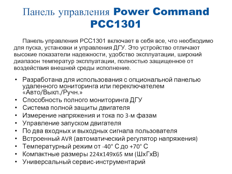
Слайд 2система индикации и управления
Возможность использования нескольких
панелей с одной ДГУ путем коммуникации через
встроенный RS485
Возможность удаления панели на расстоянии до 300 м от ДГУ
Отсутствие наружных переключателей
Мгновенное отображение статусных и аварийных сообщений
Полное отображение состояния ДГУ:
3-х фазное напряжение и ток,
температура ОЖ, давление масла,
напряжение батарей, частота,
история ошибок
Возможность настройки и
регулировки ДГУ
Компактные размеры
141х111х33,5 мм (ШхГхВ)
Защита дисплея IP54
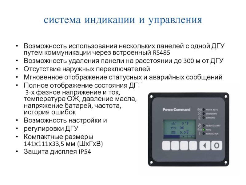
Слайд 3Компоненты системы управления
Система управления PCC1301 модульной
конструкции, состоит из следующих элементов:
PCC1301 (Основное устройство)
HMI211
(Интерфейс человек-машина)
HMI113 (Универсальный сигнализатор — Опция)
Aux101 и Aux102 (Модули Входа / Выхода – Опция)
В данном курсе рассмотрим функции контроллера PCC1301 и функции дисплея оператора HMI211
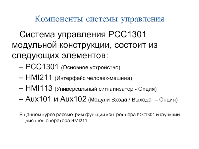
Слайд 4Структура системы управления
PCC1301
HMI211
HMI113
(Опция)
Информационная сеть
(4
кабеля)
Шина Modbus
Двигатель
Генератор
AUX101
(Опция)
(Service Tool)
Конвертер
На некоторых моделях
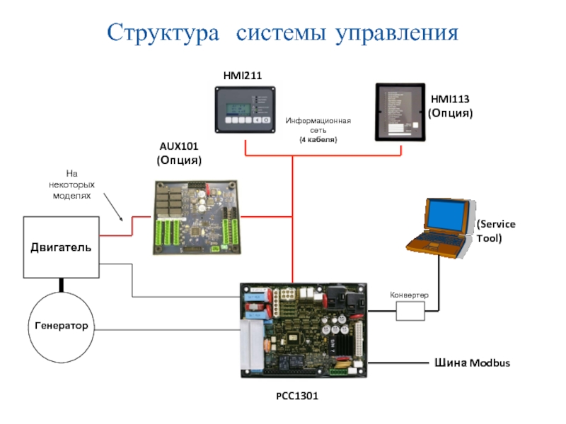
Слайд 5Функции компонентов
Контроллер PCC1301
(Основной элемент):
Эта плата является
“сердцем” системы управления. Плата содержит все логические
элементы и устройства ввода/вывода
для работы ДГУ.
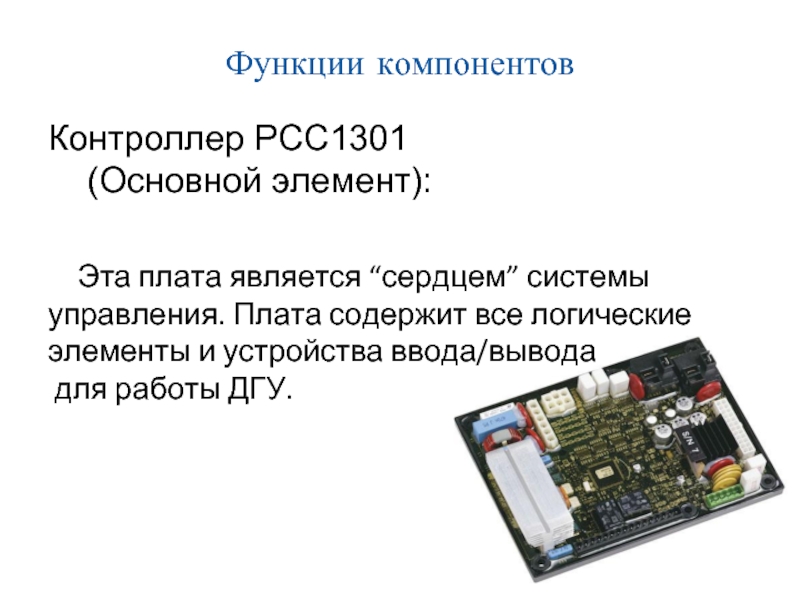
Слайд 6Функции панели управления PCC1301
Защита двигателя
давление масла,
температура двигателя,
превышение оборотов двигателя,
проблемы с
пуском,
неисправность датчика оборотов.
Защита генератора
пониженное напряжение,
повышенное напряжение,
пониженная частота тока,
превышение силы тока – требуются трансформаторы тока .
Задержка времени пуска/останова
Режим энергосбережения
пониженное энергопотребление в режимах Off и Auto
Программируемые I/O пользователя
(2 входа и 2 выхода)
Интерфейс Modbus (RS485 RTU)
Взаимодействие с сервисным ПО
Защита от воздействий окружающей среды (NEMA 3R/IP53)
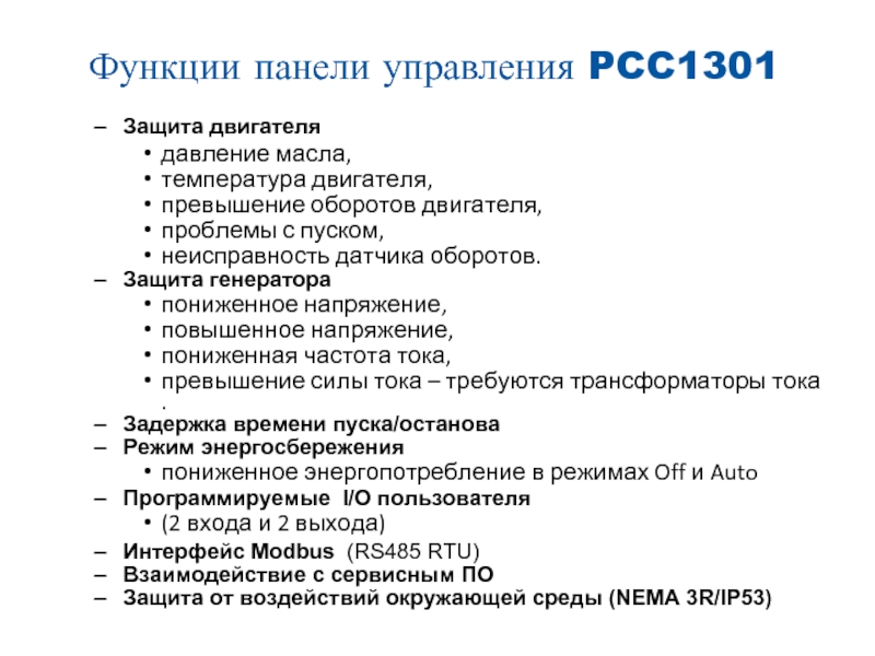
Слайд 7HMI211 Дисплей оператора
HMI211 (Интерфейс взаимодействия человек —
машина):
Модуль HMI используется для измерения параметров работы
генератора и двигателя.
Поддерживается режим оповещения
о неисправностях
(коды неисправностей и описание)
облегченный вариант системы
управления без сервисного ПО.
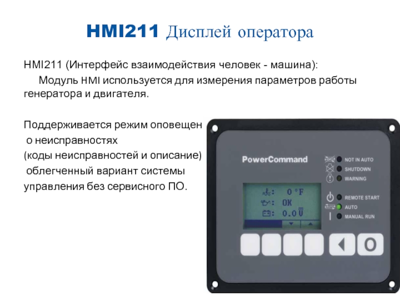
Слайд 8Функции дисплея HMI211
Свойства Дисплей оператора HMI211 :
Подсвечиваемый
ЖК дисплей
Символьный или текстовый экран оператора
поддерживает
только английский язык
Встроенный переключатель Пуск/Выключение/Авто
с программируемым кодом доступа (key switch)
Показания :
Двигатель
Давление масла , температура ОЖ ,
заряд батареи, скорость вращения
Генератор
напряжение, ток, частота,
KVA – полная мощность
Может быть дополнительно установлен дистанционно
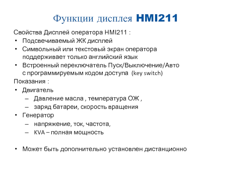
Слайд 10Дисплей оператора
Органы управления дисплея
Светодиоды:
1 не в автоматическом
режиме
2 останов
3 внимание
4 дистанционный пуск
5 автоматический режи
6
ручной режим
Кнопки:
7 режим генераторной установки «Окл» (переход в главное меню)
8 предыдущий экран
9 кнопки с функциями определяемыми символами на дисплее
Дисплей:
10 строка меню (4 символа кнопок)
11 графический ЖК дисплей
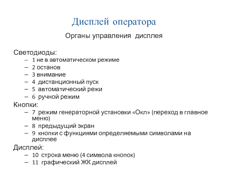
Слайд 12Отображаемые символы в символьном режиме
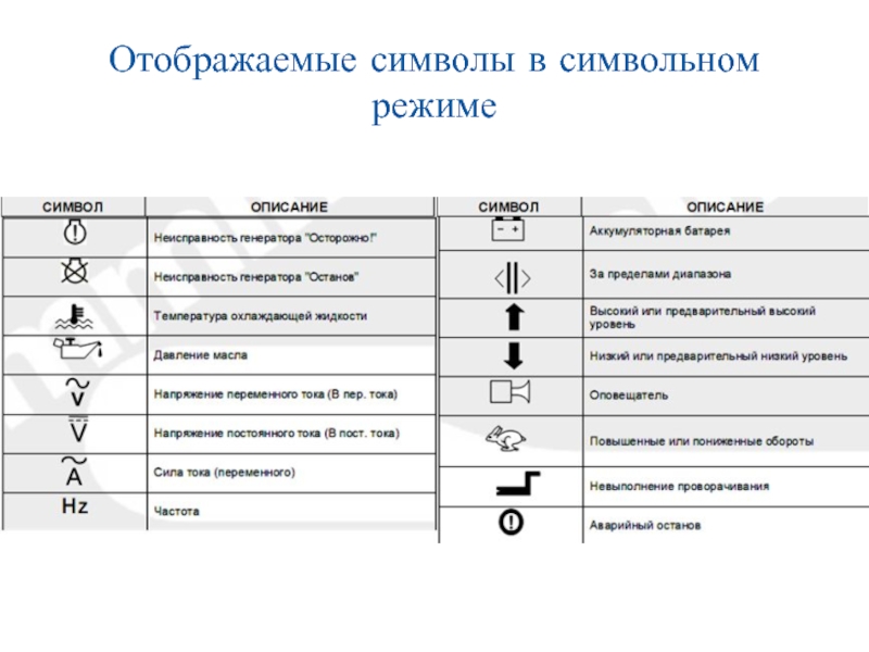
Слайд 13Дисплей — системные сообщения
Системные сообщения отображаются
при включении напряжения питания или при сбое
обмена данными с контроллером РСС1301.
При потери связи с контроллером сообщение
отображается до восстановления связи с контроллером
Когда индицируются коммуникационные сообщения,
можно выбрать режим работы автоматический / ручной.
При подаче питания
Если на экране остаётся любое
коммуникационное сообщение
(и другие меню просмотреть невозможно),
то значит связь между дисплеем и
контроллером РСС1301 утеряна.
Обратитесь за помощью к официальному дистрибьютору.
При потери связи
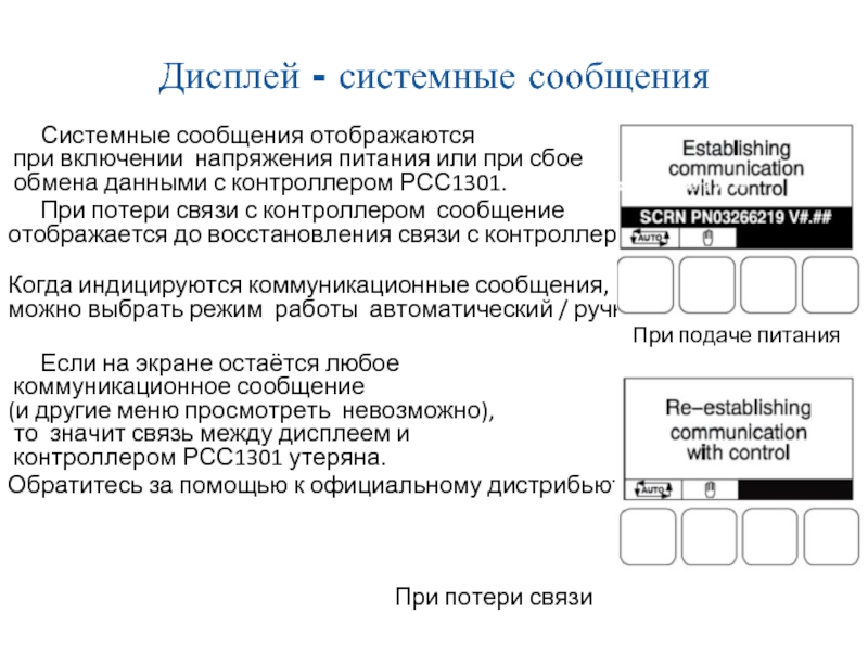
Слайд 14Дисплей — Сообщения о событиях
Когда активируются
запрограммированные события
(пуск или останов), индицируются сообщения
о событиях,
показывающие время, остающееся до завершения события.
Сообщение о неисправности является индикатором
состояния «Внимание!» или «Останов», еще одним
индикатором которого является включения лампы.
Текстовое сообщение о неисправности содержит
номер кода неисправности, краткое описание и
время возникновения неисправности ( текстовом режиме )
Символьные сообщения о неисправностях содержат
номер кода неисправности и символы, указывающие
на тип неисправности ( символьном режиме дисплея)
Подтверждение приема неисправности.
Для подтверждения приема сигнала неисправности/останова
следует нажать кнопку «Откл.» на панели дисплея или
кнопки стрелок, при этом сообщение о неисправности
удаляется с дисплея.
Сообщение о неисправности появляется повторно если
сигнал неисправности не устранен.
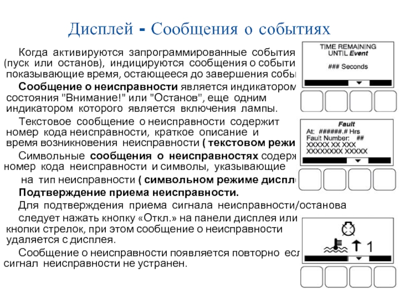
Слайд 15Меню оператора дисплея
Состояние двигателя
напряжение АКБ,
температуру ОЖ, давление масла, моточасы.
Состояние генератора переменного
тока
нагрузку генератора (КВА), частоту (Гц), обороты двигателя (об/мин).
Линейные напряжения
линейные напряжения L1-L2, L2-L3, L3-L1 только для 3-фазных систем.
Фазные напряжения
фазные напряжения L1, L2, L3 только в конфигурации звезда,
В конфигурации «треугольник» это меню не показывается,
напряжения L1-N, L2-N и L1-L2 только для однофазных систем.
Токи генератора
показываются результаты измерений токов L1, L2 и L3.
Слайд 17 автоматический и ручной режимы
ВНИМАНИЕ! ПРИ
ИЗМЕНЕНИИ РЕЖИМОВ ГЕНЕРАТОРНАЯ УСТАНОВКА МОЖЕТ ЗАПУСТИТЬСЯ ИЛИ
ОСТАНОВИТЬСЯ БЕЗ ПРЕДУПРЕЖДЕНИЯ. УБЕДИТЕСЬ, ЧТО ИЗМЕНЕНИИ РЕЖИМА НЕ СОЗДАДУТ ОПАСНОСТИ ДЛЯ ПЕРСОНАЛА ИЛИ ОБОРУДОВАНИЯ.
Смена режима автоматический / ручной из режима «Откл.» можно произвести следующим образом:
из любого меню оператора,
при сообщении «Установление связи»,
при сообщении «Восстановление связи».
Если при наладке пульта управления была
активирована функция пароля для изменения
режимов «Авт.», «Ручн.» или «Откл.», то
необходимо ввести пароль в субменю «Изменение режима»
с помощью кнопок «>», «+», «-». Пароль оператора 121.
По окончании ввода нажать кнопку с символом «>».
1. Панель управления Power Command PCC1301
Панель управления PCC1301 включает в себя все, что необходимо
для пуска, установки и управления ДГУ. Это устройство отличают
высокие показатели надежности, удобство эксплуатации, широкий
диапазон температур эксплуатации, полностью защищенное от
воздействия внешней среды исполнение.
• Разработана для использования с опциональной панелью удаленного
мониторинга или переключателем «Авто/Выкл./Ручн.»
• Способность полного мониторинга ДГУ
• Система полной защиты двигателя
• Измерение напряжения и тока по 3-м фазам
• Управление запуском двигателя
• По два входных и выходных сигнала пользователя
• Встроенный AVR (автоматический регулятор напряжения)
• Температурный режим от -40° С до +70° С
• Компактные размеры 224х149х65 мм (ШхГхВ)
• Универсальный сервис-инструментарий
2. система индикации и управления
• Возможность использования нескольких панелей с одной ДГУ путем
коммуникации через встроенный RS485
• Возможность удаления панели на расстоянии до 300 м от ДГУ
• Отсутствие наружных переключателей
• Мгновенное отображение статусных и аварийных сообщений
• Полное отображение состояния ДГУ:
3-х фазное напряжение и ток,
температура ОЖ, давление масла,
напряжение батарей, частота,
история ошибок
• Возможность настройки и
• регулировки ДГУ
• Компактные размеры
141х111х33,5 мм (ШхГхВ)
• Защита дисплея IP54
3. Компоненты системы управления
Система управления PCC1301
модульной конструкции, состоит из
следующих элементов:
– PCC1301 (Основное устройство)
– HMI211 (Интерфейс человек-машина)
– HMI113 (Универсальный сигнализатор — Опция)
– Aux101 и Aux102 (Модули Входа / Выхода – Опция)
В данном курсе рассмотрим функции контроллера PCC1301 и функции
дисплея оператора HMI211
4. Структура системы управления
HMI211
HMI113
(Опция)
Информационная сеть
(4 кабеля)
AUX101
(Опция)
На некоторых
моделях
(Service Tool)
Двигатель
Конвертер
Генератор
Шина Modbus
PCC1301
5. Функции компонентов
Контроллер PCC1301
(Основной элемент):
Эта плата является “сердцем” системы
управления. Плата содержит все логические
элементы и устройства ввода/вывода
для работы ДГУ.
6. Функции панели управления PCC1301
– Защита двигателя
давление масла,
температура двигателя,
превышение оборотов двигателя,
проблемы с пуском,
неисправность датчика оборотов.
пониженное напряжение,
повышенное напряжение,
пониженная частота тока,
превышение силы тока – требуются трансформаторы тока .
– Защита генератора
– Задержка времени пуска/останова
– Режим энергосбережения
• пониженное энергопотребление в режимах Off и Auto
– Программируемые I/O пользователя
• (2 входа и 2 выхода)
– Интерфейс Modbus (RS485 RTU)
– Взаимодействие с сервисным ПО
– Защита от воздействий окружающей среды (NEMA 3R/IP53)
7. HMI211 Дисплей оператора
HMI211 (Интерфейс взаимодействия человек — машина):
Модуль HMI используется для измерения параметров работы генератора
и двигателя.
Поддерживается режим оповещения
о неисправностях
(коды неисправностей и описание)
облегченный вариант системы
управления без сервисного ПО.
8. Функции дисплея HMI211
Свойства Дисплей оператора HMI211 :
• Подсвечиваемый ЖК дисплей
• Символьный или текстовый экран оператора
поддерживает только английский язык
• Встроенный переключатель Пуск/Выключение/Авто
с программируемым кодом доступа (key switch)
Показания :
• Двигатель
– Давление масла , температура ОЖ ,
– заряд батареи, скорость вращения
• Генератор
– напряжение, ток, частота,
– KVA – полная мощность
• Может быть дополнительно установлен дистанционно
9. Дисплей оператора
1
2
3
4
5
6
11
10
7
8
9
10. Дисплей оператора
Органы управления дисплея
Светодиоды:
– 1 не в автоматическом режиме
–
–
–
–
–
2 останов
3 внимание
4 дистанционный пуск
5 автоматический режи
6 ручной режим
Кнопки:
– 7 режим генераторной установки «Окл» (переход в главное меню)
– 8 предыдущий экран
– 9 кнопки с функциями определяемыми символами на дисплее
Дисплей:
– 10 строка меню (4 символа кнопок)
– 11 графический ЖК дисплей
11. режимы дисплея
Battery: 12.4VDC
Eng. Temp: 180~F
Oil Press: 75PSI
AUTO
Текстовый
режим
Load:
1200 kVA
Frequency:60.2Hz
Speed:
1800RPM
AUTO
:
:
:
KVA:
Hz:
RPM:
Символьный
режим
L1-L2: 208
L2-L3: 208
L3-L1: 208
AUTO
L1-N:
L2-N:
L3-N:
L1:
L2:
L3:
AUTO
120
120
120
AUTO
L1: 1200 AMPS
L2: 1200 AMPS
L3: 1200 AMPS
AUTO
1200
60.2
1800
AUTO
L1-N: 120 VAC
L2-N: 120 VAC
L3-N: 120 VAC
AUTO
AUTO
L1-L2: 208 VAC
L2-L3: 208 VAC
L3-L1: 208 VAC
AUTO
12.4VDC
180~F
75PSI
1200
1200
1200
12. Отображаемые символы в символьном режиме
13. Дисплей — системные сообщения
Системные сообщения отображаются
при включении напряжения питания или при сбое
обмена данными с контроллером РСС1301.
При потери связи с контроллером сообщение
отображается до восстановления связи с контроллером
Когда индицируются коммуникационные сообщения,
можно выбрать режим работы автоматический / ручной.
При подаче питания
Если на экране остаётся любое
коммуникационное сообщение
(и другие меню просмотреть невозможно),
то значит связь между дисплеем и
контроллером РСС1301 утеряна.
Обратитесь за помощью к официальному дистрибьютору.
При потери связи
14. Дисплей — Сообщения о событиях
Когда активируются запрограммированные события
(пуск или останов), индицируются сообщения о событиях,
показывающие время, остающееся до завершения события.
Сообщение о неисправности является индикатором
состояния «Внимание!» или «Останов», еще одним
индикатором которого является включения лампы.
Текстовое сообщение о неисправности содержит
номер кода неисправности, краткое описание и
время возникновения неисправности ( текстовом режиме )
Символьные сообщения о неисправностях содержат
номер кода неисправности и символы, указывающие
на тип неисправности ( символьном режиме дисплея)
Подтверждение приема неисправности.
Для подтверждения приема сигнала неисправности/останова
следует нажать кнопку «Откл.» на панели дисплея или
кнопки стрелок, при этом сообщение о неисправности
удаляется с дисплея.
Сообщение о неисправности появляется повторно если
сигнал неисправности не устранен.
15. Меню оператора дисплея
Состояние двигателя
• напряжение АКБ, температуру ОЖ, давление масла, моточасы.
Состояние генератора переменного тока
• нагрузку генератора (КВА), частоту (Гц), обороты двигателя (об/мин).
Линейные напряжения
• линейные напряжения L1-L2, L2-L3, L3-L1 только для 3-фазных
систем.
Фазные напряжения
• фазные напряжения L1, L2, L3 только в конфигурации звезда,
• В конфигурации «треугольник» это меню не показывается,
• напряжения L1-N, L2-N и L1-L2 только для однофазных систем.
Токи генератора
• показываются результаты измерений токов L1, L2 и L3.
16.
блок-схема меню оператора
17. автоматический и ручной режимы
ВНИМАНИЕ! ПРИ ИЗМЕНЕНИИ РЕЖИМОВ ГЕНЕРАТОРНАЯ УСТАНОВКА
МОЖЕТ ЗАПУСТИТЬСЯ ИЛИ ОСТАНОВИТЬСЯ БЕЗ ПРЕДУПРЕЖДЕНИЯ.
УБЕДИТЕСЬ, ЧТО ИЗМЕНЕНИИ РЕЖИМА НЕ СОЗДАДУТ ОПАСНОСТИ ДЛЯ
ПЕРСОНАЛА ИЛИ ОБОРУДОВАНИЯ.
Смена режима автоматический / ручной из режима «Откл.» можно
произвести следующим образом:
• из любого меню оператора,
• при сообщении «Установление связи»,
• при сообщении «Восстановление связи».
Если при наладке пульта управления была
активирована функция пароля для изменения
режимов «Авт.», «Ручн.» или «Откл.», то
необходимо ввести пароль в субменю «Изменение режима»
с помощью кнопок «>», «+», «-». Пароль оператора 121.
По окончании ввода нажать кнопку с символом «>».
18.
Выбор Режима
«АВТ.»
19.
Выбор Режима
«РУЧН.»
20.
Выбор Режима
«ОТКЛ.»