Содержание
- автокаталог. программа автокаталог
- geodyna 4300
- Балансировочный стенд Hofmann Geodyna 4300-2p
- Описание балансировочного стенда
- Характеристики балансировочного стенда Hofmann Geodyna 4300-2p:
- Технические характеристики стенда балансировочного Hofmann Geodyna 4300-2p:
- Доставка по Ростову-на-Дону и области
- Доставка по России
- Цены сервисного обслуживания на Балансировочный стенд Hofmann Geodyna 4300-2p
- Балансировочный стенд Hofmann Geodyna 4300-2
- Описание балансировочного стенда
- Характеристики стенда балансировочного Hofmann Geodyna 4300-2:
- Технические характеристики стенда балансировочного Hofmann Geodyna 4300-2:
- Доставка по Ростову-на-Дону и области
- Доставка по России
- Цены сервисного обслуживания на Балансировочный стенд Hofmann Geodyna 4300-2
автокаталог. программа автокаталог
| Продажа запчастей на грузовые автомобили и трактора | |
| Ходовые агрегаты для гусеничной техники | |
| Проверка технического состояния | |
| Контроль, диагностика, регулировка | |
| Ремонт | |
| Очистительная техника | |
| Пуск, заряд | |
| Подъемники | |
| Шиноремонт | |
|
|
| Компрессоры | |
| Смазка, заправка | |
| Вытяжное оборудование |
geodyna 4300
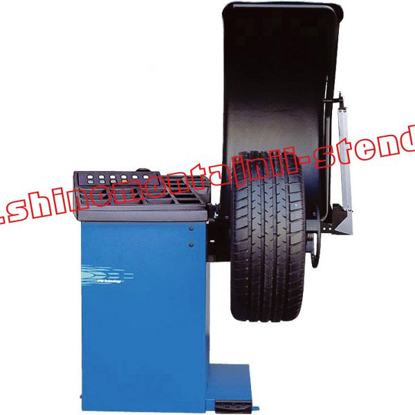
| Цифровой балансировочный станок среднего класса с ЖК дисплеем (фирма HOFMANN, Германия) | 176200 RUB |
 Цифровой балансировочный станок среднего класса с ЖК дисплеем. Для СТО с малым и средним объемом работ.
Техника VPM — виртуальные плоскости измерений. Снижает влияние дестабилизирующих факторов и повышает точность измерений.
Техника 2D — автоматический ввод расстояния от станка до колеса и диаметра обода.
KPS — измерительный рычаг с системой позиционирования клеевых грузиков. Измерительная рука запоминает выбранные места установки грузиков и находит их после измерения (акустический сигнал и индикация на дисплее).
HSP — патентованная программа установки грузиков за спицами.
8 вариантов установки грузиков, из них 7 ALU.
Программа балансировки аварийно-безопасных колес РАХ.
Автоматическая остановка колеса после измерения.
Монитороподобный большой ЖК дисплей.
Частота вращения 200 об/мин.
Время измерений 3 с.
Максимальный диаметр колеса 950 мм;
Ширина обода 1-20 дюймов.
Диаметр обода 8-24 дюйма.
Макс. ширина колеса 530 мм.
Макс. масса колеса 70 кг.
Погрешность измерений 1 г.
Электропитание 220 В.
Габариты (ВхШхГ) 1763х1213х1175 мм.
1. Анализ цен — рыночных, собственных, конкурентов.
2. Тендеры — проведение и участие.
3. Оптовая и розничная торговля и закупки.
4. Отслеживание процессов материально-технического обеспечения предприятия.
5. Каталоги товаров * и поставщиков.
*Грузовые автомобили и трактора: Автокаталог
Предлагаем оборудование для автосервиса: шиномонтажное оборудование, диагностическое оборудование (тестеры, сканеры, газоанализаторы, пьезодатчики), подъемники, оборудование для проверки технического состояния (мобильные и стационарные линии технического контроля, тестеры), оборудование для ремонта (обкаточные, рихтовочные стенды, станки, приспособления), очистительное оборудование (очистные установки, пылесосы), пускозарядное оборудование, компрессоры, оборудование для смазки и заправки.
Предлагаем запчасти для промышленной, сельскохозяйственной, железнодорожной техники, трелевочников, узлы сцепления, замки, радиаторы производства Чебоксарсого агрегатного завода.
Источник
Балансировочный стенд Hofmann Geodyna 4300-2p
Цена: 252 750,00

БрендНазначениеТипНапряжениеГабаритные размерыВес изделия с упаковкойМакс. вес колеса до
| Наименование | Параметры |
|---|---|
| Hofmann | |
| Легковой | |
| Автомат | |
| 220 В | |
| 1756x1280x1080 мм | |
| 105 кг | |
| 70 кг |
Описание балансировочного стенда
- зажимное электромеханическое устройство колеса Power Clamp;
- большой жидкокристаллический дисплей;
- автоматический ввод расстояния от колеса до станка и ободного диаметра;
- функция блокировки Power Clamp до окончания балансировки колеса.
Характеристики балансировочного стенда Hofmann Geodyna 4300-2p:
- техника проведения измерений улучшенной точности VPM (плоскости измерения виртуальные (запатентовано)) — балансировочный узел сверхточный с повышенной устойчивостью к воздействиям извне;
- программа, оптимизирующая плавность хода (имеется патент);
- рычаг измерительный, оснащенный системой позиционирования (имеется патент) и зажимом для грузов;
- внесение дополнительных параметров колесного вращения при нажатой клавише (имеется патент);
- программы для размещения грузов за спицами;
- разнообразные операторские профили;
- тормоз колеса стопорного типа;
- после проведения диагностики колесо останавливается автоматически;
- защитный колесный кожух большого размера;
- счетчик колес отбалансированных;
- программа балансировки колес типа PAX;
- стол с удобными ячейками для грузов, конусов, инструментов;
- большой ассортимент дополнительных возможностей.
Технические характеристики стенда балансировочного Hofmann Geodyna 4300-2p:
| Наименование параметра, единицы измерения | Значение параметра |
|---|---|
| Диаметр центрального дискового отверстия, мм | 43-116 |
| Валовый диаметр, мм | 40 |
| Частота валового вращения, об/мин | 200 |
| Дисковая ширина, дюймы | 1-20 |
| Дисковый диаметр, дюймы | 8-24 |
| Максимальная колесная ширина, мм | 530 |
| Максимальный колесный диаметр, мм | 950 |
| Максимальная колесная масса, кг | 70 |
| Измерительная точность, г | 1 |
| Время для проведения измерений, с | 6 |
| Размеры габаритные высота/ширина /глубина, мм | 1756/1280/1080 |
| Масса оборудования, кг | 105 |
| Электропитание балансировочного стенда, ф/В/Гц | 1/220/50 |
Купить балансировочный стенд Hofmann Geodyna 4300-2p можно у нас в компании «Кронвус-Юг», самостоятельно забрав товар со склада в Ростове-на-Дону. Если Вы не можете осуществить самовывоз, находясь в другом регионе, воспользуйтесь услугой доставки по регионам .
Москва
Санкт-Петербург
Краснодар
Сочи
Новороссийск
Анапа
Волгоград
Саратов
Самара
Невинномысск
Астрахань
Ставрополь
Владикавказ
Минеральные воды
Нальчик
Грозный
Пятигорск
Доставка по Ростову-на-Дону и области
Клиенты, которые находятся в Ростове-на-Дону, могут заказать доставку приобретаемого товара нашим грузовым транспортом. При этом сама доставка обойдется Вам в 1000 руб, вне зависимости от конечного места доставки, объема и веса товара (в пределах вместимости грузового автомобиля).
| Город | Километраж до города | Стоимость за 1км | Доставка по городу | Итог |
|---|---|---|---|---|
| Аксай | 24км | 15р | 700р | 1 060,00 |
| Батайск | 29км | 15р | 700р | 1 135,00 |
| Азов | 57км | 15р | 700р | 1 555,00 |
| Новочеркасск | 53км | 15р | 700р | 1 495,00 |
| Шахты | 89км | 15р | 700р | 2 035,00 |
| Таганрог | 70км | 15р | 700р | 1 750,00 |
Доставка по России
С открытием новых офисов продаж шиномонтажного оборудования в других регионах Южного федерального округа, наша компания осуществляет доставку купленного товара со склада, расположенного в Ростове-на-Дону, до любого терминала транспортной компании или конечного адреса клиента.
Приобретая оборудование в нашей компании, Вы можете не беспокоиться о его доставке, установке и подключении. Наличие собственной сервисной службы дает нам ряд преимуществ перед другими торгующими организациями.
Наши специалисты приедут к Вам на место, осуществят монтаж приобретенного оборудования, протестирует его на отсутствие заводских дефектов и, в случае необходимости, обучат Ваших сотрудников правильному обращению с изделием.
Цены сервисного обслуживания на Балансировочный стенд Hofmann Geodyna 4300-2p
Услугу сервисного обслуживания на Балансировочный стенд Hofmann Geodyna 4300-2p Вы можете заказать отдельно у наших менеджеров при оформлении заказа.
Подробно ознакомиться с информацией по сервисной службе, Вы можете в соответствующем разделе нашего сайта — Сервис.
Источник
Балансировочный стенд Hofmann Geodyna 4300-2
Цена: по запросу
БрендНазначениеТипНапряжениеГабаритные размерыВес изделия с упаковкойМакс. вес колеса до
| Наименование | Параметры |
|---|---|
| Hofmann | |
| Легковой | |
| Автомат | |
| 220 В | |
| 1756x1280x1080 мм | |
| 105 кг | |
| 70 кг |
Описание балансировочного стенда
- большой жидкокристаллический дисплей;
- ввод расстояния от стенда до колеса и диаметра обода автоматический.
Характеристики стенда балансировочного Hofmann Geodyna 4300-2:
- техника проведения измерений улучшенной точности VPM (плоскости измерения виртуальные (запатентовано)) — балансировочный узел сверхточный с повышенной устойчивостью к воздействиям извне;
- программа, оптимизирующая плавность хода ( имеется патент);
- рычаг измерительный, оснащенный системой позиционирования (имеется патент) и зажимом для грузов;
- внесение дополнительных параметров колесного вращения при нажатой клавише (имеется патент);
- программы для размещения грузов за спицами;
- разнообразные операторские профили;
- тормоз колеса стопорного типа;
- после проведения диагностики колесо останавливается автоматически;
- защитный колесный кожух большого размера;
- счетчик колес отбалансированных;
- программа балансировки колес типа PAX;
- стол с удобными ячейками для грузов, конусов, инструментов;
- большой ассортимент дополнительных возможностей.
Технические характеристики стенда балансировочного Hofmann Geodyna 4300-2:
| Наименование параметра, единицы измерения | Значение параметра |
|---|---|
| Диаметр центрального дискового отверстия, мм | 43-116 |
| Валовой диаметр, мм | 40 |
| Частота валового вращения, об/мин | 200 |
| Дисковая ширина, дюймы | 1-20 |
| Дисковый диаметр, дюймы | 8-24 |
| Максимальная колесная ширина, мм | 530 |
| Максимальный колесный диаметр, мм | 950 |
| Максимальная колесная масса, кг | 70 |
| Измерительная точность, г | 1 |
| Время для проведения измерений, с | 6 |
| Размеры габаритные высота/ширина /глубина, мм | 1756/1280/1080 |
| Масса стенда, кг | 105 |
| Электропитание балансировочного стенда, ф/В/Гц | 1/220/50 |
Купить балансировочный стенд Hofmann Geodyna 4300-2 можно у нас в компании «Кронвус-Юг», самостоятельно забрав товар со склада в Ростове-на-Дону. Если Вы не можете осуществить самовывоз, находясь в другом регионе, воспользуйтесь услугой доставки по регионам .
Москва
Санкт-Петербург
Краснодар
Сочи
Новороссийск
Анапа
Волгоград
Саратов
Самара
Невинномысск
Астрахань
Ставрополь
Владикавказ
Минеральные воды
Нальчик
Грозный
Пятигорск
Доставка по Ростову-на-Дону и области
Клиенты, которые находятся в Ростове-на-Дону, могут заказать доставку приобретаемого товара нашим грузовым транспортом. При этом сама доставка обойдется Вам в 1000 руб, вне зависимости от конечного места доставки, объема и веса товара (в пределах вместимости грузового автомобиля).
| Город | Километраж до города | Стоимость за 1км | Доставка по городу | Итог |
|---|---|---|---|---|
| Аксай | 24км | 15р | 700р | 1 060,00 |
| Батайск | 29км | 15р | 700р | 1 135,00 |
| Азов | 57км | 15р | 700р | 1 555,00 |
| Новочеркасск | 53км | 15р | 700р | 1 495,00 |
| Шахты | 89км | 15р | 700р | 2 035,00 |
| Таганрог | 70км | 15р | 700р | 1 750,00 |
Доставка по России
С открытием новых офисов продаж шиномонтажного оборудования в других регионах Южного федерального округа, наша компания осуществляет доставку купленного товара со склада, расположенного в Ростове-на-Дону, до любого терминала транспортной компании или конечного адреса клиента.
Приобретая оборудование в нашей компании, Вы можете не беспокоиться о его доставке, установке и подключении. Наличие собственной сервисной службы дает нам ряд преимуществ перед другими торгующими организациями.
Наши специалисты приедут к Вам на место, осуществят монтаж приобретенного оборудования, протестирует его на отсутствие заводских дефектов и, в случае необходимости, обучат Ваших сотрудников правильному обращению с изделием.
Цены сервисного обслуживания на Балансировочный стенд Hofmann Geodyna 4300-2
Услугу сервисного обслуживания на Балансировочный стенд Hofmann Geodyna 4300-2 Вы можете заказать отдельно у наших менеджеров при оформлении заказа.
Подробно ознакомиться с информацией по сервисной службе, Вы можете в соответствующем разделе нашего сайта — Сервис.
Источник
This document contains important information to use and/or repair your appliance.
Depending on the nature of the manual (use, installation, service, parts list), it provides instructions that you can’t ignore.
We provide PDF manuals : easy to download, the documents can be displayed on any equipment like mobile, tablet and computer.
This is an official document edited by the manufacturer or a local distributor.

geodyna 4300 Bruksanvisning Operation manual Mode d’emploi PV-Hjulbalanseringsmaskin Car wheel balancer Equilibreuse de roues v.t. Hofmann Werkstatt-Technik Sida 1. 2. Installation av maskinen . . . . . . . . . . . . . . . . . . . . . . . . . . 8 3. 4. Reglage och display . . . . . . . . . . . . . . . . . . . . . . . . . . . . 12 5. Att slå på maskinen . . . . . . . . . . . . . . . . . . . . . . . . . . . . . 16 6. 7. 8. Balansering av hjulet . . . . . . . . . . . . . . . . . . . . . . . . . . . . 52 9. . . . . . . . . . . . . . . . . . . . . . . . . . . . . . . . . . . . . . 80 12. Optimering/viktminimering . . . . . . . . . . . . . . . . . . . . . . . 92 13. Kundkalibrering . . . . . . . . . . . . . . . . . . . . . . . . . . . . . . . 114 14. Underhåll . . . . . . . . . . . . . . . . . . . . . . . . . . . . . . . . . . . . . 116 15. Tekniska Data . . . . . . . . . . . . . . . . . . . . . . . . . . . . . . . . . 116 16. Elschema . . . . . . . . . . . . . . . . . . . . . . . . . . . . . . . . . . . . 118 1. 1.1 1.2 2 BA geodyna 4300 – 9512 150 Contents • Safety rules and function Contents Page Page 1. Safety rules and function . . . . . . . . . . . . . . . . . . . . . . . . . 3 1. 2. Installation of the machine . . . . . . . . . . . . . . . . . . . . . . . . 9 2. 3. Electrical connection . . . . . . . . . . . . . . . . . . . . . . . . . . . . 11 3. 4. Controls and displays . . . . . . . . . . . . . . . . . . . . . . . . . . . 13 4. 5. Switching on the machine . . . . . . . . . . . . . . . . . . . . . . . . 17 5. 6. Clamping the wheel . . . . . . . . . . . . . . . . . . . . . . . . . . . . . 21 6. 7. Entry of wheel type, balancing mode and wheel size . . . . . . . . . . . . . . . . . . . . . . . . . . . . . . . . . . . . . 27 7. 8. Balancing the wheel . . . . . . . . . . . . . . . . . . . . . . . . . . . . . 53 8. 9. Behind-the-spokes placement . . . . . . . . . . . . . . . . . . . . 61 9. 10. Changing the modes of operation . . . . . . . . . . . . . . . . . 67 11. Error codes . . . . . . . . . . . . . . . . . . . . . . . . . . . . . . . . . . . . 81 12. Optimisation / weight minimisation . . . . . . . . . . . . . . . . 93 12. Optimisation / minimisation des masses . . . . . . . . . . . 93 13. Readjustment by the operator . . . . . . . . . . . . . . . . . . . 115 15. Technical data . . . . . . . . . . . . . . . . . . . . . . . . . . . . . . . . . 117 16. Electrical diagram . . . . . . . . . . . . . . . . . . . . . . . . . . . . . 118 1. Safety rules and function 1. 1.1 Special hints for the reader A few special features were used in this manual to facilitate reading and understanding of pictures and written instructions: 1.1 signals the operator where to act. Safety rules are highlighted in grey. 1.2 Arrow showing where to look Arrow showing the direction to move Scope of application The off-the-vehicle wheel balancer is designed for static and/or dynamic balancing of car and light-truck wheels weighing up to 70 kg and having an overall diameter of 950 mm. In addition to conventional balancing operations, irregular running conditions of the wheel caused by geometric deformations of the rims and/or tyres, hence unsmooth ride, can be identified, improved or, if possible, even eliminated. By exact adjustment of the two wheel components relative to each other optimum wheel running conditions or at least balance weight minimisation can be achieved. Operation manual geodyna 4300 – 9512 150 1.2 Mode d’emploi geodyna 4300 – 9512 150 3 Bild 1 2 1 3 1.3 4 5 1 4 BA geodyna 4300 – 9512 150 Safety rules and function Fig. 1 View wheel balancer Fig. 1 Front view 1 Display, key pad, and weight box 2 Wheel guard 3 Gauge arm for distance rim/machine and rim diameter 4 Pedal for main shaft lock Rear view 5 Mains switch and power supply 1.3 1.3 General safety rules Only properly trained and authorised personnel shall be allowed to operate the wheel balancer. The machine must not be used except for the scope of application and in the way specified in this manual. Unauthorised changes and modifications to the machine relieve the manufacturerer from any liability for damages and injuries that might result therefrom. On no account should safety features be removed or made inoperative. In general any work on the electrical system such as fitting of a plug or changing of connections, if necessary, must be carried out by a qualified electrician in line with relevant national standards and the regulations of the local power station. It should be noted that working with technical equipment may involve an unforeseeable acceptable risk. Therefore the operator should eliminate such dangers in advance by proper and wise behaviour. The following special points should be observed: Use technical equipment for its specified scope of application only. Always use suitable and proper equipment and tools. Follow the instructions, notes and technical data of the machine manufacturer or manufacturer of the wheels to be balanced. Wear suitable protective clothing and accessories (e. g. goggles, safety shoes, helmet). For further safety rules to be observed, please refer to the individual chapters. Operation manual geodyna 4300 – 9512 150 Mode d’emploi geodyna 4300 – 9512 150 5 1.4 Funktion 6 BA geodyna 4300 – 9512 150 Safety rules and function 1.4 Description of function 1.4 Display and key pad The display and key pad are arranged on the ergonomic front panel. Gauge arm for distance and rim diameter Entry of rim diameter and distance between left correction plane and machine is by means of an integrated gauge arm or also via the key pad. In the latter case the relative function key is held pressed while the wheel is rotated to choose the desired inputs and enter them by releasing the function key. When fitting adhesive weights with the weight holder, the machine will support the operator in relocating the correction position. Rim width is entered via the menu keys and rotation of the wheel. Balancing mode Readings in different balancing modes (weight position on the rim) can be given on the display, depending on the type of wheel to be balanced (car, light-truck, motorcycle, PAX, steel or alloy rim). Measuring run and measured values All measurements are taken and stored in one run during the automatic program. On completion of measurement the machine stops automatically and the wheel is slowed down to standstill. Amounts and locations of unbalance are read out separately for each correction plane. Main shaft lock The machines have a pedal-operated main shaft lock which is used to retain the wheel in the correction position so that the balance weights can be fitted. This lock is designed only to facilitate orientation of the wheel and must not be used for braking the main shaft. Store wheel profiles Wheel profiles permit the storage of values for wheels that are balanced frequently in order to save having to enter the wheel data etc. each time. It is possible to store up to 4 wheel profiles. Error codes Errors in operation or failures in the electronic or mechanical system are signalled via respective error codes (see § 11. Error codes). Readjustment by the operator If several measuring runs are necessary to balance a wheel because balance weight size and position have to be adjusted repeatedly, this is often due to insufficient measurement accuracy. In such case the operator has the possibility of readjusting the machine (see § 13. Readjustment by the operator). Wheel guard A wheel guard with electric interlocking is mandatory for the European Union and is part of the standard equipment. The measuring run may only be started with closed guard. The electronic unit can be programmed via code C13 so that measurement is started by closing of the guard. Operation manual geodyna 4300 – 9512 150 Mode d’emploi geodyna 4300 – 9512 150 7 Installation av maskinen 2. 523 190 Installation av maskinen 49 180 736 2 3 ÄÄÄÄ ÄÄÄÄÄ ÄÄÄÄ ÄÄÄ ÄÄ ÄÄ 1 SW 13 4 5 6 8 ÄÄÄÄÄÄ ÄÄÄÄÄÄ ÄÄÄÄÄÄ ÄÄÄÄÄÄ ÄÄÄÄÄÄ ÄÄÄÄÄÄ ÄÄÄÄÄÄ ÄÄÄÄÄÄ ÄÄÄÄÄÄ 2 2.1 ÉÉÉÉÉÉÉÉÉÉ ÄÄ ÄÄ ÄÄ ÉÉÉÉÉÉÉÉÉÉ Ä ÄÄ ÄÄ ÉÉÉÉÉÉÉÉÉÉ Ä ÄÄ ÄÄ ÉÉÉÉÉÉÉÉÉÉ BA geodyna 4300 – 9512 150 Installation of the machine 2. Installation of the machine Mise en place de la machine 2. Mise en place de la machine When choosing the site, Health and Safety at Work regulations and the regulations on working environment should be taken into account. The wheel balancer can be installed on any firm and level ground. For the weight and space requirement of the machines refer to § 15., Technical data. For installation on an upper floor, observe permissible load capacity of the floor. It is recommended, though not absolutely necessary, that the machine be secured to the floor. For this purpose three holes (Fig. 2) are provided in the base of the machine by which the latter is fixed on the floor with anchor bolts M10 or suitable dowels. Fig. 2 shows the centre-to-centre distance of the holes. Make sure that the machine has a stable position, i.e. that it is supported on three seatings. If not, ensure three-point contact on ground by inserting appropriate spacers between the floor and machine base. For ease of transport the wheel balancer is disassembled into the following units and provided with special packing (on pallets): – Machine – Wheel guard 2.1 2.1 Unpacking the machine The machine should be unpacked by two persons. Note Remarque When unpacking the machine make sure that the pedal fitted on the machine base and the whole pedal assembly is not damaged. Cut the strips of the packing (Fig. 3, item 1), lift off the packing, and set aside the wheel guard and the small parts packed in the separate small box (Fig. 3, item 2). Unscrew the three hexagon screws (width across flats 13) which hold the machine on the pallet (Fig. 4, arrow). Lift the machine by tube of the vibratory system and wheel guard arbor and turn around by 180 degrees on the pallet (Fig. 4). Then lower one side of the machine laterally on the floor (Fig. 5). Remove the pallet from underneath the machine and gently lower the entire machine onto the floor (Fig. 6). Operation manual geodyna 4300 – 9512 150 Mode d’emploi geodyna 4300 – 9512 150 9 Installation av maskin 1 2.2 5 – – 4 3 7 3. 10 BA geodyna 4300 – 9512 150 Installation of the machine Mise en place de la machine 2.2 Mounting the wheel guard (Fig. 7) 2.2 Slide the wheel guard (Fig. 7, item 1) on the arbor (Fig. 7, item 2) and raise it until the fastening holes of wheel guard and wheel guard arbor coincide. Insert the M10 setscrew (Fig. 7, item 3) with washer (Fig. 7, item 4) from below, and tighten the hexagon nut (Fig. 7, item 5) and washer. The wheel guard influences the following modes of operation: – The measuring run is started by closing the wheel guard (code C13). – – The wheel is braked on lifting the wheel guard during a measuring run (code C5). – These modes of operation can be changed either permanently, or only as long as the machine is switched on, by means of codes (see § 10. Changing modes of operation). 3. 3. Electrical connection In general any work on the electrical system such as fitting of a plug or changing of connections, if necessary, must be carried out by a qualified electrician in line with relevant national standards and the regulations of the local power station. Maskinens anslutningskabel levereras med skyddsjordad stickkontakt av standardtyp. Operation manual geodyna 4300 – 9512 150 Mode d’emploi geodyna 4300 – 9512 150 11 4. 1 2 3 Reglage och display Bild 8 4 1 2 Start Stop 3 4 8 Bild 9 1 2 1 2 3 g oz C 4 5 6 3 4 5 6 7 7 9 12 BA geodyna 4300 – 9512 150 Controls and displays 4. Controls and displays Fig. 8 1 2 3 4 2 3 Overview START key Start a measuring run STOP key – Interrupt the measuring run. – Delete an error code – If input of a mode of operation is completed with the STOP key, the new state is deselected automatically and the former state is re-established. Key pad with function keys (see Fig. 9) Display (see Fig. 10) Fig. 9 1 Detailed view of key pad with function keys OP key – Start an optimisation run. – In the opto-ride program: enter valve position. Precision key – Show amount reading with higher resolution: 1 gramme instead of 5 grammes or 0.05 oz instead of 0.25 oz (only for as long as the key is pressed) – Display residual wheel unbalance below the threshold for suppression of minor unbalance readings: As long as the key is pressed the suppression of minor unbalance readings is switched off and the actual unbalance in the wheel is read out. – Display unbalance for standard balancing mode: if balancing mode Alu 1 to Alu 5 is selected, press and hold the precision key and then press the function key for balancing mode. The unbalance readings switch over to those for standard balancing mode and the relative rim symbol appears. – In the OP and Un programs the precision key serves as change-over key. C key – Pressed briefly: Switches over the weight unit for unbalance readings (grammes or ounces). When the machine is switched on the weight unit set with code C3 is active. – Pressed longer: Switches to changing modes of operation. 4 Function key for wheel type The desired wheel type is chosen by keeping this key pressed and rotating the wheel. When the key is released, the input is stored. 5 Function key for balancing mode (Alu key) The desired balancing mode is chosen by keeping this key pressed and rotating the wheel. When the key is released, the input is stored. 6 Function key to select display of dynamic or static unbalance (S/D key). 7 Function keys for rim width, rim diameter and distance rim/machine. Operation manual geodyna 4300 – 9512 150 4. Fig. 8 1 2 3 4 Fig. 9 1 2 3 4 5 6 7 Mode d’emploi geodyna 4300 – 9512 150 13 Reglage och display 1 2 3 4 2 5 12 10 11 10 9 8 7 6 11 14 BA geodyna 4300 – 9512 150 Controls and displays Fig. 10 Display panel – display and operator prompts for various operations 1 2 3 4 5 6 7 8 Direction indicator of left correction plane OK indicators of left and right correction planes OP symbol – request to carry out an optimisation run Rim symbol and possible weight fitting positions Direction indicator of right correction plane Symbol of rim diameter Symbol for distance machine / left correction plane Digital display (three digits) of right correction plane to show – rim diameter – distance rim / machine (always in mm) – amount of unbalance of right correction plane – state of modes of operation or preset limit values 9 Symbol for START key – is shown when measuring run is to be started using the START key 10 Symbol of completed compensation run 11 Symbol of rim width 12 Digital display (three digits) of left correction plane to show – rim width – amount of unbalance of left correction plane – amount of static unbalance – error codes – C codes – balancing mode in plain language (upon operation of Alu key) and during acceleration up to the measuring run. 1 2 3 Fig. 11 Pedal of main shaft lock The main shaft is locked when the pedal is depressed. This will facilitate tightening or untightening of the clamping nut, as well as retaining the wheel in correction position for correct fitting of the balance weights. This lock is designed only to facilitate orientation of the wheel and must not be used for braking the main shaft. Operation manual geodyna 4300 – 9512 150 Mode d’emploi geodyna 4300 – 9512 150 15 Att slå på maskinen 5. Att slå på maskinen 12 – – – – Avrundning av mindre obalanser (under 4,5g) till noll – – Ingen navkompensering – 14 15 16 BA geodyna 4300 – 9512 150 Switching on the machine 5. Switching on the machine When switched on by the mains switch (Fig. 12, item 1) the electronic unit performs a number of self-tests. On successful completion of these tests a melodious three-tone signal is given. OK is read out on the displays, and the code number of the program version is briefly viewed on the display; then both displays show wheel dimensions which were entered before and are still stored in the electronic memory. As long as the machine is carrying out the self-tests, no inputs and no other operations whatsoever must be made. During this starting phase the machine must not be subjected to even the slightest vibration. 5. Status at switching on The electronic unit is factory-adjusted to the following modes of operation, which are available after switching on: – wheel type 1 (car wheel with nominal dimensions in inches, width 6.5 and diameter 15.0) – entry of rim data in inches – display of amount of unbalance in 5-g increments – suppression of minor unbalance readings (limit set to 3.5 g) – automatic braking of wheel when guard is opened during the measuring run – compensation of adaptor unbalance switched off – start of measuring run by START key only – – – – – – – Error codes at power on If an error code occurs it must be acknowledged by pressing the STOP key. No audible signal is given. The following malfunction codes may occur at power–on: E900 – Fig. 13 E900 – Fig. 13 Unknown machine model. E901 – Fig. 14 E901 – Fig. 14 The machine is not calibrated. E89 – Fig. 15 E89 – Fig. 15 A key is jammed at power–on. Find and release the jammed key, call service if necessary. Operation manual geodyna 4300 – 9512 150 Mode d’emploi geodyna 4300 – 9512 150 17 Att slå på maskinen H82 – Bild 16 16 17 19 21 22 18 BA geodyna 4300 – 9512 150 Switching on the machine H82 – Fig. 17 H82 – Fig. 17 The self–test was disturbed (e.g. by rotating the wheel). The message is displayed for 3 seconds, after which the measurement is repeated (max. 10 times), or aborted by pressing the STOP key. E3 – Fig. 17 E3 – Fig. 17 Gauge arm for distance and rim diameter is not in home position. Move gauge arm to its home position. Press the STOP key. E92 – Fig. 18 E92 – Fig. 18 During the second attempt the gauge arm for distance and rim diameter was still not in the home position. The gauge arm is rendered inoperative. Wait 3 seconds, or press the STOP key to continue. E145 – Fig. 19 E145 – Fig. 19 The contents of both permanent memories are different (but both contain valid data). Fatal error codes The self–test program has detected an error and displays a alphanumeric code consisting of six digits and/or letters. C10 800 – Fig. 20 C10 800 – Fig. 20 Line voltage under 170 V. Balancing is feasible if the motor can drive the main shaft to the measuring speed. Wheel data may be lost. Bring the line voltage to within a range of 200 – 230 – 240 Volts with an input transformer (ref. 6705 902). C10 801 – Fig. 21 Line voltage over 265 V. Damage to the electronic unit of the machine is likely! Bring the line voltage to within a range of 200 – 230 – 240 Volts with an input transformer (ref. 6705 902). C10 804 – Fig. 22 Line voltage over 275 V. Damage to the electronic unit of the machine is likely! Turn off mains switch! Any damage resulting from repeated occurrence of this error code is not covered by the guarantee. Bring the line voltage to within a range of 200 – 230 – 240 Volts with an input transformer (ref. 6705 902). Operation manual geodyna 4300 – 9512 150 Mode d’emploi geodyna 4300 – 9512 150 19 6. 6.1 2 1 3 Bild 23 Montering av konnav 23.1 1 2 23.1 23.2 3 1 2 3 23.2 23 20 BA geodyna 4300 – 9512 150 Clamping the wheel 6. Clamping the wheel 6. In their technical documentation many motor-vehicle manufacturers specify the kind of wheel mounting on the vehicle (centre bore, or stud location). The required clamping and centring means have to be selected among the different versions available. Note Remarque Please note that only such clamping and centring means that fit properly on the machine and are designed for use on it are used. In order to keep pace with technical progress, machines or clamping and centring means might undergo design revisions so that newer versions of clamping and centring means may not be compatible with existing machines, or older versions not compatible with new machines. The application and handling of the proper clamping and centring means is described in the literature given separately for each device (survey on clamping means, operation manuals for the different clamping means). 6.1 Fitting the wheel adaptor on the main shaft To facilitate transport, the wheel adaptor is supplied detached from the balancer. It is inside the machine packing and has to be mounted by the user on site. To clamp a wheel on the balancer an appropriate clamping adaptor has to be fitted on the main shaft. Only correctly mounted, mechanically perfect and clean clamping means are capable of ensuring maximum balancing accuracy. 6.1 Fig. 23 Fitting the wheel adaptor 23.1 MZV-4 cone adaptor for rims with centre bore location, or at least sufficiently accurate centre bore. Various accessories are available for this wheel adaptor. 23.1 23.2 USV and SCA universal adaptors for closed rims, or for stud hole located rims. Various accessories are available for this wheel adaptor. 23.2 1 2 3 Cone of the main shaft Basic body of the wheel adaptor Fastening screw (width across flats 14 mm) Before fitting the wheel adaptor clean the cone of the main shaft (Fig. 23, item 1) and the inner cone of the wheel adaptor. Slide the wheel adaptor onto the cone of the main shaft so that the head of the hexagon socket head cap screw attached to the end of the cone engages with one of the recesses in the basic body of the adaptor (Fig. 23, item 2). Tighten the wheel adaptor using the fastening screw (Fig. 23, item 3). Operation manual geodyna 4300 – 9512 150 1 2 3 Mode d’emploi geodyna 4300 – 9512 150 21 6.2 Navkompensering När man byter nav på maskinen: eller 6.3 2 3 24 22 BA geodyna 4300 – 9512 150 Clamping the wheel 6.2 Performing a compensation run 6.2 All clamping and centring means are balanced in our works to within a certain tolerance. To compensate for any residual unbalance that might be left in the clamping means, it is recommended that an electrical compensation run be performed (also see § 10. – „Changing modes of operation“). This mode cannot be transferred into the permanent memory. This mode of operation is retained until deleted via code C4, by starting an optimisation run or readjustment, or by switching off the machine. Press and hold the C key (Fig. 9, item 3) and rotate the main shaft to set C4 in the display. Press the START key. Appuyer sur la touche START. The compensation run takes longer than a regular measuring run. Once the compensation run is completed, C4 is read out in the left display, 1 is read out in the right display, and the symbol for compensation (Fig. 10, item 10) appears in the middle. When another clamping means is used: Repeat the compensation run or cancel compensation by pressing and holding the precision key (Fig. 9, item 2) and rotating the wheel. ou In the right display, 0 is read out. 6.3 6.3 Clamping car and light-truck wheels Remarques Notes Before clamping the wheel read the rim width from the rim or tyre. If the rim diameter is not to be determined using the gauge arm for distance and diameter but entered manually, also read the rim diameter prior to clamping the wheel. When using cone adaptors, the clamping nut should never be tightened using a hammer or similar object. Before clamping the wheel make sure the contact surfaces on wheel adaptor and rim are free from dirt and grease. Clamp the wheel depending on the adaptor used, making sure that it is exactly centred and securely clamped. Fig. 24 Cone adaptor to clamp centre bore located wheels 1 2 3 Cone Rim Clamping head with clamping nut Operation manual geodyna 4300 – 9512 150 Mode d’emploi geodyna 4300 – 9512 150 23 1 2 3 4 5 25 24 BA geodyna 4300 – 9512 150 Clamping the wheel Fig. 25 Universal clamping adaptor for clamping stud hole located wheels or wheels with closed rim. This clamping adaptor is also capable of clamping centre bore located wheels when suitable centring rings (optional extra) are used. 1 2 3 4 5 1 2 3 Rim with centre bore (centre bore location) Quick-clamping nut Centring ring for centre bore located wheels Centring ring for closed rims with centring recess Closed rim 4 5 Operation manual geodyna 4300 – 9512 150 Mode d’emploi geodyna 4300 – 9512 150 25 7. – 1 2 + 3 26 26 BA geodyna 4300 – 9512 150 Entry of wheel type, balancing mode and wheel size 7. Entry of wheel type, balancing mode and wheel size 7. For determination of unbalance the following inputs have to be made: – wheel type – balancing mode (weight fitting position on rim) – wheel size (nominal width and nominal diameter) – distance between machine and left correction plane The wheel dimensions to be entered are usually given on the rim (in inches or mm on standard wheels, in mm on TD or TRX wheels). Rim diameter is also given on the tyre. It is useful to find out rim size before the wheel is clamped on the machine. Rim width is entered by pressing and holding the relative function key (Fig. 26, item 2) and rotating the wheel until the desired value is read out. On releasing the function key the input is retained until another input is made. The distance between left correction plane/machine and the rim diameter are usually entered using the integrated gauge arm, but may also be entered by pressing and holding the relative function keys (Fig. 26, items 1 and 3) and rotating the wheel until the desired values are read out. On releasing the function key the input is retained until another input is made. Operation manual geodyna 4300 – 9512 150 Mode d’emploi geodyna 4300 – 9512 150 27 1 inch inch 7.1 mm 3 F mm – + Bild 27 Hjultyp – symboler som visas på displayen 1 2 3 4 5 mm 4 inch inch 5 inch inch 27 28 BA geodyna 4300 – 9512 150 Entry of wheel type, balancing mode and wheel size 7.1 Input of wheel type 7.1 Press and hold the function key for wheel type (Fig. 27, item F) and rotate the wheel to set the desired wheel type (symbols – Fig. 27, items 1 to 5 are read out). Release the function key as soon as the desired symbol is read out. The chosen wheel type is retained until another type is chosen or until code C0 is carried out. Fig. 27 Wheel types – symbols shown on the display 1 Standard wheel – nominal data in inches. Display: Rim symbol is viewed – unit of measure is inch. It is possible to choose either of the balancing modes nor., Alu 1 to Alu 5. 1 2 Standard wheel – nominal data in mm – TD or TRX wheel. Display: Rim symbol is viewed – unit of measure is mm. It is possible to choose either of the balancing modes nor., Alu 1 to Alu 5. 2 3 Actual data on centre of gravity of the balance weights. Display: No rim symbol is viewed, only mm. It is not possible to choose a balancing mode. Different diameters can be entered for the left and right correction plane. If the relative function key is released for less than a second after entering the first diameter and then pressed again, the diameter for the second correction plane can be entered. 3 4 Light-truck wheel with flat base rim – nominal data in inches, rim diameter given in inch in integers (e.g. 14.0 / 15.0 etc.). The threshold value for suppression of minor unbalances is automatically doubled when this type is chosen and the resolution of the amount reading set to 10 g and 2 g respectively. Display: Rim symbol with double stroke above the left and single stroke above the right rim flange – unit of measure is inch. It is not possible to choose a balancing mode. 4 5 5 Light-truck wheel with 15° taper rim – nominal data in inches, rim diameter given in inch in .5 numbers (e.g. 16.5 / 17.5). The threshold value for suppression of minor unbalances is automatically doubled when this type is chosen and the resolution of the amount reading set to 10 g and 2 g respectively. Display: Rim symbol with double stroke above the left and above the right rim flange – unit of measure is inch. It is possible to choose either balancing mode nor. or Alu 1. Operation manual geodyna 4300 – 9512 150 Mode d’emploi geodyna 4300 – 9512 150 29 7.2 1 2 2 1 2 1 2 1 2 2 2 28 nor. 1 Alu 1 + Alu 3 (Alu 3P) Alu 4 Alu 1 Symmetrische Anbringung von Klebegewichten an den Felgenschultern Alu 5 inch Alu 2 (Alu 2P) – nor. Alu 4 Alu 5 inch 29 30 BA geodyna 4300 – 9512 150 Entry of wheel type, balancing mode and wheel size 7.2 Input of balancing modes The use of different types of balance weights (balance clips, adhesive weights) on a standard (alloy) wheel and the resulting different fitting positions of the weights on the rim produce differences between the nominal rim data which have been entered and the actual correction dimensions. These differences are automatically taken into account when the respective balancing mode is selected. For this reason the wheel size (correction data) and the balancing mode are always to be seen in close context. 7.2 Fig. 28 Possible fitting positions of the balance weights – nominal rim data / actual correction data 1 2 Nominal rim dimensions to be entered Actual correction data (centre of gravity of weights) which are used for determination of unbalance The input of different balancing modes is only possible with wheel types 1 and 2, that is with ’standard wheels’ (nor., Alu 1 to Alu 5) and with wheel type 5 ’15° taper light-truck rim’ (nor. and Alu 1). 1 2 The mode chosen is read out on the display, showing the relative rim symbol (Fig. 29), or on the digital displays when the Alu key is pressed (reading e.g. Alu 1). Press and hold the Alu key (Fig. 29, item 1) and rotate the wheel to set the desired balancing mode (weight fitting positions – Fig. 29). Release the Alu key as soon as the desired mode is read out. The chosen balancing mode is retained until another mode is chosen, or until the machine is turned off. Fig. 29 Rim symbols showing weight fitting position nor. Standard balancing mode where balance clips are attached to the rim flanges – always set when the machine is turned on nor. Alu 1 Symmetric fitting of adhesive weights to the bead seats Alu 1 Alu 2 Adhesive weights – hidden adhesive weight attached (Alu 2P) in the rim disc so as not to impair the decorative appearance of alloy wheels or to balance PAX wheels Alu 3 Balance clip fitted on left rim flange, adhesive weight (Alu 3P) attached in hidden position in the rim disc Alu 4 Alu 5 Balance clip fitted on left rim flange, adhesive weight attached to right bead seat Alu 4 Balance clip fitted on right rim flange, adhesive weight attached to left bead seat Alu 5 Operation manual geodyna 4300 – 9512 150 Mode d’emploi geodyna 4300 – 9512 150 31 7.3 30 C . 1 – inch + 31 32 BA geodyna 4300 – 9512 150 Entry of wheel type, balancing mode and wheel size 7.3 Input of wheel dimensions for the standard balancing mode 7.3 If several wheels of the same wheel type and with identical nominal wheel size are balanced in succession, it is only necessary to enter the data for the first wheel. It will remain stored until new entries are made. 7.3.1 Determination and input of rim width Important Remarque importante Input of rim width is always necessary. The OK indication and recommendation for optimisation, as well as the optimisation procedure itself, will only be accurate if the rim width has been correctly entered. Manual input of rim width If rim width is not given on the rim, it can be measured on standard rims using the optional rim width callipers (Fig. 30 –Ref. no. 2900007). Fig. 31 Input of rim width (nominal size in inch / mm) To enter the rim width, press and hold the relative function key (Fig. 35, item 1). Rotate the wheel while the key is pressed in order to set the required dimension on the display, and then release the key. The rim width will be shown until the unbalance values are displayed. On completion of the input the measuring run can be started. Operation manual geodyna 4300 – 9512 150 Mode d’emploi geodyna 4300 – 9512 150 33 normal Alu 1 15,5 15,5 Alu 1 Alu 2 7,5 MZV Alu 2 P Alu 3 7,5 MZV Alu 3 P Alu 4 Alu 4 Alu 5 15,5 Alu 5 15,5 32 34 BA geodyna 4300 – 9512 150 Entry of wheel type, balancing mode and wheel size 7.3.2 Gauge head application on various wheel types In order to be able to determine unbalance in a single measuring run, the rim dimensions have to be entered correctly. Therefore proceed with utmost care and as is shown in the Figures when applying the gauge head on the rim in the desired weight fitting position. Incorrect application will result in deviations of measured values and consequently inaccurate results of the balancing run. Fig. 32 shows correct application (with and without adhesive weight) of the gauge head on various rims and for various weight fitting positions. There are either one, or two positions where the gauge head has to be applied, function of wheel type and balancing mode. normal Standard balancing mode where balance clips are attached to the rim flanges – always set when the machine is turned on Alu 1 Symmetric fitting of adhesive weights to the bead seats Alu 1 Alu 2 Adhesive weights – adhesive weight on bead seat, hidden adhesive weight attached in the rim disc: the correction planes for the adhesive weights are determined automatically by the machine Alu 2 Alu 2P Adhesive weights – adhesive weight on bead seat, hidden adhesive weight attached in the rim disc; the correction planes for the adhesive weights can be determined exactly Alu 3 Alu 3 Balance clip fitted on left rim flange, adhesive weight attached in hidden position in the rim disc; the correction plane for the adhesive weight is determined automatically by the machine Alu 3P Balance clip fitted on left rim flange, adhesive weight attached in hidden position in the rim disc the correction plane for the adhesive weight can be determined exactly Alu 4 Balance clip fitted on left rim flange, adhesive weight attached to right bead seat Alu 4 Alu 5 Balance clip fitted on right rim flange, adhesive weight attached to left bead seat Alu 5 Point of application of gauge arm Given weight position Point of appliction of gauge arm = weight position Operation manual geodyna 4300 – 9512 150 Mode d’emploi geodyna 4300 – 9512 150 35 3 2 3 4 AP1 1 4 33 C . inch mm 1 – + 34 36 BA geodyna 4300 – 9512 150 Entry of wheel type, balancing mode and wheel size 7.3.3 Determination of distance and diameter For the balancing modes nor., Alu 1, Alu 2, Alu 3, Alu 4 and Alu 5 the correction dimensions are derived from the nominal dimensions by subtraction or addition of mean correction values. Fig. 33 Gauge for distance and rim diameter 1 1 2 3 4 Scale for distance, mm only – scale with 2 mm graduations Gauge arm with gauge head Gauge head Reference edge for distance reading 2 3 4 The distance between left correction plane and machine and the rim diameter are usually entered automatically using the integrated gauge arm, but may also be entered by pressing and holding the menu keys for rim diameter and distance and rotating the wheel until the desired value is read out. Automatic determination of distance and diameter Pull the gauge arm for distance and diameter (Fig. 33, item 2) out of the cabinet, apply the gauge head (Fig. 33, item 3) on the rim flange as shown in Fig. 33, and hold in that position. Within short an audible signal confirms that distance and rim diameter have been stored automatically. Re-place the gauge arm in its home position. Upon operation of the relative function key the distance and the diameter can be read out once again. Manual input of distance rim/machine If automatic determination of the distance rim/machine is not possible (error code E92), the distance can be determined manually in balancing modes normal, Alu 1, Alu 2, Alu 3, Alu 4 and Alu 5. Attention: In balancing modes Alu 2P and Alu 3P manual input of the distance rim/machine will produce an incorrect measurement result. Pull the gauge arm (Fig. 33, item 2) out of the cabinet, apply the gauge head (Fig. 33, item 3) on the rim flange as shown in Fig. 33 and hold in that position. Read and note down the distance shown on the scale (Fig. 33, item 4). Return the gauge arm to its home position. Press and hold the function key for distance (Fig. 34, item 1). Operation manual geodyna 4300 – 9512 150 Reposer la de pige de mesure en position de repos. Mode d’emploi geodyna 4300 – 9512 150 37 1 . – . inch + 35 38 BA geodyna 4300 – 9512 150 Entry of wheel type, balancing mode and wheel size The symbols for distance and mm are viewed on the display. Holding the key pressed, rotate the wheel to enter the distance previously indicated on the scale. Release the function key after making the input. By pressing the relative function key the distance can be viewed once again. 7.3.4 Determination and input of wheel diameter Manual input of diameter Read and note the wheel diameter on the rim or tyre. To enter the wheel diameter, press and hold the function key (Fig. 35, item 1). Rotate the wheel while the key is pressed in order to enter the previously noted diameter. Having made the input release the function key. The diameter reading will be shown until the unbalance values are displayed. Operation manual geodyna 4300 – 9512 150 Mode d’emploi geodyna 4300 – 9512 150 39 C inch inch 1 – + a AP1 1 a b c d AP2 b c d 36 40 BA geodyna 4300 – 9512 150 Entry of wheel type, balancing mode and wheel size 7.3.5 Determining the position of the hidden weights (Alu 2P) Note Remarque Enter rim width before determining the position of the weights. Fig. 36 Scanning of the exact correction dimensions 1 a b c d 1 a b c d Alu key Selection of balancing mode Alu 2P Measurement procedure Application position AP1 Application position AP2 To set the desired balancing mode press and hold the Alu key (Fig. 36, item 1). Holding the key pressed rotate the wheel until mode Alu 2P is shown (Fig. 36a – the left weight symbol is displayed as long as the key is pressed). Release the Alu key as soon as the desired balancing mode is read out. Clamp an adhesive weight in the weight holder of the gauge head with the cover film of the weight being in top position prior to scanning the correction dimensions. To determine the gauge application position AP1, pull the gauge arm for distance and diameter out of the cabinet, apply the gauge head on the rim in the centre of the intended weight fitting position as shown in Fig. 36b, item AP1 and hold in that position. The symbol for the outer weight is viewed on the display (Fig. 36c). Approach the gauge head to application position AP2 and hold in that position. The symbol for the inner weight is viewed on the display (Fig. 36d). An audible signal is given when the distance has been stored. Return the gauge arm for distance and diameter to its home position. Start the measuring run. Operation manual geodyna 4300 – 9512 150 Mode d’emploi geodyna 4300 – 9512 150 41 Montering av balansvikter 1 2 3 4 5 Lås fast hjulet med fotpedalen. 42 BA geodyna 4300 – 9512 150 Entry of wheel type, balancing mode and wheel size Fitting of balance weights Select an adhesive weight for AP1 of the indicated size and adjust it to the wheel radius by bending. Clean the fitting position before attaching the adhesive weights. Raise the gauge arm (Fig. 37, item 1) and pull the holding ring of the gauge head (Fig. 37, item 2) inwards. Insert the adhesive weight (Fig. 37, item 3) into the head with the protective foil facing upwards symmetrically relative to the arrow (Fig. 37, item 4). Press the adhesive weight firmly against the head and remove the protective foil from the weight. Pull the gauge arm towards application position AP1. The display shows the dimension for the first distance, which decreases as the gauge is approached. At 0 ±1 an audible signal is given to show that AP1 has been reached. Press the pedal of the main shaft lock to hold the wheel in this position. Swing the gauge arm out towards the rim and press the weight firmly against the rim using the ejector (Fig. 37, item 5). Swing the gauge arm in and return it to its home position. Firmly press the adhesive weight on the rim by hand. Fit the second adhesive weight for AP2 in the same manner. Operation manual geodyna 4300 – 9512 150 Mode d’emploi geodyna 4300 – 9512 150 43 Observera inch inch 1 – + a AP1 1 a b c d AP2 b c d 38 44 BA geodyna 4300 – 9512 150 Entry of wheel type, balancing mode and wheel size 7.3.6 Determing the position of the hidden weights (Alu 3P) Note Remarque Enter rim width before determining the position of the weights. Fig. 38 Scanning and input of the exact correction dimensions 1 a b c d Alu key Selection of balancing mode Alu 3P Measurement procedure Application position AP1 Application position AP2 1 a b c d To set the desired balancing mode press and hold the Alu key (Fig. 38, item 1). Holding the key pressed rotate the wheel until mode Alu 3P is shown (Fig. 38a – the left weight symbol is displayed as long as the key is pressed). Release the Alu key as soon as the desired balancing mode is read out. Recommendation Conseil Clamp an adhesive weight in the weight holder of the gauge head with the cover film of the weight being in top position prior to scanning the correction dimensions. To determine the gauge application position AP1, pull the gauge arm for distance and diameter out of the cabinet, apply the gauge head on the rim in the centre of the intended weight fitting position as shown in Fig. 38b, item AP1 and hold in that position. The symbol for the outer weight is viewed on the display (Fig. 38c). Approach the gauge head to application position AP2 and hold in that position. The symbol for the inner weight is viewed on the display (Fig. 38d). An audible signal is given when the distance has been stored. Return the gauge arm for distance and diameter to its home position. Start the measuring run. Operation manual geodyna 4300 – 9512 150 Mode d’emploi geodyna 4300 – 9512 150 45 2 3 4 39 5 46 Lås fast hjulet med fotpedalen. BA geodyna 4300 – 9512 150 Entry of wheel type, balancing mode and wheel size Fitting of balance weights The weight for AP1 is a balance clip and is attached perpendicular to the main shaft after indexing the wheel, as in balancing mode nor. The gauge arm stays in its home position. The adhesive weight for AP2 is fitted as described below: Select an adhesive weight of the indicated size and adjust it to the wheel radius by bending. Clean the fitting position before attaching the adhesive weights. Raise the gauge arm (Fig. 39, item 1) and pull the holding ring of the gauge head (Fig. 39, item 2) inwards. Insert the adhesive weight (Fig. 39, item 3) into the head with the protective foil facing upwards symmetrically relative to the arrow (Fig. 39, item 4). Press the adhesive weight firmly against the head and remove the protective foil from the weight. Pull the gauge arm towards application position AP2. The display shows the dimension for the first distance, which decreases as the gauge is approached. At 0 ±1 an audible signal is given to show that AP2 has been reached. Press the pedal of the main shaft lock to hold the wheel in this position. Swing the gauge arm out towards the rim and press the weight firmly against the rim using the ejector (Fig. 39, item 5). Swing the gauge arm in and return it to its home position. Firmly press the adhesive weight on the rim by hand. Operation manual geodyna 4300 – 9512 150 Mode d’emploi geodyna 4300 – 9512 150 47 x 0 – + 2 3 7.3.9 Spara hjulprofil 40 48 – Nominella hjuldimensioner – – – Hjultyp – BA geodyna 4300 – 9512 150 Entry of wheel type, balancing mode and wheel size 7.3.7 Inputs for special balancing operations (wheel type 3) If none of the programmable balancing modes can be used (e.g. with special wheels) choose wheel type 3. Measure the distance and the actual correction dimensions (centre of gravity of balance weight to be fitted) directly on the wheel (Fig. 40). Press and hold the relative function key (Fig. 40, item 1 – 3) and rotate the wheel to set the respective values. Release the function key as soon as the desired value is read out. 7.3.8 Input for display of static unbalance (e.g. with small wheels) For wheels which should only be balanced statically (width less than 3.5”), only the correction diameter has to be entered. To enable the machine to start, an arbitrary width between 1“ and 13.8“ has to be entered as well. Input is made as for standard wheels. Press and hold the relative function key (diameter/width) and rotate the wheel to set the respective values. Release the function key as soon as the desired value is read out. For correction diameters and possibilities of static unbalance correction, please refer to Fig. 50. Wheel profiles permit the storage of values for wheels that for example are balanced frequently so that the wheel data need not be entered again and again. This function is particularly useful for workshops that carry out series fitting of tyre/rim assemblies or frequently handle the same wheel types (e.g. workshops that offer rims for retrofitting). The once–only storage of the wheel data in the profiles guarantees that the same correction planes are always used, in particular for alloy wheels, thus providing consistent balance quality. It is possible to store up to 4 wheel profiles via code C18 and to select previously stored profiles via code C17 (see § 10. Changing modes of operation). – Nominal wheel dimensions – Values measured with the gauge arm – Weight positions – – Wheel type – – Positions for relocation – – – The following values are stored: Operation manual geodyna 4300 – 9512 150 Mode d’emploi geodyna 4300 – 9512 150 49 7.4 50 BA geodyna 4300 – 9512 150 Entry of wheel type, balancing mode and wheel size 7.3.10 Correction of inputs after measurement If incorrect data and/or an incorrect wheel type or balancing mode were entered for a measuring run, enter the correct dimensions, wheel type or balancing mode, and press the precision key (Fig. 9, item 2). Upon operation of the precision key the electronic unit accepts the new input, processes it and then reads out the correspondingly corrected measured data without need to repeat the measuring run. 7.4 Observation of radial and lateral run-out of the wheel 7.4 The check for radial and lateral run-out is recommended prior to the actual measuring run as with a wheel showing considerable run-out the tyre might be incorrectly fitted on the rim and, therefore, the wheel should not be balanced at all. Check for radial and lateral run-out When supplied from our works the machine is programmed such that the wheel is braked automatically when the wheel guard is raised (code C5 set to 1). Observation of the wheel is only possible when this mode of operation is set to 0 (no braking of wheel by raising of wheel guard). If the mode is set to 0: The wheel rotates when the wheel guard is open. Make sure that the wheel is not blocked by tools or the like. Wear safety goggles and tightly fitting working clothes. If the wheel clamped on the balancer is to be checked for visible radial and/or lateral run-out, start a run by pressing the START key or by closing the wheel guard if this mode is chosen – prior to the actual measuring run. Then raise the wheel guard and observe the wheel for radial and lateral run out while it slows down. Operation manual geodyna 4300 – 9512 150 Mode d’emploi geodyna 4300 – 9512 150 51 Balansering av hjulet 8. Balansering av hjul 41 – – Sätt fast hjulet korrekt (se § 6.3). – Fastställ hjultyp (se § 7.1). – – 42 1 2 2 1 8.1 43 Vrid hjulet i pilens riktning (Bild 43, Pos. 1). 1 2 3 44 52 BA geodyna 4300 – 9512 150 Balancing the wheels 8. Balancing the wheel 8. Preparations: – Compensation run carried out, if necessary (see § 6.2). – – Wheel correctly clamped (see § 6.3). – Wheel type chosen (see § 7.1). – – Balancing mode chosen (see § 7.2). – – – – Distance and rim dimensions entered (see § 7.3). If several wheels of the same wheel type (identical nominal rim dimensions) are balanced in succession, it is only necessary to enter the data for the first wheel. The inputs will remain stored until new data is entered. If the wheels to be balanced are rather small (e. g. motorcycle wheels), only static unbalance is measured and corrected (see § 8.4). 8.1 8.1 Start the measuring run (by pressing the START key or closing the guard, depending on adjustment). If the machine does not start and an error code is given in the display, see § 11. Error codes. During the acceleration phase for the measuring run the selected balancing mode is displayed (Fig. 41). During measurement one middle segment is read out on each of the digital displays (Fig. 42). After measurement the machine stops automatically, the amounts of unbalance are read out on the digital displays (Fig. 43, item 2) and the wheel is braked down to standstill. When the wheel has stopped the direction towards the correction position (location of unbalance) is viewed on the direction indicator (Fig. 43, item 1) associated with the relative correction plane. Index the wheel into correction position following the direction indicated (Fig. 43, item 1). On reaching the respective correction position only the two arrow-heads are visible (Fig. 44, item 2). In this position attach a balance weight in the correction position at the top of the rim, exactly perpendicular to the main shaft (Fig. 44, item 3) in accordance with the chosen balancing mode and the amount of unbalance (Fig. 44, item 1). For correct fitting of the balance weights see Fig. 45, 47 and 50. Fig. 44 Example of display and correction of the righthand correction plane 1 2 1 2 3 Display of amount of unbalance Display of correction position – only the arrow-heads light up Position of balance weight on rim Operation manual geodyna 4300 – 9512 150 3 Mode d’emploi geodyna 4300 – 9512 150 53 Balansering av hjulet 8.2 45 Lås fast hjulet med fotpedalen. Efter balanseringen kontrollera obalansen igen (se § 8.3). 2 3 4 46 5 Lås fast hjulet med fotpedalen. som 54 BA geodyna 4300 – 9512 150 Balancing the wheel 8.2 Fitting the balance weights correctly 8.2 Fitting of balancing weights for the balancing modes nor., Alu 1, Alu 2, Alu 3, Alu 4, and Alu 5 is specified and illustrated in this paragraph. Fitting of balance weights for the balancing modes Alu 2P and Alu 3P is specified and illustrated in paragraphs 7.3.5 and 7.3.6 8.2.1 How to fit balance clips If necessary, index the wheel to the exact correction position in the righthand correction plane. On reaching the correction position only the two arrow-heads light up (Fig. 44, item 2). Press the pedal of the main shaft lock to hold the wheel in this position. Attach the balance clip in the correction position at the rim flange exactly perpendicular to and above the main shaft (Fig. 45). After balancing carry out a check run (see § 8.3). Weight minimisation or optimisation can be carried out afterwards (see §12. Optimisation/Weight minimisation). 8.2.2 How to fit adhesive weights using the gauge head Note If an error code H20 is read out when the gauge arm is approached to the rim, there are no data for re-locating the correction plane (see §11. Error codes). This means that either an error was made in applying the gauge arm, or the adhesive weight cannot be fitted on the rim using the gauge head. In this case refer to § 8.2.3. If necessary, index the wheel to the exact correction position in the left correction plane. On reaching the correction position only the two arrow-heads light up (Fig. 44, item 2). Press the pedal of the main shaft lock to hold the wheel in this position. Clean the fitting position before attaching the adhesive weights. Select an adhesive weight of the indicated size and adjust it to the wheel radius by bending. Raise the gauge arm (Fig. 46, item 1) and pull the holding ring of the gauge head (Fig. 46, item 2) inwards. Insert the adhesive weight (Fig. 46, item 3) into the head with the protective foil facing upwards symmetrically relative to the arrow (Fig. 46, item 4). Press the adhesive weight firmly against the head and remove the protective foil from the weight. Pull the gauge arm towards application position. The display shows the dimension for the first distance, which decreases as the gauge is approached. At 0 ±1 an audible signal is given to show that the correction plane has been reached. Operation manual geodyna 4300 – 9512 150 55 Balansering av hjulet med 15,5 15,5 7,5 47 OK 48 OK 8.3 49 56 BA geodyna 4300 – 9512 150 Balancing the wheel Swing the gauge arm out towards the rim and press the weight firmly against the rim using the ejector (Fig. 46, item 5). Swing the gauge arm in and return it to its home position. Firmly press the adhesive weight on the rim by hand. 8.2.3 How to fit adhesive weights based on given dimensions If the correction positions are not accessible with the gauge arm and the rim dimensions have been entered using the function keys and rotating the wheel: Fit adhesive weights in the given positions according to the balancing mode. Make sure to observe the given positioning dimensions (Fig. 47). Dimensional tolerances result in slight deviations of the measured values so that the weight may need to be repositioned after the check run. In this case an OK indication is not displayed after the check run. 8.3 Check run 8.3 When the balance weights are fitted start a check run. On completion of the check run when the wheel is perfectly balanced, both digital displays show 0 and the OK indicators come up (Fig. 48). Note If both amount readings are 0, but there is no OK reading, dynamic unbalances below the tolerance limit (suppression preset to 3.5 g) add to a static unbalance above the tolerance limit. These residual unbalances are read out upon operation of the precision key (Fig. 9, item 2) and should then be balanced. 8.4 Static unbalance In general the wheels should be balanced dynamically, that is in two correction planes. If the wheels to be balanced are rather small (e. g. motorcycle wheels), only static unbalance should be measured and corrected. To display static unbalance press the function key to select the display of dynamic or static unbalance (S/D key; Fig. 9, item 6). The amount of unbalance is then read out at the left digital display. The direction to be indexed and the correction position are indicated simultaneously by both direction indicators (Fig. 49). For correction diameter and possibilities of correction of static unbalance see Fig. 50. Operation manual geodyna 4300 – 9512 150 Mode d’emploi geodyna 4300 – 9512 150 57 Balansering av hjulet 50.1 50.2 Tips 50.3 50.4 50 58 BA geodyna 4300 – 9512 150 Balancing the wheel Recommendations for fitting balance weights for static unbalance correction The correction diameter of static unbalance is usually the same as the one of dynamic unbalance. With various balancing modes where the weights are not fitted on identical correction diameters (Alu 2, Alu 3, Alu 4 and Alu 5), the correction diameter for static unbalance is programmed in the machine. As it is not always possible to correct static unbalance in the ideal rim position, the following recommendations for correction (Fig. 50) should be observed. With large static unbalance (e.g. 30 g) divide the unbalance into two fairly equal parts and correct it at both sides of the wheel, considering the chosen balancing mode (Fig. 50.1). With small static unbalance fit the balance weight either in the outer or inner correction plane (Fig. 50.2 and 50.3). The dynamic unbalance created thereby is negligible. Note Remarque Figures 50.1 – 50.3 illustrate how balance clips can be fitted. When adhesive weights are used, or both types are mixed, proceed analogously depending on balancing mode. For balancing modes Alu 2 and Alu 3 fit a balance weight in hidden position inside the rim; in this case the correction diameter for static unbalance correction lies inside the rim (Fig. 50.4). Operation manual geodyna 4300 – 9512 150 Mode d’emploi geodyna 4300 – 9512 150 59 9. 15g 5g 20g 51 9.1 C 1 – + 9.2 Alu 2, Alu 2P Alu 3, Alu 3P 52 53 60 BA geodyna 4300 – 9512 150 Behind-the-spokes placement 9. Behind-the-spokes placement When spoked wheels (SOFTLINE rims) are balanced, the behind-the-spokes placement mode (also called split weight mode) allows balance weights which would have to be fitted between two spokes according to the measured unbalance (hence would be visible from outside) to be placed in hidden position behind two spokes adjacent to the unbalance location (see example, Fig. 51). After a measuring run the electronic unit automatically calculates the positions behind the spokes and reads the relative balance weight locations on the display panel. The operating steps for the behind-the-spokes placement mode are described and illustrated below. 9. 9.1 9.1 How to proceed Behind-the-spokes placement is activated automatically in Alu 2, Alu 2P and Alu 3, Alu 3P balancing modes (hidden balance weight) and can be selected there whenever required. Choice of balancing mode (weight fitting position), choice of behind-the-spokes placement mode and input of wheel data The behind-the-spokes placement mode is chosen starting from reading “Wheel data”: Press and hold the function key for balancing mode (Fig. 52, item 1). Rotate the wheel to set balancing mode Alu 2, Alu 2P, Alu 3, or Alu 3P (weight fitting positions – Fig. 52). Release the key. Press again the function key for balancing mode. Façon de procéder 9.2 9.2 Next comes Fig. 53 with HSP for behind-the-spokes placement (German: HinterSpeichenPlatzierung) and with the selected number of spokes. The number of spokes can be chosen between 3 and 12. Press and hold the function key for balancing mode (Fig. 52, item 1). Rotate the wheel to set the number of spokes of the wheel (Fig. 53). Operation manual geodyna 4300 – 9512 150 Mode d’emploi geodyna 4300 – 9512 150 61 9.3 54 56 57 58 62 BA geodyna 4300 – 9512 150 Behind-the-spokes placement 9.3 Correction of measured unbalance 9.3 Close the wheel guard or press the START key. The measuring run is carried out. During measurement one middle segment is read out on each of the digital displays (Fig. 54). After measurement the machine stops automatically, the wheel is braked down to standstill and the display is as shown in Fig. 55. This shows the unbalance measured in each correction plane and the respective direction towards the correction position on the direction indicator associated with the relative correction plane. How to fit adhesive weights on the left side of the rim disc Clean the fitting position before attaching the adhesive weights. Fit adhesive weights on the left side of the rim disc as described in § 8.2. Fixation d’une masse adhesive cachée How to fit a hidden adhesive weight Rotate the wheel so that a spoke is centred relative to and above the main shaft (Fig. 56, arrow). In this position press the function key for balancing mode (Fig. 52, item 1). The divided amount of unbalance of the behind-thespokes placement is read out for the first adhesive weight in the right correction plane (Fig. 57); in the example 15 g. Remarque Note The small arrow on the left-hand side in Fig. 57 indicates the shortest way to index the position of the other adhesive weight. If necessary, index the wheel to the exact position for correction in the first correction position and hold the wheel in this position with the main shaft lock. Clean the fitting position before attaching the adhesive weights. Fit a suitable weight in the correct fitting position (in the example 15 g, Fig. 57). The divided amount of unbalance of the behind-thespokes placement is read out for the second adhesive weight in the right correction plane (Fig. 58); in the example 5 g. Fit the second weight behind the spoke in the same way. Operation manual geodyna 4300 – 9512 150 Mode d’emploi geodyna 4300 – 9512 150 63 från till 64 BA geodyna 4300 – 9512 150 Behind-the-spokes placement To return to the undivided reading of unbalance for left and right correction plane (Fig. 55): Briefly press the function key for balancing mode (Fig. 52, item 1). The unbalances for left and right correction plane are read out. The behind-the-spokes placement mode is still active as long as Alu 2, Alu 2P, Alu 3 or Alu 3P are set. To leave the behind-the-spokes placement mode and reset the electronic unit to the conventional balancing mode: Press and hold the function key for balancing mode. Rotate the wheel to set a balancing mode other than Alu 2, Alu 2P or Alu 3, Alu 3P. or In the reading “Wheel data” press twice the function key for balancing mode and set number of spokes to 0. Notes Remarques The unbalance reading of the behind-the-spokes placement mode, which is not yet subdivided for two fitting positions (Fig. 55, example 20 g) is identical with the unbalance reading of the conventional balancing mode. The unbalance reading is only subdivided on two fitting positions when the spoke position is stored (Fig. 56). This feature allows wheels without spokes to be balanced in the behind-the-spokes placement mode without returning to the conventional balancing mode. The same situation occurs in the optimisation mode. If optimisation is desired in conjunction with the behind-thespokes placement mode, it is recommended that optimisation be carried out first. The residual unbalance read out after optimisation is subdivided automatically to two fitting positions when the behind-thespokes placement mode is chosen after the optimisation run so that there is no need to carry out another measuring run. Operation manual geodyna 4300 – 9512 150 Mode d’emploi geodyna 4300 – 9512 150 65 + C – + auf 2 to 2 à2 auf 1 to 1 à1 C2 0 C2 Stop C Senast inmatade C–kod visas. 1 Funktionsweise Code 59 Zustand State Etat 60 66 BA geodyna 4300 – 9512 150 Changing modes of operation 10. Changing modes of operation Normal operation usually does not require any modification of the factory-adjusted modes of operation or their factory-adjusted state. In special cases, or if the need arises, different modes of operation or states may be changed by entry of a code. Inputs and readings when a mode of operation is changed (Fig. 59 – example code C2) Press and hold the C key. The C code that was last set is displayed. Rotate the wheel to set the desired code (e. g. 2) in the display. Release the C key when the desired code is read out. C and code number 2 are read out in the left digital display. The right digital display shows the present state of this code, e. g. 0 for switched off. If the desired state is already read out: Press the C key to return to the basic reading (Fig. 60), or abort by pressing STOP. If the desired state has to be set: Press and hold the precision key. Rotate the wheel to set the desired state (e. g. 1) in the display. For some codes a given value can be set. Release the precision key when the desired code or value is read out. Press the C key to acknowledge the input and to return to the basic reading (Fig. 60), or abort by pressing STOP. Quit the C code or abort and return to normal working mode: Press the STOP key Appuyer sur la touche STOP. Having completed the input of mode of operation it will remain stored until the machine is switched off with the main switch, or until a new input is made. The changed modes can also be stored permanently with code C10, so that they are not cancelled when the machine is switched off but are retained in a permanent memory for future use until a new input is made and stored. Code C4 Compensation of clamping means cannot be stored in the permanent memory. The possible changes of codes and the necessary inputs are described in the following. Operation manual geodyna 4300 – 9512 150 Mode d’emploi geodyna 4300 – 9512 150 67 Visning: kod/läge Display: code/state Lecture: code/état Kod C0 0 C0 C – + till 1 to 1 à1 C0 1 Ingen funktion 1 = Kod C1 61 Bild 62 – + C – + till 1 to 1 à1 C1 till 0 to 0 à0 C1 till 1 to 1 à1 C1 0* = 5 gram (0,25 oz) intervall på obalansvisningen 1 1 gram(0,05 oz) intervall på obalansvisningen = C – + 1 C 62 + C – + till 2 to 2 à2 C2 till 0 to 0 à0 C2 till 1 to 1 à1 C2 1* = + C – = 1 * = Fabriksinställt C 63 68 BA geodyna 4300 – 9512 150 Changing modes of operation Code C0 Code C0 Fig. 61 Setting the factory-adjusted modes of operation (see § 5.) 0* = No action 0* = Aucune action 1 Set default values (state 1 is only shown briefly) 1 = = The selected mode of operation can be transferred to the permanent memory. Code C1 Code C1 Fig. 62 Selecting the resolution of unbalance readings in 1 or 5 g, or 0.05 or 0.25 oz increments 0* = 5 g (0.25 oz) increments 0* = Echelons de 5 g (0,25 oz) 1 1 g (0.05 oz) increments 1 Echelons de 1 g (0,05 oz) = = The selected mode of operation can be transferred to the permanent memory. Code C2 Code C2 Fig. 63 Selecting suppression of minor unbalance readings 0 = Suppression off 0 = 1* = Suppression on 1* = The selected mode of operation can be transferred to the permanent memory. * = Factory adjusted mode Operation manual geodyna 4300 – 9512 150 Mode d’emploi geodyna 4300 – 9512 150 69 Kod C3 – + C – + Till 3 to 3 à3 C3 till 0 to 0 à0 C3 C – + till 1 to 1 à1 C3 0* = 1 = 1 C 64 Code C4 Bild 65 Elektrisk navkompensation av resterande obalans. – + C till 4 to 4 à4 C4 0 C4 1 Start – + auf 0 to 0 à0 = 1 = Kompensationen till 65 0 – + C – + till 5 to 5 à5 C5 till 0 to 0 à0 C5 till 1 to 1 à1 C5 = Ingen bromsning 0 1* = C – + 1 * = Fabriksinställt C 66 70 BA geodyna 4300 – 9512 150 Changing modes of operation Code C3 Code C3 Fig. 64 Selecting unbalance readings in grammes or ounces, active when the machine is switched on 0* = Readings in grammes 0* = Affichage en grammes 1 = Readings in ounces 1 Affichage en onces = The selected mode of operation can be transferred to the permanent memory. Code C4 Code C4 Fig. 65 Electrical compensation of residual unbalance, if any, in the clamping means Measurement with increased precision (this mode cannot be transferred into the permanent memory). Compensation has to be cancelled and carried out once again when the clamping means is exchanged. Resetting the status to 0 cancels the compensation of adaptor unbalance. The compensation is cancelled by calibration, or readjustment of the machine, by optimisation, or when the machine is turned off. 0 = Carry out compensation 0 = 1 = Compensation completed 1 = 0 = Compensation after the mesuring run switched off again 0 = Code C5 Code C5 Fig. 66 Braking of the wheel when the (optional) wheel guard is opened during the measuring run 0 0 = No braking The wheel rotates when the wheel guard is open. Make sure that the wheel is not blocked by a tool or similar item. Wear safety goggles and tightly fitting working clothes. 1* = Braking = Pas de freinage Freinage The selected mode of operation can be transferred to the permanent memory. * = Factory adjusted mode Operation manual geodyna 4300 – 9512 150 Mode d’emploi geodyna 4300 – 9512 150 71 Inmatning: kod/läge Display: code/state Lecture: code/état Kod C6 – + till 6 to 6 à6 C – + till 7 to 7 à7 C6 C 67 + C – + till 7 to 7 à7 C7 till 60 to 60 à 60 C7 C 68 – + C till 8 to 8 à8 C8 Tröskelvärde satt till 0,25 oz. Aktuellt gränsvärde Present limit value Valeur limite actuelle – + C8 3.50 C8 C 69 72 BA geodyna 4300 – 9512 150 Changing modes of operation Code C6 Code C6 Fig. 67 Number of revolutions per measuring run 5 to 25 revolutions possible, factory–set to 10* Example: change to 7 revolutions per measuring run Note Remarque Reducing the number of measurement revolutions will reduce the accuracy of measurement. The selected mode of operation can be transferred to the permanent memory. Code C7 Code C7 Fig. 68 Volume of audible signals Scale of volume 0 to 100 (low – high), factory-adjusted to 50* The volume is not changed before the C key is pressed for quitting the mode. The selected mode of operation can be transferred to the permanent memory. Code C8 Code C8 Fig. 69 Selecting the limit (threshold) value for suppression of minor unbalance readings in grammes, or ounces. The unit (gms or oz) depends on the settings made under C3. Grammes: Grammes: Range 3.50 to 20.0 g Factory-adjusted to 3.5 g Read out limit, e. g. 3.50 g Select another limit, e. g. 5.50 g Ounces: Range 0.25 to 2.00 oz Factory-adjusted to 0.25 oz Read out limit, e. g. 0.25 oz Lire la limite, p. ex. 0,25 oz Select another limit, e. g. 0.50 oz The selected mode of operation can be transferred to the permanent memory. * = Factory adjusted mode Operation manual geodyna 4300 – 9512 150 Mode d’emploi geodyna 4300 – 9512 150 73 Visning: kod/läge Display: code/state Lecture: code/état + C – + till 10 to 10 à 10 C10 till 1 to 1 à1 C10 0* = 1 = 1 C STOP Tillbaka till balanseringk Back to working mode Repasser au mode normal XXX XXX kod C12 70 + C – + C12 till 1 to 1 à1 C12 1 222 123 C STOP till 12 to 12 à 12 Tillbaka till balansering Back to working mode Repasser au mode normal XXX XXX 1= 2= 3= 4= 5= + C – + till 13 to 13 à 13 C13 till 0 to 0 à0 C13 1 0 * = Fabriksinställt C – + till 1 to 1 à1 C13 1 C 72 74 BA geodyna 4300 – 9512 150 Changing modes of operation Code C10 Code C10 Fig. 70 Storing the selected modes of operation in the permanent memory 0* = No storage 1 Data are stored in the permanent memory 1 = Store in the permanent memory – a three-tone signal is given to acknowledge acceptance. If the mode stored in the permanent memory is to be changed, enter the desired state (e. g. on or off) for the mode in question and transfer it via code C10 into the permanent memory (not possible for code C4). Code C12 Code C12 Fig. 71 Readings of numbers of measuring runs Example: 222,123 measuring runs so far performed By pressing the precision key an turning the wheel the following counters can be displayed: 1 = Total number of measuring runs 2 = Number of measuring runs where balance quality was considered OK 3 = Number of optimisations or minimisations 4 = Number of measuring runs in service mode 5 = Number of measuring runs since the last calibration Every measuring run actually completed is stored. Maximum count is 999,999 runs. Once this number is reached, the counter is reset to zero. The information is primarily useful for statistical purposes, e. g. to obtain evidence of load intervals of parts when defective, or of monthly (yearly) use of the machine, etc. The measuring runs performed while the machine is on are transferred into the permanent memory and added when it is switched off. The counter cannot be reset or changed. Code C13 Code C13 Fig. 72 Starting the mesuring run by closing of (optional) wheel guard 0* = Start via START key 0* = 1 Start via wheel guard 1 = = The selected mode of operation can be transferred to the permanent memory. * = Factory adjusted mode Operation manual geodyna 4300 – 9512 150 Mode d’emploi geodyna 4300 – 9512 150 75 + C – + 1 till 17 to 17 à 17 C17 till 3 to 3 à3 C17 = Hjulprofil vald 3 C 73 Nominella fälgdimensioner – – – – ev.viktsplit Kod C18 Bild 74 Spara hjulprofil – + C – C 74 + till 3 to 3 à3 C17 3 – Nominell fälgdimension – – Vikternas position – – ev. viktsplit 76 BA geodyna 4300 – 9512 150 Changing modes of operation Code C14 Code C14 Readjustment of the machine by the operator See § 13. Readjustment by the operator. Code C17 Code C17 Fig. 73 Select previously stored wheel profile Press on precision key and turn the wheel until the number of the desired wheel profile is read out, e g. 3 = Wheel profile no. 3 selected Press the C key to load a stored wheel profile. This replaces the previously valid settings. The following information is available (if applicable): – Nominal wheel dimensions – – Values measured with the gauge arm – – Weight positions – – Wheel type – – Positions for relocation – See also C18 Code C18 Code C18 Fig. 74 Store wheel profile Press on precision key and turn the wheel until the number of the desired wheel profile is read out. It is possible to store up to 4 wheel profiles, e. g.: 3 = Present settings are stored as wheel profile No. 3 as soon as the C key is pressed. The following information is stored (if applicable): – Nominal wheel dimensions – – Values measured with the gauge arm – – Weight positions – – Wheel type – – Positions for relocation – See also C17 Operation manual geodyna 4300 – 9512 150 Mode d’emploi geodyna 4300 – 9512 150 77 Inmatning: kod/Inmatning Input: code/state Entrée: code/état Kod C21 – + C till 21 to 21 à 21 STOP Tillbaka till balansering Back to working mode Repasser au mode normal 22 4 300 XXX XXX för av + C – till 28 to 28 à 28 C28 + 300 7 810 4 C – + till 1 to 1 à1 C28 1 0 = 1 = C 76 78 BA geodyna 4300 – 9512 150 Changing modes of operation Code C21 Code C21 Fig. 75 Display of program version and model number Example: Programme version 1.22 for 4300 Release C–key to display program version. Press on precision key to display model number. Code C28 Code C28 Fig. 76 Select one of the 10 stored error codes and clear the error memory The last 10 different error codes are written to the error memory so that they can be called up and reported by the operator of the wheel balancer, e.g. for remote diagnosis of malfunctions. The most recent error code is written to memory location 1 and the previous error codes are shifted to the higher memory locations. Select one of the 10 malfunction code messages. Press the OP key to display the memory location (left) and number of incidents (right), e.g. error code on memory location 7 occurred 4 times Press the C key for the 2nd step. Press and hold precision key and rotate the wheel to set the desired state: 0 = Do not clear the error memory 0 = 1 = Clear error memory 1 = Operation manual geodyna 4300 – 9512 150 Mode d’emploi geodyna 4300 – 9512 150 79 Felkoder 11. Felkoder Handhavandefel Varnin Allvarlig felkod – Felkod E – Felkod H – 300 eller C10 79 80 E6 – Bild 81 Kalibreringsvikten ej monterad. 81 E8 – Bild 83 82 Ventilpositionen matades inte in i elektroniken (felkoden uppkommer endast vid optimering eller viktminskning). 83 80 BA geodyna 4300 – 9512 150 Error codes 11. Error codes Errors in operation Warnings Fatal error code 11. Codes d’erreur – Error code E – Error code H – 300 or C10 E1 – Fig. 77 E1 – Fig. 77 Rim dimensions were entered incorrectly, or incompletely. When the error code is read out, enter data once again. E2 – Fig. 78 E2 – Fig. 78 Wheel guard is not closed. E3 – Fig. 79 E3 – Fig. 79 Gauge arm for distance and rim diameter is not in home position. E5 – Fig. 80 E5 – Fig. 80 Range of electrical compensation exceeded (wheel adaptor has unacceptable unbalance). Press STOP key. Appuyer sur la touche STOP. Check wheel adaptor, repeat compensation run. E6 – Fig. 81 E6 – Fig. 81 The calibration weight was not fitted for readjustment. Press STOP key. Appuyer sur la touche STOP. Repeat readjustment. E7 – Fig. 82 E7 – Fig. 82 With this wheel type it is not possible to choose a balancing mode. If necessary, choose another wheel type. E8 – Fig. 83 E8 – Fig. 83 Valve position was not entered in electronic unit (error code only in optimisation or minimisation programs). Position valve exactly perpendicular to and above main shaft and press the OP key. Operation manual geodyna 4300 – 9512 150 Mode d’emploi geodyna 4300 – 9512 150 81 Felkoder 84 1. 2. 3. 4. 5. 6. 85 87 82 BA geodyna 4300 – 9512 150 Error codes E9 – Fig. 84 E9 – Fig. 84 Optimisation/minimisation was carried out incorrectly. 1. 2. 3. 4. 5. 6. Wheel was not exactly centred on clamping means during every run. Tyre was eccentric relative to rim for at least one time. Valve position was incorrectly indexed for at least one time, and entered incorrectly. Wrong mark (single or double mark) was used for reference when readjusting the tyre. Wheel got out of place on the clamping means during the measuring run (sudden start or stop, or the like). Wrong wheel dimensions were entered. Repeat the optimisation procedure. 2. 3. 4. 5. 6. E15 – Fig. 85 E15 – Fig. 85 Corrective term of readjustment is out of range. During readjustment values were determined which exceed, or fall short of, the given adjustment value. The error code is a warning only, press the C key to transfer the corrective terms into the permanent memory. Use clamping means supplied with the machine, or have basic calibration carried out (service). E16 – Fig. 86 E16 – Fig. 86 During the first readjustment run by the operator the calibration weight was fitted by mistake. Unscrew the calibration weight and start the measuring run again. E17 – Fig. 87 E17 – Fig. 87 Wheel slips on clamping means. The clamping nut is not well tightened, the main shaft accelerates too quickly. The machine will stop. Firmly tighten the clamping nut, or in special cases press the START key a little bit longer. Operation manual geodyna 4300 – 9512 150 Mode d’emploi geodyna 4300 – 9512 150 83 Felkoder 88 89 90 91 84 BA geodyna 4300 – 9512 150 Error codes E83 – Fig. 88 E83 – Fig. 88 During a measuring run the measured data have been made useless under the effect of outside pulses (e. g. vibrations) and measurement was interrupted. Repeat the measuring run. E88 – Fig. 89 E88 – Fig. 89 The rotating speed of the main shaft exceeds the safety limit. E89 – Fig. 90 E89 – Fig. 90 A key is jammed at power–on. Find and release the jammed key, call service if necessary. E92 – Fig. 91 E92 – Fig. 91 Gauge arm for distance and rim diameter is defective. Call service. As long as the gauge arm is defective, enter distance and nominal rim dimensions by pressing the function keys and rotating the wheel (§ 7.3.3). Operation manual geodyna 4300 – 9512 150 Mode d’emploi geodyna 4300 – 9512 150 85 Felkoder 92 93 94 H3 – Bild 95 Optimering inte rekommenderad. 95 96 97 86 BA geodyna 4300 – 9512 150 Error codes H0 – Fig. 92 H0 – Fig. 92 Wheel running conditions cannot be improved by optimisation. H1 – Fig. 93 H1 – Fig. 93 Further optimisation not recommended but feasible. H2 – Fig. 94 H2 – Fig. 94 Weight minimisation is recommended, optimisation can achieve no further improvement. H3 – Fig. 95 H3 – Fig. 95 Optimisation not recommanded. H20 – Fig. 96 H20 – Fig. 96 Correction plane cannot be re-located with the gauge arm for distance and rim diameter. Measure the correction plane and switch to dynamic unbalance reading. H21 – Bild 97 H21 – Fig. 97 The indexed position is not the one for the correction plane in which the adhesive weight is to be fitted with the gauge arm. Index the correct position for this correction plane prior to fitting the adhesive weight. Operation manual geodyna 4300 – 9512 150 Mode d’emploi geodyna 4300 – 9512 150 87 Felkoder 98 99 100 101 88 BA geodyna 4300 – 9512 150 Error codes H80 – Fig. 98 H80 – Fig. 98 Readjustment feature not foreseen during basic calibration. Consequently readjustment by the operator is not possible. Press on STOP key, error code is deleted. Call service for calibration of the machine. H82 – Fig. 99 H82 – Fig. 99 The self–test was disturbed (e.g. by rotating the wheel). The message is displayed for 3 seconds, after which the measurement is repeated (max. 10 times), or aborted by pressing the STOP key. H90 – Fig. 100 H90 – Fig. 100 The wheel was accelerated too slowly or decelerated too slowly after a measuring run. If the main shaft does not reach the required speed, check whether the wheel shaft lock is actuated or whether the weight of the wheel is excessive.In this case: Release main shaft lock. Make sure that the shaft with clamped wheel can rotate freely. Turn the wheel by hand and then press on START key. If the error cannot be remedied: call service. H91 – Fig. 101 H91 – Fig. 101 Speed variations during measuring run. The main shaft lock may be operated. Release main shaft lock. Make sure that the shaft with clamped wheel can rotate freely. Repeat the measuring run. Operation manual geodyna 4300 – 9512 150 Mode d’emploi geodyna 4300 – 9512 150 89 Felkoder 104 90 BA geodyna 4300 – 9512 150 Error codes Fatal error codes The display shows an alphanumeric code consisting of six digits and/or letters. When messages are read out starting 300XXX the error occurred during the internal operational check, if it is C10XXX it occurred during the self-test after the machine was switched on. If necessary, call service. 300 800 or C10 800 – Fig. 102 Line voltage under 170 V. Balancing is feasible if the motor can drive the main shaft to the measuring speed. Wheel data may be lost. Bring the line voltage to within a range of 200 – 230 – 240 Volts with an input transformer (ref. 6705 902). 300 801 or C10 801 – Fig. 103 Line voltage over 265 V. Damage to the electronic unit of the machine is likely! Bring the line voltage to within a range of 200 – 230 – 240 Volts with an input transformer (ref. 6705 902). 300 804 or C10 804 – Fig. 104 Line voltage over 275 V. Damage to the electronic unit of the machine is likely! Turn off mains switch. Any damage resulting from repeated occurrence of this error code is not covered by the guarantee. Bring the line voltage to within a range of 200 – 230 – 240 Volts with an input transformer (ref. 6705 902). Error messages by means of acoustic signals Error messages can also be indicated by means of acoustic signals. The service technician can locate and eliminate the corresponding error by means of the number of tones, their frequency and duration (long/short) and the length of the pauses. Switch off the machine. Call service. Operation manual geodyna 4300 – 9512 150 Débrancher la machine. Mode d’emploi geodyna 4300 – 9512 150 91 Optimering / viktminimering 92 BA geodyna 4300 – 9512 150 Optimisation/ Weight minimisation Optimisation / Minimisation des masses 12. Optimisation/ Weight minimisation 12. Optimisation / Minimisation des masses 12.1 General Opto-ride, the optimisation program, is an improvement of the matching procedure. Tyre and rim are exactly adjusted relative to each other on the basis of unbalance test results. In general this involves reduction of lateral and radial run-out and of radial and lateral force variation, if any, as well as reduction of balance weight size, hence optimisation of wheel running conditions on the whole. If optimisation is not desired, it is possible to achieve weight minimisation (so-called matching). This is for instance possible when there is no deformation of the rim, but where unsmooth ride is only due to non-uniform mass distribution in the tyre. In this case the unbalance present in the rim can be adjusted relative to the unbalance present in the tyre so that the unbalances compensate for each other and the smallest possible balance weight can be determined. 12.2 General instructions for the optimisation/ weight minimisation programs During tyre changing operations, as required for optimisation/ minimisation, the wheel balancer can be used as a conventional wheel balancer by another operator. For this purpose, interrupt the optimisation/minimisation program by pressing the STOP key. The electronic unit will store the current program step, the rim dimensions and all measurements taken so far. To continue with the optimisation/minimisation program, press the OP and C keys in succession. The program then continues at the step where it was interrupted, using the initial data inputs and measured data. If a measuring run is interrupted by operation of the STOP key (e. g. poor clamping of wheel or in case of emergency) the machine will switch back to the previous program step. Optimisation/minimisation is then continued simply by entering the valve position of the wheel once more with the OP key. After interruption by operation of the STOP key the readings refer to the unbalance of the latest measuring run. To start the optimisation/minimisation program anew after an interruption, it is only necessary to press the OP key. During optimisation/minimisation a measuring run always has to be started with the START key. The mode of operation “Starting the measuring run by closing of the wheel guard” is not operative in this case. Compensation of unbalance of the wheel adaptor is cancelled by starting an optimisation or minimisation run. Operation manual geodyna 4300 – 9512 150 Mode d’emploi geodyna 4300 – 9512 150 93 Optimering / viktminimering 105 2 g oz C 106 Montera fast hjulet. Tryck in OP–knappen (Bild 106, Pos. 1). OP 1. visas (Bild 107). 107 START 108 94 BA geodyna 4300 – 9512 150 Optimisation/ Weight minimisation 12.3 Opto-ride program The sequence of operations for the optimisation program (code OP) and for the minimisation program (code Un) is described below, with the possible readings illustrated in the figures. We advise you to choose the figure showing the readings you have and then to proceed in line with the instructions given (e. g. reading OP.6, see Fig. 113). Optimisation Use of the optimisation program is recommended automatically after a measuring run by viewing the OP symbol if the unbalance in left and/or right correction planes and/or static unbalance is greater than 30 g (Fig. 105). If optimisation is desired, check whether all rim dimension inputs are correct. Demount the tyre and clamp the rim for the compensation run. Depress the OP key (Fig. 106, item 1). Appuyer sur la touche OP (Fig. 106, pos. 1). Reading OP.1 (Fig. 107) comes up. Note that after all readings in which the valve symbol is shown at the rim contour the OP key must be pressed to enter the valve position (exactly perpendicular to and above the main shaft) after the tyre has been displaced on the rim. Readjust the rim such that the valve is exactly perpendicular to and above the main shaft. Depress the OP key (Fig. 106, item 1) to enter the valve position. Reading OP.2 (Fig. 108) comes up. An incorrect valve position input can be corrected by repeating this step. Weight minimisation (matching) Minimisation des masses (matching) If no optimisation, but only weight minimisation (i.e. without compensation run of the rim without tyre) is desired, proceed as follows: Clamp the tyre/rim assembly. Depress the OP key (Fig. 106, item 1). Appuyer sur la touche OP (Fig. 106, pos. 1). Reading OP.1 – Fig. 107 comes up. L’affichage OP.1 (Fig. 107) apparaît alors. Depress the precision key (Fig. 106, item 2) to switch over to the minimisation program. The reading goes to Un.3 (see § 12.4, Fig. 118) where you proceed with the program. At level OP.2 the compensation run can still be omitted. Again, proceed with the program by depressing the precision key. As a result the reading goes to Un.4 (see § 12.4, Fig. 119) where you continue. The valve position input of OP.1 remains entered. Operation manual geodyna 4300 – 9512 150 Mode d’emploi geodyna 4300 – 9512 150 95 Optimering / viktminimering Displayen visar OP. 4 (Bild 110). Tryck in START–knappen. 110 111 Optimeringen fortsätter Ta bort optimeringen. 96 BA geodyna 4300 – 9512 150 Optimisation/ Weight minimisation Optimisation / Minimisation des masses How to continue the OP program Press the START key (Fig. 108) to start the compensation run of rim without tyre. After the measuring run the reading is OP.3 (Fig. 109). Mount the tyre and inflate correctly (see note below). Note Remarque For mounting, demounting (tyre changer), readjustment or turning over of the tyre on the rim always apply a sufficient quantity of tyre lubricant on tyre beads, rim flanges and bead seats. Each time the tyre has been readjusted relative to the rim, inflate tyre to overpressure (approx. 3.5 bar) and then deflate to correct tyre pressure. Make sure the mounting guide rib of the tyre is correctly seated. Clamp the tyre/rim assembly on the balancer. Readjust such that the valve is exactly perpendicular to and above the main shaft. Press the OP key to enter the valve position. Reading OP.4 (Fig. 110) comes up). Press the START key. L’affichage OP.4 (Fig. 110) apparaît alors. Appuyer sur la touche START. The measuring run is carried out. After the measuring run two readings are possible: OP.5 – H 1 (see Fig. 111) Further optimisation is not recommended, but possible. OP.5 – reference mark (see Fig. 112) Continue with the OP program. Reading OP.5 – H 1 (Fig. 111) Affichage OP.5 – H 1 (Fig.111) If OP.5 – H 1 is read out further optimisation is not recommended. In this case the measured data does not exceed the limit for recommendation of the optimisation program. However, it is possible to continue optimisation so as to improve wheel running conditions even below the limit value (critical vehicle). To continue optimisation: Proceed as specified for reading OP.5 – reference mark (see Fig. 111). To abort optimisation: Press the STOP key to return to the balancing program and balance the wheel according to the readings. Operation manual geodyna 4300 – 9512 150 Mode d’emploi geodyna 4300 – 9512 150 97 Optimering / viktminimering 112 OP.6 visas på displayen (Bild 113). START Tryck in START–knappen. 113 98 BA geodyna 4300 – 9512 150 Optimisation/ Weight minimisation Optimisation / Minimisation des masses Reading OP.5 – reference mark (Fig. 112) Affichage OP.5 – repère (Fig. 112) After the measuring run index the wheel following the position reading and provide a crayon mark on the right side of the tyre exactly perpendicular to and above the main shaft. Readjust the tyre on the rim such that the tyre mark coincides with the valve. Clamp the tyre/rim assembly on the balancer and readjust such that the valve is exactly perpendicular to and above the main shaft. Press the OP key to enter the valve position. Reading OP.6 (Fig. 113) comes up. L’affichage OP.6 (Fig. 113) apparaît alors. Press the START key. Appuyer sur la touche START. After the measuring run four readings are possible: === – OP.7 (see Fig. 114) Proceed with the OP program. It is recommended that the tyre be turned over on the rim. OP.7 – === (see Fig. 115) Proceed with the OP program. It is recommended that the tyre be readjusted on the rim. H 0 (see Fig. 116) Optimum condition has been achieved and cannot be improved. H 2 (see Fig. 117) Wheel running conditions cannot be improved. However, it is possible to readjust the tyre relative to the rim to obtain a quite considerable minimisation of balance weights (i.e. smaller weights) without having an adverse effect on wheel running conditions. Depending on the readings, there are several possibilities for proceeding with the program. These possibilities are described below. Operation manual geodyna 4300 – 9512 150 Mode d’emploi geodyna 4300 – 9512 150 99 Optimering / viktminimering OP.8. visas på displayen. STOP Balansera hjulet enl instruktionen. Felkod E 9 114 Tryck in precisionsknappen Resultastet visas omvänt Nu visas OP.7 – = = = (se Bild 115) eller H0 (se Bild 116) eller H2 (se Bild 117). Displayen visar resterande obalans. 100 Balansera hjulet enligt visning på displayen. BA geodyna 4300 – 9512 150 Optimisation/ Weight minimisation Reading === – OP.7 (Fig. 114) Affichage === – OP.7 (Fig. 114) Recommendation to turn tyre over on the rim (the left display segments are rotating). Choice 1 Turn tyre over on the rim (standard program) Index the wheel following the left direction indicator and provide a double mark on left side of the tyre exactly perpendicular to and above the main shaft. Remove the wheel from the machine. Turn the tyre over on the rim and readjust until the double mark coincides with the valve. Clamp the tyre/rim assembly on the balancer and readjust such that the valve is exactly perpendicular to and above the main shaft. Press the START key (check run). If the optimisation run has been carried out correctly following the above sequence of operations, the balancer will return to the balancing mode selected before optimisation and read out the dynamic unbalance still left in the wheel (Fig. 114). Enlever la roue de la machine. Press the OP key to enter the valve position. Reading OP.8 comes up. Balance the wheel according to the readings. Hence both optimisation and balancing are accomplished. Reading of error code E9 If E9 is read out, at least one error was made with respect to the sequence of operations when performing optimisation (see § 11. Error codes). Abort the optimisation program by pressing the STOP key and, if desired, start optimisation once again. Choice 2: Do not turn tyre over on the rim Press the precision key. The result is then converted. Reading is OP.7 – = = = (see Fig. 115) or H0 (see Fig. 116) or H2 (see Fig. 117). To return to === – OP.7 (turning over the tyre), press the precision key once again. Choice 3: Abort optimisation Press the STOP key to return from the optimisation to the balancing program. The unbalance present in the wheel is read out. Balance the wheel according to the readings. Operation manual geodyna 4300 – 9512 150 Mode d’emploi geodyna 4300 – 9512 150 101 Optimering / viktminimering STOP Vänd över på Det står nu OP.8 på displayen. START Balansera hjulet enl. vad som visas på displayen. 115 Resterande obalansen visas. 102 Balansera hjulet enligt denna visning. BA geodyna 4300 – 9512 150 Optimisation/ Weight minimisation Optimisation / Minimisation des masses Reading OP.7 – === (Fig. 115) Affichage OP.7 – === (Fig. 115) Recommendation to readjust tyre on the rim (the right display segments light up permanently). Choice 1: Readjust tyre on the rim (standard program) Index the wheel following the right direction indicator and provide a double mark on right side of the tyre exactly perpendicular to and above the main shaft. Remove the wheel from the machine. Readjust the tyre on the rim until the double mark coincides with the valve. Clamp the tyre/rim assembly on the balancer and readjust such that the valve is exactly perpendicular to and above the main shaft. Press the START key (check run). If the optimisation run has been carried out correctly following the above sequence of operations, the balancer will return to the balancing mode selected before optimisation and read out the dynamic unbalance still left in the wheel (Fig. 115). Press the OP key to enter the valve position. Reading OP.8 comes up. Balance the wheel according to the readings. Hence both optimisation and balancing are accomplished. If E9 is read out, at least one error was made with respect to the sequence of operations when performing optimisation (see § 11. Error codes). Abort the optimisation program by pressing the STOP key and, if desired, start optimisation once again. Choice 2 Press the STOP key to return from the optimisation to the balancing program. The unbalance present in the wheel is read out. Balance the wheel according to the readings. Operation manual geodyna 4300 – 9512 150 Mode d’emploi geodyna 4300 – 9512 150 103 Optimering /viktminimering Display H 0 (Bild 116) Displayen visar resterande obalans. STOP 116 Tryck in precisisons–knappen. Displayen visar === – Un.7 (Bild 123) eller Un.7 – === (Bild 124). STOP 117 och Obalansen visas på displayen. 104 BA geodyna 4300 – 9512 150 till Optimisation/ Weight minimisation Optimisation / Minimisation des masses Reading H 0 (Fig. 116) Affichage H 0 (Fig. 116) Press the STOP key to leave the OP program and return to the balancing program. The unbalance present in the wheel is read out. Balance the wheel according to the readings. Optimum condition has been achieved and cannot be improved. Reading H 2 (Fig. 117) Affichage H 2 (Fig. 117) Wheel running conditions cannot be improved. However, it is possible to achieve weight minimisation (readings with code Un.). Choice 1: Continue with weight minimisation Press the precision key to continue in the program. As a result readings are === – Un.7 (Fig.123) or Un.7 – === (Fig. 124). Choice 2: Abort optimisation Press the STOP key to leave the OP program and return to the balancing program. The unbalance present in the wheel is read out. Balance the wheel according to the readings. Operation manual geodyna 4300 – 9512 150 Mode d’emploi geodyna 4300 – 9512 150 105 Optimering / viktminimering 118 Sätt fast hjulet på maskinen. Om displayen visar Un.4 (Bild119). START 119 120 Avbryta minimeringen: 106 BA geodyna 4300 – 9512 150 Optimisation/ Weight minimisation 12.4 Minimisation program If the compensation run of the rim without tyre was omitted and the precision key was pressed to go directly into the minimisation program (reading Un.3 – Fig. 118), proceed as follows. Clamp the tyre/rim assembly on the balancer. Readjust such that the valve is exactly perpendicular to and above the main shaft. Press the OP key to enter the valve position. Reading Un.4 comes up (Fig. 119). Press the START key. The measuring run is carried out. After the measuring run two readings are possible: Un.5 – H 1 (see Fig. 120) Further minimisation is not recommended, but possible. Un.5 – reference mark (see Fig. 121) Continue with the Un program. Appuyer sur la touche START. Reading Un.5 – H 1 (Fig. 120) Affichage Un.5 – H 1 (Fig.120) If Un.5 – H 1 is read out further minimisation is not recommended. In this case, the measured data does not exceed the given limit values. However, it is possible to continue minimisation so as to achieve an improvement, if only slight (critical vehicle). To continue with the minimisation program: Continuer la minimisation: Proceed as specified for reading Un.5 – reference mark (see next page). To abort minimisation: Interrompre la minimisation: Press the STOP key to return to the balancing program and balance the wheel according to the readings. Operation manual geodyna 4300 – 9512 150 Mode d’emploi geodyna 4300 – 9512 150 107 Optimering / viktminimering Displayen visar Un.5 – Referensmärke (Bild 121) 121 Displayen visar nu Un.6 (Bild 122). Tryck in START–knappen. START 122 108 BA geodyna 4300 – 9512 150 Optimisation/ Weight minimisation Optimisation / Minimisation des masses Reading Un.5 – reference mark (Fig. 121) After the measuring run index the wheel following the position reading and provide a crayon mark on the right side of the tyre exactly perpendicular to and above the main shaft. Readjust the tyre on the rim such that the tyre mark coincides with the valve. Clamp the tyre/rim assembly on the balancer and readjust such that the valve is exactly perpendicular to and above the main shaft. Press the OP key to enter the valve position. Reading Un.6 (Fig. 122) comes up. Press the START key. Appuyer sur la touche START. The second measuring run of the tyre/rim assembly is started. After the measuring run three readings are possible: === – Un.7 (see Fig. 123) Proceed with the Un program. It is recommended that the tyre be turned over on the rim. Un.7 – === (see Fig. 124) Proceed with the Un program. It is recommended that the tyre be adjusted on the rim. H 0 (see Fig. 125) Optimum condition has been achieved and cannot be improved. Depending on the readings, there are several possibilities for proceeding with the program. These possibilities are described below. Operation manual geodyna 4300 – 9512 150 Mode d’emploi geodyna 4300 – 9512 150 109 Optimering / viktminimering STOP Displayen visar nu Un.8. START Balansera hjulet enligt viktangivelserna på displayen. Felkod E 9 123 Tryck in precisionsknappen. 110 BA geodyna 4300 – 9512 150 Optimisation/ Weight minimisation Optimisation / Minimisation des masses Reading === – Un.7 (Fig. 123) Affichage === – Un .7 (Fig. 123) Recommendation to turn tyre over on the rim (the left display segments are rotating). Choice 1: Turn tyre over on the rim (standard program) Index the wheel following the left direction indicator and provide a double mark on the left side of the tyre exactly perpendicular to and above the main shaft. Remove the wheel from the machine. Turn the tyre over on the rim and readjust until the double mark coincides with the valve. Clamp the tyre/rim assembly on the machine and readjust such that the valve is exactly perpendicular to and above the main shaft. Press the START key (check run). If the minimisation run has been carried out correctly following the above sequence of operations, the balancer will return to the balancing mode selected before minimisation and read out the dynamic unbalance still left in the wheel (Fig. 123). Press the OP key to enter the valve position. Reading Un.8 comes up. Balance the wheel according to the readings. Hence both minimisation and balancing are accomplished. If E9 is read out, at least one error was made with respect to the sequence of operations when performing minimisation (see § 11. Error codes). Abort the minimisation program by pressing the STOP key and, if desired, start minimisation once again. Choice 2: Do not turn tyre over on the rim Press the precision key. The result is then converted. Reading is Un.7 – = = = (see Fig. 124) or H0 (see Fig. 125). To return to === – Un.7 (turning over the tyre), press the precision key once again. Choice 3 Press the STOP key to return from the minimisation to the balancing program. The unbalance present in the wheel is read out. Balance the wheel according to the readings. Operation manual geodyna 4300 – 9512 150 Mode d’emploi geodyna 4300 – 9512 150 111 Optimering/Viktminimering STOP START Displayen visar nu Un.8. Balansera hjulet enligt vad som visas på displayen. STOP 125 112 BA geodyna 4300 – 9512 150 Optimisation/ Weight minimisation Optimisation / Minimisation des masses Reading Un.7 – === (Fig. 124) Affichage Un .7 – === (Fig. 124) Recommendation to readjust tyre on the rim (the right display segments light up permanently). Choice 1: Readjust tyre on the rim (standard program) Index the wheel following the right direction indicator and provide a double mark on right side of the tyre exactly perpendicular to and above the main shaft. Remove the wheel from the machine. Readjust the tyre on the rim until the double mark coincides with the valve. Clamp the tyre/rim assembly on the machine and readjust such that the valve is exactly perpendicular to and above the main shaft. Press the OP key to enter the valve position. Reading Un.8 comes up. Press the START key (check run). If the minimisation run has been carried out correctly following the above sequence of operations, the balancer will return to the balancing mode selected before minimisation and read out the dynamic unbalance still left in the wheel (Fig. 124). Balance the wheel according to the readings Hence both minimisation and balancing are accomplished. Reading of error code E9 If E9 is read out, at least one error was made with respect to the sequence of operations when performing minimisation (see § 11. Error codes). Abort the minimisation program by pressing the STOP key and, if desired, start minimisation once again. Choice 2: Do not readjust tyre on the rim Press the STOP key to return from the minimisation to the balancing program. The unbalance present in the wheel is read out. Balance the wheel according to the readings. Reading H 0 (Fig. 125) Affichage H 0 (voir Fig. 125) Optimum condition has been achieved and cannot be improved. Press the STOP key to return to the balancing program and balance the wheel according to the readings. Operation manual geodyna 4300 – 9512 150 Mode d’emploi geodyna 4300 – 9512 150 113 Kundkalibrering tar tid än en vanlig Eventuell navkompensering tas bort vid kalibreringen. 126 – + Viktigt: Vid kundkalibrering måste maskinens originalnav vara monterat på maskinen. Tryck in C–Knappen. 127 128 129 130 114 BA geodyna 4300 – 9512 150 Readjustment by the operator 13. Readjustment by the operator If several measuring runs are necessary to balance a wheel because balance weight size and position have to be readjusted repeatedly, this is often due to insufficient measurement accuracy. In such case the operator has the possibility of readjusting the machine. For readjustment by the operator a calibration weight is supplied with the machine (ref. no. 6418 416 – kept on the right at the back of the weight box). A calibration run takes longer than a regular measuring run. Electrical compensation of adaptor unbalance, if carried out, will be cancelled by readjustment. Important: Readjustment must be carried out using the clamping adaptor supplied with the machine from our works. Readjustment (Code C14) Make sure no wheel or other clamping means is clamped on the machine. Press and hold the C key. The basic reading C –– is read out (Fig. 126). Rotate the main shaft (positive – negative direction) until code 14 is read out (Fig. 127). Release the C key. Relâcher la touche C. 1. and START are read out (Fig. 128). Close the wheel guard, and press the START key to carry out a first readjustment run (long measuring run – to detect residual unbalances, if any). On completion of the first run 2. and START are read out (Fig. 129). Screw the calibration weight into the threaded bore provided for this purpose in the basic body of the wheel adaptor (Fig. 130). Press the START key to carry out a second readjustment run with the calibration weight fitted on the adaptor (to detect the correction values). On completion of the second run the electronic unit processes the data determined in the calibration runs and enters them into the permanent memory. On completion of the processing operation a three-tone signal is given and readjustment is completed. The machine is now operative and the basic readings come back (Fig. 126). Once readjustment is completed, be sure to remove the calibration weight from the wheel adaptor and put it back in its designated place. Operation manual geodyna 4300 – 9512 150 Mode d’emploi geodyna 4300 – 9512 150 115 Tekniska data se bild 131 1763 mm 93 kg 530 1175,3 131 116 BA geodyna 4300 – 9512 150 0–300 mm 1–20 tum 8–24 tum 950 mm 530 mm 70 kg Maintenance • Technical Data The wheel balancer requires almost no maintenance. The bearings are greased for life and sealed. The drive belt does not require particular checks. If defects occur which cannot be eliminated by the user (error codes not mentioned under § 11. – Error codes), contact the after-sales service. Particular attention should be paid to the cone of the shaft and the clamping means. Balance quality depends considerably on their condition. Therefore they should be kept clean. If not in use they should be lightly lubricated with non-corrosive oil and stored under appropriate conditions. In Germany: Snap-on Deutschland Holding GmbH Geschäftsbereich Hofmann Werkstatt-Technik Werner-von-Siemens-Straße 2 64319 Pfungstadt Telephone: Fax: Snap-on Deutschland Holding GmbH Geschäftsbereich Hofmann Werkstatt-Technik Werner-von-Siemens-Straße 2 64319 Pfungstadt ++49 6157 12-491 or -254 ++49 6157 12 484 15. Technical Data Machine dimensions Height of machine with wheel guard open Weight of machine voir Fig. 131 1763 mm 93 kg Power supply 1/N/PE AC 50/60 Hz, 200–240 V or 2/PE AC 50/60 Hz, 200–240 V Motor rating 0.12 kW Balancing speed 225 rpm (50 Hz) Measuring time 3 sec Max. unbalance reading 400 g (14 oz) Resolution of amount reading 1 / 5 g or 0.05 / 0.25 oz Resolution of position reading 0.7 deg. Working temperature 0–45 °C Relative humidity 5–95 % at 40 °C Noise level 70 dB (A) Working range Distance rim – machine Rim width Rim diameter Overall wheel diameter Overall wheel width Max. wheel weight Fig. 131 Machine dimensions Operation manual geodyna 4300 – 9512 150 0–300 mm 1–20 inches 8–24 inches 950 mm 530 mm 70 kg 0–300 mm 1–20 8–24 950 mm 530 mm 70 kg Fig. 131 Dimensions de machine Mode d’emploi geodyna 4300 – 9512 150 117 X2 1 2 3 4 5 6 R 213 0R BA geodyna 4300 – 9512 150 EEPROM 4k x 8bit Vcc CH-A Signal Processing Circuitry CH-B 1 2 3 4 5 6 7 8 9 10 Optoelektronikplatine Opto electronic board 6726387 A3 1 2 3 4 W4 1 2 3 4 5 6 7 8 9 1 0 X10 X3 X11 X9 Abstand offset B4 B5 X8 CCW Durchmesser diameter CW CCW X7 X8.1 W12 B6 optional 1 2 3 X13 B3 B2 B8 Inkrementalgeber Hauptwelle Incremental encoder main shaft hinten Temperatur- vorn front rear sensor Temperature Meßwandler Unwucht sensor Unbalance transducers 6717253 B1 J 4402110 Radschutzschalter X13.1 S3 Wheel guard switch 1 2 X43 Vcc (+5V) Verlängerungsleitung Radschutz Wheelguard extension wire 6792044 W5 1 2 3 4 5 6 7 8 9 10 1 2 3 R93 4 5 K7 X42 Achtung: Brücke X46 während Isolationswiderstands- (500V=) und Hochspannungstests (1000V~) entfernen ! Attention: Remove jumper X46 during Insulation Resistance (500VDC) and High Voltage (1000VAC) tests ! X46: + + Vcc (+5V) K2: Vorwärtslauf Forward run K3: Rückwärtslauf Reverse run K4: Drehmoment-Kondensator CT Torque capacitor CT K7: Felgenschüsselbeleuchtung Inner rim side lighting green Vcc Vcc (+5V) H2 Power interface board 6726390 A2 Powerinterfaceplatine X30 MPWM (motor pwm signal) K2M (relais K2) K3M (relais K3) K4M (relais K4) QtTErr (quit trip error) TErr (trip error) EMB1 (PWM-output) EMB2 (fast switch-off) LAMP NC AUX3 AUX4 TEMP2 (temperature sensor) FREQ-LINE MUX-CHA MUX-CHB VREF (+4.5V) VOLTAGE-LINE ANALOG-IN1 ANALOG-IN2 ANALOG-IN3 AGND WHEELGUARD ASS PEDAL-S2 PEDAL-S1 NC NC NC NC DGND Vcc (+5V) DGND Vcc (+5V) POT STOP (STOP-key/wheel guard) AUDIO (speaker) STATUS1 (status port expander/PFI) I²C SCL (serial clock) I²C SDA (serial data) Verlängerungsleitung Breitenabtastung Extension wire 3D-Sape 6792074 W12: Breite / width - Tasteinrichtung / gauges Potentiometer mit Kabel potentiometer with connection wire 6792070 Potentiometer (10k) m. Kabel Potentiometer (10K) CW 6792037 CW CCW X6 X1 Kabel serielle Schnittstelle Connection wire serial interface 6792043 W7 1 2 3 4 5 6 7 8 9 10 NC NC RxD (receive data) RTS (request to send) TxD (transmit data) CTS (clear to send) NC NC GND 1 2 3 4 5 D13: nur für Software-update erforderlich 6 D13 EPROM 256k x 16bit for Software update only 3553526 7 8 9 10 Vcc (+5V) V ref (+4,5V) 11 FLASH Reset Sub-Voltage12 256k x 16bit circuit Regulator 13 Vcc (+5V) V ref 14 Reset AGND (+4,5V) 15 Quarz 16 10 MHz RAM 17 CPU 2 x 128k x 8bit 18 19 H1 20 red 21 Error Driver 22 stereo RefRS232E 23 analog to digital signal converter 24 25 26 analog 27 interface 28 Vcc 29 (+5V) 30 31 Driver 32 I/O - Interface I/O- Interface - power interface / digital 33 - opto electronic display / AWP EEPROM 34 4k x 8bit 35 36 37 W4: VREF 38 Verbindungsleitung Schwinger (4,5V) 39 Vibratory system harness 40 6792035 1 1 1 1 1 1 1 1 2 3 4 5 6 7 8 9 0 1 2 3 4 5 6 1 2 3 4 1 2 3 4 1 2 3 4 Controller board 6731443 A1 Controllerplatine 1 1 1 1 1 1 2 3 4 5 6 7 8 9 0 1 2 3 4 Vcc (+5V) Stop Anzeige- und Bedieneinheit Display and keyboard unit 6705832 Verbindungsltg. Anzeige- und Bedieneinheit Ribbon cable display and keyboard unit W3 6791983 Feinsicherung Miniature fuse 3350211 1,25AM F7 Vcc (+5V) Embedded PC X14 1 2 X12 Vcc (+5V) 1 2 3 4 5 6 7 8 9 10 POT STOP (STOP-key) AUDIO (speaker) STATUS1 I²C SCL (serial clock) I²C SDA (serial data) A6 AUX.1 (channel X power clamp) AUX.2 (channel Y power clamp) I²C SDA (serial data) I²C SCL (serial clock) LED-CURRENT Vcc (+5V) CH-A (channel A optoelectronic) NC CH-B (channel B optoelectronic) DGND BAL right - (unbalance signal right) BAL right + (unbalance signal right) TEMP1 (temperature sensor) AGND BAL left - (unbalance signal left) BAL left + (unbalance signal left) 118 lead 1 (+5V) -micro switch wheel guardlead 2 (low side) -micro switch wheel guard- Start 2 1 M1 3 2 V403 V404 1 L1 2 F3 3,2AT 3,2AT F4 Line in N 3 Erdung Maschinengehäuse Grounding cabinet GNYE Feinsicherung Miniature fuse 3350320 F3, F4: GNYE X41.1 Motor-Kondensator Torque capacitor 3762020 CT (20µF) Motor-Kondensator Motor capacitor 3762019 CO (10µF) Electronikbox kpl. Electronic box full assemblied 6705946 Warnhinweis: Arbeitsspannung an X41 200-240V~ Attention: working voltage at X41 200-240VAC X41: X41 F5 Netzfilter Mains filter GNYE 4 Motor 6792046 M1 1 3 V401 IGBT - Drive V402 EMIFilter Motorsteuerung Motor control unit X46 red Überstrom Overcurrent H1 K2 K3 K4 + Netzteil Power supply 2 3 2 L1 115V 1 Cy Cy Cx F1 5AT L 230V Eingang Netzwechselspannung 50/60 Hz Mains Input AC 50/60 Hz Netzkabel Mains cord 4206141 W1 0V 3 1 fuse 3350322 NetzeingangsModul Power-entrymodule 3950036 A10 Vorschalttransformator Step- up transformer 4501082 T2 optional Kabel NetzeingangsModul Cable power entry module 6792040 W2 N1 5AT F2 Feinsicherung Miniature N Operation manual geodyna 4300 – 9512 150 Mode d’emploi geodyna 4300 – 9512 150 119