Применение:
- Регулятор давления газа (РДГ) прямого действия (работает без вспомогательной энергии) предназначен для газовых станций для мелкой и крупной промышленности, а также для станций газоснабжения населенных пунктов
- Применим для газов согласно рабочей инструкции DVGW G 260 и нейтральный неагрессивных газов, иные газы по запросу
Конструкция и принцип действия:
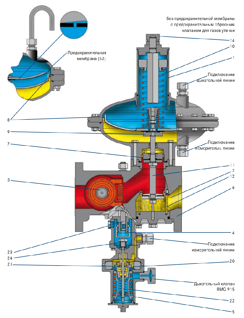
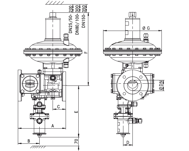
Он состоит из регулирующего устройства (1), исполнительного органа (2), исполнительного органа ПОК (3) с переключателем (4) и контрольным прибором (5) и корпуса исполнительного органа (6). Соответственно необходимое заданное значение устанавливается посредством задатчика (14). Исполнительный орган регулирующего устройства выполнен с мембраной выравнивания давления (7).
В регулирующем устройстве RE 1, RE 2 или RE 3 по выбору может встраиваться ПСК газа утечки (9). Через подключение измерительной линии подлежащее регулированию выходное давление подводится к измерительному механизму. Он сравнивает фактическое значение со значением, предварительное заданным усилием пружины задатчика (10).
Любое отклонение от заданного значения вызывает через шток клапана (11) перестановку исполнительного органа (2) таким образом, что фактическое значение приводится в соответствие с заданным значением. При нулевом отборе исполнительный орган герметично закрывается.
При исполнении с предохранительной мембраной над мембраной компаратора (8) расположена предохранительная мембрана (52), которая при прорыве мембраны (8) прилегает к крышке мембраны и предотвращает недопустимый выход газа в атмосферу.
Для шумаредуцирования в исполнительном органе может применяться цилиндр из металлопены (12). Расположенный на входе предохранительный отсекающий клапан перекрывает расход газа, если выходное давление превышает или опускается ниже предварительно заданных предельных значений. При этом измерительная мембрана (20) на основании сравнения заданного и фактического значения контрольного прибора (5) смещается таким образом, что шары (21) взводного механизма высвобождают шальтштангу (22).
Благодаря усилию пружины (24) она ударяет по взводной втулке переключателя (4), из-за чего деблокируется вал (23) исполнительного органа ПОК (3), и ПОК закрывается. ПОК может быть открыт только вручную. Выходное давление на месте измерения должно быть опущено как минимум на величину разницы повторного взвода (∆p) ниже верхнего давления срабатывания или поднято как минимум на величину разницы повторного взвода (∆p) выше нижнего давления срабатывания.
Виды исполнения (опции):
- по выбору с ПСК газа утечки (9) у регулирующего устройства 1, 2 и 3 (pd до 0,5 бар)
- с ручным срабатыванием ПОК
- по выбору с дистанционным электромагнитным срабатыванием ПОК
- по выбору с электрической индикацией положения ПОК „закр“ посредством датчика приближения объекта
- регулирующее устройство 1 и 2 по выбору с предохранительной мембраной
- с дыхательным клапаном типа RMG 915 (ПОК/RE)
- по выбору без ПОК
- по выбору с шуморедуцированием
Монтаж, ввод в эксплуатацию и техническое обслуживание:
Для монтажа и технического обслуживания следует соблюдать рабочие инструкции DVGW G 491, G 495 и G 600, а также Общее руководство по эксплуатации.
Инструкция по эксплуатации и техническому обслуживанию; запасные части“ дает подробную информацию о монтаже, вводу в эксплуатацию, техническому обслуживанию и важнейшим запасным частям. Регулятор давления газа предпочтительно следует устанавливать в трубопровод в горизонтальном положении.
Описание
Исполнительный орган с выравниванием давления. Регулирующее устройство по выбору также с: — ПСК для газов; — утечки предохранительной мембраной.
Исполнение по выбору с предохранительным отсекающим клапаном (ПОК) с осевым проходом.
По выбору шуморедуцирование.
Очень удобен при техническом обслуживании благодаря заменяемым функциональным узлам модульной конструкции. Оптимальная подгонка к рабочим условиям благодаря разлчиным диаметрам седла клапана.
Применим для газов согласно рабочей инструкции DVGW G 260 и нейтральных неагрессивных газов, иные газы по запросу.
Характеристики
Группа зон давления закрытия
SZ 2,5
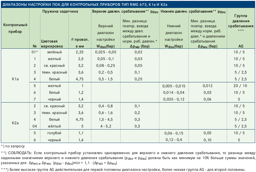
Диапазон настройки ПОК
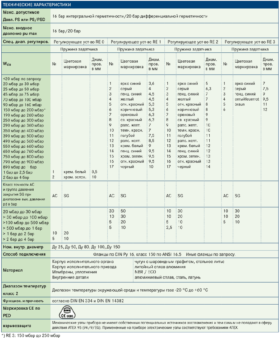
W 25 мбар до 5,2 бар
Wdo 5 мбар — 400 мбар
Диапазон настройки ПСК
Wd 15 до 90 мбар свыше pds
Диапазон регулирования Wd
20 мбар до 4 бар Wd <20 мбар по запросу
Интегральная герметичность PS (тип IS)
макс. допустимое давление PS=16 бар (20 бар)
Макс. входное давление p u max
до 16 бар (20 бар)
Подключение
Фланец DIN Ру 16 или класс 150 по ANSI 16.5 при Ду 25 до Ду 150. Иные фланцы по запросу
Оформить заявку
Для уточнения стоимости и сроков поставки отправьте заявку.
Менеджер свяжется
с вами в течении часа.
Техническая документация
Регуляторы давления газа предназначены для редуцирования высокого или среднего давления на требуемое, автоматического поддержания заданного выходного давления независимо от изменения расхода и входного давления газа, автоматического отключения подачи газа при аварийном повышении выходного давления сверх допустимого заданного значения, либо аварийном понижении выходного давления ниже допустимого заданного значения. Регулятор для коммунального хозяйства, малых и промышленных предприятий. Пригоден для динамичных линий регулирования (подключения газовых горелок).
Описание
Большой диапазон входного давления. Оптимальная подгонка к рабочим условиям благодаря установке различных диаметров седла клапана. Исполнительный орган с выравниванием давления. Регулирующее устройство по выбору RE1 или RE2. Также с:
- ПСК
- предохранительной мембраной
Исполнение по выбору с предохранительным запорным клапаном (ПЗК) или без него.
| Характеристики | Значение |
|---|---|
| Макс. допустимое давление | PS = 1,6 МПа |
| Диапазон регулирования выходного давления | Wds 2 кПа до 100 кПа (необходимы различные пружины настройки давления) |
| Диапазон настройки ПСК | 1 кПа до 30 кПа свыше pds |
| Фланцевое соединение | Ру 16 или класс ANSI 150 |
| Диапазон рабочих температур | −20°C до +60°C |
-
Каталог Honeywell
-
Прайс-лист Honeywell
-
ПРОИЗВОДСТВО
Компания специализируется на автоматизации и управлении, системах для авиации и космоса, производстве материалов для химической и электронной промышленности, внедрении систем энергетики и транспорта.
-
ПРИМЕНЕНИЕ
Honeywell предоставляет решения, которые улучшают эффективность и доходность, обеспечивают автоматизацию и энергосбережение для домов, зданий и отраслей промышленности, индустриальные решения для безопасности.
-
КАЧЕСТВО
Сотрудники компании регулярно работают над задачами повышения производительности, улучшения качества, экономии энергии, сокращения производственных затрат и создания безопасной и комфортной среды для жизни и работы.
-
Аналитические приборы
4909, 4973, 4905, APT, DL и др.
-
Регулирующие клапаны
V5822A, V5832A, V5832B и др.
-
Доп. оборудование
MCToolkit, RMA3000, SCT 3000 и др.
-
Термопары
Megopak, HEL-7xx, TD-xx и др.
-
Датчики температуры
STT850, STT25T, STT170 и др.
-
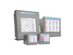
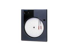
Регистраторы
EZtrend, Minitrend, DR и др.
-
Расходомеры
VersaFlow, Mag, TWC, TWM и др.
-
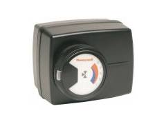
Электроприводы
ML, MТ, M, S и др.
-
Уровнемеры
SmartLine и др.
-
Контроллеры и индикаторы
UDC, DCP, UDI, CD и др.
-
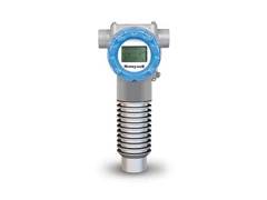
Датчики давления
STG, STD, ST, STF и др.
Обратитесь к нам или региональному дилеру для получения более подробной информации о сертификатах, характеристиках, отзывах, стоимости, наличии на складе и сроках поставки оборудования Honeywell.
Мы гарантируем ответ в течение 8 рабочих часов!
адрес для заявок: hwn@nt-rt.ru
-
029 — Громова Марина
Здравствуйте! Я могу вам чем-то помочь?
Оператор набирает сообщение
Здравствуйте! Какая продукция Вас интересует?
Задайте вопрос прямо сейчас:
- Home
-
Documents
- Gas Pressure Regulator HON 370 — Honeywell · The purpose of the direct-acting gas pressure…
Gas Pressure Regulator HON 370 Serving the Gas Industry Worldwide PRODUCT INFORMATION
Gas Pressure Regulator HON 370 — Honeywell · The purpose of the direct-acting gas pressure regulator HON 370 is to substantially stabilise the outlet pressure independently of any
-
Author
-
View
318 -
Download
4
Embed Size (px)
Text of Gas Pressure Regulator HON 370 — Honeywell · The purpose of the direct-acting gas pressure…
Gas Pressure Regulator HON 370
serving the Gas industryworldwide
Product information
2
Entwurf
Gas Pressure Regulator HON 370
Draft
Applications, characteristics, technical data
applications
• Direct-acting gas pressure regulator for commercial and industrial applications and local supply stations.• Especially suitable for dynamic regulating lines (e.g. gas furnaces, burner switching, gas engine operation)• Can also be used as a component for gas consumption devices according to EC Directive (90/396/EEC)• As a gas pressure regulating device with electrical consequential value (motorised actuator) and pneumatic
consequential setpoint• Suitable for gases in accordance with DVGW Worksheet G 260 and neutral, non-aggressive gases;
other gases on request
characteristics
• Version with integral overpressure protection (IS) • Fail open (FO) error type• Gas pressure regulator with incorporated axial safety shut-off valve (SSV) – optional designs
with safety relief valve (SRV) for the relief of leakage gases or with safety diaphragm• Large inlet pressure range• Optional installation of different valve seat diameters is possible• Easy to maintain, thanks to interchangeable functional units (plug-in modules)• SSV optionally available in function class A or B• Pressure equalisation valve (internal bypass) integrated in the SSV actuator
Versions (options)
• Without SSV• SSV with manual release• Electromagnetic remote release with SSV• With electric SSV ‘CLOSED’ position indicator by means of inductive proximity initiator or
reed sensors and intrinsically safe current circuit• Regulating device with leak gas SRV (pd up to 0.8 bar) or safety diaphragm (pd up to 1.0 bar)• With vent valve HON 915 (SSV/RA) or tripping valve HON 919 (SSV)• With noise reduction
3
Entwurf
8
Gas Pressure Regulator HON 370
Draft
technical data
Version with integral overpressure protectionmax. permissible pressure PS up to 20 barmax. inlet pressure pu max up to 20 barSpecific set range Regulating assembly RA 0 Regulating assembly RA 1 Regulating assembly RA 2 Regulating assembly RA 3
Setpoint spring Setpoint spring Setpoint spring Setpoint spring
Wds No.
Wire dia-meter(mm)
Colour coding No.
Wire dia-meter(mm)
Colour coding No.
Wire dia-meter(mm)
Colour coding No.
Wire dia-meter(mm)
Colour coding
<20 mbar on enquiry20 mbar to 30 mbar25 mbar to 50 mbar45 mbar to 75 mbar70 mbar to 100 mbar90 mbar to 160 mbar150 mbar to 200 mbar*190 mbar to 260 mbar250 mbar to 300 mbar 290 mbar to 360 mbar350 mbar to 400 mbar390 mbar to 500 mbar490 mbar to 560 mbar550 mbar to 660 mbar650 mbar to 760 mbar750 mbar to 800 mbar790 mbar to 900 mbar890 mbar to 1,000 mbar1,000 mbar to 2,000 mbar1,500 mbar to 3,000 mbar2,500 mbar to 3,500 mbar3,000 mbar to 4,500 mbar4,000 mbar to 5,000 mbar
1233+43+5
12131414/814/9.3
cream whiteemerald greenblackblack / silver grey
black / black
1234567891011121314151617
3.644.54.55.35.36.36.3777.58.599.59.59.510
signal bluegreygentian blueyellowbright redbrownhazellight redrape yellowdark redlight bluerape yellowcream whitegentian blueemerald greenbright redblack
1234567891011121314151617
56.3778899101011111212131314
signal bluegreygentian blueyellowbright redbrownhazellight redrape yellowdark redlight bluerape yellowcream whitegentian blueemerald greenbright redblack
123456
77.599.51112
signal bluegreygentian blueyellowbright redbrown
Accuracy class ACand lock-up pressure class SG withOutlet pressure range pd
AC SG AC SG AC SG AC SG
20 mbar to 100 mbar> 100 mbar to 500 mbar
> 500 mbar to 1,000 mbar> 1,000 mbar to 4,000 mbar 2.5 5
1055
302020
105
2.5
20105
105
2010
closing pressure zone group SZ 2.5
nominal width DN 25, DN 50, DN 80, DN 100, DN 150
type of connection DIN flanges PN 16, class 150 accor. to ANSI 16.5 Other flanges on enquiry.
material
Main valve body
Main valve body
Diaphragms, sealing rings
Internal parts
Ductile iron, cast steel
Cast aluminium alloy
NBR / ECO
Al alloy, steel, brass
temperature range
class 2Ambient and operating temperature range – 20 °C to +60 °C
function and strength According to DIN EN 334 and DIN EN 14382
cE mark
in accordance
with PEd
type approval test
according to
• PED (DGRL)
• GAD (GGRL) as a component for gas consumption devices
Explosion protectionAll mechanical components of this device are without potential ignition sources and / or hot faces. They are not subject to ATEX 95 (94/9/EC). All electronic accessories, on the other hand, meet ATEX requirements.
*) RA 3: 150 mbar to 250 mbar
Applications, characteristics, technical data
8
4
Entwurf
Gas Pressure Regulator HON 370
Draft
Valve specifications
nominal widthValve seat ø
flow rate coefficient
KG* value in (m3/h) / bar)
inlet pressure range** ∆ pu max (bar)
with regulating device
(mm) without noise reduction with noise reduction RA 0 RA 1 RA 2 RA 3
DN 2525 370 360 20 20*** 20
31 460 440 20 20*** 20
DN 50
25 520 500 20 20*** 20
31 900 800 20 20*** 20
50 1500 1300 20 20*** 20
DN 8060 2500 2300 20 20*** 20
80 3400 3100 20 20*** 20
DN 100
60 3200 2900 20 20*** 20
80 4000 3300 20 20*** 20
100 5300 4400 20 20*** 10
DN 150100 6100 5300 10
140 12800 11300 10 *) Valve flow rate coefficient for natural gas: d = 0.64 (ρn = 0.83 kg/m³), tu = 15° C **) The limitation of the maximum inlet pressure range ∆ pu max does not occur due to strength reasons; it is intended to maintain the
accuracy class AC. ***) For outlet pressures pd > 200 mbar, otherwise pu max = 10 bar Other pressures on enquiry.
SSV-E setting ranges for control devices of the tyPE Hon 673, k1a and k2a
control
unit
Setpoint spring upper response pressure* Lower response pressure*
accuracy group
aG***no.
Wire Ø
(mm)colour coding
Upper setting
range
Wdso (mbar)
Min. re-engage differential* between
response pressure and normal operat-
ing pressure*∆pwo (mbar)
Lower setting
range
Wdsu (mbar)
Min. re-engage differential* between
normal operating pressure* and
response pressure∆pwu (mbar)
01 2.25 green 25 to 50 20 10/5
K1a
1 2.60 yellow 50 to 100 20 10/5
2 3.20 light red 80 to 250 50 5
3 3.60 dark red 200 to 500 80 2.5
4 4.75 white 500 to 1,500 100 2.5
5 1.00 yellow 10 to 15 12 10
6 1.20 white 14 to 40 30 10/5
7 1.40 black 35 to 120 60 5
8 2.25 bright red 100 to 300 100 5
K2a
4 4.75 white 1,500 to 4,500 250 5/2.5
9 5.30 ivory 4,000 to 7,000 300** 1
5 1.10 light blue 60 to 150 50 10/5
6 1.40 black 120 to 400 100 5
8 2.25 bright red 350 to 1,000 150 5
*) PLEASE NOTE: If the control device is configured to handle both overpressure and underpressure release, the difference between the setpoints of (pdso and pdsu) must exceed the sum of the values set for ∆pwo and ∆pwu by at least 10 %. (pdso – pdsu)min = 1.1 ∙ (Δpwo + Δpwu)
**) We recommend a maximum re-engage differential of < 4.5 bar to facilitate engaging the control device.
***) The higher AG group applies to the first half, the lower AG group to the second half of the setting range.
integrated safety relief valve (leakage gas SrV) can only be used up to pds max = 0.8 bar
Setpoint spring regulating assembly response pressure *
no. Wire Ø (mm) Adjustment via pds (mbar)
1 3.5 RA 1 15 to 90
1 3.5 RA 2 15
2 3.6 30
3 4.5 60
2 3.6 RA 3 15
3 4.5 30
*) selectable setting
Applications, characteristics, technical data
5
Entwurf
Gas Pressure Regulator HON 370
Draft
Construction and mode of operation
construction and mode of operation
The purpose of the direct-acting gas pressure regulator HON 370 is to substantially stabilise the outlet pressure independently of any inlet and outlet pressure changes in the regulating line. The device consists of a regulating assembly (1), final control element (2), SSV final control element (3) with tripping device (4) and control device (5) and the main valve body (6). The required setpoint is adjusted via the setpoint adjuster (14).The control element of the regulating assembly is equipped with a pressure-compensating diaphragm (7). The regulating assemblies RA 1, RA 2 and RA 3 may be optionally equipped with a safety relief valve (9). The outlet pressure you want to control is fed to the measuring diaphragm unit via the measuring line connection. The measuring unit compares the actual value to the setpoint defined by the force of the setpoint spring (10). If a deviation is detected, the valve stem (11) will adjust the control element (2) in order to match the actual value to the setpoint again. At zero drop, the device will seal bubble-tight.The version with a safety diaphragm RE 1, RE 2 and RE 3) has an extra diaphragm (52) across the measuring diaphragm (8) which will seal the upper part of the diaphragm body in case the diaphragm (8) breaks so that the gas cannot escape into the atmosphere.A metal foam cylinder (12) may be inserted into the control element to reduce noise.If the outlet pressure exceeds or falls below the predefined limit values, the upstream safety shut-off valve will stop the gas flow. To accomplish that, the measuring diaphragm (20) of the control device (5) is shifted according to the comparison of set and actual values in such a way that the balls (21) of the release mechanism release the switch stem (22). Through the spring force of the spring (24), the switch stem will flip against the bush of the tripping device (4), thus unblocking the axle (23) of the SSV control element (3) so that the SSV closes. Now the SSV may be opened only by hand. For this, the outlet pressure at the measuring point must be reduced below the overpressure release / increased above the underpressure release by a value that must correspond at least to the re-engage differential (∆p).
assembly, commissioning and maintenance
For assembly and maintenance, please refer to DVGW Worksheets G 491, G 495 and G 600, and the manual.The “Operating and maintenance instructions ; spare parts” contain detailed information on installation, start-up, maintenance and the most important spare and replacement parts.The gas pressure regulator should preferably be installed in the pipework in a horizontal position.
6
Entwurf8
9
7
3
232421
22
5
Gas Pressure Regulator HON 370
Draft
Construction and mode of operation
Safety diaphragm (52)
Version with safety diaphragm
Version without safety diaphragm, with safety relief valve for the relief of leakage gases
Vent bore 1410
1
Vent line connection(optionally with
HON 915)*
Measuring line connection
112
12
6
4
Measuring line connection
20
Optionally with vent valve
HON 915(optionally
with HON 919)
*) attention! Not for SRV leak gas
7
Entwurf B
A
F
E
70
C
200
300
350
DN
25/5
0-RE
1
DN
25/5
0/80
/100
-RE
0 un
d RE
2
DN
80/1
00/1
50-
RE3
G
D
D
N
Anzahl derGewinde-bohrungen N
M
O P
1
2
3
4
Gas Pressure Regulator HON 370
Draft
Dimensions, weight, flange version
dimensions (mm)
dn a B c d E f G Weight (approx.)
Regulating assembly Regulating assembly Regulating assembly
RE0 RA1 RA2 RA3 RE0 RA1 RA2 RA3 RE0 RA1 RA2 RA3
(mm) (kg)
25 184* 80 52 40 286 477 360 477 —
398
308
398
— 35 23 35 —
50 254* 114 69 50 273 506 389 506 — — 46 34 46 —
80 298 143 83 65 320 550 — 550 600 — 63 — 63 83
100 352 158 95 72 314 550 — 550 600 — 558 77 — 77 96
150 451 227 120 106 339 — — — 692 — — — — — — 140
*) Optional for DN 25 installation length 180 mm, optional for DN 50 installation length 230 mm and 250 mm
flange version
dn m** n o P
25 M 124
16 19
50
M 16
21 24
Pn 16 / class 150 80 8 (4)* 21 24
1008
21 24
150 M 20 25 29
*) Measurement in brackets for class 150
**) Connection element: DN 25: Screws M12 x L EN 24014 — 5.6 DN 50 to 100: Screws M16 x L EN 24014 — 5.6
DN 150: Screws M20 x L EN 24014 — 5.6 L varies depending on version
Number of threaded bores N
8
Entwurf1 2 3 4
Gas Pressure regulator Hon 370
Draft
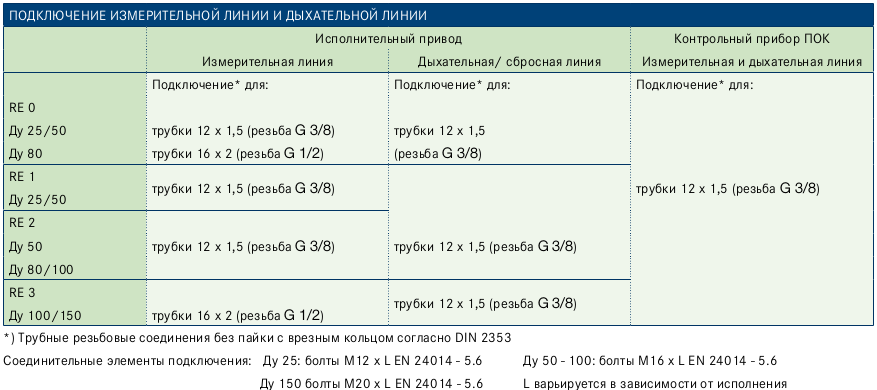
Connection of the measuring line and Vent line
Actuator SSV control device
Measuring line Vent / discharge line Measuring and vent line
Connection* for: Connection* for: Connection* for:
RA 0Pipe Ø 12 x 1.5 (thread G 3/8) Pipe Ø 12 x 1.5 (thread G 3/8)
DN 25/50/80/100
RA 1
DN 25/50Pipe Ø 12 x 1.5 (thread G 3/8) Pipe Ø 12 x 1.5 (thread G 3/8) Pipe Ø 12 x 1.5 (thread G 3/8)
RA 2Pipe Ø 12 x 1.5 (thread G 3/8) Pipe Ø 12 x 1.5 (thread G 3/8)
DN 25/50/80/100
RA 3
DN 80/100/150Pipe Ø 16 x 2 (thread G 1/2) Pipe Ø 12 x 1.5 (thread G 3/8)
*) Screw connections without brazing with compression joint accor. to DIN EN ISO 8434-1 (DIN 2353)
Connection
1 2 3 4
9
Entwurf
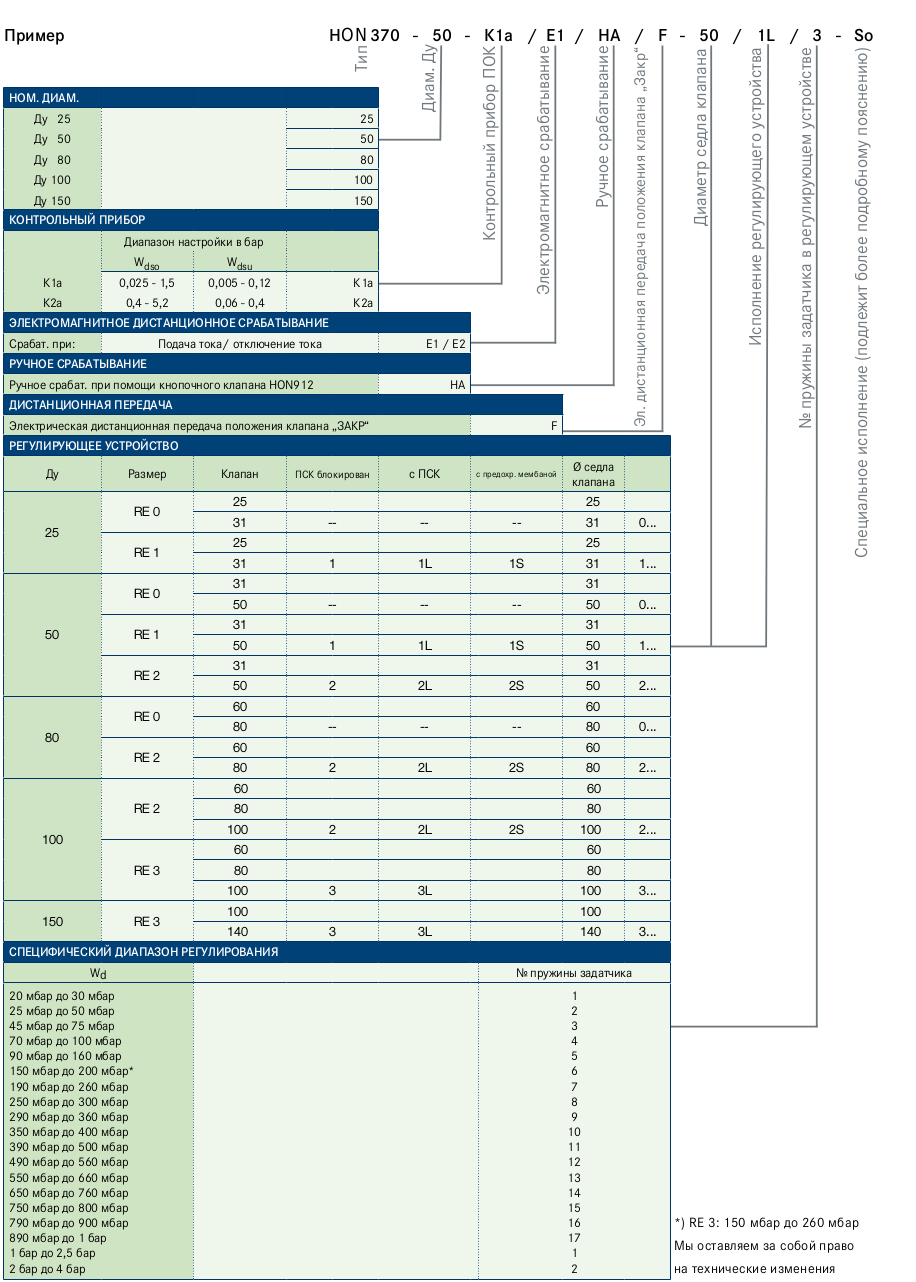
Hon 370 – 50 – k1a / E1 / Ha / f1 – 50 / 2S / 3 – So
Draft
nominal width
DN 25 25
DN 50 50
DN 80 80
DN 100 100
DN 150 150
control device
Setting range (bar)
Wdso Wdsu
K1a 0.025 to 1.5 0.01 to 0.30 K1a
K2a 1.5 to 7.0 0.06 to 1.0 K2a
Electromagnetic remote release
Triggering at: current supply / current failure E1 / E2
manual release
Manual release HA
remote indication
Electrical remote indication of the valve position “CLOSE” proximity initiator / reed sensor F1 / F2
regulating assembly
DN Value Valve SRV blocked With SRV With safety diaphragm
Valve seat ø
25
RA 025 0 — — 25 0 –
31 0 — — 31 0 –
RA 125 1 1L 1S 25 1 –
31 1 1L 1S 31 1 –
RA 225 2 2L 2S 25 2 –
31 2 2L 2S 31 2 –
50
RA 0
25 0 — — 25 0 –
31 0 — — 31 0 –
50 0 — — 50 0 –
RA 1
25 1 1L 1S 25 1 –
31 1 1L 1S 31 1 –
50 1 1L 1S 50 1 –
RA 2
25 2 2L 2S 25 2 –
31 2 2L 2S 31 2 –
50 2 2L 2S 50 2 –
80
RA 060 0 — — 60 0 –
80 0 — — 80 0 –
RA 260 2 2L 2S 60 2 –
80 2 2L 2S 80 2 –
RA 360 3 3L 3S 60 3 –
80 3 3L 3S 80 3 –
100
RA 0
60 0 — — 60 0 –
80 0 — — 80 0 –
100 0 — — 100 0 –
RA 2
60 2 2L 2S 60 2 –
80 2 2L 2S 80 2 –
100 2 2L 2S 100 2 –
RA 3
60 3 3L 3S 60 3 –
80 3 3L 3S 80 3 –
100 3 3L 3S 100 3 –
150 RA 3100 3 3L 3S 100 3 –
140 3 3L 3S 140 3 –
Specific outlet pressure range
Wds Setpoint spring no.
Setpoint spring no.RA 0 RA 1 RA 2 RA 3
20 mbar to 30 mbar25 mbar to 50 mbar45 mbar to 75 mbar70 mbar to 100 mbar90 mbar to 160 mbar150 mbar to 200 mbar*190 mbar to 260 mbar250 mbar to 300 mbar 290 mbar to 360 mbar350 mbar to 400 mbar390 mbar to 500 mbar490 mbar to 560 mbar550 mbar to 660 mbar650 mbar to 760 mbar750 mbar to 800 mbar790 mbar to 900 mbar890 mbar to 1 bar1,000 mbar to 2,000 mbar 1,500 mbar to 3,000 mbar2,500 mbar to 3,500 mbar3,000 mbar to 4,500 mbar4,000 mbar to 5,000 mbar
123
3+43+5
1234567891011121314151617
1234567891011121314151617
123456
1234567891011121314151617123
3+43+5
Device designationExample
Type
Nom
inal
w
idth
DN
SS
V co
ntro
l dev
ice
Elec
trom
agne
tic re
leas
e
Man
ual r
elea
se
Elec
tric
al re
mot
e in
dica
tion
of th
e “C
lose
d” p
ositi
on
Valv
e se
at d
iam
eter
Reg
ulat
ing
asse
mbl
y de
sign
Reg
ulat
ing
asse
mbl
y se
tpoi
nt s
prin
g no
.
Spe
cial
des
ign
(mus
t be
expl
aine
d in
mor
e de
tail)
*) RA 3: 150 mbar to 250 mbar
Subject to technical changes
10
Entwurf
Gas Pressure Regulator HON 370
Draft
11
Entwurf
Gas Pressure Regulator HON 370
Draft
HON 370.002017-01© 2017 Honeywell International Inc.
For More Information
To learn more about Honeywell’s
Advanced Gas Solutions, visit
www.honeywellprocess.com or contact
your Honeywell account manager
GERMANY
Honeywell Process Solutions
Honeywell Gas Technologies GmbH
Osterholzstrasse 45
34123 Kassel, Germany
Phone: +49 (0) 561 5007-0
Fax: +49 (0) 561 5007-107
Регуляторы давления газа предназначены для редуцирования высокого или среднего давления на требуемое, автоматического поддержания заданного выходного давления независимо от изменения расхода и входного давления газа, автоматического отключения подачи газа при аварийном повышении выходного давления сверх допустимого заданного значения, либо аварийном понижении выходного давления ниже допустимого заданного значения. Регулятор для коммунального хозяйства, малых и промышленных предприятий. Пригоден для динамичных линий регулирования (подключения газовых горелок).
Описание
Большой диапазон входного давления. Оптимальная подгонка к рабочим условиям благодаря установке различных диаметров седла клапана. Исполнительный орган с выравниванием давления. Регулирующее устройство по выбору RE1 или RE2. Также с:
- ПСК
- предохранительной мембраной
Исполнение по выбору с предохранительным запорным клапаном (ПЗК) или без него.

