-
Contents
-
Table of Contents
-
Troubleshooting
-
Bookmarks
Quick Links
ST 3000 Smart Transmitter
Release 300 with HART
Communications Option
User Manual
Doc. No.:
34-ST-25-17
Revision Date:
10/05
Related Manuals for Honeywell ST 3000
Summary of Contents for Honeywell ST 3000
-
Page 1
ST 3000 Smart Transmitter Release 300 with HART Communications Option User Manual Doc. No.: 34-ST-25-17 Revision Date: 10/05… -
Page 2: Patent Notice
In no event is Honeywell liable to anyone for any indirect, special or consequential damages. The information and specifications in this document are subject to change without notice.
-
Page 3: About This Document
Updated with STA info. 10/05 Updated bolt torque and write protect. Contacts World Wide Web The following lists Honeywell’s World Wide Web sites that will be of interest to our industrial automation and control customers. Honeywell Organization WWW Address (URL) Corporate http://www.honeywell.com…
-
Page 4: Symbol Definitions
About This Document Technical Assistance If you encounter a problem with your ST 3000 Smart Transmitter, check to see how your transmitter is currently configured to verify that all selections are consistent with your application. If the problem persists, you can reach Honeywell’s Solution Support Center for technical support by telephone during normal business hours.
-
Page 5: Table Of Contents
Mounting ST 3000 Transmitter………………….17 Piping ST 3000 Transmitter…………………..28 Wiring ST 3000 Transmitter ………………….33 5— Getting Started………………..39 Overview……………………….39 Establishing Communications ………………….39 Making Initial Checks…………………….42 6— Configuration ………………… 45 Overview……………………….45 Configuration Overview ……………………46 10/05 ST 3000 HART Transmitter Release 300 User Manual…
-
Page 6
Saving and Restoring a Configuration Database …………….93 9— Maintenance …………………. 97 Introduction……………………….97 Preventive Maintenance ……………………97 Inspecting and Cleaning Barrier Diaphragms ……………….97 Replacing Printed Wiring Assembly (PWA)………………100 Replacing Meter Body ……………………103 10— Calibration ………………… 107 ST 3000 HART Transmitter Release 300 User Manual 10/05… -
Page 7
Setting smart meter display using the HART communicator…………160 Typical smart meter indications…………………..163 Operation error codes……………………164 Meter/transmitter interaction………………….165 Appendix B— Configuration Record Sheet …………167 ST 3000 R300 Smart Transmitter with HART Communications ……………………………167 Appendix C – Freeze Protection of Transmitters………… 169 Possible Solutions/Methods ………………….169 10/05… -
Page 8
Contents Appendix D —Hazardous Area Classifications …………179 Introduction……………………….179 North American Hazardous Location Standards…………….179 International Electrotechnical Commission (IEC) Classifications…………184 Enclosure Ratings ………………………187 Index ……………………189 viii ST 3000 HART Transmitter Release 300 User Manual 10/05… -
Page 9
Table 4 Operating Temperature Limits (Transmitters with Silicone Fill Fluid DC200) ……….15 Table 5 Transmitter Maximum Allowable Working Pressure (MAWP) Ratings…………16 Table 6 Mounting ST 3000 Transmitter to a Bracket ………………..18 Table 7 Zero Corrects Procedure for Transmitters with a Small Differential Pressure Span ……..21 Table 8 Flush Mount Transmitter Installation ………………….24… -
Page 10
Tables Table 53 Major ST 3000 Smart Transmitter Parts Reference………………123 Table 54 Parts Identification for Callouts in Figure 42 and Figure 43 …………..125 Table 55 Parts Identification for Callouts in Figure 44…………………126 Table 56 Parts Identification for Callouts in Figure 45…………………129 Table 57 Parts Identification for Callouts in Figure 46. -
Page 11
Figure 3 Typical Communication Interface……………………7 Figure 4 Typical ST 3000 Transmitter Order Components……………….8 Figure 5 ST 3000 with Local Smart Meter Option………………….9 Figure 6 Typical Mounting Area Considerations Prior to Installation……………..14 Figure 7 Typical Bracket Mounted and Flange Mounted Installations…………….18 Figure 8 Leveling Transmitters ………………………21… -
Page 12
Figure C-8 Piping Installation for Differential Pressure Transmitter and Impulse Piping with Steam Heating..175 Figure C-9 Piping Installation for Process Pressure Transmitter and Impulse Piping with Steam Heating….176 Figure 1 ST 3000 Model STD110, STD120, STD125, STD130, STD170, STD924, STD930 (Rev S or greater)…………………………..201… -
Page 13
Section 13 provides additional wiring diagrams showing alternate wiring methods. Electronics Electronics Terminal Terminal Housing Housing Block Block Internal Internal Ground Ground Terminal Terminal 3-Screw Terminal Block 5-Screw Terminal Block 10/05 ST 3000 HART Transmitter Release 300 User Manual xiii… -
Page 15: 1- Introduction — First Time Users Only
1— Introduction — First Time Users Only Overview About this section This section is intended for users who have never worked with our ST 3000 Smart Transmitter with HART communications. It provides some general information to acquaint you with the ST 3000 transmitter and the HART communications interface.
-
Page 16: St 3000 Smart Transmitters
1— Introduction — First Time Users Only — ST 3000 Smart Transmitters ST 3000 Smart Transmitters About the transmitter The ST 3000 Smart Transmitter comes in a variety of models for measurement applications involving one of these basic types of pressure: •…
-
Page 17: Figure 2 Functional Block Diagram For Transmitter In Analog Mode Of Operation
1— Introduction — First Time Users Only — ST 3000 Smart Transmitters Functional block diagram Besides the process variable (PV) output, the transmitter also provides its meter body temperature as a secondary variable (SV) which is only available as a read-only parameter through the communicator interface.
-
Page 18
Specification and Model Selection Guide that is provided as a separate document. ATTENTION Be aware that previous vintages of the ST 3000 transmitter with designations of Series 100, Series 100e, Series 600, and Series 900 have been supplied at various times since the ST 3000 was introduced in 1983. -
Page 19: Table 1 St 3000 Pressure Transmitter Family
1— Introduction — First Time Users Only — ST 3000 Smart Transmitters ST 3000 transmitter family Table 1 illustrates the various ST 3000 Release 300 pressure transmitters that are presently available. Table 1 ST 3000 Pressure Transmitter Family Transmitter Type…
-
Page 20
1— Introduction — First Time Users Only — ST 3000 Smart Transmitters Transmitter Type Series 100 Model Series 900 Model STG1xx STG9xx Gauge and Absolute Pressure STA1xx STA9xx STF1xx STF9xx Flange-Mount Liquid Level Differential Pressure STR1xx STR9xx with Remote Diaphragm Seals… -
Page 21: Hart Communicator
HART Communicator Transmitter adjustments Except for optional local zero and span adjustments, the ST 3000 has no physical adjustments. You need a HART communicator to make any adjustments in a ST 3000 with the HART communications option. Transmitter operator interface The HART communicator (Model 275) is connected to the loop wiring of the ST 3000 transmitter for direct communication with the transmitter.
-
Page 22: Transmitter Order
1— Introduction — First Time Users Only — Transmitter Order Transmitter Order Order components Figure 4 shows the components that would be shipped and received for a typical ST 3000 transmitter order. Ordered ST 3000 Series 100 HART differential pressure transmitter…
-
Page 23: Local Smart Meter Option
See Figure 5. Electronics Housing Local Smart Meter Option Figure 5 ST 3000 with Local Smart Meter Option. 10/05 ST 3000 HART Transmitter Release 300 User Manual…
-
Page 24: Table 2 Local Smart Meter Options
Local Smart Meter with Zero and Span Adjustments UPPER SEL. VALUE Yes * SPAN UNITS ZERO LOWER VALUE Local Zero and Span Adjustments only Yes * SPAN ZERO * Except draft range, Model STD110. ST 3000 HART Transmitter Release 300 User Manual 10/05…
-
Page 25: 2- Quick Start Reference
This section assumes that the ST 3000 transmitter has been installed and wired correctly, and is ready to be put into operation. It also assumes that you are somewhat familiar with using the HART communicator and that the transmitter has been configured correctly for your application.
-
Page 26: Getting St 3000 Transmitter On-Line Quickly
Getting ST 3000 Transmitter On-Line Quickly Quick start-up tasks Table 3 lists common start-up tasks for an ST 3000 transmitter using a HART communicator and gives an appropriate section in this manual to reference for more information about how to do the task. The start-up tasks are listed in the order they are commonly completed.
-
Page 27: 3- Preinstallation Considerations
HART communicator interface conditions. • Operating conditions for transmitters equipped with the smart meter option. Of course, if you are replacing an existing ST 3000 transmitter you may skip this section. CE Conformity (Europe) Notice About conformity and special conditions This product is in conformity with the protection requirements of 89/336/EEC, the EMC Directive.
-
Page 28: Considerations For St 3000 Transmitter
Considerations for ST 3000 Transmitter Evaluate conditions The ST 3000 transmitter is designed to operate in common indoor industrial environments as well as outdoors. To assure optimum performance, evaluate these conditions at the mounting area relative to published transmitter specifications and accepted installation practices for electronic pressure transmitters.
-
Page 29: Table 4 Operating Temperature Limits (Transmitters With Silicone Fill Fluid Dc200)
3— Preinstallation Considerations — Considerations for ST 3000 Transmitter Table 4 Operating Temperature Limits (Transmitters with Silicone Fill Fluid DC200) Transmitter Type and Model Ambient Temperature Process Interface Temperature °C °F °C °F Draft Range STD110 -40 to 70 -40 to 158…
-
Page 30: Considerations For Hart Communicator
If your transmitter is to be installed and operated with one of the integral smart meter options, please note the Smart meter specifications and operating conditions for the meter located in Appendix A of this manual. ST 3000 HART Transmitter Release 300 User Manual 10/05…
-
Page 31: 4- Installation
4— Installation — Overview 4— Installation Overview About this section This section provides information about installing the ST 3000 transmitter. The topics in this section include: • Mounting the ST 3000 transmitter — various mounting methods are described and can be used depending upon the transmitter type.
-
Page 32: Table 6 Mounting St 3000 Transmitter To A Bracket
Flange Figure 7 Typical Bracket Mounted and Flange Mounted Installations Bracket mounting Table 6 summarizes typical steps for mounting a transmitter to a bracket. Table 6 Mounting ST 3000 Transmitter to a Bracket Step Action If you are using an……
-
Page 33
Loosen set screw on outside neck of transmitter one full turn. Rotate electronics housing in maximum of 180 degree increment in left or right direction from center to position you require 10/05 ST 3000 HART Transmitter Release 300 User Manual… -
Page 34
You do this by leveling the transmitter side-to-side and front-to-back. See Figure 8 for suggestions on how to level the transmitter using a spirit balance. Absolute pressure models Center Section Process Head Position spirit balance on center section of meter body only. ST 3000 HART Transmitter Release 300 User Manual 10/05… -
Page 35: Table 7 Zero Corrects Procedure For Transmitters With A Small Differential Pressure Span
Attach the transmitter to the mounting bracket but do not completely tighten the mounting bolts. Connect a tube between the input connections in the high pressure (HP) and low pressure (LP) heads to eliminate the affects of any surrounding air currents. 10/05 ST 3000 HART Transmitter Release 300 User Manual…
-
Page 36
Press OK to initiate zero input corrects. You will be prompted to return the loop to automatic control. Press OK Remove the tube from between the input connections, the power, and the milliammeter and ST 3000 HART Transmitter Release 300 User Manual 10/05… -
Page 37: Figure 9 Typical Flange Mounted Transmitter Installation
Maximum Level Variable Reference Head H1 Minimum Level HP Side LP Side vented mounted to atmosphere to tank Figure 9 Typical Flange Mounted Transmitter Installation 10/05 ST 3000 HART Transmitter Release 300 User Manual…
-
Page 38: Table 8 Flush Mount Transmitter Installation
Flush mounting ST 3000 flush mount transmitters (model STG9xx) are mounted directly to the process pipe or tank using a 1 inch weld nipple. Figure 10 shows a typical installation for a transmitter with a flush mount on a pipe.
-
Page 39: Figure 11 Typical Flange And Pipe Mounted Installations
Once the transmitter is mounted, the electronics housing can be rotated to the desired position. See Table 6, step 4. Tank Wall Flange Transmitter Connection Flange Process Pipe 1/2″ NPT Connection Figure 11 Typical Flange and Pipe Mounted Installations 10/05 ST 3000 HART Transmitter Release 300 User Manual…
-
Page 40: Table 9 Mounting Remote Diaphragm Seal Transmitter
4— Installation — Mounting ST 3000 Transmitter Remote seal mounting ST 3000 transmitters furnished with remote diaphragm seals (models STRxxx) can be mounted using the optional mounting brackets. (See procedure in Table 6 in this section for bracket mounting.) Follow the guidelines below to determine the mounting position of the remote seals for the given fill fluid and then use the procedure in Table 9 to mount the remote seals to the process connections.
-
Page 41: Figure 12 Typical Remote Diaphragm Seal Transmitter Installation
Maximum Level Variable Fixed Head H1 Ref. Leg Minimum Level HP Side — Model STR93D — Model STR12D LP Side — Model STR13D Figure 12 Typical Remote Diaphragm Seal Transmitter Installation. 10/05 ST 3000 HART Transmitter Release 300 User Manual…
-
Page 42: Piping St 3000 Transmitter
Figure 13 Typical 3-Valve Manifold and Blow-Down Piping Arrangement. Another piping arrangement uses a block-off valve and a tee connector in the process piping to the transmitter as shown in Figure 14. ST 3000 HART Transmitter Release 300 User Manual 10/05…
-
Page 43: Table 10 Suggested Transmitter Location For Given Processes
As a general rule there is a 56 degree C drop (100 degree F) in the temperature of the process for every foot of 1/2″ uninsulated piping. 10/05 ST 3000 HART Transmitter Release 300 User Manual…
-
Page 44: Table 11 Process Connections
(See Table 12) on High Pressure Side*. See model selection guide for description of available flanged, threaded, Remote Diaphragm chemical tee, saddle, and sanitary process connections. Seals * Reference side has standard differential pressure process head. ST 3000 HART Transmitter Release 300 User Manual 10/05…
-
Page 45: Table 12 Flange Description
(where possible) before connecting these lines to the transmitter’s meter body. • Be sure all the valves in the blow-down lines are closed tight after the initial blow-down procedure and each maintenance procedure after that. 10/05 ST 3000 HART Transmitter Release 300 User Manual…
-
Page 46: Table 13 Installing Flange Adapter
Apply an anti-seize compound on the stainless steel bolts prior to threading them into the process head. Evenly torque flange adapter bolts to a torque of 27,1 Nm +/- 1,4 Nm (20 ft lbs +/- 1.0 ft lbs) ST 3000 HART Transmitter Release 300 User Manual 10/05…
-
Page 47: Wiring St 3000 Transmitter
Operating Voltage (Vdc) 21012 Figure 15 Operating Range for ST 3000 Transmitters. The positive and negative loop wires are connected to the positive (+) and negative (–) SIGNAL terminals on the terminal block in the transmitter’s electronics housing as shown in Figure 16.
-
Page 48: Figure 16 St 3000 Transmitter Terminal Blocks
If you will be using the transmitter in a hazardous area, be sure to review the hazardous location reference data included in Appendix D of this manual before wiring and operating the transmitter. ST 3000 HART Transmitter Release 300 User Manual 10/05…
-
Page 49: Table 14 Wiring The Transmitter
• Double wound mains transformer per BS 3535 or equivalent. • An adequately rated zener diode whose voltage is not significantly higher than the rated voltage. • An adequately rated semiconductor voltage regulator. 10/05 ST 3000 HART Transmitter Release 300 User Manual…
-
Page 50: Figure 17 Ground Connection For Lightning Protection
When installed as nonincendive equipment in a Division 2 Hazardous Location, disconnect power to the transmitter in the non-hazardous area, or determine that the location is non-hazardous prior to disconnecting or connecting the transmitter wires. ST 3000 HART Transmitter Release 300 User Manual 10/05…
-
Page 51
4— Installation — Wiring ST 3000 Transmitter Output meter options The ST 3000 transmitter can be equipped with any of these three optional output indicating meters that provide a 0 to 100% indication of the transmitter’s output. Meter type Wiring Connections to Transmitter Integral smart meter connections —… -
Page 52
SM 3000 remote meter in conjunction with a new smart meter that is configured to display readings in custom or flow units, the indications of the two meters will be displayed in different units. ST 3000 HART Transmitter Release 300 User Manual 10/05… -
Page 53: 5- Getting Started
5— Getting Started Overview About this section This section tells you how to establish communications with the ST 3000 and make initial checks of the transmitter’s settings and configuration using a HART hand-held communicator. This section includes these topics: •…
-
Page 54: Figure 18 Typical Communicator Connections
4 to 20 milliampere loop wiring. (Polarity of the communicator connection does not matter.) WARNING When the transmitter’s end-cap is removed, the housing is not explosionproof. Figure 18 shows typical communicator connections across loop wiring to a ST 3000 transmitter. ST 3000 Power Supply…
-
Page 55: Table 15 Starting Communications With Transmitter
Starting communications Once you connect the communicator to the transmitter, you are ready to start communicating with the transmitter. The procedure in Table 15 outlines the steps for starting communications with an ST 3000 transmitter without an assigned tag number.
-
Page 56: Making Initial Checks
* This information is fixed and cannot be changed by reconfiguring the transmitter. ** Alarm option and transmitter security are jumper-selectable on the electronics board. After reviewing the transmitter data, press EXIT which takes you back to the “Device setup” display. ST 3000 HART Transmitter Release 300 User Manual 10/05…
-
Page 57: Figure 19 Write Protection And Failsafe Direction Jumper Location
5— Getting Started — Making Initial Checks Transmitter write protection option The ST 3000 transmitters have a transmitter security option, also known as a “write protect option,” which is jumper-selectable. When the write protect option is ordered, transmitters are shipped with a default jumper position for read-only.
-
Page 58: Figure 20 Smart Meter Display With All Indicators Lit
Local smart meter display indications If your ST 3000 transmitter is equipped with the smart meter option, you can check the status of all the indicators on the local smart meter LCD display by cycling power to the transmitter. The meter runs a brief self-test whenever power is applied to the transmitter.
-
Page 59: 6- Configuration
6— Configuration Overview About this section This section introduces you to ST 3000 transmitter configuration. It identifies the parameters that make up the transmitter’s configuration database and provides procedures for entering values/selections for the given configuration parameters. This section also provides an overview of the HART communicator, including data on menus and keyboard, descriptions of display selections and symbols, and information on making changes using the communicator.
-
Page 60: Configuration Overview
Communicator and ST 3000 transmitter memories As shown in Figure 22, both the communicator and the ST 3000 transmitter have working memories. They serve as temporary storage areas for data exchanged between them during communications.
-
Page 61: Figure 22 Communicator And St 3000 Transmitter Memories
Figure 22 Communicator and ST 3000 Transmitter Memories Copying transmitter configuration into nonvolatile memory When setting up or configuring a ST 3000, whether you are changing one value or a configuration database, all configuration data must be copied into the transmitter’s non-volatile memory to ensure the security of the data.
-
Page 62: Table 17 Summary Of Pressure Transmitter Configuration Parameters
6— Configuration — Configuration Overview What to configure Table 17 summarizes the parameters that are included in the configuration database for a ST 3000 pressure transmitter. Table 17 Summary of Pressure Transmitter Configuration Parameters Configuration Data Setting or Selection Key in a tag identification up to eight characters in length.
-
Page 63
Information available through the communicator is accessed through menus. The procedures in this manual give the shortest path from the “Online” (or HOME) menu. There are alternate paths which, depending on your starting point, may be better suited. 10/05 ST 3000 HART Transmitter Release 300 User Manual… -
Page 64: Figure 23 Online (Or Home) Menu Summary
PV Unit PV URV PROM ID Final assembly Poll address PV URL PV LRV number Number of PV LRL Date Device id request preambles Figure 23 Online (or HOME) Menu Summary ST 3000 HART Transmitter Release 300 User Manual 10/05…
-
Page 65: Figure 24 Hart Communicator Menu Summary
Please refer to the communicator product manual or use the online help Configure Communicator for details on these menu options. System Information Listen for PC Polling Storage Location Contrast Simulation Off Time Ignore diagnostics Delete Configuration Figure 24 HART Communicator Menu Summary 10/05 ST 3000 HART Transmitter Release 300 User Manual…
-
Page 66: Figure 25 Hart Communicator Keyboard
■ ■ ■ ■ ■ ■ ■ ■ ■ Arrow keys used to indicate position of characters that appear at top of buttons in keypad 22899 Figure 25 HART Communicator Keyboard ST 3000 HART Transmitter Release 300 User Manual 10/05…
-
Page 67
ATTENTION An alternate way of selecting a menu item, besides using the up and down arrows, is to press the key corresponding to the number left of the desired menu item. 10/05 ST 3000 HART Transmitter Release 300 User Manual… -
Page 68
See the example below to key in the word DATE. To key in a numeric character, merely press the key. ST 3000 HART Transmitter Release 300 User Manual 10/05… -
Page 69: Tag- Entering A Tag Number
Refer to “Making changes” in the previous section for information on keying in alphanumeric characters. Press ENTER. Either: • press SEND to download change to transmitter, or • go to another procedure and continue making changes. 10/05 ST 3000 HART Transmitter Release 300 User Manual…
-
Page 70: Pv Unit- Selecting Unit Of Pressure Measurement
Since the engineering units affect the value of LRV and URV, it is recommended that you send the changed PV unit to the transmitter and then verify and change as required the values of LRV and URV. ST 3000 HART Transmitter Release 300 User Manual 10/05…
-
Page 71: Range Values- Setting Pv Urv And Pv Lrv
Table 19 to change it.) ATTENTION • ST 3000 Smart Transmitters are factory calibrated with inches of water ranges using inches of water pressure referenced to a temperature of 39.2˚F (4˚C).
-
Page 72: Table 21 Setting Lrv And Urv To Applied Pressures
You can also use the local zero and span adjustments on the new smart meter to set the lower and upper range values to applied pressures. See Appendix A for the procedure. ST 3000 HART Transmitter Release 300 User Manual 10/05…
-
Page 73: Device Information
Enter a new value, if desired and press ENTER. Note: Pressing ESC will cancel action without changing selection. Either: • press SEND to download change to transmitter, or • go to another procedure and continue making changes. 10/05 ST 3000 HART Transmitter Release 300 User Manual…
-
Page 74: Pressure Transfer Function- Selecting Output Conformity
For differential pressure transmitters measuring the pressure drop across a primary element, the flow rate is directly proportional to the square root of the differential or pressure drop. The ST 3000 transmitter’s output is automatically converted to equal percent of flow when its output conformity is configured as square root.
-
Page 75: Figure 26 Square Root Dropout Point
70% • 16 + 4 = 15.2 mA dc Output Square root dropout To avoid unstable output at readings near zero, the ST 3000 transmitter automatically drops square root conformity and changes to linear conformity for low differential pressure readings. As shown in Figure 26, the point is near 0.5% of input for ST 3000 transmitters.
-
Page 76: Pv Damping- Adjusting Damping Time
If you do not want to change the damping value, press ABORT. Either: • press SEND to download change to transmitter, or go to another procedure and continue making changes. • ST 3000 HART Transmitter Release 300 User Manual 10/05…
-
Page 77: Sv Units- Selecting Secondary Variable Units
When the desired selection is highlighted, press ENTER. Pressing ESC will cancel procedure without changing unit selection. Either: • press SEND to download change to transmitter, or • go to another procedure and continue making changes. 10/05 ST 3000 HART Transmitter Release 300 User Manual…
-
Page 78: Poll Addr- Selecting Poll Address
A device with a poll address of 0 (zero) will provide a 4 to 20 mA analog output as well as receive requests and respond to commands from the HART communicator. The steps in Table 26 show how set the poll address of the transmitter. ST 3000 transmitters are shipped from the factory with poll address 0.
-
Page 79: 7- Start-Up
DP transmitter with remote diaphragm seals in a liquid level measurement application ATTENTION All procedures in this manual assume a transmitter poll address of 0 (zero). See Section 6, for information about poll address. 10/05 ST 3000 HART Transmitter Release 300 User Manual…
-
Page 80: Start-Up Tasks
These applications also apply for GP and AP type transmitters equipped with remote seals. However, you can only confirm that input pressure correlates with transmitter output in processes using remote seal connections. ST 3000 HART Transmitter Release 300 User Manual 10/05…
-
Page 81: Running Analog Output
If you have completed the loop test, then press OK and go to Step 8. Select 20mA to set output signal to 20 mA (5.0V or 100%). Press ENTER. The communicator notifies you that the transmitter ‘s output is fixed at 20 mA. 10/05 ST 3000 HART Transmitter Release 300 User Manual…
-
Page 82: Figure 27 Typical Communicator And Meter Connections For Constant-Current Source (Output) Mode
Supply Black — Receiver HART hand-held Commnicator Differential Note: Polarity of the Communicator Pressure connection does not matter. Transmitter Figure 27 Typical Communicator and Meter Connections for Constant-Current Source (Output) Mode ST 3000 HART Transmitter Release 300 User Manual 10/05…
-
Page 83: Flow Measurement With Dp Transmitter
Refer to Figure 27 for sample communicator and meter connections in a typical analog loop with a differential pressure-type transmitter. 10/05 ST 3000 HART Transmitter Release 300 User Manual…
-
Page 84
Check communicator and milliammeter readings again. If readings are still not correct, verify transmitter’s configuration data and change its range setting, if necessary. Remove communicator and milliammeter from loop. ST 3000 HART Transmitter Release 300 User Manual 10/05… -
Page 85: Pressure Measurement With Dp Transmitter
Open plug C and valve A to apply head pressure H to meter body. Then, open LP vent. Allow system to stabilize at head pressure At “Online” menu, read present LRV setting. 10/05 ST 3000 HART Transmitter Release 300 User Manual…
-
Page 86
Check communicator and milliammeter readings again. If readings are still not correct, verify transmitter’s configuration data and change its range setting if needed. Remove communicator and milliammeter from loop. ST 3000 HART Transmitter Release 300 User Manual 10/05… -
Page 87: Liquid Level Measurement — Vented Tank
Refer to Figure 27 for sample communicator and meter connections in a typical analog loop with a differential pressure-type transmitter. Close block-off valve A. Refer to Figure 30 for sample piping arrangement. 10/05 ST 3000 HART Transmitter Release 300 User Manual…
-
Page 88
URV can be set by filling the tank to the desired full scale level and then setting the URV through the communicator. See Range Values in Section 6 for details. ST 3000 HART Transmitter Release 300 User Manual 10/05… -
Page 89: Liquid Level Measurement — Pressurized Tank
Tap location at the minimum level to be measured Differential Pressure Transmitter HP side of transmitter Figure 31 Typical Piping Arrangement for Liquid Level Measurement with DP Type Transmitter and Pressurized Tank. 10/05 ST 3000 HART Transmitter Release 300 User Manual…
-
Page 90: Table 32 Starting Up Dp Transmitter For Liquid Level Measurement In Pressurized Tank
When the following display appears, ST3000: PT 3011 Set the: 20mA Exit ABORT ENTER choose 4mA, then press ENTER. A display will prompt you to apply new 4 mA input. Press OK. ST 3000 HART Transmitter Release 300 User Manual 10/05…
-
Page 91
20mA, then press ENTER. A display will prompt you to apply new 20 mA input. Press OK. When “Current applied process value” display appears, choose “Set as 20mA value” then press ENTER. 10/05 ST 3000 HART Transmitter Release 300 User Manual… -
Page 92: Pressure Or Liquid Level Measurement With Gp Transmitter
Figure 27 for typical communicator and meter connections.. Pipe Block-off Union Plug valve no.1 Gauge Pressure Transmitter Block-off Process valve no.2 Tee connector Figure 32 Typical Piping Arrangement for Pressure Measurement with GP Type Transmitter ST 3000 HART Transmitter Release 300 User Manual 10/05…
-
Page 93: Table 33 Starting Up Gp Transmitter For Pressure Or Liquid Level Measurement
Optional (read output in % of range): From “Online” menu, step through the following menu selections: Device setup • Process variables • At “Process variables” display, read 0% output for corresponding input pressure. Check that milliammeter reading is 4 mA (0%) output 10/05 ST 3000 HART Transmitter Release 300 User Manual…
-
Page 94
4mA, then press ENTER. A display will prompt you to apply new 4 mA input. Press OK. When “Current applied process value” display appears, choose “Set as 4mA value” then press ENTER. ST 3000 HART Transmitter Release 300 User Manual 10/05… -
Page 95: Pressure Measurement With Ap
Process For additional overrrange protection, use Sprague engineering type gauge saver or Fairchild model 95 gauge guard (style 1) Figure 34 Typical Piping Arrangement for Pressure Measurement with AP Type Transmitter 10/05 ST 3000 HART Transmitter Release 300 User Manual…
-
Page 96: Table 34 Starting Up Ap Transmitter For Pressure Measurement
Check communicator and milliammeter readings again. If readings are still not correct, verify transmitter’s configuration data and change its range setting if needed. Remove communicator and milliammeter from loop. ST 3000 HART Transmitter Release 300 User Manual 10/05…
-
Page 97: Liquid Level Measurement With Dp Transmitter With Remote Seals
Refer to Figure 27 for sample communicator and meter connections in a typical analog loop with a differential pressure-type transmitter. 10/05 ST 3000 HART Transmitter Release 300 User Manual…
-
Page 98
ENTER. LRV is set to fixed reference leg pressure H2 times density of remote seal fill fluid multiplied by –1 (pressure on low side of meter body). When the display above appears, choose Exit, then press ENTER. Return the loop to automatic control. ST 3000 HART Transmitter Release 300 User Manual 10/05… -
Page 99
From “Online” menu (if applicable, press HOME to get there), step through the following menu selections: • Device setup Diag/Service • • Calibration • Apply values You will be warned to remove the loop from automatic control. After doing so, press OK to continue. 10/05 ST 3000 HART Transmitter Release 300 User Manual… -
Page 100
Check communicator and milliammeter readings again. If readings are still not correct, verify transmitter’s configuration data and change its range setting if needed. Remove communicator and milliammeter from loop. ST 3000 HART Transmitter Release 300 User Manual 10/05… -
Page 101: 8- Operation
8— Operation Introduction About this section This section identifies how to access typical data associated with the operation of an ST 3000 transmitter. It also includes procedures for: changing the default failsafe direction of the transmitter’s output, changing the read/write access of the transmitter’s configuration database, and saving and/or restoring a transmitter’s configuration database.
-
Page 102: Table 36 Summary Of Keystrokes For Operation Data Access
PV LRL 0.00 inH2O PV URL 400.7 inH2O HELP You may need to select PV LRL and PV URL and press the right arrow key to view the values. (See Note.) ST 3000 HART Transmitter Release 300 User Manual 10/05…
-
Page 103
To view these values you must use the down arrow key to select the value and then press the right arrow key to display the value in detail. 10/05 ST 3000 HART Transmitter Release 300 User Manual… -
Page 104: Changing Default Failsafe Direction And Write Protect Jumpers
The procedure in Table 37 outlines the steps for cutting the failsafe jumper and/or repositioning the write protect jumper on the transmitter’s Printed Wiring Assembly (PWA). Figure 36 shows the location of the jumpers on the PWA of ST 3000 Release 300 transmitters. ESD HAZARD The nature of the integrated circuitry used in the transmitter’s PWA makes it susceptible to…
-
Page 105: Table 37 Changing Default Failsafe Direction Or Write Protect Jumper
90 degree increments. We recommend that you lubricate end-cap O-ring with silicon grease such as Dow Corning #33 or equivalent before you replace end cap. Turn ON transmitter power. 10/05 ST 3000 HART Transmitter Release 300 User Manual…
-
Page 106: Writing Data In The Message Area
Press ENTER to save data in message area. (If you press ESC, you will exit message area without saving change.) When all desired changes have been made, press SEND to download changes from the communicator memory to the transmitter. ST 3000 HART Transmitter Release 300 User Manual 10/05…
-
Page 107: Saving And Restoring A Configuration Database
PT3011 Message Tank Pressure Message Tank Pressure Memory Module Working Working Memory Memory Data Pack SEND SAVE Communicator ST 3000 ST 3000 Figure 37 Summary of Save and Restore Database Function 10/05 ST 3000 HART Transmitter Release 300 User Manual…
-
Page 108: Table 39 Saving A Configuration Database
A prompt may ask if you want to overwrite the existing configuration memory. Press YES or NO. The Online screen will appear when save is completed. Disconnect communicator from transmitter loop wiring and turn communicator off. ST 3000 HART Transmitter Release 300 User Manual 10/05…
-
Page 109: Table 40 Downloading A Configuration Database
The selected configuration is downloaded (sent) to the transmitter’s memory. Back out to “Offline” display, then choose Online. You can now change the tag number and other configuration data, as required. 10/05 ST 3000 HART Transmitter Release 300 User Manual…
-
Page 110
ST 3000 HART Transmitter Release 300 User Manual 10/05… -
Page 111: 9- Maintenance
Preventive Maintenance Maintenance routines and schedules The ST 3000 transmitter itself does not require any specific maintenance routine at regularly scheduled intervals. However, you should consider carrying out these typical inspection and maintenance routines on a schedule that is dictated by the characteristics of the process medium being measured and whether blow- down facilities or purge systems are being used.
-
Page 112: Table 41 Inspecting And Cleaning Barrier Diaphragms
22518 GP/AP Process Head • For process heads of a GP or AP transmitter with dual-head design, see illustration for differential pressure transmitters in Figure 38. 10/05 ST 3000 HART Transmitter Release 300 User Manual…
-
Page 113: Figure 38 Disassembly Of Dp Transmitter Process Heads From Meter Body
See Overpressure ratings in Section 3 of this manual. Nuts O-ring Bolts Process head O-ring Center section Process head Figure 38 Disassembly of DP Transmitter Process Heads from Meter Body 10/05 ST 3000 HART Transmitter Release 300 User Manual…
-
Page 114: Replacing Printed Wiring Assembly (Pwa)
About the PWA Electronics Board The circuitry in the ST 3000 Release 300 transmitters is of the single PWA design. The PWA contains connectors for the flex-tape conductor from the sensor, the loop power wires and a connector for the optional smart meter cable.
-
Page 115
PWA, and install retainers to hold screws in place. Plug meter cable into connector J4 on PWA and be sure cable is still 10/05 ST 3000 HART Transmitter Release 300 User Manual… -
Page 116
Return transmitter to service and turn ON power. If applicable, verify local smart meter configuration data. Reconfigure selected engineering units and lower and upper display range values as required. (See Appendix A for details.) 10/05 ST 3000 HART Transmitter Release 300 User Manual… -
Page 117: Replacing Meter Body
O-ring in the smaller/inner groove. On other models of GP and AP transmitters, use a large O-ring in the larger/outer groove. Never use both O-rings together. 10/05 ST 3000 HART Transmitter Release 300 User Manual…
-
Page 118
Carefully assemble process head or heads and bolts to new meter body. Finger tighten nuts. Typical Series 100 DP Transmitter Meter Body Nuts Flex Tape O-ring O-ring Bolts Process head Meter Body Process head 10/05 ST 3000 HART Transmitter Release 300 User Manual… -
Page 119
Be sure to orient Local Smart Meter for proper viewing through end-cap window. You can rotate the meter mounting orientation in 90 degree increments. Return transmitter to service and turn ON power Verify transmitter’s configuration data. Restore saved database, if applicable. 10/05 ST 3000 HART Transmitter Release 300 User Manual… -
Page 120
10/05 ST 3000 HART Transmitter Release 300 User Manual… -
Page 121: 10- Calibration
Overview About calibration The ST 3000 Smart Transmitter does not require recalibration at periodic intervals to maintain accuracy. If a recalibration is required, we recommend that you do a bench calibration with the transmitter removed from the process and located in a controlled environment to get the best accuracy.
-
Page 122: Calibrating Analog Output Signal
If not equal, select No, press ENTER, then key in new meter value. (Returns to “Enter meter value” prompt until field device output equals reference meter.) − If equal, select Yes, press ENTER. Go to Step 4. 10/05 ST 3000 HART Transmitter Release 300 User Manual…
-
Page 123: Calibrating Range
Prompt notifies you that the field device will be returned to its original output. Calibrating Range The ST 3000 Smart Transmitter has two-point calibration. This means when you calibrate two points in the range, all the points in that range adjust to that calibration.
-
Page 124: Figure 39 Typical Range Calibration Hookup
ST 3000 HART 24Vdc Power Supply 250 Ω Pressure Head Dead Weight Tester Precision Pressure Source Communicator NOTE: Polarity of communicator connection does not matter. Figure 39 Typical Range Calibration Hookup 10/05 ST 3000 HART Transmitter Release 300 User Manual…
-
Page 125: Resetting Calibration
Resetting Calibration Background Every ST 3000 transmitter is factory-characterized. The characterization process calculates a mathematical model of the performance of the transmitter’s sensors and stores that data in the transmitter’s memory. Small residual errors result from the sensor data acquisition and modeling process. These errors can be eliminated through calibration, using either a zero offset or a span correction.
-
Page 126
10/05 ST 3000 HART Transmitter Release 300 User Manual… -
Page 127: 11- Troubleshooting
Troubleshooting Overview Diagnostics The communicator and ST 3000 transmitter are constantly running internal diagnostics to monitor the functions and status of the control loop and their communications link. When a diagnostic failure is detected, a corresponding message is generated for the communicator display.
-
Page 128: Diagnostic Messages
(PROM) fault PAC FAULT Currently not implemented. Once a critical fault has been corrected, you must clear the critical status from the transmitter. See Clearing Critical Status later in this section. 10/05 ST 3000 HART Transmitter Release 300 User Manual…
-
Page 129: Table 49 Summary Of Diagnostic Messages For Non-Critical Failures
Table 50 Summary of Diagnostic Messages for Communication Errors Message Description Device Disconnected Communication with a device has been interrupted. No Device Found Communicator was unable to establish communications with any device upon power-up. 10/05 ST 3000 HART Transmitter Release 300 User Manual…
-
Page 130: Interpreting Messages
Transmitter is operating as a Exit output mode (Loop test)-. In Output Mode current source. Perform Master reset, (or cycle power). Table continued on next page ⇒ 10/05 ST 3000 HART Transmitter Release 300 User Manual…
-
Page 131
If no PWA problem. other diagnostic message is given, condition is most likely meter body related. Check installation and replace • meter body if condition persists. 10/05 ST 3000 HART Transmitter Release 300 User Manual… -
Page 132: Clearing Critical Status
When message “Master reset OK” appears, press OK. Previous calibration “CORRECTS” are removed and calibration is reset to default values. When prompted, return the loop to automatic control and press OK. 10/05 ST 3000 HART Transmitter Release 300 User Manual…
-
Page 133: 12- Parts List
Parts denoted with a “†” are recommended spares. See Table 64 for summary list of recommended spare parts. Figure 40 shows major parts for a given model with reference to parts list figures. 10/05 ST 3000 HART Transmitter Release 300 User Manual…
-
Page 134: Figure 40 Major St 3000 Smart Transmitter Parts Reference
Attention: No replacement meter body is STF924 available for Remote Diaphragm Seal Models. STF932 STF92F STF93F High Temperature Models Figure STG14T STF14T Figure 40 Major ST 3000 Smart Transmitter Parts Reference. 10/05 ST 3000 HART Transmitter Release 300 User Manual…
-
Page 135: Figure 41 Major St 3000 Smart Transmitter Parts Reference
12— Parts List — Replacement Parts Angle Mounting Bracket Flat Mounting Bracket Figure 41 Major ST 3000 Smart Transmitter Parts Reference. Table 53 Major ST 3000 Smart Transmitter Parts Reference. Part Number Description Quantity Per Unit 30752770-003 Angle Bracket Mounting Kit for all models except LGP and Flush mount…
Скачать файл PDF «Honeywell ST 3000 Инструкция по эксплуатации» (2.87 Mb)
Популярность:
927 просмотры
Подсчет страниц:
126 страницы
Тип файла:
Размер файла:
2.87 Mb
Скачать
ST 3000 Smart Transmitter
Release 300 and SFC Smart Field
Communicator Model STS 103
Installation Guide
34-ST-33-39
2/05
![]()
ST 3000 Smart Transmitter
Release 300 and Smart Field
Communicator Model STS103
User’s Manual
34-ST-25-14 6/08
Honeywell Process Solutions

Copyright, Notices, and Trademarks
© Copyright 2008 by Honeywell Inc.
June 2008
While this information is presented in good faith and believed to be accurate, Honeywell disclaims the implied warranties of merchantability and fitness for a particular purpose and makes no express warranties except as may be stated in its written agreement with and for its customer.
In no event is Honeywell liable to anyone for any indirect, special or consequential damages. The information and specifications in this document are subject to change without notice.
This document was prepared using Information Mapping® methodologies and formatting principles.
TDC 3000, SFC, Smartline and ST 3000 are U.S. registered trademarks of Honeywell Inc.
Information Mapping is a trademark of Information Mapping Inc.
Honeywell Process Solutions
512 Virginia Drive
Fort Washington, PA 19034
|
ii |
ST 3000 Release 300 and SFC Model STS103 User’s Manual |
6/08 |

About This Publication
This manual is intended as a detailed “how to” reference for installing, piping, wiring, configuring, starting up, operating, maintaining, calibrating, and servicing Honeywell’s family of Release 300 Series 100 and Series 900 ST 3000® Smart Transmitters. It is based on using a model STS103 Smart Field Communicator (SFC®) as the operator interface for the ST 3000 transmitter. Be aware that data in this manual overlaps information in the ST 3000 Smart Transmitter Installation Guide and the Smart Field Communicator Model STS103 Operating Guide to minimize cross reference.
While this manual provides detailed procedures to assist first time users, it also includes keystroke summaries for most procedures as a quick reference for experienced users.
If you will be digitally integrating the ST 3000 transmitter with our TotalPlant® Solution (TPS) system, you will need to supplement this information with data in the PM/APM Smartline® Transmitter Integration Manual which is supplied with the TDC 3000®X bookset. TPS is the evolution of TDC 3000X.
This manual does not apply for non Release 300 Series 100, Series 600, Series 100e and non Release 300 Series 900 transmitter models. If you have a non Release 300 Series 100 or Series 600 ST 3000 Smart Transmitter, refer to the Installation Guide 34-ST-33-28 and User’s Manual 34-ST-25-09 supplied with the transmitter for information. If you have a non Release 300 Series 900 or Series 100e Smart Transmitter, refer to the Installation Guide 34-ST-33-31 and User’s Manual 34-ST-25-11 supplied with the transmitter for information.
Patent Notice
This product is covered by one or more of the following U.S. Patents: 4,520,488; 4,567,466; 4,494,183; 4,502,335; 4,592,002; 4,553,104; 4,541,282; 4,806,905; 4,797,669; 4,735,090; 4,768,382; 4,787,250; 4,888,992; 5,811,690; 5,875,150; 5,765,436; 4,734,873; 6,041,659 and other patents pending.
|
6/08 |
ST 3000 Release 300 and SFC Model STS103 User’s Manual |
iii |
References
|
Publication |
Publication |
Binder |
Binder |
|
Title |
Number |
Title |
Number |
|
Smart Field Communicator |
34-ST-11-14 |
||
|
Model STS103 |
|||
|
Operating Guide |
|||
|
ST 3000 Smart Transmitter |
34-ST-33-39 |
||
|
Series 100 and Series 900 |
|||
|
Release 300 |
|||
|
Installation Guide |
|||
|
For R400 and later: |
|||
|
PM/APM Smartline Transmitter |
PM12-410 |
Implementation/ |
TDC 2045 |
|
Integration Manual |
PM/APM Optional Devices |
||
Symbol Definitions
This CAUTION symbol on the equipment refers the user to the Product Manual for additional information. This symbol appears next to required information in the manual.
This WARNING symbol on the equipment refers the user to the Product Manual for additional information. This symbol appears next to required information in the manual.
WARNING: risk of electrical shock. This symbol warns the user of a potential shock hazard where HAZARDOUS LIVE voltages greater than 30 Vrms, 42.4 Vpeak, or 60 VDC may be accessible.
ATTENTION, Electrostatic Discharge (ESD) hazards. Observe precautions for handling electrostatic sensitive devices
Protective Earth (PE) terminal. Provided for connection of the protective earth (green or green/yellow) supply system conductor.
Earth Ground. Functional earth connection. NOTE: This connection shall be bonded to Protective earth at the source of supply in accordance with national and local electrical code requirements.
|
iv |
ST 3000 Release 300 and SFC Model STS103 User’s Manual |
6/08 |

Table of Contents
|
References……………………………………………………………………………………………………………………………….. |
iv |
|
|
Technical Assistance ………………………………………………………………………………………………………………… |
xiii |
|
|
SECTION 1 —OVERVIEW — FIRST TIME USERS ONLY…………………………………………. |
1 |
|
|
1.1 |
Introduction ………………………………………………………………………………………………………………………. |
1 |
|
1.2 |
ST 3000 Smart Transmitters ………………………………………………………………………………………………. |
2 |
|
1.3 |
Smart Field Communicator…………………………………………………………………………………………………. |
8 |
|
1.4 |
Transmitter/SFC Order …………………………………………………………………………………………………….. |
11 |
|
1.5 |
Local Smart Meter Options……………………………………………………………………………………………….. |
13 |
|
SECTION 2 —QUICK START REFERENCE………………………………………………………… |
15 |
|
|
2.1 |
Introduction …………………………………………………………………………………………………………………….. |
15 |
|
2.2 |
Getting ST 3000 Transmitter On-Line Quickly …………………………………………………………………….. |
16 |
|
SECTION 3 —PREINSTALLATION CONSIDERATIONS ………………………………………. |
17 |
|
|
3.1 |
Introduction …………………………………………………………………………………………………………………….. |
17 |
|
3.2 |
CE Conformity (Europe) Notice…………………………………………………………………………………………. |
18 |
|
3.3 |
Considerations for ST 3000 Transmitter …………………………………………………………………………….. |
19 |
|
3.4 |
Considerations for SFC ……………………………………………………………………………………………………. |
22 |
|
3.5 |
Considerations for Local Smart Meter Option ……………………………………………………………………… |
24 |
|
SECTION 4 —INSTALLATION …………………………………………………………………………… |
25 |
|
|
4.1 |
Introduction …………………………………………………………………………………………………………………….. |
25 |
|
4.2 |
Mounting ST 3000 Transmitter………………………………………………………………………………………….. |
26 |
|
4.3 |
Piping ST 3000 Transmitter………………………………………………………………………………………………. |
38 |
|
4.4 |
Wiring ST 3000 Transmitter………………………………………………………………………………………………. |
43 |
|
SECTION 5 —GETTING STARTED ……………………………………………………………………. |
49 |
|
|
5.1 |
Introduction …………………………………………………………………………………………………………………….. |
49 |
|
5.2 |
Establishing Communications …………………………………………………………………………………………… |
50 |
|
5.3 |
Making Initial Checks……………………………………………………………………………………………………….. |
54 |
|
5.4 |
Changing Mode of Operation ……………………………………………………………………………………………. |
57 |
|
6/08 |
ST 3000 Release 300 and SFC Model STS103 User’s Manual |
v |

Table of Contents
|
SECTION 6 —CONFIGURATION ……………………………………………………………………….. |
59 |
|
|
6.1 |
Introduction ……………………………………………………………………………………………………………………. |
59 |
|
6.2 |
Overview ……………………………………………………………………………………………………………………….. |
60 |
|
6.3 |
Entering a Tag Number……………………………………………………………………………………………………. |
71 |
|
6.4 |
Selecting Output Form …………………………………………………………………………………………………….. |
73 |
|
6.5 |
Adjusting Damping Time………………………………………………………………………………………………….. |
76 |
|
6.6 |
Selecting Unit of Measurement…………………………………………………………………………………………. |
78 |
|
6.7 |
Setting Range Values Using SFC……………………………………………………………………………………… |
80 |
|
6.8 |
Setting Range Values Using Local Adjustments …………………………………………………………………. |
84 |
|
6.9 |
Selecting Output Signal Mode (DE Mode Only) ………………………………………………………………….. |
91 |
|
6.10 |
Selecting Message Format (DE Mode Only) ………………………………………………………………………. |
94 |
|
6.11 |
Configuring Smart Meter Using SFC …………………………………………………………………………………. |
96 |
|
6.12 |
Configuring Smart Meter Using Pushbuttons ……………………………………………………………………. |
103 |
|
6.13 |
Disconnecting SFC ……………………………………………………………………………………………………….. |
122 |
|
SECTION 7 —STARTUP………………………………………………………………………………….. |
123 |
|
|
7.1 |
Introduction ………………………………………………………………………………………………………………….. |
123 |
|
7.2 |
Startup Tasks ……………………………………………………………………………………………………………….. |
124 |
|
7.3 |
Running Analog Output Check ……………………………………………………………………………………….. |
125 |
|
7.4 |
Flow Measurement with DP Transmitter…………………………………………………………………………… |
128 |
|
7.5 |
Pressure Measurement with DP Transmitter…………………………………………………………………….. |
131 |
|
7.6 |
Liquid Level Measurement — Vented Tank ………………………………………………………………………… |
133 |
|
7.7 |
Liquid Level Measurement — Pressurized Tank …………………………………………………………………. |
136 |
|
7.8 |
Pressure or Liquid Level Measurement with GP Transmitter ………………………………………………. |
140 |
|
7.9 |
Pressure or Liquid Level Measurement with Flush Mount Transmitter …………………………………. |
144 |
|
7.10 |
Pressure Measurement with AP Transmitter …………………………………………………………………….. |
145 |
|
7.11 |
Liquid Level Measurement with DP Transmitter with Remote Seals…………………………………….. |
147 |
|
SECTION 8 —OPERATION ……………………………………………………………………………… |
151 |
|
|
8.1 |
Introduction ………………………………………………………………………………………………………………….. |
151 |
|
8.2 |
Accessing Operation Data ……………………………………………………………………………………………… |
152 |
|
8.3 |
Changing Default Failsafe Direction ………………………………………………………………………………… |
155 |
|
8.4 |
Writing Data in Scratch Pad Area ……………………………………………………………………………………. |
157 |
|
8.5 |
Saving and Restoring a Database …………………………………………………………………………………… |
159 |
|
8.6 |
Monitoring Local Smart Meter Display……………………………………………………………………………… |
163 |
|
SECTION 9 —MAINTENANCE …………………………………………………………………………. |
169 |
|
|
9.1 |
Introduction ………………………………………………………………………………………………………………….. |
169 |
|
9.2 |
Preventive Maintenance…………………………………………………………………………………………………. |
170 |
|
9.3 |
Inspecting and Cleaning Barrier Diaphragms ……………………………………………………………………. |
171 |
|
9.4 |
Replacing PWA …………………………………………………………………………………………………………….. |
175 |
|
9.5 |
Replacing Meter Body……………………………………………………………………………………………………. |
178 |
|
vi |
ST 3000 Release 300 and SFC Model STS103 User’s Manual |
6/08 |

Table of Contents
|
SECTION 10 —CALIBRATION…………………………………………………………………………. |
183 |
|
|
10.1 |
Introduction …………………………………………………………………………………………………………………… |
183 |
|
10.2 |
Overview………………………………………………………………………………………………………………………. |
184 |
|
10.3 |
Calibrating Analog Output Signal …………………………………………………………………………………….. |
185 |
|
10.4 |
Calibrating Range with SFC ……………………………………………………………………………………………. |
189 |
|
10.5 |
Resetting Calibration ……………………………………………………………………………………………………… |
192 |
|
SECTION 11 —TROUBLESHOOTING………………………………………………………………. |
195 |
|
|
11.1 |
Introduction …………………………………………………………………………………………………………………… |
195 |
|
11.2 |
Overview………………………………………………………………………………………………………………………. |
196 |
|
11.3 |
Clearing the “#” Symbol From SFC Display ………………………………………………………………………. |
197 |
|
11.4 |
Diagnostic Messages …………………………………………………………………………………………………….. |
199 |
|
11.5 |
Running Status Check……………………………………………………………………………………………………. |
202 |
|
11.6 |
Interpreting Messages ……………………………………………………………………………………………………. |
203 |
|
11.7 |
Checking SFC Display and Keyboard ………………………………………………………………………………. |
207 |
|
SECTION 12 —PARTS LIST ……………………………………………………………………………. |
209 |
|
|
12.1 |
Replacement Parts ………………………………………………………………………………………………………… |
209 |
|
SECTION 13 —REFERENCE DRAWINGS ………………………………………………………… |
231 |
|
|
13.1 |
Wiring Diagrams ……………………………………………………………………………………………………………. |
231 |
|
APPENDIX A – TABLE III OPTIONS IN MODEL NUMBER………………………………….. |
233 |
|
|
A.1 |
Table III Options Reference…………………………………………………………………………………………….. |
233 |
|
APPENDIX B – FREEZE PROTECTION OF TRANSMITTERS …………………………….. |
237 |
|
|
B.1 |
Possible Solutions/Methods ……………………………………………………………………………………………. |
237 |
|
APPENDIX C – CONFIGURATION RECORD SHEET …………………………………………. |
251 |
|
|
APPENDIX D – HAZARDOUS LOCATIONS REFERENCE ………………………………….. |
253 |
|
|
D.1 |
North American Classification of Hazardous Locations ………………………………………………………. |
253 |
|
D.2 |
International Electrotechnical Commission (IEC) Classification of Hazardous Locations ………… |
259 |
|
D.3 |
Enclosure Ratings …………………………………………………………………………………………………………. |
263 |
|
INDEX |
……………………………………………………………………………………………………………. |
266 |
|
6/08 |
ST 3000 Release 300 and SFC Model STS103 User’s Manual |
vii |

|
Figures |
||
|
Figure 1 |
Typical ST 3000 Differential Pressure Transmitter…………………………………………………………………….. |
2 |
|
Figure 2 |
Functional Block Diagram for Transmitter in Analog Mode of Operation…………………………………….. |
3 |
|
Figure 3 |
Functional Block Diagram for Transmitter in Digital DE Mode of Operation. ………………………………. |
4 |
|
Figure 4 |
Typical SFC Communication Interface…………………………………………………………………………………….. |
8 |
|
Figure 5 |
Typical ST 3000 Transmitter and SFC Order Components. ………………………………………………………. |
11 |
|
Figure 6 |
ST 3000 with Local Smart Meter Option. ……………………………………………………………………………….. |
14 |
|
Figure 7 |
Typical Mounting Area Considerations Prior to Installation ……………………………………………………… |
19 |
|
Figure 8 |
Typical Bracket Mounted and Flange Mounted Installations……………………………………………………… |
26 |
|
Figure 9 |
Leveling a Model STA122 or 922 Absolute Pressure Transmitter. …………………………………………….. |
30 |
|
Figure 10 |
Typical Flange Mounted Transmitter Installation …………………………………………………………………….. |
33 |
|
Figure 11 |
Typical Flush Mounted Transmitter Installation ………………………………………………………………………. |
34 |
|
Figure 12 |
Typical Pipe and Flange Mounted Installations ……………………………………………………………………….. |
35 |
|
Figure 13 |
Typical Remote Diaphragm Seal Transmitter Installation. ………………………………………………………… |
37 |
|
Figure 14 |
Typical 3-Valve Manifold and Blow-Down Piping Arrangement. ……………………………………………… |
38 |
|
Figure 15 |
Typical Piping Arrangement for ½” NPT Process Connection…………………………………………………… |
39 |
|
Figure 16 |
Operating Range for ST 3000 Transmitters. ……………………………………………………………………………. |
43 |
|
Figure 17 |
ST 3000 Transmitter Terminal Block……………………………………………………………………………………… |
44 |
|
Figure 18 |
Ground Connection for Lightning Protection…………………………………………………………………………… |
46 |
|
Figure 19 |
Typical SFC Connections……………………………………………………………………………………………………… |
50 |
|
Figure 20 |
Write Protect Jumper Location and Selections…………………………………………………………………………. |
55 |
|
Figure 21 |
Display With All Indicators Lit……………………………………………………………………………………………… |
56 |
|
Figure 22 |
Keystroke Summary for Changing Mode of Operation. ……………………………………………………………. |
58 |
|
Figure 23 |
Summary of Configuration Process………………………………………………………………………………………… |
60 |
|
Figure 24 |
SFC and ST 3000 Transmitter Memories………………………………………………………………………………… |
61 |
|
Figure 25 |
Flowchart — ST 3000 Pressure Transmitter Configuration……………………………………………………….. |
66 |
|
Figure 26 |
Keystroke Summary for Entering Tag Number………………………………………………………………………… |
72 |
|
Figure 27 |
Keystroke Summary for Selecting Output Conformity. …………………………………………………………….. |
74 |
|
Figure 28 |
Square Root Dropout Points………………………………………………………………………………………………….. |
75 |
|
Figure 29 |
Keystroke Summary for Adjusting Damping Time…………………………………………………………………… |
77 |
|
Figure 30 |
Keystroke Summary for Keying in LRV and URV…………………………………………………………………… |
81 |
|
Figure 31 |
Keystroke Summary for Setting LRV and URV to Applied Pressures. ……………………………………….. |
83 |
|
Figure 32 |
Typical Setup for Setting Range Values Using Local Zero and Span Adjustments……………………….. |
90 |
|
Figure 33 |
Keystroke Summary for Selecting Mode of Output Signal Indication…………………………………………. |
93 |
|
Figure 34 |
Keystroke Summary for Selecting Message Format. ………………………………………………………………… |
95 |
|
Figure 35 |
Keystroke Summary for Configuring Local Smart Meter………………………………………………………… |
102 |
|
Figure 36 |
Button Pushing Summary for Selecting Engineering Units. …………………………………………………….. |
120 |
|
Figure 37 |
Button Pushing Summary for Setting Lower and Upper Display Limits. …………………………………… |
121 |
|
Figure 38 |
Typical SFC and Meter Connections for Constant-Current Source Mode………………………………….. |
127 |
|
Figure 39 |
Typical Piping Arrangement for Flow Measurement with DP Type Transmitter ………………………… |
128 |
|
Figure 40 |
Typical Piping Arrangement for Pressure Measurement with DP Type Transmitter……………………. |
131 |
|
Figure 41 |
Typical Piping Arrangement for Liquid Level Measurement with |
|
|
DP Type Transmitter and Vented Tank…………………………………………………………………………………. |
133 |
|
|
Figure 42 |
Typical Piping Arrangement for Liquid Level Measurement with |
|
|
DP Type Transmitter and Pressurized Tank…………………………………………………………………………… |
136 |
|
|
Figure 43 |
Typical Piping Arrangement for Pressure Measurement with GP Type Transmitter……………………. |
140 |
|
Figure 44 |
Typical Piping Arrangement for Liquid Level Measurement with GP TypeTransmitter………………. |
140 |
|
Figure 45 |
Typical Arrangement for Pressure Measurement with Flush Mount Transmitter………………………… |
144 |
|
Figure 46 |
Typical Arrangement for Liquid Level Measurement with Flush Mount Transmitter………………….. |
144 |
|
Figure 47 |
Typical Piping Arrangement for Pressure Measurement with AP Type Transmitter……………………. |
145 |
|
viii |
ST 3000 Release 300 and SFC Model STS103 User’s Manual |
6/08 |

|
Figures |
||
|
Figure 48 Typical Piping Arrangement for Liquid Level Measurement with |
||
|
DP Type Transmitter with Remote Seals ………………………………………………………………………………. |
147 |
|
|
Figure 49 Location of Failsafe Direction Jumper on PWA. ……………………………………………………………………. |
156 |
|
|
Figure 50 |
Summary of Save and Restore Database Function………………………………………………………………….. |
159 |
|
Figure 51 Display With All Indicators Lit……………………………………………………………………………………………. |
163 |
|
|
Figure 52 |
Typical Calibration Hookup………………………………………………………………………………………………… |
191 |
|
Figure 53 |
Major ST 3000 Smart Transmitter Parts Reference. ……………………………………………………………….. |
210 |
|
Figure 54 ST 3000 Transmitter Mounting Bracket Parts Reference. ……………………………………………………….. |
211 |
|
|
Figure 55 |
Series 100/900 Electronics Housing — Electronics/Meter End. …………………………………………………. |
212 |
|
Figure 56 |
Series 100/900 Electronics Housing — Terminal Block End……………………………………………………… |
212 |
|
Figure 57 |
Series 100 and Series 900 DP Meter Body for Models STD924 & STD930 C, D, G, |
|
|
H, K, and L and STD974 ……………………………………………………………………………………………………. |
214 |
|
|
Figure 58 |
Series 900 DP Meter Body for Models Models STD924 & STD930 A, B, E, F, and J………………… |
217 |
|
Figure 59 |
Series 100 GP and AP Meter Bodies and Series 900 AP Meter Body……………………………………….. |
219 |
|
Figure 60 |
Series 900 Dual-Head GP Meter Bodies……………………………………………………………………………….. |
221 |
|
Figure 61 |
Series 100 and Series 900 LGP Meter Body………………………………………………………………………….. |
222 |
|
Figure 62 |
Series 900 Flush Mount Meter Body. …………………………………………………………………………………… |
223 |
|
Figure 63 |
Series 100 and Series 900 Flange Mounted Meter Body. ………………………………………………………… |
224 |
|
Figure 64 |
High Temperature Meter Body. …………………………………………………………………………………………… |
226 |
|
Figure 65 SFC Smart Field Communicator and Accessories. …………………………………………………………………. |
228 |
|
|
Figure B-1 |
Piping Installation for Sealing Liquid With Specific Gravity Heavier Than Process Fluid…………… |
238 |
|
Figure B-2 |
Piping Installation for Sealing Liquid with Specific Gravity Lighter Than Process Fluid…………….. |
239 |
|
Figure B-3 |
Piping Installation for Gas Flow. …………………………………………………………………………………………. |
240 |
|
Figure B-4 |
Piping Installation for Differential Pressure Transmitter with Metal Diaphragm Seals………………… |
241 |
|
Figure B-5 |
Piping Installation for Process Pressure Transmitter with Metal Diaphragm Seal……………………….. |
242 |
|
Figure B-6 |
Piping Installation for Differential Pressure Transmitter and |
|
|
Impulse Piping with Electric Heating and Control………………………………………………………………….. |
243 |
|
|
Figure B-7 |
Piping Installation for Process Pressure Transmitter and |
|
|
Impulse Piping with Electric Heating Control. ………………………………………………………………………. |
244 |
|
|
Figure B-8 |
Piping Installation for Differential Pressure Transmitter and Impulse Piping with Steam Heating… |
247 |
|
Figure B-9 |
Piping Installation for Process Pressure Transmitter and Impulse Piping with Steam Heating. …….. |
248 |
|
6/08 |
ST 3000 Release 300 and SFC Model STS103 User’s Manual |
ix |

|
Tables |
||
|
Table 1 |
ST 3000 Pressure Transmitter Family. ……………………………………………………………………………………. |
6 |
|
Table 2 |
SFC Model Differences………………………………………………………………………………………………………… |
9 |
|
Table 3 |
Local Smart Meter Available Options…………………………………………………………………………………… |
13 |
|
Table 4 |
Start-up Tasks Reference…………………………………………………………………………………………………….. |
16 |
|
Table 5 |
Operating Temperature Limits (Transmitters with Silicone Fill Fluids) …………………………………….. |
20 |
|
Table 6 |
Transmitter Overpressure Ratings………………………………………………………………………………………… |
21 |
|
Table 7 |
Installing and Charging SFC Battery Pack…………………………………………………………………………….. |
22 |
|
Table 8 |
Local Smart Meter Specifications. ……………………………………………………………………………………….. |
24 |
|
Table 9 |
Mounting ST 3000 Transmitter to a Bracket………………………………………………………………………….. |
27 |
|
Table 10 |
Zero Corrects Procedure for STD110……………………………………………………………………………………. |
32 |
|
Table 11 |
Mounting Remote Diaphragm Seal Transmitter……………………………………………………………………… |
36 |
|
Table 12 |
Suggested Transmitter Location for Given Process ………………………………………………………………… |
39 |
|
Table 13 |
Process Connections…………………………………………………………………………………………………………… |
40 |
|
Table 14 |
Flange Description …………………………………………………………………………………………………………….. |
41 |
|
Table 15 |
Installing Flange Adapter ……………………………………………………………………………………………………. |
42 |
|
Table 16 |
Wiring the Transmitter ……………………………………………………………………………………………………….. |
45 |
|
Table 17 |
Starting Communications with Transmitter……………………………………………………………………………. |
51 |
|
Table 18 |
Confirming Mode of Operation and Identifying Software Versions………………………………………….. |
54 |
|
Table 19 |
Changing Mode of Operation………………………………………………………………………………………………. |
57 |
|
Table 20 |
Summary of Pressure Transmitter Configuration Parameters …………………………………………………… |
63 |
|
Table 21 |
Entering Tag Number…………………………………………………………………………………………………………. |
71 |
|
Table 22 |
Selecting Output Conformity ………………………………………………………………………………………………. |
73 |
|
Table 23 |
Adjusting Damping Time ……………………………………………………………………………………………………. |
76 |
|
Table 24 |
Pre-Programmed Engineering Units for Selection ………………………………………………………………….. |
78 |
|
Table 25 |
Keying in LRV and URV……………………………………………………………………………………………………. |
80 |
|
Table 26 |
Setting LRV and URV to Applied Pressures………………………………………………………………………….. |
82 |
|
Table 27 |
Setting Range Values Using Local Zero and Span Adjustments ………………………………………………. |
84 |
|
Table 28 |
Selecting Mode of Output Signal Indication ………………………………………………………………………….. |
91 |
|
Table 29 |
Selecting Message Format…………………………………………………………………………………………………… |
94 |
|
Table 30 |
Setting Up Local Smart Meter Configuration Using an SFC ……………………………………………………. |
97 |
|
Table 31 |
Smart Meter Pushbutton Description ………………………………………………………………………………….. |
103 |
|
Table 32 |
Smart Meter Engineering Units Code …………………………………………………………………………………. |
105 |
|
Table 33 |
Selecting Engineering Units ………………………………………………………………………………………………. |
106 |
|
Table 34 |
Smart Meter Restrictions for Setting Display Values…………………………………………………………….. |
109 |
|
Table 35 |
Setting Lower Display Values for Smart Meter Display………………………………………………………… |
110 |
|
Table 36 |
Setting Upper Display Value for Smart Meter Display………………………………………………………….. |
114 |
|
Table 37 |
Startup Procedure Reference ……………………………………………………………………………………………… |
124 |
|
Table 38 |
Using Transmitter in Constant-Current Source Mode……………………………………………………………. |
125 |
|
Table 39 |
Starting Up DP Transmitter for Flow Measurement With SFC ………………………………………………. |
128 |
|
Table 40 |
Starting Up DP Transmitter for Pressure Measurement With SFC………………………………………….. |
131 |
|
Table 41 |
Starting Up DP Transmitter for Liquid Level Measurement in Vented Tank ……………………………. |
134 |
|
Table 42 |
Starting Up DP Transmitter for Liquid Level Measurement in Pressurized Tank ……………………… |
137 |
|
Table 43 |
Starting Up GP Transmitter for Pressure or Liquid Level Measurement With SFC…………………… |
141 |
|
Table 44 |
Starting Up AP Transmitter for Pressure Measurement With SFC………………………………………….. |
145 |
|
Table 45 |
Starting Up DP Transmitter with Remote Seals for Liquid Level Measurement with SFC…………. |
148 |
|
Table 46 |
Summary of Keystrokes for Operation Data Access……………………………………………………………… |
152 |
|
Table 47 |
Cutting Failsafe Direction Jumper………………………………………………………………………………………. |
156 |
|
Table 48 |
Writing Data in Scratch Pad Area ………………………………………………………………………………………. |
157 |
|
Table 49 |
Saving and Restoring a Database ……………………………………………………………………………………….. |
160 |
|
x |
ST 3000 Release 300 and SFC Model STS103 User’s Manual |
6/08 |
![]()
|
Tables |
||
|
Table 50 |
Description of Display Indicators Shown in Figure 51………………………………………………………….. |
163 |
|
Table 51 |
Summary of Typical Local Smart Meter Indications. ……………………………………………………………. |
165 |
|
Table 52 |
Possible Smart Meter Error Codes. …………………………………………………………………………………….. |
166 |
|
Table 53 |
Inspecting and Cleaning Barrier Diaphragms ………………………………………………………………………. |
171 |
|
Table 54 |
Process Head Bolt Torque Ratings……………………………………………………………………………………… |
174 |
|
Table 55 |
Replacing PWA……………………………………………………………………………………………………………….. |
175 |
|
Table 56 |
Replacing Meter Body Only………………………………………………………………………………………………. |
178 |
|
Table 57 |
Calibrating Output Signal for Transmitter in Analog Mode …………………………………………………… |
185 |
|
Table 58 |
Calibrating Measurement Range With SFC …………………………………………………………………………. |
189 |
|
Table 59 |
Resetting Calibration Data With SFC …………………………………………………………………………………. |
193 |
|
Table 60 |
Clearing the # Symbol from the SFC Display………………………………………………………………………. |
197 |
|
Table 61 |
Summary of Diagnostic Messages for Non-Critical Failures………………………………………………….. |
199 |
|
Table 62 |
Summary of Diagnostic Messages for Critical Failures…………………………………………………………. |
200 |
|
Table 63 |
Summary of Diagnostic Messages for Communication Errors ……………………………………………….. |
200 |
|
Table 64 |
Summary of Diagnostic Messages for Invalid Key Entry Errors…………………………………………….. |
201 |
|
Table 65 |
Summary of Interrupt Messages For SFC Display………………………………………………………………… |
201 |
|
Table 66 |
Running a Status Check With SFC …………………………………………………………………………………….. |
202 |
|
Table 67 |
Diagnostic Message Interpretation Table…………………………………………………………………………….. |
203 |
|
Table 68 |
Running SFC Display and Keyboard Test …………………………………………………………………………… |
207 |
|
Table 69 |
Major ST 3000 Smart Transmitter Parts Reference. ……………………………………………………………… |
211 |
|
Table 70 |
Parts Identification for Callouts in Figures 55 and 56……………………………………………………………. |
213 |
|
Table 71 |
Parts Identification for Callouts in Figure 57……………………………………………………………………….. |
215 |
|
Table 72 |
Parts Identification for Callouts in Figure 58……………………………………………………………………….. |
218 |
|
Table 73 |
Parts Identification for Callouts in Figure 59……………………………………………………………………….. |
219 |
|
Table 74 |
Replacement GP and AP Process Head Part Numbers for Narrow Profile Meter Body……………… |
220 |
|
Table 75 |
Parts Identification for Callouts in Figure 60……………………………………………………………………….. |
221 |
|
Table 76 |
Parts Identification for Callouts in Figure 61……………………………………………………………………….. |
222 |
|
Table 77 |
Parts Identification for Callouts in Figure 62……………………………………………………………………….. |
223 |
|
Table 78 |
Parts Identification for Callouts in Figure 63……………………………………………………………………….. |
225 |
|
Table 79 |
Parts Identification for Callouts in Figure 64……………………………………………………………………….. |
226 |
|
Table 80 |
Parts Identification for Callouts in Figure 65……………………………………………………………………….. |
229 |
|
Table 81 |
Summary of Recommended Spare Parts ……………………………………………………………………………… |
230 |
|
Table B-1 |
Temperature Range of Freeze Protection Systems………………………………………………………………… |
246 |
|
Table B-2 Steam Pressure Versus Steam Temperature Values ………………………………………………………………. |
250 |
|
|
Table D-1 |
Factory Mutual (FM) Entity Parameters ……………………………………………………………………………… |
257 |
|
Table D-2 |
CSA Entity Parameters……………………………………………………………………………………………………… |
258 |
|
Table D-3 |
CENELEC / LCIE Certification…………………………………………………………………………………………. |
261 |
|
Table D-4 |
Standards Australia (LOSC) Certification……………………………………………………………………………. |
262 |
|
Table D-5 Zone 2 (Europe) Declaration of Conformity………………………………………………………………………… |
262 |
|
|
Table D-6 |
NEMA Enclosure Type Numbers and Comparable IEC Enclosure Classification …………………….. |
264 |
|
6/08 |
ST 3000 Release 300 and SFC Model STS103 User’s Manual |
xi |

|
Acronyms |
|
|
AP………………………………………………………………………………………………………….. |
Absolute Pressure |
|
APM …………………………………………………………………………………………. |
Advanced Process Manager |
|
AWG ……………………………………………………………………………………………….. |
American Wire Gauge |
|
DE ………………………………………………………………………… |
Digital Enhanced Communications Mode |
|
DP………………………………………………………………………………………………………. |
Differential Pressure |
|
EMI…………………………………………………………………………………………. |
Electromagnetic Interference |
|
GP……………………………………………………………………………………………………………… |
Gauge Pressure |
|
HP………………………………………………………………………………………………………………… |
High Pressure |
|
HP………………………………………………………………………………… |
High Pressure Side (DP Transmitter) |
|
inH2O ………………………………………………………………………………………………………… |
Inches of Water |
|
LGP ………………………………………………………………………………………………… |
In-Line Gauge Pressure |
|
LP …………………………………………………………………………………………………………………. |
Low Pressure |
|
LP ………………………………………………………………………………… |
Low Pressure Side (DP Transmitter) |
|
LRV…………………………………………………………………………………………………….. |
Lower Range Value |
|
mA………………………………………………………………………………………………………………… |
Milliamperes |
|
mmHg……………………………………………………………………………………………… |
Millimeters of Mercury |
|
NPT …………………………………………………………………………………………………… |
National Pipe Thread |
|
PCB …………………………………………………………………………………………………… |
Printed Circuit Board |
|
PM …………………………………………………………………………………………………………….. |
Process Manger |
|
PROM…………………………………………………………………………….. |
Programmable Read Only Memory |
|
PSI …………………………………………………………………………………………………. |
Pounds per Square Inch |
|
PSIA …………………………………………………………………………………. |
Pounds per Square Inch Absolute |
|
RFI…………………………………………………………………………………………. |
Radio Frequency Interference |
|
SFC……………………………………………………………………………………………. |
Smart Field Communicator |
|
TPS……………………………………………………………………………………………………… |
TotalPlant Solution |
|
URL……………………………………………………………………………………………………… |
Upper Range Limit |
|
URV …………………………………………………………………………………………………….. |
Upper Range Value |
|
Vdc ……………………………………………………………………………………………………… |
Volts Direct Current |
|
XMTR ……………………………………………………………………………………………………………… |
Transmitter |
|
xii |
ST 3000 Release 300 and SFC Model STS103 User’s Manual |
6/08 |

Technical Assistance
If you encounter a problem with your ST 3000 Smart Transmitter, check to see how your transmitter is currently configured to verify that all selections are consistent with your application.
If the problem persists, you can reach Honeywell’s Solution Support Center for technical support by telephone during normal business hours. An engineer will discuss your problem with you. Please have your complete model number, serial number, and software revision number on hand for reference. You can find the model and serial numbers on the transmitter nameplates. You can also view the software version number using the SFC or SCT 3000 software application.
|
By Telephone |
Honeywell Solution Support Center Phone: |
|
|
1-800-423-9883 |
(U.S. only) |
|
|
Outside the U.S. call: 1-602-313-6510 |
||
|
Additional Help |
You may also seek additional help by contacting the Honeywell |
|
|
distributor who supplied your ST 3000 transmitter. |
||
|
By E-mail |
You can also e-mail your technical questions or comments about this |
|
|
product to: |
||
|
Honeywell Solution Support Center e-mail: ace@honeywell.com |
||
|
Problem Resolution |
If it is determined that a hardware problem exists, a replacement |
|
|
transmitter or part will be shipped with instructions for returning the |
||
|
defective unit. Please do not return your transmitter without |
||
|
authorization from Honeywell’s Solution Support Center or until the |
||
|
replacement has been received. |
|
6/08 |
ST 3000 Release 300 and SFC Model STS103 User’s Manual |
xiii |

Section 1 —Overview — First Time Users Only
1.1Introduction
Section contents
About this section
ATTENTION
This section includes these topics:
|
Section |
Topic |
See Page |
|
|
1.1 |
Introduction |
………………………………………………………………………… |
1 |
|
1.2 |
ST 3000 Transmitters…………………………………………………………… |
2 |
|
|
1.3 |
Smart Field …………………………………………………….Communicator |
8 |
|
|
1.4 |
Transmitter/SFC ………………………………………………………..Order |
11 |
|
|
1.5 |
Local Smart …………………………………………………..Meter Options |
13 |
This section is intended for users who have never worked with our
ST 3000 Smart Transmitter and its companion operator interface device the hand-held Smart Field Communicator (SFC®) before. It provides some general information to acquaint you with the ST 3000 transmitter and the SFC.
Honeywell also offers the SCT 3000 Smartline Configuration Toolkit that runs on a variety of Personal Computer (PC) platforms using MSDOS 5.0 or higher and Windows 3.1 or higher. It is a bundled Microsoft Windows software and PC-interface hardware solution that allows quick, error-free configuration of Honeywell Smartline field instruments. Some SCT 3000 features include:
•Preconfigured templates that simplify configuration and allow rapid development of configuration databases.
•Context-sensitive help and an on-line user manual.
•Extensive menus and prompts that minimize the need for prior training or experience.
•The ability to load previously configured databases at time of installation.
•Automatic verification of device identification and database configuration menus and prompts for bench set up and calibration.
•The ability to save unlimited transmitter databases on the PC.
SCT 3000 Release 3.12.2 or greater is compatible with our latest Series 100 and 900, Release 300, ST 3000 transmitters. Please contact your Honeywell representative for more information.
|
6/08 |
ST 3000 Release 300 and SFC Model STS103 User’s Manual |
1 |
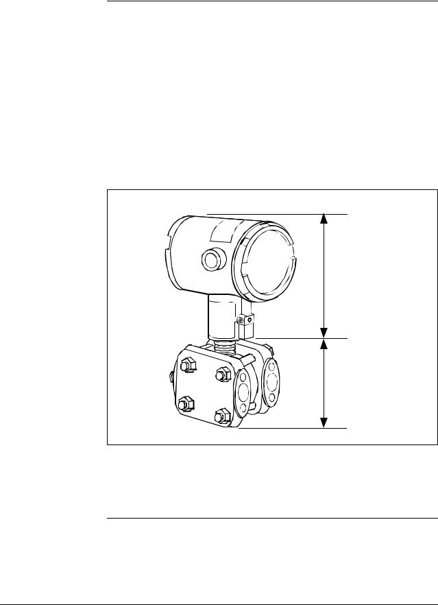
1.2ST 3000 Smart Transmitters
About the transmitter The ST 3000 Smart Transmitter comes in a variety of models for measurement applications involving one of these basic types of pressure:
•Differential Pressure
•Gauge Pressure
•Absolute Pressure
The transmitter measures the process pressure and transmits an output signal proportional to the measured variable over a 4 to 20 milliampere, two-wire loop. Its major components are an electronics housing and a meter body as shown in Figure 1 for a typical differential pressure model transmitter.
Figure 1 Typical ST 3000 Differential Pressure Transmitter.
Electronics
Housing
Meter Body
The ST 3000 can transmit its output in either an analog 4 to 20 milliampere format or a digital DE protocol format for direct digital communications with our TPS system, Allen-Bradley PLCs and other control systems.
Continued on next page
|
2 |
ST 3000 Release 300 and SFC Model STS103 User’s Manual |
6/08 |
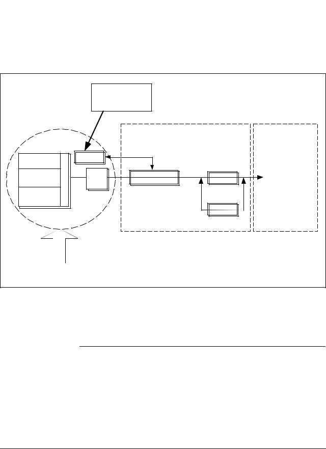
1.2 ST 3000 Smart Transmitters, Continued
About the transmitter, continued
Besides the process variable (PV) output, the transmitter also provides its meter body temperature as a secondary variable which is only available as a read-only parameter through the SFC when the transmitter is in its analog mode. See Figure 2.
Figure 2 Functional Block Diagram for Transmitter in Analog Mode of Operation.
|
Factory |
|||||
|
Characterization |
|||||
|
Data |
|||||
|
Meter Body |
Electronics Housing |
||||
|
DP or PP |
PROM |
||||
|
Sensor |
Multiplexer |
||||
|
Temperature |
A/D |
Microprocessor |
D/A |
Proportional 4 to |
|
|
Sensor |
20 mA PV output. |
||||
|
Static Pressure |
(Digital signal |
||||
|
Sensor |
imposed during |
||||
|
Digital I/O |
SFC |
||||
|
communications) |
|||||
|
Modular Electronics |
Terminal Block |
||||
|
Pressure |
When the transmitter is in its DE mode, the process variable is available for monitoring and control purposes; and the meter body temperature is also available as a secondary variable for monitoring purposes only.
See Figure 3.
Continued on next page
|
6/08 |
ST 3000 Release 300 and SFC Model STS103 User’s Manual |
3 |
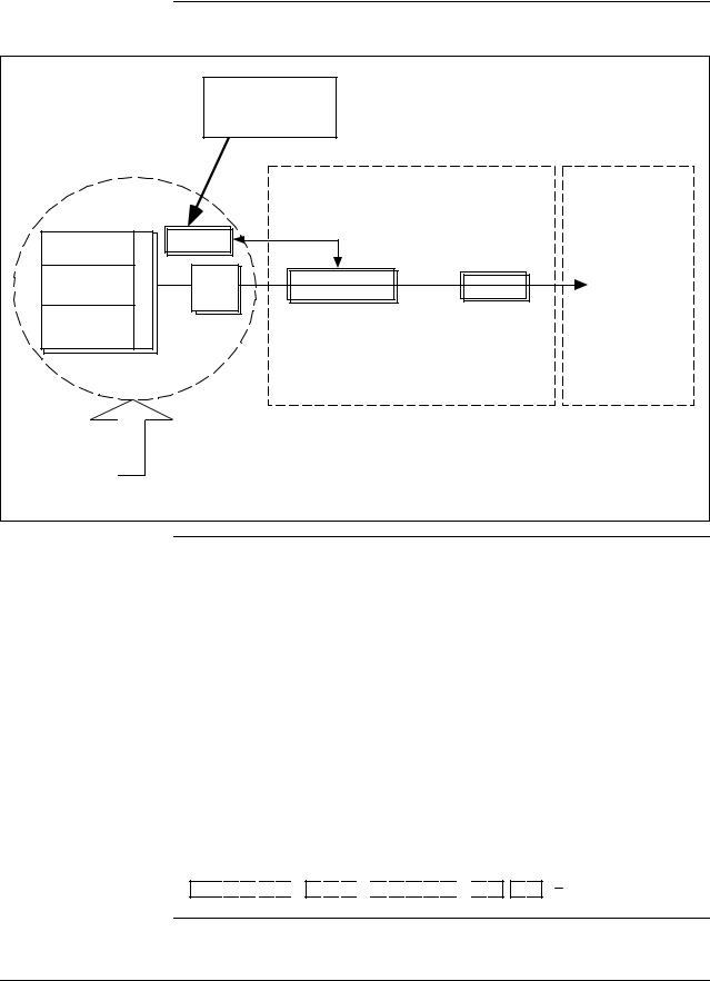
1.2ST 3000 Smart Transmitters, Continued
Figure 3 Functional Block Diagram for Transmitter in Digital DE Mode of Operation.
|
Factory |
|||||
|
Characterization |
|||||
|
Data |
|||||
|
Meter Body |
Electronics Housing |
||||
|
DP or PP |
PROM |
||||
|
Sensor |
Multiplexer |
||||
|
Temperature |
A/D |
Microprocessor |
Digital I/O |
Digital signal |
|
|
Sensor |
broadcasts PV |
||||
|
Static Pressure |
in floating point |
||||
|
Sensor |
format over |
||||
|
20 mA loop. |
|||||
|
Modular Electronics |
Terminal Block |
||||
|
Pressure |
Series and model number data
Honeywell’s line of ST 3000 Smart Transmitters includes these two series designations:
•Series 100
•Series 900
Each series includes several models to meet various process pressure measurement and interface requirements. Each transmitter comes with a nameplate located on the top of the electronics housing that lists its given “model number”. The model number format consists of a Key Number with several Table selections as shown below.
|
ly |
|||||||
|
b |
|||||||
|
m |
|||||||
|
y |
se |
||||||
|
d |
As |
s |
|||||
|
r |
Bo |
e |
|||||
|
n |
|||||||
|
ng |
t |
||||||
|
ete |
la |
io |
|||||
|
p |
|||||||
|
M |
F |
O |
|||||
|
Table I |
Table II |
Table III |
E 
 1
1 
 H
H

 0
0 
 0
0 
 0
0 
 0
0 
 0
0 

 S
S 
 B , 1
B , 1 
 C
C
Continued on next page
|
4 |
ST 3000 Release 300 and SFC Model STS103 User’s Manual |
6/08 |

1.2 ST 3000 Smart Transmitters, Continued
Series and model number data, continued
ATTENTION
Transmitter adjustments
You can quickly identify what series and basic type of transmitter you have from the third and fourth digits in the key number. The letter in the third digit represents one of these basic transmitter types:
A = Absolute Pressure D = Differential Pressure F = Flange Mounted
G = Gauge Pressure
R = Remote Seals
The number in the fourth digit matches the first digit in the transmitter Series. Thus, a “1” means the transmitter is a Series 100 and a “9” is a Series 900.
For a complete breakdown of the Table selections in your model number, please refer to the appropriate Specification and Model Selection Guide that is provided as a separate document. However, a description of the available Table III options is given in Appendix A of this manual for handy reference.
Previous models of the ST 3000 transmitter with designations of Series 100, Series 100e, Series 600, and Series 900 have been supplied at various times since the ST 3000 was introduced in 1983. While all these transmitters are functionally alike, there are differences in housing and electronics design. This manual only applies for Release 300, Series 100 transmitters with software version 3.0 or greater and Release 300, Series 900 transmitters with software version b.0 or greater. See the procedure on page 50 to use the SFC to check your transmitter’s software version.
Release 300 transmitters can be identified by the “R300” designation on the nameplate.
Except for optional zero and span adjustments, the ST 3000 has no physical adjustments. You need an SFC to make any adjustments in an ST 3000 transmitter. Alternately, certain adjustments can be made through the Universal Station if the transmitter is digitally integrated with a Honeywell TPS system; or through a PC running Honeywell SCT 3000 software.
ST 3000 Transmitters Table 1 illustrates the present ST 3000 pressure transmitter family. presently available
Continued on next page
|
6/08 |
ST 3000 Release 300 and SFC Model STS103 User’s Manual |
5 |

1.2ST 3000 Smart Transmitters, Continued
Table 1 ST 3000 Pressure Transmitter Family.
|
Transmitter Type |
Series 100 Model |
Series 900 Model |
|
Differential |
STD1xx |
STD9xx |
|
Pressure |
|
Differential Pressure |
STF1xx |
STF9xx |
|
with Flange on One |
||
|
Side |
|
Dual-Head Gauge |
Not Available |
STG9xx |
|
Pressure |
|
In-Line Gauge and |
STG1xL |
STG9xL |
|
Absolute Pressure |
STA1xL |
STA9xL |
|
Gauge and Absolute |
STG1xx |
STG9xx |
|
Pressure |
STA1xx |
STA9xx |
Continued on next page
|
6 |
ST 3000 Release 300 and SFC Model STS103 User’s Manual |
6/08 |
![]()
1.2ST 3000 Smart Transmitters, Continued
Table 1 ST 3000 Pressure Transmitter Family, continued.
|
Transmitter Type |
Series 100 Model |
Series 900 Model |
||||||
|
Flange-Mount |
STF1xx |
STF9xx |
|
Liquid Level |
|
Differential Pressure |
STR1xx |
STR9xx |
|
|
with Remote |
|||
|
Diaphragm Seals |
|
Flush Mount |
Not Available |
STG93P |
|
High Temperature |
STG14T |
Not Available |
|
STF14T |
|
6/08 |
ST 3000 Release 300 and SFC Model STS103 User’s Manual |
7 |
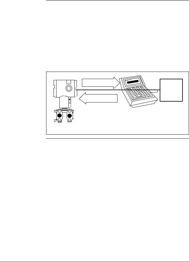
1.3Smart Field Communicator
About SFC communications
The portable, battery-powered SFC serves as the common communication interface device for Honeywell’s family of Smartline Transmitters. It communicates with a transmitter through serial digital signals over the 4 to 20 milliampere line used to power the transmitter. A request/response format is the basis for the communication operation. The transmitter’s microprocessor receives a communication signal from the SFC, identifies the request, and sends a response message.
Figure 4 shows a simplified view of the communication interface provided by an SFC.
Figure 4 Typical SFC Communication Interface.
|
Response |
Power |
|
|
4 to 20 mA line |
Supply and |
|
|
Receiver |
||
|
Request |
||
SFC
|
STR3001 |
||||||
|
ST 3000 |
||||||
|
Purpose of SFC |
The SFC allows you to adjust transmitter values, or diagnose potential |
|
|
problems from a remote location such as the control room. You can use |
||
|
the SFC to: |
||
|
• Configure: |
Define and enter the transmitter’s operating parameters |
including
–range values,
–output conformity,
–damping time,
–tag number (ID), and more
|
• |
Monitor: |
Read the input pressure to the transmitter in |
|
engineering units and the transmitter’s output in |
||
|
• |
percent. |
|
|
Display: |
Retrieve and display data from the transmitter or SFC |
|
|
• |
Change Mode |
memory. |
|
of Operation: |
Tell transmitter to operate in either its analog (4-20 |
|
|
mA) mode or its digital enhanced (DE) mode. |
||
|
Continued on next page |
|
8 |
ST 3000 Release 300 and SFC Model STS103 User’s Manual |
6/08 |

1.3 Smart Field Communicator, Continued
Purpose of SFC, continued
SFC model differences
|
• Check Current |
|
|
Output: |
Use the transmitter to supply the output current |
|
desired |
for verifying analog loop operation, troubleshooting, |
or calibrating other components in the analog loop.
• Troubleshoot: Check status of transmitter operation and display diagnostic messages to identify transmitter, communication, or operator error problems.
As Honeywell’s family of Smartline Transmitters has evolved, the SFC has been changed to meet new model and functionality requirements. Besides different software versions, some major differences exist between these four SFC model designations.
•STS100
•STS101
•STS102
•STS103
Table 2 summarizes the differences between the four SFC models for reference.
|
Table 2 |
SFC Model Differences |
||
|
If SFC |
Then it is compatible |
And additional functions |
|
|
model is. . . |
with. . . |
include . . . |
|
|
STS100 |
Analog only ST 3000 smart |
Not applicable |
|
|
pressure transmitters |
|||
|
STS101 |
Analog only ST 3000 smart |
Corrects Reset, Failsafe Direction |
|
|
pressure transmitters, if |
and Sensor Temperature |
||
|
SFC software version is less |
indication. |
||
|
than 5.0. |
|||
|
Analog and Digital (DE) |
Changing the mode from analog |
||
|
mode ST 3000 pressure |
to digital or digital to analog, |
||
|
transmitters and STT 3000 |
configuration parameters for STT |
||
|
temperature transmitters, if |
3000 and scratch pad |
||
|
SFC software version is 5.0 |
configuration area for ST 3000. |
||
|
or greater. |
|||
|
Continued on next page |
|
6/08 |
ST 3000 Release 300 and SFC Model STS103 User’s Manual |
9 |

1.3 Smart Field Communicator, Continued
SFC model differences, continued
ATTENTION
|
Table 2 |
SFC Model Differences, continued |
||
|
If SFC |
Then it is compatible |
And additional functions |
|
|
model is. . . |
with. . . |
include . . . |
|
|
STS102 |
Analog and Digital (DE) |
Changing the mode from analog |
|
|
mode ST 3000 pressure |
to digital or digital to analog. |
||
|
transmitters, STT 3000 |
Configuration parameters for |
||
|
temperature transmitters, |
Magnew 3000 as well as scratch |
||
|
and MagneW 3000 |
pad configuration area. |
||
|
electromagnetic flowmeters. |
|||
|
STS103 |
Same as STS102 plus new |
Two-line, 16-character per line |
|
|
multivariable transmitters — |
display. Made “SAVE” and |
||
|
SCM 3000 Smart Coriolis |
“RESTORE” functions part of |
||
|
Flowmeter and SGC 3000 |
configuration menu instead of |
||
|
Smart Gas Chromatograph. |
dedicated keys. Configuration |
||
|
parameters for SCM 3000 and |
|||
|
SGC 3000. |
|||
|
SMV 3000 Smart |
Configuration parameters for |
||
|
Multivariable Transmitters, if |
SMV 3000 |
||
|
SFC software version is 4.2 |
|||
|
or greater. |
|||
|
SMV 3000 with superheated |
SMV 3000 configuration |
||
|
steam algorithm and |
parameters for superheated steam |
||
|
thermocouple input, if SFC |
algorithm and thermocouple |
||
|
software version is 4.4 or |
inputs. |
||
|
greater. |
|||
|
Release 300 Series 100 and |
Local Smart Meter configuration |
||
|
900 ST 3000 pressure |
parameters. |
||
|
transmitters, if SFC software |
|||
|
version is 5.0 or greater. |
|||
The keystroke actions and prompt displays referenced in this manual are for the SFC model STS103. While the SFC model STS103 does have a two-line instead of a one-line display, many of the basic keystrokes and configuration parameter prompts for ST 3000 pressure transmitters are identical to those in the model STS102.
If you will be using a model STS102 SFC, you must refer to the SFC Smart Field Communicator Operating Guide 34-ST-11-10 for keystroke details. But, be aware that transmitter functions will be limited to only those that are supported by the Model STS102 SFC.
|
10 |
ST 3000 Release 300 and SFC Model STS103 User’s Manual |
6/08 |
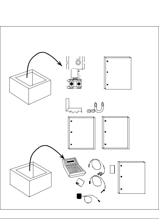
1.4Transmitter/SFC Order
|
Order components |
Figure 5 shows the components that would be shipped and received for |
|
a typical ST 3000 transmitter and SFC order. |
Figure 5 Typical ST 3000 Transmitter and SFC Order Components.
Ordered
Series 100 ST 3000 Differential pressure transmitter with optional mounting bracket
Smart Field Communicator with optional battery charger
ST 3000
Installation
Guide
Mounting Bracket (Optional)
|
Quick |
||||||||
|
ST 3000 |
Shipped |
|||||||
|
User’sManual |
Reference |
separately, |
||||||
|
Guide |
if ordered |
|||||||
|
SFC |
SFC |
||
|
Operating |
|||
|
|
Guide |
||
|
Card |
|||
|
Battery |
Leads |
||
|
Pack |
|||
|
Battery |
|||
|
Charger |
|||
|
(optional) |
|||
|
Continued on next page |
|||
|
6/08 |
ST 3000 Release 300 and SFC Model STS103 User’s Manual |
11 |

1.4Transmitter/SFC Order, Continued
About documentation Various documents are available for reference describing how to install, configure and operate the ST 3000 transmitter:
•ST 3000 Smart Transmitter Installation Guide Using SFC Model STS103 34-ST-33-39: One copy is shipped with every transmitter. This document provides information for checking, installing, and wiring the ST 3000 transmitter for operation.
•ST 3000 Smart Transmitter and SFC Smart Field Communicator Model STS 103 User’s Manual 34-ST-25-14: One or more copies are sent to the address designated on the order when specified. This document provides detailed information for installing, wiring, configuring, starting up, operating, maintaining, and servicing the ST 3000 transmitter. This is the main reference manual for the ST 3000 transmitter and it overlaps some data in the previously listed Installation Guide 34-ST-33-39 and in the following Operating Guide 34-ST-11-14 to minimize cross reference.
•ST 3000 Smart Transmitter Quick Reference Guide 34-ST-09-06: Shipped with User’s Manual. This document provides abbreviated versions of procedures for installing, wiring, configuring, calibrating and troubleshooting the ST 3000 transmitter for quick reference.
•Smart Field Communicator Model STS103 Pocket Card 34-ST-11-15: One card is shipped with every SFC. This card provides quick reference of keystroke actions for selected transmitter interface tasks.
•Smart Field Communicator Model STS103 Operating Guide 34-ST- 11-14: One copy is shipped with every SFC. This document provides detailed SFC information and keystroke actions for interfacing with these Honeywell Smartline Transmitters.
–ST 3000 Smart Pressure Transmitter (Non Release 300 models)
–STT 3000 Smart Temperature Transmitter
–MagneW 3000 Smart Electromagnetic Flowmeter
–SMV 3000 Smart Multivariable Transmitter
•Smartline Configuration Toolkit SCT 3000 Installation and Start-up Guide 34-ST-10-08: One copy is shipped when the SCT 3000 software application is ordered.
|
12 |
ST 3000 Release 300 and SFC Model STS103 User’s Manual |
6/08 |
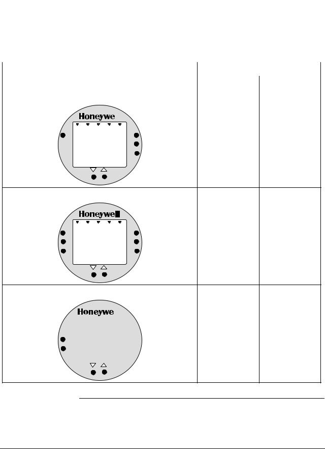
1.5Local Smart Meter Options
|
Option availability |
Depending upon your transmitter model, it can be equipped with one of |
||||||
|
the available Local Smart Meter and/or Zero and Span Adjust options as |
|||||||
|
shown in Table 3. |
|||||||
|
Table 3 |
Local Smart Meter Available Options |
||||||
|
Option Description |
Available with Transmitter Series |
||||||
|
100 |
900 |
||||||
|
Local Smart Meter only |
|||||||
|
VAR |
UPPER |
||||||
|
SEL. |
VALUE |
Yes |
Yes |
||||
|
0 |
% |
100 |
|||||
|
UNITS |
|||||||
|
SET |
|||||||
|
LOWER |
|||||||
|
VALUE |
|
Local Smart Meter with Zero and Span Adjustments |
||||
|
VAR |
UPPER |
|||
|
SEL. |
VALUE |
Yes |
||
|
0 |
% |
100 |
Yes * |
|
|
SPAN |
UNITS |
|||
|
SET |
||||
|
ZERO |
LOWER |
|||
|
VALUE |
Local Zero and Span Adjustments only
SPAN
ZERO
* Except draft range, model STD110
Continued on next page
|
6/08 |
ST 3000 Release 300 and SFC Model STS103 User’s Manual |
13 |
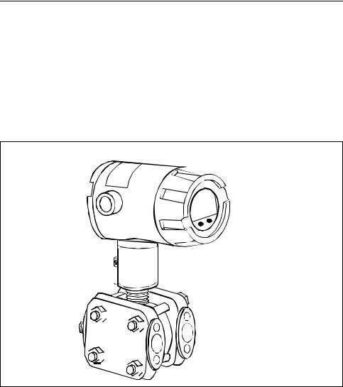
1.5Local Smart Meter Options, Continued
|
About the options |
Each Local Smart Meter and/or Zero and Span Adjust option comes as a |
|
separate assembly mounted on the transmitter’s Printed Wiring |
|
|
Assembly (PWA) mounting bracket. The meter option assembly |
|
|
includes a cable and plug assembly for mating with a connector on the |
|
|
transmitter’s PWA. A meter end-cap which includes a window is |
|
|
supplied on the electronics side of the transmitter’s housing so you can |
|
|
view the meter display with the end cap installed. See Figure 6. |
Figure 6 ST 3000 with Local Smart Meter Option.
Electronics
Housing
 Local Smart
Meter Option
|
14 |
ST 3000 Release 300 and SFC Model STS103 User’s Manual |
6/08 |

Section 2 —Quick Start Reference
2.1Introduction
|
Section Contents |
This section includes these topics: |
||
|
Section |
Topic |
See Page |
|
|
2.1 Introduction |
………………………………………………………………………. |
15 |
|
|
2.2 Getting ST 3000 ………………………..Transmitter On-Line Quickly |
16 |
||
|
About this section |
This section assumes that the ST 3000 transmitter has been installed and |
||
|
wired correctly, and is ready to be put into operation. It also assumes |
|||
|
that you are somewhat familiar with using the SFC and that the |
|||
|
transmitter has been configured correctly for your application. If the |
|||
|
transmitter has not been installed and wired, you are not familiar with |
|||
|
SFC operation, and/or you do not know if the transmitter is configured |
|||
|
correctly, please read the other sections of this manual before starting up |
|||
|
your transmitter. |
|||
|
This section provides a list of typical start-up tasks and tells you where |
|||
|
you can find detailed information about performing the task. |
|
6/08 |
ST 3000 Release 300 and SFC Model STS103 User’s Manual |
15 |

2.2Getting ST 3000 Transmitter On-Line Quickly
|
Quick start-up tasks |
Table 4 lists common start-up tasks for an ST 3000 transmitter using an |
|||||
|
SFC and gives an appropriate section in this manual to reference for |
||||||
|
more information about how to do the task. The start-up tasks are listed |
||||||
|
in the order they are commonly completed. |
||||||
|
Table 4 |
Start-up Tasks Reference |
|||||
|
Task |
Description |
Reference Section |
||||
|
1 |
Put analog loop into manual |
Appropriate vendor documentation |
||||
|
mode. |
for controller or recorder used as a |
|||||
|
receiver in analog loop with |
||||||
|
ST 3000 transmitter. |
||||||
|
2 |
Connect SFC to transmitter and |
5.2 |
||||
|
establish communications. |
||||||
|
3 |
Check or set tag ID. |
6.3 |
||||
|
4 |
Identify transmitter’s mode of |
5.3 |
||||
|
operation. |
||||||
|
5 |
Change mode of operation, if |
5.4 |
||||
|
required. |
||||||
|
6 |
Check/set output form |
6.4 |
||||
|
(Linear/Square Root). |
||||||
|
7 |
Check/set damping time. |
6.5 |
||||
|
8 |
Check/set Lower Range Value |
6.7 |
(See 6.8 for local zero and |
|||
|
and Upper Range Value. |
span adjustments) |
|||||
|
9 |
Run optional output check for |
7.3 |
||||
|
analog loop. |
||||||
|
10 |
Check zero input and set, if |
7.4 |
— See Step 9 in Table 39. |
|||
|
required. |
7.8 |
— See Step 9 in Table 43. |
||||
|
11 |
Check transmitter status. |
8.2 |
||||
|
12 |
Setup local Smart Meter, if |
6.11 or 6.12 |
||||
|
applicable. |
||||||
|
13 |
Write data in scratch pad |
8.4 |
||||
|
memory, if desired. |
||||||
|
14 |
Store all changes in the |
6.13 |
||||
|
transmitter’s non-volatile |
||||||
|
memory by pressing [SHIFT] and |
||||||
|
[ENTER]. |
||||||
|
16 |
ST 3000 Release 300 and SFC Model STS103 User’s Manual |
6/08 |
![]()
Section 3 —Preinstallation Considerations
3.1Introduction
|
Section Contents |
This section includes these topics: |
|||
|
Section |
Topic |
See Page |
||
|
3.1 |
Introduction |
………………………………………………………………………. |
17 |
|
|
3.2 |
CE Conformity …………………………………………….(Europe) Notice |
18 |
||
|
3.3 |
Considerations ………………………………..for ST 3000 Transmitter |
19 |
||
|
3.4 |
Considerations ……………………………………………………….for SFC |
22 |
||
|
3.5 |
Considerations …………………………for Local Smart Meter Option |
24 |
||
|
About this section |
This section reviews things you should take into consideration before |
|||
|
you install the transmitter and start using the SFC. Of course, if you are |
replacing an existing ST 3000 transmitter and you did not order a new SFC; you can skip this section.
|
6/08 |
ST 3000 Release 300 and SFC Model STS103 User’s Manual |
17 |

3.2CE Conformity (Europe) Notice
About conformity and special conditions
This product is in conformity with the protection requirements of 89/336/EEC, the EMC Directive. Conformity of this product with any other “CE Mark” Directive(s) shall not be assumed.
Deviation from the installation conditions specified in this manual, and the following special conditions, may invalidate this product’s conformity with the EMC Directive.
•You must use shielded, twisted-pair cable such as Belden 9318 for all signal/power wiring.
•You must connect the shield to ground at the power supply side of the wiring only and leave it insulated at the transmitter side.
|
ATTENTION |
ATTENTION |
|||
|
The emission limits of EN 50081-2 are designed to provide reasonable |
||||
|
protection against harmful interference when this equipment is operated |
||||
|
in an industrial environment. Operation of this equipment in a residential |
||||
|
area may cause harmful interference. This equipment generates, uses, |
||||
|
and can radiate radio frequency energy and may cause interference to |
||||
|
radio and television reception when the equipment is used closer than 30 |
||||
|
meters (98 feet) to the antenna(e). In special cases, when highly |
||||
|
susceptible apparatus is used in close proximity, the user may have to |
||||
|
employ additional mitigating measures to further reduce the |
||||
|
electromagnetic emissions of this equipment. |
||||
|
18 |
ST 3000 Release 300 and SFC Model STS103 User’s Manual |
6/08 |

3.3Considerations for ST 3000 Transmitter
Evaluate conditions The ST 3000 transmitter is designed to operate in common indoor industrial environments as well as outdoors. To assure optimum performance, evaluate these conditions at the mounting area relative to published transmitter specifications and accepted installation practices for electronic pressure transmitters.
•Environmental Conditions
–Ambient Temperature
–Relative Humidity
•Potential Noise Sources
–Radio Frequency Interference (RFI)
–Electromagnetic Interference (EMI)
•Vibration Sources
–Pumps
–Motorized Valves
–Valve Cavitation
•Process Characteristics
–Temperature
–Maximum Pressure Rating
Figure 7 illustrates typical mounting area considerations to make before installing a transmitter.
Figure 7 Typical Mounting Area Considerations Prior to Installation
|
Lightning |
||
|
(EMI) |
||
|
Relative |
||
|
Humidity |
||
|
Ambient |
||
|
Temperature |
Large Fan Motors |
|
|
(EMI) |
||
|
Transceivers |
||
|
(RFI) |
||
|
Pump |
Meter Body |
|
|
(vibration) |
Temperature |
21003 |
Continued on next page
|
6/08 |
ST 3000 Release 300 and SFC Model STS103 User’s Manual |
19 |

3.3Considerations for ST 3000 Transmitter, Continued
|
Temperature limits |
Table 5 lists the operating temperature limits for the various types of |
||||||
|
transmitters with silicone fill fluids. See transmitter specifications for |
|||||||
|
temperature limits of ST 3000 transmitters with alternative fill fluids. |
|||||||
|
Table 5 |
Operating Temperature Limits (Transmitters with Silicone Fill Fluids) |
||||||
|
Transmitter Type and Model |
Ambient Temperature |
Process Interface Temperature |
|||||
|
°C |
°F |
°C |
°F |
||||
|
Draft Range |
STD110 |
-40 to 70 |
-40 to 158 |
-40 to 70 |
-40 to 158 |
||
|
Differential Pressure |
STD125 |
-40 to 85 |
-40 to 185 |
-40 to 85 |
-40 to 185 |
||
|
STD120, STD130, STD170 |
-40 to 93 |
-40 to 200 |
-40 to 125 |
-40 to 257 |
|||
|
STD904, STD924, |
|||||||
|
STD930, STD974 |
-40 to 85 |
-40 to 185 |
-40 to 125 |
-40 to 257 |
|||
|
Gauge Pressure |
|||||||
|
STG140, STG170, STG180, |
|||||||
|
STG14L, STG17L, STG18L |
-40 to 93 |
-40 to 200 |
-40 to 125 |
-40 to 257 |
|||
|
STG14T |
-40 to 93 |
-40 to 200 |
-40 to 150 † |
-40 to 302 † |
|||
|
STG93P |
-15 to 65 |
5 to 149 |
-15 to 95 †† |
5 to 203 †† |
|||
|
STG944, STG974 |
-40 to 85 |
-40 to 185 |
-40 to 125 |
-40 to 257 |
|||
|
STG90L, STG94L, |
|||||||
|
STG97L, STG98L |
-40 to 85 |
-40 to 185 |
-40 to 110 |
-40 to 230 |
|||
|
Absolute PressureSTA122/12L |
-40 to 93 |
-40 to 200 |
See Specification Sheet |
||||
|
STA140/14L |
-40 to 93 |
-40 to 200 |
-40 to 80 |
-40 to 176 |
|||
|
STA922/92L |
-40 to 85 |
-40 to 185 |
See Specification Sheet |
||||
|
STA940/94L |
-40 to 85 |
-40 to 185 |
-40 to 80 |
-40 to 176 |
|||
|
Flange Mounted |
|||||||
|
STF128, STF132, STF924, |
-40 to 93 |
-40 to 200 |
-40 to 175 |
-40 to 350 |
|||
|
STF932 |
|||||||
|
Pseudo-Flanged Head |
|||||||
|
STF12F, STF13F, STF92F, |
-40 to 93 |
-40 to 200 |
-40 to 93 |
-40 to 200 |
|||
|
STF93F |
|||||||
|
STF14F |
-40 to 85 |
-40 to 185 |
-40 to 85 |
-40 to 185 |
|||
|
Gauge Pressure Flange Mount |
-40 to 93 |
-40 to 200 |
-40 to 150 † |
-40 to 302 † |
|||
|
STF14T |
|||||||
|
Remote Diaphragm Seals |
|||||||
|
STR12D, STR13D, STR14G, |
|||||||
|
STR17G, STR14A |
See Specification Sheet |
See Specification Sheet |
|||||
|
STR93D, STR94G |
-40 to 85 |
-40 to 185 |
See Specification Sheet |
†Process temperatures above 125 °C (257 °F) require a reduction in the maximum ambient temperature as follows:
|
Process Temperature |
Ambient Temperature Limit |
|
150 °C (302 °F) |
50 °C (122 °F) |
|
140 °C (284 °F) |
60 °C (140 °F) |
|
125 °C (257 °F) |
85 °C (185 °F) |
†† Process temperatures above 65 °C (149 °F) require a 1:1 reduction in maximum ambient temperature. NOTE: For transmitters with local meter option see Table 8.
NOTE: Transmitters with other fill fluids (CTFE, Neobee, Etc.) have different Operating Temperature Limits. For more specific information, refer to the appropriate Specification and Model Selection Guide or transmitter nameplate
|
20 |
ST 3000 Release 300 and SFC Model STS103 User’s Manual |
6/08 |

3.3Considerations for ST 3000 Transmitter, Continued
|
Pressure ratings |
Table 6 lists maximum working pressure for a given transmitter Upper |
|
Range Limit (URL). |
|
|
The maximum allowable working pressure (MAWP) is the pressure |
|
|
used for the approval body safety calculations. |
Table 6 Transmitter Maximum Allowable Working Pressure (MAWP) Ratings
|
Transmitter Type |
Upper Range Limit |
MAWP |
|
(URL) |
||
|
Draft Range |
10 inches H2O (25 |
50 psi (3.5 bar) |
|
mbar) |
||
|
Differential Pressure |
400 inches H2O (1 bar) |
3000 psi (210 bar) |
|
100 psi (7 bar) |
3000 psi (210 bar) |
|
|
3000 psi (210 bar) |
3000 psi (210 bar) |
|
|
Gauge Pressure |
100 psi (7 bar) |
100 psi (7 bar) |
|
300 psi (21 bar) |
300 psi (21 bar) |
|
|
500 psi (35 bar) |
500 psi (35 bar) |
|
|
3000 psi (210 bar) |
3000 psi (210 bar) |
|
|
6000 psi (415 bar) |
6000 psi (415 bar) |
|
|
10000 psi (690 bar) |
10000 psi (690 bar) |
|
|
Flange Mount |
400 inches H2O (1 bar) |
Per selected flange |
|
and material |
||
|
100 psi (7 bar) |
||
|
(ANSI/ASME 150#, |
||
|
300#, DN PN40) |
||
|
Remote Seal |
400 inches H2O (1 bar) |
Lesser MAWP of |
|
either Remote Seal |
||
|
100 psi (7 bar) |
||
|
selected or transmitter |
||
|
pressure rating |
||
|
Absolute Pressure |
780 mmHg Absolute |
780 mmHg Absolute |
|
(1 bar) |
(1 bar) |
|
|
500 psia (35 bar) |
500 psia (35 bar) |
|
Note: Maximum Allowable Working Pressure (MAWP) may vary with materials of construction and process temperature. For more specific information, refer to the appropriate Specification and Model Selection Guide or transmitter nameplate
NOTE: To convert bar values to kilopascals (kPa), multiply by 100. For example, 3.5 bar equals 350 kPa.
|
6/08 |
ST 3000 Release 300 and SFC Model STS103 User’s Manual |
21 |

3.4Considerations for SFC
Install SFC battery pack
If the SFC battery pack was removed for shipping and/or storage, you will have to install the battery pack and charge the batteries before you can operate the SFC.
The procedure in Table 7 outlines the steps for the battery pack.
Table 7 Installing and Charging SFC Battery Pack
1Turn SFC face down on working surface. Use metric hex wrench (2.5 mm) to remove screws in battery compartment cover and remove cover.
2Insert battery pack in compartment and connect plug in compartment to pin on battery back
Example — Battery pack installation.
|
Battery Pack |
Hex Screws |
||||
21004
3Replace cover and tighten hex screws
4Connect lead from battery charger to recessed connector on left side of SFC.
WARNING The SFC battery charger is not intrinsically safe. Always recharge the SFC battery pack in a nonhazardous location. The SFC itself is an intrinsically safe device.
Continued on next page
|
22 |
ST 3000 Release 300 and SFC Model STS103 User’s Manual |
6/08 |

3.4 Considerations for SFC, Continued
Install SFC battery pack, continued
Temperature Limits
Usage guidelines
Table 7 Installing and Charging SFC Battery Pack, continued
|
Step |
Action |
||||||
|
5 |
Plug battery charger into any standard 120 Vac outlet or universal- |
||||||
|
European 240 Vac outlet as applicable for charger power rating. If |
|||||||
|
240 Vac charger is supplied with stripped leads instead of universal- |
|||||||
|
European plug, lead identification for 240 Vac charger is as follows. |
|||||||
|
Lead Color… |
Function… |
||||||
|
Blue |
Neutral |
||||||
|
Brown |
Hot |
||||||
|
Green/Yellow |
Ground |
||||||
|
ATTENTION |
It takes up to 16 hours to fully recharge the battery |
||||||
|
pack and you can use the SFC continuously for up to 24 hours |
|||||||
|
before the battery pack needs recharging. |
|||||||
The ambient operating temperature limits for the SFC are –10 to 50°C (14 to 122°F) with relative humidity in the range of 10 to 90% RH.
•For transmitters operating in the Analog Mode, be sure to put an analog control loop into its manual mode before initiating SFC communications with the transmitter. Also, be sure any switches that may trip alarms or interlocks associated with the analog loop are secured or turned OFF. Communication superimposes digital signals on the loop wiring that could affect the analog control signal.
•Be sure the power supply voltage does not exceed 45Vdc.
The ST 3000 transmitter and SFC were designed to operate with voltages below 45Vdc.
•Be sure there is at least 250 ohms of resistance between the SFC and the power supply for proper communications.
|
6/08 |
ST 3000 Release 300 and SFC Model STS103 User’s Manual |
23 |

3.5Considerations for Local Smart Meter Option
|
Reference |
Table 8 lists pertinent Smart Meter specifications for reference. |
||||||||
|
specifications |
|||||||||
|
Table 8 |
Local Smart Meter Specifications. |
||||||||
|
Operating Conditions |
————— |
||||||||
|
Parameter |
Rated |
Extreme, Transportation and |
|||||||
|
Storage |
|||||||||
|
Ambient Temperature |
°F |
–40 to 176 |
–58 to 194 |
||||||
|
°C |
–40 to 80 |
–50 to 90 |
|||||||
|
Relative Humidity |
%RH |
10 to 90 |
0 to 100 |
||||||
|
Design ——————————— |
|||||||||
|
Accuracy |
No error. Reproduces transmitter signal exactly within its resolution. |
||||||||
|
Display Resolution |
Bargraph |
±3% of reading |
Shown as: |
||||||
|
Digital Readout |
±0.005 for ±19.99 reading range, |
19.99 |
|||||||
|
±0.05 for ±199.9 reading range, |
199.9 |
||||||||
|
±0.5 for ±1999 reading range, |
1999 |
||||||||
|
±5 for ±19990 reading range, |
19.99 K |
||||||||
|
±50 for ±199900 reading range, |
199.9 K |
||||||||
|
±500 for ±1999000 reading range, |
1999 K |
||||||||
|
±5000 for ±19990000 reading range. |
19990 K |
||||||||
|
Display Update Rate |
Above 32°F (0°C): ½ second |
||||||||
|
@ or below 32°F (0°C): 1½ seconds |
|||||||||
Meter Display at High
and Low Temperature
Extremes
The rated temperature limits for the local meter are listed above and are true in that no damage to the meter will occur over these temperatures, however the readability of the LCD is affected if taken to these temperature extremes:
•The LCD will turn black at some temperature between 80 to 90 °C (176 and 194 °F), rendering the display unreadable. This effect is only temporary, and normally occurs at 90 °C (194 °F).
•At low temperatures, the update rate of the display is lengthened to 1.5 seconds due to the slower response time of the display. At -20
°C (-4 °F) the display becomes unreadable due to slow response of the LCD. This is also only temporary and normal readability will return when temperature returns above -20 °C (-4 °F).
|
24 |
ST 3000 Release 300 and SFC Model STS103 User’s Manual |
6/08 |

Section 4 —Installation
4.1Introduction
|
Section Contents |
This section includes these topics: |
|||
|
Section |
Topic |
See Page |
||
|
4.1 |
Introduction |
………………………………………………………………………. |
25 |
|
|
4.2 |
Mounting ST ……………………………………………..3000 Transmitter |
26 |
||
|
4.3 |
Piping ST 3000 ………………………………………………….Transmitter |
36 |
||
|
4.4 |
Wiring ST 3000 …………………………………………………Transmitter |
41 |
||
|
About this section |
This section provides information about installing the ST 3000 |
|||
|
transmitter. It includes procedures for mounting, piping and wiring the |
||||
|
transmitter for operation. |
|
6/08 |
ST 3000 Release 300 and SFC Model STS103 User’s Manual |
25 |

4.2Mounting ST 3000 Transmitter
|
Summary |
You can mount all transmitter models (except flush mount models and |
|
those with integral flanges) to a 2-inch (50 millimeter) vertical or |
|
|
horizontal pipe using our optional angle or flat mounting bracket, or a |
|
|
bracket of your own. Flush mount models are mounted directly to the |
|
|
process pipe or tank by a 1” weld nipple. Those models with integral |
|
|
flanges are supported by the flange connection. |
Figure 8 shows typical bracket mounted and flange mounted transmitter installations for comparison.
Figure 8 Typical Bracket Mounted and Flange Mounted Installations
|
Angle |
Flat |
|
|
Mounting |
||
|
Bracket |
Mounting |
|
|
Bracket |
||
|
Horizontal Pipe |
||
|
Tank |
||
|
Wall |
||
|
Flange |
Transmitter |
|
|
Connection |
Flange |
24118 |
Continued on next page
|
26 |
ST 3000 Release 300 and SFC Model STS103 User’s Manual |
6/08 |
![]()
4.2Mounting ST 3000 Transmitter, Continued
|
Dimensions |
Detailed dimension drawings for given transmitter series and types are |
|||||
|
listed in the back of the Installation Guide (Part number 34-ST-33-39) |
||||||
|
for reference. Note that abbreviated overall dimensions are also shown |
||||||
|
in the Specification Sheets for the given transmitter models. |
||||||
|
This section assumes that the mounting dimensions have already been |
||||||
|
taken into account and the mounting area can accommodate the |
||||||
|
transmitter. |
||||||
|
Bracket mounting |
Table 9 summarizes typical steps for mounting a transmitter to a |
|||||
|
bracket. |
||||||
|
Table 9 |
Mounting ST 3000 Transmitter to a Bracket |
|||||
|
Step |
Action |
|||||
|
1 |
||||||
|
If you are using an… |
Then… |
|||||
|
optional mounting bracket |
go to Step 2. |
|||||
|
existing mounting bracket |
go to Step 3. |
2Position bracket on 2-inch (50.8 mm) horizontal or vertical pipe, and install “U” bolt around pipe and through holes in bracket. Secure with nuts and lockwashers provided.
Example — Angle mounting bracket secured to horizontal or vertical pipe.
Nuts and
Nuts and Lockwashers
Lockwashers
Mounting
Bracket 
Horizontal Pipe
Vertical Pipe
U-Bolt
Continued on next page
|
6/08 |
ST 3000 Release 300 and SFC Model STS103 User’s Manual |
27 |

4.2Mounting ST 3000 Transmitter, Continued
|
Bracket mounting, |
||||||
|
continued |
Table 9 |
Mounting ST 3000 Transmitter to a Bracket, continued |
||||
|
Step |
Action |
|||||
|
3 |
Align appropriate mounting holes in transmitter with holes in bracket |
|||||
|
and secure with bolts and washers provided. |
||||||
|
If transmitter is … |
Then … |
|||||
|
DP type with double ended |
use alternate mounting |
|||||
|
process heads and/or |
holes in end of heads. |
|||||
|
remote seals |
||||||
|
GP and AP with single- |
use mounting holes in side |
|||||
|
ended head |
of meter body. |
|||||
|
In-line GP and AP |
use smaller “U” bolt |
|||||
|
(STGxxL and STAxxL) |
provided to attach meter |
|||||
|
body to bracket. |
||||||
|
See figure below. |
||||||
|
Dual-head GP and AP |
use mounting holes in end |
|||||
|
of process head. |
Example – Inline model transmitter mounted to optional angle mounting bracket.
Inline models
Meter Body
Smaller
“U” bolt
Use bracket for hexagonal meter body
NOTE: If the meter body is hexagonal, you must use the additional bracket supplied. If meter body is round, discard the
bracket.
Continued on next page
|
28 |
ST 3000 Release 300 and SFC Model STS103 User’s Manual |
6/08 |

4.2Mounting ST 3000 Transmitter, Continued
|
Bracket mounting, |
|||||||||||||||||
|
continued |
Table 9 |
Mounting ST 3000 Transmitter to a Bracket, continued |
|||||||||||||||
|
4 |
Loosen set screw on outside neck of transmitter one full turn. Rotate |
||||||||||||||||
|
electronics housing a maximum of 180 degrees in left or right |
|||||||||||||||||
|
direction from center to the position you require and tighten set screw |
|||||||||||||||||
|
(13 to 15 lb-in/1.46 to 1.68 N.m). |
|||||||||||||||||
|
Example — Rotating electronics housing. |
|||||||||||||||||
|
Electronics |
|||||||||||||||||
|
180 degrees |
Housing |
||||||||||||||||
|
180 degrees |
|||||||||||||||||
|
max. |
|||||||||||||||||
|
max. |
|||||||||||||||||
|
Set Screw |
|||||||||||||||||
ATTENTION The metric socket head wrench kit supplied with the SFC includes 2.5, 3, and 4mm size wrenches. You will need the 4mm size wrench for the outside set screw.
Continued on next page
|
6/08 |
ST 3000 Release 300 and SFC Model STS103 User’s Manual |
29 |

4.2Mounting ST 3000 Transmitter, Continued
|
ATTENTION |
The mounting position of a model STA122, STA922, STA12L, or |
|
STA92L Absolute Pressure Transmitter or a model STD110 Draft |
|
|
Range Differential Pressure Transmitter is critical as the transmitter |
|
|
spans become smaller. A maximum zero shift of 2.5 mm Hg for an |
|
|
absolute transmitter or |
|
|
1.5 inH2O for a draft range transmitter can result from a mounting |
|
|
position which is rotated 90 degrees from vertical. A typical zero shift of |
|
|
0.12 mm Hg or 0.20 in H2O can occur for a 5 degree rotation from |
|
|
vertical. |
Precautions for Mounting Transmitters with Small Absolute or Differential Pressure Spans
To minimize these positional effects on calibration (zero shift), take the appropriate mounting precautions that follow for the given transmitter model.
For a model STA122, STA922, STA12L, or STA92L transmitter, you must ensure that the transmitter is vertical when mounting it. You do this by leveling the transmitter side-to-side and front-to-back. See Figure 9 for suggestions on how to level the transmitter using a spirit balance.
Figure 9 Leveling an Absolute Pressure Transmitter.
Leveling Absolute Pressure models
Center
Section
Process
Head
Position spirit balance on center section of meter body only.
Cont’d
Continued on next page
|
30 |
ST 3000 Release 300 and SFC Model STS103 User’s Manual |
6/08 |

4.2Mounting ST 3000 Transmitter Continued
Figure 9 Leveling an Absolute Pressure Transmitter (cont’d)
Leveling Inline models
Mount transmitter vertically to assure best accuracy. Position spirit balance on pressure connection surface of AP body.
|
6/08 |
ST 3000 Release 300 and SFC Model STS103 User’s Manual |
31 |

4.2 Mounting ST 3000 Transmitter, Continued
Precautions for Mounting Transmitters with Small Absolute or Differential Pressure Spans, continued
For a transmitter with a small differential pressure span, you must ensure that the transmitter is vertical when mounting it. You do this by leveling the transmitter side-to-side and front-to-back. See Figure 9 for suggestions on how to level the transmitter using a spirit balance. You must also zero the transmitter by following the steps in Table 10 below.
|
Table 10 |
Zero Corrects Procedure for STD110 |
||||||
|
Step |
Action |
||||||
|
1 |
Attach the transmitter to the mounting bracket but do not completely |
||||||
|
tighten the mounting bolts |
|||||||
|
2 |
Connect a tube between the input connections in the high pressure |
||||||
|
(HP) and low pressure (LP) heads to eliminate the affects of any |
|||||||
|
surrounding air currents. |
|||||||
|
3 |
Connect 24 Vdc power to the transmitter and connect a digital |
||||||
|
voltmeter or SFC to read the transmitter’s output. See Figures 18 |
|||||||
|
and 38 for typical SFC connection or connect a voltmeter across the |
|||||||
|
250 ohm resistor, if desired. |
|||||||
|
4 |
Use the SFC and establish communications with the transmitter. |
||||||
|
Follow the steps in Table 17, if needed. |
|||||||
|
5 |
While reading the transmitter’s output on an SFC or a voltmeter, |
||||||
|
position the transmitter so the output reading is at or near zero and |
|||||||
|
then completely tighten the mounting bolts. |
|||||||
|
6 |
Perform an input zero correct function using the SFC and following |
||||||
|
the steps below. This corrects the transmitter for any minor error that |
|||||||
|
may occur after the mounting bolts are tightened. |
|||||||
|
7 |
|||||||
|
^ |
|||||||
|
Initiate shift key selection. Press |
SHIFT |
key |
|||||
|
INPUT |
|||||||
|
J |
|||||||
|
OUT- |
|||||||
|
Press |
PUT |
key. Read applied input pressure. |
|||||
|
RESET |
|||||||
|
COR-K |
|||||||
|
Press |
RECT |
key. Prompt asks if the applied input pressure equals |
|||||
|
zero input. If it is zero input, go to next keystroke. If it is not, press |
|||||||
|
[CLR] key to exit function and repeat keystrokes. |
|||||||
|
NON-VOL |
|||||||
|
ENTER |
|||||||
|
Press |
(Yes) |
key. Zero input is set equal to applied input pressure. |
|||||
|
8 |
Remove the tube from between the input connections, the power, |
||||||
|
and the digital voltmeter or SFC. |
|||||||
|
9 |
Continue with the remaining installation tasks. |
Continued on next page
|
32 |
ST 3000 Release 300 and SFC Model STS103 User’s Manual |
6/08 |

4.2 Mounting ST 3000 Transmitter, Continued
Flange mounting
ATTENTION
To mount a flange mounted transmitter model, bolt the transmitter’s flange to the flange pipe on the wall of the tank.
On insulated tanks, remove enough insulation to accommodate the flange extension.
Figure 10 shows a typical installation for a transmitter with the flange on the high pressure (HP) side so the HP diaphragm is in direct contact with the process fluid. The low pressure (LP) side of the transmitter is vented to atmosphere (no connection).
It is the End User’s responsibility to provide a flange gasket and mounting hardware that are suitable for the transmitter’s service condition.
To prevent degradation of performance in Flush-Mounted Flanged Transmitters, exercise care to ensure that the internal diameter of the flange gasket does not obstruct the sensing diaphragm.
To prevent degradation of performance in Extended Mount Flanged Transmitters, ensure that there is sufficient clearance in front of the sensing diaphragm body.
Figure 10 Typical Flange Mounted Transmitter Installation
Attention: Dotted area indicates use with closed tank with reference leg.
Maximum Level
|
Variable |
Reference |
|||||||||||||||||||||||
|
Head H1 |
Leg |
|||||||||||||||||||||||
|
Minimum Level |
||||||||||||||||||||||||
|
HP Side |
LP Side vented |
|
mounted |
|
|
to tank |
to atmosphere |
|
Continued on next page |
|
6/08 |
ST 3000 Release 300 and SFC Model STS103 User’s Manual |
33 |

4.2 Mounting ST 3000 Transmitter, Continued
To mount a flush mounted model, cut a hole for a 1” standard pipe in the tank or pipe where the transmitter is to be mounted. Weld the 1” mounting sleeve to the wall of the tank or to the hole cut on the pipe. Insert the meter body of the transmitter into the mounting sleeve and secure with the locking bolt. Tighten the bolt to a torque of 6,4 Nm +/- 0,30 Nm (4.7 ft-lbs +/- 0.2 ft.-lbs.). Figure 11 shows a typical installation for a transmitter with a flush mount on a pipe.
Once the transmitter is mounted, the electronics housing can be rotated to the desired position. See Table 9, Step 4 for details.
On insulated tanks, remove enough insulation to accommodate the mounting sleeve.
Figure 11 Typical Flush Mounted Transmitter Installation
1” Pipe Mount — 316 SS Weld Nipple (standard option)
Continued on next page
|
34 |
ST 3000 Release 300 and SFC Model STS103 User’s Manual |
6/08 |

4.2 Mounting ST 3000 Transmitter, Continued
High Temperature
Transmitter Mounting
ATTENTION
You can mount the High Temperature transmitter directly to the process flange connection or the process piping. Figure 12 shows typical pipe and flange mounted transmitter installations for comparison.
To mount a flange mounted transmitter model, bolt the transmitter’s flange to the flange on the wall of the tank or process pipe.
It is the End User’s responsibility to provide a flange gasket and mounting hardware that are suitable for the transmitter’s service condition.
Once the transmitter is mounted, the electronics housing can be rotated to the desired position. See Table 9, step 4.
On insulated tanks, remove enough insulation to accommodate the flange extension.
Figure 12 Typical Pipe and Flange Mounted Installations
Tank
Wall
Flange Transmitter
Connection Flange
|
Process Pipe |
1/2″ NPT |
||||||||||||||||
|
Connection |
Continued on next page
|
6/08 |
ST 3000 Release 300 and SFC Model STS103 User’s Manual |
35 |

4.2 Mounting ST 3000 Transmitter, Continued
Remote seal mounting
WARNING
Use the procedure in Table 11 to mount a remote diaphragm seal transmitter model. Figure 13 shows a typical installation for a remote diaphragm seal transmitter for reference.
Mount the transmitter flanges within the limits stated here for the given fill-fluid in the capillary tubes with a tank at one atmosphere.
|
IF the fill fluid is… |
THEN mount the flange… |
|
Silicone DC 200 Oil |
no greater than 22 feet (6.7 meters) |
|
below the transmitter |
|
|
Silicone DC 704 Oil |
no greater than 19 feet (5.8 meters) |
|
below the transmitter |
|
|
Chlorotrifluorethylene |
no greater than 11 feet (3.4 meters) |
|
below the transmitter. |
|
NOTE: The combination of tank vacuum and high pressure capillary
|
head effect should not exceed 9 psi (300 mm Hg) absolute. |
|||||||||
|
Table 11 |
Mounting Remote Diaphragm Seal Transmitter |
||||||||
|
Step |
Action |
||||||||
|
1 |
Mount transmitter at a remote distance determined by length of |
||||||||
|
capillary tubing. |
|||||||||
|
2 |
|||||||||
|
If Transmitter Model |
Then Connect Remote |
||||||||
|
Number is… |
Seal on… |
||||||||
|
STR93D or STR12D |
high pressure (HP) side of |
||||||||
|
transmitter to lower flange |
|||||||||
|
mounting on tank wall for |
|||||||||
|
variable head H1. |
|||||||||
|
STR13D |
low pressure (LP) side of |
||||||||
|
transmitter to lower flange |
|||||||||
|
mounting on tank wall for |
|||||||||
|
variable head H1. |
|||||||||
|
ATTENTION |
On insulated tanks, remove enough insulation to |
||||||||
|
accommodate the flange extension. |
|||||||||
|
Continued on next page |
|
36 |
ST 3000 Release 300 and SFC Model STS103 User’s Manual |
6/08 |
 Loading…
![]() Преобразователь температуры STT 3000
Преобразователь температуры STT 3000
Инструкция по эксплуатации
Преобразователь температуры STT 3000 серии STT170
Руководство по выбору модели
34-44-16-07 Issue 33
инструкции
- Выберите столбец «Доступность» на основе номера ключа.
- Точка (•) обозначает неограниченную доступность.
- Выберите нужный номер ключа на основе нужного протокола связи.
- Выберите параметры и утверждения из таблиц.

Руководство по выбору модели
С ценовыми данными
Компания Honeywell

Номер ключа
| Описание | Выбор | Доступность | |||
| Выход 4-20 мА, вход RTD | STT171 | ↓ | ↓ | ↓ |
↓ |
| Выход 4-20 мА, универсальный вход | STT173 | ||||
| Протокол HART, выход 4–20 мА | STT17H | ||||
| Инструмент конфигурации для STT171, 173 и 17H | STT17C |
Таблица I – Сертификаты безопасности
| утверждение
Корпус |
Тип утверждения | Местоположение или классификация | |||||
| Ничто | Сертификация органов по утверждению не включена | 00 |
□ |
□ | □ |
□ | |
|
FM, CSA, ATEX |
Искробезопасный
Невоспламеняющийся |
I класс, отд. 1, группы A, B, C, D, T4 класс I, зона 0/1; AEx ia IIC, T4
I класс, отд. 2, группы А, В, С, D, Т4 |
BS |
□ |
□ |
□ |
|
| Искробезопасный
Невоспламеняющийся |
I класс, отд. 2, группы A, B, C, D, T4 класс I, зона 0/1; Ex ia IIC, T4
I класс, отд. 2, группы А,В,С,D, Т4 |
||||||
| * Искробезопасный
Зона 0/1 |
Ex II 1 GD, EEx ia IIC, T4..T6
Пр II 2 (1) ГД, Т4..Т6 |
||||||
| Невоспламеняющийся
Зона 2 |
I класс, отд. 2, группы А, В, С, D, Т4
Ex II 3 G, EEx nA [L] T4..T6 |
BN |
□ |
При установке в корпус для полевого монтажа Таблица IV, E _ _ или T _ _
| FM
утверждение |
Искробезопасный
Невоспламеняющийся |
I класс, отд. 1, группы А,В,С,D, Т4
класс I, зона 0/1; AEx ia IIC, T4 Класс I, Разд. 2, группы А, В, С, D, Т4 |
1G |
e |
e |
e |
|
|
CSA |
Искробезопасный
Невоспламеняющийся |
I класс, отд. 2, группы A,B,C,D, T4 класс I, зона 0/1; Ex ia IIC, T4
I класс, отд. 2, группы А,В,С,D, Т4 |
2G |
e |
e |
e |
|
| ATEX | * Искробезопасный
Зона 0/1 |
Ex II 1 GD, EEx ia IIC, T4..T6
Пр II 2 (1) ГД, Т4..Т6 |
3S | e | e | e |
* Исх II GD или II 2 (1) GD допускает установку во взрывоопасных средах, вызванных наличием горючей пыли, только при монтаже в металлический корпус формы B по DIN 43729 (корпус с головным креплением), обеспечивающий степень защиты не ниже IP 6X по EN 60529 , который подходит для приложения и правильно установлен.
ТАБЛИЦА II – Без вариантов
| Нет варианта | 0 | □ | □ | □ | □ |
ТАБЛИЦА III – Конфигурация и сертификаты
|
Конфигурация |
Нет — поставляется заводская конфигурация по умолчанию
Индивидуальная конфигурация преобразователя с печатным отчетом ** |
0 _ _
Т _ _ |
□
□ |
□
□ |
□
□ |
□ |
| Калибровка | Пользовательская калибровка преобразователя с распечаткой отчета ** | С _ _ | □ | □ | □ | |
|
Дополнительные сертификаты |
Нет варианта | _ 0 _ | □ | □ | □ | □ |
| Нет сертификата соответствия/происхождения
Сертификат соответствия/происхождения |
_ _ 0
_ _ Р |
□
□ |
□
□ |
□
□ |
Минимальная стоимость заказов, приемлемая для Honeywell, составляет 500 долларов США. Сбор за обработку представляет собой сумму разницы между долларами США и
| ТАБЛИЦА IV – Корпус преобразователя и встроенные измерители (Подробности см. в EN0I-6032) |
1 |
3 ↓ |
H ↓ |
C ↓ |
||
| Дома | Корпус не поставляется | 0 _ _ | • | • | • | • |
| Поиск Дома |
Алюминий с бежевым эпоксидным покрытием 316 из нержавеющей стали |
Э _ _ Т _ _ |
d d |
d d |
d d |
|
| Головная гора | Корпус типа 4X – бежевый | С _ _ | g | g | g | |
| Кабель / Трубопровод Запись |
Не применимо — корпус не поставляется 1/2″ NPT кабельный/кабельный ввод Кабельный/кабелепроводный ввод M20 x 1.5 |
_ 0 _ _ Н _ _ М _ |
• • • |
• • • |
• • • |
• |
| Интеграл Метр |
Встроенный счетчик не поставляется Счетчик ЕС для полевого монтажа корпуса |
_ _ 0 _ _ Э |
• h |
• h |
• h |
• |
ТАБЛИЦА V – Дополнительное оборудование
|
Исполнение |
Нет монтажного кронштейна
Монтажный кронштейн из углеродистой стали для трубы 2″ Монтажный кронштейн из нержавеющей стали для трубы 2″ Подпружиненный монтажный комплект Зажим для крепления на DIN-рейку (верхняя шляпа или G-рейка) |
0_ _ М_ _ С_ _ Л_ _ Д_ _ |
□
e |
□
e |
□
e |
□ |
|
Адаптеры M20 |
Адаптеры не требуются
1 адаптер для ввода проводки M20 x 1.5 2 переходника для ввода проводки M20 x 1.5 |
_ 0 _
_ 1 _ _ 2 _ |
□
□ □ |
□
□ □ |
□
□ □ |
□ |
| Переходники 3/4″NPT | 1 переходник для ввода проводки 3/4″NPT | _ 3 _ | □ | □ | □ | |
|
Молниезащита |
Молниезащита не поставляется. Внешняя установка на корпус для полевого монтажа. Внутренняя молниезащита. | _ _ 0
_ _ л _ _ С |
□
□ □ |
□
□ □ |
□
□ □ |
□ |
ОГРАНИЧЕНИЯ
| ограничение
Буквы |
Доступно только с | Недоступно с | ||
| Настольные | Выбор | Настольные | Выбор | |
| b | VI | Выберите только один вариант из этой группы | ||
| d | IV | _Н _ | ||
| e | IV | Э _ _ или Т _ _ | ||
| f | IV | 0_ _ | ||
| g | IV | _0Е | ||
| h | I | 00 | ||
| IV | Э _ _ или Т _ _ |
ПРИНАДЛЕЖНОСТИ Номер детали
| Зажим для DIN-рейки | 50017850-001 |
** Если заказана опция пользовательской конфигурации «T» или опция пользовательской калибровки «C», необходимая информация о конфигурации или калибровке должна быть указана в качестве примечания к заказу. Любой из следующих элементов может быть включен в зависимости от выбранного номера модели:
(СТТ171, СТТ173, СТТ17Х) Tag Номер, CJC, тип датчика, проводка датчика, единицы измерения температуры, URV/LRV, диапазон вывода, пределы вывода, действие при ошибке датчика, время отклика.
(СТТ17Ф) Tag Количество, тип датчика, URV/LRV,
Выгорание — высокое или низкое, время отклика
*** См. прайс-лист на детали (PPL) или Web Канал ценообразования.
Минимальная стоимость заказов, приемлемая для Honeywell, составляет 500 долларов США. Плата за обработку — это сумма разницы между 500 долларами США и фактической ценой покупки.
![]()
Документы / Ресурсы
|
Detail Specifications: 443/443906-st_3000.pdf file (27 Jan 2023) |
Accompanying Data:
Honeywell ST 3000 Transmitter PDF Operation & User’s Manual (Updated: Friday 27th of January 2023 10:18:25 AM)
Rating: 4.9 (rated by 63 users)
Compatible devices: 5822T, ADEMCO 5817, XNX Universal Transmitter, STDW810, K595, PEHA 450 FU-HS128, XYR 6000, 5878.
Recommended Documentation:
Text Version of Operation & User’s Manual
(Ocr-Read Summary of Contents, UPD: 27 January 2023)
-
30, 3— Preinstallation Considerations — Considerations for HART communicator ST 3000 HART Transmitter Release 300 User Manual 10/05 16 Pressure ratings Table 5 lists maximum working pressure for a given transmitter Upper Range Limit (URL). The maximum allowable working pressure (MAWP) is the pressure used for the approval body safety calculat…
-
44, 4— Installation — Piping ST 3000 Transmitter ST 3000 HART Transmitter Release 300 User Manual 10/05 30 Process connections Table 11 describes typical process connections for a given type of transmitter. Table 11 Process Connections Transmitter Type Process Connection Differential Pressure • Process heads with 1/4-inch NPT female connection. �…
-
161, Honeywell ST 3000 Appendix A— Smart Meter Reference — Setting Range Values (Local Zero and Span) 10/05 ST 3000 HART Transmitter Release 300 User Manual 145 Step Action 4 Turn ON transmitter power and let it warm up for a few minutes. Using an accurate pressure source, apply desired zero equivalent pressure to transmitter. ATTENTION For differential pressure transmi…
-
101, Honeywell ST 3000 8— Operation — Introduction 10/05 ST 3000 HART Transmitter Release 300 User Manual 87 8— Operation Introduction About this section This section identifies how to access typical data associated with the operation of an ST 3000 transmitter. It also includes procedures for: changing the default failsafe direction of the transmitter’s output, changing the read/write ac…
-
180, Appendix A— Smart Meter Reference — Operation error codes 10/05 ST 3000 HART Transmitter Release 300 User Manual 164 Operation error codes Table A-11 identifies possible meter error codes and what they mean. Table A-11 Smart Meter Error Codes and Descriptions. If error indication is . . . Then, it means UPPER VALUE UNITS LOWER VALUE SET VAR SEL. SPA…
-
13, IMPORTANT 10/05 ST 3000 HART Transmitter Release 300 User Manual xiii IMPORTANT Before You Begin, Please Note Transmitter Terminal Blocks Depending on your transmitter options, the transmitter may be equipped with either a 3-screw or 5-screw terminal block inside the electronics housing. This may affect how to connect the loop wiring and meter …
-
157, Appendix A— Smart Meter Reference — Smart Meter Display 10/05 ST 3000 HART Transmitter Release 300 User Manual 141 Smart Meter Display Display description Figure A-1 shows a smart meter display with all its indicators and segments lit for reference. Descriptions of the meter indicators are listed in Table A-1. Table A-2 shows the smart meter with the p…
-
183, Appendix B— Configuration Record Sheet — ST 3000 R300 Smart Transmitter with HART Communications 10/05 ST 3000 HART Transmitter Release 300 User Manual 167 Appendix B— Configuration Record Sheet ST 3000 R300 Smart Transmitter with HART Communications Configuration Record Sheet Model Number: ______________________________________________ Series…
-
75, 6— Configuration — Pressure transfer function— Selecting Output Conformity 10/05 ST 3000 HART Transmitter Release 300 User Manual 61 EXAMPLE: If you have a differential pressure transmitter with a range of 0 to 100 inches of water with an input of 49 inches of water, substituting into the previous formulas yields: 49 100 • 100 = 49% 49% 100…
Recommended Instructions:
AZ6834, VP-734, AA-V33EK, Clinicus I, NEBYH 18 series, GDDW60


-
WSPR Without TearsTable of ContentsIntroduction………………………………………………………………………………………………………………………………1Approach………………………………………………………………………………………………………………………………….2Raspberry Pi………… …
WSPR Without Tears 20
-
Rain Bird Sales, Inc. 970 West Sierra Madre Avenue, Azusa, CA 91702 USAPhone: (626) 963-9311 Fax: (626) 812-3411Rain Bird Sales, Inc. 6640 South Bonney Ave., Tucson, AZ 85706 USATel: 520-434-6200 Fax: 520-434-6246Rain Bird International, Inc. 145 North Grand Avenue, Glendora, CA 91741 USATel.: 626-963-9311 Fax: 626-963-4287Rain Bird Technical Service800 …
TBOS 635098 28
-
Heinrichs Messtechnik GmbH EX-Betriebsanleitung UMC3-TMx Januar 2021 Coriolis Mass Flow Meter UMC3 with TM, TME, TMU, TMR TM-SH Supplementary Operating Manual for explosion-proof flow meters This operating manual contains important information for the operation in potentially explosive atmospheres Please read the instructions carefully and store them in a safe place …
Heinrichs UMC3 37
Additional Information:
Popular Right Now:
Operating Impressions, Questions and Answers:
-
Honeywell ST 3000 — page 1
Honeywell Process Solutions ST 3000 Smart Transmitter Release 300 and Smart Field Communicator Model STS103 User’s Manual 34-ST-25-14 6/08 …
-
Honeywell ST 3000 — page 2
ii ST 3000 Release 300 and SFC Model STS103 User’s Manual 6/08 Copyright, Notices, and Trademarks © Copyright 2008 by Honeywell Inc. June 2008 While this information is presented in good faith and believed to be accurate, Honeywell disclaims the implied warrant ies of merchantability and fitness for a particular purpose and makes no express wa r …
-
Honeywell ST 3000 — page 3
6/08 ST 3000 Release 300 and SFC Model STS103 User’s Manual iii About This Publication This manual is intended as a detailed “how to” reference for installing, piping, wiring, configuring, starting up, operating, maintaining, calibrating, and servicing Honeywell’s family of Release 300 Series 100 and Series 900 ST 3000 ® Smart Transmitters …
-
Honeywell ST 3000 — page 4
iv ST 3000 Release 300 and SFC Model STS103 User’s Manual 6/08 References Publication Title Publication Number Binder Title Binder Number Smart Field Communicator Model STS103 Operating Guide 34-ST-11-14 ST 3000 Smart Transmitter Series 100 and Series 900 Release 300 Installation Guide 34-ST-33-39 For R400 and later: PM/APM Smartline Transmitter …
-
Honeywell ST 3000 — page 5
6/08 ST 3000 Release 300 and SFC Model STS103 User’s Manual v Table of Contents Refer ences……………………………………………………………………………………………………… ……………………….. iv Technical A ssis tance ……………………………………………………………………….. …
-
Honeywell ST 3000 — page 6
vi ST 3000 Release 300 and SFC Model STS103 User’s Manual 6/08 Table of Contents SECTION 6 —C ONFIGURATION ……………………………………………………………………….. 59 6.1 Intr oducti on ………………………………………………………………………………………………… ………………… …
-
Honeywell ST 3000 — page 7
6/08 ST 3000 Release 300 and SFC Model STS103 User’s Manual vii Table of Contents SECTION 10 —CAL IBRATION …………………………………………………………………………. 183 10.1 Intr oducti on ……………………………………………………………………………………………….. ……………… …
-
Honeywell ST 3000 — page 8
viii ST 3000 Release 300 and SFC Model STS103 User’s Manual 6/08 Figures Figure 1 Typical ST 3000 Differential Pre ssure Transmitter…………………………………………………………… ……….. 2 Figure 2 Functional Block Diagram for Tran smitter in Analog Mode of Operation. ……………………………………. 3 Figure …
-
Honeywell ST 3000 — page 9
6/08 ST 3000 Release 300 and SFC Model STS103 User’s Manual ix Figures Figure 48 Typical Pipi ng Arrangement for Liquid Level M easurement with DP Type Transmitter with Rem ote Seals …………………………………………………………………………….. .. 147 Figure 49 Location of Failsafe Direction Jumper on PWA. ………… …
-
Honeywell ST 3000 — page 10
x ST 3000 Release 300 and SFC Model STS103 User’s Manual 6/08 Tables Table 1 ST 3000 Pressure Transmitter Fam ily. ……………………………………………………………………….. ………….. 6 Table 2 SFC Mode l Differences …………………………………………………………………………………….. .. …
-
Honeywell ST 3000 — page 11
6/08 ST 3000 Release 300 and SFC Model STS103 User’s Manual xi Tables Table 50 Description of Display Indicators Shown in Figure 51 ………………………………………………………… .. 163 Table 51 Summa ry of Typical Lo cal Smart Meter Indications. …………………………………………………………… . 165 Table …
-
Honeywell ST 3000 — page 12
xii ST 3000 Release 300 and SFC Model STS103 User’s Manual 6/08 Acronyms AP ………………………………………………………………………………………………………….. Abs olute Pressure APM …………………………………………………………………………………………. Advanced Process Mana …
-
Honeywell ST 3000 — page 13
6/08 ST 3000 Release 300 and SFC Model STS103 User’s Manual xiii Technical Assistance If you encounter a problem with your ST 3000 Smart Transm itter, check to see how your transmitter is currently configured to verify that all selections are consistent with your application. If the problem persists, you can reach Honeywell’s Solution Support C …
-
Honeywell ST 3000 — page 14
…
-
Honeywell ST 3000 — page 15
6/08 ST 3000 Release 300 and SFC Model STS103 User’s Manual 1 Section 1 —Overview — First Time Users Only 1.1 Introduction Section contents This section includes these topics: Section Topic See Page 1.1 Introduction ………………………………………………………………………… 1 1.2 ST 3000 Transmitters ……………… …
-
Honeywell ST 3000 — page 16
2 ST 3000 Release 300 and SFC Model STS103 User’s Manual 6/08 1.2 ST 3000 Smart Transmitters About the transmitter The ST 3000 Smart Transmitter com es in a variety of models for measurement applications involving one of these basic types of pressure: • Differential Pressure • Gauge Pressure • Absolute Pressure The transmitter measures the …
-
Honeywell ST 3000 — page 17
6/08 ST 3000 Release 300 and SFC Model STS103 User’s Manual 3 1.2 ST 3000 Smart Transmitters, Continued About the transmitter, continued Besides the process variable (PV) output, the transmitter also provides its meter body temperature as a secondary variable which is only available as a read-only parameter through the SFC when the transmitter is …
-
Honeywell ST 3000 — page 18
4 ST 3000 Release 300 and SFC Model STS103 User’s Manual 6/08 1.2 ST 3000 Smart Transmitters, Continued Figure 3 Functional Block Diagram for Transmitter in Digital DE Mode of Operation. A/ D DP or P P Sen sor Tempe ratur e Sensor St at ic Pre ssure Sensor Mete r B ody El ect ro ni cs Housi ng Pre ssure Facto r y Charact er i z at ion Data Modula …
-
Honeywell ST 3000 — page 19
6/08 ST 3000 Release 300 and SFC Model STS103 User’s Manual 5 1.2 ST 3000 Smart Transmitters, Continued Series and model number data, continued You can quickly identify what series and basic type of transmitter you have from the third and fourth digits in the key number. The letter in the third digit represents one of these basic transmitter type …
-
Honeywell ST 3000 — page 20
6 ST 3000 Release 300 and SFC Model STS103 User’s Manual 6/08 1.2 ST 3000 Smart Transmitters, Continued Table 1 ST 3000 Pressure Transmitter Family. Transmitter Type Series 100 Model Series 900 Model Differential Pressure STD1xx STD9xx Differential Pressure w ith Flange on One Side STF1xx STF9xx Dual-Head Gauge Pressure Not Available STG9xx In-Li …
-
Honeywell ST 3000 — page 21
6/08 ST 3000 Release 300 and SFC Model STS103 User’s Manual 7 1.2 ST 3000 Smart Transmitters, Continued Table 1 ST 3000 Pressure Transmitter Family, continued. Transmitter Type Series 100 Model Series 900 Model Flange-Mount Liquid Level STF1xx STF9xx Differential Pressure w ith Remote Diaphragm Seals STR1xx STR9xx Flush Mount Not Available STG93P …
-
Honeywell ST 3000 — page 22
8 ST 3000 Release 300 and SFC Model STS103 User’s Manual 6/08 1.3 Smart Field Communicator About SFC communications The portable, battery-powered SFC serves as the common com munication interface device for Honeywell’s family of Smartline Transm itters. It communicates with a transm itter through serial digital signals over the 4 to 20 milliamp …
-
Honeywell ST 3000 — page 23
6/08 ST 3000 Release 300 and SFC Model STS103 User’s Manual 9 1.3 Smart Field Communicator, Continued Purpose of SFC, continued • Check Current Output: Use the transmitter to supply the output current desired for verifying analog loop operation, troubleshooting, or calibrating other components in the analog loop. • Troubleshoot: Check status …
-
Honeywell ST 3000 — page 24
10 ST 3000 Release 300 and SFC Model STS103 User’s Manual 6/08 1.3 Smart Field Communicator, Continued SFC model differences, continued Table 2 SFC Model Differences, continued If SFC model is. . . Then it is compatible w ith. . . And additional functions include . . . STS102 Analog and Digital (DE) mode ST 3000 pressure transmitters, STT 3000 te …
-
Honeywell ST 3000 — page 25
6/08 ST 3000 Release 300 and SFC Model STS103 User’s Manual 11 1.4 Transmitter/SFC Order Order components Figure 5 shows the components that would be shipped and received for a typical ST 3000 transmitter and SFC order. Figure 5 Typical ST 3000 Transmitter and SFC Order Components. ST 30 00 Installation Gui de Mounti ng Br ac ke t ( Op t iona l) …
-
Honeywell ST 3000 — page 26
12 ST 3000 Release 300 and SFC Model STS103 User’s Manual 6/08 1.4 Transmitter/SFC Order, Continued About documentation Various documents are available for reference describing how to install, configure and operate the ST 3000 transmitter: • ST 3000 Smart Transmitter Installation Guide Using SFC Model STS103 34-ST-33-39 : One copy is shipped wi …
-
Honeywell ST 3000 — page 27
6/08 ST 3000 Release 300 and SFC Model STS103 User’s Manual 13 1.5 Local Smart Meter Options Option availability Depending upon your transmitter model, it can be equipped with one of the available Local Smart Meter and/or Zero and Span Adjust options as shown in Table 3. Table 3 Local Smart Meter Available Options Option Description Available wit …
-
Honeywell ST 3000 — page 28
14 ST 3000 Release 300 and SFC Model STS103 User’s Manual 6/08 1.5 Local Smart Meter Options, Continued About the options Each Local Smart Meter and/or Zero and Span Adjust option comes as a separate assembly mounted on the transm itter’s Printed Wiring Assembly (PWA ) mounting bracket. The meter option assem bly includes a cable and plug assem …
-
Honeywell ST 3000 — page 29
6/08 ST 3000 Release 300 and SFC Model STS103 User’s Manual 15 Section 2 —Quick Start Reference 2.1 Introduction Section Contents This section includes these topics: Section Topic See Page 2.1 Introduction ………………………………………………………………………. 15 2.2 Getting ST 3000 Transmitter On-Line Quickly …… …
-
Honeywell ST 3000 — page 30
16 ST 3000 Release 300 and SFC Model STS103 User’s Manual 6/08 2.2 Getting ST 3000 Transmitter On-Line Quickly Quick start-up tasks Table 4 lists common start-up tasks for an ST 3000 transm itter using an SFC and gives an appropriate section in this manual to reference for more information about how to do the task. The start-up tasks are listed i …
-
Honeywell ST 3000 — page 31
6/08 ST 3000 Release 300 and SFC Model STS103 User’s Manual 17 Section 3 —Preinstallation Considerations 3.1 Introduction Section Contents This section includes these topics: Section Topic See Page 3.1 Introduction ………………………………………………………………………. 17 3.2 CE Conformity (Europe) Notice ……….. …
-
Honeywell ST 3000 — page 32
18 ST 3000 Release 300 and SFC Model STS103 User’s Manual 6/08 3.2 CE Conformity (Europe) Notice About conformity and special conditions This product is in conformity with the protection requirements of 89/336/EEC , the EMC Directive. Conformity of this product with any other “CE Mark” Directive(s) shall not be assumed. Deviation from the ins …
-
Honeywell ST 3000 — page 33
6/08 ST 3000 Release 300 and SFC Model STS103 User’s Manual 19 3.3 Considerations for ST 3000 Transmitter Evaluate conditions The ST 3000 transmitter is designed to operate in comm on indoor industrial environments as well as outdoors. To assure optimum performance, evaluate these conditions at the mounting area relative to published transmitter …
-
Honeywell ST 3000 — page 34
20 ST 3000 Release 300 and SFC Model STS103 User’s Manual 6/08 3.3 Considerations for ST 3000 Transmitter, Continued Temperature limits Table 5 lists the operating temperature limits for the various types of transmitters with silicone fill fluids. See transm itter specifications for temperature limits of ST 3000 transm itters with alternative fil …
-
Honeywell ST 3000 — page 35
6/08 ST 3000 Release 300 and SFC Model STS103 User’s Manual 21 3.3 Considerations for ST 3000 Transmitter, Continued Pressure ratings Table 6 lists maximum working pressure for a given transmitter Upper Range Limit (URL). The maximum allowable working pressure (MAWP) is the pressure used for the approval body safety calculations. Table 6 Transmit …
-
Honeywell ST 3000 — page 36
22 ST 3000 Release 300 and SFC Model STS103 User’s Manual 6/08 3.4 Considerations for SFC Install SFC battery pack If the SFC battery pack was removed for shipping and/or storage, you will have to install the battery pack and charge the batteries before you can operate the SFC. The procedure in Table 7 outlines the steps for the battery pack. Tab …
-
Honeywell ST 3000 — page 37
6/08 ST 3000 Release 300 and SFC Model STS103 User’s Manual 23 3.4 Considerations for SFC, Continued Install SFC battery pack, continued Table 7 Installing and Charging SFC Battery Pack, continued Step Action 5 Plug battery charger into any standard 120 Vac outlet or universal- European 240 Vac outlet as applicable for charger power rating. If 24 …
-
Honeywell ST 3000 — page 38
24 ST 3000 Release 300 and SFC Model STS103 User’s Manual 6/08 3.5 Considerations for Local Smart Meter Option Reference specifications Table 8 lists pertinent Smart Meter specifications for ref erence. Table 8 Local Smart Meter Specifications. Operating Conditions ————— Parameter Rated Extreme, Transportation and Storage Ambient Temper …
-
Honeywell ST 3000 — page 39
6/08 ST 3000 Release 300 and SFC Model STS103 User’s Manual 25 Section 4 —Installation 4.1 Introduction Section Contents This section includes these topics: Section Topic See Page 4.1 Introduction ………………………………………………………………………. 25 4.2 Mounting ST 3000 Transmitter ………………………… …
-
Honeywell ST 3000 — page 40
26 ST 3000 Release 300 and SFC Model STS103 User’s Manual 6/08 4.2 Mounting ST 3000 Transmitter Summary You can mount all transmitter models (except flush m ount models and those with integral flanges) to a 2-inch (50 millim eter) vertical or horizontal pipe using our optional angl e or flat mounting bracket, or a bracket of your own. Flush mount …
-
Honeywell ST 3000 — page 41
6/08 ST 3000 Release 300 and SFC Model STS103 User’s Manual 27 4.2 Mounting ST 3000 Transmitter, Continued Dimensions Detailed dimension drawings for given transm itter series and types are listed in the back of the Installation Guide (Part number 34-ST-33-39) for reference. Note that abbreviated overall dimensions are also shown in the Specifica …
-
Honeywell ST 3000 — page 42
28 ST 3000 Release 300 and SFC Model STS103 User’s Manual 6/08 4.2 Mounting ST 3000 Transmitter, Continued Bracket mounting, continued Table 9 Mounting ST 3000 Transmitter to a Bracket, continued Step Action 3 Align appropriate mounting holes in transmitter with holes in bracket and secure with bolts and washers provided. If transmitter is … Th …
-
Honeywell ST 3000 — page 43
6/08 ST 3000 Release 300 and SFC Model STS103 User’s Manual 29 4.2 Mounting ST 3000 Transmitter, Continued Bracket mounting, continued Table 9 Mounting ST 3000 Transmitter to a Bracket, continued 4 Loosen set screw on outside neck of transmitter one full turn. Rotate electronics housing a maximum of 180 degrees in left or right direction from cen …
-
Honeywell ST 3000 — page 44
30 ST 3000 Release 300 and SFC Model STS103 User’s Manual 6/08 4.2 Mounting ST 3000 Transmitter, Continued ATTENTION The mounting position of a model STA122, STA922, STA12L, or STA92L Absolute Pressure Transmitter or a model STD110 Draft Range Differential Pressure Transmitter is critical as the transm itter spans become smaller. A m aximum zero …
-
Honeywell ST 3000 — page 45
6/08 ST 3000 Release 300 and SFC Model STS103 User’s Manual 31 4.2 Mounting ST 3000 Transmitter Continued Figure 9 Leveling an Absolute Pressure Transmitter (cont’d) Leveling Inline models Mount transmitter vertically to assure best accuracy . Position spirit balance on pressure connection surface of AP body. …
-
Honeywell ST 3000 — page 46
32 ST 3000 Release 300 and SFC Model STS103 User’s Manual 6/08 4.2 Mounting ST 3000 Transmitter, Continued Precautions for Mounting Transmitters with Small Absolute or Differential Pressure Spans, continued For a transmitter with a small differential pressure span, you m ust ensure that the transmitter is vertical when mounting it. You do this by …
-
Honeywell ST 3000 — page 47
6/08 ST 3000 Release 300 and SFC Model STS103 User’s Manual 33 4.2 Mounting ST 3000 Transmitter, Continued Flange mounting To mount a flange mounted transmitter m odel, bolt the transmitter’s flange to the flange pipe on the wall of the tank. ATTENTION On insulated tanks, remove enough insulation to accomm odate the flange extension. Figure 10 …
-
Honeywell ST 3000 — page 48
34 ST 3000 Release 300 and SFC Model STS103 User’s Manual 6/08 4.2 Mounting ST 3000 Transmitter, Continued Flush mounting To mount a flush mounted model, cut a hole for a 1” standard pipe in the tank or pipe where the transmitter is to be mounted. W eld the 1” mounting sleeve to the wall of the tank or to the hole cut on the pipe. Insert the …
-
Honeywell ST 3000 — page 49
6/08 ST 3000 Release 300 and SFC Model STS103 User’s Manual 35 4.2 Mounting ST 3000 Transmitter, Continued High Temperature Transmitter Mounting You can mount the High Temperature transm itter directly to the process flange connection or the process piping. Figure 12 shows typical pipe and flange mounted transmitter installations for com parison. …
-
Honeywell ST 3000 — page 50
36 ST 3000 Release 300 and SFC Model STS103 User’s Manual 6/08 4.2 Mounting ST 3000 Transmitter, Continued Remote seal mounting Use the procedure in Table 11 to mount a rem ote diaphragm seal transmitter model. Figure 13 shows a typical installation f or a remote diaphragm seal transmitter f or reference. WARNING Mount the transmitter flanges wit …
-
Honeywell ST 3000 — page 51
6/08 ST 3000 Release 300 and SFC Model STS103 User’s Manual 37 4.2 Mounting ST 3000 Transmitter, Continued Remote seal mounting, continued Table 11 Mounting Rem ote Diaphragm Seal Transmitter, continued Step Action 3 If Transmitter Model Then Connect Remote Number is… Seal on… STR93D or STR12D low pressure (LP) side of transmitter to upper fl …
-
Honeywell ST 3000 — page 52
38 ST 3000 Release 300 and SFC Model STS103 User’s Manual 6/08 4.3 Piping ST 3000 Transmitter Piping arrangements The actual piping arrangement will vary depending upon the process measurement requirem ents and the transmitter model. Except fo r flanged and remote diaphragm seal connections, process connections are made to ¼ inch or ½ inch NPT …
-
Honeywell ST 3000 — page 53
6/08 ST 3000 Release 300 and SFC Model STS103 User’s Manual 39 4.3 Piping ST 3000 Transmitter, Continued Piping arrangements, continued Another piping arrangement uses a block-off valve and a tee connector in the process piping to the transmitter as shown in Figure 15. Figure 15 Typical Piping Arrangement for ½” NPT Process Connection Bl o ck …
-
Honeywell ST 3000 — page 54
40 ST 3000 Release 300 and SFC Model STS103 User’s Manual 6/08 Continued on next page 4.3 Piping ST 3000 Transmitter, Continued ATTENTION Care must be taken when installing transmitters on hot processes. The operating temperature limits f or the device (as outlined in Table 5) must not be exceeded. Impulse piping may be used to reduce the tem per …
-
Honeywell ST 3000 — page 55
6/08 ST 3000 Release 300 and SFC Model STS103 User’s Manual 41 4.3 Piping ST 3000 Transmitter, Continued Flange descriptions Table 14 describes the available flange connections for flange mounted liquid level transmitters. Table 14 Flange Description Transmitter Type Description Flush or Extended Diaphragm 2-inch 150# serrated–face flange with …
-
Honeywell ST 3000 — page 56
42 ST 3000 Release 300 and SFC Model STS103 User’s Manual 6/08 4.3 Piping ST 3000 Transmitter, Continued Installing flange adapter Table 15 gives the steps for an optional flange adapter on the process head. ATTENTION Slightly deforming the gasket supplied with the adapter before you insert it into the adapter may aid in retaining the gasket in t …
-
Honeywell ST 3000 — page 57
6/08 ST 3000 Release 300 and SFC Model STS103 User’s Manual 43 4.4 Wiring ST 3000 Transmitter Summary The transmitter is designed to operate in a two-wire power/current loop with loop resistance and power supply voltage within the operating range shown in Figure 16. Figure 16 Operating Range for ST 3000 Transmitters. 0 10.8 16.28 20.63 25 28.3 37 …
-
Honeywell ST 3000 — page 58
44 ST 3000 Release 300 and SFC Model STS103 User’s Manual 6/08 4.4 Wiring ST 3000 Transmitter, Continued Summary, continued Barriers can be installed per m anufacturer’s instructions for transmitters to be used in intrinsically safe applications. Figure 17 ST 3000 Transmitter Terminal Block — S I G N A L + + — T E S T Termin al Block El ectroni …
-
Honeywell ST 3000 — page 59
6/08 ST 3000 Release 300 and SFC Model STS103 User’s Manual 45 4.4 Wiring ST 3000 Transmitter, Continued Wiring connections and installation draw ings The procedure in Table 16 shows the steps for connecting power to the transmitter. For loop wiring and external wiring diagrams, refer to the installation drawings presented in Section 13. Detailed …
-
Honeywell ST 3000 — page 60
46 ST 3000 Release 300 and SFC Model STS103 User’s Manual 6/08 4.4 Wiring ST 3000 Transmitter, Continued Approval body requirements If your transmitter was ordered with Table III option 3N for self- declared approval per 94/9/EC (ATEX4), you must use a power supply that includes a voltage limiting device that will keep the voltage to the transmit …
-
Honeywell ST 3000 — page 61
6/08 ST 3000 Release 300 and SFC Model STS103 User’s Manual 47 4.4 Wiring ST 3000 Transmitter, Continued Process Sealing Explosionproof Conduit seal The ST 3000, Series 100, 100e, 600, and 900, Smart Pressure Transmitters are CSA certified as “Dual Seal” devices in accordance with ANSI/ISA–12.27.01–2003, Requirements for Process Sealing b …
-
Honeywell ST 3000 — page 62
48 ST 3000 Release 300 and SFC Model STS103 User’s Manual 6/08 4.4 Wiring ST 3000 Transmitter, Continued Existing meter connections Existing analog meters and SM 3000 Smart Meters can be connected to Release 300 transmitters. Examples of each m eter type are shown below. Analog Meter 8 0 1 0 0 6 0 4 0 2 0 0 % 10 2 4 6 8 1 0 Analog Meter Connectio …
-
Honeywell ST 3000 — page 63
6/08 ST 3000 Release 300 and SFC Model STS103 User’s Manual 49 Section 5 —Getting Started 5.1 Introduction Section Contents This section includes these topics: Section Topic See Page 5.1 Introduction ………………………………………………………………………. 49 5.2 Establishing Communications ………………………. …
-
Honeywell ST 3000 — page 64
50 ST 3000 Release 300 and SFC Model STS103 User’s Manual 6/08 5.2 Establishing Communications SFC connection rules • Always plug the SFC leads into the jack on the SFC before you connect them to the transmitter. • Use this formula to find the m aximum filter capacitance allowed across the sense resistor (250 ohm minim um) for SFC communicati …
-
Honeywell ST 3000 — page 65
6/08 ST 3000 Release 300 and SFC Model STS103 User’s Manual 51 5.2 Establishing Communications, Continued Starting communications Once you connect the SFC to the transmitter or loop wiring, you are ready to start communicating with the transm itter. The procedure in Table 17 outlines the steps for communications with an ST 3000 transmitter withou …
-
Honeywell ST 3000 — page 66
52 ST 3000 Release 300 and SFC Model STS103 User’s Manual 6/08 5.2 Establishing Communications, Continued Starting communications, continued Table 17 Starting Com munications with Transmitter, continued Step Press Key Read Display or Action Description 5 TA O N. G SF C W O R K IN G . . . LI N AG N O . DP T _ OR DE X T M TA O G. RN _ – OR TA G O …
-
Honeywell ST 3000 — page 67
6/08 ST 3000 Release 300 and SFC Model STS103 User’s Manual 53 5.2 Establishing Communications, Continued Starting communications, continued Table 17 Starting Com munications with Transmitter, continued Step Press Key Read Display or Action Description 7 ^ SHIFT DE READ A ID DE X T M TA O G. RN F – SH I T – TA O N. G S F C W O RK I N G –. 3 …
-
Honeywell ST 3000 — page 68
54 ST 3000 Release 300 and SFC Model STS103 User’s Manual 6/08 5.3 Making Initial Checks Checking mode and softw are Before doing anything else, it is a good idea to confirm the transmitter’s mode of operation and identify the version of software being used in the SFC and the transmitter. Table 18 outlines the steps for quickly checking the tra …
-
Honeywell ST 3000 — page 69
6/08 ST 3000 Release 300 and SFC Model STS103 User’s Manual 55 5.3 Making Initial Checks, Continued Analog and DE modes, continued A transmitter in the digital (DE) mode can com municate in a direct digital fashion with Honeywell’s TPS system and Allen-Bradley PLCs. The digital signal can include process variable as well as configuration databa …
-
Honeywell ST 3000 — page 70
56 ST 3000 Release 300 and SFC Model STS103 User’s Manual 6/08 5.3 Making Initial Checks, Continued Local smart meter display indications You can check the status of all the indicators on the Local Smart Meter LCD display by cycling power to the transmitter. The meter runs a brief self-test whenever power is applied to the transmitter. All the di …
-
Honeywell ST 3000 — page 71
6/08 ST 3000 Release 300 and SFC Model STS103 User’s Manual 57 5.4 Changing Mode of Operation Procedure If you need to change your transmitter’s m ode of operation, use the steps in Table 19 to change the mode from analog to digital or digital to analog. If you have an optional Local Smart Meter, you can readily tell your transmitter’s presen …
-
Honeywell ST 3000 — page 72
58 ST 3000 Release 300 and SFC Model STS103 User’s Manual 6/08 5.4 Changing Mode of Operation, Continued Keystroke summary Figure 22 shows keystroke summary for changing m ode of operation for quick reference. Figure 22 Keystroke Summary for Changing Mode of Operation. ^ SHIFT NON-VOL ENTER (Yes) A <–>DE Q NON-VOL ENTER (Yes) …
-
Honeywell ST 3000 — page 73
6/08 ST 3000 Release 300 and SFC Model STS103 User’s Manual 59 Section 6 —Configuration 6.1 Introduction Section Contents This section includes these topics: Section Topic See Page 6.1 Introduction ………………………………………………………………………. 59 6.2 Overview …………………………………………. …
-
Honeywell ST 3000 — page 74
ST 3000 Release 300 and SFC Model STS103 User’s Manual 6/08 60 6.2 Overview About configuration Each ST 3000 Transmitter includes a configuration database which defines its particular operating characteristics. You can use an SFC to change selected parameters within a given transmitter’s database to alter its operating characteristics. We call …
-
Honeywell ST 3000 — page 75
6/08 ST 3000 Release 300 and SFC Model STS103 User’s Manual 61 6.2 Overview, Continued SFC and ST 3000 transmitter memories Both the SFC and the ST 3000 transmitter have working memories as shown in Figure 24. They serve as temporary storage areas for data exchanged between the SFC and the transmitter during comm unications. The transmitter also …
-
Honeywell ST 3000 — page 76
ST 3000 Release 300 and SFC Model STS103 User’s Manual 6/08 62 6.2 Overview, Continued Copying data into non-volatile memory ATTENTION When setting-up or configuring a ST 3000, whether you are changing one element or a full database, all configuration data must be copied into the transmitter’s non-volatile mem ory. Normally, thirty seconds afte …
-
Honeywell ST 3000 — page 77
6/08 ST 3000 Release 300 and SFC Model STS103 User’s Manual 63 6.2 Overview, Continued What to configure Table 20 summarizes the param eters that are included in the configuration database for an ST 3000 pressure transmitter in either the analog or DE mode of operation. Be aware that configuration data for the transmitter as well as f or the Loca …
-
Honeywell ST 3000 — page 78
ST 3000 Release 300 and SFC Model STS103 User’s Manual 6/08 64 6.2 Overview, Continued What to configure, continued Table 20 Sum mary of Pressure Transm itter Configuration Parameters, continued Configuration Data Setting or Selection The following parameters are for transmitters in DE mode of operation only. Mode of Output Signal Indication Any …
-
Honeywell ST 3000 — page 79
6/08 ST 3000 Release 300 and SFC Model STS103 User’s Manual 65 6.2 Overview, Continued What to configure, continued Table 20 Sum mary of Pressure Transm itter Configuration Parameters, continued Configuration Data Setting or Selection Failsafe Mode NOTE: This parameter is valid only to select the failsafe action for the STDC card in a controller …
-
Honeywell ST 3000 — page 80
ST 3000 Release 300 and SFC Model STS103 User’s Manual 6/08 66 6.2 Overview, Continued Configuration decision summary The flowchart in Figure 25 summarizes the typical entries/selections decisions associated with configuring an ST 3000 pressure transmitter. Figure 25 Flowchart — ST 3000 Pressure Transmitter Configuration. Ha v e you as signed a …
-
Honeywell ST 3000 — page 81
6/08 ST 3000 Release 300 and SFC Model STS103 User’s Manual 67 6.2 Overview, Continued Configuration decision summary, continued Figure 25 Flowchart — ST 3000 Pressure Transmitter Configuration, continued. B Do y ou know ho w much dampin g t i m e is neede d? NO YES Deter m ine app ro priate da m ping ti me v alue f or your proces s . W e sugge …
-
Honeywell ST 3000 — page 82
ST 3000 Release 300 and SFC Model STS103 User’s Manual 6/08 68 6.2 Overview, Continued Configuration decision summary, continued Figure 25 Flowchart — ST 3000 Pressure Transmitter Configuration, continued. Do y ou kn ow w hat range val ues t o us e ? NO YES Deter m ine L ow er Range V alue (LRV) an d Upper Range Value (U RV) to be u se d for se …
-
Honeywell ST 3000 — page 83
6/08 ST 3000 Release 300 and SFC Model STS103 User’s Manual 69 6.2 Overview, Continued Configuration decision summary, continued Figure 25 Flowchart — ST 3000 Pressure Transmitter Configuration, Continued. Does t ransm it ter have Local Sma rt Meter op tion? NO YES Use button s on face of Lo cal Smart Meter or SFC to se lect engi ne er ing un i …
-
Honeywell ST 3000 — page 84
ST 3000 Release 300 and SFC Model STS103 User’s Manual 6/08 70 6.2 Overview, Continued SFC interface characteristics Keep these three basic interface characteristics in mind when you use the SFC to configure a transmitter. • If the displayed prompt contains a cursor, you can key in a number or an alphabetic character in that space. However, to …
-
Honeywell ST 3000 — page 85
6/08 ST 3000 Release 300 and SFC Model STS103 User’s Manual 71 6.3 Entering a Tag Number ATTENTION There is a Configuration Record Sheet provided in Appendix C, if you want to record the configuration data for your transmitter. Procedure The procedure in Table 21 shows how to enter a sample tag num ber of PT 3011 into the transmitter’s configur …
-
Honeywell ST 3000 — page 86
ST 3000 Release 300 and SFC Model STS103 User’s Manual 6/08 72 6.3 Entering a Tag Number, Continued Procedure, continued Table 21 Entering Tag Num ber, continued Step Press Key Read Display or Action Description 5 X 3 SW VER Z 0 1 V 1 V LI N AG N O . DP T _ PT 3 LI N AG N O . DP T _ PT 3Ø LI N AG N O . DP T _ PT 3Ø 1 LI N AG N O . DP T _ PT 3Ø …
-
Honeywell ST 3000 — page 87
6/08 ST 3000 Release 300 and SFC Model STS103 User’s Manual 73 6.4 Selecting Output Form Background You can select the transmitter’s output to represent a straight linear calculation or a square root calculation for flow measurement applications using a differential pressure type transmitter. Thus, we ref er to the linear or the square root sel …
-
Honeywell ST 3000 — page 88
ST 3000 Release 300 and SFC Model STS103 User’s Manual 6/08 74 6.4 Selecting Output Form, Continued Keystroke summary Figure 27 shows keystroke summary for selecting output conform ity for quick reference. Figure 27 Keystroke Summary for Selecting Output Conform ity. B CONF NON-VOL ENTER (Yes) MENU ITEM DE CONF I NON-VOL ENTER (Yes) NON-VOL ENTER …
-
Honeywell ST 3000 — page 89
6/08 ST 3000 Release 300 and SFC Model STS103 User’s Manual 75 6.4 Selecting Output Form, Continued About square root output, continued Example: If you have a differential pressure transmitter with a range of 0 to 100 inches of water with an input of 49 inches of water, substituting into the above formulas yields: 49 100 • 100 = 49% 49% 100 • …
-
Honeywell ST 3000 — page 90
ST 3000 Release 300 and SFC Model STS103 User’s Manual 6/08 76 6.5 Adjusting Damping Time Background You can adjust the damping tim e to reduce the output noise. We suggest that you set the damping to the smallest value that is reasonable for your process. ATTENTION The electrical noise effect on the output signal is partially related to the turn …
-
Honeywell ST 3000 — page 91
6/08 ST 3000 Release 300 and SFC Model STS103 User’s Manual 77 6.5 Adjusting Damping Time, Continued Keystroke summary Figure 29 shows keystroke summary for adjusting dam ping time for quick reference. Figure 29 Keystroke Summary for Adjusting Dam ping Time C DAMP NEXT H PREV L Number 22509 …
-
Honeywell ST 3000 — page 92
ST 3000 Release 300 and SFC Model STS103 User’s Manual 6/08 78 6.6 Selecting Unit of Measurement Background You can choose to have the pressure measurements displayed in one of the preprogrammed engineering units in the SFC. Procedure Table 24 lists the pre-programm ed units and shows how to select them. ATTENTION The engineering units shown in T …
-
Honeywell ST 3000 — page 93
6/08 ST 3000 Release 300 and SFC Model STS103 User’s Manual 79 6.6 Selecting Unit of Measurement, Continued Procedure, continued Table 24 Pre-Program med Engineering Units for Selection, continued IF you want URV, LRV, etc. displayed in … THEN sequentially press D UNITS key until display shows… inches of mercury at 32°F (0°C) PT 1 UN I T nH …
-
Honeywell ST 3000 — page 94
ST 3000 Release 300 and SFC Model STS103 User’s Manual 6/08 80 6.7 Setting Range Values Using SFC Background You can set the LRV and URV by either keying in the desired values through the SFC keyboard or applying the corresponding LRV and URV pressures directly to the transmitter. ATTENTION • We factory calibrate ST 3000 Smart Transm itters wit …
-
Honeywell ST 3000 — page 95
6/08 ST 3000 Release 300 and SFC Model STS103 User’s Manual 81 6.7 Setting Range Values Using SFC, Continued Procedure 1, continued Table 25 Keying in LRV and URV, continued Step Press Key Read Display or Action Description 5 R 4 5 S PT UR V 3 Ø 1 1 1 4 _ » H2 O _ 39 F PT UR V 3 Ø 1 1 1 4 _ 5 » H2 O _ 39 F Key in 45 as desired URV set …
-
Honeywell ST 3000 — page 96
ST 3000 Release 300 and SFC Model STS103 User’s Manual 6/08 82 6.7 Setting Range Values Using SFC, Continued Procedure 2 Table 26 gives the procedure for setting range values to sample applied pressures. Table 26 Setting LRV and URV to Applied Pressures Step Press Key Read Display or Action Description 1 Apply known input pressure to transmitter …
-
Honeywell ST 3000 — page 97
6/08 ST 3000 Release 300 and SFC Model STS103 User’s Manual 83 6.7 Setting Range Values Using SFC, Continued Procedure 2, continued Table 26 Setting LRV and URV to Applied Pressures, continued Step Press Key Read Display or Action Description 9 ^ SHIFT NON-VOL ENTER (Yes) PT UR V 3 Ø 1 1 1 SH I T – . . . F PT UR V 3 Ø 1 1 1 OR K N G CW . F. S …
-
Honeywell ST 3000 — page 98
ST 3000 Release 300 and SFC Model STS103 User’s Manual 6/08 84 6.8 Setting Range Values Using Local Adjustments Local zero and span option ST 3000 Release 300 transmitters are available with optional local zero and span adjustments. This option is for applications that do not require an SFC nor digital integration with our TPS system. About local …
-
Honeywell ST 3000 — page 99
6/08 ST 3000 Release 300 and SFC Model STS103 User’s Manual 85 6.8 Setting Range Values Using Local Adjustments, Continued Procedure, continued Table 27 Setting Range Values Using Local Zero and Span Adjustments, continued Step Action 3 Loosen end-cap lock and remove end-cap from PWA side of electronics housing to expose Local Zero and Span assem …
-
Honeywell ST 3000 — page 100
ST 3000 Release 300 and SFC Model STS103 User’s Manual 6/08 86 6.8 Setting Range Values Using Local Adjustments, Continued Procedure, continued Table 27 Setting Range Values Using Local Zero and Span Adjustments, continued Step Action 4 Turn ON transmitter power and let it warm up for a few minutes. Using an accurate pressure source, apply desire …
-
Honeywell ST 3000 — page 101
6/08 ST 3000 Release 300 and SFC Model STS103 User’s Manual 87 6.8 Setting Range Values Using Local Adjustments, Continued Procedure, continued Table 27 Setting Range Values Using Local Zero and Span Adjustments, continued Step Action 6 a. Press and hold ZERO button on Local Zero and Span assembly or Local Smart Meter. % 100 0 1 . 0 % 0 UPPER VAL …
-
Honeywell ST 3000 — page 102
ST 3000 Release 300 and SFC Model STS103 User’s Manual 6/08 88 6.8 Setting Range Values Using Local Adjustments, Continued Procedure, continued Table 27 Setting Range Values Using Local Zero and Span Adjustments, continued Step Action 7 Using an accurate pressure source, apply pressure equivalent to desired upper range value to transmitter. ATTEN …
-
Honeywell ST 3000 — page 103
6/08 ST 3000 Release 300 and SFC Model STS103 User’s Manual 89 6.8 Setting Range Values Using Local Adjustments, Continued Procedure, continued Table 27 Setting Range Values Using Local Zero and Span Adjustments, continued Step Action 9 a. Press and hold SPAN button on Local Zero and Span assembly or Local Smart Meter. % 100 0 9 . 9 % 0 UPPER VA …
-
Honeywell ST 3000 — page 104
ST 3000 Release 300 and SFC Model STS103 User’s Manual 6/08 90 6.8 Setting Range Values Using Local Adjustments, Continued Procedure, continued Table 27 Setting Range Values Using Local Zero and Span Adjustments, continued Step Action 10 Wait 30 seconds so that changes have been copied to the transmitter’s non-volatile memory. 11 Remove applied …
-
Honeywell ST 3000 — page 105
6/08 ST 3000 Release 300 and SFC Model STS103 User’s Manual 91 6.9 Selecting Output Signal Mode (DE Mode Only) DE configuration parameters You m ust configure these additional parameters for a transm itter in the DE mode of operation. • Mode of Output Signal Indication • Message Format This section and the next section cover how to configure …
-
Honeywell ST 3000 — page 106
ST 3000 Release 300 and SFC Model STS103 User’s Manual 6/08 92 6.9 Selecting Output Signal Mode (DE Mode Only), Continued Procedure , continued Table 28 Selecting Mode of Out put Signal Indication, continued Step Press Key Read Display or Action Description 3 NON-VOL ENTER (Yes) RD I NE E PT DE 301 1 O CN F TS F C EN 4B oB / PT DE 301 1 O CN F De …
-
Honeywell ST 3000 — page 107
6/08 ST 3000 Release 300 and SFC Model STS103 User’s Manual 93 6.9 Selecting Output Signal Mode (DE Mode Only), Continued Keystroke summary Figure 33 shows keystroke summary for selecting the m ode of output signal indication for transmitter in DE m ode for quick reference. Figure 33 Keystroke Summary for Selecting Mode of Output Signal Indicatio …
-
Honeywell ST 3000 — page 108
ST 3000 Release 300 and SFC Model STS103 User’s Manual 6/08 94 6.10 Selecting Message Format (DE Mode Only) Background You can select one of these broadcast formats for the digital signal transmission as described in Table 20. • 4-Byte type • 6-Byte type Procedure The procedure in Table 29 outlines the steps for selecting a 6-Byte type format …
-
Honeywell ST 3000 — page 109
6/08 ST 3000 Release 300 and SFC Model STS103 User’s Manual 95 6.10 Selecting Message Format (DE Mode Only), Continued Procedure , continued Table 29 Selecting Message Form at, continued Step Press Key Read Display or Action Description 6 NON-VOL ENTER (Yes) PT DE 301 1 O CN F OR K N G CW . F. S. I LI N DP . Y. . RE A D TØ 1 1 P3 Message exchang …
-
Honeywell ST 3000 — page 110
ST 3000 Release 300 and SFC Model STS103 User’s Manual 6/08 96 6.11 Configuring Smart Meter Using SFC Background You can select an available engineering unit or enter a custom one including upper and lower limit settings for the Local Smart Meter’s digital readout through the SFC. Configuring the Smart Meter • If you initiate an SFC command a …
-
Honeywell ST 3000 — page 111
6/08 ST 3000 Release 300 and SFC Model STS103 User’s Manual 97 6.11 Configuring Smart Meter Using SFC, Continued Transmitter Output Conformity and Smart Meter Configuration, continued • You can set both the lower and upper display limits when you have selected custom engineering units (Custom) and the transmitter output conform ity is set to LI …
-
Honeywell ST 3000 — page 112
ST 3000 Release 300 and SFC Model STS103 User’s Manual 6/08 98 6.11 Configuring Smart Meter Using SFC, Continued Procedure, continued Table 30 Setting Up Local Smart Meter Configuration Using an SFC, continued Step Press Key Read Display or Action Description 3 EN T E R (YE S ) NO N -V OL SC FO W RK N I. G. . C Me n tr o ef ig Pe rt s en Me t r e …
-
Honeywell ST 3000 — page 113
6/08 ST 3000 Release 300 and SFC Model STS103 User’s Manual 99 6.11 Configuring Smart Meter Using SFC, Continued Procedure, continued Table 30 Setting Up Local Smart Meter Configuration Using an SFC, continued Step Press Key Read Display or Action Description 5 EN T E R (YE S ) NO N -V OL ME NU ITEM I DEC ONF «2 H9 O _ 3 E Me g tr n eU ni F …
-
Honeywell ST 3000 — page 114
ST 3000 Release 300 and SFC Model STS103 User’s Manual 6/08 100 6.11 Configuring Smart Meter Using SFC, Continued Procedure, continued Table 30 Setting Up Local Smart Meter Configuration Using an SFC, continued Step Press Key Read Display or Action Description 7 EN T E R (YE S ) NO N -V OL SC FO W E Me g tr n eU ni R ts KN I. G. . Dt ao D E Me g …
-
Honeywell ST 3000 — page 115
6/08 ST 3000 Release 300 and SFC Model STS103 User’s Manual 101 6.11 Configuring Smart Meter Using SFC, Continued Procedure, continued Table 30 Setting Up Local Smart Meter Configuration Using an SFC, continued Step Press Key Read Display or Action Description 11 ENT E R (YE S ) NO N -V OL EL o C Uu st om ET NR E ED N IF C S ET NR E EH i — o L g …
-
Honeywell ST 3000 — page 116
ST 3000 Release 300 and SFC Model STS103 User’s Manual 6/08 102 6.11 Configuring Smart Meter Using SFC, Continued Keystroke summary Figure 35 shows the keystroke summary for configuring the Local Sm art Meter using the SFC for quick reference. Figure 35 Keystroke Summary for Configuring Local Sm art Meter. CO NF B ENT E R (YES ) NO N-V OL NEXT H …
-
Honeywell ST 3000 — page 117
6/08 ST 3000 Release 300 and SFC Model STS103 User’s Manual 103 6.12 Configuring Smart Meter Using Pushbuttons Background The local smart meter can be set to show the PV out in engineering units that are appropriate for your process application. You can select an available engineering unit or enter a custom one including upper and lower display l …
-
Honeywell ST 3000 — page 118
ST 3000 Release 300 and SFC Model STS103 User’s Manual 6/08 104 6.12 Configuring Smart Meter Using Pushbuttons, Continued Transmitter Output Conformity and Smart Meter Configuration Normally when using a differential type transmitter, you can select the transmitter’s output to represent a straight linear calculation or a square root calculation …
-
Honeywell ST 3000 — page 119
6/08 ST 3000 Release 300 and SFC Model STS103 User’s Manual 105 6.12 Configuring Smart Meter Using Pushbuttons, Continued Transmitter Output Conformity and Smart Meter Configuration, continued Table 32 Sm art Meter Engineering Units Code Smart Meter Code Engineering Unit Transmitter Output Conformity EU0 % * Linear or Square Root EU1 in H 2 O * E …
-
Honeywell ST 3000 — page 120
ST 3000 Release 300 and SFC Model STS103 User’s Manual 6/08 106 6.12 Configuring Smart Meter Using Pushbuttons, Continued Selecting Engineering Units, continued Table 33 Selecting Engineering Units Step Action Meter Display 1 Loosen lock on meter end-cap and unscrew cap from housing. Be sure transmitter power is ON. Typical display for meter in t …
-
Honeywell ST 3000 — page 121
6/08 ST 3000 Release 300 and SFC Model STS103 User’s Manual 107 6.12 Configuring Smart Meter Using Pushbuttons, Continued Selecting Engineering Units, continued Table 33 Selecting Engineering Units, continued Step Action Meter Display 3 Press Increase σ key to call up next code or Decrease τ button call up previous code. Repeat this action unti …
-
Honeywell ST 3000 — page 122
ST 3000 Release 300 and SFC Model STS103 User’s Manual 6/08 108 6.12 Configuring Smart Meter Using Pushbuttons, Continued Selecting Engineering Units, continued Table 33 Selecting Engineering Units, continued Step Action Meter Display 5 If selected engineering unit does not match one of six unit indicators on meter, peel off matching stick-on uni …
-
Honeywell ST 3000 — page 123
6/08 ST 3000 Release 300 and SFC Model STS103 User’s Manual 109 6.12 Configuring Smart Meter Using Pushbuttons, Continued Setting Low er and Upper Display Values The Table 34 shows the restrictions on setting the display values for given engineering units and output conformity selections. Table 34 Sm art Meter Restrictions for Setting Display Val …
-
Honeywell ST 3000 — page 124
ST 3000 Release 300 and SFC Model STS103 User’s Manual 6/08 110 6.12 Configuring Smart Meter Using Pushbuttons, Continued Setting Low er Display Values, continued Table 35 Setting Lower Display Values f or Smart Meter Display Step Action Meter Display 1 You have completed units selection in Table 33 and U-L appears on the display. Press LOWER VAL …
-
Honeywell ST 3000 — page 125
6/08 ST 3000 Release 300 and SFC Model STS103 User’s Manual 111 6.12 Configuring Smart Meter Using Pushbuttons, Continued Setting Low er Display Values, continued Table 35 Setting Lower Display Values for Smart Meter Display, continued Step Action Meter Display 3 Press Increase σ button to call up next available magnitude range selection or Decr …
-
Honeywell ST 3000 — page 126
ST 3000 Release 300 and SFC Model STS103 User’s Manual 6/08 112 6.12 Configuring Smart Meter Using Pushbuttons, Continued Setting Low er Display Values, continued Table 35 Setting Lower Display Values for Sm art Meter Display, continued Step Action Meter Display 5 Press Increase σ button to select the next available digit value or Decrease τ bu …
-
Honeywell ST 3000 — page 127
6/08 ST 3000 Release 300 and SFC Model STS103 User’s Manual 113 6.12 Configuring Smart Meter Using Pushbuttons, Continued Setting Low er Display Values, continued Table 35 Setting Lower Display Values for Smart Meter Display, continued Step Action Meter Display 10 Press LOWER VALUE button to lock-in third digit and activate next active digit. Rea …
-
Honeywell ST 3000 — page 128
ST 3000 Release 300 and SFC Model STS103 User’s Manual 6/08 114 6.12 Configuring Smart Meter Using Pushbuttons, Continued Setting Upper Display Values The procedure in Table 36 outlines the steps for setting the upper display limit to represent the 100 percent (URV) output of the transmitter. ATTENTION This procedure applies only for Flow units ( …
-
Honeywell ST 3000 — page 129
6/08 ST 3000 Release 300 and SFC Model STS103 User’s Manual 115 6.12 Configuring Smart Meter Using Pushbuttons, Continued Setting Upper Display Values, continued Table 36 Setting Upper Display Value for Smart Meter Display, continued Step Action Meter Display 3 Press Increase σ button to call up next available magnitude range selection or Decrea …
-
Honeywell ST 3000 — page 130
ST 3000 Release 300 and SFC Model STS103 User’s Manual 6/08 116 6.12 Configuring Smart Meter Using Pushbuttons, Continued Setting Upper Display Values, continued Table 36 Setting Upper Display Value for Smart Meter Display, continued Step Action Meter Display 5 Press Increase σ button to select the next available digit value or Decrease τ butto …
-
Honeywell ST 3000 — page 131
6/08 ST 3000 Release 300 and SFC Model STS103 User’s Manual 117 6.12 Configuring Smart Meter Using Pushbuttons, Continued Setting Upper Display Values, continued Table 36 Setting Upper Display Value for Sm art Meter Display, continued Step Action Meter Display 8 Press UPPER VALUE button to loc k-in second digit and activate next active digit. Rea …
-
Honeywell ST 3000 — page 132
ST 3000 Release 300 and SFC Model STS103 User’s Manual 6/08 118 6.12 Configuring Smart Meter Using Pushbuttons, Continued Setting Upper Display Values, continued Table 36 Setting Upper Display Value for Sm art Meter Display, continued Step Action Meter Display 11 Press Increase σ button to set digit to 1 or Decrease τ button to set it to BLANK. …
-
Honeywell ST 3000 — page 133
6/08 ST 3000 Release 300 and SFC Model STS103 User’s Manual 119 6.12 Configuring Smart Meter Using Pushbuttons, Continued Setting Upper Display Values, continued Table 36 Setting Upper Display Value for Smart Meter Display, continued Step Action Meter Display 14 Press UPPER VALUE button to lock in current settings as upper display value and retur …
-
Honeywell ST 3000 — page 134
ST 3000 Release 300 and SFC Model STS103 User’s Manual 6/08 120 6.12 Configuring Smart Meter Using Pushbuttons, Continued Button Pushing Summary Figure 36 shows button pushing summary for the sm art meter display to select the engineering units. Figure 36 Button Pushing Summary for Selecting Engineering Units. Uni t s Set Select Uni t : EU0 = % E …
-
Honeywell ST 3000 — page 135
6/08 ST 3000 Release 300 and SFC Model STS103 User’s Manual 121 6.12 Configuring Smart Meter Using Pushbuttons, Continued Button Pushing Summary Figure 37 shows button pushing summary for the sm art meter display to set the lower and upper display limits. Figure 37 Button Pushing Summary for Setting Lower and Upper Display Lim its. Is EUF in LINE …
-
Honeywell ST 3000 — page 136
ST 3000 Release 300 and SFC Model STS103 User’s Manual 6/08 122 6.13 Disconnecting SFC Considerations • Be sure a “#” character does not appear on the right side of the SFC display indicating that the transmitter may be in its current output mode, or the SFC has detected a non-critical status condition. – Example: PT LR V nH 301 1 i 1 2 5 …
-
Honeywell ST 3000 — page 137
6/08 ST 3000 Release 300 and SFC Model STS103 User’s Manual 123 Section 7 —Startup 7.1 Introduction Section Contents This section includes these topics Section Topic See Page 7.1 Introduction …………………………………………………………………….. 123 7.2 Startup Tasks …………………………………………… …
-
Honeywell ST 3000 — page 138
ST 3000 Release 300 and SFC Model STS103 User’s Manual 6/08 124 7.2 Startup Tasks About startup Once you have installed and configured a transmitter, you are ready to start up the process loop. Startup usually includes • Applying process pressure to the transmitter, • Checking zero input, and • Reading input and output. You can also run an …
-
Honeywell ST 3000 — page 139
6/08 ST 3000 Release 300 and SFC Model STS103 User’s Manual 125 7.3 Running Analog Output Check Background You can put the transmitter into a constant-current source mode to checkout other instruments in the loop such as recorders, controllers, and positioners. Using the SFC, you can tell the transmitter to change its output to any value between …
-
Honeywell ST 3000 — page 140
ST 3000 Release 300 and SFC Model STS103 User’s Manual 6/08 126 7.3 Running Analog Output Check, Continued Procedure, continued Table 38 Using Transm itter in Constant-Current Source Mode, continued Step Press Key Read Display or Action Description 6 NON-VOL ENTER (Yes) PT O U T 301 1 1 P# FC W O SI N G . RK . . PT OU T % 301 1 1 3 . ØØ Ø P# O …
-
Honeywell ST 3000 — page 141
6/08 ST 3000 Release 300 and SFC Model STS103 User’s Manual 127 7.3 Running Analog Output Check, Continued Procedure, continued Figure 38 Typical SFC and Meter Connections for Constant-Current Source Mode. — + — + + — 250 Ω Volt m et er SFC Pow er Su pp ly Fie ld Ter m i n al s Re c eiver Re d + Black — Preci sion Milliam m e ter Diffe renti al …
-
Honeywell ST 3000 — page 142
ST 3000 Release 300 and SFC Model STS103 User’s Manual 6/08 128 7.4 Flow Measurement with DP Transmitter Procedure The procedure in Table 39 outlines the steps for starting up a differential pressure (DP) type transmitter in a flow measurem ent application. Refer to Figure 39 for the piping arrangement identification and Figure 38 for typical SFC …
-
Honeywell ST 3000 — page 143
6/08 ST 3000 Release 300 and SFC Model STS103 User’s Manual 129 7.4 Flow Measurement with DP Transmitter, Continued Procedure, continued Table 39 Starting Up DP Transm itter for Flow Measurement With SFC, continued Step Press Key Read Display or Action Description 3 Open valves A and HP block-off to make differential pressure zero (0) by applying …
-
Honeywell ST 3000 — page 144
ST 3000 Release 300 and SFC Model STS103 User’s Manual 6/08 130 7.4 Flow Measurement with DP Transmitter, Continued Procedure, continued Table 39 Starting Up DP Transm itter for Flow Measurement W ith SFC, continued Step Press Key Read Display or Action Description 9 ^ SHIFT INPUT J OUT- PUT RESET K COR- RECT NON-VOL ENTER (Yes) PT OU T 3 Ø 1 1 …
-
Honeywell ST 3000 — page 145
6/08 ST 3000 Release 300 and SFC Model STS103 User’s Manual 131 7.5 Pressure Measurement with DP Transmitter Procedure The procedure in Table 40outlines the steps for starting up a differential pressure (DP) type transmitter in a pressure measurem ent application. Refer to Figure 40 for the piping arrangement identification and Figure 38 for typi …
-
Honeywell ST 3000 — page 146
ST 3000 Release 300 and SFC Model STS103 User’s Manual 6/08 132 7.5 Pressure Measurement with DP Transmitter, Continued Procedure, continued Table 40 Starting Up DP Transm itter for Pressure Measurement W ith SFC, continued Step Press Key Read Display or Action Description 4 DE READ A ID TA O N. G ? TR I P S S E C U R E D ? Be sure any switches t …
-
Honeywell ST 3000 — page 147
6/08 ST 3000 Release 300 and SFC Model STS103 User’s Manual 133 7.6 Liquid Level Measurement — Vented Tank Procedure The procedure in Table 41 outlines the steps for starting up a differential pressure (DP) type transmitter in a liquid level measurem ent application for a vented tank with a dry reference leg. Refer to Figure 41 for the piping arr …
-
Honeywell ST 3000 — page 148
ST 3000 Release 300 and SFC Model STS103 User’s Manual 6/08 134 7.6 Liquid Level Measurement — Vented Tank, Continued Procedure, continued Table 41 Starting Up DP Transm itter for Liquid Level Measurement in Vented Tank Step Press Key Read Display or Action Description 1 Connect SFC across loop wiring and turn it on. If possible, locate SFC where …
-
Honeywell ST 3000 — page 149
6/08 ST 3000 Release 300 and SFC Model STS103 User’s Manual 135 7.6 Liquid Level Measurement — Vented Tank, Continued Procedure, continued Table 38 Starting Up DP Transm itter for Liquid Level Measurement in Vented Tank, Continued Step Press Key Read Display or Action Description 9 Open valve A to begin measuring tank pressure. Leave LP side vent …
-
Honeywell ST 3000 — page 150
ST 3000 Release 300 and SFC Model STS103 User’s Manual 6/08 136 7.7 Liquid Level Measurement — Pressurized Tank Procedure The procedure in Table 42 outlines the steps for starting up a differential pressure (DP) type transmitter in a liquid level measurem ent application for a pressurized tank with a liquid-filled (wet) reference leg. Refer to Fi …
-
Honeywell ST 3000 — page 151
6/08 ST 3000 Release 300 and SFC Model STS103 User’s Manual 137 7.7 Liquid Level Measurement — Pressurized Tank, Continued Procedure, continued Table 42 Starting Up DP Transm itter for Liquid Level Measurement in Pressurized Tank Step Press Key Read Display or Action Description 1 Connect SFC across loop wiring and turn it on. If possible, locate …
-
Honeywell ST 3000 — page 152
ST 3000 Release 300 and SFC Model STS103 User’s Manual 6/08 138 7.7 Liquid Level Measurement — Pressurized Tank, Continued Procedure, continued Table 42 Starting Up DP Transm itter for Liquid Level Measurement in Pressurized Tank, continued Step Press Key Read Display or Action Description 8 If you … Then… can not fill tank go to Step 9. can …
-
Honeywell ST 3000 — page 153
6/08 ST 3000 Release 300 and SFC Model STS103 User’s Manual 139 7.7 Liquid Level Measurement — Pressurized Tank, Continued Procedure, continued Table 42 Starting Up DP Transm itter for Liquid Level Measurement in Pressurized Tank, continued Step Press Key Read Display or Action Description 14 Take SFC and milliammeter readings to check that outpu …
-
Honeywell ST 3000 — page 154
ST 3000 Release 300 and SFC Model STS103 User’s Manual 6/08 140 7.8 Pressure or Liquid Level Measurement with GP Transmitter Procedure The procedure in Table 43 outlines the steps for starting up a gauge pressure (GP) type transmitter in a pressure or liquid level measurem ent application. Refer to Figures 43 and 44 for the piping arrangement ide …
-
Honeywell ST 3000 — page 155
6/08 ST 3000 Release 300 and SFC Model STS103 User’s Manual 141 7.8 Pressure or Liquid Level Measurement with GP Transmitter, Continued Procedure, continued ATTENTION For the procedure in Table 43, we are assuming that piping arrangement includes a block-off valve and a T ee-connector. If your piping does not include a Tee-connector, you can only …
-
Honeywell ST 3000 — page 156
ST 3000 Release 300 and SFC Model STS103 User’s Manual 6/08 142 7.8 Pressure or Liquid Level Measurement with GP Transmitter, Continued Procedure, continued Table 43 Starting Up GP Transm itter for Pressure or Liquid Level Measurement W ith SFC, continued Step Press Key Read Display or Action Description 8 If SFC and Then… milliammeter readings …
-
Honeywell ST 3000 — page 157
6/08 ST 3000 Release 300 and SFC Model STS103 User’s Manual 143 7.8 Pressure or Liquid Level Measurement with GP Transmitter, Continued Procedure, continued Table 43 Starting Up GP Transm itter for Pressure or Liquid Level Measurement W ith SFC, continued Step Press Key Read Display or Action Description 10 E LRV 0% SET G NON-VOL ENTER (Yes) PT L …
-
Honeywell ST 3000 — page 158
ST 3000 Release 300 and SFC Model STS103 User’s Manual 6/08 144 7.9 Pressure or Liquid Level Measurement with Flush Mount Transmitter Procedure The procedure in Table 43 outlines the steps for starting up a gauge pressure (GP) type transmitter in a pressure or liquid level measurem ent application. Refer to Figures 45 and 46 for the flush mount t …
-
Honeywell ST 3000 — page 159
6/08 ST 3000 Release 300 and SFC Model STS103 User’s Manual 145 7.10 Pressure Measurement with AP Transmitter Procedure The procedure in Table 44 outlines the steps for starting up an absolute pressure (AP) type transmitter in a pressure measurem ent application. Refer to Figure 47 for the piping arrangement identification and Figure 38 for typic …
-
Honeywell ST 3000 — page 160
ST 3000 Release 300 and SFC Model STS103 User’s Manual 6/08 146 7.10 Pressure Measurement with AP Transmitter, Continued Procedure, continued Table 44 Starting Up AP Transm itter for Pressure Measurement W ith SFC, continued Step Press Key Read Display or Action Description 4 NON-VOL ENTER (Yes) TA O N. G SF C W O R K IN G . . . LI N AG N O . DP …
-
Honeywell ST 3000 — page 161
6/08 ST 3000 Release 300 and SFC Model STS103 User’s Manual 147 7.11 Liquid Level Measurement with DP Transmitter with Remote Seals Procedure The procedure in Table 45 outlines the steps for starting up a differential pressure (DP) type transmitter with remote diaphragm seals in a liquid level measurement application. Refer to Figure 48 for the p …
-
Honeywell ST 3000 — page 162
ST 3000 Release 300 and SFC Model STS103 User’s Manual 6/08 148 7.11 Liquid Level Measurement with DP Transmitter with Remote Seals, Continued Procedure, continued Table 45 Starting Up DP Transm itter with Remote Seals for Liquid Level Measurem ent with SFC Step Press Key Read Display or Action Description 1 Connect SFC across loop wiring and tur …
-
Honeywell ST 3000 — page 163
6/08 ST 3000 Release 300 and SFC Model STS103 User’s Manual 149 7.11 Liquid Level Measurement with DP Transmitter with Remote Seals, Continued Procedure, continued Table 45 Starting Up DP Transm itter with Remote Seals for Liquid Level Measurem ent with SFC, continued Step Press Key Read Display or Action Description 6 E LRV 0% SET G NON-VOL ENTE …
-
Honeywell ST 3000 — page 164
ST 3000 Release 300 and SFC Model STS103 User’s Manual 6/08 150 7.11 Liquid Level Measurement with DP Transmitter with Remote Seals, Continued Procedure, continued Table 45 Starting Up DP Transm itter with Remote Seals for Liquid Level Measurem ent with SFC, continued Step Press Key Read Display or Action Description 10 URV 100% F SET G NON-VOL E …
-
Honeywell ST 3000 — page 165
6/08 ST 3000 Release 300 and SFC Model STS103 User’s Manual 151 Section 8 —Operation 8.1 Introduction Section Contents This section includes these topics: Section Topic See Page 8.1 Introduction …………………………………………………………………….. 151 8.2 Accessing Operation Data ………………………………. …
-
Honeywell ST 3000 — page 166
ST 3000 Release 300 and SFC Model STS103 User’s Manual 6/08 152 8.2 Accessing Operation Data Summary You can access this data relevant to the operation of the transmitter using an SFC. • Input • Output • Span • Upper Range Limit • Status • Failsafe Output Direction • Sensor Temperature • Scratch Pad Messages • PROM Serial Number …
-
Honeywell ST 3000 — page 167
6/08 ST 3000 Release 300 and SFC Model STS103 User’s Manual 153 8.2 Accessing Operation Data, Continued Procedure, continued Table 46 Sum mary of Keystrokes for Operation Data Access, continued IF you want to view … THEN use these key strokes… the span, which is the URV minus the LRV SPAN Y URL Ø. Ø PT SP A 3Ø 1 1 1 N ØØ 2 » H2O _ 3 …
-
Honeywell ST 3000 — page 168
ST 3000 Release 300 and SFC Model STS103 User’s Manual 6/08 154 8.2 Accessing Operation Data, Continued Procedure, continued Table 46 Sum mary of Keystrokes for Operation Data Access, continued IF you want to view … THEN use these key strokes… the present temperature (±5 °C) measured by circuitry in the transmitter’s sensor ATTENTION You …
-
Honeywell ST 3000 — page 169
6/08 ST 3000 Release 300 and SFC Model STS103 User’s Manual 155 8.3 Changing Default Failsafe Direction Background Transmitters are shipped with a default failsaf e direction of upscale. This means that the transmitter’s output will be driven upscale (maximum output) when the transmitter detects a critical status. You can change the direction f …
-
Honeywell ST 3000 — page 170
ST 3000 Release 300 and SFC Model STS103 User’s Manual 6/08 156 8.3 Changing Default Failsafe Direction, Continued Procedure, continued Table 47 Cutting Failsafe Direction Jum per Step Action 1 Turn OFF transmitter power. Loosen end-cap lock and unscrew end cap from electronics side of transmitter housing. 2 If applicable, carefully turn Local Sm …
-
Honeywell ST 3000 — page 171
6/08 ST 3000 Release 300 and SFC Model STS103 User’s Manual 157 8.4 Writing Data in Scratch Pad Area Background You can enter or edit a message in the scratch pad area of mem ory consisting of two groups of 16 characters each through the SFC. Procedure The procedure in Table 48 outlines the steps for editing a sample message in the scratch pad ar …
-
Honeywell ST 3000 — page 172
ST 3000 Release 300 and SFC Model STS103 User’s Manual 6/08 158 8.4 Writing Data in Scratch Pad Area, Continued Procedure, continued Table 48 W riting Data in Scratch Pad Area, continued Step Press Key Read Display or Action Description 7 NEXT H P TH A AL B C3 / 2 ON 2 / SC R C 1 AD I9 3 Return to first group of 16 characters. 8 M P TH A AL B C3 …
-
Honeywell ST 3000 — page 173
6/08 ST 3000 Release 300 and SFC Model STS103 User’s Manual 159 8.5 Saving and Restoring a Database Background If it ever became necessary to replace a damaged transm itter with a spare, you could save the configuration database from the damaged transmitter to the HOLD mem ory in the SFC and then restore the saved configuration database from the …
-
Honeywell ST 3000 — page 174
ST 3000 Release 300 and SFC Model STS103 User’s Manual 6/08 160 8.5 Saving and Restoring a Database, Continued Procedure The procedure in Table 49 outlines the steps for saving a database from one transmitter and restoring it in another. Table 49 Saving and Restoring a Database Step Press Key Read Display or Action Description 1 Connect SFC acros …
-
Honeywell ST 3000 — page 175
6/08 ST 3000 Release 300 and SFC Model STS103 User’s Manual 161 8.5 Saving and Restoring a Database, Continued Procedure, continued Table 49 Saving and Restoring a Database, continued Step Press Key Read Display or Action Description 11 NON-VOL ENTER (Yes) A T EA SA V D FC W O SI N G . RK . . A T EA SA V D AT S DE D AV A TE S R E/ E O TA D SAV E …
-
Honeywell ST 3000 — page 176
ST 3000 Release 300 and SFC Model STS103 User’s Manual 6/08 162 8.5 Saving and Restoring a Database, Continued Procedure, continued Table 49 Saving and Restoring a Database, continued Step Press Key Read Display or Action Description 19 NEXT H NG O I ST C F ST O R SAV E ? R EE Call up save/restore function. 20 NON-VOL ENTER (Yes) TE S R E/ E O TA …
-
Honeywell ST 3000 — page 177
6/08 ST 3000 Release 300 and SFC Model STS103 User’s Manual 163 8.6 Monitoring Local Smart Meter Display Display description Figure 51 shows a Local Smart Meter display with all its indicators and segments lit for reference and Table 50 gives a brief description of what the indications mean. Figure 51 Display With All Indicators Lit. % 100 0 18 8 …
-
Honeywell ST 3000 — page 178
ST 3000 Release 300 and SFC Model STS103 User’s Manual 6/08 164 8.6 Monitoring Local Smart Meter Display, Continued Display description, continued Table 50 Description of Display Indicat ors Shown in Figure 51, continued Display Indicator What It Means When Lit KNOWN VALUE The Upper Value or Lower Value being displayed has previously been configu …
-
Honeywell ST 3000 — page 179
6/08 ST 3000 Release 300 and SFC Model STS103 User’s Manual 165 8.6 Monitoring Local Smart Meter Display, Continued Typical operation indications, continued Table 51 Sum mary of Typical Local Smart Meter Indications. Meter Indication What It Means Meter Indication What It Means % 100 0 No power applied. % 100 0 — — Meter has detected transmitter …
-
Honeywell ST 3000 — page 180
ST 3000 Release 300 and SFC Model STS103 User’s Manual 6/08 166 8.6 Monitoring Local Smart Meter Display, Continued Operation error codes Table 52 identifies possible meter error codes and what they m ean. Table 52 Possible Sm art Meter Error Codes. If error indication is . . . Then, it means % 100 0 Er ANALOG % 0 UPPER VALUE UNIT S LOWE R VALUE …
-
Honeywell ST 3000 — page 181
6/08 ST 3000 Release 300 and SFC Model STS103 User’s Manual 167 8.6 Monitoring Local Smart Meter Display, Continued Operation error codes, continued Table 52 Possible Sm art Meter Error Codes, continued. If error indication is . . . Then, it means % 100 0 Er ANALOG % 4 UPPER VALUE UNIT S LOWE R VALUE SET VAR SEL. You have tried to set a span valu …
-
Honeywell ST 3000 — page 182
ST 3000 Release 300 and SFC Model STS103 User’s Manual 6/08 168 …
-
Honeywell ST 3000 — page 183
6/08 ST 3000 Release 300 and SFC Model STS103 User’s Manual 169 Section 9 —Maintenance 9.1 Introduction Section Contents This section includes these topics Section Topic See Page 9.1 Introduction …………………………………………………………………….. 169 9.2 Preventive Maintenance ……………………………….. …
-
Honeywell ST 3000 — page 184
ST 3000 Release 300 and SFC Model STS103 User’s Manual 6/08 170 9.2 Preventive Maintenance Maintenance routines and schedules The ST 3000 transmitter itself does not require any specific maintenance routine at regularly scheduled intervals. However, you should consider carrying out these typical inspection and maintenance routines on a schedule t …
-
Honeywell ST 3000 — page 185
6/08 ST 3000 Release 300 and SFC Model STS103 User’s Manual 171 9.3 Inspecting and Cleaning Barrier Diaphragms Background Depending on the characteristics of the process medium being measured, sediment or other foreign particles m ay collect in the process head cavity/chamber and cause faulty measurem ent. In addition, the barrier diaphragm or di …
-
Honeywell ST 3000 — page 186
ST 3000 Release 300 and SFC Model STS103 User’s Manual 6/08 172 9.3 Inspecting and Cleaning Barrier Diaphragms, Continued Procedure, continued Table 53 Inspecting and Cleaning Barrier Diaphragm s, continued Step Action 3 Remove O-ring and clean interior of process head using soft bristle brush and suitable solvent. 4 Inspect barrier diaphragm for …
-
Honeywell ST 3000 — page 187
6/08 ST 3000 Release 300 and SFC Model STS103 User’s Manual 173 9.3 Inspecting and Cleaning Barrier Diaphragms, Continued Procedure, continued Table 53 Inspecting and Cleaning Barrier Diaphragm s, continued Step Action 6 Coat threads on process head bolts with anti-seize compound such as “Neverseize” or equivalent. 7 Replace process head or h …
-
Honeywell ST 3000 — page 188
ST 3000 Release 300 and SFC Model STS103 User’s Manual 6/08 174 9.3 Inspecting and Cleaning Barrier Diaphragms, Continued Torque ratings Table 54 lists process head bolt torque ratings for given transmitter type. Table 54 Process Head Bolt Torque Ratings Bolting Type Meter Body Type Process Head Bolting Size Carbon Steel – Standard; no option s …
-
Honeywell ST 3000 — page 189
6/08 ST 3000 Release 300 and SFC Model STS103 User’s Manual 175 9.4 Replacing PWA About the PWA Electronics Board The circuitry in the ST 3000 Release 300 transmitters is of the single PWA design. The PWA contains connectors for the flex-tape conductor from the sensor, the loop power wires and a connector for the optional smart meter cable. Proce …
-
Honeywell ST 3000 — page 190
ST 3000 Release 300 and SFC Model STS103 User’s Manual 6/08 176 9.4 Replacing PWA, Continued Procedure, continued Table 55 Replacing PW A, continued Step Action 4 If your transmitter… Then… has Local Smart Meter go to Step 5 Option does not have Local Smart go to Step 7 Meter Option 5 Note orientation of mounting bracket on PWA (side without …
-
Honeywell ST 3000 — page 191
6/08 ST 3000 Release 300 and SFC Model STS103 User’s Manual 177 9.4 Replacing PWA, Continued Procedure, continued Table 55 Replacing PW A, continued Step Action 7 Note orientation of mounting bracket on PWA (side without cable connectors). Remove screw retainers from other side of mounting screws so you can remove screws and mounting bracket from …
-
Honeywell ST 3000 — page 192
ST 3000 Release 300 and SFC Model STS103 User’s Manual 6/08 178 9.5 Replacing Meter Body Procedure You can replace the complete m eter body including process heads or only the meter body on selected DP, GP and AP transmitters by using the existing process head(s). Use the procedure in Table 56 to install a meter body only. Table 56 Replacing Mete …
-
Honeywell ST 3000 — page 193
6/08 ST 3000 Release 300 and SFC Model STS103 User’s Manual 179 9.5 Replacing Meter Body, Continued Procedure, continued Table 56 Replacing Meter Body Only, continued Step Action 5 Remove O-ring and clean interior of process head using soft bristle brush and suitable solvent. 6 Replace O-ring. ATTENTION The process head for a GP or an AP transmit …
-
Honeywell ST 3000 — page 194
ST 3000 Release 300 and SFC Model STS103 User’s Manual 6/08 180 9.5 Replacing Meter Body, Continued Procedure, continued Table 56 Replacing Meter Body Only, continued Step Action 8 Carefully assemble process head or heads and bolts to new meter body. Finger tighten nuts. Typical Series 100 DP Transmitter Meter Body H P S I D E L P S I D E Proces …
-
Honeywell ST 3000 — page 195
6/08 ST 3000 Release 300 and SFC Model STS103 User’s Manual 181 9.5 Replacing Meter Body, Continued Procedure, continued Table 56 Replacing Meter Body Only, continued Step Action 10 Feed flex tape on new meter body through neck of housing and screw new meter body into housing until bottom of header portion of center section is approximately flush …
-
Honeywell ST 3000 — page 196
ST 3000 Release 300 and SFC Model STS103 User’s Manual 6/08 182 …
-
Honeywell ST 3000 — page 197
6/08 ST 3000 Release 300 and SFC Model STS103 User’s Manual 183 Section 10 —Calibration 10.1 Introduction Section Contents This section includes these topics Section Topic See Page 10.1 Introduction …………………………………………………………………….. 183 10.2 Overview ………………………………………… …
-
Honeywell ST 3000 — page 198
ST 3000 Release 300 and SFC Model STS103 User’s Manual 6/08 184 10.2 Overview About calibration The ST 3000 Smart Transmitter does not require recalibration at periodic intervals to maintain accuracy. If a recalibration is required, we recommend that you do a bench calibration with the transm itter removed from the process and located in a contro …
-
Honeywell ST 3000 — page 199
6/08 ST 3000 Release 300 and SFC Model STS103 User’s Manual 185 10.3 Calibrating Analog Output Signal Background You can calibrate the transmitter’s analog output circuit at its 0 and 100% levels by using the transmitter in its constant-current source mode. It is not necessary to remove the transm itter from service. Procedure The procedure in …
-
Honeywell ST 3000 — page 200
ST 3000 Release 300 and SFC Model STS103 User’s Manual 6/08 186 10.3 Calibrating Analog Output Signal, Continued Procedure, continued Table 57 Calibrating Output Signal f or Transmitter in Analog Mode, continued Step Press Key Read Display or Action Description 7 RESET K COR- RECT PT O U T 301 1 1 P FC W O SI N G . RK . . A C E PT O U T 301 1 1 P …
-
Honeywell ST 3000 — page 201
6/08 ST 3000 Release 300 and SFC Model STS103 User’s Manual 187 10.3 Calibrating Analog Output Signal, Continued Procedure, continued Table 57 Calibrating Output Signal f or Transmitter in Analog Mode, continued Step Press Key Read Display or Action Description 12 1 V Z 0 Z 0 PT OU T % 301 1 1 1 _ P# PT OU T % 301 1 1 1Ø P _ # % 1Ø . PT O U T 3 …
-
Honeywell ST 3000 — page 202
ST 3000 Release 300 and SFC Model STS103 User’s Manual 6/08 188 10.3 Calibrating Analog Output Signal, Continued Procedure, continued Table 57 Calibrating Output Signal f or Transmitter in Analog Mode, continued Step Press Key Read Display or Action Description 17 PREV L O PT O U T 301 1 1 P 1 # DE C C U TS N PT O U T 301 1 1 P# FC W O SI N G . R …
-
Honeywell ST 3000 — page 203
6/08 ST 3000 Release 300 and SFC Model STS103 User’s Manual 189 10.4 Calibrating Range with SFC Background The ST 3000 Smart Transmitter has two-point calibration. This m eans when you calibrate two points in the calibration range all the points in that range adjust to that calibration. Procedure The procedure in Table 58 shows the steps for cali …
-
Honeywell ST 3000 — page 204
ST 3000 Release 300 and SFC Model STS103 User’s Manual 6/08 190 10.4 Calibrating Range with SFC, Continued Procedure, continued Table 58 Calibrating Measurem ent Range With SFC, continued Step Press Key Read Display or Action Description 9 NON-VOL ENTER (Yes) OR K N G CW . F. S. I PT LRV 3 Ø 11 1 PT LR V 3 Ø 11 1 LR V T RRE CO C D E PT LR V 3 ? …
-
Honeywell ST 3000 — page 205
6/08 ST 3000 Release 300 and SFC Model STS103 User’s Manual 191 10.4 Calibrating Range with SFC, Continued Procedure, continued Figure 52 Typical Calibration Hookup. — S I G N A L + + — T E S T 24Vdc Power Sup ply + — DVM (Se e NO TE S ) + Red — Bl a ck ST 3000 Low Pressu r e Head SFC De ad We igh t Test er (Se e NO TE S ) 250 Ω NOTES: The digit …
-
Honeywell ST 3000 — page 206
ST 3000 Release 300 and SFC Model STS103 User’s Manual 6/08 192 10.5 Resetting Calibration Background You can erase incorrect calibration data by resetting the data to default values through the SFC. The default values return the transmitter calibration to the original factory “characterization” values. Characterization calculates a mathemati …
-
Honeywell ST 3000 — page 207
6/08 ST 3000 Release 300 and SFC Model STS103 User’s Manual 193 10.5 Resetting Calibration, Continued Procedure The procedure in Table 59 shows how to reset calibration data in a transmitter with an SFC. Table 59 R esetting Calibration Data With SFC Step Press Key Read Display or Action Description 1 Connect SFC across loop wiring and turn it on. …
-
Honeywell ST 3000 — page 208
ST 3000 Release 300 and SFC Model STS103 User’s Manual 6/08 194 …
-
Honeywell ST 3000 — page 209
6/08 ST 3000 Release 300 and SFC Model STS103 User’s Manual 195 Section 11 —Troubleshooting 11.1 Introduction Section Contents This section includes these topics Section Topic See Page 11.1 Introduction …………………………………………………………………….. 195 11.2 Overview …………………………………….. …
-
Honeywell ST 3000 — page 210
ST 3000 Release 300 and SFC Model STS103 User’s Manual 6/08 196 11.2 Overview Diagnostics The SFC and ST 3000 transmitter are constantly running internal diagnostics to monitor the functions and status of the control loop and their communications link. When a diagnostic failure is detected, a corresponding m essage is generated for the SFC displa …
-
Honeywell ST 3000 — page 211
6/08 ST 3000 Release 300 and SFC Model STS103 User’s Manual 197 11.3 Clearing the “#” Symbol From SFC Display About the “#” symbol When transm itter diagnostics detect a non-critical status condition, the number symbol “ # ” appears as the last character in the top row of the SFC display along with whatever you are displaying at the t …
-
Honeywell ST 3000 — page 212
ST 3000 Release 300 and SFC Model STS103 User’s Manual 6/08 198 11.3 Clearing the “#” Symbol From SFC Display, Continued Procedure, continued Table 60 Clearing the # Sym bol from the SFC Display, continued If Message is. . . Then, Possible Cause is. . . And, Suggested Corrective Action is. . . # T 011 P3 OAD .O M. E ST AT U S R V BL OR # T 01 …
-
Honeywell ST 3000 — page 213
6/08 ST 3000 Release 300 and SFC Model STS103 User’s Manual 199 11.4 Diagnostic Messages Summary The diagnostic messages can be grouped into one of these five categories. • Non-Critical Failures — Transmitter continues to calculate PV output. • Critical Failures — Transmitter drives PV output to f ailsaf e state. • Communications Errors …
-
Honeywell ST 3000 — page 214
ST 3000 Release 300 and SFC Model STS103 User’s Manual 6/08 200 11.4 Diagnostic Messages, Continued Critical failures Table 62 summarizes the critical SFC status message displays. A critical failure has these effects on SFC operation. • Only ID, OUTPUT, and STATUS functions remain operational. • The critical status message is displayed for th …
-
Honeywell ST 3000 — page 215
6/08 ST 3000 Release 300 and SFC Model STS103 User’s Manual 201 11.4 Diagnostic Messages, Continued Communication errors, continued Table 63 Sum mary of Diagnostic Messages for Comm unication Errors, continued Message Description TA G O NV D IB LA N. AS DA IA T E Transmitter database was incorrect at powerup. TA G O NV R IE LE N. ST DU IA Q Reque …
-
Honeywell ST 3000 — page 216
ST 3000 Release 300 and SFC Model STS103 User’s Manual 6/08 202 11.5 Running Status Check Procedure The procedure in Table 66 shows how to run a status check using the SFC. Table 66 Running a Status Check W ith SFC Step Press Key Read Display or Action Description 1 Connect SFC across loop wiring for transmitter whose status is to be checked Be s …
-
Honeywell ST 3000 — page 217
6/08 ST 3000 Release 300 and SFC Model STS103 User’s Manual 203 11.6 Interpreting Messages Interpretation table Most of the diagnostic messages that can be displayed on the SFC are listed in alphabetical order in Table 67 along with a description and suggested action to be taken. Table 67 Diagnostic Message Interpretation Table Message Possible C …
-
Honeywell ST 3000 — page 218
ST 3000 Release 300 and SFC Model STS103 User’s Manual 6/08 204 11.6 Interpreting Messages, Continued Interpretation table, continued Table 67 Diagnostic Message Interpretation Table, continued Message Possible Cause What to Do O TE . H SA VE / R W .M ES R IS M A T C H Hardware mismatch. Part of Save/Restore fun ction. Nothing – SFC tried t o r …
-
Honeywell ST 3000 — page 219
6/08 ST 3000 Release 300 and SFC Model STS103 User’s Manual 205 11.6 Interpreting Messages, Continued Interpretation table, continued Table 67 Diagnostic Message Interpretation Table, continued Message Possible Cause What to Do TA G O OR XT O NM E S N. NS RP E No response from transmitter. Could be transmitter or loop failure. • Try communicati …
-
Honeywell ST 3000 — page 220
ST 3000 Release 300 and SFC Model STS103 User’s Manual 6/08 206 11.6 Interpreting Messages, Continued Interpretation table, continued Table 67 Diagnostic Message Interpretation Table, continued Message Possible Cause What to Do # T 011 P3 O N ST AT U S N UW KN Selection is unknown. Be sure SFC software is latest version. Press SHIFT and 3 to view …
-
Honeywell ST 3000 — page 221
6/08 ST 3000 Release 300 and SFC Model STS103 User’s Manual 207 11.7 Checking SFC Display and Keyboard Procedure The procedure in Table 68 shows how to run an SFC display and keyboard test. Table 68 Running SFC Display and Keyboard Test Step Press Key Read Display or Action Description 1 Turn on SFC 2 ^ SHIFT 2 W PU T IN M A N LO O P FT – SH I …
-
Honeywell ST 3000 — page 222
ST 3000 Release 300 and SFC Model STS103 User’s Manual 6/08 208 …
-
Honeywell ST 3000 — page 223
6/08 ST 3000 Release 300 and SFC Model STS103 User’s Manual 209 Section 12 —Parts List 12.1 Replacement Parts Part identification • All individually salable parts are indicated in each figure by key number callout. For example, 1, 2, 3, and so on. • All parts that are supplied in kits are indicated in each Figure by key number callout with …
-
Honeywell ST 3000 — page 224
210 ST 3000 Release 300 and SFC Model STS103 User’s Manual 6/08 12.1 Replacement Parts, Continued Figure 53 Major ST 3000 Smart Transmitter Parts Reference. ST 3000 Rel ease 300 El ectron ic Hou s ing A ssembly See Fi g ur es 55 and 56 Si ng l e Head See GP M odels Figure STG 140 59 STG 170 59 STG 180 59 Si ng l e Head See AP Models Figure STA122 …
-
Honeywell ST 3000 — page 225
6/08 ST 3000 Release 300 and SFC Model STS103 User’s Manual 211 12.1 Replacement Parts, Continued Figure 54 ST 3000 Transmitter Mounting Bracket Parts Reference. 2 Ang l e Mount i ng Br ac ket Flat Mou nting Br acke t 4 3 1 Table 69 Major ST 3000 Sm art Transmitter Parts Reference. Key No. Part Number Description Quantity Per Unit 1 30752770-003 …
-
Honeywell ST 3000 — page 226
212 ST 3000 Release 300 and SFC Model STS103 User’s Manual 6/08 12.1 Replacement Parts, Continued Figure 55 Series 100/900 Electronics Housing — Electronics/Meter End. 46 5 1 2 K1 Figure 56 Series 100/900 Electronics Housing — Terminal Block End K1 1 3/ K 2 Continued on next page …
-
Honeywell ST 3000 — page 227
6/08 ST 3000 Release 300 and SFC Model STS103 User’s Manual 213 12.1 Replacement Parts, Continued Table 70 Parts Identification for Callouts in Figures 55 and 56 Key No. Part Number Description Quantity Per Unit 1 30756961-501 30756961-502 Cap for Series 900 only Cap for Series 100 only 1 2 30756996-501 30756996-502 Cap, meter for Series 900 only …
-
Honeywell ST 3000 — page 228
214 ST 3000 Release 300 and SFC Model STS103 User’s Manual 6/08 12.1 Replacement Parts, Continued Figure 57 Series 100 and Series 900 DP Meter Body for Models STD924 & STD930 C, D, G, H, K, and L and STD974 K1 K2 K3 K4 K5 K6 1 K7 K8 K1 K2 K3 K1 K2 K3 K3 K1 K6 K5 Continued on next page …
-
Honeywell ST 3000 — page 229
6/08 ST 3000 Release 300 and SFC Model STS103 User’s Manual 215 12.1 Replacement Parts, Continued Table 71 Parts Identification for Callouts in Figure 57. Key No. Part Number Description Quantity Per Unit 1 Specify complete model number from nameplate plus R300 Series 100 replacement meter body w ithout heads 1 Specify complete model number from …
-
Honeywell ST 3000 — page 230
216 ST 3000 Release 300 and SFC Model STS103 User’s Manual 6/08 12.1 Replacement Parts, Continued Table 71 Parts Identification for Callouts in Figure 57, continued Key No. Part Number Description Quantity Per Unit Optional Flange Adapter Kits (tw o heads) — Not Show n 30754419-002 Flange adapter kit (st. steel flange adapters w ith carbon steel …
-
Honeywell ST 3000 — page 231
6/08 ST 3000 Release 300 and SFC Model STS103 User’s Manual 217 12.1 Replacement Parts, Continued Table 71 Parts Identification for Callouts in Figure 57, continued Key No. Part Number Description Quantity Per Unit Process Head Kits (one head w ith Viton head gasket) 30753908-101 Process head assembly kit (Hastelloy C head) 30753908-102 Process h …
-
Honeywell ST 3000 — page 232
218 ST 3000 Release 300 and SFC Model STS103 User’s Manual 6/08 12.1 Replacement Parts, Continued Table 72 Parts Identification for Callouts in Figure 58 Key No. Part Number Description Quantity Per Unit 1 Specify complete model number from nameplate plus R300 Series 900 replacement meter body w ithout heads 1 K1 30757506-001 Head bolts carbon st …
-
Honeywell ST 3000 — page 233
6/08 ST 3000 Release 300 and SFC Model STS103 User’s Manual 219 12.1 Replacement Parts, Continued Figure 59 Series 100 GP and AP Meter Bodies and Series 900 AP Meter Body K1 1 K2 K3 2 K4 Table 73 Parts Identification for Callouts in Figure 59 Key No. Part Number Description Quantity Per Unit 2 See Table 74 Process head (GP/AP models) 1 1 Specify …
-
Honeywell ST 3000 — page 234
220 ST 3000 Release 300 and SFC Model STS103 User’s Manual 6/08 12.1 Replacement Parts, Continued Table 73 Parts Identification for Callouts in Figure 59, continued Key No. Part Number Description Quantity Per Unit K3 Gasket, Teflon [for gasket only — 30756445-502 (narrow profile L.P), or 30756445-503 (STG180) 6 Gasket, Viton [for gasket only — 3 …
-
Honeywell ST 3000 — page 235
6/08 ST 3000 Release 300 and SFC Model STS103 User’s Manual 221 12.1 Replacement Parts, Continued Figure 60 Series 900 Dual-Head GP Meter Bodies. K1 K2 K3 1 K2 K1 Table 75 Parts Identification for Callouts in Figure 60 Key No. Part Number Description Quantity Per Unit 1 Specify complete model number from nameplate plus R300 Series 900 replacement …
-
Honeywell ST 3000 — page 236
222 ST 3000 Release 300 and SFC Model STS103 User’s Manual 6/08 12.1 Replacement Parts, Continued Figure 61 Series 100 and Series 900 LGP Meter Body. He x agona l B ody Roun d B o dy Table 76 Parts Identification for Callouts in Figure 61 Key No. Part Number Description Quantity Per Unit 1 Specify complete model number from nameplate plus R300 Se …
-
Honeywell ST 3000 — page 237
6/08 ST 3000 Release 300 and SFC Model STS103 User’s Manual 223 12.1 Replacement Parts, Continued Figure 62 Series 900 Flush Mount Meter Body. Table 77 Parts Identification for Callouts in Figure 62 Key No. Part Number Description Quantity Per Unit 1 Specify complete model number from nameplate plus R300 Series 900 replacement meter body (Flush M …
-
Honeywell ST 3000 — page 238
224 ST 3000 Release 300 and SFC Model STS103 User’s Manual 6/08 12.1 Replacement Parts, Continued Figure 63 Series 100 and Series 900 Flange Mounted Meter Body. 1 Extended Flange Design Pseudo Flange Design Continued on next page …
-
Honeywell ST 3000 — page 239
6/08 ST 3000 Release 300 and SFC Model STS103 User’s Manual 225 12.1 Replacement Parts, Continued Table 78 Parts Identification for Callouts in Figure 63 Key No. Part Number Description Quantity Per Unit 1 Specify complete model number from nameplate plus R300 Series 100 replacement meter body 1 Specify complete model number from nameplate plus R …
-
Honeywell ST 3000 — page 240
226 ST 3000 Release 300 and SFC Model STS103 User’s Manual 6/08 12.1 Replacement Parts, Continued Figure 64 High Temperature Meter Body. 1 1 Sani t ar y Sea l Sm al l Fl ange NP T Table 79 Parts Identification for Callouts in Figure 64 Key No. Part Number Description Quantity Per Unit 1 Specify complete model number from nameplate plus R300 Serie …
-
Honeywell ST 3000 — page 241
6/08 ST 3000 Release 300 and SFC Model STS103 User’s Manual 227 12.1 Replacement Parts, Continued Table 79 Parts Identification for Callouts in Figure 64, continued Key No. Part Number Description Quantity Per Unit 51204983-013 Flange adapter kit (1” NPT st. stl. 300# w/ st. stl bolts) 51204983-014 Flange adapter kit (1” NPT st. stl. 300# w/ …
-
Honeywell ST 3000 — page 242
228 ST 3000 Release 300 and SFC Model STS103 User’s Manual 6/08 12.1 Replacement Parts, Continued Figure 65 SFC Smart Field Comm unicator and Accessories. 22378 Style A Style B K1 K2 1 K4 K3 K10 K8 K7 5/6 K12 7 4 3 2 K6 Continued on next page …
-
Honeywell ST 3000 — page 243
6/08 ST 3000 Release 300 and SFC Model STS103 User’s Manual 229 12.1 Replacement Parts, Continued Table 80 Parts Identification for Callouts in Figure 65. Key No. Part Number Description Quantity Per Unit 1 Battery pack assembly 1 See Figure 62 Style A – No longer ava ilable. Order conversion kit 30755131-001 30755080-501 Style B 2 30753046-501 …
-
Honeywell ST 3000 — page 244
230 ST 3000 Release 300 and SFC Model STS103 User’s Manual 6/08 12.1 Replacement Parts, Continued Table 81 Sum mary of Recomm ended Spare Parts Reference Spares for Part Number Descriptio n Figure Nmbr. Key Nmbr. 1-10 Units 10-100 Units 100- 1000 Units Electronics Housing Assembly Figs. 55 and 56 51309397-501 51309397-504 51309397-511 51309397-51 …
-
Honeywell ST 3000 — page 245
6/08 ST 3000 Release 300 and SFC Model STS103 User’s Manual 231 …
-
Honeywell ST 3000 — page 246
232 ST 3000 Release 300 and SFC Model STS103 User’s Manual 6/08 Section 13 —Reference Drawings 13.1 Wiring Diagrams External Wiring Diagrams Wiring diagram drawing numbers are listed here for ST 3000 Release 300, Series 100 and 900 Transmitters. These wiring diagrams are included in numerical order behind this page for wiring reference. ST 3000 …
-
Honeywell ST 3000 — page 247
6/08 ST 3000 Release 300 and SFC Model STS103 User’s Manual 233 …
-
Honeywell ST 3000 — page 248
…
-
Honeywell ST 3000 — page 249
…
-
Honeywell ST 3000 — page 250
…
-
Honeywell ST 3000 — page 251
…
-
Honeywell ST 3000 — page 252
…
-
Honeywell ST 3000 — page 253
…
-
Honeywell ST 3000 — page 254
…
-
Honeywell ST 3000 — page 255
…
-
Honeywell ST 3000 — page 256
…
-
Honeywell ST 3000 — page 257
…
-
Honeywell ST 3000 — page 258
…
-
Honeywell ST 3000 — page 259
…
-
Honeywell ST 3000 — page 260
…
-
Honeywell ST 3000 — page 261
…
-
Honeywell ST 3000 — page 262
…
-
Honeywell ST 3000 — page 263
…
-
Honeywell ST 3000 — page 264
…
-
Honeywell ST 3000 — page 265
…
-
Honeywell ST 3000 — page 266
…
-
Honeywell ST 3000 — page 267
…
-
Honeywell ST 3000 — page 268
…
-
Honeywell ST 3000 — page 269
…
-
Honeywell ST 3000 — page 270
…
-
Honeywell ST 3000 — page 271
…
-
Honeywell ST 3000 — page 272
…
-
Honeywell ST 3000 — page 273
…
-
Honeywell ST 3000 — page 274
…
-
Honeywell ST 3000 — page 275
…
-
Honeywell ST 3000 — page 276
…
-
Honeywell ST 3000 — page 277
6/08 ST 3000 Release 300 and SFC Model STS103 User’s Manual 233 Appendix A – Table III Options in Model Number A.1 Table III Options Reference Codes and descriptions The following table lists available Table III options alphabetically and numerically by their codes and gives a brief description of the options. Note that restrictions do apply ba …
-
Honeywell ST 3000 — page 278
234 ST 3000 Release 300 and SFC Model STS103 User’s Manual 6/08 A.1 Table III Options Reference, Continued Codes and descriptions, continued If Code is. . . Then, transmitter option is . . . MS 316LSS Mounting Sleeve (requires customer installation to process) for STG93P only. OX Clean transmitter for Oxygen or Chlorine service with certificate. …
-
Honeywell ST 3000 — page 279
6/08 ST 3000 Release 300 and SFC Model STS103 User’s Manual 235 A.1 Table III Options Reference, Continued Codes and descriptions, continued If Code is. . . Then, transmitter option is . . . 1C FM approval body certification for: • Explosionproof/Flameproof Class I, Division 1, Groups A, B, C, D • Dust Ignition Proof Class II, III, Division 1 …
-
Honeywell ST 3000 — page 280
236 ST 3000 Release 300 and SFC Model STS103 User’s Manual 6/08 …
-
Honeywell ST 3000 — page 281
6/08 ST 3000 Release 300 and SFC Model STS103 User’s Manual 237 Appendix B – Freeze Protection of Transmitters B.1 Possible Solutions/Methods Problem When water is present in the process fluid and ambient temperatures can fall below the freezing point (32°F/0°C), pressure transmitters and their piping require freeze protection. Transmitters m …
-
Honeywell ST 3000 — page 282
238 ST 3000 Release 300 and SFC Model STS103 User’s Manual 6/08 B.1 Possible Solutions/Methods, Continued Sealing liquid method, continued Zerex are solutions of ethylene-glycol with some rust inhibitors and possibly leak sealants added; they may be used in place of pure ethylene- glycol. Another sealing liquid, used in many chemical plants, is d …
-
Honeywell ST 3000 — page 283
6/08 ST 3000 Release 300 and SFC Model STS103 User’s Manual 239 B.1 Possible Solutions/Methods, Continued Sealing liquid method, continued Figure B-2 Piping Installation for Sealing Li quid with Specific Gravity Lighter Than Process Fluid. 1/2″ seamless pi pe ni pple 6″ lon g 1/2″ shu t-off val v e (thr u port ty pe desirabl e) 1/2 …
-
Honeywell ST 3000 — page 284
240 ST 3000 Release 300 and SFC Model STS103 User’s Manual 6/08 B.1 Possible Solutions/Methods, Continued Gas applications, continued point in the transmitter meter body and the piping is sloped downward at least one inch per foot. (Side-connected transmitters with vent-drains at a lower point in the meter body must be regularly checked to assure …
-
Honeywell ST 3000 — page 285
6/08 ST 3000 Release 300 and SFC Model STS103 User’s Manual 241 B.1 Possible Solutions/Methods, Continued Mechanical (diaphragm) seals, continued You must be careful to specify large enough diaphragms to accom modate expansion and contraction of the fill fluid under varying temperatures without overextending the diaphragm into its stiff area. In …
-
Honeywell ST 3000 — page 286
242 ST 3000 Release 300 and SFC Model STS103 User’s Manual 6/08 B.1 Possible Solutions/Methods, Continued Mechanical (diaphragm) seals, continued Figure B-5 Piping Installation for Process Pressure Transmitter with Metal Diaphragm Seal. Process pressure transmitter wi th metal di aph ragm se al Pipe u ni on or coup ling Shut — of f va lve Impul s …
-
Honeywell ST 3000 — page 287
6/08 ST 3000 Release 300 and SFC Model STS103 User’s Manual 243 B.1 Possible Solutions/Methods, Continued Electric heating, continued Although systems are available with hollow bolts replacing the normal transmitter body bolts and containing electrical heating elements and thermostats, certain precautions are required with such arrangements. Some …
-
Honeywell ST 3000 — page 288
244 ST 3000 Release 300 and SFC Model STS103 User’s Manual 6/08 B.1 Possible Solutions/Methods, Continued Electric heating, continued Figure B-7 Piping Installation for Process Pressure Transmitter and Impulse Piping with Electric Heating Control. Uni o n o r c o up ling Process pressu re transmitter Tem p e ra t ur e co nt ro ller (t her m o s t …
-
Honeywell ST 3000 — page 289
6/08 ST 3000 Release 300 and SFC Model STS103 User’s Manual 245 B.1 Possible Solutions/Methods, Continued Steam heating, continued It is common practice to use conventional steam traps on all steam heating systems. They permit live, superheated steam to enter the heating coils and piping down to the trap. You should also use conventional steam tr …
-
Honeywell ST 3000 — page 290
246 ST 3000 Release 300 and SFC Model STS103 User’s Manual 6/08 B.1 Possible Solutions/Methods, Continued Steam heating, continued See Figure B-8 and B-9 for typical piping installations. Table B-1 summarizes the tem perature ranges for the various freeze protection systems. Table B-1 Temperature Range of Freeze Protection Systems Operatin g Te m …
-
Honeywell ST 3000 — page 291
6/08 ST 3000 Release 300 and SFC Model STS103 User’s Manual 247 B.1 Possible Solutions/Methods, Continued Steam heating, continued Figure B-8 Piping Installation for Differential Pressure Transm itter and Impulse Piping with Steam Heating. Steam heat tracer l in e 1/2″ , 3-val v e m ani fold (standard ty pe ) Dif f er ent ia l pr e s s ur e …
-
Honeywell ST 3000 — page 292
248 ST 3000 Release 300 and SFC Model STS103 User’s Manual 6/08 B.1 Possible Solutions/Methods, Continued Steam heating, continued Figure B-9 Piping Installation for Process Pressure Transmitter and Im pulse Piping with Steam Heating. 1/4″ OD steam tracer li ne Impul se pipi ng wi th 1/4″ th i ck in sul ation P ipe ins ula t e d wit h w …
-
Honeywell ST 3000 — page 293
6/08 ST 3000 Release 300 and SFC Model STS103 User’s Manual 249 B.1 Possible Solutions/Methods, Continued Superheated steam considerations, continued On industrial flow and pressure measurement applications, we m ay be required to use steam to heat the impulse piping to the flow or pressure transmitter, as well as the transmitter itself . For the …
-
Honeywell ST 3000 — page 294
250 ST 3000 Release 300 and SFC Model STS103 User’s Manual 6/08 B.1 Possible Solutions/Methods, Continued Superheated steam considerations, continued Table B-2 lists the various values of steam pressure, saturated steam temperatures at these pressures, degrees of superheat added to the saturated steam and finally the actual temperature of each wh …
-
Honeywell ST 3000 — page 295
6/08 ST 3000 Release 300 and SFC Model STS103 User’s Manual 251 Appendix C – Configuration Record Sheet ST 3000 Smart Transmitter Configuration Record Sheet Series: 100 900 Type: DP GP AP RS FM Model Number: Range: Tag Number: Output Conformity: Linear Square Root Engineering Units : «H2O_39F mmHg_0C PSI KPa MPa mbar bar G/cm^2 KG/cm^2 inH …
-
Honeywell ST 3000 — page 296
252 ST 3000 Release 300 and SFC Model STS103 User’s Manual 6/08 …
-
Honeywell ST 3000 — page 297
6/08 ST 3000 Release 300 and SFC Model STS103 User’s Manual 253 Appendix D – Hazardous Locations Reference Reference Information Inform ation is provided to clarify the hazardous location installation requirements in North America and internationally. An explanation of the applicable enclosure classification systems is also provided. D.1 North …
-
Honeywell ST 3000 — page 298
254 ST 3000 Release 300 and SFC Model STS103 User’s Manual 6/08 D.1 North American Classification of Hazardous Locations, Continued Examples Given the criteria above, the following examples are made: A Class III, Division 1 location is a location in which easily ignitable fibers or material processing combustible flyings are handled, manufactured …
-
Honeywell ST 3000 — page 299
6/08 ST 3000 Release 300 and SFC Model STS103 User’s Manual 255 D.1 North American Classification of Hazardous Locations, Continued Methods of Protection The following table sum marizes available methods of protection for use in given locations. Protection Concept Designation Permitted Use Principle Explosionproof XP Division 1 & 2 Contains e …
-
Honeywell ST 3000 — page 300
256 ST 3000 Release 300 and SFC Model STS103 User’s Manual 6/08 D.1 North American Classification of Hazardous Locations, Continued Intrinsically Safe Apparatus Parameters The Apparatus Parameters are defined as follows. Parameter Description Vmax Maximum safe voltage that can be applied to the apparatus terminals. Imax Maximum safe current that …
-
Honeywell ST 3000 — page 301
6/08 ST 3000 Release 300 and SFC Model STS103 User’s Manual 257 D.1 North American Classification of Hazardous Locations, Continued Entity Concept Under entity requirements, the concept allows interconnection of intrinsically safe apparatus to associated apparatus, not specifically examined in such combination. The criteria for interconnection is …
-
Honeywell ST 3000 — page 302
258 ST 3000 Release 300 and SFC Model STS103 User’s Manual 6/08 D.1 North American Classification of Hazardous Locations, Continued Table D-2 CSA Entity Parameters Code Description 2j Canadian Standards Association (CSA) • Explosion Proof for Class I, Division 1, Groups B, C & D. Dust- Ignition-Proof for Class II, Division 1, Groups E, F &a …
-
Honeywell ST 3000 — page 303
6/08 ST 3000 Release 300 and SFC Model STS103 User’s Manual 259 D.2 International Electrotechnical Commission (IEC) Classification of Hazardous Locations About IEC The IEC has established a number of recomm endations applying to the construction of explosion protected electrical apparatus identified. These recommendations are found within IEC 79- …
-
Honeywell ST 3000 — page 304
260 ST 3000 Release 300 and SFC Model STS103 User’s Manual 6/08 D.2 International Electrotechnical Commission (IEC) Classification of Hazardous Locations, Continued IEC Methods of Protection The following table summ arizes available methods of protection for use in given locations. Protection Concept Designation Permitted Use Principle Flameproof …
-
Honeywell ST 3000 — page 305
6/08 ST 3000 Release 300 and SFC Model STS103 User’s Manual 261 D.2 International Electrotechnical Commission (IEC) Classification of Hazardous Locations, Continued IEC Temperature Classification Equipment intended for installation directly within the hazardous location must also be classified for the maxim um surface temperature that can be gene …
-
Honeywell ST 3000 — page 306
262 ST 3000 Release 300 and SFC Model STS103 User’s Manual 6/08 D.2 International Electrotechnical Commission (IEC) Classification of Hazardous Locations, Continued Certification and Conformity Details, continued Table D-4 Standards Australia (LOSC) Certification Code Description 4H Intrinsically Safe Ex ia IIC T4 Class I Zone 0. Flameproof Ex d …
-
Honeywell ST 3000 — page 307
6/08 ST 3000 Release 300 and SFC Model STS103 User’s Manual 263 D.3 Enclosure Ratings NEMA and IEC Recognition The NEMA (National Electrical Manufacturer’s Association) enclosure classifications are recognized in the US. The IEC Publication 529 Classifications are recognized throughout Europe and those parts of the world that use the IEC standa …
-
Honeywell ST 3000 — page 308
264 ST 3000 Release 300 and SFC Model STS103 User’s Manual 6/08 D.3 Enclosure Ratings , Continued IEC Designations, continued Table D-6 provides an approximate conversion from NEMA enclosure type numbers to IEC enclosure classification designations. The NEMA types meet or exceed the test requirements for the associated IEC classifications; for th …
-
Honeywell ST 3000 — page 309
6/08 ST 3000 Release 300 and SFC Model STS103 User’s Manual 265 092, 18-108, 18-158, J18-108 and J18-158. Annunciation of a primary seal failure per ANSI/ISA–12.27.01 is electronic and is displayed in various forms based on the type of communication used f or the particular transmitter. Failure of the primary seal is considered a Critical Failu …
-
Honeywell ST 3000 — page 310
Index A Analog and DE Modes, 56 Analog meter connections, 48 Analog Mode, 2 B Barrier Diaphragms Cleaning and Inspecting, 171 Battery Pack Installing and Charging, 22 Bracket Mounting Transmitter, 27 C Calibration Calibrating Analog Output Signal, 185 Calibrating Range with SFC, 189 Equipment Required, 184 Resetting, 192 Typical Equipment Connectio …
-
Honeywell ST 3000 — page 311
6/08 ST 3000 Release 300 and SFC Model STS103 User’s Manual 267 Local Smart Meter Keystroke Summary (Using SFC), 103 Meter/Transmitter Interaction, 168 Options, 13 Output Conformity, 105 Pushbuttons , 104 Reference Specifications, 24 Set Up Using Meter Psuhbuttons, 104 Set Up Using SFC, 97 Setting display of LRV (using meter pushbuttons), 110 Loc …
-
Honeywell ST 3000 — page 312
S Save and Restore Database, 160 Procedure, 161 Scratch Pad Area Writing Data, 158 Sealing Liquid, 237 SFC Connecting to Transmitter, 51 Disconnecting, 123 Display Characteristics, 71 Model Designations, 9 Purpose, 8 SM 3000 Smart Meter connections, 48 Smart Meter. See Local Smart Meter Smartline Configuration Toolkit, 1 Solution Support Center, xi …
-
Honeywell ST 3000 — page 313
6/08 ST 3000 Release 300 and SFC Model STS103 User’s Manual 269 …
-
Honeywell ST 3000 — page 314
…
-
Honeywell ST 3000 — page 315
…
-
Honeywell ST 3000 — page 316
Honeywell Process Solutions 512 Virginia Drive Fort Washington, PA 19034 …
Revision Notes
The following list provides notes concerning all revisions of this document.
Doc ID
Date
34-ST-25-17
9/99
7/00
10/04
2/05
6/05
10/05
Contacts
World Wide Web
The following lists Honeywell’s World Wide Web sites that will be of interest to our industrial automation and
control customers.
Honeywell Organization
Corporate
Industrial Automation and Control
International
Telephone
Contact us by telephone at the numbers listed below.
United States and Canada
Asia Pacific
Europe
Latin America
10/05
st
1
issue of document.
Updated illustrations to show new terminal block (three screw
terminal) and R300 electronics housing.
Updated bolt torque specs, parts lists.
Updated for CFF Flange Mount
Updated with STA info.
Updated bolt torque and write protect.
Organization
Honeywell Inc.
Industrial Automation and Control
Honeywell Asia Pacific Inc.
Hong Kong
Honeywell PACE
Brussels, Belgium
Honeywell Inc.
Sunrise, Florida U.S.A.
ST 3000 HART Transmitter Release 300 User Manual
Notes
WWW Address (URL)
http://www.honeywell.com
http://www.iac.honeywell.com
http://www.honeywell.com/Business/global.asp
Phone Number
1-800-343-0228
1-800-525-7439
(852) 8298298
[32-2] 728-2111
(305) 364-2355
About This Document
Sales
Service
iii