- Manuals
- Brands
- Honeywell Manuals
- Controller
- UDC2000
- Instruction manual
-
Contents
-
Table of Contents
-
Bookmarks
Quick Links
U DC 2000
INSTRUCTION
MANUAL
This is the road map that will
unlock the magic in your UDC
2000. Study and save for future
reference.
Related Manuals for Honeywell UDC2000
Summary of Contents for Honeywell UDC2000
-
Page 1
U DC 2000 INSTRUCTION MANUAL This is the road map that will unlock the magic in your UDC 2000. Study and save for future reference. -
Page 2: Table Of Contents
CONTENTS FIRING Single Set Point Firing Firing the SPPROG Program Firing the SPRAMP Program 2000 INSTALLING THE PORTABLE P How to Stop the Furnace While Firing SPPROG or SPRAMP How to Tell if There Was a Power Failure & TERMS FEATURES REFERENCE USING THE KEYS…
-
Page 3: Installing The Portable P 2000
INSTALLING THE PORTABLE P 2000 Carefully inspect your controller as soon as it arrives. If it is damaged, call your dealer. Then notify the freight agent at once and request an inspection. Save all pack ing materials for inspection by the freight claims ad juster.
-
Page 4: Terms & Features
TERMS FEA TiJRES & Summary of Keys Func RESET is used in a tion Switch display. It will c a ncel a new adjustment. This is useful you make a FUNC brings the Func mistake with the arrow keys. tion Switches into display. This key works only when a Set-Up Mode is displayed.
-
Page 5: Using The Keys
USING THE KEYS Soak soak is a stage of firing where the temperature is held steady for a certain length of time. There are two Set Up Modes adjustments for each soak: time and temperature. SPRAMP: Set Point with Ramp SPRAMP firing, one Sf T of three ways to fire with the controller, is a single-ra�p SE T…
-
Page 6: Display Messages
DISPLAY MESSAGES Exercise Your controller temperature display is in DISPLAY MESSAGES HOLD normal temperature mode. (Note: If appear in the display window alternating with a temperature, skip this exercise until later.) Turn off the on/off switch for the elements so that the furnace will not begin firing.
-
Page 7: Single Set Point Display Messages
FIRING and six soaks. The SPPROG program is the heart of the controller. When the controller is not firing a program, it is The third method· is with the SPRAMP program. running in Single Set Point. You can set the Single Set SPRAMP is a single-ramp program.
-
Page 9
FIRING The display now reads If you use rate as a ramp unit, the bottom display ENAb:SPROG. during firing will not show time left in a ramp P ress FUNC key. STRSEG will ap 11.30). (example, Instead it will show degrees per minute (IIO-segment 1, 10 degrees per minute). -
Page 10: Firing The Spramp Program
FIRING your furnace to begin firing at a.m. When you arrive Press FUNC again to get in your studio, your furnace will have only one hour to FINLSP (final set point). Use ,nnnF go before the firing is completed. the arrow keys to enter the IUUU temperature you are firing to.
-
Page 11: Reference
REFERENCE In the event of a power failure, the furnace will fire at the Single Set Point that you set before starting the firing program. See «Single Set Point Firing» to adjust the Single Set Point. Trouble Shooter KEYERR WHEN YOU PRESS RUN/HOLD REFERENCE Both firing schedule s-the 12-segment SPPROG and the single-ramp SPRAMP-are…
-
Page 12
Ram p/Soak Worksheet 2400 2200 2100 2000 1 900 1700 1000 1 500 1400 l2JO 1 100 — L- ‘- 100 0 � g)() :::» � HOURS Function Seg- Enter This Function Seg- Enter This Display Function Seg- Enter This Display Display ment…
CONTENTS
&
BEFORE YOU START
Introduction
Congratulations on your purchase of a UDC
controller. Once you’ve studied these instructions and
used the controller a few times, the UDC
as easy to use as a digital wrist-watch. But be prepared
to spend some time learning to use it.
The typical digital wrist-watch
things once you know how to use it. But if you never read
the instructions for it, that same wrist-watch will annoy
you by beeping at odd hours. If you study this manual,
you will be delighted at the firing power at your disposal.
If you don’t read it, you’ll never really appreciate your
controller.
If you purchased the controller as part of a kiln or
furnace, you will find a furnace manual in this instruc
tion packet. Please read the furnace manual first, then
this manual.
While you’re learning to use the controller, leave your
furnace’s on/off switch in the OFF position. This will
allow you to experiment with the controller without
powering the elements. Mter you complete a firing, turn
the on/off switch to the OFF position.
Thank you for purchasing this controller. We trust
that it will open a new world of convenience for you.
2000
The UDC
controller is warranted for two years.
This warranty includes immediate technical assistance·
via a toll free telephone number and complete replace
ment of the controller if necessary. For technical assis
tance, dial
1-800-423-9883.
Your model and serial number is
OC2003-0-0080-0000-00-0111
Here’s how to remove the controller from your kiln in
the event that you need to return it to the factory under
warranty:
1.
Loosen the screw on the face ofthe controller.
2.
Pull the controller out.
When reinstalling, make sure the controller slides
under the guide clip at the bottom of the controller. Push
the controller in all the way.
© 1990, by Paragon Industries
1
2
3
4
5
5
6
2000
2000
will be
will
do some amazing
IM111f9.90
An
electric kiln
furnace is safe to operate provided
or
you follow these basic safety rules:
Do not touch hot sides.
•
Keep unsupervised chiidren away.
•
Place kiln on stand before connecting power.
•
Do not install closer than 12″ from any wall or
•
combustible surface.
Do not open lid or door until kiln has cooled
•
and is completely shut off. I f you must open
while hot, wear appropriate protective gear.
Fire only in well ventilated, covered and
•
protected area.
Dangerous voltage: Do not touch heating
•
elements with anything.
Disconnect kiln before servicing.
•
Do not leave unattended while firing.
•
•
Turn on/off switch to
is completed.
OFF
position when firing
6
6
6
9
9
9
10
10
10
10
|
Detail Specifications: 816/816401-udc2000.pdf file (19 Dec 2022) |
Accompanying Data:
Honeywell UDC2000 Controller PDF Instruction Manual (Updated: Monday 19th of December 2022 05:11:02 PM)
Rating: 4.3 (rated by 5 users)
Compatible devices: ML6174 Series, ZIO TR70-H, T775A, epc T5068A, Excel 800, VK41 V Series, TRADELINE SV9501, N20 Series.
Recommended Documentation:
Text Version of Instruction Manual
(Ocr-Read Summary of Contents, UPD: 19 December 2022)
-
12, Honeywell UDC2000 �…
-
1, �…
-
8, Honeywell UDC2000 �…
-
11, �…
-
2, Honeywell UDC2000 …
-
7, �…
-
6, �…
-
9, …
-
3, �…
Recommended Instructions:
Lyra, HM1213C, MISSION COMPUTER STAND 273, A7533A — Brocade 4Gb SAN Switch Base


-
1FIREYEMODULARMicroMFLAME SAFEGUARD CONTROLSWARNING: Selection of this control for a particular application should be made by a com-petent professional, licensed by a state or other government agency. Inappropriate applicationof this product could result in an unsafe condition hazardous to life and property.DESCRIPTIONThe Fireye MicroM Series Flame Safeguar …
MicroM Series 58
-
MDT technologies GmbH • 51766 Engelskirchen • Papiermühle 1 Tel.: + 49 — 2263 — 880 • Fax: + 49 — 2263 — 4588 • [email protected] • www.mdt.deStand: 1013Technische Änderungen und Irrtümer vorbehalten, Abbildungen können abweichen. Technische Daten Technical DataRF-TA55P2.01 RF-TA55P4.01 RF-TA55P6.01 RF-TA55P8.01RF-TA55A2.01 RF-TA55A4.01 RF-TA55A6.01 RF-TA55A8 …
Push Button RF+ 2
-
APCEPH1 pH CONTROLLERINSTRUCTION MANUALSPECIFICATIONS APCEPH1Input voltage 120 Volts ACMaximum amperage 14.5 amps @ 120 VACpH Accuracy +/- 0.2 pHpH Control range Adjustable 4.5 – 8.5 pHWeight < 1 lbsDimensions 3″ x 6″ x 3.5″ …
APCEPH1 12
Additional Information:
Popular Right Now:
Operating Impressions, Questions and Answers:
Принимаем оплату российскими картами, выкупаем и доставляем ваши заказы из магазинов США и Германии. Наша доставка работает в стандартном режиме.
×
Сейчас вы находитесь в городе Москва
Выберите город, в который Вы хотите осуществить доставку


![]()
![]()
Вопрос по товару?
Мы перезвоним!
Основные характеристики
Группа товаров:
Руководства и книги
Оригинальное название:
Honeywell UDC2000 Mini-Pro Universal Digital Controller Product Manual
Товар из США
Доставим в Ваш город
Артикул:323853689939
Продавец:
rtmindustrial
(3684)
Местонахождение:Sutherlin, Oregon, US
Доставка до склада США
Бесплатно

Товары из магазинов
США и Европы
без наценок!
Отправили
67 000 посылок
с 2008 года!
Знаменитый
каталог eBay
на русском языке!
Доставка курьером
до двери
Почтой или в удобный пункт выдачи!
Похожие товары
Honeywell UDC2000 Mini-Pro Universal Digital Controller Product Manual
Honeywell UDC2000 Mini-Pro Universal Digital Controller Product Manual – можно купить на shopozz.ru с доставкой
из Sutherlin, Oregon, US. Все товары из
категории «Руководства и книги» быстро и вовремя доставляются в Россию и страны СНГ.
Полную информацию о доставке можно посмотреть в разделе «Доставка».
На товары категории «Руководства и книги» действует доступная цена,
поэтому Honeywell UDC2000 Mini-Pro Universal Digital Controller Product Manual можно
приобрести всего за
17781 руб.
Не можете сделать выбор? Посмотрите другие товары продавца
rtmindustrial
(3684)
–
«Смотреть все товары».
Возникли вопросы о товаре, условиях оплаты либо доставки?
Закажи обратный
звонок!
Другие бренды категории
В чем наша ценность
Покупки без ограничений
- Доставка в любой город СНГ
- Простой процесс оплаты
- Каталог на русском языке
Доступ к 3 млн. товаров
- Доставка в любой город СНГ
- Простой процесс оплаты
- Каталог на русском языке
Консолидация и сервис
- Доставка в любой город СНГ
- Простой процесс оплаты
- Каталог на русском языке
Покупки в США и Европе — это просто
Вы делаете заказ — мы выкупаем товары и доставляем вам
Склад

$46
Косметика M.A.C.maccosmetics.com

$46
Часы Timexamazon.com

$15
Джинсы levi’sebay.com
К вам домойОтправляем в Россию и
во все страны СНГ
Начать выгодные покупки в зарубежных интернет-магазинах

L
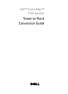
Industrial Automation and Control, 1100 Virginia Drive, Fort Washington, PA 19034Printed in U.S.A. ■ Copyright 1997 Honeywell Inc.
UDC2000 Mini-ProUniversal Digital Controller
51-52-03-082/97
Page 1 of 12
Specification
Overview
The UDC2000 Mini-Pro is a low costmember of Honeywell’s Leaderlinefamily of microprocessor-based,digital controllers. It monitors andcontrols temperatures and othervariables in applications such asenvironmental chambers, plasticprocessing machines, furnaces andovens and packaging machinery.
The Mini-Pro is a low cost alternativeto more expensive controllerswithout compromising quality orperformance. It can be used tocontrol variables such astemperature, pressure, flow, level,and rotation. A limit control model isalso available.
The Mini-Pro has a high degree offunctionality. A dedicatedconfiguration display provides multi-
ALM 1 F
SET UPDISPLAYMAN-AUTO
RESET
AUTOTUNE
RUNHOLD
2000SP
PV2 C
L
RL
22063
FUNCTION
OUT 1 2
Figure 1 — UDC2000 Mini-Pro Controller
language prompts providingunmatched operating simplicity.Programmed sequences of displaysassure quick and accurate entry ofall configurable parameters. Simplekeystrokes let you change theoperating parameters to meet yourprocess control needs.
Features
Low-Cost — This Mini-Pro meetsHoneywell’s high performancestandards at a surprisinglyaffordable price.
Easy to Configure — A brightdedicated configuration displayprovides straightforward multi-language prompts that allow easyset-up with minimum time and effort.
Universal Inputs — Accepts 10thermocouple types, RTDs,Radiamatics RH, mA, mV or voltageinputs through simpleconfiguration.
Thermocouple Failsafe -Configurable upscale or downscaleburnout or failsafe output level.
Features, continued
Accutune II — This standard featureprovides a new, truly plug and playtuning algorithm, which will, at thetouch of a button, accuratelyidentify and tune any processincluding deadtime and integratingprocesses . This speeds-up andsimplifies startup plus allows re-tuning at any setpoint.
Fuzzy Logic- This new feature usesfuzzy logic to suppress processvariable overshoot which can resultfrom setpoint changes or externallyinduced process disturbance.
It operates independently fromAccutune Tuning. It does notchange the PID constants, buttemporarily modifies the internalcontroller response to suppressovershoot. This allows moreaggressive tuning to co-exist withsmooth process variable response.
It can be enabled or disableddepending on the application or thecontrol criteria.
Features, continued
UL Recognized Component — Thisis a standard feature for all modelsfor regulatory use only.
CE Mark- Conformity with73/23/EEC, Low Voltage Directiveand 89/336/EEC, the EMCDirective
Dual Setpoints — Simple push-button selection allows quickswitchover from primary to alternatesetpoint with minimal operatorconfusion.
Limit Control — This model provides alatching relay which is activatedwhenever the PV goes above (HighLimit) or below (Low Limit) a presetsetpoint value. An alarm messagewill be displayed when the output isactivated. Reset is through a key onthe front of the controller or anoptional external switch. Normaldisplay can be configured toindicate process variable orsetpoint. Only T/C or RTD inputs areavailable on Limit models. FMapproval is available.

51-52-03-08Page 2
Features, continued
Moisture Resistant Front Panel -Capable of meeting NEMA 3 andIEC IP65 (i.e. hose down)requirements.
Diagnostic/Failsafe Outputs -Continuous diagnostic routinesdetect failure modes, trigger afailsafe output value and identify thefailure to minimize troubleshootingtime.
Highly Secure — Non-volatileEEPROM memory assures dataintegrity during loss of power.Keyboard security preventsaccidental or unauthorized changesto the display.
High Noise Immunity — The Mini-Prois designed to provide reliable,error- free performance in industrialenvironments that often affecthighly noise-sensitive digitalequipment.
Quality/Support — The Mini-Proconforms to Honeywell’s highquality standards in design,materials and workmanship. It iscovered by a two year warranty andbacked up by a toll-free phonenumber for technical assistance.
Optional Features
Dual Display — Provides the standardupper display dedicated to processvariable, plus a lower display whichcan display output, setpoints ordeviation as desired via the“DISPLAY” key.
Second Input — 4-20 mA or 1 to 5Volt input available for remotesetpoint signal.
*Auxiliary Output — This auxiliaryProcess Variable output can bescaled from 1 to 5 Volt or 0 to 5 Voltfor 0 to 100% for any range desired.
OR*Digital Input — Allows remoteswitching via an external dry contactor isolated solid-state input to selectfrom a menu of discrete modechanges as described on page 6.* These options are mutually exclusive.
Optional Features, cont.
Auto/Manual Modes — Providesautomatic or manual control withbumpless, balanceless switchingbetween modes. This includes theDual Display option as describedabove.
Alarm Selection — None, one, or tworelays to activate externalequipment when preset high/lowsetpoints are reached. There is anindicator for each alarm on theoperator interface. For Duplex or 3Position Step operation, only onealarm is available.
Timer — Provides a configurable timeperiod of 0 to 99 hours, 59 minutes.Alarm 1 is dedicated to be active atthe end of the time-out period.Timer “start” is selectable as eitherthe RUN/HOLD key or Alarm 2. Theoptional Digital Input can also beconfigured to start the Timer inaddition to either the keyboard orAlarm 2. The Timer display isselectable as either time remainingor elapsed time.
Ramp Soak Programming — Lets youprogram and run 6 ramp and 6 soaksegments for SetpointProgramming. Run or Hold ofprogram is keyboard or remoteswitch selectable.
FM and CSA Approval — Are optionalfeatures.
Solid State External Control RelayOutputs — Optional outputs rated at2 Amps at 120/240V or 10 Amps at120/240V. Minimum load 0.1 Amp.
Physical Description
The controller is housed in a 4.2inch deep, black metal case with anelastomer bezel that can bemounted in a 1/4 DIN cutout. Themodular construction of the plug-inchassis allows quick access tominimize down time. All power,input, and output wiring areconnected to screw terminals onthe rear terminal panel. Standardbezel color is gray. Blue and tancolors are optional.
Inputs
Each analog input is sampled 3times a second. The sampled signalis amplified and then converted to adigital signal which is passed to theprocessor. The PV input can beone of various Thermocouple, RTD,Radiamatic or Linear actuations(Table 1). Cold Junction compen-sation is provided. You can selectupscale or downscale sensor breakprotection. Any range can be fieldselected via internal switchpositions and keyboard selections.A second input provides a remotesetpoint function and accepts a 4 to20 mA or a 1 to 5 Vdc linear signalthat can be characterized.A configurable digital filter of 0 to120 seconds provides signalsmoothing for each input.
Outputs
The following output types areavailable per the model selectionguide:
• Current Output• Electromechanical Relay• Solid State Relay• Open Collector Output
Output Algorithms
The UDC2000 Mini-Pro is availablewith the following output algorithms:
Time Proportional — provides On-Offor Time Proportional (relay) output.Electromechanical, solid-state oropen collector outputs arestandard; 2 amp or 10 ampexternally mounted solid-state relayoutputs are optional.
Current Proportional — suppliesproportional direct current outputfor final control elements thatrequire a 4-20 mA signal.
Time Proportional Duplex(Heat/Cool) — depending on whichcontrol algorithm you select, thisduplex output type can provide on-off duplex, time proportional duplexor 3 Position Step control. The timeproportional duplex output providesindependent PID tuning constantsand two time proportional outputs:one for heat zone above the 50%output, and one for cool zonebelow 50% output.

51-52-03-08Page 3
Control Algorithm
Depending on the output algorithmyou select, the controller can beconfigured for the following controlalgorithms:
On-Off — Whenever the controlledvariable deviates a predeterminedamount from the setpoint, thecontroller moves the final controlelement to either of two extremepositions. Hysteresis: 0 to 100%
PID-A — The controller gives fullresponse to Setpoint and ProcessVariable (PV) changes involvingGain (Proportional), Reset (Integral),and Rate (Derivative) effects. Thereis a fixed relationship between thevalue of the controlled variable andthe position of the final controlelement. The adjustable Gain, Rate,and Reset Time tuning constants letyou tailor the controller’s responseto your process requirements.
PD with Manual Reset — The action issimilar to the PID-A algorithm exceptthe reset (Integral) value is enteredas Manual Reset tuning constantinstead of Reset Time. The manualreset value eliminates offset byshifting the PD calculated outputupscale or downscale to return thecontroller variable to the setpoint.
Three Position Step Control — This isan extension of the On/Off Duplexcontrol and includes internalfeedback of the state of the relays.The effect of this control action isthat the On and Off times of theoutput relay change in proportion tothe error signal and the Gain andReset time setting. The Deadbandis adjustable in the same manner asthe duplex output algorithm.
Configuration
You decide how the controller is tointeract with the process byselecting, through simplekeystrokes, the functions you want.Multi-language prompts guide theoperator through the configurationprocess assuring quick andaccurate entry of all configurableparameters. Multi-language promptsincluding French, German, Italian,and Spanish are also available viaconfiguration.
Control Modes
The controller can operate in thefollowing modes:
Local Automatic Mode — Thecontroller can operate from one ortwo local setpoints that can beselected and changed via thekeyboard or optional externalContact Input.
Remote Automatic Mode -The controller operates from thesetpoint value applied to thesecond input. This setpoint canhave ratio and bias applied.Selection between local and remotesetpoint is via the keyboard oroptional Digital Input for remotemode switching.
Manual/Automatic Switching(Optional) — The controller can beordered with bumpless, balancelesstransfer between modes using theRESET key. In the manual mode,the operator directly controls thecontroller output level. In theautomatic mode, the controller willoperate from a local setpoint, or aremote setpoint provided at thesecond input.
Alarms
Alarm output terminals are located atthe rear terminal panel. One or twoalarm relays are available to activateexternal equipment when presetalarm setpoints are reached. Eachof the two alarms can be set tomonitor two independent setpoints.Each alarm setpoint can be eitherhigh or low alarm. The alarm typecan be selected to be either theProcess Variable, Deviation, orSetpoint Programming Events.Alarm 1 is dedicated to be activatedby the Optional Timer, if enabled.
Diagnostics
The controllers have built -indiagnostic tests to ensure reliableoperation. Every time power isapplied, the microprocessor initiatestests that check the integrity of theinformation held in various memorylocations, and light all the displaysegments for a status check. Thesetests also can be operator initiatedthrough the operator interface.Continuous checks are made tocheck that the inputs are beingsampled, the stored constants aresecure, and the measured inputsfall within the established rangelimits. Test failures are identified byvarious error indications so thesource of the trouble can be easilyidentified.
Calibration
The UDC2000 is factory calibratedfor all ranges listed in Table 1. Whendesired, you can perform a fieldcalibration by accessing therequired calibration group via theSET UP key. To calibrate, you needonly to enter the calibration mode,apply the reference signal andpress the CAL key. The calibrationis automatically established by themicroprocessor, eliminating theneed for any mechanicaladjustment.

51-52-03-08Page 4
Operator Interface (Figure 2)
Status Indicators — They provide thestatus of the alarm and controlrelays. There is also indication toshow the temperature units andwhether Remote setpoint or Localsetpoint 2 is active.
Displays — A 4 digit, 9 segmentupper display is dedicated to theprocess variable or setpoint duringnormal operation, with alternateinformation displayed duringconfiguration.
A 6 digit, 14 segment lower displaycan be configured to indicate PV orSP for the normal display. It alsoprovides guidance, throughprompts, for the operator duringconfiguration.
Dual Displays — When Dual Displayoption is specified the upperdisplay is dedicated to the ProcessVariable. The lower display showsvarious key selected parameterssuch as Setpoint 1, Setpoint 2,Deviation, and Output.
ALM
OUT
PVF
FUNCTION
AUTOTUNE
MAN-AUTORESET
SET UP
RUNHOLD
ALM — Alarm conditions exist
OUT — Control Relay 1 or 2 on
Keys — See Figure 3
F — °Fahrenheit being used
C — °Centigrade being usedR — Remote or Local SP2 setpoint active
L — Local setpoint active
C
RL
1212
SP 2000
2000
22066
L
DISPLAY
OptionalDual Display
MA M or A
OptionalManual/AutoDisplay
Figure 2 — Operator Interface
Keyboard Lockout — For additionalsecurity against inadvertentchanges or tampering, the followingkeys can be disabled byconfiguration:
• Man-Auto/Reset
• Auto Tune
• Run/Hold
• Setpoint Select (Function Key during operation)
In Set Up mode, used to restore original value or selection. Also resets the latching Limit Controller relay. (For Manual/Auto model: selects Manual or Auto mode).
FUNCTIONSelects functions within each configuration group.Selects 2nd Setpoint or Remote Setpoint.
DISPLAYReturns Controller to normal display from Set Up mode.Toggles various operating parameters for display.
MAN-AUTORESET
SET UP Scrolls through the configuration groups.
AUTOTUNE
RUNHOLD
Enables Run/Hold of the SP Ramp or Programplus Timer start.
Decreases setpoint or output value. Decreases the configuration values or changes functions in Set Up groups.
Increases setpoint or output value. Increases the configuration values or changes functions in Set Up groups.
Initiates Autotune.
Five keys enable complete configuration and operation
22350
Figure 3 — Key Functions

51-52-03-08Page 5
Specifications
Design
CE Conformity (Europe) This product is in conformity with the protection requirements of the followingEuropean Council Directives: 73/23/EEC, the Low Voltage Directive, and89/336/EEC, the EMC Directive. Conformity of this product with any other “CEMark” Directive(s) shall not be assumed.
Product Classification: Class I: Permanently Connected, Panel Mounted Industrial Control Equipmentwith protective earthing (grounding). (EN 61010-1)
Enclosure Rating: Panel Mounted Equipment, IP 00, this controller must be panel mounted.Terminals must be enclosed within the panel. Front panel IP 65 (IEC 529).
Installation Category(Overvoltage Category):
Category II: Energy-consuming equipment supplied from the fixed installation.Local level appliances, and Industrial Control Equipment. (EN 61010-1)
Pollution Degree: Pollution Degree 2: Normally non-conductive pollution with occasionalconductivity caused by condensation. (Ref. IEC 664-1)
EMC Classification: Group 1, Class A, ISM Equipment (EN 55011, emissions), Industrial Equipment(EN 50082-2, immunity)
Method of EMC Assessment: Technical File (TF)
Declaration of Conformity: 513093000-000.
Accuracy ±0.3% of span typical (± 1 digit for display)14 bit resolution typical
Temperature Stability ±0.8% for 50˚F (28˚C) change
Input Signal Failure Protection Thermocouple Inputs: Upscale or downscale burnout
Burnout Current: 0.2 microamps
Failsafe Output Level: Configurable 0-100%
Input Impedance 4-20 Milliampere Input: 250 Ohms
All Voltage Inputs: 200K Ohms
Thermocouples: 10 Megohms
Resistance Temperature Detector: 10K Ohms
Stray Rejection Common Mode:
AC (50 or 60 Hz): 120dB (with maximum source impedance of 100 Ohms) or ± 1LSB (least significant bit) whichever is greater.
Normal ModeAC (50 or 60 Hz): 60 dB (with 100% span peak-to-peak maximum)
Continued next page

51-52-03-08Page 6
Specifications, continued
Design (continued)
Controller Output Types Current OutputRange can be set between 4 to 20 mA, and as direct or reverse action.Minimum output level is 3.2 mA dc.
Resolution: 11 bits for 4 to 20 mAAccuracy: 0.5% full scaleTemperature Stability: 0.03% / ˚CLoad Resistance: 0 to 750 ohms (ungrounded)
Electromechanical RelaySPST contacts. Normally Open or Normally Closed contacts selectable byjumper.
Internally socketed (Control Output #1)Resistive Load: 5 amps @ 120 Vac, 30 Vdc, 2.5 amps @ or 240 VacInductive Load: 50 VA @ 120 Vac, or 240 VacMotor: 1/6 H.P.
Solid State RelaySPST solid state contact consisting of a triac N.O. output.
Internally socketedResistive Load: 1.0 amp @ 25 ˚C and 120 or 240 Vac
0.5 amp @ 55 ˚C and 120 or 240 VacInductive Load: 50 VA @ 120 Vac or 240 Vac
Open Collector OutputsMaximum Sink Current: 20 mAOverload Protection: 100 mA
Internally powered @ 34 VdcOpto-isolated from all other circuits but not from each other.Socketed jumper assembly replaces relay.
Solid State Relays (2 amps or 10 amps)Externally mounted triac N.O. output for use with open collector output.
2 amp Relay Resistive Load: 3 amps @ 25 ˚C and 120 or 240 Vac
2 amps @ 55 ˚C and 120 or 240 Vac10 amp relay Resistive Load: 15 amps @ 25 ˚C and 120 or 240 Vac
10 amps @ 55 ˚C and 120 or 240 Vac
Inductive Load: 50 VA @ 120 Vac or 240 Vac
Motor Rating: 1 HP @ 25 ˚C0.75 HP @ 55 ˚C
Alarm Output (Optional) One SPST electromechanical relay. Normally Open or Normally Closed contact isselectable by jumper.
A second alarm is available except with Time Proportional Relay Duplex, ThreePosition Step and Limit Control Models. Alarm 2 can start the optional timer.
Up to four setpoints are independently set as high or low alarm, two for each relay.Setpoint can be either Process Variable, Deviation, or Setpoint ProgrammingEvents. Timer Output: Alarm 1.
Alarm Relay ContactsResistive Load: 5 amps @ 120 Vac or 30 Vdc, 2.5 amps @ 240 Vac
Hysteresis: Adjustable: 0 to 100% of (PV) Input Span
Continued next page

51-52-03-08Page 7
Specifications, continued
Design (continued)
Controller Output Algorithms On-Off or Time ProportionalOne SPST relay or open collector output. Control action can be set for direct orreverse. On/Off Control Hysteresis: Adjustable 0 to 100% of (PV) Input Span.
On-Off Duplex, Three Position Step Control, or Time Proportional DuplexTwo SPST relays. Control action can be set for direct or reverse.
Current Proportional4 to 20 mA dc maximum into a load of 0 to 750 ohms. Output range can be setdirect or reverse action.
Limit ControlOne SPST electromechanical latching relay. Control relay action Normally Open.(Normally Closed contact selectable by jumper.)
Auxiliary PV Output (Optional)* The Process Variable Output can be scaled for any PV range from 0 to 5 Volts for0 to 100%, with an overrange capability of 5.25 Volts at 105% output. The scaleselection is configured through the operator interface.
Voltage: 1 to 5 Volts (can be field calibrated to 0 to 5 Volts)Minimum Impedance: 2500 OhmsResolution: 12 bits over 0 to 5.25 VoltsAccuracy: 0.4% Full Scale at 2500 Ohm loadTemperature Stability: 0.06% / ˚C
Digital Input (Optional)* +20 Vdc source for external dry contact or isolated solid state contact.Contact closure selects one of the following actions:
• Local setpoint 1 from Remote setpoint• Local setpoint 2 from Local setpoint 1• Reset of Limit Controller• To Hold from Run (SP Ramp or SP Programming)• Disabled Keyboard• To Run — contact closure starts Setpoint Program or Single SP Ramp.
Re-opening contact returns to Hold.
The following Digital Input selections are available on models that contain thepertinent options:
• Timer Start — momentary contact closure will start timer.• To Manual — contact closure switches to Manual mode. Re-opening contact
switches back to Automatic mode.• To Manual /Failsafe Output — contact closures switches to Manual mode plus
configured Failsafe Output value. Re-opening contact switches back toAutomatic.
Setpoint Ramp/Soak Programming(Optional)
Lets you configure 6 ramp and 6 soak segments to be stored for use as oneprogram or several small programs. You designate the beginning and endsegments to determine where the program is to start and stop allowing severalsmall programs. Each ramp segment can be configured to be run in Hours andMinutes or degrees per minute. Soak segments can have a guaranteed soakdeviation which guarantees the time for each soak and will not start until the PV isreached.
Sampling Rate Inputs sampled 3 times per second
Input Filter Software: Single pole lowpass section with selectable time constants, off to 120seconds for each input.
* Auxiliary Output and Digital Input are mutually exclusive.
Continued next page

51-52-03-08Page 8
Specifications, continued
Design (continued)
Digital Displays Vacuum fluorescent, 9 segment and 14 segment, alphanumeric.A four digit display dedicated to the process variable, setpoints, deviation oroutput depending upon the model number.Alternate information displayed during configuration mode.A six character display primarily provides guidance during controllerconfiguration.
Status Indicators Alarm Relay Status (ALM 1 or 2)Temperature Units (F or C)Remote Setpoint or Local Setpoint 2 Active (R)Control Relay Status (OUT 1 or 2)
Dimensions See Figure 5.
Mounting Panel-mounted, 4.2 inch depth
Wiring Connections Screw terminals on the rear of the case (6-32)
Power Consumption 6 VA
Weight 1 kg (2.2 lbs.)
Environmental and Operating Conditions
Parameter Reference Rated Operative Limits Transportation and storage
AmbientTemperature
22 ± 3˚C72 ± 5˚F
15 to 55˚C58 to 131˚F
0 to 55˚C32 to 131˚F
-40 to 66˚C-40 to 151˚F
Relative Humidity 10 to 55* 10 to 90* 5 to 90* 5 to 95*Vibration Frequency (Hz) Acceleration (g)
00
0 to 700.1
0 to 2000.5
0 to 2000.5
Mechanical Shock Acceleration (g) Duration (ms))
00
130
530
2030
Voltage (Vac) 120 ± 1240 ± 2
102 to 132204 to 264
102 to 132204 to 264
— — —
Frequency (Hz) 50 ± 0.260 ± 0.2
49 to 5159 to 61
48 to 5258 to 62
— — —
* The maximum rating only applies up to 40˚C (104˚F). For higher temperatures, the RH specification is derated to maintain constant moisture content.

51-52-03-08Page 9
General Reference Data
Data
Isolation (Functional) No isolation between analog input and analog output circuits.
AC Power : is electrically isolated from all other inputs and outputs to withstand aHIPOT potential of 1900Vdc for 2 seconds per Annex K of EN61010-1.
Radio Frequency Interference (RFI)
Immunity: No effect on performance from a 5 W walkie-talkie operated at 27, 151 or450 MHz, one meter from the controller.
Surge Withstand Capability (SWC) ANSI/IEEE C37.90.1, Surge Withstand Capability (SWC) (Formerly IEEE 472)Mains power input and relay contact outputs: 2.5 kV, Common Mode andDifferential Mode. All other circuits: 1.0 kV, Common Mode and Differential Mode.
Table 1 — Field Selectable Input Actuations
Range
PV Input ˚F ˚C
Thermocouples
BEE (low)JJ (low)KK (low)Nicrosil NisilNiNiMoly (N)RSTT (low)W5W26
150 to 3300-100 to 1832-100 to 1100
0 to 16000 to 9000 to 2400
-20 to 10000 to 2372
32 to 25000 to 31000 to 3100
-300 to 700-80 to 500
0 to 4200
66 to 1815-73 to 1000-73 to 593-18 to 871-18 to 482-18 to 1316-29 to 538
-17.8 to 13000 to 1371
-18 to 1704-18 to 1704
-184 to 371-63 to 260-18 to 2316
RTD (IEC)
100 Ohm Pt.100 Ohm Pt. (low)
-300 to 9000 to 300
-184 to 482-18 to 149
Radiamatic RH 1400 to 3400 760 to 1871
Linear
Milliamps dcMillivolts dc
Volts dc
4 to 200 to 100 to 1000 to 10 to 51 to 50 to 10
Linear Ranges not availableon Limit Control Models

51-52-03-08Page 10
Model Number Interpretation
Controller Output #1C = Current 4 – 20mA E = Relay, Electromechanical – 5AMP A = Relay, Solid State AC – 1AMPT = Open Collector Output – 20mA
Additional RelaysO = None1 = Second relay for Duplex Output or 3 Position Step plus One Alarm Relay2 = Two Alarm Relays (only 1 Alarm on
Limit Models)
External InterfaceO – – = None2 – – = Auxiliary Output or Digital Input
Optional Input– O – = None– 1 – = 4 -20 mA or 1- 5V
Software Options– – O = None– – A = Autotune– – B = Autotune and Setpoint Programming
Table 1 Table 2 Table 3 Table 4Key Number
Custom Configuration– – – – OO = None– – – – BO = Blue Elastomer Bezel – – – – TO = Tan Elastomer Bezel
Limit Control OutputH = High Limit (T/C and RTD inputs only)L = Low Limit (T/C and RTD inputs only)Digital IndicatorI = Digital Indicator Only
Custom ID Tag– – – O – – = None– – – T – – = Tag (1 line 30
characters Max.)
Solid State Relay Kits(Externally Mounted)– – O – – – = None– – 1 – – – = 10 Amps– – 2 – – – = 2 Amps
Approval Bodies
– O – – – – = None– F – – – – = FM approved– C – – – – = CSA certification– D – – – – = FM and CSA– T – – – – = TUV and VDE– A – – – – = FM, CSA, TUV and VDE
Instrument Power Configuration *1 – – – – – = 120Vac (50/60 Hz)2 – – – – – = 240Vac (50/60 Hz)
* Power jumper is set at factory, but can be changed by user. 20748
D C 2 0 0 0
3 = Timer (or Alarm 1) plus Second Relay for Duplex Output or 3 Pos Step
4 = Timer (or Alarm 1) plus Second Alarm Relay
– – D = Dual Display and Autotune– – E = Dual Display, Autotune and SP Prog– – F = Manual/Auto Modes (includes Dual Display
and Autotune)– – G = Manual/Auto Modes and SP Prog (includes
Dual Display and Autotune)
Figure 4 — Model Selection Guide

51-52-03-08Page 11
Dimensions
963.780
963.780
Panel Cutout
90 =0.0+0.8
3.5906 +0.03
L
24.945
Max PanelThickness
10.394
Max (2)
4.19105.4
FUNCTION DISPLAY MAN-AUTORESET
SET UP
AUTOTUNE
RUNHOLD
1 2 F C
MA 1 2
ALM
OUT
.1032.62 with optional
rear cover
90.73.57
21.0.826
RL
Dimensions:Millimeters
Inches
20751
PV
3.622 +0.031-0.0
92 -0.0+0.008
3.622 +0.031-0.0
92 -0.0+0.008
Figure 5 — UDC2000 Mini-Pro Controller dimensions — not to scale

51-52-03-08Page 12
Ordering Information
For the complete ordering information, request Model Selection Guide: 51-51-16-33 for UDC2000 Controller.
Honeywell offers a full line of Sensors, Transmitters, and Final ControlDevices for use with the UDC2000 Controller. These devices include: Thermocouples, RTDs Digital Panel Indicator, Pressure Transmitters, Flow Transmitters, Liquid Level Transmitters. Valve, Actuators, and Electric Motors.
Specifications are subject to change without notice.
Distributor :
For more information, contact your nearest Honeywell Response Center listed below.
Industrial Automation and ControlHoneywell Inc.In the U.S.A.: Honeywell Industrial Automation and Control, 1100 Virginia Drive., Ft. Washington, PA 19114, (800) 343-0228In Europe: Honeywell S.A., 80084 Amiens Cedex 2, (33) 22.54.56.56
Honeywell Control System Ltd., Honeywell House, Bracknell, UK-RG 12 1 EB, (44) 1344 826000In Japan: Yamatake-Honeywell Co. Ltd., Nagai Int’l Bldg., 2 — 12 — 19 Shibuya-Ku, Tokyo 150 Japan, 81-3-3486-2051In Asia: Honeywell Asia Pacific Inc., Room 3213-3225, Sun Hung kai Centre, No. 30 Harbor Road, Wanchai, Hong Kong, (852) 829-8298In the Mediterranean: Africa and Middle East Region, Honeywell SpA, Via Vittor Pisani 13, 20124 Milano, Italy (39-2) 67731Honeywell Pacific Division: Honeywell Pty Ltd., 5 Thomas Holt Drive, North Ryde Sydney, NSW Australia 2113, (61-2) 353 7000In Canada: The Honeywell centre, 155 Gordon Baker Road., Ontario M2H 3N7, 1-800-461-0013In Latin America: Honeywell Inc.,14505 Commerce Way, Suite 500, Miami Lakes, Florida 33016-1556, (305) 364-2300
Table of Contents for Honeywell UDC2000:
-
�
-
�
-
-
�
-
�
-
-
�
-
-
�
-
Questions, Opinions and Exploitation Impressions:
You can ask a question, express your opinion or share our experience of Honeywell UDC2000 device using right now.
1 docs – User Manuals, Help Guides and Specs – for the Honeywell UDC2000 product are present in our data base.
Tips for Finding Manuals:
This web-page provides a list of 1 accessible operating manuals and information books describing Honeywell UDC2000.
All manuals and instructions for Honeywell UDC2000 are introduced in an easy-to-use PDF format and may be gratuitously downloaded or looked through directly from the site.
The page offers the following types of manuals: Controller.
Helpful hints: While selecting a necessary guide for Honeywell UDC2000 one should pay special attention to the type of the document.
We try to supply you with the fullest possible set of papers we or our users are able to find. These may be overviews and specifications of the device, mounting and installing instructions, the unit operating rules and maintenance regulations and much more.
Haven’t found a required manual for your Honeywell UDC2000?
Check in a while. We update our guides collection and add new documents on a daily basis for you to be always able to find the very paper you need on our web-site. In case you own a directory or an instruction for Honeywell UDC2000, which is absent on our site, and you’d like to share it with the public, please send it to us as a scanned copy or a PDF file, and we’ll definitely place it on our page while providing your name as a supplier of the doc. Lots of our users will be grateful for your assistance!
User Manuals, Guides and Specifications for your Honeywell UDC2000 Controller. Database contains 1 Honeywell UDC2000 Manuals (available for free online viewing or downloading in PDF): Instruction manual .
