hp-detect-load-my-device-portlet
![]()
Действия
- ${title}
Загрузка…
hp-product-information-portlet
![]()
Действия
- ${title}
Загрузка…
У вас уже есть учетная запись HP? Выберите продукты, которыми вы владеете.
Войти
/
Зарегистрироваться
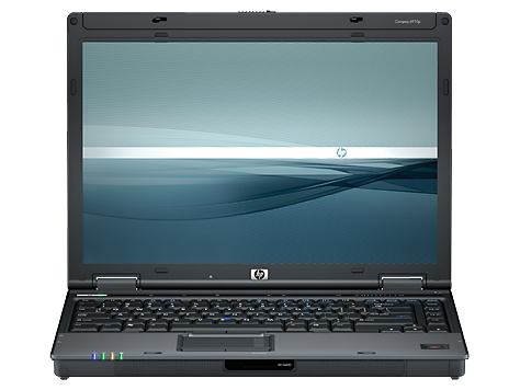
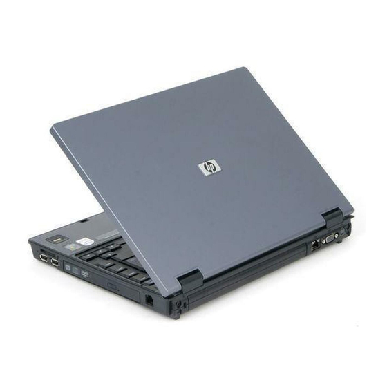
Ноутбук HP Compaq 6910p
Выбрать другие серии продуктов
![]()
Добавить этот продукт в личную панель


Этот продукт был добавлен в личную панель
hp-product-builder-portlet
![]()
Действия
- ${title}
Загрузка…
hp-pdp-secondary-navigation-portlet
![]()
Действия
- ${title}
Загрузка…
hp-promotion-tiles-portlet
![]()
Действия
- ${title}
Загрузка…
hp-country-locator-portlet
![]()
Действия
- ${title}
Загрузка…
Страна/регион:

Казахстан
hp-product-warranty-check
![]()
Действия
- ${title}
Загрузка…
- Manuals
- Brands
- HP Manuals
- Laptop
- Compaq 6910p
Manuals and User Guides for HP Compaq 6910p. We have 18 HP Compaq 6910p manuals available for free PDF download: Maintenance And Service Manual, User Manual, Quickspecs, Specifications, Setup And Configuration Manual, Network Manual, Setup Manual, White Paper, Software Update, Brochure, Installation Manual
-
Драйверы
74
-
Инструкции по эксплуатации
13
Языки:

HP Compaq 6910p инструкция по эксплуатации
(17 страниц)
- Языки:Английский
-
Тип:
PDF -
Размер:
304.93 KB
Просмотр

HP Compaq 6910p инструкция по эксплуатации
(19 страниц)
- Языки:Японский
-
Тип:
PDF -
Размер:
625.88 KB
Просмотр

HP Compaq 6910p инструкция по эксплуатации
(17 страниц)
- Языки:Турецкий
-
Тип:
PDF -
Размер:
358.24 KB
Просмотр

HP Compaq 6910p инструкция по эксплуатации
(17 страниц)
- Языки:Шведский
-
Тип:
PDF -
Размер:
307.87 KB
Просмотр

HP Compaq 6910p инструкция по эксплуатации
(17 страниц)
- Языки:Французский
-
Тип:
PDF -
Размер:
309.97 KB
Просмотр

HP Compaq 6910p инструкция по эксплуатации
(17 страниц)
- Языки:Португальский
-
Тип:
PDF -
Размер:
311.89 KB
Просмотр

HP Compaq 6910p инструкция по эксплуатации
(17 страниц)
- Языки:Китайский
-
Тип:
PDF -
Размер:
383.71 KB
Просмотр

HP Compaq 6910p инструкция по эксплуатации
(17 страниц)
- Языки:Словенский
-
Тип:
PDF -
Размер:
331.62 KB
Просмотр

HP Compaq 6910p инструкция по эксплуатации
(17 страниц)
- Языки:Немецкий
-
Тип:
PDF -
Размер:
311.46 KB
Просмотр

HP Compaq 6910p инструкция по эксплуатации
(17 страниц)
- Языки:Корейский
-
Тип:
PDF -
Размер:
359.14 KB
Просмотр

HP Compaq 6910p инструкция по эксплуатации
(17 страниц)
- Языки:Хорватский
-
Тип:
PDF -
Размер:
331.54 KB
Просмотр

HP Compaq 6910p инструкция по эксплуатации
(17 страниц)
- Языки:Датский
-
Тип:
PDF -
Размер:
309.6 KB
Просмотр

HP Compaq 6910p инструкция по эксплуатации
(15 страниц)
- Языки:Турецкий
-
Тип:
PDF -
Размер:
308.24 KB
Просмотр
На NoDevice можно скачать инструкцию по эксплуатации для HP Compaq 6910p. Руководство пользователя необходимо для ознакомления с правилами установки и эксплуатации HP Compaq 6910p. Инструкции по использованию помогут правильно настроить HP Compaq 6910p, исправить ошибки и выявить неполадки.
- Manuals
- Brands
- HP Manuals
- Laptop
- Compaq 6910p
- Maintenance and service manual
-
Contents
-
Table of Contents
-
Bookmarks
Quick Links
HP Compaq 6910p Notebook PC
Maintenance and Service Guide
Related Manuals for HP Compaq 6910p
Summary of Contents for HP Compaq 6910p
-
Page 1
HP Compaq 6910p Notebook PC Maintenance and Service Guide… -
Page 2
The information contained herein is subject to change without notice. The only warranties for HP products and services are set forth in the express warranty statements accompanying such products and services. Nothing herein should be construed as constituting an additional warranty. -
Page 3
Safety warning notice WARNING! To reduce the possibility of heat-related injuries or of overheating the computer, do not place the computer directly on your lap or obstruct the computer air vents. Use the computer only on a hard, flat surface. Do not allow another hard surface, such as an adjoining optional printer, or a soft surface, such as pillows or rugs or clothing, to block airflow. -
Page 4
Safety warning notice… -
Page 5: Table Of Contents
Table of contents 1 Product description 2 External component identification Top components ……………………7 Buttons, microphone, volume controls, and fingerprint reader ……… 7 Keys ……………………9 Pointing devices …………………. 10 Front components ……………………11 Left-side components ………………….. 12 Rear components ……………………13 Right-side components ………………….
-
Page 6
SIM ……………………43 Display inverter ………………….. 44 Hard drive ………………….46 Computer feet ………………….48 Bluetooth module ………………..48 Expansion memory module ………………50 WLAN module ………………….52 MultiBay II device ………………..56 Keyboard ………………….. 57 RTC battery ………………….60 Primary memory module ……………… -
Page 7
Phillips PM2.0×5.0 captive screw ………………110 Phillips PM2.5×13.0 captive screw ………………111 Phillips PM3.0×3.0 screw ………………… 112 Phillips PM2.0×3.0 screw ………………… 113 Phillips PM2.5×5.0 screw ………………… 115 Torx T8M2.5×11.0 captive screw ………………116 Torx T8M2.5×11.0 screw ………………… 117 Phillips PM2.0×6.0 screw ………………… 119 Phillips PM2.0×2.0 broad head screw ………………. -
Page 8
RJ-11 (modem) ……………………143 RJ-45 (network) ……………………143 S-Video-out …………………….. 144 Universal Serial Bus ………………….144 11 Power cord set requirements Requirements for all countries and regions …………….145 Requirements for specific countries and regions …………… 146 12 Recycling Battery ……………………..147 Display …………………….. -
Page 9: Product Description
Product description Category Description HP Compaq 6910p HP Compaq 6910p Notebook PC with Notebook PC with UMA video discrete video memory memory Processors Intel® Core™ Duo processors: √ √ ● T7700 2.4-GHz processor with 800-MHz Front Side Bus (FSB) and 4-MB L2 cache T7500 2.2-GHz processor with 800-MHz FSB…
-
Page 10
Category Description HP Compaq 6910p HP Compaq 6910p Notebook PC with Notebook PC with UMA video discrete video memory memory Memory Two SODIMM slots, both customer accessible/ √ √ ● upgradable (memory slot under the keyboard must be populated first) ●… -
Page 11
Category Description HP Compaq 6910p HP Compaq 6910p Notebook PC with Notebook PC with UMA video discrete video memory memory Audio ● Stereo speakers √ √ Integrated monoaural microphone ● Headphone and microphone jacks ● Modem ● 56K, v.92, data/fax modem (MDC1.5) √… -
Page 12
Category Description HP Compaq 6910p HP Compaq 6910p Notebook PC with Notebook PC with UMA video discrete video memory memory Ports 1394a port √ √ ● Docking connector ● Headphone connector ● Fast infrared port ● Microphone connector ● Primary battery connector ●… -
Page 13
Category Description HP Compaq 6910p HP Compaq 6910p Notebook PC with Notebook PC with UMA video discrete video memory memory Security ● Fingerprint reader √ √ HP 3D DriveGuard ● Security cable slot ● ● Smart card reader/bezel snap-in Trusted platform module (TPM) 1.2 on system ●… -
Page 14
Chapter 1 Product description… -
Page 15: External Component Identification
External component identification Top components Buttons, microphone, volume controls, and fingerprint reader Item Component Function Power button When the computer is off, press the button to turn on the ● computer. When the computer is on, press the button to shut down the ●…
-
Page 16
Item Component Function To learn more about power settings, follow these steps: In Windows Vista, select Start > Control Panel > ● System and Maintenance > Power Options. In Windows XP, select Start > Control Panel > ● Performance and Maintenance > Power Options. Info button (select models only) Opens Info Center, which enables you to open various software solutions. -
Page 17: Keys
Keys Item Component Function Function keys Execute frequently used system functions when pressed in combination with the key. fn key Executes frequently used system functions when pressed in combination with a function key or the key. Windows logo key Displays the Windows Start menu. Windows applications key Displays a shortcut menu for items beneath the pointer.
-
Page 18: Pointing Devices
Pointing devices Item Component Function Pointing stick (select models only) Moves the pointer and selects or activates items on the screen. Pointing stick buttons (select models only) Function like the left, middle, and right buttons on an external mouse. TouchPad* Moves the pointer and selects or activates items on the screen.
-
Page 19: Front Components
Drive light ● Blinking green: The hard drive or optical drive is being accessed. Amber (select models only): HP 3D DriveGuard has ● temporarily parked the hard drive. Infrared port Provides wireless communication between the computer and an optional IrDA-compliant device.
-
Page 20: Left-Side Components
Left-side components Item Component Function Vent Enables airflow to cool internal components. NOTE: The computer fan starts up automatically to cool internal components and prevent overheating. It is normal for the internal fan to cycle on and off during routine operation. USB ports (2) Connect USB 1.1- and 2.0-compliant devices to the computer using a standard USB cable, or connect an optional External…
-
Page 21: Rear Components
Rear components Item Component Function Security cable slot Attaches an optional security cable to the computer. NOTE: The security cable is designed to act as a deterrent, but it may not prevent the computer from being mishandled or stolen. Battery bay Holds a battery.
-
Page 22: Right-Side Components
Right-side components Item Component Function Smart card reader Supports optional smart cards and Java™ Cards. MultiBay II device Supports an optical disc. The type of optical drive varies by model. USB port Connects USB 1.1- and 2.0-compliant devices to the computer using a standard USB cable, or connects an optional External MultiBay II to the computer.
-
Page 23: Bottom Components
Bottom components Item Component Function Battery bay Holds the battery. Docking connector (select models only) Connects an optional docking device. Battery latches (2) Release the battery from the battery bay. Vents (5) Enable airflow to cool internal components. NOTE: The computer fan starts up automatically to cool internal components and prevent overheating.
-
Page 24
Chapter 2 External component identification… -
Page 25: Illustrated Parts Catalog
Illustrated parts catalog Serial number location When ordering parts or requesting information, provide the computer serial number and model number located on the bottom of the computer. Serial number location…
-
Page 26: Computer Major Components
Computer major components Chapter 3 Illustrated parts catalog…
-
Page 27
Item Description Spare part number Display assemblies (include wireless antenna transceivers and cables) 14.1-inch, WXGA+ 446436-001 14.1-inch, WXGA 446435-001 Switch cover 446401-001 Power button board (includes power button board cable) 446438-001 Keyboards (include pointing stick and pointing stick cable) Belgium 446448-A41 Brazil 446448-201… -
Page 28
Item Description Spare part number The United Kingdom 446448-031 The United States 446448-001 Cable Kit (see Cable Kit on page 26 for more Cable Kit spare part information): 446406-001 (5a) Pointing stick cable (5b) TouchPad cable (5c) Modem module cable (includes RJ-11 connector) (5d) Audio cable (5e) -
Page 29
Item Description Spare part number For use with heat sink spare part number 446447-001 (video memory is shared with main 446402-001 system memory) (17) Heat sinks For use with system boards spare part numbers 446403-001 and 446404-001 446446-001 For use with system board spare part number 446402-001 446447-001 (18) Processors (include thermal material) -
Page 30
Item Description Spare part number the Czech Republic, Denmark, Djibouti, Dominica, the Dominican Republic, East Timor, Ecuador, Egypt, El Salvador, Equitorial Guinea, Eritrea, Estonia, Ethiopia, Fiji, Finland, France, French Guiana, Gabon, Gambia Georgia, Germany, Ghana, Gibraltar, Greece, Grenada, Guadeloupe, Guam, Guatemala, Guinea, Guinea-Bissa, Guyana, Haiti, Honduras, Hong Kong, Hungary, Iceland, India, Ireland, Italy, the Ivory Coast, Jamaica, Jordan, Kenya, Kiribati, Kyrgyzstan, Laos, Latvia, Lesotho, Liberia, Liechtenstein, Lithuania, Luxembourg, Macedonia, Madagascar, Malawi, the Maldives,… -
Page 31
Item Description Spare part number Zealand, Nicaragua, Niger, Nigeria, Norway, Oman, Pakistan, Palau, Panama, Papua New Guinea, Paraguay, the People’s Republic of China, Peru, the Philippines, Poland, Portugal, the Republic of Moldova, Romania, Russia, Rwanda, Samoa, San Marino, Sao Tome & Principe, Saudi Arabia, Senegal, Serbia and Montenegro, the Seychelles, Sierra Leone, Singapore, Slovakia, Slovenia, the Solomon Islands, Somalia, South Africa, South Korea, Spain, Sri Lanka, St. -
Page 32
Item Description Spare part number the Czech Republic, Denmark, Djibouti, Dominica, the Dominican Republic, East Timor, Ecuador, Egypt, El Salvador, Equitorial Guinea, Eritrea, Estonia, Ethiopia, Fiji, Finland, France, French Guiana, Gabon, Gambia, Georgia, Germany, Ghana, Gibraltar, Greece, Grenada, Guadeloupe, Guatemala, Guinea, Guinea-Bissa, Guyana, Haiti, Honduras, Hong Kong, Hungary, Iceland, India, Indonesia, Ireland, Israel, Italy, the Ivory Coast, Jamaica, Jordan, Kazakhstan, Kenya, Kiribati, Kuwait, Kyrgyzstan, Laos, Latvia, Lebanon, Lesotho, Liberia, Liechtenstein, Lithuania, Luxembourg, Macedonia,… -
Page 33: Plastics Kit
Plastics Kit Item Description Spare part number Plastics Kit: 446439-001 PC Card slot bezel Hard drive cover (includes 2 captive screws, secured by C-clips) Memory module compartment cover (includes 1 captive screw, secured by a C-clip) WLAN module compartment cover (includes 1 captive screw, secured by a C-clip) Bluetooth module compartment cover (includes 1 captive screw, secured by a C-clip) Plastics Kit…
-
Page 34: Cable Kit
Cable Kit Item Description Spare part number Cable Kit: 446406-001 Pointing stick cable TouchPad cable Audio cable Modem module cable (includes RJ-11 connector) Bluetooth module cable Chapter 3 Illustrated parts catalog…
-
Page 35: Mass Storage Devices
Mass storage devices Item Description Spare part number Hard drives (include frame and connector) 160-GB, 5400-rpm 446411-001 120-GB, 5400-rpm 446412-001 100-GB, 7200-rpm 446412-001 80-GB, 7200-rpm 446415-001 80-GB, 5400-rpm 446414-001 MultiBay II devices (include bezel) DVD±RW and CD-RW Double-Layer Combo Drive 446409-001 DVD/CD-RW Combo Drive 446410-001…
-
Page 36: Miscellaneous Parts
366143-001 External MultiBay II power cable and stand 366144-001 HP Extended Life Battery 367456-001 HP Docking Station 374803-001 HP Docking Station Miscellaneous Plastics Kit 380089-001 Label Kit 446419-001 MultiBay II 8X DVD-ROM Drive 373314-001 MultiBay II 24X DVD/CD-RW Combo Drive…
-
Page 37: Sequential Part Number Listing
MultiBay II 8X DVD-ROM Drive 373315-001 MultiBay II 24X DVD/CD-RW Combo Drive 374803-001 HP Docking Station 380089-001 HP Docking Station Miscellaneous Plastics Kit 403811-001 Power cord for use in the United States 403811-011 Power cord for use in Australia 403811-021…
-
Page 38
802.11a/b/g Broadcom WLAN module for use in Japan 409250-004 802.11b/g Broadcom WLAN module for use in Thailand 418860-001 Verizon EVDO WWAN module 418873-001 90W non-PFC HP Smart Adapter 418875-001 90W PFC HP Smart Adapter 435098-001 Vodafone HSPDA WWAN module 436638-001… -
Page 39
Spare part Description number the Netherlands, Norway, Oman, the Philippines, Poland, Portugal, Qatar, Romania, Russia, Serbia and Montenegro, Singapore, Slovakia, Slovenia, South Africa, Spain, Sri Lanka, Sweden, Switzerland, Turkey, Ukraine, the United Kingdom, and Uzbekistan 441084-003 802.11a/b/g Intel WLAN module for use in ROW 441085-291 802.11a/b/g Intel WLAN module for use in Japan 441086-001… -
Page 40
Spare part Description number Guyana, Haiti, Honduras, Hong Kong, Hungary, Iceland, India, Ireland, Italy, the Ivory Coast, Jamaica, Jordan, Kenya, Kiribati, Kyrgyzstan, Laos, Latvia, Lesotho, Liberia, Liechtenstein, Lithuania, Luxembourg, Macedonia, Madagascar, Malawi, the Maldives, Mali, Malta, the Marshall Islands, Martinique, Mauritania, Mauritius, Mexico, Micronesia, Monaco, Mongolia, Montenegro, Morocco, Mozambique, Namibia, Nauru, Nepal, the Netherlands, New Zealand, Nicaragua, Niger, Nigeria, Norway, Oman, Pakistan, Palau, Panama, Papua New Guinea, Paraguay, the People’s Republic of China, Peru, the Philippines, Poland, Portugal, Puerto Rico,… -
Page 41
Spare part Description number 446433-001 Modem module (includes modem module cable) 446434-001 MultiBay II eject assembly 446435-001 14.1-inch, WXGA display assembly (includes wireless antenna transceivers and cables) 446436-001 14.1-inch, WXGA+ display assembly (includes wireless antenna transceivers and cables) 446437-001 PC Card assembly 446438-001 Power button board (includes power button board cable) 446439-001… -
Page 42
Spare part Description number 446448-231 Keyboard for use in Slovakia 446448-251 Keyboard for use in Russia 446448-281 Keyboard for use in Thailand 446448-291 Keyboard for use in Japan 446448-A41 Keyboard for use in Belgium 446448-AB1 Keyboard for use in Taiwan 446448-AD1 Keyboard for use in Korea 446448-B71… -
Page 43: Removal And Replacement Procedures
Removal and replacement procedures Preliminary replacement requirements Tools required You will need the following tools to complete the removal and replacement procedures: Flat-bladed screwdriver ● Magnetic screwdriver ● Phillips P0 and P1 screwdrivers ● Torx T8 screwdriver ● Service considerations The following sections include some of the considerations that you must keep in mind during disassembly and assembly procedures.
-
Page 44: Cables And Connectors
Cables and connectors CAUTION: When servicing the computer, be sure that cables are placed in their proper locations during the reassembly process. Improper cable placement can damage the computer. Cables must be handled with extreme care to avoid damage. Apply only the tension required to unseat or seat the cables during removal and insertion.
-
Page 45: Grounding Guidelines
Grounding guidelines Electrostatic discharge damage Electronic components are sensitive to electrostatic discharge (ESD). Circuitry design and structure determine the degree of sensitivity. Networks built into many integrated circuits provide some protection, but in many cases, ESD contains enough power to alter device parameters or melt silicon junctions. A discharge of static electricity from a finger or other conductor can destroy static-sensitive devices or microcircuitry.
-
Page 46: Packaging And Transporting Guidelines
Packaging and transporting guidelines Follow these grounding guidelines when packaging and transporting equipment: To avoid hand contact, transport products in static-safe tubes, bags, or boxes. ● Protect ESD-sensitive parts and assemblies with conductive or approved containers or packaging. ● Keep ESD-sensitive parts in their containers until the parts arrive at static-free workstations. ●…
-
Page 47: Equipment Guidelines
Equipment guidelines Grounding equipment must include either a wrist strap or a foot strap at a grounded workstation. When seated, wear a wrist strap connected to a grounded system. Wrist straps are flexible straps ● with a minimum of one megohm ±10% resistance in the ground cords. To provide proper ground, wear a strap snugly against the skin at all times.
-
Page 48: Unknown User Password
Unknown user password If the computer you are servicing has an unknown user password, follow these steps to clear the password: NOTE: These steps also clear CMOS. Shut down the computer. If you are unsure whether the computer is off or in Hibernation, turn the computer on, and then shut it down through the operating system.
-
Page 49: Component Replacement Procedures
Make special note of each screw size and location during removal and replacement. Serial number Report the computer serial number to HP when requesting information or ordering spare parts. The serial number is located on the bottom of the computer. Component replacement procedures…
-
Page 50: Battery
Battery Description Spare part number 6-cell, 5.1-Ah, Li-ion battery 446399-001 4-cell, 2.55-Ah, Li-ion battery 446398-001 Before disassembling the computer, follow these steps: Shut down the computer. If you are unsure whether the computer is off or in Hibernation, turn the computer on, and then shut it down through the operating system.
-
Page 51: Sim
NOTE: This section applies only to computer models with WWAN capability. NOTE: If there is a SIM inserted in the SIM slot, it must be removed before disassembling the computer. Be sure the SIM is reinserted in the SIM slot after reassembling the computer. Before removing the SIM, follow these steps: Shut down the computer.
-
Page 52: Display Inverter
Display inverter NOTE: If it has been determined that the display inverter is the component that must be replaced to complete the computer repair, the display assembly does not have to be removed. Follow the procedures in this section to replace the display inverter. For information on replacing the display assembly and the display hinges, see Display assembly on page Description…
-
Page 53
Release the bottom edge of the display bezel (3) from the display assembly. Release the inverter (1) from the display enclosure as far as the display panel cable and backlight cable allow. Disconnect the display panel cable (2) and the backlight cable (3) from the display inverter. Remove the display inverter. -
Page 54: Hard Drive
Hard drive Description Spare part number 160-GB, 5400-rpm hard drive 446411-001 120-GB, 5400-rpm hard drive 446413-001 100-GB, 7200-rpm hard drive 446412-001 80-GB, 7200-rpm hard drive 446415-001 80-GB, 5400-rpm hard drive 446414-001 Before disassembling the computer, follow these steps: Shut down the computer. If you are unsure whether the computer is off or in Hibernation, turn the computer on, and then shut it down through the operating system.
-
Page 55
Remove the hard drive (4) from the hard drive bay. If it is necessary to replace the hard drive bracket, remove the two Phillips PM3.0×3.0 hard drive bracket screws (1) from each side of the hard drive. Lift the bracket (2) straight up to remove it from the hard drive. Reverse this procedure to reassemble and install the hard drive. -
Page 56: Computer Feet
Computer feet The computer feet are adhesive-backed rubber pads. The feet are included in the Rubber Kit, spare part number 446680-001. There are 6 rubber feet in 2 different sizes. The feet attach to the base enclosure in the locations illustrated below. Bluetooth module Description Spare part number…
-
Page 57
Lift the cover (2) straight up to remove it. The Bluetooth module compartment cover is included in the Plastics Kit, spare part number 446439-001. Remove the Bluetooth module (1) from the computer. Disconnect the Bluetooth module cable (2) from the module. Remove the Bluetooth module. -
Page 58: Expansion Memory Module
Expansion memory module Description Spare part number 2048-MB (667-MHz, PC2-5300, 1-DIMM) 446430-001 1024-MB (667-MHz, PC2-5300, 1-DIMM) 446429-001 512-MB (667-MHz, PC2-5300, 1-DIMM) 446431-001 Before removing the expansion memory module, follow these steps: Shut down the computer. If you are unsure whether the computer is off or in Hibernation, turn the computer on, and then shut it down through the operating system.
-
Page 59
Remove the memory module (2) by pulling the module away from the slot at an angle. NOTE: Memory modules are designed with a notch (3) to prevent incorrect installation into the memory module slot. Reverse this procedure to install the expansion memory module. Component replacement procedures… -
Page 60: Wlan Module
WLAN module CAUTION: The WLAN module and WWAN module are not interchangeable. Description Spare part number 802.11a/b/g/n Broadcom WLAN modules: For use in Canada, the Cayman Islands, Guam, Puerto Rico, the U.S. Virgin Islands, and the 441531-001 ● United States ●…
-
Page 61
Description Spare part number Croatia, Cyprus, the Czech Republic, Denmark, Djibouti, Dominica, the Dominican Republic, East Timor, Ecuador, Egypt, El Salvador, Equitorial Guinea, Eritrea, Estonia, Ethiopia, Fiji, Finland, France, French Guiana, Gabon, Gambia, Georgia, Germany, Ghana, Gibraltar, Greece, Grenada, Guadeloupe, Guatemala, Guinea, Guinea-Bissa, Guyana, Haiti, Honduras, Hong Kong, Hungary, Iceland, India, Ireland, Israel, Italy, the Ivory Coast, Jamaica, Jordan, Kazakhstan, Kenya, Kiribati, Kyrgyzstan, Laos, Latvia, Lebanon, Lesotho, Liberia, Liechtenstein, Lithuania, Luxembourg, Macedonia, Madagascar, Malawi, Malaysia, the Maldives, Mali,… -
Page 62
Description Spare part number For use in Afghanistan, Albania, Algeria, Andorra, Angola, Antigua & Barbuda, Argentina, 441091-002 ● Armenia, Aruba, Australia, Austria, Azerbaijan, the Bahamas, Bahrain, Bangladesh, Barbados, Belarus, Belgium, Belize, Benin, Bermuda, Bhutan, Bolivia, Bosnia & Herzegovina Botswana, Brazil, the British Virgin Islands, Brunei, Bulgaria, Burkina Faso, Burundi, Cambodia, Cameroon, Cape Verde, the Central African Republic, Chad, Chile, Colombia, Comoros, the Congo, Costa Rica, Croatia, Cyprus, the Czech Republic, Denmark, Djibouti, Dominica, the Dominican Republic, East Timor, Ecuador, Egypt, El Salvador, Equitorial Guinea, Eritrea, Estonia, Ethiopia,… -
Page 63
Lift the front edge of the WLAN module compartment cover (2), swing it toward the back of the computer, and remove the cover. The WLAN module compartment cover is included in the Plastics Kit, spare part number 446439-001. Disconnect the WLAN antenna cables (1) from the terminals on the WLAN module. NOTE: The black WLAN antenna cable is connected to the WLAN module “Main”… -
Page 64: Multibay Ii Device
MultiBay II device Description Spare part number DVD±RW and CD-RW Super Multi Double-Layer Combo Drive 446409-001 DVD/CD-RW Combo Drive 446410-001 DVD-ROM Drive 446408-001 Before removing the MultiBay II device, follow these steps: Shut down the computer. If you are unsure whether the computer is off or in Hibernation, turn the computer on, and then shut it down through the operating system.
-
Page 65: Keyboard
Keyboard For use in: Spare part number For use in: Spare part number Belgium 446448-A41 The Netherlands and Europe 446448-021 Brazil 446448-201 Norway 446448-091 The Czech Republic 446448-221 Portugal 446448-131 Denmark 446448-081 Russia 446448-251 France 446448-051 Saudi Arabia 446448-171 French Canada 446448-121 Slovakia 446448-231…
-
Page 66
Loosen the three Torx T8M2.5×11.0 screws that secure the keyboard to the computer. Turn the computer display-side up, with the front toward you. Open the computer as far as possible. Slide the four keyboard retention tabs (1) toward you. The tabs are located between the keys, between the keys, between the keys, and between the… -
Page 67
Release the ZIFconnector (3) to which the pointing stick cable is attached, and disconnect the pointing stick cable (4) from the system board. Remove the keyboard. If it is necessary to replace the pointing stick cable, turn the keyboard upside down, with the bottom of the keyboard toward you. -
Page 68: Rtc Battery
RTC battery NOTE: Removing the RTC battery and leaving it uninstalled for 5 or more minutes causes all passwords and CMOS settings to be cleared. Description Spare part number RTC battery (includes 2-sided tape) 446400-001 Before removing the RTC battery, follow these steps: Shut down the computer.
-
Page 69: Primary Memory Module
Primary memory module Description Spare part number 2048-MB (667-MHz, PC2-5300, 1-DIMM) 446430-001 1024-MB (667-MHz, PC2-5300, 1-DIMM) 446429-001 512-MB (667-MHz, PC2-5300, 1-DIMM) 446431-001 Before removing the primary memory module, follow these steps: Shut down the computer. If you are unsure whether the computer is off or in Hibernation, turn the computer on, and then shut it down through the operating system.
-
Page 70: Modem Module
Modem module Description Spare part number Modem module (includes modem module cable) 446433-001 Before removing the modem module, follow these steps: Shut down the computer. If you are unsure whether the computer is off or in Hibernation, turn the computer on, and then shut it down through the operating system. Disconnect all external devices connected to the computer.
-
Page 71: Wwan Module
WWAN module CAUTION: The WWAN module and WLAN module are not interchangeable. Description Spare part number Verizon EVDO WWAN module 418860-001 Cingular HSPDA WWAN module 436638-001 Vodafone HSPDA WWAN module 435098-001 Before removing the WWAN module, follow these steps: Shut down the computer. If you are unsure whether the computer is off or in Hibernation, turn the computer on, and then shut it down through the operating system.
-
Page 72: Switch Cover
Reverse this procedure to install the WWAN module. Switch cover Description Spare part number Switch cover 446401-001 Before removing the switch cover, follow these steps: Shut down the computer. If you are unsure whether the computer is off or in Hibernation, turn the computer on, and then shut it down through the operating system.
-
Page 73
Remove the switch cover (3) by lifting it straight up until it disengages from the computer. If it is necessary to replace the power button board, turn the switch cover upside down, with the bottom of the switch cover toward you. Remove the Phillips PM2.5×3.0 screw (1) that secures the power button board to the switch cover. -
Page 74: Fan Assembly
Fan assembly Description Spare part number Fan assembly 446416-001 Before removing the fan assembly, follow these steps: Shut down the computer. If you are unsure whether the computer is off or in Hibernation, turn the computer on, and then shut it down through the operating system. Disconnect all external devices connected to the computer.
-
Page 75: Heat Sink
configurations, battery fast charging, and software applications. Exhaust air is displaced through the ventilation grill located on the left side of the computer. Heat sink NOTE: All heat sink spare part kits include thermal material. Description Spare part number For use with system boards spare part numbers 446403-001 and 446404-001 446446-001 For use with system board spare part number 446402-001 446447-001…
-
Page 76
Remove the heat sink (3) by lifting it straight up. NOTE: The thermal material must be thoroughly cleaned from the surfaces of the heat sink (1) and the processor (2), and system board components (3) and (4) each time the heat sink is removed. Thermal material is included with all heat sink and processor spare part kits. -
Page 77: Processor
Processor NOTE: All processor spare part kits include thermal material. Description Spare part number Intel Core Duo T7700 2.4-GHz processor (4-MB L2 cache) 446443-001 Intel Core Duo T7500 2.2-GHz processor (4-MB L2 cache) 446442-001 Intel Core Duo T7300 2.0-GHz processor (4-MB L2 cache) 446441-001 Intel Core Duo T7100 1.8-GHz processor (2-MB L2 cache) 446440-001…
-
Page 78
Lift the processor (2) straight up and remove it. NOTE: The gold triangle (3) on the processor must be aligned with the triangle (4) embossed on the processor socket when you install the processor. Reverse this procedure to install the processor. Chapter 4 Removal and replacement procedures… -
Page 79: Display Assembly
Display assembly Description Spare part number 14.1-inch, WXGA+ display assembly (includes wireless antenna transceivers and cables) 446436-001 14.1-inch, WXGA display assembly (includes wireless antenna transceivers and cables) 446435-001 Before removing the display assembly, follow these steps: Shut down the computer. If you are unsure whether the computer is off or in Hibernation, turn the computer on, and then shut it down through the operating system.
-
Page 80
Remove the following screws: (1) Two Torx T8M2.5×11.0 screws (2) Two Torx T8M2.5×7.0 screws (3) One Phillips PM2.5×5.0 screw Turn the computer right-side up, with the front toward you. Open the computer as far as possible. Disconnect the display panel cable (1) from the system board. Remove the wireless antenna cables from the routing channels (2) and clips (3) built into the top cover. -
Page 81
Lift the display assembly straight up and remove it (2). If it is necessary to replace the display hinges, remove the following: (1) Two rubber screw covers on the display bezel top edge (2) Two rubber screw covers one the display bezel bottom edge (3) Four Torx T8M2.5×6.0 screws Flex the inside edges of the left and right sides (1) and the top and bottom sides (2) of the display bezel until the bezel disengages from the display enclosure. -
Page 82
Remove the display bezel (3). The display bezel is available using spare part number 446420-001. Remove the two Phillips PM2.5×4.0 screws (1) and the two Phillips PM2.5×6.0 screws (2) that secure the display hinge to the display panel. Remove the display hinges (3). The left and right display hinges are available using spare part number 446417-001. -
Page 83
CAUTION: Be sure that the 3 wireless antenna cables routed out of the display right hinge are also routed and arranged properly. Each antenna cable has a metallic grounding sleeve (1) that must completely cover the exposed section of cable (2). A piece of metallic grounding tape (3) must be used to secure the cables to the flat section (4) of the display right hinge. -
Page 84: Top Cover
Top cover Description Spare part number Top cover 446407-001 Before removing the top cover, follow these steps: Shut down the computer. If you are unsure whether the computer is off or in Hibernation, turn the computer on, and then shut it down through the operating system. Disconnect all external devices connected to the computer.
-
Page 85
Remove the following: (1) Two base enclosure rubber screw covers. The base enclosure rubber screw covers are included in the Rubber Kit, spare part number 446680-001. (2) Nine Torx T8M2.5×11.0 screws. (3) One Torx T8M2.5×7.0 screw. Turn the computer right-side up, with the front toward you. Disconnect the following cables from the system board: (1) TouchPad cable (2) Fingerprint reader board cable… -
Page 86
Disconnect the microphone cable (2) from the system board. Remove the two Torx T8M2.5×7.0 screws that secure the top cover to the computer. Lift the rear edge of the top cover (1) until it disengages from the base enclosure. Swing the rear edge (2) of the top cover toward you until it rests at an angle. Lift the top cover (3) straight up and remove it. -
Page 87: Smart Card Reader Board
Reverse this procedure to install the top cover. Smart card reader board Description Spare part number Smart card reader board 446793-001 Before removing the smart card reader board, follow these steps: Shut down the computer. If you are unsure whether the computer is off or in Hibernation, turn the computer on, and then shut it down through the operating system.
-
Page 88
Remove the smart card reader board and the PC Card assembly (2). If it is necessary to replace the PC Card assembly, remove the PC Card assembly from the smart card reader board by disengaging the hooks (1) on the PC Card assembly from the tabs on the smart card reader board. -
Page 89
Remove the microphone and cable (2). The microphone is available using spare part number 446432-001. Reverse this procedure to install the smart card reader board, PC Card assembly, and microphone. Component replacement procedures… -
Page 90: Speaker Assembly
Speaker assembly Description Spare part number Speaker assembly 446445-001 Before removing the speaker assembly, follow these steps: Shut down the computer. If you are unsure whether the computer is off or in Hibernation, turn the computer on, and then shut it down through the operating system. Disconnect all external devices connected to the computer.
-
Page 91: System Board
System board Description Spare part number System board for use with heat sink spare part number 446446-001 (includes 128 MB of discrete 446403-001 video memory) System board for use with heat sink spare part number 446446-001 (includes 64 MB of discrete video 446404-001 memory) System board for use with heat sink spare part number 446447-001 (video memory is shared with…
-
Page 92
WLAN module (see WLAN module on page ● RTC battery (see RTC battery on page ● ● WWAN module (see WWAN module on page Processor (see Processor on page ● Smart card reader board (see Smart card reader board on page ●… -
Page 93
Disconnect the Bluetooth module cable (2) from the system board and remove the cable from the base enclosure. The Bluetooth module cable is available in the Cable Kit, spare part number 446406-001. Disconnect the modem module cable (1) from the system board. The modem module cable is available in the Cable Kit, spare part number 446406-001. -
Page 94
Remove the four Phillips PM2.5×4.0 screws (1) and the two Phillips PM2.0×3.0 screws (2) that secure the system board to the base enclosure. Use the optical drive connector (1) to lift the right side of the system board (2) until it rests at an angle. -
Page 95
If it is necessary to replace the audio cable, disconnect the audio cable from the 3 audio connectors on the system board. The audio cable is included in the Cable Kit, spare part number 446406-001. If it is necessary to replace the modem module cable, remove the RJ-11 connector (1) from the clip built into the base enclosure. -
Page 96: Multibay Ii Eject Assembly
MultiBay II eject assembly Description Spare part number MultiBay II eject assembly 446434-001 Before removing the MultiBay II eject assembly, follow these steps: Shut down the computer. If you are unsure whether the computer is off or in Hibernation, turn the computer on, and then shut it down through the operating system.
-
Page 97
Remove the MultiBay II eject assembly (2) from the base enclosure. Reverse this procedure to install the MultiBay II eject assembly. Component replacement procedures… -
Page 98
Chapter 4 Removal and replacement procedures… -
Page 99: Computer Setup
Computer Setup Starting Computer Setup Computer Setup is a preinstalled, ROM-based utility that can be used even when the operating system is not working or will not load. NOTE: Some of the Computer Setup menu items listed in this guide may not be supported by your computer.
-
Page 100: Using Computer Setup
Using Computer Setup Navigating and selecting in Computer Setup The information and settings in Computer Setup are accessed from the File, Security, Diagnostics, and System Configuration menus. Open Computer Setup by turning on or restarting the computer, and then pressing while the «F10 = ROM Based Setup»…
-
Page 101: Computer Setup Menus
Computer Setup menus The menu tables in this section provide an overview of Computer Setup options. NOTE: Some of the Computer Setup menu items listed in this chapter may not be supported by your computer. File menu Select To do this System information View identification information for the computer and the batteries in the system.
-
Page 102: Security Menu
Security menu Select To do this Setup password Enter, change, or delete a setup password. Power-On password Enter, change, or delete a power-on password. Password options Enable/disable stringent security. ● ● Enable/disable password requirement on computer restart. DriveLock passwords Enable/disable DriveLock on any computer hard drive and on optional ●…
-
Page 103: System Configuration Menu
LAN when not in use. ● Enable/disable SATA Native Mode. Enable/disable Dual Core CPU. ● ● Enable/disable Secondary Battery Fast Charge. Choose Bit-shift or LBA assisted HDD Translation Mode. ● Enable/disable Windows direct application launcher. ● Enable/disable HP Lockout. ● Computer Setup menus…
-
Page 104
Select To do this Built-In Device Options Enable/disable embedded WWAN Device Radio. ● Enable/disable embedded WLAN Device Radio. ● Enable/disable embedded Bluetooth® Device Radio. ● Enable/disable LAN/WLAN Switching. When enabled, switches to a WLAN ● when a LAN is either unavailable or disconnected. Enable/disable Wake on LAN from Off. -
Page 105: Specifications
Specifications Computer specifications Metric U.S. Dimensions Height (front to back) 2.91 to 3.37 cm 1.15 to 1.33 in Width 33.1 cm 13.03 in Depth 23.9 cm 9.41 in Weight (with optical drive, hard drive, and battery) 2.24 kg 4.93 lbs Input power Operating voltage 19.0 V dc @ 4.74 A –…
-
Page 106: 14.1-Inch, Wxga Display Specifications
Metric U.S. Nonoperating 1.50 g zero-to-peak, 10 Hz to 500 Hz, 0.5 oct/min sweep rate NOTE: Applicable product safety standards specify thermal limits for plastic surfaces. The computer operates well within this range of temperatures. 14.1-inch, WXGA display specifications Metric U.S.
-
Page 107: Hard Drive Specifications
Hard drive specifications 160-GB* 120-GB* 100-GB* 80-GB* Dimensions Height 9.5 mm 9.5 mm 9.5 mm 9.5 mm Width 70 mm 70 mm 70 mm 70 mm Weight 101 g 101 g 101 g 101 g Interface type SATA SATA SATA SATA Transfer rate 100 MB/sec…
-
Page 108: Primary 6-Cell, Li-Ion Battery Specifications
Primary 6-cell, Li-ion battery specifications Metric U.S. Dimensions Height 2.0 cm 0.79 in Width 20.3 cm 7.99 in Depth 5.3 cm 2.09 in Weight 0.34 kg 0.75 lb Energy Voltage 14.4 V Amp-hour capacity 2.2 Ah and 2.55 Ah Watt-hour capacity 47 Wh and 55 Wh Temperature Operating…
-
Page 109: Dvd±Rw And Cd-Rw Double-Layer Combo Drive Specifications
DVD±RW and CD-RW Double-Layer Combo Drive specifications Applicable disc Read: Write: CD-DA, CD+(E)G, CD-MIDI, CD-TEXT, CD-ROM, CD-R and CD-RW CD-ROM XA, MIXED MODE CD, CD-I, CD-I DVD+R, DVD+RW, DVD-R, DVD- Bridge (Photo-CD, Video CD), Multisession CD RW, DVD-RAM (Photo-CD, CD-EXTRA, Portfolio, CD-R, CD-RW), CD-R, CD-RW, DVD-ROM (DVD-5, DVD-9, DVD-10, DVD-18), DVD-R, DVD-RW, DVD+R, DVD+RW, DVD-RAM…
-
Page 110: Dvd/Cd-Rw Combo Drive Specifications
DVD/CD-RW Combo Drive specifications Applicable disc Read: Write: CD-DA, CD+(E)G, CD-MIDI, CD-TEXT, CD-ROM, CD-R and CD-RW CD-ROM XA, MIXED MODE CD, CD-I, CD-I Bridge (Photo-CD, Video CD), Multisession CD (Photo-CD, CD-EXTRA, Portfolio, CD-R, CD-RW), CD-R, CD-RW, DVD-ROM (DVD-5, DVD-9, DVD-10, DVD-18), DVD-R, DVD-RW, DVD+R, DVD+RW, DVD-RAM Center hole diameter 1.5 cm (0.59 in)
-
Page 111: Dvd-Rom Drive
DVD-ROM Drive Applicable disc DVD-ROM (DVD-5, DVD-9, DVD-10, DVD-18, CD-ROM (Mode 1 and 2), CD Digital Audio, CD-XA ready (Mode 2, Form 1 and Form 2), CD-I (Mode 2, Form 1 and Form 2), CD-R, CD-RW, Photo CD (single and multisession), CD-Bridge Center hole diameter 1.5 cm (0.59 in) Disc diameter…
-
Page 112: System Dma Specifications
System DMA specifications Hardware DMA System function DMA0 Not applicable DMA1* Not applicable DMA2* Not applicable DMA3 Not applicable DMA4 Direct memory access controller DMA5* Available for PC Card DMA6 Not assigned DMA7 Not assigned *PC Card controller can use DMA 1, 2, or 5. 104 Chapter 6 Specifications…
-
Page 113: System Interrupt Specifications
System interrupt specifications Hardware IRQ System function IRQ0 System timer IRQ1 Standard 101-/102-Key or Microsoft® Natural Keyboard IRQ2 Cascaded IRQ3 Intel 82801DB/DBM USB2 Enhanced Host Controller—24CD IRQ4 COM1 IRQ5* Conexant AC—Link Audio Intel 82801DB/DBM SMBus Controller—24C3 Data Fax Modem with SmartCP IRQ6 Diskette drive IRQ7*…
-
Page 114: System I/O Address Specifications
System I/O address specifications I/O address (hex) System function (shipping configuration) 000 — 00F DMA controller no. 1 010 — 01F Unused 020 — 021 Interrupt controller no. 1 022 — 024 Opti chipset configuration registers 025 — 03F Unused 02E — 02F 87334 “Super I/O”…
-
Page 115
I/O address (hex) System function (shipping configuration) 220 — 22F Entertainment audio 230 — 26D Unused 26E — 26 Unused 278 — 27F Unused 280 — 2AB Unused 2A0 — 2A7 Unused 2A8 — 2E7 Unused 2E8 — 2EF Reserved serial port 2F0 — 2F7 Unused 2F8 — 2FF… -
Page 116: System Memory Map Specifications
System memory map specifications Size Memory address System function 640 KB 00000000-0009FFFF Base memory 128 KB 000A0000-000BFFFF Video memory 48 KB 000C0000-000CBFFF Video BIOS 160 KB 000C8000-000E7FFF Unused 64 KB 000E8000-000FFFFF System BIOS 15 MB 00100000-00FFFFFF Extended memory 58 MB 04800000-07FFFFFF Super extended memory 58 MB…
-
Page 117: Screw Listing
Screw listing This section provides specification and reference information for the screws and screw locks used in the computer. All screws and screw locks listed in this section are available in the Screw Kit, spare part number 446444-001.
-
Page 118: Phillips Pm2.0×5.0 Captive Screw
Phillips PM2.0×5.0 captive screw Color Quantity Length Thread Head diameter Black 5.0 mm 2.0mm 5.0 mm Where used: (1) Two screws that secure the hard drive cover to the computer (screws are captured on the cover by C- clips) (2) One screw that secures the Bluetooth module compartment cover to the computer (screw is captured on the cover by a C-clip) (3) One screw that secures the memory module compartment cover to the computer (screw is captured on the cover by a C-clip)
-
Page 119: Phillips Pm2.5×13.0 Captive Screw
Phillips PM2.5×13.0 captive screw Color Quantity Length Thread Head diameter Silver 13.0 mm 2.5 mm 6.0 mm Where used: One screw that secures the hard drive to the computer Phillips PM2.5×13.0 captive screw 111…
-
Page 120: Phillips Pm3.0×3.0 Screw
Phillips PM3.0×3.0 screw Color Quantity Length Thread Head diameter Silver 3.0 mm 3.0 mm 5.0 mm Where used: 4 screws that secure the hard drive bracket to the hard drive 112 Chapter 7 Screw listing…
-
Page 121: Phillips Pm2.0×3.0 Screw
Phillips PM2.0×3.0 screw Color Quantity Length Thread Head diameter Silver 3.0 mm 2.0 mm 4.0 mm Where used: 2 screws that secure the WLAN module to the system board Where used: 2 screws that secure the WWAN module to the system board Phillips PM2.0×3.0 screw 113…
-
Page 122
Where used: 2 screws that secure the system board to the base enclosure 114 Chapter 7 Screw listing… -
Page 123: Phillips Pm2.5×5.0 Screw
Phillips PM2.5×5.0 screw Color Quantity Length Thread Head diameter Black 5.0 mm 2.5 mm 5.0 mm Where used: (1) One screw that secures the MultiBay II device to the computer (2) One screw that secures the display assembly to the computer Phillips PM2.5×5.0 screw 115…
-
Page 124: Torx T8M2.5×11.0 Captive Screw
Torx T8M2.5×11.0 captive screw Color Quantity Length Thread Head diameter Black 11.0 mm 2.5 mm 5.0 mm Where used: 3 screws that secure the keyboard to the computer 116 Chapter 7 Screw listing…
-
Page 125: Torx T8M2.5×11.0 Screw
Torx T8M2.5×11.0 screw Color Quantity Length Thread Head diameter Black 11.0 mm 2.5 mm 5.0 mm Where used: (1) Two screws that secure the switch cover to the computer (2) Two screws that secure the display assembly to the computer Torx T8M2.5×11.0 screw 117…
-
Page 126
Where used: 9 screws that secure the top cover to the computer 118 Chapter 7 Screw listing… -
Page 127: Phillips Pm2.0×6.0 Screw
Phillips PM2.0×6.0 screw Color Quantity Length Thread Head diameter Silver 6.0 mm 2.0 mm 5.0 mm Where used: 2 screws that secure the modem module to the system board Phillips PM2.0×6.0 screw 119…
-
Page 128
Where used: 2 screws that secure the system board to the base enclosure Where used: One screw that secures the MultiBay II eject assembly to the base enclosure 120 Chapter 7 Screw listing… -
Page 129: Phillips Pm2.0×2.0 Broad Head Screw
Phillips PM2.0×2.0 broad head screw Color Quantity Length Thread Head diameter Black 2.0 mm 2.0 mm 7.0 mm Where used: 3 screws that secure the switch cover to the computer Phillips PM2.0×2.0 broad head screw 121…
-
Page 130: Phillips Pm2.5×3.0 Screw
Phillips PM2.5×3.0 screw Color Quantity Length Thread Head diameter Silver 3.0 mm 2.5 mm 5.0 mm Where used: 2 screws that secure the power button board to the switch cover 122 Chapter 7 Screw listing…
-
Page 131: Torx T8M2.5×7.0 Screw
Torx T8M2.5×7.0 screw Color Quantity Length Thread Heat width Black 7.0 mm 2.5 mm 5.0 mm Where used: One screw that secures the fan assembly to the computer Where used: 2 screws that secure the display assembly to the computer Torx T8M2.5×7.0 screw 123…
-
Page 132
Where used: 2 screws that secure the display assembly to the computer Where used: One screw that secures the top cover to the computer Where used: 2 screws that secure the top cover to the computer 124 Chapter 7 Screw listing… -
Page 133: Phillips Pm2.0×10.0 Captive Screw
Phillips PM2.0×10.0 captive screw Color Quantity Length Thread Head diameter Silver 10.0 mm 2.0mm 5.0 mm Where used: 4 captive screws that secure the heat sink to the computer Phillips PM2.0×10.0 captive screw 125…
-
Page 134: Phillips Pm2.5×6.0 Screw
Phillips PM2.5×6.0 screw Color Quantity Length Thread Head diameter Silver 6.0 mm 2.5 mm 5.0 mm Where used: 4 screws that secure the display bezel to the display assembly Where used: 2 screws that secure the display hinges to the display panel 126 Chapter 7 Screw listing…
-
Page 135: Phillips Pm2.5×4.0 Screw
Phillips PM2.5×4.0 screw Color Quantity Length Thread Head diameter Silver 4.0 mm 2.5 mm 5.0 mm Where used: 2 screws that secure the display hinges to the display panel Phillips PM2.5×4.0 screw 127…
-
Page 136
128 Chapter 7 Screw listing… -
Page 137: Backup And Recovery In Windows Vista
You will need high-quality CD-R, DVD-R, or DVD+R discs (purchased separately). ● NOTE: Read-write discs, such as CD-RW and DVD±RW discs, are not compatible with HP Backup & Recovery Manager. ● The computer must be connected to AC power during the process.
-
Page 138: Backing Up Your Information
You can only recover files that you have previously backed up. HP recommends that you use HP Backup & Recovery Manager to create an entire drive backup as soon as you set up your computer. With HP Backup & Recovery Manager, you can perform the following tasks: ●…
-
Page 139: Backing Up Specific Files Or Folders
This process will take several minutes, depending on the file size and the speed of the computer. To back up specific files or folders: Select Start > All Programs > HP Backup & Recovery > Backup & Recovery Manager. Click Next.
-
Page 140: Creating Recovery Points
Follow the on-screen instructions. Scheduling backups Use HP Backup Scheduler to schedule backups for the entire system, for recovery points, or for specific files and folders. With this tool, you can schedule backups at specific intervals (daily, weekly, or monthly) or at specific events, such as at system restart or when you dock to an optional docking station (select models only).
-
Page 141: Performing A Recovery
You can only recover files that you have previously backed up. HP recommends that you use HP Backup & Recovery Manager to create an entire drive backup as soon as you set up your computer. HP Backup & Recovery Manager helps you with the following tasks for safeguarding your information and restoring it in case of a system failure: Recovering important files—This feature helps you reinstall important files without performing a full…
-
Page 142: Initiating A Recovery In Windows
Initiating a recovery in Windows To initiate a recovery in Windows, follow these steps: Back up all personal files. Select Start > All Programs > HP Backup & Recovery > Backup & Recovery Manager. Click Next. Click Perform a recovery, and then click Next.
-
Page 143: Backup And Recovery In Windows Xp
The next time you select Create factory software recovery CDs or DVDs to recover the system (Highly recommended), you will be prompted to continue the disc creation. To create a set of recovery discs: Select Start > All Programs > HP Backup & Recovery > HP Backup and Recovery Manager. Click Next.
-
Page 144: Backing Up Your Information
You can only recover files that you have previously backed up. HP recommends that you use HP Backup and Recovery Manager to create an entire drive backup as soon as you set up your computer. With HP Backup and Recovery Manager, you can perform the following tasks: ●…
-
Page 145: Backing Up Specific Files Or Folders
This process will take several minutes, depending on the file size and the speed of the computer. To back up specific files or folders: Select Start > All Programs > HP Backup & Recovery > HP Backup and Recovery Manager.
-
Page 146: Creating Recovery Points
Follow the on-screen instructions. Scheduling backups Use HP Backup Scheduler to schedule backups for the entire system, for recovery points, or for specific files and folders. With this tool, you can schedule backups at specific intervals (daily, weekly, or monthly) or at specific events, such as at system restart or when you dock to an optional docking station (select models only).
-
Page 147: Performing A Recovery
You can only recover files that you have previously backed up. HP recommends that you use HP Backup and Recovery Manager to create an entire drive backup as soon as you set up your computer. HP Backup and Recovery Manager helps you with the following tasks for safeguarding your information and restoring it in case of a system failure: Recovering important files—This feature helps you reinstall important files without performing a full…
-
Page 148: Initiating A Recovery In Windows
Initiating a recovery in Windows To initiate a recovery in Windows, follow these steps: Back up all personal files. Select Start > All Programs > HP Backup & Recovery > HP Backup and Recovery Manager. Click Next. Click Recover important files or the entire system, and then click Next.
-
Page 149: 10 Connector Pin Assignments
10 Connector pin assignments Audio-out (headphone) Signal Audio out, left channel Audio out, right channel Ground Audio-in (microphone) Signal Audio signal in Audio signal in Ground Audio-out (headphone) 141…
-
Page 150: External Monitor
External monitor Signal Red analog Green analog Blue analog Not connected Ground Ground analog Ground analog Ground analog +5 VDC Ground Monitor detect DDC 2B data Horizontal sync Vertical sync DDC 2B clock 142 Chapter 10 Connector pin assignments…
-
Page 151: Modem)
RJ-11 (modem) Signal Unused Ring Unused Unused Unused RJ-45 (network) Signal Transmit + Transmit — Receive + Unused Unused Receive — Unused Unused RJ-11 (modem) 143…
-
Page 152: S-Video-Out
S-Video-out Signal S-VHS color (C) signal Composite video signal S-VHS intensity (Y) signal S-VHS color ground TV-CD S-VHS intensity ground Composite video ground Universal Serial Bus Signal +5 VDC Data — Data + Ground 144 Chapter 10 Connector pin assignments…
-
Page 153: 11 Power Cord Set Requirements
11 Power cord set requirements The wide range input feature of the computer permits it to operate from any line voltage from 100 to 120 volts AC or from 220 to 240 volts AC. The 3-conductor power cord set included with the computer meets the requirements for use in the country or region where the equipment is purchased.
-
Page 154: Requirements For Specific Countries And Regions
Requirements for specific countries and regions Country/region Accredited agency Applicable note number Australia EANSW Austria Belgium CEBC Canada Denmark DEMKO Finland FIMKO France Germany Italy Japan METI Korea The Netherlands KEMA Norway NEMKO The People’s Republic of China Sweden SEMKO Switzerland Taiwan BSMI…
-
Page 155: 12 Recycling
NOTE: Materials Disposal. This HP product contains mercury in the backlight in the display assembly that might require special handling at end-of-life. Disposal of mercury may be regulated because of environmental considerations. For disposal or recycling information, contact your local authorities, or see the Electronic Industries Alliance (EIA) Web site at http://www.eiae.org.
-
Page 156
Perform the following steps to disassemble the display assembly: Remove all screw covers (1) and screws (2) that secure the display bezel to the display assembly. Lift up and out on the left and right inside edges (1) and the top and bottom inside edges (2) of the display bezel until the bezel disengages from the display assembly. -
Page 157
Disconnect all display panel cables (1) from the display inverter and remove the inverter (2). Remove all screws (1) that secure the display panel assembly to the display enclosure. Remove the display panel assembly (2) from the display enclosure. Turn the display panel assembly upside down. Remove all screws that secure the display panel frame to the display panel. -
Page 158
Remove the display panel frame (2) from the display panel. Remove the screws (1) that secure the backlight cover to the display panel. Lift the top edge of the backlight cover (2) and swing it outward. Remove the backlight cover. Turn the display panel right-side up. -
Page 159
Remove the backlight cables (1) from the clip (2) in the display panel. Turn the display panel upside down. WARNING! The backlight contains mercury. Exercise caution when removing and handling the backlight to avoid damaging this component and causing exposure to the mercury. Remove the backlight frame from the display panel. -
Page 160
Remove the backlight from the backlight frame. Disconnect the display cable (1) from the LCD panel. Remove the screws (2) that secure the LCD panel to the display rear panel. Release the LCD panel (3) from the display rear panel. Release the tape (4) that secures the LCD panel to the display rear panel. -
Page 161: Index
Index Symbols/Numerics Bluetooth module right-side 14 1394 port 12 removal 48 top 7 spare part number 24, 32, computer feet locations 48 AC adapter, spare part Bluetooth module cable, spare part number 21, 34, numbers 28, 30 illustrated 26 accessory battery connector 15 Bluetooth module compartment 15 Computer Setup antennae, disconnecting 55, 63…
-
Page 162
HP Docking Stand, spare part removal 73 fan assembly number 28, 29 spare part number 74 removal 66 HP Extended Life Battery, spare part display inverter spare part number 20, 32, number 28, 29 removal 44 spare part number 44… -
Page 163
drive 11 MultiBay II device RJ-45 jack 143 power 11 removal 56 S-Video-out jack 144 wireless 11 spare part numbers 21, 27, Universal Serial Bus (USB) 28, 29, 32, 56 port 144 specifications 101, 102, plastic parts 35 mass storage devices, spare part Plastics Kit numbers 27 MultiBay II eject assembly… -
Page 164
docking support 4 scheduling backups 132, 138 system backup 131, 137 Ethernet 3 Screw Kit system board external media cards 3 contents 109 removal 83 graphics 1 spare part number 28, 33 spare part numbers 20, 32, hard drives 2 screw listing 109 keyboard 4 security cable slot 13… -
Page 165
WLAN module compartment cover illustrated 25 removal 55 workstation guidelines 38 WWAN module removal 63 spare part numbers 20, 30, Index 157… -
Page 166
158 Index…
- Главная
-
HP
-
Ноутбуки
-
Compaq 6910p
На этой странице вы найдёте полный список документов на Ноутбуки HP Compaq 6910p.
Выберите необходимый PDF файл.
-

Ноутбуки
HP Compaq 6910p Инструкция по эксплуатацииТип файла
PDFРазмер
915 KbКол-во страниц
45Просмотров
7182Download / Read online

- 1
Другие HP Ноутбуки
-
HP PAVILION DV6 Инструкция по эксплуатации
PDF файлов
1Просмотров
14240 -
HP Compaq 6730b Инструкция по эксплуатации
PDF файлов
1Просмотров
11322 -
HP EliteBook 6930p Инструкция по эксплуатации
PDF файлов
1Просмотров
11238 -
HP Compaq 6910p Инструкция по эксплуатации
PDF файлов
1Просмотров
9558 -
HP Pavilion dv5000 Notebook PC dv5000 Инструкция по эксплуатации
PDF файлов
1Просмотров
9245 -
HP Pavilion dv2000 Notebook PC dv2000 Инструкция по эксплуатации
PDF файлов
1Просмотров
8809
Другие устройства HP
-
Калькуляторы
HP -42S Инструкция по эксплуатацииPDF файлов
1Просмотров
49686 -
Сетевые коммутаторы (свитчи)
HP 1920-24G Switch Руководство пользователяPDF файлов
2Просмотров
48959 -
Сетевые коммутаторы (свитчи)
HP 1920-48G Switch Руководство пользователяPDF файлов
2Просмотров
38918 -
Калькуляторы
HP 48G Инструкция по эксплуатацииPDF файлов
1Просмотров
36674 -
Инженерные калькуляторы
HP 15c Scientific Calculator Руководство пользователяPDF файлов
2Просмотров
32979 -
Калькуляторы
HP 32SII Инструкция по эксплуатацииPDF файлов
1Просмотров
32674
Вопросы
-
слабая батарея
Ноутбуки
Acer
1310
Alex 12.02.2016 17:26
Ранее вы смотрели
Производители
Boston Acoustics
Bush
Canicom
Empire Industries
Fiesta
Fostex
Nova Natural
TEN Technology
Welbilt
Типы устройств
Наладонники Pocket Viewer
Автофургоны
Переносные ящики для инструментов
Кухонные комбайны
Загрузчик данных
Игровые системы
Настил
Аксессуары для вентиляции
Печи с вертелом
Уход за одеждой
Устройства
Beko D 5061 B
Corel RGCHDPR1ENAM
Duracraft Baby’s Breath Vaporizer DH-722
Electrolux SIG 555
HP 6214B
Icom iF25/S
Kenwood XD-503
Remington EL-7: 100089-07
Tecumseh AEA4430YXA
Uniden GMRS750
freeuserguide.ru
About Us
Contacts
Disclamers
Privacy Policy
Эта страница полезна для вас? Поделитесь ссылкой:
HP recommends Windows Vista
HP recommends Windows Vista
HP recommends Windows Vista
HP recommends Windows Vista
®
®
®
®
Business
Business
Business
Business
1.
Volume mute button with LED indicator
13.
Touchpad buttons
2.
Volume scroll zone with up/down LED indicators
14.
Hard drive activity / HP 3D DriveGuard LED
3.
Integrated microphone
15.
Battery charging LED
4.
RJ-11/modem port
16.
Power/standby LED
5.
RJ-45/Ethernet port
17.
Wireless on/off LED
6.
USB 2.0 port
18.
Power button with LED
7.
Optical drive
19.
HP Info / HP QuickLook button with LED indicator
8.
Integrated Smart Card Reader
20.
Wireless on/off button with LED indicator
9.
HP Fingerprint Sensor
21.
HP Presentation button with LED indicator
10.
Pointstick
22.
Ambient Light Sensor
11.
Pointstick buttons
23.
Two WWAN antennas
QuickSpecs
HP Compaq 6910p Notebook PC
HP Compaq 6910p Notebook PC
HP Compaq 6910p Notebook PC
HP Compaq 6910p Notebook PC
Overview
DA — 12699 Worldwide — Version 13 — November 14, 2007
Page 1

QuickSpecs
HP Compaq 6910p Notebook PC
Overview
HP recommends Windows Vista®
Business
|
1. |
Volume mute button with LED indicator |
13. |
Touchpad buttons |
|
2. |
Volume scroll zone with up/down LED indicators |
14. |
Hard drive activity / HP 3D DriveGuard LED |
|
3. |
Integrated microphone |
15. |
Battery charging LED |
|
4. |
RJ-11/modem port |
16. |
Power/standby LED |
|
5. |
RJ-45/Ethernet port |
17. |
Wireless on/off LED |
|
6. |
USB 2.0 port |
18. |
Power button with LED |
|
7. |
Optical drive |
19. |
HP Info / HP QuickLook button with LED indicator |
|
8. |
Integrated Smart Card Reader |
20. |
Wireless on/off button with LED indicator |
|
9. |
HP Fingerprint Sensor |
21. |
HP Presentation button with LED indicator |
|
10. |
Pointstick |
22. |
Ambient Light Sensor |
|
11. |
Pointstick buttons |
23. |
Two WWAN antennas |
|
DA — 12699 Worldwide — Version 13 — November 14, 2007 |
Page 1 |

QuickSpecs
HP Compaq 6910p Notebook PC
Overview
|
12. Touchpad with scroll zone |
24. Three WLAN antennas |
|
1. |
2 USB 2.0 ports |
9. |
Power connector |
|
2. |
1394a port |
10. |
Kensington Lock slot |
|
3. |
Stereo microphone in |
11. |
Integrated stereo speakers |
|
4. |
Stereo headphone/line out |
12. |
Secure Digital (SD) slot |
|
5. |
Type I/II PC Card slot |
13. |
Fast Infrared port |
|
6. |
PC Card eject button |
14. |
Hard drive activity / HP 3D DriveGuard LED |
|
7. |
VGA/external monitor connector |
15. |
Battery charging LED |
|
8. |
S-Video TV out |
16. |
Power/standby LED |
|
17. |
Wireless on/off LED |
|
DA — 12699 Worldwide — Version 13 — November 14, 2007 |
Page 2 |

QuickSpecs
HP Compaq 6910p Notebook PC
Overview
At A Glance
Genuine Windows Vista Business*, Genuine Windows Vista Home Basic, Genuine Windows XP Professional, or FreeDOS
ATI Mobility Radeon X2300 graphics with up to 128 MB dedicated memory (256 MB HyperMemory) or Mobile Intel GMA X3100 graphics with up to 384 MB shared system memory
Flexible wireless connectivity options:
 Integrated HP ev2210 1xEVDO-A or HP hs2300 HSDPA Broadband Wireless module (select countries only)
 Integrated 802.11 a/b/g/draft-n, a/b/g, or b/g wireless LAN module
 Bluetooth®
Intel® Centrino® Pro processor technology capable, with Intel Core™2 Duo processors
Designed for common image for corporate environments
Widescreen 14.1-inch diagonal display with Ambient Light Sensor and optional HP Privacy Filter
Thin, lightweight design starting at 4.5 lb/2.0 kg and 1.1-inch/29 mm thin at front
Enhanced security features including integrated Smart Card Reader, Drive Encryption for HP ProtectTools, HP Fingerprint Sensor, TPM 1.2**
HP QuickLook on Windows Vista models for instant access to email, calendar, and contact information
Up to 160-GB 7200 rpm user-removable hard drive with HP 3D DriveGuard protection or 64-GB Solid State Drive
Enhanced reliability with HP DuraKeys and HP DuraFinish
Touch-sensitive controls for HP Info Center, HP QuickLook, wireless on/off, HP Presentation button, external volume up, volume down, and mute
MultiBay II drive bay for swapping to a different optical drive, an optional secondary hard drive, or weight-saver
Up to 4 GB of 667-MHz DDR2 SDRAM, dual channel memory support Integrated Intel Gigabit Network Connection (10/100/1000 NIC) Enhanced dual pointing devices (touchpad with scroll zone and pointstick) Type I/II PC Card slot, Secure Digital (SD) slot
*At initial boot, either 32or 64-bit can be selected. This is a one time selection and the other version will be deleted.
*TPM module disabled where not permitted by law (for example, Russia and China).
|
DA — 12699 Worldwide — Version 13 — November 14, 2007 |
Page 3 |

QuickSpecs
HP Compaq 6910p Notebook PC
Standard Features
|
Processors |
Intel Core 2 Duo Processor T7800 (2.60-GHz, 800-MHz FSB, 4-MB L2 cache)* |
|
|
Intel Core 2 Duo Processor T7700 (2.40-GHz, 800-MHz FSB, 4-MB L2 cache)* |
||
|
Intel Core 2 Duo Processor T7500 (2.20-GHz, 800-MHz FSB, 4-MB L2 cache)* |
||
|
Intel Core 2 Duo Processor T7300 (2.00-GHz, 800-MHz FSB, 4-MB L2 cache)* |
||
|
Intel Core 2 Duo Processor T7250 (2.00-GHz, 800-MHz FSB, 2-MB L2 cache)* |
||
|
Intel Core 2 Duo Processor T7100 (1.80-GHz, 800-MHz FSB, 2-MB L2 cache)* |
||
|
* Intel’s numbering is not a measurement of higher performance. |
||
|
NOTE: Processor speed denotes maximum performance mode; processors will run at lower speeds in |
||
|
battery optimization mode. |
||
|
Operating System |
Preinstalled |
Genuine Windows Vista Business†* |
|
Genuine Windows Vista Home Basic* |
||
|
Genuine Windows XP Professional |
||
|
FreeDOS |
||
|
Supported |
Genuine Windows Vista Enterprise* |
|
|
Genuine Windows 2000 |
||
|
Certified |
SuSE Linux Enterprise Desktop 10 |
|
|
† At initial boot, either 32or 64-bit can be selected. This is a one time selection and the other version |
||
|
will be deleted. |
||
|
* Certain Windows Vista product features require advanced or additional hardware. See |
||
|
http://www.microsoft.com/windowsvista/getready/hardwarereqs.mspx and |
||
|
http://www.microsoft.com/windowsvista/getready/capable.mspx for details. Windows Vista Upgrade |
||
|
Advisor can help you determine which features of Windows Vista will run on your computer. To |
||
|
download the tool, visit http://www.windowsvista.com/upgradeadvisor. |
||
|
Chipset |
Mobile Intel PM965 with 800-MHz front side bus (models with discrete graphics) |
|
|
or |
||
|
Mobile Intel GM965 with 800-MHz front side bus (models with integrated graphics) |
||
|
Intel Centrino Pro |
Intel Centrino Pro processor technology is a selectable feature that is available on units configured with |
|
|
processor technology |
an Intel Wireless WiFi Link 4965AGN or 4965AG. It provides advances in remote manageability, |
|
|
capable |
security, energy efficient performance, and wireless connectivity. Intel Active Management Technology |
|
|
(AMT) offers built-in manageability and proactive security for networked notebook PCs, even when they |
||
|
are powered off* or when the operating system is inoperable. It can help identify threats before they |
||
|
reach the operating system, isolate infected systems, and update PCs regardless of their power state. |
*Requires a Windows operating system, network hardware and software, connection with a power source, and a direct (non-VPN) corporate network connection which is either cable or wireless LAN.
NOTE: Some functionality of Intel Centrino Pro, such as Intel AMT and Intel Virtualization technology, requires additional 3rd party software in order to run. Availability of future «virtual appliances» applications for Centrino Pro processor technology is dependant on 3rd party software providers. Compatibility of this generation of Centrino Pro technology-based hardware with future «virtual appliances» and Microsoft Windows Vista operating system is to be determined.
|
DA — 12699 Worldwide — Version 13 — November 14, 2007 |
Page 4 |

QuickSpecs
HP Compaq 6910p Notebook PC
Standard Features
|
Graphics |
Models with discrete graphics: |
|
|
ATI Mobility Radeon X2300 graphics with 64 or 128 MB dedicated video memory |
||
|
(256 MB HyperMemory*) |
||
|
Models with integrated graphics: |
||
|
Mobile Intel GMA X3100 graphics with up to 384 MB shared system memory |
||
|
Microsoft DirectX9 capable |
||
|
*Indicates dedicated video memory and shared system memory. Either 64MB or 128MB dedicated video |
||
|
memory, depending on model. |
||
|
Display |
Internal |
14.1-inch diagonal WXGA anti-glare (1280 x 800 resolution) |
|
14.1-inch diagonal WXGA+ anti-glare (1440 x 900 resolution) |
||
|
Ambient Light Sensor |
||
|
Optional HP Privacy Filter |
||
|
External |
Up to 32-bit per pixel color depth |
|
|
VGA port supports resolutions up to 2048 x 1536 at 75 Hz, and lower |
||
|
resolutions at up to 100 Hz |
||
|
DVI port in optional HP Docking Station (sold separately) |
||
|
supports resolutions up to 1600 x 1200 at both full and reduced |
||
|
blanking, and 1920 x 1200 at reduced blanking |
||
|
NOTE: Resolutions are dependent upon monitor capability, and resolution |
||
|
and color depth settings. |
||
|
Memory |
Standard |
512-MB, 1024-MB, 2048-MB, or 4096-MB 667-MHz DDR2 SDRAM; two |
|
SODIMM slots supporting dual channel memory |
||
|
Maximum |
Upgradeable to 4096-MB with 2048-MB SODIMMs in slots 1 and 2 |
|
|
Dual-channel |
Maximized dual-channel performance requires SODIMMs of the same size |
|
|
and speed in both memory slots. |
||
|
NOTE: Due to the non-industry standard nature of some third-party memory modules, we recommend |
||
|
HP branded memory to ensure compatibility. If you mix memory speeds, the system will perform at the |
||
|
lower memory speed. Availability of 4 GB of memory requires Windows Vista Business 64-bit or Linux. |
||
|
With Windows 32-bit operating systems, memory above 3 GB may not all be available due to system |
||
|
resource requirements. |
||
|
Communications |
Integrated Intel Gigabit Network Connection (10/100/1000 NIC)* |
|
|
56K V.92 modem** |
||
|
* The term «10/100/1000» or «Gigabit» Ethernet indicates compliance with IEEE standard 802.3ab for |
||
|
Gigabit Ethernet, and does not connote actual operating speed of 1 Gb/s. For high-speed transmission, |
||
|
connection to a Gigabit Ethernet server and network infrastructure is required. |
||
|
** Designed for downloads from 56K modem compliant sources. Maximum achievable download |
||
|
transmission rates currently do not reach 56 KB/s, and will vary with line conditions. Modem availability |
||
|
is subject to country regulatory approval. |
||
|
Wireless Devices |
Support for a broad range of secure, integrated wireless LAN and wireless WAN options featuring |
|
|
support for the latest industry standards. Wireless LAN is factory configurable or available as an option |
||
|
to be added later. Broadband Wireless (WWAN) requires Windows Vista Business or Windows XP |
||
|
Professional and is available in select countries as a standard, factory configurable feature or as an |
|
DA — 12699 Worldwide — Version 13 — November 14, 2007 |
Page 5 |

QuickSpecs
HP Compaq 6910p Notebook PC
Standard Features
option to be added later. Integrated Bluetooth is also available (factory configurable only) and can be combined with any of the supported wireless LAN and wireless WAN options.
|
HP ev2210 |
Integrated WWAN module connects to the Verizon Wireless |
|
1xEVDO-A Broadband |
BroadbandAccess and NationalAccess networks (US only) |
|
Wireless Module |
Supports CDMA 1xEVDO-A, 1xRTT connections at 800 and 1900 MHz. |
|
NOTE: Separately purchased Verizon Wireless service is required. For |
|
|
details, go to http://www.hp.com/go/broadbandwireless. |
|
|
Upgradeable design and two 850/900/1800/1900/2100-MHz antennas |
|
|
integrated in the top of the display panel support current and future WWAN |
|
|
technologies |
|
|
HP hs2300 HSDPA |
Integrated WWAN module that provides connection to GSM, GPRS, EDGE, |
|
Broadband Wireless |
UMTS, and HSDPA mobile networks in many countries. Currently supported |
|
Module |
networks are the AT&T Broadbandconnect network in the U.S., Vodafone |
|
networks in select countries, and roaming on AT&T and Vodafone partner |
|
|
networks in more than 100 countries. |
|
|
NOTE: Separately purchased mobile network operator service is required. |
|
|
Upgradeable design and two 850/900/1800/1900/2100-MHz antennas |
|
|
integrated in the top of the display panel support current and future WWAN |
|
|
technologies. |
|
|
All 802.11a/b/g |
Wi-Fi certified |
|
integrated wireless LAN |
Cisco Compatible Extensions support (Version 4.0) with Microsoft Windows |
|
options |
XP |
|
Wired Equivalent Privacy (WEP) support up to 128-bit keys |
|
|
Wi-Fi Protected Access (WPA) and WPA2 support |
|
|
802.1x authentication support, including EAP-TLS, EAP-TTLS, PEAP-GTC, |
|
|
PEAP-MSCHAPv2, and LEAP |
|
|
Advanced Encryption Standard (AES) support |
|
|
WiFi certified for WPA2, WMM |
|
|
Three antennas integrated in the display enclosure |
|
|
Intel Wireless WiFi Link |
Integrated support for 802.11a, b, g, and draft-n |
|
4965AGN |
Up to 300-mbps data rate |
|
Intel Wireless WiFi Link |
Integrated support for 802.11 a, b and g |
|
4965AG |
Up to 54-mbps data rate |
|
Intel PRO/Wireless |
Integrated support for 802.11 b and g |
|
3945BG Network |
Up to 54-mbps data rate |
|
Connection |
Broadcom 4321AGN Integrated support for 802.11a, b, g, and draft-n
802.11a/b/g/draft-n Wi- Up to 300-mbps data rate
Fi Adapter
Broadcom 4311AG Integrated support for 802.11 a, b and g 802.11a/b/g Up to 54-mbps data rate
WiFi Adapter
Broadcom 4311BG Integrated support for 802.11 b and g 802.11b/g Up to 54-mbps data rate
WiFi Adapter
HP Integrated Module Bluetooth Specification v2.0 compliant
with Bluetooth Wireless Works with a wide range of Bluetooth devices
Technology
|
DA — 12699 Worldwide — Version 13 — November 14, 2007 |
Page 6 |

QuickSpecs
HP Compaq 6910p Notebook PC
Standard Features
|
Keyboard |
The 101/102-key compatible keyboard features an industry standard, full-pitch key layout with desktop |
|
keyboard features, such as the isolated inverted-T cursor control keys, editing keys, both left and right |
|
|
control and alt keys, and 12 function keys. US and International key layouts are available. Other |
|
|
features include an integrated numeric keypad, hotkeys for instant access to power conservation, |
|
|
brightness, and other features, 19-mm x 19-mm key pitch (center-to-center spacing), 2.5-mm stroke, |
|
|
and comfort-dished keycaps. |
|
|
HP DuraKeys is a clear coating applied over the notebook keyboard that helps protect the finish and the |
|
|
printed characters on the keys. HP DuraFinish helps protect the finish on the keyboard deck, graphics, |
|
|
and icons from normal wear and tear. |
|
Touch-sensitive controls Touch-sensitive controls provide easy access to the following features: HP Info Center, HP QuickLook, wireless on/off, HP Presentation button, external volume up, volume down, and mute
|
Pointing device |
Enhanced dual pointing devices: |
||
|
Touchpad with scroll zone, two pick buttons |
|||
|
and |
|||
|
Pointstick, two pick buttons |
|||
|
Expansion card slots |
1 Type I/II PC Card slot |
Supports 32-bit CardBus and 16-bit PC Cards |
|
|
Integrated Smart Card |
Compatible with ISO 7816 compliant Smart Cards |
||
|
Reader |
PC/SC interface support |
||
|
Secure Digital slot |
Supports SD (Secure Digital), MMC (MultiMedia Card) |
||
|
Storage |
Primary Storage Device |
80/120/160-GB 5400 rpm SMART SATA Hard Drive |
|
|
80/120/160-GB 7200 rpm SMART SATA Hard Drive |
|||
|
64-GB Solid State Drive |
|||
|
NOTE: Hard drives are customer removable and will withstand multiple insertion/removal cycles. Up to |
|||
|
10 GB is reserved for the system recovery software. |
|||
|
HP 3D DriveGuard |
The hard drive is mounted directly to the notebook frame, reducing the |
||
|
transmission of shock away from the hard drive. Uses three-axis digital |
|||
|
motion detection with intelligent sensitivity to help protect the hard drive |
|||
|
during normal use from shock and vibration. The digital accelerometer |
|||
|
temporarily halts all data transfer and parks the hard drive when abrupt |
|||
|
motion is detected. |
|||
|
Optical drives |
MultiBay II (9.5-mm) |
MultiBay II DVD-ROM Drive |
|
|
MultiBay II DVD/CD-RW Combo Drive |
|||
|
MultiBay II DVD+/-RW SuperMulti DL Drive |
|||
|
DA — 12699 Worldwide — Version 13 — November 14, 2007 |
Page 7 |

QuickSpecs
HP Compaq 6910p Notebook PC
Standard Features
|
Interfaces |
PC Card slot |
One Type I/II PC Card slot |
|
Smart Card Reader |
One |
|
|
External monitor |
One – VGA |
|
|
1394a |
One |
|
|
Stereo microphone in |
One |
|
|
Stereo headphone/line |
One |
|
|
out |
||
|
Power connector |
One |
|
|
RJ-11/modem |
One |
|
|
RJ-45/Ethernet |
One |
|
|
Fast Infrared Port |
One (4-Mb/s support) |
|
|
IrDA 4-MB compliant; IR performance will vary depending on performance |
||
|
of IR peripherals and application used. |
||
|
S-video TV out |
One (Support for NTSC/PAL) |
|
|
USB 2.0 |
Three |
|
|
Docking connector |
One |
|
|
Secondary battery |
One |
|
|
connector |
||
|
LED status indicators |
Fifteen |
|
|
Audio |
High Definition Audio support w/24-bit DAC |
|
|
Integrated stereo speakers |
||
|
Integrated microphone |
||
|
Touch-sensitive controls for volume up, volume down, and mute |
||
|
Stereo headphone/line out |
||
|
Stereo microphone in |
||
|
Software |
Preinstalled software with |
PDF Complete |
|
Windows Vista or |
HP Backup and Recovery Manager |
|
|
Windows XP |
HP Help and Support Center |
|
|
HP QuickLook (Windows Vista only) |
||
|
HP OpenView Radia Management Agent |
||
|
HP Universal Print Driver |
||
|
HP ProtectTools Security Manager: |
||
|
BIOS Configuration for HP ProtectTools |
||
|
Credential Manager for HP ProtectTools |
||
|
Device Access Manager for HP ProtectTools |
||
|
Drive Encryption for HP ProtectTools |
||
|
Embedded Security for HP ProtectTools |
||
|
HP Quick Launch Buttons |
||
|
HP Wireless Assistant |
||
|
Microsoft Office Ready with 60-day Office Professional 2007 Trial Edition |
||
|
(select models) |
||
|
Roxio Creator 9 (for optional DVD+/-RW and DVD/CDRW drives) |
||
|
Synaptics Touchpad Driver |
||
|
Symantec Norton Internet Security with complimentary 60-day live update |
|
DA — 12699 Worldwide — Version 13 — November 14, 2007 |
Page 8 |

QuickSpecs
HP Compaq 6910p Notebook PC
Standard Features
|
Intervideo WinDVD – DVD Player |
|
|
Additional software |
HP Client Manager |
|
available from the web |
Java Card Security for HP ProtectTools |
HP Backup and Recovery Each unit is shipped with HP Backup and Recovery Manager. HP Backup and Recovery Manager can Manager provide data and system file protection for HP business PCs to enable fast recovery if the system
becomes corrupted or if important information is accidentally deleted. HP Backup and Recovery Manager can perform scheduled or manual backups of the entire drive or individual files and folders. Up to 10 GB of the hard drive is reserved for the system recovery software. HP Backup and Recovery Manager can also create software recovery CDs or DVDs (requires optional hardware).
SMBIOS Version 2.4 System Management BIOS, previously known as DMI BIOS, is used to store system management information.
HP ProtectTools Security HP ProtectTools Security Manager is the security platform for business notebooks and desktops. The HP
|
Manager |
ProtectTools Security Manager is an extensible client security console that delivers enhanced security |
||
|
capabilities through add-on software modules. Modules currently available are: |
|||
|
BIOS Configuration for HP ProtectTools |
|||
|
Credential Manager for HP ProtectTools |
|||
|
Device Access Manager for HP ProtectTools |
|||
|
Drive Encryption for HP ProtectTools |
|||
|
Embedded Security for HP ProtectTools |
|||
|
Java Card Security for HP ProtectTools |
|||
|
Security |
Standard Features |
HP ProtectTools Security Manager |
|
|
HP Fingerprint Sensor |
|||
|
Integrated Smart Card Reader |
|||
|
Configuration Control Hardware |
|||
|
Memory Change Alert |
|||
|
Ownership Tag |
|||
|
Setup Password |
|||
|
Power-On Password |
|||
|
TPM 1.2 Embedded Security Chip* |
|||
|
TPM Enhanced DriveLock* |
|||
|
HP Disk Sanitizer |
|||
|
HP 3D DriveGuard |
|||
|
Kensington Lock Slot |
|||
|
Support for Computrace / LoJack for Laptops (must be purchased |
|||
|
separately) |
|||
|
Optional Features |
HP Privacy Filter |
Narrows viewing area so that screen data is |
|
|
visible only to persons directly in front of the |
|||
|
monitor |
*NOTE: TPM module disabled where use is restricted by law; for example, Russia and China. For more information on HP security solutions refer to http://www.hp.com/go/security.
|
DA — 12699 Worldwide — Version 13 — November 14, 2007 |
Page 9 |

QuickSpecs
HP Compaq 6910p Notebook PC
Standard Features
|
Power Supply |
External 90-watt Smart AC adapter, 6-foot (1.8-meter) power cord included. |
|
Total length including external AC adapter is 12 feet (3.66 meter). |
|
|
HP Fast Charge* |
*HP Fast Charge recharges your battery up to 90% within 90 minutes when the system is off. HP Fast Charge does not apply to 12cell Ultra-Capacity batteries.
|
Battery |
Primary battery |
6-cell (55 WHr) Lithium-Ion battery |
|
|
4-cell (37 WHr) Lithium-Ion battery (available only on integrated graphics |
|||
|
models) |
|||
|
Optional HP Extended |
8-cell (52 WHr) high capacity Lithium-Ion battery |
||
|
Life Battery |
|||
|
Optional HP Ultra- |
12-cell (95 WHr) high capacity Lithium-Ion battery |
||
|
Capacity Battery |
|||
|
Battery Life |
6-cell Primary with integrated |
6-cell Primary with discrete graphics |
|
|
graphics |
|||
|
Primary battery |
Up to 6 hours |
Up to 4 hours and 30 minutes |
|
|
Primary battery and |
Up to 12 hours |
Up to 9 hours |
|
|
optional HP Extended Life |
|||
|
Battery |
|||
|
Primary battery and |
Up to 15 hours and 45 minutes |
Up to 12 hours |
|
|
optional HP Ultra- |
|||
|
Capacity Battery |
|||
|
NOTE: The listed battery life measurements were taken on models running Microsoft Windows XP |
|||
|
Professional. Battery life will vary depending on the product configuration, product model, applications |
|||
|
loaded on the product, power management settings of the product, and the product features used by the |
|||
|
customer. As with all batteries, the maximum capacity of this battery will decrease with time and usage. |
|||
|
System Standby Time |
Up to 1 week |
||
Power Conservation Supports enhanced Intel SpeedStep technology with Intel Core 2 Duo (allows Battery Optimized Mode, Maximum Performance Mode, or Automatic mode)
Intel Display Power Saving technology (models with integrated graphics) ATI PowerPlay technology (models with discrete graphics)
Hibernation Standby
ACPI compliance
|
DA — 12699 Worldwide — Version 13 — November 14, 2007 |
Page 10 |
![]()
QuickSpecs
HP Compaq 6910p Notebook PC
Standard Features
Docking and Stands HP 3-in-1 NAS Docking Station
HP Advanced Docking Station
HP Docking Station
HP Standard Monitor Stand
HP Adjustable Notebook Stand
HP External MultiBay II
HP’s shared docking solutions provide simple and convenient port replication and cable management. Features include Gigabit NIC pass through, modem pass through, legacy parallel and serial ports, S- video TV out, USB 2.0 ports, integrated security mechanism*, integrated MultiBay II and ExpressCard** slots. These docking solutions are compatible across multiple Business Notebook platforms enabling a lower total cost of ownership.
*HP/Kensington Cable Lock required (purchased separately)
**HP 3-in-1 NAS Docking Station and HP Advanced Docking Station only
Service and Support HP Services offers limited 3- year, 1-year and 90-day warranty options depending on country;
1-year limited warranty on primary battery. On-site service and warranty upgrades are also available. For HP Care Pack services see http://www.hp.com/go/lookuptool.
NOTE: Certain restrictions and exclusions apply. Consult the HP Customer Support Center for details. http://h20000.www2.hp.com/bizsupport/TechSupport/ProductRoot.jsp.
Select Model(s)
6910p
GH715AW#ABA Global
(may vary based on local regulatory requirements)
|
Processor |
Intel Core 2 Duo Processor T7300* (2.00-GHz, 800-FSB, 4-MB L2 cache) |
|
Intel Centrino Pro |
Enabled |
|
processor technology |
|
|
Operating System |
Genuine Windows Vista Business** |
|
System Memory |
1024 MB 667-MHz DDR2 (1 DIMM) |
|
Hard Drive |
80-GB 5400 rpm SMART SATA |
|
Display |
14.1-inch WXGA |
|
Graphics |
Mobile Intel GMA X3100 |
|
Audio |
ADI High Definition CODEC |
|
Stereo headphone/line out and microphone in |
|
|
Integrated microphone |
|
|
Communications |
Integrated Intel Gigabit Network Connection (10/100/1000 NIC) |
|
56K V.92 modem |
|
|
Integrated Wireless |
Intel Wireless WiFi Link 4965AG |
|
Integrated Security |
Integrated Smart Card Reader |
|
Drive Encryption for HP ProtectTools |
|
|
HP Fingerprint Sensor |
|
|
TPM 1.2*** |
|
|
Pointing Device |
Enhanced dual pointing devices (touchpad with scroll zone and pointstick) |
|
MultiBay II Drive |
DVD/CD-RW Combo MultiBay II Drive |
|
Battery |
6-cell (55 WHr) Lithium-Ion |
|
Power |
External 90W adapter |
|
DA — 12699 Worldwide — Version 13 — November 14, 2007 |
Page 11 |

QuickSpecs
HP Compaq 6910p Notebook PC
Standard Features
*Intel’s numbering system is not a measurement of higher performance.
**At initial boot, either 32or 64-bit can be selected. This is a one time selection and the other version will be deleted.
***TPM module disabled where use is restricted by law; for example, Russia and China.
6910p
GH717AW#ABA Global
(may vary based on local regulatory requirements)
|
Processor |
Intel Core 2 Duo Processor T7300* (2.00-GHz, 800-FSB, 4-MB L2 cache) |
|
Intel Centrino Pro |
Enabled |
|
processor technology |
|
|
Operating System |
Genuine Windows Vista Business** |
|
System Memory |
1024 MB 667-MHz DDR2 (1 DIMM) |
|
Hard Drive |
80-GB 5400 rpm SMART SATA |
|
Display |
14.1-inch WXGA |
|
Graphics |
ATI Mobility Radeon X2300 with 64 MB of dedicated memory |
|
Audio |
ADI High Definition CODEC |
|
Stereo headphone/line out and microphone in |
|
|
Integrated microphone |
|
|
Communications |
Integrated Intel Gigabit Network Connection (10/100/1000 NIC) |
|
56K V.92 modem |
|
|
Integrated Wireless |
Intel Wireless WiFi Link 4965AG |
|
Integrated Security |
Integrated Smart Card Reader |
|
Drive Encryption for HP ProtectTools |
|
|
HP Fingerprint Sensor |
|
|
TPM 1.2*** |
|
|
Pointing Device |
Enhanced dual pointing devices (touchpad with scroll zone and pointstick) |
|
MultiBay II Drive |
DVD+/-RW SuperMulti DL Drive |
|
Battery |
6-cell (55 WHr) Lithium-Ion |
|
Power |
External 90W adapter |
|
Warranty |
3/3/0 |
*Intel’s numbering system is not a measurement of higher performance.
**At initial boot, either 32or 64-bit can be selected. This is a one time selection and the other version will be deleted.
***TPM module disabled where use is restricted by law; for example, Russia and China.
|
DA — 12699 Worldwide — Version 13 — November 14, 2007 |
Page 12 |

QuickSpecs
HP Compaq 6910p Notebook PC
Standard Features
6910p
SKU Part# GH719AW#ABA Global
(may vary based on local regulatory requirements)
|
Processor |
Intel Core 2 Duo Processor T7500* (2.20-GHz, 800-FSB, 4-MB L2 cache) |
|
Intel Centrino Pro |
Enabled |
|
processor technology |
|
|
Operating System |
Genuine Windows Vista Business** |
|
System Memory |
1024 MB 667-MHz DDR2 (1 DIMM) |
|
Hard Drive |
80-GB 7200 rpm SMART SATA |
|
Display |
14.1-inch WXGA+ |
|
Graphics |
ATI Mobility Radeon X2300 with 128 MB of dedicated memory |
|
Audio |
ADI High Definition CODEC |
|
Stereo headphone/line out and microphone in |
|
|
Integrated microphone |
|
|
Communications |
Integrated Intel Gigabit Network Connection (10/100/1000 NIC) |
|
56K V.92 modem |
|
|
Integrated Wireless |
Intel Wireless WiFi Link 4965AG |
|
Integrated Security |
Integrated Smart Card Reader |
|
Drive Encryption for HP ProtectTools |
|
|
HP Fingerprint Sensor |
|
|
TPM 1.2*** |
|
|
Pointing Device |
Enhanced dual pointing devices (touchpad with scroll zone and pointstick) |
|
MultiBay II Drive |
DVD+/-RW SuperMulti DL Drive |
|
Battery |
6-cell (55 WHr) Lithium-Ion |
|
Power |
External 90W adapter |
|
Warranty |
3/3/0 |
*Intel’s numbering system is not a measurement of higher performance.
**At initial boot, either 32or 64-bit can be selected. This is a one time selection and the other version will be deleted.
***TPM module disabled where use is restricted by law; for example, Russia and China.
|
DA — 12699 Worldwide — Version 13 — November 14, 2007 |
Page 13 |

QuickSpecs
HP Compaq 6910p Notebook PC
Options
|
Memory |
HP 512-MB (DDR2 667 MHz) SODIMM |
EM993AA |
|
HP 1-GB (DDR2 667 MHz) SODIMM |
EM994AA |
|
|
HP 2-GB (DDR2 667 MHz) SODIMM |
EM995AA |
|
|
MultiBay II Storage |
HP MultiBay II DVD-ROM Drive |
PA849A |
|
(9.5-mm) |
HP MultiBay II DVD/CD-RW Combo Drive |
PA850A |
|
HP MultiBay II DVD+/-RW SuperMulti DL Drive |
PA851A |
|
|
HP 80-GB 5400rpm MultiBay II Hard Drive |
PH357A |
|
|
Other Storage |
HP 80-GB 5400rpm Primary SATA Hard Drive |
ET354AA |
|
HP 120-GB 5400rpm Primary SATA Hard Drive |
RT080AA |
|
|
HP Notebooks USB Diskette Drive |
DC361B |
|
|
Communications |
Intel Wireless WiFi Link 4965AGN option kit |
RT081AA#xxx |
|
HP ev2210 1xEVDO-A Broadband Wireless Module (Verizon) (available Sept. 2007) |
GM763AA#ABA |
|
|
HP ev2210 1xEVDO-A Broadband Wireless Module (Sprint) (available Oct. 2007) |
GM764AA#ABA |
|
|
HP hs2300 HSDPA Broadband Wireless Module (AT&T) (available Sept. 2007) |
GG589AA#ABA |
|
|
HP hs2300 HSDPA Broadband Wireless Module (Generic) (available Oct. 2007) |
GG590AA#xxx |
|
|
Expansion Solutions |
HP Docking Station with Smart Adapter |
EN488AA#xxx |
|
HP Advanced Docking Station with Smart Adapter |
EN489AA#xxx |
|
|
HP 3-in1 NAS Docking Station with Smart Adapter |
EM537AA#xxx |
|
|
HP Standard Monitor Stand |
PA507A |
|
|
HP Adjustable Notebook Stand |
PA508A |
|
|
HP External MultiBay II |
PA509A#xxx |
|
|
Power |
HP 2-Bay Battery Charging Station (North America only) |
DT533A#xxx |
|
HP 2-Bay Battery Charging Station (rest of world) |
EW424AA#xxx |
|
|
HP 10-Bay Battery Charging Station (North America only) |
DT534A#ABA |
|
|
HP Battery Adapter Kit |
PK402A |
|
|
HP 90W Smart AC Adapter |
ED495AA#xxx |
|
|
HP 90W Smart Auto Adapter |
ED493AA |
|
|
HP 65W AC/Auto/Air Combo Smart Adapter |
ED993AA#xxx |
|
|
HP 6-Cell Li-Ion Primary Battery |
PB994A |
|
|
HP 8-cell Extended Life Battery |
PB993A |
|
|
HP 12-cell Ultra-Capacity Battery |
EJ092AA |
|
|
DA — 12699 Worldwide — Version 13 — November 14, 2007 |
Page 14 |
 Loading…
Скачать файл PDF «HP Compaq 6910p Инструкция по эксплуатации» (915 Kb)
Популярность:
7182 просмотры
Подсчет страниц:
45 страницы
Тип файла:
Размер файла:
915 Kb