-
Contents
-
Table of Contents
-
Troubleshooting
-
Bookmarks
Quick Links
HP UPS R5500
User Guide
June 2006 (Third Edition)
Part Number 351643-003
Related Manuals for HP R5500
Summary of Contents for HP R5500
-
Page 1: User Guide
HP UPS R5500 User Guide June 2006 (Third Edition) Part Number 351643-003…
-
Page 2
© Copyright 2003, 2006 Hewlett-Packard Development Company, L.P. The information contained herein is subject to change without notice. The only warranties for HP products and services are set forth in the express warranty statements accompanying such products and services. Nothing herein should be construed as constituting an additional warranty. HP shall not be liable for technical or editorial errors or omissions contained herein. -
Page 3: Table Of Contents
Contents Component identification … 6 UPS R5500 overview… 6 UPS front panel … 6 UPS front panel controls … 7 UPS front panel LED indicators … 8 UPS rear panel … 9 REPO port … 9 ERM rear panel… 10 Installation …
-
Page 4
Power management software … 30 Maintenance … 31 Removing the UPS front bezel … 31 Removing the ERM front bezel… 32 Replacing the UPS electronics module … 32 Replacing the UPS option card… 33 Replacing the batteries… 34 Important battery safety information … 34 Battery care and storage guidelines … -
Page 5
Before you contact HP… 49 HP contact information … 49 Warranty information… 50 Limited warranty … 50 $250,000 Computer Load Protection Guarantee… 50 Pre-Failure Battery Warranty … 50 Regulatory compliance notices … 52 Regulatory compliance identification numbers … 52 Federal Communications Commission notice… 52 FCC rating label… -
Page 6: Component Identification
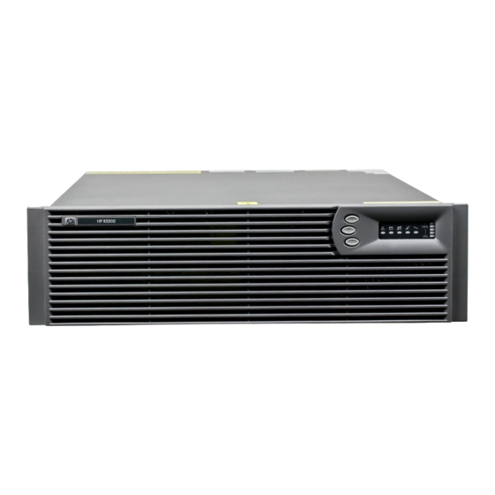
ERM rear panel… 10 UPS R5500 overview The HP UPS R5500 features a 3U rack-mount design and offers power protection for loads up to 5000 VA/4500 W (NA/JPN) or 6000 VA/5400 W (INTL). The modular design includes two hot-swappable battery modules and one hot-swappable electronics module, allowing for reduced downtime and ease of replacement.
-
Page 7: Ups Front Panel Controls
UPS front panel controls The front panel is shown with the bezel removed. Item Description On button Standby button Test/Alarm Reset button Configure button Function Powers up the UPS («Starting power to the load» on page 23) Places the UPS in Standby mode (on page Silences UPS alarms («Silencing an audible…
-
Page 8: Ups Front Panel Led Indicators
UPS front panel LED indicators The front panel is shown with the bezel removed. Item LED description Overload 76% to 100% load 51% to 75% load (2 ERMs) 26% to 50% load (1 ERM) 0% to 25% load (0 ERMs) General Alarm On Battery Battery Fault…
-
Page 9: Ups Rear Panel
UPS rear panel Item Description REPO port Ground bonding screw Communications port/option slot Load segment 1 circuit breaker (controls the C19 and C13 receptacles, but does not control the large output receptacle) Load segment 1 (two IEC-320-C19 receptacles, two IEC- 320-C13 receptacles, and one large output receptacle) Load segment 2 circuit breaker Load segment 2 (two IEC-320-C19 receptacles and two…
-
Page 10: Erm Rear Panel
The REPO feature shuts down UPS units operating under either utility or battery power. NOTE: If the UPS was operating on battery power when the remote switch was closed, no power is available to the load devices until utility power is restored and the UPS has been manually powered up. To restore power to the load devices after the REPO feature is activated, press the On button after the AC source is reconnected to the UPS.
-
Page 11: Installation
Installation In this section Precautions… 11 Preparing to install the hardware … 11 Installing the mounting rails … 13 Preparing the rails for integrated shipping… 15 Installing the UPS … 15 Installing the ERM… 23 Precautions Save these instructions. This document contains important safety instructions that should be followed during installation, operation, and maintenance of the UPS and batteries.
-
Page 12: Tools And Materials
Check the battery recharge date specified on the label that is affixed to the shipping carton. IMPORTANT: Do not use the battery if the recharge date has passed. If the date on the battery recharge date label has passed without the battery being recharged, contact an HP authorized service representative for directions.
-
Page 13: Installing The Mounting Rails
Installing the mounting rails WARNING: To reduce the risk of personal injury or damage to the equipment, be sure that: The leveling feet are extended to the floor. The full weight of the rack rests on the leveling feet. The stabilizing feet are attached to the rack if it is a single-rack installation. The racks are coupled together in multiple-rack installations.
-
Page 14
Install cage nuts or clip nuts into the rear of the rack. Insert screws through the mounting rail into the cage nuts or clip nuts. Installation 14… -
Page 15: Preparing The Rails For Integrated Shipping
Tighten the hex nuts. Preparing the rails for integrated shipping If the unit is to be shipped in an HP 9000 or 10000 series rack: Remove the hex nuts, flat washers, and lock washers from the mounting rail. Install the rail reinforcement plates and tighten using the hex nuts with captive washers included in the kit, instead of the nuts included with the rail.
-
Page 16: Removing The Ups Battery Bracket
CAUTION: Always plan the rack installation so that the heaviest item is on the bottom of the rack. Install the heaviest item first, and continue to populate the rack from the bottom to the top. Install the mounting rails With one person on each side of the carton, lift the chassis and lower it to the floor in front of the rack.
-
Page 17: Installing The Batteries
Installing the batteries WARNING: To prevent personal injury, prepare the area and observe all materials- handling procedures when transporting a battery module. Battery modules weigh 20 kg (44 lb). Replacing the UPS battery bracket Installation 17…
-
Page 18: Attaching The Ups Front Bezel
Attaching the UPS front bezel Switching on the UPS battery circuit breaker Connecting the serial communications port CAUTION: Use only the computer interface cable supplied with the UPS to connect the communications port to the host computer. CAUTION: Using a USB to serial converter cable will damage the UPS. Installation 18…
-
Page 19: Connecting The Repo Port
IMPORTANT: Power management software requires the communications port to be appropriately cabled to the host computer. Connecting the REPO port WARNING: The pins on the REPO port are polarity sensitive. Be sure to verify polarity while connecting the REPO port. WARNING: To meet the requirements stated in NEC (NFPA 70) Articles 645-10 and 645- 11, a UPS installed in a computer equipment room must be connected to a REPO circuit.
-
Page 20
NOTE: Wire the connector block using stranded, nonshielded wire (AWG #22 — #18, or equivalent). Separate wire pairs are attached to a single, normally-open contact in a parallel connection. HP recommends using different colors for the positive and negative wires. -
Page 21: Connecting The Ground Bonding Cable
Connecting the ground bonding cable The ground bonding screw is provided as an attachment point for conductors. Use a ground bonding cable if the rack contains any conductors for the purpose of functional grounding or bonding of ungrounded metal parts. The ground bonding cable is not included.
-
Page 22: Connecting The Ups Cord Retention Clips
Connect the device power cords to the appropriate output receptacles on the rear panel of the UPS. To provide additional receptacles: Plug a PDU or other device into the high current, large output receptacle. The large output receptacle is part of load segment 1 and can be turned off and on using power management software (on page 30).
-
Page 23: Starting Power To The Load
80 percent of their capacity within 3 hours 100 percent of their capacity within 48 hours Starting power to the load Start power to the load by placing the UPS in Operate mode (on page 26). IMPORTANT: AC power must be available the first time the UPS is started. Installing the ERM Before installing the ERM, review and observe all warnings in «Precautions (on page 11).»…
-
Page 24: Attaching The Erm Front Bezel
Attaching the ERM front bezel Switching off the ERM circuit breaker WARNING: To prevent personal injury from electric shock or damage to the equipment, verify that the circuit breaker is in the Off position. Installation 24…
-
Page 25: Connecting The Erm To The Ups
Connecting the ERM to the UPS NOTE: To install a second ERM, plug the cable from the second ERM into the socket at the rear of the first ERM. Up to two ERM units can be connected. Switching on the ERM circuit breaker Charging the ERM batteries Connect the UPS to a grounded utility power outlet.
-
Page 26: Ups Operations
UPS operations In this section Modes of operation … 26 Configuring the UPS … 27 Testing the LEDs … 28 Silencing an audible alarm… 28 Verifying the REPO port connection … 29 Powering down the UPS… 29 Modes of operation The UPS has four modes of operation: Standby mode (on page 26) Operate mode (on page 26)
-
Page 27: Configure Mode
To place the UPS in Operate mode, press the On button. The Utility LED turns solid green, indicating that power is available at the UPS output receptacles. The UPS acknowledges compliance with a short beep. NOTE: If the UPS is using battery power (no utility power is present and the Utility LED is red), press and hold the On button until the audible alarm sounds.
-
Page 28: Testing The Leds
Available settings Parameter Wiring Fault Setting Wiring Fault ERM Setting 0 ERMs 1 ERM 2 ERMs To change the UPS configuration parameters: Place the UPS in Configure mode (on page 27). The LEDs associated with the currently configured parameters illuminate. A flashing green cursor indicates where you are in the configuration process as you scroll through the available settings.
-
Page 29: Verifying The Repo Port Connection
Although the audible alarm silences, the condition that caused the alarm to sound may still exist. If a utility power failure caused the alarm (the Utility LED or the General Alarm LED illuminates red), the alarm silences after power is restored. For information about audible alarm conditions, see «LED and audible alarm troubleshooting (on page 38).»…
-
Page 30: Power Management
HP Power Manager software ensures maximum power reliability of computer systems through comprehensive control of UPSs. The easy-to-use browser interface enables novice users to configure and manage power protection settings. To download the latest version of HP Power Manager software, see the HP website (http://www.hp.com/go/rackandpower).
-
Page 31: Maintenance
Maintenance In this section Removing the UPS front bezel … 31 Removing the ERM front bezel … 32 Replacing the UPS electronics module… 32 Replacing the UPS option card… 33 Replacing the batteries… 34 Replacing the UPS … 35 Replacing the ERM … 36 Updating the UPS firmware …
-
Page 32: Removing The Erm Front Bezel
Removing the ERM front bezel Replacing the UPS electronics module This component is hot-swappable and can be replaced without powering down the UPS. (optional) To replace the component with the UPS powered down, refer to «Powering down the UPS (on page 29).» Disconnect the communications cable from the option card.
-
Page 33: Replacing The Ups Option Card
Replace the screw. Replace the option card. Reconnect the external cable to the card. Verify that the UPS is configured to the proper voltage and number of attached ERMs. See «Configuring the UPS (on page 27).» Replace the front bezel. Replacing the UPS option card This component is hot-swappable and can be replaced without powering down the UPS.
-
Page 34: Replacing The Batteries
To replace the component, reverse the removal procedure. NOTE: Replacing the option card might require power management software to be restarted or reconfigured. Replacing the batteries To replace the batteries: Read and observe the requirements in «Important battery safety information (on page 34)» and «Battery care and storage guidelines (on page 34).»…
-
Page 35: Ups Battery Replacement Procedure
UPS battery replacement procedure This component is hot-swappable and can be replaced without powering down the UPS. (optional) To replace the component with the UPS powered down, refer to «Powering down the UPS (on page 29).» CAUTION: When hot-swapping batteries, the UPS is not protected in the event of a utility power failure, unless at least one ERM is installed.
-
Page 36: Replacing The Erm
Switch the battery circuit breaker for the UPS to the Off (down) position. Unplug the UPS power cord. Disconnect the communications cable from the option card. Disconnect the ground bonding cable. Disconnect the REPO port. Unplug the load devices. Unplug all connected extension bars and PDUs. Unplug the ERM connected to the UPS.
-
Page 37: Updating The Ups Firmware
Updating the UPS firmware CAUTION: Using a USB to serial converter cable will damage the UPS. To update the UPS firmware, see the HP website (http://www.hp.com/go/rackandpower). Maintenance 37…
-
Page 38: Troubleshooting
Troubleshooting In this section LED and audible alarm troubleshooting… 38 Battery condition … 39 Bypass is out of range … 39 General alarm condition … 40 Input voltage is out of range … 40 Insufficient warning of low batteries… 40 Internal UPS fault condition…
-
Page 39: Battery Condition
Allow the UPS batteries to charge for 48 hours. If the LED does not turn off, replace the batteries If the condition persists, contact an HP authorized service representative. Bypass is out of range The input voltage is not within ±12 percent of nominal voltage.
-
Page 40: General Alarm Condition
If power management software is being used, check the log files to obtain specific error information to help identify the problem. For more information about the causes of a general alarm condition, see the HP Power Manager user guide available for download from the HP website (http://www.hp.com/go/rackandpower).
-
Page 41: Low Battery Shutdowns
Low battery shutdowns Ungraceful shutdown of attached servers occurs when the UPS is in a low battery condition. Action: Verify that the power management software is not delaying the shutdown of attached servers when the UPS is in a low battery condition. Allow the UPS batteries to charge for 48 hours.
-
Page 42: Ups Does Not Start
If power management software is being used, check the log files to obtain specific error information to help identify the problem. For more information about the causes of a general fault condition, see the HP Power Manager user guide available for download from the HP website (http://www.hp.com/go/rackandpower).
-
Page 43: Specifications
Width Weight UPS input specifications NOTE: An asterisk (*) indicates the default setting. UPS model Utility voltage frequency (Hz) R5500 XR 50/60 NA/JPN Value 13.03 cm (5.13 in) 66.04 cm (26 in) 44.15 cm (17.38 in) 68 kg (150 lb) Value 13.03 cm (5.13 in)
-
Page 44: Ups Output Specifications
UPS model Utility voltage frequency (Hz) R5500 XR INTL 50/60 UPS output specifications UPS model Load segment R5500 XR NA/JPN R5500 XR INTL ¹ NOTE: The circuit breakers protect the C19 and C13 outlets. ² NOTE: If an extension bar is connected to a C19 receptacle, the maximum current for each C13 receptacle on the extension bar is 10 A.
-
Page 45: Output Tolerance Specifications
Output tolerance specifications Source of power Utility power (nominal range) Battery power Output feature specifications Feature Online efficiency Voltage wave shape Surge suppression Noise filtering Battery specifications Feature Specification Type Each model contains maintenance-free, sealed, valve regulated lead-acid batteries with an 8-year minimum float service life at 25°C (77°F).
-
Page 46: Environmental Specifications
Load, W (percent) Environmental specifications Feature Operating temperature Nonoperating temperature Relative humidity Operating altitude Nonoperating altitude Audible noise REPO port specifications The REPO port meets the requirements of NFPA Articles 645-10 and 645-11 for a Disconnecting Means. Estimated battery Runtime with one ERM runtime (minutes) (minutes) Specification…
-
Page 47: Spares
UPS spare parts list… 47 Hardware options … 48 Ordering spares To order a spare, visit the HP website (http://h61003.www6.hp.com). To replace parts under warranty, contact an HP authorized service representative. UPS spare parts list Item Description X-slot serial card…
-
Page 48: Hardware Options
Extension bars and mounting hardware UPS unit NA/JPN UPS unit INTL ERM unit 10 A jumper cord * not shown Hardware options For information on the supported hardware options, see the HP website (http://www.hp.com/go/rackandpower). Spare part number 204505-001 407419-001 397642-001 419595-001*…
-
Page 49: Technical Support
In other locations, see the Contact HP worldwide (in English) webpage (http://welcome.hp.com/country/us/en/wwcontact.html). For HP technical support: In the United States, for contact options see the Contact HP United States webpage (http://welcome.hp.com/country/us/en/contact_us.html). To contact HP by phone: Call 1-800-HP-INVENT (1-800-474-6836). This service is available 24 hours a day, 7 days a week.
-
Page 50: Warranty Information
Warranty information In this section Limited warranty … 50 $250,000 Computer Load Protection Guarantee … 50 Pre-Failure Battery Warranty … 50 Limited warranty To back up the wide range of features offered with the UPS, a 3-year limited warranty is provided. $250,000 Computer Load Protection Guarantee In addition to the limited warranty, a $250,000 Computer Load Protection Guarantee (provided by the original equipment manufacturer) is offered.
-
Page 51
Notification from power management software Warranty information 51… -
Page 52: Regulatory Compliance Notices
Regulatory compliance notices In this section Regulatory compliance identification numbers… 52 Federal Communications Commission notice … 52 Declaration of conformity for products marked with the FCC logo, United States only… 53 Modifications… 54 Cables … 54 Canadian notice (Avis Canadien) … 54 European Union regulatory notice …
-
Page 53: Class A Equipment
For questions regarding this product, contact us by mail or telephone: Hewlett-Packard Company P. O. Box 692000, Mail Stop 530113 Houston, Texas 77269-2000 1-800-HP-INVENT (1-800-474-6836). (For continuous quality improvement, calls may be recorded or monitored.) For questions regarding this FCC declaration, contact us by mail or telephone: Hewlett-Packard Company P.
-
Page 54: Modifications
Modifications The FCC requires the user to be notified that any changes or modifications made to this device that are not expressly approved by Hewlett-Packard Company may void the user’s authority to operate the equipment. Cables Connections to this device must be made with shielded cables with metallic RFI/EMI connector hoods in order to maintain compliance with FCC Rules and Regulations.
-
Page 55: Disposal Of Waste Equipment By Users In Private Households In The European Union
Disposal of waste equipment by users in private households in the European Union This symbol on the product or on its packaging indicates that this product must not be disposed of with your other household waste. Instead, it is your responsibility to dispose of your waste equipment by handing it over to a designated collection point for the recycling of waste electrical and electronic equipment.
-
Page 56: Taiwan Battery Recycling Notice
Batteries, battery packs, and accumulators should not be disposed of together with the general household waste. To forward them to recycling or proper disposal, use the public collection system or return them to HP, an authorized HP Partner, or their agents.
-
Page 57: Electrostatic Discharge
Electrostatic discharge In this section Preventing electrostatic discharge… 57 Grounding methods to prevent electrostatic discharge … 57 Preventing electrostatic discharge To prevent damaging the system, be aware of the precautions you need to follow when setting up the system or handling parts. A discharge of static electricity from a finger or other conductor may damage system boards or other static-sensitive devices.
-
Page 58: Acronyms And Abbreviations
Acronyms and abbreviations extended runtime module light-emitting diode National Electrical Code NEMA National Electrical Manufacturers Association NFPA National Fire Protection Association power distribution unit power factor corrected REPO remote emergency power off uninterruptible power system Acronyms and abbreviations 58…
-
Page 59: Index
Configure button, location 7 Configure mode 27 Configure Mode On LED, location 8 connecting devices to UPS 21 connectors 6, 9, 10 contacting HP 49 cord retention clip locations 9 cord retention clips, connecting 22 Declaration of Conformity 53 devices, connecting 21…
-
Page 60
44 output tolerance specifications 45 overload condition 41 Overload LED, location 8 Overload LED, troubleshooting 38 overview, HP Power Manager 30 overview, power management software 30 overview, REPO port 9 overview, UPS 6 phone numbers 49 physical specifications 43… -
Page 61
REPO port, connecting 19 REPO port, location 9 REPO port, overview 9 REPO port, specifications 46 REPO port, verifying connection 29 required information 49 required tools 12 runtime specifications 45 safety considerations 11, 34 selecting a site 12 series number 52 shipping the UPS 15 site requirements 12 site wiring condition 41…
Скачать файл PDF «HP R5500 Инструкция по эксплуатации» (1.89 Mb)
Популярность:
723 просмотры
Подсчет страниц:
61 страницы
Тип файла:
Размер файла:
1.89 Mb
HP R5500 XR (AF416A)
Самый передовой источник бесперебойного питания HP UPS R5500 XR имеет небольшую высоту (3U), монтируется в стойку и обеспечивает эффективную выходную мощность до 4500 Вт (5400 Вт по международной системе). Эта новая разработка, позволяющая экономично использовать стоечное пространство, обеспечивает более высокую степень поддержки критически важного монтируемого в стойку оборудования. Этот продукт дополняет наш существующий ИБП R6000, обеспечивает беспрецедентно высокую плотность мощности и расширяет функциональные возможности хорошо себя зарекомендовавшего семейства монтируемых в стойку ИБП HP. Новый ИБП R5500 XR представляет собой решение с высокой плотностью мощности, предназначенное для клиентов, которые хотят обеспечить защиту питания в корпоративной среде, размещаемой в ограниченном пространстве. Кроме того, новый ИБП R5500 XR можно подсоединить к опциональным модулям продления срока бесперебойной работы. С помощью модуля ERM клиенты могут дополнительно увеличить время поддержки питания ИБП R5500 XR. Буквы «XR» в названии этих моделей ИБП HP происходят от английского «eXtended Runtime Capable» (с возможностью продления срока бесперебойной работы)
Функции:
| • |
Компактный дизайн источника питания (3U): ИБП HP R5500 XR с рейтингом около единицы обеспечивает значительную выходную мощность 5500 ВА / 4500 Вт (5400 Вт по международной системе) при компактной конструкции, рассчитанной на монтаж в стойку, что позволяет поддерживать больше критически важного оборудования. |
| • |
Увеличьте время безотказной работы с помощью модулей продления срока бесперебойной работы: Модули продления срока бесперебойной работы представляют собой монтируемые в стойку батарейные модули высотой 3U (5,25 дюйма). ИБП HP R5500 XR поддерживает до двух модулей продления срока бесперебойной работы, которые увеличивают общее время работы от батарей. |
| • |
Снижение эксплуатационных затрат благодаря инновационным технологиям: В ИБП HP R5500 XR используется новая, самая передовая в отрасли технология постоянного контроля и регулировки питания без использования батареи, благодаря чему увеличивается ресурс батареи. Выходное напряжение подстраивается автоматически в зависимости от подсоединённой нагрузки и входного напряжения. |
| • |
Защита инвестиций с помощью расширенного управления батареями HP: Функция расширенного управления батареями имеется в ИБП HP R5500 XR: это эксклюзивная, запатентованная технология, которая удваивает срок службы батареи, оптимизирует время заряда батареи и выдаёт предварительное уведомление о возможном отказе батареи. Применяя расширенное управление батареями, Вы снизите свои эксплуатационные затраты и обеспечите самую лучшую в отрасли защиту Вашего критически важного оборудования. |
| • |
Повышенная гибкость системы благодаря дополнительным картам HP: ИБП моделей HP R5500 XR оборудованы стандартным последовательным коммуникационным портом, оформленным в виде внутреннего слота. Этот опциональный слот поддерживает одну плату по выбору: либо плату расширения с 6 портами, либо плату SNMP/последовательного порта. Эти опционные платы легко вставляются со стороны задней стенки ИБП R5500 XR и существенно увеличивают гибкость системы.
|
- Главная
- Источники бесперебойного питания
- HP

- Количество выходных разъемов питания9 (из них с питанием от батарей —

- Тип выходных разъемов питанияIEC 320 C13 (компьютерный)
- Типинтерактивный
- Выходная мощность5500 ВА / 4500 Вт
- Возможность установки в стойкуесть
- Форма выходного сигналасинусоида
- Входное напряжение198 — 253 В
- Стабильность выходного напряжения (батарейный режим)± 5 %
- На входе1-фазное напряжение
- На выходе1-фазное напряжение
- Показать все
Перед приобретением HP R5500 XR по самой низкой цене, изучите характеристики, видео обзоры, плюсы и минусы модели, отзывы покупателей.
Цена от 359202 ₽
(на апрель 2021)
Характеристики HP R5500 XR
Основные характеристики*
| Количество выходных разъемов питания | 9 (из них с питанием от батарей —  |
| Тип выходных разъемов питания | IEC 320 C13 (компьютерный) |
| Тип | интерактивный |
| Выходная мощность | 5500 ВА / 4500 Вт |
| Возможность установки в стойку | есть |
| Форма выходного сигнала | синусоида |
Входы и выходы*
| Входное напряжение | 198 — 253 В |
| Стабильность выходного напряжения (батарейный режим) | ± 5 % |
| На входе | 1-фазное напряжение |
| На выходе | 1-фазное напряжение |
Система управления*
| Интерфейсы | RS-232 |
| Слот для дополнительных интерфейсов | есть |
Функции и возможности*
| Звуковая сигнализация | есть |
| Отображение информации | светодиодные индикаторы |
Батарея*
| Возможность замены батарей | есть |
| Горячая замена батарей | есть |
| Подключение дополнительных батарей | есть |
Защита*
| Фильтрация помех | есть |
| Защита от короткого замыкания | есть |
| Тип предохранителя | автоматический |
| Защита от перегрузки | есть |
| Защита телефонной линии | есть |
| Защита от высоковольтных импульсов | есть |
Другие характеристики*
| Высота (в юнитах) | 3 U |
| Вес | 73 кг |
| Габариты (ШxВxГ) | 445x130x660 мм |
| Цвет | серый |
* Точные параметры уточняйте на сайте продавца.
Отзывы пользователей о HP R5500 XR
Производитель HP (Hewlett-Packard)
Категория Power Supply
Документы, которые мы получаем от производителя устройства HP (Hewlett-Packard) R5500 мы можем разделить на несколько групп. Это в частности:
— технические чертежи HP (Hewlett-Packard)
— инструкции обслуживания R5500
— паспорта изделия HP (Hewlett-Packard)
— информационные брошюры
— энергетические этикетки HP (Hewlett-Packard) R5500
Все из них важны, однако самую важную информацию с точки зрения пользователя мы найдем в инструкции обслуживания HP (Hewlett-Packard) R5500.
Группа документов, определяемая как инструкции обслуживания, делится также на более подробные типы, такие как: Инструкции монтажа HP (Hewlett-Packard) R5500, инструкции обслуживания, короткие инструкции или инструкции пользователя HP (Hewlett-Packard) R5500. В зависимости от потребностей, Вам необходимо поискать требуемый документ. На нашем сайте Вы можете просмотреть самую популярную инструкцию использования изделия HP (Hewlett-Packard) R5500.
Полная инструкция обслуживания устройства HP (Hewlett-Packard) R5500, как должна выглядеть?
Инструкция обслуживания, определяемая также как пособие пользователя, или просто «руководство» — это технический документ, цель которого заключается в использовании HP (Hewlett-Packard) R5500 пользователями. Инструкции пишет, как правило технический писатель, языком, доступным для всех пользователей HP (Hewlett-Packard) R5500.
Полная инструкция обслуживания HP (Hewlett-Packard), должна заключать несколько основных элементов. Часть из них менее важная, как например: обложка / титульный лист или авторские страницы. Однако остальная часть, должна дать нам важную с точки зрения пользователя информацию.
1. Вступление и рекомендации, как пользоваться инструкцией HP (Hewlett-Packard) R5500 — В начале каждой инструкции, необходимо найти указания, как пользоваться данным пособием. Здесь должна находится информация, касающаяся местонахождения содержания HP (Hewlett-Packard) R5500, FAQ и самых распространенных проблем — то есть мест, которые чаще всего ищут пользователи в каждой инструкции обслуживания
2. Содержание — индекс всех советов, касающихся HP (Hewlett-Packard) R5500, которое найдем в данном документе
3. Советы по использованию основных функций устройства HP (Hewlett-Packard) R5500 — которые должны облегчить нам первые шаги во время использования HP (Hewlett-Packard) R5500
4. Troubleshooting — систематизированный ряд действия, который поможет нам диагностировать а в дальнейшем очередность решения важнейших проблем HP (Hewlett-Packard) R5500
5. FAQ — чаще всего задаваемые вопросы
6. Контактные данные Информация о том, где искать контактные данные производителя / сервисного центра HP (Hewlett-Packard) R5500 в данной стране, если самостоятельно не получится решить проблему.