- Manuals
- Brands
- Hypertherm Manuals
- Welding System
- HPR130
- Instruction manual
-
Contents
-
Table of Contents
-
Troubleshooting
-
Bookmarks
Related Manuals for Hypertherm HPR130
Summary of Contents for Hypertherm HPR130
-
Page 1
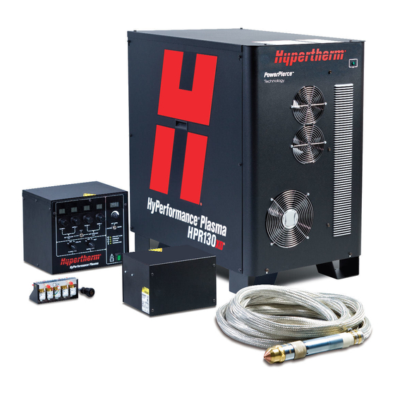
HyPerformance ® ® Plasma HPR130 Manual gas Instruction manual 804570 – Revision 6… -
Page 2
Register your new Hypertherm system Register your product on-line at www.hypertherm.com/registration for easier technical and warranty support. You can also receive updates on new Hypertherm products and a free gift as a token of our appreciation. For your records Serial number:… -
Page 3
6 – April, 2008 Hypertherm, Inc. Hanover, NH USA www.hypertherm.com © Copyright 2008 Hypertherm, Inc. All Rights Reserved Hypertherm, HyPerformance, HyDefinition, LongLife and Command THC are trademarks of Hypertherm, Inc. and may be registered in the United States and/or other countries… -
Page 4
65 6 841 2490 Fax HYPERTHERM BRASIL LTDA. 65 6 841 2489 (Technical Service) Avenida Doutor Renato de Andrade Maia 350 Hypertherm (Shanghai) Trading Co., Ltd. Parque Renato Maia Unit 1308-09, Careri Building CEP 07114-000 432 West Huai Hai Road… -
Page 5: Electromagnetic Compatibility (Emc
EMC Introduction h. Time of day that cutting or other activities are to be carried out. Hypertherm’s CE-marked equipment is built in compliance with standard EN60974-10. The equipment should be The size of the surrounding area to be considered will…
-
Page 6
Arc Welding Equipment Installation and Use. Screening and shielding Selective screening and shielding of other cables and equipment in the surrounding area may alleviate problems of interference. Screening of the entire plasma cutting installation may be considered for special applications. Hypertherm 8-06… -
Page 7: Warranty
Once the product has left the Hypertherm factory, the General certification test marks are invalidated if any of the following Hypertherm, Inc. warrants that its Products shall be free…
-
Page 8
It is your responsibility to dispose of any In no event shall Hypertherm be liable to any person Hypertherm product or component part in an or entity for any incidental, consequential, indirect,… -
Page 9: Table Of Contents
Electricidad estática puede dañar tablillas de circuito……………………1b-3 Humos tóxicos pueden causar lesiones o muerte ………………………1b-4 El arco de plasma puede causar lesiones y quemaduras ………………….1b-5 Los rayos del arco pueden producir quemaduras en los ojos y en la piel ……………..1b-5 HPR130 Manual Gas Instruction Manual…
-
Page 10
Steps to take ……………………………….3-7 Grounding diagram …………………………….3-10 Placement of the power supply…………………………3-11 Install the ignition console …………………………..3-12 Placement of the gas console …………………………3-14 Install the off-valve…………………………….3-15 Power supply to ignition console leads …………………………3-16 Pilot arc lead………………………………3-16 HPR130 Manual Gas Instruction Manual… -
Page 11
Fill the power supply with coolant…………………………..3-41 Gas requirements ………………………………3-42 Setting the supply regulators…………………………3-42 Gas regulators………………………………..3-43 Supply gas plumbing ………………………………3-44 Connect the supply gases …………………………..3-44 Supply gas hoses ………………………………3-45 Section 4 OPERATION …………………………4-1 Daily start-up………………………………….4-2 Check torch…………………………………4-2 Controls and indicators……………………………….4-3 HPR130 Manual Gas Instruction Manual… -
Page 12
Error code troubleshooting – 5 of 10 ……………………….5-15 Error code troubleshooting – 6 of 10 ……………………….5-16 Error code troubleshooting – 7 of 10 ……………………….5-17 Error code troubleshooting – 8 of 10 ……………………….5-18 Error code troubleshooting – 9 of 10 ……………………….5-19 viii HPR130 Manual Gas Instruction Manual… -
Page 13
Pump strainer cleaning ……………………………..5-27 Coolant flow troubleshooting chart …………………………5-28 Coolant flow tests………………………………5-29 Before testing………………………………5-29 Using the Hypertherm flow meter (128933) ……………………..5-29 Manual pump operation …………………………..5-30 Test 1 – return line…………………………….5-31 Test 2 – supply line at ignition console ……………………..5-31 Test 3 – change the torch……………………………5-32 Test 4 –… -
Page 14
Appendix B SOFTWARE FUNCTIONAL DESCRIPTION………………..b-1 Appendix C BEVEL CUTTING……………………….c-1 Bevel torch dimensions ……………………………….c-2 Bevel cutting definitions………………………………c-3 Cut charts………………………………….c-4 Torch connections…………………………………c-7 Connect the torch lead assembly to the quick-disconnect assembly………………c-7 Parts list ………………………………….c-9 Consumables ………………………………c-9 Part selection………………………………c-10 HPR130 Manual Gas Instruction Manual… -
Page 15: Safety
Compressed gas equipment safety ……………………..1-6 Gas cylinders can explode if damaged ……………………1-6 Noise can damage hearing ……………………….1-6 Pacemaker and hearing aid operation ……………………1-6 A plasma arc can damage frozen pipes……………………1-6 Additional safety information………………………..1-6 Warning labels …………………………..1-7 Hypertherm Plasma Systems 8-06…
-
Page 16: Recognize Safety Information
• Do not cut pressurized cylinders, pipes, or any table to eliminate the possibility of hydrogen closed container. detonation. Refer to the Appendix section of this • Do not cut containers that have held combustible manual for aeration manifold details. materials. Hypertherm Plasma Systems 11-98…
-
Page 17: Electric Shock Can Kill
This switch allows the operator to turn off the power supply quickly in • Each Hypertherm plasma system is designed to be an emergency situation. used only with specific Hypertherm torches. Do not substitute other torches which could overheat and •…
-
Page 18: Toxic Fumes Can Cause Injury Or Death
Empty and properly clean the container first. and regulations. • Monitor or test the air quality at the site as needed. • Consult with a local expert to implement a site plan to ensure safe air quality. Hypertherm Plasma Systems 8-06…
-
Page 19: A Plasma Arc Can Cause Injury And Burns
Fasten the retaining nut tightly. local electrical codes. • Tighten all electrical connections to avoid excessive heating. Hypertherm Plasma Systems 5-02…
-
Page 20: Compressed Gas Equipment Safety
Protection Association, 470 Atlantic Avenue, Boston, MA 02210 Hazardous Substances, American Welding Society 10. OSHA, Safety and Health Standards, 29FR 1910 550 LeJeune Road, P.O. Box 351040, Miami, FL 33135 U.S. Government Printing Office, Washington, D.C. 20402 Hypertherm Plasma Systems 11-98…
-
Page 21
SAFETY WARNING LABEL This warning label is affixed to some power supplies. It is important that the operator and maintenance technician understand the intent of these warning symbols as described. Hypertherm Plasma Systems 8-99… -
Page 22: Warning Labels
Use welding helmet with correct shade of filter. Wear complete body protection. 6. Become trained and read the instructions before working on the machine or cutting. 7. Do not remove or paint over (cover) warning labels. Hypertherm Plasma Systems 8-99…
-
Page 23: Section 1A
Les bouteilles de gaz comprimé peuvent exploser en cas de dommages ………….1a-6 Le bruit peut provoquer des problèmes auditifs………………….1a-6 Pacemakers et prothèses auditives ……………………1a-6 Un arc plasma peut endommager les tuyaux gelés………………..1a-6 Étiquettes de sécurité ………………………..1a-7 Hypertherm Systèmes plasma 1a-1 8-06…
-
Page 24: Identifier Les Consignes De Sécurité
• Ne pas couper de récipients contenant des matières Se référer à l’annexe du manuel pour plus de combustibles. renseignements sur les collecteurs d’aération. 1a-2 Hypertherm Systèmes plasma 11-98…
-
Page 25: Les Chocs Électriques Peuvent Être Fatals
Ce dispositif permet à la prise de terre appropriée. l’opérateur d’arrêter rapidement la source de courant en • Chaque système plasma Hypertherm est conçu pour être cas d’urgence. utilisé uniquement avec des torches Hypertherm •…
-
Page 26: Les Vapeurs Toxiques Peuvent Provoquer Des Blessures Ou La Mort
• Contrôler ou éprouver la qualité de l’air au site selon les besoins. • Consulter un expert local pour mettre en œuvre un plan du site afin d’assurer une qualité de l’air sûre. 1a-4 Hypertherm Systèmes plasma 8-06…
-
Page 27: L’arc Plasma Peut Provoquer Des Blessures Ou Des Brûlures
Table de travail Raccorder la table de travail à la terre, terre par-dessus. Bien serrer l’écrou de retenue. conformément aux codes de sécurité locaux ou nationaux • S’assurer que toutes les connexions sont bien serrées appropriés. pour éviter la surchauffe. Hypertherm Systèmes plasma 1a-5 5-02…
-
Page 28: Sécurité Des Bouteilles De Gaz Comprimé
• Ne pas s’enrouler le faisceau de la torche ou le câble de Les tuyaux gelés peuvent être endommagés ou éclater si retour autour du corps. l’on essaie de les dégeler avec une torche plasma. • Se tenir le plus loin possible de la source de courant. 1a-6 Hypertherm Systèmes plasma 11-98…
-
Page 29
SÉCURITÉ Étiquette de sécurité Cette étiquette est affichée sur la source de courant. Il est important que l’utilisateur et le technicien de maintenance comprennent la signification des symboles de sécurité. Hypertherm Systèmes plasma 1a-7 8-99… -
Page 30: Étiquettes De Sécurité
6. Se former à la technique du coupage et lire les instructions avant de manipuler l’équipement ou de procéder au coupage. 7. Ne pas retirer ou peindre (recouvrir) les étiquettes de sécurité. 1a-8 Hypertherm Systèmes plasma 8-99…
-
Page 31: Seguridad
Los cilindros de gas pueden explotar si están dañados ………………1b-6 El ruido puede deteriorar la audición ……………………1b-6 Operación de marcapasos y de audífonos ………………….1b-6 Un arco plasma puede dañar tubos congelados ………………..1b-6 Etiquetas de advertencia ……………………….1b-7 Hypertherm Sistemas plasma 1b-1 8-06…
-
Page 32: Reconocimiento De Información De Seguridad
Consulte la sección del apéndice de este • No corte depósitos que hayan contenido materiales manual para conocer detalles acerca del múltiple de combustibles. aireación. 1b-2 Hypertherm Sistemas plasma 11-98…
-
Page 33: El Choque Eléctrico Puede Provocar La Muerte
Prevención ante el electrochoque cortando. Deje la pieza en su lugar o sobre la mesa de Todos los sistemas por plasma de Hypertherm usan alto trabajo con el cable de trabajo conectado en todo voltaje en el proceso de corte (son comunes los voltajes CD momento.
-
Page 34: Humos Tóxicos Pueden Causar Lesiones O Muerte
• Monitoree o compruebe la calidad del aire en el sitio como fuera necesario. • Consulte con un experto local para realizar un plan al sitio para garantizar la calidad de aire seguro. 1b-4 Hypertherm Sistemas plasma 8-06…
-
Page 35: El Arco De Plasma Puede Causar Lesiones Y Quemaduras
Ajuste firmemente la tuerca buena toma de tierra, de conformidad con los códigos de retención. eléctricos nacionales o locales apropiados. • Asegúrese de que todas las conexiones eléctricas están firmemente realizadas para evitar sobrecalentamientos. Hypertherm Sistemas plasma 1b-5 5-02…
-
Page 36: Seguridad De Los Equipos De Gas Comprimido
• Manténgase tan lejos de la fuente de energía como sea posible. Se puede hacer daño a los tubos congelados, o se los puede reventar, si uno trata de descongelarlos con una antorcha por plasma. 1b-6 Hypertherm Sistemas plasma 11-98…
-
Page 37: Etiquetas De Advertencia
Esta etiqueta de advertencia se encuentra adherida a la fuente de energía. Es importante que el operador y el técnico de mantenimiento comprendan el sentido de estos símbolos de advertencia según se describen. El texto numerado corresponde a los cuadros numerados de la etiqueta. Hypertherm Sistemas plasma 1b-7 8-99…
-
Page 38
Proteja su cuerpo completamente. 6. Antes de trabajar en la máquina o de proceder a cortar, capacítese y lea las instrucciones completamente. 7. No retire las etiquetas de advertencia ni las cubra con pintura. 1b-8 Hypertherm Sistemas plasma 8-99… -
Page 39: Specifications
Power supply ………………………………2-3 Ignition console ………………………………2-3 Gas console ………………………………..2-3 Off-valve ………………………………..2-3 Torch ………………………………….2-3 Specifications………………………………..2-4 System gas requirements …………………………..2-4 Power supply ………………………………2-5 Ignition console – 078172…………………………..2-6 Gas console – 078170……………………………..2-8 Off-valve – 129816…………………………….2-9 Torch – 128818……………………………….2-10 HPR130 Manual Gas Instruction Manual…
-
Page 40
SPECIFICATIONS HPR130 Manual Gas Instruction Manual… -
Page 41: System Description
(1 in) for mild steel and 19 mm (3/4 in) for stainless steel and aluminum. The maximum severance capability is 38 mm (1.5 in) for mild steel and 25 mm (1 in) for stainless steel and aluminum. HPR130 Manual Gas Instruction Manual…
-
Page 42: Specifications
• Oil – the concentration of oil can be no more than 0.1 mg per cubic meter of air. Mild steel Stainless steel Aluminum Gas types Plasma Shield Plasma Shield Plasma Shield Cutting 30 to 50 A & F5 Cutting 80 A Cutting 130 A & H35 H35 & Air & Air HPR130 Manual Gas Instruction Manual…
-
Page 43: Power Supply
078178 50/60 21.5 078179 21.5 078193 50/60 21.5 078180 50/60 CE/GOST-R 21.5 078182 50/60 21.5 078181 21.5 078183 21.5 154.9 mm 1079.5 mm 6.1″ 42.5″ 317.5 kg 700 lb 967.7 mm 38.1″ 566.4 mm 22.3″ HPR130 Manual Gas Instruction Manual…
-
Page 44: Ignition Console — 078172
• Maximum cable length from the ignition console to the torch lifter station is 20 m (65 ft). Allow room to remove the top for servicing. • The ignition console may be mounted horizontally or vertically. 283 mm 11.125″ 219 mm 8.625″ 194 mm 9.1 kg 7.625″ 20 lb 216 mm 8.5″ 152 mm 6″ HPR130 Manual Gas Instruction Manual…
-
Page 45
SPECIFICATIONS LHF mounting (local) RHF mounting (remote) Mounted on table Horizontal mounting Vertical mounting HPR130 Manual Gas Instruction Manual… -
Page 46: Gas Consol — 078170
• Mount the gas console on top of the power supply or near the CNC on the cutting table. Allow room to open the top for servicing. 359 mm 292 mm 14.125″ 11.5″ 317 mm 12.5″ 14 kg 31 lb 276 mm 10.88″ 178 mm 7″ HPR130 Manual Gas Instruction Manual…
-
Page 47: Off-Valve — 129816
• The vent hole on the manifold must be kept clear at all times. 70 mm 2.75″ Vent hole: 19 mm Do not block 0.75″ 1.1 kg 2.5 lb 157 mm 6.18″ 4.7 mm 0.187″ 30 mm 76 mm 1.18″ 3″ 165 mm 6.5″ A — A HPR130 Manual Gas Instruction Manual…
-
Page 48: Torch — 128818
• The maximum bend radius for the torch leads is 152.4 mm (6.0 in). 1.8 m 27 mm 1.07″ 193 mm 116 mm 7.59″ 4.55″ 48 mm 1.89″ 51 mm 57 mm 51 mm 2.00″ 2.25″ 2.00″ 107 mm 4.22″ 336 mm 13.21″ 2.11 kg 4.65 lb 2-10 HPR130 Manual Gas Instruction Manual…
-
Page 49: Installation
Gas console to off-valve cable …………………………3-22 Off-valve cable ………………………………3-22 Power supply to CNC interface cable …………………………3-24 Optional multi-system CNC interface cable ………………………3-24 Notes to CNC interface cable run list ……………………….3-25 Examples of output circuits……………………………3-26 Examples of input circuits…………………………..3-27 HPR130 Manual Gas Instruction Manual…
-
Page 50
Coolant for hot operating temperatures………………………3-40 Water purity requirements …………………………….3-40 Fill the power supply with coolant…………………………..3-41 Gas requirements ………………………………3-42 Setting the supply regulators…………………………3-42 Gas regulators………………………………..3-43 Supply gas plumbing ………………………………3-44 Connect the supply gases …………………………..3-44 Supply gas hoses ………………………………3-45 HPR130 Manual Gas Instruction Manual… -
Page 51: Upon Receipt
Claims for damage during shipment – If your unit was damaged during shipment, you must file a claim with the carrier. Hypertherm will furnish you with a copy of the bill of lading upon request. If you need additional assistance, call Customer Service listed in the front of this manual, or your authorized Hypertherm distributor.
-
Page 52: Installation Requirements
INSTALLATION Installation requirements HPR130 Manual Gas Instruction Manual…
-
Page 53: System Components
Gas console to off-valve hose and lead assembly CNC interface cable Optional CNC interface cable for systems with multiple power supplies Torch lead assembly Work lead Supply gas hoses Oxygen Nitrogen H35 or F5 Customer-supplied power cable Main power cable HPR130 Manual Gas Instruction Manual…
-
Page 54: Recommended Grounding And Shielding Practices
It also limits the amount of noise that is received by the CNC and other control and measurement circuits. This grounding/shielding process is the main target of this document. HPR130 Manual Gas Instruction Manual…
-
Page 55: Steps To Take
9. Each Hypertherm component, as well as any other CNC or motor-drive cabinet or enclosure, must have a separate ground cable to the common (star) point on the table. This includes the ignition console, even if it is bolted to the power supply or to the cutting machine.
-
Page 56
One acceptable location is inside the plasma power supply. If the Hypertherm voltage divider board is used, the output signal is isolated from all other circuits. The processed signal should be run in twisted, shielded cable (Belden type 1800F or equivalent). -
Page 57
A single heavy cable then goes from the gantry ground bus to the ground bus bolted to the table. * Applies to systems that use a remote high frequency (RHF) console HPR130 Manual Gas Instruction Manual… -
Page 58
Metering Gas/Selection Command console console console console Bus bar Gantry Command Bus bar Ground rod Cutting table Positive DC Plasma power supply The lifter assembly and the RHF console each require a separate path to the cutting table Chassis and RFI ground AC earth/service ground ground bus bar. -
Page 59: Placement Of The Power Supply
VOIDS THE WARRANTY. • Do not place the power supply on an incline greater than 10° to prevent it from toppling. HPR130 Manual Gas Instruction Manual 3-11…
-
Page 60: Install The Ignition Console
• Allow room to remove the top for servicing. 32 mm 184 mm 1.25″ 7.25″ 216 mm 8.50″ 32 mm 1.25″ 248 mm 9.75″ 279 mm 11.00″ 7 mm .028″ (4 places) Ignition console grounding 3-12 HPR130 Manual Gas Instruction Manual…
-
Page 61
INSTALLATION Horizontal RHF mounting Vertical RHF mounting LHF mounting HPR130 Manual Gas Instruction Manual 3-13… -
Page 62: Placement Of The Gas Console
75 m (250 ft). The maximum length of cables and hoses between the gas console and the off- valve assembly is 20 m (65 ft). Preferred gas console orientation Gas console grounding 50.8 mm 228.6 mm 9.0″ 2.0″ 314.5 mm 12.38″ 38.1 mm 1.5″ 3-14 HPR130 Manual Gas Instruction Manual…
-
Page 63: Install The Off-Valve
• Mount the off-valve assembly near the torch lifter station. The maximum length of the gas hoses between the off-valve assembly and the torch is 1.8 m (6 ft). Off-valve grounding 157 mm 6.18″ 19 mm .075″ Vent hole: 30 mm Do not block 1.18″ 4.7 mm 0.187″ HPR130 Manual Gas Instruction Manual 3-15…
-
Page 64: Power Supply To Ignition Console Leads
15 m (50 ft) 123779 75 m (250 ft) Cable numbers 123683 and 123702 are for use with systems that have the ignition console mounted on the power supply Pilot arc lead Negative lead 3-16 HPR130 Manual Gas Instruction Manual…
-
Page 65
INSTALLATION Work lead Negative lead Pilot arc lead Pilot arc lead Negative lead HPR130 Manual Gas Instruction Manual 3-17… -
Page 66: Ignition Console Power Cable
10 m (35 ft) 123837 60 m (200 ft) 123671 15 m (50 ft) 123838 75 m (250 ft) Cable number 123865 is for use with systems that have the ignition console mounted on the power supply 3-18 HPR130 Manual Gas Instruction Manual…
-
Page 67: Ignition Console Coolant Hoses
60 m (200 ft) 028442 15 m (50 ft) 128985 75 m (250 ft) Green Hose set number 228030 is for use with systems that have the ignition console mounted on the power supply HPR130 Manual Gas Instruction Manual 3-19…
-
Page 68: Power Supply To Gas Console Cables
15 m (50 ft) 123850 75 m (250 ft) 123848 20 m (65 ft) unused 24Vac-hot 24Vac-return Cable numbers 123784 and 123785 are for use with systems that have the gas console mounted on the power supply 3-20 HPR130 Manual Gas Instruction Manual…
-
Page 69
INSTALLATION J300 J103 Male Female HPR130 Manual Gas Instruction Manual 3-21… -
Page 70: Gas Console To Off-Valve Connections
Cable signal list Function End B Color End A Shield Red/Black Preflow Shield Red/Black Cutflow Plasma Red/Black Preflow Plasma Red/Black 12 13 14 Cutflow Vent Red/Black End A ( male/pins) End B Ground Green/Yellow 3-22 HPR130 Manual Gas Instruction Manual…
-
Page 71
INSTALLATION HPR130 Manual Gas Instruction Manual 3-23… -
Page 72: Power Supply To Cnc Interface Cable
Brown None Not used Green None Not used Orange Power ground Ground White Power ground Ground Black CNC +24 VDC Available 24 VDC (200 milliamps maximum) See notes CNC + 24 VDC Not connected 3-24 HPR130 Manual Gas Instruction Manual…
-
Page 73: Notes To Cnc Interface Cable Run List
The CNC cable must be constructed using cable with 360 degree shielding and metal housing connectors at each end. The shielding must be terminated to the metal housings at each end to ensure proper grounding and to provide the best shielding. HPR130 Manual Gas Instruction Manual 3-25…
-
Page 74: Examples Of Output Circuits
J304 108056 CNC/PLC – High-current contact closure inputs (AC or DC) External relay 24VDC low-power coil ≤10mA or ≥2400ohm Power ground 4. Do not use this configuration. Warranty will be void. Any voltage – 3-26 HPR130 Manual Gas Instruction Manual…
-
Page 75: Examples Of Input Circuits
+24 VDC Output from CNC/PLC External relay (AC or DC) Power ground 2. Optocoupler interface +24 VDC CNC/PLC Transistor-output optocoupler Power ground 3. Amplified-output interface +24 VDC CNC/PLC 12V-24VDC Power Active-high drive ground Power ground HPR130 Manual Gas Instruction Manual 3-27…
-
Page 76: Remote On/Off Switch
24 VAC @ 100 mA. It must be a maintained-contact switch, not a momentary-contact switch. Note: The main power switch on the gas console must be in the ON position for the remote switch to function. 3-28 HPR130 Manual Gas Instruction Manual…
-
Page 77: Torch Lead Assembly
20 m (65 ft) Grey Plasma-gas vent hose Caution: Locate the exposed end of the plasma-gas vent hose away from sparks caused by piercing to avoid ignition and possible damage to the torch leads. HPR130 Manual Gas Instruction Manual 3-29…
-
Page 78: Work Lead
10 m (35 ft) 123778 60 m (200 ft) 123663 15 m (50 ft) 123779 75 m (250 ft) 123815 20 m (65 ft) Work lead Work lead Lower frame of work table (typical). 3-30 HPR130 Manual Gas Instruction Manual…
-
Page 79: Torch Connections
3. Push back the braided cover and slide the sleeve over the leads. Align the torch with the hoses in the lead assembly. The hoses must not be twisted. They are taped together to help prevent twisting. Sleeve Braided cover 4. Connect the coolant IN hose (green) to the torch. Coolant IN hose 2WRENCHES HPR130 Manual Gas Instruction Manual 3-31…
-
Page 80
5b. Screw the connector onto the pilot arc connection from the torch. Tighten by hand until it is firmly seated. 5c. Slide the sleeve forward until it clicks into place. 6. Connect the plasma-gas vent hose. 3-32 HPR130 Manual Gas Instruction Manual… -
Page 81
11. Slide the braided cover up to the torch sleeve. Make sure that the plasma, shield and vent hoses are routed through the hole in the braided cover. Loosen the hose clamp on the braided cover, slide the braided cover and clamp over the sleeve and tighten the clamp. HPR130 Manual Gas Instruction Manual 3-33… -
Page 82: Connect The Torch To The Quick-Disconnect
Be certain that there is no space between the torch body and the o-ring on the torch leads. See also Torch connections earlier in this section for torch lead connections to ignition console. 3-34 HPR130 Manual Gas Instruction Manual…
-
Page 83: Torch Mounting And Alignment
The lifter must provide 203 mm (8 in) of vertical travel. The unit should have the capability of maintaining a constant speed of up to 5080 mm/min (200 ipm) with positive braking. A unit which drifts through the stop point is not acceptable. HPR130 Manual Gas Instruction Manual 3-35…
-
Page 84: Power Requirements
National Electric Code 1990 handbook, table 310.16 (USA). Use a 4-conductor Type SO input power cable with a conductor temperature rating of 60° C (140° F). Installation must be performed by a licensed electrician. 3-36 HPR130 Manual Gas Instruction Manual…
-
Page 85: Connect The Power
European wire colors U = Black U = Black V = White V = Blue W = Red W = Brown (PE) Earth ground = Green/Yellow (PE) Earth ground = Green/Yellow Line disconnect switch Power cable HPR130 Manual Gas Instruction Manual 3-37…
-
Page 86: Torch Coolant Requirements
Standard installation Use Hypertherm premixed coolant (028872) when operating in a temperature range of 0° C to 40° C (32° F to 104° F). Refer to the non-standard installation recommendations, if temperatures during operation are ever outside of this range.
-
Page 87: Coolant For Cold Operating Temperatures
Use the chart below to determine what percentage of propylene glycol to use in the mixture. Mix 100% glycol (028873) with the premixed Hypertherm coolant (028872) to increase the percentage of glycol. The 100% glycol solution can also be mixed with purified water (see next page for water purity requirements) to achieve the required protection from freezing.
-
Page 88: Coolant For Hot Operating Temperatures
(ppm of NaCl) Water purity at 25° C at 25° C Pure water (for reference only) 0.055 18.3 Maximum purity 0.206 0.010 Minimum purity 0.054 0.43 Maximum potable water 1000 0.001 (for reference only) 3-40 HPR130 Manual Gas Instruction Manual…
-
Page 89: Fill The Power Supply With Coolant
When the flow rate is constant and greater than 22.7 lpm (0.6 gpm), release filler cap. the knob. The display will show the current again. The pump will continue to run. HPR130 Manual Gas Instruction Manual 3-41…
-
Page 90: Gas Requirements
6. Move switch (7) to the CUTFLOW position (right position). 7. While gas is flowing adjust the supply regulator for the plasma gas to 8.3 bar (120 psi). 8. Move switch (7) to the RUN position. 3-42 HPR130 Manual Gas Instruction Manual…
-
Page 91: Gas Regulators
Use a high-quality, 2-stage, gas regulator to maintain consistent gas supply pressure from high pressure gas cylinders. The high-quality gas regulators listed below are available from Hypertherm and meet U.S. Compressed Gas Association (CGA) specifications. In other countries, select gas regulators that conform to national or local codes.
-
Page 92: Supply Gas Plumbing
CUTTING WITH OXYGEN CAN CAUSE FIRE OR EXPLOSION Cutting with oxygen as the plasma gas can cause a potential fire hazard due to the oxygen-enriched atmosphere that it creates. As a precaution, Hypertherm recommends that an exhaust ventilation system be installed when cutting with oxygen.
-
Page 93: Supply Gas Hoses
7.5 m (25 ft) 024743 45 m (150 ft) 024769 10 m (35 ft) 024771 60 m (200 ft) 024656 15 m (50 ft) 024772 75 m (250 ft) 024770 20 m (65 ft) HPR130 Manual Gas Instruction Manual 3-45…
-
Page 94: Operation
Replace torch water tube…………………………….4-26 Common cutting faults………………………………4-27 How to optimize cut quality ……………………………..4-28 Tips for table and torch …………………………..4-28 Plasma set-up tips…………………………….4-28 Maximize the life of consumable parts……………………….4-28 Additional factors of cut quality…………………………4-29 Additional improvements …………………………..4-30 HPR130 Manual Gas Instruction Manual…
-
Page 95: Daily Start-Up
3. Replace consumable parts. Refer to Changing consumable parts later in this section for details. 4. Ensure that the torch is perpendicular to the workpiece. Retaining cap Shield Inner retaining cap Swirl ring Electrode Current ring Torch Nozzle HPR130 Manual Gas Instruction Manual…
-
Page 96: Controls And Indicators
Off Position (O) AC power is cut off to the control transformer, to turn off the power supply. Power indicators AC Green Indicator: Illuminates when the power switch is in the on position. HPR130 Manual Gas Instruction Manual…
-
Page 97: Manual Gas Console Operation
Position switch (8) to SET AMPS. Set amperage using knob above switch (8). Switch 8 can be in any position while operating. System is ready to cut. *The 3-digit display is for reference. The current shown during cutting may vary by +/- 2 amps from the current shown when the amperage is set. HPR130 Manual Gas Instruction Manual…
-
Page 98: Consumable Selection
220182 220179 220181 Stainless steel Inner Shield Retaining cap Nozzle Swirl ring Electrode Retaining cap 220202 220304 220201 220180 220308 220338 220304 220337 220179 220339 220173 130A 220198 220304 (H35) 220197 220179 220307 220176 (N HPR130 Manual Gas Instruction Manual…
-
Page 99: Aluminum
OPERATION Aluminum Inner Shield Nozzle Electrode Retaining cap Retaining cap Swirl ring 220202 220176 220201 220180 220308 220173 130A 220307 (H35) 220198 220197 220179 220304 (H35) 220181 (Air) 220176 (Air) HPR130 Manual Gas Instruction Manual…
-
Page 100: Install Consumables
Do not overtighten parts! Only tighten until mating parts are seated. Install the electrode Install the swirl ring Install the nozzle and swirl ring Install the inner Install the shield Install the retaining cap retaining cap Tool part number 104119 HPR130 Manual Gas Instruction Manual…
-
Page 101: Cut Charts
Marking is not possible for every combination (very thin materials). Poor quality marking or burn-through may occur with material less than 1.5 mm (0.060 in or 16 gauge). Consumables for mirror-image cutting See the Parts List section in this manual for part numbers. HPR130 Manual Gas Instruction Manual…
-
Page 102: Estimated Kerf Width Compensation
80A F5 / N 0.047 45A F5 / N 0.023 0.015 0.021 45A N 0.019 0.009 0.006 130A H35 / N 0.107 0.109 0.114 130A Air / Air 0.082 0.082 0.086 45A Air / Air 0.042 0.043 0.049 HPR130 Manual Gas Instruction Manual…
-
Page 103
0.090 .036 .048 .060 .075 .105 0.060 0.110 .135* 3/16* 1/4* Marking Torch-to-Work Marking Amperage Select Distance Speed Voltage Gases Preflow Cutflow Amps mm/min Volts 0.100 6350 *Pierce complete is recommended for these thicknesses 4-10 HPR130 Manual Gas Instruction Manual… -
Page 104
.030 .036 0.04 0.08 .048 .060 .075 0.05 0.10 .105 .135 0.06 0.12 3/16 0.08 0.16 5/16 Marking Torch-to-Work Marking Amperage Select Distance Speed Voltage Gases Preflow Cutflow Amps mm/min Volts 0.100 6350 HPR130 Manual Gas Instruction Manual 4-11… -
Page 105
Plasma Shield Plasma Shield Plasma Shield Volts factor % seconds .075 0.100 0.150 .105 .135 3/16 0.160 0.080 0.200 0.100 0.250 Marking Torch-to-Work Marking Amperage Select Distance Speed Voltage Gases Preflow Cutflow Amps mm/min Volts 0.100 6350 4-12 HPR130 Manual Gas Instruction Manual… -
Page 106
0.100 0.200 .135 3/16 0.110 0.220 0.120 0.240 0.130 0.260 0.150 0.300 0.160 1-1/4 0.180 Edge start 1-1/2 Marking Torch-to-Work Marking Amperage Select Distance Speed Voltage Gases Preflow Cutflow Amps mm/min Volts 0.100 6350 HPR130 Manual Gas Instruction Manual 4-13… -
Page 107
.105 .135 Marking Torch-to-Work Marking Amperage Select Distance Speed Voltage Gases Preflow Cutflow Amps mm/min Volts 0.100 6350 Note: This process produces a darker cut edge than the 45 A, F5/N stainless steel process 4-14 HPR130 Manual Gas Instruction Manual… -
Page 108
3/16 0.080 Marking Torch-to-Work Marking Amperage Select Distance Speed Voltage Gases Preflow Cutflow Amps mm/min Volts 0.100 6350 Note: This process produces a shinier cut edge than the 45 A, N stainless steel process HPR130 Manual Gas Instruction Manual 4-15… -
Page 109
Plasma Shield Plasma Shield Plasma Shield Volts factor % seconds .135 0.120 0.180 3/16 0.110 0.170 0.100 0.150 0.120 0.180 Marking Torch-to-Work Marking Amperage Select Distance Speed Voltage Gases Preflow Cutflow Amps mm/min Volts 0.100 6350 4-16 HPR130 Manual Gas Instruction Manual… -
Page 110
Gases Preflow Cutflow Amps mm/min Volts 0.100 6350 Note: This process produces a rougher, darker cut edge with more dross, and the cut edges are closer to perpendicular than the 130 A, H35/N process HPR130 Manual Gas Instruction Manual 4-17… -
Page 111
Voltage Gases Preflow Cutflow mm/min Volts Amps 0.100 6350 Note: This process produces a smoother, shinier cut edge with less dross, and the cut edges are less perpendicular than the 130 A, N process 4-18 HPR130 Manual Gas Instruction Manual… -
Page 112
Plasma Shield Plasma Shield Plasma Shield Volts factor % seconds .040 .051 0.100 0.150 .064 .102 .125 0.070 0.110 3/16 0.120 0.180 Marking Torch-to-Work Marking Amperage Select Distance Speed Voltage Gases Preflow Cutflow Amps mm/min Volts 0.100 6350 HPR130 Manual Gas Instruction Manual 4-19… -
Page 113
Marking Torch-to-Work Marking Amperage Select Distance Speed Voltage Gases Preflow Cutflow mm/min Volts Amps 0.100 6350 Note: This process produces a rougher cut edge that is less perpendicular than the 130 A, H35/N process 4-20 HPR130 Manual Gas Instruction Manual… -
Page 114
Marking Torch-to-Work Marking Amperage Select Distance Speed Voltage Gases Preflow Cutflow mm/min Volts Amps 0.100 6350 Note: This process produces a smoother cut edge that is more perpendicular than the 130 A, Air/Air process HPR130 Manual Gas Instruction Manual 4-21… -
Page 115: Changing Consumable Parts
Remove the Remove the Turn OFF all power to the system. nozzle and electrode swirl ring Remove the retaining Remove the inner retaining cap cap and shield Tool part number 104119 4-22 HPR130 Manual Gas Instruction Manual…
-
Page 116: Inspect Consumables
See Inspect electrode pit depth later in Center surface Wear this section O-rings 1. Damage Replace electrode* 2. Lubricant Apply a thin film of silicone lubricant if dry *Always replace the nozzle and electrode as a set. HPR130 Manual Gas Instruction Manual 4-23…
-
Page 117: Inspect Torch
External o-rings 1. Damage Replace o-ring 2. Lubricant Apply a thin film of silicone lubricant if dry Water tube* 1. Pitted or missing material Replace tube* *See Replace torch water tube later in this section. 4-24 HPR130 Manual Gas Instruction Manual…
-
Page 118: Inspect Electrode Pit Depth
Inspect electrode pit depth Electrode pit depth gauge (004630) Part Check for Action Electrode Center surface Wear Replace electrode if pit is deeper than 1 mm (0.040 in.)* *Always replace the nozzle and electrode as a set. HPR130 Manual Gas Instruction Manual 4-25…
-
Page 119: Replace Torch Water Tube
Turn OFF all power to the system. Remove consumables from torch. See Remove consumables in this section. Remove water tube Install new water tube Replace consumables. See Install consumables in this section. 4-26 HPR130 Manual Gas Instruction Manual…
-
Page 120: Common Cutting Faults
Long consumable life is difficult to achieve when cutting plate that is magnetized or becomes magnetized easily. 3. Beginning or ending the cut off the plate surface. To achieve consumable long life, all cuts must begin and end on the plate surface. HPR130 Manual Gas Instruction Manual 4-27…
-
Page 121: How To Optimize Cut Quality
Note: It may be difficult to achieve the full benefits of the LongLife process in some conditions. 4-28 HPR130 Manual Gas Instruction Manual…
-
Page 122: Additional Factors Of Cut Quality
As the workpiece heats up, more dross may form on subsequent cuts. Dross is more likely to form on mild steel than on stainless steel or aluminum. Worn or damaged consumables may produce intermittent dross. HPR130 Manual Gas Instruction Manual 4-29…
-
Page 123: Additional Improvements
• In some Hypertherm systems, the shield gas pressure automatically increases during pierce delay. • If the above steps do not solve the problem, increasing the setting of the shield gas pressure may help blow the molten metal away during piercing.
-
Page 124: Maintenance
Pump strainer cleaning ……………………………..5-27 Coolant flow troubleshooting chart …………………………5-28 Coolant flow tests………………………………5-29 Before testing………………………………5-29 Using the Hypertherm flow meter (128933) ……………………..5-29 Manual pump operation …………………………..5-30 Test 1 – return line…………………………….5-31 Test 2 – supply line at ignition console ……………………..5-31 Test 3 – change the torch……………………………5-32 Test 4 –…
-
Page 125
Pilot arc current levels …………………………….5-41 Gas console control board PCB2 ………………………….5-42 Gas console power distribution board PCB1 ……………………..5-43 Gas console AC valve-driver board PCB3……………………….5-44 Chopper tests………………………………..5-45 Phase-loss detection test…………………………….5-47 Torch lead test ………………………………..5-48 Preventive maintenance …………………………….5-49 HPR130 Manual Gas Instruction Manual… -
Page 126: Iintroduction
MAINTENANCE Introduction Hypertherm assumes that the service personnel performing the troubleshooting testing are high-level electronic service technicians who have worked with high-voltage electro-mechanical systems. Knowledge of final isolation troubleshooting techniques is also assumed. In addition to being technically qualified, maintenance personnel must perform all testing with safety in mind.
-
Page 127: System Description
Power Supply and the Gas Console. Power Cable: Provides 120 VAC to the Ignition Console and control power for the off-valve assembly. Control Cable: Provides 120 VAC control power to the solenoid valves. HPR130 Manual Gas Instruction Manual…
-
Page 128: Sequence Of Operation
Magnetics over-temp off Coolant over-temp off 9. Ramp-down – Current and gas flow decreases after plasma start has been removed Cutflow gas off 10. Auto Off – 10 second postflow Main contactors off Choppers off HPR130 Manual Gas Instruction Manual…
-
Page 129: Gas System Valve Usage
SV1 SV2 SV10 SV14 SV16 SV19 /Air Gas console AC valve driver board – LEDs process Valve Gas console Off-valve location number Preflow SV1 SV2 SV10 SV17 SV18 Cutflow SV1 SV2 SV10 SV14 SV16 SV19 HPR130 Manual Gas Instruction Manual…
-
Page 130
Preflow SV12 SV17 SV18 Cutflow SV12 SV14 SV16 SV19 /Air Gas console AC valve driver board – LEDs process Valve Gas console Off-valve location number Preflow SV11 SV17 SV18 Cutflow SV11 SV14 SV16 SV19 HPR130 Manual Gas Instruction Manual… -
Page 131
Off-valve location number Preflow SV17 SV18 Cutflow SV14 SV16 SV19 Marking Gas console AC valve driver board – LEDs process Valve Gas console Off-valve location number Preflow SV11 SV17 SV18 Cutflow SV11 SV14 SV16 SV19 HPR130 Manual Gas Instruction Manual… -
Page 133: Error Codes
MAINTENANCE Error codes HyPerformance plasma system error codes Error codes are displayed in the 3-digit LED display on the gas console. 5-10 HPR130 Manual Gas Instruction Manual…
-
Page 134: Error Code Troubleshooting — 10 Of 10
Lost phase chopper after contactor loose connections. engaged or while cutting. 4. Inspect phase loss fuses on Power Distribution board. Replace board if fuses are blown. 5. Perform phase loss test (see Maintenance section). HPR130 Manual Gas Instruction Manual 5-11…
-
Page 135: Error Code Troubleshooting — 1 Of 10
3.45 bar (50 psi) – cutflow gas pressure parameters in the cut charts. (cutting) 3. See Setting the supply regulators (Installation section). 0.34 bar (5 psi) – cutflow 4. Perform gas leak tests (Maintenance section). (marking) 5-12 HPR130 Manual Gas Instruction Manual…
-
Page 136: Error Code Troubleshooting — 2 Of 10
4. If power is present at PCB2 and PCB3 and both gas console cables are good, then PCB2 or PCB3 has failed. Use the CAN tester to verify which board needs to be replaced. HPR130 Manual Gas Instruction Manual 5-13…
-
Page 137: Error Code Troubleshooting — 3 Of 10
(50 psi) and 9.65 bar (140 psi). Increase or decrease the Auto Gas when mixing or greater inlet gas pressure to correct the problem. Only than 9.65 bar (140 psi) for non-mixing and mixing. 5-14 HPR130 Manual Gas Instruction Manual…
-
Page 138: Error Code Troubleshooting — 4 Of 10
J3.201 pins 7 and 8. Look for shorts to wires or ground. 5. If wiring is good, the transformer has overheated. 6. If voltage is higher than 3.2 V and overtemp error does not clear after 30 minutes, replace PCB3. HPR130 Manual Gas Instruction Manual 5-15…
-
Page 139: Error Code Troubleshooting — 5 Of 10
High current 35 Amps has been 2. Remove fuse F3 and check for a short on Chopper A from on CS1 detected by wire 38 to wire 39. current sensor 1. 3. Verify fuse (F3). 5-16 HPR130 Manual Gas Instruction Manual…
-
Page 140: Error Code Troubleshooting — 6 Of 10
4. If power is present at PCB2 and PCB3 and both gas console cables are good, then PCB2 or PCB3 has failed. Use the CAN tester to verify which board needs to be replaced. HPR130 Manual Gas Instruction Manual 5-17…
-
Page 141: Error Code Troubleshooting — 7 Of 10
If LED1 is extinguished with the connector removed, then reconnect J9.1 and try to fire the torch. If the chopper still goes into overcurrent, replace the chopper. b) If the chopper does not go into overcurrent, replace PCB3. 5-18 HPR130 Manual Gas Instruction Manual…
-
Page 142: Error Code Troubleshooting — 8 Of 10
4 or 6 error metering console or the properly. Replace if necessary. Auto Gas selection console. 3. Verify that the control boards in the metering and selection Only consoles are working properly. Replace if necessary. HPR130 Manual Gas Instruction Manual 5-19…
-
Page 143: Error Code Troubleshooting — 9 Of 10
3. If power is present at PCB2 and PCB3 and both metering console cables are good, then PCB2 or PCB3 has failed. Use the CAN tester to verify which board needs to be replaced. 5-20 HPR130 Manual Gas Instruction Manual…
-
Page 144: Power Supply States
Name code Idle Purge Idle 2 Preflow Pilot arc Transfer Ramp-up Steady state Ramp-down Final ramp-down Auto off Test cutflow Shutdown Reset Maintenance Test preflow Manual pump control Inlet leak check System leak check HPR130 Manual Gas Instruction Manual 5-21…
-
Page 145: Plasma System Operation With Pump Timeout
MAINTENANCE Plasma system operation with pump timeout 5-22 HPR130 Manual Gas Instruction Manual…
-
Page 146: Cnc Operation With Pump Timeout
MAINTENANCE CNC operation with pump timeout HPR130 Manual Gas Instruction Manual 5-23…
-
Page 147: Initial Checks
If there is a problem at this point, disconnect main power and check connections, power cable, and fuses at line disconnect switch. Repair or replace any defective component. 5-24 HPR130 Manual Gas Instruction Manual…
-
Page 148: Power Measurement
Check lines in the following order: U to V U to W V to W Check each line to ground. If one line is 10% or higher than the other two, put that leg on U. HPR130 Manual Gas Instruction Manual 5-25…
-
Page 149: Power Supply Coolant System Servicing
2. Press and hold the current selection knob (8) and turn ON the power switch. The pump will run continuously while (8) is pressed. 3. Run the pump until the coolant stops flowing and immediately release the current selection knob (8). 5-26 HPR130 Manual Gas Instruction Manual…
-
Page 150: Coolant System Filter And Strainer
2. Drain coolant. See Power supply coolant draining in this section. 3. Remove nut. 4. Remove and clean strainer with a mild soap and water solution. 5. Re-insert strainer. 6. Re-install nut. 7. Refill with new coolant. Strainer HPR130 Manual Gas Instruction Manual 5-27…
-
Page 151: Coolant Flow Troubleshooting Chart
Coolant flow troubleshooting chart…
-
Page 152: Coolant Flow Tests
An in-line flow meter is the most accurate way to measure the flow rate, but can not be used with all the tests described. An in-line flow meter (part number 128933) is available from Hypertherm. The following “bucket” tests give a good idea of the flow rate.
-
Page 153: Manual Pump Operation
Coolant flow must be greater than 2.3 lpm (0.6 gpm) for the system to operate. 3. Release the current selection knob (8) and then turn OFF the power. Note: a flow diagram can be found on schematic 013348, sheet 14 of 17 5-30 HPR130 Manual Gas Instruction Manual…
-
Page 154: Test 1 — Return Line
1. Turn OFF the power. Remove the supply coolant line (blue hose with green tape) from the RHF/LHF console, and place it in a 3.8 liter (1 gallon) container. A Hypertherm coolant container works well. 2. Measure how long it takes to fill the container. Turn ON the power.
-
Page 155: Test 3 — Change The Torch
1. Turn OFF the power. Remove the return coolant line (blue hose with red tape) from the RHF/LHF console, and place it in a 3.8 liter (1 gallon) container. A Hypertherm coolant container works well. 2. Measure how long it takes to fill the container. Turn ON the power.
-
Page 156: Test 6 — Bucket Test At The Pump
1. Turn OFF the power. Remove the hose from the relief valve. 2. Remove the push-to-connect fitting from the relief valve. 3. Remove the relief valve. 4. Install the push-to-connect fitting and connect the hose. HPR130 Manual Gas Instruction Manual 5-33…
-
Page 157: Pump And Motor Troubleshooting
If the motor will not turn on, verify that the fuse is OK, and make sure there is power to the motor. If you are still not getting flow from the pump, verify that the solenoid valve and check valve are working correctly. 5-34 HPR130 Manual Gas Instruction Manual…
-
Page 158: Testing The Flow Switch
VDC at the flow switch) equals 2.3 lpm (0.6 gpm). If the TP210 voltage reading is below 0.45 VDC and the flow is equal to or above 3.0 lpm (1 gpm), replace the flow switch. TP 210 TP 206 HPR130 Manual Gas Instruction Manual 5-35…
-
Page 159: Gas Leak Tests
This test is intended to identify a leak between the gas console and the off-valve. Leak test 1 1. Turn ON power to the HPR130. 2. After initial gas purge switch shield selector switch (2) to TEST. 3. Select SET PREFLOW on switch 7. The off-valve opens and exhausts gas between the gas console and torch. The inlet valves in gas console will remain closed.
-
Page 160: Power Supply Control Board Pcb3
Soft start enable Not used LEDN5 Spare LEDN6 Pilot arc enable LEDN6 Surge select LEDN7 Corner current LEDN7 Not connected LEDN8 Pierce LEDN8 Not connected LEDN9 Hold LEDN9 Not connected EDN10 Plasma start EDN10 Phase loss HPR130 Manual Gas Instruction Manual 5-37…
-
Page 161: Power Supply Power Distribution Board Pcb2
120 VAC (switched) Green HF ignition Surge select 24 VAC (switched) Green 240 VAC (switched) Green + 24 VDC Pump motor Green + 5 VDC — 15 VDC + 15 VDC 24 VAC Green 5-38 HPR130 Manual Gas Instruction Manual…
-
Page 162: Start Circuit Pcb1
Start circuit troubleshooting DANGER SHOCK HAZARD: Always use caution when servicing a power supply when plugged in and the covers are removed. Dangerous voltages exist within the power supply which could cause injury or death. HPR130 Manual Gas Instruction Manual 5-39…
-
Page 163
• Fire the torch in the air and verify that D1 is illuminated. If it is not illuminated, but a pilot arc is established the board may need to be replaced. • Verify a resistance of 1 Ω across the R3 resistor. 15kΩ 5.5kΩ 1Ω 5-40 HPR130 Manual Gas Instruction Manual… -
Page 164: Pilot Arc Current Levels
The pilot arc current level will change depending on the chosen process and arc current level. See table below. Pilot arc current Plasma gas 30-amps 45-amps 50-amps 80-amps 130-amps Transfer current Plasma gas 30-amps 45-amps 50-amps 80-amps 130-amps HPR130 Manual Gas Instruction Manual 5-41…
-
Page 165: Gas Console Control Board Pcb2
Shield preflow, right digit CAN- RX Green LEDN7 Shield cutflow, left digit Voltage error Yellow LEDN8 Shield cutflow, right digit Temperature error Yellow LEDN9 Current, left digit LEDN10 Current, center digit LEDN11 Current, right digit 5-42 HPR130 Manual Gas Instruction Manual…
-
Page 166: Gas Console Power Distribution Board Pcb1
MAINTENANCE Gas console power distribution board PCB1 Signal Name Color 120 VAC (switched) Green + 5 VDC + 24 VDC HPR130 Manual Gas Instruction Manual 5-43…
-
Page 167: Gas Console Ac Valve-Driver Board Pcb3
Gas console, AC valve-driver board PCB3 Signal Name Color Signal Name Color SV11 SV12 SV13 SV14 SV15 (not used) SV16 SV17 SV18 SV19 SV10 SV20 SV14 SV13 SV19 SV18 SV10 SV20 SV16 SV17 SV11 Off-valve SV12 5-44 HPR130 Manual Gas Instruction Manual…
-
Page 168: Chopper Tests
4. Check for loose wires or shorts from the chopper to PCB6. 5. Check for 220 VAC to 1A, 1B, and 1C on the chopper when the contactor closes. 6. Verify that the fuse (F3) is in good working condition. HPR130 Manual Gas Instruction Manual 5-45…
-
Page 169
4. Check for short circuits from the work terminal to the negative terminal on PCB6. Resistance should be about 100K ohm from the work terminal to the negative terminal. Resistance will vary if you have a voltage divider for a height control system. 5-46 HPR130 Manual Gas Instruction Manual… -
Page 170: Phase-Loss Detection Test
F5, F6, and F7. The voltage should be 220 VAC +/-15%. If one of the 3 voltage readings is less than 187 VAC, check the contacts to the contactor, and check for loose connections between the power cord – contactor – power transformer – and the chopper. HPR130 Manual Gas Instruction Manual 5-47…
-
Page 171: Torch Lead Test
6. Verify that the pilot arc wire on the torch lead is not damaged. If it is damaged replace the lead. If it is not damaged replace the torch head. 5-48 HPR130 Manual Gas Instruction Manual…
-
Page 172: Preventive Maintenance
80% of the cost of cutting, improved productivity can reduce cutting costs dramatically. Preventive maintenance protocol The following protocol covers the basic elements of all Hypertherm HyPerformance plasma systems. If inspection suggests that a component is worn and might require replacement, and you would like confirmation of your decision, please contact Hypertherm’s Technical Service department.
-
Page 173: Cooling System
B. At the ignition console; and C. At the torch main body. Also, check the coolant tank for dirt and particulates. Verify that proper Hypertherm coolant is being used. Proper Hypertherm coolant (028872) is a red liquid. Torch main body 7.
-
Page 174
23. Check the work lead (+) connection, particularly where the work lead (+) connects to the cutting table. This must be a good, clean connection because a poor connection may cause arc-transfer problems. 24. Complete the Preventive Maintenance worksheet on the next page, for future reference. HPR130 Manual Gas Instruction Manual 5-51… -
Page 175
• Verify proper coolant level. Semi-Annually: 1 st Service 2 nd Service Year • Replace service parts per the Service Part Replacement Schedule. Annually: Year • Replace service parts per the Service Part Replacement Schedule. 5-52 HPR130 Manual Gas Instruction Manual… -
Page 176: Power Supply
22. Inspect for proper system C. Air component grounding D. Nitrogen-Hydrogen 23. Inspect connection from cutting E. Argon-Hydrogen table to workpiece (+) lead F. Inspect compressed air filter system General comments and recommendations: Preventive maintenance performed by: Date: HPR130 Manual Gas Instruction Manual 5-53…
-
Page 177
003149 Coolant pump kit 128384 Torch leads System dependent Coolant pump motor kit 128385 Coolant filter element 027664 Coolant solution 70/30 028872 4.5 Years or 2700 arc hours Torch kit 128879 Quick-disconnect kit 128880 5-54 HPR130 Manual Gas Instruction Manual… -
Page 178
Pilot arc relay 003149 Coolant pump kit 128384 Torch leads System dependent Cooling fan 6″ 127039 Cooling fan 10″ 027079 6.5 Years or 3900 arc hours Repeat schedule starting at 6 months or 300 arc hours HPR130 Manual Gas Instruction Manual 5-55… -
Page 179: Section 6 Parts List
Gas console – 1 of 2………………………………6-8 Gas console – 2 of 2………………………………6-9 Off-valve………………………………….6-9 HyPerformance torch ………………………………6-10 Torch assembly ………………………………6-10 Torch leads………………………………..6-10 Consumable parts kit – 128878 …………………………..6-11 Consumables for mirror-image cutting ………………………….6-12 Recommended spare parts ……………………………..6-13 HPR130 Manual Gas Instruction Manual…
-
Page 180: Power Supply
HyPerformance Plasma power supply: 440 volt 078183 HyPerformance Plasma power supply: 600 volt 228328 Panel: top, with lable 075241 Sheet metal screws 228330 Panel: right or left side, with lable 228329 Panel: front, with lable 129633 Green power lamp assembly HPR130 Manual Gas Instruction Manual…
-
Page 181
Number Description Designator Qty. 027634 Filter housing 027664 Filter element 127014 Cap: coolant resevoir 129792 Chopper assembly 127039 6″ fan :230 CFM, 115 VAC 50-60 HZ 027079 10″ fan :450-550 CFM, 120 VAC 50-60 HZ HPR130 Manual Gas Instruction Manual… -
Page 182
EMI filter: 60 amp, 440 VAC 3PH 129791 Start circuit assembly PCB1 109004 Current sensor: hall 100 amp, 4 volt 109004 Current sensor: hall 100 amp, 4 volt 108263 Fuse: 175 amp, 250 volt * 400 volt power supply only HPR130 Manual Gas Instruction Manual… -
Page 183
Kit: pump with clamp 006046 Solenoid valve assembly: 3/8″, 240 volt CLT SOL 128385 Kit: motor with clamp * 380, 400, 440, 480 and 600 volt power supplies ** 200/208 and 240 volt power supplies HPR130 Manual Gas Instruction Manual… -
Page 184
129966 Control transformer: 240 volt, 60 HZ 129787 Control transformer: 380/400 volt, 50-60 HZ 229013 Control transformer: 440 volt, 50-60 HZ 129967 Control transformer: 480 volt, 50-60 HZ 129989 Control transformer: 600 volt, 50-60 HZ HPR130 Manual Gas Instruction Manual… -
Page 185: Ignition Console
PARTS LIST Ignition console Part Item Number Description Designator Qty. 078172 Ignition Console 129831 Coil assembly 041817 HFHV Ignition PCB PCB IGN 129854 Transformer HPR130 Manual Gas Instruction Manual…
-
Page 186: Gas Console — 1 Of 2
Part Item Number Description Designator Qty. 078170 Gas Console 041805 Power distribution PCB PCB1 041822 Valve driver PCB PCB3 005263 Pressure sensor PT1-PT4 006109 Solenoid valve SV1-SV14 006112 Replacement solenoid coil 005262 Illuminated power switch HPR130 Manual Gas Instruction Manual…
-
Page 187: Gas Console — 2 Of 2
Regulator assembly with elbow and tee fitting 228147 Kit: regulator upgrade (replaces all 4 regulators) Off-valve Part Item Number Description Designator Qty. 129816 Off valve assembly 006109 Solenoid valve V16-V20 006112 Replacement solenoid coil 123748 Off-valve cable HPR130 Manual Gas Instruction Manual…
-
Page 188: Hyperformance Torch
2 m (6 ft) 128935 3 m (10 ft) 128934 4.5 m (15 ft) 128784 7.5 m (25 ft) 128987 10 m (35 ft) 128785 15 m (50 ft) 128988 20 m (65 ft) 6-10 HPR130 Manual Gas Instruction Manual…
-
Page 189: Consumable Parts Kit — 128878
Nozzle 220194 Shield 220197 Nozzle 220198 Shield 220201 Nozzle 220202 Shield 220304 Inner retaining cap 220307 Electrode 220308 Electrode 220313 Inner retaining cap 220337 Nozzle 220338 Shield 220339 Electrode 220340 Water tube with o-ring HPR130 Manual Gas Instruction Manual 6-11…
-
Page 190: Consumables For Mirror-Image Cutting
Mild steel Inner Shield Retaining cap Nozzle Swirl ring Electrode Retaining cap 220194 220314 220193 220306 220192 220555 220314 220554 220549 220552 220173 220189 220304 220188 220305 220187 130A 220183 220304 220182 220305 220181 6-12 HPR130 Manual Gas Instruction Manual…
-
Page 191: Recommended Spare Parts
Designator Qty. 041805 Power distribution PCB PCB1 041822 Valve driver PCB PCB3 005263 Pressure sensor PT1-PT3 006109 Solenoid valve SV1-SV14 005262 Illuminated power switch Off-valve Part Number Description Designator Qty. 006109 Solenoid valve V16-V19 HPR130 Manual Gas Instruction Manual 6-13…
-
Page 192: Wiring Diagrams
X-axis of each sheet. Lining up the coordinates will bring you to the source or destination blocks (similar to a road map). Wiring Diagram Symbols Wiring diagram symbols and their identification precede the system wiring diagrams in this section. HPR130 Manual Gas Instruction Manual…
-
Page 193
Push Button, Battery Fuse Normally Closed Push Button, Ground Clamp Cap, polarized Normally Open Receptacle Ground, Chassis Cap, non-polarized Relay, Coil Ground, Earth Cap, feed-thru Relay, Normally Closed IGBT Circuit breaker Relay, Normally Open Inductor Coax shield Relay, Solid State, AC Current Sensor Relay, Solid State, DC Lamp… -
Page 194
Time Delay Open, Switch, Flow Torch Symbols NC/On Switch, Level, Time Delay Closed, Normally Closed NO/Off Electrode Switch, Pressure, Normally Closed Transformer Switch, Pressure, Normally Open Nozzle Transformer, Air Core Switch, 1 Pole, 1 Throw Transformer Coil Switch, 1 Pole, 2 Throw Shield Switch, 1 Pole, 1 Throw, Triac… -
Page 196
3 Phase Power w/ Ground Shielded Torch Leads Negative Supply Lead HF/PS Cable Unit M Atm Vent Unit 2 Oxygen Plasma Preflow Torch Unit 3 Ignition Console Nitrogen 72″ Unit 4 Lifter Shield Preflow Nozzle Unit 1 Plasma 078172 (Optional Unit) Console Valve Assy Plasma Cutflow… -
Page 197
SHEET SHEET SHEET 3-A4 3-B4 8-A4 INPUT POWER FROM FACILITY SHEET 4-D4 SHEET 12-C2 SHEET 4-C1 CABLE: 123662 J4.1 SHEET SHEET 3-B4 4-C1 SHEET 3-C1 (–)NEGATIVE J9.1 J9.6 350UF CHOPPER SA 129792 SURGE INJECTION 100K .22UF 041837 – CON1 R2 10 R4 10 SHEET (++)POSITIVE… -
Page 198
SHEET J2.15 2-C3 SHEET PHASE LOSS INPUT J8 J2.8 4-B4 CLT SOL PCB2 – PHASE LOSS OUTPUT POWER DISTRIBUTION 041802 SHEET 2-A4 J2.4 J4 J11 J2.11 24VAC YEL 24VAC 240VAC HOT RED 120VAC 120VAC ORN 240VAC 240VAC 240VAC RTN SHEET J2.14 FAN 1 FAN 2… -
Page 199
J8.1 SHEET 3-B1 RED/BLK J8.4 PCB3 J201 J3.201 POWER SUPPLY CONTROL FLOW J3.301 J301 TP210 +24V 041909 ARC BREAKOVER COOLANT FLOW SENSOR SHIELD PWM DRV A A+3.3V SHIELD SHEET COOLANT TEMP SENSOR TP206 SHIELD 2-D3 PWM DRV B XFMR TEMP SENSOR CHOPPER TEMP SENSOR A SHEET SS-C… -
Page 200
PCB3 SHEET POWER SUPPLY CONTROL 3-D4 J3.105 J105 041909 +24V PWR GND +15V –15V J100 232RX RS-232 232TX J110 TRST JTAG EMU0 EMU1 CANH CANL CAN +24V CAN GND J101 J102 J103 J3.101 CANA CANB CABLE: 123691 SHEET 10-B4 013348 7-11… -
Page 201
INPUT POWER INPUT POWER FROM FACILITY FROM FACILITY WIRED FOR 480V 60HZ WIRED FOR 240V 60HZ CON1 CON1 014282 014282 INPUT POWER FROM FACILITY INPUT POWER FROM FACILITY WIRED FOR 200-208V 50-60HZ WIRED FOR 400V 50-60HZ EMI FILTER L2 CON1 CON1 014283 014283… -
Page 202
INPUT POWER INPUT POWER FROM FACILITY FROM FACILITY WIRED FOR 440V 50-60HZ WIRED FOR 220V 50-60HZ CON1 CON1 014284 014284 INPUT POWER INPUT POWER FROM FACILITY FROM FACILITY WIRED FOR 380V 50HZ WIRED FOR 600V 60HZ CON1 CON1 014303 014281 013348 7-13… -
Page 203
CABLE: 123209 THC OPTION COMMAND PLASMA INTERFACE PCB3 041842 J12.2B J3.300A POWER SUPPLY CONTROL 041909 RX– TX– MOTION-E MOTION-C ERROR-E ERROR-C RDERR-E RDERR-C TO POWER SUPPLY NOT READY-E NOT READY-C PLASMA INTERFACE TO COMMAND CONTROL MODULE MULTI-DROP SPARE OUT 1– CORNER CURRENT–… -
Page 204
J1.2 120V RTN PCB1 RED/BLK 120V HOT GAS CONSOLE POWER DISTRIBUTION SHEET 041805 9-B4 J1.1 GAS CONSOLE +24V DC POWER +24V COM J1.6 RED/BLK 120VAC HOT AC VALVE +5V COM DRIVER POWER D4 120VAC SHEET 10-D4 D8 +5V D12 +24V SHEET 11-D3 120VAC RTN… -
Page 205
J2.4 +24V PCB2 +24V COM GAS CSL CONT 041912 RS-232 232 COM +5V COM SHEET 9-C4 J2.8 CABLE: 123691 CABLE: 123692 J2.9 CANL CAN GND CAN A CANH CAN PWR SHIELD TRST SHIELD +5V COM CANL CAN GND JTAG SHEET 5-A3 CAN B CANH… -
Page 206
PCB3 SHEET AC VALVE DRIVER 9-C1 J3.1 J3.3 041822 RED/BLK 120V HOT RED/BLK PCB2 RED/BLK GAS CSL CONT 120V RTN RED/BLK 041912 RED/BLK RED/BLK RED/BLK RED/BLK 120V RTN J2.6 J3.4 120V RTN NOT USED RED/BLK 120V RTN NOT USED RED/BLK NOT USED 120V RTN RED/BLK… -
Page 207
CABLE: 123670 SHEET 3-A4 SHEET CATHODE 2-D1 009045 FLTR BLOCK CABLE: 123662 TORCH 0.22uF 1kVDC PILOT ARC 009224 129150 0.22uF 1kVDC COIL SECONDARY IN 009224 1400pF 20kV COIL PRIMARY 2 009975 109344 1400pF 20kV 009975 009793 109344 1400pF 20kV 009975 COIL PRIMARY 1 COIL NOZZLE… -
Page 208
H35/F5 SHIELD SHIELD PLASMA PLASMA CUTFLOW PREFLOW PREFLOW CUTFLOW 013348 SHIELD PLASMA 7-19… -
Page 209
CHECK VALVE FLOW SENSOR HEAT EXCHANGER RESERVOIR MANIFOLD THERMISTOR PUMP FILTER SHUT OFF VALVE TORCH 013348 7-20… -
Page 210
Optional Multi-System Interface Unit 1 Unit 2 Unit 3 Unit 4 HPR PAC HPR PAC HPR PAC HPR PAC Dry Cutting System Dry Cutting System Dry Cutting System Dry Cutting System 041909 041909 041909 041909 CONTROL BOARD CONTROL BOARD CONTROL BOARD CONTROL BOARD J106 J107… -
Page 211
Optional Remote On/Off HPR PAC Notes: Dry Cutting System 1) For single system installation set Serial ID (S100), Machine Motion (J303), J106 & J107 as shown. Relocate the white wire on TB2 from position #3 to position #2. Connect customer supplied Remote On/Off cable in series with the power supply and the gas console power switch. -
Page 212
Optional Command THC Interface HPR PAC Dry Cutting System Torch Lifter (Optional Unit) QD Assy 220162 Torch 220163 Operator 041842 041909 Workpiece J106 J107 CONTROL BOARD PLASMA INTERFACE Pendant BOARD (Optional Unit) S100 Machine I/O Cable J303 Pendant Ext. Cable Command See Command THC Command I/O Cable… -
Page 213
Appendix A HYPERTHERM TORCH COOLANT SAFETY DATA In this section: Section 1 Chemical Product and Company Identification ………………….a-2 Section 2 Information on Ingredients …………………………a-2 Section 3 Hazards Identification………………………….a-2 Section 4 First Aid Measures …………………………..a-3 Section 5 Fire Fighting Measures …………………………a-3 Section 6 Accidental Release Measures……………………….a-3… -
Page 214: Section 1 Chemical Product And Company Identification
MATERIAL SAFETY DATA SHEET SECTION 1 – CHEMICAL PRODUCT AND COMPANY IDENTIFICATION PRODUCT NAME Hypertherm Torch Coolant Latest Revision 09-02-2004 Date EMERGENCY TELEPHONE NUMBERS ISSUE DATE 03-10-2005 Product Information: (603) 643-3441 DISTRIBUTOR: Hypertherm, Inc. Etna Road Hanover, N.H. 03755 SECTION 2 – COMPOSITION / INFORMATION ON INGREDIENTS…
-
Page 215: Section 4 First Aid Measures
MSDS Page 2 of 4 Product CODE Hypertherm Torch Coolant SECTION 4 – FIRST AID MEASURES Ingestion Never give anything by mouth to an unconscious person. Give several glasses of water. If vomiting is not spontaneous, induce vomiting. Keep airway clear. Get medical attention.
-
Page 216: Section 8 Exposure Controls / Personal Protection
MSDS Page 3 of 4 Product CODE Hypertherm Torch Coolant SECTION 8 – EXPOSURE CONTROLS / PERSONAL PROTECTION Hygienic practices Normal procedures for good hygiene. Good general ventilation. Eye wash station in immediate area of use. Engineering controls M.E.L./O.E.S Nil.
-
Page 217: Section 12 Ecological Information
Since actual use and handling are beyond our control, no warranty, express or implied, is made and no liability is assumed by Hypertherm, Inc., in connection with the use of this information. Hypertherm Plasma systems…
-
Page 218: Freezing Point Of Propylene Glycol Solution
% of Propylene Glycol Freezing Point of Propylene Glycol Solution Hypertherm Plasma systems 9/2/04…
-
Page 219
If inlet gases change, perform a purge cycle. k. Descriptions of machine states (Numbers listed below do not correspond to actual state numbers.) 1. Idle • Outputs are off. • Chopper setpoints = 0. • 6-second delay for other processors to initialize. HPR130 Manual Gas Instruction Manual… -
Page 220: Software Functional Description
• Check for chopper over temperature (065). • Check for transformer over temperature (067). 5. Pilot Arc • Turn on pilot arc controller and pilot arc relay. • Pulse HF after 50-millisecond delay to allow pilot arc relay to close. HPR130 Manual Gas Instruction Manual…
-
Page 221
9. Ramp-down • Do current ramp-down according to tables. • Put gas console into Idle state or Ramp-down state according to tables. • Once current reaches end current, go to final Ramp-down state. Error checking HPR130 Manual Gas Instruction Manual… -
Page 222
• Gas console runs preflow gases. • Wait for request to go to Idle state or Test Cutflow state. Error checking • Check for coolant flow at power-up (093) • Check for no Start signal HPR130 Manual Gas Instruction Manual… -
Page 223
Appendix C BEVEL CUTTING In this appendix: Bevel torch dimensions ……………………………….c-2 Bevel cutting definitions………………………………c-3 Cut charts………………………………….c-4 Torch connections…………………………………c-7 Connect the torch lead assembly to the quick-disconnect assembly………………c-7 Parts list ………………………………….c-9 Consumables ………………………………c-9 Part selection………………………………c-10 HPR130 Manual Gas Instruction Manual… -
Page 224: Appendix Cbevel Cutting
APPENDIX C – BEVEL CUTTING Bevel torch dimensions 42 ° 51 mm 57 mm 51 mm 2.0″ 2.25″ 2.0″ 122 mm 4.8″ 154 mm 6.1″ 280.5 mm 11.0″ HPR130 Manual Gas Instruction Manual…
-
Page 225: Bevel Cutting Definitions
The arc voltage setting on one system may be different from a second system even if the workpiece is the same thickness. The arc voltages for bevel cutting are not supplied in the bevel cut charts. Torch center-line 0° Bevel angle Torch-to-work distance Clearance Nominal thickness Equivalent thickness HPR130 Manual Gas Instruction Manual…
-
Page 226: Cut Charts
% seconds 0.100 – 0.340 0.200 0.135 3/16 0.110 – 0.340 0.220 0.120 – 0.340 0.240 0.130 – 0.340 0.260 0.080 0.150 – 0.340 0.300 0.160 – 0.340 1-1/4 0.180 – 0.340 Edge start 1-1/2 HPR130 Manual Gas Instruction Manual…
-
Page 227
Equivalent Minimum Select Torch-to-Work Cutting Initial Pierce Pierce Delay Material Gases Preflow Cutflow Clearance Distance Speed Height Time Thickness Plasma Shield Plasma Shield Plasma Shield factor % seconds 0.310 0.080 0.180 – 0.400 Edge start HPR130 Manual Gas Instruction Manual… -
Page 228
Gases Preflow Cutflow Clearance Distance Speed Height Time Thickness Plasma Shield Plasma Shield Plasma Shield factor % seconds 0.120 – 0.400 0.240 0.080 0.140 – 0.400 0.280 0.150 – 0.400 Edge start 0.170 – 0.400 HPR130 Manual Gas Instruction Manual… -
Page 229: Torch Connections
The connections are color coded. The hoses must not be twisted and are taped together to help prevent twisting. Do not remove tape from leads. 4. Connect the coolant inlet hose (green). 2WRENCHES 5. Connect the pilot arc lead (yellow). HPR130 Manual Gas Instruction Manual…
-
Page 230
11. Slide the spiral wrap into the torch sleeve, about 50 mm (2 in). There will be a gap between the spiral wrap and the braided cover. The spiral wrap and braiding do not get clamped in place. Spiral wrap Braided cover HPR130 Manual Gas Instruction Manual… -
Page 231: Parts List
Retaining cap ring Electrode Water tube 130A 220645 220603 220646 220179 220649 220700 220398 Stainless steel Inner Swirl Retaining cap Electrode Shield retaining cap Nozzle ring Water tube 130A 220571 220609 220608 220656 220179 220606 220398 HPR130 Manual Gas Instruction Manual…
-
Page 232: Part Selection
2.5 m (8.17 ft) gas leads and 2.5 m (8.17 ft) gas leads Gas lead length Standard leads Bevel leads to off-valve to off-valve fittings fittings Quick-disconnect assembly To RHF console Overall lead length c-10 HPR130 Manual Gas Instruction Manual…
-
Page 233
10 m (35 ft) 2.5 m (8.17 ft) 228063* 15 m (50 ft) 2.5 m (8.17 ft) 228089* 20 m (65 ft) 2.5 m (8.17 ft) *Use of these lead assemblies will result in reduced consumable life. HPR130 Manual Gas Instruction Manual c-11… -
Page 234
Changed Description of change for revision 6 (date of change — 4/2008) Page Updated EMC and Warranty information to the latest version and new format. Updated table of contents to i — x reflect changes for the new revision. Added information to the gas quality and pressure requirements table. Added notes below the table. Changed the format of the table to include the power supply part numbers. -
Page 235: Appendix B Software Functional Description
Changed Description of change for revision 6 (date of change — 4/2008) Page 5.28–5.34 Added new coolant flow troubleshooting onformation. 5.37 Changed the firmware part numbers from 081094 to 081107. Added 50 amp information and updated information for other amperages in the pilot arc current table and 5.41 the transfer current table.
-
Page 236
Description 9/16/05 Cover, headers The name of the manual has been changed to HPR130 Manual gas to distinguish it from the and footers HPR130 Auto gas manual. The regulatory document referenced in the note under «Earthing of Workpiece» was changed from IEC TC26 (sec) 94 and IEC TC26/108A/CD to IEC/TS 62081. -
Page 237
IM804570 Rev 4 to 5 Changed page Description 9/16/05 Added clarification on dip-switch settings for HPR130 and HPR260 to the PCB graphic. 5.23 Added note referencing schematics. 5.28 New part numbers for the firmware (was 081092 and is now 081093).
- Manuals
- Brands
- Hypertherm Manuals
- Welding System
- HPR130
Manuals and User Guides for Hypertherm HPR130. We have 4 Hypertherm HPR130 manuals available for free PDF download: Instruction Manual, Field Service Bulletin
Hypertherm HPR130 Instruction Manual (239 pages)
Brand: Hypertherm
|
Category: Welding System
|
Size: 23.78 MB
Table of Contents
-
English
9
-
Electromagnetic Compatibility (EMC
5
-
Assessment of Area
5
-
-
Warranty
7
-
Patent Indemnity
7
-
Table of Contents
9
-
-
Safety
15
-
Recognize Safety Information
16
-
Follow Safety Instructions
16
-
Cutting Can Cause Fire or Explosion
16
-
Electric Shock Can Kill
17
-
Static Electricity Can Damage Circuit Boards
17
-
Toxic Fumes Can Cause Injury or Death
18
-
A Plasma Arc Can Cause Injury and Burns
19
-
Arc Rays Can Burn Eyes and Skin
19
-
Grounding Safety
19
-
Compressed Gas Equipment Safety
20
-
Gas Cylinders Can Explode if Damaged
20
-
Noise Can Damage Hearing
20
-
Pacemaker and Hearing Aid Operation
20
-
A Plasma Arc Can Damage Frozen Pipes
20
-
Additional Safety Information
20
-
Warning Labels
22
-
-
-
Français
23
-
Sécurité
23
-
Section 1A
23
-
Identifier Les Consignes de Sécurité
24
-
Le Coupage Peut Provoquer un Incendie Ou Une Explosion
24
-
Suivre Les Instructions de Sécurité
24
-
L’électricité Statique Peut Endommager Les Cartes de Circuits Imprimés
25
-
Les Chocs Électriques Peuvent Être Fatals
25
-
Les Vapeurs Toxiques Peuvent Provoquer des Blessures Ou la Mort
26
-
L’arc Plasma Peut Provoquer des Blessures Ou des Brûlures
27
-
Les Rayons de L’arc Peuvent Brûler Les Yeux Et la Peau
27
-
Mise À la Masse Et À la Terre
27
-
Le Bruit Peut Provoquer des Problèmes Auditifs
28
-
Les Bouteilles de Gaz Comprimé Peuvent Exploser en Cas de Dommages
28
-
Pacemakers Et Prothèses Auditives
28
-
Sécurité des Bouteilles de Gaz Comprimé
28
-
Un Arc Plasma Peut Endommager Les Tuyaux Gelés
28
-
Étiquettes de Sécurité
30
-
-
-
Español
31
-
Seguridad
31
-
Section 1B SEGURIDAD
31
-
Reconocimiento de Información de Seguridad
32
-
Siga las Instrucciones de Seguridad
32
-
Los Cortes Pueden Provocar Incendios O Explosiones
32
-
El Choque Eléctrico Puede Provocar la Muerte
33
-
Electricidad Estática Puede Dañar Tablillas de Circuito
33
-
Humos Tóxicos Pueden Causar Lesiones O Muerte
34
-
El Arco de Plasma Puede Causar Lesiones y Quemaduras
35
-
Los Rayos del Arco Pueden Producir Quemaduras en Los Ojos y en la Piel
35
-
Seguridad de Toma a Tierra
35
-
Seguridad de Los Equipos de Gas Comprimido
36
-
Los Cilindros de Gas Pueden Explotar si Están Dañados
36
-
El Ruido Puede Deteriorar la Audición
36
-
Operación de Marcapasosy de Audífonos
36
-
Un Arco Plasma Puede Dañar Tubos Congelados
36
-
Etiquetas de Advertencia
37
-
-
Specifications
39
-
Section 2 SPECIFICATIONS
39
-
System Description
41
-
General
41
-
Power Supply
41
-
Ignition Console
41
-
Gas Console
41
-
Off-Valve
41
-
Torch
41
-
-
Specifications
42
-
System Gas Requirements
42
-
Power Supply
43
-
Ignition Console — 078172
44
-
Gas Consol — 078170
46
-
Gas Console — 078170
46
-
Off-Valve — 129816
47
-
Torch — 128818
48
-
-
-
Installation
49
-
Section 3 INSTALLATION
49
-
Upon Receipt
51
-
Claims
51
-
Installation Requirements
51
-
Noise Levels
51
-
Placement of System Components
51
-
Torque Specifications
51
-
-
Installation Requirements
52
-
System Components
53
-
Cables and Hoses
53
-
Supply Gas Hoses
53
-
Customer Supplied Power Cable
53
-
-
Recommended Grounding and Shielding Practices
54
-
Introduction
54
-
Types of Grounding
54
-
Steps to Take
55
-
Placement of the Power Supply
59
-
Install the Ignition Console
60
-
Placement of the Gas Console
62
-
Install the Off-Valve
63
-
-
Power Supply to Ignition Console Leads
64
-
Pilot Arc Lead
64
-
Negative Lead
64
-
Ignition Console Power Cable
66
-
Ignition Console Coolant Hoses
67
-
-
Power Supply to Gas Console Cables
68
-
Control Cable
68
-
Power Cable
68
-
-
Gas Console to Off-Valve Connections
70
-
Cable and Gas Hose Assembly
70
-
Gas Console to Off-Valve Cable
70
-
Off-Valve Cable
70
-
-
Power Supply to CNC Interface Cable
72
-
Optional Multi-System CNC Interface Cable
72
-
Notes to CNC Interface Cable Run List
73
-
Examples of Output Circuits
74
-
Examples of Input Circuits
75
-
-
Remote On/Off Switch
76
-
Torch Lead Assembly
77
-
Work Lead
78
-
Torch Connections
79
-
Connect the Torch to the Torch Lead Assembly
79
-
Connect the Torch to the Quick-Disconnect
82
-
-
Torch Mounting and Alignment
83
-
Mounting the Torch
83
-
Torch Alignment
83
-
-
Torch Lifter Requirement
83
-
Power Requirements
84
-
General
84
-
Line Disconnect Switch
84
-
Power Cable
84
-
-
Connect the Power
85
-
Torch Coolant Requirements
86
-
Standard Installation
86
-
Coolant for Cold Operating Temperatures
87
-
Coolant for Hot Operating Temperatures
88
-
-
Water Purity Requirements
88
-
Fill the Power Supply with Coolant
89
-
Gas Requirements
90
-
Setting the Supply Regulators
90
-
-
Gas Regulators
91
-
Supply Gas Plumbing
92
-
Connect the Supply Gases
92
-
-
Supply Gas Hoses
93
-
-
Operation
94
-
Section 4 OPERATION
94
-
Daily Start-Up
95
-
Check Torch
95
-
-
Controls and Indicators
96
-
General
96
-
Main Power Switch
96
-
Power Indicators
96
-
-
Manual Gas Console Operation
97
-
Consumable Selection
98
-
Mild Steel
98
-
Stainless Steel
98
-
Aluminum
99
-
-
Install Consumables
100
-
Cut Charts
101
-
Bevel Cutting
101
-
Marking
101
-
Consumables for Mirror-Image Cutting
101
-
Estimated Kerf Width Compensation
102
-
-
Changing Consumable Parts
115
-
Remove Consumables
115
-
Inspect Consumables
116
-
Inspect Torch
117
-
Inspect Electrode Pit Depth
118
-
-
Replace Torch Water Tube
119
-
Common Cutting Faults
120
-
How to Optimize Cut Quality
121
-
Tips for Table and Torch
121
-
Plasma Set-Up Tips
121
-
Maximize the Life of Consumable Parts
121
-
Additional Factors of Cut Quality
122
-
Additional Improvements
123
-
-
-
Maintenance
124
-
Section 5 MAINTENANCE
124
-
Iintroduction
126
-
Routine Maintenance
126
-
Introduction
126
-
System Description
127
-
Control and Signal Cables
127
-
-
Sequence of Operation
128
-
Gas System Valve Usage
129
-
Gas System Purge Cycle
129
-
Error Codes
133
-
Error Code Troubleshooting — 10 of 10
134
-
Error Code Troubleshooting — 1 of 10
135
-
Error Code Troubleshooting — 2 of 10
136
-
Error Code Troubleshooting — 3 of 10
137
-
Error Code Troubleshooting — 4 of 10
138
-
Error Code Troubleshooting — 5 of 10
139
-
Error Code Troubleshooting — 6 of 10
140
-
Error Code Troubleshooting — 7 of 10
141
-
Error Code Troubleshooting — 8 of 10
142
-
Error Code Troubleshooting — 9 of 10
143
-
-
Power Supply States
144
-
Plasma System Operation with Pump Timeout
145
-
CNC Operation with Pump Timeout
146
-
Initial Checks
147
-
Power Measurement
148
-
Power Supply Coolant System Servicing
149
-
Draining the Coolant System
149
-
-
Coolant System Filter and Strainer
150
-
Filter Replacement
150
-
-
Pump Strainer Cleaning
150
-
Coolant Flow Troubleshooting Chart
151
-
Coolant Flow Tests
152
-
Before Testing
152
-
Using the Hypertherm Flow Meter (128933)
152
-
Manual Pump Operation
153
-
Test 1 — Return Line
154
-
Test 2 — Supply Line at Ignition Console
154
-
Test 3 — Change the Torch
155
-
Test 4 — Supply Line to the Torch Receptacle
155
-
Test 5 — Return Line from the Torch Receptacle
155
-
Test 6 — Bucket Test at the Pump
156
-
Test 7 — Bypass the Check Valve
156
-
Pump and Motor Troubleshooting
157
-
Testing the Flow Switch
158
-
-
Gas Leak Tests
159
-
Power Supply Control Board PCB3
160
-
Power Supply Power Distribution Board PCB2
161
-
Start Circuit PCB1
162
-
Operation
162
-
Start Circuit Functional Schematic
162
-
Start Circuit Troubleshooting
162
-
Pilot Arc Current Levels
164
-
-
Gas Console Control Board PCB2
165
-
Gas Console Power Distribution Board PCB1
166
-
Gas Console AC Valve-Driver Board PCB3
167
-
Chopper Tests
168
-
Phase-Loss Detection Test
170
-
Torch Lead Test
171
-
Preventive Maintenance
172
-
Cooling System
173
-
Power Supply
176
-
Section 6 PARTS LIST
179
-
Power Supply
180
-
Ignition Console
185
-
Gas Console — 1 of 2
186
-
Gas Console — 2 of 2
187
-
Off-Valve
187
-
Hyperformance Torch
188
-
Torch Assembly
188
-
Torch Leads
188
-
-
Consumable Parts Kit — 128878
189
-
Consumables for Mirror-Image Cutting
190
-
Recommended Spare Parts
191
-
-
Wiring Diagrams
192
-
Introduction
192
-
Section 7 WIRING DIAGRAMS
192
-
-
Appendix A PROPYLENE GLYCOL SAFETY DATA / BENZOTRIAZOLE SAFETY DATA
214
-
Section 1 Chemical Product and Company Identification
214
-
Section 2 Composition / Information on Ingredients
214
-
Section 3 Hazards Identification
214
-
Chemical Product and Company Identification
214
-
Information on Ingredients
214
-
Hazards Identification
214
-
Section 4 First Aid Measures
215
-
Section 5 Fire Fighting Measures
215
-
Section 6 Accidental Release Measures
215
-
Section 7 Handling and Storage
215
-
First Aid Measures
215
-
Fire Fighting Measures
215
-
Accidental Release Measures
215
-
Handling and Storage
215
-
Section 8 Exposure Controls / Personal Protection
216
-
Section 9 Physical and Chemical Properties
216
-
Section 10 Stability and Reactivity
216
-
Section 11 Toxicological Information
216
-
Exposure Controls / Personal Protection
216
-
Physical and Chemical Properties
216
-
Stability and Reactivity
216
-
Toxicological Information
216
-
Section 12 Ecological Information
217
-
Section 13 Disposal Considerations
217
-
Section 14 Transport Information
217
-
Section 15 Regulatory Information
217
-
Section 16 Other Information
217
-
Ecological Information
217
-
Disposal Considerations
217
-
Transport Information
217
-
Regulatory Information
217
-
Other Information
217
-
Freezing Point of Propylene Glycol Solution
218
-
-
Software Functional Description
220
-
Appendix Cbevel CUTTING
224
-
Bevel Torch Dimensions
224
-
Bevel Cutting Definitions
225
-
Cut Charts
226
-
Torch Connections
229
-
Connect the Torch Lead Assembly to the Quick-Disconnect Assembly
229
-
-
Parts List
231
-
Consumables
231
-
Part Selection
232
-
-
-
Appendix B SOFTWARE FUNCTIONAL DESCRIPTION
235
-
Advertisement

Hypertherm HPR130 Instruction Manual (191 pages)
HyPerformance Plasma
Brand: Hypertherm
|
Category: Welding System
|
Size: 17.62 MB
Table of Contents
-
English
6
-
Electromagnetic Compatibility (EMC
4
-
Warranty
5
-
General
5
-
Patent Indemnity
5
-
Limitation of Liability
5
-
Liability Cap
5
-
Insurance
5
-
National and Local Codes
5
-
Transfer of Rights
5
-
Table of Contents
6
-
-
Safety
11
-
Recognize Safety Information
12
-
Follow Safety Instructions
12
-
Cutting Can Cause Fire or Explosion
12
-
Electric Shock Can Kill
13
-
Cutting Can Produce Toxic Fumes
13
-
A Plasma Arc Can Cause Injury and Burns
14
-
Arc Rays Can Burn Eyes and Skin
14
-
Grounding Safety
14
-
Compressed Gas Equipment Safety
15
-
Gas Cylinders Can Explode if Damaged
15
-
Noise Can Damage Hearing
15
-
Pacemaker and Hearing Aid Operation
15
-
A Plasma Arc Can Damage Frozen Pipes
15
-
Additional Safety Information
15
-
Warning Label
16
-
-
Français
18
-
Section 1A
18
-
Sécurité
18
-
-
Danger Avertissement Précaution
19
-
Risque D’explosion Argon-Hydrogène Et Méthane
19
-
Détonation de L’hydrogène Lors du Coupage de L’aluminium
19
-
Les Chocs Électriques Peuvent Être Fatals
20
-
Le Coupage Peut Produire des Vapeurs Toxiques
20
-
Prévention des Chocs Électriques
20
-
L’arc Plasma Peut Provoquer des Blessures Ou des Brûlures
21
-
Mise À la Masse Et À la Terre
21
-
Les Rayons de L’arc Peuvent Brûler Les Yeux Et la Peau
21
-
Torches À Allumage Instantané
21
-
Sécurité des Bouteilles de Gaz Comprimé
22
-
Les Bouteilles de Gaz Comprimé Peuvent Exploser en Cas de Dommages
22
-
Le Bruit Peut Provoquer des Problèmes Auditifs
22
-
Pacemakers Et Prothéses Auditives
22
-
Un Arc Plasma Peut Endommager Les Tuyaux Gelés
22
-
-
Identifier Les Consignes de Sécurité
19
-
Le Coupage Peut Provoquer un Incendie Ou Une Explosion
19
-
Suivre Les Instructions de Sécurité
19
-
Pacemakers Et Prothèses Auditives
22
-
Étiquette de Sécurité
23
-
Specifications
25
-
Section 2 SPECIFICATIONS
25
-
System Description
27
-
General
27
-
Power Supply
27
-
-
HPR130 Manual Gas Instruction Manual
27
-
Ignition Console
27
-
Gas Console
27
-
Off-Valve
27
-
Torch
27
-
-
Specifications
28
-
System Gas Requirements
28
-
Power Supply
29
-
Ignition Console — 078172
30
-
Gas Consol — 078170
32
-
Gas Console — 078170
32
-
Off-Valve — 129816
33
-
Torch — 128818
34
-
-
Installation
35
-
Section 3 INSTALLATION
35
-
Upon Receipt
37
-
Claims
37
-
Installation Requirements
37
-
Noise Levels
37
-
Placement of System Components
37
-
Torque Specifications
37
-
-
Installation Requirements
38
-
System Components
39
-
Cables and Hoses
39
-
Supply Gas Hoses
39
-
Customer Supplied Power Cable
39
-
-
System Grounding Requirements
40
-
Suggested Ground Cable Routing
40
-
Power Supply
40
-
Equipment Grounding
40
-
Work Table Grounding
41
-
Placement of the Power Supply
43
-
Install the Ignition Console
44
-
Placement of the Gas Console
46
-
Install the Off-Valve
47
-
-
Power Supply to Ignition Console Leads
48
-
Pilot Arc Lead
48
-
Negative Lead
48
-
Ignition Control Cable
50
-
Ignition Console Coolant Hoses
51
-
-
Power Supply to Gas Console Cables
52
-
Control Cable
52
-
Power Cable
52
-
-
Gas Console to Off-Valve Connections
54
-
Cable and Gas Hose Assembly
54
-
Gas Console to Off-Valve Cable
54
-
Off-Valve Cable
54
-
-
Power Supply to CNC Interface Cable
56
-
Optional Multi-System CNC Interface Cable
56
-
Notes to CNC Interface Cable Run List
57
-
Examples of Output Circuits
58
-
Examples of Input Circuits
59
-
-
Remote On/Off Switch
60
-
Torch Lead Assembly
61
-
Work Lead
62
-
Torch Connections
63
-
Connect the Torch to the Torch Lead Assembly
63
-
Connect the Torch to the Quick-Disconnect
65
-
-
Torch Mounting and Alignment
66
-
Torch Lifter Requirement
66
-
Power Requirements
67
-
General
67
-
Line Disconnect Switch
67
-
Power Cable
67
-
-
Connect the Power
68
-
Torch Coolant Requirements
69
-
Water Purity Requirements
69
-
Fill the Power Supply with Coolant
70
-
Gas Requirements
71
-
Setting the Supply Regulators
71
-
-
Gas Regulators
72
-
Supply Gas Plumbing
73
-
Connect the Supply Gases
73
-
-
Supply Gas Hoses
74
-
Operation
75
-
Section 4 OPERATION
75
-
Daily Start-Up
76
-
Check Torch
76
-
-
Controls and Indicators
77
-
General
77
-
Main Power Switch
77
-
Power Indicators
77
-
-
Manual Gas Console Operation
78
-
Consumable Selection
79
-
Mild Steel
79
-
Stainless Steel
79
-
Aluminum
80
-
-
Install Consumables
81
-
Cut Charts
82
-
Marking
82
-
Consumables for Mirror-Image Cutting
82
-
Estimated Kerf Width Compensation
83
-
-
Changing Consumable Parts
95
-
Remove Consumables
95
-
Inspect Consumables
96
-
Inspect Torch
97
-
Inspect Electrode Pit Depth
98
-
-
Replace Torch Water Tube
99
-
Common Cutting Faults
100
-
How to Optimize Cut Quality
101
-
Tips for Table and Torch
101
-
Plasma Set-Up Tips
101
-
Maximize the Life of Consumable Parts
101
-
Additional Factors of Cut Quality
102
-
Additional Improvements
103
-
-
Maintenance
104
-
Section 5 MAINTENANCE
104
-
Introduction
105
-
Routine Maintenance
105
-
System Description
106
-
Control and Signal Cables
106
-
-
Sequence of Operation
107
-
Error Codes
109
-
Error Code Troubleshooting — 1 of 6
110
-
Error Code Troubleshooting — 2 of 6
111
-
Error Code Troubleshooting — 3 of 6
112
-
Error Code Troubleshooting — 4 of 6
113
-
Error Code Troubleshooting — 5 of 6
114
-
Error Code Troubleshooting — 6 of 6
115
-
-
Power Supply States
116
-
Plasma System Operation with Pump Timeout
117
-
CNC Operation with Pump Timeout
118
-
Initial Checks
119
-
Power Measurement
120
-
Power Supply Coolant System Servicing
121
-
Draining the Coolant System
121
-
-
Coolant System Filter and Strainer
122
-
Filter Replacement
122
-
Pump Strainer Cleaning
122
-
-
Coolant Flow Test Procedure
123
-
Testing the Flow Switch
124
-
-
Gas Leak Test Procedure
125
-
Power Supply Control Board PCB3
126
-
Power Supply Power Distribution Board PCB2
127
-
Start Circuit PCB1
128
-
Operation
128
-
Start Circuit Functional Schematic
128
-
Start Circuit Troubleshooting
128
-
Pilot Arc Current Levels
130
-
-
Gas Console Control Board PCB2
131
-
Gas Console Power Distribution PCB1
132
-
Gas Console AC Valve-Driver PCB3
133
-
Chopper Module Test Procedure
134
-
Phase-Loss Detection Test
136
-
Torch Lead Test
137
-
Preventive Maintenance
138
-
Power Supply
142
-
Section 6 PARTS LIST
145
-
Power Supply
146
-
Ignition Console
150
-
Gas Console — 1 of 2
151
-
Gas Console — 2 of 2
152
-
Off-Valve
152
-
Hyperformance Torch
153
-
Torch Assembly
153
-
Torch Leads
153
-
-
Consumable Parts Kit — 128878
154
-
Consumables for Mirror-Image Cutting
155
-
Recommended Spare Parts
156
-
Wiring Diagrams
157
-
Introduction
157
-
Section 7 WIRING DIAGRAMS
157
-
Software Functional Description
179
-
Appendix A SOFTWARE FUNCTIONAL DESCRIPTION
182
-
Propylene Glycol Safety Data / Benzotriazole Safety Data
182
-
Appendix B PROPYLENE GLYCOL SAFETY DATA / BENZOTRIAZOLE SAFETY DATA
183
-
Section 1 Chemical Product and Company Identification
183
-
Section 2 Composition / Information on Ingredients
183
-
Section 3 Hazards Identification
183
-
Section 4 First Aid Measures
184
-
Section 5 Fire Fighting Measures
184
-
Section 6 Accidental Release Measures
184
-
Section 7 Handling and Storage
184
-
Section 8 Exposure Controls / Personal Protection
185
-
Section 9 Physical and Chemical Properties
185
-
Section 10 Stability and Reactivity
185
-
Section 11 Toxicological Information
185
-
Section 12 Ecological Information
186
-
Section 13 Disposal Considerations
186
-
Section 14 Transport Information
186
-
Section 15 Regulatory Information
186
-
Section 16 Other Information
186
-
Freezing Point of Propylene Glycol Solution
187
-
-
Hypertherm HPR130 Instruction Manual (32 pages)
Brand: Hypertherm
|
Category: Welding System
|
Size: 3.13 MB
Table of Contents
-
Table of Contents
7
-
Preventive Maintenance Program
9
-
Overview
9
-
Cleaning and Inspection Schedule
10
-
Daily
11
-
Do a Test of the Inlet Pressures
11
-
Examine All of the Air Filters
11
-
Do a Check of the Coolant Level and Condition
12
-
Examine and Lubricate O-Rings
13
-
Examine the Water Tube and Torch
13
-
-
Weekly
14
-
Examine Hoses and Torch Leads
14
-
Do Tests for Gas Leaks
14
-
Do a Check of the Coolant Flow
14
-
Do a Check of the Coolant Level
14
-
-
Monthly
15
-
Clean Inside the Power Supply
15
-
Examine the Coolant System
15
-
Examine the Main Contactor
16
-
Examine the Pilot Arc Relay
16
-
Do the Coolant Flow Test
16
-
Examine the Gas Line Connections
17
-
Examine the Hoses
17
-
Examine the Cables
17
-
Examine the Ground Connections
17
-
Examine the Table-To-Workpiece Connection
17
-
-
-
Component Replacement Schedule
18
-
Cutting Area and Operation Effects
21
-
External Cutting Area
21
-
Incoming Air Supply Quality
22
-
Metal Dust Inside the Power Supply Cabinet
22
-
Consumable Use
23
-
Cut-Cycle Time
24
-
-
-
Find Arc Hour Data on a Hypertherm CNC
25
-
Part Numbers for HPR130 Manual Gas Cables and Leads
26
-
Power Supply to Ignition Console Leads
26
-
Pilot Arc Lead
26
-
Negative Lead
26
-
Ignition Console Power Cable
26
-
Ignition Console Coolant Hose
27
-
-
Power Supply to Gas Console Cables
27
-
Control Cable
27
-
Power Cable
27
-
-
Cable and Gas Hose Assembly (Gas Console to Off-Valve)
27
-
Power Supply to CNC Interface Cable
28
-
Torch Lead
28
-
Work Lead
28
-
Supply Gas Hoses
29
-
Air Hose
29
-
Argon-Hydrogen (H35) or Nitrogen-Hydrogen (F5) Hose
29
-
Nitrogen or Argon Hose
29
-
Oxygen Hose
29
-
-
-
System Information
30
-
Model Number
30
-
Serial Number
30
-
System Voltage
30
-
Coolant Requirements
30
-
-
Notes
31
-
Maintenance Log for HPR130 Manual Gas Plasma Systems
32
Advertisement

Hypertherm HPR130 Field Service Bulletin (6 pages)
Control Board Replacement
Brand: Hypertherm
|
Category: Power Supply
|
Size: 0.19 MB
Advertisement
Related Products
-
Hypertherm HyPerformance HPR130XD
-
Hypertherm HPRXD Series
-
Hypertherm HT40C
-
Hypertherm HT4100
-
Hypertherm HT2000LHF
-
Hypertherm H65
-
Hypertherm H65s
-
Hypertherm H85
-
Hypertherm H85s
-
Hypertherm HyPerformance Plasma HPR260
Hypertherm Categories
Welding System
Cutter
Flashlight
Industrial Equipment
Controller
More Hypertherm Manuals

HPR130® Auto Gas
Preventive Maintenance Program
Instruction Manual
808580 | Revision 1 | English
HPR, Phoenix, XD, and Hypertherm are trademarks of Hypertherm Inc. and may be registered in the United States and other countries. All other trademarks are the property of their respective holders.
© 2015 Hypertherm Inc.
HPR130 Auto Gas
Preventive Maintenance Program
Instruction Manual
808580 Revision 1
English
February 2015
Hypertherm Inc.
Hanover, NH 03755 USA
|
Hypertherm Inc. |
Hypertherm Europe B.V. |
|
Etna Road, P.O. Box 5010 |
Vaartveld 9 |
|
Hanover, NH 03755 USA |
4704 SE |
|
603-643-3441 Tel (Main Office) |
Roosendaal, Nederland |
|
603-643-5352 Fax (All Departments) |
31 165 596907 Tel |
|
info@hypertherm.com (Main Office Email) |
31 165 596901 Fax |
|
800-643-9878 Tel (Technical Service) |
31 165 596908 Tel (Marketing) |
|
technical.service@hypertherm.com (Technical Service Email) |
31 165 596900 Tel (Technical Service) |
|
800-737-2978 Tel (Customer Service) |
00 800 4973 7843 Tel (Technical Service) |
|
customer.service@hypertherm.com (Customer Service Email) |
|
|
866-643-7711 Tel (Return Materials Authorization) |
Hypertherm Japan Ltd. |
|
877-371-2876 Fax (Return Materials Authorization) |
Level 9, Edobori Center Building |
|
return.materials@hypertherm.com (RMA email) |
2-1-1 Edobori, Nishi-ku |
|
Osaka 550-0002 Japan |
|
|
Hypertherm Plasmatechnik GmbH |
81 6 6225 1183 Tel |
|
Technologiepark Hanau |
81 6 6225 1184 Fax |
|
Rodenbacher Chaussee 6 |
|
|
D-63457 Hanau-Wolfgang, Deutschland |
Hypertherm Brasil Ltda. |
|
49 6181 58 2100 Tel |
Rua Bras Cubas, 231 – Jardim Maia |
|
49 6181 58 2134 Fax |
Guarulhos, SP — Brasil |
|
49 6181 58 2123 (Technical Service) |
CEP 07115-030 |
|
55 11 2409 2636 Tel |
|
|
Hypertherm (S) Pte Ltd. |
55 11 2408 0462 Fax |
|
82 Genting Lane |
|
|
Media Centre |
Hypertherm México, S.A. de C.V. |
|
Annexe Block #A01-01 |
Avenida Toluca No. 444, Anexo 1, |
|
Singapore 349567, Republic of Singapore |
Colonia Olivar de los Padres |
|
65 6841 2489 Tel |
Delegación Álvaro Obregón |
|
65 6841 2490 Fax |
México, D.F. C.P. 01780 |
|
65 6841 2489 (Technical Service) |
52 55 5681 8109 Tel |
|
52 55 5683 2127 Fax |
|
|
Hypertherm (Shanghai) Trading Co., Ltd. |
|
|
Unit 301, South Building |
Hypertherm Korea Branch |
|
495 ShangZhong Road |
#3904 Centum Leaders Mark B/D, |
|
Shanghai, 200231 |
1514 Woo-dong, Haeundae-gu, Busan |
|
PR China |
Korea, 612-889 |
|
86-21-60740003 Tel |
82 51 747 0358 Tel |
|
86-21-60740393 Fax |
82 51 701 0358 Fax |

 WARNING!
READ THE SAFETY INFORMATION
Before operating or maintaining any Hypertherm equipment, read the Safety and Compliance Manual (80669C) for important safety information.
You can find the Safety and Compliance Manual in the “Downloads library” at www.hypertherm.com.

Contents
|
Preventive Maintenance Program ………………………………………………………………………………. |
9 |
|
Overview …………………………………………………………………………………………………………………………………………………………………….. |
9 |
|
Cleaning and inspection schedule …………………………………………………………………………………………………………………………. |
10 |
|
Daily ………………………………………………………………………………………………………………………………………………………………….. |
11 |
|
Do a test of the inlet pressures …………………………………………………………………………………………………………………. |
11 |
|
Examine all of the air filters ……………………………………………………………………………………………………………………….. |
11 |
|
Do a check of the coolant level and condition …………………………………………………………………………………………. |
12 |
|
Examine and lubricate O-rings ………………………………………………………………………………………………………………….. |
13 |
|
Examine the water tube and torch ……………………………………………………………………………………………………………. |
13 |
|
Weekly ………………………………………………………………………………………………………………………………………………………………. |
14 |
|
Examine hoses and torch leads ………………………………………………………………………………………………………………… |
14 |
|
Do tests for gas leaks ……………………………………………………………………………………………………………………………….. |
14 |
|
Do a check of the coolant flow …………………………………………………………………………………………………………………. |
14 |
|
Do a check of the coolant level ………………………………………………………………………………………………………………… |
14 |
|
Monthly ……………………………………………………………………………………………………………………………………………………………… |
15 |
|
Clean inside the power supply …………………………………………………………………………………………………………………. |
15 |
|
Examine the coolant system ……………………………………………………………………………………………………………………… |
15 |
|
Examine the main contactor ……………………………………………………………………………………………………………………… |
16 |
|
Examine the pilot arc relay ………………………………………………………………………………………………………………………… |
16 |
|
Do the coolant flow test ……………………………………………………………………………………………………………………………. |
16 |
|
Examine the gas line connections …………………………………………………………………………………………………………….. |
17 |
|
Examine the hoses …………………………………………………………………………………………………………………………………….. |
17 |
|
Examine the cables ……………………………………………………………………………………………………………………………………. |
17 |
|
Examine the ground connections ……………………………………………………………………………………………………………… |
17 |
|
Examine the table-to-workpiece connection ……………………………………………………………………………………………. |
17 |
|
Component replacement schedule ………………………………………………………………………………………………………………………… |
18 |
|
Cutting area and operation effects ………………………………………………………………………………………………………………….. |
21 |
|
External cutting area ………………………………………………………………………………………………………………………………….. |
21 |
|
HPR130 Auto Gas Instruction Manual 808580 |
7 |

|
Contents |
|
|
Incoming air supply quality ………………………………………………………………………………………………………………………… |
22 |
|
Metal dust inside the power supply cabinet …………………………………………………………………………………………….. |
22 |
|
Consumable use ……………………………………………………………………………………………………………………………………….. |
23 |
|
Cut-cycle time …………………………………………………………………………………………………………………………………………… |
24 |
|
Find arc hour data on a Hypertherm CNC …………………………………………………………………………………………………………….. |
25 |
|
Part numbers for HPR130 Auto Gas cables and leads ………………………………………………………………………………………… |
26 |
|
Power supply to ignition console leads …………………………………………………………………………………………………………… |
26 |
|
Pilot arc lead …………………………………………………………………………………………………………………………………………….. |
26 |
|
Negative lead …………………………………………………………………………………………………………………………………………….. |
26 |
|
Ignition console power cable ……………………………………………………………………………………………………………………. |
26 |
|
Ignition console coolant hose …………………………………………………………………………………………………………………… |
27 |
|
Power supply to selection console cables ……………………………………………………………………………………………………… |
27 |
|
Control cable …………………………………………………………………………………………………………………………………………….. |
27 |
|
Power cable ………………………………………………………………………………………………………………………………………………. |
27 |
|
Cable and gas hose assembly (selection console to metering console) ………………………………………………………. |
27 |
|
Power supply to CNC interface cable …………………………………………………………………………………………………………….. |
28 |
|
Torch lead …………………………………………………………………………………………………………………………………………………………. |
28 |
|
Work lead …………………………………………………………………………………………………………………………………………………………. |
28 |
|
Supply gas hoses …………………………………………………………………………………………………………………………………………….. |
29 |
|
Air hose ……………………………………………………………………………………………………………………………………………………… |
29 |
|
Argon-hydrogen (H35) or nitrogen-hydrogen (F5) hose …………………………………………………………………………. |
29 |
|
Nitrogen or argon hose …………………………………………………………………………………………………………………………….. |
29 |
|
Oxygen hose ……………………………………………………………………………………………………………………………………………… |
29 |
|
System information ………………………………………………………………………………………………………………………………………………….. |
30 |
|
Model number …………………………………………………………………………………………………………………………………………………… |
30 |
|
Serial number ……………………………………………………………………………………………………………………………………………………. |
30 |
|
System voltage …………………………………………………………………………………………………………………………………………………. |
30 |
|
Coolant requirements ………………………………………………………………………………………………………………………………………. |
30 |
|
Notes ……………………………………………………………………………………………………………………………………………………………………….. |
31 |
|
Maintenance log for HPR130 Auto Gas plasma systems …………………………………………………………………………………….. |
32 |
|
8 |
HPR130 Auto Gas Instruction Manual 808580 |

Preventive Maintenance Program
Overview
Congratulations on the purchase of your Hypertherm plasma system.
Hypertherm plasma systems can operate in harsh conditions for many years. To maintain system performance, minimize operating costs, and lengthen system life, follow the maintenance procedures given in this Preventative Maintenance Program (PMP).
Hypertherm made this PMP specifically for your plasma system. The PMP has two parts: a cleaning and inspection schedule and a component replacement schedule.
If you have questions about how to maintain your plasma system, contact your OEM or regional Hypertherm Technical Service team. You can find contact information for each regional office at www.hypertherm.com on the “Contact us” page.
This document refers to your system’s instruction manual. If you do not have your instruction manual, you can find it in the Hypertherm downloads library:
1.Go to www.hypertherm.com.
2.Click Downloads library.
3.Enter your instruction manual’s part number in the Part number field.
HyPerformance HPR130 Auto Gas Instruction Manual: 804960
|
HPR130 Auto Gas Instruction Manual 808580 |
9 |

Preventive Maintenance Program
Cleaning and inspection schedule
This is a daily, weekly, and monthly schedule for cleaning and inspections. The PMP has instructions for each task. These instructions help your personnel understand what to do and what to look for during each task. In general, an operator can do the daily and weekly tasks, while maintenance personnel usually do the monthly tasks.
A monthly maintenance log is in the back of this manual. You can make photocopies of the maintenance log to record tasks.
Table 1
|
Maintenance task or activity |
Daily |
Weekly |
Monthly |
|
Do a test of the inlet pressures |
X |
||
|
Examine all of the air filters |
X |
||
|
Do a check of the coolant level and condition |
X |
||
|
Examine and lubricate O-rings |
X |
||
|
Examine the water tube and torch |
X |
||
|
Examine hoses and torch leads |
X |
||
|
Do tests for gas leaks |
X |
||
|
Do a check of the coolant flow |
X |
||
|
Do a check of the coolant level |
X |
||
|
Clean inside the power supply |
X |
||
|
Examine the coolant system |
X |
||
|
Examine the main contactor |
X |
||
|
Examine the pilot arc relay |
X |
||
|
Do the coolant flow test |
X |
||
|
Examine the gas line connections |
X |
||
|
Examine the hoses |
X |
||
|
Examine the cables |
X |
||
|
Examine the ground connections |
X |
||
|
Examine the table-to-workpiece connection |
X |
||
|
10 |
HPR130 Auto Gas Instruction Manual 808580 |
Hypertherm Manuals and Guides:
The main types of Hypertherm HPR130 instructions: user guide — rules of useing and characteristics, service manual — repair, diagnostics, maintenance, operation manual — description of the main functions of Hypertherm HPR130 equipment, etc.
Most of the instructions, that you can see on the site are uploaded by our users. If you have available a manual or document for Hypertherm HPR130, which is currently not on the site or present in a different language version, we ask you to upload your document on website, using the «uploading form» available to all registered users.