-
Contents
-
Table of Contents
-
Bookmarks
Quick Links
Operating Instructions
(Translation of original
instructions)
Electronic Pressure
Switch
EDS 3400
p
-Guard for Hydraulic
0
Accumulators
Related Manuals for Hydac EDS 3400
Summary of Contents for Hydac EDS 3400
-
Page 1
Electronic Pressure Switch EDS 3400 -Guard for Hydraulic Accumulators Operating Instructions (Translation of original instructions) -
Page 2: Table Of Contents
Parameterisation 9.1 PARAMETERISATION VIA IO-LINK MASTER 9.2 MANUAL PARAMETERISATION ON THE DEVICE 9.3 PARAMETERISATION WITH HYDAC PROGRAMMING DEVICE HPG P1-000 9.4 PARAMETERISATION WITH HYDAC PROGRAMMING ADAPTER ZBE P1-000 9 10 Output settings 10.1 SWITCHING OUTPUTS 10.1.1 Setting of the switch point (SP2) — Accumulator charge, twopoint mode 10.1.2 Setting of the pre-charge pressure monitoring…
-
Page 3: Safety Information
-Guard that the hydro accumulator has discharged completely before use. The function of the p -Guard can be combined with the following HYDAC accumulator systems: Bladder accumulators, piston accumulators, diaphragm accumulators, metal bellows accumulators as well as back-up type hydraulic accumulators and accumulator stations.
-
Page 4: Additional Functions
Assembly The installation of the EDS 3400 is carried out on the fluid side. The EDS 3400 is mounted via the pressure port as close as possible to the accumulator (Example: to the left of the diaphragm accumulator via a safety and shut-off block SAF).
-
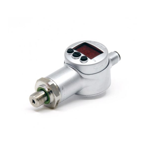
Page 5: Control Elements Of The Eds 3400
EDS 3400 CAUTION: The EDS 3400 must be fitted using a suitable open-end wrench (across flats 27) on the hexagon nut of the pressure connection. Inappropriate installation methods, such as manually fitting above the housing can damage the housing or even cause the device to fail completely, due to the rotatability of the EDS 3400.
-
Page 6: Reading The Digital Display
EDS 3400 Reading the digital display Representation on ASCII Description 7-segment display representation Accumulator precharge p Switch-of value not yet determined n. A . n.A. Actual system pressure Max value pre-set, output 1 (display only) Switch point, output 1 Switch point, output 2…
-
Page 7: Commissioning
RP2 and P.Low. The pressure must be P.Low when the hydro accumulator is completely emptied in order to enable the software of the EDS 3400 to complete the monitoring and to show p0 in the display. Check if p is displayed in the «main menu».
-
Page 8: Operation Modes
For detailed information on IO-Link device parameters, factory defaults, process and diagnostic data, supported standard system commands as well as additional HYDAC device specific system commands for the various product versions (part numbers), please refer to the corresponding IODD (IO Device Description).
-
Page 9: Manual Parameterisation On The Device
EDS 3400 MANUAL PARAMETERISATION ON THE DEVICE The EDS 3400 can be parameterised via the device keys PARAMETERISATION WITH HYDAC PROGRAMMING DEVICE HPG P1-000 (Connection with standard cable) HPG P1 Device Q1 / C PARAMETERISATION WITH HYDAC PROGRAMMING ADAPTER ZBE P1-000…
-
Page 10: Output Settings
EDS 3400 10 Output settings 10.1 SWITCHING OUTPUTS The EDS 3400 has 2 switching outputs whose switching behaviour (setting pre-charge pressure monitoring or twopoint mode) is parameterisable. In addition to the IO-Link Smart Sensor Profile Specification, a switch and switch-back delay can be set in HYDAC IO-Link sensors.
-
Page 11: Setting Of The Pre-Charge Pressure Monitoring
EDS 3400 10.1.2 Setting of the pre-charge pressure monitoring The pre-charge pressure monitoring is determined by the switching value («FL1). This is calculated as described in the following and can be checked in the main menu. = T.VAL – Td.Lo The output switches as soon as p leaves this range.
-
Page 12: Basic Settings
EDS 3400 11 Basic Settings The EDS 3400 can be adapted to suit the particular application as required by changing multiple settings. These settings are combined in a menu shown by the example of a –Guard with a measuring range of 0 .. 250 bar.
-
Page 13: Extended Functions
EDS 3400 11.2 EXTENDED FUNCTIONS Td.Hi: Max value, pre-set (may not be changed) Status: 2018-07-30 HYDAC INTERNATIONAL GMBH Part No.: 670000 E…
-
Page 14: Changing The Basic Settings
EDS 3400 12 Changing the Basic Settings NOTE: When the menu is activated, no switching operations are carried out! NOTE: If there has been no activity in this menu for approx. 60 seconds, the menu will automatically close and any changes you have made will not be applied.
-
Page 15: Program Enable
EDS 3400 15 Program enable The instrument has a program enable which must be set to change the settings. The program enable can be set or cancelled during operation. It provides protection against unintentional alterations of settings. 15.1 CHANGING THE PROGRAM ENABLE In the extended functions menu, please press the key «…
-
Page 16: Pin Connection
EDS 3400 17 PIN connection M 12×1, 4 pole Q1/C Q2/QA Signal Description Q2/QA Switching output for the accumulator charging function (SP2) / Analogue output Q1/C Switching output for the p – guarding function (SP1) / IO-Link communication Status: 2018-07-30 HYDAC INTERNATIONAL GMBH Part No.: 670000 E…
-
Page 17: Technical Data
EDS 3400 18 Technical Data Input data Measuring ranges 40 100 400 690 Overload pressures 80 200 800 1000 Burst pressure bar 200 500 1000 2000 2000 Mechanical connection G1/4 A ISO 1179-2 Tightening torque, recommended 20 Nm Parts in contact with fluid Mech.
-
Page 18: Order Details
EDS 3400 Relevant data for IO-Link: Download the IO Device Description (IODD) from: https://ioddfinder.io-link.com/#/ Features Block Parameters Data Storage Profile Characteristic 0x0001 (Device Profile: Smart Sensor), 0x8000 (Function Class: Device Identification), 0x8001 (Function Class: Binary Data Channel), 0x8002 (Function Class: Process Data Variables)
-
Page 19: Accessories
EDS 3400 20 Accessories 20.1 FOR ELECTRICAL CONNECTION ZBE 06 (4 pole) Female connector, right-angle Part No.: 6006788 ZBE 06-02 (4 pole) Female connector, right-angle with 2 m cable, Part No.: 6006790 ZBE 06-05 (4 pole) Female connector, right-angle with…
-
Page 20
EDS 3400 ZBM 3100 Clamp for wall-mounting — weld-type fitting — (Material of welding bridge: QSTE340TM, zinc coating EN 12329 FE/ZN8/B; Material of lower section: TPE Santoprene 10187; Material of top section: Steel strip DIN 95381-1.4571) Part No.: 3184632 ZBM 3200… -
Page 21: Instrument Dimensions
EDS 3400 21 Instrument dimensions Display adjustable 270° Housing adjustable 340° 6hex-SW27 ISO 1179-2 Elastomer profile gasket Din3869 Diameter connector M12x1 4-pole Status: 2018-07-30 HYDAC INTERNATIONAL GMBH Part No.: 670000 E…
-
Page 22
Fax: +49 (0) 6897 509-454 Email: speichertechnik@hydac.com Web: www.hydac.com HYDAC Service For enquiries regarding repairs, please contact HYDAC HYDAC SYSTEMS & SERVICES. HYDAC SYSTEMS & SERVICES GMBH Hauptstr. 27 D-66128 Saarbruecken Germany Phone: +49 (0)6897 509-1936 Fax: +49 (0)6897 509-1933 NOTE The information in this manual relates to the operating conditions and applications described.
![]()
Search
Request a Quote
Accessory Valves
Accumulators
Electronics
Filters
Fuel Filtration
Mobile Valves
Standard Coolers and Cooling Systems
| Brochure | Industry | Product Category | Size | |
|---|---|---|---|---|
|
|
Cooler Manual 2014 REV3.pdf | · Standard Coolers and Cooling Systems | 0.08 Mb |
-
Contents
-
Table of Contents
-
Bookmarks
Quick Links
Bedienungsanleitung
(Originalanleitung)
Operating Instructions
(Translation of original
instructions)
Notice d’utilisation
(traduction de l’original)
Elektronischer Druckschalter
Electronic Pressure Switch
Manocontacteur électronique
EDS 3000
Mit IO-Link Schnittstelle
With IO-Link Interface
Avec interface IO-Link
Related Manuals for Hydac EDS 3000
Summary of Contents for Hydac EDS 3000
-
Page 1
Elektronischer Druckschalter Electronic Pressure Switch Manocontacteur électronique EDS 3000 Mit IO-Link Schnittstelle With IO-Link Interface Avec interface IO-Link Bedienungsanleitung (Originalanleitung) Operating Instructions (Translation of original instructions) Notice d’utilisation… -
Page 2: Table Of Contents
ÄNDERN DER PROGRAMMIERFREIGABE 17 15 Nullpunktkalibrierung 16 Fehlermeldungen 17 Anschlussbelegung 18 Technische Daten 18.1 EDS 3000 MIT KERAMIK-SENSORZELLE; ABSOLUT- UND RELATIVDRUCK BIS 16 BAR (500 PSI) 19 18.2 EDS 3000 MIT DÜNNFILM DMS-SENSORZELLE; RELATIVDRUCK AB 40 BAR (1000 PSI) Stand: 04.02.2016 Mat.
-
Page 3
EDS 3000 IO-Link 19 Bestellangaben 19.1 EDS 3000 MIT KERAMIK-SENSORZELLE; ABSOLUT- UND RELATIVDRUCK BIS 16 BAR (500 PSI) 23 19.2 EDS 3000 MIT DÜNNFILM DMS-SENSORZELLE; RELATIVDRUCK AB 40 BAR (1000 PSI) 24 20 Zubehör 20.1 FÜR DEN ELEKTRISCHEN ANSCHLUSS 25 … -
Page 4
EDS 3000 IO-Link Vorwort Für Sie, den Benutzer unseres Produktes, haben wir in dieser Dokumentation die wichtigsten Hinweise zum Bedienen und Warten zusammengestellt. Sie dient Ihnen dazu, das Produkt kennen zu lernen und seine bestimmungsgemäßen Einsatzmöglichkeiten optimal zu nutzen. Diese Dokumentation muss ständig am Einsatzort verfügbar sein. -
Page 5: Sicherheitshinweis
Schaltparametern • Analogausgang Montage Der EDS 3000 kann über den Druckanschluss direkt bzw. indirekt mittels Schlauch oder Minimessleitung an einen Hydraulikblock montiert werden (Anzugsdrehmoment siehe Kap. 18 — Technische Daten). Zur optimalen Ausrichtung ist eine Verdrehung um 340° in der Längsachse, sowie um 270° im Display inkl. der Bedientasten möglich.
-
Page 6: Bedienelemente Des Eds 3000
(Schlüsselweite 27) am Sechskant des Druckanschlusses erfolgen. Eine unsachgemäße Montage, wie z. B. durch manuelles Eindrehen über das Gehäuse, kann aufgrund der Verdrehbarkeit des EDS 3000 zu Beschädigungen am Gehäuse, bis hin zum vollständigen Ausfall des Gerätes führen. Zusätzliche Montagehinweise, die erfahrungsgemäß den Einfluss elektromagnetischer Störungen reduzieren:…
-
Page 7: Betriebsarten
Modus hat Pin 4 die Funktion eines Schaltausganges. Die Mittel-LED leuchtet dauerhaft. Gemäß Kapitel 10 (Grundeinstellungen, Hauptmenü und erweiterte Funktionen) kann das Verhalten des EDS 3000 an die jeweilige Applikation angepasst werden. SDCI-MODE Über einen angeschlossenen IO-Link-Master kann der Druckschalter per Wake-Up-Signal in den SDCI-Mode (Single-drop digital communication interface for small sensors and actuators) geschaltet werden.
-
Page 8: Programmierung Im Sio Mode
EDS 3000 IO-Link Programmierung im SIO Mode Wir IO-Link nicht genutzt, so arbeitet der EDS 3000 IO-Link als Druckschalter mit 2 Schaltausgängen oder 1 Schaltausgang und 1 Analogausgang. Er kann mit dem HYDAC Programmiergerät HPG P1-000 oder dem HYDAC Programmieradapter ZBE P1-000 flexibel an die jeweilige Applikation angepasst werden.
-
Page 9: Darstellung Der Digitalanzeige
EDS 3000 IO-Link Darstellung der Digitalanzeige Darstellung Bezeichnung Darstellung ASCII 7-Segment-Anzeige Schaltpunkt, Ausgang 1 Rückschaltpunkt, Ausgang 1 Schaltpunkt, Ausgang 2 Rückschaltpunkt, Ausgang 2 Druckfenster oberer Wert, Ausgang 1 Druckfenster unterer Wert, Ausgang 1 Druckfenster oberer Wert, Ausgang 2 Druckfenster unterer Wert,…
-
Page 10
EDS 3000 IO-Link Fehleranzeige Display Rücksetzen Nein Reset Max-Wert rS.HL rS. k L Programmiersperre Nullpunktkalibrierung cALi CALi HINWEISE: • Übersteigt der aktuelle Druck den Nenndruck des Gerätes, so kann er nicht mehr angezeigt werden und die Anzeige beginnt zu blinken. -
Page 11: Ausgangsverhalten
EDS 3000 IO-Link 10 Ausgangsverhalten 10.1 SCHALTAUSGÄNGE Der EDS 3000 IO-Link verfügt über 2 Schaltausgänge, deren Schaltverhalten (Window mode oder Twopoint mode) parametriert werden können. Ergänzend zu der IO-Link Smart Sensor Profile Specification kann bei HYDAC IO-Link Sensoren eine Schalt- und Rückschaltverzögerung parametriert werden.
-
Page 12: Window Mode — Einstellung Auf Fensterfunktion (Fno / Fnc)
EDS 3000 IO-Link 10.1.2 Window mode — Einstellung auf Fensterfunktion (Fno / Fnc) Die Fensterfunktion ermöglicht es, einen Bereich zu überwachen. Zu jedem Schaltausgang können jeweils ein oberer und ein unterer Schaltwert eingegeben werden, die den Bereich bestimmen. Der jeweilige Ausgang schaltet, wenn der Druck in diesen Bereich eintritt.
-
Page 13: Einstellbereiche Für Die Schaltausgänge
EDS 3000 IO-Link 10.2 EINSTELLBEREICHE FÜR DIE SCHALTAUSGÄNGE Messbereich Untere Grenze Obere Grenze Mindestabstand Schrittweite* von RP / FL von SP / FH zw. RP und SP bzw. FL und FH in bar in bar in bar in bar — 1 .. 1…
-
Page 14: Grundeinstellungen
EDS 3000 IO-Link 11 Grundeinstellungen Zur Anpassung an die jeweilige Applikation kann das Verhalten des EDS 3000 über mehrere Einstellungen verändert werden. Diese sind zu einem Menü zusammengefasst. 11.1 HAUPTMENÜ Der Bereich wird nicht angezeigt, wenn in „Erweiterte Funktionen“ unter „ou2“ „i“ oder „u“ eingestellt ist.
-
Page 15: Erweiterte Funktionen
EDS 3000 IO-Link 11.2 ERWEITERTE FUNKTIONEN Der Bereich wird nicht angezeigt, wenn in „Erweiterte Funktionen“ unter „ou2“ „i“ oder „u“ eingestellt ist. Stand: 04.02.2016 Mat. Nr.: 669897 D HYDAC ELECTRONIC GMBH…
-
Page 16: Ändern Der Grundeinstellungen
EDS 3000 IO-Link 12 Ändern der Grundeinstellungen HINWEIS: • Bei aktiviertem Menü werden keine Schaltfunktionen ausgeführt! HINWEIS • Erfolgt ca. 60 Sekunden lang keine Tastenbetätigung wird das Menü automatisch beendet, ohne dass eventuelle Änderungen wirksam werden. Stand: 04.02.2016 Mat. Nr.: 669897 D…
-
Page 17: Programmierfreigabe
EDS 3000 IO-Link 13 Rücksetzen des Spitzenwertes Der Spitzenwert des Druckes kann zurückgesetzt werden. • In den Erweiterten Funktionen die Taste » » betätigen bis der Menüpunkt „rSHL“ erscheint. • » mode » -Taste betätigen. • Mit » » auf „YES“ setzen und mit der» mode «-Taste quittieren, nun wird Max-Wert zurückgesetzt.
-
Page 18: Fehlermeldungen
EDS 3000 IO-Link 16 Fehlermeldungen Wird ein Fehler erkannt, so erscheint eine entsprechende Fehlermeldung, die mit einem beliebigen Tastendruck quittiert werden muss. Mögliche Fehlermeldungen sind: Bei den abgespeicherten Einstellungen wurde ein Datenfehler erkannt. E.10 Mögliche Ursachen sind starke elektromagnetische Störungen oder ein Bauteildefekt.
-
Page 19: Technische Daten
EDS 3000 IO-Link 18 Technische Daten 18.1 EDS 3000 MIT KERAMIK-SENSORZELLE; ABSOLUT- UND RELATIVDRUCK BIS 16 BAR (500 PSI) Eingangskenngrößen Keramiksensor Absolutdruck Messbereiche Überlastbereich Berstdruck -1..1 Keramiksensor Relativdruck Messbereiche Überlastbereich Berstdruck Keramiksensor Absolutdruck Messbereiche Überlastbereich Berstdruck -14;5 to 75 Keramiksensor Relativdruck Messbereiche Überlastbereich…
-
Page 20
EDS 3000 IO-Link Sonstige Größen Versorgungsspannung 9 .. 35 V DC ohne Analogausgang 18 .. 35 V DC mit Analogausgang Restwelligkeit Versorgungsspannung ≤ 5 % Stromaufnahme ≤ 0,535 A mit aktiven Schaltausgängen ≤ 35 mA mit inaktiven Schaltausgängen ≤ 55 mA… -
Page 21: Eds 3000 Mit Dünnfilm Dms-Sensorzelle
EDS 3000 IO-Link 18.2 EDS 3000 MIT DÜNNFILM DMS-SENSORZELLE; RELATIVDRUCK AB 40 BAR (1000 PSI) Eingangskenngrößen Messbereiche Überlastbereich 1000 Berstdruck 1000 2000 2000 Messbereiche 1000 3000 6000 9000 Überlastbereich 2900 7250 11600 11600 Berstdruck 7250 14500 29000 29000 Mechanischer Anschluss Siehe Typenschlüssel…
-
Page 22
EDS 3000 IO-Link Relevante Daten für IO-Link: Features Block Parameter Data Storage Profile Characteristic 0x0001 (Device Profile: Smart Sensor), 0x8000 (Function Class: Device Identification), 0x8001 (Function Class: Binary Data Channel), 0x8002 (Function Class: Process Data Variables) Supported Access Locks Parameter… -
Page 23
EDS 3000 IO-Link 19 Bestellangaben 19.1 EDS 3000 MIT KERAMIK-SENSORZELLE; ABSOLUT- UND RELATIVDRUCK BIS 16 BAR (500 PSI) EDS 3 X X 6 — F31 — XXXX — XXX — X 1 Ausführung (Technologie) = Keramik absolut = Keramik relativ Anschlussart, mechanisch = G1/4 A ISO 1179-2 (DIN 3852), Außengewinde… -
Page 24
EDS 3000 IO-Link 19.2 EDS 3000 MIT DÜNNFILM DMS-SENSORZELLE; RELATIVDRUCK AB 40 BAR (1000 PSI) EDS 3 4 X 6 — F31 — XXXX — XXX Ausführung (Technologie) = Dünnfilm DMS relativ Anschlussart, mechanisch = G1/4 A ISO 1179-2 (DIN 3852) (nur in Verbindung mit Druckbereich in bar) = 9/16-18 UNF 2A (SAE6), Außengewinde… -
Page 25
EDS 3000 IO-Link 20 Zubehör 20.1 FÜR DEN ELEKTRISCHEN ANSCHLUSS ZBE 06 (4-pol.) Kupplungsdose, abgewinkelt Material-Nr.: 6006788 ZBE 06-02 (4-pol.) Kupplungsdose, abgewinkelt mit 2 m Leitung, Material-Nr.: 6006790 ZBE 06-05 (4-pol.), Kupplungsdose, abgewinkelt mit 5 m Leitung Farbkennung: Material-Nr.: 6006789 Pin 1: braun Pin 2: weiß… -
Page 26
EDS 3000 IO-Link ZBM 3100 Schelle zur Wandbefestigung, anschweißbar (Werkstoff Schweißlasche: QSTE340TM, galvanischer Überzug EN 12329 FE/ZN8/B; Unterteil: TPE Santoprene 10187; Oberteil: Bandstahl DIN 95381-1.4571) Material-Nr.: 3184632 ZBM 3200 Spritzwasserschutz (Werkstoff: Elastollan S60 A15 SPF 000) Material-Nr.: 3201919 Stand: 04.02.2016 Mat. -
Page 27
EDS 3000 IO-Link 21 Geräteabmessung Stand: 04.02.2016 Mat. Nr.: 669897 D HYDAC ELECTRONIC GMBH… -
Page 28
Betriebsbedingungen Einsatzfälle. abweichenden Einsatzfällen und/oder Betriebsbedingungen wenden Sie sich bitte an die entsprechende Fachabteilung. Bei technischen Fragen, Hinweisen oder Störungen nehmen Sie bitte Kontakt mit Ihrer HYDAC- Vertretung auf. Stand: 04.02.2016 Mat. Nr.: 669897 D HYDAC ELECTRONIC GMBH… -
Page 29
Electronic Pressure Switch EDS 3000 With IO-Link Interface Operating Instructions (Translation of original instructions) -
Page 30
15 Zero point calibration 16 Error Messages 17 Pin Assignment 18 Technical Data 18.1 EDS 3000 WITH CERAMIC SENSOR CELL; ABSOLUTE AND RELATIVE PRESSURE UP TO 16 BAR (500 PSI) 18.2 EDS 3000 WITH THIN FILM DMS SENSOR CELL;… -
Page 31
EDS 3000 WITH CERAMIC SENSOR CELL; ABSOLUTE AND RELATIVE PRESSURE UP TO 16 BAR (500 PSI) 19.2 EDS 3000 WITH THIN FILM DMS SENSOR CELL; RELATIVE PRESSURE STARTING AT 40 BAR (1000 PSI) 20 Accessories 20.1 FOR ELECTRICAL CONNECTION … -
Page 32
EDS 3000 IO-Link Preface This manual provides you, as user of our product, with key information on the operation and maintenance of the equipment. It will acquaint you with the product and assist you in obtaining maximum benefit in the applications for which it is designed. -
Page 33: Safety Information
• Analogue output Installation The EDS 3000 can be mounted directly via the pressure connection or indirectly on a hydraulic block using a hose or a minimess line (for torque value, see Chapter 18 — Technical specifications). To ensure optimum positioning, the unit can be rotated 340° about its long axis, and the display and keypad can be rotated through 270°.
-
Page 34: Control Elements Of The Eds 3000
Minimess hose, the housing must be earthed separately (e.g. with a screened cable). CAUTION: The EDS 3000 must be fitted using a suitable open-end wrench (across flats 27) on the hexagon nut of the pressure connection. Inappropriate installation methods, such as manually fitting above the housing can damage the housing or even cause the device to fail completely, due to the rotatability of the EDS 3000.
-
Page 35: Operation Modes
The centre LED is constantly lit. According Chapter 10 (basic settings, main menu and extended functions) the behaviour of the EDS 3000 can be adjusted to the corresponding application. SDCI MODE Via a connected IO-Link master the pressure switch can be switched to the SDCE mode (Single-drop digital communication interface for small sensors and actuators) by means of a wake-up signal.
-
Page 36: Programming In Sio Mode
EDS 3000 IO-Link Programming in SIO Mode If IO-Link is not used, the EDS 3000 IO-Link functions as a pressure switch with 2 switch outputs or 1 switch output and 1 analogue output. It can be flexibly adapted to the related application by means of the HYDAC programming device HPG P1-000 or the HYDAC programming adapter ZBE P1-000.
-
Page 37: Reading The Digital Display
EDS 3000 IO-Link Reading the digital display Representation on ASCII Designation 7-segment display representation Switch point, output 1 Switch-back point, output 1 Switch point, output 2 Switch-back point, output 2 Pressure window upper value output 1 Pressure window lower value…
-
Page 38
EDS 3000 IO-Link Display Reset Reset max value rS.HL rS. k L Programming lock Zero point calibration cALi CALi NOTES: • If the current pressure exceeds the device’s nominal pressure it can no longer be displayed, and the display begins to flash. -
Page 39: Output Signals
EDS 3000 IO-Link 10 Output Signals 10.1 SWITCHING OUTPUTS The EDS 3000 IO-Link has 2 switch outputs whose switching behaviour (window mode or twopoint mode) is parameterisable. In addition to the IO-Link Smart Sensor Profile Specification, a switch and switch-back delay can be set in HYDAC IO-Link sensors.
-
Page 40: Window Mode — Window Function Setting (Fno / Fnc))
EDS 3000 IO-Link 10.1.2 Window mode — Window function setting (Fno / Fnc)) The window function enables a range to be monitored. An upper and a lower switch point defining the range can be assigned to each switching output. The particular output is switched when the pressure enters this range.
-
Page 41: Setting Ranges For The Switching Outputs
EDS 3000 IO-Link 10.2 SETTING RANGES FOR THE SWITCHING OUTPUTS Measuring range Untere Grenze Upper limit of Minimum Increment* von RP / FL SP / FH difference betw. RP and SP or FL and FH in bar in bar in bar in bar — 1 ..
-
Page 42: Basic Settings
EDS 3000 IO-Link 11 Basic Settings The EDS 3000 can be adapted to suit the particular application as required by changing multiple settings. These settings are combined in a menu. 11.1 MAIN MENU The range is not displayed if «i» or «u»…
-
Page 43: Extended Functions
EDS 3000 IO-Link 11.2 EXTENDED FUNCTIONS The range is not displayed if «i» or «u» is pre-set under «ou2» in the «extended functions». Edition: 2016-02-04 Part No.: 669897 E HYDAC ELECTRONIC GMBH…
-
Page 44: Changing The Basic Settings
EDS 3000 IO-Link 12 Changing the Basic Settings NOTICE: • When the menu is activated, no switching operations are carried out! NOTICE: • If there has been no activity in this menu for approx. 60 seconds, the menu will automatically close and any changes you have made will not be applied.
-
Page 45: Resetting The Peak Value
EDS 3000 IO-Link 13 Resetting the peak value The pressure peak value can be reset. • In the extended functions menu, please press the key » » until „rSHL“ appears. • Press the «mode» key. • Press » » to select „YES“ and confirm by pressing the «mode» key — the max value is now set back.
-
Page 46: Error Messages
EDS 3000 IO-Link 16 Error Messages If an error is detected, a corresponding error message appears which must be acknowledged by pressing any key. Possible error messages are as follows: A data error has been detected in the saved settings. Possible causes are E.10…
-
Page 47: Technical Data
EDS 3000 IO-Link 18 Technical Data 18.1 EDS 3000 WITH CERAMIC SENSOR CELL; ABSOLUTE AND RELATIVE PRESSURE UP TO 16 BAR (500 PSI) Input data Ceramic sensor at absolute pressure Measuring ranges Overload ranges Burst pressures -1..1 Ceramic sensor at relative pressure…
-
Page 48
EDS 3000 IO-Link Other data Supply voltage 9 .. 35 V DC without analogue output 18 .. 35 V DC with analogue output Residual ripple of supply voltage ≤ 5 % ≤ 0.535 A Current consumption with active switch outputs ≤… -
Page 49: Eds 3000 With Thin Film Dms Sensor Cell
EDS 3000 IO-Link 18.2 EDS 3000 WITH THIN FILM DMS SENSOR CELL; RELATIVE PRESSURE STARTING AT 40 BAR (1000 PSI) Input data Measuring ranges Overload ranges 1000 Burst pressures 1000 2000 2000 Measuring ranges 1000 3000 6000 9000 Overload ranges…
-
Page 50
EDS 3000 IO-Link Relevant data concerning IO-Link: Features Block Parameters Data Storage Profile Characteristic 0x0001 (Device Profile: Smart Sensor), 0x8000 (Function Class: Device Identification), 0x8001 (Function Class: Binary Data Channel), 0x8002 (Function Class: Process Data Variables) Supported Access Locks Parameters… -
Page 51: Order Details
EDS 3000 IO-Link 19 Order details 19.1 EDS 3000 WITH CERAMIC SENSOR CELL; ABSOLUTE AND RELATIVE PRESSURE UP TO 16 BAR (500 PSI) EDS 3 X X 6 — F31 — XXXX — XXX — X 1 Model (technology) = Ceramic absolute…
-
Page 52: Eds 3000 With Thin Film Dms Sensor Cell; Relative Pressure Starting At 40 Bar (1000 Psi)
EDS 3000 IO-Link 19.2 EDS 3000 WITH THIN FILM DMS SENSOR CELL; RELATIVE PRESSURE STARTING AT 40 BAR (1000 PSI) EDS 3 4 X 6 — F31 — XXXX — 000 Model (technology) = Thin film DMS, relative Mechanical connection…
-
Page 53: Accessories
EDS 3000 IO-Link 20 Accessories 20.1 FOR ELECTRICAL CONNECTION ZBE 06 (4-pole) Female connector, right-angle Part No.: 6006788 ZBE 06-02 (4 pole) Female connector, right-angle with 2 m cable, Part No.: 6006790 ZBE 06-05 (4 pole) Female connector, right-angle with…
-
Page 54
EDS 3000 IO-Link ZBM 3100 Clamp for wall-mounting — weld-type fitting — (Material of welding bridge: QSTE340TM, zinc coating EN 12329 FE/ZN8/B; Material of lower section: TPE Santoprene 10187; Material of top section: Steel strip DIN 95381-1.4571) Material-No.: 3184632 ZBM 3200… -
Page 55
EDS 3000 IO-Link 21 Dimensions Display adjustable 270° Housing adjustable 340° 6hex-SW27 FPM- / EPDM seal Diameter connector M12x1 4-pole Edition: 2016-02-04 Part No.: 669897 E HYDAC ELECTRONIC GMBH… -
Page 56
D-66128 Saarbruecken Germany Web: E-Mail: Tel.: +49 (0)6897 509-01 Fax: +49 (0)6897 509-1726 HYDAC Service For enquiries regarding repairs, please contact HYDAC Service. HYDAC SERVICE GMBH Hauptstr. 27 D-66128 Saarbruecken Germany Tel.: +49 (0)6897 509-1936 Fax: +49 (0)6897 509-1933 Note The information in this manual relates to the operating conditions and applications described. -
Page 57
Manocontacteur électronique EDS 3000 Avec interface IO-Link Notice d’utilisation (traduction de l’original) -
Page 58
EDS 3000 IO-Link Sommaire 1 Consigne de sécurité 2 Exclusion de garantie 3 Fonctions de l’EDS 3000 4 Montage 5 Eléments de la face avant de l’EDS 3000 6 Modes de fonctionnement 6.1 MODE SIO MODE SDCI 7 Paramétrage 8 Programmation en Mode SIO PROGRAMMATION A L’AIDE DE L‘HPG P1-000… -
Page 59
EDS 3000 IO-Link 19 Code de commande 19.1 EDS 3000 AVEC CELLULE CERAMIQUE, PRESSION ABSOLUE ET RELATIVE JUSQU’A 16 BAR (500 PSI) 19.2 EDS 3000 AVEC CELLULE COUCHE MINCE, PRESSION RELATIVE A PARTIR DE 40 BAR (1000 PSI) … -
Page 60
EDS 3000 IO-Link Avant-propos Pour vous, utilisateur de notre produit, nous avons regroupé dans cette notice, les principales informations pour l’utilisation et la maintenance de l’appareil. Cette notice a pour objectif de simplifier la prise de connaissance du produit et l’exploitation optimale de ses possibilités d’utilisation, conformément à… -
Page 61: Consigne De Sécurité
• Sortie analogique Montage L’EDS 3000 peut être monté sur le bloc hydraulique directement via le raccord pression ou indirectement à l’aide d’une conduite flexible ou minimess (couple de serrage, voir chap. 18 — Caractéristiques techniques). Pour une orientation optimale, il est possible d’effectuer une rotation de 340° de l’axe longitudinal et de 270°…
-
Page 62: Eléments De La Face Avant De L’eds 3000
(largeur de clé: 27) à la pression du raccord métallique 6 pans Un mauvais montage, comme par exemple le vissage par le corps du capteur, en raison de l’orientation de l’EDS 3000, peut endommager le corps de l’appareil et peut entrainer la destruction du capteur.
-
Page 63: Modes De Fonctionnement
4 fonctionne comme sortie de commutation. L’indicateur LED du milieu est allumée en continu. Selon chapitre 10 (réglages de base, menu principal et fonctions complémentaires) le comportement de l’EDS 3000 peut être modifié pour s’adapter aux applications respectives. MODE SDCI Par le biais d’ un master IO-Link raccordé, vous pouvez faire passer le manocontacteur de…
-
Page 64: Programmation En Mode Sio
EDS 3000 IO-Link Programmation en Mode SIO Lorsque IO-Link n’est pas utilisé, l‘EDS 3000 IO-Link fonctionne comme manocontacteur avec 2 sorties de commutation ou 1 sortie de commutation et 1 sortie analogique. Vous pouvez souplement l’adapter à l’application respective à l’aide de l’appareil de programmation HYDAC HPG P1-000 ou à…
-
Page 65: Description De L’affichage Digital
EDS 3000 IO-Link Description de l’affichage digital Description Désignation affichage Description ASCII 7 segments Point de commutation, sortie 1 Point de déclenchement, sortie 1 Point de commutation, sortie 2 Point de déclenchement, sortie 2 Fenêtre de pression valeur supérieure Sortie 1 Fenêtre de pression valeur inférieure…
-
Page 66
EDS 3000 IO-Link Affichage d’erreur Ecran Fonctions complémentaires RAZ valeur max rS.HL rS. k L Verrou de programmation Calibrage du point zéro cALi CALi Nouveau REMARQUES : • Si la pression actuelle dépasse la pression nominale de l’appareil, alors celle-ci ne peut plus être affichée et l’affichage clignote. -
Page 67: Fonctionnement Des Sorties
10 Fonctionnement des sorties 10.1 SORTIES DE COMMUTATION L’EDS 3000 IO-Link dispose de 2 sorties de commutation dont le comportement de commutation (Window mode ou Twopoint mode) peut être paramétré. En plus d’une «IO-Link Smart Sensor Profile Specification», la temporisation à…
-
Page 68: Fonction Fenêtre — Réglage Fonction Fenêtre (Fno / Fnc)
EDS 3000 IO-Link 10.1.2 Fonction fenêtre — Réglage fonction fenêtre (Fno / Fnc) La fonction fenêtre permet de surveiller une plage. Pour chaque sortie de commutation, il est possible d’entrer une valeur de commutation supérieure et inférieure qui définissent la plage.
-
Page 69: Réglage Des Sorties De Commutation
EDS 3000 IO-Link 10.2 RÉGLAGE DES SORTIES DE COMMUTATION Plage de mesure Seuil inférieur de Seuil supérieur Distance Pas* RP / FL de SP / FH minimum entre RP et SP ou FL et FH en bar en bar en bar en bar — 1 ..
-
Page 70: Menu De Base
EDS 3000 IO-Link 11 Menu de base Afin de s’adapter à chaque application, le fonctionnement de l’EDS 3000 peut être modifié à l’aide de plusieurs réglages de base. Ceux-ci sont regroupés dans un menu. 11.1 MENU PRINCIPAL La zone n’est pas affichée si «i» ou «u»…
-
Page 71: Fonctions Complementaires
EDS 3000 IO-Link 11.2 FONCTIONS COMPLEMENTAIRES La zone n’est pas affichée si «i» ou «u» est réglé dans le point de menu «fonctions complémentaires» sous «ou2». Edition : 04/02/2016 Code art. : 669897 F HYDAC ELECTRONIC GMBH…
-
Page 72: Modifications Dans Le Menu De Base
EDS 3000 IO-Link 12 Modifications dans le menu de base REMARQUE : • En activant ce menu les fonctions de commutations sont désactivées. REMARQUE : • Si au bout de 60 secondes, aucune touche n’a été appuyée, l’affichage retourne à son état de fonctionnement normal sans sauvegarde des modifications.
-
Page 73: Activation De La Programmation
EDS 3000 IO-Link 13 Réinitialiser la valeur supérieure La valeur supérieure de pression se peut réinitialiser. • Dans le menu «fonctions complémentaires», appuyer la touche » » jusqu’à ce que le point de menu «rSHL» est affiché. • Appuyer sur touche «mode».
-
Page 74: Messages D’erreur
EDS 3000 IO-Link 16 Messages d’erreur Dès que l’appareil détecte une erreur, un message d’erreur est affiché : celui-ci doit être acquitté avec n’importe quelle touche. Les différents messages d’erreurs sont : Lors de la sauvegarde des réglages, une erreur a été détectée. Les sources E.10…
-
Page 75: Caractéristiques Techniques
EDS 3000 IO-Link 18 Caractéristiques techniques 18.1 EDS 3000 AVEC CELLULE CERAMIQUE, PRESSION ABSOLUE ET RELATIVE JUSQU’A 16 BAR (500 PSI) Valeurs d’entrée capteur céramique pression absolue Plages de mesure Plages de surcharge Pression d’éclatement -1..1 capteur céramique pression relative…
-
Page 76
EDS 3000 IO-Link Autres caractéristiques Tension d‘alimentation 9 .. 35 V DC sans sortie analogique 18 .. 35 V DC avec sortie analogique Oscillation résiduelle de la tension d’alim. ≤ 5 % Consommation électrique ≤ 0,535 A avec sorties de commutation actives ≤… -
Page 77: Eds 3000 Avec Cellule Couche Mince, Pression Relativea Partir De 40 Bar (1000 Psi)
EDS 3000 IO-Link 18.2 EDS 3000 AVEC CELLULE COUCHE MINCE, PRESSION RELATIVE A PARTIR DE 40 BAR (1000 PSI) Valeurs d’entrée Plages de mesure Plages de surcharge 1000 Pression d’éclatement 1000 2000 2000 Plages de mesure 1000 3000 6000 9000…
-
Page 78
EDS 3000 IO-Link Données spécifiques IO-Link : Caractéristiques Paramètres Stockage des données Profiles characteristiques 0x0001 (Device Profile: Smart Sensor), 0x8000 (Function Class: Device Identification), 0x8001 (Function Class: Binary Data Channel), 0x8002 (Function Class: Process Data Variables) Supported Access Locks Paramètres Stockage des données… -
Page 79
EDS 3000 IO-Link 19 Code de commande 19.1 EDS 3000 AVEC CELLULE CERAMIQUE, PRESSION ABSOLUE ET RELATIVE JUSQU’A 16 BAR (500 PSI) EDS 3 X X 6 — F31 — XXXX — XXX — X 1 Exécution (technologie) = Céramique absolue = Céramique relative… -
Page 80
EDS 3000 IO-Link 19.2 EDS 3000 AVEC CELLULE COUCHE MINCE, PRESSION RELATIVE A PARTIR DE 40 BAR (1000 PSI) EDS 3 4 X 6 — F31 — XXXX — 000 Exécution (technologie) = Couche mince relative Raccordement mécanique = G1/4 A ISO 1179-2 (DIN 3852), (extérieur) (avec plage de pression en bar) = 9/16-18 UNF 2A (SAE6), (extérieur) -
Page 81
EDS 3000 IO-Link 20 Accessoires 20.1 POUR LE RACCORDEMENT ELECTRIQUE ZBE 06 (4-pôles) Connecteur, coudé Code art : 6006788 ZBE 06-02 (4-pôles) Connecteur, coudé avec 2m de câble Code art : 6006790 ZBE 06-05 (4-pôles) Connecteur, coudé avec 5m de câble… -
Page 82
EDS 3000 IO-Link ZBM 3100 Collier pour fixation murale, à souder (Matériau collier à souder : QSTE340TM, galvanisé EN 12329 FE/ZN8/B; (Matériau partie inférieure : TPE Santoprene 10187 ; Matériau partie supérieure : acier DIN 95381-1.4571) Code art : 3184632… -
Page 83
EDS 3000 IO-Link 21 Encombrements orientation corps 270° orientation corps 340° Joint elastomère DIN 3869 Diamètre Embase M12x1 4 pôles Joint torique 11,89×1,98 Edition : 04/02/2016 Code art. : 669897 F HYDAC ELECTRONIC GMBH… -
Page 84
E-mail : electronic@hydac.com Tél. : +49(0)6897 / 509-01 Fax.: +49 (0)6897 509-1726 HYDAC Service Pour toute question concernant les réparations, HYDAC Service se tient à votre disposition. HYDAC SERVICE GMBH Hauptstr. 27 D-66128 Saarbrücken Allemagne Tél. : +49 (0) 6897 / 509 – 1936 Fax : +49 (0) 6897 / 509 –…

Electronic Pressure Switch
EDS 300
User manual
Stand 10.11.2000