- Manuals
- Brands
- Huawei Manuals
- UPS
- UPS2000-A Series
- User manual
-
Contents
-
Table of Contents
-
Troubleshooting
-
Bookmarks
Quick Links
UPS2000-A-(6 kVA-10 kVA)
User Manual
Issue
05
Date
2019-12-19
HUAWEI TECHNOLOGIES CO., LTD.
Related Manuals for Huawei UPS2000-A Series
Summary of Contents for Huawei UPS2000-A Series
-
Page 1
UPS2000-A-(6 kVA-10 kVA) User Manual Issue Date 2019-12-19 HUAWEI TECHNOLOGIES CO., LTD. -
Page 2
Notice The purchased products, services and features are stipulated by the contract made between Huawei and the customer. All or part of the products, services and features described in this document may not be within the purchase scope or the usage scope. Unless otherwise specified in the contract, all statements, information, and recommendations in this document are provided «AS IS»… -
Page 3: About This Document
Indicates a potentially hazardous situation which, if not avoided, could result in equipment damage, data loss, performance deterioration, or unanticipated results. NOTICE is used to address practices not related to personal injury. Issue 05 (2019-12-19) Copyright © Huawei Technologies Co., Ltd.
-
Page 4
Updated the section «Operating Environment». Issue 03 (2018-01-16) Added the description of device application scenarios. Issue 02 (2017-11-27) Updated the section «Operating Environment». Issue 01 (2015-08-18) This is the first release. Issue 05 (2019-12-19) Copyright © Huawei Technologies Co., Ltd. -
Page 5: Table Of Contents
3.2.3.3 Connecting Cables to the UPS Standard Version with Long Backup Time …………41 3.2.3.4 Connecting Cables to the UPS Professional Version with Long Backup Time ………… 42 3.3 Parallel System Installation ……………………….44 Issue 05 (2019-12-19) Copyright © Huawei Technologies Co., Ltd.
-
Page 6
6 Communications ……………………110 6.1 Optional Communications Components ……………………110 6.2 SNMP Card …………………………..110 6.3 Modbus Card …………………………..111 6.4 Dry Contact Card …………………………111 7 Routine Maintenance ………………….. 112 Issue 05 (2019-12-19) Copyright © Huawei Technologies Co., Ltd. -
Page 7
9.7 ECO Feature …………………………..129 9.8 Parallel Feature …………………………… 130 9.9 Safety Regulations and EMC ………………………. 130 A Parallel Parameter List ………………….132 B Alarm Handling ……………………133 C Acronyms and Abbreviations ………………..153 Issue 05 (2019-12-19) Copyright © Huawei Technologies Co., Ltd. -
Page 8: Safety Information
The «NOTICE», «WARNING», and «DANGER» statements in this document do not cover all the safety instructions. They are only supplements to the safety instructions. Huawei will not be liable for any consequence caused by the violation of general safety requirements or design, production, and usage safety standards.
-
Page 9
Keep irrelevant people away from the equipment. Only operators are allowed to access the equipment. Use insulated tools or tools with insulated handles, as shown in the following figure. Issue 05 (2019-12-19) Copyright © Huawei Technologies Co., Ltd. -
Page 10
To avoid electric shock, do not connect safety extra-low voltage (SELV) circuits to telecommunication network voltage (TNV) circuits. Issue 05 (2019-12-19) Copyright © Huawei Technologies Co., Ltd. -
Page 11: Personnel Requirements
Do not power on the equipment before it is installed or confirmed by professionals. 1.2 Personnel Requirements Personnel who plan to install or maintain Huawei equipment must receive thorough training, understand all necessary safety precautions, and be able to correctly perform all operations.
-
Page 12
When selecting, connecting, and routing cables, follow local safety regulations and rules. The static electricity generated by human bodies may damage the electrostatic-sensitive components on boards, for example, the large-scale integrated (LSI) circuits. Issue 05 (2019-12-19) Copyright © Huawei Technologies Co., Ltd. -
Page 13: Installation Environment Requirements
Ensure that the equipment room provides good heat insulation, and the walls and floor are dampproof. Install a rat guard at the door of the equipment room. Issue 05 (2019-12-19) Copyright © Huawei Technologies Co., Ltd.
-
Page 14: Mechanical Safety
Before hoisting objects, ensure that hoisting tools are firmly secured onto a load-bearing object or wall. Ensure that the angle formed by two hoisting cables is no more than 90 degrees, as shown in the following figure. Issue 05 (2019-12-19) Copyright © Huawei Technologies Co., Ltd.
-
Page 15
Do not climb higher than the fourth rung of the ladder from the top. Ensure that your body’s center of gravity does not shift outside the legs of the ladder. Issue 05 (2019-12-19) Copyright © Huawei Technologies Co., Ltd. -
Page 16: Device Running Safety
Metal shavings from drilling may short-circuit boards inside the equipment. Obtain the consent from the customer, subcontractor, and Huawei before drilling. Wear goggles and protective gloves when drilling holes. …
-
Page 17
The UPS can be configured with a backfeed protection dry contact to work with an external automatic circuit breaker, preventing the voltage from flowing back to input terminals over static bypass circuits. If the installation and maintenance personnel do not need backfeed Issue 05 (2019-12-19) Copyright © Huawei Technologies Co., Ltd. -
Page 18: Battery Safety
Dispose of waste batteries in accordance with local laws and regulations. Do not dispose of batteries as household waste. If a battery is disposed of improperly, it may explode. Issue 05 (2019-12-19) Copyright © Huawei Technologies Co., Ltd.
-
Page 19
The site must be equipped with qualified fire extinguishing facilities, such as firefighting sands and powder fire extinguishers. To ensure battery safety and battery management accuracy, use batteries provided with the UPS by Huawei. Huawei is not responsible for any battery faults caused by batteries not provided by Huawei. Battery Installation Before installing batteries, observe the following safety precautions: … -
Page 20: Others
Exercise caution when manually shutting down the UPS inverter for transferring to bypass mode, or when adjusting the UPS output voltage level or frequency. Doing so may affect the power supply to equipment. Issue 05 (2019-12-19) Copyright © Huawei Technologies Co., Ltd.
-
Page 21
UPS2000-A-(6 kVA-10 kVA) User Manual 1 Safety Information Exercise caution when setting battery parameters. Incorrect settings will affect the power supply and battery lifespan. Issue 05 (2019-12-19) Copyright © Huawei Technologies Co., Ltd. -
Page 22: Overview
UPS2000-A-10KTTL-S 10 kVA standard version with long backup time 10 kVA UPS2000-A-10KTTS-P professional version with standard backup time Issue 05 (2019-12-19) Copyright © Huawei Technologies Co., Ltd.
-
Page 23: Working Principle
L: long backup time model, using external large-capacity batteries that provide long backup time. Standard/Professional S: standard version standard P: professional version 2.2 Working Principle 2.2.1 Conceptual Diagram Figure 2-2 shows the UPS conceptual diagram. Issue 05 (2019-12-19) Copyright © Huawei Technologies Co., Ltd.
-
Page 24: Working Modes
ECO is short for economy control operation. By default, ECO mode described in this document refers to mains ECO mode. 2.3 Appearance Figure 2-3 shows the side view of the 6 kVA/10 kVA UPS. Issue 05 (2019-12-19) Copyright © Huawei Technologies Co., Ltd.
-
Page 25
Mounting brackets are optional for UPSs with standard backup time and battery boxes and are not required for UPSs with long backup time. Figure 2-4 shows the rear view of the 6 kVA/10 kVA UPS standard version with standard backup time. Issue 05 (2019-12-19) Copyright © Huawei Technologies Co., Ltd. -
Page 26
(7) AC output power-off (EPO) terminal (under the terminal (under the port cover) cover) Figure 2-5 shows the rear view of the 6 kVA/10 kVA UPS standard version with long backup time. Issue 05 (2019-12-19) Copyright © Huawei Technologies Co., Ltd. -
Page 27
(under terminal (under the terminal (under the port the cover) cover) cover) Figure 2-6 shows the rear view of the 6 kVA/10 kVA UPS professional version with long backup time Issue 05 (2019-12-19) Copyright © Huawei Technologies Co., Ltd. -
Page 28
UPS terminal (under the (under the cover) (under the cover) cover) Figure 2-7 shows the rear view of the UPS2000-A-6 kVA/10 kVA professional version with long backup time Issue 05 (2019-12-19) Copyright © Huawei Technologies Co., Ltd. -
Page 29
The USB port supports the standard Modbus protocol and connects to a PC through a USB cable so that you can access the NMS, configure parameters, export data, and upgrade software. Issue 05 (2019-12-19) Copyright © Huawei Technologies Co., Ltd. -
Page 30: Optional Components
Huawei product). A temperature and humidity sensor is optional. The SNMP card can also be used for web monitoring. It can be accessed through Internet Explorer and applies to large-scale and Issue 05 (2019-12-19) Copyright © Huawei Technologies Co., Ltd.
-
Page 31
Modbus or YDN-23 protocol. Dry contact RMS-RELAY01A Provides six alarm dry card contact outputs (normal mode, battery mode, bypass mode, low battery voltage, bypass backfeed, and UPS faults) and two dry Issue 05 (2019-12-19) Copyright © Huawei Technologies Co., Ltd. -
Page 32
GSM are strong.) modems. Modem TD-8013 The modem and NetEco work together to provide the SMS alarm notification function. One modem needs to be configured. Issue 05 (2019-12-19) Copyright © Huawei Technologies Co., Ltd. -
Page 33
UPS2000-A-(6 kVA-10 kVA) User Manual 2 Overview Component Model Function Remarks The input port of the power adapter of the modem complies with international standards. Issue 05 (2019-12-19) Copyright © Huawei Technologies Co., Ltd. -
Page 34: Installation
Do not install the UPS in environments with conductive metal scraps in the air. The ideal operating temperature for batteries is 20–30º C. Temperatures higher than 30º C shorten the battery lifespan and temperatures lower than 20º C reduces the backup time. Issue 05 (2019-12-19) Copyright © Huawei Technologies Co., Ltd.
-
Page 35
Reserve a clearance of at least 500 mm respectively from the front and rear panels of the UPS to the wall or adjacent equipment to facilitate ventilation and heat dissipation, as shown in Figure 3-2. Issue 05 (2019-12-19) Copyright © Huawei Technologies Co., Ltd. -
Page 36: Tools
Clamp meter Multimeter Label Phillips screwdriver (PH 2 mm x 150 mm or PH 3 mm x 250 Flat-head COAX crimping Torque screwdriver Diagonal pliers screwdriver (2 mm tool x 80 mm) Issue 05 (2019-12-19) Copyright © Huawei Technologies Co., Ltd.
-
Page 37: Power Cables
(PVC) insulation tape Heat shrink tubing Heat gun Electrician’s knife Protective gloves ESD gloves Insulated gloves Hydraulic pliers Cable tie Hammer drill and Rubber mallet drill bit φ16 3.1.3 Power Cables Issue 05 (2019-12-19) Copyright © Huawei Technologies Co., Ltd.
-
Page 38
50 A 6 mm 10 kVA Input 220 V 63 A 10 mm OT-10 2.8 N.m standard AC, 230 (feature version V AC, or terminal with 240 V Output 63 A standard Issue 05 (2019-12-19) Copyright © Huawei Technologies Co., Ltd. -
Page 39
10 kVA 208 V 63 A OT-10 Input 10 mm professional AC, 220 (feature version with V AC, standard 230 V termin Output 63 A backup time AC, or (feature 240 V Issue 05 (2019-12-19) Copyright © Huawei Technologies Co., Ltd. -
Page 40: Unpacking And Checking
If customers purchase input and output power cables by themselves, use the cables that comply with standards proposed by Underwriters Laboratories (UL) or International Electrotechnical Commission (IEC). 3.1.4 Unpacking and Checking Figure 3-3 shows the transportation safety requirements. Figure 3-3 Transportation safety requirements Issue 05 (2019-12-19) Copyright © Huawei Technologies Co., Ltd.
-
Page 41: Single Ups Installation
If there is any discrepancy, contact your local Huawei office immediately. Check that the fittings comply with the packing list. If some fittings are missing or do not comply with the packing list, record the information and contact your local Huawei office immediately.
-
Page 42: Securing A Ups
Securing the UPS Using Brake Pads Step 1 Move the UPS to the installation position. Step 2 Press down the brake pads to immobilize the UPS, as shown in Figure 3-5. Issue 05 (2019-12-19) Copyright © Huawei Technologies Co., Ltd.
-
Page 43
Mounting brackets are optional for UPSs with standard backup time and battery boxes and are not required for UPSs with long backup time. Issue 05 (2019-12-19) Copyright © Huawei Technologies Co., Ltd. -
Page 44
Step 4 Use a hammer drill to drill holes for installing the M12x60 expansion bolts and then install the expansion sleeve in the holes. Figure 3-8 shows expansion bolt composition. Figure 3-9 shows how to install an expansion bolt. Issue 05 (2019-12-19) Copyright © Huawei Technologies Co., Ltd. -
Page 45
Partially tighten the expansion bolt and vertically insert it into the hole. Knock the expansion bolt using a rubber mallet until the expansion sleeve is fully inserted into the hole. Partially tighten the expansion bolt. Issue 05 (2019-12-19) Copyright © Huawei Technologies Co., Ltd. -
Page 46: Connecting Cables
Step 1 Switch off the AC input circuit breaker at the rear of the UPS and the upstream AC circuit breaker of the UPS. Step 2 Remove the UPS input and output wiring cover. Issue 05 (2019-12-19) Copyright © Huawei Technologies Co., Ltd.
-
Page 47: Connecting Cables To The Ups Professional Version With Standard Backup Time
Step 4 Install AC output power cables and then AC input power cables, as shown in Figure 3-12. A short-circuit bar is required only for a single UPS, but not a parallel system. Issue 05 (2019-12-19) Copyright © Huawei Technologies Co., Ltd.
-
Page 48: Connecting Cables To The Ups Standard Version With Long Backup Time
Step 4 Install battery cables to external battery strings or external battery boxes. Figure 3-14 shows connecting cables to external battery strings, Figure 3-15 shows connecting cables to external battery boxes. Issue 05 (2019-12-19) Copyright © Huawei Technologies Co., Ltd.
-
Page 49: Connecting Cables To The Ups Professional Version With Long Backup Time
Procedure Step 1 Switch off the AC input and output circuit breakers at the rear of the UPS, the upstream AC circuit breaker of the UPS, and the battery circuit breaker. Issue 05 (2019-12-19) Copyright © Huawei Technologies Co., Ltd.
-
Page 50
One or two battery boxes can be connected. For details, see the ESS-240V12- 2*(9AhBPVBA, 7AhBPVBA) Quick Guide. If longer backup time is required, the large battery rack solution is recommended. Issue 05 (2019-12-19) Copyright © Huawei Technologies Co., Ltd. -
Page 51: Parallel System Installation
UPS with long backup time. Figure 3-19 Figure 3-20 use a UPS professional version with long backup time as an example to illustrate how to route cables. Route cables in other scenarios similarly. Issue 05 (2019-12-19) Copyright © Huawei Technologies Co., Ltd.
-
Page 52: Securing Upss In A Parallel System
(2) AC output power cable 3.3.2 Securing UPSs in a Parallel System Procedure Step 1 Secure each UPS in a parallel system by following the instructions provided in 3.2.2 Securing UPS. —-End Issue 05 (2019-12-19) Copyright © Huawei Technologies Co., Ltd.
-
Page 53: Connecting Cables To Parallel Upss (Professional Version With Standard Backup Time)
Step 2 Remove the AC input and output wiring cover from each UPS in the parallel system. Step 3 Install AC output power cables and then AC input power cables for each UPS in the parallel system, as shown in Figure 3-21. Issue 05 (2019-12-19) Copyright © Huawei Technologies Co., Ltd.
-
Page 54
Step 4 Reinstall the AC input and output wiring cover on the UPS. Step 5 Connect parallel cables, as shown in Figure 3-22. Issue 05 (2019-12-19) Copyright © Huawei Technologies Co., Ltd. -
Page 55: Connecting Cables To Parallel Upss (Professional Version With Long Backup Time)
Step 2 Remove the AC input, AC output and battery wiring cover from each UPS in the parallel system. Step 3 Install AC output power cables, and AC input power cables in sequence for each UPS in the parallel system, as shown in Figure 3-23. Issue 05 (2019-12-19) Copyright © Huawei Technologies Co., Ltd.
-
Page 56
UPS and a parallel system is the same. Step 5 Reinstall the AC input, output, and battery wiring cover on the UPS. Step 6 Connect parallel cables, as shown in Figure 3-24. Issue 05 (2019-12-19) Copyright © Huawei Technologies Co., Ltd. -
Page 57: Installing A Backfeed Protection Device
To minimize the risk of electric shocks, install a backfeed protection device on the input side. Table 3-4 lists the rated voltages and currents for backfeed protection contactors on the UPSs. Issue 05 (2019-12-19) Copyright © Huawei Technologies Co., Ltd.
-
Page 58: Feedback Prevention Connections (With Dry Contract Control)
Coil: 12 V rated voltage; rated current of HJ2-L-DC12V (Panasonic control relay) less than 1 A 3.4.2 Feedback Prevention Connections (With Dry Contract Control) Figure 3-25 Figure 3-26 show backfeed protection connections (with dry contract control). Issue 05 (2019-12-19) Copyright © Huawei Technologies Co., Ltd.
-
Page 59
UPS2000-A-(6 kVA-10 kVA) User Manual 3 Installation Figure 3-25 Bypass backfeed protection connections for the UPS2000-A-6 kVA/10 kVA (single-phase input single-phase output) Issue 05 (2019-12-19) Copyright © Huawei Technologies Co., Ltd. -
Page 60: Check After Installation
Ground cable connection The ground cable is securely connected to the equipment room ground bar. Measure the resistance between the UPS ground Issue 05 (2019-12-19) Copyright © Huawei Technologies Co., Ltd.
-
Page 61
0.1 ohm. Distances between cable ties Distances between cable ties are the same, and no burr exists. Operating environment Clean the conductive air and other sundries. Issue 05 (2019-12-19) Copyright © Huawei Technologies Co., Ltd. -
Page 62: Control Panel
(3) Bypass (4) Fault indicator indicator indicator (5) Enter/Startup/Battery (6) Down (7) Up button (8) Shutdown/Back Self-Check /Mute button button button 4.2 Indicators Table 4-1 describes the indicators on the control panel. Issue 05 (2019-12-19) Copyright © Huawei Technologies Co., Ltd.
-
Page 63: Functional Buttons
Enter/Startup/Battery On the default screen in bypass mode, hold Self-Check/Mute down for more than 5 seconds. Release the button when you hear a beep sound. The UPS starts. Issue 05 (2019-12-19) Copyright © Huawei Technologies Co., Ltd.
-
Page 64: Lcd
30 seconds. 4.5 LCD Startup Screens Table 4-3 Symbol conventions Symbol Description Press A. Press B after you press A. The symbol conventions apply to all chapters in this document. Issue 05 (2019-12-19) Copyright © Huawei Technologies Co., Ltd.
-
Page 65
4 Control Panel The LCD snapshots in this document correspond to the software version V100. If any LCD changes are made, contact Huawei technical support to obtain the latest snapshots. The information in the menu pictures is for reference only. -
Page 66
0%-25% (excluding 0%): Indicator 1 is steady on. 0%: Indicators 1, 2, 3, and 4 are off. Working No power Battery mode supply (mains charging connected) Others No power is Battery supplied discharging (batteries Issue 05 (2019-12-19) Copyright © Huawei Technologies Co., Ltd. -
Page 67
Others Battery mode ECO mode Battery charging Others Table 4-5 Description of working mode icons Symbol Meaning Mains input Rectifier/PFC working Battery mode Battery charging Battery hibernation Inverter mode Bypass mode Issue 05 (2019-12-19) Copyright © Huawei Technologies Co., Ltd. -
Page 68: Starting The Ups In Normal Mode
. Then, the LCD screen lights up. After the screen lights up for 1 second, initialization starts. After the initialization progress is complete, the default screen is displayed, as shown in Figure 4-5. Issue 05 (2019-12-19) Copyright © Huawei Technologies Co., Ltd.
-
Page 69: Lcd Menu Hierarchy
Table 4-6 Letter and LCD display mapping Letter Letter Letter Letter Display Display Display Display Number and LCD display mapping Table 4-7 lists the mapping between numbers and the LCD display. Issue 05 (2019-12-19) Copyright © Huawei Technologies Co., Ltd.
-
Page 70
LCD display. Table 4-9 Control menu Acronym and LCD Display No. Actual Display Meaning Abbreviation INV ON Starts the UPS. INV OFF Shuts down the UPS. ALR CLR Clears ADMC alarms. Issue 05 (2019-12-19) Copyright © Huawei Technologies Co., Ltd. -
Page 71
Acronym and Meaning Abbreviation Output voltage level Output frequency system Maximum bypass voltage Minimum bypass voltage Number of batteries Total battery capacity Charge current limit EOD mode Discharge time protection setting Issue 05 (2019-12-19) Copyright © Huawei Technologies Co., Ltd. -
Page 72: Control Menu
Table 4-11. Table 4-11 Control menu and parameters Name Function Control Starts or shuts menu down the inverter, clears ADMC alarms, replaces batteries, synchronizes parallel parameters, and restores default settings. Issue 05 (2019-12-19) Copyright © Huawei Technologies Co., Ltd.
-
Page 73
UPS2000-A-(6 kVA-10 kVA) User Manual 4 Control Panel Name Function Start Starts the inverter manually. Shutdo Shuts down the inverter manually. Clear Clears ADMC ADMC alarms. Alarms Issue 05 (2019-12-19) Copyright © Huawei Technologies Co., Ltd. -
Page 74: Setting Menu
UPSs in the parallel system. Parameters cannot be synchronized for UPSs running in inverter output mode. Restore Restores default Default settings after you Settings shut down the inverter. 4.6.2 Setting Menu Issue 05 (2019-12-19) Copyright © Huawei Technologies Co., Ltd.
-
Page 75
On the default screen, press Table and then ▲ to select a parameter and press 4-12. On the parameter setting screen, press Table 4-12 Setting parameters Function Value Preset Remarks Range Value Sett parameters. Issue 05 (2019-12-19) Copyright © Huawei Technologies Co., Ltd. -
Page 76
45 Hz to 55 Hz, and the system output frequency is 50 Hz; if power-on bypass frequency ranges from (excluding 55 Hz) 55 Hz to 65 Issue 05 (2019-12-19) Copyright © Huawei Technologies Co., Ltd. -
Page 77
10%, 15%, associated 20%, with the system 25%. voltage If the level. voltage system is 230 V, the values include 10%, 15%, 20%. If the voltage system is 240 Issue 05 (2019-12-19) Copyright © Huawei Technologies Co., Ltd. -
Page 78
Issue 05 (2019-12-19) Copyright © Huawei Technologies Co., Ltd. -
Page 79
ECO mode. backup time: 16 (not configu rable) kVA/10 professi onal version with standar backup time: 20 (not configu rable) kVA/10 with long backup time: Issue 05 (2019-12-19) Copyright © Huawei Technologies Co., Ltd. -
Page 80
The time: mode. interval is 2.0 A 0.5 A. (unconf igurable 10 kVA with standar backup time: 2.0 A (unconf igurable 6 kVA with long Issue 05 (2019-12-19) Copyright © Huawei Technologies Co., Ltd. -
Page 81
ECO mode. provide a long backup time) (Battery first: protect batterie s and extend battery lifespan (Balanc e mode) default value is Backup time first. Issue 05 (2019-12-19) Copyright © Huawei Technologies Co., Ltd. -
Page 82
Indicates The value whether to (disabled) allow a and ENA configura single UPS (enabled) ble only to work in after the blin ECO mode. inverter shuts down. Issue 05 (2019-12-19) Copyright © Huawei Technologies Co., Ltd. -
Page 83
ECO mode, inverter when the shuts difference down. between the bypass voltage and the rated output voltage exceeds this value, the system determines that the voltage is abnormal transfers to normal Issue 05 (2019-12-19) Copyright © Huawei Technologies Co., Ltd. -
Page 84
UPS) and configura alle UPS of the PAR (a ble only professiona parallel after the l version. system) inverter of a UPS of profession al version shuts down. Issue 05 (2019-12-19) Copyright © Huawei Technologies Co., Ltd. -
Page 85: Active Alarm Display Menu
4.6.3 Active Alarm Display Menu and then ▲ to enter the active alarm display menu, as On the default screen, press shown in Figure 4-7. Figure 4-7 Active alarm display menu Issue 05 (2019-12-19) Copyright © Huawei Technologies Co., Ltd.
-
Page 86: Historical Alarms Display Menu
▼ or ▲ to view the latest 10 On the historical alarm display menu, press alarms, including the alarm No, alarm ID, and alarm cause ID, as shown in Figure 4-10. Issue 05 (2019-12-19) Copyright © Huawei Technologies Co., Ltd.
-
Page 87
UPS2000-A-(6 kVA-10 kVA) User Manual 4 Control Panel Figure 4-10 Historical alarms (1) Historical alarm No. (2) Alarm ID (3) Alarm cause ID Issue 05 (2019-12-19) Copyright © Huawei Technologies Co., Ltd. -
Page 88: Operations
The input voltage rang for the mains to start the UPS is 120–280 V AC (or 80–280 V AC after the UPS powers on). The battery voltage range is (Number of batteries x 10.8)–280 V DC. 5.2 Single UPS Operations 5.2.1 Starting the UPS Issue 05 (2019-12-19) Copyright © Huawei Technologies Co., Ltd.
-
Page 89
Step 3 After the LCD screen lights up for 1s, the initialization screen is displayed. After the progress bar is complete, the default screen is displayed, as shown in Figure 5-1. Issue 05 (2019-12-19) Copyright © Huawei Technologies Co., Ltd. -
Page 90
The default value is 16 for the UPS with long backup time, and the value can range from 16 to 20. Figure 5-4 Setting the number of batteries Issue 05 (2019-12-19) Copyright © Huawei Technologies Co., Ltd. -
Page 91
On the standby screen, hold down to enter the CTR menu. Select INV ON in the CTR menu. If the UPS starts successfully, it enters normal mode, as shown in Figure 5-8. Issue 05 (2019-12-19) Copyright © Huawei Technologies Co., Ltd. -
Page 92
Figure 5-9 Power-on and default screen Step 4 Set the voltage level based on the actual output voltage. The voltage level can be set to 208 V, 220 V (default), 230 V, or 240 V. Issue 05 (2019-12-19) Copyright © Huawei Technologies Co., Ltd. -
Page 93
UPS with long backup time. The default value is 65 Ah for the 10 kVA UPS with long backup time, and the value can range from 7 Ah to 999 Ah. Figure 5-13 Setting the battery capacity Issue 05 (2019-12-19) Copyright © Huawei Technologies Co., Ltd. -
Page 94
On the standby screen, hold down to enter the CTR menu. Select INV ON in the CTR menu. If the UPS starts successfully, it enters normal mode, as shown in Figure 5-16. Figure 5-16 Battery mode Issue 05 (2019-12-19) Copyright © Huawei Technologies Co., Ltd. -
Page 95: Shutting Down The Ups
Step 3 Open the UPS upstream AC input circuit breaker, AC output circuit breaker on the rear panel of the UPS, and output circuit breaker. After all indicators turn off and fans stop, the UPS shuts down, and the loads power off. Issue 05 (2019-12-19) Copyright © Huawei Technologies Co., Ltd.
-
Page 96: Performing Epo
The external EPO switch (switch or dry contact signals controlled by a switch) is provided by the customer. After performing EPO, 55-1 critical alarm generated. When EPO expired, choose CTR > ALR CLR clears ADMC alarms on LCD, as shown in Figure 5-19. Issue 05 (2019-12-19) Copyright © Huawei Technologies Co., Ltd.
-
Page 97: Parallel System Operations
LCD accordingly. The battery lifespan will be shortened if the value on the LCD is less than the actual number, or a battery leakage or even a fire disaster may occur if the value is greater. Issue 05 (2019-12-19) Copyright © Huawei Technologies Co., Ltd.
-
Page 98
Step 3 After the LCD screen lights up for 1s, the initialization screen is displayed. The parallel system supplies no power. After the initialization progress is complete, the default screen is displayed, as shown in Figure 5-20. Issue 05 (2019-12-19) Copyright © Huawei Technologies Co., Ltd. -
Page 99
The default value is 16 for the UPS with long backup time, and the value can range from 16 to 20. Figure 5-23 Setting the number of batteries Issue 05 (2019-12-19) Copyright © Huawei Technologies Co., Ltd. -
Page 100
Figure 5-26 Transferring from single mode to parallel mode Step 10 Start each UPS in the parallel system one by one by using either of the following methods for the parallel system to work in normal mode: Issue 05 (2019-12-19) Copyright © Huawei Technologies Co., Ltd. -
Page 101
Step 11 After you ensure that the parallel system runs properly, switch on the AC output circuit breaker of the parallel system to supply power to the loads. To prevent triggering overload protection, start the loads with higher power and then loads with lower power. —-End Issue 05 (2019-12-19) Copyright © Huawei Technologies Co., Ltd. -
Page 102
Step 7 (This step is required only for the UPS with long backup time.) Set the number of batteries based on the actual battery capacity. The default value is 16 for the UPS with long backup time, and the value can range from 16 to 20. Issue 05 (2019-12-19) Copyright © Huawei Technologies Co., Ltd. -
Page 103
1.0 A to 8.0 A with an interval of 0.5 A. Figure 5-34 Setting the charge current limit Step 10 Set the parallel mode and the number of redundant UPSs. Issue 05 (2019-12-19) Copyright © Huawei Technologies Co., Ltd. -
Page 104
On the default screen, hold down to enter the CTR menu. Select INV ON in the CTR menu. If the UPS starts successfully, it enters battery mode, as shown in Figure 5-37. Issue 05 (2019-12-19) Copyright © Huawei Technologies Co., Ltd. -
Page 105: Shutting Down The Parallel System
The inverter shuts down, and the UPS transfers to bypass mode. On the default screen, press to enter the CTR menu. Choose INV OFF to shut down the inverter. The UPS transfers to bypass mode, as shown in Figure 5-38. Issue 05 (2019-12-19) Copyright © Huawei Technologies Co., Ltd.
-
Page 106
—-End Shutting Down the Inverters of a Parallel System to Transfer to No Output Mode Step 1 Shut down loads. Issue 05 (2019-12-19) Copyright © Huawei Technologies Co., Ltd. -
Page 107: Performing Epo For A Parallel System
After UPSs enter the EPO state, a 55-1 EPO alarm is generated. After the EPO is cleared, choose CTR > ALR CLR clears the automatically detected and manually cleared (ADMC) alarms on LCD, as shown in Figure 5-40. Issue 05 (2019-12-19) Copyright © Huawei Technologies Co., Ltd.
-
Page 108: Removing A Ups From A Parallel System
This topic uses the UPS professional version with long backup time as an example to illustrate how to connect maintenance bypass cables, as shown in Figure 5-41. A UPS of the professional version has embedded batteries and therefore does not require battery cables. Issue 05 (2019-12-19) Copyright © Huawei Technologies Co., Ltd.
-
Page 109
Context Before performing the following steps, check that the maintenance bypass of the parallel system power supply works properly. If the maintenance bypass is abnormal, the system may be powered off. Issue 05 (2019-12-19) Copyright © Huawei Technologies Co., Ltd. -
Page 110
Step 9 Check whether the new parallel system is working properly. If yes, shut down the system and switch on the AC output circuit breaker of the parallel system. Step 10 Switch off the maintenance bypass circuit breaker of the parallel system and start the system. —-End Issue 05 (2019-12-19) Copyright © Huawei Technologies Co., Ltd. -
Page 111: Adding A Ups From A Parallel System
This topic uses the UPS professional version with long backup time as an example to illustrate how to connect maintenance bypass cables, as shown in Figure 5-43. A UPS of the professional version has embedded batteries and therefore does not require battery cables. Issue 05 (2019-12-19) Copyright © Huawei Technologies Co., Ltd.
-
Page 112
Context Before performing the following steps, check that the maintenance bypass of the parallel system power supply works properly. If the maintenance bypass is abnormal, the system may be powered off. Issue 05 (2019-12-19) Copyright © Huawei Technologies Co., Ltd. -
Page 113: Replacing A Ups From A Parallel System
If a maintenance bypass circuit breaker is installed for a parallel system, you can maintain a UPS in the parallel system. If a maintenance bypass circuit breaker is not installed, power off the entire system before maintaining a UPS. Issue 05 (2019-12-19) Copyright © Huawei Technologies Co., Ltd.
-
Page 114
Figure 5-45 Connecting maintenance bypass cables (1) AC input circuit breaker of (2) AC input circuit (3) AC output circuit UPS 1 breaker of UPS 2 breaker of UPS 1 Issue 05 (2019-12-19) Copyright © Huawei Technologies Co., Ltd. -
Page 115
Switch on the input circuit breaker, each branch circuit breaker, the output circuit breaker, and the battery circuit breaker of the parallel system. Keep the AC output circuit breaker of the parallel system OFF. Issue 05 (2019-12-19) Copyright © Huawei Technologies Co., Ltd. -
Page 116
Step 9 Check whether the new parallel system is working properly. If yes, shut down the system and switch on the AC output circuit breaker of the parallel system. Step 10 Switch off the maintenance bypass circuit breaker of the parallel system and start the system. —-End Issue 05 (2019-12-19) Copyright © Huawei Technologies Co., Ltd. -
Page 117: Communications
Supports optional components such as temperature and humidity modules. Supports connection to a GSM modem so that information including the UPS operating status and fault alarms can be sent and received via short message service (SMS). Issue 05 (2019-12-19) Copyright © Huawei Technologies Co., Ltd.
-
Page 118: Modbus Card
Works with NetShutdown, a computer and server security shutdown program developed by Huawei, to automatically shut down the computers and servers where NetShutdown is installed to protect customer data and reduce loss. For details about the SNMP card, see the RMS-SNMP01A V100R002 User Manual.
-
Page 119: Routine Maintenance
LCD, all operating parameters. parameters are within their normal ranges, and no fault or alarm information is Issue 05 (2019-12-19) Copyright © Huawei Technologies Co., Ltd.
-
Page 120: Quarterly Maintenance
7.1.3 Yearly Maintenance Table 7-3 Yearly Maintenance Check Item Expected Result Troubleshooting Operating environment Ambient temperature: If the humidity and 0–40° C temperature are Issue 05 (2019-12-19) Copyright © Huawei Technologies Co., Ltd.
-
Page 121: Battery Maintenance
Before installing batteries, read through the battery user manuals and pay attention to safety precautions and connection methods provided by battery manufacture. When installing and maintaining batteries, pay attention to the following points: Issue 05 (2019-12-19) Copyright © Huawei Technologies Co., Ltd.
-
Page 122: Precautions
4. Keep deformed and bulged faulty batteries still for 30 minutes and then check and record open-circuit voltage of the faulty battery. 5. If the fault persists, contact Huawei technical support. 1. The service 1. Identify the cause of the abnormal battery…
-
Page 123: Quarterly Maintenance
4. Keep deformed and bulged faulty batteries still for 30 minutes and then check and record open-circuit voltage of the faulty battery. 5. If the fault persists, contact Huawei technical support. 1. The service 1. Identify the cause of the abnormal battery…
-
Page 124
3. If the fault persists, contact Huawei technical support. Issue 05 (2019-12-19) Copyright © Huawei Technologies Co., Ltd. -
Page 125: Troubleshooting
The UPS does not start is not Press for more than 5 after you press pressed long seconds until you hear a beep enough. sound. Issue 05 (2019-12-19) Copyright © Huawei Technologies Co., Ltd.
-
Page 126
1 second. The UPS is the backup AC power supply. The battery capacity is shutting down, insufficient. The UPS is and the loads are shutting down. powering off. Issue 05 (2019-12-19) Copyright © Huawei Technologies Co., Ltd. -
Page 127: Technical Specifications
Standard Backup Time 10 kVA Professional Version with 79 kg Standard Backup Time 6 kVA Professional Version with 21 kg Long Backup Time 10 kVA Professional Version with 22 kg Long Backup Time Issue 05 (2019-12-19) Copyright © Huawei Technologies Co., Ltd.
-
Page 128: Environmental Specifications
240 V AC Input 80–280 V AC (When the voltage is 80–176 V AC, the load power is linearly voltage derated to 40%-100%.) Input 45–55 Hz/55–65 Hz frequenc Input > 0.99 Issue 05 (2019-12-19) Copyright © Huawei Technologies Co., Ltd.
-
Page 129: Bypass Input Electrical Specifications
Bypass overload Load < 125%: The UPS continuously works. The input circuit capability breaker may trip in advance. 125% ≤ load < 150%: The UPS stops power output after 1 Issue 05 (2019-12-19) Copyright © Huawei Technologies Co., Ltd.
-
Page 130: Output Electrical Specifications
0.7 power factor, and specified in the IEC62040 standards of output voltage THDv.) waveform (THDv) ≤ 2% (resistive load. Each harmonic meets the limit specified by the IEC62040.) Crest factor A maximum of 3:1 Issue 05 (2019-12-19) Copyright © Huawei Technologies Co., Ltd.
-
Page 131: Battery Electrical Specifications
9 Ah, 12 V lead-acid batteries; UPS with long backup time: connects to external battery boxes and supports 16–20 batteries ≤ 500 μA Leakage current Issue 05 (2019-12-19) Copyright © Huawei Technologies Co., Ltd.
-
Page 132
Charger charge time Batteries are Determined Batteries are Determined charged to by the battery charged to by the battery more than capacity. more than capacity. 90% in 3 90% in 3 Issue 05 (2019-12-19) Copyright © Huawei Technologies Co., Ltd. -
Page 133
If a longer backup time is required, the large battery rack solution is recommended. UPS2000-A do not support battery sharing. Each UPS requires separate batteries. Issue 05 (2019-12-19) Copyright © Huawei Technologies Co., Ltd. -
Page 134
UPS2000-A-(6 kVA-10 kVA) User Manual 9 Technical Specifications Figure 9-1 Power backup specifications of one ESS-240V12-2*7AhBPVBA battery box (6 kVA) Figure 9-2 Power backup specifications of two ESS-240V12-2*7AhBPVBA battery boxes (6 kVA) Issue 05 (2019-12-19) Copyright © Huawei Technologies Co., Ltd. -
Page 135
If a longer backup time is required, the large battery rack solution is recommended. UPS2000-A do not support battery sharing. Each UPS requires separate batteries. Figure 9-3 Power backup specifications of one ESS-240V12-2*9AhBPVBA battery box (10 kVA) Issue 05 (2019-12-19) Copyright © Huawei Technologies Co., Ltd. -
Page 136: Eco Feature
Default value: ± 10% (configurable on the LCD). The range is tolerance ± (5–10)% ECO frequency Default value: ± 2 Hz (configurable on the LCD). The range is tolerance ± (0.5–3) Hz Issue 05 (2019-12-19) Copyright © Huawei Technologies Co., Ltd.
-
Page 137: Parallel Feature
IEC 61000-4-4 level 4 transient/burst (EFT/B) Surge IEC 61000-4-5 level 4 Power magnetic IEC 61000-4-8 susceptibility (PMS) Harmonic current IEC61000-3-12 Flashing IEC61000-3-11 (input current > 16 A) Impact current YD/T1095 (lightning protection) Issue 05 (2019-12-19) Copyright © Huawei Technologies Co., Ltd.
-
Page 138
UPS2000-A-(6 kVA-10 kVA) User Manual 9 Technical Specifications Item Standards Compliance Safety regulations EN62040-1: 2008 IEC62040-1: 2008 YD/T1095-2008 GB/T14715-93 CQC3108-2011/GB7260.1-2008 Issue 05 (2019-12-19) Copyright © Huawei Technologies Co., Ltd. -
Page 139: A Parallel Parameter List
Parallel Parameter List Parallel Parameter Require Synchronization Parallel system redundant UPSs Voltage level Frequency level ECO enabled ECO frequency range ECO max. voltage ECO min. voltage Bypass max. voltage Bypass min. voltage Issue 05 (2019-12-19) Copyright © Huawei Technologies Co., Ltd.
-
Page 140: B Alarm Handling
Measure: Check the status of the input fuse. Abnormal 01-3 Minor Possible cause: The mains mains frequency is volt. out of the 45–55 Hz range (for the rated frequency of 50 Hz) Issue 05 (2019-12-19) Copyright © Huawei Technologies Co., Ltd.
-
Page 141
Possible cause: The 0A-2 10-2 Minor BPS volt. bypass frequency is out of the 45-55 Hz (mapping to 50 Hz) or 55-65 Hz (mapping to 60 Hz) range. Measure: Check the Issue 05 (2019-12-19) Copyright © Huawei Technologies Co., Ltd. -
Page 142
Measure: Connect batteries. Possible cause: The batteries are in poor contact. Measure: Check the battery cable connection. If battery cables are loose, connect them securely. Issue 05 (2019-12-19) Copyright © Huawei Technologies Co., Ltd. -
Page 143
Battery 20-1 32-1 Critical Automatic An alarm is Possible cause: The overvoltag clear generated, number of batteries and the configured is less protection battery than the actual Issue 05 (2019-12-19) Copyright © Huawei Technologies Co., Ltd. -
Page 144
Measure: Check the mains, and charge batteries in a timely manner. Possible cause: The number of batteries or battery capacity is incorrectly set. Measure: Check the configured battery capacity. Issue 05 (2019-12-19) Copyright © Huawei Technologies Co., Ltd. -
Page 145
Possible cause: The overtempe clear supply is not ambient temperature rature affected. exceeds 40º C. Measure: Lower the ambient temperature. Possible cause: Air channels are blocked. Measure: Keep the air intake and Issue 05 (2019-12-19) Copyright © Huawei Technologies Co., Ltd. -
Page 146
UPS system. bypass. The system bypass is abnormal. Internal Critical Manual The UPS Possible cause: The 2A-0E 42-14 clear/Power shuts down or soft-start resistor is Issue 05 (2019-12-19) Copyright © Huawei Technologies Co., Ltd. -
Page 147
Possible cause: The fault clear/Power shuts down or hardware is -off clear transfers to damaged. another Measure: Contact working Huawei technical mode. support. Possible cause: An overload occurred when the input Issue 05 (2019-12-19) Copyright © Huawei Technologies Co., Ltd. -
Page 148
CPLD chip is faulty. -off clear Measure: Contact Huawei technical support. Internal Critical Manual Possible cause: The 2A-18 42-24 fault clear/Power EEPROM chip is faulty. -off clear Measure: Contact Huawei technical support. Issue 05 (2019-12-19) Copyright © Huawei Technologies Co., Ltd. -
Page 149
Measure: Handle the high voltage and restart the UPS. Possible cause: The output supplies power to special loads such as the inductive and Issue 05 (2019-12-19) Copyright © Huawei Technologies Co., Ltd. -
Page 150
-off transfers to cables are clear/Autom another incorrectly atic clear working connected. mode. Measure: Reconnect the parallel power cables. Possible cause: The lengths of the parallel power Issue 05 (2019-12-19) Copyright © Huawei Technologies Co., Ltd. -
Page 151
Measure: Contact Huawei technical support. Internal 2A-29 42-41 Critical Manual The power Possible cause: The fault clear/Power supply is not charger is faulty. -off clear affected. Measure: Contact Huawei technical Issue 05 (2019-12-19) Copyright © Huawei Technologies Co., Ltd. -
Page 152
Measure: Contact Huawei technical support. Critical Automatic The power Possible cause: The fan 2B-1 43-1 exception clear supply is not is abnormal. affected. Measure: Clean up the Issue 05 (2019-12-19) Copyright © Huawei Technologies Co., Ltd. -
Page 153
Measure: Lower the UPS transfers load or replace the UPS to another with a UPS with a working larger capacity. mode or shuts down. Issue 05 (2019-12-19) Copyright © Huawei Technologies Co., Ltd. -
Page 154
-off clear causing the connected are loose. parallel Measure: Check that system to shut parallel cables are down. securely connected. Possible cause: Parallel cables are damaged. Issue 05 (2019-12-19) Copyright © Huawei Technologies Co., Ltd. -
Page 155
Parallel 54-2 84-2 Minor Automatic This alarm Possible cause: The cable clear has no parallel cables alarm adverse connected are loose. impact. Measure: Check that parallel cables are securely connected. Issue 05 (2019-12-19) Copyright © Huawei Technologies Co., Ltd. -
Page 156
UPSs is too large. impact. Measure: Reduce the number of redundant UPSs or set the UPS to work in non-redundant mode. Possible cause: The load exceeds the rated loading Issue 05 (2019-12-19) Copyright © Huawei Technologies Co., Ltd. -
Page 157
Measure: Check whether other alarms are generated. If other alarms are generated, handle these alarms according to the handling methods. Possible cause: The load exceeds the rated loading capacity of the Issue 05 (2019-12-19) Copyright © Huawei Technologies Co., Ltd. -
Page 158
The UPS Possible cause: The ce circuit clear transfers to maintenance bypass breaker maintenance switch is ON during bypass mode. UPS maintenance. Measure: Set the maintenance bypass switch to OFF after maintenance. Issue 05 (2019-12-19) Copyright © Huawei Technologies Co., Ltd. -
Page 159
UPS2000-A-(6 kVA-10 kVA) User Manual B Alarm Handling After handling alarms in the preceding table, manually clear automatically detected and manually cleared (ADMC) alarms on the LCD. Figure B-1 Clearing an ADMC alarm Issue 05 (2019-12-19) Copyright © Huawei Technologies Co., Ltd. -
Page 160: C Acronyms And Abbreviations
Economy control operation End of discharge Liquid crystal display Power factor correction Protective earthing THDv Total harmonic distortion of output voltage Uninterruptible power system Universal Serial Bus Valve regulated lead acid VRLA Issue 05 (2019-12-19) Copyright © Huawei Technologies Co., Ltd.
::>Источники питания
>2022
> Обзор источника бесперебойного питания Huawei UPS2000-A-1KTTS: всегда online
Бесперебойники – редкие гости в нашей тестовой лаборатории, но мы им рады. Во-первых, они позволяют нам самим не забывать о такого рода устройствах. Ну а, во-вторых, есть возможность знакомить с ними вас, дорогие читатели.
В начале отметим, что все источники бесперебойного питания (они же ИБП или UPS) можно разделить на три категории: offline (резервные), line-interactive (линейно-интерактивные) и online (double-conversion, непрерывного действия с двойным преобразованием). Первые – самые доступные, но они вступают в работу, только когда напряжение пропадает или серьезно отклоняется от допустимых рамок. Вторые уже более интересны, ведь дополнительно обеспечивают стабилизацию выходного напряжения, независимо от входного. И оба варианта хорошо подходят для домашних нужд.
Но самая продвинутая как раз третья категория устройств. Вдобавок к преимуществам line-interactive, они также имеют нулевое время переключения на автономное питание, а форма выходного сигнала имеет форму правильной синусоиды. Среднестатистическому ПК это особо ни к чему, а вот при подключении чувствительного оборудования такие устройства незаменимы. Но вот из-за конструкционной сложности стоят они не дешево.
В текущем обзоре мы как раз познакомимся с представителем online-источников с двойным преобразованием – Huawei UPS2000-A-1KTTS. Перед нами самый доступный ИБП данного типа в линейке производителя, созданный для использования в офисах или других учреждениях. Его ценник находится в районе $400. Что же, давайте посмотрим на его внешность, начинку и проверим заявленные возможности на практике.
Спецификация
|
Модель |
Huawei UPS2000-A-1 kVA |
|
Тип |
С двойным преобразованием (online double-conversion) |
|
Форм-фактор |
Напольный |
|
Номинальная мощность |
1000 ВА / 800 Вт |
|
Входные параметры |
|
|
Номинальное входное напряжение |
220 / 230 / 240 В |
|
Частота входного напряжения |
50 / 60 Гц |
|
Выходные параметры |
|
|
Номинальное выходное напряжение |
230 В |
|
Форма сигнала |
Правильная синусоида |
|
Возможность работы при перегрузке |
<110% – 10 минут <130% – 1 минута ≥130% – 3 секунды |
|
КПД |
88% |
|
Коэффициент мощности |
0,8 |
|
Батареи |
|
|
Тип батарей |
Герметичные свинцово-кислотные |
|
Количество батарей |
2 |
|
Напряжение на батареях |
24 В (последовательное соединение 2 х 12 В) |
|
Максимальный ток |
48 А |
|
Другие особенности |
|
|
Уровень шума c расстояния 1 м |
<50 дБ |
|
Выходные разъемы |
4 розетки C13 USB, RS232, Intelligent slot |
|
Размеры источника |
282 х 145 х 220 мм |
|
Вес |
9,8 кг |
|
Сайт производителя |
Huawei |
|
Страница продукта |
Huawei UPS2000-A-1KTTS |
| Страница для покупки | Huawei UPS2000-A-1KTTS |
Упаковка и комплект поставки

Сказать, что оформлением упаковки занимались лучшие итальянские дизайнеры, мы не можем – здесь все предельно просто, как и подобает промышленному решению. Зато благодаря наклейкам совсем несложно понять, что за устройство находится внутри.
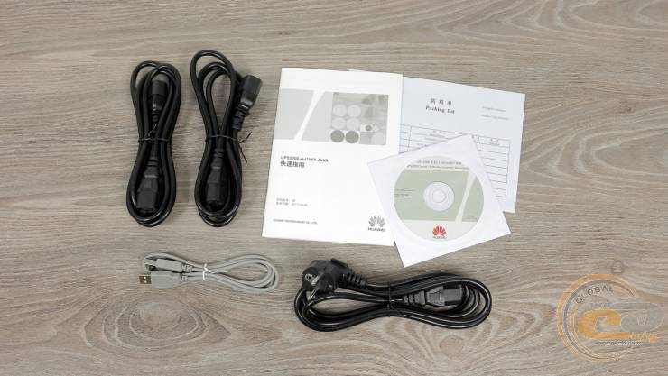
Бесперебойник дополнен четырьмя кабелями (парочкой с разъемами C13-С14, питания, USB), диском и бумажной документацией.
Внешний вид
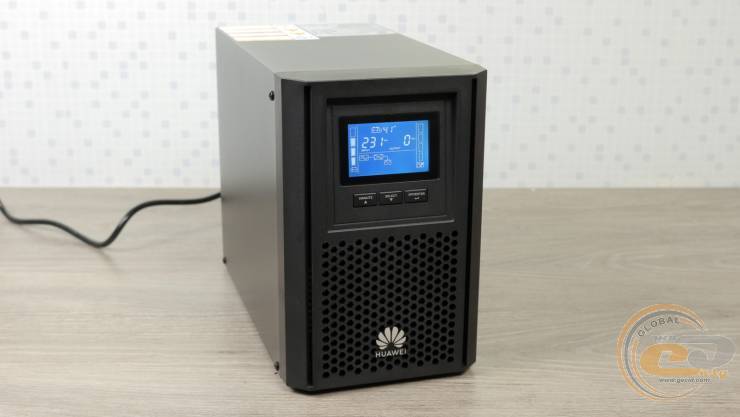
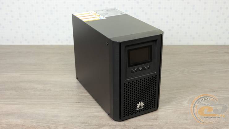
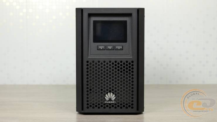
Корпус Huawei UPS2000-A-1KTTS напоминает небольшой системник с габаритами 282 х 145 х 220 мм. Но вот немаленький вес (9,8 кг) и дисплей с тремя кнопками на фронтальной панели выдают реальное предназначение устройства.
Больше всего внимания привлекает экран. Белые надписи на синем фоне смотрятся приятно. К тому же все обозначения интуитивно понятны – вверху отображается время до полной зарядки батареи, ниже – значения входного и выходного напряжений, а в самом низу показаны задействованные узлы устройства. В первом случае – это только подключенный к сети UPS, во втором – еще и дополнительный потребитель, а в третьем – только питание от источника при отключении входной сети, а вместо входного напряжения отображается напряжение на батареи. Кстати, схематические столбики справа и слева также позволят определить относительный уровень заряда аккумуляторов и нагрузки на бесперебойник.
Для включения устройства, естественно, используется кнопка «On». А вот выключить ИБП так легко не получится: сперва нажимаем «Off», затем отсоединяем входной разъем и удерживаем кнопку «Off» – такой вот нетривиальный процесс.
В нижней части фронтальной панели нашлось место для логотипа производителя и вентиляционных отверстий. Последние пригодятся для захвата воздуха внутренним вентилятором.
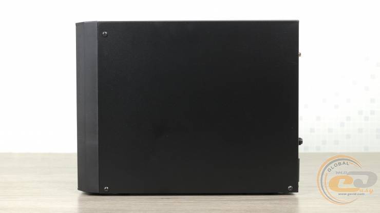
Под стать передней панели, обе боковины и верхняя крышка окрашены в черный матовый цвет и лишены каких-либо интересных элементов.
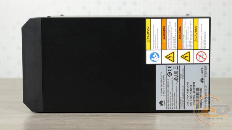
Разве что на верхней панели вы найдете наклейку с информацией об ИБП и еще одну с предостережением.
Последнее здесь нанесено не зря – все три панели представляют собой один сплошной изогнутый лист металла. Он крепится тремя винтами с каждой стороны и еще двумя в тыльной части. Открутив все перечисленные элементы, мы попадаем внутрь источника, где ряд компонентов во включенном состоянии находится под высоким напряжением. Именно об этом предупреждает наклейка.
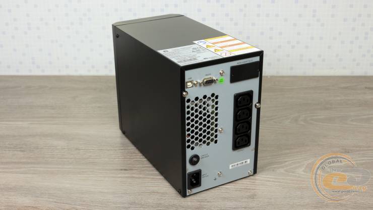
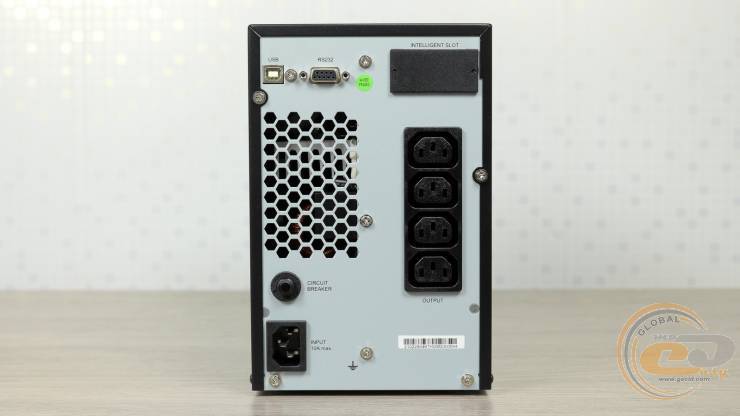
Тыльная панель Huawei UPS2000-A-1 kVA может похвастать слоем грунтовки, вентиляционными отверстиями и россыпью функциональных элементов. В их числе: один входной разъем C14 и четыре выходные розетки C13, кнопка автоматического предохранителя, Intelligent slot для установки карт расширения, а также последовательные разъемы USB и RS232. Учитывая мощность и класс устройства, все необходимое на месте.
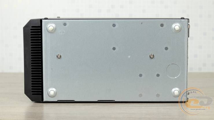
Последняя внешняя панель перед нашим взором – нижняя. Здесь и вовсе обошлись голым металлом, а из примечательного имеем четыре ножки высотой несколько миллиметров.
Внутреннее устройство
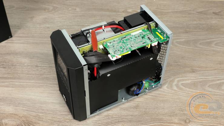
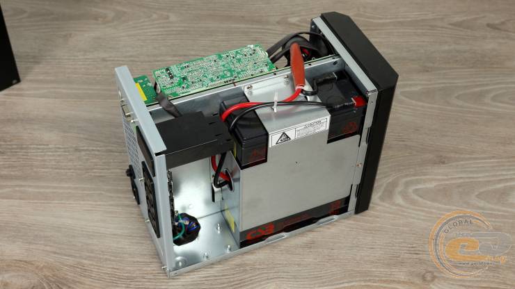
Пространство внутри Huawei UPS2000-A-1KTTS делится одной вертикальной перегородкой. Таким образом, имеем две «комнаты»: одна для схемотехники,…
… а вторая для аккумуляторов. Давайте исследуем их по порядку.
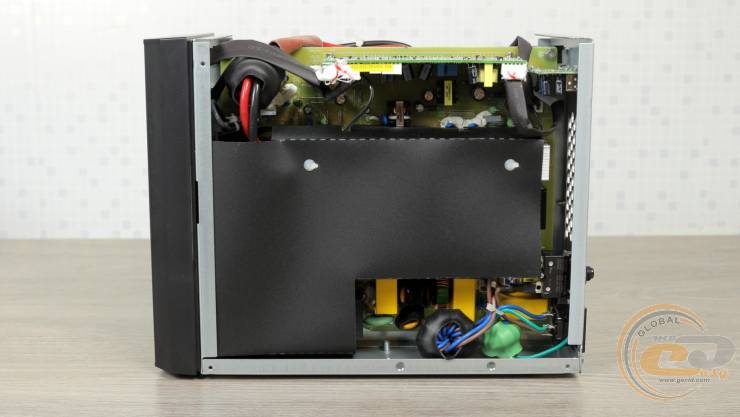
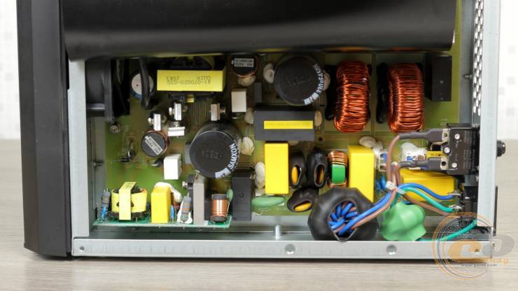
Основой устройства выступает большая печатная плата. На ней размещен кожух, который частично прикрывает высоковольтную часть, напоминая о возможных рисках.
Схемотехника в нижней части платы отвечает за первичную цепь.
UPS2000-H- (6 кВА – 10 кВА) Краткое руководство
Выпуск: 02
Дата: 2021-10-13
Подготовка к установке
ВНИМАНИЕ
- Перед установкой устройств внимательно прочтите руководство пользователя, чтобы ознакомиться с информацией о продукте и мерами безопасности.
- При установке используйте изолированные инструменты.
- Только инженеры, сертифицированные компанией Huawei или ее агентами, имеют право устанавливать, вводить в эксплуатацию и обслуживать ИБП. В противном случае возможны травмы или повреждение оборудования, а вызванные неисправности ИБП выходят за рамки гарантийных обязательств Huawei.
- Прокладывая силовые и коммуникационные кабели, следите за тем, чтобы кабели не поцарапались компонентами шкафа.
| Модель | Вес | Размеры (В х Ш х Г) |
| UPS2000-H-6KRTL-Li | 14 кг | 43 мм r 430 мм x 514 мм |
| УП52000-Н-10КРТИЛИ | 17 кг | 86 мм х мм х 430 514 мм |
| Модель | Терминал проводки | Количество фаз | Номинальный объемtage | Внешний автоматический выключатель | Площадь поперечного сечения кабеля | Тип терминала | Внимание | |
| 6 кВА: однофазный вход, однофазный выход) | вход переменного тока | L / N / PE | 1 | 220 В переменного тока / 230 В переменного тока / 240 В переменного тока | 50 А (функция C) | 10 мм ‘ | Клемма ОТ-10 мм’-М6 | Момент затяжки винта M4: 1.2 Nei Момент затяжки винтов: 4.8 Нм Примечания • Используйте гибкие жилы с рабочей температурой 90 * C или более мягкие жилы для силовых кабелей. Кабели с одножильными или скрученными проводниками могут не устанавливаться. • II отсутствует аккумуляторная шина (BBB), подключите аккумуляторные кабели к ИБП. Выберите клеммы 01 в зависимости от кабелей аккумуляторной батареи. • a: Литиевая батарея оснащена автоматическим выключателем. • b: В режиме байпаса ИБП получает питание от фазы A. Входной ток — это полный трехфазный ток. |
| Выход переменного тока | L / N / PE | 1 | 40 А (функция D) | 6 мм ‘ | Терминал ОТ-6 м и -м6 | |||
| Батарея | + | 2 | 54 V DC | 160 А • | 2 х 25 Имре | OT 25 мм’-M6 клемма | ||
| – | 2 х 25 матов | |||||||
| PE | – | 2 x 6 мм ‘ | ОТ-6 мм, -90 ′ гибочный терминал-АМ | |||||
| 10 кВА (однофазный вход, однофазный выход) | вход переменного тока | L / N / PE | 1 | 220 В переменного тока / 230 В переменного тока / 240 В переменного тока | 80 А (функция C) | 16 mm2 | Клемма ОТ-16 мм’-М6 | |
| Выход переменного тока | L / N / PE | 1 | 63 А (функция 0) | 16 мм | Терминал ОТ-16 мм | |||
| Батарея | + | 2 | 54 V DC | 250 • | 2 x 35 мм ‘ | 01-35 мм’-M6 клемма | ||
| – | 2 x 35 мм ‘ | |||||||
| PE | – | 2 x6 мм ‘ | 01 • Клемма 6 мм’-M6 | |||||
| 10 кВА (трехфазный вход, однофазный выход) | вход переменного тока | 1./н/ч | 3 | 380 В переменного тока / 400 В переменного тока / 415 В переменного тока | 80 А ° (функция C) | 16 МО | OT • клемма 16 мм’-M6 | |
| Выход переменного тока | L / N / PE | 1 | re 63 А (функция 0) |
16 мес. | OT • 16 мм ‘• Клемма M6 | |||
| Батарея | + | 2 | 54 V DC | 250 А • | 2 x 35 мм ‘ | OT • клемма 35 мм’-M6 | ||
| – | 2 x 35 мм ‘ | |||||||
| PE | + | 2 x 6 мм ‘ | Клемма ОТ-6 мм’-М6 | |||||
| литиевая батарейка | + | 2 | 54 V DC | – | 25 m2 | OT 25 мм’-M6 клемма | ||
| – | 25 мм | |||||||
| PE | 6 мм ‘ | Клемма ОТ-6 мм’-М6 |
Установка ИБП
ЗАМЕТКА
- Установка ИБП 6 кВА аналогична установке ИБП 10 кВА. В этом документе ИБП 6 кВА используется в качестве примера.ampле Выполняйте операции исходя из реальной ситуации.
- ИБП поддерживает одновременно до восьми литиевых батарей.
- Рекомендуется устанавливать блок BBB за литиевыми батареями.
- Если четыре группы батарей установлены в режиме монтажа в стойку, зарезервируйте пространство 1 ЕВ между каждыми двумя группами кабелей батарей литиевых батарей.
- Рекомендуется зарезервировать пространство 1 U между ИБП, пространство 1 U между ИБП и литиевой батареей и пространство 1 U над ИБП.
Типичный сценарий установки в башне
ЗАМЕТКА
- В следующем примере используется один ИБП 6 кВА и четыре литиевые батареи в вертикальном режиме с распределительной коробкой в качестве примера.ampим.
- Крейт может вместить до трех устройств и поддерживается только один ИБП.
- В сценарии с одним сервером, если установлено более шести литиевых батарей, необходимо установить две распределительные коробки.
Установка кабелей
Установка кабелей питания переменного тока (одиночный ИБП)
- Подключите входные и выходные силовые кабели ИБП с одинаковой последовательностью фаз. Правильно подключите клеммы аккумулятора.
- Перед подключением кабелей к ИБП убедитесь, что входной и выходной автоматические выключатели выключены, чтобы предотвратить срабатывание при включенном питании.
- Если необходимо заменить входные или выходные кабели, обратитесь в службу технической поддержки Huawei, если вы не знакомы с этой операцией. Не включайте ИБП напрямую.
- При изменении системы ввода или вывода убедитесь, что состояние короткозамкнутой медной шины и кабельные соединения на портах ввода и вывода правильные.
- В одной системе ИБП подключите нагрузки к клеммам AC OUTPUT sL и pL. Подключите первичные нагрузки к клемме sL, а вторичные нагрузки к клемме pL.
6. K1: автоматический выключатель на входе ИБП; Q1: автоматический выключатель на выходе ИБП.
Установка кабелей батарей (одиночный ИБП)
ЗАМЕТКА
При замене неисправной литиевой батареи отключите все контуры между ИБП и батареей, чтобы предотвратить обслуживание при включенном питании.
- Убедитесь, что входные и выходные силовые кабели переменного тока на каждом ИБП подключены с одинаковой последовательностью фаз, клеммы батареи подключены правильно, а силовые кабели байпаса подключены с одинаковой последовательностью фаз.
- Перед подключением кабеля отключите все автоматические выключатели в параллельной системе.
ВНИМАНИЕ
- ИБП может генерировать большие токи утечки. Не рекомендуется использовать автоматический выключатель с устройством защитного отключения (УЗО). Если требуется защита от утечки, выберите рекомендуемый автоматический выключатель.
- Автоматические выключатели, используемые для кабельного соединения, должны быть предоставлены заказчиком.
- При параллельном подключении ИБП длина выходных параллельных силовых кабелей каждого ИБП должна составлять не менее 1 м, а отклонение длины не должно превышать ± 10%. Четыре кабеля должны быть подключены на удаленном конце.
- K: автоматический выключатель на входе переменного тока; K1: автоматический выключатель на входе ИБП 1; K2: Автоматический выключатель на 2 входа ИБП; Q: общий автоматический выключатель на выходе переменного тока; Q1: автоматический выключатель на выходе ИБП 1; Q2: автоматический выключатель на выходе ИБП 2; B1 – Bn: автоматические выключатели литиевых батарей.
| Установка кабелей связи (параллельная система) |
 |
Проверка установки
| Нет. | Проверить товар |
| 1 | При изменении системы ввода или вывода убедитесь, что состояние короткозамкнутой медной шины и кабельные соединения на портах ввода и вывода правильные. |
| 2 | Чередование фаз входной мощности правильное. Используйте мультиметр, чтобы убедиться, что вход и выход не закорочены. |
| 3 | Кабели и клеммы надежно подключены. |
| 4 | Аккумуляторные кабели и клеммы подключены правильно, а объемtages соответствуют отраслевым стандартам. |
| 5 | ИБП правильно подключен к литиевой батарее. |
| 6 | Входные автоматические выключатели и выключатели нагрузки выключены. |
| Кабели питания и сигнальные кабели идентифицированы правильно. | |
| 8 | Кабель заземления надежно подключен. ОбъемtagРазница между нулевым проводом и заземляющим кабелем составляет менее 5 В переменного тока. |
| 9 | Наращивающий резистор установлен правильно. |
| 10 | ОбъемtagДиапазон включения автоматического выключателя на входе ИБП составляет 80-280 В переменного тока (фазное напряжениеtagд), а номинальная частота составляет 50/60 Гц. |
| 11 | Положительный и отрицательный объемtagЗначения напряжения литиевой батареи, измеренные мультиметром, находятся в диапазоне от 41 В до 51 В. |
Стартап
ВНИМАНИЕ
- Перед включением ИБП убедитесь, что он прошел все проверки, указанные в разделе «Проверка установки».
- ОбъемtagДиапазон включения автоматического выключателя на входе ИБП составляет 80–280 В переменного тока (фазное напряжениеtagд), а номинальная частота составляет 50/60 Гц.
| Функция кнопки питания | Описание |
| Запуск инвертора | Когда ИБП работает в режиме байпаса (горит индикатор байпаса), нажмите и удерживайте кнопку на панели ИБП более 5 секунд. Отпустите кнопку, когда индикатор инвертора начнет мигать и вы услышите звуковой сигнал. Не нажимайте никаких кнопок во время запуска инвертора. Когда команда запуска успешно доставлена и индикатор инвертора горит постоянно, ИБП переходит в нормальный режим. |
| Выключение инвертора | Когда ИБП работает в инверторном режиме, нажмите и удерживайте кнопку на панели ИБП более 5 секунд. Отпустите кнопку, когда индикатор инвертора замигает и вы услышите звуковой сигнал. Не нажимайте никакие кнопки во время выключения инвертора. Когда команда выключения успешно доставлена и индикатор инвертора не горит, ИБП отключает выход инвертора и переходит в режим байпаса. |
| Включение Wi-Fi | Когда Wi-Fi отключен, нажмите и удерживайте кнопку в течение 0.5 секунды, чтобы включить WIFi (индикатор WiFi горит). |
| Отключение WIFi | Когда Wi-Fi включен, нажмите и удерживайте кнопку в течение 0.5 секунды, чтобы отключить WIFi (индикатор WiFi не горит). |
| Холодный запуск ИБП с использованием батарей | Если сеть неисправна или отключена, подключите батарею и удерживайте переключатель литиевой батареи от 5 до 15 секунд, чтобы включить литиевую батарею. Удерживайте кнопку ИБП в течение 3 секунд (индикатор байпаса, индикатор батареи и индикатор инвертора горят одновременно), и ИБП включен. После завершения инициализации ИБП (около 10 с) состояние индикатора изменится, и ИБП перейдет в состояние ожидания (индикатор WiFi горит, а индикатор неисправности мигает). Удерживайте нажатой кнопку ИБП более Ss, и ИБП перейдет в режим работы от батареи. |
Запуск ИБП
- Удерживайте кнопку MANUAL ON / OFF на панели литиевой батареи от 5 до 15 секунд, чтобы включить литиевую батарею.
- Включите автоматический выключатель K1 на входе сети переменного тока для ИБП. ИБП работает в режиме байпаса (горит индикатор байпаса). Клемма sL выводит напряжение байпаса.tage и терминал pL не имеет громкостиtagе вывод.
- Если индикатор аварийной сигнализации на панели ИБП мигает, view подробности будильника в приложении и обработать сигнал.
- Выполните «пусковые операции» на ИБП, используя один из следующих методов, чтобы ИБП работал в нормальном режиме:
• Когда ИБП работает в режиме байпаса (индикатор байпаса горит), нажмите и удерживайте кнопку на панели ИБП более 5 секунд. Отпустите кнопку, когда индикатор инвертора замигает и вы услышите звуковой сигнал. Не нажимайте никаких кнопок во время запуска инвертора. Когда команда запуска успешно доставлена и индикатор инвертора горит постоянно, ИБП переходит в нормальный режим.
• Выберите «Конфигурация»> «Управление»> «Включение / выключение питания» в приложении, чтобы запустить инвертор. После успешного запуска ИБП переходит в нормальный режим.
Подробные сведения о том, как установить приложение и войти в него, см. В Приложении.
• На WebВ пользовательском интерфейсе выберите «Мониторинг»> «Система ИБП»> «Управление работой», чтобы запустить ИБП. - Когда ИБП работает нормально, включите выходной автоматический выключатель переменного тока ИБП Q1 для подачи питания на нагрузки.
Запуск параллельной системы
- Удерживайте кнопку MANUAL ON / OFF на панели литиевой батареи от 5 до 15 секунд, чтобы включить литиевую батарею.
- Включите автоматические выключатели на входе сети ИБП K1 и K2, автоматический выключатель на входе основной сети K и автоматические выключатели на выходе переменного тока ИБП Q1 и Q2. Параллельная система не имеет выхода.
- Если индикатор аварийной сигнализации на панели ИБП мигает, view подробности будильника в приложении и обработать сигнал. Подробные сведения о том, как установить приложение и войти в него, см. В Приложении.
- Параметры параллельной конфигурации являются адаптивными. Выберите «Конфигурация»> «Параметры системы»> «Параллельная система». При необходимости вы можете установить параметры вручную.
- Поочередно запускайте ИБП и выключите инверторы. Выходная клемма PL имеет напряжениеtagе вывод.
- Включите выходной автоматический выключатель Q1 (предоставляется заказчиком), выключите выходной автоматический выключатель Q2 (предоставляется заказчиком) и убедитесь, что напряжениеtagРазница между двумя концами выходного автоматического выключателя Q2 не превышает 2 В.
- Включите выходной автоматический выключатель Q2.
- После выполнения «операций запуска» на каждом ИБП в параллельной системе все ИБП переходят в нормальный режим.
- Когда параллельная система работает нормально, включите общий выходной автоматический выключатель Q (предоставленный заказчиком) и автоматические выключатели ответвления выходной цепи (предоставленный заказчиком) и включите нагрузки по очереди.
Завершение работы параллельной системы
Отключение одного ИБП в параллельной системе
- Выполните «операции выключения» дважды в течение 30 секунд для ИБП в параллельной системе. Затем ИБП отключается и не генерирует выходной сигнал. Другой ИБП работает без изменений.
- Удерживайте кнопку MANUAL ON / OFF на панели литиевой батареи от 5 до 15 секунд, чтобы выключить литиевую батарею.
- Отключите входные автоматические выключатели переменного тока K1 и K2 и выходные автоматические выключатели переменного тока Q1 и Q2 для ИБП. После того, как все индикаторы погаснут и вентиляторы остановятся, ИБП отключается.
- ИБП выходит из параллельной системы.
Перевод параллельной системы в режим байпаса
Выполните «операции выключения» на каждом ИБП в параллельной системе. Все ИБП отключают инверторы и переходят в режим байпаса.
Выключение параллельной системы
- Закройте загрузки.
- Выполните «операции выключения» на каждом ИБП в параллельной системе. Все ИБП отключают инверторы и переходят в режим байпаса.
- Удерживайте кнопку MANUAL ON / OFF на панели литиевой батареи от 5 до 15 секунд, чтобы выключить литиевую батарею.
- Отключите автоматические выключатели K1 и K2 на входе сети переменного тока и выключатель K на входе основной сети переменного тока для системы ИБП.
Отключите выходные автоматические выключатели переменного тока ИБП Q1 и Q2 и общий выходной автоматический выключатель переменного тока Q для системы ИБП. После того, как все индикаторы погаснут и вентиляторы остановятся, ИБП отключатся, и нагрузка отключится.
Приложение
Установка приложения
- С помощью мобильного устройства отсканируйте QR-код на панели ИБП.
- Установите приложение одним из следующих способов:
• Загрузите Приложение NetEcoс помощью браузера и установите его.
• Загрузите Приложение NetEcoиз Huawei AppGallery и установите его.
выключение
Выключение отдельного ИБП
Выключение инвертора для перевода ИБП в режим байпаса
Выполните «операции выключения» на ИБП одним из следующих способов:
- Когда ИБП работает в инверторном режиме, нажмите и удерживайте кнопку на панели ИБП более 5 секунд. Отпустите кнопку, когда индикатор инвертора замигает и вы услышите звуковой сигнал. Не нажимайте никакие кнопки во время выключения инвертора. Когда команда выключения успешно доставлена и индикатор инвертора не горит, ИБП отключает выход инвертора и переходит в режим байпаса.
- Выберите «Конфигурация»> «Управление»> «Включение / выключение питания» в приложении, чтобы выключить инвертор. После успешного завершения работы ИБП переходит в режим байпаса.
Отключение одного ИБП
- Выключите нагрузки.
- Выполните «операции выключения» на ИБП. Инвертор отключается, и ИБП переходит в режим байпаса.
- Удерживайте кнопку MANUAL ON / OFF на панели литиевой батареи от 5 до 15 секунд, чтобы выключить литиевую батарею.
- Отключите входной автоматический выключатель переменного тока K1 и выходной автоматический выключатель Q1 ИБП. После того, как все индикаторы погаснут и вентиляторы остановятся, ИБП отключается, и нагрузки отключаются.
Вход в приложение
ЗАМЕТКА
- После первоначального входа в систему своевременно меняйте пароль, чтобы повысить безопасность учетной записи и предотвратить передачу данных.ampэринг.
- Для первого входа необходимо ввести пароль от WiFi.
- Включите WLAN на вашем телефоне.
- Отключите мобильную передачу данных на своем телефоне.
- Включите ИБП.
- Нажмите и удерживайте кнопку ИБП около 0.5 с, чтобы включить ИБП WiFi (индикатор WiFi горит постоянно).
- Откройте приложение НетЭко приложение на мобильном устройстве. Откроется экран выбора приложения.
- Коснитесь ИБП. Отобразится экран «Подключить WiFi». Используйте любой из следующих методов для подключения к сети Wi-Fi.
• Подключитесь к Wi-Fi вручную.
① Коснитесь Подключается к Wi-Fi вручную. Отобразится экран выбора сети WLAN.
② Выберите имя UPS WiFi, последние 12 цифр которого совпадают с серийным номером.③ Введите пароль WiFi. (Первоначальный пароль Wi-Fi — Изменить.)
• Сканируйте, чтобы подключиться к Wi-Fi.
① Нажмите «Сканировать», чтобы подключиться к Wi-Fi.
② Отсканируйте QR-код на панели ИБП. - После того, как соединение WiFi будет установлено, отобразится экран входа в систему ИБП.
- Введите имя пользователя и пароль и нажмите «Войти». (Имя пользователя по умолчанию — admin, а начальный пароль — Изменять.)
- В открывшемся диалоговом окне коснитесь ОК. После изменения первоначального пароля введите новый пароль для входа в приложение.
- После успешного входа в систему отображается экран быстрых настроек. При необходимости вы можете установить параметры вручную.
ЗАМЕТКА
Если это не первый вход, пропустите операцию быстрой настройки. - Коснитесь ОК. Отобразится главный экран.
Отсканируйте здесь, чтобы увидеть больше документов:
Вы также можете войти в службу технической поддержки Huawei. webсайт:
https://support.huawei.com/enterprise
https://support.huawei.com
© Huawei Technologies Co., Ltd. 2021. Все права защищены.
Документы / Ресурсы
Starting the UPS to Inverter Mode
6.2
When the UPS is connected to the Mains Input, it is no output. Hold down ON/MUTE on the front
panel for over 5 seconds to make it transfer to inverter mode output. The default output of inverter
mode is 230 V.
Shutting down the UPS
6.3
•
Normal Mode: If the UPS is originally in normal mode, hold down OFF/ENTER for over 2
seconds will enable the UPS to enter the standby mode or bypass mode (if set or enabled
before).
•
Battery mode: Hold down OFF/ENTER for over 2 seconds to turn off the UPS in battery mode.
7
FAQ
Character Display Description
7.1
Acronym
Display
ENA
DIS
ESC
CF
TP
CH
FU
EE
VOT
BUZ
Buzzer Alarm Tone Description
7.2
Alarm type
Minor alarm
Overload
Critical alarm
Description
Enable
Disable
Escape
Frequency
conversion
Temperature
Charging
Bypass frequency
unstable
EEPROM error
Voltage
Buzzer off
7
Acronym
Display
FRE
BVU
BVL
CAP
DT
ECO
VU
VL
AUT
AST
Buzzer alarm tone
Beeps once every second.
Beeps twice every second.
Buzzes continuously.
Description
Frequency
Bypass overvoltage
Bypass
undervoltage
Capacity
Discharge time
ECO mode
High voltage
Low voltage
Constant-frequency
mode
Automatic startup
- Главная
- Источники бесперебойного питания
- HUAWEI
- Типинтерактивный
- Тип выходных разъемов питанияIEC 320 C13 (компьютерный)
- Время работы при полной нагрузке10 мин
- Выходная мощность1000 ВА / 800 Вт
- Количество выходных разъемов питания4
- Входная частота47 — 63 Гц
- На входе1-фазное напряжение
- Входное напряжение200 — 240 В
- На выходе1-фазное напряжение
- Поддержка SNMPесть
- Показать все
Перед приобретением HUAWEI UPS2000-A-1KTTS по самой низкой цене, изучите характеристики, видео обзоры, плюсы и минусы модели, отзывы покупателей.
Цена от 18750 ₽
(на июнь 2022)
Характеристики HUAWEI UPS2000-A-1KTTS
Основные характеристики*
| Тип | интерактивный |
| Тип выходных разъемов питания | IEC 320 C13 (компьютерный) |
| Время работы при полной нагрузке | 10 мин |
| Выходная мощность | 1000 ВА / 800 Вт |
| Количество выходных разъемов питания | 4 |
Входы и выходы*
| Входная частота | 47 — 63 Гц |
| На входе | 1-фазное напряжение |
| Входное напряжение | 200 — 240 В |
| На выходе | 1-фазное напряжение |
Система управления*
| Поддержка SNMP | есть |
| Интерфейсы | USB, RS-232 |
Функции и возможности*
| Звуковая сигнализация | есть |
| Отображение информации | ЖК-экран |
| Холодный старт | есть |
Защита*
| Фильтрация помех | есть |
| Защита от перегрузки | есть |
| Защита от высоковольтных импульсов | есть |
| Защита от короткого замыкания | есть |
Другие характеристики*
| Уровень шума | 50 дБ |
| Цвет | черный |
| Габариты (ШxВxГ) | 145x220x282 мм |
* Точные параметры уточняйте на сайте продавца.
Отзывы пользователей о HUAWEI UPS2000-A-1KTTS
Похожие товары
HUAWEI UPS2000-G-10KRTL
296749 ₽
HUAWEI UPS2000-A-1KTTL
HUAWEI UPS2000-G-2KRTS
29746 ₽
HUAWEI UPS2000-G-15KRTL
HUAWEI UPS2000-G-20KRTL
347988 ₽





 • Подключитесь к Wi-Fi вручную.
 ③ Введите пароль WiFi. (Первоначальный пароль Wi-Fi — Изменить.)


