-
Contents
-
Table of Contents
-
Bookmarks
Quick Links
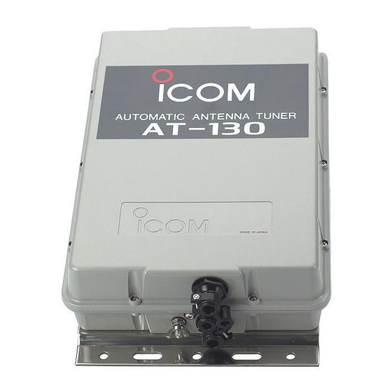
INSTRUCTION MANUAL
HF AUTOMATIC ANTENNA TUNER
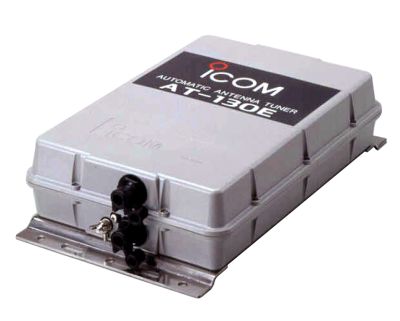
AT-130
AT-130E
Related Manuals for Icom AT-130
Summary of Contents for Icom AT-130
-
Page 1
INSTRUCTION MANUAL HF AUTOMATIC ANTENNA TUNER AT-130 AT-130E… -
Page 2: Precautions
IMPORTANT FOREWORD READ ALL INSTRUCTIONS carefully and com- Thank you for purchasing the AT-130 or AT-130E HF pletely before using the AT-130 and AT-130E. AUTOMATIC ANTENNA TUNER. SAVE THIS INSTRUCTION MANUAL. This The AT-130 and AT-130E are designed, primarily for instruction manual contains important safety and in- use with Icom HF transceivers.
-
Page 3: Table Of Contents
European Radio and Telecommunica- tion Terminal Directive 1999/5/EC. Icom, Icom Inc. and the Icom logo are registered trademarks of Icom Incorporated (Japan) in Japan, the United States, the United Kingdom, Germany, France, Spain, Russia and/or other countries.
-
Page 4: Antenna System
In some countries, HF transceivers can be used for Refer to the AH-2b instruction manual for the AH-2b land mobile operation. Ask your Icom Dealer for de- and AT-130/E installation to your vehicle. Ask your tails, since the radio law varies according to coun- Icom Dealer for details.
-
Page 5: Coaxial Cable
ANTENNA SYSTEM n Coaxial cable Insulate the lead-in cable of the AT-130/E antenna ter- To prevent erroneous indications, keep cables as far minal and antenna element from other metal objects. away as possible from the flux gate compass. To prevent interference, keep cables as far as pos-…
-
Page 6: Installations
• Refer to “PL-259 connector” as described below. • Refer to page 4, “Control cable.” r Connect the control cables to the AT-130/E. i Perform preset tuning setting. For the AT-130E, • Refer to page 4, “Cable connections.”…
-
Page 7: Control Cable
Connect the shield line to the [GND] terminal Control cable AT-130E : [ANTC] on the transceiver. [13.6] Icom offers the 10 m (32.8 feet) long control cable, [STAR] OPC-420 control cable [KEY] Refer to page 9 “Terminal information” and “Trans-…
-
Page 8: Waterproofing The Antenna Connection
• Wrap electrical tape* over the rubber vulcanizing the wing nut. tape to secure waterproofing. • Make sure the base nut is tightened firmly, before * The electrical tape is not supplied with the AT-130/E. you tighten the wing nut. (See the Fig.1 to the right.) Fig.2 •…
-
Page 9: Mounting
INSTALLATIONS n Mounting CAUTION: Mount the AT-130/E in a horizontal position or in a vertical position with the antenna terminal up. Mounting on a Mast/Metal pole Mounting on a flat surface Using nuts and bolts Using self-tapping Using U-bolts Mast/…
-
Page 10: Internal Settings
Mode switch Mode switch (S1) location According to the mode switch (S1), the AT-130/E op- erates as follows: Mode Position Description Used only for preset tuning. Refer…
-
Page 11: Emergency Tuning (At-130E)
INTERNAL SETTINGS n Emergency tuning For the AT-130E, before operation, perform emer- r Disconnect the 13.6 V DC cable from the [13.6] gency tuning setting. terminal. Tape the end of the wire. • NEVER allow the 13.6 V DC cable end to touch any other parts.
-
Page 12: Control Cable Signals
CONTROL CABLE SIGNALS n Terminal information Start voltage [STAR] Consider the following points when using a non-Icom transceiver. When a start voltage (less than 1 V) is received, the AT-130/E begins automatic tuning. Terminal Description More than _ terminal. 50 milliseconds…
-
Page 13: Unit Description And Specifications
(supplied from the HF transceiver) • Current drain : Maximum 2 A • Operating temperature range : –30°C to +60°C; –22˚F to +140˚F • Weight (approximately) : AT-130 2.5 kg; 5.5 lb AT-130E 2.7 kg; 6.0 lb : SO-239 (50 Ω) •…
-
Page 14
MEMO… -
Page 15
MEMO… -
Page 16
A-8163D-1EX-r Printed in Japan © 1992–2010 Icom Inc. 1-1-32 Kamiminami, Hirano-ku, Osaka 547-0003, Japan Printed on recycled paper with soy ink.
This manual is also suitable for:
At-130e
INSTRUCTION MANUAL
HF AUTOMATIC ANTENNA TUNER
AT-130
AT-130E
IMPORTANT
READ ALL INSTRUCTIONS
carefully and completely before using the AT-130 and AT-130E.
SAVE THIS INSTRUCTION MANUAL.
This instruction manual contains important safety and installation instructions.
Ground terminal
Mounting plate
DO NOT
operate your HF marine transceiver without running the boat’s engine.
DO NOT
use the AT-130 or AT-130E in areas where the temperature is below –30°C (–22˚F) or above
+60°C (+140˚F).
FOREWORD
Thank you for purchasing the
AT-130 or AT-130E HF
AUTOMATIC ANTENNA TUNER.
The AT-130 and AT-130E are designed, primarily for use with Icom HF transceivers. To meet with European regulations, the AT-130E includes an extra emergency tuner circuit for 2182 kHz operation.
Refer to your HF transceiver instruction manual for operation. If you have any questions, contact your nearest authorized Icom Dealer or Service Center.
PRECAUTIONS
R DANGER HIGH VOLTAGE! NEVER
touch the antenna terminal, ground terminal, antenna or counterpoise while transmitting. Place the AT-130 or AT-130E, antenna and counterpoise in positions where no one touches them.
R WARNING! NEVER
transmit during internal adjustment. This may cause an electric shock.
NEVER
use without a ground connection.
USE
the ground terminal for ground connection. The mounting plate is not connected internally.
SUPPLIED ACCESSORIES
The following parts are supplied with the AT-130/E.
q u w i e o !0
r t y
!1
!2
!3
Qty.
q
U-bolts ������������������ 2 w
U-bolt plates ��������������� 2 e
Flat washers (M6 large) ���������� 8 r
Flat washers (M6 small) ���������� 4 t
Spring washers (M6) ������������ 8 y
Nuts (M6) ����������������� 8 u
Hex head bolts (M6×50) ���������� 4 i
Self-tapping screws (A0 6×30) �������� 4 o
Weatherproof cap ������������� 1
!0
Rubber vulcanizing tape ���������� 1
!1
4-pin connector �������������� 1
!2
Connector pins �������������� 4
!3
Ground cable (OPC-412) ���������� 1 i
EXPLICIT DEFINITIONS
The explicit definitions in this instruction manual.
WORD
RDANGER!
NOTE
DEFINITION
Personal death, serious injury or an explosion may occur.
RWARNING!
Personal injury, fire hazard or electric shock may occur.
CAUTION
Equipment damage may occur.
If disregarded, inconvenience only.
No risk of personal injury, fire or electric shock.
MISCELLANEOUS ITEMS
The following parts are required for installation, but are not supplied with the AT-130 or AT-130E.
q
AWG 14×4-conductor shielded cable
* Icom offers an optional OPC-420 control cable
.
Length: 10 m; 32.8 feet w
50
Ω coaxial cable e
Two PL-259 connectors
TABLE OF CONTENTS
IMPORTANT ����������������� i
PRECAUTIONS ��������������� i
EXPLICIT DEFINITIONS ����������� i
FOREWORD ����������������� i
UNPACKING ���������������� i
MISCELLANEOUS ITEMS����������� i
TABLE OF CONTENTS ������������ ii
FEATURES ����������������� ii
1 ANTENNA SYSTEM ����������� 1–2
n Antenna for ship ������������� 1
n Antenna for land operation ��������� 1
n Coaxial cable �������������� 2
n Ground and counterpoise ��������� 2
2 INSTALLATIONS ������������� 3–6
n
Installation outline ������������ 3
n
Cable installation ������������� 3
n
PL-259 connector ������������� 3
n
Control cable ��������������� 4
n
Cable connections ������������ 4
n
Waterproofing the antenna connection ���� 5
n
Mounting ���������������� 6
3 INTERNAL SETTINGS ���������� 7–8
n Before internal settings ���������� 7
n Mode switch ��������������� 7
n Preset tuning ��������������� 7
n Emergency tuning (AT-130E) �������� 8
4 CONTROL CABLE SIGNALS �������� 9
n
Terminal information ����������� 9
n
Transceiver switch ������������ 9
5 UNIT DESCRIPTION AND SPECIFICATIONS 10
n Unit description ������������� 10
n Specifications ������������� 10
About CE
Versions of the AT-130E which display the
“CE” symbol on the serial number seal, comply with the essential requirements of the European Radio and Telecommunication Terminal Directive 1999/5/EC.
FEATURES
Matches all bands
The AT-130/E matches all frequencies on the HF marine band. For example, the tuner matches a 7 m;
23 feet long-wire antenna across 1.6–30 MHz.
Full automatic tuning
Just push the [TUNE] switch on the transceiver, the
AT-130/E immediately tunes for a minimum SWR on any frequency in the HF marine band.
HF operation on any size ship
The AT-130/E allows HF operation where antenna element length is restricted due to space.
Weather resistant
The AT-130/E is housed in a durable, completely weather resistant acrylic case with a rubber gasket.
The antenna tuner can be conveniently installed both on the deck or in the cabin near the antenna element.
Simple installation
Installation is simple. Just connect the control and antenna cables and short-times internal settings. After installation, you never need to open the cover for maintenance.
Preset tuning function
This function provides super fast tuning on your mostused frequency.
45 memories for shorter tuning time
To decrease the tune-up time, the AT-130/E automatically stores the matching conditions for up to 45 frequencies. Retuning for a memorized frequency takes only approximately 1 second.
Super capacitor for memory backup
Even if the AT-130/E is not used for approximately
1 week, the built-in super capacitor backs up the 45 memory contents.
Low power tune up
The AT-130/E emits low output power during tuning.
This feature reduces the possibility of causing interference to other stations.
Emergency tuner circuit
(AT-130E)
To meet with European regulations, the Europe version AT-130E includes an emergency tuner circuit for 2182 kHz operation. If any signal from the control cable indicates an abnormal condition, this circuit is automatically selected.
Icom, Icom Inc. and the Icom logo are registered trademarks of Icom Incorporated (Japan) in Japan, the United States, the
United Kingdom, Germany, France, Spain, Russia and/or other countries.
ii
1
1
ANTENNA SYSTEM
n
Antenna for ship
Required antenna element length
Required antenna element length to achieve full performance varies according to the lowest frequency:
The lowest frequency Required antenna element length
1.6 MHz band 7 m; 23.0 feet or longer
4 MHz band 3 m; 9.8 feet or longer
The longer the antenna element, the better the antenna efficiency.
Undesirable antenna element lengths
DO NOT use
an antenna element such as multiples of
1
⁄
2
λ lengths (half wavelength), since tuning becomes difficult.
L : Antenna element length to be avoided [m] f : Operating frequency [MHz] n : Natural number (n = 1, 2, 3, …)
L =
300 f
× n
[Example]
At an operating frequency of 16 MHz, avoid the following antenna element lengths:
L =
1 m
300
16 ×
1
2
39 inches
× n 9.4, 18.8, …
For example, if 15 m (49.2 feet) is selected for an antenna element length, you have no problem in the
1.6–25 MHz marine bands range.
Backstay operates as a long-wire antenna.
Insulator
Insulator
Whip antenna
NOTE: Keep antennas as far away from other objects as possible, especially metal objects.
n
Antenna for land operation
In some countries, HF transceivers can be used for land mobile operation. Ask your Icom Dealer for details, since the radio law varies according to countries.
For land mobile operation on 4 MHz or above, an optional AH-2b antenna element
is available. The
AH-2b includes a sturdy tow hook mount system for holding a 2.5 m (8.2 feet) stainless steel antenna element plus all the necessary hardware.
AH-2b
Refer to the AH-2b instruction manual for the AH-2b and AT-130/E installation to your vehicle. Ask your
Icom Dealer for details.
Connect a suitable antenna element for a coastal station. To achieve full performance, refer to “Required antenna element length” above.
ANTENNA SYSTEM
1 n
Coaxial cable
Insulate the lead-in cable of the AT-130/E antenna terminal and antenna element from other metal objects.
To prevent interference, keep cables as far as possible from an antenna, electric pump and other electronic equipment.
To prevent erroneous indications, keep cables as far away as possible from the flux gate compass.
Use suitable noise filters for alternators, fluorescent lights, etc. Ask your Dealer for details.
n
Ground and counterpoise
Why a ship’s ground is required
The AT-130/E’s ground terminal
MUST be connected to your ship’s ground. Grounding prevents electric shocks, interference to other equipment and other problems. Grounding also ensures effective signal transmission.
R DANGER! NEVER
connect the ground terminal to the following points. These connections may cause an explosion or electric shocks:
• Gas or electrical pipe
• Fuel tank
• Oil-catch pan
IMPORTANT:
The mounting plate is NOT connected to the AT-130/E’s internal ground. Non-through mast is NOT electrically connected to sea water.
Ideal ground points
One of following points is ideal:
• Ship’s ground terminal
• External ground plate
• External copper screen
Good ground points
If electrically connected to sea water, one of the following points is usable:
• Stainless steel tuna tower
• Stainless steel stanchion
• Through mast
• Through hull
• Metal water tank
Undesirable ground points
These connections may cause noise or electrolysis:
• Engine block
• Keel bolt
Electrolysis
All ground cables from the AT-130/E, HF transceiver, etc. on your ship should be connected to only one ship’s ground.
DO NOT
connect to two or more points. Voltage difference between two or more ship’s grounds may cause electrolysis.
DO NOT
connect between dissimilar metals where an electric current is present. These connections may cause electrolysis.
Counterpoise
If your ship is made of FRP, etc. and a good ship’s ground is not available, connect a counterpoise.
1
⁄
4
λ radial for each band
Ground terminal
AT-130/E
1 ⁄
4
λ (quarter wavelength) radial for each band is suitable for a counterpoise. Install the counterpoise directly below the AT-130/E’s ground terminal. Insulate the ends of each radial from other metal objects. Layout the radial horizontally and as straight as possible.
L : Counterpoise length for the operating frequency [m] f : Operating frequency [MHz]
L =
300 f
[Example]
At an operating frequency of 16 MHz, use a counterpoise with the following length:
L =
1 m
300
16 ×
1
4
39 inches
4.7 [m]
Ground cable
For best results, use the heaviest gauge wire or metal strap available. Make the distance between the AT-
130/E’s ground terminal and ship’s ground as short as possible.
The supplied ground cable can be used for ground connection through a mast. Confirm that the through mast is electrically connected to sea water.
R WARNING!
— When grounding to metal hull
Use a Zinc anode to protect the hull from electrolysis. Ask your technical dealer or installer, or refer to a technical book for RF ground details.
2
2
INSTALLATIONS
n
Installation outline
q
Remove the top cover.
w
Install a control cable and coaxial cable.
• Refer to “Cable installation” as described below.
e
Connect and solder the PL-259 connector to the coaxial cable.
• Refer to “PL-259 connector” as described below.
r
Connect the control cables to the AT-130/E.
• Refer to page 4, “Cable connections.” t
Mount the AT-130/E in the desired location.
• Refer to page 6, “Mounting.” y
Connect an antenna, ship’s ground or counterpoise.
• Refer to page 1, “Antenna for ship” and page 2,
“Ground and counterpoise.” u
Connect the control cable and the coaxial cable to the transceiver.
• Refer to page 4, “Control cable.” i
Perform preset tuning setting. For the AT-130E, also perform emergency tuning setting.
• Refer to page 7, “Preset tuning” and page 8, “Emergency tuning.” o
Select the mode switch (S1) to NORMAL mode
(center position). Replace the top cover.
n
Cable installation
q
Remove the 10 screws from the top cover. Remove the top cover.
w
Loosen the screws on both cable clamps.
e
Set or remove the strain relief inserts corresponding to the diameters of the cables.
r
Install the coaxial cable through the top cover cable clamp. Install the control cable through the bottom cover cable clamp.
t
After connecting the coaxial cable and control cables, perform the preset tuning setting.
• For the AT-130E, also perform emergency tuning setting.
y
After internal adjustments, tighten the cable clamp screws.
Strain relief
Coaxial cable
Control cable
Cable clamp
3 n
PL-259 connector
q
Slide the coupling ring down.
Strip the cable jacket and tin the shield.
Coupling
30 mm e
Slide the connector body on and solder it.
Solder Solder
10 mm (tin here) w
Strip the cable as shown below.
Tin the center conductor.
10 mm
1–2 mm tin r
Screw the coupling ring onto the connector body.
30 mm (1 3 ⁄
16
inches) 10 mm ( 13 ⁄
32
inches) 1–2 mm ( 1 ⁄
32
– 3 ⁄
32
inches)
INSTALLATIONS
2 n
Control cable
Between the AT-130/E and HF marine transceiver, connect four control signal lines as shown at right. To prevent RF feedback, use a four conductor shielded cable. Connect the shield line to the [GND] terminal on the transceiver.
Icom offers the 10 m (32.8 feet) long control cable,
OPC-420 control cable
.
Refer to page 9 “Terminal information” and “Transceiver switch” for details.
To the Icom HF marine transceiver
AT-130 E : [E]
AT-130E : [ANTC]
[13.6]
[STAR]
[KEY]
For an optional OPC-420
CONTROL CABLE
, you need to not assemble the supplied four pin connector.
Control cable
[GND]
To the AT-130/E n
Cable connections
Coaxial cable
PL-259 connector
[ANT]
[GND]
Icom HF transceiver
[TUNER]
4-pin connector
PL-259 connector
AT-130
To antenna element
[E]
[13.6]
[STAR]
[KEY]
AT-130E
[ANTC]
[13.6]
[STAR]
[KEY]
Connect to the [ANTC] terminal instead of the
[E] terminal.
Refer to page 7 for details.
Control cable
Before connecting to terminals, tin each end of the cable’s wires.
Ship’s ground
Ship’s ground
4
5
2
INSTALLATIONS n
Waterproofing the antenna connection
CAUTION: If you skip the following steps, moisture will get into the connector, and this could damage the antenna tuner.
pass the antenna wire through the cap.
Antenna wire
Weatherproof cap
Fig.1
crimp-on wire terminal.
• Crimp or solder the antenna wire.
Wing nut
Crimp-on wire terminal
Star washer
Base nut
Antenna tuner
Crimp Solder wing nut on the base nut, in that order, then, tighten the wing nut.
• Make sure the base nut is tightened firmly, before you tighten the wing nut. (See the Fig.1 to the right.)
• Carefully bend the wire terminal up, after you tighten the wing nut. (See the Fig.2 to the right.) insulator as possible.
• How far down it will go depends on the height of the wing nut.
tom of the insulator, then the weatherproof cap and finally the antenna wire to prevent water seeping.
• Wrap electrical tape* over the rubber vulcanizing tape to secure waterproofing.
* The electrical tape is not supplied with the AT-130/E.
Fig.2
e r t
Insulator
Bend this part up,
AFTER
you tighten the wing nut.
Rubber vulcanizing tape
INSTALLATIONS
2 n
Mounting
CAUTION: Mount the AT-130/E in a horizontal position or in a vertical position with the antenna terminal up.
Mounting on a Mast/Metal pole
Mast/
Using U-bolts
Metal pole
U-bolt
U-bolt plate
Flat washer (L)
Spring washer
Flat washer (S)
Nut
Mounting on a flat surface
Using nuts and bolts Using self-tapping screws
Using nuts and bolts
R WARNING!
Mount the AT-130/E securely with the supplied bolts and nuts. Otherwise, vibrations and shocks due to waves could loosen the antenna tuner, causing personal injury.
Nut
Flat washer (S)
Spring washer
Flat washer (L)
Flat washer (L)
Hex head bolt
Mast/
Using U-bolts
Metal pole
U-bolt
U-bolt plate
Nut
Flat washer (S)
Using self-tapping screws
Drill a hole here
Diameter:7–8 mm;
9
⁄
32
–
5
⁄
16
inches
Flat
Spring washer
Flat washer(S) washer (L)
Nut
Flat washer (L)
Hex head bolt
Drill a hole here
Diameter:7–8 mm;
9
⁄
32
–
5
⁄
16
inches
Nut
Flat washer(S)
Spring washer
Flat washer(L)
Flat washer(L)
Hex head bolt
Weatherproof cap
Drill a hole here
Diameter:7–8 mm;
9
⁄
32
–
5
⁄
16
inches
6
3
INTERNAL SETTINGS
n
Before internal settings
Before operation, preset tuning setting and emergency tuning setting are required.
What is preset tuning
Preset tuning setting provides fast tuning on your most-used frequency.
What is emergency tuning
The Europe version, AT-130E, includes an emergency tuner circuit for 2182 kHz operation separated from the automatic tuner circuit. If any signal from the control cable becomes abnormal, the emergency tuner is automatically selected.
n
Mode switch
According to the mode switch (S1), the AT-130/E operates as follows:
Mode
PRESET
NORMAL
OFF
Position
Upper
Center
Lower
Description
Used only for preset tuning. Refer below for details.
Operates in automatic tuning. For fast tune up, preset switches (S3,
S4, S5) information is also used.
Operates in automatic tuning only. This mode is for some non-
Icom HF transceivers. Refer to page 9 for details.
After internal settings are performed, select the mode switch (S1) to NORMAL mode (center position).
Mode switch (S1) location
S1
PRESET mode
NORMAL mode
OFF mode n
Preset tuning
R WARNING!
NEVER touch internal parts while transmitting. Stop transmitting when internal adjustments are performed.
q
Connect an SWR meter between an HF transceiver and the AT-130/E.
w
Confirm the mode switch (S1) is in NORMAL mode
(center position).
e
Select your most-used operating frequency.
r
Push the [TUNE] switch on the HF transceiver.
• When the AT-130/E succeeds in automatic tuning, an
LED (DS24) lights up.
• Confirm that SWR reading is less than 2:1.
t
Make a note of which LED’s (DS1–DS23) light up.
y
Select S1 to PRESET mode (upper position).
u
Select the preset switches (S3, S4, S5) so that the same LED’s light up as in step 5).
i
Select S1 to NORMAL mode (center position).
o
Replace tha top cover of the AT-130.
• For the AT-130E, perform emergency tuning settings.
Switch and LED locations
PRESET mode
NORMAL mode
DS1−DS23
S1
DS24
S3
S4
S5
Switch and LED relationship
S3–1 DS16 S4–1 DS9 S5–1 DS1
S3–2 DS17 S4–2 DS10 S5–2 DS2
S3–3 DS18 S4–3 DS11 S5–3 DS3
S3–4 DS19 S4–4 DS12 S5–4 DS4
S3–5 DS20 S4–5 DS13 S5–5 DS5
S3–6 DS21 S4–6 DS15 S5–6 DS6
S3–7 DS22 S4–7 DS14 S5–7 DS7
S3–8 DS23 — — S5–8 DS8
OFF position:
Lights up
ON position:
Goes out
J302, J324 and J325
Refer to below left for details.
INTERNAL SETTINGS
3 n
Emergency tuning
For the AT-130E, before operation, perform emergency tuning setting.
R WARNING!
NEVER touch internal parts while transmitting. Stop transmitting when internal adjustments are performed. 2182 kHz is used for distress calls, etc. Listen on the frequency before transmitting.
q
Connect an SWR meter between an HF transceiver and the AT-130E.
w
Remove the top cover of the AT-130E.
e
Select 2182 kHz and AM (H3E) mode for the HF transceiver.
• Refer to each transceiver’s instruction manual for details.
CAUTION:
If another frequency is selected, the
AT-130E may be damaged.
13.6 V DC cable
r
Disconnect the 13.6 V DC cable from the [13.6] terminal. Tape the end of the wire.
• NEVER allow the 13.6 V DC cable end to touch any other parts.
t
Disconnect all six pins on J302, J324 and J325 as shown below.
y
Connect a red cable to a pin (J307–J322) where minimum SWR reading is obtained.
u
Connect pins on J302, J324 and J325 to obtain a minimum SWR reading.
• DO NOT transmit for more than 5 seconds
• “A” has the minimum capacity.
• Selection in alphabetical order may speedup tuning.
i
Connect the 13.6 V DC cable to the [13.6] terminal.
o
Replace the top cover of the AT-130E.
Red cable positioning
Connect to a pin (J307−
J322) where a minimum
SWR reading is obtained.
Disconnect 13.6 V DC cable from the [13.6] terminal. Reconnect after emergency tuning.
Position the red cable as shown.
J302 J324
J325
Pin connections
Set the pin connections on J302, J324 and J325 to obtain minimum SWR setting.
The letters, A–F, indicate the capacity of the tuning condenser. “A” has the minimum capacity.
Incorrect cable positioning.
J302 J324
J302 J324
J325
J325
The condencer is connected.
The condencer is disconnected.
4
CONTROL CABLE SIGNALS
n
Terminal information
Consider the following points when using a non-Icom transceiver.
Terminal
[E] _ terminal.
Description
[ANT C] AT-130: No connection.
AT-130E: Antenna current detector output from the emergency tuner.
[13.6] 13.6 V DC + input terminal.
Maximum current drain; 2 A
[GND] The same voltage as the ground terminal at the bottom. No need to connect from this terminal.
[STAR] Receives start voltage.
Maximum current drain; 100 mA
[KEY] Key voltage. Grounded during tuning.
Maximum current drain; 100 mA.
[E]
[ANT C]
[13.6]
[GND]
[STAR]
[KEY]
Start voltage [STAR]
When a start voltage (less than 1 V) is received, the
AT-130/E begins automatic tuning.
More than
50 milliseconds
Start voltage
[V]
8
6
4
Approximately 7.5 V
2
0
Less than 1 V to start tuning
Time
Key voltage [KEY]
During automatic tuning, the AT-130/E grounds key voltage line, and the HF transceiver reduces output power.
Approximately 7.5 V
During automatic tuning
Key voltage
[V]
8
6
4
2
0
Grounded
Time
If the key voltage is more than 8 V, select the mode switch (S1) to OFF mode (lower position).
Mode switch (S1)
S1
NORMAL mode
OFF mode
9 n
Transceiver setting
IC-M700 with serial number 2500 and below
In the IC-M700, change the [TUNE] switch setting from the “1” position to the “2” position. Confirm that the [KEY] switch is in the “2” position. Refer to the IC-
M700 instruction manual page 9 for details.
[KEY] [TUNE]
Select “2” position.
Confirm “2” position.
Other HF transceiver
Some Icom HF transceivers have internal [KEY] and
[TUNE] switches. Suitable switch settings for the AT-
130/E are performed before shipping.
However, if a non-Icom automatic tuner was previously used, confirm the switch settings. Refer to the instruction manual for details.
Non-Icom HF transceiver
Select correct settings for the start voltage and key voltage. Refer to your HF transceiver instruction manual for details.
UNIT DESCRIPTION AND SPECIFICATIONS
n
Unit description
340 mm; 13.4 in
230 mm; 9.1 in
Ground terminal
Water drain screw
80 mm
; 3.1 in
Mounting plate
5
Antenna terminal
Mounting plate
91.5 mm
; 3.6 in n
Specifications
• Frequency coverage : 1.6–30 MHz
(with 7 m; 23.0 ft or longer antenna element)
• Power supply requirement : 13.6 V DC
(supplied from the HF transceiver)
• Current drain : Maximum 2 A
• Operating temperature range : –30°C to +60°C; –22˚F to +140˚F
• Weight (approximately) : AT-130 2.5 kg; 5.5 lb
• Antenna connector
• Maximum Input power
• Automatic tuning time
AT-130E 2.7 kg; 6.0 lb
: SO-239 (50
Ω)
: 150 W
(PEP)
100 W
(continuous)
: Approximately 2 to 3 seconds
(general condition)
Maximum 15 seconds
Approximately 1 second
(re-tuning for a memorized frequency)
• Automatic tuning accuracy : SWR 2.0:1
(after tuning, except for multiples of
1
⁄
2
λ)
All stated specifications are subject to change without notice or obligation.
10
11
MEMO
MEMO
12
A-8163D-1EX-r
Printed in Japan
© 1992–2010 Icom Inc.
Printed on recycled paper with soy ink.
1-1-32 Kamiminami, Hirano-ku, Osaka 547-0003, Japan
ICOM АТ-130 автоматический антенный тюнер предназначен для работы с КВ трансиверами ICOM. В большинстве случаев тюнер Icom AT-130, используется для морских КВ передатчиков, но также может использоваться и с радиолюбительскими трансиверами. Тюнер Icom AT-130, обеспечивает надежное согласование трансивера с антенной на диапазонах 1.6~30 МГц при использовании длинного провода, равного или более 7 метров в длине.
Тюнер Icom AT-130 простой в работе и не требует лишних действий при настройке, достаточно подключить его к трансиверу и к антенне, включить функцию настройки и тюнер сделает все остальное сам. Первоначальная настройка на частоте занимает не более 3 секунд, кроме того, Icom AT-130 имеет 8 блоков памяти для сохранения информации о настройках на разных иапазонах. Перестройка по диапазонам для запоминаемой частоты составляет приблизительно 1.5 секунды.
Icom AT-130 изготовлен в пластмассовом, защищенном от атмосферных влияний, корпусе с резиновыми прокладками для удобной установки на открытом воздухе непосредственно рядом с Вашей антенной. Трансивер и тюнер Icom AT-130 должны иметь надлежащее заземление.
Технические характеристики антенного тюнера Icom AT-130
- Точность настройки КСВ не хуже чем 2.0:1
- Входное сопротивление: 50 Ом
- Диапазон рабочих температур -30°С…+50°С
- Габариты 230x340x80 мм
- Вес 2,7 кг
Предложите, как улучшить StudyLib
(Для жалоб на нарушения авторских прав, используйте
другую форму
)
Ваш е-мэйл
Заполните, если хотите получить ответ
Оцените наш проект
1
2
3
4
5
Что-то не так?
Пожалуйста, отключите Adblock.
Портал QRZ.RU существует только за счет рекламы, поэтому мы были бы Вам благодарны если Вы внесете сайт в список исключений.
Мы стараемся размещать только релевантную рекламу, которая будет интересна не только рекламодателям, но и нашим читателям. Отключив Adblock, вы поможете не только нам, но и себе. Спасибо.
Как добавить наш сайт в исключения AdBlock