Руководства на английском языке по техническому обслуживанию и ремонту автомобиля Infiniti QX56 серии JA60 2004-2010 годов выпуска.
- Автор: —
- Издательство: Nissan Motor Co., Ltd.
- Год издания: 2004-2009
- Страниц: —
- Формат: PDF
- Размер: 464,1 Mb
Руководство на английском языке по техническому обслуживанию и ремонту автомобиля Infiniti QX56 серии Z62 2011 года выпуска.
- Автор: —
- Издательство: Nissan Motor Co., Ltd.
- Год издания: 2010
- Страниц: —
- Формат: PDF
- Размер: 82,0 Mb

Руководство по эксплуатации, техническому обслуживанию и ремонту автомобиля Infiniti QX56 серии JA60 2004-2010 годов выпуска с бензиновым двигателем VK56DE.
- Автор: —
- Издательство: Автонавигатор
- Год издания: —
- Страниц: 504
- Формат: —
- Размер: —

Руководство по эксплуатации, техническому обслуживанию и ремонту автомобиля Infiniti QX56 серии Z62 2010-2013 годов выпуска с бензиновым двигателем VK56VD.
- Автор: —
- Издательство: Автонавигатор
- Год издания: —
- Страниц: 470
- Формат: —
- Размер: —

FOREWORD
Welcome to the growing family of new INFINITI owners. This vehicle is delivered to you with confidence. It was produced using the latest techniques and strict quality control.
This manual was prepared to help you understand the operation and maintenance of your vehicle so that you may enjoy many miles (kilometers) of driving pleasure. Please read through this manual before operating your vehicle.
A separate Warranty Information Booklet explains details about the warranties covering your vehicle. The “INFINITI Service and Maintenance Guide” explains details about maintaining and servicing your vehicle. Additionally, a separate Customer Care/Lemon Law Booklet (U.S. only) will explain how to resolve any concerns you may have with your vehicle, as well as clarify your rights under your state’s lemon law.
Your INFINITI dealership knows your vehicle best. When you require any service or have any questions, they will be glad to assist you with the extensive resources available to them.
Additionally , a separate Customer Care and Lemon Law Information Booklet will explain how to resolve any concerns you may have with your vehicle, as well as clarify your rights under your state’s lemon law.
INFINITI is dedicated to providing a satisfying ownership experience for as long as you own your car. Should you have any questions regarding your INFINITI or your INFINITI dealer, please contact our Consumer Affairs department at 1–800–662–6200. In Canada 1–800–361–4792. Thank you.

READ FIRST—THEN DRIVE SAFELY
Before driving your vehicle please read this Owner’s Manual carefully. This will ensure familiarity with controls and maintenance requirements, assisting you in the safe operation of your vehicle.
WARNING
IMPORTANT SAFETY INFORMATION REMINDERS FOR SAFETY!
Follow these important driving rules to help ensure a safe and comfortable trip for you and your passengers!
cNEVER drive under the influence of alcohol or drugs.
cALWAYS observe posted speed limits and never drive too fast for conditions.
cALWAYS use your seat belts and appropriate child restraint systems. Pre-teen children should be seated in the rear seat.
cALWAYS provide information about the proper use of vehicle safety features to all occupants of the vehicle.
cALWAYS review this owner’s manual for important safety information.
For descriptions specified for four-wheel drive models, a mark is placed at the beginning of the applicable sections/items.
As with other vehicles with features for off-road use, failure to operate four-wheel drive models correctly may result in loss of control or an accident. Be sure to read “Driving safety precautions” in the “Starting and driving” section of this manual.
ON-PAVEMENT AND OFF-ROAD DRIVING
This vehicle will handle and maneuver differently from an ordinary passenger car because it has a higher center of gravity for off-road use. As with other vehicles with features of this type, failure to operate this vehicle correctly may result in loss of control or an accident.
Be sure to read “On-pavement and offroad driving precautions”, and “Avoiding collision and rollover”, and “Driving safety precautions”, in the “Starting and driving” section of this manual.
MODIFICATION OF YOUR VEHICLE
This vehicle should not be modified. Modification could affect its performance, safety or durability, and may even violate governmental regulations. In addition, damage or performance problems resulting from modifications may not be covered under INFINITI warranties.

WHEN READING THE MANUAL
This manual includes information for all options available on this model. Therefore, you may find some information that does not apply to your vehicle.
All information, specifications and illustrations in this manual are those in effect at the time of printing. INFINITI reserves the right to change specifications or design without notice and without obligation.
IMPORTANT INFORMATION ABOUT THIS MANUAL
You will see various symbols in this manual. They are used in the following ways:
WARNING
This is used to indicate the presence of a hazard that could cause death or serious personal injury. To avoid or reduce the risk, the procedures must be followed precisely.
CAUTION
This is used to indicate the presence of a hazard that could cause minor or moderate personal injury or damage to your vehicle. To avoid or reduce the risk, the procedures must be followed carefully.
APD1005
If you see this symbol, it means “Do not do this” or “Do not let this happen.”
If you see a symbol similar to these in an illustration, it means the arrow points to the front of the vehicle.
Arrows in an illustration that are similar to these indicate movement or action.
Arrows in an illustration that are similar to these call attention to an item in the illustration.
CALIFORNIA PROPOSITION 65 WARNING
WARNING
Engine exhaust, some of its constituents, and certain vehicle components contain or emit chemicals known to the State of California to cause cancer and birth defects or other reproductive harm. In addition, certain fluids contained in vehicles and certain products of component wear contain or emit chemicals known to the State of California to cause cancer and birth defects or other reproductive harm.
© 2004 NISSAN NORTH AMERICA, INC.
GARDENA, CALIFORNIA
All rights reserved. No part of this Owner’s Manual may be reproduced or stored in a retrieval system, or transmitted in any form, or by any means, electronic, mechanical, photocopying, recording or otherwise, without the prior written permission of Nissan North America, Inc., Gardena, California.
|
Illustrated table of contents |
0 |
|
|
Safety—Seats, seat belts and supplemental air bags |
1 |
|
|
Instruments and controls |
2 |
|
|
Pre-driving checks and adjustments |
3 |
|
|
Display screen, heater, air conditioner and audio systems |
4 |
|
|
Starting and driving |
5 |
|
|
In case of emergency |
6 |
|
|
Appearance and care |
7 |
|
|
Maintenance and do-it-yourself |
8 |
|
|
Technical and consumer information |
9 |
|

0 Illustrated table of contents
Airbags, seat belts and child restraints . . . . . . . . . . . . . . . 0-2 Exterior front . . . . . . . . . . . . . . . . . . . . . . . . . . . . . . . . . . . . . . 0-3 Exterior rear. . . . . . . . . . . . . . . . . . . . . . . . . . . . . . . . . . . . . . . 0-4 Passenger compartment . . . . . . . . . . . . . . . . . . . . . . . . . . . 0-5
Instrument panel. . . . . . . . . . . . . . . . . . . . . . . . . . . . . . . . . . . 0-6 Engine compartment locations . . . . . . . . . . . . . . . . . . . . . . 0-8 Warning/indicator lights . . . . . . . . . . . . . . . . . . . . . . . . . . . . 0-9

AIRBAGS, SEAT BELTS AND CHILD
RESTRAINTS
1. 3rd row bench seat belts (P. 1-30) 2. 2nd row seat belts (P. 1-30)
3. Supplemental curtain side-impact and rollover air bags (P. 1-14)
4. Front seat belts (P. 1-30)
5. Supplemental front impact air bags
(P.1-14)
6. Seats (P. 1-2)
7. Occupant classification sensor (weight sensor) (P.1-21)
8. Seat belt pretensioners (P. 1-27)
9. Supplemental side impact air bag (P. 1-14)
10. LATCH (Lower Anchors and Tethers for CHildren) (P. 1-55)
11. Top tether strap anchor (P. 1-57)
See the page number indicated in parentheses for operating details.
LII0040
0-2 Illustrated table of contents

EXTERIOR FRONT
1. Engine hood (P. 3-10)
2. Windshield wiper and washer switch (P. 2-23)
3. Windshield (P. 8-18)
4. Power windows (P. 2-47)
5. Door locks, keyfob, keys (P. 3-3, 3-5, 3-2)
6. Mirrors (P. 3-18)
7. Tire pressure (P. 9-11)
8. Flat tire (P. 6-2)
9. Tire chains (P. 8-35)
10. Replacing bulbs (P. 8-27)
11. Headlight switch (P. 2-25)
12. Fog light switch and turn signal switch (P. 2-29, P. 2-25)
13. Tow hooks (P. 6-12)
See the page number indicated in parentheses for operating details.
LII0042
Illustrated table of contents 0-3

EXTERIOR REAR
1. Roof rack (P. 2-46)
2. Vehicle loading (P. 9-12)
3. Glass hatch (P. 3-14)
4. Rear window washer (P.2-24)
5. Rear view monitor (P.4-11)
6. Towing/Trailer hitch (P.9-15)
7. Back door release (P. 3-10)
8. Rear sonar system (P.2-31)
9. Replacing bulbs (P. 8-27)
10. Power vent windows (P.2-49)
11. Fuel filler cap, fuel recommendation (P. 3-15, P. 9-3)
12. Fuel filler door (P. 3-15)
13. Child safety rear door locks (P.3-5)
14. Glass hatch (P. 3-14)
See the page number indicated in parentheses for operating details.
LII0039
0-4 Illustrated table of contents
![]()
PASSENGER COMPARTMENT
1. Rear ventilators (P. 4-13)
2. Storage (P. 2-35)
3. DVD entertainment system (if so equipped) (P. 4-28)
4. Sunroof (if so equipped) (P. 2-50)
5. Map lights (P. 2-53)
6. Sun visors (P. 3-17)
7. HomeLinkT (P. 2-54)
8. Glove box (P. 2-35)
9. Seats (P. 1-2)
10. Cup holders (P. 2-39)
11. Luggage storage (P. 2-43)
See the page number indicated in parentheses for operating details.
LII0041
Illustrated table of contents 0-5

1.Driver, center and passenger ventilators (P. 4-13)
2.Headlight/fog light/turn signal switch (P. 2-25)
3.Steering wheel switch for audio control (P. 4-26)
4.Headlight aiming control (P. 2-27)
5.Instrument brightness control (P. 2-28)
6.Driver supplemental air bag/horn (P. 1-14, P. 2-30)
7.Meters, gauges and warning/indicator lights (P. 2-3, 2-12)
8.Cruise control main/set switches and Intelligent cruise control main/set switches (if so equipped)
(P. 5-14, P.5-16)
9.Windshield wiper/washer switch and rear window wiper/washer switch (P. 2-23, 2-24)
10.Ignition switch (P. 5-7)
11.Navigation system* (P. 4-2)
12.Navigation system* controls (P. 4-2)
13.Audio system controls (P. 4-17)
14.Front passenger supplemental air bag (P. 1-14)
15.Glove box (P. 2-36)
16.Climate controls (P. 4-14)
0-6 Illustrated table of contents
17.Hazard lights (P. 2-29)
18.Power outlet (P. 2-33)
19.Heated seat switch (P. 2-30)
20.Tow mode switch (P. 2-32)
21.Vehicle dynamic control (VDC) off switch (P. 2-31)
22.Shift selector lever (P. 5-9)
23.Clock (P. 2-32)
24.Power outlet/cigarette lighter (accessory) (P. 2-33)
25.Passenger air bag status light (P. 1-23)
26.4WD shift switch (if so equipped) (P. 5-37)
27.Tilt steering wheel control (P. 3-16)
28.Rear sonar system off switch (P. 2-31)
29.Pedal position adjustment switch (P. 3-16)
30.Back door open/close switch (P. 3-10)
*: Refer to the separate Navigation System Owner’s Manual.
See the page number indicated in parentheses for operating details.
Illustrated table of contents 0-7

ENGINE COMPARTMENT LOCATIONS
1. Battery (P. 8-13)
2. Fuse/fusible link box (P. 8-22)
3. Transmission dipstick (P. 8-11)
4. Engine oil filler cap (P. 8-8)
5. Brake fluid reservoir (P. 8-12)
6. Windshield washer fluid reservoir (P. 8-12)
7. Air cleaner (P. 8-16)
8. Radiator cap (P. 8-7)
9. Power steering fluid reservoir (P. 8-11)
10. Engine oil dipstick (P. 8-8)
11. Engine coolant reservoir (P. 8-7)
See the page number indicated in parentheses for operating details.
WDI0413
0-8 Illustrated table of contents

WARNING/INDICATOR LIGHTS
|
Warning |
Name |
Page |
|
light |
||
|
Anti-lock brake |
2-13 |
|
|
or |
warning light |
|
|
Automatic |
2-13 |
|
|
transmission |
||
|
check warning |
||
|
light |
||
|
Automatic |
2-13 |
|
|
transmission |
||
|
park warning |
||
|
light ( |
||
|
model) |
||
|
Brake warning |
2-14 |
|
|
or |
light |
|
|
Warning |
Name |
Page |
|
light |
||
|
Charge warning |
2-14 |
|
|
light |
||
|
Check suspen- |
2-14 |
|
|
sion warning |
||
|
light |
||
|
Intelligent |
2-14 |
|
|
cruise control |
||
|
system warning |
||
|
light (Or- |
||
|
ange)(if so |
||
|
equipped) |
||
|
Preview Func- |
2-14 |
|
|
tion warning |
||
|
light (Orange; |
||
|
if so equipped) |
||
|
Door open |
2-14 |
|
|
warning light |
||
|
Warning |
Name |
Page |
|
light |
||
|
Engine oil pres- |
2-14 |
|
|
sure low/engine |
||
|
coolant tem- |
||
|
perature high |
||
|
warning light |
||
|
4WD warning |
2-15 |
|
|
light ( |
||
|
model) |
||
|
Low fuel warn- |
2-15 |
|
|
ing light |
||
|
Low tire pres- |
2-15 |
|
|
sure warning |
||
|
light |
||
|
Low windshield |
2-16 |
|
|
washer fluid |
||
|
warning light |
||
Illustrated table of contents 0-9

|
Warning |
Name |
Page |
|
light |
||
|
Seat belt warn- |
2-17 |
|
|
ing light and |
||
|
chime |
||
|
Supplemental |
2-17 |
|
|
air bag warning |
||
|
light |
||
|
Indicator |
Name |
Page |
|
light |
||
|
Automatic |
2-17 |
|
|
transmission |
||
|
position indica- |
||
|
tor light |
||
|
Cruise main |
2-17 |
|
|
switch indicator |
||
|
light (Green) |
||
|
Indicator |
Name |
Page |
|
|
light |
|||
|
Intelligent |
2-17 |
||
|
cruise control |
|||
|
ON/OFF switch |
|||
|
indicator light |
|||
|
(Green; if so |
|||
|
quipped) |
|||
|
Cruise set |
2-17 |
||
|
switch indicator |
|||
|
light |
|||
|
Intelligent |
2-18 |
||
|
Cruise Control |
|||
|
system set |
|||
|
switch indicator |
|||
|
light (if so |
|||
|
equipped) |
|||
|
4WD shift indi- |
2-18 |
||
|
cator light |
|||
|
( |
model) |
||
|
Indicator |
Name |
Page |
|
light |
||
|
Front passenger |
2-18 |
|
|
or |
air bag status |
|
|
light |
||
|
High beam in- |
2-18 |
|
|
dicator light |
||
|
(Blue) |
||
|
Malfunction |
2-18 |
|
|
indicator lamp |
||
|
(MIL) |
||
|
Security indica- |
2-19 |
|
|
tor light (NVIS) |
||
|
Slip indicator |
2-19 |
|
|
light |
||
0-10 Illustrated table of contents
|
Indicator |
Name |
Page |
|
light |
||
|
Transfer 4LO |
2-19 |
|
|
position indica- |
||
|
tor light |
||
|
( |
||
|
model) |
||
|
Turn |
2-19 |
|
|
signal/hazard |
||
|
indicator lights |
||
|
Vehicle dy- |
2-19 |
|
|
namic control |
||
|
off indicator |
||
|
light |
||
Illustrated table of contents 0-11
MEMO
0-12 Illustrated table of contents

1 Safety—Seats, seat belts and supplemental air bags
Seats . . . . . . . . . . . . . . . . . . . . . . . . . . . . . . . . . . . . . . . . . . . . 1-2 Front power seat adjustment. . . . . . . . . . . . . . . . . . . . . 1-3 2nd row captain’s chair adjustment . . . . . . . . . . . . . . . 1-4
2nd row bench seat adjustment
(if so equipped) . . . . . . . . . . . . . . . . . . . . . . . . . . . . . . . . 1-6 Head restraint adjustment . . . . . . . . . . . . . . . . . . . . . . . 1-7 Armrests . . . . . . . . . . . . . . . . . . . . . . . . . . . . . . . . . . . . . . 1-8 Flexible seating. . . . . . . . . . . . . . . . . . . . . . . . . . . . . . . . . 1-9 Supplemental restraint system . . . . . . . . . . . . . . . . . . . . . 1-14
Precautions on supplemental restraint
system . . . . . . . . . . . . . . . . . . . . . . . . . . . . . . . . . . . . . . .1-14 Supplemental air bag warning labels. . . . . . . . . . . . . 1-28 Supplemental air bag warning light . . . . . . . . . . . . . . 1-29 Seat belts . . . . . . . . . . . . . . . . . . . . . . . . . . . . . . . . . . . . . . .1-30 Precautions on seat belt usage. . . . . . . . . . . . . . . . . . 1-30 Child safety . . . . . . . . . . . . . . . . . . . . . . . . . . . . . . . . . . .1-32
Pregnant women . . . . . . . . . . . . . . . . . . . . . . . . . . . . . . 1-33 Injured persons. . . . . . . . . . . . . . . . . . . . . . . . . . . . . . . . 1-33 Three-point type seat belt with retractor . . . . . . . . . . 1-34 Seat belt extenders . . . . . . . . . . . . . . . . . . . . . . . . . . . . 1-39 Seat belt maintenance . . . . . . . . . . . . . . . . . . . . . . . . . 1-39
Child restraints . . . . . . . . . . . . . . . . . . . . . . . . . . . . . . . . . . .1-39 Precautions on child restraints . . . . . . . . . . . . . . . . . . 1-39 Installation on 2nd row captain’s chairs . . . . . . . . . . 1-41 Installation on 2nd row bench seats
(if so equipped) . . . . . . . . . . . . . . . . . . . . . . . . . . . . . . . 1-45 Installation on 3rd row bench seat . . . . . . . . . . . . . . . 1-50 LATCH (Lower Anchors and Tethers for
CHildren) system . . . . . . . . . . . . . . . . . . . . . . . . . . . . . . 1-55 Top tether strap child restraint . . . . . . . . . . . . . . . . . . 1-57 Installation on front passenger seat . . . . . . . . . . . . . . 1-60
WARNING
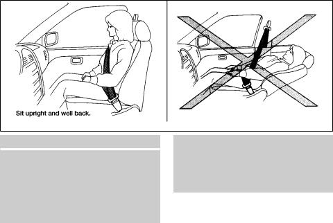
cDo not ride in a moving vehicle when the seatback is reclined. This can be dangerous. The shoulder belt will not be against your body. In an accident, you could be thrown into it and receive neck or other serious injuries. You could also slide under the lap belt and receive serious internal injuries.
cFor the most effective protection when the vehicle is in motion, the seat should be upright. Always sit well back in the seat and adjust the seat properly. See “Precautions on Seat Belt Usage” later in this section.
1-2 Safety—Seats, seat belts and supplemental air bags
![]()
WRS0163
FRONT POWER SEAT
ADJUSTMENT
WARNING
c Do not adjust the driver’s seat while driving so full attention may be given to vehicle operation. The seat may move suddenly and could cause loss of control of the vehicle.
cDo not leave children unattended inside the vehicle. They could unknowingly activate switches or controls. Unattended children could become involved in serious accidents.
Operating tips
cThe power seat motor has an auto-reset overload protection circuit. If the motor stops during operation, wait 30 seconds, then reactivate the switch.
cDo not operate the power seat switch for a long period of time when the engine is off. This will discharge the battery.
See “Automatic drive positioner” in “Pre-driving checks and adjustments” for automatic drive positioner operation.
Forward and backward
Moving the switch forward or backward will slide the seat forward or backward to the desired position.
Reclining
Move the recline switch backward until the desired angle is obtained. To bring the seatback forward again, move the switch forward and move your body forward. The seatback will move forward.
The reclining feature allows adjustment of the seatback for occupants of different sizes for added comfort and to help obtain proper seat belt fit (see “Precautions on seat belt usage” later in this section). Also, the seatback can be reclined to allow occupants to rest when the vehicle is stopped.
Safety—Seats, seat belts and supplemental air bags 1-3

WRS0164
Seat lifter
Push the front or rear end of the switch up or down to adjust the angle and height of the seat cushion.
LRS0238
Lumbar support (driver’s seat)
The lumbar support feature provides lower back support to the driver. Move the switch forward or backward to adjust the seatback lumbar area.
WRS0369
2ND ROW CAPTAIN’S CHAIR ADJUSTMENT
Reclining
To recline the seatback, pull up on the lever and lean back.
The recline feature allows adjustment of the seat back for occupants of different sizes to help obtain proper seat belt fit (see “Precautions on seat belt usage” later in this section). Also, the seatback can be reclined to allow occupants to rest when the vehicle is stopped.
1-4 Safety—Seats, seat belts and supplemental air bags

WARNING
cAfter adjustment, gently rock in the seat to make sure it is securely locked.
cDo not ride in a moving vehicle when the seatback is reclined. This can be dangerous. The shoulder belt will not be against your body. In an accident, you could be thrown into it and receive neck or other serious injuries. You could also slide under the lap belt and receive serious internal injuries.
cFor the most effective protection when the vehicle is in motion, the seat should be upright. Always sit well back in the seat and adjust the seat belt properly. See “Precautions on seat belt usage” later in this section.
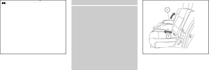
WRS0415
Tip up for easy entry to the 3rd row
The 2nd row captain’s chairs can be tipped forward for easy entry or exit from the 3rd row bench seat. To enter the 3rd row s1 raise the armrest so it is parallel to the seatback and in the stowed position, then lift up on the latch located on the upper corner of the seatback on the 2nd row captain’s chair and fold the seatback forward at an angle over the seat base. This will release the back of the seat so it may be tipped forward.
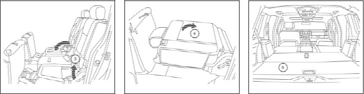
LRS0372
Then s2 lift up on the lower corner of the seat base and tip the 2nd row captain’s chair forward. To exit the 3rd row bench seat lift up on the same latch and fold the seatback forward onto the seat base. Then lift up on the seat base and tip it forward.
Safety—Seats, seat belts and supplemental air bags 1-5

WRS0369
Outboard seats
2ND ROW BENCH SEAT ADJUSTMENT (if so equipped)
Reclining
To recline the seatback, pull up on the lever and lean back.
The recline feature allows adjustment of the seat back for occupants of different sizes to help obtain proper seat belt fit (see “Precautions on seat belt usage” later in this section). Also, the seatback can be reclined to allow occupants to rest when the vehicle is stopped.
WARNING
cAfter adjustment, gently rock in the seat to make sure it is securely locked.
cDo not ride in a moving vehicle when the seatback is reclined. This can be dangerous. The shoulder belt will not be against your body. In an accident, you could be thrown into it and receive neck or other serious injuries. You could also slide under the lap belt and receive serious internal injuries.
cFor the most effective protection when the vehicle is in motion, the seat should be upright. Always sit well back in the seat and adjust the seat belt properly. See “Precautions on seat belt usage” later in this section.
1-6 Safety—Seats, seat belts and supplemental air bags
WRS0414
Tip up for easy entry to the 3rd row
The outboard seating positions on the 2nd row bench seat can be tipped forward for easy entry or exit from the 3rd row bench seat. To enter the 3rd row s1 lift up on the latch located on the upper corner of the seatback on the 2nd row bench seat and fold the seatback forward at an angle over the seat base. This will release the back of the seat so it may be tipped forward.

LRS0331
Then s2 lift up on the lower corner of the seat base and tip the outboard seating position of the 2nd row bench seat forward. To exit the 3rd row bench seat lift up on the same latch and fold the seatback forward onto the seat base. Then lift up on the seat base and tip it forward.
WARNING
Head restraints should be adjusted properly as they may provide significant protection against injury in an accident. Do not remove them. Check the adjustment after someone else uses the seat.
LRS0286
HEAD RESTRAINT ADJUSTMENT
To raise the head restraint, pull it up. To lower, push and hold the lock knob and push the head restraint down.
The head restraints on the 2nd and 3rd row seats are removable. The front seat head restraints are not removable.
Safety—Seats, seat belts and supplemental air bags 1-7

armrest to the stowed position, then pull it to the resting position and adjust to the desired height.
|
WRS0134 |
WRS0368 |
||
|
Adjust the head restraint so the center is level |
ARMRESTS |
||
|
with the center of your ears. |
To use the armrests, pull them down to the rest- |
||
|
ing position. |
|||
|
sA |
Stowed position |
||
|
sB |
Resting position |
||
|
Adjustable driver’s seat armrest (if so |
|||
|
equipped) |
To use the adjustable driver seat armrest, pull it down to the resting position. Adjust the armrest to the desired position by raising the armrest to the desired height and releasing the armrest. To readjust the armrest to a lower position, raise the
1-8 Safety—Seats, seat belts and supplemental air bags

LRS0341
FLEXIBLE SEATING
WARNING
cNever allow anyone to ride in the cargo area or on the rear seats when they are in the fold-down position. In a collision, people riding in these areas without proper restraints are more likely to be seriously injured or killed.
cDo not allow people to ride in any area of your vehicle that is not equipped with seats and seat belts. Be sure everyone in your vehicle is in a seat and using a seat belt properly.
cDo not fold down the rear seats when occupants are in the rear seat area or any luggage is on the rear seats.
cHead restraints should be adjusted properly as they may provide significant protection against injury in an accident. Always replace and adjust them properly if they have been removed for any reason.
cIf the head restraints are removed for any reason, they should be securely stored to prevent them from causing injury to passengers or damage to the vehicle in case of sudden braking or an accident.
cWhen returning the seatbacks to the upright position, be certain they are completely secured in the latched position. If they are not completely secured, passengers may be injured in an accident or sudden stop.
cProperly secure all cargo to help prevent it from sliding or shifting. Do not place cargo higher than the seatbacks. In a sudden stop or collision, unsecured cargo could cause personal injury.
Folding the front passenger’s seatback
To fold the front passenger’s seatback flat for extra storage length when transporting long items:
s1 Slide the seat to the rear-most position. Lift up on the recline lever, located on the outside edge of the seat, and fold the seatback forward as far as it will go. Then lift up on the latch located on the upper corner of the seatback to release the back of the seat.
Safety—Seats, seat belts and supplemental air bags 1-9
LRS0342
s2 Once the seatback is released it will enable you to fold the front passenger seatback flat over the seat cushion.
3.To return the front passenger’s seat to a seating position lift up on the seatback and push it up to an upright position. Then pull up on the recline lever and lean the seatback to a proper seating position. Release the lever to lock the seatback in position.
WARNING
cIf you fold the front passenger’s seatback flat forward to carry longer objects, be sure this cargo is properly secured and not near an air bag. In a crash, an inflating air bag might force that object toward a person. This could cause severe injury or even death. Secure objects away from the area in which an air bag would inflate. See “Precautions on supplemental restraint system” later in this section.
cNever allow anyone to ride in the cargo area or on the front passenger’s seat when it is in the fold-down position. Use of these areas by passengers could result in serious injury in an accident or sudden stop.
LRS0332
Folding the 2nd row captain’s chairs
To fold the 2nd row captain’s chairs flat for maximum cargo hauling:
s1 Raise the armrest to the stowed position. Remove the 2nd row center console, see “Console removal” in the “Instruments and controls” section of this Owner’s Manual.
s2 Pull the strap forward, located in the center of the seat cushion, and fold the seat cushion toward the front of the vehicle.
1-10 Safety—Seats, seat belts and supplemental air bags
LRS0333
s3 Then lift up on the recline lever to fold the seatback flat forward.
LRS0334
s4 There is a carpet panel flap that can be folded toward the back of the vehicle.
LRS0335
s5 The carpet panel flaps provide a level cargo floor when the 3rd row seats are also folded flat. Reverse this process to return the 2nd row captain’s chairs to a seating position.
Make sure to properly raise the seatback to an upright position and push the seat cushion down into place.
Safety—Seats, seat belts and supplemental air bags 1-11

LRS0336
Folding the 2nd row bench seat (if so equipped)
To fold the 2nd row bench seat flat for maximum cargo hauling:
s1 Pull the strap forward, located in the center of each seat cushion, and fold each seat cushion toward the front of the vehicle.
LRS0337
s2 Then lift up on the recline lever on the side of the outboard seats to fold the outboard seatbacks flat. To fold the center seatback flat, pull up on the strap on the edge of the center seat cushion and fold the seatback toward the front of the vehicle.
LRS0338
s3 There is a carpet panel flap on the back of each seat that can be folded toward the back of the vehicle
1-12 Safety—Seats, seat belts and supplemental air bags
![]()
LRS0339
s4 The carpet panel flap provides a level cargo floor when the 3rd row seats are also folded flat.
5.To return the outboard 2nd row bench seats to a seating position reverse the process for the outboard seats.
6.To return the center seat to a seating position, lift up on the pull strap on the back of the seat base while lifting on the seatback. Then push the seat cushion back into place.
Make sure to properly raise the seatback to an upright position and push the seat cushion down into place.
LRS0374
Folding the 3rd row bench seat
To fold the 3rd row bench seat flat for maximum cargo capacity:
Disconnect and secure the center seat belt and tongues into the retractor base. See “Stowing rear center seat belt” later in this section. Then pull up on the latch located in the center of the seatback and fold it forward over the seat base.
To return the 3rd row bench seat to a seating position unfold the seatback and push it back until it latches into position.
WARNING
cWhen returning the seatbacks, be sure to attach the rear center seat belt connector.
cDo not unfasten the rear center seat belt connector except when folding down the rear seat.
cWhen attaching the rear center seat belt connector, be certain that the seatbacks are completely secured in the latched position and the rear center seat belt connector is completely secured.
cIf the rear center seat belt connector and the seatbacks are not secured in the correct position, serious personal injury may result in an accident or sudden stop.
Safety—Seats, seat belts and supplemental air bags 1-13
SUPPLEMENTAL RESTRAINT SYSTEM
PRECAUTIONS ON SUPPLEMENTAL RESTRAINT SYSTEM
This Supplemental Restraint System (SRS) section contains important information concerning the driver and passenger supplemental front air bags (INFINITI Advanced Air Bag System), supplemental side air bags, curtain side-impact and rollover air bags and pre-tensioner seat belts.
Supplemental front impact air bag system:
The INFINITI advanced air bag system can help cushion the impact force to the head and chest of the driver and front passenger in certain frontal collisions.
Supplemental side-impact air bag system:
This system can help cushion the impact force to the chest area of the driver and front passenger in certain side impact collisions. The supplemental side air bag is designed to inflate on the side where the vehicle is impacted.
Supplemental curtain side-impact and rollover air bag system: This system can help cushion the impact force to the head of occupants in front and rear outboard seating positions in certain side impact or rollover collisions. In a side impact, the curtain air bags are designed to inflate on the side where the vehicle is impacted.
In a rollover both curtain air bags are designed to inflate and remain inflated for a short time.
These supplemental restraint systems are designed to supplement the crash protection provided by the seat belts and are not a substitute for them. Seat belts should always be correctly worn and the occupant seated a suitable distance away from the steering wheel, instrument panel and door finishers. See “Seat belts” later in this section for instructions and precautions on seat belt usage.
The supplemental air bags operate only when the ignition switch is in the ON or START position.
After turning the ignition key to the ON position, the supplemental air bag warning light illuminates. The supplemental air bag warning light will turn off after about 7 seconds if the system is operational.
1-14 Safety—Seats, seat belts and supplemental air bags

WRS0031
WARNING
c The supplemental front air bags ordinarily will not inflate in the event of a side impact, rear impact, rollover, or lower severity frontal collision. Also, the front passenger air bag will not inflate if the passenger air bag status light is lit. See “Front passenger air bag and status light” later in this section. Always wear your seat belts to help reduce the risk or severity of injury in various kinds of accidents.
c The seat belts and the supplemental front air bags are most effective when you are sitting well back and upright in the seat. The front air bags inflate with great force. Even with the INFINITI advanced air bag system, if you are unrestrained, leaning forward, sitting sideways or out of position in any way, you are at greater risk of injury or death in a crash. You may also receive serious or fatal injuries from the supplemental front air bag if you are up against it
when it inflates. Always sit back against the seatback and as far away as practical from the steering wheel or instrument panel. Always use the seat belts.
cThe driver and front passenger seat belt buckles are equipped with sensors that detect if the seat belts are fastened. The advanced air bag system monitors the severity of a collision and seat belt usage then inflates the air bags. Failure to properly wear seat belts can increase the risk or severity of injury in an accident.
cThe front passenger seat is equipped with an occupant classification sensor (weight sensor) that turns the front passenger air bag OFF under some conditions. This sensor is only used in this seat. Failure to be properly seated and wearing the seat belt can increase the risk or severity of injury in an accident. See “Front Passenger air bag and status light” later in this section.
cKeep hands on the outside of the steering wheel. Placing them inside the steering wheel rim could increase the risk that they are injured when the supplemental front air bag inflates.
Safety—Seats, seat belts and supplemental air bags 1-15

WARNING
cNever let children ride unrestrained or extend their hands or face out of the window. Do not attempt to hold them in your lap or arms. Some examples of dangerous riding positions are shown in the illustrations.
1-16 Safety—Seats, seat belts and supplemental air bags

|
ARS1042 |
ARS1043 |
ARS1044 |
WARNING
c Children may be severely injured or killed when the supplemental front air bags, side air bags or curtain sideimpact and rollover air bags inflate if they are not properly restrained. Preteens and children should be properly restrained in the rear seat, if possible.
Safety—Seats, seat belts and supplemental air bags 1-17

WARNING
c Even with the INFINITI Advanced Air
Bag System, never install a rear-facing child restraint in the front seat. An inflating supplemental front air bag could seriously injure or kill your child. See “Child restraints” later in this section for details.
WRS0431
Do not lean against doors or windows.
WARNING
Supplemental side air bag and curtain side-impact and rollover air bag:
cThe supplemental side air bag and curtain side-impact and rollover air bag ordinarily will not inflate in the event of a frontal impact, rear impact, or lower severity side collision. Always wear your seat belts to help reduce the risk or severity of injury in various kinds of accidents.
1-18 Safety—Seats, seat belts and supplemental air bags

WRS0365
Do not lean against doors or windows.
SSS0162
Do not lean against doors or windows.
WARNING
c The seat belts, the supplemental side air bags and curtain side-impact and rollover air bags are most effective when you are sitting well back and upright in the seat. The side air bag and curtain air bag inflate with great force. Do not allow anyone to place their hand, leg or face near the side air bag on the side of the seatback of the front seat or near the side roof rails. Do not allow anyone sitting in the front seats or rear outboard seats to extend their hand out of the window or lean against the door. Some examples of dangerous riding positions are shown in the previous illustrations.
Safety—Seats, seat belts and supplemental air bags 1-19

WARNING
cWhen sitting in the 2nd row rear seat, do not hold onto the seatback of the front seat. If the side air bag inflates, you may be seriously injured. Be especially careful with children, who should always be properly restrained. Some examples of dangerous riding positions are shown in the illustrations.
cDo not use seat covers on the front seatbacks. They may interfere with supplemental side air bag inflation.
1-20 Safety—Seats, seat belts and supplemental air bags

1.SRS curtain side-impact and rollover air bag modules
2.SRS curtain side-impact and rollover air bag
3.Diagnosis sensor unit
4.Supplemental front air bag modules
5.Crash zone sensor
6.Occupant classification system control unit
7.Occupant classification sensor
8.Seat belt buckle switches
9.Pre-tensioner retractor
10.Satellite sensors
11.Supplemental side air bag modules
INFINITI Advanced Air Bag System (front seats)
|
This vehicle is equipped with the INFINITI ad- |
|||
|
vanced air bag system for the driver and front |
|||
|
passenger seats. This system is designed to |
|||
|
meet certification requirements under U.S. regu- |
|||
|
lations. It is also permitted in Canada. However, |
|||
|
all of the information, cautions and warn- |
|||
|
ings in this manual still apply and must be |
|||
|
followed. |
|||
|
The driver supplemental front air bag is located in |
|||
|
WRS0434 |
the center of the steering wheel. The passenger |
||
|
supplemental front air bag is mounted |
in the |
||
|
Safety—Seats, seat belts and supplemental air bags |
1-21 |
dashboard above the glove box. The supplemental front air bags are designed to inflate in higher severity frontal collisions, although they may inflate if the forces in another type of collision are similar to those of a higher severity frontal impact. They may not inflate in certain frontal collisions. Vehicle damage (or lack of it) is not always an indication of proper supplemental front air bag system operation.
The INFINITI advanced air bag system has dual stage inflators. It also monitors information from the crash zone sensor, the diagnosis sensor unit, seat belt buckle sensors, occupant classification sensor (weight sensor) and passenger seat belt tension sensor. Inflator operation is based on the severity of a collision and seat belt usage for the driver. For the front passenger, it additionally monitors the weight of an occupant or object on the seat and seat belt tension. Based on information from the sensors, only one front air bag may inflate in a crash, depending on the crash severity and whether the front occupants are belted or unbelted. Additionally, the front passenger air bag may be automatically turned OFF under some conditions, depending on the weight detected on the passenger seat and how the seat belt is used. If the front passenger air bag is OFF, the passenger air bag status light will be illuminated. See “Front passenger air bag and status light” later in this section for further details. One
front air bag inflating does not indicate improper performance of the system.
If you have any questions about your air bag system, please contact INFINITI or your INFINITI dealer. If you are considering modification of your vehicle due to a disability, you may also contact INFINITI. Contact information is contained in the front of this Owner’s Manual.
When a supplemental front air bag inflates, a fairly loud noise may be heard, followed by the release of smoke. This smoke is not harmful and does not indicate a fire. Care should be taken to not inhale it, as it may cause irritation and choking. Those with a history of a breathing condition should get fresh air promptly.
Supplemental front air bags, along with the use of seat belts, help to cushion the impact force on the face and chest of the front occupants. They can help save lives and reduce serious injuries. However, an inflating front air bag may cause facial abrasions or other injuries. Front air bags do not provide restraint to the lower body.
Even with INFINITI advanced air bags, seat belts should be correctly worn and the driver and passenger seated upright as far as practical away from the steering wheel or instrument panel. The supplemental front air bags inflate quickly in order to help protect the front occupants. Because of this, the force of the front air bag inflating can
1-22 Safety—Seats, seat belts and supplemental air bags
increase the risk of injury if the occupant is too close to, or is against, the front air bag module during inflation.
The front air bags deflate quickly after a collision.
The supplemental front air bags operate only when the ignition switch is in the ON or START position.
After turning the ignition key to the ON position, the supplemental air bag warning light illuminates. The supplemental air bag warning light will turn off after about 7 seconds if the system is operational.
![]()
LRS0351
Front passenger air bag and status light
WARNING
The front passenger air bag is designed to automatically turn OFF under some conditions. Read this section carefully to learn how it operates. Proper use of the seat, seat belt and child restraints is necessary for most effective protection. Failure to follow all instructions in this manual concerning the use of seats, seat belts and child restraints can increase the risk or severity of injury in an accident.
Status light
|
LRS0316 |
|
|
The front passenger air bag status light |
|
|
or |
is located under the climate controls. |
The light operates as follows:
cUnoccupied passenger seat or when other
conditions are met as outlined in this section: The  or
or  illuminates to indicate that the front passenger air bag is OFF and will not inflate in a crash.
cOccupied passenger seat and the passen-
ger meets the conditions outlined in this section: The light  or
or  is OFF to indicate that the front passenger air bag is ON.
Front passenger air bag
The front passenger air bag is designed to automatically turn OFF when the vehicle is operated under some conditions as described below in accordance with U.S. regulations. If the front passenger air bag is OFF, it will not inflate in a crash. The driver air bag and other air bags in your vehicle are not part of this system.
The purpose of the regulation is to help reduce the risk of injury or death from an inflating air bag to certain front passenger seat occupants, such as children, by requiring the air bag to be automatically turned OFF. Certain sensors are used to meet the requirements.
One sensor used is the occupant classification sensor (weight sensor). It is in the bottom of the front passenger seat cushion and is designed to detect an occupant and objects on the seat by weight. It works together with seat belt sensors described later. For example, if a child is in the front passenger seat, the advanced air bag system is designed to turn the passenger air bag OFF in accordance with the regulations. Also, if a child restraint of the type specified in the regulations is on the seat, its weight and the child’s weight can be detected and cause the air bag to turn OFF. Weight sensor operation can vary depending on the front passenger seat belt sensors.
Safety—Seats, seat belts and supplemental air bags 1-23
The front passenger seat belt sensors are designed to detect if the seat belt is buckled and the amount of tension on the seat belt, such as when it is in the automatic locking mode (child restraint mode). Based on the weight on the seat detected by the weight sensor and the belt tension detected on the seat belt, the advanced air bag system determines whether the front passenger air bag should be automatically turned OFF as required by the regulations.
Front passenger seat adult occupants who are properly seated and using the seat belt as outlined in this manual should not cause the passenger air bag to be automatically turned OFF. For small adults it may be turned OFF. Also, if the occupant takes his/her weight off the seat cushion (for example, by not sitting upright, by sitting on an edge of the seat, or by otherwise being out of position), this could cause the sensor to turn the air bag OFF. In addition, if the occupant improperly uses the seat belt in the automatic locking mode (child restraint mode), this could cause the air bag to be turned OFF. Always be sure to be seated and wearing the seat belt properly for the most effective protection by the seat belt and supplemental air bag.
INFINITI recommends that pre-teens and children be properly restrained in a rear seat. INFINITI also recommends that appropriate child restraints and booster seats be properly installed
in a rear seat. If this is not possible, the weight sensor and seat belt sensors are designed to operate as described above to turn the front passenger air bag OFF for specified child restraints as required by the regulations. Failing to properly secure child restraints and to use the automatic locking mode (child restraint mode) may allow the restraint to tip or move in an accident or sudden stop. This can also result in the passenger air bag inflating in a crash instead of being OFF. See “Child restraints” later in this section for proper use and installation.
If the front passenger seat is not occupied and the seat belt is not buckled, the passenger air bag is designed not to inflate in a crash. However, heavy objects placed on the seat could result in air bag inflation, because of the object’s weight detected by the weight sensor. Other conditions could also result in air bag inflation, such as if a child is standing on the seat, or if two children are on the seat, contrary to the instructions in this manual. Always be sure that you and all vehicle occupants are seated and restrained properly.
Using the passenger air bag status light, you can monitor when the front passenger air bag is automatically turned OFF. The light will illuminate (indicating the air bag is OFF and will not inflate) when the front passenger seat is not occupied.
1-24 Safety—Seats, seat belts and supplemental air bags
If an adult occupant is in the seat and the passenger air bag status light is illuminated (indicating that the air bag is OFF), it could be that the person is a small adult, or is not sitting on the seat or using the seat belt properly. If a child restraint must be used in the front seat, but the status light is not lit (indicating that the air bag might inflate in a crash), it could be that the child restraint or seat belt is not being used properly. If such situations happen, properly position and restrain the occupant or child restraint. Otherwise reposition the occupant or child restraint in a rear seat.
If a malfunction occurs in the front passenger air bag system, the passenger air bag status light or
or  , located under the climate controls, will illuminate and the supplemental air bag warning light
 , located in the meter and gauges area in the center of the instrument panel, will blink. Have the system checked by an INFINITI dealer.

Other supplemental front air bag precautions
WARNING
cDo not place any objects on the steering wheel pad or on the instrument panel. Also, do not place any objects between any occupant and the steering wheel or instrument panel. Such objects may become dangerous projectiles and cause injury if the supplemental front air bag inflates.
cImmediately after inflation, several front air bag system components will be hot. Do not touch them; you may severely burn yourself.
cNo unauthorized changes should be made to any components or wiring of the supplemental air bag system. This is to prevent accidental inflation of the supplemental air bag or damage to the supplemental air bag system.
cDo not make unauthorized changes to your vehicle’s electrical system, suspension system or front end structure. This could affect proper operation of the supplemental front air bag system.
cTampering with the supplemental front air bag system may result in serious personal injury. Tampering includes changes to the steering wheel and the instrument panel assembly by placing material over the steering wheel pad and above the instrument panel or by installing additional trim material around the air bag system.
cModifying or tampering with the front passenger seat may result in serious personal injury. For example, do not change the front seats by placing material on the seat cushion or by installing additional trim material, such as seat covers, on the seat that are not specifically designed to assure proper air bag operation. Additionally, do not stow any objects under the front passenger seat or the seat cushion and seatback. Such objects may interfere with the proper operation of the occupant classification system (weight sensor).
cNo unauthorized changes should be made to any components or wiring of the seat belt system. This may affect the supplemental front air bag system. Tampering with the seat belt system may result in serious personal injury.
cMaintenance on and around the supplemental front air bag system should be done by an INFINITI dealer. Installation of electrical equipment should also be done by an INFINITI dealer. The Supplemental Restraint System (SRS) wiring should not be modified or disconnected. Unauthorized electrical test equipment and probing devices should not be used on the air bag system.
cA cracked windshield should be replaced immediately by a qualified repair facility. A cracked windshield could affect inflation of the supplemental air bag system.
cThe SRS wiring harness connectors are yellow and orange for easy identification.
When selling your vehicle, we request that you inform the buyer about the supplemental front air bag system and guide the buyer to the appropriate sections in this Owner’s Manual.
Safety—Seats, seat belts and supplemental air bags 1-25

WRS0381
Supplemental side-impact air bag and curtain side-impact and rollover air bags system
The supplemental side-impact air bags are located in the outside of the seatback of the front seats. The supplemental curtain side-impact and rollover air bags are located in the side roof rails in all 3 rows. These systems are designed to meet voluntary guidelines to help reduce the risk of injury to out-of-position occupants. However, all of the information, cautions and warnings in this manual still apply and must be followed. The supplemental side air bags and curtain side-impact and rollover air bags are de-
signed to inflate in higher severity side collisions, although they may inflate if the forces in another type of collision are similar to those of a higher severity side impact. They are designed to inflate on the side where the vehicle is impacted. They may not inflate in certain side collisions.
Curtain side-impact and rollover air bags are also designed to inflate in certain types of rollover collisions or near rollovers.
Vehicle damage (or lack of it) is not always an indication of proper supplemental side air bag and curtain air bag operation.
When the supplemental side air bag and curtain air bags inflate, a fairly loud noise may be heard, followed by release of smoke. This smoke is not harmful and does not indicate a fire. Care should be taken not to inhale it, as it may cause irritation and choking. Those with a history of a breathing condition should get fresh air promptly.
Supplemental side air bags, along with the use of seat belts, help to cushion the impact force on the chest of the front occupants. Curtain sideimpact and rollover air bags help to cushion the impact force to the head of occupants in the front and rear outboard seating positions in all rows. They can help save lives and reduce serious injuries. However, an inflating side air bag, or curtain air bag may cause abrasions or other injuries.
1-26 Safety—Seats, seat belts and supplemental air bags
The seat belts should be correctly worn and the driver and passenger seated upright as far as practical away from the supplemental side air bag. Rear seat passengers should be seated as far away as practical from the door finishers and side roof rails. The side air bags and curtain air bag inflate quickly in order to help protect the occupants. Because of this, the force of the side air bag and curtain air bag inflating can increase the risk of injury if the occupant is too close to, or is against, these air bag modules during inflation. The side air bag and curtain air bag will deflate after the collision is over.
The supplemental side air bags and curtain side-impact and rollover air bags operate only when the ignition switch is in the ON or START positions.
After turning the ignition key to the ON position, the supplemental air bag warning light illuminates. The supplemental air bag warning light will turn off after about 7 seconds if the system is operational.

WARNING
cDo not place any objects near the seatback of the front seats. Also, do not place any objects (an umbrella, bag, etc.) between the front door finisher and the front seat. Such objects may become dangerous projectiles and cause injury if the supplemental side air bag inflates.
cRight after inflation, several side air bag and curtain side-impact and rollover air bag system components will be hot. Do not touch them; you may severely burn yourself.
cNo unauthorized changes should be made to any components or wiring of the side air bag and curtain air bag system. This is to prevent accidental inflation of the side air bag and curtain air bag or damage to the side air bag and curtain air bag system.
cDo not make unauthorized changes to your vehicle’s electrical system, suspension system or side panel. This could affect proper operation of the supplemental curtain air bag system.
cTampering with the supplemental side air bag system may result in serious personal injury. For example, do not change the front seats by placing material near the seatback or by installing additional trim material, such as seat covers, around the side air bag.
cWork around and on the curtain air bag system should be done by an INFINITI dealer. Installation of electrical equipment should also be done by an INFINITI dealer. The SRS wiring harnesses* should not be modified or disconnected. Unauthorized electrical test equipment and probing devices should not be used on the side air bag or curtain air bag system.
* The SRS wiring harness or connectors are yellow or orange for easy identification.
When selling your vehicle, we request that you inform the buyer about the supplemental side air bag and curtain air bag system and guide the buyer to the appropriate sections in this Owner’s Manual.
Pre-tensioner seat belt system (For front seats)
WARNING
cThe pre-tensioner seat belt cannot be reused after activation. It must be replaced together with the retractor and buckle as a unit.
cIf the vehicle becomes involved in a frontal collision but the pre-tensioner is not activated, be sure to have the pretensioner system checked and, if necessary, replaced by your INFINITI dealer.
cNo unauthorized changes should be made to any components or wiring of the pre-tensioner seat belt system. This is to prevent accidental activation of the pre-tensioner seat belt or damage to the pre-tensioner seat belt operation. Tampering with the pre-tensioner seat belt system may result in serious personal injury.
Safety—Seats, seat belts and supplemental air bags 1-27

cWork around and on the pre-tensioner system should be done by an INFINITI dealer. Installation of electrical equipment should also be done by an INFINITI dealer. Unauthorized electrical test equipment and probing devices should not be used on the pre-tensioner seat belt system.
cIf you need to dispose of the pretensioner or scrap the vehicle, contact an INFINITI dealer. Correct pretensioner disposal procedures are set forth in the appropriate INFINITI Service Manual. Incorrect disposal procedures could cause personal injury.
The front seat pre-tensioner seat belt system activates in conjunction with the front and side impact supplemental air bag systems. Working with the seat belt retractor, it helps tighten the seat belt when the vehicle becomes involved in certain types of collisions, helping to restrain front seat occupants.
The pre-tensioner is encased with the seat belt’s retractor. These seat belts are used the same as conventional seat belts.
When the pre-tensioner seat belt activates, smoke is released and a loud noise may be heard. This smoke is not harmful and does not indicate a
fire. Care should be taken not to inhale it, as it may cause irritation and choking. Those with a history of a breathing condition should get fresh air promptly.
After the pre-tensioner seat belts have activated, load limiters allow the seat belt to release webbing (if necessary) to reduce forces against the chest.
If any abnormality occurs in the pre-tensioner
|
system, |
the supplemental air bag warning |
|
light |
will not come on, will flash intermit- |
tently or will turn on for 7 seconds and remain on after the ignition key has been turned to the ON or START position. In this case, the pre-tensioner seat belt may not function properly. They must be checked and repaired. Take your vehicle to the nearest INFINITI dealer.
When selling your vehicle, we request that you inform the buyer about the pre-tensioner seat belt system and guide the buyer to the appropriate sections in this Owner’s Manual.
1-28 Safety—Seats, seat belts and supplemental air bags
LRS0397
1.SRS Air bag warning labels
2.SRS Side air bag warning label
SUPPLEMENTAL AIR BAG WARNING LABELS
Warning labels about the supplemental front air bags and supplemental side air bags are placed in the vehicle as shown in the illustration.

LRS0100
SUPPLEMENTAL AIR BAG
WARNING LIGHT
The supplemental air bag warning light, displaying in the instrument panel, monitors the circuits of the supplemental front air bag, supplemental side air bag and curtain sideimpact and rollover air bag and pre-tensioner seat belt systems. The circuits monitored by the supplemental air bag warning light are the diagnosis sensor unit, crash zone sensor, satellite sensors, rollover sensor, front air bag modules, side air bag modules, curtain air bag modules, pre-tensioner seat belts and all related wiring.
When the ignition key is in the ON or START position, the supplemental air bag warning light illuminates for about 7 seconds and then turns off. This means the system is operational.
If any of the following conditions occur, the supplemental front air bag, supplemental side air bag, curtain air bag and pre-tensioner seat belt systems need servicing:
cThe supplemental air bag warning light remains on after approximately 7 seconds.
WARNING
If the supplemental air bag warning light is on, it could mean that the supplemental front air bag, supplemental side air bag, curtain and rollover air bag systems and/or pre-tensioner seat belt systems will not operate in an accident. To help avoid injury to yourself or others, have your vehicle checked by an INFINITI dealer as soon as possible.
c The supplemental air bag warning light flashes intermittently.
cThe supplemental air bag warning light does not come on at all.
Under these conditions, the supplemental front air bag, supplemental side air bags and curtain air bag or pre-tensioner seat belt systems may not operate properly. It must be checked and repaired. Take your vehicle to the nearest INFINITI dealer.
Repair and replacement procedure
The supplemental front air bags, supplemental side air bags, curtain air bags and pre-tensioner seat belts are designed to inflate on a one-time- only basis. As a reminder, unless it is damaged, the supplemental air bag warning light remains illuminated after inflation has occurred. Repair and replacement of these supplemental air bag systems should be done only by an INFINITI dealer.
When maintenance work is required on the vehicle, the supplemental front air bags, supplemental side air bags, curtain air bags, pretensioner seat belts and related parts should be pointed out to the person performing the maintenance. The ignition key should always be in the LOCK position when working under the hood or inside the vehicle.
Safety—Seats, seat belts and supplemental air bags 1-29

SEAT BELTS
WARNING
c Once a supplemental front air bag, supplemental side air bag or curtain air bag has inflated, the air bag module will not function again and must be replaced. Additionally, if any of the supplemental front air bags inflate, the activated pre-tensioner seat belts must also be replaced. The air bag module and pre-tensioner seat belt system should be replaced by an INFINITI dealer. The air bag module and pretensioner seat belt system cannot be repaired.
cThe supplemental front air bag, side air bag and curtain air bag systems, and the pre-tensioner seat belt system should be inspected by an INFINITI dealer if there is any damage to the front end or side portion of the vehicle.
cIf you need to dispose of the supplemental air bag, pre-tensioner seat belt system or scrap the vehicle, contact an INFINITI dealer. Correct supplemental air bag and pre-tensioner seat belt system disposal procedures are set forth in the appropriate INFINITI Service Manual. Incorrect disposal procedures could cause personal injury.
SSS0136
PRECAUTIONS ON SEAT BELT USAGE
If you are wearing your seat belt properly adjusted and you are sitting upright and well back in your seat, your chances of being injured or killed in an accident and/or the severity of injury may be greatly reduced. INFINITI strongly encourages you and all of your passengers to buckle up every time you drive, even if your seating position includes a supplemental air bag.
Most U.S. states and Canadian provinces or territories specify that seat belts be worn at all times when a vehicle is being driven.
1-30 Safety—Seats, seat belts and supplemental air bags

WARNING
cEvery person who drives or rides in this vehicle should use a seat belt at all times. Children should be properly restrained in the rear seat and, if appropriate, in a child restraint.
WARNING
c The seat belt should be properly adjusted to a snug fit. Failure to do so may reduce the effectiveness of the entire restraint system and increase the chance or severity of injury in an accident. Serious injury or death can occur if the seat belt is not worn properly.
Safety—Seats, seat belts and supplemental air bags 1-31

SSS0014
WARNING
c Always route the shoulder belt over your shoulder and across your chest. Never run the belt behind your back, under your arm or across your neck. The belt should be away from your face and neck, but not falling off your shoulder.
cPosition the lap belt as low and snug as possible AROUND THE HIPS, NOT THE WAIST. A lap belt worn too high could increase the risk of internal injuries in an accident.
cBe sure the seat belt tongue is securely fastened to the proper buckle.
cDo not wear the seat belt inside out or twisted. Doing so may reduce its effectiveness.
cDo not allow more than one person to use the same seat belt.
cNever carry more people in the vehicle than there are seat belts.
cIf the seat belt warning light glows continuously while the ignition is turned ON with all doors closed and all seat belts fastened, it may indicate a malfunction in the system. Have the system checked by an INFINITI dealer.
cOnce the pre-tensioner seat belt has activated, it cannot be reused and must be replaced together with the retractor. See your INFINITI dealer.
cRemoval and installation of the pretensioner seat belt system components should be done by an INFINITI dealer.
1-32 Safety—Seats, seat belts and supplemental air bags
cAll seat belt assemblies, including retractors and attaching hardware, should be inspected after any collision by an INFINITI dealer. INFINITI recommends that all seat belt assemblies in use during a collision be replaced unless the collision was minor and the belts show no damage and continue to operate properly. Seat belt assemblies not in use during a collision should also be inspected and replaced if either damage or improper operation is noted.
cAll child restraints and attaching hardware should be inspected after any collision. Always follow the restraint manufacturer’s inspection instructions and replacement recommendations. The child restraints should be replaced if they are damaged.
CHILD SAFETY
Children need adults to help protect them. They need to be properly restrained.
The proper restraint depends on the child’s size. Generally, infants up to about 1 year and less than 20 pounds (9 kg) should be placed in rear facing child restraints. Front facing child restraints are available for children who outgrow rear facing child restraints.
 Loading…

P re p a re d e x c l u s i v e l y f o r Donald Buffamanti Full refinement. Full innovation. Full size. ´04 QX56 p. 02 STANDARD FEATURES 1. Comfort and Convenience ■ ■ ■ ■ ■ ■ ■ ■ ■ ■ ■ ■ ■ ■ ■ Infiniti Navigation System1 with DVD-ROM database and Birdview™ Vehicle Information System with 6.3-inch LCD screen; includes navigation, audio and climate control displays 7-passenger seating with second-row captain’s chairs and removable second-row center console Available 8-passenger seating with second-row split bench seat Bose® premium 265-watt audio system with AM/FM, in-dash, single-slot 6-disc CD autochanger 10 speakers, including subwoofer and center speaker Dual-zone front Automatic Temperature Control system with microfiltration Rear climate controls 10-way power driver’s seat with adjustable lumbar support 8-way power passenger’s seat Heated first- and second-row seats Power adjustable pedals Aluminum, wood and leather-appointed interior Power rear liftgate Rear Park Assist sensors 2. Mechanical ■ ■ ■ ■ ■ ■ ■ ■ ■ ■ ■ ■ ■ ■ 5.6-liter V8, aluminum-alloy block and heads 315 horsepower @ 4,900 rpm 390 lb-ft of torque @ 3,600 rpm Front engine/rear-wheel drive or front engine/4-wheel drive Low-friction molybdenum-coated pistons Variable-flow induction system optimizes airflow Direct ignition system with platinum-tipped spark plugs Infiniti All-Mode 4WD® with computer-controlled transfer case; Standard on 4-wheel drive model Electronically controlled 5-speed automatic transmission with driver-adaptive learning algorithm 4-wheel vented disc brakes with 4-channel ABS, Electronic Brake force Distribution, Brake Assist Engine-speed-sensing variable-assist power rack-and-pinion steering Independent front double-wishbone with stabilizer bar Independent rear double-wishbone with auto-leveling and stabilizer bar 18-inch 7-spoke chrome aluminum-alloy wheels 3. Safety and Security ■ ■ ■ ■ ■ ■ ■ ■ ■ ■ ■ ■ ■ Infiniti Vehicle Dynamic Control2 Electronic Brake force Distribution Traction Control System Brake Assist and available Brake Assist with Preview3 Tire pressure monitor Remote keyless entry Vehicle Security System and Infiniti Vehicle Immobilizer System Zone Body construction with reinforced passenger compartment and front and rear crumple zones Dual-stage front supplemental air bags4 with seat belt sensors Driver and front-passenger supplemental side-impact air bags4 Roof-mounted curtain supplemental air bags4 for side-impact and rollover protection for front and outboard rear occupants 3-point seat belt in all seating positions LATCH System (Lower Anchors and Tethers for CHildren) helps simplify proper installation of compatible child restraint seats Snug Kids offers recommendations for choosing and installing child restraint seats. Please visit Infiniti.com for details. Big in more ways than any other full-size SUV. 1 2 3 4 Never program while driving. Requires accurate GPS service to be available and operating for features to function properly. Mapping may not be detailed in all areas or reflect current road regulations. Some Infiniti dealers may not appear on the current mapping areas. Periodic updates to the DVD will be available for an additional cost. See your Infiniti dealer for details. Infiniti VDC system is designed to help improve driving stability but does not prevent accidents due to abrupt steering or by careless or dangerous driving techniques. Always drive safely. Optional Brake Assist with Preview is only an aid to assist the driver and is not a collision warning or avoidance device. It is the driver’s responsibility to stay alert, drive safely and be in control of the vehicle at all times. Please keep in mind that air bags are a supplemental restraint system and must always be used in conjunction with the seat belt. Also, a rear-facing child restraint must never be placed in the front-passenger’s seat. In fact, all children 12 and under should ride in the rear seat properly secured in child restraints, booster seats or seat belts, according to their size. Driver and front-passenger side-impact supplemental air bags and roof-mounted curtain supplemental air bags for front- and rear-seat occupant protection are designed to inflate in higher severity side collisions on the side of the vehicle impacted. During rollovers, however, roof-mounted curtain air bags are designed to inflate on both sides. Please see your owner’s manual for more details. p. 03 1. Base MSRP 1 PRICING QX56 2WD Model QX56 4WD Model Destination and Handling 2. Models and Packages 1 $47,400 $50,400 $680 QX56 2WD Model - Includes all QX56 standard equipment QX56 4WD Model - Includes all QX56 standard equipment - Infiniti All-Mode 4WD - Skid plates—transfer case, oil pan, fuel tank Entertainment System Package $1,600 - Infiniti DVD Mobile Entertainment System with ceiling-mounted, flip-down 7.0-inch color screen, front console-mounted DVD player with wireless remote and two pairs of wireless headphones Sunroof Package $1,200 - Power sliding tinted glass sunroof with one-touch open/close, tilt feature and sliding sunshade Smart Vision Package $1,100 The scale is new. But the thinking is pure Infiniti. - RearView Monitor2 displays area behind vehicle, in real time, when vehicle is reversing via the dash-mounted color Vehicle Information System’s screen - Intelligent Cruise Control3 uses computerized laser sensors to detect vehicles ahead while automatically maintaining the preset following distance Split Bench Package (no cost option) - Second-row split bench seat increases seating capacity to 8 (replaces captain’s chairs and removable second-row center console) 3. Individual Options 1 ■ ■ ■ ■ Satellite radio, with choice of SIRIUS™ or XM® service providers4 $400 Sunroof wind deflector $90 Splash guards $100 Carpeted cargo mat $70 Pricing above includes installation. 4. Dealer-Installed Accessories ■ ■ ■ ■ ■ ■ ■ ■ ■ ■ ■ ■ 1 All prices are Manufacturer’s Suggested Retail Price (MSRP). Total MSRP excludes destination and handling, tax, title, license and options. Dealer sets actual price. 2 The RearView Monitor is a convenience but is not a substitute for proper backing procedures. Always turn and check that it is safe to do so before backing up. 3 Optional Intelligent Cruise Control is not a collision avoidance or warning device. For highway use only and not intended for congested areas or city driving. The system will not brake automatically to a stop. Failure to apply the brakes could result in an accident. 4 No satellite radio reception is available and “NO SAT” will be displayed when the SAT button is pressed unless optional satellite receiver and antenna were purchased and installed, and an XM® or SIRIUS™ satellite radio service subscription is active. ■ ■ ■ ■ ■ ■ Air bag anti-theft bolt (driver’s & passenger’s side available) $10 All-season rubber mats $75 Cargo area protector $59 Cargo organizer (requires cargo area protector) $149 Carpeted floor mats $120 Hitch ball (Class III) $13 Hitch ball mount (Class III) $54 Hitch cap $13 Hood protector $70 Igloo® cooler box $129 Interior bike mount $199 License plate frames $24.95–$45.95 Seat belt extender $16.23 Smoker’s kit $18 Tow mirror kit $425 Weight distributing hitch ball mount (Class IV) $349 Wheel locks $29 Yakima® Load Warrior roof-rack cargo carrier & roof-rack extension $398 The Total Ownership Experience ® Premium automotive machinery is only part of a premium automotive experience. You’ll recognize this understanding the very moment you arrive at an Infiniti dealer, where courteous personnel and attentive service make shopping a pleasure. You’ll notice it with services like our loan car program: When you make an appointment and drop off your Infiniti for warranty service at participating Dealers, a complimentary Infiniti Service Loan Car 1 will be waiting. We’ll support you with extensive warranty coverage 2 and a 4-year/unlimited-mileage Roadside Assistance Program that includes Trip Interruption Benefits.3 In fact, J.D. Power and Associates ranked Infiniti “#1 in Customer Satisfaction with Dealer Service” in their 2003 CUSTOMER SATISFACTION STUDY.SM 4 And we’ll help ease your Infiniti purchase with SignatureFINANCING,® SignatureLEASE ® and SignatureDIRECTPAY.®5 Owning an Infiniti will be as rewarding as driving one. 1Subject to availability. Available only during the 4-year/60,000-mile Basic coverage. The customer must be 21 years of age or older with a valid U.S. driver’s license. The customer must provide proof of primary insurance. Other restrictions apply, including mileage and day use limitations. This program is subject to change without notice at any time. 2For complete limited warranty details, see your Infiniti dealer and read the warranty. 3Roadside Assistance Program available during the first four years after initial new vehicle delivery. 4 J.D. Power and Associates 2003 Customer Service Satisfaction Study.SM Study based on 105,986 consumer responses. www.jdpower.com. 5See your Infiniti dealer for Signature Program details. Restrictions, qualifications and requirements may apply. All illustrations, photographs and specifications in this catalog are based on the latest product information; some vehicle parts cannot be shown in certain photographs. Some vehicles shown with optional equipment. See actual vehicles for complete accuracy. INFINITI Division of Nissan North America, Inc. reserves the right to make changes at any time, without notice, in prices, colors, materials, equipment, specifications and models, and to discontinue models or equipment. Availability and delivery time for particular models and equipment combinations may vary. For information on availability, additional options or accessories, contact your Infiniti dealer. All specifications, options, and accessories shown apply to the 49 continental states. Specifications, options and accessories may differ in Hawaii, U.S. territories and other countries. HomeLink is a registered trademark of Johnson Controls, Inc. Birdview is a trademark of Xanavi Corporation. The XM name and related logos are registered trademarks of XM Satellite Radio Inc. SIRIUS and related marks are trademarks of Sirius Satellite Radio Inc. All rights reserved. INFINITI, the INFINITI logo, and INFINITI model names are Nissan trademarks. ©2004 INFINITI Division of Nissan North America, Inc. Local Dealer Discover Infiniti 855 La Terraza Blvd Escondido, CA 92025 Phone: (760) 796-5500
B ENGINE
SECTION
ACC
ACCELERATOR CONTROL SYSTEM
A
ACC
C
D
E
CONTENTS
ACCELERATOR CONTROL SYSTEM …………………. 2
Removal and Installation …………………………………… 2
REMOVAL ……………………………………………………. 2
INSTALLATION …………………………………………….. 3
INSPECTION AFTER INSTALLATION …………….. 3
SERVICE DATA AND SPECIFICATIONS (SDS) …….. 4
Accelerator Control …………………………………………… 4
ADJUSTABLE ACCELERATOR PEDAL …………… 4
F
G
H
I
J
K
L
M
Revision: August 2007
ACC-1
2004 QX56
ACCELERATOR CONTROL SYSTEM
ACCELERATOR CONTROL SYSTEM
Removal and Installation
PFP:18005
EBS00IKW
Adjustable Accelerator Pedal
LBIA0379E
1.
Adjustable accelerator pedal assem- 2.
bly
4.
Adjustable brake pedal cable (part
of the accelerator pedal assembly)
A/T control cable mounting bracket (part
of the accelerator pedal assembly)
3.
Adjustable pedal electric motor (part
of the accelerator pedal assembly)
CAUTION:
●
Do not disassemble the accelerator pedal adjusting mechanism.
●
Before removal and installation the accelerator and brake pedals must be in the frontmost position. This is to align the base position of the accelerator and brake pedals.
●
Do not disassemble the accelerator pedal assembly.
●
Do not remove the accelerator pedal position sensor from the accelerator pedal bracket.
●
Avoid damage from dropping the accelerator pedal assembly during handling.
●
Keep the accelerator pedal assembly away from water.
REMOVAL
1.
2.
3.
Move the accelerator and brake pedals to the frontmost position.
Turn the ignition switch OFF and disconnect the negative battery terminal.
Disconnect the adjustable brake pedal cable from the adjustable brake pedal.
● Unlock, then pull the adjustable brake pedal cable to disconnect it from the adjustable brake pedal.
Revision: August 2007
ACC-2
2004 QX56
ACCELERATOR CONTROL SYSTEM
4.
5.
6.
7.
8.
Disconnect the adjustable pedal electric motor electrical connector.
Disconnect the adjustable pedal electric motor memory electrical connector, if equipped.
Disconnect the accelerator position sensor electrical connector.
Remove the two upper and one lower accelerator pedal nuts.
Remove the adjustable accelerator pedal assembly.
A
ACC
C
LBIA0380E
D
INSTALLATION
Installation is in the reverse order of removal.
INSPECTION AFTER INSTALLATION
●
E
Check that the accelerator pedal moves smoothly within the specified ranges.
Adjustable accelerator pedal – total pedal applied stroke
Adjustable accelerator pedal – total pedal adjustment travel
●
●
: 48.3 mm (1.90 in)
: 73.2 mm (2.88 in)
F
Depress and release the accelerator pedal to check that it returns smoothly to the original released position.
Perform an electrical inspection of the accelerator pedal position sensor. Refer to EC-576, «DTC P2138
APP SENSOR» .
CAUTION:
When the harness connector of the accelerator pedal position sensor is disconnected, perform
″Accelerator Pedal Released Position Learning″. Refer to EC-44, «Accelerator Pedal Released
Position Learning» .
G
H
I
J
K
L
M
Revision: August 2007
ACC-3
2004 QX56
SERVICE DATA AND SPECIFICATIONS (SDS)
SERVICE DATA AND SPECIFICATIONS (SDS)
Accelerator Control
PFP:00030
EBS00IKX
ADJUSTABLE ACCELERATOR PEDAL
Total Pedal Travel and Stroke
Unit: mm (in)
Adjustable accelerator pedal — total pedal applied stroke
48.3 (1.90)
Adjustable accelerator pedal — total pedal adjustment travel
73.2 (2.88)
Revision: August 2007
ACC-4
2004 QX56
K ELECTRICAL
SECTION
ACS
AUTO CRUISE CONTROL SYSTEM
A
B
C
D
E
CONTENTS
ASCD
AUTOMATIC SPEED CONTROL DEVICE (ASCD)….. 3
Description ……………………………………………………… 3
ICC
PRECAUTIONS …………………………………………………. 4
Precautions for Supplemental Restraint System
(SRS) “AIR BAG” and “SEAT BELT PRE-TENSIONER” ………………………………………………………… 4
Precautions for ICC System Service …………………… 4
Wiring Diagrams and Trouble Diagnosis ……………… 4
PREPARATION ………………………………………………….. 5
Special Service Tool …………………………………………. 5
DESCRIPTION …………………………………………………… 6
Outline ……………………………………………………………. 6
VEHICLE-TO-VEHICLE DISTANCE CONTROL
MODE …………………………………………………………. 6
CONVENTIONAL (FIXED SPEED) CRUISE
CONTROL MODE …………………………………………. 6
BRAKE ASSIST (WITH PREVIEW FUNCTION)….. 6
System Diagram ………………………………………………. 7
Components Description …………………………………… 7
CAN Communication ………………………………………… 7
SYSTEM DESCRIPTION ……………………………….. 7
Switch Operation ……………………………………………… 8
ICC System Display …………………………………………. 8
ACTION TEST …………………………………………………… 9
ICC System Running Test …………………………………. 9
VEHICLE-TO-VEHICLE DISTANCE CONTROL
MODE …………………………………………………………. 9
CONVENTIONAL (FIXED SPEED) CRUISE
CONTROL MODE ……………………………………….. 10
LASER BEAM AIMING ADJUSTMENT ………………. 12
Outline of Laser Beam Aiming Adjustment Procedure ……………………………………………………………… 12
Preparation ……………………………………………………. 12
Setting up the ICC Target Board ………………………. 12
ADJUSTING HEIGHT OF THE ICC TARGET
BOARD ……………………………………………………… 12
Revision: August 2007
ADJUSTING THE POSITION OF THE ICC TARGET BOARD STRING ………………………………….. 13
POSITIONING THE ICC TARGET BOARD …….. 13
Sensor Adjustment …………………………………………. 14
CHECK AFTER THE ADJUSTMENT ……………… 17
ELECTRICAL UNITS LOCATION ………………………. 18
Component Parts and Harness Connector Location… 18
WIRING DIAGRAM …………………………………………… 19
Schematic ……………………………………………………… 19
Wiring Diagram — ICC — ……………………………….. 20
TERMINALS AND REFERENCE VALUE …………….. 25
Terminals and Reference Values for ICC Unit …….. 25
Terminals and Reference Values for ICC Sensor … 25
TROUBLE DIAGNOSIS — GENERAL DESCRIPTION ……………………………………………………………….. 26
Work Flow ……………………………………………………… 26
CONSULT-II Function (ICC) …………………………….. 27
CONSULT-II OPERATION …………………………….. 27
WORK SUPPORT ……………………………………….. 28
SELF-DIAGNOSTIC RESULTS ……………………… 28
DATA MONITOR …………………………………………. 29
ACTIVE TEST …………………………………………….. 30
Self-Diagnostic Function ………………………………….. 32
WITH CONSULT-II ………………………………………. 32
WITHOUT CONSULT-II ………………………………… 32
SELF-DIAGNOSIS BY ICC SYSTEM DISPLAY
WILL NOT RUN …………………………………………… 34
TROUBLE DIAGNOSIS FOR SELF-DIAGNOSTIC
ITEMS ……………………………………………………………… 36
Diagnostic Trouble Code (DTC) Chart ………………. 36
DTC 11 CONTROL UNIT ………………………………… 37
DTC 12 VDC CONTROL UNIT …………………………. 37
DTC 20 CAN COMM CIRCUIT …………………………. 38
DTC 31 POWER SUPPLY CIR 1, DTC 34 POWER
SUPPLY CIR 2 ………………………………………………. 38
DTC 41 VHCL SPEED SE CIRC ………………………. 39
DTC 43 VDC/TCS/ABS CIRC ………………………….. 39
DTC 45 BRAKE SW/STOP L SW ……………………… 40
DTC 46 OPERATION SW CIRC ……………………….. 41
DTC 74 LASER BEAM OFF CENTER ………………. 42
ACS-1
2004 QX56
F
G
H
I
J
ACS
L
M
DTC 90 STOP LAMP RLY FIX …………………………. 43
DTC 92 ECM CIRCUIT ……………………………………. 47
DTC 96 NP RANGE ……………………………………….. 48
DTC 97 AT CIRCUIT ………………………………………. 48
DTC 98 GEAR POSITION ……………………………….. 49
DTC 102 LASER STAIN ………………………………….. 49
DTC 103 LASER SENSOR FAIL ………………………. 50
DTC 104 LASER AIMING INCMP …………………….. 50
DTC 107 LASER COMM FAIL ………………………….. 51
DTC 109 LASER HIGH TEMP …………………………. 51
TROUBLE DIAGNOSIS FOR SYMPTOMS ………….. 52
Symptom Chart ………………………………………………. 52
Symptom 1: ON/OFF Switch Does Not Switch ON*1
, ON/OFF Switch Does Not Switch OFF*2 ………….. 53
Symptom 2: The ICC System Cannot Be Set (ON/
OFF Switch Turns On/Off) ……………………………….. 53
Symptom 3: The ICC System Cannot Be Operated
by the CANCEL Switch, ACCEL/RES Switch, or
Revision: August 2007
DISTANCE Switch …………………………………………..54
Symptom 4: The ICC System Is Not Cancelled
When the Gear Is in Other Than ‘D’ ……………………55
Symptom 5: Chime Does Not Sound ………………….55
Symptom 6: Driving Force Is Hunting …………………56
Symptom 7: The ICC System Frequently Cannot
Detect the Vehicle Ahead/The Detection Zone is
Short ……………………………………………………………..56
Symptom 8: The System Does Not Detect the Vehicle Ahead at All ……………………………………………….56
ELECTRICAL COMPONENT INSPECTION ………….58
ICC Steering Switch …………………………………………58
ICC Brake Switch and Stop Lamp Switch ……………58
Parking Brake Switch ……………………………………….58
REMOVAL AND INSTALLATION …………………………59
ICC Unit …………………………………………………………59
ICC Sensor …………………………………………………….59
ICC Steering Switch …………………………………………59
ACS-2
2004 QX56
AUTOMATIC SPEED CONTROL DEVICE (ASCD)
[ASCD]
AUTOMATIC SPEED CONTROL DEVICE (ASCD)
Description
PFP:18930
A
EKS007NI
Regarding the information for ASCD system, refer to EC-647, «AUTOMATIC SPEED CONTROL DEVICE
(ASCD)» .
B
C
D
E
F
G
H
I
J
ACS
L
M
Revision: August 2007
ACS-3
2004 QX56
PRECAUTIONS
[ICC]
PRECAUTIONS
PFP:00001
Precautions for Supplemental Restraint System (SRS) “AIR BAG” and “SEAT
BELT PRE-TENSIONER”
EKS007YA
The Supplemental Restraint System such as “AIR BAG” and “SEAT BELT PRE-TENSIONER”, used along
with a front seat belt, helps to reduce the risk or severity of injury to the driver and front passenger for certain
types of collision. This system includes seat belt switch inputs and dual stage front air bag modules. The SRS
system uses the seat belt switches to determine the front air bag deployment, and may only deploy one front
air bag, depending on the severity of a collision and whether the front occupants are belted or unbelted.
Information necessary to service the system safely is included in the SRS and SB section of this Service Manual.
WARNING:
●
To avoid rendering the SRS inoperative, which could increase the risk of personal injury or death
in the event of a collision which would result in air bag inflation, all maintenance must be performed by an authorized NISSAN/INFINITI dealer.
●
Improper maintenance, including incorrect removal and installation of the SRS, can lead to personal injury caused by unintentional activation of the system. For removal of Spiral Cable and Air
Bag Module, see the SRS section.
●
Do not use electrical test equipment on any circuit related to the SRS unless instructed to in this
Service Manual. SRS wiring harnesses can be identified by yellow and/or orange harnesses or
harness connectors.
Precautions for ICC System Service
●
●
●
●
EKS007YB
Do not look straight into the laser beam discharger when adjusting laser beam aiming.
Turn the ON/OFF switch OFF during chassis dynamometer testing.
Do not remove, disassemble, or reposition the ICC sensor unless told to do so.
Erase DTC when replacing parts of ICC system, then check the operation of ICC system after adjusting
laser beam aiming if necessary.
Wiring Diagrams and Trouble Diagnosis
EKS007YC
When you read wiring diagrams, refer to the following:
●
Refer to GI-15, «How to Read Wiring Diagrams» in GI section.
●
Refer to PG-4, «POWER SUPPLY ROUTING CIRCUIT» for power distribution circuit in PG section.
When you perform trouble diagnosis, refer to the following:
●
Refer to GI-11, «HOW TO FOLLOW TEST GROUPS IN TROUBLE DIAGNOSES» in GI section.
●
Refer to GI-27, «How to Perform Efficient Diagnosis for an Electrical Incident» in GI section.
Revision: August 2007
ACS-4
2004 QX56
PREPARATION
[ICC]
PREPARATION
Special Service Tool
PFP:00002
A
EKS007YD
The actual shapes of Kent-Moore tools may differ from those of special service tools illustrated here.
Tool number
(Kent-Moore No.)
Tool name
Description
B
Performing laser beam aiming adjustment
C
KV99110100
(J-45718)
ICC target board
D
PKIA0358J
E
F
G
H
I
J
ACS
L
M
Revision: August 2007
ACS-5
2004 QX56
DESCRIPTION
[ICC]
DESCRIPTION
Outline
PFP:00000
EKS007RI
The Intelligent Cruise Control (ICC) system automatically maintains a selected distance from the vehicle
ahead according to that vehicle’s speed, or at the set speed, if the road ahead is clear.
The ICC function has two cruise control modes and brake assist (with preview function). The ICC system may
AUTO-CANCEL for various reasons, for example, when the windshield wipers are operated at the low speed
(LO) or high speed (HI) position.
VEHICLE-TO-VEHICLE DISTANCE CONTROL MODE
Vehicle-to-vehicle distance control mode, the same speed as other vehicles, can be maintained without the
constant need to adjust the operating speed as with a conventional cruise control system.
The system is intended to enhance the operation of the vehicle when following another vehicle in the same
lane and direction.
If the distance sensor detects a slower moving vehicle ahead, the system will reduce speed so that the vehicle
ahead can be followed at the selected distance.
The system automatically controls the throttle and applies the brakes (up to 25% of vehicle braking power) if
necessary.
The detection range of the sensor is approximately 390 ft (120 m) ahead.
Refer to Owner’s Manual for Intelligent Cruise Control System operating instructions.
CONVENTIONAL (FIXED SPEED) CRUISE CONTROL MODE
Conventional (fixed speed) cruise control mode is cruising at preset speeds.
Refer to Owner’s Manual for Intelligent Cruise Control System operation instructions.
BRAKE ASSIST (WITH PREVIEW FUNCTION)
When the force applied to brake pedal exceeds a certain level, the brake assist is activated and generates a
greater braking force than that of a conventional brake booster, even with light pedal force.
When the preview function identifies the need to apply the sudden brake by sensing the vehicle ahead in the
same lane and the distance and relative speed from it, it applies the brake pre-pressure before driver
depresses the brake pedal and improves brake response by reducing its free play.
Refer to Owner’s Manual for Intelligent Cruise Control System operating instructions.
Revision: August 2007
ACS-6
2004 QX56
DESCRIPTION
[ICC]
System Diagram
EKS007RJ
A
B
C
D
E
F
G
H
WKIA1976E
Components Description
EKS007RK
J
Vehicle-to-vehicle
distance control
mode
Conventional
(fixed speed)
cruise control
mode
Brake assist
(with preview
brake)
ICC unit
×
×
×
Controls vehicle speed through ECM via CAN
communication.
ICC sensor
×
×
Irradiate laser beam, and receives reflected
laser beam to measure distance from preceding
vehicle.
ECM
×
×
ABS actuator and electric
unit (control unit)
×
×
Brake pressure sensor
Component
Description
ACS
Transmits throttle position signal and ICC steering switch signal to ICC unit.
×
Transmits wheel speed signal to ICC unit.
Operates brake booster based on CAN communication.
×
×
Detects fluid pressure in master cylinder.
Brake booster
×
×
Adjusts brake fluid pressure based on command
from ABS actuator and electric unit (control
unit).
BCM
×
TCM
×
Transmit front wiper request signal to ICC unit.
Transmits gear position signal and output shaft
revolution signal to ICC unit.
×
CAN Communication
EKS007RO
SYSTEM DESCRIPTION
Refer to LAN-5, «CAN COMMUNICATION» .
Revision: August 2007
I
ACS-7
2004 QX56
L
M
DESCRIPTION
[ICC]
Switch Operation
EKS007RM
The system is operated by a master ON/OFF switch and four control switches, all mounted on the steering
wheel.
SKIA5973E
No.
Switch name
Description
1
ACCEL/RES switch
Resumes set speed or increases speed incrementally.
2
COAST/SET switch
Sets desired cruise speed, reduces speed incrementally.
3
ON/OFF switch
Master switch to activate the system.
4
CANCEL switch
Deactivates system without erasing set speed.
5
DISTANCE switch
Changes the following distance from: Long, Middle, Short.
ICC System Display
EKS007RN
WKIA1977E
No.
Component
Description
1
Set vehicle speed indicator
Indicates the set vehicle speed.
2
Vehicle ahead detection indicator
Indicates whether it detects a vehicle ahead.
3
Set distance indicator
Display the selected distance between vehicles set with the DISTANCE
switch.
4
Own vehicle indicator
Indicates the base vehicle.
5
ON/OFF switch indicator lamp (Green)
Indicates that the system is ON.
6
Intelligent cruise control system warning
lamp (Orange)
The light comes on if there is a malfunction in the ICC system.
7
Cruise set switch indicator lamp
Indicates that the conventional cruise control mode is on.
Revision: August 2007
ACS-8
2004 QX56
ACTION TEST
[ICC]
ACTION TEST
ICC System Running Test
PFP:00000
A
EKS007YE
VEHICLE-TO-VEHICLE DISTANCE CONTROL MODE
SET CHECKING
1. Press the ON/OFF switch for less than 1.5 seconds.
2. Drive the vehicle between 25 MPH (40 km/h) and 89 MPH (144 km/h).
3. Push the COAST/SET switch.
4. Confirm that the desired speed is set as the COAST/SET switch is released.
NOTE:
●
When there is no vehicle ahead, drive at the set speed steadily.
●
When there is a vehicle ahead, control to maintain distance from the vehicle ahead, watching its speed.
●
The set vehicle speed is displayed on the ICC system indicator in the combination meter.
B
C
D
E
CHECK FOR INCREASE OF THE CRUISING SPEED
1. Set vehicle-to-vehicle distance control mode at desired speed.
2. Check if the set speed increases by 1 MPH (1 km/h) as ACCEL/RES switch is pushed.
NOTE:
The maximum set speed of the vehicle-to-vehicle distance control mode is 89 MPH (144 km/h).
F
CHECK FOR DECREASE OF THE CRUISING SPEED
G
1. Set vehicle-to-vehicle distance control mode at desired speed.
2. Check if the set speed decreases by 1 MPH (1 km/h) as COAST/SET switch is pushed.
NOTE:
●
Vehicle-to-vehicle distance control mode is automatically turned off when the driving speed lowers to 20
MPH (32 km/h) due to the deceleration of the vehicle ahead.
●
The minimum set speed of the vehicle-to-vehicle distance control mode is 25 MPH (40 km/h).
H
I
CHECK FOR THE CANCELLATION OF VEHICLE-TO-VEHICLE DISTANCE CONTROL MODE
(NORMAL DRIVING CONDITION) IN THE FOLLOWING CASES:
1.
2.
3.
4.
J
When the brake pedal is depressed after the system is turned on.
When the A/T select lever is shifted into gears other than “D”, including manual shifts.
When the system is turned off.
When CANCEL switch is operated.
ACS
CHECK FOR RESTORING THE SPEED THAT IS SET BY VEHICLE-TO-VEHICLE DISTANCE
CONTROL MODE BEFORE CANCELLATION
1.
2.
3.
Cancel the system by depressing the brake. Then, check that the speed before cancellation is restored
when pressing ACCEL/RES switch with vehicle speed at 25 MPH (40 km/h) or above.
Cancel the system by shifting the select lever into other than “D”. Then, check if the speed set before the
cancellation is restored when ACCEL/RES switch is pressed.
Check if the speed previously set is restored when ACCEL/RES switch is operated when driving 25 MPH
(40 km/h) or above, after canceling vehicle-to-vehicle distance control mode by operating the CANCEL
switch.
CHECK ON/OFF SWITCH OPERATION
1.
2.
3.
Start the engine. Then, check that the following operations are
performed correctly.
Vehicle-to-vehicle distance control mode is displayed when ON/
OFF switch is pressed ON. Vehicle-to-vehicle distance control
mode goes off when ON/OFF switch is turned to OFF.
Turn off the ignition switch while ON/OFF switch is ON. Turn the
ignition switch back to ON and confirm that CRUISE lamp and
ICC system display are OFF.
WKIA1978E
Revision: August 2007
ACS-9
2004 QX56
L
M
ACTION TEST
[ICC]
CHECK FOR ACCEL/RES, COAST/SET, CANCEL SWITCHES
1.
2.
Check if ACCEL/RES, COAST/SET, CANCEL switches operate smoothly.
Check if switch buttons rebound as the buttons are released.
CHECK FOR DISTANCE SWITCH
1.
2.
3.
4.
Start the engine.
Press the ON/OFF switch for less than 1.5 seconds.
Press the DISTANCE switch.
Check if the set distance indicator changes display in order of:
(long)→(middle)→(short).
NOTE:
The set distance indicator shows long immediately after the engine starts.
SKIA6178E
CONVENTIONAL (FIXED SPEED) CRUISE CONTROL MODE
SET CHECKING
1. Press the ON/OFF switch for more than 1.5 seconds.
2. Drive the vehicle between 25 MPH (40 km/h) and 89 MPH (144 km/h).
3. Push the COAST/SET switch.
4. Confirm that the desired speed is set when the COAST/SET switch is released.
NOTE:
●
ICC system display in the combination meter shows nothing.
Revision: August 2007
ACS-10
2004 QX56
ACTION TEST
[ICC]
CHECK FOR INCREASE OF THE CRUISING SPEED
A
1. Set the conventional (fixed speed) cruise control mode at desired speed.
2. Check if the set speed increases by 1 MPH (1.6 km/h) as ACCEL/RES switch is pushed.
NOTE:
●
If the ACCEL/RES switch is held, the vehicle speed increases until the switch is released.
●
The maximum set speed is 89 MPH (144 km/h).
B
CHECK FOR DECREASE OF THE CRUISING SPEED
1. Set the conventional (fixed speed) cruise control mode at desired speed.
2. Check if the set speed decreases by 1 MPH (1.6 km/h) as COAST/SET switch is pushed.
NOTE:
●
Conventional (fixed speed) cruise control mode is automatically turned off when the driving speed lowers
to 20 MPH (32 km/h).
●
The lowest set speed is 25 MPH (40 km/h).
C
D
E
CHECK FOR THE CANCELLATION OF CONVENTIONAL (FIXED SPEED) CRUISE CONTROL
MODE (NORMAL DRIVING CONDITION) IN THE FOLLOWING CASES:
Refer to ACS-9, «CHECK FOR THE CANCELLATION OF VEHICLE-TO-VEHICLE DISTANCE CONTROL
MODE (NORMAL DRIVING CONDITION) IN THE FOLLOWING CASES:»
CHECK FOR RESTORING THE SPEED THAT IS SET BY CONVENTIONAL (FIXED SPEED)
CRUISE CONTROL MODE BEFORE ICC CANCELLATION
F
G
Refer to ACS-9, «CHECK FOR RESTORING THE SPEED THAT IS SET BY VEHICLE-TO-VEHICLE DISTANCE CONTROL MODE BEFORE CANCELLATION»
H
CHECK ON/OFF SWITCH OPERATION
1.
2.
3.
Start the engine. Then, check that the following operations are
performed correctly.
CRUISE lamp (green) illuminates and ICC system indicator
goes off when ON/OFF switch is pressed ON for more than 1.5
seconds. The CRUISE lamp goes off when ON/OFF switch is
turned to OFF.
Turn off the ignition switch while ON/OFF switch is ON. Turn the
ignition switch back to ON and confirm that CRUISE lamp is
OFF.
I
J
ACS
WKIA2038E
CHECK FOR ACCEL/RES, COAST/SET, CANCEL SWITCHES
1.
2.
L
Check if ACCEL/RES, COAST/SET, CANCEL switches operate smoothly.
Check if switch buttons rebound as the buttons are released.
M
Revision: August 2007
ACS-11
2004 QX56
LASER BEAM AIMING ADJUSTMENT
[ICC]
LASER BEAM AIMING ADJUSTMENT
Outline of Laser Beam Aiming Adjustment Procedure
PFP:00026
EKS007TI
CAUTION:
●
The laser beam aiming adjustment cannot be performed without CONSULT-II.
●
The laser beam aiming adjustment must be performed every time the ICC sensor is removed,
installed or has been moved as a result of a collision.
1. Prepare the vehicle and the work area.
2. Set up the ICC target board.
Tool number
3.
4.
: KV99110100 (J-45718)
Adjust the sensor following the procedure on CONSULT-II.
Check system operation after the adjustment.
Preparation
●
●
●
●
●
EKS007PC
Place the vehicle on level ground. Shift the transmission into «P» position and release the parking brake.
Adjust the tire pressure to the specified value.
See that there is no load in the vehicle. Coolant, engine oil and fuel should be filled to correct level.
Check that the vehicle suspension has been adjusted to the standard height by the load leveling rear air
suspension system. Refer to RSU-12, «Basic Inspection» .
Clean the ICC sensor with a soft cloth.
WKIA1848E
Setting up the ICC Target Board
EKS007PE
CAUTION:
Accuracy in setting up the ICC target board is essential for the laser beam aiming adjustment.
ADJUSTING HEIGHT OF THE ICC TARGET BOARD
1.
Attach a triangle scale as shown.
WKIA1849E
Revision: August 2007
ACS-12
2004 QX56
LASER BEAM AIMING ADJUSTMENT
[ICC]
2.
Adjust the height of the ICC target board stand so that the point
of the triangle aims above the center of the ICC sensor.
A
B
C
WKIA2039E
D
ADJUSTING THE POSITION OF THE ICC TARGET BOARD STRING
1.
Attach a scale or straightedge [at least 350 mm (14 in) or
longer].
E
F
G
SKIA1211E
2.
H
Suspend a string with a weight on the end 218 mm
(8.6 in) to the left side of the ICC target board center.
I
J
ACS
WKIA2040E
POSITIONING THE ICC TARGET BOARD
1.
2.
Suspend a string with weights on each end over the centerline of the vehicle. The string should lay over
the center of the front and back bumpers. Mark these centerpoints on the ground at each weight.
Connect the two center points using a string. Extend the string
an additional 5 m (16 ft) beyond the front centerpoint and mark
the floor. Position the ICC target board weight on this mark.
WKIA1851E
3.
Relocate the suspended string from the left side of the ICC target board to the center of the ICC target
board. Mark this point on the ground.
Revision: August 2007
ACS-13
2004 QX56
L
M
LASER BEAM AIMING ADJUSTMENT
[ICC]
4.
Pivot the ICC target board on its center mark 20° to either side.
NOTE:
Approx. 50 mm (1.97 in) shift will produce a 20° movement.
PKIA2589E
5.
Remove any items in the space shown in the figure below.
WKIA1858E
NOTE:
In case the background space shown in the illustration is not available, or if the background is light colored, place a 400 mm (15.75 in) long frosted black board or black cloth to both sides of the ICC target
board.
Sensor Adjustment
EKS007PF
CAUTION:
●
Complete all necessary steps for laser beam adjustment until the CONSULT-II indicates «COMPLETED». If the procedure does not complete, the ICC system is inoperable.
●
If CONSULT-II is used without connection to the CONSULT-II CONVERTER, malfunctions might be
detected during self-diagnosis.
1. Turn ignition switch OFF.
2. Connect CONSULT-II and CONSULT-II CONVERTER to the
data link connector.
BBIA0369E
Revision: August 2007
ACS-14
2004 QX56
LASER BEAM AIMING ADJUSTMENT
[ICC]
3.
Start the engine, wait for at least 10 seconds, and touch “START
(NISSAN BASED VHCL)”.
A
B
C
BCIA0029E
D
4.
Touch “ICC”.
If “ICC” is not indicated, go to GI-39, «CONSULT-II Data Link
Connector (DLC) Circuit» .
E
F
G
WKIA1749E
5.
Touch “WORK SUPPORT”.
H
I
J
WKIA2041E
6.
ACS
Touch “LASER BEAM ADJUST”.
L
M
SKIA6191E
7.
Touch “START”.
CAUTION:
If the adjustment screen does not appear on CONSULT-II 10
seconds after touching “LASER BEAM ADJUST” screen,
the following causes may be considered:
● Target is not set accurately.
● There is not enough space beside the target.
● Deformation of vehicle or inappropriate installation of
sensor. Sensor may be installed out of the adjustable
range.
Revision: August 2007
ACS-15
WKIA2675E
2004 QX56
LASER BEAM AIMING ADJUSTMENT
[ICC]
The area is not suitable for the adjustment work.
● ICC sensor is not clean.
After the CONSULT-II displays “ADJUST THE VERTICAL OF
LASER BEAM AIMING” turn the vertical adjusting screw until
“U/D CORRECT” value is set in the range of ±4.
CAUTION:
Turn the screw slowly. The value on the CONSULT-II is
slower than the actual movement of the ICC sensor. Wait 2
seconds between each adjustment.
NOTE:
Turning the screw clockwise raises the ICC sensor and counterclockwise lowers the ICC sensor.
●
8.
SKIA1221E
WKIA1869E
9.
When “U/D CORRECT” value indicates ±4, confirm that the value remains within ±4 for at least 2 seconds
while nothing is touching the ICC sensor.
When “COMPLETED THE VERTICAL AIMING OF LASER
BEAM” appears on screen, touch “END”.
CAUTION:
Be sure that the margin of “U/D CORRECT” is within ±4
when the ICC sensor unit is untouched.
WKIA2676E
10. Confirm that “ADJUSTING AUTOMATIC HORIZONTAL LASER
BEAM AIMING” is on screen and wait while the horizontal
adjustment is made automatically. (maximum: 10 seconds).
SKIA1224E
Revision: August 2007
ACS-16
2004 QX56
LASER BEAM AIMING ADJUSTMENT
[ICC]
11. Confirm that “NORMALLY COMPLETED” is displayed on CONSULT-II and close the aiming adjustment procedure by touching
“END”.
CAUTION:
Complete all the procedures once “LASER BEAM ADJUST”
mode is entered in CONSULT-II. When the procedure is discontinued, the ICC system is inoperable.
A
B
C
SKIA1225E
D
CHECK AFTER THE ADJUSTMENT
Test the ICC system by performing the ICC System Running Test. Refer to ACS-9, «ICC System Running Test»
.
E
F
G
H
I
J
ACS
L
M
Revision: August 2007
ACS-17
2004 QX56
ELECTRICAL UNITS LOCATION
[ICC]
ELECTRICAL UNITS LOCATION
Component Parts and Harness Connector Location
PFP:25230
EKS007RP
WKIA1762E
Revision: August 2007
ACS-18
2004 QX56
WIRING DIAGRAM
[ICC]
WIRING DIAGRAM
Schematic
PFP:00000
A
EKS007RG
B
C
D
E
F
G
H
I
J
ACS
L
M
WKWA3125E
Revision: August 2007
ACS-19
2004 QX56
WIRING DIAGRAM
[ICC]
Wiring Diagram — ICC —
EKS007RH
WKWA1184E
Revision: August 2007
ACS-20
2004 QX56
WIRING DIAGRAM
[ICC]
A
B
C
D
E
F
G
H
I
J
ACS
L
M
WKWA1185E
Revision: August 2007
ACS-21
2004 QX56
WIRING DIAGRAM
[ICC]
WKWA1186E
Revision: August 2007
ACS-22
2004 QX56
WIRING DIAGRAM
[ICC]
A
B
C
D
E
F
G
H
I
J
ACS
L
M
WKWA3126E
Revision: August 2007
ACS-23
2004 QX56
WIRING DIAGRAM
[ICC]
WKWA3127E
Revision: August 2007
ACS-24
2004 QX56
TERMINALS AND REFERENCE VALUE
[ICC]
TERMINALS AND REFERENCE VALUE
Terminals and Reference Values for ICC Unit
Terminals
(wire color)
(+)
A
EKS007RQ
Condition
Item
Ground
7 (B/R)
B
Voltage (V)
(Approx.)
Ignition
switch
Operation
Battery power supply
OFF
—
Battery voltage
CAN-L
—
—
—
N-P RANGE
ON
A/T selector lever in «P» or «N»
Battery voltage
(–)
1 (W/L)
2 (W/L)
5 (R)
PFP:00000
C
D
E
10 (V/R)
Brake booster signal
Ground
ON
—
F
SKIA1243E
14 (W)
CAN-H
19 (B)
20 (B)
46 (B)
Ground
—
ON
29
(BR/W)
Ground
ICC brake switch
(normally closed)
Selector
lever: Not in
“N” or “P”
position
—
—
—
—
0
Release the brake
pedal
Battery voltage
DDL-TX
—
—
33 (R/B)
42 (R/B)
Ignition switch power supply
ON
—
38 (R/G)
Stop lamp switch
(normally open)
OFF
39 (V/W)
DDL-RX
—
Parking brake signal
—
Release the brake pedal
0
—
—
Parking brake is ON
0
ACS
L
Stop lamp drive output signal
Brake operating with ICC system
Brake not operating with ICC system
Battery voltage
0
M
Terminals and Reference Values for ICC Sensor
(+)
J
Battery voltage
Parking brake is OFF
ON
Terminals
(wire color)
I
Depress the brake pedal
Ground
47 (BR)
H
Depress the brake
pedal
30 (L)
40 (G)
G
EKS007RR
Condition
Item
(–)
Ignition
switch
Voltage (V)
Operation
1 (R/B)
Ignition switch power supply
—
Battery voltage
2 (W)
CAN-H
—
—
Ground
ON
3 (R)
CAN-L
—
—
4 (B)
Ground
—
—
Revision: August 2007
ACS-25
2004 QX56
TROUBLE DIAGNOSIS — GENERAL DESCRIPTION
[ICC]
TROUBLE DIAGNOSIS — GENERAL DESCRIPTION
Work Flow
PFP:00004
EKS007PG
SKIA1227E
●
●
●
●
Reference 1··· Refer to ACS-32, «Self-Diagnostic Function» .
Reference 2··· Refer to ACS-36, «Diagnostic Trouble Code (DTC) Chart» .
Reference 3··· Refer to ACS-52, «Symptom Chart» .
Reference 4··· Refer to GI-39, «CONSULT-II Data Link Connector (DLC) Circuit»
DIAGNOSIS BY ICC SYSTEM DISPLAY WILL NOT RUN» .
Revision: August 2007
ACS-26
and ACS-34, «SELF-
2004 QX56
TROUBLE DIAGNOSIS — GENERAL DESCRIPTION
[ICC]
CONSULT-II Function (ICC)
EKS007PH
A
CONSULT-II can display each diagnostic item using the diagnostic test modes shown following.
ICC diagnostic mode
Description
B
WORK SUPPORT
Supports inspections and adjustments. Commands are transmitted to the ICC unit for setting the status suitable for required operation, input/output signals are received from the ICC unit and received
data is displayed.
Displays ICC unit self-diagnosis results.
C
SELF-DIAG RESULTS
DATA MONITOR
Displays ICC unit input/output data in real-time.
CAN DIAG SUPPORT MNTR
The results of transmit/receive diagnosis of CAN communication can be read.
ACTIVE TEST
Operation of electrical loads can be checked by sending driving signal to them.
ECU PART NUMBER
D
ICC unit part number can be read.
E
CONSULT-II OPERATION
CAUTION:
If CONSULT-II is used with no connection of CONSULT-II CONVERTER, malfunctions might be
detected in self-diagnosis depending on control unit which carries out CAN communication.
1. Turn ignition switch OFF.
2. Connect CONSULT-II and CONSULT-II CONVERTER to data
link connector.
3. Turn ignition switch ON.
F
G
H
I
BBIA0369E
4.
J
Touch “START (NISSAN BASED VHCL)”.
ACS
L
M
BCIA0029E
5.
Touch “ICC” on the «SELECT SYSTEM» screen.
If “ICC” is not indicated, go to GI-39, «CONSULT-II Data Link
Connector (DLC) Circuit» .
WKIA1750E
Revision: August 2007
ACS-27
2004 QX56
TROUBLE DIAGNOSIS — GENERAL DESCRIPTION
[ICC]
6.
Touch “WORK SUPPORT”, “SELF-DIAG RESULTS”, “DATA
MONITOR”, «CAN DIAG SUPPORT MNTR», “ACTIVE TEST” or
“ECU PART NUMBER” on selection screen.
WKIA2041E
WORK SUPPORT
Work Item
Operation
Function
CAUSE OF AUTO-CANCEL
Indicates causes of automatic cancellation of the ICC system.
LASER BEAM ADJUST
Outputs laser beam, calculates dislocation of the beam, and indicates adjustment direction.
Cause of Auto-Cancel
1.
2.
3.
4.
Touch “WORK SUPPORT” on the «SELECT DIAG MODE»
screen.
Touch “CAUSE OF AUTO-CANCEL” on the «SELECT WORK
ITEM screen.
Cause of automatic cancellation screen will be shown.
The last five causes of automatic cancellation of ICC system will
be displayed.
SKIA6191E
Possible Causes of «Auto-Cancel»
Cause of cancellation
Description
OPERATING WIPER
Windshield wipers were operated at HI or LO speed operation.
OPERATING ABS
ABS function was operated.
OPERATING TCS
TCS function was operated.
OPERATING VDC
VDC function was operated.
OPE SW VOLT CIRC
Voltage outside the standard was detected.
LASER SUN BEAM
Intense light such as sunlight entered ICC sensor light sensing part.
LASER TEMP
Temperature around ICC sensor became low.
OP SW DOUBLE TOUCH
ICC steering switches were pressed at the same time.
VDC/TCS OFF SW
VDC OFF switch was pressed.
WHEEL SPD UNMATCH
Wheel speed became different from AT vehicle speed.
TIRE SLIP
Wheel slipped.
PKB SW ON
Parking brake is applied.
IGN LOW VOLT
Power supply voltage became low.
NO RECORD
—
Laser Beam Adjust
For details, refer to ACS-12, «LASER BEAM AIMING ADJUSTMENT» .
SELF-DIAGNOSTIC RESULTS
For details, refer to ACS-36, «Diagnostic Trouble Code (DTC) Chart» .
Revision: August 2007
ACS-28
2004 QX56
TROUBLE DIAGNOSIS — GENERAL DESCRIPTION
[ICC]
DATA MONITOR
Operation Procedure
1.
2.
A
Touch “DATA MONITOR” on the «SELECT DIAG MODE»
screen.
Touch “ECU INPUT SIGNALS”, “MAIN SIGNALS“, or “SELECTION FROM MENU” on «SELECT MONITOR ITEM» screen.
B
C
D
WDIA0084E
Monitored Item
×: Applicable
E
MAIN SIGNALS
ECU
INPUT
SIGNALS
SELECTION
FROM MENU
VHCL SPEED SE
[km/h] or [mph]
×
×
×
Indicates vehicle speed calculated from wheel
speed sensor signal.
SET VHCL SPD
[km/h] or [mph]
×
×
Indicates set vehicle speed stored in ICC unit.
THRTL OPENING
[%]
×
×
×
Indicates throttle angle calculated from signal voltage of throttle position sensor.
H
×
×
Indicates engine speed read by ICC unit via CAN
communication (ECM transmits engine speed via
CAN communication).
I
Monitored Item [unit]
ENGINE RPM
[rpm]
DISTANCE ADJ
[SHOR/MID/LONG]
×
WIPER SW
[OFF/LOW/HIGH]
MAIN SW
[ON/OFF]
×
Description
F
×
×
Indicates set distance stored in ICC unit.
×
×
Indicates wiper [OFF/LOW/HIGH] status.
×
×
Indicates [ON/OFF] status as judged from control
switch signal.
SET/COAST SW
[ON/OFF]
×
×
×
Indicates [ON/OFF] status as judged from control
switch signal.
CANCEL SW
[ON/OFF]
×
×
×
Indicates [ON/OFF] status as judged from control
switch signal.
RESUME/ACC SW
[ON/OFF]
×
×
×
Indicates [ON/OFF] status as judged from control
switch signal.
×
Indicates whether vehicle speed is being controlled or not (ON means “controlling”).
CRUISE OPE
[ON/OFF]
×
BRAKE SW
[ON/OFF]
×
×
×
Indicates [ON/OFF] status as judged from ICC
brake switch signal.
STOP LAMP SW
[ON/OFF]
×
×
×
Indicates [ON/OFF] status as judged from stop
lamp switch signal.
×
Indicates [ON/OFF] status as judged from release
switch signal.
ON when brake is depressed.
OFF when brake is not depressed.
×
×
Indicates [ON/OFF] status as judged from release
switch signal.
OFF when brake is depressed.
ON when brake is not depressed.
×
×
Indicates [ON/OFF] status of idle switch read by
ICC unit via CAN communication (ECM transmits
ON/OFF status via CAN communication).
RELEASE SW NO
[ON/OFF]
RELEASE SW NC
[ON/OFF]
IDLE SW
[ON/OFF]
Revision: August 2007
×
ACS-29
2004 QX56
G
J
ACS
L
M
TROUBLE DIAGNOSIS — GENERAL DESCRIPTION
[ICC]
Monitored Item [unit]
MAIN SIGNALS
GEAR
[1, 2, 3, 4, 5]
ECU
INPUT
SIGNALS
SELECTION
FROM MENU
Description
×
×
Indicates AT gear position read by ICC unit via
CAN communication (TCM transmits gear position
via CAN communication).
BUZZER O/P
[ON/OFF]
×
Indicates [ON/OFF] status of ICC warning output.
ICC WARNING
×
NOTE:
This item is displayed but cannot be monitored.
×
Indicates vehicle speed calculated from AT vehicle
speed sensor by ICC unit via CAN communication
(TCM transmits AT vehicle speed sensor signal via
CAN communication).
×
×
Indicates brake fluid pressure value calculated
from signal voltage of pressure sensor.
×
×
NOTE:
This item is displayed but cannot be monitored.
×
Indicates [ON/OFF] status of “D” position read by
ICC unit via CAN communication (TCM transmits
ON/OFF condition of “D” position via CAN communication).
×
Indicates [ON/OFF] status of OD cancel output
under control.
×
Indicates PNP switch signal read by ICC unit via
CAN communication. (TCM transmits PNP switch
signal via CAN communication)
DISTANCE
×
NOTE:
This item is displayed but cannot be monitored.
RELATIVE SPD
×
NOTE:
This item is displayed but cannot be monitored.
×
Indicates [ON/OFF] status of brake hold relay drive
output.
VHCL SPD AT
[km/h] or [mph]
PRESS SENS
[bar]
×
PRESS SENS 2
[bar]
D RANGE SW
[ON/OFF]
×
AT OD OFF
[ON/OFF]
NP RANGE SW
[ON/OFF]
STP LMP DRIVE
[ON/OFF]
×
×
ACTIVE TEST
CAUTION:
Do not perform the active test while driving. Active test cannot be started while ICC system warning
indicator is illuminated.
Active Test
1.
2.
3.
4.
Touch “ACTIVE TEST” on «SELECT DIAG MODE» screen.
Touch any of “ICC BUZZER 1”, “METER LAMP”, “STOP LAMP”
and “BOOSTER SOL/V 3” on «SELECT TEST ITEM» screen.
Touch “START”.
Active test screen will be shown.
SKIA6195E
Revision: August 2007
ACS-30
2004 QX56
TROUBLE DIAGNOSIS — GENERAL DESCRIPTION
[ICC]
ICC BUZZER 1
●
A
Touch “ON” and “OFF” to check that ICC warning chime operates as in the following chart.
BUZZER O/P
ON
OFF
Buzzer sound
Beep
Not activated
B
C
SKIA1228E
D
METER LAMP
●
●
●
Start engine.
Touch “ON” and “OFF” to check that ICC system displays operate as required.
The following ICC lamps will illuminate at the same time,
CRUISE (orange), CRUISE (green), SET and ICC digital display.
METER LAMP
All ICC system displays
ON
OFF
Full illumination
OFF
E
F
G
H
SKIA1231E
I
STOP LAMP
●
Touch “ON” and “OFF” to check that the stop lamps operate as
in the following chart.
J
STP LMP DRIVE
Stop lamp
ON
OFF
Lamp ON
Lamp OFF
ACS
L
SKIA1232E
BOOSTER SOL/V 3
●
●
M
Touch any of “MODE 1”, “MODE 2”, “MODE 3” to check that following operation condition is caused by operating monitor and
brake pedal.
“START” is displayed 10 seconds after operation start. (Active
test is completed.)
SKIA1233E
Revision: August 2007
ACS-31
2004 QX56
TROUBLE DIAGNOSIS — GENERAL DESCRIPTION
[ICC]
PKIA0363J
Self-Diagnostic Function
EKS007PI
WITH CONSULT-II
1.
2.
3.
4.
5.
6.
7.
8.
Go to operation check after asking the customer for symptom information. Refer to ACS-9, «ACTION
TEST» .
Stop vehicle, turn ignition switch OFF, then connect CONSULT-II and CONSULT-II CONVERTER to data
link connector.
With engine started, touch “START”, “ICC”, “SELF-DIAG RESULTS” on CONSULT-II screen in this order.
CAUTION:
If “ICC” cannot be shown after several attempts, the ICC unit may be malfunctioning and should
be replaced. Refer to GI-39, «CONSULT-II Data Link Connector (DLC) Circuit» .
Self-diagnostic result appears on screen. If “NO DTC ···” is shown, check ICC warning lamp. If any malfunction is indicated, GO TO step 5.
Refer to ACS-36, «Diagnostic Trouble Code (DTC) Chart» , perform appropriate check, and repair or
replace malfunctioning part as necessary.
Turn ignition switch OFF.
Start engine and touch “START”, “ICC”, “SELF-DIAG RESULT”, and “ERASE” on CONSULT-II.
CAUTION:
DTC of an existing malfunction will not erase. If the memory does not erase, go to step 5.
Perform ICC system running test (drive vehicle with ICC system ON), and make sure that ICC warning
lamp does not illuminate.
WITHOUT CONSULT-II
1.
Go to operation check after asking the customer for symptom information. Refer to ACS-9, «ACTION
TEST» .
2. Stop the vehicle to start the self-diagnosis.
3. Turn ignition switch OFF.
4. Turn ignition switch ON, and wait 5 seconds. Press ACCEL/RES
switch 5 times, and then press COAST/SET switch 5 times all
within 5 seconds to start self-diagnosis.
CAUTION:
●
Do not start the engine.
●
Do not press the ICC ON/OFF switch ON.
●
When operation above is not completed within the 5 to 10
second window, DTC will not be displayed.
●
If self-diagnosis mode cannot be started after several
attempts, the ICC unit may be malfunctioning and should be
WKIA1921E
replaced. Refer to ACS-34, «SELF-DIAGNOSIS BY ICC SYSTEM DISPLAY WILL NOT RUN» .
5. When self-diagnosis mode is started, DTCs are shown on set vehicle speed indicator.
Revision: August 2007
ACS-32
2004 QX56
TROUBLE DIAGNOSIS — GENERAL DESCRIPTION
[ICC]
A
B
C
D
E
F
WKIA1922E
CAUTION:
● DTC will disappear after 5 minutes.
● When multiple malfunctions are detected, a maximum of 3 code numbers can be stored; the latest malfunction will be displayed first.
6. Check ACS-36, «Diagnostic Trouble Code (DTC) Chart» , and repair or replace if necessary.
7. After repair, erase DTC stored in the ICC unit. Refer to ACS-33, «Self-Diagnostic Erasing Method»
8. DTC 55 will be shown.
9. Turn ignition switch OFF to exit the diagnosis.
10. Perform ICC system running test (drive vehicle with ICC system ON), and make sure that ICC warning
lamp does not illuminate.
4.
5.
6.
H
I
J
Self-Diagnostic Erasing Method
1.
2.
3.
G
Stop the vehicle and turn the ignition switch OFF.
Turn ignition switch ON and start self-diagnosis.
ACS
During self-diagnosis mode, press CANCEL switch 5 times, and DISTANCE switch 5 times within a 10
second time period.
CAUTION:
L
● Switch inputs must be received within a 10 second time period.
● When operation is not completed within 10 seconds start again from step 1.
DTC 55 will be shown.
M
CAUTION:
DTC of an existing malfunction will not be erased.
Turn ignition switch OFF to exit the diagnosis.
Perform ICC system running test (drive vehicle with ICC system ON), and make sure that ICC system
warning lamp (orange) does not illuminate.
Revision: August 2007
ACS-33
2004 QX56
TROUBLE DIAGNOSIS — GENERAL DESCRIPTION
[ICC]
SELF-DIAGNOSIS BY ICC SYSTEM DISPLAY WILL NOT RUN
WKIA1985E
Self Diagnosis Will Not Run
Component
ICC unit power supply malfunction
Failure
No voltage supply from ignition switch
Specific causes
Fuse blown
Harness open
Harness shorted
Ground cable not connected
Harness open
Harness shorted
ICC steering switch malfunction
No signal transmitted
Harness open
Harness shorted
Spiral cable open
Spiral cable shorted
Switch or ECM malfunction
CAN communication system malfunction
Signal not transmitted
Harness open
Harness shorted
CAN communication outside the standard
Combination meter system malfunction
Indication not possible
Indicator malfunction
Indicator segments disappear
ICC unit malfunction
Internal malfunction
ICC unit
1. CHECK ICC SYSTEM DISPLAY
When ignition switch is ON, do all displays illuminate?
YES or NO
YES >> GO TO 2.
NO
>> GO TO 5.
●
2. CHECK SELF-DIAGNOSIS
Disconnect ECM connectors, and check for damaged, bent or loose terminals. Securely connect them
again.
●
Can self-diagnosis for ICC system be performed?
YES or NO
YES >> Inspection End.
NO
>> GO TO 3.
●
Revision: August 2007
ACS-34
2004 QX56
TROUBLE DIAGNOSIS — GENERAL DESCRIPTION
[ICC]
3. CHECK ICC STEERING SWITCH
A
Check ICC steering switch. Refer to ACS-58, «ICC Steering Switch» .
OK or NG
OK
>> GO TO 4.
NG
>> Replace ICC steering switch. Refer to ACS-59, «ICC Steering Switch»
●
B
4. CHECK HARNESS BETWEEN ECM AND ICC STEERING SWITCH
C
Check harness and spiral cable between ECM and ICC steering switch for open or short circuit.
OK or NG
OK
>> GO TO 6
NG
>> Repair or replace harness or spiral cable between ECM and ICC steering switch.
D
5. CHECK POWER SUPPLY FOR ICC UNIT
E
●
Check ICC unit power supply, and repair if necessary.
When ignition switch is ON, do all displays illuminate?
YES or NO
YES >> Perform self-diagnosis again.
NO
>> GO TO 6.
●
●
F
G
6. CHECK CONNECTOR FOR ICC UNIT
Disconnect ICC unit connectors, and check terminals for bends and looseness. Securely connect them
again.
●
When ignition switch is ON, do all displays illuminate?
YES or NO
YES >> Perform self-diagnosis again.
NO
>> GO TO 7.
●
H
I
J
7. CHECK CAN COMMUNICATION
Perform self-diagnosis with CONSULT-II, and check CAN communication system for malfunction.
OK or NG
OK
>> Replace combination meter. Refer to IP-13, «Combination Meter»
NG
>> CAN communication inspection. Refer to ACS-38, «DTC 20 CAN COMM CIRCUIT» .
●
ACS
L
M
Revision: August 2007
ACS-35
2004 QX56
TROUBLE DIAGNOSIS FOR SELF-DIAGNOSTIC ITEMS
[ICC]
TROUBLE DIAGNOSIS FOR SELF-DIAGNOSTIC ITEMS
Diagnostic Trouble Code (DTC) Chart
PFP:00000
EKS007X2
×:Applicable
Fail-safe
DTC
No.
CONSULT-II screen terms
ICC system
warning
lamp
Vehicleto-vehicle distance
control
mode
Conventional
(fixed
speed)
cruise
control
mode
Brake
assist
(with preview
function)
11
CONTROL UNIT
×
×
×
×
12
VDC CONTROL UNIT
×
×
×
×
20
CAN COMM CIRCUIT
×
×
×
×
31
POWER SUPPLY CIR1
×
×
×
34
POWER SUPPLY CIR2
×
×
×
41
43
45
46
VHCL SPEED SE CIRC
VDC/TCS/ABS CIRC
BRAKE SW/ STOP L SW
OPERATION SW CIRC
×
×
×
×
×
×
×
×
×
×
×
Reference
page
Malfunctions detected where…
●
ICC unit internal malfunction
●
VDC malfunction
●
Brake booster signal harness is
open or shorted
●
ICC unit detected CAN communication malfunction
ACS-38
×
●
ICC unit power supply voltage is
excessively low (less than 8V)
ACS-38
×
●
ICC unit power supply voltage is
excessively high.
ACS-38
●
Wheel sensor malfunction
●
ABS actuator and electric unit
(control unit) malfunction
●
AT vehicle speed sensor malfunction
●
TCM malfunction
●
VDC/TCS/ABS system malfunction
●
ICC brake switch or stop lamp
switch harness is open or shorted
●
ICC brake switch or stop lamp
switch is stuck to OFF
●
ICC brake switch or stop lamp
switch is stuck to ON
●
ICC steering switch harness or
spiral cable is open or shorted
●
ICC steering switch malfunction
×
×
×
×
ACS-37
ACS-37
ACS-39
ACS-39
ACS-40
ACS-41
74
LASER BEAM OFF CNTR
×
×
×
●
Laser beam of ICC sensor is off
the aiming point
ACS-42
90
STOP LAMP RLY FIX
×
×
×
●
Normally open terminal of stop
lamp relay is stuck
ACS-43
●
ECM malfunction
●
Accelerator pedal position sensor
malfunction
●
ICC unit malfunction
●
Park/neutral position switch harness is open or shorted
●
Park/neutral position switch malfunction
●
TCM malfunction
●
TCM malfunction
92
96
97
ECM CIRCUIT
NP RANGE
AT CIRCUIT
Revision: August 2007
×
×
×
×
×
×
×
×
ACS-36
×
ACS-47
ACS-48
ACS-48
2004 QX56
TROUBLE DIAGNOSIS FOR SELF-DIAGNOSTIC ITEMS
[ICC]
Fail-safe
DTC
No.
98
CONSULT-II screen terms
ICC system
warning
lamp
GEAR POSITION
×
Vehicleto-vehicle distance
control
mode
Conventional
(fixed
speed)
cruise
control
mode
A
Brake
assist
(with preview
function)
Reference
page
Malfunctions detected where…
C
●
TCM malfunction
●
AT turbine revolution sensor malfunction
●
AT vehicle speed sensor malfunction
ICC sensor body window has
contamination
ACS-49
×
ACS-49
D
102
LASER STAIN
×
×
×
●
103
LASER SENSOR FAIL
×
×
×
●
ICC sensor internal malfunction
ACS-50
104
LASER AIMING INCMP
×
×
×
●
Laser beam aiming of ICC sensor
is not adjusted
ACS-50
107
LASER COMM FAIL
×
×
×
CAN data received by ICC sensor is strange (from ICC unit,
combination meter or ECM)
ACS-51
Temperature around ICC sensor
is excessively high
ACS-51
●
109
LASER HIGH TEMP
×
×
×
DTC 11 CONTROL UNIT
●
B
E
F
G
EKS007X3
H
1. DIAGNOSTIC CHECK
1. Are any items other than “DTC 11 CONTROL UNIT” indicated on self-diagnosis display?
YES or NO
YES >> Repair or replace applicable item. Erase DTC and perform ICC system running test. Then perform
self-diagnosis of ICC system again.
NO
>> Replace ICC unit. Refer to ACS-59, «ICC Unit» . Erase DTC and perform ICC system running
test. Then perform self-diagnosis of ICC system again.
I
J
ACS
DTC 12 VDC CONTROL UNIT
EKS008DH
1. DIAGNOSIS CHECK
With CONSULT-II
●
Perform self-diagnosis of ABS actuator and electric unit (control unit). Is malfunction indicated?
YES or NO
YES >> Repair or replace applicable item. Erase DTC and perform ICC system running test. Then perform self-diagnosis of ICC system again.
NO
>> GO TO 2.
2. CHECK CONNECTOR ICC UNIT AND ABS ACTUATOR AND ELECTRIC UNIT (CONTROL UNIT)
1.
2.
Turn ignition switch OFF.
Disconnect connectors of ICC unit and ABS actuator and electric unit (control unit), and connect them
securely again. Then erase DTC. Then, perform self-diagnosis of ICC system again.
OK or NG
OK
>> Poor connector connection. Check connector housing for disconnected, loose, bent and collapsed terminals. If any malfunction is detected, repair applicable part. After repair, erase DTC
and perform ICC system running test. Then perform self-diagnosis of ICC system again.
NG
>> GO TO 3.
Revision: August 2007
ACS-37
2004 QX56
L
M
TROUBLE DIAGNOSIS FOR SELF-DIAGNOSTIC ITEMS
[ICC]
3. CHECK HARNESS BETWEEN ICC UNIT AND ABS ACTUATOR AND ELECTRIC UNIT (CONTROL
UNIT)
1.
2.
3.
Turn ignition switch OFF.
Disconnect connectors of ICC unit and ABS actuator and electric unit (control unit).
Check continuity between ICC unit harness connector B13 terminal 10 (V/R) and ABS actuator and electric unit (control unit)
connector E125 terminal 7 (V/R).
Continuity should exist.
OK or NG
OK
>> Replace ICC unit. Refer to ACS-59, «ICC Unit» . Erase
WKIA2042E
DTC and perform ICC system running test. Then perform self-diagnosis of ICC system again.
NG
>> ● Repair harness between ICC unit and ABS actuator and electric unit (control unit).
● After repair, erase DTC and perform ICC system running test. Then, perform self-diagnosis of
ICC system again.
DTC 20 CAN COMM CIRCUIT
EKS007X4
1. CHECK CAN COMMUNICATION
1.
2.
With CONSULT-II
Perform self-diagnosis.
Print self-diagnostic result.
>> After printing self-diagnostic result, go to “CAN system”. Refer to LAN-3, «Precautions When
Using CONSULT-II» .
DTC 31 POWER SUPPLY CIR 1, DTC 34 POWER SUPPLY CIR 2
EKS007X5
1. CHECK ICC UNIT CONNECTOR
1.
2.
Turn ignition switch OFF.
Disconnect ICC unit connector and connect it securely again. Then erase DTC. Then perform self-diagnosis of ICC system again.
OK or NG
OK
>> GO TO 2.
NG
>> ● Poor connector connection.
● Check connector. (Check connector housing for disconnected, loose, bent, and collapsed terminals. If any malfunction is detected, repair applicable part.) After repair, erase DTC, and perform ICC running test. Then perform self-diagnosis of ICC system again.
2. CHECK POWER SUPPLY CIRCUIT FOR ICC UNIT
1.
2.
Turn ignition switch ON.
Check voltage between ICC unit harness connector B17 terminal 33 (R/B), 42 (R/B) and ground.
Battery voltage should exist.
OK or NG
OK
>> GO TO 3.
NG
>> ● Repair ICC unit power supply harness.
● After repair, erase DTC and perform ICC system running test. Then, perform self-diagnosis of ICC system
again.
Revision: August 2007
ACS-38
SKIA1173E
2004 QX56
TROUBLE DIAGNOSIS FOR SELF-DIAGNOSTIC ITEMS
[ICC]
3. CHECK GROUND CIRCUIT FOR ICC UNIT
1.
2.
3.
A
Turn ignition switch OFF.
Disconnect ICC unit connectors.
Check continuity between ICC unit harness connector B13 terminal 19 (B), 20 (B), B17 terminal 46 (B) and ground.
B
Continuity should exist.
C
OK or NG
OK
>> Replace ICC unit, Refer to ACS-59, «ICC Unit» . Erase
DTC, and perform ICC system running test. Then perform self-diagnosis of ICC system again.
SKIA6650E
NG
>> ● Repair ICC unit ground harness.
● After repair, erase DTC and perform ICC system running test. Then perform self-diagnosis of
ICC system again.
DTC 41 VHCL SPEED SE CIRC
D
E
EKS007X6
1. PERFORM ICC UNIT SELF-DIAGNOSIS
F
1.
Perform self-diagnosis. Is “DTC 43 VDC/TCS/ABS CIRC” or “DTC 20 CAN COMM CIRCUIT” indicated in
self-diagnosis item display?
YES or NO
YES >> Repair or replace applicable item. Erase DTC and perform ICC system running test. Then perform
self-diagnosis of ICC system again.
NO
>> GO TO 2.
2. CHECK AT VEHICLE SPEED SENSOR
G
H
I
With CONSULT-II
●
With data monitor, check “VHCL SPD AT”.
J
OK or NG
OK
>> Replace ICC unit. Refer to ACS-59, «ICC Unit» . Erase DTC and perform ICC system running
test. Then perform self-diagnosis of ICC system again.
ACS
NG
>> ● Check TCM.
● After repair, erase DTC and perform ICC system running test. Then, perform self-diagnosis of
ICC system again.
L
DTC 43 VDC/TCS/ABS CIRC
EKS007X7
1. DIAGNOSIS CHECK 1
With CONSULT-II
●
Perform self-diagnosis. Is “CAN COMM CIRCUIT” indicated?
YES or NO
YES >> Repair or replace applicable item. Erase DTC and perform ICC system running test. Then perform
self-diagnosis of ICC system again.
NO
>> GO TO 2.
2. DIAGNOSIS CHECK 2
With CONSULT-II
●
Perform self-diagnosis of ABS actuator and electric unit (control unit). Is malfunction indicated?
YES or NO
YES >> Repair or replace applicable item. Erase DTC and perform ICC system running test. Then perform
self-diagnosis of ICC system again.
NO
>> Replace ICC unit. Refer to ACS-59, «ICC Unit» . Erase DTC and perform ICC system running
test. Then perform self-diagnosis of ICC system again.
Revision: August 2007
ACS-39
2004 QX56
M
TROUBLE DIAGNOSIS FOR SELF-DIAGNOSTIC ITEMS
[ICC]
DTC 45 BRAKE SW/STOP L SW
EKS007X8
1. CHECK CONNECTORS FOR ICC UNIT
1.
2.
Turn ignition switch OFF.
Disconnect ICC unit connectors, and connect them securely again. Then erase DTC. Then, perform selfdiagnosis of ICC system again.
OK or NG
OK
>> ● Poor connector connection.
● Check connectors. (Check connectors housing for disconnected, loose, bent, and collapsed
terminals. If any malfunction is detected, repair applicable part.) After repair, erase DTC, and
perform ICC system running test. Then perform self-diagnosis of ICC system again.
NG
>> GO TO 2.
2. CHECK STOP LAMP SWITCH AND ICC BRAKE SWITCH
With CONSULT-II
With data monitor, check if “STOP LAMP SW” and “BRAKE SW” are operating normally.
OK or NG
OK
>> Replace ICC unit. Refer to ACS-59, «ICC Unit» . Erase DTC and perform ICC system running
test. Then perform self-diagnosis of ICC system again.
NG
>> ● BRAKE SW: GO TO 3.
● STOP LAMP SW: GO TO 5.
●
3. ICC BRAKE SWITCH INSTALLATION AND ADJUSTMENT INSPECTION
Check ICC brake switch for proper installation and adjust if necessary. Refer to BR-6, «BRAKE PEDAL» .
OK or NG
OK
>> GO TO 4.
NG
>> After adjustment, erase DTC and perform ICC system running test. Then perform self-diagnosis
of ICC system again.
●
4. CHECK ICC BRAKE SWITCH
Check ICC brake switch. Refer to ACS-58, «ICC Brake Switch and Stop Lamp Switch» .
OK or NG
OK
>> Replace ICC unit. Refer to ACS-59, «ICC Unit» . Erase DTC and perform ICC system running
test. Then perform self-diagnosis of ICC system again.
NG
>> Replace ICC brake switch. Erase DTC and perform ICC system running test. Then perform selfdiagnosis of ICC system again.
●
5. CHECK STOP LAMP ILLUMINATION
Check stop lamp illumination.
OK or NG
OK
>> GO TO 6.
NG
>> ● Check stop lamp circuit.
● After repair, erase DTC and perform ICC system running test. Then, perform self-diagnosis of
ICC system again.
●
Revision: August 2007
ACS-40
2004 QX56
TROUBLE DIAGNOSIS FOR SELF-DIAGNOSTIC ITEMS
[ICC]
6. CHECK ICC BRAKE HOLD RELAY
1.
2.
3.
A
Turn ignition switch OFF.
Remove ICC brake hold relay.
Check continuity between terminals of ICC brake hold relay.
7-6
Continuity should not exist.
4-3
Continuity should exist.
B
C
OK or NG
OK
>> GO TO 7.
NG
>> Replace ICC brake hold relay. Erase DTC and perform
ICC system running test. Then perform self-diagnosis of
ICC system again.
D
SKIA6651E
E
7. CHECK ICC BRAKE HOLD RELAY CIRCUIT
1.
2.
Disconnect connectors of ICC unit and stop lamp switch.
Check continuity between ICC unit harness connector B17 terminal 38 (R/G) and ICC brake hold relay harness connector
E134 terminal 7 (R/G).
F
G
Continuity should exist.
3.
Check continuity between ICC unit harness connector B17 terminal 38 (R/G) and stop lamp switch harness connector E38 terminal 4 (R/G).
H
Continuity should exist.
OK or NG
WKIA3403E
OK
>> Replace ICC unit. Refer to ACS-59, «ICC Unit» . Erase
DTC and perform ICC system running test. Then perform self-diagnosis of ICC system again.
NG
>> ● Repair harness between ICC unit and ICC brake hold relay or stop lamp switch.
● After repair, erase DTC and perform ICC system running test. Then, perform self-diagnosis of
ICC system again.
I
J
ACS
DTC 46 OPERATION SW CIRC
EKS007X9
1. CHECK ECM CONNECTOR
1.
2.
Turn ignition switch OFF.
Disconnect ECM connector, and connect it securely again. Then erase DTC. Then, perform self-diagnosis
of ICC system again.
OK or NG
OK
>> ● Poor connector connection.
● Check connector. (Check connector housing for disconnected, loose, bent, and collapsed terminals. If any malfunction is detected, repair applicable part.) After repair, erase DTC, and perform ICC system running test. Then perform self-diagnosis of ICC system again.
NG
>> GO TO 2.
2. CHECK ICC STEERING SWITCH
Check ICC steering switch. Refer to ACS-58, «ICC Steering Switch» .
OK or NG
OK
>> GO TO 3.
NG
>> Replace ICC steering switch assembly. Refer to ACS-59, «ICC Steering Switch» . Erase DTC and
perform ICC system running test. Then perform self-diagnosis of ICC system again.
●
Revision: August 2007
ACS-41
2004 QX56
L
M
TROUBLE DIAGNOSIS FOR SELF-DIAGNOSTIC ITEMS
[ICC]
3. CHECK ICC STEERING SWITCH SIGNAL CIRCUIT
1.
2.
3.
Turn ignition switch OFF.
Disconnect connectors of ECM and spiral cable.
Check continuity between ECM harness connectors E16 and
F54 terminals 67 (B), 99 (G/Y) and spiral cable M30 terminal 33
(B), 34 (G/Y).
67 — 33, 99 — 34
Continuity should exist.
WKIA1928E
OK or NG
OK
>> GO TO 4.
NG
>> ● Repair harness between ECM and spiral cable.
● Erase DTC and perform ICC system running test. Then, perform self-diagnosis of ICC system
again.
4. CHECK ICC STEERING SWITCH SIGNAL CIRCUIT
1.
2.
Disconnect remaining spiral cable connector.
Check continuity between spiral cable (to vehicle) harness connector M30 terminal 33, 34 and spiral cable (to switch) harness
connector M102 terminal 14,15.
34 — 14, 33 — 15
Continuity should exist.
OK or NG
OK
>> Replace ECM. Erase DTC and perform ICC system running test. Then perform self-diagnosis of ICC system
again.
NG
>> ● Replace spiral cable. Refer to SRS-47, «Removal
and Installation» .
● Erase DTC and perform ICC system running test.
Then, perform self-diagnosis of ICC system again.
DTC 74 LASER BEAM OFF CENTER
SKIA5979E
EKS007XE
1. DIAGNOSTIC CHECK
1.
Adjust laser beam aiming. Then erase DTC, and perform ICC system running test. Refer to ACS-12,
«LASER BEAM AIMING ADJUSTMENT» .
2. After that, perform self-diagnosis of ICC system. Is DTC 74 LASER BEAM OFF CNTR indicated?
YES or NO
YES >> ● Replace ICC sensor and adjust laser beam aiming. Refer to ACS-59, «ICC Sensor» .
● After that, erase DTC and perform ICC system running test. Then perform self-diagnosis of ICC
system again.
NO
>> Inspection end.
Revision: August 2007
ACS-42
2004 QX56
TROUBLE DIAGNOSIS FOR SELF-DIAGNOSTIC ITEMS
[ICC]
DTC 90 STOP LAMP RLY FIX
EKS007XF
1. CHECK ICC UNIT CONNECTOR
A
1. Turn ignition switch OFF.
2. Disconnect and check ICC unit connector.
OK or NG
OK
>> GO TO 2.
NG
>> ● Connector malfunction.
● After repair, erase DTC, and perform ICC system running test. Then perform self-diagnosis of
system.
B
C
D
2. CHECK STOP LAMP SWITCH AND ICC BRAKE SWITCH
With CONSULT-II
1. Connect ICC unit connector and turn ignition switch ON.
2. With data monitor, check that “STOP LAMP SW” and “BRAKE SW” operate normally.
OK or NG
OK
>> GO TO 11.
NG
>> ● BRAKE SW: GO TO 3.
● STOP LAMP SW: GO TO 8.
E
F
G
3. CHECK AND ADJUST ICC BRAKE SWITCH
Check ICC brake switch for proper installation and adjust if necessary. Refer to BR-6, «BRAKE PEDAL» .
OK or NG
OK
>> GO TO 4.
NG
>> After adjustment, erase DTC and perform ICC system running test. Then perform self-diagnosis
of ICC system again.
●
4. CHECK ICC BRAKE SWITCH
H
I
J
Check ICC brake switch. Refer to ACS-58, «ICC Brake Switch and Stop Lamp Switch» .
OK or NG
ACS
OK
>> GO TO 5.
NG
>> Replace ICC brake switch. Erase DTC and perform ICC system running test. Then perform selfdiagnosis of ICC system again.
L
●
5. CHECK ICC BRAKE HOLD RELAY
●
Disconnect ICC brake hold relay, and check continuity between
ICC brake hold relay terminal 4 and terminal 3.
M
Continuity should exist.
OK or NG
OK
>> GO TO 6.
NG
>> Replace ICC brake hold relay. Erase DTC and perform
ICC system running test. Then perform self-diagnosis of
ICC system again.
SKIA6658E
Revision: August 2007
ACS-43
2004 QX56
TROUBLE DIAGNOSIS FOR SELF-DIAGNOSTIC ITEMS
[ICC]
6. CHECK HARNESS THROUGH ICC BRAKE HOLD RELAY, ICC BRAKE SWITCH, ICC UNIT
1.
Disconnect ICC brake hold relay, ECM and ICC unit harness connectors.
2.
Check continuity between ICC brake hold relay harness connector E134 terminal 4 (L) and ICC unit harness connector B17 terminal 29 (BR/W).
Continuity should exist.
3.
Check continuity between ICC unit harness connector B17 terminal 29 (BR/W) and ground.
Continuity should not exist.
OK or NG
WKIA1929E
OK
>> GO TO 7.
NG
>> ● Repair harness between ICC brake hold relay and
ICC brake switch.
● Repair harness between ICC brake switch and ICC unit.
● After repair, erase DTC and perform ICC system running test. Then, perform self-diagnosis of
ICC system again.
7. CHECK ICC BRAKE HOLD RELAY POWER SUPPLY CIRCUIT
1.
2.
Turn ignition switch ON.
Check voltage between ICC brake hold relay harness connector
E134 terminal 3 (R/B) and ground.
Battery voltage should exist.
OK or NG
OK
>> Replace ICC unit. Refer to ACS-59, «ICC Unit» . Erase
DTC and perform ICC system running test. Then perform self-diagnosis of ICC system again.
NG
>> ● Check fuse or ICC brake hold relay power supply sysWKIA1930E
tem harness.
● After repair, erase DTC and perform ICC system running test. Then, perform self-diagnosis of
ICC system again.
8. CHECK STOP LAMP SWITCH
1. Turn ignition switch OFF.
2. Check stop lamp switch. Refer to ACS-58, «ICC Brake Switch and Stop Lamp Switch» .
OK or NG
OK
>> GO TO 9.
NG
>> Replace stop lamp switch. Erase DTC and perform ICC system running test. Then, perform selfdiagnosis of ICC system again.
9. CHECK ICC BRAKE HOLD RELAY CIRCUIT
1. Disconnect stop lamp switch connector.
2. When brake pedal is not depressed, make sure that stop lamp does not illuminate.
OK or NG
OK
>> Replace ICC unit. Refer to ACS-59, «ICC Unit» . Erase DTC and perform ICC system running
test. Then perform self-diagnosis of ICC system again.
NG
>> GO TO 10.
Revision: August 2007
ACS-44
2004 QX56
TROUBLE DIAGNOSIS FOR SELF-DIAGNOSTIC ITEMS
[ICC]
10. CHECK ICC BRAKE HOLD RELAY
1.
2.
A
Disconnect ICC brake hold relay.
Check continuity between ICC brake hold relay E134 terminal 7
and terminal 6.
B
Continuity should not exist.
OK or NG
OK
>> Replace ICC unit. Refer to ACS-59, «ICC Unit» . Erase
DTC and perform ICC system running test. Then perform self-diagnosis of ICC system again.
NG
>> Replace ICC brake hold relay. Erase DTC and perform
ICC system running test. Then perform self-diagnosis of
ICC system again.
11.
1.
2.
SKIA6659E
E
Disconnect ICC unit and ICC brake hold relay harness connectors.
Check continuity between ICC unit harness connector B17 terminal 47 (BR) and ICC brake hold relay harness connector E134
terminal 1 (BR).
F
G
Continuity should exist.
H
Check continuity between ICC unit harness connector B17 terminal 47 (BR) and ground.
47 — Ground
4.
D
CHECK HARNESS THROUGH ICC UNIT, ICC BRAKE HOLD RELAY, AND GROUND
47 — 1
3.
C
Continuity should not exist.
SKIA6660E
Check continuity between ICC brake hold relay harness connector E134 terminal 2 (B) and ground.
I
J
Continuity should exist.
OK or NG
OK
>> GO TO 12.
NG
>> ● Repair harness through ICC unit and ICC brake hold
relay, or between ICC brake hold relay and ground.
● After repair, erase DTC and perform ICC system running test. Then, perform self-diagnosis of ICC system
again.
ACS
L
SKIA6661E
M
12. CHECK ICC BRAKE HOLD RELAY
●
Check continuity between ICC brake hold relay terminal 1 and
terminal 2.
Continuity should exist.
(minimal resistance through coil will exist)
OK or NG
OK
>> GO TO 13.
NG
>> Replace ICC brake hold relay. Erase DTC and perform
ICC system running test. Then perform self-diagnosis of
ICC system again.
SKIA6662E
Revision: August 2007
ACS-45
2004 QX56
TROUBLE DIAGNOSIS FOR SELF-DIAGNOSTIC ITEMS
[ICC]
13. CHECK ICC UNIT STANDARD VOLTAGE
1.
2.
With CONSULT-II
Connect connectors of ICC unit and stop lamp switch.
While performing active test (STOP LAMP: STP LMP DRIVE
ON) with CONSULT-II, check voltage between ICC unit harness
connector B17 terminal 47 (BR) and ground.
47 — Ground
Battery voltage should exist
(during active test) .
OK or NG
OK
>> GO TO 14.
NG
>> Replace ICC unit. Refer to ACS-59, «ICC Unit» . Erase
DTC and perform ICC system running test. Then perform self-diagnosis of ICC system again.
SKIA3075E
14. CHECK ICC BRAKE HOLD RELAY POWER SUPPLY CIRCUIT
1.
Check voltage between ICC brake hold relay harness connector
E134 terminal 6 (R/Y) and ground.
6 — Ground
Battery voltage should exist.
OK or NG
OK
>> GO TO 15.
NG
>> ● Check fuse or ICC brake hold relay power supply harness.
● After repair, erase DTC and perform ICC system running test. Then, perform self-diagnosis of ICC system
again.
WKIA1931E
15. CHECK HARNESS BETWEEN ICC BRAKE HOLD RELAY AND ICC UNIT
1.
2.
3.
Turn ignition switch OFF.
Disconnect ICC brake hold relay and ICC unit harness connectors.
Check continuity between ICC brake hold relay harness connector E134 terminal 7 (R/G) and ICC unit harness connector B17
terminal 38 (R/G).
7 — 38
4.
Continuity should exist.
Check continuity between ICC unit harness connector B17 terminal 38 (R/G) and ground.
38 — Ground
Continuity should not exist.
WKIA1932E
OK or NG
OK
>> GO TO 16.
NG
>> ● Repair harness between ICC brake hold relay and ICC unit or between ICC brake hold relay
and stop lamp switch.
● After repair, erase DTC and perform ICC system running test. Then, perform self-diagnosis of
ICC system again.
Revision: August 2007
ACS-46
2004 QX56
TROUBLE DIAGNOSIS FOR SELF-DIAGNOSTIC ITEMS
[ICC]
16. CHECK ICC BRAKE HOLD RELAY
A
With CONSULT-II
1. Connect ICC unit and ICC brake hold relay harness connectors.
2. Disconnect stop lamp switch connector.
3. Perform active test (STOP LAMP) with CONSULT-II, and make sure that stop lamps are illuminated.
OK or NG
OK
>> GO TO 17.
NG
>> Replace ICC brake hold relay. Erase DTC and perform ICC system running test. Then perform
self-diagnosis of ICC system again.
17. CHECK ICC UNIT STANDARD VOLTAGE
With CONSULT-II
1. Connect stop lamp switch connector.
2. While performing active test (STOP LAMP: STP LMP DRIVE
ON) with CONSULT-II, check voltage between ICC unit harness
connector B17 terminal 29 (BR/W) and ground.
29 — Ground
B
C
D
E
F
Approx. 0V (during active test)
OK or NG
OK
>> Replace ICC unit. Refer to ACS-59, «ICC Unit» . Erase
DTC and perform ICC system running test. Then perform self-diagnosis of ICC system again.
NG
>> Replace stop lamp switch. Erase DTC and perform ICC
system running test. Then perform self-diagnosis of ICC
system again.
DTC 92 ECM CIRCUIT
G
H
SKIA1200E
I
EKS007XG
1. DIAGNOSIS CHECK 1
J
With CONSULT-II
●
Perform self-diagnosis with CONSULT-II. Is “CAN COMM CIRCUIT” indicated?
ACS
YES or NO
YES >> Repair or replace applicable item. Erase DTC and perform ICC system running test. Then perform
self-diagnosis of ICC system again.
L
NO
>> GO TO 2.
2. DIAGNOSIS CHECK 2
M
With CONSULT-II
●
Perform ECM self-diagnosis with CONSULT-II. Is malfunction indicated?
YES or NO
YES >> Repair or replace applicable item. Erase DTC and perform ICC system running test. Then perform
self-diagnosis of ICC system again.
NO
>> Replace ICC unit. Refer to ACS-59, «ICC Unit» . Erase DTC and perform ICC system running
test. Then perform self-diagnosis of ICC system again.
Revision: August 2007
ACS-47
2004 QX56
TROUBLE DIAGNOSIS FOR SELF-DIAGNOSTIC ITEMS
[ICC]
DTC 96 NP RANGE
EKS007XH
1. CHECK ICC UNIT CONNECTORS
1.
2.
Turn ignition switch OFF.
Disconnect ICC unit harness connectors and connect them securely again. Then erase DTC. Then, perform self-diagnosis of ICC system again.
OK or NG
OK
>> GO TO 2.
NG
>> ● Poor connector connection.
● Check connector. (Check connector housing for disconnected, loose, bent, and collapsed terminals. If any malfunction is detected, repair applicable part.) After repair, erase DTC, and perform ICC system running test. Then perform self-diagnosis of ICC system again.
2. CHECK NP RANGE SWITCH SIGNAL
With CONSULT-II
●
With data monitor, check that “NP RANGE SW” operates normally.
OK or NG
OK
>> Perform TCM diagnosis. Refer to AT-93, «SELF-DIAGNOSTIC RESULT MODE» .
NG
>> GO TO 3.
3. CHECK HARNESS BETWEEN ICC UNIT AND TCM
1.
2.
3.
Turn ignition switch OFF.
Disconnect ICC unit harness connectors and A/T assembly harness connector.
Check continuity between ICC unit harness connector B13 terminal 7 (B/R) and A/T assembly harness connector F9 terminal
9 (B/R).
7-9
Continuity should exist.
OK or NG
OK
>> Replace ICC unit. Refer to ACS-59, «ICC Unit» . Erase
SKIA5982E
DTC and perform ICC system running test. Then perform self-diagnosis of ICC system again.
NG
>> ● Repair harness between ICC unit and TCM.
● After repair, erase DTC and perform ICC system running test. Then, perform self-diagnosis of
ICC system again.
DTC 97 AT CIRCUIT
EKS007XI
1. CHECK AT CIRCUIT
With CONSULT-II
●
With TCM diagnosis, check that shift operates normally. Refer to AT-109, «DTC P0705 PARK/NEUTRAL
POSITION SWITCH» .
OK or NG
OK
>> Replace ICC unit. Refer to ACS-59, «ICC Unit» . Erase DTC and perform self-diagnosis of ICC
system again.
NG
>> ● Perform TCM diagnosis.
● After repair, erase DTC and perform self-diagnosis of ICC system again.
Revision: August 2007
ACS-48
2004 QX56
TROUBLE DIAGNOSIS FOR SELF-DIAGNOSTIC ITEMS
[ICC]
DTC 98 GEAR POSITION
EKS007XJ
1. DIAGNOSTIC CHECK
A
With CONSULT-II
Is “DTC 43 VDC/TCS/ABS CIRC” or “DTC 41 VHCL SPEED SE CIRC” indicated in self-diagnosis display
item?
YES or NO
YES >> Repair or replace applicable item. Erase DTC and perform self-diagnosis of ICC system again.
NO
>> GO TO 2.
●
2. CHECK VEHICLE SPEED SIGNAL
B
C
D
With CONSULT-II
●
With data monitor, check that “VHCL SPEED SE” is normal.
OK or NG
OK
>> GO TO 3.
NG
>> Replace ICC unit. Refer to ACS-59, «ICC Unit» . Erase DTC and perform self-diagnosis of ICC
system again.
3. CHECK SHIFT GEAR POSITION
E
F
G
●
Check that gear positions are correct in A/T.
OK or NG
OK
>> GO TO 5.
NG
>> GO TO 4.
H
4. CHECK TCM GEAR POSITION SIGNAL
I
With CONSULT-II
●
With TCM data monitor with CONSULT-II, check that gear positions are correct.
J
OK or NG
OK
>> Replace ICC unit. Refer to ACS-59, «ICC Unit» . Erase DTC and perform self-diagnosis of ICC
system again.
ACS
NG
>> ● Perform TCM diagnosis.
● After repair, erase DTC and perform self-diagnosis of ICC system again.
L
5. CHECK TCM TURBINE ROTATION
With CONSULT-II
●
With TCM diagnosis, check that turbine rpm is normal. Refer to AT-134, «DTC P1716 TURBINE REVOLUTION SENSOR» .
OK or NG
OK
>> Replace ICC unit. Refer to ACS-59, «ICC Unit» . Erase DTC and perform self-diagnosis of ICC
system again.
NG
>> ● Perform TCM diagnosis.
● After repair, erase DTC and perform self-diagnosis of ICC system again.
DTC 102 LASER STAIN
EKS007XK
1. VISUAL INSPECTION (1)
Check that there is no contamination and foreign material on ICC sensor body window.
OK or NG
OK
>> GO TO 2.
NG
>> ● Clean ICC sensor.
● Erase DTC and perform ICC system running test. Then perform self-diagnosis of ICC system
again.
●
Revision: August 2007
ACS-49
2004 QX56
M
TROUBLE DIAGNOSIS FOR SELF-DIAGNOSTIC ITEMS
[ICC]
2. VISUAL INSPECTION (2)
Check ICC sensor body window for cracks.
OK or NG
OK
>> GO TO 3.
NG
>> ● Replace ICC sensor and adjust laser beam. Refer to ACS-12, «LASER BEAM AIMING
ADJUSTMENT» .
● After that, erase DTC and perform ICC system running test. Then perform self-diagnosis of ICC
system again.
●
3. ASK CUSTOMER FOR DRIVING CONDITIONS
1.
2.
3.
Is there any trace of contamination or foreign material on ICC sensor?
Is there any possibility that vehicle was driven in snow or ICC sensor was frosted?
Is there any possibility that ICC sensor was fogged temporarily? (Front window glass may have also been
fogged.)
Yes or No
Yes
>> Explain system operation and parameters to customer. System may be operating normally.
No
>> ● Replace ICC sensor and adjust laser beam aiming. Refer to ACS-59, «ICC Sensor» .
● After that, erase DTC and perform ICC system running test. Then perform self-diagnosis of ICC
system again.
DTC 103 LASER SENSOR FAIL
EKS007XL
1. DIAGNOSTIC CHECK
Are “DTC 11 CONTROL UNIT” or “DTC 20 CAN COMM CIRCUIT” item indicated in self-diagnosis display
item?
YES or NO
YES >> GO TO APPLICABLE ITEM INSPECTION. Refer to ACS-37, «DTC 11 CONTROL UNIT» , and
ACS-38, «DTC 20 CAN COMM CIRCUIT» .
NO
>> ● Replace ICC sensor and adjust laser beam aiming. Refer to ACS-59, «ICC Sensor» .
● After that, erase DTC and perform ICC system running test. Then perform self-diagnosis of ICC
system again.
●
DTC 104 LASER AIMING INCMP
EKS007XM
1. DIAGNOSTIC CHECK
Adjust laser beam aiming. Refer to ACS-12, «LASER BEAM AIMING ADJUSTMENT» . Erase DTC and
perform ICC system running test.
2. After that, perform self-diagnosis of ICC system. Is “DTC 104 LASER AIMING INCMP” indicated?
CAUTION:
Ensure that laser beam aiming apparatus is set up accurately.
YES or NO
YES >> ● Replace ICC sensor and adjust laser beam aiming. Refer to ACS-59, «ICC Sensor» .
● After that, erase DTC and perform ICC system running test. Then perform self-diagnosis of ICC
system again.
NO
>> Inspection end.
1.
Revision: August 2007
ACS-50
2004 QX56
TROUBLE DIAGNOSIS FOR SELF-DIAGNOSTIC ITEMS
[ICC]
DTC 107 LASER COMM FAIL
EKS007XN
1. DIAGNOSTIC CHECK
A
Is “DTC 11 CONTROL UNIT” or “DTC 20 CAN COMM CIRCUIT” indicated in the self-diagnosis display
item?
YES or NO
YES >> GO TO applicable item inspection. Refer to ACS-37, «DTC 11 CONTROL UNIT» , and ACS-38,
«DTC 20 CAN COMM CIRCUIT» .
NO
>> ● Replace ICC sensor and adjust laser beam aiming. Refer to ACS-59, «ICC Sensor» .
● After that, erase DTC and perform ICC system running test. Then perform self-diagnosis of ICC
system again.
●
DTC 109 LASER HIGH TEMP
B
C
D
EKS007XO
1. CHECK SYMPTOM
E
Is cooling system malfunctioning?
YES or NO
YES >> ● Repair cooling system.
● After that, erase DTC and perform ICC system running test. Then perform self-diagnosis of ICC
system again.
NO
>> ● Replace ICC sensor and adjust laser beam aiming. Refer to ACS-59, «ICC Sensor» .
● After repair, erase DTC. Then perform ICC system running test, and perform self-diagnosis of
ICC unit.
●
F
G
H
I
J
ACS
L
M
Revision: August 2007
ACS-51
2004 QX56
TROUBLE DIAGNOSIS FOR SYMPTOMS
[ICC]
TROUBLE DIAGNOSIS FOR SYMPTOMS
Symptom Chart
PFP:00007
EKS007XR
Symptoms
Reference page
ON/OFF switch does not switch ON.
Symptom 1
ACS-53
ON/OFF switch does not switch OFF.
Symptom 1
ACS-53
Cruise does not function for setting (powering functions).
Symptom 2
ACS-53
CANCEL switch does not function.
Symptom 3
ACS-54
RESUME does not function.
Symptom 3
ACS-54
The set speed does not increase.
Symptom 3
ACS-54
The set distance to the vehicle ahead cannot be changed.
Symptom 3
ACS-54
The ICC is not cancelled when the gear is in other than D.
Symptom 4
ACS-55
Operation
The ICC system display does not appear.
Display/Chime
Control
Function to detect the vehicle
ahead
Check combination meter.
Refer to DI-17, «How to Proceed With Trouble Diagnosis»
Chime does not function.
Symptom 5
ACS-55
Driving force is hunting.
Symptom 6
ACS-56
The system frequently cannot detect the vehicle ahead.
Symptom 7
ACS-56
The distance to detect the vehicle ahead is short.
Symptom 7
ACS-56
The system misidentifies a vehicle even though there is no
vehicle ahead.
●
Refer to ACS-12, «LASER
BEAM AIMING ADJUSTMENT»
●
Refer to ACS-9, «ICC System Running Test»
●
Refer to ACS-12, «LASER
BEAM AIMING ADJUSTMENT»
●
Refer to ACS-9, «ICC System Running Test»
The system misidentifies a vehicle in the next lane.
The system does not detect a vehicle at all.
Revision: August 2007
ACS-52
Symptom 8
ACS-56
2004 QX56
TROUBLE DIAGNOSIS FOR SYMPTOMS
[ICC]
Symptom 1: ON/OFF Switch Does Not Switch ON*1 , ON/OFF Switch Does Not
Switch OFF*2
A
NOTE:
●
*1: The ICC system display in the combination meter does not illuminate.
●
*2: The ICC system display in the combination meter remains powered.
B
EKS007XS
1. CHECK ON/OFF SWITCH
C
With CONSULT-II
With data monitor, check that ON/OFF switch operates normally.
OK or NG
OK
>> GO TO 2.
NG
>> GO TO 3.
●
D
E
2. CHECK ICC UNIT CONNECTOR
1. Turn ignition switch OFF.
2. Disconnect ICC unit harness connectors.
3. Check connector housing for disconnected, loose, bent, and collapsed terminals.
OK or NG
OK
>> GO TO 3.
NG
>> ● Poor connector connection.
● Repair ICC unit connector. After repair, erase DTC and perform ICC system running test. Then
perform self-diagnosis of ICC system again.
3. DIAGNOSIS CHECK
G
H
I
With CONSULT-II
●
Perform self-diagnosis with CONSULT-II. Is “CAN COMM CIRCUIT” indicated?
YES or NO
YES >> Refer to ACS-38, «DTC 20 CAN COMM CIRCUIT» .
NO
>> Refer to ACS-41, «DTC 46 OPERATION SW CIRC» .
J
ACS
Symptom 2: The ICC System Cannot Be Set (ON/OFF Switch Turns On/Off)
EKS007XT
The ICC cannot be set in the following cases.
●
When the vehicle speed is not in range of approx. 25 MPH (40 km/h) to 89 MPH (144 km/h).
●
When the A/T selector lever is in gears other than «D».
●
While the brake is in operation.
●
When the windshield wipers are operating.
L
M
1. CHECK CAUSE OF AUTOMATIC CANCELLATION
With CONSULT-II
1. With “CAUSE OF AUTO-CANCEL” in work support, check if any cause of cancellation exists.
OK or NG
OK
>> ● Cancel with appropriate cause.
● For causes A, B, or C, go to specified diagnosis.
A: “OPE SW VOLT CIRC”
: Refer to ACS-41, «DTC 46 OPERATION SW CIRC» .
B: “VHCL SPD UNMATCH”
: Refer to ACS-39, «DTC 41 VHCL SPEED SE CIRC» .
C: “IGN LOW VOLT”
: Refer to ACS-38, «DTC 31 POWER SUPPLY CIR 1, DTC 34
POWER SUPPLY CIR 2» .
NG
>> GO TO 2.
Revision: August 2007
F
ACS-53
2004 QX56
TROUBLE DIAGNOSIS FOR SYMPTOMS
[ICC]
2. PERFORM SELF-DIAGNOSIS
With CONSULT-II
1. Perform CONSULT-II self-diagnosis to check for malfunctioning items.
OK or NG
OK
>> GO TO 3.
NG
>> After repairing or replacing malfunctioning part, erase DTC. Perform ICC system running test, and
then perform self-diagnosis of ICC system again.
3. CHECK SWITCHES AND VEHICLE SPEED SIGNAL
With CONSULT-II
With data monitor, check that the following switches and vehicle speed signal operate normally.
A: VHCL SPEED SE
B: D RANGE SW
C: BRAKE SW D: SET/COAST SW
OK or NG
OK
>> Replace ICC unit and erase DTC. Refer to ACS-59, «ICC Unit» . Perform ICC system running
test, and then perform self-diagnosis of ICC system again.
NG
>> ● A: Refer to ACS-39, «DTC 41 VHCL SPEED SE CIRC» .
● B: Refer to ACS-55, «Symptom 4: The ICC System Is Not Cancelled When the Gear Is in Other
Than ‘D’» .
● C: Refer to ACS-40, «DTC 45 BRAKE SW/STOP L SW» .
● D: Refer to ACS-41, «DTC 46 OPERATION SW CIRC» .
1.
Symptom 3: The ICC System Cannot Be Operated by the CANCEL Switch,
ACCEL/RES Switch, or DISTANCE Switch
EKS007XU
RESUME will not function in the following cases:
●
When ON/OFF switch is pressed once after the ICC system was ON.
●
When the vehicle speed is less than 20 MPH (32 km/h).
1. CHECK SWITCH
With CONSULT-II
1. With data monitor, check that the following switches operate normally.
“RESUME/ACC SW”, “CANCEL SW”, “DISTANCE ADJ”.
OK or NG
OK
>> Replace ICC unit and erase DTC. Refer to ACS-59, «ICC Unit» . Perform ICC system running
test, and then perform self-diagnosis of ICC system again.
NG
>> GO TO 2.
2. CHECK DIAGNOSIS
With CONSULT-II
●
Perform self-diagnosis with CONSULT-II. Is “CAN COMM CIRCUIT” indicated?
YES or NO
YES >> Refer to ACS-38, «DTC 20 CAN COMM CIRCUIT» .
NO
>> Refer to ACS-41, «DTC 46 OPERATION SW CIRC» .
Revision: August 2007
ACS-54
2004 QX56
TROUBLE DIAGNOSIS FOR SYMPTOMS
[ICC]
Symptom 4: The ICC System Is Not Cancelled When the Gear Is in Other Than
‘D’
EKS007XV
A
1. CHECK D RANGE SWITCH
With CONSULT-II
1. With data monitor, check that “D RANGE SW” operates normally.
OK or NG
OK
>> Replace ICC unit and erase DTC. Refer to ACS-59, «ICC Unit» . Perform ICC system running
test, and then perform self-diagnosis of ICC system again.
NG
>> GO TO 2.
B
C
D
2. CHECK CAN COMMUNICATION
With CONSULT-II
1. With CONSULT-II self-diagnosis, check “CAN COMM CIRCUIT”.
OK or NG
OK
>> GO TO 3.
NG
>> Refer to ACS-38, «DTC 20 CAN COMM CIRCUIT» .
E
F
3. CHECK D RANGE SWITCH
G
1. With TCM data monitor, check that “D” position switch operates normally.
OK or NG
OK
>> Replace ICC unit. Refer to ACS-59, «ICC Unit» . Perform ICC system running test, and then perform self-diagnosis of ICC system again.
NG
>> After repairing or replacing malfunctioning part. Perform ICC system running test, and then perform self-diagnosis of ICC system again.
Symptom 5: Chime Does Not Sound
H
I
EKS007XW
The chime may not sound occasionally in the following cases even if the distance from the vehicle ahead is J
short:
●
When the speed difference from that of the vehicle ahead is small (both vehicles driving at similar speed).
●
When the vehicle ahead drives at faster speed (the actual distance is increasing).
ACS
●
When depressing the accelerator.
●
Chime does not sound when the vehicle is not driving.
●
Chime does not sound when the system does not detect any vehicle ahead. (Diagnose the conditions L
under which the system is detecting the vehicle ahead and when the system is malfunctioning. If there is
any malfunction in detecting the vehicle ahead, refer to ACS-56, «Symptom 7: The ICC System Frequently
Cannot Detect the Vehicle Ahead/The Detection Zone is Short» .)
M
1. CHECK ICC WARNING CHIME
With CONSULT-II
1. With active test, check that ICC warning chime operates normally.
OK or NG
OK
>> Determine preceding vehicle detection status when malfunction occurred. If chime should have
sounded replace ICC unit. Refer to ACS-59, «ICC Unit» . Perform ICC system running test, and
then perform self-diagnosis of ICC system again.
NG
>> GO TO 2.
Revision: August 2007
ACS-55
2004 QX56
TROUBLE DIAGNOSIS FOR SYMPTOMS
[ICC]
2. CAN COMMUNICATION INSPECTION
With CONSULT-II
1. With CONSULT-II self-diagnosis, check “CAN COMM CIRCUIT”.
OK or NG
OK
>> Refer to ACS-38, «DTC 20 CAN COMM CIRCUIT» .
NG
>> Replace combination meter and erase DTC. Refer to DI-25, «Removal and Installation of Combination Meter» . Perform ICC system running test, and then perform self-diagnosis of ICC system
again.
Symptom 6: Driving Force Is Hunting
EKS007XX
1. CHECK ECM
1. Perform self-diagnosis of ECM.
OK or NG
OK
>> Refer to ACS-56, «Symptom 7: The ICC System Frequently Cannot Detect the Vehicle Ahead/The
Detection Zone is Short» .
NG
>> After repairing applicable parts, erase DTC. Perform ICC system running test, and then perform
self-diagnosis of ICC system again.
Symptom 7: The ICC System Frequently Cannot Detect the Vehicle Ahead/The
Detection Zone is Short
EKS007XY
The detection function may become unstable in the following cases:
●
When the reflector of the vehicle ahead is small or not clean enough to reflect the laser.
●
When driving a road with extremely sharp corners.
●
When the laser cannot detect the reflector of the vehicle ahead as the vehicle ahead is passing a hill or
passing the peak.
1. VISUAL CHECK
1. Check ICC sensor body window for contamination and foreign materials.
OK or NG
OK
>> If any contamination or foreign materials are found, remove them. Then perform ICC system running test.
NG
>> GO TO 2.
2. CHECK FUNCTION
1.
After performing laser beam aiming adjustment, perform ICC system running test. Check that preceding
vehicle detection performance has been improved.
OK or NG
OK
>> Inspection End.
NG
>> ● Replace ICC sensor and perform laser beam aiming adjustment. Refer to ACS-59, «ICC Sensor» .
● After performing above, perform ICC system running test, and then perform self-diagnosis of
ICC system again.
Symptom 8: The System Does Not Detect the Vehicle Ahead at All
EKS007XZ
1. VISUAL CHECK
1.
With ignition switch turned ON (engine not started), check that all indicator lamps in ICC system display
are continuously lit. (Check for a missing segment in preceding vehicle detection display.)
OK or NG
OK
>> GO TO 2.
NG
>> Check combination meter. Refer to DI-17, «How to Proceed With Trouble Diagnosis» .
Revision: August 2007
ACS-56
2004 QX56
TROUBLE DIAGNOSIS FOR SYMPTOMS
[ICC]
2.
VISUAL CHECK
A
Check ICC sensor body window for contamination and foreign materials.
OK or NG
OK
>> If any contamination or foreign materials are found, remove them. Perform ICC system running
test. Refer to ACS-9, «ICC System Running Test» .
NG
>> GO TO 3.
●
B
C
3. VISUAL CHECK
Check ICC sensor body window for cracks and scratches.
OK or NG
OK
>> GO TO 4.
NG
>> ● Replace ICC sensor and perform laser beam aiming adjustment. Refer to ACS-59, «ICC Sensor» .
● After performing above, perform ICC system running test, and then perform self-diagnosis of
ICC system again.
●
D
E
F
4. ADJUST ICC SENSOR
After performing laser beam aiming adjustment, perform ICC system running test. Check that preceding
vehicle detection performance has been improved.
OK or NG
OK
>> Inspection End.
NG
>> ● Replace ICC sensor and perform laser beam aiming adjustment. Refer to ACS-59, «ICC Sensor» .
● After performing above, perform ICC system running test, and then perform self-diagnosis of
ICC system again.
●
G
H
I
J
ACS
L
M
Revision: August 2007
ACS-57
2004 QX56
ELECTRICAL COMPONENT INSPECTION
[ICC]
ELECTRICAL COMPONENT INSPECTION
ICC Steering Switch
1.
2.
PFP:00000
EKS007TT
Disconnect ICC steering switch.
Check resistance between M102 terminals 14 and 15 while
depressing each switch.
Condition
Resistance [Ω]
(Approx.)
Depressed
0
Released
5,456
Depressed
741
Released
5,456
Depressed
2,586
Released
5,456
Depressed
1,406
Released
5,456
Depressed
309
Released
5,456
Switch
ON/OFF
DISTANCE
ACCEL/RES
COAST/SET
CANCEL
WKIA1916E
ICC Brake Switch and Stop Lamp Switch
EKS007TU
Continuity
ICC brake switch
Stop lamp switch
When brake pedal is depressed
No
Yes
When brake pedal is released
Yes
No
Check each switch after adjusting brake pedal. Refer to BR-6,
«BRAKE PEDAL» .
WKIA3405E
Parking Brake Switch
EKS007TX
Continuity to ground
Parking brake pedal depressed
Yes
Parking brake pedal released
No
WKIA1918E
Revision: August 2007
ACS-58
2004 QX56
REMOVAL AND INSTALLATION
[ICC]
REMOVAL AND INSTALLATION
ICC Unit
PFP:00000
A
EKS007TO
B
C
D
E
F
WKIA1914E
ICC Sensor
G
EKS007TP
H
I
J
ACS
L
M
WKIA1915E
CAUTION:
Perform the laser beam aiming procedure every time the ICC sensor is removed or installed.
ICC Steering Switch
EKS007TQ
Replace ICC steering switch as switch kit assembly. Refer to AV-47, «Removal and Installation of Steering
Wheel Audio Control Switches» .
Revision: August 2007
ACS-59
2004 QX56
REMOVAL AND INSTALLATION
[ICC]
Revision: August 2007
ACS-60
2004 QX56
I BODY
SECTION
AP
ADJUSTABLE PEDAL
A
B
C
D
E
CONTENTS
F
ADJUSTABLE PEDAL SYSTEM …………………………. 2
Adjustable Pedal ……………………………………………… 2
G
H
AP
J
K
L
M
Revision: August 2007
AP-1
2004 QX56
ADJUSTABLE PEDAL SYSTEM
ADJUSTABLE PEDAL SYSTEM
Adjustable Pedal
PFP:98800
EIS005TT
For adjustable pedal information, refer to SE-11, «AUTOMATIC DRIVE POSITIONER» .
Revision: August 2007
AP-2
2004 QX56
C TRANSMISSION/TRANSAXLE
SECTION
AT
AUTOMATIC TRANSMISSION
A
B
AT
D
E
CONTENTS
INDEX FOR DTC ……………………………………………….. 5
Alphabetical Index ……………………………………………. 5
DTC No. Index ………………………………………………… 6
PRECAUTIONS …………………………………………………. 7
Precautions for Supplemental Restraint System
(SRS) “AIR BAG” and “SEAT BELT PRE-TENSIONER” ………………………………………………………… 7
Precautions for On Board Diagnostic (OBD) System
of A/T and Engine ……………………………………………. 7
Precautions …………………………………………………….. 8
Service Notice or Precautions ……………………………. 9
Wiring Diagrams and Trouble Diagnosis ……………… 9
PREPARATION ………………………………………………… 10
Special Service Tools ……………………………………… 10
Commercial Service Tools ……………………………….. 12
A/T FLUID ……………………………………………………….. 13
Changing A/T Fluid ………………………………………… 13
Checking A/T Fluid …………………………………………. 13
A/T Fluid Cooler Cleaning ……………………………….. 15
A/T CONTROL SYSTEM …………………………………… 18
Cross-Sectional View (2WD models) ………………… 18
Cross-Sectional View (4WD models) ………………… 19
Shift Mechanism …………………………………………….. 20
TCM Function ………………………………………………… 31
CAN Communication ………………………………………. 32
Input/Output Signal of TCM ……………………………… 32
Line Pressure Control …………………………………….. 33
Shift Control ………………………………………………….. 34
Lock-up Control ……………………………………………… 35
Engine Brake Control ……………………………………… 37
Control Valve …………………………………………………. 37
ON BOARD DIAGNOSTIC (OBD) SYSTEM ………… 39
Introduction …………………………………………………… 39
OBD-II Function for A/T System ……………………….. 39
One or Two Trip Detection Logic of OBD-II ………… 39
OBD-II Diagnostic Trouble Code (DTC) …………….. 39
Malfunction Indicator Lamp (MIL) ……………………… 42
TROUBLE DIAGNOSIS …………………………………….. 43
DTC Inspection Priority Chart ………………………….. 43
Fail-Safe ……………………………………………………….. 43
Revision: August 2007
How To Perform Trouble Diagnosis For Quick and
Accurate Repair ……………………………………………… 45
A/T Electrical Parts Location ……………………………. 50
Circuit Diagram ………………………………………………. 51
Wiring Diagram — AT — …………………………………. 52
Inspections Before Trouble Diagnosis ……………….. 58
Check Before Engine is Started ………………………… 62
Check at Idle ………………………………………………….. 62
Cruise Test — Part 1 …………………………………………. 63
Cruise Test — Part 2 …………………………………………. 65
Cruise Test — Part 3 …………………………………………. 66
Vehicle Speed When Shifting Gears …………………. 67
Vehicle Speed When Performing and Releasing
Complete Lock-up ………………………………………….. 67
Vehicle Speed When Performing and Releasing
Slip Lock-up …………………………………………………… 67
Symptom Chart ………………………………………………. 68
TCM Input/Output Signal Reference Values ……….. 90
CONSULT-II Function (A/T) ……………………………… 91
DTC U1000 CAN COMMUNICATION LINE ………… 103
Description …………………………………………………… 103
On Board Diagnosis Logic ……………………………… 103
Possible Cause …………………………………………….. 103
DTC Confirmation Procedure …………………………. 103
Diagnostic Procedure ……………………………………. 104
DTC P0615 START SIGNAL CIRCUIT ………………. 105
Description …………………………………………………… 105
CONSULT-II Reference Value ………………………… 105
On Board Diagnosis Logic ……………………………… 105
Possible Cause …………………………………………….. 105
DTC Confirmation Procedure …………………………. 105
Diagnostic Procedure ……………………………………. 106
DTC P0700 TCM …………………………………………….. 108
Description …………………………………………………… 108
On Board Diagnosis Logic ……………………………… 108
Possible Cause …………………………………………….. 108
DTC Confirmation Procedure …………………………. 108
Diagnostic Procedure ……………………………………. 108
DTC P0705 PARK/NEUTRAL POSITION SWITCH. 109
Description …………………………………………………… 109
AT-1
2004 QX56
F
G
H
I
J
K
L
M
CONSULT-II Reference Value ………………………… 109
On Board Diagnosis Logic ……………………………… 109
Possible Cause …………………………………………….. 109
DTC Confirmation Procedure …………………………. 109
Diagnostic Procedure ……………………………………. 110
DTC P0720 VEHICLE SPEED SENSOR A/T (REVOLUTION SENSOR) ……………………………………….. 112
Description …………………………………………………… 112
CONSULT-II Reference Value ………………………… 112
On Board Diagnosis Logic ……………………………… 112
Possible Cause …………………………………………….. 112
DTC Confirmation Procedure …………………………. 112
Diagnostic Procedure ……………………………………. 113
DTC P0725 ENGINE SPEED SIGNAL ………………. 115
Description …………………………………………………… 115
CONSULT-II Reference Value ………………………… 115
On Board Diagnosis Logic ……………………………… 115
Possible Cause …………………………………………….. 115
DTC Confirmation Procedure …………………………. 115
Diagnostic Procedure ……………………………………. 115
DTC P0740 TORQUE CONVERTER CLUTCH
SOLENOID VALVE …………………………………………. 118
Description …………………………………………………… 118
CONSULT-II Reference Value ………………………… 118
On Board Diagnosis Logic ……………………………… 118
Possible Cause …………………………………………….. 118
DTC Confirmation Procedure …………………………. 118
Diagnostic Procedure ……………………………………. 119
DTC P0744 A/T TCC S/V FUNCTION (LOCK-UP). 121
Description …………………………………………………… 121
CONSULT-II Reference Value ………………………… 121
On Board Diagnosis Logic ……………………………… 121
Possible Cause …………………………………………….. 121
DTC Confirmation Procedure …………………………. 121
Diagnostic Procedure ……………………………………. 122
DTC P0745 LINE PRESSURE SOLENOID VALVE. 124
Description …………………………………………………… 124
CONSULT-II Reference Value ………………………… 124
On Board Diagnosis Logic ……………………………… 124
Possible Cause …………………………………………….. 124
DTC Confirmation Procedure …………………………. 124
Diagnostic Procedure ……………………………………. 125
DTC P1702 TRANSMISSION CONTROL MODULE
(RAM) ……………………………………………………………. 127
Description …………………………………………………… 127
On Board Diagnosis Logic ……………………………… 127
Possible Cause …………………………………………….. 127
DTC Confirmation Procedure …………………………. 127
Diagnostic Procedure ……………………………………. 127
DTC P1703 TRANSMISSION CONTROL MODULE
(ROM) ……………………………………………………………. 128
Description …………………………………………………… 128
On Board Diagnosis Logic ……………………………… 128
Possible Cause …………………………………………….. 128
DTC Confirmation Procedure …………………………. 128
Diagnostic Procedure ……………………………………. 128
DTC P1705 THROTTLE POSITION SENSOR ……. 129
Description …………………………………………………… 129
CONSULT-II Reference Value ………………………… 129
Revision: August 2007
On Board Diagnosis Logic ……………………………… 129
Possible Cause …………………………………………….. 129
DTC Confirmation Procedure ………………………….. 129
Diagnostic Procedure …………………………………….. 129
DTC P1710 A/T FLUID TEMPERATURE SENSOR
CIRCUIT ………………………………………………………… 131
Description …………………………………………………… 131
CONSULT-II Reference Value …………………………. 131
On Board Diagnosis Logic ……………………………… 131
Possible Cause …………………………………………….. 131
DTC Confirmation Procedure ………………………….. 131
Diagnostic Procedure …………………………………….. 132
Component Inspection …………………………………… 133
DTC P1716 TURBINE REVOLUTION SENSOR …. 134
Description …………………………………………………… 134
CONSULT-II Reference Value …………………………. 134
On Board Diagnosis Logic ……………………………… 134
Possible Cause …………………………………………….. 134
DTC Confirmation Procedure ………………………….. 134
Diagnostic Procedure …………………………………….. 135
DTC P1721 VEHICLE SPEED SENSOR MTR ……. 136
Description …………………………………………………… 136
CONSULT-II Reference Value …………………………. 136
On Board Diagnosis Logic ……………………………… 136
Possible Cause …………………………………………….. 136
DTC Confirmation Procedure ………………………….. 136
Diagnostic Procedure …………………………………….. 137
DTC P1730 A/T INTERLOCK …………………………… 139
Description …………………………………………………… 139
On Board Diagnosis Logic ……………………………… 139
Possible Cause …………………………………………….. 139
DTC Confirmation Procedure ………………………….. 139
Judgement of A/T Interlock …………………………….. 140
Diagnostic Procedure …………………………………….. 140
DTC P1731 A/T 1ST ENGINE BRAKING …………… 142
Description …………………………………………………… 142
CONSULT-II Reference Value …………………………. 142
On Board Diagnosis Logic ……………………………… 142
Possible Cause …………………………………………….. 142
DTC Confirmation Procedure ………………………….. 142
Diagnostic Procedure …………………………………….. 143
DTC P1752 INPUT CLUTCH SOLENOID VALVE . 145
Description …………………………………………………… 145
CONSULT-II Reference Value …………………………. 145
On Board Diagnosis Logic ……………………………… 145
Possible Cause …………………………………………….. 145
DTC Confirmation Procedure ………………………….. 145
Diagnostic Procedure …………………………………….. 146
DTC P1754 INPUT CLUTCH SOLENOID VALVE
FUNCTION …………………………………………………….. 148
Description …………………………………………………… 148
CONSULT-II Reference Value …………………………. 148
On Board Diagnosis Logic ……………………………… 148
Possible Cause …………………………………………….. 148
DTC Confirmation Procedure ………………………….. 148
Diagnostic Procedure …………………………………….. 149
DTC P1757 FRONT BRAKE SOLENOID VALVE … 151
Description …………………………………………………… 151
CONSULT-II Reference Value …………………………. 151
AT-2
2004 QX56
On Board Diagnosis Logic …………………………….. 151
Possible Cause ……………………………………………. 151
DTC Confirmation Procedure …………………………. 151
Diagnostic Procedure ……………………………………. 152
DTC P1759 FRONT BRAKE SOLENOID VALVE
FUNCTION …………………………………………………….. 154
Description ………………………………………………….. 154
CONSULT-II Reference Value ………………………… 154
On Board Diagnosis Logic …………………………….. 154
Possible Cause ……………………………………………. 154
DTC Confirmation Procedure …………………………. 154
Diagnostic Procedure ……………………………………. 155
DTC P1762 DIRECT CLUTCH SOLENOID VALVE. 157
Description ………………………………………………….. 157
CONSULT-II Reference Value ………………………… 157
On Board Diagnosis Logic …………………………….. 157
Possible Cause ……………………………………………. 157
DTC Confirmation Procedure …………………………. 157
Diagnostic Procedure ……………………………………. 158
DTC P1764 DIRECT CLUTCH SOLENOID VALVE
FUNCTION …………………………………………………….. 160
Description ………………………………………………….. 160
CONSULT-II Reference Value ………………………… 160
On Board Diagnosis Logic …………………………….. 160
Possible Cause ……………………………………………. 160
DTC Confirmation Procedure …………………………. 160
Diagnostic Procedure ……………………………………. 161
DTC P1767 HIGH AND LOW REVERSE CLUTCH
SOLENOID VALVE …………………………………………. 163
Description ………………………………………………….. 163
CONSULT-II Reference Value ………………………… 163
On Board Diagnosis Logic …………………………….. 163
Possible Cause ……………………………………………. 163
DTC Confirmation Procedure …………………………. 163
Diagnostic Procedure ……………………………………. 164
DTC P1769 HIGH AND LOW REVERSE CLUTCH
SOLENOID VALVE FUNCTION ……………………….. 166
Description ………………………………………………….. 166
CONSULT-II Reference Value ………………………… 166
On Board Diagnosis Logic …………………………….. 166
Possible Cause ……………………………………………. 166
DTC Confirmation Procedure …………………………. 166
Diagnostic Procedure ……………………………………. 167
DTC P1772 LOW COAST BRAKE SOLENOID
VALVE …………………………………………………………… 169
Description ………………………………………………….. 169
CONSULT-II Reference Value ………………………… 169
On Board Diagnosis Logic …………………………….. 169
Possible Cause ……………………………………………. 169
DTC Confirmation Procedure …………………………. 169
Diagnostic Procedure ……………………………………. 170
DTC P1774 LOW COAST BRAKE SOLENOID
VALVE FUNCTION …………………………………………. 172
Description ………………………………………………….. 172
CONSULT-II Reference Value ………………………… 172
On Board Diagnosis Logic …………………………….. 172
Possible Cause ……………………………………………. 172
DTC Confirmation Procedure …………………………. 172
Diagnostic Procedure ……………………………………. 173
Revision: August 2007
DTC P1841 ATF PRESSURE SWITCH 1 …………… 175
Description …………………………………………………… 175
CONSULT-II Reference Value ………………………… 175
On Board Diagnosis Logic ……………………………… 175
Possible Cause …………………………………………….. 175
DTC Confirmation Procedure …………………………. 175
Diagnostic Procedure ……………………………………. 176
DTC P1843 ATF PRESSURE SWITCH 3 …………… 178
Description …………………………………………………… 178
CONSULT-II Reference Value ………………………… 178
On Board Diagnosis Logic ……………………………… 178
Possible Cause …………………………………………….. 178
DTC Confirmation Procedure …………………………. 178
Diagnostic Procedure ……………………………………. 179
DTC P1845 ATF PRESSURE SWITCH 5 …………… 181
Description …………………………………………………… 181
CONSULT-II Reference Value ………………………… 181
On Board Diagnosis Logic ……………………………… 181
Possible Cause …………………………………………….. 181
DTC Confirmation Procedure …………………………. 181
Diagnostic Procedure ……………………………………. 182
DTC P1846 ATF PRESSURE SWITCH 6 …………… 184
Description …………………………………………………… 184
CONSULT-II Reference Value ………………………… 184
On Board Diagnosis Logic ……………………………… 184
Possible Cause …………………………………………….. 184
DTC Confirmation Procedure …………………………. 184
Diagnostic Procedure ……………………………………. 185
CLOSED THROTTLE POSITION AND WIDE OPEN
THROTTLE POSITION CIRCUIT ………………………. 187
CONSULT-II Reference Value ………………………… 187
Diagnostic Procedure ……………………………………. 187
BRAKE SIGNAL CIRCUIT ……………………………….. 188
CONSULT-II Reference Value ………………………… 188
Diagnostic Procedure ……………………………………. 188
TOW MODE SWITCH ……………………………………… 189
Description …………………………………………………… 189
Diagnostic Procedure ……………………………………. 189
TROUBLE DIAGNOSIS FOR SYMPTOMS ………… 191
AT CHECK Indicator Lamp Does Not Come On . 191
Engine Cannot Be Started In “P” or “N” Position . 192
In “P” Position, Vehicle Moves When Pushed …… 193
In “N” Position, Vehicle Moves ………………………… 194
Large Shock (“N” to “D” Position) ……………………. 195
Vehicle Does Not Creep Backward In “R” Position. 198
Vehicle Does Not Creep Forward In “D” Position . 201
Vehicle Cannot Be Started From D1 ………………… 203
A/T Does Not Shift: D1 → D 2 ………………………….. 206
A/T Does Not Shift: D2 → D 3 ………………………….. 208
A/T Does Not Shift: D3 → D 4 ………………………….. 210
A/T Does Not Shift: D4 → D 5 ………………………….. 213
A/T Does Not Perform Lock-up ………………………. 215
A/T Does Not Hold Lock-up Condition ……………… 217
Lock-up Is Not Released ……………………………….. 219
Engine Speed Does Not Return to Idle ……………. 220
A/T Does Not Shift: 5th gear → 4th gear ………….. 221
A/T Does Not Shift: 4th gear → 3rd gear ………….. 224
A/T Does Not Shift: 3rd gear → 2nd gear …………. 225
AT-3
2004 QX56
A
B
AT
D
E
F
G
H
I
J
K
L
M
A/T Does Not Shift: 2nd gear → 1st gear …………. 227
Vehicle Does Not Decelerate By Engine Brake …. 230
SHIFT CONTROL SYSTEM ……………………………… 233
Control Device Removal and Installation ………….. 233
Adjustment of A/T Position …………………………….. 234
Checking of A/T Position ……………………………….. 234
A/T SHIFT LOCK SYSTEM ………………………………. 236
Description …………………………………………………… 236
Shift Lock System Electrical Parts Location ……… 236
Wiring Diagram — A/T — SHIFT …………………….. 237
Shift Lock Control Unit Reference Values …………. 238
Component Inspection …………………………………… 239
ON-VEHICLE SERVICE …………………………………… 241
Control Valve With TCM and A/T Fluid Temperature
Sensor 2 ……………………………………………………… 241
Rear Oil Seal ……………………………………………….. 252
AIR BREATHER HOSE ……………………………………. 253
Removal and Installation ……………………………….. 253
TRANSMISSION ASSEMBLY ………………………….. 255
Removal and Installation (4×2) ……………………….. 255
Removal and Installation (4×4) ……………………….. 258
OVERHAUL ……………………………………………………. 261
Components ………………………………………………… 261
Oil Channel ………………………………………………….. 269
Locations of Adjusting Shims, Needle Bearings,
Thrust Washers and Snap Rings …………………….. 271
DISASSEMBLY ………………………………………………. 273
Disassembly ………………………………………………… 273
Revision: August 2007
REPAIR FOR COMPONENT PARTS …………………. 290
Oil Pump ……………………………………………………… 290
Front Sun Gear, 3rd One-Way Clutch ………………. 292
Front Carrier, Input Clutch, Rear Internal Gear ….. 295
Mid Sun Gear, Rear Sun Gear, High and Low
Reverse Clutch Hub ………………………………………. 300
High and Low Reverse Clutch ………………………… 305
Direct Clutch ………………………………………………… 307
ASSEMBLY ……………………………………………………. 309
Assembly (1) ………………………………………………… 309
Adjustment …………………………………………………… 322
Assembly (2) ………………………………………………… 324
SERVICE DATA AND SPECIFICATIONS (SDS) …. 331
General Specifications …………………………………… 331
Vehicle Speed When Shifting Gears ………………… 331
Vehicle Speed When Performing and Releasing
Complete Lock-up …………………………………………. 332
Vehicle Speed When Performing and Releasing
Slip Lock-up …………………………………………………. 332
Stall Speed …………………………………………………… 332
Line Pressure ……………………………………………….. 332
A/T Fluid Temperature Sensor ………………………… 332
Turbine Revolution Sensor ……………………………… 332
Vehicle Speed Sensor A/T (Revolution Sensor) … 332
Reverse brake ………………………………………………. 333
Total End Play ………………………………………………. 333
AT-4
2004 QX56
INDEX FOR DTC
INDEX FOR DTC
Alphabetical Index
PFP:00024
A
UCS002BZ
NOTE:
If DTC U1000 is displayed with other DTC, first perform the trouble diagnosis for DTC U1000. Refer to
AT-103 .
B
DTC
Items
(CONSULT- II screen terms)
OBD- II
Except OBD- II
Reference page
CONSULT- II GST (*1)
CONSULT- II only “A/T”
A/T 1ST E/BRAKING
—
P1731
AT-142
ATF PRES SW 1/CIRC
—
P1841
AT-175
ATF PRES SW 3/CIRC
—
P1843
AT-178
ATF PRES SW 5/CIRC
—
P1845
AT-181
ATF PRES SW 6/CIRC
—
P1846
AT-184
A/T INTERLOCK
P1730
P1730
AT-139
A/T TCC S/V FNCTN
P0744
P0744
AT-121
ATF TEMP SEN/CIRC
P0710
P1710
AT-131
CAN COMM CIRCUIT
U1000
U1000
AT-103
D/C SOLENOID/CIRC
P1762
P1762
AT-157
P1764 (*2 )
P1764
AT-160
—
P0725
AT-115
FR/B SOLENOID/CIRC
P1757
P1757
AT-151
FR/B SOLENOID FNCT
P1759
P1759
AT-154
HLR/C SOL/CIRC
P1767
P1767
AT-163
D/C SOLENOID FNCTN
ENGINE SPEED SIG
HLR/C SOL FNCTN
P1769 (*2 )
P1769
AT-166
I/C SOLENOID/CIRC
P1752
P1752
AT-145
P1754 (*2 )
P1754
AT-148
L/PRESS SOL/CIRC
P0745
P0745
AT-124
LC/B SOLENOID/CIRC
P1772
P1772
AT-169
LC/B SOLENOID FNCT
P1774
P1774
AT-172
PNP SW/CIRC
P0705
P0705
AT-109
STARTER RELAY/CIRC
—
P0615
AT-105
TCC SOLENOID/CIRC
P0740
P0740
AT-118
TCM
P0700
P0700
AT-108
TCM·RAM
—
P1702
AT-127
TCM·ROM
—
P1703
AT-128
TP SEN/CIRC A/T
—
P1705
AT-129
TURBINE REV S/CIRC
P1716
P1716
AT-134
VEH SPD SE/CIR·MTR
—
P1721
AT-136
VEH SPD SEN/CIR AT
P0720
P0720
AT-112
I/C SOLENOID FNCTN
*1: These numbers are prescribed by SAE J2012.
*2: These malfunctions cannot be displayed MIL if another malfunction is assigned to MIL.
Revision: August 2007
AT-5
2004 QX56
AT
D
E
F
G
H
I
J
K
L
M
INDEX FOR DTC
DTC No. Index
UCS002C0
NOTE:
If DTC U1000 is displayed with other DTC, first perform the trouble diagnosis for DTC U1000. Refer to
AT-103, «DTC U1000 CAN COMMUNICATION LINE» .
DTC
OBD- II
Except OBD- II
CONSULT- II
GST (*1)
CONSULT- II
only “A/T”
—
P0615
STARTER RELAY/CIRC
AT-105
P0700
P0700
TCM
AT-108
P0705
P0705
PNP SW/CIRC
AT-109
P0710
P1710
ATF TEMP SEN/CIRC
AT-131
P0720
P0720
VEH SPD SEN/CIR AT
AT-112
Items
(CONSULT- II screen terms)
Reference page
—
P0725
ENGINE SPEED SIG
AT-115
P0740
P0740
TCC SOLENOID/CIRC
AT-118
P0744
P0744
A/T TCC S/V FNCTN
AT-121
P0745
P0745
L/PRESS SOL/CIRC
AT-124
—
P1702
TCM·RAM
AT-127
—
P1703
TCM·ROM
AT-128
—
P1705
TP SEN/CIRC A/T
AT-129
P1716
P1716
TURBINE REV S/CIRC
AT-136
—
P1721
VEH SPD SE/CIR·MTR
AT-136
P1730
P1730
A/T INTERLOCK
AT-139
—
P1731
A/T 1ST E/BRAKING
AT-142
P1752
P1752
I/C SOLENOID/CIRC
AT-145
P1754 (*2 )
P1754
I/C SOLENOID FNCTN
AT-148
P1757
P1757
FR/B SOLENOID/CIRC
AT-151
P1759 (*2 )
P1759
FR/B SOLENOID FNCT
AT-154
P1762
P1762
D/C SOLENOID/CIRC
AT-157
P1764 (*2 )
P1764
D/C SOLENOID FNCTN
AT-160
P1767
P1767
HLR/C SOL/CIRC
AT-163
P1769
P1769
HLR/C SOL FNCTN
AT-166
P1772
P1772
LC/B SOLENOID/CIRC
AT-169
P1774
P1774
LC/B SOLENOID FNCT
AT-172
—
P1841
ATF PRES SW 1/CIRC
AT-175
—
P1843
ATF PRES SW 3/CIRC
AT-178
—
P1845
ATF PRES SW 5/CIRC
AT-181
—
P1846
ATF PRES SW 6/CIRC
AT-184
U1000
U1000
CAN COMM CIRCUIT
AT-103
*1: These numbers are prescribed by SAE J2012.
*2: These malfunctions cannot be displayed MIL if another malfunction is assigned to MIL.
Revision: August 2007
AT-6
2004 QX56
PRECAUTIONS
PRECAUTIONS
PFP:00001
Precautions for Supplemental Restraint System (SRS) “AIR BAG” and “SEAT
BELT PRE-TENSIONER”
A
UCS002C1
The Supplemental Restraint System such as “AIR BAG” and “SEAT BELT PRE-TENSIONER”, used along B
with a front seat belt, helps to reduce the risk or severity of injury to the driver and front passenger for certain
types of collision. This system includes seat belt switch inputs and dual stage front air bag modules. The SRS
system uses the seat belt switches to determine the front air bag deployment, and may only deploy one front AT
air bag, depending on the severity of a collision and whether the front occupants are belted or unbelted.
Information necessary to service the system safely is included in the SRS and SB section of this Service Manual.
D
WARNING:
●
To avoid rendering the SRS inoperative, which could increase the risk of personal injury or death
in the event of a collision which would result in air bag inflation, all maintenance must be performed by an authorized NISSAN/INFINITI dealer.
E
●
Improper maintenance, including incorrect removal and installation of the SRS, can lead to personal injury caused by unintentional activation of the system. For removal of Spiral Cable and Air
Bag Module, see the SRS section.
F
●
Do not use electrical test equipment on any circuit related to the SRS unless instructed to in this
Service Manual. SRS wiring harnesses can be identified by yellow and/or orange harnesses or
harness connectors.
G
Precautions for On Board Diagnostic (OBD) System of A/T and Engine
UCS002C2
The ECM has an on board diagnostic system. It will light up the malfunction indicator lamp (MIL) to warn the
driver of a malfunction causing emission deterioration.
CAUTION:
●
Be sure to turn the ignition switch “OFF” and disconnect the negative battery cable before any
repair or inspection work. The open/short circuit of related switches, sensors, solenoid valves,
etc. Will cause the MIL to light up.
●
Be sure to connect and lock the connectors securely after work. A loose (unlocked) connector will
cause the MIL to light up due to an open circuit. (Be sure the connector is free from water, grease,
dirt, bent terminals, etc.)
●
Be sure to route and secure the harnesses properly after work. Interference of the harness with a
bracket, etc. May cause the MIL to light up due to a short circuit.
●
Be sure to connect rubber tubes properly after work. A misconnected or disconnected rubber tube
may cause the MIL to light up due to a malfunction of the EGR system or fuel injection system, etc.
●
Be sure to erase the unnecessary malfunction information (repairs completed) from the TCM and
ECM before returning the vehicle to the customer.
H
I
J
K
L
M
Revision: August 2007
AT-7
2004 QX56
PRECAUTIONS
Precautions
●
UCS002C3
Before connecting or disconnecting the A/T assembly harness connector, turn ignition switch “OFF” and disconnect
negative battery cable. Because battery voltage is applied
to TCM even if ignition switch is turned “OFF”.
SEF289H
●
After performing each TROUBLE DIAGNOSIS, perform
“DTC (Diagnostic Trouble Code) CONFIRMATION PROCEDURE”.
If the repair is completed the DTC should not be displayed
in the “DTC CONFIRMATION PROCEDURE”.
SEF217U
●
●
●
●
●
●
●
●
●
●
●
●
●
●
●
●
Always use the specified brand of ATF. Refer to MA-10, «RECOMMENDED FLUIDS AND LUBRICANTS»
.
Use paper rags not cloth rags during work.
After replacing the ATF, dispose of the waste oil using the methods prescribed by law, ordinance, etc.
Before proceeding with disassembly, thoroughly clean the outside of the transaxle. It is important to prevent the internal parts from becoming contaminated by dirt or other foreign matter.
Disassembly should be done in a clean work area.
Use lint-free cloth or towels for wiping parts clean. Common shop rags can leave fibers that could interfere
with the operation of the transaxle.
Place disassembled parts in order for easier and proper assembly.
All parts should be carefully cleaned with a general purpose, non-flammable solvent before inspection or
reassembly.
Gaskets, seals and O-rings should be replaced any time the transaxle is disassembled.
It is very important to perform functional tests whenever they are indicated.
The valve body contains precision parts and requires extreme care when parts are removed and serviced.
Place disassembled valve body parts in order for easier and proper assembly. Care will also prevent
springs and small parts from becoming scattered or lost.
Properly installed valves, sleeves, plugs, etc. will slide along bores in valve body under their own weight.
Before assembly, apply a coat of recommended ATF to all parts. Apply petroleum jelly to protect O-rings
and seals, or hold bearings and washers in place during assembly. Do not use grease.
Extreme care should be taken to avoid damage to O-rings, seals and gaskets when assembling.
After overhaul, refill the transaxle with new ATF.
When the A/T drain plug is removed, only some of the fluid is drained. Old A/T fluid will remain in torque
converter and ATF cooling system.
Always follow the procedures under “Changing A/T Fluid” in the AT section when changing A/T fluid. Refer
to AT-13, «Changing A/T Fluid» , AT-13, «Checking A/T Fluid» .
Revision: August 2007
AT-8
2004 QX56
PRECAUTIONS
Service Notice or Precautions
UCS002C4
A
ATF COOLER SERVICE
If A/T fluid contains frictional material (clutches, bands, etc.), or if an A/T is repaired, overhauled, or replaced,
inspect and clean the A/T fluid cooler mounted in the radiator or replace the radiator. Flush cooler lines using
cleaning solvent and compressed air after repair. For A/T fluid cooler cleaning procedure, refer to AT-15, «A/T
Fluid Cooler Cleaning» . For radiator replacement, refer to CO-10, «RADIATOR» .
B
CHECKING AND CHANGING A/T FLUID SERVICE
Increase ATF temperature by 80°C (176°F) once, and then check ATF level in 65°C (149°F) when adjusting AT
ATF level.
NOTE:
JA60 uses both systems of a water-cooling and of an air-cooling. Air-cooling system has a by-pass valve. D
When ATF temperature is not over 50°C (122°F) with water-cooling system OFF, it does not flow to air-cooling
system. If ATF level is set without the flow of ATF, the level will be 10mm lower than the standard. Therefore,
piping should be filled with ATF when adjusting level.
E
OBD-II SELF-DIAGNOSIS
A/T self-diagnosis is performed by the TCM in combination with the ECM. The results can be read through
the blinking pattern of the malfunction indicator lamp (MIL). Refer to the table on AT-93, «SELF-DIAGNOSTIC RESULT MODE» for the indicator used to display each self-diagnostic result.
●
The self-diagnostic results indicated by the MIL are automatically stored in both the ECM and TCM memories.
Always perform the procedure on AT-40, «HOW TO ERASE DTC» to complete the repair and avoid
unnecessary blinking of the MIL.
For details of OBD-II, refer to AT-39, «ON BOARD DIAGNOSTIC (OBD) SYSTEM» .
●
Certain systems and components, especially those related to OBD, may use the new style slidelocking type harness connector. For description and how to disconnect, refer to PG-68, «HARNESS CONNECTOR» .
●
Wiring Diagrams and Trouble Diagnosis
F
G
H
I
UCS002C5
When you read wiring diagrams, refer to the following:
●
GI-15, «How to Read Wiring Diagrams».
●
PG-4, «POWER SUPPLY ROUTING CIRCUIT» for power distribution circuit.
When you perform trouble diagnosis, refer to the following:
●
GI-11, «How to Follow Trouble Diagnoses».
●
GI-27, «How to Perform Efficient Diagnosis for an Electrical Incident».
J
K
L
M
Revision: August 2007
AT-9
2004 QX56
PREPARATION
PREPARATION
Special Service Tools
PFP:00002
UCS002C6
The actual shapes of Kent-Moore tools may differ from those of special service tools illustrated here.
Description
Tool number
(Kent-Moore No.)
Tool name
ST2505S001
(J-34301-C)
Oil pressure gauge set
1 ST25051001
(
—
)
Oil pressure gauge
2 ST25052000
(
—
)
Hose
3 ST25053000
(
—
)
Joint pipe
4 ST25054000
(
—
)
Adapter
5 ST25055000
(
—
)
Adapter
Measuring line pressure
ZZA0600D
Measuring line pressure
KV31103600
(J-45674)
Joint pipe adapter
(With ST25054000)
ZZA1227D
ST33400001
(J-26082)
Drift
a: 60 mm (2.36 in) dia.
b: 47 mm (1.85 in) dia.
●
Installing rear oil seal (2WD models)
●
Installing oil pump housing oil seal
NT086
Installing reverse brake return spring retainer
KV31102400
(J-34285 and J-34285-87)
Clutch spring compressor
a: 320 mm (12.60 in)
b: 174 mm (6.85 in)
NT423
Revision: August 2007
AT-10
2004 QX56
PREPARATION
Tool number
(Kent-Moore No.)
Tool name
Description
ST25850000
(J-25721-A)
Sliding hammer
a: 179 mm (7.05 in)
b: 70 mm (2.76 in)
c: 40 mm (1.57 in)
d: M12X1.75P
Remove oil pump assembly
A
B
AT
NT422
—
(J-47002)
Transmission jack adapter kit
—
(J-47002-1)
Center bracket (Pathfinder with AllMode 4WD)
—
(J-47002-2)
Center bracket (Titan and Armada)
—
(J-47002-3)
Adapter plate
—
(J-47002-4)
Adapter block
Assist in removal of transmission and transfer
case as one assembly using only one transmission jack.
D
E
F
LCIA0364E
G
H
I
J
K
L
M
Revision: August 2007
AT-11
2004 QX56
PREPARATION
Commercial Service Tools
UCS002C7
Tool name
Description
Power tool
Loosening bolts and nuts
PBIC0190E
Drift
a: 22 mm (0.87 in) dia.
Installing manual shaft seals
NT083
Drift
a: 64 mm (2.52 in) dia.
Installing rear oil seal (4WD models)
SCIA5338E
Revision: August 2007
AT-12
2004 QX56
A/T FLUID
A/T FLUID
Changing A/T Fluid
1.
2.
3.
4.
PFP:KLE40
A
UCS002C8
Increase ATF temperature by 80°C (176°F) once.
Stop engine.
B
Remove the tightening bolt for ATF level gauge.
Drain ATF from drain plug and refill with new ATF. Always refill same volume with drained fluid.
● To replace the ATF, pour in new fluid at the charging pipe with the engine idling and at the same time AT
drain the old fluid from the radiator cooler hose return side.
● When the color of the fluid coming out is about the same as the color of the new fluid, the replacement
is complete. The amount of new transmission fluid to use should be 30 to 50% increase of the stipu- D
lated amount.
ATF: NISSAN Matic Fluid J
Fluid capacity: 10.6
E
(11-1/4 US qt, 9-3/8 lmp qt)
CAUTION:
● Use only Genuine NISSAN ATF Matic Fluid J. Do not mix with other fluid.
● Using automatic transmission fluid other than Genuine NISSAN ATF Matic Fluid J will cause
deterioration in driveability and automatic transmission durability, and may damage the automatic transmission, which is not covered by the warranty.
● When filling ATF, take care not to scatter heat generating parts such as exhaust.
Drain plug:
: 34 N·m (3.5 kg-m, 25 ft-lb)
5.
6.
7.
F
G
H
Increase ATF temperature by 80°C (176°F) once.
Check fluid level and condition. Refer to AT-13, «Checking A/T Fluid» . If fluid is still dirty, repeat step 2.
through 5.
Install the removed ATF level gauge in the fluid charging pipe.
I
J
Level gauge bolt:
: 5.1 N·m (0.52 kg-m, 45 in-lb)
K
Checking A/T Fluid
1.
2.
3.
4.
a.
b.
c.
d.
e.
f.
5.
UCS002C9
Warm up engine.
Check for fluid leakage.
Remove the tightening bolt for ATF level gauge.
Before driving, fluid level can be checked at fluid temperatures of 30° to 50°C (86° to 122°F) using
“COLD” range on ATF level gauge as follows.
Park vehicle on level surface and set parking brake.
Start engine and move selector lever through each gear position. Leave selector lever in “P” position.
Check fluid level with engine idling.
Remove ATF level gauge and wipe clean with lint-free paper.
CAUTION:
When wiping away the fluid level gauge, always use lint-free paper, not a cloth one.
Re-insert ATF level gauge into charging pipe as far as it will go.
CAUTION:
To check fluid level, insert the ATF level gauge until the cap contacts the end of the charging pipe,
with the gauge reversed from the normal attachment conditions.
Remove ATF level gauge and note reading. If reading is at low side of range, add fluid to the charging
pipe.
CAUTION:
Do not overfill.
Increase ATF temperature by 80°C (176°F) once.
Revision: August 2007
AT-13
2004 QX56
L
M
A/T FLUID
6.
Make the fluid temperature approximately 65°C (149°F).
NOTE:
Fluid level will be greatly affected by temperature as shown in figure. Therefore, be certain to perform operation while checking data with CONSULT-II.
a.
b.
c.
7.
Connect CONSULT-II to data link connector.
Select “MAIN SIGNALS” in “DATA MONITOR” mode for “A/T” with CONSULT-II.
Read out the value of “ATF TEMP 1”.
Re-check fluid level at fluid temperatures of approximately 65°C (149°F) using “HOT” range on A/T fluid
level gauge.
CAUTION:
● When wiping away the fluid level gauge, always use lint-free paper, not a cloth one.
● To check fluid level, insert the ATF level gauge until the
cap contacts the end of the charging pipe, with the gauge
reversed from the normal attachment conditions as
shown.
Check fluid condition.
● If fluid is very dark or smells burned, refer to check operation
of A/T. Flush cooling system after repair of A/T.
● If ATF contains frictional material (clutches, bands, etc.),
replace radiator and flush cooler line using cleaning solvent
and compressed air after repair of A/T. Refer to CO-10,
SCIA1684E
«RADIATOR» and AT-15, «A/T Fluid Cooler Cleaning» .
Install the removed ATF level gauge into the fluid charging pipe.
SLIA0016E
8.
9.
Level gauge bolt:
: 5.1 N·m (0.52 kg-m, 45 in-lb)
Revision: August 2007
AT-14
2004 QX56
A/T FLUID
A/T Fluid Cooler Cleaning
UCS002CA
A
Whenever an automatic transmission is repaired, overhauled, or replaced, the A/T fluid cooler mounted in the
radiator must be inspected and cleaned.
Metal debris and friction material, if present, can become trapped in the A/T fluid cooler. This debris can contaminate the newly serviced A/T or, in severe cases, can block or restrict the flow of A/T fluid. In either case, B
malfunction of the newly serviced A/T may result.
Debris, if present, may build up as A/T fluid enters the cooler inlet. It will be necessary to back flush the cooler
through the cooler outlet in order to flush out any built up debris.
AT
A/T FLUID COOLER CLEANING PROCEDURE
1.
2.
3.
4.
Position an oil pan under the automatic transmission’s inlet and outlet cooler hoses.
Identify the inlet and outlet fluid cooler hoses.
Disconnect the fluid cooler inlet and outlet rubber hoses from the
steel cooler tubes or bypass valve.
NOTE:
Replace the cooler hoses if rubber material from the hose
remains on the tube fitting.
Allow any A/T fluid that remains in the cooler hoses to drain into
the oil pan.
D
E
F
G
SCIA3830E
5.
6.
7.
8.
Insert the extension adapter hose of a can of Transmission
Cooler Cleaner (Nissan P/N 999MP-AM006) into the cooler outlet hose.
CAUTION:
● Wear safety glasses and rubber gloves when spraying
the Transmission Cooler Cleaner.
● Spray cooler cleaner only with adequate ventilation.
● Avoid contact with eyes and skin.
● Do not breath vapors or spray mist.
Hold the hose and can as high as possible and spray Transmission Cooler Cleaner in a continuous stream into the cooler outlet
hose until fluid flows out of the cooler inlet hose for 5 seconds.
Insert the tip of an air gun into the end of the cooler outlet hose.
Wrap a shop rag around the air gun tip and of the cooler outlet
hose.
H
I
J
K
SCIA3831E
L
M
SCIA3832E
9.
10.
11.
12.
13.
Blow compressed air regulated to 5 — 9 kg/cm2 (70 — 130 psi) through the cooler outlet hose for 10 seconds to force out any remaining fluid.
Repeat steps 5 through 9 three additional times.
Position an oil pan under the banjo bolts that connect the fluid cooler steel lines to the transmission.
Remove the banjo bolts.
Flush each steel line from the cooler side back toward the transmission by spraying Transmission Cooler
Cleaner in a continuous stream for 5 seconds.
Revision: August 2007
AT-15
2004 QX56
A/T FLUID
14. Blow compressed air regulated to 5 — 9 kg/cm2 (70 — 130 psi) through each steel line from the cooler side
back toward the transmission for 10 seconds to force out any remaining fluid.
15. Ensure all debris is removed from the steel cooler lines.
16. Ensure all debris is removed from the banjo bolts and fittings.
17. PerformAT-16, «A/T FLUID COOLER DIAGNOSIS PROCEDURE» .
A/T FLUID COOLER DIAGNOSIS PROCEDURE
NOTE:
Insufficient cleaning of the cooler inlet hose exterior may lead to inaccurate debris identification.
1. Position an oil pan under the automatic transmission’s inlet and outlet cooler hoses.
2. Clean the exterior and tip of the cooler inlet hose.
3. Insert the extension adapter hose of a can of Transmission
Cooler Cleaner (Nissan P/N 999MP-AM006) into the cooler outlet hose.
CAUTION:
● Wear safety glasses and rubber gloves when spraying
the Transmission Cooler Cleaner.
● Spray cooler cleaner only with adequate ventilation.
● Avoid contact with eyes and skin.
● Do not breath vapors or spray mist.
4. Hold the hose and can as high as possible and spray Transmission Cooler Cleaner in a continuous stream into the cooler outlet
hose until fluid flows out of the cooler inlet hose for 5 seconds.
5. Tie a common white, basket-type coffee filter to the end of the
cooler inlet hose.
SCIA3831E
SCIA3833E
6.
7.
Insert the tip of an air gun into the end of the cooler outlet hose.
Wrap a shop rag around the air gun tip and end of cooler outlet
hose.
Blow compressed air regulated to 5 — 9 kg/cm2 (70 — 130 psi)
through the cooler outlet hose to force any remaining A/T fluid
into the coffee filter.
9. Remove the coffee filter from the end of the cooler inlet hose.
10. Perform AT-17, «A/T FLUID COOLER INSPECTION PROCEDURE» .
8.
SCIA3834E
Revision: August 2007
AT-16
2004 QX56
A/T FLUID
A/T FLUID COOLER INSPECTION PROCEDURE
1.
a.
A
Inspect the coffee filter for debris.
If small metal debris less than 1mm (0.040 in) in size or metal
powder is found in the coffee filter, this is normal. If normal
debris is found, the A/T fluid cooler/radiator can be re-used and
the procedure is ended.
B
AT
SCIA2967E
b.
If one or more pieces of debris are found that are over 1mm
(0.040 in) in size and/or peeled clutch facing material is found in
the coffee filter, the fluid cooler is not serviceable. The A/T fluid
cooler/radiator must be replaced and the inspection procedure is
ended. Refer to CO-10, «RADIATOR» .
D
E
F
G
SCIA5257E
H
A/T FLUID COOLER FINAL INSPECTION
After performing all procedures, ensure that all remaining oil is cleaned from all components.
I
J
K
L
M
Revision: August 2007
AT-17
2004 QX56
A/T CONTROL SYSTEM
A/T CONTROL SYSTEM
Cross-Sectional View (2WD models)
PFP:31036
UCS002CB
SCIA5267E
1.
Front planetary gear
2.
Mid planetary gear
3.
Rear planetary gear
4.
Direct clutch
5.
High and low reverse clutch
6.
Reverse brake
7.
Drum support
Low coast brake
8.
Forward brake
9.
10. Input shaft
11.
Torque converter
12. Oil pump
13. Front brake
14. 3rd one-way clutch
15. Input clutch
16. 1st one-way clutch
17. Control valve with TCM
18. Forward one-way clutch
19. Rear extension
20. Output shaft
Revision: August 2007
AT-18
2004 QX56
A/T CONTROL SYSTEM
Cross-Sectional View (4WD models)
UCS002CC
A
B
AT
D
E
F
G
H
I
SCIA5268E
1.
Front planetary gear
2.
Mid planetary gear
3.
Rear planetary gear
4.
Direct clutch
5.
High and low reverse clutch
6.
Reverse brake
7.
Drum support
8.
Forward brake
9.
Low coast brake
10. Input shaft
11.
Torque converter
12. Oil pump
13. Front brake
14. 3rd one-way clutch
15. Input clutch
16. 1st one-way clutch
17. Control valve with TCM
18. Forward one-way clutch
19. Adapter case
20. Output shaft
J
K
L
M
Revision: August 2007
AT-19
2004 QX56
A/T CONTROL SYSTEM
Shift Mechanism
UCS002CD
The automatic transmission uses compact dual planetary gear systems to improve power-transmission efficiency, simplify construction and reduce weight.
It also employs an optimum shift control and super wide gear ratios. They improve starting performance and
acceleration during medium and high-speed operation.
CONSTRUCTION
PCIA0002J
1.
Front brake
2.
Input clutch
3.
Direct clutch
4.
High and low reverse clutch
5.
Reverse brake
6.
Forward brake
7.
Low coast brake
Forward one-way clutch
8.
1st one-way clutch
9.
10. 3rd one-way clutch
11.
Front sun gear
12. Input shaft
13. Mid internal gear
14. Front internal gear
15. Rear carrier
16. Rear sun gear
17. Mid sun gear
18. Front carrier
19. Mid carrier
20. Rear internal gear
21. Output shaft
22. Parking gear
23. Parking pawl
FUNCTION OF CLUTCH AND BRAKE
Name of the Part
Abbreviation
Function
Front brake (1)
FR/B
Input clutch (2)
I/C
Connects the input shaft (12), the front internal gear (14) and the mid internal
gear (13).
D/C
Connects the rear carrier (15) and the rear sun gear (16).
Direct clutch (3)
High and low reverse clutch (4)
HLR/C
Fastens the front sun gear (11).
Connects the mid sun gear (17) and the rear sun gear (16).
Reverse brake (5)
R/B
Fastens the rear carrier (15).
Forward brake (6)
F/B
Fastens the mid sun gear (17).
LC/B
Fastens the mid sun gear (17).
Low coast brake (7)
1st one-way clutch (8)
Forward one-way clutch (9)
3rd one-way clutch (10)
Revision: August 2007
1st/O.C
Allows the rear sun gear (16) to turn freely forward relative to the mid sun gear
(17) but fastens it for reverse rotation.
F/O.C
Allows the mid sun gear (17) to turn freely in the forward direction but fastens it
for reverse rotation.
3rd/O.C
Allows the front sun gear (11) to turn freely in the forward direction but fastens
it for reverse rotation.
AT-20
2004 QX56
A/T CONTROL SYSTEM
CLUTCH AND BAND CHART
Shift position
I/C
HLR/C
D/C
R/B
FR/B
LC/B
Fwd/B
1st
OWC
Fwd
OWC
A
3rd
OWC
Remarks
P
PARK POSITION
R
REVERSE
POSITION
N
NEUTRAL POSITION
B
AT
1st
D
2nd
D
Automatic shift
1⇔2⇔3⇔4⇔5
3rd
4th
E
5th
1st
4
F
2nd
Automatic shift
3rd
1⇔2⇔3⇔4
G
4th
1st
H
2nd
Automatic shift
1⇔2⇔3⇐4
3
3rd
I
4th
1st
2nd
Automatic shift
1⇔2⇐3⇐4
2
3rd
4th
J
K
1st
Locks (held stationary in 1st
gear)
1⇐2⇐3⇐4
2nd
1
3rd
4th
M
●
—Operates
●
—Operates during “progressive” acceleration.
●
—Operates and effects power transmission while coasting.
●
—Line pressure is applied but does not affect power transmission.
●
●
—Operates under conditions shown in HLR/C Operating Condition
—Operates under conditions shown in LC/B Operating Condition. Delay control is applied during D (4,3,2,1)
Revision: August 2007
L
AT-21
ÞN shift.
2004 QX56
A/T CONTROL SYSTEM
LCIA0316E
POWER TRANSMISSION
“N” Position
Since both the forward brake and the reverse brake are released, torque from the input shaft drive is not transmitted to the output shaft.
“P” Position
●
●
The same as for the “N” position, both the forward brake and the reverse brake are released, so torque
from the input shaft drive is not transmitted to the output shaft.
The parking pawl linked with the select lever meshes with the parking gear and fastens the output shaft
mechanically.
PCIA0003J
1.
Front brake
2.
Input clutch
3.
Direct clutch
4.
High and low reverse clutch
5.
Reverse brake
6.
Forward brake
7.
Low coast brake
8.
1st one-way clutch
9.
Forward one-way clutch
10. 3rd one-way clutch
11. Front sun gear
13. Mid internal gear
14. Front internal gear
15. Rear carrier
16. Rear sun gear
17. Mid sun gear
18. Front carrier
19. Mid carrier
20. Rear internal gear
21. Output shaft
22. Parking gear
23. Parking pawl
Revision: August 2007
AT-22
12. Input shaft
2004 QX56
A/T CONTROL SYSTEM
“D”, “4”, “3”, “2” Positions 1st Gear
●
●
●
●
The forward brake and the forward one-way clutch regulate reverse rotation of the mid sun gear.
The 1st one-way clutch regulates reverse rotation of the rear sun gear.
The 3rd one-way clutch regulates reverse rotation of the front sun gear.
During deceleration, the mid sun gear turns forward, so the forward one-way clutch idles and the engine
brake is not activated.
A
B
AT
D
E
F
G
H
I
J
SCIA1512E
1.
Front brake
2.
Input clutch
3.
4.
High and low reverse clutch
5.
Reverse brake
6.
Forward brake
7.
Low coast brake
8.
1st one-way clutch
9.
Forward one-way clutch
10. 3rd one-way clutch
11. Front sun gear
12. Input shaft
13. Mid internal gear
14. Front internal gear
15. Rear carrier
16. Rear sun gear
17. Mid sun gear
18. Front carrier
19. Mid carrier
20. Rear internal gear
21. Output shaft
22. Parking gear
23. Parking pawl
Revision: August 2007
AT-23
K
Direct clutch
L
M
2004 QX56
A/T CONTROL SYSTEM
“1 ” Position 1st Gear
●
●
●
●
●
The front brake fastens the front sun gear.
The forward brake and the forward one-way clutch regulate reverse rotation of the mid sun gear.
High and low reverse clutch connects the rear sun gear and the mid sun gear.
The low coast brake fastens the mid sun gear.
During deceleration, the low coast brake regulates forward rotation of the mid sun gear and the engine
brake functions.
SCIA1513E
1.
Front brake
2.
Input clutch
3.
Direct clutch
4.
High and low reverse clutch
5.
Reverse brake
6.
Forward brake
7.
Low coast brake
8.
1st one-way clutch
9.
Forward one-way clutch
10. 3rd one-way clutch
11. Front sun gear
12. Input shaft
13. Mid internal gear
14. Front internal gear
15. Rear carrier
16. Rear sun gear
17. Mid sun gear
18. Front carrier
19. Mid carrier
20. Rear internal gear
21. Output shaft
22. Parking gear
23. Parking pawl
Revision: August 2007
AT-24
2004 QX56
A/T CONTROL SYSTEM
“D”, “4”, “3” Positions 2nd Gear
●
●
●
●
The forward brake and the forward one-way clutch regulate reverse rotation of the mid sun gear.
The 3rd one-way clutch regulates reverse rotation of the front sun gear.
The direct clutch is coupled and the rear carrier and rear sun gear are connected.
During deceleration, the mid sun gear turns forward, so the forward one-way clutch idles and engine
brake is not activated.
A
B
AT
D
E
F
G
H
I
J
SCIA1514E
1.
Front brake
2.
Input clutch
3.
4.
High and low reverse clutch
5.
Reverse brake
6.
Forward brake
7.
Low coast brake
8.
1st one-way clutch
9.
Forward one-way clutch
10. 3rd one-way clutch
11. Front sun gear
12. Input shaft
13. Mid internal gear
14. Front internal gear
15. Rear carrier
16. Rear sun gear
17. Mid sun gear
18. Front carrier
19. Mid carrier
20. Rear internal gear
21. Output shaft
22. Parking gear
23. Parking pawl
Revision: August 2007
AT-25
K
Direct clutch
L
M
2004 QX56
A/T CONTROL SYSTEM
“2”, “1” Position 2nd Gear
●
●
●
●
●
The front brake fastens the front sun gear.
The forward brake and the forward one-way clutch regulate reverse rotation of the mid sun gear.
The direct clutch is coupled, and the rear carrier and rear sun gear are connected.
The low coast brake fastens the mid sun gear.
During deceleration, the low coast brake regulates forward rotation of the mid sun gear and the engine
brake functions.
SCIA1515E
1.
Front brake
2.
Input clutch
3.
Direct clutch
4.
High and low reverse clutch
5.
Reverse brake
6.
Forward brake
7.
Low coast brake
8.
1st one-way clutch
9.
Forward one-way clutch
10. 3rd one-way clutch
11. Front sun gear
12. Input shaft
13. Mid internal gear
14. Front internal gear
15. Rear carrier
16. Rear sun gear
17. Mid sun gear
18. Front carrier
19. Mid carrier
20. Rear internal gear
21. Output shaft
22. Parking gear
23. Parking pawl
Revision: August 2007
AT-26
2004 QX56
A/T CONTROL SYSTEM
“D”, “4”, “3” Positions 3rd Gear
●
●
●
The front brake fastens the front sun gear.
The direct clutch is coupled, and the rear carrier and rear sun gear are connected.
The high and low reverse clutch is coupled and the mid sun gear and rear sun gear are connected.
A
B
AT
D
E
F
G
H
I
J
SCIA1516E
1.
Front brake
2.
Input clutch
3.
4.
High and low reverse clutch
5.
Reverse brake
6.
Direct clutch
Forward brake
7.
Low coast brake
8.
1st one-way clutch
9.
Forward one-way clutch
10. 3rd one-way clutch
11. Front sun gear
12. Input shaft
13. Mid internal gear
14. Front internal gear
15. Rear carrier
16. Rear sun gear
17. Mid sun gear
18. Front carrier
19. Mid carrier
20. Rear internal gear
21. Output shaft
22. Parking gear
23. Parking pawl
Revision: August 2007
AT-27
K
L
M
2004 QX56
A/T CONTROL SYSTEM
“D”, “4” Positions 4th Gear
●
●
●
●
The direct clutch is coupled, and the rear carrier and rear sun gear are connected.
The high and low reverse clutch is coupled and the mid sun gear and rear sun gear are connected.
The input clutch is coupled and the front internal gear and mid internal gear are connected.
The drive power is conveyed to the front internal gear, mid internal gear, and rear carrier and the three
planetary gears rotate forward as one unit.
SCIA1517E
1.
Front brake
2.
Input clutch
3.
Direct clutch
4.
High and low reverse clutch
5.
Reverse brake
6.
Forward brake
7.
Low coast brake
8.
1st one-way clutch
9.
Forward one-way clutch
10. 3rd one-way clutch
11. Front sun gear
13. Mid internal gear
14. Front internal gear
15. Rear carrier
16. Rear sun gear
17. Mid sun gear
18. Front carrier
19. Mid carrier
20. Rear internal gear
21. Output shaft
22. Parking gear
23. Parking pawl
Revision: August 2007
AT-28
12. Input shaft
2004 QX56
A/T CONTROL SYSTEM
“D” Position 5th Gear
●
●
●
The front brake fastens the front sun gear.
The input clutch is coupled and the front internal gear and mid internal gear are connected.
The high and low reverse clutch is coupled and the mid sun gear and rear sun gear are connected.
A
B
AT
D
E
F
G
H
I
J
SCIA1518E
1.
Front brake
2.
Input clutch
3.
4.
High and low reverse clutch
5.
Reverse brake
6.
Direct clutch
Forward brake
7.
Low coast brake
8.
1st one-way clutch
9.
Forward one-way clutch
10. 3rd one-way clutch
11. Front sun gear
12. Input shaft
13. Mid internal gear
14. Front internal gear
15. Rear carrier
16. Rear sun gear
17. Mid sun gear
18. Front carrier
19. Mid carrier
20. Rear internal gear
21. Output shaft
22. Parking gear
23. Parking pawl
Revision: August 2007
AT-29
K
L
M
2004 QX56
A/T CONTROL SYSTEM
“R” Position
●
●
●
The front brake fastens the front sun gear.
The high and low reverse clutch is coupled, and the mid sun gear and rear sun gear are connected.
The reverse brake fastens the rear carrier.
SCIA1519E
1.
Front brake
2.
Input clutch
3.
Direct clutch
4.
High and low reverse clutch
5.
Reverse brake
6.
Forward brake
7.
Low coast brake
8.
1st one-way clutch
9.
Forward one-way clutch
10. 3rd one-way clutch
11. Front sun gear
12. Input shaft
13. Mid internal gear
14. Front internal gear
15. Rear carrier
16. Rear sun gear
17. Mid sun gear
18. Front carrier
19. Mid carrier
20. Rear internal gear
21. Output shaft
22. Parking gear
23. Parking pawl
Revision: August 2007
AT-30
2004 QX56
A/T CONTROL SYSTEM
TCM Function
UCS002CE
A
The function of the TCM is to:
●
Receive input signals sent from various switches and sensors.
●
Determine required line pressure, shifting point, lock-up operation, and engine brake operation.
●
Send required output signals to the respective solenoids.
B
CONTROL SYSTEM OUTLINE
The automatic transmission senses vehicle operating conditions through various sensors or signals. It always AT
controls the optimum shift position and reduces shifting and lock-up shocks.
SENSORS (or SIGNALS)
PNP switch
Accelerator pedal position sensor
Closed throttle position signal
Wide open throttle position signal
Engine speed signal
A/T fluid temperature sensor
Revolution sensor
Vehicle speed signal
Stop lamp switch signal
Turbine revolution sensor
1st position switch signal
4th position switch signal
Þ
TCM
ACTUATORS
Shift control
Line pressure control
Lock-up control
Engine brake control
Timing control
Fail-safe control
Self-diagnosis
CONSULT-II communication line
Duet-EA control
CAN system
Input clutch solenoid valve
Direct clutch solenoid valve
Front brake solenoid valve
High and low reverse clutch
solenoid valve
Low coast brake solenoid valve
Torque converter clutch solenoid
valve
Line pressure solenoid valve
A/T CHECK indicator lamp
Starter relay
Back-up lamp relay
Þ
D
E
F
G
CONTROL SYSTEM DIAGRAM
H
I
J
K
L
M
LCIA0317E
Revision: August 2007
AT-31
2004 QX56
A/T CONTROL SYSTEM
CAN Communication
UCS002CF
SYSTEM DESCRIPTION
Refer to LAN-5, «CAN Communication Unit» .
Input/Output Signal of TCM
Line
pressure
control
Vehicle
speed
control
Shift
control
Lock-up
control
Engine
brake
control
Fail-safe
function
(*3)
Self-diagnostics
function
Accelerator pedal position signal (*4)
X
X
X
X
X
X
X
Vehicle speed sensor A/T
(revolution sensor)
X
X
X
X
X
X
Vehicle speed sensor MTR(*1) (*4)
X
X
X
X
Closed throttle position signal(*4)
(*2) X
(*2) X
Wide open throttle position signal(*4)
(*2) X
(*2) X
Turbine revolution sensor 1
X
X
X
X
X
Turbine revolution sensor 2
(for 4th speed only)
X
X
X
X
X
Control item
Input
UCS002CG
X
Engine speed signals(*4)
(*2) X
X
(*2) X
X
X
X
PNP switch
X
X
X
X
X
X
X
A/T fluid temperature sensors 1, 2
X
X
X
X
X
X
X
X
X
X
X
X
X
X
X
Operation signal(*4)
ICC or
ASCD
Overdrive cancel
X
signal(*4)
TCM power supply voltage signal
Output
X
X
X
Direct clutch solenoid (ATF pressure switch 5)
X
X
X
X
Input clutch solenoid (ATF pressure
switch 3)
X
X
X
X
High and low reverse clutch solenoid (ATF pressure switch 6)
X
X
X
X
Front brake solenoid (ATF pressure
switch 1)
X
X
X
X
Low coast brake solenoid (ATF
pressure switch 2)
X
X
X
X
X
X
X
X
X
X
X
X
X
X
Line pressure solenoid
X
X
TCC solenoid
X
X
Starter relay
X
*1: Spare for vehicle speed sensor·A/T (revolution sensor)
*2: Spare for accelerator pedal position signal
*3: If these input and output signals are different, the TCM triggers the fail-safe function.
*4: CAN communications
Revision: August 2007
AT-32
2004 QX56
A/T CONTROL SYSTEM
Line Pressure Control
●
●
UCS002CH
When an input torque signal equivalent to the engine drive force is sent from the ECM to the TCM, the
TCM controls the line pressure solenoid.
This line pressure solenoid controls the pressure regulator valve as the signal pressure and adjusts the
pressure of the operating oil discharged from the oil pump to the line pressure most appropriate to the
driving state.
A
B
AT
D
E
PCIA0007E
LINE PRESSURE CONTROL IS BASED ON THE TCM LINE PRESSURE CHARACTERISTIC
PATTERN
●
●
The TCM has stored in memory a number of patterns for the optimum line pressure characteristic for the
driving state.
In order to obtain the most appropriate line pressure characteristic to meet the current driving state, the
TCM controls the line pressure solenoid current valve and thus controls the line pressure.
F
G
H
Normal Control
Each clutch is adjusted to the necessary pressure to match the
engine drive force.
I
J
K
PCIA0008E
L
Back-up Control (Engine Brake)
When the select operation is performed during driving and the transmission is shifted down, the line pressure is set according to the
vehicle speed.
M
PCIA0009E
Revision: August 2007
AT-33
2004 QX56
A/T CONTROL SYSTEM
During Shift Change
The necessary and adequate line pressure for shift change is set.
For this reason, line pressure pattern setting corresponds to input
torque and gearshift selection. Also, line pressure characteristic is
set according to engine speed, during engine brake operation.
PCIA0010E
At Low Fluid Temperature
When the A/T fluid temperature drops below the prescribed temperature, in order to speed up the action of each friction element, the line
pressure is set higher than the normal line pressure characteristic.
PCIA0011E
Shift Control
UCS002CI
The clutch pressure control solenoid is controlled by the signals from the switches and sensors. Thus, the
clutch pressure is adjusted to be appropriate to the engine load state and vehicle driving state. It becomes
possible to finely control the clutch hydraulic pressure with high precision and a smoother shift change characteristic is attained.
PCIA0012E
SHIFT CHANGE
The clutch is controlled with the optimum timing and oil pressure by the engine speed, engine torque information, etc.
Revision: August 2007
AT-34
2004 QX56
A/T CONTROL SYSTEM
Shift Change System Diagram
A
B
AT
D
E
F
PCIA0013E
*1: Full phase real-time feedback control monitors movement of gear ratio at gear change, and controls oil
pressure at real-time to achieve the best gear ratio.
Lock-up Control
UCS002CJ
G
H
The torque converter clutch piston in the torque converter is engaged to eliminate torque converter slip to
increase power transmission efficiency.
The torque converter clutch control valve operation is controlled by the torque converter clutch solenoid valve,
which is controlled by a signal from TCM, and the torque converter clutch control valve engages or releases
the torque converter clutch piston.
I
Lock-up Operation Condition Table
J
Select lever
D position
4 position
3 position
2 position
Gear position
5
4
4
3
2
Lock-up
×
–
×
×
×
Slip lock-up
×
×
–
–
–
K
L
TORQUE CONVERTER CLUTCH CONTROL VALVE CONTROL
Lock-up Control System Diagram
M
PCIA0014E
Lock-up Released
●
In the lock-up released state, the torque converter clutch control valve is set into the unlocked state by the
torque converter clutch solenoid and the lock-up apply pressure is drained.
In this way, the torque converter clutch piston is not coupled.
Revision: August 2007
AT-35
2004 QX56
A/T CONTROL SYSTEM
Lock-up Applied
●
In the lock-up applied state, the torque converter clutch control valve is set into the locked state by the
torque converter clutch solenoid and lock-up apply pressure is generated.
In this way, the torque converter clutch piston is pressed and coupled.
SMOOTH LOCK-UP CONTROL
When shifting from the lock-up released state to the lock-up applied state, the current output to the torque converter clutch solenoid is controlled with the TCM. In this way, when shifting to the lock-up applied state, the
torque converter clutch is temporarily set to the half-clutched state to reduce the shock.
Half-clutched State
●
The current output from the TCM to the torque converter clutch solenoid is varied to gradually increase
the torque converter clutch solenoid pressure.
In this way, the lock-up apply pressure gradually rises and while the torque converter clutch piston is put
into half-clutched status, the torque converter clutch piston operating pressure is increased and the coupling is completed smoothly.
Slip Lock-up Control
●
In the slip region, the torque converter clutch solenoid current is controlled with the TCM to put it into the
half-clutched state. This absorbs the engine torque fluctuation and lock-up operates from low speed.
This raises the fuel efficiency for 4th and 5th gears at both low speed and when the accelerator has a low
degree of opening.
Revision: August 2007
AT-36
2004 QX56
A/T CONTROL SYSTEM
Engine Brake Control
●
UCS002CK
The forward one-way clutch transmits the drive force from the engine to the rear wheels. But the reverse
drive from the rear wheels is not transmitted to the engine because the one-way clutch is idling.
Therefore, the low coast brake solenoid is operated to prevent the forward one-way clutch from idling and
the engine brake is operated in the same manner as conventionally.
A
B
AT
D
E
F
G
SCIA1520E
●
The operation of the low coast brake solenoid switches the low coast brake switching valve and controls
the coupling and releasing of the low coast brake.
The low coast brake reducing valve controls the low coast brake coupling force.
Control Valve
H
I
UCS002CL
FUNCTION OF CONTROL VALVE
Name
Torque converter regulator valve
J
Function
In order to prevent the pressure supplied to the torque converter from being excessive,
the line pressure is adjusted to the optimum pressure (torque converter operating pressure).
Pressure regulator valve
Pressure regulator plug
Pressure regulator sleeve
Adjusts the oil discharged from the oil pump to the optimum pressure (line pressure) for
the driving state.
Front brake control valve
When the front brake is coupled, adjusts the line pressure to the optimum pressure
(front brake pressure) and supplies it to the front brake. (In 1st, 2nd, 3rd, and 5th gears,
adjusts the clutch pressure.)
Accumulator control valve
Adjusts the pressure (accumulator control pressure) acting on the accumulator piston
and low coast reducing valve to the pressure appropriate to the driving state.
Pilot valve A
Adjusts the line pressure and produces the constant pressure (pilot pressure) required
for line pressure control, shift change control, and lock-up control.
Pilot valve B
Adjusts the line pressure and produces the constant pressure (pilot pressure) required
for shift change control.
Low coast brake switching valve
During engine braking, supplies the line pressure to the low coast brake reducing valve.
Low coast brake reducing valve
When the low coast brake is coupled, adjusts the line pressure to the optimum pressure
(low coast brake pressure) and supplies it to the low coast brake.
N-R accumulator
Produces the stabilizing pressure for when N-R is selected.
Direct clutch piston switching valve
Operates in 4th gear and switches the direct clutch coupling capacity.
High and low reverse clutch control valve
When the high and low reverse clutch is coupled, adjusts the line pressure to the optimum pressure (high and low reverse clutch pressure) and supplies it to the high and low
reverse clutch. (In 1st, 3rd, 4th and 5th gears, adjusts the clutch pressure.)
Revision: August 2007
AT-37
2004 QX56
K
L
M
A/T CONTROL SYSTEM
Name
Function
Input clutch control valve
When the input clutch is coupled, adjusts the line pressure to the optimum pressure
(input clutch pressure) and supplies it to the input clutch. (In 4th and 5th gears, adjusts
the clutch pressure.)
Direct clutch control valve
When the direct clutch is coupled, adjusts the line pressure to the optimum pressure
(direct clutch pressure) and supplies it to the direct clutch. (In 2nd, 3rd, and 4th gears,
adjusts the clutch pressure.)
TCC control valve
TCC control plug
TCC control sleeve
Switches the lock-up to operating or released. Also, by performing the lock-up operation
transiently, lock-up smoothly.
Torque converter lubrication valve
Operates during lock-up to switch the torque converter, cooling, and lubrication system
oil path.
Cool bypass valve
Allows excess oil to bypass cooler circuit without being fed into it.
Line pressure relief valve
Discharges excess oil from line pressure circuit.
N-D accumulator
Produces the stabilizing pressure for when N-D is selected.
Manual valve
Sends line pressure to each circuit according to the select position. The circuits to which
the line pressure is not sent drain.
FUNCTION OF PRESSURE SWITCH
Name
Function
Pressure switch 1 (FR/B)
Detects any malfunction in the front brake hydraulic pressure. When it detects any malfunction, it puts the system into fail-safe mode.
Pressure switch 2 (LC/B)
Detects any malfunction in the low coast brake hydraulic pressure. When it detects any
malfunction, it puts the system into fail-safe mode.
Pressure switch 3 (I/C)
Detects any malfunction in the input clutch hydraulic pressure. When it detects any malfunction, it puts the system into fail-safe mode.
Pressure switch 5 (D/C)
Detects any malfunction in the direct clutch hydraulic pressure. When it detects any malfunction, it puts the system into fail-safe mode.
Pressure switch 6 (HLR/C)
Detects any malfunction in the high and low reverse clutch hydraulic pressure. When it
detects any malfunction, it puts the system into fail-safe mode.
Revision: August 2007
AT-38
2004 QX56
ON BOARD DIAGNOSTIC (OBD) SYSTEM
ON BOARD DIAGNOSTIC (OBD) SYSTEM
Introduction
PFP:00028
A
UCS002CM
The A/T system has two self-diagnostic systems.
The first is the emission-related on board diagnostic system (OBD-II) performed by the TCM in combination B
with the ECM. The malfunction is indicated by the MIL (malfunction indicator lamp) and is stored as a DTC in
the ECM memory but not the TCM memory.
The second is the TCM original self-diagnosis indicated by the A/T CHECK indicator lamp. The malfunction is
stored in the TCM memory. The detected items are overlapped with OBD-II self-diagnostic items. For detail, AT
refer to AT-93, «SELF-DIAGNOSTIC RESULT MODE» .
OBD-II Function for A/T System
UCS002CN
The ECM provides emission-related on board diagnostic (OBD-II) functions for the A/T system. One function
is to receive a signal from the TCM used with OBD-related parts of the A/T system. The signal is sent to the
ECM when a malfunction occurs in the corresponding OBD-related part. The other function is to indicate a
diagnostic result by means of the MIL (malfunction indicator lamp) on the instrument panel. Sensors, switches
and solenoid valves are used as sensing elements.
The MIL automatically illuminates in One or Two Trip Detection Logic when a malfunction is sensed in relation
to A/T system parts.
One or Two Trip Detection Logic of OBD-II
D
E
F
UCS002CO
ONE TRIP DETECTION LOGIC
If a malfunction is sensed during the first test drive, the MIL will illuminate and the malfunction will be stored in
the ECM memory as a DTC. The TCM is not provided with such a memory function.
G
TWO TRIP DETECTION LOGIC
H
When a malfunction is sensed during the first test drive, it is stored in the ECM memory as a 1st trip DTC
(diagnostic trouble code) or 1st trip freeze frame data. At this point, the MIL will not illuminate. — First Trip
If the same malfunction as that experienced during the first test drive is sensed during the second test drive,
the MIL will illuminate. — Second Trip
The “trip” in the “One or Two Trip Detection Logic” means a driving mode in which self-diagnosis is performed
during vehicle operation.
I
OBD-II Diagnostic Trouble Code (DTC)
J
UCS002CP
HOW TO READ DTC AND 1ST TRIP DTC
DTC and 1st trip DTC can be read by the following methods.
( with CONSULT-II or
GST) CONSULT-II or GST (Generic Scan Tool) Examples: P0705, P0720 etc.
These DTC are prescribed by SAE J2012.
(CONSULT-II also displays the malfunctioning component or system.)
●
1st trip DTC No. is the same as DTC No.
●
Output of the diagnostic trouble code indicates that the indicated circuit has a malfunction. However, in case of the Mode II and GST, they do not indicate whether the malfunction is still occurring
or occurred in the past and returned to normal.
CONSULT-II can identify them as shown below, therefore, CONSULT-II (if available) is recommended.
A sample of CONSULT-II display for DTC and 1st trip DTC is shown
on the next page. DTC or 1st trip DTC of a malfunction is displayed
in SELF-DIAGNOSTIC RESULTS mode for “ENGINE” with CONSULT-II. Time data indicates how many times the vehicle was driven
after the last detection of a DTC.
BCIA0030E
Revision: August 2007
AT-39
2004 QX56
K
L
M
ON BOARD DIAGNOSTIC (OBD) SYSTEM
If the DTC is being detected currently, the time data will be “0”.
SAT015K
If a 1st trip DTC is stored in the ECM, the time data will be “1t”.
SAT016K
Freeze Frame Data and 1st Trip Freeze Frame Data
The ECM has a memory function, which stores the driving condition such as fuel system status, calculated
load value, engine coolant temperature, short term fuel trim, long term fuel trim, engine speed and vehicle
speed at the moment the ECM detects a malfunction.
Data which are stored in the ECM memory, along with the 1st trip DTC, are called 1st trip freeze frame data,
and the data, stored together with the DTC data, are called freeze frame data and displayed on CONSULT-II
or GST. The 1st trip freeze frame data can only be displayed on the CONSULT-II screen, not on the GST. For
detail, refer to AT-39, «ON BOARD DIAGNOSTIC (OBD) SYSTEM» .
Only one set of freeze frame data (either 1st trip freeze frame data of freeze frame data) can be stored in the
ECM. 1st trip freeze frame data is stored in the ECM memory along with the 1st trip DTC. There is no priority
for 1st trip freeze frame data and it is updated each time a different 1st trip DTC is detected. However, once
freeze frame data (2nd trip detection/MIL on) is stored in the ECM memory, 1st trip freeze frame data is no
longer stored. Remember, only one set of freeze frame data can be stored in the ECM. The ECM has the following priorities to update the data.
Priority
1
Items
Freeze frame data
2
3
Misfire — DTC: P0300 — P0306
Fuel Injection System Function — DTC: P0171, P0172, P0174, P0175
Except the above items (Includes A/T related items)
1st trip freeze frame data
Both 1st trip freeze frame data and freeze frame data (along with the DTC) are cleared when the ECM memory is erased.
HOW TO ERASE DTC
The diagnostic trouble code can be erased by CONSULT-II, GST or ECM DIAGNOSTIC TEST MODE as
described following.
●
If the battery cable is disconnected, the diagnostic trouble code will be lost within 24 hours.
●
When you erase the DTC, using CONSULT-II or GST is easier and quicker than switching the mode
selector on the ECM.
The following emission-related diagnostic information is cleared from the ECM memory when erasing DTC
related to OBD-II. For details, refer to EC-50, «Emission-related Diagnostic Information» .
●
Diagnostic trouble codes (DTC)
●
1st trip diagnostic trouble codes (1st trip DTC)
●
Freeze frame data
Revision: August 2007
AT-40
2004 QX56
ON BOARD DIAGNOSTIC (OBD) SYSTEM
●
●
●
1st trip freeze frame data
System readiness test (SRT) codes
Test values
A
HOW TO ERASE DTC (WITH CONSULT-II)
●
1.
2.
3.
4.
5.
6.
7.
B
If a DTC is displayed for both ECM and TCM, it is necessary to be erased for both ECM and TCM.
If the ignition switch stays “ON” after repair work, be sure to turn ignition switch “OFF” once. Wait at least
10 seconds and then turn it “ON” (engine stopped) again.
AT
Turn CONSULT-II “ON” and touch “A/T”.
Touch “SELF-DIAG RESULTS”.
D
Touch “ERASE”. (The DTC in the TCM will be erased.) Then touch “BACK” twice.
Touch “ENGINE”.
Touch “SELF-DIAG RESULTS”.
E
Touch “ERASE”. (The DTC in the ECM will be erased.)
F
G
H
I
J
K
L
M
SCIA5334E
HOW TO ERASE DTC (WITH GST)
1.
2.
If the ignition switch stays “ON” after repair work, be sure to turn ignition switch “OFF” once. Wait at least
10 seconds and then turn it “ON” (engine stopped) again.
Select Mode 4 with the Generic Scan Tool (GST). For details refer to EC-116, «Generic Scan Tool (GST)
Function» .
HOW TO ERASE DTC (NO TOOLS)
1.
2.
Disconnect battery for 24 hours.
Reconnect battery.
Revision: August 2007
AT-41
2004 QX56
ON BOARD DIAGNOSTIC (OBD) SYSTEM
Malfunction Indicator Lamp (MIL)
UCS002CQ
DESCRIPTION
The MIL is located on the instrument panel.
1. The MIL will light up when the ignition switch is turned “ON” without the engine running. This is a bulb check.
●
If the MIL does not light up, refer to DI-31, «WARNING LAMPS»
.
2. When the engine is started, the MIL should go off.
If the MIL remains on, the on board diagnostic system has
detected an engine system malfunction.
SEF217U
Revision: August 2007
AT-42
2004 QX56
TROUBLE DIAGNOSIS
TROUBLE DIAGNOSIS
DTC Inspection Priority Chart
PFP:00004
A
UCS002CR
If some DTCs are displayed at the same time, perform inspections one by one based on the following priority
chart.
B
NOTE:
If DTC U1000 is displayed with other DTCs, first perform the trouble diagnosis for DTC U1000. Refer to
AT-103 .
AT
Priority
Detected items (DTC)
1
U1000 CAN communication line
2
Except above
D
Fail-Safe
UCS002CS
The TCM has an electrical fail-safe mode. This mode makes it possible to operate even if there is a an error in
a main electronic control input/output signal circuit. In fail-safe mode the transmission is fixed in 2nd or 4th
(depending on the breakdown position), so the customer should feel “slipping” or “poor acceleration”. When
fail-safe mode is triggered, when the ignition switch is switched “ON”, the AT CHECK indicator lamp flashes for
about 8 seconds.
Even when the electronic circuits are normal, under special conditions (for example, when slamming on the
brake with the wheels spinning drastically and stopping the tire rotation), the transmission can go into fail-safe
mode. If this happens, switch “OFF” the ignition switch for 10 seconds, then switch it “ON” again to return to
the normal shift pattern. Also, the AT CHECK indicator lamp flashes for about 8 seconds once, then is cleared.
Therefore, the customer’s vehicle has returned to normal, so handle according to the “diagnostics flow” (Refer
to AT-46, «WORK FLOW» ).
E
F
G
H
FAIL-SAFE FUNCTION
If any malfunction occurs in a sensor or solenoid, this function controls the A/T to mark driving possible.
I
Vehicle Speed Sensor
●
Signals are input from two systems — from vehicle speed sensor A/T (revolution sensor) installed on the
transmission and from combination meter so normal driving is possible even if there is a malfunction in
one of the systems. And if vehicle speed sensor A/T (revolution sensor) has unusual cases, 5th gear is
prohibited.
Accelerator Pedal Position Sensor
●
J
K
If there is a malfunction in one of the systems, the accelerator opening angle is controlled by ECM according to a pre-determined accelerator angle to make driving possible. And if there are malfunctions in tow
systems, the engine speed is fixed by ECM to a pre-determined engine speed to make driving possible.
L
Throttle Position Sensor
●
If there is a malfunction in one of the systems, the accelerator opening angle is controlled by ECM according to a pre-determined accelerator angle to make driving possible. And if there are malfunctions in tow
systems, the accelerator opening angle is controlled by the idle signal sent from the ECM which is based
on input indicating either idle condition or off-idle condition (pre-determined accelerator opening) in order
to make driving possible.
PNP Switch
●
In the unlikely event that a malfunction signal enters the TCM, the position indicator is switched “OFF”, the
starter relay is switched “OFF” (starter starting is disabled), the back-up lamp relay switched “OFF” (backup lamp is OFF) and the position is fixed to the “D” range to make driving possible.
Starter Relay
●
The starter relay is switched “OFF”. (Starter starting is disabled.)
Revision: August 2007
AT-43
2004 QX56
M
TROUBLE DIAGNOSIS
A/T Interlock
●
●
If there is an A/T interlock judgment malfunction, the transmission is fixed in 2nd gear to make driving possible.
NOTE:
When the vehicle is driven fixed in 2nd gear, a turbine revolution sensor malfunction is displayed,
but this is not a turbine revolution sensor malfunction.
When the coupling pattern below is detected, the fail-safe action corresponding to the pattern is performed.
A/T INTERLOCK COUPLING PATTERN TABLE
●: NG X: OK
Clutch pressure output pattern after fail-safe function
ATF pressure switch output
Gear position
A/T interlock coupling pattern
SW3
(I/C)
SW6
(HLR/
C)
SW5
(D/C)
SW1
(Fr/B)
SW2
(LC/B)
3rd
–
X
X
–
●
4th
–
X
X
–
5th
X
X
–
X
Fail-safe
function
I/C
HLR/C
D/C
Fr/B
LC/B
L/U
Held in
2nd gear
OFF
OFF
ON
OFF
OFF
OFF
●
Held in
2nd gear
OFF
OFF
ON
OFF
OFF
OFF
●
Held in
2nd gear
OFF
OFF
ON
OFF
OFF
OFF
A/T 1st Engine Braking
●
When there is an A/T first gear engine brake judgment malfunction, the low coast brake solenoid is
switched “OFF” to avoid the engine brake operation.
Line Pressure Solenoid
●
The solenoid is switched “OFF” and the line pressure is set to the maximum hydraulic pressure to make
driving possible.
Torque Converter Clutch Solenoid
●
The solenoid is switched “OFF” to release the lock-up.
Low Coast Brake Solenoid
●
When a (electrical or functional) malfunction occurs, in order to make driving possible, the engine brake is
not applied in 1st and 2nd gear.
Input Clutch Solenoid
●
If a (electrical or functional) malfunction occurs with the solenoid either “ON” or “OFF”, the transmission is
held in 4th gear to make driving possible.
Direct Clutch Solenoid
●
If a (electrical or functional) malfunction occurs with the solenoid either “ON” or “OFF”, the transmission is
held in 4th gear to make driving possible.
Front Brake Solenoid
●
If a (electrical or functional) malfunction occurs with the solenoid “ON”, in order to make driving possible,
the A/T is held in 5th gear; if the solenoid is OFF, 4th gear.
High and Low Reverse Clutch Solenoid
●
If a (electrical or functional) malfunction occurs with the solenoid either “ON” or “OFF”, the transmission is
held in 4th gear to make driving possible.
Turbine Revolution Sensor 1 or 2
●
The control is the same as if there were no turbine revolution sensors, 5th gear is prohibited.
Revision: August 2007
AT-44
2004 QX56
TROUBLE DIAGNOSIS
How To Perform Trouble Diagnosis For Quick and Accurate Repair
UCS002CT
A
INTRODUCTION
The TCM receives a signal from the vehicle speed sensor, accelerator pedal position sensor (throttle position
sensor) or PNP switch and provides shift control or lock-up control via A/T solenoid valves.
The TCM also communicates with the ECM by means of a signal
B
sent from sensing elements used with the OBD-related parts of the
A/T system for malfunction-diagnostic purposes. The TCM is capable of diagnosing malfunctioning parts while the ECM can store malAT
functions in its memory.
Input and output signals must always be correct and stable in the
operation of the A/T system. The A/T system must be in good operD
ating condition and be free of valve seizure, solenoid valve malfunction, etc.
SAT631IB
It is much more difficult to diagnose a error that occurs intermittently
rather than continuously. Most intermittent errors are caused by poor
electric connections or improper wiring. In this case, careful checking of suspected circuits may help prevent the replacement of good
parts.
A visual check only may not find the cause of the errors. A road test
with CONSULT-II (or GST) or a circuit tester connected should be
performed. Follow the AT-46, «WORK FLOW» .
E
F
G
H
SAT632I
I
Before undertaking actual checks, take a few minutes to talk with a
customer who approaches with a driveability complaint. The customer can supply good information about such errors, especially
intermittent ones. Find out what symptoms are present and under
what conditions they occur. A “Diagnostic Worksheet” as shown on
the example (Refer to AT-47 ) should be used.
Start your diagnosis by looking for “conventional” errors first. This will
help troubleshoot driveability errors on an electronically controlled
engine vehicle.
Also check related Service bulletins.
J
K
L
SEF234G
M
Revision: August 2007
AT-45
2004 QX56
TROUBLE DIAGNOSIS
WORK FLOW
A good understanding of the malfunction conditions can make troubleshooting faster and more accurate.
In general, each customer feels differently about a malfunction. It is important to fully understand the symptoms or conditions for a customer complaint.
Make good use of the two sheets provided, “Information From Customer” (Refer to AT-47 ) and “Diagnostic
Worksheet” (Refer to AT-47 ), to perform the best troubleshooting possible.
Work Flow Chart
WCIA0251E
*1.
AT-47
*2.
AT-47
*3.
AT-43
*4.
AT-58
*5.
AT-58, AT-59
*6.
AT-61
*7.
AT-91
*8.
AT-39
*9.
AT-103
*10. AT-189
*11. AT-191
*12.
AT-230
*13. AT-68
*14. AT-40
*15.
AT-184
*16. EC-50
Revision: August 2007
AT-46
2004 QX56
TROUBLE DIAGNOSIS
DIAGNOSTIC WORKSHEET
Information From Customer
A
KEY POINTS
●
WHAT….. Vehicle & A/T model
●
WHEN….. Date, Frequencies
●
WHERE….. Road conditions
●
HOW….. Operating conditions, Symptoms
Customer name
MR/MS
B
AT
Model & Year
VIN
Trans. Model
Engine
Mileage
Malfunction Date
Manuf. Date
In Service Date
Frequency
❏ Continuous
Symptoms
❏ Vehicle does not move.
❏ No up-shift
❏ Intermittent (
times a day)
(❏ Any position ❏ Particular position)
(❏ 1st → 2nd
❏ No down-shift
D
❏ 2nd → 3rd
E
❏ 3rd → 4th ❏ 4th → 5th)
(❏ 5th → 4th ❏ 4th → 3rd
❏ 3rd → 2nd
❏ 2nd → 1st)
F
❏ Lock-up malfunction
❏ Shift point too high or too low.
❏ Shift shock or slip
(❏ N → D
❏ Lock-up
❏ Any drive position)
G
❏ Noise or vibration
❏ No kick down
H
❏ No pattern select
❏ Others
(
AT CHECK indicator lamp
)
I
Blinks for about 8 seconds.
Malfunction indicator lamp (MIL)
❏ Continuously lit
❏ Not lit
❏ Continuously lit
❏ Not lit
J
Diagnostic Worksheet Chart
1
❏ Read the item on “cautions concerning fail-safe and understand the customer’s complaint.
AT-43
❏ ATF inspection
2
❏ Leak (Repair leak location.)
❏ State
❏ Amount
K
AT-58
L
❏ Stall test and line pressure test
❏ Stall test
M
❏ Torque converter one-way clutch
❏ Front brake
❏ High and low reverse clutch
❏ Low coast brake
❏ Forward brake
❏ Reverse brake
❏ Forward one-way clutch
3
❏ 1st one-way clutch
❏ 3rd one-way clutch
❏ Engine
❏ Line pressure low
❏ Except for input clutch and direct
clutch, clutches and brakes OK
AT-58, AT59
❏ Line pressure inspection — Suspected part:
Revision: August 2007
AT-47
2004 QX56
TROUBLE DIAGNOSIS
❏ Perform all road tests and enter checks in required inspection items.
AT-61
Check before engine is started
❏ AT-191, «AT CHECK Indicator Lamp Does Not Come On» .
❏ Perform self-diagnostics Enter checks for detected items. AT-93
AT-62
❏ AT-103, «DTC U1000 CAN COMMUNICATION LINE»
❏ AT-105, «DTC P0615 START SIGNAL CIRCUIT»
❏ AT-108, «DTC P0700 TCM»
❏ AT-109, «DTC P0705 PARK/NEUTRAL POSITION SWITCH»
❏ AT-112, «DTC P0720 VEHICLE SPEED SENSOR A/T (REVOLUTION SENSOR)»
❏ AT-115, «DTC P0725 ENGINE SPEED SIGNAL»
❏ AT-118, «DTC P0740 TORQUE CONVERTER CLUTCH SOLENOID VALVE»
❏ AT-121, «DTC P0744 A/T TCC S/V FUNCTION (LOCK-UP)»
❏ AT-124, «DTC P0745 LINE PRESSURE SOLENOID VALVE»
❏ AT-127, «DTC P1702 TRANSMISSION CONTROL MODULE (RAM)»
❏ AT-128, «DTC P1703 TRANSMISSION CONTROL MODULE (ROM)»
❏ AT-129, «DTC P1705 THROTTLE POSITION SENSOR»
❏ AT-131, «DTC P1710 A/T FLUID TEMPERATURE SENSOR CIRCUIT»
❏ AT-134, «DTC P1716 TURBINE REVOLUTION SENSOR»
❏ AT-136, «DTC P1721 VEHICLE SPEED SENSOR MTR»
❏ AT-139, «DTC P1730 A/T INTERLOCK»
❏ AT-142, «DTC P1731 A/T 1ST ENGINE BRAKING»
❏ AT-145, «DTC P1752 INPUT CLUTCH SOLENOID VALVE»
❏ AT-148, «DTC P1754 INPUT CLUTCH SOLENOID VALVE FUNCTION»
❏ AT-151, «DTC P1757 FRONT BRAKE SOLENOID VALVE»
❏ AT-154, «DTC P1759 FRONT BRAKE SOLENOID VALVE FUNCTION»
❏ AT-157, «DTC P1762 DIRECT CLUTCH SOLENOID VALVE»
❏ AT-160, «DTC P1764 DIRECT CLUTCH SOLENOID VALVE FUNCTION»
❏ AT-163, «DTC P1767 HIGH AND LOW REVERSE CLUTCH SOLENOID VALVE»
❏ AT-166, «DTC P1769 HIGH AND LOW REVERSE CLUTCH SOLENOID VALVE
FUNCTION»
❏ AT-169, «DTC P1772 LOW COAST BRAKE SOLENOID VALVE»
❏ AT-172, «DTC P1774 LOW COAST BRAKE SOLENOID VALVE FUNCTION»
❏ AT-175, «DTC P1841 ATF PRESSURE SWITCH 1»
❏ AT-178, «DTC P1843 ATF PRESSURE SWITCH 3»
❏ AT-181, «DTC P1845 ATF PRESSURE SWITCH 5»
❏ AT-184, «DTC P1846 ATF PRESSURE SWITCH 6»
4-1.
4
Idle inspection
4-2.
❏ AT-192, «Engine Cannot Be Started In “P” or “N” Position»
❏ AT-193, «In “P” Position, Vehicle Moves When Pushed»
❏ AT-194, «In “N” Position, Vehicle Moves»
❏ AT-195, «Large Shock (“N” to “D” Position)»
❏ AT-198, «Vehicle Does Not Creep Backward In “R” Position»
❏ AT-201, «Vehicle Does Not Creep Forward In “D” Position»
AT-62
Driving tests
Part 1
4-3.
❏ AT-203, «Vehicle Cannot Be Started From D1»
❏ AT-206, «A/T Does Not Shift: D1 → D2»
❏ AT-208, «A/T Does Not Shift: D2 → D3»
❏ AT-210, «A/T Does Not Shift: D3 → D4»
❏ AT-213, «A/T Does Not Shift: D4 → D5»
❏ AT-215, «A/T Does Not Perform Lock-up»
❏ AT-217, «A/T Does Not Hold Lock-up Condition»
❏ AT-219, «Lock-up Is Not Released»
❏ AT-220, «Engine Speed Does Not Return to Idle»
Revision: August 2007
AT-48
AT-63
2004 QX56
TROUBLE DIAGNOSIS
Part 2
❏ AT-203, «Vehicle Cannot Be Started From D1»
❏ AT-206, «A/T Does Not Shift: D1 → D2»
❏ AT-208, «A/T Does Not Shift: D2 → D3»
❏ AT-210, «A/T Does Not Shift: D3 → D4»
A
AT-65
B
Part 3
❏ AT-221, «A/T Does Not Shift: 5th gear → 4th gear»
❏ AT-224, «A/T Does Not Shift: 4th gear → 3rd gear»
❏ AT-225, «A/T Does Not Shift: 3rd gear → 2nd gear»
❏ AT-227, «A/T Does Not Shift: 2nd gear → 1st gear»
❏ AT-230, «Vehicle Does Not Decelerate By Engine Brake»
❏ Perform self-diagnostics Enter checks for detected items. AT-93
4
4-3
❏ Inspect each system for items found to be NG in the self-diagnostics and repair or replace the malfunction
parts.
6
❏ Perform all road tests and enter the checks again for the required items.
8
❏ For any remaining NG items, perform the “diagnostics procedure” and repair or replace the malfunction parts.
See the chart for diagnostics by symptoms. (This chart also contains other symptoms and inspection procedures.)
❏ Erase the results of the self-diagnostics from the TCM.
Revision: August 2007
AT-49
AT
D
❏ AT-103, «DTC U1000 CAN COMMUNICATION LINE»
❏ AT-105, «DTC P0615 START SIGNAL CIRCUIT»
❏ AT-108, «DTC P0700 TCM»
❏ AT-109, «DTC P0705 PARK/NEUTRAL POSITION SWITCH»
❏ AT-112, «DTC P0720 VEHICLE SPEED SENSOR A/T (REVOLUTION SENSOR)»
❏ AT-115, «DTC P0725 ENGINE SPEED SIGNAL»
❏ AT-118, «DTC P0740 TORQUE CONVERTER CLUTCH SOLENOID VALVE»
❏ AT-121, «DTC P0744 A/T TCC S/V FUNCTION (LOCK-UP)»
❏ AT-124, «DTC P0745 LINE PRESSURE SOLENOID VALVE»
❏ AT-127, «DTC P1702 TRANSMISSION CONTROL MODULE (RAM)»
❏ AT-128, «DTC P1703 TRANSMISSION CONTROL MODULE (ROM)»
❏ AT-129, «DTC P1705 THROTTLE POSITION SENSOR»
❏ AT-131, «DTC P1710 A/T FLUID TEMPERATURE SENSOR CIRCUIT»
❏ AT-134, «DTC P1716 TURBINE REVOLUTION SENSOR»
❏ AT-136, «DTC P1721 VEHICLE SPEED SENSOR MTR»
❏ AT-139, «DTC P1730 A/T INTERLOCK»
❏ AT-142, «DTC P1731 A/T 1ST ENGINE BRAKING»
❏ AT-145, «DTC P1752 INPUT CLUTCH SOLENOID VALVE»
❏ AT-148, «DTC P1754 INPUT CLUTCH SOLENOID VALVE FUNCTION»
❏ AT-151, «DTC P1757 FRONT BRAKE SOLENOID VALVE»
❏ AT-154, «DTC P1759 FRONT BRAKE SOLENOID VALVE FUNCTION»
❏ AT-157, «DTC P1762 DIRECT CLUTCH SOLENOID VALVE»
❏ AT-160, «DTC P1764 DIRECT CLUTCH SOLENOID VALVE FUNCTION»
❏ AT-163, «DTC P1767 HIGH AND LOW REVERSE CLUTCH SOLENOID VALVE»
❏ AT-166, «DTC P1769 HIGH AND LOW REVERSE CLUTCH SOLENOID VALVE
FUNCTION»
❏ AT-169, «DTC P1772 LOW COAST BRAKE SOLENOID VALVE»
❏ AT-172, «DTC P1774 LOW COAST BRAKE SOLENOID VALVE FUNCTION»
❏ AT-175, «DTC P1841 ATF PRESSURE SWITCH 1»
❏ AT-178, «DTC P1843 ATF PRESSURE SWITCH 3»
❏ AT-181, «DTC P1845 ATF PRESSURE SWITCH 5»
❏ AT-184, «DTC P1846 ATF PRESSURE SWITCH 6»
5
7
AT-66
E
F
G
H
I
J
K
L
M
AT-61
AT-68
AT-40
2004 QX56
TROUBLE DIAGNOSIS
A/T Electrical Parts Location
UCS002CU
BCIA0028E
Revision: August 2007
AT-50
2004 QX56
TROUBLE DIAGNOSIS
Circuit Diagram
UCS002CV
A
B
AT
D
E
F
G
H
I
J
K
L
M
WCWA0216E
Revision: August 2007
AT-51
2004 QX56
TROUBLE DIAGNOSIS
Wiring Diagram — AT —
UCS002CW
BCWA0157E
Revision: August 2007
AT-52
2004 QX56
TROUBLE DIAGNOSIS
A
B
AT
D
E
F
G
H
I
J
K
L
M
BCWA0055E
Revision: August 2007
AT-53
2004 QX56
TROUBLE DIAGNOSIS
WCWA0217E
Revision: August 2007
AT-54
2004 QX56
TROUBLE DIAGNOSIS
A
B
AT
D
E
F
G
H
I
J
K
L
M
WCWA0218E
Revision: August 2007
AT-55
2004 QX56
TROUBLE DIAGNOSIS
BCWA0155E
Revision: August 2007
AT-56
2004 QX56
TROUBLE DIAGNOSIS
TCM TERMINAL MEASUREMENT CHART
TCM terminals and data are reference value. Measured between each terminal and ground.
Terminal
Wire
Item
Condition
No.
color
A
Data (Approx.)
B
1
P
Power supply
(Memory back-up)
–
Battery voltage
2
P
Power supply
(Memory back-up)
–
Battery voltage
3
W
CAN-H
4
V
K-line (CONSULTII signal)
5
B
Ground
–
–
The terminal is connected to the data link connector for CONSULT-II.
6
Y/R
D
–
–
–
–
AT
E
Battery voltage
F
Power supply
–
0V
Selector lever in “R” position.
0V
Selector lever in other positions.
Battery voltage
G
7
R
8
R
9
B/R
10
B
Back-up lamp
relay
CAN-L
Starter relay
–
Selector lever in “N”,“ P” positions.
Battery voltage
Selector lever in other positions.
0V
Ground
–
H
–
I
–
J
K
L
M
Revision: August 2007
AT-57
2004 QX56
TROUBLE DIAGNOSIS
Inspections Before Trouble Diagnosis
UCS002CX
A/T FLUID CHECK
Fluid Leakage and Fluid Level Check
Inspect for fluid leakage and check the fluid level. Refer to AT-13, «Checking A/T Fluid» .
●
Fluid Condition Check
Inspect the fluid condition.
Fluid condition
Conceivable Cause
Required Operation
Varnished (viscous
varnish state)
Clutch, brake
scorched
Replace the ATF and check the A/T
main unit and the vehicle for malfunctions (wire harnesses, cooler
pipes, etc.)
Milky white or
cloudy
Water in the fluid
Replace the ATF and check for
places where water is getting in.
Large amount of
metal powder mixed
in
Unusual wear of
sliding parts within
A/T
Replace the ATF and check for
improper operation of the A/T.
SAT638A
STALL TEST
Stall Test Procedure
1.
2.
Inspect the amount of engine oil. Replenish the engine oil if necessary.
Drive for about 10 minutes to warm up the vehicle so that the A/
T fluid temperature is 50 to 80°C (122 to 176°F). Inspect the
amount of ATF. Replenish if necessary.
SAT647B
3.
Securely engage the parking brake so that the tires do not turn.
SCIA1224E
4.
5.
6.
7.
8.
Engine start, apply foot brake, and place selector lever in “D”
position.
While holding down the foot brake, gradually press down the
accelerator pedal.
Quickly read off the stall speed, then quickly remove your foot
from the accelerator pedal.
CAUTION:
Do not hold down the accelerator pedal for more than 5 seconds during this test.
Move the selector lever to the “N” position.
Cool down the ATF.
Revision: August 2007
AT-58
SAT514G
2004 QX56
TROUBLE DIAGNOSIS
CAUTION:
Run the engine at idle for at least one minute.
Stall speed:
A
2,500 — 2,800 rpm
Judgement of Stall Test
B
Selector lever position
D
H
Expected problem location
R
O
Stall rotation
●
Forward brake
●
Forward one-way clutch
●
1st one-way clutch
●
3rd one-way clutch
AT
D
O
H
●
Reverse brake
L
L
●
Engine and torque converter one-way clutch
H
H
●
E
Line pressure low
O: Stall speed within standard value position
H: Stall speed higher than standard value
L: Stall speed lower than standard value
F
Stall test standard value position
G
Does not shift-up D position 1 → 2
Slipping in 2nd, 3rd, 4th gears
Direct clutch slippage
Does not shift-up D position 2 → 3
Slipping in 3rd, 4th, 5th gears
High & low reverse clutch slippage
Does not shift-up D position 3 → 4
Slipping in 4th, 5th gears
Input clutch slippage
Does not shift-up D position 4 → 5
Slipping in 5th gear
Front brake slippage
H
LINE PRESSURE TEST
Line Pressure Test Port
I
J
K
L
SCIA1291E
Line Pressure Test Procedure
1.
2.
M
Inspect the amount of engine oil and replenish if necessary.
Drive the car for about 10 minutes to warm it up so that the ATF reaches in range of 50 to 80°C (122 to
176°F), then inspect the amount of ATF and replenish if necessary.
NOTE:
The automatic fluid temperature rises in range of 50 to 80°C (122 to 176°F) during 10 minutes of
driving.
Revision: August 2007
AT-59
2004 QX56
TROUBLE DIAGNOSIS
3.
After warming up remove the oil pressure detection plug and
install the oil pressure gauge [ST2505S001(J34301-C)].
CAUTION:
When using the oil pressure gauge, be sure to use the Oring attached to the oil pressure detection plug.
SCIA0504E
4.
Securely engage the parking brake so that the tires do not turn.
SCIA1224E
5.
6.
Start the engine, then measure the line pressure at both idle and
the stall speed.
CAUTION:
● Keep the brake pedal pressed all the way down during
measurement.
●
When measuring the line pressure at the stall speed,
refer to AT-58, «STALL TEST» .
After the measurements are complete, install the oil pressure
detection plug and tighten to the regulation torque below.
:7.3 N·m (0.74 kg-m, 65 in-lb)
SAT493G
CAUTION:
Do not reuse the O-ring.
Line Pressure
Line pressure [kPa (kg/cm2 , psi)]
Engine speed
R position
D position
At idle speed
392 — 441 (4.0 — 4.5, 57 — 64)
373 — 422 (3.8 — 4.3, 54 — 61)
At stall speed
1,700 — 1,890 (17.3 — 19.3, 247 — 274)
1,310 — 1,500 (13.3 — 15.3, 190 — 218)
Revision: August 2007
AT-60
2004 QX56
TROUBLE DIAGNOSIS
Judgement of Line Pressure Test
Judgement
A
Possible cause
Possible causes include malfunctions in the pressure supply system and low oil pump output.
For example
Low for all positions
(P, R, N, D)
Idle speed
Only low for a specific position
B
●
Oil pump wear
●
Pressure regulator valve or plug sticking or spring fatigue
●
Oil strainer
●
Engine idle speed too low
Þ oil pump Þ pressure regulator valve passage oil leak
AT
Possible causes include an oil pressure leak in a passage or device related to the position after
the pressure is distributed by the manual valve.
Possible causes include a sensor malfunction or malfunction in the line pressure adjustment function.
For example
High
●
Accelerator pedal position signal malfunction
●
ATF temperature sensor malfunction
●
Line pressure solenoid malfunction (sticking in “OFF” state, filter clog, cut line)
●
Pressure regulator valve or plug sticking
D
E
F
Possible causes include a sensor malfunction or malfunction in the pressure adjustment function.
For example
Oil pressure does
not rise higher than
the oil pressure for
idle.
Stall speed
The pressure rises,
but does not enter
the standard position.
Only low for a specific position
●
Accelerator pedal position signal malfunction
●
TCM breakdown
●
Line pressure solenoid malfunction (shorting, sticking in“ ON” state)
●
Pressure regulator valve or plug sticking
●
Pilot valve sticking or pilot filter clogged
G
H
Possible causes include malfunctions in the pressure supply system and malfunction in the pressure adjustment function.
For example
●
Accelerator pedal position signal malfunction
●
Line pressure solenoid malfunction (sticking, filter clog)
●
Pressure regulator valve or plug sticking
●
Pilot valve sticking or pilot filter clogged
J
Possible causes include an oil pressure leak in a passage or device related to the position after
the pressure is distributed by the manual valve.
ROAD TEST
Description
●
●
1.
2.
3.
●
●
K
L
The road test inspects overall performance of the A/T and analyzes possible malfunction causes.
The road test is carried out in the following three stages.
Check before engine is started. Refer to AT-62 .
Check at idle. Refer to AT-62 .
Cruise test
● Inspect all the items from Part 1 to Part 3. Refer to AT-63 , AT-65 , AT-66 .
Before beginning the road test, check the test procedure and inspection items.
Test all inspection items until the symptom is uncovered. Diagnose NG items when all road tests are complete.
Revision: August 2007
I
AT-61
2004 QX56
M
TROUBLE DIAGNOSIS
Check Before Engine is Started
UCS002CY
1. CHECK AT CHECK INDICATOR LAMP
1. Park vehicle on level surface.
2. Move selector lever to “P” position.
3. Turn ignition switch to “OFF” position and wait at least 10 seconds.
4. Turn ignition switch to “ON” position. (Do not start engine.)
Does AT CHECK indicator lamp light up for about 2 seconds?
YES >> GO TO 2.
NO
>> Stop the road test and go to AT-191, «AT CHECK Indicator Lamp Does Not Come On» .
2. CHECK AT CHECK INDICATOR LAMP
Does AT CHECK indicator lamp flash for about 8 seconds?
YES >> For TCM fail-safe mode, carry out self-diagnostics and record all NG items on the diagnostics
worksheet. Refer to AT-93 .
NO
>> 1. Turn ignition switch to “OFF” position.
2. Carry out the self-diagnostics and record all NG items on the diagnostics worksheet. Refer to
AT-93 .
3. Go to AT-62, «Check at Idle» .
Check at Idle
UCS002CZ
1. CHECK STARTING THE ENGINE
1. Park vehicle on level surface.
2. Move selector lever to “P” or “N” position.
3. Turn ignition switch to “OFF” position.
4. Turn ignition switch to “START” position.
Does the engine start?
YES >> GO TO 2.
NO
>> Stop the road test and go to AT-192, «Engine Cannot Be Started In “P” or “N” Position» .
2. CHECK STARTING THE ENGINE
1. Turn ignition switch to “ON” position.
2. Move selector lever in “D”,“4”, “3”, “2”, “1” or “R” position.
3. Turn ignition switch to “START” position.
Does the engine start in either position?
YES >> Stop the road test and go to AT-192, «Engine Cannot Be Started In “P” or “N” Position» .
NO
>> GO TO 3.
3. CHECK “P” POSITION FUNCTIONS
1. Move selector lever to “P” position.
2. Turn ignition switch to “OFF” position.
3. Release the parking brake.
4. Push the vehicle forward or backward.
5. Engage the parking brake.
When you push the vehicle with disengaging the parking brake, does it move?
YES >> Enter a check mark at “Vehicle moves when pushed in “P” position” on the diagnostics worksheet,
then continue the road test.
NO
>> GO TO 4.
Revision: August 2007
AT-62
2004 QX56
TROUBLE DIAGNOSIS
4. CHECK “N” POSITION FUNCTIONS
A
1. Start the engine.
2. Move selector lever to “N” position.
B
3. Release the parking brake.
Does vehicle move forward or backward?
YES >> Enter a check mark at “Vehicle moves in “N” position” on the diagnostics worksheet, then continue
AT
the road test.
NO
>> GO TO 5.
5. CHECK SHIFT SHOCK
D
1. Engage the brake.
2. Move selector lever to “D” position.
When the transmission is shifted from “N” to “D”, is there an excessive shock?
YES >> Enter a check mark at “Large shock when shifted from N to D” on the diagnostics worksheet, then
continue the road test.
NO
>> GO TO 6.
6. CHECK “R” POSITION FUNCTIONS
7. CHECK “D” POSITION FUNCTIONS
Cruise Test — Part 1
I
K
L
UCS002D0
1. CHECK STARTING OUT FROM D1
M
Drive the vehicle for about 10 minutes to warm up the engine oil and ATF.
Appropriate temperature for the ATF: 50 — 80°C (122 — 176°F)
Park the vehicle on a level surface.
Move selector lever to “P” position.
Start the engine.
Move selector lever to “D” position.
Press the accelerator pedal about half way down to accelerate the vehicle.
With CONSULT-II
Read off the gear positions.
Starts from D1?
YES >> GO TO 2.
NO
>> Enter a check mark at “Vehicle cannot be started from D1” on the diagnostics worksheet, then
continue the road test.
Revision: August 2007
H
J
Inspect whether the vehicle moves forward when the transmission is put into the “D” position.
Does the vehicle creep forward in the “D” positions?
YES >> Go to AT-63, «Cruise Test — Part 1» , AT-65, «Cruise Test — Part 2» , and AT-66, «Cruise Test — Part
3» .
NO
>> Enter a check mark at “Vehicle does not move forward in D positions” on the diagnostics worksheet, then continue the road test.
2.
3.
4.
5.
6.
F
G
1. Engage the brake.
2. Move selector lever to “R” position.
3. Disengage the brake for 4 to 5 seconds.
Does the vehicle creep backward?
YES >> GO TO 7.
NO
>> Enter a check mark at “Vehicle does not creep backward in R position” on the diagnostics worksheet, then continue the road test.
1.
E
AT-63
2004 QX56
TROUBLE DIAGNOSIS
2. CHECK SHIFT-UP D1 → D2
Press down the accelerator pedal about half way and inspect if the vehicle shifts up (D1 → D2) at the appropriate speed.
●
Refer to AT-67, «Vehicle Speed When Shifting Gears» .
With CONSULT-II
Read the gear position, throttle degree of opening, and vehicle speed.
Does the A/T shift-up D1 → D2 at the correct speed?
YES >> GO TO 3.
NO
>> Enter a check mark at “A/T does not shift D1 → D2” on the diagnostics worksheet, then continue
the road test.
3. CHECK SHIFT-UP D2 → D3
Press down the accelerator pedal about half way and inspect if the vehicle shifts up (D2 → D3) at the appropriate speed.
●
Refer to AT-67, «Vehicle Speed When Shifting Gears» .
With CONSULT-II
Read the gear position, throttle degree of opening, and vehicle speed.
Does the A/T shift-up D2 → D3 at the correct speed?
YES >> GO TO 4.
NO
>> Enter a check mark at “A/T does not shift D2 → D3” on the diagnostics worksheet, then continue
the road test.
4. CHECK SHIFT-UP D3 → D4
Press down the accelerator pedal about half way and inspect if the vehicle shifts up (D3 → D4) at the appropriate speed.
●
Refer to AT-67, «Vehicle Speed When Shifting Gears» .
With CONSULT-II
Read the gear position, throttle degree of opening, and vehicle speed.
Does the A/T shift-up D3 → D4 at the correct speed?
YES >> GO TO 5.
NO
>> Enter a check mark at “A/T does not shift D3 → D4” on the diagnostics worksheet, then continue
the road test.
5. CHECK SHIFT-UP D4 → D5
Press down the accelerator pedal about half way and inspect if the vehicle shifts up (D4 → D5) at the appropriate speed.
●
Refer to AT-67, «Vehicle Speed When Shifting Gears» .
With CONSULT-II
Read the gear position, throttle degree of opening, and vehicle speed.
Does the A/T shift-up D4 → D5 at the correct speed?
YES >> GO TO 6.
NO
>> Enter a check mark at “A/T does not shift D4 → D5” on the diagnostics worksheet, then continue
the road test.
Revision: August 2007
AT-64
2004 QX56
TROUBLE DIAGNOSIS
6. CHECK LOCK-UP
A
When releasing accelerator pedal from D5, check lock-up from D5 to L/U.
●
Refer to AT-67, «Vehicle Speed When Shifting Gears» .
B
With CONSULT-II
Select “TCC SOLENOID 0.00A” with the “MAIN SIGNAL” mode for A/T.
Does it lock-up?
AT
YES >> GO TO 7.
NO
>> Enter a check mark at “A/T does not perform lock-up” on the diagnostics worksheet, then continue
the road test.
D
CHECK LOCK-UP HOLD
7.
E
Does it maintain lock-up status?
YES >> GO TO 8.
NO
>> Enter a check mark at “A/T hold does not lock-up condition” on the diagnostics worksheet, then
continue the road test.
8. CHECK LOCK-UP RELEASE
F
G
Check lock-up cancellation by depressing brake pedal lightly to decelerate.
With CONSULT-II
Select “TCC SOLENOID 0.00A” with the “MAIN SIGNAL” mode for A/T.
Does lock-up cancel?
YES >> GO TO 9.
NO
>> Enter a check mark at “Lock-up is not released” on the diagnostics worksheet, then continue the
road test.
9. CHECK SHIFT-DOWN D5 → D4
H
I
J
Decelerate by pressing lightly on the brake pedal.
With CONSULT-II
Read the gear position and engine speed.
When the A/T shift-down D5 → D4, does the engine speed drop smoothly back to idle?
YES >> 1. Stop the vehicle.
2. Go to Cruise test — Part 2 (Refer to AT-65 ).
NO
>> Enter a check mark at “A/T does not shift-down” on the diagnostics worksheet, then continue the
road test. Go to Cruise test — Part 2 (Refer to AT-65 ).
Cruise Test — Part 2
UCS002D1
1. CHECK STARTING FROM D1
1.
2.
Move selector lever the “D” position.
Accelerate at half throttle.
With CONSULT-II
Read the gear position.
Does it start from D1?
YES >> GO TO 2.
NO
>> Enter a check mark at “Vehicle cannot be started from D1” on the diagnostics worksheet, then
continue the road test.
Revision: August 2007
AT-65
2004 QX56
K
L
M
TROUBLE DIAGNOSIS
2. CHECK SHIFT-UP D1 → D2
Press the accelerator pedal down all the way and inspect whether or not the transmission shifts up (D1 → D2)
at the correct speed.
●
Refer to AT-67, «Vehicle Speed When Shifting Gears» .
With CONSULT-II
Read the gear position, throttle position and vehicle speed.
Does the A/T shift-up D1 → D2 at the correct speed?
YES >> GO TO 3.
NO
>> Enter a check mark at “Vehicle does not shift D1 → D2” on the diagnostics worksheet, then continue the road test.
3. CHECK SHIFT-UP D2 → D3
Press the accelerator pedal down all the way and inspect whether or not the transmission shifts up (D2 → D3)
at the correct speed.
●
Refer to AT-67, «Vehicle Speed When Shifting Gears» .
With CONSULT-II
Read the gear position, throttle position and vehicle speed.
Does the A/T shift-up D2 → D3 at the correct speed?
YES >> GO TO 4.
NO
>> Enter a check mark at “Vehicle does not shift D2 → D3” on the diagnostics worksheet, then continue the road test.
4. CHECK SHIFT-UP D3 → D4 AND ENGINE BRAKE
When the transmission changes speed D3 → D4, return the accelerator pedal.
Does the A/T shift-up D3 → D4 and apply the engine brake?
YES >> 1. Stop the vehicle.
2. See AT-66, «Cruise Test — Part 3» .
NO
>> Enter a check mark at “Vehicle does not shift D3 → D4” on the diagnostics worksheet, then continue the road test.
Cruise Test — Part 3
UCS002D2
1. CHECK SHIFT-DOWN
During D5 driving, move gear selector from D → 4 → 3 → 2 → 1.
With CONSULT-II
Read the gear position.
Is downshifting correctly performed?
YES >> GO TO 2.
NO
>> Enter a check mark at “Vehicle does not shift” at the corresponding position (5th → 4th, 4th → 3rd,
3rd → 2nd, 2nd → 1st) on the diagnostics worksheet, then continue the road test.
2. CHECK ENGINE BRAKE
Does engine braking effectively reduce speed in 11 position?
YES >> 1. Stop the vehicle.
2. Carry out the self-diagnostics. Refer to AT-93, «SELF-DIAGNOSTIC RESULT MODE» .
NO
>> Enter a check mark at “Vehicle does not decelerate by engine brake” on the diagnostics worksheet, then continue trouble diagnosis.
Revision: August 2007
AT-66
2004 QX56
TROUBLE DIAGNOSIS
Vehicle Speed When Shifting Gears
UCS002D3
A
NORMAL MODE
Final
gear
ratio
Vehicle speed km/h (MPH)
Throttle position
D1 →D2
D2 →D3
D3 →D4
D4 →D5
D5 →D4
D4 →D3
D3 →D2
D2 →D1
Full throttle
70 — 74
(44 — 46)
112 — 120
(70 — 75)
176 — 186
(110 — 116)
249 — 259
(155 — 161)
245 — 255
(152 — 159)
166 — 176
(103 — 110)
100 — 108
(62 — 67)
43 — 47
(27 — 30)
Half throttle
46 — 50
(28 — 31)
74 — 82
(46 — 51)
103 — 113
(64 — 70)
135 — 145
(84 — 90)
109 — 119
(68 — 74)
69 — 79
(43 — 49)
44 — 52
(27 — 32)
11 — 15
(7 — 10)
Full throttle
61 — 65
(38 — 41)
97 — 105
(61 — 66)
153 — 163
(95 — 102)
236 — 246
(147 — 153)
232 — 242
(144 — 151)
143 — 153
(89 — 95)
87 — 95
(54 — 59)
43 — 47
(27 — 29)
Half throttle
41 — 45
(26 — 28)
66 — 74
(41 — 46)
89 — 99
(56 — 62)
117 — 127
(73 — 79)
95 — 105
(59 — 65)
59 — 69
(37 — 43)
38 — 46
(24 — 29)
11 — 15
(7 — 10)
2.937
3.357
●
B
AT
D
E
At half throttle, the accelerator opening is 4/8 of the full opening.
TOW MODE
Final
gear
ratio
Vehicle speed km/h (MPH)
Throttle position
D1 →D2
D2 →D3
D3 →D4
D4 →D5
D5 →D4
D4 →D3
D3 →D2
D2 →D1
Full throttle
70 — 74
(44 — 46)
112 — 120
(70 — 75)
176 — 186
(110 — 116)
249 — 259
(155 — 161)
245 — 255
(152 — 159)
166 — 176
(103 — 110)
100 — 108
(62 — 67)
43 — 47
(27 — 30)
Half throttle
50 — 54
(31 — 34)
81 — 89
(50 — 55)
113 — 123
(70 — 76)
135 — 145
(84 — 90)
109 — 119
(68 — 74)
68 — 78
(42 — 48)
44 — 52
(27 — 32)
11 — 15
(7 — 10)
Full throttle
61 — 65
(38 — 41)
97 — 105
(61 — 66)
153 — 163
(95 — 102)
236 — 246
(147 — 153)
232 — 242
(144 — 151)
143 — 153
(89 — 95)
87 — 95
(54 — 59)
43 — 47
(27 — 29)
Half throttle
43 — 47
(27 — 29)
72 — 80
(45 — 50)
98 — 108
(61 — 67)
117 — 127
(73 — 79)
95 — 105
(59 — 65)
59 — 69
(37 — 43)
37 — 45
(23 — 28)
11 — 15
(7 — 10)
2.937
3.357
●
F
H
I
At half throttle, the accelerator opening is 4/8 of the full opening.
Vehicle Speed When Performing and Releasing Complete Lock-up
Final
gear
ratio
2.937
3.357
UCS002D4
J
Vehicle speed km/h (MPH)
Throttle position
Closed throttle
Half throttle
Closed throttle
Half throttle
Lock-up “ON”
Lock-up “OFF”
74 — 82 (46 — 51)
71 — 79 (45 — 49)
188 — 196 (117 — 122)
136 — 144 (85 — 90)
65 — 73 (41 — 46)
62 — 70 (39 — 44)
168 — 176 (105 — 110)
118 — 126 (74 — 79)
●
At closed throttle, the accelerator opening is less than 1/8 condition.
●
At half throttle, the accelerator opening is 4/8 of the full opening.
K
L
M
Vehicle Speed When Performing and Releasing Slip Lock-up
●
G
Final
gear
ratio
Throttle position
2.937
Closed throttle
3.357
Closed throttle
UCS002D5
Vehicle speed km/h (MPH)
Gear position
Slip lock-up “ON”
Slip lock-up “OFF”
4th
52 — 60 (33 — 38)
49 — 57 (31 — 36)
5th
52 — 60 (33 — 38)
49 — 57 (31 — 36)
4th
46 — 54 (29 — 34)
43 — 51 (27 — 32)
5th
46 — 54 (29 — 34)
43 — 51 (27 — 32)
At closed throttle, the accelerator opening is less than 1/8 condition.
Revision: August 2007
AT-67
2004 QX56
TROUBLE DIAGNOSIS
Symptom Chart
UCS002D6
The diagnostics item numbers show the sequence for inspection. Inspect in order from item 1.
Overhaul and inspect inside the A/T only if A/T fluid condition is NG. Refer to AT-58, «Fluid Condition Check» .
●
●
No.
Items
Symptom
Large shock. (“N” →“
D” position)
Refer to AT-195,
«Large Shock (“N” to
“D” Position)» .
1
Condition
ON vehicle
OFF vehicle
2
Shift
Shock
Shock is too large
when changing D1 →
D2 .
ON vehicle
Diagnostic Item
1. Engine idle speed
EC-32
2. Engine speed signal
AT-115
3. Accelerator pedal position sensor
AT-129
4. Control cable adjustment
AT-234
5. ATF temperature sensor
AT-131
6. ATF pressure switch 1 and front brake solenoid valve
AT-175,
AT-151
7. CAN communication line
AT-103
8. Fluid level and state
AT-58
9. Line pressure test
AT-59
10. Control valve with TCM
AT-242
11. Forward brake (Parts behind drum support is impossible
to perform inspection by disassembly. Refer to AT-18 , AT-19
.)
AT-273
1. Accelerator pedal position sensor
AT-129
2. Control cable adjustment
AT-234
3. ATF pressure switch 5 and direct clutch solenoid valve
AT-181,
AT-157
4. CAN communication line
AT-103
5. Engine speed signal
AT-115
6. Turbine revolution sensor
AT-134
7. Vehicle speed sensor A/T and vehicle speed sensor MTR
AT-112,
AT-136
8. Fluid level and state
OFF vehicle
3
Shock is too large
when changing D2 →
D3 .
ON vehicle
Revision: August 2007
AT-58
9. Control valve with TCM
AT-241
10. Direct clutch
AT-307
1. Accelerator pedal position sensor
AT-129
2. Control cable adjustment
AT-234
3. ATF pressure switch 6, high and low reverse clutch solenoid valve
AT-184,
AT-163
4. CAN communication line
AT-103
5. Engine speed signal
AT-115
6. Turbine revolution sensor
AT-134
7. Vehicle speed sensor A/T and vehicle speed sensor MTR
AT-112,
AT-136
8. Fluid level and state
OFF vehicle
Reference
page
AT-58
9. Control valve with TCM
AT-241
10. High and low reverse clutch
AT-305
AT-68
2004 QX56
TROUBLE DIAGNOSIS
No.
Items
Symptom
Shock is too large
when changing D3 →
D4 .
4
Condition
ON vehicle
OFF vehicle
5
Shift
Shock
Shock is too large
when changing D4 →
D5 .
ON vehicle
OFF vehicle
ON vehicle
6
Shock is too large for
downshift when accelerator pedal is
pressed.
OFF vehicle
Revision: August 2007
Diagnostic Item
Reference
page
1. Accelerator pedal position sensor
AT-129
2. Control cable adjustment
AT-234
3. ATF pressure switch 3 and input clutch solenoid valve
AT-178,
AT-145
4. CAN communication line
AT-103
5. Engine speed signal
AT-115
6. Turbine revolution sensor
AT-134
7. Vehicle speed sensor A/T and vehicle speed sensor MTR
AT-112,
AT-136
8. Fluid level and state
AT-58
9. Control valve with TCM
AT-241
10. Input clutch
AT-295
1. Accelerator pedal position sensor
AT-129
2. Control cable adjustment
AT-234
3. ATF pressure switch 1 and front brake solenoid valve
AT-175,
AT-151
4. CAN communication line
AT-103
5. Engine speed signal
AT-115
6. Turbine revolution sensor
AT-134
7. Vehicle speed sensor A/T and vehicle speed sensor MTR
AT-112,
AT-136
8. Fluid level and state
AT-58
9. Control valve with TCM
AT-241
10. Front brake (brake band)
AT-261
11. Input clutch
AT-295
1. Accelerator pedal position sensor
AT-129
2. Control cable adjustment
AT-234
3. CAN communication line
AT-103
4. Engine speed signal
AT-115
5. Turbine revolution sensor
AT-134
6. Vehicle speed sensor A/T and vehicle speed sensor MTR
AT-112,
AT-136
7. Fluid level and state
AT-58
8. Control valve with TCM
AT-241
9. Front brake (brake band)
AT-261
10. Input clutch
AT-295
11. High and low reverse clutch
AT-305
12. Direct clutch
AT-307
AT-69
2004 QX56
A
B
AT
D
E
F
G
H
I
J
K
L
M
TROUBLE DIAGNOSIS
No.
Items
Symptom
Condition
ON vehicle
Shock is too large for
upshift when accelerator pedal is released.
7
OFF vehicle
Shift
Shock
8
Shock is too large for
lock-up.
ON vehicle
OFF vehicle
ON vehicle
9
Shock is too large
during engine brake.
OFF vehicle
Revision: August 2007
Diagnostic Item
Reference
page
1. Accelerator pedal position sensor
AT-129
2. Control cable adjustment
AT-234
3. Engine speed signal
AT-115
4. CAN communication line
AT-103
5. Turbine revolution sensor
AT-134
6. Vehicle speed sensor A/T and vehicle speed sensor MTR
AT-112,
AT-136
7. Fluid level and state
AT-58
8. Control valve with TCM
AT-241
9. Front brake (brake band)
AT-261
10. Input clutch
AT-295
11. High and low reverse clutch
AT-305
12. Direct clutch
AT-307
1. Accelerator pedal position sensor
AT-129
2. Control cable adjustment
AT-234
3. Engine speed signal
AT-115
4. CAN communication line
AT-103
5. Turbine revolution sensor
AT-134
6. Vehicle speed sensor A/T and vehicle speed sensor MTR
AT-112,
AT-136
7. Torque converter clutch solenoid valve
AT-118
8. Fluid level and state
AT-58
9. Control valve with TCM
AT-241
10. Torque converter
AT-273
1. Accelerator pedal position sensor
AT-129
2. Control cable adjustment
AT-234
3. CAN communication line
AT-103
4. Fluid level and state
AT-58
5. Control valve with TCM
AT-241
6. Front brake (brake band)
AT-261
7. Input clutch
AT-295
8. High and low reverse clutch
AT-305
9. Direct clutch
AT-307
AT-70
2004 QX56
TROUBLE DIAGNOSIS
No.
Items
Symptom
Condition
Diagnostic Item
1. Fluid level and state
Gear does not change
from D1 → D2 .
Refer to AT-206, «A/T
Does Not Shift: D1 →
D2» .
10
ON vehicle
OFF vehicle
Gear does not change
from D2 → D3 .
Refer toAT-208, «A/T
Does Not Shift: D2 →
D3» .
11
ON vehicle
OFF vehicle
No Up
Shift
12
Gear does not change
from D3 → D4 .
Refer toAT-210, «A/T
Does Not Shift: D3 →
D4» .
13
Gear does not change
from D4 → D5 .
Refer toAT-213, «A/T
Does Not Shift: D4 →
D5» .
ON vehicle
OFF vehicle
Revision: August 2007
A
AT-58
2. Vehicle speed sensor A/T and vehicle speed sensor MTR
AT-112,
AT-136
3. ATF pressure switch 5 and direct clutch solenoid valve
AT-181,
AT-157
4. Line pressure test
AT-59
5. CAN communication line
AT-103
6. Control valve with TCM
AT-241
7. Direct clutch
AT-307
1. Fluid level and state
AT-58
2. Vehicle speed sensor A/T and vehicle speed sensor MTR
AT-112,
AT-136
3. ATF pressure switch 6, high and low reverse clutch solenoid valve
AT-184,
AT-163
4. Line pressure test
AT-59
5. CAN communication line
AT-103
6. Control valve with TCM
AT-241
7. High and low reverse clutch
AT-305
1. Fluid level and state
AT-58
2. Vehicle speed sensor A/T and vehicle speed sensor MTR
AT-112,
AT-136
3. ATF pressure switch 3 and input clutch solenoid valve
AT-178,
AT-145
4. ATF pressure switch 1 and front brake solenoid valve
AT-175,
AT-151
ON vehicle
OFF vehicle
Reference
page
5. Line pressure test
AT-59
6. CAN communication line
AT-103
7. Control valve with TCM
AT-241
8. Input clutch
AT-295
1. Fluid level and state
AT-58
2. Vehicle speed sensor A/T and vehicle speed sensor MTR
AT-112,
AT-136
3. ATF pressure switch 1 and front brake solenoid valve
AT-175,
AT-151
4. ATF pressure switch 5 and direct clutch solenoid valve
AT-181,
AT-157
5. Turbine revolution sensor
AT-134
6. Line pressure test
AT-59
7. CAN communication line
AT-103
8. Control valve with TCM
AT-241
9. Front brake (brake band)
AT-273
10. Input clutch
AT-295
AT-71
2004 QX56
B
AT
D
E
F
G
H
I
J
K
L
M
TROUBLE DIAGNOSIS
No.
Items
Symptom
Condition
Diagnostic Item
1. Fluid level and state
In “D” range, does not
downshift to 4th gear.
Refer to AT-221, «A/T
Does Not Shift: 5th
gear → 4th gear» .
14
In “D” range, does not
downshift to 3rd gear.
Refer toAT-224, «A/T
Does Not Shift: 4th
gear → 3rd gear» .
15
OFF vehicle
16
In “D” range, does not
downshift to 2nd gear.
Refer toAT-225, «A/T
Does Not Shift: 3rd
gear → 2nd gear» .
ON vehicle
OFF vehicle
17
In “D” range, does not
downshift to 1st gear.
Refer toAT-227, «A/T
Does Not Shift: 2nd
gear → 1st gear» .
ON vehicle
OFF vehicle
Revision: August 2007
2. Vehicle speed sensor A/T and vehicle speed sensor MTR
3. ATF pressure switch 1 and front brake solenoid valve
AT-175,
AT-151
4. ATF pressure switch 5 and direct clutch solenoid valve
AT-181,
AT-157
5. CAN communication line
AT-103
6. Line pressure test
AT-59
7. Control valve with TCM
AT-241
8. Front brake (brake band)
AT-273
9. Input clutch
AT-295
1. Fluid level and state
AT-58
2. Vehicle speed sensor A/T and vehicle speed sensor MTR
AT-112,
AT-136
3. ATF pressure switch 3 and input clutch solenoid valve
AT-178,
AT-145
4. ATF pressure switch 1 and front brake solenoid valve
AT-175,
AT-151
5. CAN communication line
AT-103
ON vehicle
No Down
Shift
AT-58
AT-112,
AT-136
ON vehicle
OFF vehicle
Reference
page
6. Line pressure test
AT-59
7. Control valve with TCM
AT-241
8. Input clutch
AT-295
1. Fluid level and state
AT-58
2. Vehicle speed sensor A/T and vehicle speed sensor MTR
AT-112,
AT-136
3. ATF pressure switch 6, high and low reverse clutch solenoid valve
AT-184,
AT-163
4. CAN communication line
AT-103
5. Line pressure test
AT-59
6. Control valve with TCM
AT-241
7. High and low reverse clutch
AT-305
1. Fluid level and state
AT-58
2. Vehicle speed sensor A/T and vehicle speed sensor MTR
AT-112,
AT-136
3. ATF pressure switch 5 and direct clutch solenoid valve
AT-181,
AT-157
4. CAN communication line
AT-103
5. Line pressure test
AT-59
6. Control valve with TCM
AT-241
7. Direct clutch
AT-307
AT-72
2004 QX56
TROUBLE DIAGNOSIS
No.
Items
Symptom
Condition
Diagnostic Item
1. Fluid level and state
ON vehicle
When “D” position,
remains in 1st gear.
18
OFF vehicle
Slips/Will
Not
engage
19
When “D” position,
remains in 2nd gear.
OFF vehicle
A
AT-58
2. Vehicle speed sensor A/T and vehicle speed sensor MTR
AT-112,
AT-136
3. Direct clutch solenoid valve
AT-157
4. Line pressure test
AT-59
5. CAN communication line
AT-103
6. Control valve with TCM
AT-241
7. 3rd one-way clutch
AT-292
8. 1st one-way clutch
AT-300
9. Gear system
AT-261
10. Reverse brake
AT-273
11. Forward one-way clutch (Parts behind drum support is
impossible to perform inspection by disassembly. Refer to
AT-18 , AT-19 .)
AT-273
12. Forward brake (Parts behind drum support is impossible
to perform inspection by disassembly. Refer to AT-18 , AT-19
.)
AT-273
1. Fluid level and state
AT-58
2. Vehicle speed sensor A/T and vehicle speed sensor MTR
ON vehicle
Reference
page
B
AT
D
E
F
G
AT-112 ,
AT-136
3. Low coast brake solenoid valve
AT-169
4. Line pressure test
AT-59
5. CAN communication line
AT-103
6. Control valve with TCM
AT-241
7. 3rd one-way clutch
AT-292
8. Gear system
AT-261
9. Direct clutch
AT-307
10. Forward brake (Parts behind drum support is impossible
to perform inspection by disassembly. Refer to AT-18 , AT-19
.)
AT-273
H
I
J
K
L
M
Revision: August 2007
AT-73
2004 QX56
TROUBLE DIAGNOSIS
No.
Items
Symptom
Condition
Diagnostic Item
1. Fluid level and state
2. Vehicle speed sensor A/T and vehicle speed sensor MTR
ON vehicle
When “D” position,
remains in 3rd gear.
20
OFF vehicle
Slips/Will
Not
engage
ON vehicle
21
When “D” position,
remains in 4th gear.
OFF vehicle
Revision: August 2007
Reference
page
AT-58
AT-112,
AT-136
3. Line pressure test
AT-59
4. CAN communication line
AT-103
5. Control valve with TCM
AT-241
6. 3rd one-way clutch
AT-292
7. Gear system
AT-261
8. High and low reverse clutch
AT-305
9. Forward one-way clutch (Parts behind drum support is
impossible to perform inspection by disassembly. Refer to
AT-18 , AT-19 .)
AT-273
10. Forward brake (Parts behind drum support is impossible
to perform inspection by disassembly. Refer to AT-18 , AT-19
.)
AT-273
1. Fluid level and state
AT-58
2. Vehicle speed sensor A/T and vehicle speed sensor MTR
AT-112,
AT-136
3. ATF pressure switch 3 and input clutch solenoid valve
AT-178,
AT-145
4. ATF pressure switch 5 and direct clutch solenoid valve
AT-181,AT157
5. ATF pressure switch 6, high and low reverse clutch solenoid valve
AT-184,
AT-163
6. Low coast brake solenoid valve
AT-169
7. Front brake solenoid valve
AT-151
8. Line pressure test
AT-59
9. CAN communication line
AT-103
10. Control valve with TCM
AT-241
11. Input clutch
AT-295
12. Gear system
AT-261
13. High and low reverse clutch
AT-305
14. Direct clutch
AT-307
AT-74
2004 QX56
TROUBLE DIAGNOSIS
No.
Items
Symptom
Condition
Diagnostic Item
1. Fluid level and state
ON vehicle
When “D” position,
remains in 5th gear.
22
OFF vehicle
ON vehicle
23
Slips/Will
Not
Engage
Vehicle cannot be
started from D1 .
Refer toAT-203, «Vehicle Cannot Be Started
From D1» .
OFF vehicle
24
Does not lock-up.
Refer to AT-215, «A/T
Does Not Perform
Lock-up» .
ON vehicle
OFF vehicle
Revision: August 2007
Reference
page
AT-58
2. Vehicle speed sensor A/T and vehicle speed sensor MTR
AT-112,
AT-136
3. ATF pressure switch 1 and front brake solenoid valve
AT-175,
AT-151
4. Line pressure test
AT-59
5. CAN communication line
AT-103
6. Control valve with TCM
AT-241
7. Front brake (brake band)
AT-273
8. Input clutch
AT-295
9. Gear system
AT-261
10. High and low reverse clutch
AT-305
1. Fluid level and state
AT-58
2. Accelerator pedal position sensor
AT-129
3. Line pressure test
AT-59
4. CAN communication line
AT-103
5. Control valve with TCM
AT-241
6. Torque converter
AT-273
7. Oil pump assembly
AT-290
8. 3rd one-way clutch
AT-292
9. 1st one-way clutch
AT-300
10. Gear system
AT-261
11. Reverse brake
AT-273
B
AT
D
E
F
G
H
I
J
12. Forward one-way clutch (Parts behind drum support is
impossible to perform inspection by disassembly. Refer to
AT-18 , AT-19 .)
AT-273
13. Forward brake (Parts behind drum support is impossible
to perform inspection by disassembly. Refer to AT-18 , AT-19
.)
AT-273
1. Fluid level and state
AT-58
2. Line pressure test
AT-59
3. Engine speed signal
AT-115
4. Turbine revolution sensor
AT-134
5. Torque converter clutch solenoid valve
AT-118
6. CAN communication line
AT-103
K
7. Control valve with TCM
AT-241
8. Torque converter
AT-273
9. Oil pump assembly
AT-290
AT-75
A
2004 QX56
L
M
TROUBLE DIAGNOSIS
No.
Items
Symptom
Does not hold lock-up
condition.
Refer toAT-217, «A/T
Does Not Hold Lockup Condition» .
25
Condition
ON vehicle
OFF vehicle
Lock-up is not
released.
Refer toAT-219,
«Lock-up Is Not
Released» .
26
Slips/Will
Not
engage
ON vehicle
OFF vehicle
ON vehicle
27
No shock at all or the
clutch slips when
vehicle changes
speed D1 → D2 .
OFF vehicle
Revision: August 2007
Diagnostic Item
Reference
page
1. Fluid level and state
AT-58
2. Line pressure test
AT-59
3. Engine speed signal
AT-115
4. Turbine revolution sensor
AT-134
5. Torque converter clutch solenoid valve
AT-118
6. CAN communication line
AT-103
7. Control valve with TCM
AT-241
8. Torque converter
AT-273
9. Oil pump assembly
AT-290
1. Fluid level and state
AT-58
2. Line pressure test
AT-59
3. Engine speed signal
AT-115
4. Turbine revolution sensor
AT-134
5. Torque converter clutch solenoid valve
AT-118
6. CAN communication line
AT-103
7. Control valve with TCM
AT-241
8. Torque converter
AT-273
9. Oil pump assembly
AT-290
1. Fluid level and state
AT-58
2. Vehicle speed sensor A/T and vehicle speed sensor MTR
AT-112,
AT-136
3. ATF pressure switch 5 and direct clutch solenoid valve
AT-181,
AT-157
4. CAN communication line
AT-103
5. Line pressure test
AT-59
6. Control valve with TCM
AT-241
7. Torque converter
AT-273
8. Oil pump assembly
AT-290
9. 3rd one-way clutch
AT-292
10. Gear system
AT-261
11. Direct clutch
AT-307
12. Forward brake (Parts behind drum support is impossible
to perform inspection by disassembly. Refer to AT-18 , AT-19
.)
AT-273
AT-76
2004 QX56
TROUBLE DIAGNOSIS
No.
Items
Symptom
Condition
Diagnostic Item
1. Fluid level and state
ON vehicle
No shock at all or the
clutch slips when
vehicle changes
speed D2 → D3 .
28
OFF vehicle
Slips/Will
Not
engage
29
OFF vehicle
Revision: August 2007
2. Vehicle speed sensor A/T and vehicle speed sensor MTR
3. ATF pressure switch 6, high and low reverse clutch solenoid valve
AT-184,
AT-163
4. CAN communication line
AT-103
5. Line pressure test
AT-59
6. Control valve with TCM
AT-241
7. Torque converter
AT-273
8. Oil pump assembly
AT-290
9. 3rd one-way clutch
AT-292
10. Gear system
AT-261
11. High and low reverse clutch
AT-305
12. Forward one- way clutch (Parts behind drum support is
impossible to perform inspection by disassembly. Refer to
AT-18 , AT-19 .)
AT-273
B
AT
D
E
F
G
13. Forward brake (Parts behind drum support is impossible
to perform inspection by disassembly. Refer to AT-18 , AT-19
.)
AT-273
1. Fluid level and state
AT-58
2. Vehicle speed sensor A/T and vehicle speed sensor MTR
AT-112,
AT-136
3. ATF pressure switch 3 and input clutch solenoid valve
AT-178,
AT-145
4. ATF pressure switch 1 and front brake solenoid valve
AT-175,
AT-151
5. CAN communication line
AT-103
6. Line pressure test
AT-59
7. Control valve with TCM
AT-241
8. Torque converter
AT-273
9. Oil pump assembly
AT-290
10. Input clutch
AT-295
11. Gear system
AT-261
12. High and low reverse clutch
AT-305
13. Direct clutch
AT-307
AT-77
A
AT-58
AT-112,
AT-136
ON vehicle
No shock at all or the
clutch slips when
vehicle changes
speed D3 → D4 .
Reference
page
2004 QX56
H
I
J
K
L
M
TROUBLE DIAGNOSIS
No.
Items
Symptom
Condition
Diagnostic Item
1. Fluid level and state
30
OFF vehicle
Slips/Will
Not
engage
2. Vehicle speed sensor A/T and vehicle speed sensor MTR
3. ATF pressure switch 1 and front brake solenoid valve
AT-175,
AT-151
4. ATF pressure switch 5 and direct clutch solenoid valve
AT-181,
AT-157
5. CAN communication line
AT-103
6. Line pressure test
AT-59
7. Control valve with TCM
AT-241
8. Torque converter
AT-273
9. Oil pump assembly
AT-290
10. Front brake (brake band)
AT-273
11. Input clutch
AT-295
12. Gear system
AT-261
13. High and low reverse clutch
AT-305
1. Fluid level and state
AT-58
2. Vehicle speed sensor A/T and vehicle speed sensor MTR
AT-112,
AT-136
3. ATF pressure switch 1 and front brake solenoid valve
AT-175,
AT-151
4. ATF pressure switch 5 and direct clutch solenoid valve
AT-181,
AT-157
5. CAN communication line
AT-103
6. Line pressure test
AT-59
7. Control valve with TCM
AT-241
8. Torque converter
AT-273
9. Oil pump assembly
AT-290
10. Input clutch
AT-295
11. Gear system
AT-261
12. High and low reverse clutch
AT-305
13. Direct clutch
AT-307
ON vehicle
31
When you press the
accelerator pedal and
shift speed D5 → D4
the engine idles or the
transmission slips.
OFF vehicle
Revision: August 2007
AT-58
AT-112,
AT-136
ON vehicle
No shock at all or the
clutch slips when
vehicle changes
speed D4 → D5 .
Reference
page
AT-78
2004 QX56
TROUBLE DIAGNOSIS
No.
Items
Symptom
Condition
Diagnostic Item
1. Fluid level and state
32
OFF vehicle
Slips/Will
Not
engage
2. Vehicle speed sensor A/T and vehicle speed sensor MTR
3. ATF pressure switch 3 and input clutch solenoid valve
AT-178,
AT-145
4. ATF pressure switch 1 and front brake solenoid valve
AT-175,
AT-151
5. CAN communication line
AT-103
6. Line pressure test
AT-59
7. Control valve with TCM
AT-241
8. Torque converter
AT-273
9. Oil pump assembly
AT-290
10. 3rd one-way clutch
AT-292
11. Gear system
AT-261
12. High and low reverse clutch
AT-305
13. Forward one- way clutch (Parts behind drum support is
impossible to perform inspection by disassembly. Refer to
AT-18 , AT-19 .)
AT-273
14. Forward brake (Parts behind drum support is impossible
to perform inspection by disassembly. Refer to AT-18 , AT-19
.)
AT-273
1. Fluid level and state
AT-58
2. Vehicle speed sensor A/T and vehicle speed sensor MTR
AT-112,
AT-136
3. ATF pressure switch 6, high and low reverse clutch solenoid valve
AT-184,
AT-163
4. ATF pressure switch 5 and direct clutch solenoid valve
AT-181,
AT-157
5. CAN communication line
AT-103
6. Line pressure test
AT-59
7. Control valve with TCM
AT-241
8. Torque converter
AT-273
9. Oil pump assembly
AT-290
10. 3rd one-way clutch
AT-292
11. Gear system
AT-261
12. Direct clutch
AT-307
13. Forward brake (Parts behind drum support is impossible
to perform inspection by disassembly. Refer to AT-18 , AT-19
.)
AT-273
ON vehicle
33
When you press the
accelerator pedal and
shift speed D3 → D2
the engine idles or the
transmission slips.
OFF vehicle
Revision: August 2007
AT-79
A
AT-58
AT-112,
AT-136
ON vehicle
When you press the
accelerator pedal and
shift speed D4 → D3
the engine idles or the
transmission slips.
Reference
page
2004 QX56
B
AT
D
E
F
G
H
I
J
K
L
M
TROUBLE DIAGNOSIS
No.
Items
Symptom
Condition
Diagnostic Item
1. Fluid level and state
ON vehicle
When you press the
accelerator pedal and
shift speed D2 → D1
the engine idles or the
transmission slips.
34
OFF vehicle
Slips/Will
Not
Engage
ON vehicle
35
With selector lever in
“D” position, acceleration is extremely poor.
OFF vehicle
Revision: August 2007
Reference
page
AT-58
2. Vehicle speed sensor A/T and vehicle speed sensor MTR
AT-112,
AT-136
3. ATF pressure switch 5 and direct clutch solenoid valve
AT-181,
AT-157
4. CAN communication line
AT-103
5. Line pressure test
AT-59
6. Control valve with TCM
AT-241
7. Torque converter
AT-273
8. Oil pump assembly
AT-290
9. 3rd one-way clutch
AT-292
10. 1st one-way clutch
AT-300
11. Gear system
AT-261
12. Reverse brake
AT-273
13. Forward one- way clutch (Parts behind drum support is
impossible to perform inspection by disassembly. Refer to
AT-18 , AT-19 .)
AT-273
14. Forward brake (Parts behind drum support is impossible
to perform inspection by disassembly. Refer to AT-18 , AT-19
.)
AT-273
1. Fluid level and state
AT-58
2. Line pressure test
AT-59
3. Accelerator pedal position sensor
AT-129
4. CAN communication line
AT-103
5. PNP switch
AT-109
6. Control cable adjustment
AT-234
7. Control valve with TCM
AT-241
8. Torque converter
AT-273
9. Oil pump assembly
AT-290
10. 1st one-way clutch
AT-300
11. Gear system
AT-261
12. Reverse brake
AT-273
13. Forward one- way clutch (Parts behind drum support is
impossible to perform inspection by disassembly. Refer to
AT-18 , AT-19 .)
AT-273
14. Forward brake (Parts behind drum support is impossible
to perform inspection by disassembly. Refer to AT-18 , AT-19
.)
AT-273
AT-80
2004 QX56
TROUBLE DIAGNOSIS
No.
Items
Symptom
Condition
ON vehicle
With selector lever in
“R” position, acceleration is extremely poor.
36
OFF vehicle
ON vehicle
37
Slips/Will
Not
Engage
While starting off by
accelerating in 1st,
engine races or slippage occurs.
OFF vehicle
ON vehicle
38
While accelerating in
2nd, engine races or
slippage occurs.
OFF vehicle
Revision: August 2007
Diagnostic Item
Reference
page
1. Fluid level and state
AT-58
2. Line pressure test
AT-59
3. Accelerator pedal position sensor
AT-129
4. ATF pressure switch 6, high and low reverse clutch solenoid valve
AT-184,
AT-163
5. CAN communication line
AT-103
6. PNP switch
AT-109
7. Control cable adjustment
AT-234
8. Control valve with TCM
AT-241
9. Gear system
AT-261
10. Output shaft
AT-273
11. Reverse brake
AT-273
1. Fluid level and state
AT-58
2. Line pressure test
AT-59
3. Accelerator pedal position sensor
AT-129
4. CAN communication line
AT-103
5. Control valve with TCM
AT-241
6. Torque converter
AT-273
7. Oil pump assembly
AT-290
8. 3rd one-way clutch
AT-292
9. 1st one-way clutch
AT-300
10. Gear system
AT-261
11. Reverse brake
AT-273
12. Forward one- way clutch (Parts behind drum support is
impossible to perform inspection by disassembly. Refer to
AT-18 , AT-19 .)
AT-273
B
AT
D
E
F
G
H
I
J
K
13. Forward brake (Parts behind drum support is impossible
to perform inspection by disassembly. Refer to AT-18 , AT-19
.)
AT-273
1. Fluid level and state
AT-58
2. Line pressure test
AT-59
3. Accelerator pedal position sensor
AT-129
4. CAN communication line
AT-103
5. ATF pressure switch 5 and direct clutch solenoid valve
AT-181,
AT-157
6. Control valve with TCM
AT-241
7. Torque converter
AT-273
8. Oil pump assembly
AT-290
9. 3rd one-way clutch
AT-292
10. Gear system
AT-261
11. Direct clutch
AT-307
12. Forward brake (Parts behind drum support is impossible
to perform inspection by disassembly. Refer to AT-18 , AT-19
.)
AT-273
AT-81
A
2004 QX56
L
M
TROUBLE DIAGNOSIS
No.
Items
Symptom
Condition
ON vehicle
While accelerating in
3rd, engine races or
slippage occurs.
39
OFF vehicle
Slips/Will
Not
Engage
ON vehicle
40
While accelerating in
4th, engine races or
slippage occurs.
OFF vehicle
Revision: August 2007
Diagnostic Item
Reference
page
1. Fluid level and state
AT-58
2. Line pressure test
AT-59
3. Accelerator pedal position sensor
AT-129
4. CAN communication line
AT-103
5. ATF pressure switch 6, high and low reverse clutch solenoid valve
AT-184,
AT-163
6. Control valve with TCM
AT-241
7. Torque converter
AT-273
8. Oil pump assembly
AT-290
9. 3rd one-way clutch
AT-292
10. Gear system
AT-261
11. High and low reverse clutch
AT-305
12. Forward one- way clutch (Parts behind drum support is
impossible to perform inspection by disassembly. Refer to
AT-18 , AT-19 .)
AT-273
13. Forward brake (Parts behind drum support is impossible
to perform inspection by disassembly. Refer to AT-18 , AT-19
.)
AT-273
1. Fluid level and state
AT-58
2. Line pressure test
AT-59
3. Accelerator pedal position sensor
AT-129
4. CAN communication line
AT-103
5. ATF pressure switch 3 and input clutch solenoid valve
AT-178,
AT-145
6. Control valve with TCM
AT-241
7. Torque converter
AT-273
8. Oil pump assembly
AT-290
9. Input clutch
AT-295
10. Gear system
AT-261
11. High and low reverse clutch
AT-305
12. Direct clutch
AT-307
AT-82
2004 QX56
TROUBLE DIAGNOSIS
No.
Items
Symptom
Condition
ON vehicle
While accelerating in
5th, engine races or
slippage occurs.
41
OFF vehicle
ON vehicle
42
Slips at lock-up.
Slips/Will
Not
Engage
OFF vehicle
ON vehicle
43
No creep at all.
Refer toAT-198, «Vehicle Does Not Creep
Backward In “R” Position» , AT-201, «Vehicle Does Not Creep
Forward In “D” Position»
OFF vehicle
Revision: August 2007
Diagnostic Item
Reference
page
1. Fluid level and state
AT-58
2. Line pressure test
AT-59
3. Accelerator pedal position sensor
AT-129
4. CAN communication line
AT-103
5. ATF pressure switch 1 and front brake solenoid valve
AT-175,
AT-151
6. Control valve with TCM
AT-241
7. Torque converter
AT-273
8. Oil pump assembly
AT-290
9. Front brake (brake band)
AT-273
10. Input clutch
AT-295
11. Gear system
AT-261
12. High and low reverse clutch
AT-305
1. Fluid level and state
AT-58
2. Line pressure test
AT-59
3. Engine speed signal
AT-115
4. Turbine revolution sensor
AT-134
5. Torque converter clutch solenoid valve
AT-118
6. CAN communication line
AT-103
7. Control valve with TCM
AT-241
8. Torque converter
AT-273
9. Oil pump assembly
AT-290
1. Fluid level and state
AT-58
2. Line pressure test
AT-59
3. Accelerator pedal position sensor
AT-129
4. ATF pressure switch 5 and direct clutch solenoid valve
AT-181,
AT-157
5. PNP switch
AT-109
6. CAN communication line
AT-103
7. Control cable adjustment
AT-234
8. Control valve with TCM
AT-241
9. Torque converter
AT-273
10. Oil pump assembly
AT-290
11. 1st one-way clutch
AT-300
12. Gear system
AT-261
13. Reverse brake
AT-273
14. Direct clutch
AT-307
15. Forward one- way clutch (Parts behind drum support is
impossible to perform inspection by disassembly. Refer to
AT-18 , AT-19 .)
AT-273
16. Forward brake (Parts behind drum support is impossible
to perform inspection by disassembly. Refer to AT-18 , AT-19
.)
AT-273
AT-83
2004 QX56
A
B
AT
D
E
F
G
H
I
J
K
L
M
TROUBLE DIAGNOSIS
No.
Items
Symptom
Condition
ON vehicle
Vehicle cannot run in
all positions.
44
OFF vehicle
ON vehicle
45
Slips/Will
Not
Engage
With selector lever in
“D” position, driving is
not possible.
OFF vehicle
ON vehicle
With selector lever in
“R” position, driving is
not possible.
46
OFF vehicle
47
Others
Shift point is high in
“D” position.
Revision: August 2007
ON vehicle
Diagnostic Item
Reference
page
1. Fluid level and state
AT-58
2. Line pressure test
AT-59
3. PNP switch
AT-109
4. Control cable adjustment
AT-234
5. Control valve with TCM
AT-241
6. Oil pump assembly
AT-290
7. Gear system
AT-261
8. Output shaft
AT-273
1. Fluid level and state
AT-58
2. Line pressure test
AT-59
3. PNP switch
AT-109
4. Control cable adjustment
AT-234
5. Control valve with TCM
AT-241
6. Torque converter
AT-273
7. Oil pump assembly
AT-290
8. 1st one-way clutch
AT-300
9. Gear system
AT-261
10. Reverse brake
AT-273
11. Forward one- way clutch (Parts behind drum support is
impossible to perform inspection by disassembly. Refer to
AT-18 , AT-19 .)
AT-273
12. Forward brake (Parts behind drum support is impossible
to perform inspection by disassembly. Refer to AT-18 , AT-19
.)
AT-273
1. Fluid level and state
AT-58
2. Line pressure test
AT-59
3. PNP switch
AT-109
4. Control cable adjustment
AT-234
5. Control valve with TCM
AT-241
6. Gear system
AT-261
7. Output shaft
AT-273
8. Reverse brake
AT-273
1. Vehicle speed sensor A/T and vehicle speed sensor MTR
AT-112,
AT-136
2. Accelerator pedal position sensor
AT-129
3. CAN communication line
AT-103
4. ATF temperature sensor
AT-131
5. Control valve with TCM
AT-241
AT-84
2004 QX56
TROUBLE DIAGNOSIS
No.
Items
Symptom
Shift point is low in “D”
position.
48
Judder occurs during
lock-up.
49
ON vehicle
ON vehicle
OFF vehicle
ON vehicle
Strange noise in “R”
position.
50
Others
OFF vehicle
ON vehicle
51
Strange noise in “N”
position.
OFF vehicle
ON vehicle
52
Strange noise in “D”
position.
OFF vehicle
Revision: August 2007
Diagnostic Item
Reference
page
1. Vehicle speed sensor A/T and vehicle speed sensor MTR
AT-112,
AT-136
2. Accelerator pedal position sensor
AT-129
3. CAN communication line
AT-103
4. Control valve with TCM
AT-241
1. Fluid level and state
AT-58
Condition
2. Engine speed signal
AT-115
3. Turbine revolution sensor
AT-134
4. Vehicle speed sensor A/T and vehicle speed sensor MTR
AT-112,
AT-136
5. Accelerator pedal position sensor
AT-129
6. CAN communication line
AT-103
7. Torque converter clutch solenoid valve
AT-118
8. Control valve with TCM
AT-241
9. Torque converter
AT-273
1. Fluid level and state
AT-58
2. Engine speed signal
AT-115
3. CAN communication line
AT-103
4. Control valve with TCM
AT-241
5. Torque converter
AT-273
6. Oil pump assembly
AT-290
7. Gear system
AT-261
8. High and low reverse clutch
AT-305
9. Reverse brake
AT-273
1. Fluid level and state
AT-58
2. Engine speed signal
AT-115
3. CAN communication line
AT-103
4. Control valve with TCM
AT-241
5. Torque converter
AT-273
6. Oil pump assembly
AT-290
7. Gear system
AT-261
1. Fluid level and state
AT-58
2. Engine speed signal
AT-115
3. CAN communication line
AT-103
4. Control valve with TCM
AT-241
5. Torque converter
AT-273
6. Oil pump assembly
AT-290
7. Gear system
AT-261
8. Forward brake (Parts behind drum support is impossible
to perform inspection by disassembly. Refer to AT-18 , AT-19
.)
AT-273
AT-85
2004 QX56
A
B
AT
D
E
F
G
H
I
J
K
L
M
TROUBLE DIAGNOSIS
No.
Items
Symptom
Vehicle dose not
decelerate by engine
brake.
Refer to AT-230,
«Vehicle Does Not
Decelerate By Engine
Brake» .
53
Condition
ON vehicle
OFF vehicle
ON vehicle
54
Others
Engine brake does
not operate in “2”
position.
OFF vehicle
ON vehicle
55
Engine brake does
not operate in “1”
position.
OFF vehicle
Revision: August 2007
Diagnostic Item
Reference
page
1. PNP switch
AT-109
2. Fluid level and state
AT-58
3. Control cable adjustment
AT-234
4. 1st position switch
AT-230
5. ATF pressure switch 5
AT-181
6. CAN communication line
AT-103
7. Control valve with TCM
AT-241
8. Input clutch
AT-295
9. High and low reverse clutch
AT-305
10. Direct clutch
AT-307
1. PNP switch
AT-109
2. Fluid level and state
AT-58
3. Control cable adjustment
AT-234
5. ATF pressure switch 6
AT-184
6. CAN communication line
AT-103
7. Control valve with TCM
AT-241
8. Front brake (brake band)
AT-273
9. Input clutch
AT-295
10. High and low reverse clutch
AT-305
1. PNP switch
AT-109
2. Fluid level and state
AT-58
3. Control cable adjustment
AT-234
4. 1st position switch
AT-230
5. ATF pressure switch 5
AT-181
6. CAN communication line
AT-103
7. Control valve with TCM
AT-241
8. Input clutch
AT-295
9. High and low reverse clutch
AT-305
10. Direct clutch
AT-307
AT-86
2004 QX56
TROUBLE DIAGNOSIS
No.
Items
Symptom
Condition
ON vehicle
56
Maximum speed low.
OFF vehicle
Others
57
Extremely large
creep.
ON vehicle
OFF vehicle
58
59
With selector lever in
“P” position, vehicle
does not enter parking
condition or, with
selector lever in
another position, parking condition is not
cancelled.
Refer to AT-193, «In
“P” Position, Vehicle
Moves When Pushed»
.
Vehicle runs with
transmission in “P”
position.
Reference
page
1. Fluid level and state
AT-58
2. Line pressure test
AT-59
3. Accelerator pedal position sensor
AT-129
4. CAN communication line
AT-103
5. Direct clutch solenoid valve
AT-157
6. Control valve with TCM
AT-241
7. Torque converter
AT-273
8. Oil pump assembly
AT-290
9. Input clutch
AT-295
10. Gear system
AT-261
11. High and low reverse clutch
AT-305
12. Direct clutch
AT-307
A
B
AT
D
E
F
13. Forward one- way clutch (Parts behind drum support is
impossible to perform inspection by disassembly. Refer to
AT-18 , AT-19 .)
AT-273
14 Forward brake (Parts behind drum support is impossible
to perform inspection by disassembly. Refer to AT-18 , AT-19
.)
AT-273
1. Engine idle speed
EC-32
2. CAN communication line
AT-103
3. ATF pressure switch 5
AT-181
4. Torque converter
AT-273
1. PNP switch
AT-109
2. Control cable adjustment
AT-234
3. Parking pawl components
AT-261
G
ON vehicle
H
I
J
K
L
ON vehicle
OFF vehicle
Revision: August 2007
Diagnostic Item
1. PNP switch
AT-109
2. Fluid level and state
AT-58
3. Control cable adjustment
AT-234
4. Control valve with TCM
AT-241
5. Parking pawl components
AT-261
6. Gear system
AT-261
AT-87
2004 QX56
M
TROUBLE DIAGNOSIS
No.
Items
Symptom
Condition
ON vehicle
Vehicle runs with
transmission in “N”
position.
Refer to AT-194, «In
“N” Position, Vehicle
Moves» .
60
Engine does not start
in “N” or “P” position.
Refer to AT-192,
«Engine Cannot Be
Started In “P” or “N”
Position» .
61
OFF vehicle
ON vehicle
Diagnostic Item
1. PNP switch
AT-109
2. Fluid level and state
AT-58
3. Control cable adjustment
AT-234
4. Control valve with TCM
AT-241
5. Input clutch
AT-295
6. Gear system
AT-261
7. Direct clutch
AT-307
8. Reverse brake
AT-273
9. Forward one- way clutch (Parts behind drum support is
impossible to perform inspection by disassembly. Refer to
AT-18 , AT-19 .)
AT-273
10. Forward brake (Parts behind drum support is impossible
to perform inspection by disassembly. Refer to AT-18 , AT-19
.)
AT-273
1. Ignition switch and starter
PG-4, SC10
2. Control cable adjustment
AT-234
3. PNP switch
AT-109
Others
62
63
Engine starts in positions other than “N” or
“P”.
Engine stall.
ON vehicle
ON vehicle
OFF vehicle
64
Engine stalls when
select lever shifted “N”
→ “D”, “R”.
ON vehicle
OFF vehicle
Revision: August 2007
Reference
page
1. Ignition switch and starter
PG-4, SC10
2. Control cable adjustment
AT-234
3. PNP switch
AT-109
1. Fluid level and state
AT-58
2. Engine speed signal
AT-115
3. Turbine revolution sensor
AT-134
4. Torque converter clutch solenoid valve
AT-118
5. CAN communication line
AT-103
6. Control valve with TCM
AT-241
7. Torque converter
AT-273
1. Fluid level and state
AT-58
2. Engine speed signal
AT-115
3. Turbine revolution sensor
AT-134
4. Torque converter clutch solenoid valve
AT-118
5. CAN communication line
AT-103
6. Control valve with TCM
AT-241
7. Torque converter
AT-273
AT-88
2004 QX56
TROUBLE DIAGNOSIS
No.
Items
Symptom
Condition
Diagnostic Item
1. Fluid level and state
65
Others
Engine speed does
not return to idle.
Refer to AT-220,
«Engine Speed Does
Not Return to Idle» .
ON vehicle
OFF vehicle
Reference
page
A
AT-58
2. ATF pressure switch 5 and direct clutch solenoid valve
AT-181,
AT-157
3. ATF pressure switch 1 and front brake solenoid valve
AT-175,
AT-151
4. Accelerator pedal position sensor
AT-129
5. Vehicle speed sensor A/T and vehicle speed sensor MTR
AT-112,
AT-136
6. CAN communication line
AT-103
7. Control valve with TCM
AT-241
8. Front brake (brake band)
AT-273
9. Direct clutch
AT-307
B
AT
D
E
F
G
H
I
J
K
L
M
Revision: August 2007
AT-89
2004 QX56
TROUBLE DIAGNOSIS
TCM Input/Output Signal Reference Values
UCS002D7
A/T ASSEMBLY TERMINAL CONNECTOR LAYOUT
SCIA1658E
TCM INSPECTION TABLE
Data are reference value and are measured between each terminal and ground.
Terminal
Wire
Item
Condition
No.
color
Data (Approx.)
1
P
Power supply
(Memory back-up)
–
Battery voltage
2
P
Power supply
(Memory back-up)
–
Battery voltage
3
W
CAN-H
4
V
K-line (CONSULTII signal)
5
B
Ground
6
Y/R
–
–
The terminal is connected to the data link connector for CONSULT-II.
–
–
–
–
Battery voltage
–
0V
Selector lever in “R” position.
0V
Selector lever in other positions.
Battery voltage
Power supply
7
R
Back-up lamp
relay
8
R
CAN-L
9
B/R
10
B
Starter relay
–
Selector lever in “N”,“ P” positions.
Battery voltage
Selector lever in other positions.
0V
Ground
Revision: August 2007
–
–
AT-90
–
2004 QX56
TROUBLE DIAGNOSIS
CONSULT-II Function (A/T)
UCS002D8
A
CONSULT-II can display each diagnostic item using the diagnostic test modes shown following.
TCM diagnostic mode
Description
WORK SUPPORT
Supports inspections and adjustments. Commands are transmitted to the TCM for setting the status
suitable for required operation, input/output signals are received from the TCM and received data is
displayed.
SELF-DIAG RESULTS
Displays TCM self-diagnosis results.
DATA MONITOR
Displays TCM input/output data in real time.
CAN DIAG SUPPORT MNTR
The result of transmit/receive diagnosis of CAN communication can be read.
ACTIVE TEST
Operation of electrical loads can be checked by sending drive signal to them.
FUNCTION TEST
Conducted by CONSULT-II instead of a technician to determine whether each system is “OK” or
“NG”.
ECU PART NUMBER
TCM part number can be read.
B
AT
D
E
CONSULT-II REFERENCE VALUE
NOTICE:
1. The CONSULT-II electrically displays shift timing and lock-up timing (that is, operation timing of each solenoid).
Check for time difference between actual shift timing and the CONSULT-II display. If the difference is
noticeable, mechanical parts (except solenoids, sensors, etc.) may be malfunctioning. Check mechanical
parts using applicable diagnostic procedures.
2. Shift schedule (which implies gear position) displayed on CONSULT-II and that indicated in Service Manual may differ slightly. This occurs because of the following reasons:
–
Actual shift schedule has more or less tolerance or allowance,
–
Shift schedule indicated in Service Manual refers to the point where shifts start, and
–
Gear position displayed on CONSULT-II indicates the point where shifts are completed.
3. Display of solenoid valves on CONSULT-II changes at the start of shifting, while gear position is displayed
upon completion of shifting (which is computed by TCM).
Item name
Condition
ATF TEMP SE 1
ATF TEMP SE 2
When perform lock-up
0.4 — 0.6 A
Selector lever in “N”,“P” position.
N/P
Selector lever in “R” position.
R
Selector lever in “D” position.
D
Selector lever in “4” position.
4
Selector lever in “3” position.
3
Selector lever in “2” position.
2
Selector lever in “1” position.
1
VHCL/S SE·A/T
During driving
Approximately matches the
speedometer reading.
ENGINE SPEED
Engine running
Closely matches the tachometer
reading.
LINE PRES SOL
During driving
0.2 — 0.6 A
TURBINE REV
During driving (lock-up ON)
Approximately matches the
engine speed.
VHCL/S SE·MTR
During driving
Approximately matches the
speedometer reading.
Revision: August 2007
AT-91
I
J
K
0.2 — 0.4 A
SLCT LVR POSI
H
3.2 — 2.4 — 0.65 V
When perform slip lock-up
TCC SOLENOID
G
Display value
3.2 — 2.5 — 0.8 V
0°C (32° F) — 20°C (68°F) — 80°C (176°F)
F
L
M
2004 QX56
TROUBLE DIAGNOSIS
Item name
ATF PRES SW 1
ATF PRES SW 2
ATF PRES SW 3
ATF PRES SW 5
ATF PRES SW 6
I/C SOLENOID
FR/B SOLENOID
D/C SOLENOID
HLR/C SOL
ON OFF SOL
STARTER RELAY
ACCELE POSI
THROTTLE POSI
CLSD THL POS
W/O THL POS
BRAKE SW
Revision: August 2007
Condition
Display value
Front brake engaged. Refer to AT-21
ON
Front brake disengaged. Refer to AT-21
OFF
Low coast brake engaged. Refer to AT-21
ON
Low coast brake disengaged. Refer to AT-21
OFF
Input clutch engaged. Refer to AT-21
ON
Input clutch disengaged. Refer to AT-21
OFF
Direct clutch engaged. Refer to AT-21
ON
Direct clutch disengaged. Refer to AT-21
OFF
High and low reverse clutch engaged. Refer to AT-21
ON
High and low reverse clutch disengaged. Refer to AT-21
OFF
Input clutch disengaged. Refer to AT-21
0.6 — 0.8 A
Input clutch engaged. Refer to AT-21
0 — 0.05 A
Front brake engaged. Refer to AT-21
0.6 — 0.8 A
Front brake disengaged. Refer to AT-21
0 — 0.05 A
Direct clutch disengaged. Refer to AT-21
0.6 — 0.8 A
Direct clutch engaged. Refer to AT-21
0 — 0.05 A
High and low reverse clutch disengaged. Refer to AT-21
0.6 — 0.8 A
High and low reverse clutch engaged. Refer to AT-21
0 — 0.05 A
Low coast brake engaged. Refer to AT-21
ON
Low coast brake disengaged. Refer to AT-21
OFF
Selector lever in “N”,“P” position.
ON
Selector lever in other position.
OFF
Released accelerator pedal.
0.0/8
Fully depressed accelerator pedal.
8/8
Released accelerator pedal.
0.0/8
Fully depressed accelerator pedal.
8/8
Released accelerator pedal.
ON
Fully depressed accelerator pedal.
OFF
Fully depressed accelerator pedal.
ON
Released accelerator pedal.
OFF
Depressed brake pedal.
ON
Released brake pedal.
OFF
AT-92
2004 QX56
TROUBLE DIAGNOSIS
CONSULT-II SETTING PROCEDURE
A
CAUTION:
If CONSULT-II is used with no connection of CONSULT-II CONVERTER, malfunctions might be
detected in self-diagnosis depending on control unit which carries out CAN communication.
B
●
For details, refer to the separate “CONSULT-II Operations Manual”.
1. Turn ignition switch “OFF”.
AT
2. Connect CONSULT-II and CONSULT-II CONVERTER to data
link connector, which is located in instrument lower panel on
driver side.
D
BBIA0369E
3.
4.
Turn ignition switch “ON”. (Do not start engine.)
Touch “START (NISSAN BASED VHCL)”.
E
F
G
H
BCIA0029E
5.
6.
Touch “A/T”.
If “A/T” is not indicated, go to GI-39, «CONSULT-II Data Link
Connector (DLC) Circuit» .
Perform each diagnostic test mode according to each service
procedure.
I
J
K
L
BCIA0030E
M
SELF-DIAGNOSTIC RESULT MODE
Operation Procedure
1.
Perform “CONSULT-II SETTING PROCEDURE” Refer to AT-93, «CONSULT-II SETTING PROCEDURE»
.
2.
Touch “SELF-DIAG RESULTS”.
Display shows malfunction experienced since the last erasing
operation.
BCIA0031E
Revision: August 2007
AT-93
2004 QX56
TROUBLE DIAGNOSIS
Display Items List
X: Applicable, —: Not applicable
Items (CONSULT-II
screen terms)
CAN COMM CIRCUIT
Malfunction is detected when…
TCM selfdiagnosis
OBD-II (DTC)
“A/T” with
CONSULT-II
MIL indicator
lamp*1,
“ENGINE” with
CONSULT-II or
GST
●
When a malfunction is detected in CAN communications
U1000
U1000
●
If this signal is ON other than in P or N position, this is judged to be a
malfunction.
(And if it is OFF in P or N position, this too is judged to be a malfunction.)
P0615
—
●
TCM is malfunctioning.
P0700
P0700
●
PNP switch 1-4 signals input with impossible pattern
●
PNP switch 3 monitor terminal cut line
P0705
P0705
●
“P” position is detected from N position without any other position
being detected in between.
●
Signal from vehicle speed sensor A/T (Revolution sensor) not input
due to cut line or the like
●
Unexpected signal input during running
P0720
P0720
●
After ignition switch is turned ON, unexpected signal input from vehicle
speed sensor MTR before the vehicle starts moving
ENGINE SPEED SIG
●
TCM does not receive the CAN communication signal from the ECM.
P0725
—
TCC SOLENOID/CIRC
●
Normal voltage not applied to solenoid due to cut line, short, or the like
P0740
P0740
●
A/T cannot perform lock-up even if electrical circuit is good.
●
TCM detects as irregular by comparing difference value with slip rotation.
P0744
P0744*2
●
Normal voltage not applied to solenoid due to cut line, short, or the like
●
TCM detects as irregular by comparing target value with monitor value.
P0745
P0745
TCM·RAM
●
TCM memory (RAM) is malfunctioning.
P1702
—
TCM·ROM
●
TCM memory (ROM) is malfunctioning.
P1703
—
●
TCM does not receive the proper accelerator pedal position signals
(input by CAN communication) from ECM.
P1705
P1705
●
During running, the ATF temperature sensor signal voltage is excessively high or low
P1710
P0710
●
TCM does not receive the proper voltage signal from the sensor.
●
TCM detects an irregularity only at position of 4th gear for turbine revolution sensor 2.
P1716
P1716
●
Signal (CAN communication) from vehicle speed sensor MTR not input
due to cut line or the like
P1721
—
●
Unexpected signal input during running
●
Except during shift change, the gear position and ATF pressure switch
states are monitored and comparative judgement made.
P1730
P1730
●
Each ATF pressure switch and solenoid current is monitored and if a
pattern is detected having engine braking 1st gear other than in the M1
position, a malfunction is detected.
P1731
—
P1752
P1752
STARTER RELAY/
CIRC
TCM
PNP SW/CIRC
VEH SPD SEN/CIR AT
(Revolution sensor)
A/T TCC S/V FNCTN
L/PRESS SOL/CIRC
TP SEN/CIRC A/T
ATF TEMP SEN/CIRC
TURBINE REV S/CIRC
VEH SPD SE/CIR·MTR
A/T INTERLOCK
A/T 1ST E/BRAKING
●
Normal voltage not applied to solenoid due to functional malfunction,
cut line, short, or the like
●
TCM detects as irregular by comparing target value with monitor value.
I/C SOLENOID/CIRC
Revision: August 2007
AT-94
2004 QX56
TROUBLE DIAGNOSIS
Items (CONSULT-II
screen terms)
I/C SOLENOID FNCTN
Malfunction is detected when…
●
TCM detects that actual gear ratio is irregular, and relation between
gear position and condition of ATF pressure switch 3 is irregular during
depressing accelerator pedal. (Other than during shift change)
●
TCM detects that relation between gear position and condition of ATF
pressure switch 3 is irregular during releasing accelerator pedal.
(Other than during shift change)
●
Normal voltage not applied to solenoid due to functional malfunction,
cut line, short, or the like
●
TCM detects as irregular by comparing target value with monitor value.
●
TCM detects that actual gear ratio is irregular, and relation between
gear position and condition of ATF pressure switch 1 is irregular during
depressing accelerator pedal. (Other than during shift change)
FR/B SOLENOID/CIRC
FR/B SOLENOID
FNCT
D/C SOLENOID/CIRC
D/C SOLENOID
FNCTN
●
●
Normal voltage not applied to solenoid due to cut line, short, or the like
●
TCM detects as irregular by comparing target value with monitor value.
●
TCM detects that actual gear ratio is irregular, and relation between
gear position and condition of ATF pressure switch 5 is irregular during
depressing accelerator pedal. (Other than during shift change)
●
TCM detects that relation between gear position and condition of ATF
pressure switch 5 is irregular during releasing accelerator pedal.
(Other than during shift change)
●
Normal voltage not applied to solenoid due to functional malfunction,
cut line, short, or the like
HLR/C SOL/CIRC
HLR/C SOL FNCTN
LC/B SOLENOID/CIRC
LC/B SOLENOID FNCT
●
TCM detects as irregular by comparing target value with monitor value.
●
TCM detects that actual gear ratio is irregular, and relation between
gear position and condition of ATF pressure switch 6 is irregular during
depressing accelerator pedal. (Other than during shift change)
●
TCM detects that relation between gear position and condition of ATF
pressure switch 6 is irregular during releasing accelerator pedal.
(Other than during shift change)
●
Normal voltage not applied to solenoid due to functional malfunction,
cut line, short, or the like
●
TCM detects an improper voltage drop when it tries to operate the
solenoid valve.
●
Condition of ATF pressure switch 2 is different from monitor value, and
relation between gear position and actual gear ratio is irregular.
●
ATF PRES SW 1/CIRC
●
ATF PRES SW 3/CIRC
●
ATF PRES SW 5/CIRC
Revision: August 2007
TCM detects that relation between gear position and condition of ATF
pressure switch 1 is irregular during releasing accelerator pedal.
(Other than during shift change)
TCM selfdiagnosis
OBD-II (DTC)
A
“A/T” with
CONSULT-II
MIL indicator
lamp*1,
“ENGINE” with
CONSULT-II or
GST
B
AT
P1754
P1754*2
D
P1757
P1757
P1759
P1759*2
F
G
P1762
P1762
H
P1764
P1764*2
P1767
P1767
I
J
K
P1769
P1769*2
L
P1772
P1772
P1774
P1774*2
TCM detects that actual gear ratio is normal, and relation between
gear position and condition of ATF pressure switch 1 is irregular during
depressing accelerator pedal. (Other than during shift change)
P1841
—
TCM detects that actual gear ratio is normal, and relation between
gear position and condition of ATF pressure switch 3 is irregular during
depressing accelerator pedal. (Other than during shift change)
P1843
—
TCM detects that actual gear ratio is normal, and relation between
gear position and condition of ATF pressure switch 5 is irregular during
depressing accelerator pedal. (Other than during shift change)
P1845
—
AT-95
E
2004 QX56
M
TROUBLE DIAGNOSIS
Items (CONSULT-II
screen terms)
Malfunction is detected when…
●
ATF PRES SW 6/CIRC
NO DTC IS
DETECTED FURTHER TESTING MAY
BE REQUIRED
●
TCM detects that actual gear ratio is normal, and relation between
gear position and condition of ATF pressure switch 6 is irregular during
depressing accelerator pedal. (Other than during shift change)
No NG item has been detected.
TCM selfdiagnosis
OBD-II (DTC)
“A/T” with
CONSULT-II
MIL indicator
lamp*1,
“ENGINE” with
CONSULT-II or
GST
P1846
—
X
X
*1: Refer to AT-42, «Malfunction Indicator Lamp (MIL)» .
*2:These malfunctions cannot be displayed MIL if another malfunction is assigned to MIL.
How to Erase Self-diagnostic Results
1.
2.
Perform “CONSULT-II SETTING PROCEDURE” Refer to AT-93, «CONSULT-II SETTING PROCEDURE»
.
Touch “SELF-DIAG RESULTS”.
BCIA0031E
3.
Touch ”ERASE”. (The self-diagnostic results will be erased.)
PCIA0061E
Revision: August 2007
AT-96
2004 QX56
TROUBLE DIAGNOSIS
DATA MONITOR MODE
Operation Procedure
1.
A
Perform “CONSULT-II SETTING PROCEDURE” Refer to AT-93, «CONSULT-II SETTING PROCEDURE»
.
B
2.
Touch “DATA MONITOR”.
NOTE:
When malfunction is detected, CONSULT-II performs
“REAL-TIME DIAGNOSIS”. Also, any malfunction detected
while in this mode will be displayed at real time.
AT
D
E
BCIA0031E
Display Items List
X: Standard, —: Not applicable
F
Monitor Item Selection
ECU
INPUT
SIGNALS
MAIN SIGNALS
SELECTION
FROM
MENU
VHCL/S SE·A/T (km/h)
X
X
X
VHCL/S SE·MTR (km/h)
X
—
X
ACCELE POSI (0.0/8)
X
—
X
Accelerator pedal position signal
X
Degree of opening for accelerator recognized by
the TCM
For fail-safe operation, the specific value used
for control is displayed.
Monitored item (Unit)
THROTTLE POSI (0.0/8)
X
X
G
Remarks
H
Revolution sensor
I
CLSD THL POS (ON-OFF display)
X
—
X
W/O THL POS (ON-OFF display)
X
—
X
BRAKE SW (ON-OFF display)
X
—
X
Stop lamp switch
GEAR
—
X
X
Gear position recognized by the TCM updated
after gear-shifting
ENGINE SPEED (rpm)
X
X
X
TURBINE REV (rpm)
X
X
X
OUTPUT REV (rpm)
X
X
X
GEAR RATIO
—
X
X
TC SLIP SPEED (rpm)
—
X
X
F SUN GR REV (rpm)
—
—
X
F CARR GR REV (rpm)
—
—
X
ATF TEMP SE 1 (V)
X
—
X
ATF TEMP SE 2 (V)
X
—
X
ATF TEMP 1 (°C)
—
X
X
ATF TEMP 2 (°C)
—
X
X
BATTERY VOLT (V)
X
—
X
ATF PRES SW 1 (ON-OFF display)
X
X
X
(for FR/B solenoid)
ATF PRES SW 2 (ON-OFF display)
X
X
X
(for LC/B solenoid)
ATF PRES SW 3 (ON-OFF display)
X
X
X
(for I/C solenoid)
Revision: August 2007
AT-97
J
Signal input with CAN communications
K
L
M
Difference between engine speed and torque
converter input shaft speed
2004 QX56
TROUBLE DIAGNOSIS
Monitor Item Selection
ECU
INPUT
SIGNALS
MAIN SIGNALS
SELECTION
FROM
MENU
ATF PRES SW 5 (ON-OFF display)
X
X
X
(for D/C solenoid)
ATF PRES SW 6 (ON-OFF display)
X
X
X
(for HLR/C solenoid)
PNP SW 1 (ON-OFF display)
X
—
X
PNP SW 2 (ON-OFF display)
X
—
X
PNP SW 3 (ON-OFF display)
X
—
X
PNP SW 4 (ON-OFF display)
X
—
X
Monitored item (Unit)
Remarks
SLCT LVR POSI
—
X
X
Selector lever position is recognized by the
TCM.
For fail-safe operation, the specific value used
for control is displayed.
1 POSITION SW (ON-OFF display)
X
—
X
1st position switch
OD CONT SW (ON-OFF display)
X
—
X
4th position switch
POWERSHIFT SW (ON-OFF display)
X
—
X
HOLD SW (ON-OFF display)
X
—
X
MANU MODE SW (ON-OFF display)
X
—
X
NON M-MODE SW (ON-OFF display)
X
—
X
UP SW LEVER (ON-OFF display)
X
—
X
DOWN SW LEVER (ON-OFF display)
X
—
X
SFT UP ST SW (ON-OFF display)
—
—
X
SFT DWN ST SW (ON-OFF display)
—
—
X
ASCD-OD CUT (ON-OFF display)
—
—
X
ASCD-CRUISE (ON-OFF display)
—
—
X
ABS SIGNAL (ON-OFF display)
—
—
X
ACC OD CUT (ON-OFF display)
—
—
X
ACC SIGNAL (ON-OFF display)
—
—
X
TCS GR/P KEEP (ON-OFF display)
—
—
X
TCS SIGNAL 2 (ON-OFF display)
—
—
X
TCS SIGNAL 1 (ON-OFF display)
—
—
X
TCC SOLENOID (A)
—
X
X
LINE PRES SOL (A)
—
X
X
I/C SOLENOID (A)
—
X
X
FR/B SOLENOID (A)
—
X
X
D/C SOLENOID (A)
—
X
X
HLR/C SOL (A)
—
X
X
ON OFF SOL (ON-OFF display)
—
—
X
TCC SOL MON (A)
—
—
X
L/P SOL MON (A)
—
—
X
I/C SOL MON (A)
—
—
X
FR/B SOL MON (A)
—
—
X
D/C SOL MON (A)
—
—
X
HLR/C SOL MON (A)
—
—
X
ONOFF SOL MON (ON-OFF display)
—
—
X
Revision: August 2007
AT-98
Not mounted but displayed.
ICC (Intelligent cruise control)
LC/B solenoid
LC/B solenoid
2004 QX56
TROUBLE DIAGNOSIS
Monitor Item Selection
SELECTION
FROM
MENU
A
ECU
INPUT
SIGNALS
MAIN SIGNALS
P POSI IND (ON-OFF display)
—
—
X
R POSI IND (ON-OFF display)
—
—
X
N POSI IND (ON-OFF display)
—
—
X
D POSI IND (ON-OFF display)
—
—
X
4TH POSI IND (ON-OFF display)
—
—
X
3RD POSI IND (ON-OFF display)
—
—
X
2ND POSI IND (ON-OFF display)
—
—
X
1ST POSI IND (ON-OFF display)
—
—
X
MANU MODE IND (ON-OFF display)
—
—
X
POWER M LAMP (ON-OFF display)
—
—
X
F-SAFE IND/L (ON-OFF display)
—
—
X
ATF WARN LAMP (ON-OFF display)
—
—
X
BACK-UP LAMP (ON-OFF display)
—
—
X
STARTER RELAY (ON-OFF display)
—
—
X
PNP SW3 MON (ON-OFF display)
—
—
X
C/V CLB ID1
—
—
X
C/V CLB ID2
—
—
X
C/V CLB ID3
—
—
X
UNIT CLB ID1
—
—
X
UNIT CLB ID2
—
—
X
UNIT CLB ID3
—
—
X
TRGT GR RATIO
—
—
X
TRGT PRES TCC (kPa)
—
—
X
TRGT PRES L/P (kPa)
—
—
X
TRGT PRES I/C (kPa)
—
—
X
TRGT PRE FR/B (kPa)
—
—
X
TRGT PRES D/C (kPa)
—
—
X
TRG PRE HLR/C (kPa)
—
—
X
SHIFT PATTERN
—
—
X
DRV CST JUDGE
—
—
X
START RLY MON
—
—
X
NEXT GR POSI
—
—
X
SHIFT MODE
—
—
X
MANU GR POSI
—
—
X
VEHICLE SPEED (km/h)
—
X
X
Vehicle speed recognized by the TCM.
Voltage (V)
—
—
X
Displays the value measured by the voltage
probe.
Frequency (Hz)
—
—
X
DUTY-HI (high) (%)
—
—
X
DUTY-LOW (low) (%)
—
—
X
PLS WIDTH-HI (ms)
—
—
X
PLS WIDTH-LOW (ms)
—
—
X
Monitored item (Unit)
Revision: August 2007
AT-99
Remarks
B
AT
D
E
Not mounted but displayed.
F
G
H
I
J
K
L
M
The value measured by the pulse probe is displayed.
2004 QX56
TROUBLE DIAGNOSIS
CAN DIAGNOSTIC SUPPORT MONITOR MODE
Operation Procedure
1.
Perform “CONSULT-II SETTING PROCEDURE” Refer to AT-93, «CONSULT-II SETTING PROCEDURE»
.
2.
Touch “CAN DIAG SUPPORT MNTR”. Refer to LAN-3, «Precautions When Using CONSULT-II» .
BCIA0031E
DTC WORK SUPPORT MODE
Operation Procedure
1.
Perform “CONSULT-II SETTING PROCEDURE”. Refer to AT-93, «CONSULT-II SETTING PROCEDURE»
.
2.
Touch “DTC WORK SUPPORT”.
BCIA0031E
3.
Touch select item menu.
SCIA0512E
4.
Touch “START”.
SCIA5159E
Revision: August 2007
AT-100
2004 QX56
TROUBLE DIAGNOSIS
5.
Perform driving test according to “DTC CONFIRMATION PROCEDURE” in “TROUBLE DIAGNOSIS FOR DTC”.
A
B
AT
SCIA5160E
D
●
When testing conditions are satisfied, CONSULT-II screen
changes from “OUT OF CONDITION” to “TESTING”.
E
F
G
SCIA5161E
6.
Stop vehicle.
H
I
J
SCIA5164E
●
If “NG” appears on the screen, malfunction may exist. Go
to “Diagnostic Procedure”.
K
L
M
SCIA5162E
Revision: August 2007
AT-101
2004 QX56
TROUBLE DIAGNOSIS
7.
8.
9.
Perform test drive to check gear shift feeling in accordance with
instructions displayed.
Touch “YES” or “NO”.
CONSULT-II procedure is ended.
SCIA5163E
●
If “NG” appears on the screen, a malfunction may exist.
Go to “Diagnostic Procedure”.
SCIA5162E
Display Items List
DTC work support item
Description
Check item
I/C SOL FUNCTN CHECK*
—
—
FR/B SOL FUNCTN CHECK*
—
—
D/C SOL FUNCTN CHECK*
—
—
HLR/C SOL FUNCTN CHECK*
—
—
LC/B SOL FUNCTN CHECK*
—
—
Following items for “TCC solenoid function (lock-up) ” can be confirmed.
TCC SOL FUNCTN CHECK
●
Self-diagnosis status (whether the diagnosis is being conducted
or not)
●
Self-diagnosis result (OK or NG)
●
TCC solenoid valve
●
Hydraulic control circuit
*: Do not use, but displayed.
Revision: August 2007
AT-102
2004 QX56
DTC U1000 CAN COMMUNICATION LINE
DTC U1000 CAN COMMUNICATION LINE
Description
PFP:23710
A
UCS002D9
CAN (Controller Area Network) is a serial communication line for real time application. It is an on-vehicle multiplex communication line with high data communication speed and excellent malfunction detection ability. B
Many electronic control units are equipped onto a vehicle, and each control unit shares information and links
with other control units during operation (not independent). In CAN communication, control units are connected with 2 communication lines (CAN H line, CAN L line) allowing a high rate of information transmission
AT
with less wiring. Each control unit transmits/receives data but selectively reads required data only.
On Board Diagnosis Logic
●
●
UCS002DA
This is an OBD-II self-diagnostic item.
Diagnostic trouble code “CAN COMM CIRCUIT” with CONSULT-II or U1000 without CONSULT-II is
detected when TCM cannot communicate to other control units.
E
Possible Cause
UCS002DB
Harness or connectors
(CAN communication line is open or shorted.)
F
DTC Confirmation Procedure
UCS002DC
NOTE:
If “DTC Confirmation Procedure” has been previously performed, always turn ignition switch “OFF”
and wait at least 10 seconds before performing the next test.
After the repair, perform the following procedure to confirm the malfunction is eliminated.
G
H
WITH CONSULT-II
1.
2.
3.
4.
D
Turn ignition switch “ON”. (Do not start engine.)
Select “DATA MONITOR” mode for “ENGINE” with CONSULT-II.
Start engine and wait for at least 6 seconds.
If DTC is detected, go to AT-104, «Diagnostic Procedure» .
I
J
K
BCIA0030E
WITH GST
L
Follow the procedure “WITH CONSULT-II”.
M
Revision: August 2007
AT-103
2004 QX56
DTC U1000 CAN COMMUNICATION LINE
Diagnostic Procedure
UCS002DD
1. CHECK CAN COMMUNICATION CIRCUIT
With CONSULT-II
Turn ignition switch “ON” and start engine.
Select “SELF-DIAG RESULTS” mode for “A/T” with CONSULTII.
Is any malfunction of the “CAN COMM CIRCUIT” indicated?
YES >> Print out CONSULT-II screen, GO TO LAN section.
Refer to LAN-3, «Precautions When Using CONSULT-II»
.
NO
>> INSPECTION END
1.
2.
PCIA0061E
Revision: August 2007
AT-104
2004 QX56
DTC P0615 START SIGNAL CIRCUIT
DTC P0615 START SIGNAL CIRCUIT
Description
PFP:25230
A
UCS002DE
TCM controls park/neutral (PNP) relay (starter relay) in IPDM E/R.
TCM switches PNP relay “ON” at “P” or “N” position and allows to crank engine.
Then it prohibits cranking other than at “P” or “N” position.
●
●
●
B
CONSULT-II Reference Value
UCS002DF
Item name
STARTER RELAY
Condition
Display value
Selector lever in “N”,“P” position.
ON
Selector lever in other position.
OFF
On Board Diagnosis Logic
●
●
●
D
UCS002DG
This is not an OBD-II self-diagnostic item.
Diagnostic trouble code “STARTER RELAY/CIRC” with CONSULT-II is detected when detects as irregular
when park/neutral (PNP) relay (starter relay) is switched “ON” other than at “P” or “N” position. (Or when
switched “OFF” at “P” or “N” position).
Possible Cause
●
E
F
UCS002DH
Harness or connectors
[The park/neutral position (PNP) relay (starter relay) and TCM circuit is open or shorted.]
Park/neutral position (PNP) relay (starter relay)
G
H
DTC Confirmation Procedure
UCS002DI
NOTE:
If “DTC Confirmation Procedure” has been previously performed, always turn ignition switch “OFF”
and wait at least 10 seconds before performing the next test.
After the repair, perform the following procedure to confirm the malfunction is eliminated.
WITH CONSULT-II
1.
2.
3.
4.
5.
AT
I
J
Turn ignition switch “ON”. (Do not start engine.)
Select “DATA MONITOR” mode for “A/T” with CONSULT-II.
Start engine.
Drive vehicle for at least 2 consecutive seconds.
If DTC is detected, go to AT-106, «Diagnostic Procedure» .
K
L
M
BCIA0030E
Revision: August 2007
AT-105
2004 QX56
DTC P0615 START SIGNAL CIRCUIT
Diagnostic Procedure
UCS002DJ
1. CHECK STARTER RELAY
1.
2.
With CONSULT-II
Turn ignition switch “ON”. (Do not start engine.)
Select “SELECTION FROM MENU” in “DATA MONITOR” mode
for “A/T” with CONSULT-II and check monitor “STARTER
RELAY” ON/OFF.
Item name
STARTER RELAY
Condition
Display value
Selector lever in N, P position.
ON
Selector lever in other position.
OFF
PCIA0056E
Without CONSULT-II
1. Turn ignition switch “ON”. (Do not start engine.)
2. Check the voltage between the IPDM E/R connector and
ground.
Item
Starter
relay
Connector
E122
Terminal
(Wirer color)
48
(B/R)
Shift position
Ground
N and P
Voltage (Approx.)
Battery voltage
R, D and M
0V
OK or NG
OK
>> GO TO 3.
NG
>> GO TO 2.
LCIA0320E
2. DETECT MALFUNCTIONING ITEM
Check the following items:
●
Starter relay, Refer to SC-10, «STARTING SYSTEM» .
●
IPDM E/R, Refer to PG-17, «IPDM E/R (INTELLIGENT POWER DISTRIBUTION MODULE ENGINE
ROOM)» .
●
Disconnections or short-circuits in the harness between TCM and IPDM E/R.
OK or NG
OK
>> GO TO 3.
NG
>> Repair or replace damaged parts.
3. CHECK TCM
Perform TCM input/output signals inspection. Refer to AT-90, «TCM Input/Output Signal Reference Values» .
OK or NG
OK
>> GO TO 5.
NG
>> GO TO 4.
4. DETECT MALFUNCTIONING ITEM
Check the following items:
●
Power supply and ground circuit for TCM.
●
The A/T assembly harness connector terminals for damage or loose connection with harness connector.
OK or NG
OK
>> GO TO 5.
NG
>> Repair or replace damaged parts.
Revision: August 2007
AT-106
2004 QX56
DTC P0615 START SIGNAL CIRCUIT
5. CHECK DTC
A
Perform “DTC Confirmation Procedure”.
●
Refer to AT-105, «DTC Confirmation Procedure» .
OK or NG
OK
>> INSPECTION END
NG
>> GO TO 6.
B
AT
6. DETECT MALFUNCTIONING ITEM
Check the following items:
●
The A/T assembly harness connector terminals for damage or loose connection with harness connector.
OK or NG
OK
>> Replace the control valve with TCM. Refer to AT-241, «Control Valve With TCM and A/T Fluid
Temperature Sensor 2» .
NG
>> Repair or replace damaged parts.
D
E
F
G
H
I
J
K
L
M
Revision: August 2007
AT-107
2004 QX56
DTC P0700 TCM
DTC P0700 TCM
Description
PFP:31036
UCS002DK
The TCM consists of a microcomputer and connectors for signal input and output and for power supply. The
TCM controls the A/T.
On Board Diagnosis Logic
●
●
UCS002DL
This is an OBD-II self-diagnostic item.
Diagnostic trouble code “TCM” with CONSULT-II or P0700 without CONSULT-II is detected when the
TCM is malfunctioning.
Possible Cause
UCS002DM
TCM.
DTC Confirmation Procedure
UCS002DN
NOTE:
If “DTC Confirmation Procedure” has been previously performed, always turn ignition switch “OFF”
and wait at least 10 seconds before performing the next test.
After the repair, perform the following procedure to confirm the malfunction is eliminated.
WITH CONSULT-II
1.
2.
3.
4.
5.
Turn ignition switch “ON”. (Do not start engine.)
Select “DATA MONITOR” mode for “A/T” with CONSULT-II.
Start engine.
Run engine for at least 2 consecutive seconds at idle speed.
If DTC is detected, go to AT-108, «Diagnostic Procedure» .
BCIA0030E
WITH GST
Follow the procedure “With CONSULT-II”.
Diagnostic Procedure
UCS002DO
1. CHECK DTC
With CONSULT-II
Turn ignition switch “ON”. (Do not start engine.)
Select “SELF DIAG RESULTS” mode for “A/T” with CONSULTII.
3. Touch “ERASE”.
4. Turn ignition switch “OFF” and wait at least 10 seconds.
5. Perform DTC Confirmation Procedure, AT-108, «DTC Confirmation Procedure» .
Is the “TCM” displayed again?
YES >> Replace the control valve with TCM. Refer to AT-241,
«Control Valve With TCM and A/T Fluid Temperature
Sensor 2» .
NO
>> INSPECTION END
1.
2.
Revision: August 2007
AT-108
BCIA0031E
2004 QX56
DTC P0705 PARK/NEUTRAL POSITION SWITCH
DTC P0705 PARK/NEUTRAL POSITION SWITCH
Description
PFP:32006
A
UCS002DP
The park/neutral position (PNP) switch includes a transmission position switch.
The transmission range switch detects the selector lever position and sends a signal to the TCM.
●
●
CONSULT-II Reference Value
UCS002DQ
Item name
SLCTLVR POSI
Condition
Display value
Selector lever in “N”,“P” position.
N/P
Selector lever in “R” position.
R
Selector lever in “D” position.
D
Selector lever in “4” position.
4
Selector lever in “3” position.
3
Selector lever in “2” position.
2
Selector lever in “1” position.
1
●
–
–
●
D
E
UCS002DR
This is an OBD-II self-diagnostic item.
Diagnostic trouble code “PNP SW/CIRC” with CONSULT-II or P0705 without CONSULT-II is detected
under the following conditions.
When TCM does not receive the correct voltage signal from the PNP switch 1, 2, 3, 4 based on the gear
position.
When no other position but “P” position is detected from “N” positions.
Possible Cause
●
AT
F
On Board Diagnosis Logic
●
B
UCS002DS
Harness or connectors
[The park/neutral position (PNP) switch 1, 2, 3, 4 and TCM circuit is open or shorted.]
Park/neutral position (PNP) switch 1, 2, 3, 4
DTC Confirmation Procedure
BCIA0030E
WITH GST
Follow the procedure “With CONSULT-II”.
AT-109
K
L
M
Turn ignition switch “ON”. (Do not start engine.)
Select “DATA MONITOR” mode for “ENGINE” with CONSULT-II.
Start engine.
Drive vehicle and maintain the following conditions for at least 2
consecutive seconds.
THRTL POS SEN: More than 1.2V
If DTC is detected, go to AT-110, «Diagnostic Procedure» .
Revision: August 2007
I
UCS002DT
WITH CONSULT-II
5.
H
J
CAUTION:
Always drive vehicle at a safe speed.
NOTE:
If “DTC Confirmation Procedure” has been previously performed, always turn ignition switch “OFF”
and wait at least 10 seconds before performing the next test.
After the repair, perform the following procedure to confirm the malfunction is eliminated.
1.
2.
3.
4.
G
2004 QX56
DTC P0705 PARK/NEUTRAL POSITION SWITCH
Diagnostic Procedure
UCS002DU
1. CHECK PNP SW CIRCUIT
With CONSULT-II
Turn ignition switch “ON”. (Do not start engine.)
Select “MAIN SIGNALS” in “DATA MONITOR” mode for “A/T”
with CONSULT-II.
3. Read out “N·P”, “R” and “D” position switches moving selector
lever to each position.
1.
2.
Item name
Condition
Display value
Selector lever in “N”,“P” position.
SLCTLVR POSI
N/P
Selector lever in “R” position.
R
Selector lever in “D” position.
D
Selector lever in “4” position.
4
Selector lever in “3” position.
3
Selector lever in “2” position.
2
Selector lever in “1” position.
1
PCIA0034E
OK or NG
OK
>> GO TO 6.
NG
>> GO TO 2.
2. CHECK TCM
Perform TCM input/output signals inspection. Refer to AT-90, «TCM Input/Output Signal Reference Values» .
OK or NG
OK
>> GO TO 3.
NG
>> GO TO 5.
3. CHECK DTC
Perform “DTC Confirmation Procedure”.
●
Refer to AT-109, «DTC Confirmation Procedure» .
OK or NG
OK
>> INSPECTION END
NG
>> GO TO 4.
4. DETECT MALFUNCTIONING ITEM
Check the following items:
●
The A/T assembly harness connector terminals for damage or loose connection with harness connector.
OK or NG
OK
>> Replace the control valve with TCM. Refer to AT-241, «Control Valve With TCM and A/T Fluid
Temperature Sensor 2» .
NG
>> Repair or replace damaged parts.
5. DETECT MALFUNCTIONING ITEM
Check the following items:
●
Power supply and ground circuit for TCM.
●
The A/T assembly harness connector terminals for damage or loose connection with harness connector.
OK or NG
OK
>> GO TO 6.
NG
>> Repair or replace damaged parts.
Revision: August 2007
AT-110
2004 QX56
DTC P0705 PARK/NEUTRAL POSITION SWITCH
6. CHECK DTC
A
Perform “DTC Confirmation Procedure”.
●
Refer to AT-109, «DTC Confirmation Procedure» .
OK or NG
OK
>> INSPECTION END
NG
>> GO TO 2.
B
AT
D
E
F
G
H
I
J
K
L
M
Revision: August 2007
AT-111
2004 QX56
DTC P0720 VEHICLE SPEED SENSOR A/T (REVOLUTION SENSOR)
DTC P0720 VEHICLE SPEED SENSOR A/T (REVOLUTION SENSOR)
Description
PFP:32702
UCS002DV
The revolution sensor detects the revolution of the idler gear parking pawl lock gear and emits a pulse signal.
The pulse signal is sent to the TCM which converts it into vehicle speed.
CONSULT-II Reference Value
UCS002DW
Item name
VHCL/S SE·A/T
Condition
Display value (km/h)
During driving
Approximately matches the speedometer reading.
On Board Diagnosis Logic
●
●
–
–
UCS002DX
This is an OBD-II self-diagnostic item.
Diagnostic trouble code “VEH SPD SEN/CIR AT” with CONSULT-II or P0720 without CONSULT-II is
detected under the following conditions.
When TCM does not receive the proper voltage signal from the sensor.
After ignition switch is turned “ON”, irregular signal input from vehicle speed sensor MTR before the vehicle starts moving.
Possible Cause
●
●
●
UCS002DY
Harness or connectors
(The sensor circuit is open or shorted.)
Revolution sensor
Vehicle speed sensor MTR
DTC Confirmation Procedure
UCS002DZ
CAUTION:
●
Always drive vehicle at a safe speed.
●
Be careful not to rev engine into the red zone on the tachometer.
NOTE:
If “DTC Confirmation Procedure” has been previously performed, always turn ignition switch “OFF”
and wait at least 10 seconds before performing the next test.
After the repair, perform the following procedure to confirm the malfunction is eliminated.
WITH CONSULT-II
1.
2.
3.
4.
5.
6.
Turn ignition switch “ON”. (Do not start engine.)
Select “DATA MONITOR” mode for “A/T” with CONSULT-II.
Drive vehicle and check for an increase of “VHCL/S SE·A/T”
value in response to “VHCL/S SE·MTR” value.
If the check result is NG, go to AT-113, «Diagnostic Procedure» .
If the check result is OK, go to following step.
Select “DATA MONITOR” mode for “ENGINE” with CONSULT-II.
Start engine and maintain the following conditions for at least 5
consecutive seconds.
VHCL SPEED SE: 30 km/h (19 MPH) or more
BCIA0030E
THRTL POS SEN: More than 1.0/8
Selector lever: “D” position
Driving location: Driving the vehicle uphill (increased engine load) will help maintain the driving
conditions required for this test.
If the check result is NG, go to AT-113, «Diagnostic Procedure» .
If the check result is OK, go to following step.
Maintain the following conditions for at least 5 consecutive seconds.
ENGINE SPEED: 3,500 rpm or more
THRTL POS SEN: More than 1.0/8
Selector lever: “D” position
Driving location: Driving the vehicle uphill (increased engine load) will help maintain the driving
conditions required for this test.
If the check result is NG, go to AT-113, «Diagnostic Procedure» .
Revision: August 2007
AT-112
2004 QX56
DTC P0720 VEHICLE SPEED SENSOR A/T (REVOLUTION SENSOR)
WITH GST
A
Follow the procedure “With CONSULT-II”.
Diagnostic Procedure
UCS002E0
1. CHECK INPUT SIGNAL
1.
2.
3.
4.
B
With CONSULT-II
Turn ignition switch “ON”. (Do not start engine.)
Select “ECU INPUT SIGNALS” in “DATA MONITOR” mode for
“A/T” with CONSULT-II.
Start the engine.
Read out the value of “VHCL/S SE·A/T” while driving.
Check the value changes according to driving speed.
Item name
VHCL/S SE·A/T
Condition
During driving
AT
D
E
Display value (km/h)
Approximately matches the
speedometer reading.
SCIA2148E
OK or NG
OK
>> GO TO 6.
NG
>> GO TO 2.
F
G
2. CHECK TCM
Perform TCM input/output signals inspection. Refer to AT-90, «TCM Input/Output Signal Reference Values» .
OK or NG
OK
>> GO TO 3.
NG
>> GO TO 5.
H
I
3. CHECK DTC
J
Perform “DTC Confirmation Procedure”.
●
Refer to AT-112, «DTC Confirmation Procedure» .
OK or NG
OK
>> INSPECTION END
NG
>> GO TO 4.
K
4. DETECT MALFUNCTIONING ITEM
L
Check the following items:
●
The A/T assembly harness connector terminals for damage or loose connection with harness connector.
OK or NG
OK
>> Replace the control valve with TCM. Refer to AT-241, «Control Valve With TCM and A/T Fluid
Temperature Sensor 2» .
NG
>> Repair or replace damaged parts.
5. DETECT MALFUNCTIONING ITEM
Check the following items:
●
Power supply and ground circuit for TCM.
●
The A/T assembly harness connector terminals for damage or loose connection with harness connector.
OK or NG
OK
>> GO TO 6.
NG
>> Repair or replace damaged parts.
Revision: August 2007
AT-113
2004 QX56
M
DTC P0720 VEHICLE SPEED SENSOR A/T (REVOLUTION SENSOR)
6. CHECK DTC
Perform “DTC Confirmation Procedure”.
●
Refer to AT-112, «DTC Confirmation Procedure» .
OK or NG
OK
>> INSPECTION END
NG
>> GO TO 2.
Revision: August 2007
AT-114
2004 QX56
DTC P0725 ENGINE SPEED SIGNAL
DTC P0725 ENGINE SPEED SIGNAL
Description
PFP:24825
A
UCS002E1
The engine speed signal is sent from the ECM to the TCM.
B
CONSULT-II Reference Value
UCS002E2
Item name
ENGINE SPEED
Condition
Display value (rpm)
Engine running
Closely matches the tachometer reading.
On Board Diagnosis Logic
●
●
UCS002E3
This is not an OBD-II self-diagnostic item.
Diagnostic trouble code “ENGINE SPEED SIG” with CONSULT-II is detected when TCM does not receive
the ignition signal from ECM during engine cranking or running.
UCS002E4
Harness or connectors
(The ECM to the TCM circuit is open or shorted.)
F
DTC Confirmation Procedure
UCS002E5
CAUTION:
Always drive vehicle at a safe speed.
NOTE:
If “DTC Confirmation Procedure” has been previously performed, always turn ignition switch “OFF”
and wait at least 10 seconds before performing the next test.
After the repair, perform the following procedure to confirm the malfunction is eliminated.
WITH CONSULT-II
2.
3.
D
E
Possible Cause
1.
AT
G
H
I
Turn ignition switch “ON” and select “DATA MONITOR” mode for
“A/T” with CONSULT-II.
Start engine and maintain the following conditions for at least 10
consecutive seconds.
VHCL SPEED SE: 10 km/h (6 MPH) or more
ACCELE POSI: More than 1/8
Selector lever: “D” position
If DTC is detected, go to AT-115, «Diagnostic Procedure» .
J
K
L
BCIA0030E
Diagnostic Procedure
UCS002E6
1. CHECK CAN COMMUNICATION LINE
M
Perform the self-diagnosis.Refer to AT-93, «SELF-DIAGNOSTIC RESULT MODE» .
Is a malfunction in the CAN communication indicated in the results?
YES >> Check CAN communication line. Refer to AT-103, «DTC U1000 CAN COMMUNICATION LINE» .
NO
>> GO TO 2.
Revision: August 2007
AT-115
2004 QX56
DTC P0725 ENGINE SPEED SIGNAL
2. CHECK DTC WITH TCM
With CONSULT-II
Start engine.
Select “ECU INPUT SIGNALS” in “DATA MONITOR” mode for
“A/T” with CONSULT-II.
3. While monitoring engine speed, check for engine speed change
corresponding to wide-open throttle position signal.
1.
2.
Item name
ENGINE SPEED
Condition
Display value (rpm)
Engine running
Closely matches the tachometer reading.
PCIA0041E
With GST
Follow the procedure “With CONSULT-II”.
OK or NG
OK
>> GO TO 3.
NG
>> Check the ignition signal circuit.
● Refer to EC-583, «IGNITION SIGNAL» .
3. CHECK TCM
Perform TCM input/output signals inspection. Refer to AT-90, «TCM Input/Output Signal Reference Values» .
OK or NG
OK
>> GO TO 4.
NG
>> GO TO 6.
4. CHECK DTC
Perform “DTC Confirmation Procedure”.
●
Refer to AT-115, «DTC Confirmation Procedure» .
OK or NG
OK
>> INSPECTION END
NG
>> GO TO 5.
5. DETECT MALFUNCTIONING ITEM
Check the following items:
●
The A/T assembly harness connector terminals for damage or loose connection with harness connector.
OK or NG
OK
>> Replace the control valve with TCM. Refer to AT-241, «Control Valve With TCM and A/T Fluid
Temperature Sensor 2» .
NG
>> Repair or replace damaged parts.
6. DETECT MALFUNCTIONING ITEM
Check the following items:
●
Power supply and ground circuit for TCM.
●
The A/T assembly harness connector terminals for damage or loose connection with harness connector.
OK or NG
OK
>> GO TO 7.
NG
>> Repair or replace damaged parts.
Revision: August 2007
AT-116
2004 QX56
DTC P0725 ENGINE SPEED SIGNAL
7. CHECK DTC
A
Perform “DTC Confirmation Procedure”.
●
Refer to AT-115, «DTC Confirmation Procedure» .
OK or NG
OK
>> INSPECTION END
NG
>> GO TO 3.
B
AT
D
E
F
G
H
I
J
K
L
M
Revision: August 2007
AT-117
2004 QX56
DTC P0740 TORQUE CONVERTER CLUTCH SOLENOID VALVE
DTC P0740 TORQUE CONVERTER CLUTCH SOLENOID VALVE
Description
PFP:31940
UCS002E7
The torque converter clutch solenoid valve is activated, with the gear in D4 , D5 by the TCM in response
to signals sent from the vehicle speed sensor and accelerator pedal position sensor (throttle position sensor). Torque converter clutch piston operation will then be controlled.
Lock-up operation, however, is prohibited when A/T fluid temperature is too low.
When the accelerator pedal is depressed (less than 1/8) in lock-up condition, the engine speed should not
change abruptly. If there is a big jump in engine speed, there is no lock-up.
●
●
●
CONSULT-II Reference Value
UCS002E8
Item name
TCC SOLENOID
Condition
Display value (Approx.) (A)
When performing slip lock-up
0.2 — 0.4
When performing lock-up
0.4 — 0.6
On Board Diagnosis Logic
●
●
–
–
UCS002E9
This is an OBD-II self-diagnostic item.
Diagnostic trouble code “TCC SOLENOID/CIRC” with CONSULT-II or P0740 without CONSULT-II is
detected under the following conditions.
When TCM detects an improper voltage drop when it tries to operate the solenoid valve.
When TCM detects as irregular by comparing target value with monitor value.
Possible Cause
●
●
UCS002EA
Torque converter clutch solenoid valve
Harness or connectors
(The solenoid circuit is open or shorted.)
DTC Confirmation Procedure
UCS002EB
CAUTION:
Always drive vehicle at a safe speed.
NOTE:
If “DTC Confirmation Procedure” has been previously performed, always turn ignition switch “OFF”
and wait at least 10 seconds before performing the next test.
After the repair, perform the following procedure to confirm the malfunction is eliminated.
WITH CONSULT-II
1.
2.
3.
4.
Turn ignition switch “ON”. (Do not start engine.)
Select “DATA MONITOR” mode for “ENGINE” with CONSULT-II.
Start engine and maintain the following conditions for at least 5
consecutive seconds.
VHCL SPEED SE: 80 km/h (50 MPH) or more
ACCELE POS: 0.5/8 — 1.0/8
SELECTOR LEVER: “D” position
Driving location: Driving the vehicle uphill (increased
engine load) will help maintain the driving conditions
required for this test.
If DTC is detected go to AT-119, «Diagnostic Procedure» .
BCIA0030E
WITH GST
Follow the procedure “With CONSULT-II”.
Revision: August 2007
AT-118
2004 QX56
DTC P0740 TORQUE CONVERTER CLUTCH SOLENOID VALVE
Diagnostic Procedure
UCS002EC
1. CHECK INPUT SIGNAL
A
With CONSULT-II
Turn ignition switch “ON”. (Do not start engine.)
Select “MAIN SIGNALS” in “DATA MONITOR” mode for “A/T”
with CONSULT-II.
3. Start the engine.
4. Read out the value of “TCC SOLENOID” while driving.
B
1.
2.
Item name
TCC SOLENOID
Condition
AT
Display value (Approx.)
When performing slip lock-up
0.2 — 0.4 A
When performing lock-up
0.4 — 0.6 A
D
E
OK or NG
OK
>> GO TO 6.
NG
>> GO TO 2.
SCIA4793E
F
2. CHECK TCM
Perform TCM input/output signals inspection. Refer to AT-90, «TCM Input/Output Signal Reference Values» .
OK or NG
OK
>> GO TO 3.
NG
>> GO TO 5.
G
H
3. CHECK DTC
I
Perform “DTC Confirmation Procedure”.
●
Refer to AT-118, «DTC Confirmation Procedure» .
OK or NG
OK
>> INSPECTION END
NG
>> GO TO 4.
J
4. DETECT MALFUNCTIONING ITEM
K
Check the following items:
The A/T assembly harness connector terminals for damage or loose connection with harness connector.
OK or NG
OK
>> Replace the control valve with TCM. Refer to AT-241, «Control Valve With TCM and A/T Fluid
Temperature Sensor 2» .
NG
>> Repair or replace damaged parts.
●
5. DETECT MALFUNCTIONING ITEM
Check the following items:
●
Power supply and ground circuit for TCM.
●
The A/T assembly harness connector terminals for damage or loose connection with harness connector.
OK or NG
OK
>> GO TO 6.
NG
>> Repair or replace damaged parts.
Revision: August 2007
AT-119
2004 QX56
L
M
DTC P0740 TORQUE CONVERTER CLUTCH SOLENOID VALVE
6. CHECK DTC
Perform “DTC Confirmation Procedure”.
●
Refer to AT-118, «DTC Confirmation Procedure» .
OK or NG
OK
>> INSPECTION END
NG
>> GO TO 2.
Revision: August 2007
AT-120
2004 QX56
DTC P0744 A/T TCC S/V FUNCTION (LOCK-UP)
DTC P0744 A/T TCC S/V FUNCTION (LOCK-UP)
Description
PFP:31940
A
UCS002ED
This malfunction is detected when the A/T does not shift into 5th gear position or the torque converter clutch
does not lock-up as instructed by the TCM. This is not only caused by electrical malfunction (circuits open or
shorted) but also by mechanical malfunction such as control valve sticking, improper solenoid valve operation,
etc.
CONSULT-II Reference Value
UCS002EE
Item name
TCC SOLENOID
Condition
Display value (Approx.) (A)
When performing slip lock-up
0.2 — 0.4
When performing lock-up
0.4 — 0.6
On Board Diagnosis Logic
●
●
–
–
●
●
●
AT
D
UCS002EF
This is an OBD-II self-diagnostic item.
Diagnostic trouble code “A/T TCC S/V FNCTN” with CONSULT-II or P0744 without CONSULT-II is
detected under the following conditions.
When A/T cannot perform lock-up even if electrical circuit is good.
When TCM detects as irregular by comparing difference value with slip rotation.
Possible Cause
B
UCS002EG
Harness or connectors
(The solenoid circuit is open or shorted.)
Torque converter clutch solenoid valve
Hydraulic control circuit
E
F
G
H
DTC Confirmation Procedure
UCS002EH
CAUTION:
Always drive vehicle at a safe speed.
NOTE:
If “DTC Confirmation Procedure” has been previously performed, always turn ignition switch “OFF”
and wait at least 10 seconds before performing the next test.
After the repair, perform the following procedure to confirm the malfunction is eliminated.
I
J
K
WITH CONSULT-II
1.
2.
–
–
–
3.
Start engine and Select “TCC S/V FNCTN CHECK” of “DTC
WORK SUPPORT” mode for “A/T” with CONSULT-II and touch
“START”.
Accelerate vehicle to more than 80 km/h (50 MPH) and maintain
the following condition continuously until “TESTING” has turned
to “COMPLETE”. (It will take approximately 30 seconds after
“TESTING” shows.)
ACCELE POSI: More than 1.0/8 (at all times during step 4)
TCC SOLENOID: 0.4 — 0.6 A
Selector lever: “D” position
[Reference speed: Constant speed of more than 80 km/h (50
BCIA0030E
MPH)]
Make sure “GEAR” shows “5”.
For shift schedule, refer to AT-67, «Vehicle Speed When Performing and Releasing Complete Lockup» .
If “TESTING” does not appear on CONSULT-II for a long time, select “SELF-DIAG RESULTS”. In
case a 1st trip DTC other than P0744 is shown, refer to applicable “TROUBLE DIAGNOSIS FOR
DTC”.
Make sure that “OK” is displayed. (If “NG” is displayed, refer to “DIAGNOSTIC PROCEDURE”.)
Refer to AT-122, «Diagnostic Procedure» .
Refer to shift schedule, AT-67, «Vehicle Speed When Performing and Releasing Complete Lock-up» .
Revision: August 2007
AT-121
2004 QX56
L
M
DTC P0744 A/T TCC S/V FUNCTION (LOCK-UP)
WITH GST
Follow the procedure “With CONSULT-II”.
Diagnostic Procedure
UCS002EI
1. CHECK INPUT SIGNAL
1.
2.
3.
4.
With CONSULT-II
Turn ignition switch “ON”. (Do not start engine.)
Select “MAIN SIGNALS” in “DATA MONITOR” mode for “A/T”
with CONSULT-II.
Start the engine.
Read out the value of “TCC SOLENOID” while driving.
Item name
TCC SOLENOID
Condition
Display value (Approx.)
When performing slip lock-up
0.2 — 0.4 A
When performing lock-up
0.4 — 0.6 A
OK or NG
OK
>> GO TO 6.
NG
>> GO TO 2.
SCIA4793E
2. CHECK TCM
Perform TCM input/output signals inspection. Refer to AT-90, «TCM Input/Output Signal Reference Values» .
OK or NG
OK
>> GO TO 3.
NG
>> GO TO 5.
3. CHECK DTC
Perform “DTC Confirmation Procedure”.
●
Refer to AT-121, «DTC Confirmation Procedure» .
OK or NG
OK
>> INSPECTION END
NG
>> GO TO 4.
4. DETECT MALFUNCTIONING ITEM
Check the following items:
●
The A/T assembly harness connector terminals for damage or loose connection with harness connector.
OK or NG
OK
>> Replace the control valve with TCM. Refer to AT-241, «Control Valve With TCM and A/T Fluid
Temperature Sensor 2» .
NG
>> Repair or replace damaged parts.
5. DETECT MALFUNCTIONING ITEM
Check the following items:
●
Power supply and ground circuit for TCM.
●
The A/T assembly harness connector terminals for damage or loose connection with harness connector.
OK or NG
OK
>> GO TO 6.
NG
>> Repair or replace damaged parts.
Revision: August 2007
AT-122
2004 QX56
DTC P0744 A/T TCC S/V FUNCTION (LOCK-UP)
6. CHECK DTC
A
Perform “DTC Confirmation Procedure”.
●
Refer to AT-121, «DTC Confirmation Procedure» .
OK or NG
OK
>> INSPECTION END
NG
>> GO TO 2.
B
AT
D
E
F
G
H
I
J
K
L
M
Revision: August 2007
AT-123
2004 QX56
DTC P0745 LINE PRESSURE SOLENOID VALVE
DTC P0745 LINE PRESSURE SOLENOID VALVE
Description
PFP:31940
UCS002EJ
The line pressure solenoid valve regulates the oil pump discharge pressure to suit the driving condition in
response to a signal sent from the TCM.
The line pressure duty cycle value is not consistent when the closed throttle position signal is “ON”.
To confirm the line pressure duty cycle at low pressure, the accelerator (throttle) should be open until
the closed throttle position signal is “OFF”.
CONSULT-II Reference Value
Item name
LINE PRES SOL
UCS002EK
Condition
Display value (Approx.) (A)
During driving
0.2 — 0.6
On Board Diagnosis Logic
●
●
–
–
UCS002EL
This is an OBD-II self-diagnostic item.
Diagnostic trouble code “L/PRESS SOL/CIRC” with CONSULT-II or P0745 without CONSULT-II is
detected under the following conditions.
When TCM detects an improper voltage drop when it tries to operate the solenoid valve.
When TCM detects as irregular by comparing target value with monitor value.
Possible Cause
●
●
UCS002EM
Harness or connectors
(The solenoid circuit is open or shorted.)
Line pressure solenoid valve
DTC Confirmation Procedure
UCS002EN
NOTE:
If “DTC Confirmation Procedure” has been previously performed, always turn ignition switch “OFF”
and wait at least 10 seconds before performing the next test.
After the repair, perform the following procedure to confirm the malfunction is eliminated.
WITH CONSULT-II
1.
2.
3.
Turn ignition switch “ON” and select “DATA MONITOR” mode for
“ENGINE” with CONSULT-II.
Engine start and wait at least 5 second.
If DTC is detected, go to AT-125, «Diagnostic Procedure» .
BCIA0030E
WITH GST
Follow the procedure “With CONSULT-II”.
Revision: August 2007
AT-124
2004 QX56
DTC P0745 LINE PRESSURE SOLENOID VALVE
Diagnostic Procedure
UCS002EO
1. CHECK INPUT SIGNAL
A
With CONSULT-II
Turn ignition switch “ON”. (Do not start engine.)
Select “MAIN SIGNALS” in “DATA MONITOR” mode for “A/T”
with CONSULT-II.
3. Start the engine.
4. Read out the value of “LINE PRES SOL” while driving.
B
1.
2.
Item name
LINE PRES SOL
Condition
During driving
AT
Display value (Approx.)
D
0.2 — 0.6 A
E
SCIA4793E
OK or NG
OK
>> GO TO 6.
NG
>> GO TO 2.
F
2. CHECK TCM
G
Perform TCM input/output signals inspection. Refer to AT-90, «TCM Input/Output Signal Reference Values» .
OK or NG
OK
>> GO TO 3.
NG
>> GO TO 5.
H
3. CHECK DTC
I
Perform “DTC Confirmation Procedure”.
●
Refer to AT-124, «DTC Confirmation Procedure» .
OK or NG
OK
>> INSPECTION END
NG
>> GO TO 4.
J
K
4. DETECT MALFUNCTIONING ITEM
Check the following items:
●
The A/T assembly harness connector terminals for damage or loose connection with harness connector.
OK or NG
OK
>> Replace the control valve with TCM. Refer to AT-241, «Control Valve With TCM and A/T Fluid
Temperature Sensor 2» .
NG
>> Repair or replace damaged parts.
5. DETECT MALFUNCTIONING ITEM
Check the following items:
●
Power supply and ground circuit for TCM.
●
The A/T assembly harness connector terminals for damage or loose connection with harness connector.
OK or NG
OK
>> GO TO 6.
NG
>> Repair or replace damaged parts.
Revision: August 2007
AT-125
2004 QX56
L
M
DTC P0745 LINE PRESSURE SOLENOID VALVE
6. CHECK DTC
Perform “DTC Confirmation Procedure”.
●
Refer to AT-124, «DTC Confirmation Procedure» .
OK or NG
OK
>> INSPECTION END
NG
>> GO TO 2.
Revision: August 2007
AT-126
2004 QX56
DTC P1702 TRANSMISSION CONTROL MODULE (RAM)
DTC P1702 TRANSMISSION CONTROL MODULE (RAM)
Description
PFP:31036
A
UCS002EP
The TCM consists of a microcomputer and connectors for signal input and output and for power supply. The
TCM controls the A/T.
On Board Diagnosis Logic
●
●
B
UCS002EQ
This is not an OBD-II self-diagnostic item.
AT
Diagnostic trouble code “TCM·RAM” with CONSULT-II is detected when TCM memory RAM is malfunctioning.
Possible Cause
UCS002ER
D
UCS002ES
E
TCM.
DTC Confirmation Procedure
NOTE:
If “DTC Confirmation Procedure” has been previously performed, always turn ignition switch “OFF”
and wait at least 10 seconds before performing the next test.
After the repair, perform the following procedure to confirm the malfunction is eliminated.
F
WITH CONSULT-II
1.
2.
3.
4.
5.
G
Turn ignition switch “ON”. (Do not start engine.)
Select “DATA MONITOR” mode for “A/T” with CONSULT-II.
Start engine.
Run engine for at least 2 consecutive seconds at idle speed.
If DTC is detected, go to AT-127, «Diagnostic Procedure» .
H
I
BCIA0030E
Diagnostic Procedure
UCS002ET
1. CHECK DTC
K
With CONSULT-II
1. Turn ignition switch “ON”. (Do not start engine.)
2. Select “SELF-DIAG RESULTS” mode for “A/T” with CONSULTII.
3. Touch “ERASE”.
4. Turn ignition switch “OFF” and wait at least 10 seconds.
5. Perform “DTC Confirmation Procedure”, AT-127, «DTC Confirmation Procedure» .
Is the “TCM·RAM” displayed again?
YES >> Replace the control valve with TCM. Refer to AT-241,
«Control Valve With TCM and A/T Fluid Temperature
Sensor 2» .
NO
>> INSPECTION END
Revision: August 2007
J
AT-127
L
M
BCIA0031E
2004 QX56
DTC P1703 TRANSMISSION CONTROL MODULE (ROM)
DTC P1703 TRANSMISSION CONTROL MODULE (ROM)
Description
PFP:31036
UCS002EU
The TCM consists of a microcomputer and connectors for signal input and output and for power supply. The
TCM controls the A/T.
On Board Diagnosis Logic
●
●
UCS002EV
This is not an OBD-II self-diagnostic item.
Diagnostic trouble code “TCM·ROM” with CONSULT-II is detected when TCM memory ROM is malfunctioning.
Possible Cause
UCS002EW
TCM.
DTC Confirmation Procedure
UCS002EX
NOTE:
If “DTC Confirmation Procedure” has been previously performed, always turn ignition switch “OFF”
and wait at least 10 seconds before performing the next test.
After the repair, perform the following procedure to confirm the malfunction is eliminated.
WITH CONSULT-II
1.
2.
3.
4.
5.
Turn ignition switch to “ON”. (Do not start engine.)
Select “DATA MONITOR” mode for A/T with CONSULT-II.
Start engine.
Run engine for at least 2 consecutive seconds at idle speed.
If DTC is detected, go to AT-128, «Diagnostic Procedure» .
BCIA0030E
Diagnostic Procedure
UCS002EY
1. CHECK DTC
With CONSULT-II
1. Turn ignition switch “ON”. (Do not start engine.)
2. Select “SELF-DIAG RESULTS” mode for “A/T” with CONSULTII.
3. Touch “ERASE”.
4. Turn ignition switch “OFF” and wait at least 10 seconds.
5. Perform “DTC Confirmation Procedure”, AT-128, «DTC Confirmation Procedure» .
Is the “TCM·ROM” displayed again?
YES >> Replace the control valve with TCM. Refer to AT-241,
«Control Valve With TCM and A/T Fluid Temperature
Sensor 2» .
NO
>> INSPECTION END
Revision: August 2007
AT-128
BCIA0031E
2004 QX56
DTC P1705 THROTTLE POSITION SENSOR
DTC P1705 THROTTLE POSITION SENSOR
Description
PFP:22620
A
UCS002EZ
Electric throttle control actuator consists of throttle control motor, accelerator pedal position sensor, throttle
position sensor, etc. The actuator sends a signal to the ECM, and ECM sends signals to TCM with CAN communication.
CONSULT-II Reference Value
B
UCS002F0
AT
Item name
ACCELE POSI
THROTTLE POSI
Condition
Display value (Approx.)
Released accelerator pedal.
0.0/8
Fully depressed accelerator pedal.
8/8
Released accelerator pedal.
0.0/8
Fully depressed accelerator pedal.
8/8
D
E
On Board Diagnosis Logic
●
●
UCS002F1
This is not an OBD-II self-diagnostic item.
Diagnostic trouble code “TP SEN/CIRC A/T” with CONSULT-II is detected when TCM does not receive
the proper accelerator pedal position signals (input by CAN communication) from ECM.
Possible Cause
UCS002F2
F
G
Harness or connectors
(The sensor circuit is open or shorted.)
DTC Confirmation Procedure
UCS002F3
NOTE:
If “DTC Confirmation Procedure” has been previously performed, always turn ignition switch “OFF”
and wait at least 10 seconds before performing the next test.
After the repair, perform the following procedure to confirm the malfunction is eliminated.
WITH CONSULT-II
1.
2.
3.
4.
H
I
J
Turn ignition switch “ON”. (Do not start engine.)
Select “DATA MONITOR” mode for “A/T” with CONSULT-II.
Start engine and let it idle for 1 second.
If DTC is detected, go to AT-129, «Diagnostic Procedure» .
K
L
M
BCIA0030E
WITH GST
Follow the procedure “With CONSULT-II”.
Diagnostic Procedure
UCS002F4
1. CHECK CAN COMMUNICATION LINE
Perform the self-diagnosis. Refer to AT-93, «SELF-DIAGNOSTIC RESULT MODE» .
Is a malfunction in the CAN communication indicated in the results?
YES >> Check CAN communication line. Refer to AT-103, «DTC U1000 CAN COMMUNICATION LINE» .
NO
>> GO TO 2.
Revision: August 2007
AT-129
2004 QX56
DTC P1705 THROTTLE POSITION SENSOR
2. CHECK DTC WITH TCM
With CONSULT-II
Turn ignition switch “ON”. (Do not start engine.)
Select “ECU INPUT SIGNALS” in “DATA MONITOR” mode for
“A/T” with CONSULT-II.
3. Depress accelerator pedal and read out the value of “ACCLE
POSI” and “THROTTLE POSI”.
Check engine speed changes according to throttle position.
1.
2.
Item name
ACCLE POSI
THROTTLE POSI
4.
Condition
Released accelerator pedal.
Fully depressed accelerator pedal.
Released accelerator pedal.
Fully depressed accelerator pedal.
Display value
(Approx.)
0.0/8
8/8
PCIA0070E
0.0/8
8/8
Select “SELF-DIAG RESULTS” mode for “A/T” with CONSULT-II. Refer to AT-93, «SELF-DIAGNOSTIC
RESULT MODE» .
With GST
Follow the procedure “With CONSULT-II”.
OK or NG
OK
>> GO TO 4.
NG
>> GO TO 3.
3. CHECK DTC WITH ECM
With CONSULT-II
1. Turn ignition switch “ON”. (Do not start engine.)
2. Select “SELF-DIAG RESULTS” mode for “ENGINE” with CONSULT-II. Refer to EC-103, «CONSULT-II Function» .
With GST
Follow the procedure “With CONSULT-II”.
OK or NG
OK
>> GO TO 4.
NG
>> Check the DTC detected item. Refer to EC-103, «CONSULT-II Function» .
● If CAN communication line is detected, go to AT-103,
«DTC U1000 CAN COMMUNICATION LINE» .
BCIA0031E
4. CHECK DTC
Perform “DTC Confirmation Procedure”.
●
Refer to AT-129, «DTC Confirmation Procedure» .
OK or NG
OK
>> INSPECTION END
NG
>> Replace the control valve with TCM. Refer to AT-241, «Control Valve With TCM and A/T Fluid
Temperature Sensor 2» .
Revision: August 2007
AT-130
2004 QX56
DTC P1710 A/T FLUID TEMPERATURE SENSOR CIRCUIT
DTC P1710 A/T FLUID TEMPERATURE SENSOR CIRCUIT
Description
PFP:31940
A
UCS002F5
The A/T fluid temperature sensor detects the A/T fluid temperature and sends a signal to the TCM.
B
CONSULT-II Reference Value
UCS002F6
Condition °C (°F)
Item name
ATF TEMP SE 1
0 (32) — 20 (68) — 80 (176)
ATF TEMP SE 2
●
UCS002F7
This is an OBD-II self-diagnostic item.
Diagnostic trouble code “ATF TEMP SEN/CIRC” with CONSULT-II or P1710 (A/T), P0710 (ENGINE) without CONSULT-II is detected when TCM receives an excessively low or high voltage from the sensor.
Possible Cause
●
●
AT
3.2 — 2.5 — 0.8
3.2 — 2.4 — 0.65
On Board Diagnosis Logic
●
Display value (Approx.) V
D
E
UCS002F8
Harness or connectors
(The sensor circuit is open or shorted.)
A/T fluid temperature sensors 1, 2
F
DTC Confirmation Procedure
UCS002F9
CAUTION:
Always drive vehicle at a safe speed.
NOTE:
If “DTC Confirmation Procedure” has been previously performed, always turn ignition switch “OFF”
and wait at least 10 seconds before performing the next test.
After the repair, perform the following procedure to confirm the malfunction is eliminated.
G
H
I
WITH CONSULT-II
1.
2.
3.
4.
Turn ignition switch “ON”. (Do not start engine.)
Select “DATA MONITOR” mode for “ENGINE” with CONSULT-II.
Start engine and maintain the following conditions for at least 10
minutes (Total). (It is not necessary to maintain continuously.)
VHCL SPEED SE: 10 km/h (6 MPH) or more
THRTL POS SEN: More than 1.0/8
Selector lever: “D” position
If DTC is detected, go to AT-132, «Diagnostic Procedure» .
J
K
L
BCIA0030E
WITH GST
Follow the procedure “With CONSULT-II”.
Revision: August 2007
AT-131
2004 QX56
M
DTC P1710 A/T FLUID TEMPERATURE SENSOR CIRCUIT
Diagnostic Procedure
UCS002FA
1. CHECK A/T FLUID TEMPERATURE SENSOR 1 SIGNAL
With CONSULT-II
Start engine.
Select “ECU INPUT SIGNALS” in “DATA MONITOR” mode for
“A/T” with CONSULT-II.
3. Read out the value of “ATF TEMP SE 1”.
1.
2.
Condition °C (°F)
Display value (Approx.)
0 (32) — 20 (68) — 80 (176)
3.2 — 2.5 — 0.8 V
Item name
ATF TEMP SE 1
OK or NG
OK
>> GO TO 2.
NG
>> GO TO 4.
PCIA0039E
2. CHECK A/T FLUID TEMPERATURE SENSOR 2 SIGNAL
With CONSULT-II
1. Start engine.
2. Select “ECU INPUT SIGNALS” in “DATA MONITOR” mode for
“A/T” with CONSULT-II.
3. Read out the value of “ATF TEMP SE 2”.
Condition °C (°F)
Display value (Approx.)
0 (32) — 20 (68) — 80 (176)
3.2 — 2.4 — 0.65 V
Item name
ATF TEMP SE 2
OK or NG
OK
>> GO TO 8.
NG
>> GO TO 3.
PCIA0039E
3. CHECK A/T FLUID TEMPERATURE SENSOR 2
Check A/T fluid temperature sensor 2. Refer to AT-133, «Component Inspection» .
OK or NG
OK
>> GO TO 4.
NG
>> Replace the A/T fluid temperature sensor 2. Refer to AT-249, «A/T FLUID TEMPERATURE SENSOR 2 REMOVAL AND INSTALLATION» .
4. CHECK TCM
Perform TCM input/output signals inspection. Refer to AT-90, «TCM Input/Output Signal Reference Values» .
OK or NG
OK
>> GO TO 5.
NG
>> GO TO 7.
5. CHECK DTC
Perform “DTC Confirmation Procedure”.
●
Refer to AT-131, «DTC Confirmation Procedure» .
OK or NG
OK
>> INSPECTION END
NG
>> GO TO 6.
Revision: August 2007
AT-132
2004 QX56
DTC P1710 A/T FLUID TEMPERATURE SENSOR CIRCUIT
6. DETECT MALFUNCTIONING ITEM
A
Check the following items:
●
The A/T assembly harness connector terminals for damage or loose connection with harness connector.
B
OK or NG
OK
>> Replace the control valve with TCM. Refer to AT-241, «Control Valve With TCM and A/T Fluid
Temperature Sensor 2» .
AT
NG
>> Repair or replace damaged parts.
7. DETECT MALFUNCTIONING ITEM
Check the following items:
●
Power supply and ground circuit for TCM.
●
The A/T assembly harness connector terminals for damage or loose connection with harness connector.
OK or NG
OK
>> GO TO 8.
NG
>> Repair or replace damaged parts.
D
E
F
8. CHECK DTC
Perform “DTC Confirmation Procedure”.
●
Refer to AT-131, «DTC Confirmation Procedure» .
OK or NG
OK
>> INSPECTION END
NG
>> GO TO 4.
Component Inspection
G
H
UCS002FB
A/T FLUID TEMPERATURE SENSOR 2
1.
2.
Remove A/T fluid temperature sensor 2. Refer to AT-249, «A/T FLUID TEMPERATURE SENSOR 2
REMOVAL AND INSTALLATION» .
Check resistance between terminals. Refer to AT-332, «A/T Fluid Temperature Sensor» .
Temperature °C (°F)
Resistance (KΩ) (Approx.)
0 (32)
10
20 (68)
4
80 (176)
0.5
I
J
K
L
M
Revision: August 2007
AT-133
2004 QX56
DTC P1716 TURBINE REVOLUTION SENSOR
DTC P1716 TURBINE REVOLUTION SENSOR
Description
PFP:31935
UCS002FC
The turbine revolution sensor detects input shaft rpm (revolutions per minute). It is located on the input side of
the automatic transmission. Monitors revolution of sensor 1 and sensor 2 for non-standard conditions.
CONSULT-II Reference Value
UCS002FD
Item name
TURBINE REV
Condition
Display value (rpm)
During driving (lock-up ON)
Approximately matches the engine speed.
On Board Diagnosis Logic
●
●
–
–
UCS002FE
This is an OBD-II self-diagnostic item.
Diagnostic trouble code “TURBINE REV S/CIRC” with CONSULT-II or P1716 without CONSULT-II is
detected under the following conditions.
When TCM does not receive the proper voltage signal from the sensor.
When TCM detects an irregularity only at position of 4th gear for turbine revolution sensor 2.
Possible Cause
●
●
UCS002FF
Harness or connectors
(The sensor circuit is open or shorted.)
Turbine revolution sensor 1, 2
DTC Confirmation Procedure
UCS002FG
CAUTION:
Always drive vehicle at a safe speed.
NOTE:
If “DTC Confirmation Procedure” has been previously performed, always turn ignition switch “OFF”
and wait at least 10 seconds before performing the next test.
After the repair, perform the following procedure to confirm the malfunction is eliminated.
WITH CONSULT-II
1.
2.
3.
4.
Turn ignition switch “ON”. (Do not start engine.)
Select “DATA MONITOR” mode for “A/T” with CONSULT-II.
Start engine and maintain the following conditions for at least 5
consecutive seconds.
VHCL SPEED SE: 40 km/h (25 MPH) or more
ENGINE SPEED: 1,500 rpm or more
ACCELE POS: 0.5/8 or more
Selector lever: “D” position
Gear position (Turbine revolution sensor 1): 4th or 5th position
Gear position (Turbine revolution sensor 2): All position
Driving location: Driving the vehicle uphill (increased
engine load) will help maintain the driving conditions required for this test.
If DTC is detected, go to AT-135, «Diagnostic Procedure» .
BCIA0030E
WITH GST
Follow the procedure “With CONSULT-II”.
Revision: August 2007
AT-134
2004 QX56
DTC P1716 TURBINE REVOLUTION SENSOR
Diagnostic Procedure
UCS002FH
1. CHECK INPUT SIGNAL
A
With CONSULT-II
Start engine.
Select “ECU INPUT SIGNALS” in “DATA MONITOR” mode for
“A/T” with CONSULT-II.
3. Vehicle start and read out the value of “TURBINE REV”.
B
1.
2.
Item name
TURBINE REV
Condition
During driving (lock-up ON)
AT
Display value (rpm)
D
Approximately matches the
engine speed.
OK or NG
OK
>> GO TO 6.
NG
>> GO TO 2.
E
PCIA0041E
2. CHECK TCM
F
Perform TCM input/output signals inspection. Refer to AT-90, «TCM Input/Output Signal Reference Values» .
OK or NG
OK
>> GO TO 3.
NG
>> GO TO 5.
G
3. CHECK DTC
H
Perform “DTC Confirmation Procedure”.
Refer to AT-134, «DTC Confirmation Procedure» .
OK or NG
OK
>> INSPECTION END
NG
>> GO TO 4.
●
I
J
4. DETECT MALFUNCTIONING ITEM
Check the following items:
●
The A/T assembly harness connector terminals for damage or loose connection with harness connector.
OK or NG
OK
>> Replace the control valve with TCM. Refer to AT-241, «Control Valve With TCM and A/T Fluid
Temperature Sensor 2» .
NG
>> Repair or replace damaged parts.
5. DETECT MALFUNCTIONING ITEM
Check the following items:
●
Power supply and ground circuit for TCM.
●
The A/T assembly harness connector terminals for damage or loose connection with harness connector.
OK or NG
OK
>> GO TO 6.
NG
>> Repair or replace damaged parts.
6. CHECK DTC
Perform “DTC Confirmation Procedure”.
Refer to AT-134, «DTC Confirmation Procedure» .
OK or NG
OK
>> INSPECTION END
NG
>> GO TO 2.
●
Revision: August 2007
AT-135
2004 QX56
K
L
M
DTC P1721 VEHICLE SPEED SENSOR MTR
DTC P1721 VEHICLE SPEED SENSOR MTR
Description
PFP:24814
UCS002FI
The vehicle speed sensor·MTR signal is transmitted from combination meter to TCM by CAN communication
line. The signal functions as an auxiliary device to the revolution sensor when it is malfunctioning. The TCM
will then use the vehicle speed sensor·MTR signal.
CONSULT-II Reference Value
Item name
VHCL/S SE·MTR
UCS002FJ
Condition
Display value (Approx.) (km/h)
During driving
Approximately matches the speedometer reading.
On Board Diagnosis Logic
●
●
UCS002FK
This is not an OBD-II self-diagnostic item.
Diagnostic trouble code “VHE SPD SE·MTR” with CONSULT-II is detected when TCM does not receive
the proper vehicle speed sensor MTR signal (input by CAN communication) from combination meter.
Possible Cause
UCS002FL
Harness or connectors
(The sensor circuit is open or shorted.)
DTC Confirmation Procedure
UCS002FM
CAUTION:
Always drive vehicle at a safe speed.
NOTE:
If “DTC Confirmation Procedure” has been previously performed, always turn ignition switch “OFF”
and wait at least 10 seconds before performing the next test.
After the repair, perform the following procedure to confirm the malfunction is eliminated.
WITH CONSULT-II
1.
2.
3.
4.
Turn ignition switch “ON”. (Do not start engine.)
Select “DATA MONITOR” mode for “A/T” with CONSULT-II.
Start engine and maintain the following conditions for at least 5
consecutive seconds.
ACCELE POS: 1/8 or less
VHCL SPEED SE: 30 km/h (17 MPH) or more
If DTC is detected, go to AT-137, «Diagnostic Procedure» .
BCIA0030E
Revision: August 2007
AT-136
2004 QX56
DTC P1721 VEHICLE SPEED SENSOR MTR
Diagnostic Procedure
UCS002FN
1. CHECK CAN COMMUNICATION LINE
A
Perform the self-diagnosis. Refer AT-93, «SELF-DIAGNOSTIC RESULT MODE» .
Is a malfunction in the CAN communication indicated in the results?
YES >> Check CAN communication line. Refer to AT-103, «DTC U1000 CAN COMMUNICATION LINE» .
NO
>> GO TO 2.
AT
2. CHECK INPUT SIGNAL
With CONSULT-II
1. Start engine.
2. Select “ECU INPUT SIGNALS” in “DATA MONITOR” mode for
“A/T” with CONSULT-II.
3. Drive vehicle and read out the value of “VHCL/S SE·MTR”.
Item name
VHCL/S SE·MTR
Condition
During driving
B
D
E
Display value (km/h)
F
Approximately matches the
speedometer reading.
OK or NG
OK
>> GO TO 4.
NG
>> GO TO 3.
G
SCIA2148E
3. CHECK COMBINATION METER
H
Check combination meter. Refer to DI-17, «How to Proceed With Trouble Diagnosis»
OK or NG
OK
>> GO TO 8.
NG
>> Repair or replace damaged parts.
I
J
4. CHECK TCM
Perform TCM input/output signals inspection. Refer to AT-90, «TCM Input/Output Signal Reference Values» .
OK or NG
OK
>> GO TO 5.
NG
>> GO TO 7.
L
5. CHECK DTC
Perform “DTC Confirmation Procedure”.
●
Refer to AT-136, «DTC Confirmation Procedure» .
OK or NG
OK
>> INSPECTION END
NG
>> GO TO 6.
M
6. DETECT MALFUNCTIONING ITEM
Check the following items:
●
The A/T assembly harness connector terminals for damage or loose connection with harness connector.
OK or NG
OK
>> Replace the control valve with TCM. Refer to AT-241, «Control Valve With TCM and A/T Fluid
Temperature Sensor 2» .
NG
>> Repair or replace damaged parts.
Revision: August 2007
K
AT-137
2004 QX56
DTC P1721 VEHICLE SPEED SENSOR MTR
7. DETECT MALFUNCTIONING ITEM
Check the following items:
●
Power supply and ground circuit for TCM.
●
The A/T assembly harness connector pin terminals for damage or loose connection with harness connector.
OK or NG
OK
>> GO TO 8.
NG
>> Repair or replace damaged parts.
8. CHECK DTC
Perform “DTC Confirmation Procedure”.
●
Refer to AT-136, «DTC Confirmation Procedure» .
OK or NG
OK
>> INSPECTION END
NG
>> GO TO 4.
Revision: August 2007
AT-138
2004 QX56
DTC P1730 A/T INTERLOCK
DTC P1730 A/T INTERLOCK
Description
●
PFP:00000
A
UCS002FO
Fail-safe function to detect interlock conditions.
B
On Board Diagnosis Logic
●
●
●
UCS002FP
This is an OBD-II self-diagnostic item.
Diagnostic trouble code “A/T INTERLOCK” with CONSULT-II or P1730 without CONSULT-II is detected AT
when TCM does not receive the proper voltage signal from the sensor and switch.
TCM monitors and compares gear position and conditions of each ATF pressure switch when gear is
steady.
D
Possible Cause
●
●
●
UCS002FQ
Harness or connectors
(The solenoid and switch circuit is open or shorted.)
Low coast brake solenoid valve
ATF pressure switch 2
DTC Confirmation Procedure
E
F
UCS002FR
NOTE:
If “DTC Confirmation Procedure” has been previously performed, always turn ignition switch “OFF”
and wait at least 10 seconds before performing the next test.
After the repair, perform the following procedure to confirm the malfunction is eliminated.
H
WITH CONSULT-II
1.
2.
3.
4.
5.
G
Turn ignition switch “ON”. (Do not start engine.)
Select “DATA MONITOR” mode for “A/T” with CONSULT-II.
Start engine.
Drive vehicle and maintain the following conditions for at least 2
consecutive seconds.
Selector lever: “D” position
If DTC is detected, go to AT-140, «Diagnostic Procedure» .
I
J
K
BCIA0030E
WITH GST
L
Follow the procedure “With CONSULT-II”.
M
Revision: August 2007
AT-139
2004 QX56
DTC P1730 A/T INTERLOCK
Judgement of A/T Interlock
UCS002FS
When A/T Interlock is judged to be malfunctioning, the vehicle should be fixed in 2nd gear, and should be set
in a condition in which it can travel.
When one of the following fastening patterns is detected, the fail-safe function in correspondence with the individual pattern should be performed.
A/T INTERLOCK COUPLING PATTERN TABLE
●: NG, X: OK
ATF pressure switch output
Gear position
A/T interlock
coupling pattern
SW3
(I/C)
SW6
(HLR/
C)
SW5
(D/C)
SW1
(Fr/B)
SW2
(LC/B)
3rd
–
X
X
–
●
4th
–
X
X
–
5th
X
X
–
X
Fail-safe
function
Clutch pressure output pattern after fail-safe function
I/C
HLR/C
D/C
Fr/B
LC/B
L/U
Held in
2nd gear
OFF
OFF
ON
OFF
OFF
OFF
●
Held in
2nd gear
OFF
OFF
ON
OFF
OFF
OFF
●
Held in
2nd gear
OFF
OFF
ON
OFF
OFF
OFF
Diagnostic Procedure
UCS002FT
1. SELF-DIAGNOSIS
With CONSULT-II
1. Drive vehicle.
2. Stop vehicle and turn ignition switch “OFF”.
3. Turn ignition switch “ON”. (Do not start engine.)
4. Select “SELF-DIAG RESULTS” mode for “A/T” with CONSULTII.
OK or NG
OK
>> GO TO 6.
NG
>> Check low coast brake solenoid valve circuit and function. Refer to AT-169, «DTC P1772 LOW COAST
BRAKE SOLENOID VALVE» , AT-172, «DTC P1774
LOW COAST BRAKE SOLENOID VALVE FUNCTION»
.
BCIA0031E
2. CHECK TCM
Perform TCM input/output signals inspection. Refer to AT-90, «TCM Input/Output Signal Reference Values» .
OK or NG
OK
>> GO TO 3.
NG
>> GO TO 4.
3. CHECK DTC
Perform “DTC Confirmation Procedure”.
●
Refer to AT-139, «DTC Confirmation Procedure» .
OK or NG
OK
>> INSPECTION END
NG
>> GO TO 5.
Revision: August 2007
AT-140
2004 QX56
DTC P1730 A/T INTERLOCK
4. DETECT MALFUNCTIONING ITEM
A
Check the following items:
●
Power supply and ground circuit for TCM.
●
The A/T assembly harness connector pin terminals for damage or loose connection with harness connec- B
tor.
OK or NG
AT
OK
>> GO TO 6.
NG
>> Repair or replace damaged parts.
5. DETECT MALFUNCTIONING ITEM
D
Check the following items:
●
The A/T assembly harness connector pin terminals for damage or loose connection with harness connector.
OK or NG
OK
>> Replace the control valve with TCM. Refer to AT-241, «Control Valve With TCM and A/T Fluid
Temperature Sensor 2» .
NG
>> Repair or replace damaged parts.
6. CHECK DTC
E
F
G
Perform “DTC Confirmation Procedure”.
●
Refer to AT-139, «DTC Confirmation Procedure» .
OK or NG
OK
>> INSPECTION END
NG
>> GO TO 2.
H
I
J
K
L
M
Revision: August 2007
AT-141
2004 QX56
DTC P1731 A/T 1ST ENGINE BRAKING
DTC P1731 A/T 1ST ENGINE BRAKING
Description
PFP:00000
UCS002FU
Fail-safe function to prevent sudden decrease in speed by engine brake other than at M1 position.
CONSULT-II Reference Value
Item name
ON OFF SOL
ATF PRES SW 2
UCS002FV
Condition
Low coast brake engaged. Refer to AT-21 .
ON
Low coast brake disengaged. Refer to AT-21 .
OFF
Low coast brake engaged. Refer to AT-21 .
ON
Low coast brake disengaged. Refer to AT-21 .
OFF
On Board Diagnosis Logic
●
●
–
–
UCS002FW
This is not an OBD-II self-diagnostic item.
Diagnostic trouble code “A/T 1ST E/BRAKING” with CONSULT-II is detected under the following conditions.
When TCM does not receive the proper voltage signal from the sensor.
When TCM monitors each ATF pressure switch and solenoid monitor value, and detects as irregular when
engine brake of 1st gear acts other than at 1 position.
Possible Cause
●
●
●
Display value (ON-OFF display)
UCS002FX
Harness or connectors
(The sensor circuit is open or shorted.)
Low coast brake solenoid valve
ATF pressure switch 2
DTC Confirmation Procedure
UCS002FY
NOTE:
If “DTC Confirmation Procedure” has been previously preformed, always turn ignition switch “OFF”
and wait at least 10 seconds before performing the next test.
After the repair, perform the following procedure to confirm the malfunction is eliminated.
WITH CONSULT-II
1.
2.
3.
4.
5.
Turn ignition switch “ON”. (Do not start engine.)
Select “DATA MONITOR” mode for “A/T” with CONSULT-II.
Start engine.
Drive vehicle and maintain the following conditions for at least 2
consecutive seconds.
ENGINE SPEED: 1,200 rpm
Selector lever: “1” position
Gear position: 1st gear
If DTC is detected, go to AT-143, «Diagnostic Procedure» .
BCIA0030E
Revision: August 2007
AT-142
2004 QX56
DTC P1731 A/T 1ST ENGINE BRAKING
Diagnostic Procedure
UCS002FZ
1. CHECK INPUT SIGNALS
A
With CONSULT-II
Start the engine.
Select “ECU INPUT SIGNALS” or “MAIN SIGNALS” in “DATA
MONITOR” mode for “A/T” with CONSULT-II.
3. Drive vehicle in the “M” position (1st gear), and confirm the ON/
OFF actuation of the “ATF PRES SW 2”.
B
1.
2.
Item name
AT
Display value
(ON-OFF display)
Condition
ON OFF
SOL
Low coast brake engaged. Refer to AT-21 .
ON
Low coast brake disengaged. Refer to AT-21 .
OFF
ATF PRES
SW 2
Low coast brake engaged. Refer to AT-21 .
ON
Low coast brake disengaged. Refer to AT-21 .
OFF
D
E
PCIA0067E
F
OK or NG
OK
>> GO TO 6.
NG
>> GO TO 2.
G
2. CHECK TCM
Perform TCM input/output signals inspection. Refer to AT-90, «TCM Input/Output Signal Reference Values» .
OK or NG
OK
>> GO TO 3.
NG
>> GO TO 5.
H
I
3. CHECK DTC
J
Perform “DTC Confirmation Procedure”.
●
Refer to AT-142, «DTC Confirmation Procedure» .
OK or NG
OK
>> INSPECTION END
NG
>> GO TO 4.
K
4. DETECT MALFUNCTIONING ITEM
L
Check the following items:
●
The A/T assembly harness connector terminals for damage or loose connection with harness connector.
OK or NG
OK
>> Replace the control valve with TCM. Refer to AT-241, «Control Valve With TCM and A/T Fluid
Temperature Sensor 2» .
NG
>> Repair or replace damaged parts.
5. DETECT MALFUNCTIONING ITEM
Check the following items:
Power supply and ground circuit for TCM.
●
The A/T assembly harness connector terminals for damage or loose connection with harness connector.
OK or NG
OK
>> GO TO 6.
NG
>> Repair or replace damaged parts.
●
Revision: August 2007
AT-143
2004 QX56
M
DTC P1731 A/T 1ST ENGINE BRAKING
6. CHECK DTC
Perform “DTC Confirmation Procedure”.
●
Refer to AT-142, «DTC Confirmation Procedure» .
OK or NG
OK
>> INSPECTION END
NG
>> GO TO 2.
Revision: August 2007
AT-144
2004 QX56
DTC P1752 INPUT CLUTCH SOLENOID VALVE
DTC P1752 INPUT CLUTCH SOLENOID VALVE
Description
PFP:31940
A
UCS002G0
Input clutch solenoid valve is controlled by the TCM in response to signals sent from the PNP switch, vehicle
speed sensor and accelerator pedal position sensor (throttle position sensor). Gears will then be shifted to the
optimum position.
CONSULT-II Reference Value
B
UCS002G1
AT
Item name
I/C SOLENOID
Condition
Display value (Approx) (A)
Input clutch disengaged. Refer to AT-21 .
0.6 — 0.8
Input clutch engaged. Refer to AT-21 .
0 — 0.05
On Board Diagnosis Logic
●
●
–
–
UCS002G2
This is an OBD-II self-diagnostic item.
Diagnostic trouble code “I/C SOLENOID/CIRC” with CONSULT-II or P1752 without CONSULT-II is
detected under the following conditions.
When TCM detects an improper voltage drop when it tries to operate the solenoid valve.
When TCM detects as irregular by comparing target value with monitor value.
Possible Cause
●
●
D
UCS002G3
Harness or connectors
(The solenoid circuit is open or shorted.)
Input clutch solenoid valve
WITH CONSULT-II
Turn ignition switch “ON”. (Do not start engine.)
Select “DATA MONITOR” mode for “A/T” with CONSULT-II.
Start engine.
Drive vehicle and maintain the following conditions for at least 5
consecutive seconds.
ACCELE POS: 1.5/8 — 2.0/8
Selector lever: “D” position
Gear position: 3rd
4th Gear (I/C ON/OFF)
Driving location: Driving the vehicle uphill (increased
engine load) will help maintain the driving conditions
required for this test.
If DTC is detected go to AT-146, «Diagnostic Procedure» .
J
L
M
BCIA0030E
WITH GST
Follow the procedure “With CONSULT-II”.
AT-145
I
K
Þ
Revision: August 2007
G
UCS002G4
CAUTION:
Always drive vehicle at a safe speed.
NOTE:
If “DTC Confirmation Procedure” has been previously performed, always turn ignition switch “OFF”
and wait at least 10 seconds before performing the next test.
After the repair, perform the following procedure to confirm the malfunction is eliminated.
5.
F
H
DTC Confirmation Procedure
1.
2.
3.
4.
E
2004 QX56
DTC P1752 INPUT CLUTCH SOLENOID VALVE
Diagnostic Procedure
UCS002G5
1. CHECK INPUT SIGNAL
With CONSULT-II
Turn ignition switch “ON”. (Do not start engine.)
Select “MAIN SIGNALS” in “DATA MONITOR” mode for “A/T”
with CONSULT-II.
3. Start the engine.
4. Read out the value of “I/C SOLENOID” while driving.
1.
2.
Item name
Condition
Display value (Approx)
I/C SOLENOID
Input clutch disengaged. Refer to AT-21 .
0.6 — 0.8 A
Input clutch engaged. Refer to AT-21 .
0 — 0.05 A
SCIA4793E
OK or NG
OK
>> GO TO 6.
NG
>> GO TO 2.
2. CHECK TCM
Perform TCM input/output signals inspection. Refer to AT-90, «TCM Input/Output Signal Reference Values» .
OK or NG
OK
>> GO TO 3.
NG
>> GO TO 5.
3. CHECK DTC
Perform “DTC Confirmation Procedure”.
●
Refer to AT-145, «DTC Confirmation Procedure» .
OK or NG
OK
>> INSPECTION END
NG
>> GO TO 4.
4. DETECT MALFUNCTIONING ITEM
Check the following items:
●
The A/T assembly harness connector terminals for damage or loose connection with harness connector.
OK or NG
OK
>> Replace the control valve with TCM. Refer to AT-241, «Control Valve With TCM and A/T Fluid
Temperature Sensor 2» .
NG
>> Repair or replace damaged parts.
5. DETECT MALFUNCTIONING ITEM
Check the following items:
●
Power supply and ground circuit for TCM.
●
The A/T assembly harness connector terminals for damage or loose connection with harness connector.
OK or NG
OK
>> GO TO 6.
NG
>> Repair or replace damaged parts.
Revision: August 2007
AT-146
2004 QX56
DTC P1752 INPUT CLUTCH SOLENOID VALVE
6. CHECK DTC
A
Perform “DTC Confirmation Procedure”.
●
Refer to AT-145, «DTC Confirmation Procedure» .
OK or NG
OK
>> INSPECTION END
NG
>> GO TO 2.
B
AT
D
E
F
G
H
I
J
K
L
M
Revision: August 2007
AT-147
2004 QX56
DTC P1754 INPUT CLUTCH SOLENOID VALVE FUNCTION
DTC P1754 INPUT CLUTCH SOLENOID VALVE FUNCTION
Description
PFP:31940
UCS002G6
Input clutch solenoid valve is controlled by the TCM in response to signals sent from the PNP switch, vehicle speed sensor and accelerator pedal position sensor (throttle position sensor). Gears will then be
shifted to the optimum position.
This is not only caused by electrical malfunction (circuits open or shorted) but also by mechanical malfunction such as control valve sticking, improper solenoid valve operation.
●
●
CONSULT-II Reference Value
Item name
I/C SOLENOID
ATF PRES SW 3
UCS002G7
Condition
Display value (Approx)
Input clutch disengaged. Refer to AT-21 .
0.6 — 0.8 A
Input clutch engaged. Refer to AT-21 .
0 — 0.05 A
Input clutch engaged. Refer to AT-21 .
ON
Input clutch disengaged. Refer to AT-21 .
OFF
On Board Diagnosis Logic
●
●
–
–
UCS002G8
This is an OBD-II self-diagnostic item.
Diagnostic trouble code “I/C SOLENOID FNCTN” with CONSULT-II or P1754 without CONSULT-II is
detected under the following conditions.
When TCM detects that actual gear ratio is irregular, and relation between gear position and condition of
pressure switch 3 is irregular during depressing accelerator pedal. (Other than during shift change)
When TCM detects that relation between gear position and condition of ATF pressure switch 3 is irregular
during releasing accelerator pedal. (Other than during shift change)
Possible Cause
●
●
●
UCS002G9
Harness or connectors
(The solenoid and switch circuits are open or shorted.)
Input clutch solenoid valve
ATF pressure switch 3
DTC Confirmation Procedure
UCS002GA
CAUTION:
Always drive vehicle at a safe speed.
NOTE:
If “DTC Confirmation Procedure” has been previously performed, always turn ignition switch “OFF”
and wait at least 10 seconds before performing the next test.
After the repair, perform the following procedure to confirm the malfunction is eliminated.
WITH CONSULT-II
1.
2.
Start engine.
Accelerate vehicle to maintain the following conditions.
ACCELE POSI: 1.5/8 — 2.0/8
Selector lever: “D” position
4th Gear (I/C ON/OFF)
Gear position: 3rd
Driving location: Driving the vehicle uphill (increased
engine load) will help maintain the driving conditions
required for this test.
Perform step “2” again.
Turn ignition switch “OFF”, then perform step “1” to “3” again.
Check “SELF-DIAG RESULTS” mode for “A/T” with CONSULTII. If DTC (P1754) is detected, refer to AT-149, «Diagnostic Procedure» .
If DTC (P1752) is detected, go to AT-146, «Diagnostic Procedure» .
If DTC (P1843) is detected, go to AT-179, «Diagnostic Procedure» .
Þ
3.
4.
5.
Revision: August 2007
AT-148
BCIA0030E
2004 QX56
DTC P1754 INPUT CLUTCH SOLENOID VALVE FUNCTION
WITH GST
A
Follow the procedure “With CONSULT-II”.
Diagnostic Procedure
UCS002GB
1. CHECK INPUT SIGNALS
1.
2.
3.
4.
B
With CONSULT-II
Turn ignition switch “ON”. (Do not start engine.)
Select “SELECTION FROM MENU” in “DATA MONITOR” mode
for “A/T” with CONSULT-II.
Start the engine.
4th gear), and confirm
Drive vehicle in the “D” position (3rd
the ON/OFF actuation of the “ATF PRES SW 3” and electrical
current value of “I/C SOLENOID”.
AT
D
Þ
Item name
Condition
Display value (Approx)
I/C SOLENOID
Input clutch disengaged. Refer to AT-21 .
0.6 — 0.8 A
Input clutch engaged. Refer to AT-21 .
0 — 0.05 A
ATF PRES
SW 3
Input clutch engaged. Refer to AT-21 .
ON
Input clutch disengaged. Refer to AT-21 .
OFF
E
SCIA4795E
F
G
OK or NG
OK
>> GO TO 6.
NG
>> GO TO 2.
H
2. CHECK TCM
I
Perform TCM input/output signals inspection. Refer to AT-90, «TCM Input/Output Signal Reference Values» .
OK or NG
OK
>> GO TO 3.
NG
>> GO TO 5.
J
3. CHECK DTC
K
Perform “DTC Confirmation Procedure”.
●
Refer to AT-148, «DTC Confirmation Procedure» .
OK or NG
OK
>> INSPECTION END
NG
>> GO TO 4.
L
M
4. DETECT MALFUNCTIONING ITEM
Check the following items:
The A/T assembly harness connector terminals for damage or loose connection with harness connector.
OK or NG
OK
>> Replace the control valve with TCM. Refer to AT-241, «Control Valve With TCM and A/T Fluid
Temperature Sensor 2» .
NG
>> Repair or replace damaged parts.
●
Revision: August 2007
AT-149
2004 QX56
DTC P1754 INPUT CLUTCH SOLENOID VALVE FUNCTION
5. DETECT MALFUNCTIONING ITEM
Check the following items:
●
Power supply and ground circuit for TCM.
●
The A/T assembly harness connector terminals for damage or loose connection with harness connector.
OK or NG
OK
>> GO TO 6.
NG
>> Repair or replace damaged parts.
6. CHECK DTC
Perform “DTC Confirmation Procedure”.
●
Refer to AT-148, «DTC Confirmation Procedure» .
OK or NG
OK
>> INSPECTION END
NG
>> GO TO 2.
Revision: August 2007
AT-150
2004 QX56
DTC P1757 FRONT BRAKE SOLENOID VALVE
DTC P1757 FRONT BRAKE SOLENOID VALVE
Description
PFP:31940
A
UCS002GC
Front brake solenoid valve is controlled by the TCM in response to signals sent from the PNP switch, vehicle
speed sensor and accelerator pedal position sensor (throttle position sensor). Gears will then be shifted to the
optimum position.
CONSULT-II Reference Value
B
UCS002GD
AT
Item name
FR/B SOLENOID
Condition
Display value (Approx) (A)
Front brake engaged. Refer to AT-21 .
0.6 — 0.8
Front brake disengaged. Refer to AT-21 .
0 — 0.05
On Board Diagnosis Logic
●
●
–
–
UCS002GE
This is an OBD-II self-diagnostic item.
Diagnostic trouble code “FR/B SOLENOID/CIRC” with CONSULT-II or P1757 without CONSULT-II is
detected under the following conditions.
When TCM detects an improper voltage drop when it tries to operate the solenoid valve.
When TCM detects as irregular by comparing target value with monitor value.
Possible Cause
●
●
D
UCS002GF
Harness or connectors
(The solenoid circuit is open or shorted.)
Front brake solenoid valve
WITH CONSULT-II
Turn ignition switch “ON”. (Do not start engine.)
Select “DATA MONITOR” mode for “A/T” with CONSULT-II.
Start engine.
Drive vehicle and maintain the following conditions for at least 5
consecutive seconds.
ACCELE POS: 1.5/8 — 2.0/8
Selector lever: “D” position
Gear position: 3rd
4th Gear (FR/B ON/OFF)
Driving location: Driving the vehicle uphill (increased
engine load) will help maintain the driving conditions
required for this test.
If DTC is detected go to AT-152, «Diagnostic Procedure» .
J
L
M
BCIA0030E
WITH GST
Follow the procedure “With CONSULT-II”.
AT-151
I
K
Þ
Revision: August 2007
G
UCS002GG
CAUTION:
Always drive vehicle at a safe speed.
NOTE:
If “DTC Confirmation Procedure” has been previously performed, always turn ignition switch “OFF”
and wait at least 10 seconds before performing the next test.
After the repair, perform the following procedure to confirm the malfunction is eliminated.
5.
F
H
DTC Confirmation Procedure
1.
2.
3.
4.
E
2004 QX56
DTC P1757 FRONT BRAKE SOLENOID VALVE
Diagnostic Procedure
UCS002GH
1. CHECK INPUT SIGNAL
With CONSULT-II
Turn ignition switch “ON”. (Do not start engine.)
Select “MAIN SIGNALS” in “DATA MONITOR” mode for “A/T”
with CONSULT-II.
3. Start the engine.
4. Read out the value of “FR/B SOLENOID” while driving.
1.
2.
Item name
Condition
Display value (Approx)
FR/B SOLENOID
Front brake engaged. Refer to AT-21 .
0.6 — 0.8 A
Front brake disengaged. Refer to AT-21 .
0 — 0.05 A
SCIA4793E
OK or NG
OK
>> GO TO 6.
NG
>> GO TO 2.
2. CHECK TCM
Perform TCM input/output signals inspection. Refer to AT-90, «TCM Input/Output Signal Reference Values» .
OK or NG
OK
>> GO TO 3.
NG
>> GO TO 5.
3. CHECK DTC
Perform “DTC Confirmation Procedure”.
●
Refer to AT-151, «DTC Confirmation Procedure» .
OK or NG
OK
>> INSPECTION END
NG
>> GO TO 4.
4. DETECT MALFUNCTIONING ITEM
Check the following items:
●
The A/T assembly harness connector terminals for damage or loose connection with harness connector.
OK or NG
OK
>> Replace the control valve with TCM. Refer to AT-241, «Control Valve With TCM and A/T Fluid
Temperature Sensor 2» .
NG
>> Repair or replace damaged parts.
5. DETECT MALFUNCTIONING ITEM
Check the following items:
●
Power supply and ground circuit for TCM.
●
The A/T assembly harness connector terminals for damage or loose connection with harness connector.
OK or NG
OK
>> GO TO 6.
NG
>> Repair or replace damaged parts.
Revision: August 2007
AT-152
2004 QX56
DTC P1757 FRONT BRAKE SOLENOID VALVE
6. CHECK DTC
A
Perform “DTC Confirmation Procedure”.
●
Refer to AT-151, «DTC Confirmation Procedure» .
OK or NG
OK
>> INSPECTION END
NG
>> GO TO 2.
B
AT
D
E
F
G
H
I
J
K
L
M
Revision: August 2007
AT-153
2004 QX56
DTC P1759 FRONT BRAKE SOLENOID VALVE FUNCTION
DTC P1759 FRONT BRAKE SOLENOID VALVE FUNCTION
Description
PFP:31940
UCS002GI
Front brake solenoid valve is controlled by the TCM in response to signals sent from the PNP switch, vehicle speed sensor and accelerator pedal position sensor (throttle position sensor). Gears will then be
shifted to the optimum position.
This is not only caused by electrical malfunction (circuits open or shorted) but also by mechanical malfunction such as control valve sticking, improper solenoid valve operation.
●
●
CONSULT-II Reference Value
Item name
FR/B SOLENOID
ATF PRES SW 1
UCS002GJ
Condition
Display value (Approx)
Front brake engaged. Refer to AT-21 .
0.6 — 0.8 A
Front brake disengaged. Refer to AT-21 .
0 — 0.05 A
Front brake engaged. Refer to AT-21 .
ON
Front brake disengaged. Refer to AT-21 .
OFF
On Board Diagnosis Logic
●
●
–
–
UCS002GK
This is an OBD-II self-diagnostic item.
Diagnostic trouble code “FR/B SOLENOID FNCT” with CONSULT-II or P1759 without CONSULT-II is
detected under the following conditions.
When TCM detects that actual gear ratio is irregular, and relation between gear position and condition of
ATF pressure switch 1 is irregular during depressing accelerator pedal. (Other than during shift change)
When TCM detects that relation between gear position and condition of ATF pressure switch 1 is irregular
during releasing accelerator pedal. (Other than during shift change)
Possible Cause
●
●
●
UCS002GL
Harness or connectors
(The solenoid and switch circuits are open or shorted.)
Front brake solenoid valve
ATF pressure switch 1
DTC Confirmation Procedure
UCS002GM
CAUTION:
Always drive vehicle at a safe speed.
NOTE:
If “DTC Confirmation Procedure” has been previously performed, always turn ignition switch “OFF”
and wait at least 10 seconds before performing the next test.
After the repair, perform the following procedure to confirm the malfunction is eliminated.
WITH CONSULT-II
1.
2.
Start engine.
Accelerate vehicle to maintain the following conditions.
ACCELE POS: 1.5/8 — 2.0/8
Selector lever: “D” position
4th Gear (FR/B ON/OFF)
Gear position: 3rd
Driving location: Driving the vehicle uphill (increased
engine load) will help maintain the driving conditions
required for this test.
Perform step “2” again.
Turn ignition switch “OFF”, then perform step “1” to “3” again.
Check “SELF-DIAG RESULTS” mode for “A/T” with CONSULTII. If DTC (P1759) is detected, refer to AT-155, «Diagnostic Procedure» .
If DTC (P1757) is detected, go to AT-152, «Diagnostic Procedure» .
If DTC (P1841) is detected, go to AT-176, «Diagnostic Procedure» .
Þ
3.
4.
5.
Revision: August 2007
AT-154
BCIA0030E
2004 QX56
DTC P1759 FRONT BRAKE SOLENOID VALVE FUNCTION
WITH GST
A
Follow the procedure “With CONSULT-II”.
Diagnostic Procedure
UCS002GN
1. CHECK INPUT SIGNALS
1.
2.
3.
4.
B
With CONSULT-II
Turn ignition switch “ON”. (Do not start engine.)
Select “SELECTION FROM MENU” in “DATA MONITOR” mode
for “A/T” with CONSULT-II.
Start the engine.
4th gear), and confirm
Drive vehicle in the “D” position (3rd
the ON/OFF actuation of the “ATF PRES SW 1” and electrical
current value of “FR/B SOLENOID”.
D
Þ
Item name
Condition
Display value (Approx)
FR/B SOLENOID
Front brake engaged. Refer to AT-21 .
0.6 — 0.8 A
Front brake disengaged. Refer to AT-21 .
0 — 0.05 A
ATF PRES
SW 1
AT
E
SCIA4796E
Front brake engaged. Refer to AT-21 .
ON
Front brake disengaged. Refer to AT-21 .
OFF
F
G
OK or NG
OK
>> GO TO 6.
NG
>> GO TO 2.
H
2. CHECK TCM
I
Perform TCM input/output signals inspection. Refer to AT-90, «TCM Input/Output Signal Reference Values» .
OK or NG
OK
>> GO TO 3.
NG
>> GO TO 5.
J
3. CHECK DTC
K
Perform “DTC Confirmation Procedure”.
●
Refer to AT-154, «DTC Confirmation Procedure» .
OK or NG
OK
>> INSPECTION END
NG
>> GO TO 4.
L
M
4. DETECT MALFUNCTIONING ITEM
Check the following items:
The A/T assembly harness connector terminals for damage or loose connection with harness connector.
OK or NG
OK
>> Replace the control valve with TCM. Refer to AT-241, «Control Valve With TCM and A/T Fluid
Temperature Sensor 2» .
NG
>> Repair or replace damaged parts.
●
Revision: August 2007
AT-155
2004 QX56
DTC P1759 FRONT BRAKE SOLENOID VALVE FUNCTION
5. DETECT MALFUNCTIONING ITEM
Check the following items:
●
Power supply and ground circuit for TCM.
●
The A/T assembly harness connector terminals for damage or loose connection with harness connector.
OK or NG
OK
>> GO TO 6.
NG
>> Repair or replace damaged parts.
6. CHECK DTC
Perform “DTC Confirmation Procedure”.
●
Refer to AT-154, «DTC Confirmation Procedure» .
OK or NG
OK
>> INSPECTION END
NG
>> GO TO 2.
Revision: August 2007
AT-156
2004 QX56
DTC P1762 DIRECT CLUTCH SOLENOID VALVE
DTC P1762 DIRECT CLUTCH SOLENOID VALVE
Description
PFP:31940
A
UCS002GO
Direct clutch solenoid valve is controlled by the TCM in response to signals sent from the PNP switch, vehicle
speed sensor and accelerator pedal position sensor (throttle position sensor). Gears will then be shifted to the
optimum position.
CONSULT-II Reference Value
B
UCS002GP
AT
Item name
D/C SOLENOID
Condition
Display value (Approx) (A)
Direct clutch disengaged. Refer to AT-21 .
0.6 — 0.8
Direct clutch engaged. Refer to AT-21 .
0 — 0.05
On Board Diagnosis Logic
●
●
–
–
UCS002GQ
This is an OBD-II self-diagnostic item.
Diagnostic trouble code “D/C SOLENOID/CIRC” with CONSULT-II or P1762 without CONSULT-II is
detected under the following conditions.
When TCM detects an improper voltage drop when it tries to operate the solenoid valve.
When TCM detects as irregular by comparing target value with monitor value.
Possible Cause
●
●
D
UCS002GR
Harness or connectors
(The solenoid circuit is open or shorted.)
Direct clutch solenoid valve
I
J
WITH CONSULT-II
Turn ignition switch “ON”. (Do not start engine.)
Select “DATA MONITOR” mode for “A/T” with CONSULT-II.
Start engine.
Drive vehicle and maintain the following conditions for at least 5
consecutive seconds.
ACCELE POS: 1.5/8 — 2.0/8
Selector lever: “D” position
Gear position: 1st
2nd Gear (D/C ON/OFF)
Driving location: Driving the vehicle uphill (increased
engine load) will help maintain the driving conditions
required for this test.
If DTC is detected, go to AT-158, «Diagnostic Procedure» .
K
L
Þ
M
BCIA0030E
WITH GST
Follow the procedure “With CONSULT-II”.
Revision: August 2007
G
UCS002GS
NOTE:
If “DTC Confirmation Procedure” has been previously performed, always turn ignition switch “OFF”
and wait at least 10 seconds before performing the next test.
After the repair, perform the following procedure to confirm the malfunction is eliminated.
5.
F
H
DTC Confirmation Procedure
1.
2.
3.
4.
E
AT-157
2004 QX56
DTC P1762 DIRECT CLUTCH SOLENOID VALVE
Diagnostic Procedure
UCS002GT
1. CHECK INPUT SIGNAL
With CONSULT-II
Turn ignition switch “ON”. (Do not start engine.)
Select “MAIN SIGNALS” in “DATA MONITOR” mode for “A/T”
with CONSULT-II.
3. Start the engine.
4. Read out the value of “D/C SOLENOID” while driving.
1.
2.
Item name
Condition
Display value
(Approx.)
D/C SOLENOID
Direct clutch disengaged. Refer to AT-21 .
0.6 — 0.8 A
Direct clutch engaged. Refer to AT-21 .
0 — 0.05 A
SCIA4793E
OK or NG
OK
>> GO TO 6.
NG
>> GO TO 2.
2. CHECK TCM
Perform TCM input/output signals inspection. Refer to AT-90, «TCM Input/Output Signal Reference Values» .
OK or NG
OK
>> GO TO 3.
NG
>> GO TO 5.
3. CHECK DTC
Perform “DTC Confirmation Procedure”.
●
Refer to AT-157, «DTC Confirmation Procedure» .
OK or NG
OK
>> INSPECTION END
NG
>> GO TO 4.
4. DETECT MALFUNCTIONING ITEM
Check the following items:
●
The A/T assembly harness connector terminals for damage or loose connection with harness connector.
OK or NG
OK
>> Replace the control valve with TCM. Refer to AT-241, «Control Valve With TCM and A/T Fluid
Temperature Sensor 2» .
NG
>> Repair or replace damaged parts.
5. DETECT MALFUNCTIONING ITEM
Check the following items:
●
Power supply and ground circuit for TCM.
●
The A/T assembly harness connector terminals for damage or loose connection with harness connector.
OK or NG
OK
>> GO TO 6.
NG
>> Repair or replace damaged parts.
Revision: August 2007
AT-158
2004 QX56
DTC P1762 DIRECT CLUTCH SOLENOID VALVE
6. CHECK DTC
A
Perform “DTC Confirmation Procedure”.
●
Refer to AT-157, «DTC Confirmation Procedure» .
OK or NG
OK
>> INSPECTION END
NG
>> GO TO 2.
B
AT
D
E
F
G
H
I
J
K
L
M
Revision: August 2007
AT-159
2004 QX56
DTC P1764 DIRECT CLUTCH SOLENOID VALVE FUNCTION
DTC P1764 DIRECT CLUTCH SOLENOID VALVE FUNCTION
Description
PFP:31940
UCS002GU
Direct clutch solenoid valve is controlled by the TCM in response to signals sent from the PNP switch,
vehicle speed sensor and accelerator pedal position sensor (throttle position sensor). Gears will then be
shifted to the optimum position.
This is not only caused by electrical malfunction (circuits open or shorted) but also by mechanical malfunction such as control valve sticking, improper solenoid valve operation.
●
●
CONSULT-II Reference Value
Item name
D/C SOLENOID
ATF PRES SW 5
UCS002GV
Condition
Display value (Approx)
Direct clutch disengaged. Refer to AT-21 .
0.6 — 0.8 A
Direct clutch engaged. Refer to AT-21 .
0 — 0.05 A
Direct clutch engaged. Refer to AT-21 .
ON
Direct clutch disengaged. Refer to AT-21 .
OFF
On Board Diagnosis Logic
●
●
–
–
UCS002GW
This is an OBD-II self-diagnostic item.
Diagnostic trouble code “D/C SOLENOID FNCTN” with CONSULT-II or P1764 without CONSULT-II is
detected under the following conditions.
When TCM detects that actual gear ratio is irregular, and relation between gear position and condition of
ATF pressure switch 5 is irregular during depressing accelerator pedal. (Other than during shift change)
When TCM detects that relation between gear position and condition of ATF pressure switch 5 is irregular
during releasing accelerator pedal. (Other than during shift change)
Possible Cause
●
●
●
UCS002GX
Harness or connectors
(The solenoid and switch circuits are open or shorted.)
Direct clutch solenoid valve
ATF pressure switch 5
DTC Confirmation Procedure
UCS002GY
NOTE:
If “DTC Confirmation Procedure” has been previously performed, always turn ignition switch “OFF”
and wait at least 10 seconds before performing the next test.
After the repair, perform the following procedure to confirm the malfunction is eliminated.
WITH CONSULT-II
1.
2.
Start engine.
Accelerate vehicle to maintain the following conditions.
ACCELE POS: 1.5/8 — 2.0/8
Selector lever: “D” position
2nd Gear (D/C ON/OFF)
Gear position: 1st
Driving location: Driving the vehicle uphill (increased
engine load) will help maintain the driving conditions
required for this test.
Perform step “2” again.
Turn ignition switch “OFF”, then perform step “1” to “3” again.
Check “SELF-DIAG RESULTS” mode for “A/T” with CONSULTII. If DTC (P1764) is detected, refer to AT-161, «Diagnostic Procedure» .
If DTC (P1762) is detected, go to AT-158, «Diagnostic Procedure» .
If DTC (P1845) is detected, go to AT-182, «Diagnostic Procedure» .
Þ
3.
4.
5.
BCIA0030E
WITH GST
Follow the procedure “With CONSULT-II”.
Revision: August 2007
AT-160
2004 QX56
DTC P1764 DIRECT CLUTCH SOLENOID VALVE FUNCTION
Diagnostic Procedure
UCS002GZ
1. CHECK INPUT SIGNALS
A
With CONSULT-II
Turn ignition switch “ON”. (Do not start engine.)
Select “SELECTION FROM MENU” in “DATA MONITOR” mode
for “A/T” with CONSULT-II.
3. Start the engine.
2nd gear), and confirm
4. Drive vehicle in the “D” position (1st
the display actuation of the “ATF PRES SW 5” and electrical current value of “D/C SOLENOID”.
B
1.
2.
AT
Þ
Item name
D/C SOLENOID
ATF PRES SW 5
Condition
Display value
(Approx)
Direct clutch disengaged. Refer to AT-21 .
0.6 — 0.8 A
Direct clutch engaged. Refer to AT-21 .
0 — 0.05 A
Direct clutch engaged. Refer to AT-21 .
ON
Direct clutch disengage. Refer to AT-21 .
OFF
D
E
SCIA4797E
F
G
OK or NG
OK
>> GO TO 6.
NG
>> GO TO 2.
H
2. CHECK TCM
Perform TCM input/output signals inspection. Refer to AT-90, «TCM Input/Output Signal Reference Values» .
OK or NG
OK
>> GO TO 3.
NG
>> GO TO 5.
I
J
3. CHECK DTC
Perform “DTC Confirmation Procedure”.
●
Refer to AT-160, «DTC Confirmation Procedure» .
OK or NG
OK
>> INSPECTION END
NG
>> GO TO 4.
K
L
4. DETECT MALFUNCTIONING ITEM
M
Check the following items:
●
The A/T assembly harness connector terminals for damage or loose connection with harness connector.
OK or NG
OK
>> Replace the control valve with TCM. Refer to AT-241, «Control Valve With TCM and A/T Fluid
Temperature Sensor 2» .
NG
>> Repair or replace damaged parts.
5. DETECT MALFUNCTIONING ITEM
Check the following items:
Power supply and ground circuit for TCM.
●
The A/T assembly harness connector terminals for damage or loose connection with harness connector.
OK or NG
OK
>> GO TO 6.
NG
>> Repair or replace damaged parts.
●
Revision: August 2007
AT-161
2004 QX56
DTC P1764 DIRECT CLUTCH SOLENOID VALVE FUNCTION
6. CHECK DTC
Perform “DTC Confirmation Procedure”.
●
Refer to AT-160, «DTC Confirmation Procedure» .
OK or NG
OK
>> INSPECTION END
NG
>> GO TO 2.
Revision: August 2007
AT-162
2004 QX56
DTC P1767 HIGH AND LOW REVERSE CLUTCH SOLENOID VALVE
DTC P1767 HIGH AND LOW REVERSE CLUTCH SOLENOID VALVE
Description
PFP:31940
A
UCS002H0
High and low reverse clutch solenoid valve is controlled by the TCM in response to signals sent from the PNP
switch, vehicle speed sensor and accelerator pedal position sensor (throttle position sensor). Gears will then
be shifted to the optimum position.
CONSULT-II Reference Value
B
UCS002H1
AT
Item name
HLR/C SOL
Condition
Display value (Approx) (A)
High and low reverse clutch disengaged. Refer to AT-21 .
0.6 — 0.8
High and low reverse clutch engaged. Refer to AT-21 .
0 — 0.05
On Board Diagnosis Logic
●
●
–
–
UCS002H2
This is an OBD-II self-diagnostic item.
Diagnostic trouble code “HLR/C SOL/CIRC” with CONSULT-II or P1767 without CONSULT-II is detected
under the following conditions.
When TCM detects an improper voltage drop when it tries to operate the solenoid valve.
When TCM detects as irregular by comparing target value with monitor value.
Possible Cause
●
●
D
UCS002H3
Harness or connectors
(The solenoid circuit is open or shorted.)
High and low reverse clutch solenoid valve
WITH CONSULT-II
Turn ignition switch “ON”. (Do not start engine.)
Select “DATA MONITOR” mode for “A/T” with CONSULT-II.
Start engine.
Drive vehicle and maintain the following conditions for at least 5
consecutive seconds.
ACCELE POS: 1.5/8 — 2.0/8
Selector lever: “D” position
Gear position: 2nd
3rd Gear (HLR/C ON/OFF)
Driving location: Driving the vehicle uphill (increased
engine load) will help maintain the driving conditions
required for this test.
If DTC is detected, go to AT-164, «Diagnostic Procedure» .
J
L
M
BCIA0030E
WITH GST
Follow the procedure “With CONSULT-II”.
AT-163
I
K
Þ
Revision: August 2007
G
UCS002H4
CAUTION:
Always drive vehicle at a safe speed.
NOTE:
If “DTC Confirmation Procedure” has been previously performed, always turn ignition switch “OFF”
and wait at least 10 seconds before performing the next test.
After the repair, perform the following procedure to confirm the malfunction is eliminated.
5.
F
H
DTC Confirmation Procedure
1.
2.
3.
4.
E
2004 QX56
DTC P1767 HIGH AND LOW REVERSE CLUTCH SOLENOID VALVE
Diagnostic Procedure
UCS002H5
1. CHECK INPUT SIGNAL
With CONSULT-II
Turn ignition switch “ON”. (Do not start engine.)
Select “MAIN SIGNALS” in “DATA MONITOR” mode for “A/T”
with CONSULT-II.
3. Start the engine.
4. Read out the value of “HLR/C SOLENOID” while driving.
1.
2.
Item name
HLR/C SOL
Condition
Display value (Approx)
High and low reverse clutch disengaged.
Refer to AT-21 .
0.6 — 0.8 A
High and low reverse clutch engaged.
Refer to AT-21 .
0 — 0.05 A
SCIA4793E
OK or NG
OK
>> GO TO 6.
NG
>> GO TO 2.
2. CHECK TCM
Perform TCM input/output signals inspection. Refer to AT-90, «TCM Input/Output Signal Reference Values» .
OK or NG
OK
>> GO TO 3.
NG
>> GO TO 5.
3. CHECK DTC
Perform “DTC Confirmation Procedure”.
●
Refer to AT-163, «DTC Confirmation Procedure» .
OK or NG
OK
>> INSPECTION END
NG
>> GO TO 4.
4. DETECT MALFUNCTIONING ITEM
Check the following items:
●
The A/T assembly harness connector terminals for damage or loose connection with harness connector.
OK or NG
OK
>> Replace the control valve with TCM. Refer to AT-241, «Control Valve With TCM and A/T Fluid
Temperature Sensor 2» .
NG
>> Repair or replace damaged parts.
5. DETECT MALFUNCTIONING ITEM
Check the following items:
●
The A/T assembly harness connector terminals for damage or loose connection with harness connector.
●
Power supply and ground circuit for TCM.
OK or NG
OK
>> GO TO 6.
NG
>> Repair or replace damaged parts.
Revision: August 2007
AT-164
2004 QX56
DTC P1767 HIGH AND LOW REVERSE CLUTCH SOLENOID VALVE
6. CHECK DTC
A
Perform “DTC Confirmation Procedure”.
●
Refer to AT-163, «DTC Confirmation Procedure» .
OK or NG
OK
>> INSPECTION END
NG
>> GO TO 2.
B
AT
D
E
F
G
H
I
J
K
L
M
Revision: August 2007
AT-165
2004 QX56
DTC P1769 HIGH AND LOW REVERSE CLUTCH SOLENOID VALVE FUNCTION
DTC P1769 HIGH AND LOW REVERSE CLUTCH SOLENOID VALVE FUNCTION
PFP:31940
Description
UCS002H6
High and low reverse clutch solenoid valve is controlled by the TCM in response to signals sent from the
PNP switch, vehicle speed sensor and accelerator pedal position sensor (throttle position sensor). Gears
will then be shifted to the optimum position.
This is not only caused by electrical malfunction (circuits open or shorted) but also by mechanical malfunction such as control valve sticking, improper solenoid valve operation.
●
●
CONSULT-II Reference Value
Item name
HLR/C SOL
ATF PRES SW 6
UCS002H7
Condition
Display value (Approx)
High and low reverse clutch disengaged. Refer to AT-21 .
0.6 — 0.8 A
High and low reverse clutch engaged. Refer to AT-21 .
0 — 0.05 A
High and low reverse clutch engaged. Refer to AT-21 .
ON
High and low reverse clutch disengaged. Refer to AT-21 .
OFF
On Board Diagnosis Logic
●
●
–
–
UCS002H8
This is an OBD-II self-diagnostic item.
Diagnostic trouble code “HLR/C SOL FNCTN” with CONSULT-II or P1769 without CONSULT-II is
detected under the following conditions.
When TCM detects that actual gear ratio is irregular, and relation between gear position and condition of
ATF pressure switch 6 is irregular during depressing accelerator pedal. (Other than during shift change)
When TCM detects that relation between gear position and condition of ATF pressure switch 6 is irregular
during releasing accelerator pedal. (Other than during shift change)
Possible Cause
●
●
●
UCS002H9
Harness or connectors
(The solenoid and switch circuits are open or shorted.)
High and low reverse clutch solenoid valve
ATF pressure switch 6
DTC Confirmation Procedure
UCS002HA
CAUTION:
Always drive vehicle at a safe speed.
NOTE:
If “DTC Confirmation Procedure” has been previously performed, always turn ignition switch “OFF”
and wait at least 10 seconds before performing the next test.
After the repair, perform the following procedure to confirm the malfunction is eliminated.
WITH CONSULT-II
1.
2.
Start engine.
Accelerate vehicle to maintain the following conditions.
ACCELE POS: 1.5/8 — 2.0/8
Selector lever: “D” position
3rd Gear (HLR/C ON/OFF)
Gear position: 2nd
Driving location: Driving the vehicle uphill (increased
engine load) will help maintain the driving conditions
required for this test.
Perform step “2” again.
Turn ignition switch “OFF”, then perform step “1” to “3” again.
Check “SELF-DIAG RESULTS” mode for “A/T” with CONSULTII. If DTC (P1769) is detected, refer to AT-167, «Diagnostic Procedure» .
If DTC (P1767) is detected, go to AT-164, «Diagnostic Procedure» .
If DTC (P1846) is detected, go to AT-185, «Diagnostic Procedure» .
Þ
3.
4.
5.
Revision: August 2007
AT-166
BCIA0030E
2004 QX56
DTC P1769 HIGH AND LOW REVERSE CLUTCH SOLENOID VALVE FUNCTION
WITH GST
A
Follow the procedure “With CONSULT-II”.
Diagnostic Procedure
UCS002HB
1. CHECK INPUT SIGNALS
1.
2.
3.
4.
B
With CONSULT-II
Turn ignition switch “ON”. (Do not start engine.)
Select “SELECTION FROM MENU” in “DATA MONITOR” mode
for “A/T” with CONSULT-II.
Start the engine.
3rd gear), and confirm
Drive vehicle in the “D” position (2nd
the ON/OFF actuation of the “ATF PRES SW 6” and electrical
current value of “HLR/C SOL”.
Item name
HLR/C SOL
ATF PRES
SW 6
AT
D
Þ
Condition
Display value
(Approx)
High and low reverse clutch disengaged. Refer to
AT-21 .
0.6 — 0.8 A
High and low reverse clutch engaged. Refer to AT21 .
0 — 0.05 A
High and low reverse clutch engaged. Refer to AT21 .
ON
High and low reverse clutch disengaged. Refer to
AT-21 .
OFF
E
SCIA4798E
F
G
H
OK or NG
OK
>> GO TO 6.
NG
>> GO TO 2.
I
2. CHECK TCM
J
Perform TCM input/output signals inspection. Refer to AT-90, «TCM Input/Output Signal Reference Values» .
OK or NG
OK
>> GO TO 3.
NG
>> GO TO 5.
L
3. CHECK DTC
Perform “DTC Confirmation Procedure”.
●
Refer to AT-166, «DTC Confirmation Procedure» .
OK or NG
OK
>> INSPECTION END
NG
>> GO TO 4.
M
4. DETECT MALFUNCTIONING ITEM
Check the following items:
The A/T assembly harness connector terminals for damage or loose connection with harness connector.
OK or NG
OK
>> Replace the control valve with TCM. Refer to AT-241, «Control Valve With TCM and A/T Fluid
Temperature Sensor 2» .
NG
>> Repair or replace damaged parts.
●
Revision: August 2007
K
AT-167
2004 QX56
DTC P1769 HIGH AND LOW REVERSE CLUTCH SOLENOID VALVE FUNCTION
5. DETECT MALFUNCTIONING ITEM
Check the following items:
●
Power supply and ground circuit for TCM.
●
The A/T assembly harness connector terminals for damage or loose connection with harness connector.
OK or NG
OK
>> GO TO 6.
NG
>> Repair or replace damaged parts.
6. CHECK DTC
Perform “DTC Confirmation Procedure”.
●
Refer to AT-166, «DTC Confirmation Procedure» .
OK or NG
OK
>> INSPECTION END
NG
>> GO TO 2.
Revision: August 2007
AT-168
2004 QX56
DTC P1772 LOW COAST BRAKE SOLENOID VALVE
DTC P1772 LOW COAST BRAKE SOLENOID VALVE
Description
PFP:31940
A
UCS002HC
Low coast brake solenoid valve is turned “ON” or “OFF” by the TCM in response to signals sent from the PNP
switch, vehicle speed sensor and accelerator pedal position sensor (throttle position sensor). Gears will then
be shifted to the optimum position.
CONSULT-II Reference Value
B
UCS002HD
AT
Item name
ON OFF SOL
Condition
Display value (ON-OFF display)
Low coast brake engaged. Refer to AT-21 .
ON
Low coast brake disengaged. Refer to AT-21 .
OFF
On Board Diagnosis Logic
●
●
UCS002HE
This is an OBD-II self-diagnostic item.
Diagnostic trouble code “LC/B SOLENOID/CIRC” with CONSULT-II or P1772 without CONSULT-II is
detected when TCM detects an improper voltage drop when it tries to operate the solenoid valve.
Possible Cause
●
●
D
UCS002HF
Harness or connectors
(The solenoid circuit is open or shorted.)
Low coast brake solenoid valve
E
F
G
DTC Confirmation Procedure
UCS002HG
NOTE:
If “DTC Confirmation Procedure” has been previously performed, always turn ignition switch “OFF”
and wait at least 10 seconds before performing the next test.
After the repair, perform the following procedure to confirm the malfunction is eliminated.
H
I
WITH CONSULT-II
1.
2.
3.
4.
5.
Turn ignition switch “ON”. (Do not start engine.)
Select “DATA MONITOR” mode for “ENGINE” with CONSULT-II.
Start engine.
Drive vehicle and maintain the following conditions for at least 5
consecutive seconds.
Selector lever: “1” or “2”
Gear position: “1st” or “2nd” gear (LC/B ON/OFF)
If DTC is detected, go to AT-170, «Diagnostic Procedure» .
J
K
L
BCIA0030E
WITH GST
Follow the procedure “With CONSULT-II”.
Revision: August 2007
AT-169
2004 QX56
M
DTC P1772 LOW COAST BRAKE SOLENOID VALVE
Diagnostic Procedure
UCS002HH
1. CHECK INPUT SIGNAL
With CONSULT-II
Turn ignition switch “ON”. (Do not start engine.)
Select “SELECTION FROM MENU” in “DATA MONITOR” mode
for “A/T” with CONSULT-II.
3. Start the engine.
4. Read out the value of “ON OFF SOL” while driving.
1.
2.
Item name
ON OFF SOL
Condition
Display value (ON-OFF display)
Low coast brake engaged.
Refer to AT-21 .
ON
Low coast brake disengaged.
Refer to AT-21 .
OFF
SCIA4794E
OK or NG
OK
>> GO TO 6.
NG
>> GO TO 2.
2. CHECK TCM
Perform TCM input/output signals inspection. Refer to AT-90, «TCM Input/Output Signal Reference Values» .
OK or NG
OK
>> GO TO 3.
NG
>> GO TO 5.
3. CHECK DTC
Perform “DTC Confirmation Procedure”.
●
Refer to AT-169, «DTC Confirmation Procedure» .
OK or NG
OK
>> INSPECTION END
NG
>> GO TO 4.
4. DETECT MALFUNCTIONING ITEM
Check the following items:
●
The A/T assembly harness connector terminals for damage or loose connection with harness connector.
OK or NG
OK
>> Replace the control valve with TCM. Refer to AT-241, «Control Valve With TCM and A/T Fluid
Temperature Sensor 2» .
NG
>> Repair or replace damaged parts.
5. DETECT MALFUNCTIONING ITEM
Check the following items:
●
Power supply and ground circuit for TCM.
●
The A/T assembly harness connector terminals for damage or loose connection with harness connector.
OK or NG
OK
>> GO TO 6.
NG
>> Repair or replace damaged parts.
Revision: August 2007
AT-170
2004 QX56
DTC P1772 LOW COAST BRAKE SOLENOID VALVE
6. CHECK DTC
A
Perform “DTC Confirmation Procedure”.
●
Refer to AT-169, «DTC Confirmation Procedure» .
OK or NG
OK
>> INSPECTION END
NG
>> GO TO 2.
B
AT
D
E
F
G
H
I
J
K
L
M
Revision: August 2007
AT-171
2004 QX56
DTC P1774 LOW COAST BRAKE SOLENOID VALVE FUNCTION
DTC P1774 LOW COAST BRAKE SOLENOID VALVE FUNCTION
Description
PFP:31940
UCS002HI
Low coast brake solenoid valve is turned “ON” or “OFF” by the TCM in response to signals sent from the
PNP switch, vehicle speed sensor and accelerator pedal position sensor (throttle position sensor). Gears
will then be shifted to the optimum position.
This is not only caused by electrical malfunction (circuits open or shorted) but also by mechanical malfunction such as control valve sticking, improper solenoid valve operation.
●
●
CONSULT-II Reference Value
Item name
ON OFF SOL
ATF PRES SW 2
UCS002HJ
Condition
Display value (ON-OFF display)
Low coast brake engaged. Refer to AT-21 .
ON
Low coast brake disengaged. Refer to AT-21 .
OFF
Low coast brake engaged. Refer to AT-21 .
ON
Low coast brake disengaged. Refer to AT-21 .
OFF
On Board Diagnosis Logic
●
●
–
–
UCS002HK
This is an OBD-II self-diagnostic item.
Diagnostic trouble code “LC/B SOLENOID FNCT” with CONSULT-II or P1774 without CONSULT-II is
detected under the following conditions.
When TCM detects that actual gear ratio is irregular, and relation between gear position and condition of
ATF pressure switch 2 is irregular during depressing accelerator pedal. (Other than during shift change)
When TCM detects that relation between gear position and condition of ATF pressure switch 2 is irregular
during releasing accelerator pedal. (Other than during shift change)
Possible Cause
●
●
●
UCS002HL
Harness or connectors
(The solenoid and switch circuits are open or shorted.)
Low coast brake solenoid valve
ATF pressure switch 2
DTC Confirmation Procedure
UCS002HM
CAUTION:
Always drive vehicle at a safe speed.
NOTE:
If “DTC Confirmation Procedure” has been previously performed, always turn ignition switch “OFF”
and wait at least 10 seconds before performing the next test.
After the repair, perform the following procedure to confirm the malfunction is eliminated.
WITH CONSULT-II
1.
2.
3.
4.
5.
Start engine.
Accelerate vehicle to maintain the following conditions.
Selector lever: “1” or “2” position
Gear position: “1st” or “2nd” gear (LC/B ON/OFF)
Perform step “2” again.
Turn ignition switch “OFF”, then perform step “1” to “3” again.
Check “SELF-DIAG RESULTS” mode for “A/T” with CONSULTII. If DTC (P1774) is detected, refer to AT-173, «Diagnostic Procedure» .
If DTC (P1772) is detected, go to AT-170, «Diagnostic Procedure» .
BCIA0030E
WITH GST
Follow the procedure “With CONSULT-II”.
Revision: August 2007
AT-172
2004 QX56
DTC P1774 LOW COAST BRAKE SOLENOID VALVE FUNCTION
Diagnostic Procedure
UCS002HN
1. CHECK INPUT SIGNALS
A
With CONSULT-II
Turn ignition switch “ON”. (Do not start engine.)
Select “SELECTION FORM MENU” in “DATA MONITOR” mode
for “A/T” with CONSULT-II.
3. Start the engine.
4. Drive vehicle in the manual mode (“M1-1st” or “M2-2nd” gear),
and confirm the ON/OFF actuation of the “ATF PRES SW 2” and
“ON OFF SOL”.
B
1.
2.
Item name
ON OFF SOL
ATF PRES
SW 2
Condition
Display value
(ON-OFF display)
Low coast brake engaged. Refer to
AT-21 .
ON
Low coast brake disengaged. Refer
to AT-21 .
OFF
Low coast brake engaged. Refer to
AT-21 .
ON
Low coast brake disengaged. Refer
to AT-21 .
OFF
AT
D
E
SCIA4794E
F
G
H
OK or NG
OK
>> GO TO 6.
NG
>> GO TO 2.
I
2. CHECK TCM
Perform TCM input/output signals inspection. Refer to AT-90, «TCM Input/Output Signal Reference Values» .
OK or NG
OK
>> GO TO 3.
NG
>> GO TO 5.
3. CHECK DTC
K
L
Perform “DTC Confirmation Procedure”.
●
Refer to AT-172, «DTC Confirmation Procedure» .
OK or NG
OK
>> INSPECTION END
NG
>> GO TO 4.
M
4. DETECT MALFUNCTIONING ITEM
Check the following items:
●
The A/T assembly harness connector terminals for damage or loose connection with harness connector.
OK or NG
OK
>> Replace the control valve with TCM. Refer to AT-241, «Control Valve With TCM and A/T Fluid
Temperature Sensor 2» .
NG
>> Repair or replace damaged parts.
Revision: August 2007
J
AT-173
2004 QX56
DTC P1774 LOW COAST BRAKE SOLENOID VALVE FUNCTION
5. DETECT MALFUNCTIONING ITEM
Check the following items:
●
Power supply and ground circuit for TCM.
●
The A/T assembly harness connector terminals for damage or loose connection with harness connector.
OK or NG
OK
>> GO TO 6.
NG
>> Repair or replace damaged parts.
6. CHECK DTC
Perform “DTC Confirmation Procedure”.
●
Refer to AT-172, «DTC Confirmation Procedure» .
OK or NG
OK
>> INSPECTION END
NG
>> GO TO 2.
Revision: August 2007
AT-174
2004 QX56
DTC P1841 ATF PRESSURE SWITCH 1
DTC P1841 ATF PRESSURE SWITCH 1
Description
PFP:25240
A
UCS002HO
Fail-safe function to detect front brake clutch solenoid valve condition.
B
CONSULT-II Reference Value
Item name
ATF PRES SW 1
UCS002HP
Condition
Display value (ON-OFF display)
Front brake engaged. Refer to AT-21 .
ON
Front brake disengaged. Refer to AT-21 .
OFF
On Board Diagnosis Logic
●
●
UCS002HQ
This is not an OBD-II self-diagnostic item.
Diagnostic trouble code “ATF PRES SW 1/CIRC” with CONSULT-II is detected when TCM detects that
actual gear ratio is normal, and relation between gear position and condition of ATF pressure switch 1 is
irregular during depressing accelerator pedal. (Other than during shift change)
Possible Cause
●
●
AT
UCS002HR
ATF pressure switch 1
Harness or connectors
(The switch circuit is open or shorted.)
WITH CONSULT-II
Start engine.
Accelerate vehicle to maintain the following conditions.
ACCELE POS: 1.5/8 — 2.0/8
Selector lever: “D” position
4th Gear (FR/B ON/OFF)
Gear position: 3rd
Driving location: Driving the vehicle uphill (increased
engine load) will help maintain the driving conditions
required for this test.
Perform step “2” again.
Turn ignition switch “OFF”, then perform step “1” to “3” again.
Check “SELF-DIAG RESULTS” mode for “A/T” with CONSULTII.
If DTC (P1841) is detected, go to AT-176, «Diagnostic Procedure» .
If DTC (P1757) is detected, go to AT-152, «Diagnostic Procedure» .
AT-175
H
I
J
K
Þ
Revision: August 2007
F
UCS002HS
CAUTION:
Always drive vehicle at a safe speed.
NOTE:
If “DTC Confirmation Procedure” has been previously performed, always turn ignition switch “OFF”
and wait at least 10 seconds before performing the next test.
After the repair, perform the following procedure to confirm the malfunction is eliminated.
3.
4.
5.
E
G
DTC Confirmation Procedure
1.
2.
D
L
M
BCIA0030E
2004 QX56
DTC P1841 ATF PRESSURE SWITCH 1
Diagnostic Procedure
UCS002HT
1. CHECK INPUT SIGNAL
With CONSULT-II
Start engine.
Select “ECU INPUT SIGNALS” or “MAIN SIGNALS” in “DATA
MONITOR” mode for “A/T” with CONSULT-II.
3. Drive vehicle in the “D” position (3rd
4th gear), and confirm
the ON/OFF actuation of the “ATF PRES SW 1”.
1.
2.
Þ
Item name
Condition
Display value (ON-OFF
display)
ATF PRES
SW 1
Front brake engaged. Refer to AT-21 .
ON
Front brake disengaged. Refer to AT-21 .
OFF
PCIA0067E
OK or NG
OK
>> GO TO 6.
NG
>> GO TO 2.
2. CHECK TCM
Perform TCM input/output signals inspection. Refer to AT-90, «TCM Input/Output Signal Reference Values» .
OK or NG
OK
>> GO TO 3.
NG
>> GO TO 5.
3. CHECK DTC
Perform “DTC Confirmation Procedure”.
●
Refer to AT-175, «DTC Confirmation Procedure» .
OK or NG
OK
>> INSPECTION END
NG
>> GO TO 4.
4. DETECT MALFUNCTIONING ITEM
Check the following items:
●
The A/T assembly harness connector terminals for damage or loose connection with harness connector.
OK or NG
OK
>> Replace the control valve with TCM. Refer to AT-241, «Control Valve With TCM and A/T Fluid
Temperature Sensor 2» .
NG
>> Repair or replace damaged parts.
5. DETECT MALFUNCTIONING ITEM
Check the following items:
●
Power supply and ground circuit for TCM.
●
The A/T assembly harness connector pin terminals for damage or loose connection with harness connector.
OK or NG
OK
>> GO TO 6.
NG
>> Repair or replace damaged parts.
Revision: August 2007
AT-176
2004 QX56
DTC P1841 ATF PRESSURE SWITCH 1
6. CHECK DTC
A
Perform “DTC Confirmation Procedure”.
●
Refer to AT-175, «DTC Confirmation Procedure» .
OK or NG
OK
>> INSPECTION END
NG
>> GO TO 2.
B
AT
D
E
F
G
H
I
J
K
L
M
Revision: August 2007
AT-177
2004 QX56
DTC P1843 ATF PRESSURE SWITCH 3
DTC P1843 ATF PRESSURE SWITCH 3
Description
PFP:25240
UCS002HU
Fail-safe function to detect input clutch solenoid valve condition.
CONSULT-II Reference Value
Item name
ATF PRES SW 3
UCS002HV
Condition
Display value (ON-OFF display)
Input clutch engaged. Refer to AT-21 .
ON
Input clutch disengaged. Refer to AT-21 .
OFF
On Board Diagnosis Logic
●
●
UCS002HW
This is not an OBD-II self-diagnostic item.
Diagnostic trouble code “ATF PRES SW 3/CIRC” with CONSULT-II is detected when TCM detects that
actual gear ratio is normal, and relation between gear position and condition of ATF pressure switch 3 is
irregular during depressing accelerator pedal. (Other than during shift change)
Possible Cause
●
●
UCS002HX
ATF pressure switch 3
Harness or connectors
(The switch circuit is open or shorted.)
DTC Confirmation Procedure
UCS002HY
CAUTION:
Always drive vehicle at a safe speed.
NOTE:
If “DTC Confirmation Procedure” has been previously performed, always turn ignition switch “OFF”
and wait at least 10 seconds before performing the next test.
After the repair, perform the following procedure to confirm the malfunction is eliminated.
WITH CONSULT-II
1.
2.
Start engine.
Accelerate vehicle to maintain the following conditions.
ACCELE POS: 1.5/8 — 2.0/8
Selector lever: “D” position
4th Gear (I/C ON/OFF)
Gear position: 3rd
Driving location: Driving the vehicle uphill (increased
engine load) will help maintain the driving conditions
required for this test.
Perform step “2” again.
Turn ignition switch “OFF”, then perform step “1” to “3” again.
Check “SELF-DIAG RESULTS” mode for “A/T” with CONSULTII.
If DTC (P1843) is detected, go to AT-179, «Diagnostic Procedure» .
If DTC (P1752) is detected, go to AT-146, «Diagnostic Procedure» .
Þ
3.
4.
5.
Revision: August 2007
AT-178
BCIA0030E
2004 QX56
DTC P1843 ATF PRESSURE SWITCH 3
Diagnostic Procedure
UCS002HZ
1. CHECK INPUT SIGNAL
A
With CONSULT-II
Start engine.
Select “ECU INPUT SIGNALS” or “MAIN SIGNALS” in “DATA
MONITOR” mode for “A/T” with CONSULT-II.
3. Drive vehicle in the “D” position (3rd
4th gear), and confirm
the ON/OFF actuation of the “ATF PRES SW 3”.
B
1.
2.
Þ
Item name
Condition
Display value (ONOFF display)
ATF PRES
SW 3
Input clutch engaged. Refer to AT-21 .
ON
Input clutch disengaged. Refer to AT-21 .
OFF
AT
D
E
PCIA0067E
OK or NG
OK
>> GO TO 6.
NG
>> GO TO 2.
F
2. CHECK TCM
Perform TCM input/output signals inspection. Refer to AT-90, «TCM Input/Output Signal Reference Values» .
OK or NG
OK
>> GO TO 3.
NG
>> GO TO 5.
G
H
3. CHECK DTC
I
Perform “DTC Confirmation Procedure”.
●
Refer to AT-178, «DTC Confirmation Procedure» .
OK or NG
OK
>> INSPECTION END
NG
>> GO TO 4.
J
K
4. DETECT MALFUNCTIONING ITEM
Check the following items:
●
The A/T assembly harness connector terminals for damage or loose connection with harness connector.
OK or NG
OK
>> Replace the control valve with TCM. Refer to AT-241, «Control Valve With TCM and A/T Fluid
Temperature Sensor 2» .
NG
>> Repair or replace damaged parts.
5. DETECT MALFUNCTIONING ITEM
Check the following items:
●
Power supply and ground circuit for TCM.
●
The A/T assembly harness connector terminals for damage or loose connection with harness connector.
OK or NG
OK
>> GO TO 6.
NG
>> Repair or replace damaged parts.
Revision: August 2007
AT-179
2004 QX56
L
M
DTC P1843 ATF PRESSURE SWITCH 3
6. CHECK DTC
Perform “DTC Confirmation Procedure”.
●
Refer to AT-178, «DTC Confirmation Procedure» .
OK or NG
OK
>> INSPECTION END
NG
>> GO TO 2.
Revision: August 2007
AT-180
2004 QX56
DTC P1845 ATF PRESSURE SWITCH 5
DTC P1845 ATF PRESSURE SWITCH 5
Description
PFP:25240
A
UCS002I0
Fail-safe function to detect direct clutch solenoid valve condition.
B
CONSULT-II Reference Value
Item name
ATF PRES SW 5
UCS002I1
Condition
Display value (ON-OFF display)
Direct clutch engaged. Refer to AT-21 .
ON
Direct clutch disengaged. Refer to AT-21 .
OFF
On Board Diagnosis Logic
●
●
UCS002I2
This is not an OBD-II self-diagnostic item.
Diagnostic trouble code “ATF PRES SW 5/CIRC” with CONSULT-II is detected when TCM detects that
actual gear ratio is normal, and relation between gear position and condition of ATF pressure switch 5 is
irregular during depressing accelerator pedal. (Other than during shift change)
Possible Cause
●
●
AT
UCS002I3
ATF pressure switch 5
Harness or connectors
(The switch circuit is open or shorted.)
WITH CONSULT-II
Start engine.
Accelerate vehicle to maintain the following conditions.
ACCELE POS: 1.5/8 — 2.0/8
Selector lever: “D” position
2nd Gear (D/C ON/OFF)
Gear position: 1st
Driving location: Driving the vehicle uphill (increased
engine load) will help maintain the driving conditions
required for this test.
Perform step “2” again.
Turn ignition switch “OFF”, then perform step “1” to “3” again.
Check “SELF-DIAG RESULTS” mode for “A/T” with CONSULTII.
If DTC (P1845) is detected, go to AT-182, «Diagnostic Procedure» .
If DTC (P1762) is detected, go to AT-158, «Diagnostic Procedure» .
AT-181
H
I
J
K
Þ
Revision: August 2007
F
UCS002I4
CAUTION:
Always drive vehicle at a safe speed.
NOTE:
If “DTC Confirmation Procedure” has been previously performed, always turn ignition switch “OFF”
and wait at least 10 seconds before performing the next test.
After the repair, perform the following procedure to confirm the malfunction is eliminated.
3.
4.
5.
E
G
DTC Confirmation Procedure
1.
2.
D
L
M
BCIA0030E
2004 QX56
DTC P1845 ATF PRESSURE SWITCH 5
Diagnostic Procedure
UCS002I5
1. CHECK INPUT SIGNAL
With CONSULT-II
Start engine.
Select “ECU INPUT SIGNALS” or “MAIN SIGNALS” in “DATA
MONITOR” mode for “A/T” with CONSULT-II.
3. Drive vehicle in the “D” position (1st
2nd gear), and confirm
the ON/OFF actuation of the “ATF PRES SW 5”.
1.
2.
Þ
Item name
Condition
Display value (ONOFF display)
ATF PRES
SW 5
Direct clutch egaged. Refer to AT-21 .
ON
Direct clutch disegaged. Refer to AT-21 .
OFF
PCIA0067E
OK or NG
OK
>> GO TO 6.
NG
>> GO TO 2.
2. CHECK TCM
Perform TCM input/output signals inspection. Refer to AT-90, «TCM Input/Output Signal Reference Values» .
OK or NG
OK
>> GO TO 3.
NG
>> GO TO 5.
3. CHECK DTC
Perform “DTC Confirmation Procedure”.
●
Refer to AT-181, «DTC Confirmation Procedure» .
OK or NG
OK
>> INSPECTION END
NG
>> GO TO 4.
4. DETECT MALFUNCTIONING ITEM
Check the following items:
●
The A/T assembly harness connector terminals for damage or loose connection with harness connector.
OK or NG
OK
>> Replace the control valve with TCM. Refer to AT-241, «Control Valve With TCM and A/T Fluid
Temperature Sensor 2» .
NG
>> Repair or replace damaged parts.
5. DETECT MALFUNCTIONING ITEM
Check the following items:
●
Power supply and ground circuit for TCM.
●
The A/T assembly harness connector terminals for damage or loose connection with harness connector.
OK or NG
OK
>> GO TO 6.
NG
>> Repair or replace damaged parts.
Revision: August 2007
AT-182
2004 QX56
DTC P1845 ATF PRESSURE SWITCH 5
6. CHECK DTC
A
Perform “DTC Confirmation Procedure”.
●
Refer to AT-181, «DTC Confirmation Procedure» .
OK or NG
OK
>> INSPECTION END
NG
>> GO TO 2.
B
AT
D
E
F
G
H
I
J
K
L
M
Revision: August 2007
AT-183
2004 QX56
DTC P1846 ATF PRESSURE SWITCH 6
DTC P1846 ATF PRESSURE SWITCH 6
Description
PFP:25240
UCS002I6
Fail-safe function to detect high and low reverse clutch solenoid valve condition.
CONSULT-II Reference Value
Item name
ATF PRES SW 6
UCS002I7
Condition
Display value (ON-OFF display)
High and low reverse clutch engaged. Refer to AT-21 .
ON
High and low reverse clutch disengaged. Refer to AT-21 .
OFF
On Board Diagnosis Logic
●
●
UCS002I8
This is not an OBD-II self-diagnostic item.
Diagnostic trouble code “ATF PRES SW 6/CIRC” with CONSULT-II is detected when TCM detects that
actual gear ratio is normal, and relation between gear position and condition of ATF pressure switch 6 is
irregular during depressing accelerator pedal. (Other than during shift change)
Possible Cause
●
●
UCS002I9
ATF pressure switch 6
Harness or connectors
(The switch circuit is open or shorted.)
DTC Confirmation Procedure
UCS002IA
CAUTION:
Always drive vehicle at a safe speed.
NOTE:
If “DTC Confirmation Procedure” has been previously performed, always turn ignition switch “OFF”
and wait at least 10 seconds before performing the next test.
After the repair, perform the following procedure to confirm the malfunction is eliminated.
WITH CONSULT-II
1.
2.
Start engine.
Accelerate vehicle to maintain the following conditions.
ACCELE POS: 1.5/8 — 2.0/8
Selector lever: “D” position
3rd Gear (HLR/C ON/OFF)
Gear position: 2nd
Driving location: Driving the vehicle uphill (increased
engine load) will help maintain the driving conditions
required for this test.
Perform step “2” again.
Turn ignition switch “OFF”, then perform step “1” to “3” again.
Check “SELF-DIAG RESULTS” mode for “A/T” with CONSULTII.
If DTC (P1846) is detected, go to AT-185, «Diagnostic Procedure» .
If DTC (P1767) is detected, go to AT-164, «Diagnostic Procedure» .
Þ
3.
4.
5.
Revision: August 2007
AT-184
BCIA0030E
2004 QX56
DTC P1846 ATF PRESSURE SWITCH 6
Diagnostic Procedure
UCS002IB
1. CHECK INPUT SIGNAL
A
With CONSULT-II
Start the engine.
Select “ECU INPUT SIGNALS” or “MAIN SIGNALS” in “DATA
MONITOR” mode for “A/T” with CONSULT-II.
3. Drive vehicle in the “D” position (2nd
3rd gear), and confirm
the ON/OFF actuation of the “ATF PRES SW 6”.
B
1.
2.
Þ
Item name
ATF PRES
SW 6
Condition
Display value (ONOFF display)
High and low reverse clutch engaged.
Refer to AT-21 .
ON
High and low reverse clutch disengaged.
Refer to AT-21 .
AT
D
E
PCIA0067E
OFF
OK or NG
OK
>> GO TO 6.
NG
>> GO TO 2.
F
2. CHECK TCM
G
Perform TCM input/output signals inspection. Refer to AT-90, «TCM Input/Output Signal Reference Values» .
OK or NG
OK
>> GO TO 3.
NG
>> GO TO 5.
I
3. CHECK DTC
Perform “DTC Confirmation Procedure”.
Refer to AT-184, «DTC Confirmation Procedure» .
OK or NG
OK
>> INSPECTION END
NG
>> GO TO 4.
J
●
K
4. DETECT MALFUNCTIONING ITEM
L
Check the following items:
●
The A/T assembly harness connector pin terminals for damage or loose connection with harness connector.
OK or NG
OK
>> Replace the control valve with TCM. Refer to AT-241, «Control Valve With TCM and A/T Fluid
Temperature Sensor 2» .
NG
>> Repair or replace damaged parts.
5. DETECT MALFUNCTIONING ITEM
Check the following items:
●
Power supply and ground circuit for TCM.
●
The A/T assembly harness connector pin terminals for damage or loose connection with harness connector.
OK or NG
OK
>> GO TO 6.
NG
>> Repair or replace damaged parts.
Revision: August 2007
H
AT-185
2004 QX56
M
DTC P1846 ATF PRESSURE SWITCH 6
6. CHECK DTC
Perform “DTC Confirmation Procedure”.
●
Refer to AT-184, «DTC Confirmation Procedure» .
OK or NG
OK
>> INSPECTION END
NG
>> GO TO 2.
Revision: August 2007
AT-186
2004 QX56
CLOSED THROTTLE POSITION AND WIDE OPEN THROTTLE POSITION CIRCUIT
CLOSED THROTTLE POSITION AND WIDE OPEN THROTTLE POSITION CIRCUIT
PFP:18002
CONSULT-II Reference Value
A
UCS002IC
Item name
CLSD THL POS
W/O THL POS
Condition
Display value
Released accelerator pedal.
ON
Fully depressed accelerator pedal.
OFF
Fully depressed accelerator pedal.
ON
Released accelerator pedal.
OFF
B
AT
D
Diagnostic Procedure
UCS002ID
1. CHECK CAN COMMUNICATION LINE
Perform the self-diagnosis. Refer to AT-93, «SELF-DIAGNOSTIC RESULT MODE» .
Is a malfunction in the CAN communication indicated in the results?
YES >> Check CAN communication line. Refer to AT-103, «DTC U1000 CAN COMMUNICATION LINE» .
NO
>> GO TO 2.
E
F
2. CHECK THROTTLE POSITION SIGNAL CIRCUIT
G
With CONSULT-II
1. Turn ignition switch “ON”. (Do not start engine.)
2. Select “ECU INPUT SIGNALS” in “DATA MONITOR” mode for
“A/T” with CONSULT-II.
3. Depress accelerator pedal and read out the value of “CLSD THL
POS” and “W/O THL POS”.
H
I
Monitor Item
Accelerator Pedal Operation
CLSD THL POS
W/O THL POS
Released
ON
OFF
Fully depressed
OFF
ON
J
PCIA0070E
K
OK or NG
OK
>> INSPECTION END
NG
>> Check the following items. If NG, repair or replace damaged parts.
● Perform the self-diagnosis for “ENGINE” with CONSULT-II.
● Open circuit or short to ground or short to power in harness or connectors.
● Pin terminals for damage or loose connection with harness connector.
Revision: August 2007
AT-187
L
M
2004 QX56
BRAKE SIGNAL CIRCUIT
BRAKE SIGNAL CIRCUIT
CONSULT-II Reference Value
Item name
BRAKE SW
PFP:25320
UCS002IE
Condition
Display value
Depressed brake pedal.
ON
Released brake pedal.
OFF
Diagnostic Procedure
UCS002IF
1. CHECK CAN COMMUNICATION LINE
Perform the self-diagnosis. Refer to AT-93, «SELF-DIAGNOSTIC RESULT MODE» .
Is a malfunction in the CAN communication indicated in the results?
YES >> Check CAN communication line. Refer to AT-103, «DTC U1000 CAN COMMUNICATION LINE» .
NO
>> GO TO 2.
2. CHECK STOP LAMP SWITCH CIRCUIT
With CONSULT-II
Turn ignition switch “ON”. (Do not start engine.)
Select “ECU INPUT SIGNALS” in “DATA MONITOR” mode for
“A/T” with CONSULT-II.
3. Read out ON/OFF switching action of the “BRAKE SW”.
OK or NG
OK
>> INSPECTION END
NG
>> GO TO 3.
1.
2.
PCIA0070E
3. CHECK STOP LAMP SWITCH
Check continuity between stop lamp switch harness connector terminals 3 and 4.
Condition
Continuity
When brake pedal is depressed
Yes
When brake pedal is released
No
Check stop lamp switch after adjusting brake pedal — refer to
BR-6, «BRAKE PEDAL» .
OK or NG
OK
>> INSPECTION END
NG
>> Check the following items. If NG, repair or replace damaged parts.
● Harness for short or open between battery and stop lamp switch.
● Harness for short or open between stop lamp switch and combination meter.
Revision: August 2007
AT-188
SCIA2126E
2004 QX56
TOW MODE SWITCH
TOW MODE SWITCH
Description
PFP:25129
A
UCS002IG
When tow mode switch is “ON”, tow mode switch signals are sent to TCM from combination meter by CAN
communication line.Then it`s a tow mode condition.
Diagnostic Procedure
B
UCS002IH
1. CHECK CAN COMMUNICATION LINE
AT
Perform the self-diagnosis. Refer to AT-93, «SELF-DIAGNOSTIC RESULT MODE» .
Is any malfunction in the CAN communication indicated in the results?
YES >> Check CAN communication line. Refer to AT-103, «DTC U1000 CAN COMMUNICATION LINE» .
NO
>> GO TO 2.
D
2. CHECK POWER SOURCE
E
1.
2.
F
Turn ignition switch “ON”. (Do not start engine.)
Check the voltage between tow mode switch connector terminal
1 and ground.
Condition
When ignition switch is turned to “ON”
Tow mode
switch
Data (Approx.)
ON
0V
OFF
G
Battery voltage
H
OK or NG
OK
>> INSPECTION END
NG
>> GO TO 3.
SCIA5156E
I
3. CHECK TOW MODE SWITCH
1.
2.
3.
Turn ignition switch “OFF”.
Disconnect tow mode switch connector.
Check continuity between tow mode switch connector M254 terminals 1 and 2.
Condition
J
K
Continuity
Tow mode switch “ON”
Yes
Tow mode switch “OFF”
No
OK or NG
OK
>> GO TO 4.
NG
>> Repair or replace tow mode switch.
L
SCIA5157E
4. DETECT MALFUNCTIONING ITEM
Check the following items. If any items are damaged, repair or replace damaged parts.
Harness for short or open between combination meter connector terminal 35 and tow mode switch connector terminal 1.
●
Harness for short or open between tow mode switch connector terminal 2 and ground.
OK or NG
OK
>> GO TO 5.
NG
>> Repair or replace damaged parts.
●
Revision: August 2007
AT-189
2004 QX56
M
TOW MODE SWITCH
5. CHECK COMBINATION METER
Check the combination meter. Refer to DI-17, «How to Proceed With Trouble Diagnosis» .
OK or NG
OK
>> INSPECTION END
NO
>> Repair or replace damaged parts.
Revision: August 2007
AT-190
2004 QX56
TROUBLE DIAGNOSIS FOR SYMPTOMS
TROUBLE DIAGNOSIS FOR SYMPTOMS
AT CHECK Indicator Lamp Does Not Come On
PFP:00007
A
UCS002II
SYMPTOM:
AT CHECK indicator lamp does not come on for about 2 seconds when turning ignition switch to
“ON”.
B
DIAGNOSTIC PROCEDURE
1. CHECK CAN COMMUNICATION LINE
AT
Perform the self-diagnosis. Refer to AT-93, «SELF-DIAGNOSTIC RESULT MODE» .
Is any malfunction in the CAN communication indicated in the results?
YES >> Check CAN communication line. Refer to AT-103, «DTC U1000 CAN COMMUNICATION LINE» .
NO
>> GO TO 2.
E
2. CHECK TCM POWER SOURCE
1.
2.
3.
Disconnect A/T assembly harness connector.
Turn ignition switch “ON”. (Do not start engine.)
Check voltage between A/T assembly harness connector (vehicle side) and ground. Refer to AT-52, «Wiring Diagram — AT —»
.
Item
Connector No.
Terminal No.
(Wire color)
D
F
G
Voltage
H
1 (P) — Ground
TCM
F9
2 (P) — Ground
Battery voltage
I
6 (Y/R) — Ground
SCIA2105E
4.
5.
J
Turn ignition switch “OFF”.
Check voltage between A/T assembly harness connector (vehicle side) and ground. Refer to AT-52, «Wiring Diagram — AT —»
.
Item
Connector No.
Terminal No.
(Wire color)
1 (P) — Ground
TCM
F9
2 (P) — Ground
6 (Y/R) — Ground
K
Voltage
L
Battery voltage
M
0V
OK or NG
OK
>> GO TO 4.
NG
>> GO TO 3.
SCIA2104E
3. DETECT MALFUNCTIONING ITEM
Check the following items:
●
Harness for short or open between battery and A/T assembly harnhess connector terminals 1, 2
●
Harness for short or open between ignition switch and TCM connector terminal 6
●
10A fuse (No. 3, located in the fuse block)
●
10A fuse (No. 49, located in the IPDM E/R)
●
Ignition switch, Refer to PG-4, «POWER SUPPLY ROUTING CIRCUIT» .
OK or NG
OK
>> GO TO 4.
NG
>> Repair or replace damaged parts.
Revision: August 2007
AT-191
2004 QX56
TROUBLE DIAGNOSIS FOR SYMPTOMS
4. CHECK TCM GROUND CIRCUIT
1.
2.
3.
Turn ignition switch “OFF”.
Disconnect the A/T assembly harness connector.
Check the continuity between A/T assembly harness connector
(vehicle side) 5 (B), 10 (B) and ground. Refer to AT-52, «Wiring
Diagram — AT —» .
4. If OK, check the harness for short-circuit to ground or the power
source.
OK or NG
OK
>> GO TO 5.
NG
>> Repair the open or short circuit in the harness or connector.
SCIA2106E
5. CHECK AT CHECK INDICATOR LAMP CIRCUIT
1.
2.
Turn ignition switch “OFF”.
Check the combination meter.
Refer to DI-17, «How to Proceed With Trouble Diagnosis» .
OK or NG
OK
>> INSPECTION END
NG
>> Repair or replace damaged parts.
Engine Cannot Be Started In “P” or “N” Position
UCS002IJ
SYMPTOM:
●
●
Engine cannot be started with selector lever in “P” or “N” position.
Engine can be started with selector lever in “D”or “R” position.
DIAGNOSTIC PROCEDURE
1. CHECK SELF-DIAGNOSIS RESULTS
Perform self-diagnosis. Refer to AT-93, «SELF-DIAGNOSTIC RESULT MODE» .
Do the self-diagnosis results indicate PNP switch?
YES >> Check the malfunctioning system. Refer to AT-109, «DTC P0705 PARK/NEUTRAL POSITION
SWITCH» .
NO
>> GO TO 2.
2. CHECK CONTROL CABLE
Check the control cable.
●
Refer to AT-234, «Checking of A/T Position» .
OK or NG
OK
>> GO TO 3.
NG
>> Adjust control cable. Refer to AT-234, «Adjustment of A/
T Position» .
LCIA0324E
Revision: August 2007
AT-192
2004 QX56
TROUBLE DIAGNOSIS FOR SYMPTOMS
3. CHECK STARTING SYSTEM
A
Check the starting system. Refer to SC-10, «STARTING SYSTEM» .
OK or NG
OK
>> INSPECTION END
NG
>> Repair or replace damaged parts.
B
In “P” Position, Vehicle Moves When Pushed
UCS002IK
SYMPTOM:
Even though the selector lever is set in the “P” position, the parking mechanism is not actuated,
allowing the vehicle to be moved when it is pushed.
AT
D
DIAGNOSTIC PROCEDURE
1. CHECK PNP SWITCH CIRCUIT
E
Perform self-diagnosis. Refer to AT-93, «SELF-DIAGNOSTIC RESULT MODE» .
Do the self-diagnosis results indicate PNP switch?
YES >> Check the malfunctioning system. Refer to AT-109, «DTC P0705 PARK/NEUTRAL POSITION
SWITCH» .
NO
>> GO TO 2.
F
G
2. CHECK CONTROL CABLE
Check the control cable.
●
Refer to AT-234, «Checking of A/T Position» .
OK or NG
OK
>> GO TO 3.
NG
>> Adjust control cable. Refer to AT-234, «Adjustment of A/
T Position» .
H
I
J
LCIA0324E
K
3. CHECK A/T FLUID CONDITION
Remove oil pan. Refer to AT-241, «Control Valve With TCM and A/T Fluid Temperature Sensor 2» .
Check A/T fiuid condition. Refer to AT-58, «Fluid Condition
Check» .
OK or NG
OK
>> INSPECTION END
NG
>> GO TO 4.
1.
2.
SCIA5199E
4. DETECT MALFUNCTIONING ITEM
Check the malfunction items. If any items are damaged, repair or replace damaged parts. Refer to AT-68,
«Symptom Chart» (Symptom No.58).
OK or NG
OK
>> INSPECTION END
NG
>> Repair or replace damaged parts.
●
Revision: August 2007
AT-193
2004 QX56
L
M
TROUBLE DIAGNOSIS FOR SYMPTOMS
In “N” Position, Vehicle Moves
UCS002IL
SYMPTOM:
Vehicle moves forward or backward when selecting “N” position.
DIAGNOSTIC PROCEDURE
1. CHECK PNP SWITCH CIRCUIT
Perform self-diagnosis. Refer to AT-93, «SELF-DIAGNOSTIC RESULT MODE» .
Do the self-diagnostic results indicate PNP switch?
YES >> Check the malfunctioning system. Refer to AT-109, «DTC P0705 PARK/NEUTRAL POSITION
SWITCH» .
NO
>> GO TO 2.
2. CHECK CONTROL CABLE
Check the control cable.
●
Refer to AT-234, «Checking of A/T Position» .
OK or NG
OK
>> GO TO 3.
NG
>> Adjust control cable. Refer to AT-234, «Adjustment of A/
T Position» .
LCIA0324E
3. CHECK A/T FLUID LEVEL
Check A/T fluid level. Refer to AT-13, «Checking A/T Fluid» .
OK or NG
OK
>> GO TO 4.
NG
>> Refill ATF.
SAT638A
4. CHECK A/T FLUID CONDITION
Remove oil pan. Refer to AT-241, «Control Valve With TCM and A/T Fluid Temperature Sensor 2» .
Check A/T fluid condition. Refer to AT-58, «Fluid Condition
Check» .
OK or NG
OK
>> GO TO 5.
NG
>> Check the malfunction items. If any items are damaged,
repair or replace damaged parts. Refer to AT-68, «Symptom Chart» (Symptom No.60).
1.
2.
SCIA5199E
Revision: August 2007
AT-194
2004 QX56
TROUBLE DIAGNOSIS FOR SYMPTOMS
5. CHECK SYMPTOM
A
Check again. Refer to AT-62, «Check at Idle» .
OK or NG
OK
>> INSPECTION END
NG
>> GO TO 6.
B
6. PERFORM TCM INSPECTION
AT
Perform TCM input/output signals inspection. Refer to AT-90, «TCM Input/Output Signal Reference Values» .
2. If NG, recheck A/T assembly harness connector terminals for damage or loose connection with harness
connector.
OK or NG
OK
>> INSPECTION END
NG
>> Repair or replace damaged parts.
1.
Large Shock (“N” to “D” Position)
UCS002IM
SYMPTOM:
D
E
F
A noticeable shock occurs when the selector lever is shifted from the “N” to “D” position.
G
DIAGNOSTIC PROCEDURE
1. CHECK SELF-DIAGNOSTIC RESULTS
Perform self-diagnosis. Refer to AT-93, «SELF-DIAGNOSTIC RESULT MODE» .
Do the self-diagnostic results indicate A/T fluid temperature sensor, engine speed signal, accelerator pedal
position sensor, ATF pressure switch 1, front brake solenoid valve, CAN communication line?
YES >> Check the malfunctioning system. Refer to AT-131, «DTC P1710 A/T FLUID TEMPERATURE
SENSOR CIRCUIT» , AT-115, «DTC P0725 ENGINE SPEED SIGNAL» ., AT-129, «DTC P1705
THROTTLE POSITION SENSOR» , AT-175, «DTC P1841 ATF PRESSURE SWITCH 1» , AT151, «DTC P1757 FRONT BRAKE SOLENOID VALVE» , AT-103, «DTC U1000 CAN COMMUNICATION LINE» .
NO
>> GO TO 2.
H
2. ENGINE IDLE SPEED
K
Check the engine idle speed. Refer to EC-32, «Idle Speed and Ignition Timing Check» .
OK or NG
OK
>> GO TO 3.
NG
>> Repair.
J
L
M
3. CHECK CONTROL CABLE
Check the control cable.
●
Refer to AT-234, «Checking of A/T Position» .
OK or NG
OK
>> GO TO 4.
NG
>> Adjust control cable. Refer to AT-234, «Adjustment of A/
T Position» .
LCIA0324E
Revision: August 2007
I
AT-195
2004 QX56
TROUBLE DIAGNOSIS FOR SYMPTOMS
4. CHECK A/T FLUID LEVEL
Check the A/T fluid level. Refer to AT-13, «Checking A/T Fluid» .
OK or NG
OK
>> GO TO 5.
NG
>> Refill ATF.
SAT638A
5. CHECK LINE PRESSURE
Check line pressure at idle with selector lever in “D” position. Refer
to AT-59, «LINE PRESSURE TEST» .
OK or NG
OK
>> GO TO 8.
NG — 1 >> Line pressure high: GO TO 6.
NG — 2 >> Line pressure low: GO TO 7.
SAT494G
6. DETECT MALFUNCTIONING ITEM
Check control valve with TCM. Refer to AT-241, «Control Valve With TCM and A/T Fluid Temperature Sensor 2» .
2. Disassemble A/T. Refer to AT-273, «Disassembly» .
3. Check the following items:
–
Oil pump assembly. Refer to AT-290, «Oil Pump» .
OK or NG
OK
>> GO TO 8.
NG
>> Repair or replace damaged parts.
1.
7. DETECT MALFUNCTIONING ITEM
Check control valve with TCM. Refer to AT-241, «Control Valve With TCM and A/T Fluid Temperature Sensor 2» .
2. Disassemble A/T. Refer to AT-273, «Disassembly» .
3. Check the following items:
–
Oil pump assembly. Refer to AT-290, «Oil Pump» .
–
Power train system. Refer to AT-273, «Disassembly» .
–
Transmission case. Refer to AT-273, «Disassembly» .
OK or NG
OK
>> GO TO 8.
NG
>> Repair or replace damaged parts.
1.
Revision: August 2007
AT-196
2004 QX56
TROUBLE DIAGNOSIS FOR SYMPTOMS
8. CHECK A/T FLUID CONDITION
A
Remove oil pan. Refer to AT-241, «Control Valve With TCM and A/T Fluid Temperature Sensor 2» .
Check A/T fluid condition. Refer to AT-58, «Fluid Condition
Check» .
OK or NG
OK
>> GO TO 10.
NG
>> GO TO 9.
1.
2.
B
AT
D
SCIA5199E
E
9. DETECT MALFUNCTIONING ITEM
Check the malfunction items. If any items are damaged, repair or replace damaged parts. Refer to AT-68,
«Symptom Chart» (Symptom No.1).
OK or NG
OK
>> GO TO 10.
NG
>> Repair or replace damaged parts.
●
10. CHECK SYMPTOM
F
G
H
Check again. Refer to AT-62, «Check at Idle» .
OK or NG
OK
>> INSPECTION END
NG
>> GO TO 11.
I
11. PERFORM TCM INSPECTION
J
Perform TCM input/output signals inspection. Refer to AT-90, «TCM Input/Output Signal Reference Values» .
2. If NG, recheck A/T assembly harness connector terminals for damage or loose connection with harness
connector.
OK or NG
OK
>> INSPECTION END
NG
>> Repair or replace damaged parts.
1.
K
L
M
Revision: August 2007
AT-197
2004 QX56
TROUBLE DIAGNOSIS FOR SYMPTOMS
Vehicle Does Not Creep Backward In “R” Position
UCS002IN
SYMPTOM:
The vehicle does not creep in the “R” position. Or an extreme lack of acceleration is observed.
DIAGNOSTIC PROCEDURE
1. CHECK SELF-DIAGNOSTIC RESULTS
Perform self-diagnosis. Refer to AT-93, «SELF-DIAGNOSTIC RESULT MODE» .
Do the self-diagnostic results indicate accelerator pedal position sensor, ATF pressure switch 6, high and low
reverse clutch solenoid valve, CAN communication line, PNP switch?
YES >> Check the malfunctioning system. Refer to AT-129, «DTC P1705 THROTTLE POSITION SENSOR» , AT-184, «DTC P1846 ATF PRESSURE SWITCH 6» , AT-163, «DTC P1767 HIGH AND
LOW REVERSE CLUTCH SOLENOID VALVE» , AT-103, «DTC U1000 CAN COMMUNICATION
LINE» , AT-109, «DTC P0705 PARK/NEUTRAL POSITION SWITCH» .
NO
>> GO TO 2.
2. CHECK CONTROL CABLE
Check the control cable.
●
Refer to AT-234, «Checking of A/T Position» .
OK or NG
OK
>> GO TO 3.
NG
>> Adjust control cable. Refer to AT-234, «Adjustment of A/
T Position» .
LCIA0324E
3. CHECK A/T FLUID LEVEL
Check A/T fluid level. Refer to AT-13, «Checking A/T Fluid» .
OK or NG
OK
>> GO TO 4.
NG
>> Refill ATF.
SAT638A
4. CHECK STALL TEST
Check stall revolution with selector lever in “1” and “R” positions.
Refer to AT-58, «STALL TEST» .
OK or NG
OK
>> GO TO 6.
OK in “1” position, NG in “R” position>>GO TO 5.
NG in both “1” and “R” positions>>GO TO 8.
SAT493G
Revision: August 2007
AT-198
2004 QX56
TROUBLE DIAGNOSIS FOR SYMPTOMS
5. DETECT MALFUNCTIONING ITEM
A
Disassemble A/T. Refer to AT-273, «Disassembly» .
Check the following items:
–
Reverse brake. Refer to AT-273, «Disassembly» .
OK or NG
OK
>> GO TO 9.
NG
>> Repair or replace damaged parts.
1.
2.
B
AT
6. CHECK LINE PRESSURE
D
Check the line pressure with the engine idling. Refer to AT-59, «LINE
PRESSURE TEST» .
OK or NG
OK
>> GO TO 9.
NG — 1 >> Line pressure high. GO TO 7.
NG — 2 >> Line pressure low. GO TO 8.
E
F
G
SAT494G
7. DETECT MALFUNCTIONING ITEM
H
Check control valve with TCM. Refer to AT-241, «Control Valve With TCM and A/T Fluid Temperature Sensor 2» .
2. Disassemble A/T. Refer to AT-273, «Disassembly» .
3. Check the following items:
–
Oil pump assembly. Refer to AT-290, «Oil Pump» .
OK or NG
OK
>> GO TO 9.
NG
>> Repair or replace damaged parts.
1.
8. DETECT MALFUNCTIONING ITEM
Check control valve with TCM. Refer to AT-241, «Control Valve With TCM and A/T Fluid Temperature Sensor 2» .
2. Disassemble A/T. Refer to AT-273, «Disassembly» .
3. Check the following items:
–
Oil pump assembly. Refer to AT-290, «Oil Pump» .
–
Power train system. Refer to AT-273, «Disassembly» .
–
Transmission case. Refer to AT-273, «Disassembly» .
OK or NG
OK
>> GO TO 9.
NG
>> Repair or replace damaged parts.
1.
Revision: August 2007
AT-199
2004 QX56
I
J
K
L
M
TROUBLE DIAGNOSIS FOR SYMPTOMS
9. CHECK A/T FLUID CONDITION
Remove oil pan. Refer to AT-241, «Control Valve With TCM and A/T Fluid Temperature Sensor 2» .
Check A/T fluid condition. Refer to AT-58, «Fluid Condition
Check» .
OK or NG
OK
>> GO TO 10.
NG
>> GO TO 13.
1.
2.
SCIA5199E
10. DETECT MALFUNCTIONING ITEM
Check the malfunction items. If any items are damaged, repair or replace damaged parts. Refer to AT-68,
«Symptom Chart» (Symptom No.43).
OK or NG
OK
>> GO TO 11.
NG
>> Repair or replace damaged parts.
●
11. CHECK SYMPTOM
Check again. Refer to AT-62, «Check at Idle» .
OK or NG
OK
>> INSPECTION END
NG
>> GO TO 12.
12. PERFORM TCM INSPECTION
Perform TCM input/output signals inspection. Refer to AT-90, «TCM Input/Output Signal Reference Values» .
2. If NG, recheck A/T assembly harness connector terminals for damage or loose connection with harness
connector.
OK or NG
OK
>> INSPECTION END
NG
>> Repair or replace damaged parts.
1.
13. DETECT MALFUNCTIONING ITEM
Check the malfunction items. If any items are damaged, repair or replace damaged parts. Refer to AT-68,
«Symptom Chart» (Symptom No.43).
OK or NG
OK
>> GO TO 11.
NG
>> Repair or replace damaged parts.
●
Revision: August 2007
AT-200
2004 QX56
TROUBLE DIAGNOSIS FOR SYMPTOMS
Vehicle Does Not Creep Forward In “D” Position
UCS002IO
A
SYMPTOM:
Vehicle does not creep forward when selecting “D” position.
DIAGNOSTIC PROCEDURE
B
1. CHECK SELF-DIAGNOSTIC RESULTS
Perform self-diagnosis. Refer to AT-93, «SELF-DIAGNOSTIC RESULT MODE» .
AT
Do the self-diagnostic results indicate accelerator pedal position sensor, CAN communication line, PNP
switch?
YES >> Check the malfunctioning system. Refer to AT-129, «DTC P1705 THROTTLE POSITION SEN- D
SOR» , AT-103, «DTC U1000 CAN COMMUNICATION LINE» , AT-109, «DTC P0705 PARK/NEUTRAL POSITION SWITCH» .
NO
>> GO TO 2.
E
CHECK CONTROL CABLE
2.
Check the control cable.
●
Refer to AT-234, «Checking of A/T Position» .
OK or NG
OK
>> GO TO 3.
NG
>> Adjust control cable. Refer to AT-234, «Adjustment of A/
T Position» .
F
G
H
LCIA0324E
I
3. CHECK A/T FLUID LEVEL
J
Check A/T fluid level. Refer to AT-13, «Checking A/T Fluid» .
OK or NG
OK
>> GO TO 4.
NG
>> Refill ATF.
K
L
SAT638A
4. CHECK STALL TEST
Check stall revolution with selector lever in “D” position. Refer to AT58, «STALL TEST» .
OK or NG
OK
>> GO TO 5.
NG
>> GO TO 7.
SAT493G
Revision: August 2007
AT-201
2004 QX56
M
TROUBLE DIAGNOSIS FOR SYMPTOMS
5. CHECK LINE PRESSURE
Check line pressure at idle with selector lever in “D” position. Refer
to AT-59, «LINE PRESSURE TEST» .
OK or NG
OK
>> GO TO 8.
NG — 1 >> Line pressure high. GO TO 6.
NG — 2 >> Line pressure low. GO TO 7.
SAT494G
6. DETECT MALFUNCTIONING ITEM
Check control valve with TCM. Refer to AT-241, «Control Valve With TCM and A/T Fluid Temperature Sensor 2» .
2. Disassemble A/T. Refer to AT-273, «Disassembly» .
3. Check the following items:
–
Oil pump assembly. Refer to AT-290, «Oil Pump» .
OK or NG
OK
>> GO TO 8.
NG
>> Repair or replace damaged parts.
1.
7. DETECT MALFUNCTIONING ITEM
Check control valve with TCM. Refer to AT-241, «Control Valve With TCM and A/T Fluid Temperature Sensor 2» .
2. Disassemble A/T. Refer to AT-273, «Disassembly» .
3. Check the following items:
–
Oil pump assembly. Refer to AT-290, «Oil Pump» .
–
Power train system. Refer to AT-273, «Disassembly» .
–
Transmission case. Refer to AT-273, «Disassembly» .
OK or NG
OK
>> GO TO 8.
NG
>> Repair or replace damaged parts.
1.
8. CHECK A/T FLUID CONDITION
Remove oil pan. Refer to AT-241, «Control Valve With TCM and A/T Fluid Temperature Sensor 2» .
Check A/T fluid condition. Refer to AT-58, «Fluid Condition
Check» .
OK or NG
OK
>> GO TO 9.
NG
>> GO TO 12.
1.
2.
SCIA5199E
Revision: August 2007
AT-202
2004 QX56
TROUBLE DIAGNOSIS FOR SYMPTOMS
9. DETECT MALFUNCTIONING ITEM
A
Check the malfunction items. If any items are damaged, repair or replace damaged parts. Refer to AT-68,
«Symptom Chart» (Symptom No.43).
OK or NG
OK
>> GO TO 10.
NG
>> Repair or replace damaged parts.
●
B
AT
10. CHECK SYMPTOM
Check again. Refer to AT-62, «Check at Idle» .
OK or NG
OK
>> INSPECTION END
NG
>> GO TO 11.
D
E
11. PERFORM TCM INSPECTION
Perform TCM input/output signals inspection. Refer to AT-90, «TCM Input/Output Signal Reference Values» .
2. If NG, recheck A/T assembly harness connector terminals for damage or loose connection with harness
connector.
OK or NG
OK
>> INSPECTION END
NG
>> Repair or replace damaged parts.
1.
F
G
H
12. DETECT MALFUNCTIONING ITEM
Check the malfunction items. If any items are damaged, repair or replace damaged parts. Refer to AT-68,
«Symptom Chart» (Symptom No.43).
OK or NG
OK
>> GO TO 10.
NG
>> Repair or replace damaged parts.
●
Vehicle Cannot Be Started From D1
UCS002IP
SYMPTOM:
I
J
K
Vehicle cannot be started from D1 on cruise test — Part 1.
DIAGNOSTIC PROCEDURE
L
1. CONFIRM THE SYMPTOM
Check if vehicle creeps in “R” position.
OK or NG
OK
>> GO TO 2.
NG
>> Refer to AT-198, «Vehicle Does Not Creep Backward In “R” Position» .
M
2. CHECK SELF-DIAGNOSTIC RESULTS
Perform self-diagnosis. Refer to AT-93, «SELF-DIAGNOSTIC RESULT MODE» .
Is any malfunction detected by self-diagnostic results?
YES >> Check the malfunctioning system.
NO
>> GO TO 3.
Revision: August 2007
AT-203
2004 QX56
TROUBLE DIAGNOSIS FOR SYMPTOMS
3. CHECK ACCELERATOR PEDAL POSITION (APP) SENSOR
Check accelerator pedal position (APP) sensor. Refer to AT-129, «DTC P1705 THROTTLE POSITION SENSOR»
OK or NG
OK
>> GO TO 4.
NG
>> Repair or replace accelerator pedal position (APP) sensor.
4. CHECK A/T FLUID LEVEL
Check A/T fluid level. Refer to AT-13, «Checking A/T Fluid» .
OK or NG
OK
>> GO TO 5.
NG
>> Refill ATF.
SAT638A
5. CHECK LINE PRESSURE
Check line pressure at the engine stall point. Refer to AT-59, «LINE
PRESSURE TEST» .
OK or NG
OK
>> GO TO 8.
NG — 1 >> Line pressure high. GO TO 6.
NG — 2 >> Line pressure low. GO TO 7.
SAT494G
6. DETECT MALFUNCTIONING ITEM
Check control valve with TCM. Refer to AT-241, «Control Valve With TCM and A/T Fluid Temperature Sensor 2» .
2. Disassemble A/T. Refer to AT-273, «Disassembly» .
3. Check the following items:
–
Oil pump assembly. Refer to AT-290, «Oil Pump» .
OK or NG
OK
>> GO TO 8.
NG
>> Repair or replace damaged parts.
1.
Revision: August 2007
AT-204
2004 QX56
TROUBLE DIAGNOSIS FOR SYMPTOMS
7. DETECT MALFUNCTIONING ITEM
A
Check control valve with TCM. Refer to AT-241, «Control Valve With TCM and A/T Fluid Temperature Sensor 2» .
B
2. Disassemble A/T. Refer to AT-273, «Disassembly» .
3. Check the following items:
–
Oil pump assembly. Refer to AT-290, «Oil Pump» .
AT
–
Power train system. Refer to AT-273, «Disassembly» .
–
Transmission case. Refer to AT-273, «Disassembly» .
OK or NG
D
OK
>> GO TO 8.
NG
>> Repair or replace damaged parts.
1.
8. CHECK A/T FLUID CONDITION
E
Remove oil pan. Refer to AT-241, «Control Valve With TCM and A/T Fluid Temperature Sensor 2» .
Check A/T fluid condition. Refer to AT-58, «Fluid Condition
Check» .
OK or NG
OK
>> GO TO 9.
NG
>> GO TO 12.
1.
2.
F
G
H
SCIA5199E
I
9. DETECT MALFUNCTIONING ITEM
Check the malfunction items. If any items are damaged, repair or replace damaged parts. Refer to AT-68,
«Symptom Chart» (Symptom No.23).
OK or NG
OK
>> GO TO 10.
NG
>> Repair or replace damaged parts.
●
J
K
10. CHECK SYMPTOM
L
Check again. Refer to AT-63, «Cruise Test — Part 1» , AT-65, «Cruise Test — Part 2» .
OK or NG
OK
>> INSPECTION END
NG
>> GO TO 11.
M
11. PERFORM TCM INSPECTION
Perform TCM input/output signals inspection. Refer to AT-90, «TCM Input/Output Signal Reference Values» .
2. If NG, recheck A/T assembly harness connector terminals for damage or loose connection with harness
connector.
OK or NG
OK
>> INSPECTION END
NG
>> Repair or replace damaged parts.
1.
Revision: August 2007
AT-205
2004 QX56
TROUBLE DIAGNOSIS FOR SYMPTOMS
12. DETECT MALFUNCTIONING ITEM
Check the malfunction items. If any items are damaged, repair or replace damaged parts. Refer to AT-68,
«Symptom Chart» (Symptom No.23).
OK or NG
OK
>> GO TO 10.
NG
>> Repair or replace damaged parts.
●
A/T Does Not Shift: D1 → D2
UCS002IQ
SYMPTOM:
The vehicle does not shift-up from the D1 to D2 gear at the specified speed.
DIAGNOSTIC PROCEDURE
1. CONFIRM THE SYMPTOM
Check if vehicle creeps forward in “D” position and vehicle can be started from D1.
OK or NG
OK
>> GO TO 2.
NG
>> Refer to AT-201, «Vehicle Does Not Creep Forward In “D” Position» , AT-203, «Vehicle Cannot Be
Started From D1» .
2. CHECK SELF-DIAGNOSTIC RESULTS
Perform self-diagnosis. Refer to AT-93, «SELF-DIAGNOSTIC RESULT MODE» .
Do the self-diagnostic results indicate ATF pressure switch 5, direct clutch solenoid valve, accelerator pedal
position sensor, vehicle speed sensor A/T (revolution sensor) and vehicle speed sensor MTR?
YES >> Check the malfunctioning system. Refer to AT-181, «DTC P1845 ATF PRESSURE SWITCH 5» ,
AT-157, «DTC P1762 DIRECT CLUTCH SOLENOID VALVE» , AT-129, «DTC P1705 THROTTLE
POSITION SENSOR» , AT-112, «DTC P0720 VEHICLE SPEED SENSOR A/T (REVOLUTION
SENSOR)» , AT-136, «DTC P1721 VEHICLE SPEED SENSOR MTR» .
NO
>> GO TO 3.
3. CHECK A/T FLUID LEVEL
Check A/T fluid level. Refer to AT-13, «Checking A/T Fluid» .
OK or NG
OK
>> GO TO 4.
NG
>> Refill ATF.
SAT638A
4. CHECK LINE PRESSURE
Check line pressure at the engine stall point. Refer to AT-59, «LINE
PRESSURE TEST» .
OK or NG
OK
>> GO TO 7.
NG — 1 >> Line pressure high. GO TO 5.
NG — 2 >> Line pressure low. GO TO 6.
SAT494G
Revision: August 2007
AT-206
2004 QX56
TROUBLE DIAGNOSIS FOR SYMPTOMS
5. DETECT MALFUNCTIONING ITEM
A
Check control valve with TCM. Refer to AT-241, «Control Valve With TCM and A/T Fluid Temperature Sensor 2» .
B
2. Disassemble A/T. Refer to AT-273, «Disassembly» .
3. Check the following items:
–
Oil pump assembly. Refer to AT-290, «Oil Pump» .
AT
OK or NG
OK
>> GO TO 7.
NG
>> Repair or replace damaged parts.
D
DETECT MALFUNCTIONING ITEM
1.
6.
Check control valve with TCM. Refer to AT-241, «Control Valve With TCM and A/T Fluid Temperature Sensor 2» .
2. Disassemble A/T. Refer to AT-273, «Disassembly» .
3. Check the following items:
–
Oil pump assembly. Refer to AT-290, «Oil Pump» .
–
Power train system. Refer to AT-273, «Disassembly» .
–
Transmission case. Refer to AT-273, «Disassembly» .
OK or NG
OK
>> GO TO 7.
NG
>> Repair or replace damaged parts.
1.
E
F
G
H
7. CHECK A/T FLUID CONDITION
Remove oil pan. Refer to AT-241, «Control Valve With TCM and A/T Fluid Temperature Sensor 2» .
Check A/T fluid condition. Refer to AT-58, «Fluid Condition
Check» .
OK or NG
OK
>> GO TO 8.
NG
>> GO TO 11.
1.
2.
I
J
K
L
SCIA5199E
8. DETECT MALFUNCTIONING ITEM
M
Check the malfunction items. If any items are damaged, repair or replace damaged parts. Refer to AT-68,
«Symptom Chart» (Symptom No.10).
OK or NG
OK
>> GO TO 9.
NG
>> Repair or replace damaged parts.
●
9. CHECK SYMPTOM
Check again. Refer to AT-63, «Cruise Test — Part 1» , AT-65, «Cruise Test — Part 2» .
OK or NG
OK
>> INSPECTION END
NG
>> GO TO 10.
Revision: August 2007
AT-207
2004 QX56
TROUBLE DIAGNOSIS FOR SYMPTOMS
10. PERFORM TCM INSPECTION
Perform TCM input/output signals inspection. Refer to AT-90, «TCM Input/Output Signal Reference Values» .
2. If NG, recheck A/T assembly harness connector terminals for damage or loose connection with harness
connector.
OK or NG
OK
>> INSPECTION END
NG
>> Repair or replace damaged parts.
1.
11. DETECT MALFUNCTIONING ITEM
Check the malfunction items. If any items are damaged, repair or replace damaged parts. Refer to AT-68,
«Symptom Chart» (Symptom No.10).
OK or NG
OK
>> GO TO 9.
NG
>> Repair or replace damaged parts.
●
A/T Does Not Shift: D2 → D3
UCS002IR
SYMPTOM:
The vehicle does not shift-up from D2 to D3 gear at the specified speed.
DIAGNOSTIC PROCEDURE
1. CONFIRM THE SYMPTOM
Check if vehicle creeps forward in “D” position and vehicle can be started from D1.
OK or NG
OK
>> GO TO 2.
NG
>> Refer to AT-201, «Vehicle Does Not Creep Forward In “D” Position» , AT-203, «Vehicle Cannot Be
Started From D1» .
2. CHECK SELF-DIAGNOSTIC RESULTS
Perform self-diagnosis. Refer to AT-93, «SELF-DIAGNOSTIC RESULT MODE» .
Do the self-diagnostic results indicate ATF pressure switch 6, high and low reverse clutch solenoid valve,
accelerator pedal position sensor, vehicle speed sensor A/T (revolution sensor) and vehicle speed sensor
MTR?
YES >> Check the malfunctioning system. Refer to AT-184, «DTC P1846 ATF PRESSURE SWITCH 6» ,
AT-163, «DTC P1767 HIGH AND LOW REVERSE CLUTCH SOLENOID VALVE» , AT-129, «DTC
P1705 THROTTLE POSITION SENSOR» , AT-112, «DTC P0720 VEHICLE SPEED SENSOR A/T
(REVOLUTION SENSOR)» , AT-136, «DTC P1721 VEHICLE SPEED SENSOR MTR» .
NO
>> GO TO 3.
3. CHECK A/T FLUID LEVEL
Check A/T fluid level. Refer to AT-13, «Checking A/T Fluid» .
OK or NG
OK
>> GO TO 4.
NG
>> Refill ATF.
SAT638A
Revision: August 2007
AT-208
2004 QX56
TROUBLE DIAGNOSIS FOR SYMPTOMS
4. CHECK LINE PRESSURE
A
Check line pressure at the engine stall point. Refer to AT-59, «LINE
PRESSURE TEST» .
OK or NG
OK
>> GO TO 7.
NG — 1 >> Line pressure high. GO TO 5.
NG — 2 >> Line pressure low. GO TO 6.
B
AT
D
SAT494G
5. DETECT MALFUNCTIONING ITEM
E
Check control valve with TCM. Refer to AT-241, «Control Valve With TCM and A/T Fluid Temperature Sensor 2» .
2. Disassemble A/T. Refer to AT-273, «Disassembly» .
3. Check the following items:
–
Oil pump assembly. Refer to AT-290, «Oil Pump» .
OK or NG
OK
>> GO TO 7.
NG
>> Repair or replace damaged parts.
1.
F
G
H
6. DETECT MALFUNCTIONING ITEM
Check control valve with TCM. Refer to AT-241, «Control Valve With TCM and A/T Fluid Temperature Sensor 2» .
2. Disassemble A/T. Refer to AT-273, «Disassembly» .
3. Check the following items:
–
Oil pump assembly. Refer to AT-290, «Oil Pump» .
–
Power train system. Refer to AT-273, «Disassembly» .
–
Transmission case. Refer to AT-273, «Disassembly» .
OK or NG
OK
>> GO TO 7.
NG
>> Repair or replace damaged parts.
1.
I
J
K
L
7. CHECK A/T FLUID CONDITION
M
Remove oil pan. Refer to AT-241, «Control Valve With TCM and A/T Fluid Temperature Sensor 2» .
Check A/T fluid condition. Refer to AT-58, «Fluid Condition
Check» .
OK or NG
OK
>> GO TO 8.
NG
>> GO TO 11.
1.
2.
SCIA5199E
Revision: August 2007
AT-209
2004 QX56
TROUBLE DIAGNOSIS FOR SYMPTOMS
8. DETECT MALFUNCTIONING ITEM
Check the malfunction items. If any items are damaged, repair or replace damaged parts. Refer to AT-68,
«Symptom Chart» (Symptom No.11).
OK or NG
OK
>> GO TO 9.
NG
>> Repair or replace damaged parts.
●
9. CHECK SYMPTOM
Check again. Refer to AT-63, «Cruise Test — Part 1» , AT-65, «Cruise Test — Part 2» .
OK or NG
OK
>> INSPECTION END
NG
>> GO TO 10.
10. PERFORM TCM INSPECTION
Perform TCM input/output signals inspection. Refer to AT-90, «TCM Input/Output Signal Reference Values» .
2. If NG, recheck A/T assembly harness connector terminals for damage or loose connection with harness
connector.
OK or NG
OK
>> INSPECTION END
NG
>> Repair or replace damaged parts.
1.
11. DETECT MALFUNCTIONING ITEM
Check the malfunction items. If any items are damaged, repair or replace damaged parts. Refer to AT-68,
«Symptom Chart» (Symptom No.11).
OK or NG
OK
>> GO TO 9.
NG
>> Repair or replace damaged parts.
●
A/T Does Not Shift: D3 → D4
UCS002IS
SYMPTOM:
●
●
The vehicle does not shift-up from the D3 to D4 gear at the specified speed.
The vehicle does not shift-up from the D3 to D4 gear unless A/T is warmed up.
DIAGNOSTIC PROCEDURE
1. CONFIRM THE SYMPTOM
Check if vehicle creeps forward in “D” position and vehicle can be started from D1.
OK or NG
OK
>> GO TO 2.
NG
>> Refer to AT-201, «Vehicle Does Not Creep Forward In “D” Position» , AT-203, «Vehicle Cannot Be
Started From D1» .
2. CHECK SELF-DIAGNOSTIC RESULTS
Perform self-diagnosis. Refer to AT-93, «SELF-DIAGNOSTIC RESULT MODE» .
Do the self-diagnostic results indicate ATF pressure switch 1, ATF pressure switch 3, front brake solenoid
valve, input clutch solenoid valve, accelerator pedal position sensor, vehicle speed sensor A/T (revolution sensor) and vehicle speed sensor MTR?
YES >> Check the malfunctioning system. Refer to AT-175, «DTC P1841 ATF PRESSURE SWITCH 1» ,
AT-178, «DTC P1843 ATF PRESSURE SWITCH 3» , AT-145, «DTC P1752 INPUT CLUTCH
SOLENOID VALVE» , AT-151, «DTC P1757 FRONT BRAKE SOLENOID VALVE» , AT-129, «DTC
Revision: August 2007
AT-210
2004 QX56
TROUBLE DIAGNOSIS FOR SYMPTOMS
NO
P1705 THROTTLE POSITION SENSOR» , AT-112, «DTC P0720 VEHICLE SPEED SENSOR A/T
(REVOLUTION SENSOR)» , AT-136, «DTC P1721 VEHICLE SPEED SENSOR MTR» .
>> GO TO 3.
3. CHECK A/T FLUID LEVEL
A
B
Check A/T fluid level. Refer to AT-13, «Checking A/T Fluid» .
OK or NG
OK
>> GO TO 4.
NG
>> Refill ATF.
AT
D
E
SAT638A
4. CHECK LINE PRESSURE
F
Check line pressure at the engine stall point. Refer to AT-59, «LINE
PRESSURE TEST» .
OK or NG
OK
>> GO TO 7.
NG — 1 >> Line pressure high. GO TO 5.
NG — 2 >> Line pressure low. GO TO 6.
G
H
I
SAT494G
5. DETECT MALFUNCTIONING ITEM
J
Check control valve with TCM. Refer to AT-241, «Control Valve With TCM and A/T Fluid Temperature Sensor 2» .
2. Disassemble A/T. Refer to AT-273, «Disassembly» .
3. Check the following items:
–
Oil pump assembly. Refer to AT-290, «Oil Pump» .
OK or NG
OK
>> GO TO 7.
NG
>> Repair or replace damaged parts.
1.
6. DETECT MALFUNCTIONING ITEM
Check control valve with TCM. Refer to AT-241, «Control Valve With TCM and A/T Fluid Temperature Sensor 2» .
2. Disassemble A/T. Refer to AT-273, «Disassembly» .
3. Check the following items:
–
Oil pump assembly. Refer to AT-290, «Oil Pump» .
–
Power train system. Refer to AT-273, «Disassembly» .
–
Transmission case. Refer to AT-273, «Disassembly» .
OK or NG
OK
>> GO TO 7.
NG
>> Repair or replace damaged parts.
1.
Revision: August 2007
AT-211
2004 QX56
K
L
M
TROUBLE DIAGNOSIS FOR SYMPTOMS
7. CHECK A/T FLUID CONDITION
Remove oil pan. Refer to AT-241, «Control Valve With TCM and A/T Fluid Temperature Sensor 2» .
Check A/T fluid condition. Refer to AT-58, «Fluid Condition
Check» .
OK or NG
OK
>> GO TO 8.
NG
>> GO TO 11.
1.
2.
SCIA5199E
8. DETECT MALFUNCTIONING ITEM
Check the malfunction items. If any items are damaged, repair or replace damaged parts. Refer to AT-68,
«Symptom Chart» (Symptom No.12).
OK or NG
OK
>> GO TO 9.
NG
>> Repair or replace damaged parts.
●
9. CHECK SYMPTOM
Check again. Refer to AT-63, «Cruise Test — Part 1» , AT-65, «Cruise Test — Part 2» .
OK or NG
OK
>> INSPECTION END
NG
>> GO TO 10.
10. PERFORM TCM INSPECTION
Perform TCM input/output signals inspection. Refer to AT-90, «TCM Input/Output Signal Reference Values» .
2. If NG, recheck A/T assembly harness connector terminals for damage or loose connection with harness
connector.
OK or NG
OK
>> INSPECTION END
NG
>> Repair or replace damaged parts.
1.
11. DETECT MALFUNCTIONING ITEM
Check the malfunction items. If any items are damaged, repair or replace damaged parts. Refer to AT-68,
«Symptom Chart» (Symptom No.12).
OK or NG
OK
>> GO TO 9.
NG
>> Repair or replace damaged parts.
●
Revision: August 2007
AT-212
2004 QX56
TROUBLE DIAGNOSIS FOR SYMPTOMS
A/T Does Not Shift: D4 → D5
UCS002IT
A
SYMPTOM:
●
●
The vehicle does not shift-up from the D4 to D5 gear at the specified speed.
The vehicle does not shift-up from the D4 to D5 gear unless A/T is warmed up.
B
DIAGNOSTIC PROCEDURE
1. CONFIRM THE SYMPTOM
AT
Check if vehicle creeps forward in “D” position and vehicle can be started from D1.
OK or NG
OK
>> GO TO 2.
NG
>> Refer to AT-201, «Vehicle Does Not Creep Forward In “D” Position» , AT-203, «Vehicle Cannot Be
Started From D1» .
D
2. CHECK SELF-DIAGNOSTIC RESULTS
E
Perform self-diagnosis. Refer to AT-93, «SELF-DIAGNOSTIC RESULT MODE» .
Do the self-diagnostic results indicate ATF pressure switch 1, ATF pressure switch 5, front brake solenoid
valve, direct clutch solenoid valve, accelerator pedal position sensor, turbine revolution sensor, vehicle speed
sensor A/T (revolution sensor) and vehicle speed sensor MTR?
YES >> Check the malfunctioning system. Refer to AT-175, «DTC P1841 ATF PRESSURE SWITCH 1» ,
AT-181, «DTC P1845 ATF PRESSURE SWITCH 5» , AT-151, «DTC P1757 FRONT BRAKE
SOLENOID VALVE» , AT-157, «DTC P1762 DIRECT CLUTCH SOLENOID VALVE» , AT-129,
«DTC P1705 THROTTLE POSITION SENSOR» , AT-134, «DTC P1716 TURBINE REVOLUTION
SENSOR» , AT-112, «DTC P0720 VEHICLE SPEED SENSOR A/T (REVOLUTION SENSOR)» ,
AT-136, «DTC P1721 VEHICLE SPEED SENSOR MTR» .
NO
>> GO TO 3.
F
G
H
I
3. CHECK A/T FLUID LEVEL
Check A/T fluid level. Refer to AT-13, «Checking A/T Fluid» .
OK or NG
OK
>> GO TO 4.
NG
>> Refill ATF.
J
K
L
SAT638A
4. CHECK LINE PRESSURE
Check line pressure at the engine stall point. Refer to AT-59, «LINE
PRESSURE TEST» .
OK or NG
OK
>> GO TO 7.
NG — 1 >> Line pressure high. GO TO 5.
NG — 2 >> Line pressure low. GO TO 6.
SAT494G
Revision: August 2007
AT-213
2004 QX56
M
TROUBLE DIAGNOSIS FOR SYMPTOMS
5. DETECT MALFUNCTIONING ITEM
Check control valve with TCM. Refer to AT-241, «Control Valve With TCM and A/T Fluid Temperature Sensor 2» .
2. Disassemble A/T. Refer to AT-273, «Disassembly» .
3. Check the following items:
–
Oil pump assembly. Refer to AT-290, «Oil Pump» .
OK or NG
OK
>> GO TO 7.
NG
>> Repair or replace damaged parts.
1.
6. DETECT MALFUNCTIONING ITEM
Check control valve with TCM. Refer to AT-241, «Control Valve With TCM and A/T Fluid Temperature Sensor 2» .
2. Disassemble A/T. Refer to AT-273, «Disassembly» .
3. Check the following items:
–
Oil pump assembly. Refer to AT-290, «Oil Pump» .
–
Power train system. Refer to AT-273, «Disassembly» .
–
Transmission case. Refer to AT-273, «Disassembly» .
OK or NG
OK
>> GO TO 7.
NG
>> Repair or replace damaged parts.
1.
7. CHECK A/T FLUID CONDITION
Remove oil pan. Refer to AT-241, «Control Valve With TCM and A/T Fluid Temperature Sensor 2» .
Check A/T fluid condition. Refer to AT-58, «Fluid Condition
Check» .
OK or NG
OK
>> GO TO 8.
NG
>> GO TO 11.
1.
2.
SCIA5199E
8. DETECT MALFUNCTIONING ITEM
Check the malfunction items. If any items are damaged, repair or replace damaged parts. Refer to AT-68,
«Symptom Chart» (Symptom No.13).
OK or NG
OK
>> GO TO 9.
NG
>> Repair or replace damaged parts.
●
9. CHECK SYMPTOM
Check again. Refer to AT-63, «Cruise Test — Part 1» .
OK or NG
OK
>> INSPECTION END
NG
>> GO TO 10.
Revision: August 2007
AT-214
2004 QX56
TROUBLE DIAGNOSIS FOR SYMPTOMS
10. PERFORM TCM INSPECTION
A
Perform TCM input/output signals inspection. Refer to AT-90, «TCM Input/Output Signal Reference Values» .
2. If NG, recheck A/T assembly harness connector terminals for damage or loose connection with harness B
connector.
OK or NG
AT
OK
>> INSPECTION END
NG
>> Repair or replace damaged parts.
1.
11. DETECT MALFUNCTIONING ITEM
D
Check the malfunction items. If any items are damaged, repair or replace damaged parts. Refer to AT-68,
«Symptom Chart» (Symptom No.13).
OK or NG
OK
>> GO TO 9.
NG
>> Repair or replace damaged parts.
●
E
F
A/T Does Not Perform Lock-up
UCS002IU
SYMPTOM:
A/T does not perform lock-up at the specified speed.
G
DIAGNOSTIC PROCEDURE
1. CHECK SELF-DIAGNOSTIC RESULTS
H
Perform self-diagnosis. Refer to AT-93, «SELF-DIAGNOSTIC RESULT MODE» .
Do the self-diagnostic results indicate torque converter clutch solenoid valve, engine speed signal, turbine revolution sensor, accelerator pedal position sensor, CAN communication?
YES >> Check the malfunctioning system. Refer to AT-118, «DTC P0740 TORQUE CONVERTER
CLUTCH SOLENOID VALVE» , AT-115, «DTC P0725 ENGINE SPEED SIGNAL» , AT-134, «DTC
P1716 TURBINE REVOLUTION SENSOR» , AT-129, «DTC P1705 THROTTLE POSITION SENSOR» , AT-103, «DTC U1000 CAN COMMUNICATION LINE» .
NO
>> GO TO 2.
2. CHECK A/T FLUID LEVEL
I
J
K
Check A/T fluid level. Refer to AT-13, «Checking A/T Fluid» .
OK or NG
OK
>> GO TO 3.
NG
>> Refill ATF.
L
M
SAT638A
Revision: August 2007
AT-215
2004 QX56
TROUBLE DIAGNOSIS FOR SYMPTOMS
3. CHECK LINE PRESSURE
Check line pressure at the engine stall point. Refer to AT-59, «LINE
PRESSURE TEST» .
OK or NG
OK
>> GO TO 6.
NG — 1 >> Line pressure high. GO TO 4.
NG — 2 >> Line pressure low. GO TO 5.
SAT494G
4. DETECT MALFUNCTIONING ITEM
Check control valve with TCM. Refer to AT-241, «Control Valve With TCM and A/T Fluid Temperature Sensor 2» .
2. Disassemble A/T. Refer to AT-273, «Disassembly» .
3. Check the following items:
–
Oil pump assembly. Refer to AT-290, «Oil Pump» .
OK or NG
OK
>> GO TO 7.
NG
>> Repair or replace damaged parts.
1.
5. DETECT MALFUNCTIONING ITEM
Check control valve with TCM. Refer to AT-241, «Control Valve With TCM and A/T Fluid Temperature Sensor 2» .
2. Disassemble A/T. Refer to AT-273, «Disassembly» .
3. Check the following items:
–
Oil pump assembly. Refer to AT-290, «Oil Pump» .
–
Power train system. Refer to AT-273, «Disassembly» .
–
Transmission case. Refer to AT-273, «Disassembly» .
OK or NG
OK
>> GO TO 7.
NG
>> Repair or replace damaged parts.
1.
6. CHECK A/T FLUID CONDITION
Remove oil pan. Refer to AT-241, «Control Valve With TCM and A/T Fluid Temperature Sensor 2» .
Check A/T fluid condition. Refer to AT-58, «Fluid Condition
Check» .
OK or NG
OK
>> GO TO 7.
NG
>> GO TO 10.
1.
2.
SCIA5199E
Revision: August 2007
AT-216
2004 QX56
TROUBLE DIAGNOSIS FOR SYMPTOMS
7. DETECT MALFUNCTIONING ITEM
A
Check the malfunction items. If any items are damaged, repair or replace damaged parts. Refer to AT-68,
«Symptom Chart» (Symptom No.24).
OK or NG
OK
>> GO TO 8.
NG
>> Repair or replace damaged parts.
●
B
AT
8. CHECK SYMPTOM
Check again. Refer to AT-63, «Cruise Test — Part 1» .
OK or NG
OK
>> INSPECTION END
NG
>> GO TO 9.
D
E
9. PERFORM TCM INSPECTION
Perform TCM input/output signals inspection. Refer to AT-90, «TCM Input/Output Signal Reference Values» .
2. If NG, recheck A/T assembly harness connector terminals for damage or loose connection with harness
connector.
OK or NG
OK
>> INSPECTION END
NG
>> Repair or replace damaged parts.
1.
F
G
H
10. DETECT MALFUNCTIONING ITEM
Check the malfunction items. If any items are damaged, repair or replace damaged parts. Refer to AT-68,
«Symptom Chart» (Symptom No.24).
OK or NG
OK
>> GO TO 8.
NG
>> Repair or replace damaged parts.
●
A/T Does Not Hold Lock-up Condition
UCS002IV
SYMPTOM:
I
J
K
The lock-up condition cannot be maintained for more than 30 seconds.
DIAGNOSTIC PROCEDURE
L
1. CHECK SELF-DIAGNOSTIC RESULTS
Perform self-diagnosis. Refer to AT-93, «SELF-DIAGNOSTIC RESULT MODE» .
Do the self-diagnostic results indicate torque converter clutch solenoid valve, engine speed signal, turbine revolution sensor, CAN communication?
YES >> Check the malfunctioning system. Refer to AT-118, «DTC P0740 TORQUE CONVERTER
CLUTCH SOLENOID VALVE» , AT-115, «DTC P0725 ENGINE SPEED SIGNAL» , AT-134, «DTC
P1716 TURBINE REVOLUTION SENSOR» , AT-103, «DTC U1000 CAN COMMUNICATION
LINE» .
NO
>> GO TO 2.
Revision: August 2007
AT-217
2004 QX56
M
TROUBLE DIAGNOSIS FOR SYMPTOMS
2. CHECK A/T FLUID LEVEL
Check A/T fluid level. Refer to AT-13, «Checking A/T Fluid» .
OK or NG
OK
>> GO TO 3.
NG
>> Refill ATF.
SAT638A
3. CHECK A/T FLUID CONDITION
Remove oil pan. Refer to AT-241, «Control Valve With TCM and A/T Fluid Temperature Sensor 2» .
Check A/T fluid condition. Refer to AT-58, «Fluid Condition
Check» .
OK or NG
OK
>> GO TO 4.
NG
>> GO TO 7.
1.
2.
SCIA5199E
4. DETECT MALFUNCTIONING ITEM
Check the malfunction items. If any items are damaged, repair or replace damaged parts. Refer to AT-68,
«Symptom Chart» (Symptom No.25).
OK or NG
OK
>> GO TO 5.
NG
>> Repair or replace damaged parts.
●
5. CHECK SYMPTOM
Check again. Refer to AT-63, «Cruise Test — Part 1» .
OK or NG
OK
>> INSPECTION END
NG
>> GO TO 6.
6. PERFORM TCM INSPECTION
Perform TCM input/output signals inspection. Refer to AT-90, «TCM Input/Output Signal Reference Values» .
2. If NG, recheck A/T assembly harness connector terminals for damage or loose connection with harness
connector.
OK or NG
OK
>> INSPECTION END
NG
>> Repair or replace damaged parts.
1.
Revision: August 2007
AT-218
2004 QX56
TROUBLE DIAGNOSIS FOR SYMPTOMS
7. DETECT MALFUNCTIONING ITEM
A
Check the malfunction items. If any items are damaged, repair or replace damaged parts. Refer to AT-68,
«Symptom Chart» (Symptom No.25).
OK or NG
OK
>> GO TO 5.
NG
>> Repair or replace damaged parts.
●
B
AT
Lock-up Is Not Released
UCS002IW
SYMPTOM:
The lock-up condition cannot be cancelled even after releasing the accelerator pedal.
D
DIAGNOSTIC PROCEDURE
1. CHECK SELF-DIAGNOSTIC RESULTS
E
Perform self-diagnosis. Refer to AT-93, «SELF-DIAGNOSTIC RESULT MODE» .
Do the self-diagnostic results indicate torque converter clutch solenoid valve, engine speed signal, turbine revolution sensor, CAN communication?
YES >> Check the malfunctioning system. Refer to AT-118, «DTC P0740 TORQUE CONVERTER
CLUTCH SOLENOID VALVE» , AT-115, «DTC P0725 ENGINE SPEED SIGNAL» , AT-134, «DTC
P1716 TURBINE REVOLUTION SENSOR» , AT-103, «DTC U1000 CAN COMMUNICATION
LINE» .
NO
>> GO TO 2.
F
G
2. CHECK SYMPTOM
H
Check again. Refer to AT-63, «Cruise Test — Part 1» .
OK or NG
OK
>> INSPECTION END
NG
>> GO TO 3.
I
J
3. PERFORM TCM INSPECTION
Perform TCM input/output signals inspection. Refer to AT-90, «TCM Input/Output Signal Reference Values» .
2. If NG, recheck A/T assembly harness connector terminals for damage or loose connection with harness
connector.
OK or NG
OK
>> INSPECTION END
NG
>> Repair or replace damaged parts.
1.
K
L
M
Revision: August 2007
AT-219
2004 QX56
TROUBLE DIAGNOSIS FOR SYMPTOMS
Engine Speed Does Not Return to Idle
UCS002IX
SYMPTOM:
When a shift-down is performed, the engine speed does not smoothly return to the idling speed.
DIAGNOSTIC PROCEDURE
1. CHECK A/T FLUID LEVEL
Check A/T fluid level. Refer to AT-13, «Checking A/T Fluid» .
OK or NG
OK
>> GO TO 2.
NG
>> Refill ATF.
SAT638A
2. CHECK SELF-DIAGNOSTIC RESULTS
Perform self-diagnosis. Refer to AT-93, «SELF-DIAGNOSTIC RESULT MODE» .
Do the self-diagnostic results indicate front brake solenoid valve, direct clutch solenoid valve, ATF pressure
switch 1, ATF pressure switch 5, accelerator pedal position sensor, vehicle speed sensor A/T (revolution sensor) and vehicle speed sensor MTR?
YES >> Check the malfunctioning system. Refer to AT-151, «DTC P1757 FRONT BRAKE SOLENOID
VALVE» , AT-157, «DTC P1762 DIRECT CLUTCH SOLENOID VALVE» , AT-175, «DTC P1841
ATF PRESSURE SWITCH 1» , AT-181, «DTC P1845 ATF PRESSURE SWITCH 5» , AT-129,
«DTC P1705 THROTTLE POSITION SENSOR» , AT-112, «DTC P0720 VEHICLE SPEED SENSOR A/T (REVOLUTION SENSOR)» , AT-136, «DTC P1721 VEHICLE SPEED SENSOR MTR» .
NO
>> GO TO 3.
3. CHECK A/T FLUID CONDITION
Remove oil pan. Refer to AT-241, «Control Valve With TCM and A/T Fluid Temperature Sensor 2» .
Check A/T fluid condition. Refer to AT-58, «Fluid Condition
Check» .
OK or NG
OK
>> GO TO 4.
NG
>> GO TO 7.
1.
2.
SCIA5199E
4. DETECT MALFUNCTIONING ITEM
Check the malfunction items. If any items are damaged, repair or replace damaged parts. Refer to AT-68,
«Symptom Chart» (Symptom No.65).
OK or NG
OK
>> GO TO 5.
NG
>> Repair or replace damaged parts.
●
Revision: August 2007
AT-220
2004 QX56
TROUBLE DIAGNOSIS FOR SYMPTOMS
5. CHECK SYMPTOM
A
Check again. Refer to AT-63, «Cruise Test — Part 1» .
OK or NG
OK
>> INSPECTION END
NG
>> GO TO 6.
B
6. PERFORM TCM INSPECTION
AT
Perform TCM input/output signals inspection. Refer to AT-90, «TCM Input/Output Signal Reference Values» .
2. If NG, recheck A/T assembly harness connector terminals for damage or loose connection with harness
connector.
OK or NG
OK
>> INSPECTION END
NG
>> Repair or replace damaged parts.
1.
7. DETECT MALFUNCTIONING ITEM
D
E
F
Check the malfunction items. If any items are damaged, repair or replace damaged parts. Refer to AT-68,
«Symptom Chart» (Symptom No.65).
OK or NG
OK
>> GO TO 5.
NG
>> Repair or replace damaged parts.
●
A/T Does Not Shift: 5th gear → 4th gear
G
H
UCS002IY
SYMPTOM:
I
When shifted from D5 to 44 position, does not downshift from 5th to 4th gears.
DIAGNOSTIC PROCEDURE
1. CHECK SELF-DIAGNOSIS RESULTS
J
Perform self-diagnosis. Refer to AT-93, «SELF-DIAGNOSTIC RESULT MODE» .
Do the self-diagnosis results indicate PNP switch, ATF pressure switch 1?
YES >> Check the malfunctioning system. Refer to AT-109, «DTC P0705 PARK/NEUTRAL POSITION
SWITCH» , AT-175, «DTC P1841 ATF PRESSURE SWITCH 1» .
NO
>> GO TO 2.
K
L
M
Revision: August 2007
AT-221
2004 QX56
TROUBLE DIAGNOSIS FOR SYMPTOMS
2. CHECK 4TH POSITION SWITCH CIRCUIT
With CONSULT-II
Turn ignition switch “ON”.
Select «ECU INPUT SIGNALS» in «DATA MONITOR» mode for
«A/T» with CONSULT-II.
3. Read out «OD CONT SW» switch moving selector lever to each
position.
1.
2.
Monitor item
Condition
Display value
ON
OD CONT SW
When setting the selector
lever to «4» and «3» position.
When setting selector
lever to other positions.
OFF
1.
2.
LCIA0339E
Without CONSULT-II
Turn ignition switch “ON”. (Do not start engine)
Check voltage between A/T device harness connector terminal
and ground.
Item
4th position
switch
Connector No.
M203
Terminal No.
(Wire color)
1 (SB) Ground
Condition
Data
(Approx.)
When setting
the selector
lever to «4»
and «3» position.
0V
LCIA0340E
When setting
selector lever
to other positions.
Battery voltage
OK or NG
OK
>> GO TO 3.
NG
>> Repair or replace damaged parts.
3. CHECK A/T FLUID LEVEL
Check the A/T fluid level again. Refer to AT-13, «Checking A/T Fluid»
.
OK or NG
OK
>> GO TO 4.
NG
>> Refill ATF.
SAT638A
Revision: August 2007
AT-222
2004 QX56
TROUBLE DIAGNOSIS FOR SYMPTOMS
4. CHECK CONTROL CABLE
A
Check the control cable.
●
Refer to AT-234, «Checking of A/T Position» .
OK or NG
OK
>> GO TO 5.
NG
>> Adjust control cable. Refer to AT-234, «Adjustment of A/
T Position» .
B
AT
D
LCIA0324E
5. CHECK A/T FLUID CONDITION
E
Remove oil pan. Refer to AT-241, «Control Valve With TCM and A/T Fluid Temperature Sensor 2» .
Check A/T fluid condition. Refer to AT-58, «Fluid Condition
Check» .
OK or NG
OK
>> GO TO 6.
NG
>> GO TO 9.
1.
2.
F
G
H
SCIA5199E
I
6. DETECT MALFUNCTIONING ITEM
Check the malfunction items. If any items are damaged, repair or replace damaged parts. Refer to AT-68,
«Symptom Chart» (Symptom No.14).
OK or NG
OK
>> GO TO 7.
NG
>> Repair or replace damaged parts.
●
7. CHECK SYMPTOM
K
L
Check again. Refer to AT-66, «Cruise Test — Part 3» .
OK or NG
OK
>> INSPECTION END
NG
>> GO TO 8.
M
8. PERFORM TCM INSPECTION
Perform TCM input/output signals inspection. Refer to AT-90, «TCM Input/Output Signal Reference Values» .
2. If NG, recheck A/T assembly harness connector terminals for damage or loose connection with harness
connector.
OK or NG
OK
>> INSPECTION END
NG
>> Repair or replace damaged parts.
1.
Revision: August 2007
J
AT-223
2004 QX56
TROUBLE DIAGNOSIS FOR SYMPTOMS
9. DETECT MALFUNCTIONING ITEM
Check the malfunction items. If any items are damaged, repair or replace damaged parts. Refer to AT-68,
«Symptom Chart» (Symptom No.14).
OK or NG
OK
>> GO TO 7.
NG
>> Repair or replace damaged parts.
●
A/T Does Not Shift: 4th gear → 3rd gear
UCS002IZ
SYMPTOM:
When shifted from 44 to 33 position, does not downshift from 4th to 3rd gears.
DIAGNOSTIC PROCEDURE
1. CHECK SELF-DIAGNOSIS RESULTS
Perform self-diagnosis. Refer to AT-93, «SELF-DIAGNOSTIC RESULT MODE» .
Do the self-diagnosis results indicate PNP switch, ATF pressure switch 1, ATF pressure switch 3?
YES >> Check the malfunctioning system. Refer to AT-109, «DTC P0705 PARK/NEUTRAL POSITION
SWITCH» , AT-175, «DTC P1841 ATF PRESSURE SWITCH 1» , AT-178, «DTC P1843 ATF
PRESSURE SWITCH 3» .
NO
>> GO TO 2.
2. CHECK A/T FLUID LEVEL
Check the A/T fluid level again. Refer to AT-13, «Checking A/T Fluid»
.
OK or NG
OK
>> GO TO 3.
NG
>> Refill ATF.
SAT638A
3. CHECK CONTROL CABLE
Check the control cable.
●
Refer to AT-234, «Checking of A/T Position» .
OK or NG
OK
>> GO TO 4.
NG
>> Adjust control cable. Refer to AT-234, «Adjustment of A/
T Position» .
LCIA0324E
Revision: August 2007
AT-224
2004 QX56
TROUBLE DIAGNOSIS FOR SYMPTOMS
4. CHECK A/T FLUID CONDITION
A
Remove oil pan. Refer to AT-241, «Control Valve With TCM and A/T Fluid Temperature Sensor 2» .
Check A/T fluid condition. Refer to AT-58, «Fluid Condition
Check» .
OK or NG
OK
>> GO TO 5.
NG
>> GO TO 8.
1.
2.
B
AT
D
SCIA5199E
E
5. DETECT MALFUNCTIONING ITEM
Check the malfunction items. If any items are damaged, repair or replace damaged parts. Refer to AT-68,
«Symptom Chart» (Symptom No.15).
OK or NG
OK
>> GO TO 6.
NG
>> Repair or replace damaged parts.
●
6. CHECK SYMPTOM
F
G
H
Check again. Refer to AT-66, «Cruise Test — Part 3» .
OK or NG
OK
>> INSPECTION END
NG
>> GO TO 7.
I
7. PERFORM TCM INSPECTION
J
Perform TCM input/output signals inspection. Refer to AT-90, «TCM Input/Output Signal Reference Values» .
2. If NG, recheck A/T assembly harness connector terminals for damage or loose connection with harness
connector.
OK or NG
OK
>> INSPECTION END
NG
>> Repair or replace damaged parts.
1.
8. DETECT MALFUNCTIONING ITEM
L
M
Check the malfunction items. If any items are damaged, repair or replace damaged parts. Refer to AT-68,
«Symptom Chart» (Symptom No.15).
OK or NG
OK
>> GO TO 6.
NG
>> Repair or replace damaged parts.
●
A/T Does Not Shift: 3rd gear → 2nd gear
UCS002J0
SYMPTOM:
When shifted from 33 to 22 position, does not downshift from 3rd to 2nd gears.
Revision: August 2007
K
AT-225
2004 QX56
TROUBLE DIAGNOSIS FOR SYMPTOMS
DIAGNOSTIC PROCEDURE
1. CHECK SELF-DIAGNOSIS RESULTS
Perform self-diagnosis. Refer to AT-93, «SELF-DIAGNOSTIC RESULT MODE» .
Do the self-diagnosis results indicate PNP switch, ATF pressure switch 6?
YES >> Check the malfunctioning system. Refer to AT-109, «DTC P0705 PARK/NEUTRAL POSITION
SWITCH» , AT-184, «DTC P1846 ATF PRESSURE SWITCH 6» .
NO
>> GO TO 2.
2. CHECK A/T FLUID LEVEL
Check the A/T fluid level again. Refer to AT-13, «Checking A/T Fluid»
.
OK or NG
OK
>> GO TO 3.
NG
>> Refill ATF.
SAT638A
3. CHECK CONTROL CABLE
Check the control cable.
●
Refer to AT-234, «Checking of A/T Position» .
OK or NG
OK
>> GO TO 4.
NG
>> Adjust control cable. Refer to AT-234, «Adjustment of A/
T Position» .
LCIA0324E
4. CHECK A/T FLUID CONDITION
Remove oil pan. Refer to AT-241, «Control Valve With TCM and A/T Fluid Temperature Sensor 2» .
Check A/T fluid condition. Refer to AT-58, «Fluid Condition
Check» .
OK or NG
OK
>> GO TO 5.
NG
>> GO TO 8.
1.
2.
SCIA5199E
5. DETECT MALFUNCTIONING ITEM
Check the malfunction items. If any items are damaged, repair or replace damaged parts. Refer to AT-68,
«Symptom Chart» (Symptom No.16).
OK or NG
OK
>> GO TO 6.
NG
>> Repair or replace damaged parts.
●
Revision: August 2007
AT-226
2004 QX56
TROUBLE DIAGNOSIS FOR SYMPTOMS
6. CHECK SYMPTOM
A
Check again. Refer to AT-66, «Cruise Test — Part 3» .
OK or NG
OK
>> INSPECTION END
NG
>> GO TO 7.
B
7. PERFORM TCM INSPECTION
AT
Perform TCM input/output signals inspection. Refer to AT-90, «TCM Input/Output Signal Reference Values» .
2. If NG, recheck A/T assembly harness connector terminals for damage or loose connection with harness
connector.
OK or NG
OK
>> INSPECTION END
NG
>> Repair or replace damaged parts.
1.
8. DETECT MALFUNCTIONING ITEM
D
E
F
Check the malfunction items. If any items are damaged, repair or replace damaged parts. Refer to AT-68,
«Symptom Chart» (Symptom No.16).
OK or NG
OK
>> GO TO 6.
NG
>> Repair or replace damaged parts.
●
A/T Does Not Shift: 2nd gear → 1st gear
G
H
UCS002J1
SYMPTOM:
I
When shifted from 22 to 11 position, does not downshift from 2nd to 1st gears.
DIAGNOSTIC PROCEDURE
1. CHECK SELF-DIAGNOSIS RESULTS
J
Perform self-diagnosis. Refer to AT-93, «SELF-DIAGNOSTIC RESULT MODE» .
Do the self-diagnosis results indicate PNP switch, ATF pressure switch 5?
YES >> Check the malfunctioning system. Refer to AT-109, «DTC P0705 PARK/NEUTRAL POSITION
SWITCH» , AT-181, «DTC P1845 ATF PRESSURE SWITCH 5» .
NO
>> GO TO 2.
K
L
M
Revision: August 2007
AT-227
2004 QX56
TROUBLE DIAGNOSIS FOR SYMPTOMS
2. CHECK 1ST POSITION SWITCH CIRCUIT
With CONSULT-II
Turn ignition switch “ON”.
Select «ECU INPUT SIGNALS» in «DATA MONITOR» mode for
«A/T» with CONSULT-II.
3. Read out «1 POSITION SW» switch moving selector lever to
each position.
1.
2.
Monitor item
1 POSITION SW
Condition
Display value
When setting the selector
lever to «1» position.
ON
When setting selector
lever to other positions.
OFF
LCIA0339E
Without CONSULT-II
1. Turn ignition switch “ON”. (Do not start engine)
2. Check voltage between A/T device harness connector terminal
and ground.
Item
1st position
switch
Connector No.
M203
Terminal No.
(Wire color)
7 (Y/G) Ground
Condition
Data
(Approx.)
When setting
the selector
lever to «1»
position.
When setting
selector lever
to other positions.
0V
LCIA0341E
Battery voltage
OK or NG
OK
>> GO TO 3.
NG
>> Repair or replace damaged parts.
3. CHECK A/T FLUID LEVEL
Check the A/T fluid level again. Refer to AT-13, «Checking A/T Fluid»
.
OK or NG
OK
>> GO TO 4.
NG
>> Refill ATF.
SAT638A
Revision: August 2007
AT-228
2004 QX56
TROUBLE DIAGNOSIS FOR SYMPTOMS
4. CHECK CONTROL CABLE
A
Check the control cable.
●
Refer to AT-234, «Checking of A/T Position» .
OK or NG
OK
>> GO TO 5.
NG
>> Adjust control cable. Refer to AT-234, «Adjustment of A/
T Position» .
B
AT
D
LCIA0324E
5. CHECK A/T FLUID CONDITION
E
Remove oil pan. Refer to AT-241, «Control Valve With TCM and A/T Fluid Temperature Sensor 2» .
Check A/T fluid condition. Refer to AT-58, «Fluid Condition
Check» .
OK or NG
OK
>> GO TO 6.
NG
>> GO TO 9.
1.
2.
F
G
H
SCIA5199E
I
6. DETECT MALFUNCTIONING ITEM
Check the malfunction items. If any items are damaged, repair or replace damaged parts. Refer to AT-68,
«Symptom Chart» (Symptom No.17).
OK or NG
OK
>> GO TO 7.
NG
>> Repair or replace damaged parts.
●
7. CHECK SYMPTOM
K
L
Check again. Refer to AT-66, «Cruise Test — Part 3» .
OK or NG
OK
>> INSPECTION END
NG
>> GO TO 8.
M
8. PERFORM TCM INSPECTION
Perform TCM input/output signals inspection. Refer to AT-90, «TCM Input/Output Signal Reference Values» .
2. If NG, recheck A/T assembly harness connector terminals for damage or loose connection with harness
connector.
OK or NG
OK
>> INSPECTION END
NG
>> Repair or replace damaged parts.
1.
Revision: August 2007
J
AT-229
2004 QX56
TROUBLE DIAGNOSIS FOR SYMPTOMS
9. DETECT MALFUNCTIONING ITEM
Check the malfunction items. If any items are damaged, repair or replace damaged parts. Refer to AT-68,
«Symptom Chart» (Symptom No.17).
OK or NG
OK
>> GO TO 7.
NG
>> Repair or replace damaged parts.
●
Vehicle Does Not Decelerate By Engine Brake
UCS002J2
SYMPTOM:
No engine brake is applied when the gear is shifted from the 22 to 11 .
DIAGNOSTIC PROCEDURE
1. CHECK SELF-DIAGNOSIS RESULTS
Perform self-diagnosis.
Do the self-diagnosis results indicate PNP switch, ATF pressure switch 5?
YES >> Check the malfunctioning system. Refer to AT-109, «DTC P0705 PARK/NEUTRAL POSITION
SWITCH» , AT-181, «DTC P1845 ATF PRESSURE SWITCH 5» .
NO
>> GO TO 2.
2. CHECK 1ST POSITION SWITCH CIRCUIT
With CONSULT-II
Turn ignition switch “ON”.
Select «ECU INPUT SIGNALS» in «DATA MONITOR» mode for
«A/T» with CONSULT-II.
3. Read out «OVERDRIVE SW» switch moving selector lever to
each position.
1.
2.
Monitor item
1 POSITION SW
Condition
Display value
When setting the selector
lever to «1» position.
ON
When setting selector
lever to other positions.
OFF
LCIA0339E
Without CONSULT-II
1. Turn ignition switch “ON”. (Do not start engine)
2. Check voltage between A/T device harness connector terminal
and ground.
Item
1st position
switch
Connector No.
M203
Terminal No.
(Wire color)
7 (Y/G) Ground
Condition
Data
(Approx.)
When setting
the selector
lever to «1»
position.
When setting
selector lever
to other positions.
0V
LCIA0341E
Battery voltage
OK or NG
OK
>> GO TO 3.
NG
>> Repair or replace damaged parts.
Revision: August 2007
AT-230
2004 QX56
TROUBLE DIAGNOSIS FOR SYMPTOMS
3. CHECK A/T FLUID LEVEL
A
Check the A/T fluid level again. Refer to AT-13, «Checking A/T Fluid»
.
OK or NG
OK
>> GO TO 4.
NG
>> Refill ATF.
B
AT
D
SAT638A
4. CHECK CONTROL CABLE
E
Check the control cable.
●
Refer to AT-234, «Checking of A/T Position» .
OK or NG
OK
>> GO TO 5.
NG
>> Adjust control cable. Refer to AT-234, «Adjustment of A/
T Position» .
F
G
H
LCIA0324E
5. CHECK A/T FLUID CONDITION
I
Remove oil pan. Refer to AT-241, «Control Valve With TCM and A/T Fluid Temperature Sensor 2» .
Check A/T fluid condition. Refer to AT-58, «Fluid Condition
Check» .
OK or NG
OK
>> GO TO 6.
NG
>> GO TO 9.
1.
2.
J
K
L
SCIA5199E
6. DETECT MALFUNCTIONING ITEM
Check the malfunction items. If any items are damaged, repair or replace damaged parts. Refer to AT-68,
«Symptom Chart» (Symptom No.53).
OK or NG
OK
>> GO TO 7.
NG
>> Repair or replace damaged parts.
●
7. CHECK SYMPTOM
Check again. Refer to AT-66, «Cruise Test — Part 3» .
OK or NG
OK
>> INSPECTION END
NG
>> GO TO 8.
Revision: August 2007
AT-231
2004 QX56
M
TROUBLE DIAGNOSIS FOR SYMPTOMS
8. PERFORM TCM INSPECTION
Perform TCM input/output signals inspection. Refer to AT-90, «TCM Input/Output Signal Reference Values» .
2. If NG, recheck A/T assembly harness connector terminals for damage or loose connection with harness
connector.
OK or NG
OK
>> INSPECTION END
NG
>> Repair or replace damaged parts.
1.
9. DETECT MALFUNCTIONING ITEM
Check the malfunction items. If any items are damaged, repair or replace damaged parts. Refer to AT-68,
«Symptom Chart» (Symptom No.53).
OK or NG
OK
>> GO TO 7.
NG
>> Repair or replace damaged parts.
●
Revision: August 2007
AT-232
2004 QX56
SHIFT CONTROL SYSTEM
SHIFT CONTROL SYSTEM
Control Device Removal and Installation
PFP:34901
A
UCS002J3
B
AT
D
E
F
G
H
I
J
K
L
WCIA0536E
1.
Select lever knob
2.
A/T console finisher
3.
Control device assembly
4.
Position lamp
5.
A/T selector control cable
6.
Lock plate
Revision: August 2007
AT-233
2004 QX56
M
SHIFT CONTROL SYSTEM
REMOVAL
1.
2.
3.
4.
5.
6.
Remove the select lever knob.
Remove console finisher.
● Refer to IP-10, «INSTRUMENT PANEL ASSEMBLY» .
Remove center console.
● Refer to IP-10, «INSTRUMENT PANEL ASSEMBLY» .
Disconnect selector control cable.
Disconnect A/T device harness connector.
Remove control device assembly.
LCIA0323E
INSTALLATION
Installation is in reverse order of removal.
NOTE:
●
: Vehicle front
Apply adhesive, Cemedyne 3000 or equivalent, to thread of select
lever knob before installation. Rotate knob clockwise through complete thread range (A) at low torque. When knob rotation is finished
through complete thread range, rotation torque will sunddenly
increase. Continue knob rotation in incomplete thread range (B), not
more than 360°, until knob rotational position is as shown.
●
After installation is completed, adjust and check A/T position.
Þ
LCIA0397E
Adjustment of A/T Position
1.
2.
3.
ECS0090O
Loosen nut of control cable.
Place PNP switch and selector lever in “P” position.
After pushing the control cable in the direction shown with a
force of 9.8 N·m (1kg-m, 2.2 lb-ft), release it. This is in the natural state, tighten control cable nut to specifications.
Control cable nut
: 14.5 N·m (1.5 kg-m, 11 ft-lb)
LCIA0345E
Checking of A/T Position
1.
2.
3.
4.
5.
6.
ECS0090P
Place selector lever in “P” position, and turn ignition switch ON
(engine stop).
Make sure selector lever can be shifted to other than “P” position when brake pedal is depressed. Also make sure selector
lever can be shifted from “P” position only when brake pedal is
depressed.
Move the selector lever and check for excessive effort, sticking,
noise or rattle.
Confirm the selector lever stops at each position with the feel of
engagement when it is moved through all the positions. Check
LCIA0325E
whether or not the actual position the selector lever is in
matches the position shown by the shift position indicator and
the transmission body.
The method of operating the lever to individual positions correctly should be as shown.
Confirm the back-up lamps illuminate only when lever is placed in the “R” position. Confirm the back-up
lamps does not illuminate when selector lever is pushed against “R” position in the “P” or “N” position.
Revision: August 2007
AT-234
2004 QX56
SHIFT CONTROL SYSTEM
7.
8.
Confirm the engine can only be started with the selector lever in the “P” and “N” positions.
Make sure transmission is locked completely in “P” position.
A
B
AT
D
E
F
G
H
I
J
K
L
M
Revision: August 2007
AT-235
2004 QX56
A/T SHIFT LOCK SYSTEM
A/T SHIFT LOCK SYSTEM
Description
●
●
PFP:34950
UCS002J6
The electrical key interlock mechanism also operates as a shift lock:
With the ignition switch turned to ON, the selector lever cannot be shifted from “P” (parking) to any other
position unless the brake pedal is depressed.
With the key removed, the selector lever cannot be shifted from “P” to any other position.
The key cannot be removed unless the selector lever is placed in “P”.
The shift lock and key interlock mechanisms are controlled by the ON-OFF operation of the shift lock solenoid and by the operation of the rotator and slider located inside the key cylinder, respectively.
Shift Lock System Electrical Parts Location
UCS002J7
LCIA0326E
Revision: August 2007
AT-236
2004 QX56
A/T SHIFT LOCK SYSTEM
Wiring Diagram — A/T — SHIFT
UCS002J8
A
B
AT
D
E
F
G
H
I
J
K
L
M
BCWA0408E
Revision: August 2007
AT-237
2004 QX56
A/T SHIFT LOCK SYSTEM
Shift Lock Control Unit Reference Values
UCS002J9
SHIFT LOCK HARNESS CONNECTOR TERMINALS LAYOUT
LCIA0327E
SHIFT LOCK CONTROL UNIT INSPECTION TABLE
Data are reference values.
TERWIRE
MINAL
COLOR
NO.
1
2
3
4
5
6
7
8
9
10
Y/R
L/R
GR
R/G
W/R
G/R
R/W
B
G/W
W/G
ITEM
CONDITION
VOLTAGE
(V)
Ignition switch: “ON”
Battery voltage
Ignition switch: “OFF”
Battery voltage
Detention switch
(for key)
When selector lever is not in «P» position with key inserted.
Battery voltage
Except the above
Approx. 0V
Detention switch
(for shift)
When selector lever is not in «P» position
Battery voltage
Except the above
Approx. 0V
When brake pedal is depressed
Battery voltage
When brake pedal is released
Approx. 0V
Power source
Stop lamp switch
—
Vehicle speed signal
Ignition signal
Shift lock solenoid
—
Key unlock solenoid
—
Ignition switch: “OFF”
Approx. 0V
Ignition switch: “ON”
Battery voltage
When brake pedal is depressed with ignition switch «ON».
Approx. 0V
When brake pedal is depressed.
Battery voltage
Ground
Key lock solenoid
—
—
Approx. 0V
When the selector lever is set to a position other than the “P”
position, and the key switch is turned from “ON” to “OFF”
Battery voltage for
approx. 0.1 sec.
(Note)
Except the above
Approx. 0V
When ignition switch is not in «ON” position with key inserted.
Battery voltage for
approx. 0.1 sec.
(Note)
Except the above
Approx. 0V
NOTE:
Confirm that the pointer swings only momentarily because the output time is so short. If the inspection is done with an oscilloscope, it
should be observed that the power source voltage lasts for 3.5 to 10 ms.
Revision: August 2007
AT-238
2004 QX56
A/T SHIFT LOCK SYSTEM
Component Inspection
UCS002JA
A
SHIFT LOCK SOLENOID
Check operation by applying battery voltage to the A/T device.
CAUTION:
Be sure to apply the voltage of the correct polarity to the
respective terminals. Otherwise, the part may be damaged.
●
Connector No.
Terminal No.
M203
9 (Battery voltage) — 10 (Ground)
B
AT
D
LCIA0328E
DETENTION SWITCH
For key:
●
E
Check continuity between terminals of the A/T device.
Condition
When selector lever is “P”
position.
When selector lever is not “P”
position.
Connector
No.
Terminal No.
M203
5-6
F
Continuity
No
G
Yes
H
LIIA1599E
I
DETENTION SWITCH
For shift:
●
Check continuity between terminals of the A/T device.
Condition
When selector lever is “P”
position.
When selector lever is not “P”
position.
Connector
No.
Terminal No.
M203
3-4
J
Continuity
K
No
Yes
L
WCIA0401E
KEY LOCK SOLENOID
Key lock
Check operation by applying battery voltage to key switch and
key lock solenoid.
CAUTION:
Be careful not to cause burnout of the harness.
●
Connector No.
Terminal No. (Wire color)
M27
1 (Battery voltage) — 2 (Ground)
WCIA0240E
Revision: August 2007
AT-239
2004 QX56
M
A/T SHIFT LOCK SYSTEM
Key unlock
Check operation by applying battery voltage to key switch and
key lock solenoid.
CAUTION:
Be careful not to cause burnout of the harness.
●
Connector No.
Terminal No. (Wire color)
M27
2 (Battery voltage) — 1 (Ground)
WCIA0241E
KEY SWITCH
●
Check continuity between terminals of the key switch and key
lock solenoid.
Condition
Connector No.
Terminal No.
(Wire color)
M27
3-4
Key inserted
Key withdrawn
Continuity
Yes
No
WCIA0242E
STOP LAMP SWITCH
●
Check continuity between terminals of the stop lamp switch.
Condition
When brake pedal is depressed
When brake pedal is released
Connector
No.
Terminal No.
(Wire color)
E38
3-4
Continuity
Yes
No
Check stop lamp switch after adjusting brake pedal.
SCIA2126E
Revision: August 2007
AT-240
2004 QX56
ON-VEHICLE SERVICE
ON-VEHICLE SERVICE
Control Valve With TCM and A/T Fluid Temperature Sensor 2
PFP:00000
A
UCS002JB
COMPONENTS
B
AT
D
E
F
G
H
I
J
K
L
M
SCIA5190E
1.
Transmission
2.
Control valve with TCM
3.
Bracket
4.
A/T fluid temperature sensor 2
5.
Oil pan gasket
6.
Oil pan
7.
Magnet
8.
Drain plug gasket
9.
Drain plug
10. Oil pan mounting bolt
Revision: August 2007
11. Snap ring
AT-241
12. O-ring
2004 QX56
ON-VEHICLE SERVICE
CONTROL VALVE WITH TCM REMOVAL AND INSTALLATION
Removal
1.
2.
3.
4.
Disconnect negative battery terminal
Drain ATF through drain plug.
Disconnect A/T assembly harness connector.
Remove snap ring from A/T assembly harness connector.
SCIA5021E
5.
Push A/T assembly harness connector.
CAUTION:
Be careful not to damage connector.
SCIA5022E
6.
Remove oil pan and oil pan gasket.
SCIA2308E
7.
Check foreign materials in oil pan to help determine causes of
malfunction. If the A/T fluid is very dark, smells burned, or contains foreign particles, frictional material (clutches, band) may
need replacement. A tacky film that will not wipe clean indicates
varnish build up. Varnish can cause valves, servo, and clutches
to stick and can inhibit pump pressure.
● If frictional material is detected, perform A/T fluid cooler
cleaning. Refer to AT-15, «A/T Fluid Cooler Cleaning» .
SCIA5199E
Revision: August 2007
AT-242
2004 QX56
ON-VEHICLE SERVICE
8.
Remove magnets from oil pan.
A
B
AT
SCIA5200E
D
9.
Disconnect A/T fluid temperature sensor 2 connector.
CAUTION:
Be careful not to damage connector.
E
F
G
SCIA5023E
10. Straighten terminal clip to free A/T fluid temperature sensor 2
harness.
H
I
J
SCIA5146E
11. Disconnect revolution sensor connector.
CAUTION:
Be careful not to damage connector.
K
L
M
SCIA5024E
12. Straighten terminal clips to free revolution sensor harness.
SCIA3969E
Revision: August 2007
AT-243
2004 QX56
ON-VEHICLE SERVICE
13. Remove bolts A, B and C from control valve with TCM.
Bolt symbol
Length mm (in)
Number of bolts
A
42 (1.65)
5
B
55 (2.17)
6
C
40 (1.57)
1
SCIA5139E
14. Remove control valve with TCM from transmission case.
CAUTION:
When removing, be careful with the manual valve notch and
manual plate height. Remove it vertically.
SCIA5142E
15. Remove A/T fluid temperature sensor 2 with bracket from control valve with TCM.
SCIA5301E
16. Remove bracket from A/T fluid temperature sensor 2.
SCIA5264E
17. Remove O-ring from A/T assembly harness connector.
SCIA5155E
Revision: August 2007
AT-244
2004 QX56
ON-VEHICLE SERVICE
Installation
A
CAUTION:
After completing installation, check fluid leakage and fluid level. Refer to AT-13, «Changing A/T Fluid»
, AT-13, «Checking A/T Fluid» .
B
1. Install O-ring in A/T assembly harness connector.
CAUTION:
● Do not reuse O-ring.
AT
● Apply ATF to O-ring.
D
SCIA5155E
2.
E
Install A/T fluid temperature sensor 2 to bracket.
F
G
H
SCIA5264E
3.
I
Install A/T fluid temperature sensor 2 (with bracket) in control
valve with TCM. Tighten A/T fluid temperature sensor 2 mounting bolt to the specified torque. Refer to AT-241, «COMPONENTS» .
CAUTION:
Adjust bolt hole of bracket to bolt hole of control valve with
TCM.
J
K
L
SCIA5301E
4.
Install control valve with TCM in transmission case.
CAUTION:
● Make sure that turbine revolution sensor securely installs
turbine revolution sensor hole.
● Hang down revolution sensor harness toward outside so
as not to disturb installation of control valve with TCM.
● Adjust A/T assembly harness connector of control valve
with TCM to terminal hole of transmission case.
M
SCIA5034E
Revision: August 2007
AT-245
2004 QX56
ON-VEHICLE SERVICE
●
Assemble it so that manual valve cutout is engaged with
manual plate projection.
SCIA5142E
5.
Install bolts A, B and C in control valve with TCM.
Bolt symbol
Length mm (in)
Number of bolts
A
42 (1.65)
5
B
55 (2.17)
6
C
40 (1.57)
1
SCIA5139E
6.
7.
Tighten bolt 1, 2 and 3 temporarily to prevent dislocation. After
that tighten them in order (1 → 2 → 3), and then tighten other
bolts.
Tighten control valve with TCM mounting bolts to the specified
torque. Refer to AT-241, «COMPONENTS» .
SCIA5140E
8.
Connect A/T fluid temperature sensor 2 connector.
SCIA5023E
Revision: August 2007
AT-246
2004 QX56
ON-VEHICLE SERVICE
9.
Securely fasten A/T fluid temperature sensor 2 harness with terminal clip.
A
B
AT
SCIA5146E
D
10. Connect revolution sensor connector.
E
F
G
SCIA5024E
11. Securely fasten revolution sensor harness with terminal clips.
H
I
J
SCIA3969E
K
12. Install magnets in oil pan.
L
M
SCIA5200E
13. Install oil pan to transmission case.
a. Install oil pan gasket to oil pan.
CAUTION:
● Do not reuse oil pan gasket.
● Install it in the direction to align hole positions.
● Complete remove all moisture, oil and old gasket, etc. From oil pan gasket mounting surfaces.
Revision: August 2007
AT-247
2004 QX56
ON-VEHICLE SERVICE
b.
Install oil pan (with oil pan gasket) to transmission case.
CAUTION:
● Install it so that drain plug comes to the position as
shown in the figure.
● Be careful not to pinch harnesses.
● Complete remove all moisture, oil and old gasket, etc.
From oil pan mounting surfaces.
SCIA2308E
c.
Tighten oil pan mounting bolts to the specified torque in numerical order shown in the figure after temporarily tightening them.
Refer to AT-241, «COMPONENTS» .
CAUTION:
Do not reuse oil pan mounting bolts.
14. Install drain plug to oil pan. Tighten drain plug to the specified
torque. Refer to AT-241, «COMPONENTS» .
CAUTION:
Do not reuse drain plug gasket.
SCIA2492E
15. Pull up A/T assembly harness connector.
CAUTION:
Be careful not to damage connector.
SCIA5038E
16. Install snap ring to A/T assembly harness connector.
17. Connect A/T assembly harness connector.
18. Pour ATF into transmission assembly. Refer to AT-13, «Changing A/T Fluid» .
19. Connect the negative battery terminal
SCIA5039E
Revision: August 2007
AT-248
2004 QX56
ON-VEHICLE SERVICE
A/T FLUID TEMPERATURE SENSOR 2 REMOVAL AND INSTALLATION
Removal
1.
2.
3.
A
Disconnect negative battery terminal
Drain ATF through drain plug.
Remove oil pan and oil pan gasket.
B
AT
D
E
SCIA2308E
4.
Check foreign materials in oil pan to help determine causes of
malfunction. If the A/T fluid is very dark, smells burned, or contains foreign particles, frictional material (clutches, band) may
need replacement. A tacky film that will not wipe clean indicates
varnish build up. Varnish can cause valves, servo, and clutches
to stick and can inhibit pump pressure.
● If frictional material is detected, perform A/T fluid cooler
cleaning. Refer to AT-15, «A/T Fluid Cooler Cleaning» .
F
G
H
SCIA5199E
I
5.
Disconnect A/T fluid temperature sensor 2 connector.
CAUTION:
Be careful not to damage connector.
J
K
L
SCIA5023E
6.
Straighten terminal clip to free A/T fluid temperature sensor 2
harness.
M
SCIA5146E
Revision: August 2007
AT-249
2004 QX56
ON-VEHICLE SERVICE
7.
Remove A/T fluid temperature sensor 2 with bracket from control valve with TCM.
SCIA5253E
8.
Remove bracket from A/T fluid temperature sensor 2.
SCIA5264E
Installation
CAUTION:
After completing installation, check fluid leakage and fluid level. Refer to AT-13, «Changing A/T Fluid»
, AT-13, «Checking A/T Fluid» .
1. Install A/T fluid temperature sensor 2 to bracket.
SCIA5264E
2.
Install A/T fluid temperature sensor 2 (with bracket) in control
valve with TCM. Tighten A/T fluid temperature sensor 2 mounting bolt to the specified torque. Refer to AT-241, «COMPONENTS» .
CAUTION:
Adjust bolt hole of bracket to bolt hole of control valve with
TCM.
SCIA5253E
Revision: August 2007
AT-250
2004 QX56
ON-VEHICLE SERVICE
3.
Connect A/T fluid temperature sensor 2 connector.
A
B
AT
SCIA5023E
D
4.
Securely fasten A/T temperature sensor 2 harness with terminal
clip.
E
F
G
SCIA5146E
5.
a.
b.
Install oil pan to transmission case.
Install oil pan gasket to oil pan.
CAUTION:
● Do not reuse oil pan gasket.
● Install it in the direction to align hole positions.
● Complete remove all moisture, oil and old sealant, etc. From oil pan gasket mounting surfaces.
H
I
J
Install oil pan (with oil pan gasket) to transmission case.
CAUTION:
● Install it so that drain plug comes to the position as
shown in the figure.
● Be careful not to pinch harnesses.
● Complete remove all moisture, oil and old sealant, etc.
From oil pan mounting surfaces.
K
L
M
SCIA2308E
c.
6.
7.
8.
Tighten oil pan mounting bolts to the specified torque in numerical order shown in the figure after temporarily tightening them.
Refer to AT-241, «COMPONENTS» .
CAUTION:
Do not reuse oil pan mounting bolts.
Install drain plug to oil pan. Tighten drain plug to the specified
torque. Refer to AT-241, «COMPONENTS» .
CAUTION:
Do not reuse drain plug gasket.
Pour ATF into transmission assembly. Refer to AT-13, «Changing A/T Fluid» .
Connect the negative battery terminal
Revision: August 2007
AT-251
SCIA2492E
2004 QX56
ON-VEHICLE SERVICE
Rear Oil Seal
UCS002JC
REMOVAL AND INSTALLATION
Removal
1.
2.
3.
Remove rear propeller shaft.Refer to PR-9, «REMOVAL» .
Remove transfer from transmission (4WD models). Refer to TF109, «REMOVAL AND INSTALLATION» .
Remove rear oil seal using a flat-bladed screwdriver.
CAUTION:
Be careful not to scratch rear extension assembly (2WD
models) or adapter case assembly (4WD models).
SCIA5254E
Installation
CAUTION:
After completing installation, check fluid leakage and fluid level. Refer to AT-13, «Changing A/T Fluid»
,AT-13, «Checking A/T Fluid» .
1. As shown below, use a drift to drive rear oil seal into the extension case (2WD models) or adapter case (4WD models) until it
is flush.
CAUTION:
● Apply ATF to rear oil seal.
● Do not reuse rear oil seal
2. Install transfer to transmission (4WD models). Refer to TF-109,
«REMOVAL AND INSTALLATION» .
3. Install rear propeller shaft. Refer to PR-9, «INSTALLATION» .
SCIA5255E
Revision: August 2007
AT-252
2004 QX56
AIR BREATHER HOSE
AIR BREATHER HOSE
Removal and Installation
PFP:31098
A
UCS002JD
4X2
Refer to the figure below for air breather hose removal and installation procedure.
B
AT
D
E
F
G
H
I
J
LCIA0331E
CAUTION:
●
When installing an air breather hose, be careful not to be crushed or blocked by folding or bending the hose.
●
When inserting a hose to the transmission tube, be sure to insert it fully until its end reaches the
tube bend portion.
K
L
M
Revision: August 2007
AT-253
2004 QX56
AIR BREATHER HOSE
4X4
Refer to the figure below for air breather hose removal and installation procedure.
LCIA0332E
CAUTION:
●
When installing an air breather hose, be careful not to be crushed or blocked by folding or bending the hose.
●
When inserting a hose to the transmission tube, be sure to insert it fully until its end reaches the
tube bend portion.
Revision: August 2007
AT-254
2004 QX56
TRANSMISSION ASSEMBLY
TRANSMISSION ASSEMBLY
Removal and Installation (4×2)
PFP:31020
A
UCS002JE
COMPONENTS
B
AT
D
E
F
G
H
I
J
LCIA0333E
1.
A/T fluid indicator pipe
2.
A/T fluid indicator
3.
O-ring
6.
A/T cross member
4.
Transmission assembly
5.
Fluid cooler tube
7.
Insulator
8.
Copper washers
K
L
REMOVAL
CAUTION:
When removing the A/T assembly from engine, first remove the crankshaft position sensor (POS) from
the A/T assembly.
Be careful not to damage sensor edge.
1. Disconnect the negative battery terminal.
2. Remove engine cover.
3. Remove A/T fluid indicator gauge.
4. Remove engine under cover with power tool.
5. Remove exhaust front tube and center muffler with power tool. Refer to EX-3, «Removal and Installation» .
6. Remove rear propeller shaft. Refer to PR-9, «REMOVAL» .
7. Remove A/T control cable. Refer to AT-233, «SHIFT CONTROL SYSTEM» .
Revision: August 2007
AT-255
2004 QX56
M
TRANSMISSION ASSEMBLY
8. Remove crankshaft position sensor (POS) from A/T assembly.
9. Remove fluid cooler tube.
10. Remove dust cover from converter housing part.
LCIA0334E
11. Turn crankshaft, and remove the four tightening bolts for drive
plate and torque converter.
CAUTION:
When turning crankshaft, turn it clockwise as viewed from
the front of the engine.
12. Support A/T assembly with a transmission jack.
CAUTION:
When setting the transmission jack, be careful not to allow
it to collide against the drain plug.
13. Remove cross member with power tool.
14. Remove air breather hose. Refer to AT-253, «Removal and
Installation» .
15. Disconnect A/T assembly connector.
16. Remove A/T fluid indicator pipe from A/T assembly.
17. Plug up openings such as the fluid charging pipe hole, etc.
18. Remove the A/T assembly to engine bolts with power tool.
19. Remove A/T assembly from vehicle using Tool and a transmission jack.
Tool number
●
●
:
—
LCIA0335E
(J-47002)
Secure torque converter to prevent it from dropping.
Secure A/T assembly to a transmission jack.
SCIA0499E
INSPECTION
Installation and Inspection of Torque Converter
●
After inserting a torque converter to a transmission, be sure to
check dimension A to ensure it is within the reference value
limit.
Dimension A
: 24.0 mm (0.94 in) or more
SAT017B
Revision: August 2007
AT-256
2004 QX56
TRANSMISSION ASSEMBLY
INSTALLATION
A
Installation of the remaining components is in the reverse order of
the removal, while paying attention to the following work.
●
If removed install drive plate.
–
Align dowel pin of crankshaft rear end with pin holes of each
parts to install.
B
AT
KBIA2494E
Install drive plate, reinforcement plate and pilot converter as
shown.
–
Face chamfered or rounded edge side to crankshaft.
CAUTION:
●
When replacing an engine or transmission you must make
sure the dowels are installed correctly during re-assembly.
●
Improper alignment caused by missing dowels may cause
vibration, oil leaks or breakage of drivetrain components.
D
–
E
F
G
KBIA2537E
H
●
When installing transmission to the engine, attach the bolts in
accordance with the following standard.
1
2*
3
Number of bolts
4
1
4
70 (2.76)
70 (2.76)
70 (2.76)
J
113
(12, 83)
K
Bolt length
“ ”mm (in)
Tightening torque
N·m (kg-m, ft-lb)
113
(12, 83)
*: No.2 bolt also secures air breather vent.
–
I
Bolt No.
LCIA0371E
L
Align the positions of tightening bolts for drive plate with those of
the torque converter, and temporarily tighten the bolts. Then,
tighten the bolts with the specified torque.
M
LCIA0335E
CAUTION:
●
When turning crankshaft, turn it clockwise as viewed from the front of the engine.
●
After converter is installed to drive plate, rotate crankshaft several turns and check to be sure that
transmission rotates freely without binding.
●
After completing installation, check fluid leakage, fluid level, and the positions of A/T. Refer to AT-13,
«Checking A/T Fluid» , AT-234, «Checking of A/T Position» , AT-234, «Adjustment of A/T Position» .
Revision: August 2007
AT-257
2004 QX56
TRANSMISSION ASSEMBLY
Removal and Installation (4×4)
UCS002JF
COMPONENTS
WCIA0257E
1.
A/T fluid indicator pipe
4.
Transmission assembly
7.
A/T cross member
2.
A/T fluid indicator
3.
O-ring
5.
Fluid cooler tube
6.
Copper washer
8.
Insulator
REMOVAL
CAUTION:
When removing the A/T assembly from engine, first remove the crankshaft position sensor (POS) from
the A/T assembly.
Be careful not to damage sensor edge.
1. Disconnect the negative battery terminal.
2. Remove engine cover with power tool.
3. Remove A/T fluid indicator.
4. Remove engine under cover with power tool.
5. Remove exhaust front tube and center muffler with power tool. Refer to EX-3, «Removal and Installation» .
6. Remove propeller shaft. Refer to PR-5, «REMOVAL» (front), or PR-9, «REMOVAL» (rear).
7. Remove A/T control cable. Refer to AT-233, «SHIFT CONTROL SYSTEM» .
Revision: August 2007
AT-258
2004 QX56
TRANSMISSION ASSEMBLY
8. Remove crankshaft position sensor (POS) from A/T assembly.
9. Disconnect A/T fluid cooler tube from A/T assembly.
10. Remove dust cover from converter housing part.
A
B
AT
LCIA0334E
D
11. Turn crankshaft, and remove the four tightening bolts for drive
plate and torque converter.
CAUTION:
When turning crankshaft, turn it clockwise as viewed from
the front of the engine.
12. Support A/T assembly with a transmission jack.
CAUTION:
When setting the transmission jack, be careful not to allow
it to collide against the drain plug.
13. Remove cross member with power tool.
LCIA0335E
14. Tilt the transmission slightly to keep the clearance between body
and transmission, and then disconnect air breather hose from charging pipe. Refer to AT-253, «Removal
and Installation» .
15. Disconnect A/T assembly connector and transfer unit connector.
16. Remove A/T fluid indicator pipe.
17. Plug up openings such as the fluid charging pipe hole, etc.
18. Remove A/T assembly to engine bolts with power tool.
19. Remove A/T assembly from vehicle using Tool and a transmission jack.
Tool number
:
—
(J-47002)
E
F
G
H
I
J
K
Secure torque converter to prevent it from dropping.
● Secure A/T assembly to a transmission jack.
NOTE:
The actual special service Tool may differ from Tool shown.
20. Remove transfer from A/T assembly. Refer to TF-109,
«REMOVAL AND INSTALLATION» .
●
L
SCIA0499E
INSPECTION
Installation and Inspection of Torque Converter
●
After inserting a torque converter to a transmission, be sure to
check dimension A to ensure it is within the reference value
limit.
Dimension A
: 24.0 mm (0.94 in) or more
SAT017B
Revision: August 2007
AT-259
2004 QX56
M
TRANSMISSION ASSEMBLY
INSTALLATION
Installation of the remaining components is in the reverse order of
the removal, while paying attention to the following work.
●
If removed, install drive plate.
–
Align dowel pin of crankshaft rear end with pin holes of each
parts to install.
KBIA2494E
Install drive plate, reinforcement plate and pilot converter as
shown.
–
Face chamfered or rounded edge side to crankshaft.
CAUTION:
●
When replacing an engine or transmission you must make
sure the dowels are installed correctly during re-assembly.
●
Improper alignment caused by missing dowels may cause
vibration, oil leaks or breakage of drivetrain components.
–
KBIA2537E
●
When installing transmission to the engine, attach the bolts in
accordance with the following standard.
Bolt No.
1
2*
3
Number of bolts
4
1
4
70 (2.76)
70 (2.76)
70 (2.76)
Bolt length
“ ”mm (in)
Tightening torque
N·m (kg-m, ft-lb)
113
(12, 83)
113
(12, 83)
*: No.2 bolt also secures air breather vent.
–
LCIA0371E
Align the positions of tightening bolts for drive plate with those of
the torque converter, and temporarily tighten the bolts. Then,
tighten the bolts with the specified torque.
LCIA0335E
CAUTION:
When turning crankshaft, turn it clockwise as viewed from the front of the engine.
●
After converter is installed to drive plate, rotate crankshaft several turns and check to be sure that
transmission rotates freely without binding.
●
After completing installation, check fluid leakage, fluid level, and the positions of A/T. Refer to AT-13,
«Checking A/T Fluid» , AT-234, «Checking of A/T Position» , AT-234, «Adjustment of A/T Position» .
●
Revision: August 2007
AT-260
2004 QX56
OVERHAUL
OVERHAUL
Components
PFP:00000
A
UCS002JG
B
AT
D
E
F
G
H
I
J
K
L
M
SCIA5180E
Revision: August 2007
AT-261
2004 QX56
OVERHAUL
1.
O-ring
2.
Oil pump cover
3.
O-ring
4.
Oil pump housing
5.
Self-sealing bolt
6.
Torque converter
7.
Converter housing
8.
Oil pump housing oil seal
9.
Bearing race
10. Needle bearing
11. O-ring
12. Front carrier assembly
13. Needle bearing
14. Snap ring
15. Front sun gear
16. 3rd one-way clutch
17. Snap ring
18. Bearing race
19. Needle bearing
20. Seal ring
21. Input clutch assembly
22. Needle bearing
23. Rear internal gear
24. Brake band
25. Mid carrier assembly
26. Needle bearing
27. Bearing race
28. Rear carrier assembly
29. Needle bearing
30. Mid sun gear
31. Seal ring
32. Rear sun gear
33. 1st one-way clutch
34. Snap ring
35. Needle bearing
36. High and low reverse clutch hub
37. Snap ring
38. Bearing race
39. Needle bearing
Revision: August 2007
AT-262
2004 QX56
OVERHAUL
A
B
AT
D
E
F
G
H
I
J
K
L
M
SCIA5181E
1.
Bearing race
2.
High and low reverse clutch assem- 3.
bly
Needle bearing
4.
Direct clutch assembly
5.
Needle bearing
Reverse brake dish plate
Revision: August 2007
AT-263
6.
2004 QX56
OVERHAUL
7.
Reverse brake driven plate
8.
N-sprig
9.
Snap ring
10. Reverse brake retaining plate
11. Reverse brake drive plate
12. Snap ring
13. Spring retainer
14. Return spring
15. Reverse brake piston
16. D-ring
17. D-ring
Revision: August 2007
AT-264
2004 QX56
OVERHAUL
2WD models
A
B
AT
D
E
F
G
H
I
J
K
L
M
SCIA5183E
1.
Rear oil seal
2.
Bracket
3.
Bracket
4.
Rear extension
5.
Parking actuator support
6.
Return spring
Revision: August 2007
AT-265
2004 QX56
OVERHAUL
7.
Parking pawl
8.
Pawl shaft
9.
Self-sealing bolt
10. Bracket
11. Seal ring
12. Needle bearing
13. Revolution sensor
14. Parking gear
15. Output shaft
16. Bearing race
17. Needle bearing
18. Manual plate
19. Parking rod
20. Manual shaft oil seal
21. Manual shaft
22. O-ring
23. Band servo anchor end pin
24. Detent spring
25. Spacer
26. Seal rings
27. Snap ring
28. O-ring
29. Transmission case
30. Retaining pin
31. Return spring
32. O-ring
33. Servo assembly
34. Snap ring
35. Control valve with TCM
36. Bracket
37. A/T fluid temperature sensor 2
38. Oil pan gasket
39. Oil pan
40. Magnet
41. Drain plug
42. Drain plug gasket
43. Oil pan mounting bolt
Revision: August 2007
AT-266
2004 QX56
OVERHAUL
4WD models
A
B
AT
D
E
F
G
H
I
J
K
L
M
SCIA5184E
1.
Rear oil seal
2.
Bracket
3.
Adapter case
4.
Parking actuator support
5.
Return spring
6.
Parking pawl
Revision: August 2007
AT-267
2004 QX56
OVERHAUL
7.
Pawl shaft
8.
Bracket
9.
Self-sealing bolt
10. Seal ring
11. Needle bearing
12. Gasket
13. Revolution sensor
14. Parking gear
15. Output shaft
16. Bearing race
17. Needle bearing
18. Manual plate
19. Parking rod
20. Manual shaft oil seal
21. Manual shaft
22. O-ring
23. Band servo anchor end pin
24. Detent spring
25. Spacer
26. Seal ring
27. Snap ring
28. O-ring
29. Transmission case
30. Retaining pin
31. Return spring
32. O-ring
33. Servo assembly
34. Snap ring
35. Control valve with TCM
36. Bracket
37. A/T fluid temperature sensor 2
38. Oil pan gasket
39. Oil pan
40. Magnet
41. Drain plug
42. Drain plug gasket
43. Oil pan mounting bolt
Revision: August 2007
AT-268
2004 QX56
OVERHAUL
Oil Channel
UCS002JH
A
2WD models
B
AT
D
E
F
G
H
I
J
K
L
M
SCIA5185E
Revision: August 2007
AT-269
2004 QX56
OVERHAUL
4WD models
SCIA5189E
Revision: August 2007
AT-270
2004 QX56
OVERHAUL
Locations of Adjusting Shims, Needle Bearings, Thrust Washers and Snap
Rings
UCS002JI
A
2WD models
B
AT
D
E
F
G
H
I
J
K
L
M
SCIA5196E
Revision: August 2007
AT-271
2004 QX56
OVERHAUL
4WD models
SCIA5197E
Revision: August 2007
AT-272
2004 QX56
DISASSEMBLY
DISASSEMBLY
Disassembly
PFP:31020
A
UCS002JJ
CAUTION:
Do not disassemble parts behind Drum Support. Refer to AT-18, «Cross-Sectional View (2WD models)» B
or AT-19, «Cross-Sectional View (4WD models)» .
1. Drain ATF through drain plug.
2. Remove torque converter by holding it firmly and turing while
AT
pulling straight out.
D
E
SCIA5010E
3.
a.
b.
c.
Check torque converter one-way clutch using check tool as
shown at figure.
Insert check tool into the groove of bearing support built into
one-way clutch outer race.
When fixing bearing support with check tool, rotate one- way
clutch spline using screwdriver.
Check that inner race rotates clockwise only. If not, replace
torque converter assembly.
F
G
H
I
J
K
L
SCIA3171E
4.
Remove converter housing from transmission case.
CAUTION:
Be careful not to scratch converter housing.
SCIA5171E
Revision: August 2007
AT-273
2004 QX56
M
DISASSEMBLY
5.
Remove O-ring from input clutch assembly.
SCIA5011E
6.
Remove tightening bolts for oil pump assembly and transmission case.
SCIA2300E
7.
Attach sliding hammer to oil pump assembly and extract it
evenly from transmission case.
CAUTION:
● Fully tighten sliding hammer screw.
● Make sure that bearing race is installed to the oil pump
assembly edge surface.
SCIA5012E
8.
Remove O-ring from oil pump assembly.
SCIA5172E
Revision: August 2007
AT-274
2004 QX56
DISASSEMBLY
9.
Remove bearing race from oil pump assembly.
A
B
AT
SCIA5252E
D
10. Remove needle bearing from front sun gear assembly.
E
F
G
SCIA2808E
11. Remove front sun gear assembly from front carrier assembly.
NOTE:
Remove front sun gear assembly by rotating left/right.
H
I
J
SCIA5014E
K
12. Remove seal rings from input clutch assembly.
L
M
SCIA5269E
13. Remove front carrier assembly, input clutch assembly and rear
internal gear as a unit.
CAUTION:
Be careful to remove it with needle bearing.
SCIA5173E
Revision: August 2007
AT-275
2004 QX56
DISASSEMBLY
14. Loosen lock nut and remove band servo anchor end pin from
transmission case.
SCIA5016E
15. Remove brake band from transmission case.
SCIA5345E
●
●
To prevent brake linings from cracking or peeling, do not
stretch the flexible band unnecessarily. When removing
the brake band, always secure it with a clip as shown in
the figure at left.
Leave the clip in position after removing the brake band.
Check brake band facing for damage, cracks, wear or
burns.
SAT655
16. Remove mid carrier assembly and rear carrier assembly as a
unit.
SCIA5344E
Revision: August 2007
AT-276
2004 QX56
DISASSEMBLY
17. Remove mid carrier assembly from rear carrier assembly.
A
B
AT
SCIA5174E
D
18. Remove needle bearing (front side) from mid carrier assembly.
E
F
G
SCIA5176E
19. Remove needle bearing (rear side) from mid carrier assembly.
H
I
J
SCIA5177E
K
20. Remove bearing race from rear carrier assembly.
L
M
SCIA5178E
21. Remove needle bearing from rear carrier assembly.
SCIA5179E
Revision: August 2007
AT-277
2004 QX56
DISASSEMBLY
22. Remove mid sun gear assembly, rear sun gear assembly and
high and low reverse clutch hub as a unit.
CAUTION:
Be careful to remove then with bearing races and needle
bearing.
SCIA5018E
23. Remove high and low reverse clutch assembly from direct clutch
assembly.
CAUTION:
Make sure that needle bearing is installed to the high and
low reverse clutch assembly edge surface.
SCIA2306E
24. Remove direct clutch assembly from reverse brake.
SCIA5019E
25. Remove needle bearing from drum support edge surface.
SCIA5198E
26. Remove snap ring from A/T assembly harness connector.
SCIA5021E
Revision: August 2007
AT-278
2004 QX56
DISASSEMBLY
27. Push A/T assembly harness connector.
CAUTION:
Be careful not to damage connector.
A
B
AT
SCIA5022E
D
28. Remove oil pan and oil pan gasket.
E
F
G
SCIA2308E
H
29. Check foreign materials in oil pan to help determine causes of
malfunction. If the A/T fluid is very dark, smells burned, or contains foreign particles, the frictional material (clutches, band)
may need replacement. A tacky film that will not wipe clean indicates varnish build up. Varnish can cause valves, servo, and
clutches to stick and can inhibit pump pressure.
● If frictional material is detected, perform A/T fluid cooler
cleaning. Refer to AT-15, «A/T Fluid Cooler Cleaning» .
I
J
K
SCIA5199E
30. Remove magnets from oil pan.
L
M
SCIA5200E
Revision: August 2007
AT-279
2004 QX56
DISASSEMBLY
31. Disconnect A/T fluid temperature sensor 2 connector.
CAUTION:
Be careful not to damage connector.
SCIA5023E
32. Straighten terminal clip to free A/T fluid temperature sensor 2
harness.
SCIA5146E
33. Disconnect revolution sensor connector.
CAUTION:
Be careful not to damage connector.
SCIA5024E
34. Straighten terminal clips to free revolution sensor harness.
SCIA5293E
35. Remove bolts A, B and C from control valve with TCM.
Bolt symbol
Length mm (in)
Number of bolts
A
42 (1.65)
5
B
55 (2.17)
6
C
40 (1.57)
1
SCIA5025E
Revision: August 2007
AT-280
2004 QX56
DISASSEMBLY
36. Remove control valve with TCM from transmission case.
CAUTION:
When removing, be careful with transmission assembly terminal connector and the manual valve notch and manual
plate height.Remove it vertically.
A
B
AT
SCIA5308E
D
37. Remove A/T fluid temperature sensor 2 with bracket from control valve with TCM.
E
F
G
SCIA5301E
38. Remove bracket from A/T fluid temperature sensor 2.
H
I
J
SCIA5264E
K
39. Remove O-ring from A/T assembly harness connector.
L
M
SCIA5155E
40. Remove rear extension assembly (2WD models) or adapter case assembly (4WD models) according to
the following procedures.
Revision: August 2007
AT-281
2004 QX56
DISASSEMBLY
a.
i.
ii.
2WD models
Remove tightening bolts for rear extension assembly and transmission case.
Remove bracket.
SCIA5349E
iii. Tap rear extension assembly with soft hammer.
SCIA5028E
iv.
Remove rear extension assembly from transmission case. (With
needle bearing)
SCIA5029E
b.
i.
ii.
4WD models
Remove tightening bolts for adapter case assembly and transmission case.
Remove bracket.
SCIA5203E
Revision: August 2007
AT-282
2004 QX56
DISASSEMBLY
iii. Tap adapter case assembly with soft hammer.
A
iv. Remove adapter case assembly from transmission case. (With
needle bearing)
B
AT
D
SCIA5205E
v.
Remove gasket from transmission case.
E
F
G
SCIA5231E
H
41. Remove bearing race from output shaft.
I
J
K
SCIA5245E
L
42. Remove output shaft from transmission case by rotating left/
right.
M
SCIA5030E
Revision: August 2007
AT-283
2004 QX56
DISASSEMBLY
43. Remove parking gear from output shaft.
SCIA5247E
44. Remove seal rings from output shaft.
SCIA5209E
45. Remove needle bearing from transmission case.
SCIA5213E
46. Remove revolution sensor from transmission case.
CAUTION:
● Do not subject it to impact by dropping or hitting it.
● Be careful not to damage harness with the edge of case.
● Do not allow metal filings, etc., to get on the sensor’s
front edge magnetic area.
● Do not place in an area affected by magnetism.
SCIA2320E
47. Remove reverse brake snap ring (fixing plate) using 2 flatbladed screwdrivers.
NOTE:
Press out snap ring from the transmission case oil pan side gap
using a flat-bladed screwdriver, and remove it using another
screwdriver.
48. Remove reverse brake retaining plate from transmission case.
SCIA5032E
Revision: August 2007
AT-284
2004 QX56
DISASSEMBLY
49. Remove N-spring from transmission case.
A
B
AT
SCIA5214E
D
50. Remove reverse brake drive plates, driven plates and dish plate
from transmission case.
E
F
G
SCIA2322E
51. Set SST on spring retainer and remove snap ring (fixing spring
retainer) from transmission case while compressing return
spring.
H
I
J
K
L
M
SCIA5217E
52. Remove spring retainer and return spring from transmission
case.
SCIA2324E
Revision: August 2007
AT-285
2004 QX56
DISASSEMBLY
53. Remove seal rings from drum support.
SCIA3333E
54. Remove needle bearing from drum support edge surface.
SCIA2796E
55. Remove reverse brake piston from transmission case with compressed air. Refer to AT-269, «Oil Channel» .
CAUTION:
Care should be taken not to abruptly blow air. It makes pistons incline, as the result, it becomes hard to disassemble
the pistons.
SCIA5047E
56. Remove D-rings from reverse brake piston.
SCIA5340E
Revision: August 2007
AT-286
2004 QX56
DISASSEMBLY
57. Use a pin punch (4mm dia. commercial service tool) to knock
out retaining pin.
A
B
AT
SCIA2328E
D
58. Remove manual shaft retaining pin with pliers.
E
F
G
SCIA5218E
59. Remove manual plate (with parking rod) from manual shaft.
H
I
J
SCIA5219E
60. Remove parking rod from manual plate.
61. Remove manual shaft from transmission case.
K
L
M
SCIA5220E
62. Remove manual shaft oil seals using a flat-bladed screwdriver.
CAUTION:
Be careful not to scratch transmission case.
SCIA5355E
Revision: August 2007
AT-287
2004 QX56
DISASSEMBLY
63. Remove detent spring and spacer from transmission case.
SCIA5248E
64. Using snap ring pliers, remove snap ring from transmission
case.
SCIA2333E
65. Remove servo assembly (with return spring) from transmission
case.
66. Remove return spring from servo assembly.
67. Remove O-rings from servo assembly.
SCIA2334E
68. Remove parking actuator support from rear extension (2WD
models) or adapter case (4WD models).
SCIA3423E
Revision: August 2007
AT-288
2004 QX56
DISASSEMBLY
69. Remove parking pawl (with return spring) and pawl shaft from
rear extension (2WD models) or adapter case (4WD models).
A
B
AT
SCIA3424E
D
70. Remove return spring from parking pawl.
E
F
G
SCIA2445E
71. Remove needle bearing from rear extension (2WD models) or
adapter case (4WD models).
H
I
J
SCIA5221E
72. Remove rear oil seal from rear extension (2WD models) or
adapter case (4WD models).
CAUTION:
Be careful not to scratch rear extension (2WD models) or
adapter case (4WD models).
K
L
M
SCIA5272E
Revision: August 2007
AT-289
2004 QX56
REPAIR FOR COMPONENT PARTS
REPAIR FOR COMPONENT PARTS
Oil Pump
PFP:00000
UCS002JK
COMPONENTS
SCIA5227E
1.
O-ring
2.
Oil pump cover
4.
Oil pump housing
5.
Oil pump housing oil seal
3.
O-ring
DISASSEMBLY
1.
Remove oil pump housing from oil pump cover.
SCIA5228E
2.
Remove oil pump housing oil seal using a flat-bladed screwdriver.
CAUTION:
Be careful not to scratch oil pump housing.
SCIA2840E
Revision: August 2007
AT-290
2004 QX56
REPAIR FOR COMPONENT PARTS
3.
Remove O-ring from oil pump housing.
A
B
AT
SCIA2841E
D
4.
Remove O-ring from oil pump cover.
E
F
G
SCIA5230E
ASSEMBLY
1.
H
Install O-ring to oil pump cover.
CAUTION:
● Do not reuse O-ring.
● Apply ATF to O-ring.
I
J
K
SCIA5230E
2.
L
Install O-ring to oil pump housing.
CAUTION:
● Do not reuse O-ring.
● Apply ATF to O-ring.
M
SCIA2841E
Revision: August 2007
AT-291
2004 QX56
REPAIR FOR COMPONENT PARTS
3.
Using a drift, install oil pump housing oil seal to the oil pump
housing until it is flush.
CAUTION:
● Do not reuse oil seal.
● Apply ATF to oil seal.
SCIA2839E
4.
Install oil pump housing in oil pump cover. Tighten oil pump
housing fitting bolt to the specified torque. Refer to AT-290,
«COMPONENTS» .
SCIA5228E
Front Sun Gear, 3rd One-Way Clutch
UCS002JL
COMPONENTS
SCIA3114E
1.
Front sun gear
Revision: August 2007
2.
3rd one-way clutch
AT-292
3.
Snap ring
2004 QX56
REPAIR FOR COMPONENT PARTS
DISASSEMBLY
1.
A
Using a flat-bladed screwdriver, remove snap ring from front sun
gear.
B
AT
SCIA3110E
2.
D
Remove 3rd one-way clutch from front sun gear.
E
F
G
SCIA3111E
H
INSPECTION
3rd One-way Clutch
●
I
Check frictional surface for wear or damage.
CAUTION:
If necessary, replace the 3rd one-way clutch.
J
Front Sun Gear Snap Ring
●
Check for deformation, fatigue or damage.
CAUTION:
If necessary, replace the snap ring.
K
Front Sun Gear
●
L
Check for deformation, fatigue or damage.
CAUTION:
If necessary, replace the front sun gear.
M
ASSEMBLY
1.
Install 3rd one-way clutch in front sun gear.
CAUTION:
Apply ATF to 3rd one-way clutch.
SCIA3111E
Revision: August 2007
AT-293
2004 QX56
REPAIR FOR COMPONENT PARTS
2.
Using a flat-bladed screwdriver, install snap ring in front sun
gear.
SCIA3110E
3.
a.
b.
Check operation of 3rd one-way clutch.
Hold oil pump assembly and turn front sun gear.
Check 3rd one-way clutch for correct locking and unlocking
directions.
CAUTION:
If not as shown in illustration, check installation direction of
3rd one-way clutch.
SCIA3131E
Revision: August 2007
AT-294
2004 QX56
REPAIR FOR COMPONENT PARTS
Front Carrier, Input Clutch, Rear Internal Gear
UCS002JM
A
COMPONENTS
B
AT
D
E
F
G
H
I
J
K
L
M
SCIA5244E
1.
Seal ring
2.
O-ring
3.
Needle bearing
4.
Bearing race
5.
Front carrier assembly
6.
Needle bearing
7.
Snap ring
8.
Snap ring
9.
Retaining plate
10. Driven plate
11. Input clutch drum
12. Drive plate
13. Rear internal gear
Revision: August 2007
AT-295
2004 QX56
REPAIR FOR COMPONENT PARTS
DISASSEMBLY
1.
2.
3.
Compress snap ring using 2 flat-bladed screwdrivers.
Remove front carrier assembly and input clutch assembly from
rear internal gear.
Remove front carrier assembly from input clutch assembly.
SCIA5339E
a.
Remove bearing race from front carrier assembly.
SCIA5232E
b.
Remove needle bearing from front carrier assembly.
SCIA5233E
c.
Remove snap ring from front carrier assembly.
CAUTION:
Do not expand snap ring excessively.
SCIA5234E
Revision: August 2007
AT-296
2004 QX56
REPAIR FOR COMPONENT PARTS
4.
a.
Disassemble input clutch assembly.
Remove O-ring and seal rings from input clutch assembly.
A
B
AT
SCIA5235E
D
b.
Remove needle bearing from input clutch assembly.
E
F
G
SCIA2853E
c.
d.
Using a flat-bladed screwdriver, remove snap ring from input
clutch drum.
Remove drive plates, driven plates and retaining plate from input
clutch drum.
H
I
J
SCIA2864E
K
INSPECTION
Front Carrier Snap Ring
●
L
Check for deformation, fatigue or damage.
CAUTION:
If necessary, replace the snap ring.
M
Input Clutch Snap Ring
●
Check for deformation, fatigue or damage.
CAUTION:
If necessary, replace the input clutch assembly.
Input Clutch Drum
●
Check for deformation, fatigue or damage or burns.
CAUTION:
If necessary, replace the input clutch assembly.
Input Clutch Drive Plates
●
Check facing for burns, cracks or damage.
CAUTION:
If necessary, replace the input clutch assembly.
Input Clutch Retaining Plate and Driven Plates
●
Check facing for burns, cracks or damage.
Revision: August 2007
AT-297
2004 QX56
REPAIR FOR COMPONENT PARTS
CAUTION:
If necessary, replace the input clutch assembly.
Front Carrier Assembly
●
Check for deformation, fatigue or damage.
CAUTION:
If necessary, replace the front carrier assembly.
Rear Internal Gear
●
Check for deformation, fatigue or damage.
CAUTION:
If necessary, replace the rear internal gear.
ASSEMBLY
1.
a.
Install input clutch.
Install drive plates, driven plates and retaining plate in input
clutch drum.
CAUTION:
Take care with order of plates.
SCIA5237E
b.
Using a flat-bladed screwdriver, install snap ring in input clutch
drum.
SCIA2864E
Revision: August 2007
AT-298
2004 QX56
REPAIR FOR COMPONENT PARTS
c.
Install needle bearing in input clutch assembly.
CAUTION:
Apply petroleum jelly to needle bearing.
A
B
AT
SCIA2853E
D
d.
Install O-ring and seal rings in input clutch assembly.
CAUTION:
● Do not reuse O-ring and seal rings.
● Apply ATF to O-ring.
● Apply petroleum jelly to seal rings.
E
F
G
SCIA5235E
2.
a.
Install front carrier assembly.
Install snap ring to front carrier assembly.
CAUTION:
Do not expand snap ring excessively.
H
I
J
SCIA5234E
b.
Install needle bearing in front carrier assembly.
CAUTION:
● Take care with the direction of needle baering. Refer to
AT-271, «Locations of Adjusting Shims, Needle Bearings,
Thrust Washers and Snap Rings» .
● Apply petroleum jelly to needle bearing.
L
M
SCIA5233E
c.
d.
Install bearing race in front carrier assembly.
CAUTION:
Apply petroleum jelly to bearing race.
Install front carrier assembly to input clutch assembly.
SCIA5232E
Revision: August 2007
AT-299
K
2004 QX56
REPAIR FOR COMPONENT PARTS
3.
4.
Compress snap ring using 2 flat-bladed screwdrivers.
Install front carrier assembly and input clutch assembly to rear
internal gear.
SCIA5339E
Mid Sun Gear, Rear Sun Gear, High and Low Reverse Clutch Hub
UCS002JN
COMPONENTS
SCIA5343E
1.
Needle bearing
2.
Bearing race
3.
Snap ring
4.
High and low reverse clutch hub
5.
Needle bearing
6.
Snap ring
7.
1st one-way clutch
8.
Rear sun gear
9.
Seal ring
10. Mid sun gear
DISASSEMBLY
1.
Remove needle bearing and bearing races from high and low
reverse clutch hub.
SCIA5238E
Revision: August 2007
AT-300
2004 QX56
REPAIR FOR COMPONENT PARTS
2.
Using a snap ring pliers, remove snap ring from mid sun gear
assembly.
CAUTION:
Do not expand snap ring excessively.
A
B
AT
SCIA2855E
D
3.
Remove high and low reverse clutch hub from mid sun gear
assembly.
E
F
G
SCIA2856E
a.
Remove needle bearing from high and low reverse clutch hub.
H
I
J
SCIA2857E
4.
K
Remove rear sun gear assembly from mid sun gear assembly.
L
M
SCIA2858E
Revision: August 2007
AT-301
2004 QX56
REPAIR FOR COMPONENT PARTS
a.
Using a flat-bladed screwdriver, remove snap ring from rear sun
gear.
SCIA2859E
b.
Remove 1st one-way clutch from rear sun gear.
SCIA4633E
5.
Remove seal rings from mid sun gear.
SCIA2861E
INSPECTION
High and Low Reverse Clutch Hub Snap Ring, Rear Sun Gear Snap Ring
●
Check for deformation, fatigue or damage.
CAUTION:
If necessary, replace the snap ring.
1st One-way Clutch
●
Check frictional surface for wear or damage.
CAUTION:
If necessary, replace the 1st one-way clutch.
Mid Sun Gear
●
Check for deformation, fatigue or damage.
CAUTION:
If necessary, replace the mid sun gear.
Rear Sun Gear
●
Check for deformation, fatigue or damage.
CAUTION:
If necessary, replace the rear sun gear.
High and Low Reverse Clutch Hub
●
Check for deformation, fatigue or damage.
Revision: August 2007
AT-302
2004 QX56
REPAIR FOR COMPONENT PARTS
CAUTION:
If necessary, replace the high and low reverse clutch hub.
A
ASSEMBLY
1.
Install seal rings from mid sun gear.
CAUTION:
● Do not reuse seal rings.
● Apply petroleum jelly to seal rings.
B
AT
D
SCIA2861E
2.
Install 1st one-way clutch to rear sun gear.
CAUTION:
Apply petroleum jelly to 1st one-way clutch.
E
F
G
H
SCIA4633E
3.
Using a flat-bladed screwdriver, install snap ring to rear sun
gear.
I
J
K
SCIA2859E
4.
L
Install rear sun gear assembly to mid sun gear assembly.
M
SCIA2858E
Revision: August 2007
AT-303
2004 QX56
REPAIR FOR COMPONENT PARTS
5.
Install needle bearing to high and low reverse clutch hub.
CAUTION:
● Take care with the direction of needle baering. Refer to
AT-271, «Locations of Adjusting Shims, Needle Bearings,
Thrust Washers and Snap Rings» .
● Apply petroleum jelly to needle bearing.
SCIA2857E
6.
Install high and low reverse clutch hub to mid sun gear assembly.
SCIA2856E
7.
Using a snap ring pliers, install snap ring to mid sun gear
assembly.
CAUTION:
Do not expand snap ring excessively.
SCIA2855E
8.
a.
b.
Check operation of 1st one-way clutch.
Hold mid sun gear and turn rear sun gear.
Check 1st one-way clutch for correct locking and unlocking
directions.
CAUTION:
If not as shown in illustration, check installation direction of
1st one-way clutch.
SCIA3132E
9.
Install needle bearing and bearing races to high and low reverse
clutch hub.
CAUTION:
● Apply petroleum jelly to needle bearing and bearing
races.
● Take care with order of bearing races.
SCIA5238E
Revision: August 2007
AT-304
2004 QX56
REPAIR FOR COMPONENT PARTS
High and Low Reverse Clutch
UCS002JO
COMPONENTS
A
B
AT
D
E
F
SCIA5239E
1.
High and low reverse clutch drum
2.
Driven plate
3.
Retaining plate
4.
Snap ring
5.
Drive plate
6.
Bearing race
G
H
DISASSEMBLY
1.
Remove bearing race from high and low reverse clutch drum.
I
J
K
SCIA5240E
2.
3.
L
Using a flat-bladed screwdriver, remove snap ring from high and
low reverse clutch drum.
Remove drive plates, driven plates and retaining plate from high
and low reverse clutch drum.
M
SCIA2868E
INSPECTION
●
Check the following, and replace high and low reverse clutch assembly if necessary.
High and Low Reverse Clutch Snap Ring
●
Check for deformation, fatigue or damage.
High and Low Reverse Clutch Drive Plates
●
Check facing for burns, cracks or damage.
Revision: August 2007
AT-305
2004 QX56
REPAIR FOR COMPONENT PARTS
High and Low Reverse Clutch Retaining Plate and Driven Plates
●
Check facing for burns, cracks or damage.
ASSEMBLY
1.
Install drive plates, driven plates and retaining plate in high and
low reverse clutch drum.
CAUTION:
Take care with the order of plates.
SCIA5241E
2.
Using a flat-bladed screwdriver, install snap ring in high and low
reverse clutch drum.
SCIA2868E
3.
Install bearing race to high and low reverse clutch drum.
CAUTION:
Apply petroleum jelly to bearing race.
SCIA5240E
Revision: August 2007
AT-306
2004 QX56
REPAIR FOR COMPONENT PARTS
Direct Clutch
UCS002JP
A
COMPONENTS
B
AT
D
E
F
SCIA5242E
1.
Direct clutch drum
2.
Driven plate
4.
Snap ring
5.
Drive plate
3.
H
DISASSEMBLY
1.
2.
G
Retaining plate
Using a flat-bladed screwdriver, remove snap rings from direct
clutch drum.
Remove drive plates, driven plates and retaining plate from
direct clutch drum.
I
J
K
SCIA2868E
INSPECTION
●
L
Check the following, and replace direct clutch assembly if necessary.
Direct Clutch Snap Rings
●
M
Check for deformation, fatigue or damage.
Direct Clutch Drive Plates
●
Check facing for burns, cracks or damage.
Direct Clutch Retaining Plate and Driven Plates
●
Check facing for burns, cracks or damage.
Revision: August 2007
AT-307
2004 QX56
REPAIR FOR COMPONENT PARTS
ASSEMBLY
1.
Install drive plates, driven plates and retaining plate in direct
clutch drum.
CAUTION:
Take care with the order of plates.
SCIA5243E
2.
Using a flat-bladed screwdriver, install snap rings in direct clutch
drum.
SCIA2868E
Revision: August 2007
AT-308
2004 QX56
ASSEMBLY
ASSEMBLY
Assembly (1)
1.
PFP:00000
A
UCS002JQ
As shown in the right figure illustration, use a drift [commercial
service tool φ22 mm (0.87 in)] to drive manual shaft oil seals into
the transmission case until it is flush.
CAUTION:
● Apply ATF to manual shaft oil seals.
● Do not reuse manual shaft oil seals.
B
AT
D
SCIA5256E
2.
E
Install detent spring and spacer in transmission case. Tighten
mounting bolt to the specified torque. Refer to AT-261, «Components» .
F
G
H
SCIA5248E
3.
4.
Install manual shaft to transmission case.
Install parking rod to manual plate.
I
J
K
SCIA5220E
5.
L
Install manual plate (with parking rod) to manual shaft.
M
SCIA5219E
Revision: August 2007
AT-309
2004 QX56
ASSEMBLY
6.
a.
b.
Install retaining pin into the manual plate and manual shaft.
Fit pinhole of the manual plate to pinhole of the manual shaft
with a pin punch.
Use a hammer to tap the retaining pin into the manual plate.
CAUTION:
● Drive retaining pin to 2±0.5 mm over the manual
plate.
● Do not reuse retaining pin.
SCIA5297E
7.
a.
b.
Install retaining pin into the transmission case and manual shaft.
Fit pinhole of the transmission case to pinhole of the manual
shaft with a pin punch.
Use a hammer to tap the retaining pin into the transmission
case.
CAUTION:
● Drive retaining pin to 5±1 mm over the transmission case.
● Do not reuse retaining pin.
SCIA2427E
8.
Install O-rings to servo assembly.
CAUTION:
● Do not reuse O-rings.
● Apply petroleum jelly to O-rings.
9. Install return spring to servo assembly.
10. Install servo assembly in transmission case.
SCIA2334E
11. Using snap ring pliers, install snap ring to transmission case.
SCIA2333E
12. Install D-rings in reverse brake piston.
CAUTION:
● Do not reuse D-rings.
● Apply ATF to D-rings.
SCIA5340E
Revision: August 2007
AT-310
2004 QX56
ASSEMBLY
13. Install reverse brake piston in transmission case.
A
B
AT
SCIA2325E
D
14. Install needle bearing to drum support edge surface.
CAUTION:
Apply petroleum jelly to needle bearing.
E
F
G
SCIA2796E
15. Install seal rings to drum support.
CAUTION:
● Do not reuse seal rings.
● Apply petroleum jelly to seal rings.
H
I
J
SCIA3333E
K
16. Install spring retainer and return spring in transmission case.
L
M
SCIA2324E
Revision: August 2007
AT-311
2004 QX56
ASSEMBLY
17. Set SST on spring retainer and install snap ring (fixing spring
retainer) in transmission case while compressing return spring.
CAUTION:
Securely assemble them using a flat-bladed screwdriver so
that snap ring tension is slightly weak.
SCIA5217E
18. Install reverse brake drive plates, driven plates and dish plate in
transmission case.
CAUTION:
Take care with the order and direction of plates.
SCIA5342E
Revision: August 2007
AT-312
2004 QX56
ASSEMBLY
19. Assemble N-spring.
20. Install reverse brake retaining plate in transmission case.
A
B
AT
D
E
F
G
SCIA5249E
21. Install snap ring in transmission case.
H
I
J
SCIA2439E
K
22. Measure clearance between retaining plate and snap ring. If not
within specified clearance, select proper retaining plate.
L
Specified clearance “A”:
Standard: 0.7 — 1.1mm (0.028 — 0.043 in)
Retaining plate:
M
Refer to AT-333, «Reverse brake» .
SCIA5341E
23. Install needle bearing to transmission case.
CAUTION:
● Take care with the direction of needle baering. Refer to
AT-271, «Locations of Adjusting Shims, Needle Bearings,
Thrust Washers and Snap Rings» .
● Apply petroleum jelly to needle bearing.
SCIA5213E
Revision: August 2007
AT-313
2004 QX56
ASSEMBLY
24. Install revolution sensor to transmission case. Tighten revolution
sensor mounting bolt to the specified torque. Refer to AT-261,
«Components» .
CAUTION:
● Do not subject it to impact by dropping or hitting it.
● Be careful not to damage harness with the edge of case.
● Do not allow metal filings, etc., to get on the sensor’s
front edge magnetic area.
● Do not place in an area affected by magnetism.
SCIA2320E
25. As shown in the right figure illustration, use a drift to drive rear
oil seal into the rear extension (2WD models) or adapter case
(4WD models) until it is flush.
CAUTION:
● Apply ATF to rear oil seal.
● Do not reuse rear oil seal.
SCIA5270E
26. Install return spring to parking pawl.
SCIA2445E
27. Install parking pawl (with return spring) and pawl shaft to rear
extension (2WD models) or adapter case (4WD models).
SCIA3424E
Revision: August 2007
AT-314
2004 QX56
ASSEMBLY
28. Install parking actuator support to rear extension (2WD models)
or adapter case (4WD models).
A
B
AT
SCIA3423E
D
29. Install needle bearing to rear extension (2WD models) or
adapter case (4WD models).
CAUTION:
Apply petroleum jelly to needle bearing.
E
F
G
SCIA5221E
30. Install seal rings to output shaft.
CAUTION:
● Do not reuse seal rings.
● Apply petroleum jelly to seal rings.
H
I
J
SCIA5209E
K
31. Install parking gear to output shaft.
L
M
SCIA5247E
32. Install output shaft in transmission case.
CAUTION:
Be careful not to mistake front for rear because both sides
looks similar. (Thinner end is front side.)
SCIA5030E
Revision: August 2007
AT-315
2004 QX56
ASSEMBLY
33. Install bearing race in output shaft.
SCIA5245E
34. Install rear extension assembly (2WD models) or adapter case assembly (4WD models) according to the
following procedures.
a. 2WD models
i. Apply recommended sealant (Genuine Anaerobic Liquid Gasket
or equivalent. Refer to GI-45, «Recommended Chemical Products and Sealants» .) to rear extension assembly as shown in
illustration.
CAUTION:
Complete remove all moisture, oil and old sealant, etc.
From the transmission case and rear extension assembly
mounting surfaces.
SCIA5212E
ii.
Install rear extension assembly to transmission case.
SCIA5029E
iii. Install bracket.
iv. Tighten rear extension assembly mounting bolts to specified
torque.
CAUTION:
Do not reuse self-sealing bolt.
Rear extension assembly mounting bolt:
: 52 N·m (5.3 kg-m, 38 ft-lb)
Self-sealing bolt:
: 61 N·m (6.2 kg-m, 45 ft-lb)
Revision: August 2007
SCIA5349E
AT-316
2004 QX56
ASSEMBLY
b.
i.
4WD models
Install gasket to transmission case.
CAUTION:
● Do not reuse gasket.
● Complete remove all moisture, oil and old gasket, etc.
From the transmission case and adapter case assembly
mounting surfaces.
A
B
AT
SCIA5231E
D
ii.
Install adapter case assembly to transmission case.
E
F
G
SCIA5205E
iii. Install bracket.
iv. Tighten adapter case assembly mounting bolts to specified
torque.
CAUTION:
Do not reuse self-sealing bolt.
H
I
Adapter case assembly mounting bolt:
: 52 N·m (5.3 kg-m, 38 ft-lb)
J
Self-sealing bolt:
: 61 N·m (6.2 kg-m, 45 ft-lb)
K
L
M
SCIA5203E
35. Install needle bearing in drum support edge surface.
CAUTION:
Apply petroleum jelly to needle bearing.
SCIA5198E
Revision: August 2007
AT-317
2004 QX56
ASSEMBLY
36. Install direct clutch assembly in reverse brake.
SCIA5019E
37. Install high and low reverse clutch assembly in direct clutch
assembly.
SCIA2306E
38. Using a flat-bladed screwdriver, range the drive plate.
SCIA3169E
39. Install high and low reverse clutch hub, mid sun gear assembly
and rear sun gear assembly as a unit.
SCIA5018E
Revision: August 2007
AT-318
2004 QX56
ASSEMBLY
CAUTION:
Check that portion A of high and low reverse clutch drum
protrudes approximately 2 mm (0.08 in) beyond portion B of
rear sun gear.
A
B
AT
SCIA3130E
40. Install needle bearing in rear carrier assembly.
CAUTION:
Apply petroleum jelly to needle bearing.
D
E
F
G
SCIA5179E
H
41. Install bearing race in rear carrier assembly.
CAUTION:
Apply petroleum jelly to bearing race.
I
J
K
SCIA5178E
42. Install rear carrier assembly in direct clutch drum.
L
M
SCIA2462E
Revision: August 2007
AT-319
2004 QX56
ASSEMBLY
43. Install needle bearing (rear side) in mid carrier assembly.
CAUTION:
Apply petroleum jelly to needle bearing.
SCIA5177E
44. Install needle bearing (front side) in mid carrier assembly.
CAUTION:
Apply petroleum jelly to needle bearing.
SCIA5176E
45. Install mid carrier assembly in rear carrier assembly.
SCIA5344E
46. Install front carrier assembly, input clutch assembly and rear
internal gear as a unit.
SCIA5173E
47. Install seal rings in input clutch assembly.
CAUTION:
● Do not reuse seal rings.
● Apply petroleum jelly to seal rings.
SCIA5269E
Revision: August 2007
AT-320
2004 QX56
ASSEMBLY
48. Install band servo anchor end pin and lock nut in transmission
case.
CAUTION:
Do not reuse band servo anchor end pin.
A
B
AT
SCIA5016E
D
49. Install brake band in transmission case.
CAUTION:
Assemble it so that identification to avoid incorrect installation faces servo side.
E
F
G
SCIA2809E
50. Install front sun gear assembly to front carrier assembly.
CAUTION:
Apply ATF to front sun gear radial bearing and 3rd one-way
clutch end bearing.
H
I
J
SCIA5014E
51. Install needle bearing in front sun gear assembly.
CAUTION:
Apply petroleum jelly to needle bearing.
K
L
M
SCIA2808E
52. Adjust brake band tilting using clips so that brake band contacts
front sun gear drum evenly.
SCIA5033E
Revision: August 2007
AT-321
2004 QX56
ASSEMBLY
53. Adjust brake band.
a. Loosen lock nut.
b. Tighten band servo anchor end pin to specified torque.
: 5.0 N·m (0.51 kg-m, 44 in-lb)
c.
d.
Back of band servo anchor end pin three turns.
Holding band servo anchor end pin, tighten lock nut to specified
torque. Refer to AT-261, «Components» .
SCIA2809E
Adjustment
UCS002JR
TOTAL END PLAY
●
●
Measure clearance between front sun gear and bearing race for
oil pump cover.
Select proper thickness of bearing race so that end play is within
specifications.
SCIA2810E
1.
Measure dimensions “K” and “L” and then calculate dimension
“J”.
SCIA5350E
a.
Measure dimension “K”.
SCIA5351E
Revision: August 2007
AT-322
2004 QX56
ASSEMBLY
b.
c.
Measure dimension “L”.
Calculate dimension “J”.
A
“J”: Distance between oil pump fitting surface of
transmission case and needle bearing mating surface
of front sun gear.
B
J=K–L
AT
SCIA5352E
2.
D
Measure dimensions “M1 ” and “M2 ” and then calculate dimension “M”.
E
F
G
SCIA3125E
a.
Place bearing race and needle bearing on oil pump assembly.
H
I
J
SCIA3124E
b.
K
Measure dimension “M1 ”.
L
M
SCIA3126E
c.
Measure dimension “M2 ”.
SCIA3127E
Revision: August 2007
AT-323
2004 QX56
ASSEMBLY
d.
Calculate dimension “M”.
“M”: Distance between transmission case fitting surface of oil pump and needle bearing on oil pump.
M = M1 – M2
SCIA3125E
3.
Adjust total end play “T1 ”.
T1 = J – M
Total end play “T1 ”:
0.25 — 0.55 mm (0.0098 — 0.0217 in)
●
Select proper thickness of bearing race so that total end play
is within specifications.
Bearing races:
Refer to AT-333, «BEARING RACE FOR ADJUSTING TOTAL END PLAY» .
Assembly (2)
1.
SCIA2810E
UCS002JS
Install O-ring to oil pump assembly.
CAUTION:
● Do not reuse O-ring.
● Apply ATF to O-ring.
SCIA5172E
2.
Install bearing race to oil pump assembly.
CAUTION:
Apply petroleum jelly to bearing race.
SCIA5252E
Revision: August 2007
AT-324
2004 QX56
ASSEMBLY
3.
Install oil pump assembly in transmission case.
CAUTION:
Apply ATF to oil pump radial bearing.
A
B
AT
SCIA2811E
D
4.
Apply recommended sealant (Genuine RTV Silicone Sealant or
equivalent. Refer to GI-45, «Recommended Chemical Products
and Sealants» .) to oil pump assembly as shown in illustration.
CAUTION:
Complete remove all moisture, oil and old sealant, etc.
From the oil pump mounting bolts and oil pump mounting
bolt mounting surfaces.
E
F
G
SCIA5321E
5.
Tighten oil pump mounting bolts to specified torque. Refer to AT261, «Components» .
CAUTION:
Apply ATF to oil pump bushing.
H
I
J
SCIA2300E
6.
Install O-ring to input clutch assembly.
CAUTION:
● Do not reuse O-ring.
● Apply ATF to O-ring.
K
L
M
SCIA5011E
7.
Install converter housing to transmission case.
CAUTION:
Do not reuse self-sealing bolt.
Converter housing mounting bolt:
: 52 N·m (5.3 kg-m, 38 ft-lb)
Self-sealing bolt:
: 61 N·m (6.2 kg-m, 45 ft-lb)
SCIA5171E
Revision: August 2007
AT-325
2004 QX56
ASSEMBLY
8.
Make sure that brake band does not close turbine revolution
sensor hole.
SCIA5034E
9.
a.
Install control valve with TCM.
Install A/T fluid temperature sensor 2 to bracket.
SCIA5264E
b.
Install A/T fluid temperature sensor 2 (with bracket) in control
valve with TCM. Tighten A/T fluid temperature sensor 2 mounting bolt to the specified torque. Refer to AT-261, «Components»
.
CAUTION:
Adjust bolt hole of bracket to bolt hole of control valve with
TCM.
SCIA5301E
c.
Install O-ring to A/T assembly harness connector.
CAUTION:
● Do not reuse O-ring.
● Apply ATF to O-ring.
SCIA5155E
d.
Install control valve with TCM in transmission case.
CAUTION:
● Make sure that turbine revolution sensor securely installs
turbine revolution sensor hole.
● Adjust A/T assembly harness connector of control valve
with TCM to terminal hole of transmission case.
● Hang down revolution sensor harness toward outside so
as not to disturb installation of control valve with TCM.
SCIA5034E
Revision: August 2007
AT-326
2004 QX56
ASSEMBLY
●
Assemble it so that manual valve cutout is engaged with
manual plate projection.
A
B
AT
SCIA5035E
D
e.
Install bolts A, B and C to control valve with TCM.
Bolt symbol
Length: mm (in)
Number of bolts
A
42 (1.65)
5
B
55 (2.17)
6
C
40 (1.57)
1
E
F
G
SCIA5025E
f.
g.
Tighten bolt 1, 2 and 3 temporarily to prevent dislocation. After
that tighten them in order (1 → 2 → 3), and then tighten other
bolts.
Tighten control valve with TCM mounting bolts to the specified
torque. Refer to AT-261, «Components» .
H
I
J
SCIA5037E
K
10. Connect A/T fluid temperature sensor 2 connector.
L
M
SCIA5023E
11. Securely fasten A/T fluid temperature sensor 2 harness with terminal clip.
SCIA5146E
Revision: August 2007
AT-327
2004 QX56
ASSEMBLY
12. Connect revolution sensor connector.
SCIA5024E
13. Securely fasten revolution sensor harness with terminal clips.
SCIA5293E
14. Pull down A/T assembly harness connector.
CAUTION:
Be careful not to damage connector.
SCIA5299E
15. Install snap ring to A/T assembly harness connector.
SCIA5300E
16. Install magnets in oil pan.
SCIA5200E
Revision: August 2007
AT-328
2004 QX56
ASSEMBLY
17. Install oil pan to transmission case.
A
a. Install oil pan gasket to oil pan.
CAUTION:
● Do not reuse oil pan gasket.
B
● Install it in the direction to align hole positions.
● Complete remove all moisture, oil and old gasket, etc. From the oil pan gasket mounting surfaces.
AT
b. Install oil pan (with oil pan gasket) to transmission case.
CAUTION:
● Install it so that drain plug comes to the position as
D
shown in the figure.
● Be careful not to pinch harnesses.
● Complete remove all moisture, oil and old gasket, etc.
E
From the oil pan mounting surfaces.
F
SCIA2308E
c.
Tighten oil pan mounting bolts to the specified torque in numerical order shown in the figure after temporarily tightening them.
Refer to AT-261, «Components» .
CAUTION:
Do not reuse oil pan mounting bolts.
18. Install drain plug to oil pan. Tighten drain plug to the specified
torque. Refer to AT-261, «Components» .
CAUTION:
Do not reuse drain plug gasket.
G
H
I
SCIA4113E
19. Install torque converter.
a. Pour ATF into torque converter.
● Approximately 2 liter (2-1/8 US qt, 1-3/4 Imp qt) of fluid is
required for a new torque converter.
● When reusing old torque converter, add the same amount
of fluid as was drained.
J
K
L
M
SAT428DA
b.
Install torque converter while aligning notches of torque converter with notches of oil pump.
CAUTION:
Install torque converter while rotating it.
SCIA5010E
Revision: August 2007
AT-329
2004 QX56
ASSEMBLY
c.
Measure distance “A” to check that torque converter is in proper
position.
Distance “A”:
: 24.0 mm (0.94 in) or more
SAT017B
Revision: August 2007
AT-330
2004 QX56
SERVICE DATA AND SPECIFICATIONS (SDS)
SERVICE DATA AND SPECIFICATIONS (SDS)
General Specifications
Applied model
PFP:00030
A
UCS002JT
4×2
4×4
Automatic transmission model
Transmission model code number
95X13
Stall torque ratio
Transmission gear ratio
B
RE5R05A
95X14
2.0: 1
1st
3.827
2nd
2.368
3rd
1.519
4th
1.000
5th
0.834
Reverse
2.613
Recommended fluid
AT
D
E
NISSAN Matic Fluid J*1
Fluid capacity
F
10.6 liter (11-1/4 US qt, 9-3/8 Imp qt)
CAUTION:
Use only Genuine NISSAN ATF Matic Fluid J. Do not mix with other fluid.
●
●
Using automatic transmission fluid other than Genuine NISSAN an ATF Matic Fluid J will deteriorate in driveability and
automatic transmission durability, and may damage the automatic transmission, which is not covered by the warranty.
G
*1: Refer to MA-10, «Fluids and Lubricants» .
H
Vehicle Speed When Shifting Gears
UCS002JU
NORMAL MODE
Final
gear
ratio
Vehicle speed km/h (MPH)
Throttle position
D2 →D3
D3 →D4
D4 →D5
D5 →D4
D4 →D3
D3 →D2
D2 →D1
Full throttle
70 — 74
(44 — 46)
112 — 120
(70 — 75)
176 — 186
(110 — 116)
249 — 259
(155 — 161)
245 — 255
(152 — 159)
166 — 176
(103 — 110)
100 — 108
(62 — 67)
43 — 47
(27 — 30)
Half throttle
46 — 50
(28 — 31)
74 — 82
(46 — 51)
103 — 113
(64 — 70)
135 — 145
(84 — 90)
109 — 119
(68 — 74)
69 — 79
(43 — 49)
44 — 52
(27 — 32)
11 — 15
(7 — 10)
Full throttle
61 — 65
(38 — 41)
97 — 105
(61 — 66)
153 — 163
(95 — 102)
236 — 246
(147 — 153)
232 — 242
(144 — 151)
143 — 153
(89 — 95)
87 — 95
(54 — 59)
43 — 47
(27 — 29)
Half throttle
41 — 45
(26 — 28)
66 — 74
(41 — 46)
89 — 99
(56 — 62)
117 — 127
(73 — 79)
95 — 105
(59 — 65)
59 — 69
(37 — 43)
38 — 46
(24 — 29)
11 — 15
(7 — 10)
2.937
3.357
●
I
D1 →D2
K
L
At half throttle, the accelerator opening is 4/8 of the full opening.
TOW MODE
Final
gear
ratio
M
Vehicle speed km/h (MPH)
Throttle position
D1 →D2
D2 →D3
D3 →D4
D4 →D5
D5 →D4
D4 →D3
D3 →D2
D2 →D1
Full throttle
70 — 74
(44 — 46)
112 — 120
(70 — 75)
176 — 186
(110 — 116)
249 — 259
(155 — 161)
245 — 255
(152 — 159)
166 — 176
(103 — 110)
100 — 108
(62 — 67)
43 — 47
(27 — 30)
Half throttle
50 — 54
(31 — 34)
81 — 89
(50 — 55)
113 — 123
(70 — 76)
135 — 145
(84 — 90)
109 — 119
(68 — 74)
68 — 78
(42 — 48)
44 — 52
(27 — 32)
11 — 15
(7 — 10)
Full throttle
61 — 65
(38 — 41)
97 — 105
(61 — 66)
153 — 163
(95 — 102)
236 — 246
(147 — 153)
232 — 242
(144 — 151)
143 — 153
(89 — 95)
87 — 95
(54 — 59)
43 — 47
(27 — 29)
Half throttle
43 — 47
(27 — 29)
72 — 80
(45 — 50)
98 — 108
(61 — 67)
117 — 127
(73 — 79)
95 — 105
(59 — 65)
59 — 69
(37 — 43)
37 — 45
(23 — 28)
11 — 15
(7 — 10)
2.937
3.357
●
J
At half throttle, the accelerator opening is 4/8 of the full opening.
Revision: August 2007
AT-331
2004 QX56
SERVICE DATA AND SPECIFICATIONS (SDS)
Vehicle Speed When Performing and Releasing Complete Lock-up
Final
gear
ratio
Vehicle speed km/h (MPH)
Throttle position
Closed throttle
2.937
Half throttle
Closed throttle
3.357
UCS002JV
Half throttle
Lock-up “ON”
Lock-up “OFF”
74 — 82 (46 — 51)
71 — 79 (45 — 49)
188 — 196 (117 — 122)
136 — 144 (85 — 90)
65 — 73 (41 — 46)
62 — 70 (39 — 44)
168 — 176 (105 — 110)
118 — 126 (74 — 79)
●
At closed throttle, the accelerator opening is less than 1/8 condition.
●
At half throttle, the accelerator opening is 4/8 of the full opening.
Vehicle Speed When Performing and Releasing Slip Lock-up
Final
gear
ratio
Throttle position
2.937
Closed throttle
3.357
●
UCS002JW
Vehicle speed km/h (MPH)
Closed throttle
Gear position
Slip lock-up “ON”
Slip lock-up “OFF”
4th
52 — 60 (33 — 38)
49 — 57 (31 — 36)
5th
52 — 60 (33 — 38)
49 — 57 (31 — 36)
4th
46 — 54 (29 — 34)
43 — 51 (27 — 32)
5th
46 — 54 (29 — 34)
43 — 51 (27 — 32)
At closed throttle, the accelerator opening is less than 1/8 condition.
Stall Speed
UCS002JX
Stall speed
2,500 — 2,800 rpm
Line Pressure
UCS002JY
Line pressure [kPa (kg/cm2 , psi)]
Engine speed
R position
D position
At idle speed
392 — 441 (4.0 — 4.5, 57 — 64)
373 — 422 (3.8 — 4.3, 54 — 61)
At stall speed
1,700 — 1,890 (17.3 — 19.3, 247 — 274)
1,310 — 1,500 (13.3 — 15.3, 190 — 218)
A/T Fluid Temperature Sensor
UCS002JZ
Name
Condition
CONSULT-II “DATA MONITOR” (Approx.) (V)
0°C (32°F)
2.2
15
A/T fluid temperature sensor 1
20°C (68°F)
1.8
6.5
80°C (176°F)
0.6
0.9
0°C (32°F)
2.2
10
20°C (68°F)
1.7
4
80°C (176°F)
0.45
0.5
A/T fluid temperature sensor 2
Resistance (Approx.) (kΩ)
Turbine Revolution Sensor
Name
UCS002K0
Condition
Turbine revolution
sensor 1
When running at 50 km/h (31 MPH) in 4th speed with the closed throttle position switch
“OFF”.
Turbine revolution
sensor 2
When moving at 20 km/h (12 MPH) in 1st speed with the closed throttle position switch
“OFF”.
Data (Approx.)
1.3 (kHz)
Vehicle Speed Sensor A/T (Revolution Sensor)
Name
Revolution sensor
Condition
When moving at 20 km/h (12 MPH).
Revision: August 2007
UCS002K1
Data (Approx.)
185 (Hz)
AT-332
2004 QX56
SERVICE DATA AND SPECIFICATIONS (SDS)
Reverse brake
UCS002K2
A
Thickness
mm (in)
Part number*
31667 90X14
31667 90X15
31667 90X16
31667 90X17
31667 90X18
31667 90X19
4.2 (0.165)
4.4 (0.173)
4.6 (0.181)
4.8 (0.189)
5.0 (0.197)
5.2 (0.205)
Thickness of retaining plates
B
AT
*: Always check with the Parts Department for the latest parts information.
Total End Play
Total end play
UCS002K3
mm (in)
D
0.25 — 0.55 (0.0098 — 0.0217)
BEARING RACE FOR ADJUSTING TOTAL END PLAY
Thickness
mm (in)
E
Part number*
31435
31435
31435
31435
31435
31435
0.8 (0.031)
1.0 (0.039)
1.2 (0.047)
1.4 (0.055)
1.6 (0.063)
1.8 (0.071)
95X00
95X01
95X02
95X03
95X04
95X05
F
G
*: Always check with the Parts Department for the latest parts information.
H
I
J
K
L
M
Revision: August 2007
AT-333
2004 QX56
SERVICE DATA AND SPECIFICATIONS (SDS)
Revision: August 2007
AT-334
2004 QX56
J AIR CONDITIONER
SECTION
ATC
AUTOMATIC AIR CONDITIONER
A
B
C
D
E
CONTENTS
PRECAUTIONS …………………………………………………. 5
Precautions for Supplemental Restraint System
(SRS) “AIR BAG” and “SEAT BELT PRE-TENSIONER” ………………………………………………………… 5
Precautions for Working with HFC-134a (R-134a)….. 5
Contaminated Refrigerant …………………………………. 5
General Refrigerant Precautions ………………………… 6
Precautions for Leak Detection Dye ……………………. 6
A/C Identification Label …………………………………….. 7
Precautions for Refrigerant Connection ………………. 7
FEATURES OF NEW TYPE REFRIGERANT
CONNECTION ……………………………………………… 7
O-RING AND REFRIGERANT CONNECTION ….. 8
Precautions for Servicing Compressor ………………..11
Precautions for Service Equipment …………………….11
RECOVERY/RECYCLING EQUIPMENT ………….11
ELECTRONIC LEAK DETECTOR …………………..11
VACUUM PUMP …………………………………………. 12
MANIFOLD GAUGE SET ……………………………… 12
SERVICE HOSES ……………………………………….. 12
SERVICE COUPLERS …………………………………. 13
REFRIGERANT WEIGHT SCALE …………………. 13
CHARGING CYLINDER ……………………………….. 13
Wiring Diagrams and Trouble Diagnosis ……………. 13
PREPARATION ………………………………………………… 14
Special Service Tools ……………………………………… 14
HFC-134a (R-134a) Service Tools and Equipment… 14
Commercial Service Tools ……………………………….. 17
REFRIGERATION SYSTEM ………………………………. 18
Refrigerant Cycle …………………………………………… 18
REFRIGERANT FLOW ………………………………… 18
Refrigerant System Protection …………………………. 18
REFRIGERANT PRESSURE SENSOR …………. 18
PRESSURE RELIEF VALVE ………………………… 19
Component Layout …………………………………………. 20
FRONT REFRIGERATION SYSTEM ……………… 20
REAR REFRIGERATION SYSTEM ……………….. 21
Revision: August 2007
LUBRICANT …………………………………………………….. 22
Maintenance of Lubricant Quantity in Compressor… 22
LUBRICANT ……………………………………………….. 22
CHECKING AND ADJUSTING ………………………. 22
AIR CONDITIONER CONTROL …………………………. 24
Description …………………………………………………….. 24
Operation ………………………………………………………. 24
AIR MIX DOORS CONTROL ………………………… 24
FAN SPEED CONTROL ……………………………….. 24
INTAKE DOOR CONTROL …………………………… 24
MODE DOOR CONTROL …………………………….. 24
DEFROSTER DOOR CONTROL …………………… 24
MAGNET CLUTCH CONTROL ……………………… 25
SELF-DIAGNOSTIC SYSTEM ………………………. 25
Description of Control System ………………………….. 26
Control Operation …………………………………………… 26
DISPLAY SCREEN ………………………………………. 27
AUTO SWITCH …………………………………………… 27
TEMPERATURE DIAL (DRIVER) …………………… 27
TEMPERATURE DIAL (PASSENGER) …………… 27
RECIRCULATION SWITCH () ……………………….. 27
DEFROSTER () SWITCH ……………………………… 27
REAR WINDOW DEFOGGER SWITCH …………. 27
OFF SWITCH (HOLD FAN DOWN SWITCH
UNTIL SYSTEM SHUTS OFF) ………………………. 27
A/C SWITCH ………………………………………………. 27
MODE SWITCH ………………………………………….. 27
FRONT FAN SWITCH ………………………………….. 27
REAR FAN SWITCH (FRONT) ………………………. 27
REAR TEMPERATURE/MODE DIAL (FRONT)… 27
REAR TEMPERATURE/MODE DIAL (REAR) … 28
REAR FAN CONTROL SWITCH (REAR) ……….. 28
Discharge Air Flow …………………………………………. 29
FRONT ………………………………………………………. 29
REAR ………………………………………………………… 29
System Description (Front) ………………………………. 30
CONTROLS AND THEIR FUNCTIONS ………….. 30
System Description (Rear) ………………………………. 31
CONTROLS AND THEIR FUNCTIONS ………….. 31
CAN Communication System Description ………….. 32
ATC-1
2004 QX56
F
G
H
I
ATC
K
L
M
TROUBLE DIAGNOSIS …………………………………….. 33
CONSULT-II Function (BCM) ……………………………. 33
CONSULT-II BASIC OPERATION ………………….. 33
DATA MONITOR ………………………………………….. 34
How to Perform Trouble Diagnosis for Quick and
Accurate Repair ……………………………………………… 35
WORK FLOW ……………………………………………… 35
SYMPTOM TABLE ………………………………………. 35
Component Parts and Harness Connector Location… 37
ENGINE COMPARTMENT ……………………………. 37
FRONT PASSENGER COMPARTMENT ………… 38
REAR PASSENGER COMPARTMENT …………… 39
Schematic ……………………………………………………… 40
Wiring Diagram — A/C,A — …………………………….. 41
Front Air Control Terminals and Reference Value… 51
PIN CONNECTOR TERMINAL LAYOUT ………… 51
TERMINALS AND REFERENCE VALUE FOR
FRONT AIR CONTROL ………………………………… 51
A/C System Self-diagnosis Function …………………. 53
DESCRIPTION ……………………………………………. 53
Operational Check (Front) ……………………………….. 56
CHECKING MEMORY FUNCTION ………………… 56
CHECKING BLOWER ………………………………….. 56
CHECKING DISCHARGE AIR ………………………. 57
CHECKING RECIRCULATION ………………………. 57
CHECKING TEMPERATURE DECREASE ……… 57
CHECKING TEMPERATURE INCREASE ………. 58
CHECK A/C SWITCH …………………………………… 58
CHECKING AUTO MODE …………………………….. 58
Operational Check (Rear) ………………………………… 59
CHECKING BLOWER ………………………………….. 59
CHECKING TEMPERATURE DECREASE ……… 59
CHECKING TEMPERATURE INCREASE ………. 59
Power Supply and Ground Circuit for Front Air Control ………………………………………………………………… 60
INSPECTION FLOW ……………………………………. 60
COMPONENT DESCRIPTION ………………………. 61
DIAGNOSTIC PROCEDURE FOR A/C SYSTEM… 61
Mode Door Motor Circuit …………………………………. 63
INSPECTION FLOW ……………………………………. 63
SYSTEM DESCRIPTION ……………………………… 64
COMPONENT DESCRIPTION ………………………. 65
DIAGNOSTIC PROCEDURE FOR MODE
DOOR MOTOR …………………………………………… 65
Air Mix Door Motor Circuit ……………………………….. 67
INSPECTION FLOW ……………………………………. 67
SYSTEM DESCRIPTION ……………………………… 68
COMPONENT DESCRIPTION ………………………. 69
DIAGNOSTIC PROCEDURE FOR AIR MIX
DOOR MOTOR (DRIVER) …………………………….. 69
DIAGNOSTIC PROCEDURE FOR AIR MIX
DOOR MOTOR (PASSENGER) …………………….. 71
DIAGNOSTIC PROCEDURE FOR AIR MIX
DOOR MOTOR (REAR) ……………………………….. 73
Intake Door Motor Circuit …………………………………. 76
INSPECTION FLOW ……………………………………. 76
SYSTEM DESCRIPTION ……………………………… 77
COMPONENT DESCRIPTION ………………………. 78
DIAGNOSTIC PROCEDURE FOR INTAKE
Revision: August 2007
DOOR MOTOR …………………………………………….78
Defroster Door Motor Circuit ……………………………..79
SYMPTOM: ………………………………………………….79
INSPECTION FLOW ……………………………………..79
SYSTEM DESCRIPTION ……………………………….80
COMPONENT DESCRIPTION ……………………….80
DIAGNOSTIC PROCEDURE FOR
DEFROSTER DOOR MOTOR ………………………..81
Front Blower Motor Circuit ………………………………..83
INSPECTION FLOW ……………………………………..83
SYSTEM DESCRIPTION ……………………………….84
COMPONENT DESCRIPTION ……………………….85
DIAGNOSTIC PROCEDURE FOR BLOWER
MOTOR ……………………………………………………….85
COMPONENT INSPECTION ………………………….89
Rear Blower Motor Circuit …………………………………90
INSPECTION FLOW ……………………………………..90
SYSTEM DESCRIPTION ……………………………….91
DIAGNOSTIC PROCEDURE FOR REAR
BLOWER MOTOR ………………………………………..91
COMPONENT INSPECTION ………………………….99
Rear Air Control Circuit ………………………………….. 101
INSPECTION FLOW …………………………………… 101
SYSTEM DESCRIPTION …………………………….. 102
DIAGNOSTIC PROCEDURE FOR REAR AIR
CONTROL ………………………………………………… 102
Magnet Clutch Circuit …………………………………….. 104
INSPECTION FLOW …………………………………… 104
SYSTEM DESCRIPTION …………………………….. 105
DIAGNOSTIC PROCEDURE FOR MAGNET
CLUTCH …………………………………………………… 105
Insufficient Cooling ………………………………………… 110
INSPECTION FLOW …………………………………… 110
PERFORMANCE TEST DIAGNOSES ………….. 111
PERFORMANCE CHART ……………………………. 113
TROUBLE DIAGNOSES FOR UNUSUAL PRESSURE ……………………………………………………….. 114
Insufficient Heating ……………………………………….. 117
INSPECTION FLOW …………………………………… 117
Noise …………………………………………………………… 118
INSPECTION FLOW …………………………………… 118
Self-diagnosis ………………………………………………. 120
INSPECTION FLOW …………………………………… 120
Memory Function ………………………………………….. 121
INSPECTION FLOW …………………………………… 121
Water Valve Circuit ………………………………………… 121
COMPONENT DESCRIPTION …………………….. 121
DIAGNOSTIC PROCEDURE FOR WATER
VALVE ………………………………………………………. 122
COMPONENT INSPECTION ……………………….. 124
Ambient Sensor Circuit ………………………………….. 125
COMPONENT DESCRIPTION …………………….. 125
AMBIENT TEMPERATURE INPUT PROCESS .125
DIAGNOSTIC PROCEDURE FOR AMBIENT
SENSOR …………………………………………………… 125
COMPONENT INSPECTION ……………………….. 127
In-vehicle Sensor Circuit ………………………………… 128
COMPONENT DESCRIPTION …………………….. 128
DIAGNOSTIC PROCEDURE FOR IN-VEHICLE
ATC-2
2004 QX56
SENSOR ………………………………………………….. 129
COMPONENT INSPECTION ………………………. 131
Optical Sensor Circuit …………………………………… 131
COMPONENT DESCRIPTION ……………………. 131
OPTICAL INPUT PROCESS ………………………. 131
DIAGNOSTIC PROCEDURE FOR OPTICAL
SENSOR ………………………………………………….. 132
Intake Sensor Circuit …………………………………….. 133
COMPONENT DESCRIPTION ……………………. 133
DIAGNOSTIC PROCEDURE FOR INTAKE SENSOR ………………………………………………………… 133
COMPONENT INSPECTION ………………………. 134
CONTROL UNIT …………………………………………….. 135
Removal and Installation ……………………………….. 135
FRONT AIR CONTROL ……………………………… 135
REAR AIR CONTROL ………………………………… 135
AMBIENT SENSOR ………………………………………… 136
Removal and Installation ……………………………….. 136
REMOVAL ………………………………………………… 136
INSTALLATION …………………………………………. 136
IN-VEHICLE SENSOR …………………………………….. 137
Removal and Installation ……………………………….. 137
REMOVAL ………………………………………………… 137
INSTALLATION …………………………………………. 137
OPTICAL SENSOR ………………………………………… 138
Removal and Installation ……………………………….. 138
INTAKE SENSOR …………………………………………… 139
Removal and Installation ……………………………….. 139
REMOVAL ………………………………………………… 139
INSTALLATION …………………………………………. 139
BLOWER MOTOR ………………………………………….. 140
Components ………………………………………………… 140
Removal and Installation ……………………………….. 140
FRONT BLOWER MOTOR …………………………. 140
REAR BLOWER MOTOR …………………………… 141
IN-CABIN MICROFILTER ………………………………… 142
Removal and Installation ……………………………….. 142
FUNCTION ……………………………………………….. 142
REPLACEMENT TIMING ……………………………. 142
REPLACEMENT PROCEDURE ………………….. 142
HEATER & COOLING UNIT ASSEMBLY ………….. 144
Components ………………………………………………… 144
Removal and Installation ……………………………….. 145
FRONT HEATER AND COOLING UNIT ASSEMBLY ………………………………………………………….. 145
REAR HEATER AND COOLING UNIT ASSEMBLY ………………………………………………………….. 146
HEATER CORE ……………………………………………… 147
Components ………………………………………………… 147
Removal and Installation ……………………………….. 148
FRONT HEATER CORE …………………………….. 148
REAR HEATER CORE ………………………………. 149
DEFROSTER DOOR MOTOR ………………………….. 150
Removal and Installation ……………………………….. 150
REMOVAL ………………………………………………… 150
INSTALLATION …………………………………………. 150
Revision: August 2007
INTAKE DOOR MOTOR ………………………………….. 151
Removal and Installation ……………………………….. 151
REMOVAL ………………………………………………… 151
INSTALLATION …………………………………………. 151
MODE DOOR MOTOR …………………………………….. 152
Removal and Installation ……………………………….. 152
REMOVAL ………………………………………………… 152
INSTALLATION …………………………………………. 152
AIR MIX DOOR MOTOR ………………………………….. 153
Components ………………………………………………… 153
Removal and Installation ……………………………….. 153
FRONT AIR MIX DOOR MOTOR (DRIVER) ….. 153
FRONT AIR MIX DOOR MOTOR (PASSENGER). 154
REAR AIR MIX DOOR MOTOR …………………… 154
VARIABLE BLOWER CONTROL ……………………… 155
Removal and Installation ……………………………….. 155
REMOVAL ………………………………………………… 155
INSTALLATION …………………………………………. 155
REAR BLOWER MOTOR RESISTOR ……………….. 156
Removal and Installation ……………………………….. 156
REMOVAL ………………………………………………… 156
INSTALLATION …………………………………………. 156
DUCTS AND GRILLES ……………………………………. 157
Components ………………………………………………… 157
Removal and Installation ……………………………….. 160
CENTER CONSOLE HEAT DUCT AND REAR
FINISHER ASSEMBLY GRILLE …………………… 160
DEFROSTER NOZZLE ………………………………. 160
RH AND LH SIDE DEMISTER DUCT …………… 160
RH AND LH VENTILATOR DUCT ………………… 160
CENTER VENTILATOR DUCT ……………………. 160
FLOOR DUCT …………………………………………… 160
REAR OVERHEAD DUCTS ………………………… 160
REAR FLOOR DUCT …………………………………. 161
GRILLES ………………………………………………….. 161
REFRIGERANT LINES ……………………………………. 162
HFC-134a (R-134a) Service Procedure …………… 162
SETTING OF SERVICE TOOLS AND EQUIPMENT ………………………………………………………. 162
Components ………………………………………………… 164
Removal and Installation for Compressor ………… 166
REMOVAL ………………………………………………… 166
INSTALLATION …………………………………………. 167
Removal and Installation for Compressor Clutch . 167
REMOVAL ………………………………………………… 167
INSPECTION ……………………………………………. 168
INSTALLATION …………………………………………. 168
BREAK-IN OPERATION ……………………………… 170
Removal and Installation for Low-pressure Flexible
Hose …………………………………………………………… 170
REMOVAL ………………………………………………… 170
INSTALLATION …………………………………………. 170
Removal and Installation for High-pressure Flexible
Hose …………………………………………………………… 170
REMOVAL ………………………………………………… 170
INSTALLATION …………………………………………. 170
Removal and Installation for High-pressure Pipe . 170
REMOVAL ………………………………………………… 170
INSTALLATION …………………………………………. 171
ATC-3
2004 QX56
A
B
C
D
E
F
G
H
I
ATC
K
L
M
Removal and Installation for Low-pressure Pipe . 171
REMOVAL ………………………………………………… 171
INSTALLATION ………………………………………….. 171
Removal and Installation for Rear High- and Lowpressure A/C and Heater Core Pipes ………………. 171
REMOVAL ………………………………………………… 171
INSTALLATION ………………………………………….. 172
Removal and Installation for Underfloor Rear Highand Low-pressure A/C and Heater Core Pipes …. 172
REMOVAL ………………………………………………… 172
INSTALLATION ………………………………………….. 173
Removal and Installation for Refrigerant Pressure
Sensor ………………………………………………………… 173
REMOVAL ………………………………………………… 173
INSTALLATION ………………………………………….. 173
Removal and Installation for Condenser …………… 173
REMOVAL ………………………………………………… 173
INSTALLATION ………………………………………….. 174
Removal and Installation for Front Evaporator ….. 175
REMOVAL ………………………………………………… 175
INSTALLATION ………………………………………….. 176
Removal and Installation for Rear Evaporator …… 176
REMOVAL ………………………………………………… 177
Revision: August 2007
INSTALLATION ………………………………………….. 177
Removal and Installation for Front Expansion Valve.177
REMOVAL …………………………………………………. 177
INSTALLATION ………………………………………….. 177
Removal and Installation for Rear Expansion Valve.177
REMOVAL …………………………………………………. 177
INSTALLATION ………………………………………….. 178
Checking for Refrigerant Leaks ………………………. 178
Checking System for Leaks Using the Fluorescent
Dye Leak Detector ………………………………………… 178
Dye Injection ………………………………………………… 178
Electronic Refrigerant Leak Detector ……………….. 179
PRECAUTIONS FOR HANDLING LEAK
DETECTOR ………………………………………………. 179
CHECKING PROCEDURE ………………………….. 180
SERVICE DATA AND SPECIFICATIONS (SDS) …. 182
Service Data and Specifications (SDS) ……………. 182
COMPRESSOR …………………………………………. 182
LUBRICANT ………………………………………………. 182
REFRIGERANT …………………………………………. 182
ENGINE IDLING SPEED …………………………….. 182
BELT TENSION …………………………………………. 182
ATC-4
2004 QX56
PRECAUTIONS
PRECAUTIONS
PFP:00001
Precautions for Supplemental Restraint System (SRS) “AIR BAG” and “SEAT
BELT PRE-TENSIONER”
A
EJS002BF
The Supplemental Restraint System such as “AIR BAG” and “SEAT BELT PRE-TENSIONER”, used along
with a front seat belt, helps to reduce the risk or severity of injury to the driver and front passenger for certain
types of collision. This system includes seat belt switch inputs and dual stage front air bag modules. The SRS
system uses the seat belt switches to determine the front air bag deployment, and may only deploy one front
air bag, depending on the severity of a collision and whether the front occupants are belted or unbelted.
Information necessary to service the system safely is included in the SRS and SB section of this Service Manual.
WARNING:
●
To avoid rendering the SRS inoperative, which could increase the risk of personal injury or death
in the event of a collision which would result in air bag inflation, all maintenance must be performed by an authorized NISSAN/INFINITI dealer.
●
Improper maintenance, including incorrect removal and installation of the SRS, can lead to personal injury caused by unintentional activation of the system. For removal of Spiral Cable and Air
Bag Module, see the SRS section.
●
Do not use electrical test equipment on any circuit related to the SRS unless instructed to in this
Service Manual. SRS wiring harnesses can be identified by yellow and/or orange harnesses or
harness connectors.
Precautions for Working with HFC-134a (R-134a)
B
C
D
E
F
G
EJS002BG
WARNING:
●
CFC-12 (R-12) refrigerant and HFC-134a (R-134a) refrigerant are not compatible. If the refrigerants H
are mixed compressor failure is likely to occur. Refer ATC-5, «Contaminated Refrigerant» . To
determine the purity of HFC-134a (R-134a) in the vehicle and recovery tank, use Refrigerant
Recovery/Recycling Recharging equipment and Refrigerant Identifier.
I
●
Use only specified lubricant for the HFC-134a (R-134a) A/C system and HFC-134a (R-134a) components. If lubricant other than that specified is used, compressor failure is likely to occur.
●
The specified HFC-134a (R-134a) lubricant rapidly absorbs moisture from the atmosphere. The fol- ATC
lowing handling precautions must be observed:
–
When removing refrigerant components from a vehicle, immediately cap (seal) the component to
minimize the entry of moisture from the atmosphere.
K
–
When installing refrigerant components to a vehicle, do not remove the caps (unseal) until just
before connecting the components. Connect all refrigerant loop components as quickly as possible to minimize the entry of moisture into system.
L
–
Only use the specified lubricant from a sealed container. Immediately reseal containers of lubricant. Without proper sealing, lubricant will become moisture saturated and should not be used.
–
Avoid breathing A/C refrigerant and lubricant vapor or mist. Exposure may irritate eyes, nose and M
throat. Remove HFC-134a (R-134a) from the A/C system using certified service equipment meeting
requirements of SAE J2210 [HFC-134a (R-134a) recycling equipment], or J2209 [HFC-134a (R-134a)
recovery equipment]. If accidental system discharge occurs, ventilate work area before resuming
service. Additional health and safety information may be obtained from refrigerant and lubricant
manufacturers.
–
Do not allow the lubricant NISSAN A/C System Lubricant Type S (DH-PS) to come in contact with
styrofoam parts. Damage may result.
Contaminated Refrigerant
EJS002BH
If a refrigerant other than pure HFC-134a (R-134a) is identified in a vehicle, your options are:
●
Explain to the customer that environmental regulations prohibit the release of contaminated refrigerant
into the atmosphere.
●
Explain that recovery of the contaminated refrigerant could damage your service equipment and refrigerant supply.
●
Suggest the customer return the vehicle to the location of previous service where the contamination may
have occurred.
Revision: August 2007
ATC-5
2004 QX56
PRECAUTIONS
●
●
If you choose to perform the repair, recover the refrigerant using only dedicated equipment and containers. Do not recover contaminated refrigerant into your existing service equipment. If your facility
does not have dedicated recovery equipment, you may contact a local refrigerant product retailer for available service. This refrigerant must be disposed of in accordance with all federal and local regulations. In
addition, replacement of all refrigerant system components on the vehicle is recommended.
If the vehicle is within the warranty period, the air conditioner warranty is void. Please contact NISSAN
Customer Affairs for further assistance.
General Refrigerant Precautions
EJS002BI
WARNING:
●
Do not release refrigerant into the air. Use approved recovery/recycling equipment to capture the
refrigerant every time an air conditioning system is discharged.
●
Always wear eye and hand protection (goggles and gloves) when working with any refrigerant or
air conditioning system.
●
Do not store or heat refrigerant containers above 52°C (125°F).
●
Do not heat a refrigerant container with an open flame; if container warming is required, place the
bottom of the container in a warm pail of water.
●
Do not intentionally drop, puncture, or incinerate refrigerant containers.
●
Keep refrigerant away from open flames: poisonous gas will be produced if refrigerant burns.
●
Refrigerant will displace oxygen, therefore be certain to work in well ventilated areas to prevent
suffocation.
●
Do not pressure test or leak test HFC-134a (R-134a) service equipment and/or vehicle air conditioning systems with compressed air during repair. Some mixtures of air and HFC-134a (R-134a)
have been shown to be combustible at elevated pressures. These mixtures, if ignited, may cause
injury or property damage. Additional health and safety information may be obtained from refrigerant manufacturers.
Precautions for Leak Detection Dye
●
●
●
●
●
●
●
●
●
●
●
EJS002BJ
The A/C system contains a fluorescent leak detection dye used for locating refrigerant leaks. An ultraviolet
(UV) lamp is required to illuminate the dye when inspecting for leaks.
Always wear fluorescence enhancing UV safety goggles to protect your eyes and enhance the visibility of
the fluorescent dye.
The fluorescent dye leak detector is not a replacement for an electronic refrigerant leak detector. The fluorescent dye leak detector should be used in conjunction with an electronic refrigerant leak detector (J41995).
For your safety and the customer’s satisfaction, read and follow all manufacturer’s operating instructions
and precautions prior to performing work.
A compressor shaft seal should not be repaired because of dye seepage. The compressor shaft seal
should only be repaired after confirming the leak with an electronic refrigerant leak detector (J-41995).
Always remove any dye from the leak area after repairs are complete to avoid a misdiagnosis during a
future service.
Do not allow dye to come into contact with painted body panels or interior components. If dye is spilled,
clean immediately with the approved dye cleaner. Fluorescent dye left on a surface for an extended period
of time cannot be removed .
Do not spray the fluorescent dye cleaning agent on hot surfaces (engine exhaust manifold, etc.).
Do not use more than one refrigerant dye bottle (1/4 ounce / 7.4 cc) per A/C system.
Leak detection dyes for HFC-134a (R-134a) and CFC-12 (R-12) A/C systems are different. Do not use
HFC-134a (R-134a) leak detection dye in CFC-12 (R-12) A/C systems or CFC-12 (R-12) leak detection
dye in HFC-134a (R-134a) A/C systems or A/C system damage may result.
The fluorescent properties of the dye will remain for over three (3) years unless a compressor failure
occurs.
Revision: August 2007
ATC-6
2004 QX56
PRECAUTIONS
A/C Identification Label
EJS002BK
A
Vehicles with factory installed fluorescent dye have this identification
label on the underside of hood.
B
C
D
WJIA0672E
Precautions for Refrigerant Connection
EJS002BL
A new type refrigerant connection has been introduced to all refrigerant lines except the following locations.
●
Expansion valve to cooling unit
●
Evaporator pipes to evaporator (inside cooling unit)
●
Refrigerant pressure sensor
E
F
FEATURES OF NEW TYPE REFRIGERANT CONNECTION
●
●
The O-ring has been relocated. It has also been provided with a groove for proper installation. This
reduces the possibility of the O-ring being caught in, or damaged by, the mating part. The sealing direction
of the O-ring is now set vertically in relation to the contacting surface of the mating part to improve sealing
characteristics.
The reaction force of the O-ring will not occur in the direction that causes the joint to pull out, thereby facilitating piping connections.
G
H
I
ATC
K
L
M
SHA815E
Revision: August 2007
ATC-7
2004 QX56
PRECAUTIONS
O-RING AND REFRIGERANT CONNECTION
Front A/C Compressor and Condenser
WJIA1578E
Revision: August 2007
ATC-8
2004 QX56
PRECAUTIONS
1.
High-pressure service valve
2.
Grommet
3.
High-pressure pipe
4.
Refrigerant pressure sensor
5.
Condenser
6.
Compressor shaft seal
7.
High-pressure flexible hose
8.
Low-pressure flexible hose
9.
Low-pressure service valve
10. Low-pressure pipe
11. Expansion valve (front)
A
12. Drain hose
B
Rear A/C
C
D
E
F
G
H
I
ATC
K
L
M
WJIA2315E
1.
Rear heater and cooling unit assembly
2.
Rear A/C pipes
3.
Rear A/C heater core pipes
4.
Rear heater core hose
5.
Rear blower motor
6.
Underfloor rear A/C pipes
7.
Underfloor rear heater core pipes
A.
Bolt torque specifications
B.
Leak checking order (l — r)
C.
Tightening torque
D.
Wrench size
E.
O-ring size
⇐
Front
NOTE: The O-ring size 8 is the high-side and the O-ring size 16 is the low-side.
Revision: August 2007
ATC-9
2004 QX56
PRECAUTIONS
CAUTION:
The new and former refrigerant connections use different O-ring configurations. Do not confuse Orings since they are not interchangeable. If a wrong O-ring is installed, refrigerant will leak at or
around the connection.
O-Ring Part Numbers and Specifications
Connection type
O-ring
size
Part number*
D
New
8
92471 N8210
6.8 (0.268)
1.85 (0.0728)
Former
10
J2476 89956
9.25 (0.3642)
1.78 (0.0701)
92472 N8210
10.9 (0.429)
2.43 (0.0957)
92475 71L00
11.0 (0.433)
2.4 (0.094)
92473 N8210
13.6 (0.535)
2.43 (0.0957)
New
Former
New
Former
New
SHA814E
Former
New
12
16
19
24
mm (in)
W mm (in)
92475 72L00
14.3 (0.563)
2.3 (0.091)
92474 N8210
16.5 (0.650)
2.43 (0.0957)
92477 N8200
17.12 (0.6740)
1.78 (0.0701)
92195 AH300
21.8 (0.858)
2.4 (0.094)
*: Always check with the Parts Department for the latest parts information.
WARNING:
Make sure all refrigerant is discharged into the recycling equipment and the pressure in the system is
less than atmospheric pressure. Then gradually loosen the discharge side hose fitting and remove it.
CAUTION:
When replacing or cleaning refrigerant cycle components, observe the following.
●
When the compressor is removed, store it in the same position as it is when mounted on the car.
Failure to do so will cause lubricant to enter the low pressure chamber.
●
When connecting tubes, always use a torque wrench and a back-up wrench.
●
After disconnecting tubes, immediately plug all openings to prevent entry of dirt and moisture.
●
When installing an air conditioner in the vehicle, connect the pipes as the final stage of the operation. Do not remove the seal caps of pipes and other components until just before required for
connection.
●
Allow components stored in cool areas to warm to working area temperature before removing seal
caps. This prevents condensation from forming inside A/C components.
●
Thoroughly remove moisture from the refrigeration system before charging the refrigerant.
●
Always replace used O-rings.
●
When connecting tube, apply lubricant to circle of the O-rings shown in illustration. Be careful not
to apply lubricant to threaded portion.
Lubricant name: NISSAN A/C System Oil Type DH-PS
Part number: KLH00-PAGS0
●
O-ring must be closely attached to dented portion of tube.
●
When replacing the O-ring, be careful not to damage O-ring and tube.
●
Connect tube until you hear it click, then tighten the nut or bolt by hand until snug. Make sure that
the O-ring is installed to tube correctly.
Revision: August 2007
ATC-10
2004 QX56
PRECAUTIONS
●
After connecting line, conduct leak test and make sure that there is no leakage from connections.
When the gas leaking point is found, disconnect that line and replace the O-ring. Then tighten connections of seal seat to the specified torque.
A
B
C
D
E
F
G
RHA861F
Precautions for Servicing Compressor
●
●
●
●
●
●
EJS002BM
H
Plug all openings to prevent moisture and foreign matter from entering.
When the compressor is removed, store it in the same position as it is when mounted on the car.
When replacing or repairing compressor, follow “Maintenance of Lubricant Quantity in CompresI
sor” exactly. Refer to ATC-22, «Maintenance of Lubricant Quantity in Compressor» .
Keep friction surfaces between clutch and pulley clean. If the surface is contaminated with lubricant, wipe it off by using a clean waste cloth moistened with thinner.
ATC
After compressor service operation, turn the compressor shaft by hand more than 5 turns in both
directions. This will equally distribute lubricant inside the compressor. After the compressor is
installed, let the engine idle and operate the compressor for 1 hour.
After replacing the compressor magnet clutch, apply voltage to the new one and check for normal K
operation. Refer to ATC-167, «Removal and Installation for Compressor Clutch»
Precautions for Service Equipment
EJS002BN
RECOVERY/RECYCLING EQUIPMENT
Follow the manufacturer’s instructions for machine operation and machine maintenance. Never introduce any
refrigerant other than that specified into the machine.
ELECTRONIC LEAK DETECTOR
Follow the manufacturer’s instructions for tester operation and tester maintenance.
Revision: August 2007
ATC-11
2004 QX56
L
M
PRECAUTIONS
VACUUM PUMP
The lubricant contained inside the vacuum pump is not compatible
with the specified lubricant for HFC-134a (R-134a) A/C systems.
The vent side of the vacuum pump is exposed to atmospheric pressure so the vacuum pump lubricant may migrate out of the pump into
the service hose. This is possible when the pump is switched off
after evacuation (vacuuming) and hose is connected to it.
To prevent this migration, use a manual valve situated near the
hose-to-pump connection, as follows.
●
Usually vacuum pumps have a manual isolator valve as part of
the pump. Close this valve to isolate the service hose from the
pump.
●
For pumps without an isolator, use a hose equipped with a manual shut-off valve near the pump end. Close the valve to isolate
the hose from the pump.
●
If the hose has an automatic shut off valve, disconnect the hose
from the pump: as long as the hose is connected, the valve is
open and lubricating oil may migrate.
Some one-way valves open when vacuum is applied and close
under a no vacuum condition. Such valves may restrict the pump’s
ability to pull a deep vacuum and are not recommended.
RHA270D
MANIFOLD GAUGE SET
Be certain that the gauge face indicates HFC-134a (R-134a or
134a). Make sure the gauge set has 1/2″-16 ACME threaded connections for service hoses. Confirm the set has been used only with
refrigerant HFC-134a (R-134a) along with specified lubricant.
SHA533D
SERVICE HOSES
Be certain that the service hoses display the markings described
(colored hose with black stripe). All hoses must include positive shutoff devices (either manual or automatic) near the end of the hoses
opposite the manifold gauge.
RHA272D
Revision: August 2007
ATC-12
2004 QX56
PRECAUTIONS
SERVICE COUPLERS
A
Never attempt to connect HFC-134a (R-134a) service couplers to a
CFC-12 (R-12) A/C system. The HFC-134a (R-134a) couplers will
not properly connect to the CFC-12 (R-12) system. If an improper
connection is attempted, discharging and contamination may occur.
Shut-off valve rotation
B
A/C service valve
Clockwise
Open
Counterclockwise
Close
C
RHA273D
D
REFRIGERANT WEIGHT SCALE
Verify that no refrigerant other than HFC134a (R-134a) and specified
lubricants have been used with the scale. If the scale controls refrigerant flow electronically, the hose fitting must be 1/2”-16 ACME.
E
F
G
RHA274D
H
CHARGING CYLINDER
Using a charging cylinder is not recommended. Refrigerant may be vented into air from cylinder’s top valve
when filling the cylinder with refrigerant. Also, the accuracy of the cylinder is generally less than that of an
electronic scale or of quality recycle/recharge equipment.
Wiring Diagrams and Trouble Diagnosis
EJS002BO
When you read wiring diagrams, refer to the following:
●
GI-15, «How to Read Wiring Diagrams»
●
PG-4, «POWER SUPPLY ROUTING CIRCUIT»
When you perform trouble diagnosis, refer to the following:
●
GI-11, «How to Follow Trouble Diagnoses»
●
GI-27, «How to Perform Efficient Diagnosis for an Electrical Incident»
I
ATC
K
L
M
Revision: August 2007
ATC-13
2004 QX56
PREPARATION
PREPARATION
Special Service Tools
PFP:00002
EJS002BP
The actual shapes of Kent-Moore tools may differ from those of special service tools illustrated here.
Tool number
(Kent-Moore No.)
Tool name
Description
—
(J-38873-A)
Drive plate installer
Installing pulley and drive plate
WJIA0367E
KV99233130
(J-29884)
Pulley puller
Removing pulley
LHA172
HFC-134a (R-134a) Service Tools and Equipment
EJS002BQ
Never mix HFC-134a refrigerant and/or its specified lubricant with CFC-12 (R-12) refrigerant and/or its lubricant.
Separate and non-interchangeable service equipment must be used for handling each type of refrigerant/lubricant.
Refrigerant container fittings, service hose fittings and service equipment fittings (equipment which handles
refrigerant and/or lubricant) are different between CFC-12 (R-12) and HFC-134a (R-134a). This is to avoid
mixed use of the refrigerants/lubricant.
Adapters that convert one size fitting to another must never be used refrigerant/lubricant contamination will
occur and compressor failure will result.
Tool number
(Kent-Moore No.)
Tool name
Description
HFC-134a (R-134a) refrigerant
Container color: Light blue
Container marking: HFC-134a (R134a)
Fitting size: Thread size
●
large container 1/2″-16 ACME
S-NT196
Type: Poly alkylene glycol oil (PAG),
type DH-PS
Application: HFC-134a (R-134a)
swash plate compressors (Nissan
only)
Lubricity: 40 m (1.4 US fl oz, 1.4 Imp
fl oz)
KLH00-PAGS0
( — )
Nissan A/C System Oil Type DHPS
S-NT197
KV991J0130
(ACR2005-NI)
ACR A/C Service Center
Refrigerant recovery, recycling and recharging
WJIA0293E
Revision: August 2007
ATC-14
2004 QX56
PREPARATION
Tool number
(Kent-Moore No.)
Tool name
A
Description
(J-41995)
Electronic refrigerant leak detector
Power supply:
●
DC 12V (battery terminal)
B
C
D
AHA281A
(J-43926)
Refrigerant dye leak detection kit
Kit includes:
(J-42220)
UV lamp and UV safety goggles
(J-41459)
Refrigerant dye injector
(J-41447)
HFC-134a (R-134a) Fluorescent
leak detection dye
(Box of 24, 1/4 ounce bottles)
(J-43872)
Refrigerant dye cleaner
E
Power supply:
●
DC 12V (battery terminal)
F
G
H
ZHA200H
(J-42220)
UV lamp and UV safety goggles
Power supply:
●
DC 12V (battery terminal)
For checking refrigerant leak when fluorescent dye is installed in A/C system.
Includes: UV lamp and UV safety goggles
I
ATC
SHA438F
Application: For HFC-134a (R-134a)
PAG oil
Container: 1/4 ounce (7.4cc) bottle
(Includes self-adhesive dye identification labels for affixing to vehicle after
charging system with dye.)
(J-41447)
HFC-134a (R-134a) Fluorescent
leak detection dye
(Box of 24, 1/4 ounce bottles)
For injecting 1/4 ounce of fluorescent
leak detection dye into A/C system.
SHA440F
(J-43872)
Refrigerant dye cleaner
For cleaning dye spills.
SHA441F
Revision: August 2007
ATC-15
L
M
SHA439F
(J-41459)
HFC-134a (R-134a) Dye injector
Use with J-41447, 1/4 ounce bottle
K
2004 QX56
PREPARATION
Tool number
(Kent-Moore No.)
Tool name
Description
(J-39183-C)
Manifold gauge set (with hoses
and couplers)
Identification:
●
The gauge face indicates R-134a.
Fitting size-Thread size
●
1/2″-16 ACME
RJIA0196E
Service hoses
●
High side hose
(J-39500-72B)
●
Low side hose
(J-39500-72R)
●
Utility hose
(J-39500-72Y)
Hose color:
S-NT201
Service couplers
●
High side coupler
(J-39500-20A)
●
Low side coupler
(J-39500-24A)
●
Low side hose: Blue with black stripe
●
High side hose: Red with black stripe
●
Utility hose: Yellow with black stripe
or green with black stripe
Hose fitting to gauge:
●
1/2″-16 ACME
Hose fitting to service hose:
●
M14 x 1.5 fitting is optional or permanently attached.
S-NT202
(J-39699)
Refrigerant weight scale
For measuring of refrigerant
Fitting size-Thread size
●
1/2″-16 ACME
S-NT200
Capacity:
(J-39649)
Vacuum pump
(Including the isolator valve)
●
Air displacement: 4 CFM
●
Micron rating: 20 microns
●
Oil capacity: 482 g (17 oz)
Fitting size-Thread size
●
1/2″-16 ACME
S-NT203
Revision: August 2007
ATC-16
2004 QX56
PREPARATION
Commercial Service Tools
EJS002BR
A
Tool name
Description
(J-41810-NI)
Refrigerant identifier equipment(R-134a)
For checking refrigerant purity and
system contamination
B
C
D
RJIA0197E
Power tool
E
Loosening bolts and nuts
F
PBIC0190E
(J-44614)
Clutch disc holding tool
G
Clutch disc holding tool
H
I
WHA230
ATC
K
L
M
Revision: August 2007
ATC-17
2004 QX56
REFRIGERATION SYSTEM
REFRIGERATION SYSTEM
Refrigerant Cycle
PFP:KA990
EJS002BS
REFRIGERANT FLOW
The refrigerant flows in the standard pattern, that is, through the compressor, the condenser with liquid tank,
through the front and rear evaporators, and back to the compressor. The refrigerant evaporation through the
evaporator coils are controlled by front and rear externally equalized expansion valves, located inside the front
and rear evaporator cases.
Refrigerant System Protection
EJS002BT
REFRIGERANT PRESSURE SENSOR
The refrigerant system is protected against excessively high or low pressures by the refrigerant pressure sensor, located on the condenser. If the system pressure rises above or falls below the specifications, the refrigerant pressure sensor detects the pressure inside the refrigerant line and sends a voltage signal to the ECM.
The ECM deenergizes the A/C relay to disengage the magnetic compressor clutch when pressure on the high
pressure side detected by refrigerant pressure sensor is over about 2,746 kPa (28 kg/cm2 , 398 psi), or below
about 120 kPa (1.22 kg/cm2 , 17.4 psi).
Revision: August 2007
ATC-18
2004 QX56
REFRIGERATION SYSTEM
PRESSURE RELIEF VALVE
The refrigerant system is also protected by a pressure relief valve, located in the rear head of the compressor.
When the pressure of refrigerant in the system increases to an abnormal level [more than 2,990 kPa (30.5 kg/
cm2 , 433.6 psi)], the release port on the pressure relief valve automatically opens and releases refrigerant
into the atmosphere.
A
B
C
D
E
F
G
H
I
ATC
K
L
M
WJIA1342E
Revision: August 2007
ATC-19
2004 QX56
REFRIGERATION SYSTEM
Component Layout
EJS002BU
FRONT REFRIGERATION SYSTEM
LJIA0141E
Revision: August 2007
ATC-20
2004 QX56
REFRIGERATION SYSTEM
1.
Defroster nozzle
2.
LH side demister duct
3.
LH ventilator duct
4.
RH side demister duct
5.
RH ventilator duct
6.
Center ventilator duct
7.
Front heater and cooling unit assembly
8.
Floor duct
9.
Clips
A
REAR REFRIGERATION SYSTEM
B
C
D
E
F
G
H
I
ATC
K
LJIA0142E
1.
Rear floor duct
4.
Rear upper overhead duct
2.
Rear heater and cooling unit assembly
3.
Rear lower overhead duct
L
M
Revision: August 2007
ATC-21
2004 QX56
LUBRICANT
LUBRICANT
Maintenance of Lubricant Quantity in Compressor
PFP:KLG00
EJS002BV
The lubricant in the compressor circulates through the system with the refrigerant. Add lubricant to compressor when replacing any component or after a large refrigerant leakage has occurred. It is important to maintain
the specified amount.
If lubricant quantity is not maintained properly, the following malfunctions may result:
●
Lack of lubricant: May lead to a seized compressor
●
Excessive lubricant: Inadequate cooling (thermal exchange interference)
LUBRICANT
Name: NISSAN A/C System Lubricant Type S (DH-PS)
Part number: KLH00-PAGS0
CHECKING AND ADJUSTING
CAUTION:
If excessive lubricant leakage is noted, do not perform the lubricant return operation.
Start the engine and set the following conditions:
test condition
●
Engine speed: Idling to 1,200 rpm
●
A/C switch: On
●
Blower speed: Max. position
●
Temp. control: Optional [Set so that intake air temperature is 25 to 30° C (77 to 86°F).]
●
Intake position: Recirculation (
)
●
Perform lubricant return operation for about ten minutes
Adjust the lubricant quantity according to the following table.
Lubricant Adjusting Procedure for Components Replacement Except Compressor
After replacing any of the following major components, add the correct amount of lubricant to the system.
Amount of Lubricant to be Added
Lubricant to be added to system
Part replaced
Amount of lubricant
m (US fl oz, Imp fl oz)
Remarks
Front evaporator
75 (2.5, 2.6)
—
Rear evaporator
75 (2.5, 2.6)
—
Condenser
75 (2.5, 2.6)
—
Liquid tank
5 (0.2, 0.2)
Add if compressor is not replaced.
30 (1.0, 1.1)
Large leak
—
Small leak *1
In case of refrigerant leak
*1:
If refrigerant leak is small, no addition of lubricant is needed.
Lubricant Adjustment Procedure for Compressor Replacement
1.
2.
3.
4.
5.
6.
Before connecting recovery/recycling equipment to vehicle, check recovery/recycling equipment gauges.
No refrigerant pressure should be displayed. If NG, recover refrigerant from equipment lines.
Connect recovery/recycling equipment to vehicle. Confirm refrigerant purity in supply tank using recovery/
recycling equipment and refrigerant identifier. If NG, refer to ATC-5, «Contaminated Refrigerant» .
Confirm refrigerant purity in vehicle A/C system using recovery/recycling equipment and refrigerant identifier. If NG, refer to ATC-5, «Contaminated Refrigerant» .
Discharge refrigerant into the refrigerant recovery/recycling equipment. Measure lubricant discharged into
the recovery/recycling equipment.
Drain the lubricant from the “old” (removed) compressor into a graduated container and recover the
amount of lubricant drained.
Drain the lubricant from the “new” compressor into a separate, clean container.
Revision: August 2007
ATC-22
2004 QX56
LUBRICANT
7.
8.
9.
Measure an amount of new lubricant installed equal to amount drained from “old” compressor. Add this
lubricant to “new” compressor through the suction port opening.
Measure an amount of new lubricant equal to the amount recovered during discharging. Add this lubricant
to “new” compressor through the suction port opening.
If the liquid tank also needs to be replaced, add an additional 5 m (0.2 US fl oz, 0.2 Imp fl oz) of lubricant
at this time.
Do not add this 5 m (0.2 US fl oz, 0.2 Imp fl oz) of lubricant if only replacing the compressor.
A
B
C
D
E
F
G
H
I
ATC
K
L
RHA065DD
M
Revision: August 2007
ATC-23
2004 QX56
AIR CONDITIONER CONTROL
AIR CONDITIONER CONTROL
Description
PFP:27500
EJS002BW
The front air control provides automatic regulation of the vehicle’s interior temperature. The system is based
on the driver’s and passenger’s selected «set temperature», regardless of the outside temperature changes.
This is done by utilizing a microcomputer that is part of the front air control, which receives input signals from
the following five sensors:
●
Ambient sensor
●
In-vehicle sensor
●
Intake sensor
●
Optical sensor (one sensor for driver and passenger side)
●
PBR (position balanced resistor)
The front air control uses these signals (including the set temperature) to automatically control:
●
Outlet air volume
●
Air temperature
●
Air distribution
The front air control also provides separate regulation of the vehicle’s interior temperature for the rear passenger area. The system is based on the temperature and rear blower settings selected on the front air control
rear fan switch (front) and rear temperature/mode dial (front), or from the rear fan switch (rear) and rear temperature/mode dial (rear) on the rear air control, when the rear fan switch (front) is set to the rear (R) position.
The front air control or rear air control is used to select:
●
Outlet air volume
●
Air temperature/mode distribution
Operation
EJS002BX
AIR MIX DOORS CONTROL
The air mix doors are automatically controlled so that in-vehicle temperature is maintained at a predetermined
value by the temperature setting, ambient temperature, in-vehicle temperature and amount of sunload.
FAN SPEED CONTROL
Blower speed is automatically controlled based on temperature setting, ambient temperature, in-vehicle temperature, intake temperature, amount of sunload and air mix door position.
When AUTO switch is pressed, the blower motor starts to gradually increase air flow volume (if required).
When engine coolant temperature is low, the blower motor operation is delayed to prevent cool air from flowing.
INTAKE DOOR CONTROL
The intake door is automatically controlled by the temperature setting, ambient temperature, in-vehicle temperature, intake temperature, amount of sunload and ON-OFF operation of the compressor.
MODE DOOR CONTROL
The mode door is automatically controlled by the temperature setting, ambient temperature, in-vehicle temperature, intake temperature and amount of sunload.
DEFROSTER DOOR CONTROL
The defroster door is controlled by turning the defroster dial to front defroster.
Revision: August 2007
ATC-24
2004 QX56
AIR CONDITIONER CONTROL
MAGNET CLUTCH CONTROL
A
B
C
D
E
F
WJIA0751E
When the A/C or DEF switch is activated, the front air control outputs a compressor ON signal to the BCM.
Upon receiving this input, the BCM sends a compressor ON signal to the ECM via CAN communication lines.
The ECM then judges whether the compressor can be turned ON, based on each sensor status (refrigerant
pressure sensor signal, throttle angle sensor, etc.). If it determines the compressor can be turned ON, a compressor ON signal is sent to the IPDM E/R via CAN communication lines.
Upon receipt of a compressor ON signal, the IPDM E/R turns ON the A/C relay which engages the magnet
clutch and operates the A/C compressor.
G
H
I
SELF-DIAGNOSTIC SYSTEM
A self-diagnostic system is built into the front air control to quickly locate the cause of symptoms. Refer to
ATC
ATC-53, «A/C System Self-diagnosis Function»
K
L
M
Revision: August 2007
ATC-25
2004 QX56
AIR CONDITIONER CONTROL
Description of Control System
EJS002BY
The control system consists of input sensors, switches, the front air control (microcomputer) and outputs.
The relationship of these components is shown in the figure below:
WJIA0755E
Control Operation
EJS002BZ
Front air control
WJIA0756E
Revision: August 2007
ATC-26
2004 QX56
AIR CONDITIONER CONTROL
DISPLAY SCREEN
A
Displays the operational status of the system.
AUTO SWITCH
●
The compressor, intake door, air mix doors, outlet doors and blower speed are automatically controlled so
that the in-vehicle temperature will reach, and be maintained at the set temperature selected by the operator.
TEMPERATURE DIAL (DRIVER)
B
C
Increases or decreases the driver zone temperature.
TEMPERATURE DIAL (PASSENGER)
D
Increases or decreases the passenger zone temperature.
RECIRCULATION SWITCH ()
●
●
When pressed an indicator turns ON in the display, and air inlet is set to recirculation mode.
Recirculation mode is cancelled by pressing the switch again, turning ON the front defroster, pressing the
OFF switch, or pressing the A/C switch to turn off the A/C system and compressor.
E
F
DEFROSTER () SWITCH
Positions the air outlet doors to the defrost position. Also positions the intake door to the outside air position.
REAR WINDOW DEFOGGER SWITCH
G
When switch is ON, rear window is defogged.
OFF SWITCH (HOLD FAN DOWN SWITCH UNTIL SYSTEM SHUTS OFF)
The compressor and blower are OFF, the intake door is set to the outside air position, and the air outlet doors
are set to the foot (75% foot and 25% defrost) position.
A/C SWITCH
The compressor is ON or OFF.
(Pressing the A/C switch when the AUTO switch is ON will turn off the A/C switch and compressor.)
MODE SWITCH
H
I
ATC
Controls the air discharge outlets.
FRONT FAN SWITCH
Manually controls the blower speed. Seven speeds are available for manual control (as shown on the display
screen).
REAR FAN SWITCH (FRONT)
L
Manually controls the rear blower speed. Four speeds are available for manual control. When the rear fan
switch (front) is in the off (0) position, the rear blower motor cannot operate. Position (R) allows control of rear
blower speed and rear temperature/mode operation to be transferred to rear air control.
REAR TEMPERATURE/MODE DIAL (FRONT)
Increases or decreases the rear zone temperature and adjusts the mode simultaneously. FLOOR is full hot
setting, FLOOR/PANEL is warm setting, and PANEL is full cold setting.
Revision: August 2007
K
ATC-27
2004 QX56
M
AIR CONDITIONER CONTROL
Rear Air Control
LJIA0024E
REAR TEMPERATURE/MODE DIAL (REAR)
Increases or decreases the rear zone temperature and adjusts the mode simultaneously. FLOOR is full hot
setting, FLOOR/PANEL is warm setting, and PANEL is full cold setting. Operates only with rear fan switch
(front) is in the (R) position.
REAR FAN CONTROL SWITCH (REAR)
When the rear fan switch (front) is in the (R) position, it allows the rear fan switch (rear) to control the blower
motor speed. In any other position (1-4), the rear fan switch (front) controls the rear blower motor speed
regardless of the rear fan switch (rear) position.
Revision: August 2007
ATC-28
2004 QX56
AIR CONDITIONER CONTROL
Discharge Air Flow
EJS002C0
A
FRONT
B
C
WJIA0540E
D
E
F
G
WJIA0528E
REAR
H
I
ATC
K
L
M
WJIA0541E
WJIA0893E
Revision: August 2007
ATC-29
2004 QX56
AIR CONDITIONER CONTROL
System Description (Front)
EJS002C1
CONTROLS AND THEIR FUNCTIONS
WJIA1680E
WJIA0757E
Revision: August 2007
ATC-30
2004 QX56
AIR CONDITIONER CONTROL
System Description (Rear)
EJS002C2
A
CONTROLS AND THEIR FUNCTIONS
B
C
D
E
F
G
H
I
WJIA0623E
ATC
K
L
M
WJIA0758E
Revision: August 2007
ATC-31
2004 QX56
AIR CONDITIONER CONTROL
CAN Communication System Description
EJS002C3
Refer to LAN-5, «CAN COMMUNICATION» .
Revision: August 2007
ATC-32
2004 QX56
TROUBLE DIAGNOSIS
TROUBLE DIAGNOSIS
CONSULT-II Function (BCM)
PFP:00004
A
EJS002C4
CONSULT-II can display each diagnostic item using the diagnostic test modes shown following.
BCM diagnostic
test item
Diagnostic mode
WORK SUPPORT
DATA MONITOR
ACTIVE TEST
Inspection by part
SELF-DIAG RESULTS
CAN DIAG SUPPORT MNTR
ECU PART NUMBER
CONFIGURATION
B
Description
Supports inspections and adjustments. Commands are transmitted to the BCM
for setting the status suitable for required operation, input/output signals are
received from the BCM and received data is displayed.
C
Displays BCM input/output data in real time.
Operation of electrical loads can be checked by sending drive signal to them.
D
Displays BCM self-diagnosis results.
The result of transmit/receive diagnosis of CAN communication can be read.
BCM part number can be read.
E
Performs BCM configuration read/write functions.
F
CONSULT-II BASIC OPERATION
CAUTION:
If CONSULT-II is used with no connection of CONSULT-II CONVERTER, malfunctions might be
detected in self-diagnosis depending on control unit which carries out CAN communication.
1. With the ignition switch OFF, connect CONSULT-II and CONSULT-II CONVERTER to the data link connector, then turn the
ignition switch ON.
G
H
I
ATC
BBIA0369E
2.
K
Touch “START (NISSAN BASED VHCL)”.
L
M
BCIA0029E
3.
Touch “BCM” on “SELECT SYSTEM” screen. If “BCM” is not
indicated, go to GI-39, «CONSULT-II Data Link Connector (DLC)
Circuit» .
BCIA0030E
Revision: August 2007
ATC-33
2004 QX56
TROUBLE DIAGNOSIS
DATA MONITOR
Operation Procedure
1.
Touch “AIR CONDITIONER” on “SELECT TEST ITEM” screen.
WJIA0468E
2.
Touch “DATA MONITOR” on “SELECT DIAG MODE” screen.
BCIA0031E
3.
Touch either “ALL SIGNALS” or “SELECTION FROM MENU” on
“DATA MONITOR” screen.
All signals
Monitors all the items.
Selection from menu
Selects and monitors the individual item selected.
4.
5.
6.
Touch “START”.
When “SELECTION FROM MENU” is selected, touch items to
be monitored. When “ALL SIGNALS” is selected, all the items
will be monitored.
Touch “RECORD” while monitoring, then the status of the monitored item can be recorded. To stop recording, touch “STOP”.
WJIA0469E
Display Item List
Monitor item name “operation or
unit”
Contents
IGN ON SW
“ON/OFF”
Displays “IGN Position (ON)/OFF, ACC Position (OFF)” status as judged from ignition switch signal.
COMP ON SIG
“ON/OFF”
Displays “COMP (ON)/COMP (OFF)” status as judged from air conditioner switch signal.
FAN ON SIG
“ON/OFF”
Displays “FAN (ON)/FAN (OFF)” status as judged from blower motor switch signal.
Revision: August 2007
ATC-34
2004 QX56
TROUBLE DIAGNOSIS
How to Perform Trouble Diagnosis for Quick and Accurate Repair
EJS002C5
A
WORK FLOW
B
C
D
SHA900E
*1
ATC-56, «Operational Check (Front)»
or ATC-59, «Operational Check
(Rear)» .
E
SYMPTOM TABLE
Symptom
F
Reference Page
A/C system does not come on.
Go to Trouble Diagnosis Procedure for A/C System.
ATC-60, «Power
Supply and
Ground Circuit for
Front Air Control»
A/C system display is malfunctioning.
Go to «Navigation System».
AV-61, «NAVIGATION SYSTEM»
H
A/C system cannot be controlled.
Go to Self-diagnosis Function.
ATC-53, «A/C System Self-diagnosis Function»
I
Air outlet does not change.
Mode door motor is malfunctioning.
Go to Trouble Diagnosis Procedure for Mode Door Motor.
ATC-63, «Mode
Door Motor Circuit»
Go to Trouble Diagnosis Procedure for Air Mix Door Motor.
ATC-67, «Air Mix
Door Motor Circuit»
Go to Trouble Diagnosis Procedure for Intake Door Motor.
ATC-76, «Intake
Door Motor Circuit»
Discharge air temperature does not change.
Air mix door motor is malfunctioning.
Intake door does not change.
Intake door motor is malfunctioning.
Defroster door motor is malfunctioning.
Go to Trouble Diagnosis Procedure for Defroster Door Motor.
ATC-79,
«Defroster Door
Motor Circuit»
Front blower motor operation is malfunctioning.
Go to Trouble Diagnosis Procedure for Front Blower Motor.
ATC-83, «Front
Blower Motor Circuit»
Rear blower motor operation is malfunctioning.
Go to Trouble Diagnosis Procedure for Rear Blower Motor.
ATC-90, «Rear
Blower Motor Circuit»
Rear discharge air temperature and/or air
outlet does not change.
Go to Trouble Diagnosis Procedure for Rear Air Control circuit.
ATC-101, «Rear
Air Control Circuit»
Magnet clutch does not engage.
Go to Trouble Diagnosis Procedure for Magnet Clutch.
ATC-104, «Magnet Clutch Circuit»
Insufficient cooling
Go to Trouble Diagnosis Procedure for Insufficient Cooling.
ATC-110, «Insufficient Cooling»
Insufficient heating
Go to Trouble Diagnosis Procedure for Insufficient Heating.
ATC-117, «Insufficient Heating»
Noise
Go to Trouble Diagnosis Procedure for Noise.
ATC-118, «Noise»
Revision: August 2007
ATC-35
2004 QX56
G
ATC
K
L
M
TROUBLE DIAGNOSIS
Symptom
Reference Page
Self-diagnosis cannot be performed.
Go to Trouble Diagnosis Procedure for Self-diagnosis.
ATC-120, «Selfdiagnosis»
Memory function does not operate.
Go to Trouble Diagnosis Procedure for Memory Function.
ATC-121, «Memory Function»
Revision: August 2007
ATC-36
2004 QX56
TROUBLE DIAGNOSIS
Component Parts and Harness Connector Location
EJS002C6
A
ENGINE COMPARTMENT
B
C
D
E
F
G
H
I
ATC
K
L
M
WJIA0833E
Revision: August 2007
ATC-37
2004 QX56
TROUBLE DIAGNOSIS
FRONT PASSENGER COMPARTMENT
WJIA0834E
Revision: August 2007
ATC-38
2004 QX56
TROUBLE DIAGNOSIS
REAR PASSENGER COMPARTMENT
A
B
C
D
E
F
G
H
I
ATC
K
L
WJIA0835E
M
Revision: August 2007
ATC-39
2004 QX56
TROUBLE DIAGNOSIS
Schematic
EJS002C7
WJWA0206E
Revision: August 2007
ATC-40
2004 QX56
TROUBLE DIAGNOSIS
Wiring Diagram — A/C,A —
EJS002C8
A
B
C
D
E
F
G
H
I
ATC
K
L
M
WJWA0118E
Revision: August 2007
ATC-41
2004 QX56
TROUBLE DIAGNOSIS
WJWA0119E
Revision: August 2007
ATC-42
2004 QX56
TROUBLE DIAGNOSIS
A
B
C
D
E
F
G
H
I
ATC
K
L
M
WJWA0120E
Revision: August 2007
ATC-43
2004 QX56
TROUBLE DIAGNOSIS
WJWA0121E
Revision: August 2007
ATC-44
2004 QX56
TROUBLE DIAGNOSIS
A
B
C
D
E
F
G
H
I
ATC
K
L
M
WJWA0122E
Revision: August 2007
ATC-45
2004 QX56
TROUBLE DIAGNOSIS
WJWA0123E
Revision: August 2007
ATC-46
2004 QX56
TROUBLE DIAGNOSIS
A
B
C
D
E
F
G
H
I
ATC
K
L
M
WJWA0161E
Revision: August 2007
ATC-47
2004 QX56
TROUBLE DIAGNOSIS
WJWA0125E
Revision: August 2007
ATC-48
2004 QX56
TROUBLE DIAGNOSIS
A
B
C
D
E
F
G
H
I
ATC
K
L
M
WJWA0126E
Revision: August 2007
ATC-49
2004 QX56
TROUBLE DIAGNOSIS
WJWA0136E
Revision: August 2007
ATC-50
2004 QX56
TROUBLE DIAGNOSIS
Front Air Control Terminals and Reference Value
EJS002C9
A
Measure voltage between each terminal and ground by following
Terminals and Reference Value for Front Air Control.
B
C
D
WJIA0759E
PIN CONNECTOR TERMINAL LAYOUT
E
F
G
WJIA0402E
H
TERMINALS AND REFERENCE VALUE FOR FRONT AIR CONTROL
Voltage (V)
(Approx.)
Ignition
switch
Condition
—
—
0V
Power supply for each door motor
PBR
ON
—
0 — 5V
Air mix door motor (Driver) CW
ON
Clockwise rotation
Battery voltage
Air mix door motor (Driver) CCW
ON
Counterclockwise rotation
Battery voltage
Mode door motor CW
ON
Clockwise rotation
Battery voltage
P/L
Mode door motor CCW
ON
Counterclockwise rotation
Battery voltage
7
O
Intake door motor CCW
ON
Counterclockwise rotation
Battery voltage
8
G/B
Intake door motor CW
ON
Clockwise rotation
Battery voltage
9
L/B
Intake sensor
ON
Terminal No.
Wire
color
1
B
Ground
2
Y
3
W/G
4
G
5
BR/W
6
Item
—
5V
Fan switch ON
0V
10
L/R
Fan ON signal
ON
11
Y/B
Rear defroster request
ON
12
W/R
Compressor ON signal
ON
13
G/R
Variable blower control
ON
—
0 — 5V
14
Y/G
Power supply for IGN
ON
—
Battery voltage
15
P
Ground for each door motor PBR
ON
—
0 — 5V
16
GR
Mode door motor PBR feedback
ON
—
0 — 5V
17
P
Ambient sensor
ON
—
0 — 5V
18
SB
Air mix door motor (Driver) PBR
feedback
ON
—
0 — 5V
19
LG
Defroster door motor CW
ON
Clockwise rotation
Battery voltage
20
P/B
Defroster door motor CCW
ON
Counterclockwise rotation
Battery voltage
Revision: August 2007
—
K
L
M
Battery voltage
A/C switch OFF
5V
A/C switch ON
0V
ATC-51
ATC
0 — 5V
Fan switch OFF
I
2004 QX56
TROUBLE DIAGNOSIS
Terminal No.
Wire
color
Item
21
V/R
Sensor ground
22
Y/R
Power supply for BAT
23
R/L
Power supply for illumination
24
BR
Illumination ground
Voltage (V)
(Approx.)
Ignition
switch
Condition
ON
—
0 — 5V
—
—
Battery voltage
ON
Park lamps ON
—
Park lamps ON
Battery voltage
PIIA2344E
25
LG/B
Defroster door motor feedback
ON
26
R/B
Front blower motor request
ON
27
GR/R
Air mix door motor (Rear) CW
28
L/Y
29
—
0 — 5V
Front blower motor OFF
Battery voltage
Front blower motor ON
0V
ON
Clockwise rotation
Battery voltage
Air mix door motor (Rear) CCW
ON
Counterclockwise rotation
Battery voltage
W/G
Water valve
ON
Water valve open
0V
Water valve closed
5V
31
W/V
Optical sensor (Passenger)
ON
—
0 — 5V
32
LG/R
In-vehicle sensor signal
ON
—
0 — 5V
33
V
Air mix door motor (Rear) set point
ON
—
0 — 5V
34
W
CAN-H
ON
—
—
35
R
CAN-L
ON
—
—
36
G/W
Air mix door motor (Passenger) CW
ON
Clockwise rotation
Battery voltage
37
L
Air mix door motor (Passenger)
CCW
ON
Counter clockwise rotation
Battery voltage
38
W/L
Rear blower motor request
ON
Rear blower motor OFF
Battery voltage
Rear blower motor ON
0V
39
Y/B
Rear select signal
ON
—
0 — 5V
40
G/O
Optical sensor (Driver)
ON
—
0 — 5V
41
R/W
Air mix door motor (Passenger) PBR
feedback
ON
—
0 — 5V
42
R/Y
Air mix door motor (Rear) PBR feedback
ON
—
0 — 5V
43
BR/Y
In-vehicle sensor motor (power)
ON
—
Battery voltage
44
O/B
In-vehicle sensor motor (ground)
ON
—
0V
Revision: August 2007
ATC-52
2004 QX56
TROUBLE DIAGNOSIS
A/C System Self-diagnosis Function
EJS002CA
A
DESCRIPTION
Using Front Air Control Switches
NOTE:
Ambient temperature must be at least 10° C (50° F) to run self-diagnosis.
The self-diagnostic system diagnoses sensors, door motors, blower motor, etc. Refer to applicable sections
(items) for details. Shifting from usual control to the self-diagnostic system is accomplished by turning the ignition switch ON and pressing the fan (down) switch while turning the passenger temperature dial in either direction (hold momentarily). Within 3 seconds of doing this, press the AUTO switch. The front blower speed
indication bars will flash and the ambient temperature display will indicate 0° during the self-diagnosis. Fault
codes (if any are present) will be displayed in the ambient temperature display area. Refer to ATC-55, «SELFDIAGNOSIS CODE CHART» .
B
C
D
E
F
G
H
I
ATC
K
L
M
WJIA0837E
Revision: August 2007
ATC-53
2004 QX56
TROUBLE DIAGNOSIS
Using Confirmation/Adjustment Mode (NAVI)
NOTE:
Ambient temperature must be at least 10° C (50° F) to run self-diagnosis.
1. Start engine.
2. Turn the audio system off.
3. While pressing the «PAUSE/MUTE» button, turn the volume control dial clockwise or counterclockwise for 30 clicks or more.
(When the self diagnosis mode is started, a short beep will be
heard.)
● Shifting from current screen to previous screen is performed
by pressing «PREV» button.
WKIA1504E
4.
The initial self-diagnosis screen will be shown, and items «SelfDiagnosis (DCU)», «Self-Diagnosis (NAVI)», «Confirmation/
Adjustment» and «CAN DIAG SUPPORT MONITOR» will
become selective.
SKIA4207E
5.
6.
7.
When «Confirmation/Adjustment» is selected on the initial selfdiagnosis screen, the operation will enter CONFIRMATION/
ADJUSTMENT mode. In this mode, check and adjustment of
each item will become possible.
The initial trouble diagnosis screen will be shown, and items
«display Diagnosis», «Vehicle Signals», «Auto Climate Control»
and «Navigation» will become selective.
Select the «Auto Climate Control» switch on «CONFIRMATION/
ADJUSTMENT» screen to display the «Auto Climate Control»
diagnosis screen to begin diagnosis The front blower speed indiSKIA4220E
cation bars will flash and the ambient temperature display will
indicate 0° during the self-diagnosis. Fault codes (if any are
present) will be displayed in the ambient temperature display area. Refer to ATC-55, «SELF-DIAGNOSIS
CODE CHART» .
Revision: August 2007
ATC-54
2004 QX56
TROUBLE DIAGNOSIS
SELF-DIAGNOSIS CODE CHART
A
Code No.
Reference page
02
EE changed by calibration
ATC-135, «FRONT AIR CONTROL»
03
Battery voltage out of range
SC-4, «BATTERY»
04
Mode switch circuit open or short
ATC-135, «FRONT AIR CONTROL»
05
Blower motor malfunction
ATC-83, «Front Blower Motor Circuit»
12
Air mix door motor (Passenger) circuit malfunction
ATC-71, «DIAGNOSTIC PROCEDURE FOR AIR MIX DOOR
MOTOR (PASSENGER)»
20
BCM not responding to A/C request
ATC-104, «Magnet Clutch Circuit»
21
BCM not responding to rear defroster request
GW-78, «REAR WINDOW DEFOGGER»
22
Air mix door motor (Driver) circuit malfunction
ATC-69, «DIAGNOSTIC PROCEDURE FOR AIR MIX DOOR
MOTOR (DRIVER)»
30
In-vehicle sensor circuit out of range (low)
31
In-vehicle sensor circuit out of range (high)
34
Air mix door motor (Driver) PBR circuit malfunction
ATC-69, «DIAGNOSTIC PROCEDURE FOR AIR MIX DOOR
MOTOR (DRIVER)»
36
Air mix door motor (Passenger) PBR circuit malfunction
ATC-71, «DIAGNOSTIC PROCEDURE FOR AIR MIX DOOR
MOTOR (PASSENGER)»
38
Air mix door motor (rear) circuit malfunction
ATC-73, «DIAGNOSTIC PROCEDURE FOR AIR MIX DOOR
MOTOR (REAR)»
40
Ambient sensor circuit short
41
Ambient sensor circuit open
44
In-vehicle sensor motor circuit open
46
In-vehicle sensor motor circuit short
50
Optical sensor (Driver) circuit open or short
52
Optical sensor (Passenger) circuit open or short
56
Intake sensor circuit short
57
Intake sensor circuit open
62
Defroster door motor circuit malfunction
ATC-79, «Defroster Door Motor Circuit»
72
Intake door motor circuit malfunction
ATC-76, «Intake Door Motor Circuit»
80
CAN bus malfunction
81
CAN BCM message missing
82
Intake door motor circuit malfunction
ATC-76, «Intake Door Motor Circuit»
90
Stuck button
ATC-135, «FRONT AIR CONTROL»
92
Mode door motor circuit malfunction
ATC-63, «Mode Door Motor Circuit»
Revision: August 2007
B
C
D
E
ATC-128, «In-vehicle Sensor Circuit»
F
G
H
ATC-125, «Ambient Sensor Circuit»
ATC-128, «In-vehicle Sensor Circuit»
I
ATC-131, «Optical Sensor Circuit»
ATC
ATC-133, «Intake Sensor Circuit»
K
L
LAN-5, «CAN COMMUNICATION»
ATC-55
M
2004 QX56
TROUBLE DIAGNOSIS
Operational Check (Front)
EJS002CB
The purpose of the operational check is to confirm that the system operates properly.
Conditions
: Engine running and at normal operating temperature
CHECKING MEMORY FUNCTION
1.
2.
3.
4.
Set the temperature to 90°F or 32°C.
Press OFF switch [hold fan (down) switch down until system
shuts OFF].
Turn ignition switch OFF.
Turn ignition switch ON.
WJIA0404E
5.
6.
Press the AUTO switch.
Confirm that the set temperature remains at previous temperature.
WJIA0411E
7.
Press OFF switch [hold fan (down) switch down until system
shuts OFF].
If NG, go to trouble diagnosis procedure for ATC-121, «Memory
Function» .
If OK, continue with next check.
WJIA0404E
CHECKING BLOWER
1.
Press fan (up) switch. Blower should operate on low speed. The
front blower speed symbol should have one bar lit (on display).
2. Press fan (up) switch again, and continue checking blower
speed and blower symbol until all speeds are checked.
3. Leave blower on maximum speed.
If NG, go to trouble diagnosis procedure for ATC-85, «DIAGNOSTIC
PROCEDURE FOR BLOWER MOTOR» .
If OK, continue with next check.
WJIA0405E
Revision: August 2007
ATC-56
2004 QX56
TROUBLE DIAGNOSIS
CHECKING DISCHARGE AIR
1.
2.
A
Press MODE switch four times and then rotate the DEF dial
counterclockwise.
Each position indicator should change shape (on display).
B
C
WJIA0406E
Confirm that discharge air comes out according to the air distribution table. Refer to ATC-29, «Discharge Air Flow» .
Mode door position is checked in the next step.
If NG, go to trouble diagnosis procedure for ATC-63, «Mode Door
Motor Circuit» .
If OK, continue with next check.
NOTE:
Confirm that the compressor clutch is engaged (sound or visual
inspection) and intake door position is at fresh when the DEF or D/F
is selected.
D
3.
E
F
G
WJIA0528E
H
CHECKING RECIRCULATION
1.
Press recirculation (
) switch one time. Recirculation indicator should illuminate.
2. Press recirculation (
) switch one more time. Fresh (
)
indicator should illuminate.
3. Listen for intake door position change (blower sound should
change slightly).
If NG, go to trouble diagnosis procedure for ATC-76, «Intake Door
Motor Circuit» .
If OK, continue with next check.
NOTE:
Confirm that the compressor clutch is engaged (sound or visual
inspection) and intake door position is at fresh when the DEF or D/F is selected.
I
ATC
K
WJIA0407E
L
CHECKING TEMPERATURE DECREASE
1.
Rotate temperature dial counterclockwise (driver or passenger)
until 18°C (60°F) is displayed.
2. Check for cold air at appropriate discharge air outlets.
If NG, listen for sound of air mix door motor operation. If OK, go to
trouble diagnosis procedure for ATC-110, «Insufficient Cooling» . If
air mix door motor appears to be malfunctioning, go to ATC-69,
«DIAGNOSTIC PROCEDURE FOR AIR MIX DOOR MOTOR
(DRIVER)» or ATC-71, «DIAGNOSTIC PROCEDURE FOR AIR MIX
DOOR MOTOR (PASSENGER)» .
If OK, continue with next check.
M
WJIA0408E
Revision: August 2007
ATC-57
2004 QX56
TROUBLE DIAGNOSIS
CHECKING TEMPERATURE INCREASE
1.
Rotate temperature dial clockwise (driver or passenger) until
32°C (90°F) is displayed.
2. Check for hot air at appropriate discharge air outlets.
If NG, listen for sound of air mix door motor operation. If OK, go to
trouble diagnosis procedure for ATC-117, «Insufficient Heating» . If
air mix door motor appears to be malfunctioning, go to ATC-69,
«DIAGNOSTIC PROCEDURE FOR AIR MIX DOOR MOTOR
(DRIVER)» or ATC-71, «DIAGNOSTIC PROCEDURE FOR AIR MIX
DOOR MOTOR (PASSENGER)» .
If OK, continue with next check.
WJIA0409E
CHECK A/C SWITCH
1.
2.
Press A/C switch.
A/C switch indicator will turn ON.
● Confirm that the compressor clutch engages (sound or visual
inspection).
If NG, go to trouble diagnosis procedure for ATC-104, «Magnet
Clutch Circuit» .
If OK, continue with next check.
WJIA0410E
CHECKING AUTO MODE
1.
2.
Press AUTO switch.
Display should indicate AUTO.
● If ambient temperature is warm, and selected temperature is
cool, confirm that the compressor clutch engages (sound or
visual inspection). (Discharge air and blower speed will
depend on ambient, in-vehicle, and set temperatures.)
If NG, go to trouble diagnosis procedure for ATC-60, «Power Supply
and Ground Circuit for Front Air Control» , then if necessary, trouble
diagnosis procedure for ATC-104, «Magnet Clutch Circuit» .
If all operational checks are OK (symptom cannot be duplicated), go
WJIA0411E
to malfunction Simulation Tests in ATC-35, «How to Perform Trouble
Diagnosis for Quick and Accurate Repair» and perform tests as outlined to simulate driving conditions environment. If symptom appears. Refer to ATC-35, «How to Perform Trouble Diagnosis for Quick and Accurate Repair» , ATC-35, «SYMPTOM TABLE» and perform applicable trouble
diagnosis procedures.
Revision: August 2007
ATC-58
2004 QX56
TROUBLE DIAGNOSIS
Operational Check (Rear)
EJS002CC
A
The purpose of the operational check is to confirm that the system operates properly.
Conditions
: Engine running and at normal operating temperature
B
CHECKING BLOWER
1.
Turn the rear fan switch (front) clockwise to «1». The rear blower
should operate on low speed.
2. Turn the rear fan switch (front) clockwise again to switch position
«2», «3», and «4» until all speeds are checked.
3. Leave blower on maximum speed.
If NG, go to trouble diagnosis procedure for ATC-90, «Rear Blower
Motor Circuit» .
If OK, continue with next check.
C
D
E
WJIA0838E
CHECKING TEMPERATURE DECREASE
F
1.
2.
Rotate rear temperature/mode dial (front) fully counterclockwise.
Check for cold air at appropriate discharge air outlets (headliner
outlets).
If NG, listen for sound of air mix door motor operation. If OK, go to
trouble diagnosis procedure for ATC-110, «Insufficient Cooling» . If
air mix door motor appears to be malfunctioning, go to ATC-73,
«DIAGNOSTIC PROCEDURE FOR AIR MIX DOOR MOTOR
(REAR)» .
If OK, continue with next check.
G
H
I
WJIA0626E
CHECKING TEMPERATURE INCREASE
ATC
1.
2.
Rotate rear temperature/mode dial (front) clockwise.
Check for hot air at appropriate discharge air outlets (floor outlets).
If NG, listen for sound of air mix door motor operation. If OK, go to
trouble diagnosis procedure for ATC-117, «Insufficient Heating» . If
air mix door motor appears to be malfunctioning, go to ATC-73,
«DIAGNOSTIC PROCEDURE FOR AIR MIX DOOR MOTOR
(REAR)» .
If OK, continue with next check.
K
L
WJIA0627E
Revision: August 2007
ATC-59
2004 QX56
M
TROUBLE DIAGNOSIS
Power Supply and Ground Circuit for Front Air Control
EJS002CD
SYMPTOM: A/C system does not come on.
INSPECTION FLOW
WJIA0764E
*1
ATC-60, «Power Supply and Ground
Circuit for Front Air Control»
Revision: August 2007
*2
ATC-56, «Operational Check (Front)»
or ATC-59, «Operational Check
(Rear)»
ATC-60
2004 QX56
TROUBLE DIAGNOSIS
COMPONENT DESCRIPTION
Front Air Control
A
The front air control has a built-in microcomputer which processes
information sent from various sensors needed for air conditioner
operation. The air mix door motors, mode door motor, intake door
motor, defroster door motor, blower motor and compressor are then
controlled.
The front air control is unitized with control mechanisms. When the
various switches and temperature dials are operated, data is input to
the front air control.
Self-diagnostic functions are also built into the front air control to provide quick check of malfunctions in the auto air conditioner system.
B
C
D
WJIA0759E
Potentio Temperature Control (PTC)
E
There are two PTCs (passenger and driver) built into the front air
control. They can be set at an interval of 0.5°C (1.0°F) in the 18°C
(65°F) to 30°C (85°F) temperature range by rotating the temperature
dial. The set temperature is displayed.
F
G
H
WJIA0413E
DIAGNOSTIC PROCEDURE FOR A/C SYSTEM
I
SYMPTOM: A/C system does not come on.
ATC
K
L
WJIA0414E
M
Revision: August 2007
ATC-61
2004 QX56
TROUBLE DIAGNOSIS
1. CHECK POWER SUPPLY CIRCUITS FOR FRONT AIR CONTROL
1.
2.
Disconnect front air control connector M49.
Check voltage between front air control harness connector M49
terminals 14 (Y/G) and 22 (Y/R), and ground.
Terminals
Ignition switch position
(+)
Front air
control
connector
Terminal No.
(Wire color)
(-)
14 (Y/G)
M49
Ground
22 (Y/R)
OFF
ACC
ON
Approx. 0V
Approx. 0V
Battery
voltage
Battery
voltage
Battery
voltage
Battery
voltage
WJIA0415E
OK or NG
OK
>> GO TO 2.
NG
>> Check 10A fuses [No. 8 and 19, located in the fuse block (J/B)]. Refer to PG-76, «FUSE BLOCKJUNCTION BOX(J/B)» .
● If fuses are OK, check harness for open circuit. Repair or replace as necessary.
● If fuses are NG, replace fuse and check harness for short circuit. Repair or replace as necessary.
2. CHECK GROUND CIRCUIT FOR FRONT AIR CONTROL
1.
2.
Turn ignition switch OFF.
Check continuity between front air control harness connector
M49 terminal 1 (B) and ground.
1 — Ground
: Continuity should exist.
OK or NG
OK
>> Replace front air control. Refer to ATC-135, «FRONT
AIR CONTROL» .
NG
>> Repair harness or connector.
WJIA0964E
Revision: August 2007
ATC-62
2004 QX56
TROUBLE DIAGNOSIS
Mode Door Motor Circuit
EJS002CE
A
SYMPTOM:
●
Air outlet does not change.
●
Mode door motor does not operate normally.
B
INSPECTION FLOW
C
D
E
F
G
H
I
ATC
K
L
M
WJIA0766E
*1
ATC-29, «Discharge Air Flow»
*2
ATC-56, «Operational Check
(Front)»
*4
ATC-55, «SELF-DIAGNOSIS CODE
CHART»
*5
ATC-65, «DIAGNOSTIC PROCEDURE FOR MODE DOOR
MOTOR»
Revision: August 2007
ATC-63
*3
ATC-53, «A/C System Self-diagnosis
Function»
2004 QX56
TROUBLE DIAGNOSIS
SYSTEM DESCRIPTION
Component Parts
Mode door control system components are:
●
Front air control
●
Mode door motor
●
PBR (built into mode door motor)
●
In-vehicle sensor
●
Ambient sensor
●
Optical sensor
●
Intake sensor
System Operation
The mode door position (vent, B/L, foot, defrost/floor, and defrost) is set by the front air control by means of the
mode door motor. When a mode door position is selected on the front air control, voltage is applied to one circuit of the mode door motor while ground is applied to the other circuit, causing the mode door motor to rotate.
The direction of rotation is determined by which circuit has voltage applied to it, and which one has ground
applied to it. The front air control monitors the mode door position by measuring the voltage signal on the PBR
circuit.
In AUTO mode the mode door position is set by the front air control which determines the proper position
based on inputs from the in-vehicle sensor, ambient sensor, optical sensor, intake sensor, and the temperature
selected by the driver or passenger.
WJIA0959E
Mode Door Control Specification
WJIA0965E
Revision: August 2007
ATC-64
2004 QX56
TROUBLE DIAGNOSIS
COMPONENT DESCRIPTION
Mode Door Motor
A
The mode door motor is attached to the heater & cooling unit. It
rotates so that air is discharged from the outlet as indicated by the
front air control. Motor rotation is conveyed to a link which activates
the mode door.
B
C
D
WJIA0587E
DIAGNOSTIC PROCEDURE FOR MODE DOOR MOTOR
E
1. CHECK RESULT FROM FRONT AIR CONTROL SELF-DIAGNOSIS
Self-diagnosis code 92 is present. Refer to ATC-53, «A/C System Self-diagnosis Function» .
YES or NO
YES >> GO TO 2.
NO
>> GO TO 3.
F
G
2. CHECK POWER SUPPLY AND GROUND CIRCUITS FOR MODE DOOR MOTOR
1.
2.
3.
H
Turn ignition switch OFF.
Disconnect front air control connector M49 and mode door
motor connector M142.
Check continuity between front air control harness connector
M49 terminal 5 (BR/W) and mode door motor connector M142
terminal 5 (BR/W) and between front air control harness connector M49 terminal 6 (P/L) and mode door motor connector
M142 terminal 6 (P/L).
5-5
6-6
: Continuity should exist.
: Continuity should exist.
I
ATC
LJIA0027E
OK or NG
OK
>> Replace mode door motor. Refer to ATC-152, «Removal and Installation» .
NG
>> Repair or replace harness as necessary.
L
3. CHECK PBR REFERENCE SIGNAL VOLTAGE
1.
2.
3.
M
Disconnect mode door motor connector M142.
Turn ignition switch ON.
Check voltage between mode door motor harness connector
M142 terminal 3 (Y) and ground.
3 — Ground
: Approx. 5V
OK or NG
OK
>> GO TO 5.
NG
>> GO TO 4.
LJIA0028E
Revision: August 2007
ATC-65
K
2004 QX56
TROUBLE DIAGNOSIS
4. CHECK PBR REFERENCE VOLTAGE CIRCUIT BETWEEN MODE DOOR AND FRONT AIR CONTROL
1.
2.
3.
Turn ignition switch OFF.
Disconnect front air control connector M49.
Check continuity between mode door motor harness connector
M142 terminal 3 (Y) and front air control harness connector M49
terminal 2 (Y).
3-2
: Continuity should exist.
OK or NG
OK
>> Replace front air control. Refer to ATC-135, «FRONT
AIR CONTROL» .
NG
>> Repair or replace harness as necessary.
LJIA0029E
5. CHECK PBR GROUND REFERENCE CIRCUIT
1.
2.
3.
Turn ignition switch OFF.
Disconnect front air control connector M49.
Check continuity between mode door motor harness connector
M142 terminal 1 (P) and front air control harness connector M49
terminal 15 (P).
1 — 15
: Continuity should exist.
OK or NG
OK
>> GO TO 6.
NG
>> Repair or replace harness as necessary.
LJIA0031E
6. CHECK PBR FEEDBACK SIGNAL
1.
2.
3.
4.
Reconnect front air control connector and mode door motor connector.
Turn ignition switch ON.
Check voltage between front air control harness connector M49
terminal 16 (GR) and ground.
Press mode switch through all modes.
16 — Ground
: Approx. 0 — 5V
OK or NG
OK
>> Replace front air control. Refer to ATC-135, «FRONT
AIR CONTROL» .
NG
>> GO TO 7.
LJIA0032E
7. CHECK PBR FEEDBACK CIRCUIT
1.
2.
3.
Turn ignition switch OFF.
Disconnect mode door motor connector M142 and front air control harness connector M49.
Check continuity between mode door motor harness connector
M142 terminal 2 (GR) and front air control harness connector
M49 terminal 16 (GR).
2 — 16
: Continuity should exist.
OK or NG
OK
>> Replace mode door motor. Refer to ATC-152, «MODE
DOOR MOTOR» .
NG
>> Repair or replace harness as necessary.
Revision: August 2007
ATC-66
LJIA0034E
2004 QX56
TROUBLE DIAGNOSIS
Air Mix Door Motor Circuit
EJS002CF
A
SYMPTOM:
●
Discharge air temperature does not change.
●
Air mix door motor does not operate.
B
INSPECTION FLOW
C
D
E
F
G
H
I
ATC
K
L
M
WJIA0768E
*1
ATC-56, «Operational Check (Front)» *2
or ATC-59, «Operational Check
(Rear)»
ATC-53, «A/C System Self-diagnosis Function»
*3
ATC-55, «SELF-DIAGNOSIS CODE
CHART»
*4
ATC-69, «DIAGNOSTIC PROCEDURE FOR AIR MIX DOOR
MOTOR (DRIVER)»
ATC-71, «DIAGNOSTIC PROCEDURE FOR AIR MIX DOOR
MOTOR (PASSENGER)»
*6
ATC-73, «DIAGNOSTIC PROCEDURE FOR AIR MIX DOOR
MOTOR (REAR)»
Revision: August 2007
*5
ATC-67
2004 QX56
TROUBLE DIAGNOSIS
SYSTEM DESCRIPTION
Component Parts
Air mix door control system components are:
●
Front air control
●
Air mix door motors (driver, passenger, and rear)
●
PBR (built-into air mix door motors)
●
In-vehicle sensor
●
Ambient sensor
●
Optical sensor
●
Intake sensor
System Operation
The front air control receives data from the temperature selected by the driver side, passenger side, and rear.
The front air control then applies a voltage to one circuit of the appropriate air mix door motor, while ground is
applied to the other circuit, causing the appropriate air mix door motor to rotate. The direction of rotation is
determined by which circuit has voltage applied to it, and which one has ground applied to it. The front air control monitors the air mix door positions by measuring the voltage signal on the PBR circuits of each door.
In AUTO mode the air mix, intake, mode door, and defrost door positions are set by the front air control which
determines the proper position based on inputs from the in-vehicle sensor, ambient sensor, optical sensor,
intake sensor, and the temperature selected by the driver and front and rear passengers.
Subsequently, HOT/COLD or DEFROST/VENT or FRESH/RECIRCULATION operation is selected. The new
door position data is returned to the front air control.
WJIA0427E
Air Mix Door Control Specification
WJIA0435E
Revision: August 2007
ATC-68
2004 QX56
TROUBLE DIAGNOSIS
COMPONENT DESCRIPTION
Air Mix Door Motors
A
The driver and front passenger air mix door motors are attached to
the front heater & cooling unit. The rear air mix door motor is
attached to the rear heater & cooling unit. These motors rotate so
that the air mix door is opened or closed to a position set by the front
(or rear) air control. Motor rotation is then conveyed through a shaft
and the air mix door position is then fed back to the front air control
by the PBR built into the air mix door motors.
B
C
D
WJIA0546E
E
F
G
H
WJIA0547E
I
ATC
K
WJIA0894E
L
DIAGNOSTIC PROCEDURE FOR AIR MIX DOOR MOTOR (DRIVER)
1. CHECK RESULT FROM FRONT AIR CONTROL SELF-DIAGNOSIS
M
Self-diagnosis code 22 is present. Refer to ATC-53, «A/C System Self-diagnosis Function» .
YES or NO
YES >> GO TO 2.
NO
>> GO TO 3.
Revision: August 2007
ATC-69
2004 QX56
TROUBLE DIAGNOSIS
2. CHECK POWER SUPPLY CIRCUITS FOR AIR MIX DOOR MOTOR (DRIVER)
1.
2.
3.
Turn ignition switch OFF.
Disconnect front air control connector M49 and air mix door
motor (Driver) connector M147.
Check continuity between front air control harness connector
M49 terminal 3 (W/G) and 4 (G) and air mix door motor (Driver)
harness connector M147 terminal 1 (W/G) and 6 (G).
3-1
: Continuity should exist.
4-6
: Continuity should exist.
OK or NG
OK
>> Replace air mix door motor (Driver). Refer to ATC-153,
«FRONT AIR MIX DOOR MOTOR (DRIVER)» .
NG
>> Repair or replace harness as necessary.
WJIA0588E
3. CHECK PBR REFERENCE SIGNAL VOLTAGE
1.
2.
3.
4.
Turn ignition switch OFF.
Disconnect air mix door motor (Driver) connector M147.
Turn ignition switch ON.
Check voltage between air mix door motor (Driver) harness connector M147 terminal 3 (Y) and ground.
3 — Ground
: Approx. 5V
OK or NG
OK
>> GO TO 5.
NG
>> GO TO 4.
LJIA0038E
4. CHECK PBR REFERENCE VOLTAGE CIRCUIT BETWEEN AIR MIX DOOR MOTOR (DRIVER) AND
FRONT AIR CONTROL
1.
2.
3.
Turn ignition switch OFF.
Disconnect front air control connector M49.
Check continuity between air mix door motor (Driver) harness
connector M147 terminal 3 (Y) and front air control harness connector M49 terminal 2 (Y).
3-2
: Continuity should exist.
OK or NG
OK
>> Replace front air control. Refer to ATC-135, «FRONT
AIR CONTROL» .
NG
>> Repair or replace harness as necessary.
LJIA0039E
5. CHECK PBR GROUND REFERENCE CIRCUIT
1.
2.
3.
Turn ignition switch OFF.
Disconnect front air control connector M49.
Check continuity between air mix door motor (Driver) harness
connector M147 terminal 2 (P) and front air control harness connector M49 terminal 15 (P).
2 — 15
: Continuity should exist.
OK or NG
OK
>> GO TO 6.
NG
>> Repair or replace harness as necessary.
Revision: August 2007
ATC-70
WJIA0589E
2004 QX56
TROUBLE DIAGNOSIS
6. CHECK PBR FEEDBACK SIGNAL
1.
2.
3.
4.
A
Reconnect front air control connector and air mix door motor
(Driver) connector.
Turn ignition switch ON.
Check voltage between front air control harness connector M49
terminal 18 (SB) and ground.
Rotate temperature dial (Driver) through complete range.
18 — Ground
B
C
: Approx. 0V — 5V
OK or NG
OK
>> Replace front air control. Refer to ATC-135, «FRONT
AIR CONTROL» .
NG
>> GO TO 7.
D
LJIA0041E
E
7. CHECK PBR FEEDBACK CIRCUIT
1.
2.
3.
F
Turn ignition switch OFF.
Disconnect air mix door motor (Driver) connector M147 and
front air control connector M49.
Check continuity between air mix door motor (Driver) harness
connector M147 terminal 4 (SB) and front air control harness
connector M49 terminal 18 (SB).
4 — 18
G
H
Continuity should exist.
OK or NG
OK
>> Replace air mix door motor (Driver). Refer to ATC-153,
«FRONT AIR MIX DOOR MOTOR (DRIVER)» .
NG
>> Repair or replace harness as necessary.
WJIA0590E
DIAGNOSTIC PROCEDURE FOR AIR MIX DOOR MOTOR (PASSENGER)
I
ATC
1. CHECK RESULT FROM FRONT AIR CONTROL SELF-DIAGNOSIS
Self-diagnosis code 12 is present. Refer to ATC-53, «A/C System Self-diagnosis Function» .
YES or NO
YES >> GO TO 2.
NO
>> GO TO 3.
K
L
2. CHECK POWER SUPPLY CIRCUIT FOR AIR MIX DOOR MOTOR (PASSENGER)
1.
2.
3.
M
Turn ignition switch OFF.
Disconnect front air control connector M50 and air mix door
motor (Passenger) connector M143.
Check continuity between front air control harness connector
M50 terminal 36 (G/W) and 37 (L) and air mix door motor (Passenger) connector M143 terminal 1 (G/W) and 6 (L).
36 — 1
37 — 6
Continuity should exist.
Continuity should exist.
OK or NG
OK
>> Replace air mix door motor (Passenger). Refer to ATC154, «FRONT AIR MIX DOOR MOTOR (PASSENGER)» .
NG
>> Repair or replace harness as necessary.
Revision: August 2007
ATC-71
WJIA0548E
2004 QX56
TROUBLE DIAGNOSIS
3. CHECK PBR REFERENCE SIGNAL VOLTAGE
1.
2.
3.
4.
Turn ignition switch OFF.
Disconnect air mix door motor (Passenger) connector M143.
Turn ignition switch ON.
Check voltage between air mix door motor (Passenger) harness
connector M143 terminal 3 (Y) and ground.
3 — Ground
: Approx.5V
OK or NG
OK
>> GO TO 5.
NG
>> GO TO 4.
LJIA0044E
4. CHECK PBR REFERENCE VOLTAGE CIRCUIT BETWEEN AIR MIX DOOR (PASSENGER) AND
FRONT AIR CONTROL
1.
2.
3.
Turn ignition switch OFF.
Disconnect front air control connector M49.
Check continuity between air mix door motor (Passenger) harness connector M143 terminal 3 (Y) and front air control harness
connector M49 terminal 2 (Y).
3-2
Continuity should exist.
OK or NG
OK
>> Replace front air control. Refer to ATC-135, «FRONT
AIR CONTROL» .
NG
>> Repair or replace harness as necessary.
LJIA0045E
5. CHECK PBR GROUND REFERENCE CIRCUIT
1.
2.
3.
Turn ignition switch OFF.
Disconnect front air control connector M49.
Check continuity between air mix door motor (Passenger) harness connector M143 terminal 2 (P) and front air control harness
connector M49 terminal 15 (P).
2 — 15
Continuity should exist.
OK or NG
OK
>> GO TO 6.
NG
>> Repair or replace harness as necessary.
WJIA0549E
6. CHECK PBR FEEDBACK SIGNAL
1.
2.
3.
4.
Reconnect front air control connector and air mix door motor
(Passenger) connector.
Turn ignition switch ON.
Check voltage between front air control harness connector M50
terminal 41 (R/W) and ground.
Rotate temperature dial (Passenger) through complete range.
41 — Ground
: Approx. 0 — 5V
OK or NG
OK
>> Replace front air control. Refer to ATC-135, «FRONT
AIR CONTROL» .
NG
>> GO TO 7.
Revision: August 2007
ATC-72
LJIA0047E
2004 QX56
TROUBLE DIAGNOSIS
7. CHECK PBR FEEDBACK CIRCUIT
1.
2.
3.
A
Turn ignition switch OFF.
Disconnect air mix door motor (Passenger) connector M143 and
front air control connector M50.
Check continuity between air mix door motor (Passenger) harness connector M143 terminal 4 (R/W) and front air control harness connector M50 terminal 41 (R/W).
4 — 41
B
C
: Continuity should exist.
OK or NG
OK
>> Replace air mix door motor (Passenger). Refer to ATC154, «FRONT AIR MIX DOOR MOTOR (PASSENGER)»
.
NG
>> Repair or replace harness as necessary.
D
WJIA0550E
E
DIAGNOSTIC PROCEDURE FOR AIR MIX DOOR MOTOR (REAR)
1. CHECK RESULT FROM FRONT AIR CONTROL SELF-DIAGNOSIS
F
Self-diagnosis code 38 is present. Refer to ATC-53, «A/C System Self-diagnosis Function» .
YES or NO
YES >> GO TO 2.
NO
>> GO TO 3.
G
H
2. CHECK POWER SUPPLY CIRCUIT FOR AIR MIX DOOR MOTOR (REAR)
1.
2.
3.
Turn ignition switch OFF.
Disconnect front air control connector M50 and air mix door
motor (Rear) connector B155.
Check continuity between front air control harness connector
M50 terminal 27 (GR/R) and air mix door motor (Rear) harness
connector B155 terminal 1 (GR/R) and between front air control
harness connector M50 terminal 28 (L/Y) and air mix door motor
(Rear) harness connector B155 terminal 6 (L/Y).
27 — 1
Continuity should exist.
28 — 6
Continuity should exist.
I
ATC
K
LJIA0049E
OK or NG
OK
>> Replace air mix door motor (Rear). Refer to ATC-154, «REAR AIR MIX DOOR MOTOR» .
NG
>> Repair or replace harness as necessary.
M
3. CHECK PBR REFERENCE SIGNAL VOLTAGE
1.
2.
3.
4.
Turn ignition switch OFF.
Disconnect air mix door motor (Rear) connector B155.
Turn ignition switch ON.
Check voltage between air mix door motor (Rear) harness connector B155 terminal 3 (Y) and ground.
3 — Ground
: Approx. 5V
OK or NG
OK
>> GO TO 5.
NG
>> GO TO 4.
Revision: August 2007
LJIA0050E
ATC-73
L
2004 QX56
TROUBLE DIAGNOSIS
4. CHECK PBR REFERENCE VOLTAGE CIRCUIT BETWEEN AIR MIX DOOR MOTOR (REAR) AND
FRONT AIR CONTROL
1.
2.
3.
Turn ignition switch OFF.
Disconnect front air control connector M49.
Check continuity between air mix door motor (Rear) harness
connector B155 terminal 3 (Y) and front air control harness connector M49 terminal 2 (Y).
3-2
Continuity should exist.
OK or NG
OK
>> Replace front air control. Refer to ATC-135, «FRONT
AIR CONTROL» .
NG
>> Repair or replace harness as necessary.
LJIA0051E
5. CHECK PBR GROUND REFERENCE CIRCUIT
1.
2.
3.
Turn ignition switch OFF.
Disconnect front air control connector M49.
Check continuity between air mix door motor (Rear) harness
connector B155 terminal 2 (P) and front air control harness connector M49 terminal 15 (P).
2 — 15
Continuity should exist.
OK or NG
OK
>> GO TO 6.
NG
>> Repair or replace harness as necessary.
LJIA0052E
6. CHECK PBR FEEDBACK SIGNAL
1.
2.
3.
4.
Reconnect front air control connector and air mix door motor
(Rear) connector.
Turn ignition switch ON.
Check voltage between front air control harness connector M50
terminal 42 (R/Y) and ground.
Rotate rear temperature/mode dial (Front) through complete
range.
42 — Ground
: Approx. 0 — 5V
OK or NG
OK
>> Replace front air control. Refer to ATC-135, «FRONT
AIR CONTROL» .
NG
>> GO TO 7.
Revision: August 2007
ATC-74
LJIA0053E
2004 QX56
TROUBLE DIAGNOSIS
7. CHECK PBR FEEDBACK CIRCUIT
1.
2.
3.
A
Turn ignition switch OFF.
Disconnect air mix door motor (Rear) connector B155 and front
air control connector M50.
Check continuity between air mix door motor (Rear) harness
connector B155 terminal 4 (R/Y) and front air control harness
connector M50 terminal 42 (R/Y).
4 — 42
B
C
Continuity should exist.
OK or NG
OK
>> Replace air mix door motor (Rear) ATC-154, «REAR AIR
MIX DOOR MOTOR» .
NG
>> Repair or replace harness as necessary.
D
LJIA0054E
E
F
G
H
I
ATC
K
L
M
Revision: August 2007
ATC-75
2004 QX56
TROUBLE DIAGNOSIS
Intake Door Motor Circuit
EJS002CG
SYMPTOM:
●
Intake door does not change.
●
Intake door motor does not operate normally.
INSPECTION FLOW
WJIA0767E
*1
ATC-56, «Operational Check (Front)» *2
Revision: August 2007
ATC-53, «A/C System Self-diagnosis Function»
ATC-76
*3
ATC-55, «SELF-DIAGNOSIS CODE
CHART»
2004 QX56
TROUBLE DIAGNOSIS
SYSTEM DESCRIPTION
Component Parts
A
Intake door control system components are:
●
Front air control
●
Intake door motor
●
PBR (built into intake door motor)
●
In-vehicle sensor
●
Ambient sensor
●
Optical sensor
●
Intake sensor
B
C
D
System Operation
The intake door control determines the intake door position based on the position of the recirculation switch.
When the recirculation switch is depressed the intake door motor rotates closing off the fresh air inlet and
recirculating the cabin air. If the recirculation switch is depressed again, the intake door motor rotates in the
opposite direction, again allowing fresh air into the cabin.
In the AUTO mode, the front air control determines the intake door position based on the ambient temperature, the intake air temperature and the in-vehicle temperature. When the DEFROST, or OFF switches are
pushed or A/C switch is OFF, the front air control sets the intake door at the fresh position.
E
F
G
H
I
ATC
K
L
WJIA0960E
Intake Door Control Specification
M
WJIA0436E
Revision: August 2007
ATC-77
2004 QX56
TROUBLE DIAGNOSIS
COMPONENT DESCRIPTION
Intake door motor
The intake door motor is attached to the intake unit. It rotates so that
air is drawn from inlets set by the front air control. Motor rotation is
conveyed to a lever which activates the intake door.
WJIA0552E
DIAGNOSTIC PROCEDURE FOR INTAKE DOOR MOTOR
1. CHECK RESULT FROM FRONT AIR CONTROL SELF-DIAGNOSIS
Self-diagnosis code 72 is present. Refer to ATC-53, «A/C System Self-diagnosis Function» .
YES or NO
YES >> GO TO 2.
NO
>> Replace front air control. Refer to ATC-135, «FRONT AIR CONTROL» .
2. CHECK POWER SUPPLY CIRCUIT FOR INTAKE DOOR MOTOR
1.
2.
3.
Turn ignition switch OFF.
Disconnect front air control connector M49 and intake door
motor connector M58.
Check continuity between front air control harness connector
M49 terminal 7 (O) and intake door motor harness connector
M58 terminal 1 (O) and between front air control harness connector M49 terminal 8 (G/B) and intake door motor harness connector M58 terminal 6 (G/B).
7-1
8-6
Continuity should exist.
Continuity should exist.
OK or NG
OK
>> Replace intake door motor. Refer to ATC-151, «INTAKE DOOR MOTOR» .
NG
>> Repair or replace harness as necessary.
Revision: August 2007
ATC-78
WJIA0591E
2004 QX56
TROUBLE DIAGNOSIS
Defroster Door Motor Circuit
EJS002CH
A
SYMPTOM:
●
●
Defroster door does not change.
Defroster door motor does not operate normally.
B
INSPECTION FLOW
C
D
E
F
G
H
I
ATC
K
L
M
LJIA0062E
*1
ATC-56, «Operational Check
(Front)»
Revision: August 2007
*2
ATC-53, «A/C System Self-diagnosis
Function»
ATC-79
*3
ATC-55, «SELF-DIAGNOSIS CODE
CHART»
2004 QX56
TROUBLE DIAGNOSIS
SYSTEM DESCRIPTION
Component Parts
Defroster door control system components are:
●
Front air control
●
Defroster door motor
●
PBR (Built into defroster door motor)
●
In-vehicle sensor
●
Ambient sensor
●
Optical sensor
●
Intake sensor
System Operation
The front air control determines defroster door position based on the position of the defroster switch. When the
defroster switch is rotated counterclockwise, the defroster door motor rotates directing air to the defroster
ducts. When any mode other than defroster is selected, the defroster motor rotates in the opposite direction
closing off air flow to the defroster ducts.
In the AUTO mode, the front air control determines defroster door position based on the ambient temperature,
the intake air temperature and the in-vehicle temperature.
WJIA0961E
COMPONENT DESCRIPTION
Defroster door motor
The defroster door motor is attached to the front heater & cooling
unit. The front air control sends a voltage to rotate to the defroster
door directing the air flow either to the defroster ducts, or to the floor
ducts, depending on which way the voltage and ground are applied
to the motor leads. Motor rotation is conveyed to a lever which activates the defroster door.
WJIA0592E
Revision: August 2007
ATC-80
2004 QX56
TROUBLE DIAGNOSIS
DIAGNOSTIC PROCEDURE FOR DEFROSTER DOOR MOTOR
A
1. CHECK RESULT FROM FRONT AIR CONTROL SELF-DIAGNOSIS
Self-diagnosis code 62 is present. Refer to ATC-53, «A/C System Self-diagnosis Function» .
YES or NO
YES >> GO TO 2.
NO
>> GO TO 3.
B
C
2. CHECK POWER SUPPLY CIRCUIT FOR DEFROSTER DOOR MOTOR
1.
2.
3.
Turn ignition switch OFF.
Disconnect front air control connector M49 and defroster door
motor connector M144.
Check continuity between front air control harness connector
M49 terminal 19 (LG) and defroster door motor harness connector M144 terminal 1 (LG) and between front air control harness
connector M49 terminal 20 (P/B) and defroster door motor connector M144 terminal 6 (P/B).
19 — 1
20 — 6
: Continuity should exist.
: Continuity should exist.
D
E
F
WJIA0553E
OK or NG
OK
>> Replace defroster door motor. Refer to ATC-150, «Removal and Installation» .
NG
>> Repair or replace harness as necessary.
G
H
3. CHECK PBR REFERENCE SIGNAL VOLTAGE
1.
2.
3.
I
Disconnect defroster door motor harness connector M144.
Turn ignition switch ON.
Check voltage between defroster door motor harness connector
M144 terminal 3 (Y) and ground.
3 — Ground
ATC
: Approx. 5V
K
OK or NG
OK
>> GO TO 5.
NG
>> GO TO 4.
L
WJIA0554E
4. CHECK PBR REFERENCE VOLTAGE CIRCUIT BETWEEN DEFROSTER DOOR MOTOR AND FRONT
AIR CONTROL
1.
2.
3.
Turn ignition switch OFF.
Disconnect front air control connector M49.
Check continuity between defroster door motor harness connector M144 terminal 3 (Y) and front air control harness connector
M49 terminal 2 (Y).
3-2
: Continuity should exist.
OK or NG
OK
>> Replace front air control. Refer to ATC-135, «FRONT
AIR CONTROL» .
NG
>> Repair or replace harness as necessary.
Revision: August 2007
ATC-81
WJIA0555E
2004 QX56
M
TROUBLE DIAGNOSIS
5. CHECK PBR GROUND REFERENCE CIRCUIT
1.
2.
3.
Turn ignition switch OFF.
Disconnect front air control connector M49.
Check continuity between defroster door motor harness connector M144 terminal 2 (P) and front air control harness connector
M49 terminal 15 (P).
2 — 15
: Continuity should exist.
OK or NG
OK
>> GO TO 6.
NG
>> Repair or replace harness as necessary.
WJIA0556E
6. CHECK PBR FEEDBACK SIGNAL
1.
2.
3.
4.
Reconnect front air control connector and defroster door motor
connector.
Turn ignition switch ON.
Check voltage between front air control harness connector M49
terminal 25 (LG/B) and ground.
Change mode between floor, defroster, and panel.
25 — Ground
: Approx. 0 — 5V
OK or NG
OK
>> Replace front air control. Refer to ATC-135, «FRONT
AIR CONTROL» .
NG
>> GO TO 7.
WJIA0770E
7. CHECK PBR FEEDBACK CIRCUIT
1.
2.
3.
Turn ignition switch OFF.
Disconnect defroster door motor connector M144 and front air
control connector M49.
Check continuity between defroster door motor harness connector M144 terminal 4 (LG/B) and front air control harness connector M49 terminal 25 (LG/B).
4 — 25
: Continuity should exist.
OK or NG
OK
>> Replace defroster door motor. Refer to ATC-150,
«Removal and Installation» .
NG
>> Repair or replace harness as necessary.
Revision: August 2007
ATC-82
WJIA0558E
2004 QX56
TROUBLE DIAGNOSIS
Front Blower Motor Circuit
EJS002CI
A
SYMPTOM:
●
Blower motor operation is malfunctioning.
INSPECTION FLOW
B
C
D
E
F
G
H
I
ATC
K
L
M
WJIA0771E
*1
.ATC-56, «Operational Check
(Front)»
*2
ATC-53, «A/C System Self-diagnosis *3
Function»
*4
ATC-85, «DIAGNOSTIC PROCEDURE FOR BLOWER MOTOR»
*5
EC-410, «DTC P1217 ENGINE
OVER TEMPERATURE»
Revision: August 2007
ATC-83
ATC-55, «SELF-DIAGNOSIS CODE
CHART»
2004 QX56
TROUBLE DIAGNOSIS
SYSTEM DESCRIPTION
Component Parts
Blower speed control system components are:
●
Front air control
●
Front blower motor
●
In-vehicle sensor
●
Ambient sensor
●
Optical sensor
●
Intake sensor
System Operation
WJIA0440E
Automatic Mode
In the automatic mode, the blower motor speed is calculated by the front air control and variable blower control
based on input from the in-vehicle sensor, optical sensor, intake sensor and ambient sensor, and potentio temperature control (PTC).
When the air flow is increased, the duty ratio of the blower motor′s drive signal is changed at 8%/sec. to prevent a sudden increase in air flow.
In addition to manual air flow control and the usual automatic air flow control, starting air flow control, low
water temperature starting control and high passenger compartment temperature starting control are available.
Starting Blower Speed Control
Start up from cold soak condition (Automatic mode).
In a cold start up condition where the engine coolant temperature is below 50°C (122°F), the blower will not
operate at blower speed 1 for a short period of time (up to 210 seconds). The exact start delay time varies
depending on the ambient and engine coolant temperatures.
In the most extreme case (very low ambient temperature) the blower starting delay will be 210 seconds as
described above. After the coolant temperature reaches 50°C (122°F), or the 210 seconds has elapsed, the
blower speed will increase to the objective blower speed.
Start up from normal operating or hot soak condition (Automatic mode).
The blower will begin operation momentarily after the AUTO switch is pushed. The blower speed will gradually
rise to the objective speed over a time period of 3 seconds or less (actual time depends on the objective
blower speed).
Revision: August 2007
ATC-84
2004 QX56
TROUBLE DIAGNOSIS
Blower Speed Compensation — Sunload
When the in-vehicle temperature and the set temperature are very close, the blower will be operating at low
speed. The speed will vary depending on the sunload. During conditions of low or no sunload, the blower
operates at low speed. During high sunload conditions, the front air control causes the blower speed to
increase.
A
B
Blower Speed Control Specification
C
D
E
WJIA0441E
F
COMPONENT DESCRIPTION
Variable Blower Control
The variable blower control is located on the front heater and cooling
unit. The variable blower control receives a gate voltage from the
front air control to steplessly maintain the blower motor voltage in the
0 to 5 volt range (approx.).
G
H
I
WJIA0559E
ATC
DIAGNOSTIC PROCEDURE FOR BLOWER MOTOR
SYMPTOM: Blower motor operation is malfunctioning under starting
blower speed control.
K
L
M
WJIA0778E
Revision: August 2007
ATC-85
2004 QX56
TROUBLE DIAGNOSIS
1. CHECK FUSES
Check 20A fuses [No. 24 and 27 (located in the fuse and fusible link box)]. For fuse layout. Refer to PG-77,
«FUSE AND FUSIBLE LINK BOX» .
OK or NG
OK
>> GO TO 2.
NG
>> GO TO 10.
2. CHECK FRONT BLOWER MOTOR POWER SUPPLY CIRCUIT
1.
2.
3.
4.
5.
6.
Turn ignition switch OFF.
Disconnect front blower motor connector M62.
Turn ignition switch ON.
Press the MODE switch to select any mode except OFF.
Set front fan switch to high.
Check voltage between front blower motor harness connector
M62 terminal 2 (W/L) and ground.
2 — Ground
: Battery voltage should exist.
OK or NG
OK
>> GO TO 12.
NG
>> GO TO 3.
WJIA1331E
3. CHECK FRONT BLOWER MOTOR RELAY (SWITCH SIDE) POWER SUPPLY CIRCUIT
1.
2.
3.
Turn ignition switch OFF.
Disconnect front blower motor relay M107.
Check voltage between front blower motor relay harness connector M107 terminals 5 (GR) and 7 (P), and ground.
5, 7 — Ground
: Battery voltage should exist.
OK or NG
OK
>> GO TO 4.
NG
>> Repair harness or connector.
WJIA0780E
4. CHECK FRONT BLOWER MOTOR RELAY
Refer to ATC-89, «Front Blower Motor Relay» .
OK or NG
OK
>> GO TO 5.
NG
>> Replace front blower motor relay.
5. CHECK FRONT BLOWER MOTOR RELAY (SWITCH SIDE) CIRCUIT FOR OPEN
1.
2.
3.
Turn ignition switch OFF.
Disconnect blower motor relay connector M107 and front blower
motor connector M62.
Check continuity between front blower motor relay harness connector M107 terminals 3 (W/L) and 6 (W/L)
and front blower motor harness connector M62 terminal 2 (W/L).
3, 6 — 2
: Continuity should exist.
OK or NG
OK
>> GO TO 6.
NG
>> Repair harness or connector.
Revision: August 2007
WJIA0781E
ATC-86
2004 QX56
TROUBLE DIAGNOSIS
6. CHECK VARIABLE BLOWER CONTROL POWER SUPPLY CIRCUIT FOR OPEN
1.
2.
A
Disconnect variable blower control connector M122.
Check continuity between front blower motor relay harness connector M107 terminals 3 (W/L) and 6 (W/L), and variable blower
control harness connector M122 terminal 1 (W/L).
3, 6 — 1
B
: Continuity should exist.
C
OK or NG
OK
>> GO TO 7.
NG
>> Repair harness or connector.
D
WJIA0784E
7. CHECK VARIABLE BLOWER CONTROL SIGNAL CIRCUIT
1.
2.
E
Disconnect front air control connector M49.
Check continuity between front air control harness connector
M49 terminal 13 (G/R) and variable blower control harness connector M122 terminal 2 (G/R).
13 — 2
F
: Continuity should exist.
G
OK or NG
OK
>> GO TO 8.
NG
>> Repair harness or connector.
H
WJIA0785E
8. CHECK FRONT BLOWER MOTOR RELAY (COIL SIDE) POWER SUPPLY
1.
2.
I
Turn ignition switch ON.
Check voltage between front blower motor relay harness connector M107 terminal 1 (Y/G) and ground.
1 — Ground
ATC
: Battery voltage should exist.
K
OK or NG
OK
>> GO TO 9.
NG
>> Repair harness or connector.
L
WJIA0786E
M
9. CHECK FRONT BLOWER MOTOR RELAY (COIL SIDE) GROUND CIRCUIT
1.
2.
Turn ignition switch OFF.
Check continuity between front blower motor relay harness connector M107 terminal 2 (R/B) and front air control harness connector M49 terminal 26 (R/B).
2 — 26
: Continuity should exist.
OK or NG
OK
>> Replace front air control. Refer to ATC-135, «FRONT
AIR CONTROL» .
NG
>> Repair harness or connector.
WJIA0471E
Revision: August 2007
ATC-87
2004 QX56
TROUBLE DIAGNOSIS
10. REPLACE FUSES
1. Replace fuses.
2. Activate the front blower motor.
3. Do fuses blow?
YES or NO
YES >> GO TO 11.
NO
>> Inspection End.
11. CHECK FRONT BLOWER MOTOR POWER SUPPLY CIRCUIT FOR SHORT
1.
2.
3.
Turn ignition switch OFF.
Disconnect variable blower control connector M122.
Check continuity between variable blower control harness connector M122 terminal 1 (W/L) and ground.
1 — Ground.
: Continuity should not exist.
OK or NG
OK
>> GO TO 12.
NG
>> Repair harness or connector.
WJIA0788E
12. CHECK VARIABLE BLOWER CONTROL SIGNAL CIRCUIT
1.
2.
Disconnect front air control connector M49.
Check continuity between front air control harness connector
M49 terminal 13 (G/R) and variable blower control harness connector M122 terminal 2 (G/R).
13 — 2
: Continuity should exist.
OK or NG
OK
>> Check blower motor, if OK replace variable blower control. Refer to ATC-89, «Front Blower Motor» .
NG
>> Repair harness or connector.
WJIA0785E
Revision: August 2007
ATC-88
2004 QX56
TROUBLE DIAGNOSIS
COMPONENT INSPECTION
Front Blower Motor Relay
A
Check continuity between terminals by supplying 12 volts and
ground to coil side terminals of relay.
B
C
D
E
F
G
LJIA0068E
H
Front Blower Motor
Confirm smooth rotation of the blower motor.
●
Ensure that there are no foreign particles inside the blower unit.
●
Apply 12 volts to terminal 2 and ground to terminal 1 and verify
that the motor operates freely and quietly.
I
ATC
K
L
WJIA0895E
M
Revision: August 2007
ATC-89
2004 QX56
TROUBLE DIAGNOSIS
Rear Blower Motor Circuit
EJS002CJ
SYMPTOM:
●
Blower motor operation is malfunctioning.
INSPECTION FLOW
WJIA0791E
*1
ATC-59, «Operational Check (Rear)» *2
Revision: August 2007
ATC-99, «Rear Fan Switch (Front)»
ATC-90
*3
ATC-35, «SYMPTOM TABLE»
2004 QX56
TROUBLE DIAGNOSIS
SYSTEM DESCRIPTION
Component Parts
A
Rear blower speed control system components are:
●
Front air control
●
Rear fan switch (front)
●
Rear fan switch (rear)
●
Rear blower motor resistor
●
Rear blower motor
●
Rear blower motor relay
B
C
D
System Operation
E
F
G
H
I
ATC
K
L
WJIA1687E
NOTE:
The rear heat or A/C cannot operate unless the front heat or A/C is on.
M
Rear Blower Control
When the rear fan switch (front) is in the off (O) position, the rear blower motor cannot operate.
When the rear fan switch (front) is in the rear (R) position, it allows the rear fan switch (rear) to control the rear
blower motor speed. In any other position (1-4), the rear fan switch (front) controls the rear blower motor
speed regardless of the rear fan switch (rear) position.
DIAGNOSTIC PROCEDURE FOR REAR BLOWER MOTOR
Rear Fan Switch (Rear) Circuit
SYMPTOM:
●
Rear blower motor does not rotate when rear fan switch (front) is set to rear (R) position.
Revision: August 2007
ATC-91
2004 QX56
TROUBLE DIAGNOSIS
1. CHECK REAR BLOWER MOTOR OPERATION
Blower motor rotates normally when rear fan switch (front) is set at 1 — 4 speed.
OK or NG
OK
>> GO TO 2.
NG
>> Refer to ATC-93, «Trouble Diagnosis Procedure For Rear Blower Motor (1 — 4 Speed)» .
2. CHECK REAR FAN SWITCH (FRONT)
Refer to ATC-99, «Rear Fan Switch (Front)» .
OK or NG
OK
>> GO TO 3.
NG
>> Replace rear fan switch (front). Refer to ATC-135, «FRONT AIR CONTROL»
3. CHECK REAR FAN SWITCH (REAR)
Refer to ATC-99, «Rear Fan Switch (Rear)» .
OK or NG
OK
>> GO TO 4.
NG
>> Replace rear fan switch (rear). Refer to ATC-135, «REAR AIR CONTROL» .
4. CHECK CIRCUIT CONTINUITY
1.
2.
3.
Turn ignition switch OFF.
Disconnect rear fan switch (front) connector M52 and rear fan
switch (rear) (Rear air control) connector R208.
Check voltage between rear fan switch (front) harness connector M52 terminal 2 (BR) and rear fan switch (rear) (Rear air control) harness connector R208 terminal 10 (BR).
2 — 10
: Continuity should exist.
OK or NG
OK
>> Inspection End.
NG
>> Repair harness or connector.
Revision: August 2007
WJIA0794E
ATC-92
2004 QX56
TROUBLE DIAGNOSIS
Trouble Diagnosis Procedure For Rear Blower Motor (1 — 4 Speed)
A
SYMPTOM:
●
Rear blower motor does not rotate when rear fan switch (front) is set at 1 — 4 speed.
Inspection Flow
B
C
D
E
F
G
H
I
ATC
K
L
M
WJIA0795E
*1
ATC-59, «Operational Check (Rear)» *2
Revision: August 2007
ATC-93, «Trouble Diagnosis Procedure For Rear Blower Motor (1 — 4
Speed)»
ATC-93
*3
ATC-35, «SYMPTOM TABLE»
2004 QX56
TROUBLE DIAGNOSIS
1. DIAGNOSTIC PROCEDURE
Blower motor rotates normally at each speed.
OK or NG
OK
>> Inspection End.
NG
>> 1. Does not rotate at any speed, GO TO 2.
2. Does not rotate at 1 — 3 speed, GO TO 13.
3. Does not rotate at 4 speed, GO TO 18.
2. CHECK FUSES
Check 15A fuses [Nos. 10 and 11, located in the fuse block (J/B)]. Refer to PG-76, «FUSE BLOCK-JUNCTION
BOX(J/B)» .
OK or NG
OK
>> GO TO 3.
NG
>> GO TO 8.
3. CHECK REAR BLOWER MOTOR POWER SUPPLY
1.
2.
3.
4.
5.
Turn ignition switch OFF.
Disconnect rear blower motor connector B134.
Select any rear blower speed except OFF.
Turn ignition switch ON.
Check voltage between rear blower motor harness connector
B134 terminal 2 (L/R) and ground.
1 — Ground
: Battery voltage should exist.
OK or NG
OK
>> GO TO 11.
NG
>> GO TO 4.
WJIA0596E
4. CHECK REAR BLOWER MOTOR RELAY
Refer to ATC-99, «Rear Blower Motor Relay» .
OK or NG
OK
>> GO TO 5.
NG
>> Replace rear blower motor relay.
5. CHECK REAR BLOWER MOTOR POWER FROM RELAY TO REAR BLOWER MOTOR
1.
2.
3.
4.
5.
6.
Turn ignition switch OFF.
Reconnect rear blower motor connector.
Disconnect rear blower motor relay J1.
Turn ignition switch ON.
Set rear fan switch (front) to any position except off (0), rear (R),
or 4 — speed.
Momentarily (no more than 4 seconds), connect a jumper wire
between rear blower motor relay connector J1 terminals 3 and 5.
Rear blower motor should rotate.
LJIA0100E
OK or NG
OK
>> GO TO 6.
NG
>> GO TO 10.
Revision: August 2007
ATC-94
2004 QX56
TROUBLE DIAGNOSIS
6. CHECK REAR BLOWER MOTOR RELAY (COIL SIDE) POWER SUPPLY CIRCUIT
1.
2.
3.
4.
5.
A
Turn ignition switch OFF.
Disconnect fuse block (J/B) connector M39.
Turn ignition switch ON.
Set rear fan switch (front) to any position except off (0), rear (R),
or 4 — speed.
Check voltage between fuse block (J/B) harness connector M39
terminal 3Q (W/L) and ground.
1 — Ground
B
C
: Battery voltage should exist.
OK or NG
OK
>> GO TO 7.
NG
>> GO TO 20.
D
LJIA0101E
E
7. CHECK REAR BLOWER MOTOR RELAY (COIL SIDE) GROUND CIRCUIT
1.
2.
3.
F
Turn ignition switch OFF.
Disconnect fuse block (J/B) connector M3.
Check continuity between fuse block (J/B) harness connector
M3 terminal 7N (B) and ground.
7N — Ground
G
: Continuity should exist.
H
OK or NG
OK
>> Replace fuse block (J/B).
NG
>> Repair harness or connector.
WJIA0597E
I
8. REPLACE FUSE
ATC
Refer to PG-76, «FUSE BLOCK-JUNCTION BOX(J/B)» .
Fuse should not open when rear blower motor is activated.
OK or NG
OK
>> Inspection End.
NG
>> GO TO 9.
K
9. CHECK REAR BLOWER MOTOR POWER SUPPLY CIRCUIT FOR SHORT
L
1.
2.
3.
Turn ignition switch OFF.
Disconnect battery cables and rear blower motor connector
B134.
Check continuity between rear blower motor harness connector
B134 terminal 2 (L/R) and ground.
2 — Ground
: Continuity should not exist.
OK or NG
OK
>> Check rear blower motor. Refer to ATC-100, «Rear
Blower Motor» .
NG
>> Repair harness or connector.
Revision: August 2007
M
ATC-95
WJIA0598E
2004 QX56
TROUBLE DIAGNOSIS
10. CHECK REAR BLOWER MOTOR RELAY (SWITCH SIDE) POWER SUPPLY CIRCUIT
1.
2.
3.
Turn ignition switch OFF.
Disconnect fuse block (J/B) connector M3 and rear blower motor
connector B134.
Check continuity between fuse block (J/B) harness connector
M3 terminal 3N (SB) and 8N (L/R) and rear blower motor harness connector B134 terminal 2 (L/R).
3N, 8N — 2
: Continuity should exist.
OK or NG
OK
>> GO TO 20.
NG
>> Repair harness or connector.
WJIA0599E
11. CHECK REAR BLOWER MOTOR
Refer to ATC-100, «Rear Blower Motor» .
OK or NG
OK
>> GO TO 12.
NG
>> Replace rear blower motor. Refer to ATC-141, «REAR BLOWER MOTOR» .
12. CHECK REAR FAN SWITCH (FRONT)
Refer to ATC-99, «Rear Fan Switch (Front)» .
OK or NG
OK
>> GO TO 15.
NG
>> Replace rear fan switch (front). Refer to ATC-135, «FRONT AIR CONTROL» .
13. CHECK REAR BLOWER MOTOR RESISTOR
Refer to ATC-100, «Rear Blower Motor Resistor» .
OK or NG
OK
>> GO TO 14.
NG
>> Replace rear blower motor resistor. Refer to ATC-156, «Removal and Installation» .
14. CHECK REAR FAN SWITCH (FRONT) CIRCUIT
1.
2.
3.
4.
5.
Turn ignition switch OFF.
Disconnect rear fan switch (front) M52.
Reconnect rear blower motor resistor harness connector B133.
Turn ignition switch ON.
Check voltage between each rear fan switch (front) connector
M52 terminals 3 (LG), 7 (W/L), and 8 (G), and ground.
Terminal No.
(+)
(-)
Voltage
(Approx.)
LJIA0108E
3
7
Ground
12V
8
OK or NG
OK
>> GO TO 17.
NG
>> GO TO 16.
Revision: August 2007
ATC-96
2004 QX56
TROUBLE DIAGNOSIS
15. CHECK REAR BLOWER MOTOR GROUND CIRCUIT TO REAR BLOWER MOTOR RESISTOR
1.
2.
3.
Turn ignition switch OFF.
Disconnect rear blower motor connector B134 and rear blower
motor resistor connector B133.
Check continuity between rear blower motor connector B134
terminal 1 (L/B) and rear blower motor resistor harness connector B133 terminal 3 (L/B).
1-3
4.
A
B
C
: Continuity should exist.
Check continuity between rear blower motor connector B134
terminal 1 (L/B) and ground.
D
WJIA0798E
1 — Ground
: Continuity should not exist.
E
OK or NG
OK
>> GO TO 16.
NG
>> Repair harness or connector.
F
16. CHECK REAR FAN SWITCH (FRONT) CIRCUIT
1.
2.
3.
Turn ignition switch OFF.
Disconnect rear fan switch (front) connector M52.
Check continuity between rear fan switch (front) connector M52
terminals 3 (LG), 7 (W/L), and 8 (G), and rear blower motor
resistor connector B133 terminals 1 (LG), 4 (W/L), and 2 (G).
Terminal No.
G
H
Continuity
Rear fan switch (front)
Rear blower motor resistor
3
1
7
4
8
2
Should exist
I
WJIA0839E
ATC
OK or NG
OK
>> Inspection End.
NG
>> Repair harness or connector.
K
17. CHECK REAR FAN SWITCH (FRONT) CIRCUIT
L
1.
2.
M
3.
Turn ignition switch OFF.
Disconnect rear fan switch (rear) (Rear air control) connector
R208.
Check continuity between rear fan switch (front) connector M52
terminals 3 (LG), 5 (L/B), 7 (W/L), and 8 (G), and rear fan switch
(rear) (Rear air control) connector R208 terminals 9 (LG), 6 (L/
B), 8 (W/L), and 7 (G).
Terminal No.
Rear fan switch (front)
Rear fan switch (rear)
3
9
5
6
7
8
8
7
Continuity
WJIA0799E
Should exist
OK or NG
OK
>> GO TO 18.
NG
>> Repair harness or connector.
Revision: August 2007
ATC-97
2004 QX56
TROUBLE DIAGNOSIS
18. CHECK REAR FAN SWITCH (FRONT)
Refer to ATC-99, «Rear Fan Switch (Front)» .
OK or NG
OK
>> GO TO 19.
NG
>> Replace rear fan switch (front). Refer to ATC-135, «FRONT AIR CONTROL» .
19. CHECK REAR FAN SWITCH (REAR)
Refer to ATC-99, «Rear Fan Switch (Rear)» .
OK or NG
OK
>> Inspection End.
NG
>> Replace rear fan switch (rear). Refer to ATC-135, «REAR AIR CONTROL» .
20. CHECK CIRCUIT BETWEEN FRONT AIR CONTROL AND FUSE BLOCK (J/B) [REAR BLOWER
MOTOR RELAY (COIL SIDE) POWER]
1.
2.
Disconnect front air control connector M50 and fuse block (J/B)
connector M39.
Check continuity between front air control harness connector
M50 terminal 38 (W/L) and fuse block (J/B) connector M39 terminal 3Q (W/L).
38 — 3Q
: Continuity should exist.
OK or NG
OK
>> Replace front air control. Refer to ATC-135, «FRONT
AIR CONTROL»
NG
>> Repair harness or connector.
Revision: August 2007
ATC-98
LJIA0111E
2004 QX56
TROUBLE DIAGNOSIS
COMPONENT INSPECTION
Rear Blower Motor Relay
A
Check circuit continuity between terminals by supplying 12 volts and
ground to coil side terminals of relays.
B
C
D
E
F
G
WJIA0896E
H
Rear Fan Switch (Rear)
Check continuity between terminals at each switch position.
I
ATC
K
WJIA0800E
L
Rear Fan Switch (Front)
Check continuity between terminals at each switch position.
M
WJIA0897E
Revision: August 2007
ATC-99
2004 QX56
TROUBLE DIAGNOSIS
Rear Blower Motor
Check that there are no foreign particles inside the intake unit.
Apply 12 volts to terminal 2 and ground to terminal 1 and ensure that
the blower motor rotates freely and quietly.
WJIA0898E
Rear Blower Motor Resistor
Check continuity between terminals. There will be resistance, but
there should not be an open or short between any two terminals.
LJIA0116E
Revision: August 2007
ATC-100
2004 QX56
TROUBLE DIAGNOSIS
Rear Air Control Circuit
EJS002CK
A
SYMPTOM:
●
Temperature cannot be adjusted from the rear air control.
INSPECTION FLOW
B
C
D
E
F
G
H
I
ATC
K
L
M
WJIA0801E
*1
ATC-59, «Operational Check (Rear)»
*2
ATC-53, «A/C System Self-diagnosis Function»
*4
ATC-102, «DIAGNOSTIC PROCEDURE FOR REAR AIR CONTROL»
*5
ATC-73, «DIAGNOSTIC PROCEDURE FOR AIR MIX DOOR
MOTOR (REAR)»
Revision: August 2007
ATC-101
*3
ATC-55, «SELF-DIAGNOSIS CODE
CHART»
2004 QX56
TROUBLE DIAGNOSIS
SYSTEM DESCRIPTION
Component Parts
Rear air control system components are:
●
Front air control
●
Rear air control
●
Air mix door motor (rear)
●
Rear blower motor relay
●
Rear blower motor resistor
●
Rear blower motor
System Operation
LJIA0120E
Rear Air Control
When the rear fan switch (front) (integral to the front air control) is in the rear (R) position the rear blower motor
speeds and the rear temperature/mode are controlled by the rear fan switch (rear) and the rear temperature/
mode dial (rear) (both integral to the rear air control).
DIAGNOSTIC PROCEDURE FOR REAR AIR CONTROL
SYMPTOM:
●
Blower motor operation is malfunctioning. Refer to ATC-90, «Rear Blower Motor Circuit» .
●
Temperature/mode operation is malfunctioning.
1. CHECK OPERATION FROM FRONT AIR CONTROL
Does rear temperature/mode operate normally from front air control?
YES or NO
YES >> GO TO 2.
NO
>> Refer to ATC-73, «DIAGNOSTIC PROCEDURE FOR AIR MIX DOOR MOTOR (REAR)» .
Revision: August 2007
ATC-102
2004 QX56
TROUBLE DIAGNOSIS
2. CHECK CIRCUIT BETWEEN REAR AIR CONTROL AND FRONT AIR CONTROL FOR OPEN AND
SHORT
1.
2.
3.
Turn ignition switch OFF.
Disconnect front air control M50 and rear temperature/mode dial
(rear) (Rear air control) connector R209.
Check continuity between front air control harness connector
M50 terminal 33 (V) and rear temperature/mode dial (rear)
(Rear air control) connector R209 terminal 5 (V).
33 — 5
4.
B
C
Continuity should exist.
D
Check continuity between rear temperature/mode dial (rear)
(Rear air control) connector R209 terminal 5 (V) and ground.
5 — Ground
A
Continuity should not exist.
WJIA0803E
OK or NG
OK
>> GO TO 3.
NG
>> Repair harness or connector.
E
F
3. CHECK CIRCUIT BETWEEN REAR AIR CONTROL AND AIR MIX DOOR MOTOR (REAR) FOR OPEN
OR SHORT
1.
2.
3.
G
Disconnect air mix door motor (rear) connector B155.
Check continuity between rear temperature/mode dial (rear)
(Rear air control) connector R209 terminal 2 (P) and 4 (Y) and
air mix door motor (rear) harness connector B155 terminal 2 (P)
and 3 (Y).
2-2
Continuity should exist.
4-3
Continuity should exist.
Check continuity between rear temperature/mode dial (rear)
(Rear air control) connector R209 terminals 2 (P) and 4 (Y) and
ground.
2, 4 — Ground
H
I
ATC
WJIA0804E
K
Continuity should not exist.
OK or NG
OK
>> Replace rear air control [rear temperature/mode dial (rear)]. Refer to ATC-135, «REAR AIR CONTROL» .
NG
>> Repair harness or connector.
L
M
Revision: August 2007
ATC-103
2004 QX56
TROUBLE DIAGNOSIS
Magnet Clutch Circuit
EJS002CL
SYMPTOM: Magnet clutch does not engage.
INSPECTION FLOW
WJIA0962E
*1
ATC-56, «Operational Check (Front)» *2
ATC-53, «A/C System Self-diagnosis
Function»
*3
ATC-55, «SELF-DIAGNOSIS CODE
CHART»
*4
ATC-125, «Ambient Sensor Circuit»
ATC-133, «Intake Sensor Circuit»
*6
ATC-35, «SYMPTOM TABLE»
Revision: August 2007
*5
ATC-104
2004 QX56
TROUBLE DIAGNOSIS
SYSTEM DESCRIPTION
The front air control controls compressor operation based on ambient and intake temperature and a signal
from ECM.
Low Temperature Protection Control
The front air control will turn the compressor ON or OFF as determined by a signal detected by the intake sensor and the ambient sensor.
When intake air temperature is higher than the preset value, the compressor turns ON. The compressor turns
OFF when intake air temperature is lower than the preset value. That preset value is dependent on the ambient temperature, refer to the following table.
Ambient temperature °C (°F)
Compressor ON
intake temperature °C (°F)
Compressor OFF
intake temperature °C (°F)
0 (32)
5.5 (41.9)
5.0 (41.0)
10 (50)
4.5 (40.1)
4.0 (39.2)
20 (68)
2.5 (36.5)
2.0 (35.6)
30 (86)
2.0 (35.6)
1.0 (33.8)
40 (104)
2.0 (35.6)
0.5 (32.9)
50 (122)
2.0 (35.6)
0.5 (32.9)
A
B
C
D
E
F
DIAGNOSTIC PROCEDURE FOR MAGNET CLUTCH
G
SYMPTOM: Magnet clutch does not engage when A/C switch is ON.
H
I
ATC
K
L
M
WJIA1369E
1. CHECK INTAKE AND AMBIENT SENSOR CIRCUITS
Check intake and ambient sensors. Refer to ATC-53, «A/C System Self-diagnosis Function» .
OK or NG
OK
>> GO TO 2.
NG
>> ● Malfunctioning intake sensor. Refer to ATC-133, «Intake Sensor Circuit» .
● Malfunctioning ambient sensor. Refer to ATC-125, «Ambient Sensor Circuit» .
Revision: August 2007
ATC-105
2004 QX56
TROUBLE DIAGNOSIS
2. PERFORM AUTO ACTIVE TEST
Refer to PG-23, «Auto Active Test» .
Does magnet clutch operate?
YES or NO
YES >> ●
WITH CONSULT-II
GO TO 5.
WITHOUT CONSULT-II
GO TO 6.
>> Check 10A fuse (No. 42, located in IPDM E/R), and GO TO 3.
●
NO
3. CHECK CIRCUIT CONTINUITY BETWEEN IPDM E/R AND COMPRESSOR
1.
2.
3.
Turn ignition switch OFF.
Disconnect IPDM E/R connector E119 and compressor (magnet
clutch) connector F3.
Check continuity between IPDM E/R harness connector E119
terminal 11 (Y/B) and compressor harness connector F3 terminal 1 (Y/B).
11 – 1
: Continuity should exist.
OK or NG
OK
>> GO TO 4.
NG
>> Repair harness or connector.
WJIA0808E
4. CHECK MAGNET CLUTCH CIRCUIT
Check for operation sound when applying battery voltage direct current to terminal.
OK or NG
OK
>> Replace IPDM E/R. Refer to PG-29, «Removal and
Installation of IPDM E/R» .
NG
>> Replace magnet clutch. Refer to ATC-167, «Removal
and Installation for Compressor Clutch» .
SJIA0197E
5. CHECK BCM INPUT (COMPRESSOR ON) SIGNAL
Check compressor ON/OFF signal. Refer to ATC-33, «CONSULT-II
Function (BCM)» .
A/C SW ON
A/C SW OFF
: COMP ON SIG ON
: COMP ON SIG OFF
OK or NG
OK
>> GO TO 8.
NG
>> GO TO 6.
WJIA0469E
Revision: August 2007
ATC-106
2004 QX56
TROUBLE DIAGNOSIS
6. CHECK CIRCUIT CONTINUITY BETWEEN BCM AND FRONT AIR CONTROL
1.
2.
3.
A
Turn ignition switch OFF.
Disconnect BCM connector M18 and front air control connector
M49.
Check continuity between BCM harness connector M18 terminal
27 (W/R) and front air control harness connector M49 terminal
12 (W/R).
27 — 12
B
C
Continuity should exist.
OK or NG
OK
>> GO TO 7.
NG
>> Repair harness or connector.
D
WJIA0809E
7. CHECK VOLTAGE FOR FRONT AIR CONTROL (COMPRESSOR ON SIGNAL)
E
1.
2.
3.
F
Reconnect BCM connector and front air control connector.
Turn ignition switch ON.
Check voltage between front air control harness connector M49
terminal 12 (W/R) and ground.
G
Terminals
(+)
Front air
control connector
M49
Terminal No.
(Wire color)
Condition
Voltage
(Approx.)
A/C switch: ON
0V
A/C switch: OFF
5V
(-)
H
WJIA0449E
12 (W/R)
Ground
I
OK or NG
ATC
OK
>> GO TO 8.
NG-1 >> If the voltage is approx. 5V when A/C switch is ON, replace front air control. Refer to ATC-135,
«FRONT AIR CONTROL» .
NG-2 >> If the voltage is approx. 0V when A/C switch is OFF, replace BCM. Refer to BCS-19, «Removal K
and Installation of BCM» .
L
M
Revision: August 2007
ATC-107
2004 QX56
TROUBLE DIAGNOSIS
8. CHECK REFRIGERANT PRESSURE SENSOR
1.
2.
1.
2.
WITH CONSULT-II
Start engine.
Check voltage of refrigerant pressure sensor. Refer to ATC-33, «CONSULT-II Function (BCM)» .
WITHOUT CONSULT-II
Start engine.
Check voltage between ECM harness connector F54 terminal
70 (B/W) and ground.
Terminals
(+)
ECM connector
Terminal No.
(Wire color)
(-)
F54
70 (B/W)
Ground
OK or NG
OK
>> ●
Condition
Voltage
A/C switch: ON
Approx. 0.36 — 3.88V
WITH CONSULT-II
GO TO 9.
LJIA0124E
WITHOUT CONSULT-II
GO TO 10.
>> Refer to EC-607, «REFRIGERANT PRESSURE SENSOR» .
●
NG
9. CHECK BCM INPUT (FAN ON) SIGNAL
Check FAN ON/OFF signal while changing the front switch position.
Refer to ATC-33, «CONSULT-II Function (BCM)» .
FRONT FAN SWITCH ON
FRONT FAN SWITCH OFF
: FAN ON SIG ON
: FAN ON SIG OFF
OK or NG
OK
>> GO TO 12.
NG
>> GO TO 10.
WJIA0469E
10. CHECK CIRCUIT CONTINUITY BETWEEN BCM AND FRONT AIR CONTROL
1.
2.
3.
Turn ignition switch OFF.
Disconnect BCM connector M18 and front air control connector
M49.
Check continuity between BCM harness connector M18 terminal
28 (L/R) and front air control harness connector M49 terminal 10
(L/R).
28 — 10
Continuity should exist.
OK or NG
OK
>> GO TO 11.
NG
>> Repair harness or connector.
Revision: August 2007
WJIA0450E
ATC-108
2004 QX56
TROUBLE DIAGNOSIS
11. CHECK VOLTAGE FOR FRONT AIR CONTROL (FAN ON SIGNAL)
1.
2.
3.
A
Reconnect BCM connector and front air control connector.
Turn ignition switch ON.
Check voltage between front air control harness connector M49
terminal 10 (L/R) and ground.
B
Terminals
C
(+)
Front air control connector
M49
Terminal No.
(Wire color)
10 (L/R)
(-)
Condition
Voltage
(Approx.)
D
Ground
A/C switch: ON
Blower motor
operates
0V
A/C switch: OFF
5V
WJIA0451E
E
OK or NG
OK
>> Check CAN communication. Refer to ATC-32, «CAN Communication System Description» .
NG-1 >> If the voltage is approx. 5V when blower motor is ON, replace front air control. Refer to ATC-135,
«FRONT AIR CONTROL» .
NG-2 >> If the voltage is approx. 0V when blower motor is OFF, replace BCM. Refer to BCS-19, «Removal
and Installation of BCM» .
F
G
H
I
ATC
K
L
M
Revision: August 2007
ATC-109
2004 QX56
TROUBLE DIAGNOSIS
Insufficient Cooling
EJS002CM
SYMPTOM: Insufficient cooling
INSPECTION FLOW
WJIA0963E
*1
.ATC-56, «Operational Check
(Front)»
*4
*7
ATC-53, «A/C System Self-diagnosis Function»
*3
ATC-55, «SELF-DIAGNOSIS CODE
CHART»
EC-410, «SYSTEM DESCRIPTION» *5
ATC-5, «Contaminated Refrigerant»
*6
.ATC-111, «PERFORMANCE TEST
DIAGNOSES»
ATC-113, «Test Reading»
MA-12, «Checking Drive Belts»
*9
ATC-121, «Water Valve Circuit»
Revision: August 2007
*2
*8
ATC-110
2004 QX56
TROUBLE DIAGNOSIS
PERFORMANCE TEST DIAGNOSES
A
B
C
D
E
F
G
H
I
ATC
K
L
M
RJIA1601E
*1
ATC-113, «PERFORMANCE
CHART»
*4
ATC-67, «Air Mix Door Motor Circuit»
Revision: August 2007
*2
ATC-113, «PERFORMANCE
CHART»
ATC-111
*3
ATC-114, «Trouble Diagnoses for
Unusual Pressure»
2004 QX56
TROUBLE DIAGNOSIS
WJIA0361E
*1
ATC-167, «Removal and Installation
for Compressor Clutch»
Revision: August 2007
*2
ATC-83, «Front Blower Motor Circuit» *3
ATC-112
MA-12, «Checking Drive Belts»
2004 QX56
TROUBLE DIAGNOSIS
PERFORMANCE CHART
Test Condition
A
Testing must be performed as follows:
Vehicle location
Indoors or in the shade (in a well-ventilated place)
Doors
Closed
Door window
Open
Hood
Open
TEMP.
Max. COLD
Mode switch
B
C
(Ventilation) set
Recirculation (REC) switch
D
(Recirculation) set
Max. speed set
Fan (blower) speed
Engine speed
E
Idle speed
Operate the air conditioning system for 10 minutes before taking measurements.
Test Reading
F
Recirculating-to-discharge Air Temperature Table
Inside air (Recirculating air) at blower assembly inlet
Relative humidity
%
Discharge air temperature at center ventilator
°C (°F)
Air temperature
°C (°F)
20 (68)
5.3 — 6.5 (42 — 44)
25 (77)
9.7 — 11.5 (49 — 53)
30 (86)
13.8 — 16.3 (57 — 61)
35 (95)
18.0 — 21.2 (64 — 70)
40 (104)
22.2 — 25.7 (72 — 78)
50 — 60
20 (68)
6.5 — 7.7 (44 — 46)
25 (77)
11.5 — 13.3 (53 — 56)
30 (86)
16.3 — 18.8 (61 — 66)
35 (95)
21.2 — 24.0 (70 — 75)
40 (104)
25.7 — 29.2 (78 — 85)
60 — 70
H
I
ATC
K
Ambient Air Temperature-to-operating Pressure Table
Ambient air
Relative humidity
%
50 — 70
Revision: August 2007
G
L
High-pressure (Discharge side)
Low-pressure (Suction side)
Air temperature
°C (°F)
kPa (kg/cm2 , psi)
kPa (kg/cm2 , psi)
20 (68)
680 — 840
(6.94 — 8.57, 98.6 — 121.8)
160 — 198
(1.63 — 2.02, 23.2 — 28.7)
25 (77)
800 — 985
(8.16 — 10.05, 116.0 — 142.8)
198 — 245
(2.02 — 2.50, 28.7 — 35.5)
30 (86)
940 — 1,150
(9.59 — 11.73, 136.3 — 166.8)
225 — 278
(2.30 — 2.84, 32.6 — 40.3)
35 (95)
1,160 — 1,410
(11.83 — 14.38, 168.2 — 204.5)
273 — 335
(2.78 — 3.42, 39.6 — 48.6)
40 (104)
1,325 — 1,620
(13.52 — 16.52, 192.1 — 234.9)
325 — 398
(3.32 — 4.06, 47.1 — 57.7)
M
ATC-113
2004 QX56
TROUBLE DIAGNOSIS
TROUBLE DIAGNOSES FOR UNUSUAL PRESSURE
Whenever system′s high and/or low side pressure(s) is/are unusual, diagnose using a manifold gauge. The
marker above the gauge scale in the following tables indicates the standard (usual) pressure range. Since the
standard (usual) pressure, however, differs from vehicle to vehicle, refer to preceding table (Ambient air temperature-to-operating pressure table).
Both High- and Low-pressure Sides are Too High
Gauge indication
Refrigerant cycle
Pressure is reduced soon
after water is splashed on
condenser.
Air suction by cooling fan is
insufficient.
Probable cause
Excessive refrigerant charge
in refrigeration cycle
Insufficient condenser cooling
performance
↓
1. Condenser fins are clogged.
Corrective action
Reduce refrigerant until specified pressure is obtained.
●
Clean condenser.
●
Check and repair cooling fan
as necessary.
2. Improper fan rotation of
cooling fan
Both high- and low-pressure sides
are too high.
●
Low-pressure pipe is not
cold.
●
When compressor is
stopped high-pressure
value quickly drops by
approximately 196 kPa (2
kg/cm2 , 28 psi). It then
decreases gradually thereafter.
AC359A
Engine tends to overheat.
●
●
An area of the low-pressure pipe is colder than
areas near the evaporator
outlet.
Plates are sometimes covered with frost.
Poor heat exchange in condenser
(After compressor operation
stops, high-pressure
decreases too slowly.)
↓
Air in refrigeration cycle
Evacuate and recharge system.
Engine cooling systems malfunction.
Check and repair engine cooling system.
●
Excessive liquid refrigerant
on low-pressure side
●
Excessive refrigerant discharge flow
●
Expansion valve is open a
little compared with the
specification.
Replace expansion valve.
↓
Improper expansion valve
adjustment
High-pressure Side is Too High and Low-pressure Side is Too Low
Gauge indication
Refrigerant cycle
Probable cause
Corrective action
High-pressure side is too high and
low-pressure side is too low.
Upper side of condenser and
high-pressure side are hot,
however, liquid tank is not so
hot.
High-pressure tube or parts
located between compressor
and condenser are clogged or
crushed.
●
Check and repair or replace
malfunctioning parts.
●
Check lubricant for contamination.
AC360A
Revision: August 2007
ATC-114
2004 QX56
TROUBLE DIAGNOSIS
High-pressure Side is Too Low and Low-pressure Side is Too High
Gauge indication
High-pressure side is too low and
low-pressure side is too high.
Refrigerant cycle
Probable cause
High- and low-pressure sides
become equal soon after compressor operation stops.
Compressor pressure operation is improper.
↓
Damaged inside compressor
packings.
No temperature difference
between high- and low-pressure sides.
Compressor pressure operation is improper.
↓
Damaged inside compressor
packings.
AC356A
Corrective action
Replace compressor.
A
B
C
Replace compressor.
D
Both High- and Low-pressure Sides are Too Low
Gauge indication
Refrigerant cycle
●
●
●
Both high- and low-pressure sides
are too low.
There is a big temperature
difference between receiver
drier outlet and inlet. Outlet
temperature is extremely
low.
Liquid tank inside is slightly
clogged.
Corrective action
●
Replace liquid tank.
●
Check lubricant for contamination.
Liquid tank inlet and expansion valve are frosted.
Temperature of expansion
valve inlet is extremely low
as compared with areas
near liquid tank.
●
Expansion valve inlet may
be frosted.
●
Temperature difference
occurs somewhere in highpressure side.
Expansion valve and liquid
tank are warm or only cool
when touched.
AC353A
Probable cause
There is a big temperature difference between expansion
valve inlet and outlet while the
valve itself is frosted.
Air flow volume is too low.
Revision: August 2007
F
G
High-pressure pipe located
between receiver drier and
expansion valve is clogged.
●
Check and repair malfunctioning parts.
●
Check lubricant for contamination.
Low refrigerant charge.
↓
Leaking fittings or components.
Check refrigerant system for
leaks. Refer to ATC-178,
«Checking for Refrigerant
Leaks» .
Expansion valve closes a little
compared with the specification.
↓
●
Remove foreign particles by
using compressed air.
●
Check lubricant for contamination.
1. Improper expansion valve
adjustment.
2. Malfunctioning expansion
valve.
3. Outlet and inlet may be
clogged.
An area of the low-pressure
pipe is colder than areas near
the evaporator outlet.
E
Low-pressure pipe is clogged
or crushed.
●
Check and repair malfunctioning parts.
●
Check lubricant for contamination.
●
Check intake sensor circuit.
Refer to ATC-133, «Intake
Sensor Circuit» .
●
Replace compressor.
Evaporator is frozen.
ATC-115
2004 QX56
H
I
ATC
K
L
M
TROUBLE DIAGNOSIS
Low-pressure Side Sometimes Becomes Negative
Gauge indication
Low-pressure side sometimes
becomes negative.
Refrigerant cycle
●
●
Air conditioning system
does not function and does
not cyclically cool the compartment air.
The system constantly functions for a certain period of
time after compressor is
stopped and restarted.
Probable cause
Refrigerant does not discharge cyclically.
↓
Moisture is frozen at expansion valve outlet and inlet.
↓
Water is mixed with refrigerant.
Corrective action
●
Drain water from refrigerant
or replace refrigerant.
●
Replace liquid tank.
AC354A
Low-pressure Side Becomes Negative
Gauge indication
Refrigerant cycle
Probable cause
Corrective action
Leave the system at rest until
no frost is present. Start it
again to check whether or not
the malfunction is caused by
water or foreign particles.
●
If water is the cause, initially
cooling is okay. Then the
water freezes causing a
blockage. Drain water from
refrigerant or replace refrigerant.
●
If due to foreign particles,
remove expansion valve
and remove the particles
with dry and compressed air
(not shop air).
●
If either of the above methods cannot correct the malfunction, replace expansion
valve.
●
Replace liquid tank.
●
Check lubricant for contamination.
Low-pressure side becomes negative.
Liquid tank or front/rear side of
expansion valve′s pipe is
frosted or dewed.
High-pressure side is closed
and refrigerant does not flow.
↓
Expansion valve or liquid tank
is frosted.
AC362A
Revision: August 2007
ATC-116
2004 QX56
TROUBLE DIAGNOSIS
Insufficient Heating
EJS002CN
A
SYMPTOM: Insufficient heating
INSPECTION FLOW
B
C
D
E
F
G
H
I
ATC
K
L
M
WJIA0812E
*1
.ATC-56, «Operational Check
(Front)» or ATC-59, «Operational
Check (Rear)»
*2
ATC-67, «Air Mix Door Motor Circuit» *3
ATC-53, «A/C System Self-diagnosis Function»
*4
ATC-53, «A/C System Self-diagnosis *5
Function»
ATC-83, «Front Blower Motor Circuit» *6
EC-165, «DTC P0117, P0118 ECT
SENSOR»
*7
MA-12, «Changing Engine Coolant»
CO-8, «CHECKING RESERVOIR
CAP»
ATC-121, «Water Valve Circuit»
*8
*9
*10 CO-4, «OVERHEATING CAUSE
ANALYSIS»
Revision: August 2007
ATC-117
2004 QX56
TROUBLE DIAGNOSIS
Noise
EJS002CO
SYMPTOM: Noise
INSPECTION FLOW
WJIA0473E
Revision: August 2007
ATC-118
2004 QX56
TROUBLE DIAGNOSIS
*1
ATC-167, «REMOVAL»
*2
*4
ATC-56, «Operational Check (Front)» *5
or ATC-59, «Operational Check
(Rear)»
ATC-168, «INSTALLATION»
*3
ATC-22, «Maintenance of Lubricant
Quantity in Compressor»
A
MA-12, «Checking Drive Belts»
B
C
D
E
F
G
H
I
ATC
K
L
M
Revision: August 2007
ATC-119
2004 QX56
TROUBLE DIAGNOSIS
Self-diagnosis
EJS002CP
SYMPTOM: Self-diagnosis cannot be performed.
INSPECTION FLOW
WJIA0813E
*1
ATC-60, «Power Supply and Ground
Circuit for Front Air Control»
*2
ATC-125, «Ambient Sensor Circuit»
*3
ATC-128, «In-vehicle Sensor Circuit»
*4
ATC-131, «Optical Sensor Circuit»
*5
ATC-133, «Intake Sensor Circuit»
*6
ATC-67, «Air Mix Door Motor Circuit»
*7
ATC-56, «Operational Check (Front)» *8
Revision: August 2007
ATC-35, «SYMPTOM TABLE»
ATC-120
2004 QX56
TROUBLE DIAGNOSIS
Memory Function
EJS002CQ
A
SYMPTOM: Memory function does not operate.
INSPECTION FLOW
B
C
D
E
F
G
H
I
ATC
K
WJIA0797E
*1
ATC-60, «Power Supply and Ground
Circuit for Front Air Control»
*2
ATC-56, «Operational Check (Front)» *3
Water Valve Circuit
ATC-53, «A/C System Self-diagnosis
Function»
COMPONENT DESCRIPTION
Water Valve
M
The water valve cuts the flow of engine coolant to the front and rear
heater cores to allow for maximum cooling during A/C operation. It is
controlled by the front air control through the water valve relay.
WJIA1015E
Revision: August 2007
L
EJS002CR
ATC-121
2004 QX56
TROUBLE DIAGNOSIS
DIAGNOSTIC PROCEDURE FOR WATER VALVE
1. CHECK WATER VALVE RELAY POWER INPUT CIRCUITS
1.
2.
3.
4.
Turn ignition switch OFF.
Disconnect water valve relay connector M7.
Turn ignition switch ON.
Check voltage between water valve relay harness connector terminals and ground.
Terminals
Ignition switch position
(+)
Water valve
relay connector
Terminal No.
(Wire color)
(-)
3 (G/Y)
ON
WJIA0900E
2 (Y/G)
M7
OFF
Battery voltage
Battery voltage
0V
Battery voltage
Ground
OK or NG
OK
>> GO TO 2.
NG
>> Repair harness or connector.
2. CHECK WATER VALVE CONTROL
1.
2.
3.
Turn ignition switch ON.
Select MAX A/C with mode switch.
Check continuity between water valve relay harness connector
M7 terminal 1 (W/G) and ground, as MAX A/C is switched OFF
and ON.
Terminals
(+)
Water valve
relay connector
Terminal No.
(Wire color)
(-)
M7
1 (W/G)
Ground
Condition
Continuity
WJIA0901E
MAX A/C: ON
Yes
MAX A/C: OFF
No
OK or NG
OK
>> GO TO 4.
NG
>> GO TO 3.
3. CHECK WATER VALVE CONTROL OUTPUT CIRCUIT
1.
2.
3.
Turn ignition switch OFF.
Disconnect front air control connector M50.
Check continuity between water valve relay harness connector
M7 terminal 1 (W/G) and front air control harness connector
M50 terminal 29 (W/G).
1 — 29
4.
: Continuity should exist.
Check continuity between water valve relay harness connector
M7 terminal 1 (W/G) and ground.
1 — Ground
: Continuity should not exist.
WJIA0902E
OK or NG
OK
>> Replace front air control. Refer to ATC-135, «FRONT AIR CONTROL» .
NG
>> Repair harness or connector.
Revision: August 2007
ATC-122
2004 QX56
TROUBLE DIAGNOSIS
4. CHECK WATER VALVE RELAY
A
Check water valve relay. Refer to ATC-124, «Water Valve Relay» .
OK or NG
OK
>> GO TO 5.
NG
>> Replace water valve relay.
B
5. CHECK WATER VALVE GROUND CIRCUIT
1.
2.
3.
C
Turn ignition switch OFF.
Disconnect water valve connector E141.
Check continuity between water valve harness connector E141
terminal — (B) and ground.
(-) — Ground
D
E
: Continuity should exist.
OK or NG
OK
>> GO TO 6.
NG
>> Repair harness or connector.
F
WJIA0816E
6. CHECK WATER VALVE POWER CIRCUIT
1.
Check continuity between water valve relay connector terminal 5
(Y/L) and water valve connector E141 terminal + (Y/L)
5-+
2.
G
H
: Continuity should exist.
Check continuity between water valve relay harness connector
M7 terminal 5 (Y/L) and ground.
5 — Ground
I
: Continuity should not exist.
ATC
OK or NG
OK
>> Replace water valve.
NG
>> Repair harness or connector.
WJIA0903E
K
L
M
Revision: August 2007
ATC-123
2004 QX56
TROUBLE DIAGNOSIS
COMPONENT INSPECTION
Water Valve Relay
Check continuity between terminals by supplying 12 volts and
ground to coil side terminals of relay.
WJIA0899E
Revision: August 2007
ATC-124
2004 QX56
TROUBLE DIAGNOSIS
Ambient Sensor Circuit
EJS002CS
A
COMPONENT DESCRIPTION
Ambient Sensor
The ambient sensor is attached on the radiator core support (left
side). It detects ambient temperature and converts it into a value
which is then input into the front air control.
B
C
D
WJIA0819E
AMBIENT TEMPERATURE INPUT PROCESS
The front air control includes a processing circuit for the ambient sensor input. However, when the temperature detected by the ambient sensor increases quickly, the processing circuit retards the front air control function. It only allows the front air control to recognize an ambient temperature increase of 0.33°C (0.6°F) per 100
seconds.
This prevents constant adjustments due to momentary conditions, such as stopping after high speed driving.
Although the actual ambient temperature has not changed, the temperature detected by the ambient sensor
will increase. This is because the heat from the engine compartment can radiate to the front grille area, location of the ambient sensor.
E
F
G
H
DIAGNOSTIC PROCEDURE FOR AMBIENT SENSOR
SYMPTOM: Ambient sensor circuit is open or shorted. (40 or 41 is
indicated as a result of conducting the front air control self-diagnosis)
I
ATC
K
WJIA0456E
L
1. CHECK VOLTAGE BETWEEN AMBIENT SENSOR AND GROUND
1.
2.
3.
Disconnect ambient sensor connector E1.
Turn ignition switch ON.
Check voltage between ambient sensor harness connector E1
terminal 1 (P) and ground.
1 — Ground
M
: Approx. 5V
OK or NG
OK
>> GO TO 2.
NG
>> GO TO 4.
WJIA0966E
Revision: August 2007
ATC-125
2004 QX56
TROUBLE DIAGNOSIS
2. CHECK CIRCUIT CONTINUITY BETWEEN AMBIENT SENSOR AND FRONT AIR CONTROL
1.
2.
3.
Turn ignition switch OFF.
Disconnect front air control connector M49.
Check continuity between ambient sensor harness connector
E1 terminal 2 (V/R) and front air control harness connector M49
terminal 21 (V/R).
2 — 21
: Continuity should exist.
OK or NG
OK
>> GO TO 3.
NG
>> Repair harness or connector.
WJIA0820E
3. CHECK AMBIENT SENSOR
Refer to ATC-127, «Ambient Sensor» .
OK or NG
OK
>> 1. Replace front air control. Refer to ATC-135, «FRONT AIR CONTROL» .
2. Go to self-diagnosis ATC-53, «A/C System Self-diagnosis Function» and perform self-diagnosis.
NG
>> 1. Replace ambient sensor. Refer to ATC-136, «AMBIENT SENSOR» .
2. Go to self-diagnosis ATC-53, «A/C System Self-diagnosis Function» and perform self-diagnosis.
4. CHECK CIRCUIT CONTINUITY BETWEEN AMBIENT SENSOR AND FRONT AIR CONTROL
1.
2.
3.
Turn ignition switch OFF.
Disconnect front air control connector M49.
Check continuity between ambient sensor harness connector
E1 terminal 1 (P) and front air control harness connector M49
terminal 17 (P).
1 — 17
4.
: Continuity should exist.
Check continuity between ambient sensor harness connector
E1 terminal 2 (V/R) and ground.
1 — Ground
: Continuity should not exist.
WJIA0967E
OK or NG
OK
>> 1. Replace front air control. Refer to ATC-135, «FRONT AIR CONTROL» .
2. Go to self-diagnosis ATC-53, «A/C System Self-diagnosis Function» and perform self-diagnosis.
NG
>> Repair harness or connector.
Revision: August 2007
ATC-126
2004 QX56
TROUBLE DIAGNOSIS
COMPONENT INSPECTION
Ambient Sensor
A
After disconnecting ambient sensor connector E1, measure resistance between terminals 2 and 1 at sensor component side, using
the table below.
B
Temperature °C (°F)
Resistance kΩ
−15 (5)
12.60
−10 (14)
9.92
−5 (23)
7.80
0 (32)
6.19
5 (41)
4.95
10 (50)
3.99
15 (59)
3.24
20 (68)
2.65
25 (77)
2.19
30 (86)
1.81
35 (95)
1.51
40 (104)
1.27
45 (113)
1.07
C
D
E
F
G
WJIA0821E
If NG, replace ambient sensor.
H
I
ATC
K
L
M
Revision: August 2007
ATC-127
2004 QX56
TROUBLE DIAGNOSIS
In-vehicle Sensor Circuit
EJS002CT
COMPONENT DESCRIPTION
In-vehicle Sensor
The in-vehicle sensor is located on cluster lid D. It converts variations in temperature of passenger compartment air (drawn in through
the integrated fan) into a value. It is then input into the front air control.
WJIA0822E
WJIA0606E
Revision: August 2007
ATC-128
2004 QX56
TROUBLE DIAGNOSIS
DIAGNOSTIC PROCEDURE FOR IN-VEHICLE SENSOR
A
SYMPTOM: In-vehicle sensor circuit is open or shorted. (30 or 31 is
indicated as a result of conducting self-diagnosis.
B
C
WJIA0460E
D
1. CHECK IN-VEHICLE SENSOR CIRCUIT
E
Are diagnostic codes 44 or 46 present?
YES or NO
YES >> GO TO 6.
NO
>> GO TO 2.
F
2. CHECK VOLTAGE BETWEEN IN-VEHICLE SENSOR AND GROUND
1.
2.
3.
G
Disconnect in-vehicle sensor connector M32.
Turn ignition switch ON.
Check voltage between in-vehicle sensor harness connector
M32 terminal 4 (LG/R) and ground.
4 — Ground
H
: Approx. 5V
I
OK or NG
OK
>> GO TO 3.
NG
>> GO TO 5.
ATC
LJIA0089E
3. CHECK CIRCUIT CONTINUITY BETWEEN IN-VEHICLE SENSOR AND FRONT AIR CONTROL
1.
2.
3.
Turn ignition switch OFF.
Disconnect front air control connector M49.
Check continuity between in-vehicle sensor harness connector
M32 terminal 1 (V/R) and front air control harness connector
M49 terminal 21 (V/R).
1 — 21
L
M
: Continuity should exist.
OK or NG
OK
>> GO TO 4.
NG
>> Repair harness or connector.
LJIA0090E
4. CHECK IN-VEHICLE SENSOR
Refer to ATC-131, «In-vehicle Sensor» .
OK or NG
OK
>> 1. Replace front air control. Refer to ATC-135, «FRONT AIR CONTROL» .
2. Go to ATC-53, «A/C System Self-diagnosis Function» and perform self-diagnosis.
NG
>> 1. Replace in-vehicle sensor. Refer to ATC-137, «IN-VEHICLE SENSOR» .
2. Go to ATC-53, «A/C System Self-diagnosis Function» and perform self-diagnosis.
Revision: August 2007
ATC-129
K
2004 QX56
TROUBLE DIAGNOSIS
5. CHECK CIRCUIT CONTINUITY BETWEEN IN-VEHICLE SENSOR AND FRONT AIR CONTROL
1.
2.
3.
Turn ignition switch OFF.
Disconnect front air control connector M50.
Check continuity between in-vehicle sensor harness connector
M32 terminal 4 (LG/R) and front air control harness connector
M50 terminal 32 (LG/R).
4 — 32
4.
: Continuity should exist.
Check continuity between in-vehicle sensor harness connector
M32 terminal 4 (LG/R) and ground.
4 — Ground
Continuity should not exist.
WJIA0823E
OK or NG
OK
>> 1. Replace front air control. Refer to ATC-135, «FRONT AIR CONTROL» .
2. Go to self-diagnosis ATC-53, «A/C System Self-diagnosis Function» and perform self-diagnosis.
NG
>> Repair harness or connector.
6. CHECK CIRCUIT CONTINUITY BETWEEN IN-VEHICLE SENSOR MOTOR AND FRONT AIR CONTROL (SELF-DIAGNOSIS CODES 44 OR 46)
1.
2.
3.
Turn ignition switch OFF.
Disconnect front air control connector M50 and in-vehicle sensor
connector M32.
Check continuity between in-vehicle sensor harness connector
M32 terminal 2 (O/B) and 3 (BR/Y) and front air control harness
connector M50 terminal 44 (O/B) and 43 (BR/Y).
2 — 44
3 — 43
4.
: Continuity should exist.
: Continuity should exist.
Check continuity between in-vehicle sensor harness connector
M32 terminal 2 (O/B) and 3 (BR/Y) and ground.
2, 3 — Ground
WJIA0824E
:Continuity should not exist.
OK or NG
OK
>> 1. Replace front air control. Refer to ATC-135, «FRONT AIR CONTROL» .
2. Go to ATC-53, «A/C System Self-diagnosis Function» and perform self-diagnosis.
NG
>> Repair harness or connector.
Revision: August 2007
ATC-130
2004 QX56
TROUBLE DIAGNOSIS
COMPONENT INSPECTION
In-vehicle Sensor
A
After disconnecting in-vehicle sensor connector M32, measure resistance between terminals 1 and 4 at sensor component side, using
the table below.
B
Temperature °C (°F)
Resistance kΩ
−15 (5)
21.40
−10 (14)
16.15
−5 (23)
12.29
0 (32)
9.41
5 (41)
7.27
10 (50)
5.66
15 (59)
4.45
20 (68)
3.51
25 (77)
2.79
30 (86)
2.24
35 (95)
1.80
40 (104)
1.45
45 (113)
1.18
C
D
E
F
G
WJIA0825E
If NG, replace in-vehicle sensor.
Optical Sensor Circuit
H
EJS002CU
COMPONENT DESCRIPTION
I
The optical sensor is located on the top center of the instrument
panel. It detects sunload entering through windshield by means of a
photo diode. The sensor converts the sunload into a current value
which is then input into the front air control.
ATC
K
L
WJIA0569E
M
OPTICAL INPUT PROCESS
The front air control includes a processing circuit which averages the variations in detected sunload over a
period of time. This prevents adjustments in the ATC system operation due to small or quick variations in
detected sunload.
For example, consider driving along a road bordered by an occasional group of large trees. The sunload
detected by the optical sensor will vary whenever the trees obstruct the sunlight. The processing circuit averages the detected sunload over a period of time, so that the (insignificant) effect of the trees momentarily
obstructing the sunlight does not cause any change in the ATC system operation. On the other hand, shortly
after entering a long tunnel, the system will recognize the change in sunload, and the system will react accordingly.
Revision: August 2007
ATC-131
2004 QX56
TROUBLE DIAGNOSIS
DIAGNOSTIC PROCEDURE FOR OPTICAL SENSOR
SYMPTOM: Optical sensor circuit is open or shorted. [50 (Driver) or
52 (Passenger) is indicated as a result of conducting self-diagnosis.]
WJIA0826E
1. CHECK CIRCUIT CONTINUITY BETWEEN OPTICAL SENSOR AND FRONT AIR CONTROL
1.
2.
3.
Turn ignition switch OFF.
Disconnect front air control connector M50 and optical sensor
connector M402.
Check continuity between optical sensor harness connector
M402 terminal 1 (W/V) and 2 (G/O) and front air control harness
connector M50 terminal 31 (W/V) and 40 (G/O).
1 — 31
2 — 40
4.
: Continuity should exist.
: Continuity should exist.
Check continuity between optical sensor harness connector
M402 terminal 1 (W/V) and 2 (G/O) and ground.
1, 2 — Ground.
WJIA0827E
: Continuity should not exist.
OK or NG
OK
>> GO TO 2.
NG
>> Repair harness or connector.
2. CHECK CIRCUIT CONTINUITY BETWEEN OPTICAL SENSOR AND BCM
1.
2.
Disconnect BCM connector M18.
Check continuity between optical sensor harness connector
M402 terminal 3 (P) and BCM harness connector M18 terminal
18 (P).
3 — 18
3.
: Continuity should exist.
Check continuity between optical sensor harness connector
M402 terminal 3 (P) and ground.
3 — Ground
: Continuity should not exist.
OK or NG
OK
>> Replace optical sensor. Refer to ATC-138, «OPTICAL SENSOR» .
NG
>> Repair harness or connector.
Revision: August 2007
ATC-132
WJIA0828E
2004 QX56
TROUBLE DIAGNOSIS
Intake Sensor Circuit
EJS002CV
A
COMPONENT DESCRIPTION
Intake Sensor
The intake sensor is located on the front heater & cooling unit. It converts temperature of air after it passes through the evaporator into a
resistance value which is then input to the front air control.
B
C
D
WJIA0571E
DIAGNOSTIC PROCEDURE FOR INTAKE SENSOR
SYMPTOM: Intake sensor circuit is open or shorted. (56 or 57 is indicated as a result of conducting self-diagnosis).
E
F
G
H
WJIA0464E
1. CHECK VOLTAGE BETWEEN INTAKE SENSOR AND GROUND
1.
2.
3.
I
Disconnect intake sensor connector M146.
Turn ignition switch ON.
Check voltage between intake sensor harness connector M146
terminal 2 (L/B) and ground.
2 — Ground
ATC
K
: Approx. 5V
OK or NG
OK
>> GO TO 2.
NG
>> GO TO 4.
L
WJIA0829E
M
2. CHECK CIRCUIT CONTINUITY BETWEEN INTAKE SENSOR AND FRONT AIR CONTROL
1.
2.
3.
Turn ignition switch OFF.
Disconnect front air control connector M49.
Check continuity between intake sensor harness connector
M146 terminal 1 (V/R) and front air control harness connector
M49 terminal 21 (V/R).
1 — 21
: Continuity should exist.
OK or NG
OK
>> GO TO 3.
NG
>> Repair harness or connector.
Revision: August 2007
WJIA0830E
ATC-133
2004 QX56
TROUBLE DIAGNOSIS
3. CHECK INTAKE SENSOR
Refer to ATC-134, «Intake Sensor» .
OK or NG
OK
>> 1. Replace front air control. Refer to ATC-135, «FRONT AIR CONTROL» .
2. Go to self-diagnosis ATC-53, «A/C System Self-diagnosis Function» and perform self-diagnosis.
NG
>> 1. Replace intake sensor. Refer to ATC-139, «INTAKE SENSOR» .
2. Go to self-diagnosis ATC-53, «A/C System Self-diagnosis Function» and perform self-diagnosis.
4. CHECK CIRCUIT CONTINUITY BETWEEN INTAKE SENSOR AND FRONT AIR CONTROL
1.
2.
3.
Turn ignition switch OFF.
Disconnect front air control connector M49.
Check continuity between intake sensor harness connector
M146 terminal 2 (L/B) and front air control harness connector
M49 terminal 9 (L/B).
2-9
4.
: Continuity should exist.
Check continuity between intake sensor harness connector
M146 terminal 2 (L/B) and ground.
2 — Ground
: Continuity should not exist.
WJIA0831E
OK or NG
OK
>> 1. Replace front air control. Refer to ATC-135, «FRONT AIR CONTROL» .
2. Go to self-diagnosis ATC-53, «A/C System Self-diagnosis Function» and perform self-diagnosis.
NG
>> Repair harness or connector.
COMPONENT INSPECTION
Intake Sensor
After disconnecting intake sensor connector, measure resistance
between terminals 1 and 2 at sensor harness side, using the table
below.
Temperature °C (°F)
Resistance kΩ
−15 (5)
209.0
−10 (14)
160.0
−5 (23)
123.0
0 (32)
95.8
5 (41)
74.9
10 (50)
58.9
15 (59)
46.7
20 (68)
37.3
25 (77)
30.0
30 (86)
24.2
35 (95)
19.7
40 (104)
16.1
45 (113)
13.2
WJIA0832E
If NG, replace intake sensor.
Revision: August 2007
ATC-134
2004 QX56
CONTROL UNIT
CONTROL UNIT
Removal and Installation
PFP:27500
A
EJS002CW
FRONT AIR CONTROL
Removal
1.
2.
3.
4.
B
Remove the five control knobs from the front air control unit.
Remove the cluster lid C. Refer to IP-12, «Cluster Lid C» .
Remove the four screws securing the front air control unit to
cluster lid C.
Remove the front air control unit.
C
D
E
LJIA0130E
F
Installation
Installation is in the reverse order of removal.
G
REAR AIR CONTROL
Removal
1.
2.
Remove the overhead console from the headliner. Refer to EI-37, «HEADLINING» .
Remove the four screws and remove the rear air control.
H
I
ATC
K
LJIA0131E
Installation
L
Installation is in the reverse order of removal.
M
Revision: August 2007
ATC-135
2004 QX56
AMBIENT SENSOR
AMBIENT SENSOR
Removal and Installation
PFP:27722
EJS002CX
REMOVAL
1.
2.
Disconnect the ambient sensor electrical connector.
NOTE:
The ambient sensor is located behind the front bumper, in front
of the condenser.
Release the ambient sensor clip and then remove the ambient
sensor.
WJIA0819E
INSTALLATION
Installation is in the reverse order of removal.
Revision: August 2007
ATC-136
2004 QX56
IN-VEHICLE SENSOR
IN-VEHICLE SENSOR
Removal and Installation
PFP:27720
A
EJS002CY
REMOVAL
1.
2.
Remove the cluster lid D. Refer to IP-12, «Cluster Lid D» .
Remove the two screws and remove the in-vehicle sensor.
B
C
D
E
LJIA0132E
INSTALLATION
F
Installation is in the reverse order of removal.
G
H
I
ATC
K
L
M
Revision: August 2007
ATC-137
2004 QX56
OPTICAL SENSOR
OPTICAL SENSOR
Removal and Installation
PFP:28576
EJS002CZ
The optical sensor is located in the top center of the instrument
panel. Refer to LT-64, «Removal and Installation of Optical Sensor» .
WJIA0607E
Revision: August 2007
ATC-138
2004 QX56
INTAKE SENSOR
INTAKE SENSOR
Removal and Installation
PFP:27723
A
EJS002D0
REMOVAL
1.
2.
3.
Remove the instrument panel. Refer to IP-10, «INSTRUMENT PANEL ASSEMBLY» .
Disconnect the intake sensor electrical connector.
NOTE:
The intake sensor is located on the top of the front heater and
cooling unit assembly next to the A/C evaporator cover.
Twist the intake sensor to remove the intake sensor from the
front heater and cooling unit assembly.
B
C
D
E
LJIA0133E
INSTALLATION
F
Installation is in the reverse order of removal.
G
H
I
ATC
K
L
M
Revision: August 2007
ATC-139
2004 QX56
BLOWER MOTOR
BLOWER MOTOR
Components
PFP:27226
EJS002D1
Front Blower Motor
LJIA0136E
1.
Front heater and cooling unit assembly
2.
Front blower motor
3.
Variable blower control
Rear Blower Motor
LJIA0055E
1.
Rear blower motor
2.
Rear blower motor case
3.
Rear blower motor resistor
Removal and Installation
EJS002D2
FRONT BLOWER MOTOR
Removal
1.
2.
3.
Remove the glove box assembly. Refer to IP-14, «Instrument Lower Cover RH and Glove Box» .
Disconnect the front blower motor electrical connector.
Remove the three screws and remove the front blower motor.
Installation
Installation is in the reverse order of removal.
Revision: August 2007
ATC-140
2004 QX56
BLOWER MOTOR
REAR BLOWER MOTOR
Removal
1.
2.
3.
A
Remove the rear RH interior trim panel. Refer to EI-35, «CENTER PILLAR LOWER FINISHER» .
Disconnect the rear blower motor electrical connector.
Remove the three screws and remove the rear blower motor.
B
C
D
LJIA0056E
E
Installation
Installation is in the reverse order of removal.
F
G
H
I
ATC
K
L
M
Revision: August 2007
ATC-141
2004 QX56
IN-CABIN MICROFILTER
IN-CABIN MICROFILTER
Removal and Installation
PFP:27277
EJS002D3
FUNCTION
The air inside the passenger compartment is filtered by the in-cabin
microfilters when the heater or A/C controls are set on either the
recirculation or fresh mode. The two in-cabin microfilters are located
in the front heater and cooling unit assembly. The rear heater and
cooling unit assembly only draws in air from the passenger compartment to recirculate into the passenger compartment, so the rear
heater and cooling unit assembly is not equipped with in-cabin
microfilters.
LJIA0012E
REPLACEMENT TIMING
Replacement of the two in-cabin microfilters is recommended on a regular interval depending on the driving
conditions. Refer to MA-6, «PERIODIC MAINTENANCE» . It may also be necessary to replace the two incabin microfilters as part of a component replacement if the in-cabin microfilters are damaged.
REPLACEMENT PROCEDURE
1.
Remove the two lower glove box hinge pins to remove the glove
box from the instrument panel and let it hang from the cord.
WLIA0027E
2.
3.
Remove the screw and remove the in-cabin microfilter cover.
Remove the in-cabin microfilters from the front heater and cooling unit assembly housing.
LJIA0134E
4.
Insert the first new in-cabin microfilter into the front heater and
cooling unit assembly housing and slide it over to the right.
Insert the second new in-cabin microfilter into the front heater
and cooling unit assembly housing.
NOTE:
The in-cabin microfilters are marked with air flow arrows. The
end of the microfilter with the arrow should face the rear of the
vehicle. The arrows should point downward.
LJIA0148E
Revision: August 2007
ATC-142
2004 QX56
IN-CABIN MICROFILTER
5.
Install the in-cabin microfilter cover.
A
B
C
LJIA0134E
D
6.
Install the lower glove box in the instrument panel and secure it
with the two hinge pins.
E
F
G
WLIA0027E
H
I
ATC
K
L
M
Revision: August 2007
ATC-143
2004 QX56
HEATER & COOLING UNIT ASSEMBLY
HEATER & COOLING UNIT ASSEMBLY
Components
PFP:27110
EJS002D4
Front Heater and Cooling Unit Assembly
WJIA0957E
1.
High-pressure A/C pipe
2.
Front expansion valve
3.
Low-pressure A/C pipe
4.
Front heater core pipe
5.
Front heater core hose
6.
A/C drain hose
7.
Front heater and cooling unit assembly
Revision: August 2007
ATC-144
2004 QX56
HEATER & COOLING UNIT ASSEMBLY
Rear A/C
A
B
C
D
E
F
G
H
I
ATC
K
L
M
WJIA2315E
1.
Rear heater and cooling unit assembly
2.
Rear A/C pipes
3.
4.
Rear heater core hose
5.
Rear blower motor
6.
Rear A/C heater core pipes
Underfloor rear A/C pipes
7.
Underfloor rear heater core pipes
A.
Bolt torque specifications
B.
Leak checking order (l — r)
C.
Tightening torque
D.
Wrench size
E.
O-ring size
⇐
Front
NOTE: The O-ring size 8 is the high-side and the O-ring size 16 is the low-side.
Removal and Installation
EJS002D5
FRONT HEATER AND COOLING UNIT ASSEMBLY
Removal
1.
2.
3.
Discharge the refrigerant from the A/C system. Refer to ATC-162, «Discharging Refrigerant» .
Drain the coolant from the engine cooling system. Refer to MA-12, «DRAINING ENGINE COOLANT» .
Remove the cowl top extension. Refer to EI-18, «Removal and Installation» .
Revision: August 2007
ATC-145
2004 QX56
HEATER & COOLING UNIT ASSEMBLY
4.
5.
6.
7.
8.
9.
10.
Remove the exhaust system. Refer to EX-3, «Removal and Installation» .
Disconnect the front heater hoses from the front heater core.
Disconnect the high/low pressure pipes from the front expansion valve.
Move the two front seats to the rearmost position on the seat track.
Remove the instrument panel and console panel. Refer to IP-10, «INSTRUMENT PANEL ASSEMBLY» .
Remove the steering column. Refer to PS-10, «Removal and Installation» .
Disconnect the instrument panel wire harness at the RH and LH in-line connector brackets, and the fuse
block (J/B) electrical connectors. Refer to PG-40, «Harness Layout» .
11. Disconnect the steering member from each side of the vehicle body.
12. Remove the front heater and cooling unit assembly with it attached to the steering member, from the vehicle.
CAUTION:
Use care not to damage the seats and interior trim panels when removing the front heater and
cooling unit assembly with it attached to the steering member.
13. Remove the front heater and cooling unit assembly from the steering member.
Installation
Installation is in the reverse order of removal.
CAUTION:
●
Replace the O-ring of the low-pressure pipe and high-pressure pipe with a new one, and apply
compressor oil to it when installing it.
●
After charging the refrigerant, check for leaks.
NOTE:
●
Fill the engine cooling system with the specified coolant mixture. Refer to MA-13, «REFILLING ENGINE
COOLANT» .
●
Recharge the A/C system. Refer to ATC-162, «Evacuating System and Charging Refrigerant» .
REAR HEATER AND COOLING UNIT ASSEMBLY
Removal
1.
2.
3.
4.
5.
6.
7.
8.
Discharge the refrigerant from the A/C system. Refer to ATC-162, «Discharging Refrigerant» .
Drain the coolant from the engine cooling system. Refer to MA-12, «DRAINING ENGINE COOLANT» .
Disconnect the rear heater core hoses from the rear heater core.
Disconnect the rear A/C pipes from the rear expansion valve.
Remove the rear RH interior trim panel. Refer to EI-34,
«Removal and Installation» .
Disconnect the following electrical connectors:
● Rear blower motor
● Rear blower motor resistor
● Rear air mix door motor
Disconnect the ducts from the rear heater and cooling unit
LJIA0021E
assembly.
Remove the rear heater and cooling unit assembly.
Installation
Installation is in the reverse order of removal.
CAUTION:
●
Replace the O-ring of the low-pressure pipe and high-pressure pipe with a new one, and apply
compressor oil to it when installing it.
●
After charging the refrigerant, check for leaks.
NOTE:
●
Fill the engine cooling system with the specified coolant mixture. Refer to MA-13, «REFILLING ENGINE
COOLANT» .
●
Recharge the A/C system. Refer to ATC-162, «Evacuating System and Charging Refrigerant» .
Revision: August 2007
ATC-146
2004 QX56
HEATER CORE
HEATER CORE
Components
PFP:27140
A
EJS002D6
Front Heater and Cooling Unit Assembly
B
C
D
E
F
G
H
I
ATC
K
L
M
LJIA0138E
1.
Heater core cover
2.
Heater core pipe bracket
3.
Heater core
4.
Upper bracket
5.
Upper heater and cooling unit case
6.
A/C evaporator
7.
Lower heater and cooling unit case
8.
Blower motor
9.
Variable blower control
Revision: August 2007
ATC-147
2004 QX56
HEATER CORE
Rear Heater and Cooling Unit Assembly
LJIA0135E
1.
Front cover
2.
Evaporator and heater core case
3.
Evaporator
4.
Side cover
5.
Heater core
6.
Blower motor
7.
Blower motor case
8.
Blower motor resistor
Removal and Installation
EJS002D7
FRONT HEATER CORE
Removal
1.
2.
3.
4.
Remove the front heater and cooling unit assembly. Refer to ATC-145, «FRONT HEATER AND COOLING
UNIT ASSEMBLY» .
Remove the four screws and remove the upper bracket.
Remove the four screws and remove the heater core cover.
Remove the heater core pipe bracket.
Revision: August 2007
ATC-148
2004 QX56
HEATER CORE
5.
Remove the heater core.
NOTE:
If the in-cabin microfilters are contaminated from coolant leaking
from the heater core, replace the in-cabin microfilters with new
ones before installing the new heater core.
A
B
C
LJIA0134E
D
Installation
Installation is in the reverse order of removal.
REAR HEATER CORE
Removal
1.
2.
3.
E
Partially drain the engine cooling system. Refer to MA-12, «DRAINING ENGINE COOLANT» .
Remove the rear RH interior trim panel. Refer to EI-34, «Removal and Installation» .
Disconnect the rear heater hoses from the heater core.
F
G
H
I
LJIA0069E
4.
5.
ATC
Remove the rear heater core bracket.
Remove the heater core.
K
L
LJIA0071E
Installation
Installation is in the reverse order of removal.
Revision: August 2007
ATC-149
2004 QX56
M
DEFROSTER DOOR MOTOR
DEFROSTER DOOR MOTOR
Removal and Installation
PFP:27733
EJS002D8
Defroster Door Motor — Front Heater and Cooling Unit Assembly
LJIA0139E
1.
Front heater and cooling unit assembly
2.
Intake door motor
3.
Air mix door motor (driver)
4.
Variable blower control
5.
Air mix door motor (passenger)
6.
Mode door motor
7.
Defroster door motor
REMOVAL
1.
2.
3.
4.
Remove the front heater and cooling unit assembly. Refer to ATC-145, «FRONT HEATER AND COOLING
UNIT ASSEMBLY» .
Remove the steering member from the front heater and cooling unit assembly.
Disconnect the defroster door motor electrical connector.
Remove the three screws and remove the defroster door motor.
INSTALLATION
Installation is in the reverse order of removal.
Revision: August 2007
ATC-150
2004 QX56
INTAKE DOOR MOTOR
INTAKE DOOR MOTOR
Removal and Installation
PFP:27730
A
EJS002D9
Intake Door Motor — Front Heater and Cooling Unit Assembly
B
C
D
E
F
G
H
I
ATC
K
L
M
LJIA0139E
1.
Front heater and cooling unit assembly
2.
Intake door motor
3.
Air mix door motor (driver)
4.
Variable blower control
5.
Air mix door motor (passenger)
6.
Mode door motor
7.
Defroster door motor
REMOVAL
1.
2.
3.
4.
Remove the front heater and cooling unit assembly. Refer to ATC-145, «FRONT HEATER AND COOLING
UNIT ASSEMBLY» .
Remove the steering member from the front heater and cooling unit assembly.
Disconnect the intake door motor electrical connector.
Remove the three screws and remove the intake door motor.
INSTALLATION
Installation is in the reverse order of removal.
Revision: August 2007
ATC-151
2004 QX56
MODE DOOR MOTOR
MODE DOOR MOTOR
Removal and Installation
PFP:27731
EJS002DA
Mode Door Motor — Front Heater and Cooling Unit Assembly
LJIA0139E
1.
Front heater and cooling unit assembly
2.
Intake door motor
3.
Air mix door motor (driver)
4.
Variable blower control
5.
Air mix door motor (passenger)
6.
Mode door motor
7.
Defroster door motor
REMOVAL
1.
2.
3.
4.
Remove the front heater and cooling unit assembly. Refer to ATC-145, «FRONT HEATER AND COOLING
UNIT ASSEMBLY» .
Remove the steering member from the front heater and cooling unit assembly.
Disconnect the mode door motor electrical connector.
Remove the two screws and remove the mode door motor.
INSTALLATION
Installation is in the reverse order of removal.
Revision: August 2007
ATC-152
2004 QX56
AIR MIX DOOR MOTOR
AIR MIX DOOR MOTOR
Components
PFP:27732
A
EJS002DB
Air Mix Door Motors — Front Heater and Cooling Unit Assembly
B
C
D
E
F
G
H
I
ATC
K
L
M
LJIA0139E
1.
Front heater and cooling unit assembly
2.
Intake door motor
3.
Air mix door motor (driver)
4.
Variable blower control
5.
Air mix door motor (passenger)
6.
Mode door motor
7.
Defroster door motor
Removal and Installation
EJS002DC
FRONT AIR MIX DOOR MOTOR (DRIVER)
Removal
1.
2.
3.
4.
Remove the front heater and cooling unit assembly. Refer to ATC-145, «FRONT HEATER AND COOLING
UNIT ASSEMBLY» .
Remove the steering member from the front heater and cooling unit assembly.
Disconnect the air mix door motor electrical connector.
Remove the three screws and remove the air mix door motor.
Installation
Installation is in the reverse order of removal.
Revision: August 2007
ATC-153
2004 QX56
AIR MIX DOOR MOTOR
FRONT AIR MIX DOOR MOTOR (PASSENGER)
Removal
1.
2.
3.
4.
Remove the front heater and cooling unit assembly. Refer to ATC-145, «FRONT HEATER AND COOLING
UNIT ASSEMBLY» .
Remove the steering member from the front heater and cooling unit assembly.
Disconnect the air mix door motor electrical connector.
Remove the three screws and remove the air mix door motor.
Installation
Installation is in the reverse order of removal.
REAR AIR MIX DOOR MOTOR
Removal
1.
2.
3.
Remove the RH rear interior trim panel. Refer to EI-34, «Removal and Installation» .
Disconnect the rear air mix door motor electrical connector.
Remove the three screws and remove the rear air mix door
motor.
LJIA0021E
Installation
Installation is in the reverse order of removal.
Revision: August 2007
ATC-154
2004 QX56
VARIABLE BLOWER CONTROL
VARIABLE BLOWER CONTROL
Removal and Installation
PFP:27200
A
EJS002DD
Variable Blower Control — Front Heater and Cooling Unit Assembly
B
C
D
E
F
G
H
I
ATC
K
L
M
LJIA0139E
1.
Front heater and cooling unit assembly
2.
Intake door motor
3.
Air mix door motor (driver)
4.
Variable blower control
5.
Air mix door motor (passenger)
6.
Mode door motor
7.
Defroster door motor
REMOVAL
1.
2.
3.
4.
Remove the front heater and cooling unit assembly. Refer to ATC-145, «FRONT HEATER AND COOLING
UNIT ASSEMBLY» .
Remove the steering member from the front heater and cooling unit assembly.
Disconnect the variable blower control electrical connector.
Remove the two screws and remove the variable blower control.
INSTALLATION
Installation is in the reverse order of removal.
Revision: August 2007
ATC-155
2004 QX56
REAR BLOWER MOTOR RESISTOR
REAR BLOWER MOTOR RESISTOR
Removal and Installation
PFP:27150
EJS002DE
Rear Blower Motor Resistor
LJIA0055E
1.
Rear blower motor
2.
Rear blower motor case
3.
Rear blower motor resistor
REMOVAL
1.
2.
3.
Remove the rear RH interior trim panel. Refer to EI-34, «Removal and Installation» .
Disconnect the rear blower motor resistor electrical connector.
Remove the two screws and remove the rear blower motor resistor.
INSTALLATION
Installation is in the reverse order of removal.
Revision: August 2007
ATC-156
2004 QX56
DUCTS AND GRILLES
DUCTS AND GRILLES
Components
PFP:27860
A
EJS002DF
Ducts — Front Heater and Cooling Unit Assembly
B
C
D
E
F
G
H
I
ATC
K
L
M
WJIA0956E
Revision: August 2007
ATC-157
2004 QX56
DUCTS AND GRILLES
1.
Defroster nozzle
2.
LH side demister duct
3.
LH ventilator duct
4.
RH side demister duct
5.
RH ventilator duct
6.
Center ventilator duct
7.
Front heater and cooling unit assembly
8.
Floor duct
9.
Clips
10. Heat duct
Ducts — Rear Heater and Cooling Unit Assembly
LJIA0142E
1.
Rear floor duct
4.
Rear upper overhead duct
Revision: August 2007
2.
Rear heater and cooling unit assembly
ATC-158
3.
Rear lower overhead duct
2004 QX56
DUCTS AND GRILLES
Grilles
A
B
C
D
E
F
G
H
I
ATC
K
L
M
LJIA0140E
1.
Overhead console trim panel
2.
Overhead console front grilles (front)
3.
Overhead console rear grilles (rear)
4.
Instrument panel
5.
Storage tray bottom cover (LH)
6.
LH side ventilator and demister grille
Revision: August 2007
ATC-159
2004 QX56
DUCTS AND GRILLES
7.
LH ventilator grille
8.
RH ventilator grille
9.
RH side ventilator and demister grille
10. Storage tray bottom cover (RH)
Removal and Installation
EJS002DG
CENTER CONSOLE HEAT DUCT AND REAR FINISHER ASSEMBLY GRILLE
Removal
The center console must be removed and disassembled to remove the heat duct and rear finisher assembly
grille. Refer to IP-15, «Center Console» .
Installation
Installation is in the reverse order of removal.
DEFROSTER NOZZLE
Removal
1.
2.
Remove the instrument panel trim. Refer to IP-10, «INSTRUMENT PANEL ASSEMBLY» .
Remove the defroster nozzle.
Installation
Installation is in the reverse order of removal.
RH AND LH SIDE DEMISTER DUCT
Removal
1.
2.
Remove the instrument panel trim. Refer to IP-10, «INSTRUMENT PANEL ASSEMBLY» .
Remove the RH or LH side demister duct.
Installation
Installation is in the reverse order of removal.
RH AND LH VENTILATOR DUCT
Removal
1.
2.
Remove the instrument panel trim. Refer to IP-10, «INSTRUMENT PANEL ASSEMBLY» .
Remove the RH or LH ventilator duct.
Installation
Installation is in the reverse order of removal.
CENTER VENTILATOR DUCT
Removal
1.
2.
3.
4.
5.
Remove the instrument panel trim. Refer to IP-10, «INSTRUMENT PANEL ASSEMBLY» .
Remove the defroster nozzle.
Remove the RH and LH side demister ducts.
Remove the RH and LH ventilator ducts.
Remove the center ventilator duct.
Installation
Installation is in the reverse order of removal.
FLOOR DUCT
Removal
1.
2.
Remove the floor carpet. Refer to EI-36, «Removal and Installation» .
Remove the two clips and remove the floor duct.
Installation
Installation is in the reverse order of removal.
REAR OVERHEAD DUCTS
Removal
1.
2.
Remove the rear RH interior trim panel. Refer to EI-34, «Removal and Installation» .
Remove the headliner. Refer to EI-37, «Removal and Installation» .
Revision: August 2007
ATC-160
2004 QX56
DUCTS AND GRILLES
3.
NOTE:
The rear headliner duct connected to the rear upper overhead duct is part of the headlining trim panel and
is replaced as an assembly. Refer to EI-37, «Removal and Installation» .
Remove the two bolts and remove the rear lower and upper overhead ducts.
A
B
Installation
Installation is in the reverse order of removal.
REAR FLOOR DUCT
Removal
C
1.
2.
3.
D
Remove the rear RH interior trim panel. Refer to EI-34, «Removal and Installation» .
Reposition the floor carpet out of the way.
Remove the two bolts and remove the rear floor duct.
Installation
E
Installation is in the reverse order of removal.
GRILLES
Removal
1.
2.
F
Remove the interior trim panel as necessary. Refer to IP-10, «INSTRUMENT PANEL ASSEMBLY» or EI37, «Removal and Installation» .
Remove the grille from the interior trim panel.
NOTE:
To remove the overhead console front and rear grilles, turn the grille counter-clockwise to release the
grille from the overhead console trim panel.
G
H
Installation
Installation is in the reverse order of removal.
I
ATC
K
L
M
Revision: August 2007
ATC-161
2004 QX56
REFRIGERANT LINES
REFRIGERANT LINES
HFC-134a (R-134a) Service Procedure
PFP:92600
EJS002DH
SETTING OF SERVICE TOOLS AND EQUIPMENT
Discharging Refrigerant
WARNING:
Avoid breathing A/C refrigerant and lubricant vapor or mist. Exposure may irritate eyes, nose and
throat. Remove HFC-134a (R-134a) refrigerant from the A/C system using certified service equipment
meeting requirements of SAE J2210 HFC-134a (R-134a) recycling equipment or SAE J2201 HFC-134a
(R-134a) recovery equipment. If an accidental system discharge occurs, ventilate the work area before
resuming service. Additional health and safety information may be obtained from the refrigerant and
lubricant manufacturers.
WJIA0579E
1.
Shut-off valve
2.
A/C service valve
3.
Recovery/recycling equipment
Evacuating System and Charging Refrigerant
WJIA0580E
1.
Shut-off valve
2.
A/C service valve
3.
Recovery/recycling equipment
4.
Refrigerant container (HFC-134a)
5.
Weight scale (J-39650)
6.
Evacuating vacuum pump (J-39699)
7.
Manifold gauge set (J-39183)
Revision: August 2007
ATC-162
2004 QX56
REFRIGERANT LINES
A
B
C
D
E
F
G
H
I
ATC
K
L
M
WJIA0530E
*1
ATC-22, «CHECKING AND
ADJUSTING» .
*3
ATC-178, «Checking for Refrigerant
Leaks».
*2
ATC-178, «Checking for Refrigerant
Leaks».
*4
ATC-111, «PERFORMANCE TEST
DIAGNOSES».
Revision: August 2007
ATC-163
*5
ATC-5, «Contaminated Refrigerant».
2004 QX56
REFRIGERANT LINES
Components
EJS002DI
Front A/C Compressor and Condenser
WJIA1578E
Revision: August 2007
ATC-164
2004 QX56
REFRIGERANT LINES
1.
High-pressure service valve
2.
Grommet
3.
High-pressure pipe
4.
Refrigerant pressure sensor
5.
Condenser
6.
Compressor shaft seal
7.
High-pressure flexible hose
8.
Low-pressure flexible hose
9.
Low-pressure service valve
10. Low-pressure pipe
11. Expansion valve (front)
A
12. Drain hose
B
Rear A/C
C
D
E
F
G
H
I
ATC
K
L
M
WJIA2315E
1.
Rear heater and cooling unit assembly
2.
Rear A/C pipes
3.
Rear A/C heater core pipes
4.
Rear heater core hose
5.
Rear blower motor
6.
Underfloor rear A/C pipes
7.
Underfloor rear heater core pipes
A.
Bolt torque specifications
B.
Leak checking order (l — r)
C.
Tightening torque
D.
Wrench size
E.
O-ring size
⇐
Front
NOTE: The O-ring size 8 is the high-side and the O-ring size 16 is the low-side.
NOTE:
Refer to ATC-7, «Precautions for Refrigerant Connection» .
Revision: August 2007
ATC-165
2004 QX56
REFRIGERANT LINES
Removal and Installation for Compressor
EJS002DJ
A/C Compressor Mounting
WJIA0958E
REMOVAL
1.
2.
3.
4.
5.
6.
7.
8.
Discharge the refrigerant. Refer to ATC-162, «HFC-134a (R-134a) Service Procedure» .
Remove the front right wheel and tire assembly. Refer to WT-6, «Rotation» .
Remove the engine under cover and the splash shield using power tool.
Remove the engine air cleaner and air ducts. Refer to EM-14, «REMOVAL» .
Remove the drive belt. Refer to EM-12, «Removal» .
Disconnect the compressor electrical connector.
Disconnect the high-pressure flexible hose and low-pressure flexible hose from the compressor.
CAUTION:
Cap or wrap the joint of the hose with suitable material such as vinyl tape to avoid the entry of
contaminants.
Remove the compressor bolts and nut using power tools.
Revision: August 2007
ATC-166
2004 QX56
REFRIGERANT LINES
INSTALLATION
Installation is in the reverse order of removal.
CAUTION:
●
Replace the O-ring of the low-pressure flexible hose and high-pressure flexible hose with a new
one, apply compressor oil to the O-rings before installation.
●
After recharging the A/C system with refrigerant, check for leaks.
Removal and Installation for Compressor Clutch
EJS002DK
A
B
C
Magnet Clutch Assembly
D
E
F
G
H
I
WJIA0372E
1.
Magnet clutch assembly
2.
Magnet coil
3.
Pulley
4.
Clutch disc
5.
Snap ring
6.
Thermal protector (built in)
7.
Compressor
ATC
REMOVAL
1.
2.
Tool number
3.
K
Remove the compressor. Refer to ATC-166, «Removal and Installation for Compressor» .
Remove the center bolt while holding the clutch disc stationary
using Tool as shown.
L
: J-44614
Remove the clutch disc.
M
WHA228
4.
Remove the snap ring using external snap ring pliers or suitable
tool.
RHA072C
Revision: August 2007
ATC-167
2004 QX56
REFRIGERANT LINES
5.
Remove the pulley using Tool with a small adapter. Position the
small adapter on the end of the drive shaft and the center of the
puller on the small adapter.
CAUTION:
To prevent deformation of the pulley groove, the puller
claws should be hooked under the pulley groove and not
into the pulley groove.
LHA173
6.
Remove the magnet coil harness clip using a screwdriver,
remove the three magnet coil fixing screws and remove the
magnet coil.
WHA212
INSPECTION
Clutch Disc
If the contact surface shows signs of damage due to excessive heat,
replace clutch disc and pulley.
WHA183
Pulley
Check the appearance of the pulley assembly. If contact surface of pulley shows signs of excessive grooving,
replace clutch disc and pulley. The contact surfaces of the pulley assembly should be cleaned with a suitable
solvent before reinstallation.
Coil
Check magnet coil for loose connections or any cracked insulation.
INSTALLATION
1.
Install the magnet coil.
CAUTION:
Be sure to align the magnet coil pin with the hole in the
compressor front head.
WHA213
Revision: August 2007
ATC-168
2004 QX56
REFRIGERANT LINES
2.
3.
Install the magnet coil harness clip using a screwdriver.
Install the pulley assembly using Tool and a wrench, then install
the snap ring using snap ring pliers.
Tool number
:
—
A
(J-38873-A)
B
C
WJIA0368E
4.
Install the clutch disc on the compressor shaft, together with the
original shim(s). Press the clutch disc down by hand.
D
E
F
G
WHA184
5.
H
Install the clutch pulley bolt using Tool, to prevent the clutch disc
from turning and tighten the bolt to specification. Refer to ATC164, «Components» .
Tool number
I
: J-44614
CAUTION:
After tightening the clutch pulley bolt, check that the clutch
pulley rotates smoothly.
ATC
K
WHA229
6.
Check the pulley clearance all the way around the clutch disc as
shown.
Clutch disc-to-pulley clearance
L
: 0.3 — 0.6 mm
(0.012 — 0.024 in)
M
7.
If the specified clearance is not obtained, replace the adjusting
spacer to readjust.
8. Connect the compressor electrical connector.
9. Install the drive belt. Refer to EM-13, «Installation» .
10. Install the engine under cover and the splash shield.
WHA194
Revision: August 2007
ATC-169
2004 QX56
REFRIGERANT LINES
BREAK-IN OPERATION
When replacing compressor clutch assembly, always conduct the break-in operation. This is done by engaging and disengaging the clutch about 30 times. Break-in operation raises the level of transmitted torque.
Removal and Installation for Low-pressure Flexible Hose
EJS002DL
REMOVAL
1.
2.
3.
4.
5.
Remove the engine room cover using power tools.
Remove the engine air cleaner and air ducts. Refer to EM-14, «REMOVAL» .
Remove the cowl top extension. Refer to EI-18, «COWL TOP» .
Discharge the refrigerant. Refer to ATC-162, «HFC-134a (R-134a) Service Procedure» .
CAUTION:
Cap or wrap the joint of the pipe with suitable material such as vinyl tape to avoid the entry of contaminants.
Remove the low-pressure flexible hose. Refer to ATC-164, «Components» .
INSTALLATION
Installation is in the reverse order of removal.
Refer to ATC-164, «Components» .
CAUTION:
●
Replace the O-ring of the low-pressure flexible hose with a new one, then apply compressor oil to
it when installing it.
●
After charging refrigerant, check for leaks.
Removal and Installation for High-pressure Flexible Hose
EJS002DM
REMOVAL
1.
2.
3.
4.
Remove the engine under cover.
Remove the engine air cleaner and air ducts. Refer to EM-14, «REMOVAL» .
Discharge the refrigerant. Refer to ATC-162, «HFC-134a (R-134a) Service Procedure» .
Remove the high-pressure flexible hose. Refer to ATC-164, «Components» .
CAUTION:
Cap or wrap the joint of the hose with suitable material such as vinyl tape to avoid the entry of
contaminants.
INSTALLATION
Installation is in the reverse order of removal.
Refer to ATC-164, «Components» .
CAUTION:
●
Replace the O-ring of the high-pressure flexible hose with a new one, then apply compressor oil to
it when installing it.
●
After charging refrigerant, check for leaks.
Removal and Installation for High-pressure Pipe
EJS002DN
REMOVAL
1.
2.
3.
4.
5.
6.
7.
8.
Remove the cowl top extension. Refer to EI-18, «COWL TOP» .
Disconnect the battery negative cable.
Reposition the IPDM E/R aside.
Remove the front right wheel and tire assembly. Refer to WT-6, «Rotation» .
Position aside the front floor insulator.
Discharge the refrigerant. Refer to ATC-162, «HFC-134a (R-134a) Service Procedure» .
Remove the low pressure pipe. Refer to ATC-171, «Removal and Installation for Low-pressure Pipe» .
Remove the high-pressure pipe. Refer to ATC-164, «Components» .
CAUTION:
Cap or wrap the joint of the pipe with suitable material such as vinyl tape to avoid the entry of contaminants.
Revision: August 2007
ATC-170
2004 QX56
REFRIGERANT LINES
INSTALLATION
Installation is in the reverse order of removal.
Refer to ATC-164, «Components» .
CAUTION:
●
Replace the O-ring of the high-pressure pipe with a new one, then apply compressor oil to it when
installing it.
●
After charging refrigerant, check for leaks.
A
Removal and Installation for Low-pressure Pipe
C
B
EJS002DO
REMOVAL
1.
2.
3.
Discharge the refrigerant. Refer to ATC-162, «HFC-134a (R-134a) Service Procedure» .
Remove the cowl top and the cowl top extension. Refer to EI-18, «COWL TOP» .
Remove the low-pressure pipe. Refer to ATC-164, «Components» .
CAUTION:
Cap or wrap the joint of the pipes with suitable material such as vinyl tape to avoid the entry of
contaminants.
D
E
INSTALLATION
F
Installation is in the reverse order of removal.
Refer to ATC-164, «Components» .
CAUTION:
●
Replace the O-ring of the high/low-pressure pipe with a new one, then apply compressor oil to it
when installing it.
●
After charging refrigerant, check for leaks.
G
H
Removal and Installation for Rear High- and Low-pressure A/C and Heater Core
Pipes
EJS0060M
REMOVAL
1.
2.
3.
4.
5.
I
Discharge the refrigerant. Refer to ATC-162, «HFC-134a (R-134a) Service Procedure» .
Drain the coolant from the engine cooling system. Refer to CO-8, «Changing Engine Coolant» .
Disconnect the underfloor rear heater hoses (1 and 2) from the
rear heater pipes underneath the vehicle.
● ⇐: Front
Remove the rear high- and low-pressure pipes bolt (A) to disconnect the rear high- and low-pressure pipes from the underfloor rear high- and low-pressure pipes underneath the vehicle.
CAUTION:
Cap or wrap the joint of the pipes with suitable material
such as vinyl tape to avoid the entry of air.
Remove the rear high- and low-pressure pipes nuts (B) underneath the vehicle.
ATC
K
L
M
WJIA2310E
NOTE:
The remaining steps are performed inside the rear luggage area of the vehicle.
6. Remove the luggage side finisher lower RH. Refer to EI-39, «LUGGAGE FLOOR TRIM» .
7. Disconnect the rear heater core hoses (1 and 2) from the rear
heater core (3).
● ⇐: Front
WJIA2311E
Revision: August 2007
ATC-171
2004 QX56
REFRIGERANT LINES
8.
Remove the rear high- and low-pressure pipes bracket bolt (A)
to release the bracket.
● Rear blower motor (1)
● ⇐: Front
WJIA2312E
9.
Remove the rear high- and low-pressure pipes bolt (A) to disconnect the rear high- and low-pressure pipes from the rear
expansion valve (1).
● ⇐: Front
CAUTION:
Cap or wrap the joint of the pipes with suitable material
such as vinyl tape to avoid the entry of air.
WJIA2313E
10. Disconnect the following electrical connectors:
● Rear air mix door motor (1)
● Rear blower motor resistor (2)
● Rear blower motor (3)
● ⇐: Front
WJIA2314E
11. Disconnect the ducts from the rear heater and cooling unit assembly. Refer to ATC-157, «Components» .
12. Remove the rear heater and cooling unit assembly.
CAUTION:
Cap or wrap the joint of the pipes with suitable material such as vinyl tape to avoid the entry of air.
13. Remove the rear high- and low-pressure A/C pipes.
INSTALLATION
Installation is in the reverse order of removal.
Refer to ATC-164, «Components» .
CAUTION:
●
Replace the O-ring of the high/low-pressure pipe with a new one, then apply compressor oil to it
when installing it.
●
After charging refrigerant, check for leaks.
Removal and Installation for Underfloor Rear High- and Low-pressure A/C and
Heater Core Pipes
EJS0060N
REMOVAL
1.
2.
3.
4.
Drain the coolant from the engine cooling system. Refer to CO-8, «Changing Engine Coolant» .
Disconnect the battery negative terminal.
Disconnect the generator harness.
Discharge the refrigerant. Refer to ATC-162, «HFC-134a (R-134a) Service Procedure» .
Revision: August 2007
ATC-172
2004 QX56
REFRIGERANT LINES
5.
6.
7.
8.
9.
10.
11.
12.
13.
14.
15.
16.
Remove the front and rear bumper fascia. Refer to EI-13, «FRONT BUMPER» (front), EI-15, «REAR
BUMPER» (rear).
Reposition the front fender protector out of the way. Refer to EI-23, «FENDER PROTECTOR» .
Disconnect the chassis harness connector.
Remove the spare wheel and tire.
Remove the tailpipe and tailpipe hanger bracket. Refer to EX-3, «Removal and Installation» .
Remove the seatbelt latch anchor. Refer to RSU-25, «Components» .
Remove the front floor heat shield.
Disconnect each end of the underfloor rear high- and low-pressure A/C and heater core pipes. Refer to
ATC-164, «Components» .
CAUTION:
Cap or wrap the joint of the pipes with suitable material such as vinyl tape to avoid the entry of air.
Set two suitable jacks at the RH body mount points to support the vehicle body when it is separated from
the RH side of the frame.
Remove the RH body mount bolts. Refer to BL-159, «Body Mounting» .
Use the vehicle hoist to lower the RH side of the frame from the RH side of the body [approximately 305
mm (12 in)] until there is sufficient clearance to remove the underfloor rear high- and low-pressure A/C
and heater core pipes from between the body and the frame.
Remove the underfloor rear high- and low-pressure A/C and heater core pipes from the back of the vehicle.
A
B
C
D
E
F
G
INSTALLATION
Installation is in the reverse order of removal.
Refer to ATC-164, «Components» .
CAUTION:
●
Replace the O-ring of the high/low-pressure pipe with a new one, then apply compressor oil to it
when installing it.
●
After charging refrigerant, check for leaks.
Removal and Installation for Refrigerant Pressure Sensor
EJS002DP
H
I
ATC
REMOVAL
1.
2.
Discharge the refrigerant. Refer to ATC-162, «HFC-134a (R-134a) Service Procedure» .
Disconnect the refrigerant pressure sensor electrical connector
and remove the refrigerant pressure sensor from the condenser.
CAUTION:
Be careful not to damage the condenser fins.
K
L
M
LJIA0145E
INSTALLATION
Installation is in the reverse order of removal.
Refer to ATC-164, «Components» .
CAUTION:
●
Be careful not to damage the condenser fins.
●
Replace the O-ring of the refrigerant pressure sensor with a new one, then apply compressor oil to
it when installing it.
●
After charging refrigerant, check for leaks.
Removal and Installation for Condenser
EJS002DQ
REMOVAL
1.
Discharge the refrigerant. Refer to ATC-162, «HFC-134a (R-134a) Service Procedure» .
Revision: August 2007
ATC-173
2004 QX56
REFRIGERANT LINES
2.
3.
4.
5.
Remove the radiator. Refer to CO-10, «Removal and Installation» .
CAUTION:
Be careful not to damage the core surface of the condenser and the radiator.
Disconnect the high-pressure flexible hose and the high-pressure pipe from the condenser.
CAUTION:
Cap or wrap the joint of the hose and pipe with suitable material such as vinyl tape to avoid the
entry of contaminants.
Disconnect the refrigerant pressure sensor connector.
● Remove the refrigerant pressure sensor from the condenser
as necessary.
Lift the condenser out of the mounting grommets to remove the
condenser.
LJIA0145E
INSTALLATION
Installation is in the reverse order of removal.
Refer to ATC-164, «Components» .
CAUTION:
●
Replace the O-rings of the high-pressure pipe, refrigerant pressure sensor, and the high-pressure
flexible hose with new ones, then apply compressor oil to them after installing them.
●
After charging refrigerant, check for leaks.
●
Replace the grommets as necessary.
Revision: August 2007
ATC-174
2004 QX56
REFRIGERANT LINES
Removal and Installation for Front Evaporator
EJS002DR
A
Front Heater and Cooling Unit Assembly
B
C
D
E
F
G
H
I
ATC
K
L
M
LJIA0138E
1.
Heater core cover
2.
Heater core pipe bracket
3.
Heater core
4.
Upper bracket
5.
Upper heater and cooling unit case
6.
A/C evaporator
7.
Lower heater and cooling unit case
8.
Blower motor
9.
Variable blower control
REMOVAL
1.
Remove the front heater core. Refer to ATC-148, «FRONT HEATER CORE» .
Revision: August 2007
ATC-175
2004 QX56
REFRIGERANT LINES
2.
3.
4.
Remove the defroster mode door arm.
Separate the heater core and cooling unit case.
Remove the evaporator.
INSTALLATION
Installation is in the reverse order of removal.
CAUTION:
Replace the O-rings on the low-pressure flexible hose and the high-pressure pipe with new ones.
Apply compressor oil to the O-rings before installing them.
Removal and Installation for Rear Evaporator
EJS002DS
Rear Heater and Cooling Unit Assembly
LJIA0135E
1.
Front cover
2.
Evaporator and heater core case
3.
Evaporator
4.
Side cover
5.
Heater core
6.
Rear blower motor
7.
Blower motor case
8.
Rear blower motor resistor
Revision: August 2007
ATC-176
2004 QX56
REFRIGERANT LINES
REMOVAL
1.
2.
3.
4.
5.
6.
Remove the rear heater and cooling unit assembly from the vehicle. Refer to ATC-146, «REAR HEATER
AND COOLING UNIT ASSEMBLY» .
Remove the rear blower motor.
Remove the rear blower speed resistor.
Remove the rear air mix door motor.
Remove the rear duct and blend door assembly. Refer to ATC160, «DEFROSTER NOZZLE» .
Disassemble the rear heater and cooling unit assembly to
remove the evaporator.
A
B
C
D
E
LJIA0021E
INSTALLATION
F
Installation is in the reverse order of removal.
CAUTION:
●
Replace the O-rings on the rear A/C pipes with new ones. Apply compressor oil to the O-rings
before installing them.
●
After charging refrigerant, check for leaks.
G
Removal and Installation for Front Expansion Valve
H
EJS002DT
REMOVAL
1.
2.
3.
4.
Discharge the refrigerant. Refer to ATC-162, «HFC-134a (R-134a) Service Procedure» .
I
Remove the front heater and cooling unit assembly. Refer to ATC-145, «FRONT HEATER AND COOLING
UNIT ASSEMBLY» .
Remove the cooler grommet.
ATC
Remove the expansion valve.
K
L
WJIA0582E
M
INSTALLATION
Installation is in the reverse order of removal.
Expansion valve bolts
A/C refrigerant pipe to expansion valve bolt
: 4 N·m (0.41 kg-m, 35 in-lb)
: Refer to ATC-164, «Components» .
CAUTION:
●
Replace the O-rings on the A/C refrigerant pipes with new ones, then apply compressor oil to them
when installing them.
●
After charging refrigerant, check for leaks.
Removal and Installation for Rear Expansion Valve
EJS002DU
REMOVAL
1.
2.
3.
Discharge the refrigerant. Refer to ATC-162, «HFC-134a (R-134a) Service Procedure» .
Remove the rear RH interior side trim panel. Refer to EI-34, «Removal and Installation» .
Disconnect the A/C refrigerant pipes from the expansion valve.
Revision: August 2007
ATC-177
2004 QX56
REFRIGERANT LINES
4.
CAUTION:
Cap or wrap the A/C refrigerant pipe ends with a suitable material such as vinyl tape to avoid the
entry of contaminants.
Remove the expansion valve.
INSTALLATION
Installation is in the reverse order of removal.
Expansion valve bolts
A/C refrigerant pipe to expansion valve bolt
: 4 N·m (0.41 kg-m, 35 in-lb)
: Refer to ATC-164, «Components» .
CAUTION:
●
Replace the O-rings on the A/C refrigerant pipes with new ones, then apply compressor oil to them
when installing them.
●
After charging refrigerant, check for leaks.
Checking for Refrigerant Leaks
EJS002DV
Perform a visual inspection of all refrigeration parts, fittings, hoses and components for signs of A/C lubricant
leakage, damage, and corrosion. Any A/C lubricant leakage may indicate an area of refrigerant leakage. Allow
extra inspection time in these areas when using either an electronic refrigerant leak detector (J-41995) or fluorescent dye leak detector (J-42220).
If any dye is observed using a fluorescent dye leak detector (J-42220), confirm the leak using a electronic
refrigerant leak detector (J-41995). It is possible that the dye is from a prior leak that was repaired and not
properly cleaned.
When searching for leaks, do not stop when one leak is found but continue to check for additional leaks at all
system components and connections.
When searching for refrigerant leaks using an electronic refrigerant leak detector (J-41995), move the probe
along the suspected leak area at 25 — 50 mm (1 — 2 in) per second and no further than 6 mm (1/4 in) from the
component.
CAUTION:
Moving the electronic refrigerant leak detector probe slower and closer to the suspected leak area will
improve the chances of finding a leak.
Checking System for Leaks Using the Fluorescent Dye Leak Detector
1.
2.
3.
4.
EJS002DW
Check the A/C system for leaks using the fluorescent dye leak detector and safety goggles (J-42220) in a
low sunlight area (area without windows preferable). Illuminate all components, fittings and lines. The dye
will appear as a bright green/yellow area at the point of leakage. Fluorescent dye observed at the evaporator drain opening indicates an evaporator core assembly leak (tubes, core or expansion valve).
If the suspected area is difficult to see, use an adjustable mirror or wipe the area with a clean shop rag or
cloth, then inspect the shop rag or cloth with the fluorescent dye leak detector (J-42220) for dye residue.
After the leak is repaired, remove any residual dye using refrigerant dye cleaner (J-43872) to prevent
future misdiagnosis.
Perform a system performance check and then verify the leak repair using a electronic refrigerant leak
detector (J-41995).
NOTE:
● Other gases in the work area or substances on the A/C components, for example, anti-freeze, windshield washer fluid, solvents and lubricants, may falsely trigger the leak detector. Make sure the surfaces to be checked are clean.
● Clean with a dry cloth or blow off with shop air.
● Do not allow the sensor tip of the electronic refrigerant leak detector (J-41995) to contact with any substance. This can also cause false readings and may damage the detector.
Dye Injection
EJS002DX
NOTE:
This procedure is only necessary when recharging the system or when the compressor has seized and must
be replaced.
1.
Check the A/C system static (at rest) pressure. Pressure must be at least 345 kPa (3.52 kg/cm 2 , 50 psi).
Revision: August 2007
ATC-178
2004 QX56
REFRIGERANT LINES
2.
3.
4.
5.
6.
7.
Pour one bottle 7.4 cc (1/4 ounce) of the HFC-134a (R-134a) fluorescent leak detection dye (J-41447) into
the HFC-134a (R-134a) dye injector (J-41459).
CAUTION:
If repairing the A/C system or replacing a component, pour the HFC-134a (R-134a) fluorescent leak
detection dye (J-41447) directly into the open system connection and proceed with the service
procedures.
Connect the refrigerant dye injector (J-41459) to the low-pressure service valve.
Start the engine and switch the A/C system ON.
When the A/C system is operating (compressor running), inject one bottle 7.4 cc (1/4 ounce) of HFC-134a
(R-134a) fluorescent leak detection dye (J-41447) through the low-pressure service valve using HFC134a (R-134a) dye injector (J-41459). Refer to the manufacturer’s operating instructions.
With the engine still running, disconnect the HFC-134a (R-134a) dye injector (J-41459) from the low-pressure service valve.
Operate the A/C system for a minimum of 20 minutes to mix the HFC-134a (R-134a) fluorescent leak
detection dye (J-41447) with the A/C system oil. Depending on the leak size, operating conditions and
location of the leak, it may take from minutes to days for the HFC-134a (R-134a) fluorescent leak detection dye to penetrate an A/C system leak and become visible.
Electronic Refrigerant Leak Detector
A
B
C
D
E
F
EJS002DY
PRECAUTIONS FOR HANDLING LEAK DETECTOR
NOTE:
When performing a refrigerant leak check, use a electronic refrigerant leak detector (J-41995) or equivalent.
Ensure that the electronic refrigerant leak detector (J-41995) is calibrated and set properly according to the
manufacturer’s operating instructions.
The electronic refrigerant leak detector (J-41995) is a delicate
device. To use the leak detector properly, read the manufacturer’s
operating instructions and perform any specified maintenance.
G
H
I
ATC
AHA281A
1.
Position the probe approximately 5 mm (3/16 in) away from the
point to be checked as shown.
K
L
M
SHA707EA
Revision: August 2007
ATC-179
2004 QX56
REFRIGERANT LINES
2.
When checking for leaks, circle each fitting completely with the
probe as shown.
SHA706E
3.
Move the probe along each component at a speed of approximately 25 — 50 mm (1 — 2 in)/second as shown.
SHA708EA
CHECKING PROCEDURE
NOTE:
To prevent inaccurate or false readings, make sure there is no refrigerant vapor, shop chemicals, or cigarette
smoke in the vicinity of the vehicle. Perform the leak test in a calm area (low air/wind movement) so that the
leaking refrigerant is not dispersed.
1. Turn the engine OFF.
2. Connect the manifold gauge set (J-39183-C) to the A/C service ports. Refer to ATC-162, «SETTING OF
SERVICE TOOLS AND EQUIPMENT» .
3.
4.
Check if the A/C refrigerant pressure is at least 345 kPa (3.52 kg/cm2 , 50 psi) above a temperature of
16°C (61°F). If less than specification, recover/evacuate and recharge the system with the specified
amount of refrigerant. Refer to ATC-162, «HFC-134a (R-134a) Service Procedure» .
NOTE:
At temperatures below 16°C (61°F), leaks may not be detected since the system may not reach 345 kPa
(3.52 kg/cm2 , 50 psi) pressure.
Perform the leak test from the high-pressure side (front A/C compressor discharge “a” to evaporator inlet
“f”, or rear piping connection “l”) to the low-pressure side (front A/C evaporator drain hose “g” to shaft seal
“k”, and rear A/C evaporator drain hose “o” to piping connection “r”). Refer to ATC-164, «Components» .
Clean the component to be checked and carefully move the electronic refrigerant leak detector probe
completely around the following connections and components.
● Compressor
● Check the high and low-pressure pipe and hose fittings, relief valve, and compressor shaft seal
● Check the liquid tank
● Check the refrigerant pressure sensor
● Check all around the service valves. Check that the service valve caps are tightly screwed on to the
service valves (to prevent leaks).
NOTE:
After removing manifold gauge set (J-39183-C) from the service valves, wipe any residue from the service valves to prevent any false readings by the electronic refrigerant leak detector (J-41995).
● Evaporator
With engine OFF, turn blower fan on “High” for at least 15 seconds to dissipate any refrigerant trace in
the heater and cooling unit assembly. Wait a minimum of 10 minutes accumulation time (refer to the
manufacturer’s recommended procedure for actual wait time) before inserting the electronic refrigerant
leak detector probe into the heater and cooling unit assembly drain hose.
Revision: August 2007
ATC-180
2004 QX56
REFRIGERANT LINES
5.
6.
7.
8.
9.
a.
b.
c.
d.
e.
NOTE:
Keep the probe inserted for at least 10 seconds. Use caution not to contaminate the probe tip with
water or dirt that may be in the drain hose.
If a leak is detected, verify at least once by blowing compressed air into the area of the suspected leak,
then repeat the leak check.
Do not stop when one leak is found. Continue to check for additional leaks at all system components and
connections.
If no leaks are found, perform steps 8 — 11.
Start the engine.
Set the heater A/C controls as follows:
NOTE:
For the automatic system, turn OFF the automatic controls and set the heater A/C controls manually.
A/C switch to ON
Air flow to VENT mode
Intake position to RECIRCULATION mode
Temperature to MAX cold
Fan speed to HIGH
10. Run the engine at 1,500 rpm for at least 2 minutes.
11. Turn the engine OFF and perform the leak check again following
steps 4 through 6 above.
Refrigerant leaks should be checked immediately after turning
the engine OFF. Begin with the leak detector at the compressor.
The pressure on the high pressure side will gradually drop after
the refrigerant circulation stops and pressure on the low pressure side will gradually rise, as shown in the graph. Some leaks
are more easily detected when the pressure is high.
C
D
E
F
H
I
12. Before connecting the recovery/recycling equipment to the vehicle, check the recovery/recycling equipment gauges. No refrigerant pressure should be displayed. If pressure is displayed, recover the refrigerant from the equipment lines and then check the refrigerant purity.
13. Confirm refrigerant purity in supply tank using recovery/recycling equipment and refrigerant identifier
equipment (J-41810-NI).
14. Confirm the refrigerant purity in the vehicle’s A/C system using recovery/recycling equipment and refrigerant identifier equipment (J-41810-NI).
15. Discharge the A/C system using recovery/recycling equipment. Repair the leaking fitting or component as
necessary.
16. Evacuate and recharge the A/C system and perform the leak test to confirm that there are no refrigerant
leaks.
17. Conduct the Operational Check to ensure system works properly. Refer to ATC-56, «Operational Check
(Front)» .
ATC-181
B
G
SHA839E
Revision: August 2007
A
2004 QX56
ATC
K
L
M
SERVICE DATA AND SPECIFICATIONS (SDS)
SERVICE DATA AND SPECIFICATIONS (SDS)
Service Data and Specifications (SDS)
PFP:00030
EJS002DZ
COMPRESSOR
Make
ZEXEL VALEO CLIMATE CONTROL
Model
DKS-17D
Type
Swash plate
Displacement
175.5 (10.7) / revolution
cm3 (cu in) / revolution
Cylinder bore × stroke
mm (in)
30.5 (1.20) x 24.0 (0.94)
Direction of rotation
Clockwise (viewed from drive end)
Drive belt
Poly V
LUBRICANT
Name
NISSAN A/C System Lubricant Type S (DH-PS)
Part number
KLH00-PAGS0
Capacity
m (US fl oz, lmp fl oz)
Total in system
290 (9.8, 10.2)
Compressor (service part) charging amount
Refer to ATC-22, «Lubricant Adjustment Procedure
for Compressor Replacement» .
REFRIGERANT
Type
HFC-134a (R-134a)
Capacity
kg (lb)
1.08 ± 0.05 (2.38 ± 0.11)
ENGINE IDLING SPEED
Refer to EC-32, «Idle Speed and Ignition Timing Check» .
BELT TENSION
Refer to MA-12, «DRIVE BELT TENSION» .
Revision: August 2007
ATC-182
2004 QX56
K ELECTRICAL
SECTION
AV
AUDIO, VISUAL, NAVIGATION & TELEPHONE SYSTEM
A
B
C
D
E
CONTENTS
PRECAUTIONS …………………………………………………. 4
Precautions for Supplemental Restraint System
(SRS) “AIR BAG” and “SEAT BELT PRE-TENSIONER” ………………………………………………………… 4
Wiring Diagrams and Trouble Diagnosis ……………… 4
PREPARATION ………………………………………………….. 5
Commercial Service Tool ………………………………….. 5
AUDIO ………………………………………………………………. 6
Component Parts and Harness Connector Location….. 6
System Description ………………………………………….. 7
REAR AUDIO REMOTE CONTROL UNIT ……….. 7
SATELLITE RADIO TUNER (PRE-WIRING) …….. 8
SPEED SENSITIVE VOLUME SYSTEM ………….. 8
Schematic ………………………………………………………. 9
Wiring Diagram -AUDIO- …………………………………. 10
Terminals and Reference Value for Audio Unit ……. 19
Terminals and Reference Value for BOSE Speaker
Amp. …………………………………………………………….. 22
Terminals and Reference Value for Rear Audio
Remote Control Unit ……………………………………….. 24
Terminals and Reference Value for AV Switch ……. 25
AV Switch Self-Diagnosis Function …………………… 27
STARTING THE SELF-DIAGNOSIS MODE ……. 27
EXITING THE SELF-DIAGNOSIS MODE ……….. 27
DIAGNOSIS FUNCTION ………………………………. 27
Trouble Diagnosis ………………………………………….. 28
MALFUNCTION WITH RADIO AND CD …………. 28
FOR RADIO ONLY ………………………………………. 29
FOR CD ONLY ……………………………………………. 30
Noise Inspection …………………………………………….. 30
TYPE OF NOISE AND POSSIBLE CAUSE …….. 30
Power Supply Circuit Inspection ………………………. 30
Steering Switch Check ……………………………………. 32
AV Switch Check ……………………………………………. 33
Audio Communication Line Check ……………………. 33
Sound Is Not Heard From Front Door Speaker or
Front Tweeter ………………………………………………… 34
Sound Is Not Heard From Rear Door Speaker or
Rear Door Tweeter …………………………………………. 38
Sound Is Not Heard From Center Speaker ………… 41
Revision: August 2007
Sound Is Not Heard From Subwoofer ……………….. 42
Removal and Installation for Audio Unit …………….. 45
Removal and Installation for AV Switch ……………… 45
Removal and Installation of Front Door Speaker … 45
Removal and Installation of Rear Door Speaker … 45
Removal and Installation of Front Tweeter …………. 46
Removal and Installation of Rear Door Tweeter ….. 46
Removal and Installation of Center Speaker ………. 46
Removal and Installation of Subwoofer ……………… 46
Removal and Installation of BOSE Speaker Amp…. 46
Removal and Installation of Rear Audio Remote
Control Unit ……………………………………………………. 47
Removal and Installation of Steering Wheel Audio
Control Switches …………………………………………….. 47
AUDIO ANTENNA ……………………………………………. 48
System Description …………………………………………. 48
Wiring Diagram — W/ANT — …………………………… 49
Location of Antenna ………………………………………… 50
Window Antenna Repair ………………………………….. 50
ELEMENT CHECK ………………………………………. 50
ELEMENT REPAIR ……………………………………… 51
DVD ENTERTAINMENT SYSTEM ………………………. 52
Component Parts and Harness Connector Location… 52
System Description …………………………………………. 53
Schematic ……………………………………………………… 54
Wiring Diagram — DVD — ………………………………. 55
Trouble Diagnosis …………………………………………… 58
Power Supply Circuit Inspection ……………………….. 59
Removal and Installation of DVD Player ……………. 59
Removal and Installation of Video Monitor …………. 60
NAVIGATION SYSTEM ……………………………………… 61
System Description …………………………………………. 61
TRAVEL DISTANCE …………………………………….. 61
TRAVEL DIRECTION …………………………………… 61
MAP-MATCHING …………………………………………. 61
GPS (GLOBAL POSITIONING SYSTEM) ………. 62
COMPONENT DESCRIPTION ………………………. 63
BIRDVIEW™ ………………………………………………. 63
MAP DISPLAY …………………………………………….. 64
FUNCTION OF CENTER SWITCH ………………… 65
AV-1
2004 QX56
F
G
H
I
J
AV
L
M
“VIEW” MODE …………………………………………….. 70
“HEADING” MODE ………………………………………. 71
“NEARBY DISPLAY ICONS” MODE ………………. 71
“SAVE CURRENT LOCATION” MODE …………… 71
“ADJUST CURRENT LOCATION” MODE ……….. 71
“AUTO RE-ROUTE” MODE …………………………… 72
“AVOID AREA SETTINGS” MODE …………………. 72
“CLEAR MEMORY” MODE …………………………… 72
“EDIT ADDRESS BOOK” MODE …………………… 73
“GPS INFORMATION” MODE ……………………….. 73
“QUICK STOP CUSTOMER SETTING” MODE… 73
“SET AVERAGE SPEED” MODE …………………… 73
“TRACKING” MODE …………………………………….. 74
GUIDANCE VOLUME ………………………………….. 74
DISPLAY WITH PUSHED “TRIP” BUTTON …….. 74
TRIP 1 OR TRIP 2 ……………………………………….. 75
FUEL ECONOMY ………………………………………… 75
MAINTENANCE ………………………………………….. 75
ENGINE OIL OR TIRE ROTATION ………………… 75
TIRE PRESSURE ………………………………………… 76
WARNING INDICATIONS …………………………….. 76
CAN Communication System Description ………….. 76
Component Parts Location ………………………………. 77
Schematic ……………………………………………………… 78
Wiring Diagram —NAVI— ………………………………… 79
Schematic ……………………………………………………… 86
Wiring Diagram — COMM — …………………………… 87
Terminals and Reference Value for NAVI Control
unit ……………………………………………………………….. 90
Terminals and Reference Value for Display Control
unit ……………………………………………………………….. 92
Terminals and Reference Value for Display unit ….. 96
Terminals and Reference Value for AV Switch ……. 98
Terminals and Reference Value for BCM ……………. 99
On Board Self-Diagnosis Function ………………….. 101
DESCRIPTION ………………………………………….. 101
DIAGNOSIS ITEM ……………………………………… 101
Self-Diagnosis Mode (DCU) …………………………… 101
OPERATION PROCEDURE ………………………… 101
SELF–DIAGNOSIS RESULT ……………………….. 103
Self-Diagnosis Mode (NAVI) …………………………… 104
OPERATION PROCEDURE ………………………… 104
SELF–DIAGNOSIS RESULT ……………………….. 105
Confirmation/Adjustment Mode ………………………. 107
OPERATION PROCEDURE ………………………… 107
DISPLAY DIAGNOSIS ………………………………… 108
VEHICLE SIGNALS ……………………………………. 108
NAVIGATION …………………………………………….. 109
DISPLAY DIAGNOSIS ………………………………… 109
VEHICLE SIGNALS ……………………………………. 110
HISTORY OF ERRORS ……………………………… 110
DIAGNOSIS BY HISTORY OF ERRORS ………. 110
NAVIGATION …………………………………………….. 112
CAN DIAG SUPPORT MONITOR …………………… 114
OPERATION PROCEDURE ………………………… 114
AV Switch Self-Diagnosis Function ………………….. 115
Power Supply and Ground Circuit Check for NAVI
Control Unit ………………………………………………….. 116
Power Supply and Ground Circuit Check for Display
Revision: August 2007
Control Unit ………………………………………………….. 117
Power Supply and Ground Circuit Check for Display
Unit ……………………………………………………………… 118
Power Supply and Ground Circuit Check for AV
Switch …………………………………………………………. 120
Vehicle Speed Signal Check for NAVI Control Unit.121
Vehicle Speed Signal Check for Display Control Unit.122
Illumination Signal Check for NAVI Control Unit … 123
Illumination Signal Check for Display Control Unit.123
Ignition Signal Check for NAVI Control Unit ………. 123
Ignition Signal Check for Display Control Unit …… 124
Reverse Signal Check for NAVI Control Unit …….. 124
Reverse Signal Check for Display Control Unit …. 124
AV Communication Line Check (Between Display
Control Unit and NAVI Control Unit) …………………. 125
Audio Communication Line Check (Between Display Control Unit and Audio Unit) …………………….. 126
Display Communication Line Check (Between Display Control Unit and Display Unit) ………………….. 128
AV Communication Line Check (Between Display
Control Unit and AV Switch) ……………………………. 130
CAN Communication Line Check ……………………. 131
If NAVI Control Unit Detects That DVD-ROM Map
is Not Inserted ………………………………………………. 131
If NAVI Control Unit Detects That Inserted DVDROM Map Malfunctioning or If It is Impossible to
Load Data from DVD-ROM Map ……………………… 131
If Connection Between NAVI Control Unit and GPS
Antenna is Malfunctioning ………………………………. 132
Operating Screen for Audio and A/C is Not Displayed When Showing NAVI Screen ………………… 132
Color of RGB Image is Not Proper (Only NAVI
Screen Looks Bluish) …………………………………….. 134
Color of RGB Image is Not Proper (Only NAVI
Screen Looks Reddish) ………………………………….. 135
Color of RGB Image is Not Proper (Only NAVI
Screen Looks Yellowish) ………………………………… 136
Color of RGB Image is Not Proper (All Screen Looks
Bluish) …………………………………………………………. 137
Color of RGB Image is Not Proper (All Screen Looks
Reddish) ………………………………………………………. 138
Color of RGB Image is Not Proper (All Screen Looks
Yellowish) …………………………………………………….. 139
NAVI Screen is Rolling …………………………………… 140
Guide Sound is Not Heard ……………………………… 142
Screen is Not Shown …………………………………….. 143
A/C Screen is Not Shown (NAVI Screen is Shown).143
FUEL ECONOMY Screen is Not Shown …………… 143
Average Fuel Economy Displayed is Not Shown (“
*** ” is Shown) ………………………………………………. 143
Distance to Empty Displayed is Not Shown (“ *** ”
is Shown) …………………………………………………….. 144
Driving Distance or Average Speed Displayed is Not
Shown (“ *** ” is Shown) ………………………………… 144
WARNING DOOR OPEN Screen is Not Shown … 144
Unable to Operate All of AV Switches (Unable to
Start Self-Diagnosis) ……………………………………… 145
Audio Does Not Work ……………………………………. 145
Navigation System Does Not Activate ……………… 145
AV-2
2004 QX56
Previous NAVI Conditions are Not Stored ………… 146
Previous Vehicle Conditions are Not Stored …….. 146
Position of Current Location Mark is Not Correct . 146
Radio Wave From GPS Satellite is Not Received. 146
Driving Test …………………………………………………. 147
Example of Symptoms Judged Not Malfunction . 148
BASIC OPERATION ………………………………….. 148
VEHICLE MARK ……………………………………….. 148
DESTINATION, PASSING POINTS, AND MENU
ITEMS CANNOT BE SELECTED/SET …………. 149
VOICE GUIDE …………………………………………… 149
ROUTE SEARCH ………………………………………. 150
EXAMPLES OF CURRENT-LOCATION MARK
DISPLACEMENT ………………………………………. 151
CURRENT LOCATION MARK SHOWS A POSITION WHICH IS COMPLETELY WRONG …….. 154
CURRENT-LOCATION MARK JUMPS …………. 154
CURRENT LOCATION MARK IS IN A RIVER OR
SEA …………………………………………………………. 155
WHEN DRIVING ON SAME ROAD, SOME-
TIMES CURRENT-LOCATION MARK IS IN
RIGHT PLACE AND SOMETIMES IT IS WRONG
PLACE ……………………………………………………… 155
LOCATION CORRECTION BY MAP-MATCHING IS SLOW ……………………………………………. 155
ALTHOUGH GPS RECEIVING DISPLAY IS
GREEN, VEHICLE MARK DOES NOT RETURN
TO CORRECT LOCATION ………………………….. 155
NAME OF CURRENT PLACE IS NOT DISPLAYED ……………………………………………………. 155
CONTENTS OF DISPLAY DIFFER FOR BIRDVIEW™ AND THE (FLAT) MAP SCREEN …….. 155
Program Loading of NAVI Control Unit …………….. 156
Removal and Installation of NAVI Control Unit ….. 157
Removal and Installation of GPS Antenna ……….. 157
Removal and Installation of Steering Wheel Switch. 157
Removal and Installation of AV Switch …………….. 158
Removal and Installation of Display Unit ………….. 158
Removal and Installation of Display Control Unit . 158
A
B
C
D
E
F
G
H
I
J
AV
L
M
Revision: August 2007
AV-3
2004 QX56
PRECAUTIONS
PRECAUTIONS
PFP:00001
Precautions for Supplemental Restraint System (SRS) “AIR BAG” and “SEAT
BELT PRE-TENSIONER”
EKS007K6
The Supplemental Restraint System such as “AIR BAG” and “SEAT BELT PRE-TENSIONER”, used along
with a front seat belt, helps to reduce the risk or severity of injury to the driver and front passenger for certain
types of collision. This system includes seat belt switch inputs and dual stage front air bag modules. The SRS
system uses the seat belt switches to determine the front air bag deployment, and may only deploy one front
air bag, depending on the severity of a collision and whether the front occupants are belted or unbelted.
Information necessary to service the system safely is included in the SRS and SB section of this Service Manual.
WARNING:
●
To avoid rendering the SRS inoperative, which could increase the risk of personal injury or death
in the event of a collision which would result in air bag inflation, all maintenance must be performed by an authorized NISSAN/INFINITI dealer.
●
Improper maintenance, including incorrect removal and installation of the SRS, can lead to personal injury caused by unintentional activation of the system. For removal of Spiral Cable and Air
Bag Module, see the SRS section.
●
Do not use electrical test equipment on any circuit related to the SRS unless instructed to in this
Service Manual. SRS wiring harnesses can be identified by yellow and/or orange harnesses or
harness connectors.
Wiring Diagrams and Trouble Diagnosis
EKS007K7
When you read wiring diagrams, refer to the following:
●
GI-15, «How to Read Wiring Diagrams».
●
PG-4, «POWER SUPPLY ROUTING CIRCUIT».
When you perform trouble diagnosis, refer to the following:
●
GI-11, «HOW TO FOLLOW TEST GROUPS IN TROUBLE DIAGNOSES».
●
GI-27, «How to Perform Efficient Diagnosis for an Electrical Incident».
Revision: August 2007
AV-4
2004 QX56
PREPARATION
PREPARATION
Commercial Service Tool
PFP:00002
A
EKS007K8
Tool name
Description
Power tool
Loosening bolts and nuts
B
C
D
PBIC0191E
E
F
G
H
I
J
AV
L
M
Revision: August 2007
AV-5
2004 QX56
AUDIO
AUDIO
Component Parts and Harness Connector Location
PFP:28111
EKS007K9
WKIA4159E
Revision: August 2007
AV-6
2004 QX56
AUDIO
System Description
EKS007KA
A
Refer to Owner’s Manual for audio system operating instructions.
Power is supplied at all times
●
through 15A fuse [No. 17, located in the fuse block (J/B)]
B
●
to subwoofer terminal 6
●
through 20A fuse [No. 31, located in the fuse and fusible link box]
●
to audio unit terminal 6
C
●
to BOSE speaker amp. terminal 1
●
to AV switch terminal 1 and
D
●
to display control unit terminal 1.
With the ignition switch in the ACC or ON position, power is supplied
●
through 10A fuse [No. 4, located in the fuse block (J/B)]
E
●
to audio unit terminal 10 and
●
to AV switch terminal 2 and
●
to display control unit terminal 10.
F
With the ignition switch in the ON or START position, power is supplied
●
through 10A fuse [No. 12, located in the fuse block (J/B)]
●
to display control unit terminal 12.
G
Ground is supplied through the case of the audio unit.
Ground is also supplied
●
to subwoofer terminal 5
H
●
through body grounds B7 and B19 and
●
to BOSE speaker amp. terminal 17
I
●
to AV switch terminal 5 and
●
to display unit terminal 1 and
●
to display control unit terminal 3
J
●
through body grounds M57, M61 and M79.
Then audio signals are supplied
●
through audio unit terminals 1, 2, 3, 4, 13, 14, 15 and 16
AV
●
to BOSE speaker amp. terminals 23, 24, 25, 26, 27, 28, 29 and 30.
Audio signals are amplified by the BOSE speaker amp.
The amplified audio signals are supplied
L
●
through BOSE speaker amp. terminals 2, 3, 9,10,11,12, 13, 14, 15, 16, 18 and 19
●
to terminals + and — of front door speaker LH and RH and
●
to terminals + and — of front tweeter LH and RH and
M
●
to terminals + and — of center speaker and
●
to terminals + and — of rear door speaker LH and RH and
●
to terminals + and — of rear door tweeter LH and RH and
●
to terminals 1 and 2 of subwoofer.
When one of steering wheel audio control switches is pushed, the resistance in steering switch circuit changes
depending on which button is pushed.
REAR AUDIO REMOTE CONTROL UNIT
Power is supplied
●
from audio unit terminal 32
●
to rear audio remote control unit terminal 13.
Ground is supplied
●
to rear audio remote control unit terminal 15
●
through body grounds B117 and B132.
Audio signals are supplied
Revision: August 2007
AV-7
2004 QX56
AUDIO
●
●
through audio unit terminals 26, 27, 28 and 29
to terminals 1, 2, 3, and 4 of rear audio remote control unit.
SATELLITE RADIO TUNER (PRE-WIRING)
The satellite radio tuner pre-wiring allows connection of a satellite radio tuner.
Power is supplied at all times
●
through 20A fuse [No. 31, located in the fuse and fusible link box]
●
to satellite radio tuner pre-wiring terminal 32.
With the ignition switch in the ACC or ON position, power is supplied
●
through 10A fuse [No. 4, located in the fuse block (J/B)]
●
to satellite radio tuner pre-wiring terminal 36.
Ground is supplied through the case of the satellite radio tuner.
SPEED SENSITIVE VOLUME SYSTEM
Volume level of this system goes up and down automatically in proportion to the vehicle speed. The control
level can be selected by the customer. Refer to Owner’s Manual for operating instructions.
Revision: August 2007
AV-8
2004 QX56
AUDIO
Schematic
EKS007KB
A
B
C
D
E
F
G
H
I
J
AV
L
M
WKWA3069E
Revision: August 2007
AV-9
2004 QX56
AUDIO
Wiring Diagram -AUDIO-
EKS007KC
WKWA1235E
Revision: August 2007
AV-10
2004 QX56
AUDIO
A
B
C
D
E
F
G
H
I
J
AV
L
M
WKWA1236E
Revision: August 2007
AV-11
2004 QX56
AUDIO
WKWA1237E
Revision: August 2007
AV-12
2004 QX56
AUDIO
A
B
C
D
E
F
G
H
I
J
AV
L
M
WKWA1238E
Revision: August 2007
AV-13
2004 QX56
AUDIO
WKWA1239E
Revision: August 2007
AV-14
2004 QX56
AUDIO
A
B
C
D
E
F
G
H
I
J
AV
L
M
WKWA1240E
Revision: August 2007
AV-15
2004 QX56
AUDIO
WKWA2186E
Revision: August 2007
AV-16
2004 QX56
AUDIO
A
B
C
D
E
F
G
H
I
J
AV
L
M
WKWA1242E
Revision: August 2007
AV-17
2004 QX56
AUDIO
WKWA1243E
Revision: August 2007
AV-18
2004 QX56
AUDIO
Terminals and Reference Value for Audio Unit
EKS007KE
A
Terminal
(Wire color)
+
Item
–
Signal
input/
output
Condition
Ignition
switch
Operation
Reference value
(Approx.)
Example of symptom
B
C
2 (W)
1 (B)
Audio sound
signal front
LH
Output
ON
No sound from front
door speaker LH or
tweeter LH.
Receive audio
signal
D
SKIA0177E
E
4 (Y)
3 (BR)
Audio sound
signal front
RH
Output
ON
No sound from front
door speaker RH or
tweeter RH.
Receive audio
signal
SKIA0177E
5 (G/W)
Ground
Antenna
signal
6 (Y)
Ground
Battery
power
Ground
Illumination
control signal
7 (BR)
8 (R/L)
9
Ground
–
Illumination
signal
Shield
G
Output
ON
–
More than 10V
Poor radio reception.
Input
–
–
Battery voltage
System does not
work properly.
ON
Illumination control switch is
operated by lighting switch in 1st
position.
Changes between 0 and 12V
Lighting switch is
in 1st position.
Battery voltage
Lighting switch is
OFF.
3V or less
–
0V
Input
Input
–
OFF
–
Audio unit illumination cannot be controlled.
Audio unit illumination does not come
on when lighting
switch is in 1st position.
Interference and distortion heard from
speakers.
Input
ON
–
Battery voltage
System does not
work properly.
Amp. ON
signal
Output
ON
–
More than 6.5V
Amp. does not work
properly.
Audio sound
signal rear
LH
Output
ON
10 (V)
Ground
ACC signal
12 (G/W)
Ground
14 (BR)
13 (B/R)
No sound from rear
door speaker LH or
rear door tweeter LH.
Receive audio
signal
SKIA0177E
16 (L)
15 (B/W)
Audio sound
signal rear
RH
Output
ON
No sound from rear
door speaker RH or
rear door tweeter
RH.
Receive audio
signal
SKIA0177E
Revision: August 2007
AV-19
F
2004 QX56
H
I
J
AV
L
M
AUDIO
Terminal
(Wire color)
Item
Signal
input/
output
Condition
Ignition
switch
Example of symptom
+
–
21 (V)
Ground
Remote
control A
Output
ON
Audio unit ON
5V
Rear audio remote
control unit does not
operate properly.
22 (P)
Ground
Remote
control B
Output
ON
Audio unit ON
5V
Rear audio remote
control unit does not
operate properly.
23 (BR/Y)
Ground
Remote
control C
Output
ON
Audio unit ON
5V
Rear audio remote
control unit does not
operate properly.
24 (L)
Ground
Remote
control D
Output
ON
Audio unit ON
5V
Rear audio remote
control unit does not
operate properly.
25 (LG)
–
Remote
control
ground
–
–
0V
Rear audio remote
control switches do
not function.
27 (O/L)
26 (O)
Output
ON
Audio sound
signal LH
Operation
Reference value
(Approx.)
–
Receive audio
signal
No sound from LH
headphone channel.
SKIA0177E
29 (W)
28 (W/L)
Audio sound
signal RH
Output
ON
Receive audio
signal
No sound from RH
headphone channel.
SKIA0177E
30
31 (O)
32 (V)
42 (R)
–
Shield
0V
Interference and distortion heard from
headphones or rear
audio remote control
unit switches not
operating properly.
Audio unit ON
5V
Rear audio remote
control unit does not
operate.
ON
Audio unit ON
12V
Rear audio remote
control unit does not
operate.
ON
Receive audio
signal
–
–
Ground
Remote
control
enable signal
Output
ON
Ground
Remote
control
switch
power supply
Output
41 (G)
Audio left
channel
sound signal from satellite radio
tuner
Input
–
No sound from satellite radio tuner left
channel.
SKIA0177E
Revision: August 2007
AV-20
2004 QX56
AUDIO
Terminal
(Wire color)
+
Item
–
Signal
input/
output
Condition
Ignition
switch
Operation
Reference value
(Approx.)
A
Example of symptom
B
44 (W)
43 (B)
Audio right
channel
sound signal from satellite radio
tuner
Input
ON
No sound from satellite radio tuner right
channel.
Receive audio
signal
D
SKIA0177E
45
–
Shield
ground
(audio signal)
46
–
Shield
ground
(data)
48 (L)
Ground
Satellite
radio tuner
request to
audio unit
C
–
–
–
0V
–
–
–
–
0V
–
Input
ON
Turn audio unit
ON
5V
Satellite radio tuner
does not operate
properly.
E
F
G
H
49 (O/L)
Ground
Audio RX
Input
ON
Satellite radio tuner
audio information
does not display
properly.
Operate audio
volume
I
SKIA4403E
J
50 (W/L)
Ground
Audio TX
Output
ON
Satellite radio tuner
audio information
does not display
properly.
Operate audio
volume
SKIA4402E
65 (O/L)
Ground
Audio RX
Input
ON
Operate audio
volume
L
Audio does not operate properly.
SKIA4403E
66 (W/L)
Ground
Audio TX
Output
ON
Operate audio
volume
Audio does not operate properly.
SKIA4402E
67
–
Shield
–
ON
–
0V
Interference and distortion heard from
speakers.
70
–
Shield
–
–
–
0V
Interference and distortion heard from
speakers.
Revision: August 2007
AV-21
AV
2004 QX56
M
AUDIO
Terminal
(Wire color)
+
–
71 (B)
69 (W)
Item
Voice guide
signal (with
NAVI)
Signal
input/
output
Output
Condition
Ignition
switch
Operation
ON
Press the
«GUIDE/VOICE»
button.
Reference value
(Approx.)
Example of symptom
Only route guide and
operation guide are
not heard.
SKIA0171J
72 (W/B)
Ground
CD eject
signal
Input
ON
Operate EJECT
button
0V→5V
CD will not eject from
audio unit.
73 (Y/B)
Ground
CD load signal
Input
ON
Operate LOAD
button
0V→5V
CD will not load into
audio unit.
Terminals and Reference Value for BOSE Speaker Amp.
Terminal
(wire color)
Item
+
–
1 (Y)
Ground
Battery
10 (B/Y)
Rear door
speaker LH
and rear door
tweeter LH
9 (SB)
Signal
input/
output
Input
Output
Condition
Ignition
switch
Operation
–
–
ON
Receive audio
signal
EKS007KF
Reference value
(Approx.)
Battery voltage
Example of
symptom
System does not
work properly.
No sound from
rear door speaker
LH or rear door
tweeter LH.
SKIA0177E
11 (O/L)
12 (R/L)
Rear door
speaker RH
and rear door
tweeter RH
Output
ON
No sound from
rear door speaker
RH or rear door
tweeter RH.
Receive audio
signal
SKIA0177E
13 (L/W)
14 (L/R)
Front door
speaker LH
and front
tweeter LH
Output
ON
No sound from
front door speaker
LH or front tweeter
LH.
Receive audio
signal
SKIA0177E
15 (W/B)
16 (L/B)
Front door
speaker RH
and front
tweeter RH
Output
ON
No sound from
front door speaker
RH or front tweeter
RH.
Receive audio
signal
SKIA0177E
17 (B)
Ground
Ground
Revision: August 2007
–
ON
–
AV-22
–
–
2004 QX56
AUDIO
Terminal
(wire color)
+
Item
–
Signal
input/
output
Condition
Ignition
switch
Operation
Reference value
(Approx.)
Example of
symptom
A
B
18 (V)
2 (R)
Center
speaker
Output
ON
Receive audio
signal
No sound from
center speaker.
SKIA0177E
19 (W)
3 (B)
Subwoofer
Output
ON
Receive audio
signal
D
No sound from
subwoofer.
Ground
Subwoofer ON
signal
Input
ON
–
More than 6.5V
E
F
SKIA0177E
22
(W/G)
C
Subwoofer does
not work properly.
G
24 (L)
23 (B/W)
Audio sound
signal rear RH
Input
ON
No sound from
rear door speaker
RH or rear door
tweeter RH.
Receive audio
signal
H
I
SKIA0177E
26 (BR)
25 (B/R)
Audio sound
signal rear LH
Input
ON
No sound from
rear door speaker
LH or rear door
tweeter LH.
Receive audio
signal
J
AV
SKIA0177E
L
28 (Y)
27 (BR)
Audio sound
signal front RH
Input
ON
No sound from
front door speaker
RH or front tweeter
RH.
Receive audio
signal
SKIA0177E
30 (W)
29 (B)
Audio sound
signal front LH
Input
ON
No sound from
front door speaker
LH or front tweeter
LH.
Receive audio
signal
SKIA0177E
31 (G/W)
Ground
Amp. ON signal
Revision: August 2007
Input
ON
–
AV-23
More than 6.5V
System does not
work properly.
2004 QX56
M
AUDIO
Terminals and Reference Value for Rear Audio Remote Control Unit
Terminal
(Wire color)
+
–
2 (G)
1 (B)
Item
Audio sound
signal LH
Signal
input/
output
Input
EKS007KG
Condition
Ignition
switch
ON
Operation
Reference value
(Approx.)
Receive audio
signal
Example of symptom
No sound from LH
headphone channel.
SKIA0177E
4 (W)
3 (R)
Audio sound
signal RH
Input
ON
Receive audio
signal
No sound from RH
headphone channel.
SKIA0177E
5
6 (R/L)
7 (LG)
–
Ground
–
Shield
Illumination
Remote
control
ground
–
Input
–
ON
–
–
Input
ON
–
0V
Lighting switch
ON
12V
Lighting switch
OFF
0V
Interference and distortion heard from
headphones or rear
audio remote control
unit switches not
operating properly.
Rear audio remote
control unit does not
illuminate.
0V
Rear audio remote
control unit switches
do not function.
Audio unit ON
5V
Rear audio remote
control unit does not
operate.
–
8 (O)
Ground
Remote
control
enable signal
9 (V)
Ground
Remote
control A
Input
ON
Audio unit ON
5V
Rear audio remote
control unit does not
operate properly.
10 (P)
Ground
Remote
control B
Input
ON
Audio unit ON
5V
Rear audio remote
control unit does not
operate properly.
11 (BR/
Y)
Ground
Remote
control C
Input
ON
Audio unit ON
5V
Rear audio remote
control unit does not
operate properly.
12 (L)
Ground
Remote
control D
Input
ON
Audio unit ON
5V
Rear audio remote
control unit does not
operate properly.
13 (V)
Ground
Remote
control
switch
power supply
Input
ON
Audio unit ON
12V
Rear audio remote
control does not
operate.
15 (B)
–
–
ON
Ground
Revision: August 2007
–
AV-24
0V
–
2004 QX56
AUDIO
Terminals and Reference Value for AV Switch
EKS007KH
A
Terminal No.
(Wire color)
+
–
1 (Y)
Ground
2 (V)
3 (R/L)
4 (BR)
5 (B)
Ground
Ground
Ground
Item
Battery
power
ACC signal
Illumination
signal
Signal
input/
output
Input
Input
Ignition
switch
Operation
OFF
–
ACC
–
Lighting switch is
ON (position 1).
Input
Illumination
control signal
Input
Ground
–
Ground
Condition
Voltage
(Approx.)
Example of
symptom
Battery voltage
System does not
work properly.
Battery voltage
System does not
work properly.
Battery voltage
OFF
ON
ON
Turn lighting switch
OFF.
Approx. 3.0V or less
Illumination control
switch is operated
by lighting switch in
1st position.
Changes between 0 and 12V.
–
0V
AV switch illumination does not
come on when
lighting switch is
ON (position 1).
AV switch illumination cannot be
controlled.
B
C
D
E
F
–
G
6 (V)
Ground
Communication signal (+)
Input/
output
ON
System does not
work properly.
–
H
SKIA0175E
7
Shield
ground
–
–
–
–
I
–
J
8 (LG)
Ground
Communication signal (-)
Input/
output
ON
System does not
work properly.
–
AV
SKIA0176E
12 (R)
13 (G)
Ground
Ground
Remote control A
Remote control B
Input
Input
ON
ON
14 (L)
–
Remote control ground
–
–
16 (W/B)
Ground
CD EJECT
signal
Output
ON
Revision: August 2007
Press MODE
switch
0V
Press SEEK UP
switch
0.75V
Press VOL UP
switch
2V
Except for above
5V
Press POWER
switch
0V
Press SEEK
DOWN switch
0.75V
Press VOL DOWN
switch
2V
Except for above
5V
–
–
Pressed
0V
Released
5V
AV-25
L
Steering wheel
audio controls
do not function.
Steering wheel
audio controls
do not function.
Steering wheel
audio controls
do not function.
CD eject does
not function.
2004 QX56
M
AUDIO
Terminal No.
(Wire color)
Item
+
–
17 (Y/B)
Ground
CD LOAD
signal
Ground
Vehicle
speed signal
24 (W/R)
Signal
input/
output
Output
Input
Condition
Ignition
switch
ON
ON
Operation
Voltage
(Approx.)
Pressed
0V
Released
5V
Example of
symptom
CD load does
not function.
Speed sensitive
volume function
does not work
properly.
Vehicle is driven
SKIA0175E
Revision: August 2007
AV-26
2004 QX56
AUDIO
AV Switch Self-Diagnosis Function
EKS007KI
It can check ON/OFF operation of each switch in the AV switch and diagnose the input signals from the steering switch.
STARTING THE SELF-DIAGNOSIS MODE
1.
2.
3.
A
B
Turn ignition switch from OFF to ACC.
Within 10 seconds press and hold the switches “PAUSE/MUTE”
and “PREV” simultaneously for 3 seconds.
Then the self-diagnosis operates. A single beep indicates selfdiagnosis mode is active.
Press each switch and listen for beep.
NOTE:
CD player LOAD and EJECT buttons are not included in this test
and will not beep when pressed.
C
D
E
WKIA1489E
EXITING THE SELF-DIAGNOSIS MODE
●
F
Turn ignition switch OFF. Then the self-diagnosis ends.
DIAGNOSIS FUNCTION
●
●
It can check for continuity of the switches by sounding the beep when each AV switch and steering switch
is pressed.
It can check for continuity of harness between AV switch and steering switch.
G
H
I
J
AV
L
M
Revision: August 2007
AV-27
2004 QX56
AUDIO
Trouble Diagnosis
EKS007KJ
The majority of the audio troubles are the result of outside causes (bad CD, electromagnetic interference,
etc.). Check the inspection items below to diagnose the malfunction.
MALFUNCTION WITH RADIO AND CD
Before proceeding, confirm that other AV switch functions (except audio functions) operate. If not, refer to AV145, «Unable to Operate All of AV Switches (Unable to Start Self-Diagnosis)» .
Symptom
Inoperative
Possible cause
●
Audio unit power circuit check. Refer to AV-30, «Power Supply Circuit
Inspection» .
●
Audio communication line check. Refer to AV-126, «Audio Communication
Line Check (Between Display Control Unit and Audio Unit)» .
●
AV switch check. Refer to AV-33, «AV Switch Check» .
If above check is OK, remove audio unit for repair.
Steering switch does not operate
●
Steering switch check. Refer to AV-32, «Steering Switch Check» .
●
AV switch check. Refer to AV-33, «AV Switch Check» .
If above check is OK, replace audio unit.
Audio information is not displayed on screen (with
NAVI)
●
Display unit check. Refer to AV-101, «Self-Diagnosis Mode (DCU)» .
●
Audio unit
●
BOSE speaker amp. power supply and ground circuit check. Refer to AV-30,
«Power Supply Circuit Inspection» .
●
BOSE speaker amp. ON signal
●
BOSE speaker amp.
●
Front door speaker check. Refer to AV-34, «Sound Is Not Heard From Front
Door Speaker or Front Tweeter» .
●
Rear door speaker check. Refer to AV-38, «Sound Is Not Heard From Rear
Door Speaker or Rear Door Tweeter» .
●
Subwoofer check. Refer to AV-42, «Sound Is Not Heard From Subwoofer» .
●
Center speaker check. Refer to AV-41, «Sound Is Not Heard From Center
Speaker» .
●
Audio unit
●
BOSE speaker amp.
●
Speaker
●
Audio unit
●
BOSE speaker amp.
●
Electrical equipment (generator, bonding wire, etc.)
All speakers do not sound
One or several speakers do not sound
Poor sound
Noisy
Revision: August 2007
AV-28
2004 QX56
AUDIO
FOR RADIO ONLY
Symptom
No sound
Noisy
A
Possible cause
●
Audio unit
●
Antenna feeder, wiring or connections
●
Antenna amplifier, power supply, wiring or connections
●
Audio unit
●
Audio unit case ground
●
Antenna feeder, wiring or connections
●
Antenna amplifier, power supply, wiring or connections
●
Noise prevention parts
●
Each electrical equipment
●
Wire harness of each piece of electrical equipment
●
Audio unit power circuit check. Refer to AV-30, «Power Supply Circuit Inspection» .
●
Audio unit
All radio stations stored in memory are deleted
B
C
D
NOTE:
1. The following noise results from variations in field strength, such as fading noise and multi-path noise, or
external noise from trains and other sources. It is not a malfunction.
●
Fading noise: This noise occurs because of variations in the field strength in a narrow range due to mountains or buildings blocking the signal.
●
Multi-path noise: This noise results from the waves sent directly from the broadcast station arriving at the
antenna at a different time from the waves which reflect off mountains or buildings.
E
F
G
H
I
J
AV
L
M
Revision: August 2007
AV-29
2004 QX56
AUDIO
FOR CD ONLY
Symptom
Possible cause
CD cannot be inserted.
CD cannot be ejected.
●
CD
The CD cannot be played.
●
Audio unit
The sound skips, stops suddenly, or is distorted.
Noise Inspection
EKS007KK
The vehicle itself can be a source of noise if noise prevention parts or electrical equipment is malfunctioning.
Check if noise is caused and/or changed by engine speed, ignition switch turned to each position, and operation of each piece of electrical equipment, and determine the cause.
NOTE:
The source of the noise can be found easily by listening to the noise while removing the fuses of electrical
components, one by one.
TYPE OF NOISE AND POSSIBLE CAUSE
Occurrence condition
Occurs only when engine is ON.
Possible cause
A continuous growling noise occurs. The speed of
the noise varies with changes in the engine speed.
●
Ignition components
A whistling noise occurs while the engine speed is
high. A booming noise occurs while the engine is
running and the lighting switch is ON.
●
Generator
●
Fuel pump condenser
●
Relay malfunction, audio unit malfunction
●
Motor case ground
●
Motor
●
Rear defogger coil malfunction
●
Open circuit in printed heater
●
Poor ground of antenna amplifier or
antenna feeder line
●
Ground wire of body parts
●
Ground due to improper part installation
●
Wiring connections or a short circuit
The occurrence of the noise is linked with the operation of the fuel pump.
Noise only occurs when various
electrical components are operating.
A cracking or snapping sound occurs with the
operation of various switches.
The noise occurs when various motors are operating.
The noise occurs constantly, not just under certain conditions.
A cracking or snapping sound occurs while the vehicle is being driven, especially
when it is vibrating excessively.
Power Supply Circuit Inspection
EKS007KL
1. CHECK FUSES
●
Check that the following fuses are not blown.
Unit
Audio unit
AV switch
Terminals
Signal name
Fuse No.
6
Battery power
31
10
Ignition switch ACC or ON
4
1
Battery power
31
2
Ignition switch ACC or ON
4
BOSE speaker amp.
1
Battery power
31
Subwoofer
6
Battery power
17
OK or NG
OK
>> GO TO 2.
NG
>> If fuse is blown, be sure to eliminate cause of problem before installing new fuse. Refer to PG-4,
«POWER SUPPLY ROUTING CIRCUIT» .
Revision: August 2007
AV-30
2004 QX56
AUDIO
2. POWER SUPPLY CIRCUIT CHECK
1.
2.
A
Disconnect audio unit, subwoofer or BOSE speaker amp. connector.
Check voltage between the audio unit and ground.
B
Terminal No.
(+)
Unit
Connector
Audio unit
OFF
Terminal
(wire color)
(-)
6 (Y)
Ground
M43
10 (V)
Ground
ACC
ON
C
Battery
voltage
Battery
voltage
Battery
voltage
0V
Battery
voltage
Battery
voltage
D
SKIA1992E
3.
E
Check voltage between subwoofer and ground.
F
Terminal No.
(+)
Unit
Subwoofer
Connector
Terminal
(wire color)
(-)
B72
6 (R)
Ground
OFF
ACC
ON
G
Battery
voltage
Battery
voltage
Battery
voltage
H
WKIA1598E
4.
I
Check voltage between BOSE speaker amp. and ground.
J
Terminal No.
(+)
Unit
BOSE
speaker
amp.
OFF
Connector
Terminal
(wire color)
(-)
M112
1 (Y)
Ground
ACC
ON
AV
Battery
voltage
Battery
voltage
Battery
voltage
OK or NG
OK
>> GO TO 3.
NG
>> ● Check connector housings for disconnected or loose
terminals.
● Repair harness or connector.
L
SKIA4311E
3. GROUND CIRCUIT CHECK
Check continuity between subwoofer harness connector B72 terminal 5 (B) and BOSE speaker amp. harness connector M112 terminal
17 (B) and ground.
Continuity should exist.
OK or NG
OK
>> Inspection End.
NG
>> ● Check connector housings for disconnected or loose
terminals.
● Repair harness or connector.
WKIA1599E
Revision: August 2007
AV-31
2004 QX56
M
AUDIO
Steering Switch Check
EKS007KM
1. AV SWITCH SELF-DIAGNOSIS FUNCTION CHECK
1. Start AV switch self-diagnosis function. Refer to AV-27, «AV Switch Self-Diagnosis Function» .
2. Operate steering switch.
Does steering switch operate normally?
YES >> Inspection End.
NO
>> GO TO 2.
2. CHECK HARNESS
1.
2.
3.
Turn ignition switch OFF.
Disconnect AV switch connector and spiral cable connector.
Check continuity between spiral cable harness connector terminal and AV switch harness connector terminal.
Terminals
Spiral cable
Connector
AV switch
Terminal
Connector
Terminal (Wire color)
32 (G)
M30
13 (G)
31 (L)
M98
24 (R)
4.
Continuity
14 (L)
Yes
12 (R)
Check continuity between AV switch and ground.
Terminals
WKIA1600E
AV switch
Connector
Continuity
Terminal (Wire color)
—
12 (R)
M98
13 (G)
Ground
No
14 (L)
OK or NG
OK
>> GO TO 3.
NG
>> Repair harness.
3. SPIRAL CABLE CHECK
1.
2.
Disconnect spiral cable connector.
Check continuity between spiral cable terminals.
Terminals
Spiral cable
Continuity
Terminal
Terminal
32
16
31
17
24
20
Yes
OK or NG
OK
>> GO TO 4.
NG
>> Replace spiral cable. Refer to SRS-47, «Removal and Installation» .
Revision: August 2007
AV-32
WKIA3489E
2004 QX56
AUDIO
4. CHECK STEERING SWITCH RESISTANCE
A
Check resistance between steering switch terminals.
Terminal
16
20
17
17
Signal name
Resistance
(Ω)
(Approx.)
Condition
Seek (down)
Depress (station) down switch.
Power
Depress power switch.
Volume (down)
Depress volume down switch.
652
Seek (up)
Depress (station) up switch.
165
Mode
Depress mode switch.
Volume (up)
Depress volume up switch.
B
165
C
0
D
0
652
WKIA3490E
OK or NG
OK
>> Inspection End.
NG
>> Replace steering switch. Refer to AV-47, «Removal and Installation of Steering Wheel Audio Control Switches» .
AV Switch Check
E
F
EKS007KN
1. AV SWITCH SELF-DIAGNOSIS FUNCTION CHECK
G
1. Perform AV switch self-diagnosis function. Refer to AV-27, «AV Switch Self-Diagnosis Function» .
Does AV switch operate normally?
YES >> Inspection End.
NO
>> GO TO 2.
H
2. CHECK AV SWITCH POWER SUPPLY AND GROUND CIRCUIT
I
Check AV switch power supply and ground circuit. Refer to AV-120, «Power Supply and Ground Circuit
Check for AV Switch» .
J
OK or NG
YES >> Replace AV switch. Refer to AV-45, «Removal and Installation for AV Switch» .
AV
NO
>> Repair malfunctioning part.
1.
Audio Communication Line Check
EKS007KO
1. CHECK AUDIO COMMUNICATION LINE
L
Start audio communication line check. Refer to AV-126, «Audio Communication Line Check (Between Display Control Unit and Audio Unit)» .
OK or NG
OK
>> Inspection End.
NG
>> Replace malfunctioning part.
●
Revision: August 2007
AV-33
2004 QX56
M
AUDIO
Sound Is Not Heard From Front Door Speaker or Front Tweeter
EKS007KR
1. HARNESS CHECK
1.
2.
Disconnect BOSE speaker amp. connector M113 and suspect speaker connector.
Check continuity between BOSE speaker amp. harness connector terminal M113 and suspect speaker harness connector terminal.
Terminals
BOSE speaker amp.
Speaker or tweeter
Terminal
(Wire color)
Connector
Connector
13 (L/W)
D12
14 (L/R)
+ (W/B)
D112
16 (L/B)
13 (L/W)
— (L/B)
+ (L/W)
M109
14 (L/R)
15 (W/B)
Yes
— (L/R)
+ (W/B)
M111
16 (L/B)
3.
+ (L/W)
— (L/R)
15 (W/B)
M113
Continuity
Terminal
(Wire color)
— (L/B)
Check continuity between BOSE speaker amp. harness connector terminal M113 and ground.
Terminals
WKIA2018E
BOSE speaker amp.
Connector
Terminal (Wire color)
Continuity
—
13 (L/W)
M113
14 (L/R)
15 (W/B)
Ground
No
16 (L/B)
OK or NG
OK
>> GO TO 2.
NG
>> ● Check connector housings for disconnected or loose terminals.
● Repair harness or connector.
Revision: August 2007
AV-34
2004 QX56
AUDIO
2. FRONT SPEAKER SIGNAL CHECK
1.
2.
3.
4.
A
Connect BOSE speaker amp. connector M113 and suspect speaker connector.
Turn ignition switch to ACC.
Push “POWER” switch.
Check the signal BOSE speaker amp. harness connector M113
terminal with CONSULT-II or oscilloscope.
B
C
Terminals
(+)
Connector
Terminal
(Wire
color)
(-)
Connector
13 (L/W)
M113
15 (W/B)
Terminal
(Wire
color)
Condition
Reference
signal
D
E
14 (L/R)
M113
16 (L/B)
Receive
audio
signal
F
G
SKIA0177E
OK or NG
OK
>> Replace suspect speaker. Refer to AV-45, «Removal
and Installation of Front Door Speaker»
or AV-46,
«Removal and Installation of Front Tweeter» .
NG
>> GO TO 3.
H
SKIA4283E
I
J
AV
L
M
Revision: August 2007
AV-35
2004 QX56
AUDIO
3. HARNESS CHECK
1.
2.
Disconnect audio unit connector and BOSE speaker amp. connector.
Check continuity between audio unit harness connector terminal
and BOSE speaker amp. harness connector terminal.
Terminals
Audio unit
Connector
BOSE speaker amp.
Terminal
(Wire color)
Connector
1 (B)
M43
3.
Continuity
Terminal
(Wire color)
29 (B)
2 (W)
M113
30 (W)
3 (BR)
27 (BR)
4 (Y)
28 (Y)
Yes
Check continuity between audio unit harness connector terminal
and ground.
Terminals
Audio unit
Connector
Terminal (Wire color)
—
Continuity
1 (B)
M43
2 (W)
Ground
No
3 (BR)
SKIA4284E
4 (Y)
OK or NG
OK
>> GO TO 4.
NG
>> ● Check connector housings for disconnected or loose terminals.
● Repair harness or connector.
Revision: August 2007
AV-36
2004 QX56
AUDIO
4. FRONT SPEAKER SIGNAL CHECK
1.
2.
3.
4.
A
Connect audio unit connector and BOSE speaker amp. connector.
Turn ignition switch ACC.
Push “POWER” switch.
Check the signal audio unit harness connector terminal with
CONSULT-II or oscilloscope.
B
C
Terminals
(+)
Connector
(-)
Terminal
(Wire
color)
Connector
2 (W)
M43
4 (Y)
Terminal
(Wire
color)
Condition
Reference
signal
D
E
1 (B)
M43
3 (BR)
Receive
audio
signal
F
G
SKIA0177E
OK or NG
OK
>> Replace BOSE speaker amp. Refer to AV-46, «Removal
and Installation of BOSE Speaker Amp.» .
NG
>> Replace audio unit. Refer to AV-45, «Removal and
Installation for Audio Unit» .
H
SKIA4278E
I
J
AV
L
M
Revision: August 2007
AV-37
2004 QX56
AUDIO
Sound Is Not Heard From Rear Door Speaker or Rear Door Tweeter
EKS007KS
1. HARNESS CHECK
1.
2.
Disconnect BOSE speaker amp. connector M113 and suspect speaker connector.
Check continuity between BOSE speaker amp. harness connector terminal M113 and suspect speaker harness connector terminal.
Terminals
BOSE speaker amp.
Speaker or tweeter
Terminal
(Wire color)
Connector
Connector
9 (SB)
D207
10 (B/Y)
+ (O/L)
D307
12 (R/L)
9 (SB)
— (R/L)
+ (SB)
D208
10 (B/Y)
11 (O/L)
Yes
— (B/Y)
+ (O/L)
D308
12 (R/L)
3.
+ (SB)
— (B/Y)
11 (O/L)
M113
Continuity
Terminal
(Wire color)
— (R/L)
Check continuity between BOSE speaker amp. harness connector M113 terminal and ground.
Terminals
WKIA1635E
BOSE speaker amp.
Connector
Terminal (Wire color)
Continuity
—
9 (SB)
M113
10 (B/Y)
11 (O/L)
Ground
No
12 (R/L)
OK or NG
OK
>> GO TO 2.
NG
>> ● Check connector housings for disconnected or loose terminals.
● Repair harness or connector.
Revision: August 2007
AV-38
2004 QX56
AUDIO
2. REAR SPEAKER SIGNAL CHECK
1.
2.
3.
4.
A
Connect BOSE speaker amp. connector M113 and suspect speaker connector.
Turn ignition switch to ACC.
Push “POWER” switch.
Check the signal BOSE speaker amp. harness connector M113
terminal with CONSULT-II or oscilloscope.
B
C
Terminals
(+)
Connector
Terminal
(Wire
color)
(-)
Connector
9 (SB)
M113
11 (O/L)
Terminal
(Wire
color)
Condition
Reference
signal
D
10 (B/Y)
M113
12 (R/L)
E
Receive
audio
signal
F
G
SKIA0177E
OK or NG
OK
>> Replace suspect speaker. Refer to AV-45, «Removal
and Installation of Rear Door Speaker»
or AV-46,
«Removal and Installation of Rear Door Tweeter» .
NG
>> GO TO 3.
H
SKIA4314E
I
J
AV
L
M
Revision: August 2007
AV-39
2004 QX56
AUDIO
3. HARNESS CHECK
1.
2.
Disconnect audio unit connector M44 and BOSE speaker amp. connector M113.
Check continuity between audio unit harness connector M44 terminal and BOSE speaker amp. harness connector M113 terminal.
Terminals
Audio unit
Connector
BOSE speaker amp.
Terminal
(Wire color)
Connector
13 (B/R)
M44
3.
Continuity
Terminal
(Wire color)
25 (B/R)
14 (BR)
M113
26 (BR)
15 (B/W)
23 (B/W)
16 (L)
24 (L)
Yes
Check continuity between audio unit harness connector terminal
and ground.
Terminals
Audio unit
Connector
Terminal (Wire color)
—
Continuity
13 (B/R)
M44
14 (BR)
Ground
No
SKIA4315E
15 (B/W)
16 (L)
OK or NG
OK
>> GO TO 4.
NG
>> ● Check connector housings for disconnected or loose terminals.
● Repair harness or connector.
Revision: August 2007
AV-40
2004 QX56
AUDIO
4. REAR SPEAKER SIGNAL CHECK
1.
2.
3.
4.
A
Connect audio unit connector M44 and BOSE speaker amp. connector M113.
Turn ignition switch to ACC.
Push “POWER” switch.
Check the signal at audio unit harness connector M44 terminal
with CONSULT-II or oscilloscope.
B
C
Terminals
(+)
Connector
(-)
Terminal
(Wire
color)
Connector
Reference
signal
D
E
14
(BR)
13 (B/R)
Receive
audio
15 (B/W) signal
M44
M44
Condition
Terminal
(Wire
color)
16 (L)
F
G
SKIA0177E
OK or NG
OK
>> Replace BOSE speaker amp. Refer to AV-46, «Removal
and Installation of BOSE Speaker Amp.» .
NG
>> Replace audio unit. Refer to AV-45, «Removal and
Installation for Audio Unit» .
Sound Is Not Heard From Center Speaker
H
SKIA4316E
EKS007KT
1. HARNESS CHECK
1.
2.
J
Disconnect BOSE speaker amp. connector M112 and center speaker connector M110.
Check continuity between BOSE speaker amp. harness connector terminal M112 center speaker harness connector terminal
M110.
AV
L
Terminals
BOSE speaker amp.
Connector
2 (R)
M112
3.
Center speaker
Terminal
(Wire color)
Connector
M110
18 (V)
Continuity
Terminal
(Wire color)
— (R)
+ (V)
M
Yes
WKIA1222E
Check continuity between BOSE speaker amp. harness connector M112 terminal and ground.
Terminals
BOSE speaker amp.
Connector
Terminal (Wire color)
M112
2 (R)
18 (V)
—
Continuity
Ground
No
OK or NG
OK
>> GO TO 2.
NG
>> ● Check connector housings for disconnected or loose terminals.
● Repair harness or connector.
Revision: August 2007
I
AV-41
2004 QX56
AUDIO
2. CENTER SPEAKER SIGNAL CHECK
1.
2.
3.
4.
Connect BOSE speaker amp. connector M112 and center speaker connector M110.
Turn ignition switch to ACC.
Push “POWER” switch.
Check the signal BOSE speaker amp. harness connector M112
terminal with CONSULT-II or oscilloscope.
Terminals
(+)
Connector
(-)
Terminal
(Wire
color)
Terminal
(Wire
color)
Connector
Condition
Reference
signal
WKIA1223E
M112
18 (V)
M112
2 (R)
Receive
audio
signal
SKIA0177E
OK or NG
OK
>> Replace center speaker. Refer to AV-46, «Removal and Installation of Center Speaker» .
NG
>> Replace BOSE speaker amp. Refer to AV-46, «Removal and Installation of BOSE Speaker Amp.»
.
Sound Is Not Heard From Subwoofer
EKS007KU
1. CHECK FUSE
Check that the following fuse is not blown.
●
Unit
Terminal
Subwoofer
Signal name
6
Battery power
Fuse No.
17
OK or NG
OK
>> GO TO 2.
NG
>> If fuse is blown, be sure to eliminate cause of problem before installing new fuse. Refer to PG-4,
«POWER SUPPLY ROUTING CIRCUIT» .
2. POWER SUPPLY CIRCUIT CHECK
1.
2.
Disconnect subwoofer connector.
Check voltage between the subwoofer and ground.
Terminal No.
(+)
Unit
Subwoofer
Connector
Terminal
(wire color)
(-)
B72
6 (R)
Ground
OFF
ACC
ON
Battery
voltage
Battery
voltage
Battery
voltage
OK or NG
OK
>> GO TO 3.
NG
>> ● Check connector housings for disconnected or loose
terminals.
● Repair harness or connector.
Revision: August 2007
AV-42
WKIA1601E
2004 QX56
AUDIO
3. GROUND CIRCUIT CHECK
A
Check continuity between subwoofer harness connector B72 terminal 5 (B) and ground.
B
Continuity should exist.
OK or NG
OK
>> GO TO 4.
NG
>> ● Check connector housings for disconnected or loose
terminals.
● Repair harness or connector.
C
D
WKIA1602E
4. CHECK SUBWOOFER AMP. ON SIGNAL
1.
E
Operate system and check voltage between subwoofer harness
connector B72 terminal 4 (W/G) and ground.
Voltage
F
: More than approx. 6.5V
OK or NG
OK
>> GO TO 5.
NG
>> ● Check connector housings for disconnected or loose
terminals.
● Repair harness or connector.
G
H
WKIA2078E
5. HARNESS CHECK
I
1.
2.
J
Disconnect BOSE speaker amp. connector and subwoofer connectors.
Check continuity between BOSE speaker amp. harness connector terminal and subwoofer harness connector harness connector terminal.
AV
Terminals
BOSE speaker amp.
Connector
M112
3.
Subwoofer
Continuity
Terminal
(Wire color)
Connector
Terminal
(Wire color)
3 (B)
B72
1 (B)
19 (W)
B72
2 (W)
L
Yes
WKIA1604E
Check continuity between BOSE speaker amp. harness connector terminal and ground.
Terminals
BOSE speaker amp.
Connector
Terminal (Wire color)
M112
3 (B)
19 (W)
—
Continuity
Ground
No
OK or NG
OK
>> GO TO 6.
NG
>> ● Check connector housings for disconnected or loose terminals.
● Repair harness or connector.
Revision: August 2007
AV-43
2004 QX56
M
AUDIO
6. SUBWOOFER SIGNAL CHECK
1.
2.
3.
Connect BOSE speaker amp. connector and subwoofer connector.
Turn ignition switch to ACC.
Check the signal BOSE speaker amp. harness connector terminal with CONSULT-II or oscilloscope.
Terminals
(+)
Connector
(-)
Terminal
(Wire
color)
Connector
Terminal
(Wire
color)
Condition
Reference
signal
WKIA1170E
M112
19
(W)
M112
3 (B)
Receive
audio
signal
SKIA0177E
OK or NG
OK
>> Replace subwoofer. Refer to AV-46, «Removal and Installation of Subwoofer» .
NG
>> Replace BOSE speaker amp. Refer to AV-46, «Removal and Installation of BOSE Speaker Amp.»
.
Revision: August 2007
AV-44
2004 QX56
AUDIO
Removal and Installation for Audio Unit
1.
2.
3.
4.
5.
EKS007KV
A
Remove cluster lid C. Refer to IP-12, «Cluster Lid C» .
Disconnect the negative battery cable.
Using power tool, remove the four audio unit screws.
Pull out audio unit and disconnect connectors.
Installation is in the reverse order of removal.
B
C
D
WKIA1490E
Removal and Installation for AV Switch
1.
2.
3.
4.
E
EKS007KW
Remove cluster lid C. Refer to IP-12, «Cluster Lid C» .
Remove the four AV switch screws.
Carefully remove the AV switch.
Installation is in the reverse order of removal.
F
G
H
I
WKIA1798E
Removal and Installation of Front Door Speaker
1.
2.
3.
4.
EKS007KX
J
Remove door finisher. Refer to EI-31, «DOOR FINISHER» .
Remove the four front door speaker screws.
Disconnect connector and remove the speaker.
Installation is in the reverse order of removal.
Front door speaker
screws
AV
: 3.5 N·m (0.36 kg-m, 31 in-lb)
L
M
WKIA1498E
Removal and Installation of Rear Door Speaker
1.
2.
3.
4.
EKS007KY
Remove door finisher. Refer to EI-31, «DOOR FINISHER» .
Remove the three rear speaker screws and remove speaker.
Disconnect connector.
Installation is in the reverse order of removal.
Rear speaker screws
: 3.5 N·m (0.36 kg-m, 31 in-lb)
WKIA1492E
Revision: August 2007
AV-45
2004 QX56
AUDIO
Removal and Installation of Front Tweeter
1.
2.
3.
4.
Remove tweeter grille. Refer to IP-10, «INSTRUMENT PANEL ASSEMBLY» .
Remove tweeter fasteners.
Disconnect connector and remove tweeter.
Installation is in the reverse order of removal.
Removal and Installation of Rear Door Tweeter
1.
2.
3.
EKS007KZ
EKS007L0
Remove door finisher. Refer to EI-31, «DOOR FINISHER» .
Remove screws and remove tweeter.
Installation is in the reverse order of removal.
WKIA1494E
Removal and Installation of Center Speaker
1.
2.
3.
EKS007L1
Remove cluster lid D. Refer to IP-12, «Cluster Lid D» .
Remove the screws and remove the center speaker.
Installation is in the reverse order of removal.
WKIA1799E
Removal and Installation of Subwoofer
1.
2.
3.
4.
EKS007L2
Remove front seat LH. Refer to SE-96, «Components» .
Remove the subwoofer bolts.
Disconnect the connector and remove the subwoofer.
Installation is in the reverse order of removal.
Subwoofer mounting
bolts
: 3.5 N·m (0.36 kg-m, 31 in-lb)
WKIA1496E
Removal and Installation of BOSE Speaker Amp.
1.
EKS007L3
Remove BCM. Refer to BCS-19, «Removal and Installation of BCM» .
Revision: August 2007
AV-46
2004 QX56
AUDIO
2.
3.
4.
Remove BOSE speaker amp. bracket screws and slide BOSE
speaker amp. down.
Disconnect connectors and remove BOSE speaker amp.
Installation is in the reverse order of removal.
BOSE speaker amp.
mounting screws
A
B
: 3.5 N·m (0.36 kg-m, 31 in-lb)
C
WKIA1605E
Removal and Installation of Rear Audio Remote Control Unit
1.
2.
3.
D
EKS007L4
Carefully remove the rear audio remote control unit from the rear
roof console assembly.
CAUTION:
Wrap removal tool with clean shop cloth to prevent damage
to the headliner.
Disconnect connector and remove the rear audio control unit.
Installation is in the reverse order of removal.
E
F
G
WKIA1201E
Removal and Installation of Steering Wheel Audio Control Switches
1.
2.
3.
4.
EKS007L5
Remove steering wheel. Refer to PS-8, «Removal and Installation» .
Remove steering wheel rear cover screws and remove steering wheel rear cover.
Remove steering wheel switch assembly screws and steering
wheel switches.
Installation is in the reverse order of removal.
H
I
J
AV
L
WKIA1226E
M
Revision: August 2007
AV-47
2004 QX56
AUDIO ANTENNA
AUDIO ANTENNA
System Description
PFP:28200
EKS007L6
With the ignition switch in ACC or ON, power is supplied
●
through 10A fuse [No. 4, located in the fuse block (J/B)]
●
to audio unit terminal 10.
Ground is supplied through the case of the antenna amp.
When the radio switch is turned ON, antenna signal is supplied
●
through audio unit terminal 5
●
to the antenna amp. terminal 1.
Then the antenna amp. is activated.
The amplified radio signals are supplied to the audio unit through the antenna amp.
Revision: August 2007
AV-48
2004 QX56
AUDIO ANTENNA
Wiring Diagram — W/ANT —
EKS007L7
A
B
C
D
E
F
G
H
I
J
AV
L
M
WKWA2158E
Revision: August 2007
AV-49
2004 QX56
AUDIO ANTENNA
Location of Antenna
EKS007L8
WKIA1800E
Window Antenna Repair
EKS007L9
ELEMENT CHECK
1.
Attach probe circuit tester (ohm setting) to antenna terminal on
each side.
SEL250I
●
When measuring continuity, wrap tin foil around the top of
probe. Then, press the foil against the wire with your finger.
SEL122R
Revision: August 2007
AV-50
2004 QX56
AUDIO ANTENNA
2.
If an element is broken, no continuity will exist.
A
B
C
D
E
F
G
SEL252I
3.
To locate a break, move probe along element. Tester indication
will change abruptly when probe passes the broken point.
H
I
J
SEL253I
ELEMENT REPAIR
AV
Refer to GW-97, «Filament Repair» .
L
M
Revision: August 2007
AV-51
2004 QX56
DVD ENTERTAINMENT SYSTEM
DVD ENTERTAINMENT SYSTEM
Component Parts and Harness Connector Location
PFP:28184
EKS007LA
WKIA4160E
Revision: August 2007
AV-52
2004 QX56
DVD ENTERTAINMENT SYSTEM
System Description
EKS007LB
A
Refer to Owner’s Manual for DVD entertainment system operating instructions.
Power is supplied at all times
●
through 20A fuse (No. 31, located in the fuse and fusible link box)
●
to DVD player terminal 16.
With the ignition switch in the ACC or ON position, power is supplied
●
through 10A fuse [No. 4, located in the fuse block (J/B)]
●
to DVD player terminal 15.
Power is also supplied
●
from DVD player terminals 31 and 32
●
to video monitor terminals 11 and 12.
Ground is supplied
●
to DVD player terminal 22
●
through body grounds M57, M61 and M79.
Audio signals are supplied
●
through DVD player terminals 1, 2, 3 and 4
●
to audio unit terminals 34, 35, 36 and 37.
Video signals are supplied
●
through DVD player terminals 23, 24, 28 and 29
●
to video monitor terminals 5, 6, 7 and 8.
B
C
D
E
F
G
H
I
J
AV
L
M
Revision: August 2007
AV-53
2004 QX56
DVD ENTERTAINMENT SYSTEM
Schematic
EKS007LC
WKWA0801E
Revision: August 2007
AV-54
2004 QX56
DVD ENTERTAINMENT SYSTEM
Wiring Diagram — DVD —
EKS007LD
A
B
C
D
E
F
G
H
I
J
AV
L
M
WKWA1408E
Revision: August 2007
AV-55
2004 QX56
DVD ENTERTAINMENT SYSTEM
WKWA1188E
Revision: August 2007
AV-56
2004 QX56
DVD ENTERTAINMENT SYSTEM
A
B
C
D
E
F
G
H
I
J
AV
L
M
WKWA1244E
Revision: August 2007
AV-57
2004 QX56
DVD ENTERTAINMENT SYSTEM
Trouble Diagnosis
EKS007LE
Symptom
Possible causes
Repair order
1. Power supply
1. Refer to AV-59, «Power Supply Circuit Inspection» .
2. Ground circuit
2. Refer to AV-59, «Power Supply Circuit Inspection» .
3. Audio enable circuit
3. Check audio enable circuits for open or short between
audio unit terminals 39, 40 and DVD player terminals
11, 9.
4. DVD enable signal
DVD player inoperative
5. Audio enable signal
4. Push power switch of DVD player and verify approx.
5V is present at terminal 39 of audio unit.
6. DVD player
7. Audio unit
5. Push power switch of DVD player and verify approx.
5V is present at terminal 9 of DVD player.
6. Remove DVD player for repair.
7. Remove audio unit for repair.
No sound when playing
DVD
1. Audio signal circuits
1. Check audio signal circuits for open or short between
DVD player terminals 1, 2, 3 and 4 and audio unit terminals 34, 35, 36 and 37.
2. DVD player
3. Audio unit
2. Remove DVD player for repair.
3. Remove audio unit for repair.
Video monitor is inoperative/does not operate properly
1. Power supply
1. Operate DVD player and verify battery positive voltage
is present at terminals 11 and 12 of video monitor. Verify approximately 5 volts is present at terminal 10 of
video monitor.
2. Video monitor ground circuit
3. Video circuits
4. Data signal
2. Check video monitor ground circuits between DVD
player terminals 19 and 27 and video monitor terminals
1 and 2.
5. Video monitor
6. DVD player
3. Check video circuits between DVD player terminals 23
and 24 and video monitor terminals 7 and 8.
4. Check data signal circuit for open or short between
DVD player terminal 29 and video monitor terminal 5.
5. Remove video monitor for repair.
6. Remove DVD player for repair.
DVD remote control is
inoperative/does not operate properly
1. Data signal
2. DVD player remote control batteries
1. Check data signal circuit for open or short between
DVD player terminal 28 and video monitor terminal 6.
3. DVD player remote control
2. Replace DVD player remote control batteries.
4. Video monitor
3. Replace DVD player remote control.
4. Remove video monitor for repair.
Headphones inoperative
Snowy video/poor audio
Snowy video (audio OK)
No video (audio OK)
Dim video (audio OK)
Revision: August 2007
1. Headphone batteries
1. Replace headphone batteries.
2. Headphones
2. Replace headphones.
3. Rear audio remote control unit
3. Replace rear audio remote control unit.
1. Harness or connectors
1. Check harness and connectors for open or short.
2. DVD player
2. Check DVD player.
1. Harness or connectors
1. Check harness and connectors for open or short.
2. DVD player
2. Check DVD player.
1. Harness or connectors
1. Check harness and connectors for open or short.
2. DVD player
2. Check DVD player.
3. Video monitor
3. Check video monitor.
1. Harness or connectors
1. Check harness and connectors for open or short.
2. DVD player
2. Check DVD player.
3. Video monitor
3. Check video monitor.
AV-58
2004 QX56
DVD ENTERTAINMENT SYSTEM
Power Supply Circuit Inspection
EKS007LF
1. CHECK FUSES
●
A
Check that the following fuses are not blown.
B
Unit
Terminals
DVD player
Signal name
Fuse No.
16
Battery power
31
15
Ignition switch ACC or ON
4
C
OK or NG
OK
>> GO TO 2.
NG
>> If fuse is blown, be sure to eliminate cause of problem before installing new fuse. Refer to PG-4,
«POWER SUPPLY ROUTING CIRCUIT» .
D
2. POWER SUPPLY CIRCUIT CHECK
E
1.
2.
F
Disconnect DVD player connector.
Check voltage between the DVD player and ground.
Terminal No.
(+)
Unit
Connector
DVD player
OFF
ACC
ON
Ground
Battery
voltage
Battery
voltage
Battery
voltage
Ground
0V
Battery
voltage
Battery
voltage
Terminal
(wire color)
(-)
16 (Y)
15 (V)
M205
OK or NG
OK
>> GO TO 3.
NG
>> ● Check connector housings for disconnected or loose terminals.
● Repair harness or connector.
G
H
I
WKIA1197E
J
3. GROUND CIRCUIT CHECK
AV
Check continuity between DVD player harness connector P105 terminal 22 (B) and ground.
Continuity should exist.
L
OK or NG
OK
>> Inspection End.
NG
>> ● Check connector housings for disconnected or loose
terminals.
● Repair harness or connector.
M
WKIA1198E
Removal and Installation of DVD Player
1.
EKS007LG
Remove center console compartment. Refer to IP-15, «Center Console» .
Revision: August 2007
AV-59
2004 QX56
DVD ENTERTAINMENT SYSTEM
2.
3.
Remove the screws and DVD player.
Installation is in reverse order of removal.
WKIA1503E
Removal and Installation of Video Monitor
1.
2.
3.
4.
EKS007LH
Remove rear roof console assembly. Refer to EI-37, «HEADLINING» .
Disconnect the video monitor connector.
Remove the video housing screws.
Remove the video monitor and housing.
WKIA1502E
5.
6.
Remove the video monitor hinge screws and remove the video
monitor.
Installation is in reverse order of removal.
WKIA1219E
Revision: August 2007
AV-60
2004 QX56
NAVIGATION SYSTEM
NAVIGATION SYSTEM
System Description
PFP:25915
A
EKS007LI
The navigation system periodically calculates the vehicle’s current
position according to the following three signals: Travel distance of
the vehicle as determined by the vehicle speed sensor, turning angle
of the vehicle as determined by the gyroscope (angular velocity sensor), and the direction of vehicle travel as determined by the GPS
antenna (GPS information).
The current position of the vehicle is then identified by comparing the
calculated vehicle position with map data read from the map DVDROM, which is stored in the DVD-ROM drive (map-matching), and
indicated on the screen with a current-location mark.
B
C
D
WKIA1371E
E
By comparing the vehicle position detection results found by the
GPS and by map-matching, more accurate vehicle position data can
be used.
The current vehicle position will be calculated by detecting the distance the vehicle moved from the previous calculation point and its
direction.
F
G
H
SEL684V
TRAVEL DISTANCE
Travel distance calculations are based on the vehicle speed sensor input signal. Therefore, the calculation
may become incorrect as the tires wear down. To prevent this, an automatic distance fine adjustment function
has been adopted. Adjustments can be made in extreme cases (such as driving with tire chain fitted on tires).
Refer to AV-107, «Confirmation/Adjustment Mode» .
I
J
TRAVEL DIRECTION
Change in the travel direction of the vehicle is calculated by a gyroscope (angular velocity sensor) and a GPS AV
antenna (GPS information). As the gyroscope and GPS antenna have both merit and demerit, input signals
from them are prioritized in each situation. However, this order of priority may change in accordance with more
detailed travel conditions so that the travel direction is detected more accurately.
L
Type
Gyroscope (angular velocity sensor)
GPS antenna (GPS information)
Advantage
●
Can detect the vehicle’s turning angle
quite accurately.
●
Can detect the vehicle’s travel direction
(North/South/East/West).
Disadvantage
●
●
Direction errors may accumulate when the
vehicle is driven for long distances without
stopping.
Correct direction cannot be detected when
the vehicle speed is low.
MAP-MATCHING
Map-matching is a function that repositions the vehicle on the road
map when a new location is judged to be the most accurate. This is
done by comparing the current vehicle position, calculated by the
method described in the position detection principle, with the road
map data around the vehicle, read from the map DVD-ROM stored in
the DVD-ROM drive.
Therefore, the vehicle position may not be corrected after the vehicle
is driven over a certain distance or time in which GPS information is
hard to receive. In this case, the current-location mark on the display
must be corrected manually.
CAUTION:
The road map data is based on data stored in the map DVDROM.
Revision: August 2007
AV-61
SEL685V
2004 QX56
M
NAVIGATION SYSTEM
●
In map-matching, alternative routes to reach the destination will
be shown and prioritized, after the road on which the vehicle is
currently driven has been judged and the current-location mark
has been repositioned.
If there is an error in distance and/or direction, the alternative
routes will be shown in different order of priority, and the wrong
road can be avoided.
If two roads are running in parallel, they are of the same priority.
Therefore, the current-location mark may appear on either of
them alternately, depending on maneuvering of the steering
wheel and configuration of the road.
SEL686V
●
●
Map-matching does not function correctly when the road on
which the vehicle is driving is new and not recorded in the map
DVD-ROM, or when the road pattern stored in the map data and
the actual road pattern are different due to repair.
When driving on a road not present in the map, the map-matching function may find another road and position the current-location mark on it. Then, when the correct road is detected, the
current-location mark may leap to it.
Effective range for comparing the vehicle position and travel
direction calculated by the distance and direction with the road
data read from the map DVD-ROM is limited. Therefore, when
there is an excessive gap between the current vehicle position
and the position on the map, correction by map-matching is not possible.
SKIA0613E
GPS (GLOBAL POSITIONING SYSTEM)
GPS (Global Positioning System) has been developed and controlled by the US Department of Defense. The system utilizes GPS
satellite (NAVSTAR), sending out radio waves while flying on an orbit
around the earth at the height of approx. 21,000 km (13,000 miles).
The GPS receiver calculates the vehicle’s position in three dimensions (latitude/longitude/altitude) according to the time lag of the
radio waves received from four or more GPS satellites (three-dimensional positioning). If radio waves were received only from three
GPS satellites, the GPS receiver calculates the vehicle’s position in
two dimensions (latitude/longitude), utilizing the altitude data calculated previously by using radio waves from four or more GPS satelSEL526V
lites (two-dimensional positioning).
Accuracy of the GPS will deteriorate under the following conditions.
●
In two-dimensional positioning, the GPS accuracy will deteriorate when the altitude of the vehicle position
changes.
●
There may be an error of approximately 10 m (30 ft) in position detected by three-dimensional positioning,
which is more accurate than two-dimensional positioning. The accuracy can be even lower depending on
the arrangement of the GPS satellites utilized for the positioning.
●
Position detection is not possible when the vehicle is in an area where radio waves from the GPS satellite
do not reach, such as in a tunnel, parking lot in a building, and under an elevated highway. Radio waves
from the GPS satellites may not be received when some object is located over the GPS antenna.
●
Position correction by GPS is not available while the vehicle is stopped.
Revision: August 2007
AV-62
2004 QX56
NAVIGATION SYSTEM
COMPONENT DESCRIPTION
NAVI Control Unit
●
●
A
The gyro (angular speed sensor) and the DVD-ROM drive are
built-in units that control the navigation functions.
Signals are received from the gyro, the vehicle speed sensor,
and the GPS antenna. Vehicle location is determined by combining this data with the data contained in the DVD-ROM map.
Location information is shown on liquid crystal display (display
unit).
B
C
D
PKIA0248E
DVD-ROM Drive
E
Maps, traffic control regulations, and other pertinent information can
be easily read from the DVD-ROM disc.
F
G
H
PKIA0249E
Map DVD-ROM
●
●
The map DVD-ROM has maps, traffic control regulations, and other pertinent information.
To improve DVD-ROM map matching and route determination functions, the DVD-ROM uses an exclusive
Nissan format. Therefore, the use of a DVD-ROM provided by other manufacturers cannot be used.
Gyro (Angular Speed Sensor)
●
●
The oscillator gyro sensor is used to detect changes in vehicle steering angle.
The gyro is built into the navigation (NAVI) control unit.
I
J
AV
BIRDVIEW ™
The BIRDVIEW™ provides a detailed and easily seen display of road conditions covering the vehicle’s immediate to distant area.
●
PLAN VIEW
L
M
WKIA1948E
Revision: August 2007
AV-63
2004 QX56
NAVIGATION SYSTEM
●
BIRDVIEW ™
WKIA1949E
Description
●
●
●
Display area: Trapezoidal representation showing approximate
distances (Wn, D, and Wd).
Ten horizontal grid lines indicate display width while six vertical
grid lines indicate display depth and direction.
Pushing the “ZOOM IN” button during operation displays the
scale change and the view point height on the left side of the
screen.
The height of the view point increases or decreases when
“ZOOM” or “WIDE” is selected with the joystick.
SKIA5613E
MAP DISPLAY
Function of each icon is as follows:
1. Azimuth indication.
2. Position marker.
–
The tip of the arrow shows the current location. The shaft of the
arrow indicates the direction in which the vehicle is traveling.
3. GPS reception signal (indicates current reception conditions).
4. Distance display (shows the distance in a reduced scale).
WKIA1950E
Revision: August 2007
AV-64
2004 QX56
NAVIGATION SYSTEM
FUNCTION OF CENTER SWITCH
Display with Pushed “DEST” button
●
A
Easy Mode («Short Menus» ON)
B
C
D
SKIA3509E
●
E
Expert Mode («Short Menus» OFF)
F
G
SKIA3510E
H
The function of each icon is as follows:
Mode
Icon
Easy
Address Book
Address/Street
×
Point of Interest (POI)
×
×
Favorite place can be saved to memory.
×
The destination can be searched from the address.
×
The destination of favorite facility can be searched.
Previous Dest.
×
The previous ten destinations stored in memory are displayed.
Intersection
×
The destination can be searched from the intersection.
City
×
The destination can be searched from city name.
Map
×
The destination can be searched from the map.
Phone Number
×
The destination can be set by entering the phone number.
Home
×
Sets the home as a destination.
Help
×
Explanation of navigational functions appear on the display.
Country
×
Revision: August 2007
×
I
Description
Expert
J
AV
L
M
Select country (USA, CANADA)
AV-65
2004 QX56
NAVIGATION SYSTEM
Display with Pushed “ROUTE” button
●
Easy Mode («Short Menus» ON)
SKIA4494E
●
Expert Mode («Short Menus» OFF)
SKIA4495E
The function of each icon is as follows:
Mode
Icon
Description
Easy
Expert
Quick Stop
×
×
The selected facility is set as the destination or way point.
(Route guidance has been turned OFF or the destination has been reached.)
Where am I?
×
×
Next, current and previous street names can be displayed.
The following items can be selected.
Cancel Guidance
×
×
●
All Destinations
●
Way point
●
Not Cancel
(Displayed only when the destination area has been set.)
The following items can be selected.
×
Route Info.*
●
Complete Route
●
Turn List
●
Route Simulation
(Displayed only when the destination area has been set.)
×
Edit Route*
Help
×
Change the destination or add the transit points of the route set in the route guide. (Displayed only when the automatic reroute function has been turned OFF and the recommended route is not followed.)
Explanation of navigational functions appear on the display.
*: When in Easy Mode, “Route Info.” and “Edit Route” are not displayed.
Revision: August 2007
AV-66
2004 QX56
NAVIGATION SYSTEM
Display with Pushed “SETTING” button
A
The function of each icon is as follows:
B
C
SKIA4496E
D
Icon
Description
Display
Settings of display can be performed.
Vehicle Electronic Systems
Settings of vehicle electrical equipment can be performed.
System Settings
Settings of linguistic select, time adjusting and beep sound can be performed.
Navigation
Settings and adjusting of navigation can be performed.
Short Menus
Easy Mode and Expert Mode can be switched.
Guidance Volume
The volume and/or on/off of voice prompt can be controlled by the joystick.
Help (only easy mode)
Explanation of navigational functions appear on the display.
E
F
G
Display Settings
H
How To Perform Display Setting
1. Start the engine.
2. Push “SETTING” button.
3. Select “Display” with «ENTER» button.
I
J
AV
SKIA5791E
Application Items
L
Icon
Description
Reference
page
Brightness/Contrast/Map Background
Brightness, Contrast and Map Background can be set.
AV-67
Display Off
Display sleep mode ON/OFF can be switched.
AV-67
Setting of the under section display
The setting status of A/C or AV can be shown.
AV-68
Brightness/Contrast/Map Back ground
How To Perform Navigation Setting
1. Select “Brightness/Contrast/Map Background”.
●
Brightness, Contrast and Background are shown at the lower part of the screen, and it can be set with the
joystick.
Display Off
How To Perform Navigation Setting
1. Select “Display Off”.
●
When setting is turned on (Indicator light ON), the display will be under sleep mode.
Revision: August 2007
AV-67
2004 QX56
M
NAVIGATION SYSTEM
Setting of the under section display
How To Perform Under Section Display Setting
1. Select “Setting of the Under Section Display”.
●
The setting status that is selected from A/C or AV is shown at the lower part of the screen.
Vehicle Electronic Systems
WKIA1802E
Application Items
Icon
Description
Adjust Driver Seat When Exiting Vehicle
The driver’s seat automatically moves back and returns to the original position.
Lift Steering Column When Exiting Vehicle
The steering column automatically tilts up and returns to the original position.
Remote Unlock Driver’s Door First
This option allows selection of which doors will unlock first during an unlocking operation.
Keyless Remote Response — Horn
This option allows the horn chirp mode when pressing the LOCK or UNLOCK button
on the keyfob to be changed.
Keyless Remote Response — Lights
This option allows the hazard flash mode when pressing the LOCK or UNLOCK button on the keyfob to be changed.
Auto Re-Lock Time
This option allows the length of time before doors auto re-lock to be set.
Sensitivity of Automatic Headlights
This option allows the sensitivity of the autolights to be set.
Automatic Headlights Off Delay
This option allows the length of time before the autolights turn off to be set.
Speed Dependent Wiper
This option allows the driving speed dependent wiper function to be turned on or off.
Return All Settings to Default
All settings will return to the initial conditions.
How To Perform Navigation Setting
1. Start the engine.
2. Push “SETTING” button.
3. Select “Vehicle Electronic Systems”.
System Settings
How To Perform System Setting
1. Start the engine.
2. Push “SETTING” button.
3. Select “System Settings”.
SKIA4536E
Revision: August 2007
AV-68
2004 QX56
NAVIGATION SYSTEM
Application Items
Icon
Description
Reference
page
Language/Unit
Settings of language or unit can be performed.
AV-69
Clock
Settings of clock can be performed.
AV-69
Beep Setting
Settings of beep sound can be performed.
AV-69
A
B
Language Setting
C
How To Perform Language Setting
1. Select «Language/Unit».
●
Language setting can be switched.
●
Unit setting can be changed.
D
E
F
SKIA2065E
G
Clock Settings
How To Perform Clock Setting
1. Select “Clock”.
●
Select the «Hours» or «Minutes» key and tilt the joystick to the
right or left to adjust the time.
●
Turn ON and OFF daylight saving time.
●
Select the «Auto Adjust» key. The time will be reset to the GPS
time.
●
Select the «Select Time Zone» key. The [TIME ZONE] screen will
appear.
H
I
J
SKIA2063E
AV
Beep Setting
How To Perform Beep Setting
1. Select “Beep Setting”.
●
When Beep Setting is on (indicator light on), a beep will sound if
the button is pushed.
NOTE:
Items in exception of Beep Setting ON/OFF.
●
An error beep.
●
An interrupted-screen beep.
L
M
SKIA4829E
Revision: August 2007
AV-69
2004 QX56
NAVIGATION SYSTEM
Navigation Setting
How To Perform Navigation Setting
1. Start the engine.
2. Push “SETTING” button.
3. Select “NAVIGATION”.
SKIA0551E
Application Items
Icon
Description
Reference
page
View
Map display mode can be switched.
AV-70
Heading
Heading of the map display can be customized for either north heading or the
actual driving direction of the vehicle.
AV-71
Nearby Display Icons*
Icons of facilities can be displayed.
Facilities to be displayed can be selected from the variety selections.
AV-71
Save Current Location*
Current vehicle location can be registered in Address Book.
AV-71
Adjust Current Location*
Current location of position marker can be adjusted. Direction of position marker
also can be calibrated when heading direction of the vehicle on the display is
not matched with the actual direction.
AV-71
Auto Re-route On/Off*
ON/OFF of Auto Re-route can be switched.
AV-72
Avoid Area Setting*
A particular area can be avoided when routing.
AV-72
Clear Memory*
Address Book, Previous destination or Avoid area can be deleted.
AV-72
Edit Address Book*
Address Book can be edited.
AV-73
GPS Information*
The GPS data includes longitude, latitude and altitude (distance above sea
level) of the present vehicle position, and current date and time for the area in
which the vehicle is being driven.
Also indicated are the GPS reception conditions and the GPS satellite position.
AV-73
Quick Stop Customer Setting*
One facility of your selection can be added to your Quick Stop.
AV-73
Set Average Speed for Estimated
Journey Time*
Average vehicle speed can be set to calibrate estimated journey time for the
destination.
AV-73
Tracking On/Off*
Tracking to the present vehicle position can be displayed.
AV-74
*: Not displayed in Easy Mode.
“VIEW” MODE
1.
Select “Birdview™” or “Plan View” icon.
● To open the map screen display with Birdview™, select “Birdview™”.
● To open the map screen display with Plan View, select “Plan
View”.
SKIA0554E
Revision: August 2007
AV-70
2004 QX56
NAVIGATION SYSTEM
“HEADING” MODE
●
●
A
To display North up, select “North up”.
To display the car heading up, select “Heading up”.
B
C
SKIA0561E
D
“NEARBY DISPLAY ICONS” MODE
●
Select an icon to display on the map screen.
E
F
G
SKIA0562E
H
“SAVE CURRENT LOCATION” MODE
●
The current vehicle location can be registered in “Address
Book”.
NOTE:
“Address Book” can store 50 items maximum.
I
J
AV
SKIA0556E
“ADJUST CURRENT LOCATION” MODE
1.
2.
3.
Move marker to correct location.
Select «SET» and then vehicle mark will be located in the current
position.
Select an icon “right” or “left” to calibrate the heading direction.
(Arrow marks will rotate corresponding to the calibration key.)
M
SKIA0563E
Revision: August 2007
AV-71
L
2004 QX56
NAVIGATION SYSTEM
4.
Select “Set”. Then the vehicle mark will be matched to the arrow
mark.
SKIA0564E
“AUTO RE-ROUTE” MODE
●
●
To activate “AUTO RE-ROUTE” mode, select “On”.
To deactivate “AUTO RE-ROUTE” mode, select “Off”.
SKIA0558E
“AVOID AREA SETTINGS” MODE
●
Areas to avoid can be registered.
SKIA2058E
“CLEAR MEMORY” MODE
●
To delete all the stored places in “Address Book”, “Avoid Area”
and “Previous Destinations”, select “Yes”.
SKIA3572E
Revision: August 2007
AV-72
2004 QX56
NAVIGATION SYSTEM
“EDIT ADDRESS BOOK” MODE
●
A
Edit the items registered in Address Book.
B
C
SKIA3511E
D
“GPS INFORMATION” MODE
●
Latitude, longitude, altitude, astrometric state, and satellite location are displayed as GPS information.
NOTE:
Altitude is displayed only in three-dimensional status.
E
F
G
SKIA0555E
H
“QUICK STOP CUSTOMER SETTING” MODE
●
Select a category for the “Quick Stop” menu.
NOTE:
This only replaces the fifth position on the «Quick Stop» menu
when «Route» is pressed.
I
J
AV
SKIA0557E
“SET AVERAGE SPEED” MODE
●
●
Set the average vehicle speed to calibrate the estimated journey
time for the destination.
Set three items: “Freeway”, “Main Roads”, and “Ordinary
Roads”.
M
SKIA0565E
Revision: August 2007
AV-73
L
2004 QX56
NAVIGATION SYSTEM
“TRACKING” MODE
To delete the tracking marks on the map, select “Off”.
●
To leave the tracking marks on the map, select “On”.
NOTE:
When a trail display is turned OFF, trail data is erased from the memory.
●
SKIA0559E
GUIDANCE VOLUME
Description
Following guidance volume settings can be changed.
SKIA4497E
Activation/Deactivation Setting
●
The voice prompt can be turned on/off by pressing the “Guidance Volume” button.
Voice Volume Setting
●
Volume of the voice can be controlled by tilting the joystick to left/right.
DISPLAY WITH PUSHED “TRIP” BUTTON
●
●
When the “TRIP” button is pushed, the following items will display on the screen.
Warning message (if there are any) →TRIP1→TRIP2→FUEL ECONOMY→MAINTENANCE→OFF.
Display items
Trip1 or Trip2
Fuel Economy
Maintenance
Revision: August 2007
Display/Setting contents
Elapsed Time
Displays driving time with a range of 0000:00:00 to
9999:59:59.
Driving Distance
[(km) or (miles)]
Displays driving distance with a range of 00000.0 to
99999.9.
Average speed
[(km/h) or (MPH)]
Displays average speed with a range of 000.0 to 999.9.
Average Fuel Economy
[(MPG) or (l/100km)]
Displays fuel economy with ignition switch ON, average
fuel economy each 30 seconds.
Distance to Empty
[(km) or (miles)]
Displays possible driving distance with remaining fuel.
Fuel Economy [(MPG)
or (l/100km)]
Displays fuel economy each approx. 100 ms.
Engine oil
Maintenance intervals of engine oil and setting of oil
change cycle.
Tire rotation
Maintenance intervals of tire and setting of tire replacement cycle.
Tire pressure
Tire pressure displayed as tire pressure information.
AV-74
Reference
page
AV-75
AV-75
AV-75
2004 QX56
NAVIGATION SYSTEM
TRIP 1 OR TRIP 2
●
●
A
Elapsed time, Driving distance and Average speed are displayed as Trip 1 information or Trip 2 information.
The way to reset is by pushing the “Reset” switch or by pushing
“TRIP” button more than 1.5 seconds.
B
C
WKIA1953E
D
FUEL ECONOMY
●
●
Average Fuel Economy, Distance to Empty, Fuel Economy are
displayed as Fuel Economy information.
The way to reset is by pushing the “Reset” switch or by pushing
“TRIP” button more than 1.5 seconds.
E
F
G
WKIA1954E
H
MAINTENANCE
Engine Oil, Tire Rotation and Tire pressure are displayed as
Maintenance information.
NOTE:
In a case of a vehicle with low tire pressure warning control unit,
“Tire Pressure” switch is displayed.
●
I
J
AV
WKIA1955E
ENGINE OIL OR TIRE ROTATION
●
Possible to set up interval of engine oil and tire rotation by tilting
joystick right and left.
M
WKIA1956E
Revision: August 2007
AV-75
L
2004 QX56
NAVIGATION SYSTEM
TIRE PRESSURE
●
●
●
●
●
Pressure indication in
psi on the screen indicates that the
pressure is being measured. After a few trips, the pressures for
all four tires will be displayed.
The order of tire pressure figures displayed on the screen does
not correspond with the actual order of tire position.
Tire pressure rises and falls depending on the heat caused by
the vehicle’s traveling condition and the temperature.
In case of low tire pressure, the low tire pressure warning light
will come on and/or a warning is displayed on the screen.
FLAT TIRE – very low tire pressure.
WKIA1809E
NOTE:
●
●
In a case of FLAT TIRE pressure, interrupt screen is not shown on the display.
On the screen of TIRE PRESSURE, «FLAT TIRE Check All tires» is displayed.
WARNING INDICATIONS
Warning signal (Door switch signal) is received from BCM through
CAN communication line.
WKIA1957E
Warning indicators
Warning lamps in
instrument panel
Warning detection and cancel conditions
Detection condition
DOOR OPEN
Door
Cancel condition
Vehicle is running [approx. 5 km/h
(3 MPH) or faster] and door ajar of
any of the doors is detected.
Cases of malfunction
Door is open
Vehicle is stopped and all the
doors lock.
CAN Communication System Description
EKS008IM
Refer to LAN-5, «CAN COMMUNICATION» .
Revision: August 2007
AV-76
2004 QX56
NAVIGATION SYSTEM
Component Parts Location
EKS007LJ
A
B
C
D
E
F
G
H
I
J
AV
L
M
WKIA4161E
Revision: August 2007
AV-77
2004 QX56
NAVIGATION SYSTEM
Schematic
EKS007LK
WKWA3070E
Revision: August 2007
AV-78
2004 QX56
NAVIGATION SYSTEM
Wiring Diagram —NAVI—
EKS007LL
A
B
C
D
E
F
G
H
I
J
AV
L
M
WKWA1499E
Revision: August 2007
AV-79
2004 QX56
NAVIGATION SYSTEM
WKWA3071E
Revision: August 2007
AV-80
2004 QX56
NAVIGATION SYSTEM
A
B
C
D
E
F
G
H
I
J
AV
L
M
WKWA3072E
Revision: August 2007
AV-81
2004 QX56
NAVIGATION SYSTEM
WKWA1247E
Revision: August 2007
AV-82
2004 QX56
NAVIGATION SYSTEM
A
B
C
D
E
F
G
H
I
J
AV
L
M
WKWA1410E
Revision: August 2007
AV-83
2004 QX56
NAVIGATION SYSTEM
WKWA3073E
Revision: August 2007
AV-84
2004 QX56
NAVIGATION SYSTEM
A
B
C
D
E
F
G
H
I
J
AV
L
M
WKWA1249E
Revision: August 2007
AV-85
2004 QX56
NAVIGATION SYSTEM
Schematic
EKS007LM
WKWA1460E
Revision: August 2007
AV-86
2004 QX56
NAVIGATION SYSTEM
Wiring Diagram — COMM —
EKS007LN
A
B
C
D
E
F
G
H
I
J
AV
L
M
WKWA3074E
Revision: August 2007
AV-87
2004 QX56
NAVIGATION SYSTEM
WKWA1492E
Revision: August 2007
AV-88
2004 QX56
NAVIGATION SYSTEM
A
B
C
D
E
F
G
H
I
J
AV
L
M
WKWA1413E
Revision: August 2007
AV-89
2004 QX56
NAVIGATION SYSTEM
Terminals and Reference Value for NAVI Control unit
Terminal No.
(Wire color)
EKS007LO
Condition
Item
Signal
input/
output
Ignition
switch
Operation
Voltage
(Approx.)
Example of
symptom
+
–
1 (B)
Ground
Ground
–
ON
–
0V
–
Ground
Battery
power
Input
OFF
–
Battery voltage
System does not
work properly.
4 (B)
Ground
Ground
–
ON
–
0V
–
6 (O)
Ground
ACC signal
Input
ACC
–
Battery voltage
System does not
work properly.
8 (W)
Voice guide
signal
ON
Press the “GUIDE/
VOICE” button.
2 (Y)
3 (Y)
7 (B)
Output
Only route guide
and operation
guide are not
heard.
SKIA0171J
9
–
Shield
ground
–
–
–
–
Audio noise
interference.
14
–
Shield
ground
–
–
–
–
Video display
interference.
ON
Select “Display
Diagnosis (NAVI)” of
CONFIRMATION/
ADJUSTMENT
function.
15 (B)
17
RGB signal
(B: blue)
Output
NAVI screen
looks yellowish.
SKIA4979E
16 (W)
14
RGB synchronizing
signal
–
Shield
ground
Output
ON
Press the “MAP”
button.
NAVI screen is
rolling.
SKIA0164E
17
18 (R)
17
RGB signal
(R: red)
–
Output
–
–
ON
Select “Display
Diagnosis (NAVI)” of
CONFIRMATION/
ADJUSTMENT
function.
Video display
interference.
–
NAVI screen
looks bluish.
SKIA4977E
21 (R/W)
17
RGB signal
(G: green)
Output
ON
Select “Display
Diagnosis (NAVI)” of
CONFIRMATION/
ADJUSTMENT
function.
NAVI screen
looks reddish.
SKIA4978E
Revision: August 2007
AV-90
2004 QX56
NAVIGATION SYSTEM
Terminal No.
(Wire color)
Item
+
25 (R/L)
26 (G/R)
–
30 (B)
Ground
Illumination
signal
Ignition signal
Signal
input/
output
Input
Input
Condition
Ignition
switch
ON
ON
Operation
28 (W/R)
Reverse
signal
Ground
Ground
Vehicle
speed signal
(8-pulse)
Input
Lighting switch in
1st position
Battery voltage
Lighting switch is
OFF
3V or less
–
Display unit illumination does
not change
when lighting
switch is turned
to 1st position.Navigation current location
mark does not
indicate the correct position.
Battery voltage
The navigation
current location
mark moves
strangely when
the vehicle is
moving backwards.
Battery voltage
ON
Selector lever not in
R position
Input
Example of
symptom
B
Selector lever in R
position
27 (G/W)
A
Voltage
(Approx.)
ON
0V
Navigation current location
mark does not
indicate the correct position.
When vehicle speed
is approx. 40 km/h
(25 MPH)
C
D
E
F
G
H
I
PKIA1935E
43
–
Shield
ground
–
–
–
44 (L)
Ground
Communication signal (+)
Input/
output
ON
–
–
–
J
AV
System does not
work properly.
L
SKIA0175E
M
45 (P)
Ground
Communication signal (–)
Input/
output
ON
System does not
work properly.
–
SKIA0176E
66
67
GPS signal
Revision: August 2007
Input
ON
Connector is not
connected.
AV-91
5V
Navigation system GPS correction is not
possible.
2004 QX56
NAVIGATION SYSTEM
Terminals and Reference Value for Display Control unit
Terminal No.
(Wire color)
EKS007LP
Condition
Item
Signal
input/
output
Ignition
switch
Operation
Voltage
(Approx.)
Example of
symptom
System does not
work properly.
+
–
1 (Y)
Ground
Battery
Power
Input
OFF
–
Battery voltage
2 (L/W)
Ground
Power Supply (Inverter)
Output
ON
–
9V
3 (B)
Ground
Ground
–
ON
–
0V
4 (L/R)
Ground
Power Supply (Signal)
Output
ON
–
9V
5 (P)
Ground
(Inverter)
Ground
–
ON
–
0V
–
Selector lever in R
position
Battery voltage
Ground
Reverse
signal
Selector lever not in
R position
0V
Impossible to
gain direction of
vehicle.
6 (GR)
Input
ON
Screen is not
shown.
–
Screen is not
shown.
7 (P/L)
Ground
(Signal)
Ground
–
ON
–
0V
–
10 (O)
Ground
ACC signal
Input
ACC
–
Battery voltage
System does not
work properly.
12 (G/R)
Ground
Ignition signal
Input
ON
–
Battery voltage
Vehicle information setting is not
possible.
13 (B)
Ground
Ground
–
ON
–
0V
–
Lighting switch position 1st or 2nd
Battery voltage
Lighting switch position OFF
0V
14 (R/L)
16 (W/R)
Ground
Ground
Illumination
signal
Vehicle
speed signal
(8–pulse)
Input
Input
OFF
ON
Display unit
does not change
when lighting
switch is turned
to 1st position.
Value of vehicle
speed information is not accurately displayed.
When vehicle speed
is approx. 40 km/h
(25 MPH)
SKIA0168E
25 (W)
–
CAN H
–
–
–
–
–
26 (R)
–
CAN L
–
–
–
–
–
28 (V)
Ground
Communication signal (+)
Input/
Output
ON
–
System does not
work properly.
SKIA0175E
29
–
Revision: August 2007
Shield
ground
–
–
–
AV-92
–
–
2004 QX56
NAVIGATION SYSTEM
Terminal No.
(Wire color)
Item
+
30 (LG)
–
Ground
Communication signal (–)
Signal
input/
output
Input/
output
Condition
Ignition
switch
Operation
ON
–
A
Voltage
(Approx.)
Example of
symptom
B
System does not
work properly.
C
D
SKIA0176E
E
32 (L)
Ground
Communication signal (+)
Input/
output
ON
System does not
work properly.
–
F
SKIA0175E
33
Shield
ground
–
–
–
–
–
–
G
H
34 (P)
Ground
Communication signal (–)
Input/
output
ON
System does not
work properly.
–
I
SKIA0176E
J
36 (B/W)
37
Display Communication
signal
(DCU-DSP)
Output
ON
Though a screen
is displayed, it is
impossible to
adjust brightness.
Press the “TRIP”
button.
SKIA4364E
37
–
Shield
ground
37
Display Communication
signal
(DSP-DCU)
–
–
–
–
AV
L
–
M
38 (L)
Input
ON
Though a screen
is displayed, it is
impossible to
adjust brightness.
Press the “TRIP”
button.
SKIA4363E
39
–
Shield
ground
–
–
–
40 (O/L)
Ground
Audio TX
Communication signal
Output
ON
Operate audio
volume.
–
–
Audio does not
operate properly.
SKIA4402E
Revision: August 2007
AV-93
2004 QX56
NAVIGATION SYSTEM
Terminal No.
(Wire color)
Item
Signal
input/
output
Condition
Ignition
switch
Operation
+
–
41
–
Shield
ground
–
–
–
42 (W/L)
Ground
Audio RX
communication signal
Input
ON
Operate audio
volume.
Voltage
(Approx.)
Example of
symptom
–
–
Audio does not
operate properly.
SKIA4403E
43 (W)
41
RGB synchronizing
signal
Input
ON
Press the “MAP”
button.
NAVI screen is
rolling.
SKIA0164E
44 (R/L)
45
RGB signal
(R: red)
–
Shield
ground
Input
ON
Select “Display
Diagnosis (NAVI)” of
CONFIRMATION/
ADJUSTMENT
function.
NAVI screen
looks bluish.
SKIA4977E
45
46 (R/W)
45
RGB signal
(G: green)
–
Input
–
–
ON
Select “Display
Diagnosis (NAVI)” of
CONFIRMATION/
ADJUSTMENT
function.
–
–
NAVI screen
looks reddish.
SKIA4978E
47
48 (B)
Shield
ground
–
45
RGB signal
(B: blue)
–
Input
–
–
ON
Select “Display
Diagnosis (NAVI)” of
CONFIRMATION/
ADJUSTMENT
function.
–
–
NAVI screen
looks yellowish.
SKIA4979E
49
50 (R/L)
Shield
ground
–
47
RGB signal
(R: red)
–
Output
–
–
ON
Select “Display
Diagnosis (DCU)” of
CONFIRMATION/
ADJUSTMENT
function.
–
–
NAVI screen
looks bluish.
SKIA4980E
Revision: August 2007
AV-94
2004 QX56
NAVIGATION SYSTEM
Terminal No.
(Wire color)
Item
+
51 (B)
–
49
RGB area
(YS) signal
Signal
input/
output
Output
Condition
Ignition
switch
Operation
ON
Press the“TRIP”
button.
A
Voltage
(Approx.)
Example of
symptom
B
RGB screen is
not shown.
C
D
SKIA0162E
52 (R/W)
47
RGB signal
(G: green)
Output
ON
Select “Display
Diagnosis (DCU)” of
CONFIRMATION/
ADJUSTMENT
function.
E
Screen looks
reddish.
F
SKIA4981E
53 (W)
49
Vertical synchronizing
(VP) signal
Input
ON
Operating
screen for audio
and A/C is not
displayed when
showing NAVI
screen.
–
G
H
SKIA4983E
I
54 (B)
47
RGB signal
(B: blue)
Output
ON
Select “Display
Diagnosis (DCU)” of
CONFIRMATION/
ADJUSTMENT
function.
Screen looks
yellowish.
SKIA4982E
55 (R)
49
Horizontal
synchronizing (HP) signal
Input
ON
AV
Operating
screen for audio
and A/C is not
displayed when
showing NAVI
screen.
–
SKIA4983E
56 (G)
49
RGB synchronizing
signal
Output
ON
Press the “TRIP”
button.
NAVI screen is
rolling.
SKIA0164E
Revision: August 2007
AV-95
J
2004 QX56
L
M
NAVIGATION SYSTEM
Terminals and Reference Value for Display unit
Terminal No. (Wire
color)
EKS007LQ
Condition
Item
Signal
input/
output
Ignition
switch
Operation
Voltage
(Approx.)
Example of
symptom
–
+
–
1 (B)
Ground
Ground
–
ON
–
0V
2 (L/W)
Ground
Power supply (Inverter)
Input
ON
–
9V
Screen is not
shown.
3 (L/R)
Ground
Power supply (Signal)
Input
ON
–
9V
Screen is not
shown.
ON
Select “Display
Diagnosis (DCU)” of
CONFIRMATION/
ADJUSTMENT
function.
6 (R/W)
7
RGB signal
(G: green)
Input
Screen looks
reddish.
SKIA4981E
7
8 (R)
–
Shield
ground
21
Horizontal
synchronizing (HP) signal
–
Output
–
ON
–
–
–
Operating
screen for audio
and A/C is not
displayed when
showing NAVI
screen.
–
SKIA4983E
9 (B)
21
RGB area
(YS) signal
Input
ON
Press the “TRIP”
button.
RGB screen is
not shown.
SKIA0162E
11 (B/W)
23
Display communication
signal
(DCU-DSP)
Input
ON
Though a screen
is displayed, it is
impossible to
adjust brightness.
–
SKIA4364E
13 (P)
Ground
(Inverter)
Ground
–
ON
–
0V
–
14 (P/L)
Ground
(Signal)
Ground
–
ON
–
0V
–
ON
Select “Display
Diagnosis (DCU)” of
CONFIRMATION/
ADJUSTMENT
function.
17 (R/L)
7
RGB signal
(R: red)
Input
Screen looks
bluish.
SKIA4980E
Revision: August 2007
AV-96
2004 QX56
NAVIGATION SYSTEM
Terminal No. (Wire
color)
Item
+
18 (B)
–
7
RGB signal
(B: blue)
Signal
input/
output
Input
Condition
Ignition
switch
Operation
ON
Select “Display
Diagnosis (DCU)” of
CONFIRMATION/
ADJUSTMENT
function.
A
Voltage
(Approx.)
Example of
symptom
B
Screen looks
yellowish.
C
D
SKIA4982E
E
19 (G)
RGB synchronizing
signal
21
Input
ON
Press the “TRIP”
button.
NAVI screen is
rolling.
F
SKIA0164E
20 (W)
21
Vertical synchronizing
(VP) signal
Output
ON
Operating
screen for audio
and A/C is not
displayed when
showing NAVI
screen.
–
G
H
SKIA4983E
21
22 (L)
–
Shield
ground
23
Display communication
signal
(DSP-DCU)
–
Output
–
ON
–
–
–
Though a screen
is displayed, it is
impossible to
adjust brightness.
–
I
J
AV
SKIA4363E
23
–
Shield
ground
–
–
–
–
–
L
M
Revision: August 2007
AV-97
2004 QX56
NAVIGATION SYSTEM
Terminals and Reference Value for AV Switch
Terminal No.
(Wire color)
Item
Signal
input/
output
EKS007LR
Condition
Ignition
switch
Operation
Voltage
(Approx.)
Example of
symptom
+
–
1 (Y)
Ground
Battery
power
Input
OFF
—
Battery voltage
System does not
work properly.
2 (V)
Ground
ACC signal
Input
ACC
—
Battery voltage
System does not
work properly.
3 (R/L)
Ground
Illumination
signal
Lighting switch is
ON (position 1).
Input
AV switch illumination does not
come on when
lighting switch is
ON (position 1).
Battery voltage
OFF
Turn lighting switch
OFF.
3.0V or less
Changes between 0 and 12V.
AV switch illumination cannot be
controlled.
0V
—
Input
ON
Illumination control
switch is operated
by lighting switch in
1st position.
4 (BR)
Ground
Illumination
control signal
5 (B)
Ground
Ground
—
ON
—
6 (V)
Ground
Communication signal (+)
Input/
output
ON
—
System does not
work properly.
SKIA0175E
7
—
Shield
ground
—
—
—
8 (LG)
Ground
Communication signal (-)
Input/
output
ON
—
—
—
System does not
work properly.
SKIA0176E
12 (R)
13 (G)
14 (L)
Ground
Ground
—
Remote control A
Remote control B
Remote control ground
Revision: August 2007
Input
Input
—
ON
ON
—
Press MODE
switch
0V
Press SEEK UP
switch
0.75V
Press VOL UP
switch
2V
Except for above
5V
Press POWER
switch
0V
Press SEEK
DOWN switch
0.75V
Press VOL DOWN
switch
2V
Except for above
5V
—
—
AV-98
Steering wheel
audio controls
do not function.
Steering wheel
audio controls
do not function.
Steering wheel
audio controls
do not function.
2004 QX56
NAVIGATION SYSTEM
Terminals and Reference Value for BCM
EKS007LS
A
Terminal
No.
2
Measuring condition
Wire
color
SB
Signal name
Combination switch input 5
Ignition
switch
ON
Operation or condition
Reference value
(Approx.)
B
C
Lighting, turn, wiper OFF
Wiper dial position 4
D
SKIA5291E
E
3
G/Y
Combination switch input 4
ON
Lighting, turn, wiper OFF
Wiper dial position 4
F
SKIA5292E
G
4
Y
Combination switch input 3
ON
Lighting, turn, wiper OFF
Wiper dial position 4
H
SKIA5291E
5
G/B
Combination switch input 2
6
V
Combination switch input 1
11
O
Ignition switch ACC
I
ON
Lighting, turn, wiper OFF
Wiper dial position 4
J
SKIA5292E
ACC
—
AV
Battery voltage
L
32
R/G
Combination switch output 5
ON
Lighting, turn, wiper OFF
Wiper dial position 4
M
SKIA5291E
33
R/Y
Combination switch output 4
ON
Lighting, turn, wiper OFF
Wiper dial position 4
SKIA5292E
34
L
Combination switch output 3
ON
Lighting, turn, wiper OFF
Wiper dial position 4
SKIA5291E
Revision: August 2007
AV-99
2004 QX56
NAVIGATION SYSTEM
Measuring condition
Terminal
No.
Wire
color
35
O/B
Combination switch output 2
36
R/W
Combination switch output 1
Signal name
Ignition
switch
ON
Operation or condition
Reference value
(Approx.)
Lighting, turn, wiper OFF
Wiper dial position 4
SKIA5292E
38
W/L
Ignition switch (ON)
ON
—
Battery voltage
39
W
CAN− H
—
—
—
40
R
CAN− L
—
—
—
57
Y/R
Battery power supply
OFF
—
Battery voltage
67
B
Ground
ON
—
0V
70
W/B
Battery power supply (fusible link)
OFF
—
Battery voltage
Revision: August 2007
AV-100
2004 QX56
NAVIGATION SYSTEM
On Board Self-Diagnosis Function
EKS007LT
A
DESCRIPTION
●
●
●
Diagnosis function consists of the self-diagnosis mode performed automatically and the CONFIRMATION/
ADJUSTMENT mode operated manually.
Self-diagnosis mode checks for connections between the units constituting this system, analyzes each
individual unit at the same time, and displays the results on the LCD screen.
CONFIRMATION/ADJUSTMENT mode is used to perform trouble diagnosis that require operation and
judgment by an operator (trouble that cannot be automatically judged by the system), to check/change the
set value, and to display the History of Errors of the navigation system.
B
C
DIAGNOSIS ITEM
D
Mode
Description
Self-diagnosis (DCU)
Display control unit diagnosis.
Self-diagnosis (NAVI)
●
NAVI Control unit diagnosis (DVD-ROM drive) will not be diagnosed
when no map DVD-ROM is in it.
●
Analyzes connection between the NAVI control unit and the GPS
antenna and operation of each unit.
F
In display control unit mode, color tone and shading of the screen can be
checked by the display of a color bar and a gray scale.
Display diagnosis
In display control unit mode, analyzes the following vehicle signals: VehiVehicle signals
cle speed signal, light signalNOTE , ignition switch signal, and reverse signal.
Auto Climate Control
A/C self-diagnosis of A/C system.
CONFIRMATION/
ADJUSTMENT
Display diagnosis
Vehicle signals
In NAVI C/U mode, analyzes the following vehicle signals: Vehicle speed
signal, light signal, ignition switch signal, and reverse signal.
History of Errors
Diagnosis results previously stored in the memory (before turning ignition
switch ON) are displayed in this mode. Time and location when/where the
errors occurred are also displayed.
Navigation
J
Display the map. Use the joystick to adjust position. Longitude and latitude
will be displayed.
Speed Calibration
Under ordinary conditions, the navigation system distance measuring
function will automatically compensate for minute decreases in wheel and
tire diameter caused by tire wear or low-pressure. Speed calibration immediately restores system accuracy in cases such as when distance calibration is needed because of the use of tire chains in inclement weather.
L
Angle
adjustment
Corrects difference between actual turning angle of a vehicle and turning
angle of the car mark on the display.
M
Initialize
Location
This mode is for initializing the current location. Use when the vehicle is
transported a long distance on a trailer, etc.
Display status of CAN communication.
NOTE:
Make the status that is set by D/N function be shown.
Self-Diagnosis Mode (DCU)
EKS007LU
OPERATION PROCEDURE
Start the engine.
Turn the audio system off.
Revision: August 2007
I
Display Longitude & Latitude
CAN DIAG SUPPORT MONITOR
1.
2.
G
H
In NAVI C/U mode, color tone and shading of the screen can be checked
by the display of a color bar and a gray scale.
Navigation
E
AV-101
2004 QX56
AV
NAVIGATION SYSTEM
3.
While pressing the “PAUSE/MUTE” button, turn the volume control dial clockwise or counterclockwise for 30 clicks or more.
(When the self-diagnosis mode is started, a short beep will be
heard.)
● Shifting from current screen to previous screen is performed
by pressing “PREV” button.
WKIA1504E
4.
The initial self-diagnosis screen will be shown, and items “SelfDiagnosis (DCU)”, “Self-Diagnosis (NAVI)”, “Confirmation/
Adjustment” and “CAN DIAG SUPPORT MONITOR” will
become selective.
SKIA4207E
5.
Perform self-diagnosis by selecting the “Self-diagnosis”.
● Self-diagnosis subdivision screen will be shown and the operation enters the self-diagnosis mode.
● A bar graph shown below the self-diagnosis subdivision
screen indicates progress of the diagnosis.
SKIA4208E
6.
When the self-diagnosis completes, optional part confirmation
screen will be shown.
● When connection of an optional part is judged error, a screen
to check if the optional part is actually fitted on the vehicle or
not will be shown. When fitted, select the switch of the part on
the screen and press “End”. Then the “SELF DIAGNOSIS”
screen will be shown.
● When the optional part is connected normally, the switch for
the part will not appear on the screen.
SKIA4209E
Revision: August 2007
AV-102
2004 QX56
NAVIGATION SYSTEM
7.
On the “SELF DIAGNOSIS” screen, each unit name will be colored according to the diagnosis result, as follows.
Green
Yellow
: Not malfunctioning.
: Cannot be judged by self-diagnosis results.
Red
Gray
: Unit is malfunctioning.
: Diagnosis has not been done.
A
B
If several malfunctions are present in a unit, color of its switch
on the screen will be either red, yellow, or gray, determined by
the malfunction of the highest priority.
●
C
WKIA1189E
D
8.
Select a switch on the “SELF DIAGNOSIS” screen and comments for the diagnosis results will be shown.
● When the switch is green, the following comment will be
shown. “Self-diagnosis was successful. Further diagnosis and
adjustments are recommended. Follow the “confirmation/
adjustment” menu or refer to the service manual.”
● When the switch is yellow, the following comment will be
shown. “Connection to the following unit is abnormal. See the
service manual for further details”.
● When the switch is red, the following comment will be shown.
“DCU is abnormal”.
E
F
G
SKIA4211E
SELF–DIAGNOSIS RESULT
Quick reference table
1.
2.
3.
H
Select a malfunctioning diagnosis No. in the diagnosis result quick reference table.
Find estimated malfunctioning system in the diagnosis No. table and perform check by referring to AV-87,
«Wiring Diagram — COMM —» .
Turn the ignition switch OFF and perform self-diagnosis again.
J
Screen switch
Switch color
DCU*
Red
×
×
Gray
x
DISPLAY
Audio unit
Navigation
GPS
antenna
Diagnosis No.
1
x
x
3
×
×
Self-Diagnosis Codes
Possible cause
Reference
page
1
Display control unit malfunction
Refer to AV-158 .
2
Display communication line between display control unit and display unit
Refer to AV-128 .
3
Audio unit power supply and ground circuit
Audio communication line between display control unit and audio unit
Refer to AV-126 .
4
NAVI control unit power supply and ground circuit
AV communication line between display control unit and NAVI control unit
Refer to AV-125 .
AV-103
L
4
*: DCU = Display control unit
CAUTION:
●
When AV switch has a malfunction, you cannot start. Refer to AV-145, «Unable to Operate All of AV
Switches (Unable to Start Self-Diagnosis)» .
●
When display unit has a malfunction, you cannot start. Refer to AV-143, «Screen is Not Shown» .
Revision: August 2007
AV
2
×
Diagnosis
No.
I
2004 QX56
M
NAVIGATION SYSTEM
Self-Diagnosis Mode (NAVI)
EKS007LV
OPERATION PROCEDURE
1.
2.
3.
Start the engine.
Turn the audio system off.
While pressing the “PAUSE/MUTE” button, turn the volume control dial clockwise or counterclockwise for 30 clicks or more.
(When the self-diagnosis mode is started, a short beep will be
heard.)
● Shifting from current screen to previous screen is performed
by pressing “PREV” button.
WKIA1504E
4.
The initial self-diagnosis screen will be shown, and items “SelfDiagnosis (DCU)”, “Self-Diagnosis (NAVI)”, “Confirmation/
Adjustment” and “CAN DIAG SUPPORT MONITOR” will
become selective.
SKIA4207E
5.
Perform self-diagnosis by selecting the “Self-diagnosis (NAVI)”.
● Self-diagnosis subdivision screen will be shown and the operation enters the self-diagnosis mode.
● A bar graph will be shown on the screen to indicate progress
of the diagnosis.
SKIA4212E
Revision: August 2007
AV-104
2004 QX56
NAVIGATION SYSTEM
6.
On the “SELF DIAGNOSIS” screen, each unit name will be colored according to the diagnosis result, as follows.
Green
Yellow
: Not malfunctioning.
: Cannot be judged by self-diagnosis results.
Red
Gray
: Unit is malfunctioning.
: Diagnosis has not been done.
A
B
If several malfunctions are present in a unit, color of its switch
on the screen will be either red, yellow, or gray, determined by
the malfunction of the highest priority.
●
C
SKIA4214E
D
7.
Select a switch on the “SELF DIAGNOSIS” screen and comments for the diagnosis results will be shown.
● When the switch is green, the following comment will be
shown. “Self-diagnosis was successful. Further diagnosis and
adjustments are recommended. Follow the “Confirmation and
Adjustments” menu or refer to the service manual.”
● When the switch is yellow, the following comment will be
shown. “Connection to the following unit is abnormal. See the
service manual for further details”.
● When the switch is red, the following comment will be shown.
SKIA4211E
“Center Control Unit is abnormal”.
● When the switch is gray, the following comment will be shown. “Self-diagnosis for DVD-ROM DRIVER
of NAVI was not conducted because no DVD-ROM was available.”
SELF–DIAGNOSIS RESULT
Quick reference table
1.
2.
3.
Select an malfunctioning diagnosis No. in the diagnosis result quick reference table.
Find estimated malfunctioning system in the diagnosis No. table and perform check by referring to AV-87,
«Wiring Diagram — COMM —» .
Turn the ignition switch OFF and perform self-diagnosis again.
Screen switch
Center control unit*
Red
×
1
Gray
×
2
×
3
×
4
Yellow
×
GPS antenna
Diagnosis No.
Switch color
×
Reference
page
1
NAVI control unit malfunction.
Refer to
AV-157
2
No map DVD-ROM is inserted in the NAVI control unit.
Refer to
AV-131
Revision: August 2007
AV-105
G
H
I
J
AV
M
5
Self-diagnosis codes
Possible cause
F
L
*: Center Control unit = NAVI control unit
CAUTION:
●
When AV switch has a malfunction, you cannot start. Refer to AV-145, «Unable to Operate All of AV
Switches (Unable to Start Self-Diagnosis)» .
●
When display unit has a malfunction, you cannot start. Refer to AV-143, «Screen is Not Shown» .
Diagnosis
No.
E
2004 QX56
NAVIGATION SYSTEM
Diagnosis
No.
Possible cause
Reference
page
When “DVD-ROM error. Please check disc.” is shown.
1. Eject map DVD-ROM and check if it is compatible with the system.
3
2. Check ejected DVD-ROM for dirt, damage, and warpage.
3. If no error is found, insert a known good map DVD-ROM of the same type and perform self-diagnosis again. If same result is shown, the NAVI control unit is malfunctioning. If result is normal, the map
DVD-ROM is malfunctioning.
4
If “Error found in DVD-ROM or DVD-ROM driver in control unit. Please perform diagnosis in accordance with service manual” is shown, carry out same inspection as diagnosis No. 3.
Refer to
AV-131
Refer to
AV-131
GPS antenna system.
1. Visually check for a broken wire in the GPS antenna coaxial cable.
5
2. Disconnect GPS antenna connector, and make sure approximately 5V is supplied from the NAVI
control unit. If not, the NAVI control unit is malfunctioning. If 5V is supplied, replace the GPS
antenna. If the connection is still malfunction after the replacement of the GPS antenna, the NAVI
control unit is malfunctioning.
Revision: August 2007
AV-106
Refer to
AV-132
2004 QX56
NAVIGATION SYSTEM
Confirmation/Adjustment Mode
EKS007LW
OPERATION PROCEDURE
A
1.
2.
3.
B
Start the engine.
Turn the audio system off.
While pressing the “PAUSE/MUTE” button, turn the volume control dial clockwise or counterclockwise for 30 clicks or more.
(When the self-diagnosis mode is started, a short beep will be
heard.)
● Shifting from current screen to previous screen is performed
by pressing “PREV” button.
C
D
E
F
G
H
WKIA1504E
4.
I
The initial self-diagnosis screen will be shown, and items “SelfDiagnosis (DCU)”, “Self-Diagnosis (NAVI)”, “Confirmation/
Adjustment” and “CAN DIAG SUPPORT MONITOR” will
become selective.
J
AV
L
SKIA4207E
5.
6.
7.
When “Confirmation/Adjustment” is selected on the initial selfdiagnosis screen, the operation will enter the CONFIRMATION/
ADJUSTMENT mode. In this mode, check and adjustment of
each item will become possible.
The initial trouble diagnosis screen will be shown, and items
“Display Diagnosis”, “Vehicle Signals”, “Auto Climate Control”
and “Navigation” will become selective.
Select each switch on “CONFIRMATION/ADJUSTMENT”
screen to display the relevant diagnosis screen.
M
SKIA4220E
Revision: August 2007
AV-107
2004 QX56
NAVIGATION SYSTEM
DISPLAY DIAGNOSIS
LKIA0216E
●
●
When RGB signal error occurred in the RGB system, tone of the color bar will change as follows.
R (red) signal error
G (green) signal error
: Screen looks bluish
: Screen looks reddish
B (blue) signal error
: Screen looks yellowish
When the color of the screen looks unusual, refer to AV-137, «Color of RGB Image is Not Proper (All
Screen Looks Bluish)» , AV-138, «Color of RGB Image is Not Proper (All Screen Looks Reddish)» and
AV-139, «Color of RGB Image is Not Proper (All Screen Looks Yellowish)» .
VEHICLE SIGNALS
●
A comparison check can be made of each actual vehicle signal
and the signals recognized by the system.
CAUTION:
In case of confirming light signal, set D/N mode to ON/OFF
of lighting switch (normal setting).
● OFF: D (Day mode)
● ON: N (Night mode)
Unless above setting, light signal (ON/OFF) may not be
accurately displayed.
LKIA0217E
Diagnosis item
Vehicle speed
Display
ON
Vehicle speed > 0 km/h (0 MPH)
OFF
Vehicle speed = 0 km/h (0 MPH)
–
Light
IGN
Reverse
Remarks
Changes in indication may be delayed by
approx. 1.5 seconds. This is normal.
Ignition switch in ACC position
ON
Lighting switch ON
OFF
Lighting switch OFF
ON
Ignition switch ON
OFF
Ignition switch ACC
ON
Selector lever in R position
OFF
Selector lever in other than R position
–
Revision: August 2007
Condition
–
–
Changes in indication may be delayed by
approx. 1.5 seconds. This is normal.
Ignition switch in ACC position
AV-108
2004 QX56
NAVIGATION SYSTEM
●
●
●
●
If vehicle speed is NG, refer to AV-122, «Vehicle Speed Signal Check for Display Control Unit» .
If light is NG, refer to AV-123, «Illumination Signal Check for Display Control Unit» .
If IGN is NG, refer to AV-124, «Ignition Signal Check for Display Control Unit» .
If reverse is NG, refer to AV-124, «Reverse Signal Check for Display Control Unit» .
A
B
NAVIGATION
1.
2.
The initial confirmation/adjustment screen will be shown, and
items “Display Diagnosis”, “Vehicle Signals”, “History of Errors”
and “Navigation” will become selective.
Select each switch on “CONFIRMATION/ADJUSTMENT”
screen to display the relevant diagnosis screen.
C
D
E
SKIA4226E
F
DISPLAY DIAGNOSIS
G
H
I
J
AV
SKIA0362E
●
●
L
When RGB signal error occurred in the RGB system, tone of the color bar will change as follows.
R (red) signal error
G (green) signal error
: Screen looks bluish
: Screen looks reddish
B (blue) signal error
: Screen looks yellowish
M
When the color of the screen looks unusual, refer to AV-134, «Color of RGB Image is Not Proper (Only
NAVI Screen Looks Bluish)» , AV-135, «Color of RGB Image is Not Proper (Only NAVI Screen Looks Reddish)» and AV-139, «Color of RGB Image is Not Proper (All Screen Looks Yellowish)» .
Revision: August 2007
AV-109
2004 QX56
NAVIGATION SYSTEM
VEHICLE SIGNALS
●
A comparison check can be made of each actual vehicle signal
and the signals recognized by the system.
CAUTION:
In case of confirming light signal, set D/N mode to ON/OFF
of light switch (normal setting).
● OFF: D (Day mode)
● ON: N (Night mode)
Unless mode is in above setting, light signal (ON/OFF) may
not be accurately displayed.
LKIA0217E
Diagnosis item
Vehicle speed
Display
ON
Vehicle speed > 0 km/h (0 MPH)
OFF
Vehicle speed = 0 km/h (0 MPH)
–
Light
IGN
Reverse
●
●
●
Remarks
Changes in indication may be delayed by
approx. 1.5 seconds. This is normal.
Ignition switch in ACC position
ON
Lighting switch ON
OFF
Lighting switch OFF
ON
Ignition switch ON
OFF
Ignition switch ACC
ON
Selector lever in R position
OFF
Selector lever in other than R position
–
●
Condition
–
–
Changes in indication may be delayed by
approx. 1.5 seconds. This is normal.
Ignition switch in ACC position
If vehicle speed is NG, refer to AV-121, «Vehicle Speed Signal Check for NAVI Control Unit» .
If light is NG, refer to AV-123, «Illumination Signal Check for NAVI Control Unit» .
If IGN is NG, refer to AV-123, «Ignition Signal Check for NAVI Control Unit» .
If reverse is NG, refer to AV-124, «Reverse Signal Check for NAVI Control Unit» .
HISTORY OF ERRORS
SKIA0366E
DIAGNOSIS BY HISTORY OF ERRORS
The “Self-diagnosis” results indicate whether an error occurred during the period from when the ignition switch
is turned to ON until “Self-diagnosis” is completed.
Revision: August 2007
AV-110
2004 QX56
NAVIGATION SYSTEM
If an error occurred before the ignition switch was turned to ON and does not occur again until the “Self-diagnosis” is completed, the diagnosis result will be judged normal. Therefore, those errors in the past which cannot be found by the “Self-diagnosis” must be found by diagnosing the “History of Errors”.
The History of Errors displays the time and place of the most recent occurrence of that error. However, take
note of the following points.
●
Correct time of the error occurrence may not be displayed when the GPS antenna substrate within the
NAVI control unit has malfunctioned.
●
Place of the error occurrence is represented by the position of the current-location mark at the time when
the error occurred. If the current-location mark has deviated from the correct position, then the place of
the error occurrence may be located correctly.
●
The maximum number of occurrences which can be stored is 50. For the 51st and later occurrences, the
displayed number remains 50.
When a reproducible malfunction occurred but its cause cannot be identified because several errors are
present, record the item, number and place (longitude/latitude) of error occurrence (or delete the History of
Errors), then turn the ignition switch from OFF to ON to reproduce the malfunction. Check the History of Errors
to find the items which show an increased number of occurrences, and diagnose the item.
A
B
C
D
E
Possible causes
Error item
Example of symptom
Action/symptom
F
Communications malfunction between NAVI control unit and internal gyro.
Gyro sensor
disconnected
●
●
Perform self-diagnosis.
●
When the NAVI control unit is judged normal by self-diagnosis,
the symptom may be intermittent, caused by strong radio interference.
Communication error between NAVI control unit and internal GPS
substrate.
GPS disconnected
●
Perform self-diagnosis.
●
When the NAVI control unit is judged normal by self-diagnosis,
the symptom may be intermittent, caused by strong radio interference.
Navigation location detection performance
has deteriorated.
(Angular velocity cannot be detected.)
G
H
●
●
Navigation location detection performance
has deteriorated.
(Location correction using GPS is not performed.)
I
GPS receiving status remains gray.
J
Malfunctioning transmission wires to NAVI control unit and internal
GPS substrate.
GPS transmission cable
malfunction
●
●
Perform self-diagnosis.
●
When the NAVI control unit is judged normal by self-diagnosis,
the symptom may be intermittent, caused by strong radio interference.
Malfunctioning receiving wires to NAVI control unit and internal
GPS substrate.
GPS input
line connection error
●
Perform self-diagnosis.
●
When the NAVI control unit is judged normal by self-diagnosis,
the symptom may be intermittent, caused by strong radio interference.
Oscillating frequency of the GPS substrate frequency synchronizing oscillation circuit exceeded (or below) the specification
GPS TCX0
over
GPS TCX0
under
●
Perform self-diagnosis.
●
When the NAVI control unit is judged normal by self-diagnosis,
the symptom may be intermittent, caused by strong radio interference, or the control unit may have been subjected to excessively high or low temperatures.
Contents of ROM (or RAM) in GPS substrate are malfunctioning.
GPS ROM
malfunction
GPS RAM
malfunction
●
Perform self-diagnosis.
●
When the NAVI control unit is judged normal by self-diagnosis,
the symptom may be intermittent, caused by strong radio interference.
Revision: August 2007
AV-111
During self-diagnosis, GPS diagnosis is not
performed.
AV
L
●
Navigation location detection performance
has deteriorated.
(Location correction using GPS is not performed.)
●
GPS receiving status remains gray.
●
Navigation location detection performance
has deteriorated.
(Location correction using GPS is not performed.)
●
GPS receiving status remains gray.
●
Location detection accuracy of the navigation
system will deteriorate, depending on the error
area in the memory, because GPS cannot
make correct positioning.
(Location correction using GPS is not performed.)
2004 QX56
M
NAVIGATION SYSTEM
Possible causes
Error item
Example of symptom
Action/symptom
Clock IC in GPS substrate is malfunctioning.
●
Perform self-diagnosis.
●
When the NAVI control unit is judged normal by self-diagnosis,
the symptom may be intermittent, caused by strong radio interference.
GPS RTC
malfunction
Malfunctioning connection between GPS substrate in NAVI control
unit and GPS antenna.
GPS antenna
disconnected
●
Perform self-diagnosis.
●
When connection between NAVI control unit and GPS antenna
is judged normal by self-diagnosis, the symptom may be intermittent, caused by impact or vibration.
The power voltage supplied to the GPS circuit board has
decreased.
Low voltage
of GPS
●
Perform self-diagnosis.
●
When connection between NAVI control unit and GPS antenna
is judged normal by self-diagnosis, the symptom may be intermittent, caused by impact or vibration.
●
Correct time may not be displayed.
●
After the power is turned on, the system
always takes some time until GPS positioning
becomes possible. (The GPS receiver starts
positioning without re-collecting the whole satellite information when it judged the data
stored in the receiver is correct.)
●
Correct time of error occurrence may not be
stored in the ″History of Errors″.
●
Navigation location detection performance
has deteriorated.
(Location correction using GPS is not performed.)
●
GPS receiving status remains gray.
●
Navigation location detection performance
has deteriorated.
(Location correction using GPS is not performed.)
●
GPS receiving status remains gray.
Malfunctioning NAVI control unit.
DVD-ROM
Malfunction
DVD-ROM
Read error
DVD-ROM
Response
Error
—
Dedicated map DVD-ROM is in the system, but the data cannot be
read.
●
Is map DVD-ROM damaged, warped, or dirty?
–
If damaged or warped, the map DVD-ROM is malfunctioning.
–
If dirty, wipe the DVD-ROM clean with a soft cloth.
●
Perform self-diagnosis.
●
When NAVI control unit is judged normal by self-diagnosis, the
symptom is judged intermittent, caused by vibration.
●
The map of a particular location cannot be displayed.
●
Specific guidance information cannot be displayed.
●
Map display is slow.
●
Guidance information display is slow.
●
System has been affected by vibration.
NAVIGATION
1.
2.
The navigation screen will be shown, and items “Display Longitude & Latitude”, “Speed Calibration”, “Angle Adjustment” and
“Initialize Location” will become selective.
Select each switch on “NAVIGATION” screen to display the relevant diagnosis screen.
SKIA4576E
Revision: August 2007
AV-112
2004 QX56
NAVIGATION SYSTEM
Display Longitude & Latitude
●
A
Able to confirm/adjust longitude and latitude.
B
C
SKIA4575E
D
Angle adjustment
●
E
Adjusts turning angle output detected by the gyroscope.
F
G
H
SKIA0364E
Speed Calibration
●
During normal driving, distance error caused by tire wear and
tire pressure change is automatically adjusted for by the automatic distance correction function. This function, on the other
hand, is for immediate adjustment, in cases such as driving with
tire chain fitted on tires.
I
J
AV
SKIA0365E
L
Initialize Location
●
This mode is for initializing the current location.
Revision: August 2007
AV-113
M
2004 QX56
NAVIGATION SYSTEM
CAN DIAG SUPPORT MONITOR
EKS007LX
OPERATION PROCEDURE
1.
2.
3.
Start the engine.
Turn the audio system off.
While pressing the “PAUSE/MUTE” button, turn the volume control dial clockwise or counterclockwise for 30 clicks or more.
(When the self-diagnosis mode is started, a short beep will be
heard.)
● Shifting from current screen to previous screen is performed
by pressing “PREV” button.
WKIA1504E
4.
5.
The initial self-diagnosis screen will be shown, and items “SelfDiagnosis (DCU)”, “Self-Diagnosis (NAVI)”, “Confirmation/
Adjustment” and “CAN DIAG SUPPORT MONITOR” will
become selective.
Select “CAN DIAG SUPPORT MONITOR”.
SKIA4207E
6.
Display status of CAN communication.
Item
Content
Error counter
CANCOMM
OK/NG
0-50
CAN_CIRC_1
OK/UNKWN
0-50
CAN_CIRC_2
OK/UNKWN
0-50
CAN_CIRC_3
OK/UNKWN
0-50
CAN_CIRC_4
OK/UNKWN
0-50
CAN_CIRC_5
OK/UNKWN
0-50
CAN_CIRC_6
OK/UNKWN
0-50
CAN_CIRC_7
OK/UNKWN
0-50
CAN_CIRC_8
OK/UNKWN
0-50
CAN_CIRC_9
OK/UNKWN
0-50
SKIA4288E
●
If the ignition is turned on and UNKWN is shown on the screen, the value of the counter will be up.
(MAX50)
Revision: August 2007
AV-114
2004 QX56
NAVIGATION SYSTEM
●
●
The value of the counter does not change if the ignition changes to OFF. (MAX50)
If the counter shows the value of 50 and UNKWN is shown, the value of 50 will not be changed.
AV Switch Self-Diagnosis Function
A
EKS007LY
Refer to AV-27, «AV Switch Self-Diagnosis Function» .
B
C
D
E
F
G
H
I
J
AV
L
M
Revision: August 2007
AV-115
2004 QX56
NAVIGATION SYSTEM
Power Supply and Ground Circuit Check for NAVI Control Unit
EKS007LZ
1. CHECK FUSE
●
Make sure the following fuses of the NAVI control unit are not blown.
Terminals
Connector
Power source
Fuse No.
2 (Y), 3 (Y)
Battery power
31
6 (O)
ACC power
4
Terminal (Wire color)
B151
OK or NG
OK
>> GO TO 2.
NG
>> If fuse is blown, be sure to eliminate case of malfunction before installing new fuse. Refer to PG-4,
«POWER SUPPLY ROUTING CIRCUIT» .
2. CHECK POWER SUPPLY CIRCUIT
1.
2.
Disconnect NAVI control unit connector.
Check voltage between connector terminals and ground as follows.
Terminals
Ignition switch position
(+)
Connector
(–)
Terminal
(Wire color)
2 (Y), 3 (Y)
B151
Ground
OFF
ACC
ON
Battery
voltage
Battery
voltage
Battery
voltage
0V
Battery
voltage
Battery
voltage
6 (O)
WKIA1372E
OK or NG
OK
>> GO TO 3.
NG
>> Check harness for open or short between NAVI control unit and fuse.
3. CHECK GROUND CIRCUIT
Check continuity between the following NAVI control unit and
ground.
Terminals
Connector
Terminal (Wire color)
—
B151
1 (B), 4 (B)
Ground
Ignition switch
Continuity
OFF
Yes
OK or NG
OK
>> Inspection End.
NG
>> Repair or replace harness.
SKIA4291E
Revision: August 2007
AV-116
2004 QX56
NAVIGATION SYSTEM
Power Supply and Ground Circuit Check for Display Control Unit
EKS007M0
1. CHECK FUSE
●
A
Make sure the following fuses of the display control unit are not blown.
B
Terminals
Connector
Power source
Fuse No.
1 (Y)
Battery power
31
10 (O)
ACC power
4
Terminal (Wire color)
M94
C
OK or NG
OK
>> GO TO 2.
NG
>> If fuse is blown, be sure to eliminate case of malfunction before installing new fuse. Refer to PG-4,
«POWER SUPPLY ROUTING CIRCUIT» .
E
2. CHECK POWER SUPPLY CIRCUIT
1.
2.
Disconnect display control unit connector.
Check voltage between connector terminals and ground as follows.
Terminals
D
F
Ignition switch position
G
(+)
Connector
(–)
Terminal
(Wire color)
OFF
ACC
ON
H
1 (Y)
M94
Ground
Battery
voltage
Battery
voltage
Battery
voltage
0V
Battery
voltage
Battery
voltage
10 (O)
I
WKIA1373E
OK or NG
OK
>> GO TO 3.
NG
>> Check harness for open or short between display control unit and fuse.
J
3. CHECK GROUND CIRCUIT
AV
Check continuity between the following display control unit and
ground.
L
Terminals
Connector
Terminal (Wire color)
—
Ignition switch
Continuity
OFF
Yes
M
3 (B)
M94
13 (B)
Ground
OK or NG
OK
>> Inspection End.
NG
>> Repair or replace harness.
Revision: August 2007
WKIA2680E
AV-117
2004 QX56
NAVIGATION SYSTEM
Power Supply and Ground Circuit Check for Display Unit
1.
EKS007M1
CHECK POWER SUPPLY AND GROUND CIRCUIT FOR DISPLAY CONTROL UNIT
Check power supply and ground circuit for display control unit. Refer to AV-117, «Power Supply and
Ground Circuit Check for Display Control Unit» .
OK or NG
OK
>> GO TO 2.
NG
>> Repair malfunctioning part.
1.
2.
1.
2.
3.
CHECK POWER SUPPLY CIRCUIT FOR DISPLAY UNIT
Disconnect display unit connector.
Turn ignition switch ON.
Check voltage between display unit harness connector M93 terminals 2 (L/W), 3 (L/R) and ground.
Approx. 9V
OK or NG
OK
>> GO TO 4.
NG
>> GO TO 3.
WKIA1227E
3. CHECK HARNESS
1.
2.
3.
Turn ignition switch OFF.
Disconnect display unit connector and display control unit connector.
Check continuity between display control unit harness connector M94 terminals 2 (L/W), 4 (L/R) and display unit harness connector M93 terminals 2 (L/W), 3 (L/R).
Terminals
Display control unit
Connector
M94
Display unit
Terminal
(Wire color)
Connector
2 (L/W)
M93
4 (L/R)
4.
Continuity
Terminal
(Wire color)
2 (L/W)
Yes
3 (L/R)
Check continuity between display unit and ground.
Terminals
WKIA1229E
Display unit
Connector
Continuity
—
Terminal (Wire color)
M93
2 (L/W)
Ground
No
3 (L/R)
OK or NG
OK
>> Replace display control unit. Refer to AV-158, «Removal and Installation of Display Control Unit» .
NG
>> Repair harness.
Revision: August 2007
AV-118
2004 QX56
NAVIGATION SYSTEM
4.
1.
2.
CHECK GROUND CIRCUIT
A
Turn ignition switch OFF.
Check continuity between display unit harness connector M93
terminals 13 (P), 14 (P/L) and ground.
B
Continuity should exist.
OK or NG
OK
>> GO TO 6.
NG
>> GO TO 5.
C
D
WKIA2079E
5.
1.
2.
E
CHECK HARNESS
Disconnect display control unit connector.
Check continuity between display unit harness connector M93
terminals 13 (P), 14 (P/L) and display control unit harness connector M94 terminals 5 (P), 7 (P/L).
F
G
Continuity should exist.
OK or NG
OK
>> Replace display control unit. Refer to AV-158, «Removal
and Installation of Display Control Unit» .
NG
>> Repair harness.
H
I
WKIA2080E
6. CHECK GROUND CIRCUIT
J
Check continuity between display unit and ground as follows.
1.
Terminals
Connector
Terminal (Wire color)
—
Ignition
switch
Continuity
M93
1 (B)
Ground
OFF
Yes
AV
L
OK or NG
OK
>> Inspection End.
NG
>> Repair harness.
M
WKIA1228E
Revision: August 2007
AV-119
2004 QX56
NAVIGATION SYSTEM
Power Supply and Ground Circuit Check for AV Switch
EKS007M2
1. CHECK FUSE
●
Make sure the following fuses of the AV switch are not blown.
Terminals
Connector
Power source
Fuse No.
1 (Y)
Battery power
31
2 (V)
ACC power
4
Terminal (Wire color)
M98
OK or NG
OK
>> GO TO 2.
NG
>> If fuse is blown, be sure to eliminate case of malfunction before installing new fuse. Refer to PG-4,
«POWER SUPPLY ROUTING CIRCUIT» .
2. CHECK POWER SUPPLY CIRCUIT
1.
2.
Disconnect AV switch connector.
Check voltage between connector terminals and ground as follows.
Terminals
Ignition switch position
(+)
Connector
(–)
Terminal
(Wire color)
1 (Y)
M98
Ground
OFF
ACC
ON
Battery
voltage
Battery
voltage
Battery
voltage
0V
Battery
voltage
Battery
voltage
2 (V)
WKIA1767E
OK or NG
OK
>> GO TO 3.
NG
>> Check harness for open or short between AV switch and fuse.
3. CHECK GROUND CIRCUIT
Check continuity between AV switch and ground as follows.
Terminals
Connector
Terminal (Wire color)
—
M98
5 (B)
Ground
Ignition switch
Continuity
OFF
Yes
OK or NG
OK
>> Inspection End.
NG
>> Repair or replace harness.
WKIA1768E
Revision: August 2007
AV-120
2004 QX56
NAVIGATION SYSTEM
Vehicle Speed Signal Check for NAVI Control Unit
EKS007M3
1. CHECK HARNESS
1.
2.
3.
A
Turn ignition switch OFF.
Disconnect NAVI control unit connector, combination meter connector, display control unit connector and
shift lock control unit connector.
Check continuity between NAVI control unit harness connector
B152 terminal 28 (W/R) and combination meter harness connector M24 terminal 29 (W/R).
Continuity should exist.
4.
B
C
D
Check continuity between NAVI control unit harness connector
B152 terminal 28 (W/R) and ground.
E
Continuity should not exist.
OK or NG
OK
>> GO TO 2.
NG
>> Repair harness.
WKIA1769E
F
2. CHECK 1: VEHICLE SPEED SIGNAL
1.
2.
3.
G
Connect NAVI control unit connector.
Turn ignition switch ON.
Check voltage between NAVI control unit harness connector
B152 terminal 28 (W/R) and ground.
H
Approx. 3.5V or more
I
OK or NG
OK
>> GO TO 3.
NG
>> Replace NAVI control unit. Refer to AV-157, «Removal
and Installation of NAVI Control Unit» .
J
SKIA4295E
AV
3. CHECK 2: VEHICLE SPEED SIGNAL
1.
2.
3.
Connect combination meter connector, display control unit connector and shift lock control unit connector.
Drive vehicle at a constant speed.
Check signal between NAVI control unit harness connector
B152 terminal 28 (W/R) and ground with CONSULT-ll or oscilloscope.
28 (W/R) – Ground
: Refer to AV-90, «Terminals
and Reference Value for NAVI
Control unit» .
OK or NG
OK
>> Replace NAVI control unit. Refer to AV-157, «Removal
and Installation of NAVI Control Unit» .
NG
>> Check combination meter system. Refer to DI-19, «Vehicle Speed Signal Inspection» .
Revision: August 2007
AV-121
SKIA4615E
2004 QX56
L
M
NAVIGATION SYSTEM
Vehicle Speed Signal Check for Display Control Unit
EKS007M4
1. CHECK HARNESS
1.
2.
3.
Turn ignition switch OFF.
Disconnect display control unit connector, combination meter connector, NAVI control unit connector and
shift lock control unit connector.
Check continuity between display control unit harness connector
M94 terminal 16 (W/R) and combination meter harness connector M24 terminal 29 (W/R).
Continuity should exist.
4.
Check continuity between display control unit harness connector
M94 terminal 16 (W/R) and ground.
Continuity should not exist.
OK or NG
OK
>> GO TO 2.
NG
>> Repair harness.
WKIA1506E
2. CHECK 1: VEHICLE SPEED SIGNAL
1.
2.
3.
Connect display control unit connector.
Turn ignition switch ON.
Check voltage between display control unit harness connector
M94 terminal 16 (W/R) and ground.
Approx. 3.5V or more
OK or NG
OK
>> GO TO 3.
NG
>> Replace display control unit. Refer to AV-158, «Removal
and Installation of Display Control Unit» .
SKIA4297E
3. CHECK 2: VEHICLE SPEED SIGNAL
1.
2.
3.
Connect combination meter connector, NAVI control unit connector and shift lock control unit connector.
Drive vehicle at a constant speed.
Check signal between display control unit harness connector
M94 terminal 16 (W/R) and ground with CONSULT-ll or oscilloscope.
16 (W/R) – Ground
: Refer to AV-92, «Terminals
and Reference Value for Display Control unit» .
OK or NG
OK
>> Replace display control unit. Refer to AV-158, «Removal
and Installation of Display Control Unit» .
NG
>> Check combination meter system. Refer to DI-19, «Vehicle Speed Signal Inspection» .
Revision: August 2007
AV-122
SKIA4616E
2004 QX56
NAVIGATION SYSTEM
Illumination Signal Check for NAVI Control Unit
EKS007M5
1. CHECK ILLUMINATION SIGNAL
1.
2.
A
Turn the ignition switch ON.
Check voltage between NAVI control unit and ground.
Terminals
B
Lighting switch position
(+)
(–)
Connector
Terminal
(Wire color)
B152
25 (R/L)
Ground
C
1st or 2nd
position
OFF
Battery
voltage
Approx. 0V
OK or NG
OK
>> Replace NAVI control unit. Refer to AV-157, «Removal
and Installation of NAVI Control Unit» .
NG
>> Check harness for open or short between NAVI control unit and IPDM E/R.
Illumination Signal Check for Display Control Unit
D
SKIA4298E
EKS007M6
E
F
1. CHECK ILLUMINATION SIGNAL
1.
2.
Turn ignition switch ON.
Check voltage between display control unit and ground.
G
Terminals
Lighting switch position
(+)
Connector
Terminal
(Wire color)
(–)
M94
14 (R/L)
Ground
1st or 2nd
position
OFF
Battery
voltage
Approx. 0V
H
I
OK or NG
OK
>> Replace display control unit. Refer to AV-158, «Removal
and Installation of Display Control Unit» .
NG
>> Check harness for open or short between display control unit and IPDM E/R.
Ignition Signal Check for NAVI Control Unit
J
SKIA4299E
AV
EKS007M7
1. CHECK IGNITION SIGNAL
L
1.
2.
3.
Disconnect NAVI control unit connector.
Turn ignition switch ON.
Check voltage between NAVI control unit harness connector
B152 terminal 26 (G/R) and ground.
M
Battery voltage should exist.
OK or NG
OK
>> Replace NAVI control unit. Refer to AV-157, «Removal
and Installation of NAVI Control Unit» .
NG
>> Check harness for open or short between NAVI control
unit and fuse.
SKIA4300E
Revision: August 2007
AV-123
2004 QX56
NAVIGATION SYSTEM
Ignition Signal Check for Display Control Unit
EKS007M8
1. CHECK IGNITION SIGNAL
1.
2.
3.
Disconnect display control unit connector.
Turn ignition switch ON.
Check voltage between display control unit harness connector
M94 terminal 12 (G/R) and ground.
Battery voltage should exist.
OK or NG
OK
>> Replace display control unit. Refer to AV-158, «Removal
and Installation of Display Control Unit» .
NG
>> Check harness for open or short between display control unit and fuse.
WKIA1230E
Reverse Signal Check for NAVI Control Unit
EKS007M9
1. CHECK REVERSE LAMP
1. Turn ignition switch ON.
2. Place selector lever into R-position. Do back-up lamps come on?
YES or NO
YES >> GO TO 2.
NO
>> Check back-up lamp system. Refer to LT-106, «BACK-UP LAMP» .
2. CHECK REVERSE SIGNAL
With the selector lever in R-position, check voltage between NAVI
control unit and ground.
Terminals
Selector lever position
(+)
Connector
Terminal
(Wire color)
(–)
B152
27 (G/W)
Ground
R-position
Other than Rposition
Battery voltage
Approx. 0V
OK or NG
OK
>> Replace NAVI control unit. Refer to AV-157, «Removal
SKIA4302E
and Installation of NAVI Control Unit» .
NG
>> Check harness for open or short between NAVI control unit and back-up lamp position relay.
Reverse Signal Check for Display Control Unit
EKS007MA
1. CHECK REVERSE LAMP
1. Turn ignition switch ON.
2. Place selector lever into R-position. Do back-up lamps come on?
YES or NO
YES >> GO TO 2.
NO
>> Check back-up lamp system. Refer to LT-106, «BACK-UP LAMP» .
Revision: August 2007
AV-124
2004 QX56
NAVIGATION SYSTEM
2. CHECK REVERSE SIGNAL
A
With the selector lever in R-position, check voltage between display
control unit and ground.
B
Terminals
Selector lever position
(+)
Connector
Terminal
(Wire color)
(–)
M94
6 (GR)
Ground
R-position
Other than
R-position
Battery voltage
Approx. 0V
C
OK or NG
OK
>> Replace display control unit. Refer to AV-158, «Removal
SKIA4303E
and Installation of Display Control Unit» .
NG
>> Check harness for open or short between display control unit and back-up lamp position relay.
D
E
AV Communication Line Check (Between Display Control Unit and NAVI Control
Unit)
EKS007MB
1. CHECK POWER SUPPLY AND GROUND CIRCUIT
F
Check power supply and ground circuit for NAVI control unit. Refer to AV-116, «Power Supply and Ground
Circuit Check for NAVI Control Unit» .
OK or NG
OK
>> GO TO 2.
NG
>> Check the malfunctioning parts.
1.
G
H
2. CHECK HARNESS
1.
2.
3.
I
Turn ignition switch OFF.
Disconnect NAVI control unit connector and display control unit connector.
Check continuity between NAVI control unit and display control unit.
J
Terminals
NAVI control unit
Connector
B152
4.
Display control unit
Terminal
(Wire color)
Connector
44 (L)
M95
45 (P)
Continuity
AV
Terminal
(Wire color)
32 (L)
Yes
34 (P)
L
Check continuity between NAVI control unit and ground.
Terminals
M
SKIA4444E
NAVI control unit
Connector
Terminal (Wire color)
B152
44 (L)
45 (P)
Continuity
—
Ground
No
OK or NG
OK
>> GO TO 3.
NG
>> Repair harness or connector.
Revision: August 2007
AV-125
2004 QX56
NAVIGATION SYSTEM
3. CHECK SELF-DIAGNOSIS OF DCU
1. Replace NAVI control unit.
2. Connect NAVI control unit connector and display control unit connector.
3. Turn ignition switch ON.
4. Start self-diagnosis of DCU and check the self-diagnosis result.
OK or NG
OK
>> Inspection End.
NG
>> Replace display control unit. Refer to AV-158, «Removal and Installation of Display Control Unit» .
Audio Communication Line Check (Between Display Control Unit and Audio
Unit)
EKS007MC
1. CHECK POWER SUPPLY AND GROUND CIRCUIT
Check system of power supply and ground circuit audio unit. Refer to AV-30, «Power Supply Circuit
Inspection» .
OK or NG
OK
>> GO TO 2.
NG
>> Check the malfunctioning parts.
1.
2. CHECK HARNESS
1.
2.
3.
Turn ignition switch OFF.
Disconnect audio unit connector and display control unit connector.
Check continuity between audio unit and display control unit.
Terminals
Display control unit
Connector
M95
Audio unit
Terminal
(Wire color)
Connector
40 (O/L)
M45
42 (W/L)
4.
Continuity
Terminal
(Wire color)
65 (O/L)
Yes
66 (W/L)
Check continuity between display control unit and ground.
Terminals
WKIA1192E
Display control unit
Connector
Continuity
—
Terminal (Wire color)
M95
40 (O/L)
Ground
No
42 (W/L)
OK or NG
OK
>> GO TO 3.
NG
>> Repair harness or connector.
Revision: August 2007
AV-126
2004 QX56
NAVIGATION SYSTEM
3. CHECK 1: AUDIO-TX COMMUNICATION SIGNAL
1.
2.
3.
A
Connect display control unit connector.
Turn ignition switch ON.
Check voltage between display control unit harness connector
M95 terminal 42 (W/L) and ground.
B
Approx. 3.5V or more.
C
OK or NG
OK
>> GO TO 4.
NG
>> Replace display control unit. Refer to AV-158, «Removal
and Installation of Display Control Unit» .
D
WKIA1770E
E
4. CHECK 2: AUDIO-RX COMMUNICATION SIGNAL
1.
2.
3.
4.
5.
F
Turn ignition switch OFF.
Disconnect display control unit connector.
Connect audio unit connector.
Turn ignition switch ON.
Check voltage between audio unit harness connector M45 terminal 65 (O/L) and ground.
G
H
Approx. 3.5V or more.
OK or NG
OK
>> GO TO 5.
NG
>> Replace audio unit. Refer to AV-45, «Removal and
Installation for Audio Unit» .
I
J
WKIA1771E
AV
5. CHECK 3: AUDIO-TX COMMUNICATION SIGNAL
1.
2.
3.
4.
Turn ignition switch OFF.
Connect display control unit connector.
Turn ignition switch ON.
Check signal between display control unit harness connector
M95 terminal 40 (O/L) and ground with CONSULT-ll or oscilloscope.
40 (O/L) — Ground
M
: Refer to AV-92, «Terminals
and Reference Value for Display Control unit» .
OK or NG
OK
>> GO TO 6.
NG
>> Replace display control unit. Refer to AV-158, «Removal
and Installation of Display Control Unit» .
Revision: August 2007
L
AV-127
SKIA4447E
2004 QX56
NAVIGATION SYSTEM
6. CHECK 4: AUDIO-RX COMMUNICATION SIGNAL
1.
2.
Turn ignition switch ON.
Check signal between display control unit harness connector
M95 terminal 42 (W/L) and ground with CONSULT-ll or oscilloscope.
42 (W/L) — Ground
: Refer to AV-92, «Terminals
and Reference Value for Display Control unit» .
OK or NG
OK
>> Inspection End.
NG
>> Replace audio unit. Refer to AV-45, «Removal and
Installation for Audio Unit» .
SKIA4448E
Display Communication Line Check (Between Display Control Unit and Display
Unit)
EKS007MD
1. CHECK HARNESS
1.
2.
3.
Turn ignition switch OFF.
Disconnect display unit connector and display control unit connector.
Check continuity between display control unit and display unit.
Terminals
Display control unit
Connector
M95
Display unit
Terminal
(Wire color)
Connector
36 (B/W)
M93
38 (L)
4.
Continuity
Terminal
(Wire color)
11 (B/W)
Yes
22 (L)
Check continuity between display control unit and ground.
Terminals
WKIA2019E
Display control unit
Connector
Continuity
—
Terminal (Wire color)
M95
36 (B/W)
Ground
No
38 (L)
OK or NG
OK
>> GO TO 2.
NG
>> Repair harness or connector.
2. CHECK 1: COMMUNICATION SIGNAL (DCU–DSP)
1.
2.
3.
Connect display unit connector.
Turn ignition switch ON.
Check voltage between display unit harness connector M93 terminal 11 (B/W) and ground.
Approx. 3.5V or more.
OK or NG
OK
>> GO TO 3.
NG
>> Replace display unit. Refer to AV-158, «Removal and
Installation of Display Unit» .
WKIA1377E
Revision: August 2007
AV-128
2004 QX56
NAVIGATION SYSTEM
3. CHECK 2: COMMUNICATION SIGNAL (DSP–DCU)
1.
2.
3.
4.
5.
A
Turn ignition switch OFF.
Disconnect display control unit connector.
Connect display control unit connector.
Turn ignition switch ON.
Check voltage between display control unit harness connector
M95 terminal 38 (L) and ground.
B
C
Approx. 3.5V or more.
D
OK or NG
OK
>> GO TO 4.
NG
>> Replace display control unit. Refer to AV-158, «Removal
and Installation of Display Control Unit» .
E
SKIA4453E
F
4. CHECK 3: COMMUNICATION SIGNAL (DCU–DSP)
1.
2.
3.
4.
Turn ignition switch OFF.
Connect display unit connector.
Turn ignition switch ON.
Check signal between display control unit harness connector
M95 terminal 36 (B/W) and ground with CONSULT-ll or oscilloscope.
36 (B/W) – Ground
G
H
I
: Refer to AV-92, «Terminals
and Reference Value for Display Control unit» .
OK or NG
OK
>> GO TO 5.
NG
>> Replace display control unit. Refer to AV-158, «Removal
and Installation of Display Control Unit» .
J
SKIA4452E
AV
5. CHECK 4: COMMUNICATION SIGNAL (DSP–DCU)
L
1.
2.
Turn ignition switch ON.
Check signal between display control unit harness connector
M95 terminal 38 (L) and ground with CONSULT-ll or oscilloscope.
38 (L) – Ground
: Refer to AV-92, «Terminals
and Reference Value for Display Control unit» .
OK or NG
OK
>> Inspection End.
NG
>> Replace display unit. Refer to AV-158, «Removal and
Installation of Display Unit» .
Revision: August 2007
M
AV-129
SKIA4453E
2004 QX56
NAVIGATION SYSTEM
AV Communication Line Check (Between Display Control Unit and AV Switch)
EKS007ME
1. CHECK AV SWITCH CIRCUIT
1.
2.
3.
Turn ignition switch OFF.
Disconnect display control unit connector and AV switch connector.
Check continuity between display control unit and AV switch.
Terminals
Display control unit
Connector
M95
AV switch
Terminal
(Wire color)
Connector
28 (V)
M98
30 (LG)
4.
Continuity
Terminal
(Wire color)
6 (V)
Yes
8 (LG)
Check continuity between display control unit and ground.
Terminals
WKIA1597E
Display control unit
Connector
Continuity
—
Terminal (Wire color)
M95
28 (V)
Ground
No
30 (LG)
OK or NG
OK
>> GO TO 2.
NG
>> Repair harness or connector.
2. CHECK SELF-DIAGNOSIS OF DCU
1. Replace AV switch.
2. Connect display control unit connector and AV switch connector.
3. Turn ignition switch ON.
4. Start self-diagnosis of DCU and check the self-diagnosis result.
OK or NG
OK
>> Inspection End.
NG
>> Replace display control unit. Refer to AV-158, «Removal and Installation of Display Control Unit» .
Revision: August 2007
AV-130
2004 QX56
NAVIGATION SYSTEM
CAN Communication Line Check
EKS007MF
1. CHECK MONITOR DESCRIPTION
1.
2.
Start display control unit self-diagnosis. Refer to AV-101, «Self-Diagnosis Mode (DCU)» .
Select “CAN DIAG SUPPORT MONITOR”. Refer to AV-114,
«CAN DIAG SUPPORT MONITOR» .
content
Item
3.
A
B
C
Error counter
Normal condition
Error (Example)
CAN_COMM
OK
NG
0-50
CAN_CIRC_1
OK
UNKWN
0-50
CAN_CIRC_2
OK
UNKWN
0-50
CAN_CIRC_3
OK
UNKWN
0-50
CAN_CIRC_4
OK
UNKWN
0-50
CAN_CIRC_5
OK
UNKWN
0-50
CAN_CIRC_6
OK
UNKWN
0-50
CAN_CIRC_7
OK
UNKWN
0-50
CAN_CIRC_8
OK
UNKWN
0-50
CAN_CIRC_9
OK
UNKWN
0-50
D
SKIA4288E
E
F
G
Record each item display description (OK/NG/UKNWN) displayed on the following CAN DIAG SUPPORT
MONITOR Check Sheet.
H
CAN DIAG SUPPORT MONITOR Check Sheet
Diagnosis item
Screen display
Diagnosis item
Screen display
CAN_COMM
OK
NG
CAN_CIRC_5
OK
UNKWN
CAN_CIRC_1
OK
UNKWN
CAN_CIRC_6
OK
UNKWN
CAN_CIRC_2
OK
UNKWN
CAN_CIRC_7
OK
UNKWN
CAN_CIRC_3
OK
UNKWN
CAN_CIRC_8
OK
UNKWN
CAN_CIRC_4
OK
UNKWN
CAN_CIRC_9
OK
UNKWN
I
J
AV
>> After filling in CAN DIAG SUPPORT MONITOR Check Sheet, GO TO LAN-5, «CAN COMMUNICATION» .
If NAVI Control Unit Detects That DVD-ROM Map is Not Inserted
L
EKS007MG
1. CHECK DVD-ROM
1. Make sure identified DVD-ROM map is inserted.
OK or NG
OK
>> Replace NAVI control unit. Refer to AV-157, «Removal and Installation of NAVI Control Unit» .
NG
>> Insert identified DVD-ROM map.
If NAVI Control Unit Detects That Inserted DVD-ROM Map Malfunctioning or If It
is Impossible to Load Data from DVD-ROM Map
EKS007MH
1. CHECK 1: DVD-ROM
1. Remove inserted DVD-ROM map to check that it is identified.
OK or NG
OK
>> GO TO 2.
NG
>> Replace identified DVD-ROM map.
Revision: August 2007
AV-131
2004 QX56
M
NAVIGATION SYSTEM
2. CHECK 2: DVD-ROM
1. Check DVD-ROM for dirt, scratches and warpage.
OK or NG
OK
>> GO TO 3.
NG
>> Replace DVD-ROM map.
3. CHECK 3: DVD-ROM
1. Insert same DVD-ROM to make sure same diagnosis result is found as last self-diagnosis.
OK or NG
OK
>> Replace NAVI control unit. Refer to AV-157, «Removal and Installation of NAVI Control Unit» .
NG
>> Replace DVD-ROM map.
If Connection Between NAVI Control Unit and GPS Antenna is Malfunctioning
EKS007MI
1. CHECK GPS ANTENNA
1. Check cable for GPS antenna for damage.
OK or NG
OK
>> GO TO 2.
NG
>> Replace GPS antenna. Refer to AV-157, «Removal and Installation of GPS Antenna» .
2. CHECK BY REPLACEMENT OF GPS ANTENNA
1. Replace other functional GPS antenna to try self-diagnosis again.
Result of self-diagnosis; Found same result?
Yes
>> Replace NAVI control unit. Refer to AV-157, «Removal and Installation of NAVI Control Unit» .
No
>> Replace GPS antenna. Refer to AV-157, «Removal and Installation of GPS Antenna» .
Operating Screen for Audio and A/C is Not Displayed When Showing NAVI
Screen
EKS007MJ
1. CHECK HARNESS
1.
2.
3.
Turn ignition switch OFF.
Disconnect display control unit connector and display unit connector.
Check continuity between display control unit harness connector M95 terminal 49, 51 (B), 53 (W), 55 (R)
and display unit harness connector M93 terminal 21, 9 (B), 20 (W), 8 (R).
Continuity should exist.
4.
Check continuity between display control unit harness connector
M95 terminal 49, 51 (B), 53 (W), 55 (R) and ground.
Continuity should not exist.
OK or NG
OK
>> GO TO 2.
NG
>> Repair harness.
WKIA1965E
Revision: August 2007
AV-132
2004 QX56
NAVIGATION SYSTEM
2. CHECK HORIZONTAL SYNCHRONIZATION SIGNAL
1.
2.
3.
A
Connect display control unit connector and display unit connector.
Turn ignition switch ON.
Check signal between display control unit connector M95 terminals 55 (R) and 49 with CONSULT-ll or oscilloscope.
55 (R) — 49
B
: Refer to AV-92, «Terminals and Reference Value for Display Control unit» .
C
OK or NG
OK
>> GO TO 3.
NG
>> Replace display unit. Refer to AV-158, «Removal and
Installation of Display Unit» .
D
SKIA4305E
E
3. CHECK VERTICAL SYNCHRONIZATION SIGNAL
1.
2.
F
Turn ignition switch ON.
Check signal between display control unit connector M95 terminals 53 (W) and 49 with CONSULT-ll or oscilloscope.
53 (W) — 49
G
: Refer to AV-92, «Terminals and Reference Value for Display Control unit» .
H
OK or NG
OK
>> GO TO 4.
NG
>> Replace display unit. Refer to AV-158, «Removal and
Installation of Display Unit» .
I
WKIA1773E
J
4. CHECK RGB AREA SIGNAL
1.
2.
Press the “TRIP” button.
Check signal between display control unit connector M95 terminals 51 (B) and 49 with CONSULT-ll or oscilloscope.
51 (B) – 49
AV
: Refer to AV-92, «Terminals and Reference Value for Display Control unit» .
L
OK or NG
OK
>> Replace display unit. Refer to AV-158, «Removal and
Installation of Display Unit» .
NG
>> Replace display control unit. Refer to AV-158, «Removal
and Installation of Display Control Unit» .
M
SKIA4306E
Revision: August 2007
AV-133
2004 QX56
NAVIGATION SYSTEM
Color of RGB Image is Not Proper (Only NAVI Screen Looks Bluish)
EKS007MK
1. CHECK RGB HARNESS
1.
2.
3.
4.
●
Turn ignition switch OFF.
Disconnect NAVI control unit connector and display control unit connector.
Check continuity between NAVI control unit and display control unit.
Check continuity between NAVI control unit and ground.
When the screen looks bluish.
Terminals
NAVI control unit
Connector
Display control unit
Terminal
(Wire color)
Connector
18 (R)
B151
Continuity
Terminal
(Wire color)
44 (R/L)
M95
17
Yes
45
Terminals
NAVI control unit
Connector
Continuity
Terminal (Wire color)
—
SKIA4349E
18 (R)
B151
Ground
17
No
OK or NG
OK
>> GO TO 2.
NG
>> Repair harness or connector.
2. CHECK RGB SIGNAL
1.
2.
3.
4.
●
Connect NAVI control unit connector and display control unit connector.
Turn ignition switch ON.
Display “Color bar” by “CONFIRMATION/ADJUSTMENT” mode.
Check signal between NAVI control unit connector B151 terminal 18 (R) and 17 with CONSULT-ll or oscilloscope.
When the screen looks bluish.
Voltage signal between NAVI control unit connector B151 terminal 18 (R) and 17.
18 (R) – 17
: Refer to AV-90, «Terminals
and Reference Value for
NAVI Control unit» .
OK or NG
SKIA4629E
OK
>> Replace display control unit. Refer to AV-158, «Removal
and Installation of Display Control Unit» .
NG
>> Replace NAVI control unit. Refer to AV-157, «Removal and Installation of NAVI Control Unit» .
Revision: August 2007
AV-134
2004 QX56
NAVIGATION SYSTEM
Color of RGB Image is Not Proper (Only NAVI Screen Looks Reddish)
EKS007ML
1. CHECK RGB HARNESS
1.
2.
3.
4.
●
A
Turn ignition switch OFF.
Disconnect NAVI control unit connector and display control unit connector.
Check continuity between NAVI control unit and display control unit.
Check continuity between NAVI control unit and ground.
When the screen looks reddish.
B
C
Terminals
NAVI control unit
Connector
Display control unit
Terminal
(Wire color)
Connector
21 (R/W)
B151
D
Continuity
Terminal
(Wire color)
E
46 (R/W)
M95
17
Yes
45
F
Terminals
NAVI control unit
Connector
Continuity
Terminal (Wire color)
—
SKIA4350E
G
21 (R/W)
B151
Ground
17
No
OK or NG
OK
>> GO TO 2.
NG
>> Repair harness or connector.
H
2. CHECK RGB SIGNAL
I
1.
2.
3.
4.
●
Connect NAVI control unit connector and display control unit connector.
Turn ignition switch ON.
Display ″Color bar″ by ″CONFIRMATION/ADJUSTMENT″ mode.
Check signal between NAVI control unit connector B151 terminal 21 (R/W) and 17 with CONSULT-ll or oscilloscope.
When the screen looks reddish.
Voltage signal between NAVI control unit connector B151 terminal 21 (R/W) and 17.
21 (R/W) – 17
J
AV
L
: Refer to AV-90, «Terminals
and Reference Value for
NAVI Control unit» .
M
OK or NG
SKIA4630E
OK
>> Replace display control unit. Refer to AV-158, «Removal
and Installation of Display Control Unit» .
NG
>> Replace NAVI control unit. Refer to AV-157, «Removal and Installation of NAVI Control Unit» .
Revision: August 2007
AV-135
2004 QX56
NAVIGATION SYSTEM
Color of RGB Image is Not Proper (Only NAVI Screen Looks Yellowish)
EKS007MM
1. CHECK RGB HARNESS
1.
2.
3.
4.
Turn ignition switch OFF.
Disconnect NAVI control unit connector and display control unit connector.
Check continuity between NAVI control unit and display control unit.
Check continuity between NAVI control unit and ground.
●
When the screen looks yellowish.
Terminals
NAVI control unit
Connector
Display control unit
Terminal
(Wire color)
Connector
15 (B)
B151
Continuity
Terminal
(Wire color)
48 (B)
M95
17
Yes
45
Terminals
NAVI control unit
Connector
Continuity
Terminal (Wire color)
—
SKIA4351E
15 (B)
B151
Ground
17
No
OK or NG
OK
>> GO TO 2.
NG
>> Repair harness or connector.
2. CHECK RGB SIGNAL
1.
2.
3.
4.
●
Connect NAVI control unit connector and display control unit connector.
Turn ignition switch ON.
Display ″Color bar″ by ″CONFIRMATION/ADJUSTMENT″ mode.
Check signal between NAVI control unit connector B151 terminal 15 (B) and 17 with CONSULT-ll or oscilloscope.
When the screen looks yellowish.
Voltage signal between NAVI control unit connector B151 terminal 15 (B) and 17.
15 (B) – 17
: Refer to AV-90, «Terminals
and Reference Value for
NAVI Control unit» .
OK or NG
SKIA4631E
OK
>> Replace display control unit. Refer to AV-158, «Removal
and Installation of Display Control Unit» .
NG
>> Replace NAVI control unit. Refer to AV-157, «Removal and Installation of NAVI Control Unit» .
Revision: August 2007
AV-136
2004 QX56
NAVIGATION SYSTEM
Color of RGB Image is Not Proper (All Screen Looks Bluish)
EKS007MN
1. CHECK RGB HARNESS
1.
2.
3.
4.
●
A
Turn ignition switch OFF.
Disconnect display control unit connector and display unit connector.
Check continuity between display control unit and display unit.
Check continuity between display control unit and ground.
When the screen looks bluish.
B
C
Terminals
Display control unit
Connector
Display unit
Terminal
(Wire color)
Connector
50 (R/L)
M95
D
Continuity
Terminal
(Wire color)
E
17 (R/L)
M93
47
Yes
7
F
Terminals
Display control unit
Connector
Continuity
Terminal (Wire color)
—
SKIA4353E
G
50 (R/L)
M95
Ground
47
No
OK or NG
OK
>> GO TO 2.
NG
>> Repair harness or connector.
H
2. CHECK RGB SIGNAL
I
1.
2.
3.
4.
●
Connect display control unit connector and display unit connector.
Turn ignition switch ON.
Display “Color bar” by “CONFIRMATION/ADJUSTMENT” mode.
Check the following with CONSULT-ll or oscilloscope.
When the screen looks bluish.
Voltage signal between display control unit connector M95 terminal 50 (R/L) and 47.
50 (R/L) – 47
J
AV
L
: Refer to AV-92, «Terminals
and Reference Value for Display Control unit» .
M
OK or NG
OK
>> Replace display unit. Refer to AV-158, «Removal and
SKIA4697E
Installation of Display Unit» .
NG
>> Replace display control unit. Refer to AV-158, «Removal and Installation of Display Control Unit» .
Revision: August 2007
AV-137
2004 QX56
NAVIGATION SYSTEM
Color of RGB Image is Not Proper (All Screen Looks Reddish)
EKS007MO
1. CHECK RGB HARNESS
1.
2.
3.
4.
●
Turn ignition switch OFF.
Disconnect display control unit connector and display unit connector.
Check continuity between display control unit and display unit.
Check continuity between display control unit and ground.
When the screen looks reddish.
Terminals
Display control unit
Connector
Display unit
Terminal
(Wire color)
Connector
52 (R/W)
M95
Continuity
Terminal
(Wire color)
6 (R/W)
M93
47
Yes
7
Terminals
Display control unit
Connector
Continuity
Terminal (Wire color)
—
SKIA4354E
52 (R/W)
M95
Ground
47
No
OK or NG
OK
>> GO TO 2.
NG
>> Repair harness or connector.
2. CHECK RGB SIGNAL
1.
2.
3.
4.
●
Connect display control unit connector and display unit connector.
Turn ignition switch ON.
Display “Color bar” by “CONFIRMATION/ADJUSTMENT” mode.
Check the following with CONSULT-ll or oscilloscope.
When the screen looks reddish.
Voltage signal between display control unit connector M95 terminal 52 (R/W) and 47.
52 (R/W) – 47
: Refer to AV-92, «Terminals
and Reference Value for Display Control unit» .
OK or NG
OK
>> Replace display unit. Refer to AV-158, «Removal and
SKIA4698E
Installation of Display Unit» .
NG
>> Replace display control unit. Refer to AV-158, «Removal and Installation of Display Control Unit» .
Revision: August 2007
AV-138
2004 QX56
NAVIGATION SYSTEM
Color of RGB Image is Not Proper (All Screen Looks Yellowish)
EKS007MP
1. CHECK RGB HARNESS
A
1.
2.
3.
4.
Turn ignition switch OFF.
Disconnect display control unit connector and display unit connector.
Check continuity between display control unit and display unit.
Check continuity between display control unit and ground.
●
When the screen looks yellowish.
B
C
Terminals
D
Display control unit
Connector
Display unit
Terminal
(Wire color)
Connector
54 (B)
M95
Continuity
Terminal
(Wire color)
E
18 (B)
M93
47
Yes
7
F
Terminals
Display control unit
Connector
Continuity
Terminal (Wire color)
—
SKIA4355E
G
54 (B)
M95
Ground
47
No
H
OK or NG
OK
>> GO TO 2.
NG
>> Repair harness or connector.
I
2. CHECK RGB SIGNAL
1.
2.
3.
4.
●
J
Connect display control unit connector and display unit connector.
Turn ignition switch ON.
Display “Color bar” by “CONFIRMATION/ADJUSTMENT” mode.
Check the following with CONSULT-ll or oscilloscope.
When the screen looks yellowish.
Voltage signal between display control unit connector M95 terminal 54 (B) and 47.
54 (B) – 47
AV
L
: Refer to AV-92, «Terminals
and Reference Value for Display Control unit» .
M
OK or NG
OK
>> Replace display unit. Refer to AV-158, «Removal and
SKIA4356E
Installation of Display Unit» .
NG
>> Replace display control unit. Refer to AV-158, «Removal and Installation of Display Control Unit» .
Revision: August 2007
AV-139
2004 QX56
NAVIGATION SYSTEM
NAVI Screen is Rolling
EKS007MQ
1. CHECK HARNESS
1.
2.
3.
Turn ignition switch OFF.
Disconnect NAVI control unit connector and display control unit connector.
Check continuity between NAVI control unit and display control unit.
Terminals
NAVI control unit
Connector
Display control unit
Terminal
(Wire color)
Connector
16 (W)
B151
4.
Continuity
Terminal
(Wire color)
43 (W)
M95
14
Yes
41
Check continuity between NAVI control unit and ground.
Terminals
WKIA2020E
NAVI control unit
Connector
Continuity
Terminal (Wire color)
—
16 (W)
B151
14
Ground
No
OK or NG
OK
>> GO TO 2.
NG
>> Repair harness.
2. CHECK RGB SYNCHRONIZING SIGNAL
1.
2.
3.
Connect NAVI control unit connector and display control unit connector.
Turn ignition switch ON.
Check signal between NAVI control unit connector M95 terminals 16 (W) and 14 with CONSULT-II or oscilloscope.
16 (W) — 14
: Refer to AV-90, «Terminals
and Reference Value for
NAVI Control unit» .
OK or NG
OK
>> GO TO 3.
NG
>> Replace NAVI control unit. Refer to AV-157, «Removal
and Installation of NAVI Control Unit» .
SKIA4358E
Revision: August 2007
AV-140
2004 QX56
NAVIGATION SYSTEM
3. CHECK HARNESS
1.
2.
3.
A
Turn ignition switch OFF.
Disconnect display control unit connector and display unit connector.
Check continuity between display control unit and display unit.
B
Terminals
Display control unit
Connector
M95
4.
Display unit
Terminal
(Wire color)
Connector
56 (G)
M93
49
C
Continuity
Terminal
(Wire color)
19 (G)
D
Yes
21
Check continuity between display control unit and ground.
E
Terminals
WKIA2775E
Display control unit
Connector
Continuity
—
Terminal (Wire color)
F
56 (G)
M95
49
Ground
No
G
OK or NG
OK
>> GO TO 4.
NG
>> Repair harness.
H
4. CHECK RGB SYNCHRONIZING SIGNAL
1.
2.
3.
Connect display control unit connector and display unit connector.
Turn ignition switch ON.
Check signal between display unit connector M93 terminals 19
(G) and 21 with CONSULT-II or oscilloscope.
19 (G) — 21
J
: Refer to AV-96, «Terminals
and Reference Value for Display unit» .
OK or NG
OK
>> Replace display unit. Refer to AV-158, «Removal and
Installation of Display Unit» .
NG
>> Replace display control unit. Refer to AV-158, «Removal
and Installation of Display Control Unit» .
Revision: August 2007
I
AV-141
AV
L
WKIA2022E
M
2004 QX56
NAVIGATION SYSTEM
Guide Sound is Not Heard
EKS007MS
1. CHECK VOICE GUIDE SETTING
While driving in the dark pink route, voice guide does not operate. (note)
NOTE:
Voice guide is only available at intersections that satisfy certain conditions (indicated by ● on the map). Therefore, guidance may not be given even when the route on the map changes direction.
Is volume setting switched OFF?
YES >> Switch the setting ON and turn the volume up.
NO
>> GO TO 2.
2. CHECK HARNESS
1.
2.
3.
Turn ignition switch OFF.
Disconnect NAVI control unit connector and audio unit connector.
Check continuity between NAVI control unit and audio unit.
Terminals
NAVI control unit
Connector
B151
Audio unit
Terminal
(Wire color)
Connector
7 (B)
M45
8 (W)
4.
Continuity
Terminal
(Wire color)
71 (B)
Yes
69 (W)
Check continuity between NAVI control unit and ground.
Terminals
WKIA1193E
NAVI control unit
Connector
Continuity
—
Terminal (Wire color)
B151
7 (B)
Ground
No
8 (W)
Ok or NG
OK
>> GO TO 3.
NG
>> Repair harness.
3. CHECK VOICE GUIDE
1.
2.
3.
Connect NAVI control unit connector and audio unit connector.
Turn ignition switch ON.
Check signal between NAVI control unit harness connector
B151 terminal 7 (B) and 8 (W) with CONSULT-II or oscilloscope.
7 (B) – 8 (W)
: Refer to AV-90, «Terminals
and Reference Value for
NAVI Control unit» .
OK or NG
OK
>> Replace audio unit. Refer to AV-45, «Removal and
Installation for Audio Unit» .
NG
>> Replace NAVI control unit. Refer to AV-157, «Removal
and Installation of NAVI Control Unit» .
Revision: August 2007
AV-142
SKIA4362E
2004 QX56
NAVIGATION SYSTEM
Screen is Not Shown
EKS007MT
1. POWER SUPPLY AND GROUND CIRCUIT CHECK
A
Check power supply and ground circuit. Refer to AV-118, «Power Supply and Ground Circuit Check for Display
Unit» .
OK or NG
OK
>> Replace display unit. Refer to AV-158, «Removal and Installation of Display Unit» .
NG
>> Check the malfunctioning parts.
A/C Screen is Not Shown (NAVI Screen is Shown)
B
C
EKS007MV
1. CHECK IGNITION SIGNAL
D
Check ignition signal. Refer to AV-124, «Ignition Signal Check for Display Control Unit» .
OK or NG
OK
>> GO TO 2.
NG
>> Check the malfunctioning parts.
E
2. CHECK CAN COMMUNICATION LINE
F
Check CAN communication line. Refer to AV-131, «CAN Communication Line Check» .
OK or NG
OK
>> Replace display control unit. Refer to AV-158, «Removal and Installation of Display Control Unit» .
NG
>> After filling out CAN DIAG SUPPORT MONITOR check sheet, GO TO LAN-5, «CAN COMMUNICATION» .
FUEL ECONOMY Screen is Not Shown
1.
H
EKS007MW
CHECK IGNITION SIGNAL
I
Check ignition signal. Refer to AV-124, «Ignition Signal Check for Display Control Unit» .
OK or NG
OK
>> GO TO 2.
NG
>> Check the malfunctioning parts.
J
2. CHECK CAN COMMUNICATION LINE
AV
Check CAN communication line. Refer to AV-131, «CAN Communication Line Check» .
OK or NG
OK
>> Replace display control unit. Refer to AV-158, «Removal and Installation of Display Control Unit» .
NG
>> After filling out CAN DIAG SUPPORT MONITOR check sheet, GO TO LAN-5, «CAN COMMUNICATION» .
Average Fuel Economy Displayed is Not Shown (“ *** ” is Shown)
EKS007MX
1. CHECK VEHICLE SPEED SIGNAL
Check vehicle speed signal. Refer to AV-122, «Vehicle Speed Signal Check for Display Control Unit» .
OK or NG
OK
>> GO TO 2.
NG
>> Check the malfunctioning parts.
2. CHECK CAN COMMUNICATION LINE
Check CAN communication line. Refer to AV-131, «CAN Communication Line Check» .
OK or NG
OK
>> Replace display control unit. Refer to AV-158, «Removal and Installation of Display Control Unit» .
NG
>> After filling out CAN DIAG SUPPORT MONITOR check sheet, GO TO LAN-5, «CAN COMMUNICATION» .
Revision: August 2007
G
AV-143
2004 QX56
L
M
NAVIGATION SYSTEM
Distance to Empty Displayed is Not Shown (“ *** ” is Shown)
EKS007MY
1. CHECK SPEEDOMETER
Confirm that speedometer is functioning.
Is speedometer functioning?
YES >> GO TO 2.
NO
>> Refer to DI-19, «Vehicle Speed Signal Inspection» .
2. CHECK FUEL GAUGE
Confirm that fuel gauge is functioning.
Is fuel gauge functioning?
YES >> GO TO 3.
NO
>> Refer to DI-22, «Fuel Level Sensor Unit Inspection» .
3. CHECK CAN COMMUNICATION LINE
Check CAN communication line. Refer to AV-131, «CAN Communication Line Check» .
OK or NG
OK
>> Replace display control unit. Refer to AV-158, «Removal and Installation of Display Control Unit» .
NG
>> After filling out CAN DIAG SUPPORT MONITOR check sheet, GO TO LAN-5, «CAN COMMUNICATION» .
Driving Distance or Average Speed Displayed is Not Shown (“ *** ” is Shown)
EKS007MZ
1.
CHECK IGNITION SIGNAL
Check ignition signal. Refer to AV-124, «Ignition Signal Check for Display Control Unit» .
OK or NG
OK
>> GO TO 2.
NG
>> After filling out CAN DIAG SUPPORT MONITOR check sheet, GO TO LAN-5, «CAN COMMUNICATION» .
2. CHECK VEHICLE SPEED SIGNAL
Check vehicle speed signal. Refer to AV-122, «Vehicle Speed Signal Check for Display Control Unit» .
OK or NG
OK
>> Replace display control unit. Refer to AV-158, «Removal and Installation of Display Control Unit» .
NG
>> Check the malfunctioning parts.
WARNING DOOR OPEN Screen is Not Shown
1.
EKS007N0
CHECK IGNITION SIGNAL
Check ignition signal. Refer to AV-124, «Ignition Signal Check for Display Control Unit» .
OK or NG
OK
>> GO TO 2.
NG
>> Check the malfunctioning parts.
2. CHECK VEHICLE SPEED SIGNAL
Check vehicle speed signal. Refer to AV-122, «Vehicle Speed Signal Check for Display Control Unit» .
OK or NG
OK
>> GO TO 3.
NG
>> Check the malfunctioning parts.
Revision: August 2007
AV-144
2004 QX56
NAVIGATION SYSTEM
3. CHECK CAN COMMUNICATION LINE
A
Check CAN communication line. Refer to AV-131, «CAN Communication Line Check» .
OK or NG
OK
>> Replace display control unit. Refer to AV-158, «Removal and Installation of Display Control Unit» .
NG
>> After filling out CAN DIAG SUPPORT MONITOR check sheet, GO TO LAN-5, «CAN COMMUNICATION» .
Unable to Operate All of AV Switches (Unable to Start Self-Diagnosis)
B
C
EKS007N1
1. CHECK POWER SUPPLY AND GROUND CIRCUIT
Check power supply and ground circuit. Refer to AV-120, «Power Supply and Ground Circuit Check for AV
Switch» .
OK or NG
OK
>> GO TO 2.
NG
>> Check the malfunctioning parts.
D
E
2. AV SWITCH SELF-DIAGNOSIS
F
AV switch self-diagnosis. Refer to AV-115, «AV Switch Self-Diagnosis Function» .
OK or NG
OK
>> GO TO 3.
NG
>> Check the malfunctioning parts.
G
3. CHECK POWER SUPPLY AND GROUND CIRCUIT
H
Check power supply and ground circuit. Refer to AV-117, «Power Supply and Ground Circuit Check for Display
Control Unit» .
OK or NG
OK
>> GO TO 4.
NG
>> Check the malfunctioning parts.
I
J
4. CHECK COMMUNICATION LINE
Check communication line. Refer to AV-130, «AV Communication Line Check (Between Display Control Unit AV
and AV Switch)» .
OK or NG
L
OK
>> Replace AV switch. Refer to AV-158, «Removal and Installation of AV Switch» .
NG
>> Replace display control unit. Refer to AV-158, «Removal and Installation of Display Control Unit» .
Audio Does Not Work
EKS007N2
Refer to AV-28, «Trouble Diagnosis» .
Navigation System Does Not Activate
EKS007N4
1. POWER SUPPLY AND GROUND CIRCUIT CHECK
Check power supply and ground circuit. Refer to AV-116, «Power Supply and Ground Circuit Check for NAVI
Control Unit» .
OK or NG
OK
>> Replace NAVI control unit. Refer to AV-157, «Removal and Installation of NAVI Control Unit» .
NG
>> Check the malfunctioning parts.
Revision: August 2007
AV-145
2004 QX56
M
NAVIGATION SYSTEM
Previous NAVI Conditions are Not Stored
EKS007N5
1. CHECK BATTERY POWER
Check NAVI control unit battery power.
Refer to AV-116, «Power Supply and Ground Circuit Check for NAVI Control Unit» .
OK or NG
OK
>> Replace NAVI control unit. Refer to AV-157, «Removal and Installation of NAVI Control Unit» .
NG
>> Check NAVI control unit battery power system harness.
●
Previous Vehicle Conditions are Not Stored
EKS007N6
1. CHECK BATTERY POWER
Check display control unit battery power.
Refer to AV-117, «Power Supply and Ground Circuit Check for Display Control Unit» .
OK or NG
OK
>> Replace display control unit. Refer to AV-158, «Removal and Installation of Display Control Unit» .
NG
>> Check display control unit battery power system harness.
●
Position of Current Location Mark is Not Correct
EKS007N7
1. SELF-DIAGNOSIS
Perform “Self-diagnosis mode” of the self-diagnosis function. Refer to AV-104, «Self-Diagnosis Mode
(NAVI)» .
OK or NG
OK
>> GO TO 2.
NG
>> Check the malfunctioning parts.
●
2. HISTORY OF ERRORS DIAGNOSIS
Was any error stored in AV-110, «HISTORY OF ERRORS»
mode?
YES or NO
YES >> AV-110, «DIAGNOSIS BY HISTORY OF ERRORS».
NO
>> AV-147, «Driving Test».
●
Radio Wave From GPS Satellite is Not Received
of the CONFIRMATION/ADJUSTMENT
EKS007N8
1. CHECK ENVIRONMENT
Check if any metal object that intercepts radio waves or an object that emits radio waves (such as a portable phone) is located near the GPS antenna. Check if the vehicle is shielded by a building.
OK or NG
OK
>> ● System is not malfunctioning.
The GPS antenna may not be able to receive radio waves from the GPS satellite if it is shielded
by metal object or an object emitting radio waves is placed near it.
NG
>> GO TO 2.
●
2. SELF-DIAGNOSIS
Perform “Self-diagnosis mode” of the self-diagnosis function. Refer to AV-104, «Self-Diagnosis Mode
(NAVI)» .
OK or NG
OK
>> Replace GPS antenna. Refer to AV-157, «Removal and Installation of GPS Antenna» .
NG
>> Check the malfunctioning parts.
●
Revision: August 2007
AV-146
2004 QX56
NAVIGATION SYSTEM
Driving Test
EKS007N9
1. DRIVING TEST 1
A
1.
Scroll the map screen to display the area to make correction. Press “ENTER” and select “CURRENT
LOCATION CORRECTION”.
2. Correct direction of the vehicle mark.
3. Perform the distance correction of the CONFIRMATION/ADJUSTMENT mode.
Note: Normally, adjustment is not necessary because this system has automatic distance correction function. However, when a tire chain is fitted, adjustment in accordance with the tire diameter ratio must be
made.
4. Are symptoms malfunctioning to the AV-148, «Example of Symptoms Judged Not Malfunction» present
after driving the vehicle?
YES or NO
YES >> Limit of the location detection capacity of the navigation system.
NO
>> GO TO 2.
2. DRIVING TEST 2
B
C
D
E
F
Did any malfunction occur when the proper test in the following test patterns is performed?
●
Test pattern
G
Driving test finds the difference between the symptoms monitored with and without each sensor.
–
Test pattern 1: Test method with no GPS location correction
Disconnect GPS antenna connector (GT5) connected to the NAVI control unit. Accurately adjust the current location and the direction, then drive the vehicle.
H
–
Test pattern 2: Test method with no map-matching
Accurately adjust the current location and the direction. Eject the map DVD-ROM from the NAVI control
unit with ignition switch turned to OFF, then drive the vehicle. After driving, insert the map DVD-ROM back
I
in the unit, display the track of the vehicle on the map screen and compare it with the actual road configuration.
●
Sample tests
J
–
Perform test pattern 1.
AV
–
Perform test pattern 1 & 2.
Compare the track of the vehicle on the map screen and the actual road configuration. For fairly accurate
L
tracking, plotting shall be made every several hundred meters (feet).
–
Perform test pattern 1 & 2.
Drive on a road of which distance is accurately known (by utilizing distance posts on a highway). Calculate M
the rate of change (increased/decreased) of the distance by comparing with the actual distance.
Correction = A/B
A: Distance shown on the screen
B: Actual distance
YES or NO
YES >> ● If adjustment is insufficient, perform adjustment again.
● If any error is found in the map, please contact map data supplier. Refer to Navigation System
Owner’s Manual for contact information.
● Replace NAVI control unit. Refer to AV-157, «Removal and Installation of NAVI Control Unit» .
NO
>> Limit of the location detection capacity of the navigation system.
●
Revision: August 2007
AV-147
2004 QX56
NAVIGATION SYSTEM
Example of Symptoms Judged Not Malfunction
EKS007NA
BASIC OPERATION
Symptom
Cause
Remedy
No image is shown.
Display brightness adjustment is set fully to
DARK side.
Adjust the display brightness.
No guide sound is heard.
Audio guide volume is too low or
too high.
Volume control is set to OFF, MIN or MAX.
Adjust the audio guide volume.
Audio guidance is not available while the vehicle
is driving on a dark pink route.
System is not malfunctioning.
Screen is too dark.
Motion of the image is too slow.
Temperature inside the vehicle is low.
Wait until the temperature inside the vehicle
reaches the proper temperature.
Small black or bright spots appear
on the screen.
Symptom peculiar to a liquid crystal display (display unit).
System is not malfunction.
VEHICLE MARK
Symptom
Cause
Remedy
Map screen and BIRDVIEW™
Name of the place varies with the
screen.
Some thinning of the character data is done to
prevent the display becoming to complex. In
some cases and in some locations, the display
contents may differ.
The same place name, street name, etc. may not
be displayed every time on account of the data
processing.
System is not malfunctioning.
Vehicle mark is not positioned correctly.
Vehicle is transferred by ferry or by towing after its
ignition switch is turned to OFF.
Drive the vehicle for a while in the GPS satellite signal receiving condition.
Screen will not switch to nighttime
mode after the lighting switch is
turned ON.
The daytime screen is selected by the “SWITCH
SCREENS” when the last time the screen dimming setting is done.
Switching between daytime/nighttime screen may
be inhibited by the automatic illumination adjustment function.
Perform screen dimming and select the
nighttime screen by “SWITCH SCREENS”.
Map screen will not scroll in accor- Current location is not displayed.
dance with the vehicle travel.
Press “MAP” button to display the current
location.
Vehicle mark will not be shown.
Current location is not displayed.
Press “MAP” button to display the current
location.
Accuracy indicator (GPS satellite
mark) on the map screen stays
gray.
GPS satellite signal is intercepted because the
vehicle is in or behind a building.
Move the vehicle out to an open space.
GPS satellite signal cannot be received because
an obstacle is placed on top of the instrument
panel.
Do not place anything in the center on top of
the display.
GPS satellites are not visible from current location.
Wait until GPS satellites are visible by moving the vehicle.
Accuracy indicator (GPS satellite mark) on the
map screen stays gray.
Current location is not determined.
Vehicle speed setting by the vehicle speed pulse
has been deviated (advanced or retarded) from
the actual vehicle speed because tire chain is fitted or the system has been used on another vehicle.
Drive the vehicle for a while [for approx. 30
minutes at approx. 30 km/h (19 MPH)] and
the deviation will be automatically adjusted.
If advancement or retard still occur, perform
the distance adjustment by CONFIRMATION/ADJUSTMENT mode of diagnosis
function.
Map data has error or omission. (Vehicle mark is
always deviated to the same position.)
As a rule, an updated map DVD–ROM will
be released once a year.
Vehicle location accuracy is low.
Revision: August 2007
AV-148
2004 QX56
NAVIGATION SYSTEM
DESTINATION, PASSING POINTS, AND MENU ITEMS CANNOT BE SELECTED/SET
Symptom
Cause
A
Remedy
Destination cannot be set.
Destination to be set is on an expressway.
Set the destination on an ordinary road.
Passing point is not searched
when re-searching the route.
The vehicle has already passed the passing point,
or the system judged so.
To include the passing points that have been
passed into the route again, set the route
again.
Route information will not be displayed.
Route searching has not been done.
Set the destination and perform route
searching.
Vehicle mark is not on the recommended route.
Drive on the recommended route.
Route guide is turned OFF.
Turn route guide ON.
Route information is not available on the dark pink
route.
System is not malfunctioning.
After the route searching, no guide
sign will appear as the vehicle
goes near the entrance/exit to the
toll road.
Vehicle mark is not on the recommended route.
(On the display, only guide signs related to the
recommended route will be shown.)
Drive on the recommended route.
E
Automatic route searching is not
possible.
Vehicle is driving on a highway (gray route), or no
recommended route is available.
Drive on a road to be searched. Or re–
search the route manually. In this case, however, the whole route will be searched.
F
Performed automatic detour
search (or detour search). However, the result is the same as that
of the previous search.
Performed search with every condition considered. However, the result is the same as that of
the previous search.
System is not malfunctioning.
G
Passing points cannot be set.
More than five passing points were set.
Passing points can be set up to five. To stop
at more than five points, perform sharing in
several steps.
When setting the route, the starting point cannot be selected.
The current vehicle location is always set as the
starting point of a route.
System is not malfunctioning.
I
Some menu items cannot be
selected.
The vehicle is being driven.
Stop the vehicle at a safe place and then
operate the system.
J
B
C
D
H
VOICE GUIDE
Symptom
Voice guide will not operate.
Voice guide does not match the
actual road pattern.
Revision: August 2007
Cause
Remedy
AV
Note: Voice guide is only available at intersections
that satisfy certain conditions (indicated by ● on
the map). Therefore, guidance may not be given
even when the route on the map changes direction.
System is not malfunctioning.
The vehicle is not on the recommended route.
Return to the recommended route or research the route.
L
Voice guide is turned OFF.
Turn voice guide ON.
Route guide is turned OFF.
Turn route guide ON.
Voice guide may vary with the direction to which
the vehicle is turned and the connection of the
road to other roads.
Drive in conformity to the actual traffic rules.
AV-149
2004 QX56
M
NAVIGATION SYSTEM
ROUTE SEARCH
Symptom
No route is shown.
Indicated route is intermittent.
Cause
Remedy
No road to be searched is found around the destination.
Find wider road (orange road or wider)
nearby and reset the destination and passing
points onto it. Take care of the traveling
direction when there are separate up and
down roads.
Starting point and the destination are too close.
Set the destination at more distant point.
Conditional traffic regulation (day of the week/
time of the day) is set at the area around the current location or the destination.
Turn the time-regulating search conditions
OFF. Turn “Avoid regulation time” in the
search conditions OFF.
In some areas, highways (gray routes) are not
System is not malfunctioning.
used for the search(Note) Therefore, the route to
the current location or the passing points may be
intermittent.
When the vehicle has passed the
recommended route, it is deleted
from the screen.
A recommended route is controlled by each section. When the vehicle has passed the passing
point 1, then the map data from the starting point
up to the passing point 1 will be deleted. (The
data may remain undeleted in some areas.)
System is not malfunctioning.
Detouring route is recommended.
In some areas, highways (gray routes) are not
used for the search. (Note). Therefore, detour
route may be recommended.
Set the route closer to the basic route (gray
route).
A detour route may be shown when some traffic
regulation (one-way traffic, etc.) is set at the area
around the starting point or the destination.
Slightly move the starting point or the destination, or set the passing point on the route
of your choice.
In the area where highways (gray routes) are
used for the search, left turn has priority around
the current location and the destination (passing
points). For this reason, the recommended route
may be detouring.
System is not malfunctioning.
Landmarks on the map do not
match the actual ones.
This can be happen due to omission or error in
the map data.
As a rule, an updated map DVD-ROM will be
released once a year. Wait until the latest
map has become available.
Recommended route is far from
the starting point, passing points,
and destination.
Starting point, passing points, and destination of
the route guide were set far from the desired
points because route searching data around
these area were not stored.
Reset the destination onto the road nearby. If
this road is one of the highways (gray
routes), an ordinary road nearby may be displayed as the recommended route.
NOTE:
Except for the ordinance-designated cities. (Malfunctioning areas may be changed in the updated map disc.)
Revision: August 2007
AV-150
2004 QX56
NAVIGATION SYSTEM
EXAMPLES OF CURRENT-LOCATION MARK DISPLACEMENT
Vehicle’s travel amount is calculated by reading its travel distance and turning angle. Therefore, if the vehicle
is driven in the following manner, an error will occur in the vehicle’s current location display. If correct location
has not been restored after driving the vehicle for a while, perform location correction.
A
B
C
D
E
F
G
H
I
SEL698V
J
AV
L
M
Revision: August 2007
AV-151
2004 QX56
NAVIGATION SYSTEM
Cause (condition)
–: While driving
ooo: Display
Driving condition
Remarks (correction, etc.)
Y–intersections
At a Y intersection or similar gradual division of roads, an error in the direction of
travel deduced by the sensor may result in
the current-location mark appearing on the
wrong road.
ELK0192D
Spiral roads
When driving on a large, continuous spiral
road (such as loop bridge), turning angle
error is accumulated and the vehicle mark
may deviate from the correct location.
ELK0193D
Straight roads
When driving on a long, straight road and
slow curve without stopping, map-matching does not work effectively enough and
distance errors may accumulate. As a
result, the vehicle mark may deviate from
the correct location when the vehicle is
turned at a corner.
Road configuration
Zigzag roads
ELK0194D
When driving on a zigzag road, the map
may be matched to other roads in the similar direction nearby at every turn, and the
vehicle mark may deviate from the correct
location.
If after travelling about 10 km (6
miles) the correct location has
not been restored, perform
location correction and, if necessary, direction correction.
ELK0195D
Roads laid out in a grid pattern
When driving where roads are laid out in a
grid pattern, or where many roads are running in the similar direction nearby, the
map may be matched to them by mistake
and the vehicle mark may deviate from the
correct location.
ELK0196D
Parallel roads
When two roads are running in parallel
(such as highway and sideway), the map
may be matched to the other road by mistake and the vehicle mark may deviate
from the correct location.
ELK0197D
Revision: August 2007
AV-152
2004 QX56
NAVIGATION SYSTEM
Cause (condition)
–: While driving
ooo: Display
In a parking lot
SEL709V
Driving condition
Remarks (correction, etc.)
A
When driving in a parking lot, or other location where there are no roads on the map,
matching may place the vehicle mark on a
nearby road. When the vehicle returns to
the road, the vehicle mark may have deviated from the correct location.
When driving in circle or turning the steering wheel repeatedly, direction errors accumulate, and the vehicle mark may deviate
from the correct location.
B
C
Turntable
D
When the ignition switch is OFF, the navigation system cannot get the signal from
the gyroscope (angular speed sensor).
Therefore, the displayed direction may be
wrong and the correct road may not be
easily returned to after rotating the vehicle
on a turntable with the ignition OFF.
Place
E
SEL710V
Slippery roads
F
On snow, wet roads, gravel, or other roads
where tires may slip easily, accumulated
mileage errors may cause the vehicle mark
to deviate from the correct road.
Slopes
When parking in sloped garages, when
travelling on banked roads, or in other
cases where the vehicle turns when tilted,
an error in the turning angle will occur, and
the vehicle mark may deviate from the
road.
If after travelling about 10 km (6
miles) the correct location has
not been restored, perform
location correction and, if necessary, direction correction.
G
H
I
Road not displayed on the map screen
When driving on new roads or other roads
not displayed on the map screen, map
matching does not function correctly and
matches the location to a nearby road.
When the vehicle returns to a road which is
on the map, the vehicle mark may deviate
from the correct road.
J
AV
SEL699V
Map data
Different road pattern
(Changed due to repair)
L
If the road pattern stored in the map data
and the actual road pattern are different,
map matching does not function correctly
and matches the location to a nearby road.
The vehicle mark may deviate from the
correct road.
M
ELK0201D
Vehicle
Use of tire chains
Revision: August 2007
When tire chains are used, the mileage is
not correctly detected, and the vehicle
mark may deviate from the correct road.
AV-153
Drive the vehicle for a while. If
the distance still deviates,
adjust it by using the distance
adjustment function. (If the tire
chain is removed, recover the
original value.)
2004 QX56
NAVIGATION SYSTEM
Cause (condition)
–: While driving
ooo: Display
Just after the engine is started
Continuous driving without stopping
Precautions
for driving
Abusive driving
Driving condition
Remarks (correction, etc.)
If the vehicle is driven just after the engine
is started when the gyroscope (angular
speed sensor) correction is not completed,
the vehicle can lose its direction and may
have deviated from the correct location.
Wait for a short while before
driving after starting the engine.
When driving long distances without stopping, direction errors may accumulate, and
the current-location mark may deviate from
the correct road.
Stop and adjust the orientation.
Spinning the wheels or engaging in other
kinds of abusive driving may result in the
system being unable perform correct
detection, and may cause the vehicle mark
to deviate from the correct road.
If after travelling about 10 km (6
miles) the correct location has
not been restored, perform
location correction and, if necessary, direction correction.
If the accuracy of location settings is poor,
accuracy may be reduced when the correct
road cannot be found, particularly in places
where there are many roads.
Enter in the road displayed on
the screen with an accuracy of
approx. 1mm.
Caution: Whenever possible,
use detailed map for the correction.
If the accuracy of location settings during
correction is poor, accuracy may be
reduced afterwards.
Perform direction correction.
Position correction accuracy
How to correct location
SEL701V
Direction when location is corrected
SEL702V
CURRENT LOCATION MARK SHOWS A POSITION WHICH IS COMPLETELY WRONG
In the following cases, the current-location mark may appear on completely different position in the map
depending on the GPS satellite signal receiving conditions. In this case, perform location correction and direction correction.
●
When location correction has not been done
–
If the receiving conditions of the GPS satellite signal is poor, or if the current-location mark becomes out of
place, it may move to a completely different location and not come back if location correction is not done.
The position will be corrected if the GPS signal can be received.
●
When the vehicle has traveled by ferry, or when the vehicle has been towed
–
Because calculation of the current location cannot be done when travelling with the ignition OFF, for
example when traveling by ferry or when being towed, the location before travel is displayed. If the precise
location can be detected with GPS, the location will be corrected.
CURRENT-LOCATION MARK JUMPS
In the following cases, the current-location mark may appear to jump as a result of automatic correction of the
current location.
●
When map-matching has been done
–
If the current location and the current-location mark are different when map-matching is done, the currentlocation mark may seem to jump. At this time, the location may be “corrected” to the wrong road or to a
location which is not on a road.
●
When GPS location correction has been done
–
If the current location and the current-location mark are different when the location is corrected using GPS
measurements, the current-location mark may seem to jump. At this time, the location may be “corrected”
to a location which is not on a road.
Revision: August 2007
AV-154
2004 QX56
NAVIGATION SYSTEM
CURRENT LOCATION MARK IS IN A RIVER OR SEA
The navigation system moves the current-location mark with no distinction between land and rivers or sea. If
the location mark is somehow out of place, it may appear that the vehicle is driving in a river or the sea.
A
WHEN DRIVING ON SAME ROAD, SOMETIMES CURRENT-LOCATION MARK IS IN RIGHT
PLACE AND SOMETIMES IT IS WRONG PLACE
B
The conditions of the GPS antenna (GPS data) and gyroscope (angular speed sensor) change gradually.
Depending on the road traveled and the operation of the steering wheel, the location detection results will be
different. Therefore, even on a road on which the location has never been wrong, conditions may cause the
vehicle mark to deviate.
C
LOCATION CORRECTION BY MAP-MATCHING IS SLOW
●
●
The map-matching function needs to refer to the data of the surrounding area. It is necessary to drive
some distance for the function to work.
Because map-matching operates on this principle, when there are many roads running in similar directions in the surrounding area, no matching determination may be made. The location may not be corrected until some special feature is found.
ALTHOUGH GPS RECEIVING DISPLAY IS GREEN, VEHICLE MARK DOES NOT RETURN TO
CORRECT LOCATION
●
●
●
The GPS accuracy has an error of approximately 10 m (30 ft). In some cases the current-location mark
may not be on the correct street, even when GPS location-correction is done.
The navigation system compares the results of GPS location detection with the results from map-matching location detection. The one which is determined to have higher accuracy is used.
GPS location correction may not be performed when the vehicle is stopped.
D
E
F
G
H
NAME OF CURRENT PLACE IS NOT DISPLAYED
The current place name may not be displayed if there are no place names displayed on the map screen.
I
CONTENTS OF DISPLAY DIFFER FOR BIRDVIEW™ AND THE (FLAT) MAP SCREEN
Difference of the BIRDVIEW™ screen from the flat map screen are as follows.
●
●
●
●
●
The current place name displays names which are primarily in the direction of vehicle travel.
J
The amount of time before the vehicle travel or turn angle is updated on the screen is longer than for the
(flat) map display.
The conditions for display of place names, roads, and other data are different for nearby areas and for AV
more distant areas.
Some thinning of the character data is done to prevent the display becoming too complex. In some cases
and in some locations, the display contents may differ.
L
The same place name, street name, etc. may be displayed multiple times.
M
Revision: August 2007
AV-155
2004 QX56
NAVIGATION SYSTEM
Program Loading of NAVI Control Unit
EKS007NB
SKIA0389E
Revision: August 2007
AV-156
2004 QX56
NAVIGATION SYSTEM
Removal and Installation of NAVI Control Unit
EKS007NC
A
CAUTION:
To avoid damage, eject map DVD-ROM before removing the NAVI control unit.
1. Slide front seat RH fully forward.
2. Remove NAVI control unit kick shield.
B
C
D
E
WKIA1594E
3.
4.
5.
6.
Disconnect connectors.
Remove screws and remove NAVI control unit.
Remove screws and brackets from NAVI control unit.
Installation is in the reverse order of removal.
F
G
H
WKIA1510E
Removal and Installation of GPS Antenna
1.
2.
3.
I
EKS007ND
Remove defrost grille.
Remove screws.
Remove center console. Refer to IP-15, «Center Console» .
J
AV
L
M
WKIA1508E
4.
5.
Disconnect GPS antenna connector and remove GPS antenna
and feeder assembly out the top.
Installation is in the reverse order of removal.
WKIA1509E
Removal and Installation of Steering Wheel Switch
EKS007NE
Refer to AV-47, «Removal and Installation of Steering Wheel Audio Control Switches» .
Revision: August 2007
AV-157
2004 QX56
NAVIGATION SYSTEM
Removal and Installation of AV Switch
EKS007NF
Refer to AV-45, «Removal and Installation for AV Switch» .
Removal and Installation of Display Unit
1.
2.
3.
4.
5.
EKS007NG
Remove cluster lid D.
Remove the four display unit assembly screws.
Disconnect connectors and remove display unit assembly.
Remove screws and remove display unit from brackets.
Installation is in reverse order of removal.
WKIA1512E
Removal and Installation of Display Control Unit
1.
2.
3.
4.
5.
EKS007NH
Remove cluster lid D.
Remove the four display unit assembly screws.
Disconnect connectors and remove display unit assembly.
Remove screws and remove display control unit from brackets.
Installation is in reverse order of removal.
WKIA1512E
Revision: August 2007
AV-158
2004 QX56
K ELECTRICAL
SECTION
BCS
BODY CONTROL SYSTEM
A
B
C
D
E
CONTENTS
PRECAUTIONS …………………………………………………. 2
Precautions for Supplemental Restraint System
(SRS) “AIR BAG” and “SEAT BELT PRE-TENSIONER” ………………………………………………………… 2
BCM (BODY CONTROL MODULE) ……………………… 3
System Description ………………………………………….. 3
BCM FUNCTION …………………………………………… 3
COMBINATION SWITCH READING FUNCTION….. 3
CAN COMMUNICATION CONTROL ……………….. 6
BCM STATUS CONTROL ………………………………. 6
SYSTEMS CONTROLLED BY BCM DIRECTLY….. 7
SYSTEMS CONTROLLED BY BCM AND IPDM
E/R ……………………………………………………………… 7
MAJOR COMPONENTS AND CONTROL SYSTEM …………………………………………………………….. 7
CAN Communication System Description ……………. 8
Schematic ……………………………………………………….. 9
CONSULT-II Function (BCM) …………………………… 11
CONSULT-II OPERATION …………………………….. 11
ITEMS OF EACH PART ……………………………….. 12
WORK SUPPORT ……………………………………….. 12
CAN Communication Inspection Using CONSULTII (Self-Diagnosis) …………………………………………… 13
Configuration …………………………………………………. 13
DESCRIPTION ……………………………………………. 13
READ CONFIGURATION PROCEDURE ………… 13
WRITE CONFIGURATION PROCEDURE ………. 16
Removal and Installation of BCM ……………………… 19
REMOVAL ………………………………………………….. 19
INSTALLATION …………………………………………… 19
F
G
H
I
J
BCS
L
M
Revision: August 2007
BCS-1
2004 QX56
PRECAUTIONS
PRECAUTIONS
PFP:00001
Precautions for Supplemental Restraint System (SRS) “AIR BAG” and “SEAT
BELT PRE-TENSIONER”
EKS007GD
The Supplemental Restraint System such as “AIR BAG” and “SEAT BELT PRE-TENSIONER”, used along
with a front seat belt, helps to reduce the risk or severity of injury to the driver and front passenger for certain
types of collision. This system includes seat belt switch inputs and dual stage front air bag modules. The SRS
system uses the seat belt switches to determine the front air bag deployment, and may only deploy one front
air bag, depending on the severity of a collision and whether the front occupants are belted or unbelted.
Information necessary to service the system safely is included in the SRS and SB section of this Service Manual.
WARNING:
●
To avoid rendering the SRS inoperative, which could increase the risk of personal injury or death
in the event of a collision which would result in air bag inflation, all maintenance must be performed by an authorized NISSAN/INFINITI dealer.
●
Improper maintenance, including incorrect removal and installation of the SRS, can lead to personal injury caused by unintentional activation of the system. For removal of Spiral Cable and Air
Bag Module, see the SRS section.
●
Do not use electrical test equipment on any circuit related to the SRS unless instructed to in this
Service Manual. SRS wiring harnesses can be identified by yellow and/or orange harnesses or
harness connectors.
Revision: August 2007
BCS-2
2004 QX56
BCM (BODY CONTROL MODULE)
BCM (BODY CONTROL MODULE)
System Description
●
PFP:284B2
A
EKS007GE
BCM (body control module) controls the operation of various electrical units installed on the vehicle.
BCM FUNCTION
B
BCM has a combination switch reading function for reading the operation of combination switches (light, wiper
washer, turn signal) in addition to the function for controlling the operation of various electrical components.
Also, it functions as an interface that receives signals from the front air control, and sends signals to ECM
using CAN communication.
C
COMBINATION SWITCH READING FUNCTION
1.
2.
Description
● BCM reads combination switch (light, wiper) status, and controls various electrical components according to the results.
● BCM reads information of a maximum of 20 switches by combining five output terminals (OUTPUT 1-5)
and five input terminals (INPUT 1-5).
Operation description
● BCM activates transistors of output terminals (OUTPUT 1-5) periodically and allows current to flow in
turn.
● If any (1 or more) of the switches are turned ON, circuit of output terminals (OUTPUT 1-5) and input terminals (INPUT 1-5) becomes active.
● At this time, transistors of output terminals (OUTPUT 1-5) are activated to allow current to flow. When
voltage of input terminals (INPUT 1-5) corresponding to that switch changes, interface in BCM detects
voltage change and BCM determines that switch is ON.
D
E
F
G
H
I
J
BCS
L
M
LIIA0757E
3.
BCM — Operation table of combination switch
● BCM reads operation status of combination switch by the combination shown in the following table.
Revision: August 2007
BCS-3
2004 QX56
BCM (BODY CONTROL MODULE)
SKIA4959E
NOTE:
Headlamp has a dual system switch.
4.
Example operation: (When lighting switch 1st position turned ON)
● When lighting switch 1st position is turned ON, contact in combination switch turns ON. At this time if
OUTPUT 4 transistor is activated, BCM detects that voltage changes in INPUT 5.
● When OUTPUT 4 transistor is ON, BCM detects that voltage changes in INPUT 5, and judges lighting
switch 1st position is ON. Then BCM sends tail lamp ON signal to IPDM E/R using CAN communication.
● When OUTPUT 4 transistor is activated again, BCM detects that voltage changes in INPUT 5 and recognizes that lighting switch 1st position is continuously ON.
Revision: August 2007
BCS-4
2004 QX56
BCM (BODY CONTROL MODULE)
A
B
C
D
E
F
G
H
LIIA0760E
I
5.
NOTE:
Each OUTPUT terminal transistor is activated at 10 ms intervals. Therefore, after a switch is turned ON,
electrical loads are activated with a time delay. But this time delay is so short that it cannot be noticed.
J
Operation mode
● Combination switch reading function has operation modes as follows:
BCS
Normal status
● When BCM is not in sleep status, OUTPUT terminals (1-5) each turn ON-OFF every 10 ms.
Sleep status
L
M
Revision: August 2007
BCS-5
2004 QX56
BCM (BODY CONTROL MODULE)
●
When BCM is in sleep mode, transistors of OUTPUT 1 and 5 stop the output, and BCM enters low-current-consumption mode. OUTPUTS (2, 3, and 4) turn ON-OFF at 60 ms intervals, and receives lighting
switch input only.
WKIA4093E
CAN COMMUNICATION CONTROL
CAN communication allows a high rate of information through the two communication lines (CAN-L, CAN-H)
connecting the various control units in the system. Each control unit transmits/receives data, but selectively
reads required data only.
BCM STATUS CONTROL
BCM changes its status depending on the operation status in order to save power consumption.
1. CAN communication status
● With ignition switch ON, CAN communicates with other control units normally.
● Control by BCM is being operated properly.
● When ignition switch is OFF, switching to sleep mode is possible.
● Even when ignition switch is OFF, if CAN communication with IPDM E/R and combination meter is
active, CAN communication status is active.
2. Sleep transient status
● This status shuts down CAN communication when ignition switch is turned OFF.
● It transmits sleep request signal to IPDM E/R and combination meter.
● Two seconds after CAN communication of all control units stops, CAN communication switches to inactive status.
3. CAN communication inactive status
● With ignition switch OFF, CAN communication is not active.
● With ignition switch OFF, control performed only by BCM is active.
● Three seconds after CAN communication of all control units stops, CAN communication switches to
inactive status.
4.
Sleep status
Revision: August 2007
BCS-6
2004 QX56
BCM (BODY CONTROL MODULE)
●
●
●
●
–
–
–
–
–
–
–
–
–
●
●
BCM is activated with low current consumption mode.
CAN communication is not active.
When CAN communication operation is detected, it switches to CAN communication status.
When a state of the following switches changes, it switches to CAN communication state:
Key switch
Hazard switch
Door lock/unlock switch
Front door switch (LH, RH)
Rear door switch (LH, RH)
Back door switch
Combination switch (passing, lighting switch 1st position, front fog lamp)
Keyfob (lock/unlock signal)
Door lock assembly LH (key cylinder switch)
When control performed only by BCM is required by switch, it shifts to CAN communication inactive
mode.
Status of combination switch reading function is changed.
A
B
C
D
E
F
SYSTEMS CONTROLLED BY BCM DIRECTLY
●
Power door lock system. Refer to BL-16, «POWER DOOR LOCK SYSTEM» .
Remote keyless entry system. Refer to BL-44, «REMOTE KEYLESS ENTRY SYSTEM» .
●
Power window system. Refer to GW-15, «POWER WINDOW SYSTEM» . NOTE
●
G
Sunroof system. Refer to RF-10, «SUNROOF» . NOTE
●
Room lamp timer. Refer to LT-129, «INTERIOR ROOM LAMP» .
●
Warning chime system. Refer to DI-43, «WARNING CHIME» .
●
Turn signal and hazard warning lamps system. Refer to LT-80, «TURN SIGNAL AND HAZARD WARNING
LAMPS» .
NOTE:
Power supply only. No system control.
●
H
I
J
SYSTEMS CONTROLLED BY BCM AND IPDM E/R
●
●
●
●
●
●
●
BCS
Panic system. Refer to BL-44, «REMOTE KEYLESS ENTRY SYSTEM» .
Theft warning system. Refer to BL-75, «VEHICLE SECURITY (THEFT WARNING) SYSTEM» .
IVIS (NATS) system. Refer to BL-138, «IVIS (INFINITI VEHICLE IMMOBILIZER SYSTEM-NATS)» .
Headlamp, daytime light, fog lamp, tail lamp, auto light and battery saver control systems. Refer to LT-6, L
«HEADLAMP (FOR USA)» , LT-34, «HEADLAMP (FOR CANADA) — DAYTIME LIGHT SYSTEM -» , LT-69,
«FRONT FOG LAMP» , LT-108, «PARKING, LICENSE PLATE AND TAIL LAMPS» , or LT-47, «AUTO
LIGHT SYSTEM» .
M
Front wiper and washer system. Refer to WW-4, «FRONT WIPER AND WASHER SYSTEM» .
Rear wiper and washer system. Refer to WW-33, «REAR WIPER AND WASHER SYSTEM» .
Rear window defogger system. Refer to GW-78, «REAR WINDOW DEFOGGER» .
MAJOR COMPONENTS AND CONTROL SYSTEM
System
Remote keyless entry system
Power door lock system
Power supply (IGN) to power window and
sunroof
Revision: August 2007
Input
Keyfob
●
Front power door lock/unlock
switch (LH, RH)
●
All door switch
●
Key switch
Output
●
All-door locking actuator
●
Back door opener actuator
●
Turn signal lamp (LH, RH)
All-door locking actuator
Ignition power supply
BCS-7
Power supply to power window and sunroof system
2004 QX56
BCM (BODY CONTROL MODULE)
System
Power supply (BAT) to power window and
sunroof
Panic alarm
Auto light system
Battery saver control
Input
Battery power supply
●
Key switch
●
Keyfob
●
Auto light sensor
●
Combination switch
●
Ignition switch
●
Combination switch
●
Front door switch LH
●
Front door switch RH
Output
Power supply to power window and sunroof system
IPDM E/R
IPDM E/R
IPDM E/R
Headlamp
Combination switch
IPDM E/R
Tail lamp
Combination switch
IPDM E/R
Fog lamp
Combination switch
IPDM E/R
Turn signal lamp
Combination switch
Hazard lamp
Hazard switch
●
Key switch
●
Keyfob
●
Main power window and door
lock/unlock switch
Room lamp timer
Key warning chime
Light warning chime
Vehicle-speed-sensing intermittent wiper
Rear window defogger
●
Front door lock assembly LH
(key cylinder switch)
●
All door switch
●
Key switch
●
Front door switch LH
●
Combination switch
●
Key switch
●
Front door switch LH
●
Combination switch
●
Combination meter
●
Turn signal lamp
●
Combination meter
●
Turn signal lamp
●
Combination meter
Interior room lamp
Combination meter (warning buzzer)
Combination meter (warning buzzer)
Rear window defogger switch
IPDM E/R
IPDM E/R
Air conditioner switch signal
Front air control
ECM
Blower fan switch signal
Front air control
ECM
Low tire pressure warning system
Remote keyless entry receiver
Trailer tow
Combination switch
Vehicle security system
●
Remote keyless entry receiver
(Keyfob)
●
Main power window and door
lock/unlock switch
●
Power window and door lock/
unlock switch RH
●
Front door lock assembly LH
(key cylinder switch)
●
All door switch
●
Glass hatch ajar switch
CAN Communication System Description
●
Combination meter
●
Display control unit
Trailer turn signal lamp
●
IPDM E/R
●
Security indicator lamp
EKS007GF
Refer to LAN-5, «CAN COMMUNICATION» .
Revision: August 2007
BCS-8
2004 QX56
BCM (BODY CONTROL MODULE)
Schematic
EKS007GG
A
B
C
D
E
F
G
H
I
J
BCS
L
M
WKWA3104E
Revision: August 2007
BCS-9
2004 QX56
BCM (BODY CONTROL MODULE)
LIWA0453E
Revision: August 2007
BCS-10
2004 QX56
BCM (BODY CONTROL MODULE)
CONSULT-II Function (BCM)
EKS007GH
A
CONSULT-II can display each diagnostic item using the diagnostic test modes shown following.
BCM diagnostic
test item
Diagnostic mode
Content
B
WORK SUPPORT
DATA MONITOR
ACTIVE TEST
Inspection by part
SELF-DIAG RESULTS
CAN DIAG SUPPORT MNTR
ECU PART NUMBER
CONFIGURATION
Supports inspections and adjustments. Commands are transmitted to the BCM
for setting the status suitable for required operation, input/output signals are
received from the BCM and received data is displayed.
C
Displays BCM input/output data in real time.
Operation of electrical loads can be checked by sending drive signal to them.
Displays BCM self-diagnosis results.
D
The results of transmit/receive diagnosis of CAN communication can be read.
BCM part number can be read.
E
Performs BCM configuration read/write functions.
CONSULT-II OPERATION
CAUTION:
If CONSULT-II is used with no connection of CONSULT-II CONVERTER, malfunctions might be
detected in self-diagnosis depending on control unit which carries out CAN communication.
1. With ignition switch OFF, connect CONSULT-II and CONSULT-II
CONVERTER to data link connector and turn ignition switch ON.
F
G
H
I
BBIA0369E
2.
Touch “START (NISSAN BASED VHCL)”.
J
BCS
L
M
BCIA0029E
3.
Touch “BCM” on “SELECT SYSTEM” screen.
If «BCM» is not indicated, go to GI-39, «CONSULT-II Data Link
Connector (DLC) Circuit» .
BCIA0030E
Revision: August 2007
BCS-11
2004 QX56
BCM (BODY CONTROL MODULE)
4.
Select item to be diagnosed on “SELECT TEST ITEM” screen.
LKIA0183E
ITEMS OF EACH PART
NOTE:
CONSULT-II will only display systems the vehicle possesses.
Diagnostic test mode (Inspection by part)
CONSULT-II
display
System and item
WORK
SUPPORT
SELF−DIAG
RESULTS
CAN DIAG
SUPPORT
MNTR
×
×
BCM
BCM
×
Power door lock system
DOOR LOCK
×
Rear defogger
DATA
MONITOR
ECU
PART
NUMBER
ACTIVE
TEST
×
×
×
×
REAR
DEFOGGER
×
×
Warning chime
BUZZER
×
×
Room lamp timer
INT LAMP
×
×
×
Remote keyless
entry system
MULTI
REMOTE ENT
×
×
×
Headlamp
HEAD LAMP
×
×
×
Wiper
WIPER
×
×
Turn signal lamp
Hazard lamp
FLASHER
×
×
Blower fan switch
signal
Air conditioner
switch signal
AIR
CONDITIONER
×
Combination switch
COMB SW
×
IVIS (NATS)
IMMU
×
×
Interior lamp battery
saver
BATTERY
SAVER
×
×
Back door
BACK DOOR
×
×
Retained power control
RETAINED
PWR
×
×
×
×
CONFIGURATION
WORK SUPPORT
Operation Procedure
1.
2.
3.
4.
5.
6.
7.
Touch «BCM» on «SELECT TEST ITEM» screen.
Touch «WORK SUPPORT» on «SELECT DIAG MODE» screen.
Touch «RESET SETTING VALUE» on «SELECT WORK ITEM» screen.
Touch «START».
«RESET SETTING VALUE OK?» is displayed, and touch «YES».
The setting will be changed and «COMPLETED» will be displayed.
Touch «END».
Revision: August 2007
BCS-12
2004 QX56
BCM (BODY CONTROL MODULE)
Display Item List
A
Item
Description
RESET SETTING VALUE
Return a value set with WORK SUPPORT of each system to a default value in factory shipment.
CAN Communication Inspection Using CONSULT-II (Self-Diagnosis)
B
EKS007GI
1. SELF-DIAGNOSTIC RESULT CHECK
CAUTION:
If CONSULT-II is used with no connection of CONSULT-II CONVERTER, malfunctions might be
detected in self-diagnosis depending on control unit which carries out CAN communication.
1. Connect to CONSULT-II, and select “BCM” on “SELECT SYSTEM” screen.
2. Select “BCM” on “SELECT TEST ITEM” screen, and select “SELF-DIAG RESULTS”.
3. Check display content in self-diagnostic results.
CONSULT-II display code
C
D
E
Diagnosis item
INITIAL DIAG
F
TRANSMIT DIAG
ECM
U1000
IPDM E/R
G
METER/M&A
I-KEY
Contents displayed
No malfunction>>Inspection End
Malfunction in CAN communication system>>After printing the monitor items, go to LAN-5, «CAN COMMUNICATION» .
Configuration
I
EKS007GJ
DESCRIPTION
CONFIGURATION has two functions as follows:
●
READ CONFIGURATION is the function to confirm vehicle configuration of current BCM.
●
WRITE CONFIGURATION is the function to write vehicle configuration on BCM.
CAUTION:
●
When replacing BCM, you must perform WRITE CONFIGURATION with CONSULT-II.
●
Complete the procedure of WRITE CONFIGURATION in order.
●
If you set incorrect WRITE CONFIGURATION, incidents will occur.
●
Configuration is different for each vehicle model. Confirm configuration of each vehicle model.
J
BCS
L
M
READ CONFIGURATION PROCEDURE
CAUTION:
If CONSULT-II is used with no connection of CONSULT-II CONVERTER, malfunctions might be
detected in self-diagnosis depending on control unit which carries out CAN communication.
1. With ignition switch OFF, connect CONSULT-II and CONSULT-II
CONVERTER to data link connector and turn ignition switch ON.
BBIA0369E
Revision: August 2007
H
BCS-13
2004 QX56
BCM (BODY CONTROL MODULE)
2.
Touch “START (NISSAN BASED VHCL)”.
BCIA0029E
3.
Touch “BCM” on “SELECT SYSTEM” screen.
If «BCM» is not indicated, go to GI-39, «CONSULT-II Data Link
Connector (DLC) Circuit» .
BCIA0030E
4.
Touch “BCM” on “SELECT TEST ITEM” screen.
LKIA0183E
5.
Touch “CONFIGURATION” on “SELECT DIAG MODE” screen.
BCIA0031E
Revision: August 2007
BCS-14
2004 QX56
BCM (BODY CONTROL MODULE)
6.
Touch “JA60” and «OK» on “VEHICLE SELECT” screen. For
canceling, touch «CANCEL» on «VEHICLE SELECT» screen.
NOTE:
Confirm vehicle model. Refer to GI-46, «Model Variation» in GI
section.
A
B
C
LKIA0606E
D
7.
Touch “READ CONFIGURATION” on “SELECT CONFIG ITEM”
screen.
E
F
G
LKIA0547E
8.
Configuration of current BCM is printed out automatically. A listing of manual setting items and auto setting items will be displayed. Auto setting items are preset and cannot be changed.
Manual setting items can be set by using WRITE CONFIGURATION PROCEDURE. Refer to BCS-16, «WRITE CONFIGURATION PROCEDURE» .
H
I
J
BCS
L
M
LKIA0504E
9.
Touch “BACK” on “READ CONFIGURATION” screen.
LKIA0395E
Revision: August 2007
BCS-15
2004 QX56
BCM (BODY CONTROL MODULE)
WRITE CONFIGURATION PROCEDURE
CAUTION:
If CONSULT-II is used with no connection of CONSULT-II CONVERTER, malfunctions might be
detected in self-diagnosis depending on control unit which carries out CAN communication.
1. With ignition switch OFF, connect CONSULT-II and CONSULT-II
CONVERTER to data link connector and turn ignition switch ON.
BBIA0369E
2.
Touch “START (NISSAN BASED VHCL)”.
BCIA0029E
3.
Touch “BCM” on “SELECT SYSTEM” screen.
If «BCM» is not indicated, go to GI-39, «CONSULT-II Data Link
Connector (DLC) Circuit» .
BCIA0030E
4.
Touch “BCM” on “SELECT TEST ITEM” screen.
LKIA0183E
Revision: August 2007
BCS-16
2004 QX56
BCM (BODY CONTROL MODULE)
5.
Touch “CONFIGURATION” on “SELECT DIAG MODE” screen.
A
B
C
BCIA0031E
D
6.
Touch “JA60” and «OK» on “VEHICLE SELECT” screen. For
canceling, touch «CANCEL» on «VEHICLE SELECT» screen.
NOTE:
Confirm vehicle model. Refer to GI-46, «Model Variation» in GI
section.
E
F
G
LKIA0606E
7.
Touch “WRITE CONFIGURATION” on “SELECT CONFIG
ITEM” screen.
H
I
J
LKIA0547E
8.
BCS
Touch YES”.
For canceling, touch «NO».
L
M
LKIA0175E
9.
Touch “WITH” or «WITHOUT» on «WRITE CONFIGURATION» screen based on the following ITEM LIST.
● Depending on CONSULT-II software version being used, some or all of the write configuration items
shown in the following configuration lists may be displayed. If an item does not appear on the CONSULT-II «WRITE CONFIGURATION» screen(s), then it is an auto setting item and it cannot be manually
set or changed.
ITEM
SET VAL
DTRL
WITH ⇔ WITHOUT
NOTE:
Confirm vehicle model. Refer to GI-46, «Model Variation» in GI section.
Revision: August 2007
BCS-17
2004 QX56
BCM (BODY CONTROL MODULE)
10. Touch «CHNG SETTING» on «WRITE CONFIGURATION» screen.
CAUTION:
Make sure to touch «CHNG SETTING» even if the indicated configuration of new BCM is same as
the desirable configuration.
If not, configuration which is set automatically by selecting vehicle model cannot be memorized.
11. Touch “OK” on «WRITE CONFIGURATION» screen.
If «CANCEL» is touched, it will return to previous screen.
LKIA0397E
12. Wait until the next screen during setting.
LKIA0398E
13. WRITE CONFIGURATION results are printed out automatically.
Confirm «WRITE CONFIGURATION» is correctly executed by
comparing sheet automatically printed out with applicable configuration list shown in step 9.
LKIA0509E
Revision: August 2007
BCS-18
2004 QX56
BCM (BODY CONTROL MODULE)
14. Touch «OK» on «WRITE CONFIGURATION» screen.
WRITE CONFIGURATION is completed.
A
B
C
LKIA0400E
D
Removal and Installation of BCM
EKS007GK
REMOVAL
NOTE:
If possible, before removing BCM, retrieve current BCM configuration to use for reference when configuring
brand-new BCM after installation. Refer to BCS-13, «Configuration» .
1. Disconnect negative battery cable.
2. Remove lower knee protector LH. Refer to IP-10, «INSTRUMENT PANEL ASSEMBLY» .
3. Remove screw and release BCM.
4. Disconnect connectors and then remove BCM.
E
F
G
H
I
LEIA0068E
J
INSTALLATION
Installation is in the reverse order of removal.
NOTE:
BCS
●
When replacing BCM, it must be configured. Refer to BCS-13, «Configuration» .
●
When replacing BCM, perform initialization of NATS system and registration of all NATS ignition key IDs.
Refer to BL-138, «IVIS (INFINITI VEHICLE IMMOBILIZER SYSTEM-NATS)» .
L
●
When replacing BCM, perform ID registration procedure of low tire pressure warning system. Refer to
WT-13, «ID Registration Procedure» .
M
Revision: August 2007
BCS-19
2004 QX56
BCM (BODY CONTROL MODULE)
Revision: August 2007
BCS-20
2004 QX56
I BODY
SECTION
BL
BODY, LOCK & SECURITY SYSTEM
A
B
C
D
E
CONTENTS
PRECAUTIONS …………………………………………………. 4
Precautions for Supplemental Restraint System
(SRS) “AIR BAG” and “SEAT BELT PRE-TENSIONER” ………………………………………………………… 4
Precautions for work ………………………………………… 4
Wiring Diagnosis and Trouble Diagnosis …………….. 4
PREPARATION ………………………………………………….. 5
Special service tool ………………………………………….. 5
Commercial Service Tool ………………………………….. 5
SQUEAK AND RATTLE TROUBLE DIAGNOSIS ….. 6
Work Flow ………………………………………………………. 6
CUSTOMER INTERVIEW ………………………………. 6
DUPLICATE THE NOISE AND TEST DRIVE ……. 7
CHECK RELATED SERVICE BULLETINS ……….. 7
LOCATE THE NOISE AND IDENTIFY THE
ROOT CAUSE ……………………………………………… 7
REPAIR THE CAUSE ……………………………………. 7
CONFIRM THE REPAIR ………………………………… 8
Generic Squeak and Rattle Troubleshooting ……….. 8
INSTRUMENT PANEL …………………………………… 8
CENTER CONSOLE ……………………………………… 8
DOORS ……………………………………………………….. 8
BACK DOOR ………………………………………………… 9
SUNROOF/HEADLINER ………………………………… 9
OVERHEAD CONSOLE (FRONT AND REAR)….. 9
SEATS …………………………………………………………. 9
UNDERHOOD ………………………………………………. 9
Diagnostic Worksheet …………………………………….. 10
HOOD …………………………………………………………….. 12
Fitting Adjustment ………………………………………….. 12
CLEARANCE AND SURFACE HEIGHT
ADJUSTMENT ……………………………………………. 13
HOOD LOCK ADJUSTMENT ……………………….. 13
Removal and Installation of Hood Assembly ………. 13
Removal and Installation of Hood Lock Control ….. 14
REMOVAL ………………………………………………….. 14
INSTALLATION …………………………………………… 15
Hood Lock Control Inspection ………………………….. 15
POWER DOOR LOCK SYSTEM ………………………… 16
Component Parts and Harness Connector Location… 16
Revision: August 2007
System Description …………………………………………. 17
OUTLINE ……………………………………………………. 18
Schematic ……………………………………………………… 19
Wiring Diagram — D/LOCK — …………………………. 20
Terminals and Reference Value for BCM …………… 25
Work Flow ……………………………………………………… 25
CONSULT–II Function (BCM) ………………………….. 26
CONSULT–II INSPECTION PROCEDURE ……… 26
DATA MONITOR …………………………………………. 27
ACTIVE TEST …………………………………………….. 28
Trouble Diagnoses Symptom Chart ………………….. 29
BCM Power Supply and Ground Circuit Check …… 29
Door Switch Check …………………………………………. 31
Key Switch (Insert) Check ……………………………….. 33
Door Lock/Unlock Switch Check ………………………. 34
Glass Hatch Switch Circuit Inspection ……………….. 36
Front Door Lock Assembly LH (Actuator) Check … 37
Front Door Lock Actuator RH Check …………………. 39
Rear Door Lock Actuator RH/LH Check …………….. 40
Glass Hatch Lock Actuator Check …………………….. 41
Front Door Lock Assembly LH (Key Cylinder Switch)
Check …………………………………………………………… 42
REMOTE KEYLESS ENTRY SYSTEM ………………… 44
Component Parts and Harness Connector Location… 44
System Description …………………………………………. 45
INPUTS ……………………………………………………… 45
OPERATING PROCEDURE ………………………….. 46
CAN Communication System Description ………….. 48
Schematic ……………………………………………………… 49
Wiring Diagram — KEYLES — …………………………. 50
…………………………………………………………………. 50
…………………………………………………………………. 51
…………………………………………………………………. 52
Terminals and Reference Value for BCM …………… 53
Terminals and Reference Value for IPDM E/R ……. 54
CONSULT-II Function (BCM) …………………………… 55
CONSULT-II Inspection Procedure ……………………. 55
“MULTI REMOTE ENT” ………………………………… 55
CONSULT-II Application Items …………………………. 56
“MULTI REMOTE ENT” ………………………………… 56
BL-1
2004 QX56
F
G
H
BL
J
K
L
M
Trouble Diagnosis Procedure …………………………… 59
BCM Power Supply and Ground Circuit Check …… 59
Trouble Diagnoses ………………………………………….. 60
SYMPTOM CHART ……………………………………… 60
Key Switch (Insert) Check ……………………………….. 62
Door Switch Check …………………………………………. 63
Keyfob Battery and Function Check ………………….. 65
Remote Keyless Entry Receiver System Check ….. 66
ACC Power Check ………………………………………….. 68
IPDM E/R Operation Check ……………………………… 68
Check Hazard Function …………………………………… 70
Check Horn Function ………………………………………. 70
Check Headlamp Function ………………………………. 70
Check Map Lamp Illumination Function …………….. 70
ID Code Entry Procedure ………………………………… 71
KEYFOB ID SET UP WITH CONSULT-II ………… 71
KEYFOB ID SET UP WITHOUT CONSULT-II ….. 73
Keyfob Battery Replacement ……………………………. 74
VEHICLE SECURITY (THEFT WARNING) SYSTEM… 75
Component Parts and Harness Connector Location… 75
System Description …………………………………………. 76
DESCRIPTION ……………………………………………. 76
POWER SUPPLY AND GROUND CIRCUIT ……. 76
INITIAL CONDITION TO ACTIVATE THE SYSTEM …………………………………………………………… 77
VEHICLE SECURITY SYSTEM ALARM OPERATION ………………………………………………………… 78
VEHICLE SECURITY SYSTEM DEACTIVATION… 78
PANIC ALARM OPERATION …………………………. 78
CAN Communication System Description ………….. 78
Schematic ……………………………………………………… 79
Wiring Diagram — VEHSEC — ………………………… 80
………………………………………………………………….. 80
………………………………………………………………….. 81
………………………………………………………………….. 82
………………………………………………………………….. 83
………………………………………………………………….. 84
Terminals and Reference Value for BCM ……………. 85
Terminals and Reference Value for IPDM E/R …….. 86
CONSULT-II Function (BCM) ……………………………. 86
CONSULT-II INSPECTION PROCEDURE ………. 87
CONSULT-II APPLICATION ITEM ………………….. 89
Trouble Diagnosis …………………………………………… 90
WORK FLOW ……………………………………………… 90
Preliminary Check ………………………………………….. 91
Symptom Chart ………………………………………………. 92
Door Switch Check …………………………………………. 93
Hood Switch Check ………………………………………… 95
Combination Meter (Security Indicator Lamp)
Check …………………………………………………………… 97
Front Door Lock Assembly LH (Key Cylinder Switch)
Check …………………………………………………………… 98
Vehicle Security Horn Alarm Check …………………. 100
Vehicle Security Headlamp Alarm Check …………. 100
Door Lock/Unlock Switch Check …………………….. 100
AUTOMATIC BACK DOOR SYSTEM ………………… 101
Component Parts and Harness Connector Location. 101
System Description ……………………………………….. 102
OPERATION DESCRIPTION ………………………. 102
Revision: August 2007
Schematic ……………………………………………………. 107
Wiring Diagram — B/CLOS — ………………………… 108
Terminals and Reference Value for Back Door Control Unit ………………………………………………………… 113
Terminals and Reference Value for BCM ………….. 114
Trouble Diagnosis Procedure ………………………….. 115
Self-Diagnosis Procedures …………………………….. 115
INPUT SIGNAL CHECK MODE ……………………. 115
OPERATING CHECK MODE ……………………….. 115
Diagnosis Chart ……………………………………………. 116
Back Door Power Supply and Ground Circuit
Inspection …………………………………………………….. 117
Power Liftgate Switch System Inspection …………. 118
GLASS HATCH AJAR SWITCH CHECK ……….. 119
Back Door Close (Close) Switch System Inspection.120
Back Door Close (Cancel) Switch System Inspection ……………………………………………………………… 121
Pinch Strip System Inspection ………………………… 122
Back Door Warning Chime System Inspection ….. 123
Half-Latch Switch System Inspection ……………….. 124
Open Switch System Inspection ……………………… 125
Close Switch System Inspection ……………………… 126
Back Door Handle Switch System Inspection ……. 127
Cinch Latch Motor System Inspection ……………… 128
DOOR ……………………………………………………………. 129
Fitting Adjustment …………………………………………. 129
FRONT DOOR …………………………………………… 129
REAR DOOR …………………………………………….. 129
STRIKER ADJUSTMENT ……………………………. 129
Removal and Installation ………………………………… 130
FRONT DOOR …………………………………………… 130
REAR DOOR …………………………………………….. 130
BACK DOOR …………………………………………….. 131
FRONT DOOR LOCK ………………………………………. 132
Component Structure …………………………………….. 132
Removal and Installation ………………………………… 132
REMOVAL …………………………………………………. 132
INSTALLATION ………………………………………….. 134
Disassembly and Assembly ……………………………. 134
DOOR KEY CYLINDER ASSEMBLY …………….. 134
REAR DOOR LOCK ………………………………………… 135
Component Structure …………………………………….. 135
Removal and Installation ………………………………… 135
REMOVAL …………………………………………………. 135
INSTALLATION ………………………………………….. 135
BACK DOOR LOCK ………………………………………… 136
Power Back Door Opener ………………………………. 136
REMOVAL ………………………………………………… 136
INSTALLATION …………………………………………. 136
Door Lock Assembly ……………………………………… 137
REMOVAL ………………………………………………… 137
INSTALLATION …………………………………………. 137
IVIS (INFINITI VEHICLE IMMOBILIZER SYSTEMNATS) ……………………………………………………………. 138
Component Parts and Harness Connector Location.138
System Description ……………………………………….. 139
System Composition ……………………………………… 139
ECM Re-communicating Function …………………… 140
Wiring Diagram — NATS — ……………………………. 141
BL-2
2004 QX56
Terminals and Reference Value for BCM …………. 142
CONSULT-II ………………………………………………… 142
CONSULT-II INSPECTION PROCEDURE ……. 142
CONSULT-II DIAGNOSTIC TEST MODE FUNCTION ………………………………………………………… 143
HOW TO READ SELF-DIAGNOSTIC RESULTS. 144
IVIS (NATS) SELF-DIAGNOSTIC RESULTS
ITEM CHART ……………………………………………. 144
Work Flow …………………………………………………… 145
Trouble Diagnoses ……………………………………….. 146
SYMPTOM MATRIX CHART 1 ……………………. 146
SYMPTOM MATRIX CHART 2 ……………………. 147
DIAGNOSTIC SYSTEM DIAGRAM ……………… 147
Diagnostic Procedure 1 …………………………………. 148
Diagnostic Procedure 2 …………………………………. 149
Diagnostic Procedure 3 …………………………………. 150
Diagnostic Procedure 4 …………………………………. 151
Diagnostic Procedure 5 …………………………………. 152
Diagnostic Procedure 6 …………………………………. 155
How to Replace NATS Antenna Amp. ……………… 156
HOMELINK UNIVERSAL TRANSCEIVER …………. 157
Wiring Diagram — TRNSCV — ……………………… 157
Trouble Diagnoses ……………………………………….. 158
DIAGNOSTIC PROCEDURE ………………………. 158
CAB AND REAR BODY ………………………………….. 159
Body Mounting …………………………………………….. 159
BODY REPAIR ……………………………………………….. 160
Body Exterior Paint Color ………………………………. 160
Body Component Parts …………………………………. 161
UNDERBODY COMPONENT PARTS ………….. 161
BODY COMPONENT PARTS ……………………… 163
FRAME COMPONENT PARTS ……………………. 165
Corrosion Protection …………………………………….. 167
DESCRIPTION ………………………………………….. 167
ANTI-CORROSIVE WAX ……………………………. 168
UNDERCOATING ………………………………………. 169
Body Sealing ……………………………………………….. 170
DESCRIPTION ………………………………………….. 170
Body Construction ………………………………………… 173
BODY CONSTRUCTION ……………………………. 173
Body Alignment ……………………………………………. 174
BODY CENTER MARKS …………………………….. 174
PANEL PARTS MATCHING MARKS …………….. 175
DESCRIPTION ………………………………………….. 176
ENGINE COMPARTMENT ………………………….. 177
UNDERBODY …………………………………………… 179
PASSENGER COMPARTMENT ………………….. 182
REAR BODY …………………………………………….. 187
Handling Precautions for Plastics ……………………. 189
HANDLING PRECAUTIONS FOR PLASTICS . 189
LOCATION OF PLASTIC PARTS …………………. 190
Precautions in Repairing High Strength Steel ……. 192
HIGH STRENGTH STEEL (HSS) USED IN NISSAN VEHICLES ………………………………………… 192
Foam Repair ………………………………………………… 194
URETHANE FOAM APPLICATIONS ……………. 194
FILL PROCEDURES ………………………………….. 194
Replacement Operations ……………………………….. 195
DESCRIPTION ………………………………………….. 195
HOODLEDGE …………………………………………… 198
FRONT PILLAR …………………………………………. 199
CENTER PILLAR ………………………………………. 202
OUTER SILL …………………………………………….. 204
REAR FENDER …………………………………………. 205
REAR SIDE MEMBER ……………………………….. 207
REAR FLOOR REAR …………………………………. 208
CRUSH HORN ………………………………………….. 209
A
B
C
D
E
F
G
H
BL
J
K
L
M
Revision: August 2007
BL-3
2004 QX56
PRECAUTIONS
PRECAUTIONS
PFP:00001
Precautions for Supplemental Restraint System (SRS) “AIR BAG” and “SEAT
BELT PRE-TENSIONER”
EIS002QW
The Supplemental Restraint System such as “AIR BAG” and “SEAT BELT PRE-TENSIONER”, used along
with a front seat belt, helps to reduce the risk or severity of injury to the driver and front passenger for certain
types of collision. This system includes seat belt switch inputs and dual stage front air bag modules. The SRS
system uses the seat belt switches to determine the front air bag deployment, and may only deploy one front
air bag, depending on the severity of a collision and whether the front occupants are belted or unbelted.
Information necessary to service the system safely is included in the SRS and SB section of this Service Manual.
WARNING:
●
To avoid rendering the SRS inoperative, which could increase the risk of personal injury or death
in the event of a collision which would result in air bag inflation, all maintenance must be performed by an authorized NISSAN/INFINITI dealer.
●
Improper maintenance, including incorrect removal and installation of the SRS, can lead to personal injury caused by unintentional activation of the system. For removal of Spiral Cable and Air
Bag Module, see the SRS section.
●
Do not use electrical test equipment on any circuit related to the SRS unless instructed to in this
Service Manual. SRS wiring harnesses can be identified by yellow and/or orange harnesses or
harness connectors.
Precautions for work
●
●
EIS002QX
After removing and installing the opening/closing parts, be sure to carry out fitting adjustments to check
their operation.
Check the lubrication level, damage, and wear of each part. If necessary, grease or replace it.
Wiring Diagnosis and Trouble Diagnosis
EIS002QY
When you read wiring diagrams, refer to the following:
●
GI-15, «How to Read Wiring Diagrams»
●
PG-4, «POWER SUPPLY ROUTING CIRCUIT»
When you perform trouble diagnosis, refer to the following:
●
GI-11, «HOW TO FOLLOW TEST GROUPS IN TROUBLE DIAGNOSES»
●
GI-27, «How to Perform Efficient Diagnosis for an Electrical Incident»
Check for any Service bulletins before servicing the vehicle.
Revision: August 2007
BL-4
2004 QX56
PREPARATION
PREPARATION
Special service tool
PFP:00002
A
EIS002QZ
The actual shapes of Kent-Moore tools may differ from those of special service tools illustrated here.
B
Tool number
(Kent-Moore No.)
Tool name
Description
—
(J-39570)
Chassis ear
C
Locating the noise
D
SIIA0993E
E
F
Repairing the cause of noise
—
(J-43980)
NISSAN Squeak and Rattle Kit
G
H
SIIA0994E
BL
Used to test keyfobs
—
(J-43241)
Remote Keyless Entry
Tester
J
K
LEL946A
L
Commercial Service Tool
EIS002R0
Tool name
(Kent-Moore No.)
M
Description
Engine ear
(J-39565)
Locating the noise
SIIA0995E
Revision: August 2007
BL-5
2004 QX56
SQUEAK AND RATTLE TROUBLE DIAGNOSIS
SQUEAK AND RATTLE TROUBLE DIAGNOSIS
Work Flow
PFP:00000
EIS002R1
SBT842
CUSTOMER INTERVIEW
Interview the customer if possible, to determine the conditions that exist when the noise occurs. Use the Diagnostic Worksheet during the interview to document the facts and conditions when the noise occurs and any
customer’s comments; refer BL-10, «Diagnostic Worksheet» . This information is necessary to duplicate the
conditions that exist when the noise occurs.
●
The customer may not be able to provide a detailed description or the location of the noise. Attempt to
obtain all the facts and conditions that exist when the noise occurs (or does not occur).
●
If there is more than one noise in the vehicle, be sure to diagnose and repair the noise that the customer
is concerned about. This can be accomplished by test driving the vehicle with the customer.
●
After identifying the type of noise, isolate the noise in terms of its characteristics.The noise characteristics
are provided so the customer, service adviser and technician are all speaking the same language when
defining the noise.
●
Squeak —(Like tennis shoes on a clean floor)
Squeak characteristics include the light contact/fast movement/brought on by road conditions/hard surfaces = higher pitch noise/softer surfaces = lower pitch noises/edge to surface = chirping
●
Creak—(Like walking on an old wooden floor)
Creak characteristics include firm contact/slow movement/twisting with a rotational movement/pitch
dependent on materials/often brought on by activity.
●
Rattle—(Like shaking a baby rattle)
Rattle characteristics include the fast repeated contact/vibration or similar movement/loose parts/missing
clip or fastener/incorrect clearance.
●
Knock —(Like a knock on a door)
Knock characteristics include hollow sounding/sometimes repeating/often brought on by driver action.
●
Tick—(Like a clock second hand)
Tick characteristics include gentle contacting of light materials/loose components/can be caused by driver
action or road conditions.
●
Thump—(Heavy, muffled knock noise)
Thump characteristics include softer knock/dead sound often drought on by activity.
●
Buzz—(Like a bumble bee)
Buzz characteristics include high frequency rattle/firm contact.
●
Often the degree of acceptable noise level will vary depending upon the person. A noise that you may
judge as acceptable may be very irritating to the customer.
●
Weather conditions, especially humidity and temperature, may have a great effect on noise level.
Revision: August 2007
BL-6
2004 QX56
SQUEAK AND RATTLE TROUBLE DIAGNOSIS
DUPLICATE THE NOISE AND TEST DRIVE
If possible, drive the vehicle with the customer until the noise is duplicated. Note any additional information on
the Diagnostic Worksheet regarding the conditions or location of the noise. This information can be used to
duplicate the same conditions when you confirm the repair.
If the noise can be duplicated easily during the test drive, to help identify the source of the noise, try to duplicate the noise with the vehicle stopped by doing one or all of the following:
1) Close a door.
2) Tap or push/pull around the area where the noise appears to be coming from.
3) Rev the engine.
4) Use a floor jack to recreate vehicle «twist».
5) At idle, apply engine load (electrical load, half-clutch on M/T model, drive position on A/T model).
6) Raise the vehicle on a hoist and hit a tire with a rubber hammer.
●
Drive the vehicle and attempt to duplicate the conditions the customer states exist when the noise occurs.
●
If it is difficult to duplicate the noise, drive the vehicle slowly on an undulating or rough road to stress the
vehicle body.
A
B
C
D
E
CHECK RELATED SERVICE BULLETINS
After verifying the customer concern or symptom, check ASIST for Technical Service Bulletins (TSBs) related
to that concern or symptom.
If a TSB relates to the symptom, follow the procedure to repair the noise.
F
LOCATE THE NOISE AND IDENTIFY THE ROOT CAUSE
1.
2.
●
●
●
●
●
G
Narrow down the noise to a general area. To help pinpoint the source of the noise, use a listening tool
(Chassis Ear: J-39570, Engine Ear: J-39565 and mechanic’s stethoscope).
Narrow down the noise to a more specific area and identify the cause of the noise by:
H
removing the components in the area that you suspect the noise is coming from.
Do not use too much force when removing clips and fasteners, otherwise clips and fastener can be broken
or lost during the repair, resulting in the creation of new noise.
BL
tapping or pushing/pulling the component that you suspect is causing the noise.
Do not tap or push/pull the component with excessive force, otherwise the noise will be eliminated only
temporarily.
feeling for a vibration with your hand by touching the component(s) that you suspect is (are) causing the J
noise.
placing a piece of paper between components that you suspect are causing the noise.
K
looking for loose components and contact marks.
Refer to BL-8, «Generic Squeak and Rattle Troubleshooting» .
REPAIR THE CAUSE
If the cause is a loose component, tighten the component securely.
●
If the cause is insufficient clearance between components:
–
separate components by repositioning or loosening and retightening the component, if possible.
–
insulate components with a suitable insulator such as urethane pads, foam blocks, felt cloth tape or urethane tape. A Nissan Squeak and Rattle Kit (J-43980) is available through your authorized Nissan Parts
Department.
CAUTION:
Do not use excessive force as many components are constructed of plastic and may be damaged.
Always check with the Parts Department for the latest parts information.
The following materials are contained in the Nissan Squeak and Rattle Kit (J-43980). Each item can be
ordered separately as needed.
URETHANE PADS [1.5 mm (0.059 in) thick]
Insulates connectors, harness, etc.
76268-9E005: 100×135 mm (3.94×5.31 in)/76884-71L01: 60×85 mm (2.36×3.35 in)/76884-71L02: 15×25
mm (0.59×0.98 in)
INSULATOR (Foam blocks)
Insulates components from contact. Can be used to fill space behind a panel.
73982-9E000: 45 mm (1.77 in) thick, 50×50 mm (1.97×1.97 in)/73982-50Y00: 10 mm (0.39 in) thick,
50×50 mm (1.97×1.97 in)
INSULATOR (Light foam block)
L
●
Revision: August 2007
BL-7
2004 QX56
M
SQUEAK AND RATTLE TROUBLE DIAGNOSIS
80845-71L00: 30 mm (1.18 in) thick, 30×50 mm (1.18×1.97 in)
FELT CLOTH TAPE
Used to insulate where movement does not occur.Ideal for instrument panel applications.
68370-4B000: 15×25 mm (0.59×0.98 in) pad/68239-13E00: 5 mm (0.20 in) wide tape roll The following materials, not found in the kit, can also be used to repair squeaks and rattles.
UHMW (TEFLON) TAPE
Insulates where slight movement is present. Ideal for instrument panel applications.
SILICONE GREASE
Used in place of UHMW tape that will be visible or not fit.
Note: Will only last a few months.
SILICONE SPRAY
Use when grease cannot be applied.
DUCT TAPE
Use to eliminate movement.
CONFIRM THE REPAIR
Confirm that the cause of a noise is repaired by test driving the vehicle. Operate the vehicle under the same
conditions as when the noise originally occurred. Refer to the notes on the Diagnostic Worksheet.
Generic Squeak and Rattle Troubleshooting
EIS002R2
Refer to Table of Contents for specific component removal and installation information.
INSTRUMENT PANEL
Most incidents are caused by contact and movement between:
1. The cluster lid A and instrument panel
2. Acrylic lens and combination meter housing
3. Instrument panel to front pillar garnish
4. Instrument panel to windshield
5. Instrument panel mounting pins
6. Wiring harnesses behind the combination meter
7. A/C defroster duct and duct joint
These incidents can usually be located by tapping or moving the components to duplicate the noise or by
pressing on the components while driving to stop the noise. Most of these incidents can be repaired by applying felt cloth tape or silicone spray (in hard to reach areas). Urethane pads can be used to insulate wiring harness.
CAUTION:
Do not use silicone spray to isolate a squeak or rattle. If you saturate the area with silicone, you will
not be able to recheck the repair.
CENTER CONSOLE
Components to pay attention to include:
1. Shifter assembly cover to finisher
2. A/C control unit and cluster lid C
3. Wiring harnesses behind audio and A/C control unit
The instrument panel repair and isolation procedures also apply to the center console.
DOORS
Pay attention to the:
1. Finisher and inner panel making a slapping noise
2. Inside handle escutcheon to door finisher
3. Wiring harnesses tapping
4. Door striker out of alignment causing a popping noise on starts and stops
Tapping or moving the components or pressing on them while driving to duplicate the conditions can isolate
many of these incidents. You can usually insulate the areas with felt cloth tape or insulator foam blocks from
the Nissan Squeak and Rattle Kit (J-43980) to repair the noise.
Revision: August 2007
BL-8
2004 QX56
SQUEAK AND RATTLE TROUBLE DIAGNOSIS
BACK DOOR
Back door noises are often caused by a loose jack or loose items put into the rear of the vehicle by the owner.
In addition look for:
1. Back door bumpers out of adjustment
2. Back door striker out of adjustment
3. A loose license plate or bracket
Most of these incidents can be repaired by adjusting, securing or insulating the item(s) or component(s) causing the noise.
A
B
C
SUNROOF/HEADLINER
Noises in the sunroof/headliner area can often be traced to one of the following:
1. Sunroof lid, rail, linkage or seals making a rattle or light knocking noise
2. Sun visor shaft shaking in the holder
3. Front or rear windshield touching headliner and squeaking
Again, pressing on the components to stop the noise while duplicating the conditions can isolate most of these
incidents. Repairs usually consist of insulating with felt cloth tape.
D
OVERHEAD CONSOLE (FRONT AND REAR)
F
Overhead console noises are often caused by the console panel clips not being engaged correctly. Most of
these incidents are repaired by pushing up on the console at the clip locations until the clips engage.
In addition look for:
1. Loose harness or harness connectors.
2. Front console map/reading lamp lense loose.
3. Loose screws at console attachment points.
E
G
H
SEATS
When isolating seat noise it’s important to note the position the seat is in and the load placed on the seat when BL
the noise is present. These conditions should be duplicated when verifying and isolating the cause of the
noise.
Cause of seat noise include:
J
1. Headrest rods and holder
2. A squeak between the seat pad cushion and frame
3. The rear seatback lock and bracket
K
These noises can be isolated by moving or pressing on the suspected components while duplicating the conditions under which the noise occurs. Most of these incidents can be repaired by repositioning the component
or applying urethane tape to the contact area.
L
UNDERHOOD
Some interior noise may be caused by components under the hood or on the engine wall. The noise is then
transmitted into the passenger compartment.
Causes of transmitted underhood noise include:
1. Any component mounted to the engine wall
2. Components that pass through the engine wall
3. Engine wall mounts and connectors
4. Loose radiator mounting pins
5. Hood bumpers out of adjustment
6. Hood striker out of adjustment
These noises can be difficult to isolate since they cannot be reached from the interior of the vehicle. The best
method is to secure, move or insulate one component at a time and test drive the vehicle. Also, engine RPM
or load can be changed to isolate the noise. Repairs can usually be made by moving, adjusting, securing, or
insulating the component causing the noise.
Revision: August 2007
BL-9
2004 QX56
M
SQUEAK AND RATTLE TROUBLE DIAGNOSIS
Diagnostic Worksheet
EIS002R3
SBT860
Revision: August 2007
BL-10
2004 QX56
SQUEAK AND RATTLE TROUBLE DIAGNOSIS
A
B
C
D
E
F
G
H
BL
J
K
L
M
SBT844
Revision: August 2007
BL-11
2004 QX56
HOOD
HOOD
Fitting Adjustment
PFP:F5100
EIS002R4
LIIA1442E
1.
Hood hinge
2.
Hood stay
3.
Hood lock assembly
4.
Hood assembly
5.
Front grille
6.
Headlamp
7.
Front fender
8.
Front bumper fascia
Revision: August 2007
BL-12
2004 QX56
HOOD
CLEARANCE AND SURFACE HEIGHT ADJUSTMENT
1.
Remove the hood lock assembly and adjust the height by rotating the bumper rubber until the hood clearance of hood and fender becomes 1 mm (0.04 in) lower than fitting standard dimension.
2. Temporarily tighten the hood lock, and position it by engaging it with the hood striker. Check the lock and
striker for looseness, and tighten the lock bolts to the specified torque.
3. Adjust the clearance and surface height of hood and fender according to the fitting standard dimension by
rotating right and left bumper rubbers.
CAUTION:
Adjust right/left gap between hood and each part to the following specification.
Hood and headlamp (B–B)
2.
3.
B
C
: Less than 2.0 mm
D
HOOD LOCK ADJUSTMENT
1.
A
Move the hood lock to the left or right so that striker center is vertically aligned with hood lock center
(when viewed from vehicle front).
Make sure the secondary latch is properly engaged with the secondary striker with hood’s own weight by dropping it from
approx. 200 mm (7.87 in) height or by pressing it lightly approx.
3 kg (29 N, 7lb).
CAUTION:
Do not drop the hood from 300 mm (11.81 in) height or
higher.
After adjusting hood lock, tighten the lock bolts to the specified
torque.
E
F
G
H
PIIA3806E
Removal and Installation of Hood Assembly
EIS002R5
BL
1.
Support the hood striker with a proper material to prevent it from
falling.
WARNING:
Body injury may occur if no supporting rod is holding the
hood open when removing the damper stay.
2. Remove the hinge nuts from the hood to remove the hood
assembly.
CAUTION:
Operate with two workers, because of its heavy weight.
Installation is in the reverse order of removal.
J
K
L
M
LIIA1443E
Revision: August 2007
BL-13
2004 QX56
HOOD
Removal and Installation of Hood Lock Control
EIS002R6
LIIA1444E
1.
Hood lock assembly
2.
Secondary hood lock release
assembly
3.
Secondary hood lock cable
4.
Primary hood lock cable
5.
Grommet
6.
Hood lock release handle
REMOVAL
1.
2.
3.
4.
5.
Remove the front fender protector (LH). Refer to EI-23, «FENDER PROTECTOR» .
Disconnect the hood lock primary and secondary hood lock cables from the hood lock. Unclip the primary
cable from the radiator core support upper and hood ledge.
Remove the hood lock assembly.
Remove the secondary hood lock release assembly.
Remove the grommet on the dashboard, and pull the primary hood lock cable toward the passenger
room.
CAUTION:
While pulling, be careful not to damage the outside of the hood lock cable.
Revision: August 2007
BL-14
2004 QX56
HOOD
INSTALLATION
1.
2.
3.
A
Pull the hood lock cable through the panel hole to the engine room.
Be careful not to bend the cable too much, keeping the radius
100mm (3.94 in) or more.
Make sure the cable is not offset from the grommet, and push
the grommet into the panel hole securely.
Apply sealant to the grommet (at * mark) properly.
B
C
D
PIIA0173E
4.
5.
6.
Install the primary and secondary cables securely to the hood
lock.
Install the hood lock and the secondary hood lock release
assemblies.
Check the hood lock adjustment and hood opener operation.
Refer to BL-12, «Fitting Adjustment» .
E
F
G
PIIA0174E
Hood Lock Control Inspection
H
EIS002R7
CAUTION:
If the hood lock cable is bent or deformed, replace it.
1. Make sure the secondary latch is properly engaged with the secondary striker with hood’s own weight by dropping it from
approx. 200 mm (7.87 in) height.
2. While operating the hood opener, carefully make sure the front
end of the hood is raised by approx. 20 mm (0.79 in). Also make
sure the hood opener returns to the original position.
BL
J
K
L
PIIA1086E
3.
M
Check the hood lock lubrication condition. If necessary, apply
“body grease” to the points shown in the figure.
PIIA0176E
Revision: August 2007
BL-15
2004 QX56
POWER DOOR LOCK SYSTEM
POWER DOOR LOCK SYSTEM
Component Parts and Harness Connector Location
PFP:24814
EIS002R8
LIIA1924E
Revision: August 2007
BL-16
2004 QX56
POWER DOOR LOCK SYSTEM
System Description
EIS002R9
A
Power is supplied at all times
●
to BCM terminal 70
●
through 50A fusible link (letter f, located in the fuse and fusible link box) and
B
●
to BCM terminal 57
●
through 15A fuse [No. 22, located in the fuse block (J/B)] and
●
to key switch and key lock solenoid terminal 3
C
●
through 10A fuse [No. 19, located in the fuse block (J/B)].
With ignition key inserted, power is supplied
D
●
to BCM terminal 37
●
through key switch and key lock solenoid terminals 3 and 4
●
through 10A fuse [No. 19, located in fuse block (J/B)].
E
Ground is supplied to terminal 67 of BCM through body grounds M57, M61 and M79.
When the door is locked or unlocked with main power window and door lock/unlock switch, ground is supplied
●
to CPU of main power window and door lock/unlock switch
F
●
through main power window and door lock/unlock switch terminal 17
●
through grounds M57, M61 and M79.
Then main power window and door lock/unlock switch operation signal is supplied
G
●
to BCM terminal 22
●
through main power window and door lock/unlock switch terminal 14.
H
When the door is locked or unlocked with power window and door lock/unlock switch RH, ground is supplied
●
to CPU of power window and door lock/unlock switch RH
●
through power window and door lock/unlock switch RH terminal 11
BL
●
through grounds M57, M61 and M79.
Then power window and door lock/unlock switch RH operation signal is supplied
●
to BCM terminal 22
J
●
through power window and door lock/unlock switch RH terminal 16.
When the door is locked with front door lock assembly LH (key cylinder switch), ground is supplied
●
to main power window and door lock/unlock switch terminal 4
K
●
through front door lock assembly LH (key cylinder switch) terminals 1 and 5
●
through grounds M57, M61 and M79.
L
Then front door lock assembly LH (key cylinder switch) operation signal is supplied
●
to BCM terminal 22
●
through main power window and door lock/unlock switch terminal 14.
M
When the door is unlocked with front door lock assembly LH (key cylinder switch), ground is supplied
●
to main power window and door lock/unlock switch terminal 6
●
through front door lock assembly LH (key cylinder switch) terminals 6 and 5
●
through grounds M57, M61 and M79.
Then front door lock assembly LH (key cylinder switch) operation signal is supplied
●
to BCM terminal 22
●
through main power window and door lock/unlock switch terminal 14.
BCM is connected to main power window and door lock/unlock switch and power window and door lock/unlock
switch RH through a serial link.
When the front door switch LH is ON (door is open), ground is supplied
●
to BCM terminal 47
●
through front door switch LH terminal 2
●
through front door switch LH case ground.
When the front door switch RH is ON (door is open), ground is supplied
●
to BCM terminal 12
Revision: August 2007
BL-17
2004 QX56
POWER DOOR LOCK SYSTEM
through front door switch RH terminal 2
●
through front door switch RH case ground.
When the rear door switch LH is ON (door is open), ground is supplied
●
to BCM terminal 48
●
through rear door switch LH terminal 2
●
through rear door switch LH case ground.
When the rear door switch RH is ON (door is open), ground is supplied
●
to BCM terminal 13
●
through rear door switch RH terminal 2
●
through rear door switch RH case ground.
When the back door latch (door ajar switch) is ON (door is open), ground is supplied
●
to BCM terminal 43
●
through back door latch (door ajar switch) terminal 7
●
through back door latch (door ajar switch) terminal 8
●
through grounds B7 and B19.
●
OUTLINE
Functions available by operating the door lock and unlock switches on driver door and passenger door
●
●
Interlocked with the locking operation of door lock and unlock switch, door lock actuators of all doors and
glass hatch actuator are locked.
Interlocked with the unlocking operation of door lock and unlock switch, door lock actuators of all doors
and glass hatch actuator are unlocked.
Functions available by operating the front door lock assembly LH (key cylinder switch)
●
●
●
Interlocked with the locking operation of door key cylinder, door lock actuators of all doors are locked.
When door key cylinder is unlocked, front door lock assembly LH (actuator) is unlocked.
When door key cylinder is unlocked for the second time within 5 seconds after the first operation, door
lock actuators on all doors are unlocked.
Key reminder door system
When door lock and unlock switch is operated to lock doors with ignition key in key cylinder and any door
open, all door lock actuators are locked and then unlocked.
Revision: August 2007
BL-18
2004 QX56
POWER DOOR LOCK SYSTEM
Schematic
EIS002RA
A
B
C
D
E
F
G
H
BL
J
K
L
M
WIWA1100E
Revision: August 2007
BL-19
2004 QX56
POWER DOOR LOCK SYSTEM
Wiring Diagram — D/LOCK —
EIS002RB
WIWA0840E
Revision: August 2007
BL-20
2004 QX56
POWER DOOR LOCK SYSTEM
A
B
C
D
E
F
G
H
BL
J
K
L
M
WIWA1081E
Revision: August 2007
BL-21
2004 QX56
POWER DOOR LOCK SYSTEM
LIWA0418E
Revision: August 2007
BL-22
2004 QX56
POWER DOOR LOCK SYSTEM
A
B
C
D
E
F
G
H
BL
J
K
L
M
LIWA0419E
Revision: August 2007
BL-23
2004 QX56
POWER DOOR LOCK SYSTEM
WIWA1071E
Revision: August 2007
BL-24
2004 QX56
POWER DOOR LOCK SYSTEM
Terminals and Reference Value for BCM
EIS002RC
A
Terminal
Wire
Color
12
R/L
13
GR
Condition
Voltage (V)
(Approx.)
Front door switch RH
Door open (ON) → Door close (OFF)
0 → Battery voltage
Rear door switch RH
Door open (ON) → Door close (OFF)
0 → Battery voltage
Item
B
C
22
W/V
Power window serial link
When ignition switch is ON or power
window timer operates
D
PIIA2344E
30
Y/BR
37
B/R
39
W
40
R
Glass hatch switch released →
Glass hatch switch pressed
Battery voltage → 0
Key inserted in IGN key cylinder (ON) →
Key removed from IGN key cylinder
(OFF)
Battery voltage → 0
CAN-H
—
—
CAN-L
—
—
Door open (ON) → Door close (OFF)
0 → Battery voltage
Glass hatch switch
Key switch and key lock solenoid (insert)
43
R/B
47
SB
Front door switch LH
Door open (ON) → Door close (OFF)
0 → Battery voltage
48
R/Y
Rear door switch LH
Door open (ON) → Door close (OFF)
0 → Battery voltage
53
L/W
Glass hatch lock actuator
57
Y/R
Battery power supply
59
G
65
V
66
G/Y
67
B
70
W/B
1.
2.
3.
4.
5.
H
0 → Battery voltage for 300 ms
—
Battery voltage
Front door lock assembly LH
(actuator) (unlock)
Driver door lock knob
(locked → unlocked)
0 → Battery voltage
All door lock actuators (lock)
Driver door lock knob (neutral → lock)
0 → Battery voltage
Front door lock actuator RH,
rear door lock actuators LH/RH
and back door lock actuator
(unlock)
Door lock and unlock switch (locked →
unlocked)
0 → Battery voltage
Ground
—
—
Battery power supply
—
Battery voltage
Work Flow
F
G
Back door latch (door ajar
switch)
Glass hatch switch released →
Glass hatch switch pressed
E
J
K
L
EIS002RD
Check the symptom and customer’s requests.
Understand the outline of system. Refer to BL-17, «System Description» .
According to the trouble diagnosis chart, repair or replace the cause of the malfunction. Refer to BL-29,
«Trouble Diagnoses Symptom Chart» .
Does power door lock system operate normally? OK: GO TO 5, NG: GO TO 3.
Inspection End.
Revision: August 2007
BL-25
BL
2004 QX56
M
POWER DOOR LOCK SYSTEM
CONSULT–II Function (BCM)
EIS002RE
CONSULT-II can display each diagnostic item using the diagnostic test modes shown following.
BCM
diagnostic test item
Diagnostic mode
Description
WORK SUPPORT
Supports inspections and adjustments. Commands are transmitted to the
BCM for setting the status suitable for required operation, input/output signals are received from the BCM and received date is displayed.
DATA MONITOR
ACTIVE TEST
Inspection by part
SELF-DIAG RESULTS
CAN DIAG SUPPORT MNTR
ECU PART NUMBER
CONFIGURATION
Displays BCM input/output data in real time.
Operation of electrical loads can be checked by sending drive signal to
them.
Displays BCM self-diagnosis results.
The result of transmit/receive diagnosis of CAN communication can be
read.
BCM part number can be read.
Performs BCM configuration read/write functions.
CONSULT–II INSPECTION PROCEDURE
CONSULT-II can display each diagnostic item using the following diagnostic test modes: data monitor, active
test, and CAN diagnostic support monitor through data reception and command transmission via the BCM
communication line.
«DOOR LOCK»
CAUTION:
If CONSULT-II is used with no connection of CONSULT-II CONVERTER, malfunctions might be
detected in self-diagnosis depending on control unit which carries out CAN communication.
1. Turn ignition switch OFF.
2. Connect CONSULT-II and CONSULT-II CONVERTER to the
data link connector.
BBIA0369E
3.
4.
Turn ignition switch ON.
Touch “START (NISSAN BASED VHCL)”.
BCIA0029E
Revision: August 2007
BL-26
2004 QX56
POWER DOOR LOCK SYSTEM
5.
Touch “BCM”.
If «BCM» is not indicated, refer to GI-39, «CONSULT-II Data Link
Connector (DLC) Circuit» .
A
B
C
BCIA0030E
6.
Touch “DOOR LOCK”.
D
E
F
LIIA1137E
7.
Select diagnosis mode.
“DATA MONITOR” and “ACTIVE TEST” are available.
G
H
BL
J
BCIA0031E
K
DATA MONITOR
Monitor item «OPERATION»
Content
KEY ON SW
«ON/OFF»
Indicates [ON/OFF] condition of key switch.
CDL LOCK SW
«ON/OFF»
Indicates [ON/OFF] condition of lock signal from lock/unlock switch LH and RH.
CDL UNLOCK SW
«ON/OFF»
Indicates [ON/OFF] condition of unlock signal from lock/unlock switch LH and RH.
KEY CYL LK-SW
«ON/OFF»
Indicates [ON/OFF] condition of lock signal from key cylinder.
KEY CYL UN-SW
«ON/OFF»
Indicates [ON/OFF] condition of unlock signal from key cylinder.
IGN ON SW
«ON/OFF»
Indicates [ON/OFF] condition of ignition switch.
DOOR SW–DR
«ON/OFF»
Indicates [ON/OFF] condition of front door switch LH.
DOOR SW–AS
«ON/OFF»
Indicates [ON/OFF] condition of front door switch RH.
DOOR SW–RR
«ON/OFF»
Indicates [ON/OFF] condition of rear door switch RH.
DOOR SW–RL
«ON/OFF»
Indicates [ON/OFF] condition of rear door switch LH.
BACK DOOR SW
«ON/OFF»
Indicates [ON/OFF] condition of back door latch (door ajar switch).
KEYLESS LOCK
«ON/OFF»
Indicates [ON/OFF] condition of lock signal from keyfob.
KEYLESS UNLOCK
«ON/OFF»
Indicates [ON/OFF] condition of unlock signal from keyfob.
Revision: August 2007
BL-27
L
M
2004 QX56
POWER DOOR LOCK SYSTEM
ACTIVE TEST
Test item
Content
ALL LOCK/UNLOCK
This test is able to check all door lock actuators lock operation. These actuators lock when
«ON» on CONSULT–II screen is touched.
DR UNLOCK
This test is able to check front door lock assembly LH (actuator) unlock operation.These actuators lock when «ON» on CONSULT–II screen is touched.
OTHER UNLOCK
This test is able to check door lock actuators [except front door lock assembly LH (actuator)]
unlock operation.These actuators unlock when «ON» on CONSULT–II screen is touched.
Revision: August 2007
BL-28
2004 QX56
POWER DOOR LOCK SYSTEM
Trouble Diagnoses Symptom Chart
EIS002RF
A
Symptom
Repair order
Key reminder door function does not operate
properly.
Refer to page
1. Door switch check
BL-31
2. Key switch (insert) check
BL-33
3. Replace BCM.
BCS-19
Power door lock does not operate with door lock
and unlock switch on main power window and
door lock/unlock switch or power window and
door lock/unlock switch RH.
1. Door lock/unlock switch check
BL-34
Front door lock assembly LH (actuator) does not
operate.
1. Front door lock assembly LH (Actuator) check
BL-37
1. Front door lock actuator RH check
BL-39
2. Rear door lock actuator RH/LH check
BL-40
1. Front door lock assembly LH (key cylinder
switch) check
BL-42
Specific door lock actuator does not operate.
Power door lock does not operate with front door
key cylinder LH operation.
Power door lock does not operate.
Back door opener does not operate.
Glass hatch lock actuator does not operate.
B
2. Replace BCM.
C
D
E
F
BCS-19
1. BCM power supply and ground circuit check
BL-29
2. Door lock/unlock switch check
BL-34
1. Back door power supply and ground circuit
inspection
BL-117
2. Door switch check
BL-31
3. Power liftgate switch system inspection
BL-118
1. Glass hatch switch check
BL-36
2.Glass hatch lock actuator check
BL-41
3. Replace BCM.
G
H
BL
BCS-19
BCM Power Supply and Ground Circuit Check
EIS002RG
J
1. CHECK FUSE AND FUSIBLE LINK
Check the following BCM fuse and fusible link.
K
Component Parts
Terminal No. (SIGNAL)
Ampere
No.
BCM
57 (BAT power supply)
15A
22
BCM
70 (BAT power supply)
50A
f
Location
Fuse block (J/B)
Fuse and fusible link box
NOTE:
Refer to BL-101, «Component Parts and Harness Connector Location» .
OK or NG
OK
>> GO TO 2.
NG
>> If fuse is blown, be sure to eliminate cause of problem before installing new fuse, refer to PG-4,
«POWER SUPPLY ROUTING CIRCUIT» .
Revision: August 2007
BL-29
2004 QX56
L
M
POWER DOOR LOCK SYSTEM
2. CHECK POWER SUPPLY CIRCUIT
1.
2.
3.
Turn ignition switch OFF.
Disconnect BCM.
Check voltage between BCM connector M20 terminals 57, 70
and ground.
Terminals
(Wire color)
Connector
(+)
M20
Voltage (V)
(Approx.)
(-)
57 (Y/R)
Ground
70 (W/B)
Battery voltage
OK or NG
OK
>> GO TO 3.
NG
>> Repair or replace harness.
LIIA1039E
3. CHECK GROUND CIRCUIT
Check continuity between BCM connector M20 terminal 67 and
ground.
Terminals
(Wire color)
Connector
M20
67 (B)
Continuity
Ground
Yes
OK or NG
OK
>> Power supply and ground circuit is OK.
NG
>> Repair or replace harness.
LIIA1040E
Revision: August 2007
BL-30
2004 QX56
POWER DOOR LOCK SYSTEM
Door Switch Check
EIS003ER
1. CHECK DOOR SWITCHES INPUT SIGNAL
A
With CONSULT-II
Check door switches («DOOR SW-DR», «DOOR SW-AS», «DOOR SW-RL», «DOOR SW-RR», «BACK DOOR
SW») in DATA MONITOR mode with CONSULT–II.Refer to BL-27, «DATA MONITOR» .
●
When doors are open:
●
DOOR SW-DR
: ON
DOOR SW-AS
DOOR SW-RL
: ON
: ON
DOOR SW-RR
BACK DOOR SW
: ON
: ON
C
D
E
When doors are closed:
DOOR SW-DR
DOOR SW-AS
: OFF
: OFF
DOOR SW-RL
DOOR SW-RR
: OFF
: OFF
BACK DOOR SW
: OFF
LIIA0665E
Item
Terminals (Wire color)
(+)
M19
M18
Back door
latch (door
ajar switch)
43 (R/B)
Front door
switch LH
47 (SB)
Rear door
switch LH
48 (R/Y)
Front door
switch RH
12 (R/L)
Rear door
switch RH
13 (GR)
Condition
(–)
H
BL
Voltage (V)
(Approx.)
J
Ground
Open
↓
Closed
0
↓
Battery voltage
K
LIIA1041E
L
M
OK or NG
OK
>> Door switch circuit is OK.
NG
>> GO TO 2.
Revision: August 2007
F
G
Without CONSULT-II
Check voltage between BCM connector M18 or M19 terminals 12,
13, 43, 47, 48 and ground.
Connector
B
BL-31
2004 QX56
POWER DOOR LOCK SYSTEM
2. CHECK DOOR SWITCH CIRCUIT
1.
2.
3.
4.
Turn ignition switch OFF.
Disconnect door switch and BCM.
Check continuity between door switch connector (B) B8 (front LH), B108 (front RH), B18 (rear LH), B116
(rear RH) terminal 2 or back door latch connector (C) D503 terminal 7 and BCM connectors (A) M18, M19
terminals 12, 13, 43, 47 and 48.
2 (R/L) — 12 (R/L)
2 (GR) — 13 (GR)
: Continuity should exist.
: Continuity should exist.
2 (SB) — 47 (SB)
2 (R/Y) — 48 (R/Y)
: Continuity should exist.
: Continuity should exist.
7 (R/W) — 43 (R/B)
: Continuity should exist.
Check continuity between door switch connector (B) B8 (front
LH), B108 (front RH), B18 (rear LH), B116 (rear RH) terminal 2
or back door latch connector (C) D503 terminal 7 and ground.
2 (SB, R/L, R/Y or GR) — Ground : Continuity should not
exist.
7 (R/W) — Ground
: Continuity should not
exist.
OK or NG
OK
>> GO TO 3.
NG
>> Repair or replace harness.
WIIA0750E
3. CHECK DOOR SWITCHES
FRONT AND REAR DOORS
Check continuity between front or rear door switch terminal 2 and
exposed metal of switch while pressing and releasing switch.
Door switch is released
Door switch is pushed
: Continuity should exist.
: Continuity should not exist.
WIIA0644E
BACK DOOR
Check continuity between back door latch connector (A) D503 terminals 7 and 8 while pressing (closing back door) and releasing (opening back door) switch.
When back door is open
: Continuity should exist.
When back door is closed : Continuity should not exist.
OK or NG
OK
>> (Front and rear doors) Switch circuit is OK.
OK
>> (Back door) GO TO 4.
NG
>> Replace door switch.
WIIA0752E
Revision: August 2007
BL-32
2004 QX56
POWER DOOR LOCK SYSTEM
4. CHECK BACK DOOR SWITCH GROUND
A
Check continuity between back door latch connector terminal 8 and
ground.
8 (B) — Ground
B
: Continuity should exist.
OK or NG
OK
>> Back door switch circuit is OK.
NG
>> Repair or replace harness.
C
D
LIIA0828E
Key Switch (Insert) Check
EIS002RI
1. CHECK KEY SWITCH INPUT SIGNAL
With CONSULT-II
Check key switch «KEY ON SW» in DATA MONITOR mode with CONSULT–II. Refer to BL-27, «DATA MONITOR» .
●
When key is inserted to ignition key cylinder:
KEY ON SW
●
E
F
G
:ON
When key is removed from ignition key cylinder:
KEY ON SW
H
:OFF
BL
J
LIIA0169E
Without CONSULT-II
Check voltage between BCM connector M18 terminal 37 and
ground.
Connector
M18
Terminal (Wire color)
(+)
(–)
37 (B/R)
Ground
L
Condition
Voltage (V)
Key is inserted.
Battery voltage
Key is removed.
0
OK or NG
OK
>> Key switch (insert) circuit is OK.
NG
>> GO TO 2.
Revision: August 2007
K
M
LIIA0567E
BL-33
2004 QX56
POWER DOOR LOCK SYSTEM
2. CHECK KEY SWITCH (INSERT)
1.
2.
3.
Turn ignition switch OFF.
Disconnect key switch and key lock solenoid.
Check continuity between key switch and key lock solenoid terminals 3, 4.
Terminals
3–4
Condition
Continuity
Key is inserted.
Yes
Key is removed.
No
OK or NG
OK
>> Repair or replace harness.
NG
>> Replace key switch.
LIIA1044E
Door Lock/Unlock Switch Check
EIS002RJ
1. CHECK DOOR LOCK/UNLOCK SWITCH INPUT SIGNAL
With CONSULT-II
Check door lock/unlock switch («CDL LOCK SW», «CDL UNLOCK SW») in DATA MONITOR mode in CONSULT–II. Refer to BL-27, «DATA MONITOR»
●
When door lock/unlock switch is turned to LOCK:
CDL LOCK SW
●
:ON
When door lock/unlock switch is turned to UNLOCK:
CDL UNLOCK SW
:ON
PIIA6538E
Without CONSULT-II
Remove key from ignition key cylinder.
Check the signal between BCM connector M18 terminal 22 and ground with oscilloscope when door lock/
unlock switch is turned to LOCK or UNLOCK.
3. Make sure the signals which are shown in the figure below can be detected during 10 seconds just after
the door lock/unlock switch is turned to LOCK or UNLOCK.
1.
2.
Connector
M18
Terminal (Wire color)
(+)
(–)
22 (W/V)
Ground
Voltage (V)
PIIA1297E
PIIA6379E
OK or NG
OK
>> Door lock and unlock switch circuit is OK.
NG
>> GO TO 2.
Revision: August 2007
BL-34
2004 QX56
POWER DOOR LOCK SYSTEM
2. CHECK BCM OUTPUT SIGNAL
A
Check («POWER WINDOW DOWN») in ACTIVE TEST mode for
«MULTI REMOTE ENT» with CONSULT–II. Refer to BL-28, «ACTIVE
TEST» .
B
When «ACTIVE TEST» is performed, are the front windows lowered?
C
OK or NG
OK
>> GO TO 3.
NG
>> Replace BCM. Refer to BCS-19, «Removal and Installation of BCM» .
D
PIIA3080E
3. CHECK DOOR LOCK/UNLOCK SWITCH GROUND HARNESS
1.
2.
3.
E
Turn ignition switch OFF.
Disconnect main power window and door lock/unlock switch or power window and door lock/unlock switch
RH
Check continuity between main power window and door lock/
unlock switch connector D8 terminal 17 and ground.
17 (B) — Ground
F
G
: Continuity should exist.
H
BL
LIIA0392E
4.
J
Check continuity between power window and door lock/unlock
switch RH connector D105 terminal 11 and ground
11 (B) — Ground
: Continuity should exist.
K
OK or NG
OK
>> GO TO 4.
NG
>> Repair or replace harness.
L
M
LIIA1140E
Revision: August 2007
BL-35
2004 QX56
POWER DOOR LOCK SYSTEM
4. CHECK POWER WINDOW SERIAL LINK CIRCUIT
1.
2.
Disconnect BCM.
Check continuity between BCM connector M18 terminal 22 and
main power window and door lock/unlock switch connector D7
terminal 14.
22 (W/V) — 14 (LG/W)
: Continuity should exist.
LIIA0394E
3.
Check continuity between BCM connector M18 terminal 22 and
power window and door lock/unlock switch RH connector D105
terminal 16.
22 (W/V) — 16 (LG/W)
: Continuity should exist.
OK or NG
OK
>> Replace main power window and door lock/unlock
switch or power window and door lock/unlock switch RH
NG
>> Repair or replace harness.
LIIA1271E
Glass Hatch Switch Circuit Inspection
EIS005X5
1. CHECK GLASS HATCH SWITCH
1.
2.
3.
Turn ignition switch OFF.
Disconnect glass hatch switch.
Check continuity between glass hatch switch terminal 2 and ground.
Connector
D710
Terminals
(+)
2
(–)
Ground
Condition
Continuity
With the glass hatch switch
pressed
Yes
With the glass hatch switch
released
No
OK or NG
OK
>> GO TO 2.
NG
>> Replace glass hatch switch.
Revision: August 2007
LIIA1935E
BL-36
2004 QX56
POWER DOOR LOCK SYSTEM
2. CHECK HARNESS CONTINUITY
1.
2.
30 (Y/BR) — 2 (Y/BR)
3.
A
Disconnect BCM.
Check continuity between BCM connector (A) M18 terminal 30
and glass hatch switch connector (B) D710 terminal 2.
B
: Continuity should exist.
Check continuity between BCM connector M18 terminal 30 and
ground.
30 (Y/BR) — Ground
C
: Continuity should not exist.
D
OK or NG
OK
>> Glass hatch switch circuit is OK.
NG
>> Repair or replace harness.
WIIA0754E
E
Front Door Lock Assembly LH (Actuator) Check
EIS002RK
1. CHECK DOOR LOCK ACTUATOR HARNESS
F
1.
2.
3.
Turn ignition switch OFF.
Disconnect BCM and front door lock assembly LH (actuator).
Check continuity between BCM connector M20 terminals 59, 65
and front door lock assembly LH (actuator) connector D14 terminals 2, 3.
Connector
Terminals
(Wire color)
M20
4.
Connector
59 (G)
D14
65 (V)
G
H
Terminals
(wire color)
Continuity
2 (G)
Yes
3 (V)
Yes
BL
Check continuity between BCM connector M20 terminals 59, 65
and ground.
LIIA1574E
Connector
Terminals (Wire color)
59 (G)
M20
65 (V)
Ground
No
K
No
OK or NG
OK
>> GO TO 2.
NG
>> Repair or replace harness.
L
2. CHECK DOOR LOCK ACTUATOR SIGNAL
1.
2.
M
Reconnect BCM.
Check voltage between BCM connector M20 terminals 59, 65
and ground.
Connector
Terminals
(Wire color)
(+)
(-)
59 (G)
M20
Condition
Ground
65 (V)
Revision: August 2007
J
Continuity
Voltage (V)
(Approx.)
Driver door lock/unlock
switch is turned to
UNLOCK
0 → Battery voltage
for 300 ms
Driver door lock/unlock
switch is turned to LOCK
0 → Battery voltage
for 300 ms
BL-37
LIIA1046E
2004 QX56
POWER DOOR LOCK SYSTEM
OK or NG
OK
>> Replace front door lock assembly LH (actuator). Refer to BL-132, «FRONT DOOR LOCK» .
NG
>> Replace BCM. Refer to BCS-19, «Removal and Installation of BCM» .
Revision: August 2007
BL-38
2004 QX56
POWER DOOR LOCK SYSTEM
Front Door Lock Actuator RH Check
EIS002RL
1. CHECK FRONT DOOR LOCK ACTUATOR RH HARNESS
A
1.
2.
3.
B
Turn ignition switch OFF.
Disconnect BCM and front door lock actuator RH.
Check continuity between BCM connector M20 terminals 65, 66
and front door lock actuator RH D114 terminals 2, 3.
C
Terminal
4.
Continuity
65 (V)
3 (V)
Yes
66 (G/Y)
2 (G/Y)
Yes
D
Check continuity between BCM connector M20 terminals 65, 66
and ground.
E
Terminals (Wire color)
Continuity
65 (V)
LIIA1479E
No
Ground
66 (G/Y)
F
No
OK or NG
OK
>> GO TO 2.
NG
>> Repair or replace harness.
G
2. CHECK FRONT DOOR LOCK ACTUATOR RH SIGNAL
1.
2.
H
Reconnect BCM.
Check voltage between BCM connector M20 terminals 65, 66
and ground.
Connector
Terminals
(Wire color)
(+)
M20
Condition
Voltage (V)
(Approx.)
J
Door lock/unlock switch is
turned to LOCK
0 → Battery voltage
for 300 ms
K
Door lock/unlock switch is
turned to UNLOCK
0 → Battery voltage
for 300 ms
(-)
65 (V)
Ground
66 (G/Y)
BL
LIIA1048E
OK or NG
OK
>> Replace front door lock actuator RH. Refer to BL-132, «FRONT DOOR LOCK» .
NG
>> Replace BCM. Refer to BCS-19, «Removal and Installation of BCM» .
Revision: August 2007
BL-39
L
M
2004 QX56
POWER DOOR LOCK SYSTEM
Rear Door Lock Actuator RH/LH Check
EIS002RM
1. CHECK REAR DOOR LOCK ACTUATOR LH OR RH HARNESS
1.
2.
3.
Turn ignition switch OFF.
Disconnect BCM and each door lock actuator.
Check continuity between BCM connector M20 terminals 65, 66
and rear door lock actuator RH/LH connectors terminals 2, 3.
Terminal
4.
Continuity
65 (V)
3 (V)
Yes
66 (G/Y)
2 (G/Y)
Yes
Check continuity between BCM connector M20 terminals 65, 66
and ground.
Terminals (Wire color)
Continuity
65 (V)
LIIA1480E
No
Ground
66 (G/Y)
No
OK or NG
OK
>> GO TO 2.
NG
>> Repair or replace harness.
2. CHECK DOOR LOCK ACTUATOR SIGNAL
1.
2.
Reconnect BCM.
Check voltage between BCM connector M20 terminals 65, 66
and ground.
Connector
Terminals
(Wire color)
(+)
(-)
65 (V)
M20
Condition
Ground
66 (G/Y)
Voltage (V)
(Approx.)
Door lock/unlock switch
is turned to LOCK
0 → Battery voltage
for 300 ms
Door lock/unlock switch
is turned to UNLOCK
0 → Battery voltage
for 300 ms
LIIA1048E
OK or NG
OK
>> Replace door lock actuator. Refer to BL-135, «REAR DOOR LOCK» .
NG
>> Replace BCM. Refer to BCS-19, «Removal and Installation of BCM» .
Revision: August 2007
BL-40
2004 QX56
POWER DOOR LOCK SYSTEM
Glass Hatch Lock Actuator Check
EIS005X6
1. CHECK GLASS HATCH LOCK ACTUATOR GROUND CIRCUIT
A
1.
2.
3.
B
Turn ignition switch OFF.
Disconnect glass hatch lock actuator.
Check continuity between glass hatch lock actuator connector
D711 terminal 1 and ground.
C
Terminal (Wire color)
1 (B)
Continuity
Ground
Yes
D
OK or NG
OK
>> GO TO 2.
NG
>> Repair or replace harness. Refer to BL-136, «BACK
DOOR LOCK» .
E
LIIA1940E
2. CHECK GLASS HATCH LOCK ACTUATOR HARNESS
F
1.
2.
G
Disconnect BCM.
Check continuity between BCM connector M19 terminal 53 and
glass hatch lock actuator connector D711 terminal 3.
Terminals (wire color)
53 (L/W)
3.
Continuity
3 (L/W)
H
Yes
Check continuity between BCM connector M19 terminals 53 and
ground.
Terminals (Wire color)
53 (L/W)
BL
Continuity
Ground
No
LIIA1939E
OK or NG
OK
>> GO TO 3.
NG
>> Repair or replace harness.
K
3. CHECK GLASS HATCH LOCK ACTUATOR SIGNAL
1.
2.
L
Reconnect BCM.
Check voltage between BCM connector M19 terminal 53 and
ground.
Connector
M19
Terminals
(Wire color)
(+)
(-)
53 (L/W)
Ground
Condition
Glass hatch switch is
depressed
M
Voltage (V)
(Approx.)
0 → Battery voltage
for 300 ms
OK or NG
OK
>> Replace glass hatch lock actuator.
NG
>> Replace BCM. Refer to BCS-19, «Removal and Installation of BCM» .
Revision: August 2007
J
BL-41
LIIA1938E
2004 QX56
POWER DOOR LOCK SYSTEM
Front Door Lock Assembly LH (Key Cylinder Switch) Check
EIS002RN
1. CHECK DOOR KEY CYLINDER SWITCH LH
With CONSULT-II
Check front door lock assembly LH (key cylinder switch) («KEY CYL LK-SW») and («KEY CYL UN-SW) in
DATA MONITOR mode with CONSULT–II. Refer to BL-27, «DATA MONITOR» .
●
When key inserted in front key cylinder is turned to LOCK:
KEY CYL LK-SW
●
: ON
When key inserted in front key cylinder is turned to UNLOCK:
KEY CYL UN-SW
: ON
LIIA0188E
Without CONSULT-II
Check voltage between main power window and door lock/unlock
switch connector D7 terminals 4, 6 and ground.
Connector
Terminals
(Wire color)
(+)
Voltage (V)
(Approx.)
Neutral/Unlock
5
Lock
0
Neutral/Lock
5
Unlock
0
(–)
4 (L)
D7
Condition
Ground
6 (R)
LIIA0566E
OK or NG
OK
>> Front door lock assembly LH (key cylinder switch) signal is OK.
NG
>> GO TO 2.
2. CHECK DOOR KEY CYLINDER SWITCH LH GROUND HARNESS
Check continuity between front door lock assembly LH (key cylinder
switch) connector (A) D14 terminal 5 and body ground.
Connector
Terminal (wire color)
Continuity
D14
5 (B) – Ground
Yes
WIIA0755E
OK or NG
OK
>> GO TO 3.
NG
>> Repair or replace harness.
Revision: August 2007
BL-42
2004 QX56
POWER DOOR LOCK SYSTEM
3. CHECK DOOR KEY CYLINDER SWITCH LH
A
Check continuity between front door lock assembly LH (key cylinder
switch) terminals.
Terminals
1–5
Condition
Continuity
Key is turned to UNLOCK or neutral.
No
Key is turned to LOCK.
Yes
Key is turned to LOCK or neutral.
No
Key is turned to UNLOCK.
Yes
5–6
B
C
OK or NG
LIIA1573E
OK
>> GO TO 4.
NG
>> Replace front door lock assembly LH (key cylinder switch). Refer to BL-132, «Removal and Installation» .
D
E
4. CHECK DOOR KEY CYLINDER HARNESS
F
Check continuity between main power window and door lock/unlock
switch connector (A) D7 terminals 4, 6 and front door lock assembly
LH (key cylinder switch) connector (B) D14 terminals 1, 6 and body
ground.
Connector
Terminals
(wire color)
4 (L)
A: Main
power window and
door lock/
unlock
switch
6 (R)
4 (L),
6 (R)
Connector
Terminals
(wire color)
Continuity
1 (L)
Yes
6 R)
Yes
B: Front
door lock
assembly
LH (key
cylinder
switch)
Ground
G
H
BL
WIIA0756E
J
No
OK or NG
OK
>> Replace main power window and door lock/unlock switch.
NG
>> Repair or replace harness.
K
L
M
Revision: August 2007
BL-43
2004 QX56
REMOTE KEYLESS ENTRY SYSTEM
REMOTE KEYLESS ENTRY SYSTEM
Component Parts and Harness Connector Location
PFP:28596
EIS002RO
WIIA0588E
Revision: August 2007
BL-44
2004 QX56
REMOTE KEYLESS ENTRY SYSTEM
System Description
EIS002RP
A
INPUTS
Power is supplied at all times
●
to BCM terminal 70
●
through 50A fusible link (letter f , located in the fuse and fusible link box).
●
to BCM terminal 57
●
through 15A fuse [No. 22, located in the fuse block (J/B)].
When the key is inserted in key switch and key lock solenoid, power is supplied
●
to BCM terminal 37
●
through key switch and key lock solenoid terminals 3 and 4
●
through 10A fuse [No. 19, located in the fuse block (J/B)].
When the ignition switch is in ACC or ON position, power is supplied
●
to BCM terminal 11
●
through 10A fuse [No. 4, located in the fuse block (J/B)].
When the ignition switch is in ON or START position, power is supplied
●
to BCM terminal 38
●
through 10A fuse (No. 59, located in the fuse and relay box).
When the front door switch LH is ON (door is OPEN), ground is supplied
●
to BCM terminal 47
●
through front door switch LH terminal 2
●
through front door switch LH case ground.
When the front door switch RH is ON (door is OPEN), ground is supplied
●
to BCM terminal 12
●
through front door switch RH terminal 2
●
through front door switch RH case ground.
When the rear door switch LH is ON (door is OPEN), ground is supplied
●
to BCM terminal 48
●
through rear door switch LH terminal 2
●
through rear door switch LH case ground.
When the rear door switch RH is ON (door is OPEN), ground is supplied
●
to BCM terminal 13
●
through rear door switch RH terminal 2
●
through rear door switch RH case ground.
When the back door latch (door ajar switch) is ON (door is OPEN), ground is supplied
●
to BCM terminal 43
●
through back door latch (door ajar switch) terminal 7,
●
through back door latch (door ajar switch) terminal 8,
●
through body grounds B7 and B19.
When the glass hatch ajar switch is ON (glass hatch is OPEN), ground is supplied
●
to BCM terminal 42
●
through glass hatch ajar switch
●
through glass hatch ajar switch case ground.
Keyfob signal is input into the BCM from the remote keyless entry receiver.
The remote keyless entry system controls operation of the:
●
power door lock
●
back door opener
●
interior lamp and step lamps
●
panic alarm
●
hazard and horn reminder
Revision: August 2007
BL-45
B
C
D
E
F
G
H
BL
J
K
L
M
2004 QX56
REMOTE KEYLESS ENTRY SYSTEM
●
●
keyless power window down (open)
auto door lock operation
OPERATING PROCEDURE
●
●
●
●
●
●
●
When the keyfob is operated, the signal from the keyfob is sent and the remote keyless entry receiver
receives the signal and sends it to the BCM. The BCM only locks/unlocks the doors if the ID number
matches (remote control entry functions).
Using the keyfob, the transmitter sends radio waves to the remote keyless entry receiver, which then
sends the received waves to the BCM. Only if the ID number matches does the BCM lock/unlock the
doors (remote control door function).
Unless the key is inserted into the ignition key cylinder or one of the doors is opened within 1 minute after
the UNLOCK switch on the keyfob is pressed, all the doors are automatically locked (auto lock function).
When a door is locked or unlocked, the vehicle turn signal lamps flash and the horn sounds to verify operation (active check function).
When the key is in the ignition key cylinder (when the key switch is ON) and one of the doors is open, the
door lock function does not work even when the door lock is operated with the keyfob.
Keyfob ID set up is available.
If a keyfob is lost, a new keyfob can be set up. A maximum of 5 IDs can be set up simultaneously.
Remote Control Entry Functions
Operation Description
●
When a button on the keyfob is operated, the signal is sent from the keyfob and received by the remote
keyless entry receiver.
●
The received signal is sent to the BCM and compared with the registered ID number.
●
If the ID number matches, the BCM sends the lock/unlock signal to each door lock actuator.
●
When the door lock actuators receive this signal, each operates to lock/unlock its door.
●
BCM locks all doors with input of LOCK signal from keyfob.
●
When an UNLOCK signal is sent from keyfob once, driver’s door will be unlocked.
●
Then, if an UNLOCK signal is sent from keyfob again within 5 seconds, all other doors will be unlocked.
Remote control entry operation conditions
Keyfob operation
Door lock operation (locking)
Door lock operation (unlocking)
Operation condition
●
With key removed (key switch: OFF)
●
Closing all doors (door switch: OFF)
With key removed (key switch: OFF)
Auto Lock Function
Operation Description
●
Unless the key is inserted into the ignition key cylinder, one of the doors is opened, or the keyfob is operated within 1 minute after a door lock is unlocked by keyfob operation, all the doors are automatically
locked.
The 1 minute timer count is executed by the BCM and after 1 minute, the BCM sends the lock signal to all
doors.
Lock operations are the same as for the remote control entry function.
Remote Control Automatic Back Door Function
Switching from all closed to all open
●
When a button on the keyfob is operated, the signal is sent from the keyfob and received by the remote
keyless entry receiver.
●
The received signal is sent to the BCM and compared with the registered ID number.
●
If the ID number matches, the BCM uses power window serial link communication to send the back door
open signal to the back door control unit.
●
When the back door control unit receives the back door open signal for 0.5 seconds, if the remote control
automatic back door operation enable conditions are met, the warning chime is sounded and the back
door unlock signal is sent to the back door latch using communication.
Revision: August 2007
BL-46
2004 QX56
REMOTE KEYLESS ENTRY SYSTEM
When the back door latch receives the back door unlock signal, it operates the release actuator and
releases to back door latch.
●
The back door control unit operates the back door motor to open the back door. (At this time, speed control, input reverse, and overload reverse control are executed.)
●
When the back door is opened to the fully open position, the full-open position is detected with the rotation
sensor, the back door motor is stopped.
●
The door held by the back door stays at the full open position.
Full open → full closed operation
●
When a button of the keyfob is operated, the signal is sent from the keyfob and received by the remote
keyless entry receiver.
●
The received signal is sent to the BCM and compared with the registered ID number.
●
If the ID number matches, the BCM uses power window serial link communication to send the back door
close request signal to the back door control unit.
●
When the back door control unit receives the back door close request signal for 0.5 seconds, if the remote
control automatic back door operation enable conditions are met, the warning chime is sounded and the
back door motor begins closing the back door.
●
The back door control unit operates the magnetic clutch and the back door motor to close the back door.
(At this time, the back door control unit executes speed control, input reverse, and overload reverse control.)
●
When the back door comes to the half-latch state, the back door latch detects the half-latch state through
half-latch switch operation. The back door latch latches the back door.
For the automatic back door system operation enable conditions, refer to BL-101, «AUTOMATIC BACK DOOR
SYSTEM» .
●
A
B
C
D
E
F
G
H
Active Check Function
Operation Description
When a door is locked or unlocked by keyfob operation, the vehicle turn signals flash and the horn sounds to BL
verify operation.
●
When a button on the keyfob is operated, the signal is sent from the remote controller and received by the
keyless remote entry receiver.
J
●
The received signal is sent to the BCM and compared with the registered ID number.
●
If the ID number matches, the BCM sends the turn signal flashing and horn signal to the IPDM E/R.
K
●
The IPDM E/R flashes the turn signal lamps and sounds the horn for each keyfob operation.
Operating function of hazard and horn reminder
C mode
S mode
L
Keyfob operation
Lock
Unlock
Lock
Unlock
Hazard warning lamp
flash
Twice
Once
Twice
—
Horn sound
Once
—
—
—
M
Hazard and Horn Reminder
BCM output to IPDM E/R for horn reminder signal as DATA LINE (CAN-H and CAN-L).
The hazard and horn reminder has C mode (horn chirp mode) and S mode (non-horn chirp mode).
How to change hazard and horn reminder mode
With CONSULT-II
Hazard and horn reminder can be changed using “WORK SUPPORT” mode in “MULTI ANSWER BACK SET».
Without CONSULT-II
Refer to Owner’s Manual for instructions.
Interior Lamp Operation
When the following input signals are both supplied:
●
all door switches are in the OFF position (when all the doors are closed);
●
interior lamp switch is in DOOR position.
Revision: August 2007
BL-47
2004 QX56
REMOTE KEYLESS ENTRY SYSTEM
Remote keyless entry system turns on interior lamp and ignition keyhole illumination (for 30 seconds) with
input of UNLOCK signal from keyfob.
For detailed description, refer to LT-131, «ROOM LAMP TIMER OPERATION» .
Panic Alarm Operation
When key switch is OFF (ignition key is not inserted in key cylinder), remote keyless entry system turns on and
off horn and headlamp intermittently with input of PANIC ALARM signal from keyfob.
The alarm automatically turns off after 25 seconds or when BCM receives any signal from keyfob.
Keyless Power Window Down (Open) Operation
When keyfob unlock switch is turned ON with ignition switch OFF, and the switch is detected to be on continuously for 3 seconds, the driver’s door and passenger’s door power windows are simultaneously opened.
Power window is operated to open and the operation continues as long as the keyfob unlock switch is
pressed.
CAN Communication System Description
EIS002RQ
Refer to LAN-5, «CAN COMMUNICATION» .
Revision: August 2007
BL-48
2004 QX56
REMOTE KEYLESS ENTRY SYSTEM
Schematic
EIS002RR
A
B
C
D
E
F
G
H
BL
J
K
L
M
WIWA1072E
Revision: August 2007
BL-49
2004 QX56
REMOTE KEYLESS ENTRY SYSTEM
Wiring Diagram — KEYLES —
EIS002RS
LIWA0427E
Revision: August 2007
BL-50
2004 QX56
REMOTE KEYLESS ENTRY SYSTEM
A
B
C
D
E
F
G
H
BL
J
K
L
M
WIWA0841E
Revision: August 2007
BL-51
2004 QX56
REMOTE KEYLESS ENTRY SYSTEM
WIWA1073E
Revision: August 2007
BL-52
2004 QX56
REMOTE KEYLESS ENTRY SYSTEM
Terminals and Reference Value for BCM
EIS002RT
A
Terminal
Wire
Color
11
O
12
Item
Condition
Voltage (V)
(Approx.)
Ignition switch (ACC or ON)
Ignition switch (ACC or ON position)
Battery voltage
R/L
Front door switch RH
Door open (ON) → Door close (OFF)
Battery voltage → 0
13
GR
Rear door switch RH
Door open (ON) → Door close (OFF)
Battery voltage → 0
18
P
Remote keyless entry
receiver ground
—
0
B
C
D
19
V/W
Remote keyless entry
receiver (Power supply)
Ignition switch OFF
E
LIIA1893E
F
G
Stand-by (keyfob buttons released)
H
20
G/W
Remote keyless entry
receiver signal (Signal)
LIIA1894E
BL
When remote keyless entry receiver
receives signal from keyfob (keyfob
buttons pressed)
J
LIIA1895E
37
B/R
Key switch and key lock solenoid (insert)
Key inserted in IGN key cylinder (ON)
→ Key removed from IGN key cylinder
(OFF)
38
W/L
Ignition switch (ON or
START)
Ignition switch (ON or START position)
39
W
CAN-H
—
—
40
R
CAN-L
—
—
0 → Battery voltage
Battery voltage → 0
Battery voltage
42
GR
Glass hatch ajar switch
43
R/B
Back door latch (door ajar
switch)
Door open (ON) → Door close (OFF)
0 → Battery voltage
47
SB
Front door switch LH
Door open (ON) → Door close (OFF)
0 → Battery voltage
48
R/Y
Rear door switch LH
Door open (ON) → Door close (OFF)
0 → Battery voltage
56
R/G
Battery saver
(Interior lamp)
Battery saver does operated → Does
not operated (ON → OFF)
Battery voltage → 0
57
Y/R
Battery power supply
—
Battery voltage
59
G
60
G/B
Turn signal LH
61
G/Y
Turn signal RH
Revision: August 2007
Door lock & unlock switch
(Neutral → Unlock)
When doors are locked or unlocked
using keyfob (OFF → ON)*1
When doors are locked or unlocked
using keyfob (OFF → ON)*1
BL-53
L
M
Glass hatch open (ON) → Glass hatch
close (OFF)
Front door lock assembly LH
(actuator) (unlock)
K
0 → Battery voltage
0 → Battery voltage
0 → Battery voltage
2004 QX56
REMOTE KEYLESS ENTRY SYSTEM
Terminal
Wire
Color
62
R/W
63
L
Item
Step lamp LH and RH
Room lamp
Condition
Voltage (V)
(Approx.)
Step lamp ON
0
Step lamp OFF
Battery voltage
Room lamp ON*2
Battery voltage
Room Lamp
OFF*2
0
V
All door lock actuators (lock)
Door lock & unlock switch
(Neutral → Lock)
0 → Battery voltage
66
G/Y
Front door lock actuator RH,
rear door lock actuators LH/
RH and back door lock actuator (unlock)
Door lock & unlock switch
(Neutral → Unlock)
0 → Battery voltage
67
B
69
70
65
Ground
—
0
W/R
Rear power window power
supply
—
Battery voltage
W/B
Battery power supply
—
Battery voltage
●
*1: when hazard reminder is ON.
●
*2: when room lamp switch is in «DOOR» position.
Terminals and Reference Value for IPDM E/R
EIS002RU
Condition
Voltage (V)
(Approx.)
Ground
—
0
W
CAN-H
—
—
R
CAN-L
—
—
Terminal
Wire
Color
38
B
39
40
45
G/W
59
B
Item
Horn relay
When doors locks are operated
using keyfob (OFF → ON) *
Ground
—
Battery voltage → 0
0
*: when horn reminder is ON.
Revision: August 2007
BL-54
2004 QX56
REMOTE KEYLESS ENTRY SYSTEM
CONSULT-II Function (BCM)
EIS002RV
A
CONSULT-II can display each diagnostic item using the diagnostic test modes shown following.
BCM
diagnostic test item
Diagnostic mode
Description
WORK SUPPORT
Supports inspections and adjustments. Commands are transmitted to the
BCM for setting the status suitable for required operation, input/output signals are received from the BCM and received date is displayed.
B
DATA MONITOR
ACTIVE TEST
Inspection by part
SELF-DIAG RESULTS
CAN DIAG SUPPORT MNTR
ECU PART NUMBER
CONFIGURATION
C
Displays BCM input/output data in real time.
Operation of electrical loads can be checked by sending drive signal to
them.
Displays BCM self-diagnosis results.
The result of transmit/receive diagnosis of CAN communication can be
read.
D
E
BCM part number can be read.
Performs BCM configuration read/write functions.
F
CONSULT-II Inspection Procedure
EIS002RW
CONSULT-II can display each diagnostic item using the following diagnostic test modes: work support, data
monitor, active test, and CAN diagnostic support monitor through data reception and command transmission
via the BCM communication line.
G
“MULTI REMOTE ENT”
CAUTION:
H
If CONSULT-II is used with no connection of CONSULT-II CONVERTER, malfunctions might be
detected in self-diagnosis depending on control unit which carries out CAN communication.
1. Turn ignition switch OFF.
BL
2. Connect CONSULT-II and CONSULT-II CONVERTER to the
data link connector.
J
K
BBIA0369E
3.
4.
Turn ignition switch ON.
Touch “START (NISSAN BASED VHCL)».
M
BCIA0029E
Revision: August 2007
L
BL-55
2004 QX56
REMOTE KEYLESS ENTRY SYSTEM
5.
Touch “BCM”.
If «BCM» is not indicated, refer to GI-39, «CONSULT-II Data Link
Connector (DLC) Circuit» .
BCIA0030E
6.
Touch “MULTI REMOTE ENT”.
LIIA0194E
7.
Select diagnosis mode.
“DATA MONITOR”, “ACTIVE TEST” and “WORK SUPPORT”
are available.
BCIA0031E
CONSULT-II Application Items
EIS002RX
“MULTI REMOTE ENT”
Data Monitor
Monitored Item
Description
DOOR SW-AS
Indicates [ON/OFF] condition of front door switch RH.
DOOR SW-RR
Indicates [ON/OFF] condition of rear door switch RH.
DOOR SW-RL
Indicates [ON/OFF] condition of rear door switch LH.
DOOR SW-DR
Indicates [ON/OFF] condition of front door switch LH.
BACK DOOR SW
Indicates [ON/OFF] condition of back door latch.
KEY ON SW
Indicates [ON/OFF] condition of key switch.
ACC ON SW
Indicates [ON/OFF] condition of ignition switch in ACC position.
IGN ON SW
Indicates [ON/OFF] condition of ignition switch in ON position.
KEYLESS PANIC
Indicates [ON/OFF] condition of panic signal from keyfob.
KEYLESS UNLOCK
Indicates [ON/OFF] condition of unlock signal from keyfob.
KEYLESS LOCK
Indicates [ON/OFF] condition of lock signal from keyfob.
KEY CYL LK-SW
Indicates [ON/OFF] condition of lock signal from door key cylinder switch.
KEY CYL UN-SW
Indicates [ON/OFF] condition of unlock signal from door key cylinder switch.
KEYLESS PBD
Indicates [ON/OFF] condition of power back door signal from keyfob.
Revision: August 2007
BL-56
2004 QX56
REMOTE KEYLESS ENTRY SYSTEM
Monitored Item
Description
CDL UNLOCK SW
Indicates [ON/OFF] condition of unlock signal from lock/unlock switch.
CDL LOCK SW
Indicates [ON/OFF] condition of lock signal from lock/unlock switch.
DOOR SW-RL
Indicates [ON/OFF] condition of rear door switch LH.
A
B
DOOR SW-RR
Indicates [ON/OFF] condition of rear door switch RH.
RKE LCK-UNLCK
Indicates [ON/OFF] condition of lock/unlock signal at the same time from keyfob.
RKE KEEP UNLK
Indicates [ON/OFF] condition of unlock signal from keyfob.
TRNK OPN MNTR
Indicates [ON/OFF] condition of glass open switch.
C
Active Test
D
Test Item
Description
FLASHER
This test is able to check right and left hazard reminder operation. The right hazard lamp turns on
when “RH” on CONSULT-II screen is touched and the left hazard lamp turns on when «LH» on CONSULT-II screen is touched.
POWER WINDOW DOWN
This test is able to check power window down operation. The windows are lowered when “ON” on
CONSULT-II screen is touched.
HORN
This test is able to check panic alarm and horn reminder operations. The alarm activate for 0.5 seconds after “ON” on CONSULT-II screen is touched.
DOOR LOCK
This test is able to check door lock operation. The doors lock and unlock based on the item on CONSULT-II screen touched.
TRUNK/BACK DOOR
This test is able to check back door actuator operation. The back door is opened when “OPEN” on
CONSULT-II screen is touched.
PSB/PBD OPEN TEST
F
G
H
This test is able to check power back door operation. The power back door is fully opened when
“OPEN” on the CONSULT-II screen is touched if the door operation enable conditions are met.
BL
Work Support
Test Item
Description
REMO CONT ID REGIST
Keyfob ID code can be registered.
REMO CONT ID ERASUR
Keyfob ID code can be erased.
REMO CONT ID CONFIR
It can be checked whether keyfob ID code is registered or not in this mode.
HORN CHIRP SET
Horn chirp function mode can be changed in this mode. The function mode will be changed when
«CHANG SETT» on CONSULT-II screen is touched.
HAZARD LAMP SET
Hazard lamp function mode can be changed in this mode. The function mode will be changed when
«CHANG SETT» on CONSULT-II screen is touched.
J
MULTI ANSWER BACK SET
Hazard and horn reminder mode can be changed in this mode. The reminder mode will be changed
when “CHANG SETT” on CONSULT-II screen is touched.
AUTO LOCK SET
Auto locking function mode can be changed in this mode. The function mode will be changed when
«CHANG SETT» on CONSULT-II screen is touched.
PANIC ALRM SET
Panic alarm operation mode can be changed in this mode. The operation mode will be changed
when «CHANG SETT» on CONSULT-II screen is touched.
TRUNK OPEN SET
Back door opener operation mode can be changed in this mode. The operation mode will be
changed when «CHANG SETT» on CONSULT-II screen is touched.
PW DOWN SET
Keyless power window down (open) operation mode can be changed in this mode. The operation
mode will be changed when «CHANG SETT» on CONSULT-II screen is touched.
Revision: August 2007
E
BL-57
2004 QX56
K
L
M
REMOTE KEYLESS ENTRY SYSTEM
Hazard and horn reminder mode
MODE 1
(C mode)
MODE 2
(S mode)
MODE 3
MODE 4
MODE 5
MODE 6
Keyfob
operation
Lock
Unlock
Lock
Unlock
Lock
Unlock
Lock
Unlock
Lock
Unlock
Lock
Unlock
Hazard warning
lamp flash
Twice
Once
Twice
—
—
—
Twice
Once
Twice
—
—
Once
Horn sound
Once
—
—
—
—
—
—
—
Once
—
Once
—
Auto locking function mode
Auto locking function
MODE 1
MODE 2
MODE 3
5 minutes
Nothing
1 minute
MODE 1
MODE 2
MODE 3
0.5 seconds
Nothing
1.5 seconds
MODE 1
MODE 2
MODE 3
0.5 seconds
Nothing
0.5 seconds
Panic alarm operation mode
Keyfob operation
Back door open operation mode
Keyfob operation
Keyless power window down operation mode
Keyfob operation
Revision: August 2007
MODE 1
MODE 2
MODE 3
3 seconds
Nothing
5 seconds
BL-58
2004 QX56
REMOTE KEYLESS ENTRY SYSTEM
Trouble Diagnosis Procedure
1.
2.
3.
4.
5.
6.
EIS002RY
Check the symptom and customer’s requests.
Understand outline of system. Refer to BL-45, «System Description» .
Confirm system operation.
● Check that the power door lock system operates normally. Refer to BL-16, «POWER DOOR LOCK
SYSTEM» .
● Check that the automatic back door system operates normally. Refer to BL-101, «AUTOMATIC BACK
DOOR SYSTEM» .
Perform pre-diagnosis inspection. Refer to BL-59, «BCM Power Supply and Ground Circuit Check» .
Refer to trouble diagnosis chart by symptom, repair or replace any malfunctioning parts. Refer to BL-60,
«Trouble Diagnoses» .
Inspection End.
BCM Power Supply and Ground Circuit Check
EIS003EF
A
B
C
D
E
1. CHECK FUSES AND FUSIBLE LINK
Check the following BCM fuses and fusible link.
Component Parts
BCM
F
Terminal No. (SIGNAL)
Ampere
No.
Location
57 (BAT power supply)
15A
22
70 (BAT power supply)
50A
f
Fuse and fusible link box
11 (ACC power supply)
10A
4
Fuse block (J/B)
38 (IGN power supply)
10A
59
Fuse and relay box
Fuse block (J/B)
G
H
NOTE:
Refer to BL-44, «Component Parts and Harness Connector Location» .
BL
OK or NG
OK
>> GO TO 2.
NG
>> If fuse is blown, be sure to eliminate cause of problem before installing new fuse, refer to PG-4,
«POWER SUPPLY ROUTING CIRCUIT» .
J
2. CHECK POWER SUPPLY CIRCUIT
1.
2.
3.
K
Turn ignition switch OFF.
Disconnect BCM.
Check voltage between BCM connectors M18, M20 terminals
11, 38, 57, 70 and ground.
Connector
Terminals
(Wire color)
Signal name
Ignition
switch
Voltage
70 (W/B)
Battery power
supply
OFF
Battery
voltage
57 (Y/R)
Battery power
supply
OFF
Battery
voltage
11 (O)
ACC power
supply
ACC
Battery
voltage
38 (W/L)
IGN power
supply
ON
Battery
voltage
( + )
( – )
M20
Ground
M18
L
M
WIIA0600E
OK or NG
OK
>> GO TO 3.
NG
>> Repair or replace harness.
Revision: August 2007
BL-59
2004 QX56
REMOTE KEYLESS ENTRY SYSTEM
3. CHECK GROUND CIRCUIT
Check continuity between BCM connector M20 terminal 67 and
ground.
Terminals
(Wire color)
Connector
M20
Continuity
(+)
(-)
67 (B)
Ground
Yes
OK or NG
OK
>> Power supply and ground circuit is OK.
NG
>> Repair or replace harness.
LIIA1040E
Trouble Diagnoses
EIS002S0
SYMPTOM CHART
NOTE:
●
Always check the «Trouble Diagnosis Procedure» before troubleshooting. Refer to BL-59, «Trouble Diagnosis Procedure» .
●
Always check keyfob battery before replacing keyfob. Refer to BL-65, «Keyfob Battery and Function
Check» .
●
The panic alarm operation and power back door opener operation of remote keyless entry system do not
activate with the ignition key inserted in the ignition key cylinder.
●
Use Remote Keyless Entry Tester J-43241 (follow instructions on tester) to check operation of keyfob
before replacing keyfob.
Symptom
Diagnoses/service procedure
1. Keyfob battery and function check (use Remote Keyless Entry
Tester J-43241)
All functions of remote keyless entry system do not
operate.
Reference
page
BL-65
NOTE:
If the result of keyfob function check is OK, keyfob is not malfunctioning.
2. Check BCM and keyless receiver.
BL-66
1. Keyfob battery and function check (use Remote Keyless Entry
Tester J-43241)
BL-65
NOTE:
If the result of keyfob function check is OK, keyfob is not malfunctioning.
The new ID of keyfob cannot be entered.
2. Key switch and key lock solenoid (insert) check
BL-62
3. Door switch check
BL-63
4. ACC power check
BL-68
5. Replace BCM.
Door lock or unlock does not function.
(If the power door lock system does not operate
manually, check power door lock system. Refer to
BL-16, «POWER DOOR LOCK SYSTEM» )
1. Keyfob battery and function check (use Remote Keyless Entry
Tester J-43241)
BCS-19
BL-65
NOTE:
If the result of keyfob function check is OK, keyfob is not malfunctioning.
2. Replace BCM.
BCS-19
1. Check hazard and horn reminder mode with CONSULT-II
Hazard and horn reminder does not activate properly when pressing lock or unlock button of keyfob.
NOTE:
Hazard and horn reminder mode can be changed.
First check the hazard and horn reminder mode setting.
BL-57
2. Door switch check
BL-63
3. Replace BCM.
Revision: August 2007
BL-60
BCS-19
2004 QX56
REMOTE KEYLESS ENTRY SYSTEM
Symptom
Diagnoses/service procedure
Reference
page
A
1. Check hazard reminder mode with CONSULT-II
Hazard reminder does not activate properly when
pressing lock or unlock button of keyfob.
(Horn reminder OK)
NOTE:
Hazard reminder mode can be changed.
First check the hazard reminder mode setting.
2. Check hazard function with hazard switch
3. Replace BCM.
BL-57
B
—
BCS-19
C
BL-57
D
1. Check horn reminder mode with CONSULT-II
Horn reminder does not activate properly when
pressing lock or unlock button of keyfob.
(Hazard reminder OK)
NOTE:
Horn reminder mode can be changed.
First check the horn reminder mode setting.
2. Check horn function with horn switch
3. IPDM E/R operation check
4. Replace BCM.
Back door open/close operation is not carried out
with keyfob operation.
(The automatic back door system is normal.)
2. Key switch (insert) check
BL-62
3. Check that glass hatch is closed
—
2. Ignition kehole illumination operation check
BL-70
3.Step lamp operation check
LT-130
4. Door switch check
BL-63
3. Replace BCM.
H
BL
BCS-19
BL-65
NOTE:
If the result of keyfob function check is OK, keyfob is not malfunctioning.
2. Key switch and key lock solenoid (insert) check
G
BCS-19
BL-70
1. Keyfob battery and function check (use Remote Keyless Entry
Tester J-43241)
F
BL-68
1. Room lamp operation check
5. Replace BCM.
E
BCS-19
BL-65
5. Replace BCM.
Panic alarm (horn and headlamp) does not activate
when panic alarm button is continuously pressed.
BL-68
1. Keyfob battery and function check (use Remote Keyless Entry
Tester J-43241)
4. Remote keyless entry receiver system
Room lamp, ignition keyhole illumination and step
lamp operation do not activate properly.
—
J
K
BL-62
BCS-19
L
1. Check auto door lock operation mode with CONSULT-II
Auto door lock operation does not activate properly.
(All other remote keyless entry functions OK.)
NOTE:
Auto door lock operation mode can be changed.
First check the auto door lock operation mode setting.
2. Replace BCM.
BL-57
M
BCS-19
1. Check power window down operation mode with CONSULT-II
Keyless power window down (open) operation does
not activate properly.
(All other remote keyless entry functions OK.)
NOTE:
Power window down operation mode can be changed.
First check the power window down operation mode setting.
2. Check power window function with switch
3. Replace BCM.
Revision: August 2007
BL-61
BL-57
—
BCS-19
2004 QX56
REMOTE KEYLESS ENTRY SYSTEM
Key Switch (Insert) Check
EIS002S1
1. CHECK KEY SWITCH INPUT SIGNAL
With CONSULT-II
Check key switch «KEY ON SW» in DATA MONITOR mode with CONSULT–II. Refer to BL-27, «DATA MONITOR» .
●
When key is inserted to ignition key cylinder:
KEY ON SW
: ON
When key is removed from ignition key cylinder:
●
KEY ON SW
: OFF
LIIA0169E
Without CONSULT-II
Check voltage between BCM connector M18 terminal 37 and
ground.
Terminal
(Wire color)
Connector
M18
(+)
(–)
37 (B/R)
Ground
Condition
Voltage (V)
Key is inserted.
Battery voltage
Key is removed.
0
OK or NG
OK
>> Key switch (insert) circuit is OK.
NG
>> GO TO 2.
LIIA0567E
2. CHECK KEY SWITCH (INSERT)
1.
2.
3.
Turn ignition switch OFF.
Disconnect key switch and key lock solenoid.
Check continuity between key switch terminals 3, 4.
Terminals
3–4
Condition
Continuity
Key is inserted.
Yes
Key is removed.
No
OK or NG
OK
>> Repair or replace harness.
NG
>> Replace key switch.
LIIA1044E
Revision: August 2007
BL-62
2004 QX56
REMOTE KEYLESS ENTRY SYSTEM
Door Switch Check
EIS007WE
1. CHECK DOOR SWITCHES INPUT SIGNAL
A
With CONSULT-II
Check door switches («DOOR SW-DR», «DOOR SW-AS», «DOOR SW-RL», «DOOR SW-RR», «BACK DOOR
SW») in DATA MONITOR mode with CONSULT–II.Refer to BL-27, «DATA MONITOR» .
●
When doors are open:
●
DOOR SW-DR
: ON
DOOR SW-AS
DOOR SW-RL
: ON
: ON
DOOR SW-RR
BACK DOOR SW
: ON
: ON
C
D
E
When doors are closed:
DOOR SW-DR
DOOR SW-AS
: OFF
: OFF
DOOR SW-RL
DOOR SW-RR
: OFF
: OFF
BACK DOOR SW
: OFF
LIIA0665E
Item
Terminals (Wire color)
(+)
M19
M18
Back door
latch (door
ajar switch)
43 (R/B)
Front door
switch LH
47 (SB)
Rear door
switch LH
48 (R/Y)
Front door
switch RH
12 (R/L)
Rear door
switch RH
13 (GR)
Condition
(–)
H
BL
Voltage (V)
(Approx.)
J
Ground
Open
↓
Closed
0
↓
Battery voltage
K
LIIA1041E
L
M
OK or NG
OK
>> Door switch circuit is OK.
NG
>> GO TO 2.
Revision: August 2007
F
G
Without CONSULT-II
Check voltage between BCM connector M18 or M19 terminals 12,
13, 43, 47, 48 and ground.
Connector
B
BL-63
2004 QX56
REMOTE KEYLESS ENTRY SYSTEM
2. CHECK DOOR SWITCH CIRCUIT
1.
2.
3.
4.
Turn ignition switch OFF.
Disconnect door switch and BCM.
Check continuity between door switch connector (B) B8 (front LH), B108 (front RH), B18 (rear LH), B116
(rear RH) terminal 2 or back door latch connector (C) D503 terminal 7 and BCM connectors (A) M18, M19
terminals 12, 13, 43, 47 and 48.
2 (R/L) — 12 (R/L)
2 (GR) — 13 (GR)
: Continuity should exist.
: Continuity should exist.
2 (SB) — 47 (SB)
2 (R/Y) — 48 (R/Y)
: Continuity should exist.
: Continuity should exist.
7 (R/W) — 43 (R/B)
: Continuity should exist.
Check continuity between door switch connector (B) B8 (front
LH), B108 (front RH), B18 (rear LH), B116 (rear RH) terminal 2
or back door latch connector (C) D503 terminal 7 and ground.
2 (SB, R/L, R/Y or GR) — Ground : Continuity should not
exist.
7 (R/W) — Ground
: Continuity should not
exist.
OK or NG
OK
>> GO TO 3.
NG
>> Repair or replace harness.
WIIA0750E
3. CHECK DOOR SWITCHES
FRONT AND REAR DOORS
Check continuity between front or rear door switch terminal 2 and
exposed metal of switch while pressing and releasing switch.
Door switch is released
Door switch is pushed
: Continuity should exist.
: Continuity should not exist.
WIIA0644E
BACK DOOR
Check continuity between back door latch connector (A) D503 terminals 7 and 8 while pressing (closing back door) and releasing (opening back door) switch.
When back door is open
: Continuity should exist.
When back door is closed : Continuity should not exist.
OK or NG
OK
>> (Front and rear doors) Switch circuit is OK.
OK
>> (Back door) GO TO 4.
NG
>> Replace door switch.
WIIA0752E
Revision: August 2007
BL-64
2004 QX56
REMOTE KEYLESS ENTRY SYSTEM
4. CHECK BACK DOOR SWITCH GROUND
A
Check continuity between back door latch connector terminal 8 and
ground.
8 (B) — Ground
B
: Continuity should exist.
OK or NG
OK
>> Back door switch circuit is OK.
NG
>> Repair or replace harness.
C
D
LIIA0828E
Keyfob Battery and Function Check
EIS002S3
1. CHECK KEYFOB BATTERY
Remove battery and measure voltage across battery positive and negative terminals, (+) and (−).
Voltage
E
F
: 2.5V — 3.0V
NOTE:
Keyfob does not function if battery is not set correctly.
OK or NG
OK
>> GO TO 2.
NG
>> Replace battery.
G
H
BL
SEL237W
J
K
L
M
Revision: August 2007
BL-65
2004 QX56
REMOTE KEYLESS ENTRY SYSTEM
2. CHECK KEYFOB FUNCTION
With CONSULT-II
Check keyfob function in “DATA MONITOR” mode with CONSULT-II.
When pushing each button of keyfob, the corresponding monitor item should
be turned as follows.
Condition
Monitor item
Pushing LOCK
KEYLESS LOCK
: ON
Pushing UNLOCK
KEYLESS UNLOCK
: ON
Keep pushing UNLOCK
RKE KEEP UNLK
turns to ON 3 seconds
after UNLOCK button
is pushed.
LIIA1487E
Pushing PANIC
KEYLESS PANIC
: ON
Pushing LOCK and UNLOCK
at the same time
RKE LCK-UNLCK
: ON
Pushing Power Back Door
KEYLESS PBD
: ON
Without CONSULT-II
Check keyfob function using Remote Keyless Entry Tester J-43241.
OK or NG
OK
>> WITH CONSULT-II: Keyfob, remote keyless entry receiver and wiring harness between BCM and
remote keyless entry receiver are OK. Replace BCM. Refer to BCS-19, «Removal and Installation
of BCM» .
OK
>> WITHOUT CONSULT-II: Keyfob is OK. Further inspection is necessary. Refer to BL-60, «Trouble
Diagnoses» .
NG
>> WITH CONSULT-II: Further inspection is necessary. Refer to BL-60, «Trouble Diagnoses» .
NG
>> WITHOUT CONSULT-II: Replace keyfob. Refer to BL-71, «ID Code Entry Procedure» .
Remote Keyless Entry Receiver System Check
EIS005X1
1. REMOTE KEYLESS ENTRY RECEIVER SIGNAL
Check signal voltage waveform between BCM connector M18 terminal 20 and ground using an oscilloscope.
Condition:
Keyfob buttons released
: Refer to BL-53, «Terminals and Reference Value
for BCM» .
Keyfob buttons pressed
: Refer to BL-53, «Terminals and Reference Value
for BCM» .
LIIA1275E
OK or NG
OK
>> Remote keyless entry receiver signal power supply, ground and signal circuits are OK. Replace
BCM. Refer to BCS-19, «Removal and Installation of BCM» .
NG
>> GO TO 2.
Revision: August 2007
BL-66
2004 QX56
REMOTE KEYLESS ENTRY SYSTEM
2. REMOTE KEYLESS ENTRY RECEIVER POWER SUPPLY INSPECTION
A
Check signal voltage waveform between BCM connector M18 terminal 19 and ground using an oscilloscope.
19 (V/W) — Ground
B
: Refer to BL-53, «Terminals and Reference Value
for BCM» .
C
OK or NG
OK
>> GO TO 3.
NG
>> Replace BCM. Refer to BCS-19, «Removal and Installation of BCM» .
D
WIIA0433E
3. REMOTE KEYLESS ENTRY RECEIVER GROUND CIRCUIT INSPECTION (BCM)
E
Check continuity between BCM connector M18 terminal 18 and
ground.
18 (P) — Ground
F
: Continuity should exist.
OK or NG
OK
>> GO TO 4.
NG
>> Replace BCM. Refer to BCS-19, «Removal and Installation of BCM» .
G
H
WIIA0434E
4. HARNESS INSPECTION BETWEEN BCM AND REMOTE KEYLESS ENTRY RECEIVER
1.
2.
3.
BL
Disconnect remote keyless entry receiver and BCM connectors.
Check continuity between remote keyless entry receiver connector M120 terminals 1, 2, 4 and BCM connector M18 terminals 18, 19, 20.
1 (P) — 18 (P)
2 (G/W) — 20 (G/W)
: Continuity should exist.
: Continuity should exist.
4 (V/W) — 19 (V/W)
: Continuity should exist.
J
K
L
Check continuity between remote keyless entry receiver terminals 1, 2 and 4 and ground.
1 (P) — Ground
2 (G/W) — Ground
: Continuity should not exist.
: Continuity should not exist.
4 (V/W) — Ground
: Continuity should not exist.
WIIA0308E
OK or NG
OK
>> Replace remote keyless entry receiver.
NG
>> Repair or replace harness.
Revision: August 2007
BL-67
2004 QX56
M
REMOTE KEYLESS ENTRY SYSTEM
ACC Power Check
EIS002S5
1. CHECK ACC POWER
With CONSULT-II
Check «ACC ON SW» in DATA MONITOR mode with CONSULT–II. Refer to BL-27, «DATA MONITOR» .
Monitor Item
Condition
ACC ON SW
Ignition switch position ACC
: ON
Ignition switch position OFF
: OFF
PIIA3367E
Without CONSULT-II
Check voltage between BCM connector M18 terminal 11 and
ground.
Connector
M18
Terminal
(Wire color)
(+)
(–)
11 (O)
Ground
Condition
Voltage (V)
(Approx.)
ACC
Battery voltage
OFF
0
OK or NG
OK
>> ACC power circuit is OK.
NG
>> Check the following:
● 10A fuse [No. 4, located in fuse block (J/B)]
● Harness for open or short.
IPDM E/R Operation Check
PIIA7002E
EIS002S6
1. CHECK IPDM E/R INPUT VOLTAGE
Check voltage between IPDM E/R connector E122 terminal 45 and
ground.
Connector
E122
Terminal
(Wire color)
(+)
(–)
45 (G/W)
Ground
Voltage (V)
(Approx.)
Battery voltage
OK or NG
OK
>> Replace IPDM E/R.
NG
>> GO TO 2.
Revision: August 2007
LIIA1053E
BL-68
2004 QX56
REMOTE KEYLESS ENTRY SYSTEM
2. CHECK IPDM E/R INPUT VOLTAGE
1.
2.
3.
45 (G/W) — 1 (R/W)
4.
A
Turn ignition switch OFF.
Disconnect IPDM E/R and horn relay.
Check continuity between IPDM E/R connector E122 terminal
45 and horn relay connector H-1 terminal 1.
B
: Continuity should exist.
C
Check continuity between IPDM E/R connector E122 terminal
45 and ground.
45 (G/W) — ground
D
: Continuity should not exist.
OK or NG
OK
>> Further inspection is necessary. Refer to BL-60, «SYMPTOM CHART» .
NG
>> Repair or replace harness
WIIA0679E
E
F
G
H
BL
J
K
L
M
Revision: August 2007
BL-69
2004 QX56
REMOTE KEYLESS ENTRY SYSTEM
Check Hazard Function
EIS002S7
1. CHECK HAZARD WARNING LAMP
Does hazard indicator flash with hazard switch?
Yes or No
Yes
>> Hazard warning lamp circuit is OK.
No
>> Check hazard indicator. Refer to LT-80, «TURN SIGNAL AND HAZARD WARNING LAMPS» .
Check Horn Function
EIS002S8
First, perform the «SELF-DIAG RESULTS» in «BCM» with CONSULT-II, then perform the trouble diagnosis of
malfunction system indicated in «SELF-DIAG RESULTS» of «BCM».
1. CHECK HORN FUNCTION
Does horn sound with horn switch?
Yes or No
Yes
>> Horn circuit is OK.
No
>> Check horn circuit. Refer to WW-56, «HORN» .
Check Headlamp Function
EIS002S9
First, perform the «SELF-DIAG RESULTS» in «BCM» with CONSULT-II, then perform the trouble diagnosis of
malfunction system indicated in «SELF-DIAG RESULTS» of «BCM».
1. CHECK HEADLAMP OPERATION
Does headlamp come on when turning lighting switch ON?
Yes or No
Yes
>> Headlamp operation circuit is OK.
No
>> Check headlamp circuit. Refer to LT-6, «HEADLAMP (FOR USA)» .
Check Map Lamp Illumination Function
EIS002SA
1. CHECK MAP LAMP ILLUMINATION FUNCTION
When map lamp switch is in DOOR position, open the front door LH or RH.
Map lamp and ignition keyhole illumination should illuminate.
OK or NG
OK
>> Map lamp illumination circuit is OK.
NG
>> Check map lamp illumination circuit. Refer to LT-152, «ILLUMINATION» .
Revision: August 2007
BL-70
2004 QX56
REMOTE KEYLESS ENTRY SYSTEM
ID Code Entry Procedure
EIS002SB
A
KEYFOB ID SET UP WITH CONSULT-II
NOTE:
●
If a keyfob is lost, the ID code of the lost keyfob must be erased to prevent unauthorized use. A
specific ID code can be erased with CONSULT-II. However, when the ID code of a lost keyfob is not
known, all controller ID codes should be erased. After all ID codes are erased, the ID codes of all
remaining and/or new keyfobs must be re-registered.
●
When registering an additional keyfob, the existing ID codes in memory may or may not be erased.
If five ID codes are stored in memory when an additional code is registered, only the oldest code is
erased. If less than five codes are stored in memory when an additional code is registered, the
new ID code is added and no ID codes are erased.
●
Entry of a maximum of five ID codes is allowed. When more than five codes are entered, the oldest
ID code will be erased.
●
Even if the same ID code that is already in memory is input, the same ID code can be entered. The
code is counted as an additional code.
CAUTION:
If CONSULT-II is used with no connection of CONSULT-II CONVERTER, malfunctions might be
detected in self-diagnosis depending on control unit which carries out CAN communication.
1. Turn ignition switch OFF.
2. Connect CONSULT-II and CONSULT-II CONVERTER to the
data link connector.
B
C
D
E
F
G
H
BL
BBIA0336E
3.
4.
Turn ignition switch ON.
Touch “START (NISSAN BASED VHCL)”.
J
K
L
BCIA0029E
5.
Touch “BCM”.
If «BCM» is not indicated, refer to GI-39, «CONSULT-II Data Link
Connector (DLC) Circuit» .
BCIA0030E
Revision: August 2007
BL-71
2004 QX56
M
REMOTE KEYLESS ENTRY SYSTEM
6.
Touch “MULTI REMOTE ENT”.
LIIA0194E
7.
Touch “WORK SUPPORT”.
BCIA0031E
8.
The items are shown on the figure can be set up.
● “REMO CONT ID REGIST”
Use this mode to register a keyfob ID code.
NOTE:
Register the ID code when keyfob or BCM is replaced, or
when additional keyfob is required.
● “REMO CONT ID ERASUR”
Use this mode to erase a keyfob ID code.
● “REMO CONT ID CONFIR”
Use this mode to confirm if a keyfob ID code is registered or
not.
Revision: August 2007
BL-72
LIIA1147E
2004 QX56
REMOTE KEYLESS ENTRY SYSTEM
KEYFOB ID SET UP WITHOUT CONSULT-II
A
B
C
D
E
F
G
H
BL
J
K
L
M
LIIA1670E
Revision: August 2007
BL-73
2004 QX56
REMOTE KEYLESS ENTRY SYSTEM
NOTE:
●
If a keyfob is lost, the ID code of the lost keyfob must be erased to prevent unauthorized use. A specific ID
code can be erased with CONSULT-II. However, when the ID code of a lost keyfob is not known, all controller ID codes should be erased. After all ID codes are erased, the ID codes of all remaining and/or new
keyfobs must be re-registered.
To erase all ID codes in memory, register one ID code (keyfob) five times. After all ID codes are erased,
the ID codes of all remaining and/or new keyfobs must be re-registered.
●
When registering an additional keyfob, the existing ID codes in memory may or may not be erased. If five
ID codes are stored in memory, when an additional code is registered, only the oldest code is erased. If
less than five ID codes are stored in memory, when an additional ID code is registered, the new ID code is
added and no ID codes are erased.
●
If you need to activate more than two additional new keyfobs, repeat the procedure “Additional ID code
entry” for each new keyfob.
●
Entry of maximum five ID codes is allowed. When more than five ID codes are entered, the oldest ID code
will be erased.
●
Even if same ID code that is already in the memory is input, the same ID code can be entered. The code
is counted as an additional code.
Keyfob Battery Replacement
EIS002SC
LIIA1514E
Revision: August 2007
BL-74
2004 QX56
VEHICLE SECURITY (THEFT WARNING) SYSTEM
VEHICLE SECURITY (THEFT WARNING) SYSTEM
Component Parts and Harness Connector Location
PFP:28491
A
EIS002SD
B
C
D
E
F
G
H
BL
J
K
L
M
LIIA1929E
Revision: August 2007
BL-75
2004 QX56
VEHICLE SECURITY (THEFT WARNING) SYSTEM
System Description
EIS002SE
DESCRIPTION
Operation Flow
PIIA1367E
Setting the vehicle security system
Initial condition
●
Ignition switch is in OFF position.
Disarmed phase
●
When the vehicle is being driven or when doors or glass hatch is open, the vehicle security system is set
in the disarmed phase on the assumption that the owner is inside or near the vehicle.
Pre-armed phase and armed phase
●
There are three conditions to enable the vehicle security system to turn into the «pre-armed» phase and
transition into armed phase. The initial requirements are that hood, glass hatch and all doors must be
closed (ignition key removed) for the transition to take place. Those three conditions are:
1. Locking vehicle with either front power door lock switch before exiting vehicle and closing all doors.
2. Using keyfob to lock already closed doors after leaving the vehicle.
3. Using driver key cylinder switch to lock already closed doors after leaving the vehicle.
●
Upon any of the above three steps taking place, the security indicator lamp illuminates for 30 seconds,
then the system automatically shifts into the «armed» phase.
Canceling the set vehicle security system
When one of the following operations is performed, the armed phase is canceled.
1. Unlock the doors with the key or the keyfob.
2. Open the power back door with the keyfob. When the power back door is closed after opening the power
back door with the keyfob, the system returns to the armed phase.
Activating the alarm operation of the vehicle security system
Make sure the system is in the armed phase.
When one of the following operations is performed, the system sounds the horns and flashes the headlamps
for about 50 seconds.
1. Engine hood, glass hatch or any door is opened before unlocking door with key or keyfob.
2. Door is unlocked without using key or keyfob.
3. Power back door is opened without using the keyfob.
POWER SUPPLY AND GROUND CIRCUIT
Power is supplied at all times
●
through 10A fuse [No.19, located in the fuse block (J/B)]
Revision: August 2007
BL-76
2004 QX56
VEHICLE SECURITY (THEFT WARNING) SYSTEM
to combination meter (security indicator lamp) terminal 8.
●
through 50A fusible link (letter f , located in the fuse and fusible link box)
●
to BCM terminal 70.
●
through 15A fuse [No. 22, located in the fuse block (J/B)]
●
to BCM terminal 57.
●
through 15A fuse (No. 25, located in the fuse and fusible link box)
●
to horn relay terminal 2.
●
through 20A fuse (No. 52, located in the IPDM E/R) and
●
through 20A fuse (No. 53, located in the IPDM E/R),
●
to IPDM E/R internal CPU.
With the ignition switch in the ACC or ON position, power is supplied
●
through 10A fuse [No. 4, located in the fuse block (J/B)]
●
to BCM terminal 11.
Ground is supplied
●
to BCM terminal 67
●
through body grounds M57, M61 and M79 and
●
to IPDM E/R terminals 38 and 59
●
through body ground E9, E15 and E24.
●
A
B
C
D
E
F
G
INITIAL CONDITION TO ACTIVATE THE SYSTEM
The operation of the vehicle security system is controlled by the doors, hood and glass hatch.
To activate the vehicle security system, BCM must receive signals indicating the doors, hood and glass hatch H
are closed and the doors are locked.
When a door or glass hatch is open, BCM terminal 12, 13, 42, 43, 47 or 48 receives a ground signal from that
switch. When the hood is open, IPDM E/R terminal 41 receives a ground signal from the hood switch.
BL
When the front door switch LH is ON (door is open), ground is supplied
●
to BCM terminal 47
●
through front door switch LH terminal 2
J
●
through front door switch LH case ground.
When the front door switch RH is ON (door is open), ground is supplied
●
to BCM terminal 12
K
●
through front door switch RH terminal 2
●
through front door switch RH case ground.
L
When the rear door switch LH is ON (door is open), ground is supplied
●
to BCM terminal 48
●
through rear door switch LH terminal 2
M
●
through rear door switch LH case ground.
When the rear door switch RH is ON (door is open), ground is supplied
●
to BCM terminal 13
●
through rear door switch RH terminal 2
●
through rear door switch RH case ground.
When the back door latch (door ajar switch) is ON (door is open), ground is supplied
●
to BCM terminal 43
●
through back door latch (door ajar switch) terminal 7
●
through back door latch (door ajar switch) terminal 8
●
through grounds B7 and B19.
When the glass hatch ajar switch is ON (hatch is open) ground is supplied
●
to BCM terminal 42
●
through glass hatch ajar switch terminal +
●
through glass hatch ajar switch case ground.
Revision: August 2007
BL-77
2004 QX56
VEHICLE SECURITY (THEFT WARNING) SYSTEM
When the hood switch is ON (hood is open) ground is supplied
●
to IPDM E/R terminal 41
●
through hood switch terminal 2
●
through hood switch terminal 1
●
through grounds E9, E15 and E24.
VEHICLE SECURITY SYSTEM ALARM OPERATION
The vehicle security system is triggered by
●
opening a door
●
opening the hood
●
opening the glass hatch
●
unlocking door without using the key or keyfob.
The vehicle security system will be triggered once the system is in armed phase,
●
when BCM receives a ground signal at terminals 12, 13, 47, 48 (door switch), terminal 42 (glass hatch ajar
switch) or terminal 43 [back door latch (door ajar switch)], or IPDM E/R terminal 41 (hood switch) receives
a ground signal.
Power is supplied at all times
●
to horn relay terminal 2
●
through 15A fuse (No. 25, located in fuse and fusible link box).
When the vehicle security system is triggered, ground is supplied intermittently
●
from IPDM E/R terminal 45
●
to headlamp high relay and
●
to horn relay terminal 1.
The headlamps flash and the horn sounds intermittently.
The alarm automatically turns off after 50 seconds, but will reactivate if the vehicle is tampered with again.
VEHICLE SECURITY SYSTEM DEACTIVATION
To deactivate the vehicle security system, a door must be unlocked with the key or keyfob.
When the key is used to unlock the front door LH, BCM terminal 22 receives signal
●
from terminal 14 of the main power window and door lock/unlock switch.
When the BCM receives this signal or unlock signal from keyfob, the vehicle security system is deactivated.
(Disarmed phase)
PANIC ALARM OPERATION
Remote keyless entry system may or may not operate vehicle security system (horn and headlamps) as
required.
When the remote keyless entry system is triggered, ground is supplied intermittently
●
from IPDM E/R terminal 45
●
to headlamp high relay and
●
to horn relay terminal 1.
The headlamp flashes and the horn sounds intermittently.
The alarm automatically turns off after 25 seconds or when BCM receives any signal from keyfob.
CAN Communication System Description
EIS002SF
Refer to LAN-5, «CAN COMMUNICATION» .
Revision: August 2007
BL-78
2004 QX56
VEHICLE SECURITY (THEFT WARNING) SYSTEM
Schematic
EIS002SG
A
B
C
D
E
F
G
H
BL
J
K
L
M
WIWA1074E
Revision: August 2007
BL-79
2004 QX56
VEHICLE SECURITY (THEFT WARNING) SYSTEM
Wiring Diagram — VEHSEC —
EIS002SH
WIWA1075E
Revision: August 2007
BL-80
2004 QX56
VEHICLE SECURITY (THEFT WARNING) SYSTEM
A
B
C
D
E
F
G
H
BL
J
K
L
M
LIWA0458E
Revision: August 2007
BL-81
2004 QX56
VEHICLE SECURITY (THEFT WARNING) SYSTEM
WIWA0178E
Revision: August 2007
BL-82
2004 QX56
VEHICLE SECURITY (THEFT WARNING) SYSTEM
A
B
C
D
E
F
G
H
BL
J
K
L
M
WIWA0844E
Revision: August 2007
BL-83
2004 QX56
VEHICLE SECURITY (THEFT WARNING) SYSTEM
WIWA1076E
Revision: August 2007
BL-84
2004 QX56
VEHICLE SECURITY (THEFT WARNING) SYSTEM
Terminals and Reference Value for BCM
EIS002SI
A
Terminal
Wire
Color
Item
Condition
Voltage (V)
(Approx.)
11
O
Ignition switch (ACC or ON)
Ignition switch (ACC or ON position)
Battery voltage
12
R/L
Front door switch RH
Door open (ON) → Door close (OFF)
0 → Battery voltage
13
GR
Rear door switch RH
Door open (ON) → Door close (OFF)
0 → Battery voltage
B
C
22
W/V
Power window serial link
When ignition switch is ON or power
window timer operates
D
PIIA2344E
Goes off → Illumiates (Every 2.4 seconds)
Battery voltage → 0
CAN-H
—
—
CAN-L
—
—
Combination meter (security
indicator lamp)
23
G/O
39
W
40
R
42
GR
Glass hatch ajar switch
Glass hatch open (ON) → Glass
hatch close (OFF)
Battery voltage → 0
43
R/B
Back door latch (door ajar
switch)
Door open (ON) → Door close (OFF)
0 → Battery voltage
47
SB
Front door switch LH
Door open (ON) → Door close (OFF)
0 → Battery voltage
48
R/Y
Rear door switch LH
Door open (ON) → Door close (OFF)
0 → Battery voltage
57
Y/R
Battery power supply
—
Battery voltage
67
B
Ground
—
0
70
W/B
Battery power supply
—
Battery voltage
E
F
G
H
BL
J
K
L
M
Revision: August 2007
BL-85
2004 QX56
VEHICLE SECURITY (THEFT WARNING) SYSTEM
Terminals and Reference Value for IPDM E/R
EIS002SJ
Condition
Voltage (V)
(Approx.)
Ground
—
0
W
CAN-H
—
—
40
R
CAN-L
—
—
41
Y/B
Hood switch
45
G/W
Horn relay
Terminal
Wire
Color
38
B
39
52
54
55
56
59
L
R/Y
G
L/W *2
Y *3
B
Item
Headlamp low (LH)
Headlamp low (RH)
Headlamp high (LH)
Headlamp high (RH)
Hood closed
OFF
Battery voltage
Hood open
ON
0V
When doors locks are operated
using keyfob (OFF → ON) *1
Battery voltage → 0V
Lighting
switch
2ND position
OFF
0V
Ignition
SW ON
ON
Battery voltage
Lighting
switch
2ND position
OFF
0V
Ignition
SW ON
ON
Battery voltage
OFF
0V
Ignition
SW ON
Lighting
switch
HIGH or
PASS
position
ON
Battery voltage
OFF
0V
Ignition
SW ON
Lighting
switch
HIGH or
PASS
position
ON
Battery voltage
Ground
—
0
*1: when horn reminder is ON.
*2: L/W is for USA.
*3: Y is for Canada.
CONSULT-II Function (BCM)
EIS002SK
CONSULT-II can display each diagnostic item using the diagnostic test modes shown following.
BCM
diagnostic test item
Diagnostic mode
Description
WORK SUPPORT
Supports inspections and adjustments. Commands are transmitted to the
BCM for setting the status suitable for required operation, input/output signals are received from the BCM and received date is displayed.
DATA MONITOR
ACTIVE TEST
Inspection by part
SELF-DIAG RESULTS
CAN DIAG SUPPORT MNTR
ECU PART NUMBER
CONFIGURATION
Revision: August 2007
Displays BCM input/output data in real time.
Operation of electrical loads can be checked by sending drive signal to
them.
Displays BCM self-diagnosis results.
The result of transmit/receive diagnosis of CAN communication can be
read.
BCM part number can be read.
Performs BCM configuration read/write functions.
BL-86
2004 QX56
VEHICLE SECURITY (THEFT WARNING) SYSTEM
CONSULT-II INSPECTION PROCEDURE
CAUTION:
If CONSULT-II is used with no connection of CONSULT-II CONVERTER, malfunctions might be
detected in self-diagnosis depending on control unit which carries out CAN communication.
1. Turn ignition switch OFF.
2. Connect CONSULT-II and CONSULT-II CONVERTER to the
data link connector.
A
B
C
D
BBIA0369E
3.
4.
Turn ignition switch ON.
Touch “START (NISSAN BASED VHCL)».
E
F
G
H
BCIA0029E
5.
BL
Touch “BCM”.
If «BCM» is not indicated, refer to GI-39, «CONSULT-II Data Link
Connector (DLC) Circuit» .
J
K
L
BCIA0030E
6.
Touch “THEFT ALM” on the «SELECT TEST ITEM» screen.
M
LIIA1552E
Revision: August 2007
BL-87
2004 QX56
VEHICLE SECURITY (THEFT WARNING) SYSTEM
7.
Select diagnosis mode.
“DATA MONITOR”, “ACTIVE TEST” and “WORK SUPPORT”
are available.
BCIA0031E
Revision: August 2007
BL-88
2004 QX56
VEHICLE SECURITY (THEFT WARNING) SYSTEM
CONSULT-II APPLICATION ITEM
Data Monitor
A
Monitored Item
Description
DOOR SW-AS
Indicates [ON/OFF] condition of front door switch RH.
DOOR SW-RR
Indicates [ON/OFF] condition of rear door switch RH.
DOOR SW-RL
Indicates [ON/OFF] condition of rear door switch LH.
DOOR SW-DR
Indicates [ON/OFF] condition of front door switch LH.
BACK DOOR SW
Indicates [ON/OFF] condition of back door latch.
TRNK OPEN MNTR
Indicates [ON/OFF] condition of glass hatch ajar switch.
ACC ON SW
Indicates [ON/OFF] condition of ignition switch in ACC position.
IGN ON SW
Indicates [ON/OFF] condition of ignition switch in ON position.
KEYLESS UNLOCK
Indicates [ON/OFF] condition of unlock signal from keyfob.
KEYLESS LOCK
Indicates [ON/OFF] condition of lock signal from keyfob.
KEY CYL LK-SW
Indicates [ON/OFF] condition of lock signal from door key cylinder switch.
KEY CYL UN-SW
Indicates [ON/OFF] condition of unlock signal from door key cylinder switch.
KEYLESS PBD
Indicates [ON/OFF] condition of unlock signal from door key cylinder switch.
CDL UNLOCK SW
Indicates [ON/OFF] condition of unlock signal from lock/unlock switch.
CDL LOCK SW
Indicates [ON/OFF] condition of lock signal from lock/unlock switch.
HOOD SW
Indicates [ON/OFF] condition of hood switch.
B
C
D
E
F
G
H
Active Test
Test Item
Description
THEFT IND
This test is able to check security indicator lamp operation. The lamp will be turned on when “ON”
on CONSULT-II screen is touched.
HEADLAMP (HI)
This test is able to check vehicle security lamp operation. The highbeam headlamps will be activated for 0.5 seconds after “ON” on CONSULT-II screen is touched.
VEHICLE SECURITY HORN
This test is able to check vehicle security horn operation. The horns will be activated for 0.5 seconds after “ON” on CONSULT-II screen is touched.
J
K
Work Support
Test Item
Description
SECURITY ALARM SET
This mode can confirm and change security alarm ON-OFF setting.
THEFT ALM TRG
The switch which triggered vehicle security alarm is recorded. This mode is able to confirm and
erase the record of vehicle security alarm. The trigger data can be erased by touching “CLEAR”
on CONSULT-II screen.
Revision: August 2007
BL
BL-89
L
2004 QX56
M
VEHICLE SECURITY (THEFT WARNING) SYSTEM
Trouble Diagnosis
EIS002SL
WORK FLOW
WIIA0599E
●
●
“POWER DOOR LOCK SYSTEM” Diagnosis refer to BL-16, «POWER DOOR LOCK SYSTEM» .
“REMOTE CONTROL SYSTEM” Diagnosis refer to BL-44, «REMOTE KEYLESS ENTRY SYSTEM» .
Revision: August 2007
BL-90
2004 QX56
VEHICLE SECURITY (THEFT WARNING) SYSTEM
Preliminary Check
EIS002SM
The system operation is canceled by turning ignition switch to ACC at any step between START and ARMED
in the following flow chart.
A
B
C
D
E
F
G
H
BL
J
K
L
M
WIIA0627E
After performing preliminary check, go to symptom chart.
Revision: August 2007
BL-91
2004 QX56
VEHICLE SECURITY (THEFT WARNING) SYSTEM
Symptom Chart
EIS002SN
PROCEDURE
Diagnostic procedure
SYMPTOM
1
Vehicle security
system cannot be
set by ····
Door switch
Refer to BL-93, «Door Switch Check» .
Lock/unlock switch
Refer to BL-100, «Door Lock/Unlock Switch Check» .
Door outside key
Refer to BL-98, «Front Door Lock Assembly LH (Key Cylinder Switch)
Check» .
BCM
If the above systems are “OK”, replace BCM.
Security indicator does not turn “ON”.
Refer to BL-97, «Combination Meter (Security Indicator Lamp) Check» .
If the above systems are “OK”, replace BCM.
2
*1 Vehicle security system does
not alarm when
····
Any door, hood or glass hatch
is opened.
Refer to BL-93, «Door Switch Check» .
Refer to BL-95, «Hood Switch Check» .
If the above systems are “OK”, replace BCM.
Refer to BL-100, «Vehicle Security Horn Alarm Check» .
3
Vehicle security
alarm does not
activate.
Horn alarm
Refer to BL-100, «Vehicle Security Headlamp Alarm Check» .
Headlamp alarm
Door outside key
4
If the above systems are “OK”, check horn system.
Refer to WW-56, «HORN» .
Vehicle security
system cannot be
canceled by ····
Keyfob
If the above systems are “OK”, replace BCM.
Refer to BL-98, «Front Door Lock Assembly LH (Key Cylinder Switch)
Check» .
If the above systems are “OK”, check main power window and door lock/
unlock switch.
Check remote keyless entry function. Refer toBL-65, «Keyfob Battery and
Function Check»
If the above systems are “OK”, replace BCM.
*1: Make sure the system is in the armed phase.
Revision: August 2007
BL-92
2004 QX56
VEHICLE SECURITY (THEFT WARNING) SYSTEM
Door Switch Check
EIS003ES
1. CHECK DOOR SWITCHES INPUT SIGNAL
A
With CONSULT-II
Check door switches («DOOR SW-DR», «DOOR SW-AS», «DOOR SW-RL», «DOOR SW-RR», «BACK DOOR
SW», «TRNK OPN MNTR») in DATA MONITOR mode with CONSULT–II.Refer to BL-27, «DATA MONITOR» .
●
When doors are open:
●
DOOR SW-DR
: ON
DOOR SW-AS
DOOR SW-RL
: ON
: ON
DOOR SW-RR
BACK DOOR SW
: ON
: ON
TRNK OPN MNTR
: ON
B
C
D
E
When doors are closed:
DOOR SW-DR
: OFF
DOOR SW-AS
DOOR SW-RL
: OFF
: OFF
DOOR SW-RR
BACK DOOR SW
: OFF
: OFF
TRNK OPN MNTR
: OFF
WIIA0466E
G
H
Without CONSULT-II
Check voltage between BCM connector M18 or M19 terminals 12,
13, 42, 43, 47, 48 and ground.
Connector
Item
Terminals (Wire color)
(+)
M19
M18
Glass hatch
ajar switch
42 (GR)
Back door
latch (door
ajar switch)
43 (R/B)
Front door
switch LH
47 (SB)
Rear door
switch LH
48 (R/Y)
Front door
switch RH
12 (R/L)
Rear door
switch RH
13 (GR)
Condition
(–)
BL
Voltage (V)
(Approx.)
J
K
LIIA1451E
Ground
Open
↓
Closed
0
↓
Battery voltage
BL-93
L
M
OK or NG
OK
>> Door switch circuit is OK.
NG
>> GO TO 2.
Revision: August 2007
F
2004 QX56
VEHICLE SECURITY (THEFT WARNING) SYSTEM
2. CHECK DOOR SWITCH CIRCUIT
1.
2.
3.
4.
Turn ignition switch OFF.
Disconnect door or hatch switch and BCM.
Check continuity between door switch connector (B) B8 (front LH), B108 (front RH), B18 (rear LH), B116
(rear RH) terminal 2 or back door latch connector (C) D503 terminal 7 or glass hatch ajar switch connector
(D) D707 terminal + and BCM connectors (A) M18, M19 terminals 12, 13, 42, 43, 47 and 48.
2 (R/L) — 12 (R/L)
2 (GR) — 13 (GR)
: Continuity should exist.
: Continuity should exist.
2 (SB) — 47 (SB)
2 (R/Y) — 48 (R/Y)
: Continuity should exist.
: Continuity should exist.
7 (R/W) — 43 (R/B)
+ (GR) — 42 (GR)
: Continuity should exist.
: Continuity should exist.
Check continuity between door switch connector (B) B8 (front
LH), B108 (front RH), B18 (rear LH), B116 (rear RH) terminal 2,
back door latch connector (C) D503 terminal 7 or glass hatch
ajar switch connector (D) D707 terminal + and ground.
2 (SB, R/L, R/Y or GR) Ground
7 (R/W) — Ground
: Continuity should not exist.
: Continuity should not exist.
+ (GR) — Ground
: Continuity should not exist.
OK or NG
OK
>> GO TO 3.
NG
>> Repair or replace harness.
WIIA0751E
3. CHECK DOOR SWITCHES
FRONT, REAR DOORS AND GLASS HATCH
Check continuity between door switch connector (A) B8 (front LH),
B108 (front RH), B18 (rear LH), B116 (rear RH) terminal 2, glass
hatch ajar switch connector (B) D707 terminal + and ground while
pressing switch (closing glass hatch) and releasing switch (opening
glass hatch).
Door switch is pressed
(or glass hatch closed)
: Continuity should not exist.
Door switch is released
(or glass hatch open)
: Continuity should exist.
WIIA0753E
BACK DOOR
Check continuity between back door latch connector (A) D503 terminals 7 and 8 while pressing (closing back door) and releasing (opening back door) switch.
Back door is open
: Continuity should exist.
Back door is closed
: Continuity should not exist.
OK or NG
OK
>> (Front, rear doors and glass hatch) Switch circuit is OK.
OK
>> (Back door) GO TO 4.
NG
>> Replace door switch.
WIIA0752E
Revision: August 2007
BL-94
2004 QX56
VEHICLE SECURITY (THEFT WARNING) SYSTEM
4. CHECK BACK DOOR SWITCH GROUND
A
Check continuity between back door latch connector terminal 8 and
ground.
8 (B) — Ground
B
: Continuity should exist.
OK or NG
OK
>> Back door switch circuit is OK.
NG
>> Repair or replace harness.
C
D
LIIA0828E
Hood Switch Check
EIS0039U
1. CHECK HOOD SWITCH
Check hood switch and hood fitting condition.
OK or NG
OK
>> GO TO 2.
NG
>> Adjust installation of hood switch.
E
F
G
2. CHECK HOOD SWITCH INPUT SIGNAL
H
With CONSULT-II
Check «HOOD SW» in «DATA MONITOR» mode with CONSULT-II.
When hood is open
: HOOD SW ON
When hood is closed
: HOOD SW OFF
BL
J
LIIA0038E
Without CONSULT-II
Check voltage between IPDM E/R harness connector E122 terminal
41 and ground.
Connector
E122
Terminal (Wire color)
(+)
(-)
41 (Y/B)
Ground
Condition of
hood
Voltage (V)
(Approx.)
Open
0
Closed
Battery voltage
OK or NG
OK
>> Hood switch circuit is OK.
NG
>> GO TO 3.
Revision: August 2007
L
M
WIIA0601E
BL-95
K
2004 QX56
VEHICLE SECURITY (THEFT WARNING) SYSTEM
3. CHECK HOOD SWITCH
1.
2.
3.
Turn ignition switch OFF.
Disconnect IPDM E/R connector E122 and hood switch connector.
Check continuity between IPDM E/R connector (A) E122 terminal 41 and hood switch connector (B) E8 terminal 2.
41 (Y/B) — 2 (Y/B)
4.
: Continuity should exist.
Check continuity between IPDM E/R connector (A) E122 terminal 41 and ground.
41 (Y/B) — ground
: Continuity should not exist.
OK or NG
OK
>> GO TO 4.
NG
>> Repair or replace harness.
WIIA0761E
4. CHECK HOOD SWITCH
Check continuity between hood switch connector E8 terminals 1 and 2.
Terminals
1- 2
Condition of hood switch
Continuity
Pressed
No
Released
Yes
OK or NG
OK
>> Repair or replace harness between hood switch and
grounds E9, E15 and E24.
NG
>> Replace hood switch.
LIIA1932E
Revision: August 2007
BL-96
2004 QX56
VEHICLE SECURITY (THEFT WARNING) SYSTEM
Combination Meter (Security Indicator Lamp) Check
EIS002SP
1. SECURITY INDICATOR LAMP ACTIVE TEST
A
With CONSULT-II
Check «THEFT IND” in «ACTIVE TEST» mode with CONSULT-II.
B
C
D
LIIA0044E
Without CONSULT-II
1. Disconnect BCM.
2. Check voltage between BCM harness connector M18 terminal
23 and ground.
Connector
Terminal (Wire color)
(+)
M18
23 (G/O)
Condition
Voltage (V)
(Approx.)
ON
0
OFF
Battery voltage
(-)
Ground
E
F
G
H
BL
OK or NG
OK
>> Security indicator lamp is OK.
NG
>> GO TO 2.
LIIA0523E
J
2. SECURITY INDICATOR LAMP CHECK
Check security indicator lamp condition.
Refer to DI-5, «COMBINATION METERS» .
OK or NG
OK
>> GO TO 3.
NG
>> Replace combination meter (security indicator lamp). Refer to DI-25, «Removal and Installation of
Combination Meter» .
K
L
M
Revision: August 2007
BL-97
2004 QX56
VEHICLE SECURITY (THEFT WARNING) SYSTEM
3. CHECK HARNESS CONTINUITY
1.
2.
3.
Turn ignition switch OFF.
Disconnect BCM and combination meter (security indicator lamp).
Check continuity between BCM connector (A) M18 terminal 23
and combination meter (security indicator lamp) harness connector (B) M24 terminal 28.
23 (G/O) — 28 (G/O)
4.
: Continuity should exist.
Check continuity between BCM connector (A) M18 terminal 23
and ground.
23 (G/O) — ground
: Continuity should not exist.
OK or NG
LIIA2253E
OK
>> Check the following:
● 10A fuse [No. 19, located in fuse block (J/B)]
● Harness for open or short between combination meter (security indicator lamp) and fuse
NG
>> Repair or replace harness.
Front Door Lock Assembly LH (Key Cylinder Switch) Check
EIS002SQ
1. CHECK FRONT DOOR LOCK ASSEMBLY LH (KEY CYLINDER SWITCH)
With CONSULT-II
Check front door lock assembly LH (key cylinder switch) («KEY CYL LK-SW») and («KEY CYL UN-SW) in
DATA MONITOR mode in CONSULT–II.Refer to BL-27, «DATA MONITOR» .
●
When key inserted in front key cylinder is turned to LOCK:
KEY CYL LK-SW
●
: ON
When key inserted in front key cylinder is turned to UNLOCK:
KEY CYL UN-SW
: ON
LIIA0188E
Without CONSULT-II
Check voltage between main power window and door lock/unlock switch connector D7 terminals 4, 6 and
ground.
Connector
Terminals (Wire
color)
(+)
(–)
4 (L)
D7
Ground
6 (R)
Condition of key cylinder
switch
Voltage (V)
(Approx.)
Neutral/Unlock
5
Lock
0
Neutral/Lock
5
Unlock
0
LIIA0566E
OK or NG
OK
>> Front door lock assembly LH (key cylinder switch) signal is OK.
NG
>> GO TO 2.
Revision: August 2007
BL-98
2004 QX56
VEHICLE SECURITY (THEFT WARNING) SYSTEM
2. CHECK DOOR KEY CYLINDER SWITCH LH GROUND HARNESS
A
Check continuity between front door lock assembly LH (key cylinder
switch) connector (A) D14 terminal 5 and body ground.
Connector
Terminal (wire color)
Continuity
D14
5 (B) – Ground
Yes
B
C
D
WIIA0755E
OK or NG
OK
>> GO TO 3.
NG
>> Repair or replace harness.
E
3. CHECK DOOR KEY CYLINDER SWITCH LH
F
Check continuity between front door lock assembly LH (key cylinder
switch) terminals.
Terminals
Condition
Continuity
Key is turned to UNLOCK or neutral.
No
Key is turned to LOCK.
Yes
Key is turned to LOCK or neutral.
No
Key is turned to UNLOCK.
Yes
1–5
5–6
G
H
BL
OK or NG
LIIA1573E
OK
>> GO TO 4.
NG
>> Replace front door lock assembly LH (key cylinder switch). Refer to BL-132, «Removal and Installation» .
J
4. CHECK DOOR KEY CYLINDER HARNESS
K
Check continuity between main power window and door lock/unlock
switch connector (A) D7 terminals 4, 6 and front door lock assembly
LH (key cylinder switch) connector (B) D14 terminals 1, 6 and body
ground.
L
Connector
Terminals
(wire color)
4 (L)
A: Main
power window and
door lock/
unlock
switch
6 (R)
4 (L),
6 (R)
Connector
Terminals
(wire color)
Continuity
1 (L)
Yes
6 R)
Yes
B: Front
door lock
assembly
LH (key
cylinder
switch)
Ground
M
WIIA0756E
No
OK or NG
OK
>> Replace main power window and door lock/unlock switch.
NG
>> Repair or replace harness.
Revision: August 2007
BL-99
2004 QX56
VEHICLE SECURITY (THEFT WARNING) SYSTEM
Vehicle Security Horn Alarm Check
EIS002SR
1. CHECK HORN OPERATION
Check if horn sounds with horn switch.
Does horn operate?
Yes
>> Check harness for open or short between IPDM E/R and horn relay.
No
>> Check horn circuit. Refer to WW-56, «HORN» .
Vehicle Security Headlamp Alarm Check
EIS002SS
1. CHECK VEHICLE SECURITY HEADLAMP ALARM OPERATION
Check if headlamps operate with lighting switch.
Do headlamps come on when turning switch ON?
Yes
>> Headlamp alarm is OK.
No
>> Check headlamp system. Refer to LT-6, «HEADLAMP (FOR USA)» or LT-34, «HEADLAMP (FOR
CANADA) — DAYTIME LIGHT SYSTEM -» .
Door Lock/Unlock Switch Check
EIS002ST
1. CHECK DOOR LOCK/UNLOCK SWITCH INPUT SIGNAL
Check if power door lock operates with door lock/unlock switch.
Do doors lock/unlock when using each door lock/unlock switch?
Yes
>> Door lock/unlock switch is OK.
No
>> Refer to BL-34, «Door Lock/Unlock Switch Check» .
Revision: August 2007
BL-100
2004 QX56
AUTOMATIC BACK DOOR SYSTEM
AUTOMATIC BACK DOOR SYSTEM
Component Parts and Harness Connector Location
PFP:82580
A
EIS002SU
B
C
D
E
F
G
H
BL
J
K
L
M
LIIA2059E
Revision: August 2007
BL-101
2004 QX56
AUTOMATIC BACK DOOR SYSTEM
System Description
EIS002SV
The automatic back door system consists of a one piece unit that combines the back door control unit along
with the back door motor, back door clutch and the back door encoder. The back door latch contains a lock
function that can control the two functions of automatic back door latch closure and electrical opener with a
single motor when you close the back door to the halfway-state.
●
Back door auto closure
When the back door is closed to the halfway state (half-latch) position, the motor automatically drives to
rotate the latch lever and pull it in from half latched to full latched.
●
Power back door
With the back door closed, press the power liftgate switch or press the remote keyless entry button, or pull
the back door handle with the back door unlocked, the back door latch motor opens the locking plate and
releases the latch. The back door motor then raises the door to the full open position.
With the back door fully open, press the power liftgate switch, remote keyless entry button or the back
door close switch, the back door motor closes the door to the half-latch state. The back door latch motor
then drives the latch to the full close position.
At the onset of each power open or power close application, the hazard lamps will flash 3 times and the
warning chime will sound 3 times lasting a total of 2 seconds.
OPERATION DESCRIPTION
Power Liftgate Switch Operation (Fully Closed → Fully Open Operation)
●
●
●
●
●
●
When the power liftgate switch is pressed, back door control unit terminal 23 receives the signal.
The back door control unit checks the A/T selector lever (P position) through terminal 18, vehicle speed
through terminal 21, ignition status through terminal 7, glass hatch is closed through terminal 17 and battery voltage is present through terminal 3.
When the back door control unit receives the signal, if the auto back door operating enable conditions are
met, it sends a 5 volt signal through terminal 6 and grounds terminal 9 to sound the warning chime, sends
a signal to the BCM through terminal 4 to flash the hazard lamps and unlocks the back door latch through
terminal 12.
The back door control unit supplies power to the magnetic clutch and the back door motor and moves the
back door in the open direction. (At this time, it also executes speed control, input reverse, and anti-pinch
detection control.)
When the back door is opened to the full-open position, the full-open position is detected by the encoder,
and the back door control unit switches the back door motor OFF and the magnetic clutch is pulsed and
then turned OFF.
The back door is held in the fully open position by the gas stays.
Remote Keyless Entry Operation (Fully Closed → Fully Open Operation)
●
●
●
●
●
●
When the remote keyless entry button is pressed for at least 0.5 seconds, back door control unit terminal
21 receives the signal.
The back door control unit checks the A/T selector lever (P position) through terminal 18, vehicle speed
through terminal 21, ignition status through terminal 7, glass hatch is closed through terminal 17 and battery voltage is present through terminal 3.
When the back door control unit receives the signal, if the auto back door operating enable conditions are
met, it sends a 5 volt signal through terminal 6 and grounds terminal 9 to sound the warning chime, sends
a signal to the BCM through terminal 4 to flash the hazard lamps and unlocks the back door latch through
terminal 12.
The back door control unit supplies power to the magnetic clutch and the back door motor and moves the
back door in the open direction. (At this time, it also executes speed control, input reverse, and anti-pinch
detection control.)
When the back door is opened to the full-open position, the full-open position is detected by the encoder,
and the back door control unit switches the back door motor OFF and the magnetic clutch is pulsed and
then turned OFF.
The back door is held in the fully open position by the gas stays.
Revision: August 2007
BL-102
2004 QX56
AUTOMATIC BACK DOOR SYSTEM
Back Door Handle Switch Operation (Fully Closed → Fully Open Operation)
●
●
●
●
●
●
When the back door handle is pulled, back door control unit terminal 26 receives the signal.
The back door control unit checks that the back door is unlocked and checks the A/T selector lever (P
position) through terminal 18, vehicle speed through terminal 21, ignition status through terminal 7, glass
hatch is closed, battery voltage and back door close switch position through terminal 13.
When the back door control unit receives the signal, if all auto back door operating enable conditions are
met, it sends a 5 volt signal through terminal 6 and grounds terminal 9 to sound the warning chime, sends
a signal to the BCM through terminal 4 to flash the hazard lamps and unlocks the back door latch through
terminal 12.
The back door control unit supplies power to the magnetic clutch and the back door motor and moves the
back door in the open direction. (At this time, it also executes speed control, input reverse, and anti-pinch
detection control.)
When the back door is opened to the full-open position, the full-open position is detected by the encoder,
and the back door control unit switches the back door motor OFF and the magnetic clutch is pulsed and
then turned OFF.
The back door is held in the fully open position by the gas stays.
A
B
C
D
E
Power Liftgate Switch Operation (Fully Open → Fully Closed Operation)
●
●
●
●
●
●
●
F
When the power liftgate switch is pressed, the back door control unit terminal 23 receives the signal.
The back door control units checks door position through the rotary encoder.
When the back door control unit receives the signal, if the auto back door operating enable conditions are G
met, it sends a signal through terminal 6 and grounds terminal 9 to sound the warning chime and sends a
signal to the BCM through terminal 4 to flash the hazard lamps.
The back door control unit supplies power to the magnetic clutch and the back door motor and move the H
back door in the close direction. (At this time, it also executes speed control, input reverse, and anti-pinch
detection control.)
When the back door reaches the half-latch state, the half-latch switch detects this and the signal is sent to BL
the back door control unit terminal 22.
When the back door control unit receives the half latch switch signal, it switches OFF the back door motor
and the magnetic clutch and operates the cinch latch motor.
J
When the back door latch operates and full close is detected through terminal 14 of the back door control
unit, the cinch latch motor reverses to the neutral position and the back door auto closure operation ends
and the door is fully closed.
K
Remote Keyless Entry Operation (Fully Open → Fully Closed Operation)
●
●
●
●
●
●
●
When the remote keyless entry switch is pressed for at least 0.5 seconds, the back door control unit terminal 21 receives the signal.
The back door control units checks door position through the rotary encoder.
When the back door control unit receives the signal, if the auto back door operating enable conditions are
met, it sends a signal through terminal 6 and grounds terminal 9 to sound the warning chime and sends a
signal to the BCM through terminal 4 to flash the hazard lamps.
The back door control unit supplies power to the magnetic clutch and the back door motor and move the
back door in the close direction. (At this time, it also executes speed control, input reverse, and anti-pinch
detection control.)
When the back door reaches the half-latch state, the half-latch switch detects this and the signal is sent to
the back door control unit terminal 22.
When the back door control unit receives the half latch switch signal, it switches OFF the back door motor
and the magnetic clutch and operates the cinch latch motor.
When the back door latch operates and full close is detected through terminal 14 of the back door control
unit, the cinch latch motor reverses to the neutral position and the back door auto closure operation ends
and the door is fully closed.
Revision: August 2007
BL-103
2004 QX56
L
M
AUTOMATIC BACK DOOR SYSTEM
Back Door Close Switch Operation (Fully Open → Fully Closed Operation)
●
●
●
●
●
●
●
When the back door close switch is pressed, the back door control unit terminal 8 receives the signal.
The back door control units checks back door disable switch terminal 13 status and door position (must be
fully opened), through rotary encoder and battery voltage.
When the back door control unit receives the signal, if the auto back door operating enable conditions are
met, it sends a signal through terminal 6 and grounds terminal 9 to sound the warning chime and sends a
signal to the BCM through terminal 4 to flash the hazard lamps.
The back door control unit supplies power to the magnetic clutch and the back door motor and move the
back door in the close direction. (At this time, it also executes speed control, input reverse, and anti-pinch
detection control.)
When the back door reaches the half-latch state, the half-latch switch detects this and the signal is sent to
the back door control unit terminal 22.
When the back door control unit receives the half latch switch signal, it switches OFF the back door motor
and the magnetic clutch and operates the cinch latch motor.
When the back door latch operates and full close is detected through terminal 14 of the back door control
unit, the cinch latch motor reverses to the neutral position and the back door auto closure operation ends
and the door is fully closed.
Reversal
●
●
If the power liftgate switch, remote keyless entry switch or the back door close switch is pressed during
back door power open and close operation, the back door will reverse direction.
If the outside handle switch is pulled during power open or power close, the power back door will automatically stop and go to manual mode.
Anti-Pinch Function
●
●
●
●
●
During auto open or close operation, if an object is detected in the door’s path, the back door operates in
the reverse direction until fully closed or open to prevent pinching.
During auto close operation, if an object is detected by the pinch strips in the door’s path, the back door
operates in the open direction until it is fully open.
During auto cinch latch operation, if an object is detected by the pinch strips in the door’s path, the back
door operates depending on the back door disable switch position. If the back door disable switch is in the
OFF position, the back door operates in the open direction until it is fully open. If the back door disable
switch is in the ON position, the back door will reverse only until the latch is fully released.
If the pinch strips are present but are not functioning properly (permanently sensing a pinch), the automatic back door system will operate in the open direction only.
If the pinch strips are not connected to the automatic back door system, it will not operate.
Gas Stay Check
●
●
During each power open operation, the back door control unit monitors motor current draw to determine if
the gas stays are functioning properly.
If a failure of the gas stays is detected, the back door control unit will close the back door while sounding
the warning chime.
Warning Functions
●
The warning chime is sounded according to the back door operating state, operations, and conditions.
Revision: August 2007
BL-104
2004 QX56
AUTOMATIC BACK DOOR SYSTEM
Auto Back Door Operation Enable Conditions
Operation
Power liftgate switch
Fully closed →
open
Operating
direction
Remote keyless entry
Fully open →
closed
Disable
switch
Fully closed →
open
Fully open
→ closed
Fully closed →
open
ON or OFF
Vehicle stop
condition
A/T selector
lever in P or N
range and vehicle speed less
than 2 km/h or
ignition switch
in OFF position
Fully open →
closed
Fully open →
closed
OFF
A/T selector
lever in P or N
range and vehicle speed less
than 2 km/h or
ignition switch
in OFF position
—
Back door
close switch
Back door handle switch
Battery voltage
C
—
—
D
E
Approx. 11V or more
Back door
lock status
—
—
—
—
Glass hatch
B
OFF
A/T selector
lever in P or N
range and vehicle speed less
than 2 km/h or
ignition switch
in OFF position
—
A
Unlocked
—
—
F
Closed
Control When Operating Enable Conditions Not Met During Power Open/Close
Items
Operation condition
Not met case
A/T selector lever P position
P or N position with ignition ON
or any position with ignition
OFF
Other
Back door disable switch
OFF
ON
Voltage drop
11 > V > 9
11V or more
9 > V > reset voltage
G
Control
Continue power open or close,
but sounds warning chime.
H
Cancels power open/close
operation or door will release to
manual mode.
BL
Reset voltage > V
No power function available
Handle switch
Normal (GND)
Error (OPEN)
No operation. Cancel power
open/close release to manual.
Glass hatch
Closed
OFF
Cancels power door open operation, door will release to manual mode.
Control When Operating Enable Conditions No Longer Met
Description
Control
Back door disable switch turned ON
→ Shift to manual mode
A/T selector lever P or N position with ignition switch ON
Warning chime active and one-way operation continuous
(Warning chime inactive and door fully
open or fully closed or operating conditions
recovered)
Full open: power close operation allowed
Full close: operating conditions not met →
no power open function.
Voltage drop 11 — 9V
One-way operation continued (equivalent
to the case of starting voltage ← 11V for
handle operation with warning chime
active)
Not allowed
Revision: August 2007
●
Motor stopped
●
Clutch may slip
●
Control not possible because microcomputer being reset
BL-105
K
L
Operation
Warning chime active
→ Shift to manual mode after full open or
close operation is complete
(Recovery to power mode when main
switch turned OFF or door fully closed)
Voltage drop less than 9V
(Microcomputer reset voltage — clutch hold
voltage)
J
M
Control not possible because microcomputer being reset
2004 QX56
AUTOMATIC BACK DOOR SYSTEM
Warning Chime Active Conditions
The warning chime uses two types of audio warnings, a friendly chime and a warning chime. The friendly
chime consists of dings lasting 0.66 seconds each immediately followed by the next ding. The warning chime
consists of beeps lasting 0.33 seconds with a pause of 0.33 seconds between each beep.
Operation status
Operation or conditions
Warning chime pattern
Power liftgate switch operation
Remote keyless entry operation
When auto operation starts
Back door handle switch operation
Friendly chime
2 seconds, 3 dings
Back door close switch operation
When reverse operation starts
Operating at low voltage
When reverse request is detected from
power liftgate switch, remote keyless
entry or back door close switch
Friendly chime
1.3 seconds, 2 dings
When obstacle is detected
Warning chime
2 seconds, 3 beeps
While opening or closing
Warning chime
2 seconds, 3 beeps
Back door close operation
Friendly chime
Continuously dings
Back door open operation
Warning chime
Continuously beeps
(until close operation is started)
A/T selector lever not in P position
Reverse Conditions
Type
Operation covered
Detection method
Non-reversed area
Number of times reverse allowed
Revision: August 2007
Overload reverse
Both directions
Operation speed and motor current change direction
Pinch strips during back door close operation
●
For about 0.5 seconds immediately after drive motor operation
starts
●
Between full open and approx. 7° from full open
●
Closure operation area (half switch — close switch)
One reversal is allowed (if a second obstacle is detected during a
power open or close operation, the door reverts to manual
mode).
BL-106
2004 QX56
AUTOMATIC BACK DOOR SYSTEM
Schematic
EIS002SW
A
B
C
D
E
F
G
H
BL
J
K
L
M
LIWA0454E
Revision: August 2007
BL-107
2004 QX56
AUTOMATIC BACK DOOR SYSTEM
Wiring Diagram — B/CLOS —
EIS002SX
WIWA0863E
Revision: August 2007
BL-108
2004 QX56
AUTOMATIC BACK DOOR SYSTEM
A
B
C
D
E
F
G
H
BL
J
K
L
M
WIWA0174E
Revision: August 2007
BL-109
2004 QX56
AUTOMATIC BACK DOOR SYSTEM
WIWA0175E
Revision: August 2007
BL-110
2004 QX56
AUTOMATIC BACK DOOR SYSTEM
A
B
C
D
E
F
G
H
BL
J
K
L
M
WIWA1077E
Revision: August 2007
BL-111
2004 QX56
AUTOMATIC BACK DOOR SYSTEM
WIWA1078E
Revision: August 2007
BL-112
2004 QX56
AUTOMATIC BACK DOOR SYSTEM
Terminals and Reference Value for Back Door Control Unit
EIS002SY
A
Terminal
Wire
Color
1
B
2
B
3
Y/R
Condition
Voltage (V)
(Approx.)
Ground
—
—
Ground
—
—
Battery power supply
—
Battery voltage
Item
B
Pulse must be >50ms
but less than 250ms
C
D
4
G
Hazard lamp output
Request to flash hazards
E
PIIA3278E
5
B/P
6
R
7
G/R
Pinch strip ground
Warning chime output
Ignition switch
—
—
Back door motor active
Battery voltage
Ignition switch ON
Battery voltage
Ignition switch OFF
0
G
Back door close switch ON
0
Back door close switch OFF
5
Warning chime ground
—
—
Battery power supply
—
Battery voltage
Cinch latch motor
CLOSE output
Back door close operation
Battery voltage
Closure motor
RETURN output
Back door release operation
Battery voltage
Back door cancel switch ON
0
Back door cancel switch OFF
5
8
GR/B
Back door close switch
9
L
10
W/L
11
Y
12
L
Back door cancel switch
P/L
14
P
Close switch signal
Back door close status
5
15
O/L
Open switch signal
Back door open status
5
17
GR
Glass hatch ajar signal
18
GR/R
19
BR/B
Pinch strip RH
20
V/G
Pinch strip LH
21
W/V
Power window serial link
H
BL
J
13
Park switch
F
Glass hatch OPEN
0
Glass hatch CLOSED
5
P or N position (Ignition is ON)
0
Other (Ignition is ON)
5
Detecting obstruction
0
Other
5
Detecting obstruction
0
Other
5
K
L
M
—
PIIA2344E
22
BR
Half switch signal
23
L/W
Power liftgate switch
Revision: August 2007
Back door half latch position
0
ON
0
OFF
5
BL-113
2004 QX56
AUTOMATIC BACK DOOR SYSTEM
Terminal
Wire
Color
Item
26
V
Back door handle switch signal
Condition
Voltage (V)
(Approx.)
Handle operation
0
Other
5
Terminals and Reference Value for BCM
Terminal
Wire
Color
10
G
Hazard lamp flash input
22
W/V
Power window serial link
EIS002SZ
Condition
Voltage (V)
(Approx.)
Back door active
0
Other
5
Item
—
PIIA2344E
Open
0
Closed
5
Open
0
Closed
5
Ground
—
0
Battery power supply
—
Battery voltage
42
GR
Glass hatch ajar switch
43
R/B
Back door latch (door ajar
switch)
67
B
70
W/B
Revision: August 2007
BL-114
2004 QX56
AUTOMATIC BACK DOOR SYSTEM
Trouble Diagnosis Procedure
1.
2.
3.
4.
5.
6.
EIS002T0
Check the symptom and customer’s requests.
Understand outline of system. Refer to BL-45, «System Description» .
Confirm system operation.
Perform self-diagnosis procedures. Refer to BL-115, «Self-Diagnosis Procedures» .
Refer to diagnosis chart by symptom, repair or replace any malfunctioning parts. Refer to BL-116, «Diagnosis Chart» .
Inspection End.
Self-Diagnosis Procedures
A
B
C
EIS005X4
D
INPUT SIGNAL CHECK MODE
Input signal check mode allows testing of switch input signal to the back door control unit.
To activate input signal check mode on the automatic back door, perform the following steps:
E
1. Turn ignition switch OFF.
2. Turn back door close switch to CANCEL (system cancelled).
3. Place A/T selector lever in P position.
F
4. Using the inside emergency release lever, open the back door.
5. Have an assistant press and hold the back door handle switch.
6. While the assistant continues to hold the back door handle switch, turn ignition switch ON (DO NOT start G
engine).
7. After approximately 5 seconds, the back door warning chime will sound for 0.5 seconds.
8. Release the back door handle switch.
H
9. Within 8 seconds of the back door warning chime sounding, press and hold the power liftgate switch.
10. After approximately 5 seconds, the back door warning chime will sound for 1 second.
BL
11. Release the power liftgate switch.
12. The input signal check mode is now initialized.
The input signal check mode can test the following inputs. The back door warning chime will sound for approximately 0.5 seconds each time a switch signal input occurs. Use this test when one of these inputs is not J
responding during normal automatic back door operation.
Switch signal
Operation
Refer to
Power liftgate switch
OFF → ON
BL-118
Back door close switch (CLOSE)
OFF → ON
BL-120
Back door close switch (CANCEL)
OFF → ON
BL-121
Back door handle switch
OFF → ON
BL-127
Glass switch
OFF → ON
BL-36
A/T device (park switch)
P position → other than P position
AT-191
Vehicle speed*
Vehicle speed
AT-68
Remote keyless entry signal
Keyfob switch OFF → ON
BL-66
Door lock/unlock signal
LOCK → UNLOCK
BL-34
Pinch strip LH signal
OFF → ON
BL-122
Pinch strip RH signal
OFF → ON
BL-122
*Back door warning chime should sound as soon as vehicle moves.
Turn ignition switch OFF to end input signal check mode.
OPERATING CHECK MODE
Operating check mode allows self-diagnosis of the automatic back door system.
To activate operating check mode on the automatic back door, perform the following steps:
1. Turn ignition switch OFF.
2. Turn back door close switch to CANCEL (system cancelled).
3. Place A/T selector lever in P position.
Revision: August 2007
BL-115
2004 QX56
K
L
M
AUTOMATIC BACK DOOR SYSTEM
4.
5.
6.
Using the inside emergency release lever, open the back door.
Have an assistant press and hold the back door handle switch.
While the assistant continues to hold the back door handle switch, turn ignition switch ON (DO NOT start
engine).
7. After approximately 5 seconds, the back door warning chime will sound for 0.5 seconds.
8. Release the back door handle switch.
9. Within 8 seconds of the back door warning chime sounding, press the power liftgate switch 5 times in
rapid succession.
10. After approximately 5 seconds, the back door warning chime will sound for 1 second.
11. Release the power liftgate switch.
12. Immediately close the back door manually.
13. Press and release the power liftgate switch to activate operating check mode.
Self-diagnosis results are indicated by the back door warning chime.
Back door warning chime order
Back door warning chime length
Start self-diagnosis
1.5 seconds
OK
NG
1. Operating conditions diagnosis
0.5 seconds
0.2 seconds
2. Back door encoder diagnosis
0.5 seconds
0.2 seconds
3. Back door clutch diagnosis
0.5 seconds
0.2 seconds
4. Back door motor diagnosis
0.5 seconds
0.2 seconds
5. Cinch latch motor diagnosis
0.5 seconds
Restart self-diagnosis
0.2 seconds
1.5 seconds
Item
NG Result
Refer to
1. Operating conditions diagnosis result
One of the following operating conditions no
longer met: ignition switch ON, back door
close switch (CANCEL) ON, A/T selector lever
in P position
—
2. Back door encoder diagnosis result
Sensor diagnosis/short, pulse signal, pulse
signal direction
BL-117
3. Back door clutch diagnosis result
Back door clutch does not operate
BL-124
4. Back door motor diagnosis result
Back door motor does not operate (no operating current)
BL-117
5. Cinch latch motor diagnosis result
Cinch latch motor does not operate (no operating current)
BL-128
Turn ignition switch OFF to end input signal check mode.
Diagnosis Chart
EIS002T1
Symptom
Suspect systems
Power liftgate switch system inspection
Automatic operations are not executed from the back door fully
closed or fully open position.
(Auto closure operates normally.)
Automatic operations are not carried out together with open/close
operations.
(Manual operations are normal.)
The auto closure function does not operate.
(Stops at the halfway position for auto closing operations.)
Revision: August 2007
Park switch
Refer to
BL-118
—
Power window serial link
BL-114
Pinch strip system inspection
BL-122
Power liftgate switch system inspection
BL-118
Back door close switch system inspection
BL-120
Auto back door power supply and ground circuit system inspection.
BL-117
Pinch strip system inspection
BL-122
BL-116
2004 QX56
AUTOMATIC BACK DOOR SYSTEM
Symptom
Suspect systems
Refer to
A
During auto closing operations, if obstruction is detected, the
door does not operate in reverse.
Back door motor assembly
During close or cinch operations, the door does not operate in
reverse if the back door handle is operated.
Handle switch system
BL-127
Remote keyless entry system inspection
BL-44
Power window serial link
BL-114
Pinch strip system inspection
BL-122
When the keyfob is operated, the back door does not operate
automatically.
—
Half-latch switch system
BL-124
Cinch latch motor system
BL-128
Handle switch system
BL-127
The back door does not open.
(Closure motor rotation is not reversed.)
Open switch system
BL-125
Handle switch system
BL-127
Warning chime does not sound.
Back door warning chime system
BL-123
Close switch system
BL-126
Handle switch system
BL-127
Cinch latch motor system
BL-128
Auto closure does not operate.
Auto closure operation works, but the back door is not fully
closed
Back door latch assembly mechanism damaged or worn.
Back Door Power Supply and Ground Circuit Inspection
: Approx. battery voltage
10 (L/B) — Ground
: Approx. battery voltage
D
E
F
G
EIS002T2
Turn ignition switch OFF.
Disconnect back door control unit.
Check voltage between back door control unit connector B55
terminals 3, 10 and ground.
3 (Y/R) — Ground
C
—
1. BACK DOOR POWER SUPPLY CIRCUIT INSPECTION
1.
2.
3.
B
H
BL
J
K
OK or NG
OK
>> GO TO 2.
NG
>> Repair or replace harness.
L
WIIA0567E
M
2. BACK DOOR GROUND CIRCUIT INSPECTION
Check continuity between back door control unit connector B55 terminal 1, 2 and ground.
1 (B) — Ground
: Continuity should exist.
2 (B) — Ground
: Continuity should exist.
OK or NG
OK
>> Circuit is OK.
NG
>> Repair or replace harness.
LIIA0801E
Revision: August 2007
BL-117
2004 QX56
AUTOMATIC BACK DOOR SYSTEM
Power Liftgate Switch System Inspection
EIS002T3
1. POWER LIFTGATE SWITCH FUNCTION INSPECTION
Check power liftgate switch using switch operation.
OK or NG
OK
>> Power liftgate switch is OK.
NG
>> GO TO 2.
2. POWER LIFTGATE SWITCH POWER SUPPLY CIRCUIT INSPECTION
1.
2.
Turn ignition switch OFF.
While operating the power liftgate switch, check voltage
between back door control unit connector B55 terminal 23 and
ground.
Connector terminal
(Wire color)
(+)
(-)
23 (L/W)
Ground
Voltage (V)
(Approx.)
Condition
Power liftgate
switch
ON
0
OFF
5
OK or NG
OK
>> Switch is OK.
NG
>> GO TO 3.
LIIA0802E
3. POWER LIFTGATE SWITCH CIRCUIT INSPECTION
1.
2.
Disconnect power liftgate switch and back door control unit connector.
Check continuity between back door control unit connector (A)
B55 terminal 23 and power liftgate switch connector (B) M92 terminal 1.
1 (L/W) — 23 (L/W)
3.
: Continuity should exist.
Check continuity between power liftgate switch connector (B)
M92 terminal 1 and ground.
1 (L/W) — ground
: Continuity should not exist.
OK or NG
OK
>> GO TO 5.
NG
>> Repair or replace harness.
LIIA2254E
4. POWER LIFTGATE SWITCH GROUND INSPECTION
Check continuity between power liftgate switch connector terminal 2
and ground.
2 (B) — Ground
: Continuity should exist.
OK or NG
OK
>> Replace the power liftgate switch.
NG
>> Repair or replace harness.
LIIA1065E
Revision: August 2007
BL-118
2004 QX56
AUTOMATIC BACK DOOR SYSTEM
GLASS HATCH AJAR SWITCH CHECK
A
1. CHECK GLASS HATCH AJAR SWITCH INPUT SIGNAL
With CONSULT-II
Check glass hatch ajar switch («TRNK OPN MNTR») in DATA MONITOR mode with CONSULT–II. Refer to
BL-27, «DATA MONITOR» .
●
When glass hatch is open:
TRNK OPN MNTR
●
: ON
B
C
When glass hatch is closed:
TRNK OPN MNTR
D
: OFF
E
WIIA0108E
Without CONSULT-II
Check voltage between BCM connector M19 terminal 42 and ground.
Connector
Item
M19
BCM
Terminals (Wire color)
(+)
(–)
42 (GR)
Ground
Condition
Voltage (V)
(Approx.)
Open
↓
Closed
0
↓
5
F
G
H
BL
OK or NG
OK
>> System is OK.
NG
>> GO TO 2.
J
LIIA1149E
2. CHECK GLASS HATCH AJAR SWITCH CIRCUIT
K
1.
2.
3.
L
Turn ignition switch OFF.
Disconnect glass hatch ajar switch, BCM and back door control unit.
Check continuity between glass hatch ajar switch connector D707 terminal + and BCM connector M19 terminal 42.
+ (GR) — 42 (GR)
4.
M
Check continuity between glass hatch ajar switch connector
D707 terminal + and back door control unit connector B55 terminal 17.
+ (GR) — 17 (GR)
5.
: Continuity should exist
: Continuity should exist
Check continuity between glass hatch ajar switch connector
D707 terminal + and ground.
+ (GR) — Ground
: Continuity should not exist
LIIA1547E
OK or NG
OK
>> GO TO 3.
NG
>> Repair or replace harness.
Revision: August 2007
BL-119
2004 QX56
AUTOMATIC BACK DOOR SYSTEM
3. CHECK GLASS HATCH AJAR SWITCH
Check continuity between glass hatch ajar switch connector terminal
and ground.
Terminal
Glass hatch ajar
switch
+ – Ground
Condition
Continuity
Open
Yes
Closed
No
OK or NG
OK
>> Check glass hatch ajar switch case ground.
NG
>> Replace glass hatch ajar switch.
LIIA1151E
Back Door Close (Close) Switch System Inspection
EIS002T4
1. BACK DOOR CLOSE SWITCH FUNCTION INSPECTION
Check back door close (close) switch using switch operation.
OK or NG
OK
>> Back door close switch is OK.
NG
>> GO TO 2.
2. BACK DOOR CLOSE SWITCH SIGNAL INSPECTION
1.
2.
Turn ignition switch OFF.
While operating the back door close switch, check voltage
between back door control unit connector B55 terminal 8 and
ground.
Connector terminal
(Wire color)
(+)
(-)
8 (GR/B)
Ground
Position of back door close
switch
Momentary
close position
Voltage (V)
(Approx.)
ON
0
OFF
5
OK or NG
OK
>> Switch is OK.
NG
>> GO TO 3.
LIIA0805E
3. BACK DOOR CLOSE SWITCH CIRCUIT INSPECTION
1.
2.
Disconnect back door close switch and back door control unit connector.
Check continuity between back door control unit connector (A)
B55 terminal 8 and back door close switch connector (B) B63
terminal 1.
1 (GR/B) — 8 (GR/B)
3.
: Continuity should exist.
Check continuity between back door close switch connector (B)
B63 terminal 1 and ground.
1 (GR/B) — Ground
: Continuity should not exist.
OK or NG
OK
>> GO TO 4.
NG
>> Repair or replace harness.
Revision: August 2007
LIIA2255E
BL-120
2004 QX56
AUTOMATIC BACK DOOR SYSTEM
4. BACK DOOR CLOSE SWITCH GROUND INSPECTION
A
Check continuity between back door close switch connector B63 terminal 3 and ground.
3 (B) — Ground
B
: Continuity should exist.
OK or NG
OK
>> Replace the back door close switch.
NG
>> Repair or replace harness.
C
D
WIIA0602E
Back Door Close (Cancel) Switch System Inspection
EIS002T5
1. BACK DOOR CLOSE SWITCH FUNCTION INSPECTION
Check back door close (cancel) switch using switch operation.
OK or NG
OK
>> Back door close switch is OK.
NG
>> GO TO 2.
E
F
G
2. BACK DOOR CLOSE (CANCEL) SWITCH SIGNAL INSPECTION
1.
2.
Turn ignition switch OFF.
While operating the back door close (cancel) switch, check voltage between back door control unit connector B55 terminal 13
and ground.
Connector terminal
(Wire color)
(+)
(-)
13 (P/L)
Ground
Position of back door close
switch
Cancel position
H
BL
Voltage (V)
(Approx.)
ON
0
OFF
5
OK or NG
OK
>> Switch is OK.
NG
>> GO TO 3.
J
K
LIIA1068E
L
3. BACK DOOR CLOSE (CANCEL) SWITCH CIRCUIT INSPECTION
1.
2.
5 (P/L) — 13 (P/L)
3.
M
Disconnect back door close switch and back door control unit connector.
Check continuity between back door control unit connector (A)
B55 terminal 13 and back door close switch connector (B) B63
terminal 5.
: Continuity should exist.
Check continuity between back door close switch connector (B)
B63 terminal 5 and ground.
5 (P/L) — ground
: Continuity should not exist.
OK or NG
OK
>> GO TO 4.
NG
>> Repair or replace harness.
Revision: August 2007
LIIA2256E
BL-121
2004 QX56
AUTOMATIC BACK DOOR SYSTEM
4. BACK DOOR CLOSE SWITCH GROUND INSPECTION
Check continuity between back door close switch connector B63 terminal 3 and ground.
3 (B) — Ground
: Continuity should exist.
OK or NG
OK
>> Replace the back door close switch.
NG
>> Repair or replace harness.
WIIA0602E
Pinch Strip System Inspection
EIS002T6
1. PINCH STRIP SIGNAL INSPECTION
1.
2.
Turn ignition switch OFF.
While operating the pinch strip, check voltage between back
door control unit connector B55 terminals 19, 20 and ground.
Connector terminal
(Wire color)
(+)
(-)
19 (BR/B)
20 (V/G)
Ground
Condition
Voltage (V)
(Approx.)
Pinch strip operation
0
Other
5
OK or NG
OK
>> Switch is OK.
NG
>> GO TO 2.
LIIA0811E
2. PINCH STRIP CIRCUIT INSPECTION
1.
2.
3.
Disconnect pinch strip and back door control unit.
Check continuity between back door control unit connector (A)
B55 terminal 5, 19 (RH), 20 (LH) and pinch strip connector (B)
D715 (RH), D517 (LH) terminals 1, 2.
1 (BR/B) — 19 (BR/B)
1 (V/G) — 20 (V/G)
: Continuity should exist.
: Continuity should exist.
2 (B/P) — 5 (B/P)
: Continuity should exist.
Check continuity between pinch strip connector (B) D715 (RH),
D517 (LH) terminal 1 and ground.
1 (BR/B) — ground
1 (V/G) — ground)
: Continuity should not exist.
: Continuity should not exist.
LIIA2257E
OK or NG
OK
>> GO TO 3.
NG
>> Repair the harness between the pinch strip and the back door control unit.
Revision: August 2007
BL-122
2004 QX56
AUTOMATIC BACK DOOR SYSTEM
3. PINCH STRIP GROUND INSPECTION
1.
2.
A
Connect back door control unit.
Check continuity between pinch strip connector terminal 2 and
ground.
2 (B/P) — Ground
B
: Continuity should exist.
OK or NG
OK
>> Replace the pinch strip.
NG
>> Repair or replace harness.
C
D
LIIA0817E
Back Door Warning Chime System Inspection
E
EIS002T7
1. BACK DOOR WARNING CHIME CIRCUIT INSPECTION
1.
2.
1 (R) — 6 (R)
3.
F
Disconnect back door warning chime and back door control unit.
Check continuity between back door control unit connector (A)
B55 terminal 6 and back door warning chime connector (B)
D514 terminal 1.
G
: Continuity should exist.
H
Check continuity between back door warning chime connector
(B) D514 terminal 1 and ground.
1 (R) — ground
: Continuity should not exist.
OK or NG
OK
>> GO TO 2.
NG
>> Repair or replace harness.
BL
LIIA2258E
J
2. WARNING CHIME CIRCUIT INSPECTION
1.
2.
K
Connect back door control unit.
Check continuity between warning chime connector D514 terminal 2 and ground.
2 (L) — Ground
L
: Continuity should exist.
OK or NG
OK
>> Replace warning chime.
NG
>> Repair or replace harness.
M
WIIA0603E
Revision: August 2007
BL-123
2004 QX56
AUTOMATIC BACK DOOR SYSTEM
Half-Latch Switch System Inspection
EIS002T8
1. HALF-LATCH SWITCH SIGNAL INSPECTION
1.
2.
Turn ignition switch OFF.
While fully opening and closing the back door, check voltage
between back door control unit connector B55 terminal 22 and
ground.
22 (BR) — Ground
PIIA2169E
LIIA0826E
OK or NG
OK
>> Half-latch switch is OK.
NG
>> GO TO 2.
2. HALF-LATCH SWITCH CIRCUIT INSPECTION
1.
2.
Disconnect back door latch and back door control unit connector.
Check continuity between back door control unit connector (A)
B55 terminal 22 and back door latch (half-latch switch) connector (B) D503 terminal 6.
6 (BR) — 22 (BR)
3.
: Continuity should exist.
Check continuity between back door latch (half-latch switch)
connector (B) D503 terminal 6 and ground.
6 (BR) — 22 (BR)
: Continuity should not exist.
OK or NG
OK
>> GO TO 3.
NG
>> Repair or replace harness.
LIIA2259E
3. HALF-LATCH SWITCH GROUND INSPECTION
Check continuity between back door latch (half-latch switch) connector D503 terminal 8 and ground.
8 (B) — Ground
: Continuity should exist.
OK or NG
OK
>> Replace the back door latch.
NG
>> Repair or replace harness.
LIIA0828E
Revision: August 2007
BL-124
2004 QX56
AUTOMATIC BACK DOOR SYSTEM
Open Switch System Inspection
EIS002T9
1. OPEN SWITCH SIGNAL INSPECTION
1.
2.
A
Turn ignition switch OFF.
While fully closing and opening the back door, check voltage
between back door control unit connector B55 terminal 15 and
ground.
B
C
D
15 (O/L) — Ground
PIIA2171E
LIIA0829E
OK or NG
OK
>> Open switch is OK.
NG
>> GO TO 2.
E
F
2. OPEN SWITCH CIRCUIT INSPECTION
1.
2.
4 (O/L) — 15 (O/L)
3.
G
Disconnect back door latch and back door control unit connector.
Check continuity between back door control unit connector (A)
B55 terminal 15 and back door latch (open switch) connector (B)
D503 terminal 4.
H
: Continuity should exist.
BL
Check continuity between back door latch (open switch) connector (B) D503 terminal 4 and ground.
4 (O/L) — ground
: Continuity should not exist.
OK or NG
OK
>> GO TO 3.
NG
>> Repair or replace harness.
J
LIIA2260E
K
3. OPEN SWITCH GROUND INSPECTION
L
Check continuity between back door latch (open switch) connector
D503 terminal 8 and ground.
8 (B) — Ground
: Continuity should exist.
M
OK or NG
OK
>> Replace the back door latch.
NG
>> Repair or replace harness.
LIIA0828E
Revision: August 2007
BL-125
2004 QX56
AUTOMATIC BACK DOOR SYSTEM
Close Switch System Inspection
EIS002TA
1. CLOSE SWITCH SIGNAL INSPECTION
1.
2.
Turn ignition switch OFF.
While fully opening and closing the back door, check voltage
between back door control unit connector B55 terminal 14 andground.
14 (P) — Ground
PIIA2172E
LIIA0831E
OK or NG
OK
>> Close switch is OK.
NG
>> GO TO 2.
2. CLOSE SWITCH CIRCUIT INSPECTION
1.
2.
Disconnect back door latch and back door control unit.
Check continuity between back door control unit connector (A)
B55 terminal 14 and back door latch (close switch) connector
(B) D503 terminal 5.
5 (P) — 14 (P)
3.
: Continuity should exist.
Check continuity between back door latch (close switch) connector (B) D503 terminal 5 and ground.
5 (P) — ground
: Continuity should not exist.
OK or NG
OK
>> GO TO 3.
NG
>> Repair or replace harness.
LIIA2261E
3. CLOSE SWITCH GROUND INSPECTION
Check continuity between back door latch (close switch) connector
D503 terminal 8 and ground.
8 (B) — Ground
: Continuity should exist.
OK or NG
OK
>> Replace the back door latch.
NG
>> Repair or replace harness.
LIIA0828E
Revision: August 2007
BL-126
2004 QX56
AUTOMATIC BACK DOOR SYSTEM
Back Door Handle Switch System Inspection
EIS002TB
1. BACK DOOR HANDLE SWITCH SIGNAL INSPECTION
1.
2.
A
Turn ignition switch OFF.
While operating the back door handle switch, check voltage
between back door control unit connector B55 terminal 26 and
ground.
Connector terminal
(Wire color)
(+)
26 (V)
C
Condition
Voltage (V)
(Approx.)
Back door handle switch (ON)
0
Other (OFF)
5
(-)
Ground
B
OK or NG
OK
>> Switch is OK.
NG
>> GO TO 2.
D
LIIA0833E
F
2. BACK DOOR HANDLE SWITCH CIRCUIT INSPECTION
1.
2.
Disconnect back door handle switch and back door control unit.
Check continuity between back door control unit connector (A)
B55 terminal 26 and back door handle switch connector (B)
D706 terminal 3.
3 (V) — 26 (V)
3.
G
H
: Continuity should exist.
Check continuity between back door handle switch connector
(B) D706 terminal 3 and ground.
3 (V) — 26 (V)
BL
: Continuity should not exist.
OK or NG
OK
>> GO TO 4.
NG
>> Repair or replace harness.
J
LIIA2262E
3. BACK DOOR HANDLE SWITCH GROUND INSPECTION
K
Check continuity between back door handle switch connector D706
terminal 4 and ground.
4 (B) — Ground
L
: Continuity should exist.
OK or NG
OK
>> Replace the back door handle switch.
NG
>> Repair or replace harness.
M
WIIA0605E
Revision: August 2007
E
BL-127
2004 QX56
AUTOMATIC BACK DOOR SYSTEM
Cinch Latch Motor System Inspection
EIS002TC
1. CINCH LATCH MOTOR CIRCUIT INSPECTION
1.
2.
3.
Turn ignition switch OFF.
Disconnect back door latch and back door control unit.
Check continuity between back door control unit connector (A)
B55 terminals 11, 12 and back door latch (cinch latch motor)
connector (B) D503 terminals 1, 2.
1 (L) — 12 (L)
2 (Y) — 11 (Y)
4.
: Continuity should exist.
: Continuity should exist.
Check continuity between back door latch (cinch latch motor)
connector (B) D503 terminals 1, 2 and ground.
1 (L) — ground
: Continuity should not exist.
2 (Y) — ground
: Continuity should not exist.
LIIA2263E
OK or NG
OK
>> GO TO 2.
NG
>> Repair or replace harness.
2. CINCH LATCH MOTOR OPERATION INSPECTION
Connect battery power to terminals 1 and 2 on the back door latch
and check motor operation.
1 (+) — 2 (-)
1 (-) — 2 (+)
: It operates.
: It operates. (Reverse rotation)
OK or NG
OK
>> GO TO 3.
NG
>> Replace the back door latch.
LIIA1937E
3. CINCH LATCH MOTOR SIGNAL INSPECTION
1.
2.
Reconnect back door latch and back door control unit.
While fully opening and closing the back door, check voltage
between back door control unit connector B55 terminals 11, 12
and ground.
11 (Y) — Ground
12 (L) — Ground
SIIA1480E
LIIA0836E
OK or NG
OK
>> Cinch latch motor circuit is OK.
NG
>> Replace the back door control unit.
Revision: August 2007
BL-128
2004 QX56
DOOR
DOOR
Fitting Adjustment
PFP:80100
A
EIS002TD
B
C
D
E
F
G
H
BL
J
WIIA0583E
K
FRONT DOOR
Longitudinal clearance and surface height adjustment at front end
1.
2.
Remove the front fender. Refer to EI-20, «FRONT FENDER» .
Loosen the hinge bolts. Raise the front door at rear end to adjust.
L
REAR DOOR
Longitudinal clearance and surface height adjustment at front end
1.
2.
M
Remove the center pillar upper finisher. Refer to EI-34, «BODY SIDE TRIM» .
Accessing from inside the vehicle, loosen the nuts. Open the rear door, and raise the rear door at rear end
to adjust.
STRIKER ADJUSTMENT
1.
Adjust the striker so that it becomes parallel with the lock insertion direction.
LIIA1502E
Revision: August 2007
BL-129
2004 QX56
DOOR
Removal and Installation
EIS002TE
FRONT DOOR
CAUTION:
●
When removing and installing the door assembly, support the door with a jack and shop cloth to
protect the door and body.
●
When removing and installing door assembly, be sure to carry out the fitting adjustment.
●
Check the hinge rotating part for poor lubrication. If necessary, apply «body grease».
1. Remove the front door lock assembly. Refer to BL-132, «FRONT DOOR LOCK» .
2. Remove the door harness.
3. Remove the check link cover.
4. Remove the bolt from the check link on the door hinge pillar.
LIIA1503E
5.
Remove the door-side hinge nuts and bolts and the door assembly.
Installation is in the reverse order of removal.
LIIA1504E
REAR DOOR
CAUTION:
●
When removing and installing the door assembly, support the door with a jack and shop cloth to
protect the door and body.
●
When removing and installing door assembly, be sure to carry out the fitting adjustment.
●
Check the hinge rotating part for poor lubrication. If necessary, apply «body grease».
1. Remove the rear door lock assembly. Refer to BL-135, «REAR DOOR LOCK» .
2. Remove the door harness.
3. Remove the check link cover.
4. Remove the bolt from the check link on the door hinge pillar.
LIIA1503E
Revision: August 2007
BL-130
2004 QX56
DOOR
5.
Remove the door-side hinge nuts and bolts and the door assembly.
Installation is in the reverse order of removal.
A
B
C
LIIA1504E
D
BACK DOOR
WARNING:
Always support the back door when removing or replacing back door stays. Power back door opener
E
will not support back door with back door stays removed.
1. Remove the back door glass. Refer to GW-13, «REAR WINDOW GLASS AND MOLDING» .
2. Remove the license lamp finisher. Refer to EI-24, «LICENSE LAMP FINISHER» .
F
3. Remove the back door lock assembly. Refer to BL-136, «BACK DOOR LOCK» .
4. Remove the rear wiper motor. Refer to WW-51, «Removal and Installation of Rear Wiper Motor» .
5. Remove the back door wire harness.
G
6. Remove the rear washer nozzle and hose from the back door. Refer to WW-52, «Removal and Installation
of Rear Washer Nozzle»
CAUTION:
H
Two technicians should be used to avoid damaging the back door during removal.
7. Support the back door.
8. Disconnect the power back door lift arm from the door.
BL
9. Remove the back door stays.
10. Remove the door side nuts and the back door assembly.
J
K
L
M
LIIA1898E
Installation is in the reverse order of removal.
Revision: August 2007
BL-131
2004 QX56
FRONT DOOR LOCK
FRONT DOOR LOCK
Component Structure
PFP:80502
EIS002TF
LIIA1728E
1.
Grommet
2.
Front door striker
3.
Door lock assembly
4.
Outside handle cable
5.
Inside handle assembly
6.
Inside handle cable
7.
Door lock cable
8.
Key cylinder rod (Driver side only)
9.
Door lock cylinder
10. Outside handle bracket
11. Front gasket
13. Door key cylinder escutcheon
(Driver side) Outside handle
escutcheon (Passenger side)
14. Rear gasket
12. Outside handle
Removal and Installation
EIS006BK
REMOVAL
1.
2.
3.
Remove the front door glass regulator. Refer to GW-70, «FRONT DOOR GLASS REGULATOR» .
Remove the front door window rear glass run.
Remove the door side grommet, and the bolt (TORX T30) from
the grommet hole.
Torx bolt
5.3 N·m (0.54 kg-m, 47 in-lb)
PIIA3553E
4.
While pulling the outside handle, remove the door key cylinder
assembly or escutcheon.
PIIA3554E
Revision: August 2007
BL-132
2004 QX56
FRONT DOOR LOCK
5.
6.
Separate the key cylinder rod from the door key cylinder assembly (if equipped).
While pulling the outside handle, slide it toward rear of vehicle to
remove.
A
B
C
LIIA0532E
7.
D
Remove the front and rear gaskets.
E
F
G
PIIA3557E
8.
H
Remove the TORX bolts (T30), and the door lock assembly.
Door lock assembly bolts
7.5 N·m (0.77 kg-m, 66 in-lb)
BL
J
K
PIIA1090E
9.
While pulling the outside handle bracket, slide it toward the rear
of vehicle to remove it and the door lock assembly.
L
M
PIIA3558E
10. Disconnect the door lock actuator electrical connector.
Revision: August 2007
BL-133
2004 QX56
FRONT DOOR LOCK
11. Separate the outside handle cable connection from the outside
handle bracket.
PIIA5059E
INSTALLATION
Installation in the reverse order of removal.
CAUTION:
To install each rod, be sure to rotate the rod holder until a click is felt.
Disassembly and Assembly
EIS006BL
DOOR KEY CYLINDER ASSEMBLY
PIIA4136E
Remove the key cylinder escutcheon pawl and remove the door key cylinder.
Revision: August 2007
BL-134
2004 QX56
REAR DOOR LOCK
REAR DOOR LOCK
Component Structure
PFP:82502
A
EIS002TI
B
C
D
E
F
G
H
BL
J
K
L
LIIA1465E
Removal and Installation
M
EIS002TJ
REMOVAL
1.
2.
3.
4.
5.
6.
7.
Remove the rear door glass regulator. Refer to GW-73, «REAR DOOR GLASS REGULATOR» .
Remove door grommets, and the outside handle nuts from grommet hole.
Remove outside handle.
Disconnect the outside handle cable connection.
Remove the inside door handle actuator.
Disconnect the door lock actuator connector.
Remove the door lock actuator assembly.
INSTALLATION
Installation is in the reverse order of removal.
Revision: August 2007
BL-135
2004 QX56
BACK DOOR LOCK
BACK DOOR LOCK
Power Back Door Opener
PFP:90504
EIS002TK
REMOVAL
WIIA0613E
1.
2.
3.
4.
Remove the LH luggage side upper. Refer to EI-39, «LUGGAGE FLOOR TRIM» .
Disconnect the power back door motor electrical connector.
Disconnect the ball socket from the back door.
Remove the power back door motor assembly.
INSTALLATION
Installation is in the reverse order of removal.
Revision: August 2007
BL-136
2004 QX56
BACK DOOR LOCK
Door Lock Assembly
EIS005W3
A
REMOVAL
B
C
D
E
F
G
H
BL
J
K
L
M
WIIA0614E
1.
2.
3.
4.
5.
6.
Remove the lower back door trim panel. Refer to EI-41, «BACK DOOR TRIM» .
Remove the weathershields.
Disconnect the back door lock electrical connectors.
Remove the back door lock assembly.
Disconnect the back door glass lock electrical connector.
Remove the back door glass lock.
INSTALLATION
Installation is in the reverse order of removal.
Revision: August 2007
BL-137
2004 QX56
IVIS (INFINITI VEHICLE IMMOBILIZER SYSTEM-NATS)
IVIS (INFINITI VEHICLE IMMOBILIZER SYSTEM-NATS)
Component Parts and Harness Connector Location
PFP:28591
EIS002TL
LIIA1934E
Revision: August 2007
BL-138
2004 QX56
IVIS (INFINITI VEHICLE IMMOBILIZER SYSTEM-NATS)
System Description
EIS002TM
IVIS (Infiniti Vehicle Immobilizer System-NATS) has the following immobilizer functions:
●
Since only IVIS (NATS) ignition keys, whose IDs have been registered into the ECM and BCM, allow the
engine to run, operation of a stolen vehicle without an IVIS (NATS) registered key is prevented by IVIS
(NATS).
IVIS (NATS) will immobilize the engine if someone tries to start it without the registered key of IVIS
(NATS).
●
All of the originally supplied ignition key IDs have been IVIS (NATS) registered.
If requested by the vehicle owner, a maximum of five key IDs can be registered into the IVIS (NATS) components.
●
The security indicator blinks when the ignition switch is in OFF or ACC position. IVIS (NATS) warns outsiders that the vehicle is equipped with the anti-theft system.
●
When IVIS (NATS) detects a malfunction, the security indicator lamp lights up while ignition key is in the
ON position.
●
IVIS (NATS) trouble diagnoses, system initialization and additional registration of other IVIS (NATS) ignition key IDs must be carried out using CONSULT-II hardware and CONSULT-II IVIS (NATS) software.
When IVIS (NATS) initialization has been completed, the ID of the inserted ignition key is automatically
IVIS (NATS) registered. Then, if necessary, additional registration of other IVIS (NATS) ignition key IDs
can be carried out.
Regarding the procedures of IVIS (NATS) initialization and IVIS (NATS) ignition key ID registration, refer
to CONSULT-II Operation Manual NATS-IVIS/NVIS.
●
When servicing a malfunction of the IVIS (NATS) (indicated by lighting up of Security Indicator
Lamp) or registering another IVIS (NATS) ignition key ID, it may be necessary to re-register original key identification. Therefore, be sure to receive ALL KEYS from vehicle owner.
System Composition
A
B
C
D
E
F
G
H
EIS002TN
The immobilizer function of the IVIS (NATS) consists of the following:
●
NATS ignition key
●
NATS antenna amp. located in the ignition key cylinder
●
Body control module (BCM)
●
Engine control module (ECM)
●
Security indicator
NOTE:
The communication between ECM and BCM uses the CAN communication system.
BL
J
K
L
M
PIIA1121E
Revision: August 2007
BL-139
2004 QX56
IVIS (INFINITI VEHICLE IMMOBILIZER SYSTEM-NATS)
ECM Re-communicating Function
EIS002TO
The following procedure can automatically perform re-communication of ECM and BCM, but only when the
ECM has been replaced with a new one which has never been energized on-board.
(In this step, initialization procedure by CONSULT-II is not necessary)
NOTE:
●
When registering new key IDs or replacing the ECM other than brand new, refer to CONSULT-II
Operation Manual NATS-IVIS/NVIS.
●
If multiple keys are attached to the key holder, separate them before work.
●
Distinguish keys with unregistered key ID from those with registered ID.
1. Install ECM.
2. Using a registered key (*1), turn ignition switch to ON.
*1: To perform this step, use the key that has been used before performing ECM replacement.
3. Maintain ignition switch in ON position for at least 5 seconds.
4. Turn ignition switch to OFF.
5. Start engine.
If engine can be started, procedure is completed.
If engine cannot be started, refer to CONSULT-II Operation Manual NATS-IVIS/NVIS and initialize control
unit.
Revision: August 2007
BL-140
2004 QX56
IVIS (INFINITI VEHICLE IMMOBILIZER SYSTEM-NATS)
Wiring Diagram — NATS —
EIS002TP
A
B
C
D
E
F
G
H
BL
J
K
L
M
WIWA1079E
Revision: August 2007
BL-141
2004 QX56
IVIS (INFINITI VEHICLE IMMOBILIZER SYSTEM-NATS)
Terminals and Reference Value for BCM
Terminal
Wire
Color
21
G
23
Item
EIS002TQ
Condition
Voltage (V)
(Approx.)
Just after turning ignition switch
ON: Pointer of tester should move.
NATS antenna amp.
Ignition switch (OFF → ON)
G/O
Security indicator lamp
Goes OFF → illuminates (Every 2.4
seconds)
25
BR
NATS antenna amp.
Ignition switch (OFF → ON)
38
W/L
Ignition switch (ON or START)
Ignition switch (ON or START position)
Battery voltage
39
W
CAN-H
—
—
40
R
CAN-L
—
—
57
Y/R
Battery power supply
—
Battery voltage
67
B
Ground
—
0
70
W/B
Battery power supply
—
Battery voltage
CONSULT-II
Battery voltage → 0
Just after turning ignition switch
ON: Pointer of tester should move.
EIS002TR
CONSULT-II INSPECTION PROCEDURE
CAUTION:
If CONSULT-II is used with no connection of CONSULT-II CONVERTER, malfunctions might be
detected in self-diagnosis depending on control unit which carries out CAN communication.
1. Turn ignition switch OFF.
2. Insert IVIS (NATS) program card into CONSULT-II.
Program card
3.
: NATS (AEN04A-1) or later
Connect CONSULT-II and CONSULT-II CONVERTER to data
link connector.
BBIA0369E
4.
5.
Turn ignition switch ON.
Touch “START”.
PBR455D
Revision: August 2007
BL-142
2004 QX56
IVIS (INFINITI VEHICLE IMMOBILIZER SYSTEM-NATS)
6.
Touch «JA60» and «OK» on «VEHICLE SELECT» screen. For cancelling touch «CANCEL» on «VEHICLE
SELECT» screen.
NOTE:
Confirm vehicle model on IDENTIFICATION PLATE. Refer to
GI-46, «Model Variation»
A
B
C
D
LKIA0606E
7.
E
Select “NATS V.5.0”.
If “NATS V5.0” is not indicated, go to GI-39, «CONSULT-II Data
Link Connector (DLC) Circuit» .
F
G
H
SEL027X
8.
Perform each diagnostic test mode according to each service
procedure.
For further information, see the CONSULT-II Operation Manual
NATS-IVIS/NVIS.
BL
J
K
SEL150X
L
CONSULT-II DIAGNOSTIC TEST MODE FUNCTION
CONSULT-II DIAGNOSTIC TEST
MODE
Description
M
C/U INITIALIZATION
When replacing any of the following components, C/U initialization and re-registration of all
NATS ignition keys are necessary.
[(NATS ignition key/ BCM/ ECM]
SELF-DIAG RESULTS
Detected items (screen terms) are as shown in the chart.
Refer to BL-144, «IVIS (NATS) SELF-DIAGNOSTIC RESULTS ITEM CHART» .
NOTE:
●
When any initialization is performed, all IDs previously registered will be erased and all NATS ignition keys
must be registered again.
●
The engine cannot be started with an unregistered key. In this case, the system will show “DIFFERENCE
OF KEY” or “LOCK MODE” as a self-diagnostic result on the CONSULT-II screen.
●
In rare case, “CHAIN OF ECM-IMMU” might be stored as a self-diagnostic result during key registration
procedure, even if the system is not malfunctioning.
Revision: August 2007
BL-143
2004 QX56
IVIS (INFINITI VEHICLE IMMOBILIZER SYSTEM-NATS)
HOW TO READ SELF-DIAGNOSTIC RESULTS
PIIA1124E
IVIS (NATS) SELF-DIAGNOSTIC RESULTS ITEM CHART
Detected items
[IVIS (NATS) program card screen
terms]
P No. Code
(Self-diagnostic
result of
“ENGINE”)
Malfunction is detected when…..
Reference
page
CHAIN OF ECM-IMMU
[P1612]
NATS MALFUNCTION
P1612
Communication impossible between ECM and BCM
In rare case, “CHAIN OF ECM-IMMU” might be stored
during key registration procedure, even if the system is
not malfunctioning.
Refer to
BL-148 .
DIFFERENCE OF KEY
[P1615]
NATS MALFUNCTION
P1615
BCM can receive the key ID signal but the result of ID
verification between key ID and BCM is NG.
Refer to
BL-149 .
CHAIN OF IMMU-KEY
[P1614]
NATS MALFUNCTION
P1614
BCM cannot receive the key ID signal.
Refer to
BL-152 .
ID DISCORD, IMM-ECM
[P1611]
NATS MALFUNCTION
P1611
The result of ID verification between BCM and ECM is
NG. System initialization is required.
Refer to
BL-150 .
When the starting operation is carried out five or more
times consecutively under the following conditions, IVIS
(NATS) will shift the mode to one which prevents the
engine from being started.
Refer to
BL-151 .
LOCK MODE
[P1610]
DON’T ERASE BEFORE CHECKING ENG DIAG
Revision: August 2007
NATS MALFUNCTION
P1610
—
●
Unregistered ignition key is used.
●
BCM or ECM malfunctioning.
All engine trouble codes except IVIS (NATS) trouble code
has been detected in ECM.
BL-144
Refer to
BL-145 .
2004 QX56
IVIS (INFINITI VEHICLE IMMOBILIZER SYSTEM-NATS)
Work Flow
EIS002TS
A
B
C
D
E
F
G
H
BL
J
K
L
M
SEL024X
Revision: August 2007
BL-145
2004 QX56
IVIS (INFINITI VEHICLE IMMOBILIZER SYSTEM-NATS)
Trouble Diagnoses
EIS002TT
SYMPTOM MATRIX CHART 1
Self-diagnosis related item
Symptom
Displayed “SELF-DIAG
RESULTS” on CONSULT-II screen.
CHAIN OF ECM-IMMU
[P1612]
●
Security indicator
lighting up*
●
Engine cannot be
started
DIFFERENCE OF KEY
[P1615]
CHAIN OF IMMU-KEY
[P1614]
Security indicator lighting up*
Diagnostic Procedure
(Reference page)
PROCEDURE 1
(BL-148 )
PROCEDURE 2
(BL-149 )
PROCEDURE 5
(BL-152 )
ID DISCORD, IMM-ECM
[P1611]
PROCEDURE 3
(BL-150 )
LOCK MODE
[P1610]
PROCEDURE 4
(BL-151 )
DON’T ERASE
BEFORE CHECKING
ENG DIAG
WORK FLOW
(BL-145 )
System
(Malfunctioning part or
mode)
Reference Part No. Of
Illustration On System
Diagram
In rare case, “CHAIN OF
ECM-IMMU” might be
stored during key registration procedure, even if
the system is not malfunctioning.
—
Open circuit in battery
voltage line of BCM circuit
C1
Open circuit in ignition
line of BCM circuit
C2
Open circuit in ground
line of BCM circuit
C3
Open or short circuit
between BCM and ECM
communication line
C4
ECM
B
BCM
A
Unregistered key
D
BCM
A
Malfunction of key ID
chip
E5
Communication line
between ANT/ AMP and
BCM:
Open circuit or short circuit of battery voltage
line or ground line
E1
E2
Open circuit in power
source line of ANT/ AMP
circuit
E3
Open circuit in ground
line of ANT/ AMP circuit
E4
NATS antenna amp.
E6
BCM
A
System initialization has
not yet been completed.
F
ECM
B
LOCK MODE
D
Engine trouble data and
IVIS (NATS) trouble data
have been detected in
ECM
—
*: When IVIS (NATS) detects trouble, the security indicator lights up while ignition key is in the “ON” position.
Revision: August 2007
BL-146
2004 QX56
IVIS (INFINITI VEHICLE IMMOBILIZER SYSTEM-NATS)
SYMPTOM MATRIX CHART 2
A
Non self-diagnosis related item
Symptom
Security indicator does not light
up*.
Diagnostic Procedure
(Reference page)
PROCEDURE 6
(BL-155 )
System
(Malfunctioning part or mode)
Reference Part No. Of Illustration On System Diagram
B
Combination meter (security
indictor lamp)
—
Open circuit between fuse and
BCM
—
BCM
A
C
*: CONSULT-II self-diagnostic results display screen “no malfunction is detected”.
D
DIAGNOSTIC SYSTEM DIAGRAM
E
F
G
H
BL
J
WIIA0550E
K
L
M
Revision: August 2007
BL-147
2004 QX56
IVIS (INFINITI VEHICLE IMMOBILIZER SYSTEM-NATS)
Diagnostic Procedure 1
EIS002TU
Self-diagnostic results:
“CHAIN OF ECM-IMMU” displayed on CONSULT-II screen
First perform the “SELF-DIAG RESULTS” in “BCM” with CONSULT-II, then perform the trouble diagnosis of malfunction system indicated “SELF-DIAG RESULTS” of “BCM”. Refer to BL-142, «CONSULT-II»
.
1. CONFIRM SELF-DIAGNOSTIC RESULTS
Confirm SELF-DIAGNOSTIC RESULTS “CHAIN OF ECM-IMMU”
displayed on CONSULT-II screen.
NOTE:
In rare case, “CHAIN OF ECM-IMMU” might be stored during key
registration procedure, even if the system is not malfunctioning.
Is CONSULT-II screen displayed as above?
Yes
>> GO TO 2.
No
>> GO TO BL-146, «SYMPTOM MATRIX CHART 1» .
PIIA1260E
2. CHECK POWER SUPPLY CIRCUIT FOR BCM
1.
2.
Disconnect BCM.
Check voltage between BCM connector M20 terminal 70 and ground.
70 (W/B) — Ground
: Battery voltage
OK or NG
OK
>> GO TO 3.
NG
>> Check the following:
● 50A fusible link (letter f , located in fuse and fusible
link box)
● Harness for open or short between fuse and BCM
connector
Ref. Part No. C1
LIIA1071E
3. CHECK IGN SW. ON SIGNAL
1.
2.
Turn ignition switch ON.
Check voltage between BCM connector M18 terminal 38 and ground.
38 (W/L) — Ground
: Battery voltage
OK or NG
OK
>> GO TO 4.
NG
>> Check the following:
● 10A fuse [No. 59, located in the fuse and relay box]
● Harness for open or short between fuse and BCM
connector
Ref. part No. C2
LIIA0527E
Revision: August 2007
BL-148
2004 QX56
IVIS (INFINITI VEHICLE IMMOBILIZER SYSTEM-NATS)
4. CHECK GROUND CIRCUIT FOR BCM
1.
2.
A
Turn ignition switch OFF.
Check continuity between BCM connector M18 terminal 67 and ground.
67 (B) — Ground
B
: Continuity should exist.
OK or NG
OK
>> GO TO 5.
NG
>> Repair or replace harness. Ref. part No. C3
C
D
LIIA1040E
E
5. REPLACE BCM
F
1.
2.
Replace BCM. Ref. part No. A
Perform initialization with CONSULT-II.
For initialization, refer to “CONSULT-II Operation Manual NATS-IVIS/NVIS”.
Does the engine start?
Yes
>> BCM is malfunctioning.
No
>> ECM is malfunctioning.
● Replace ECM. Ref. part No. B
● Perform initialization or re-communicating function.
● For initialization, refer to “CONSULT-II Operation Manual NATS-IVIS/NVIS”.
● For re-communicating function, refer to BL-140, «ECM Re-communicating Function» .
Diagnostic Procedure 2
G
H
BL
EIS002TV
J
Self-diagnostic results:
“DIFFERENCE OF KEY” displayed on CONSULT-II screen
1. CONFIRM SELF-DIAGNOSTIC RESULTS
K
Confirm SELF-DIAGNOSTIC RESULTS “DIFFERENCE OF KEY”
displayed on CONSULT-II screen.
Is CONSULT-II screen displayed as above?
Yes
>> GO TO 2.
No
>> GO TO BL-146, «SYMPTOM MATRIX CHART 1» .
L
M
PIIA1261E
Revision: August 2007
BL-149
2004 QX56
IVIS (INFINITI VEHICLE IMMOBILIZER SYSTEM-NATS)
2. PERFORM INITIALIZATION WITH CONSULT-II
Perform initialization with CONSULT-II. Re-register all NATS ignition key IDs.
For initialization and registration of NATS ignition key IDs, refer to “CONSULT-II Operation Manual NATS-IVIS/
NVIS”.
NOTE:
If the initialization is not completed or malfunctions, CONSULT-II
shows message on the screen.
Can the system be initialized and can the engine be started with reregistered NATS ignition key?
Yes
>> Ignition key ID was unregistered. Ref. part No. D
No
>> BCM is malfunctioning.
● Replace BCM. Ref. part No. A
● Perform initialization with CONSULT-II.
● For initialization, refer to “CONSULT-II Operation
Manual NATS-IVIS/NVIS”.
SEL297W
Diagnostic Procedure 3
EIS002TW
Self-diagnostic results:
“ID DISCORD, IMM-ECM” displayed on CONSULT-II screen
1. CONFIRM SELF-DIAGNOSTIC RESULTS
Confirm SELF-DIAGNOSTIC RESULTS “ID DISCORD, IMM-ECM” displayed on CONSULT-II screen.
NOTE:
“ID DISCORD IMM-ECM”:
Registered ID of BCM is in discord with that of ECM.
Is CONSULT-II screen displayed as above?
Yes
>> GO TO 2.
No
>> GO TO BL-146, «SYMPTOM MATRIX CHART 1» .
PIIA1262E
2. PERFORM INITIALIZATION WITH CONSULT-II
Perform initialization with CONSULT-II. Re-register all NATS ignition key IDs.
For initialization, refer to “CONSULT-II Operation Manual NATSIVIS/NVIS”.
NOTE:
If the initialization is not completed or malfunctions, CONSULT-II
shows message on the screen.
Can the system be initialized?
Yes
>> ● Start engine. (END)
● (System initialization had not been completed. Ref.
part No. F )
No
>> ECM is malfunctioning.
● Replace ECM. Ref. part No. B
● Perform initialization with CONSULT-II.
For initialization, refer to “CONSULT-II Operation Manual NATS-IVIS/NVIS”.
Revision: August 2007
BL-150
SEL297W
2004 QX56
IVIS (INFINITI VEHICLE IMMOBILIZER SYSTEM-NATS)
Diagnostic Procedure 4
EIS002TX
A
Self-diagnostic results:
“LOCK MODE” displayed on CONSULT-II screen
1. CONFIRM SELF-DIAGNOSTIC RESULTS
B
Confirm SELF-DIAGNOSTIC RESULTS “LOCK MODE” is displayed
on CONSULT-II screen.
Is CONSULT-II screen displayed as above?
Yes
>> GO TO 2.
No
>> GO TO BL-146, «SYMPTOM MATRIX CHART 1» .
C
D
E
PIIA1264E
2. ESCAPE FROM LOCK MODE
F
1. Turn ignition switch OFF.
2. Turn ignition switch ON with registered key. (Do not start engine.) Wait 5 seconds.
3. Return the key to OFF position. Wait 5 seconds.
4. Repeat steps 2 and 3 twice (total of three cycles).
5. Start the engine.
Does engine start?
Yes
>> System is OK (Now system is escaped from “LOCK MODE”). Clear all codes.
No
>> GO TO 3.
G
H
BL
3. PERFORM INITIALIZATION WITH CONSULT-II
J
Perform initialization with CONSULT-II.
For initialization, refer to “CONSULT-II Operation Manual NATSIVIS/NVIS”.
NOTE:
If the initialization is not completed or malfunctions, CONSULT-II
shows the message on the screen.
Can the system be initialized?
Yes
>> System is OK.
No
>> GO TO 4.
K
L
M
SEL297W
Revision: August 2007
BL-151
2004 QX56
IVIS (INFINITI VEHICLE IMMOBILIZER SYSTEM-NATS)
4. PERFORM INITIALIZATION WITH CONSULT-II AGAIN
1.
2.
Replace BCM.
Perform initialization with CONSULT-II.
For initialization, refer to “CONSULT-II Operation Manual NATSIVIS/NVIS”.
NOTE:
If the initialization is not completed or malfunctions, CONSULT-II
shows the message on the screen.
Can the system be initialized?
Yes
>> System is OK. BCM is malfunctioning. Ref. part No. A
No
>> ECM is malfunctioning.
● Replace ECM. Ref. part No. B
● Perform initialization with CONSULT-II.
For initialization, refer to “CONSULT-II Operation
Manual NATS-IVIS/NVIS”.
Diagnostic Procedure 5
SEL297W
EIS002TY
Self-diagnostic results:
“CHAIN OF IMMU-KEY” displayed on CONSULT-II screen
1. CONFIRM SELF-DIAGNOSTIC RESULTS
Confirm SELF-DIAGNOSTIC RESULTS “CHAIN OF IMMU-KEY”
displayed on CONSULT-II screen.
Is CONSULT-II screen displayed as above?
Yes
>> GO TO 2.
No
>> GO TO BL-146, «SYMPTOM MATRIX CHART 1» .
PIIA1263E
2. CHECK NATS ANTENNA AMP. INSTALLATION
Check NATS antenna amp. installation. Refer to BL-156, «How to Replace NATS Antenna Amp.» .
OK or NG
OK
>> GO TO 3.
NG
>> Reinstall NATS antenna amp. correctly.
3. CHECK IVIS (NATS) IGNITION KEY ID CHIP
Start engine with another registered NATS ignition key.
Does the engine start?
Yes
>> Ignition key ID chip is malfunctioning.
● Replace the ignition key.
Ref. part No. E5
● Perform initialization with CONSULT-II.
For initialization, refer to “CONSULT-II Operation Manual NATS-IVIS/NVIS”.
No
>> GO TO 4.
Revision: August 2007
BL-152
2004 QX56
IVIS (INFINITI VEHICLE IMMOBILIZER SYSTEM-NATS)
4. CHECK POWER SUPPLY FOR NATS ANTENNA AMP.
1.
2.
A
Turn ignition switch ON.
Check voltage between NATS antenna amp. connector M21 terminal 1 and ground.
1 (W) — Ground
B
: Battery voltage
OK or NG
OK
>> GO TO 5.
NG
>> Repair or replace fuse or harness. Ref. part No. E3
C
D
LIIA1498E
E
5. CHECK NATS ANTENNA AMP. SIGNAL LINE- 1
F
Check voltage between NATS antenna amp. connector M21 terminal
2 and ground with analog tester.
G
H
BL
LIIA1642E
Connector terminals
(wire colors)
(+)
2 (G)
J
Position of ignition key cylinder
Voltage (V)
(Approx.)
Before inserting ignition key
Battery voltage
After inserting ignition key
Pointer of tester should move for approx. 30 seconds,
then return to battery voltage
Just after turning ignition
switch ON
Pointer of tester should move for approx. 1 second,
then return to battery voltage
(-)
Ground
K
OK or NG
OK
>> GO TO 6.
NG
>> ● Repair or replace harness. Ref. part No. E1
NOTE:
If harness is OK, replace BCM, refer to BCS-19, «Removal and Installation of BCM» . Perform
initialization with CONSULT-II. For initialization, refer to “CONSULT-II Operation Manual NATSIVIS/NVIS”.
Revision: August 2007
BL-153
2004 QX56
L
M
IVIS (INFINITI VEHICLE IMMOBILIZER SYSTEM-NATS)
6. CHECK NATS ANTENNA AMP. SIGNAL LINE- 2
Check voltage between NATS antenna amp. connector M21 terminal
4 and ground with analog tester.
LIIA1643E
Connector terminals
(wire colors)
(+)
4 (BR)
Voltage (V)
(Approx.)
Position of ignition key cylinder
(-)
Ground
Before inserting ignition key
Battery voltage
After inserting ignition key
Pointer of tester should move for approx. 30 seconds,
then return to battery voltage
Just after turning ignition
switch ON
Pointer of tester should move for approx. 1 second,
then return to battery voltage
OK or NG
OK
>> GO TO 7.
NG
>> ● Repair or replace harness. Ref. part No. E2
NOTE:
If harness is OK, replace BCM, refer to BCS-19, «Removal and Installation of BCM» . Perform
initialization with CONSULT-II. For initialization, refer to “CONSULT-II Operation Manual NATSIVIS/NVIS”.
7. CHECK NATS ANTENNA AMP. GROUND LINE CIRCUIT
1.
2.
3.
Turn ignition switch OFF.
Disconnect NATS antenna amp.
Check continuity between NATS antenna amp. connector M21 terminal 3 and ground.
3 (B) — Ground
: Continuity should exist.
OK or NG
OK
>> NATS antenna amp. is malfunctioning. Ref. part No. E6
NG
>> ● Repair or replace harness.
NOTE:
If harness is OK, replace BCM, perform initialization
with CONSULT-II. For initialization, refer to “CONSULT-II Operation Manual NATS-IVIS/NVIS”.
LIIA1283E
Revision: August 2007
BL-154
2004 QX56
IVIS (INFINITI VEHICLE IMMOBILIZER SYSTEM-NATS)
Diagnostic Procedure 6
EIS002TZ
A
“SECURITY INDICATOR LAMP DOES NOT LIGHT UP”
1. CHECK FUSE
B
Check 10A fuse [No.19, located in the fuse block (J/B)]
OK or NG
OK
>> GO TO 2.
NG
>> If fuse is blown, be sure to eliminate cause of malfunction before installing new fuse.
C
2. CHECK SECURITY INDICATOR LAMP
D
1.
2.
Start engine and turn ignition switch OFF.
Check the security indicator lamp lights up.
E
Security indicator lamp should light up.
OK or NG
OK
>> Inspection End.
NG
>> GO TO 3.
F
3. CHECK SECURITY INDICATOR LAMP POWER SUPPLY CIRCUIT
1.
2.
G
Disconnect security indicator lamp.
Check voltage between security indicator lamp connector M24
terminal 8 and ground.
8 (Y/R) — Ground
H
: Battery voltage
OK or NG
OK
>> GO TO 4.
NG
>> Repair or replace harness.
BL
J
LIIA1072E
K
4. CHECK BCM (NATS CONTROL UNIT) FUNCTION
1.
2.
3.
Connect security indicator lamp.
Disconnect BCM.
Check voltage between BCM connector M18 terminal 23 and
ground.
23 (G/O) — Ground
L
M
: Battery voltage
OK or NG
OK
>> BCM is malfunctioning.
● Replace BCM.
Ref. part No. A
● Perform initialization with CONSULT-II.
● For initialization, refer to “CONSULT-II Operation
LIIA0523E
Manual NATS-IVIS/NVIS”.
NG
>> Check the following:
● Harness for open or short between security indicator lamp and BCM (NATS control unit).
● Indicator lamp condition
Revision: August 2007
BL-155
2004 QX56
IVIS (INFINITI VEHICLE IMMOBILIZER SYSTEM-NATS)
How to Replace NATS Antenna Amp.
EIS002U0
NOTE:
●
If NATS antenna amp. is not installed correctly, IVIS (NATS)
system will not operate properly and SELF-DIAG RESULTS
on CONSULT-II screen will show “LOCK MODE” or “CHAIN
OF IMMU-KEY”.
●
Initialization is not necessary when only NATS antenna
amp. is replaced with a new one.
SIIA1683E
Revision: August 2007
BL-156
2004 QX56
HOMELINK UNIVERSAL TRANSCEIVER
HOMELINK UNIVERSAL TRANSCEIVER
Wiring Diagram — TRNSCV —
PFP:96401
A
EIS002U1
B
C
D
E
F
G
H
BL
J
K
L
M
WIWA1080E
Revision: August 2007
BL-157
2004 QX56
HOMELINK UNIVERSAL TRANSCEIVER
Trouble Diagnoses
EIS002U2
DIAGNOSTIC PROCEDURE
SYMPTOM: Transmitter does not activate receiver.
Before conducting the procedure given below, make sure that system receiver (garage door opener, etc.)
operates with original, hand-held transmitter. If NG, receiver or hand-held transmitter is at fault, not vehicle
related.
1. ILLUMINATE CHECK
Turn ignition switch OFF.
Does amber light (LED) of transmitter illuminate when any button is pressed?
YES or NO
YES >> GO TO 2.
NO
>> GO TO 3.
●
●
LIIA1466E
2. TRANSMITTER CHECK
Check transmitter with Tool. For details, refer to Technical Service Bulletin.
OK or NG
OK
>> Receiver or hand-held transmitter malfunction, not vehicle related.
NG
>> Replace transmitter.
3. POWER SUPPLY CHECK
1.
2.
Disconnect transmitter.
Check voltage between HomeLink® universal transceiver connector R106 terminal 1 and ground.
1 (Y/R) — Ground
: Battery voltage
OK or NG
OK
>> GO TO 4.
NG
>> Repair or replace fuse or harness.
LIIA1467E
4. GROUND CIRCUIT CHECK
Check continuity between HomeLink® universal transceiver connector R106 terminal 2 (B) and body ground.
2 (B) — Ground
: Continuity should exist.
OK or NG
OK
>> Replace HomeLink® universal transceiver.
NG
>> Repair or replace harness.
LIIA2039E
Revision: August 2007
BL-158
2004 QX56
CAB AND REAR BODY
CAB AND REAR BODY
Body Mounting
PFP:93020
A
EIS0039X
When removing, be sure to replace bolts and nuts (sealant applied bolts or self-lock nuts are used for all
mounting).
B
C
D
E
F
G
H
BL
J
K
L
M
LIIA1564E
Revision: August 2007
BL-159
2004 QX56
BODY REPAIR
BODY REPAIR
Body Exterior Paint Color
PFP:60100
EIS002U3
LIIA1437E
Color code
A14
B18
EY2
G10
J20
K11
K12
Q11
Description
Opus
Red
Cobalt
Blue
Kashmir
Liquid
Onyx
Jade
Silver
Graphite
Silver
Indulgence
Tuscan
Pearl
Clear coat
t
t
t
t
t
t
t
t
Body
Chromium
plate
Cr2P
Cr2P
Cr2P
Cr2P
Cr2P
Cr2P
Cr2P
Cr2P
Base
Black
KH3
KH3
KH3
KH3
KH3
KH3
KH3
KH3
Radiator
grille
Center
and
emblem
Chromium
plate
Cr2P
Cr2P
Cr2P
Cr2P
Cr2P
Cr2P
Cr2P
Cr2P
Bumpers
Fascias
Body color
A14
B18
EY2
G10
J20
K11
K12
Q11
Component
1
2
3
4
Outside
mirror
Valance
5
Running
Boards
6
Outside
handles
7
Side
Guard
Molding
8
License
plate finisher
Black
KH3
KH3
KH3
KH3
KH3
KH3
KH3
KH3
Body
Body color
A14
B18
EY2
G10
J20
K11
K12
Q11
Step
pad
Black
KH3
KH3
KH3
KH3
KH3
KH3
KH3
KH3
Chromium
plate
Cr2P
Cr2P
Cr2P
Cr2P
Cr2P
Cr2P
Cr2P
Cr2P
Base
Body color
A14
B18
EY2
G10
J20
K11
BK12
BQ10
Top
Trim
Chromium
plate
Cr2P
Cr2P
Cr2P
Cr2P
Cr2P
Cr2P
Cr2P
Cr2P
Base
Body color
A14
B18
EY2
G10
J20
K11
K12
Q11
Top and
bottom
trim
Chromium
plate
Cr2P
Cr2P
Cr2P
Cr2P
Cr2P
Cr2P
Cr2P
Cr2P
9
Cowl top
cover
Body color
A14
B18
EY2
G10
J20
K11
K12
Q11
10
Rear
spoiler
Body color
A14
B18
EY2
G10
J20
K11
K12
Q11
M: Metallic; 2S: 2-Coat Solid, 2P: 2-Coat Pearl; 3P: 3-Coat Pearl; t: New Cross Linking Clear Coat
Revision: August 2007
BL-160
2004 QX56
BODY REPAIR
Body Component Parts
EIS002U4
A
UNDERBODY COMPONENT PARTS
B
C
D
E
F
G
H
BL
J
K
L
M
LIIA0908E
Revision: August 2007
BL-161
2004 QX56
BODY REPAIR
1.
2.
3.
4.
5.
6.
7.
8.
9.
10.
11.
12.
13.
14.
15.
16.
17.
18.
19.
20.
21.
22.
23.
24.
25.
26.
27.
28.
29.
30.
31.
32.
33.
34.
35.
Hoodledge assembly (RH, LH)
Hoodledge reinforcement (RH, LH)
Body mounting bracket (RH, LH)
Hoodledge front brace (RH), Battery mounting bracket (LH)
Harness connector bracket
Rear floor reinforcement
Rear floor
Rear floor reinforcement
Rear floor side (RH, LH)
Crossmember
Second seat rear crossmember
Second seat front crossmember
Rear front seat crossmember
Second Body crossmember
Front floor
Front seat front crossmember
Front floor reinforcement
Outer sill (RH, LH)
Second crossmember extension
Rear crossmember end
Rear lower crossmember end
Rear crossmember end (RH, LH)
Rear side member rear reinforcement (RH, LH)
Rear side member (RH, LH)
Rear side member reinforcement (RH, LH)
Inner sill extension (RH, LH)
Rear crossmember
Upper dash top
Upper dash bottom
Cowl top
Lower dash
Lower dash insulator (RH)
Lower dash reinforcement
Side dash (RH, LH)
Lower dash insulator
Revision: August 2007
BL-162
2004 QX56
BODY REPAIR
BODY COMPONENT PARTS
A
B
C
D
E
F
G
H
BL
J
K
L
M
LIIA1438E
Revision: August 2007
BL-163
2004 QX56
BODY REPAIR
1.
2.
3.
4.
5.
6.
7.
8.
9.
10.
11.
12.
13.
14.
15.
16.
17.
18.
19.
20.
21.
22.
23.
24.
25.
26.
27.
28.
Front fender (RH, LH)
Hood assembly
Rear hoodledge reinforcement (RH, LH)
Outer sill reinforcement (RH, LH)
Front pillar hinge brace (RH, LH)
Center pillar hinge brace
Outer front pillar reinforcement (RH, LH)
Center inner pillar (RH, LH)
Front inner pillar upper (RH, LH)
Inner roof side rail (RH, LH)
Roof with sunroof opening
Roof
Front roof rail
Sunroof reinforcement
Roof 1st bow
Roof 2nd bow
Roof 3rd bow
Roof 4th bow
Rear roof rail
Main back pillar (RH, LH)
Back pillar reinforcement (RH, LH)
Rear inner side panel (RH, LH)
Rear wheel housing (RH, LH)
Rear body side outer (RH, LH)
Front body side outer (RH, LH)
Front door assembly (RH, LH)
Rear door assembly (RH, LH)
Lift gate assembly
Revision: August 2007
BL-164
2004 QX56
BODY REPAIR
FRAME COMPONENT PARTS
A
B
C
D
E
F
G
H
BL
J
K
L
M
LIIA1594E
Revision: August 2007
BL-165
2004 QX56
BODY REPAIR
1.
2.
3.
4.
5.
6.
7.
8.
9.
10.
11.
12.
13.
14.
15.
16.
17.
18.
19.
20.
21.
22.
23.
24.
25.
26.
27.
28.
29.
30.
31.
32.
Front shock absorber bracket RH/LH
Front differential mounting bracket RH/LH
1st cab mounting bracket RH/LH
Front side member extension assembly RH/LH
1st crossmember assembly
2nd crossmember assembly
Front upper link mounting bracket RH/LH
Panhard rod bracket reinforcement
Bound bumper bracket RH/LH
Front brake hose bracket RH/LH
Panhard rod reinforcement
4th crossmember gusset RH/LH
2nd cab mounting bracket RH/LH
3rd cab mounting bracket RH/LH
4th cab mounting reinforcement RH/LH
4th cab mounting bracket RH/LH
Rear suspension mounting bracket RH/LH
Rear brake hose bracket
Rear shock absorber bracket assembly RH/LH
Rear bound bumper bracket RH/LH
Rear bracket bumper reinforcement RH/LH
Cab mounting bracket assembly RH/LH
9th crossmember assembly
Exhaust bracket assembly
Canister bracket, LH
7th crossmember reinforcement
7th crossmember assembly
6th crossmember assembly
4th crossmember gusset RH/LH
4th crossmember assembly
3rd crossmember assembly
Frame assembly
Revision: August 2007
BL-166
2004 QX56
BODY REPAIR
Corrosion Protection
EIS002U5
DESCRIPTION
A
To provide improved corrosion prevention, the following anti-corrosive measures have been implemented in
NISSAN production plants. When repairing or replacing body panels, it is necessary to use the same anti-corrosive measures.
B
ANTI-CORROSIVE PRECOATED STEEL (GALVANNEALED STEEL)
To improve repairability and corrosion resistance, a new type of anticorrosive precoated steel sheet has been adopted replacing conventional zinc-coated steel sheet.
Galvannealed steel is electroplated and heated to form Zinc-iron
alloy, which provides excellent and long term corrosion resistance
with cationic electrode position primer.
C
D
E
PIIA0093E
Nissan Genuine Service Parts are fabricated from galvannealed steel. Therefore, it is recommended that
GENUINE NISSAN PARTS or equivalent be used for panel replacement to maintain the anti-corrosive performance built into the vehicle at the factory.
F
G
PHOSPHATE COATING TREATMENT AND CATIONIC ELECTRODEPOSITION PRIMER
A phosphate coating treatment and a cationic electrode position primer, which provide excellent corrosion pro- H
tection, are employed on all body components.
CAUTION:
Confine paint removal during welding operations to an absolute
BL
minimum.
J
K
PIIA0095E
Nissan Genuine Service Parts are also treated in the same manner. Therefore, it is recommended that GENUINE NISSAN PARTS or equivalent be used for panel replacement to maintain anti-corrosive performance built
into the vehicle at the factory.
Revision: August 2007
BL-167
2004 QX56
L
M
BODY REPAIR
ANTI-CORROSIVE WAX
To improve corrosion resistance, anti-corrosive wax is applied inside the body sill and inside other closed sections. Accordingly, when replacing these parts, be sure to apply anti-corrosive wax to the appropriate areas of
the new parts. Select an excellent anti-corrosive wax which will penetrate after application and has a long shelf
life.
LIIA0905E
Revision: August 2007
BL-168
2004 QX56
BODY REPAIR
UNDERCOATING
The underside of the floor and wheelhouse are undercoated to prevent rust, vibration, noise and stone chipping. Therefore, when such a panel is replaced or repaired, apply undercoating to that part. Use an undercoating which is rust preventive, soundproof, vibration-proof, shock-resistant, adhesive, and durable.
A
Precautions in undercoating
B
1.
2.
3.
4.
Do not apply undercoating to any place unless specified (such as the areas above the muffler and three
way catalyst which are subjected to heat).
Do not undercoat the exhaust pipe or other parts which become hot.
Do not undercoat rotating parts.
Apply bitumen wax after applying undercoating.
C
D
E
F
G
H
BL
J
K
L
LIIA0129E
M
Revision: August 2007
BL-169
2004 QX56
BODY REPAIR
Body Sealing
EIS002U6
DESCRIPTION
The following figure shows the areas which are sealed at the factory. Sealant which has been applied to these
areas should be smooth and free from cuts or gaps. Care should be taken not to apply an excess amount of
sealant and not to allow other unaffected parts to come into contact with the sealant.
LIIA1439E
Revision: August 2007
BL-170
2004 QX56
BODY REPAIR
A
B
C
D
E
F
G
H
BL
J
K
L
M
WIIA0278E
Revision: August 2007
BL-171
2004 QX56
BODY REPAIR
LIIA0912E
Revision: August 2007
BL-172
2004 QX56
BODY REPAIR
Body Construction
EIS002U7
A
BODY CONSTRUCTION
B
C
D
E
F
G
H
BL
J
K
L
M
LIIA1113E
Revision: August 2007
BL-173
2004 QX56
BODY REPAIR
Body Alignment
EIS002U8
BODY CENTER MARKS
A mark has been placed on each part of the body to indicate the vehicle center. When repairing parts damaged by an accident which might affect the vehicle frame (members, pillars, etc.), more accurate and effective
repair will be possible by using these marks together with body alignment specifications.
LIIA1440E
Revision: August 2007
BL-174
2004 QX56
BODY REPAIR
PANEL PARTS MATCHING MARKS
A mark has been placed on each body panel to indicate the parts matching positions. When repairing parts
damaged by an accident which might affect the vehicle structure (members, pillars, etc.), more accurate and
effective repair will be possible by using these marks together with body alignment specifications.
A
B
C
D
E
F
G
H
BL
J
K
L
M
WIIA0284E
Revision: August 2007
BL-175
2004 QX56
BODY REPAIR
DESCRIPTION
●
●
●
●
●
●
All dimensions indicated in the figures are actual.
When using a tracking gauge, adjust both pointers to equal length. Then check the pointers and gauge
itself to make sure there is no free play.
When a measuring tape is used, check to be sure there is no elongation, twisting or bending.
Measurements should be taken at the center of the mounting holes.
An asterisk (*) following the value at the measuring point indicates that the measuring point on the other
side is symmetrically the same value.
The coordinates of the measurement points are the distances measured from the standard line of «X», «Y»
and «Z».
LIIA1506E
Revision: August 2007
BL-176
2004 QX56
BODY REPAIR
ENGINE COMPARTMENT
MEASUREMENT
A
B
C
D
E
F
G
H
BL
J
K
L
M
WIIA0551E
Revision: August 2007
BL-177
2004 QX56
BODY REPAIR
MEASUREMENT POINTS
WIIA0279E
Revision: August 2007
BL-178
2004 QX56
BODY REPAIR
UNDERBODY
MEASUREMENT
A
B
C
D
E
F
G
H
BL
J
K
L
M
LIIA1101E
Revision: August 2007
BL-179
2004 QX56
BODY REPAIR
MEASUREMENT POINTS
LIIA1508E
Revision: August 2007
BL-180
2004 QX56
BODY REPAIR
A
B
C
D
E
F
G
H
BL
J
K
L
M
LIIA1509E
Revision: August 2007
BL-181
2004 QX56
BODY REPAIR
PASSENGER COMPARTMENT
MEASUREMENT
LIIA1510E
Revision: August 2007
BL-182
2004 QX56
BODY REPAIR
A
B
C
D
E
F
G
H
BL
J
K
L
M
LIIA1105E
Revision: August 2007
BL-183
2004 QX56
BODY REPAIR
MEASUREMENT POINTS
LIIA1103E
Revision: August 2007
BL-184
2004 QX56
BODY REPAIR
A
B
C
D
E
F
G
H
BL
J
K
L
M
LIIA1104E
Revision: August 2007
BL-185
2004 QX56
BODY REPAIR
LIIA1106E
Revision: August 2007
BL-186
2004 QX56
BODY REPAIR
REAR BODY
MEASUREMENT
A
B
C
D
E
F
G
H
BL
J
K
L
M
LIIA1511E
Revision: August 2007
BL-187
2004 QX56
BODY REPAIR
MEASUREMENT POINTS
WIIA0280E
Revision: August 2007
BL-188
2004 QX56
BODY REPAIR
Handling Precautions for Plastics
EIS002U9
A
HANDLING PRECAUTIONS FOR PLASTICS
Abbreviation
PE
Material name
Polyethylene
Heat resisting
temperature
°C (°F)
Resistance to gasoline and
solvents
60 (140)
Gasoline and most solvents are
harmless if applied for a very
short time (wipe up quickly).
Flammable
Other cautions
B
C
PVC
Polyvinyl Chloride
80 (176)
Same as above.
Poison gas is emitted
when burned.
EPM/
EPDM
Ethylene Propylene (Diene) rubber
80 (176)
Same as above.
Flammable
TPO/
TPR
Thermoplastic Olefine/
Thermoplastic Rubber
80 (176)
Same as above.
Flammable
D
E
PP
Polypropylene
90 (194)
Same as above.
Flammable, avoid battery acid.
UP
Polyester thermoset
90 (194)
Same as above.
Flammable
PS
Polystyrene
80 (176)
Avoid solvents.
Flammable
ABS
Acrylonitrile Butadiene Styrene
resin
80 (176)
Avoid gasoline and solvents.
AES
Acrylonitrile Ethylene Styrene
80 (176)
Same as above.
PMMA
Polymethyl Methacrylate
85 (185)
Same as above.
AAS
Acrylonitrile Acrylic Styrene
85 (185)
Same as above.
AS
Acrylonitrile Styrene
85 (185)
Same as above.
EVA
Polyvinyl Ethyl Acetate
90 (194)
Same as above.
ASA
Acrylonitrile Styrene Acrylate
100 (222)
Same as above.
PPO/
PPE
Polyphenylene Oxide/
Polyphenylene Ether
110 (230)
Same as above.
PC
Polycarbonate
120 (248)
Same as above.
PAR
Polyacrylate
180 (356)
Same as above.
LLDPE
Lenear Low Density PE
45 (100)
Gasoline and most solvents are
harmless.
PUR
Polyurethane
90 (194)
Same as above.
TPU
Thermoplastic Urethane
110 (230)
Same as above.
PPC
Polypropylene Composite
115 (239)
Same as above.
Flammable
POM
Polyacetal
120 (248)
Same as above.
Avoid battery acid.
PBT+P
C
Polybutylene Terephthalate+Polycarbonate
120 (248)
Same as above.
Flammable
PA
Polyamide (Nylon)
140 (284)
Same as above.
Avoid immersing in water.
PBT
Polybutylene Terephthalate
140 (284)
Same as above.
FRP
Fiber Reinforced Plastics
170 (338)
Same as above.
PET
Polyethylene Terephthalate
180 (356)
Same as above.
PEI
Polyetherimide
200 (392)
Same as above.
F
G
H
BL
Flammable
J
K
Flammable
L
Avoid battery acid.
1.
When repairing and painting a portion of the body adjacent to plastic parts, consider their characteristics
(influence of heat and solvent) and remove them if necessary or take suitable measures to protect them.
2.
Plastic parts should be repaired and painted using methods suiting the materials, characteristics.
Revision: August 2007
BL-189
2004 QX56
M
BODY REPAIR
LOCATION OF PLASTIC PARTS
LIIA1441E
Revision: August 2007
BL-190
2004 QX56
BODY REPAIR
A
B
C
D
E
F
G
H
LIIA1061E
BL
J
K
L
M
Revision: August 2007
BL-191
2004 QX56
BODY REPAIR
Precautions in Repairing High Strength Steel
EIS002UA
High strength steel is used for body panels in order to reduce vehicle weight.
Accordingly, precautions in repairing automotive bodies made of high strength steel are described below:
HIGH STRENGTH STEEL (HSS) USED IN NISSAN VEHICLES
Tensile strength
373 N/mm2
(38kg/mm2 ,54klb/sq in)
Nissan/Infiniti designation
SP130
Major applicable parts
●
Front inner pillar upper
●
Front pillar hinge brace
●
Outer front pillar reinforcement
●
Other reinforcements
●
Outer sill reinforcement
●
Main back pillar
2
785-981 N/mm
(80-100kg/mm2
114-142klb/sq in)
SP150
SP130 is the most commonly used HSS.
SP150 HSS is used only on parts that require much more strength.
Read the following precautions when repairing HSS:
1. Additional points to consider
● The repair of reinforcements (such as side members) by heating is not recommended since it may weaken the component.
When heating is unavoidable, do not heat HSS parts above
550°C (1,022°F).
Verify heating temperature with a thermometer.
(Crayon-type and other similar type thermometer are appropriate.)
PIIA0115E
●
When straightening body panels, use caution in pulling any
HSS panel. Because HSS is very strong, pulling may cause
deformation in adjacent portions of the body. In this case,
increase the number of measuring points, and carefully pull
the HSS panel.
PIIA0116E
●
When cutting HSS panels, avoid gas (torch) cutting if possible. Instead, use a saw to avoid weakening surrounding areas
due to heat. If gas (torch) cutting is unavoidable, allow a minimum margin of 50 mm (1.97in).
PIIA0117E
Revision: August 2007
BL-192
2004 QX56
BODY REPAIR
●
When welding HSS panels, use spot welding whenever possible in order to minimize weakening surrounding areas due to
heat.
If spot welding is impossible, use M.I.G. welding. Do not use
gas (torch) welding because it is inferior in welding strength.
A
B
C
PIIA0144E
D
●
●
2.
The spot weld on HSS panels is harder than that of an ordinary steel panel.
Therefore, when cutting spot welds on a HSS panel, use a
low speed high torque drill (1,000 to 1,200 rpm) to increase
drill bit durability and facilitate the operation.
SP150 HSS panels with a tensile strength of 785 to 981 N/
mm2 (80 to 100 kg/mm2 , 114 to 142 klb/sq in), used as reinforcement in the door guard beams, is too strong to repair.
When these HSS parts are damaged, the outer panels also
sustain substantial damage; therefore, the assembly parts
must be replaced.
E
F
G
PIIA0145E
H
Precautions in spot welding HSS
This work should be performed under standard working conditions. Always note the following when spot welding HSS:
● The electrode tip diameter must be sized properly according
to the metal thickness.
BL
J
PIIA0146E
●
The panel surfaces must fit flush to each other, leaving no
gaps.
K
L
M
PIIA0147E
Revision: August 2007
BL-193
2004 QX56
BODY REPAIR
●
Follow the specifications for the proper welding pitch.
Unit:mm
Thickness (t)
0.6
0.8
1.0
1.2
1.6
1.8
(0.024)
(0.031)
(0.039)
(0.047)
(0.063)
(0.071)
Minimum pitch ( )
10 (0.39) or over
12 (0.47) or over
18 (0.71) or over
20 (0.79) or over
27 (1.06) or over
31 (1.22) or over
PIIA0148E
Foam Repair
EIS002UB
During factory body assembly, foam insulators are installed in certain body panels and locations around the
vehicle. Use the following procedure(s) to replace any factory-installed foam insulators.
URETHANE FOAM APPLICATIONS
Use commercially available spray foam for sealant (foam material) repair of material used on vehicle. Read
instructions on product for fill procedures.
FILL PROCEDURES
1.
–
–
–
–
Fill procedures after installation of service part.
Remove foam material remaining on vehicle side.
Clean area in which foam was removed.
Install service part.
Insert nozzle into hole near fill area and fill foam material or fill in enough to close gap with the service
part.
LIIA1081E
2.
–
–
–
–
Fill procedures before installation of service part.
Remove foam material remaining on vehicle side.
Clean area in which foam was removed.
Fill foam material on wheelhouse outer side.
NOTE:
Fill in enough to close gap with service part while avoiding
flange area.
Install service part.
NOTE:
Refer to label for information on working times.
LIIA1082E
Revision: August 2007
BL-194
2004 QX56
BODY REPAIR
Replacement Operations
EIS002UC
DESCRIPTION
A
This section is prepared for technicians who have attained a high level of skill and experience in repairing collision-damaged vehicles and also use modern service tools and equipment. Persons unfamiliar with body
repair techniques should not attempt to repair collision-damaged vehicles by using this section.
B
Technicians are also encouraged to read Body Repair Manual (Fundamentals) in order to ensure that the original functions and quality of the vehicle can be maintained. The Body Repair Manual (Fundamentals) contains
additional information, including cautions and warnings, that are not including in this manual. Technicians
should refer to both manuals to ensure proper repairs.
Please note that this information is prepared for worldwide usage, and as such, certain procedures may not
apply in some regions or countries.
C
D
E
F
G
H
BL
J
K
L
M
Revision: August 2007
BL-195
2004 QX56
BODY REPAIR
The symbols used in this section for cutting and welding / brazing operations are shown below.
PIIA0149E
Revision: August 2007
BL-196
2004 QX56
BODY REPAIR
●
Front pillar butt joint can be determined anywhere within shaded
area as shown in the figure. The best location for the butt joint is
at position A due to the construction of the vehicle. Refer to the
front pillar section.
A
B
C
PIIA0150E
D
●
Determine cutting position and record distance from the locating
indent. Use this distance when cutting the service part. Cut outer
front pillar over 60 mm above inner front pillar cut position.
E
F
G
PIIA0151E
●
H
Prepare a cutting jig to make outer pillar easier to cut. Also, this
will permit service part to be accurately cut at joint position.
BL
J
K
PIIA0152E
●
1.
2.
3.
4.
5.
An example of cutting operation using a cutting jig is as follows.
Mark cutting lines.
A: Cut position of outer pillar
B: Cut position of inner pillar
Align cutting line with notch on jig. Clamp jig to pillar.
Cut outer pillar along groove of jig. (At position A)
Remove jig and cut remaining portions.
Cut inner pillar at position B in same manner.
L
M
PIIA0153E
Revision: August 2007
BL-197
2004 QX56
BODY REPAIR
HOODLEDGE
●
Work after radiator core support has been removed.
LIIA1154E
Revision: August 2007
BL-198
2004 QX56
BODY REPAIR
FRONT PILLAR
●
A
Work after rear hoodledge reinforcement has been removed.
B
C
D
E
F
G
H
BL
J
K
L
M
WIIA0552E
Revision: August 2007
BL-199
2004 QX56
BODY REPAIR
WIIA0632E
Revision: August 2007
BL-200
2004 QX56
BODY REPAIR
A
B
C
D
E
F
G
H
BL
J
K
L
M
WIIA0633E
Revision: August 2007
BL-201
2004 QX56
BODY REPAIR
CENTER PILLAR
LIIA1111E
Revision: August 2007
BL-202
2004 QX56
BODY REPAIR
A
B
C
D
E
F
G
H
BL
J
K
L
M
WIIA0634E
Revision: August 2007
BL-203
2004 QX56
BODY REPAIR
OUTER SILL
LIIA1118E
Revision: August 2007
BL-204
2004 QX56
BODY REPAIR
REAR FENDER
A
B
C
D
E
F
G
H
BL
J
K
L
M
WIIA0635E
Revision: August 2007
BL-205
2004 QX56
BODY REPAIR
WIIA0636E
Revision: August 2007
BL-206
2004 QX56
BODY REPAIR
REAR SIDE MEMBER
A
B
C
D
E
F
G
H
BL
J
K
L
M
WIIA0637E
Revision: August 2007
BL-207
2004 QX56
BODY REPAIR
REAR FLOOR REAR
●
WIIA0638E
Revision: August 2007
BL-208
2004 QX56
BODY REPAIR
CRUSH HORN
●
A
Work after 1st crossmember has been removed.
B
C
D
E
F
G
H
BL
J
LIIA1083E
Portions to be welded:
A. Inner side rail crush horn, inner side rail crush horn and outer side rail crush horn.
B. Outer side rail crush horn, outer side rail crush horn and inner side rail crush horn.
K
L
M
Revision: August 2007
BL-209
2004 QX56
BODY REPAIR
Removal Notes
●
Scribe a straight line on the outer side rail crush horn and inner side rail crush horn along the hole center
as shown in the figure.
LIIA1084E
●
Cut off outer side rail crush horn and inner side rail crush horn along scribed line A. Do not cut on the hole.
●
Cut inner side rail crush horn at 45 mm backward cut position of cut line A. (along line B)
LIIA1085E
Revision: August 2007
BL-210
2004 QX56
BODY REPAIR
A
B
C
D
E
F
LIIA1086E
●
After removing outer panel, dress area on the inner panel surface with a sander or equivalent.
G
H
BL
J
K
L
M
Revision: August 2007
BL-211
2004 QX56
BODY REPAIR
Installation Notes
LIIA1087E
●
Scribe a straight line on the inner side rail crush horn along the hole center as shown in the figure. Cut off
inner side rail crush horn along scribed line.
LIIA1088E
●
Scribe a straight line on the outer side rail crush horn along the hole center as shown in the figure. Cut off
outer side rail crush horn along scribed line.
Revision: August 2007
BL-212
2004 QX56
BODY REPAIR
●
Weld part to be butt-welded and seam-welded corner to corner as shown in the figure.
A
B
C
D
E
F
G
H
BL
J
K
L
LIIA1089E
M
Revision: August 2007
BL-213
2004 QX56
BODY REPAIR
Revision: August 2007
BL-214
2004 QX56
F BRAKES
SECTION
BR
BRAKE SYSTEM
A
B
C
D
E
CONTENTS
PRECAUTIONS …………………………………………………. 3
Precautions for Supplemental Restraint System
(SRS) “AIR BAG” and “SEAT BELT PRE-TENSIONER” ………………………………………………………… 3
Precautions for Brake System ……………………………. 3
PREPARATION ………………………………………………….. 4
Special Service Tool …………………………………………. 4
Commercial Service Tools …………………………………. 4
NOISE, VIBRATION, AND HARSHNESS (NVH)
TROUBLESHOOTING ………………………………………… 5
NVH Troubleshooting Chart ………………………………. 5
BRAKE PEDAL …………………………………………………. 6
Inspection and Adjustment ………………………………… 6
INSPECTION ……………………………………………….. 6
ADJUSTMENT ……………………………………………… 7
Removal and Installation …………………………………… 8
REMOVAL ……………………………………………………. 8
INSPECTION AFTER REMOVAL ……………………. 9
INSTALLATION …………………………………………….. 9
BRAKE FLUID …………………………………………………. 10
On-board Inspection ……………………………………….. 10
LEVEL CHECK …………………………………………… 10
Drain and Refill ………………………………………………. 10
Bleeding Brake System …………………………………….11
BRAKE PIPING AND HOSE ……………………………… 12
Hydraulic Circuit …………………………………………….. 12
Removal and Installation of Front Brake Hose ……. 12
REMOVAL ………………………………………………….. 12
INSTALLATION …………………………………………… 13
Removal and Installation of Rear Brake Hose ……. 13
REMOVAL ………………………………………………….. 13
INSTALLATION …………………………………………… 13
Inspection After Installation ……………………………… 14
BRAKE MASTER CYLINDER ……………………………. 15
On-board Inspection ……………………………………….. 15
LEAK INSPECTION …………………………………….. 15
Removal and Installation …………………………………. 15
REMOVAL ………………………………………………….. 15
Revision: August 2007
INSTALLATION …………………………………………… 16
Disassembly and Assembly ……………………………… 16
DISASSEMBLY …………………………………………… 16
ASSEMBLY ………………………………………………… 16
BRAKE BOOSTER …………………………………………… 17
On-Vehicle Service …………………………………………. 17
OPERATING CHECK …………………………………… 17
AIRTIGHT CHECK ………………………………………. 17
Removal and Installation …………………………………. 18
REMOVAL ………………………………………………….. 18
INSPECTION AFTER REMOVAL ………………….. 18
INSTALLATION …………………………………………… 19
VACUUM LINES ………………………………………………. 20
Removal and Installation …………………………………. 20
Inspection ……………………………………………………… 20
VISUAL INSPECTION ………………………………….. 20
CHECK VALVE INSPECTION ……………………….. 20
FRONT DISC BRAKE ……………………………………….. 21
On-vehicle Inspection ……………………………………… 21
PAD WEAR INSPECTION …………………………….. 21
Components ………………………………………………….. 21
Removal and Installation of Brake Pad ……………… 22
REMOVAL ………………………………………………….. 22
INSTALLATION …………………………………………… 22
Removal and Installation of Brake Caliper and Disc
Rotor …………………………………………………………….. 22
REMOVAL ………………………………………………….. 22
INSTALLATION …………………………………………… 23
Disassembly and Assembly of Brake Caliper
Assembly ………………………………………………………. 23
DISASSEMBLY …………………………………………… 23
CALIPER INSPECTION ……………………………….. 24
ASSEMBLY ………………………………………………… 24
DISC ROTOR INSPECTION …………………………. 25
BRAKE BURNISHING PROCEDURE …………….. 25
REAR DISC BRAKE …………………………………………. 27
On-vehicle Inspection ……………………………………… 27
PAD WEAR INSPECTION …………………………….. 27
Components ………………………………………………….. 27
Removal and Installation of Brake Pad ……………… 28
BR-1
2004 QX56
BR
G
H
I
J
K
L
M
REMOVAL ………………………………………………….. 28
INSTALLATION ……………………………………………. 28
Removal and Installation of Brake Caliper Assembly
and Disc Rotor ……………………………………………….. 28
REMOVAL ………………………………………………….. 28
INSTALLATION ……………………………………………. 28
Disassembly and Assembly of Brake Caliper
Assembly ………………………………………………………. 29
DISASSEMBLY …………………………………………… 29
CALIPER INSPECTION ……………………………….. 29
ASSEMBLY ………………………………………………… 30
DISC ROTOR INSPECTION …………………………. 30
BRAKE BURNISHING PROCEDURE …………….. 31
Revision: August 2007
SERVICE DATA AND SPECIFICATIONS (SDS) ……32
General Specifications ……………………………………..32
Brake Pedal ……………………………………………………32
Brake Booster …………………………………………………32
Check Valve ……………………………………………………32
Front Disc Brake ……………………………………………..32
Rear Disc Brake ………………………………………………33
BR-2
2004 QX56
PRECAUTIONS
PRECAUTIONS
PFP:00001
Precautions for Supplemental Restraint System (SRS) “AIR BAG” and “SEAT
BELT PRE-TENSIONER”
A
EFS003P3
The Supplemental Restraint System such as “AIR BAG” and “SEAT BELT PRE-TENSIONER”, used along B
with a front seat belt, helps to reduce the risk or severity of injury to the driver and front passenger for certain
types of collision. This system includes seat belt switch inputs and dual stage front air bag modules. The SRS
system uses the seat belt switches to determine the front air bag deployment, and may only deploy one front C
air bag, depending on the severity of a collision and whether the front occupants are belted or unbelted.
Information necessary to service the system safely is included in the SRS and SB section of this Service Manual.
D
WARNING:
●
To avoid rendering the SRS inoperative, which could increase the risk of personal injury or death
in the event of a collision which would result in air bag inflation, all maintenance must be performed by an authorized NISSAN/INFINITI dealer.
E
●
Improper maintenance, including incorrect removal and installation of the SRS, can lead to personal injury caused by unintentional activation of the system. For removal of Spiral Cable and Air
Bag Module, see the SRS section.
BR
●
Do not use electrical test equipment on any circuit related to the SRS unless instructed to in this
Service Manual. SRS wiring harnesses can be identified by yellow and/or orange harnesses or
harness connectors.
G
Precautions for Brake System
EFS0062U
Refer to MA-10, «RECOMMENDED FLUIDS AND LUBRICANTS» for recommended brake fluid.
●
Do not reuse drained brake fluid.
●
Be careful not to splash brake fluid on painted areas.
●
To clean or wash all parts of master cylinder, disc brake caliper and wheel cylinder, use clean brake fluid.
●
Do not use mineral oils such as gasoline or kerosene. They will ruin rubber parts of the hydraulic system.
●
Use flare nut wrench when removing and installing brake tube.
●
Always check tightening torque when installing brake lines.
●
Before working, turn ignition switch to OFF and disconnect connectors for ABS actuator and electric unit (control unit) or battery
terminals.
●
Burnish the brake contact surfaces after refinishing or replacing
drums or rotors, after replacing pads or linings, or if a soft pedal
occurs at very low mileage. Refer to BR-25, «BRAKE BURNISHING PROCEDURE» .
WARNING:
SBR686C
●
Clean brake pads and shoes with a waste cloth, then wipe
with a dust collector.
●
Revision: August 2007
BR-3
2004 QX56
H
I
J
K
L
M
PREPARATION
PREPARATION
Special Service Tool
PFP:00002
EFS0062T
The actual shapes of Kent-Moore tools may differ from those of special service tools illustrated here.
Description
Tool number
(Kent-Moore No.)
Tool name
Measuring brake pedal height.
—
(J-46532)
Brake and clutch pedal height measurement tool
LFIA0227E
Commercial Service Tools
EFS003P5
Tool name
Description
1. Flare nut crowfoot
2. Torque wrench
Removing and installing brake piping.
a: 10 mm (0.39 in) / 12 mm (0.47 in)
S-NT360
Power tool
Removing bolts, nuts, and screws.
PBIC0190E
PBIC0191E
Revision: August 2007
BR-4
2004 QX56
Symptom
Revision: August 2007
×
×
×
Shake
×
Shimmy, Shudder
×
×
BR-5
×
×
×
×
×
PROPELLER SHAFT
DIFFERENTIAL
DRIVESHAFT
SUSPENSION
TIRES AND ROAD WHEEL
STEERING
Rotor thickness variation
Rotor rust
Rotor deflection
Rotor deformation
Rotor runout
Rotor damage
Rotor imbalance
Shims damaged
Noise
Pads — uneven wear
Possible cause and
SUSPECTED PARTS
×
PS-5, «NVH Troubleshooting Chart»
NOISE, VIBRATION, AND HARSHNESS (NVH) TROUBLESHOOTING
NVH Troubleshooting Chart
WT-3, «NVH Troubleshooting Chart»
FSU-4, «NVH Troubleshooting Chart» (FSU),
RSU-5, «NVH Troubleshooting Chart» (RSU)
FAX-4, «NVH Troubleshooting Chart» (FAX),
RAX-4, «NVH Troubleshooting Chart» (RAX)
FFD-7, «NVH Troubleshooting Chart» (FFD),
RFD-5, «NVH Troubleshooting Chart» (RFD)
PR-3, «NVH Troubleshooting Chart»
BR-25, BR-31
BR-25, BR-31
BR-25, BR-30
BR-25, BR-30
BR-25, BR-30
BR-25, BR-30
BR-25, BR-30
BR-21, BR-27
BR-21, BR-27
BR-21, BR-27
Reference page
Pads — damaged
NOISE, VIBRATION, AND HARSHNESS (NVH) TROUBLESHOOTING
PFP:00003
EFS003P6
A
Use the chart below to help you find the cause of the symptom. If necessary, repair or replace these parts.
B
×
×
×
×
×
×
×
×
×
×
×
×
×
×
2004 QX56
C
D
E
BR
G
H
I
J
×: Applicable
K
L
M
BRAKE PEDAL
BRAKE PEDAL
Inspection and Adjustment
PFP:46501
EFS003P7
INSPECTION
1.
Inspect the brake pedal free height «H» from the lower dash panel using tool.
Tool number
2.
:
—
(J-46532)
Adjust the height referring to the following specifications.
CAUTION:
The adjustable pedal must be in the forwardmost (closest to
the floor) position for pedal height measurement.
WFIA0160E
Brake Pedal Specifications
Free height «H»
: 182.3 — 192.3 mm (7.18 — 7.57 in)
Depressed pedal height «D» [under a force of 490 N (50 kg, 110 lb) with engine
running]
: More than 90.3 mm (3.55 in)
Clearance between pedal stopper and threaded end of stop lamp switch and
ASCD switch «C»
: 0.74 — 1.96 mm (0.029 — 0.077 in)
Pedal play «A»
: 3 — 11 mm (0.12 — 0.43 in)
Revision: August 2007
BR-6
2004 QX56
BRAKE PEDAL
ADJUSTMENT
1.
2.
Lock nut
3.
4.
5.
6.
A
Loosen the stop lamp switch and ASCD switch by turning 45° counterclockwise.
Loosen lock nut on the input rod, then turn input rod to adjust the
pedal to specified height. When finished adjusting, tighten lock
nut.
CAUTION:
Make sure that the screw portion of the end of input rod is
located inside the clevis.
B
C
: 18.5 N·m (1.9 kg-m, 14 ft-lb)
With the pedal pulled up and held by hand, press the stop lamp
switch and the ASCD switch in until threaded ends contact pedal
arm.
With the threaded ends of the stop lamp switch and ASCD
switch contacting the pedal arm, turn the switches 45° clockwise
to lock in place.
CAUTION:
Make sure that the gap (C) between the rubber stops and
switch ends are within specification.
Check the pedal play.
CAUTION:
Make sure that the stop lamp goes off when the pedal is
released.
Start the engine and check the height of the brake pedal when
depressing it.
D
E
BR
G
PFIA0436E
H
I
J
K
L
M
Revision: August 2007
BR-7
2004 QX56
BRAKE PEDAL
Removal and Installation
EFS003P8
WFIA0232E
1.
Brake pedal assembly
2.
Snap pin
3.
Clip
4.
Stop lamp switch
5.
Pedal pad
6.
Clevis pin
7.
ASCD cancel switch
REMOVAL
WARNING:
Do not deform the brake tube.
CAUTION:
●
Before removal and installation the accelerator and brake pedals must be in the forward most
position (closest to the floor). This is to align the base position of the accelerator and brake pedals.
●
Do not disassemble the brake pedal adjusting mechanism.
●
Avoid damage from dropping the brake pedal assembly during handling.
●
Keep the brake pedal assembly away from water.
1. Remove the lower driver instrument panel. Refer to IP-13, «Instrument Lower Cover LH» .
2. Remove the stop lamp switch and ASCD switch from the pedal assembly.
Revision: August 2007
BR-8
2004 QX56
BRAKE PEDAL
3.
4.
5.
Disconnect the adjustable brake pedal cable from the adjustable
pedal electric motor.
● Unlock (1) then pull (2) the adjustable brake pedal cable to
disconnect it from the adjustable pedal electric motor as
shown.
Remove snap pin and clevis pin from the clevis of brake booster.
Remove mounting nuts and the pedal assembly.
● Temporarily install nuts by hand to support booster.
CAUTION:
● Before removal and installation the accelerator and brake
pedals must be in the forwardmost position (closest to
the floor). This is to align the base position of the accelerator and brake pedals.
● Do not disassemble the brake pedal adjusting mechanism.
● Avoid damage from dropping the brake pedal assembly during handling.
● Keep the brake pedal assembly away from water.
A
B
C
LBIA0374E
D
E
INSPECTION AFTER REMOVAL
BR
Check brake pedal for following items.
●
Crack or deformation of clevis pin stopper
●
Clevis pin deformation
●
Crack of any welded portion
●
Brake pedal bend
G
H
I
SBR997
INSTALLATION
1.
●
J
Installation is in the reverse order of removal.
● Check the brake pedal for smooth operation. There should be no binding or sticking when applying or
releasing the brake pedal.
● Check the brake pedal adjustable feature for smooth operation. There should be no binding or sticking
when adjusting the brake pedal forward or backward.
After installing the brake pedal assembly in the vehicle, be sure to adjust it. Refer to BR-6, «Inspection and
Adjustment» .
K
L
M
Revision: August 2007
BR-9
2004 QX56
BRAKE FLUID
BRAKE FLUID
On-board Inspection
PFP:KN100
EFS003P9
LEVEL CHECK
●
●
●
●
Make sure the fluid level in reservoir tank is within the standard
(between MAX and MIN lines).
Visually check around reservoir tank for fluid leaks.
If fluid level is excessively low, check brake system for leaks.
If brake warning lamp remains illuminated after parking lever is
released, check brake system for fluid leakage.
LFIA0225E
Drain and Refill
EFS003PA
CAUTION:
●
Refill with recommended brake fluid. Refer to MA-10, «RECOMMENDED FLUIDS AND LUBRICANTS» .
●
Do not reuse drained brake fluid.
●
Do not let brake fluid splash on the painted surfaces of the body. This might damage the paint, so
when splashing it, immediately wipe off the area and wash away with water.
●
Before servicing, disconnect actuator connector or battery negative cable.
1. Connect a vinyl tube to each bleed valve.
2. Depress brake pedal, loosen each bleed valve, and gradually
remove brake fluid.
SBR419C
3.
4.
Make sure there is no foreign material in reservoir tank, and refill
with new brake fluid.
Rest foot on brake pedal. Loosen bleed valve. Slowly depress
pedal until it stops. Tighten bleed valve. Release brake pedal.
Repeat this process a few times, then pause to add new brake
fluid to master cylinder. Continue until new brake fluid flows out.
Bleed air from brake system. Refer to BR-11, «Bleeding Brake
System» .
SBR995
Revision: August 2007
BR-10
2004 QX56
BRAKE FLUID
Bleeding Brake System
EFS003PB
CAUTION:
While bleeding, pay attention to master cylinder fluid level.
1. Turn ignition switch OFF and disconnect ABS actuator and electric unit (control unit) connector or battery
negative cable.
2. Connect a vinyl tube to the rear right bleed valve.
3. Fully depress brake pedal 4 to 5 times.
4. With brake pedal depressed, loosen bleed valve to let the air out, and then tighten it immediately.
5. Repeat steps 3 and 4 until no more air comes out.
6. Tighten bleed valve to the specified torque. Refer to BR-21, «Components» (front disc brake), BR-27,
«Components» (rear disc brake).
7. Repeat steps 2 through 6, with master cylinder reservoir tank filled at least half way, bleed air from the
front left, rear left, and front right bleed valve.
A
B
C
D
E
BR
G
H
I
J
K
L
M
Revision: August 2007
BR-11
2004 QX56
BRAKE PIPING AND HOSE
BRAKE PIPING AND HOSE
Hydraulic Circuit
PFP:46210
EFS003PC
WFIA0278E
1.
Actuator
4.
Connector
2.
Master cylinder
3.
Brake booster
CAUTION:
●
All hoses and tubes must be free from excessive bending, twisting and pulling.
●
Make sure there is no interference with other parts when turning steering both clockwise and
counterclockwise.
●
The brake piping is an important safety part. If a brake fluid leak is detected, always disassemble
the parts. Replace applicable part with a new one, if necessary.
●
Be careful not to splash brake fluid on painted areas; it way cause paint damage. If brake fluid is
splashed on painted areas, wash it away with water immediately.
●
Do not bend or twist brake hose sharply, or strongly pull it.
●
When removing components, cover connections so that no dirt, dust, or other foreign matter gets
in.
●
Refill with recommended brake fluid. Refer to MA-10, «RECOMMENDED FLUIDS AND LUBRICANTS» .
●
Do not reuse drained brake fluid.
Removal and Installation of Front Brake Hose
EFS003PD
REMOVAL
1.
2.
3.
4.
Drain brake fluid. Refer to BR-10, «Drain and Refill» .
Using a flare nut wrench, remove brake tube from brake hose.
Remove lock plate and brake hose from bracket.
Remove union bolt and then remove brake hose from caliper assembly.
Revision: August 2007
BR-12
2004 QX56
BRAKE PIPING AND HOSE
INSTALLATION
1.
A
Install brake hose by aligning with the protrusion on caliper
assembly, and tighten union bolt.
CAUTION:
Do not reuse copper washer.
B
C
LFIA0214E
2.
3.
4.
Insert brake hose end through bracket, then secure it to bracket
with lock plate.
Install brake tube to brake hose, then tighten flare nut using a
flare nut wrench.
Refill brake fluid and bleed air. Refer to BR-11, «Bleeding Brake
System» .
D
E
BR
G
LFIA0213E
Removal and Installation of Rear Brake Hose
H
EFS003PE
REMOVAL
1.
2.
3.
4.
Drain brake fluid. Refer to BR-10, «Drain and Refill» .
Using a flare nut wrench, remove brake tube from brake hose.
Remove lock plate and brake hose from bracket.
Remove union bolt, and then remove brake hose from caliper assembly.
I
J
INSTALLATION
1.
Install brake hose by aligning with the protrusion on caliper
assembly, and tighten union bolt.
CAUTION:
Do not reuse copper washers.
K
L
M
LFIA0212E
2.
3.
4.
Insert brake hose end through bracket, then secure it to bracket
with lock plate.
Install brake tube to brake hose, then tighten flare nut to using a
flare nut wrench.
Refill brake fluid and bleed air. Refer to BR-11, «Bleeding Brake
System» .
LFIA0213E
Revision: August 2007
BR-13
2004 QX56
BRAKE PIPING AND HOSE
Inspection After Installation
EFS003PF
CAUTION:
If a leak is detected at the connections, retighten it or, if necessary, replace the damaged part.
1. Check brake tubes and hose connections for fluid leaks, damage, twist, deformation, contact with other
parts, and loose connections. Replace any damage parts.
2. While depressing brake pedal under a force of 785 N (80 kg, 177 lb) with engine running for approximately
5 seconds, check for fluid leakage from each part.
Revision: August 2007
BR-14
2004 QX56
BRAKE MASTER CYLINDER
BRAKE MASTER CYLINDER
On-board Inspection
PFP:46010
A
EFS003PG
LEAK INSPECTION
●
Check for leaks at brake master cylinder to brake booster attachment point, reservoir tank, and brake tube
connections.
Removal and Installation
B
EFS003PH
C
D
E
BR
G
H
I
J
K
L
WFIA0378E
1.
Reservoir cap
2.
Fluid level sensor
3.
Grommet
4.
7.
Master cylinder sub-assembly
5.
Front pressure sensor
6.
Rear pressure sensor
Reservoir tank
8.
Seal
M
CAUTION:
Be careful not to splash brake fluid on painted areas; it may cause paint damage. If brake fluid is
splashed on painted areas, wash it away with water immediately.
REMOVAL
1.
2.
3.
4.
Drain brake fluid. Refer to BR-10, «Drain and Refill» .
Disconnect harness connectors for fluid level sensor and pressure sensors.
Using a flare nut wrench, disconnect brake tube from brake master cylinder.
Remove brake master cylinder mounting nuts, and master cylinder assembly.
Revision: August 2007
BR-15
2004 QX56
BRAKE MASTER CYLINDER
INSTALLATION
●
●
●
Installation is in the reverse order of removal.
Refill brake fluid and bleed air. Refer to BR-11, «Bleeding Brake System» .
CAUTION:
● Refill with recommended brake fluid. Refer to MA-10, «RECOMMENDED FLUIDS AND LUBRICANTS» .
● Do not reuse drained brake fluid.
Adjust brake pedal. Refer to BR-7, «ADJUSTMENT» .
Disassembly and Assembly
EFS003PI
DISASSEMBLY
CAUTION:
●
Master cylinder cannot be disassembled.
●
Remove reservoir tank only when absolutely necessary.
Pull reservoir tank off master cylinder sub-assembly, then remove grommets from master cylinder sub-assembly body.
ASSEMBLY
CAUTION:
●
Never use mineral oil such as kerosene, gasoline during the cleaning and assembly process.
●
Do not drop parts. If a part is dropped, do not use it.
1. Apply brake fluid or rubber grease to new grommets, then insert into master cylinder sub-assembly. Refer
to GI-45, «RECOMMENDED CHEMICAL PRODUCTS AND SEALANTS» .
CAUTION:
Do not reuse grommet.
2. Install reservoir tank onto master cylinder sub-assembly.
Revision: August 2007
BR-16
2004 QX56
BRAKE BOOSTER
BRAKE BOOSTER
On-Vehicle Service
PFP:47200
A
EFS003PJ
OPERATING CHECK
With engine stopped, change the vacuum to the atmospheric pressure by depressing brake pedal several times. Then with brake
pedal fully depressed, start engine and when the vacuum pressure
reaches the standard, make sure the clearance between brake pedal
and floor panel decreases.
CAUTION:
Depressing pedal interval is approximately 5 seconds.
B
C
D
BRA0037D
E
AIRTIGHT CHECK
Run engine at idle for approximately 1 minute, and stop it after
applying vacuum to booster. Depress brake pedal normally to
change the vacuum to the atmospheric pressure. Make sure distance between brake pedal and floor panel gradually increases.
●
Depress brake pedal while engine is running and stop engine
with pedal depressed. The pedal stroke should not change after
holding pedal down for 30 seconds.
CAUTION:
Depressing pedal interval is approximately 5 seconds.
●
BR
G
H
SBR365AA
I
J
K
L
M
Revision: August 2007
BR-17
2004 QX56
BRAKE BOOSTER
Removal and Installation
EFS003PK
WFIA0233E
1.
Reservoir tank
2.
Brake master cylinder
3.
Gasket
4.
Brake pedal
5.
Lock nut
6.
Spacer block
7.
Brake booster
8.
Active booster
9.
Delta stroke sensor
REMOVAL
CAUTION:
●
Be careful not to deform or bend brake piping while removing and installing brake booster.
●
Replace clevis pin if it is damaged.
●
Be careful not to damage brake booster stud bolt threads. If brake booster is tilted or inclined during installation, dash panel may damage the threads.
●
Attach the check valve in the correct direction.
1. Remove engine room cover with power tool. Refer to EM-11, «Removal and Installation» .
2. Remove engine air duct assembly. Refer to EM-14, «Removal and Installation» .
3. Remove brake piping from brake master cylinder.
4. Remove brake master cylinder. Refer to BR-15, «Removal and Installation» .
5. Remove vacuum hose from brake booster. Refer to BR-20, «VACUUM LINES» .
6. Disconnect active boost and delta stroke sensor harness connectors from brake booster assembly.
7. Remove brake pedal attachment snap pin and clevis pin from inside the vehicle.
8. Remove nuts on brake booster and brake pedal assembly.
9. Remove brake booster assembly from dash panel.
INSPECTION AFTER REMOVAL
Output Rod Length Inspection
1.
2.
Using a handy vacuum pump, apply a vacuum of – 66.7 kPa (–
500 mmHg, –19.69 inHg) to brake booster.
Check output rod length.
Standard dimension when
vacuum – 66.7 kPa (– 500
mmHg, – 19.69 inHg)
: 15.6 − 15.9 mm
(0.614 − 0.626 in)
SBR208E
Revision: August 2007
BR-18
2004 QX56
BRAKE BOOSTER
INSTALLATION
1.
Length “B”
2.
3.
4.
5.
6.
7.
8.
9.
10.
11.
12.
13.
A
Loosen lock nut to adjust input rod length so that the length B (in
the figure) satisfies the specified value.
: 125 mm (4.92 in)
B
After adjusting “B”, temporarily tighten lock nut and install
booster assembly to the vehicle.
● Install a gaskets and spacer block between booster assembly
and the dash panel.
Connect brake pedal with clevis of input rod.
Install pedal bracket mounting nuts and tighten them to the
SGIA0060E
specified torque.
Install brake piping from brake master cylinder to ABS actuator. Refer to BR-12, «Hydraulic Circuit» .
Connect active boost and delta stroke sensor harness connectors to brake booster assembly.
Connect vacuum hose to brake booster.
Install master cylinder to booster assembly. Refer to BR-18, «Removal and Installation» .
Adjust the height and play of brake pedal.
Tighten lock nut of input rod to the specified torque.
Install engine air duct assembly. Refer to EM-14, «Removal and Installation» .
Install engine room cover with power tool. Refer to EM-11, «Removal and Installation» .
Refill with new brake fluid and bleed air. Refer to BR-11, «Bleeding Brake System» .
C
D
E
BR
G
H
I
J
K
L
M
Revision: August 2007
BR-19
2004 QX56
VACUUM LINES
VACUUM LINES
Removal and Installation
PFP:41920
EFS003PL
LFIA0216E
1.
2.
3.
4.
1.
Hose clip
4.
Check valve
2.
Clamp
3.
Vacuum hose
Disconnect vacuum hose from hose clip.
Release clamps and disconnect vacuum hose.
Remove check valve from brake booster.
Installation is in the reverse order of removal.
CAUTION:
● Insert vacuum hose for at least 24 mm (0.94 in).
● Do not use lubricating oil during assembly.
SBR225B
Inspection
EFS003PM
VISUAL INSPECTION
Check for improper assembly, damage and deterioration.
CHECK VALVE INSPECTION
Airtightness Inspection
Use a suitable vacuum pump to check. Connect to brake booster
side of check valve.
Check
valve
specification
: Vacuum decrease should be within 1.3
kPa (10 mmHg, 0.39 inHg) for 15 seconds
under a vacuum of – 66.7 kPa (– 500 mmHg,
– 19.69 inHg)
LFIA0217E
Revision: August 2007
BR-20
2004 QX56
FRONT DISC BRAKE
FRONT DISC BRAKE
On-vehicle Inspection
PFP:41000
A
EFS003PN
PAD WEAR INSPECTION
●
Inspect the thickness of pad through cylinder body inspection
hole. Use a scale for inspection if necessary.
Standard thickness
Repair limit thickness
B
: 11.88 mm (0.468 in)
: 1.0 mm (0.039 in)
C
D
BRA0010D
Components
E
EFS003PO
BR
G
H
I
J
K
L
M
WFIA0393E
1.
Upper sliding pin
2.
Sliding pin boot
3.
Torque member bolt
4.
Torque member
5.
Piston seal
6.
Piston
7.
Inner pad
8.
Pad retainer
9.
Outer pad
10.
Piston boot
11. Union bolt
13.
Sliding pin bolt
14. Bleed valve
15. Cylinder body
16.
Cap
17. Brake hose
18. Lower sliding pin
Revision: August 2007
12. Copper washer
BR-21
2004 QX56
FRONT DISC BRAKE
WARNING:
Clean dust on cylinder body and brake pads with a vacuum dust collector to minimize the hazard of
airborne particles or other materials.
CAUTION:
●
While removing cylinder body never depress brake pedal because piston will pop out.
●
It is not necessary to remove bolts on torque member and brake hose except for disassembly or
replacement of cylinder body. In this case, hang cylinder body with a wire so as not to stretch
brake hose.
●
Do not damage piston boot.
●
Burnish brake contact surface after refinishing or replacing rotors, after replacing pads, or if a soft
pedal occurs at very low mileage. Refer to BR-25, «BRAKE BURNISHING PROCEDURE» .
Removal and Installation of Brake Pad
EFS003PP
REMOVAL
1.
2.
3.
4.
Remove wheel and tire using power tool.
Remove master cylinder reservoir cap.
Remove lower sliding pin bolt using power tool.
Suspend cylinder body with a wire and remove pads, shims and retainers from torque member.
INSTALLATION
1.
2.
3.
4.
5.
6.
7.
8.
Apply Molykote AS880N grease between brake pad plate and shim, then attach shims to brake pads.
Refer to MA-10, «RECOMMENDED FLUIDS AND LUBRICANTS» .
Attach pad retainer to torque member, then install brake pad and
shim assemblies.
CAUTION:
When attaching pad retainer, attach it firmly so that it is
flush with torque member, as shown.
Push pistons into cylinder body.
NOTE:
Using a disc brake piston tool (commercial service tool), etc.,
makes it easier to push in piston.
CAUTION:
PFIA0273E
By pushing in piston, brake fluid returns to master cylinder
reservoir tank. Watch the level of the surface of reservoir tank.
Remove wire then swing cylinder body down over brake pad assemblies.
Install lower sliding pin bolt and tighten to specification. Refer to BR-21, «Components» .
Check brake for drag.
Inspect fluid level, then install master cylinder reservoir cap.
Install wheel and tire. Refer to WT-6, «Rotation» .
Removal and Installation of Brake Caliper and Disc Rotor
EFS0062V
REMOVAL
1.
2.
3.
4.
5.
Remove wheel and tire using power tool.
Drain brake fluid, as necessary. Refer to BR-10, «Drain and Refill» .
NOTE:
Do not remove union bolt unless removing cylinder body from vehicle.
Remove union bolt as necessary and torque member bolts, then remove cylinder body and torque member assembly.
NOTE:
Position cylinder body aside using suitable wire, as necessary.
NOTE:
When servicing cylinder body, remove sliding pin bolts and cylinder body from torque member.
Remove torque member, as necessary.
Remove disc rotor.
Revision: August 2007
BR-22
2004 QX56
FRONT DISC BRAKE
INSTALLATION
A
CAUTION:
●
Refill with new brake fluid. Refer to MA-10, «RECOMMENDED FLUIDS AND LUBRICANTS» .
●
Do not reuse drained brake fluid.
1. Install disc rotor.
2. Install torque member and tighten to specification. Refer to BR-21, «Components» .
3. Install sliding pin bolts, if removed.
4. Install cylinder body, then tighten sliding pin bolts to the specified
torque. Refer to BR-21, «Components» .
CAUTION:
● When attaching cylinder body to the vehicle, wipe any oil
off knuckle spindle, washers and cylinder body attachment surfaces.
● Do not reuse cylinder body torque member bolts.
B
C
D
E
BR
LFIA0209E
5.
Install brake hose to cylinder body, if removed, then tighten
union bolt to the specified torque. Refer to BR-21, «Components» .
CAUTION:
● Do not reuse copper washers for union bolt.
● Attach brake hose to cylinder body together with union
bolt and washers.
G
H
I
LFIA0214E
6.
7.
Refill new brake fluid and bleed air. Refer to BR-11, «Bleeding Brake System» .
Install wheel and tire. Refer to WT-6, «Rotation» .
Disassembly and Assembly of Brake Caliper Assembly
J
K
EFS003PR
DISASSEMBLY
1.
Remove sliding pin bolt, and then remove the pad, shim, shim cover, and pad retainer from the torque
member.
L
2.
3.
Remove sliding pins and sliding pin boots from torque member.
Place a wooden block as shown in the figure, and blow air from
union bolt mounting hole to remove pistons and piston boots.
CAUTION:
Do not get your fingers caught in piston.
M
MAA0272D
Revision: August 2007
BR-23
2004 QX56
FRONT DISC BRAKE
4.
Using a flat-bladed screwdriver, remove piston seal from cylinder body.
CAUTION:
Be careful not to damage cylinder body inner wall.
SFIA1301E
CALIPER INSPECTION
Cylinder Body
CAUTION:
●
Use new brake fluid for cleaning. Do not use mineral oils such as gasoline or kerosene.
●
Check inside surface of cylinder body for score, rust, wear, damage or foreign materials. If any of
the above conditions are observed, replace cylinder body.
●
Minor damage from rust or foreign materials may be eliminated by polishing surface with a fine
emery paper. Replace cylinder body if necessary.
Torque Member
Check for wear, cracks, and damage. If damage or deformation is present, replace the affected part.
Piston
Check piston for score, rust, wear, damage or presence of foreign materials. Replace if any of the above condition are observed.
CAUTION:
Piston sliding surface is plated, do not polish with emery paper even if rust or foreign materials are
stuck to sliding surface.
Sliding Pins, and Sliding Pin Boots
Check sliding pin and sliding pin boot for wear, damage, and cracks. If damage or deformation is present,
replace the affected part.
CAUTION:
Trailing/upper sliding pin must be replaced at each service.
ASSEMBLY
CAUTION:
Do not use NISSAN Rubber Grease (KRE00 00010, KRE00 00010 01) when assembling.
1. Apply clean brake fluid to new piston seal and insert seal in to
groove on cylinder body.
CAUTION:
Do not reuse piston seal.
WFIA0210E
Revision: August 2007
BR-24
2004 QX56
FRONT DISC BRAKE
2.
Apply brake fluid to piston and piston boot, then install piston
boot in to piston groove.
CAUTION:
Do not reuse piston boot.
A
B
C
WFIA0211E
D
3.
4.
5.
Insert into cylinder body by hand and insert piston boot piston-side lip into piston groove.
CAUTION:
Press piston evenly and vary the pressing point to prevent cylinder body inner wall from being E
rubbed.
Install sliding pins and sliding pin boots to torque member.
BR
CAUTION:
Trailing/upper sliding pin must be replaced at each service.
Install cylinder body. Tighten sliding pin bolt to the specified torque. Refer to BR-21, «Components» .
G
DISC ROTOR INSPECTION
Visual Inspection
Check surface of disc rotor for uneven wear, cracks, and serious damage. If any of them is detected, replace
applicable part.
H
Runout Inspection
1.
2.
Using wheel nuts, fix disc rotor to wheel hub at 2 or more positions.
Inspect runout using a dial gauge. (Measured at 10 mm (0.39 in)
inside the disc edge.)
Runout limit (on vehicle)
3.
4.
I
J
: 0.04 mm (0.0016 in)
NOTE:
Make sure that wheel bearing axial end play is within the specifications before measuring runout. Refer to FAX-5, «WHEEL
BEARING INSPECTION» .
If runout is outside the limit, find the minimum runout point by
shifting mounting positions of disc rotor and wheel hub by one
hole.
If runout still out of specification, turn rotor with on-car brake
lathe.
K
L
BRA0013D
M
Thickness Inspection
Using a micrometer, check thickness of disc rotor. If thickness is
either at or below the wear limit, or exceeds maximum uneven wear,
replace disc rotor.
Standard thickness
Repair limit thickness
: 26.0 mm (1.024 in)
: 24.5 mm (0.965 in)
Maximum uneven wear
(Measured at 8 positions)
: 0.015 mm (0.0006 in)
SBR020B
BRAKE BURNISHING PROCEDURE
Burnish brake contact surface according to the following procedure after refinishing or replacing rotors, after
replacing pads, or if a soft pedal occurs at very low mileage.
Revision: August 2007
BR-25
2004 QX56
FRONT DISC BRAKE
CAUTION:
Only perform this procedure under safe road and traffic conditions. Use extreme caution.
1. Drive the vehicle on a straight smooth road at 50 km/h (31 MPH).
2. Use medium brake pedal/foot effort to bring the vehicle to a complete stop from 50 km/h (31 MPH). Adjust
brake pedal/foot pressure such that vehicle stopping time equals 3 to 5 seconds.
3. To cool brake system, drive the vehicle at 50 km/h (31 MPH) for 1 minute without stopping.
4. Repeat steps 1 to 3, 10 times or more to complete the burnishing procedure.
Revision: August 2007
BR-26
2004 QX56
REAR DISC BRAKE
REAR DISC BRAKE
On-vehicle Inspection
PFP:44000
A
EFS003PS
PAD WEAR INSPECTION
●
Inspect the thickness of pad through cylinder body inspection
hole. Use a scale for inspection if necessary.
Standard thickness
Repair limit thickness
B
: 12.13 mm (0.478 in)
: 1.0 mm (0.039 in)
C
D
BRA0010D
Components
E
EFS003PT
BR
G
H
I
J
K
L
M
WFIA0422E
1.
Union bolt
2.
Brake hose
3.
Copper washer
4.
Cap
5.
Bleed valve
6.
Mounting bolt
7.
Cylinder body
8.
Piston seal
9.
Piston
10. Piston boot
11. Knuckle slide
12. Sliding sleeve boot
13. Sliding sleeve
14. Inner pad
15. Outer pad
WARNING:
Clean dust on cylinder body and brake pad with a vacuum dust collector to minimize the hazard of airborne particles or other materials.
Revision: August 2007
BR-27
2004 QX56
REAR DISC BRAKE
CAUTION:
●
While removing cylinder body, never depress brake pedal because piston will pop out.
●
It is not necessary to remove bolts on torque member and brake hose except for disassembly or
replacement of cylinder body assembly. In this case, hang cylinder body with a wire so as not to
stretch brake hose.
●
Do not damage piston boot.
●
Burnish brake contact surface after refinishing or replacing rotors, after replacing pads, or it a soft
pedal occurs at very low mileage. Refer to BR-31, «BRAKE BURNISHING PROCEDURE» .
Removal and Installation of Brake Pad
EFS003PU
REMOVAL
1.
2.
3.
Remove tires from vehicle with power tool.
Remove mounting bolt from the top mount.
Swing cylinder body open, and remove pads.
INSTALLATION
1.
2.
3.
4.
5.
Push piston in so that pad is firmly attached and mount cylinder body to torque member.
NOTE:
Using a disc brake piston tool (commercial service tool), makes it easier to push in the piston.
CAUTION:
By pushing in piston, brake fluid returns to master cylinder reservoir tank. Watch the level of the
surface of reservoir tank.
Install pads to cylinder body.
Install top mounting bolt and tighten to specification.
Check brake for drag.
Install tires to the vehicle. Refer to WT-6, «Rotation»
Removal and Installation of Brake Caliper Assembly and Disc Rotor
EFS003PV
REMOVAL
1.
2.
3.
4.
Remove tires from vehicle with power tool.
Drain brake fluid as necessary. Refer to BR-10, «Drain and Refill» .
NOTE:
Do not remove union bolt unless removing cylinder body from vehicle.
Remove mounting bolts and cylinder body.
NOTE:
Position cylinder body aside using suitable wire, as necessary.
Remove disc rotor.
LFIA0211E
INSTALLATION
CAUTION:
●
Refill with recommended brake fluid. Refer to MA-10, «RECOMMENDED FLUIDS AND LUBRICANTS» .
●
Do not reuse drained brake fluid.
1. Install disc rotor.
2. Install cylinder body to the vehicle, and tighten mounting bolts to specification. Refer to BR-27, «Components» .
CAUTION:
Before installing cylinder body to the vehicle, wipe off mounting surface of cylinder body.
Revision: August 2007
BR-28
2004 QX56
REAR DISC BRAKE
3.
4.
5.
Install brake hose to cylinder body and tighten union bolt to specification as necessary. Refer to BR-27,
«Components» .
CAUTION:
● Do not reuse copper washers.
● Securely attach brake hose to protrusion on cylinder body.
Refill with new brake fluid and bleed air as necessary. Refer to BR-11, «Bleeding Brake System» .
Install tires to the vehicle. Refer to WT-6, «Rotation»
A
B
C
Disassembly and Assembly of Brake Caliper Assembly
EFS003PW
DISASSEMBLY
1.
2.
3.
Remove pads from cylinder body.
Remove sliding sleeve and boot from cylinder body body.
Place a wooden block as shown in the figure, and blow air from
union bolt mounting hole to remove piston and piston boot.
CAUTION:
Do not get your fingers caught in piston.
D
E
BR
G
BRD0041D
4.
H
Using a flat-bladed screwdriver, remove piston seal from cylinder body.
CAUTION:
Be careful not to damage cylinder body inner wall.
I
J
K
PFIA0269E
CALIPER INSPECTION
Cylinder Body
L
CAUTION:
●
Use new brake fluid to clean. Do not use mineral oils such as gasoline or kerosene.
●
Check inside surface of cylinder body for score, rust wear, damage or foreign materials. If any of
the above conditions are observed, replace cylinder body.
●
Minor damage from rust or foreign materials may be eliminated by polishing surface with a fine
emery paper. Replace cylinder body if necessary.
Torque Member
Check for wear, cracks, and damage. If damage or deformation is present, replace the affected part.
Piston
CAUTION:
●
Piston sliding surface is plated, do not polish with emery paper even if rust of foreign materials
are stuck to sliding surface.
●
Check piston for score, rust, wear, damage or presence of foreign materials. Replace if any of the
above conditions are observed.
Sliding Pin Bolts and Sliding Pin Boots
Make sure there is no wear, damage, or cracks in sliding sleeve and sliding sleeve boots, and if there are,
replace them.
Revision: August 2007
BR-29
2004 QX56
M
REAR DISC BRAKE
ASSEMBLY
CAUTION:
Do not use NISSAN Rubber Grease (KRE00 00010, KRE00 00010 01) when assembling.
1. Apply clean brake fluid to new piston seal and insert in to
groove on cylinder body.
CAUTION:
Do not reuse piston seal.
WFIA0210E
2.
Apply brake fluid to piston and to piston boot, then install piston
boot in to piston groove.
CAUTION:
Do not reuse piston boot.
WFIA0211E
3.
4.
Insert into cylinder body by hand and insert piston boot piston-side lip into piston groove.
CAUTION:
Press piston evenly and vary the pressing point to prevent cylinder body inner wall from being
rubbed.
Install sliding boots and sleeves to cylinder body.
DISC ROTOR INSPECTION
Visual Inspection
Check surface of disc rotor for uneven wear, cracks, and serious damage. If any non-standard condition is
detected, replace applicable part.
Runout Inspection
1.
2.
Using wheel nuts, install disc rotor to wheel hub. (2 or more positions.)
Inspect runout using a dial gauge. [Measured at 10 mm (0.39 in)
inside disk edge.]
Runout limit (on vehicle)
3.
4.
: 0.05 mm (0.0020 in)
NOTE:
Make sure that wheel bearing axial end play is within the specification before measuring runout. Refer to RAX-5, «WHEEL
BEARING INSPECTION» .
If runout is outside the limit, find the minimum runout point by
shifting mounting positions of disc rotor and wheel hub by one
hole.
If runout still out of specification, turn rotor with on-car brake
lathe.
Revision: August 2007
BR-30
BRA0013D
2004 QX56
REAR DISC BRAKE
Thickness Inspection
A
Using a micrometer, check thickness of disc rotor. If thickness is
either at or below the wear limit, or exceeds maximum uneven wear,
replace disc rotor.
Standard thickness
: 14.0 mm (0.551 in)
Wear limit
Maximum uneven wear
(measured at 8 positions)
: 12.0 mm (0.472 in)
: 0.015 mm (0.0006 in)
B
C
SBR020B
D
BRAKE BURNISHING PROCEDURE
Burnish brake contact surface according to the following procedure after refinishing or replacing rotors, after E
replacing pads, or if a soft pedal occurs at very low mileage.
CAUTION:
Only perform this procedure under safe road and traffic conditions. Use extreme caution.
BR
1. Drive the vehicle on a straight smooth road at 50 km/h (31 MPH).
2. Use medium brake pedal/foot effort to bring the vehicle to a complete stop from 50 km/h (31 MPH). Adjust
brake pedal/foot pressure such that vehicle stopping time equals 3 to 5 seconds.
G
3. To cool brake system, drive the vehicle at 50 km/h (31 MPH) for 1 minute without stopping.
4. Repeat steps 1 to 3, 10 times or more to complete the burnishing procedure.
H
I
J
K
L
M
Revision: August 2007
BR-31
2004 QX56
SERVICE DATA AND SPECIFICATIONS (SDS)
SERVICE DATA AND SPECIFICATIONS (SDS)
General Specifications
PFP:00030
EFS003PX
Unit: mm (in)
Front brake
Brake model
CLZ31VC
Rotor outer diameter × thickness
320 × 26 (12.60 × 1.02)
Pad Length × width × thickness
Rear brake
111.0 × 73.5 × 9.5 (4.73 × 2.894 × 0.374)
Cylinder bore diameter
51 (2.01)
Brake model
AD14VE
Rotor outer diameter × thickness
320 × 14 (12.60 × 0.55)
Pad Length × width × thickness
83.0 × 33.0 × 8.5 (3.268 × 1.299 × 0.335)
Cylinder bore diameter
Control valve
Valve model
Brake booster
Booster model
48 (1.89)
Electric brake force distribution
C215T
Diaphragm diameter
215 (8.46)
Refer to MA-10, «RECOMMENDED FLUIDS AND LUBRICANTS» .
Recommended brake fluid
Brake Pedal
EFS003PY
Unit: mm (in)
182.3 − 192.3 (7.18 − 7.57)
Brake pedal height (from dash lower panel top surface)
Depressed pedal height [under a force of 490 N (50 kg, 110 lb)
with engine running]
More than 90.3 (3.55)
Clearance between stopper rubber and the threaded end of stop
lamp switch
0.74 − 1.96 (0.029 − 0.077)
3 − 11 (0.12 − 0.43)
Pedal play
Brake Booster
EFS003PZ
Unit: mm (in)
15.6 − 15.9 (0.614 − 0.626)
Input rod installation standard dimension
Check Valve
EFS003Q0
Unit: kPa (mmHg, inHg)
Vacuum leakage
[at vacuum of – 66.7 (– 500, – 19.69)]
Within 1.3 kPa (10 mmHg, 0.39 inHg) of vacuum for 15 seconds
Front Disc Brake
EFS003Q1
Unit: mm (in)
Brake model
CLZ31VC
Standard thickness (new)
Brake pad
Disc rotor
11.88 (0.468)
Repair limit thickness
1.0 (0.039)
Standard thickness (new)
26.0 (1.024)
Repair limit thickness
24.5 (0.965)
Maximum uneven wear (measured at 8 positions)
0.015 (0.0006)
Runout limit (with it attached to the vehicle)
0.04 (0.0016)
Revision: August 2007
BR-32
2004 QX56
SERVICE DATA AND SPECIFICATIONS (SDS)
Rear Disc Brake
EFS003Q2
Unit: mm (in)
Brake model
Brake pad
Disc rotor
A
AD14VE
Standard thickness (new)
12.13 (0.478)
Repair limit thickness
1.0 (0.039)
Standard thickness (new)
14.0 (0.551)
Repair limit thickness
12.0 (0.472)
Maximum uneven wear (measured at 8 positions)
0.015 (0.0006)
Runout limit (with it attached to the vehicle)
0.05 (0.0020)
B
C
D
E
BR
G
H
I
J
K
L
M
Revision: August 2007
BR-33
2004 QX56
SERVICE DATA AND SPECIFICATIONS (SDS)
Revision: August 2007
BR-34
2004 QX56
F BRAKES
SECTION
BRC
BRAKE CONTROL SYSTEM
A
B
C
D
E
CONTENTS
VDC/TCS/ABS
PRECAUTIONS …………………………………………………. 3
Precautions for Supplemental Restraint System
(SRS) “AIR BAG” and “SEAT BELT PRE-TENSIONER” ………………………………………………………… 3
Precautions for Brake System ……………………………. 3
Precautions When Using CONSULT-II ………………… 3
CHECK POINTS FOR USING CONSULT-II ……… 3
Precautions for Brake Control ……………………………. 4
Precautions for CAN System …………………………….. 4
Wiring Diagrams and Trouble Diagnosis ……………… 5
PREPARATION ………………………………………………….. 6
Special Service Tool …………………………………………. 6
Commercial Service Tools …………………………………. 6
SYSTEM DESCRIPTION …………………………………….. 7
System Components ………………………………………… 7
ABS Function ………………………………………………….. 8
EBD Function ………………………………………………….. 8
TCS Function ………………………………………………….. 8
VDC Function ………………………………………………….. 8
Fail-Safe Function ……………………………………………. 8
ABS/EBD SYSTEM ……………………………………….. 9
VDC/TCS SYSTEM ……………………………………….. 9
ACTIVE BOOSTER ……………………………………….. 9
Hydraulic Circuit Diagram …………………………………. 9
CAN COMMUNICATION …………………………………… 10
System Description ………………………………………… 10
TROUBLE DIAGNOSIS ………………………………………11
How to Perform Trouble Diagnoses for Quick and
Accurate Repair ………………………………………………11
INTRODUCTION …………………………………………..11
WORK FLOW ……………………………………………… 12
CLARIFY CONCERN …………………………………… 13
EXAMPLE OF DIAGNOSIS SHEET ………………. 13
Component Parts and Harness Connector Location… 14
Schematic …………………………………………………….. 15
Wiring Diagram — VDC — ………………………………. 16
Basic Inspection …………………………………………….. 23
BRAKE FLUID LEVEL, FLUID LEAK, AND
BRAKE PAD INSPECTION …………………………… 23
Revision: August 2007
POWER SYSTEM TERMINAL LOOSENESS
AND BATTERY INSPECTION ……………………….. 23
ABS WARNING LAMP, SLIP INDICATOR LAMP
AND VDC OFF INDICATOR LAMP INSPECTION… 23
Warning Lamp and Indicator Timing ………………….. 24
Control Unit Input/Output Signal Standard …………. 24
REFERENCE VALUE FROM CONSULT-II ……… 24
CONSULT-II Function (ABS) ……………………………. 28
CONSULT-II BASIC OPERATION PROCEDURE
… 28
SELF-DIAGNOSIS ………………………………………. 29
DATA MONITOR …………………………………………. 32
ACTIVE TEST …………………………………………….. 36
TROUBLE DIAGNOSIS FOR SELF-DIAGNOSTIC
ITEMS ……………………………………………………………… 38
Wheel Sensor System Inspection ……………………… 38
Engine System Inspection ……………………………….. 39
ABS/TCS/VDC Control Unit Inspection ……………… 40
Steering Angle Sensor System …………………………. 40
Yaw Rate/Side/Decel G Sensor System Inspection… 41
Solenoid and VDC Change-Over Valve System
Inspection ……………………………………………………… 43
Actuator Motor, Motor Relay, and Circuit Inspection… 44
Stop Lamp Switch System Inspection ……………….. 45
ABS/TCS/VDC Control Unit Power and Ground
Systems Inspection ………………………………………… 46
Brake Fluid Level Switch System Inspection ………. 47
Active Booster System Inspection …………………….. 48
Delta Stroke Sensor System Inspection …………….. 49
Pressure Sensor System Inspection …………………. 51
Steering Angle Sensor Safe Mode Inspection …….. 53
CAN Communication System Inspection ……………. 54
ICC System Inspection ……………………………………. 54
Inspection For Self-diagnosis Result «ST ANGLE
SEN SIGNAL» ………………………………………………… 55
Inspection For Self-diagnosis Result «DECEL G
SEN SET» ……………………………………………………… 55
VDC OFF Indicator lamp Does Not Illuminate …….. 55
Component Inspection …………………………………….. 56
VDC OFF SWITCH ……………………………………… 56
BRC-1
2004 QX56
BRC
G
H
I
J
K
L
M
TROUBLE DIAGNOSES FOR SYMPTOMS …………. 57
ABS Works Frequently ……………………………………. 57
Unexpected Pedal Action ………………………………… 58
Long Stopping Distance …………………………………… 59
ABS Does Not Work ……………………………………….. 59
Pedal Vibration or ABS Operation Noise ……………. 59
ABS Warning Lamp Does Not Come On When Ignition Switch Is Turned On …………………………………. 60
ABS Warning Lamp Stays On When Ignition Switch
Is Turned On ………………………………………………….. 60
Vehicle Jerks During TCS/VDC Activation ………….. 61
ON-VEHICLE SERVICE …………………………………….. 62
Adjustment of Steering Angle Sensor Neutral Position ……………………………………………………………….. 62
Calibration of Decel G Sensor ………………………….. 62
Revision: August 2007
WHEEL SENSORS ……………………………………………64
Removal and Installation …………………………………..64
REMOVAL ……………………………………………………64
INSTALLATION …………………………………………….64
SENSOR ROTOR ………………………………………………65
Removal and Installation …………………………………..65
ACTUATOR AND ELECTRIC UNIT (ASSEMBLY) …66
Removal and Installation …………………………………..66
REMOVAL ……………………………………………………66
INSTALLATION …………………………………………….67
STEERING ANGLE SENSOR ……………………………..68
Removal and Installation …………………………………..68
G SENSOR ……………………………………………………….69
Removal and Installation …………………………………..69
REMOVAL ……………………………………………………69
INSTALLATION …………………………………………….69
BRC-2
2004 QX56
PRECAUTIONS
[VDC/TCS/ABS]
PRECAUTIONS
PFP:00001
Precautions for Supplemental Restraint System (SRS) “AIR BAG” and “SEAT
BELT PRE-TENSIONER”
A
EFS0062W
The Supplemental Restraint System such as “AIR BAG” and “SEAT BELT PRE-TENSIONER”, used along B
with a front seat belt, helps to reduce the risk or severity of injury to the driver and front passenger for certain
types of collision. This system includes seat belt switch inputs and dual stage front air bag modules. The SRS
system uses the seat belt switches to determine the front air bag deployment, and may only deploy one front C
air bag, depending on the severity of a collision and whether the front occupants are belted or unbelted.
Information necessary to service the system safely is included in the SRS and SB section of this Service Manual.
D
WARNING:
●
To avoid rendering the SRS inoperative, which could increase the risk of personal injury or death
in the event of a collision which would result in air bag inflation, all maintenance must be performed by an authorized NISSAN/INFINITI dealer.
E
●
Improper maintenance, including incorrect removal and installation of the SRS, can lead to personal injury caused by unintentional activation of the system. For removal of Spiral Cable and Air
Bag Module, see the SRS section.
BRC
●
Do not use electrical test equipment on any circuit related to the SRS unless instructed to in this
Service Manual. SRS wiring harnesses can be identified by yellow and/or orange harnesses or
harness connectors.
G
Precautions for Brake System
EFS003QB
CAUTION:
●
Always use recommended brake fluid. Refer to MA-10, «RECOMMENDED FLUIDS AND LUBRICANTS» .
●
Never reuse drained brake fluid.
●
Be careful not to splash brake fluid on painted areas; it may cause paint damage. If brake fluid is
splashed on painted areas, wash it away with water immediately.
●
To clean or wash all parts of master cylinder and disc brake caliper, use clean brake fluid.
●
Never use mineral oils such as gasoline or kerosene. They will ruin rubber parts of the hydraulic
system.
●
Use flare nut wrench when removing and installing brake
tube.
●
If a brake fluid leak is found, the part must be disassembled
without fail. Then it has to be replaced with a new one if a
defect exists.
●
Turn the ignition switch OFF and remove the connector of
the ABS actuator control unit or the battery terminal before
performing the work.
●
Always torque brake lines when installing.
●
Burnish the brake contact surfaces after refinishing or
SBR686C
replacing rotors, after replacing pads, or if a soft pedal
occurs at very low mileage.
Refer to BR-25, «BRAKE BURNISHING PROCEDURE» (front disc brake) or BR-31, «BRAKE BURNISHING PROCEDURE» (rear disc brake).
WARNING:
●
Clean brake pads and shoes with a waste cloth, then wipe with a dust collector.
Precautions When Using CONSULT-II
EFS003QC
When connecting CONSULT-II to data link connector, connect them through CONSULT-II CONVERTER.
CAUTION:
If CONSULT-II is used with no connection of CONSULT-II CONVERTER, malfunctions might be
detected in self-diagnosis depending on control unit which carries out CAN communication.
CHECK POINTS FOR USING CONSULT-II
1.
Has CONSULT-II been used without connecting CONSULT-II CONVERTER on this vehicle?
Revision: August 2007
BRC-3
2004 QX56
H
I
J
K
L
M
PRECAUTIONS
[VDC/TCS/ABS]
If YES, GO TO 2.
● If NO, GO TO 5.
Is there any indication other than indications relating to CAN communication system in the self-diagnosis
results?
● If YES, GO TO 3.
● If NO, GO TO 4.
Based on self-diagnosis results unrelated to CAN communication, carry out the inspection.
Malfunctions may be detected in self-diagnosis depending on control units carrying out CAN communication. Therefor, erase the self-diagnosis results.
Diagnose CAN communication system. Refer to BRC-10, «CAN COMMUNICATION» .
●
2.
3.
4.
5.
Precautions for Brake Control
●
●
●
●
●
●
●
●
●
●
●
●
EFS003QD
During ABS operation, the brake pedal may vibrate lightly and a mechanical noise may be heard. This is
normal.
Just after starting vehicle, the brake pedal may vibrate or a motor operating noise may be heard from
engine compartment. This is a normal status of operation check.
Stopping distance may be longer than that of vehicles without ABS when vehicle drives on rough, gravel,
or snow-covered (fresh, deep snow) roads.
When an error is indicated by ABS or another warning lamp, collect all necessary information from customer (what symptoms are present under what conditions) and check for simple causes before starting
diagnosis. Besides electrical system inspection, check booster operation, brake fluid level, and fluid leaks.
If incorrect tire sizes or types are installed on the vehicle or brake pads are not Genuine NISSAN parts,
stopping distance or steering stability may deteriorate.
If there is a radio, antenna or related wiring near control module, ABS function may have a malfunction or
error.
If aftermarket parts (car stereo, CD player, etc.) have been installed, check for incidents such as harness
pinches, open circuits or improper wiring.
If the following components are replaced with non-genuine components or modified, the VDC OFF indicator lamp and SLIP indicator lamp may turn on or the VDC system may not operate properly. Components
related to suspension (shock absorbers, struts, springs, bushings, etc.), tires, wheels (exclude specified
size), components related to brake system (pads, rotors, calipers, etc.), components related to engine
(muffler, ECM, etc.), components related to body reinforcement (roll bar, tower bar, etc.).
Driving with broken or excessively worn suspension components, tires or brake system components may
cause the VDC OFF indicator lamp and the SLIP indicator lamp to turn on, and the VDC system may not
operate properly.
When the TCS or VDC is activated by sudden acceleration or sudden turn, some noise may occur. The
noise is a result of the normal operation of the TCS and VDC.
When driving on roads which have extreme slopes (such as mountainous roads) or high banks (such as
sharp curves on a freeway), the VDC may not operate normally, or the VDC warning lamp and the SLIP
indicator lamp may turn on. This is not a problem if normal operation can be resumed after restarting the
engine.
Sudden turns (such as spin turns, acceleration turns), drifting, etc. with VDC turned off may cause the yaw
rate/side G sensor to indicate a problem. This is not a problem if normal operation can be resumed after
restarting the engine.
Precautions for CAN System
●
●
●
EFS003QE
Do not apply voltage of 7.0V or higher to terminal to be measured.
Maximum open terminal voltage of tester in use must be less than 7.0V.
Before checking harnesses, turn ignition switch OFF and disconnect battery negative cable.
Revision: August 2007
BRC-4
2004 QX56
PRECAUTIONS
[VDC/TCS/ABS]
●
Area to be repaired must be soldered and wrapped with tape.
Make sure that fraying of twisted wire is within 110 mm (4.33 in).
A
B
C
PKIA0306E
D
●
Do not make a bypass connection to repaired area. (If the circuit
is bypassed, characteristics of twisted wire will be lost.)
E
BRC
G
PKIA0307E
Wiring Diagrams and Trouble Diagnosis
EFS003QF
When you read wiring diagrams, refer to the following:
●
GI-15, «How to Read Wiring Diagrams».
●
PG-4, «POWER SUPPLY ROUTING CIRCUIT».
When you perform trouble diagnosis, refer to the following:
●
GI-11, «HOW TO FOLLOW TEST GROUPS IN TROUBLE DIAGNOSES».
●
GI-27, «How to Perform Efficient Diagnosis for an Electrical Incident».
H
I
J
K
L
M
Revision: August 2007
BRC-5
2004 QX56
PREPARATION
[VDC/TCS/ABS]
PREPARATION
Special Service Tool
PFP:00002
EFS003QG
The actual shapes of Kent-Moore tools may differ from those of special service tools illustrated here.
Tool number
(Kent-Moore No.)
Tool name
Description
(J-45741)
ABS active wheel sensor tester
Checking operation of ABS active wheel sensors
WFIA0101E
Commercial Service Tools
EFS003QH
Tool name
Description
1. Flare nut crowfoot
2. Torque wrench
Removing and installing brake piping
a: 10mm (0.39 in)/12mm (0.47 in)
S-NT360
Revision: August 2007
BRC-6
2004 QX56
SYSTEM DESCRIPTION
[VDC/TCS/ABS]
SYSTEM DESCRIPTION
System Components
PFP:00000
A
EFS003QI
B
C
D
E
BRC
G
H
I
J
K
L
M
WFIA0222E
Revision: August 2007
BRC-7
2004 QX56
SYSTEM DESCRIPTION
[VDC/TCS/ABS]
ABS Function
●
●
●
●
●
●
EFS003QJ
The Anti-Lock Brake System detects wheel revolution while braking and improves handling stability during
sudden braking by electrically preventing wheel lockup. Maneuverability is also improved for avoiding
obstacles.
If the electrical system malfunctions, the Fail-Safe function is activated, the ABS becomes inoperative and
the ABS warning lamp turns on.
The electrical system can be diagnosed using CONSULT-II.
During ABS operation, the brake pedal may vibrate lightly and a mechanical noise may be heard. This is
normal.
Just after starting the vehicle, the brake pedal may vibrate or a motor operating noise may be heard from
engine compartment. This is a normal status of operation check.
Stopping distance may be longer than that of vehicles without ABS when vehicle drives on rough, gravel,
or snow-covered (fresh, deep snow) roads.
EBD Function
●
●
●
●
●
EFS003QK
Electronic Brake Distribution is a function that detects subtle slippages between the front and rear wheels
during braking, and it improves handling stability by electronically controlling the brake fluid pressure
which results in reduced rear wheel slippage.
If the electrical system malfunctions, the Fail-Safe function is activated, the EBD and ABS become inoperative, and the ABS warning lamp and BRAKE warning lamp are turned on.
The electrical system can be diagnosed using CONSULT-II.
During EBD operation, the brake pedal may vibrate lightly and a mechanical noise may be heard. This is
normal.
Just after starting the vehicle, the brake pedal may vibrate or a motor operating noise may be heard from
engine compartment. This is a normal status of operation check.
TCS Function
●
●
●
●
EFS003QL
Spinning of the drive wheels is detected by the ABS actuator and electric unit (control unit) using inputs
from the wheel speed sensors. If wheel spin occurs, the drive wheel right and left brake fluid pressure
control and engine fuel cut are activated while the throttle value is restricted to reduce the engine torque
and decrease the amount of wheel spin. In addition, the throttle opening is controlled to achieve the optimum engine torque.
Depending on road condition, the vehicle may have a sluggish feel. This is normal, because optimum traction has the highest priority during TCS operation.
TCS may be activated during sudden vehicle acceleration, wide open throttle acceleration, sudden transmission shifts or when the vehicle is driven on a road with a varying surface friction coefficient.
The SLIP indicator lamp flashes to inform the driver of TCS operation.
VDC Function
●
●
●
●
EFS003QM
In addition to the ABS/TCS function, the driver steering amount and brake operation amount are detected
from the steering angle sensor and front and rear pressure sensors, and the vehicle’s driving status
(amount of under steering/over steering) is determined using inputs from the yaw rate sensor/side G sensor, wheel speed sensors, etc. and this information is used to improve vehicle stability by controlling the
braking and engine torque application to the wheels.
The SLIP indicator lamp flashes to inform the driver of VDC operation.
During VDC operation, the vehicle body and brake pedal may vibrate lightly and a mechanical noise may
be heard. This is normal.
The ABS warning lamp, VDC OFF indicator lamp and SLIP indicator lamp may turn on when the vehicle is
subject to strong shaking or large vibration, such as when the vehicle is on a turn table or a ship while the
engine is running or on a steep slope. In this case, restart the engine on a normal road and if the ABS
warning lamp, VDC OFF indicator lamp and SLIP indicator lamp turn off, there is no problem.
Fail-Safe Function
EFS003QN
CAUTION:
If the Fail-Safe function is activated, perform the Self Diagnosis for ABS/TCS/VDC system.
Revision: August 2007
BRC-8
2004 QX56
SYSTEM DESCRIPTION
[VDC/TCS/ABS]
ABS/EBD SYSTEM
In case of an electrical malfunction with the ABS, the ABS warning lamp, VDC OFF indicator lamp and SLIP
indicator lamp will turn on. In case of an electrical malfunction with the EBD system, the BRAKE warning lamp,
ABS warning lamp, VDC OFF indicator lamp and SLIP indicator lamp will turn on.
The system will revert to one of the following conditions of the Fail-Safe function.
1. For ABS malfunction, only the EBD is operative and the condition of the vehicle is the same condition of
vehicles without ABS/TCS/VDC system.
2. For EBD malfunction, the EBD and ABS become inoperative, and the condition of the vehicle is the same
as the condition of vehicles without ABS/TCS/VDC or EBD system.
A
B
C
VDC/TCS SYSTEM
In case of TCS/VDC system malfunction, the VDC OFF indicator lamp and SLIP indicator lamp are turned on
and the condition of the vehicle is the same as the condition of vehicles without TCS/VDC system. In case of
an electrical malfunction with the TCS/VDC system, the ABS control continues to operate normally without
TCS/VDC control.
D
E
ACTIVE BOOSTER
The active brake booster consists of a vacuum booster, an active booster control group and a delta stroke
sensor. In case of brake booster system malfunction due to loss of vacuum, the delta stroke sensor will signal BRC
the ABS actuator and electric unit (control unit) that a booster failure has occurred. The active booster then
applies supplemental force to the master cylinder relative to the amount of force exerted on the brake pedal.
G
Hydraulic Circuit Diagram
EFS003QO
H
I
J
K
L
M
WFIA0187E
Revision: August 2007
BRC-9
2004 QX56
CAN COMMUNICATION
[VDC/TCS/ABS]
CAN COMMUNICATION
System Description
PFP:23710
EFS003QP
Refer to LAN-5, «CAN COMMUNICATION» .
Revision: August 2007
BRC-10
2004 QX56
TROUBLE DIAGNOSIS
[VDC/TCS/ABS]
TROUBLE DIAGNOSIS
How to Perform Trouble Diagnoses for Quick and Accurate Repair
PFP:00000
A
EFS003QQ
INTRODUCTION
The ABS/TCS/VDC system has an electronic control unit to control
major functions. The control unit accepts input signals from sensors
and controls actuator operation. It is also important to check for conventional problems such as air leaks in the booster or lines, lack of
brake fluid, or other problems with the brake system.
It is much more difficult to diagnose a problem that occurs intermittently rather than continuously. Most intermittent problems are
caused by poor electrical connections or faulty wiring. In this case,
careful checking of suspicious circuits may help prevent the replacement of good parts.
A visual check only may not find the cause of the problem, so a road
test should be performed.
Before undertaking actual checks, take just a few minutes to talk with
a customer who approaches with an ABS/TCS/VDC complaint. The
customer is a very good source of information on such problems,
especially intermittent ones. Through the talks with the customer,
find out what symptoms are present and under what conditions they
occur.
Start your diagnosis by looking for “conventional” problems first. This
is one of the best ways to troubleshoot brake problems on an ABS/
TCS/VDC equipped vehicle. Also check related Service Bulletins for
information.
B
C
D
SEF233G
E
BRC
G
H
SEF234G
I
J
K
L
M
Revision: August 2007
BRC-11
2004 QX56
TROUBLE DIAGNOSIS
[VDC/TCS/ABS]
WORK FLOW
WFIA0358E
Revision: August 2007
BRC-12
2004 QX56
TROUBLE DIAGNOSIS
[VDC/TCS/ABS]
CLARIFY CONCERN
●
●
●
A
A customer’s description of a vehicle concern may vary depending on the individual. It is important to clarify the customer’s concern.
Ask the customer about what symptoms are present under what
conditions. Use this information to reproduce the symptom while
driving.
It is also important to use the diagnosis sheet to understand
what type of trouble the customer is having.
B
C
SBR339B
D
EXAMPLE OF DIAGNOSIS SHEET
E
BRC
G
H
I
J
K
L
M
WFIA0097E
Revision: August 2007
BRC-13
2004 QX56
TROUBLE DIAGNOSIS
[VDC/TCS/ABS]
Component Parts and Harness Connector Location
EFS003QR
WFIA0223E
Revision: August 2007
BRC-14
2004 QX56
TROUBLE DIAGNOSIS
[VDC/TCS/ABS]
Schematic
EFS003QS
A
B
C
D
E
BRC
G
H
I
J
K
L
M
WFWA0288E
Revision: August 2007
BRC-15
2004 QX56
TROUBLE DIAGNOSIS
[VDC/TCS/ABS]
Wiring Diagram — VDC —
EFS003QT
WFWA0289E
Revision: August 2007
BRC-16
2004 QX56
TROUBLE DIAGNOSIS
[VDC/TCS/ABS]
A
B
C
D
E
BRC
G
H
I
J
K
L
M
WFWA0055E
Revision: August 2007
BRC-17
2004 QX56
TROUBLE DIAGNOSIS
[VDC/TCS/ABS]
WFWA0078E
Revision: August 2007
BRC-18
2004 QX56
TROUBLE DIAGNOSIS
[VDC/TCS/ABS]
A
B
C
D
E
BRC
G
H
I
J
K
L
M
WFWA0097E
Revision: August 2007
BRC-19
2004 QX56
TROUBLE DIAGNOSIS
[VDC/TCS/ABS]
WFWA0098E
Revision: August 2007
BRC-20
2004 QX56
TROUBLE DIAGNOSIS
[VDC/TCS/ABS]
A
B
C
D
E
BRC
G
H
I
J
K
L
M
WFWA0079E
Revision: August 2007
BRC-21
2004 QX56
TROUBLE DIAGNOSIS
[VDC/TCS/ABS]
WFWA0290E
Revision: August 2007
BRC-22
2004 QX56
TROUBLE DIAGNOSIS
[VDC/TCS/ABS]
Basic Inspection
EFS003QU
A
Check fluid level in the brake fluid reservoir. If fluid level is low, add fluid.
Check the brake piping and around the ABS actuator and electric unit (control unit) for leaks. If there is
B
leaking or seeping fluid, check the following items.
● If ABS actuator and electric unit (control unit) connection is loose, tighten the piping to the specified
torque and recheck for leaks.
C
● If there is damage to the connection flare nut or ABS actuator and electric unit (control unit) threads,
replace the damaged part and recheck for leaks.
● When there is fluid leaking or seeping from a fluid connection, use a clean cloth to wipe off the fluid and
recheck for leaks. If fluid is still seeping out, replace the damaged part. If the fluid is leaking at the ABS D
actuator and electric unit (control unit), replace the ABS actuator and electric unit (control unit) assembly.
CAUTION:
E
The ABS actuator and electric unit (control unit) cannot be disassembled and must be replaced
as an assembly.
Check the brake pads for excessive wear.
BRC
BRAKE FLUID LEVEL, FLUID LEAK, AND BRAKE PAD INSPECTION
1.
2.
3.
POWER SYSTEM TERMINAL LOOSENESS AND BATTERY INSPECTION
Make sure the battery positive cable, negative cable and ground connection are not loose. In addition, make
sure the battery is sufficiently charged.
G
ABS WARNING LAMP, SLIP INDICATOR LAMP AND VDC OFF INDICATOR LAMP INSPECTION
1.
2.
3.
4.
5.
Make sure ABS warning lamp, SLIP indicator lamp and VDC OFF indicator lamp (when VDC OFF switch
is off), turn on for approximately 2 seconds when the ignition switch is turned ON. If they do not, check the
VDC OFF indicator lamp and the VDC OFF switch. Refer to BRC-56, «VDC OFF SWITCH» . Check CAN
communications. If there are no errors with the VDC OFF switch or CAN communication system, check
combination meter. Refer to DI-5, «COMBINATION METERS» .
Make sure the lamps turn off approximately 2 seconds after the ignition switch is turned ON. If the lamp
does not turn off, conduct self-diagnosis.
With the engine running, make sure the VDC OFF indicator lamp turns on and off when the VDC OFF
switch is turned on and off. If the indicator lamp status does not correspond to switch operation, check the
VDC OFF switch. Refer to BRC-56, «VDC OFF SWITCH» .
Make sure ABS warning lamp, SLIP indicator lamp and VDC OFF indicator lamp turn off approximately 2
seconds after the engine is started. If ABS warning lamp, SLIP indicator lamp or VDC OFF indicator lamp
have not turned off 10 seconds after the engine has been started, conduct self-diagnosis of the ABS actuator and electric unit (control unit).
After conducting the self-diagnosis, be sure to erase the error memory. Refer to BRC-28, «CONSULT-II
Function (ABS)» .
H
I
J
K
L
M
Revision: August 2007
BRC-23
2004 QX56
TROUBLE DIAGNOSIS
[VDC/TCS/ABS]
Warning Lamp and Indicator Timing
EFS003QV
ABS
warning lamp
VDC OFF
indicator lamp
SLIP
indicator lamp
Remarks
When the ignition switch is OFF
—
—
—
—
After the ignition switch is turned
ON for approx. 1 second
×
×
×
—
After the ignition switch is turned
ON for approx. 2 seconds
—
—
—
Lamp goes off approx. 2 seconds
after the engine is started.
When the VDC OFF switch is
pressed (VDC function OFF)
—
×
—
—
×
×
×
—
Condition
×
×
—
When the ABS actuator and electric unit (control unit) is malfunctioning (power supply or ground
malfunction).
—
×
×
—
ABS/TCS/VDC malfunction
When the VDC is malfunctioning
X: ON
—: OFF
Control Unit Input/Output Signal Standard
EFS003QW
REFERENCE VALUE FROM CONSULT-II
CAUTION:
The display shows the control unit calculation data, so a normal value might be displayed even in the
event the output circuit (harness) is open or short circuited.
Data monitor
Monitor item
Display content
N POSI SIG
PNP switch signal ON/
OFF condition
P POSI SIG
PNP switch signal ON/
OFF condition
GEAR
A/T gear position
FR RH SENSOR
FR LH SENSOR
RR RH SENSOR
RR LH SENSOR
Wheel speed
ACCEL POS SIG
Open/close condition
of throttle valve (linked
with accelerator pedal).
ENGINE SPEED
Revision: August 2007
With engine running
Condition
Reference value in
normal operation
Note: Error inspection
checklist
A/T shift position = N position
ON
A/T shift position = other than
N positions
OFF
A/T shift position P position
ON
A/T shift position = other than
P positions
OFF
1st gear
1
2nd gear
2
3rd gear
3
4th gear
4
5th gear
5
Vehicle stopped
0 [km/h (MPH)]
Vehicle running (Note 1)
Almost in accordance with speedometer display
(within ±10%)
BRC-38, «Wheel Sensor
System Inspection»
Accelerator pedal not
depressed (ignition switch is
ON)
0%
Depress accelerator pedal
(ignition switch is ON)
0 to 100%
BRC-54, «CAN Communication System Inspection»
With engine stopped
0 rpm
Engine running
Almost in accordance with
tachometer display
BRC-24
BRC-54, «CAN Communication System Inspection»
BRC-54, «CAN Communication System Inspection»
—
BRC-39, «Engine System
Inspection»
2004 QX56
TROUBLE DIAGNOSIS
[VDC/TCS/ABS]
Data monitor
Monitor item
Display content
Condition
STR ANGLE SIG
Steering angle
detected by steering
angle sensor
YAW RATE SEN
Yaw rate detected by
yaw rate sensor
SIDE G SENSOR
Transverse G detected
by side G-sensor
BATTERY VOLT
Battery voltage supplied to ABS actuator
and electric unit (control unit)
STOP LAMP SW
Stop lamp switch operation
OFF SW
ABS WARN LAMP
MOTOR RELAY
ACTUATOR RLY
OFF LAMP
SLIP LAMP
Revision: August 2007
VDC OFF switch
ON/OFF status
ABS warning lamp ON
condition (Note 2)
Operation status of
motor and motor relay
Actuator relay operation status
VDC OFF indicator
lamp status (Note 3)
SLIP indicator lamp
status (Note 4)
Reference value in
normal operation
Straight-ahead
Approx. 0 deg
Steering wheel turned
–756 to 756 deg
Vehicle stopped
Approx. 0 d/s
Vehicle running
–100 to 100 d/s
Vehicle stopped
Approx. 0 m/s2
Vehicle running
–16.7 to 16.7 m/s2
Ignition switch ON
10 to 16V
Brake pedal depressed
ON
Brake pedal not depressed
OFF
VDC OFF switch ON
(When VDC OFF indicator
lamp is ON)
ON
VDC OFF switch OFF
(When VDC OFF indicator
lamp is OFF)
OFF
ABS warning lamp ON
ON
ABS warning lamp OFF
OFF
Ignition switch ON or running
(ABS not activated)
OFF
Ignition switch ON or engine
running (ABS activated)
ON
Vehicle stopped (Ignition
switch ON)
OFF
Vehicle stopped (Engine running)
ON
When VDC OFF indicator
lamp is ON
ON
When VDC OFF indicator
lamp is OFF
OFF
When SLIP indicator lamp is
ON
ON
When SLIP indicator lamp is
OFF
OFF
BRC-25
Note: Error inspection
checklist
A
BRC-40, «Steering Angle
Sensor System»
B
BRC-41, «Yaw Rate/Side/
Decel G Sensor System
Inspection»
C
BRC-41, «Yaw Rate/Side/
Decel G Sensor System
Inspection»
D
BRC-46, «ABS/TCS/VDC
Control Unit Power and
Ground Systems Inspection»
E
BRC-45, «Stop Lamp
Switch System Inspection»
BRC
G
BRC-56, «VDC OFF
SWITCH»
H
—
I
BRC-44, «Actuator Motor,
Motor Relay, and Circuit
Inspection»
BRC-44, «Actuator Motor,
Motor Relay, and Circuit
Inspection»
BRC-54, «CAN Communication System Inspection»
J
K
L
M
BRC-54, «CAN Communication System Inspection»
2004 QX56
TROUBLE DIAGNOSIS
[VDC/TCS/ABS]
Data monitor
Monitor item
Display content
Condition
FR LH IN SOL
FR LH OUT SOL
FR RH IN SOL
FR RH OUT SOL
RR RH IN SOL
RR RH OUT SOL
RR LH IN SOL
RR LH OUT SOL
CV1
CV2
SV1
SV2
Solenoid valve operation
VDC switch-over valve
status
DECEL G-SEN
Longitudinal acceleration detected by Decel
G-Sensor
PRESS SENSOR
Brake fluid pressure
detected by pressure
sensor
FLUID LEV SW
VDC SIGNAL
TCS SIGNAL
ABS SIGNAL
EBD SIGNAL
VDC FAIL SIG
TCS FAIL SIG
ABS FAIL SIG
EBD FAIL SIG
ON/OFF status of
brake fluid level switch
Signal status
Fail signal status
Reference value in
normal operation
Actuator (solenoid) is active
(“ACTIVE TEST” with CONSULT-II) or actuator relay is
inactive (in fail-safe mode).
ON
When actuator (solenoid) is
not active and actuator relay is
active (ignition switch ON).
OFF
Note: Error inspection
checklist
BRC-43, «Solenoid and
VDC Change-Over Valve
System Inspection»
When actuator (switch-over
valve) is active (“ACTIVE
TEST” with CONSULT-II) or
actuator relay is inactive (when
in fail-safe mode).
ON
When actuator (switch-over
valve) is not active and actuator relay is active (ignition
switch ON).
OFF
Vehicle stopped
Approx. 0 G
Vehicle running
-1.7 to 1.7 G
Do not step on the Brake pedal
(When ignition switch is ON)
Approx. 0 bar
BRC-41, «Yaw Rate/Side/
Decel G Sensor System
Inspection»
—
Step on the Brake pedal
(When ignition switch is ON)
-40 to 300 bar
When brake fluid level switch
ON
ON
When brake fluid level switch
OFF
OFF
VDC active
TCS active
ABS active
EBD active
ON
VDC not active
TCS not active
ABS not active
EBD not active
OFF
VDC fail
TCS fail
ABS fail
EBD fail
ON
VDC normal
TCS normal
ABS normal
EBD normal
OFF
DI-31, «WARNING
LAMPS»
VDC system
TCS system
ABS system
EBD system
VDC system
TCS system
ABS system
EBD system
Note 1: Confirm tire pressure is normal.
Note 2: ON/OFF timing of ABS warning lamp
ON: For approximately 2 seconds after ignition switch is turned ON, or when a malfunction is detected.
OFF: Approximately 2 seconds after ignition switch is turned ON (when system is in normal operation) and TCS/VDC function is not
activated.
Note 3: ON/OFF timing of VDC OFF indicator lamp
ON: For approximately 2 seconds after ignition switch is turned ON, or when a malfunction is detected and VDC OFF switch is ON.
OFF: Approximately 2 seconds after ignition switch is turned ON (when system is in normal operation.) And when VDC OFF switch is
OFF.
Note 4: SLIP indicator lamp ON/OFF timing
ON: For approximately 2 seconds after ignition switch is turned ON, or when a malfunction is detected and TCS/VDC function is activated while driving.
Revision: August 2007
BRC-26
2004 QX56
TROUBLE DIAGNOSIS
[VDC/TCS/ABS]
OFF: Approximately 2 seconds after ignition switch is turned ON (when system is in normal operation) and TCS/VDC function is not
activated.
Flashing: TCS/VDC function is active during driving
A
B
C
D
E
BRC
G
H
I
J
K
L
M
Revision: August 2007
BRC-27
2004 QX56
TROUBLE DIAGNOSIS
[VDC/TCS/ABS]
CONSULT-II Function (ABS)
EFS003QX
CONSULT-II can display each diagnostic item using the diagnostic test modes shown following.
ABS diagnostic mode
WORK SUPPORT
SELF-DIAG RESULTS
DATA MONITOR
Description
Supports inspection and adjustments. Commands are transmitted to the ABS actuator and electric
unit (control unit) for setting the status suitable for required operation, input/output signals are
received from the ABS actuator and electric unit (control unit) and received data is displayed.
Displays ABS actuator and electric unit (control unit) self-diagnosis results.
Displays ABS actuator and electric unit (control unit) input/output data in real time.
CAN DIAG SUPPORT MNTR
The result of transmit/receive diagnosis of CAN communication can be read.
ACTIVE TEST
Operation of electrical loads can be checked by sending drive signal to them.
FUNCTION TEST
ECU PART NUMBER
Conducted by CONSULT-II instead of a technician to determine whether each system is «OK» or
«NG».
ABS actuator and electric unit (control unit) part number can be read.
CONSULT-II BASIC OPERATION PROCEDURE
1.
2.
3.
Turn ignition switch OFF.
Connect CONSULT-II and CONSULT-II CONVERTER to the
data link connector.
CAUTION:
If CONSULT-II is used with no connection of CONSULT-II
CONVERTER, malfunctions might be detected in self-diagnosis depending on control unit which carries out CAN
communication.
Turn ignition switch ON.
BBIA0369E
4.
Touch “START (NISSAN BASED VHCL)”.
BCIA0029E
5.
Touch “ABS” in the “SELECT SYSTEM” screen.
If “ABS” is not indicated, go to GI-39, «CONSULT-II Data Link
Connector (DLC) Circuit» .
BCIA0030E
Revision: August 2007
BRC-28
2004 QX56
TROUBLE DIAGNOSIS
[VDC/TCS/ABS]
6.
Select the required diagnostic location from the “SELECT DIAG
MODE” screen.
For further information, see the CONSULT-II Operation Manual.
A
B
C
BCIA0031E
D
SELF-DIAGNOSIS
Description
If an error is detected in the system, the ABS warning lamp will turn on. In this case, perform self-diagnosis as
follows:
E
Operation Procedure
1.
2.
Turn ignition switch OFF.
BRC
Connect CONSULT-II and CONSULT-II CONVERTER to the data link connector.
CAUTION:
If CONSULT-II is used with no connection of CONSULT-II CONVERTER, malfunctions might be G
detected in self-diagnosis depending on control unit which carries out CAN communication.
3.
4.
5.
Turn ignition switch ON.
Start engine and drive at approximately 30 km/h (19 MPH) or more for approximately 1 minute.
After stopping the vehicle, with the engine running, touch “START (NISSAN BASED VHCL)”, “ABS”,
“SELF-DIAG RESULTS” in order on the CONSULT-II screen.
CAUTION:
If “START (NISSAN BASED VHCL)” is touched immediately after starting the engine or turning on
the ignition switch, “ABS” might not be displayed in the Select System screen. In this case, repeat
the operation from step 1.
6. The self-diagnostic results are displayed. (If necessary, the self-diagnostic results can be printed out by
touching “PRINT”.)
● When “NO DTC IS DETECTED” is displayed, check the ABS warning lamp, SLIP indicator lamp and
VDC OFF indicator lamp.
7. Conduct the appropriate inspection from the display item list, and repair or replace the malfunctioning
component.
8. Start engine and drive at approximately 30 km/h (19 MPH) or more for approximately 1 minute.
CAUTION:
● When a wheel sensor “short-circuit” is detected, if the vehicle is not driven at 30 km/h (19 MPH)
for at least 1 minute, the ABS warning lamp will not turn off even if the malfunction is repaired.
9. Turn ignition switch OFF to prepare for erasing the memory.
10. Start the engine and touch “START (NISSAN BASED VHCL)”, “ABS”, “SELF-DIAG RESULTS”, “ERASE”
in order on the CONSULT-II screen to erase the error memory.
If “ABS” is not indicated, go to GI-39, «CONSULT-II Data Link Connector (DLC) Circuit» .
CAUTION:
If the error memory is not erased, re-conduct the operation from step 5.
11. For the final inspection, drive at approximately 30 km/h (19 MPH) or more for approximately 1 minute and
confirm that the ABS warning lamp, SLIP indicator lamp, and VDC OFF indicator lamp are off.
Revision: August 2007
BRC-29
2004 QX56
H
I
J
K
L
M
TROUBLE DIAGNOSIS
[VDC/TCS/ABS]
Display Item List
Self-diagnostic item
Malfunction detecting condition
Check system
FR LH SENSOR 1
[C1104]
Circuit of front LH wheel sensor is open, shorted or sensor power
voltage is unusual.
RR RH SENSOR 1
[C1101]
Circuit of rear RH wheel sensor is open, shorted or sensor power
voltage is unusual.
FR RH SENSOR 1
[C1103]
Circuit of front RH wheel sensor is open, shorted or sensor power
voltage is unusual.
RR LH SENSOR 1
[C1102]
Circuit of rear LH wheel sensor is open, shorted or sensor power
voltage is unusual.
FR LH SENSOR 2
[C1108]
ABS actuator and electric unit (control unit) cannot identify sensor pulses, because of large gap between wheel sensor and sensor rotor.
RR RH SENSOR 2
[C1105]
ABS actuator and electric unit (control unit) cannot identify sensor pulses, because of large gap between wheel sensor and sensor rotor.
FR RH SENSOR 2
[C1107]
ABS actuator and electric unit (control unit) cannot identify sensor pulses, because of large gap between wheel sensor and sensor rotor.
RR LH SENSOR 2
[C1106]
ABS actuator and electric unit (control unit) cannot identify sensor pulses, because of large gap between wheel sensor and sensor rotor.
ABS SENSOR
[C1115]
Wheel sensor input is abnormal.
STOP LAMP SW
[C1116]
Stop lamp switch or circuit malfunction.
BRC-45, «Stop Lamp
Switch System Inspection»
DECEL G SEN SET
[C1160]
ABS decel sensor adjustment is incomplete.
BRC-55, «Inspection For
Self-diagnosis Result
«DECEL G SEN SET»»
ST ANGL SEN SAFE
[C1163]
When steering angle sensor is in safe mode.
BRC-53, «Steering Angle
Sensor Safe Mode
Inspection»
ST ANGLE SEN CIRCUIT
[C1143]
Neutral position of steering angle sensor is dislocated, or steering angle sensor is malfunctioning.
BRC-40, «Steering Angle
Sensor System»
YAW RATE SENSOR
[C1145]
Yaw rate sensor has generated an error, or yaw rate sensor signal line is open or shorted.
BRC-41, «Yaw Rate/
Side/Decel G Sensor
System Inspection»
Revision: August 2007
BRC-30
BRC-38, «Wheel Sensor
System Inspection»
(Note 1)
2004 QX56
TROUBLE DIAGNOSIS
[VDC/TCS/ABS]
Self-diagnostic item
Malfunction detecting condition
FR LH IN ABS SOL
[C1120]
Circuit of front LH IN ABS solenoid is open or shorted, or control
line is open or shorted to power supply or ground.
FR LH OUT ABS SOL
[C1121]
Circuit of front LH OUT ABS solenoid is open or shorted, or control line is open or shorted to power supply or ground.
RR RH IN ABS SOL
[C1126]
Circuit of rear RH IN ABS solenoid is open or shorted, or control
line is open or shorted to power supply or ground.
RR RH OUT ABS SOL
[C1127]
Circuit of rear RH OUT ABS solenoid is open or shorted, or control line is open or shorted to power supply or ground.
FR RH IN ABS SOL
[C1122]
Circuit of front RH IN ABS solenoid is open or shorted, or control
line is open or shorted to power supply or ground.
FR RH OUT ABS SOL
[C1123]
Circuit of front RH OUT ABS solenoid is open or shorted, or control line is open or shorted to power supply or ground.
RR LH IN ABS SOL
[C1124]
Circuit of rear LH IN ABS solenoid is open or shorted, or control
line is open or shorted to power supply or ground.
RR LH OUT ABS SOL
[C1125]
Circuit of rear LH OUT ABS solenoid is open or shorted, or control line is open or shorted to power supply or ground.
CV1
[C1164]
Front side VDC switch-over solenoid valve (cut valve) is open or
shorted, or control line is open or shorted to power supply or
ground.
CV2
[C1165]
Rear side VDC switch-over solenoid valve (cut valve) is open or
shorted, or control line is open or shorted to power supply or
ground.
SV1
[C1166]
Front side VDC switch-over solenoid valve (suction valve) is
open or shorted, or control line is open or shorted to power supply or ground.
SV2
[C1167]
Rear side VDC switch-over solenoid valve (suction valve) is open
or shorted, or control line is open or shorted to power supply or
ground.
PUMP MOTOR (Note 3)
[C1111]
During actuator motor operation with ON, when actuator motor
turns OFF or when control line for actuator motor relay is open.
During actuator motor operation with OFF, when actuator motor
turns ON or when control line for relay is shorted to ground.
Check system
A
B
C
D
BRC-43, «Solenoid and
VDC Change-Over Valve
System Inspection»
BRC
G
H
I
J
BRC-44, «Actuator
Motor, Motor Relay, and
Circuit Inspection»
K
BATTERY VOLTAGE
[ABNORMAL]
[C1109]
ABS actuator and electric unit (control unit) power voltage is too
low.
BRC-46, «ABS/TCS/
VDC Control Unit Power
and Ground Systems
Inspection»
ST ANGLE SEN SIGNAL
[C1144]
Neutral position correction of steering angle sensor is not finished.
BRC-55, «Inspection For
Self-diagnosis Result
«ST ANGLE SEN SIGNAL»»
ST ANG SEN COM CIR
[C1156]
CAN communication line or steering angle sensor has generated
an error.
BRC-40, «Steering Angle
Sensor System»
G-SENSOR
[C1113]
Longitudinal G-sensor is malfunctioning, or signal line of longitudinal G-sensor is open or shorted.
BRC-41, «Yaw Rate/
Side/Decel G Sensor
System Inspection»
CONTROLLER FAILURE
[C1110]
Internal malfunction of ABS actuator and electric unit (control
unit)
BRC-40, «ABS/TCS/
VDC Control Unit
Inspection»
CAN COMM CIRCUIT
[U1000]
Revision: August 2007
●
CAN communication line is open or shorted.
●
ABS actuator and electric unit (control unit) internal malfunction
●
Battery voltage for ECM is suddenly interrupted for approximately 0.5 second or more.
BRC-31
E
BRC-54, «CAN Communication System Inspection» (Note 2)
2004 QX56
L
M
TROUBLE DIAGNOSIS
[VDC/TCS/ABS]
Self-diagnostic item
Malfunction detecting condition
Check system
SIDE G-SEN CIRCUIT
[C1146]
Lateral G-sensor is malfunctioning, or signal line of lateral G-sensor is open or shorted.
BRC-41, «Yaw Rate/
Side/Decel G Sensor
System Inspection»
BR FLUID LEVEL LOW
[C1155]
Brake fluid level drops or circuit between ABS actuator and electric unit (control unit) and brake fluid level switch is open or
shorted.
BRC-47, «Brake Fluid
Level Switch System
Inspection»
ENGINE SIGNAL 1
[C1130]
Based on the signal from ECM, ABS actuator and electric unit
(control unit) judges that engine fuel cut system is malfunctioning.
ENGINE SIGNAL 2
[C1131]
Based on the signal from ECM, ABS actuator and electric unit
(control unit) judges that engine fuel cut system is malfunctioning.
ENGINE SIGNAL 3
[C1132]
Based on the signal from ECM, ABS actuator and electric unit
(control unit) judges that engine fuel cut system is malfunctioning.
ENGINE SIGNAL 4
[C1133]
Based on the signal from ECM, ABS actuator and electric unit
(control unit) judges that engine fuel cut system is malfunctioning.
ENGINE SIGNAL 6
[C1136]
Based on the signal from ECM, ABS actuator and electric unit
(control unit) judges that engine fuel cut system is malfunctioning.
ACTUATOR RLY
[C1140]
ABS actuator relay or circuit malfunction.
BRC-44, «Actuator
Motor, Motor Relay, and
Circuit Inspection»
PRESS SEN CIRCUIT
[C1142]
ABS pressure sensor circuit malfunction.
BRC-51, «Pressure Sensor System Inspection»
VARIANT CODING
[C1170]
V coding is not malfunctioning.
BRC-40, «ABS/TCS/
VDC Control Unit
Inspection»
ACTIVE BOOSTER SOLENOID
NG
[C1178]
Active booster solenoid is malfunctioning, or signal line of active
booster servo is open or shorted.
BRC-48, «Active Booster
System Inspection»
DELTA S SEN NG
[C1179]
Delta stroke sensor malfunctioning, or signal line of delta stroke
sensor is open or shorted.
BRC-49, «Delta Stroke
Sensor System Inspection»
ACTIVE BOOSTER RESPONSE
NG
[C1181]
Active booster response is malfunctioning, or signal line of active
booster response is open or shorted.
BRAKE RELEASE SW NG
[C1184]
Brake release switch is malfunctioning, or signal line of brake
release switch is open or shorted.
ACC CU INTERNAL NG
[C1185]
ICC control unit circuit malfunction.
BRC-54, «ICC System
Inspection»
BRAKE BOOSTER DEFECT
[C1189]
Brake booster is defective or malfunctioning.
BRC-48, «Active Booster
System Inspection»
BRC-39, «Engine System Inspection»
BRC-48, «Active Booster
System Inspection»
Note 1. If wheel sensor 2 for each wheel is indicated, check ABS actuator and electric unit (control unit) power
supply voltage in addition to wheel sensor circuit check.
Note 2. If multiple malfunctions are detected including CAN communication line [U1000], perform diagnosis for
CAN communication line first.
Note 3: «ACTUATOR RLY» on the CONSULT-II self-diagnosis results indicates the malfunction of the actuator
motor relay or circuit.
DATA MONITOR
Operation Procedure
1.
After turning OFF the ignition switch, connect CONSULT-II and the CONSULT-II CONVERTER to the data
link connector.
Revision: August 2007
BRC-32
2004 QX56
TROUBLE DIAGNOSIS
[VDC/TCS/ABS]
2.
3.
4.
CAUTION:
If CONSULT-II is used with no connection of CONSULT-II CONVERTER, malfunctions might be
detected in self-diagnosis depending on control unit which carries out CAN communication.
Touch “START (NISSAN BASED VHCL)”, “ABS”, “DATA MONITOR” in order on the CONSULT-II screen.
If “ABS” is not indicated, go to GI-39, «CONSULT-II Data Link Connector (DLC) Circuit» .
CAUTION:
When “START (NISSAN BASED VHCL)” is touched immediately after starting the engine or turning
on the ignition switch, “ABS” might not be displayed in the system selection screen. In this case,
repeat the operation from step 2.
Return to the Monitor Item Selection screen, and touch “ECU INPUT SIGNALS”, “MAIN SIGNALS”, or
“SELECTION FROM MENU”. Refer to the following information.
When “START” is touched, the data monitor screen is displayed.
A
B
C
D
Display Item List
Item
(Unit)
E
Data monitor item selection
Remarks
ECU INPUT
SIGNALS
MAIN
SIGNALS
SELECTION
FROM MENU
GEAR
×
×
×
Gear position judged by PNP
switch signal is displayed.
FR RH SENSOR
(km/h, MPH)
×
×
×
Wheel speed calculated by front
RH wheel sensor signal is displayed.
FR LH SENSOR
(km/h, MPH)
×
×
×
Wheel speed calculated by front LH
wheel sensor signal is displayed.
RR RH SENSOR
(km/h, MPH)
×
×
×
Wheel speed calculated by rear RH
wheel sensor signal is displayed.
RR LH SENSOR
(km/h, MPH)
×
×
×
Wheel speed calculated by rear LH
wheel sensor signal is displayed.
BATTERY VOLT
(V)
×
×
×
Voltage supplied to ABS actuator
and electric unit (control unit) is displayed.
N POSI SIG
–
–
×
Shift position judged by PNP switch
signal.
P POSI SIG
–
–
×
Shift position judged by PNP switch
signal.
ACCEL POS SIG
(%)
×
–
×
Throttle valve open/close status
judged by CAN communication signal is displayed.
ENGINE SPEED
(rpm)
×
×
×
Engine speed judged by CAN communication signal is displayed.
STR ANGLE SIG
(deg)
×
–
×
Steering angle detected by steering
angle sensor is displayed.
YAW RATE SEN
(d/s)
×
×
×
Yaw rate detected by yaw rate sensor is displayed.
DECEL G SEN
(d/s)
×
×
×
Longitudinal acceleration detected
by decel G-sensor is displayed.
×
–
×
Transverse acceleration detected
by side G-sensor is displayed.
STOP LAMP SW
(ON/OFF)
×
×
×
Stop lamp switch (ON/OFF) status
is displayed.
OFF SW
(ON/OFF)
×
×
×
VDC OFF switch (ON/OFF) status
is displayed.
ABS WARN LAMP
(ON/OFF)
–
×
×
ABS warning lamp (ON/OFF) status
is displayed.
SIDE G-SENSOR
(m/s2 )
Revision: August 2007
BRC-33
2004 QX56
BRC
G
H
I
J
K
L
M
TROUBLE DIAGNOSIS
[VDC/TCS/ABS]
Data monitor item selection
Item
(Unit)
ECU INPUT
SIGNALS
MAIN
SIGNALS
SELECTION
FROM MENU
Remarks
SLIP LAMP
(ON/OFF)
–
×
×
SLIP indicator lamp (ON/OFF) status is displayed.
FR LH IN SOL
(ON/OFF)
–
×
×
Front LH IN ABS solenoid (ON/
OFF) status is displayed.
FR LH OUT SOL
(ON/OFF)
–
×
×
Front LH OUT ABS solenoid (ON/
OFF) status is displayed.
RR RH IN SOL
(ON/OFF)
–
×
×
Rear RH IN ABS solenoid (ON/
OFF) status is displayed.
RR RH OUT SOL
(ON/OFF)
–
×
×
Rear RH OUT ABS solenoid (ON/
OFF) status is displayed.
FR RH IN SOL
(ON/OFF)
–
×
×
Front RH IN ABS solenoid (ON/
OFF) status is displayed.
FR RH OUT SOL
(ON/OFF)
–
×
×
Front RH OUT ABS solenoid (ON/
OFF) status is displayed.
RR LH IN SOL
(ON/OFF)
–
×
×
Rear LH IN ABS solenoid (ON/
OFF) status is displayed.
RR LH OUT SOL
(ON/OFF)
–
×
×
Rear LH OUT ABS solenoid (ON/
OFF) status is displayed.
OFF LAMP
(ON/OFF)
–
×
×
OFF Lamp (ON/OFF) status is displayed.
MOTOR RELAY
(ON/OFF)
–
×
×
ABS motor relay signal (ON/OFF)
status is displayed.
ACTUATOR RLY
(ON/OFF)
–
×
×
ABS actuator relay signal (ON/
OFF) status is displayed.
CV1
(ON/OFF)
–
–
×
Front side switch-over solenoid
valve (cut valve) (ON/OFF) status is
displayed.
CV2
(ON/OFF)
–
–
×
Rear side switch-over solenoid
valve (cut-valve) (ON/OFF) status
is displayed.
SV1
(ON/OFF)
–
–
×
Front side switch-over solenoid
valve (suction valve) (ON/OFF) status is displayed.
SV2
(ON/OFF)
–
–
×
Rear side switch-over solenoid
valve (suction valve) (ON/OFF) status is displayed.
VDC FAIL SIG
(ON/OFF)
–
–
×
VDC fail signal (ON/OFF) status is
displayed.
TCS FAIL SIG
(ON/OFF)
–
–
×
TCS fail signal (ON/OFF) status is
displayed.
ABS FAIL SIG
(ON/OFF)
–
–
×
ABS fail signal (ON/OFF) status is
displayed.
EBD FAIL SIG
(ON/OFF)
–
–
×
EBD fail signal (ON/OFF) status is
displayed.
FLUID LEV SW
(ON/OFF)
×
–
×
Brake fluid level switch (ON/OFF)
status is displayed.
EBD SIGNAL
(ON/OFF)
–
–
×
EBD operation (ON/OFF) status is
displayed.
ABS SIGNAL
(ON/OFF)
–
–
×
ABS operation (ON/OFF) status is
displayed.
TCS SIGNAL
(ON/OFF)
–
–
×
TCS operation (ON/OFF) status is
displayed.
Revision: August 2007
BRC-34
2004 QX56
TROUBLE DIAGNOSIS
[VDC/TCS/ABS]
Data monitor item selection
Item
(Unit)
A
Remarks
ECU INPUT
SIGNALS
MAIN
SIGNALS
SELECTION
FROM MENU
VDC SIGNAL
(ON/OFF)
–
–
×
VDC operation (ON/OFF) status is
displayed.
EBD WARN LAMP
–
–
×
Brake warning lamp (ON/OFF) status is displayed.
SLCT LVR POSI
×
×
×
Shift position judged by PNP switch
signal.
R POSI SIG
–
–
×
Shift position judged by PNP switch
signal.
D
4WD FAIL REQ
–
–
×
The state of 4WD controller is displayed by CAN communication signal.
E
2WD/4WD
–
–
×
It recognizes on software whether it
is 2WD and whether it is in 4WD
state.
BST OPER SIG
–
–
×
Active booster operation (ON/OFF)
status is displayed.
PRESS SENSOR
×
–
×
Brake pressure detected by pressure sensor is displayed.
CRANKING SIG
–
–
×
The input state of the key SW
START position signal is displayed.
PRESS SEN 2
–
–
×
Brake pressure detected by pressure sensor is displayed.
×
The amount of stroke sensor movements in the active booster
detected by DELTA S SEN is displayed.
×
Release switch signal (ON/OFF)
status is displayed. «ON» indicates
that the brake pedal is depressed.
«OFF» is that the brake pedal is
released.
DELTA S SEN
RELEASE SW NO
–
–
–
–
RELEASE SW NC
–
–
×
Release switch signal (ON/OFF)
status is displayed. «OFF» indicates that the brake pedal is
depressed on. «ON» is that the
brake pedal is released.
OHB FAIL
–
–
×
OHB fail status is displayed.
HBA FAIL
–
–
×
HBA fail status is displayed.
OHB SIG
–
–
×
OHB operation (ON/OFF) status is
displayed.
HBA SIG
–
–
×
HBA operation (ON/OFF) status is
displayed.
PRES CTRL ACC
–
–
×
Pressure control state (ON/OFF) is
displayed. It is applied only to an
ICC vehicle.
PRES FAIL ACC
–
–
×
Pressure control fail state (ON/
OFF) is displayed. It is applied only
to an ICC vehicle.
STP OFF RLY
–
–
×
Stop lamp relay signal (ON/OFF)
status is displayed.
×: Applicable
–: Not applicable
Revision: August 2007
BRC-35
2004 QX56
B
C
BRC
G
H
I
J
K
L
M
TROUBLE DIAGNOSIS
[VDC/TCS/ABS]
ACTIVE TEST
CAUTION:
●
Do not perform active test while driving.
●
Make sure to completely bleed air from the brake system.
●
The ABS and brake (EBD) warning lamps turn on during the active test.
Operation Procedure
1.
2.
3.
4.
5.
6.
Connect the CONSULT-II and CONSULT-II CONVERTER to the data link connector and start the engine.
CAUTION:
If CONSULT-II is used with no connection of CONSULT-II CONVERTER, malfunctions might be
detected in self-diagnosis depending on control unit which carries out CAN communication.
Touch “START (NISSAN BASED VHCL) ” on the display screen.
Touch “ABS”.
If “ABS” is not indicated, go to GI-39, «CONSULT-II Data Link Connector (DLC) Circuit» .
Touch “ACTIVE TEST”.
The test item selection screen is displayed.
Touch necessary test item.
LBR379
7.
8.
With the “MAIN SIGNALS” display selected, touch “START”.
The Active Test screen will be displayed, so conduct the following test.
Solenoid Valve Operation Chart
ABS solenoid valve
Operation
ABS solenoid valve (ACT)
UP
KEEP
DOWN
UP
ACTUATOR UP
ACTUATOR KEEP
FR RH SOL
FR RH ABS SOLENOID (ACT)
FR RH IN SOL
OFF
ON
ON
OFF
OFF
OFF
FR RH OUT SOL
OFF
OFF
ON*
OFF
OFF
OFF
FR LH SOL
FR LH ABS SOLENOID (ACT)
FR LH IN SOL
OFF
ON
ON
OFF
OFF
OFF
FR LH OUT SOL
OFF
OFF
ON*
OFF
OFF
OFF
RR RH SOL
RR RH ABS SOLENOID (ACT)
RR RH IN SOL
OFF
ON
ON
OFF
OFF
OFF
RR RH OUT SOL
OFF
OFF
ON*
OFF
OFF
OFF
RR LH SOL
RR LH ABS SOLENOID (ACT)
RR LH IN SOL
OFF
ON
ON
OFF
OFF
OFF
RR LH OUT SOL
OFF
OFF
ON*
OFF
OFF
OFF
RR RH IN SOL
OFF
ON
ON
OFF
OFF
OFF
RR RH OUT SOL
OFF
OFF
ON*
OFF
OFF
OFF
RR LH IN SOL
OFF
ON
ON
OFF
OFF
OFF
RR LH OUT SOL
OFF
OFF
ON*
OFF
OFF
OFF
REAR SOL
*: ON for 1 to 2 seconds after the touch, and then OFF
NOTE:
●
If active test is performed with brake pedal depressed, pedal stroke may change. This is normal.
●
“TEST IS STOPPED” is displayed approximately 10 seconds after operation starts.
●
After “TEST IS STOPPED” is displayed, to perform test again, repeat Step 6.
Revision: August 2007
BRC-36
2004 QX56
TROUBLE DIAGNOSIS
[VDC/TCS/ABS]
ABS Motor
A
Touch “ON” and “OFF” on the screen. Check that ABS motor relay
operates as shown in table below.
Operation
ON
OFF
ABS actuator relay
ON
ON
ABS motor relay
ON
OFF
NOTE:
●
If active test is performed with brake pedal depressed, pedal
stroke may change. This is normal.
●
“TEST IS STOPPED” is displayed approximately 10 seconds
after operation starts.
B
C
SFIA0593E
D
E
BRC
G
H
I
J
K
L
M
Revision: August 2007
BRC-37
2004 QX56
TROUBLE DIAGNOSIS FOR SELF-DIAGNOSTIC ITEMS
[VDC/TCS/ABS]
TROUBLE DIAGNOSIS FOR SELF-DIAGNOSTIC ITEMS
Wheel Sensor System Inspection
PFP:00000
EFS003QY
INSPECTION PROCEDURE
1. CONNECTOR INSPECTION
Disconnect the ABS actuator and electric unit (control unit) connector E125 and wheel sensor of malfunctioning code.
Check the terminals for deformation, disconnection, looseness or damage.
OK or NG
OK
>> GO TO 2.
NG
>> Repair or replace as necessary.
2. CHECK WHEEL SENSOR OUTPUT SIGNAL
1.
2.
Connect ABS active wheel sensor tester (J-45741) to wheel sensor using appropriate adapter.
Turn on the ABS active wheel sensor tester power switch.
NOTE:
The green POWER indicator should illuminate. If the POWER indicator does not illuminate, replace the
battery in the ABS active wheel sensor tester before proceeding.
3. Spin the wheel of the vehicle by hand and observe the red SENSOR indicator on the ABS active wheel
sensor tester. The red SENSOR indicator should flash on and off to indicate an output signal.
NOTE:
If the red SENSOR indicator illuminates but does not flash, reverse the polarity of the tester leads and
retest.
Does the ABS active wheel sensor tester detect a signal?
Yes
>> GO TO 3.
No
>> Replace the wheel sensor. Refer to BRC-64, «Removal and Installation» .
3. CHECK TIRES
Check for inflation pressure, wear and size of each tire.
Are tire pressure and size correct and is tire wear within specifications?
Yes
>> GO TO 4.
No
>> Adjust tire pressure or replace tire(s).
4. CHECK WHEEL BEARINGS
Check wheel bearing axial end play. Refer to FAX-5, «WHEEL BEARING INSPECTION» or RAX-5, «WHEEL
BEARING INSPECTION» .
OK or NG
OK
>> GO TO 5.
NG
>> Repair or replace as necessary. Refer to FAX-5, «WHEEL BEARING INSPECTION» or RAX-5,
«WHEEL BEARING INSPECTION» .
5. CHECK WIRING HARNESS FOR SHORT CIRCUIT
1.
2.
Disconnect ABS actuator and electric unit (control unit) connector and wheel sensor connector of malfunction code No.
Check resistance between wheel sensor harness connector terminals and ground.
Continuity should not exist.
OK or NG
OK
>> GO TO 6.
NG
>> Repair the circuit.
WFIA0192E
Revision: August 2007
BRC-38
2004 QX56
TROUBLE DIAGNOSIS FOR SELF-DIAGNOSTIC ITEMS
[VDC/TCS/ABS]
6. CHECK WIRING HARNESS FOR OPEN CIRCUIT
1.
A
Check continuity between ABS actuator and electric unit (control unit) harness connector E125 and the
malfunctioning wheel sensor harness connector E18, E117, C10, or C11.
Wheel sensor
Connector — terminal
Front LH
Front RH
Rear LH
Rear RH
B
ABS actuator and
electric unit (control unit)
Wheel sensor
Wire color
Connector — terminal
Continuity
Wire color
E125 — 45
G/O
E18 — 1
G/O
E125 — 46
BR/W
E18 — 2
BR/W
E125 — 34
B/R
E117 — 1
B/R
E125 — 33
BR
E117 — 2
BR
E125 — 37
P
C11 — DS
P
E125 — 36
L
C11 — DP
L
E125 — 42
V
C10 — DS
V
E125 — 43
G/Y
C10 — DP
G/Y
C
D
Yes
E
BRC
Continuity should exist.
OK or NG
OK
>> Replace the ABS actuator and electric unit (control unit). Refer to BRC-66, «Removal and Installation» .
NG
>> Repair the circuit.
Engine System Inspection
G
H
EFS003QZ
INSPECTION PROCEDURE
I
1. SELF-DIAGNOSIS RESULT CHECK
Check self-diagnosis results.
J
Self-diagnosis results
ENGINE SIGNAL 1
K
ENGINE SIGNAL 2
ENGINE SIGNAL 3
ENGINE SIGNAL 4
L
ENGINE SIGNAL 6
Is the above displayed in the self-diagnosis display items?
Yes
>> GO TO 2.
No
>> Inspection End.
M
2. ENGINE SYSTEM INSPECTION
1. Perform ECM self-diagnosis and repair as necessary.
2. Perform ABS actuator and electric unit (control unit) self-diagnosis again.
OK or NG
OK
>> Inspection End.
NG
>> Repair or replace as necessary.
Revision: August 2007
BRC-39
2004 QX56
TROUBLE DIAGNOSIS FOR SELF-DIAGNOSTIC ITEMS
[VDC/TCS/ABS]
ABS/TCS/VDC Control Unit Inspection
EFS003R0
INSPECTION PROCEDURE
1. SELF-DIAGNOSIS RESULT CHECK
Check self-diagnosis results.
Self-diagnosis results
CONTROLLER FAILURE
VARIANT CODING
Is the above displayed in the self-diagnosis display items?
Yes
>> Replace ABS actuator and electric unit (control unit). Refer to BRC-66, «Removal and Installation»
.
No
>> Inspection End.
Steering Angle Sensor System
EFS003R1
INSPECTION PROCEDURE
1. CHECK SELF-DIAGNOSIS RESULT
Check self-diagnosis results.
Self-diagnosis results
ST ANGLE SEN CIRCUIT
ST ANG SEN COM CIR
Is above displayed in self-diagnosis item?
YES >> GO TO 2.
NO
>> Inspection End.
2. CHECK CONNECTOR
1.
Disconnect steering angle sensor connector M47 and ABS actuator and electric unit (control unit) connector E125 and check terminals for deformation, disconnection, looseness, or damage. Repair or replace as
necessary.
2. Reconnect connectors and repeat ABS actuator and electric unit (control unit) self-diagnosis.
IS «ST ANGLE SEN CIRCUIT» or «ST ANG SEN COM CIR» DISPLAYED?
YES >> GO TO 3.
NO
>> Inspection End.
Revision: August 2007
BRC-40
2004 QX56
TROUBLE DIAGNOSIS FOR SELF-DIAGNOSTIC ITEMS
[VDC/TCS/ABS]
3. CHECK STEERING ANGLE SENSOR HARNESS
1.
2.
3.
A
Check CAN communication system. Refer to LAN-5, «CAN COMMUNICATION» .
Turn ignition switch OFF and disconnect steering angle sensor
connector M47 and ABS actuator and electric unit (control unit)
connector E125.
Check continuity between ABS actuator and electric unit (control
unit) connector E125 and steering angle sensor connector M47.
ABS actuator and
electric unit (control
unit) harness connector E125
Steering angle
sensor
harness connector M47
Continuity
11 (W)
3 (W)
Yes
15 (R)
4 (R)
Yes
B
C
D
WFIA0224E
E
OK or NG
OK
>> GO TO 4.
NG
>> Repair or replace harness.
BRC
4. CHECK DATA MONITOR
G
1.
2.
H
Connect steering angle sensor and ABS actuator and electric unit (control unit) connectors.
Use “DATA MONITOR” to check if the status of «STR ANGLE SIG» is normal.
Steering condition
Data monitor
Straight-ahead
–3.5 deg to +3.5 deg
Turn wheel to the right by 90°
Approx. — 90deg
Turn wheel to the left by 90°
Approx. + 90deg
I
OK or NG
OK
>> Perform ABS actuator and electric unit (control unit) self-diagnosis again.
NG
>> Replace spiral cable (steering angle sensor) and adjust neutral position of steering angle sensor.
Refer to BRC-62, «Adjustment of Steering Angle Sensor Neutral Position» .
Yaw Rate/Side/Decel G Sensor System Inspection
K
EFS003R2
CAUTION:
Sudden turns (such as spin turns, acceleration turns), drifting, etc. when VDC function is OFF may
cause the yaw rate/side/decel G sensor system to indicate a problem. This is not a problem if normal
operation can be resumed after restarting the engine.
L
M
INSPECTION PROCEDURE
1. SELF-DIAGNOSIS RESULT CHECK
Check self-diagnosis results.
Self-diagnosis results
YAW RATE SENSOR
SIDE G-SEN CIRCUIT
G-SENSOR
CAUTION:
If vehicle is on turn table at entrance to parking garage, or on other moving surface, VDC OFF indicator lamp may illuminate and CONSULT-II self-diagnosis may indicate yaw rate sensor system malfunc-
Revision: August 2007
J
BRC-41
2004 QX56
TROUBLE DIAGNOSIS FOR SELF-DIAGNOSTIC ITEMS
[VDC/TCS/ABS]
tion. However, in this case there is no malfunction in yaw rate sensor system. Take vehicle off of turn
table or other moving surface, and start engine. Results will return to normal.
Is the above displayed in the self-diagnosis display items?
Yes
>> GO TO 2.
No
>> Inspection End.
2. CONNECTOR INSPECTION
Disconnect the ABS actuator and electric unit (control unit) connector E125 and yaw rate/side/decel G sensor
connector M108.
Check the terminals for deformation, disconnection, looseness or damage.
OK or NG
OK
>> GO TO 3.
NG
>> Repair or replace as necessary.
3. YAW RATE/SIDE/DECEL G SENSOR HARNESS INSPECTION
1.
2.
Turn off the ignition switch and disconnect yaw rate/side/decel G sensor connector M108 and ABS actuator and electric unit (control unit) connector E125.
Check continuity between the ABS actuator and electric unit (control unit) connector E125 and the yaw
rate/side/decel G sensor connector M108.
ABS actuator and electric unit
(control unit) harness connector
E125
6 (Y/R)
Yaw rate/side/decel G sensor
harness connector M108
Continuity
3 (Y/R)
Yes
24 (P)
25 (G/R)
5 (P)
1 (G/R)
Yes
Yes
29 (G/W)
2 (G/W)
Yes
OK or NG
OK
>> GO TO 4.
NG
>> Repair or replace as necessary.
4. YAW RATE/SIDE/DECEL G SENSOR INSPECTION
1.
2.
Connect the yaw rate/side/decel G sensor connector M108 and ABS actuator and electric unit (control
unit) connector E125.
Use “DATA MONITOR” to check if the yaw rate/side/decel G sensor signals are normal.
Vehicle status
Yaw rate sensor
(Data monitor standard)
Side G sensor
(Data monitor standard)
Decel G Sensor
(Data monitor standard)
When stopped
-4 to +4 deg/s
-1.1 to +1.1 m/s
-0.11 G to +0.11 G
Right turn
Negative value
Negative value
—
Left turn
Positive value
Positive value
—
Speed up
—
—
Negative value
Speed down
—
—
Positive value
OK or NG
OK
>> Inspection End.
NG
>> Replace the yaw rate/side/decel G sensor. Refer to BRC-69, «Removal and Installation» .
Revision: August 2007
BRC-42
2004 QX56
TROUBLE DIAGNOSIS FOR SELF-DIAGNOSTIC ITEMS
[VDC/TCS/ABS]
Solenoid and VDC Change-Over Valve System Inspection
EFS003R3
A
INSPECTION PROCEDURE
1. SELF-DIAGNOSIS RESULT CHECK
B
Check self-diagnosis results.
Self-diagnosis results
C
FR LH IN ABS SOL
FR LH OUT ABS SOL
RR RH IN ABS SOL
D
RR RH OUT ABS SOL
FR RH IN ABS SOL
E
FR RH OUT ABS SOL
RR LH IN ABS SOL
RR LH OUT ABS SOL
BRC
CV 1
CV 2
SV 1
G
SV 2
Is the above displayed in the self-diagnosis display items?
Yes
>> GO TO 2.
No
>> Inspection End.
H
2. CONNECTOR INSPECTION
I
1. Disconnect ABS actuator and electric unit (control unit) connector E125.
2. Check the terminals for deformation, disconnection, looseness or damage.
OK or NG
OK
>> GO TO 3.
NG
>> Repair or replace as necessary.
J
K
L
M
Revision: August 2007
BRC-43
2004 QX56
TROUBLE DIAGNOSIS FOR SELF-DIAGNOSTIC ITEMS
[VDC/TCS/ABS]
3.
1.
CHECKING SOLENOID POWER AND GROUND
Check voltage between ABS actuator and electric unit (control
unit) harness connector E125 and body ground.
ABS actuator and electric
unit (control unit)
connector E125
Body
ground
Measured
value
(Approx.)
32 (B/Y)
—
12V
WFIA0195E
2.
Check resistance between ABS actuator and electric unit (control unit) harness connector E125 and body ground.
ABS actuator and electric
unit (control unit)
connector E125
16 (B)
47 (B)
—
Measured
value Ω
(Approx.)
0 Ω
—
0 Ω
Body
ground
OK or NG
OK
>> Perform self-diagnosis again. If the same results
appear, replace ABS actuator and electric unit (control
unit). Refer to BRC-66, «Removal and Installation» .
NG
>> Repair the circuit.
Actuator Motor, Motor Relay, and Circuit Inspection
WFIA0196E
EFS003R4
INSPECTION PROCEDURE
1. CHECKING SELF-DIAGNOSIS RESULTS
Check self-diagnosis results.
Self-diagnosis results
PUMP MOTOR
ACTUATOR RLY
Is the above displayed in the self-diagnosis display items?
Yes
>> GO TO 2.
No
>> Inspection End.
2. CONNECTOR INSPECTION
1. Disconnect ABS actuator and electric unit (control unit) connector E125.
2. Check the terminals for deformation, disconnection, looseness or damage.
OK or NG
OK
>> GO TO 3.
NG
>> Repair or replace as necessary.
Revision: August 2007
BRC-44
2004 QX56
TROUBLE DIAGNOSIS FOR SELF-DIAGNOSTIC ITEMS
[VDC/TCS/ABS]
3.
1.
CHECKING ABS MOTOR AND MOTOR RELAY POWER SYSTEM
A
Check voltage between ABS actuator and electric unit (control
unit) harness connector E125 and body ground.
ABS actuator and electric
unit (control unit)
connector E125
Body
ground
Measured
value
(Approx.)
1 (Y)
—
12V
B
C
D
WFIA0209E
2.
Check resistance between ABS actuator and electric unit (control unit) connector E125 and body ground.
E
ABS actuator and electric
unit (control unit)
harness connector E125
Body
ground
Measured
value Ω
(Approx.)
BRC
16 (B)
47 (B)
—
—
0Ω
0Ω
G
OK or NG
OK
>> Perform self-diagnosis again. If the same results
appear, replace ABS actuator and electric unit (control
unit). Refer to BRC-66, «Removal and Installation» .
NG
>> Repair the circuit.
Stop Lamp Switch System Inspection
WFIA0196E
H
I
EFS003R5
INSPECTION PROCEDURE
J
1. SELF-DIAGNOSIS RESULT CHECK
Check self-diagnosis results.
K
Self-diagnosis results
STOP LAMP SW
L
Is the above displayed in the self-diagnosis display items?
Yes
>> GO TO 2.
No
>> Inspection End.
M
2. CONNECTOR INSPECTION
1.
Disconnect the ABS actuator and electric unit (control unit) connector E125 and stop lamp switch connector E38.
2. Check the terminals for deformation, disconnection, looseness or damage.
OK or NG
OK
>> GO TO 3.
NG
>> Repair or replace as necessary.
Revision: August 2007
BRC-45
2004 QX56
TROUBLE DIAGNOSIS FOR SELF-DIAGNOSTIC ITEMS
[VDC/TCS/ABS]
3. STOP LAMP SWITCH INSPECTION
Check the voltage between the ABS actuator and electric unit (control unit) harness connector E125 terminal 41 (R/B) and body
ground.
Brake pedal depressed
: Battery voltage
(approx. 12V)
Brake pedal not depressed : Approx. 0V
OK or NG
OK
>> Perform self-diagnosis again. If the same results
appear, replace ABS actuator and electric unit (control
unit). Refer to BRC-66, «Removal and Installation» .
NG
>> GO TO 4.
WFIA0198E
4. STOP LAMP RELAY CIRCUIT INSPECTION
1.
2.
Disconnect the stop lamp relay harness connector E12.
Check the continuity between the ABS actuator and electric unit
(control unit) harness connector E125 terminal 41 (R/B) and
stop lamp relay harness connector E12 terminal 4 (R/B).
Continuity should exist
OK or NG
OK
>> Perform self-diagnosis again. If the same results
appear, replace ABS actuator and electric unit (control
unit). Refer to BRC-66, «Removal and Installation» .
NG
>> Refer to LT-103, «STOP LAMP» .
LFIA0218E
ABS/TCS/VDC Control Unit Power and Ground Systems Inspection
EFS003R6
INSPECTION PROCEDURE
1. SELF-DIAGNOSIS RESULT CHECK
Check self-diagnosis results.
Self-diagnosis results
BATTERY VOLTAGE
Is the above displayed in the self-diagnosis display items?
Yes
>> GO TO 2.
No
>> Inspection End.
2. CONNECTOR INSPECTION
1. Disconnect the ABS actuator and electric unit (control unit) connector E125.
2. Check the terminals for deformation, disconnection, looseness or damage.
OK or NG
OK
>> GO TO 3.
NG
>> Repair or replace as necessary.
Revision: August 2007
BRC-46
2004 QX56
TROUBLE DIAGNOSIS FOR SELF-DIAGNOSTIC ITEMS
[VDC/TCS/ABS]
3. ABS/TCS/VDC CONTROL UNIT POWER AND GROUND CIRCUIT INSPECTION
A
Measure the voltage and continuity between the ABS actuator and electric unit (control unit) harness connector E125 and body ground.
Signal name
ABS actuator and electric unit
(control unit)
harness connector E125
Power supply
B
Body
ground
C
1 (Y)
—
32 (B/Y)
Battery voltage (Approx. 12V)
D
16 (B)
Ground
Measured value
—
47 (B)
Continuity should exist.
E
OK or NG
OK
>> Check the battery for loose terminals, low voltage, etc. Repair as necessary.
NG
>> Repair the circuit.
BRC
Brake Fluid Level Switch System Inspection
EFS003R7
INSPECTION PROCEDURE
1. SELF-DIAGNOSIS RESULT CHECK
G
1.
2.
H
Check the brake reservoir tank fluid level. If the level is low, add brake fluid.
Erase the self-diagnosis results and check the self-diagnosis results.
Self-diagnosis results
BR FLUID LEVEL LOW
I
Is the above displayed in the self-diagnosis display items?
Yes
>> GO TO 2.
No
>> Inspection End.
J
2. CONNECTOR INSPECTION
1.
Disconnect the ABS actuator and electric unit (control unit) connector E125 and brake fluid level switch
connector E21.
2. Check the terminals for deformation, disconnection, looseness or damage.
OK or NG
OK
>> GO TO 3.
NG
>> Repair or replace as necessary.
3. CHECK THE HARNESS BETWEEN THE BRAKE FLUID LEVEL SWITCH AND THE ABS ACTUATOR
AND ELECTRIC UNIT (CONTROL UNIT)
Check the continuity between the brake fluid level switch harness connector E21 and the ABS actuator and
electric unit (control unit) harness connector E125.
ABS actuator and electric unit
(control unit) harness connector
E125
Brake fluid level switch harness
connector E21
Continuity
8 (P/B)
+ (P/B)
Yes
8 (P/B)
Ground
No
Ground
— (B)
Yes
OK or NG
OK
>> GO TO 4.
NG
>> Repair the circuit.
Revision: August 2007
BRC-47
2004 QX56
K
L
M
TROUBLE DIAGNOSIS FOR SELF-DIAGNOSTIC ITEMS
[VDC/TCS/ABS]
4. CHECK BRAKE FLUID LEVEL SWITCH
Check continuity between brake fluid level switch terminals + and -.
Continuity should not exist.
OK or NG
OK
>> Perform self-diagnosis again. If the same results appear, replace ABS actuator and electric unit
(control unit). Refer to BRC-66, «Removal and Installation» .
NG
>> Replace brake fluid level switch.
Active Booster System Inspection
EFS003R8
INSPECTION PROCEDURE
1. DISPLAY SELF DIAGNOSIS RESULTS
Check self-diagnosis results.
Self-diagnosis results
ACTIVE BOOSTER SOLENOID NG
ACTIVE BOOSTER RESPONSE NG
BRAKE RELEASE SWITCH NG
BRAKE BOOSTER DEFECT
Is the above displayed in the self-diagnosis display items?
YES >> GO TO 2.
NO
>> Inspection End.
2. CONNECTOR INSPECTION
1.
2.
Turn the ignition switch OFF.
Disconnect the active booster connector E49 and ABS actuator and electric unit (control unit) connector
E125 and inspect the terminals for deformation, disconnection, looseness, or damage.
OK or NG
OK
>> GO TO 3.
NG
>> Repair connector.
Revision: August 2007
BRC-48
2004 QX56
TROUBLE DIAGNOSIS FOR SELF-DIAGNOSTIC ITEMS
[VDC/TCS/ABS]
3. ACTIVE BOOSTER CIRCUIT INSPECTION
1.
2.
A
Measure the continuity between the ABS actuator and electric unit (control unit) connector E125 and
active booster connector E49.
ABS actuator and electric unit
(control unit) connector E125
Active booster connector
E49
17 (W/R)
3 (W/R)
27 (L/B)
1 (L/B)
28 (Y/B)
5 (Y/B)
30 (LG/R)
2 (LG/R)
31 (W/G)
4 (W/G)
B
Continuity
C
Yes
D
Measure the continuity between the ABS actuator and electric unit (control unit) connector E125 and body
ground.
ABS actuator and electric unit
(control unit) connector E125
Body ground
E
BRC
Continuity
17 (W/R)
G
27 (L/B)
28 (Y/B)
—
No
H
30 (LG/R)
31 (W/G)
OK or NG
OK
>> GO TO 4.
NG
>> Repair or replace harness or connector.
I
4. ACTIVE BOOSTER SENSOR INSPECTION
1.
2.
J
Reconnect the active booster and ABS actuator and electric unit (control unit) connectors.
Use «DATA MONITOR» to check if the status of «RELEASE SW NO» and «RELEASE SW NC» is normal.
Condition
Data monitor display
RELEASE SW NO
RELEASE SW NC
When brake pedal is depressed
When brake pedal is released
ON
OFF
L
OFF
ON
M
OK or NG
OK
>> Inspection End.
NG
>> Replace active booster.
Delta Stroke Sensor System Inspection
EFS003R9
INSPECTION PROCEDURE
1. DISPLAY SELF DIAGNOSIS RESULTS
Check self-diagnosis results.
Self-diagnosis results
DELTA S SEN NG
Is the above displayed in the self-diagnosis display items?
YES >> GO TO 2.
NO
>> Inspection End.
Revision: August 2007
K
BRC-49
2004 QX56
TROUBLE DIAGNOSIS FOR SELF-DIAGNOSTIC ITEMS
[VDC/TCS/ABS]
2. CONNECTOR INSPECTION
1.
2.
Turn the ignition switch OFF.
Disconnect the delta stroke sensor connector E114 and ABS actuator and electric unit (control unit) connector E125 and inspect the terminals for deformation, disconnection, looseness, or damage.
OK or NG
OK
>> GO TO 3.
NG
>> Repair connector.
3. DELTA STROKE SENSOR CIRCUIT INSPECTION
1.
2.
Measure the continuity between the ABS actuator and electric unit (control unit) connector E125 and delta
stroke sensor connector E114.
ABS actuator and electric unit
(control unit) connector E125
Delta stroke sensor
connector E114
26 (W/V)
1 (W/V)
39 (G/B)
3 (G/B)
40 (R/Y)
5 (R/Y)
Continuity
Yes
Measure the continuity between the ABS actuator and electric unit (control unit) connector E125 and body
ground.
ABS actuator and electric unit
(control unit) connector E125
Body ground
Continuity
—
No
26 (W/V)
39 (G/B)
40 (R/Y)
OK or NG
OK
>> GO TO 4.
NG
>> Repair or replace harness or connector.
4. DELTA STROKE SENSOR INSPECTION
1.
2.
Reconnect the delta stroke sensor and ABS actuator and electric unit (control unit) connectors.
Use «DATA MONITOR» to check if the status of «DELTA S SEN» is normal.
Data monitor display (Approx.)
Condition
DELTA S SEN
0.00 mm (+0.6/-0.4)
When brake pedal is released
When brake pedal is depressed
1.05–1.80 mm
OK or NG
OK
>> Inspection End.
NG
>> Replace delta stroke sensor.
Revision: August 2007
BRC-50
2004 QX56
TROUBLE DIAGNOSIS FOR SELF-DIAGNOSTIC ITEMS
[VDC/TCS/ABS]
Pressure Sensor System Inspection
EFS003RA
A
FRONT PRESSURE INSPECTION PROCEDURE
1. DISPLAY SELF DIAGNOSIS RESULTS
B
Check self-diagnosis results.
Self-diagnosis results
C
PRESS SEN CIRCUIT
Is the above displayed in the self-diagnosis display items?
YES >> GO TO 2.
NO
>> Inspection End.
D
2. CONNECTOR INSPECTION
E
Turn the ignition switch OFF.
Disconnect the front pressure sensor connector E31 and ABS actuator and electric unit (control unit) connector E125 and inspect the terminals for deformation, disconnection, looseness, or damage.
BRC
OK or NG
OK
>> GO TO 3.
NG
>> Repair connector.
G
1.
2.
3. FRONT PRESSURE SENSOR CIRCUIT INSPECTION
1.
2.
Measure the continuity between the ABS actuator and electric unit (control unit) harness connector E125
and front pressure sensor harness connector E31.
ABS actuator and electric unit
(control unit) harness connector
E125
Front pressure sensor harness connector E31
18 (LG)
3 (LG)
19 (SB)
1 (SB)
20 (R/L)
2 (R/L)
I
Continuity
J
Yes
Measure the continuity between the ABS actuator and electric unit (control unit) harness connector E125
and body ground.
K
L
ABS actuator and electric unit
(control unit) harness connector
E125
Body ground
Continuity
M
18 (LG)
19 (SB)
—
No
20 (R/L)
OK or NG
OK
>> GO TO 4.
NG
>> Repair or replace harness or connector.
Revision: August 2007
H
BRC-51
2004 QX56
TROUBLE DIAGNOSIS FOR SELF-DIAGNOSTIC ITEMS
[VDC/TCS/ABS]
4. FRONT PRESSURE SENSOR INSPECTION
1.
2.
Reconnect the front pressure sensor and ABS actuator and electric unit (control unit) connectors.
Use «DATA MONITOR» to check if the status of «PRESS SENSOR» is normal.
Condition
Data monitor display (Approx.)
PRESS SENSOR
When brake pedal is depressed
When brake pedal is released
Positive value
0 bar
OK or NG
OK
>> Inspection End.
NG
>> Replace pressure sensor.
REAR PRESSURE INSPECTION PROCEDURE
1. DISPLAY SELF DIAGNOSIS RESULTS
Check self-diagnosis results.
Self-diagnosis results
PRESS SEN CIRCUIT
Is the above displayed in the self-diagnosis display items?
YES >> GO TO 2.
NO
>> Inspection End.
2. CONNECTOR INSPECTION
1.
2.
Turn the ignition switch OFF.
Disconnect the rear pressure sensor connector E32 and ABS actuator and electric unit (control unit) connector E125 and inspect the terminals for deformation, disconnection, looseness, or damage.
OK or NG
OK
>> GO TO 3.
NG
>> Repair connector.
3. REAR PRESSURE SENSOR CIRCUIT INSPECTION
1.
2.
Measure the continuity between the ABS actuator and electric unit (control unit) connector E125 and rear
pressure sensor connector E32.
ABS actuator and electric unit
(control unit) connector E125
Rear pressure sensor connector E32
21 (R/G)
1 (R/G)
22 (W/L)
3 (W/L)
23 (W/O)
2 (W/O)
Continuity
Yes
Measure the continuity between the ABS actuator and electric unit (control unit) connector E125 and body
ground.
ABS actuator and electric unit
(control unit) connector E125
Body ground
Continuity
—
No
21 (R/G)
22 (W/L)
23 (W/O)
OK or NG
OK
>> GO TO 4.
NG
>> Repair or replace harness or connector.
Revision: August 2007
BRC-52
2004 QX56
TROUBLE DIAGNOSIS FOR SELF-DIAGNOSTIC ITEMS
[VDC/TCS/ABS]
4. REAR PRESSURE SENSOR INSPECTION
1.
2.
A
Reconnect the rear pressure sensor and ABS actuator and electric unit (control unit) connectors.
Use «DATA MONITOR» to check if the status of «PRESS SEN 2» is normal.
Condition
Data monitor display (Approx.)
PRESS SEN 2
When brake pedal is depressed
When brake pedal is released
Positive value
0 bar
B
C
OK or NG
OK
>> Inspection End.
NG
>> Replace rear pressure sensor.
D
Steering Angle Sensor Safe Mode Inspection
EFS0062X
E
INSPECTION PROCEDURE
1. INDICATOR LAMP CHECK
BRC
Check that VDC OFF indicator lamp is on.
OK or NG
OK
>> GO TO 2.
NG
>> GO TO 3.
G
2. ADJUSTMENT OF STEERING ANGLE SENSOR NEUTRAL POSITION
H
Adjust steering angle sensor neutral position. Refer to BRC-62, «Adjustment of Steering Angle Sensor Neutral
Position» .
OK or NG
OK
>> GO TO 3.
NG
>> Check steering angle sensor. Refer to BRC-40, «Steering Angle Sensor System» .
I
J
3. INDICATOR LAMP CHECK
Check that VDC OFF indicator lamp is off.
OK or NG
OK
>> GO TO 4.
NG
>> Perform basic inspection. Refer to BRC-23, «Basic Inspection» .
K
L
4. CHECK SELF-DIAGNOSTIC RESULTS
M
Perform ABS actuator and electric unit (control unit) self-diagnosis.
Self-diagnosis results
ST ANGL SEN SAFE
NOTE:
When self-diagnostic results show items other than those above, perform repair or replacement for the item
indicated and repeat self-diagnosis.
Is the above displayed on self-diagnosis display?
YES >> Erase error memory.
NO
>> Inspection End.
Revision: August 2007
BRC-53
2004 QX56
TROUBLE DIAGNOSIS FOR SELF-DIAGNOSTIC ITEMS
[VDC/TCS/ABS]
CAN Communication System Inspection
EFS003RB
INSPECTION PROCEDURE
1. CHECK CONNECTOR
1.
Turn ignition switch OFF, disconnect the ABS actuator and electric unit (control unit) connector, and check
the terminals for deformation, disconnection, looseness, and so on. If there is a malfunction, repair or
replace the terminal.
2. Reconnect connector to perform self-diagnosis.
Is «CAN COMM CIRCUIT» displayed in self-diagnosis display items?
YES >> Print out the self-diagnostic results, and refer to LAN-5, «CAN COMMUNICATION» .
NO
>> Connector terminal is loose, damaged, open, or shorted.
ICC System Inspection
EFS0059I
INSPECTION PROCEDURE
1. SELF-DIAGNOSIS RESULT CHECK
Perform self-diagnosis of ICC control unit. Refer to ACS-32, «Self-Diagnostic Function» .
Are self-diagnosis result items displayed?
YES >> After checking and repairing the applicable item, perform ICC control unit self-diagnosis again.
NO
>> GO TO 2.
2. CONNECTOR INSPECTION
Disconnect the ABS actuator and electric unit (control unit) connector and the ICC control unit connector and
check the terminals for deformation, disconnection, looseness or damage.
OK or NG
OK
>> GO TO 3.
NG
>> Repair or replace as necessary.
3. ICC CONTROL UNIT CIRCUIT INSPECTION
1.
2.
Measure the continuity between ABS actuator and electric unit (control unit) connector E125 and ICC control unit connector B13.
ABS actuator and electric unit
(control unit) connector E125
ICC control unit connector
B13
Continuity
7 (V/R)
10 (V/R)
Yes
Measure the continuity between ABS actuator and electric unit (control unit) connector E125 and body
ground.
ABS actuator and electric unit
(control unit) connector E125
Body ground
Continuity
7 (V/R)
—
No
OK or NG
OK
>> Replace ABS actuator and electric unit (control unit). Refer to BRC-66, «Removal and Installation»
.
NG
>> Repair or replace harness or connector.
Revision: August 2007
BRC-54
2004 QX56
TROUBLE DIAGNOSIS FOR SELF-DIAGNOSTIC ITEMS
[VDC/TCS/ABS]
Inspection For Self-diagnosis Result «ST ANGLE SEN SIGNAL»
EFS003RC
A
INSPECTION PROCEDURE
1. PERFORM SELF-DIAGNOSIS
B
Perform ABS actuator and electric unit (control unit) self-diagnosis.
Self-diagnosis results
: ST ANGLE SEN SIGNAL
Do self-diagnosis results indicate anything other than shown above?
Yes
>> Perform repair or replacement for the item indicated.
No
>> Perform adjustment of steering angle sensor neutral position. GO TO 2.
C
2. PERFORM SELF-DIAGNOSIS AGAIN
D
1. Turn the ignition switch to OFF and then to ON to erase self-diagnosis results.
2. Perform ABS actuator and electric unit (control unit) self-diagnosis again.
Are any self-diagnosis results displayed?
Yes
>> Replace steering angle sensor. Refer to BRC-68, «Removal and Installation» .
No
>> Inspection End.
Inspection For Self-diagnosis Result «DECEL G SEN SET»
E
BRC
EFS003RD
G
INSPECTION PROCEDURE
1. PERFORM SELF-DIAGNOSIS
H
Perform ABS actuator and electric unit (control unit) self-diagnosis.
Self-diagnosis results
: DECEL G SEN SET
Do self-diagnosis results indicate anything other than shown above?
Yes
>> Perform repair or replacement for the item indicated.
No
>> Perform adjustment of decel G sensor neutral position. GO TO 2.
I
2. PERFORM SELF-DIAGNOSIS AGAIN
J
1. Turn the ignition switch to OFF and then to ON to erase self-diagnosis results.
2. Perform ABS actuator and electric unit (control unit) self-diagnosis again.
Are any self-diagnosis results displayed?
Yes
>> Replace decel G sensor. Refer to BRC-69, «Removal and Installation» .
No
>> Inspection End.
VDC OFF Indicator lamp Does Not Illuminate
K
L
EFS003RE
INSPECTION PROCEDURE
M
1. CHECK VDC OFF INDICATOR LAMP
Disconnect ABS actuator and electric unit (control unit) connector E125.
Do the ABS warning lamp and VDC OFF indicator lamp illuminate?
Yes
>> Replace combination meter.
No
>> Replace ABS actuator and electric unit (control unit).
2. PERFORM SELF-DIAGNOSIS AGAIN
1. Turn the ignition switch to OFF and then to ON to erase self-diagnosis results.
2. Perform ABS actuator and electric unit (control unit) self-diagnosis again.
Are any self-diagnosis results displayed?
Yes
>> Replace decel G sensor. Refer to BRC-69, «Removal and Installation» .
No
>> Inspection End.
Revision: August 2007
BRC-55
2004 QX56
TROUBLE DIAGNOSIS FOR SELF-DIAGNOSTIC ITEMS
[VDC/TCS/ABS]
Component Inspection
EFS003RF
VDC OFF SWITCH
●
Check the continuity between terminals 1 and 2.
1-2
: Continuity should exist when pushing the
switch.
Continuity should not exist when releasing
the switch.
PFIA0307E
Revision: August 2007
BRC-56
2004 QX56
TROUBLE DIAGNOSES FOR SYMPTOMS
[VDC/TCS/ABS]
TROUBLE DIAGNOSES FOR SYMPTOMS
ABS Works Frequently
PFP:99999
A
EFS0044T
1. CHECK WARNING LAMP ACTIVATION
B
Make sure warning lamp remains off while driving.
OK or NG
OK
>> GO TO 2.
NG
>> Carry out self-diagnosis. Refer to BRC-29, «SELF-DIAGNOSIS» .
C
D
2. CHECK WHEEL SENSORS
Check the following.
●
Wheel sensor mounting for looseness
●
Wheel sensors for physical damage
●
Wheel sensor connectors for terminal damage or loose connections
OK or NG
OK
>> GO TO 3.
NG
>> Repair or replace as necessary.
E
BRC
G
3. CHECK FRONT AND REAR AXLES
Check front and rear axles for excessive looseness. Refer to FAX-5, «WHEEL HUB»
HUB» .
OK or NG
OK
>> GO TO 4.
NG
>> Repair as necessary.
or RAX-5, «WHEEL
H
I
4. CHECK BRAKE FLUID PRESSURE
J
Check brake fluid pressure distribution.
Refer to BRC-23, «Basic Inspection» .
Is brake fluid pressure distribution normal?
YES >> Inspection End.
NO
>> Perform Basic Inspection. Refer to BRC-23, «Basic Inspection» .
K
L
M
Revision: August 2007
BRC-57
2004 QX56
TROUBLE DIAGNOSES FOR SYMPTOMS
[VDC/TCS/ABS]
Unexpected Pedal Action
EFS0044U
1. CHECK WARNING LAMP ACTIVATION
Make sure warning lamp remains off while driving.
OK or NG
OK
>> GO TO 2.
NG
>> Carry out self-diagnosis. Refer to BRC-29, «SELF-DIAGNOSIS» .
2. CHECK BRAKE PEDAL STROKE
Check brake pedal stroke.
Is pedal stroke excessive?
YES >> Perform Basic Inspection. Refer to BRC-23, «Basic
Inspection» .
NO
>> GO TO 3.
SBR540A
3. CHECK CONNECTOR AND BRAKING PERFORMANCE
1.
2.
Disable ABS by disconnecting ABS actuator and electric unit (control unit) connector.
Drive vehicle and check brake operation.
NOTE:
Stopping distance may be longer than vehicles without ABS when road condition is slippery.
NOTE:
Driving the vehicle with the ABS actuator and electric unit (control unit) disconnected may induce DTCs in
electrical control units using CAN communication. After the inspection, clear all DTCs. Refer to BRC-10,
«CAN COMMUNICATION» .
OK or NG
OK
>> GO TO 4.
NG
>> Perform Basic Inspection. Refer to BRC-23, «Basic Inspection» .
4. CHECK WHEEL SENSORS
Check the following.
●
Wheel sensor mounting for looseness
●
Wheel sensors for physical damage
●
Wheel sensor connectors for terminal damage or loose connections
OK or NG
OK
>> Check ABS actuator and electric unit (control unit) connector terminals for deformation, disconnection, looseness or damage. Reconnect ABS actuator and electric unit (control unit) harness
connector. Then retest.
NG
>> Repair or replace as necessary.
Revision: August 2007
BRC-58
2004 QX56
TROUBLE DIAGNOSES FOR SYMPTOMS
[VDC/TCS/ABS]
Long Stopping Distance
EFS0044V
A
1. CHECK BASE BRAKING SYSTEM PERFORMANCE
B
1.
2.
Disable ABS by disconnecting ABS actuator and electric unit (control unit) connector.
Drive vehicle and check brake operation.
NOTE:
Stopping distance may be longer than vehicles without ABS when road condition is slippery.
OK or NG
OK
>> Go to BRC-57, «ABS Works Frequently» .
NG
>> Perform Basic Inspection. Refer to BRC-23, «Basic Inspection» .
C
D
ABS Does Not Work
EFS0044W
E
CAUTION:
The ABS does not operate when the vehicle speed is 10 km/h (6 MPH) or less.
BRC
1. CHECK WARNING LAMP ACTIVATION
Turn ignition switch ON and check for warning lamp activation.
●
Warning lamp should activate for approximately 1 second after turning the ignition switch ON.
OK or NG
OK
>> Carry out self-diagnosis. Refer to BRC-29, «SELF-DIAGNOSIS» .
NG
>> Go to BRC-60, «ABS Warning Lamp Does Not Come On When Ignition Switch Is Turned On» .
Pedal Vibration or ABS Operation Noise
G
H
EFS0044X
NOTE:
During ABS activation, pedal vibration may be felt and a noise may be heard. This is normal and does not indicate a malfunction.
I
J
1. CHECK SYMPTOM
K
1. Apply brake.
2. Start engine.
Does the symptom occur only when engine is started?
YES >> Carry out self-diagnosis. Refer to BRC-29, «SELF-DIAGNOSIS» .
NO
>> GO TO 2.
L
2. RECHECK SYMPTOM
M
Does the symptom occur only when electrical equipment switches (such as headlamps) are turned on?
YES
NO
>> Check for radio, antenna or related wiring that is routed too close to the ABS actuator and electric
unit (control unit) and reroute as necessary.
>> Go to BRC-57, «ABS Works Frequently» .
Revision: August 2007
BRC-59
2004 QX56
TROUBLE DIAGNOSES FOR SYMPTOMS
[VDC/TCS/ABS]
ABS Warning Lamp Does Not Come On When Ignition Switch Is Turned On
EFS0044Y
1. CHECK ABS ACTUATOR AND ELECTRIC UNIT (CONTROL UNIT) FUSES
Check 30A fusible link h and 40A fusible link i for ABS actuator and electric unit (control unit). For fusible
link layout, refer to PG-4, «POWER SUPPLY ROUTING CIRCUIT» .
OK or NG
OK
>> GO TO 2.
NG
>> If fusible link is blown, be sure to eliminate cause of problem before replacing.
2. CHECK ABS ACTUATOR AND ELECTRIC UNIT (CONTROL UNIT) POWER SUPPLY CIRCUITS
1.
Disconnect ABS actuator and electric unit (control unit) connector.
2. Check voltage between ABS actuator and electric unit (control
unit) connector terminal 1 (Y) and ground and terminal 32 (B/Y)
and ground.
Does battery voltage exist?
YES >> GO TO 3.
NO
>> Repair harness or connectors between fusible link and
ABS actuator and electric unit (control unit).
WFIA0199E
3. CHECK ABS ACTUATOR AND ELECTRIC UNIT (CONTROL UNIT) GROUND CIRCUIT
Check continuity between ABS actuator and electric unit (control
unit) connector terminal 16 (B) and ground and terminal 47 (B) and
ground.
Does continuity exist?
YES >> Replace ABS actuator and electric unit (control unit).
Refer to BRC-66, «Removal and Installation» .
NO
>> Repair harness or connectors between ABS actuator
and electric unit (control unit) and ground.
WFIA0196E
ABS Warning Lamp Stays On When Ignition Switch Is Turned On
EFS0044Z
1. CARRY OUT SELF-DIAGNOSIS
Carry out self-diagnosis. Refer to BRC-29, «SELF-DIAGNOSIS» .
Are malfunctions detected in self-diagnosis?
YES >> Refer to BRC-30, «Display Item List» .
NO
>> Refer to DI-31, «WARNING LAMPS» .
Revision: August 2007
BRC-60
2004 QX56
TROUBLE DIAGNOSES FOR SYMPTOMS
[VDC/TCS/ABS]
Vehicle Jerks During TCS/VDC Activation
EFS00450
A
1. ABS ACTUATOR AND ELECTRIC UNIT (CONTROL UNIT) SELF-DIAGNOSIS
Perform ABS actuator and electric unit (control unit) self-diagnosis.
Are self-diagnosis result items displayed?
YES >> After checking and repairing the applicable item, perform the ABS actuator and electric unit (control unit) self-diagnosis again.
NO
>> GO TO 2.
B
C
2. ENGINE SPEED SIGNAL INSPECTION
D
Perform data monitor with CONSULT-II for the ABS actuator and electric unit (control unit).
Is the engine speed at idle 400 rpm or higher?
YES >> GO TO 4.
NO
>> GO TO 3.
E
3. ECM SELF-DIAGNOSIS
BRC
Perform ECM self-diagnosis.
Are self-diagnosis result items displayed?
YES >> After checking and repairing the applicable item, perform the ECM self-diagnosis again.
NO
>> GO TO 4.
G
H
4. TCM SELF-DIAGNOSIS
Perform TCM self-diagnosis.
Are self-diagnosis result items displayed?
YES >> After checking and repairing the applicable item, perform the TCM self-diagnosis again.
NO
>> GO TO 5.
I
J
5. CONNECTOR INSPECTION
Disconnect the ABS actuator and electric unit (control unit) connector and the ECM connectors and check the
terminals for deformation, disconnection, looseness or damage.
OK or NG
OK
>> GO TO 6.
NG
>> Repair or replace as necessary.
6. CAN COMMUNICATION INSPECTION
L
M
Check the CAN communication system. Refer to BRC-54, «CAN Communication System Inspection» .
OK or NG
OK
>> Inspection End.
NG
>> Refer to LAN-5, «CAN COMMUNICATION» .
Revision: August 2007
K
BRC-61
2004 QX56
ON-VEHICLE SERVICE
[VDC/TCS/ABS]
ON-VEHICLE SERVICE
Adjustment of Steering Angle Sensor Neutral Position
PFP:00000
EFS003RM
After removing/installing or replacing ABS actuator and electric unit (control unit), steering angle sensor, steering and suspension components which affect wheel alignment or after adjusting wheel alignment, be sure to
adjust neutral position of steering angle sensor before running vehicle.
NOTE:
Adjustment of steering angle sensor neutral position requires CONSULT-II.
1. Stop vehicle with front wheels in straight-ahead position.
2. Connect CONSULT-II to data link connector on vehicle, and turn
ignition switch ON (do not start engine).
3. Touch “ABS”, “WORK SUPPORT” and “ST ANGLE SENSOR
ADJUSTMENT” on CONSULT-II screen in this order.
BBIA0369E
4.
Touch “START”.
CAUTION:
Do not touch steering wheel while adjusting steering angle
sensor.
5. After approximately 10 seconds, touch “END”. (After approximately 60 seconds, it ends automatically.)
6. Turn ignition switch OFF, then turn it ON again.
7. Run vehicle with front wheels in straight-ahead position, then
stop.
8. Select “DATA MONITOR”, “SELECTION FROM MENU”, and
“STR ANGLE SIG” on CONSULT-II screen. Then check that
“STR ANGLE SIG” is within 0±3.5 deg. If value is more than specification, repeat steps 1 to 5.
9. Erase memory of ABS actuator and electric unit (control unit) and ECM.
10. Turn ignition switch to OFF.
Calibration of Decel G Sensor
WFIA0239E
EFS003RN
After removing/installing or replacing ABS actuator and electric unit (control unit), yaw rate/side/decel G sensor, steering and suspension components which affect wheel alignment or after adjusting wheel alignment, be
sure to calibrate the decel G sensor before running vehicle.
NOTE:
Calibration of decel G sensor requires CONSULT-II.
1. Stop vehicle with front wheels in straight-ahead position.
CAUTION:
● The work should be done on a level area with an unloaded vehicle.
● Keep all the tires inflated to the correct pressures. Adjust the tire pressure to the specified pressure value.
2. Connect CONSULT-II with CONSULT-II CONVERTER to data link connector on vehicle, and turn ignition
switch ON (do not start engine).
CAUTION:
If CONSULT-II is used with no connection of CONSULT-II CONVERTER, malfunctions might be
detected in self-diagnosis depending on control unit which carries out CAN communication.
3. Touch «ABS», «WORK SUPPORT» and «DECEL G SEN CALIBRATION» on CONSULT-II screen in this
order. Refer to BRC-28, «CONSULT-II BASIC OPERATION PROCEDURE» .
Revision: August 2007
BRC-62
2004 QX56
ON-VEHICLE SERVICE
[VDC/TCS/ABS]
4.
Touch «START».
CAUTION:
Set vehicle as shown in the display.
5. After approximately 10 seconds, touch «END». (After approximately 60 seconds, it ends automatically.)
6. Turn ignition switch OFF, then turn it ON again.
CAUTION:
Be sure to carry out above operation
7. Run vehicle with front wheels in straight-ahead position, then
stop.
SFIA1162E
8. Select «DATA MONITOR», «SELECTION FROM MENU», and
«DECEL G SEN» on CONSULT-II screen. Then check that «DECEL G SEN» is within ±0.08G. If value is
more than specification, repeat steps 3 to 7.
9. Erase memory of ABS actuator and electric unit (control unit) and ECM.
10. Turn ignition switch to OFF.
A
B
C
D
E
BRC
G
H
I
J
K
L
M
Revision: August 2007
BRC-63
2004 QX56
WHEEL SENSORS
[VDC/TCS/ABS]
WHEEL SENSORS
Removal and Installation
PFP:47910
EFS003RO
WFIA0240E
REMOVAL
1.
2.
3.
Remove wheel sensor mounting screw.
● When removing the front wheel sensor, first remove the disc rotor to gain access to the front wheel sensor mounting bolt. Refer to BR-22, «Removal and Installation of Brake Caliper and Disc Rotor» .
● When removing the rear wheel sensor, first remove the rear hub and bearing assembly to gain access
to the rear wheel sensor mounting bolt. Refer to RAX-5, «Removal and Installation» .
Pull out the sensor, being careful to turn it as little as possible.
CAUTION:
● Do not pull on the sensor harness.
Disconnect wheel sensor harness electrical connector, then remove harness from mounts.
INSTALLATION
Installation is in the reverse order of removal. Tighten wheel sensor bolt to the specified torque.
CAUTION:
Installation should be performed while paying attention to the following.
●
Inspect wheel sensor O-ring, replace sensor assembly if damaged.
●
Before installing wheel sensor, make sure no foreign materials (such as iron fragments) are
adhered to the pick-up part of the sensor, to the inside of the sensor mounting hole or on the rotor
mounting surface.
●
Apply a coat of suitable grease to the wheel sensor O-ring and mounting hole.
Revision: August 2007
BRC-64
2004 QX56
SENSOR ROTOR
[VDC/TCS/ABS]
SENSOR ROTOR
Removal and Installation
PFP:47970
A
EFS003RP
NOTE:
The wheel sensor rotors are built into the wheel hubs and are not removable. If damaged, replace wheel hub
and bearing assembly. Refer to FAX-5, «Removal and Installation» (Front), RAX-5, «Removal and Installation»
(Rear).
B
C
D
E
BRC
G
H
I
J
K
L
M
Revision: August 2007
BRC-65
2004 QX56
ACTUATOR AND ELECTRIC UNIT (ASSEMBLY)
[VDC/TCS/ABS]
ACTUATOR AND ELECTRIC UNIT (ASSEMBLY)
Removal and Installation
PFP:47660
EFS003RQ
WFIA0241E
1. To rear left
2. To rear right
4. To front right
5. From the master cylinder secondary side 6. From the master cylinder primary side
3. To front left
7. ABS actuator and electric unit (control
unit)
8. Harness connector
REMOVAL
1.
2.
3.
4.
5.
6.
Disconnect the negative battery terminal.
Remove the cowl top extension. Refer to EI-18, «Removal and Installation» .
Drain the brake fluid. Refer to BR-10, «Drain and Refill» .
Disconnect the actuator harness from the ABS actuator and electric unit (control unit).
CAUTION:
● To remove the brake tubes, use a flare nut wrench to prevent the flare nuts and brake tubes from
being damaged.
● Be careful not to splash brake fluid on painted areas.
Disconnect the brake tubes.
Remove the three bolts and remove the ABS actuator and electric unit (control unit).
Revision: August 2007
BRC-66
2004 QX56
ACTUATOR AND ELECTRIC UNIT (ASSEMBLY)
[VDC/TCS/ABS]
INSTALLATION
Installation is in the reverse order of removal.
CAUTION:
To install, use a flare nut wrench (commercial service tool).
●
Always tighten brake tubes to specification when installing. Refer to BR-12, «BRAKE PIPING AND
HOSE» .
●
Never reuse drained brake fluid.
●
After installation of the ABS actuator and electric unit (control unit), refill brake system with new
brake fluid. Then bleed the air from the system. Refer to BR-11, «Bleeding Brake System» .
●
After installation of ABS actuator, adjust steering angle sensor. Refer to BRC-62, «Adjustment of
Steering Angle Sensor Neutral Position» .
●
After installation of ABS actuator, calibrate the decel G sensor. Refer to BRC-62, «Calibration of
Decel G Sensor» .
A
B
C
D
E
BRC
G
H
I
J
K
L
M
Revision: August 2007
BRC-67
2004 QX56
STEERING ANGLE SENSOR
[VDC/TCS/ABS]
STEERING ANGLE SENSOR
Removal and Installation
PFP:25554
EFS003RR
The steering angle sensor is an integral part of the spiral cable. Refer to SRS-47, «Removal and Installation» .
CAUTION:
After installation of spiral cable, adjust steering angle sensor. Refer to BRC-62, «Adjustment of Steering Angle Sensor Neutral Position» .
Revision: August 2007
BRC-68
2004 QX56
G SENSOR
[VDC/TCS/ABS]
G SENSOR
Removal and Installation
PFP:47930
A
EFS003RS
REMOVAL
1.
2.
3.
Remove center console. Refer to IP-10, «INSTRUMENT PANEL ASSEMBLY» .
Remove yaw rate/side/decel G sensor attaching nuts.
CAUTION:
● Do not use power tools to remove or install yaw rate/side/
decel G sensor.
● Do not drop or strike the yaw rate/side/decel G sensor.
Disconnect harness connector and remove the yaw rate/side/
decel G sensor.
B
C
D
E
WFIA0230E
INSTALLATION
BRC
Installation is in the reverse order of removal.
CAUTION:
●
Do not drop or strike the yaw rate/side/decel G sensor.
●
After installation, calibrate the decel G sensor. Refer to BRC-62, «Calibration of Decel G Sensor» . G
H
I
J
K
L
M
Revision: August 2007
BRC-69
2004 QX56
G SENSOR
[VDC/TCS/ABS]
Revision: August 2007
BRC-70
2004 QX56
B ENGINE
SECTION
CO
ENGINE COOLING SYSTEM
A
CO
C
D
E
CONTENTS
PRECAUTIONS …………………………………………………. 2
Precautions for Supplemental Restraint System
(SRS) “AIR BAG” and “SEAT BELT PRE-TENSIONER” ………………………………………………………… 2
PREPARATION ………………………………………………….. 3
Special Service Tools ……………………………………….. 3
Commercial Service Tools …………………………………. 3
OVERHEATING CAUSE ANALYSIS …………………….. 4
Troubleshooting Chart ………………………………………. 4
COOLING SYSTEM ……………………………………………. 6
Cooling Circuit …………………………………………………. 6
System Drawing ………………………………………………. 7
ENGINE COOLANT ……………………………………………. 8
Inspection ……………………………………………………….. 8
LEVEL CHECK …………………………………………….. 8
CHECKING COOLING SYSTEM FOR LEAKS ….. 8
CHECKING RESERVOIR CAP ……………………….. 8
CHECKING RADIATOR CAP ………………………….. 8
Changing Engine Coolant …………………………………. 8
DRAINING ENGINE COOLANT ……………………… 8
REFILLING ENGINE COOLANT …………………….. 9
FLUSHING COOLING SYSTEM ……………………… 9
RADIATOR ………………………………………………………. 10
Removal and Installation …………………………………. 10
REMOVAL ………………………………………………….. 10
INSTALLATION …………………………………………… 12
INSPECTION AFTER INSTALLATION …………… 12
Checking Radiator ………………………………………….. 12
Revision: August 2007
ENGINE COOLING FAN ……………………………………. 13
Removal and Installation (Crankshaft Driven Type)… 13
REMOVAL ………………………………………………….. 13
INSPECTION AFTER REMOVAL ………………….. 13
INSTALLATION …………………………………………… 13
INSPECTION AFTER INSTALLATION ……………. 13
Removal and Installation (Motor Driven Type) ……. 14
REMOVAL ………………………………………………….. 14
INSTALLATION …………………………………………… 14
WATER PUMP …………………………………………………. 15
Removal and Installation …………………………………. 15
REMOVAL ………………………………………………….. 15
INSPECTION AFTER REMOVAL ………………….. 15
INSTALLATION …………………………………………… 15
INSPECTION AFTER INSTALLATION ……………. 16
THERMOSTAT AND WATER PIPING …………………. 17
Removal and Installation …………………………………. 17
REMOVAL ………………………………………………….. 17
INSPECTION AFTER REMOVAL ………………….. 18
INSTALLATION …………………………………………… 18
INSPECTION AFTER INSTALLATION ……………. 18
SERVICE DATA AND SPECIFICATIONS (SDS) …… 19
Standard and Limit ………………………………………….. 19
ENGINE COOLANT CAPACITY (APPROXIMATE) ………………………………………………………… 19
THERMOSTAT ……………………………………………. 19
RADIATOR …………………………………………………. 19
CO-1
2004 QX56
F
G
H
I
J
K
L
M
PRECAUTIONS
PRECAUTIONS
PFP:00001
Precautions for Supplemental Restraint System (SRS) “AIR BAG” and “SEAT
BELT PRE-TENSIONER”
EBS00I4Q
The Supplemental Restraint System such as “AIR BAG” and “SEAT BELT PRE-TENSIONER”, used along
with a front seat belt, helps to reduce the risk or severity of injury to the driver and front passenger for certain
types of collision. This system includes seat belt switch inputs and dual stage front air bag modules. The SRS
system uses the seat belt switches to determine the front air bag deployment, and may only deploy one front
air bag, depending on the severity of a collision and whether the front occupants are belted or unbelted.
Information necessary to service the system safely is included in the SRS and SB section of this Service Manual.
WARNING:
●
To avoid rendering the SRS inoperative, which could increase the risk of personal injury or death
in the event of a collision which would result in air bag inflation, all maintenance must be performed by an authorized NISSAN/INFINITI dealer.
●
Improper maintenance, including incorrect removal and installation of the SRS, can lead to personal injury caused by unintentional activation of the system. For removal of Spiral Cable and Air
Bag Module, see the SRS section.
●
Do not use electrical test equipment on any circuit related to the SRS unless instructed to in this
Service Manual. SRS wiring harnesses can be identified by yellow and/or orange harnesses or
harness connectors.
Revision: August 2007
CO-2
2004 QX56
PREPARATION
PREPARATION
Special Service Tools
PFP:00002
A
EBS00I4R
The actual shapes of Kent-Moore tools may differ from those of special service tools illustrated here.
Description
Tool number
(Kent-Moore No.)
Tool name
CO
Adapting radiator cap tester to radiator cap
and radiator filler neck
a: 28 (1.10) dia.
b: 31.4 (1.236) dia.
c: 41.3 (1.626) dia.
Unit: mm (in)
EG17650301
(J-33984-A)
Radiator cap tester adapter
C
D
S-NT564
Checking concentration of ethylene glycol in
engine coolant
KV991J0010
(J-23688)
Engine coolant refractometer
E
F
WBIA0539E
G
Commercial Service Tools
EBS00I4S
Tool name
Description
Power tool
Loosening bolts and nuts
H
I
J
PBIC0190E
Radiator cap tester
Checking radiator and radiator cap
K
L
PBIC1982E
Coolant system tester adapter
Adapting radiator cap tester to reservoir filler
neck
WBIA0408E
Coolant system tester adapter
Adapting radiator cap tester to reservoir cap
WBIA0409E
Revision: August 2007
CO-3
2004 QX56
M
OVERHEATING CAUSE ANALYSIS
OVERHEATING CAUSE ANALYSIS
Troubleshooting Chart
PFP:00012
EBS00I4T
Symptom
Check items
Water pump malfunction
Worn or loose drive belt
Thermostat stuck closed
—
Dust contamination or
paper clogging
Damaged fins
Physical damage
Poor heat transfer
Clogged radiator cooling
tube
Excess foreign material
(rust, dirt, sand, etc.)
Water cut valve malfunction
Excess foreign material
(rust, dirt, sand, etc.), physical damage
—
Cooling fan does not operate
Reduced air flow
High resistance to fan rotation
Fan assembly
—
Damaged fan blades
Cooling system parts
malfunction
Damaged radiator shroud
—
—
—
Improper engine coolant
mixture ratio
—
—
—
Poor engine coolant quality
—
Engine coolant density
Cooling hose
Water pump
Radiator cap
—
Loose clamp
Cracked hose
Poor sealing
Loose
Poor sealing
Engine coolant leaks
O-ring for damage, deterioration or improper fitting
Insufficient engine coolant
Radiator
Cracked radiator tank
Cracked radiator core
Reservoir tank
Overflowing reservoir tank
Revision: August 2007
CO-4
Exhaust gas leaks into
cooling system
Cracked reservoir tank
Cylinder head deterioration
Cylinder head gasket deterioration
2004 QX56
OVERHEATING CAUSE ANALYSIS
Symptom
Check items
High engine rpm under no
load
Abusive driving
Driving in low gear for
extended time
A
CO
Driving at extremely high
speed
—
Overload on engine
Installed improper size
wheels and tires
Except cooling system
parts malfunction
C
Powertrain system malfunction
—
D
Dragging brakes
Improper ignition timing
Blocked bumper
E
—
Installed car brassiere
Blocked radiator grille
Blocked or restricted air
flow
Blocked radiator
Mud contamination or
paper clogging
F
—
—
G
Blocked condenser
Installed large fog lamp
Blocked air flow
H
I
J
K
L
M
Revision: August 2007
CO-5
2004 QX56
COOLING SYSTEM
COOLING SYSTEM
Cooling Circuit
PFP:21020
EBS00I4U
WBIA0439E
Revision: August 2007
CO-6
2004 QX56
COOLING SYSTEM
System Drawing
EBS00I4V
A
CO
C
D
E
F
G
H
I
WBIA0463E
J
K
L
M
Revision: August 2007
CO-7
2004 QX56
ENGINE COOLANT
ENGINE COOLANT
Inspection
PFP:KQ100
EBS00I4W
LEVEL CHECK
●
●
Check if the engine coolant reservoir tank level is within MIN to
MAX level when engine is cool.
Adjust engine coolant level as necessary.
SMA412B
CHECKING COOLING SYSTEM FOR LEAKS
WARNING:
Never remove the radiator or reservoir cap when the engine is hot. Serious burns could occur from
high-pressure engine coolant escaping from the radiator or reservoir.
●
To check for leakage, apply pressure to the cooling system at
the reservoir filler neck using suitable tool and Tool.
Tool number
: EG17650301 (J-33984-A)
Leakage test pressure
●
: 137 kPa (1.4 kg/cm, 20 psi)
CAUTION:
Higher pressure than specified may cause radiator damage.
NOTE:
In case that engine coolant decreases, replenish cooling system
with engine coolant.
If any concerns are found, repair or replace damaged parts.
WBIA0612E
CHECKING RESERVOIR CAP
●
Check reservoir cap relief pressure using suitable tool and Tool.
Tool number
Standard
●
: EG17650301 (J-33984-A)
: 95 — 125 kPa (0.97 — 1.28 kg/cm2 , 14 — 18
psi)
NOTE:
Apply engine coolant to the cap seal.
Replace the reservoir cap if there is any damage in the negative-pressure valve, or if the open-valve pressure is outside of
the limit.
WBIA0611E
CHECKING RADIATOR CAP
Inspect the radiator cap.
NOTE:
Thoroughly wipe out the radiator filler neck to remove any waxy residue or foreign material.
●
Replace the cap if the metal plunger cannot be seen around the edge of the black rubber gasket.
●
Replace the cap if deposits of waxy residue or other foreign material are on the black rubber gasket or the
metal retainer.
Changing Engine Coolant
EBS00I4X
Refer to MA-12, «Changing Engine Coolant» .
DRAINING ENGINE COOLANT
Refer to MA-12, «DRAINING ENGINE COOLANT» .
Revision: August 2007
CO-8
2004 QX56
ENGINE COOLANT
REFILLING ENGINE COOLANT
A
Refer to MA-13, «REFILLING ENGINE COOLANT» .
FLUSHING COOLING SYSTEM
Refer to MA-14, «FLUSHING COOLING SYSTEM» .
CO
C
D
E
F
G
H
I
J
K
L
M
Revision: August 2007
CO-9
2004 QX56
RADIATOR
RADIATOR
Removal and Installation
PFP:21400
EBS00I4Y
WBIA0519E
1.
Radiator
2.
Bolt
3.
Mounting rubber
4.
A/T fluid cooler hose
5.
Radiator hose (lower)
6.
Flaps
7.
Radiator shroud (upper)
8.
Radiator shroud (lower)
9.
Drain plug
10. Radiator hose (upper)
11. Reservoir tank hose
13. Reservoir tank
14. Reservoir tank cap
12. By-pass hose
WARNING:
Never remove the radiator cap when the engine is hot. Serious burns could occur from high-pressure
engine coolant escaping from the radiator.
REMOVAL
CAUTION:
Perform when the engine is cold.
1. Remove engine room cover. Refer to EM-11, «ENGINE ROOM COVER» .
2. Drain engine coolant from the radiator. Refer to MA-12, «DRAINING ENGINE COOLANT» .
3. Remove air cleaner and air duct assembly. Refer to EM-14, «REMOVAL» .
4. Disconnect A/T fluid cooler hoses.
● Install blind plug to avoid leakage of A/T fluid.
5. Disconnect radiator upper and lower hoses from radiator.
Revision: August 2007
CO-10
2004 QX56
RADIATOR
6.
Remove the lower radiator shroud.
● Release the tabs, pull lower radiator shroud rearwards and
down to remove.
A
CO
C
WBIA0407E
D
7.
Remove the radiator shroud upper bolts and remove the radiator
shroud upper.
E
F
G
PBIC1535E
8.
H
Remove the A/C condenser bolts and brackets.
NOTE:
Lift A/C condenser up and forward to remove from radiator.
I
J
K
WBIA0395E
9.
Remove A/T oil cooler bolts and oil cooler from radiator and
position aside.
L
M
WBIA0396E
Revision: August 2007
CO-11
2004 QX56
RADIATOR
10. Lift up and remove the radiator.
CAUTION:
Do not damage or scratch air conditioner condenser and
radiator core when removing.
PBIC1536E
INSTALLATION
Installation is in the reverse order of removal.
INSPECTION AFTER INSTALLATION
●
●
Check for leaks of engine coolant. Refer to CO-8, «CHECKING COOLING SYSTEM FOR LEAKS» .
Start and warm up the engine. Visually make sure that there are no leaks of the engine coolant.
Checking Radiator
EBS00NKC
Check radiator for mud or clogging. If necessary, clean radiator as follows.
CAUTION:
●
Be careful not to bend or damage the radiator fins.
●
When radiator is cleaned without removal, remove all surrounding parts such as cooling fan, radiator shroud and horns. Then tape the harness and electrical connectors to prevent water from
entering.
1. Apply water by hose to the back side of the radiator core vertically downward.
2. Apply water again to all radiator core surfaces.
3. Stop washing when dirt and debris no longer flow out from the radiator.
4. Blow air into the back side of radiator core vertically downward.
Use compressed air lower than 490 kPa (5 kg/cm2 , 71 psi) and keep distance more than 30 cm (11.8
in).
Blow air again into all the radiator core surfaces until no water sprays out.
●
5.
Revision: August 2007
CO-12
2004 QX56
ENGINE COOLING FAN
ENGINE COOLING FAN
Removal and Installation (Crankshaft Driven Type)
PFP:21140
A
EBS00I51
CO
C
D
WBIA0632E
1.
Cooling fan
4.
Cooling fan pulley
2.
Fan coupling
3.
E
Fan bracket
REMOVAL
1.
2.
3.
4.
Remove
Remove
Remove
Remove
F
air duct. Refer to EM-14, «REMOVAL» .
the engine front undercover using power tool.
the lower radiator shroud. Refer to CO-10, «RADIATOR» .
cooling fan.
G
INSPECTION AFTER REMOVAL
Fan Coupling
H
Inspect fan coupling for oil leakage and bimetal conditions.
I
J
K
SLC072
Fan Bracket
●
●
L
Visually check that there is no significant looseness in the fan
bracket shaft, and that it turns smoothly by hand.
If there are any unusual concerns, replace the cooling fan pulley.
M
WBIA0418E
INSTALLATION
Installation is in the reverse order of removal.
●
Install cooling fan with its front mark “F” facing front of engine. Refer to CO-13, «Removal and Installation
(Crankshaft Driven Type)» .
INSPECTION AFTER INSTALLATION
●
●
Check for leaks of the engine coolant. Refer to CO-8, «CHECKING COOLING SYSTEM FOR LEAKS» .
Start and warm up the engine. Visually make sure that there are no leaks of the engine coolant.
Revision: August 2007
CO-13
2004 QX56
ENGINE COOLING FAN
Removal and Installation (Motor Driven Type)
EBS00I52
REMOVAL
1.
2.
3.
Remove front bumper. Refer to EI-13, «FRONT BUMPER» .
Disconnect harness connector from fan motor.
Remove fan grille and motor bolt and remove the fan grille and
motor assembly.
WBIA0518E
INSTALLATION
Installation is in the reverse order of removal.
●
Cooling fan is controlled by ECM. For details, refer to EC-410, «Cooling Fan Operation» .
Revision: August 2007
CO-14
2004 QX56
WATER PUMP
WATER PUMP
Removal and Installation
PFP:21020
A
EBS00I53
CO
C
D
E
F
KBIA2543E
1.
Gasket
2.
Water pump
3.
Water pump pulley
H
CAUTION:
●
When removing water pump, be careful not to get engine coolant on drive belt.
●
Water pump cannot be disassembled and should be replaced as a unit.
I
REMOVAL
1.
2.
3.
4.
5.
6.
Drain engine coolant so that no engine coolant comes out from water pump fitting hole. Refer to MA-12,
«DRAINING ENGINE COOLANT» .
CAUTION:
Perform when the engine is cold.
Remove the engine front undercover using power tool.
Remove the air duct and resonator assembly. Refer to EM-14, «Removal and Installation» .
Remove the drive belt. Refer to EM-12, «Removal and Installation» .
Remove the water pump pulley.
Remove the water pump.
● Engine coolant will leak from the cylinder block, so have a receptacle ready below.
CAUTION:
Handle water pump vane so that it does not contact any other parts.
INSPECTION AFTER REMOVAL
●
●
●
Visually check that there is no significant dirt or rusting on the
water pump body and vane.
Make sure there is no looseness in the vane shaft, and that it
turns smoothly when rotated by hand.
If there are any unusual concerns, replace the water pump
assembly.
KBIA2552E
INSTALLATION
Installation is in the reverse order of removal.
Revision: August 2007
G
CO-15
2004 QX56
J
K
L
M
WATER PUMP
●
For bleeding the air from the cooling system, refer to MA-13, «REFILLING ENGINE COOLANT» .
INSPECTION AFTER INSTALLATION
●
●
Check for leaks of engine coolant. Refer to CO-8, «CHECKING COOLING SYSTEM FOR LEAKS» .
Start and warm up engine. Visually make sure that there are no leaks of engine coolant.
Revision: August 2007
CO-16
2004 QX56
THERMOSTAT AND WATER PIPING
THERMOSTAT AND WATER PIPING
Removal and Installation
PFP:21200
A
EBS00I54
CO
C
D
E
F
G
H
I
J
KBIA2501E
K
1.
Heater pipe
2.
Gasket
3.
Water outlet
4.
Gasket
5.
O-ring
6.
O-ring
7.
Thermostat housing
8.
Rubber ring
9.
Thermostat
10.
Water inlet
11.
Water suction hose
12.
Water suction pipe
13.
Gasket
14.
Heater pipe
L
M
REMOVAL
Removal of Thermostat
1.
2.
3.
4.
5.
Drain engine coolant from the radiator. Refer to MA-12, «DRAINING ENGINE COOLANT» .
CAUTION:
Perform when engine is cold.
Remove air duct and resonator assembly. Refer to EM-14, «REMOVAL» .
Remove engine room cover using power tools.
Disconnect water suction hose from water inlet.
Remove water inlet and thermostat.
Removal of Thermostat Housing, Water Outlet and Heater Pipe
1.
2.
Remove intake manifold. Refer to EM-15, «REMOVAL» .
Remove thermostat housing, water outlet and heater pipe.
Removal of Water Cut Valve
1.
Drain engine coolant from the radiator. Refer to MA-12, «DRAINING ENGINE COOLANT» .
Revision: August 2007
CO-17
2004 QX56
THERMOSTAT AND WATER PIPING
2.
3.
4.
5.
6.
7.
CAUTION:
Perform when the engine is cold.
Remove air duct and resonator assembly. Refer to EM-14, «REMOVAL» .
Remove engine room cover using power tools.
Disconnect heater hose (heater core side).
Remove heater hose bracket.
Disconnect the water cut valve connector.
Remove the water cut valve
INSPECTION AFTER REMOVAL
●
●
●
●
Place a thread so that it is caught in the valve of the thermostat.
Immerse fully in a container filled with water. Heat while stirring.
The valve opening temperature is the temperature at which the
valve opens and falls from the thread.
Continue heating. Check the full-open lift amount.
After checking the full-open lift amount, lower the water temperature and check the valve closing temperature.
SLC252B
Standard values:
Thermostat
Valve opening temperature
80 — 84°C (176 — 183° F)
Full-open lift amount
More than 10 mm/ 95°C (0.39 in/ 203°F)
Valve closing temperature
77°C (171°F) or higher
INSTALLATION
Installation is in the reverse order of removal.
Installation of Thermostat
●
●
Install the thermostat with the whole circumference of each
flange part fit securely inside the rubber ring as shown.
Install the thermostat with the jiggle valve facing upwards.
KBIA2502E
Installation of Water Outlet Pipe and Heater Pipe
First apply a neutral detergent to the O-rings, then quickly insert the insertion parts of the water outlet pipe and
heater pipe into the installation holes.
INSPECTION AFTER INSTALLATION
●
●
Check for leaks of the engine coolant. Refer to CO-8, «CHECKING COOLING SYSTEM FOR LEAKS» .
Start and warm up the engine. Visually make sure that there is no leaks of the engine coolant.
Revision: August 2007
CO-18
2004 QX56
SERVICE DATA AND SPECIFICATIONS (SDS)
SERVICE DATA AND SPECIFICATIONS (SDS)
Standard and Limit
PFP:00030
A
EBS00I55
ENGINE COOLANT CAPACITY (APPROXIMATE)
Unit:
Engine coolant capacity (With reservoir tank) (MAX level)
(US gal, Imp gal)
14.4 (3 3/4, 3 1/8)
CO
THERMOSTAT
Valve opening temperature
C
80 — 84°C (176 — 183°F)
Maximum valve lift
More than 10 mm/95°C (0.39 in/203°F)
Valve closing temperature
77°C (171°F) or higher
D
RADIATOR
Unit: kPa (kg/cm2 , psi)
Reservoir cap relief pressure
Standard
E
95 — 125 (0.97- 1.28, 14 — 18)
Leakage test pressure
137 (1.4, 20)
F
G
H
I
J
K
L
M
Revision: August 2007
CO-19
2004 QX56
SERVICE DATA AND SPECIFICATIONS (SDS)
Revision: August 2007
CO-20
2004 QX56
K ELECTRICAL
SECTION
DI
DRIVER INFORMATION SYSTEM
A
B
C
D
E
CONTENTS
PRECAUTION …………………………………………………… 3
Precautions for Supplemental Restraint System
(SRS) “AIR BAG” and “SEAT BELT PRE-TENSIONER” ………………………………………………………… 3
Wiring Diagrams and Trouble Diagnosis ……………… 3
PREPARATION ………………………………………………….. 4
Commercial Service Tool ………………………………….. 4
COMBINATION METERS ……………………………………. 5
System Description ………………………………………….. 5
UNIFIED METER CONTROL UNIT …………………. 5
POWER SUPPLY AND GROUND CIRCUIT …….. 6
WATER TEMPERATURE GAUGE …………………… 6
ENGINE OIL PRESSURE GAUGE ………………….. 6
A/T OIL TEMPERATURE GAUGE …………………… 6
VOLTAGE GAUGE ………………………………………… 6
TACHOMETER …………………………………………….. 6
FUEL GAUGE ………………………………………………. 6
SPEEDOMETER …………………………………………… 6
CAN COMMUNICATION SYSTEM DESCRIPTION ……………………………………………………………. 6
Component Parts and Harness Connector Location….. 7
Combination Meter …………………………………………… 8
CHECK ………………………………………………………… 8
Circuit Diagram ……………………………………………….. 9
Wiring Diagram — METER — ………………………….. 10
Terminals and Reference Value for Combination
Meter ……………………………………………………………. 12
Meter/Gauge Operation and Odo/Trip Meter ……… 13
SELF-DIAGNOSIS FUNCTION …………………….. 13
HOW TO INITIATE COMBINATION METER
SELF- DIAGNOSIS MODE …………………………… 13
COMBINATION METER SELF-DIAGNOSIS
MODE FUNCTIONS ……………………………………. 13
How to Proceed With Trouble Diagnosis ……………. 17
Diagnosis Flow ………………………………………………. 17
Power Supply and Ground Circuit Inspection …….. 18
Symptom Chart ……………………………………………… 19
Vehicle Speed Signal Inspection ………………………. 19
Engine Oil Pressure Signal Inspection ………………. 19
Water Temperature Signal Inspection ……………….. 21
Revision: August 2007
Engine Speed Signal Inspection ……………………….. 21
Fuel Level Sensor Unit Inspection …………………….. 22
FUEL LEVEL SENSOR UNIT ……………………….. 22
LOW-FUEL WARNING LAMP ……………………….. 22
Fuel Gauge Fluctuates, Indicates Wrong Value, or
Varies ……………………………………………………………. 24
Fuel Gauge Does Not Move to Full-position ……….. 24
Electrical Components Inspection …………………….. 25
FUEL LEVEL SENSOR UNIT CHECK ……………. 25
Removal and Installation of Combination Meter ….. 25
COMPASS AND THERMOMETER ……………………… 26
System Description …………………………………………. 26
OUTSIDE TEMPERATURE DISPLAY …………….. 26
DIRECTION DISPLAY ………………………………….. 26
Wiring Diagram — COMPAS — ……………………….. 27
Trouble Diagnoses …………………………………………. 28
PRELIMINARY CHECK FOR THERMOMETER… 28
INSPECTION/COMPASS AND THERMOMETER …………………………………………………………… 28
Calibration Procedure for Compass ………………….. 29
CORRECTION FUNCTIONS OF COMPASS …… 29
INITIAL CORRECTION PROCEDURE FOR
COMPASS ………………………………………………….. 30
WARNING LAMPS ……………………………………………. 31
Schematic ……………………………………………………… 31
Wiring Diagram — WARN — ……………………………. 32
Oil Pressure Warning Lamp Stays Off (Ignition
Switch ON) ……………………………………………………. 38
Oil Pressure Warning Lamp Does Not Turn Off (Oil
Pressure Is Normal) ………………………………………… 40
A/T INDICATOR ……………………………………………….. 41
Wiring Diagram — AT/IND — …………………………… 41
A/T Indicator Does Not Illuminate ……………………… 42
WARNING CHIME …………………………………………….. 43
Component Parts and Harness Connector Location… 43
System Description …………………………………………. 44
FUNCTION …………………………………………………. 44
IGNITION KEY WARNING CHIME ………………… 44
LIGHT WARNING CHIME …………………………….. 44
SEAT BELT WARNING CHIME ……………………… 44
DI-1
2004 QX56
F
G
H
I
J
DI
L
M
CAN Communication System Description ………….. 45
Wiring Diagram — CHIME — …………………………… 46
Terminals and Reference Value for BCM ……………. 48
Terminals and Reference Value for Combination
Meter ……………………………………………………………. 49
How to Proceed With Trouble Diagnosis ……………. 49
Preliminary Check ………………………………………….. 49
INSPECTION FOR POWER SUPPLY AND
GROUND CIRCUIT ……………………………………… 49
CONSULT-II Function (BCM) ……………………………. 51
CONSULT-II BASIC OPERATION PROCEDURE
… 51
DATA MONITOR ………………………………………….. 52
ACTIVE TEST …………………………………………….. 52
SELF-DIAGNOSTIC RESULTS ……………………… 52
All Warning Chimes Do Not Operate …………………. 53
Key Warning Chime and Light Warning Chime Do
Not Operate (Seat Belt Warning Chime Does Operate) ………………………………………………………………. 53
Key Warning Chime Does Not Operate ……………… 54
Light Warning Chime Does Not Operate ……………. 56
Seat Belt Warning Chime Does Not Operate ……… 57
REAR SONAR SYSTEM ……………………………………. 59
Component Parts and Harness Connector Location… 59
System Description …………………………………………. 60
FUNCTION …………………………………………………. 60
REAR SONAR SYSTEM OFF SWITCH ………….. 60
SONAR BUZZER ………………………………………… 60
REAR SONAR SENSOR ………………………………. 61
Wiring Diagram — SONAR — ………………………….. 62
Terminals And Reference Value For Sonar Control
Unit ………………………………………………………………. 64
How to Proceed With Trouble Diagnosis ……………. 64
Pre-diagnosis Inspection …………………………………. 65
SENSOR STATUS CHECK …………………………… 65
Self-diagnosis Function …………………………………… 65
ENTERING DIAGNOSTICS MODE ……………….. 65
REQUESTING NUMBER OF FAULT CODES
MODE ………………………………………………………… 65
REQUESTING FAULT CODES MODE …………… 66
IDLING OR CLEARING FAULT CODES MODE… 66
Preliminary Check ………………………………………….. 67
Revision: August 2007
INSPECTION FOR POWER SUPPLY AND
GROUND CIRCUIT ………………………………………67
Symptom Chart ……………………………………………….68
Component Inspection ……………………………………..69
SONAR BUZZER ………………………………………….69
REAR SONAR SYSTEM OFF SWITCH …………..69
REAR SONAR SYSTEM OFF INDICATOR ………69
Removal and Installation of Rear Sonar System …69
REAR SONAR SENSORS ……………………………..69
SONAR CONTROL UNIT ………………………………69
CLOCK …………………………………………………………….70
Wiring Diagram — CLOCK — ……………………………70
Removal and Installation of Clock ………………………71
REMOVAL ……………………………………………………71
INSTALLATION …………………………………………….71
REAR VIEW MONITOR ………………………………………72
System Description ………………………………………….72
POWER SUPPLY AND GROUND …………………..72
AV COMMUNICATION LINE ………………………….72
REAR VIEW CAMERA OPERATION ………………72
Component Parts and Harness Connector Location…73
Schematic ………………………………………………………74
Wiring Diagram — R/VIEW — …………………………..75
Terminals and Reference Value for Rear View Camera Control Unit ……………………………………………….78
CONSULT-II Function (REARVIEW CAMERA) ……79
CONSULT-II BASIC OPERATION …………………..79
WORK SUPPORT ………………………………………..80
DATA MONITOR …………………………………………..80
Side Distance Guideline Correction ……………………81
SIDE DISTANCE GUIDELINE CORRECTION
PROCEDURE ………………………………………………81
Power Supply and Ground Circuit Inspection ………83
Rear View Is Not Displayed With The A/T Selector
Lever In R Position …………………………………………..84
Removal and Installation of Rear View Camera Control Unit …………………………………………………………..88
REMOVAL ……………………………………………………88
INSTALLATION …………………………………………….88
Removal and Installation of Rear View Camera …..88
REMOVAL ……………………………………………………88
INSTALLATION …………………………………………….88
DI-2
2004 QX56
PRECAUTION
PRECAUTION
PFP:00011
Precautions for Supplemental Restraint System (SRS) “AIR BAG” and “SEAT
BELT PRE-TENSIONER”
A
EKS007DI
The Supplemental Restraint System such as “AIR BAG” and “SEAT BELT PRE-TENSIONER”, used along
with a front seat belt, helps to reduce the risk or severity of injury to the driver and front passenger for certain
types of collision. This system includes seat belt switch inputs and dual stage front air bag modules. The SRS
system uses the seat belt switches to determine the front air bag deployment, and may only deploy one front
air bag, depending on the severity of a collision and whether the front occupants are belted or unbelted.
Information necessary to service the system safely is included in the SRS and SB section of this Service Manual.
WARNING:
●
To avoid rendering the SRS inoperative, which could increase the risk of personal injury or death
in the event of a collision which would result in air bag inflation, all maintenance must be performed by an authorized NISSAN/INFINITI dealer.
●
Improper maintenance, including incorrect removal and installation of the SRS, can lead to personal injury caused by unintentional activation of the system. For removal of Spiral Cable and Air
Bag Module, see the SRS section.
●
Do not use electrical test equipment on any circuit related to the SRS unless instructed to in this
Service Manual. SRS wiring harnesses can be identified by yellow and/or orange harnesses or
harness connectors.
Wiring Diagrams and Trouble Diagnosis
B
C
D
E
F
G
EKS007DJ
When you read wiring diagrams, refer to the following:
●
Refer to GI-15, «How to Read Wiring Diagrams» .
●
Refer to PG-4, «POWER SUPPLY ROUTING CIRCUIT» for power distribution circuit.
When you perform trouble diagnosis, refer to the following:
●
Refer to GI-11, «HOW TO FOLLOW TEST GROUPS IN TROUBLE DIAGNOSES» .
●
Refer to GI-27, «How to Perform Efficient Diagnosis for an Electrical Incident» .
H
I
J
DI
L
M
Revision: August 2007
DI-3
2004 QX56
PREPARATION
PREPARATION
Commercial Service Tool
PFP:00002
EKS007DK
Tool name
Description
Power tool
Loosening bolts and nuts.
PBIC0191E
Revision: August 2007
DI-4
2004 QX56
COMBINATION METERS
COMBINATION METERS
System Description
PFP:24814
A
EKS007DL
UNIFIED METER CONTROL UNIT
●
●
●
●
●
Speedometer, odometer, tachometer, fuel gauge, oil pressure gauge, voltage meter, A/T temperature
gauge, and water temperature gauge are controlled by the unified meter control unit, which is built into the
combination meter.
Warning indicators are controlled by signals drawn from the CAN communication system, BCM (body control module), and components connected directly to the combination meter.
Digital meter is adopted for odometer/trip meters*, as well as the A/T position indicator display.
*The record of the odometer is kept even if the battery cable is disconnected.
Odometer/trip meters and A/T indicator segments can be checked in diagnosis mode.
Meters/gauges can be checked in diagnosis mode.
Illumination control
B
C
D
E
The unified meter control unit outputs the speedometer, odometer/trip meters, tachometer, oil pressure gauge,
voltage meter, A/T indicator, A/T temperature gauge, fuel and temperature gauge lighting when the ignition
switch is turned on. When the lighting switch is turned on, the illumination control switch can be used to adjust
the brightness of the combination meter illumination and the odometer/trip meters and meter illumination.
When the ignition switch is turned from the OFF to the ON position, the combination meter dial lighting will
remain off for 0.7 seconds. For additional combination meter illumination control information, refer to LT-152,
«System Description» .
F
G
H
I
J
DI
L
M
Revision: August 2007
DI-5
2004 QX56
COMBINATION METERS
POWER SUPPLY AND GROUND CIRCUIT
Power is supplied at all times
●
through 10A fuse [No.19, located in the fuse block (J/B)]
●
to combination meter terminal 8.
With the ignition switch in the ON or START position, power is supplied
●
through 10A fuse [No.14, located in the fuse block (J/B)]
●
to combination meter terminal 24.
With the ignition switch in the ACC or ON position, power is supplied
●
through 10A fuse [No.4, located in the fuse block (J/B)]
●
to combination meter terminal 1.
Ground is supplied
●
to combination meter terminal 17
●
through body grounds M57, M61 and M79.
WATER TEMPERATURE GAUGE
The water temperature gauge indicates the engine coolant temperature.
ECM provides an engine coolant temperature signal to combination meter via CAN communication lines.
ENGINE OIL PRESSURE GAUGE
The engine oil pressure gauge indicates the engine oil pressure.
The engine oil pressure gauge is regulated by the unified meter control unit and input from the oil pressure
sensor.
A/T OIL TEMPERATURE GAUGE
The A/T oil temperature gauge indicates the A/T fluid temperature.
TCM (transmission control module) provides an A/T fluid temperature signal to combination meter via CAN
communication lines.
VOLTAGE GAUGE
The voltage gauge indicates the battery/charging system voltage.
The voltage gauge is regulated by the unified meter control unit.
TACHOMETER
The tachometer indicates engine speed in revolutions per minute (rpm).
ECM provides an engine speed signal to combination meter via CAN communication lines.
FUEL GAUGE
The fuel gauge indicates the approximate fuel level in the fuel tank.
The fuel gauge is regulated by the unified meter control unit and a variable resistor signal supplied
●
to combination meter terminal 15.
●
through fuel level sensor unit and fuel pump terminal 2
●
through fuel level sensor unit and fuel pump terminal 5
●
from combination meter terminal 16
SPEEDOMETER
ABS actuator and electric unit (control unit) provides a vehicle speed signal to the combination meter via CAN
communication lines.
CAN COMMUNICATION SYSTEM DESCRIPTION
Refer to LAN-5, «CAN COMMUNICATION» .
Revision: August 2007
DI-6
2004 QX56
COMBINATION METERS
Component Parts and Harness Connector Location
EKS007DM
A
B
C
D
E
F
G
H
WKIA4145E
I
J
DI
L
M
Revision: August 2007
DI-7
2004 QX56
COMBINATION METERS
Combination Meter
EKS007DN
CHECK
WKIA4146E
Revision: August 2007
DI-8
2004 QX56
COMBINATION METERS
Circuit Diagram
EKS007DO
A
B
C
D
E
F
G
H
I
J
DI
L
M
WKWA3051E
Revision: August 2007
DI-9
2004 QX56
COMBINATION METERS
Wiring Diagram — METER —
EKS007DP
WKWA3052E
Revision: August 2007
DI-10
2004 QX56
COMBINATION METERS
A
B
C
D
E
F
G
H
I
J
DI
L
M
WKWA3053E
Revision: August 2007
DI-11
2004 QX56
COMBINATION METERS
Terminals and Reference Value for Combination Meter
EKS007DQ
Condition
Terminal
No.
Wire
color
1
O
Ignition
switch
Operation or condition
Reference value (V)
(Approx.)
Ignition switch ACC or
ON
ACC
—
Battery voltage
Battery power supply
Item
8
Y/R
OFF
—
Battery voltage
11
W
CAN-H
—
—
—
12
R
CAN-L
—
—
—
15
Y/L
Fuel level sensor signal
—
—
16
B/P
Fuel level sensor and oil
pressure sensor ground
ON
—
0V
17
B
Ground
OFF
—
0V
18
BR
20
Y
22
GR/L
24
O/L
Refer to LT-153, «ILLUMINATION
OPERATION BY LIGHTING
SWITCH» .
Illumination control switch
—
Oil pressure sensor signal
ON
—
0 — 5V
Oil pressure sensor reference voltage
ON
—
5V
Ignition switch ON or
START
ON
—
Battery voltage
Revision: August 2007
Lighting switch ON
Refer to DI-22, «Fuel Level Sensor
Unit Inspection» .
DI-12
2004 QX56
COMBINATION METERS
Meter/Gauge Operation and Odo/Trip Meter
EKS007DR
A
SELF-DIAGNOSIS FUNCTION
The following items can be checked during Combination Meter Self-Diagnosis Mode.
●
Gauge sweep and present gauge values.
●
Illuminates all odometer, fuel, and engine temperature segments.
●
Illuminates all micro controlled lamps/LED’s regardless of switch configuration.
●
Displays estimated present battery voltage.
●
Displays seat belt buckle switch LH status.
B
C
HOW TO INITIATE COMBINATION METER SELF- DIAGNOSIS MODE
NOTE:
Once entered, Combination Meter Self-Diagnosis Mode will function with the ignition switch in ON or START.
Combination Meter Self-Diagnosis Mode will exit upon turning the ignition switch to OFF or ACC.
To initiate Combination Meter Self-Diagnosis Mode, refer to the following procedure.
1. Turn the ignition switch ON, while holding the odometer/trip meter switch for 5 — 8 seconds.
NOTE:
If the diagnosis function is activated the odometer/trip meter will display tESt.
D
E
F
COMBINATION METER SELF-DIAGNOSIS MODE FUNCTIONS
To interpret Combination Meter Self-Diagnosis Mode functions, refer to the following table.
G
Event
Odometer/trip meter A/B
switch held from 5 to 8
seconds (or until
released)
Odometer Display
Description of Test/Data
tESt
Notes:
Return to normal operation of all lamps/LEDs and
displays hex ROM rev. If
a ROM checksum fault
exists, display alternates
between «r XXXX» and
«FAIL».
I
Odometer/trip meter A/B
switch engaged and
released = next test
requested
rXXXX, FAIL
Next test requested
nrXXXX
Displays hex ROM rev as
stored in NVM.
GAGE
Performs sweep of all
gauges, then displays
present gauge values.
Performs checksum tests
on ROM and EE.
Gauges sweep within 10 seconds
Next test requested
(All segments illuminated)
Lights all odometer/trip
meter, fuel, and engine
temperature display segments.
Initiating self-diagnosis mode
complete
Next test requested
bulb
Illuminates all micro-controlled lamps/LEDs
regardless of SW configuration.
Next test requested
EE XX, FAIL
Hex EE level. If EE
checksum fault exists,
display alternates
between «EE XX» and
«FAIL».
Next test requested
dtXXXX
Hex coding of final manufacturing test date.
Next test requested
Revision: August 2007
H
Initiating self-diagnosis mode
DI-13
J
DI
L
M
2004 QX56
COMBINATION METERS
Event
Odometer Display
Description of Test/Data
Notes:
Next test requested
Sc1XX
Displays 8-bit software
configuration value in Hex
format.
Bit Coding
7-3 = reserved for future use
2 = TCS/VDC 0 = not present
1 = present
1 = Shift type 0 = Column shift
1 = Floor shift
0 = ICC
0 = not present
1 = present
Next test requested
Sc2XX
Displays 8-bit software
configuration value in Hex
format.
Bit coding
7-0 = Reserved for future use
Next test requested
EprXX
Displays 8-bit software
configuration value in Hex
format.
Bit Coding
7-2 = reserved for future use
1 = A/T Oil Temp (gauge)
0 = not present
1 = present
1 = Odo Units 0 = kilometers
1 = miles
Next test requested
1nFXX
Displays 8-bit market info
value in Hex format.
$31 = USA
$2A = Canada
Next test requested
cYLXX
Displays 8-bit engine configuration value in Hex
format.
$08 = 8 cylinder
$06 = 6 cylinder
Next test requested
FFXXXX
Displays 16-bit fuel flow
constant «Q» in tenths of
cc/min in Hex format.
$0000 — $FFFF
Next test requested
tF
Displays 16-bit tire factor
«A» in hundredths in Hex
format.
$0000 — $FFFF
Next test requested
ot1XX
Displays oil pressure telltale «on» threshold in A/D
counts in Hex format.
$00 — $FF
Next test requested
ot0XX
Displays oil pressure telltale «off» threshold in A/D
counts in Hex format.
$00 — $FF
XXXXX
Raw uncompensated
english speed value in
hundredths of MPH.
Speedometer indicates
present speed.
Will display «——» if message is
not received. Will display
«99999» if data received is
invalid
Next test requested
XXXXX
Raw uncompensated
metric speed value in
hundredths of KPH.
Speedometer indicates
present speed.
Will display «——» if message is
not received. Will display
«99999» if data received is
invalid
Next test requested
tXXXX
Tachometer value in
RPM. Tachometer indicates present RPM.
Will display «——» if message is
not received.
F1 XXXX
Present ratioed fuel level
A/D input 1 in decimal format. Fuel gauge indicates
present filtered level.
000-009 = Short circuit
010-254 = Normal range
255 = Open circuit
— = Missing 5 seconds
XXXC
Last temperature gauge
input value in degrees C.
Temperature gauge indicates present filtered temperature.
Will display «—«C if message is
not received.
Will display «999» if data
received is invalid.
Next test requested
Next test requested
Next test requested
Revision: August 2007
DI-14
2004 QX56
COMBINATION METERS
Event
Odometer Display
Description of Test/Data
Notes:
A
Next test requested
BAtXX.X
Estimated present battery voltage.
Next test requested
rES -X
Seat belt buckle switch
LH status.
Next test requested
PA -XX
Hex value port A.
Next test requested
Pb -XX
Hex value port B.
Next test requested
PE -XX
Hex value port E.
Next test requested
PL -XX
Hex value port L.
Next test requested
P6 -XX
Hex value port K.
Next test requested
Pn -XX
Hex value port M.
Next test requested
PP -XX
Hex value port P.
Next test requested
PS -XX
Hex value port S.
Next test requested
Pt -XX
Hex value port T.
Next test requested
Pu -XX
Hex value port U.
Next test requested
P4 -XX
Hex value port V.
Next test requested
Puu -XX
Hex value port W.
Next test requested
A01XXX
A/D port A/D value (nonratioed).
0-255
Next test requested
A02XXX
A/D port A/D value (nonratioed).
0-255
Next test requested
A03XXX
A/D port A/D value (nonratioed).
0-255
Next test requested
A04XXX
A/D port A/D value (nonratioed).
0-255
Next test requested
A05XXX
A/D port A/D value (nonratioed).
0-255
Next test requested
A06XXX
A/D port A/D value (nonratioed).
0-255
Next test requested
A07XXX
A/D port A/D value (nonratioed).
0-255
Next test requested
A08XXX
A/D port A/D value (nonratioed).
0-255
Next test requested
A09XXX
A/D port A/D value (nonratioed).
0-255
Next test requested
A10XXX
A/D port A/D value (nonratioed).
0-255
Next test requested
A11XXX
A/D port A/D value (nonratioed).
0-255
Next test requested
A12XXX
A/D port A/D value (nonratioed).
0-255
Next test requested
A13XXX
A/D port A/D value (nonratioed).
0-255
Next test requested
A14XXX
A/D port A/D value (nonratioed).
0-255
Next test requested
A15XXX
A/D port A/D value (nonratioed).
0-255
Next test requested
PA0-XX
Hex value representing
state of A/D ports 0-7.
Next test requested
PA1-XX
Hex value representing
state of A/D ports 0-7.
Revision: August 2007
DI-15
1= Buckled
0 = Unbuckled
B
C
D
E
F
G
H
I
J
DI
L
M
2004 QX56
COMBINATION METERS
Event
Odometer Display
Description of Test/Data
Notes:
Next test requested
Thr-XXX
Decimal value of thermistor A/D reading.
0-255
Next test requested
D-HI
Meter/LCD Illumination.
Full daytime brightness all
LCD segments active
Next test requested
N-HI
Meter/LCD Illumination.
Full nighttime brightness all
LCD segments active
Next test requested
N-LO
Meter/LCD Illumination.
Min. nighttime brightness all
LCD segments active
Next test requested
GAGE
Revision: August 2007
Return to beginning of selfdiagnosis.
DI-16
2004 QX56
COMBINATION METERS
How to Proceed With Trouble Diagnosis
1.
2.
3.
4.
5.
EKS007DS
A
Confirm the symptom or customer complaint.
Perform diagnosis according to diagnosis flow. Refer to DI-17, «Diagnosis Flow» .
According to the symptom chart, repair or replace the cause of the symptom.
Does the meter operate normally? If so, go to 5. If not, go to 2.
Inspection End.
Diagnosis Flow
B
EKS007DT
C
1. CHECK WARNING INDICATOR ILLUMINATION
1.
2.
Turn ignition switch ON.
Make sure warning indicators (such as malfunction indicator lamp and oil pressure low/coolant temperature high warning indicator) illuminate.
Do warning indicators illuminate?
YES >> GO TO 2.
NO
>> Check ignition power supply system of combination meter. Refer to DI-18, «Power Supply and
Ground Circuit Inspection» .
D
E
F
2. CHECK SELF-DIAGNOSIS OPERATION OF COMBINATION METER
Perform combination meter self-diagnosis. Refer to DI-13, «SELF-DIAGNOSIS FUNCTION» .
Does self-diagnosis function operate?
YES >> GO TO 3.
NO
>> Check the following.
● Combination meter power supply and ground circuit. Refer to DI-18, «Power Supply and
Ground Circuit Inspection» .
3. CHECK ODOMETER OPERATION
Check segment display status of odometer.
Is the display normal?
YES >> GO TO 4.
NO
>> Replace the combination meter. Refer to IP-13, «Combination Meter» .
G
H
I
J
DI
L
WKIA1531E
4. CHECK COMBINATION METER CIRCUIT
Check indication of each meter/gauge in self-diagnosis mode.
OK or NG
OK
>> Go to DI-19, «Symptom Chart» .
NG
>> Replace the combination meter. Refer to IP-13, «Combination Meter» .
WKIA1814E
Revision: August 2007
DI-17
2004 QX56
M
COMBINATION METERS
Power Supply and Ground Circuit Inspection
EKS007DU
1. CHECK FUSES
Check for blown combination meter fuses.
Unit
Power source
Combination meter
Fuse No.
Battery
19
Ignition switch ON or START
14
Ignition switch ACC or ON
4
Refer to DI-10, «Wiring Diagram — METER —» .
OK or NG
OK
>> GO TO 2.
NG
>> If fuse is blown, be sure to eliminate cause of malfunction before installing new fuse. Refer to PG4, «POWER SUPPLY ROUTING CIRCUIT» .
2. CHECK POWER SUPPLY CIRCUIT
1.
2.
Disconnect combination meter connector.
Check voltage between combination meter harness connector
terminals and ground.
Terminals
Ignition switch position
(+)
Connector
OFF
ACC
ON
1 (O)
0V
Battery
voltage
Battery
voltage
8 (Y/R)
Battery
voltage
Battery
voltage
Battery
voltage
0V
0V
Battery
voltage
Terminal
(Wire color)
(–)
WKIA1815E
M24
Ground
24 (O/L)
OK or NG
OK
>> GO TO 3.
NG
>> Check the harness for open between combination meter and fuse.
3. CHECK GROUND CIRCUIT
Check continuity between combination meter harness connector terminals and ground.
Terminals
(+)
Connector
Terminal
(Wire color)
(–)
M24
17 (B)
Ground
Continuity
Yes
OK or NG
OK
>> Inspection End.
NG
>> Repair harness or connector.
Revision: August 2007
WKIA1526E
DI-18
2004 QX56
COMBINATION METERS
Symptom Chart
EKS007DV
A
Trouble phenomenon
Possible cause
Improper tachometer indication.
Refer to DI-21, «Engine Speed Signal Inspection» .
Improper water temperature gauge indication.
Refer to DI-21, «Water Temperature Signal Inspection» .
Improper speedometer or odometer.
Refer to DI-19, «Vehicle Speed Signal Inspection» .
B
Improper fuel gauge indication.
Refer to DI-22, «Fuel Level Sensor Unit Inspection» .
Fuel warning lamp indication is irregular.
C
Refer to AT-131, «DTC P1710 A/T FLUID TEMPERATURE SENSOR CIRCUIT» .
Improper A/T oil temperature gauge indication
Improper voltage gauge indication
More than one gauge does not give proper indication.
Replace combination meter. Refer to IP-13, «Combination Meter»
.
Improper A/T position indication.
Refer to DI-41, «A/T INDICATOR» .
Illumination control does not operate properly.
Refer to LT-152, «ILLUMINATION» .
Vehicle Speed Signal Inspection
E
EKS007DW
1. CHECK ABS ACTUATOR AND ELECTRIC UNIT (CONTROL UNIT) SELF-DIAGNOSIS
Refer to BRC-29, «SELF-DIAGNOSIS» .
OK or NG
OK
>> Replace the combination meter. Refer to IP-13, «Combination Meter» .
NG
>> Perform the «Diagnostic Procedure» for displayed DTC. Refer to BRC-11, «TROUBLE DIAGNOSIS» .
Engine Oil Pressure Signal Inspection
D
F
G
H
EKS0086D
1. CHECK OIL PRESSURE SENSOR SIGNAL
I
1.
2.
J
Turn ignition switch ON.
Check voltage between combination meter harness connector
M24 terminal 20 (Y) and ground.
Terminals
DI
(+)
Connector
M24
Terminal
(Wire color)
20 (Y)
(–)
Condition
Voltage (V)
When ignition switch is in ON
position. (Engine stopped)
Yes
Engine running. (Idle speed)
Yes
L
Ground
WKIA1833E
OK or NG
OK
>> GO TO 2.
NG
>> GO TO 3.
Revision: August 2007
DI-19
2004 QX56
M
COMBINATION METERS
2. CHECK OIL PRESSURE SENSOR GROUND CIRCUIT
1.
2.
3.
Turn ignition switch OFF.
Disconnect combination meter connector M24 and oil pressure
sensor connector F4.
Check continuity between combination meter harness connector
M24 terminal 16 (B/P) and oil pressure sensor harness connector F4 terminal 3 (B/P).
Continuity should exist.
OK or NG
OK
>> Replace the combination meter. Refer to IP-13, «Combination Meter» .
NG
>> Repair harness or connector.
WKIA1837E
3. CHECK OIL PRESSURE SENSOR REFERENCE VOLTAGE
1.
2.
3.
4.
Turn ignition switch OFF.
Disconnect oil pressure sensor connector F4.
Turn ignition switch ON.
Check voltage between combination meter harness connector
M24 terminal 22 (GR/L) and ground.
Voltage
: Approx. 5V
OK or NG
OK
>> GO TO 4.
NG
>> Replace the combination meter. Refer to IP-13, «Combination Meter» .
WKIA1834E
4. CHECK OIL PRESSURE SENSOR POWER SUPPLY CIRCUIT
1.
2.
3.
Turn ignition switch OFF.
Disconnect combination meter connector M24.
Check continuity between combination meter harness connector M24 terminal 22 (GR/L) and oil pressure
sensor harness connector F4 terminal 1 (GR/L).
Continuity should exist.
4.
Check continuity between combination meter harness connector
M24 terminal 22 (GR/L) and ground.
Continuity should not exist.
OK or NG
OK
>> GO TO 5.
NG
>> Repair harness or connector.
WKIA1835E
Revision: August 2007
DI-20
2004 QX56
COMBINATION METERS
5. CHECK OIL PRESSURE SENSOR SIGNAL CIRCUIT
1.
A
Check continuity between combination meter harness connector M24 terminal 20 (Y) and oil pressure
sensor harness connector F4 terminal 2 (Y).
B
Continuity should exist.
2.
Check continuity between combination meter harness connector
M24 terminal 20 (Y) and ground.
C
Continuity should not exist.
OK or NG
OK
>> GO TO 6.
NG
>> Repair harness or connector.
D
E
WKIA1836E
F
6. CHECK OIL PRESSURE SENSOR GROUND CIRCUIT
Check continuity between combination meter harness connector
M24 terminal 16 (B/P) and ground.
G
Continuity should not exist.
OK or NG
OK
>> Replace oil pressure sensor.
NG
>> Repair harness or connector.
H
I
WKIA2685E
J
Water Temperature Signal Inspection
EKS007DX
1. CHECK ECM SELF-DIAGNOSIS
Perform ECM self-diagnosis. Refer to EC-107, «SELF-DIAG RESULTS MODE» .
OK or NG
OK
>> Replace the combination meter. Refer to IP-13, «Combination Meter» .
NG
>> Perform «Diagnostic procedure» for displayed DTC. Refer to EC-71, «TROUBLE DIAGNOSIS» .
Engine Speed Signal Inspection
L
EKS007DY
1. CHECK ECM SELF-DIAGNOSIS
M
Perform ECM self-diagnosis. Refer to EC-107, «SELF-DIAG RESULTS MODE» .
OK or NG
OK
>> Replace the combination meter. Refer to IP-13, «Combination Meter» .
NG
>> Perform «Diagnostic procedure» for displayed DTC. Refer to EC-71, «TROUBLE DIAGNOSIS» .
Revision: August 2007
DI
DI-21
2004 QX56
COMBINATION METERS
Fuel Level Sensor Unit Inspection
EKS007DZ
FUEL LEVEL SENSOR UNIT
The following symptoms do not indicate a malfunction.
●
Depending on vehicle position or driving circumstance, the fuel in the tank shifts and the indication may
fluctuate.
●
If the vehicle is fueled with the ignition switch ON, the indication will update slowly.
●
If the vehicle is tilted when the ignition switch is turned ON, fuel in the tank may flow to one direction
resulting in a change of reading.
LOW-FUEL WARNING LAMP
Depending on vehicle posture or driving circumstances, the fuel level in the tank varies, and the warning lamp
ON timing may be changed.
1. CHECK SELF-DIAGNOSIS
Perform the combination meter self-diagnosis. Refer to DI-13, «SELF-DIAGNOSIS FUNCTION» .
OK or NG
OK
>> GO TO 2.
NG
>> Replace the combination meter. Refer to IP-13, «Combination Meter» .
2. CHECK HARNESS CONNECTOR
1.
2.
Turn the ignition switch OFF.
Check combination meter and fuel level sensor unit and fuel pump terminals (meter-side, and harnessside) for poor connection.
OK or NG
OK
>> GO TO 3.
NG
>> Repair or replace terminals or connectors.
3. CHECK HARNESS CONNECTOR OUTPUT SIGNAL
1.
2.
3.
Disconnect fuel level sensor unit and fuel pump connector.
Turn ignition switch ON.
Check voltage between combination meter harness connector
M24 terminal 15 (Y/L) and ground.
Battery voltage
OK or NG
OK
>> GO TO 4.
NG
>> Replace the combination meter. Refer to IP-13, «Combination Meter» .
Revision: August 2007
DI-22
WKIA1816E
2004 QX56
COMBINATION METERS
4. CHECK HARNESS FOR OPEN OR SHORT CIRCUIT
1.
2.
3.
A
Turn the ignition switch OFF.
Disconnect combination meter connector M24.
Check continuity between combination meter harness connector
M24 terminal 15 (Y/L) and fuel level sensor unit and fuel pump
harness connector C5 terminal 2 (Y/L).
B
C
Continuity should exist.
4.
Check continuity between fuel level sensor unit and fuel pump
harness connector C5 terminal 2 (Y/L) and ground.
Continuity should not exist.
D
WKIA2070E
OK or NG
OK
>> GO TO 5.
NG
>> Repair harness or connector.
E
5. CHECK FUEL LEVEL SENSOR CIRCUIT
1.
F
Check continuity between combination meter harness connector
M24 terminal 16 (B/P) and fuel level sensor unit and fuel pump
harness connector C5 terminal 5 (B/P).
G
Continuity should exist.
2.
H
Check continuity between fuel level sensor unit and fuel pump
harness connector C5 terminal 5 (B/P) and ground.
Continuity should not exist.
I
OK or NG
OK
>> GO TO 6.
NG
>> Repair harness or connector.
WKIA2071E
J
6. CHECK FUEL LEVEL SENSOR UNIT
DI
Check the fuel level sensor unit. Refer to DI-25, «FUEL LEVEL SENSOR UNIT CHECK» .
OK or NG
OK
>> GO TO 7.
NG
>> Replace the fuel level sensor unit. Refer to FL-5, «Removal and Installation» .
L
7. CHECK INSTALLATION CONDITION
M
Check fuel level sensor unit installation, and determine whether the float arm interferes or binds with any of the
internal components in the fuel tank.
OK or NG
OK
>> Replace the combination meter. Refer to IP-13, «Combination Meter» .
NG
>> Install the fuel level sensor unit properly.
Revision: August 2007
DI-23
2004 QX56
COMBINATION METERS
Fuel Gauge Fluctuates, Indicates Wrong Value, or Varies
EKS007E0
1. CHECK FUEL GAUGE FLUCTUATION
Test drive vehicle to see if gauge fluctuates only during driving or just before or just after stopping.
Does the indication value vary only during driving or just before or just after stopping?
YES >> The fluctuation may be caused by fuel level change in the fuel tank. Condition is normal.
NO
>> Ask the customer about the situation when the symptom occurs in detail, Refer to DI-22, «Fuel
Level Sensor Unit Inspection» .
Fuel Gauge Does Not Move to Full-position
EKS007E1
1. CHECK POINTER MOVEMENT TO FULL-POSITION
Does it take a long time for the pointer to move to full-position?
YES or NO
YES >> GO TO 2.
NO
>> GO TO 3.
2. CHECK IGNITION SWITCH POSITION
Was the vehicle fueled with the ignition switch ON?
YES or NO
YES >> Be sure to fuel the vehicle with the ignition switch OFF. Otherwise, it will take a long time for the
pointer to move to full-position because of the characteristic of the fuel gauge.
NO
>> GO TO 3.
3. OBSERVE VEHICLE POSITION
Is the vehicle parked on an incline?
YES or NO
YES >> Check the fuel level indication with vehicle on a level surface.
NO
>> GO TO 4.
4. CHECK POINTER MOVEMENT TO EMPTY-POSITION
During driving, does the fuel gauge move gradually toward empty-position?
YES or NO
YES >> Check the fuel level sensor unit. Refer to DI-25, «FUEL LEVEL SENSOR UNIT CHECK» .
NO
>> Check fuel level sensor unit installation, and determine whether the float arm interferes or binds
with any of the internal components in the fuel tank.
Revision: August 2007
DI-24
2004 QX56
COMBINATION METERS
Electrical Components Inspection
EKS007E2
A
FUEL LEVEL SENSOR UNIT CHECK
For removal, refer to FL-5, «Removal and Installation» .
Check Fuel Level Sensor Unit and Fuel Pump
B
Check resistance between fuel level sensor unit and fuel pump connector terminals 2 and 5.
Terminals
2
5
Float position
mm (in)
Resistance
value Ω
(Approx.)
C
D
*1
Empty
25.86 (1.02)
81.66
*2
Full
254.6 (10.02)
6.98
*1 and *2: When float rod is in contact with stopper.
E
LKIA0402E
Removal and Installation of Combination Meter
EKS007E3
F
Refer to IP-13, «Combination Meter» for removal and installation procedures.
G
H
I
J
DI
L
M
Revision: August 2007
DI-25
2004 QX56
COMPASS AND THERMOMETER
COMPASS AND THERMOMETER
System Description
PFP:24835
EKS007E4
This unit displays the following items:
●
Earth magnetism and heading direction of vehicle.
●
Outside air temperature.
●
Caution for frozen road surfaces.
WKIA1817E
OUTSIDE TEMPERATURE DISPLAY
Push the mode switch when the ignition switch is in the ON position. The outside temperature will be displayed
in “°F”.
●
Selecting the indication range
Push the mode switch to change from °F → °C → OFF → °F.
●
The indicated temperature on the thermometer is not readily affected by engine heat. It changes only
when one of the following conditions is present.
–
The temperature detected by the ambient sensor is lower than the indicated temperature on the thermometer.
–
The vehicle speed is greater than 20 km/h (13 MPH).
(This is to prevent the indicated temperature from being affected by engine heat during low-speed driving.)
–
The ignition switch has been turned to the OFF position for more than 2 hours. (The engine is cold.)
DIRECTION DISPLAY
Push the mode switch when the ignition switch is in the ON position. The direction will be displayed.
Revision: August 2007
DI-26
2004 QX56
COMPASS AND THERMOMETER
Wiring Diagram — COMPAS —
EKS007E5
A
B
C
D
E
F
G
H
I
J
DI
L
M
WKWA3054E
Revision: August 2007
DI-27
2004 QX56
COMPASS AND THERMOMETER
Trouble Diagnoses
EKS007E6
PRELIMINARY CHECK FOR THERMOMETER
1. COOL DOWN CHECK
1. Turn the ignition switch to the ON position.
2. Cool down the ambient sensor with water or ice.
Does the indicated temperature drop?
Yes
>> GO TO 2.
No
>> The system is malfunctioning. Refer to DI-28, «INSPECTION/COMPASS AND THERMOMETER»
.
2. WARM UP CHECK
1. Leave the vehicle for 10 minutes.
2. With the ignition switch in the ON position, disconnect and reconnect the ambient sensor connector.
Does the indicated temperature rise?
Yes
>> The system is OK.
No
>> The system is malfunctioning. Refer to DI-28, «INSPECTION/COMPASS AND THERMOMETER»
.
NOTE:
●
The indicated temperature on the thermometer is not readily affected by engine heat. It changes only
when one of the following conditions is present.
–
The temperature detected by the ambient sensor is lower than the indicated temperature on the thermometer.
–
The vehicle speed is greater than 20 km/h (13 MPH).
(This is to prevent the indicated temperature from being affected by engine heat during low-speed driving.)
–
The ignition switch has been turned to the OFF position for more than 2 hours. (The engine is cold.)
INSPECTION/COMPASS AND THERMOMETER
Symptom
No display at all
Possible causes
Repair order
1. 10A fuse
1. Check 10A fuse [No. 12, located in fuse block (J/B)].
Turn the ignition switch ON and verify that battery positive voltage is at terminal 2 of compass and thermometer.
2. Ground circuit
3. Compass and thermometer
2. Check ground circuit for compass and thermometer.
3. Replace compass and thermometer.
Forward direction indication slips off the mark
or incorrect.
1. In manual correction mode (Bar and
display vanish.)
Compass reading
remains unchanged.
1. Vehicle speed signal is not entered.
Displays wrong temperature when ambient
temperature is between
−40°C (−40°F) and
55°C (130°F). (See
NOTE above.)
1. Check operation
1. Perform preliminary check shown above.
2. Ambient sensor circuit
2. Check harness for open or short between ambient sensor and
compass and thermometer.
1. Drive the vehicle and turn at an angle of 90°.
2. Perform the zone variation change.
2. Zone variation change is not done.
2. Compass and thermometer
1. Check harness for open or short between combination meter
terminal 29 and compass and thermometer terminal 8.
2. Replace compass and thermometer.
3. Vehicle speed signal is not entered.
4. Ambient sensor
5. Compass and thermometer
3. Check harness for open or short between combination meter
terminal 29 and compass and thermometer terminal 8.
4. Replace ambient sensor.
5. Replace compass and thermometer.
Displays SC or OC.
2. Ambient sensor.
1. Ambient sensor circuit.
1. Check harness for open or short between ambient sensor and
compass and thermometer.
3. Compass and thermometer.
2. Replace ambient sensor.
3. Replace compass and thermometer.
Revision: August 2007
DI-28
2004 QX56
COMPASS AND THERMOMETER
Calibration Procedure for Compass
EKS007E7
The difference between magnetic North and geographical North can sometimes be great enough to cause
false compass readings. In order for the compass to operate accurately in a particular zone, it must be calibrated using the following procedure.
A
B
Zone Variation Chart
C
D
E
F
G
H
I
J
WKIA4148E
1. Determine your location on the zone map.
DI
2. Turn the ignition switch to the ON position.
3. Press and hold the mode switch for about 5 seconds. The current zone number will appear in the display.
4. Press the mode switch repeatedly until the desired number appears in the display.
L
Once the desired zone number is displayed, stop pressing the mode switch and the display will show a compass direction after a few seconds.
NOTE:
M
Use zone number 5 for Hawaii.
CORRECTION FUNCTIONS OF COMPASS
The direction display is equipped with automatic correction function.
If the direction is not shown correctly, carry out initial correction.
WKIA1817E
Revision: August 2007
DI-29
2004 QX56
COMPASS AND THERMOMETER
INITIAL CORRECTION PROCEDURE FOR COMPASS
1.
Pushing the Mode switch for about 10 seconds will enter the initial correction mode. The compass display
will begin to flash.
2. Turn the vehicle slowly in an open, safe place. The initial correction is completed in approximately one
and a half turns.
NOTE:
In places where the terrestrial magnetism is extremely disturbed, the initial correction may start automatically.
Revision: August 2007
DI-30
2004 QX56
WARNING LAMPS
WARNING LAMPS
Schematic
PFP:24814
A
EKS007E8
B
C
D
E
F
G
H
I
J
DI
L
M
WKWA3055E
Revision: August 2007
DI-31
2004 QX56
WARNING LAMPS
Wiring Diagram — WARN —
EKS007E9
WKWA3056E
Revision: August 2007
DI-32
2004 QX56
WARNING LAMPS
A
B
C
D
E
F
G
H
I
J
DI
L
M
WKWA3057E
Revision: August 2007
DI-33
2004 QX56
WARNING LAMPS
WKWA3058E
Revision: August 2007
DI-34
2004 QX56
WARNING LAMPS
A
B
C
D
E
F
G
H
I
J
DI
L
M
WKWA3059E
Revision: August 2007
DI-35
2004 QX56
WARNING LAMPS
WKWA3060E
Revision: August 2007
DI-36
2004 QX56
WARNING LAMPS
4WD Models
A
B
C
D
E
F
G
H
I
J
DI
L
M
WKWA3061E
Revision: August 2007
DI-37
2004 QX56
WARNING LAMPS
Oil Pressure Warning Lamp Stays Off (Ignition Switch ON)
EKS007EA
1. CHECK OIL PRESSURE SENSOR SIGNAL
1.
2.
Turn ignition switch ON.
Check voltage between combination meter harness connector
M24 terminal 20 (Y) and ground.
Terminals
(+)
Connector
Terminal
(Wire color)
(–)
M24
20 (Y)
Ground
Condition
Voltage (V)
When ignition switch is in ON
position. (Engine stopped)
Yes
Engine running. (Idle speed)
Yes
WKIA1833E
OK or NG
OK
>> GO TO 2.
NG
>> GO TO 3.
2. CHECK OIL PRESSURE SENSOR GROUND CIRCUIT
1.
2.
3.
Turn ignition switch OFF.
Disconnect combination meter connector M24 and oil pressure
sensor connector F4.
Check continuity between combination meter harness connector
M24 terminal 16 (B/P) and oil pressure sensor harness connector F4 terminal 3 (B/P).
Continuity should exist.
OK or NG
OK
>> Replace the combination meter. Refer to IP-13, «Combination Meter» .
NG
>> Repair harness or connector.
WKIA1837E
3. CHECK OIL PRESSURE SENSOR REFERENCE VOLTAGE
1.
2.
3.
4.
Turn ignition switch OFF.
Disconnect oil pressure sensor connector F4.
Turn ignition switch ON.
Check voltage between combination meter harness connector
M24 terminal 22 (GR/L) and ground.
Voltage
: Approx. 5V
OK or NG
OK
>> GO TO 4.
NG
>> Replace the combination meter. Refer to IP-13, «Combination Meter» .
WKIA1834E
Revision: August 2007
DI-38
2004 QX56
WARNING LAMPS
4. CHECK OIL PRESSURE SENSOR POWER SUPPLY CIRCUIT
1.
2.
3.
A
Turn ignition switch OFF.
Disconnect combination meter connector M24.
Check continuity between combination meter harness connector M24 terminal 22 (GR/L) and oil pressure
sensor harness connector F4 terminal 1 (GR/L).
Continuity should exist.
4.
B
C
Check continuity between combination meter harness connector
M24 terminal 22 (GR/L) and ground.
D
Continuity should not exist.
OK or NG
OK
>> GO TO 5.
NG
>> Repair harness or connector.
E
F
WKIA1835E
5. CHECK OIL PRESSURE SENSOR SIGNAL CIRCUIT
1.
G
Check continuity between combination meter harness connector M24 terminal 20 (Y) and oil pressure
sensor harness connector F4 terminal 2 (Y).
H
Continuity should exist.
2.
Check continuity between combination meter harness connector
M24 terminal 20 (Y) and ground.
I
Continuity should not exist.
OK or NG
OK
>> GO TO 6.
NG
>> Repair harness or connector.
J
DI
WKIA1836E
L
6. CHECK OIL PRESSURE SENSOR GROUND CIRCUIT
Check continuity between combination meter harness connector
M24 terminal 16 (B/P) and ground.
M
Continuity should not exist.
OK or NG
OK
>> Replace oil pressure sensor.
NG
>> Repair harness or connector.
WKIA2685E
Revision: August 2007
DI-39
2004 QX56
WARNING LAMPS
Oil Pressure Warning Lamp Does Not Turn Off (Oil Pressure Is Normal)
EKS007EB
NOTE:
For oil pressure inspection, refer to LU-7, «OIL PRESSURE CHECK» .
1. CHECK ENGINE OIL PRESSURE GAUGE OPERATION
Observe operation of engine oil pressure gauge.
Does engine oil pressure gauge function properly?
YES >> Replace the combination meter. Refer to DI-25, «Removal and Installation of Combination Meter»
.
NO
>> Go to DI-19, «Engine Oil Pressure Signal Inspection» .
Revision: August 2007
DI-40
2004 QX56
A/T INDICATOR
A/T INDICATOR
Wiring Diagram — AT/IND —
PFP:24814
A
EKS007EC
B
C
D
E
F
G
H
I
J
DI
L
M
WKWA3062E
Revision: August 2007
DI-41
2004 QX56
A/T INDICATOR
A/T Indicator Does Not Illuminate
EKS007ED
1. CHECK SELF-DIAGNOSIS OF COMBINATION METER
Perform combination meter self-diagnosis. Refer to DI-13, «SELF-DIAGNOSIS FUNCTION» .
OK or NG
OK
>> GO TO 2.
NG
>> Replace the combination meter. Refer to DI-25, «Removal and Installation of Combination Meter»
.
2. CHECK TCM
Perform self-diagnosis of TCM. Refer to AT-93, «SELF-DIAGNOSTIC RESULT MODE» .
OK or NG
OK
>> Replace the combination meter. Refer to DI-25, «Removal and Installation of Combination Meter»
.
NG
>> Refer to DI-13, «SELF-DIAGNOSIS FUNCTION» .
Revision: August 2007
DI-42
2004 QX56
WARNING CHIME
WARNING CHIME
Component Parts and Harness Connector Location
PFP:24814
A
EKS007EE
B
C
D
E
F
G
H
I
J
DI
L
M
WKIA3764E
Revision: August 2007
DI-43
2004 QX56
WARNING CHIME
System Description
EKS007EF
FUNCTION
Power is supplied at all times
●
through 50A fusible link (letter f , located in the fuse and fusible link box)
●
to BCM terminal 70, and
●
through 10A fuse [No. 19, located in the fuse block (J/B)]
●
to key switch and key lock solenoid terminal 3.
With ignition switch in ON or START position, power is supplied
●
through 10A fuse [No. 59, located in the fuse and relay box)
●
to BCM terminal 38.
Ground is supplied
●
to BCM terminal 67
●
through body grounds M57, M61, and M79.
NOTE:
When ignition key warning chime, light warning chime, and seat belt warning chime are required at the same
time, the priorities for each chime are the following.
1. Light warning chime
2. Ignition key warning chime
3. Seat belt warning chime
IGNITION KEY WARNING CHIME
With the key inserted in the ignition switch, the ignition switch in OFF position, and the driver’s door open, the
warning chime will sound.
Power is supplied
●
through key switch and key lock solenoid terminal 4
●
to BCM terminal 37.
Ground is supplied
●
to BCM terminal 47
●
through front door switch LH terminal 2.
Front door switch LH is case grounded.
BCM detects key inserted into the ignition switch, and sends key warning signal to combination meter via CAN
communication lines. When the combination meter receives key warning signal, it sounds warning chime.
LIGHT WARNING CHIME
With the key removed from the ignition switch, the driver’s door open, and the lighting switch (part of the combination switch) in 1st or 2nd position, the warning chime will sound. [Except when headlamp battery saver
control operates (5 minutes after ignition switch is turned to OFF or ACC position) and headlamps do not illuminate.]
Signal is supplied
●
from combination switch (lighting switch) terminals 1, 2, 3, 4, 5, 6, 7, 8, 9 and 10
●
to BCM terminals 2, 3, 4, 5, 6, 32, 33, 34, 35 and 36.
NOTE:
BCM detected lighting switch in 1st or 2nd position. Refer to BCS-3, «COMBINATION SWITCH READING
FUNCTION» .
Ground is supplied
●
to BCM terminal 47
●
through front door switch LH terminal 2.
Front door switch LH is case grounded.
BCM detects headlamps are illuminated, and sends light warning signal to combination meter CAN communication lines. When the combination meter receives light warning signal, it sounds warning chime.
SEAT BELT WARNING CHIME
When the ignition switch is turned ON with the seat belt unfastened (seat belt buckle switch LH unfastened),
warning chime will sound for approximately 6 seconds.
Revision: August 2007
DI-44
2004 QX56
WARNING CHIME
Ground is supplied
●
to combination meter terminal 27
●
through seat belt buckle pre-tensioner assembly LH (seat belt buckle switch) terminal 1.
Seat belt buckle pre-tensioner assembly LH (seat belt buckle switch) terminal 2 is grounded through body
grounds B7 and B19.
The combination meter sends seat belt buckle switch LH unfastened signal to BCM via CAN communication
line.
BCM receives seat belt buckle switch LH unfastened signal from combination meter via CAN communication
line, and sends seat belt warning signal to the combination meter via CAN communication line. When the
combination meter receives the seat belt warning signal, it sounds the warning chime. The BCM controls the
(6 second) duration of the seat belt warning chime.
CAN Communication System Description
A
B
C
D
EKS007EG
Refer to LAN-5, «CAN COMMUNICATION» .
E
F
G
H
I
J
DI
L
M
Revision: August 2007
DI-45
2004 QX56
WARNING CHIME
Wiring Diagram — CHIME —
EKS007EH
WKWA3063E
Revision: August 2007
DI-46
2004 QX56
WARNING CHIME
A
B
C
D
E
F
G
H
I
J
DI
L
M
WKWA3064E
Revision: August 2007
DI-47
2004 QX56
WARNING CHIME
Terminals and Reference Value for BCM
EKS007EI
Condition
Terminal
No.
Wire
color
2
SB
Item
Combination switch input 5
Ignition
switch
Measurement method
●
Light switch and wiper switch
OFF
●
Wiper dial position 4
ON
Reference value (V)
(Approx.)
SKIA5291E
3
G/Y
Combination switch input 4
●
Light switch and wiper switch
OFF
●
Wiper dial position 4
ON
SKIA5292E
4
Y
Combination switch input 3
●
Light switch and wiper switch
OFF
●
Wiper dial position 4
ON
SKIA5291E
5
6
G/B
V
Combination switch input 2
Combination switch input 1
●
Light switch and wiper switch
OFF
●
Wiper dial position 4
ON
SKIA5292E
32
R/G
Combination switch output 5
●
Light switch and wiper switch
OFF
●
Wiper dial position 4
ON
SKIA5291E
33
R/Y
Combination switch output 4
●
Light switch and wiper switch
OFF
●
Wiper dial position 4
ON
SKIA5292E
34
L
Combination switch output 3
●
Light switch and wiper switch
OFF
●
Wiper dial position 4
ON
SKIA5291E
Revision: August 2007
DI-48
2004 QX56
WARNING CHIME
Condition
Terminal
No.
Wire
color
35
O/B
36
R/W
Item
Ignition
switch
Measurement method
Reference value (V)
(Approx.)
A
Combination switch output 2
Combination switch output 1
B
●
Light switch and wiper switch
OFF
●
Wiper dial position 4
ON
C
SKIA5292E
37
B/R
38
W/L
39
Key switch signal
OFF
D
Key is removed
0
Key is inserted
Battery voltage
Ignition switch ON or START
ON
—
Battery voltage
W
CAN-H
—
—
—
40
R
CAN-L
—
—
—
47
SB
67
B
70
W/B
ON (open)
0
OFF (closed)
5
E
F
Front door switch LH signal
OFF
Ground
OFF
—
0
Battery power supply
OFF
—
Battery voltage
Terminals and Reference Value for Combination Meter
G
EKS007EJ
H
Condition
Terminal
No.
Wire
color
11
W
12
R
27
O/B
Ignition
switch
Measurement method
Reference value (V)
(Approx.)
CAN-H
—
—
—
CAN-L
—
—
—
Seat belt buckle switch LH
ON
Unfastened (ON)
0
Fastened (OFF)
Battery voltage
Item
I
J
How to Proceed With Trouble Diagnosis
1.
2.
3.
4.
5.
6.
EKS007EK
Confirm the symptom or customer complaint.
Understand operation description and function description. Refer to DI-44, «System Description» .
Perform the preliminary check. Refer to DI-49, «Preliminary Check» .
Check symptom and repair or replace the cause of malfunction.
Does the warning chime operate properly? If so, go to 6. If not, go to 3.
Inspection End.
Preliminary Check
L
M
EKS007EL
INSPECTION FOR POWER SUPPLY AND GROUND CIRCUIT
1. CHECK FUSE AND FUSIBLE LINK
Check for blown BCM fuse or fusible link.
Unit
BCM
Power source
Fuse or fusible link No.
Battery
f
Ignition switch ON or START
59
Refer to DI-46, «Wiring Diagram — CHIME —» .
OK or NG
OK
>> GO TO 2.
NG
>> If fuse is blown, be sure to eliminate cause of malfunction before installing new fuse. Refer to PG4, «POWER SUPPLY ROUTING CIRCUIT» .
Revision: August 2007
DI-49
DI
2004 QX56
WARNING CHIME
2. CHECK POWER SUPPLY CIRCUIT
1.
2.
Disconnect BCM connector.
Check voltage between BCM harness connector terminals and
ground.
Terminals
Ignition switch position
(+)
Connector
Terminal (Wire
color)
M20
70 (W/B)
(–)
Ground
M18
38 (W/L)
OFF
ON
Battery voltage
Battery voltage
0V
Battery voltage
WKIA2072E
OK or NG
OK
>> GO TO 3.
NG
>> Check harness for open between BCM and fuse.
3. CHECK GROUND CIRCUIT
1.
2.
Turn ignition switch OFF.
Check continuity between BCM harness connector M20 terminal
67 (B) and ground.
Continuity should exist.
OK or NG
OK
>> Inspection End.
NG
>> Repair harness or connector.
WKIA2073E
Revision: August 2007
DI-50
2004 QX56
WARNING CHIME
CONSULT-II Function (BCM)
EKS007EM
A
CONSULT-II can display each diagnostic item using the diagnostic test modes shown following.
BCM
diagnostic test item
Diagnostic mode
Description
WORK SUPPORT
Supports inspections and adjustments. Commands are transmitted to the BCM
for setting the status suitable for required operation, input/output signals are
received from the BCM and received data is displayed.
B
DATA MONITOR
ACTIVE TEST
Inspection by part
SELF-DIAG RESULTS
CAN DIAG SUPPORT MNTR
ECU PART NUMBER
CONFIGURATION
C
Displays BCM input/output data in real time.
Operation of electrical loads can be checked by sending drive signal to them.
Displays BCM self-diagnosis results.
D
The result of transmit/receive diagnosis of CAN communication can be read.
BCM part number can be read.
E
Performs BCM configuration read/write functions.
CONSULT-II BASIC OPERATION PROCEDURE
CAUTION:
If CONSULT-II is used with no connection of CONSULT-II CONVERTER, malfunctions might be
detected in self-diagnosis depending on control unit which carries out CAN communication.
1. With the ignition switch OFF, connect “CONSULT-II” and “CONSULT-II CONVERTER” to the data link connector, and turn ignition switch ON.
F
G
H
I
BBIA0369E
2.
J
Touch “START (NISSAN BASED VHCL)”.
DI
L
M
BCIA0029E
3.
Touch “BCM” on “SELECT SYSTEM” screen. If “BCM” is not
indicated, go to GI-39, «CONSULT-II Data Link Connector (DLC)
Circuit» .
BCIA0030E
Revision: August 2007
DI-51
2004 QX56
WARNING CHIME
4.
5.
Touch «BUZZER» or “BCM”.
Select “DATA MONITOR”, “ACTIVE TEST” or “SELF-DIAG
RESULTS”.
SKIA5788E
DATA MONITOR
Operation Procedure
1.
2.
3.
Touch “BUZZER” on “SELECT TEST ITEM” screen.
Touch “DATA MONITOR” on “SELECT DIAG MODE” screen.
Touch “ALL SIGNALS” or “SELECTION FROM MENU” on “DATA MONITOR″ screen.
ALL SIGNALS
Monitors main items.
SELECTION FROM MENU
Selects and monitors items.
4.
5.
6.
If “SELECTION FROM MENU” is selected, touch the item you desire to monitor. If “ALL SIGNALS” is
selected, all control items are monitored.
Touch “START”.
During monitoring, touching “RECORD” can start recording the monitored item status.
Display Item List
Monitored item
Description
IGN ON SW
Indicates [ON/OFF] condition of ignition switch.
KEY ON SW
Indicates [ON/OFF] condition of key switch.
DOOR SW-DR
Indicates [ON/OFF] condition of front door switch (driver side).
TAIL LAMP SW
Indicates [ON/OFF] condition of lighting switch.
BUCKLE SW
Indicates [ON/OFF] condition of seat belt buckle switch LH.
ACTIVE TEST
Operation Procedure
1.
2.
3.
4.
Touch “BUZZER” on “SELECT TEST ITEM” screen.
Touch “ACTIVE TEST” on “SELECT DIAG MODE” screen.
Touch the item to be tested, and check the operation.
During the operation check, touching “OFF” deactivates the operation.
Display Item List
Test item
Malfunction is detected when···
LIGHT WARN ALM
This test is able to check light warning chime operation. Light warning chime sounds for 2 seconds after touching “ON” on CONSULT-II screen.
IGN KEY WARN ALM
This test is able to check key warning chime operation. Key warning chime sounds for 2 seconds
after touching “ON” on CONSULT-II screen.
SEAT BELT WARN TEST
This test is able to check seat belt warning chime operation. Seat belt warning chime sounds for 2
seconds after touching “ON” on CONSULT-II screen.
SELF-DIAGNOSTIC RESULTS
Operation Procedure
1.
2.
3.
Touch “BCM” on «SELECT TEST ITEM” screen.
Touch “SELF-DIAG RESULTS” on “SELECT DIAG MODE” screen.
Self-diagnostic results are displayed.
Revision: August 2007
DI-52
2004 QX56
WARNING CHIME
Display Item List
Monitored Item
CONSULT-II display
A
Description
CAN communication
CAN communication [U1000]
Malfunction is detected in CAN communication.
CAN communication system
CAN communication system 1 to 6 [U1000]
Malfunction is detected in CAN system.
All Warning Chimes Do Not Operate
B
EKS007EN
1. CHECK BCM CHIME OPERATION
C
Select “BUZZER” on CONSULT-II, and perform “LIGHT WARN
ALM”, «IGN KEY WARN ALM», OR «SEAT BELT WARN» active test.
Does chime sound?
YES >> Replace the BCM. Refer to BCS-19, «Removal and
Installation of BCM» .
NO
>> Replace the combination meter. Refer to DI-25,
«Removal and Installation of Combination Meter» .
D
E
F
SKIA6331E
Key Warning Chime and Light Warning Chime Do Not Operate (Seat Belt Warning Chime Does Operate)
G
EKS007EO
1. CHECK BCM INPUT SIGNAL
H
With CONSULT-II
1. Select «BCM» on CONSULT-II.
2. With «DATA MONITOR» of «BUZZER», confirm «DOOR SW-DR»
changes with the status of front door LH.
When front door LH is
opened
When front door LH is
closed
I
: DOOR SW-DR ON
J
: DOOR SW-DR OFF
DI
LKIA0335E
L
Without CONSULT-II
Check voltage between BCM harness connector M19 terminal 47
(SB) and ground.
When front door LH is
opened
When front door LH is
closed
M
: Approx. 0V
: Approx. 5V
OK or NG
OK
>> Replace the BCM. Refer to BCS-19, «Removal and
Installation of BCM» .
NG
>> GO TO 2.
Revision: August 2007
DI-53
WKIA1515E
2004 QX56
WARNING CHIME
2. CHECK FRONT DOOR SWITCH LH CIRCUIT
1.
2.
3.
Turn ignition switch OFF.
Disconnect BCM connector and front door switch LH connector.
Check continuity between BCM harness connector M19 terminal
47 (SB) and front door switch LH harness connector B8 terminal
2 (SB).
Continuity should exist.
4.
Check continuity between BCM harness connector M19 terminal
47 (SB) and ground.
Continuity should not exist.
WKIA1516E
OK or NG
OK
>> GO TO 3.
NG
>> Repair harness or connector.
3. CHECK FRONT DOOR SWITCH LH
Check continuity between front door switch LH terminal 2 and
exposed metal of switch while pressing and releasing switch.
When front door switch
LH is released
When front door switch
LH is pressed
: Continuity should exist.
: Continuity should not
exist.
OK or NG
OK
>> Replace the BCM. Refer to BCS-19, «Removal and
Installation of BCM» .
NG
>> Replace the front door switch LH.
Key Warning Chime Does Not Operate
WKIA2023E
EKS007EP
1. CHECK FUSE
Check if the key switch fuse [No. 19, located in the fuse block (J/B)] is blown. Refer to DI-46, «Wiring Diagram
— CHIME —» .
Is the fuse blown?
YES >> Replace the fuse. Be sure to repair the cause of malfunction before installing new fuse.
NO
>> GO TO 2.
2. CHECK WARNING CHIME OPERATION
With key removed from the ignition key cylinder and the front door LH open, turn the lighting switch to 1st or
2nd position.
Does warning chime sound?
YES >> GO TO 3.
NO
>> Go to DI-53, «All Warning Chimes Do Not Operate» or DI-53, «Key Warning Chime and Light
Warning Chime Do Not Operate (Seat Belt Warning Chime Does Operate)» .
Revision: August 2007
DI-54
2004 QX56
WARNING CHIME
3. CHECK BCM INPUT SIGNAL
A
With CONSULT-II
With «DATA MONITOR» of «BUZZER», confirm «KEY ON SW»
changes when the key is inserted/removed from the ignition key cylinder.
When key is inserted in ignition
key cylinder
: KEY ON SW ON
When key is removed from
ignition key cylinder
: KEY ON SW OFF
B
C
D
SKIA1960E
E
Without CONSULT-II
Check voltage between BCM harness connector M18 terminal 37 (B/
R) and ground.
F
Terminals
(+)
Condition
(–)
Connector
Terminal
(Wire color)
M18
37 (B/R)
Ground
Voltage (V)
G
Key is inserted
Battery voltage
H
Key is removed
0
OK or NG
OK
>> Replace the BCM. Refer to BCS-19, «Removal and
Installation of BCM» .
NG
>> GO TO 4.
LKIA0255E
I
J
4. CHECK KEY SWITCH
1.
2.
3.
Turn ignition switch OFF.
Disconnect key switch and key lock solenoid connector.
Check continuity between key switch and key lock solenoid connector M27 terminals 3 and 4.
Terminals
3
Condition
4
L
Continuity
Key is inserted
Yes
Key is removed
No
OK or NG
OK
>> GO TO 5.
NG
>> Replace the key switch and key lock solenoid.
Revision: August 2007
DI
DI-55
M
WKIA1820E
2004 QX56
WARNING CHIME
5. CHECK KEY SWITCH CIRCUIT
1.
2.
Disconnect BCM connector.
Check continuity between BCM harness connector M18 terminal
37 (B/R) and key switch and key lock solenoid harness connector M27 terminal 4 (B/R).
Continuity should exist.
3.
Check continuity between BCM harness connector M18 terminal
37 (B/R) and ground.
Continuity should not exist.
OK or NG
OK
>> GO TO 6.
NG
>> Repair harness or connector.
WKIA2074E
6. CHECK KEY SWITCH POWER SUPPLY CIRCUIT
Check voltage between key switch and key lock solenoid harness
connector M27 terminal 3 (Y/R) and ground.
Battery voltage should exist.
OK or NG
OK
>> Replace the BCM. Refer to BCS-19, «Removal and
Installation of BCM» .
NG
>> Check harness for open or short between fuse and key
switch and key lock solenoid.
WKIA2075E
Light Warning Chime Does Not Operate
EKS007EQ
1. CHECK WARNING CHIME OPERATION
Check key warning chime and seat belt warning chime functions.
Do key warning chime and seat belt warning chime sound?
YES >> GO TO 2.
NO
>> Go to DI-53, «All Warning Chimes Do Not Operate» .
2. CHECK BCM INPUT SIGNAL
With CONSULT-II
1. Select «BCM».
2. With «DATA MONITOR» of «BUZZER», confirm «LIGHT SW 1ST»
status changes when the lighting switch is moved from ON (1st
position) to OFF.
Lighting switch ON (1st position)
: LIGHT SW 1ST ON
Lighting switch OFF
: LIGHT SW 1ST OFF
Without CONSULT-II
Check combination switch. Refer to LT-98, «Combination Switch
Reading Function» .
OK or NG
OK
>> Replace the BCM. Refer to BCS-19, «Removal and Installation of BCM» .
NG
>> Check lighting switch. Refer to LT-98, «Combination Switch Reading Function» .
Revision: August 2007
DI-56
WKIA1877E
2004 QX56
WARNING CHIME
Seat Belt Warning Chime Does Not Operate
EKS007ER
1. CHECK WARNING CHIME OPERATION
A
1.
With key removed from the ignition and the front door LH open, turn the lighting switch to 1st or 2nd position.
2. Return lighting switch to OFF position, and insert key into ignition.
Does warning chime sound for both steps?
YES >> GO TO 2.
NO
>> Go to DI-53, «All Warning Chimes Do Not Operate» .
2. CHECK SEAT BELT WARNING LAMP OPERATION
B
C
D
Turn ignition switch ON. Buckle and unbuckle the driver seat belt while watching seat belt warning lamp.
When seat belt is fastened
When seat belt is unfastened
: Warning lamp OFF
: Warning lamp ON
E
OK or NG
OK
>> Replace the BCM. Refer to BCS-19, «Removal and Installation of BCM» .
NG
>> GO TO 3.
F
3. CHECK COMBINATION METER INPUT SIGNAL
G
1.
2.
H
Turn ignition switch ON.
Check voltage between combination meter harness connector
M24 terminal 27 (O/B) and ground.
Terminals
I
(+)
Connector
Terminal
(Wire
color)
(–)
M24
27 (O/B)
Ground
Condition
Voltage (V)
(Approx.)
J
Seat belt is fastened
Battery voltage
Seat belt is unfastened
WKIA1821E
DI
0
OK or NG
OK
>> Replace the combination meter. Refer to DI-25, «Removal and Installation of Combination Meter»
NG
>> GO TO 4.
L
4. CHECK SEAT BELT BUCKLE SWITCH
M
1.
2.
3.
Turn ignition switch OFF.
Disconnect seat belt buckle pre-tensioner assembly LH (seat
belt buckle switch) connector.
Check continuity between seat belt buckle pre-tensioner assembly LH (seat belt buckle switch) terminals 1 and 2.
Terminals
1
Condition
2
Continuity
Seat belt is fastened
No
Seat belt is unfastened
Yes
OK or NG
OK
>> GO TO 5.
NG
>> Replace the seat belt buckle pre-tensioner assembly LH (seat belt buckle switch).
Revision: August 2007
DI-57
WKIA4163E
2004 QX56
WARNING CHIME
5. CHECK SEAT BELT BUCKLE SWITCH CIRCUIT
1.
2.
Disconnect combination meter connector.
Check continuity between combination meter harness connector
M24 terminal 27 (O/B) and seat belt buckle pre-tensioner
assembly LH (seat belt buckle switch) harness connector B74
terminal 1 (O/B).
A
Connector
Combination meter:
M24
3.
B
Terminal
Connector
Terminal
27
Seat belt
buckle pretensioner
assembly LH
(seat belt
buckle
switch): B74
1
Continuity
WKIA4164E
Yes
Check continuity between combination meter harness connector M24 terminal 27 (O/B) and ground.
B
Connector
Terminal
Combination meter:
M24
27
Continuity
Ground
No
OK or NG
OK
>> Check seat belt buckle pre-tensioner assembly LH (seat belt buckle switch) ground circuit.
NG
>> Repair harness or connector.
Revision: August 2007
DI-58
2004 QX56
REAR SONAR SYSTEM
REAR SONAR SYSTEM
Component Parts and Harness Connector Location
PFP:28532
A
EKS007ES
B
C
D
E
F
G
H
I
J
DI
L
M
WKIA1823E
Revision: August 2007
DI-59
2004 QX56
REAR SONAR SYSTEM
System Description
EKS007ET
FUNCTION
With the ignition switch in the ON or START position, power is supplied
●
through 10A fuse [No. 12 , located in the fuse block (J/B)]
●
to sonar control unit terminal 8, and
●
through 10A fuse [No. 51, located in the IPDM E/R]
●
to back-up lamp relay terminals 1 and 3.
Ground is supplied
●
to sonar control unit terminal 6
●
through body grounds B7 and B19.
With the ignition switch in the ON or START position, and the transmission gear selector lever in the R position, power is supplied
●
to sonar control unit terminal 5
●
from back-up lamp relay terminal 5.
With power and ground supplied, transmission gear selector lever in R position, and the rear sonar system
OFF switch ON, the rear sonar system will detect obstacles within 1.8 m (5.9 ft.) of the rear sonar sensors.
The vehicle operator is notified of obstacles by varied rate of tone from the sonar buzzer depending on distance of obstacle being sensed.
REAR SONAR SYSTEM OFF SWITCH
With power and ground supplied to the sonar control unit, transmission gear selector lever in R position, the
sonar system can be disabled and the sonar buzzer silenced by momentarily pressing the rear sonar system
OFF switch. The rear sonar system OFF indicator lamp will be illuminated in the rear sonar system OFF
switch.
To disable the rear sonar system, ground is supplied
●
to sonar control unit terminal 13
●
through rear sonar system OFF switch terminal 1
●
through rear sonar system OFF switch terminal 2
●
from body grounds M57, M61, and M79.
To light the rear sonar system OFF indicator, power is supplied
●
to the rear sonar system OFF switch terminal 5
●
from sonar control unit terminal 4.
Ground is supplied
●
to the rear sonar system OFF switch terminal 6
●
from body grounds M57, M61, and M79.
The rear sonar system and buzzer will be disabled and the rear sonar system OFF indicator will be illuminated
until the ignition switch is turned OFF. When the ignition switch is turned ON, the rear sonar system will be
enabled. Depressing the rear sonar system OFF switch momentarily will enable the rear sonar system also.
Enabling the rear sonar system will cause the rear sonar system OFF indicator to go out.
SONAR BUZZER
With power supplied to the sonar control unit and the transmission gear selector lever in R position, a stationary object that is at least 7.0 cm (2.8 in.) wide and 1.0 m (39.0 in.) tall and that is closer than 1.8 meters (5.9 ft.)
will be detected by the rear sonar sensors, causing the sonar buzzer to sound a tone. As the vehicle moves
closer to the object, the rate of the tone will increase. When the object is less than 25.0 cm (10 in.) from the
rear bumper, the tone will sound continuously.
Power is supplied
●
to sonar buzzer terminal +
●
from sonar control unit terminal 7.
Ground is supplied
●
to sonar buzzer terminal ●
from sonar control unit terminal 3.
Revision: August 2007
DI-60
2004 QX56
REAR SONAR SYSTEM
REAR SONAR SENSOR
With power and ground supplied to the rear sonar sensors, the sonar sensors transmit a 38.4 kHz ultrasonic
signal. This signal is reflected back to the sensor by objects large enough and close enough to be detected.
The rear sonar sensors measure the time from the transmitted signal to the time the signal is reflected back
and sends this information to the sonar control unit.
Power is supplied
●
to each rear sonar sensor terminal 1
●
from sonar control unit terminal 16.
Ground is supplied
●
to each rear sonar sensor terminal 3
●
from sonar control unit terminal 15.
Signal is supplied
●
to sonar control unit terminals 9, 10, 11 and 12.
●
from each rear sonar sensor terminal 2
A
B
C
D
E
F
G
H
I
J
DI
L
M
Revision: August 2007
DI-61
2004 QX56
REAR SONAR SYSTEM
Wiring Diagram — SONAR —
EKS007EU
WKWA3065E
Revision: August 2007
DI-62
2004 QX56
REAR SONAR SYSTEM
A
B
C
D
E
F
G
H
I
J
DI
L
M
WKWA1177E
Revision: August 2007
DI-63
2004 QX56
REAR SONAR SYSTEM
Terminals And Reference Value For Sonar Control Unit
TERMINAL
(COLOR)
CONDITION
ITEM
IGNITION
SWITCH
OPERATION
Reference value (V)
(Approx.)
—
0 — 12 (variable)
3 (R)
Sonar buzzer return
ON
4 (BR/Y)
Rear sonar system
OFF indicator output
ON
5 (G/W)
Reverse signal
EKS007EV
ON
ON
0
OFF
12
Transmission gear
selector lever
R position
12
Transmission gear
selector lever
Not R position
0
Rear sonar system OFF
switch
Sonar control unit
ground
—
—
0
Sonar buzzer drive
signal
ON
—
12
8 (G/R)
Sonar control unit
power
ON
—
12
9 (GR)
Rear sonar sensor
signal — RH outer
6 (B)
7 (L)
10 (P)
11 (O)
12 (LG)
Rear sonar sensor
signal — LH outer
Rear sonar sensor
signal — LH inner
Rear sonar sensor
signal — RH inner
ON
ON
ON
ON
Rear sonar system
OFF switch signal
ON
15 (Y)
Rear sonar sensor
ground
ON
16 (LG/B)
Rear sonar sensor
power
ON
13 (LG)
●
Rear sonar system OFF switch ON
●
Transmission gear selector lever in R
position
●
No obstacles
●
Rear sonar system OFF switch ON
●
Transmission gear selector lever in R
position
●
No obstacles
●
Rear sonar system OFF switch ON
●
Transmission gear selector lever in R
position
●
Distance obstacles
●
Rear sonar system OFF switch ON
●
Transmission gear selector lever in R
position
●
Distance obstacles
Rear sonar system OFF
switch
—
Ignition switch ON
12
12
12
12
ON
0
OFF
12
0
12
How to Proceed With Trouble Diagnosis
1.
2.
3.
4.
5.
6.
7.
8.
9.
EKS007EW
Confirm the symptom or customer complaint.
Understand operation description and function description. Refer to DI-60, «System Description» .
Perform pre-diagnosis inspection. Refer to DI-65, «Pre-diagnosis Inspection» .
Perform self-diagnosis. Refer to DI-65, «Self-diagnosis Function» .
Perform the preliminary check. Refer to DI-67, «Preliminary Check» .
Check symptom and repair or replace the cause of malfunction. Refer to DI-68, «Symptom Chart» .
Does the rear sonar system operate properly? If so, go to 8. If not, go to 3.
Clear fault codes. Refer to DI-66, «IDLING OR CLEARING FAULT CODES MODE» .
Inspection End.
Revision: August 2007
DI-64
2004 QX56
REAR SONAR SYSTEM
Pre-diagnosis Inspection
EKS007EX
A
SENSOR STATUS CHECK
Check that the rear sonar sensor is properly aligned (bumper is not misaligned, no deformation in sensor
mounting area.
●
Check that snow, mud, or other foreign objects are not adhering to the rear sonar sensor.
●
Check that there is no deformation, scratches, or other damage to the rear sonar sensor.
●
Check that water has not accumulated in the rear sonar sensor.
CAUTION:
Use water, cotton swab, or other soft material for cleaning the sensor.
1. Check that there are no obstacles within each rear sonar sensor’s detection range.
●
B
C
D
Detection range
Rear sonar sensors
2.
3.
Approx. 1.8 m (5.9 ft.) maximum
Check that there are no nearby ultrasound sources (such as the sounds of vehicle horns, motorcycle
engines, or truck air brakes).
Check that the vehicle is on a level surface.
F
Self-diagnosis Function
EKS007EY
There are four modes of self-diagnosis; entering diagnostics, requesting number of fault codes, requesting
fault codes, and idling or clearing fault codes. These steps must be followed in order. Self-diagnosis can be
manually exited by turning the ignition switch OFF, or selecting reverse gear. Self-diagnosis will exit unless a
fault code request occurs before a message is repeated five times without acknowledgement.
2.
3.
G
H
ENTERING DIAGNOSTICS MODE
1.
E
Turn ignition switch ON. Rear sonar system OFF switch indicator lamp illuminates for three seconds and then turns off.
Immediately push rear sonar system OFF switch ten times
within five seconds.
The sonar buzzer will sound once and the rear sonar system
OFF indicator will flash once.
I
J
DI
LKIA0389E
L
REQUESTING NUMBER OF FAULT CODES MODE
1.
2.
3.
4.
5.
While in diagnostic mode, push rear sonar system OFF switch
once.
The sonar buzzer will sound once.
Rear sonar system OFF indicator will flash once and sonar
buzzer will sound once for each fault code detected.
There will be a four second pause.
The number of fault codes will repeat five times then pause.
NOTE:
Self-diagnosis will exit unless requesting fault codes occurs
before five repeats ends.
Revision: August 2007
DI-65
M
LKIA0388E
2004 QX56
REAR SONAR SYSTEM
REQUESTING FAULT CODES MODE
1.
2.
3.
4.
5.
While in «requesting number of fault codes» mode, push rear
sonar system OFF switch once.
The sonar buzzer will sound once.
Rear sonar system OFF indicator will flash and sonar buzzer will
sound the first digit of the fault code followed by a one second
pause.
Rear sonar system OFF indicator will flash and sonar buzzer will
sound the second digit of the fault code followed by a four second pause.
The fault codes will repeat five times then pause.
LKIA0390E
NOTE:
Requesting fault codes will exit unless the fault code is acknowledged before five repeats ends.
The fault code is acknowledged by pushing the rear sonar system OFF switch once (the sonar buzzer
may sound). When all fault codes have been indicated, idle mode will be entered. See the following table
for fault code identification.
Fault Code
Malfunction
Page Reference
11
Rear sonar sensor LH
outer
12
Rear sonar sensor LH
inner
13
Rear sonar sensor RH
inner
14
Rear sonar sensor RH
outer
21
Sonar buzzer
DI-69, «SONAR BUZZER»
22
Rear sonar system OFF
indicator
DI-69, «REAR SONAR
SYSTEM OFF INDICATOR»
23
Rear sonar system OFF
switch
DI-69, «REAR SONAR
SYSTEM OFF SWITCH»
Sonar control unit
Replace sonar control
unit. Refer to DI-69,
«SONAR CONTROL
UNIT»
24
Check harness for open
or short. If NG repair or
replace harness. If OK
replace sensor. Refer to
DI-69, «REAR SONAR
SENSORS» .
IDLING OR CLEARING FAULT CODES MODE
NOTE:
While in idle mode, self-diagnosis will automatically exit if no activity occurs for thirty seconds.
1. Push and hold rear sonar system OFF switch for three seconds
to reset time-out counter.
2. Push and hold rear sonar system OFF switch for three seconds
to clear codes.
LKIA0391E
Revision: August 2007
DI-66
2004 QX56
REAR SONAR SYSTEM
Preliminary Check
EKS007EZ
A
INSPECTION FOR POWER SUPPLY AND GROUND CIRCUIT
1. CHECK FUSES
B
Check for blown rear sonar system fuses.
●
Unit
Power Source
Fuse
Sonar control unit
ON or START
12
C
Refer to DI-62, «Wiring Diagram — SONAR —» .
OK or NG
OK
>> GO TO 2.
NG
>> If fuse is blown, be sure to eliminate cause of problem before installing new fuse. Refer to PG-4,
«POWER SUPPLY ROUTING CIRCUIT» .
2. CHECK POWER SUPPLY CIRCUIT
1.
2.
Disconnect sonar control unit connector.
Check voltage between sonar control unit connector B56 terminal 8 (G/R) and ground.
Terminals
D
E
F
G
Ignition switch position
(+)
Connector
Terminal
(Wire color)
B56
8 (G/R)
(-)
ON or START
Ground
H
Battery voltage
OK or NG
OK
>> GO TO 3.
NG
>> Check harness for open between sonar control unit and fuse.
WKIA1145E
J
3. CHECK GROUND CIRCUIT
1.
2.
Turn ignition switch OFF.
Check continuity between sonar control unit B56 terminal 6 and
ground.
DI
L
Terminals
(+)
(–)
Connector
Terminal
(Wire color)
B56
6 (B)
Ground
Continuity
M
Yes
OK or NG
OK
>> Inspection End.
NG
>> Check harness ground circuit.
Revision: August 2007
I
WKIA1146E
DI-67
2004 QX56
REAR SONAR SYSTEM
Symptom Chart
EKS007F0
Symptom
Repair order
1. Check rear sonar system OFF switch for malfunction. Refer to
DI-69, «REAR SONAR SYSTEM OFF SWITCH» .
When the rear sonar system OFF switch is OFF, the indicator
lamp does not light and the buzzer does not sound.
2. Check rear sonar system OFF switch ground circuit.
3. Check harness and connections between rear sonar system
OFF switch and sonar control unit.
4. Replace sonar control unit. Refer to DI-69, «SONAR CONTROL UNIT» .
1. Check rear sonar system OFF indicator for malfunction. Refer
to DI-69, «REAR SONAR SYSTEM OFF INDICATOR» .
When the rear sonar system OFF switch is OFF, the indicator
lamp does not light but buzzer sounds.
2. Check harness and connections between rear sonar system
OFF indicator and sonar control unit.
3. Replace sonar control unit. Refer to DI-69, «SONAR CONTROL UNIT» .
1. Check sonar buzzer. Refer to DI-69, «SONAR BUZZER» .
2. Check harness and connections between sonar buzzer and
sonar control unit.
When the rear sonar system OFF switch is OFF, the sonar
buzzer does not sound but indicator lamp illuminates.
3. Replace sonar control unit. Refer to: DI-69, «SONAR CONTROL UNIT» .
When rear sonar system OFF switch is ON, the rear sonar system OFF indicator lamp lights up and the sonar buzzer sounds
intermittently (for about 4 seconds).
1. Check harness between rear sonar sensors and sonar control
unit for an open condition.
2. Check rear sonar sensors for malfunction.
3. Replace sonar control unit. Refer to DI-69, «SONAR CONTROL UNIT» .
1. Check rear sonar system OFF switch for malfunction. Refer to
DI-69, «REAR SONAR SYSTEM OFF SWITCH» .
The rear sonar system operates with the rear sonar system OFF
switch OFF.
2. Check rear sonar system OFF switch ground circuit.
3. Check harness and connections between rear sonar system
OFF switch and sonar control unit.
4. Replace sonar control unit. Refer to DI-69, «SONAR CONTROL UNIT» .
1. Check for PNP switch failure. Refer to AT-93, «SELF-DIAGNOSTIC RESULT MODE» .
When the transmission gear selector lever is in the R position
and the rear sonar system OFF switch is OFF, the sonar system
does not operate.
2. Check harness and connections between sonar control unit
and PNP/reverse lamp circuits.
3. Replace sonar control unit. Refer to DI-69, «SONAR CONTROL UNIT» .
1. Check for adhesion of snow, mud, or other foreign objects to
rear sonar sensors; dew condensation; etc. Refer to DI-65,
«Pre-diagnosis Inspection» .
When the rear sonar system OFF switch is OFF, the indicator
lamp lights up and buzzer sounds although there is no obstacle
within the detection range.
2. Check that the rear sonar sensor is properly aligned (bumper
is not misaligned, no deformation in sensor mounting area
3. Check harness and connections between rear sonar sensors
and sonar control unit.
4. Check rear sonar sensors for malfunction.
5. Replace sonar control unit. Refer to DI-69, «SONAR CONTROL UNIT» .
1. Check rear sonar sensors for malfunction.
The rear sonar sensors do not operate according to the distance
between each sensor and the obstacle. (There is a large error in
the obstacle detection distance.
2. Replace sonar control unit. Refer to DI-69, «SONAR CONTROL UNIT» .
3. Check for adhesion of snow, mud, or other foreign objects to
rear sonar sensors; dew condensation; etc. Refer to DI-65,
«Pre-diagnosis Inspection» .
4. Check that the rear sonar sensor is properly aligned (bumper
is not misaligned, no deformation in sensor mounting area
Revision: August 2007
DI-68
2004 QX56
REAR SONAR SYSTEM
Component Inspection
EKS007F1
A
SONAR BUZZER
1.
2.
Disconnect the sonar buzzer connector.
Check continuity between buzzer connector M117 terminal (+)
and terminal (-)
(+) — (-)
B
: Continuity should exist
C
D
WKIA2024E
REAR SONAR SYSTEM OFF SWITCH
E
Disconnect the rear sonar system OFF switch connector M116.
Check continuity between the following terminals.
Rear sonar system OFF
switch
Terminal to be inspected
ON
F
Continuity
Yes
1-2
OFF
G
No
H
WKIA2025E
REAR SONAR SYSTEM OFF INDICATOR
I
Disconnect the rear sonar system OFF switch connector M116, and
apply battery voltage (approx. 12V) to terminal 5. Check the rear
sonar system OFF indicator operation when terminal 6 is connected
to battery ground.
Terminal to be
inspected
Condition
Operation
5
Approx. 12V
6
Ground
Rear sonar
system OFF
indicator lights
Rear sonar system OFF switch
J
DI
WKIA2026E
Removal and Installation of Rear Sonar System
EKS007F2
REAR SONAR SENSORS
Refer to EI-15, «Removal and Installation» for rear sonar sensor removal and installation procedures.
SONAR CONTROL UNIT
REMOVAL
1.
2.
3.
4.
Remove luggage side finisher lower LH. Refer to EI-39, «LUGGAGE FLOOR TRIM» .
Disconnect electrical connector. Refer to DI-59, «Component Parts and Harness Connector Location» .
Remove sonar control unit screws.
Remove sonar control unit.
INSTALLATION
Installation is in the reverse order of removal.
Revision: August 2007
DI-69
L
2004 QX56
M
CLOCK
CLOCK
Wiring Diagram — CLOCK —
PFP:25820
EKS007R2
WKWA1178E
Revision: August 2007
DI-70
2004 QX56
CLOCK
Removal and Installation of Clock
EKS007R3
A
REMOVAL
1.
2.
Remove cluster lid C. Refer to IP-10, «INSTRUMENT PANEL
ASSEMBLY» .
Remove screws (3), and remove clock from cluster lid C.
B
C
D
LKIA0477E
INSTALLATION
E
Installation is in the reverse order of removal.
F
G
H
I
J
DI
L
M
Revision: August 2007
DI-71
2004 QX56
REAR VIEW MONITOR
REAR VIEW MONITOR
System Description
●
●
PFP:28260
EKS007R4
When the A/T selector is in the reverse position, the display shows view to the rear of the vehicle.
Lines which indicate the vehicle clearance and distances are displayed on the monitor.
POWER SUPPLY AND GROUND
Power is supplied at all times
●
through 20A fuse [No. 31, located in the fuse and fusible link box]
●
to rear view camera control unit terminal 1.
When ignition switch is in ACC or ON position, power is supplied
●
through 10A fuse [No. 4, located in the fuse block (J/B)]
●
to rear view camera control unit terminal 2.
Ground is supplied
●
to rear view camera control unit terminal 3 and
●
to rear view camera terminal 2
●
through grounds B7 and B19.
AV COMMUNICATION LINE
Rear view camera control unit is connected to the following units with AV communication line. Each unit transmits/receives data with AV communication line.
●
NAVI control unit
●
Display unit
●
Display control unit
●
AV switch
REAR VIEW CAMERA OPERATION
When ignition switch is in ON or START position, power is supplied
●
through 10A fuse (No. 51, located in the IPDM E/R)
●
to back-up lamp relay terminals 1 and 3.
When A/T selector lever is in reverse position, power is supplied
●
through back-up lamp relay terminal 2
●
to TCM terminal 7.
Then, when back-up lamp relay is energized,
●
from back-up lamp relay terminal 5
●
to rear view camera control unit terminal 4.
Then, rear view camera control unit is sent camera ON signal
●
through rear view camera control unit terminal 8
●
to rear view camera terminal 1.
An image taken by rear view camera is sent
●
through rear view camera terminals 3 and 4
●
to rear view camera control unit terminals 10 and 9.
Then an image is sent
●
through rear view camera control unit terminals 11 and 12
●
to the display unit terminals 4 and 15.
An image of rear view will be projected on the display.
Side Distance Guideline
When A/T selector lever is in reverse position, rear view camera control unit is sent rear view camera guideline
image
●
through rear view camera control unit terminals 11 and 12
●
to the display unit terminals 4 and 15.
Revision: August 2007
DI-72
2004 QX56
REAR VIEW MONITOR
Rear view camera guideline will be projected on the display.
Display shows image from rear view camera image and rear view camera guideline.
Component Parts and Harness Connector Location
A
EKS007R5
B
C
D
E
F
G
H
I
J
DI
L
M
WKIA3565E
Revision: August 2007
DI-73
2004 QX56
REAR VIEW MONITOR
Schematic
EKS007R6
WKWA1179E
Revision: August 2007
DI-74
2004 QX56
REAR VIEW MONITOR
Wiring Diagram — R/VIEW —
EKS007R7
A
B
C
D
E
F
G
H
I
J
DI
L
M
WKWA1180E
Revision: August 2007
DI-75
2004 QX56
REAR VIEW MONITOR
WKWA3066E
Revision: August 2007
DI-76
2004 QX56
REAR VIEW MONITOR
A
B
C
D
E
F
G
H
I
J
DI
L
M
WKWA1182E
Revision: August 2007
DI-77
2004 QX56
REAR VIEW MONITOR
Terminals and Reference Value for Rear View Camera Control Unit
EKS007R8
Condition
Terminal
No.
Wire
color
1
Y
2
Ignition
switch
Operation
Reference value (V)
(Approx.)
Battery power
OFF
—
Battery voltage
V
ACC power
ACC
—
Battery voltage
3
B
Ground
ON
—
0
4
G/W
Reverse signal input
ON
5
BR
AV Control
ON
6
G/W
DDL
—
Item
A/T selector lever R position
8
Y
Camera power output
ON
9
—
Camera image input (–)
ON
10
G
Camera image input (+)
ON
11
—
Shield ground
—
12
W
Composite image output
ON
Battery voltage
A/T selector lever in other than R
position
0
A/T selector lever R position
0
—
0
—
—
A/T selector lever R position
—
6
0
A/T selector lever R position
SKIA4894E
—
—
A/T selector lever R position
SKIA4896E
Revision: August 2007
DI-78
2004 QX56
REAR VIEW MONITOR
CONSULT-II Function (REARVIEW CAMERA)
EKS007R9
A
CONSULT-II can display each diagnostic item using the diagnostic test modes shown following.
REARVIEW CAMERA
diagnostic mode
Description
WORK SUPPORT
Supports inspection and adjustments. Commands are transmitted to the rearview camera control unit
for setting the status suitable for required operation, input/output signals are received from the rearview camera control unit and received data is displayed.
DATA MONITOR
ECU PART NUMBER
B
C
Displays rearview camera control unit input/output data in real time.
Rearview camera control unit part number can be read.
D
CONSULT-II BASIC OPERATION
CAUTION:
If CONSULT-II is used with no connection of CONSULT-II CONVERTER, malfunctions might be
detected in self-diagnosis depending on control unit which carries out CAN communication.
1. With the ignition switch OFF, connect “CONSULT-II” and “CONSULT-II CONVERTER” to the data link connector, then turn ignition switch ON.
E
F
G
H
BBIA0369E
2.
I
Touch “START (NISSAN BASED VHCL)”.
J
DI
L
BCIA0029E
3.
Touch “REARVIEW CAMERA” on “SELECT SYSTEM” screen. If
“REARVIEW CAMERA” is not indicated, go to GI-39, «CONSULT-II Data Link Connector (DLC) Circuit» .
M
BCIA0030E
Revision: August 2007
DI-79
2004 QX56
REAR VIEW MONITOR
4.
Select “WORK SUPPORT”, “DATA MONITOR” or “ECU PART
NUMBER”.
BCIA0031E
WORK SUPPORT
Operation Procedure
1.
2.
Touch “WORK SUPPORT” on “SELECT DIAG MODE” screen.
Touch either “SELCT GUIDELINE PATTERN” or “ADJ GUIDELINE POSITION” on the “SELECT WORK
ITEM” screen.
SELCT GUIDELINE PATTERN
Side distance guideline is optional from two patterns.
ADJ GUIDELINE POSITION
Side distance guideline is adjustable toward up and down, right and left.
Refer to DI-81, «SIDE DISTANCE GUIDELINE CORRECTION PROCEDURE» for detail.
DATA MONITOR
Operation Procedure
1.
2.
Touch “DATA MONITOR” on “SELECT DIAG MODE” screen.
Touch either “ALL SIGNALS” or “SELECTION FROM MENU” on the “SELECT MONITOR ITEM” screen.
ALL SIGNALS
Monitors all signals.
SELECTION FROM MENU
Selects and monitors individual signal.
3.
4.
5.
When “SELECTION FROM MENU” is selected, touch individual items to be monitored. When “ALL SIGNALS” is selected, all items will be monitored.
Touch “START”.
Touch “RECORD” while monitoring, then the status of the monitored item can be recorded. To stop
recording, touch “STOP”.
Display Item List
Display item [Unit]
R POSI SIG [ON/OFF]
Revision: August 2007
ALL SIGNALS
SELECTION
FROM MENU
X
X
Contents
Indicates [ON/OFF] condition of R position signal input.
DI-80
2004 QX56
REAR VIEW MONITOR
Side Distance Guideline Correction
EKS007RA
This mode is used to modify the side distance guidelines if they are dislocated from the rear view monitor
image, because of variations of body/camera mounting conditions.
SIDE DISTANCE GUIDELINE CORRECTION PROCEDURE
1.
2.
A
B
Create a correction line to modify the screen.
Draw lines on the rearward of the vehicle passing through the
following points: 200 mm (7.87 inch) from both sides of the vehicle, and
● *1: 0.5 m (1.5 feet)
● *2: 1 m (3 feet)
● *3: 2 m (7 feet)
● *4: 3 m (10 feet)
and from the rear end of the bumper
With the ignition switch OFF, connect “CONSULT-II” and “CONSULT-II CONVERTER” to the data link connector, then turn ignition switch ON. Touch “REARVIEW CAMERA” on “SELECT
SYSTEM” screen.
CAUTION:
Stop engine for safety when correcting side distance guideline.
C
D
E
F
G
H
SKIA5637E
I
3.
Shift the A/T select lever to R position.
J
DI
L
SKIA6103E
4.
Touch “SELCT GUIDELINE PATTERN” on “SELECT WORK
ITEM” screen.
M
SKIA5638E
Revision: August 2007
DI-81
2004 QX56
REAR VIEW MONITOR
5.
6.
7.
Touch “UP” or “DOWN”, and select the guide line, “PATTERN
NO. 0” or “PATTERN NO. 1”, which is the closest to the corrected line.
Touch “SAVE”, and confirm the guide line.
Touch “END”.
SKIA5639E
8.
Touch “ADJ GUIDELINE POSITION” on “SELECT WORK
ITEM” screen.
SKIA5638E
9.
Adjust the guide line touching “X UP”, “X DOWN”, “Y UP” or “Y
DOWN” so that the corrected line can fit the guide line.
10. Touch “SAVE”, and confirm the guide line.
11. Touch “END” to finish correcting.
SKIA5642E
Revision: August 2007
DI-82
2004 QX56
REAR VIEW MONITOR
Power Supply and Ground Circuit Inspection
EKS007RB
1. CHECK FUSES
A
Check for blown rear view camera system fuses.
Unit
Rear view camera control unit
Power source
Fuse No.
Battery
31
Ignition switch ACC or ON
4
B
C
OK or NG
OK
>> GO TO 2.
NG
>> If fuse is blown, be sure to eliminate cause of problem before installing new fuse. Refer to PG-4,
«POWER SUPPLY ROUTING CIRCUIT» .
2. CHECK POWER SUPPLY CIRCUIT
1.
2.
D
E
Disconnect rear view camera control unit connector.
Check voltage between rear view camera control unit and
ground.
F
Terminals
(+)
Connector
B73
OFF
ACC
G
Ground
Battery voltage
Battery voltage
H
Ground
0V
Battery voltage
Terminal
(Wire color)
(–)
1 (Y)
2 (V)
WKIA2027E
OK or NG
OK
>> GO TO 3.
NG
>> Check harness for open between rear view camera control unit and fuse.
I
3. CHECK REAR VIEW CAMERA CONTROL UNIT GROUND CIRCUIT
J
1.
2.
Turn ignition switch OFF.
Check continuity between rear view camera control unit harness
connector B73 terminal 3 (B) and ground.
DI
Continuity should exist.
L
OK or NG
OK
>> GO TO 4.
NG
>> Repair harness or connector.
M
SKIA5081E
4. CHECK REAR VIEW CAMERA GROUND CIRCUIT
1.
2.
Disconnect rear view camera connector.
Check continuity between rear view camera harness connector
D504 terminal 2 (B) and ground.
Continuity should exist.
OK or NG
OK
>> Inspection End.
NG
>> Repair harness or connector.
SKIA5082E
Revision: August 2007
DI-83
2004 QX56
REAR VIEW MONITOR
Rear View Is Not Displayed With The A/T Selector Lever In R Position
EKS007RC
1. BACK-UP LAMP INSPECTION
1. Turn ignition switch ON.
2. Shift A/T selector lever to R position.
Does back-up lamp illuminate?
YES >> GO TO 2.
NO
>> Check back-up lamp system. Refer to LT-106, «BACK-UP LAMP» .
2. CHECK REVERSE POSITION INPUT SIGNAL
With CONSULT-II
Select “DATA MONITOR” of “REARVIEW CAMERA”. Operate ignition switch with “R POSI SIG” of “DATA MONITOR” and check operate status.
SKIA7147E
1.
2.
3.
4.
5.
Without CONSULT-II
Turn ignition switch OFF.
Disconnect rear view camera control unit connector.
Turn ignition switch ON.
Shift A/T selector lever to R position.
Check voltage between rear view camera control unit harness
connector B73 terminal 4 (G/W) and ground.
Battery voltage should exist.
OK or NG
OK
>> GO TO 3.
NG
>> Check harness for open or short between rear view
camera control unit and back-up lamp relay.
SKIA5086E
3. CHECK DISPLAY CONTROL UNIT OUTPUT SIGNAL
1.
2.
3.
4.
Turn ignition switch OFF.
Disconnect rear view camera control unit connector.
Turn ignition switch ON.
Check voltage between rear view camera control unit harness
connector B73 terminal 5 (BR) and ground.
Voltage
: Approx. 5V
OK or NG
OK
>> GO TO 5.
NG
>> GO TO 4.
Revision: August 2007
SKIA7148E
DI-84
2004 QX56
REAR VIEW MONITOR
4. CHECK DISPLAY CONTROL UNIT CIRCUIT
1.
2.
3.
A
Turn ignition switch OFF.
Disconnect display control unit connector.
Check continuity between rear view camera control unit harness
connector B73 terminal 5 (BR) and display control unit harness
connector M94 terminal 8 (BR).
B
C
Continuity should exist.
4.
Check continuity between rear view camera control unit harness
connector B73 terminal 5 (BR) and ground.
Continuity should not exist.
D
SKIA7149E
OK or NG
OK
>> Replace display control unit. Refer to AV-158, «Removal and Installation of Display Control Unit» .
NG
>> Repair harness or connector.
5. CHECK AV CONTROL SIGNAL
1.
2.
3.
4.
F
Turn ignition switch OFF.
Connect rear view camera control unit connector.
Shift A/T selector lever to R position.
Check voltage between rear view camera control unit harness
connector B73 terminal 5 (BR) and ground.
Voltage
E
G
H
: Approx. 0V
OK or NG
OK
>> GO TO 6.
NG
>> Replace rear view camera control unit. Refer to DI-88,
«Removal and Installation of Rear View Camera Control
Unit» .
I
SKIA7150E
J
6. CHECK REAR VIEW CAMERA OPEN CIRCUIT
DI
1.
2.
3.
Turn ignition switch OFF.
Disconnect rear view camera connector.
Check continuity between rear view camera control unit harness
connector B73 terminal 8 (Y) and rear view camera harness
connector D504 terminal 1 (Y).
L
M
Continuity should exist.
4.
Check continuity between rear view camera control unit harness
connector B73 terminal 9 and rear view camera harness connector D504 terminal 4.
SKIA5095E
Continuity should exist.
5.
Check continuity between rear view camera control unit harness connector B73 terminal 10 (G) and rear
view camera harness connector D504 terminal 3 (G).
Continuity should exist.
OK or NG
OK
>> GO TO 7.
NG
>> Repair harness or connector.
Revision: August 2007
DI-85
2004 QX56
REAR VIEW MONITOR
7. CHECK REAR VIEW CAMERA SHORT CIRCUIT
1.
Check continuity between rear view camera control unit harness
connector B73 terminal 8 (Y) and ground.
Continuity should not exist.
2.
Check continuity between rear view camera control unit harness
connector B73 terminal 9 and ground.
Continuity should not exist.
3.
Check continuity between rear view camera control unit harness
connector B73 terminal 10 (G) and ground.
SKIA5098E
Continuity should not exist.
OK or NG
OK
>> GO TO 8.
NG
>> Repair harness on connector.
8. CHECK POWER SUPPLY AND GROUND CIRCUIT
Check power supply and ground circuit. Refer to DI-83, «Power Supply and Ground Circuit Inspection» .
OK or NG
OK
>> GO TO 9.
NG
>> Repair or replace power supply or ground circuit.
9. CHECK REAR VIEW CAMERA CONTROL UNIT OUTPUT SIGNAL
1.
2.
3.
4.
Connect rear view camera control unit connector.
Turn ignition switch ON.
Shift A/T selector lever to R position.
Check voltage between rear view camera control unit harness
connector B73 terminal 8 (Y) and ground.
Voltage
: Approx. 6V
OK or NG
OK
>> GO TO 10.
NG
>> Replace the rear view camera control unit. Refer to DI88, «Removal and Installation of Rear View Camera
Control Unit» .
Revision: August 2007
DI-86
SKIA5099E
2004 QX56
REAR VIEW MONITOR
10. CHECK REAR VIEW CAMERA SIGNAL
1.
2.
3.
4.
A
Connect rear view camera connector.
Turn ignition switch ON.
Shift A/T selector lever to R position.
Check voltage signal between rear view camera control unit harness connector B73 terminal 10 (G) and ground.
B
C
D
10 (G) — Ground:
SKIA5100E
E
SKIA4894E
OK or NG
OK
>> GO TO 11.
NG
>> Replace the rear view camera. Refer to DI-88, «Removal and Installation of Rear View Camera» .
F
11. CHECK COMPOSITE SIGNAL OPEN OR SHORT CIRCUIT
1.
2.
3.
G
Turn ignition switch OFF.
Disconnect rear view camera control unit connector and display
unit connector.
Check continuity between rear view camera control unit harness
connector B73 terminal 12 (W) and display unit harness connector M93 terminal 15 (W).
H
I
Continuity should exist.
4.
Check continuity between rear view camera control unit harness
connector B73 terminal 12 (W) and ground.
J
WKIA1825E
Continuity should not exist.
OK or NG
OK
>> GO TO 12.
NG
>> Repair harness or connector.
DI
L
12. CHECK COMPOSITE SIGNAL GROUND CIRCUIT
1.
Check continuity between rear view camera control unit harness
connector B73 terminal 11 and display unit harness connector
M93 terminal 4.
M
Continuity should exist.
2.
Check continuity between rear view camera control unit harness
connector B73 terminal 11 and ground.
Continuity should not exist.
OK or NG
OK
>> GO TO 13.
NG
>> Repair harness or connector.
Revision: August 2007
WKIA1826E
DI-87
2004 QX56
REAR VIEW MONITOR
13. CHECK REAR VIEW CAMERA CONTROL UNIT COMPOSITE SIGNAL
1.
2.
3.
Connect rear view camera control unit connector and display
unit connector.
Turn ignition switch ON.
Check voltage signal between rear view camera control unit harness connector B73 terminal 12 (W) and ground.
12 (W) — Ground:
WKIA1827E
SKIA4896E
OK or NG
OK
>> Replace the display unit. Refer to AV-158, «Removal and Installation of Display Unit» .
NG
>> Replace the rear view camera control unit. Refer to DI-88, «Removal and Installation of Rear View
Camera Control Unit» .
Removal and Installation of Rear View Camera Control Unit
EKS007RE
REMOVAL
1.
2.
Remove luggage side finisher lower LH. Refer to EI-39, «LUGGAGE FLOOR TRIM» .
Remove screws (2), and remove rear view camera control unit.
LKIA0478E
INSTALLATION
Installation is in the reverse order of removal.
Removal and Installation of Rear View Camera
EKS007RF
REMOVAL
1.
2.
3.
Remove back door lower finisher. Refer to EI-41, «BACK DOOR TRIM» .
Remove connector.
Remove screws (2), and remove rear view camera.
LKIA0479E
INSTALLATION
Installation is in the reverse order of removal.
Revision: August 2007
DI-88
2004 QX56
B ENGINE
SECTION
EC
ENGINE CONTROL SYSTEM
A
EC
C
D
E
CONTENTS
INDEX FOR DTC ……………………………………………….. 8
Alphabetical Index ……………………………………………. 8
DTC No. Index ………………………………………………. 12
PRECAUTIONS ……………………………………………….. 16
Precautions for Supplemental Restraint System
(SRS) “AIR BAG” and “SEAT BELT PRE-TENSIONER” ………………………………………………………. 16
On Board Diagnostic (OBD) System of Engine and
A/T ……………………………………………………………….. 16
Precaution …………………………………………………….. 16
Wiring Diagrams and Trouble Diagnosis ……………. 19
PREPARATION ………………………………………………… 20
Special Service Tools ……………………………………… 20
Commercial Service Tools ……………………………….. 22
ENGINE CONTROL SYSTEM ……………………………. 23
System Diagram …………………………………………….. 23
Vacuum Hose Drawing ……………………………………. 24
System Chart ………………………………………………… 25
Multiport Fuel Injection (MFI) System ……………….. 26
Electronic Ignition (EI) System …………………………. 28
Nissan Torque Demand (NTD) Control System ….. 29
Air Conditioning Cut Control …………………………….. 30
Fuel Cut Control (at No Load and High Engine
Speed) ………………………………………………………….. 30
CAN communication ………………………………………. 31
BASIC SERVICE PROCEDURE ………………………… 32
Idle Speed and Ignition Timing Check ……………….. 32
Idle Speed/Ignition Timing/Idle Mixture Ratio
Adjustment ……………………………………………………. 33
Accelerator Pedal Released Position Learning …… 44
Throttle Valve Closed Position Learning ……………. 44
Idle Air Volume Learning …………………………………. 44
Fuel Pressure Check ………………………………………. 46
ON BOARD DIAGNOSTIC (OBD) SYSTEM ………… 49
Introduction …………………………………………………… 49
Two Trip Detection Logic …………………………………. 49
Emission-related Diagnostic Information ……………. 50
IVIS (Infiniti Vehicle Immobilizer System — NATS)… 63
Malfunction Indicator Lamp (MIL) ……………………… 63
OBD System Operation Chart ………………………….. 66
Revision: August 2007
TROUBLE DIAGNOSIS …………………………………….. 71
Trouble Diagnosis Introduction …………………………. 71
DTC Inspection Priority Chart …………………………… 76
Fail-safe Chart ……………………………………………….. 77
Basic Inspection …………………………………………….. 79
Symptom Matrix Chart …………………………………….. 84
Engine Control Component Parts Location ………… 88
Circuit Diagram ………………………………………………. 94
ECM Harness Connector Terminal Layout …………. 96
ECM Terminals and Reference Value ………………… 96
CONSULT-II Function ……………………………………. 103
Generic Scan Tool (GST) Function ………………….. 116
CONSULT-II Reference Value in Data Monitor ….. 118
Major Sensor Reference Graph in Data Monitor
Mode …………………………………………………………… 121
TROUBLE DIAGNOSIS — SPECIFICATION VALUE. 123
Description …………………………………………………… 123
Testing Condition ………………………………………….. 123
Inspection Procedure …………………………………….. 123
Diagnostic Procedure ……………………………………. 124
TROUBLE DIAGNOSIS FOR INTERMITTENT INCIDENT …………………………………………………………….. 127
Description …………………………………………………… 127
Diagnostic Procedure ……………………………………. 127
POWER SUPPLY AND GROUND CIRCUIT ……….. 128
Wiring Diagram …………………………………………….. 128
Diagnostic Procedure ……………………………………. 129
Ground Inspection ………………………………………… 133
DTC U1000, U1001 CAN COMMUNICATION LINE. 135
Description …………………………………………………… 135
On Board Diagnosis Logic ……………………………… 135
DTC Confirmation Procedure …………………………. 135
Wiring Diagram …………………………………………….. 136
Diagnostic Procedure ……………………………………. 137
DTC P0037, P0038, P0057, P0058 HO2S2 HEATER. 138
Description …………………………………………………… 138
CONSULT-II Reference Value in Data Monitor Mode
. 138
On Board Diagnosis Logic ……………………………… 138
DTC Confirmation Procedure …………………………. 139
EC-1
2004 QX56
F
G
H
I
J
K
L
M
Wiring Diagram …………………………………………….. 140
Diagnostic Procedure ……………………………………. 143
Component Inspection …………………………………… 145
Removal and Installation ……………………………….. 145
DTC P0101 MAF SENSOR ………………………………. 146
Component Description …………………………………. 146
CONSULT-II Reference Value in Data Monitor Mode
. 146
On Board Diagnosis Logic ……………………………… 146
DTC Confirmation Procedure …………………………. 147
Overall Function Check …………………………………. 148
Wiring Diagram …………………………………………….. 149
Diagnostic Procedure ……………………………………. 150
Component Inspection …………………………………… 153
Removal and Installation ……………………………….. 153
DTC P0102, P0103 MAF SENSOR ……………………. 154
Component Description …………………………………. 154
CONSULT-II Reference Value in Data Monitor Mode
. 154
On Board Diagnosis Logic ……………………………… 154
DTC Confirmation Procedure …………………………. 155
Wiring Diagram …………………………………………….. 156
Diagnostic Procedure ……………………………………. 157
Component Inspection …………………………………… 160
Removal and Installation ……………………………….. 160
DTC P0112, P0113 IAT SENSOR ……………………… 161
Component Description …………………………………. 161
On Board Diagnosis Logic ……………………………… 161
DTC Confirmation Procedure …………………………. 161
Wiring Diagram …………………………………………….. 162
Diagnostic Procedure ……………………………………. 163
Component Inspection …………………………………… 164
Removal and Installation ……………………………….. 164
DTC P0117, P0118 ECT SENSOR …………………….. 165
Component Description …………………………………. 165
On Board Diagnosis Logic ……………………………… 165
DTC Confirmation Procedure …………………………. 166
Wiring Diagram …………………………………………….. 167
Diagnostic Procedure ……………………………………. 168
Component Inspection …………………………………… 169
Removal and Installation ……………………………….. 170
DTC P0122, P0123 TP SENSOR ………………………. 171
Component Description …………………………………. 171
CONSULT-II Reference Value in Data Monitor Mode
. 171
On Board Diagnosis Logic ……………………………… 171
DTC Confirmation Procedure …………………………. 172
Wiring Diagram …………………………………………….. 173
Diagnostic Procedure ……………………………………. 174
Component Inspection …………………………………… 177
Removal and Installation ……………………………….. 177
DTC P0125 ECT SENSOR ……………………………….. 178
Component Description …………………………………. 178
On Board Diagnosis Logic ……………………………… 178
DTC Confirmation Procedure …………………………. 179
Diagnostic Procedure ……………………………………. 179
Component Inspection …………………………………… 180
Removal and Installation ……………………………….. 180
DTC P0127 IAT SENSOR ………………………………… 181
Revision: August 2007
Component Description …………………………………. 181
On Board Diagnosis Logic ……………………………… 181
DTC Confirmation Procedure ………………………….. 181
Diagnostic Procedure …………………………………….. 182
Component Inspection …………………………………… 183
Removal and Installation ………………………………… 183
DTC P0128 THERMOSTAT FUNCTION …………….. 184
On Board Diagnosis Logic ……………………………… 184
DTC Confirmation Procedure ………………………….. 184
Diagnostic Procedure …………………………………….. 184
Component Inspection …………………………………… 184
Removal and Installation ………………………………… 185
DTC P0138, P0158 HO2S2 ………………………………. 186
Component Description …………………………………. 186
CONSULT-II Reference Value in Data Monitor Mode
.186
On Board Diagnosis Logic ……………………………… 186
DTC Confirmation Procedure ………………………….. 187
Wiring Diagram …………………………………………….. 188
Diagnostic Procedure …………………………………….. 191
Component Inspection …………………………………… 194
Removal and Installation ………………………………… 195
DTC P0139, P0159 HO2S2 ………………………………. 196
Component Description …………………………………. 196
CONSULT-II Reference Value in Data Monitor Mode
.196
On Board Diagnosis Logic ……………………………… 196
DTC Confirmation Procedure ………………………….. 197
Overall Function Check ………………………………….. 197
Wiring Diagram …………………………………………….. 199
Diagnostic Procedure …………………………………….. 202
Component Inspection …………………………………… 205
Removal and Installation ………………………………… 207
DTC P0171, P0174 FUEL INJECTION SYSTEM
FUNCTION …………………………………………………….. 208
On Board Diagnosis Logic ……………………………… 208
DTC Confirmation Procedure ………………………….. 208
Wiring Diagram …………………………………………….. 210
Diagnostic Procedure …………………………………….. 212
DTC P0172, P0175 FUEL INJECTION SYSTEM
FUNCTION …………………………………………………….. 217
On Board Diagnosis Logic ……………………………… 217
DTC Confirmation Procedure ………………………….. 217
Wiring Diagram …………………………………………….. 219
Diagnostic Procedure …………………………………….. 221
DTC P0181 FTT SENSOR ……………………………….. 225
Component Description …………………………………. 225
On Board Diagnosis Logic ……………………………… 225
DTC Confirmation Procedure ………………………….. 225
Wiring Diagram …………………………………………….. 227
Diagnostic Procedure …………………………………….. 228
Component Inspection …………………………………… 229
Removal and Installation ………………………………… 230
DTC P0182, P0183 FTT SENSOR …………………….. 231
Component Description …………………………………. 231
On Board Diagnosis Logic ……………………………… 231
DTC Confirmation Procedure ………………………….. 231
Wiring Diagram …………………………………………….. 232
Diagnostic Procedure …………………………………….. 233
EC-2
2004 QX56
Component Inspection ………………………………….. 234
Removal and Installation ……………………………….. 235
DTC P0222, P0223 TP SENSOR ……………………… 236
Component Description …………………………………. 236
CONSULT-II Reference Value in Data Monitor Mode
. 236
On Board Diagnosis Logic …………………………….. 236
DTC Confirmation Procedure …………………………. 237
Wiring Diagram ……………………………………………. 238
Diagnostic Procedure ……………………………………. 239
Component Inspection ………………………………….. 242
Removal and Installation ……………………………….. 242
DTC P0300 — P0308 MULTIPLE CYLINDER MISFIRE, NO. 1 — 8 CYLINDER MISFIRE ………………… 243
On Board Diagnosis Logic …………………………….. 243
DTC Confirmation Procedure …………………………. 243
Diagnostic Procedure ……………………………………. 244
DTC P0327, P0328, P0332, P0333 KS ……………… 250
Component Description …………………………………. 250
On Board Diagnosis Logic …………………………….. 250
DTC Confirmation Procedure …………………………. 250
Wiring Diagram ……………………………………………. 251
Diagnostic Procedure ……………………………………. 252
Component Inspection ………………………………….. 254
Removal and Installation ……………………………….. 254
DTC P0335 CKP SENSOR (POS) …………………….. 255
Component Description …………………………………. 255
CONSULT-II Reference Value in Data Monitor Mode
. 255
On Board Diagnosis Logic …………………………….. 255
DTC Confirmation Procedure …………………………. 255
Wiring Diagram ……………………………………………. 256
Diagnostic Procedure ……………………………………. 257
Component Inspection ………………………………….. 260
Removal and Installation ……………………………….. 260
DTC P0340 CAMSHAFT POSITION (CMP) SENSOR (PHASE) ………………………………………………… 261
Component Description …………………………………. 261
On Board Diagnosis Logic …………………………….. 261
DTC Confirmation Procedure …………………………. 261
Wiring Diagram ……………………………………………. 262
Diagnostic Procedure ……………………………………. 263
Component Inspection ………………………………….. 266
Removal and Installation ……………………………….. 266
DTC P0420, P0430 THREE WAY CATALYST FUNCTION ……………………………………………………………… 267
On Board Diagnosis Logic …………………………….. 267
DTC Confirmation Procedure …………………………. 267
Overall Function Check …………………………………. 268
Diagnostic Procedure ……………………………………. 269
DTC P0441 EVAP CONTROL SYSTEM ……………. 271
System Description ………………………………………. 271
On Board Diagnosis Logic …………………………….. 271
DTC Confirmation Procedure …………………………. 271
Overall Function Check …………………………………. 272
Diagnostic Procedure ……………………………………. 273
DTC P0442 EVAP CONTROL SYSTEM ……………. 276
On Board Diagnosis Logic …………………………….. 276
Revision: August 2007
DTC Confirmation Procedure …………………………. 277
Diagnostic Procedure ……………………………………. 278
DTC P0444, P0445 EVAP CANISTER PURGE VOLUME CONTROL SOLENOID VALVE …………………. 285
Description …………………………………………………… 285
CONSULT-II Reference Value in Data Monitor Mode
. 285
On Board Diagnosis Logic ……………………………… 286
DTC Confirmation Procedure …………………………. 286
Wiring Diagram …………………………………………….. 287
Diagnostic Procedure ……………………………………. 289
Component Inspection …………………………………… 290
Removal and Installation ……………………………….. 291
DTC P0447 EVAP CANISTER VENT CONTROL
VALVE …………………………………………………………… 292
Component Description …………………………………. 292
CONSULT-II Reference Value in Data Monitor Mode
. 292
On Board Diagnosis Logic ……………………………… 292
DTC Confirmation Procedure …………………………. 293
Wiring Diagram …………………………………………….. 294
Diagnostic Procedure ……………………………………. 295
Component Inspection …………………………………… 297
DTC P0451 EVAP CONTROL SYSTEM PRESSURE
SENSOR ……………………………………………………….. 299
Component Description …………………………………. 299
CONSULT-II Reference Value in Data Monitor Mode
. 299
On Board Diagnosis Logic ……………………………… 299
DTC Confirmation Procedure …………………………. 300
Diagnostic Procedure ……………………………………. 300
Component Inspection …………………………………… 301
DTC P0452 EVAP CONTROL SYSTEM PRESSURE
SENSOR ……………………………………………………….. 302
Component Description …………………………………. 302
CONSULT-II Reference Value in Data Monitor Mode
. 302
On Board Diagnosis Logic ……………………………… 302
DTC Confirmation Procedure …………………………. 303
Wiring Diagram …………………………………………….. 304
Diagnostic Procedure ……………………………………. 305
Component Inspection …………………………………… 307
DTC P0453 EVAP CONTROL SYSTEM PRESSURE
SENSOR ……………………………………………………….. 308
Component Description …………………………………. 308
CONSULT-II Reference Value in Data Monitor Mode
. 308
On Board Diagnosis Logic ……………………………… 308
DTC Confirmation Procedure …………………………. 309
Wiring Diagram …………………………………………….. 310
Diagnostic Procedure ……………………………………. 311
Component Inspection …………………………………… 315
DTC P0455 EVAP CONTROL SYSTEM …………….. 316
On Board Diagnosis Logic ……………………………… 316
DTC Confirmation Procedure …………………………. 317
Diagnostic Procedure ……………………………………. 318
DTC P0456 EVAP CONTROL SYSTEM …………….. 324
On Board Diagnosis Logic ……………………………… 324
DTC Confirmation Procedure …………………………. 325
EC-3
2004 QX56
A
EC
C
D
E
F
G
H
I
J
K
L
M
Overall Function Check …………………………………. 326
Diagnostic Procedure ……………………………………. 327
DTC P0460 FUEL LEVEL SENSOR ………………….. 334
Component Description …………………………………. 334
On Board Diagnosis Logic ……………………………… 334
DTC Confirmation Procedure …………………………. 334
Diagnostic Procedure ……………………………………. 335
Removal and Installation ……………………………….. 335
DTC P0461 FUEL LEVEL SENSOR ………………….. 336
Component Description …………………………………. 336
On Board Diagnosis Logic ……………………………… 336
Overall Function Check …………………………………. 336
Diagnostic Procedure ……………………………………. 337
Removal and Installation ……………………………….. 337
DTC P0462, P0463 FUEL LEVEL SENSOR CIRCUIT ……………………………………………………………… 338
Component Description …………………………………. 338
On Board Diagnosis Logic ……………………………… 338
DTC Confirmation Procedure …………………………. 338
Diagnostic Procedure ……………………………………. 339
Removal and Installation ……………………………….. 339
DTC P0500 VSS ……………………………………………… 340
Description …………………………………………………… 340
On Board Diagnosis Logic ……………………………… 340
DTC Confirmation Procedure …………………………. 340
Overall Function Check …………………………………. 340
Diagnostic Procedure ……………………………………. 341
DTC P0506 ISC SYSTEM ………………………………… 342
Description …………………………………………………… 342
On Board Diagnosis Logic ……………………………… 342
DTC Confirmation Procedure …………………………. 342
Diagnostic Procedure ……………………………………. 343
DTC P0507 ISC SYSTEM ………………………………… 344
Description …………………………………………………… 344
On Board Diagnosis Logic ……………………………… 344
DTC Confirmation Procedure …………………………. 344
Diagnostic Procedure ……………………………………. 345
DTC P0550 PSP SENSOR ……………………………….. 346
Component Description …………………………………. 346
CONSULT-II Reference Value in Data Monitor Mode
. 346
On Board Diagnosis Logic ……………………………… 346
DTC Confirmation Procedure …………………………. 346
Wiring Diagram …………………………………………….. 347
Diagnostic Procedure ……………………………………. 348
Component Inspection …………………………………… 350
Removal and Installation ……………………………….. 350
DTC P0605 ECM …………………………………………….. 351
Component Description …………………………………. 351
On Board Diagnosis Logic ……………………………… 351
DTC Confirmation Procedure …………………………. 351
Diagnostic Procedure ……………………………………. 352
DTC P1031, P1032, P1051, P1052 A/F SENSOR 1
HEATER ………………………………………………………… 354
Description …………………………………………………… 354
CONSULT-II Reference Value in Data Monitor Mode
. 354
On Board Diagnosis Logic ……………………………… 354
DTC Confirmation Procedure …………………………. 354
Revision: August 2007
Wiring Diagram …………………………………………….. 355
Diagnostic Procedure …………………………………….. 358
Component Inspection …………………………………… 360
Removal and Installation ………………………………… 360
DTC P1065 ECM POWER SUPPLY …………………… 361
Component Description …………………………………. 361
On Board Diagnosis Logic ……………………………… 361
DTC Confirmation Procedure ………………………….. 361
Wiring Diagram …………………………………………….. 362
Diagnostic Procedure …………………………………….. 363
DTC P1121 ELECTRIC THROTTLE CONTROL
ACTUATOR ……………………………………………………. 365
Component Description …………………………………. 365
On Board Diagnosis Logic ……………………………… 365
DTC Confirmation Procedure ………………………….. 365
Diagnostic Procedure …………………………………….. 366
DTC P1122 ELECTRIC THROTTLE CONTROL
FUNCTION …………………………………………………….. 367
Description …………………………………………………… 367
On Board Diagnosis Logic ……………………………… 367
DTC Confirmation Procedure ………………………….. 367
Wiring Diagram …………………………………………….. 368
Diagnostic Procedure …………………………………….. 369
Component Inspection …………………………………… 372
Remove and Installation ………………………………… 372
DTC P1124, P1126 THROTTLE CONTROL MOTOR
RELAY …………………………………………………………… 373
Component Description …………………………………. 373
CONSULT-II Reference Value in Data Monitor Mode
.373
On Board Diagnosis Logic ……………………………… 373
DTC Confirmation Procedure ………………………….. 373
Wiring Diagram …………………………………………….. 375
Diagnostic Procedure …………………………………….. 376
DTC P1128 THROTTLE CONTROL MOTOR ……… 378
Component Description …………………………………. 378
On Board Diagnosis Logic ……………………………… 378
DTC Confirmation Procedure ………………………….. 378
Wiring Diagram …………………………………………….. 379
Diagnostic Procedure …………………………………….. 380
Component Inspection …………………………………… 381
Removal and Installation ………………………………… 382
DTC P1146, P1166 HO2S2 ………………………………. 383
Component Description …………………………………. 383
CONSULT-II Reference Value in Data Monitor Mode
.383
On Board Diagnosis Logic ……………………………… 383
DTC Confirmation Procedure ………………………….. 384
Overall Function Check ………………………………….. 384
Wiring Diagram …………………………………………….. 386
Diagnostic Procedure …………………………………….. 389
Component Inspection …………………………………… 392
Removal and Installation ………………………………… 394
DTC P1147, P1167 HO2S2 ………………………………. 395
Component Description …………………………………. 395
CONSULT-II Reference Value in Data Monitor Mode
.395
On Board Diagnosis Logic ……………………………… 395
DTC Confirmation Procedure ………………………….. 396
EC-4
2004 QX56
Overall Function Check …………………………………. 396
Wiring Diagram ……………………………………………. 398
Diagnostic Procedure ……………………………………. 401
Component Inspection ………………………………….. 404
Removal and Installation ……………………………….. 406
DTC P1148, P1168 CLOSED LOOP CONTROL …. 407
On Board Diagnosis Logic …………………………….. 407
DTC P1211 TCS CONTROL UNIT ……………………. 408
Description ………………………………………………….. 408
On Board Diagnosis Logic …………………………….. 408
DTC Confirmation Procedure …………………………. 408
Diagnostic Procedure ……………………………………. 408
DTC P1212 TCS COMMUNICATION LINE ………… 409
Description ………………………………………………….. 409
On Board Diagnosis Logic …………………………….. 409
DTC Confirmation Procedure …………………………. 409
Diagnostic Procedure ……………………………………. 409
DTC P1217 ENGINE OVER TEMPERATURE ……. 410
Description ………………………………………………….. 410
CONSULT-II Reference Value in Data Monitor Mode
. 410
On Board Diagnosis Logic ………………………………411
Overall Function Check …………………………………..411
Wiring Diagram ……………………………………………. 413
Diagnostic Procedure ……………………………………. 415
Main 12 Causes of Overheating ……………………… 418
Component Inspection ………………………………….. 419
DTC P1225 TP SENSOR …………………………………. 420
Component Description …………………………………. 420
On Board Diagnosis Logic …………………………….. 420
DTC Confirmation Procedure …………………………. 420
Diagnostic Procedure ……………………………………. 421
Removal and Installation ……………………………….. 421
DTC P1226 TP SENSOR …………………………………. 422
Component Description …………………………………. 422
On Board Diagnosis Logic …………………………….. 422
DTC Confirmation Procedure …………………………. 422
Diagnostic Procedure ……………………………………. 423
Removal and Installation ……………………………….. 423
DTC P1229 SENSOR POWER SUPPLY ……………. 424
On Board Diagnosis Logic …………………………….. 424
DTC Confirmation Procedure …………………………. 424
Wiring Diagram ……………………………………………. 425
Diagnostic Procedure ……………………………………. 426
DTC P1271, P1281 A/F SENSOR 1 ………………….. 429
Component Description …………………………………. 429
CONSULT-II Reference Value in Data Monitor Mode
. 429
On Board Diagnosis Logic …………………………….. 429
DTC Confirmation Procedure …………………………. 429
Wiring Diagram ……………………………………………. 431
Diagnostic Procedure ……………………………………. 434
Removal and Installation ……………………………….. 436
DTC P1272, P1282 A/F SENSOR 1 ………………….. 437
Component Description …………………………………. 437
CONSULT-II Reference Value in Data Monitor Mode
. 437
On Board Diagnosis Logic …………………………….. 437
DTC Confirmation Procedure …………………………. 437
Revision: August 2007
Wiring Diagram …………………………………………….. 439
Diagnostic Procedure ……………………………………. 442
Removal and Installation ……………………………….. 444
DTC P1273, P1283 A/F SENSOR 1 ………………….. 445
Component Description …………………………………. 445
CONSULT-II Reference Value in Data Monitor Mode
. 445
On Board Diagnosis Logic ……………………………… 445
DTC Confirmation Procedure …………………………. 445
Wiring Diagram …………………………………………….. 447
Diagnostic Procedure ……………………………………. 450
Removal and Installation ……………………………….. 453
DTC P1274, P1284 A/F SENSOR 1 ………………….. 454
Component Description …………………………………. 454
CONSULT-II Reference Value in Data Monitor Mode
. 454
On Board Diagnosis Logic ……………………………… 454
DTC Confirmation Procedure …………………………. 454
Wiring Diagram …………………………………………….. 456
Diagnostic Procedure ……………………………………. 459
Removal and Installation ……………………………….. 462
DTC P1276, P1286 A/F SENSOR 1 ………………….. 463
Component Description …………………………………. 463
CONSULT-II Reference Value in Data Monitor Mode
. 463
On Board Diagnosis Logic ……………………………… 463
DTC Confirmation Procedure …………………………. 463
Overall Function Check …………………………………. 464
Wiring Diagram …………………………………………….. 466
Diagnostic Procedure ……………………………………. 469
Removal and Installation ……………………………….. 471
DTC P1278, P1288 A/F SENSOR 1 ………………….. 472
Component Description …………………………………. 472
CONSULT-II Reference Value in Data Monitor Mode
. 472
On Board Diagnosis Logic ……………………………… 472
DTC Confirmation Procedure …………………………. 473
Wiring Diagram …………………………………………….. 475
Diagnostic Procedure ……………………………………. 478
Removal and Installation ……………………………….. 483
DTC P1279, P1289 A/F SENSOR 1 ………………….. 484
Component Description …………………………………. 484
CONSULT-II Reference Value in Data Monitor Mode
. 484
On Board Diagnosis Logic ……………………………… 484
DTC Confirmation Procedure …………………………. 485
Wiring Diagram …………………………………………….. 487
Diagnostic Procedure ……………………………………. 490
Removal and Installation ……………………………….. 495
DTC P1444 EVAP CANISTER PURGE VOLUME
CONTROL SOLENOID VALVE …………………………. 496
Description …………………………………………………… 496
CONSULT-II Reference Value in Data Monitor Mode
. 496
On Board Diagnosis Logic ……………………………… 497
DTC Confirmation Procedure …………………………. 497
Wiring Diagram …………………………………………….. 498
Diagnostic Procedure ……………………………………. 500
EC-5
2004 QX56
A
EC
C
D
E
F
G
H
I
J
K
L
M
Component Inspection …………………………………… 503
Removal and Installation ……………………………….. 503
DTC P1446 EVAP CANISTER VENT CONTROL
VALVE …………………………………………………………… 504
Component Description …………………………………. 504
CONSULT-II Reference Value in Data Monitor Mode
. 504
On Board Diagnosis Logic ……………………………… 504
DTC Confirmation Procedure …………………………. 505
Wiring Diagram …………………………………………….. 506
Diagnostic Procedure ……………………………………. 507
Component Inspection …………………………………… 508
DTC P1564 ICC STEERING SWITCH ……………….. 510
Component Description …………………………………. 510
CONSULT-II Reference Value in Data Monitor Mode
. 510
On Board Diagnosis Logic ……………………………… 510
DTC Confirmation Procedure …………………………. 510
Wiring Diagram …………………………………………….. 512
Diagnostic Procedure ……………………………………. 514
Component Inspection …………………………………… 516
DTC P1564 ASCD STEERING SWITCH ……………. 517
Component Description …………………………………. 517
CONSULT-II Reference Value in Data Monitor Mode
. 517
On Board Diagnosis Logic ……………………………… 517
DTC Confirmation Procedure …………………………. 518
Wiring Diagram …………………………………………….. 519
Diagnostic Procedure ……………………………………. 521
Component Inspection …………………………………… 522
DTC P1568 ICC FUNCTION …………………………….. 524
On Board Diagnosis Logic ……………………………… 524
DTC Confirmation Procedure …………………………. 524
Diagnostic Procedure ……………………………………. 524
DTC P1572 ICC BRAKE SWITCH …………………….. 525
Component Description …………………………………. 525
CONSULT-II Reference Value in Data Monitor Mode
. 525
On Board Diagnosis Logic ……………………………… 525
DTC Confirmation Procedure …………………………. 525
Wiring Diagram …………………………………………….. 527
Diagnostic Procedure ……………………………………. 528
Component Inspection …………………………………… 532
DTC P1572 ASCD BRAKE SWITCH …………………. 534
Component Description …………………………………. 534
CONSULT-II Reference Value in Data Monitor Mode
. 534
On Board Diagnosis Logic ……………………………… 534
DTC Confirmation Procedure …………………………. 535
Wiring Diagram …………………………………………….. 536
Diagnostic Procedure ……………………………………. 537
Component Inspection …………………………………… 541
DTC P1574 ICC VEHICLE SPEED SENSOR ……… 542
Component Description …………………………………. 542
On Board Diagnosis Logic ……………………………… 542
DTC Confirmation Procedure …………………………. 542
Diagnostic Procedure ……………………………………. 543
DTC P1574 ASCD VEHICLE SPEED SENSOR ….. 544
Component Description …………………………………. 544
Revision: August 2007
On Board Diagnosis Logic ……………………………… 544
DTC Confirmation Procedure ………………………….. 544
Diagnostic Procedure …………………………………….. 545
DTC P1706 PNP SWITCH ………………………………… 546
Component Description …………………………………. 546
CONSULT-II Reference Value in Data Monitor Mode
.546
On Board Diagnosis Logic ……………………………… 546
DTC Confirmation Procedure ………………………….. 546
Overall Function Check ………………………………….. 547
Wiring Diagram …………………………………………….. 548
Diagnostic Procedure …………………………………….. 549
DTC P1805 BRAKE SWITCH …………………………… 551
Description …………………………………………………… 551
CONSULT-II Reference Value in Data Monitor Mode
.551
On Board Diagnosis Logic ……………………………… 551
DTC Confirmation Procedure ………………………….. 551
Wiring Diagram …………………………………………….. 552
Diagnostic Procedure …………………………………….. 553
Component Inspection …………………………………… 555
DTC P2122, P2123 APP SENSOR ……………………. 556
Component Description …………………………………. 556
CONSULT-II Reference Value in Data Monitor Mode
.556
On Board Diagnosis Logic ……………………………… 556
DTC Confirmation Procedure ………………………….. 557
Wiring Diagram …………………………………………….. 558
Diagnostic Procedure …………………………………….. 559
Component Inspection …………………………………… 561
Removal and Installation ………………………………… 561
DTC P2127, P2128 APP SENSOR ……………………. 562
Component Description …………………………………. 562
CONSULT-II Reference Value in Data Monitor Mode
.562
On Board Diagnosis Logic ……………………………… 562
DTC Confirmation Procedure ………………………….. 563
Wiring Diagram …………………………………………….. 564
Diagnostic Procedure …………………………………….. 565
Component Inspection …………………………………… 568
Removal and Installation ………………………………… 568
DTC P2135 TP SENSOR …………………………………. 569
Component Description …………………………………. 569
CONSULT-II Reference Value in Data Monitor Mode
.569
On Board Diagnosis Logic ……………………………… 569
DTC Confirmation Procedure ………………………….. 570
Wiring Diagram …………………………………………….. 571
Diagnostic Procedure …………………………………….. 572
Component Inspection …………………………………… 575
Removal and Installation ………………………………… 575
DTC P2138 APP SENSOR ……………………………….. 576
Component Description …………………………………. 576
CONSULT-II Reference Value in Data Monitor Mode
.576
On Board Diagnosis Logic ……………………………… 576
DTC Confirmation Procedure ………………………….. 577
Wiring Diagram …………………………………………….. 578
Diagnostic Procedure …………………………………….. 579
EC-6
2004 QX56
Component Inspection ………………………………….. 582
Removal and Installation ……………………………….. 582
IGNITION SIGNAL ………………………………………….. 583
Component Description …………………………………. 583
Wiring Diagram ……………………………………………. 584
Diagnostic Procedure ……………………………………. 589
Component Inspection ………………………………….. 593
Removal and Installation ……………………………….. 594
INJECTOR CIRCUIT ……………………………………….. 595
Component Description …………………………………. 595
CONSULT-II Reference Value in Data Monitor Mode
. 595
Wiring Diagram ……………………………………………. 596
Diagnostic Procedure ……………………………………. 597
Component Inspection ………………………………….. 600
Removal and Installation ……………………………….. 600
FUEL PUMP CIRCUIT …………………………………….. 601
Description ………………………………………………….. 601
CONSULT-II Reference Value in Data Monitor Mode
. 601
Wiring Diagram ……………………………………………. 602
Diagnostic Procedure ……………………………………. 603
Component Inspection ………………………………….. 606
Removal and Installation ……………………………….. 606
REFRIGERANT PRESSURE SENSOR …………….. 607
Component Description …………………………………. 607
Wiring Diagram ……………………………………………. 608
Diagnostic Procedure ……………………………………. 609
Removal and Installation …………………………………611
ELECTRICAL LOAD SIGNAL ………………………….. 612
Description ………………………………………………….. 612
CONSULT-II Reference Value in Data Monitor Mode
. 612
Diagnostic Procedure ……………………………………. 612
ICC BRAKE SWITCH ……………………………………… 613
Component Description …………………………………. 613
CONSULT-II Reference Value in Data Monitor Mode
. 613
Wiring Diagram ……………………………………………. 614
Diagnostic Procedure ……………………………………. 615
Component Inspection ………………………………….. 619
ASCD BRAKE SWITCH ………………………………….. 621
Component Description …………………………………. 621
Revision: August 2007
CONSULT-II Reference Value in Data Monitor Mode
. 621
Wiring Diagram …………………………………………….. 622
Diagnostic Procedure ……………………………………. 623
Component Inspection …………………………………… 627
ASCD INDICATOR ………………………………………….. 628
Component Description …………………………………. 628
CONSULT-II Reference Value in Data Monitor Mode
. 628
Wiring Diagram …………………………………………….. 629
Diagnostic Procedure ……………………………………. 630
MIL AND DATA LINK CONNECTOR …………………. 631
Wiring Diagram …………………………………………….. 631
EVAPORATIVE EMISSION SYSTEM ………………… 633
Description …………………………………………………… 633
Component Inspection …………………………………… 636
Removal and Installation ……………………………….. 637
How to Detect Fuel Vapor Leakage …………………. 637
ON BOARD REFUELING VAPOR RECOVERY
(ORVR) ………………………………………………………….. 640
System Description ……………………………………….. 640
Diagnostic Procedure ……………………………………. 641
Component Inspection …………………………………… 643
POSITIVE CRANKCASE VENTILATION …………… 645
Description …………………………………………………… 645
Component Inspection …………………………………… 645
AUTOMATIC SPEED CONTROL DEVICE (ASCD). 647
System Description ……………………………………….. 647
Component Description …………………………………. 648
SERVICE DATA AND SPECIFICATIONS (SDS) …. 649
Fuel Pressure ………………………………………………. 649
Idle Speed and Ignition Timing ……………………….. 649
Calculated Load Value …………………………………… 649
Mass Air Flow Sensor ……………………………………. 649
Intake Air Temperature Sensor ……………………….. 649
Engine Coolant Temperature Sensor ………………. 649
A/F Sensor 1 Heater ……………………………………… 649
Heated Oxygen sensor 2 Heater …………………….. 649
Crankshaft Position Sensor (POS) ………………….. 649
Camshaft Position Sensor (PHASE) ……………….. 649
Throttle Control Motor ……………………………………. 649
Injector ………………………………………………………… 650
Fuel Pump …………………………………………………… 650
EC-7
2004 QX56
A
EC
C
D
E
F
G
H
I
J
K
L
M
INDEX FOR DTC
INDEX FOR DTC
Alphabetical Index
PFP:00024
UBS00GZ3
NOTE:
If DTC U1000 or U1001 is displayed with other DTC, first perform the trouble diagnosis for DTC U1000,
U1001. Refer to EC-135, «DTC U1000, U1001 CAN COMMUNICATION LINE» .
×:Applicable —: Not applicable
Items
(CONSULT-II screen terms)
DTC*1
CONSULT-II
Trip
MIL lighting
up
Reference page
3
GST*2
ECM*
A/F SEN1 (B1)
P1271
1271
2
×
EC-429
A/F SEN1 (B1)
P1272
1272
2
×
EC-437
A/F SEN1 (B1)
P1273
1273
2
×
EC-445
A/F SEN1 (B1)
P1274
1274
2
×
EC-454
A/F SEN1 (B1)
P1276
1276
2
×
EC-463
A/F SEN1 (B1)
P1278
1278
2
×
EC-472
A/F SEN1 (B1)
P1279
1279
2
×
EC-484
A/F SEN1 (B2)
P1281
1281
2
×
EC-429
A/F SEN1 (B2)
P1282
1282
2
×
EC-437
A/F SEN1 (B2)
P1283
1283
2
×
EC-445
A/F SEN1 (B2)
P1284
1284
2
×
EC-454
A/F SEN1 (B2)
P1286
1286
2
×
EC-463
A/F SEN1 (B2)
P1288
1288
2
×
EC-472
A/F SEN1 (B2)
P1289
1289
2
×
EC-484
A/F SEN1 HTR (B1)
P1031
1031
2
×
EC-354
A/F SEN1 HTR (B1)
P1032
1032
2
×
EC-354
A/F SEN1 HTR (B2)
P1051
1051
2
×
EC-354
A/F SEN1 HTR (B2)
P1052
1052
2
×
EC-354
P1568
1568
1
—
EC-524
A/T INTERLOCK
P1730
1730
1
×
AT-139
A/T TCC S/V FNCTN
P0744
0744
2
×
AT-121
APP SEN 1/CIRC
P2122
2122
1
×
EC-556
APP SEN 1/CIRC
P2123
2123
1
×
EC-556
APP SEN 2/CIRC
P2127
2127
1
×
EC-562
APP SEN 2/CIRC
P2128
2128
1
×
EC-562
APP SENSOR
P2138
2138
1
×
EC-576
ASCD BRAKE SW
P1572
1572
1
—
EC-525, EC-534
ASCD SW
P1564
1564
1
—
EC-510, EC-517
P1574
1574
1
—
EC-542, EC-544
ATF TEMP SEN/CIRC
P0710
0710
2
×
AT-131
BRAKE SW/CIRCUIT
P1805
1805
2
—
EC-551
CAN COMM CIRCUIT
U1000
1000*4
1
×
EC-135
CAN COMM CIRCUIT
U1001
1001*4
2
—
EC-135
CKP SEN/CIRCUIT
P0335
0335
2
×
EC-255
CLOSED LOOP-B1
P1148
1148
1
×
EC-407
CLOSED LOOP-B2
P1168
1168
1
×
EC-407
ACC COMMAND
ASCD VHL SPD
VALUE*7
SEN*6
Revision: August 2007
EC-8
2004 QX56
INDEX FOR DTC
Items
(CONSULT-II screen terms)
DTC*1
CONSULT-II
GST*2
ECM*3
Trip
MIL lighting
up
Reference page
CMP SEN/CIRC-B1
P0340
0340
2
×
EC-261
CTP LEARNING
P1225
1225
2
—
EC-420
CTP LEARNING
P1226
1226
2
—
EC-422
CYL 1 MISFIRE
P0301
0301
2
×
EC-243
CYL 2 MISFIRE
P0302
0302
2
×
EC-243
CYL 3 MISFIRE
P0303
0303
2
×
EC-243
CYL 4 MISFIRE
P0304
0304
2
×
EC-243
CYL 5 MISFIRE
P0305
0305
2
×
EC-243
CYL 6 MISFIRE
P0306
0306
2
×
EC-243
CYL 7 MISFIRE
P0307
0307
2
×
EC-243
CYL 8 MISFIRE
P0308
0308
2
×
EC-243
D/C SOLENOID/CIRC
P1762
1762
1
×
AT-157
D/C SOLENOID FNCTN
P1764
1764
1
×
AT-160
ECM
P0605
0605
1 or 2
× or —
EC-351
ECM BACK UP/CIRCUIT
P1065
1065
2
×
EC-361
ECT SEN/CIRCUIT
P0117
0117
1
×
EC-165
ECT SEN/CIRCUIT
P0118
0118
1
×
EC-165
ECT SENSOR
P0125
0125
1
×
EC-178
ENG OVER TEMP
P1217
1217
1
×
EC-410
ETC ACTR
P1121
1121
1
×
EC-365
ETC FUNCTION/CIRC
P1122
1122
1
×
EC-367
ETC MOT
P1128
1128
1
×
EC-378
ETC MOT PWR
P1124
1124
1
×
EC-373
ETC MOT PWR
P1126
1126
1
×
EC-373
EVAP GROSS LEAK
P0455
0455
2
×
EC-316
EVAP PURG FLOW/MON
P0441
0441
2
×
EC-271
EVAP SMALL LEAK
P0442
0442
2
×
EC-276
EVAP SYS PRES SEN
P0451
0451
2
×
EC-299
EVAP SYS PRES SEN
P0452
0452
2
×
EC-302
EVAP SYS PRES SEN
P0453
0453
2
×
EC-308
EVAP VERY SML LEAK
P0456
0456
2
×
EC-324
FR/B SOLENOID FNCT
P1759
1759
1
×
AT-154
FR/B SOLENOID/CIRC
P1757
1757
1
×
AT-151
FTT SEN/CIRCUIT
P0182
0182
2
×
EC-231
FTT SEN/CIRCUIT
P0183
0183
2
×
EC-231
FTT SENSOR
P0181
0181
2
×
EC-225
FUEL LEV SEN SLOSH
P0460
0460
2
×
EC-334
FUEL LEVEL SENSOR
P0461
0461
2
×
EC-336
FUEL LEVL SEN/CIRC
P0462
0462
2
×
EC-338
FUEL LEVL SEN/CIRC
P0463
0463
2
×
EC-338
FUEL SYS-LEAN-B1
P0171
0171
2
×
EC-208
FUEL SYS-LEAN-B2
P0174
0174
2
×
EC-208
Revision: August 2007
EC-9
2004 QX56
A
EC
C
D
E
F
G
H
I
J
K
L
M
INDEX FOR DTC
Items
(CONSULT-II screen terms)
DTC*1
CONSULT-II
GST*2
ECM*3
Trip
MIL lighting
up
Reference page
FUEL SYS-RICH-B1
P0172
0172
2
×
EC-217
FUEL SYS-RICH-B2
P0175
0175
2
×
EC-217
HLR/C SOL FNCTN
P1769
1769
1
×
AT-166
HLR/C SOL/CIRC
P1767
1767
1
×
AT-163
HO2S2 (B1)
P0138
0138
2
×
EC-186
HO2S2 (B1)
P0139
0139
2
×
EC-196
HO2S2 (B1)
P1146
1146
2
×
EC-383
HO2S2 (B1)
P1147
1147
2
×
EC-395
HO2S2 (B2)
P0158
0158
2
×
EC-186
HO2S2 (B2)
P0159
0159
2
×
EC-196
HO2S2 (B2)
P1166
1166
2
×
EC-383
HO2S2 (B2)
P1167
1167
2
×
EC-395
HO2S2 HTR (B1)
P0037
0037
2
×
EC-138
HO2S2 HTR (B1)
P0038
0038
2
×
EC-138
HO2S2 HTR (B2)
P0057
0057
2
×
EC-138
HO2S2 HTR (B2)
P0058
0058
2
×
EC-138
I/C SOLENOID/CIRC
P1752
1752
1
×
AT-145
I/C SOLENOID FNCTN
P1754
1754
1
×
AT-148
IAT SEN/CIRCUIT
P0112
0112
2
×
EC-161
IAT SEN/CIRCUIT
P0113
0113
2
×
EC-161
IAT SENSOR
P0127
0127
2
×
EC-181
ISC SYSTEM
P0506
0506
2
×
EC-342
ISC SYSTEM
P0507
0507
2
×
EC-344
KNOCK SEN/CIRC-B1
P0327
0327
2
—
EC-250
KNOCK SEN/CIRC-B1
P0328
0328
2
—
EC-250
KNOCK SEN/CIRC-B2
P0332
0332
2
—
EC-250
KNOCK SEN/CIRC-B2
P0333
0333
2
—
EC-250
L/PRESS SOL/CIRC
P0745
0745
2
×
AT-124
LC/B SOLENOID FNCT
P1774
1774
1
×
AT-172
LC/B SOLENOID/CIRC
P1772
1772
1
×
AT-169
MAF SEN/CIRCUIT
P0101
0101
1
×
EC-146
MAF SEN/CIRCUIT
P0102
0102
1
×
EC-154
MAF SEN/CIRCUIT
P0103
0103
1
×
EC-154
MULTI CYL MISFIRE
P0300
0300
2
×
EC-243
P1610 — P1615
1610 — 1615
2
—
BL-138
NO DTC IS DETECTED.
FURTHER TESTING
MAY BE REQUIRED.
P0000
0000
—
—
—
P-N POS SW/CIRCUIT
P1706
1706
2
×
EC-546
PNP SW/CIRC
P0705
0705
2
×
AT-109
PURG VOLUME CONT/V
P0444
0444
2
×
EC-285
PURG VOLUME CONT/V
P0445
0445
2
×
EC-285
PURG VOLUME CONT/V
P1444
1444
2
×
EC-496
NATS MALFUNCTION
Revision: August 2007
EC-10
2004 QX56
INDEX FOR DTC
Items
(CONSULT-II screen terms)
DTC*1
CONSULT-II
GST*2
ECM*3
Trip
MIL lighting
up
Reference page
PW ST P SEN/CIRC
P0550
0550
2
—
EC-346
SENSOR POWER/CIRC
P1229
1229
1
×
EC-424
TCC SOLENOID/CIRC
P0740
0740
2
×
AT-118
TCM
P0700
0700
1
×
AT-108
TCS C/U FUNCTN
P1211
1211
2
—
EC-408
TCS/CIRC
P1212
1212
2
—
EC-409
THERMSTAT FNCTN
P0128
0128
2
×
EC-184
TP SEN 1/CIRC
P0222
0222
1
×
EC-236
TP SEN 1/CIRC
P0223
0223
1
×
EC-236
TP SEN 2/CIRC
P0122
0122
1
×
EC-171
TP SEN 2/CIRC
P0123
0123
1
×
EC-171
TP SENSOR
P2135
2135
1
×
EC-569
TURBINE REV S/CIRC
P1716
1716
2
×
AT-134
TW CATALYST SYS-B1
P0420
0420
2
×
EC-267
TW CATALYST SYS-B2
P0430
0430
2
×
EC-267
P0720
0720
2
×
AT-112
VEH SPEED SEN/CIRC*5
P0500
0500
2
×
EC-340
VENT CONTROL VALVE
P0447
0447
2
×
EC-292
VENT CONTROL VALVE
P1446
1446
2
×
EC-504
VEH SPD SEN/CIR
AT*5
*1: 1st trip DTC No. is the same as DTC No.
*2: This number is prescribed by SAE J2012.
*3: In Diagnostic Test Mode II (Self-diagnostic results). This number is controlled by NISSAN.
*4: The troubleshooting for this DTC needs CONSULT-II.
*5: When the fail-safe operations for both self-diagnoses occur at the same time, the MIL illuminates.
*6: 2WD models
*7: Models with ICC system
A
EC
C
D
E
F
G
H
I
J
K
L
M
Revision: August 2007
EC-11
2004 QX56
INDEX FOR DTC
DTC No. Index
UBS00GZ4
NOTE:
If DTC U1000 or U1001 is displayed with other DTC, first perform the trouble diagnosis for DTC U1000,
U1001. Refer to EC-135, «DTC U1000, U1001 CAN COMMUNICATION LINE» .
×:Applicable —: Not applicable
DTC*1
CONSULT-II
Items
(CONSULT-II screen terms)
Trip
MIL lighting
up
Reference page
2
ECM*3
U1000
1000*4
CAN COMM CIRCUIT
1
×
EC-135
U1001
1001*4
CAN COMM CIRCUIT
2
—
EC-135
P0000
0000
NO DTC IS DETECTED.
FURTHER TESTING
MAY BE REQUIRED.
—
—
—
P0037
0037
HO2S2 HTR (B1)
2
×
EC-138
P0038
0038
HO2S2 HTR (B1)
2
×
EC-138
P0057
0057
HO2S2 HTR (B2)
2
×
EC-138
P0058
0058
HO2S2 HTR (B2)
2
×
EC-138
P0101
0101
MAF SEN/CIRCUIT
1
×
EC-146
P0102
0102
MAF SEN/CIRCUIT
1
×
EC-154
P0103
0103
MAF SEN/CIRCUIT
1
×
EC-154
P0112
0112
IAT SEN/CIRCUIT
2
×
EC-161
P0113
0113
IAT SEN/CIRCUIT
2
×
EC-161
P0117
0117
ECT SEN/CIRCUIT
1
×
EC-165
P0118
0118
ECT SEN/CIRCUIT
1
×
EC-165
P0122
0122
TP SEN 2/CIRC
1
×
EC-171
P0123
0123
TP SEN 2/CIRC
1
×
EC-171
P0125
0125
ECT SENSOR
1
×
EC-178
P0127
0127
IAT SENSOR
2
×
EC-181
P0128
0128
THERMSTAT FNCTN
2
×
EC-184
P0138
0138
HO2S2 (B1)
2
×
EC-186
P0139
0139
HO2S2 (B1)
2
×
EC-196
P0158
0158
HO2S2 (B2)
2
×
EC-186
P0159
0159
HO2S2 (B2)
2
×
EC-196
P0171
0171
FUEL SYS-LEAN-B1
2
×
EC-208
P0172
0172
FUEL SYS-RICH-B1
2
×
EC-217
P0174
0174
FUEL SYS-LEAN-B2
2
×
EC-208
P0175
0175
FUEL SYS-RICH-B2
2
×
EC-217
P0181
0181
FTT SENSOR
2
×
EC-225
P0182
0182
FTT SEN/CIRCUIT
2
×
EC-231
GST*
P0183
0183
FTT SEN/CIRCUIT
2
×
EC-231
P0222
0222
TP SEN 1/CIRC
1
×
EC-236
P0223
0223
TP SEN 1/CIRC
1
×
EC-236
P0300
0300
MULTI CYL MISFIRE
2
×
EC-243
P0301
0301
CYL 1 MISFIRE
2
×
EC-243
P0302
0302
CYL 2 MISFIRE
2
×
EC-243
P0303
0303
CYL 3 MISFIRE
2
×
EC-243
Revision: August 2007
EC-12
2004 QX56
INDEX FOR DTC
DTC*1
CONSULT-II
GST*2
Items
(CONSULT-II screen terms)
ECM*3
Trip
MIL lighting
up
Reference page
P0304
0304
CYL 4 MISFIRE
2
×
EC-243
P0305
0305
CYL 5 MISFIRE
2
×
EC-243
P0306
0306
CYL 6 MISFIRE
2
×
EC-243
P0307
0307
CYL 7 MISFIRE
2
×
EC-243
P0308
0308
CYL 8 MISFIRE
2
×
EC-243
P0327
0327
KNOCK SEN/CIRC-B1
2
—
EC-250
P0328
0328
KNOCK SEN/CIRC-B1
2
—
EC-250
P0332
0332
KNOCK SEN/CIRC-B2
2
—
EC-250
P0333
0333
KNOCK SEN/CIRC-B2
2
—
EC-250
P0335
0335
CKP SEN/CIRCUIT
2
×
EC-255
P0340
0340
CMP SEN/CIRC-B1
2
×
EC-261
P0420
0420
TW CATALYST SYS-B1
2
×
EC-267
P0430
0430
TW CATALYST SYS-B2
2
×
EC-267
P0441
0441
EVAP PURG FLOW/MON
2
×
EC-271
P0442
0442
EVAP SMALL LEAK
2
×
EC-276
P0444
0444
PURG VOLUME CONT/V
2
×
EC-285
P0445
0445
PURG VOLUME CONT/V
2
×
EC-285
P0447
0447
VENT CONTROL VALVE
2
×
EC-292
P0451
0451
EVAP SYS PRES SEN
2
×
EC-299
P0452
0452
EVAP SYS PRES SEN
2
×
EC-302
P0453
0453
EVAP SYS PRES SEN
2
×
EC-308
P0455
0455
EVAP GROSS LEAK
2
×
EC-316
P0456
0456
EVAP VERY SML LEAK
2
×
EC-324
P0460
0460
FUEL LEV SEN SLOSH
2
×
EC-334
P0461
0461
FUEL LEVEL SENSOR
2
×
EC-336
P0462
0462
FUEL LEVL SEN/CIRC
2
×
EC-338
P0463
0463
FUEL LEVL SEN/CIRC
2
×
EC-338
P0500
0500
VEH SPEED SEN/CIRC*5
2
×
EC-340
P0506
0506
ISC SYSTEM
2
×
EC-342
P0507
0507
ISC SYSTEM
2
×
EC-344
P0550
0550
PW ST P SEN/CIRC
2
—
EC-346
P0605
0605
ECM
1 or 2
× or —
EC-351
P0700
0700
TCM
1
×
AT-108
P0705
0705
PNP SW/CIRC
2
×
AT-109
P0710
0710
ATF TEMP SEN/CIRC
2
×
AT-131
2
×
AT-112
5
P0720
0720
VEH SPD SEN/CIR AT*
P0740
0740
TCC SOLENOID/CIRC
2
×
AT-118
P0744
0744
A/T TCC S/V FNCTN
2
×
AT-121
P0745
0745
L/PRESS SOL/CIRC
2
×
AT-124
P1031
1031
A/F SEN1 HTR (B1)
2
×
EC-354
P1032
1032
A/F SEN1 HTR (B1)
2
×
EC-354
P1051
1051
A/F SEN1 HTR (B2)
2
×
EC-354
Revision: August 2007
EC-13
2004 QX56
A
EC
C
D
E
F
G
H
I
J
K
L
M
INDEX FOR DTC
DTC*1
CONSULT-II
GST*2
ECM*3
Items
(CONSULT-II screen terms)
Trip
MIL lighting
up
Reference page
P1052
1052
A/F SEN1 HTR (B2)
2
×
EC-354
P1065
1065
ECM BACK UP/CIRCUIT
2
×
EC-361
P1121
1121
ETC ACTR
1
×
EC-365
P1122
1122
ETC FUNCTION/CIRC
1
×
EC-367
P1124
1124
ETC MOT PWR
1
×
EC-373
P1126
1126
ETC MOT PWR
1
×
EC-373
P1128
1128
ETC MOT
1
×
EC-378
P1146
1146
HO2S2 (B1)
2
×
EC-383
P1147
1147
HO2S2 (B1)
2
×
EC-395
P1148
1148
CLOSED LOOP-B1
1
×
EC-407
P1166
1166
HO2S2 (B2)
2
×
EC-383
P1167
1167
HO2S2 (B2)
2
×
EC-395
P1168
1168
CLOSED LOOP-B2
1
×
EC-407
P1211
1211
TCS C/U FUNCTN
2
—
EC-408
P1212
1212
TCS/CIRC
2
—
EC-409
P1217
1217
ENG OVER TEMP
1
×
EC-410
P1225
1225
CTP LEARNING
2
—
EC-420
P1226
1226
CTP LEARNING
2
—
EC-422
P1229
1229
SENSOR POWER/CIRC
1
×
EC-424
P1271
1271
A/F SENSOR (B1)
2
×
EC-429
P1272
1272
A/F SENSOR (B1)
2
×
EC-437
P1273
1273
A/F SENSOR (B1)
2
×
EC-445
P1274
1274
A/F SENSOR (B1)
2
×
EC-454
P1276
1276
A/F SENSOR (B1)
2
×
EC-463
P1278
1278
A/F SENSOR (B1)
2
×
EC-472
P1279
1279
A/F SENSOR (B1)
2
×
EC-484
P1281
1281
A/F SENSOR (B2)
2
×
EC-429
P1282
1282
A/F SENSOR (B2)
2
×
EC-437
P1283
1283
A/F SENSOR (B2)
2
×
EC-445
P1284
1284
A/F SENSOR (B2)
2
×
EC-454
P1286
1286
A/F SENSOR (B2)
2
×
EC-463
P1288
1288
A/F SENSOR (B2)
2
×
EC-472
P1289
1289
A/F SENSOR (B2)
2
×
EC-484
P1444
1444
PURG VOLUME CONT/V
2
×
EC-496
P1446
1446
VENT CONTROL VALVE
2
×
EC-504
P1564
1564
ASCD SW
1
—
EC-510, EC-517
P1568
1568
ACC COMMAND VALUE*7
1
—
EC-524
P1572
1572
ASCD BRAKE SW
1
—
EC-525, EC-544
P1574
1574
ASCD VHL SPD SEN*6
1
—
EC-542, EC-517
P1610 — P1615
1610 — 1615
NATS MALFUNCTION
2
—
BL-138
P1706
1706
P-N POS SW/CIRCUIT
2
×
EC-546
P1716
1716
TURBINE REV S/CIRC
2
×
AT-134
Revision: August 2007
EC-14
2004 QX56
INDEX FOR DTC
DTC*1
CONSULT-II
GST*2
ECM*3
Items
(CONSULT-II screen terms)
Trip
MIL lighting
up
Reference page
P1730
1730
A/T INTERLOCK
1
×
AT-139
P1752
1752
I/C SOLENOID/CIRC
1
×
AT-145
P1754
1754
I/C SOLENOID FNCTN
1
×
AT-148
P1757
1757
FR/B SOLENOID/CIRC
1
×
AT-151
P1759
1759
FR/B SOLENOID FNCT
1
×
AT-154
P1762
1762
D/C SOLENOID/CIRC
1
×
AT-157
P1764
1764
D/C SOLENOID FNCTN
1
×
AT-160
P1767
1767
HLR/C SOL/CIRC
1
×
AT-163
P1769
1769
HLR/C SOL FNCTN
1
×
AT-166
P1772
1772
LC/B SOLENOID/CIRC
1
×
AT-169
P1774
1774
LC/B SOLENOID FNCT
1
×
AT-172
P1805
1805
BRAKE SW/CIRCUIT
2
—
EC-551
P2122
2122
APP SEN 1/CIRC
1
×
EC-556
P2123
2123
APP SEN 1/CIRC
1
×
EC-556
P2127
2127
APP SEN 2/CIRC
1
×
EC-562
P2128
2128
APP SEN 2/CIRC
1
×
EC-562
P2135
2135
TP SENSOR
1
×
EC-569
P2138
2138
APP SENSOR
1
×
EC-576
*1: 1st trip DTC No. is the same as DTC No.
*2: This number is prescribed by SAE J2012.
*3: In Diagnostic Test Mode II (Self-diagnostic results). This number is controlled by NISSAN.
*4: The troubleshooting for this DTC needs CONSULT-II.
*5: When the fail-safe operations for both self-diagnoses occur at the same time, the MIL illuminates.
*6: 2WD models
*7: Models with ICC system
A
EC
C
D
E
F
G
H
I
J
K
L
M
Revision: August 2007
EC-15
2004 QX56
PRECAUTIONS
PRECAUTIONS
PFP:00001
Precautions for Supplemental Restraint System (SRS) “AIR BAG” and “SEAT
BELT PRE-TENSIONER”
UBS00GZ5
The Supplemental Restraint System such as “AIR BAG” and “SEAT BELT PRE-TENSIONER”, used along
with a front seat belt, helps to reduce the risk or severity of injury to the driver and front passenger for certain
types of collision. This system includes seat belt switch inputs and dual stage front air bag modules. The SRS
system uses the seat belt switches to determine the front air bag deployment, and may only deploy one front
air bag, depending on the severity of a collision and whether the front occupants are belted or unbelted.
Information necessary to service the system safely is included in the SRS and SB section of this Service Manual.
WARNING:
●
To avoid rendering the SRS inoperative, which could increase the risk of personal injury or death
in the event of a collision which would result in air bag inflation, all maintenance must be performed by an authorized NISSAN/INFINITI dealer.
●
Improper maintenance, including incorrect removal and installation of the SRS, can lead to personal injury caused by unintentional activation of the system. For removal of Spiral Cable and Air
Bag Module, see the SRS section.
●
Do not use electrical test equipment on any circuit related to the SRS unless instructed to in this
Service Manual. SRS wiring harnesses can be identified by yellow and/or orange harnesses or
harness connectors.
On Board Diagnostic (OBD) System of Engine and A/T
UBS00GZ6
The ECM has an on board diagnostic system. It will light up the malfunction indicator lamp (MIL) to warn the
driver of a malfunction causing emission deterioration.
CAUTION:
●
Be sure to turn the ignition switch OFF and disconnect the negative battery cable before any
repair or inspection work. The open/short circuit of related switches, sensors, solenoid valves,
etc. will cause the MIL to light up.
●
Be sure to connect and lock the connectors securely after work. A loose (unlocked) connector will
cause the MIL to light up due to the open circuit. (Be sure the connector is free from water, grease,
dirt, bent terminals, etc.)
●
Certain systems and components, especially those related to OBD, may use a new style slidelocking type harness connector. For description and how to disconnect, refer to PG-68, «HARNESS CONNECTOR» .
●
Be sure to route and secure the harnesses properly after work. The interference of the harness
with a bracket, etc. may cause the MIL to light up due to the short circuit.
●
Be sure to connect rubber tubes properly after work. A misconnected or disconnected rubber tube
may cause the MIL to light up due to the malfunction of the EVAP system or fuel injection system,
etc.
●
Be sure to erase the unnecessary malfunction information (repairs completed) from the ECM and
TCM (Transmission control module) before returning the vehicle to the customer.
Precaution
●
●
●
●
UBS00GZ7
Always use a 12 volt battery as power source.
Do not attempt to disconnect battery cables while engine is
running.
Before connecting or disconnecting the ECM harness connector, turn ignition switch OFF and disconnect negative
battery cable. Failure to do so may damage the ECM
because battery voltage is applied to ECM even if ignition
switch is turned OFF.
Before removing parts, turn ignition switch OFF and then
disconnect battery ground cable.
SEF289H
Revision: August 2007
EC-16
2004 QX56
PRECAUTIONS
●
●
Do not disassemble ECM.
If a battery cable is disconnected, the memory will return to
the ECM value.
The ECM will now start to self-control at its initial value.
Engine operation can vary slightly when the terminal is disconnected. However, this is not an indication of a malfunction. Do not replace parts because of a slight variation.
A
EC
C
PBIB1164E
D
●
When connecting ECM harness connector, fasten it
securely with a lever as far as it will go as shown in the figure.
E
F
G
BBIA0387E
●
●
●
●
●
●
●
●
●
●
●
When connecting or disconnecting pin connectors into or
from ECM, take care not to damage pin terminals (bend or
break).
Make sure that there are not any bends or breaks on ECM
pin terminal, when connecting pin connectors.
Securely connect ECM harness connectors.
A poor connection can cause an extremely high (surge)
voltage to develop in coil and condenser, thus resulting in
damage to ICs.
Keep engine control system harness at least 10 cm (4 in)
PBIB0090E
away from adjacent harness, to prevent engine control system malfunctions due to receiving external noise, degraded
operation of ICs, etc.
Keep engine control system parts and harness dry.
Before replacing ECM, perform ECM Terminals and Reference Value inspection and make sure ECM functions properly. Refer to EC-96, «ECM Terminals and Reference Value»
.
Handle mass air flow sensor carefully to avoid damage.
Do not disassemble mass air flow sensor.
Do not clean mass air flow sensor with any type of detergent.
Do not disassemble electric throttle control actuator.
Even a slight leak in the air intake system can cause seriMEF040D
ous incidents.
Do not shock or jar the camshaft position sensor (PHASE), crankshaft position sensor (POS).
Revision: August 2007
EC-17
2004 QX56
H
I
J
K
L
M
PRECAUTIONS
●
After performing each TROUBLE DIAGNOSIS, perform DTC
Confirmation Procedure or Overall Function Check.
The DTC should not be displayed in the DTC Confirmation
Procedure if the repair is completed. The Overall Function
Check should be a good result if the repair is completed.
SEF217U
●
●
When measuring ECM signals with a circuit tester, never
allow the two tester probes to contact.
Accidental contact of probes will cause a short circuit and
damage the ECM power transistor.
Do not use ECM ground terminals when measuring input/
output voltage. Doing so may result in damage to the ECM’s
transistor. Use a ground other than ECM terminals, such as
the ground.
SEF348N
●
B1 indicates the bank 1, B2 indicates the bank 2 as shown
in the figure.
PBIB1144E
Revision: August 2007
EC-18
2004 QX56
PRECAUTIONS
●
●
Do not operate fuel pump when there is no fuel in lines.
Tighten fuel hose clamps to the specified torque.
A
EC
C
BBIA0402E
D
●
●
●
Do not depress accelerator pedal when starting.
Immediately after starting, do not rev up engine unnecessarily.
Do not rev up engine just prior to shutdown.
E
F
G
SEF709Y
●
–
–
–
–
When installing C.B. ham radio or a mobile phone, be sure
to observe the following as it may adversely affect electronic control systems depending on installation location.
Keep the antenna as far as possible from the electronic
control units.
Keep the antenna feeder line more than 20 cm (8 in) away
from the harness of electronic controls.
Do not let them run parallel for a long distance.
Adjust the antenna and feeder line so that the standingwave radio can be kept smaller.
Be sure to ground the radio to vehicle body.
Wiring Diagrams and Trouble Diagnosis
H
I
J
K
SEF708Y
UBS00GZ8
When you read wiring diagrams, refer to the following:
●
GI-15, «How to Read Wiring Diagrams»
●
PG-4, «POWER SUPPLY ROUTING CIRCUIT» for power distribution circuit
When you perform trouble diagnosis, refer to the following:
●
GI-11, «HOW TO FOLLOW TEST GROUPS IN TROUBLE DIAGNOSES»
●
GI-27, «How to Perform Efficient Diagnosis for an Electrical Incident»
Revision: August 2007
EC-19
L
M
2004 QX56
PREPARATION
PREPARATION
Special Service Tools
PFP:00002
UBS00GZ9
The actual shapes of Kent-Moore tools may differ from those of special service tools illustrated here.
Tool number
(Kent-Moore No.)
Description
Tool name
Adapting radiator cap tester to radiator cap and radiator filler neck
a: 28 (1.10) dia.
b: 31.4 (1.236) dia.
c: 41.3 (1.626) dia.
Unit: mm (in)
EG17650301
(J-33984-A)
Radiator cap tester
adapter
S-NT564
Loosening or tightening heated oxygen sensors
with 22 mm (0.87 in) hexagon nut
KV10117100
(J-36471-A)
Heated oxygen sensor
wrench
S-NT379
Loosening or tightening heated oxygen sensors
a: 22 mm (0.87 in)
KV10114400
(J-38365)
Heated oxygen sensor
wrench
S-NT636
(J-44626)
Air fuel ratio (A/F) sensor wrench
Loosening or tightening air fuel ratio (A/F) sensor 1
LEM054
(J-44321)
Fuel pressure gauge
kit
Checking fuel pressure
LEC642
(J-44321-6)
Fuel pressure adapter
Connecting fuel pressure gauge to quick connector type fuel lines.
LBIA0376E
Remove fuel tube quick connectors in engine
room.
(J-45488)
Quick connector release
PBIC0198E
Revision: August 2007
EC-20
2004 QX56
PREPARATION
Tool number
(Kent-Moore No.)
Tool name
A
Description
Measuring the ECM signals with a circuit tester
KV109E0010
(J-46209)
Break-out box
EC
C
S-NT825
Measuring the ECM signals with a circuit tester
KV109E0080
(J-45819)
Y-cable adapter
D
E
S-NT826
Checking concentration of ethylene glycol in engine coolant
(J-23688)
Engine coolant refractometer
F
G
H
WBIA0539E
I
J
K
L
M
Revision: August 2007
EC-21
2004 QX56
PREPARATION
Commercial Service Tools
Tool name
(Kent-Moore No.)
UBS00GZA
Description
Leak detector
i.e.: (J-41416)
Locating the EVAP leak
S-NT703
EVAP service port
adapter
i.e.: (J-41413-OBD)
Applying positive pressure through EVAP service
port
S-NT704
Fuel filler cap adapter
i.e.: (MLR-8382)
Checking fuel tank vacuum relief valve opening
pressure
S-NT815
Socket wrench
Removing and installing engine coolant temperature sensor
S-NT705
Reconditioning the exhaust system threads before
installing a new oxygen sensor. Use with antiseize lubricant shown below.
a: 18 mm diameter with pitch 1.5 mm for Zirconia Oxygen Sensor
b: 12 mm diameter with pitch 1.25 mm for Titania Oxygen Sensor
Oxygen sensor thread
cleaner
i.e.: (J-43897-18)
(J-43897-12)
AEM488
Anti-seize lubricant
i.e.: (PermatexTM
133AR or equivalent
meeting MIL specification MIL-A-907)
Lubricating oxygen sensor thread cleaning tool
when reconditioning exhaust system threads.
S-NT779
Revision: August 2007
EC-22
2004 QX56
ENGINE CONTROL SYSTEM
ENGINE CONTROL SYSTEM
System Diagram
PFP:23710
A
UBS00GZB
EC
C
D
E
F
G
H
I
J
K
L
M
PBIB2051E
Revision: August 2007
EC-23
2004 QX56
ENGINE CONTROL SYSTEM
Vacuum Hose Drawing
UBS00GZC
PBIB2052E
Refer to EC-23, «System Diagram» for Vacuum Control System.
Revision: August 2007
EC-24
2004 QX56
ENGINE CONTROL SYSTEM
System Chart
UBS00GZD
A
Input (Sensor)
ECM Function
Output (Actuator)
●
Camshaft position sensor (PHASE)
Fuel injection & mixture ratio control
Fuel injector
●
Crankshaft position sensor (POS)
Electronic ignition system
Power transistor
●
Mass air flow sensor
●
Engine coolant temperature sensor
●
A/F sensor 1
●
Throttle position sensor
●
Accelerator pedal position sensor
●
Nissan torque demand control system
EC
●
Electric throttle control actuator
●
Fuel injector
C
Fuel pump control
Fuel pump relay
ASCD vehicle speed control
Electric throttle control actuator
Park/neutral position (PNP) switch
On board diagnostic system
MIL (On the instrument panel)*4
●
Intake air temperature sensor
A/F sensor 1 heater control
A/F sensor 1 heater
●
Power steering pressure sensor
Heated oxygen sensor 2 heater control
Heated oxygen sensor 2 heater
●
Ignition switch
EVAP canister purge flow control
EVAP canister purge volume control
solenoid valve
Air conditioning cut control
Air conditioner relay*4
Cooling fan control
Cooling fan relay*4
●
Battery voltage
●
Knock sensor
●
Refrigerant pressure sensor
●
Stop lamp switch
●
ASCD steering switch
●
ASCD brake switch
●
Fuel level sensor*1 *3
●
EVAP control system pressure sensor
●
Fuel tank temperature sensor*1
●
Heated oxygen sensor 2*2
●
TCM (Transmission control
D
E
F
G
H
ON BOARD DIAGNOSIS for EVAP system
EVAP canister vent control valve
module)*3
●
ABS actuator and electric unit (control
●
Air conditioner switch*3
●
Wheel sensor*3
●
Electrical load signal*3
I
unit)*3
J
*1: This sensor is not used to control the engine system. This is used only for the on board diagnosis.
*2: This sensor is not used to control the engine system under normal conditions.
*3: This input signal is sent to the ECM through CAN communication line.
*4: This output signal is sent from the ECM through CAN communication line.
K
L
M
Revision: August 2007
EC-25
2004 QX56
ENGINE CONTROL SYSTEM
Multiport Fuel Injection (MFI) System
UBS00GZE
INPUT/OUTPUT SIGNAL CHART
Sensor
Crankshaft position sensor (POS)
Input signal to ECM
Camshaft position sensor (PHASE)
Engine speed*3
Piston position
Mass air flow sensor
Amount of intake air
Engine coolant temperature sensor
Engine coolant temperature
A/F sensor 1
Density of oxygen in exhaust gas
Throttle position sensor
Throttle position
Accelerator pedal position sensor
Accelerator pedal position
Park/neutral position (PNP) switch
Gear position
Knock sensor
Engine knocking condition
Battery
Battery voltage*3
Power steering pressure sensor
Power steering operation
Heated oxygen sensor 2*1
Density of oxygen in exhaust gas
ABS actuator and electric unit (control unit)*2
VDC/TCS operation command
Air conditioner switch*2
Air conditioner operation
Wheel sensor*2
Vehicle speed
ECM function
Fuel injection
& mixture ratio
control
Actuator
Fuel injector
*1: This sensor is not used to control the engine system under normal conditions.
*2: This signal is sent to the ECM through CAN communication line.
*3: ECM determines the start signal status by the signals of engine speed and battery voltage.
SYSTEM DESCRIPTION
The amount of fuel injected from the fuel injector is determined by the ECM. The ECM controls the length of
time the valve remains open (injection pulse duration). The amount of fuel injected is a program value in the
ECM memory. The program value is preset by engine operating conditions. These conditions are determined
by input signals (for engine speed and intake air) from both the crankshaft position sensor (POS), camshaft
position sensor (PHASE) and the mass air flow sensor.
VARIOUS FUEL INJECTION INCREASE/DECREASE COMPENSATION
In addition, the amount of fuel injected is compensated to improve engine performance under various operating conditions as listed below.
●
During warm-up
●
When starting the engine
●
During acceleration
●
Hot-engine operation
●
When selector lever is changed from N to D
●
High-load, high-speed operation
●
During deceleration
●
During high engine speed operation
Revision: August 2007
EC-26
2004 QX56
ENGINE CONTROL SYSTEM
MIXTURE RATIO FEEDBACK CONTROL (CLOSED LOOP CONTROL)
A
EC
C
SEF503YB
The mixture ratio feedback system provides the best air-fuel mixture ratio for driveability and emission control.
The three way catalyst (manifold) can then better reduce CO, HC and NOx emissions. This system uses air
fuel ratio (A/F) sensor 1 in the exhaust manifold to monitor whether the engine operation is rich or lean. The
ECM adjusts the injection pulse width according to the sensor voltage signal. For more information about air
fuel ratio (A/F) sensor 1, refer to EC-429 . This maintains the mixture ratio within the range of stoichiometric
(ideal air-fuel mixture).
This stage is referred to as the closed loop control condition.
Heated oxygen sensor 2 is located downstream of the three way catalyst (manifold). Even if the switching
characteristics of air fuel ratio (A/F) sensor 1 shift, the air-fuel ratio is controlled to stoichiometric by the signal
from heated oxygen sensor 2.
D
E
F
G
Open Loop Control
The open loop system condition refers to when the ECM detects any of the following conditions. Feedback
control stops in order to maintain stabilized fuel combustion.
●
Deceleration and acceleration
●
High-load, high-speed operation
●
Malfunction of air fuel ratio (A/F) sensor 1 or its circuit
●
Insufficient activation of air fuel ratio (A/F) sensor 1 at low engine coolant temperature
●
High engine coolant temperature
●
During warm-up
●
After shifting from N to D
●
When starting the engine
H
I
J
K
MIXTURE RATIO SELF-LEARNING CONTROL
The mixture ratio feedback control system monitors the mixture ratio signal transmitted from A/F sensor 1.
This feedback signal is then sent to the ECM. The ECM controls the basic mixture ratio as close to the theoretical mixture ratio as possible. However, the basic mixture ratio is not necessarily controlled as originally
designed. Both manufacturing differences (i.e., mass air flow sensor hot wire) and characteristic changes during operation (i.e., injector clogging) directly affect mixture ratio.
Accordingly, the difference between the basic and theoretical mixture ratios is monitored in this system. This is
then computed in terms of “injection pulse duration” to automatically compensate for the difference between
the two ratios.
“Fuel trim” refers to the feedback compensation value compared against the basic injection duration. Fuel trim
includes short term fuel trim and long term fuel trim.
“Short term fuel trim” is the short-term fuel compensation used to maintain the mixture ratio at its theoretical
value. The signal from A/F sensor 1 indicates whether the mixture ratio is RICH or LEAN compared to the theoretical value. The signal then triggers a reduction in fuel volume if the mixture ratio is rich, and an increase in
fuel volume if it is lean.
“Long term fuel trim” is overall fuel compensation carried out long-term to compensate for continual deviation
of the short term fuel trim from the central value. Such deviation will occur due to individual engine differences,
wear over time and changes in the usage environment.
Revision: August 2007
EC-27
2004 QX56
L
M
ENGINE CONTROL SYSTEM
FUEL INJECTION TIMING
PBIB0122E
Two types of systems are used.
Sequential Multiport Fuel Injection System
Fuel is injected into each cylinder during each engine cycle according to the firing order. This system is used
when the engine is running.
Simultaneous Multiport Fuel Injection System
Fuel is injected simultaneously into all eight cylinders twice each engine cycle. In other words, pulse signals of
the same width are simultaneously transmitted from the ECM.
The eight injectors will then receive the signals two times for each engine cycle.
This system is used when the engine is being started and/or if the fail-safe system (CPU) is operating.
FUEL SHUT-OFF
Fuel to each cylinder is cut off during deceleration or operation of the engine at excessively high speeds.
Electronic Ignition (EI) System
UBS00GZF
INPUT/OUTPUT SIGNAL CHART
Sensor
Crankshaft position sensor (POS)
Input signal to ECM
Camshaft position sensor (PHASE)
Engine speed*2
Piston position
Mass air flow sensor
Amount of intake air
Engine coolant temperature sensor
Engine coolant temperature
Throttle position sensor
Throttle position
Accelerator pedal position sensor
Accelerator pedal position
Knock sensor
Engine knocking
Park/neutral position (PNP) switch
Gear position
Battery
Battery voltage*2
Wheel sensor*1
Vehicle speed
ECM function
Ignition timing
control
Actuator
Power transistor
*1: This signal is sent to the ECM through CAN communication line.
*2: ECM determines the start signal status by the signals of engine speed and battery voltage.
SYSTEM DESCRIPTION
The ignition timing is controlled by the ECM to maintain the best airfuel ratio for every running condition of the engine. The ignition timing data is stored in the ECM. This data forms the map shown.
The ECM receives information such as the injection pulse width and
camshaft position sensor signal. Computing this information, ignition
signals are transmitted to the power transistor.
e.g., N: 1,800 rpm, Tp: 1.50 msec
A °BTDC
During the following conditions, the ignition timing is revised by the
ECM according to the other data stored in the ECM.
●
At starting
●
During warm-up
Revision: August 2007
EC-28
SEF742M
2004 QX56
ENGINE CONTROL SYSTEM
At idle
A
●
At low battery voltage
●
During acceleration
The knock sensor retard system is designed only for emergencies. The basic ignition timing is programmed
within the anti-knocking zone, if recommended fuel is used under dry conditions. The retard system does not EC
operate under normal driving conditions. If engine knocking occurs, the knock sensor monitors the condition.
The signal is transmitted to the ECM. The ECM retards the ignition timing to eliminate the knocking condition.
C
●
Nissan Torque Demand (NTD) Control System
UBS00GZG
INPUT/OUTPUT SIGNAL CHART
Sensor
Input signal to ECM
Camshaft position sensor (PHASE)
Crankshaft position sensor (POS)
Engine speed
Mass air flow sensor
Amount of intake air
Engine coolant temperature sensor
Engine coolant temperature
Throttle position sensor
Throttle position
Accelerator pedal position sensor
Accelerator pedal position
Park/Neutral position (PNP) switch
Gear position
Power steering pressure sensor
Power steering operation
Battery
Battery voltage
TCM (CAN communication)
A/T control signal
Air conditioner switch*1
Air conditioner operation
ABS actuator and electric unit (control unit)*1
VDC/TCS/ABS operation
Wheel sensor*1
Vehicle speed
1
Electrical load*
ECM function
Actuator
D
E
F
NTD control
Electric throttle control actuator and fuel
injector
G
H
I
Electrical load signal
*1: Signal is sent to the ECM through CAN communication line.
J
SYSTEM DESCRIPTION
NTD control system decides the target traction based on the accelerator operation status and the current driving condition. It then selects the engine torque target by correcting running resistance and atmospheric pressure, and controlling the power-train. Using electric throttle control actuator, it achieves the engine torque
development target which corresponds linearly to the driver’s accelerator operation.
Running resistance correction control compares the engine torque estimate value, measured vehicle acceleration, and running resistance on a flat road, and estimates vehicle weight gain and running resistance variation caused by slopes to correct the engine torque estimate value.
Atmospheric pressure correction control compares the engine torque estimate value from the airflow rate and
the target engine torque for the target traction, and estimates variation of atmospheric pressure to correct the
target engine torque. This system achieves powerful driving without reducing engine performance in the practical speed range in mountains and high-altitude areas.
Revision: August 2007
EC-29
2004 QX56
K
L
M
ENGINE CONTROL SYSTEM
Air Conditioning Cut Control
UBS00GZH
INPUT/OUTPUT SIGNAL CHART
Sensor
Input signal to ECM
Air conditioner switch*1
Air conditioner ON signal
Throttle position sensor
Throttle position
Accelerator pedal position sensor
Accelerator pedal position
Crankshaft position sensor (POS)
Camshaft position sensor (PHASE)
Engine speed*2
Engine coolant temperature sensor
Engine coolant temperature
Battery
Battery voltage*2
Refrigerant pressure sensor
Refrigerant pressure
Power steering pressure sensor
Power steering operation
1
ECM function
Air conditioner
cut control
Actuator
Air conditioner relay
Vehicle speed
Wheel sensor*
*1: Signal is sent to the ECM through CAN communication line.
*2: ECM determines the start signal status by the signals of engine speed and battery voltage.
SYSTEM DESCRIPTION
This system improves engine operation when the air conditioner is used.
Under the following conditions, the air conditioner is turned off.
●
When the accelerator pedal is fully depressed.
●
When cranking the engine.
●
At high engine speeds.
●
When the engine coolant temperature becomes excessively high.
●
When operating power steering during low engine speed or low vehicle speed.
●
When engine speed is excessively low.
●
When refrigerant pressure is excessively low or high.
Fuel Cut Control (at No Load and High Engine Speed)
UBS00GZI
INPUT/OUTPUT SIGNAL CHART
Sensor
Input signal to ECM
Park/neutral position (PNP) switch
Neutral position
Accelerator pedal position sensor
Accelerator pedal position
Engine coolant temperature sensor
Engine coolant temperature
Crankshaft position sensor (POS)
Camshaft position sensor (PHASE)
Engine speed
Wheel sensor*1
Vehicle speed
ECM function
Fuel cut control
Actuator
Fuel injector
*1: Signal is sent to the ECM through CAN communication line.
SYSTEM DESCRIPTION
If the engine speed is above 1,400 rpm under no load (for example, the shift position is neutral and engine
speed is over 1,400 rpm) fuel will be cut off after some time. The exact time when the fuel is cut off varies
based on engine speed.
Fuel cut will be operated until the engine speed reaches 1,000 rpm, then fuel cut will be cancelled.
NOTE:
This function is different from deceleration control listed under Multiport Fuel Injection (MFI) System, EC-26 .
Revision: August 2007
EC-30
2004 QX56
ENGINE CONTROL SYSTEM
CAN communication
UBS00GZJ
A
SYSTEM DESCRIPTION
CAN (Controller Area Network) is a serial communication line for real time application. It is an on-vehicle multiplex communication line with high data communication speed and excellent error detection ability. Many electronic control units are equipped onto a vehicle, and each control unit shares information and links with other EC
control units during operation (not independent). In CAN communication, control units are connected with 2
communication lines (CAN H line, CAN L line) allowing a high rate of information transmission with less wiring.
Each control unit transmits/receives data but selectively reads required data only.
C
Refer to LAN-5, «CAN Communication Unit» , about CAN communication for detail.
D
E
F
G
H
I
J
K
L
M
Revision: August 2007
EC-31
2004 QX56
BASIC SERVICE PROCEDURE
BASIC SERVICE PROCEDURE
Idle Speed and Ignition Timing Check
PFP:00018
UBS00GZK
IDLE SPEED
With CONSULT-II
Check idle speed in “DATA MONITOR” mode with CONSULT-II.
SEF058Y
With GST
Check idle speed with GST.
IGNITION TIMING
Any of following two methods may be used.
Method A
1.
2.
Attach timing light to loop wire near No. 1 ignition coil as shown.
NOTE:
Do not use loop wire located near No. 2 ignition coil.
Check ignition timing.
BBIA0377E
Method B
1.
Remove No. 1 ignition coil.
BBIA0360E
2.
Connect No. 1 ignition coil and No. 1 spark plug with suitable
high-tension wire as shown, and attach timing light clamp to this
wire.
BBIA0378E
Revision: August 2007
EC-32
2004 QX56
BASIC SERVICE PROCEDURE
A
EC
C
SEF011V
3.
D
Check ignition timing.
E
F
G
BBIA0379E
Idle Speed/Ignition Timing/Idle Mixture Ratio Adjustment
UBS00GZL
PREPARATION
1.
2.
3.
4.
5.
6.
H
Make sure that the following parts are in good order.
● Battery
● Ignition system
● Engine oil and coolant levels
● Fuses
● ECM harness connector
● Vacuum hoses
● Air intake system
(Oil filler cap, oil level gauge, etc.)
● Fuel pressure
● Engine compression
● Throttle valve
● Evaporative emission system
On air conditioner equipped models, checks should be carried out while the air conditioner is OFF.
On automatic transmission equipped models, when checking idle rpm, ignition timing and mixture ratio,
checks should be carried out while shift lever is in N position.
When measuring CO percentage, insert probe more than 40 cm (15.7 in) into tail pipe.
Turn off headlamp, heater blower, rear window defogger.
Keep front wheels pointed straight ahead.
Revision: August 2007
EC-33
2004 QX56
I
J
K
L
M
BASIC SERVICE PROCEDURE
OVERALL INSPECTION SEQUENCE
PBIB2061E
Revision: August 2007
EC-34
2004 QX56
BASIC SERVICE PROCEDURE
INSPECTION PROCEDURE
A
1. INSPECTION START
1.
2.
–
–
–
–
–
–
3.
–
–
–
–
4.
Check service records for any recent repairs that may indicate a related malfunction, or a current need for
EC
scheduled maintenance.
Open engine hood and check the following:
Harness connectors for improper connections
C
Wiring harness for improper connections, pinches and cut
Vacuum hoses for splits, kinks and improper connections
Hoses and ducts for leaks
D
Air cleaner clogging
Gasket
Confirm that electrical or mechanical loads are not applied.
E
Headlamp switch is OFF.
SEF983U
Air conditioner switch is OFF.
F
Rear window defogger switch is OFF.
Steering wheel is in the straight-ahead position, etc.
Start engine and warm it up until engine coolant temperature
G
indicator points the middle of gauge.
Ensure engine stays below 1,000 rpm.
H
I
SEF976U
Run engine at about 2,000 rpm for about 2 minutes under no
load.
6. Make sure that no DTC is displayed with CONSULT-II or GST.
OK or NG
OK
>> GO TO 3.
NG
>> GO TO 2.
J
5.
K
L
M
SEF977U
2. REPAIR OR REPLACE
Repair or replace components as necessary according to corresponding Diagnostic Procedure.
>> GO TO 3.
Revision: August 2007
EC-35
2004 QX56
BASIC SERVICE PROCEDURE
3. CHECK TARGET IDLE SPEED
1.
2.
With CONSULT-II
Run engine at about 2,000 rpm for about 2 minutes under no load.
Rev engine (2,000 to 3,000 rpm) two or three times under no
load, then run engine at idle speed for about 1 minute.
SEF978U
3.
Read idle speed in “DATA MONITOR” mode with CONSULT-II.
650 ± 50 rpm (in P or N position)
SEF058Y
Without CONSULT-II
Run engine at about 2,000 rpm for about 2 minutes under no load.
Rev engine (2,000 to 3,000 rpm) two or three times under no load, then run engine at idle speed for about
1 minute.
3. Check idle speed.
1.
2.
650 ± 50 rpm (in P or N position)
OK or NG
OK
>> GO TO 10.
NG
>> GO TO 4.
4. PERFORM ACCELERATOR PEDAL RELEASED POSITION LEARNING
1.
2.
Stop engine.
Perform EC-44, «Accelerator Pedal Released Position Learning» .
>> GO TO 5.
5. PERFORM THROTTLE VALVE CLOSED POSITION LEARNING
Perform EC-44, «Throttle Valve Closed Position Learning» .
>> GO TO 6.
Revision: August 2007
EC-36
2004 QX56
BASIC SERVICE PROCEDURE
6. PERFORM IDLE AIR VOLUME LEARNING
A
Perform EC-44, «Idle Air Volume Learning» .
Is Idle Air Volume Learning carried out successfully?
Yes or No
Yes
>> GO TO 7.
No
>> 1. Follow the instruction of Idle Air Volume Learning.
2. GO TO 4.
EC
C
7. CHECK TARGET IDLE SPEED AGAIN
D
With CONSULT-II
1. Start engine and warm it up to normal operating temperature.
2. Read idle speed in “DATA MONITOR” mode with CONSULT-II.
E
650 ± 50 rpm (in P or N position)
Without CONSULT-II
1. Start engine and warm it up to normal operating temperature.
2. Check idle speed.
F
G
650 ± 50 rpm (in P or N position)
OK or NG
OK
>> GO TO 10.
NG
>> GO TO 8.
H
8. DETECT MALFUNCTIONING PART
I
Check the following.
●
Check camshaft position sensor (PHASE) and circuit. Refer to EC-261 .
●
Check crankshaft position sensor (POS) and circuit. Refer to EC-255 .
OK or NG
OK
>> GO TO 9.
NG
>> 1. Repair or replace.
2. GO TO 4.
J
K
9. CHECK ECM FUNCTION
1.
2.
L
Substitute another known-good ECM to check ECM function. (ECM may be the cause of an incident, but
this is a rare case.)
Perform initialization of IVIS (NATS) system and registration of all IVIS (NATS) ignition key IDs. Refer to
IBL-140, «ECM Re-communicating Function» .
>> GO TO 4.
Revision: August 2007
EC-37
2004 QX56
M
BASIC SERVICE PROCEDURE
10. CHECK IGNITION TIMING
1.
2.
Run engine at idle.
Check ignition timing with a timing light.
15 ± 5° BTDC (in P or N position)
OK or NG
OK (With CONSULT-II)>>GO TO 19.
OK (Without CONSULT-II)>>GO TO 20.
NG
>> GO TO 11.
BBIA0379E
11. PERFORM ACCELERATOR PEDAL RELEASED POSITION LEARNING
1.
2.
Stop engine.
Perform EC-44, «Accelerator Pedal Released Position Learning» .
>> GO TO 12.
12. PERFORM THROTTLE VALVE CLOSED POSITION LEARNING
Perform EC-44, «Throttle Valve Closed Position Learning» .
>> GO TO 13.
13. PERFORM IDLE AIR VOLUME LEARNING
Perform EC-44, «Idle Air Volume Learning» .
Is Idle Air Volume Learning carried out successfully?
Yes or No
Yes
>> GO TO 14.
No
>> 1. Follow the instruction of Idle Air Volume Learning.
2. GO TO 4.
14. CHECK TARGET IDLE SPEED AGAIN
With CONSULT-II
1. Start engine and warm it up to normal operating temperature.
2. Read idle speed in “DATA MONITOR” mode with CONSULT-II.
650 ± 50 rpm (in P or N position)
Without CONSULT-II
1. Start engine and warm it up to normal operating temperature.
2. Check idle speed.
650 ± 50 rpm (in P or N position)
OK or NG
OK
>> GO TO 15.
NG
>> GO TO 17.
Revision: August 2007
EC-38
2004 QX56
BASIC SERVICE PROCEDURE
15. CHECK IGNITION TIMING AGAIN
1.
2.
A
Run engine at idle.
Check ignition timing with a timing light.
EC
15 ± 5° BTDC (in P or N position)
OK or NG
OK (With CONSULT-II)>>GO TO 19.
OK (Without CONSULT-II)>>GO TO 20.
NG
>> GO TO 16.
C
D
BBIA0379E
E
16. CHECK TIMING CHAIN INSTALLATION
Check timing chain installation. Refer to EM-35, «TIMING CHAIN» .
OK or NG
OK
>> GO TO 17.
NG
>> 1. Repair the timing chain installation.
2. GO TO 4.
F
G
17. DETECT MALFUNCTIONING PART
H
Check the following.
●
Check camshaft position sensor (PHASE) and circuit. Refer to EC-261 .
●
Check crankshaft position sensor (POS) and circuit. Refer to EC-255 .
OK or NG
OK
>> GO TO 18.
NG
>> 1. Repair or replace.
2. GO TO 4.
I
J
18. CHECK ECM FUNCTION
1.
2.
K
Substitute another known-good ECM to check ECM function. (ECM may be the cause of an incident, but
this is a rare case.)
Perform initialization of IVIS (NATS) system and registration of all IVIS (NATS) ignition key IDs. Refer to
BL-140, «ECM Re-communicating Function» .
L
M
>> GO TO 4.
Revision: August 2007
EC-39
2004 QX56
BASIC SERVICE PROCEDURE
19. CHECK AIR FUEL RATIO (A/F) SENSOR 1 FUNCTION
With CONSULT-II
Turn ignition switch OFF and wait at a least 10 seconds.
Start engine and warm it up to normal operating temperature.
Drive the vehicle at a speed of 80 km/h (50 MPH) for a few minutes in D position with “OD” OFF.
NOTE:
Keep the accelerator pedal as steady as possible during the cruising.
4. Set “OD” ON, then release the accelerator pedal fully until the vehicle speed decreases to 50 km/h (30
MPH).
NOTE:
Never apply brake during releasing the accelerator pedal.
5. Repeat steps 3 to 4 five times.
6. Stop the vehicle and connect CONSULT-II to the vehicle.
7. Make sure that no (1st trip) DTC is displayed in “SELF-DIAG RESULTS” mode.
OK or NG
OK
>> INSPECTION END
NG
>> GO TO 21.
1.
2.
3.
20. CHECK AIR FUEL RATIO (A/F) SENSOR 1 FUNCTION
With GST
1. Turn ignition switch OFF and wait at a least 10 seconds.
2. Start engine and warm it up to normal operating temperature.
3. Drive the vehicle at a speed of 80 km/h (50 MPH) for a few minutes in D position with “OD” OFF.
NOTE:
Keep the accelerator pedal as steady as possible during the cruising.
4. Set “OD” ON, then release the accelerator pedal fully until the vehicle speed decreases to 50 km/h (30
MPH).
NOTE:
Never apply brake during releasing the accelerator pedal.
5. Repeat steps 3 to 4 five times.
6. Stop the vehicle and connect GST to the vehicle.
7. Make sure that no (1st trip) DTC is displayed.
OK or NG
OK
>> INSPECTION END
NG
>> GO TO 21.
Revision: August 2007
EC-40
2004 QX56
BASIC SERVICE PROCEDURE
21. CHECK AIR FUEL RATIO (A/F) SENSOR 1 HARNESS
1.
2.
3.
4.
A
Turn ignition switch OFF and disconnect battery ground cable.
Disconnect ECM harness connector.
Disconnect A/F sensor 1 harness connector.
Check harness continuity between the following terminals. Refer to EC-431, «Wiring Diagram» .
Bank 1
Bank 2
EC
C
A/F sensor 1 terminal
ECM terminal
A/F sensor 1 terminal
ECM terminal
1
16
1
76
2
75
2
77
4
2
4
24
5
35
5
57
6
56
6
58
D
E
Continuity should exist.
F
5. Also check harness for short to ground and short to power.
OK or NG
OK
>> GO TO 22.
NG
>> 1. Repair open circuit or short to ground or short to power in harness or connectors between ECM
and A/F sensor 1.
2. GO TO 4.
G
H
22. PERFORM ACCELERATOR PEDAL RELEASED POSITION LEARNING
1.
2.
I
Reconnect ECM harness connector.
Perform EC-44, «Accelerator Pedal Released Position Learning» .
J
>> GO TO 23.
23. PERFORM THROTTLE VALVE CLOSED POSITION LEARNING
K
Perform EC-44, «Throttle Valve Closed Position Learning» .
L
>> GO TO 24.
24. PERFORM IDLE AIR VOLUME LEARNING
M
Refer to EC-44, «Idle Air Volume Learning» .
Is Idle Air Volume Learning carried out successfully?
Yes or No
Yes (With CONSULT-II)>>GO TO 25.
Yes (Without CONSULT-II)>>GO TO 26.
No
>> 1. Follow the instruction of Idle Air Volume Learning.
2. GO TO 4.
Revision: August 2007
EC-41
2004 QX56
BASIC SERVICE PROCEDURE
25. CHECK CO%
With CONSULT-II
Start engine and warm it up until engine coolant temperature indicator points to the middle of gauge.
Turn ignition switch OFF, wait at least 10 seconds and then turn ON.
Select “ENG COOLANT TEMP” in “ACTIVE TEST” mode.
Set “ENG COOLANT TEMP” to 5°C (41°F) by touching “DWN”
and “Qd”.
5. Start engine and rev it (2,000 to 3,000 rpm) two or three times
under no load, then run engine at idle speed.
6. Check CO%.
1.
2.
3.
4.
Idle CO: 3 − 11% and engine runs smoothly.
OK or NG
OK
>> GO TO 28.
NG
>> GO TO 27.
SEF172Y
26. CHECK CO%
1.
2.
3.
4.
5.
6.
Without CONSULT-II
Start engine and warm it up until engine coolant temperature indicator points to the middle of gauge.
Turn ignition switch OFF.
Disconnect engine coolant temperature sensor harness connector.
Connect a resistor (4.4 kΩ) between terminals of engine coolant
temperature sensor harness connector.
Start engine and rev it (2,000 to 3,000 rpm) two or three times
under no load, then run engine at idle speed.
Check CO%.
Idle CO: 3 − 11% and engine runs smoothly.
7.
After checking CO%, turn ignition switch OFF, disconnect the
resistor from the terminals of engine coolant temperature sensor
harness connector, and then connect engine coolant temperature sensor harness connector to engine coolant temperature
sensor.
OK or NG
OK
>> GO TO 28.
NG
>> GO TO 27.
SEF982UA
27. RECONNECT AIR FUEL RATIO (A/F) SENSOR 1 HARNESS CONNECTOR
1.
2.
Turn ignition switch OFF.
Reconnect A/F sensor 1 harness connector.
>> GO TO 31.
28. REPLACE AIR FUEL RATIO (A/F) SENSOR 1
1.
2.
Stop engine.
Replace A/F sensor 1 on the malfunctioning bank.
With CONSULT-II>>GO TO 29.
Without CONSULT-II>>GO TO 30.
Revision: August 2007
EC-42
2004 QX56
BASIC SERVICE PROCEDURE
29. CHECK AIR FUEL RATIO (A/F) SENSOR 1 FUNCTION
A
With CONSULT-II
Turn ignition switch OFF and wait at a least 10 seconds.
EC
Start engine and warm it up to normal operating temperature.
Drive the vehicle at a speed of 80 km/h (50 MPH) for a few minutes in D position with “OD” OFF.
NOTE:
C
Keep the accelerator pedal as steady as possible during the cruising.
4. Set “OD” ON, then release the accelerator pedal fully until the vehicle speed decreases to 50 km/h (30
MPH).
D
NOTE:
Never apply brake during releasing the accelerator pedal.
5. Repeat steps 3 to 4 five times.
E
6. Stop the vehicle and connect CONSULT-II to the vehicle.
7. Make sure that no (1st trip) DTC is displayed in “SELF-DIAG RESULTS” mode.
OK or NG
F
OK
>> GO TO 4.
NG
>> GO TO 31.
1.
2.
3.
30. CHECK AIR FUEL RATIO (A/F) SENSOR 1 FUNCTION
G
With GST
1. Turn ignition switch OFF and wait at a least 10 seconds.
2. Start engine and warm it up to normal operating temperature.
3. Drive the vehicle at a speed of 80 km/h (50 MPH) for a few minutes in D position with “OD” OFF.
NOTE:
Keep the accelerator pedal as steady as possible during the cruising.
4. Set “OD” ON, then release the accelerator pedal fully until the vehicle speed decreases to 50 km/h (30
MPH).
NOTE:
Never apply brake during releasing the accelerator pedal.
5. Repeat steps 3 to 4 five times.
6. Stop the vehicle and connect GST to the vehicle.
7. Make sure that no (1st trip) DTC is displayed.
OK or NG
OK
>> GO TO 4.
NG
>> GO TO 31.
31. DETECT MALFUNCTIONING PART
Check the following.
●
Check fuel pressure regulator, and repair or replace if necessary. Refer to EC-47, «FUEL PRESSURE
CHECK» .
●
Check mass air flow sensor and its circuit, and repair or replace if necessary. Refer to EC-146 and EC154 .
●
Check injector and its circuit, and repair or replace if necessary. Refer to EC-595 .
●
Check engine coolant temperature sensor and its circuit, and repair or replace if necessary. Refer to EC165 and EC-178 .
OK or NG
OK
>> GO TO 33.
NG
>> 1. Repair or replace.
2. GO TO 32.
Revision: August 2007
EC-43
2004 QX56
H
I
J
K
L
M
BASIC SERVICE PROCEDURE
32. ERASE UNNECESSARY DTC
After this inspection, unnecessary DTC might be displayed.
Erase the stored memory in ECM and TCM. Refer to EC-62, «HOW TO ERASE EMISSION-RELATED DIAGNOSTIC INFORMATION» and AT-40, «HOW TO ERASE DTC» .
>> GO TO 4.
33. CHECK ECM FUNCTION
1.
2.
Substitute another known-good ECM to check ECM function. (ECM may be the cause of an incident, but
this is a rare case.)
Perform initialization of IVIS (NATS) system and registration of all IVIS (NATS) ignition key IDs. Refer to
BL-140, «ECM Re-communicating Function» .
>> GO TO 4.
Accelerator Pedal Released Position Learning
UBS00GZM
DESCRIPTION
Accelerator Pedal Released Position Learning is an operation to learn the fully released position of the accelerator pedal by monitoring the accelerator pedal position sensor output signal. It must be performed each time
harness connector of accelerator pedal position sensor or ECM is disconnected.
OPERATION PROCEDURE
1.
2.
3.
4.
5.
Make sure that accelerator pedal is fully released.
Turn ignition switch ON and wait at least 2 seconds.
Turn ignition switch OFF wait at least 10 seconds.
Turn ignition switch ON and wait at least 2 seconds.
Turn ignition switch OFF wait at least 10 seconds.
Throttle Valve Closed Position Learning
UBS00GZN
DESCRIPTION
Throttle Valve Closed Position Learning is an operation to learn the fully closed position of the throttle valve by
monitoring the throttle position sensor output signal. It must be performed each time harness connector of
electric throttle control actuator or ECM is disconnected.
OPERATION PROCEDURE
1.
2.
3.
Make sure that accelerator pedal is fully released.
Turn ignition switch ON.
Turn ignition switch OFF wait at least 10 seconds.
Make sure that throttle valve moves during above 10 seconds by confirming the operating sound.
Idle Air Volume Learning
UBS00GZO
DESCRIPTION
Idle Air Volume Learning is an operation to learn the idle air volume that keeps each engine within the specific
range. It must be performed under any of the following conditions:
●
Each time electric throttle control actuator or ECM is replaced.
●
Idle speed or ignition timing is out of specification.
PREPARATION
Before performing Idle Air Volume Learning, make sure that all of the following conditions are satisfied.
Learning will be cancelled if any of the following conditions are missed for even a moment.
●
Battery voltage: More than 12.9V (At idle)
●
Engine coolant temperature: 70 — 100°C (158 — 212°F)
●
PNP switch: ON
●
Electric load switch: OFF
(Air conditioner, headlamp, rear window defogger)
Revision: August 2007
EC-44
2004 QX56
BASIC SERVICE PROCEDURE
On vehicles equipped with daytime light systems, if the parking brake is applied before the engine
is started, the headlamp will not be illuminated.
A
Steering wheel: Neutral (Straight-ahead position)
Vehicle speed: Stopped
EC
Transmission: Warmed-up
For models with CONSULT-II, drive vehicle until “FLUID TEMP SE” in “DATA MONITOR” mode of “A/T”
system indicates less than 0.9V.
For models without CONSULT-II, drive vehicle for 10 minutes.
C
●
●
●
OPERATION PROCEDURE
With CONSULT-II
1.
2.
3.
4.
5.
Perform EC-44, «Accelerator Pedal Released Position Learning» .
Perform EC-44, «Throttle Valve Closed Position Learning» .
Start engine and warm it up to normal operating temperature.
Check that all items listed under the topic PREPARATION (previously mentioned) are in good order.
Select “IDLE AIR VOL LEARN” in “WORK SUPPORT” mode.
D
E
F
G
H
SEF217Z
I
6.
Touch “START” and wait 20 seconds.
J
K
L
SEF454Y
7.
8.
Make sure that “CMPLT” is displayed on CONSULT-II screen. If
“CMPLT” is not displayed, Idle Air Volume Learning will not be
carried out successfully. In this case, find the cause of the incident by referring to the Diagnostic Procedure below.
Rev up the engine two or three times and make sure that idle
speed and ignition timing are within the specifications.
ITEM
SPECIFICATION
Idle speed
650±50 rpm (in P or N position)
Ignition timing
15±5° BTDC (in P or N position)
M
MBIB0238E
Without CONSULT-II
NOTE:
●
It is better to count the time accurately with a clock.
●
It is impossible to switch the diagnostic mode when an accelerator pedal position sensor circuit
has a malfunction.
1. Perform EC-44, «Accelerator Pedal Released Position Learning» .
Revision: August 2007
EC-45
2004 QX56
BASIC SERVICE PROCEDURE
2.
3.
4.
5.
6.
7.
a.
b.
8.
Perform EC-44, «Throttle Valve Closed Position Learning» .
Start engine and warm it up to normal operating temperature.
Check that all items listed under the topic PREPARATION (previously mentioned) are in good order.
Turn ignition switch OFF and wait at least 10 seconds.
Confirm that accelerator pedal is fully released, turn ignition switch ON and wait 3 seconds.
Repeat the following procedure quickly five times within 5 seconds.
Fully depress the accelerator pedal.
Fully release the accelerator pedal.
Wait 7 seconds, fully depress the accelerator pedal and keep it for approx. 20 seconds until the MIL stops
blinking and turned ON.
9. Fully release the accelerator pedal within 3 seconds after the MIL turned ON.
10. Start engine and let it idle.
11. Wait 20 seconds.
SEC897C
12. Rev up the engine two or three times and make sure that idle speed and ignition timing are within the
specifications.
ITEM
SPECIFICATION
Idle speed
650±50 rpm (in P or N position)
Ignition timing
15±5° BTDC (in P or N position)
13. If idle speed and ignition timing are not within the specification, Idle Air Volume Learning will not be carried
out successfully. In this case, find the cause of the incident by referring to the DIAGNOSTIC PROCEDURE below.
DIAGNOSTIC PROCEDURE
If idle air volume learning cannot be performed successfully, proceed as follows:
1. Check that throttle valve is fully closed.
2. Check PCV valve operation.
3. Check that downstream of throttle valve is free from air leakage.
4. When the above three items check out OK, engine component parts and their installation condition are questionable. Check and eliminate the cause of the incident.
It is useful to perform EC-123, «TROUBLE DIAGNOSIS — SPECIFICATION VALUE» .
5. If any of the following conditions occur after the engine has started, eliminate the cause of the
incident and perform Idle air volume learning all over again:
● Engine stalls.
● Erroneous idle.
Fuel Pressure Check
UBS00GZP
FUEL PRESSURE RELEASE
With CONSULT-II
1.
Turn ignition switch ON.
Revision: August 2007
EC-46
2004 QX56
BASIC SERVICE PROCEDURE
2.
3.
4.
5.
Perform “FUEL PRESSURE RELEASE” in “WORK SUPPORT”
mode with CONSULT-II.
Start engine.
After engine stalls, crank it two or three times to release all fuel
pressure.
Turn ignition switch OFF.
A
EC
C
SEF214Y
D
Without CONSULT-II
1.
2.
3.
4.
5.
Remove fuel pump fuse located in IPDM E/R.
Start engine.
After engine stalls, crank it two or three times to release all fuel
pressure.
Turn ignition switch OFF.
Reinstall fuel pump fuse after servicing fuel system.
E
F
G
BBIA0380E
FUEL PRESSURE CHECK
H
CAUTION:
●
Before disconnecting fuel line, release fuel pressure from fuel line to eliminate danger.
●
Prepare pans or saucers under the disconnected fuel line because the fuel may spill out. The fuel
pressure cannot be completely released because A60 models do not have fuel return system.
●
Be careful not to scratch or get the fuel hose connection area dirty when servicing, so that the
quick connector o-ring maintains sealability.
●
Use Fuel Pressure Gauge Kit J-44321 and Fuel Pressure Adapter J-44321-6 to check fuel pressure.
●
Do not perform fuel pressure check with electrical system operating (i.e. lights, rear defog, A/C,
etc.). Fuel pressure gauge may indicate false readings due to varying engine loads and changes in
manifold vacuum.
1. Release fuel pressure to zero. Refer to EC-46, «FUEL PRESSURE RELEASE» .
2. Remove engine cover.
3. Remove fuel hose using Quick Connector Release J-45488.
Refer to EM-29, «FUEL INJECTOR AND FUEL TUBE» .
● Do not twist or kink fuel hose because it is plastic hose.
● Do not remove fuel hose from quick connector.
● Keep fuel hose connections clean.
BBIA0389E
Revision: August 2007
EC-47
2004 QX56
I
J
K
L
M
BASIC SERVICE PROCEDURE
4.
5.
6.
7.
Install Fuel Pressure Adapter J-44321-6 and Fuel Pressure
Gauge (from kit J-44321) as shown in figure.
● Do not distort or bend fuel rail tube when installing fuel pressure gauge adapter.
● When reconnecting fuel hose, check the original fuel hose for
damage and abnormality.
Turn ignition switch ON (reactivate fuel pump), and check for
fuel leakage.
Start engine and check for fuel leakage.
Read the indication of fuel pressure gauge.
● During fuel pressure check, check for fuel leakage from fuel
connection every 3 minutes.
At idling:
BBIA0390E
Approximately 350 kPa (3.57 kg/cm2 , 51 psi)
8.
9.
If result is unsatisfactory, go to next step.
Check the following.
● Fuel hoses and fuel tubes for clogging
● Fuel filter for clogging
● Fuel pump
● Fuel pressure regulator for clogging
If OK, replace fuel pressure regulator.
If NG, repair or replace.
10. Before disconnecting Fuel Pressure Gauge and Fuel Pressure Adapter J-44321-6, release fuel pressure
to zero. Refer to EC-46, «FUEL PRESSURE RELEASE» .
Revision: August 2007
EC-48
2004 QX56
ON BOARD DIAGNOSTIC (OBD) SYSTEM
ON BOARD DIAGNOSTIC (OBD) SYSTEM
Introduction
PFP:00028
A
UBS00GZQ
The ECM has an on board diagnostic system, which detects malfunctions related to engine sensors or actuators. The ECM also records various emission-related diagnostic information including:
EC
Emission-related diagnostic information
SAE Mode
Diagnostic Trouble Code (DTC)
Mode 3 of SAE J1979
Freeze Frame data
Mode 2 of SAE J1979
System Readiness Test (SRT) code
Mode 1 of SAE J1979
1st Trip Diagnostic Trouble Code (1st Trip DTC)
Mode 7 of SAE J1979
C
D
1st Trip Freeze Frame data
Test values and Test limits
Mode 6 of SAE J1979
Calibration ID
Mode 9 of SAE J1979
The above information can be checked using procedures listed in the table below.
E
×: Applicable —: Not applicable
DTC
1st trip DTC
Freeze Frame
data
1st trip Freeze
Frame data
SRT code
Test value
CONSULT-II
×
×
×
×
×
—
GST
×
×
×
—
×
×
ECM
×
×*
—
—
—
—
G
H
*: When DTC and 1st trip DTC simultaneously appear on the display, they cannot be clearly distinguished from each other.
The malfunction indicator lamp (MIL) on the instrument panel lights up when the same malfunction is detected
in two consecutive trips (Two trip detection logic), or when the ECM enters fail-safe mode. (Refer to EC-77,
«Fail-safe Chart» .)
Two Trip Detection Logic
I
UBS00GZR
When a malfunction is detected for the first time, 1st trip DTC and 1st trip Freeze Frame data are stored in the
ECM memory. The MIL will not light up at this stage. <1st trip>
If the same malfunction is detected again during the next drive, the DTC and Freeze Frame data are stored in
the ECM memory, and the MIL lights up. The MIL lights up at the same time when the DTC is stored. <2nd
trip> The “trip” in the “Two Trip Detection Logic” means a driving mode in which self-diagnosis is performed
during vehicle operation. Specific on board diagnostic items will cause the ECM to light up or blink the MIL,
and store DTC and Freeze Frame data, even in the 1st trip, as shown below.
×: Applicable —: Not applicable
MIL
DTC
1st trip
Items
2nd trip
2nd trip
displaying
1st trip
displaying
2nd trip
displaying
—
—
—
×
—
×
—
—
×
—
—
×
—
—
×
—
—
—
—
—
×
—
×
×
—
Blinking
Blinking
Lighting
up
Misfire (Possible three way catalyst
damage) — DTC: P0300 — P0308 is
being detected
×
—
—
Misfire (Possible three way catalyst
damage) — DTC: P0300 — P0308 is
being detected
—
—
One trip detection diagnoses (Refer
to EC-8, «INDEX FOR DTC» .)
—
Except above
—
When there is an open circuit on MIL circuit, the ECM cannot warn the driver by lighting MIL up when there is
malfunction on engine control system.
Therefore, when electrical controlled throttle and part of ECM related diagnoses are continuously detected as
NG for 5 trips, ECM warns the driver that engine control system malfunctions and MIL circuit is open by means
of operating fail-safe function.
EC-49
J
K
L
1st trip DTC
1st trip
displaying
Lighting
up
Revision: August 2007
F
2004 QX56
M
ON BOARD DIAGNOSTIC (OBD) SYSTEM
The fail-safe function also operates when above diagnoses except MIL circuit are detected, and demands the
driver to repair the malfunction.
Engine operating condition in fail-safe mode
Engine speed will not rise more than 2,500 rpm due to the fuel cut
Emission-related Diagnostic Information
UBS00GZS
EMISSION-RELATED DIAGNOSTIC INFORMATION ITEMS
×: Applicable
DTC*1
Items
(CONSULT-II screen terms)
CONSULT-II
GST*2
ECM*3
—: Not applicable
SRT code
Test value/
Test limit
(GST only)
1st trip DTC
Reference
page
CAN COMM CIRCUIT
U1000
1000*5
—
—
—
EC-135
CAN COMM CIRCUIT
U1001
1001*5
—
—
×
EC-135
NO DTC IS DETECTED.
FURTHER TESTING
MAY BE REQUIRED.
P0000
0000
—
—
—
—
HO2S2 HTR (B1)
P0037
0037
×
×
×
EC-138
HO2S2 HTR (B1)
P0038
0038
×
×
×
EC-138
HO2S2 HTR (B2)
P0057
0057
×
×
×
EC-138
HO2S2 HTR (B2)
P0058
0058
×
×
×
EC-138
MAF SEN/CIRCUIT
P0101
0101
—
—
—
EC-146
MAF SEN/CIRCUIT
P0102
0102
—
—
—
EC-154
MAF SEN/CIRCUIT
P0103
0103
—
—
—
EC-154
IAT SEN/CIRCUIT
P0112
0112
—
—
×
EC-161
IAT SEN/CIRCUIT
P0113
0113
—
—
×
EC-161
ECT SEN/CIRCUIT
P0117
0117
—
—
—
EC-165
ECT SEN/CIRCUIT
P0118
0118
—
—
—
EC-165
TP SEN 2/CIRC
P0122
0122
—
—
—
EC-171
TP SEN 2/CIRC
P0123
0123
—
—
—
EC-171
ECT SENSOR
P0125
0125
—
—
—
EC-178
IAT SENSOR
P0127
0127
—
—
×
EC-181
THERMSTAT FNCTN
P0128
0128
—
—
×
EC-184
HO2S2 (B1)
P0138
0138
—
×
×
EC-186
HO2S2 (B1)
P0139
0139
×
×
×
EC-196
HO2S2 (B2)
P0158
0158
—
×
×
EC-186
HO2S2 (B2)
P0159
0159
×
×
×
EC-196
FUEL SYS-LEAN-B1
P0171
0171
—
—
×
EC-208
FUEL SYS-RICH-B1
P0172
0172
—
—
×
EC-217
FUEL SYS-LEAN-B2
P0174
0174
—
—
×
EC-208
FUEL SYS-RICH-B2
P0175
0175
—
—
×
EC-217
FTT SENSOR
P0181
0181
—
—
×
EC-225
FTT SEN/CIRCUIT
P0182
0182
—
—
×
EC-231
FTT SEN/CIRCUIT
P0183
0183
—
—
×
EC-231
TP SEN 1/CIRC
P0222
0222
—
—
—
EC-236
TP SEN 1/CIRC
P0223
0223
—
—
—
EC-236
MULTI CYL MISFIRE
P0300
0300
—
—
×
EC-243
CYL 1 MISFIRE
P0301
0301
—
—
×
EC-243
CYL 2 MISFIRE
P0302
0302
—
—
×
EC-243
Revision: August 2007
EC-50
2004 QX56
ON BOARD DIAGNOSTIC (OBD) SYSTEM
Items
(CONSULT-II screen terms)
DTC*1
CONSULT-II
GST*2
ECM*3
SRT code
Test value/
Test limit
(GST only)
1st trip DTC
Reference
page
A
EC
CYL 3 MISFIRE
P0303
0303
—
—
×
EC-243
CYL 4 MISFIRE
P0304
0304
—
—
×
EC-243
CYL 5 MISFIRE
P0305
0305
—
—
×
EC-243
CYL 6 MISFIRE
P0306
0306
—
—
×
EC-243
CYL 7 MISFIRE
P0307
0307
—
—
×
EC-243
CYL 8 MISFIRE
P0308
0308
—
—
×
EC-243
KNOCK SEN/CIRC-B1
P0327
0327
—
—
×
EC-250
KNOCK SEN/CIRC-B1
P0328
0328
—
—
×
EC-250
KNOCK SEN/CIRC-B2
P0332
0332
—
—
×
EC-250
KNOCK SEN/CIRC-B2
P0333
0333
—
—
×
EC-250
CKP SEN/CIRCUIT
P0335
0335
—
—
×
EC-255
CMP SEN/CIRC-B1
P0340
0340
—
—
×
EC-261
TW CATALYST SYS-B1
P0420
0420
×
×
×
EC-267
TW CATALYST SYS-B2
P0430
0430
×
×
×
EC-267
EVAP PURG FLOW/MON
P0441
0441
×
×
×
EC-271
EVAP SMALL LEAK
P0442
0442
×
×
×
EC-276
PURG VOLUME CONT/V
P0444
0444
—
—
×
EC-285
PURG VOLUME CONT/V
P0445
0445
—
—
×
EC-285
VENT CONTROL VALVE
P0447
0447
—
—
×
EC-292
EVAP SYS PRES SEN
P0451
0451
—
—
×
EC-299
EVAP SYS PRES SEN
P0452
0452
—
—
×
EC-302
EVAP SYS PRES SEN
P0453
0453
—
—
×
EC-308
EVAP GROSS LEAK
P0455
0455
—
×
×
EC-316
6
×
×
EC-324
EVAP VERY SML LEAK
P0456
0456
×*
FUEL LEV SEN SLOSH
P0460
0460
—
—
×
EC-334
FUEL LEVEL SENSOR
P0461
0461
—
—
×
EC-336
FUEL LEVL SEN/CIRC
P0462
0462
—
—
×
EC-338
FUEL LEVL SEN/CIRC
P0463
0463
—
—
×
EC-338
P0500
0500
—
—
×
EC-340
ISC SYSTEM
P0506
0506
—
—
×
EC-342
ISC SYSTEM
P0507
0507
—
—
×
EC-344
PW ST P SEN/CIRC
P0550
0550
—
—
×
EC-346
ECM
P0605
0605
—
—
× or —
EC-351
TCM
P0700
0700
—
—
—
AT-108
PNP SW/CIRC
P0705
0705
—
—
×
AT-109
ATF TEMP SEN/CIRC
P0710
0710
—
—
×
AT-131
VEH SPD SEN/CIR AT*4
P0720
0720
—
—
×
AT-112
TCC SOLENOID/CIRC
P0740
0740
—
—
×
AT-118
A/T TCC S/V FNCTN
P0744
0744
—
—
×
AT-121
L/PRESS SOL/CIRC
P0745
0745
—
—
×
AT-124
A/F SEN1 HTR (B1)
P1031
1031
×
×
×
EC-354
A/F SEN1 HTR (B1)
P1032
1032
×
×
×
EC-354
VEH SPEED
SEN/CIRC*4
Revision: August 2007
EC-51
2004 QX56
C
D
E
F
G
H
I
J
K
L
M
ON BOARD DIAGNOSTIC (OBD) SYSTEM
Items
(CONSULT-II screen terms)
DTC*1
CONSULT-II
GST*2
ECM*3
SRT code
Test value/
Test limit
(GST only)
1st trip DTC
Reference
page
A/F SEN1 HTR (B2)
P1051
1051
×
×
×
EC-354
A/F SEN1 HTR (B2)
P1052
1052
×
×
×
EC-354
ECM BACK UP/CIRC
P1065
1065
—
—
×
EC-361
ETC ACTR
P1121
1121
—
—
—
EC-365
ETC FUNCTION/CIRC
P1122
1122
—
—
—
EC-367
ETC MOT PWR
P1124
1124
—
—
—
EC-373
ETC MOT PWR
P1126
1126
—
—
—
EC-373
ETC MOT
P1128
1128
—
—
—
EC-378
HO2S2 (B1)
P1146
1146
×
×
×
EC-383
HO2S2 (B1)
P1147
1147
×
×
×
EC-395
CLOSED LOOP-B1
P1148
1148
—
—
—
EC-407
HO2S2 (B2)
P1166
1166
×
×
×
EC-383
HO2S2 (B2)
P1167
1167
×
×
×
EC-395
CLOSED LOOP-B2
P1168
1168
—
—
—
EC-407
TCS C/U FUNCTN
P1211
1211
—
—
×
EC-408
TCS/CIRC
P1212
1212
—
—
×
EC-409
ENG OVER TEMP
P1217
1217
—
—
—
EC-410
CTP LEARNING
P1225
1225
—
—
×
EC-420
CTP LEARNING
P1226
1226
—
—
×
EC-422
SENSOR POWER/CIRC
P1229
1229
—
—
—
EC-424
A/F SENSOR1 (B1)
P1271
1271
—
—
×
EC-429
A/F SENSOR1 (B1)
P1272
1272
—
—
×
EC-437
A/F SENSOR1 (B1)
P1273
1273
—
—
×
EC-445
A/F SENSOR1 (B1)
P1274
1274
—
—
×
EC-454
A/F SENSOR1 (B1)
P1276
1276
—
—
×
EC-463
A/F SENSOR1 (B1)
P1278
1278
×
×
×
EC-472
A/F SENSOR1 (B1)
P1279
1279
×
×
×
EC-484
A/F SENSOR1 (B2)
P1281
1281
—
—
×
EC-429
A/F SENSOR1 (B2)
P1282
1282
—
—
×
EC-437
A/F SENSOR1 (B2)
P1283
1283
—
—
×
EC-445
A/F SENSOR1 (B2)
P1284
1284
—
—
×
EC-454
A/F SENSOR1 (B2)
P1286
1286
—
—
×
EC-463
A/F SENSOR1 (B2)
P1288
1288
×
×
×
EC-472
A/F SENSOR1 (B2)
P1289
1289
×
×
×
EC-484
PURG VOLUME CONT/V
P1444
1444
—
—
×
EC-496
VENT CONTROL VALVE
P1446
1446
—
—
×
EC-504
ASCD SW
P1564
1564
—
—
—
EC-510,
EC-517
ACC COMMAND VALUE*8
P1568
1568
—
—
—
EC-524
ASCD BRAKE SW
P1572
1572
—
—
—
EC-525,
EC-534
ASCD VHL SPD SEN*7
P1574
1574
—
—
—
EC-542,
EC-534
Revision: August 2007
EC-52
2004 QX56
ON BOARD DIAGNOSTIC (OBD) SYSTEM
Items
(CONSULT-II screen terms)
DTC*1
CONSULT-II
GST*2
ECM*3
SRT code
Test value/
Test limit
(GST only)
1st trip DTC
Reference
page
A
EC
NATS MALFUNCTION
P1610 P1615
1610 — 1615
—
—
×
BL-138
P-N POS SW/CIRCUIT
P1706
1706
—
—
×
EC-546
TURBINE REV S/CIRC
P1716
1716
—
—
×
AT-134
A/T INTERLOCK
P1730
1730
—
—
—
AT-139
I/C SOLENOID/CIRC
P1752
1752
—
—
—
AT-145
I/C SOLENOID FNCTN
P1754
1754
—
—
—
AT-148
FR/B SOLENOID/CIRC
P1757
1757
—
—
—
AT-151
FR/B SOLENOID/CIRC
P1759
1759
—
—
—
AT-154
D/C SOLENOID/CIRC
P1762
1762
—
—
—
AT-157
D/C SOLENOID FNCTN
P1764
1764
—
—
—
AT-160
HLR/C SOL/CIRC
P1767
1767
—
—
—
AT-163
HLR/C SOL FNCTN
P1769
1769
—
—
—
AT-166
LC/B SOLENOID/CIRC
P1772
1772
—
—
—
AT-169
LC/B SOLENOID FNCT
P1774
1774
—
—
—
AT-172
BRAKE SW/CIRCUIT
P1805
1805
—
—
×
EC-551
APP SEN 1/CIRC
P2122
2122
—
—
—
EC-556
APP SEN 1/CIRC
P2123
2123
—
—
—
EC-556
APP SEN 2/CIRC
P2127
2127
—
—
—
EC-562
APP SEN 2/CIRC
P2128
2128
—
—
—
EC-562
TP SENSOR
P2135
2135
—
—
—
EC-569
APP SENSOR
P2138
2138
—
—
—
EC-576
*1: 1st trip DTC No. is the same as DTC No.
*2: This number is prescribed by SAE J2012.
*3: In Diagnostic Test Mode II (Self-diagnostic results). This number is controlled by NISSAN.
*4: When the fail-safe operations for both self-diagnoses occur at the same time, the MIL illuminates.
*5: The trouble shooting for this DTC needs CONSULT-II.
*6: SRT code will not be set if the self-diagnostic result is NG.
*7: 2WD models
*8: Models with ICC system
E
F
G
H
I
J
L
The 1st trip DTC (whose number is the same as the DTC number) is displayed for the latest self-diagnostic
result obtained. If the ECM memory was cleared previously, and the 1st trip DTC did not reoccur, the 1st trip
DTC will not be displayed.
If a malfunction is detected during the 1st trip, the 1st trip DTC is stored in the ECM memory. The MIL will not
light up (two trip detection logic). If the same malfunction is not detected in the 2nd trip (meeting the required
driving pattern), the 1st trip DTC is cleared from the ECM memory. If the same malfunction is detected in the
2nd trip, both the 1st trip DTC and DTC are stored in the ECM memory and the MIL lights up. In other words,
the DTC is stored in the ECM memory and the MIL lights up when the same malfunction occurs in two consecutive trips. If a 1st trip DTC is stored and a non-diagnostic operation is performed between the 1st and 2nd
trips, only the 1st trip DTC will continue to be stored. For malfunctions that blink or light up the MIL during the
1st trip, the DTC and 1st trip DTC are stored in the ECM memory.
Procedures for clearing the DTC and the 1st trip DTC from the ECM memory are described in EC-62, «HOW
TO ERASE EMISSION-RELATED DIAGNOSTIC INFORMATION» .
For malfunctions in which 1st trip DTCs are displayed, refer to EC-50, «EMISSION-RELATED DIAGNOSTIC
INFORMATION ITEMS» . These items are required by legal regulations to continuously monitor the system/
component. In addition, the items monitored non-continuously are also displayed on CONSULT-II.
EC-53
D
K
DTC AND 1ST TRIP DTC
Revision: August 2007
C
2004 QX56
M
ON BOARD DIAGNOSTIC (OBD) SYSTEM
1st trip DTC is specified in Mode 7 of SAE J1979. 1st trip DTC detection occurs without lighting up the MIL and
therefore does not warn the driver of a malfunction. However, 1st trip DTC detection will not prevent the vehicle from being tested, for example during Inspection/Maintenance (I/M) tests.
When a 1st trip DTC is detected, check, print out or write down and erase (1st trip) DTC and Freeze Frame
data as specified in Work Flow procedure Step II, refer to EC-72, «WORK FLOW» . Then perform DTC Confirmation Procedure or Overall Function Check to try to duplicate the malfunction. If the malfunction is duplicated, the item requires repair.
How to Read DTC and 1st Trip DTC
DTC and 1st trip DTC can be read by the following methods.
With CONSULT-II
With GST
CONSULT-II or GST (Generic Scan Tool) Examples: P0340, P1148, P1706, etc.
These DTCs are prescribed by SAE J2012.
(CONSULT-II also displays the malfunctioning component or system.)
No Tools
The number of blinks of the MIL in the Diagnostic Test Mode II (Self-Diagnostic Results) indicates the DTC.
Example: 0340, 1148, 1706, etc.
These DTCs are controlled by NISSAN.
●
1st trip DTC No. is the same as DTC No.
●
Output of a DTC indicates a malfunction. However, GST or the Diagnostic Test Mode II do not indicate whether the malfunction is still occurring or has occurred in the past and has returned to normal. CONSULT-II can identify malfunction status as shown below. Therefore, using CONSULT-II (if
available) is recommended.
A sample of CONSULT-II display for DTC and 1st trip DTC is shown below. DTC or 1st trip DTC of a malfunction is displayed in “SELF-DIAGNOSTIC RESULTS” mode of CONSULT-II. Time data indicates how many
times the vehicle was driven after the last detection of a DTC.
If the DTC is being detected currently, the time data will be [0].
If a 1st trip DTC is stored in the ECM, the time data will be [1t].
PBIB0911E
FREEZE FRAME DATA AND 1ST TRIP FREEZE FRAME DATA
The ECM records the driving conditions such as fuel system status, calculated load value, engine coolant temperature, short term fuel trim, long term fuel trim, engine speed, vehicle speed, base fuel schedule and intake
air temperature at the moment a malfunction is detected.
Data which are stored in the ECM memory, along with the 1st trip DTC, are called 1st trip freeze frame data.
The data, stored together with the DTC data, are called freeze frame data and displayed on CONSULT-II or
GST. The 1st trip freeze frame data can only be displayed on the CONSULT-II screen, not on the GST. For
details, see EC-107, «Freeze Frame Data and 1st Trip Freeze Frame Data» .
Only one set of freeze frame data (either 1st trip freeze frame data or freeze frame data) can be stored in the
ECM. 1st trip freeze frame data is stored in the ECM memory along with the 1st trip DTC. There is no priority
for 1st trip freeze frame data and it is updated each time a different 1st trip DTC is detected. However, once
freeze frame data (2nd trip detection/MIL on) is stored in the ECM memory, 1st trip freeze frame data is no
longer stored. Remember, only one set of freeze frame data can be stored in the ECM. The ECM has the following priorities to update the data.
Revision: August 2007
EC-54
2004 QX56
ON BOARD DIAGNOSTIC (OBD) SYSTEM
Priority
1
Items
Freeze frame data
2
3
A
Misfire — DTC: P0300 — P0308
Fuel Injection System Function — DTC: P0171, P0172, P0174, P0175
Except the above items (Includes A/T related items)
EC
1st trip freeze frame data
For example, the EGR malfunction (Priority: 2) was detected and the freeze frame data was stored in the 2nd
trip. After that when the misfire (Priority: 1) is detected in another trip, the freeze frame data will be updated
from the EGR malfunction to the misfire. The 1st trip freeze frame data is updated each time a different malfunction is detected. There is no priority for 1st trip freeze frame data. However, once freeze frame data is
stored in the ECM memory, 1st trip freeze data is no longer stored (because only one freeze frame data or 1st
trip freeze frame data can be stored in the ECM). If freeze frame data is stored in the ECM memory and freeze
frame data with the same priority occurs later, the first (original) freeze frame data remains unchanged in the
ECM memory.
Both 1st trip freeze frame data and freeze frame data (along with the DTCs) are cleared when the ECM memory is erased. Procedures for clearing the ECM memory are described in EC-62, «HOW TO ERASE EMISSION-RELATED DIAGNOSTIC INFORMATION» .
System Readiness Test (SRT) code is specified in Mode 1 of SAE J1979.
As part of an enhanced emissions test for Inspection & Maintenance (I/M), certain states require the status of
SRT be used to indicate whether the ECM has completed self-diagnosis of major emission systems and components. Completion must be verified in order for the emissions inspection to proceed.
If a vehicle is rejected for a State emissions inspection due to one or more SRT items indicating “INCMP”, use
the information in this Service Manual to set the SRT to “CMPLT”.
In most cases the ECM will automatically complete its self-diagnosis cycle during normal usage, and the SRT
status will indicate “CMPLT” for each application system. Once set as “CMPLT”, the SRT status remains
“CMPLT” until the self-diagnosis memory is erased.
Occasionally, certain portions of the self-diagnostic test may not be completed as a result of the customer’s
normal driving pattern; the SRT will indicate “INCMP” for these items.
NOTE:
The SRT will also indicate “INCMP” if the self-diagnosis memory is erased for any reason or if the ECM memory power supply is interrupted for several hours.
If, during the state emissions inspection, the SRT indicates “CMPLT” for all test items, the inspector will continue with the emissions test. However, if the SRT indicates “INCMP” for one or more of the SRT items the
vehicle is returned to the customer untested.
NOTE:
If MIL is ON during the state emissions inspection, the vehicle is also returned to the customer untested even
though the SRT indicates “CMPLT” for all test items. Therefore, it is important to check SRT (“CMPLT”) and
DTC (No DTCs) before the inspection.
SRT Item
Priority*1
Required self-diagnostic items to set the SRT to “CMPLT”
Corresponding DTC
No.
CATALYST
2
Three way catalyst function
P0420, P0430
EVAPORATIVE
SYSTEM
2
EVAP control system purge flow monitoring
P0441
1
EVAP control system
P0442
2
EVAP control system
P0456
2
A/F sensor 1
P1278, P1288
A/F sensor 1
P1279, P1289
Heated oxygen sensor 2
P0139, P0159
Heated oxygen sensor 2
P1146, P1166
Heated oxygen sensor 2
P1147, P1167
HO2S
Revision: August 2007
E
EC-55
G
H
I
J
K
L
M
The table below shows required self-diagnostic items to set the SRT to “CMPLT”.
Performance
D
F
SYSTEM READINESS TEST (SRT) CODE
Item
(CONSULT-II indication)
C
2004 QX56
ON BOARD DIAGNOSTIC (OBD) SYSTEM
Item
(CONSULT-II indication)
Performance
Priority*1
HO2S HTR
2
Corresponding DTC
No.
Required self-diagnostic items to set the SRT to “CMPLT”
A/F sensor 1 heater
P1031, P1032,
P1051, P1052
Heated oxygen sensor 2 heater
P0037, P0038,
P0057, P0058
*1: If completion of several SRTs is required, perform driving patterns (DTC confirmation procedure), one by one based on the priority for
models with CONSULT-II.
SRT Set Timing
SRT is set as “CMPLT” after self-diagnosis has been performed one or more times. Completion of SRT is
done regardless of whether the result is OK or NG. The set timing is different between OK and NG results and
is shown in the table below.
Example
Self-diagnosis result
All OK
Case 1
Case 2
NG exists
Case 3
Ignition cycle
← ON → OFF ← ON →
Diagnosis
← ON →
P0400
OK (1)
— (1)
OK (2)
— (2)
P0402
OK (1)
— (1)
— (1)
OK (2)
P1402
OK (1)
OK (2)
— (2)
— (2)
SRT of EGR
“CMPLT”
“CMPLT”
“CMPLT”
“CMPLT”
P0400
OK (1)
— (1)
— (1)
— (1)
P0402
— (0)
— (0)
OK (1)
— (1)
OFF
OFF
← ON →
P1402
OK (1)
OK (2)
— (2)
— (2)
SRT of EGR
“INCMP”
“INCMP”
“CMPLT”
“CMPLT”
P0400
OK
OK
—
—
P0402
—
—
—
—
P1402
NG
—
NG
NG
(Consecutive
NG)
(1st trip)
DTC
1st trip DTC
—
1st trip DTC
DTC
(= MIL “ON”)
SRT of EGR
“INCMP”
“INCMP”
“INCMP”
“CMPLT”
OK: Self-diagnosis is carried out and the result is OK.
NG: Self-diagnosis is carried out and the result is NG.
—: Self-diagnosis is not carried out.
When all SRT related self-diagnoses showed OK results in a single cycle (Ignition OFF-ON-OFF), the SRT will
indicate “CMPLT”. → Case 1 above
When all SRT related self-diagnoses showed OK results through several different cycles, the SRT will indicate
“CMPLT” at the time the respective self-diagnoses have at least one OK result. → Case 2 above
If one or more SRT related self-diagnoses showed NG results in 2 consecutive cycles, the SRT will also indicate “CMPLT”. → Case 3 above
The table above shows that the minimum number of cycles for setting SRT as “INCMP” is one (1) for each
self-diagnosis (Case 1 & 2) or two (2) for one of self-diagnoses (Case 3). However, in preparation for the state
emissions inspection, it is unnecessary for each self-diagnosis to be executed twice (Case 3) for the following
reasons:
●
The SRT will indicate “CMPLT” at the time the respective self-diagnoses have one (1) OK result.
●
The emissions inspection requires “CMPLT” of the SRT only with OK self-diagnosis results.
●
When, during SRT driving pattern, 1st trip DTC (NG) is detected prior to “CMPLT” of SRT, the self-diagnosis memory must be erased from ECM after repair.
●
If the 1st trip DTC is erased, all the SRT will indicate “INCMP”.
NOTE:
SRT can be set as “CMPLT” together with the DTC(s). Therefore, DTC check must always be carried out
prior to the state emission inspection even though the SRT indicates “CMPLT”.
Revision: August 2007
EC-56
2004 QX56
ON BOARD DIAGNOSTIC (OBD) SYSTEM
SRT Service Procedure
If a vehicle has failed the state emissions inspection due to one or more SRT items indicating “INCMP”, review
the flowchart diagnostic sequence on the next page.
A
EC
C
D
E
F
G
H
I
J
K
L
M
SEF573XA
*1
EC-54
Revision: August 2007
*2
EC-58
*3
EC-57
EC-58
2004 QX56
ON BOARD DIAGNOSTIC (OBD) SYSTEM
How to Display SRT Code
WITH CONSULT-II
Selecting “SRT STATUS” in “DTC CONFIRMATION” mode with
CONSULT-II.
For items whose SRT codes are set, a “CMPLT” is displayed on the
CONSULT-II screen; for items whose SRT codes are not set,
“INCMP” is displayed.
A sample of CONSULT-II display for SRT code is shown at right.
“INCMP” means the self-diagnosis is incomplete and SRT is not set.
“CMPLT” means the self-diagnosis is complete and SRT is set.
WITH GST
Selecting MODE 1 with GST (Generic Scan Tool)
SEF935Z
How to Set SRT Code
To set all SRT codes, self-diagnosis for the items indicated above must be performed one or more times. Each
diagnosis may require a long period of actual driving under various conditions.
WITH CONSULT-II
Perform corresponding DTC Confirmation Procedure one by one based on Performance Priority in the table
on EC-55, «SRT Item» .
WITHOUT CONSULT-II
The most efficient driving pattern in which SRT codes can be properly set is explained on the next page. The
driving pattern should be performed one or more times to set all SRT codes.
Revision: August 2007
EC-58
2004 QX56
ON BOARD DIAGNOSTIC (OBD) SYSTEM
Driving Pattern
A
EC
C
D
E
F
G
H
I
J
K
L
M
PBIB2243E
Revision: August 2007
EC-59
2004 QX56
ON BOARD DIAGNOSTIC (OBD) SYSTEM
The time required for each diagnosis varies with road surface conditions, weather, altitude, individual driving habits, etc.
Zone A refers to the range where the time, required for the diagnosis under normal conditions*, is the
shortest.
Zone B refers to the range where the diagnosis can still be performed if the diagnosis is not completed
within zone A.
*: Normal conditions refer to the following:
●
Sea level
●
Flat road
●
Ambient air temperature: 20 — 30°C (68 — 86°F)
●
Diagnosis is performed as quickly as possible under normal conditions.
Under different conditions [For example: ambient air temperature other than 20 — 30°C (68 — 86°F)], diagnosis may also be performed.
Pattern 1:
●
The engine is started at the engine coolant temperature of −10 to 35°C (14 to 95°F)
(where the voltage between the ECM terminal 73 and ground is 3.0 — 4.3V).
●
The engine must be operated at idle speed until the engine coolant temperature is greater than
70°C (158°F) (where the voltage between the ECM terminal 73 and ground is lower than 1.4V).
●
The engine is started at the fuel tank temperature of warmer than 0°C (32°F) (where the voltage
between the ECM terminal 107 and ground is less than 4.1V).
Pattern 2:
●
When steady-state driving is performed again even after it is interrupted, each diagnosis can be conducted. In this case, the time required for diagnosis may be extended.
Pattern 3:
●
Operate vehicle following the driving pattern shown in the figure.
●
Release the accelerator pedal during decelerating vehicle speed
from 90 km/h (56 MPH) to 0 km/h (0 MPH).
Pattern 4:
●
The accelerator pedal must be held very steady during steadystate driving.
●
If the accelerator pedal is moved, the test must be conducted all
over again.
*1: Depress the accelerator pedal until vehicle speed is 90 km/h (56
MPH), then release the accelerator pedal and keep it released for
PBIB2244E
more than 10 seconds. Depress the accelerator pedal until vehicle
speed is 90 km/h (56 MPH) again.
*2: Checking the vehicle speed with GST is advised.
●
Suggested Transmission Gear Position
Set the selector lever in the D position.
TEST VALUE AND TEST LIMIT (GST ONLY — NOT APPLICABLE TO CONSULT-II)
The following is the information specified in Mode 6 of SAE J1979.
The test value is a parameter used to determine whether a system/circuit diagnostic test is OK or NG while
being monitored by the ECM during self-diagnosis. The test limit is a reference value which is specified as the
maximum or minimum value and is compared with the test value being monitored.
These data (test value and test limit) are specified by Test ID (TID) and Component ID (CID) and can be displayed on the GST screen.
SRT item
Self-diagnostic test item
DTC
Test value (GST display)
TID
Three way catalyst function (Bank 1)
CATALYST
Three way catalyst function (Bank 2)
Revision: August 2007
Test limit
Conversion
CID
P0420
01H
01H
Max.
1/128
P0420
02H
81H
Min.
1
P0430
03H
02H
Max.
1/128
P0430
04H
82H
Min.
1
EC-60
2004 QX56
ON BOARD DIAGNOSTIC (OBD) SYSTEM
Test value (GST display)
SRT item
EVAPORATIVE
SYSTEM
Self-diagnostic test item
DTC
Test limit
Conversion
EVAP control system (Small leak)
03H
Max.
1/128mm2
06H
83H
Min.
20mV
P0456
07H
03H
Max.
1/128mm2
P1271
41H
8EH
Min.
5 mV
P1272
42H
0EH
Max.
5 mV
P1273
43H
0EH
Max.
0.002
P1274
44H
8EH
Min.
0.002
P1278
45H
8EH
Min.
0.004
P1276
46H
0EH
Max.
5 mV
P1276
47H
8EH
Min.
5 mV
P1279
48H
8EH
Min.
0.004
P1281
4CH
8FH
Min.
5 mV
P1282
4DH
0FH
Max.
5 mV
P1283
4EH
0FH
Max.
0.002
P1284
4FH
8FH
Min.
0.002
P1288
50H
8FH
Min.
0.004
P1286
51H
0FH
Max.
5 mV
P1286
52H
8FH
Min.
5 mV
P1289
53H
8FH
Min.
0.004
P0139
19H
86H
Min.
10mV/500ms
P1147
1AH
86H
Min.
10mV
P1146
1BH
06H
Max.
10mV
P0138
1CH
06H
Max.
10mV
P0159
21H
87H
Min.
10mV/500ms
P1167
22H
87H
Min.
10mV
P1166
23H
07H
Max.
10mV
P0158
24H
07H
Max.
10mV
P1032
57H
10H
Max.
5 mV
P1031
58H
90H
Min.
5 mV
P1052
59H
11H
Max.
5 mV
P1051
5AH
91H
Min.
5 mV
P0038
2DH
0AH
Max.
20mV
P0037
2EH
8AH
Min.
20mV
P0058
2FH
0BH
Max.
20mV
P0057
30H
8BH
Min.
20mV
TID
CID
P0442
05H
EVAP control system purge flow monitoring
P0441
EVAP control system (Very small leak)
A/F sensor 1 (Bank 1)
HO2S
A/F sensor 1 (Bank 2)
Heated oxygen sensor 2 (Bank 1)
Heated oxygen sensor 2 (Bank 2)
A/F sensor 1 heater (Bank 1)
A/F sensor 1 heater (Bank 2)
HO2S HTR
Heated oxygen sensor 2 heater (Bank 1)
Heated oxygen sensor 2 heater (Bank 2)
Revision: August 2007
EC-61
2004 QX56
A
EC
C
D
E
F
G
H
I
J
K
L
M
ON BOARD DIAGNOSTIC (OBD) SYSTEM
HOW TO ERASE EMISSION-RELATED DIAGNOSTIC INFORMATION
How to Erase DTC
With CONSULT-II
The emission related diagnostic information in the ECM can be erased by selecting “ERASE” in the “SELFDIAG RESULTS” mode with CONSULT-II.
If DTCs are displayed for both ECM and TCM (Transmission control module), they need to be erased individually from the ECM and TCM (Transmission control module).
NOTE:
If the DTC is not for A/T related items (see EC-8 ), skip steps 2 through 4.
1. If the ignition switch stays ON after repair work, be sure to turn ignition switch OFF once. Wait at least 10
seconds and then turn it ON (engine stopped) again.
2. Turn CONSULT-II ON and touch “A/T”.
3. Touch “SELF-DIAG RESULTS”.
4. Touch “ERASE”. [The DTC in the TCM (Transmission control module) will be erased.] Then touch “BACK”
twice.
5. Touch “ENGINE”.
6. Touch “SELF-DIAG RESULTS”.
7. Touch “ERASE”. (The DTC in the ECM will be erased.)
SCIA5334E
With GST
The emission related diagnostic information in the ECM can be erased by selecting MODE 4 with GST.
NOTE:
If the DTC is not for A/T related items (see EC-8 ), skip step 2.
1. If the ignition switch stays ON after repair work, be sure to turn ignition switch OFF once. Wait at least 10
seconds and then turn it ON (engine stopped) again.
Revision: August 2007
EC-62
2004 QX56
ON BOARD DIAGNOSTIC (OBD) SYSTEM
2.
3.
Perform AT-41, «HOW TO ERASE DTC (WITH GST)» . (The DTC in the TCM will be erased.)
Select MODE 4 with GST. (The DTC in the ECM will be erased.)
A
No Tools
NOTE:
EC
If the DTC is not for A/T related items (see EC-8 ), skip step 3.
1. If the ignition switch stays ON after repair work, be sure to turn ignition switch OFF once.
2. Wait at least 10 seconds and then turn it ON (engine stopped) again.
C
3. Perform AT-41, «HOW TO ERASE DTC (NO TOOLS)» . (The DTC in the TCM will be erased.)
4. Change the diagnostic test mode from Mode II to Mode I by depressing the accelerator pedal. Refer to
EC-64, «HOW TO SWITCH DIAGNOSTIC TEST MODE» .
D
●
If the battery is disconnected, the emission-related diagnostic information will be lost within 24
hours.
●
The following data are cleared when the ECM memory is erased.
E
–
Diagnostic trouble codes
–
1st trip diagnostic trouble codes
–
Freeze frame data
F
–
1st trip freeze frame data
–
System readiness test (SRT) codes
G
–
Test values
–
Others
Actual work procedures are explained using a DTC as an example. Be careful so that not only the DTC, but all
H
of the data listed above, are cleared from the ECM memory during work procedures.
IVIS (Infiniti Vehicle Immobilizer System — NATS)
●
●
●
UBS00GZT
If the security indicator lights up with the ignition switch in
the ON position or “NATS MALFUNCTION” is displayed on
“SELF-DIAG RESULTS” screen, perform self-diagnostic
results mode with CONSULT-II using NATS program card.
Refer to BL-138, «IVIS (INFINITI VEHICLE IMMOBILIZER
SYSTEM-NATS)» .
Confirm no self-diagnostic results of IVIS (NATS) is displayed before touching “ERASE” in “SELF-DIAG RESULTS”
mode with CONSULT-II.
When replacing ECM, initialization of IVIS (NATS) system
SEF543X
and registration of all IVIS (NATS) ignition key IDs must be
carried out with CONSULT-II using NATS program card.
Therefore, be sure to receive all keys from vehicle owner. Regarding the procedures of IVIS (NATS)
initialization and IVIS (NATS) ignition key ID registration, refer to CONSULT-II operation manual,
IVIS/NVIS.
Malfunction Indicator Lamp (MIL)
UBS00GZU
DESCRIPTION
The MIL is located on the instrument panel.
1. The MIL will light up when the ignition switch is turned ON without the engine running. This is a bulb check.
If the MIL does not light up, refer to DI-31, «WARNING LAMPS»
, or see EC-631, «MIL AND DATA LINK CONNECTOR» .
2. When the engine is started, the MIL should go off.
If the MIL remains on, the on board diagnostic system has
detected an engine system malfunction.
SEF217U
ON BOARD DIAGNOSTIC SYSTEM FUNCTION
The on board diagnostic system has the following 3 functions.
Revision: August 2007
EC-63
2004 QX56
I
J
K
L
M
ON BOARD DIAGNOSTIC (OBD) SYSTEM
Diagnostic Test
Mode
KEY and ENG.
Status
Function
Explanation of Function
Mode I
Ignition switch in
ON position
BULB CHECK
This function checks the MIL bulb for damage (blown,
open circuit, etc.).
If the MIL does not come on, check MIL circuit.
MALFUNCTION
WARNING
This is a usual driving condition. When a malfunction is
detected twice in two consecutive driving cycles (two trip
detection logic), the MIL will light up to inform the driver
that a malfunction has been detected.
The following malfunctions will light up or blink the MIL in
the 1st trip.
Engine stopped
Engine running
Mode II
Ignition switch in
ON position
SELF-DIAGNOSTIC
RESULTS
●
Misfire (Possible three way catalyst damage)
●
One trip detection diagnoses
This function allows DTCs and 1st trip DTCs to be read.
Engine stopped
When there is an open circuit on MIL circuit, the ECM cannot warn the driver by lighting MIL up when there is
malfunction on engine control system.
Therefore, when electrical controlled throttle and part of ECM related diagnoses are continuously detected as
NG for 5 trips, ECM warns the driver that engine control system malfunctions and MIL circuit is open by means
of operating fail-safe function.
The fail-safe function also operates when above diagnoses except MIL circuit are detected, and demands the
driver to repair the malfunction.
Engine operating condition in fail-safe mode
Engine speed will not rise more than 2,500 rpm due to the fuel cut
HOW TO SWITCH DIAGNOSTIC TEST MODE
NOTE:
●
It is better to count the time accurately with a clock.
●
It is impossible to switch the diagnostic mode when an accelerator pedal position sensor circuit
has a malfunction.
●
Always ECM returns to Diagnostic Test Mode I after ignition switch is turned OFF.
How to Set Diagnostic Test Mode II (Self-diagnostic Results)
1.
2.
a.
b.
3.
4.
Confirm that accelerator pedal is fully released, turn ignition switch ON and wait 3 seconds.
Repeat the following procedure quickly five times within 5 seconds.
Fully depress the accelerator pedal.
Fully release the accelerator pedal.
Wait 7 seconds, fully depress the accelerator pedal and keep it for approx. 10 seconds until the MIL starts
blinking.
Fully release the accelerator pedal.
Revision: August 2007
EC-64
2004 QX56
ON BOARD DIAGNOSTIC (OBD) SYSTEM
ECM has entered to Diagnostic Test Mode II (Self-diagnostic results).
A
EC
C
PBIB0092E
D
How to Erase Diagnostic Test Mode II (Self-diagnostic Results)
1.
2.
3.
Set ECM in Diagnostic Test Mode II (Self-diagnostic results). Refer to EC-64, «How to Set Diagnostic Test
Mode II (Self-diagnostic Results)» .
Fully depress the accelerator pedal and keep it for more than 10 seconds.
The emission-related diagnostic information has been erased from the backup memory in the ECM.
Fully release the accelerator pedal, and confirm the DTC 0000 is displayed.
E
F
DIAGNOSTIC TEST MODE I — BULB CHECK
In this mode, the MIL on the instrument panel should stay ON. If it remains OFF, check the bulb. Refer to DI31, «WARNING LAMPS» or see EC-631, «MIL AND DATA LINK CONNECTOR» .
G
DIAGNOSTIC TEST MODE I — MALFUNCTION WARNING
MIL
H
Condition
ON
When the malfunction is detected.
OFF
No malfunction.
I
These DTC numbers are clarified in Diagnostic Test Mode II (SELF-DIAGNOSTIC RESULTS)
DIAGNOSTIC TEST MODE II — SELF-DIAGNOSTIC RESULTS
In this mode, the DTC and 1st trip DTC are indicated by the number of blinks of the MIL as shown below.
The DTC and 1st trip DTC are displayed at the same time. If the MIL does not illuminate in diagnostic test
mode I (Malfunction warning), all displayed items are 1st trip DTCs. If only one code is displayed when the MIL
illuminates in diagnostic test mode II (SELF-DIAGNOSTIC RESULTS), it is a DTC; if two or more codes are
displayed, they may be either DTCs or 1st trip DTCs. DTC No. is same as that of 1st trip DTC. These unidentified codes can be identified by using the CONSULT-II or GST. A DTC will be used as an example for how to
read a code.
J
K
L
M
PBIA3905E
Revision: August 2007
EC-65
2004 QX56
ON BOARD DIAGNOSTIC (OBD) SYSTEM
A particular trouble code can be identified by the number of four-digit numeral flashes. The “zero” is indicated
by the number of ten flashes. The length of time the 1,000th-digit numeral flashes on and off is 1.2 seconds
consisting of an ON (0.6-second) — OFF (0.6-second) cycle.
The 100th-digit numeral and lower digit numerals consist of a 0.3-second ON and 0.3-second OFF cycle.
A change from one digit numeral to another occurs at an interval of 1.0-second OFF. In other words, the later
numeral appears on the display 1.3 seconds after the former numeral has disappeared.
A change from one trouble code to another occurs at an interval of 1.8-second OFF.
In this way, all the detected malfunctions are classified by their DTC numbers. The DTC 0000 refers to no malfunction. (See EC-8, «INDEX FOR DTC» )
How to Erase Diagnostic Test Mode II (Self-diagnostic Results)
The DTC can be erased from the back up memory in the ECM by depressing accelerator pedal. Refer to EC66, «How to Erase Diagnostic Test Mode II (Self-diagnostic Results)» .
●
If the battery is disconnected, the DTC will be lost from the backup memory within 24 hours.
●
Be careful not to erase the stored memory before starting trouble diagnoses.
OBD System Operation Chart
UBS00GZV
RELATIONSHIP BETWEEN MIL, 1ST TRIP DTC, DTC, AND DETECTABLE ITEMS
●
●
●
●
●
When a malfunction is detected for the first time, the 1st trip DTC and the 1st trip freeze frame data are
stored in the ECM memory.
When the same malfunction is detected in two consecutive trips, the DTC and the freeze frame data are
stored in the ECM memory, and the MIL will come on. For details, refer to EC-49, «Two Trip Detection
Logic» .
The MIL will go off after the vehicle is driven 3 times with no malfunction. The drive is counted only when
the recorded driving pattern is met (as stored in the ECM). If another malfunction occurs while counting,
the counter will reset.
The DTC and the freeze frame data will be stored until the vehicle is driven 40 times (driving pattern A)
without the same malfunction recurring (except for Misfire and Fuel Injection System). For Misfire and
Fuel Injection System, the DTC and freeze frame data will be stored until the vehicle is driven 80 times
(driving pattern C) without the same malfunction recurring. The “TIME” in “SELF-DIAGNOSTIC
RESULTS” mode of CONSULT-II will count the number of times the vehicle is driven.
The 1st trip DTC is not displayed when the self-diagnosis results in OK for the 2nd trip.
SUMMARY CHART
Items
MIL (goes off)
DTC, Freeze Frame Data (no
display)
1st Trip DTC (clear)
1st Trip Freeze Frame Data
(clear)
Fuel Injection System
Misfire
Other
3 (pattern B)
3 (pattern B)
3 (pattern B)
80 (pattern C)
80 (pattern C)
40 (pattern A)
1 (pattern C), *1
1 (pattern C), *1
1 (pattern B)
*1, *2
*1, *2
1 (pattern B)
For details about patterns B and C under “Fuel Injection System” and “Misfire”, see EC-68 .
For details about patterns A and B under “Other”, see EC-70 .
*1: Clear timing is at the moment OK is detected.
*2: Clear timing is when the same malfunction is detected in the 2nd trip.
Revision: August 2007
EC-66
2004 QX56
ON BOARD DIAGNOSTIC (OBD) SYSTEM
RELATIONSHIP BETWEEN MIL, DTC, 1ST TRIP DTC AND DRIVING PATTERNS FOR “MISFIRE
” , “FUEL INJECTION SYSTEM”
A
EC
C
D
E
F
G
H
I
J
K
L
M
SEF392S
*1: When the same malfunction is
detected in two consecutive trips,
MIL will light up.
*2: MIL will go off after vehicle is driven
3 times (pattern B) without any malfunctions.
*4: The DTC and the freeze frame data *5: When a malfunction is detected for
the first time, the 1st trip DTC and
will not be displayed any longer after
the 1st trip freeze frame data will be
vehicle is driven 80 times (pattern C)
stored in ECM.
without the same malfunction. (The
DTC and the freeze frame data still
remain in ECM.)
*7: When the same malfunction is
detected in the 2nd trip, the 1st trip
freeze frame data will be cleared.
Revision: August 2007
*3: When the same malfunction is
detected in two consecutive trips, the
DTC and the freeze frame data will
be stored in ECM.
*6: The 1st trip DTC and the 1st trip
freeze frame data will be cleared at
the moment OK is detected.
*8: 1st trip DTC will be cleared when
vehicle is driven once (pattern C)
without the same malfunction after
DTC is stored in ECM.
EC-67
2004 QX56
ON BOARD DIAGNOSTIC (OBD) SYSTEM
EXPLANATION FOR DRIVING PATTERNS FOR “MISFIRE ”, “FUEL INJECTION SYSTEM”
Driving pattern B means the vehicle operation as follows:
All components and systems should be monitored at least once by the OBD system.
●
The B counter will be cleared when the malfunction is detected once regardless of the driving pattern.
●
The B counter will be counted up when driving pattern B is satisfied without any malfunction.
●
The MIL will go off when the B counter reaches 3. (*2 in OBD SYSTEM OPERATION CHART)
Driving pattern C means the vehicle operation as follows:
The following conditions should be satisfied at the same time:
Engine speed: (Engine speed in the freeze frame data) ±375 rpm
Calculated load value: (Calculated load value in the freeze frame data) x (1±0.1) [%]
Engine coolant temperature (T) condition:
●
When the freeze frame data shows lower than 70°C (158°F), T should be lower than 70°C (158°F).
●
When the freeze frame data shows higher than or equal to 70°C (158°F), T should be higher than or equal
to 70°C (158°F).
Example:
If the stored freeze frame data is as follows:
Engine speed: 850 rpm, Calculated load value: 30%, Engine coolant temperature: 80°C (176°F)
To be satisfied with driving pattern C, the vehicle should run under the following conditions:
Engine speed: 475 — 1,225 rpm, Calculated load value: 27 — 33%, Engine coolant temperature: more than 70°C
(158°F)
●
The C counter will be cleared when the malfunction is detected regardless of vehicle conditions above.
●
The C counter will be counted up when vehicle conditions above is satisfied without the same malfunction.
●
The DTC will not be displayed after C counter reaches 80.
●
The 1st trip DTC will be cleared when C counter is counted once without the same malfunction after DTC
is stored in ECM.
Revision: August 2007
EC-68
2004 QX56
ON BOARD DIAGNOSTIC (OBD) SYSTEM
RELATIONSHIP BETWEEN MIL, DTC, 1ST TRIP DTC AND DRIVING PATTERNS EXCEPT FOR
“MISFIRE ”, “FUEL INJECTION SYSTEM”
A
EC
C
D
E
F
G
H
I
J
K
L
M
SEF393SD
*1: When the same malfunction is
detected in two consecutive trips,
MIL will light up.
*2: MIL will go off after vehicle is driven
3 times (pattern B) without any malfunctions.
*3: When the same malfunction is
detected in two consecutive trips, the
DTC and the freeze frame data will
be stored in ECM.
*4: The DTC and the freeze frame data
will not be displayed any longer after
vehicle is driven 40 times (pattern A)
without the same malfunction.
(The DTC and the freeze frame data
still remain in ECM.)
*5: When a malfunction is detected for
the first time, the 1st trip DTC and
the 1st trip freeze frame data will be
stored in ECM.
*6: 1st trip DTC will be cleared after
vehicle is driven once (pattern B)
without the same malfunction.
*7: When the same malfunction is
detected in the 2nd trip, the 1st trip
freeze frame data will be cleared.
Revision: August 2007
EC-69
2004 QX56
ON BOARD DIAGNOSTIC (OBD) SYSTEM
EXPLANATION FOR DRIVING PATTERNS EXCEPT FOR “MISFIRE ”, “FUEL INJECTION SYSTEM”
AEC574
●
●
●
The A counter will be cleared when the malfunction is detected regardless of (1) — (4).
The A counter will be counted up when (1) — (4) are satisfied without the same malfunction.
The DTC will not be displayed after the A counter reaches 40.
Driving pattern B means the vehicle operation as follows:
All components and systems should be monitored at least once by the OBD system.
●
The B counter will be cleared when the malfunction is detected once regardless of the driving pattern.
●
The B counter will be counted up when driving pattern B is satisfied without any malfunctions.
●
The MIL will go off when the B counter reaches 3 (*2 in OBD SYSTEM OPERATION CHART).
Revision: August 2007
EC-70
2004 QX56
TROUBLE DIAGNOSIS
TROUBLE DIAGNOSIS
Trouble Diagnosis Introduction
PFP:00004
A
UBS00GZW
INTRODUCTION
The engine has an ECM to control major systems such as fuel control, ignition control, idle air control system, etc. The ECM accepts
input signals from sensors and instantly drives actuators. It is essential that both input and output signals are proper and stable. At the
same time, it is important that there are no malfunctions such as vacuum leaks, fouled spark plugs, or other malfunctions with the engine.
EC
C
D
MEF036D
It is much more difficult to diagnose an incident that occurs intermittently rather than continuously. Most intermittent incidents are
caused by poor electric connections or improper wiring. In this case,
careful checking of suspected circuits may help prevent the replacement of good parts.
E
F
G
H
SEF233G
I
A visual check only may not find the cause of the incidents. A road
test with CONSULT-II (or GST) or a circuit tester connected should
be performed. Follow EC-72, «WORK FLOW» .
Before undertaking actual checks, take a few minutes to talk with a
customer who approaches with a driveability complaint. The customer can supply good information about such incidents, especially
intermittent ones. Find out what symptoms are present and under
what conditions they occur. A Diagnostic Worksheet like the example
on EC-75 should be used.
Start your diagnosis by looking for conventional malfunctions first.
This will help troubleshoot driveability malfunctions on an electronically controlled engine vehicle.
J
K
L
SEF234G
M
Revision: August 2007
EC-71
2004 QX56
TROUBLE DIAGNOSIS
WORK FLOW
Flow Chart
PBIB1043E
*1
If time data of “SELF-DIAG
RESULTS” is other than [0] or [1t],
perform EC-127, «TROUBLE DIAGNOSIS FOR INTERMITTENT INCIDENT» .
*2
If the incident cannot be verified, per- *3
form EC-127, «TROUBLE DIAGNOSIS FOR INTERMITTENT
INCIDENT» .
If the on board diagnostic system
cannot be performed, check main
power supply and ground circuit.
Refer to EC-128, «POWER SUPPLY
AND GROUND CIRCUIT» .
*4
If malfunctioning part cannot be
detected, perform EC-127, «TROUBLE DIAGNOSIS FOR INTERMITTENT INCIDENT» .
*5
EC-59, «Driving Pattern»
EC-123, «TROUBLE DIAGNOSIS SPECIFICATION VALUE»
Revision: August 2007
EC-72
*6
2004 QX56
TROUBLE DIAGNOSIS
Description for Work Flow
STEP
A
DESCRIPTION
STEP I
Get detailed information about the conditions and the environment when the incident/symptom occurred using the
EC-74, «DIAGNOSTIC WORKSHEET» .
STEP II
Before confirming the concern, check and write down (print out using CONSULT-II or GST) the (1st trip) DTC and the
(1st trip) freeze frame data, then erase the DTC and the data. (Refer to EC-62, «HOW TO ERASE EMISSIONRELATED DIAGNOSTIC INFORMATION» .) The (1st trip) DTC and the (1st trip) freeze frame data can be used
when duplicating the incident at STEP III & IV.
If the incident cannot be verified, perform EC-127, «TROUBLE DIAGNOSIS FOR INTERMITTENT INCIDENT» .
Study the relationship between the cause, specified by (1st trip) DTC, and the symptom described by the customer.
(The Symptom Matrix Chart will be useful. See EC-84, «Symptom Matrix Chart» .)
Also check related service bulletins for information.
STEP III
Try to confirm the symptom and under what conditions the incident occurs.
The DIAGNOSTIC WORK SHEET and the freeze frame data are useful to verify the incident. Connect CONSULT-II
to the vehicle in DATA MONITOR (AUTO TRIG) mode and check real time diagnosis results.
If the incident cannot be verified, perform EC-127, «TROUBLE DIAGNOSIS FOR INTERMITTENT INCIDENT» .
If the malfunction code is detected, skip STEP IV and perform STEP V.
STEP IV
Try to detect the (1st trip) DTC by driving in (or performing) the DTC Confirmation Procedure. Check and read the (1st
trip) DTC and (1st trip) freeze frame data by using CONSULT-II or GST.
During the (1st trip) DTC verification, be sure to connect CONSULT-II to the vehicle in DATA MONITOR (AUTO TRIG)
mode and check real time diagnosis results.
If the incident cannot be verified, perform EC-127, «TROUBLE DIAGNOSIS FOR INTERMITTENT INCIDENT» .
In case the DTC Confirmation Procedure is not available, perform the Overall Function Check instead. The (1st trip)
DTC cannot be displayed by this check, however, this simplified check is an effective alternative.
The NG result of the Overall Function Check is the same as the (1st trip) DTC detection.
STEP V
Take the appropriate action based on the results of STEP I through IV.
If the malfunction code is indicated, proceed to TROUBLE DIAGNOSIS FOR DTC PXXXX.
If the normal code is indicated, proceed to the BASIC INSPECTION. (Refer to EC-79, «Basic Inspection» .) Then perform inspections according to the Symptom Matrix Chart. (Refer to EC-84, «Symptom Matrix Chart» .)
STEP VI
Identify where to begin diagnosis based on the relationship study between symptom and possible causes. Inspect the
system for mechanical binding, loose connectors or wiring damage using (tracing) “Harness Layouts”.
Gently shake the related connectors, components or wiring harness with CONSULT-II set in “DATA MONITOR
(AUTO TRIG)” mode.
Check the voltage of the related ECM terminals or monitor the output data from the related sensors with CONSULT-II.
Refer to EC-96, «ECM Terminals and Reference Value» , EC-118, «CONSULT-II Reference Value in Data Monitor» .
The Diagnostic Procedure in EC section contains a description based on open circuit inspection. A short circuit
inspection is also required for the circuit check in the Diagnostic Procedure. For details, refer to “Circuit Inspection” in
GI-27, «How to Perform Efficient Diagnosis for an Electrical Incident» .
Repair or replace the malfunction parts.
If malfunctioning part cannot be detected, perform EC-127, «TROUBLE DIAGNOSIS FOR INTERMITTENT INCIDENT» .
STEP VII
Once you have repaired the circuit or replaced a component, you need to run the engine in the same conditions and
circumstances which resulted in the customer’s initial complaint.
Perform the DTC Confirmation Procedure and confirm the normal code [DTC No. P0000] is detected. If the incident is
still detected in the final check, perform STEP VI by using a method different from the previous one.
Before returning the vehicle to the customer, be sure to erase the unnecessary (already fixed) (1st trip) DTC in ECM
and TCM (Transmission control module). (Refer to EC-62, «HOW TO ERASE EMISSION-RELATED DIAGNOSTIC
INFORMATION» and AT-40, «HOW TO ERASE DTC» .)
Revision: August 2007
EC-73
2004 QX56
EC
C
D
E
F
G
H
I
J
K
L
M
TROUBLE DIAGNOSIS
DIAGNOSTIC WORKSHEET
Description
There are many operating conditions that lead to the malfunction of
engine components. A good grasp of such conditions can make troubleshooting faster and more accurate.
In general, each customer feels differently about an incident. It is
important to fully understand the symptoms or conditions for a customer complaint.
Utilize a diagnostic worksheet like the one on the next page in order
to organize all the information for troubleshooting.
Some conditions may cause the MIL to come on steady or blink and
DTC to be detected. Examples:
●
Vehicle ran out of fuel, which caused the engine to misfire.
●
Fuel filler cap was left off or incorrectly screwed on, allowing fuel
to evaporate into the atmosphere.
Revision: August 2007
EC-74
SEF907L
2004 QX56
TROUBLE DIAGNOSIS
Worksheet Sample
A
EC
C
D
E
F
G
H
I
J
K
L
M
LEC031A
Revision: August 2007
EC-75
2004 QX56
TROUBLE DIAGNOSIS
DTC Inspection Priority Chart
UBS00GZX
If some DTCs are displayed at the same time, perform inspections one by one based on the following priority
chart.
NOTE:
If DTC U1000 and/or U1001 is displayed with other DTC, first perform the trouble diagnosis for DTC
U1000, U1001. Refer to EC-135, «DTC U1000, U1001 CAN COMMUNICATION LINE» .
Priority
1
Detected items (DTC)
●
U1000 U1001 CAN communication line
●
P0101 P0102 P0103 Mass air flow sensor
●
P0112 P0113 P0127 Intake air temperature sensor
●
P0117 P0118 P0125 Engine coolant temperature sensor
●
P0122 P0123 P0222 P0223 P1225 P1226 P2135 Throttle position sensor
●
P0128 Thermostat function
●
P0181 P0182 P0183 Fuel tank temperature sensor
●
P0327 P0328 P0332 P0333 Knock sensor
●
P0335 Crankshaft position sensor (POS)
●
P0340 Camshaft position sensor (PHASE)
●
P0460 P0461 P0462 P0463 Fuel level sensor
●
P0500 Vehicle speed sensor
●
P0605 ECM
●
P0705 Park/Neutral position (PNP) switch
●
P1229 Sensor power supply
●
P1610 — P1615 NATS
●
P1706 Park/Neutral position (PNP) switch
●
P2122 P2123 P2127 P2128 P2138 Accelerator pedal position sensor
Revision: August 2007
EC-76
2004 QX56
TROUBLE DIAGNOSIS
Priority
2
3
Detected items (DTC)
A
●
P0037 P0038 P0057 P0058 Heated oxygen sensor 2 heater
●
P0138 P0139 P0158 P0159 P1146 P1147 P1166 P1167 Heated oxygen sensor 2
●
P0441 EVAP control system purge flow monitoring
●
P0444 P0445 P1444 EVAP canister purge volume control solenoid valve
●
P0447 P1446 EVAP canister vent control valve
●
P0451 P0452 P0453 EVAP control system pressure sensor
●
P0550 Power steering pressure sensor
●
P0700 P0710 P0720 P0740 P0744 P0745 P1706 P1716 P1730 P1752 P1754 P1757 P1759 P1762 P1764 P1767
P1769 P1772 P1774 A/T related sensors and solenoid valves
●
P1031 P1032 P1051 P1052 A/F sensor 1 heater
●
P1065 ECM power supply
●
P1122 Electric throttle control function
●
P1124 P1126 P1128 Electric throttle control actuator
●
P1217 Engine over temperature (OVERHEAT)
●
P1271 P1272 P1273 P1274 P1276 P1278 P1279 P1281 P1282 P1283 P1284 P1286 P1288 P1289 A/F sensor 1
●
P1805 Brake switch
●
P0171 P0172 P0174 P0175 Fuel injection system function
●
P0300 — P0308 Misfire
●
P0420 P0430 Three way catalyst function
●
P0442 P0456 EVAP control system (SMALL LEAK, VERY SMALL LEAK)
●
P0455 EVAP control system (GROSS LEAK)
●
P0506 P0507 Idle speed control system
●
P1121 Electric throttle control actuator
●
P1148 P1168 Closed loop control
●
P1211 TCS control unit
●
P1212 TCS communication line
●
P1564 ICC steering switch/ASCD steering switch
●
P1568 ICC command value
●
P1572 ICC brake switch/ASCD brake switch
●
P1574 ICC vehicle speed sensor/ASCD vehicle speed sensor
EC
C
E
H
I
J
K
UBS00GZY
When the DTC listed below is detected, the ECM enters fail-safe mode and the MIL lights up.
Detected items
P0101
P0102
P0103
Mass air flow sensor circuit
P0117
P0118
Engine coolant temperature sensor circuit
F
G
Fail-safe Chart
DTC No.
D
L
Engine operating condition in fail-safe mode
Engine speed will not rise more than 2,400 rpm due to the fuel cut.
M
Engine coolant temperature will be determined by ECM based on the time after turning
ignition switch ON or START.
CONSULT-II displays the engine coolant temperature decided by ECM.
Condition
Engine coolant temperature decided
(CONSULT-II display)
Just as ignition switch is turned
ON or START
40°C (104°F)
More than approx. 4 minutes after
ignition ON or START
80°C (176°F)
Except as shown above
40 — 80°C (104 — 176°F)
(Depends on the time)
When the fail-safe system for engine coolant temperature sensor is activated, the cooling
fan operates while engine is running.
Revision: August 2007
EC-77
2004 QX56
TROUBLE DIAGNOSIS
DTC No.
Detected items
Engine operating condition in fail-safe mode
P0122
P0123
P0222
P0223
P2135
Throttle position sensor
The ECM controls the electric throttle control actuator in regulating the throttle opening in
order for the idle position to be within +10 degrees.
The ECM regulates the opening speed of the throttle valve to be slower than the normal
condition.
So, the acceleration will be poor.
P1121
Electric throttle control
actuator
(When electric throttle control actuator does not function properly due to the return spring
malfunction:)
ECM controls the electric throttle actuator by regulating the throttle opening around the
idle position. The engine speed will not rise more than 2,000 rpm.
(When throttle valve opening angle in fail-safe mode is not in specified range:)
ECM controls the electric throttle control actuator by regulating the throttle opening to 20
degrees or less.
(When ECM detects the throttle valve is stuck open:)
While the vehicle is driving, it slows down gradually by fuel cut. After the vehicle stops,
the engine stalls.
The engine can restart in N or P position, and engine speed will not exceed 1,000 rpm or
more.
●
P1122
Electric throttle control
function
ECM stops the electric throttle control actuator control, throttle valve is maintained at a
fixed opening (approx. 5 degrees) by the return spring.
P1124
P1126
Throttle control motor relay
ECM stops the electric throttle control actuator control, throttle valve is maintained at a
fixed opening (approx. 5 degrees) by the return spring.
P1128
Throttle control motor
ECM stops the electric throttle control actuator control, throttle valve is maintained at a
fixed opening (approx. 5 degrees) by the return spring.
P1229
Sensor power supply
ECM stops the electric throttle control actuator control, throttle valve is maintained at a
fixed opening (approx. 5 degrees) by the return spring.
P2122
P2123
P2127
P2128
P2138
Accelerator pedal position
sensor
The ECM controls the electric throttle control actuator in regulating the throttle opening in
order for the idle position to be within +10 degrees.
The ECM regulates the opening speed of the throttle valve to be slower than the normal
condition.
So, the acceleration will be poor.
When there is an open circuit on MIL circuit, the ECM cannot warn the driver by lighting MIL up when
there is malfunction on engine control system.
Therefore, when electrical controlled throttle and part of ECM related diagnoses are continuously detected
as NG for 5 trips, ECM warns the driver that engine control system malfunctions and MIL circuit is open by
means of operating fail-safe function.
The fail-safe function also operates when above diagnoses except MIL circuit are detected, and demands
the driver to repair the malfunction.
Engine operating condition in fail-safe mode
Revision: August 2007
Engine speed will not rise more than 2,500 rpm due to the fuel cut
EC-78
2004 QX56
TROUBLE DIAGNOSIS
Basic Inspection
UBS00GZZ
1. INSPECTION START
1.
2.
–
–
–
–
–
–
3.
–
–
–
–
4.
A
Check service records for any recent repairs that may indicate a related malfunction, or a current need for
scheduled maintenance.
EC
Open engine hood and check the following:
Harness connectors for improper connections
C
Wiring harness for improper connections, pinches and cut
Vacuum hoses for splits, kinks and improper connections
Hoses and ducts for leaks
D
Air cleaner clogging
Gasket
Confirm that electrical or mechanical loads are not applied.
E
Head lamp switch is OFF.
SEF983U
Air conditioner switch is OFF.
Rear window defogger switch is OFF.
F
Steering wheel is in the straight-ahead position, etc.
Start engine and warm it up until engine coolant temperature
G
indicator points the middle of gauge.
Ensure engine stays below 1,000 rpm.
H
I
SEF976U
J
5.
Run engine at about 2,000 rpm for about 2 minutes under no
load.
6. Make sure that no DTC is displayed with CONSULT-II or GST.
OK or NG
OK
>> GO TO 3.
NG
>> GO TO 2.
K
L
M
SEF977U
2. REPAIR OR REPLACE
Repair or replace components as necessary according to corresponding Diagnostic Procedure.
>> GO TO 3.
Revision: August 2007
EC-79
2004 QX56
TROUBLE DIAGNOSIS
3. CHECK TARGET IDLE SPEED
1.
2.
With CONSULT-II
Run engine at about 2,000 rpm for about 2 minutes under no load.
Rev engine (2,000 to 3,000 rpm) two or three times under no
load, then run engine at idle speed for about 1 minute.
SEF978U
3.
Read idle speed in “DATA MONITOR” mode with CONSULT-II.
650 ± 50 rpm (in P or N position)
SEF058Y
Without CONSULT-II
Run engine at about 2,000 rpm for about 2 minutes under no load.
Rev engine (2,000 to 3,000 rpm) two or three times under no load, then run engine at idle speed for about
1 minute.
3. Check idle speed.
1.
2.
650 ± 50 rpm (in P or N position)
OK or NG
OK
>> GO TO 9.
NG
>> GO TO 4.
4. PERFORM ACCELERATOR PEDAL RELEASED POSITION LEARNING
1.
2.
Stop engine.
Perform EC-44, «Accelerator Pedal Released Position Learning» .
>> GO TO 5.
5. PERFORM THROTTLE VALVE CLOSED POSITION LEARNING
Perform EC-44, «Throttle Valve Closed Position Learning» .
>> GO TO 6.
Revision: August 2007
EC-80
2004 QX56
TROUBLE DIAGNOSIS
6. PERFORM IDLE AIR VOLUME LEARNING
A
Refer to EC-44, «Idle Air Volume Learning» .
Is Idle Air Volume Learning carried out successfully?
Yes or No
Yes
>> GO TO 7.
No
>> 1. Follow the instruction of Idle Air Volume Learning.
2. GO TO 4.
EC
C
7. CHECK TARGET IDLE SPEED AGAIN
D
With CONSULT-II
1. Start engine and warm it up to normal operating temperature.
2. Read idle speed in “DATA MONITOR” mode with CONSULT-II.
E
650 ± 50 rpm (in P or N position)
Without CONSULT-II
1. Start engine and warm it up to normal operating temperature.
2. Check idle speed.
F
G
650 ± 50 rpm (in P or N position)
OK or NG
OK
>> GO TO 10.
NG
>> GO TO 8.
H
8. DETECT MALFUNCTIONING PART
I
Check the following.
●
Check camshaft position sensor (PHASE) and circuit. Refer to EC-261 .
●
Check crankshaft position sensor (POS) and circuit. Refer to EC-255 .
OK or NG
OK
>> GO TO 9.
NG
>> 1. Repair or replace.
2. GO TO 4.
J
K
9. CHECK ECM FUNCTION
1.
2.
L
Substitute another known-good ECM to check ECM function. (ECM may be the cause of an incident, but
this is a rare case.)
Perform initialization of IVIS (NATS) system and registration of all IVIS (NATS) ignition key IDs. Refer to
BL-138, «IVIS (INFINITI VEHICLE IMMOBILIZER SYSTEM-NATS)» .
>> GO TO 4.
Revision: August 2007
EC-81
2004 QX56
M
TROUBLE DIAGNOSIS
10. CHECK IGNITION TIMING
1.
2.
Run engine at idle.
Check ignition timing with a timing light.
15 ± 5° BTDC (in P or N position)
OK or NG
OK
>> INSPECTION END
NG
>> GO TO 11.
BBIA0379E
11. PERFORM ACCELERATOR PEDAL RELEASED POSITION LEARNING
1.
2.
Stop engine.
Perform EC-44, «Accelerator Pedal Released Position Learning» .
>> GO TO 12.
12. PERFORM THROTTLE VALVE CLOSED POSITION LEARNING
Perform EC-44, «Throttle Valve Closed Position Learning» .
>> GO TO 13.
13. PERFORM IDLE AIR VOLUME LEARNING
Refer to EC-44, «Idle Air Volume Learning» .
Is Idle Air Volume Learning carried out successfully?
Yes or No
Yes
>> GO TO 14.
No
>> 1. Follow the instruction of Idle Air Volume Learning.
2. GO TO 4.
14. CHECK TARGET IDLE SPEED AGAIN
With CONSULT-II
1. Start engine and warm it up to normal operating temperature.
2. Read idle speed in “DATA MONITOR” mode with CONSULT-II.
650 ± 50 rpm (in P or N position)
Without CONSULT-II
1. Start engine and warm it up to normal operating temperature.
2. Check idle speed.
650 ± 50 rpm (in P or N position)
OK or NG
OK
>> GO TO 15.
NG
>> GO TO 17.
Revision: August 2007
EC-82
2004 QX56
TROUBLE DIAGNOSIS
15. CHECK IGNITION TIMING AGAIN
1.
2.
A
Run engine at idle.
Check ignition timing with a timing light.
EC
15 ± 5° BTDC (in P or N position)
OK or NG
OK
>> INSPECTION END
NG
>> GO TO 16.
C
D
BBIA0379E
E
16. CHECK TIMING CHAIN INSTALLATION
Check timing chain installation. Refer to EM-35, «TIMING CHAIN» .
OK or NG
OK
>> GO TO 17.
NG
>> 1. Repair the timing chain installation.
2. GO TO 4.
F
G
17. DETECT MALFUNCTIONING PART
H
Check the following.
●
Check camshaft position sensor (PHASE) and circuit. Refer to EC-261 .
●
Check crankshaft position sensor (POS) and circuit. Refer to EC-255 .
OK or NG
OK
>> GO TO 18.
NG
>> 1. Repair or replace.
2. GO TO 4.
I
J
18. CHECK ECM FUNCTION
1.
2.
K
Substitute another known-good ECM to check ECM function. (ECM may be the cause of an incident, but
this is a rare case.)
Perform initialization of IVIS (NATS) system and registration of all IVIS (NATS) ignition key IDs. Refer to
BL-138, «IVIS (INFINITI VEHICLE IMMOBILIZER SYSTEM-NATS)» .
L
M
>> GO TO 4.
Revision: August 2007
EC-83
2004 QX56
TROUBLE DIAGNOSIS
Symptom Matrix Chart
UBS00H00
SYSTEM — BASIC ENGINE CONTROL SYSTEM
1
1
2
3
2
Fuel pressure regulator system
3
3
4
4
4
Injector circuit
1
1
2
3
2
Evaporative emission system
3
3
4
4
4
Air
Positive crankcase ventilation system
3
3
4
4
4
Incorrect idle speed adjustment
Electric throttle control actuator
Ignition
1
1
2
3
3
BATTERY DEAD (UNDER CHARGE)
Fuel pump circuit
EXCESSIVE OIL CONSUMPTION
Fuel
EXCESSIVE FUEL CONSUMPTION
AE
OVERHEATS/WATER TEMPERATURE HIGH
LACK OF POWER/POOR ACCELERATION
AD
SLOW/NO RETURN TO IDLE
SPARK KNOCK/DETONATION
AC
IDLING VIBRATION
HESITATION/SURGING/FLAT SPOT
AB
ROUGH IDLE/HUNTING
ENGINE STALL
AA
Warranty symptom code
HIGH IDLE/LOW IDLE
HARD/NO START/RESTART (EXCP. HA)
SYMPTOM
AF
AG
AH
AJ
AK
AL
AM
HA
2
2
4
4
2
2
4
4
4
4
4
1
2
4
3
4
2
Reference
page
EC-601
4
EC-46
2
EC-595
4
4
EC-633
4
4
4
1
1
1
1
2
2
2
2
1
EC-645
EC-79
2
EC-365,
EC-367
Incorrect ignition timing adjustment
3
3
1
1
1
1
1
1
EC-79
Ignition circuit
1
1
2
2
2
2
2
2
EC-583
2
2
3
3
3
3
3
3
EC-128
Main power supply and ground circuit
Mass air flow sensor circuit
2
EC-146,
EC-154
2
1
Engine coolant temperature sensor circuit
3
EC-165,
EC-178
3
3
A/F sensor 1 circuit
1
2
2
2
2
2
EC-171,
EC-236 ,
EC-420 ,
EC-422 ,
EC-569
Throttle position sensor circuit
2
Accelerator pedal position sensor circuit
3
Knock sensor circuit
2
2
EC-429,
EC-437 ,
EC-445 ,
EC-454 ,
EC-463 ,
EC-472 ,
EC-484
2
EC-424,
EC-556 ,
EC-562 ,
EC-576
1
3
EC-250
Crankshaft position sensor (POS) circuit
2
2
EC-255
Camshaft position sensor (PHASE) circuit
3
2
EC-261
Revision: August 2007
EC-84
2004 QX56
TROUBLE DIAGNOSIS
SYMPTOM
HARD/NO START/RESTART (EXCP. HA)
ENGINE STALL
HESITATION/SURGING/FLAT SPOT
SPARK KNOCK/DETONATION
LACK OF POWER/POOR ACCELERATION
HIGH IDLE/LOW IDLE
ROUGH IDLE/HUNTING
IDLING VIBRATION
SLOW/NO RETURN TO IDLE
OVERHEATS/WATER TEMPERATURE HIGH
EXCESSIVE FUEL CONSUMPTION
EXCESSIVE OIL CONSUMPTION
BATTERY DEAD (UNDER CHARGE)
A
AA
AB
AC
AD
AE
AF
AG
AH
AJ
AK
AL
AM
HA
Vehicle speed signal circuit
2
3
Power steering pressure sensor circuit
2
Warranty symptom code
ECM
2
2
PNP switch circuit
3
3
3
3
3
Refrigerant pressure sensor circuit
3
3
3
2
3
3
3
3
3
3
Electrical load signal circuit
Air conditioner circuit
3
2
ABS actuator and electric unit (control unit)
3
3
3
3
C
D
E
F
EC-346
3
3
3
3
Reference
page
EC-340
3
EC-351,
EC-361
3
EC-546
4
EC-607
3
2
EC
G
H
EC-612
3
3
3
2
4
ATC-33
BRC-11
1 — 6: The numbers refer to the order of inspection.
(continued on next page)
I
J
SYSTEM — ENGINE MECHANICAL & OTHER
SYMPTOM
Fuel
Fuel tank
Fuel piping
HARD/NO START/RESTART (EXCP. HA)
ENGINE STALL
HESITATION/SURGING/FLAT SPOT
SPARK KNOCK/DETONATION
LACK OF POWER/POOR ACCELERATION
HIGH IDLE/LOW IDLE
ROUGH IDLE/HUNTING
IDLING VIBRATION
SLOW/NO RETURN TO IDLE
OVERHEATS/WATER TEMPERATURE HIGH
EXCESSIVE FUEL CONSUMPTION
EXCESSIVE OIL CONSUMPTION
BATTERY DEAD (UNDER CHARGE)
Warranty symptom code
K
AA
AB
AC
AD
AE
AF
AG
AH
AJ
AK
AL
AM
HA
5
5
5
5
5
5
Revision: August 2007
FL-3
—
5
Valve deposit
Poor fuel (Heavy weight gasoline, Low octane)
Reference
page
FL-9
5
Vapor lock
L
—
5
5
5
EC-85
5
5
5
5
—
2004 QX56
M
TROUBLE DIAGNOSIS
Air
ENGINE STALL
HESITATION/SURGING/FLAT SPOT
SPARK KNOCK/DETONATION
LACK OF POWER/POOR ACCELERATION
HIGH IDLE/LOW IDLE
ROUGH IDLE/HUNTING
IDLING VIBRATION
SLOW/NO RETURN TO IDLE
OVERHEATS/WATER TEMPERATURE HIGH
EXCESSIVE FUEL CONSUMPTION
EXCESSIVE OIL CONSUMPTION
BATTERY DEAD (UNDER CHARGE)
Warranty symptom code
HARD/NO START/RESTART (EXCP. HA)
SYMPTOM
AA
AB
AC
AD
AE
AF
AG
AH
AJ
AK
AL
AM
HA
Air duct
EM-14
Air cleaner
EM-14
Air leakage from air duct
(Mass air flow sensor — electric
throttle control actuator)
Electric throttle control actuator
5
5
5
5
5
5
5
5
EM-14
5
5
EM-15
Air leakage from intake manifold/
Collector/Gasket
Cranking
EM-15
Battery
Generator circuit
Engine
Reference
page
SC-4
1
1
1
1
1
1
1
SC-17
Starter circuit
3
Signal plate
6
EM-15
PNP switch
4
AT-109
Cylinder head
Cylinder head gasket
5
SC-10
1
5
5
5
5
5
5
4
5
3
EM-59
Cylinder block
4
Piston
Piston ring
Connecting rod
6
6
6
6
6
6
6
6
EM-73
Bearing
Crankshaft
Valve
mechanism
Timing chain
EM-35
Camshaft
Intake valve
EM-43
5
5
5
5
5
5
5
5
3
Exhaust valve
Exhaust
Exhaust manifold/Tube/Muffler/
Gasket
5
5
5
5
5
5
5
5
Three way catalyst
Lubrication
Oil pan/Oil strainer/Oil pump/Oil
filter/Oil gallery/Oil cooler
5
5
5
5
Oil level (Low)/Filthy oil
Revision: August 2007
5
5
5
5
EM-59
EM-19, EX3
EM-22, LU10 , LU-11
, LU-13
LU-7
EC-86
2004 QX56
TROUBLE DIAGNOSIS
SYMPTOM
Cooling
HARD/NO START/RESTART (EXCP. HA)
ENGINE STALL
HESITATION/SURGING/FLAT SPOT
SPARK KNOCK/DETONATION
LACK OF POWER/POOR ACCELERATION
HIGH IDLE/LOW IDLE
ROUGH IDLE/HUNTING
IDLING VIBRATION
SLOW/NO RETURN TO IDLE
OVERHEATS/WATER TEMPERATURE HIGH
EXCESSIVE FUEL CONSUMPTION
EXCESSIVE OIL CONSUMPTION
BATTERY DEAD (UNDER CHARGE)
Warranty symptom code
A
AA
AB
AC
AD
AE
AF
AG
AH
AJ
AK
AL
AM
HA
Radiator/Hose/Radiator filler cap
5
D
E
CO-15
5
5
5
5
5
5
5
4
Cooling fan
C
F
CO-17
Water pump
5
G
CO-6
EC-410
5
Coolant level (Low)/Contaminated coolant
IVIS (Infinti Vehicle Immobilizer System —
NATS)
Reference
page
CO-10
Thermostat
Water gallery
EC
1
H
CO-8
EC-63 or
BL-138
1
I
1 — 6: The numbers refer to the order of inspection.
J
K
L
M
Revision: August 2007
EC-87
2004 QX56
TROUBLE DIAGNOSIS
Engine Control Component Parts Location
UBS00H01
BBIA0449E
Revision: August 2007
EC-88
2004 QX56
TROUBLE DIAGNOSIS
A
EC
C
D
E
F
G
H
I
J
K
L
M
BBIA0447E
Revision: August 2007
EC-89
2004 QX56
TROUBLE DIAGNOSIS
BBIA0382E
Revision: August 2007
EC-90
2004 QX56
TROUBLE DIAGNOSIS
A
EC
C
D
E
F
G
H
I
J
K
L
M
BBIA0448E
Revision: August 2007
EC-91
2004 QX56
TROUBLE DIAGNOSIS
BBIA0384E
Revision: August 2007
EC-92
2004 QX56
TROUBLE DIAGNOSIS
A
EC
C
D
E
F
G
H
I
J
K
L
M
BBIA0641E
Revision: August 2007
EC-93
2004 QX56
TROUBLE DIAGNOSIS
Circuit Diagram
UBS00H02
BBWA1788E
Revision: August 2007
EC-94
2004 QX56
TROUBLE DIAGNOSIS
A
EC
C
D
E
F
G
H
I
J
K
L
M
BBWA1994E
Revision: August 2007
EC-95
2004 QX56
TROUBLE DIAGNOSIS
ECM Harness Connector Terminal Layout
UBS00H03
PBIB1192E
ECM Terminals and Reference Value
UBS00H04
PREPARATION
1.
2.
ECM is located in the engine room passenger side behind battery.
Remove ECM harness connector.
BBIA0386E
3.
4.
When disconnecting ECM harness connector, loosen it with
levers as far as they will go as shown in the figure.
Connect a break-out box (SST) and Y-cable adapter (SST)
between the ECM and ECM harness connector.
● Use extreme care not to touch 2 pins at one time.
● Data is for comparison and may not be exact.
BBIA0387E
ECM INSPECTION TABLE
Specification data are reference values and are measured between each terminal and ground.
Pulse signal is measured by CONSULT-II.
CAUTION:
Do not use ECM ground terminals when measuring input/output voltage. Doing so may result in damage to the ECMs transistor. Use a ground other than ECM terminals, such as the ground.
TERMINAL
NO.
1
WIRE
COLOR
B
ITEM
ECM ground
CONDITION
[Engine is running]
●
Idle speed
DATA (DC Voltage)
Body ground
Approximately 5V
[Engine is running]
2
O/B
A/F sensor 1 heater
(bank 1)
●
Warm-up condition
●
Idle speed
PBIB1584E
Revision: August 2007
EC-96
2004 QX56
TROUBLE DIAGNOSIS
TERMINAL
NO.
3
WIRE
COLOR
L
ITEM
Throttle control motor relay
power supply
CONDITION
[Ignition switch: ON]
DATA (DC Voltage)
BATTERY VOLTAGE
(11 — 14V)
A
EC
0 — 14V
[Ignition switch: ON]
4
L/W
Throttle control motor (Close)
●
Engine stopped
●
Shift lever position: D
●
Accelerator pedal: Released
C
D
PBIB1104E
0 — 14V
E
[Ignition switch: ON]
5
L/B
Throttle control motor (Open)
●
Engine stopped
●
Shift lever position: D
●
Accelerator pedal: Fully depressed
F
PBIB1105E
G
[Engine is running]
6
GR
●
Engine speed is below 3,600 rpm after the
following conditions are met.
–
Engine: After warming up
–
Keeping the engine speed between 3,500
and 4,000 rpm for 1 minute and at idle for 1
minute under no load
Heated oxygen sensor 2
heater (bank 1)
H
0 — 1.0V
I
[Ignition switch: ON]
●
Engine stopped
[Engine is running]
●
12
R
●
Steering wheel is being turned.
[Engine is running]
●
J
0.5 — 4.5V
K
Engine speed is above 3,600 rpm.
[Engine is running]
Power steering pressure
sensor
BATTERY VOLTAGE
(11 — 14V)
Steering wheel is not being turned.
[Engine is running]
●
Warm-up condition
●
Idle speed
0.4 — 0.8V
L
1.0 — 2.0V
M
NOTE:
The pulse cycle changes depending on rpm
at idle.
13
O
PBIB1041E
Crankshaft position sensor
(POS)
1.0 — 2.0V
[Engine is running]
●
Engine speed is 2,000 rpm.
PBIB1042E
Revision: August 2007
EC-97
2004 QX56
TROUBLE DIAGNOSIS
TERMINAL
NO.
WIRE
COLOR
ITEM
CONDITION
[Engine is running]
●
Warm-up condition
●
Idle speed
DATA (DC Voltage)
1.0 — 4.0V
NOTE:
The pulse cycle changes depending on rpm
at idle.
14
Y
Camshaft position sensor
(PHASE)
PBIB1039E
1.0 — 4.0V
[Engine is running]
●
Engine speed is 2,000 rpm.
PBIB1040E
15
W
16
BR/R
35
Knock sensor 1
LG/B
75
P/B
●
Idle speed
Approximately 2.5V
Approximately 3.1V
[Engine is running]
BR/G
56
[Engine is running]
A/F sensor 1 (bank 1)
●
Warm-up condition
●
Idle speed
Approximately 2.6V
Approximately 2.3V
Approximately 2.3V
BATTERY VOLTAGE
[Engine is running]
21
22
23
40
41
42
44
63
O/L
BR
GR/W
Y/G
P
L
O
G
Injector No. 5
Injector No. 3
Injector No. 1
Injector No. 6
Injector No. 4
Injector No. 2
Injector No. 7
Injector No. 8
●
Warm-up condition
●
Idle speed
(11 — 14V)
NOTE:
The pulse cycle changes depending on rpm
at idle.
PBIB0042E
BATTERY VOLTAGE
(11 — 14V)
[Engine is running]
●
Warm-up condition
●
Engine speed is 2,000 rpm.
PBIB0043E
Approximately 5V
[Engine is running]
24
BR/W
A/F sensor 1 heater
(bank 2)
●
Warm-up condition
●
Idle speed
PBIB1584E
Revision: August 2007
EC-98
2004 QX56
TROUBLE DIAGNOSIS
TERMINAL
NO.
WIRE
COLOR
ITEM
CONDITION
DATA (DC Voltage)
A
[Engine is running]
25
O/G
●
Engine speed is below 3,600 rpm after the
following conditions are met.
–
Engine: After warming up
–
Keeping the engine speed between 3,500
and 4,000 rpm for 1 minute and at idle for 1
minute under no load.
Heated oxygen sensor 2
heater (bank 2)
EC
0 — 1.0V
C
[Ignition switch: ON]
●
Engine stopped
[Engine is running]
●
32
L
EVAP control system pressure sensor
34
R/B
Intake air temperature sensor
36
W
Knock sensor 2
D
BATTERY VOLTAGE
(11 — 14V)
Engine speed is above 3,600 rpm.
E
[Ignition switch: ON]
Approximately 1.8 — 4.8V
[Engine is running]
Approximately 0 — 4.8V
Output voltage varies with intake
air temperature.
F
Approximately 2.5V
G
[Engine is running]
●
Idle speed
BATTERY VOLTAGE
(11 — 14V)
H
[Engine is running]
45
L/Y
●
Idle speed
●
Accelerator pedal is not depressed even
slightly, after starting engine.
I
EVAP canister purge volume
control solenoid valve
PBIB0050E
J
11 — 14V
K
[Engine is running]
●
Engine speed is about 2,000 rpm (More
than 100 seconds after starting engine).
L
PBIB0051E
[Engine is running]
46
60
61
62
65
79
80
81
L/R
GR/R
O/W
Y/R
G/R
V/W
W/R
W/G
Ignition signal No. 7
Ignition signal No. 5
Ignition signal No. 3
Ignition signal No. 1
Ignition signal No. 8
Ignition signal No. 6
Ignition signal No. 4
Ignition signal No. 2
●
Warm-up condition
●
Idle speed
0 — 0.2V
M
NOTE:
The pulse cycle changes depending on rpm
at idle.
PBIB0044E
0.1 — 0.4V
[Engine is running]
●
Warm-up condition
●
Engine speed is 2,000 rpm.
PBIB0045E
47
Y
Sensor power supply
(Throttle position sensor)
Revision: August 2007
[Ignition switch: ON]
EC-99
Approximately 5V
2004 QX56
TROUBLE DIAGNOSIS
TERMINAL
NO.
WIRE
COLOR
ITEM
CONDITION
DATA (DC Voltage)
48
SB
Sensor power supply
(EVAP control system pressure sensor)
[Ignition switch: ON]
Approximately 5V
49
R/Y
Sensor power supply
(Refrigerant pressure sensor)
[Ignition switch: ON]
Approximately 5V
[Ignition switch: ON]
50
B
Throttle position sensor 1
●
Engine stopped
●
Shift lever position: D
●
Accelerator pedal: Fully released
More than 0.36V
[Ignition switch: ON]
●
Engine stopped
●
Shift lever position: D
●
Accelerator pedal: Fully depressed
Less than 4.75V
[Engine is running]
51
W
Mass air flow sensor
●
Warm-up condition
●
Idle speed
1.1 — 1.4V
[Engine is running]
●
Warm-up condition
●
Engine speed is 2,500 rpm.
1.7 — 2.0V
[Engine is running]
55
R
●
Warm-up condition
●
Revving engine from idle to 3,000 rpm
quickly after the following conditions are
met.
Heated oxygen sensor 2
(bank 1)
–
57
58
After keeping the engine speed between
3,500 and 4,000 rpm for 1 minute and at
idle for 1 minute under no load.
L/P
GR/G
76
G/L
77
BR/B
66
R
0 — Approximately 1.0V
Approximately 2.6V
[Engine is running]
A/F sensor 1 (bank 2)
●
Warm-up condition
●
Idle speed
Approximately 2.3V
Approximately 3.1V
Approximately 2.3V
[Engine is running]
Sensor ground
(Throttle position sensor)
●
Warm-up condition
●
Idle speed
Approximately 0V
[Engine is running]
67
68
B
W/L
Sensor ground
Sensor power supply
(Power steering pressure
sensor)
●
Warm-up condition
●
Idle speed
[Ignition switch: ON]
Approximately 0V
Approximately 5V
[Ignition switch: ON]
69
W
Throttle position sensor 2
Revision: August 2007
●
Engine stopped
●
Shift lever position: D
●
Accelerator pedal: Fully released
Less than 4.75V
[Ignition switch: ON]
●
Engine stopped
●
Shift lever position: D
●
Accelerator pedal: Fully depressed
EC-100
More than 0.36V
2004 QX56
TROUBLE DIAGNOSIS
TERMINAL
NO.
WIRE
COLOR
ITEM
CONDITION
DATA (DC Voltage)
A
[Engine is running]
70
73
B/W
Y/B
Refrigerant pressure sensor
Engine coolant temperature
sensor
●
Warm-up condition
●
Both A/C switch and blower switch are ON.
(Compressor operates.)
[Engine is running]
EC
1.0 — 4.0V
Approximately 0 — 4.8V
Output voltage varies with
engine coolant temperature.
[Engine is running]
74
L
●
Warm-up condition
●
Revving engine from idle to 3,000 rpm
quickly after the following conditions are
met.
Heated oxygen sensor 2
(bank 2)
–
C
D
0 — Approximately 1.0V
After keeping the engine speed between
3,500 and 4,000 rpm for 1 minute and at
idle for 1 minute under no load.
E
F
[Engine is running]
82
B/R
Sensor ground
(APP sensor 1)
●
Warm-up condition
●
Idle speed
Approximately 0V
G
[Engine is running]
83
85
G/W
G/W
Sensor ground
(APP sensor 2)
Data link connector
●
Warm-up condition
●
Idle speed
[Ignition switch: ON]
●
CONSULT-II or GST is disconnected.
Approximately 0V
H
Approximately 5V — Battery voltage (11 — 14V)
I
86
R
CAN communication line
[Ignition switch: ON]
Approximately 1.1 — 2.3V
Output voltage varies with the
communication status.
90
L
Sensor power supply
(APP sensor 1)
[Ignition switch: ON]
Approximately 5V
91
W/R
Sensor power supply
(APP sensor 2)
[Ignition switch: ON]
Approximately 5V
K
94
W
CAN communication line
[Ignition switch: ON]
Approximately 2.6 — 3.2V
Output voltage varies with the
communication status.
L
J
[Ignition switch: ON]
98
G/R
Accelerator pedal position
sensor 2
Revision: August 2007
●
Engine stopped
●
Accelerator pedal: Fully released
0.15 — 0.60V
M
[Ignition switch: ON]
●
Engine stopped
●
Accelerator pedal: Fully depressed
EC-101
1.95 — 2.40V
2004 QX56
TROUBLE DIAGNOSIS
TERMINAL
NO.
WIRE
COLOR
ITEM
CONDITION
[Ignition switch: ON]
●
ICC steering switch: OFF
[Ignition switch: ON]
●
ON/OFF(MAIN) switch: Pressed
[Ignition switch: ON]
99
G/Y
ICC steering switch
(models with ICC system)
●
CANCEL switch: Pressed
[Ignition switch: ON]
●
DISTANCE switch: Pressed
[Ignition switch: ON]
●
COAST/SET switch: Pressed
[Ignition switch: ON]
●
ACCEL/RESUME switch: Pressed
[Ignition switch: ON]
●
ASCD steering switch: OFF
[Ignition switch: ON]
●
99
G/Y
ASCD steering switch
(models with ASCD system)
ON/OFF(MAIN) switch: Pressed
[Ignition switch: ON]
●
CANCEL switch: Pressed
[Ignition switch: ON]
●
COAST/SET switch: Pressed
[Ignition switch: ON]
●
ACCEL/RESUME switch: Pressed
[Ignition switch: OFF]
101
R/W
Stop lamp switch
●
Brake pedal: Fully released
[Ignition switch: OFF]
●
Brake pedal: Depressed
[Ignition switch: ON]
102
GR/R
PNP switch
●
Shift lever position: P or N
[Ignition switch: ON]
●
104
O
Throttle control motor relay
Except the above gear position
DATA (DC Voltage)
Approximately 4.3V
Approximately 0V
Approximately 1.3V
Approximately 2.2V
Approximately 3.0V
Approximately 3.7V
Approximately 4V
Approximately 0V
Approximately 1V
Approximately 2V
Approximately 3V
Approximately 0V
BATTERY VOLTAGE
(11 — 14V)
Approximately 0V
BATTERY VOLTAGE
(11 — 14V)
[Ignition switch: OFF]
BATTERY VOLTAGE
(11 — 14V)
[Ignition switch: ON]
0 — 1.0V
[Ignition switch: ON]
106
107
BR/W
V/R
Accelerator pedal position
sensor 1
Fuel tank temperature sensor
●
Engine stopped
●
Accelerator pedal: Fully released
[Ignition switch: ON]
●
Engine stopped
●
Accelerator pedal: Fully depressed
[Engine is running]
[Ignition switch: ON]
108
BR/W
ASCD brake switch
●
Brake pedal: Depressed
[Ignition switch: ON]
●
Revision: August 2007
0.5 — 1.0V
Brake pedal: Fully released
EC-102
3.9 — 4.7V
Approximately 0 — 4.8V
Output voltage varies with fuel
tank temperature.
Approximately 0V
BATTERY VOLTAGE
(11 — 14V)
2004 QX56
TROUBLE DIAGNOSIS
TERMINAL
NO.
109
WIRE
COLOR
B/R
ITEM
CONDITION
[Ignition switch: OFF]
0V
[Ignition switch: ON]
BATTERY VOLTAGE
(11 — 14V)
Ignition switch
[Engine is running]
[Ignition switch: OFF]
111
W/B
ECM relay
(Self shut-off)
●
For a few seconds after turning ignition
switch OFF
[Ignition switch: OFF]
●
More than a few seconds after turning ignition switch OFF
A
DATA (DC Voltage)
EC
C
0 — 1.5V
D
BATTERY VOLTAGE
(11 — 14V)
[Ignition switch: ON]
●
113
GR
Fuel pump relay
E
For 1 second after turning ignition switch
ON
0 — 1.5V
[Engine is running]
F
[Ignition switch: ON]
●
More than 1 second after turning ignition
switch ON
[Engine is running]
BATTERY VOLTAGE
(11 — 14V)
G
115
116
B
B/W
ECM ground
117
L/Y
EVAP canister vent control
valve
[Ignition switch: ON]
BATTERY VOLTAGE
(11 — 14V)
119
120
BR
BR
Power supply for ECM
[Ignition switch: ON]
BATTERY VOLTAGE
(11 — 14V)
W
Power supply for ECM
(Back-up)
[Ignition switch: OFF]
BATTERY VOLTAGE
(11 — 14V)
121
●
Body ground
Idle speed
H
I
J
: Average voltage for pulse signal (Actual pulse signal can be confirmed by oscilloscope.)
CONSULT-II Function
UBS00H05
FUNCTION
K
Diagnostic test mode
Work support
Self-diagnostic results
Function
This mode enables a technician to adjust some devices faster and more accurately by following the
indications on the CONSULT-II unit.
can be read and erased quickly.*1
M
Data monitor
Input/Output data in the ECM can be read.
Data monitor (SPEC)
Input/Output of the specification for Basic fuel schedule, AFM, A/F feedback control value and the
other data monitor items can be read.
CAN diagnostic support
monotor
The results of transmit/receive diagnosis of CAN communication can be read.
Active test
Diagnostic Test Mode in which CONSULT-II drives some actuators apart from the ECMs and also
shifts some parameters in a specified range.
DTC & SRT confirmation
The status of system monitoring tests and the self-diagnosis status/result can be confirmed.
Function test
This mode is used to inform customers when their vehicle condition requires periodic maintenance.
ECM part number
ECM part number can be read.
*1: The following emission-related diagnostic information is cleared when the ECM memory is erased.
●
Diagnostic trouble codes
●
1st trip diagnostic trouble codes
●
Freeze frame data
●
1st trip freeze frame data
Revision: August 2007
L
Self-diagnostic results such as 1st trip DTC, DTCs and 1st trip freeze frame data or freeze frame data
EC-103
2004 QX56
TROUBLE DIAGNOSIS
●
System readiness test (SRT) codes
●
Test values
●
Others
ENGINE CONTROL COMPONENT PARTS/CONTROL SYSTEMS APPLICATION
DIAGNOSTIC TEST MODE
SELF-DIAGNOSTIC
RESULTS
INPUT
ENGINE CONTROL COMPONENT PARTS
Item
WORK
SUPPORT
DATA
MONITOR
DATA
MONITOR
(SPEC)
DTC*1
FREEZE
FRAME
DATA*2
Crankshaft position sensor (POS)
×
×
×
×
Camshaft position sensor (PHASE)
×
×
×
×
Mass air flow sensor
×
×
×
Engine coolant temperature sensor
×
×
×
×
DTC & SRT
CONFIRMATION
ACTIVE
TEST
SRT
STATUS
DTC
WORK
SUPPORT
×
A/F sensor 1
×
×
×
×
×
Heated oxygen sensor 2
×
×
×
×
×
Vehicle speed sensor
×
×
×
Accelerator pedal position sensor
×
×
×
Throttle position sensor
×
×
×
Fuel tank temperature sensor
×
×
×
EVAP control system pressure
sensor
×
×
×
Intake air temperature sensor
×
×
×
Knock sensor
×
Refrigerant pressure sensor
×
×
Closed throttle position switch
(accelerator pedal position sensor
signal)
×
×
Air conditioner switch
×
×
×
×
Park/neutral position (PNP) switch
×
×
×
Stop lamp switch
×
×
×
Power steering pressure sensor
×
×
×
Battery voltage
×
×
Load signal
×
×
Fuel level sensor
×
×
×
ICC steering switch
×
×
×
ASCD steering switch
×
×
×
ICC brake switch
×
×
×
ASCD brake switch
×
×
×
Revision: August 2007
EC-104
×
2004 QX56
TROUBLE DIAGNOSIS
DIAGNOSTIC TEST MODE
OUTPUT
DTC & SRT
CONFIRMATION
DATA
MONITOR
DATA
MONITOR
(SPEC)
ACTIVE
TEST
Injector
×
×
×
Power transistor (Ignition timing)
×
×
×
×
×
×
×
×
×
×
×
×
×
Item
ENGINE CONTROL COMPONENT PARTS
SELF-DIAGNOSTIC
RESULTS
WORK
SUPPORT
DTC*1
Throttle control motor relay
×
Throttle control motor
×
EVAP canister purge volume control solenoid valve
×
FREEZE
FRAME
DATA*2
Air conditioner relay
Fuel pump relay
×
Cooling fan relay
×
×
×
A/F sensor 1 heater
×
×
×
×
×
×
×
×
×
×
×
Heated oxygen sensor 2 heater
EVAP canister vent control valve
×
×
Calculated load value
SRT
STATUS
DTC
WORK
SUPPORT
A
EC
C
D
×
×
E
F
×
×
G
×
X: Applicable
*1: This item includes 1st trip DTCs.
*2: This mode includes 1st trip freeze frame data or freeze frame data. The items appear on CONSULT-II screen in freeze frame data
mode only if a 1st trip DTC or DTC is detected. For details, refer to EC-54, «FREEZE FRAME DATA AND 1ST TRIP FREEZE FRAME
DATA» .
H
I
INSPECTION PROCEDURE
CAUTION:
If CONSULT-II is used with no connection of CONSULT-II CONVERTER, malfunctions might be
detected in self-diagnosis depending on control unit which carry out CAN communication.
1. Turn ignition switch OFF.
2. Connect “CONSULT-II” and “CONSULT-II CONVERTER” to
data link connector, which is located under LH dash panel near
the center console.
3. Turn ignition switch ON.
J
K
L
M
BBIA0369E
4.
Touch “START (NISSAN BASED VHCL)”.
BCIA0029E
Revision: August 2007
EC-105
2004 QX56
TROUBLE DIAGNOSIS
5.
Touch “ENGINE”.
If “ENGINE” is not indicated, go to GI-39, «CONSULT-II Data
Link Connector (DLC) Circuit» .
BCIA0030E
6.
Perform each diagnostic test mode according to each service
procedure.
For further information, see the CONSULT-II Operation Manual.
BCIA0031E
WORK SUPPORT MODE
Work Item
WORK ITEM
CONDITION
USAGE
FUEL PRESSURE RELEASE
●
FUEL PUMP WILL STOP BY TOUCHING “START” DURING IDLING.
CRANK A FEW TIMES AFTER ENGINE STALLS.
When releasing fuel pressure
from fuel line
IDLE AIR VOL LEARN
●
THE IDLE AIR VOLUME THAT KEEPS THE ENGINE
WITHIN THE SPECIFIED RANGE IS MEMORIZED IN
ECM.
When learning the idle air volume
SELF-LEARNING CONT
●
THE COEFFICIENT OF SELF-LEARNING CONTROL
MIXTURE RATIO RETURNS TO THE ORIGINAL COEFFICIENT.
When clearing the coefficient of
self-learning control value
EVAP SYSTEM CLOSE
CLOSE THE EVAP CANISTER VENT CONTROL VALVE IN
ORDER TO MAKE EVAP SYSTEM CLOSE UNDER THE
FOLLOWING CONDITIONS.
●
IGN SW ON
●
ENGINE NOT RUNNING
●
AMBIENT TEMPERATURE IS ABOVE 0°C (32°F).
●
NO VACUUM AND NO HIGH PRESSURE IN EVAP SYSTEM
●
When detecting EVAP vapor leak
point of EVAP system
FUEL TANK TEMP. IS MORE THAN 0°C (32°F).
●
WITHIN 10 MINUTES AFTER STARTING “EVAP SYSTEM CLOSE”
●
WHEN TRYING TO EXECUTE “EVAP SYSTEM CLOSE”
UNDER THE CONDITION EXCEPT ABOVE, CONSULTII WILL DISCONTINUE IT AND DISPLAY APPROPRIATE INSTRUCTION.
NOTE:
WHEN STARTING ENGINE, CONSULT-II MAY DISPLAY
“BATTERY VOLTAGE IS LOW. CHARGE BATTERY”,
EVEN IN USING CHARGED BATTERY.
TARGET IDLE RPM ADJ*
●
IDLE CONDITION
When setting target idle speed
TARGET IGN TIM ADJ*
●
IDLE CONDITION
When adjusting target ignition timing
Revision: August 2007
EC-106
2004 QX56
TROUBLE DIAGNOSIS
*: This function is not necessary in the usual service procedure.
A
SELF-DIAG RESULTS MODE
Self Diagnostic Item
Regarding items of DTC and 1st trip DTC, refer to EC-8, «INDEX FOR DTC» .)
EC
Freeze Frame Data and 1st Trip Freeze Frame Data
Freeze frame data
Description
item*1
DIAG TROUBLE
CODE
[PXXXX]
FUEL SYS-B1
●
C
The engine control component part/control system has a trouble code, it is displayed as “PXXXX”. (Refer
to EC-8, «INDEX FOR DTC» .)
●
“Fuel injection system status” at the moment a malfunction is detected is displayed.
●
One mode in the following is displayed.
“Mode2”: Open loop due to detected system malfunction
“Mode3”: Open loop due to driving conditions (power enrichment, deceleration enleanment)
“Mode4”: Closed loop — using oxygen sensor(s) as feedback for fuel control
“Mode5”: Open loop — has not yet satisfied condition to go to closed loop
FUEL SYS-B2
E
F
CAL/LD VALUE [%]
●
The calculated load value at the moment a malfunction is detected is displayed.
COOLANT TEMP
[°C] or [°F]
●
The engine coolant temperature at the moment a malfunction is detected is displayed.
L-FUEL TRM-B1 [%]
●
“Long-term fuel trim” at the moment a malfunction is detected is displayed.
●
The long-term fuel trim indicates much more gradual feedback compensation to the base fuel schedule
than short-term fuel trim.
●
“Short-term fuel trim” at the moment a malfunction is detected is displayed.
●
The short-term fuel trim indicates dynamic or instantaneous feedback compensation to the base fuel
schedule.
ENGINE SPEED
[rpm]
●
The engine speed at the moment a malfunction is detected is displayed.
VEHICL SPEED
[km/h] or [mph]
●
The vehicle speed at the moment a malfunction is detected is displayed.
B/FUEL SCHDL
[msec]
●
The base fuel schedule at the moment a malfunction is detected is displayed.
INT/A TEMP SE
[°C] or [°F]
●
The intake air temperature at the moment a malfunction is detected is displayed.
L-FUEL TRM-B2 [%]
S-FUEL TRM-B1 [%]
S-FUEL TRM-B2 [%]
D
G
H
I
J
K
*1: The items are the same as those of 1st trip freeze frame data.
L
DATA MONITOR MODE
Monitored Item
×: Applicable
Monitored item
[Unit]
ECM
INPUT
SIGNALS
MAIN
SIGNALS
Description
●
ENG SPEED [rpm]
×
×
MAS A/F SE-B1 [V]
×
×
B/FUEL SCHDL
[msec]
Revision: August 2007
×
Indicates the engine speed computed from the
signal of the crankshaft position sensor (POS)
and camshaft position sensor (PHASE).
●
The signal voltage of the mass air flow sensor
is displayed.
●
“Base fuel schedule” indicates the fuel injection pulse width programmed into ECM, prior
to any learned on board correction.
EC-107
Remarks
●
Accuracy becomes poor if engine
speed drops below the idle rpm.
●
If the signal is interrupted while the
engine is running, an abnormal value
may be indicated.
●
When the engine is stopped, a certain
value is indicated.
2004 QX56
M
TROUBLE DIAGNOSIS
Monitored item
[Unit]
ECM
INPUT
SIGNALS
MAIN
SIGNALS
Description
×
A/F ALPHA-B1 [%]
●
×
A/F ALPHA-B2 [%]
COOLAN TEMP/S
[°C] or [°F]
×
×
A/F SEN1 (B1) [V]
×
×
A/F SEN1 (B2) [V]
×
HO2S2 (B1) [V]
×
HO2S2 (B2) [V]
×
HO2S2 MNTR (B1)
[RICH/LEAN]
×
HO2S2 MNTR (B2)
[RICH/LEAN]
×
VHCL SPEED SE
[km/h] or [mph]
×
×
BATTERY VOLT
[V]
×
×
ACCEL SEN 1 [V]
×
×
The mean value of the air-fuel ratio feedback
correction factor per cycle is indicated.
●
The engine coolant temperature (determined
by the signal voltage of the engine coolant
temperature sensor) is displayed.
●
The A/F signal computed from the input signal
of the A/F sensor 1 is displayed.
●
The signal voltage of the heated oxygen sensor 2 is displayed.
●
Display of heated oxygen sensor 2 signal:
RICH: Means the amount of oxygen after
three way catalyst is relatively small.
LEAN: Means the amount of oxygen after
three way catalyst is relatively large.
●
When the engine is stopped, a certain
value is indicated.
●
This data also includes the data for the
air-fuel ratio learning control.
●
When the engine coolant temperature
sensor is open or short-circuited, ECM
enters fail-safe mode. The engine
coolant temperature determined by the
ECM is displayed.
●
When the engine is stopped, a certain
value is indicated.
●
The vehicle speed computed from the vehicle
speed signal sent from combination meter is
displayed.
●
The power supply voltage of ECM is displayed.
●
The accelerator pedal position sensor signal
voltage is displayed.
●
Accelerator pedal position sensor 2
signal is converted by ECM internally.
Thus, it differs from ECM terminal voltage signal.
●
The throttle position sensor signal voltage is
displayed.
●
Throttle position sensor 2 signal is
converted by ECM internally. Thus, it
differs from ECM terminal voltage signal.
●
The fuel temperature (determined by the signal voltage of the fuel tank temperature sensor) is displayed.
●
The intake air temperature (determined by the
signal voltage of the intake air temperature
sensor) is indicated.
●
After starting the engine, [OFF] is displayed regardless of the starter signal.
ACCEL SEN 2 [V]
×
THRTL SEN 1 [V]
×
THRTL SEN 2 [V]
×
FUEL T/TEMP SE
[°C] or [°F]
×
INT/A TEMP SE
[°C] or [°F]
×
EVAP SYS PRES
[V]
×
●
The signal voltage of EVAP control system
pressure sensor is displayed.
FUEL LEVEL SE
[V]
×
●
The signal voltage of the fuel level sensor is
displayed.
START SIGNAL
[ON/OFF]
●
×
×
Indicates start signal status [ON/OFF] computed by the ECM according to the signals of
engine speed and battery voltage.
CLSD THL POS
[ON/OFF]
●
×
×
Indicates idle position [ON/OFF] computed by
ECM according to the accelerator pedal position sensor signal.
AIR COND SIG
[ON/OFF]
●
×
×
Indicates [ON/OFF] condition of the air conditioner switch as determined by the air conditioner signal.
Revision: August 2007
Remarks
×
×
EC-108
2004 QX56
TROUBLE DIAGNOSIS
Monitored item
[Unit]
P/N POSI SW
[ON/OFF]
PW/ST SIGNAL
[ON/OFF]
ECM
INPUT
SIGNALS
MAIN
SIGNALS
×
×
×
Description
●
Indicates [ON/OFF] condition from the park/
neutral position (PNP) switch signal.
●
[ON/OFF] condition of the power steering system (determined by the signal voltage of the
power steering pressure sensor signal) is indicated.
×
●
LOAD SIGNAL
[ON/OFF]
×
×
●
Indicates [ON/OFF] condition from ignition
switch signal.
HEATER FAN SW
[ON/OFF]
●
Indicates [ON/OFF] condition from the heater
fan switch signal.
BRAKE SW
[ON/OFF]
●
Indicates [ON/OFF] condition from the stop
lamp switch signal.
●
Indicates the actual fuel injection pulse width
compensated by ECM according to the input
signals.
×
INJ PULSE-B2
[msec]
IGN TIMING
[BTDC]
×
CAL/LD VALUE [%]
MASS AIRFLOW
[g·m/s]
PURG VOL C/V
[%]
AIR COND RLY
[ON/OFF]
×
FUEL PUMP RLY
[ON/OFF]
×
●
COOLING FAN
[HI/OFF]
Revision: August 2007
C
Indicates the ignition timing computed by ECM
according to the input signals.
D
E
F
G
●
When the engine is stopped, a certain
computed value is indicated.
H
●
When the engine is stopped, a certain
value is indicated.
I
●
“Calculated load value” indicates the value of
the current air flow divided by peak air flow.
●
Indicates the mass air flow computed by ECM
according to the signal voltage of the mass air
flow sensor.
J
●
Indicates the EVAP canister purge volume
control solenoid valve control value computed
by the ECM according to the input signals.
K
●
The opening becomes larger as the value
increases.
●
The air conditioner relay control condition
(determined by ECM according to the input
signals) is indicated.
●
Indicates the fuel pump relay control condition
determined by ECM according to the input signals.
●
The control condition of the EVAP canister
vent control valve (determined by ECM
according to the input signals) is indicated.
ON: Closed
OFF: Open
●
Indicates the throttle control motor relay control condition determined by the ECM according to the input signals.
●
The control condition of the cooling fan (determined by ECM according to the input signals)
is indicated.
ON: Operating
OFF: Stop
VENT CONT/V
[ON/OFF]
THRTL RELAY
[ON/OFF]
EC
Indicates [ON/OFF] condition from the electrical load signal.
ON: Rear window defogger switch is ON and/
or lighting switch is in 2nd position.
OFF: Both rear window defogger switch and
lighting switch are OFF.
IGNITION SW
[ON/OFF]
INJ PULSE-B1
[msec]
A
Remarks
EC-109
L
M
2004 QX56
TROUBLE DIAGNOSIS
Monitored item
[Unit]
ECM
INPUT
SIGNALS
HO2S2 HTR (B1)
[ON/OFF]
MAIN
SIGNALS
Description
●
Indicates [ON/OFF] condition of heated oxygen sensor 2 heater determined by ECM
according to the input signals.
I/P PULLY SPD
[rpm]
●
Indicates the engine speed computed from the
turbine revolution sensor signal.
VEHICLE SPEED
[km/h] or [MPH]
●
Indicates the vehicle speed computed from
the revolution sensor signal.
●
Display the condition of idle air volume learning
YET: Idle air volume learning has not been
performed yet.
CMPLT: Idle air volume learning has already
been performed successfully.
●
Distance traveled while MIL is activated.
●
Indicates A/F sensor 1 heater control value
computed by the ECM according to the input
signals.
●
The current flow to the heater becomes larger
as the value increases.
AC PRESS SEN
[V]
●
The signal voltage from the refrigerant pressure sensor is displayed.
VHCL SPEED SE
[km/h] or [mph]
●
The vehicle speed computed from the vehicle
speed signal sent from TCM is displayed.
●
The preset vehicle speed is displayed.
MAIN SW
[ON/OFF]
●
Indicates [ON/OFF] condition from ON/
OFF(MAIN) switch signal.
CANCEL SW
[ON/OFF]
●
Indicates [ON/OFF] condition from CANCEL
switch signal.
RESUME/ACC SW
[ON/OFF]
●
Indicates [ON/OFF] condition from ACCEL/
RESUME switch signal.
SET SW
[ON/OFF]
●
Indicates [ON/OFF] condition from COAST/
SET switch signal.
DIST SW
[ON/OFF]
●
Indicates [ON/OFF] condition from DISTANCE
switch signal.
BRAKE SW1 SW
[ON/OFF]
●
Indicates [ON/OFF] condition from ASCD
brake switch signal.
BRAKE SW2 SW
[ON/OFF]
●
Indicates [ON/OFF] condition of stop lamp
switch signal.
●
Indicates the vehicle cruise condition.
NON: Vehicle speed is maintained at the
ASCD set speed.
CUT: Vehicle speed increased to excessively
high compared with the ASCD set speed, and
ASCD operation is cut off.
●
Indicates the vehicle cruise condition.
NON: Vehicle speed is maintained at the
ASCD set speed.
CUT: Vehicle speed decreased to excessively
low compared with the ASCD set speed, and
ASCD operation is cut off.
HO2S2 HTR (B2)
[ON/OFF]
IDL A/V LEARN
[YET/CMPLT]
TRVL AFTER MIL
[km] or [mile]
A/F S1 HTR (B1)
[%]
A/F S1 HTR (B2)
[%]
SET VHCL SPD
[km/h] or [mph]
VHCL SPD CUT
[NON/CUT]
LOW SPEED CUT
[NON/CUT]
Revision: August 2007
EC-110
Remarks
2004 QX56
TROUBLE DIAGNOSIS
Monitored item
[Unit]
ECM
INPUT
SIGNALS
MAIN
SIGNALS
Description
AT OD MONITOR
[ON/OFF]
●
Indicates [ON/OFF] condition of A/T O/D
according to the input signal from TCM.
AT OD CANCEL
[ON/OFF]
●
Indicates [ON/OFF] condition of A/T O/D cancel signal from TCM.
●
Indicates [ON/OFF] condition of CRUISE lamp
determined by the ECM according to the input
signals.
●
Indicates [ON/OFF] condition of SET lamp
determined by the ECM according to the input
signals.
CRUISE LAMP
[ON/OFF]
SET LAMP
[ON/OFF]
A
Remarks
EC
C
D
E
Voltage [V]
Frequency [msec],
[Hz] or [%]
●
DUTY-HI
DUTY-LOW
Voltage, frequency, duty cycle or pulse width
measured by the probe.
PLS WIDTH-HI
●
Only “#” is displayed if item is unable
to be measured.
●
Figures with “#”s are temporary ones.
They are the same figures as an actual
piece of data which was just previously
measured.
F
G
PLS WIDTH-LOW
NOTE:
● Any monitored item that does not match the vehicle being diagnosed is deleted from the display automatically.
H
DATA MONITOR (SPEC) MODE
Monitored Item
Monitored item [Unit]
ENG SPEED [rpm]
MAS A/F SE-B1 [V]
B/FUEL SCHDL
[msec]
A/F ALPHA-B1 [%]
A/F ALPHA-B2 [%]
ECM
INPUT
SIGNALS
MAIN
SIGNALS
×
×
×
×
I
Description
J
●
Indicates the engine speed computed
from the signal of the crankshaft position
sensor (POS).
●
The signal voltage of the mass air flow
sensor specification is displayed.
●
“Base fuel schedule” indicates the fuel
injection pulse width programmed into
ECM, prior to any learned on board correction.
×
●
×
Remarks
The mean value of the air-fuel ratio feedback correction factor per cycle is indicated.
K
●
When engine is running specification
range is indicated.
●
When engine is running specification
range is indicated.
●
When engine is running specification
range is indicated.
●
This data also includes the data for the
air-fuel ratio learning control.
L
NOTE:
Any monitored item that does not match the vehicle being diagnosed is deleted from the display automatically.
Revision: August 2007
EC-111
2004 QX56
M
TROUBLE DIAGNOSIS
ACTIVE TEST MODE
Test Item
TEST ITEM
CONDITION
●
FUEL INJECTION
IGNITION TIMING
POWER BALANCE
COOLING FAN*
FUEL PUMP
RELAY
PURG VOL
CONT/V
FUEL/T TEMP
SEN
VENT CONTROL/V
If trouble symptom disappears, see
CHECK ITEM.
CHECK ITEM (REMEDY)
●
Harness and connectors
●
Fuel injector
●
Air fuel ratio (A/F) sensor 1
●
Perform Idle Air Volume Learning.
●
Change the amount of fuel injection using CONSULT-II.
●
Engine: Return to the original
trouble condition
●
Timing light: Set
●
Retard the ignition timing using
CONSULT-II.
●
Engine: After warming up, idle
the engine.
●
Harness and connectors
●
Compression
●
A/C switch OFF
●
Fuel injector
●
Shift lever N
●
Power transistor
●
Cut off each injector signal one at
a time using CONSULT-II.
●
Spark plug
●
Ignition coil
●
Ignition switch: ON
●
Harness and connectors
●
Turn the cooling fan ON and OFF
using CONSULT-II.
●
Cooling fan motor
●
IPDM E/R
●
Harness and connectors
●
Engine coolant temperature sensor
●
Fuel injector
Fuel pump relay makes the operating sound.
●
Harness and connectors
●
Fuel pump relay
Engine speed changes according to
the opening percent.
●
Harness and connectors
●
Solenoid valve
●
Harness and connectors
●
Solenoid valve
●
ENG COOLANT
TEMP
Engine: Return to the original
trouble condition
JUDGEMENT
●
Engine: Return to the original
trouble condition
Change the engine coolant temperature using CONSULT-II.
●
Ignition switch: ON (Engine
stopped)
●
Turn the fuel pump relay ON and
OFF using CONSULT-II and listen to operating sound.
●
Engine: After warming up, run
engine at 1,500 rpm.
●
Change the EVAP canister purge
volume control solenoid valve
opening percent using CONSULT-II.
If trouble symptom disappears, see
CHECK ITEM.
Engine runs rough or dies.
Cooling fan moves and stops.
If trouble symptom disappears, see
CHECK ITEM.
●
Change the fuel tank temperature using CONSULT-II.
●
Ignition switch: ON (Engine
stopped)
●
Turn solenoid valve ON and OFF
with the CONSULT-II and listen
to operating sound.
Solenoid valve makes an operating
sound.
*: Leaving cooling fan OFF with CONSULT-II while engine is running may cause the engine to overheat.
DTC & SRT CONFIRMATION MODE
SRT STATUS Mode
For details, refer to EC-55, «SYSTEM READINESS TEST (SRT) CODE» .
SRT Work Support Mode
This mode enables a technician to drive a vehicle to set the SRT while monitoring the SRT status.
Revision: August 2007
EC-112
2004 QX56
TROUBLE DIAGNOSIS
DTC Work Support Mode
Test mode
EVAPORATIVE SYSTEM
A/F SEN1
Test item
Condition
PURGE FLOW P0441
EC-271
EVAP SML LEAK P0442/P1442*
EC-276
EVAP V/S SML LEAK P0456/P1456*
EC-324
PURG VOL CN/V P1444
EC-496
A/F SEN1 (B1) P1276
EC-463
A/F SEN1 (B2) P1286
EC-463
A/F SEN1 (B1) P1278/P1279
Refer to corresponding
trouble diagnosis for DTC.
A/F SEN1 (B2) P1288/1289
H02S2
Reference page
EC-472, EC-484
A
EC
C
D
EC-472, EC-484
HO2S2 (B1) P0139
EC-196
HO2S2 (B1) P1146
EC-383
HO2S2 (B1) P1147
EC-395
HO2S2 (B2) P0159
EC-196
HO2S2 (B2) P1166
EC-383
HO2S2 (B2) P1167
EC-395
*: DTC P1442 and P1456 does not apply to JA60 models but appears in DTC Work Support Mode screens.
E
F
G
H
I
J
K
L
M
Revision: August 2007
EC-113
2004 QX56
TROUBLE DIAGNOSIS
REAL TIME DIAGNOSIS IN DATA MONITOR MODE (RECORDING VEHICLE DATA)
Description
CONSULT-II has two kinds of triggers and they can be selected by touching “SETTING” in “DATA MONITOR”
mode.
1. “AUTO TRIG” (Automatic trigger):
● The malfunction will be identified on the CONSULT-II screen
in real time.
In other words, DTC/1st trip DTC and malfunction item will be
displayed if the malfunction is detected by ECM.
At the moment a malfunction is detected by ECM, “MONITOR” in “DATA MONITOR” screen is changed to “Recording
Data … xx%” as shown at right, and the data after the malfunction detection is recorded. Then when the percentage
reached 100%, “REAL-TIME DIAG” screen is displayed. If
“STOP” is touched on the screen during “Recording Data …
SEF705Y
xx%”, “REAL-TIME DIAG” screen is also displayed.
The recording time after the malfunction detection and the
recording speed can be changed by “TRIGGER POINT” and
“Recording Speed”. Refer to CONSULT-II OPERATION MANUAL.
2. “MANU TRIG” (Manual trigger):
● DTC/1st trip DTC and malfunction item will not be displayed
automatically on CONSULT-II screen even though a malfunction is detected by ECM.
DATA MONITOR can be performed continuously even though
a malfunction is detected.
SEF707X
Revision: August 2007
EC-114
2004 QX56
TROUBLE DIAGNOSIS
Operation
1.
2.
A
“AUTO TRIG”
● While trying to detect the DTC/1st trip DTC by performing the DTC Confirmation Procedure, be sure to
select to “DATA MONITOR (AUTO TRIG)” mode. You can confirm the malfunction at the moment it is
detected.
EC
● While narrowing down the possible causes, CONSULT-II should be set in “DATA MONITOR (AUTO
TRIG)” mode, especially in case the incident is intermittent.
When you are inspecting the circuit by gently shaking (or twisting) the suspicious connectors, compo- C
nents and harness in the DTC Confirmation Procedure, the moment a malfunction is found the DTC/1st
trip DTC will be displayed. (Refer to “INCIDENT SIMULATION TESTS” in GI-27, «How to Perform Efficient Diagnosis for an Electrical Incident» .)
D
“MANU TRIG”
● If the malfunction is displayed as soon as “DATA MONITOR” is selected, reset CONSULT-II to “MANU
TRIG”. By selecting “MANU TRIG” you can monitor and store the data. The data can be utilized for furE
ther diagnosis, such as a comparison with the value for the normal operating condition.
F
G
H
I
J
K
L
M
PBIB0197E
Revision: August 2007
EC-115
2004 QX56
TROUBLE DIAGNOSIS
Generic Scan Tool (GST) Function
UBS00H06
DESCRIPTION
Generic Scan Tool (OBDII scan tool) complying with SAE J1978 has
8 different functions explained below.
ISO9141 is used as the protocol.
The name “GST” or “Generic Scan Tool” is used in this service manual.
SEF139P
FUNCTION
Diagnostic test mode
Function
MODE 1
READINESS TESTS
This mode gains access to current emission-related data values, including analog inputs
and outputs, digital inputs and outputs, and system status information.
MODE 2
(FREEZE DATA)
This mode gains access to emission-related data value which were stored by ECM during
the freeze frame. For details, refer to EC-54, «FREEZE FRAME DATA AND 1ST TRIP
FREEZE FRAME DATA» .
MODE 3
DTCs
This mode gains access to emission-related power train trouble codes which were stored
by ECM.
This mode can clear all emission-related diagnostic information. This includes:
MODE 4
CLEAR DIAG INFO
●
Clear number of diagnostic trouble codes (MODE 1)
●
Clear diagnostic trouble codes (MODE 3)
●
Clear trouble code for freeze frame data (MODE 1)
●
Clear freeze frame data (MODE 2)
●
Reset status of system monitoring test (MODE 1)
●
Clear on board monitoring test results (MODE 6 and 7)
MODE 6
(ON BOARD TESTS)
This mode accesses the results of on board diagnostic monitoring tests of specific components/systems that are not continuously monitored.
MODE 7
(ON BOARD TESTS)
This mode enables the off board test drive to obtain test results for emission-related powertrain components/systems that are continuously monitored during normal driving conditions.
This mode can close EVAP system in ignition switch ON position (Engine stopped). When
this mode is performed, the following parts can be opened or closed.
●
EVAP canister vent control valve open
In the following conditions, this mode cannot function.
MODE 8
MODE 9
—
(CALIBRATION ID)
●
Low ambient temperature
●
Low battery voltage
●
Engine running
●
Ignition switch OFF
●
Low fuel temperature
●
Too much pressure is applied to EVAP system
This mode enables the off-board test device to request specific vehicle information such
as Vehicle Identification Number (VIN) and Calibration IDs.
INSPECTION PROCEDURE
1.
Turn ignition switch OFF.
Revision: August 2007
EC-116
2004 QX56
TROUBLE DIAGNOSIS
2.
Connect GST to data link connector, which is located under LH
dash panel near the center console.
A
EC
C
BBIA0369E
D
3.
4.
Turn ignition switch ON.
Enter the program according to instruction on the screen or in
the operation manual.
(*: Regarding GST screens in this section, sample screens are
shown.)
E
F
G
SEF398S
5.
Perform each diagnostic mode according to each service procedure.
For further information, see the GST Operation Manual of
the tool maker.
H
I
J
SEF416S
K
L
M
Revision: August 2007
EC-117
2004 QX56
TROUBLE DIAGNOSIS
CONSULT-II Reference Value in Data Monitor
UBS00H07
Remarks:
● Specification data are reference values.
● Specification data are output/input values which are detected or supplied by the ECM at the connector.
* Specification data may not be directly related to their components signals/values/operations.
i.e. Adjust ignition timing with a timing light before monitoring IGN TIMING, because the monitor may show the specification data in
spite of the ignition timing not being adjusted to the specification data. This IGN TIMING monitors the data calculated by the ECM
according to the signals input from the camshaft position sensor and other ignition timing related sensors.
MONITOR ITEM
CONDITION
SPECIFICATION
ENG SPEED
MAS A/F SE-B1
B/FUEL SCHDL
●
Run engine and compare the CONSULT-II value with tachometer indication.
●
Engine: After warming up
●
Air conditioner switch: OFF
●
Shift lever: N
●
no load
●
Engine: After warming up
●
Air conditioner switch: OFF
●
Shift lever: N
Almost the same speed as the
tachometer indication.
Idle
Approx. 1.1 — 1.4V
2,500 rpm
Approx. 1.7 — 2.0V
Idle
3.0 — 4.2 msec
2,000 rpm
3.0 — 4.2 msec
Maintaining engine speed at 2,000
rpm
54% — 155%
●
no load
A/F ALPHA-B1
A/F ALPHA-B2
●
Engine: After warming up
COOLAN TEMP/S
●
Engine: After warming up
A/F SEN1 (B1)
A/F SEN1 (B2)
●
Engine: After warming up
●
Warm-up condition
●
After keeping engine speed
between 3,500 and 4,000 rpm for
1 minute and at idle for 1 minute
under no load.
●
Warm-up condition
●
After keeping engine speed
between 3,500 and 4,000 rpm for
1 minute and at idle for 1 minute
under no load.
●
Turn drive wheels and compare the CONSULT-II value with speedometer
indication.
Almost the same speed as the
speedometer indication
●
Ignition switch: ON (Engine stopped)
11 — 14V
●
Ignition switch: ON
(Engine stopped)
Accelerator pedal: Fully released
0.5 — 1.0V
Accelerator pedal: Fully depressed
4.0 — 4.7V
Ignition switch: ON
(Engine stopped)
Accelerator pedal: Fully released
0.3 — 1.2V
Accelerator pedal: Fully depressed
3.9 — 4.8V
●
Ignition switch: ON
(Engine stopped)
Accelerator pedal: Fully released
More than 0.36V
●
Shift lever: D
Accelerator pedal: Fully depressed
Less than 4.75V
EVAP SYS PRES
●
Ignition switch: ON
Approx. 1.8 — 4.8V
START SIGNAL
●
Ignition switch: ON → START → ON
OFF → ON → OFF
●
Ignition switch: ON
(Engine stopped)
HO2S2 (B1)
HO2S2 (B2)
HO2S2 MNTR (B1)
HO2S2 MNTR (B2)
VEH SPEED SE
BATTERY VOLT
ACCEL SEN1
ACCEL SEN2*
THRTL SEN1
THRTL SEN2*
CLSD THL POS
AIR COND SIG
P/N POSI SW
●
●
●
Revision: August 2007
Engine: After warming up, idle
the engine
Ignition switch: ON
More than 70°C (158°F)
Maintaining engine speed at 2,000
rpm
Fluctuated around 1.5V
Revving engine from idle to 3,000 rpm
quickly.
0 — 0.3V ←→ Approx. 0.6 1.0V
Revving engine from idle to 3,000 rpm
quickly.
LEAN ←→ RICH
Accelerator pedal: Fully released
ON
Accelerator pedal: Slightly depressed
OFF
Air conditioner switch: OFF
OFF
Air conditioner switch: ON
(Compressor operates.)
ON
Shift lever: P or N
ON
Shift lever: Except above
OFF
EC-118
2004 QX56
TROUBLE DIAGNOSIS
MONITOR ITEM
PW/ST SIGNAL
LOAD SIGNAL
IGNITION SW
HEATER FAN SW
BRAKE SW
INJ PULSE-B1
INJ PULSE-B2
IGN TIMING
CAL/LD VALUE
MASS AIRFLOW
PURG VOL C/V
AIR COND RLY
CONDITION
●
●
Engine: After warming up, idle
the engine
Ignition switch: ON
●
Ignition switch: ON → OFF → ON
●
Engine: After warming up, idle
the engine
●
Ignition switch: ON
●
Engine: After warming up
●
Air conditioner switch: OFF
●
Shift lever: N
●
no load
●
Engine: After warming up
●
Air conditioner switch: OFF
●
Shift lever: N
●
no load
●
Engine: After warming up
●
Air conditioner switch: OFF
●
Shift lever: N
●
no load
●
Engine: After warming up
●
Air conditioner switch: OFF
●
Shift lever: N
●
no load
●
Engine: After warming up
●
Air conditioner switch: OFF
●
Shift lever: N
●
no load
●
Engine: After warming up, idle
the engine
SPECIFICATION
A
Steering wheel is in neutral position.
(Forward direction)
OFF
Steering wheel is turned.
ON
Rear window defogger switch is ON
and/or lighting switch is in 2nd.
ON
Rear window defogger switch is OFF
and lighting switch is OFF.
OFF
Heater fan is operating.
ON
Heater fan is not operating
OFF
Brake pedal: Fully released
OFF
Brake pedal: Slightly depressed
ON
Idle
2.0 — 2.8 msec
2,000 rpm
1.9 — 2.9 msec
Idle
14° — 18° BTDC
2,000 rpm
25° — 45° BTDC
Idle
14% — 33%
2,500 rpm
12% — 25%
Idle
3.0 — 9.0 g·m/s
2,500 rpm
9.0 — 28.0 g·m/s
Idle
(Accelerator pedal is not depressed
even slightly, after starting engine)
0%
2,000 rpm
—
Air conditioner switch: OFF
OFF
Air conditioner switch: ON
(Compressor operates)
ON
●
Except above conditions
OFF
VENT CONT/V
●
Ignition switch: ON
OFF
THRTL RELAY
●
Ignition switch: ON
ON
●
Air conditioner switch: OFF
Revision: August 2007
F
G
I
K
Engine running or cranking
COOLING FAN
E
J
For 1 second after turning ignition switch ON
Engine: After warming up, idle
the engine
D
H
●
●
C
ON → OFF → ON
●
FUEL PUMP RLY
EC
M
ON
Engine coolant temperature is 99°C
(210°F) or less
OFF
Engine coolant temperature is
between 100°C (212°F) and 104°C
(219°F) at vehicle speed less than 40
km/h (25 MPH)
ON
Engine coolant temperature is 105°C
(221°F) or more
ON
EC-119
L
2004 QX56
TROUBLE DIAGNOSIS
MONITOR ITEM
CONDITION
SPECIFICATION
●
Engine speed is below 3,600 rpm after the following conditions are met.
–
Engine: After warming up
–
Keeping the engine speed between 3,500 and 4,000 rpm for 1 minute and
at idle for 1 minute under no load
●
Engine speed: Above 3,600 rpm
OFF
●
Vehicle speed: More than 20 km/h (12 MPH)
Almost the same speed as the
tachometer indication
●
Turn drive wheels and compare the CONSULT-II value with speedometer
indication.
Almost the same speed as the
speedometer indication
●
Ignition switch: ON
●
Ignition switch: ON (Engine stopped)
●
Engine: Idle
●
Air conditioner switch: OFF
●
Turn drive wheels and compare the CONSULT-II value with speedometer
indication.
Almost the same speed as the
speedometer indication
SET VHCL SPD
●
Engine: Running
The preset vehicle speed is
displayed.
MAIN SW
●
Ignition switch: ON
CANCEL SW
●
Ignition switch: ON
RESUME/ACC SW
●
Ignition switch: ON
SET SW
●
Ignition switch: ON
DIST SW
●
Ignition switch: ON
BRAKE SW1
●
Ignition switch: ON
BRAKE SW2
●
Ignition switch: ON
CRUISE LAMP
●
HO2S2 HTR (B1)
HO2S2 HTR (B2)
I/P PULLY SPD
VEHICLE SPEED
TRVL AFTER MIL
AC PRESS SEN
VEH SPEED SE
SET LAMP
ON
Vehicle has traveled after MIL has
turned ON.
0 — 65,535 km
(0 — 40,723 miles)
Approx. 0V
1.0 — 4.0V
ASCD: Operating.
ON/OFF(MAIN) switch: Pressed
ON
ON/OFF(MAIN) switch: Released
OFF
CANCEL switch: Pressed
ON
CANCEL switch: Released
OFF
ACCEL/RESUME switch: Pressed
ON
ACCEL/RESUME switch: Released
OFF
COAST/SET switch: Pressed
ON
COAST/SET switch: Released
OFF
DISTANCE switch: Pressed
ON
DISTANCE switch: Released
OFF
Brake pedal: Fully released
ON
Brake pedal: Slightly depressed
OFF
Brake pedal: Fully released
OFF
Brake pedal: Slightly depressed
ON
Ignition switch: ON
ON/OFF(MAIN) switch: Pressed at the
1st time → at the 2nd time
ON → OFF
●
CRUISE switch: ON
COAST/SET switch: Pressed
ON
●
When vehicle switch is between
40 km/h (25 MPH) and 144 km/h
(89 MPH).
COAST/SET switch: Released
OFF
*: Accelerator pedal position sensor 2 signal and throttle position sensor 2 signal are converted by ECM internally. Thus, they differ from
ECM terminals voltage signal.
Revision: August 2007
EC-120
2004 QX56
TROUBLE DIAGNOSIS
Major Sensor Reference Graph in Data Monitor Mode
UBS00H08
A
The following are the major sensor reference graphs in “DATA MONITOR” mode.
CLSD THL POS, ACCEL SEN 1, THRTL SEN 1
Below is the data for “CLSD THL POS”, “ACCEL SEN 1” and “THRTL SEN 1” when depressing the accelera- EC
tor pedal with the ignition switch ON and with selector lever in D position.
The signal of “ACCEL SEN 1” and “THRTL SEN 1” should rise gradually without any intermittent drop or rise
after “CLSD THL POS” is changed from “ON” to “OFF”.
C
D
E
F
PBIB0198E
ENG SPEED, MAS A/F SE-B1, THRTL SEN 1, HO2S2 (B1), INJ PULSE-B1
Below is the data for “ENG SPEED”, “MAS A/F SE-B1”, “THRTL SEN 1”, “HO2S2 (B1)”, and “INJ PULSE-B1”
when revving engine quickly up to 4,800 rpm under no load after warming up engine sufficiently.
Each value is for reference, the exact value may vary.
G
H
I
J
K
L
M
SEF241Y
Revision: August 2007
EC-121
2004 QX56
TROUBLE DIAGNOSIS
PBIB1594E
Revision: August 2007
EC-122
2004 QX56
TROUBLE DIAGNOSIS — SPECIFICATION VALUE
TROUBLE DIAGNOSIS — SPECIFICATION VALUE
Description
PFP:00031
A
UBS00H09
The specification (SP) value indicates the tolerance of the value that is displayed in “DATA MONITOR (SPEC)”
mode of CONSULT-II during normal operation of the Engine Control System. When the value in “DATA MONI- EC
TOR (SPEC)” mode is within the SP value, the Engine Control System is confirmed OK. When the value in
“DATA MONITOR (SPEC)” mode is NOT within the SP value, the Engine Control System may have one or
more malfunctions.
The SP value is used to detect malfunctions that may affect the Engine Control System, but will not light the C
MIL.
The SP value will be displayed for the following three items:
●
B/FUEL SCHDL (The fuel injection pulse width programmed into ECM prior to any learned on board cor- D
rection)
●
A/F ALPHA-B1/B2 (The mean value of air-fuel ratio feedback correction factor per cycle)
E
●
MAS A/F SE-B1 (The signal voltage of the mass air flow sensor)
Testing Condition
●
UBS00H0A
Vehicle driven distance: More than 5,000 km (3,017 miles)
●
Barometric pressure: 98.3 — 104.3 kPa (1.003 — 1.064 kg/cm
Atmospheric temperature: 20 — 30°C (68 — 86°F)
Engine coolant temperature: 75 — 95°C (167 — 203°F)
●
Transmission: Warmed-up*1
●
●
F
2
, 14.25 — 15.12 psi)
G
Electrical load: Not applied* 2
●
Engine speed: Idle
*1: After the engine is warmed up to normal operating temperature, drive vehicle until “FLUID TEMP SE” (A/T
fluid temperature sensor signal) indicates more than 60°C (140°F).
*2: Rear window defogger switch, air conditioner switch, lighting switch are OFF. Steering wheel is straight
ahead.
H
Inspection Procedure
J
●
UBS00H0B
NOTE:
Perform “DATA MONITOR (SPEC)” mode in maximum scale display.
1. Perform EC-79, «Basic Inspection» .
2. Confirm that the testing conditions indicated above are met.
3. Select “B/FUEL SCHDL”, “A/F ALPHA-B1”, “A/F ALPHA-B2”
and “MAS A/F SE-B1” in “DATA MONITOR (SPEC)” mode with
CONSULT-II.
4. Make sure that monitor items are within the SP value.
5. If NG, go to EC-124, «Diagnostic Procedure» .
K
L
M
SEF601Z
Revision: August 2007
EC-123
I
2004 QX56
TROUBLE DIAGNOSIS — SPECIFICATION VALUE
Diagnostic Procedure
UBS00H0C
SEF613ZD
Revision: August 2007
EC-124
2004 QX56
TROUBLE DIAGNOSIS — SPECIFICATION VALUE
A
EC
C
D
E
F
G
H
I
J
K
L
M
SEF768Z
Revision: August 2007
EC-125
2004 QX56
TROUBLE DIAGNOSIS — SPECIFICATION VALUE
SEF615ZA
Revision: August 2007
EC-126
2004 QX56
TROUBLE DIAGNOSIS FOR INTERMITTENT INCIDENT
TROUBLE DIAGNOSIS FOR INTERMITTENT INCIDENT
Description
PFP:00006
A
UBS00H0D
Intermittent incidents (I/I) may occur. In many cases, the malfunction resolves itself (the part or circuit function
returns to normal without intervention). It is important to realize that the symptoms described in the customer’s EC
complaint often do not recur on (1st trip) DTC visits. Realize also that the most frequent cause of I/I occurrences is poor electrical connections. Because of this, the conditions under which the incident occurred may
not be clear. Therefore, circuit checks made as part of the standard diagnostic procedure may not indicate the
C
specific malfunctioning area.
Common I/I Report Situations
STEP in Work Flow
Situation
D
II
The CONSULT-II is used. The SELF-DIAG RESULTS screen shows time data other than [0] or [1t].
III
The symptom described by the customer does not recur.
IV
(1st trip) DTC does not appear during the DTC Confirmation Procedure.
VI
The Diagnostic Procedure for PXXXX does not indicate the malfunctioning area.
Diagnostic Procedure
E
UBS00H0E
F
1. INSPECTION START
Erase (1st trip) DTCs. Refer to EC-62, «HOW TO ERASE EMISSION-RELATED DIAGNOSTIC INFORMATION» .
G
H
>> GO TO 2.
2. CHECK GROUND TERMINALS
Check ground terminals for corroding or loose connection.
Refer to GI-27, «How to Perform Efficient Diagnosis for an Electrical Incident» , “CIRCUIT INSPECTION”,
“Ground Inspection”.
OK or NG
OK
>> GO TO 3.
NG
>> Repair or replace.
J
K
3. SEARCH FOR ELECTRICAL INCIDENT
Perform GI-27, «How to Perform Efficient Diagnosis for an Electrical Incident» , “INCIDENT SIMULATION
TESTS”.
OK or NG
OK
>> GO TO 4.
NG
>> Repair or replace.
4. CHECK CONNECTOR TERMINALS
Refer to GI-24, «How to Check Terminal» , “HOW TO PROBE CONNECTORS”, “How to Check Enlarged Contact Spring of Terminal”.
OK or NG
OK
>> INSPECTION END
NG
>> Repair or replace connector.
Revision: August 2007
I
EC-127
2004 QX56
L
M
POWER SUPPLY AND GROUND CIRCUIT
POWER SUPPLY AND GROUND CIRCUIT
Wiring Diagram
PFP:24110
UBS00H0F
BBWA1155E
Revision: August 2007
EC-128
2004 QX56
POWER SUPPLY AND GROUND CIRCUIT
Specification data are reference values and are measured between each terminal and ground.
CAUTION:
Do not use ECM ground terminals when measuring input/output voltage. Doing so may result in damage to the ECM’s transistor. Use a ground other than ECM terminals, such as the ground.
TERMINAL
NO.
1
109
EC
WIRE
COLOR
ITEM
B
ECM ground
B/R
Ignition switch
CONDITION
[Engine is running]
●
Idle speed
W/B
ECM relay
(Self shut-off)
B
B/W
ECM ground
119
120
BR
BR
Power supply for ECM
C
Body ground
0V
[Ignition switch: ON]
BATTERY VOLTAGE
(11 — 14V)
●
For a few seconds after turning ignition
switch OFF
[Ignition switch: OFF]
●
115
116
DATA (DC Voltage)
[Ignition switch: OFF]
[Engine is running]
[Ignition switch: OFF]
111
More than a few seconds after turning ignition switch OFF
[Engine is running]
●
Idle speed
[Ignition switch: ON]
Diagnostic Procedure
D
E
0 — 1.5V
F
BATTERY VOLTAGE
(11 — 14V)
G
Body ground
BATTERY VOLTAGE
(11 — 14V)
H
UBS00H0G
1. INSPECTION START
I
Start engine.
Is engine running?
Yes or No
Yes
>> GO TO 9.
No
>> GO TO 2.
J
K
2. CHECK 10A FUSE
1. Turn ignition switch OFF.
2. Check 10A fuse (No. 59, located in the fuse and relay box).
OK or NG
OK
>> Reinstall fuse. GO TO 3.
NG
>> ● Repair harness or connectors
● Replace fuse
L
M
3. CHECK ECM POWER SUPPLY CIRCUIT-I
1.
2.
A
Turn ignition switch ON.
Check voltage between ECM terminal 109 and ground with
CONSULT-II or tester.
Voltage: Battery voltage
OK or NG
OK
>> GO TO 5.
NG
>> GO TO 4.
MBIB0015E
Revision: August 2007
EC-129
2004 QX56
POWER SUPPLY AND GROUND CIRCUIT
4. DETECT MALFUNCTIONING PART
Check the following.
●
10A fuse
●
Harness for open or short between ECM and ignition switch
>> Repair harness or connectors.
5. CHECK GROUND CONNECTIONS
1.
2.
Turn ignition switch OFF.
Loosen and retighten three ground screws on the body.
BBIA0354E
Refer to EC-133, «Ground Inspection» .
OK or NG
OK
>> GO TO 6.
NG
>> Repair or replace ground connections.
6. CHECK ECM GROUND CIRCUIT FOR OPEN AND SHORT-I
1.
2.
Disconnect ECM harness connector.
Check harness continuity between ECM terminals 1, 115, 116 and body ground.
Refer to Wiring Diagram.
Continuity should exist.
3. Also check harness for short to power.
OK or NG
OK
>> GO TO 8.
NG
>> GO TO 7.
7. DETECT MALFUNCTIONING PART
Check the following.
●
Harness connectors F32, E2
●
Harness for open or short between ECM and body ground
>> Repair open circuit or short to power in harness or connectors.
Revision: August 2007
EC-130
2004 QX56
POWER SUPPLY AND GROUND CIRCUIT
8. CHECK ECM POWER SUPPLY CIRCUIT-II
1.
2.
3.
A
Reconnect ECM harness connector.
Turn ignition switch ON.
Check voltage between IPDM E/R terminal 4 and ground with
CONSULT-II or tester.
EC
Voltage: Battery voltage
C
OK or NG
OK
>> Go to EC-583, «IGNITION SIGNAL» .
NG
>> GO TO 9.
D
PBIB2063E
E
9. CHECK ECM POWER SUPPLY CIRCUIT-III
1.
2.
3.
F
Turn ignition switch OFF and wait at least 10 seconds.
Turn ignition switch ON and then OFF.
Check voltage between ECM terminals 119, 120 and ground
with CONSULT-II or tester.
Voltage:
G
After turning ignition switch OFF, battery
voltage will exist for a few seconds, then
drop approximately 0V.
OK or NG
OK
>> GO TO 17.
NG (Battery voltage does not exist.)>>GO TO 10.
NG (Battery voltage exists for more than a few seconds.)>>GO TO
17.
H
I
PBIB1630E
J
10. CHECK ECM POWER SUPPLY CIRCUIT-IV
1.
2.
K
Turn ignition switch OFF and wait at least 10 seconds.
Check voltage between ECM terminal 111 and ground with
CONSULT-II or tester.
L
Voltage: Battery voltage
OK or NG
OK
>> GO TO 11.
NG
>> GO TO 12.
M
PBIB1191E
Revision: August 2007
EC-131
2004 QX56
POWER SUPPLY AND GROUND CIRCUIT
11. CHECK ECM POWER SUPPLY CIRCUIT-V
1.
2.
3.
Disconnect ECM harness connector.
Disconnect IPDM E/R harness connector E119.
Check harness continuity between ECM terminals 119, 120 and IPDM E/R terminal 3.
Refer to Wiring Diagram.
Continuity should exist.
4. Also check harness for short to ground and short to power.
OK or NG
OK
>> GO TO 14.
NG
>> Repair open circuit or short to ground or short to power in harness or connectors.
12. CHECK ECM POWER SUPPLY CIRCUIT-VI
1.
2.
3.
Disconnect ECM harness connector.
Disconnect IPDM E/R harness connector E119.
Check harness continuity between ECM terminal 111 and IPDM E/R terminal 7.
Refer to Wiring Diagram.
Continuity should exist.
4. Also check harness for short to ground and short to power.
OK or NG
OK
>> GO TO 13.
NG
>> Repair open circuit or short to ground or short to power in harness or connectors.
13. CHECK 20A FUSE
Check 20A fuse (No. 53, located in the IPDM E/R).
OK or NG
OK
>> GO TO 17.
NG
>> Replace 20A fuse.
14. CHECK GROUND CONNECTIONS
1.
2.
Turn ignition switch OFF.
Loosen and retighten three ground screws on the body.
BBIA0354E
Refer to EC-133, «Ground Inspection» .
OK or NG
OK
>> GO TO 15.
NG
>> Repair or replace ground connections.
Revision: August 2007
EC-132
2004 QX56
POWER SUPPLY AND GROUND CIRCUIT
15. CHECK ECM GROUND CIRCUIT FOR OPEN AND SHORT-II
1.
2.
A
Disconnect ECM harness connector.
Check harness continuity between ECM terminals 1, 115, 116 and ground.
Refer to Wiring Diagram.
EC
Continuity should exist.
3. Also check harness for short to power.
OK or NG
OK
>> GO TO 17.
NG
>> GO TO 16.
C
D
16. DETECT MALFUNCTIONING PART
E
Check the following.
●
Harness connectors F32, E2
●
Harness for open or short between ECM and ground
F
>> Repair open circuit or short to power in harness or connectors.
17. CHECK INTERMITTENT INCIDENT
G
Refer to EC-127, «TROUBLE DIAGNOSIS FOR INTERMITTENT INCIDENT» .
OK or NG
OK
>> Replace IPDM E/R.
NG
>> Repair open circuit or short to power in harness or connectors.
H
I
Ground Inspection
UBS00H0H
Ground connections are very important to the proper operation of electrical and electronic circuits. Ground
connections are often exposed to moisture, dirt and other corrosive elements. The corrosion (rust) can
become an unwanted resistance. This unwanted resistance can change the way a circuit works.
Electronically controlled circuits are very sensitive to proper grounding. A loose or corroded ground can drastically affect an electronically controlled circuit. A poor or corroded ground can easily affect the circuit. Even
when the ground connection looks clean, there can be a thin film of rust on the surface.
When inspecting a ground connection follow these rules:
●
Remove the ground bolt or screw.
●
Inspect all mating surfaces for tarnish, dirt, rust, etc.
●
Clean as required to assure good contact.
●
Reinstall bolt or screw securely.
●
Inspect for “add-on” accessories which may be interfering with the ground circuit.
●
If several wires are crimped into one ground eyelet terminal, check for proper crimps. Make sure all of the
wires are clean, securely fastened and providing a good ground path. If multiple wires are cased in one
eyelet make sure no ground wires have excess wire insulation.
Revision: August 2007
EC-133
2004 QX56
J
K
L
M
POWER SUPPLY AND GROUND CIRCUIT
For detailed ground distribution information, refer to PG-30, «Ground Distribution» .
PBIB1870E
Revision: August 2007
EC-134
2004 QX56
DTC U1000, U1001 CAN COMMUNICATION LINE
DTC U1000, U1001 CAN COMMUNICATION LINE
Description
PFP:23710
A
UBS00H0I
CAN (Controller Area Network) is a serial communication line for real time application. It is an on-vehicle multiplex communication line with high data communication speed and excellent error detection ability. Many elec- EC
tronic control units are equipped onto a vehicle, and each control unit shares information and links with other
control units during operation (not independent). In CAN communication, control units are connected with 2
communication lines (CAN H line, CAN L line) allowing a high rate of information transmission with less wiring.
C
Each control unit transmits/receives data but selectively reads required data only.
On Board Diagnosis Logic
DTC No.
Trouble diagnosis name
U1000*1
1000*1
UBS00H0J
CAN communication line
U1001*2
1001*2
DTC detecting condition
●
ECM cannot communicate to other control
units.
●
ECM cannot communicate for more than the
specified time.
D
Possible cause
●
Harness or connectors
(CAN communication line is open or
shorted)
F
*1: This self-diagnosis has the one trip detection logic.
*2: The MIL will not light up for this diagnosis.
DTC Confirmation Procedure
1.
2.
3.
E
UBS00H0K
Turn ignition switch ON and wait at least 3 seconds.
Select “DATA MONITOR” mode with CONSULT-II.
If 1st trip DTC is detected, go to EC-137, «Diagnostic Procedure» .
G
H
I
J
K
L
M
Revision: August 2007
EC-135
2004 QX56
DTC U1000, U1001 CAN COMMUNICATION LINE
Wiring Diagram
UBS00H0L
BBWA0873E
Revision: August 2007
EC-136
2004 QX56
DTC U1000, U1001 CAN COMMUNICATION LINE
Diagnostic Procedure
UBS00H0M
A
Go to LAN-3, «Precautions When Using CONSULT-II» .
EC
C
D
E
F
G
H
I
J
K
L
M
Revision: August 2007
EC-137
2004 QX56
DTC P0037, P0038, P0057, P0058 HO2S2 HEATER
DTC P0037, P0038, P0057, P0058 HO2S2 HEATER
Description
PFP:226A0
UBS00H0N
SYSTEM DESCRIPTION
Sensor
Input signal to ECM
Camshaft position sensor (PHASE)
Crankshaft position sensor (POS)
Engine speed
Engine coolant temperature sensor
Engine coolant temperature
Mass air flow sensor
Amount of intake air
ECM function
Actuator
Heated oxygen sensor 2
heater control
Heated oxygen sensor 2 heater
The ECM performs ON/OFF control of the heated oxygen sensor 2 heater corresponding to the engine speed,
amount of intake air and engine coolant temperature.
OPERATION
Engine speed rpm
Heated oxygen sensor 2 heater
Above 3,600
OFF
Below 3,600 rpm after the following conditions are met.
●
Engine: After warming up
●
Keeping the engine speed between 3,500 and 4,000 rpm for 1
minute and at idle for 1 minute under no load
ON
CONSULT-II Reference Value in Data Monitor Mode
UBS00H0O
Specification data are reference values.
MONITOR ITEM
HO2S2 HTR (B1)
HO2S2 HTR (B2)
CONDITION
SPECIFICATION
●
Engine speed is below 3,600 rpm after the following conditions are met.
–
Engine: After warming up
–
Keeping the engine speed between 3,500 and 4,000 rpm for 1 minute and
at idle for 1 minute under no load
●
Engine speed: Above 3,600 rpm
ON
OFF
On Board Diagnosis Logic
DTC No.
P0037
0037
(Bank 1)
P0057
0057
(Bank 2)
P0038
0038
(Bank 1)
P0058
0058
(Bank 2)
UBS00H0P
Trouble diagnosis name
DTC detecting condition
Heated oxygen sensor 2
heater control circuit low
The current amperage in the heated oxygen sensor 2 heater circuit is out of the normal range.
(An excessively low voltage signal is sent to ECM
through the heated oxygen sensor 2 heater.)
Heated oxygen sensor 2
heater control circuit high
Revision: August 2007
The current amperage in the heated oxygen sensor 2 heater circuit is out of the normal range.
(An excessively high voltage signal is sent to
ECM through the heated oxygen sensor 2
heater.)
EC-138
Possible cause
●
Harness or connectors
(The heated oxygen sensor 2 heater
circuit is open or shorted.)
●
Heater oxygen sensor 2 heater
●
Harness or connectors
(The heated oxygen sensor 2 heater
circuit is shorted.)
●
Heater oxygen sensor 2 heater
2004 QX56
DTC P0037, P0038, P0057, P0058 HO2S2 HEATER
DTC Confirmation Procedure
UBS00H0Q
A
NOTE:
If DTC Confirmation Procedure has been previously conducted, always turn ignition switch OFF and wait at
least 10 seconds before conducting the next test.
EC
TESTING CONDITION:
Before performing the following procedure, confirm that battery voltage is between 10.5V and 16V at
idle.
C
WITH CONSULT-II
1.
2.
3.
4.
5.
6.
Turn ignition switch ON and select “DATA MONITOR” mode with CONSULT-II.
Start engine and warm it up to the normal operating temperature.
Turn ignition switch OFF and wait at least 10 seconds.
Start the engine and keep the engine speed between 3,500 rpm
and 4,000 rpm for at least 1 minute under no load.
Let engine idle for 1 minute.
If 1st trip DTC is detected, go to EC-143, «Diagnostic Procedure»
.
D
E
F
SEF174Y
WITH GST
G
Follow the procedure “WITH CONSULT-II” above.
H
I
J
K
L
M
Revision: August 2007
EC-139
2004 QX56
DTC P0037, P0038, P0057, P0058 HO2S2 HEATER
Wiring Diagram
UBS00H0R
BANK 1
BBWA1156E
Revision: August 2007
EC-140
2004 QX56
DTC P0037, P0038, P0057, P0058 HO2S2 HEATER
Specification data are reference values and are measured between each terminal and ground.
CAUTION:
Do not use ECM ground terminals when measuring input/output voltage. Doing so may result in damage to the ECM’s transistor. Use a ground other than ECM terminals, such as the ground.
TERMINAL
NO.
EC
WIRE
COLOR
ITEM
CONDITION
DATA (DC Voltage)
[Engine is running]
6
GR
A
●
Engine speed is below 3,600 rpm after the
following conditions are met.
–
Engine: after warming up
–
Keeping the engine speed between 3,500
and 4,000 rpm for 1 minute and at idle for 1
minute under no load.
Heated oxygen sensor 2
heater (bank 1)
C
0 — 1.0V
D
E
[Ignition switch: ON]
●
Engine stopped
[Engine is running]
●
BATTERY VOLTAGE
(11 — 14V)
Engine speed is above 3,600 rpm.
F
G
H
I
J
K
L
M
Revision: August 2007
EC-141
2004 QX56
DTC P0037, P0038, P0057, P0058 HO2S2 HEATER
BANK 2
BBWA1157E
Revision: August 2007
EC-142
2004 QX56
DTC P0037, P0038, P0057, P0058 HO2S2 HEATER
Specification data are reference values and are measured between each terminal and ground.
CAUTION:
Do not use ECM ground terminals when measuring input/output voltage. Doing so may result in damage to the ECM’s transistor. Use a ground other than ECM terminals, such as the ground.
TERMINAL
NO.
EC
WIRE
COLOR
ITEM
CONDITION
DATA (DC Voltage)
[Engine is running]
25
O/G
●
Engine speed is below 3,600 rpm after the
following conditions are met.
–
Engine: after warming up
–
Keeping the engine speed between 3,500
and 4,000 rpm for 1 minute and at idle for 1
minute under no load.
Heated oxygen sensor 2
heater (bank 2)
C
0 — 1.0V
D
E
[Ignition switch: ON]
●
Engine stopped
[Engine is running]
●
BATTERY VOLTAGE
(11 — 14V)
F
Engine speed is above 3,600 rpm.
Diagnostic Procedure
UBS00H0S
1. CHECK HO2S2 POWER SUPPLY CIRCUIT
1.
2.
A
G
Turn ignition switch OFF.
Disconnect heated oxygen sensor 2 harness connector.
H
I
J
K
BBIA0435E
3.
4.
Turn ignition switch ON.
Check voltage between HO2S2 terminal 3 and ground with
CONSULT-II or tester.
L
M
Voltage: Battery voltage
OK or NG
OK
>> GO TO 3.
NG
>> GO TO 2.
PBIB0112E
Revision: August 2007
EC-143
2004 QX56
DTC P0037, P0038, P0057, P0058 HO2S2 HEATER
2. DETECT MALFUNCTIONING PART
Check the following.
●
Harness connectors E5, F14
●
IPDM E/R connector E119
●
10A fuse
●
Harness for open or short between heated oxygen sensor 2 and fuse
>> Repair harness or connectors.
3. CHECK HO2S2 OUTPUT SIGNAL CIRCUIT FOR OPEN AND SHORT
1.
2.
3.
Turn ignition switch OFF.
Disconnect ECM harness connector.
Check harness continuity between ECM terminal and HO2S2 terminal as follows.
Refer to Wiring Diagram.
Terminals
DTC
Bank
ECM
Sensor
P0037, P0038
6
2
1
P0057, P0058
25
2
2
Continuity should exist.
4. Also check harness for short to ground and short to power.
OK or NG
OK
>> GO TO 4.
NG
>> Repair open circuit or short to ground or short to power in harness or connectors.
4. CHECK HEATED OXYGEN SENSOR 2 HEATER
Refer to EC-145, «Component Inspection» .
OK or NG
OK
>> GO TO 5.
NG
>> Replace malfunctioning heated oxygen sensor 2.
5. CHECK INTERMITTENT INCIDENT
Refer to EC-127, «TROUBLE DIAGNOSIS FOR INTERMITTENT INCIDENT» .
>> INSPECTION END
Revision: August 2007
EC-144
2004 QX56
DTC P0037, P0038, P0057, P0058 HO2S2 HEATER
Component Inspection
UBS00H0T
A
HEATED OXYGEN SENSOR 2 HEATER
1.
Check resistance between HO2S2 terminals as follows.
Terminal No.
Resistance
2 and 3
5.0 — 7.0 Ω at 25°C (77°F)
1 and 2, 3, 4
∞Ω
(Continuity should not exist)
4 and 1, 2, 3
EC
C
2. If NG, replace heated oxygen sensor 2.
CAUTION:
●
Discard any heated oxygen sensor which has been dropped
from a height of more than 0.5 m (19.7 in) onto a hard surface such as a concrete floor; use a new one.
●
Before installing new oxygen sensor, clean exhaust system
threads using Oxygen Sensor Thread Cleaner tool J-4389718 or J-43897-12 and approved anti-seize lubricant.
D
E
F
G
SEF249Y
Removal and Installation
H
UBS00H0U
HEATED OXYGEN SENSOR 2
I
Refer to EM-19, «EXHAUST MANIFOLD AND THREE WAY CATALYST» .
J
K
L
M
Revision: August 2007
EC-145
2004 QX56
DTC P0101 MAF SENSOR
DTC P0101 MAF SENSOR
Component Description
PFP:22680
UBS00H0V
The mass air flow sensor is placed in the stream of intake air. It measures the intake flow rate by measuring a part of the entire intake
flow. The mass air flow sensor controls the temperature of the hot
wire to a certain amount. The heat generated by the hot wire is
reduced as the intake air flows around it. The more air, the greater
the heat loss.
Therefore, the electric current supplied to the hot wire is changed to
maintain the temperature of the hot wire as air flow increases. The
ECM detects the air flow by means of this current change.
BBIA0355E
CONSULT-II Reference Value in Data Monitor Mode
UBS00H0W
Specification data are reference values.
MONITOR ITEM
MAS A/F SE-B1
CAL/LD VALUE
MASS AIRFLOW
CONDITION
●
Engine: After warming up
●
Air conditioner switch: OFF
●
Shift lever: N
●
No load
●
Engine: After warming up
●
Air conditioner switch: OFF
●
Shift lever: N
●
No load
●
Engine: After warming up
●
Air conditioner switch: OFF
●
Shift lever: N
●
No load
SPECIFICATION
Idle
Approx. 1.1 — 1.4V
2,500 rpm
Approx. 1.7 — 2.0V
Idle
14% — 33%
2,500 rpm
12% — 25%
Idle
3.0 — 9.0 g·m/s
2,500 rpm
9.0 — 28.0 g·m/s
On Board Diagnosis Logic
UBS00H0X
This self-diagnosis has the one trip detection logic.
DTC No.
Trouble diagnosis name
DTC detecting condition
A)
P0101
0101
Revision: August 2007
●
Harness or connectors
(The sensor circuit is open or
shorted.)
●
Mass air flow sensor
●
Harness or connectors
(The sensor circuit is open or
shorted.)
●
Intake air leaks
●
Mass air flow sensor
A high voltage from the sensor is sent to ECM
under light load driving condition.
Mass air flow sensor circuit
range/performance problem
B)
Possible cause
A low voltage from the sensor is sent to ECM
under heavy load driving condition.
EC-146
2004 QX56
DTC P0101 MAF SENSOR
DTC Confirmation Procedure
UBS00H0Y
A
Perform PROCEDURE FOR MALFUNCTION A first.
If the DTC cannot be confirmed, perform PROCEDURE FOR MALFUNCTION B.
NOTE:
If DTC Confirmation Procedure has been previously conducted, always turn ignition switch OFF and wait at EC
least 10 seconds before conducting the next test.
PROCEDURE FOR MALFUNCTION A
NOTE:
If engine will not start or stops soon, wait at least 10 seconds with engine stopped (Ignition switch ON) instead
of running engine at idle speed.
C
D
With CONSULT-II
1.
2.
3.
4.
5.
Turn ignition switch ON.
Select “DATA MONITOR” mode with CONSULT-II.
Start engine and warm it up to normal operating temperature.
Run engine for at least 10 seconds at idle speed.
If DTC is detected, go to EC-150, «Diagnostic Procedure» .
E
F
G
SEF174Y
H
With GST
Follow the procedure “With CONSULT-II” above.
I
PROCEDURE FOR MALFUNCTION B
CAUTION:
Always drive vehicle at a safe speed.
J
With CONSULT-II
1.
2.
3.
4.
5.
6.
Turn ignition switch ON.
Start engine and warm it up to normal operating temperature.
If engine cannot be started, go to EC-150, «Diagnostic Procedure» .
Select “DATA MONITOR” mode with CONSULT-II.
Check the voltage of “MAS A/F SE-B1” with “DATA MONITOR”.
Increases engine speed to about 4,000 rpm.
Monitor the linear voltage rise in response to engine speed
increases.
If NG, go to EC-150, «Diagnostic Procedure» .
If OK, go to following step.
K
L
M
SEF243Y
Revision: August 2007
EC-147
2004 QX56
DTC P0101 MAF SENSOR
7.
Maintain the following conditions for at least 10 consecutive seconds.
ENG SPEED
More than 2,000 rpm
THRTL SEN 1
More than 3V
THRTL SEN 2
More than 3V
Selector lever
Suitable position
Driving location
Driving vehicle uphill (Increased engine load) will help
maintain the driving conditions required for this test.
8.
If DTC is detected, go to EC-150, «Diagnostic Procedure» .
Overall Function Check
PBIB0199E
UBS00H0Z
PROCEDURE FOR MALFUNCTION B
Use this procedure to check the overall function of the mass air flow sensor circuit. During this check, a DTC
might not be confirmed.
With GST
1.
2.
3.
4.
5.
Start engine and warm it up to normal operating temperature.
Select MODE 1 with GST.
Check the mass air flow sensor signal with MODE 1.
Check for linear mass air flow sensor signal value rise in
response to increases to about 4,000 rpm in engine speed.
If NG, go to EC-150, «Diagnostic Procedure» .
SEF534P
Revision: August 2007
EC-148
2004 QX56
DTC P0101 MAF SENSOR
Wiring Diagram
UBS00H10
A
EC
C
D
E
F
G
H
I
J
K
L
M
BBWA1160E
Revision: August 2007
EC-149
2004 QX56
DTC P0101 MAF SENSOR
Specification data are reference values and are measured between each terminal and ground.
CAUTION:
Do not use ECM ground terminals when measuring input/output voltage. Doing so may result in damage to the ECM’s transistor. Use a ground other than ECM terminals, such as the ground.
TERMINAL
NO.
WIRE
COLOR
ITEM
CONDITION
DATA (DC Voltage)
[Engine is running]
51
W
Mass air flow sensor
●
Warm-up condition
●
Idle speed
1.1 — 1.4V
[Engine is running]
●
Warm-up condition
●
Engine speed is 2,500 rpm.
1.7 — 2.0V
[Engine is running]
67
B
Sensor ground
●
Warm-up condition
●
Idle speed
[Engine is running]
[Ignition switch: OFF]
111
W/B
ECM relay
(Self shut-off)
●
[Ignition switch: OFF]
●
119
120
BR
BR
Power supply for ECM
For a few seconds after turning ignition
switch OFF
More than a few seconds after turning ignition switch OFF
[Ignition switch: ON]
Diagnostic Procedure
Approximately 0V
0 — 1.5V
BATTERY VOLTAGE
(11 — 14V)
BATTERY VOLTAGE
(11 — 14V)
UBS00H11
1. INSPECTION START
Which malfunction (A or B) is duplicated?
A or B
A
>> GO TO 3.
B
>> GO TO 2.
2. CHECK INTAKE SYSTEM
Check the following for connection.
●
Air duct
●
Vacuum hoses
●
Intake air passage between air duct to intake manifold
OK or NG
OK
>> GO TO 3.
NG
>> Reconnect the parts.
Revision: August 2007
EC-150
2004 QX56
DTC P0101 MAF SENSOR
3. RETIGHTEN GROUND SCREWS
1.
2.
A
Turn ignition switch OFF.
Loosen and retighten three ground screws on the body.
EC
C
D
BBIA0354E
E
Refer to EC-133, «Ground Inspection» .
OK or NG
OK
>> GO TO 4.
NG
>> Repair or replace ground connections.
F
4. CHECK MAF SENSOR POWER SUPPLY CIRCUIT
G
1.
2.
H
Disconnect mass air flow (MAF) sensor harness connector.
Turn ignition switch ON.
I
J
BBIA0368E
3.
K
Check voltage between MAF sensor terminal 2 and ground with
CONSULT-II or tester.
Voltage: Battery voltage
L
OK or NG
OK
>> GO TO 6.
NG
>> GO TO 5.
M
PBIB1168E
5. DETECT MALFUNCTIONING PART
Check the following.
Harness connectors E2, F32
●
Harness for open or short between IPDM E/R and mass air flow sensor
●
Harness for open or short between mass air flow sensor and ECM
●
>> Repair harness or connectors.
Revision: August 2007
EC-151
2004 QX56
DTC P0101 MAF SENSOR
6. CHECK MAF SENSOR GROUND CIRCUIT FOR OPEN AND SHORT
1.
2.
3.
Turn ignition switch OFF.
Disconnect ECM harness connector.
Check harness continuity between MAF sensor terminal 3 and ECM terminal 67.
Refer to Wiring Diagram.
Continuity should exist.
4. Also check harness for short to ground and short to power.
OK or NG
OK
>> GO TO 7.
NG
>> Repair open circuit or short to ground or short to power in harness or connectors.
7. CHECK MAF SENSOR INPUT SIGNAL CIRCUIT FOR OPEN AND SHORT
1.
Check harness continuity between MAF sensor terminal 4 and ECM terminal 51.
Refer to Wiring Diagram.
Continuity should exist.
2. Also check harness for short to ground and short to power.
OK or NG
OK
>> GO TO 8.
NG
>> Repair open circuit or short to ground or short to power in harness or connectors.
8. CHECK MASS AIR FLOW SENSOR
Refer to EC-153, «Component Inspection» .
OK or NG
OK
>> GO TO 9.
NG
>> Replace mass air flow sensor.
9. CHECK INTERMITTENT INCIDENT
Refer to EC-127, «TROUBLE DIAGNOSIS FOR INTERMITTENT INCIDENT» .
>> INSPECTION END
Revision: August 2007
EC-152
2004 QX56
DTC P0101 MAF SENSOR
Component Inspection
UBS00H12
A
MASS AIR FLOW SENSOR
1.
2.
3.
Reconnect all harness connectors disconnected.
Start engine and warm it up to normal operating temperature.
Check voltage between ECM terminal 51 (Mass air flow sensor
signal) and ground.
Condition
Voltage V
Ignition switch ON (Engine stopped.)
Approx. 0.4
Idle (Engine is warmed-up to normal
operating temperature.)
1.1 — 1.4
2,500 rpm (Engine is warmed-up to
normal operating temperature.)
1.7 — 2.0
Idle to about 4,000 rpm*
EC
C
D
E
1.1 — 1.4 to Approx. 4.0
PBIB1106E
*: Check for linear voltage rise in response to engine being increased to about
4,000 rpm.
4.
5.
6.
F
If the voltage is out of specification, proceed the following.
● Turn ignition switch OFF.
● Disconnect mass air flow sensor harness connector and reconnect it again.
● Perform steps 2 and 3 again.
If NG, remove mass air flow sensor from air duct. Check hot wire for damage or dust.
If NG, clean or replace mass air flow sensor.
Removal and Installation
G
H
UBS00H13
MASS AIR FLOW SENSOR
I
Refer to EM-14, «AIR CLEANER AND AIR DUCT» .
J
K
L
M
Revision: August 2007
EC-153
2004 QX56
DTC P0102, P0103 MAF SENSOR
DTC P0102, P0103 MAF SENSOR
Component Description
PFP:22680
UBS00H14
The mass air flow sensor is placed in the stream of intake air. It measures the intake flow rate by measuring a part of the entire intake
flow. The mass air flow sensor controls the temperature of the hot
wire to a certain amount. The heat generated by the hot wire is
reduced as the intake air flows around it. The more air, the greater
the heat loss.
Therefore, the electric current supplied to the hot wire is changed to
maintain the temperature of the hot wire as air flow increases. The
ECM detects the air flow by means of this current change.
BBIA0355E
CONSULT-II Reference Value in Data Monitor Mode
UBS00H15
Specification data are reference values.
MONITOR ITEM
MAS A/F SE-B1
CAL/LD VALUE
MASS AIRFLOW
CONDITION
●
Engine: After warming up
●
Air conditioner switch: OFF
●
Shift lever: N
●
No load
●
Engine: After warming up
●
Air conditioner switch: OFF
●
Shift lever: N
●
No load
●
Engine: After warming up
●
Air conditioner switch: OFF
●
Shift lever: N
●
No load
SPECIFICATION
Idle
Approx. 1.1 — 1.4V
2,500 rpm
Approx. 1.7 — 2.0V
Idle
14% — 33%
2,500 rpm
12% — 25%
Idle
3.0 — 9.0 g·m/s
2,500 rpm
9.0 — 28.0 g·m/s
On Board Diagnosis Logic
UBS00H16
These self-diagnoses have the one trip detection logic.
DTC No.
P0102
0102
P0103
0103
Trouble diagnosis name
Mass air flow sensor circuit
low input
Mass air flow sensor circuit
high input
DTC detecting condition
An excessively low voltage from the sensor is
sent to ECM.
An excessively high voltage from the sensor is
sent to ECM.
Possible cause
●
Harness or connectors
(The sensor circuit is open or shorted.)
●
Intake air leaks
●
Mass air flow sensor
●
Harness or connectors
(The sensor circuit is open or shorted.)
●
Mass air flow sensor
FAIL-SAFE MODE
When the malfunction is detected, the ECM enters fail-safe mode and the MIL lights up.
Detected items
Mass air flow sensor circuit
Revision: August 2007
Engine operating condition in fail-safe mode
Engine speed will not rise more than 2,400 rpm due to the fuel cut.
EC-154
2004 QX56
DTC P0102, P0103 MAF SENSOR
DTC Confirmation Procedure
UBS00H17
NOTE:
If DTC Confirmation Procedure has been previously conducted, always turn ignition switch OFF and wait at
least 10 seconds before conducting the next test.
EC
PROCEDURE FOR DTC P0102
With CONSULT-II
1.
2.
3.
4.
A
Turn ignition switch ON.
Select “DATA MONITOR” mode with CONSULT-II.
Start engine and wait at least 5 seconds.
If DTC is detected, go to EC-157, «Diagnostic Procedure» .
C
D
E
F
SEF058Y
With GST
Follow the procedure “With CONSULT-II” above.
G
PROCEDURE FOR DTC P0103
With CONSULT-II
H
1.
2.
3.
4.
5.
6.
Turn ignition switch ON.
Select “DATA MONITOR” mode with CONSULT-II.
Wait at least 5 seconds.
If DTC is detected, go to EC-157, «Diagnostic Procedure» .
If DTC is not detected, go to next step.
Start engine and wait at least 5 seconds.
If DTC is detected, go to EC-157, «Diagnostic Procedure» .
I
J
K
SEF058Y
L
With GST
Follow the procedure “With CONSULT-II” above.
M
Revision: August 2007
EC-155
2004 QX56
DTC P0102, P0103 MAF SENSOR
Wiring Diagram
UBS00H18
BBWA1160E
Revision: August 2007
EC-156
2004 QX56
DTC P0102, P0103 MAF SENSOR
Specification data are reference values and are measured between each terminal and ground.
CAUTION:
Do not use ECM ground terminals when measuring input/output voltage. Doing so may result in damage to the ECM’s transistor. Use a ground other than ECM terminals, such as the ground.
TERMINAL
NO.
EC
WIRE
COLOR
ITEM
CONDITION
DATA (DC Voltage)
[Engine is running]
51
W
Mass air flow sensor
●
Warm-up condition
●
Idle speed
C
1.1 — 1.4V
D
[Engine is running]
●
Warm-up condition
●
Engine speed is 2,500 rpm.
1.7 — 2.0V
E
[Engine is running]
67
B
Sensor ground
●
Warm-up condition
●
Idle speed
[Engine is running]
[Ignition switch: OFF]
111
W/B
ECM relay
(Self shut-off)
●
BR
BR
Power supply for ECM
For a few seconds after turning ignition
switch OFF
[Ignition switch: OFF]
●
119
120
A
More than a few seconds after turning ignition switch OFF
[Ignition switch: ON]
Approximately 0V
F
0 — 1.5V
G
BATTERY VOLTAGE
(11 — 14V)
H
BATTERY VOLTAGE
(11 — 14V)
I
Diagnostic Procedure
UBS00H19
1. INSPECTION START
J
Which malfunction (P0102 or P0103) is duplicated?
P0102 or P0103
P0102 >> GO TO 2.
P0103 >> GO TO 3.
K
2. CHECK INTAKE SYSTEM
L
Check the following for connection.
●
Air duct
●
Vacuum hoses
●
Intake air passage between air duct to intake manifold
OK or NG
OK
>> GO TO 3.
NG
>> Reconnect the parts.
Revision: August 2007
EC-157
M
2004 QX56
DTC P0102, P0103 MAF SENSOR
3. RETIGHTEN GROUND SCREWS
1.
2.
Turn ignition switch OFF.
Loosen and retighten three ground screws on the body.
BBIA0354E
Refer to EC-133, «Ground Inspection» .
OK or NG
OK
>> GO TO 4.
NG
>> Repair or replace ground connections.
4. CHECK MAF SENSOR POWER SUPPLY CIRCUIT
1.
2.
Disconnect mass air flow (MAF) sensor harness connector.
Turn ignition switch ON.
BBIA0368E
3.
Check voltage between MAF sensor terminal 2 and ground with
CONSULT-II or tester.
Voltage: Battery voltage
OK or NG
OK
>> GO TO 6.
NG
>> GO TO 5.
PBIB1168E
5. DETECT MALFUNCTIONING PART
Check the following.
●
Harness connectors E2, F32
●
Harness for open or short between IPDM E/R and mass air flow sensor
●
Harness for open or short between mass air flow sensor and ECM
>> Repair harness or connectors.
Revision: August 2007
EC-158
2004 QX56
DTC P0102, P0103 MAF SENSOR
6. CHECK MAF SENSOR GROUND CIRCUIT FOR OPEN AND SHORT
1.
2.
3.
A
Turn ignition switch OFF.
Disconnect ECM harness connector.
Check harness continuity between MAF sensor terminal 3 and ECM terminal 67.
Refer to Wiring Diagram.
EC
Continuity should exist.
C
4. Also check harness for short to ground and short to power.
OK or NG
OK
>> GO TO 7.
NG
>> Repair open circuit or short to ground or short to power in harness or connectors.
D
7. CHECK MAF SENSOR INPUT SIGNAL CIRCUIT FOR OPEN AND SHORT
1.
E
Check harness continuity between MAF sensor terminal 4 and ECM terminal 51.
Refer to Wiring Diagram.
F
Continuity should exist.
2. Also check harness for short to ground and short to power.
OK or NG
OK
>> GO TO 8.
NG
>> Repair open circuit or short to ground or short to power in harness or connectors.
G
H
8. CHECK MASS AIR FLOW SENSOR
Refer to EC-160, «Component Inspection» .
OK or NG
OK
>> GO TO 9.
NG
>> Replace mass air flow sensor.
I
J
9. CHECK INTERMITTENT INCIDENT
Refer to EC-127, «TROUBLE DIAGNOSIS FOR INTERMITTENT INCIDENT» .
K
>> INSPECTION END
L
M
Revision: August 2007
EC-159
2004 QX56
DTC P0102, P0103 MAF SENSOR
Component Inspection
UBS00H1A
MASS AIR FLOW SENSOR
1.
2.
3.
Reconnect all harness connectors disconnected.
Start engine and warm it up to normal operating temperature.
Check voltage between ECM terminal 51 (Mass air flow sensor
signal) and ground.
Condition
Voltage V
Ignition switch ON (Engine stopped.)
Approx. 0.4
Idle (Engine is warmed-up to normal
operating temperature.)
1.1 — 1.4
2,500 rpm (Engine is warmed-up to
normal operating temperature.)
1.7 — 2.0
Idle to about 4,000 rpm*
1.1 — 1.4 to Approx. 4.0
PBIB1106E
*: Check for linear voltage rise in response to engine being increased to about
4,000 rpm.
4.
5.
6.
If the voltage is out of specification, proceed the following.
● Turn ignition switch OFF.
● Disconnect mass air flow sensor harness connector and reconnect it again.
● Perform steps 2 and 3 again.
If NG, remove mass air flow sensor from air duct. Check hot wire for damage or dust.
If NG, clean or replace mass air flow sensor.
Removal and Installation
UBS00H1B
MASS AIR FLOW SENSOR
Refer to EM-14, «AIR CLEANER AND AIR DUCT» .
Revision: August 2007
EC-160
2004 QX56
DTC P0112, P0113 IAT SENSOR
DTC P0112, P0113 IAT SENSOR
Component Description
PFP:22630
A
UBS00H1C
The intake air temperature sensor is built-into mass air flow sensor.
The sensor detects intake air temperature and transmits a signal to
the ECM.
The temperature sensing unit uses a thermistor which is sensitive to
the change in temperature. Electrical resistance of the thermistor
decreases in response to the temperature rise.
EC
C
D
BBIA0355E
E
Intake air temperature
°C (°F)
Voltage*
V
Resistance
F
kΩ
25 (77)
3.32
1.9 — 2.1
80 (176)
1.23
0.31 — 0.37
G
*: This data is reference value and is measured between ECM terminal 34 (Intake air
temperature sensor) and ground.
H
CAUTION:
Do not use ECM ground terminals when measuring input/output
voltage. Doing so may result in damage to the ECM’s transistor.
Use a ground other than ECM terminals, such as the ground.
SEF012P
I
On Board Diagnosis Logic
DTC No.
Trouble diagnosis name
UBS00H1D
DTC detecting condition
Possible cause
J
P0112
0112
Intake air temperature
sensor circuit low input
An excessively low voltage from the sensor is
sent to ECM.
●
Harness or connectors
(The sensor circuit is open or shorted.)
P0113
0113
Intake air temperature
sensor circuit high input
An excessively high voltage from the sensor is
sent to ECM.
●
Intake air temperature sensor
DTC Confirmation Procedure
K
UBS00H1E
NOTE:
If DTC Confirmation Procedure has been previously conducted, always turn ignition switch OFF and wait at
least 10 seconds before conducting the next test.
M
WITH CONSULT-II
1.
2.
3.
4.
Turn ignition switch ON.
Select “DATA MONITOR” mode with CONSULT-II.
Wait at least 5 seconds.
If 1st trip DTC is detected, go to EC-163, «Diagnostic Procedure»
.
SEF058Y
WITH GST
Follow the procedure “WITH CONSULT-II” above.
Revision: August 2007
L
EC-161
2004 QX56
DTC P0112, P0113 IAT SENSOR
Wiring Diagram
UBS00H1F
BBWA0879E
Revision: August 2007
EC-162
2004 QX56
DTC P0112, P0113 IAT SENSOR
Diagnostic Procedure
UBS00H1G
1. CHECK GROUND CONNECTIONS
1.
2.
A
Turn ignition switch OFF.
Loosen and retighten three ground screws on the body.
EC
C
D
E
BBIA0354E
Refer to EC-133, «Ground Inspection» .
OK or NG
OK
>> GO TO 2.
NG
>> Repair or replace ground connections.
F
G
2. CHECK INTAKE AIR TEMPERATURE SENSOR POWER SUPPLY CIRCUIT
1.
2.
Disconnect mass air flow sensor (intake air temperature sensor
is built-into) harness connector.
Turn ignition switch ON.
H
I
J
BBIA0368E
3.
Check voltage between mass air flow sensor terminal 5 and
ground.
K
L
Voltage: Approximately 5V
OK or NG
OK
>> GO TO 3.
NG
>> Repair harness or connectors.
M
PBIB1169E
Revision: August 2007
EC-163
2004 QX56
DTC P0112, P0113 IAT SENSOR
3. CHECK INTAKE AIR TEMPERATURE SENSOR GROUND CIRCUIT FOR OPEN AND SHORT
1.
2.
3.
Turn ignition switch OFF.
Disconnect ECM harness connector.
Check harness continuity between mass air flow sensor terminal 6 and ECM terminal 67.
Refer to Wiring Diagram.
Continuity should exist.
4. Also check harness for short to ground and short to power.
OK or NG
OK
>> GO TO 4.
NG
>> Repair open circuit or short to ground or short to power in harness or connectors.
4. CHECK INTAKE AIR TEMPERATURE SENSOR
Refer to EC-164, «Component Inspection» .
OK or NG
OK
>> GO TO 5.
NG
>> Replace mass air flow sensor (with intake air temperature sensor).
5. CHECK INTERMITTENT INCIDENT
Refer to EC-127, «TROUBLE DIAGNOSIS FOR INTERMITTENT INCIDENT» .
>> INSPECTION END
Component Inspection
UBS00H1H
INTAKE AIR TEMPERATURE SENSOR
1.
2.
Check resistance between mass air flow sensor terminals 5 and
6 under the following conditions.
Intake air temperature °C (°F)
Resistance kΩ
25 (77)
1.9 — 2.1
If NG, replace mass air flow sensor (with intake air temperature
sensor).
BBIA0355E
SEF012P
Removal and Installation
UBS00H1I
MASS AIR FLOW SENSOR
Refer to EM-14, «AIR CLEANER AND AIR DUCT» .
Revision: August 2007
EC-164
2004 QX56
DTC P0117, P0118 ECT SENSOR
DTC P0117, P0118 ECT SENSOR
Component Description
PFP:22630
A
UBS00H1J
The engine coolant temperature sensor is used to detect the engine
coolant temperature. The sensor modifies a voltage signal from the
ECM. The modified signal returns to the ECM as the engine coolant
temperature input. The sensor uses a thermistor which is sensitive to
the change in temperature. The electrical resistance of the thermistor decreases as temperature increases.
EC
C
D
SEF594K
E
Engine coolant temperature
°C (°F)
Voltage*
V
Resistance
F
kΩ
20 (68)
3.5
2.1 — 2.9
50 (122)
2.2
0.68 — 1.00
90 (194)
0.9
0.236 — 0.260
G
*: This data is reference value and is measured between ECM terminal 73 (Engine
coolant temperature sensor) and ground.
H
SEF012P
CAUTION:
Do not use ECM ground terminals when measuring input/output
voltage. Doing so may result in damage to the ECM’s transistor. Use a ground other than ECM terminals, such as the ground.
On Board Diagnosis Logic
UBS00H1K
I
J
These self-diagnoses have the one trip detection logic.
DTC
No.
Trouble Diagnosis Name
P0117
0117
Engine coolant temperature
sensor circuit low input
An excessively low voltage from the sensor is
sent to ECM.
●
Harness or connectors
(The sensor circuit is open or shorted.)
P0118
0118
Engine coolant temperature
sensor circuit high input
An excessively high voltage from the sensor is
sent to ECM.
●
Engine coolant temperature sensor
DTC Detecting Condition
Possible Cause
K
FAIL-SAFE MODE
M
When the malfunction is detected, the ECM enters fail-safe mode and the MIL lights up.
Detected items
Engine operating condition in fail-safe mode
Engine coolant temperature will be determined by ECM based on the time after turning ignition switch ON
or START.
CONSULT-II displays the engine coolant temperature decided by ECM.
Engine coolant temperature decided
(CONSULT-II display)
Condition
Engine coolant temperature sensor circuit
Just as ignition switch is turned ON or START
40°C (104°F)
More than approx. 4 minutes after ignition ON or
START
80°C (176°F)
40 — 80°C (104 — 176°F)
(Depends on the time)
Except as shown above
When the fail-safe system for engine coolant temperature sensor is activated, the cooling fan operates
while engine is running.
Revision: August 2007
L
EC-165
2004 QX56
DTC P0117, P0118 ECT SENSOR
DTC Confirmation Procedure
UBS00H1L
NOTE:
If DTC Confirmation Procedure has been previously conducted, always turn ignition switch OFF and wait at
least 10 seconds before conducting the next test.
WITH CONSULT-II
1.
2.
3.
4.
Turn ignition switch ON.
Select “DATA MONITOR” mode with CONSULT-II.
Wait at least 5 seconds.
If DTC is detected, go to EC-168, «Diagnostic Procedure» .
SEF058Y
WITH GST
Follow the procedure “WITH CONSULT-II” above.
Revision: August 2007
EC-166
2004 QX56
DTC P0117, P0118 ECT SENSOR
Wiring Diagram
UBS00H1M
A
EC
C
D
E
F
G
H
I
J
K
L
M
BBWA1161E
Revision: August 2007
EC-167
2004 QX56
DTC P0117, P0118 ECT SENSOR
Diagnostic Procedure
UBS00H1N
1. CHECK GROUND CONNECTIONS
1.
2.
Turn ignition switch OFF.
Loosen and retighten three ground screws on the body.
BBIA0354E
Refer to EC-133, «Ground Inspection» .
OK or NG
OK
>> GO TO 2.
NG
>> Repair or replace ground connections.
2. CHECK ECT SENSOR POWER SUPPLY CIRCUIT
1.
Disconnect engine coolant temperature (ECT) sensor harness connector.
2.
3.
Turn ignition switch ON.
Check voltage between ECT sensor terminal 1 and ground with
CONSULT-II or tester.
BBIA0370E
Voltage: Approximately 5V
OK or NG
OK
>> GO TO 4.
NG
>> GO TO 3.
PBIB0080E
3. DETECT MALFUNCTIONING RART
Check the following.
●
Harness connector F26, F101
●
Harness for open or short between ECM and engine coolant temperature sensor
>> Repair open circuit or short to ground or short to power in harness or connectors.
Revision: August 2007
EC-168
2004 QX56
DTC P0117, P0118 ECT SENSOR
4. CHECK ECT SENSOR GROUND CIRCUIT FOR OPEN AND SHORT
1.
2.
3.
A
Turn ignition switch OFF.
Disconnect ECM harness connector.
Check harness continuity between ECT sensor terminal 2 and ECM terminal 67.
Refer to Wiring Diagram.
EC
Continuity should exist.
C
4. Also check harness for short to ground or short to power.
OK or NG
OK
>> GO TO 6.
NG
>> GO TO 5.
D
5. DETECT MALFUNCTIONING PART
E
Check the following.
Harness connector F26, F101
●
Harness for open and short between ECT sensor and ECM
●
F
>> Repair open circuit or short to ground or short to power in harness or connectors.
G
6. CHECK ENGINE COOLANT TEMPERATURE SENSOR
H
Refer to EC-169, «Component Inspection» .
OK or NG
OK
>> GO TO 7.
NG
>> Replace engine coolant temperature sensor.
I
7. CHECK INTERMITTENT INCIDENT
J
Refer to EC-127, «TROUBLE DIAGNOSIS FOR INTERMITTENT INCIDENT» .
>> INSPECTION END
K
Component Inspection
UBS00H1O
ENGINE COOLANT TEMPERATURE SENSOR
1.
L
Check resistance between engine coolant temperature sensor
terminals 1 and 2 as shown in the figure.
M
PBIB0081E
Revision: August 2007
EC-169
2004 QX56
DTC P0117, P0118 ECT SENSOR
Engine coolant
temperature °C (°F)
Voltage*
V
Resistance
kΩ
20 (68)
3.5
2.1 — 2.9
50 (122)
2.2
0.68 — 1.00
90 (194)
0.9
0.236 — 0.260
*: This data is reference value and is measured between ECM terminal 73
(Engine coolant temperature sensor) and ground.
2.
If NG, replace engine coolant temperature sensor.
Removal and Installation
SEF012P
UBS00H1P
ENGINE COOLANT TEMPERATURE SENSOR
Refer to EM-59, «CYLINDER HEAD» .
Revision: August 2007
EC-170
2004 QX56
DTC P0122, P0123 TP SENSOR
DTC P0122, P0123 TP SENSOR
Component Description
PFP:16119
A
UBS00H1Q
Electric throttle control actuator consists of throttle control motor,
throttle position sensor, etc. The throttle position sensor responds to
the throttle valve movement.
The throttle position sensor has the two sensors. These sensors are
a kind of potentiometers which transform the throttle valve position
into output voltage, and emit the voltage signal to the ECM. In addition, these sensors detect the opening and closing speed of the
throttle valve and feed the voltage signals to the ECM. The ECM
judges the current opening angle of the throttle valve from these signals and the ECM controls the throttle control motor to make the
throttle valve opening angle properly in response to driving condition.
EC
C
D
PBIB0145E
E
CONSULT-II Reference Value in Data Monitor Mode
UBS00H1R
Specification data are reference values.
MONITOR ITEM
THRTL SEN1
THRTL SEN2*
CONDITION
●
Ignition switch: ON
(Engine stopped)
●
Shift lever: D
F
SPECIFICATION
Accelerator pedal: Fully released
More than 0.36V
Accelerator pedal: Fully depressed
Less than 4.75V
G
*: Throttle position sensor 2 signal is converted by ECM internally. Thus, it differs from ECM terminal voltage signal.
On Board Diagnosis Logic
UBS00H1S
H
These self-diagnoses have the one trip detection logic.
DTC No.
Trouble diagnosis name
DTC detecting condition
P0122
0122
Throttle position sensor
2 circuit low input
An excessively low voltage from the TP sensor
2 is sent to ECM.
P0123
0123
Throttle position sensor
2 circuit high input
An excessively high voltage from the TP sensor 2 is sent to ECM.
Possible cause
I
●
Harness or connectors
(TP sensor 2 circuit is open or shorted.)
(APP sensor 2 circuit is shorted.)
J
●
Electric throttle control actuator
(TP sensor 2)
●
Accelerator pedal position sensor
K
FAIL-SAFE MODE
When the malfunction is detected, ECM enters fail-safe mode and the MIL lights up.
L
Engine operation condition in fail-safe mode
The ECM controls the electric throttle control actuator in regulating the throttle opening in order for the idle position to be within +10
degrees.
The ECM regulates the opening speed of the throttle valve to be slower than the normal condition.
So, the acceleration will be poor.
Revision: August 2007
EC-171
2004 QX56
M
DTC P0122, P0123 TP SENSOR
DTC Confirmation Procedure
UBS00H1T
NOTE:
If DTC Confirmation Procedure has been previously conducted, always turn ignition switch OFF and wait at
least 10 seconds before conducting the next test.
TESTING CONDITION:
Before performing the following procedure, confirm that battery voltage is more than 8V at idle.
WITH CONSULT-II
1.
2.
3.
4.
Turn ignition switch ON.
Select “DATA MONITOR” mode with CONSULT-II.
Start engine and let it idle for 1 second.
If DTC is detected, go to EC-174, «Diagnostic Procedure» .
SEF058Y
WITH GST
Follow the procedure “WITH CONSULT-II” above.
Revision: August 2007
EC-172
2004 QX56
DTC P0122, P0123 TP SENSOR
Wiring Diagram
UBS00H1U
A
EC
C
D
E
F
G
H
I
J
K
L
M
BBWA1167E
Revision: August 2007
EC-173
2004 QX56
DTC P0122, P0123 TP SENSOR
Specification data are reference values and are measured between each terminal and ground.
CAUTION:
Do not use ECM ground terminals when measuring input/output voltage. Doing so may result in damage to the ECM’s transistor. Use a ground other than ECM terminals, such as the ground.
TERMINAL
NO.
47
WIRE
COLOR
Y
ITEM
Sensor power supply
(Throttle position sensor)
CONDITION
[Ignition switch: ON]
DATA (DC Voltage)
Approximately 5V
[Ignition switch: ON]
50
B
Throttle position sensor 1
●
Engine stopped
●
Shift lever: D
●
Accelerator pedal: Fully released
More than 0.36V
[Ignition switch: ON]
●
Engine stopped
●
Shift lever: D
●
Accelerator pedal: Fully depressed
Less than 4.75V
[Engine is running]
66
R
Sensor ground
(Throttle position sensor)
●
Warm-up condition
●
Idle speed
Approximately 0V
[Ignition switch: ON]
69
91
W
W/R
Throttle position sensor 2
Sensor power supply
(APP sensor 2)
●
Engine stopped
●
Shift lever: D
●
Accelerator pedal: Fully released
Less than 4.75V
[Ignition switch: ON]
●
Engine stopped
●
Shift lever: D
●
Accelerator pedal: Fully depressed
[Ignition switch: ON]
Diagnostic Procedure
More than 0.36V
Approximately 5V
UBS00H1V
1. CHECK GROUND CONNECTIONS
1.
2.
Turn ignition switch OFF.
Loosen and retighten three ground screws on the body.
BBIA0354E
Refer to EC-133, «Ground Inspection» .
OK or NG
OK
>> GO TO 2.
NG
>> Repair or replace ground connections.
Revision: August 2007
EC-174
2004 QX56
DTC P0122, P0123 TP SENSOR
2. CHECK THROTTLE POSITION SENSOR 2 POWER SUPPLY CIRCUIT-I
1.
2.
A
Disconnect electric throttle control actuator harness connector.
Turn ignition switch ON.
EC
C
D
PBIB1480E
3.
Check voltage between electric throttle control actuator terminal
2 and ground with CONSULT-II or tester.
E
Voltage: Approximately 5V
F
OK or NG
OK
>> GO TO 7.
NG
>> GO TO 3.
G
PBIB2065E
H
3. CHECK THROTTLE POSITION SENSOR 2 POWER SUPPLY CIRCUIT-II
1.
2.
3.
Turn ignition switch OFF.
Disconnect ECM harness connector.
Check harness continuity between electric throttle control actuator terminal 2 and ECM terminal 47.
Refer to Wiring Diagram.
I
J
Continuity should exist.
K
OK or NG
OK
>> GO TO 4.
NG
>> Repair or replace open circuit.
L
4. CHECK THROTTLE POSITION SENSOR 2 POWER SUPPLY CIRCUIT-II
Check the following.
Harness for short to power and short to ground, between the following terminals.
M
●
ECM terminal
Sensor terminal
Reference Wiring Diagram
47
Electric throttle control actuator terminal 2
EC-173
91
APP sensor terminal 6
EC-564
OK or NG
OK
>> GO TO 5.
NG
>> Repair short to ground or short to power in harness or connectors.
5. CHECK ACCELERATOR PEDAL POSITION SENSOR
Refer to EC-568, «Component Inspection» .
OK or NG
OK
>> GO TO 11.
NG
>> GO TO 6.
Revision: August 2007
EC-175
2004 QX56
DTC P0122, P0123 TP SENSOR
6. REPLACE ACCELERATOR PEDAL ASSEMBLY
1.
2.
3.
4.
Replace the accelerator pedal assembly.
Perform EC-44, «Accelerator Pedal Released Position Learning» .
Perform EC-44, «Throttle Valve Closed Position Learning» .
Perform EC-44, «Idle Air Volume Learning» .
>> INSPECTION END
7. CHECK THROTTLE POSITION SENSOR 2 GROUND CIRCUIT FOR OPEN AND SHORT
1.
2.
3.
Turn ignition switch OFF.
Disconnect ECM harness connector.
Check harness continuity between electric throttle control actuator terminal 4 and ECM terminal 66.
Refer to Wiring Diagram.
Continuity should exist.
4. Also check harness for short to ground and short to power.
OK or NG
OK
>> GO TO 8.
NG
>> Repair open circuit or short to ground or short to power in harness or connectors.
8. CHECK THROTTLE POSITION SENSOR 2 INPUT SIGNAL CIRCUIT FOR OPEN AND SHORT
1.
Check harness continuity between ECM terminal 69 and electric throttle control actuator terminal 3.
Refer to Wiring Diagram.
Continuity should exist.
2. Also check harness for short to ground and short to power.
OK or NG
OK
>> GO TO 9.
NG
>> Repair open circuit or short to ground or short to power in harness or connectors.
9. CHECK THROTTLE POSITION SENSOR
Refer to EC-177, «Component Inspection» .
OK or NG
OK
>> GO TO 11.
NG
>> GO TO 10.
10. REPLACE ELECTRIC THROTTLE CONTROL ACTUATOR
1.
2.
3.
Replace the electric throttle control actuator.
Perform EC-44, «Throttle Valve Closed Position Learning» .
Perform EC-44, «Idle Air Volume Learning» .
>> INSPECTION END
11. CHECK INTERMITTENT INCIDENT
Refer to EC-127, «TROUBLE DIAGNOSIS FOR INTERMITTENT INCIDENT» .
>> INSPECTION END
Revision: August 2007
EC-176
2004 QX56
DTC P0122, P0123 TP SENSOR
Component Inspection
UBS00H1W
A
THROTTLE POSITION SENSOR
1.
2.
3.
4.
5.
Reconnect all harness connectors disconnected.
Perform EC-44, «Throttle Valve Closed Position Learning» .
Turn ignition switch ON.
Set selector lever to D position.
Check voltage between ECM terminals 50 (TP sensor 1signal),
69 (TP sensor 2signal) and ground under the following conditions.
Terminal
50
(Throttle position sensor 1)
69
(Throttle position sensor 2)
6.
7.
8.
Accelerator pedal
Voltage
Fully released
More than 0.36V
Fully depressed
Less than 4.75V
Fully released
Less than 4.75V
Fully depressed
More than 0.36V
If NG, replace electric throttle control actuator and go to the next
step.
Perform EC-44, «Throttle Valve Closed Position Learning» .
Perform EC-44, «Idle Air Volume Learning» .
Removal and Installation
EC
C
D
E
PBIB1530E
F
G
UBS00H1X
ELECTRIC THROTTLE CONTROL ACTUATOR
H
Refer to EM-15, «INTAKE MANIFOLD» .
I
J
K
L
M
Revision: August 2007
EC-177
2004 QX56
DTC P0125 ECT SENSOR
DTC P0125 ECT SENSOR
Component Description
PFP:22630
UBS00H1Y
NOTE:
If DTC P0125 is displayed with P0117 or P0118, first perform the trouble diagnosis for DTC P0117 or
P0118. Refer to EC-165, «DTC P0117, P0118 ECT SENSOR» .
The engine coolant temperature sensor is used to detect the engine
coolant temperature. The sensor modifies a voltage signal from the
ECM. The modified signal returns to the ECM as the engine coolant
temperature input. The sensor uses a thermistor which is sensitive to
the change in temperature. The electrical resistance of the thermistor decreases as temperature increases.
SEF594K
Engine coolant
temperature °C (°F)
Voltage*
V
Resistance
kΩ
20 (68)
3.5
2.1 — 2.9
50 (122)
2.2
0.68 — 1.00
90 (194)
0.9
0.236 — 0.260
*: This data is reference value and is measured between ECM terminal 73 (Engine
coolant temperature sensor) and ground.
SEF012P
CAUTION:
Do not use ECM ground terminals when measuring input/output
voltage. Doing so may result in damage to the ECM’s transistor. Use a ground other than ECM terminals, such as the ground.
On Board Diagnosis Logic
UBS00H1Z
This self-diagnosis has the one trip detection logic.
DTC No.
P0125
0125
Trouble diagnosis name
Insufficient engine coolant
temperature for closed loop
fuel control
Revision: August 2007
DTC detecting condition
●
Voltage sent to ECM from the sensor is not
practical, even when some time has passed
after starting the engine.
●
Engine coolant temperature is insufficient for
closed loop fuel control.
EC-178
Possible cause
●
Harness or connectors
(High resistance in the circuit)
●
Engine coolant temperature sensor
●
Thermostat
2004 QX56
DTC P0125 ECT SENSOR
DTC Confirmation Procedure
UBS00H20
A
CAUTION:
Be careful not to overheat engine.
NOTE:
If DTC Confirmation Procedure has been previously conducted, always turn ignition switch OFF and wait at EC
least 10 seconds before conducting the next test.
WITH CONSULT-II
1.
2.
3.
4.
5.
C
Turn ignition switch ON.
Select “DATA MONITOR” mode with CONSULT-II.
Check that “COOLAN TEMP/S” is above 10°C (50°F).
If it is above 10°C (50°F), the test result will be OK.
If it is below 10°C (50°F), go to following step.
Start engine and run it for 65 minutes at idle speed.
If “COOLAN TEMP/S” increases to more than 10°C (50°F)
within 65 minutes, stop engine because the test result will
be OK.
If 1st trip DTC is detected, go to EC-179, «Diagnostic Procedure»
.
D
E
F
G
SEF174Y
H
WITH GST
Follow the procedure “WITH CONSULT-II” above.
I
Diagnostic Procedure
UBS00H21
1. CHECK GROUND CONNECTIONS
1.
2.
J
Turn ignition switch OFF.
Loosen and retighten three ground screws on the body.
K
L
M
BBIA0354E
Refer to EC-133, «Ground Inspection» .
OK or NG
OK
>> GO TO 2.
NG
>> Repair or replace ground connections.
2. CHECK ENGINE COOLANT TEMPERATURE SENSOR
Refer to EC-180, «Component Inspection» .
OK or NG
OK
>> GO TO 3.
NG
>> Replace engine coolant temperature sensor.
Revision: August 2007
EC-179
2004 QX56
DTC P0125 ECT SENSOR
3. CHECK THERMOSTAT OPERATION
When the engine is cold [lower than 70°C (158°F)] condition, grasp lower radiator hose and confirm the engine
coolant does not flow.
OK or NG
OK
>> GO TO 4.
NG
>> Repair or replace thermostat. Refer to CO-17, «THERMOSTAT AND WATER PIPING» .
4. CHECK INTERMITTENT INCIDENT
Refer to EC-127, «TROUBLE DIAGNOSIS FOR INTERMITTENT INCIDENT» .
>> INSPECTION END
Component Inspection
UBS00H22
ENGINE COOLANT TEMPERATURE SENSOR
1.
Check resistance between engine coolant temperature sensor
terminals 1 and 2 as shown in the figure.
PBIB2064E
Engine coolant
temperature °C (°F)
Voltage*
V
Resistance
kΩ
20 (68)
3.5
2.1 — 2.9
50 (122)
2.2
0.68 — 1.00
90 (194)
0.9
0.236 — 0.260
*: This data is reference value and is measured between ECM terminal 73
(Engine coolant temperature sensor) and ground.
2.
If NG, replace engine coolant temperature sensor.
Removal and Installation
SEF012P
UBS00H23
ENGINE COOLANT TEMPERATURE SENSOR
Refer to CO-17, «THERMOSTAT AND WATER PIPING» .
Revision: August 2007
EC-180
2004 QX56
DTC P0127 IAT SENSOR
DTC P0127 IAT SENSOR
Component Description
PFP:22630
A
UBS00H24
The intake air temperature sensor is built into mass air flow sensor.
The sensor detects intake air temperature and transmits a signal to
the ECM.
The temperature sensing unit uses a thermistor which is sensitive to
the change in temperature. Electrical resistance of the thermistor
decreases in response to the temperature rise.
EC
C
D
BBIA0355E
E
Intake air temperature
°C (°F)
Voltage*
V
Resistance
F
kΩ
–10 (14)
4.43
7.9 — 9.3
25 (77)
3.32
1.9 — 2.1
80 (176)
1.23
0.31 — 0.37
G
*: This data is reference value and is measured between ECM terminal 34 (Intake air
temperature sensor) and ground.
H
SEF012P
CAUTION:
Do not use ECM ground terminals when measuring input/output
voltage. Doing so may result in damage to the ECM’s transistor. Use a ground other than ECM terminals, such as the ground.
On Board Diagnosis Logic
DTC No.
P0127
0127
Trouble diagnosis name
Intake air temperature
too high
UBS00H25
DTC detecting condition
Rationally incorrect voltage from the sensor is
sent to ECM, compared with the voltage signal
from engine coolant temperature sensor.
DTC Confirmation Procedure
●
Harness or connectors
(The sensor circuit is open or shorted)
●
Intake air temperature sensor
UBS00H26
WITH CONSULT-II
Wait until engine coolant temperature is less than 90°C (194°F)
Turn ignition switch ON.
Revision: August 2007
EC-181
J
Possible cause
NOTE:
If DTC Confirmation Procedure has been previously conducted, always turn ignition switch OFF and wait at
least 10 seconds before conducting the next test.
CAUTION:
Always drive vehicle at a safe speed.
TESTING CONDITION:
This test may be conducted with the drive wheels lifted in the shop or by driving the vehicle. If a road
test is expected to be easier, it is unnecessary to lift the vehicle.
1.
a.
I
2004 QX56
K
L
M
DTC P0127 IAT SENSOR
b.
c.
d.
2.
3.
4.
5.
6.
Select “DATA MONITOR” mode with CONSULT-II.
Check the engine coolant temperature.
If the engine coolant temperature is not less than 90°C (194°F),
turn ignition switch OFF and cool down engine.
● Perform the following steps before engine coolant temperature is above 90°C (194°F).
Turn ignition switch ON.
Select “DATA MONITOR” mode with CONSULT-II.
Start engine.
Hold vehicle speed at more than 70 km/h (43 MPH) for 100 consecutive seconds.
If 1st trip DTC is detected, go to EC-182, «Diagnostic Procedure» .
SEF189Y
WITH GST
Follow the procedure “WITH CONSULT-II” above.
Diagnostic Procedure
UBS00H27
1. CHECK GROUND CONNECTIONS
1.
2.
Turn ignition switch OFF.
Loosen and retighten three ground screws on the body.
BBIA0354E
Refer to EC-133, «Ground Inspection» .
OK or NG
OK
>> GO TO 2.
NG
>> Repair or replace ground connections.
2. CHECK INTAKE AIR TEMPERATURE SENSOR
Refer to EC-183, «Component Inspection» .
OK or NG
OK
>> GO TO 3.
NG
>> Replace mass air flow sensor (with intake air temperature sensor).
3. CHECK INTERMITTENT INCIDENT
Refer to EC-127, «TROUBLE DIAGNOSIS FOR INTERMITTENT INCIDENT» .
>> INSPECTION END
Revision: August 2007
EC-182
2004 QX56
DTC P0127 IAT SENSOR
Component Inspection
UBS00H28
A
INTAKE AIR TEMPERATURE SENSOR
1.
2.
Check resistance between intake air temperature sensor terminals 5 and 6 under the following conditions.
Intake air temperature °C (°F)
Resistance kΩ
25 (77)
1.9 — 2.1
EC
If NG, replace mass air flow sensor (with intake air temperature
sensor).
C
D
BBIA0355E
E
F
G
SEF012P
Removal and Installation
H
UBS00H29
MASS AIR FLOW SENSOR
I
Refer to EM-14, «AIR CLEANER AND AIR DUCT» .
J
K
L
M
Revision: August 2007
EC-183
2004 QX56
DTC P0128 THERMOSTAT FUNCTION
DTC P0128 THERMOSTAT FUNCTION
On Board Diagnosis Logic
PFP:21200
UBS00H2A
Engine coolant temperature has not risen enough to open the thermostat even though the engine has run long
enough.
This is due to a leak in the seal or the thermostat stuck open.
DTC No.
P0128
0128
Trouble diagnosis name
DTC detecting condition
The engine coolant temperature does not
reach to specified temperature even though
the engine has run long enough.
Thermostat function
DTC Confirmation Procedure
Possible cause
●
Thermostat
●
Leakage from sealing portion of thermostat
●
Engine coolant temperature sensor
UBS00H2B
NOTE:
If DTC Confirmation Procedure has been previously conducted, always turn ignition switch OFF and wait at
least 10 seconds before conducting the next test.
TESTING CONDITION:
●
For best results, perform at ambient temperature of –10°C (14°F) or higher.
●
For best results, perform at engine coolant temperature of –10°C (14°F) to 60°C (140°F).
WITH CONSULT-II
1.
2.
3.
4.
5.
Replace thermostat with new one. Refer to CO-17, «THERMOSTAT AND WATER PIPING» . Use only a
genuine NISSAN thermostat as a replacement. If an incorrect thermostat is used, the MIL may come on.
Turn ignition switch ON.
Select “COOLAN TEMP/S” in “DATA MONITOR” mode with CONSULT-II.
Check that the “COOLAN TEMP/S” is above 60°C (140°F).
If it is below 60°C (140°F), go to following step.
If it is above 60°C (140°F), cool down the engine to less than 60°C (140°F), then retry from step 1.
Drive vehicle for 10 consecutive minutes under the following conditions.
VHCL SPEED SE
80 — 120 km/h (50 — 75 MPH)
If 1st trip DTC is detected, go to EC-184, «Diagnostic Procedure» .
WITH GST
1.
Follow the procedure “WITH CONSULT-II” above.
Diagnostic Procedure
UBS00H2C
1. CHECK ENGINE COOLANT TEMPERATURE SENSOR
Refer to EC-184, «Component Inspection» .
OK or NG
OK
>> INSPECTION END
NG
>> Replace engine coolant temperature sensor.
Component Inspection
UBS00H2D
ENGINE COOLANT TEMPERATURE SENSOR
Check resistance as shown in the figure.
PBIB2064E
Revision: August 2007
EC-184
2004 QX56
DTC P0128 THERMOSTAT FUNCTION
A
Temperature °C (°F)
Resistance kΩ
20 (68)
2.1 — 2.9
50 (122)
0.68 — 1.0
90 (194)
0.236 — 0.260
EC
C
If NG, replace engine coolant temperature sensor.
SEF012P
Removal and Installation
D
UBS00H2E
ENGINE COOLANT TEMPERATURE SENSOR
E
Refer to CO-17, «THERMOSTAT AND WATER PIPING» .
F
G
H
I
J
K
L
M
Revision: August 2007
EC-185
2004 QX56
DTC P0138, P0158 HO2S2
DTC P0138, P0158 HO2S2
Component Description
PFP:226A0
UBS00H2F
The heated oxygen sensor 2, after three way catalyst (manifold),
monitors the oxygen level in the exhaust gas on each bank.
Even if switching characteristics of the air fuel ratio (A/F) sensor 1
are shifted, the air-fuel ratio is controlled to stoichiometric, by the signal from the heated oxygen sensor 2.
This sensor is made of ceramic zirconia. The zirconia generates voltage from approximately 1V in richer conditions to 0V in leaner conditions.
Under normal conditions the heated oxygen sensor 2 is not used for
engine control operation.
SEF327R
CONSULT-II Reference Value in Data Monitor Mode
UBS00H2G
Specification data are reference values.
MONITOR ITEM
HO2S2 (B1)
HO2S2 (B2)
CONDITION
●
Warm-up condition
●
After keeping engine speed
between 3,500 and 4,000 rpm for
1 minute and at idle for 1 minute
under no load.
HO2S2 MNTR (B1)
HO2S2 MNTR (B2)
SPECIFICATION
Revving engine from idle to 3,000 rpm
quickly.
0 — 0.3V ←→ Approx. 0.6 1.0V
LEAN ←→ RICH
On Board Diagnosis Logic
UBS00H2H
The heated oxygen sensor 2 has a much longer switching time
between rich and lean than the air fuel ratio (A/F) sensor 1. The oxygen storage capacity of the three way catalyst (manifold) causes the
longer switching time. To judge the malfunctions of heated oxygen
sensor 2, ECM monitors whether the voltage is unusually high during
the various driving condition such as fuel-cut.
PBIB1848E
DTC No.
P0138
0138
(Bank 1)
P0158
0158
(Bank 2)
Trouble diagnosis name
Heated oxygen sensor
2 circuit high voltage
Revision: August 2007
DTC detecting condition
An excessively high voltage from the sensor is
sent to ECM.
EC-186
Possible cause
●
Harness or connectors
(The sensor circuit is open or shorted)
●
Heated oxygen sensor 2
2004 QX56
DTC P0138, P0158 HO2S2
DTC Confirmation Procedure
UBS00H2I
A
CAUTION:
Always drive vehicle at a safe speed.
NOTE:
If DTC Confirmation Procedure has been previously conducted, always turn ignition switch OFF and wait at EC
least 10 seconds before conducting the next test.
WITH CONSULT-II
1.
2.
3.
4.
5.
6.
Turn ignition switch ON and select “DATA MONITOR” mode with
CONSULT-II.
Start engine and warm it up to the normal operating temperature.
Turn ignition switch OFF and wait at least 10 seconds.
Start engine and keep the engine speed between 3,500 and
4,000 rpm for at least 1 minute under no load.
Let engine idle for 2 minutes.
If 1st trip DTC is detected, go to EC-191, «Diagnostic Procedure»
.
C
D
E
F
SEF174Y
WITH GST
G
Follow the procedure “WITH CONSULT-II” above.
H
I
J
K
L
M
Revision: August 2007
EC-187
2004 QX56
DTC P0138, P0158 HO2S2
Wiring Diagram
UBS00H2J
BANK 1
BBWA1158E
Revision: August 2007
EC-188
2004 QX56
DTC P0138, P0158 HO2S2
Specification data are reference values and are measured between each terminal and ground.
CAUTION:
Do not use ECM ground terminals when measuring input/output voltage. Doing so may result in damage to the ECM’s transistor. Use a ground other than ECM terminals, such as the ground.
TERMINAL
NO.
EC
WIRE
COLOR
ITEM
CONDITION
DATA (DC Voltage)
[Engine is running]
55
R
A
Heated oxygen sensor 2
(bank 1)
●
Warm-up condition
●
Revving engine from idle to 3,000 rpm
quickly after the following conditions are met
–
C
0 — Approximately 1.0V
D
After keeping the engine speed between
3,500 and 4,000 rpm for 1 minute and at idle
for 1 minute under no load
E
F
G
H
I
J
K
L
M
Revision: August 2007
EC-189
2004 QX56
DTC P0138, P0158 HO2S2
BANK 2
BBWA1159E
Revision: August 2007
EC-190
2004 QX56
DTC P0138, P0158 HO2S2
Specification data are reference values and are measured between each terminal and ground.
CAUTION:
Do not use ECM ground terminals when measuring input/output voltage. Doing so may result in damage to the ECM’s transistor. Use a ground other than ECM terminals, such as the ground.
TERMINAL
NO.
EC
WIRE
COLOR
ITEM
CONDITION
DATA (DC Voltage)
[Engine is running]
74
L
A
Heated oxygen sensor 2
(bank 2)
●
Warm-up condition
●
Revving engine from idle to 3,000 rpm
quickly after the following conditions are met
–
C
0 — Approximately 1.0V
D
After keeping the engine speed between
3,500 and 4,000 rpm for 1 minute and at idle
for 1 minute under no load
E
Diagnostic Procedure
UBS00H2K
1. CHECK GROUND CONNECTIONS
F
1.
2.
Turn ignition switch OFF.
Loosen and retighten three ground screws on the body.
G
H
I
BBIA0354E
Refer to EC-133, «Ground Inspection» .
OK or NG
OK
>> GO TO 2.
NG
>> Repair or replace ground connections.
J
K
L
M
Revision: August 2007
EC-191
2004 QX56
DTC P0138, P0158 HO2S2
2. CHECK HO2S2 GROUND CIRCUIT FOR OPEN AND SHORT
1.
Disconnect heated oxygen sensor 2 harness connector.
2.
Check harness continuity between HO2S2 terminal 4 and body ground.
Refer to Wiring Diagram.
BBIA0435E
Continuity should exist.
3. Also check harness for short to power.
OK or NG
OK
>> GO TO 4.
NG
>> GO TO 3.
3. DETECT MALFUNCTIONING PART
Check the following.
●
Harness connectors E5, F14
●
Harness for open or short between heated oxygen sensor 2 and body ground
>> Repair open circuit or short to power in harness or connectors.
Revision: August 2007
EC-192
2004 QX56
DTC P0138, P0158 HO2S2
4. CHECK HO2S2 INPUT SIGNAL CIRCUIT FOR OPEN AND SHORT
1.
2.
A
Disconnect ECM harness connector.
Check harness continuity between ECM terminal and HO2S2 terminal as follows.
Refer to Wiring Diagram.
DTC
Terminals
EC
Bank
ECM
Sensor
P0138
55
1
1
P0158
74
1
2
C
D
Continuity should exist.
3.
Check harness continuity between the following terminals and ground.
Refer to Wiring Diagram.
Terminals
DTC
ECM
E
Bank
Sensor
F
P0138
55
1
1
P0158
74
1
2
G
Continuity should not exist.
4. Also check harness for short to ground and short to power.
OK or NG
OK
>> GO TO 5.
NG
>> Repair open circuit or short to ground or short to power in harness or connectors.
H
I
5. CHECK HO2S2 CONNECTOR FOR WATER
1.
2.
3.
Turn ignition switch OFF.
Disconnect heated oxygen sensor 2 harness connector.
Check connectors for water.
J
K
Water should not exist.
OK or NG
OK
>> GO TO 6.
NG
>> Repair or replace harness or connectors.
L
6. CHECK HEATED OXYGEN SENSOR 2
M
Refer to EC-194, «Component Inspection» .
OK or NG
OK
>> GO TO 7.
NG
>> Replace malfunctioning heated oxygen sensor 2.
7. CHECK INTERMITTENT INCIDENT
Refer to EC-127, «TROUBLE DIAGNOSIS FOR INTERMITTENT INCIDENT» .
>> INSPECTION END
Revision: August 2007
EC-193
2004 QX56
DTC P0138, P0158 HO2S2
Component Inspection
UBS00H2L
HEATED OXYGEN SENSOR 2
With CONSULT-II
1.
2.
3.
4.
5.
Turn ignition switch ON and select “DATA MONITOR” mode with
CONSULT-II.
Start engine and warm it up to the normal operating temperature.
Turn ignition switch OFF and wait at least 10 seconds.
Start engine and keep the engine speed between 3,500 and
4,000 rpm for at least 1 minute under no load.
Let engine idle for 1 minute.
SEF174Y
6.
Select “FUEL INJECTION” in “ACTIVE TEST” mode, and select
“HO2S2 (B1)/(B2)” as the monitor item with CONSULT-II.
PBIB1672E
7.
Check “HO2S2 (B1)/(B2)” at idle speed when adjusting “FUEL INJECTION” to ±25%.
PBIB1210E
“HO2S2 (B1)/(B2)” should be above 0.70V at least once when the “FUEL INJECTION” is +25%.
“HO2S2 (B1)/(B2)” should be below 0.18V at least once when the “FUEL INJECTION” is −25%.
CAUTION:
●
Discard any heated oxygen sensor which has been dropped from a height of more than 0.5 m (19.7
in) onto a hard surface such as a concrete floor; use a new one.
●
Before installing new oxygen sensor, clean exhaust system threads using Oxygen Sensor Thread
Cleaner tool J-43897-18 or J-43897-12 and approved anti-seize lubricant.
Without CONSULT-II
1.
2.
3.
4.
5.
Start engine and warm it up to the normal operating temperature.
Turn ignition switch OFF and wait at least 10 seconds.
Start engine and keep the engine speed between 3,500 and 4,000 rpm for at least 1 minute under no load.
Let engine idle for 1 minute.
Set voltmeter probes between ECM terminal 55 [HO2S2 (B1) signal] or 74 [HO2S2 (B2) signal] and
ground.
Revision: August 2007
EC-194
2004 QX56
DTC P0138, P0158 HO2S2
6.
Check the voltage when revving up to 4,000 rpm under no load
at least 10 times.
A
(Depress and release accelerator pedal as soon as possible.)
The voltage should be above 0.70V at least once during this
procedure.
EC
If the voltage is above 0.70V at step 6, step 7 is not necessary.
7. Keep vehicle at idling for 10 minutes, then check voltage. Or
C
check the voltage when coasting from 80 km/h (50 MPH) in D
position.
The voltage should be below 0.18V at least once during this
PBIB2054E
procedure.
D
8. If NG, replace heated oxygen sensor 2.
CAUTION:
●
Discard any heated oxygen sensor which has been dropped from a height of more than 0.5 m (19.7 E
in) onto a hard surface such as a concrete floor; use a new one.
●
Before installing new oxygen sensor, clean exhaust system threads (using Oxygen Sensor Thread
Cleaner tool J-43897-18 or J-43897-12) and approved anti-seize lubricant.
F
Removal and Installation
UBS00H2M
HEATED OXYGEN SENSOR 2
G
Refer to EM-19, «EXHAUST MANIFOLD AND THREE WAY CATALYST» .
H
I
J
K
L
M
Revision: August 2007
EC-195
2004 QX56
DTC P0139, P0159 HO2S2
DTC P0139, P0159 HO2S2
Component Description
PFP:226A0
UBS00H2N
The heated oxygen sensor 2, after three way catalyst (manifold),
monitors the oxygen level in the exhaust gas on each bank.
Even if switching characteristics of the air fuel ratio (A/F) sensor 1
are shifted, the air-fuel ratio is controlled to stoichiometric, by the signal from the heated oxygen sensor 2.
This sensor is made of ceramic zirconia. The zirconia generates voltage from approximately 1V in richer conditions to 0V in leaner conditions.
Under normal conditions the heated oxygen sensor 2 is not used for
engine control operation.
SEF327R
CONSULT-II Reference Value in Data Monitor Mode
UBS00H2O
Specification data are reference values.
MONITOR ITEM
HO2S2 (B1)
HO2S2 (B2)
CONDITION
●
Warm-up condition
●
After keeping engine speed
between 3,500 and 4,000 rpm for
1 minute and at idle for 1 minute
under no load.
HO2S2 MNTR (B1)
HO2S2 MNTR (B2)
SPECIFICATION
Revving engine from idle to 3,000 rpm
quickly.
0 — 0.3V ←→ Approx. 0.6 1.0V
LEAN ←→ RICH
On Board Diagnosis Logic
UBS00H2P
The heated oxygen sensor 2 has a much longer switching time
between rich and lean than the air fuel ratio (A/F) sensor 1. The oxygen storage capacity of the three way catalyst (manifold) causes the
longer switching time. To judge the malfunctions of heated oxygen
sensor 2, ECM monitors whether the switching response of the sensor’s voltage is faster than specified during the various driving condition such as fuel-cut.
SEF302U
DTC No.
P0139
0139
(Bank 1)
P0159
0159
(Bank 2)
Trouble diagnosis name
Heated oxygen sensor
2 circuit slow response
Revision: August 2007
DTC detecting condition
It takes more time for the sensor to respond
between rich and lean than the specified time.
EC-196
Possible cause
●
Harness or connectors
(The sensor circuit is open or shorted)
●
Heated oxygen sensor 2
●
Fuel pressure
●
Injector
●
Intake air leaks
2004 QX56
DTC P0139, P0159 HO2S2
DTC Confirmation Procedure
UBS00H2Q
NOTE:
If DTC Confirmation Procedure has been previously conducted, always turn ignition switch OFF and wait at
least 10 seconds before conducting the next test.
A
EC
WITH CONSULT-II
TESTING CONDITION:
For better results, perform “DTC WORK SUPPORT” at a temperature of 0 to 30 °C (32 to 86 °F).
1. Turn ignition switch ON and select “DATA MONITOR” mode with
CONSULT-II.
2. Start engine and warm it up to the normal operating temperature.
3. Turn ignition switch OFF and wait at least 10 seconds.
4. Start engine and keep the engine speed between 3,500 and
4,000 rpm for at least 1 minute under no load.
5. Let engine idle for 1 minute.
6. Make sure that “COOLAN TEMP/S” indicates more than 70°C
(158°F).
SEF174Y
If not, warm up engine and go to next step when “COOLAN
TEMP/S” indication reaches to 70°C (158°F).
7. Select “HO2S2 (B1) P0139” or “HO2S2 (B2) P0159” of “HO2S2” in “DTC WORK SUPPORT” mode with
CONSULT-II.
8. Start engine and following the instruction of CONSULT-II.
C
D
E
F
G
H
I
J
K
PBIB0115E
9.
a.
b.
Make sure that “OK” is displayed after touching “SELF-DIAG RESULTS”.
If “NG” is displayed, refer to EC-202, «Diagnostic Procedure» .
If “CAN NOT BE DIAGNOSED” is displayed, perform the following.
Turn ignition switch OFF and leave the vehicle in a cool place (soak the vehicle).
Return to step 1.
Overall Function Check
L
M
UBS00H2R
Use this procedure to check the overall function of the heated oxygen sensor 2 circuit. During this check, a 1st
trip DTC might not be confirmed.
WITH GST
1.
2.
3.
4.
5.
Start engine and warm it up to the normal operating temperature.
Turn ignition switch OFF and wait at least 10 seconds.
Start engine and keep the engine speed between 3,500 and 4,000 rpm for at least 1 minute under no load.
Let engine idle for 1 minute.
Set voltmeter probes between ECM terminal 55 [HO2S2 (B1) signal] or 74 [HO2S2 (B2) signal] and
ground.
Revision: August 2007
EC-197
2004 QX56
DTC P0139, P0159 HO2S2
6.
7.
8.
Check the voltage when revving up to 4,000 rpm under no load
at least 10 times.
(Depress and release accelerator pedal as soon as possible.)
A change of voltage should be more than 0.06V for 1 second during this procedure.
If the voltage can be confirmed in step 6, step 7 is not necessary.
Keep vehicle at idling for 10 minutes, then check the voltage. Or
check the voltage when coasting from 80 km/h (50 MPH) in D
position.
A change of voltage should be more than 0.06V for 1 second during this procedure.
If NG, go to EC-202, «Diagnostic Procedure» .
Revision: August 2007
EC-198
PBIB2054E
2004 QX56
DTC P0139, P0159 HO2S2
Wiring Diagram
UBS00H2S
A
BANK 1
EC
C
D
E
F
G
H
I
J
K
L
M
BBWA1158E
Revision: August 2007
EC-199
2004 QX56
DTC P0139, P0159 HO2S2
Specification data are reference values and are measured between each terminal and ground.
CAUTION:
Do not use ECM ground terminals when measuring input/output voltage. Doing so may result in damage to the ECM’s transistor. Use a ground other than ECM terminals, such as the ground.
TERMINAL
NO.
WIRE
COLOR
ITEM
CONDITION
DATA (DC Voltage)
[Engine is running]
55
R
Heated oxygen sensor 2
(bank 1)
●
Warm-up condition
●
Revving engine from idle to 3,000 rpm
quickly after the following conditions are met
–
Revision: August 2007
0 — Approximately 1.0V
After keeping the engine speed between
3,500 and 4,000 rpm for 1 minute and at idle
for 1 minute under no load
EC-200
2004 QX56
DTC P0139, P0159 HO2S2
BANK 2
A
EC
C
D
E
F
G
H
I
J
K
L
M
BBWA1159E
Revision: August 2007
EC-201
2004 QX56
DTC P0139, P0159 HO2S2
Specification data are reference values and are measured between each terminal and ground.
CAUTION:
Do not use ECM ground terminals when measuring input/output voltage. Doing so may result in damage to the ECM’s transistor. Use a ground other than ECM terminals, such as the ground.
TERMINAL
NO.
WIRE
COLOR
ITEM
CONDITION
DATA (DC Voltage)
[Engine is running]
74
L
Heated oxygen sensor 2
(bank 2)
●
Warm-up condition
●
Revving engine from idle to 3,000 rpm
quickly after the following conditions are met
–
0 — Approximately 1.0V
After keeping the engine speed between
3,500 and 4,000 rpm for 1 minute and at idle
for 1 minute under no load
Diagnostic Procedure
UBS00H2T
1. CHECK GROUND CONNECTIONS
1.
2.
Turn ignition switch OFF.
Loosen and retighten three ground screws on the body.
BBIA0354E
Refer to EC-133, «Ground Inspection» .
OK or NG
OK
>> GO TO 2.
NG
>> Repair or replace ground connections.
Revision: August 2007
EC-202
2004 QX56
DTC P0139, P0159 HO2S2
2. CLEAR THE SELF-LEARNING DATA
A
With CONSULT-II
Start engine and warm it up to normal operating temperature.
Select “SELF-LEARNING CONT” in “WORK SUPPORT” mode
with CONSULT-II.
3. Clear the self-learning control coefficient by touching “CLEAR”.
4. Run engine for at least 10 minutes at idle speed.
Is the 1st trip DTC P0171, P0172, P0174 or P0175 detected?
Is it difficult to start engine?
1.
2.
EC
C
D
E
SEF968Y
Without CONSULT-II
Start engine and warm it up to normal operating temperature.
Turn ignition switch OFF.
Disconnect mass air flow sensor harness connector, and restart
and run engine for at least 5 seconds at idle speed.
4. Stop engine and reconnect mass air flow sensor harness connector.
5. Make sure DTC P0102 is displayed.
6. Erase the DTC memory. Refer to EC-62, «HOW TO ERASE
EMISSION-RELATED DIAGNOSTIC INFORMATION» .
7. Make sure DTC P0000 is displayed.
8. Run engine for at least 10 minutes at idle speed.
Is the 1st trip DTC P0171, P0172, P0174 or P0175 detected?
BBIA0368E
Is it difficult to start engine?
Yes or No
Yes
>> Perform trouble diagnosis for DTC P0171, P0174 or P0172, P0175. Refer to EC-208 or EC-217
.
No
>> GO TO 3.
1.
2.
3.
F
G
H
I
J
K
L
M
Revision: August 2007
EC-203
2004 QX56
DTC P0139, P0159 HO2S2
3. CHECK HO2S2 GROUND CIRCUIT FOR OPEN AND SHORT
1.
2.
Turn ignition switch OFF.
Disconnect heated oxygen sensor 2 harness connector.
BBIA0435E
3.
Check harness continuity between HO2S2 terminal 4 and body ground.
Refer to Wiring Diagram.
Continuity should exist.
4. Also check harness for short to power.
OK or NG
OK
>> GO TO 5.
NG
>> GO TO 4.
4. DETECT MALFUNCTIONING PART
Check the following.
●
Harness connectors E5, F14
●
Harness for open or short between heated oxygen sensor 2 and body ground
>> Repair open circuit or short to power in harness or connectors.
Revision: August 2007
EC-204
2004 QX56
DTC P0139, P0159 HO2S2
5. CHECK HO2S2 INPUT SIGNAL CIRCUIT FOR OPEN AND SHORT
1.
2.
A
Disconnect ECM harness connector.
Check harness continuity between ECM terminal and HO2S2 terminal as follows.
Refer to Wiring Diagram.
DTC
Terminals
EC
Bank
ECM
Sensor
P0139
55
1
1
P0159
74
1
2
C
D
Continuity should exist.
3.
Check harness continuity between the following terminals and ground.
Refer to Wiring Diagram.
Terminals
DTC
E
Bank
ECM
Sensor
P0139
55
1
1
P0159
74
1
2
F
G
Continuity should not exist.
4. Also check harness for short to ground and short to power.
OK or NG
OK
>> GO TO 6.
NG
>> Repair open circuit or short to ground or short to power in harness or connectors.
H
I
6. CHECK HEATED OXYGEN SENSOR 2
Refer to EC-205, «Component Inspection» .
OK or NG
OK
>> GO TO 7.
NG
>> Replace malfunctioning heated oxygen sensor 2.
J
K
7. CHECK INTERMITTENT INCIDENT
L
Refer to EC-127, «TROUBLE DIAGNOSIS FOR INTERMITTENT INCIDENT» .
>> INSPECTION END
M
Component Inspection
UBS00H2U
HEATED OXYGEN SENSOR 2
With CONSULT-II
1.
2.
3.
4.
5.
Turn ignition switch ON and select “DATA MONITOR” mode with
CONSULT-II.
Start engine and warm it up to the normal operating temperature.
Turn ignition switch OFF and wait at least 10 seconds.
Start engine and keep the engine speed between 3,500 and
4,000 rpm for at least 1 minute under no load.
Let engine idle for 1 minute.
SEF174Y
Revision: August 2007
EC-205
2004 QX56
DTC P0139, P0159 HO2S2
6.
Select “FUEL INJECTION” in “ACTIVE TEST” mode, and select
“HO2S2 (B1)/(B2)” as the monitor item with CONSULT-II.
PBIB1672E
7.
Check “HO2S2 (B1)/(B2)” at idle speed when adjusting “FUEL INJECTION” to ±25%.
PBIB1210E
“HO2S2 (B1)/(B2)” should be above 0.70V at least once when the “FUEL INJECTION” is +25%.
“HO2S2 (B1)/(B2)” should be below 018V at least once when the “FUEL INJECTION” is −25%.
CAUTION:
●
Discard any heated oxygen sensor which has been dropped from a height of more than 0.5 m (19.7
in) onto a hard surface such as a concrete floor; use a new one.
●
Before installing new oxygen sensor, clean exhaust system threads using Oxygen Sensor Thread
Cleaner tool J-43897-18 or J-43897-12 and approved anti-seize lubricant.
Without CONSULT-II
1.
2.
3.
4.
5.
Start engine and warm it up to the normal operating temperature.
Turn ignition switch OFF and wait at least 10 seconds.
Start engine and keep the engine speed between 3,500 and 4,000 rpm for at least 1 minute under no load.
Let engine idle for 1 minute.
Set voltmeter probes between ECM terminal 55 [HO2S2 (B1) signal] or 74 [HO2S2 (B2) signal] and
ground.
6. Check the voltage when revving up to 4,000 rpm under no load
at least 10 times.
(Depress and release accelerator pedal as soon as possible.)
The voltage should be above 0.70V at least once during this
procedure.
If the voltage is above 0.70V at step 6, step 7 is not necessary.
7. Keep vehicle at idling for 10 minutes, then check voltage. Or
check the voltage when coasting from 80 km/h (50 MPH) in D
position.
The voltage should be below 0.18V at least once during this
PBIB2054E
procedure.
8. If NG, replace heated oxygen sensor 2.
CAUTION:
●
Discard any heated oxygen sensor which has been dropped from a height of more than 0.5 m (19.7
in) onto a hard surface such as a concrete floor; use a new one.
●
Before installing new oxygen sensor, clean exhaust system threads using Oxygen Sensor Thread
Cleaner tool J-43897-18 or J-43897-12 and approved anti-seize lubricant.
Revision: August 2007
EC-206
2004 QX56
DTC P0139, P0159 HO2S2
Removal and Installation
UBS00H2V
A
HEATED OXYGEN SENSOR 2
Refer to EM-19, «EXHAUST MANIFOLD AND THREE WAY CATALYST» .
EC
C
D
E
F
G
H
I
J
K
L
M
Revision: August 2007
EC-207
2004 QX56
DTC P0171, P0174 FUEL INJECTION SYSTEM FUNCTION
DTC P0171, P0174 FUEL INJECTION SYSTEM FUNCTION
On Board Diagnosis Logic
PFP:16600
UBS00H2W
With the Air/Fuel Mixture Ratio Self-Learning Control, the actual mixture ratio can be brought closely to the
theoretical mixture ratio based on the mixture ratio feedback signal from the A/F sensor 1. The ECM calculates the necessary compensation to correct the offset between the actual and the theoretical ratios.
In case the amount of the compensation value is extremely large (the actual mixture ratio is too lean.), the
ECM judges the condition as the fuel injection system malfunction and lights up the MIL (2 trip detection logic).
Sensor
Input signal to ECM
Density of oxygen in exhaust gas
(Mixture ratio feedback signal)
Heated oxygen sensors 1
DTC No.
Trouble diagnosis name
ECM function
Fuel injection
control
DTC detecting condition
P0171
0171
(Bank 1)
P0174
0174
(Bank 2)
Fuel injection system too
lean
●
Fuel injection system does not operate properly.
●
The amount of mixture ratio compensation is too
large. (The mixture ratio is too lean.)
DTC Confirmation Procedure
Actuator
Fuel injector
Possible cause
●
Intake air leaks
●
A/F sensor 1
●
Injector
●
Exhaust gas leaks
●
Incorrect fuel pressure
●
Lack of fuel
●
Mass air flow sensor
●
Incorrect PCV hose connection
UBS00H2X
NOTE:
If DTC Confirmation Procedure has been previously conducted, always turn ignition switch OFF and wait at
least 10 seconds before conducting the next test.
WITH CONSULT-II
1.
2.
3.
4.
5.
6.
7.
8.
Start engine and warm it up to normal operating temperature.
Turn ignition switch OFF and wait at least 10 seconds.
Turn ignition switch ON and select “SELF-LEARNING CONT” in “WORK SUPPORT” mode with CONSULT-II.
Clear the self-learning control coefficient by touching “CLEAR”.
Select “DATA MONITOR” mode with CONSULT-II.
Start engine again and let it idle for at least 10 minutes.
The 1st trip DTC P0171 or P0174 should be detected at this
stage, if a malfunction exists. If so, go to EC-212, «Diagnostic
Procedure» .
If it is difficult to start engine at step 6, the fuel injection system
has a malfunction, too.
Crank engine while depressing accelerator pedal. If engine
starts, go to EC-212, «Diagnostic Procedure» . If engine does
SEF968Y
not start, check exhaust and intake air leak visually.
Revision: August 2007
EC-208
2004 QX56
DTC P0171, P0174 FUEL INJECTION SYSTEM FUNCTION
WITH GST
A
Start engine and warm it up to normal operating temperature.
Turn ignition switch OFF and wait at least 10 seconds.
Disconnect mass air flow sensor harness connector. Then
EC
restart and run engine for at least 5 seconds at idle speed.
4. Stop engine and reconnect mass air flow sensor harness connector.
C
5. Select MODE 3 with GST. Make sure DTC P0102 is detected.
6. Select MODE 4 with GST and erase the DTC P0102.
7. Start engine again and let it idle for at least 10 minutes.
D
8. Select MODE 7 with GST. The 1st trip DTC P0171 or P0174
should be detected at this stage, if a malfunction exists. If so, go
to EC-212, «Diagnostic Procedure» .
BBIA0368E
E
9. If it is difficult to start engine at step 7, the fuel injection system
has a malfunction.
10. Crank engine while depressing accelerator pedal. If engine starts, go to EC-212, «Diagnostic Procedure» .
F
If engine does not start, check exhaust and intake air leak visually.
1.
2.
3.
G
H
I
J
K
L
M
Revision: August 2007
EC-209
2004 QX56
DTC P0171, P0174 FUEL INJECTION SYSTEM FUNCTION
Wiring Diagram
UBS00H2Y
BANK 1
BBWA1162E
Revision: August 2007
EC-210
2004 QX56
DTC P0171, P0174 FUEL INJECTION SYSTEM FUNCTION
BANK 2
A
EC
C
D
E
F
G
H
I
J
K
L
M
BBWA1163E
Revision: August 2007
EC-211
2004 QX56
DTC P0171, P0174 FUEL INJECTION SYSTEM FUNCTION
Diagnostic Procedure
UBS00H2Z
1. CHECK EXHAUST GAS LEAK
1.
2.
Start engine and run it at idle.
Listen for an exhaust gas leak before three way catalyst (manifold).
PBIB1216E
OK or NG
OK
>> GO TO 2.
NG
>> Repair or replace.
2. CHECK FOR INTAKE AIR LEAK
1. Listen for an intake air leak after the mass air flow sensor.
2. Check PCV hose connection.
OK or NG
OK
>> GO TO 3.
NG
>> Repair or replace.
Revision: August 2007
EC-212
2004 QX56
DTC P0171, P0174 FUEL INJECTION SYSTEM FUNCTION
3. CHECK A/F SENSOR 1 INPUT SIGNAL CIRCUIT
1.
2.
A
Turn ignition switch OFF.
Disconnect corresponding A/F sensor 1 harness connector.
EC
C
D
BBIA0376E
3.
4.
Disconnect ECM harness connector.
Check harness continuity between the following terminals.
Refer to Wiring Diagram.
F
A/F sensor 1 terminal
ECM terminal
1
16
2
75
5
35
6
56
1
76
2
77
5
57
6
58
Bank1
Bank 2
E
G
H
I
J
Continuity should exist.
5.
Check harness continuity between the following terminals and ground.
Refer to Wiring Diagram.
Bank 1
K
Bank 2
A/F sensor 1 terminal
ECM terminal
A/F sensor 1 terminal
ECM terminal
1
16
1
76
2
75
2
77
5
35
5
57
6
56
6
58
L
M
Continuity should not exist.
6. Also check harness for short to power.
OK or NG
OK
>> GO TO 4.
NG
>> Repair open circuit or short to ground or short to power in harness or connectors.
Revision: August 2007
EC-213
2004 QX56
DTC P0171, P0174 FUEL INJECTION SYSTEM FUNCTION
4. CHECK FUEL PRESSURE
1.
2.
Release fuel pressure to zero. Refer to EC-46, «FUEL PRESSURE RELEASE» .
Install fuel pressure gauge and check fuel pressure. Refer to EC-47, «FUEL PRESSURE CHECK» .
At idling: 350 kPa (3.57 kg/cm2 , 51 psi)
OK or NG
OK
>> GO TO 6.
NG
>> GO TO 5.
5. DETECT MALFUNCTIONING PART
Check the following.
●
Fuel pump and circuit (Refer to EC-601, «FUEL PUMP CIRCUIT» .)
●
Fuel pressure regulator (Refer to EC-47, «FUEL PRESSURE CHECK» .)
●
Fuel lines
●
Fuel filter for clogging
>> Repair or replace.
6. CHECK MASS AIR FLOW SENSOR
With CONSULT-II
1. Install all removed parts.
2. Check “MASS AIR FLOW” in “DATA MONITOR” mode with CONSULT-II.
3.0 — 9.0 g·m/sec:
at idling
9.0 — 28.0 g·m/sec:
at 2,500 rpm
With GST
1. Install all removed parts.
2. Check mass air flow sensor signal in MODE 1 with GST.
3.0 — 9.0 g·m/sec:
9.0 — 28.0 g·m/sec:
at idling
at 2,500 rpm
OK or NG
OK
>> GO TO 7.
NG
>> Check connectors for rusted terminals or loose connections in the mass air flow sensor circuit or
engine grounds. Refer to EC-146, «DTC P0101 MAF SENSOR» .
Revision: August 2007
EC-214
2004 QX56
DTC P0171, P0174 FUEL INJECTION SYSTEM FUNCTION
7. CHECK FUNCTION OF INJECTORS
A
With CONSULT-II
Start engine.
Perform “POWER BALANCE” in “ACTIVE TEST” mode with
CONSULT-II.
3. Make sure that each circuit produces a momentary engine
speed drop.
1.
2.
EC
C
D
E
PBIB0133E
Without CONSULT-II
1. Start engine.
2. Listen to each injector operating sound.
F
G
Clicking noise should be heard.
H
I
PBIB1986E
J
OK or NG
OK
>> GO TO 8.
NG
>> Perform trouble diagnosis for EC-595, «INJECTOR CIRCUIT» .
K
8. CHECK INJECTOR
1.
2.
3.
4.
5.
6.
7.
8.
L
Confirm that the engine is cooled down and there are no fire hazards near the vehicle.
Turn ignition switch OFF.
Disconnect all injector harness connectors.
Remove injector gallery assembly. Refer to EM-29, «FUEL INJECTOR AND FUEL TUBE» .
Keep fuel hose and all injectors connected to injector gallery.
For DTC P0171, reconnect injector harness connectors on bank 1.
For DTC P0174, reconnect injector harness connectors on bank 2.
Disconnect all ignition coil harness connectors.
Prepare pans or saucers under each injector.
Crank engine for about 3 seconds.
For DTC P0171, make sure that fuel sprays out from injectors
on bank 1.
For DTC P0174, make sure that fuel sprays out from injectors
on bank 2.
M
Fuel should be sprayed evenly for each injector.
OK or NG
OK
>> GO TO 9.
NG
>> Replace injectors from which fuel does not spray out.
Always replace O-ring with new ones.
Revision: August 2007
EC-215
PBIB1726E
2004 QX56
DTC P0171, P0174 FUEL INJECTION SYSTEM FUNCTION
9. CHECK INTERMITTENT INCIDENT
Refer to EC-127, «TROUBLE DIAGNOSIS FOR INTERMITTENT INCIDENT» .
>> INSPECTION END
Revision: August 2007
EC-216
2004 QX56
DTC P0172, P0175 FUEL INJECTION SYSTEM FUNCTION
DTC P0172, P0175 FUEL INJECTION SYSTEM FUNCTION
On Board Diagnosis Logic
PFP:16600
A
UBS00H30
With the Air/Fuel Mixture Ratio Self-Learning Control, the actual mixture ratio can be brought closely to the
theoretical mixture ratio based on the mixture ratio feedback signal from the A/F sensor 1. The ECM calcu- EC
lates the necessary compensation to correct the offset between the actual and the theoretical ratios.
In case the amount of the compensation value is extremely large (the actual mixture ratio is too rich.), the
ECM judges the condition as the fuel injection system malfunction and lights up the MIL (2 trip detection logic).
C
Sensor
Input signal to ECM
Density of oxygen in exhaust gas
(Mixture ratio feedback signal)
Heated oxygen sensors 1
DTC No.
P0172
0172
(Bank 1)
P0175
0175
(Bank 2)
Trouble diagnosis name
Fuel injection system too
rich
ECM function
Fuel injection
control
DTC detecting condition
Actuator
Fuel injector
D
Possible cause
●
A/F sensor 1
●
Fuel injection system does not operate properly.
●
Injector
●
The amount of mixture ratio compensation is too
large. (The mixture ratio is too rich.)
●
Exhaust gas leaks
●
Incorrect fuel pressure
●
Mass air flow sensor
DTC Confirmation Procedure
E
F
UBS00H31
NOTE:
If DTC Confirmation Procedure has been previously conducted, always turn ignition switch OFF and wait at
least 10 seconds before conducting the next test.
G
H
WITH CONSULT-II
1.
2.
3.
4.
5.
6.
7.
8.
Start engine and warm it up to normal operating temperature.
Turn ignition switch OFF and wait at least 10 seconds.
Turn ignition switch ON and select “SELF-LEARNING CONT” in “WORK SUPPORT” mode with CONSULT-II.
Clear the self-learning control coefficient by touching “CLEAR”.
Select “DATA MONITOR” mode with CONSULT-II.
Start engine again and let it idle for at least 10 minutes.
The 1st trip DTC P0172, P0175 should be detected at this stage,
if a malfunction exists. If so, go to EC-221, «Diagnostic Procedure» .
If it is difficult to start engine at step 6, the fuel injection system
has a malfunction, too.
Crank engine while depressing accelerator pedal.
If engine starts, go to EC-221, «Diagnostic Procedure» .
SEF968Y
If engine does not start, remove spark plugs and check for fouling, etc.
Revision: August 2007
EC-217
2004 QX56
I
J
K
L
M
DTC P0172, P0175 FUEL INJECTION SYSTEM FUNCTION
WITH GST
1.
2.
3.
Start engine and warm it up to normal operating temperature.
Turn ignition switch OFF and wait at least 10 seconds.
Disconnect mass air flow sensor harness connector. Then
restart and run engine for at least 5 seconds at idle speed.
4. Stop engine and reconnect mass air flow sensor harness connector.
5. Select MODE 3 with GST. Make sure DTC P0102 is detected.
6. Select MODE 4 with GST and erase the DTC P0102.
7. Start engine again and let it idle for at least 10 minutes.
8. Select MODE 7 with GST. The 1st trip DTC P0172 or P0175
should be detected at this stage, if a malfunction exists. If so, go
to EC-221, «Diagnostic Procedure» .
BBIA0368E
9. If it is difficult to start engine at step 7, the fuel injection system
has a malfunction.
10. Crank engine while depressing accelerator pedal.
If engine starts, go to EC-221, «Diagnostic Procedure» . If engine does not start, remove spark plugs and
check for fouling, etc.
Revision: August 2007
EC-218
2004 QX56
DTC P0172, P0175 FUEL INJECTION SYSTEM FUNCTION
Wiring Diagram
UBS00H32
A
BANK 1
EC
C
D
E
F
G
H
I
J
K
L
M
BBWA1162E
Revision: August 2007
EC-219
2004 QX56
DTC P0172, P0175 FUEL INJECTION SYSTEM FUNCTION
BANK 2
BBWA1163E
Revision: August 2007
EC-220
2004 QX56
DTC P0172, P0175 FUEL INJECTION SYSTEM FUNCTION
Diagnostic Procedure
UBS00H33
1. CHECK EXHAUST GAS LEAK
1.
2.
A
Start engine and run it at idle.
Listen for an exhaust gas leak before three way catalyst (manifold).
EC
C
D
E
PBIB1216E
OK or NG
OK
>> GO TO 2.
NG
>> Repair or replace.
F
2. CHECK FOR INTAKE AIR LEAK
G
Listen for an intake air leak after the mass air flow sensor.
OK or NG
OK
>> GO TO 3.
NG
>> Repair or replace.
H
I
J
K
L
M
Revision: August 2007
EC-221
2004 QX56
DTC P0172, P0175 FUEL INJECTION SYSTEM FUNCTION
3. CHECK A/F SENSOR 1 INPUT SIGNAL CIRCUIT
1.
2.
Turn ignition switch OFF.
Disconnect corresponding A/F sensor 1 harness connector.
BBIA0376E
3.
4.
Disconnect ECM harness connector.
Check harness continuity between the following terminals.
Refer to Wiring Diagram.
A/F sensor 1 terminal
ECM terminal
1
16
2
75
5
35
6
56
1
76
2
77
5
57
6
58
Bank1
Bank 2
Continuity should exist.
5.
Check harness continuity between the following terminals and ground.
Refer to Wiring Diagram.
Bank 1
Bank 2
A/F sensor 1 terminal
ECM terminal
A/F sensor 1 terminal
ECM terminal
1
16
1
76
2
75
2
77
5
35
5
57
6
56
6
58
Continuity should not exist.
6. Also check harness for short to power.
OK or NG
OK
>> GO TO 4.
NG
>> Repair open circuit or short to ground or short to power in harness or connectors.
Revision: August 2007
EC-222
2004 QX56
DTC P0172, P0175 FUEL INJECTION SYSTEM FUNCTION
4. CHECK FUEL PRESSURE
1.
2.
A
Release fuel pressure to zero. Refer to EC-46, «FUEL PRESSURE RELEASE» .
Install fuel pressure gauge and check fuel pressure. Refer to EC-47, «FUEL PRESSURE CHECK» .
EC
At idling: 350 kPa (3.57 kg/cm2 , 51 psi)
OK or NG
OK
>> GO TO 6.
NG
>> GO TO 5.
C
5. DETECT MALFUNCTIONING PART
D
Check the following.
●
Fuel pump and circuit (Refer to, EC-601, «FUEL PUMP CIRCUIT» .)
●
Fuel pressure regulator (Refer to EC-47, «FUEL PRESSURE CHECK» .)
E
>> Repair or replace.
F
6. CHECK MASS AIR FLOW SENSOR
G
With CONSULT-II
1. Install all removed parts.
2. Check “MASS AIR FLOW” in “DATA MONITOR” mode with CONSULT-II.
3.0 — 9.0 g·m/sec:
9.0 — 28.0 g·m/sec:
H
at idling
at 2,500 rpm
I
With GST
1. Install all removed parts.
2. Check mass air flow sensor signal in MODE 1 with GST.
3.0 — 9.0 g·m/sec:
9.0 — 28.0 g·m/sec:
J
at idling
at 2,500 rpm
K
OK or NG
OK
>> GO TO 7.
NG
>> Check connectors for rusted terminals or loose connections in the mass air flow sensor circuit or
engine grounds. Refer to EC-146, «DTC P0101 MAF SENSOR» .
L
M
Revision: August 2007
EC-223
2004 QX56
DTC P0172, P0175 FUEL INJECTION SYSTEM FUNCTION
7. CHECK FUNCTION OF INJECTORS
With CONSULT-II
Start engine.
Perform “POWER BALANCE” in “ACTIVE TEST” mode with
CONSULT-II.
3. Make sure that each circuit produces a momentary engine
speed drop.
1.
2.
PBIB0133E
1.
2.
Without CONSULT-II
Start engine.
Listen to each injector operating sound.
Clicking noise should be heard.
PBIB1986E
OK or NG
OK
>> GO TO 8.
NG
>> Perform trouble diagnosis for EC-595, «INJECTOR CIRCUIT» .
8. CHECK INJECTOR
Remove injector assembly. Refer to EM-29, «FUEL INJECTOR AND FUEL TUBE» .
Keep fuel hose and all injectors connected to injector gallery.
2. Confirm that the engine is cooled down and there are no fire hazards near the vehicle.
3. Disconnect all injector harness connectors.
4. Disconnect all ignition coil harness connectors.
5. Prepare pans or saucers under each injectors.
6. Crank engine for about 3 seconds.
Make sure fuel does not drip from injector.
OK or NG
OK (Does not drip.)>>GO TO 9.
NG (Drips.)>>Replace the injectors from which fuel is dripping. Always replace O-ring with new one.
1.
9. CHECK INTERMITTENT INCIDENT
Refer to EC-127, «TROUBLE DIAGNOSIS FOR INTERMITTENT INCIDENT» .
>> INSPECTION END
Revision: August 2007
EC-224
2004 QX56
DTC P0181 FTT SENSOR
DTC P0181 FTT SENSOR
Component Description
PFP:22630
A
UBS00H34
The fuel tank temperature sensor is used to detect the fuel temperature inside the fuel tank. The sensor modifies a voltage signal from
the ECM. The modified signal returns to the ECM as the fuel temperature input. The sensor uses a thermistor which is sensitive to the
change in temperature. The electrical resistance of the thermistor
decreases as temperature increases.
EC
C
D
BBIA0583E
E
Fluid temperature
°C (°F)
Voltage*
V
Resistance
kΩ
20 (68)
3.5
2.3 — 2.7
50 (122)
2.2
0.79 — 0.90
F
G
*: This data is reference value and is measured between ECM terminal 107 (Fuel
tank temperature sensor) and ground.
H
CAUTION:
Do not use ECM ground terminals when measuring input/output
voltage. Doing so may result in damage to the ECM’s transistor.
Use a ground other than ECM terminals, such as the ground.
SEF012P
I
On Board Diagnosis Logic
DTC No.
P0181
0181
Trouble diagnosis name
Fuel tank temperature
sensor circuit range/
performance
UBS00H35
DTC detecting condition
Rationally incorrect voltage from the sensor is
sent to ECM, compared with the voltage signals from engine coolant temperature sensor
and intake air temperature sensor.
DTC Confirmation Procedure
J
Possible cause
●
Harness or connectors
(The sensor circuit is open or shorted)
●
Fuel tank temperature sensor
K
UBS00H36
NOTE:
If DTC Confirmation Procedure has been previously conducted, always turn ignition switch OFF and wait at
least 10 seconds before conducting the next test.
M
WITH CONSULT-II
1.
2.
3.
4.
5.
6.
7.
Turn ignition switch ON.
Select “DATA MONITOR” mode with CONSULT-II.
Wait at least 10 seconds.
If the result is NG, go to EC-228, «Diagnostic Procedure» .
If the result is OK, go to following step.
Check “COOLAN TEMP/S” value.
If “COOLAN TEMP/S” is less than 60°C (140°F), the result will
be OK.
If “COOLAN TEMP/S” is above 60°C (140°F), go to the following
step.
Cool engine down until “COOLAN TEMP/S” is less than 60°C
(140°F).
Wait at least 10 seconds.
If 1st trip DTC is detected, go to EC-228, «Diagnostic Procedure» .
Revision: August 2007
L
EC-225
SEF174Y
2004 QX56
DTC P0181 FTT SENSOR
WITH GST
Follow the procedure “WITH CONSULT-II” above.
Revision: August 2007
EC-226
2004 QX56
DTC P0181 FTT SENSOR
Wiring Diagram
UBS00H37
A
EC
C
D
E
F
G
H
I
J
K
L
M
BBWA1995E
Revision: August 2007
EC-227
2004 QX56
DTC P0181 FTT SENSOR
Diagnostic Procedure
UBS00H38
1. CHECK DTC WITH COMBINATION METER
Refer to DI-5, «COMBINATION METERS» .
OK or NG
OK
>> GO TO 2.
NG
>> Go to DI-22, «Fuel Level Sensor Unit Inspection» .
2. CHECK GROUND CONNECTIONS
1.
2.
Turn ignition switch OFF.
Loosen and retighten three ground screws on the body.
BBIA0354E
Refer to EC-133, «Ground Inspection» .
OK or NG
OK
>> GO TO 3.
NG
>> Repair or replace ground connections.
3. CHECK FUEL TANK TEMPERATURE SENSOR POWER SUPPLY CIRCUIT
1.
2.
Disconnect “fuel level sensor unit and fuel pump” harness connector.
Turn ignition switch ON.
BBIA0583E
3.
Check voltage between “fuel level sensor unit and fuel pump”
terminal 4 and ground with CONSULT-II or tester.
Voltage: Approximately 5V
OK or NG
OK
>> GO TO 5.
NG
>> GO TO 4.
PBIB0932E
Revision: August 2007
EC-228
2004 QX56
DTC P0181 FTT SENSOR
4. DETECT MALFUNCTIONING PART
A
Check the following.
●
Harness connectors C1, E41
●
Harness for open or short between ECM and “fuel level sensor unit and fuel pump”
EC
>> Repair harness or connector.
C
5. CHECK FUEL TANK TEMPERATURE SENSOR GROUND CIRCUIT FOR OPEN AND SHORT
1.
2.
3.
Turn ignition switch OFF.
Disconnect combination meter harness connector.
Check harness continuity between “fuel level sensor unit and fuel pump” terminal 5 and combination
meter terminal 16. Refer to Wiring Diagram.
D
E
Continuity should exist.
4. Also check harness for short to ground and short to power.
OK or NG
OK
>> GO TO 7.
NG
>> GO TO 6.
F
G
6. DETECT MALFUNCTIONING PART
H
Check the following.
●
Harness connectors C1, E41
●
Harness connectors E152, M31
●
Harness for open or short between “fuel level sensor unit and fuel pump” and combination meter
I
>> Repair open circuit or short to ground or short to power in harness or connector.
J
7. CHECK FUEL TANK TEMPERATURE SENSOR
Refer to EC-229, «Component Inspection» .
OK or NG
OK
>> GO TO 8.
NG
>> Replace fuel level sensor unit.
K
L
8. CHECK INTERMITTENT INCIDENT
M
Refer to EC-127, «TROUBLE DIAGNOSIS FOR INTERMITTENT INCIDENT» .
>> INSPECTION END
Component Inspection
UBS00H39
FUEL TANK TEMPERATURE SENSOR
1.
Remove fuel level sensor unit.
Revision: August 2007
EC-229
2004 QX56
DTC P0181 FTT SENSOR
2.
Check resistance between “fuel level sensor unit and fuel pump”
terminals 4 and 5 by heating with hot water or heat gun as
shown in the figure.
Temperature °C (°F)
Resistance kΩ
20 (68)
2.3 — 2.7
50 (122)
0.79 — 0.90
PBIB0931E
Removal and Installation
UBS00H3A
FUEL TANK TEMPERATURE SENSOR
Refer to FL-5, «FUEL LEVEL SENSOR UNIT, FUEL FILTER AND FUEL PUMP ASSEMBLY» .
Revision: August 2007
EC-230
2004 QX56
DTC P0182, P0183 FTT SENSOR
DTC P0182, P0183 FTT SENSOR
Component Description
PFP:22630
A
UBS00H3B
The fuel tank temperature sensor is used to detect the fuel temperature inside the fuel tank. The sensor modifies a voltage signal from
the ECM. The modified signal returns to the ECM as the fuel temperature input. The sensor uses a thermistor which is sensitive to the
change in temperature. The electrical resistance of the thermistor
decreases as temperature increases.
EC
C
D
BBIA0583E
E
Fluid temperature
°C (°F)
Voltage*
V
Resistance
kΩ
20 (68)
3.5
2.3 — 2.7
50 (122)
2.2
0.79 — 0.90
F
G
*: This data is reference value and is measured between ECM terminal 107 (Fuel
tank temperature sensor) and ground.
H
CAUTION:
Do not use ECM ground terminals when measuring input/output
voltage. Doing so may result in damage to the ECM’s transistor.
Use a ground other than ECM terminals, such as the ground.
SEF012P
I
On Board Diagnosis Logic
DTC No.
Trouble diagnosis name
UBS00H3C
DTC detecting condition
J
Possible cause
P0182
0182
Fuel tank temperature
sensor circuit low input
An excessively low voltage from the sensor is
sent to ECM.
●
Harness or connectors
(The sensor circuit is open or shorted.)
P0183
0183
Fuel tank temperature
sensor circuit high input
An excessively high voltage from the sensor is
sent to ECM.
●
Fuel tank temperature sensor
DTC Confirmation Procedure
UBS00H3D
NOTE:
If DTC Confirmation Procedure has been previously conducted, always turn ignition switch OFF and wait at
least 10 seconds before conducting the next test.
WITH CONSULT-II
1.
2.
3.
4.
Turn ignition switch ON.
Select “DATA MONITOR” mode with CONSULT-II.
Wait at least 5 seconds.
If 1st trip DTC is detected, go to EC-233, «Diagnostic Procedure»
.
SEF174Y
WITH GST
Follow the procedure “WITH CONSULT-II” above.
Revision: August 2007
EC-231
2004 QX56
K
L
M
DTC P0182, P0183 FTT SENSOR
Wiring Diagram
UBS00H3E
BBWA1995E
Revision: August 2007
EC-232
2004 QX56
DTC P0182, P0183 FTT SENSOR
Diagnostic Procedure
UBS00H3F
1. CHECK DTC WITH COMBINATION METER
A
Refer to DI-5, «COMBINATION METERS» .
OK or NG
OK
>> GO TO 2.
NG
>> Go to DI-22, «Fuel Level Sensor Unit Inspection» .
EC
C
2. CHECK GROUND CONNECTIONS
1.
2.
Turn ignition switch OFF.
Loosen and retighten three ground screws on the body.
D
E
F
G
BBIA0354E
Refer to EC-133, «Ground Inspection» .
OK or NG
OK
>> GO TO 3.
NG
>> Repair or replace ground connections.
H
I
3. CHECK FUEL TANK TEMPERATURE SENSOR POWER SUPPLY CIRCUIT
1.
2.
J
Disconnect “fuel level sensor unit and fuel pump” harness connector.
Turn ignition switch ON.
K
L
BBIA0583E
3.
Check voltage between “fuel level sensor unit and fuel pump”
terminal 4 and ground with CONSULT-II or tester.
Voltage: Approximately 5V
OK or NG
OK
>> GO TO 5.
NG
>> GO TO 4.
PBIB0932E
Revision: August 2007
EC-233
2004 QX56
M
DTC P0182, P0183 FTT SENSOR
4. DETECT MALFUNCTIONING PART
Check the following.
●
Harness connectors C1, E41
●
Harness for open or short between ECM and “fuel level sensor unit and fuel pump”
>> Repair harness or connector.
5. CHECK FUEL TANK TEMPERATURE SENSOR GROUND CIRCUIT FOR OPEN AND SHORT
1.
2.
3.
Turn ignition switch OFF.
Disconnect combination meter harness connector.
Check harness continuity between “fuel level sensor unit and fuel pump” terminal 5 and combination
meter terminal 16. Refer to Wiring Diagram.
Continuity should exist.
4. Also check harness for short to ground and short to power.
OK or NG
OK
>> GO TO 7.
NG
>> GO TO 6.
6. DETECT MALFUNCTIONING PART
Check the following.
●
Harness connectors C1, E41
●
Harness connectors E152, M31
●
Harness for open or short between “fuel level sensor unit and fuel pump” and combination meter
>> Repair open circuit or short to ground or short to power in harness or connector.
7. CHECK FUEL TANK TEMPERATURE SENSOR
Refer to EC-234, «Component Inspection» .
OK or NG
OK
>> GO TO 8.
NG
>> Replace fuel level sensor unit.
8. CHECK INTERMITTENT INCIDENT
Refer to EC-127, «TROUBLE DIAGNOSIS FOR INTERMITTENT INCIDENT» .
>> INSPECTION END
Component Inspection
UBS00H3G
FUEL TANK TEMPERATURE SENSOR
1.
Remove fuel level sensor unit.
Revision: August 2007
EC-234
2004 QX56
DTC P0182, P0183 FTT SENSOR
2.
Check resistance between “fuel level sensor unit and fuel pump”
terminals 4 and 5 by heating with hot water or heat gun as
shown in the figure.
Temperature °C (°F)
Resistance kΩ
20 (68)
2.3 — 2.7
50 (122)
0.79 — 0.90
A
EC
C
PBIB0931E
D
Removal and Installation
UBS00H3H
FUEL TANK TEMPERATURE SENSOR
Refer to FL-5, «FUEL LEVEL SENSOR UNIT, FUEL FILTER AND FUEL PUMP ASSEMBLY» .
E
F
G
H
I
J
K
L
M
Revision: August 2007
EC-235
2004 QX56
DTC P0222, P0223 TP SENSOR
DTC P0222, P0223 TP SENSOR
Component Description
PFP:16119
UBS00H3I
Electric throttle control actuator consists of throttle control motor,
throttle position sensor, etc. The throttle position sensor responds to
the throttle valve movement.
The throttle position sensor has the two sensors. These sensors are
a kind of potentiometers which transform the throttle valve position
into output voltage, and emit the voltage signal to the ECM. In addition, these sensors detect the opening and closing speed of the
throttle valve and feed the voltage signals to the ECM. The ECM
judges the current opening angle of the throttle valve from these signals and the ECM controls the throttle control motor to make the
throttle valve opening angle properly in response to driving condition.
PBIB0145E
CONSULT-II Reference Value in Data Monitor Mode
UBS00H3J
Specification data are reference values.
MONITOR ITEM
THRTL SEN1
THRTL SEN2*
CONDITION
●
Ignition switch: ON
(Engine stopped)
●
Shift lever: D
SPECIFICATION
Accelerator pedal: Fully released
More than 0.36V
Accelerator pedal: Fully depressed
Less than 4.75V
*: Throttle position sensor 2 signal is converted by ECM internally. Thus, it differs from ECM terminal voltage signal.
On Board Diagnosis Logic
UBS00H3K
These self-diagnoses have the one trip detection logic.
DTC No.
Trouble diagnosis name
DTC detecting condition
Possible cause
P0222
0222
Throttle position sensor
1 circuit low input
An excessively low voltage from the TP sensor
1 is sent to ECM.
●
Harness or connectors
(TP sensor 1 circuit is open or shorted.)
(APP sensor 2 circuit is shorted.)
P0223
0223
Throttle position sensor
1 circuit high input
An excessively high voltage from the TP sensor 1 is sent to ECM.
●
Electric throttle control actuator
(TP sensor 1)
●
Accelerator pedal position sensor
FAIL-SAFE MODE
When the malfunction is detected, ECM enters fail-safe mode and the MIL lights up.
Engine operation condition in fail-safe mode
The ECM controls the electric throttle control actuator in regulating the throttle opening in order for the idle position to be within +10
degrees.
The ECM regulates the opening speed of the throttle valve to be slower than the normal condition.
So, the acceleration will be poor.
Revision: August 2007
EC-236
2004 QX56
DTC P0222, P0223 TP SENSOR
DTC Confirmation Procedure
UBS00H3L
A
NOTE:
If DTC Confirmation Procedure has been previously conducted, always turn ignition switch OFF and wait at
least 10 seconds before conducting the next test.
EC
TESTING CONDITION:
Before performing the following procedure, confirm that battery voltage is more than 8V at idle.
WITH CONSULT-II
1.
2.
3.
4.
C
Turn ignition switch ON.
Select “DATA MONITOR” mode with CONSULT-II.
Start engine and let it idle for 1 second.
If DTC is detected, go to EC-239, «Diagnostic Procedure» .
D
E
F
SEF058Y
WITH GST
G
Follow the procedure “WITH CONSULT-II” above.
H
I
J
K
L
M
Revision: August 2007
EC-237
2004 QX56
DTC P0222, P0223 TP SENSOR
Wiring Diagram
UBS00H3M
BBWA1166E
Revision: August 2007
EC-238
2004 QX56
DTC P0222, P0223 TP SENSOR
Specification data are reference values and are measured between each terminal and ground.
CAUTION:
Do not use ECM ground terminals when measuring input/output voltage. Doing so may result in damage to the ECM’s transistor. Use a ground other than ECM terminals, such as the ground.
TERMINAL
NO.
47
EC
WIRE
COLOR
Y
A
ITEM
Sensor power supply
(Throttle position sensor)
CONDITION
[Ignition switch: ON]
DATA (DC Voltage)
C
Approximately 5V
[Ignition switch: ON]
50
B
Throttle position sensor 1
●
Engine stopped
●
Shift lever: D
●
Accelerator pedal: Fully released
D
More than 0.36V
E
[Ignition switch: ON]
●
Engine stopped
●
Shift lever: D
●
Accelerator pedal: Fully depressed
Less than 4.75V
F
[Engine is running]
66
R
Sensor ground
(Throttle position sensor)
●
●
Warm-up condition
Approximately 0V
G
Idle speed
[Ignition switch: ON]
69
91
W
W/R
Throttle position sensor 2
Sensor power supply
(APP sensor 2)
●
Engine stopped
●
Shift lever: D
●
Accelerator pedal: Fully released
H
Less than 4.75V
[Ignition switch: ON]
●
Engine stopped
●
Shift lever: D
●
Accelerator pedal: Fully depressed
[Ignition switch: ON]
Diagnostic Procedure
I
More than 0.36V
J
Approximately 5V
UBS00H3N
K
1. CHECK GROUND CONNECTIONS
1.
2.
L
Turn ignition switch OFF.
Loosen and retighten three ground screws on the body.
M
BBIA0354E
Refer to EC-133, «Ground Inspection» .
OK or NG
OK
>> GO TO 2.
NG
>> Repair or replace ground connections.
Revision: August 2007
EC-239
2004 QX56
DTC P0222, P0223 TP SENSOR
2. CHECK THROTTLE POSITION SENSOR 1 POWER SUPPLY CIRCUIT-I
1.
2.
Disconnect electric throttle control actuator harness connector.
Turn ignition switch ON.
BBIA0371E
3.
Check voltage between electric throttle control actuator terminal
2 and ground with CONSULT-II or tester.
Voltage: Approximately 5V
OK or NG
OK
>> GO TO 7.
NG
>> GO TO 3.
PBIB2065E
3. CHECK THROTTLE POSITION SENSOR 2 POWER SUPPLY CIRCUIT-II
1.
2.
3.
Turn ignition switch OFF.
Disconnect ECM harness connector.
Check harness continuity between electric throttle control actuator terminal 2 and ECM terminal 47.
Refer to Wiring Diagram.
Continuity should exist.
OK or NG
OK
>> GO TO 4.
NG
>> Repair or replace open circuit.
4. CHECK THROTTLE POSITION SENSOR 2 POWER SUPPLY CIRCUIT-II
Check the following.
●
Harness for short to power and short to ground, between the following terminals.
ECM terminal
Sensor terminal
Reference Wiring Diagram
47
Electric throttle control actuator terminal 2
EC-238
91
APP sensor terminal 7
EC-564
OK or NG
OK
>> GO TO 5.
NG
>> Repair short to ground or short to power in harness or connectors.
5. CHECK ACCELERATOR PEDAL POSITION SENSOR
Refer to EC-568, «Component Inspection» .
OK or NG
OK
>> GO TO 11.
NG
>> GO TO 6.
Revision: August 2007
EC-240
2004 QX56
DTC P0222, P0223 TP SENSOR
6. REPLACE ACCELERATOR PEDAL ASSEMBLY
1.
2.
3.
4.
A
Replace the accelerator pedal assembly.
Perform EC-44, «Accelerator Pedal Released Position Learning» .
Perform EC-44, «Throttle Valve Closed Position Learning» .
Perform EC-44, «Idle Air Volume Learning» .
EC
C
>> INSPECTION END
7. CHECK THROTTLE POSITION SENSOR 1 GROUND CIRCUIT FOR OPEN AND SHORT
1.
2.
3.
D
Turn ignition switch OFF.
Disconnect ECM harness connector.
Check harness continuity between electric throttle control actuator terminal 4 and ECM terminal 66.
Refer to Wiring Diagram.
Continuity should exist.
F
4. Also check harness for short to ground and short to power.
OK or NG
OK
>> GO TO 8.
NG
>> Repair open circuit or short to ground or short to power in harness or connectors.
G
8. CHECK THROTTLE POSITION SENSOR 1 INPUT SIGNAL CIRCUIT FOR OPEN AND SHORT
1.
H
Check harness continuity between ECM terminal 50 and electric throttle control actuator terminal 1.
Refer to Wiring Diagram.
I
Continuity should exist.
2. Also check harness for short to ground and short to power.
OK or NG
OK
>> GO TO 9.
NG
>> Repair open circuit or short to ground or short to power in harness or connectors.
J
K
9. CHECK THROTTLE POSITION SENSOR
Refer to EC-242, «Component Inspection» .
OK or NG
OK
>> GO TO 11.
NG
>> GO TO 10.
L
M
10. REPLACE ELECTRIC THROTTLE CONTROL ACTUATOR
1.
2.
3.
E
Replace the electric throttle control actuator.
Perform EC-44, «Throttle Valve Closed Position Learning» .
Perform EC-44, «Idle Air Volume Learning» .
>> INSPECTION END
11. CHECK INTERMITTENT INCIDENT
Refer to EC-127, «TROUBLE DIAGNOSIS FOR INTERMITTENT INCIDENT» .
>> INSPECTION END
Revision: August 2007
EC-241
2004 QX56
DTC P0222, P0223 TP SENSOR
Component Inspection
UBS00H3O
THROTTLE POSITION SENSOR
1.
2.
3.
4.
5.
Reconnect all harness connectors disconnected.
Perform EC-44, «Throttle Valve Closed Position Learning» .
Turn ignition switch ON.
Set selector lever to D position.
Check voltage between ECM terminals 50 (TP sensor 1signal),
69 (TP sensor 2signal) and ground under the following conditions.
Terminal
Accelerator pedal
Voltage
50
(Throttle position sensor 1)
Fully released
More than 0.36V
Fully depressed
Less than 4.75V
Fully released
Less than 4.75V
Fully depressed
More than 0.36V
69
(Throttle position sensor 2)
6.
7.
8.
If NG, replace electric throttle control actuator and go to the next
step.
Perform EC-44, «Throttle Valve Closed Position Learning» .
Perform EC-44, «Idle Air Volume Learning» .
Removal and Installation
PBIB1530E
UBS00H3P
ELECTRIC THROTTLE CONTROL ACTUATOR
Refer to EM-15, «INTAKE MANIFOLD» .
Revision: August 2007
EC-242
2004 QX56
DTC P0300 — P0308 MULTIPLE CYLINDER MISFIRE, NO. 1 — 8 CYLINDER MISFIRE
DTC P0300 — P0308 MULTIPLE CYLINDER MISFIRE, NO. 1 — 8 CYLINDER MISFIRE
PFP:00000
On Board Diagnosis Logic
A
UBS00H3Q
When a misfire occurs, engine speed will fluctuate. If the engine speed fluctuates enough to cause the crank- EC
shaft position (CKP) sensor (POS) signal to vary, ECM can determine that a misfire is occurring.
Sensor
Crankshaft position sensor (POS)
Input signal to ECM
Engine speed
ECM function
C
On board diagnosis of misfire
The misfire detection logic consists of the following two conditions.
1. One Trip Detection Logic (Three Way Catalyst Damage)
On the first trip that a misfire condition occurs that can damage the three way catalyst (TWC) due to overheating, the MIL will blink.
When a misfire condition occurs, the ECM monitors the CKP sensor signal every 200 engine revolutions
for a change.
When the misfire condition decreases to a level that will not damage the TWC, the MIL will turn off.
If another misfire condition occurs that can damage the TWC on a second trip, the MIL will blink.
When the misfire condition decreases to a level that will not damage the TWC, the MIL will remain on.
If another misfire condition occurs that can damage the TWC, the MIL will begin to blink again.
2. Two Trip Detection Logic (Exhaust quality deterioration)
For misfire conditions that will not damage the TWC (but will affect vehicle emissions), the MIL will only
light when the misfire is detected on a second trip. During this condition, the ECM monitors the CKP sensor signal every 1,000 engine revolutions.
A misfire malfunction can be detected on any one cylinder or on multiple cylinders.
DTC No.
Trouble diagnosis name
DTC detecting condition
P0300
0300
Multiple cylinder misfire
detected
Multiple cylinder misfire.
P0301
0301
No.1 cylinder misfire
detected
No. 1 cylinder misfires.
P0302
0302
No. 2 cylinder misfire
detected
P0303
0303
No. 3 cylinder misfire
detected
No. 3 cylinder misfires.
P0304
0304
No. 4 cylinder misfire
detected
No. 4 cylinder misfires.
P0305
0305
No. 5 cylinder misfire
detected
No. 5 cylinder misfires.
P0306
0306
No. 6 cylinder misfire
detected
No. 6 cylinder misfires.
P0307
0307
No. 7 cylinder misfire
detected
No. 7 cylinder misfires.
P0308
0308
No. 8 cylinder misfire
detected
No. 8 cylinder misfires.
No. 2 cylinder misfires.
DTC Confirmation Procedure
F
G
H
I
●
Improper spark plug
●
Insufficient compression
●
Incorrect fuel pressure
●
The injector circuit is open or shorted
●
Fuel injector
●
Intake air leak
●
The ignition signal circuit is open or
shorted
●
Lack of fuel
●
Signal plate
●
Air fuel ratio (A/F) sensor 1
●
Incorrect PCV hose connection
J
K
L
M
UBS00H3R
EC-243
E
Possible cause
CAUTION:
Always drive vehicle in safe manner according to traffic conditions and obey all traffic laws when driving.
NOTE:
If DTC Confirmation Procedure has been previously conducted, always turn ignition switch OFF and wait at
least 10 seconds before conducting the next test.
Revision: August 2007
D
2004 QX56
DTC P0300 — P0308 MULTIPLE CYLINDER MISFIRE, NO. 1 — 8 CYLINDER MISFIRE
WITH CONSULT-II
1.
Turn ignition switch ON, and select “DATA MONITOR” mode
with CONSULT-II.
2. Start engine and warm it up to normal operating temperature.
3. Turn ignition switch OFF and wait at least 10 seconds.
4. Restart engine and let it idle for about 15 minutes.
5. If 1st trip DTC is detected, go to EC-244, «Diagnostic Procedure»
.
NOTE:
If 1st trip DTC is not detected during above procedure, performing
the following procedure is advised.
PBIB0164E
1. Turn ignition switch OFF and wait at least 10 seconds.
2. Start engine and drive the vehicle under the similar conditions to (1st trip) Freeze Frame Data for a certain
time. Refer to the table below.
Hold the accelerator pedal as steady as possible.
The similar conditions to (1st trip) Freeze Frame Data means the vehicle operation that the following conditions should be satisfied at the same time.
Engine speed
Engine speed in the freeze frame data ± 400 rpm
Vehicle speed
Vehicle speed in the freeze frame data ± 10 km/h (6 MPH)
Engine coolant temperature
(T) condition
When the freeze frame data shows lower than 70 °C (158 °F),
T should be lower than 70 °C (158 °F).
When the freeze frame data shows higher than or equal to 70 °C (158 °F),
T should be higher than or equal to 70 °C (158 °F).
The time to driving varies according to the engine speed in the freeze frame data.
Engine speed
Time
Around 1,000 rpm
Approximately 10 minutes
Around 2,000 rpm
Approximately 5 minutes
More than 3,000 rpm
Approximately 3.5 minutes
WITH GST
Follow the procedure “WITH CONSULT-II” above.
Diagnostic Procedure
UBS00H3S
1. CHECK FOR INTAKE AIR LEAK AND PCV HOSE
1. Start engine and run it at idle speed.
2. Listen for the sound of the intake air leak.
3. Check PCV hose connection.
OK or NG
OK
>> GO TO 2.
NG
>> Discover air leak location and repair.
2. CHECK FOR EXHAUST SYSTEM CLOGGING
Stop engine and visually check exhaust tube, three way catalyst and muffler for dents.
OK or NG
OK
>> GO TO 3.
NG
>> Repair or replace it.
Revision: August 2007
EC-244
2004 QX56
DTC P0300 — P0308 MULTIPLE CYLINDER MISFIRE, NO. 1 — 8 CYLINDER MISFIRE
3. PERFORM POWER BALANCE TEST
1.
2.
A
With CONSULT-II
Perform “POWER BALANCE” in “ACTIVE TEST” mode.
Is there any cylinder which does not produce a momentary
engine speed drop?
EC
C
D
PBIB0133E
Without CONSULT-II
When disconnecting each injector harness connector one at a time, is there any cylinder which does not produce a momentary engine speed drop?
E
F
G
H
I
BBIA0374E
Yes or No
Yes
>> GO TO 4.
No
>> GO TO 7.
J
4. CHECK INJECTOR
K
Does each injector make an operating sound at idle?
Yes or No
Yes
>> GO TO 5.
No
>> Check injector(s) and circuit(s). Refer to EC-595,
«INJECTOR CIRCUIT» .
L
M
PBIB1986E
Revision: August 2007
EC-245
2004 QX56
DTC P0300 — P0308 MULTIPLE CYLINDER MISFIRE, NO. 1 — 8 CYLINDER MISFIRE
5. CHECK IGNITION SPARK
1. Turn ignition switch OFF.
2. Remove ignition coil assembly from rocker cover.
3. Remove spark plug from ignition coil assembly.
4. Connect a known-good spark plug to the ignition coil.
5. Disconnect all injector harness connectors.
6. Place end of spark plug against a suitable ground and crank engine.
7. Check for spark.
OK or NG
OK
>> GO TO 6.
NG
>> Check ignition coil, power transistor and their circuits.
Refer to EC-583, «IGNITION SIGNAL» .
SEF575Q
6. CHECK SPARK PLUGS
Remove the spark plugs and check for fouling, etc.
OK or NG
OK
>> GO TO 7.
NG
>> Repair or replace spark plug(s) with standard type
one(s). For spark plug type, refer to MA-17, «Changing
Spark Plugs» .
SEF156I
7. CHECK COMPRESSION PRESSURE
Check compression pressure. Refer to EM-59, «CHECKING COMPRESSION PRESSURE» .
Standard:
1,520 kPa (15.5 kg/cm2 , 220 psi)/200 rpm
Minimum:
1,324 kPa (13.5 kg/cm2 , 192 psi)/200 rpm
Difference between each
cylinder:
98 kPa (1.0 kg/cm2 , 14 psi)/200 rpm
OK or NG
OK
>> GO TO 8.
NG
>> Check pistons, piston rings, valves, valve seats and cylinder head gaskets.
Revision: August 2007
EC-246
2004 QX56
DTC P0300 — P0308 MULTIPLE CYLINDER MISFIRE, NO. 1 — 8 CYLINDER MISFIRE
8. CHECK FUEL PRESSURE
1.
2.
3.
A
Install all removed parts.
Release fuel pressure to zero. Refer to EC-46, «FUEL PRESSURE RELEASE» .
Install fuel pressure gauge and check fuel pressure. Refer to EC-47, «FUEL PRESSURE CHECK» .
At idle: Approx. 350 kPa (3.57 kg/cm2 , 51
psi)
EC
C
OK or NG
OK
>> GO TO 10.
NG
>> GO TO 9.
D
9. DETECT MALFUNCTIONING PART
E
Check the following.
●
Fuel pump and circuit (Refer to EC-601, «FUEL PUMP CIRCUIT» .)
●
Fuel pressure regulator (Refer to EC-47, «FUEL PRESSURE CHECK» .)
●
Fuel lines
●
Fuel filter for clogging
F
G
>> Repair or replace.
10. CHECK IGNITION TIMING
H
Check the following items. Refer to EC-79, «Basic Inspection» .
Items
I
Specifications
Target idle speed
650 ± 50 rpm (in P or N position)
Ignition timing
15 ± 5° BTDC (in P or N position)
J
OK or NG
OK
>> GO TO 11.
NG
>> Follow the EC-79, «Basic Inspection» .
K
L
M
Revision: August 2007
EC-247
2004 QX56
DTC P0300 — P0308 MULTIPLE CYLINDER MISFIRE, NO. 1 — 8 CYLINDER MISFIRE
11. CHECK A/F SENSOR 1 INPUT SIGNAL CIRCUIT FOR OPEN AND SHORT
1.
2.
Turn ignition switch OFF.
Disconnect A/F sensor 1 harness connector.
BBIA0376E
3.
4.
Disconnect ECM harness connector.
Check harness continuity between the following terminals.
Refer to Wiring Diagram, EC-431, «Wiring Diagram» .
A/F sensor 1 terminal
ECM terminal
1
16
2
75
5
35
6
56
1
76
2
77
5
57
6
58
Bank1
Bank 2
Continuity should exist.
5.
Check harness continuity between the following terminals and ground.
Refer to Wiring Diagram.
Bank 1
Bank 2
A/F sensor 1 terminal
ECM terminal
A/F sensor 1 terminal
ECM terminal
1
16
1
76
2
75
2
77
5
35
5
57
6
56
6
58
Continuity should not exist.
6. Also check harness for short to power.
OK or NG
OK
>> GO TO 12.
NG
>> Repair open circuit or short to ground or short to power in harness or connectors between ECM
and A/F sensor 1.
12. CHECK A/F SENSOR 1 HEATER (BANK 1)/(BANK 2)
Refer to EC-360, «Component Inspection» .
OK or NG
OK
>> GO TO 13.
NG
>> Replace (malfunctioning) A/F sensor 1.
Revision: August 2007
EC-248
2004 QX56
DTC P0300 — P0308 MULTIPLE CYLINDER MISFIRE, NO. 1 — 8 CYLINDER MISFIRE
13. CHECK MASS AIR FLOW SENSOR
A
With CONSULT-II
Check mass air flow sensor signal in “DATA MONITOR” mode with CONSULT-II.
3.0 — 9.0 g·m/sec:
at idling
9.0 — 28.0 g·m/sec:
at 2,500 rpm
EC
With GST
Check mass air flow sensor signal in MODE 1 with GST.
3.0 — 9.0 g·m/sec:
at idling
9.0 — 28.0 g·m/sec:
at 2,500 rpm
C
D
OK or NG
OK
>> GO TO 14.
NG
>> Check connectors for rusted terminals or loose connections in the mass air flow sensor circuit or
engine grounds. Refer to EC-146, «DTC P0101 MAF SENSOR» .
E
14. CHECK SYMPTOM MATRIX CHART
F
Check items on the rough idle symptom in EC-84, «Symptom Matrix Chart» .
OK or NG
OK
>> GO TO 15.
NG
>> Repair or replace.
G
15. ERASE THE 1ST TRIP DTC
H
Some tests may cause a 1st trip DTC to be set.
Erase the 1st trip DTC from the ECM memory after performing the tests. Refer to EC-62, «HOW TO ERASE
EMISSION-RELATED DIAGNOSTIC INFORMATION» .
I
J
>> GO TO 16.
16. CHECK INTERMITTENT INCIDENT
K
Refer to EC-127, «TROUBLE DIAGNOSIS FOR INTERMITTENT INCIDENT» .
>> INSPECTION END
L
M
Revision: August 2007
EC-249
2004 QX56
DTC P0327, P0328, P0332, P0333 KS
DTC P0327, P0328, P0332, P0333 KS
Component Description
PFP:22060
UBS00H3T
The knock sensor is attached to the cylinder block. It senses engine
knocking using a piezoelectric element. A knocking vibration from
the cylinder block is sensed as vibrational pressure. This pressure is
converted into a voltage signal and sent to the ECM.
PBIB0021E
On Board Diagnosis Logic
UBS00H3U
The MIL will not light up for these diagnoses.
DTC No.
P0327
0327
(bank 1)
P0332
0332
(bank 2)
P0328
0328
(bank 1)
P0333
0333
(bank 2)
Trouble diagnosis name
Knock sensor circuit low
input
Knock sensor circuit high
input
DTC detecting condition
Possible cause
An excessively low voltage from the sensor
is sent to ECM.
●
Harness or connectors
(The sensor circuit is open or shorted.)
●
Knock sensor
An excessively high voltage from the sensor
is sent to ECM.
DTC Confirmation Procedure
UBS00H3V
NOTE:
If DTC Confirmation Procedure has been previously conducted, always turn ignition switch OFF and wait at
least 10 seconds before conducting the next test.
TESTING CONDITION:
Before performing the following procedure, confirm that battery voltage is more than 10V at idle.
WITH CONSULT-II
1.
2.
3.
Turn ignition switch ON and select “DATA MONITOR” mode with
CONSULT-II.
Start engine and run it for at least 5 seconds at idle speed.
If 1st trip DTC is detected, go to EC-252, «Diagnostic Procedure»
SEF058Y
WITH GST
Follow the procedure “WITH CONSULT-II” above.
Revision: August 2007
EC-250
2004 QX56
DTC P0327, P0328, P0332, P0333 KS
Wiring Diagram
UBS00H3W
A
EC
C
D
E
F
G
H
I
J
K
L
M
BBWA1171E
Revision: August 2007
EC-251
2004 QX56
DTC P0327, P0328, P0332, P0333 KS
Specification data are reference values and are measured between each terminal and ground.
CAUTION:
Do not use ECM ground terminals when measuring input/output voltage. Doing so may result in damage to the ECM’s transistor. Use a ground other than ECM terminals, such as the ground.
TERMINAL
NO.
15
36
WIRE
COLOR
W
W
ITEM
Knock sensor (bank 1)
Knock sensor (bank 2)
CONDITION
[Engine is running]
●
Idle speed
DATA (DC Voltage)
Approximately 2.5V
Diagnostic Procedure
UBS00H3X
1. CHECK KNOCK SENSOR INPUT SIGNAL CIRCUIT FOR OPEN AND SHORT-I
1.
2.
3.
Turn ignition switch OFF.
Disconnect ECM harness connector.
Check resistance between ECM terminals 15, 36 and body ground. Refer to Wiring Diagram.
NOTE:
It is necessary to use an ohmmeter which can measure more than 10 MΩ.
Resistance: Approximately 532 — 588 kΩ [at 20°C (68°F)]
4. Also check harness for short to ground and short to power.
OK or NG
OK
>> GO TO 5.
NG
>> GO TO 2.
2. CHECK KNOCK SENSOR INPUT SIGNAL CIRCUIT FOR OPEN AND SHORT-II
1.
2.
Disconnect knock sensor harness connector.
Check harness continuity between ECM terminal 15 and knock
sensor (bank1) terminal 1, ECM terminal 36 and knock sensor
(bank 2) terminal 1.
Refer to Wiring Diagram.
Continuity should exist.
3. Also check harness for short to ground and short to power.
OK or NG
OK
>> GO TO 4.
NG
>> GO TO 3.
PBIB0021E
3. DETECT MALFUNCTIONING PART
Check the following.
●
Harness connectors F26, F101
●
Harness for open or short between ECM and knock sensor
>> Repair open circuit or short to ground or short to power in harness or connectors.
4. CHECK KNOCK SENSOR
Refer to EC-254, «Component Inspection» .
OK or NG
OK
>> GO TO 5.
NG
>> Replace knock sensor.
Revision: August 2007
EC-252
2004 QX56
DTC P0327, P0328, P0332, P0333 KS
5. CHECK GROUND CONNECTIONS
1.
2.
A
Turn ignition switch OFF.
Loosen and retighten three ground screws on the body.
EC
C
D
BBIA0354E
E
Refer to EC-133, «Ground Inspection» .
OK or NG
OK
>> GO TO 6.
NG
>> Repair or replace ground connections.
F
6. CHECK KNOCK SENSOR SHIELD CIRCUIT FOR OPEN AND SHORT
G
1.
2.
3.
H
Turn ignition switch OFF.
Disconnect knock sensor harness connector.
Check harness continuity between knock sensor terminal 2 and body ground. Refer to Wiring Diagram.
Continuity should exist.
I
4. Also check harness for short to power.
OK or NG
OK
>> GO TO 8.
NG
>> GO TO 7.
J
7. DETECT MALFUNCTIONING PART
K
Check the following.
Harness connectors F26, F101
●
Harness connectors F14, E5
●
Harness for open or short between knock sensor terminal 2 and body ground
●
L
M
>> Repair open circuit or short power in harness or connectors.
8. CHECK INTERMITTENT INCIDENT
Refer to EC-127, «TROUBLE DIAGNOSIS FOR INTERMITTENT INCIDENT» .
>> INSPECTION END
Revision: August 2007
EC-253
2004 QX56
DTC P0327, P0328, P0332, P0333 KS
Component Inspection
UBS00H3Y
KNOCK SENSOR
Check resistance between knock sensor terminal 1 and ground.
NOTE:
It is necessary to use an ohmmeter which can measure more
than 10 MΩ.
Resistance: Approximately 532 — 588 kΩ [at 20°C (68°F)]
CAUTION:
Do not use any knock sensors that have been dropped or physically damaged. Use only new ones.
SEF111Y
Removal and Installation
UBS00H3Z
KNOCK SENSOR
Refer to EM-73, «CYLINDER BLOCK» .
Revision: August 2007
EC-254
2004 QX56
DTC P0335 CKP SENSOR (POS)
DTC P0335 CKP SENSOR (POS)
Component Description
PFP:23731
A
UBS00H40
The crankshaft position sensor (POS) is located on the A/T assembly facing the gear teeth (cogs) of the signal plate. It detects the fluctuation of the engine revolution.
The sensor consists of a permanent magnet and Hall IC.
When the engine is running, the high and low parts of the teeth
cause the gap with the sensor to change.
The changing gap causes the magnetic field near the sensor to
change.
Due to the changing magnetic field, the voltage from the sensor
changes.
The ECM receives the voltage signal and detects the fluctuation of
the engine revolution.
EC
C
D
PBIB0562E
E
CONSULT-II Reference Value in Data Monitor Mode
UBS00H41
Specification data are reference values.
MONITOR ITEM
ENG SPEED
CONDITION
●
Run engine and compare CONSULT-II value with the tachometer indication.
Almost the same speed as the
tachometer indication.
On Board Diagnosis Logic
DTC No.
P0335
0335
Trouble diagnosis name
Crankshaft position
sensor (POS) circuit
DTC detecting condition
The crankshaft position sensor (POS) signal
is not detected by the ECM during the first
few seconds of engine cranking.
●
The proper pulse signal from the crankshaft
position sensor (POS) is not sent to ECM
while the engine is running.
The crankshaft position sensor (POS) signal
is not in the normal pattern during engine
running.
Possible cause
H
●
Harness or connectors
(The sensor circuit is open or shorted)
I
●
Crankshaft position sensor (POS)
●
Signal plate
J
K
DTC Confirmation Procedure
UBS00H43
NOTE:
If DTC Confirmation Procedure has been previously conducted, always turn ignition switch OFF and wait at
least 10 seconds before conducting the next test.
TESTING CONDITION:
Before performing the following procedure, confirm that battery voltage is more than 10.5V with ignition switch ON.
WITH CONSULT-II
1.
2.
3.
Turn ignition switch ON and select “DATA MONITOR” mode with
CONSULT-II.
Crank engine for at least 2 seconds and run it for at least 5 seconds at idle speed.
If 1st trip DTC is detected, go to EC-257, «Diagnostic Procedure»
.
SEF058Y
WITH GST
Follow the procedure “WITH CONSULT-II” above.
Revision: August 2007
G
UBS00H42
●
●
F
SPECIFICATION
EC-255
2004 QX56
L
M
DTC P0335 CKP SENSOR (POS)
Wiring Diagram
UBS00H44
BBWA1685E
Revision: August 2007
EC-256
2004 QX56
DTC P0335 CKP SENSOR (POS)
Specification data are reference values and are measured between each terminal and ground.
Pulse signal is measured by CONSULT-II.
A
CAUTION:
Do not use ECM ground terminals when measuring input/output voltage. Doing so may result in damage to the ECM’s transistor. Use a ground other than ECM terminals, such as the ground.
EC
TERMINAL
NO.
WIRE
COLOR
ITEM
CONDITION
DATA (DC Voltage)
C
[Engine is running]
●
Warm-up condition
●
Idle speed
1.0 — 2.0V
D
NOTE:
The pulse cycle changes depending on rpm at
idle.
13
O
E
PBIB1041E
Crankshaft position sensor
(POS)
1.0 — 2.0V
F
[Engine is running]
●
Engine speed is 2,000 rpm.
G
PBIB1042E
H
: Average voltage for pulse signal (Actual pulse signal can be confirmed by oscilloscope.)
Diagnostic Procedure
UBS00H45
1. CHECK GROUND CONNECTIONS
I
1.
2.
J
Turn ignition switch OFF.
Loosen and retighten three ground screws on the body.
K
L
M
BBIA0354E
Refer to EC-133, «Ground Inspection» .
OK or NG
OK
>> GO TO 2.
NG
>> Repair or replace ground connections.
Revision: August 2007
EC-257
2004 QX56
DTC P0335 CKP SENSOR (POS)
2. CHECK CRANKSHAFT POSITION (CKP) SENSOR (POS) POWER SUPPLY CIRCUIT
1.
2.
Disconnect crankshaft position (CKP) sensor (POS) harness
connector.
Turn ignition switch ON.
BBIA0367E
3.
Check voltage between CKP sensor (POS) terminal 3 and
ground with CONSULT-II or tester.
Voltage: Battery voltage
4. Also check harness for short to ground and short to power.
OK or NG
OK
>> GO TO 4.
NG
>> GO TO 3.
SEF481Y
3. DETECT MALFUNCTIONING PART
Check the following.
●
Harness connectors F32, E2
●
Harness for open or short between crankshaft position sensor (POS) and ECM
●
Harness for open or short between crankshaft position sensor (POS) and IPDM E/R
>> Repair open circuit or short to ground or short to power in harness or connectors.
4. CHECK CKP SENSOR (POS) GROUND CIRCUIT FOR OPEN AND SHORT
1.
2.
Turn ignition switch OFF.
Check harness continuity between CKP sensor (POS) terminal 1 and body ground. Refer to Wiring Diagram.
Continuity should exist.
3. Also check harness for short to power.
OK or NG
OK
>> GO TO 6.
NG
>> GO TO 5.
5. DETECT MALFUNCTIONING PART
Check the following.
●
Harness connectors F32, E2
●
Harness for open or short between crankshaft position sensor (POS) and ground
>> Repair open circuit or short to power in harness or connectors.
Revision: August 2007
EC-258
2004 QX56
DTC P0335 CKP SENSOR (POS)
6. CHECK CKP SENSOR (POS) INPUT SIGNAL CIRCUIT FOR OPEN AND SHORT
1.
2.
A
Disconnect ECM harness connector.
Check harness continuity between ECM terminal 13 and CKP sensor (POS) terminal 2.
Refer to Wiring Diagram.
EC
Continuity should exist.
3. Also check harness for short to ground and short to power.
OK or NG
OK
>> GO TO 7.
NG
>> Repair open circuit or short to ground or short to power in harness or connectors.
C
D
7. CHECK CRANKSHAFT POSITION SENSOR (POS)
E
Refer to EC-260, «Component Inspection» .
OK or NG
OK
>> GO TO 8.
NG
>> Replace crankshaft position sensor (POS).
F
8. CHECK GEAR TOOTH
G
Visually check for chipping signal plate gear tooth.
OK or NG
OK
>> GO TO 9.
NG
>> Replace the signal plate.
H
9. CHECK INTERMITTENT INCIDENT
I
Refer to EC-127, «TROUBLE DIAGNOSIS FOR INTERMITTENT INCIDENT» .
J
>> INSPECTION END
K
L
M
Revision: August 2007
EC-259
2004 QX56
DTC P0335 CKP SENSOR (POS)
Component Inspection
UBS00H46
CRANKSHAFT POSITION SENSOR (POS)
1.
2.
3.
4.
Loosen the fixing bolt of the sensor.
Disconnect crankshaft position sensor (POS) harness connector.
Remove the sensor.
Visually check the sensor for chipping.
PBIB0563E
5.
Check resistance as shown in the figure.
Terminal No. (Polarity)
Resistance Ω [at 25°C (77°F)]
1 (+) — 2 (-)
1 (+) — 3 (-)
Except 0 or ∞
2 (+) — 3 (-)
PBIB0564E
Removal and Installation
UBS00H47
CRANKSHAFT POSITION SENSOR (POS)
Refer to AT-255, «TRANSMISSION ASSEMBLY» .
Revision: August 2007
EC-260
2004 QX56
DTC P0340 CAMSHAFT POSITION (CMP) SENSOR (PHASE)
DTC P0340 CAMSHAFT POSITION (CMP) SENSOR (PHASE)
Component Description
PFP:23731
A
UBS00H48
The camshaft position sensor (PHASE) senses the protrusion of
exhaust valve cam sprocket to identify a particular cylinder. The
camshaft position sensor (PHASE) senses the piston position.
When the crankshaft position sensor (POS) system becomes inoperative, the camshaft position sensor (PHASE) provides various controls of engine parts instead, utilizing timing of cylinder identification
signals.
The sensor consists of a permanent magnet and Hall IC.
When engine is running, the high and low parts of the teeth cause
the gap with the sensor to change.
The changing gap causes the magnetic field near the sensor to
change.
Due to the changing magnetic field, the voltage from the sensor changes.
EC
C
D
PBIB0562E
E
On Board Diagnosis Logic
DTC No.
Trouble diagnosis name
DTC detecting condition
●
P0340
0340
Camshaft position sensor (PHASE) circuit
UBS00H49
The cylinder No. signal is not sent to ECM
for the first few seconds during engine
cranking.
F
Possible cause
●
Harness or connectors
(The sensor circuit is open or shorted)
●
Camshaft position sensor (PHASE)
●
Camshaft (Exhaust)
●
The cylinder No. signal is not sent to ECM
during engine running.
●
Starter motor (Refer to SC-10, «STARTING SYSTEM» .)
●
The cylinder No. signal is not in the normal
pattern during engine running.
●
Starting system circuit (Refer to SC-10,
«STARTING SYSTEM» .)
●
Dead (Weak) battery
DTC Confirmation Procedure
UBS00H4A
WITH CONSULT-II
4.
5.
6.
J
K
L
Turn ignition switch ON.
Select “DATA MONITOR” mode with CONSULT-II.
Crank engine for at least 2 seconds and run it for at least 5 seconds at idle speed.
If 1st trip DTC is detected, go to EC-263, «Diagnostic Procedure»
.
If 1st trip DTC is not detected, go to next step.
Maintaining engine speed at more than 800 rpm for at least 5
seconds.
If 1st trip DTC is detected, go to EC-263, «Diagnostic Procedure»
.
M
SEF058Y
WITH GST
Follow the procedure “WITH CONSULT-II” above.
Revision: August 2007
H
I
NOTE:
If DTC Confirmation Procedure has been previously conducted, always turn ignition switch OFF and wait at
least 10 seconds before conducting the next test.
TESTING CONDITION:
Before performing the following procedure, confirm that battery voltage is more than 10.5V with ignition switch ON.
1.
2.
3.
G
EC-261
2004 QX56
DTC P0340 CAMSHAFT POSITION (CMP) SENSOR (PHASE)
Wiring Diagram
UBS00H4B
BBWA1198E
Revision: August 2007
EC-262
2004 QX56
DTC P0340 CAMSHAFT POSITION (CMP) SENSOR (PHASE)
Specification data are reference values and are measured between each terminal and ground.
Pulse signal is measured by CONSULT-II.
A
CAUTION:
Do not use ECM ground terminals when measuring input/output voltage. Doing so may result in damage to the ECM’s transistor. Use a ground other than ECM terminals, such as the ground.
EC
TERMINAL
NO.
WIRE
COLOR
ITEM
CONDITION
DATA (DC Voltage)
C
[Engine is running]
●
Warm-up condition
●
Idle speed
1.0 — 4.0V
D
NOTE:
The pulse cycle changes depending on rpm at
idle.
14
Y
E
PBIB1039E
Camshaft position sensor
(PHASE)
1.0 — 4.0V
F
[Engine is running]
●
Engine speed is 2,000 rpm.
G
PBIB1040E
H
: Average voltage for pulse signal (Actual pulse signal can be confirmed by oscilloscope.)
Diagnostic Procedure
UBS00H4C
I
1. CHECK STARTING SYSTEM
Turn ignition switch to START position.
J
Does the engine turn over?
Does the starter motor operate?
Yes or No
Yes
>> GO TO 2.
No
>> Check starting system. (Refer to SC-10, «STARTING SYSTEM» .)
K
2. CHECK GROUND CONNECTIONS
L
1.
2.
Turn ignition switch OFF.
Loosen and retighten three ground screws on the body.
M
BBIA0354E
Refer to EC-133, «Ground Inspection» .
OK or NG
OK
>> GO TO 3.
NG
>> Repair or replace ground connections.
Revision: August 2007
EC-263
2004 QX56
DTC P0340 CAMSHAFT POSITION (CMP) SENSOR (PHASE)
3. CHECK CAMSHAFT POSITION (CMP) SENSOR (PHASE) POWER SUPPLY CIRCUIT
1.
2.
Disconnect camshaft position (CMP) sensor (PHASE) harness
connector.
Turn ignition switch ON.
BBIA0372E
3.
Check voltage between CMP sensor (PHASE) terminal 3 and
ground with CONSULT-II or tester.
Voltage: Battery voltage
4. Also check harness for short to ground and short to power.
OK or NG
OK
>> GO TO 5.
NG
>> GO TO 4.
SEF481Y
4. DETECT MALFUNCTIONING PART
Check the following.
●
Harness connectors F32, E2
●
Harness for open or short between camshaft position sensor (PHASE) and ECM
●
Harness for open or short between camshaft position sensor (PHASE) and IPDM E/R
>> Repair open circuit or short to ground or short to power in harness or connectors.
5. CHECK CMP SENSOR (PHASE) GROUND CIRCUIT FOR OPEN AND SHORT
1.
2.
Turn ignition switch OFF.
Check harness continuity between CMP sensor (PHASE) terminal 1 and body ground.
Continuity should exist.
3. Also check harness for short to power.
OK or NG
OK
>> GO TO 7.
NG
>> GO TO 6.
6. DETECT MALFUNCTIONING PART
Check the following.
●
Harness connectors F32, E2
●
Harness for open or short between CMP sensor (PHASE) and body ground
>> Repair open circuit or short to power in harness or connectors.
Revision: August 2007
EC-264
2004 QX56
DTC P0340 CAMSHAFT POSITION (CMP) SENSOR (PHASE)
7. CHECK CMP SENSOR (PHASE) INPUT SIGNAL CIRCUIT FOR OPEN AND SHORT
1.
2.
A
Disconnect ECM harness connector.
Check harness continuity between ECM terminal 14 and CMP sensor (PHASE) terminal 2.
Refer to Wiring Diagram.
EC
Continuity should exist.
3. Also check harness for short to ground or short to power.
OK or NG
OK
>> GO TO 8.
NG
>> Repair open circuit or short to ground or short to power in harness or connectors.
C
D
8. CHECK CAMSHAFT POSITION SENSOR (PHASE)
E
Refer to EC-266, «Component Inspection» .
OK or NG
OK
>> GO TO 9.
NG
>> Replace camshaft position sensor (PHASE).
F
9. CHECK INTERMITTENT INCIDENT
G
Refer to EC-127, «TROUBLE DIAGNOSIS FOR INTERMITTENT INCIDENT» .
>> INSPECTION END
H
I
J
K
L
M
Revision: August 2007
EC-265
2004 QX56
DTC P0340 CAMSHAFT POSITION (CMP) SENSOR (PHASE)
Component Inspection
UBS00H4D
CAMSHAFT POSITION SENSOR (PHASE)
1.
2.
3.
4.
Loosen the fixing bolt of the sensor.
Disconnect camshaft position sensor (PHASE) harness connector.
Remove the sensor.
Visually check the sensor for chipping.
PBIB0563E
5.
Check resistance as shown in the figure.
Terminal No. (Polarity)
Resistance Ω [at 25°C (77°F)]
3(+) — 1 (-)
2 (+) — 1 (-)
Except 0 or ∞
3 (+) — 2 (-)
PBIB0564E
Removal and Installation
UBS00H4E
CAMSHAFT POSITION SENSOR (PHASE)
Refer to EM-43, «CAMSHAFT» .
Revision: August 2007
EC-266
2004 QX56
DTC P0420, P0430 THREE WAY CATALYST FUNCTION
DTC P0420, P0430 THREE WAY CATALYST FUNCTION
On Board Diagnosis Logic
PFP:20905
A
UBS00H4F
The ECM monitors the switching frequency ratio of air fuel sensor
(A/F) sensor 1 and heated oxygen sensor 2.
A three way catalyst (manifold) with high oxygen storage capacity
will indicate a low switching frequency of heated oxygen sensor 2.
As oxygen storage capacity decreases, the heated oxygen sensor 2
switching frequency will increase.
When the frequency ratio of air fuel ratio (A/F) sensor 1 and heated
oxygen sensor 2 approaches a specified limit value, the three way
catalyst (manifold) malfunction is diagnosed.
EC
C
D
PBIB2055E
E
DTC No.
Trouble diagnosis name
P0420
0420
(Bank 1)
P0430
0430
(Bank 2)
DTC detecting condition
●
Catalyst system efficiency below threshold
●
Possible cause
●
Three way catalyst (manifold)
●
Exhaust tube
Three way catalyst (manifold) does not operate properly.
●
Intake air leaks
Three way catalyst (manifold) does not have
enough oxygen storage capacity.
●
Fuel injector
●
Fuel injector leaks
●
Spark plug
●
Improper ignition timing
DTC Confirmation Procedure
F
G
H
UBS00H4G
NOTE:
If DTC Confirmation Procedure has been previously conducted, always turn ignition switch OFF and wait at
least 10 seconds before conducting the next test.
J
WITH CONSULT-II
TESTING CONDITION:
Do not hold engine speed for more than the specified minutes below.
1. Turn ignition switch ON and select “DATA MONITOR” mode with
CONSULT-II.
2. Start engine and warm it up to the normal operating temperature.
3. Turn ignition switch OFF and wait at least 10 seconds.
4. Start engine and keep the engine speed between 3,500 and
4,000 rpm for at least 1 minute under no load.
5. Let engine idle for 1 minute.
6. Make sure that “COOLAN TEMP/S” indicates more than 70°C
(158°F).
If not, warm up engine and go to next step when “COOLAN
TEMP/S” indication reaches to 70°C (158°F).
7. Open engine hood.
Revision: August 2007
I
EC-267
K
L
M
SEF189Y
2004 QX56
DTC P0420, P0430 THREE WAY CATALYST FUNCTION
8.
Select “DTC & SRT CONFIRMATION” then “SRT WORK SUPPORT” mode with CONSULT-II.
9. Rev engine up to 2,000 to 3,000 rpm and hold it for 3 consecutive minutes then release the accelerator pedal completely.
If “INCMP” of “CATALYST” changed to “CMPLT”, go to step 12.
10. Wait 5 seconds at idle.
PBIB1784E
11. Rev engine up to 2,000 to 3,000 rpm and maintain it until
“INCMP” of “CATALYST” changes to “CMPLT” (It will take
approximately 5 minutes).
If not “CMPLT”, stop engine and cool it down to less than 70°C
(158°F) and then retest from step 1.
PBIB1785E
12. Select “SELF-DIAG RESULTS” mode with CONSULT-II.
13. Confirm that the 1st trip DTC is not detected.
If the 1st trip DTC is detected, go to EC-269, «Diagnostic Procedure» .
SEF535Z
Overall Function Check
UBS00H4H
Use this procedure to check the overall function of the three way catalyst (manifold). During this check, a 1st
trip DTC might not be confirmed.
WITH GST
1.
2.
3.
4.
5.
6.
7.
8.
Start engine and warm it up to the normal operating temperature.
Turn ignition switch OFF and wait at least 10 seconds.
Start engine and keep the engine speed between 3,500 and 4,000 rpm for at least 1 minute under no load.
Let engine idle for 1 minute.
Open engine hood.
Set voltmeter probe between ECM terminals ECM terminals 74
[HO2S2 (bank 1) signal], 55 [HO2S2 (bank 2) signal] and
ground.
Keep engine speed at 2,500 rpm constant under no load.
Make sure that the voltage does not vary for more than 5 seconds.
If the voltage fluctuation cycle takes less than 5 seconds, go to
EC-269, «Diagnostic Procedure» .
● 1 cycle: 0.6 — 1.0 → 0 — 0.3 → 0.6 — 1.0
PBIB2056E
Revision: August 2007
EC-268
2004 QX56
DTC P0420, P0430 THREE WAY CATALYST FUNCTION
Diagnostic Procedure
UBS00H4I
1. CHECK EXHAUST SYSTEM
A
Visually check exhaust tubes and muffler for dent.
OK or NG
OK
>> GO TO 2.
NG
>> Repair or replace.
EC
C
2. CHECK EXHAUST GAS LEAK
1.
2.
Start engine and run it at idle.
Listen for an exhaust gas leak before the three way catalyst (manifold).
D
E
F
G
PBIB1216E
OK or NG
OK
>> GO TO 3.
NG
>> Repair or replace.
H
3. CHECK INTAKE AIR LEAK
I
Listen for an intake air leak after the mass air flow sensor.
OK or NG
OK
>> GO TO 4.
NG
>> Repair or replace.
J
K
4. CHECK IGNITION TIMING
Check the following items. Refer to EC-79, «Basic Inspection» .
Items
L
Specifications
Target idle speed
650 ± 50 rpm (in P or N position)
Ignition timing
15 ± 5° BTDC (in P or N position)
M
OK or NG
OK
>> GO TO 5.
NG
>> Follow the EC-79, «Basic Inspection» .
Revision: August 2007
EC-269
2004 QX56
DTC P0420, P0430 THREE WAY CATALYST FUNCTION
5. CHECK INJECTORS
1.
2.
Stop engine and then turn ignition switch ON.
Check voltage between ECM terminals 21, 22, 23, 40, 41, 42,
44, 63 and ground with CONSULT-II or tester.
Refer to Wiring Diagram for Injectors, EC-596 .
Battery voltage should exist.
OK or NG
OK
>> GO TO 6.
NG
>> Perform EC-597, «Diagnostic Procedure» .
PBIB1527E
6. CHECK IGNITION SPARK
1. Turn ignition switch OFF.
2. Disconnect ignition coil assembly from rocker cover.
3. Connect a known-good spark plug to the ignition coil assembly.
4. Disconnect all injector harness connectors.
5. Place end of spark plug against a suitable ground and crank engine.
6. Check for spark.
OK or NG
OK
>> GO TO 7.
NG
>> Check ignition coil with power transistor and their circuit.
Refer to EC-583, «IGNITION SIGNAL» .
SEF575Q
7. CHECK INJECTOR
1.
2.
Turn ignition switch OFF.
Remove injector assembly.
Refer to EM-29, «FUEL INJECTOR AND FUEL TUBE» .
Keep fuel hose and all injectors connected to injector gallery.
3. Disconnect all ignition coil harness connectors.
4. Reconnect injector harness connector.
5. Turn ignition switch ON.
Make sure fuel does not drip from injector.
OK or NG
OK (Does not drip.)>>GO TO 8.
NG (Drips.)>>Replace the injector(s) from which fuel is dripping.
8. CHECK INTERMITTENT INCIDENT
Refer to EC-127, «TROUBLE DIAGNOSIS FOR INTERMITTENT INCIDENT» .
Trouble is fixed.>>INSPECTION END
Trouble is not fixed.>>Replace three way catalyst assembly.
Revision: August 2007
EC-270
2004 QX56
DTC P0441 EVAP CONTROL SYSTEM
DTC P0441 EVAP CONTROL SYSTEM
System Description
PFP:14950
A
UBS00H4J
NOTE:
If DTC P0441 is displayed with other DTC such as P2122, P2123, P2127, P2128 or P2138, first perform EC
trouble diagnosis for other DTC.
C
D
E
F
G
H
PBIB1026E
In this evaporative emission (EVAP) control system, purge flow occurs during non-closed throttle conditions.
Purge volume is related to air intake volume. Under normal purge conditions (non-closed throttle), the EVAP
canister purge volume control solenoid valve is open to admit purge flow. Purge flow exposes the EVAP control system pressure sensor to intake manifold vacuum.
On Board Diagnosis Logic
UBS00H4K
I
J
Under normal conditions (non-closed throttle), sensor output voltage indicates if pressure drop and purge flow
are adequate. If not, a malfunction is determined.
DTC No.
P0441
0441
Trouble diagnosis name
EVAP control system
incorrect purge flow
DTC detecting condition
EVAP control system does not operate properly, EVAP control system has a leak between
intake manifold and EVAP control system pressure sensor.
DTC Confirmation Procedure
K
Possible cause
●
EVAP canister purge volume control
solenoid valve stuck closed
●
EVAP control system pressure sensor
and the circuit
●
Loose, disconnected or improper connection of rubber tube
●
Blocked rubber tube
●
Cracked EVAP canister
●
EVAP canister purge volume control
solenoid valve circuit
●
Accelerator pedal position sensor
●
Blocked purge port
●
EVAP canister vent control valve
UBS00H4L
CAUTION:
Always drive vehicle at a safe speed.
NOTE:
If DTC Confirmation Procedure has been previously conducted, always turn ignition switch OFF and wait at
least 10 seconds before conducting the next test.
TESTING CONDITION:
Always perform test at a temperature of 5°C (41°F) or more.
Revision: August 2007
EC-271
2004 QX56
L
M
DTC P0441 EVAP CONTROL SYSTEM
WITH CONSULT-II
1.
2.
3.
4.
5.
6.
Start engine and warm it up to normal operating temperature.
Turn ignition switch OFF and wait at least 10 seconds.
Start engine and let it idle for at least 70 seconds.
Select “PURG FLOW P0441” of “EVAPORATIVE SYSTEM” in “DTC CONFIRMATION” mode with CONSULT-II.
Touch “START”.
If “COMPLETED” is displayed, go to step 7.
When the following conditions are met, “TESTING” will be displayed on the CONSULT-II screen. Maintain
the conditions continuously until “TESTING” changes to “COMPLETED”. (It will take at least 35 seconds.)
Selector lever
Suitable position
Vehicle speed
32 — 120 km/h (20 — 75 MPH)
ENG SPEED
500 — 3,000 rpm
B/FUEL SCHDL
1.0 — 12.0 msec
Engine coolant temperature
70 — 100°C (158 — 212°F)
PBIB0826E
7.
If “TESTING” is not changed for a long time, retry from step 2.
Make sure that “OK” is displayed after touching “SELF-DIAG RESULTS”. If “NG” is displayed, refer to EC273, «Diagnostic Procedure» .
Overall Function Check
UBS00H4M
Use this procedure to check the overall monitoring function of the EVAP control system purge flow monitoring.
During this check, a 1st trip DTC might not be confirmed.
WITH GST
1.
2.
3.
4.
5.
6.
7.
Lift up drive wheels.
Start engine (VDC switch OFF) and warm it up to normal operating temperature.
Turn ignition switch OFF, wait at least 10 seconds.
Start engine and wait at least 70 seconds.
Set voltmeter probes to ECM terminals 32 (EVAP control system
pressure sensor signal) and ground.
Check EVAP control system pressure sensor value at idle speed
and note it.
Establish and maintain the following conditions for at least 1
minute.
Air conditioner switch
ON
Headlamp switch
ON
Rear window defogger switch
ON
Engine speed
Approx. 3,000 rpm
Gear position
Any position other than P, N or R
PBIB1109E
8.
Verify that EVAP control system pressure sensor value stays 0.1V less than the value at idle speed (measured at step 6) for at least 1 second.
Revision: August 2007
EC-272
2004 QX56
DTC P0441 EVAP CONTROL SYSTEM
9.
If NG, go to EC-273, «Diagnostic Procedure» .
A
Diagnostic Procedure
UBS00H4N
1. CHECK EVAP CANISTER
EC
1. Turn ignition switch OFF.
2. Check EVAP canister for cracks.
OK or NG
OK (With CONSULT-II)>>GO TO 2.
OK (Without CONSULT-II)>>GO TO 3.
NG
>> Replace EVAP canister.
C
D
2. CHECK PURGE FLOW
1.
2.
3.
4.
5.
With CONSULT-II
Disconnect vacuum hose connected to EVAP canister purge volume control solenoid valve at EVAP service port and install vacuum gauge. For the location of EVAP service port, refer to EC-634, «EVAPORATIVE EMISSION LINE DRAWING» .
Start engine and let it idle.
Select “PURG VOL CONT/V” in “ACTIVE TEST” mode with CONSULT-II.
Rev engine up to 2,000 rpm.
Touch “Qd” and “Qu” on CONSULT-II screen to adjust “PURG
VOL CONT/V” opening and check vacuum existence.
PURG VOL CONT/V
Should exist.
0%
Should not exist.
F
G
H
Vacuum
100%
E
I
OK or NG
OK
>> GO TO 7.
NG
>> GO TO 4.
J
PBIB1678E
3. CHECK PURGE FLOW
1.
2.
3.
4.
5.
K
Without CONSULT-II
Start engine and warm it up to normal operating temperature.
Stop engine.
Disconnect vacuum hose connected to EVAP canister purge volume control solenoid valve at EVAP service port and install vacuum gauge. For the location of EVAP service port, refer to EC-634, «EVAPORATIVE EMISSION LINE DRAWING» .
Start engine and let it idle.
Do not depress accelerator pedal even slightly.
Check vacuum gauge indication before 60 seconds passed after starting engine.
Vacuum should not exist.
6.
Revving engine up to 2,000 rpm after 100 seconds passed after starting engine.
Vacuum should exist.
OK or NG
OK
>> GO TO 7.
NG
>> GO TO 4.
Revision: August 2007
EC-273
2004 QX56
L
M
DTC P0441 EVAP CONTROL SYSTEM
4. CHECK EVAP PURGE LINE
1.
2.
Turn ignition switch OFF.
Check EVAP purge line for improper connection or disconnection.
Refer to EC-634, «EVAPORATIVE EMISSION LINE DRAWING» .
OK or NG
OK
>> GO TO 5.
NG
>> Repair it.
5. CHECK EVAP PURGE HOSE AND PURGE PORT
1.
2.
Disconnect purge hoses connected to EVAP service port A and
EVAP canister purge volume control solenoid valve B .
Blow air into each hose and EVAP purge port C .
SEF367U
3. Check that air flows freely.
OK or NG
OK (With CONSULT-II)>>GO TO 6.
OK (Without CONSULT-II)>>GO TO 7.
NG
>> Repair or clean hoses and/or purge port.
SEF368U
6. CHECK EVAP CANISTER PURGE VOLUME CONTROL SOLENOID VALVE
With CONSULT-II
1. Start engine.
2. Perform “PURG VOL CONT/V” in “ACTIVE TEST” mode with
CONSULT-II. Check that engine speed varies according to the
valve opening.
OK or NG
OK
>> GO TO 8.
NG
>> GO TO 7.
PBIB1678E
7. CHECK EVAP CANISTER PURGE VOLUME CONTROL SOLENOID VALVE
Refer to EC-290, «Component Inspection» .
OK or NG
OK
>> GO TO 8.
NG
>> Replace EVAP canister purge volume control solenoid valve.
Revision: August 2007
EC-274
2004 QX56
DTC P0441 EVAP CONTROL SYSTEM
8. CHECK EVAP CONTROL SYSTEM PRESSURE SENSOR CONNECTOR
1.
2.
A
Disconnect EVAP control system pressure sensor harness connector.
Check connectors for water.
EC
Water should not exist.
OK or NG
OK
>> GO TO 9.
NG
>> Replace EVAP control system pressure sensor.
C
9. CHECK EVAP CONTROL SYSTEM PRESSURE SENSOR FUNCTION
D
Refer to DTC Confirmation Procedure for DTC P0452 EC-302 , P0453 EC-308 .
OK or NG
OK
>> GO TO 10.
NG
>> Replace EVAP control system pressure sensor.
E
10. CHECK RUBBER TUBE FOR CLOGGING
F
1. Disconnect rubber tube connected to EVAP canister vent control valve.
2. Check the rubber tube for clogging.
OK or NG
OK
>> GO TO 11.
NG
>> Clean the rubber tube using an air blower.
G
H
11. CHECK EVAP CANISTER VENT CONTROL VALVE
I
Refer to EC-297, «Component Inspection» .
OK or NG
OK
>> GO TO 12.
NG
>> Replace EVAP canister vent control valve.
J
12. CHECK EVAP PURGE LINE
K
Inspect EVAP purge line (pipe and rubber tube). Check for evidence of leaks.
Refer to EC-634, «EVAPORATIVE EMISSION LINE DRAWING» .
OK or NG
OK
>> GO TO 13.
NG
>> Replace it.
L
13. CLEAN EVAP PURGE LINE
M
Clean EVAP purge line (pipe and rubber tube) using air blower.
>> GO TO 14.
14. CHECK INTERMITTENT INCIDENT
Refer to EC-127, «TROUBLE DIAGNOSIS FOR INTERMITTENT INCIDENT» .
>> INSPECTION END
Revision: August 2007
EC-275
2004 QX56
DTC P0442 EVAP CONTROL SYSTEM
DTC P0442 EVAP CONTROL SYSTEM
On Board Diagnosis Logic
PFP:14950
UBS00H4O
This diagnosis detects leaks in the EVAP purge line using engine intake manifold vacuum.
If pressure does not increase, the ECM will check for leaks in the line between the fuel tank and EVAP canister
purge volume control solenoid valve, under the following “Vacuum test” conditions.
The EVAP canister vent control valve is closed to shut the EVAP purge line off. The EVAP canister purge volume control solenoid valve will then be opened to depressurize the EVAP purge line using intake manifold
vacuum. After this occurs, the EVAP canister purge volume control solenoid valve will be closed.
PBIB1026E
DTC No.
P0442
0442
Trouble diagnosis name
EVAP control system
small leak detected
(negative pressure)
Revision: August 2007
DTC detecting condition
EVAP control system has a leak, EVAP
control system does not operate properly.
EC-276
Possible cause
●
Incorrect fuel tank vacuum relief valve
●
Incorrect fuel filler cap used
●
Fuel filler cap remains open or fails to close.
●
Foreign matter caught in fuel filler cap.
●
Leak is in line between intake manifold and
EVAP canister purge volume control solenoid
valve.
●
Foreign matter caught in EVAP canister vent
control valve.
●
EVAP canister or fuel tank leaks
●
EVAP purge line (pipe and rubber tube) leaks
●
EVAP purge line rubber tube bent
●
Loose or disconnected rubber tube
●
EVAP canister vent control valve and the circuit
●
EVAP canister purge volume control solenoid
valve and the circuit
●
Fuel tank temperature sensor
●
O-ring of EVAP canister vent control valve is
missing or damaged
●
EVAP canister is saturated with water
●
EVAP control system pressure sensor
●
Fuel level sensor and the circuit
●
Refueling EVAP vapor cut valve
●
ORVR system leaks
2004 QX56
DTC P0442 EVAP CONTROL SYSTEM
CAUTION:
●
Use only a genuine NISSAN fuel filler cap as a replacement. If an incorrect fuel filler cap is used, A
the MIL may come on.
●
If the fuel filler cap is not tightened properly, the MIL may come on.
●
Use only a genuine NISSAN rubber tube as a replacement.
EC
DTC Confirmation Procedure
UBS00H4P
NOTE:
●
If DTC Confirmation Procedure has been previously conducted, always turn ignition switch OFF and wait
at least 10 seconds before conducting the next test.
TESTING CONDITION:
●
Perform “DTC WORK SUPPORT” when the fuel level is between 1/4 and 3/4 full, and vehicle is
placed on flat level surface.
●
Always perform test at a temperature of 0 to 30°C (32 to 86°F).
C
D
E
WITH CONSULT-II
1.
2.
3.
4.
5.
Turn ignition switch ON.
Turn ignition switch OFF and wait at least 10 seconds.
Turn ignition switch ON and select “DATA MONITOR” mode with CONSULT-II.
Make sure that the following conditions are met.
COOLAN TEMP/S: 0 — 70°C (32 — 158°F)
INT/A TEMP SE: 0 — 30°C (32 — 86°F)
Select “EVAP SML LEAK P0442/P1442” of “EVAPORATIVE SYSTEM” in “DTC WORK SUPPORT” mode
with CONSULT-II.
Follow the instruction displayed.
F
G
H
I
J
K
PBIB0829E
NOTE:
If the engine speed cannot be maintained within the range displayed on the CONSULT-II screen, go to
EC-79, «Basic Inspection» .
6.
M
Make sure that “OK” is displayed.
If “NG” is displayed, refer to EC-278, «Diagnostic Procedure» .
NOTE:
Make sure that EVAP hoses are connected to EVAP canister
purge volume control solenoid valve properly.
SEC763C
WITH GST
NOTE:
Be sure to read the explanation of EC-59, «Driving Pattern» before driving vehicle.
1. Start engine.
2. Drive vehicle according to EC-59, «Driving Pattern» .
Revision: August 2007
EC-277
L
2004 QX56
DTC P0442 EVAP CONTROL SYSTEM
3.
4.
5.
–
–
Stop vehicle.
Turn ignition switch OFF, wait at least 10 seconds and then turn ON.
Select MODE 7 with GST.
If P0442 is displayed on the screen, go to EC-278, «Diagnostic Procedure» .
If P0441 is displayed on the screen, go to EC-273, «Diagnostic Procedure» .
Diagnostic Procedure
UBS00H4Q
1. CHECK FUEL FILLER CAP DESIGN
1. Turn ignition switch OFF.
2. Check for genuine NISSAN fuel filler cap design.
OK or NG
OK
>> GO TO 2.
NG
>> Replace with genuine NISSAN fuel filler cap.
SEF915U
2. CHECK FUEL FILLER CAP INSTALLATION
Check that the cap is tightened properly by rotating the cap clockwise.
OK or NG
OK
>> GO TO 3.
NG
>> 1. Open fuel filler cap, then clean cap and fuel filler neck threads using air blower.
2. Retighten until ratcheting sound is heard.
3. CHECK FUEL FILLER CAP FUNCTION
Check for air releasing sound while opening the fuel filler cap.
OK or NG
OK
>> GO TO 5.
NG
>> GO TO 4.
4. CHECK FUEL TANK VACUUM RELIEF VALVE
Refer to EC-636, «FUEL TANK VACUUM RELIEF VALVE (BUILT INTO FUEL FULLER CAP)» .
OK or NG
OK
>> GO TO 5.
NG
>> Replace fuel filler cap with a genuine one.
Revision: August 2007
EC-278
2004 QX56
DTC P0442 EVAP CONTROL SYSTEM
5. INSTALL THE PRESSURE PUMP
A
To locate the EVAP leak, install EVAP service port adapter and pressure pump to EVAP service port securely. For the location of EVAP
service port, refer to EC-634, «EVAPORATIVE EMISSION LINE
DRAWING» .
EC
C
D
BBIA0366E
E
F
G
SEF916U
NOTE:
Improper installation of the EVAP service port adapter to the EVAP service port may cause leaking.
With CONSULT-II>>GO TO 6.
Without CONSULT-II>>GO TO 7.
H
I
J
K
L
M
Revision: August 2007
EC-279
2004 QX56
DTC P0442 EVAP CONTROL SYSTEM
6. CHECK FOR EVAP LEAK
1.
2.
3.
With CONSULT-II
Turn ignition switch ON.
Select “EVAP SYSTEM CLOSE” of “WORK SUPPORT” mode with CONSULT-II.
Touch “START” and apply pressure into the EVAP line until the
pressure indicator reaches the middle of the bar graph.
NOTE:
● Never use compressed air or a high pressure pump.
●
Do not exceed 4.12 kPa (0.042 kg/cm2 , 0.6 psi) of pressure in the system.
PEF917U
4.
Using EVAP leak detector, locate the EVAP leak. For the leak
detector, refer to the instruction manual for more details.
Refer to EC-634, «EVAPORATIVE EMISSION LINE DRAWING»
.
OK or NG
OK
>> GO TO 8.
NG
>> Repair or replace.
SEF200U
Revision: August 2007
EC-280
2004 QX56
DTC P0442 EVAP CONTROL SYSTEM
7. CHECK FOR EVAP LEAK
1.
2.
A
Without CONSULT-II
Turn ignition switch OFF.
EC
Apply 12 volts DC to EVAP canister vent control valve. The valve will close. (Continue to apply 12 volts
until the end of test.)
C
D
E
BBIA0443E
3.
Pressurize the EVAP line using pressure pump with 1.3 to 2.7 kPa (10 to 20 mmHg, 0.39 to 0.79 inHg),
then remove pump and EVAP service port adapter.
NOTE:
● Never use compressed air or a high pressure pump.
Do not exceed 4.12 kPa (0.042 kg/cm2 , 0.6 psi) of pressure in the system.
4. Using EVAP leak detector, locate the EVAP leak. For the leak
detector, refer to the instruction manual for more details. Refer
to EC-634, «EVAPORATIVE EMISSION LINE DRAWING» .
OK or NG
OK
>> GO TO 8.
NG
>> Repair or replace.
F
G
●
H
I
J
SEF200U
K
8. CHECK EVAP CANISTER VENT CONTROL VALVE
L
Check the following.
●
EVAP canister vent control valve is installed properly.
Refer to EC-637, «Removal and Installation» .
●
EVAP canister vent control valve.
Refer to EC-297, «Component Inspection» .
OK or NG
OK
>> GO TO 9.
NG
>> Repair or replace EVAP canister vent control valve and O-ring.
Revision: August 2007
EC-281
M
2004 QX56
DTC P0442 EVAP CONTROL SYSTEM
9. CHECK IF EVAP CANISTER SATURATED WITH WATER
1.
Remove EVAP canister with EVAP canister vent control valve and EVAP control system pressure sensor
attached.
2. Does water drain from the EVAP canister?
Yes or No
Yes
>> GO TO 10.
No (With CONSULT-II)>>GO TO 12.
No (Without CONSULT-II)>>GO TO 13.
BBIA0351E
10. CHECK EVAP CANISTER
Weigh the EVAP canister with the EVAP canister vent control valve and EVAP control system pressure sensor
attached.
The weight should be less than 2.2 kg (4.9 lb).
OK or NG
OK (With CONSULT-II)>>GO TO 12.
OK (Without CONSULT-II)>>GO TO 13.
NG
>> GO TO 11.
11. DETECT MALFUNCTIONING PART
Check the following.
●
EVAP canister for damage
●
EVAP hose between EVAP canister and vehicle frame for clogging or poor connection
>> Repair hose or replace EVAP canister.
12. CHECK EVAP CANISTER PURGE VOLUME CONTROL SOLENOID VALVE OPERATION
With CONSULT-II
1. Disconnect vacuum hose to EVAP canister purge volume control solenoid valve at EVAP service port.
2. Start engine.
3. Perform “PURG VOL CONT/V” in “ACTIVE TEST” mode.
4. Touch “Qu” on CONSULT-II screen to increase “PURG VOL
CONT/V” opening to 100%.
5. Check vacuum hose for vacuum when revving engine up to
2,000 rpm.
OK or NG
OK
>> GO TO 15.
NG
>> GO TO 14.
PBIB1678E
Revision: August 2007
EC-282
2004 QX56
DTC P0442 EVAP CONTROL SYSTEM
13. CHECK EVAP CANISTER PURGE VOLUME CONTROL SOLENOID VALVE OPERATION
1.
2.
3.
4.
5.
A
Without CONSULT-II
Start engine and warm it up to normal operating temperature.
Stop engine.
Disconnect vacuum hose to EVAP canister purge volume control solenoid valve at EVAP service port.
Start engine and let it idle for at least 80 seconds.
Check vacuum hose for vacuum when revving engine up to 2,000 rpm.
EC
C
Vacuum should exist.
D
OK or NG
OK
>> GO TO 16.
NG
>> GO TO 14.
E
14. CHECK VACUUM HOSE
Check vacuum hoses for clogging or disconnection. Refer to EC-24, «Vacuum Hose Drawing» .
OK or NG
OK
>> GO TO 15.
NG
>> Repair or reconnect the hose.
F
G
15. CHECK EVAP CANISTER PURGE VOLUME CONTROL SOLENOID VALVE
H
Refer to EC-290, «Component Inspection» .
OK or NG
OK
>> GO TO 16.
NG
>> Replace EVAP canister purge volume control solenoid valve.
I
16. CHECK FUEL TANK TEMPERATURE SENSOR
J
Refer to EC-229, «Component Inspection» .
OK or NG
OK
>> GO TO 17.
NG
>> Replace fuel level sensor unit.
K
17. CHECK EVAP CONTROL SYSTEM PRESSURE SENSOR
L
Refer to EC-301, «Component Inspection» .
OK or NG
OK
>> GO TO 18.
NG
>> Replace EVAP control system pressure sensor.
M
18. CHECK EVAP PURGE LINE
Check EVAP purge line (pipe, rubber tube, fuel tank and EVAP canister) for cracks or improper connection.
Refer to EC-634, «EVAPORATIVE EMISSION LINE DRAWING» .
OK or NG
OK
>> GO TO 19.
NG
>> Repair or reconnect the hose.
19. CLEAN EVAP PURGE LINE
Clean EVAP purge line (pipe and rubber tube) using air blower.
>> GO TO 20.
Revision: August 2007
EC-283
2004 QX56
DTC P0442 EVAP CONTROL SYSTEM
20. CHECK EVAP/ORVR LINE
Check EVAP/ORVR line between EVAP canister and fuel tank for clogging, kink, looseness and improper connection. For location, refer to EC-640, «ON BOARD REFUELING VAPOR RECOVERY (ORVR)» .
OK or NG
OK
>> GO TO 21.
NG
>> Repair or replace hoses and tubes.
21. CHECK RECIRCULATION LINE
Check recirculation line between filler neck tube and fuel tank for clogging, kink, cracks, looseness and
improper connection.
OK or NG
OK
>> GO TO 22.
NG
>> Repair or replace hose, tube or filler neck tube.
22. CHECK REFUELING EVAP VAPOR CUT VALVE
Refer to EC-643, «Component Inspection» .
OK or NG
OK
>> GO TO 23.
NG
>> Replace refueling EVAP vapor cut valve with fuel tank.
23. CHECK FUEL LEVEL SENSOR
Refer to DI-22, «Fuel Level Sensor Unit Inspection» .
OK or NG
OK
>> GO TO 24.
NG
>> Replace fuel level sensor unit.
24. CHECK INTERMITTENT INCIDENT
Refer to EC-127, «TROUBLE DIAGNOSIS FOR INTERMITTENT INCIDENT» .
>> INSPECTION END
Revision: August 2007
EC-284
2004 QX56
DTC P0444, P0445 EVAP CANISTER PURGE VOLUME CONTROL SOLENOID
VALVE
DTC P0444, P0445 EVAP CANISTER PURGE VOLUME CONTROL SOLENOID
VALVE
PFP:14920
Description
A
UBS00H4R
SYSTEM DESCRIPTION
EC
Sensor
Input signal to ECM
Crankshaft position sensor (POS)
Camshaft position sensor (PHASE)
Engine speed*1
Mass air flow sensor
Amount of intake air
Engine coolant temperature sensor
Engine coolant temperature
Battery
Battery voltage*1
Throttle position sensor
Throttle position
Accelerator pedal position sensor
Accelerator pedal position
A/F sensor 1
Density of oxygen in exhaust gas
(Mixture ratio feedback signal)
Fuel tank temperature sensor
Fuel temperature in fuel tank
Wheel sensor*2
Vehicle speed
ECM function
Actuator
C
D
EVAP canister
purge flow control
EVAP canister purge volume control solenoid valve
E
F
*1: ECM determines the start signal status by the signals of engine speed and battery voltage.
*2: This signal is sent to the ECM through CAN communication line.
G
This system controls flow rate of fuel vapor from the EVAP canister. The opening of the vapor by-pass passage in the EVAP canister purge volume control solenoid valve changes to control the flow rate. The EVAP
canister purge volume control solenoid valve repeats ON/OFF operation according to the signal sent from the
ECM. The opening of the valve varies for optimum engine control. The optimum value stored in the ECM is
determined by considering various engine conditions. When the engine is operating, the flow rate of fuel vapor
from the EVAP canister is regulated as the air flow changes.
H
I
COMPONENT DESCRIPTION
The EVAP canister purge volume control solenoid valve uses a ON/
OFF duty to control the flow rate of fuel vapor from the EVAP canister. The EVAP canister purge volume control solenoid valve is
moved by ON/OFF pulses from the ECM. The longer the ON pulse,
the greater the amount of fuel vapor that will flow through the valve.
J
K
L
PBIB2057E
CONSULT-II Reference Value in Data Monitor Mode
UBS00H4S
Specification data are reference values.
MONITOR ITEM
PURG VOL C/V
CONDITION
●
Engine: After warming up
●
Air conditioner switch: OFF
●
Shift lever: N
●
No load
Revision: August 2007
SPECIFICATION
Idle
(Accelerator pedal is not depressed
even slightly, after starting engine)
0%
2,000 rpm
—
EC-285
2004 QX56
M
DTC P0444, P0445 EVAP CANISTER PURGE VOLUME CONTROL SOLENOID
VALVE
On Board Diagnosis Logic
DTC No.
UBS00H4T
Trouble diagnosis name
DTC detecting condition
P0444
0444
EVAP canister purge volume
control solenoid valve circuit
open
An excessively low voltage signal is sent
to ECM through the valve
P0445
0445
EVAP canister purge volume
control solenoid valve circuit
shorted
An excessively high voltage signal is sent
to ECM through the valve
DTC Confirmation Procedure
Possible cause
●
Harness or connectors
(The solenoid valve circuit is open or
shorted.)
●
EVAP canister purge volume control
solenoid valve
●
Harness or connectors
(The solenoid valve circuit is shorted.)
●
EVAP canister purge volume control
solenoid valve
UBS00H4U
NOTE:
If DTC Confirmation Procedure has been previously conducted, always turn ignition switch OFF and wait at
least 10 seconds before conducting the next test.
TESTING CONDITION:
Before performing the following procedure, confirm battery voltage is more than 11V at idle.
WITH CONSULT-II
1.
2.
3.
4.
Turn ignition switch ON.
Select “DATA MONITOR” mode with CONSULT-II.
Start engine and let it idle for at least 13 seconds.
If 1st trip DTC is detected, go to EC-289, «Diagnostic Procedure»
.
SEF058Y
WITH GST
Follow the procedure “WITH CONSULT-II” above.
Revision: August 2007
EC-286
2004 QX56
DTC P0444, P0445 EVAP CANISTER PURGE VOLUME CONTROL SOLENOID
VALVE
Wiring Diagram
UBS00H4V
A
EC
C
D
E
F
G
H
I
J
K
L
M
BBWA1172E
Revision: August 2007
EC-287
2004 QX56
DTC P0444, P0445 EVAP CANISTER PURGE VOLUME CONTROL SOLENOID
VALVE
Specification data are reference values and are measured between each terminal and ground.
Pulse signal is measured by CONSULT-II.
CAUTION:
Do not use ECM ground terminals when measuring input/output voltage. Doing so may result in damage to the ECM’s transistor. Use a ground other than ECM terminals, such as the ground.
TERMINAL
NO.
WIRE
COLOR
ITEM
CONDITION
DATA (DC Voltage)
BATTERY VOLTAGE
(11 — 14V)
[Engine is running]
45
L/Y
●
Idle speed
●
Accelerator pedal is not depressed even
slightly, after starting engine.
EVAP canister purge volume control solenoid valve
PBIB0050E
11 — 14V
[Engine is running]
●
Engine speed is about 2,000 rpm (More
than 100 seconds after starting engine).
PBIB0051E
[Engine is running]
[Ignition switch: OFF]
111
W/B
ECM relay
(Self shut-off)
●
[Ignition switch: OFF]
●
119
120
BR
BR
Power supply for ECM
For a few seconds after turning ignition
switch OFF
More than a few seconds after turning ignition switch OFF
[Ignition switch: ON]
0 — 1.5V
BATTERY VOLTAGE
(11 — 14V)
BATTERY VOLTAGE
(11 — 14V)
: Average voltage for pulse signal (Actual pulse signal can be confirmed by oscilloscope.)
Revision: August 2007
EC-288
2004 QX56
DTC P0444, P0445 EVAP CANISTER PURGE VOLUME CONTROL SOLENOID
VALVE
Diagnostic Procedure
UBS00H4W
1. CHECK EVAP CANISTER PURGE VOLUME CONTROL SOLENOID VALVE POWER SUPPLY CIR-
A
CUIT
1.
2.
3.
Turn ignition switch OFF.
Disconnect EVAP canister purge volume control solenoid valve
harness connector.
Turn ignition switch ON.
EC
C
D
E
BBIA0366E
4.
F
Check voltage between EVAP canister purge volume control
solenoid valve terminal 1 and ground with CONSULT-II or tester.
Voltage: Battery voltage
G
OK or NG
OK
>> GO TO 3.
NG
>> GO TO 2.
H
PBIB2245E
I
2. DETECT MALFUNCTIONING PART
Check the following.
●
Harness connectors E2, F32
●
Harness for open or short between EVAP canister purge volume control solenoid valve and IPDM E/R
●
Harness for open or short between EVAP canister purge volume control solenoid valve and ECM
J
K
L
>> Repair harness or connectors.
3. CHECK EVAP CANISTER PURGE VOLUME CONTROL SOLENOID VALVE OUTPUT SIGNAL CIRCUIT FOR OPEN AND SHORT
1.
2.
3.
M
Turn ignition switch OFF.
Disconnect ECM harness connector.
Check harness continuity between ECM terminal 45 and EVAP canister purge volume control solenoid
valve terminal 2. Refer to Wiring Diagram.
Continuity should exist.
4. Also check harness for short to ground and short to power.
OK or NG
OK (With CONSULT-II)>>GO TO 4.
OK (Without CONSULT-II)>>GO TO 5.
NG
>> Repair open circuit or short to ground or short to power in harness or connectors.
Revision: August 2007
EC-289
2004 QX56
DTC P0444, P0445 EVAP CANISTER PURGE VOLUME CONTROL SOLENOID
VALVE
4. CHECK EVAP CANISTER PURGE VOLUME CONTROL SOLENOID VALVE OPERATION
With CONSULT-II
Reconnect all harness connectors disconnected.
Start engine.
Perform “PURG VOL CONT/V” in “ACTIVE TEST” mode with
CONSULT-II. Check that engine speed varies according to the
valve opening.
OK or NG
OK
>> GO TO 6.
NG
>> GO TO 5.
1.
2.
3.
PBIB1678E
5. CHECK EVAP CANISTER PURGE VOLUME CONTROL SOLENOID VALVE
Refer to EC-290, «Component Inspection» .
OK or NG
OK
>> GO TO 6.
NG
>> Replace EVAP canister purge volume control solenoid valve.
6. CHECK INTERMITTENT INCIDENT
Refer to EC-127, «TROUBLE DIAGNOSIS FOR INTERMITTENT INCIDENT» .
>> INSPECTION END
Component Inspection
UBS00H4X
EVAP CANISTER PURGE VOLUME CONTROL SOLENOID VALVE
With CONSULT-II
Check air passage continuity of EVAP canister purge volume control
solenoid valve under the following conditions.
Condition
(PURG VOL CONT/V value)
Air passage continuity
between A and B
100%
Yes
0%
No
PBIB2058E
Without CONSULT-II
Check air passage continuity of EVAP canister purge volume control
solenoid valve under the following conditions.
Condition
Air passage continuity
between A and B
12V direct current supply between
terminals 1 and 2
Yes
No supply
No
PBIB2059E
Revision: August 2007
EC-290
2004 QX56
DTC P0444, P0445 EVAP CANISTER PURGE VOLUME CONTROL SOLENOID
VALVE
Removal and Installation
UBS00H4Y
A
EVAP CANISTER PURGE VOLUME CONTROL SOLENOID VALVE
Refer to EM-15, «INTAKE MANIFOLD» .
EC
C
D
E
F
G
H
I
J
K
L
M
Revision: August 2007
EC-291
2004 QX56
DTC P0447 EVAP CANISTER VENT CONTROL VALVE
DTC P0447 EVAP CANISTER VENT CONTROL VALVE
Component Description
PFP:14935
UBS00H4Z
The EVAP canister vent control valve is located on the EVAP canister and is used to seal the canister vent.
This solenoid valve responds to signals from the ECM. When the
ECM sends an ON signal, the coil in the solenoid valve is energized.
A plunger will then move to seal the canister vent. The ability to seal
the vent is necessary for the on board diagnosis of other evaporative
emission control system components.
This solenoid valve is used only for diagnosis, and usually remains
opened.
When the vent is closed, under normal purge conditions, the evaporative emission control system is depressurized and allows “EVAP
Control System” diagnosis.
PBIB1263E
BBIA0443E
CONSULT-II Reference Value in Data Monitor Mode
UBS00H50
Specification data are reference values.
MONITOR ITEM
VENT CONT/V
CONDITION
●
SPECIFICATION
Ignition switch: ON
OFF
On Board Diagnosis Logic
DTC No.
P0447
0447
Trouble diagnosis name
EVAP canister vent control valve circuit open
Revision: August 2007
UBS00H51
DTC detecting condition
An improper voltage signal is sent to ECM
through EVAP canister vent control valve.
EC-292
Possible cause
●
Harness or connectors
(The valve circuit is open or shorted.)
●
EVAP canister vent control valve
2004 QX56
DTC P0447 EVAP CANISTER VENT CONTROL VALVE
DTC Confirmation Procedure
UBS00H52
A
NOTE:
If DTC Confirmation Procedure has been previously conducted, always turn ignition switch OFF and wait at
least 10 seconds before conducting the next test.
EC
TESTING CONDITION:
Before performing the following procedure, confirm battery voltage is more than 11V at idle.
WITH CONSULT-II
1.
2.
3.
4.
C
Turn ignition switch ON.
Select “DATA MONITOR” mode with CONSULT-II.
Start engine and wait at least 8 seconds.
If 1st trip DTC is detected, go to EC-295, «Diagnostic Procedure»
.
D
E
F
SEF058Y
G
WITH GST
Follow the procedure “WITH CONSULT-II” above.
H
I
J
K
L
M
Revision: August 2007
EC-293
2004 QX56
DTC P0447 EVAP CANISTER VENT CONTROL VALVE
Wiring Diagram
UBS00H53
BBWA1174E
Revision: August 2007
EC-294
2004 QX56
DTC P0447 EVAP CANISTER VENT CONTROL VALVE
Specification data are reference values and are measured between each terminal and ground.
CAUTION:
Do not use ECM ground terminals when measuring input/output voltage. Doing so may result in damage to the ECM’s transistor. Use a ground other than ECM terminals, such as the ground.
TERMINAL
NO.
117
EC
WIRE
COLOR
L/Y
A
ITEM
EVAP canister vent control
valve
CONDITION
[Ignition switch: ON]
Diagnostic Procedure
DATA (DC Voltage)
BATTERY VOLTAGE
(11 — 14V)
C
UBS00H54
D
1. INSPECTION START
Do you have CONSULT-II?
Yes or No
Yes
>> GO TO 2.
No
>> GO TO 3.
E
F
2. CHECK EVAP CANISTER VENT CONTROL VALVE CIRCUIT
With CONSULT-II
1. Turn ignition switch OFF and then turn ON.
2. Select “VENT CONTROL/V” in “ACTIVE TEST” mode with CONSULT-II.
3. Touch “ON/OFF” on CONSULT-II screen.
4. Check for operating sound of the valve.
Clicking noise should be heard.
OK or NG
OK
>> GO TO 7.
NG
>> GO TO 3.
G
H
I
J
PBIB1679E
K
L
M
Revision: August 2007
EC-295
2004 QX56
DTC P0447 EVAP CANISTER VENT CONTROL VALVE
3. CHECK EVAP CANISTER VENT CONTROL VALVE POWER SUPPLY CIRCUIT
1.
2.
Turn ignition switch OFF.
Disconnect EVAP canister vent control valve harness connector.
BBIA0443E
3.
4.
Turn ignition switch ON.
Check voltage between EVAP canister vent control valve terminal 1 and ground with CONSULT-II or tester.
Voltage: Battery voltage
OK or NG
OK
>> GO TO 5.
NG
>> GO TO 4.
PBIB0152E
4. DETECT MALFUNCTIONING PART
Check the following.
●
Harness connectors E41, C1
●
IPDM E/R harness connector E119
●
Harness for open or short between EVAP canister vent control valve and IPDM E/R
>> Repair harness or connectors.
5. CHECK EVAP CANISTER VENT CONTROL VALVE OUTPUT SIGNAL CIRCUIT FOR OPEN AND
SHORT
1.
2.
3.
Turn ignition switch OFF.
Disconnect ECM harness connector.
Check harness continuity between ECM terminal 117 and EVAP canister vent control valve terminal 2.
Refer to Wiring Diagram.
Continuity should exist.
4. Also check harness for short to ground and short to power.
OK or NG
OK
>> GO TO 7.
NG
>> GO TO 6.
Revision: August 2007
EC-296
2004 QX56
DTC P0447 EVAP CANISTER VENT CONTROL VALVE
6. DETECT MALFUNCTIONING PART
A
Check the following.
●
Harness connectors E41, C1
●
Harness for open or short between EVAP canister vent control valve and ECM
EC
>> Repair open circuit or short to ground or short to power in harness or connectors.
C
7. CHECK RUBBER TUBE FOR CLOGGING
1. Disconnect rubber tube connected to EVAP canister vent control valve.
2. Check the rubber tube for clogging.
OK or NG
OK
>> GO TO 8.
NG
>> Clean the rubber tube using an air blower.
D
E
8. CHECK EVAP CANISTER VENT CONTROL VALVE
F
Refer to EC-297, «Component Inspection» .
OK or NG
OK
>> GO TO 9.
NG
>> Replace EVAP canister vent control valve.
G
9. CHECK INTERMITTENT INCIDENT
H
Refer to EC-127, «TROUBLE DIAGNOSIS FOR INTERMITTENT INCIDENT» .
I
>> INSPECTION END
Component Inspection
UBS00H55
EVAP CANISTER VENT CONTROL VALVE
With CONSULT-II
1.
2.
3.
4.
Remove EVAP canister vent control valve from EVAP canister.
Check portion B of EVAP canister vent control valve for being
rusted.
If NG, replace EVAP canister vent control valve.
If OK, go to next step.
Reconnect harness connectors disconnected.
Turn ignition switch ON.
K
L
M
PBIB1033E
5.
6.
Perform “VENT CONTROL/V” in “ACTIVE TEST” mode.
Check air passage continuity and operation delay time.
Make sure new O-ring is installed properly.
Condition VENT CONTROL/V
Air passage continuity between A and B
ON
No
OFF
Yes
Operation takes less than 1 second.
If NG, replace EVAP canister vent control valve.
If OK, go to next step.
Revision: August 2007
EC-297
J
PBIB1679E
2004 QX56
DTC P0447 EVAP CANISTER VENT CONTROL VALVE
7.
8.
Clean the air passage (portion A to B ) of EVAP canister vent control valve using an air blower.
Perform step 6 again.
Without CONSULT-II
1.
2.
Remove EVAP canister vent control valve from EVAP canister.
Check portion B of EVAP canister vent control valve for being
rusted.
PBIB1033E
3.
Check air passage continuity and operation delay time under the
following conditions.
Make sure new O-ring is installed properly.
Condition
Air passage continuity between A and B
12V direct current supply between
terminals 1 and 2
No
OFF
Yes
Operation takes less than 1 second.
4.
5.
If NG, replace EVAP canister vent control valve.
If OK, go to next step.
Clean the air passage (portion A to B ) of EVAP canister vent control valve using an air blower.
Perform step 3 again.
Revision: August 2007
EC-298
PBIB1034E
2004 QX56
DTC P0451 EVAP CONTROL SYSTEM PRESSURE SENSOR
DTC P0451 EVAP CONTROL SYSTEM PRESSURE SENSOR
Component Description
PFP:22365
A
UBS00H56
The EVAP control system pressure sensor detects pressure in the purge line. The sensor output voltage to the
ECM increases as pressure increases.
EC
C
D
E
BBIA0443E
F
G
H
PBIB1207E
CONSULT-II Reference Value in Data Monitor Mode
UBS00H57
J
Specification data are reference values.
MONITOR ITEM
EVAP SYS PRES
CONDITION
●
SPECIFICATION
Ignition switch: ON
Approx. 1.8 — 4.8V
On Board Diagnosis Logic
DTC No.
P0451
0451
Trouble diagnosis name
EVAP control system pressure
sensor performance
I
K
UBS00H58
DTC detecting condition
ECM detects a sloshing signal from the
EVAP control system pressure sensor
Possible cause
L
●
Harness or connectors
●
EVAP control system pressure sensor
M
Revision: August 2007
EC-299
2004 QX56
DTC P0451 EVAP CONTROL SYSTEM PRESSURE SENSOR
DTC Confirmation Procedure
UBS00H59
NOTE:
If DTC Confirmation Procedure has been previously conducted, always turn ignition switch OFF and wait at
least 10 seconds before conducting the next test.
WITH CONSULT-II
1.
2.
3.
Turn ignition switch OFF and wait at least 10 seconds.
Turn ignition switch ON and select “DATA MONITOR” mode with
CONSULT-II.
Start engine and wait at least 40 seconds.
NOTE:
Do not depress accelerator pedal even slightly.
If 1st trip DTC is detected, go to EC-300, «Diagnostic Procedure»
.
SEF194Y
WITH GST
Follow the procedure “WITH CONSULT-II” above.
Diagnostic Procedure
UBS00H5A
1. CHECK GROUND CONNECTIONS
1.
2.
Turn ignition switch OFF.
Loosen and retighten three ground screws on the body.
BBIA0354E
Refer to EC-133, «Ground Inspection» .
OK or NG
OK
>> GO TO 2.
NG
>> Repair or replace ground connections.
Revision: August 2007
EC-300
2004 QX56
DTC P0451 EVAP CONTROL SYSTEM PRESSURE SENSOR
2. CHECK EVAP CONTROL SYSTEM PRESSURE SENSOR CONNECTOR FOR WATER
1.
A
Disconnect EVAP control system pressure sensor harness connector.
EC
C
D
BBIA0443E
2.
E
Check sensor harness connector for water.
Water should not exist.
OK or NG
OK
>> GO TO 3.
NG
>> Repair or replace harness connector.
F
3. CHECK EVAP CONTROL SYSTEM PRESSURE SENSOR
G
Refer to EC-301, «Component Inspection» .
OK or NG
OK
>> GO TO 4.
NG
>> Replace EVAP control system pressure sensor.
H
I
4. CHECK INTERMITTENT INCIDENT
Refer to EC-127, «TROUBLE DIAGNOSIS FOR INTERMITTENT INCIDENT» .
For wiring diagram, refer to EC-304, «Wiring Diagram» .
J
>> INSPECTION END
K
Component Inspection
UBS00H5B
EVAP CONTROL SYSTEM PRESSURE SENSOR
1.
2.
3.
Remove EVAP control system pressure sensor with its harness connector connected from EVAP canister.
Always replace O-ring with a new one.
Install a vacuum pump to EVAP control system pressure sensor.
Turn ignition switch ON and check output voltage between ECM
terminal 32 and ground under the following conditions.
Applied vacuum kPa
(mmHg, inHg)
Voltage V
Not applied
1.8 — 4.8
-26.7 (-200, -7.87)
2.1 to 2.5V lower than above value
CAUTION:
Always calibrate the vacuum pump gauge when using it.
● Do not apply below -93.3 kPa (-700 mmHg, -27.56 inHg) or
pressure over 101.3 kPa (760 mmHg, 29.92 inHg).
If NG, replace EVAP control system pressure sensor.
●
4.
Revision: August 2007
EC-301
PBIB1173E
2004 QX56
L
M
DTC P0452 EVAP CONTROL SYSTEM PRESSURE SENSOR
DTC P0452 EVAP CONTROL SYSTEM PRESSURE SENSOR
Component Description
PFP:25085
UBS00H5C
The EVAP control system pressure sensor detects pressure in the purge line. The sensor output voltage to the
ECM increases as pressure increases.
BBIA0443E
PBIB1207E
CONSULT-II Reference Value in Data Monitor Mode
UBS00H5D
Specification data are reference values.
MONITOR ITEM
EVAP SYS PRES
CONDITION
●
SPECIFICATION
Ignition switch: ON
Approx. 1.8 — 4.8V
On Board Diagnosis Logic
DTC No.
P0452
0452
Trouble diagnosis name
EVAP control system pressure
sensor low input
Revision: August 2007
UBS00H5E
DTC detecting condition
An excessively low voltage from the
sensor is sent to ECM.
EC-302
Possible cause
●
Harness or connectors
(The sensor circuit is open or shorted.)
●
EVAP control system pressure sensor
2004 QX56
DTC P0452 EVAP CONTROL SYSTEM PRESSURE SENSOR
DTC Confirmation Procedure
UBS00H5F
A
NOTE:
If DTC Confirmation Procedure has been previously conducted, always turn ignition switch OFF and wait at
least 10 seconds before conducting the next test.
EC
TESTING CONDITION:
Always perform test at a temperature of 5°C (41°F) or more.
WITH CONSULT-II
1.
2.
3.
4.
5.
6.
C
Start engine and warm it up to normal operating temperature.
Turn ignition switch OFF and wait at least 10 seconds.
Turn ignition switch ON.
Select “DATA MONITOR” mode with CONSULT-II.
Make sure that “FUEL T/TMP SE” is more than 0°C (32°F).
Start engine and wait at least 20 seconds.
If 1st trip DTC is detected, go to EC-305, «Diagnostic Procedure»
.
D
E
F
G
SEF194Y
WITH GST
1.
2.
3.
4.
5.
H
Start engine and warm it up to normal operating temperature.
Check that voltage between ECM terminal 107 (Fuel tank temperature sensor signal) and ground is less than 4.2V.
Turn ignition switch OFF and wait at least 10 seconds.
Start engine and wait at least 20 seconds.
Select MODE 7 with GST.
If 1st trip DTC is detected, go to EC-305, «Diagnostic Procedure»
.
I
J
K
PBIB1110E
L
M
Revision: August 2007
EC-303
2004 QX56
DTC P0452 EVAP CONTROL SYSTEM PRESSURE SENSOR
Wiring Diagram
UBS00H5G
BBWA1689E
Revision: August 2007
EC-304
2004 QX56
DTC P0452 EVAP CONTROL SYSTEM PRESSURE SENSOR
Specification data are reference values and are measured between each terminal and ground.
CAUTION:
Do not use ECM ground terminals when measuring input/output voltage. Doing so may result in damage to the ECM’s transistor. Use a ground other than ECM terminals, such as the ground.
TERMINAL
NO.
A
EC
WIRE
COLOR
ITEM
CONDITION
DATA (DC Voltage)
32
L
EVAP control system pressure
sensor
[Ignition switch: ON]
Approximately 1.8 — 4.8V
48
SB
Sensor power supply
(EVAP control system pressure
sensor)
[Ignition switch: ON]
Approximately 5V
D
67
B
Sensor ground
●
Warm-up condition
Approximately 0V
E
●
Idle speed
C
[Engine is running]
Diagnostic Procedure
UBS00H5H
1. CHECK GROUND CONNECTIONS
1.
2.
F
Turn ignition switch OFF.
Loosen and retighten three ground screws on the body.
G
H
I
J
BBIA0354E
Refer to EC-133, «Ground Inspection» .
OK or NG
OK
>> GO TO 2.
NG
>> Repair or replace ground connections.
K
L
2. CHECK CONNECTOR
1.
Disconnect EVAP control system pressure sensor harness connector.
M
BBIA0443E
2.
Check sensor harness connector for water.
Water should not exist.
OK or NG
OK
>> GO TO 3.
NG
>> Repair or replace harness connector.
Revision: August 2007
EC-305
2004 QX56
DTC P0452 EVAP CONTROL SYSTEM PRESSURE SENSOR
3. CHECK EVAP CONTROL SYSTEM PRESSURE SENSOR POWER SUPPLY CIRCUIT
1.
2.
Turn ignition switch ON.
Check voltage between EVAP control system pressure sensor
terminal 3 and ground with CONSULT-II or tester.
Voltage: Approximately 5V
OK or NG
OK
>> GO TO 5.
NG
>> GO TO 4.
PBIB0138E
4. DETECT MALFUNCTIONING PART
Check the following.
●
Harness connectors C1, E41
●
Harness connectors E5, F14
●
Harness for open or short between EVAP control system pressure sensor and ECM
>> Repair open circuit or short to ground or short to power in harness or connectors.
5. CHECK EVAP CONTROL SYSTEM PRESSURE SENSOR GROUND CIRCUIT FOR OPEN AND
SHORT
1.
2.
3.
Turn ignition switch OFF.
Disconnect ECM harness connector.
Check harness continuity between EVAP control system pressure sensor terminal 1 and ECM terminal
67.
Refer to Wiring Diagram.
Continuity should exist.
4. Also check harness for short to ground and short to power.
OK or NG
OK
>> GO TO 7.
NG
>> GO TO 6.
6. DETECT MALFUNCTIONING PART
Check the following.
●
Harness connectors C1, E41
●
Harness connectors E5, F14
●
Harness for open or short between EVAP control system pressure sensor and ECM
>> Repair open circuit or short to ground or short to power in harness or connectors.
Revision: August 2007
EC-306
2004 QX56
DTC P0452 EVAP CONTROL SYSTEM PRESSURE SENSOR
7. CHECK EVAP CONTROL SYSTEM PRESSURE SENSOR INPUT SIGNAL CIRCUIT FOR OPEN AND
SHORT
1.
A
Check harness continuity between ECM terminal 32 and EVAP control system pressure sensor terminal
2.
EC
Refer to Wiring Diagram.
Continuity should exist.
C
2. Also check harness for short to ground and short to power.
OK or NG
OK
>> GO TO 9.
NG
>> GO TO 8.
D
8. DETECT MALFUNCTIONING PART
E
Check the following.
●
Harness connectors C1, E41
●
Harness connectors E5, F14
●
Harness for open or short between EVAP control system pressure sensor and ECM
F
G
>> Repair open circuit or short to ground or short to power in harness or connectors.
9. CHECK EVAP CONTROL SYSTEM PRESSURE SENSOR
H
Refer to EC-307, «Component Inspection» .
OK or NG
OK
>> GO TO 10.
NG
>> Replace EVAP control system pressure sensor.
I
10. CHECK INTERMITTENT INCIDENT
J
Refer to EC-127, «TROUBLE DIAGNOSIS FOR INTERMITTENT INCIDENT» .
K
>> INSPECTION END
Component Inspection
UBS00H5I
EVAP CONTROL SYSTEM PRESSURE SENSOR
1.
2.
3.
L
Remove EVAP control system pressure sensor with its harness connector connected from EVAP canister.
Always replace O-ring with a new one.
Install a vacuum pump to EVAP control system pressure sensor.
Turn ignition switch ON and check output voltage between ECM
terminal 32 and ground under the following conditions.
Applied vacuum kPa
(mmHg, inHg)
Voltage V
Not applied
1.8 — 4.8
-26.7 (-200, -7.87)
2.1 to 2.5V lower than above value
CAUTION:
Always calibrate the vacuum pump gauge when using it.
● Do not apply below -93.3 kPa (-700 mmHg, -27.56 inHg) or
pressure over 101.3 kPa (760 mmHg, 29.92 inHg).
If NG, replace EVAP control system pressure sensor.
●
4.
Revision: August 2007
EC-307
PBIB1173E
2004 QX56
M
DTC P0453 EVAP CONTROL SYSTEM PRESSURE SENSOR
DTC P0453 EVAP CONTROL SYSTEM PRESSURE SENSOR
Component Description
PFP:25085
UBS00H5J
The EVAP control system pressure sensor detects pressure in the purge line. The sensor output voltage to
the ECM increases as pressure increases.
BBIA0443E
PBIB1207E
CONSULT-II Reference Value in Data Monitor Mode
UBS00H5K
Specification data are reference values.
MONITOR ITEM
EVAP SYS PRES
CONDITION
●
SPECIFICATION
Ignition switch: ON
Approx. 1.8 — 4.8V
On Board Diagnosis Logic
DTC No.
P0453
0453
Trouble diagnosis name
EVAP control system pressure
sensor high input
Revision: August 2007
UBS00H5L
DTC detecting condition
An excessively high voltage from the
sensor is sent to ECM.
EC-308
Possible cause
●
Harness or connectors
(The sensor circuit is open or shorted.)
●
EVAP control system pressure sensor
●
EVAP canister vent control valve
●
EVAP canister
●
Rubber hose from EVAP canister vent
control valve to vehicle frame
2004 QX56
DTC P0453 EVAP CONTROL SYSTEM PRESSURE SENSOR
DTC Confirmation Procedure
UBS00H5M
A
NOTE:
If DTC Confirmation Procedure has been previously conducted, always turn ignition switch OFF and wait at
least 10 seconds before conducting the next test.
EC
TESTING CONDITION:
Always perform test at a temperature of 5°C (41°F) or more.
WITH CONSULT-II
1.
2.
3.
4.
5.
6.
7.
C
Start engine and warm it up to normal operating temperature.
Turn ignition switch OFF and wait at least 10 seconds.
Turn ignition switch ON.
Select “DATA MONITOR” mode with CONSULT-II.
Make sure that “FUEL T/TMP SE” is more than 0°C (32°F).
Start engine and wait at least 20 seconds.
If 1st trip DTC is detected, go to EC-311, «Diagnostic Procedure»
.
D
E
F
G
SEF194Y
WITH GST
1.
2.
3.
4.
5.
H
Start engine and warm it up to normal operating temperature.
Check that voltage between ECM terminal 107 (Fuel tank temperature sensor signal) and ground is less than 4.2V.
Turn ignition switch OFF and wait at least 10 seconds.
Start engine and wait at least 20 seconds.
Select MODE 7 with GST.
If 1st trip DTC is detected, go to EC-311, «Diagnostic Procedure»
.
I
J
K
PBIB1110E
L
M
Revision: August 2007
EC-309
2004 QX56
DTC P0453 EVAP CONTROL SYSTEM PRESSURE SENSOR
Wiring Diagram
UBS00H5N
BBWA1175E
Revision: August 2007
EC-310
2004 QX56
DTC P0453 EVAP CONTROL SYSTEM PRESSURE SENSOR
Specification data are reference values and are measured between each terminal and ground.
CAUTION:
Do not use ECM ground terminals when measuring input/output voltage. Doing so may result in damage to the ECM’s transistor. Use a ground other than ECM terminals, such as the ground.
TERMINAL
NO.
WIRE
COLOR
ITEM
CONDITION
A
EC
DATA (DC Voltage)
C
32
L
EVAP control system pressure
sensor
[Ignition switch: ON]
Approximately 1.8 — 4.8V
48
SB
Sensor power supply
(EVAP control system pressure
sensor)
[Ignition switch: ON]
Approximately 5V
D
67
B
Sensor ground
●
Approximately 0V
E
[Engine is running]
●
Warm-up condition
Idle speed
Diagnostic Procedure
UBS00H5O
1. CHECK GROUND CONNECTIONS
1.
2.
Turn ignition switch OFF.
Loosen and retighten three ground screws on the body.
F
G
H
I
J
BBIA0354E
Refer to EC-133, «Ground Inspection» .
OK or NG
OK
>> GO TO 2.
NG
>> Repair or replace ground connections.
K
L
M
Revision: August 2007
EC-311
2004 QX56
DTC P0453 EVAP CONTROL SYSTEM PRESSURE SENSOR
2. CHECK CONNECTOR
1.
Disconnect EVAP control system pressure sensor harness connector.
2.
Check sensor harness connector for water.
BBIA0443E
Water should not exist.
OK or NG
OK
>> GO TO 3.
NG
>> Repair or replace harness connector.
3. CHECK EVAP CONTROL SYSTEM PRESSURE SENSOR POWER SUPPLY CIRCUIT
1.
2.
Turn ignition switch ON.
Check voltage between EVAP control system pressure sensor
terminal 3 and ground with CONSULT-II or tester.
Voltage: Approximately 5V
OK or NG
OK
>> GO TO 5.
NG
>> GO TO 4.
PBIB0138E
4. DETECT MALFUNCTIONING PART
Check the following.
●
Harness connectors C1, E41
●
Harness connectors E5, F14
●
Harness for open or short between EVAP control system pressure sensor and ECM
>> Repair open circuit or short to ground or short to power in harness or connectors.
Revision: August 2007
EC-312
2004 QX56
DTC P0453 EVAP CONTROL SYSTEM PRESSURE SENSOR
5. CHECK EVAP CONTROL SYSTEM PRESSURE SENSOR GROUND CIRCUIT FOR OPEN AND
SHORT
1.
2.
3.
A
Turn ignition switch OFF.
EC
Disconnect ECM harness connector.
Check harness continuity between EVAP control system pressure sensor terminal 1 and ECM terminal
67.
Refer to Wiring Diagram.
C
Continuity should exist.
4. Also check harness for short to ground and short to power.
OK or NG
OK
>> GO TO 7.
NG
>> GO TO 6.
D
E
6. DETECT MALFUNCTIONING PART
F
Check the following.
●
Harness connectors C1, E41
●
Harness connectors E5, F14
●
Harness for open or short between EVAP control system pressure sensor and ECM
G
>> Repair open circuit or short to ground or short to power in harness or connectors.
H
7. CHECK EVAP CONTROL SYSTEM PRESSURE SENSOR INPUT SIGNAL CIRCUIT FOR OPEN AND
SHORT
1.
I
Check harness continuity between ECM terminal 32 and EVAP control system pressure sensor terminal
2.
Refer to Wiring Diagram.
J
Continuity should exist.
2. Also check harness for short to ground and short to power.
OK or NG
OK
>> GO TO 9.
NG
>> GO TO 8.
K
L
8. DETECT MALFUNCTIONING PART
Check the following.
Harness connectors C1, E41
●
Harness connectors E5, F14
●
Harness for open or short between EVAP control system pressure sensor and ECM
M
●
>> Repair open circuit or short to ground or short to power in harness or connectors.
9. CHECK RUBBER TUBE
1. Disconnect rubber tube connected to EVAP canister vent control valve.
2. Check the rubber tube for clogging, vent or kinked.
OK or NG
OK
>> GO TO 10.
NG
>> Clean the rubber tube using an air blower, repair or replace rubber tube.
Revision: August 2007
EC-313
2004 QX56
DTC P0453 EVAP CONTROL SYSTEM PRESSURE SENSOR
10. CHECK EVAP CANISTER VENT CONTROL VALVE
Refer to EC-297, «Component Inspection» .
OK or NG
OK
>> GO TO 11.
NG
>> Replace EVAP canister vent control valve.
11. CHECK EVAP CONTROL SYSTEM PRESSURE SENSOR
Refer to EC-315, «Component Inspection» .
OK or NG
OK
>> GO TO 12.
NG
>> Replace EVAP control system pressure sensor.
12. CHECK IF EVAP CANISTER SATURATED WITH WATER
1.
Remove EVAP canister with EVAP canister vent control valve and EVAP control system pressure sensor
attached.
2. Check if water will drain from the EVAP canister.
Yes or No
Yes
>> GO TO 13.
No
>> GO TO 15.
BBIA0351E
13. CHECK EVAP CANISTER
Weigh the EVAP canister with the EVAP canister vent control valve and EVAP control system pressure sensor
attached.
The weight should be less than 2.2 kg (4.9 lb).
OK or NG
OK
>> GO TO 15.
NG
>> GO TO 14.
14. DETECT MALFUNCTIONING PART
Check the following.
●
EVAP canister for damage
●
EVAP hose between EVAP canister and vehicle frame for clogging or poor connection
>> Repair hose or replace EVAP canister.
15. CHECK INTERMITTENT INCIDENT
Refer to EC-127, «TROUBLE DIAGNOSIS FOR INTERMITTENT INCIDENT» .
>> INSPECTION END
Revision: August 2007
EC-314
2004 QX56
DTC P0453 EVAP CONTROL SYSTEM PRESSURE SENSOR
Component Inspection
UBS00H5P
A
Remove EVAP control system pressure sensor with its harness connector connected from EVAP canister.
Always replace O-ring with a new one.
EC
Install a vacuum pump to EVAP control system pressure sensor.
Turn ignition switch ON and check output voltage between ECM
terminal 32 and ground under the following conditions.
C
EVAP CONTROL SYSTEM PRESSURE SENSOR
1.
2.
3.
Applied vacuum kPa
(mmHg, inHg)
Voltage V
Not applied
1.8 — 4.8
-26.7 (-200, -7.87)
2.1 to 2.5V lower than above value
CAUTION:
Always calibrate the vacuum pump gauge when using it.
● Do not apply below -93.3 kPa (-700 mmHg, -27.56 inHg) or
pressure over 101.3 kPa (760 mmHg, 29.92 inHg).
If NG, replace EVAP control system pressure sensor.
D
E
●
4.
PBIB1173E
F
G
H
I
J
K
L
M
Revision: August 2007
EC-315
2004 QX56
DTC P0455 EVAP CONTROL SYSTEM
DTC P0455 EVAP CONTROL SYSTEM
On Board Diagnosis Logic
PFP:14950
UBS00H5Q
This diagnosis detects a very large leak (fuel filler cap fell off etc.) in EVAP system between the fuel tank and
EVAP canister purge volume control solenoid valve.
PBIB1026E
DTC No.
P0455
0455
Trouble diagnosis name
EVAP control system
gross leak detected
DTC detecting condition
EVAP control system has a very large leak
such as fuel filler cap fell off, EVAP control
system does not operate properly.
Possible cause
●
Fuel filler cap remains open or fails to
close.
●
Incorrect fuel tank vacuum relief valve
●
Incorrect fuel filler cap used
●
Foreign matter caught in fuel filler cap.
●
Leak is in line between intake manifold and
EVAP canister purge volume control solenoid valve.
●
Foreign matter caught in EVAP canister
vent control valve.
●
EVAP canister or fuel tank leaks
●
EVAP purge line (pipe and rubber tube)
leaks
●
EVAP purge line rubber tube bent.
●
Loose or disconnected rubber tube
●
EVAP canister vent control valve and the
circuit
●
EVAP canister purge volume control solenoid valve and the circuit
●
Fuel tank temperature sensor
●
O-ring of EVAP canister vent control valve
is missing or damaged.
●
EVAP control system pressure sensor
●
Refueling EVAP vapor cut valve
●
ORVR system leaks
CAUTION:
●
Use only a genuine NISSAN fuel filler cap as a replacement. If an incorrect fuel filler cap is used,
the MIL may come on.
●
If the fuel filler cap is not tightened properly, the MIL may come on.
●
Use only a genuine NISSAN rubber tube as a replacement.
Revision: August 2007
EC-316
2004 QX56
DTC P0455 EVAP CONTROL SYSTEM
DTC Confirmation Procedure
UBS00H5R
A
CAUTION:
Never remove fuel filler cap during the DTC Confirmation Procedure.
NOTE:
●
Make sure that EVAP hoses are connected to EVAP canister purge volume control solenoid valve EC
properly.
●
If DTC Confirmation Procedure has been previously conducted, always turn ignition switch OFF and wait
C
at least 10 seconds before conducting the next test.
TESTING CONDITION:
●
Perform “DTC WORK SUPPORT” when the fuel level is between 1/4 and 3/4 full, and vehicle is
D
placed on flat level surface.
●
Open engine hood before conducting the following procedures.
WITH CONSULT-II
1.
2.
3.
4.
5.
6.
E
Tighten fuel filler cap securely until ratcheting sound is heard.
Turn ignition switch ON.
Turn ignition switch OFF and wait at least 10 seconds.
Turn ignition switch ON and select “DATA MONITOR” mode with CONSULT-II.
Make sure that the following conditions are met.
COOLAN TEMP/S: 0 — 70°C (32 — 158°F)
INT/A TEMP SE: 0 — 60°C (32 — 140°F)
Select “EVAP SML LEAK P0442/P1442” of “EVAPORATIVE SYSTEM” in “DTC WORK SUPPORT” mode
with CONSULT-II.
Follow the instruction displayed.
F
G
H
I
J
K
PBIB0829E
7.
NOTE:
If the engine speed cannot be maintained within the range displayed on the CONSULT-II screen, go to
EC-79, «Basic Inspection» .
Make sure that “OK” is displayed.
If “NG” is displayed, select “SELF-DIAG RESULTS” mode and
make sure that “EVAP GROSS LEAK [P0455]” is displayed. If it
is displayed, refer to EC-318, «Diagnostic Procedure» .
If P0442 is displayed, perform Diagnostic Procedure for DTC
P0442 EC-278, «Diagnostic Procedure» .
SEC763C
Revision: August 2007
EC-317
2004 QX56
L
M
DTC P0455 EVAP CONTROL SYSTEM
WITH GST
NOTE:
Be sure to read the explanation of EC-59, «Driving Pattern» before driving vehicle.
1. Start engine.
2. Drive vehicle according to EC-59, «Driving Pattern» .
3. Stop vehicle.
4. Turn ignition switch OFF, wait at least 10 seconds and then turn ON.
5. Select MODE 7 with GST.
● If P0455 is displayed on the screen, go to EC-318, «Diagnostic Procedure» .
● If P0442 is displayed on the screen, go to EC-278, «Diagnostic Procedure» .
● If P0441 is displayed on the screen, go to EC-273, «Diagnostic Procedure» .
Diagnostic Procedure
UBS00H5S
1. CHECK FUEL FILLER CAP DESIGN
1. Turn ignition switch OFF.
2. Check for genuine NISSAN fuel filler cap design.
OK or NG
OK
>> GO TO 2.
NG
>> Replace with genuine NISSAN fuel filler cap.
SEF915U
2. CHECK FUEL FILLER CAP INSTALLATION
Check that the cap is tightened properly by rotating the cap clockwise.
OK or NG
OK
>> GO TO 3.
NG
>> 1. Open fuel filler cap, then clean cap and fuel filler neck threads using air blower.
2. Retighten until ratcheting sound is heard.
3. CHECK FUEL FILLER CAP FUNCTION
Check for air releasing sound while opening the fuel filler cap.
OK or NG
OK
>> GO TO 5.
NG
>> GO TO 4.
4. CHECK FUEL TANK VACUUM RELIEF VALVE
Refer to EC-636, «FUEL TANK VACUUM RELIEF VALVE (BUILT INTO FUEL FULLER CAP)» .
OK or NG
OK
>> GO TO 5.
NG
>> Replace fuel filler cap with a genuine one.
Revision: August 2007
EC-318
2004 QX56
DTC P0455 EVAP CONTROL SYSTEM
5. CHECK EVAP PURGE LINE
A
Check EVAP purge line (pipe, rubber tube, fuel tank and EVAP canister) for cracks, improper connection or
disconnection.
Refer to EC-634, «EVAPORATIVE EMISSION LINE DRAWING» .
EC
OK or NG
OK
>> GO TO 6.
NG
>> Repair or reconnect the hose.
C
6. CLEAN EVAP PURGE LINE
D
Clean EVAP purge line (pipe and rubber tube) using air blower.
>> GO TO 7.
E
7. CHECK EVAP CANISTER VENT CONTROL VALVE
Check the following.
●
EVAP canister vent control valve is installed properly.
Refer to EC-637, «Removal and Installation» .
●
EVAP canister vent control valve.
Refer to EC-297, «Component Inspection» .
OK or NG
OK
>> GO TO 8.
NG
>> Repair or replace EVAP canister vent control valve and O-ring.
F
G
H
8. INSTALL THE PRESSURE PUMP
I
To locate the EVAP leak, install EVAP service port adapter and pressure pump to EVAP service port securely.
NOTE:
Improper installation of the EVAP service port adapter to the
EVAP service port may cause leaking.
J
K
L
BBIA0366E
M
SEF916U
With CONSULT-II>>GO TO 9.
Without CONSULT-II>>GO TO 10.
Revision: August 2007
EC-319
2004 QX56
DTC P0455 EVAP CONTROL SYSTEM
9. CHECK FOR EVAP LEAK
With CONSULT-II
Turn ignition switch ON.
Select “EVAP SYSTEM CLOSE” of “WORK SUPPORT” mode
with CONSULT-II.
3. Touch “START” and apply pressure into the EVAP line until the
pressure indicator reaches the middle of the bar graph.
NOTE:
● Do not use compressed air or a high pressure pump.
1.
2.
●
Do not exceed 4.12 kPa (0.042 kg/cm2 , 0.6 psi) of pressure in the system.
PEF917U
4.
Using EVAP leak detector, locate the EVAP leak. For the leak
detector, refer to the instruction manual for more details.
Refer to EC-634, «EVAPORATIVE EMISSION LINE DRAWING»
.
OK or NG
OK
>> GO TO 11.
NG
>> Repair or replace.
SEF200U
Revision: August 2007
EC-320
2004 QX56
DTC P0455 EVAP CONTROL SYSTEM
10. CHECK FOR EVAP LEAK
1.
2.
A
Without CONSULT-II
Turn ignition switch OFF.
EC
Apply 12 volts DC to EVAP canister vent control valve. The valve will close. (Continue to apply 12 volts
until the end of test.)
C
D
E
BBIA0443E
3.
Pressurize the EVAP line using pressure pump with 1.3 to 2.7 kPa (10 to 20 mmHg, 0.39 to 0.79 inHg),
then remove pump and EVAP service port adapter.
NOTE:
● Do not use compressed air or a high pressure pump.
Do not exceed 4.12 kPa (0.042 kg/cm2 , 0.6 psi) of pressure in the system.
4. Using EVAP leak detector, locate the EVAP leak. For the leak
detector, refer to the instruction manual for more details. Refer
to EC-634, «EVAPORATIVE EMISSION LINE DRAWING» .
OK or NG
OK
>> GO TO 12.
NG
>> Repair or replace.
F
G
●
H
I
J
SEF200U
K
11. CHECK EVAP CANISTER PURGE VOLUME CONTROL SOLENOID VALVE OPERATION
With CONSULT-II
1. Disconnect vacuum hose to EVAP canister purge volume control solenoid valve at EVAP service port.
2. Start engine.
3. Perform “PURG VOL CONT/V” in “ACTIVE TEST” mode.
4. Touch “Qu” on CONSULT-II screen to increase “PURG VOL
CONT/V” opening to 100%.
5. Check vacuum hose for vacuum when revving engine up to
2,000 rpm.
OK or NG
OK
>> GO TO 14.
NG
>> GO TO 13.
PBIB1678E
Revision: August 2007
EC-321
2004 QX56
L
M
DTC P0455 EVAP CONTROL SYSTEM
12. CHECK EVAP CANISTER PURGE VOLUME CONTROL SOLENOID VALVE OPERATION
1.
2.
3.
4.
5.
Without CONSULT-II
Start engine and warm it up to normal operating temperature.
Stop engine.
Disconnect vacuum hose to EVAP canister purge volume control solenoid valve at EVAP service port.
Start engine and let it idle for at least 80 seconds.
Check vacuum hose for vacuum when revving engine up to 2,000 rpm.
Vacuum should exist.
OK or NG
OK
>> GO TO 15.
NG
>> GO TO 13.
13. CHECK VACUUM HOSE
Check vacuum hoses for clogging or disconnection. Refer to EC-24, «Vacuum Hose Drawing» .
OK or NG
OK (With CONSULT-II)>>GO TO 14.
OK (Without CONSULT-II)>>GO TO 15.
NG
>> Repair or reconnect the hose.
14. CHECK EVAP CANISTER PURGE VOLUME CONTROL SOLENOID VALVE
With CONSULT-II
1. Start engine.
2. Perform “PURG VOL CONT/V” in “ACTIVE TEST” mode with
CONSULT-II. Check that engine speed varies according to the
valve opening.
OK or NG
OK
>> GO TO 16.
NG
>> GO TO 15.
PBIB1678E
15. CHECK EVAP CANISTER PURGE VOLUME CONTROL SOLENOID VALVE
Refer to EC-290, «Component Inspection» .
OK or NG
OK
>> GO TO 16.
NG
>> Replace EVAP canister purge volume control solenoid valve.
16. CHECK FUEL TANK TEMPERATURE SENSOR
Refer to EC-229, «Component Inspection» .
OK or NG
OK
>> GO TO 17.
NG
>> Replace fuel level sensor unit.
Revision: August 2007
EC-322
2004 QX56
DTC P0455 EVAP CONTROL SYSTEM
17. CHECK EVAP CONTROL SYSTEM PRESSURE SENSOR
A
Refer to EC-301, «Component Inspection» .
OK or NG
OK
>> GO TO 18.
NG
>> Replace EVAP control system pressure sensor.
EC
18. CHECK EVAP/ORVR LINE
C
Check EVAP/ORVR line between EVAP canister and fuel tank for clogging, kink, looseness and improper connection. For location, refer to EC-640, «ON BOARD REFUELING VAPOR RECOVERY (ORVR)» .
OK or NG
OK
>> GO TO 19.
NG
>> Repair or replace hoses and tubes.
D
E
19. CHECK RECIRCULATION LINE
Check recirculation line between filler neck tube and fuel tank for clogging, kink, cracks, looseness and
improper connection.
OK or NG
OK
>> GO TO 20.
NG
>> Repair or replace hose, tube or filler neck tube.
20. CHECK REFUELING EVAP VAPOR CUT VALVE
F
G
H
Refer to EC-643, «Component Inspection» .
OK or NG
OK
>> GO TO 21.
NG
>> Replace refueling EVAP vapor cut valve with fuel tank.
I
21. CHECK INTERMITTENT INCIDENT
J
Refer to EC-127, «TROUBLE DIAGNOSIS FOR INTERMITTENT INCIDENT» .
K
>> INSPECTION END
L
M
Revision: August 2007
EC-323
2004 QX56
DTC P0456 EVAP CONTROL SYSTEM
DTC P0456 EVAP CONTROL SYSTEM
On Board Diagnosis Logic
PFP:14950
UBS00H5T
This diagnosis detects very small leaks in the EVAP line between fuel tank and EVAP canister purge volume
control solenoid valve, using the intake manifold vacuum in the same way as conventional EVAP small leak
diagnosis.
If ECM judges a leak which corresponds to a very small leak, the very small leak P0456 will be detected.
If ECM judges a leak equivalent to a small leak, EVAP small leak P0442 will be detected.
If ECM judges there are no leaks, the diagnosis will be OK.
PBIB1026E
DTC No.
P0456
0456
Trouble diagnosis name
Evaporative emission
control system very
small leak (negative
pressure check)
Revision: August 2007
DTC detecting condition
Possible cause
●
Incorrect fuel tank vacuum relief valve
●
Incorrect fuel filler cap used
●
Fuel filler cap remains open or fails to close.
●
Foreign matter caught in fuel filler cap.
●
Leak is in line between intake manifold and EVAP
canister purge volume control solenoid valve.
●
Foreign matter caught in EVAP canister vent control valve.
●
EVAP canister or fuel tank leaks
●
EVAP purge line (pipe and rubber tube) leaks
●
EVAP purge line rubber tube bent
●
EVAP system has a very small leak.
●
Loose or disconnected rubber tube
●
EVAP system does not operate properly.
●
EVAP canister vent control valve and the circuit
●
EVAP canister purge volume control solenoid
valve and the circuit
●
Fuel tank temperature sensor
●
O-ring of EVAP canister vent control valve is missing or damaged
●
EVAP canister is saturated with water
●
EVAP control system pressure sensor
●
Refueling EVAP vapor cut valve
●
ORVR system leaks
●
Fuel level sensor and the circuit
●
Foreign matter caught in EVAP canister purge volume control solenoid valve
EC-324
2004 QX56
DTC P0456 EVAP CONTROL SYSTEM
CAUTION:
●
Use only a genuine NISSAN fuel filler cap as a replacement. If an incorrect fuel filler cap is used, A
the MIL may come on.
●
If the fuel filler cap is not tightened properly, the MIL may come on.
●
Use only a genuine NISSAN rubber tube as a replacement.
EC
DTC Confirmation Procedure
UBS00H5U
NOTE:
●
If DTC P0456 is displayed with P0442, first perform trouble diagnosis for DTC P0456.
●
After repair, make sure that the hoses and clips are installed properly.
●
If DTC Confirmation Procedure has been previously conducted, always turn ignition switch OFF and wait
at least 10 seconds before conducting the next test.
TESTING CONDITION:
●
Open engine hood before conducting following procedure.
●
If any of following conditions are met just before the DTC confirmation procedure, leave the vehicle for more than 1 hour.
–
Fuel filler cap is removed.
–
Fuel is refilled or drained.
–
EVAP component parts is/are removed.
●
Before performing the following procedure, confirm that battery voltage is more than 11V at idle.
C
D
E
F
G
WITH CONSULT-II
1.
2.
3.
4.
Turn ignition switch ON and select “DATA MONITOR” mode with CONSULT-II.
Make sure the following conditions are met.
FUEL LEVEL SE: 0.25 — 1.4V
COOLAN TEMP/S: 0 — 32°C (32 — 90°F)
FUEL T/TMP SE: 0 — 35°C (32 — 95°F)
INT A/TEMP SE: More than 0°C (32°F)
If NG, turn ignition switch OFF and leave the vehicle in a cool place (soak the vehicle) or refilling/draining
fuel until the output voltage condition of the “FUEL LEVEL SE” meets within the range above and leave
the vehicle for more than 1 hour. Then start from step 1).
Turn ignition switch OFF, wait at least 10 seconds and then turn ON.
Select “EVAP V/S LEAK P0456/P1456” of “EVAPORATIVE SYSTEM” in “DTC WORK SUPPORT” mode
with CONSULT-II.
Follow the instruction displayed.
H
I
J
K
L
M
PBIB0837E
5.
Make sure that “OK” is displayed.
If “NG” is displayed, refer to EC-327, «Diagnostic Procedure» .
NOTE:
● If the engine speed cannot be maintained within the range displayed on CONSULT-II screen, go
to EC-79, «Basic Inspection» .
● Make sure that EVAP hoses are connected to EVAP canister purge volume control solenoid
valve properly.
Revision: August 2007
EC-325
2004 QX56
DTC P0456 EVAP CONTROL SYSTEM
Overall Function Check
UBS00H5V
WITH GST
Use this procedure to check the overall function of the EVAP very small leak function. During this check, a 1st
trip DTC might not be confirmed.
CAUTION:
●
Do not use compressed air, doing so may damage the EVAP system.
●
Do not start engine.
●
1.
Do not exceeded 4.12 kPa (0.042 kg/cm2 , 0.6 psi).
Attach the EVAP service port adapter securely to the EVAP service port.
BBIA0366E
2.
3.
4.
5.
6.
7.
8.
9.
10.
11.
12.
13.
Set the pressure pump and a hose.
Also set a vacuum gauge via 3-way connector and a hose.
Turn ignition switch ON.
Connect GST and select MODE 8.
Using mode 8 control the EVAP canister vent control valve
(close).
Apply pressure and make sure the following conditions are satisfied.
Pressure to be applied: 2.7 kPa (20 mmHg, 0.79 inHg)
Time to be waited after the pressure drawn in to the EVAP
system and the pressure to be dropped: 60 seconds and
the pressure should not be dropped more than 0.4 kPa (3 mmHg, 0.12 inHg).
If NG, go to EC-327, «Diagnostic Procedure» .
If OK, go to next step.
Disconnect GST.
Start engine and warm it up to normal operating temperature.
Turn ignition switch OFF and wait at least 10 seconds.
Restart engine and let it idle for 90 seconds.
Keep engine speed at 2,000 rpm for 30 seconds.
Turn ignition switch OFF.
NOTE:
For more information, refer to GST instruction manual.
Revision: August 2007
EC-326
SEF462UI
2004 QX56
DTC P0456 EVAP CONTROL SYSTEM
Diagnostic Procedure
UBS00H5W
1. CHECK FUEL FILLER CAP DESIGN
A
1. Turn ignition switch OFF.
2. Check for genuine NISSAN fuel filler cap design.
OK or NG
OK
>> GO TO 2.
NG
>> Replace with genuine NISSAN fuel filler cap.
EC
C
D
SEF915U
E
2. CHECK FUEL FILLER CAP INSTALLATION
F
Check that the cap is tightened properly by rotating the cap clockwise.
OK or NG
OK
>> GO TO 3.
NG
>> 1. Open fuel filler cap, then clean cap and fuel filler neck threads using air blower.
2. Retighten until ratcheting sound is heard.
G
H
3. CHECK FUEL FILLER CAP FUNCTION
Check for air releasing sound while opening the fuel filler cap.
OK or NG
OK
>> GO TO 5.
NG
>> GO TO 4.
I
J
4. CHECK FUEL TANK VACUUM RELIEF VALVE
Refer to EC-636, «FUEL TANK VACUUM RELIEF VALVE (BUILT INTO FUEL FULLER CAP)» .
OK or NG
OK
>> GO TO 5.
NG
>> Replace fuel filler cap with a genuine one.
K
L
M
Revision: August 2007
EC-327
2004 QX56
DTC P0456 EVAP CONTROL SYSTEM
5. INSTALL THE PRESSURE PUMP
To locate the EVAP leak, install EVAP service port adapter and pressure pump to EVAP service port securely. For the location of EVAP
service port, refer to EC-634, «EVAPORATIVE EMISSION LINE
DRAWING» .
BBIA0366E
SEF916U
NOTE:
Improper installation of the EVAP service port adapter to the EVAP service port may cause leaking.
With CONSULT-II>>GO TO 6.
Without CONSULT-II>>GO TO 7.
Revision: August 2007
EC-328
2004 QX56
DTC P0456 EVAP CONTROL SYSTEM
6. CHECK FOR EVAP LEAK
1.
2.
3.
A
With CONSULT-II
Turn ignition switch ON.
Select “EVAP SYSTEM CLOSE” of “WORK SUPPORT” mode with CONSULT-II.
Touch “START” and apply pressure into the EVAP line until the
pressure indicator reaches the middle of the bar graph.
NOTE:
● Do not use compressed air or a high pressure pump.
●
EC
C
Do not exceed 4.12 kPa (0.042 kg/cm2 , 0.6 psi) of pressure in the system.
D
E
PEF917U
F
4.
Using EVAP leak detector, locate the EVAP leak. For the leak
detector, refer to the instruction manual for more details.
Refer to EC-634, «EVAPORATIVE EMISSION LINE DRAWING»
.
OK or NG
OK
>> GO TO 8.
NG
>> Repair or replace.
G
H
SEF200U
I
J
K
L
M
Revision: August 2007
EC-329
2004 QX56
DTC P0456 EVAP CONTROL SYSTEM
7. CHECK FOR EVAP LEAK
1.
2.
Without CONSULT-II
Turn ignition switch OFF.
Apply 12 volts DC to EVAP canister vent control valve. The valve will close. (Continue to apply 12 volts
until the end of test.)
BBIA0443E
3.
Pressurize the EVAP line using pressure pump with 1.3 to 2.7 kPa (10 to 20 mmHg, 0.39 to 0.79 inHg),
then remove pump and EVAP service port adapter.
NOTE:
● Do not use compressed air or a high pressure pump.
Do not exceed 4.12 kPa (0.042 kg/cm2 , 0.6 psi) of pressure in the system.
4. Using EVAP leak detector, locate the EVAP leak. For the leak
detector, refer to the instruction manual for more details. Refer
to EC-634, «EVAPORATIVE EMISSION LINE DRAWING» .
OK or NG
OK
>> GO TO 8.
NG
>> Repair or replace.
●
SEF200U
8. CHECK EVAP CANISTER VENT CONTROL VALVE
Check the following.
●
EVAP canister vent control valve is installed properly.
Refer to EC-637, «Removal and Installation» .
●
EVAP canister vent control valve.
Refer to EC-297, «Component Inspection» .
OK or NG
OK
>> GO TO 9.
NG
>> Repair or replace EVAP canister vent control valve and O-ring.
Revision: August 2007
EC-330
2004 QX56
DTC P0456 EVAP CONTROL SYSTEM
9. CHECK IF EVAP CANISTER SATURATED WITH WATER
A
Remove EVAP canister with EVAP canister vent control valve and EVAP control system pressure sensor
attached.
EC
2. Does water drain from the EVAP canister?
Yes or No
Yes
>> GO TO 10.
C
No (With CONSULT-II)>>GO TO 12.
No (Without CONSULT-II)>>GO TO 13.
1.
D
BBIA0351E
E
10. CHECK EVAP CANISTER
Weigh the EVAP canister with the EVAP canister vent control valve and EVAP control system pressure sensor
attached.
The weight should be less than 2.2 kg (4.9 lb).
OK or NG
OK (With CONSULT-II)>>GO TO 12.
OK (Without CONSULT-II)>>GO TO 13.
NG
>> GO TO 11.
F
G
H
11. DETECT MALFUNCTIONING PART
I
Check the following.
●
EVAP canister for damage
●
EVAP hose between EVAP canister and vehicle frame for clogging or poor connection
J
>> Repair hose or replace EVAP canister.
K
12. CHECK EVAP CANISTER PURGE VOLUME CONTROL SOLENOID VALVE OPERATION
With CONSULT-II
1. Disconnect vacuum hose to EVAP canister purge volume control solenoid valve at EVAP service port.
2. Start engine.
3. Perform “PURG VOL CONT/V” in “ACTIVE TEST” mode.
4. Touch “Qu” on CONSULT-II screen to increase “PURG VOL
CONT/V” opening to 100%.
5. Check vacuum hose for vacuum when revving engine up to
2,000 rpm.
OK or NG
OK
>> GO TO 15.
NG
>> GO TO 14.
PBIB1678E
Revision: August 2007
EC-331
2004 QX56
L
M
DTC P0456 EVAP CONTROL SYSTEM
13. CHECK EVAP CANISTER PURGE VOLUME CONTROL SOLENOID VALVE OPERATION
1.
2.
3.
4.
5.
Without CONSULT-II
Start engine and warm it up to normal operating temperature.
Stop engine.
Disconnect vacuum hose to EVAP canister purge volume control solenoid valve at EVAP service port.
Start engine and let it idle for at least 80 seconds.
Check vacuum hose for vacuum when revving engine up to 2,000 rpm.
Vacuum should exist.
OK or NG
OK
>> GO TO 16.
NG
>> GO TO 14.
14. CHECK VACUUM HOSE
Check vacuum hoses for clogging or disconnection. Refer to EC-24, «Vacuum Hose Drawing» .
OK or NG
OK
>> GO TO 15.
NG
>> Repair or reconnect the hose.
15. CHECK EVAP CANISTER PURGE VOLUME CONTROL SOLENOID VALVE
Refer to EC-290, «Component Inspection» .
OK or NG
OK
>> GO TO 16.
NG
>> Replace EVAP canister purge volume control solenoid valve.
16. CHECK FUEL TANK TEMPERATURE SENSOR
Refer to EC-229, «Component Inspection» .
OK or NG
OK
>> GO TO 17.
NG
>> Replace fuel level sensor unit.
17. CHECK EVAP CONTROL SYSTEM PRESSURE SENSOR
Refer to EC-301, «Component Inspection» .
OK or NG
OK
>> GO TO 18.
NG
>> Replace EVAP control system pressure sensor.
18. CHECK EVAP PURGE LINE
Check EVAP purge line (pipe, rubber tube, fuel tank and EVAP canister) for cracks or improper connection.
Refer to EC-634, «EVAPORATIVE EMISSION LINE DRAWING» .
OK or NG
OK
>> GO TO 19.
NG
>> Repair or reconnect the hose.
19. CLEAN EVAP PURGE LINE
Clean EVAP purge line (pipe and rubber tube) using air blower.
>> GO TO 20.
Revision: August 2007
EC-332
2004 QX56
DTC P0456 EVAP CONTROL SYSTEM
20. CHECK EVAP/ORVR LINE
A
Check EVAP/ORVR line between EVAP canister and fuel tank for clogging, kink, looseness and improper connection. For location, refer to EC-640, «ON BOARD REFUELING VAPOR RECOVERY (ORVR)» .
EC
OK or NG
OK
>> GO TO 21.
NG
>> Repair or replace hoses and tubes.
C
CHECK RECIRCULATION LINE
21.
Check recirculation line between filler neck tube and fuel tank for clogging, kink, cracks, looseness and
improper connection.
OK or NG
OK
>> GO TO 22.
NG
>> Repair or replace hose, tube or filler neck tube.
D
E
22. CHECK REFUELING EVAP VAPOR CUT VALVE
F
Refer to EC-643, «Component Inspection» .
OK or NG
OK
>> GO TO 23.
NG
>> Replace refueling EVAP vapor cut valve with fuel tank.
G
23. CHECK FUEL LEVEL SENSOR
H
Refer to DI-22, «Fuel Level Sensor Unit Inspection» .
OK or NG
OK
>> GO TO 24.
NG
>> Replace fuel level sensor unit.
I
24. CHECK INTERMITTENT INCIDENT
J
Refer to EC-127, «TROUBLE DIAGNOSIS FOR INTERMITTENT INCIDENT» .
K
>> INSPECTION END
L
M
Revision: August 2007
EC-333
2004 QX56
DTC P0460 FUEL LEVEL SENSOR
DTC P0460 FUEL LEVEL SENSOR
Component Description
PFP:25060
UBS00H5X
The fuel level sensor is mounted in the fuel level sensor unit. The
sensor detects a fuel level in the fuel tank and transmits a signal to
the combination meter. The combination meter sends the fuel level
sensor signal to the ECM through CAN communication line.
It consists of two parts, one is mechanical float and the other is variable resistor. Fuel level sensor output voltage changes depending on
the movement of the fuel mechanical float.
BBIA0402E
On Board Diagnosis Logic
UBS00H5Y
NOTE:
If DTC P0460 is displayed with DTC U1000 or U1001, first perform the trouble diagnosis for DTC U1000,
U1001. Refer to EC-135, «DTC U1000, U1001 CAN COMMUNICATION LINE» .
When the vehicle is parked, naturally the fuel level in the fuel tank is stable. It means that output signal of the
fuel level sensor does not change. If ECM senses sloshing signal from the sensor, fuel level sensor malfunction is detected.
DTC No.
P0460
0460
Trouble diagnosis name
Fuel level sensor circuit
noise
DTC detecting condition
Even though the vehicle is parked, a signal
being varied is sent from the fuel level sensor
to ECM.
DTC Confirmation Procedure
Possible cause
●
Harness or connectors
(The CAN communication line is open or
shorted)
●
Harness or connectors
(The sensor circuit is open or shorted)
●
Combination meter
●
Fuel level sensor
UBS00H5Z
NOTE:
If DTC Confirmation Procedure has been previously conducted, always turn ignition switch OFF and wait at
least 10 seconds before conducting the next test.
WITH CONSULT-II
1.
2.
3.
4.
Turn ignition switch ON.
Select “DATA MONITOR” mode with CONSULT-II.
Start engine and wait maximum of 2 consecutive minutes.
If 1st trip DTC is detected, go to EC-335, «Diagnostic Procedure»
.
SEF195Y
WITH GST
Follow the procedure “WITH CONSULT-II” above.
Revision: August 2007
EC-334
2004 QX56
DTC P0460 FUEL LEVEL SENSOR
Diagnostic Procedure
UBS00H60
1. CHECK DTC WITH COMBINATION METER
A
Refer to DI-5, «COMBINATION METERS» .
OK or NG
OK
>> GO TO 2.
NG
>> Go to DI-22, «Fuel Level Sensor Unit Inspection» .
EC
C
2. CHECK INTERMITTENT INCIDENT
Refer to EC-127, «TROUBLE DIAGNOSIS FOR INTERMITTENT INCIDENT» .
D
>> INSPECTION END
Removal and Installation
UBS00H61
E
FUEL LEVEL SENSOR
Refer to FL-5, «FUEL LEVEL SENSOR UNIT, FUEL FILTER AND FUEL PUMP ASSEMBLY» .
F
G
H
I
J
K
L
M
Revision: August 2007
EC-335
2004 QX56
DTC P0461 FUEL LEVEL SENSOR
DTC P0461 FUEL LEVEL SENSOR
Component Description
PFP:25060
UBS00H62
The fuel level sensor is mounted in the fuel level sensor unit. The
sensor detects a fuel level in the fuel tank and transmits a signal to
the combination meter. The combination meter sends the fuel level
sensor signal to the ECM through CAN communication line.
It consists of two parts, one is mechanical float and the other is variable resistor. Fuel level sensor output voltage changes depending on
the movement of the fuel mechanical float.
BBIA0402E
On Board Diagnosis Logic
UBS00H63
NOTE:
If DTC P0461 is displayed with DTC U1000 or U1001, first perform the trouble diagnosis for DTC U1000,
U1001. Refer to EC-135, «DTC U1000, U1001 CAN COMMUNICATION LINE» .
Driving long distances naturally affect fuel gauge level.
This diagnosis detects the fuel gauge malfunction of the gauge not moving even after a long distance has
been driven.
DTC No.
P0461
0461
Trouble diagnosis name
Fuel level sensor circuit
range/performance
DTC detecting condition
The output signal of the fuel level sensor
does not change within the specified range
even though the vehicle has been driven a
long distance.
Overall Function Check
Possible cause
●
Harness or connectors
(The CAN communication line is open or
shorted)
●
Harness or connectors
(The sensor circuit is open or shorted)
●
Combination meter
●
Fuel level sensor
UBS00H64
Use this procedure to check the overall function of the fuel level sensor function. During this check, a 1st trip
DTC might not be confirmed.
WARNING:
When performing following procedure, be sure to observe the handling of the fuel. Refer to FL-9,
«FUEL TANK» .
TESTING CONDITION:
Before starting overall function check, preparation of draining fuel and refilling fuel is required.
WITH CONSULT-II
NOTE:
Start from step 10, if it is possible to confirm that the fuel cannot be drained by 30 (7-7/8 US gal, 6-5/
8 Imp gal) in advance.
1. Prepare a fuel container and a spare hose.
2. Release fuel pressure from fuel line, refer to EC-46, «FUEL PRESSURE RELEASE» .
3. Remove the fuel feed hose on the fuel level sensor unit.
4. Connect a spare fuel hose where the fuel feed hose was removed.
5. Turn ignition switch OFF and wait at least 10 seconds then turn ON.
6. Select “FUEL LEVEL SE” in “DATA MONITOR” mode with CONSULT-II.
Revision: August 2007
EC-336
2004 QX56
DTC P0461 FUEL LEVEL SENSOR
7.
8.
9.
10.
11.
12.
13.
Check “FUEL LEVEL SE” output voltage and note it.
Select “FUEL PUMP” in “ACTIVE TEST” mode with CONSULTII.
Touch “ON” and drain fuel approximately 30 (7-7/8 US gal, 65/8 Imp gal) and stop it.
Check “FUEL LEVEL SE” output voltage and note it.
Fill fuel into the fuel tank for 30 (7-7/8 US gal, 6-5/8 Imp gal).
Check “FUEL LEVEL SE” output voltage and note it.
Confirm whether the voltage changes more than 0.03V during
step 7 to 10 and 10 to 12.
If NG, go to EC-337, «Diagnostic Procedure» .
A
EC
C
SEF195Y
D
WITH GST
NOTE:
Start from step 8, if it is possible to confirm that the fuel cannot be drained by 30 (7-7/8 US gal, 6-5/8
Imp gal) in advance.
1. Prepare a fuel container and a spare hose.
2. Release fuel pressure from fuel line. Refer to EC-46, «FUEL PRESSURE RELEASE» .
3. Remove the fuel feed hose on the fuel level sensor unit.
4. Connect a spare fuel hose where the fuel feed hose was removed.
5. Turn ignition switch ON.
6. Drain fuel by 30 (7-7/8 US gal, 6-5/8 Imp gal) from the fuel tank using proper equipment.
7. Confirm that the fuel gauge indication varies.
8. Fill fuel into the fuel tank for 30 (7-7/8 US gal, 6-5/8 Imp gal).
9. Confirm that the fuel gauge indication varies.
10. If NG, go to EC-337, «Diagnostic Procedure» .
Diagnostic Procedure
E
F
G
H
I
UBS00H65
1. CHECK DTC WITH COMBINATION METER
J
Refer to DI-5, «COMBINATION METERS» .
OK or NG
OK
>> GO TO 2.
NG
>> Go to DI-22, «Fuel Level Sensor Unit Inspection» .
K
L
2. CHECK INTERMITTENT INCIDENT
Refer to EC-127, «TROUBLE DIAGNOSIS FOR INTERMITTENT INCIDENT» .
M
>> INSPECTION END
Removal and Installation
UBS00H66
FUEL LEVEL SENSOR
Refer to FL-5, «FUEL LEVEL SENSOR UNIT, FUEL FILTER AND FUEL PUMP ASSEMBLY» .
Revision: August 2007
EC-337
2004 QX56
DTC P0462, P0463 FUEL LEVEL SENSOR CIRCUIT
DTC P0462, P0463 FUEL LEVEL SENSOR CIRCUIT
Component Description
PFP:25060
UBS00H67
The fuel level sensor is mounted in the fuel level sensor unit. The
sensor detects a fuel level in the fuel tank and transmits a signal to
the combination meter. The combination meter sends the fuel level
sensor signal to the ECM through CAN communication line.
It consists of two parts, one is mechanical float and the other is variable resistor. Fuel level sensor output voltage changes depending on
the movement of the fuel mechanical float.
BBIA0402E
On Board Diagnosis Logic
UBS00H68
NOTE:
If DTC P0462 is displayed with DTC U1000 or U1001, first perform the trouble diagnosis for DTC U1000,
U1001. Refer to EC-135, «DTC U1000, U1001 CAN COMMUNICATION LINE» .
This diagnosis indicates the former, to detect open or short circuit malfunction.
DTC No.
P0462
0462
P0463
0463
Trouble diagnosis name
Fuel level sensor circuit
low input
Fuel level sensor circuit
high input
DTC detecting condition
An excessively low voltage from the sensor is
sent to ECM.
An excessively high voltage from the sensor is
sent to ECM.
DTC Confirmation Procedure
Possible cause
●
Harness or connectors
(The CAN communication line is open or
shorted)
●
Harness or connectors
(The sensor circuit is open or shorted)
●
Combination meter
●
Fuel level sensor
UBS00H69
NOTE:
If DTC Confirmation Procedure has been previously conducted, always turn ignition switch OFF and wait at
least 10 seconds before conducting the next test.
TESTING CONDITION:
Before performing the following procedure, confirm that battery voltage is more than 11V at ignition
switch ON.
WITH CONSULT-II
1.
2.
3.
4.
Turn ignition switch ON.
Select “DATA MONITOR” mode with CONSULT-II.
Wait at least 5 seconds.
If 1st trip DTC is detected, go to EC-339, «Diagnostic Procedure»
.
SEF195Y
WITH GST
Follow the procedure “WITH CONSULT-II” above.
Revision: August 2007
EC-338
2004 QX56
DTC P0462, P0463 FUEL LEVEL SENSOR CIRCUIT
Diagnostic Procedure
UBS00H6A
1. CHECK DTC WITH COMBINATION METER
A
Refer to DI-5, «COMBINATION METERS» .
OK or NG
OK
>> GO TO 2.
NG
>> Go to DI-22, «Fuel Level Sensor Unit Inspection» .
EC
C
2. CHECK INTERMITTENT INCIDENT
Refer to EC-127, «TROUBLE DIAGNOSIS FOR INTERMITTENT INCIDENT» .
D
>> INSPECTION END
Removal and Installation
UBS00H6B
E
FUEL LEVEL SENSOR
Refer to FL-5, «FUEL LEVEL SENSOR UNIT, FUEL FILTER AND FUEL PUMP ASSEMBLY» .
F
G
H
I
J
K
L
M
Revision: August 2007
EC-339
2004 QX56
DTC P0500 VSS
DTC P0500 VSS
Description
PFP:32702
UBS00H6C
NOTE:
If DTC P0500 is displayed with DTC U1000 or U1001, first perform the trouble diagnosis for DTC U1000,
U1001. Refer to EC-135, «DTC U1000, U1001 CAN COMMUNICATION LINE» .
The vehicle speed signal is sent to the combination meter from the “ABS actuator and electric unit (control
unit)” by CAN communication line. The c combination meter then sends a signal to the ECM by CAN communication line.
On Board Diagnosis Logic
DTC No.
P0500
0500
Trouble diagnosis name
Vehicle speed sensor
UBS00H6D
DTC detecting condition
The almost 0 km/h (0 MPH) signal from
vehicle speed sensor is sent to ECM
even when vehicle is being driven.
DTC Confirmation Procedure
Possible cause
●
Harness or connectors
(The CAN communication line is open or
shorted)
●
Harness or connectors
(The vehicle speed signal circuit is open or
shorted)
●
Wheel sensor
●
Combination meter
●
ABS actuator and electric unit (control unit)
UBS00H6E
CAUTION:
Always drive vehicle at a safe speed.
NOTE:
If DTC Confirmation Procedure has been previously conducted, always turn ignition switch OFF and wait at
least 10 seconds before conducting the next test.
TESTING CONDITION:
Steps 1 and 2 may be conducted with the drive wheels lifted in the shop or by driving the vehicle. If a
road test is expected to be easier, it is unnecessary to lift the vehicle.
WITH CONSULT-II
1.
2.
3.
4.
5.
Start engine (VDC switch OFF).
Read “VHCL SPEED SE” in “DATA MONITOR” mode with CONSULT-II. The vehicle speed on CONSULTII should exceed 10 km/h (6 MPH) when rotating wheels with suitable gear position.
If NG, go to EC-341, «Diagnostic Procedure» .
If OK, go to following step.
Select “DATA MONITOR” mode with CONSULT-II.
Warm engine up to normal operating temperature.
Maintain the following conditions for at least 60 consecutive seconds.
ENG SPEED
More than 1,600 rpm
COOLAN TEMP/S
More than 70°C (158°F)
B/FUEL SCHDL
More than 6.9 msec
Selector lever
Except P or N position
PW/ST SIGNAL
OFF
6.
If 1st trip DTC is detected, go to EC-341, «Diagnostic Procedure»
.
Overall Function Check
SEF196Y
UBS00H6F
Use this procedure to check the overall function of the vehicle speed sensor circuit. During this check, a 1st
trip DTC might not be confirmed.
WITH GST
1.
Lift up drive wheels.
Revision: August 2007
EC-340
2004 QX56
DTC P0500 VSS
2.
3.
4.
Start engine.
A
Read vehicle speed sensor signal in MODE 1 with GST.
The vehicle speed sensor on GST should be able to exceed 10 km/h (6 MPH) when rotating wheels with
suitable gear position.
If NG, go to EC-341, «Diagnostic Procedure» .
EC
Diagnostic Procedure
UBS00H6G
1. CHECK DTC WITH ABS ACTUATOR AND ELECTRIC UNIT (CONTROL UNIT)
C
Refer to BRC-11, «TROUBLE DIAGNOSIS» .
OK or NG
OK
>> GO TO 2.
NG
>> Repair or replace.
D
2. CHECK DTC WITH COMBINATION METER
E
Refer to DI-5, «COMBINATION METERS» .
F
>> INSPECTION END
G
H
I
J
K
L
M
Revision: August 2007
EC-341
2004 QX56
DTC P0506 ISC SYSTEM
DTC P0506 ISC SYSTEM
Description
PFP:23781
UBS00H6H
NOTE:
If DTC P0506 is displayed with other DTC, first perform the trouble diagnosis for the other DTC.
The ECM controls the engine idle speed to a specified level through the fine adjustment of the air, which is let
into the intake manifold, by operating the electric throttle control actuator. The operating of the throttle valve is
varied to allow for optimum control of the engine idling speed. The crankshaft position sensor (POS) detects
the actual engine speed and sends a signal to the ECM.
The ECM controls the electric throttle control actuator so that the engine speed coincides with the target value
memorized in the ECM. The target engine speed is the lowest speed at which the engine can operate steadily.
The optimum value stored in the ECM is determined by taking into consideration various engine conditions,
such as during warming up, deceleration, and engine load (air conditioner, power steering and cooling fan
operation, etc.).
On Board Diagnosis Logic
DTC No.
P0506
0506
UBS00H6I
Trouble diagnosis name
Idle speed control system
RPM lower than expected
DTC detecting condition
The idle speed is less than the target idle
speed by 100 rpm or more.
DTC Confirmation Procedure
Possible cause
●
Electric throttle control actuator
●
Intake air leak
UBS00H6J
NOTE:
●
If DTC Confirmation Procedure has been previously conducted, always turn ignition switch OFF and wait
at least 10 seconds before conducting the next test.
●
If the target idle speed is out of the specified value, perform EC-44, «Idle Air Volume Learning» ,
before conducting DTC Confirmation Procedure. For the target idle speed, refer to the EC-649,
«SERVICE DATA AND SPECIFICATIONS (SDS)» .
TESTING CONDITION:
●
Before performing the following procedure, confirm that battery voltage is more than 11V at idle.
●
Always perform the test at a temperature above −10°C (14°F).
WITH CONSULT-II
1.
2.
3.
4.
5.
6.
Open engine hood.
Start engine and warm it up to normal operating temperature.
Turn ignition switch OFF and wait at least 10 seconds.
Turn ignition switch ON again and select “DATA MONITOR”
mode with CONSULT-II.
Start engine and run it for at least 1 minute at idle speed.
If 1st trip DTC is detected, go to EC-343, «Diagnostic Procedure»
.
SEF174Y
WITH GST
Follow the procedure “WITH CONSULT-II” above.
Revision: August 2007
EC-342
2004 QX56
DTC P0506 ISC SYSTEM
Diagnostic Procedure
UBS00H6K
1. CHECK INTAKE AIR LEAK
A
1. Start engine and let it idle.
2. Listen for an intake air leak after the mass air flow sensor.
OK or NG
OK
>> GO TO 2.
NG
>> Discover air leak location and repair.
EC
C
2. REPLACE ECM
1.
2.
3.
4.
5.
6.
Stop engine.
Replace ECM.
Perform initialization of IVIS(NATS) system and registration of all IVIS(NATS) ignition key IDs. Refer to
BL-140, «ECM Re-communicating Function» .
Perform EC-44, «Accelerator Pedal Released Position Learning» .
Perform EC-44, «Throttle Valve Closed Position Learning» .
Perform EC-44, «Idle Air Volume Learning» .
D
E
F
G
>> INSPECTION END
H
I
J
K
L
M
Revision: August 2007
EC-343
2004 QX56
DTC P0507 ISC SYSTEM
DTC P0507 ISC SYSTEM
Description
PFP:23781
UBS00H6L
NOTE:
If DTC P0507 is displayed with other DTC, first perform the trouble diagnosis for the other DTC.
The ECM controls the engine idle speed to a specified level through the fine adjustment of the air, which is let
into the intake manifold, by operating the electric throttle control actuator. The operating of the throttle valve is
varied to allow for optimum control of the engine idling speed. The crankshaft position sensor (POS) detects
the actual engine speed and sends a signal to the ECM.
The ECM controls the electric throttle control actuator so that the engine speed coincides with the target value
memorized in the ECM. The target engine speed is the lowest speed at which the engine can operate steadily.
The optimum value stored in the ECM is determined by taking into consideration various engine conditions,
such as during warming up, deceleration, and engine load (air conditioner, power steering and cooling fan
operation, etc.).
On Board Diagnosis Logic
DTC No.
P0507
0507
UBS00H6M
Trouble diagnosis name
Idle speed control system
RPM higher than expected
DTC detecting condition
The idle speed is more than the target idle
speed by 200 rpm or more.
DTC Confirmation Procedure
Possible cause
●
Electric throttle control actuator
●
Intake air leak
●
PCV system
UBS00H6N
NOTE:
●
If DTC Confirmation Procedure has been previously conducted, always turn ignition switch OFF and wait
at least 10 seconds before conducting the next test.
●
If the target idle speed is out of the specified value, perform EC-44, «Idle Air Volume Learning» ,
before conducting DTC Confirmation Procedure. For the target idle speed, refer to the EC-649,
«SERVICE DATA AND SPECIFICATIONS (SDS)» .
TESTING CONDITION:
●
Before performing the following procedure, confirm that battery voltage is more than 11V at idle.
●
Always perform the test at a temperature above −10°C (14°F).
WITH CONSULT-II
1.
2.
3.
4.
5.
6.
Open engine hood.
Start engine and warm it up to normal operating temperature.
Turn ignition switch OFF and wait at least 10 seconds.
Turn ignition switch ON again and select “DATA MONITOR”
mode with CONSULT-II.
Start engine and run it for at least 1 minute at idle speed.
If 1st trip DTC is detected, go to EC-345, «Diagnostic Procedure»
.
SEF174Y
WITH GST
Follow the procedure “WITH CONSULT-II” above.
Revision: August 2007
EC-344
2004 QX56
DTC P0507 ISC SYSTEM
Diagnostic Procedure
UBS00H6O
1. CHECK PCV HOSE CONNECTION
A
Confirm that PCV hose is connected correctly.
OK or NG
OK
>> GO TO 2.
NG
>> Repair or replace.
EC
C
2. CHECK INTAKE AIR LEAK
1. Start engine and let it idle.
2. Listen for an intake air leak after the mass air flow sensor.
OK or NG
OK
>> GO TO 3.
NG
>> Discover air leak location and repair.
D
E
3. REPLACE ECM
1.
2.
3.
4.
5.
6.
F
Stop engine.
Replace ECM.
Perform initialization of IVIS(NATS) system and registration of all IVIS(NATS) ignition key IDs. Refer to
BL-140, «ECM Re-communicating Function» .
Perform EC-44, «Accelerator Pedal Released Position Learning» .
Perform EC-44, «Throttle Valve Closed Position Learning» .
Perform EC-44, «Idle Air Volume Learning» .
G
H
I
>> INSPECTION END
J
K
L
M
Revision: August 2007
EC-345
2004 QX56
DTC P0550 PSP SENSOR
DTC P0550 PSP SENSOR
Component Description
PFP:49763
UBS00H6P
Power steering pressure (PSP) sensor is installed to the power
steering high-pressure tube and detects a power steering load. This
sensor is a potentiometer which transforms the power steering load
into output voltage, and emits the voltage signal to the ECM. The
ECM controls the electric throttle control actuator and adjusts the
throttle valve opening angle to increase the engine speed and
adjusts the idle speed for the increased load.
BBIA0365E
CONSULT-II Reference Value in Data Monitor Mode
UBS00H6Q
Specification data are reference values.
MONITOR ITEM
PW/ST SIGNAL
CONDITION
●
Engine: After warming up, idle
the engine
SPECIFICATION
Steering wheel is in neutral position.
(Forward direction)
OFF
Steering wheel is turned.
ON
On Board Diagnosis Logic
UBS00H6R
The MIL will not light up for this diagnosis.
NOTE:
If DTC P0550 is displayed with DTC P1229, first perform the trouble diagnosis for DTC P1229. Refer to
EC-424, «DTC P1229 SENSOR POWER SUPPLY» .
DTC No.
P0550
0550
Trouble diagnosis name
Power steering pressure
sensor circuit
DTC detecting condition
An excessively low or high voltage from the
sensor is sent to ECM.
DTC Confirmation Procedure
Possible cause
●
Harness or connectors
(The sensor circuit is open or shorted)
●
Power steering pressure sensor
UBS00H6S
NOTE:
If DTC Confirmation Procedure has been previously conducted, always turn ignition switch OFF and wait at
least 10 seconds before conducting the next test.
WITH CONSULT-II
1.
2.
3.
4.
Turn ignition switch ON.
Select “DATA MONITOR” mode with CONSULT-II.
Start engine and let it idle for at least 5 seconds.
If 1st trip DTC is detected, go to EC-348, «Diagnostic Procedure»
.
SEF058Y
WITH GST
Follow the procedure “WITH CONSULT-II” above.
Revision: August 2007
EC-346
2004 QX56
DTC P0550 PSP SENSOR
Wiring Diagram
UBS00H6T
A
EC
C
D
E
F
G
H
I
J
K
L
M
BBWA1176E
Revision: August 2007
EC-347
2004 QX56
DTC P0550 PSP SENSOR
Specification data are reference values and are measured between each terminal and ground.
CAUTION:
Do not use ECM ground terminals when measuring input/output voltage. Doing so may result in damage to the ECM’s transistor. Use a ground other than ECM terminals, such as the ground.
TERMINAL
NO.
WIRE
COLOR
ITEM
CONDITION
[Engine is running]
12
R
Power steering pressure
sensor
●
Steering wheel is being turned.
[Engine is running]
●
Steering wheel is not being turned.
DATA (DC Voltage)
0.5 — 4.5V
0.4 — 0.8V
[Engine is running]
67
68
B
W/L
Sensor ground
Sensor power supply
(Power steering pressure
sensor)
●
Warm-up condition
●
Idle speed
[Ignition switch: ON]
Diagnostic Procedure
Approximately 0V
Approximately 5V
UBS00H6U
1. CHECK GROUND CONNECTIONS
1.
2.
Turn ignition switch OFF.
Loosen and retighten three ground screws on the body.
BBIA0354E
Refer to EC-133, «Ground Inspection» .
OK or NG
OK
>> GO TO 2.
NG
>> Repair or replace ground connections.
Revision: August 2007
EC-348
2004 QX56
DTC P0550 PSP SENSOR
2. CHECK PSP SENSOR POWER SUPPLY CIRCUIT
1.
2.
A
Disconnect PSP sensor harness connector.
Turn ignition switch ON.
EC
C
D
BBIA0365E
3.
Check voltage between PSP sensor terminal 1 and ground with
CONSULT-II or tester.
E
Voltage: Approximately 5V
F
OK or NG
OK
>> GO TO 3.
NG
>> Repair harness or connectors.
G
PBIB0188E
H
3. CHECK PSP SENSOR GROUND CIRCUIT FOR OPEN AND SHORT
1.
2.
3.
I
Turn ignition switch OFF.
Disconnect ECM harness connector.
Check harness continuity between PSP sensor terminal 3 and ECM terminal 67.
Refer to Wiring Diagram.
J
Continuity should exist.
K
4. Also check harness for short to ground or short to power.
OK or NG
OK
>> GO TO 4.
NG
>> Repair open circuit or short to ground or short to power in harness or connectors.
L
4. CHECK PSP SENSOR INPUT SIGNAL CIRCUIT FOR OPEN AND SHORT
1.
M
Check harness continuity between ECM terminal 12 and PSP sensor terminal 2.
Continuity should exist.
2. Also check harness for short to ground and short to power.
OK or NG
OK
>> GO TO 5.
NG
>> Repair open circuit or short to ground or short to power in harness or connectors.
5. CHECK PSP SENSOR
Refer to EC-350, «Component Inspection» .
OK or NG
OK
>> GO TO 6.
NG
>> Replace PSP sensor.
Revision: August 2007
EC-349
2004 QX56
DTC P0550 PSP SENSOR
6. CHECK INTERMITTENT INCIDENT
Refer to EC-127, «TROUBLE DIAGNOSIS FOR INTERMITTENT INCIDENT» .
>> INSPECTION END
Component Inspection
UBS00H6V
POWER STEERING PRESSURE SENSOR
1.
2.
3.
Reconnect all harness connectors disconnected.
Start engine and let it idle.
Check voltage between ECM terminal 12 and ground under the
following conditions.
Condition
Voltage
Steering wheel is being turned.
0.5 — 4.5V
Steering wheel is not being turned.
0.4 — 0.8V
MBIB0126E
Removal and Installation
UBS00H6W
POWER STEERING PRESSURE SENSOR
Refer to PS-31, «HYDRAULIC LINE» .
Revision: August 2007
EC-350
2004 QX56
DTC P0605 ECM
DTC P0605 ECM
Component Description
PFP:23710
A
UBS00H6X
The ECM consists of a microcomputer and connectors for signal
input and output and for power supply. The ECM controls the engine.
EC
C
D
PBIB1164E
E
On Board Diagnosis Logic
UBS00H6Y
This self-diagnosis has one or two trip detection logic.
DTC No.
P0605
0605
Trouble diagnosis name
Engine control module
DTC detecting condition
A)
ECM calculation function is malfunctioning.
B)
ECM EEP-ROM system is malfunctioning.
C)
ECM self shut-off function is malfunctioning.
F
Possible cause
●
ECM
G
FAIL-SAFE MODE
H
ECM enters fail-safe mode when the malfunction A is detected.
Detected items
Engine operation condition in fail-safe mode
●
ECM stops the electric throttle control actuator control, throttle valve is maintained at a fixed opening (approx.
5 degrees) by the return spring.
●
ECM deactivates ASCD operation.
Malfunction A
J
DTC Confirmation Procedure
UBS00H6Z
Perform PROCEDURE FOR MALFUNCTION A first. If the 1st trip DTC cannot be confirmed, perform
PROCEDURE FOR MALFUNCTION B. If there is no malfunction on PROCEDURE FOR MALFUNCTION
B, perform PROCEDURE FOR MALFUNCTION C.
NOTE:
If DTC Confirmation Procedure has been previously conducted, always turn ignition switch OFF and wait at
least 10 seconds before conducting the next test.
PROCEDURE FOR MALFUNCTION A
With CONSULT-II
1.
2.
3.
K
L
M
Turn ignition switch ON.
Select “DATA MONITOR” mode with CONSULT-II.
If 1st trip DTC is detected, go to EC-352, «Diagnostic Procedure»
.
SEF058Y
With GST
Follow the procedure “With CONSULT-II” above.
Revision: August 2007
I
EC-351
2004 QX56
DTC P0605 ECM
PROCEDURE FOR MALFUNCTION B
With CONSULT-II
1.
2.
3.
4.
Turn ignition switch ON and wait at least 1 second.
Select “DATA MONITOR” mode with CONSULT-II.
Turn ignition switch OFF, wait at least 10 seconds and then turn
ON.
If 1st trip DTC is detected, go to EC-352, «Diagnostic Procedure»
.
SEF058Y
With GST
Follow the procedure “With CONSULT-II” above.
PROCEDURE FOR MALFUNCTION C
With CONSULT-II
1.
2.
3.
4.
5.
Turn ignition switch ON and wait at least 1 second.
Select “DATA MONITOR” mode with CONSULT-II.
Turn ignition switch OFF, wait at least 10 seconds and then turn
ON.
Repeat step 3 for 32 times.
If 1st trip DTC is detected, go to EC-352, «Diagnostic Procedure»
.
SEF058Y
With GST
Follow the procedure “With CONSULT-II” above.
Diagnostic Procedure
UBS00H70
1. INSPECTION START
With CONSULT-II
Turn ignition switch ON.
Select “SELF DIAG RESULTS” mode with CONSULT-II.
Touch “ERASE”.
Perform DTC Confirmation Procedure.
See EC-351, «DTC Confirmation Procedure» .
5. Is the 1st trip DTC P0605 displayed again?
1.
2.
3.
4.
With GST
Turn ignition switch ON.
Select MODE 4 with GST.
Touch “ERASE”.
Perform DTC Confirmation Procedure.
See EC-351, «DTC Confirmation Procedure» .
5. Is the 1st trip DTC P0605 displayed again?
Yes or No
Yes
>> GO TO 2.
No
>> INSPECTION END
1.
2.
3.
4.
Revision: August 2007
EC-352
2004 QX56
DTC P0605 ECM
2. REPLACE ECM
1.
2.
3.
4.
5.
A
Replace ECM.
Perform initialization of IVIS(NATS) system and registration of all IVIS(NATS) ignition key IDs. Refer to
EC
BL-140, «ECM Re-communicating Function» .
Perform EC-44, «Accelerator Pedal Released Position Learning» .
Perform EC-44, «Throttle Valve Closed Position Learning» .
C
Perform EC-44, «Idle Air Volume Learning» .
>> INSPECTION END
D
E
F
G
H
I
J
K
L
M
Revision: August 2007
EC-353
2004 QX56
DTC P1031, P1032, P1051, P1052 A/F SENSOR 1 HEATER
DTC P1031, P1032, P1051, P1052 A/F SENSOR 1 HEATER
Description
PFP:22693
UBS00H71
SYSTEM DESCRIPTION
Sensor
Input Signal to ECM
Camshaft position sensor (PHASE)
Crankshaft position sensor (POS)
Engine speed
Mass air flow sensor
Amount of intake air
ECM function
Actuator
Air fuel ratio (A/F) sensor 1
heater control
Air fuel ratio (A/F) sensor 1
heater
The ECM performs ON/OFF duty control of the A/F sensor 1 heater corresponding to the engine operating
condition to keep the temperature of A/F sensor 1 element at the specified range.
CONSULT-II Reference Value in Data Monitor Mode
UBS00H72
Specification data are reference values.
MONITOR ITEM
A/F S1 HTR (B1)
A/F S1 HTR (B2)
CONDITION
●
SPECIFICATION
Engine: After warming up, idle the engine
0 — 100%
On Board Diagnosis Logic
DTC No.
P1031
1031
(Bank 1)
P1051
1051
(Bank 2)
P1032
1032
(Bank 1)
P1052
1052
(Bank 2)
Trouble diagnosis name
UBS00H73
DTC detecting condition
Air fuel ratio (A/F) sensor
1 heater control circuit
low
The current amperage in the heated air fuel ratio
(A/F) sensor 1 heater circuit is out of the normal
range.
(An excessively low voltage signal is sent to ECM
through the heated air fuel ratio (A/F) sensor 1
heater.)
Air fuel ratio (A/F) sensor
1 heater control circuit
high
The current amperage in the heated air fuel ratio
(A/F) sensor 1 heater circuit is out of the normal
range.
(An excessively high voltage signal is sent to ECM
through the heated air fuel ratio (A/F) sensor 1
heater.)
DTC Confirmation Procedure
Possible cause
●
Harness or connectors
(The A/F sensor 1 heater circuit is
open or shorted.)
●
A/F sensor 1 heater
●
Harness or connectors
(The A/F sensor 1 heater circuit is
shorted.)
●
A/F sensor 1 heater
UBS00H74
NOTE:
If DTC Confirmation Procedure has been previously conducted, always turn ignition switch OFF and wait at
least 10 seconds before conducting the next test.
TESTING CONDITION:
Before performing the following procedure, confirm that battery voltage is between 10.5V and 16V at
idle.
WITH CONSULT-II
1.
2.
3.
Turn ignition switch ON and select “DATA MONITOR” mode with
CONSULT-II.
Start engine and let it idle for at least 10 seconds.
If 1st trip DTC is detected, go to EC-358, «Diagnostic Procedure»
.
SEF058Y
WITH GST
Follow the procedure “WITH CONSULT-II” above.
Revision: August 2007
EC-354
2004 QX56
DTC P1031, P1032, P1051, P1052 A/F SENSOR 1 HEATER
Wiring Diagram
UBS00H75
A
BANK 1
EC
C
D
E
F
G
H
I
J
K
L
M
BBWA1370E
Revision: August 2007
EC-355
2004 QX56
DTC P1031, P1032, P1051, P1052 A/F SENSOR 1 HEATER
Specification data are reference values and are measured between each terminal and ground.
Pulse signal is measured by CONSULT-II.
CAUTION:
Do not use ECM ground terminals when measuring input/output voltage. Doing so may result in damage to the ECM’s transistor. Use a ground other than ECM terminals, such as the ground.
TERMINAL
NO.
WIRE
COLOR
ITEM
CONDITION
DATA (DC Voltage)
Approximately 5V
[Engine is running]
2
O/B
A/F sensor 1 heater
(Bank 1)
●
Warm-up condition
●
Idle speed
PBIB1584E
: Average voltage for pulse signal (Actual pulse signal can be confirmed by oscilloscope.)
Revision: August 2007
EC-356
2004 QX56
DTC P1031, P1032, P1051, P1052 A/F SENSOR 1 HEATER
BANK 2
A
EC
C
D
E
F
G
H
I
J
K
L
M
BBWA1201E
Revision: August 2007
EC-357
2004 QX56
DTC P1031, P1032, P1051, P1052 A/F SENSOR 1 HEATER
Specification data are reference values and are measured between each terminal and ground.
Pulse signal is measured by CONSULT-II.
CAUTION:
Do not use ECM ground terminals when measuring input/output voltage. Doing so may result in damage to the ECM’s transistor. Use a ground other than ECM terminals, such as the ground.
TERMINAL
NO.
WIRE
COLOR
ITEM
CONDITION
DATA (DC Voltage)
Approximately 5V
[Engine is running]
24
BR/W
A/F sensor 1 heater
(Bank 2)
●
Warm-up condition
●
Idle speed
PBIB1584E
: Average voltage for pulse signal (Actual pulse signal can be confirmed by oscilloscope.)
Diagnostic Procedure
UBS00H76
1. CHECK GROUND CONNECTIONS
1.
2.
Turn ignition switch OFF.
Loosen and retighten three ground screws on the body.
BBIA0354E
Refer to EC-133, «Ground Inspection» .
OK or NG
OK
>> GO TO 2.
NG
>> Repair or replace ground connections.
Revision: August 2007
EC-358
2004 QX56
DTC P1031, P1032, P1051, P1052 A/F SENSOR 1 HEATER
2. CHECK AIR FUEL RATIO (A/F) SENSOR 1 POWER SUPPLY CIRCUIT
1.
A
Disconnect air fuel ratio (A/F) sensor 1 harness connector.
EC
C
D
BBIA0376E
2.
3.
E
Turn ignition switch ON.
Check voltage between A/F sensor 1 terminal 3 and ground with
CONSULT-II or tester.
F
Voltage: Battery voltage
OK or NG
OK
>> GO TO 4.
NG
>> GO TO 3.
G
H
PBIB1683E
3. DETECT MALFUNCTIONING PART
I
Check the following.
Harness connectors E5, F14
●
IPDM E/R harness connector E119
●
10A fuse
●
Harness for open or short between A/F sensor 1 and fuse
●
J
K
>> Repair or replace harness or connectors.
L
4. CHECK A/F SENSOR 1 HEATER OUTPUT SIGNAL CIRCUIT
1.
2.
3.
Turn ignition switch OFF.
Disconnect ECM harness connector.
Check harness continuity between ECM terminal 2 (bank 1) or 24 (bank 2) and A/F sensor 1 terminal 4.
Refer to Wiring Diagram.
Continuity should exist.
4. Also check harness for short to ground or short to power.
OK or NG
OK
>> GO TO 5.
NG
>> Repair open circuit or short to ground or short to power in harness or connectors.
5. CHECK A/F SENSOR 1 HEATER
Refer to EC-360, «Component Inspection» .
OK or NG
OK
>> GO TO 6.
NG
>> Replace A/F sensor 1.
Revision: August 2007
EC-359
2004 QX56
M
DTC P1031, P1032, P1051, P1052 A/F SENSOR 1 HEATER
6. CHECK INTERMITTENT INCIDENT
Perform EC-127, «TROUBLE DIAGNOSIS FOR INTERMITTENT INCIDENT» .
OK or NG
OK
>> Replace A/F sensor 1.
NG
>> Repair or replace.
Component Inspection
UBS00H77
AIR FUEL RATIO (A/F) SENSOR 1 HEATER
Check resistance between terminals 3 and 4.
Resistance: 2.3 — 4.3Ω at 25°C (77°F)
Check continuity between terminals 3 and 1, 2, 5, 6, terminals 4 and
1, 2, 5, 6.
Continuity should not exist.
If NG, replace the A/F sensor 1.
CAUTION:
●
Discard any A/F sensor which has been dropped from a
height of more than 0.5 m (19.7 in) onto a hard surface such
as a concrete floor; use a new one.
●
Before installing new A/F sensor, clean exhaust system
threads using Heated Oxygen Sensor Thread Cleaner tool
J-43897-18 or J-43897-12 and approved anti-seize lubricant.
PBIB1684E
Removal and Installation
UBS00H78
AIR FUEL RATIO (A/F) SENSOR 1
Refer to EM-19, «EXHAUST MANIFOLD AND THREE WAY CATALYST» .
Revision: August 2007
EC-360
2004 QX56
DTC P1065 ECM POWER SUPPLY
DTC P1065 ECM POWER SUPPLY
Component Description
PFP:23710
A
UBS00H79
Battery voltage is supplied to the ECM even when the ignition switch
is turned OFF for the ECM memory function of the DTC memory, the
air-fuel ratio feedback compensation value memory, the idle air volume learning value memory, etc.
EC
C
D
PBIB1164E
E
On Board Diagnosis Logic
DTC No.
P1065
1065
UBS00H7A
Trouble diagnosis name
ECM power supply circuit
DTC detecting condition
Possible cause
●
Harness or connectors
[ECM power supply (back-up) circuit is
open or shorted.]
●
ECM
ECM back-up RAM system does not function
properly.
DTC Confirmation Procedure
G
UBS00H7B
NOTE:
If DTC Confirmation Procedure has been previously conducted, always turn ignition switch OFF and wait at
least 10 seconds before conducting the next test.
WITH CONSULT-II
1.
2.
3.
4.
5.
6.
F
H
I
Turn ignition switch ON and wait at least 1 second.
Select “DATA MONITOR” mode with CONSULT-II.
Start engine and let it idle for 1 second.
Turn ignition switch OFF, wait at least 10 seconds and then turn
ON.
Repeat steps 3 and 4 for 4 times.
If 1st trip DTC is detected, go to EC-363, «Diagnostic Procedure»
.
J
K
L
SEF058Y
M
WITH GST
Follow the procedure “WITH CONSULT-II” above.
Revision: August 2007
EC-361
2004 QX56
DTC P1065 ECM POWER SUPPLY
Wiring Diagram
UBS00H7C
BBWA1177E
Revision: August 2007
EC-362
2004 QX56
DTC P1065 ECM POWER SUPPLY
Specification data are reference values and are measured between each terminal and ground.
CAUTION:
Do not use ECM ground terminals when measuring input/output voltage. Doing so may result in damage to the ECM’s transistor. Use a ground other than ECM terminals, such as the ground.
TERMINAL
NO.
121
EC
WIRE
COLOR
W
A
ITEM
Power supply for ECM
(Back-up)
CONDITION
[Ignition switch: OFF]
Diagnostic Procedure
DATA (DC Voltage)
BATTERY VOLTAGE
(11 — 14V)
C
UBS00H7D
1. CHECK ECM POWER SUPPLY
D
1.
2.
3.
E
Turn ignition switch OFF.
Disconnect ECM harness connector.
Check voltage between ECM terminal 121 and ground with
CONSULT-II or tester.
F
Voltage: Battery voltage
OK or NG
OK
>> GO TO 3.
NG
>> GO TO 2.
G
H
MBIB0026E
2. DETECT MALFUNCTIONING PART
I
Check the following.
IPDM E/R connector E121
●
20A fuse
●
Harness for open or short between ECM and battery
●
J
K
>> Repair or replace harness or connectors.
3. CHECK INTERMITTENT INCIDENT
L
Refer to EC-127, «TROUBLE DIAGNOSIS FOR INTERMITTENT INCIDENT» .
OK or NG
OK
>> GO TO 4.
NG
>> Repair or replace harness or connectors.
M
Revision: August 2007
EC-363
2004 QX56
DTC P1065 ECM POWER SUPPLY
4. PERFORM DTC CONFIRMATION PROCEDURE
With CONSULT-II
Turn ignition switch ON.
Select “SELF DIAG RESULTS” mode with CONSULT-II.
Touch “ERASE”.
Perform DTC Confirmation Procedure.
See EC-361, «DTC Confirmation Procedure» .
5. Is the 1st trip DTC P1065 displayed again?
1.
2.
3.
4.
With GST
Turn ignition switch ON.
Select MODE 4 with GST.
Touch “ERASE”.
Perform DTC Confirmation Procedure.
See EC-361, «DTC Confirmation Procedure» .
5. Is the 1st trip DTC P1065 displayed again?
Yes or No
Yes
>> GO TO 5.
No
>> INSPECTION END
1.
2.
3.
4.
5. REPLACE ECM
1.
2.
3.
4.
5.
Replace ECM.
Perform initialization of IVIS(NATS) system and registration of all IVIS(NATS) ignition key IDs. Refer to
BL-140, «ECM Re-communicating Function» .
Perform EC-44, «Accelerator Pedal Released Position Learning» .
Perform EC-44, «Throttle Valve Closed Position Learning» .
Perform EC-44, «Idle Air Volume Learning» .
>> INSPECTION END
Revision: August 2007
EC-364
2004 QX56
DTC P1121 ELECTRIC THROTTLE CONTROL ACTUATOR
DTC P1121 ELECTRIC THROTTLE CONTROL ACTUATOR
Component Description
PFP:16119
A
UBS00H7E
Electric throttle control actuator consists of throttle control motor, throttle position sensor, etc.
The throttle control motor is operated by the ECM and it opens and closes the throttle valve.
EC
The throttle position sensor detects the throttle valve position, and the opening and closing speed of the throttle valve and feeds the voltage signals to the ECM. The ECM judges the current opening angle of the throttle
valve from these signals and the ECM controls the throttle control motor to make the throttle valve opening
C
angle properly in response to driving condition.
On Board Diagnosis Logic
UBS00H7F
D
This self-diagnosis has one trip detection logic.
DTC No.
P1121
1121
Trouble diagnosis name
Electric throttle control
actuator
DTC detecting condition
A)
Electric throttle control actuator does not function properly due to the return spring malfunction.
B)
Throttle valve opening angle in fail-safe mode is
not in specified range.
C)
ECM detect the throttle valve is stuck open.
Possible cause
E
●
Electric throttle control actuator
F
G
FAIL-SAFE MODE
When the malfunction is detected, ECM enters fail-safe mode and the MIL lights up.
Detected items
H
Engine operating condition in fail-safe mode
Malfunction A
The ECM controls the electric throttle actuator by regulating the throttle opening around the idle position.
The engine speed will not rise more than 2,000 rpm.
Malfunction B
ECM controls the electric throttle control actuator by regulating the throttle opening to 20 degrees or less.
Malfunction C
While the vehicle is driving, it slows down gradually by fuel cut. After the vehicle stops, the engine stalls.
The engine can restart in N or P position, and engine speed will not exceed 1,000 rpm or more.
I
J
DTC Confirmation Procedure
UBS00H7G
NOTE:
●
Perform PROCEDURE FOR MALFUNCTION A AND B first. If the DTC cannot be confirmed, perform
PROCEDURE FOR MALFUNCTION C.
●
If DTC Confirmation Procedure has been previously conducted, always turn ignition switch OFF and wait
at least 10 seconds before conducting the next test.
K
L
PROCEDURE FOR MALFUNCTION A AND B
With CONSULT-II
Turn ignition switch ON and wait at least 1 second.
Select “DATA MONITOR” mode with CONSULT-II.
Shift selector lever to D position and wait at least 2 seconds.
Shift selector lever to P position.
Turn ignition switch OFF and wait at least 10 seconds.
Turn ignition switch ON and wait at least 1 second.
Shift selector lever to D position and wait at least 2 seconds.
Shift selector lever to P position.
Turn ignition switch OFF, wait at least 10 seconds and then turn
ON.
10. If DTC is detected, go to EC-366, «Diagnostic Procedure» .
M
1.
2.
3.
4.
5.
6.
7.
8.
9.
SEF058Y
With GST
Follow the procedure “With CONSULT-II” above.
Revision: August 2007
EC-365
2004 QX56
DTC P1121 ELECTRIC THROTTLE CONTROL ACTUATOR
PROCEDURE FOR MALFUNCTION C
With CONSULT-II
1.
2.
3.
4.
5.
6.
Turn ignition switch ON and wait at least 1 second.
Select “DATA MONITOR” mode with CONSULT-II.
Shift selector lever to D position and wait at least 2 seconds.
Shift selector lever to N, P position.
Start engine and let it idle for 3 seconds.
If DTC is detected, go to EC-366, «Diagnostic Procedure» .
SEF058Y
With GST
Follow the procedure “With CONSULT-II” above.
Diagnostic Procedure
UBS00H7H
1. CHECK ELECTRIC THROTTLE CONTROL ACTUATOR VISUALLY
1.
2.
Remove the intake air duct.
Check if a foreign matter is caught between the throttle valve
and the housing.
OK or NG
OK
>> GO TO 2.
NG
>> Remove the foreign matter and clean the electric throttle
control actuator inside.
BBIA0364E
2. REPLACE ELECTRIC THROTTLE CONTROL ACTUATOR
1.
2.
3.
Replace the electric throttle control actuator.
Perform EC-44, «Throttle Valve Closed Position Learning» .
Perform EC-44, «Idle Air Volume Learning» .
>> INSPECTION END
Revision: August 2007
EC-366
2004 QX56
DTC P1122 ELECTRIC THROTTLE CONTROL FUNCTION
DTC P1122 ELECTRIC THROTTLE CONTROL FUNCTION
Description
PFP:16119
A
UBS00H7I
NOTE:
If DTC P1122 is displayed with DTC P1121 or 1126, first perform the trouble diagnosis for DTC P1121 or EC
P1126. Refer to EC-365 or EC-373 .
Electric throttle control actuator consists of throttle control motor, throttle position sensor, etc.
The throttle control motor is operated by the ECM and it opens and closes the throttle valve.
The current opening angle of the throttle valve is detected by the throttle position sensor and it provides feed- C
back to the ECM to control the throttle control motor to make the throttle valve opening angle properly in
response to driving condition.
D
On Board Diagnosis Logic
UBS00H7J
This self-diagnosis has the one trip detection logic.
DTC No.
Trouble diagnosis name
DTC detecting condition
●
P1122
1122
Electric throttle control
performance problem
E
Possible cause
Electric throttle control function does not operate properly.
●
Harness or connectors
(Throttle control motor circuit is open or
shorted)
F
Electric throttle control actuator
FAIL-SAFE MODE
G
When the malfunction is detected, ECM enters fail-safe mode and the MIL lights up.
Engine operating condition in fail-safe mode
ECM stops the electric throttle control actuator control, throttle valve is maintained at a fixed opening (approx. 5 degrees) by the return
spring.
DTC Confirmation Procedure
UBS00H7K
NOTE:
If DTC Confirmation Procedure has been previously conducted, always turn ignition switch OFF and wait at
least 10 seconds before conducting the next test.
TESTING CONDITION:
Before performing the following procedure, confirm that battery voltage is more than 11V when engine
is running.
H
I
J
K
WITH CONSULT-II
1.
2.
3.
4.
Turn ignition switch ON and wait at least 2 seconds.
Select “DATA MONITOR” mode with CONSULT-II.
Start engine and let it idle for 5 seconds.
If DTC is detected, go to EC-369, «Diagnostic Procedure» .
L
M
SEF058Y
WITH GST
Follow the procedure “WITH CONSULT-II” above.
Revision: August 2007
EC-367
2004 QX56
DTC P1122 ELECTRIC THROTTLE CONTROL FUNCTION
Wiring Diagram
UBS00H7L
BBWA1694E
Revision: August 2007
EC-368
2004 QX56
DTC P1122 ELECTRIC THROTTLE CONTROL FUNCTION
Specification data are reference values and are measured between each terminal and ground.
Pulse signal is measured by CONSULT-II.
A
CAUTION:
Do not use ECM ground terminals when measuring input/output voltage. Doing so may result in damage to the ECM’s transistor. Use a ground other than ECM terminals, such as the ground.
EC
TERMINAL
NO.
3
WIRE
COLOR
ITEM
CONDITION
DATA (DC Voltage)
C
L
Throttle control motor relay
power supply
[Ignition switch: ON]
BATTERY VOLTAGE
(11 — 14V)
0 — 14V
D
[Ignition switch: ON]
4
L/W
Throttle control motor
(Close)
●
Engine stopped
●
Shift lever: D
●
Accelerator pedal: Released
E
PBIB1104E
F
0 — 14V
[Ignition switch: ON]
5
L/B
Throttle control motor
(Open)
●
Engine stopped
●
Shift lever: D
●
Accelerator pedal: Fully depressed
G
H
PBIB1105E
104
O
Throttle control motor relay
[Ignition switch: OFF]
BATTERY VOLTAGE
(11 — 14V)
[Ignition switch: ON]
0 — 1.0V
I
: Average voltage for pulse signal (Actual pulse signal can be confirmed by oscilloscope.)
Diagnostic Procedure
J
UBS00H7M
1. CHECK GROUND CONNECTIONS
1.
2.
K
Turn ignition switch OFF.
Loosen and retighten three ground screws on the body.
L
M
BBIA0354E
Refer to EC-133, «Ground Inspection» .
OK or NG
OK
>> GO TO 2.
NG
>> Repair or replace ground connections.
Revision: August 2007
EC-369
2004 QX56
DTC P1122 ELECTRIC THROTTLE CONTROL FUNCTION
2. CHECK THROTTLE CONTROL MOTOR RELAY INPUT SIGNAL CIRCUIT-I
1.
Check voltage between ECM terminal 3 and ground under the
following conditions with CONSULT-II or tester.
Ignition switch
Voltage
OFF
Approximately 0V
ON
Battery voltage
(11 — 14V)
OK or NG
OK
>> GO TO 9.
NG
>> GO TO 3.
MBIB0028E
3. CHECK THROTTLE CONTROL MOTOR RELAY INPUT SIGNAL CIRCUIT-II
1.
2.
3.
4.
Turn ignition switch OFF.
Disconnect ECM harness connector.
Disconnect IPDM E/R harness connector E119.
Check harness continuity between ECM terminal 3 and IPDM E/R terminal 6.
Refer to Wiring Diagram.
Continuity should exist.
5. Also check harness for short to ground and short to power.
OK or NG
OK
>> GO TO 5.
NG
>> GO TO 4.
4. DETECT MALFUNCTIONING PART
Check the following.
●
Harness connectors E2, F32
●
Harness for open or short between ECM and IPDM E/R
>> Repair open circuit or short to ground or short to power in harness or connectors.
5. CHECK THROTTLE CONTROL MOTOR RELAY POWER SUPPLY CIRCUIT-I
1.
2.
3.
Reconnect all harness connectors disconnected.
Turn ignition switch OFF.
Check voltage between ECM terminal 104 and ground with
CONSULT-II or tester.
Voltage: Battery voltage
OK or NG
OK
>> GO TO 8.
NG
>> GO TO 6.
PBIB1171E
Revision: August 2007
EC-370
2004 QX56
DTC P1122 ELECTRIC THROTTLE CONTROL FUNCTION
6. CHECK THROTTLE CONTROL MOTOR RELAY POWER SUPPLY CIRCUIT-II
1.
2.
3.
A
Disconnect ECM harness connector.
Disconnect IPDM E/R harness connector E122.
Check harness continuity between ECM terminal 104 and IPDM E/R terminal 47.
Refer to Wiring Diagram.
EC
Continuity should exist.
C
4. Also check harness for short to ground and short to power.
OK or NG
OK
>> GO TO 7.
NG
>> Repair open circuit or short to ground or short to power in harness or connectors.
D
7. CHECK FUSE
E
1. Disconnect 20A fuse.
2. Check 20A fuse for blown.
OK or NG
OK
>> GO TO 8.
NG
>> Replace 20A fuse.
F
G
8. CHECK INTERMITTENT INCIDENT
Refer to EC-127, «TROUBLE DIAGNOSIS FOR INTERMITTENT INCIDENT» .
OK or NG
OK
>> Replace IPDM E/R. Refer to PG-17, «IPDM E/R (INTELLIGENT POWER DISTRIBUTION MODULE ENGINE ROOM)» .
NG
>> Repair or replace harness or connectors.
9. CHECK THROTTLE CONTROL MOTOR OUTPUT SIGNAL CIRCUIT FOR OPEN OR SHORT
1.
2.
3.
4.
5
6
ECM terminal
K
L
Continuity
5
Should not exist
4
Should exist
5
Should exist
4
Should not exist
M
PBIB1480E
5. Also check harness for short to ground and short to power.
OK or NG
OK
>> GO TO 10.
NG
>> Repair or replace.
Revision: August 2007
I
J
Turn ignition switch OFF.
Disconnect electric throttle control actuator harness connector.
Disconnect ECM harness connector.
Check harness continuity between the following terminals.
Refer to Wiring Diagram.
Electric throttle control
actuator terminal
H
EC-371
2004 QX56
DTC P1122 ELECTRIC THROTTLE CONTROL FUNCTION
10. CHECK ELECTRIC THROTTLE CONTROL ACTUATOR VISUALLY
1.
2.
Remove the intake air duct.
Check if foreign matter is caught between the throttle valve and
the housing.
OK or NG
OK
>> GO TO 11.
NG
>> Remove the foreign matter and clean the electric throttle
control actuator inside.
BBIA0364E
11. CHECK THROTTLE CONTROL MOTOR
Refer to EC-372, «Component Inspection» .
OK or NG
OK
>> GO TO 12.
NG
>> GO TO 13.
12. CHECK INTERMITTENT INCIDENT
Refer to EC-127, «TROUBLE DIAGNOSIS FOR INTERMITTENT INCIDENT» .
OK or NG
OK
>> GO TO 13.
NG
>> Repair or replace harness or connectors.
13. REPLACE ELECTRIC THROTTLE CONTROL ACTUATOR
1.
2.
3.
Replace the electric throttle control actuator.
Perform EC-44, «Throttle Valve Closed Position Learning» .
Perform EC-44, «Idle Air Volume Learning» .
>> INSPECTION END
Component Inspection
UBS00H7N
THROTTLE CONTROL MOTOR
1.
2.
Disconnect electric throttle control actuator harness connector.
Check resistance between terminals 5 and 6.
Resistance: Approximately 1 — 15 Ω [at 25 °C (77°F)]
3.
4.
5.
If NG, replace electric throttle control actuator and go to next
step.
Perform EC-44, «Throttle Valve Closed Position Learning» .
Perform EC-44, «Idle Air Volume Learning» .
PBIB2066E
Remove and Installation
UBS00H7O
ELECTRIC THROTTLE CONTROL ACTUATOR
Refer to EM-15, «INTAKE MANIFOLD» .
Revision: August 2007
EC-372
2004 QX56
DTC P1124, P1126 THROTTLE CONTROL MOTOR RELAY
DTC P1124, P1126 THROTTLE CONTROL MOTOR RELAY
Component Description
PFP:16119
A
UBS00H7P
Power supply for the throttle control motor is provided to the ECM via throttle control motor relay. The throttle
control motor relay is ON/OFF controlled by the ECM. When the ignition switch is turned ON, the ECM sends EC
an ON signal to throttle control motor relay and battery voltage is provided to the ECM. When the ignition
switch is turned OFF, the ECM sends an OFF signal to throttle control motor relay and battery voltage is not
provided to the ECM.
C
CONSULT-II Reference Value in Data Monitor Mode
UBS00H7Q
Specification data are reference values.
MONITOR ITEM
THRTL RELAY
CONDITION
●
D
SPECIFICATION
Ignition switch: ON
ON
On Board Diagnosis Logic
UBS00H7R
E
These self-diagnoses have the one trip detection logic.
DTC No.
Trouble diagnosis name
DTC detecting condition
P1124
1124
Throttle control motor
relay circuit short
ECM detect the throttle control motor
relay is stuck ON.
P1126
1126
Throttle control motor
relay circuit open
ECM detects a voltage of power source
for throttle control motor is excessively
low.
F
Possible cause
●
Harness or connectors
(Throttle control motor relay circuit is shorted)
●
Throttle control motor relay
●
Harness or connectors
(Throttle control motor relay circuit is open)
●
Throttle control motor relay
G
H
FAIL-SAFE MODE
I
When the malfunction is detected, ECM enters fail-safe mode and the MlL lights up.
Engine operating condition in fail-safe mode
ECM stops the electric throttle control actuator control, throttle valve is maintained at a fixed opening (approx. 5 degrees) by the return
spring.
DTC Confirmation Procedure
UBS00H7S
NOTE:
If DTC Confirmation Procedure has been previously conducted, always turn ignition switch OFF and wait at
least 10 seconds before conducting the next test.
TESTING CONDITION:
Before performing the following procedure, confirm that battery voltage is more than 8V when engine
is running.
With CONSULT-II
Turn ignition switch ON and wait at least 1 second.
Select “DATA MONITOR” mode with CONSULT-II.
If DTC is detected, go to EC-376, «Diagnostic Procedure» .
SEF058Y
With GST
Follow the procedure “With CONSULT-II” above.
Revision: August 2007
K
L
PROCEDURE FOR DTC P1124
1.
2.
3.
J
EC-373
2004 QX56
M
DTC P1124, P1126 THROTTLE CONTROL MOTOR RELAY
PROCEDURE FOR DTC P1126
With CONSULT-II
1.
2.
3.
4.
Turn ignition switch ON and wait at least 2 seconds.
Select “DATA MONITOR””mode with CONSULT-II.
Start engine and let it idle for 5 seconds.
If DTC is detected, go to EC-376, «Diagnostic Procedure» .
SEF058Y
With GST
Follow the procedure “With CONSULT-II” above.
Revision: August 2007
EC-374
2004 QX56
DTC P1124, P1126 THROTTLE CONTROL MOTOR RELAY
Wiring Diagram
UBS00H7T
A
EC
C
D
E
F
G
H
I
J
K
L
M
BBWA1179E
Revision: August 2007
EC-375
2004 QX56
DTC P1124, P1126 THROTTLE CONTROL MOTOR RELAY
Specification data are reference values and are measured between each terminal and ground.
CAUTION:
Do not use ECM ground terminals when measuring input/output voltage. Doing so may result in damage to the ECM’s transistor. Use a ground other than ECM terminals, such as the ground.
TERMINAL
NO.
3
104
WIRE
COLOR
L
O
ITEM
Throttle control motor relay
power supply
Throttle control motor relay
CONDITION
DATA (DC Voltage)
[Ignition switch: ON]
BATTERY VOLTAGE
(11 — 14V)
[Ignition switch: OFF]
BATTERY VOLTAGE
(11 — 14V)
[Ignition switch: ON]
0 — 1.0V
Diagnostic Procedure
UBS00H7U
1. CHECK THROTTLE CONTROL MOTOR RELAY POWER SUPPLY CIRCUIT-I
1.
2.
Turn ignition switch OFF.
Check voltage between ECM terminal 104 and ground with
CONSULT-II or tester.
Voltage: Battery voltage
OK or NG
OK
>> GO TO 4.
NG
>> GO TO 2.
PBIB1171E
2. CHECK THROTTLE CONTROL MOTOR RELAY POWER SUPPLY CIRCUIT-II
1.
2.
3.
Disconnect ECM harness connector.
Disconnect IPDM E/R harness connector E122.
Check continuity between ECM terminal 104 and IPDM E/R terminal 47.
Refer to Wiring Diagram.
Continuity should exist.
4. Also check harness for short to ground and short to power.
OK or NG
OK
>> GO TO 3.
NG
>> Repair open circuit or short to ground or short to power in harness or connectors.
3. CHECK FUSE
1. Disconnect 20A fuse.
2. Check 20A fuse for blown.
OK or NG
OK
>> GO TO 7.
NG
>> Replace 20A fuse.
Revision: August 2007
EC-376
2004 QX56
DTC P1124, P1126 THROTTLE CONTROL MOTOR RELAY
4. CHECK THROTTLE CONTROL MOTOR RELAY INPUT SIGNAL CIRCUIT-I
1.
A
Check voltage between ECM terminal 3 and ground under the
following conditions with CONSULT-II or tester.
Ignition switch
Voltage
OFF
Approximately 0V
ON
Battery voltage
(11 — 14V)
OK or NG
OK
>> GO TO 7.
NG
>> GO TO 5.
EC
C
D
MBIB0028E
5. CHECK THROTTLE CONTROL MOTOR RELAY INPUT SIGNAL CIRCUIT-II
E
1.
2.
3.
4.
F
Turn ignition switch OFF.
Disconnect ECM harness connector.
Disconnect IPDM E/R harness connector E119.
Check continuity between ECM terminal 3 and IPDM E/R terminal 6.
Refer to Wiring Diagram.
G
Continuity should exist.
5. Also check harness for short to ground and short to power.
OK or NG
OK
>> GO TO 7.
NG
>> GO TO 6.
H
I
6. DETECT MALFUNCTIONING PART
Check the following.
●
Harness connectors E2, F32
●
Harness for open or short between ECM and IPDM E/R
J
K
>> Repair open circuit or short to ground or short to power in harness or connectors.
7. CHECK INTERMITTENT INCIDENT
L
Refer to EC-127, «TROUBLE DIAGNOSIS FOR INTERMITTENT INCIDENT» .
OK or NG
OK
>> Replace IPDM E/R. Refer to PG-17, «IPDM E/R (INTELLIGENT POWER DISTRIBUTION MODULE ENGINE ROOM)» .
NG
>> Repair or replace harness or connectors.
Revision: August 2007
EC-377
2004 QX56
M
DTC P1128 THROTTLE CONTROL MOTOR
DTC P1128 THROTTLE CONTROL MOTOR
Component Description
PFP:16119
UBS00H7V
The throttle control motor is operated by the ECM and it opens and closes the throttle valve.
The current opening angle of the throttle valve is detected by the throttle position sensor and it provides feedback to the ECM to control the throttle control motor to make the throttle valve opening angle properly in
response to driving condition.
On Board Diagnosis Logic
UBS00H7W
This self-diagnosis has the one trip detection logic.
DTC No.
P1128
1128
Trouble diagnosis name
Throttle control motor
circuit short
DTC detecting condition
ECM detects short in both circuits between
ECM and throttle control motor.
Possible cause
●
Harness or connectors
(Throttle control motor circuit is shorted.)
●
Electric throttle control actuator
(Throttle control motor)
FAIL-SAFE MODE
When the malfunction is detected, the ECM enters fail-safe mode and the MIL lights up.
Engine operating condition in fail-safe mode
ECM stops the electric throttle control actuator control, throttle valve is maintained at a fixed opening (approx. 5 degrees) by the return
spring.
DTC Confirmation Procedure
UBS00H7X
NOTE:
If DTC Confirmation Procedure has been previously conducted, always turn ignition switch OFF and wait at
least 10 seconds before conducting the next test.
WITH CONSULT-II
1.
2.
3.
4.
Turn ignition switch ON and wait at least 2 seconds.
Select “DATA MONITOR” mode with CONSULT-II.
Start engine and let it idle for 5 seconds.
If DTC is detected, go to EC-380, «Diagnostic Procedure» .
SEF058Y
WITH GST
Follow the procedure “WITH CONSULT-II” above.
Revision: August 2007
EC-378
2004 QX56
DTC P1128 THROTTLE CONTROL MOTOR
Wiring Diagram
UBS00H7Y
A
EC
C
D
E
F
G
H
I
J
K
L
M
BBWA1180E
Revision: August 2007
EC-379
2004 QX56
DTC P1128 THROTTLE CONTROL MOTOR
Specification data are reference values and are measured between each terminal and ground.
Pulse signal is measured by CONSULT-II.
CAUTION:
Do not use ECM ground terminals when measuring input/output voltage. Doing so may result in damage to the ECM’s transistor. Use a ground other than ECM terminals, such as the ground.
TERMINAL
NO.
WIRE
COLOR
ITEM
CONDITION
DATA (DC Voltage)
0 — 14V
[Ignition switch: ON]
4
L/W
Throttle control motor
(Close)
●
Engine stopped
●
Shift lever: D
●
Accelerator pedal: Released
PBIB1104E
0 — 14V
[Ignition switch: ON]
5
L/B
Throttle control motor
(Open)
●
Engine stopped
●
Shift lever: D
●
Accelerator pedal: Fully depressed
PBIB1105E
: Average voltage for pulse signal (Actual pulse signal can be confirmed by oscilloscope.)
Diagnostic Procedure
UBS00H7Z
1. CHECK GROUND CONNECTIONS
1.
2.
Turn ignition switch OFF.
Loosen and retighten three ground screws on the body.
BBIA0354E
Refer to EC-133, «Ground Inspection» .
OK or NG
OK
>> GO TO 2.
NG
>> Repair or replace ground connections.
Revision: August 2007
EC-380
2004 QX56
DTC P1128 THROTTLE CONTROL MOTOR
2. CHECK THROTTLE CONTROL MOTOR OUTPUT SIGNAL CIRCUIT FOR OPEN OR SHORT
1.
2.
3.
A
Disconnect electric throttle control actuator harness connector.
Disconnect ECM harness connector.
Check harness continuity between the following terminals.
Refer to Wiring Diagram.
Electric throttle control
actuator terminal
ECM terminal
5
6
EC
C
Continuity
5
Should not exist
4
Should exist
5
Should exist
4
Should not exist
D
BBIA0371E
E
4. Also check harness for short to ground and short to power.
OK or NG
OK
>> GO TO 3.
NG
>> Repair or replace.
F
3. CHECK THROTTLE CONTROL MOTOR
G
Refer to EC-381, «Component Inspection» .
OK or NG
OK
>> GO TO 4.
NG
>> GO TO 5.
H
4. CHECK INTERMITTENT INCIDENT
I
Refer to EC-127, «TROUBLE DIAGNOSIS FOR INTERMITTENT INCIDENT» .
OK or NG
OK
>> GO TO 5.
NG
>> Repair or replace harness or connectors.
J
5. REPLACE ELECTRIC THROTTLE CONTROL ACTUATOR
K
1.
2.
3.
L
Replace the electric throttle control actuator.
Perform EC-44, «Throttle Valve Closed Position Learning» .
Perform EC-44, «Idle Air Volume Learning» .
M
>> INSPECTION END
Component Inspection
UBS00H80
THROTTLE CONTROL MOTOR
1.
2.
Disconnect electric throttle control actuator harness connector.
Check resistance between terminals 5 and 6.
Resistance: Approximately 1 — 15 Ω [at 25 °C (77°F)]
3.
4.
5.
If NG, replace electric throttle control actuator and go to next
step.
Perform EC-44, «Throttle Valve Closed Position Learning» .
Perform EC-44, «Idle Air Volume Learning» .
PBIB2066E
Revision: August 2007
EC-381
2004 QX56
DTC P1128 THROTTLE CONTROL MOTOR
Removal and Installation
UBS00H81
ELECTRIC THROTTLE CONTROL ACTUATOR
Refer to EM-15, «INTAKE MANIFOLD» .
Revision: August 2007
EC-382
2004 QX56
DTC P1146, P1166 HO2S2
DTC P1146, P1166 HO2S2
Component Description
PFP:226A0
A
UBS00H82
The heated oxygen sensor 2, after three way catalyst (manifold),
monitors the oxygen level in the exhaust gas on each bank.
Even if switching characteristics of the air fuel ratio (A/F) sensor 1
are shifted, the air-fuel ratio is controlled to stoichiometric, by the signal from the heated oxygen sensor 2.
This sensor is made of ceramic zirconia. The zirconia generates voltage from approximately 1V in richer conditions to 0V in leaner conditions.
Under normal conditions the heated oxygen sensor 2 is not used for
engine control operation.
EC
C
D
SEF327R
E
CONSULT-II Reference Value in Data Monitor Mode
UBS00H83
Specification data are reference values.
MONITOR ITEM
HO2S2 (B1)
HO2S2 (B2)
CONDITION
●
Warm-up condition
●
After keeping engine speed
between 3,500 and 4,000 rpm for
1 minute and at idle for 1 minute
under no load.
HO2S2 MNTR (B1)
HO2S2 MNTR (B2)
F
SPECIFICATION
Revving engine from idle to 3,000 rpm
quickly.
0 — 0.3V ←→ Approx. 0.6 1.0V
G
LEAN ←→ RICH
On Board Diagnosis Logic
UBS00H84
The heated oxygen sensor 2 has a much longer switching time
between rich and lean than the air fuel ratio (A/F) sensor 1. The oxygen storage capacity of the three way catalyst (manifold) causes the
longer switching time. To judge the malfunctions of heated oxygen
sensor 2, ECM monitors whether the minimum voltage of sensor is
sufficiently low during the various driving condition such as fuel-cut.
H
I
J
K
SEF558Z
L
DTC No.
P1146
1146
(Bank 1)
P1166
1166
(Bank 2)
Trouble diagnosis name
Heated oxygen sensor
2 minimum voltage
monitoring
Revision: August 2007
DTC detecting condition
The minimum voltage from the sensor is not
reached to the specified voltage.
EC-383
Possible cause
●
Harness or connectors
(The sensor circuit is open or shorted)
●
Heated oxygen sensor 2
●
Fuel pressure
●
Injector
2004 QX56
M
DTC P1146, P1166 HO2S2
DTC Confirmation Procedure
UBS00H85
NOTE:
If DTC confirmation Procedure has been previously conducted, always turn ignition switch OFF and wait at
least 10 seconds before conducting the next test.
WITH CONSULT-II
TESTING CONDITION:
For better results, perform “DTC WORK SUPPORT” at a temperature of 0 to 30 °C (32 to 86 °F).
1. Turn ignition switch ON and select “DATA MONITOR” mode with
CONSULT-II.
2. Start engine and warm it up to the normal operating temperature.
3. Turn ignition switch OFF and wait at least 10 seconds.
4. Start engine and keep the engine speed between 3,500 and
4,000 rpm for at least 1 minute under no load.
5. Let engine idle for 1 minute.
6. Make sure that “COOLAN TEMP/S” indicates more than 70°C
(158°F).
SEF174Y
If not, warm up engine and go to next step when “COOLAN
TEMP/S” indication reaches to 70°C (158°F).
7. Open engine hood.
8. Select “HO2S2 (B1) P1146” or “HO2S2 (B2) P1166” of “HO2S2” in “DTC WORK SUPPORT” mode with
CONSULT-II.
9. Start engine and following the instruction of CONSULT-II.
PBIB0818E
10. Make sure that “OK” is displayed after touching “SELF-DIAG RESULTS”.
If “NG” is displayed, refer to EC-389, «Diagnostic Procedure» .
If “CAN NOT BE DIAGNOSED” is displayed, perform the following.
a. Turn ignition switch OFF and leave the vehicle in a cool place (soak the vehicle).
b. Return to step 1.
Overall Function Check
UBS00H86
Use this procedure to check the overall function of the heated oxygen sensor 2 circuit. During this check, a 1st
trip DTC might not be confirmed.
WITH GST
1.
2.
3.
4.
5.
Start engine and warm it up to the normal operating temperature.
Turn ignition switch OFF and wait at least 10 seconds.
Start engine and keep the engine speed between 3,500 and 4,000 rpm for at least 1 minute under no load.
Let engine idle for 1 minute.
Set voltmeter probes between ECM terminal 55 [HO2S2 (B1) signal] or 74 [HO2S2 (B2) signal] and
ground.
Revision: August 2007
EC-384
2004 QX56
DTC P1146, P1166 HO2S2
6.
7.
8.
Check the voltage when revving up to 4,000 rpm under no load
at least 10 times.
(Depress and release accelerator pedal as soon as possible.)
The voltage should be below 0.18V at least once during this
procedure.
If the voltage can be confirmed in step 6, step 7 is not necessary.
Keep vehicle at idling for 10 minutes, then check the voltage. Or
check the voltage when coasting from 80 km/h (50 MPH) in D
position.
The voltage should be below 0.18V at least once during this
procedure.
If NG, go to EC-389, «Diagnostic Procedure» .
A
EC
C
PBIB2054E
D
E
F
G
H
I
J
K
L
M
Revision: August 2007
EC-385
2004 QX56
DTC P1146, P1166 HO2S2
Wiring Diagram
UBS00H87
BANK 1
BBWA1158E
Revision: August 2007
EC-386
2004 QX56
DTC P1146, P1166 HO2S2
Specification data are reference values and are measured between each terminal and ground.
CAUTION:
Do not use ECM ground terminals when measuring input/output voltage. Doing so may result in damage to the ECM’s transistor. Use a ground other than ECM terminals, such as the ground.
TERMINAL
NO.
EC
WIRE
COLOR
ITEM
CONDITION
DATA (DC Voltage)
[Engine is running]
55
R
A
Heated oxygen sensor 2
(bank 1)
●
Warm-up condition
●
Revving engine from idle to 3,000 rpm
quickly after the following conditions are met
–
C
0 — Approximately 1.0V
D
After keeping the engine speed between
3,500 and 4,000 rpm for 1 minute and at idle
for 1 minute under no load
E
F
G
H
I
J
K
L
M
Revision: August 2007
EC-387
2004 QX56
DTC P1146, P1166 HO2S2
BANK 2
BBWA1159E
Revision: August 2007
EC-388
2004 QX56
DTC P1146, P1166 HO2S2
Specification data are reference values and are measured between each terminal and ground.
CAUTION:
Do not use ECM ground terminals when measuring input/output voltage. Doing so may result in damage to the ECM’s transistor. Use a ground other than ECM terminals, such as the ground.
TERMINAL
NO.
EC
WIRE
COLOR
ITEM
CONDITION
DATA (DC Voltage)
[Engine is running]
74
L
A
Heated oxygen sensor 2
(bank 2)
●
Warm-up condition
●
Revving engine from idle to 3,000 rpm
quickly after the following conditions are met
–
C
0 — Approximately 1.0V
D
After keeping the engine speed between
3,500 and 4,000 rpm for 1 minute and at idle
for 1 minute under no load
E
Diagnostic Procedure
UBS00H88
1. CHECK GROUND CONNECTIONS
F
1.
2.
Turn ignition switch OFF.
Loosen and retighten three ground screws on the body.
G
H
I
BBIA0354E
Refer to EC-133, «Ground Inspection» .
OK or NG
OK
>> GO TO 2.
NG
>> Repair or replace ground connections.
J
K
L
M
Revision: August 2007
EC-389
2004 QX56
DTC P1146, P1166 HO2S2
2. CLEAR THE SELF-LEARNING DATA
With CONSULT-II
Start engine and warm it up to normal operating temperature.
Select “SELF-LEARNING CONT” in “WORK SUPPORT” mode
with CONSULT-II.
3. Clear the self-learning control coefficient by touching “CLEAR”.
4. Run engine for at least 10 minutes at idle speed.
Is the 1st trip DTC P0172 or P0175 detected?
Is it difficult to start engine?
1.
2.
SEF968Y
Without CONSULT-II
Start engine and warm it up to normal operating temperature.
Turn ignition switch OFF.
Disconnect mass air flow sensor harness connector, and restart
and run engine for at least 5 seconds at idle speed.
4. Stop engine and reconnect mass air flow sensor harness connector.
5. Make sure DTC P0102 is displayed.
6. Erase the DTC memory. Refer to EC-62, «HOW TO ERASE
EMISSION-RELATED DIAGNOSTIC INFORMATION» .
7. Make sure DTC P0000 is displayed.
8. Run engine for at least 10 minutes at idle speed.
Is the 1st trip DTC P0172 or P0175 detected?
Is it difficult to start engine?
Yes or No
Yes
>> Perform trouble diagnosis for DTC P0172 or P0175. Refer to EC-217 .
No
>> GO TO 3.
1.
2.
3.
Revision: August 2007
EC-390
BBIA0368E
2004 QX56
DTC P1146, P1166 HO2S2
3. CHECK HO2S2 GROUND CIRCUIT FOR OPEN AND SHORT
1.
2.
A
Turn ignition switch OFF.
Disconnect heated oxygen sensor 2 harness connector.
EC
C
D
BBIA0435E
3.
E
Check harness continuity between HO2S2 terminal 4 and body ground.
Refer to Wiring Diagram.
F
Continuity should exist.
4. Also check harness for short to power.
OK or NG
OK
>> GO TO 5.
NG
>> GO TO 4.
G
H
4. DETECT MALFUNCTIONING PART
Check the following.
●
Harness connectors F14, E5
●
Harness for open or short between HO2S2 and body ground
I
J
>> Repair open circuit or short to power in harness or connectors.
K
L
M
Revision: August 2007
EC-391
2004 QX56
DTC P1146, P1166 HO2S2
5. CHECK HO2S2 INPUT SIGNAL CIRCUIT FOR OPEN AND SHORT
1.
2.
Disconnect ECM harness connector.
Check harness continuity between ECM terminal and HO2S2 terminal as follows.
Refer to Wiring Diagram.
DTC
Terminals
Bank
ECM
Sensor
P1146
55
1
1
P1166
74
1
2
Continuity should exist.
3.
Check harness continuity between the following terminals and ground.
Refer to Wiring Diagram.
Terminals
DTC
ECM
Bank
Sensor
P1146
55
1
1
P1166
74
1
2
Continuity should not exist.
4. Also check harness for short to ground or short to power.
OK or NG
OK
>> GO TO 6.
NG
>> Repair open circuit or short to ground or short to power in harness or connectors.
6. CHECK HEATED OXYGEN SENSOR 2
Refer to EC-392, «Component Inspection» .
OK or NG
OK
>> GO TO 7.
NG
>> Replace malfunctioning heated oxygen sensor 2.
7. CHECK INTERMITTENT INCIDENT
Refer to EC-127, «TROUBLE DIAGNOSIS FOR INTERMITTENT INCIDENT» .
>> INSPECTION END
Component Inspection
UBS00H89
HEATED OXYGEN SENSOR 2
With CONSULT-II
1.
2.
3.
4.
5.
Turn ignition switch ON and select “DATA MONITOR” mode with
CONSULT-II.
Start engine and warm it up to the normal operating temperature.
Turn ignition switch OFF and wait at least 10 seconds.
Start engine and keep the engine speed between 3,500 and
4,000 rpm for at least 1 minute under no load.
Let engine idle for 1 minute.
SEF174Y
Revision: August 2007
EC-392
2004 QX56
DTC P1146, P1166 HO2S2
6.
Select “FUEL INJECTION” in “ACTIVE TEST” mode, and select
“HO2S2 (B1)/(B2)” as the monitor item with CONSULT-II.
A
EC
C
PBIB1672E
7.
D
Check “HO2S2 (B1)/(B2)” at idle speed when adjusting “FUEL INJECTION” to ±25%.
E
F
G
PBIB1210E
“HO2S2 (B1)/(B2)” should be above 0.70V at least once when the “FUEL INJECTION” is +25%.
“HO2S2 (B1)/(B2)” should be below 0.18V at least once when the “FUEL INJECTION” is −25%.
CAUTION:
●
Discard any heated oxygen sensor which has been dropped from a height of more than 0.5 m (19.7
in) onto a hard surface such as a concrete floor; use a new one.
●
Before installing new oxygen sensor, clean exhaust system threads using Oxygen Sensor Thread
Cleaner tool J-43897-18 or J-43897-12 and approved anti-seize lubricant.
H
I
J
Without CONSULT-II
1.
2.
3.
4.
5.
Start engine and warm it up to the normal operating temperature.
Turn ignition switch OFF and wait at least 10 seconds.
Start engine and keep the engine speed between 3,500 and 4,000 rpm for at least 1 minute under no load.
Let engine idle for 1 minute.
Set voltmeter probes between ECM terminal 55 [HO2S2 (B1) signal] or 74 [HO2S2 (B2) signal] and
ground.
6. Check the voltage when revving up to 4,000 rpm under no load
at least 10 times.
(Depress and release accelerator pedal as soon as possible.)
The voltage should be above 0.70V at least once during this
procedure.
If the voltage is above 0.70V at step 6, step 7 is not necessary.
7. Keep vehicle at idling for 10 minutes, then check voltage. Or
check the voltage when coasting from 80 km/h (50 MPH) in D
position.
The voltage should be below 0.18V at least once during this
PBIB2054E
procedure.
8. If NG, replace heated oxygen sensor 2.
CAUTION:
●
Discard any heated oxygen sensor which has been dropped from a height of more than 0.5 m
(19.7 in) onto a hard surface such as a concrete floor; use a new one.
●
Before installing new oxygen sensor, clean exhaust system threads using Oxygen Sensor Thread
Cleaner tool J-43897-18 or J-43897-12 and approved anti-seize lubricant.
Revision: August 2007
EC-393
2004 QX56
K
L
M
DTC P1146, P1166 HO2S2
Removal and Installation
UBS00H8A
HEATED OXYGEN SENSOR 2
Refer to EM-19, «EXHAUST MANIFOLD AND THREE WAY CATALYST» .
Revision: August 2007
EC-394
2004 QX56
DTC P1147, P1167 HO2S2
DTC P1147, P1167 HO2S2
Component Description
PFP:226A0
A
UBS00H8B
The heated oxygen sensor 2, after three way catalyst (manifold),
monitors the oxygen level in the exhaust gas on each bank.
Even if switching characteristics of the air fuel ratio (A/F) sensor 1
are shifted, the air-fuel ratio is controlled to stoichiometric, by the signal from the heated oxygen sensor 2.
This sensor is made of ceramic zirconia. The zirconia generates voltage from approximately 1V in richer conditions to 0V in leaner conditions.
Under normal conditions the heated oxygen sensor 2 is not used for
engine control operation.
EC
C
D
SEF327R
E
CONSULT-II Reference Value in Data Monitor Mode
UBS00H8C
Specification data are reference values.
MONITOR ITEM
HO2S2 (B1)
HO2S2 (B2)
CONDITION
●
Warm-up condition
●
After keeping engine speed
between 3,500 and 4,000 rpm for
1 minute and at idle for 1 minute
under no load.
HO2S2 MNTR (B1)
HO2S2 MNTR (B2)
F
SPECIFICATION
Revving engine from idle to 3,000 rpm
quickly.
0 — 0.3V ←→ Approx. 0.6 1.0V
G
LEAN ←→ RICH
On Board Diagnosis Logic
UBS00H8D
The heated oxygen sensor 2 has a much longer switching time
between rich and lean than the air fuel ratio (A/F) sensor 1. The oxygen storage capacity of the three way catalyst (manifold) causes the
longer switching time. To judge the malfunctions of heated oxygen
sensor 2, ECM monitors whether the maximum voltage of the sensor
is sufficiently high during the various driving condition such as fuelcut.
H
I
J
K
SEF559Z
L
DTC No.
P1147
1147
(Bank 1)
P1167
1167
(Bank 2)
Trouble diagnosis name
Heated oxygen sensor
2 maximum voltage
monitoring
Revision: August 2007
DTC detecting condition
The maximum voltage from the sensor is not
reached to the specified voltage.
EC-395
Possible cause
●
Harness or connectors
(The sensor circuit is open or shorted)
●
Heated oxygen sensor 2
●
Fuel pressure
●
Injector
●
Intake air leaks
2004 QX56
M
DTC P1147, P1167 HO2S2
DTC Confirmation Procedure
UBS00H8E
NOTE:
If DTC confirmation Procedure has been previously conducted, always turn ignition switch OFF and wait at
least 10 seconds before conducting the next test.
WITH CONSULT-II
TESTING CONDITION:
For better results, perform “DTC WORK SUPPORT” at a temperature of 0 to 30 °C (32 to 86 °F).
1. Turn ignition switch ON and select “DATA MONITOR” mode with
CONSULT-II.
2. Start engine and warm it up to the normal operating temperature.
3. Turn ignition switch OFF and wait at least 10 seconds.
4. Start engine and keep the engine speed between 3,500 and
4,000 rpm for at least 1 minute under no load.
5. Let engine idle for 1 minute.
6. Make sure that “COOLAN TEMP/S” indicates more than 70°C
(158°F).
SEF174Y
If not, warm up engine and go to next step when “COOLAN
TEMP/S” indication reaches to 70°C (158°F).
7. Open engine hood.
8. Select “HO2S2 (B1) P1147” or “HO2S2 (B2) P1167” of “HO2S2” in “DTC WORK SUPPORT” mode with
CONSULT-II.
9. Start engine and following the instruction of CONSULT-II.
PBIB0819E
10. Make sure that “OK” is displayed after touching “SELF-DIAG RESULTS”.
If “NG” is displayed, refer to EC-401, «Diagnostic Procedure» .
If “CAN NOT BE DIAGNOSED” is displayed, perform the following.
a. Turn ignition switch OFF and leave the vehicle in a cool place (soak the vehicle).
b. Return to step 1.
Overall Function Check
UBS00H8F
Use this procedure to check the overall function of the heated oxygen sensor 2 circuit. During this check, a 1st
trip DTC might not be confirmed.
WITH GST
1.
2.
3.
4.
5.
Start engine and warm it up to the normal operating temperature.
Turn ignition switch OFF and wait at least 10 seconds.
Start engine and keep the engine speed between 3,500 and 4,000 rpm for at least 1 minute under no load.
Let engine idle for 1 minute.
Set voltmeter probes between ECM terminal 55 [HO2S2 (B1) signal] or 74 [HO2S2 (B2) signal] and
ground.
Revision: August 2007
EC-396
2004 QX56
DTC P1147, P1167 HO2S2
6.
7.
8.
Check the voltage when revving up to 4,000 rpm under no load
at least 10 times.
(Depress and release accelerator pedal as soon as possible.)
The voltage should be above 0.70V at least once during this
procedure.
If the voltage can be confirmed in step 6, step 7 is not necessary.
Keep vehicle at idling for 10 minutes, then check the voltage. Or
check the voltage when coasting from 80 km/h (50 MPH) in D
position.
The voltage should be above 0.70V at least once during this
procedure.
If NG, go to EC-401, «Diagnostic Procedure» .
A
EC
C
PBIB2054E
D
E
F
G
H
I
J
K
L
M
Revision: August 2007
EC-397
2004 QX56
DTC P1147, P1167 HO2S2
Wiring Diagram
UBS00H8G
BANK 1
BBWA1158E
Revision: August 2007
EC-398
2004 QX56
DTC P1147, P1167 HO2S2
Specification data are reference values and are measured between each terminal and ground.
CAUTION:
Do not use ECM ground terminals when measuring input/output voltage. Doing so may result in damage to the ECM’s transistor. Use a ground other than ECM terminals, such as the ground.
TERMINAL
NO.
EC
WIRE
COLOR
ITEM
CONDITION
DATA (DC Voltage)
[Engine is running]
55
R
A
Heated oxygen sensor 2
(bank 1)
●
Warm-up condition
●
Revving engine from idle to 3,000 rpm
quickly after the following conditions are met
–
C
0 — Approximately 1.0V
D
After keeping the engine speed between
3,500 and 4,000 rpm for 1 minute and at idle
for 1 minute under no load
E
F
G
H
I
J
K
L
M
Revision: August 2007
EC-399
2004 QX56
DTC P1147, P1167 HO2S2
BANK 2
BBWA1159E
Revision: August 2007
EC-400
2004 QX56
DTC P1147, P1167 HO2S2
Specification data are reference values and are measured between each terminal and ground.
CAUTION:
Do not use ECM ground terminals when measuring input/output voltage. Doing so may result in damage to the ECM’s transistor. Use a ground other than ECM terminals, such as the ground.
TERMINAL
NO.
EC
WIRE
COLOR
ITEM
CONDITION
DATA (DC Voltage)
[Engine is running]
74
L
A
Heated oxygen sensor 2
(bank 2)
●
Warm-up condition
●
Revving engine from idle to 3,000 rpm
quickly after the following conditions are met
–
C
0 — Approximately 1.0V
D
After keeping the engine speed between
3,500 and 4,000 rpm for 1 minute and at idle
for 1 minute under no load
E
Diagnostic Procedure
UBS00H8H
1. CHECK GROUND CONNECTIONS
F
1.
2.
Turn ignition switch OFF.
Loosen and retighten three ground screws on the body.
G
H
I
BBIA0354E
Refer to EC-133, «Ground Inspection» .
OK or NG
OK
>> GO TO 2.
NG
>> Repair or replace ground connections.
J
K
L
M
Revision: August 2007
EC-401
2004 QX56
DTC P1147, P1167 HO2S2
2. CLEAR THE SELF-LEARNING DATA
With CONSULT-II
Start engine and warm it up to normal operating temperature.
Select “SELF-LEARNING CONT” in “WORK SUPPORT” mode
with CONSULT-II.
3. Clear the self-learning control coefficient by touching “CLEAR”.
4. Run engine for at least 10 minutes at idle speed.
Is the 1st trip DTC P0171 or P0174 detected?
Is it difficult to start engine?
1.
2.
SEF968Y
Without CONSULT-II
Start engine and warm it up to normal operating temperature.
Turn ignition switch OFF.
Disconnect mass air flow sensor harness connector, and restart
and run engine for at least 5 seconds at idle speed.
4. Stop engine and reconnect mass air flow sensor harness connector.
5. Make sure DTC P0102 is displayed.
6. Erase the DTC memory. Refer to EC-62, «HOW TO ERASE
EMISSION-RELATED DIAGNOSTIC INFORMATION» .
7. Make sure DTC P0000 is displayed.
8. Run engine for at least 10 minutes at idle speed.
Is the 1st trip DTC P0171 or P0174 detected?
Is it difficult to start engine?
Yes or No
Yes
>> Perform trouble diagnosis for DTC P0171 or P0174. Refer to EC-208 .
No
>> GO TO 3.
1.
2.
3.
Revision: August 2007
EC-402
BBIA0368E
2004 QX56
DTC P1147, P1167 HO2S2
3. CHECK HO2S2 GROUND CIRCUIT FOR OPEN AND SHORT
1.
2.
A
Turn ignition switch OFF.
Disconnect heated oxygen sensor 2 harness connector.
EC
C
D
BBIA0435E
3.
E
Check harness continuity between HO2S2 terminal 4 and body ground.
Refer to Wiring Diagram.
F
Continuity should exist.
4. Also check harness for short to power.
OK or NG
OK
>> GO TO 5.
NG
>> GO TO 4.
G
H
4. DETECT MALFUNCTIONING PART
Check the following.
●
Harness connectors F14, E5
●
Harness for open or short between HO2S2 and body ground
I
J
>> Repair open circuit or short to power in harness or connectors.
K
L
M
Revision: August 2007
EC-403
2004 QX56
DTC P1147, P1167 HO2S2
5. CHECK HO2S2 INPUT SIGNAL CIRCUIT FOR OPEN AND SHORT
1.
2.
Disconnect ECM harness connector.
Check harness continuity between ECM terminal and HO2S2 terminal as follows.
Refer to Wiring Diagram.
DTC
Terminals
Bank
ECM
Sensor
P1147
55
1
1
P1167
74
1
2
Continuity should exist.
3.
Check harness continuity between the following terminals and ground.
Refer to Wiring Diagram.
Terminals
DTC
ECM
Bank
Sensor
P1147
55
1
1
P1167
74
1
2
Continuity should not exist.
4. Also check harness for short to ground or short to power.
OK or NG
OK
>> GO TO 6.
NG
>> Repair open circuit or short to ground or short to power in harness or connectors.
6. CHECK HEATED OXYGEN SENSOR 2
Refer to EC-404, «Component Inspection» .
OK or NG
OK
>> GO TO 7.
NG
>> Replace malfunctioning heated oxygen sensor 2.
7. CHECK INTERMITTENT INCIDENT
Refer to EC-127, «TROUBLE DIAGNOSIS FOR INTERMITTENT INCIDENT» .
>> INSPECTION END
Component Inspection
UBS00H8I
HEATED OXYGEN SENSOR 2
With CONSULT-II
1.
2.
3.
4.
5.
Turn ignition switch ON and select “DATA MONITOR” mode with
CONSULT-II.
Start engine and warm it up to the normal operating temperature.
Turn ignition switch OFF and wait at least 10 seconds.
Start engine and keep the engine speed between 3,500 and
4,000 rpm for at least 1 minute under no load.
Let engine idle for 1 minute.
SEF174Y
Revision: August 2007
EC-404
2004 QX56
DTC P1147, P1167 HO2S2
6.
Select “FUEL INJECTION” in “ACTIVE TEST” mode, and select
“HO2S2 (B1)/(B2)” as the monitor item with CONSULT-II.
A
EC
C
PBIB1672E
7.
D
Check “HO2S2 (B1)/(B2)” at idle speed when adjusting “FUEL INJECTION” to ±25%.
E
F
G
PBIB1210E
“HO2S2 (B1)/(B2)” should be above 0.70V at least once when the “FUEL INJECTION” is +25%.
“HO2S2 (B1)/(B2)” should be below 018V at least once when the “FUEL INJECTION” is −25%.
CAUTION:
●
Discard any heated oxygen sensor which has been dropped from a height of more than 0.5 m (19.7
in) onto a hard surface such as a concrete floor; use a new one.
●
Before installing new oxygen sensor, clean exhaust system threads using Oxygen Sensor Thread
Cleaner tool J-43897-18 or J-43897-12 and approved anti-seize lubricant.
H
I
J
Without CONSULT-II
1.
2.
3.
4.
5.
Start engine and warm it up to the normal operating temperature.
Turn ignition switch OFF and wait at least 10 seconds.
Start engine and keep the engine speed between 3,500 and 4,000 rpm for at least 1 minute under no load.
Let engine idle for 1 minute.
Set voltmeter probes between ECM terminal 55 [HO2S2 (B1) signal] or 74 [HO2S2 (B2) signal] and
ground.
6. Check the voltage when revving up to 4,000 rpm under no load
at least 10 times.
(Depress and release accelerator pedal as soon as possible.)
The voltage should be above 0.70V at least once during this
procedure.
If the voltage is above 0.70V at step 6, step 7 is not necessary.
7. Keep vehicle at idling for 10 minutes, then check voltage. Or
check the voltage when coasting from 80 km/h (50 MPH) in D
position.
The voltage should be below 0.18V at least once during this
PBIB2054E
procedure.
8. If NG, replace heated oxygen sensor 2.
CAUTION:
●
Discard any heated oxygen sensor which has been dropped from a height of more than 0.5 m (19.7
in) onto a hard surface such as a concrete floor; use a new one.
●
Before installing new oxygen sensor, clean exhaust system threads using Oxygen Sensor Thread
Cleaner tool J-43897-18 or J-43897-12 and approved anti-seize lubricant.
Revision: August 2007
EC-405
2004 QX56
K
L
M
DTC P1147, P1167 HO2S2
Removal and Installation
UBS00H8J
HEATED OXYGEN SENSOR 2
Refer to EM-19, «EXHAUST MANIFOLD AND THREE WAY CATALYST» .
Revision: August 2007
EC-406
2004 QX56
DTC P1148, P1168 CLOSED LOOP CONTROL
DTC P1148, P1168 CLOSED LOOP CONTROL
On Board Diagnosis Logic
PFP:22690
A
UBS00H8K
These self-diagnoses have the one trip detection logic.
DTC No.
P1148
1148
(Bank 1)
P1168
1168
(Bank 2)
Trouble diagnosis name
Closed loop control
function
DTC detecting condition
The closed loop control function for bank 1
does not operate even when vehicle is driving
in the specified condition.
The closed loop control function for bank 2
does not operate even when vehicle is driving
in the specified condition.
EC
Possible cause
●
Harness or connectors
[The air fuel ratio (A/F) sensor 1 circuit is
open or shorted.]
●
Air fuel ratio (A/F) sensor 1
●
Air fuel ratio (A/F) sensor 1 heater
DTC P1148 or P1168 is displayed with another DTC for air fuel ratio (A/F) sensor 1.
Perform the trouble diagnosis for the corresponding DTC.
C
D
E
F
G
H
I
J
K
L
M
Revision: August 2007
EC-407
2004 QX56
DTC P1211 TCS CONTROL UNIT
DTC P1211 TCS CONTROL UNIT
Description
PFP:47850
UBS00H8L
The malfunction information related to TCS is transferred through the CAN communication line from “ABS
actuator and electric unit (control unit)” to ECM.
Be sure to erase the malfunction information such as DTC not only for “ABS actuator and electric unit
(control unit)” but also for ECM after TCS related repair.
On Board Diagnosis Logic
UBS00H8M
Freeze frame data is not stored in the ECM for this self-diagnosis.
The MIL will not light up for this self-diagnosis.
DTC No.
P1211
1211
Trouble diagnosis name
TCS control unit
DTC detecting condition
ECM receives a malfunction information from
“ABS actuator electric unit (control unit)”
DTC Confirmation Procedure
Possible cause
●
ABS actuator and electric unit (control
unit)
●
TCS related parts
UBS00H8N
TESTING CONDITION:
Before performing the following procedure, confirm that battery voltage is more than 10.5V at idle.
WITH CONSULT-II
1.
2.
3.
4.
Turn ignition switch ON.
Select “DATA MONITOR” mode with CONSULT-II.
Start engine and let it idle for at least 60 seconds.
If 1st trip DTC is detected, go to EC-408, «Diagnostic Procedure»
.
SEF058Y
WITH GST
Follow the procedure “WITH CONSULT-II” above.
Diagnostic Procedure
UBS00H8O
Go to BRC-11, «TROUBLE DIAGNOSIS» .
Revision: August 2007
EC-408
2004 QX56
DTC P1212 TCS COMMUNICATION LINE
DTC P1212 TCS COMMUNICATION LINE
Description
PFP:47850
A
UBS00H8P
NOTE:
If DTC P1212 is displayed with DTC U1000 or U1001, first perform the trouble diagnosis for DTC U1000, EC
U1001. Refer to EC-135, «DTC U1000, U1001 CAN COMMUNICATION LINE» .
This CAN communication line is used to control the smooth engine operation during the TCS operation. Pulse
signals are exchanged between ECM and “ABS actuator and electric unit (control unit)”.
Be sure to erase the malfunction information such as DTC not only for “ABS actuator and electric unit C
(control unit)” but also for ECM after TCS related repair.
On Board Diagnosis Logic
UBS00H8Q
D
Freeze frame data is not stored in the ECM for this self-diagnosis.
The MIL will not light up for this self-diagnosis.
DTC No.
Trouble diagnosis name
DTC detecting condition
●
P1212
1212
TCS communication
line
ECM can not receive the information
from “ABS actuator and electric unit (control unit)” continuously.
E
Possible cause
Harness or connectors
(The CAN communication line is open or
shorted.)
F
●
ABS actuator and electric unit (control unit)
●
Dead (Weak) battery
G
DTC Confirmation Procedure
UBS00H8R
TESTING CONDITION:
Before performing the following procedure, confirm that battery voltage is more than 10.5V at idle.
H
WITH CONSULT-II
1.
2.
3.
4.
Turn ignition switch ON.
Select “DATA MONITOR” mode with CONSULT-II.
Start engine and let it idle for at least 10 seconds.
If a 1st trip DTC is detected, go to EC-409, «Diagnostic Procedure» .
I
J
K
L
SEF058Y
WITH GST
Follow the procedure “WITH CONSULT-II” above.
M
Diagnostic Procedure
UBS00H8S
1. CHECK ABS ACTUATOR AND ELECTRIC UNIT (CONTROL UNIT) FUNCTION
Refer to BRC-11, «TROUBLE DIAGNOSIS» .
>> INSPECTION END
Revision: August 2007
EC-409
2004 QX56
DTC P1217 ENGINE OVER TEMPERATURE
DTC P1217 ENGINE OVER TEMPERATURE
Description
PFP:00000
UBS00H8T
SYSTEM DESCRIPTION
NOTE:
If DTC P1217 is displayed with DTC U1000 or U1001, first perform the trouble diagnosis for DTC U1000,
U1001. Refer to EC-135, «DTC U1000, U1001 CAN COMMUNICATION LINE» .
Cooling Fan Control
Sensor
Input signal to ECM
Crankshaft position sensor (POS)
Camshaft position sensor (PHASE)
Engine speed*1
Battery
Battery voltage*1
Wheel sensor*2
Vehicle speed
Engine coolant temperature sensor
Engine coolant temperature
Air conditioner switch
Air conditioner ON signal*2
Refrigerant pressure sensor
Refrigerant pressure
ECM function
Cooling fan
control
Actuator
IPDM E/R
(Cooling fan relay)
*1: The ECM determines the start signal status by the signals of engine speed and battery voltage.
*2: This signal is sent to ECM through CAN communication line.
The ECM controls the cooling fan corresponding to the vehicle speed, engine coolant temperature, refrigerant
pressure, and air conditioner ON signal. The control system has 2-step control [ON/OFF].
Cooling Fan Operation
PBIB2060E
CONSULT-II Reference Value in Data Monitor Mode
UBS00H8U
Specification data are reference values.
MONITOR ITEM
COOLING FAN
CONDITION
●
Revision: August 2007
Engine: After warming up, idle
the engine
SPECIFICATION
Engine coolant temperature is 99°C
(210°F) or less
OFF
Engine coolant temperature is 100°C
(212°F) or more
ON
EC-410
2004 QX56
DTC P1217 ENGINE OVER TEMPERATURE
On Board Diagnosis Logic
UBS00H8V
A
If the cooling fan or another component in the cooling system malfunctions, engine coolant temperature will
rise.
When the engine coolant temperature reaches an abnormally high temperature condition, a malfunction is
EC
indicated.
This self-diagnosis has the one trip detection logic.
DTC No.
Trouble diagnosis name
DTC detecting condition
Harness or connectors
(The cooling fan circuit is open or
shorted.)
●
Cooling fan
Cooling fan system does not operate properly (Overheat).
●
Radiator hose
●
Radiator
●
Engine coolant was not added to the system
using the proper filling method.
●
Radiator cap
●
Engine coolant is not within the specified
range.
●
Water pump
●
Thermostat
●
Engine over temperature (Overheat)
C
●
●
P1217
1217
Possible cause
Cooling fan does not operate properly (Overheat).
D
E
For more information, refer to EC-418,
«Main 12 Causes of Overheating» .
CAUTION:
When a malfunction is indicated, be sure to replace the coolant. Refer to CO-8, «Changing Engine
Coolant» . Also, replace the engine oil. Refer to LU-8, «Changing Engine Oil» .
1. Fill radiator with coolant up to specified level with a filling speed of 2 liters per minute. Be sure to
use coolant with the proper mixture ratio. Refer to MA-11, «ANTI-FREEZE COOLANT MIXTURE
RATIO» .
2. After refilling coolant, run engine to ensure that no water-flow noise is emitted.
Overall Function Check
WITH CONSULT-II
2.
3.
H
I
J
K
L
Check the coolant level in the reservoir tank and radiator.
Allow engine to cool before checking coolant level.
If the coolant level in the reservoir tank and/or radiator is below
the proper range, skip the following steps and go to EC-415,
«Diagnostic Procedure» .
Confirm whether customer filled the coolant or not. If customer
filled the coolant, skip the following steps and go to EC-415,
«Diagnostic Procedure» .
Turn ignition switch ON.
M
SEF621W
Revision: August 2007
G
UBS00H8W
Use this procedure to check the overall function of the cooling fan. During this check, a DTC might not be confirmed.
WARNING:
Never remove the radiator cap when the engine is hot. Serious burns could be caused by high pressure fluid escaping from the radiator.
Wrap a thick cloth around cap. Carefully remove the cap by turning it a quarter turn to allow built-up
pressure to escape. Then turn the cap all the way off.
1.
F
EC-411
2004 QX56
DTC P1217 ENGINE OVER TEMPERATURE
4.
5.
Perform “COOLING FAN” in “ACTIVE TEST” mode with CONSULT-II.
If the results are NG, go to EC-415, «Diagnostic Procedure» .
SEF646X
WITH GST
1.
2.
3.
4.
5.
6.
Check the coolant level in the reservoir tank and radiator.
Allow engine to cool before checking coolant level.
If the coolant level in the reservoir tank and/or radiator is below
the proper range, skip the following steps and go to EC-415,
«Diagnostic Procedure» .
Confirm whether customer filled the coolant or not. If customer
filled the coolant, skip the following steps and go to EC-415,
«Diagnostic Procedure» .
Disconnect engine coolant temperature sensor harness connector.
Connect 150Ω resistor to engine coolant temperature sensor
harness connector.
SEF621W
Start engine and make sure that cooling fan operates at higher
speed than low speed.
Be careful not to overheat engine.
If NG, go to EC-415, «Diagnostic Procedure» .
SEF882V
Revision: August 2007
EC-412
2004 QX56
DTC P1217 ENGINE OVER TEMPERATURE
Wiring Diagram
UBS00H8X
A
EC
C
D
E
F
G
H
I
J
K
L
M
BBWA1181E
Revision: August 2007
EC-413
2004 QX56
DTC P1217 ENGINE OVER TEMPERATURE
BBWA1182E
Revision: August 2007
EC-414
2004 QX56
DTC P1217 ENGINE OVER TEMPERATURE
Diagnostic Procedure
UBS00H8Y
1. INSPECTION START
A
Do you have CONSULT-II?
Yes or No
Yes
>> GO TO 2.
No
>> GO TO 3.
EC
C
2. CHECK COOLING FAN MOTOR OPERATION
With CONSULT-II
Start engine and let it idle.
Select “COOLING FAN” in “ACTIVE TEST” mode with CONSULT-II.
3. Make sure that cooling fan operates.
OK or NG
OK
>> GO TO 4.
NG
>> Check cooling fan control circuit. (Go to EC-417, «PROCEDURE A» .)
D
1.
2.
E
F
G
SEF646X
3. CHECK COOLING FAN MOTOR OPERATION
H
Without CONSULT-II
1. Disconnect engine coolant temperature sensor harness connector.
2. Connect 150Ω resistor to engine coolant temperature sensor harness connector.
3. Start engine and let it idle.
4. Make sure that cooling fan operates.
OK or NG
OK
>> GO TO 4.
NG
>> Check cooling fan control circuit. (Go to EC-417, «PROCEDURE A» .)
I
J
K
L
M
SEF882V
Revision: August 2007
EC-415
2004 QX56
DTC P1217 ENGINE OVER TEMPERATURE
4. CHECK COOLING SYSTEM FOR LEAK
Apply pressure to the cooling system with a tester, and check if the
pressure drops.
Testing pressure: 157 kPa (1.6 kg/cm2 , 23 psi)
CAUTION:
Higher than the specified pressure may cause radiator damage.
Pressure should not drop.
OK or NG
OK
>> GO TO 5.
NG
>> Check the following for leak. Refer to CO-8, «CHECKING COOLING SYSTEM FOR LEAKS» .
● Hose
● Radiator
● Water pump
PBIC1528E
5. CHECK RADIATOR CAP
Apply pressure to cap with a tester.
Radiator cap relief
pressure:
59 — 98 kPa (0.6 — 1.0 kg/cm2
, 9 — 14 psi)
OK or NG
OK
>> GO TO 6.
NG
>> Replace radiator cap.
SLC755A
6. CHECK THERMOSTAT
1.
2.
Check valve seating condition at normal room temperatures.
It should seat tightly.
Check valve opening temperature and valve lift.
Valve opening temperature:
Valve lift:
82°C (180°F) [standard]
More than 10.0 mm/95°C
(0.394 in/203°F)
3.
Check if valve is closed at 5°C (9°F) below valve opening temperature.
For details, refer to CO-17, «THERMOSTAT AND WATER PIPING» .
OK or NG
OK
>> GO TO 7.
NG
>> Replace thermostat
SLC343
7. CHECK ENGINE COOLANT TEMPERATURE SENSOR
Refer to EC-169, «Component Inspection» .
OK or NG
OK
>> GO TO 8.
NG
>> Replace engine coolant temperature sensor.
Revision: August 2007
EC-416
2004 QX56
DTC P1217 ENGINE OVER TEMPERATURE
8. CHECK MAIN 12 CAUSES
A
If the cause cannot be isolated, go to EC-418, «Main 12 Causes of Overheating» .
EC
>> INSPECTION END
PROCEDURE A
1. CHECK POWER SUPPLY CIRCUIT
C
1.
2.
3.
D
Turn ignition switch OFF.
Disconnect IPDM E/R harness connector E120.
Check voltage between IPDM E/R terminal 24 and ground with
CONSULT-II or tester.
E
Voltage: Battery voltage
OK or NG
OK
>> GO TO 3.
NG
>> GO TO 2.
F
G
WBIA0532E
2. DETECT MALFUNCTIONING PART
H
Check the following.
●
40A fusible link
●
Harness for open or short between IPDM E/R and battery
I
>> Repair open circuit or short to ground or short to power in harness or connectors.
J
3. CHECK COOLING FAN MOTOR CIRCUIT FOR OPEN OR SHORT
1.
2.
K
Disconnect cooling fan motor harness connector.
Check harness continuity between cooling fan motor terminal 1
and IPDM E/R terminal 24, cooling fan motor terminal 2 and
body ground.
Refer to wiring diagram.
L
Continuity should exist.
3. Also check harness for short to ground and short to power.
OK or NG
OK
>> GO TO 4.
NG
>> Repair open circuit or short to ground or short to power
in harness or connectors.
M
BBIA0446E
4. CHECK COOLING FAN MOTOR
Refer to EC-419, «Component Inspection» .
OK or NG
OK
>> GO TO 5.
NG
>> Replace cooling fan motor.
Revision: August 2007
EC-417
2004 QX56
DTC P1217 ENGINE OVER TEMPERATURE
5. CHECK INTERMITTENT INCIDENT
Perform EC-127, «TROUBLE DIAGNOSIS FOR INTERMITTENT INCIDENT» .
OK or NG
OK
>> Replace IPDM E/R. Refer to PG-17, «IPDM E/R (INTELLIGENT POWER DISTRIBUTION MODULE ENGINE ROOM)» .
NG
>> Repair or replace harness connectors.
Main 12 Causes of Overheating
Engine
Step
OFF
1
Inspection item
●
Blocked radiator
●
Blocked condenser
●
Blocked radiator grille
●
Blocked bumper
2
●
3
4
UBS00H8Z
Equipment
Standard
Reference page
●
Visual
No blocking
Coolant mixture
●
Coolant tester
50 — 50% coolant mixture
MA-10, «RECOMMENDED FLUIDS AND
LUBRICANTS»
●
Coolant level
●
Visual
Coolant up to MAX level
in reservoir tank and radiator filler neck
CO-8, «Changing Engine
Coolant»
●
Radiator cap
●
Pressure tester
59 — 98 kPa
CO-8, «CHECKING RESERVOIR CAP»
(0.6 — 1.0 kg/cm2 , 9 — 14
psi) (Limit)
—
ON*2
5
●
Coolant leaks
●
Visual
No leaks
CO-8, «CHECKING
COOLING SYSTEM FOR
LEAKS»
ON*2
6
●
Thermostat
●
Touch the upper and
lower radiator hoses
Both hoses should be hot
CO-17, «THERMOSTAT
AND WATER PIPING»
ON*1
7
●
Cooling fan
●
CONSULT-II
Operating
See trouble diagnosis for
DTC P1217 (EC-410,
«DTC P1217 ENGINE
OVER TEMPERATURE» ).
OFF
8
●
Combustion gas leak
●
Color checker chemical
tester 4 Gas analyzer
Negative
—
ON*3
9
●
Coolant temperature
gauge
●
Visual
Gauge less than 3/4
when driving
—
●
Coolant overflow to
reservoir tank
●
Visual
No overflow during driving
and idling
CO-8, «Changing Engine
Coolant»
OFF*4
10
●
Coolant return from
reservoir tank to radiator
●
Visual
Should be initial level in
reservoir tank
CO-8, «Changing Engine
Coolant»
OFF
11
●
Cylinder head
●
Straight gauge feeler
gauge
0.1 mm (0.004 in) Maximum distortion (warping)
EM-64, «Inspection After
Disassembly»
12
●
Cylinder block and pistons
●
Visual
No scuffing on cylinder
walls or piston
EM-89, «Inspection After
Disassembly»
*1: Turn the ignition switch ON.
*2: Engine running at 3,000 rpm for 10 minutes.
*3: Drive at 90 km/h (55 MPH) for 30 minutes and then let idle for 10 minutes.
*4: After 60 minutes of cool down time.
For more information, refer to CO-4, «OVERHEATING CAUSE ANALYSIS» .
Revision: August 2007
EC-418
2004 QX56
DTC P1217 ENGINE OVER TEMPERATURE
Component Inspection
UBS00H90
A
COOLING FAN MOTOR
1.
2.
Disconnect cooling fan motor harness connector.
Supply cooling fan motor terminals with battery voltage and
check operation.
Cooling fan motor should operate.
If NG, replace cooling fan motor.
EC
C
D
SEF888V
E
F
G
H
I
J
K
L
M
Revision: August 2007
EC-419
2004 QX56
DTC P1225 TP SENSOR
DTC P1225 TP SENSOR
Component Description
PFP:16119
UBS00H91
Electric throttle control actuator consists of throttle control motor,
throttle position sensor, etc. The throttle position sensor responds to
the throttle valve movement.
The throttle position sensor has the two sensors. These sensors are
a kind of potentiometers which transform the throttle valve position
into output voltage, and emit the voltage signal to the ECM. In addition, these sensors detect the opening and closing speed of the
throttle valve and feed the voltage signals to the ECM. The ECM
judges the current opening angle of the throttle valve from these signals and the ECM controls the throttle control motor to make the
throttle valve opening angle properly in response to driving condition.
PBIB0145E
On Board Diagnosis Logic
UBS00H92
The MIL will not light up for this diagnosis.
DTC No.
P1225
1225
Trouble diagnosis name
Closed throttle position learning
performance problem
DTC detecting condition
Closed throttle position learning value is
excessively low.
DTC Confirmation Procedure
Possible cause
●
Electric throttle control actuator
(TP sensor 1 and 2)
UBS00H93
NOTE:
If DTC Confirmation Procedure has been previously conducted, always turn ignition switch OFF and wait at
least 10 seconds before conducting the next test.
TESTING CONDITION:
Before performing the following procedure, confirm that battery voltage is more than 10V at idle.
WITH CONSULT-II
1.
2.
3.
4.
5.
Turn ignition switch ON.
Select “DATA MONITOR” mode with CONSULT-II.
Turn ignition switch OFF and wait at least 10 seconds.
Turn ignition switch ON.
If 1st trip DTC is detected, go to EC-421, «Diagnostic Procedure»
.
SEF058Y
WITH GST
Follow the procedure “WITH CONSULT-II” above.
Revision: August 2007
EC-420
2004 QX56
DTC P1225 TP SENSOR
Diagnostic Procedure
UBS00H94
1. CHECK ELECTRIC THROTTLE CONTROL ACTUATOR VISUALLY
A
1.
2.
3.
Turn ignition switch OFF.
Remove the intake air duct.
Check if foreign matter is caught between the throttle valve and
the housing.
OK or NG
OK
>> GO TO 2.
NG
>> Remove the foreign matter and clean the electric throttle
control actuator inside.
EC
C
D
E
BBIA0364E
2. REPLACE ELECTRIC THROTTLE CONTROL ACTUATOR
F
1.
2.
3.
G
Replace the electric throttle control actuator.
Perform EC-44, «Throttle Valve Closed Position Learning» .
Perform EC-44, «Idle Air Volume Learning» .
H
>> INSPECTION END
Removal and Installation
UBS00H95
ELECTRIC THROTTLE CONTROL ACTUATOR
I
Refer to EM-15, «INTAKE MANIFOLD» .
J
K
L
M
Revision: August 2007
EC-421
2004 QX56
DTC P1226 TP SENSOR
DTC P1226 TP SENSOR
Component Description
PFP:16119
UBS00H96
Electric throttle control actuator consists of throttle control motor,
throttle position sensor, etc. The throttle position sensor responds to
the throttle valve movement.
The throttle position sensor has the two sensors. These sensors are
a kind of potentiometers which transform the throttle valve position
into output voltage, and emit the voltage signal to the ECM. In addition, these sensors detect the opening and closing speed of the
throttle valve and feed the voltage signals to the ECM. The ECM
judges the current opening angle of the throttle valve from these signals and the ECM controls the throttle control motor to make the
throttle valve opening angle properly in response to driving condition.
PBIB0145E
On Board Diagnosis Logic
UBS00H97
The MIL will not light up for this diagnosis.
DTC No.
P1226
1226
Trouble diagnosis name
DTC detecting condition
Closed throttle position learning
performance problem
Closed throttle position learning is not performed
successfully, repeatedly.
DTC Confirmation Procedure
Possible cause
●
Electric throttle control actuator
(TP sensor 1 and 2)
UBS00H98
NOTE:
If DTC Confirmation Procedure has been previously conducted, always turn ignition switch OFF and wait at
least 10 seconds before conducting the next test.
TESTING CONDITION:
Before performing the following procedure, confirm that battery voltage is more than 10V at idle.
WITH CONSULT-II
1.
2.
3.
4.
5.
6.
Turn ignition switch ON.
Select “DATA MONITOR” mode with CONSULT-II.
Turn ignition switch OFF and wait at least 10 seconds.
Turn ignition switch ON.
Repeat steps 3 and 4 for 32 times.
If 1st trip DTC is detected, go to EC-423, «Diagnostic Procedure»
.
SEF058Y
WITH GST
Follow the procedure “WITH CONSULT-II” above.
Revision: August 2007
EC-422
2004 QX56
DTC P1226 TP SENSOR
Diagnostic Procedure
UBS00H99
1. CHECK ELECTRIC THROTTLE CONTROL ACTUATOR VISUALLY
A
1.
2.
3.
Turn ignition switch OFF.
Remove the intake air duct.
Check if foreign matter is caught between the throttle valve and
the housing.
OK or NG
OK
>> GO TO 2.
NG
>> Remove the foreign matter and clean the electric throttle
control actuator inside.
EC
C
D
E
BBIA0364E
2. REPLACE ELECTRIC THROTTLE CONTROL ACTUATOR
F
1.
2.
3.
G
Replace the electric throttle control actuator.
Perform EC-44, «Throttle Valve Closed Position Learning» .
Perform EC-44, «Idle Air Volume Learning» .
H
>> INSPECTION END
Removal and Installation
UBS00H9A
ELECTRIC THROTTLE CONTROL ACTUATOR
I
Refer to EM-15, «INTAKE MANIFOLD» .
J
K
L
M
Revision: August 2007
EC-423
2004 QX56
DTC P1229 SENSOR POWER SUPPLY
DTC P1229 SENSOR POWER SUPPLY
On Board Diagnosis Logic
PFP:16119
UBS00H9B
This self-diagnosis has the one trip detection logic.
DTC No.
P1229
1229
Trouble diagnosis name
Sensor power supply circuit
short
DTC detecting condition
Possible cause
●
Harness or connectors
(APP sensor 1 circuit is shorted.)
(PSP sensor circuit is shorted.)
(Refrigerant pressure sensor circuit is
shorted.)
(EVAP control system pressure sensor circuit
is shorted.)
●
Accelerator pedal position sensor
●
Power steering pressure sensor
●
Refrigerant pressure sensor
●
EVAP control system pressure sensor
ECM detects a voltage of power source
for sensor is excessively low or high.
FAIL-SAFE MODE
When the malfunction is detected, ECM enters fail-safe mode and the MIL lights up.
Engine operation condition in fail-safe mode
ECM stops the electric throttle control actuator control, throttle valve is maintained at a fixed opening (approx. 5 degrees) by the return
spring.
DTC Confirmation Procedure
UBS00H9C
NOTE:
If DTC Confirmation Procedure has been previously conducted, always turn ignition switch OFF and wait at
least 10 seconds before conducting the next test.
TESTING CONDITION:
Before performing the following procedure, confirm that battery voltage is more than 10V at idle.
WITH CONSULT-II
1.
2.
3.
4.
Turn ignition switch ON.
Select “DATA MONITOR” mode with CONSULT-II.
Start engine and let it idle for 1 second.
If DTC is detected, go to EC-426, «Diagnostic Procedure» .
SEF058Y
WITH GST
Follow the procedure “WITH CONSULT-II” above.
Revision: August 2007
EC-424
2004 QX56
DTC P1229 SENSOR POWER SUPPLY
Wiring Diagram
UBS00H9D
A
EC
C
D
E
F
G
H
I
J
K
L
M
BBWA1699E
Revision: August 2007
EC-425
2004 QX56
DTC P1229 SENSOR POWER SUPPLY
Specification data are reference values and are measured between each terminal and ground.
CAUTION:
Do not use ECM ground terminals when measuring input/output voltage. Doing so may result in damage to the ECM’s transistor. Use a ground other than ECM terminals, such as the ground.
TERMINAL
NO.
WIRE
COLOR
ITEM
CONDITION
DATA (DC Voltage)
48
SB
Sensor power supply
(EVAP control system
pressure sensor)
[Ignition switch: ON]
Approximately 5V
49
R/Y
Sensor power supply
(Refrigerant pressure
sensor)
[Ignition switch: ON]
Approximately 5V
68
W/L
Sensor power supply
(Power steering pressure
sensor)
[Ignition switch: ON]
Approximately 5V
90
L
Sensor power supply
(APP sensor 1)
[Ignition switch: ON]
Approximately 5V
Diagnostic Procedure
UBS00H9E
1. CHECK GROUND CONNECTIONS
1.
2.
Turn ignition switch OFF.
Loosen and retighten three ground screws on the body.
BBIA0354E
Refer to EC-133, «Ground Inspection» .
OK or NG
OK
>> GO TO 2.
NG
>> Repair or replace ground connections.
Revision: August 2007
EC-426
2004 QX56
DTC P1229 SENSOR POWER SUPPLY
2. CHECK APP SENSOR 1 POWER SUPPLY CIRCUIT
1.
2.
A
Disconnect accelerator pedal position (APP) sensor harness
connector.
Turn ignition switch ON.
EC
C
D
BBIA0361E
3.
Check voltage between APP sensor terminal 7 and ground with
CONSULT-II or tester.
E
Voltage: Approximately 5V
F
OK or NG
OK
>> GO TO 5.
NG
>> GO TO 3.
G
PBIB2070E
H
3. CHECK SENSOR POWER SUPPLY CIRCUITS
I
Check the following.
●
Harness for short to power and short to ground, between the following terminals
ECM terminal
Sensor terminal
Reference Wiring Diagram
48
EVAP control system pressure sensor terminal 3
EC-304
49
Refrigerant pressure sensor terminal 1
EC-608
68
Power steering pressure sensor terminal 1
EC-347
90
APP sensor terminal 7
EC-425
J
K
OK or NG
OK
>> GO TO 4.
NG
>> Repair short to ground or short to power in harness or connectors.
L
4. CHECK COMPONENTS
M
Check the following.
EVAP control system pressure sensor (Refer to EC-307, «Component Inspection» .)
●
Power steering pressure sensor (Refer to EC-350, «Component Inspection» .)
●
Refrigerant pressure sensor (Refer to EC-607, «REFRIGERANT PRESSURE SENSOR» .)
OK or NG
OK
>> GO TO 7.
NG
>> Replace malfunctioning components.
●
5. CHECK ACCELERATOR PEEDAL POSITION SENSOR
Refer to EC-582, «Component Inspection» .
OK or NG
OK
>> GO TO 7.
NG
>> GO TO 6.
Revision: August 2007
EC-427
2004 QX56
DTC P1229 SENSOR POWER SUPPLY
6. REPLACE ACCELERATOR PEDAL ASSEMBLY
1.
2.
3.
4.
Replace accelerator pedal position assembly.
Perform EC-44, «Accelerator Pedal Released Position Learning» .
Perform EC-44, «Throttle Valve Closed Position Learning» .
Perform EC-44, «Idle Air Volume Learning» .
>> INSPECTION END
7. CHECK INTERMITTENT INCIDENT
Refer to EC-127, «TROUBLE DIAGNOSIS FOR INTERMITTENT INCIDENT» .
>> INSPECTION END
Revision: August 2007
EC-428
2004 QX56
DTC P1271, P1281 A/F SENSOR 1
DTC P1271, P1281 A/F SENSOR 1
Component Description
PFP:22693
A
UBS00H9F
The air fuel ratio (A/F) sensor 1 is a planar dual-cell limit current sensor. The sensor element of the A/F sensor 1 is the combination of a
Nernst concentration cell (sensor cell) with an oxygen-pump cell,
which transports ions. It has a heater in the element.
The sensor is capable of precise measurement = 1, but also in the
lean and rich range. Together with its control electronics, the sensor
outputs a clear, continuous signal throughout a wide range (0.7 <
< air).
The exhaust gas components diffuse through the diffusion gap at the
electrode of the oxygen pump and Nernst concentration cell, where
they are brought to thermodynamic balance.
EC
C
D
SEF579Z
E
An electronic circuit controls the pump current through the oxygenpump cell so that the composition of the exhaust gas in the diffusion
gap remains constant at = 1. Therefore, the A/F sensor 1 is able to
indicate air/fuel ratio by this pumping of current. In addition, a heater
is integrated in the sensor to ensure the required operating temperature of 700 — 800°C (1,292 — 1,472°F).
F
G
H
SEF580Z
CONSULT-II Reference Value in Data Monitor Mode
UBS00H9G
I
Specification data are reference values.
MONITOR ITEM
A/F SEN1 (B1)
A/F SEN1 (B2)
CONDITION
●
Engine: After warming up
SPECIFICATION
Maintaining engine speed at
2,000 rpm
J
Fluctuates around 1.5V
On Board Diagnosis Logic
UBS00H9H
K
To judge the malfunction, the diagnosis checks that the A/F signal computed by ECM from the A/F sensor 1
signal is not inordinately low.
DTC No.
P1271
1271
(Bank 1)
P1281
1281
(Bank 2)
Trouble diagnosis name
DTC detecting condition
●
Air fuel ratio (A/F) sensor 1
circuit no activity detected
●
L
Possible Cause
The A/F signal computed by ECM from the
A/F sensor 1 signal is constantly approx. 0V.
●
Harness or connectors
(The A/F sensor 1 circuit is open or
shorted.)
Air fuel ratio (A/F) sensor 1
DTC Confirmation Procedure
UBS00H9I
NOTE:
If DTC Confirmation Procedure has been previously conducted, always turn ignition switch OFF and wait at
least 10 seconds before conducting the next test.
TESTING CONDITION:
Before performing the following procedure, confirm that battery voltage is more than 10.5V at idle.
WITH CONSULT-II
1.
2.
Start engine and warm it up to normal operating temperature.
Select “A/F SEN1 (B1)” or “A/F SEN1 (B2)” in “DATA MONITOR” mode with CONSULT-II.
Revision: August 2007
EC-429
2004 QX56
M
DTC P1271, P1281 A/F SENSOR 1
3.
4.
5.
6.
Check “A/F SEN1 (B1)” or “A/F SEN1 (B2)” indication.
If the indication is constantly approx. 0V, go to EC-434, «Diagnostic Procedure» .
If the indication is not constantly approx. 0V, go to next step.
Turn ignition switch OFF, wait at least 10 seconds and then
restart engine.
Drive and accelerate vehicle to more than 40 km/h (25 MPH)
within 20 seconds after restarting engine.
Maintain the following conditions for about 20 consecutive seconds.
SEF581Z
ENG SPEED
1,000 — 3,200 rpm
VHCL SPEED SE
More than 40 km/h (25 MPH)
B/FUEL SCHDL
1.5 — 9.0 msec
Gear position
Suitable position
NOTE:
Keep the accelerator pedal as steady as possible during the cruising.
● If this procedure is not completed within 1 minute after restarting engine at step 4, return to step
4.
If 1st trip DTC is displayed, go to EC-434, «Diagnostic Procedure» .
●
7.
WITH GST
Follow the procedure “WITH CONSULT-II” above.
Revision: August 2007
EC-430
2004 QX56
DTC P1271, P1281 A/F SENSOR 1
Wiring Diagram
UBS00H9J
A
BANK 1
EC
C
D
E
F
G
H
I
J
K
L
M
BBWA1369E
Revision: August 2007
EC-431
2004 QX56
DTC P1271, P1281 A/F SENSOR 1
Specification data are reference values and are measured between each terminal and ground.
CAUTION:
Do not use ECM ground terminals when measuring input/output voltage. Doing so may result in damage to the ECM’s transistor. Use a ground other than ECM terminals, such as the ground.
TERMINAL
NO.
16
35
WIRE
COLOR
ITEM
CONDITION
Approximately 3.1V
BR/R
BR/G
56
LG/B
75
P/B
DATA (DC Voltage)
[Engine is running]
A/F sensor 1 (Bank 1)
Revision: August 2007
●
Warm-up condition
●
Idle speed
Approximately 2.6V
Approximately 2.3V
Approximately 2.3V
EC-432
2004 QX56
DTC P1271, P1281 A/F SENSOR 1
BANK 2
A
EC
C
D
E
F
G
H
I
J
K
L
M
BBWA0919E
Revision: August 2007
EC-433
2004 QX56
DTC P1271, P1281 A/F SENSOR 1
Specification data are reference values and are measured between each terminal and ground.
CAUTION:
Do not use ECM ground terminals when measuring input/output voltage. Doing so may result in damage to the ECM’s transistor. Use a ground other than ECM terminals, such as the ground.
TERMINAL
NO.
57
58
WIRE
COLOR
ITEM
CONDITION
Approximately 2.6V
L/P
GR/G
76
G/L
77
BR/B
DATA (DC Voltage)
[Engine is running]
A/F sensor 1 (Bank 2)
●
Warm-up condition
●
Idle speed
Approximately 2.3V
Approximately 3.1V
Approximately 2.3V
Diagnostic Procedure
UBS00H9K
1. CHECK GROUND CONNECTIONS
1.
2.
Turn ignition switch OFF.
Loosen and retighten three ground screws on the body.
BBIA0354E
Refer to EC-133, «Ground Inspection» .
OK or NG
OK
>> GO TO 2.
NG
>> Repair or replace ground connections.
Revision: August 2007
EC-434
2004 QX56
DTC P1271, P1281 A/F SENSOR 1
2. CHECK AIR FUEL RATIO (A/F) SENSOR 1 POWER SUPPLY CIRCUIT
1.
A
Disconnect A/F sensor 1 harness connector.
EC
C
D
BBIA0376E
2.
3.
E
Turn ignition switch ON.
Check voltage between A/F sensor 1 terminal 3 and ground with
CONSULT-II or tester.
F
Voltage: Battery voltage
OK or NG
OK
>> GO TO 4.
NG
>> GO TO 3.
G
H
PBIB1683E
3. DETECT MALFUNCTIONING PART
I
Check the following.
Harness connectors E5, F14
●
IPDM E/R harness connector E119
●
10A fuse
●
Harness for open or short between A/F sensor 1 and fuse
●
J
K
>> Repair or replace harness or connectors.
L
M
Revision: August 2007
EC-435
2004 QX56
DTC P1271, P1281 A/F SENSOR 1
4. CHECK A/F SENSOR 1 INPUT SIGNAL CIRCUIT FOR OPEN AND SHORT
1.
2.
3.
Turn ignition switch OFF.
Disconnect ECM harness connector.
Check harness continuity between A/F sensor 1 terminal and ECM terminal as follows.
Refer to Wiring Diagram.
A/F sensor 1 terminal
ECM terminal
1
16
2
75
5
35
6
56
1
76
2
77
5
57
6
58
Bank1
Bank 2
Continuity should exist.
4.
Check harness continuity between the following terminals and ground.
Refer to Wiring Diagram.
Bank 1
Bank 2
A/F sensor 1 terminal
ECM terminal
A/F sensor 1 terminal
ECM terminal
1
16
1
76
2
75
2
77
5
35
5
57
6
56
6
58
Continuity should not exist.
5. Also check harness for short to power.
OK or NG
OK
>> GO TO 5.
NG
>> Repair open circuit or short to ground or short to power in harness or connectors.
5. CHECK INTERMITTENT INCIDENT
Perform EC-127, «TROUBLE DIAGNOSIS FOR INTERMITTENT INCIDENT» .
OK or NG
OK
>> Replace A/F sensor 1.
NG
>> Repair or replace.
Removal and Installation
UBS00H9L
AIR FUEL RATIO (A/F) SENSOR 1
Refer to EM-19, «EXHAUST MANIFOLD AND THREE WAY CATALYST» .
Revision: August 2007
EC-436
2004 QX56
DTC P1272, P1282 A/F SENSOR 1
DTC P1272, P1282 A/F SENSOR 1
Component Description
PFP:22693
A
UBS00H9M
The air fuel ratio (A/F) sensor 1 is a planar dual-cell limit current sensor. The sensor element of the A/F sensor 1 is the combination of a
Nernst concentration cell (sensor cell) with an oxygen-pump cell,
which transports ions. It has a heater in the element.
The sensor is capable of precise measurement = 1, but also in the
lean and rich range. Together with its control electronics, the sensor
outputs a clear, continuous signal throughout a wide range (0.7 <
< air).
The exhaust gas components diffuse through the diffusion gap at the
electrode of the oxygen pump and Nernst concentration cell, where
they are brought to thermodynamic balance.
EC
C
D
SEF579Z
E
An electronic circuit controls the pump current through the oxygenpump cell so that the composition of the exhaust gas in the diffusion
gap remains constant at = 1. Therefore, the A/F sensor 1 is able to
indicate air/fuel ratio by this pumping of current. In addition, a heater
is integrated in the sensor to ensure the required operating temperature of 700 — 800°C (1,292 — 1,472°F).
F
G
H
SEF580Z
CONSULT-II Reference Value in Data Monitor Mode
UBS00H9N
I
Specification data are reference values.
MONITOR ITEM
A/F SEN1 (B1)
A/F SEN1 (B2)
CONDITION
●
Engine: After warming up
SPECIFICATION
Maintaining engine speed at
2,000 rpm
J
Fluctuates around 1.5V
On Board Diagnosis Logic
UBS00H9O
K
To judge the malfunction, the diagnosis checks that the A/F signal computed by ECM from the A/F sensor 1
signal is not inordinately high.
DTC No.
P1272
1272
(Bank 1)
P1282
1282
(Bank 2)
Trouble diagnosis name
DTC detecting condition
●
Air fuel ratio (A/F) sensor 1
circuit no activity detected
●
L
Possible Cause
The A/F signal computed by ECM from the A/F
sensor 1 signal is constantly approx. 5V.
●
Harness or connectors
(The A/F sensor 1 circuit is open or
shorted.)
Air fuel ratio (A/F) sensor 1
DTC Confirmation Procedure
UBS00H9P
NOTE:
If DTC Confirmation Procedure has been previously conducted, always turn ignition switch OFF and wait at
least 10 seconds before conducting the next test.
TESTING CONDITION:
Before performing the following procedure, confirm that battery voltage is more than 10.5V at idle.
WITH CONSULT-II
1.
2.
Start engine and warm it up to normal operating temperature.
Select “A/F SEN1 (B1)” or “A/F SEN1 (B2)” in “DATA MONITOR” mode with CONSULT-II.
Revision: August 2007
EC-437
2004 QX56
M
DTC P1272, P1282 A/F SENSOR 1
3.
4.
5.
6.
Check “A/F SEN1 (B1)” or “A/F SEN1 (B2)” indication.
If the indication is constantly approx. 5V, go to EC-442, «Diagnostic Procedure» .
If the indication is not constantly approx. 5V, go to next step.
Turn ignition switch OFF, wait at least 10 seconds and then
restart engine.
Drive and accelerate vehicle to more than 40 km/h (25 MPH)
within 20 seconds after restarting engine.
Maintain the following conditions for about 20 consecutive seconds.
SEF581Z
ENG SPEED
1,000 — 3,200 rpm
VHCL SPEED SE
More than 40 km/h (25 MPH)
B/FUEL SCHDL
1.5 — 9.0 msec
Gear position
Suitable position
NOTE:
Keep the accelerator pedal as steady as possible during the cruising.
● If this procedure is not completed within 1 minute after restarting engine at step 4, return to step
4.
If 1st trip DTC is displayed, go to EC-442, «Diagnostic Procedure» .
●
7.
WITH GST
Follow the procedure “WITH CONSULT-II” above.
Revision: August 2007
EC-438
2004 QX56
DTC P1272, P1282 A/F SENSOR 1
Wiring Diagram
UBS00H9Q
A
BANK 1
EC
C
D
E
F
G
H
I
J
K
L
M
BBWA1369E
Revision: August 2007
EC-439
2004 QX56
DTC P1272, P1282 A/F SENSOR 1
Specification data are reference values and are measured between each terminal and ground.
CAUTION:
Do not use ECM ground terminals when measuring input/output voltage. Doing so may result in damage to the ECM’s transistor. Use a ground other than ECM terminals, such as the ground.
TERMINAL
NO.
16
35
WIRE
COLOR
ITEM
CONDITION
Approximately 3.1V
BR/R
BR/G
56
LG/B
75
P/B
DATA (DC Voltage)
[Engine is running]
A/F sensor 1 (Bank 1)
Revision: August 2007
●
Warm-up condition
●
Idle speed
Approximately 2.6V
Approximately 2.3V
Approximately 2.3V
EC-440
2004 QX56
DTC P1272, P1282 A/F SENSOR 1
BANK 2
A
EC
C
D
E
F
G
H
I
J
K
L
M
BBWA0919E
Revision: August 2007
EC-441
2004 QX56
DTC P1272, P1282 A/F SENSOR 1
Specification data are reference values and are measured between each terminal and ground.
CAUTION:
Do not use ECM ground terminals when measuring input/output voltage. Doing so may result in damage to the ECM’s transistor. Use a ground other than ECM terminals, such as the ground.
TERMINAL
NO.
57
58
WIRE
COLOR
ITEM
CONDITION
Approximately 2.6V
L/P
GR/G
76
G/L
77
BR/B
DATA (DC Voltage)
[Engine is running]
A/F sensor 1 (Bank 2)
●
Warm-up condition
●
Idle speed
Approximately 2.3V
Approximately 3.1V
Approximately 2.3V
Diagnostic Procedure
UBS00H9R
1. CHECK GROUND CONNECTIONS
1.
2.
Turn ignition switch OFF.
Loosen and retighten three ground screws on the body.
BBIA0354E
Refer to EC-133, «Ground Inspection» .
OK or NG
OK
>> GO TO 2.
NG
>> Repair or replace ground connections.
Revision: August 2007
EC-442
2004 QX56
DTC P1272, P1282 A/F SENSOR 1
2. CHECK AIR FUEL RATIO (A/F) SENSOR 1 POWER SUPPLY CIRCUIT
1.
A
Disconnect A/F sensor 1 harness connector.
EC
C
D
BBIA0376E
2.
3.
E
Turn ignition switch ON.
Check voltage between A/F sensor 1 terminal 3 and ground with
CONSULT-II or tester.
F
Voltage: Battery voltage
OK or NG
OK
>> GO TO 4.
NG
>> GO TO 3.
G
H
PBIB1683E
3. DETECT MALFUNCTIONING PART
I
Check the following.
Harness connectors E5, F14
●
IPDM E/R harness connector E119
●
10A fuse
●
Harness for open or short between A/F sensor 1 and fuse
●
J
K
>> Repair or replace harness or connectors.
L
M
Revision: August 2007
EC-443
2004 QX56
DTC P1272, P1282 A/F SENSOR 1
4. CHECK A/F SENSOR 1 INPUT SIGNAL CIRCUIT FOR OPEN AND SHORT
1.
2.
3.
Turn ignition switch OFF.
Disconnect ECM harness connector.
Check harness continuity between A/F sensor 1 terminal and ECM terminal as follows.
Refer to Wiring Diagram.
A/F sensor 1 terminal
ECM terminal
1
16
2
75
5
35
6
56
1
76
2
77
5
57
6
58
Bank1
Bank 2
Continuity should exist.
4.
Check harness continuity between the following terminals and ground.
Refer to Wiring Diagram.
Bank 1
Bank 2
A/F sensor 1 terminal
ECM terminal
A/F sensor 1 terminal
ECM terminal
1
16
1
76
2
75
2
77
5
35
5
57
6
56
6
58
Continuity should not exist.
5. Also check harness for short to power.
OK or NG
OK
>> GO TO 5.
NG
>> Repair open circuit or short to ground or short to power in harness or connectors.
5. CHECK INTERMITTENT INCIDENT
Perform EC-127, «TROUBLE DIAGNOSIS FOR INTERMITTENT INCIDENT» .
OK or NG
OK
>> Replace A/F sensor 1.
NG
>> Repair or replace.
Removal and Installation
UBS00H9S
AIR FUEL RATIO (A/F) SENSOR 1
Refer to EM-19, «EXHAUST MANIFOLD AND THREE WAY CATALYST» .
Revision: August 2007
EC-444
2004 QX56
DTC P1273, P1283 A/F SENSOR 1
DTC P1273, P1283 A/F SENSOR 1
Component Description
PFP:22693
A
UBS00H9T
The air fuel ratio (A/F) sensor 1 is a planar dual-cell limit current sensor. The sensor element of the A/F sensor 1 is the combination of a
Nernst concentration cell (sensor cell) with an oxygen-pump cell,
which transports ions. It has a heater in the element.
The sensor is capable of precise measurement = 1, but also in the
lean and rich range. Together with its control electronics, the sensor
outputs a clear, continuous signal throughout a wide range (0.7 <
< air).
The exhaust gas components diffuse through the diffusion gap at the
electrode of the oxygen pump and Nernst concentration cell, where
they are brought to thermodynamic balance.
EC
C
D
SEF579Z
E
An electronic circuit controls the pump current through the oxygenpump cell so that the composition of the exhaust gas in the diffusion
gap remains constant at = 1. Therefore, the A/F sensor 1 is able to
indicate air/fuel ratio by this pumping of current. In addition, a heater
is integrated in the sensor to ensure the required operating temperature of 700 — 800°C (1,292 — 1,472°F).
F
G
H
SEF580Z
CONSULT-II Reference Value in Data Monitor Mode
UBS00H9U
I
Specification data are reference values.
MONITOR ITEM
A/F SEN1 (B1)
A/F SEN1 (B2)
CONDITION
●
Engine: After warming up
SPECIFICATION
J
Maintaining engine speed at
2,000 rpm
Fluctuates around 1.5V
On Board Diagnosis Logic
UBS00H9V
K
To judge the malfunction, the A/F signal computed by ECM from the A/F sensor 1 signal is monitored not to be
shifted LEAN side or RICH side.
DTC No.
P1273
1273
(Bank 1)
P1283
1283
(Bank 2)
Trouble diagnosis name
Air fuel ratio (A/F) sensor 1
lean shift monitoring
DTC detecting condition
●
The output voltage computed by ECM from the
A/F sensor 1 signal is shifted to the lean side
for a specified period.
DTC Confirmation Procedure
L
Possible Cause
●
Air fuel ratio (A/F) sensor 1
●
Air fuel ratio (A/F) sensor 1 heater
●
Fuel pressure
●
Injector
●
Intake air leaks
UBS00H9W
NOTE:
If DTC Confirmation Procedure has been previously conducted, always turn ignition switch OFF and wait at
least 10 seconds before conducting the next test.
TESTING CONDITION:
Before performing the following procedure, confirm that battery voltage is more than 11V at idle.
WITH CONSULT-II
1.
2.
3.
Start engine and warm it up to normal operating temperature.
Turn ignition switch OFF and wait at least 10 seconds.
Turn ignition switch ON and select “SELF-LEARNING CONT” in “WORK SUPPORT” mode with CONSULT-II.
Revision: August 2007
EC-445
2004 QX56
M
DTC P1273, P1283 A/F SENSOR 1
4.
5.
6.
7.
8.
9.
Clear the self-learning coefficient by touching “CLEAR”.
Turn ignition switch OFF and wait at least 10 seconds.
Start engine and keep the engine speed between 3,500 and
4,000 rpm for 1 minute under no load.
Let engine idle for 1 minute.
Keep engine speed between 2,500 and 3,000 rpm for 20 minutes.
If 1st trip DTC is detected, go to EC-450, «Diagnostic Procedure»
.
SEF968Y
WITH GST
1.
2.
3.
4.
5.
Start engine and warm it up to normal operating temperature.
Turn ignition switch OFF and wait at least 10 seconds.
Disconnect mass air flow sensor harness connector.
Start engine and let it idle for at least 5 seconds.
Stop engine and reconnect mass air flow sensor harness connector.
6. Select “MODE 3” with GST and make sure that DTC P0102 is
detected.
7. Select “MODE 4” with GST and erase the DTC P0102.
8. Start engine and keep the engine speed between 3,500 and
4,000 rpm for 1 minute under no load.
9. Let engine idle for 1 minute.
10. Keep engine speed between 2,500 and 3,000 rpm for 20 minutes.
11. Select “MODE 7” with GST.
If 1st trip DTC is detected, go to EC-450, «Diagnostic Procedure» .
Revision: August 2007
EC-446
BBIA0368E
2004 QX56
DTC P1273, P1283 A/F SENSOR 1
Wiring Diagram
UBS00H9X
A
BANK 1
EC
C
D
E
F
G
H
I
J
K
L
M
BBWA1369E
Revision: August 2007
EC-447
2004 QX56
DTC P1273, P1283 A/F SENSOR 1
Specification data are reference values and are measured between each terminal and ground.
CAUTION:
Do not use ECM ground terminals when measuring input/output voltage. Doing so may result in damage to the ECM’s transistor. Use a ground other than ECM terminals, such as the ground.
TERMINAL
NO.
16
35
WIRE
COLOR
ITEM
CONDITION
Approximately 3.1V
BR/R
BR/G
56
LG/B
75
P/B
DATA (DC Voltage)
[Engine is running]
A/F sensor 1 (Bank 1)
Revision: August 2007
●
Warm-up condition
●
Idle speed
Approximately 2.6V
Approximately 2.3V
Approximately 2.3V
EC-448
2004 QX56
DTC P1273, P1283 A/F SENSOR 1
BANK 2
A
EC
C
D
E
F
G
H
I
J
K
L
M
BBWA0919E
Revision: August 2007
EC-449
2004 QX56
DTC P1273, P1283 A/F SENSOR 1
Specification data are reference values and are measured between each terminal and ground.
CAUTION:
Do not use ECM ground terminals when measuring input/output voltage. Doing so may result in damage to the ECM’s transistor. Use a ground other than ECM terminals, such as the ground.
TERMINAL
NO.
57
58
WIRE
COLOR
ITEM
CONDITION
Approximately 2.6V
L/P
GR/G
76
G/L
77
BR/B
DATA (DC Voltage)
[Engine is running]
A/F sensor 1 (Bank 2)
●
Warm-up condition
●
Idle speed
Approximately 2.3V
Approximately 3.1V
Approximately 2.3V
Diagnostic Procedure
UBS00H9Y
1. CHECK GROUND CONNECTIONS
1.
2.
Turn ignition switch OFF.
Loosen and retighten three ground screws on the body.
BBIA0354E
Refer to EC-133, «Ground Inspection» .
OK or NG
OK
>> GO TO 2.
NG
>> Repair or replace ground connections.
2. RETIGHTEN A/F SENSOR 1
Loosen and retighten the A/F sensor 1.
BBIA0375E
Tightening torque: 50 N-m (5.1 kg-m, 37 ft-lb)
>> GO TO 3.
Revision: August 2007
EC-450
2004 QX56
DTC P1273, P1283 A/F SENSOR 1
3. CLEAR THE SELF-LEARNING DATA
1.
2.
3.
4.
A
With CONSULT-II
Start engine and warm it up to normal operating temperature.
Select “SELF-LEARNING CONT” in “WORK SUPPORT” mode with CONSULT-II.
Clear the self-learning control coefficient by touching “CLEAR”.
Run engine for at least 10 minutes at idle speed.
Is the 1st trip DTC P0171 or P0174 detected?
Is it difficult to start engine?
EC
C
D
E
SEF968Y
F
Without CONSULT-II
1. Start engine and warm it up to normal operating temperature.
2. Turn ignition switch OFF.
3. Disconnect mass air flow sensor harness connector.
4. Restart engine and let it idle for at least 5 seconds.
5. Stop engine and reconnect mass air flow sensor harness connector.
6. Make sure DTC P0102 is displayed.
7. Erase the DTC memory. Refer to EC-62, «HOW TO ERASE
EMISSION-RELATED DIAGNOSTIC INFORMATION» .
8. Make sure DTC P0000 is displayed.
9. Run engine for at least 10 minutes at idle speed.
Is the 1st trip DTC P0171 or P0174 detected?
Is it difficult to start engine?
Yes or No
Yes
>> Perform trouble diagnosis for DTC P0171 or P0174. Refer to EC-208 .
No
>> GO TO 4.
G
H
I
J
BBIA0368E
K
L
M
Revision: August 2007
EC-451
2004 QX56
DTC P1273, P1283 A/F SENSOR 1
4. CHECK A/F SENSOR 1 POWER SUPPLY CIRCUIT
1.
2.
Turn ignition switch OFF.
Disconnect A/F sensor 1 harness connector.
BBIA0376E
3.
4.
Turn ignition switch ON.
Check voltage between A/F sensor 1 terminal 3 and ground with
CONSULT-II or tester.
Voltage: Battery voltage
OK or NG
OK
>> GO TO 6.
NG
>> GO TO 5.
PBIB1683E
5. DETECT MALFUNCTIONING PART
Check the following.
●
Harness connectors E5, F14
●
IPDM E/R harness connector E119
●
10A fuse
●
Harness for open or short between A/F sensor 1 and fuse
>> Repair or replace harness or connectors.
Revision: August 2007
EC-452
2004 QX56
DTC P1273, P1283 A/F SENSOR 1
6. CHECK A/F SENSOR 1 INPUT SIGNAL CIRCUIT FOR OPEN AND SHORT
1.
2.
3.
A
Turn ignition switch OFF.
Disconnect ECM harness connector.
Check harness continuity between A/F sensor 1 terminal and ECM terminal as follows.
Refer to Wiring Diagram.
A/F sensor 1 terminal
ECM terminal
1
16
2
75
5
35
6
56
1
76
2
77
5
57
6
58
Bank1
Bank 2
EC
C
D
E
F
Continuity should exist.
4.
G
Check harness continuity between the following terminals and ground.
Refer to Wiring Diagram.
Bank 1
Bank 2
H
A/F sensor 1 terminal
ECM terminal
A/F sensor 1 terminal
ECM terminal
1
16
1
76
2
75
2
77
5
35
5
57
6
56
6
58
I
J
Continuity should not exist.
5. Also check harness for short to power.
OK or NG
OK
>> GO TO 7.
NG
>> Repair open circuit or short to ground or short to power in harness or connectors.
K
L
7. CHECK A/F SENSOR 1 HEATER
M
Refer to EC-360, «Component Inspection» .
OK or NG
OK
>> GO TO 8.
NG
>> Replace A/F sensor 1.
8. CHECK INTERMITTENT INCIDENT
Perform EC-127, «TROUBLE DIAGNOSIS FOR INTERMITTENT INCIDENT» .
OK or NG
OK
>> Replace A/F sensor 1.
NG
>> Repair or replace.
Removal and Installation
UBS00H9Z
AIR FUEL RATIO (A/F) SENSOR 1
Refer to EM-19, «EXHAUST MANIFOLD AND THREE WAY CATALYST» .
Revision: August 2007
EC-453
2004 QX56
DTC P1274, P1284 A/F SENSOR 1
DTC P1274, P1284 A/F SENSOR 1
Component Description
PFP:22693
UBS00HA0
The air fuel ratio (A/F) sensor 1 is a planar dual-cell limit current sensor. The sensor element of the A/F sensor 1 is the combination of a
Nernst concentration cell (sensor cell) with an oxygen-pump cell,
which transports ions. It has a heater in the element.
The sensor is capable of precise measurement = 1, but also in the
lean and rich range. Together with its control electronics, the sensor
outputs a clear, continuous signal throughout a wide range (0.7 <
< air).
The exhaust gas components diffuse through the diffusion gap at the
electrode of the oxygen pump and Nernst concentration cell, where
they are brought to thermodynamic balance.
SEF579Z
An electronic circuit controls the pump current through the oxygenpump cell so that the composition of the exhaust gas in the diffusion
gap remains constant at = 1. Therefore, the A/F sensor 1 is able to
indicate air/fuel ratio by this pumping of current. In addition, a heater
is integrated in the sensor to ensure the required operating temperature of 700 — 800°C (1,292 — 1,472°F).
SEF580Z
CONSULT-II Reference Value in Data Monitor Mode
UBS00HA1
Specification data are reference values.
MONITOR ITEM
A/F SEN1 (B1)
A/F SEN1 (B2)
CONDITION
●
Engine: After warming up
SPECIFICATION
Maintaining engine speed at
2,000 rpm
Fluctuates around 1.5V
On Board Diagnosis Logic
UBS00HA2
To judge the malfunction, the A/F signal computed by ECM from the A/F sensor 1 signal is monitored not to be
shifted to the LEAN side or RICH side.
DTC No.
P1274
1274
(Bank 1)
P1284
1244
(Bank 2)
Trouble diagnosis name
Air fuel ratio (A/F) sensor 1
rich shift monitoring
DTC detecting condition
●
The A/F signal computed by ECM from the
A/F sensor 1 signal is shifted to the rich side
for a specified period.
DTC Confirmation Procedure
Possible Cause
●
Air fuel ratio (A/F) sensor 1
●
Air fuel ratio (A/F) sensor 1 heater
●
Fuel pressure
●
Injector
UBS00HA3
NOTE:
If DTC Confirmation Procedure has been previously conducted, always turn ignition switch OFF and wait at
least 10 seconds before conducting the next test.
TESTING CONDITION:
Before performing the following procedure, confirm that battery voltage is more than 11V at idle.
WITH CONSULT-II
1.
2.
3.
Start engine and warm it up to normal operating temperature.
Turn ignition switch OFF and wait at least 10 seconds.
Turn ignition switch ON and select “SELF-LEARNING CONT” in “WORK SUPPORT” mode with CONSULT-II.
Revision: August 2007
EC-454
2004 QX56
DTC P1274, P1284 A/F SENSOR 1
4.
5.
6.
7.
8.
9.
Clear the self-learning coefficient by touching “CLEAR”.
Turn ignition switch OFF and wait at least 10 seconds.
Start engine and keep the engine speed between 3,500 and
4,000 rpm for 1 minute under no load.
Let engine idle for 1 minute.
Keep engine speed between 2,500 and 3,000 rpm for 20 minutes.
If 1st trip DTC is detected, go to EC-459, «Diagnostic Procedure»
.
A
EC
C
SEF968Y
D
WITH GST
1.
2.
3.
4.
5.
Start engine and warm it up to normal operating temperature.
Turn ignition switch OFF and wait at least 10 seconds.
Disconnect mass air flow sensor harness connector.
Start engine and let it idle for at least 5 seconds.
Stop engine and reconnect mass air flow sensor harness connector.
6. Select “MODE 3” with GST and make sure that DTC P0102 is
detected.
7. Select “MODE 4” with GST and erase the DTC P0102.
8. Start engine and keep the engine speed between 3,500 and
4,000 rpm for 1 minute under no load.
9. Let engine idle for 1 minute.
10. Keep engine speed between 2,500 and 3,000 rpm for 20 minutes.
11. Select “MODE 7” with GST.
If 1st trip DTC is detected, go to EC-459, «Diagnostic Procedure» .
E
F
G
H
PBIB1077E
I
J
K
L
M
Revision: August 2007
EC-455
2004 QX56
DTC P1274, P1284 A/F SENSOR 1
Wiring Diagram
UBS00HA4
BANK 1
BBWA1369E
Revision: August 2007
EC-456
2004 QX56
DTC P1274, P1284 A/F SENSOR 1
Specification data are reference values and are measured between each terminal and ground.
CAUTION:
Do not use ECM ground terminals when measuring input/output voltage. Doing so may result in damage to the ECM’s transistor. Use a ground other than ECM terminals, such as the ground.
TERMINAL
NO.
16
35
EC
WIRE
COLOR
ITEM
CONDITION
56
LG/B
75
P/B
DATA (DC Voltage)
Approximately 3.1V
BR/R
BR/G
A
[Engine is running]
A/F sensor 1 (Bank 1)
●
Warm-up condition
●
Idle speed
C
Approximately 2.6V
Approximately 2.3V
D
Approximately 2.3V
E
F
G
H
I
J
K
L
M
Revision: August 2007
EC-457
2004 QX56
DTC P1274, P1284 A/F SENSOR 1
BANK 2
BBWA0919E
Revision: August 2007
EC-458
2004 QX56
DTC P1274, P1284 A/F SENSOR 1
Specification data are reference values and are measured between each terminal and ground.
CAUTION:
Do not use ECM ground terminals when measuring input/output voltage. Doing so may result in damage to the ECM’s transistor. Use a ground other than ECM terminals, such as the ground.
TERMINAL
NO.
57
58
EC
WIRE
COLOR
ITEM
CONDITION
76
G/L
77
BR/B
DATA (DC Voltage)
Approximately 2.6V
L/P
GR/G
A
[Engine is running]
A/F sensor 1 (Bank 2)
●
Warm-up condition
●
Idle speed
C
Approximately 2.3V
Approximately 3.1V
D
Approximately 2.3V
Diagnostic Procedure
UBS00HA5
1. CHECK GROUND CONNECTIONS
E
1.
2.
F
Turn ignition switch OFF.
Loosen and retighten three ground screws on the body.
G
H
I
BBIA0354E
Refer to EC-133, «Ground Inspection» .
OK or NG
OK
>> GO TO 2.
NG
>> Repair or replace ground connections.
J
K
2. RETIGHTEN A/F SENSOR 1
Loosen and retighten the A/F sensor 1.
L
M
BBIA0375E
Tightening torque: 50 N-m (5.1 kg-m, 37 ft-lb)
>> GO TO 3.
Revision: August 2007
EC-459
2004 QX56
DTC P1274, P1284 A/F SENSOR 1
3. CLEAR THE SELF-LEARNING DATA.
1.
2.
3.
4.
With CONSULT-II
Start engine and warm it up to normal operating temperature.
Select “SELF-LEARNING CONT” in “WORK SUPPORT” mode with CONSULT-II.
Clear the self-learning control coefficient by touching “CLEAR”.
Run engine for at least 10 minutes at idle speed.
Is the 1st trip DTC P0172 or P0175 detected?
Is it difficult to start engine?
SEF968Y
Without CONSULT-II
1. Start engine and warm it up to normal operating temperature.
2. Turn ignition switch OFF.
3. Disconnect mass air flow sensor harness connector.
4. Restart engine and let it idle for at least 5 seconds.
5. Stop engine and reconnect mass air flow sensor harness connector.
6. Make sure DTC P0102 is displayed.
7. Erase the DTC memory. Refer to EC-62, «HOW TO ERASE
EMISSION-RELATED DIAGNOSTIC INFORMATION» .
8. Make sure DTC P0000 is displayed.
9. Run engine for at least 10 minutes at idle speed.
Is the 1st trip DTC P0172 or P0175 detected?
Is it difficult to start engine?
Yes or No
Yes
>> Perform trouble diagnosis for DTC P0172 or P0175. Refer to EC-217 .
No
>> GO TO 4.
Revision: August 2007
EC-460
BBIA0368E
2004 QX56
DTC P1274, P1284 A/F SENSOR 1
4. CHECK HARNESS CONNECTOR
1.
2.
A
Turn ignition switch OFF.
Disconnect A/F sensor 1 harness connector.
EC
C
D
BBIA0376E
Check harness connector for water.
Water should not exit.
OK or NG
OK
>> GO TO 5.
NG
>> Repair or replace harness connector.
E
3.
F
G
5. CHECK A/F SENSOR 1 POWER SUPPLY CIRCUIT
1.
2.
Turn ignition switch ON.
Check voltage between A/F sensor 1 terminal 3 and ground with
CONSULT-II or tester.
H
I
Voltage: Battery voltage
OK or NG
OK
>> GO TO 7.
NG
>> GO TO 6.
J
K
PBIB1683E
6.
DETECT MALFUNCTIONING PART
L
Check the following.
Harness connectors E5, F14
●
IPDM E/R harness connector E119
●
10A fuse
●
Harness for open or short between A/F sensor 1 and fuse
●
M
>> Repair or replace harness or connectors.
Revision: August 2007
EC-461
2004 QX56
DTC P1274, P1284 A/F SENSOR 1
7. CHECK A/F SENSOR 1 INPUT SIGNAL CIRCUIT FOR OPEN AND SHORT
1.
2.
3.
Turn ignition switch OFF.
Disconnect ECM harness connector.
Check harness continuity between A/F sensor 1 terminal and ECM terminal as follows.
Refer to Wiring Diagram.
A/F sensor 1 terminal
ECM terminal
1
16
2
75
5
35
6
56
1
76
2
77
5
57
6
58
Bank1
Bank 2
Continuity should exist.
4.
Check harness continuity between the following terminals and ground.
Refer to Wiring Diagram.
Bank 1
Bank 2
A/F sensor 1 terminal
ECM terminal
A/F sensor 1 terminal
ECM terminal
1
16
1
76
2
75
2
77
5
35
5
57
6
56
6
58
Continuity should not exist.
5. Also check harness for short to power.
OK or NG
OK
>> GO TO 8.
NG
>> Repair open circuit or short to ground or short to power in harness or connectors.
8. CHECK A/F SENSOR 1 HEATER
Refer to EC-360, «Component Inspection» .
OK or NG
OK
>> GO TO 9.
NG
>> Replace A/F sensor 1.
9. CHECK INTERMITTENT INCIDENT
Perform EC-127, «TROUBLE DIAGNOSIS FOR INTERMITTENT INCIDENT» .
OK or NG
OK
>> Replace A/F sensor 1.
NG
>> Repair or replace.
Removal and Installation
UBS00HA6
AIR FUEL RATIO (A/F) SENSOR 1
Refer to EM-19, «EXHAUST MANIFOLD AND THREE WAY CATALYST» .
Revision: August 2007
EC-462
2004 QX56
DTC P1276, P1286 A/F SENSOR 1
DTC P1276, P1286 A/F SENSOR 1
Component Description
PFP:22693
A
UBS00HA7
The air fuel ratio (A/F) sensor 1 is a planar dual-cell limit current sensor. The sensor element of the A/F sensor 1 is the combination of a
Nernst concentration cell (sensor cell) with an oxygen-pump cell,
which transports ions. It has a heater in the element.
The sensor is capable of precise measurement = 1, but also in the
lean and rich range. Together with its control electronics, the sensor
outputs a clear, continuous signal throughout a wide range (0.7 <
< air).
The exhaust gas components diffuse through the diffusion gap at the
electrode of the oxygen pump and Nernst concentration cell, where
they are brought to thermodynamic balance.
EC
C
D
SEF579Z
E
An electronic circuit controls the pump current through the oxygenpump cell so that the composition of the exhaust gas in the diffusion
gap remains constant at = 1. Therefore, the A/F sensor 1 is able to
indicate air/fuel ratio by this pumping of current. In addition, a heater
is integrated in the sensor to ensure the required operating temperature of 700 — 800°C (1,292 — 1,472°F).
F
G
H
SEF580Z
CONSULT-II Reference Value in Data Monitor Mode
UBS00HA8
I
Specification data are reference values.
MONITOR ITEM
A/F SEN1 (B1)
A/F SEN1 (B2)
CONDITION
●
Engine: After warming up
SPECIFICATION
Maintaining engine speed at
2,000 rpm
J
Fluctuates around 1.5V
On Board Diagnosis Logic
UBS00HA9
K
To judge the malfunction, the diagnosis checks that the A/F signal computed by ECM from the A/F sensor 1
signal fluctuates according to fuel feedback control.
DTC No.
P1276
1276
(Bank 1)
P1286
1286
(Bank 2)
Trouble diagnosis name
Air fuel ratio (A/F) sensor 1
circuit high voltage
DTC detecting condition
●
The A/F signal computed by ECM from the A/F
sensor 1 signal is constantly approx. 1.5V.
L
Possible Cause
●
Harness or connectors
(The A/F sensor 1 circuit is open or
shorted.)
●
Air fuel ratio (A/F) sensor 1
DTC Confirmation Procedure
UBS00HAA
CAUTION:
Always drive vehicle at a safe speed.
NOTE:
If DTC Confirmation Procedure has been previously conducted, always turn ignition switch OFF and wait at
least 10 seconds before conducting the next test.
TESTING CONDITION:
Before performing the following procedure, confirm that battery voltage is more than 11V at idle.
WITH CONSULT-II
1.
2.
3.
Start engine and warm it up to normal operating temperature.
Select “A/F SEN1 (B1)” or “A/F SEN1 (B2)” in “DATA MONITOR” mode with CONSULT-II.
Check “A/F SEN1 (B1)” or “A/F SEN1 (B2)” indication.
Revision: August 2007
EC-463
2004 QX56
M
DTC P1276, P1286 A/F SENSOR 1
4.
5.
6.
If the indication is constantly approx. 1.5V and does not fluctuates, go to EC-469, «Diagnostic Procedure»
.
If the indication fluctuates around 1.5V, go to next step.
Select “A/F SEN1 (B1) P1276” or “A/F SEN1 (B2) P1286” of “A/F SEN1” in “DTC WORK SUPPORT”
mode with CONSULT-II.
Touch “START”.
When the following conditions are met, “TESTING” will be displayed on the CONSULT-II screen.
ENG SPEED
850 — 3,200 rpm
Vehicle speed
More than 64 km/h (40 MPH)
B/FUEL SCHDL
1.0 — 8.0 msec
Selector lever
D position with “OD” ON
If “TESTING” is not displayed after 20 seconds, retry from
step 2.
SEF576Z
7.
Release accelerator pedal fully.
NOTE:
Never apply brake during releasing the accelerator pedal.
SEF577Z
8.
9.
Make sure that “TESTING” changes to “COMPLETED”.
If “TESTING” changed to “OUT OF CONDITION”, retry from
step 6.
Make sure that “OK” is displayed after touching “SELF-DIAG
RESULT”.
If “NG” is displayed, go to EC-469, «Diagnostic Procedure» .
SEF578Z
Overall Function Check
UBS00HAB
Use this procedure to check the overall function of the A/F sensor 1 circuit. During this check, a 1st trip DTC
might not be confirmed.
WITH GST
1.
2.
3.
4.
5.
6.
Start engine and warm it up to normal operating temperature.
Drive the vehicle at a speed of 80 km/h (50 MPH) for a few minutes in the suitable gear position.
Set 5th position, then release the accelerator pedal fully until the vehicle speed decreases to 50 km/h (30
MPH).
NOTE:
Never apply brake during releasing the accelerator pedal.
Repeat steps 2 to 3 five times.
Stop the vehicle and turn ignition switch OFF.
Wait at least 10 seconds and restart engine.
Revision: August 2007
EC-464
2004 QX56
DTC P1276, P1286 A/F SENSOR 1
7.
8.
9.
Repeat steps 2 to 3 five times.
Stop the vehicle and connect GST to the vehicle.
Make sure that no DTC is displayed.
If the DTC is displayed, go to EC-469, «Diagnostic Procedure» .
A
EC
C
D
E
F
G
H
I
J
K
L
M
Revision: August 2007
EC-465
2004 QX56
DTC P1276, P1286 A/F SENSOR 1
Wiring Diagram
UBS00HAC
BANK 1
BBWA1369E
Revision: August 2007
EC-466
2004 QX56
DTC P1276, P1286 A/F SENSOR 1
Specification data are reference values and are measured between each terminal and ground.
CAUTION:
Do not use ECM ground terminals when measuring input/output voltage. Doing so may result in damage to the ECM’s transistor. Use a ground other than ECM terminals, such as the ground.
TERMINAL
NO.
16
35
EC
WIRE
COLOR
ITEM
CONDITION
56
LG/B
75
P/B
DATA (DC Voltage)
Approximately 3.1V
BR/R
BR/G
A
[Engine is running]
A/F sensor 1 (Bank 1)
●
Warm-up condition
●
Idle speed
C
Approximately 2.6V
Approximately 2.3V
D
Approximately 2.3V
E
F
G
H
I
J
K
L
M
Revision: August 2007
EC-467
2004 QX56
DTC P1276, P1286 A/F SENSOR 1
BANK 2
BBWA0919E
Revision: August 2007
EC-468
2004 QX56
DTC P1276, P1286 A/F SENSOR 1
Specification data are reference values and are measured between each terminal and ground.
CAUTION:
Do not use ECM ground terminals when measuring input/output voltage. Doing so may result in damage to the ECM’s transistor. Use a ground other than ECM terminals, such as the ground.
TERMINAL
NO.
57
58
EC
WIRE
COLOR
ITEM
CONDITION
76
G/L
77
BR/B
DATA (DC Voltage)
Approximately 2.6V
L/P
GR/G
A
[Engine is running]
A/F sensor 1 (Bank 2)
●
Warm-up condition
●
Idle speed
C
Approximately 2.3V
Approximately 3.1V
D
Approximately 2.3V
Diagnostic Procedure
UBS00HAD
1. CHECK GROUND CONNECTIONS
E
1.
2.
F
Turn ignition switch OFF.
Loosen and retighten three ground screws on the body.
G
H
I
BBIA0354E
Refer to EC-133, «Ground Inspection» .
OK or NG
OK
>> GO TO 2.
NG
>> Repair or replace ground connections.
J
K
L
M
Revision: August 2007
EC-469
2004 QX56
DTC P1276, P1286 A/F SENSOR 1
2. CHECK AIR FUEL RATIO (A/F) SENSOR 1 POWER SUPPLY CIRCUIT
1.
Disconnect A/F sensor 1 harness connector.
2.
3.
Turn ignition switch ON.
Check voltage between A/F sensor 1 terminal 3 and ground with
CONSULT-II or tester.
BBIA0376E
Voltage: Battery voltage
OK or NG
OK
>> GO TO 4.
NG
>> GO TO 3.
PBIB1683E
3. DETECT MALFUNCTIONING PART
Check the following.
●
Harness connectors E5, F14
●
IPDM E/R harness connector E119
●
10A fuse
●
Harness for open or short between A/F sensor 1 and fuse
>> Repair or replace harness or connectors.
Revision: August 2007
EC-470
2004 QX56
DTC P1276, P1286 A/F SENSOR 1
4.
1.
2.
3.
CHECK A/F SENSOR 1 INPUT SIGNAL CIRCUIT FOR OPEN AND SHORT
A
Turn ignition switch OFF.
Disconnect ECM harness connector.
Check harness continuity between A/F sensor 1 terminal and ECM terminal as follows.
Refer to Wiring Diagram.
A/F sensor 1 terminal
ECM terminal
1
16
2
75
5
35
6
56
1
76
2
77
5
57
6
58
Bank1
Bank 2
EC
C
D
E
F
Continuity should exist.
4.
G
Check harness continuity between the following terminals and ground.
Refer to Wiring Diagram.
Bank 1
Bank 2
H
A/F sensor 1 terminal
ECM terminal
A/F sensor 1 terminal
ECM terminal
1
16
1
76
2
75
2
77
5
35
5
57
6
56
6
58
I
J
Continuity should not exist.
5. Also check harness for short to power.
OK or NG
OK
>> GO TO 5.
NG
>> Repair open circuit or short to ground or short to power in harness or connectors.
K
L
5. CHECK INTERMITTENT INCIDENT
M
Perform EC-127, «TROUBLE DIAGNOSIS FOR INTERMITTENT INCIDENT» .
OK or NG
OK
>> Replace A/F sensor 1.
NG
>> Repair or replace.
Removal and Installation
UBS00HAE
AIR FUEL RATIO (A/F) SENSOR 1
Refer to EM-19, «EXHAUST MANIFOLD AND THREE WAY CATALYST» .
Revision: August 2007
EC-471
2004 QX56
DTC P1278, P1288 A/F SENSOR 1
DTC P1278, P1288 A/F SENSOR 1
Component Description
PFP:22693
UBS00HAF
The air fuel ratio (A/F) sensor 1 is a planar dual-cell limit current sensor. The sensor element of the A/F sensor 1 is the combination of a
Nernst concentration cell (sensor cell) with an oxygen-pump cell,
which transports ions. It has a heater in the element.
The sensor is capable of precise measurement = 1, but also in the
lean and rich range. Together with its control electronics, the sensor
outputs a clear, continuous signal throughout a wide range (0.7 <
< air).
The exhaust gas components diffuse through the diffusion gap at the
electrode of the oxygen pump and Nernst concentration cell, where
they are brought to thermodynamic balance.
SEF579Z
An electronic circuit controls the pump current through the oxygenpump cell so that the composition of the exhaust gas in the diffusion
gap remains constant at = 1. Therefore, the A/F sensor 1 is able to
indicate air/fuel ratio by this pumping of current. In addition, a heater
is integrated in the sensor to ensure the required operating temperature of 700 — 800°C (1,292 — 1,472°F).
SEF580Z
CONSULT-II Reference Value in Data Monitor Mode
UBS00HAG
Specification data are reference values.
MONITOR ITEM
A/F SEN1 (B1)
A/F SEN1 (B2)
CONDITION
●
Engine: After warming up
SPECIFICATION
Maintaining engine speed at
2,000 rpm
Fluctuates around 1.5V
On Board Diagnosis Logic
UBS00HAH
To judge the malfunction of A/F sensor 1, this diagnosis measures response time of the A/F signal computed
by ECM from the A/F sensor 1 signal. The time is compensated by engine operating (speed and load), fuel
feedback control constant, and the A/F sensor 1 temperature index. Judgment is based on whether the compensated time (the A/F signal cycling time index) is inordinately long or not.
DTC No.
Trouble diagnosis name
DTC detecting condition
P1278
1278
(Bank 1)
P1288
1288
(Bank 2)
Air fuel ratio (A/F) sensor 1
circuit slow response
Revision: August 2007
●
The response (from RICH to LEAN) of the A/F
signal computed by ECM from A/F sensor 1
signal takes more than the specified time.
EC-472
Possible Cause
●
Harness or connectors
(The A/F sensor 1 circuit is open or
shorted.)
●
Air fuel ratio (A/F) sensor 1
●
Air fuel ratio (A/F) sensor 1 heater
●
Fuel pressure
●
Injector
●
Intake air leaks
●
Exhaust gas leaks
●
PCV
●
Mass air flow sensor
2004 QX56
DTC P1278, P1288 A/F SENSOR 1
DTC Confirmation Procedure
UBS00HAI
A
NOTE:
If DTC Confirmation Procedure has been previously conducted, always turn ignition switch OFF and wait at
least 10 seconds before conducting the next test.
EC
TESTING CONDITION:
Before performing the following procedure, confirm that battery voltage is more than 11V at idle.
WITH CONSULT-II
1.
2.
3.
4.
5.
6.
Start engine and warm it up to normal operating temperature.
Turn ignition switch OFF and wait at least 10 seconds.
Start engine and keep the engine speed between 3,500 and 4,000 rpm for at least 1minute under no load.
Let engine idle for 1 minute.
Select “A/F SEN1(B1) P1278/P1279” or “A/F SEN1(B1) P1288/P1289” of “A/F SEN1” in “DTC WORK
SUPPORT” mode with CONSULT-II.
Touch “START”.
If “COMPLETED” appears on CONSULT-II screen, go to step
10.
If “COMPLETED” does not appear on CONSULT-II screen, go to
the following step.
C
D
E
F
G
H
PBIB0756E
7.
a.
b.
8.
After perform the following procedure, “TESTING” will be displayed on the CONSULT-II screen.
Increase the engine speed up to 4,000 to 5,000 rpm and keep it
for 10 seconds.
Fully release accelerator pedal and then let engine idle for about
10 seconds.
If “TESTING” is not displayed after 10 seconds, refer to EC123, «TROUBLE DIAGNOSIS — SPECIFICATION VALUE» .
Wait for about 20 seconds at idle at under the condition that
“TESTING” is displayed on the CONSULT-II screen.
I
J
K
PBIB1925E
Make sure that “TESTING” changes to “COMPLETED”.
If “TESTING” changed to “OUT OF CONDITION”, refer to
EC-123, «TROUBLE DIAGNOSIS — SPECIFICATION VALUE»
.
10. Make sure that “OK” is displayed after touching “SELF-DIAG
RESULT”.
If “NG” is displayed, go to EC-478, «Diagnostic Procedure» .
L
9.
M
PBIB0758E
WITH GST
1.
2.
3.
Start engine and warm it up to normal operating temperature.
Select “MODE 1” with GST.
Calculate the total value of “Short term fuel trim” and “Long term fuel trim” indications.
Make sure that the total percentage should be within ±15%.
If OK, go to the following step.
If NG, check the following.
Revision: August 2007
EC-473
2004 QX56
DTC P1278, P1288 A/F SENSOR 1
Intake air leaks
● Exhaust gas leaks
● Incorrect fuel pressure
● Lack of fuel
● Injectors
● Incorrect PCV hose connection
● PCV valve
● Mass air flow sensor
Turn ignition switch OFF and wait at least 10 seconds.
Start engine and keep the engine speed between 3,500 and 4,000 rpm for at least 1minute under no load.
Let engine idle for 1 minute.
Increase the engine speed up to 4,000 to 5,000 rpm and keep it for 10 seconds.
Fully release accelerator pedal and then let engine idle for about 1 minute.
Select “MODE 7” with GST.
If the 1st trip DTC is displayed, go to EC-478, «Diagnostic Procedure» .
●
4.
5.
6.
7.
8.
9.
Revision: August 2007
EC-474
2004 QX56
DTC P1278, P1288 A/F SENSOR 1
Wiring Diagram
UBS00HAJ
A
BANK 1
EC
C
D
E
F
G
H
I
J
K
L
M
BBWA1369E
Revision: August 2007
EC-475
2004 QX56
DTC P1278, P1288 A/F SENSOR 1
Specification data are reference values and are measured between each terminal and ground.
CAUTION:
Do not use ECM ground terminals when measuring input/output voltage. Doing so may result in damage to the ECM’s transistor. Use a ground other than ECM terminals, such as the ground.
TERMINAL
NO.
16
35
WIRE
COLOR
ITEM
CONDITION
BR/R
BR/G
56
LG/B
75
P/B
DATA (DC Voltage)
Approximately 3.1V
[Engine is running]
A/F sensor 1 (Bank 1)
Revision: August 2007
●
Warm-up condition
●
Idle speed
Approximately 2.6V
Approximately 2.3V
Approximately 2.3V
EC-476
2004 QX56
DTC P1278, P1288 A/F SENSOR 1
BANK 2
A
EC
C
D
E
F
G
H
I
J
K
L
M
BBWA0919E
Revision: August 2007
EC-477
2004 QX56
DTC P1278, P1288 A/F SENSOR 1
Specification data are reference values and are measured between each terminal and ground.
CAUTION:
Do not use ECM ground terminals when measuring input/output voltage. Doing so may result in damage to the ECM’s transistor. Use a ground other than ECM terminals, such as the ground.
TERMINAL
NO.
57
58
WIRE
COLOR
ITEM
CONDITION
Approximately 2.6V
L/P
GR/G
76
G/L
77
BR/B
DATA (DC Voltage)
[Engine is running]
A/F sensor 1 (Bank 2)
●
Warm-up condition
●
Idle speed
Approximately 2.3V
Approximately 3.1V
Approximately 2.3V
Diagnostic Procedure
UBS00HAK
1. CHECK GROUND CONNECTIONS
1.
2.
Turn ignition switch OFF.
Loosen and retighten three ground screws on the body.
BBIA0354E
Refer to EC-133, «Ground Inspection» .
OK or NG
OK
>> GO TO 2.
NG
>> Repair or replace ground connections.
2. RETIGHTEN A/F SENSOR 1
Loosen and retighten the A/F sensor 1.
BBIA0375E
Tightening torque: 50 N-m (5.1 kg-m, 37 ft-lb)
>> GO TO 3.
Revision: August 2007
EC-478
2004 QX56
DTC P1278, P1288 A/F SENSOR 1
3. CHECK EXHAUST GAS LEAK
1.
2.
A
Start engine and run it at idle.
Listen for an exhaust gas leak before three way catalyst (manifold).
EC
C
D
PBIB1216E
OK or NG
OK
>> GO TO 4.
NG
>> Repair or replace.
E
F
4. CHECK FOR INTAKE AIR LEAK
G
Listen for an intake air leak after the mass air flow sensor.
OK or NG
OK
>> GO TO 5.
NG
>> Repair or replace.
H
I
J
K
L
M
Revision: August 2007
EC-479
2004 QX56
DTC P1278, P1288 A/F SENSOR 1
5. CLEAR THE SELF-LEARNING DATA
1.
2.
3.
4.
With CONSULT-II
Start engine and warm it up to normal operating temperature.
Select “SELF-LEARNING CONT” in “WORK SUPPORT” mode with CONSULT-II.
Clear the self-learning control coefficient by touching “CLEAR”
or “START”.
Run engine for at least 10 minutes at idle speed.
Is the 1st trip DTC P0171, P172, P0174 or P0175 detected?
Is it difficult to start engine?
SEF968Y
Without CONSULT-II
1. Start engine and warm it up to normal operating temperature.
2. Turn ignition switch OFF.
3. Disconnect mass air flow sensor harness connector.
4. Restart engine and let it idle for at least 5 seconds.
5. Stop engine and reconnect mass air flow sensor harness connector.
6. Make sure DTC P0102 is displayed.
7. Erase the DTC memory. Refer to EC-62, «HOW TO ERASE
EMISSION-RELATED DIAGNOSTIC INFORMATION» .
8. Make sure DTC P0000 is displayed.
9. Run engine for at least 10 minutes at idle speed.
BBIA0368E
Is the 1st trip DTC P0171, P0172, P0174 or P0175 detected?
Is it difficult to start engine?
Yes or No
Yes
>> Perform trouble diagnosis for DTC P0171, P0174 or P0172, P0175. Refer to EC-208 or EC-217
.
No
>> GO TO 6.
Revision: August 2007
EC-480
2004 QX56
DTC P1278, P1288 A/F SENSOR 1
6. CHECK A/F SENSOR 1 POWER SUPPLY CIRCUIT
1.
2.
A
Turn ignition switch OFF.
Disconnect A/F sensor 1 harness connector.
EC
C
D
BBIA0376E
3.
4.
Turn ignition switch ON.
Check voltage between A/F sensor 1 terminal 3 and ground with
CONSULT-II or tester.
E
F
Voltage: Battery voltage
G
OK or NG
OK
>> GO TO 8.
NG
>> GO TO 7.
H
PBIB1683E
I
7. DETECT MALFUNCTIONING PART
Check the following.
●
Harness connectors E5, F14
●
IPDM E/R harness connector E119
●
10A fuse
●
Harness for open or short between A/F sensor 1 and fuse
J
K
L
>> Repair or replace harness or connectors.
M
Revision: August 2007
EC-481
2004 QX56
DTC P1278, P1288 A/F SENSOR 1
8. CHECK A/F SENSOR 1 INPUT SIGNAL CIRCUIT FOR OPEN AND SHORT
1.
2.
3.
Turn ignition switch OFF.
Disconnect ECM harness connector.
Check harness continuity between A/F sensor 1 terminal and ECM terminal as follows.
Refer to Wiring Diagram.
A/F sensor 1 terminal
ECM terminal
1
16
2
75
5
35
6
56
1
76
2
77
5
57
6
58
Bank1
Bank 2
Continuity should exist.
4.
Check harness continuity between the following terminals and ground.
Refer to Wiring Diagram.
Bank 1
Bank 2
A/F sensor 1 terminal
ECM terminal
A/F sensor 1 terminal
ECM terminal
1
16
1
76
2
75
2
77
5
35
5
57
6
56
6
58
Continuity should not exist.
5. Also check harness for short to power.
OK or NG
OK
>> GO TO 9.
NG
>> Repair open circuit or short to ground or short to power in harness or connectors.
9. CHECK AIR FUEL RATIO (A/F) SENSOR 1 HEATER
Refer to EC-360, «Component Inspection» .
OK or NG
OK
>> GO TO 10.
NG
>> Replace A/F sensor 1.
10. CHECK MASS AIR FLOW SENSOR
Refer to EC-153, «Component Inspection» .
OK or NG
OK
>> GO TO 11.
NG
>> Replace mass air flow sensor.
Revision: August 2007
EC-482
2004 QX56
DTC P1278, P1288 A/F SENSOR 1
11. CHECK PCV VALVE
A
Refer to EC-645, «POSITIVE CRANKCASE VENTILATION» .
OK or NG
OK
>> GO TO 12.
NG
>> Repair or replace PCV valve.
EC
12. CHECK INTERMITTENT INCIDENT
C
Perform EC-127, «TROUBLE DIAGNOSIS FOR INTERMITTENT INCIDENT» .
OK or NG
OK
>> Replace A/F sensor 1.
NG
>> Repair or replace.
D
Removal and Installation
UBS00HAL
E
AIR FUEL RATIO (A/F) SENSOR 1
Refer to EM-19, «EXHAUST MANIFOLD AND THREE WAY CATALYST» .
F
G
H
I
J
K
L
M
Revision: August 2007
EC-483
2004 QX56
DTC P1279, P1289 A/F SENSOR 1
DTC P1279, P1289 A/F SENSOR 1
Component Description
PFP:22693
UBS00HAM
The air fuel ratio (A/F) sensor 1 is a planar dual-cell limit current sensor. The sensor element of the A/F sensor 1 is the combination of a
Nernst concentration cell (sensor cell) with an oxygen-pump cell,
which transports ions. It has a heater in the element.
The sensor is capable of precise measurement = 1, but also in the
lean and rich range. Together with its control electronics, the sensor
outputs a clear, continuous signal throughout a wide range (0.7 <
< air).
The exhaust gas components diffuse through the diffusion gap at the
electrode of the oxygen pump and Nernst concentration cell, where
they are brought to thermodynamic balance.
SEF579Z
An electronic circuit controls the pump current through the oxygenpump cell so that the composition of the exhaust gas in the diffusion
gap remains constant at = 1. Therefore, the A/F sensor 1 is able to
indicate air/fuel ratio by this pumping of current. In addition, a heater
is integrated in the sensor to ensure the required operating temperature of 700 — 800°C (1,292 — 1,472°F).
SEF580Z
CONSULT-II Reference Value in Data Monitor Mode
UBS00HAN
Specification data are reference values.
MONITOR ITEM
A/F SEN1 (B1)
A/F SEN1 (B2)
CONDITION
●
Engine: After warming up
SPECIFICATION
Maintaining engine speed at
2,000 rpm
Fluctuates around 1.5V
On Board Diagnosis Logic
UBS00HAO
To judge the malfunction of A/F sensor 1, this diagnosis measures response time of the A/F signal computed
by ECM from the air fuel ration A/F sensor 1 signal. The time is compensated by engine operating (speed and
load), fuel feedback control constant, and the A/F sensor 1 temperature index. Judgment is based on whether
the compensated time (the A/F signal cycling time index) is inordinately long or not.
DTC No.
Trouble diagnosis name
DTC detecting condition
P1279
1279
(Bank 1)
P1289
1289
(Bank 2)
Air fuel ratio (A/F) sensor 1
circuit slow response
Revision: August 2007
●
The response (from LEAN to RICH) of the A/F
signal computed by ECM from A/F sensor 1
signal takes more than the specified time.
EC-484
Possible Cause
●
Harness or connectors
(The A/F sensor 1 circuit is open or
shorted.)
●
Air fuel ratio (A/F) sensor 1
●
Air fuel ratio (A/F) sensor 1 heater
●
Fuel pressure
●
Injector
●
Intake air leaks
●
Exhaust gas leaks
●
PCV
●
Mass air flow sensor
2004 QX56
DTC P1279, P1289 A/F SENSOR 1
DTC Confirmation Procedure
UBS00HAP
A
NOTE:
If DTC Confirmation Procedure has been previously conducted, always turn ignition switch OFF and wait at
least 10 seconds before conducting the next test.
EC
TESTING CONDITION:
Before performing the following procedure, confirm that battery voltage is more than 11V at idle.
WITH CONSULT-II
1.
2.
3.
4.
5.
6.
Start engine and warm it up to normal operating temperature.
Turn ignition switch OFF and wait at least 10 seconds.
Start engine and keep the engine speed between 3,500 and 4,000 rpm for at least 1minute under no load.
Let engine idle for 1 minute.
Select “A/F SEN1(B1) P1278/P1279” or “A/F SEN1(B1) P1288/P1289” of “A/F SEN1” in “DTC WORK
SUPPORT” mode with CONSULT-II.
Touch “START”.
If “COMPLETED” appears on CONSULT-II screen, go to step
10.
If “COMPLETED” does not appear on CONSULT-II screen, go to
the following step.
C
D
E
F
G
H
PBIB0756E
7.
a.
b.
8.
After perform the following procedure, “TESTING” will be displayed on the CONSULT-II screen.
Increase the engine speed up to 4,000 to 5,000 rpm and keep it
for 10 seconds.
Fully release accelerator pedal and then let engine idle for about
10 seconds.
If “TESTING” is not displayed after 10 seconds, refer to EC123, «TROUBLE DIAGNOSIS — SPECIFICATION VALUE» .
Wait for about 20 seconds at idle at under the condition that
“TESTING” is displayed on the CONSULT-II screen.
I
J
K
PBIB1925E
Make sure that “TESTING” changes to “COMPLETED”.
If “TESTING” changed to “OUT OF CONDITION”, refer to
EC-123, «TROUBLE DIAGNOSIS — SPECIFICATION VALUE»
.
10. Make sure that “OK” is displayed after touching “SELF-DIAG
RESULT”.
If “NG” is displayed, go to EC-490, «Diagnostic Procedure» .
L
9.
M
PBIB0758E
WITH GST
1.
2.
3.
Start engine and warm it up to normal operating temperature.
Select “MODE 1” with GST.
Calculate the total value of “Short term fuel trim” and “Long term fuel trim” indications.
Make sure that the total percentage should be within ±15%.
If OK, go to the following step.
If NG, check the following.
Revision: August 2007
EC-485
2004 QX56
DTC P1279, P1289 A/F SENSOR 1
Intake air leaks
● Exhaust gas leaks
● Incorrect fuel pressure
● Lack of fuel
● Injectors
● Incorrect PCV hose connection
● PCV valve
● Mass air flow sensor
Turn ignition switch OFF and wait at least 10 seconds.
Start engine and keep the engine speed between 3,500 and 4,000 rpm for at least 1minute under no load.
Let engine idle for 1 minute.
Increase the engine speed up to 4,000 to 5,000 rpm and keep it for 10 seconds.
Fully release accelerator pedal and then let engine idle for about 1 minute.
Select “MODE 7” with GST.
If the 1st trip DTC is displayed, go to EC-490, «Diagnostic Procedure» .
●
4.
5.
6.
7.
8.
9.
Revision: August 2007
EC-486
2004 QX56
DTC P1279, P1289 A/F SENSOR 1
Wiring Diagram
UBS00HAQ
A
BANK 1
EC
C
D
E
F
G
H
I
J
K
L
M
BBWA1369E
Revision: August 2007
EC-487
2004 QX56
DTC P1279, P1289 A/F SENSOR 1
Specification data are reference values and are measured between each terminal and ground.
CAUTION:
Do not use ECM ground terminals when measuring input/output voltage. Doing so may result in damage to the ECM’s transistor. Use a ground other than ECM terminals, such as the ground.
TERMINAL
NO.
16
35
WIRE
COLOR
ITEM
CONDITION
BR/R
BR/G
56
LG/B
75
P/B
DATA (DC Voltage)
Approximately 3.1V
[Engine is running]
A/F sensor 1 (Bank 1)
Revision: August 2007
●
Warm-up condition
●
Idle speed
Approximately 2.6V
Approximately 2.3V
Approximately 2.3V
EC-488
2004 QX56
DTC P1279, P1289 A/F SENSOR 1
BANK 2
A
EC
C
D
E
F
G
H
I
J
K
L
M
BBWA0919E
Revision: August 2007
EC-489
2004 QX56
DTC P1279, P1289 A/F SENSOR 1
Specification data are reference values and are measured between each terminal and ground.
CAUTION:
Do not use ECM ground terminals when measuring input/output voltage. Doing so may result in damage to the ECM’s transistor. Use a ground other than ECM terminals, such as the ground.
TERMINAL
NO.
57
58
WIRE
COLOR
ITEM
CONDITION
Approximately 2.6V
L/P
GR/G
76
G/L
77
BR/B
DATA (DC Voltage)
[Engine is running]
A/F sensor 1 (Bank 2)
●
Warm-up condition
●
Idle speed
Approximately 2.3V
Approximately 3.1V
Approximately 2.3V
Diagnostic Procedure
UBS00HAR
1. CHECK GROUND CONNECTIONS
1.
2.
Turn ignition switch OFF.
Loosen and retighten three ground screws on the body.
BBIA0354E
Refer to EC-133, «Ground Inspection» .
OK or NG
OK
>> GO TO 2.
NG
>> Repair or replace ground connections.
2. RETIGHTEN A/F SENSOR 1
Loosen and retighten the A/F sensor 1.
BBIA0375E
Tightening torque: 50 N-m (5.1 kg-m, 37 ft-lb)
>> GO TO 3.
Revision: August 2007
EC-490
2004 QX56
DTC P1279, P1289 A/F SENSOR 1
3. CHECK EXHAUST GAS LEAK
1.
2.
A
Start engine and run it at idle.
Listen for an exhaust gas leak before three way catalyst (Manifold).
EC
C
D
PBIB1216E
OK or NG
OK
>> GO TO 4.
NG
>> Repair or replace.
E
F
4. CHECK FOR INTAKE AIR LEAK
G
Listen for an intake air leak after the mass air flow sensor.
OK or NG
OK
>> GO TO 5.
NG
>> Repair or replace.
H
I
J
K
L
M
Revision: August 2007
EC-491
2004 QX56
DTC P1279, P1289 A/F SENSOR 1
5. CLEAR THE SELF-LEARNING DATA
1.
2.
3.
4.
With CONSULT-II
Start engine and warm it up to normal operating temperature.
Select “SELF-LEARNING CONT” in “WORK SUPPORT” mode with CONSULT-II.
Clear the self-learning control coefficient by touching “CLEAR”
or “START”.
Run engine for at least 10 minutes at idle speed.
Is the 1st trip DTC P0171, P172, P0174 or P0175 detected?
Is it difficult to start engine?
SEF968Y
Without CONSULT-II
1. Start engine and warm it up to normal operating temperature.
2. Turn ignition switch OFF.
3. Disconnect mass air flow sensor harness connector.
4. Restart engine and let it idle for at least 5 seconds.
5. Stop engine and reconnect mass air flow sensor harness connector.
6. Make sure DTC P0102 is displayed.
7. Erase the DTC memory. Refer to EC-62, «HOW TO ERASE
EMISSION-RELATED DIAGNOSTIC INFORMATION» .
8. Make sure DTC P0000 is displayed.
9. Run engine for at least 10 minutes at idle speed.
BBIA0368E
Is the 1st trip DTC P0171, P0172, P0174 or P0175 detected?
Is it difficult to start engine?
Yes or No
Yes
>> Perform trouble diagnosis for DTC P0171, P0174 or P0172, P0175. Refer to EC-208 or EC-217
.
No
>> GO TO 6.
Revision: August 2007
EC-492
2004 QX56
DTC P1279, P1289 A/F SENSOR 1
6. CHECK A/F SENSOR 1 POWER SUPPLY CIRCUIT
1.
2.
A
Turn ignition switch OFF.
Disconnect A/F sensor 1 harness connector.
EC
C
D
BBIA0376E
3.
4.
Turn ignition switch ON.
Check voltage between A/F sensor 1 terminal 3 and ground with
CONSULT-II or tester.
E
F
Voltage: Battery voltage
G
OK or NG
OK
>> GO TO 8.
NG
>> GO TO 7.
H
PBIB1683E
I
7. DETECT MALFUNCTIONING PART
Check the following.
●
Harness connectors E5, F14
●
IPDM E/R harness connector E119
●
10A fuse
●
Harness for open or short between A/F sensor 1 and fuse
J
K
L
>> Repair or replace harness or connectors.
M
Revision: August 2007
EC-493
2004 QX56
DTC P1279, P1289 A/F SENSOR 1
8. CHECK A/F SENSOR 1 INPUT SIGNAL CIRCUIT FOR OPEN AND SHORT
1.
2.
3.
Turn ignition switch OFF.
Disconnect ECM harness connector.
Check harness continuity between A/F sensor 1 terminal and ECM terminal as follows.
Refer to Wiring Diagram.
A/F sensor 1 terminal
ECM terminal
1
16
2
75
5
35
6
56
1
76
2
77
5
57
6
58
Bank1
Bank 2
Continuity should exist.
4.
Check harness continuity between the following terminals and ground.
Refer to Wiring Diagram.
Bank 1
Bank 2
A/F sensor 1 terminal
ECM terminal
A/F sensor 1 terminal
ECM terminal
1
16
1
76
2
75
2
77
5
35
5
57
6
56
6
58
Continuity should not exist.
5. Also check harness for short to power.
OK or NG
OK
>> GO TO 9.
NG
>> Repair open circuit or short to ground or short to power in harness or connectors.
9. CHECK AIR FUEL RATIO (A/F) SENSOR 1 HEATER
Refer to EC-360, «Component Inspection» .
OK or NG
OK
>> GO TO 10.
NG
>> Replace A/F sensor 1.
10. CHECK MASS AIR FLOW SENSOR
Refer to EC-153, «Component Inspection» .
OK or NG
OK
>> GO TO 11.
NG
>> Replace mass air flow sensor.
Revision: August 2007
EC-494
2004 QX56
DTC P1279, P1289 A/F SENSOR 1
11. CHECK PCV VALVE
A
Refer to EC-645, «POSITIVE CRANKCASE VENTILATION» .
OK or NG
OK
>> GO TO 12.
NG
>> Repair or replace PCV valve.
EC
12. CHECK INTERMITTENT INCIDENT
C
Perform EC-127, «TROUBLE DIAGNOSIS FOR INTERMITTENT INCIDENT» .
OK or NG
OK
>> Replace A/F sensor 1.
NG
>> Repair or replace.
D
Removal and Installation
UBS00HAS
E
AIR FUEL RATIO (A/F) SENSOR 1
Refer to EM-19, «EXHAUST MANIFOLD AND THREE WAY CATALYST» .
F
G
H
I
J
K
L
M
Revision: August 2007
EC-495
2004 QX56
DTC P1444 EVAP CANISTER PURGE VOLUME CONTROL SOLENOID VALVE
DTC P1444 EVAP CANISTER PURGE VOLUME CONTROL SOLENOID VALVE
PFP:14920
Description
UBS00HAT
SYSTEM DESCRIPTION
Sensor
Input signal to ECM
Crankshaft position sensor (POS)
Camshaft position sensor (PHASE)
Engine speed*1
Mass air flow sensor
Amount of intake air
Engine coolant temperature sensor
Engine coolant temperature
Battery
Battery voltage*1
Throttle position sensor
Throttle position
Accelerator pedal position sensor
Accelerator pedal position
A/F sensor 1
Density of oxygen in exhaust gas
(Mixture ratio feedback signal)
Fuel tank temperature sensor
Fuel temperature in fuel tank
Wheel
sensor*2
ECM function
Actuator
EVAP canister
purge flow control
EVAP canister purge volume control solenoid valve
Vehicle speed
*1: ECM determines the start signal status by the signals of engine speed and battery voltage.
*2: This signal is sent to the ECM through CAN communication line.
This system controls flow rate of fuel vapor from the EVAP canister. The opening of the vapor by-pass passage in the EVAP canister purge volume control solenoid valve changes to control the flow rate. The EVAP
canister purge volume control solenoid valve repeats ON/OFF operation according to the signal sent from the
ECM. The opening of the valve varies for optimum engine control. The optimum value stored in the ECM is
determined by considering various engine conditions. When the engine is operating, the flow rate of fuel vapor
from the EVAP canister is regulated as the air flow changes.
COMPONENT DESCRIPTION
The EVAP canister purge volume control solenoid valve uses a ON/
OFF duty to control the flow rate of fuel vapor from the EVAP canister. The EVAP canister purge volume control solenoid valve is
moved by ON/OFF pulses from the ECM. The longer the ON pulse,
the greater the amount of fuel vapor that will flow through the valve.
PBIB2057E
CONSULT-II Reference Value in Data Monitor Mode
UBS00HAU
Specification data are reference values.
MONITOR ITEM
PURG VOL C/V
CONDITION
●
Engine: After warming up
●
Air conditioner switch: OFF
●
Shift lever: N
●
No load
Revision: August 2007
SPECIFICATION
Idle
(Accelerator pedal is not depressed
even slightly, after starting engine)
0%
2,000 rpm
—
EC-496
2004 QX56
DTC P1444 EVAP CANISTER PURGE VOLUME CONTROL SOLENOID VALVE
On Board Diagnosis Logic
UBS00HAV
A
DTC No.
P1444
1444
Trouble diagnosis name
EVAP canister purge
volume control solenoid
valve
DTC detecting condition
The canister purge flow is detected during the
specified driving conditions, even when EVAP
canister purge volume control solenoid valve is
completely closed.
DTC Confirmation Procedure
Possible cause
●
EVAP control system pressure sensor
●
EVAP canister purge volume control
solenoid valve
(The valve is stuck open.)
●
EVAP canister vent control valve
●
EVAP canister
●
Hoses
(Hoses are connected incorrectly or
clogged.)
EC
C
D
UBS00HAW
NOTE:
If DTC Confirmation Procedure has been previously conducted, always turn ignition switch OFF and wait at
least 10 seconds before conducting the next test.
TESTING CONDITION:
Always perform test at a temperature of 5°C (41°F) or more.
E
F
WITH CONSULT-II
1.
2.
3.
4.
5.
Start engine and warm it up to normal operating temperature.
Turn ignition switch OFF and wait at least 10 seconds.
Turn ignition switch ON.
Select “PURG VOL CN/V P1444” of “EVAPORATIVE SYSTEM” in “DTC WORK SUPPORT” mode with
CONSULT-II.
Touch “START”.
G
H
I
J
K
L
PBIB0839E
6.
7.
Start engine and let it idle until “TESTING” on CONSULT-II changes to “COMPLETED”. (It will take
approximately 10 seconds.)
If “TESTING” is not displayed after 5 minutes, retry from step 2.
Make sure that “OK” is displayed after touching “SELF-DIAG RESULTS”. If “NG” is displayed, refer to EC500, «Diagnostic Procedure» .
WITH GST
1.
2.
3.
4.
5.
Start engine and warm it up to normal operating temperature.
Turn ignition switch OFF and wait at least 10 seconds.
Start engine and let it idle for at least 20 seconds.
Select MODE 7 with GST.
If 1st trip DTC is detected, go to EC-500, «Diagnostic Procedure» .
Revision: August 2007
EC-497
2004 QX56
M
DTC P1444 EVAP CANISTER PURGE VOLUME CONTROL SOLENOID VALVE
Wiring Diagram
UBS00HAX
BBWA1172E
Revision: August 2007
EC-498
2004 QX56
DTC P1444 EVAP CANISTER PURGE VOLUME CONTROL SOLENOID VALVE
Specification data are reference values and are measured between each terminal and ground.
Pulse signal is measured by CONSULT-II.
A
CAUTION:
Do not use ECM ground terminals when measuring input/output voltage. Doing so may result in damage to the ECM’s transistor. Use a ground other than ECM terminals, such as the ground.
EC
TERMINAL
NO.
WIRE
COLOR
ITEM
CONDITION
DATA (DC Voltage)
C
BATTERY VOLTAGE
(11 — 14V)
[Engine is running]
45
L/Y
●
Idle speed
●
Accelerator pedal is not depressed even
slightly, after starting engine
D
E
EVAP canister purge volume control solenoid valve
PBIB0050E
F
11 — 14V
[Engine is running]
●
G
Engine speed is about 2,000 rpm (More
than 100 seconds after starting engine).
PBIB0051E
[Engine is running]
[Ignition switch: OFF]
111
W/B
ECM relay
(Self shut-off)
●
[Ignition switch: OFF]
●
119
120
BR
BR
Power supply for ECM
For a few seconds after turning ignition
switch OFF
More than a few seconds after turning ignition switch OFF
[Ignition switch: ON]
0 — 1.5V
H
I
BATTERY VOLTAGE
(11 — 14V)
BATTERY VOLTAGE
(11 — 14V)
J
K
: Average voltage for pulse signal (Actual pulse signal can be confirmed by oscilloscope.)
L
M
Revision: August 2007
EC-499
2004 QX56
DTC P1444 EVAP CANISTER PURGE VOLUME CONTROL SOLENOID VALVE
Diagnostic Procedure
UBS00HAY
1. CHECK EVAP CANISTER PURGE VOLUME CONTROL SOLENOID VALVE POWER SUPPLY CIRCUIT
1.
2.
3.
Turn ignition switch OFF.
Disconnect EVAP canister purge volume control solenoid valve
harness connector.
Turn ignition switch ON.
BBIA0366E
4.
Check voltage between EVAP canister purge volume control
solenoid valve terminal 1 and ground with CONSULT-II or tester.
Voltage: Battery voltage
OK or NG
OK
>> GO TO 3.
NG
>> GO TO 2.
PBIB2245E
2. DETECT MALFUNCTIONING PART
Check the following.
●
Harness connectors E2, F32
●
IPDM E/R harness connector E119
●
Harness for open or short between EVAP canister purge volume control solenoid valve and IPDM E/R
●
Harness for open or short between EVAP canister purge volume control solenoid valve and ECM
>> Repair harness or connectors.
3. CHECK EVAP CANISTER PURGE VOLUME CONTROL SOLENOID VALVE OUTPUT SIGNAL CIRCUIT FOR OPEN AND SHORT
1.
2.
3.
Turn ignition switch OFF.
Disconnect ECM harness connector.
Check harness continuity between ECM terminal 45 and EVAP canister purge volume control solenoid
valve terminal 2. Refer to Wiring Diagram.
Continuity should exist.
4. Also check harness for short to ground and short to power.
OK or NG
OK
>> GO TO 4.
NG
>> Repair open circuit or short to ground or short to power in harness or connectors.
Revision: August 2007
EC-500
2004 QX56
DTC P1444 EVAP CANISTER PURGE VOLUME CONTROL SOLENOID VALVE
4. CHECK EVAP CONTROL SYSTEM PRESSURE SENSOR CONNECTOR
1.
2.
A
Disconnect EVAP control system pressure sensor harness connector.
Check connectors for water.
EC
Water should not exist.
OK or NG
OK
>> GO TO 5.
NG
>> Replace EVAP control system pressure sensor.
C
5. CHECK EVAP CONTROL SYSTEM PRESSURE SENSOR
D
Refer to EC-301, «Component Inspection» .
OK or NG
OK (With CONSULT-II)>>GO TO 6.
OK (Without CONSULT-II)>>GO TO 7.
NG
>> Replace EVAP control system pressure sensor.
E
F
6. CHECK EVAP CANISTER PURGE VOLUME CONTROL SOLENOID VALVE
With CONSULT-II
1. Turn ignition switch OFF.
2. Reconnect all harness connectors disconnected.
3. Start engine.
4. Perform “PURG VOL CONT/V” in “ACTIVE TEST” mode with
CONSULT-II. Check that engine speed varies according to the
valve opening.
OK or NG
OK
>> GO TO 8.
NG
>> GO TO 7.
G
H
I
J
K
PBIB1678E
7. CHECK EVAP CANISTER PURGE VOLUME CONTROL SOLENOID VALVE
L
Refer to EC-503, «Component Inspection» .
OK or NG
OK
>> GO TO 8.
NG
>> Replace EVAP canister purge volume control solenoid valve.
M
8. CHECK RUBBER TUBE FOR CLOGGING
1. Disconnect rubber tube connected to EVAP canister vent control valve.
2. Check the rubber tube for clogging.
OK or NG
OK
>> GO TO 9.
NG
>> Clean the rubber tube using an air blower.
9. CHECK EVAP CANISTER VENT CONTROL VALVE
Refer to EC-297, «Component Inspection» .
OK or NG
OK
>> GO TO 10.
NG
>> Replace EVAP canister vent control valve.
Revision: August 2007
EC-501
2004 QX56
DTC P1444 EVAP CANISTER PURGE VOLUME CONTROL SOLENOID VALVE
10. CHECK IF EVAP CANISTER SATURATED WITH WATER
1.
Remove EVAP canister with EVAP canister vent control valve and EVAP control system pressure sensor
attached.
2. Check if water will drain from the EVAP canister.
Yes or No
Yes
>> GO TO 11.
No
>> GO TO 13.
BBIA0351E
11. CHECK EVAP CANISTER
Weigh the EVAP canister with the EVAP canister vent control valve and EVAP control system pressure sensor
attached.
The weight should be less than 2.2 kg (4.9 lb).
OK or NG
OK
>> GO TO 13.
NG
>> GO TO 12.
12. DETECT MALFUNCTIONING PART
Check the following.
●
EVAP canister for damage
●
EVAP hose between EVAP canister and vehicle frame for clogging or poor connection
>> Repair hose or replace EVAP canister.
13. CHECK INTERMITTENT INCIDENT
Refer to EC-127, «TROUBLE DIAGNOSIS FOR INTERMITTENT INCIDENT» .
>> INSPECTION END
Revision: August 2007
EC-502
2004 QX56
DTC P1444 EVAP CANISTER PURGE VOLUME CONTROL SOLENOID VALVE
Component Inspection
UBS00HAZ
A
EVAP CANISTER PURGE VOLUME CONTROL SOLENOID VALVE
With CONSULT-II
Check air passage continuity of EVAP canister purge volume control
solenoid valve under the following conditions.
Condition
(PURG VOL CONT/V value)
Air passage continuity
between A and B
100%
Yes
0%
No
EC
C
D
PBIB2058E
Without CONSULT-II
Check air passage continuity of EVAP canister purge volume control
solenoid valve under the following conditions.
Condition
E
F
Air passage continuity
between A and B
12V direct current supply between
terminals 1 and 2
Yes
No supply
No
G
H
PBIB2059E
Removal and Installation
UBS00HB0
I
EVAP CANISTER PURGE VOLUME CONTROL SOLENOID VALVE
Refer to EM-15, «INTAKE MANIFOLD» .
J
K
L
M
Revision: August 2007
EC-503
2004 QX56
DTC P1446 EVAP CANISTER VENT CONTROL VALVE
DTC P1446 EVAP CANISTER VENT CONTROL VALVE
Component Description
PFP:14935
UBS00HB1
The EVAP canister vent control valve is located on the EVAP canister and is used to seal the canister vent.
This solenoid valve responds to signals from the ECM. When the
ECM sends an ON signal, the coil in the solenoid valve is energized.
A plunger will then move to seal the canister vent. The ability to seal
the vent is necessary for the on board diagnosis of other evaporative
emission control system components.
This solenoid valve is used only for diagnosis, and usually remains
opened.
When the vent is closed, under normal purge conditions, the evaporative emission control system is depressurized and allows EVAP
Control System diagnosis.
PBIB1263E
BBIA0443E
CONSULT-II Reference Value in Data Monitor Mode
UBS00HB2
Specification data are reference values.
MONITOR ITEM
VENT CONT/V
CONDITION
●
SPECIFICATION
Ignition switch: ON
OFF
On Board Diagnosis Logic
DTC No.
P1446
1446
Trouble diagnosis name
EVAP canister vent control valve close
Revision: August 2007
UBS00HB3
DTC detecting condition
EVAP canister vent control valve remains
closed under specified driving conditions.
EC-504
Possible cause
●
EVAP canister vent control valve
●
EVAP control system pressure sensor
and the circuit
●
Blocked rubber tube to EVAP canister
vent control valve
●
EVAP canister is saturated with water
2004 QX56
DTC P1446 EVAP CANISTER VENT CONTROL VALVE
DTC Confirmation Procedure
UBS00HB4
NOTE:
If DTC Confirmation Procedure has been previously conducted, always turn ignition switch OFF and wait at
least 10 seconds before conducting the next test.
EC
WITH CONSULT-II
1.
2.
3.
4.
5.
a.
b.
6.
7.
a.
b.
A
Turn ignition switch ON and wait at least 5 seconds.
Turn ignition switch OFF and wait at least 10 seconds.
Turn ignition switch ON and select “DATA MONITOR” mode with
CONSULT-II.
Start engine and let it idle for at least 1 minute.
Repeat next procedures 3 times.
Increase the engine speed up to 3,000 to 3,500 rpm and keep it
for 2 minutes and 50 seconds to 3 minutes.
Never exceed 3 minutes.
Fully released accelerator pedal and keep engine idle for about
5 seconds.
If 1st trip DTC is detected, go to EC-507, «Diagnostic Procedure»
SEF058Y
.
If 1st trip DTC is not detected, go to the next step.
Repeat next procedure 20 times.
Quickly increase the engine speed up to 4,000 to 4,500 rpm or more and keep it for 25 to 30 seconds.
Fully released accelerator pedal and keep engine idle for at least 35 seconds.
C
D
E
F
G
H
I
J
K
PBIB0972E
8.
If 1st trip DTC is detected, go to EC-507, «Diagnostic Procedure» .
L
WITH GST
Follow the procedure “WITH CONSULT-II” above.
M
Revision: August 2007
EC-505
2004 QX56
DTC P1446 EVAP CANISTER VENT CONTROL VALVE
Wiring Diagram
UBS00HB5
BBWA1174E
Revision: August 2007
EC-506
2004 QX56
DTC P1446 EVAP CANISTER VENT CONTROL VALVE
Specification data are reference values and are measured between each terminal and ground.
CAUTION:
Do not use ECM ground terminals when measuring input/output voltage. Doing so may result in damage to the ECM’s transistor. Use a ground other than ECM terminals, such as the ground.
TERMINAL
NO.
117
EC
WIRE
COLOR
L/Y
A
ITEM
EVAP canister vent control
valve
CONDITION
[Ignition switch: ON]
Diagnostic Procedure
DATA (DC Voltage)
BATTERY VOLTAGE
(11 — 14V)
C
UBS00HB6
1. CHECK RUBBER TUBE
D
1.
2.
E
Turn ignition switch OFF.
Disconnect rubber tube connected to EVAP canister vent control valve.
F
G
H
BBIA0443E
3. Check the rubber tube for clogging.
OK or NG
OK
>> GO TO 2.
NG
>> Clean rubber tube using an air blower.
I
J
2. CHECK EVAP CANISTER VENT CONTROL VALVE
Refer to EC-508, «Component Inspection» .
OK or NG
OK
>> GO TO 3.
NG
>> Replace EVAP canister vent control valve.
K
L
3. CHECK IF EVAP CANISTER SATURATED WITH WATER
1.
Remove EVAP canister with EVAP canister vent control valve and EVAP control system pressure sensor
attached.
2. Check if water will drain from the EVAP canister.
Yes or No
Yes
>> GO TO 4.
No
>> GO TO 6.
BBIA0351E
Revision: August 2007
EC-507
2004 QX56
M
DTC P1446 EVAP CANISTER VENT CONTROL VALVE
4. CHECK EVAP CANISTER
Weigh the EVAP canister with the EVAP canister vent control valve and EVAP control system pressure sensor
attached.
The weight should be less than 2.2 kg (4.9 lb).
OK or NG
OK
>> GO TO 6.
NG
>> GO TO 5.
5. DETECT MALFUNCTIONING PART
Check the following.
●
EVAP canister for damage
●
EVAP hose between EVAP canister and vehicle frame for clogging or poor connection
>> Repair hose or replace EVAP canister.
6. CHECK EVAP CONTROL SYSTEM PRESSURE SENSOR CONNECTOR
1.
2.
Disconnect EVAP control system pressure sensor harness connector.
Check connectors for water.
Water should not exist.
OK or NG
OK
>> GO TO 7.
NG
>> Replace EVAP control system pressure sensor.
7. CHECK EVAP CONTROL SYSTEM PRESSURE SENSOR
Refer to EC-301, «Component Inspection» .
OK or NG
OK
>> GO TO 8.
NG
>> Replace EVAP control system pressure sensor.
8. CHECK INTERMITTENT INCIDENT
Refer to EC-127, «TROUBLE DIAGNOSIS FOR INTERMITTENT INCIDENT» .
>> INSPECTION END
Component Inspection
UBS00HB7
EVAP CANISTER VENT CONTROL VALVE
With CONSULT-II
1.
2.
3.
4.
Remove EVAP canister vent control valve from EVAP canister.
Check portion B of EVAP canister vent control valve for being
rusted.
If NG, replace EVAP canister vent control valve.
If OK, go to next step.
Reconnect harness connectors disconnected.
Turn ignition switch ON.
PBIB1033E
Revision: August 2007
EC-508
2004 QX56
DTC P1446 EVAP CANISTER VENT CONTROL VALVE
5.
6.
Perform “VENT CONTROL/V” in “ACTIVE TEST” mode.
Check air passage continuity and operation delay time.
Make sure that new O-ring is installed properly.
Condition VENT CONTROL/V
Air passage continuity between A and B
ON
No
OFF
Yes
A
EC
C
Operation takes less than 1 second.
7.
8.
If NG, replace EVAP canister vent control valve.
If OK, go to next step.
Clean the air passage (Portion A to B ) of EVAP canister vent control valve using an air blower.
Perform step 6 again.
PBIB1679E
D
Without CONSULT-II
1.
2.
E
Remove EVAP canister vent control valve from EVAP canister.
Check portion B of EVAP canister vent control valve for being
rusted.
F
G
H
PBIB1033E
I
3.
Check air passage continuity and operation delay time under the
following conditions.
Make sure that new O-ring is installed properly.
Condition
J
Air passage continuity between A and B
12V direct current supply between
terminals 1 and 2
No
OFF
Yes
K
Operation takes less than 1 second.
4.
5.
L
If NG, replace EVAP canister vent control valve.
If OK, go to next step.
Clean the air passage (Portion A to B ) of EVAP canister vent control valve using an air blower.
Perform step 3 again.
Revision: August 2007
EC-509
PBIB1034E
2004 QX56
M
DTC P1564 ICC STEERING SWITCH
DTC P1564 ICC STEERING SWITCH
Component Description
PFP:25551
UBS00HYP
ICC steering switch has variant values of electrical resistance for
each button. ECM reads voltage variation of switch, and determines
which button is operated.
Refer to ACS-6, «DESCRIPTION» for the ICC function.
BBIA0469E
CONSULT-II Reference Value in Data Monitor Mode
UBS00HYQ
Specification data are reference values.
MONITOR ITEM
MAIN SW
CANCEL SW
RESUME/ACC SW
SET SW
DIST SW
CONDITION
●
Ignition switch: ON
●
Ignition switch: ON
●
Ignition switch: ON
●
Ignition switch: ON
●
Ignition switch: ON
SPECIFICATION
●
ON/OFF (MAIN) switch: Pressed
ON
●
ON/OFF (MAIN) switch: Released
OFF
●
CANCEL switch: Pressed
ON
●
CANCEL switch: Released
OFF
●
ACCEL/RESUME switch: Pressed
ON
●
ACCEL/RESUME switch: Released
OFF
●
COAST/SET switch: Pressed
ON
●
COAST/SET switch: Released
OFF
●
DISTANCE switch: Pressed
ON
●
DISTANCE switch: Released
OFF
On Board Diagnosis Logic
UBS00HYR
This self-diagnosis has the one trip detection logic.
The MIL will not light up for this self-diagnosis.
NOTE:
If DTC P1564 is displayed with DTC P0605, first perform the trouble diagnosis for DTC P0605. Refer to
EC-351, «DTC P0605 ECM» .
●
●
DTC No.
P1564
1564
Trouble Diagnosis
Name
ICC steering switch
DTC Detecting Condition
Possible Cause
●
An excessively high voltage signal from the
ICC steering switch is sent to ECM.
●
●
ECM detects that input signal from the ICC
steering switch is out of the specified range.
Harness or connectors
(The switch circuit is open or shorted.)
●
ICC steering switch
●
ECM detects that the ICC steering switch is
stuck ON.
●
ECM
DTC Confirmation Procedure
UBS00HYS
NOTE:
If DTC Confirmation Procedure has been previously conducted, always turn ignition switch OFF and wait at
least 10 seconds before conducting the next test.
Revision: August 2007
EC-510
2004 QX56
DTC P1564 ICC STEERING SWITCH
WITH CONSULT-II
1.
2.
3.
4.
5.
6.
7.
8.
9.
Turn ignition switch ON.
Select “DATA MONITOR” mode with CONSULT-II.
Wait at least 10 seconds.
Press ON/OFF (MAIN) switch for at least 10 seconds, then
release it and wait at least 10 seconds.
Press ACCEL/RESUME switch for at least 10 seconds, then
release it and wait at least 10 seconds.
Press COAST/SET switch for at least 10 seconds, then release
it and wait at least 10 seconds.
Press DISTANCE switch for at least 10 seconds, then release it
and wait at least 10 seconds.
Press CANCEL switch for at least 10 seconds, then release it
and wait at least 10 seconds.
If DTC is detected, go to EC-514, «Diagnostic Procedure» .
A
EC
C
D
SEF058Y
E
WITH GST
F
Follow the procedure “WITH CONSULT-II” above.
G
H
I
J
K
L
M
Revision: August 2007
EC-511
2004 QX56
DTC P1564 ICC STEERING SWITCH
Wiring Diagram
UBS00HYT
BBWA1330E
Revision: August 2007
EC-512
2004 QX56
DTC P1564 ICC STEERING SWITCH
Specification data are reference values and are measured between each terminal and ground.
CAUTION:
Do not use ECM ground terminals when measuring input/output voltage. Doing so may result in damage to the ECM’s transistor. Use a ground other than ECM terminals, such as the ground.
TERMINAL
NO.
WIRE
COLOR
EC
ITEM
CONDITION
DATA (DC Voltage)
[Engine is running]
67
B
Sensor ground
(ICC steering switch)
●
Warm-up condition
●
Idle speed
[Ignition switch: ON]
●
ICC steering switch: OFF
[Ignition switch: ON]
●
ON/OFF (MAIN) switch: Pressed
[Ignition switch: ON]
99
G/Y
A
ICC steering switch
●
CANCEL switch: Pressed
[Ignition switch: ON]
●
DISTANCE switch: Pressed
[Ignition switch: ON]
●
COAST/SET switch: Pressed
[Ignition switch: ON]
●
ACCEL/RESUME switch: Pressed
C
Approximately 0V
Approximately 4.3V
Approximately 0V
D
E
Approximately 1.3V
F
Approximately 2.2V
G
Approximately 3V
Approximately 3.7V
H
I
J
K
L
M
Revision: August 2007
EC-513
2004 QX56
DTC P1564 ICC STEERING SWITCH
Diagnostic Procedure
UBS00HYU
1. CHECK ICC STEERING SWITCH CIRCUIT
With CONSULT-II
Turn ignition switch ON.
Select “MAIN SW”, “RESUME/ACC SW”, “SET SW”, “DIST SW”
and “CANCEL SW” in “DATA MONITOR” mode with CONSULTII.
3. Check each item indication under the following conditions.
1.
2.
Switch
Monitor item
ON/OFF (MAIN)
switch
MAIN SW
COAST/SET switch
SET SW
ACCEL/RESUME
switch
RESUME/ACC SW
DISTANCE switch
DIST SW
CANCEL switch
CANCEL SW
Condition
Indication
Pressed
ON
Released
OFF
Pressed
ON
Released
OFF
Pressed
ON
Released
OFF
Pressed
ON
Released
OFF
Pressed
ON
Released
OFF
MBIB0064E
Without CONSULT-II
1. Turn ignition switch ON.
2. Check voltage between ECM terminal 99 and ground with pressing each button.
Switch
ON/OFF (MAIN) switch
COAST/SET switch
ACCEL/RESUME switch
DISTANCE switch
CANCEL switch
Condition
Voltage [V]
Pressed
Approx. 0
Released
Approx. 4.3
Pressed
Approx. 3.0
Released
Approx. 4.3
Pressed
Approx. 3.7
Released
Approx. 4.3
Pressed
Approx. 2.2
Released
Approx. 4.3
Pressed
Approx. 1.3
Released
Approx. 4.3
PBIB0311E
OK or NG
OK
>> GO TO 7.
NG
>> GO TO 2.
Revision: August 2007
EC-514
2004 QX56
DTC P1564 ICC STEERING SWITCH
2. CHECK ICC STEERING SWITCH GROUND CIRCUIT FOR OPEN AND SHORT
1.
2.
3.
4.
A
Turn ignition switch OFF.
Disconnect combination switch harness connector.
Disconnect ECM harness connector.
Check harness continuity between combination switch terminal
15 and ECM terminal 67.
Refer to Wiring Diagram.
EC
C
Continuity should exist.
5. Also check harness for short to ground and short to power.
OK or NG
OK
>> GO TO 4.
NG
>> GO TO 3.
D
BBIA0469E
E
3. DETECT MALFUNCTIONING PART
F
Check the following.
●
Harness connectors M31, E152
●
Harness connectors E19, F33
●
Combination switch (spiral cable)
●
Harness for open and short between ECM and combination switch
G
H
>> Repair open circuit or short to ground or short to power in harness or connectors.
4. CHECK ICC STEERING SWITCH INPUT SIGNAL CIRCUIT FOR OPEN AND SHORT
1.
I
Check harness continuity between ECM terminal 99 and combination switch terminal 14.
Refer to Wiring Diagram.
J
Continuity should exist.
2. Also check harness for short to ground and short to power.
OK or NG
OK
>> GO TO 6.
NG
>> GO TO 5.
K
L
5. DETECT MALFUNCTIONING PART
Check the following.
●
Harness connectors M31, E152
●
Combination switch (spiral cable)
●
Harness for open and short between ECM and combination switch
M
>> Repair open circuit or short to ground or short to power in harness or connectors.
6. CHECK ICC STEERING SWITCH
Refer to EC-516, «Component Inspection» .
OK or NG
OK
>> GO TO 7.
NG
>> Replace ICC steering switch.
Revision: August 2007
EC-515
2004 QX56
DTC P1564 ICC STEERING SWITCH
7. CHECK INTERMITTENT INCIDENT
Refer to EC-127, «TROUBLE DIAGNOSIS FOR INTERMITTENT INCIDENT» .
>> INSPECTION END
Component Inspection
UBS00HYV
ICC STEERING SWITCH
1.
2.
Disconnect combination switch (spiral cable).
Check continuity between combination switch (spiral cable) terminals 14 and 15 with pushing each switch.
Switch
ON/OFF (MAIN) switch
COAST/SET switch
ACCEL/RESUME switch
DISTANCE switch
CANCEL switch
Condition
Resistance [Ω]
Pressed
Approx. 0
Released
Approx. 5,500
Pressed
Approx. 1,400
Released
Approx. 5,500
Pressed
Approx. 2,600
Released
Approx. 5,500
Pressed
Approx. 740
Released
Approx. 5,500
Pressed
Approx. 310
Released
Approx. 5,500
PBIB1673E
If NG, replace ICC steering switch.
Revision: August 2007
EC-516
2004 QX56
DTC P1564 ASCD STEERING SWITCH
DTC P1564 ASCD STEERING SWITCH
Component Description
PFP:25551
A
UBS00HB8
ASCD steering switch has variant values of electrical resistance for
each button. ECM reads voltage variation of switch, and determines
which button is operated.
Refer to EC-647, «AUTOMATIC SPEED CONTROL DEVICE
(ASCD)» for the ASCD function.
EC
C
D
BBIA0362E
E
CONSULT-II Reference Value in Data Monitor Mode
UBS00HB9
Specification data are reference values.
MONITOR ITEM
MAIN SW
CONDITION
●
Ignition switch: ON
CANCEL SW
●
Ignition switch: ON
RESUME/ACC SW
●
Ignition switch: ON
SET SW
●
Ignition switch: ON
F
SPECIFICATION
ON/OFF(MAIN) switch: Pressed
ON
ON/OFF(MAIN) switch: Released
OFF
CANCEL switch: Pressed
ON
CANCEL switch: Released
OFF
ACCEL/RESUME switch: Pressed
ON
ACCEL/RESUME switch: Released
OFF
COAST/SET switch: Pressed
ON
COAST/SET switch: Released
OFF
G
H
I
On Board Diagnosis Logic
UBS00HBA
This self-diagnosis has the one trip detection logic.
The MIL will not light up for this diagnosis.
NOTE:
If DTC P1564 is displayed with DTC P0605, first perform the trouble diagnosis for DTC P0605. Refer to
EC-351, «DTC P0605 ECM» .
DTC No.
P1564
1564
Trouble diagnosis name
ASCD steering switch
Revision: August 2007
DTC detecting condition
K
Possible cause
L
●
An excessively high voltage signal from the
ASCD steering switch is sent to ECM.
●
●
ECM detects that input signal from the ASCD
steering switch is out of the specified range.
Harness or connectors
(The switch circuit is open or shorted.)
●
ASCD steering switch
●
ECM detects that the ASCD steering switch is
stuck ON.
●
ECM
EC-517
J
M
2004 QX56
DTC P1564 ASCD STEERING SWITCH
DTC Confirmation Procedure
UBS00HBB
NOTE:
If DTC Confirmation Procedure has been previously conducted, always turn ignition switch OFF and wait at
least 10 seconds before conducting the next test.
WITH CONSULT-II
1.
2.
3.
4.
5.
6.
7.
8.
Turn ignition switch ON.
Select “DATA MONITOR” mode with CONSULT-II.
Wait at least 10 seconds.
Press ON/OFF(MAIN) switch for at least 10 seconds, then release it and wait at least 10 seconds.
Press ACCEL/RESUME switch for at least 10 seconds, then release it and wait at least 10 seconds.
Press COAST/SET switch for at least 10 seconds, then release it and wait at least 10 seconds.
Press CANCEL switch for at least 10 seconds, then release it and wait at least 10 seconds.
If DTC is detected, go to EC-521, «Diagnostic Procedure» .
WITH GST
Follow the procedure “WITH CONSULT-II” above.
Revision: August 2007
EC-518
2004 QX56
DTC P1564 ASCD STEERING SWITCH
Wiring Diagram
UBS00HBC
A
EC
C
D
E
F
G
H
I
J
K
L
M
BBWA1368E
Revision: August 2007
EC-519
2004 QX56
DTC P1564 ASCD STEERING SWITCH
Specification data are reference values and are measured between each terminal and ground.
CAUTION:
Do not use ECM ground terminals when measuring input/output voltage. Doing so may result in damage to the ECM’s transistor. Use a ground other than ECM terminals, such as the ground.
TERMINAL
NO.
WIRE
COLOR
ITEM
CONDITION
DATA (DC Voltage)
[Engine is running]
67
B
Sensor ground
●
Warm-up condition
●
Idle speed
[Ignition switch: ON]
●
ASCD steering switch: OFF.
[Ignition switch ON]
●
99
G/Y
ASCD steering switch
ON/OFF(MAIN) switch: Pressed
[Ignition switch: ON]
●
CANCEL switch: Pressed
[Ignition switch: ON]
●
COAST/SET switch: Pressed
[Ignition switch: ON]
●
Revision: August 2007
ACCEL/RESUME switch: Pressed
EC-520
Approximately 0V
Approximately 4V
Approximately 0V
Approximately 1V
Approximately 2V
Approximately 3V
2004 QX56
DTC P1564 ASCD STEERING SWITCH
Diagnostic Procedure
UBS00HBD
1. CHECK ASCD STEERING SWITCH CIRCUIT
A
With CONSULT-II
EC
Turn ignition switch ON.
Select “MAIN SW”, “RESUME/ACC SW”, “SET SW” and “CANCEL SW” in “DATA MONITOR” mode with
CONSULT-II.
C
3. Check each item indication under the following conditions.
1.
2.
Switch
Monitor item
ON/OFF(MAIN)
switch
MAIN SW
ACCEL/RESUME
switch
RESUME/ACC SW
COAST/SET switch
SET SW
Condition
Indication
Pressed
ON
Released
OFF
Pressed
ON
Released
OFF
Pressed
ON
Released
OFF
D
E
F
SEC006D
CANCEL switch
CANCEL SW
Pressed
ON
Released
OFF
G
1.
2.
Without CONSULT-II
Turn ignition switch ON.
Check voltage between ECM terminal 99 and ground with pressing each button.
Switch
ON/OFF(MAIN) switch
ACCEL/RESUME switch
COAST/SET switch
CANCEL switch
Condition
Voltage [V]
Pressed
Approx. 0
Released
Approx. 4
Pressed
Approx. 3
Released
Approx. 4
Pressed
Approx. 2
Released
Approx. 4
Pressed
Approx. 1
Released
Approx. 4
H
I
J
K
PBIB0311E
L
OK or NG
OK
>> GO TO 7.
NG
>> GO TO 2.
M
2. CHECK ASCD STEERING SWITCH GROUND CIRCUIT FOR OPEN AND SHORT
1.
2.
3.
4.
Turn ignition switch OFF.
Disconnect ECM harness connector.
Disconnect combination switch harness connector.
Check harness continuity between combination switch terminal
15 and ECM terminal 67. Refer to Wiring Diagram.
Continuity should exist.
5. Also check harness for short to ground and short to power.
OK or NG
OK
>> GO TO 4.
NG
>> GO TO 3.
BBIA0362E
Revision: August 2007
EC-521
2004 QX56
DTC P1564 ASCD STEERING SWITCH
3. DETECT MALFUNCTIONING PART
Check the following.
●
Harness connectors M31, E152
●
Harness connectors E19, F33
●
Combination switch (spiral cable)
●
Harness for open and short between ECM and combination switch
>> Repair open circuit or short to ground or short to power in harness or connectors.
4. CHECK ASCD STEERING SWITCH INPUT SIGNAL CIRCUIT FOR OPEN AND SHORT
1.
Check harness continuity between ECM terminal 99 and combination switch terminal 14.
Refer to Wiring Diagram.
Continuity should exist.
2. Also check harness for short to ground and short to power.
OK or NG
OK
>> GO TO 6.
NG
>> GO TO 5.
5. DETECT MALFUNCTIONING PART
Check the following.
●
Harness connectors M31, E152
●
Combination switch (spiral cable)
●
Harness for open and short between ECM and combination switch
>> Repair open circuit or short to ground or short to power in harness or connectors.
6. CHECK ASCD STEERING SWITCH
Refer to EC-522, «Component Inspection» .
OK or NG
OK
>> GO TO 7.
NG
>> Replace ASCD steering switch.
7. CHECK INTERMITTENT INCIDENT
Refer to EC-127, «TROUBLE DIAGNOSIS FOR INTERMITTENT INCIDENT» .
>> INSPECTION END
Component Inspection
UBS00HBE
ASCD STEERING SWITCH
1.
2.
Disconnect combination switch (spiral cable).
Check continuity between ASCD steering switch terminals 14
and 15 with pushing each switch.
Switch
ON/OFF(MAIN) switch
COAST/SET switch
Condition
Resistance [Ω]
Pressed
Approx. 0
Released
Approx. 4,000
Pressed
Approx. 660
Released
Approx. 4,000
PBIB1673E
Revision: August 2007
EC-522
2004 QX56
DTC P1564 ASCD STEERING SWITCH
Switch
ACCEL/RESUME switch
CANCEL switch
Condition
Resistance [Ω]
Pressed
Approx. 1,480
Released
Approx. 4,000
Pressed
Approx. 250
Released
Approx. 4,000
A
EC
C
D
E
F
G
H
I
J
K
L
M
Revision: August 2007
EC-523
2004 QX56
DTC P1568 ICC FUNCTION
DTC P1568 ICC FUNCTION
On Board Diagnosis Logic
PFP:18995
UBS00HYW
NOTE:
●
If DTC P1568 is displayed with DTC U1000, U1001, first perform the trouble diagnosis for DTC
U1000, U1001. Refer to EC-135, «DTC U1000, U1001 CAN COMMUNICATION LINE» .
●
If DTC P1568 is displayed with DTC P0605, first perform the trouble diagnosis for DTC P0605.
Refer to EC-351, «DTC P0605 ECM».
●
This self-diagnosis has the one trip detection logic.
●
The MIL will not light up for this self-diagnosis.
DTC No.
P1568
1568
Trouble Diagnosis Name
ICC function
DTC Detecting Condition
ECM detects a difference between signals
from ICC unit is out of specified range.
DTC Confirmation Procedure
Possible Cause
●
Harness or connectors
(The CAN communication line is open or
shorted.)
●
ICC unit
●
ECM
UBS00HYX
CAUTION:
Always drive vehicle at a safe speed.
NOTE:
If DTC Confirmation Procedure has been previously conducted, always turn ignition switch OFF and wait at
least 10 seconds before conducting the next test.
Step 4 may be conducted with the drive wheels lifted in the shop or by driving the vehicle. If a road test
is expected to be easier, it is unnecessary to lift the vehicle.
WITH CONSULT-II
1.
2.
3.
4.
5.
6.
Turn ignition switch ON.
Select “DATA MONITOR” mode with CONSULT-II.
Press ON/OFF (MAIN) switch on ICC steering switch.
Drive the vehicle at more than 40 km/h (25 MPH).
Press COAST/SET switch.
If DTC is detected, go to EC-524, «Diagnostic Procedure» .
SEF058Y
WITH GST
Follow the procedure “WITH CONSULT-II” above.
Diagnostic Procedure
UBS00HYY
1. REPLACE ICC UNIT
1.
2.
3.
Replace ICC unit.
Perform ACS-9, «ACTION TEST» .
Check DTC of ICC unit. Refer to ACS-36, «TROUBLE DIAGNOSIS FOR SELF-DIAGNOSTIC ITEMS» .
>> INSPECTION END
Revision: August 2007
EC-524
2004 QX56
DTC P1572 ICC BRAKE SWITCH
DTC P1572 ICC BRAKE SWITCH
Component Description
PFP:25320
A
UBS00HYZ
When the brake pedal is depressed, ICC brake switch is turned OFF
and stop lamp switch is turned ON. ECM detects the state of the
brake pedal by this input of two kinds (ON/OFF signal).
Refer to ACS-6, «DESCRIPTION» for the ICC function.
EC
C
D
BBIA0470E
E
CONSULT-II Reference Value in Data Monitor Mode
UBS00HZ0
Specification data are reference values.
MONITOR ITEM
BRAKE SW1
(ICC brake switch)
BRAKE SW2
(stop lamp switch)
CONDITION
●
●
Ignition switch: ON
Ignition switch: ON
F
SPECIFICATION
●
Brake pedal: Fully released
ON
●
Brake pedal: Slightly depressed
OFF
●
Brake pedal: Fully released
OFF
●
Brake pedal: Slightly depressed
ON
On Board Diagnosis Logic
G
UBS00HZ1
NOTE:
●
If DTC P1572 is displayed with DTC P0605, first perform the trouble diagnosis for DTC P0605.
Refer to EC-351, «DTC P0605 ECM» .
●
This diagnosis has the one trip detection logic.
●
The MIL will not light up for this self-diagnosis.
DTC No.
Trouble Diagnosis Name
DTC Detecting Condition
●
ICC brake switch
ON signals from the stop lamp switch and the
ICC brake switch are sent to ECM at the same
time.
DTC Confirmation Procedure
Harness or connectors
(The stop lamp switch circuit is open or
shorted.)
Harness or connectors
(The ICC brake switch circuit is open or
shorted.)
●
Stop lamp switch
●
ICC brake switch
●
ICC brake hold relay
●
Incorrect stop lamp switch installation
●
Incorrect ICC brake switch installation
●
ECM
UBS00HZ2
WITH CONSULT-II
Start engine.
Revision: August 2007
EC-525
J
K
L
M
CAUTION:
Always drive vehicle at a safe speed.
NOTE:
If DTC Confirmation Procedure has been previously conducted, always turn ignition switch OFF and wait at
least 10 seconds before conducting the next test.
TESTING CONDITION:
Steps 3 and 4 may be conducted with the drive wheels lifted in the shop or by driving the vehicle. If a
road test is expected to be easier, it is unnecessary to lift the vehicle.
1.
I
Possible Cause
●
P1572
1572
H
2004 QX56
DTC P1572 ICC BRAKE SWITCH
2.
3.
Select “DATA MONITOR” mode with CONSULT-II.
Drive the vehicle for at least 5 consecutive seconds under the following condition.
VHCL SPEED SE
More than 30 km/h (19 MPH)
Selector lever
Suitable position
If DTC is detected, go to EC-528, «Diagnostic Procedure» .
If DTC is not detected, go to the following step.
4.
Drive the vehicle for at least 5 consecutive seconds under the following condition.
VHCL SPEED SE
More than 30 km/h (19 MPH)
Selector lever
Suitable position
Driving location
Depress the brake pedal for more than
five seconds so as not to come off from
the above-mentioned condition.
5.
If DTC is detected, go to EC-528, «Diagnostic Procedure» .
WITH GST
Follow the procedure “WITH CONSULT-II” above.
Revision: August 2007
EC-526
2004 QX56
DTC P1572 ICC BRAKE SWITCH
Wiring Diagram
UBS00HZ3
A
EC
C
D
E
F
G
H
I
J
K
L
M
BBWA2028E
Revision: August 2007
EC-527
2004 QX56
DTC P1572 ICC BRAKE SWITCH
Specification data are reference values and are measured between each terminal and ground.
CAUTION:
Do not use ECM ground terminals when measuring input/output voltage. Doing so may result in damage to the ECM’s transistor. Use a ground other than ECM terminals, such as the ground.
TERMINAL
NO.
WIRE
COLOR
ITEM
CONDITION
[Ignition switch: OFF]
101
R/W
Stop lamp switch
●
Brake pedal: Fully released
[Ignition switch: OFF]
●
Brake pedal: Slightly depressed
[Ignition switch: ON]
108
BR/W
ICC brake switch
●
Brake pedal: Slightly depressed
[Ignition switch: ON]
●
Brake pedal: Fully released
Diagnostic Procedure
DATA (DC Voltage)
Approximately 0V
BATTERY VOLTAGE
(11 — 14V)
Approximately 0V
BATTERY VOLTAGE
(11 — 14V)
UBS00HZ4
1. CHECK OVERALL FUNCTION-I
With CONSULT-II
1. Turn ignition switch ON.
2. Select “BRAKE SW1” in “DATA MONITOR” mode with CONSULT-II.
3. Check “BRAKE SW1” indication under the following conditions.
CONDITION
INDICATION
When brake pedal is slightly depressed
OFF
When brake pedal is fully released
ON
SEC011D
Without CONSULT-II
1. Turn ignition switch ON.
2. Check voltage between ECM terminal 108 and ground under the
following conditions.
CONDITION
When brake pedal is slightly depressed
When brake pedal is fully released
VOLTAGE
Approximately 0V
Battery voltage
OK or NG
OK
>> GO TO 2.
NG
>> GO TO 3.
MBIB0061E
Revision: August 2007
EC-528
2004 QX56
DTC P1572 ICC BRAKE SWITCH
2. CHECK OVERALL FUNCTION-II
A
With CONSULT-II
Check “BRAKE SW2” indication in “DATA MONITOR” mode.
EC
CONDITION
INDICATION
When brake pedal is fully released
OFF
When brake pedal is slightly depressed
ON
C
D
SEC013D
E
Without CONSULT-II
Check voltage between ECM terminal 101 and ground under the following conditions.
CONDITION
When brake pedal is fully released
When brake pedal is slightly depressed
F
VOLTAGE
Approximately 0V
G
Battery voltage
H
MBIB0060E
I
OK or NG
OK
>> GO TO 15.
NG
>> GO TO 10.
J
3. CHECK DTC WITH ICC UNIT
K
Refer to ACS-26, «TROUBLE DIAGNOSIS — GENERAL DESCRIPTION» .
OK or NG
OK
>> GO TO 4.
NG
>> Repair or replace.
L
M
Revision: August 2007
EC-529
2004 QX56
DTC P1572 ICC BRAKE SWITCH
4. CHECK ICC BRAKE HOLD RELAY POWER SUPPLY CIRCUIT
1.
2.
3.
Turn ignition switch OFF.
Disconnect ICC brake hold relay.
Turn ignition switch ON.
BBIA0471E
4.
Check voltage between ICC brake hold relay terminal 4 and
ground with CONSULT-II or tester.
Voltage: Battery voltage
OK or NG
OK
>> GO TO 6.
NG
>> GO TO 5.
MBIB0059E
5. DETECT MALFUNCTIONING PART
Check the following.
●
Harness connectors M31, E152
●
Fuse block (J/B) connector M14
●
10A fuse
●
Harness for open or short between ICC brake hold relay and fuse
>> Repair open circuit or short to ground or short to power in harness or connectors.
6. CHECK ICC BRAKE SWITCH POWER SUPPLY CIRCUIT
1.
2.
3.
Turn ignition switch OFF.
Disconnect ICC brake switch.
Check harness continuity between ICC brake switch terminal 1
and ICC brake hold relay terminal 3.
Continuity should exist.
4. Also check harness for short to ground and short to power.
OK or NG
OK
>> GO TO 7.
NG
>> Repair open circuit or short to ground or short to power
in harness or connectors.
Revision: August 2007
EC-530
BBIA0470E
2004 QX56
DTC P1572 ICC BRAKE SWITCH
7. CHECK ICC BRAKE SWITCH INPUT SIGNAL CIRCUIT
1.
2.
A
Disconnect ECM harness connector.
Check harness continuity between ICC brake switch terminal 2 and ECM terminal 108.
EC
Continuity should exist.
3. Also check harness for short to ground and short to power.
OK or NG
OK
>> GO TO 8.
NG
>> Repair open circuit or short to ground or short to power in harness or connectors.
C
D
8. CHECK ICC BRAKE SWITCH
Refer to EC-532, «Component Inspection» .
OK
NG
E
>> GO TO 9.
>> Replace ICC brake switch.
F
9. CHECK ICC BRAKE HOLD RELAY
Refer to EC-532, «Component Inspection» .
OK or NG
OK
>> GO TO 14.
NG
>> Replace ICC brake hold relay.
G
H
10. CHECK STOP LAMP SWITCH POWER SUPPLY CIRCUIT
1.
2.
I
Turn ignition switch OFF.
Disconnect stop lamp switch harness connector.
J
K
L
BBIA0470E
3.
M
Check voltage between stop lamp switch terminal 3 and ground
with CONSULT -II or tester.
Voltage: Battery voltage
OK or NG
OK
>> GO TO 12.
NG
>> GO TO 11.
PBIB2309E
Revision: August 2007
EC-531
2004 QX56
DTC P1572 ICC BRAKE SWITCH
11. DETECT MALFUNCTIONING PART
Check the following.
●
Harness connectors M31, E152
●
Fuse block (J/B) connector M60
●
10A fuse
●
Harness for open or short between stop lamp switch and battery
>> Repair open circuit or short to ground or short to power in harness or connectors.
12. CHECK STOP LAMP SWITCH INPUT SIGNAL CIRCUIT FOR OPEN AND SHORT
1.
2.
Disconnect ECM harness connector.
Check harness continuity between ECM terminal 101 and stop lamp switch terminal 4.
Refer to Wiring Diagram.
Continuity should exist.
3. Also check harness for short to ground and short to power.
OK or NG
OK
>> GO TO 13.
NG
>> Repair open circuit or short to ground or short to power in harness or connectors.
13. CHECK STOP LAMP SWITCH
Refer to EC-532, «Component Inspection»
OK or NG
OK
>> GO TO 14.
NG
>> Replace stop lamp switch.
14. CHECK INTERMITTENT INCIDENT
Refer to EC-127, «TROUBLE DIAGNOSIS FOR INTERMITTENT INCIDENT» .
>> INSPECTION END
Component Inspection
UBS00HZ5
ICC BRAKE SWITCH
1.
2.
3.
Turn ignition switch OFF.
Disconnect ICC brake switch harness connector.
Check continuity between ICC brake switch terminals 1 and 2
under the following conditions.
Condition
When brake pedal is fully released.
When brake pedal is slightly depressed.
Continuity
Should exist.
Should not exist.
If NG, adjust ICC brake switch installation, refer to BR-6,
«BRAKE PEDAL» , and perform step 3 again.
SEC023D
STOP LAMP SWITCH
1.
2.
Turn ignition switch OFF.
Disconnect stop lamp switch harness connector.
Revision: August 2007
EC-532
2004 QX56
DTC P1572 ICC BRAKE SWITCH
3.
Check continuity between stop lamp switch terminals 3 and 4
under the following conditions.
Condition
A
Continuity
When brake pedal is fully released.
Should not exist.
When brake pedal is slightly depressed.
EC
Should exist.
If NG, adjust stop lamp switch installation, refer to BR-6,
«BRAKE PEDAL» , and perform step 3 again.
C
PBIB2310E
D
ICC BRAKE HOLD RELAY
1.
2.
Apply 12V direct current between ICC brake hold relay terminals 1 and 2.
Check continuity between relay terminals 3 and 4, 6 and 7 under
the following conditions.
Condition
12V direct current supply
between terminals 1 and 2
No current supply
3.
Between terminals
Continuity
3 and 4
Should not exist
6 and 7
Should exist
3 and 4
Should exist
6 and 7
Should not exist
E
F
G
If NG, replace ICC brake hold relay.
MBIB0063E
H
I
J
K
L
M
Revision: August 2007
EC-533
2004 QX56
DTC P1572 ASCD BRAKE SWITCH
DTC P1572 ASCD BRAKE SWITCH
Component Description
PFP:25320
UBS00HBF
When the brake pedal is depressed, ASCD brake switch is turned
OFF and stop lamp switch is turned ON. ECM detects the state of
the brake pedal by this input of two kinds (ON/OFF signal).
Refer to EC-647, «AUTOMATIC SPEED CONTROL DEVICE
(ASCD)» for the ASCD function.
BBIA0373E
CONSULT-II Reference Value in Data Monitor Mode
UBS00HBG
Specification data are reference values.
MONITOR ITEM
CONDITION
BRAKE SW 1
(ASCD brake switch)
●
Ignition switch: ON
BRAKE SW 2
(stop lamp switch)
●
Ignition switch: ON
SPECIFICATION
●
Brake pedal: Fully released
ON
●
Brake pedal: Slightly depressed
OFF
●
Brake pedal: Fully released
OFF
●
Brake pedal: Slightly depressed
ON
On Board Diagnosis Logic
UBS00HBH
This self-diagnosis has the one trip detection logic.
The MIL will not light up for this diagnosis.
NOTE:
If DTC P1572 is displayed with DTC P0605, first perform the trouble diagnosis for DTC P0605. Refer to
EC-351, «DTC P0605 ECM»
DTC No.
P1572
1572
Trouble diagnosis name
ASCD brake switch
Revision: August 2007
DTC detecting condition
When the vehicle speed is above 30 km/h
(19 MPH), ON signals from the stop lamp
switch and the ASCD brake switch are sent
to the ECM at the same time.
EC-534
Possible cause
●
Harness or connectors
(The stop lamp switch circuit is open or
shorted.)
●
Harness or connectors
(The ASCD brake switch circuit is open or
shorted.)
●
Stop lamp switch
●
ASCD brake switch
●
Incorrect stop lamp switch installation
●
Incorrect ASCD brake switch installation
●
ECM
2004 QX56
DTC P1572 ASCD BRAKE SWITCH
DTC Confirmation Procedure
UBS00HBI
A
CAUTION:
Always drive vehicle at a safe speed.
NOTE:
If DTC Confirmation Procedure has been previously conducted, always turn ignition switch OFF and wait at EC
least 10 seconds before conducting the next test.
TESTING CONDITION:
Steps 3 and 4 may be conducted with the drive wheels lifted in the shop or by driving the vehicle. If a C
road test is expected to be easier, it is unnecessary to lift the vehicle.
WITH CONSULT-II
1.
2.
3.
VHCL SPEED SE
More than 30 km/h (19 MPH)
Selector lever
Suitable position
4.
E
F
If DTC is detected, go to EC-537, «Diagnostic Procedure» .
If DTC is not detected, go to the following step.
Drive the vehicle for at least 5 consecutive seconds under the following conditions.
VHCL SPEED SE
More than 30 km/h (19 MPH)
Selector lever
Suitable position
Driving location
Depress the brake pedal for more than
five seconds so as not to come off from
the above-mentioned condition.
5.
D
Start engine (VDC switch OFF).
Select “DATA MONITOR” mode with CONSULT-II.
Drive the vehicle for at least 5 consecutive seconds under the following conditions.
G
H
I
If DTC is detected, go to EC-537, «Diagnostic Procedure» .
WITH GST
Follow the procedure “WITH CONSULT-II” above.
J
K
L
M
Revision: August 2007
EC-535
2004 QX56
DTC P1572 ASCD BRAKE SWITCH
Wiring Diagram
UBS00HBJ
BBWA1194E
Revision: August 2007
EC-536
2004 QX56
DTC P1572 ASCD BRAKE SWITCH
Specification data are reference values and are measured between each terminal and ground.
CAUTION:
Do not use ECM ground terminals when measuring input/output voltage. Doing so may result in damage to the ECM’s transistor. Use a ground other than ECM terminals, such as the ground.
TERMINAL
NO.
EC
WIRE
COLOR
ITEM
CONDITION
[Ignition switch: OFF]
101
R/W
Stop lamp switch
●
Brake pedal: Fully released
[Ignition switch: OFF]
●
Brake pedal: Slightly depressed
[Ignition switch: ON]
108
BR/W
A
ASCD brake switch
●
Brake pedal: Slightly depressed
[Ignition switch: ON]
●
Brake pedal: Fully released
Diagnostic Procedure
DATA (DC Voltage)
C
Approximately 0V
BATTERY VOLTAGE
(11 — 14V)
D
Approximately 0V
E
BATTERY VOLTAGE
(11 — 14V)
UBS00HBK
F
1. CHECK OVERALL FUNCTION-I
With CONSULT-II
1. Turn ignition switch ON.
2. Select “BRAKE SW1” in “DATA MONITOR” mode with CONSULT-II.
3. Check “BRAKE SW1” indication under the following conditions.
CONDITION
G
H
INDICATION
When brake pedal is depressed
OFF
When brake pedal is fully released
ON
I
J
K
SEC011D
1.
2.
Without CONSULT-II
Turn ignition switch ON.
Check voltage between ECM terminal 108 and ground under the
following conditions.
CONDITION
When brake pedal is depressed
When brake pedal is fully released
L
M
VOLTAGE
Approximately 0V
Battery voltage
MBIB0061E
OK or NG
OK
>> GO TO 2.
NG
>> GO TO 3.
Revision: August 2007
EC-537
2004 QX56
DTC P1572 ASCD BRAKE SWITCH
2. CHECK OVERALL FUNCTION-II
With CONSULT-II
Check “BRAKE SW2” indication in “DATA MONITOR” mode.
CONDITION
INDICATION
When brake pedal is released
OFF
When brake pedal is depressed
ON
SEC013D
Without CONSULT-II
Check voltage between ECM terminal 101 and ground under the following conditions.
CONDITION
When brake pedal is released
When brake pedal is depressed
VOLTAGE
Approximately 0V
Battery voltage
PBIB1537E
OK or NG
OK
>> GO TO 11.
NG
>> GO TO 7.
Revision: August 2007
EC-538
2004 QX56
DTC P1572 ASCD BRAKE SWITCH
3. CHECK ASCD BRAKE SWITCH POWER SUPPLY CIRCUIT
1.
2.
3.
A
Turn ignition switch OFF.
Disconnect ASCD brake switch harness connector.
Turn ignition switch ON.
EC
C
D
BBIA0373E
E
4.
Check voltage between ASCD brake switch terminal 1 and
ground with CONSULT-II or tester.
F
Voltage: Battery voltage
OK or NG
OK
>> GO TO 5.
NG
>> GO TO 4.
G
H
PBIB0857E
4. DETECT MALFUNCTIONING PART
I
Check the following.
Harness connectors M31, E152
●
Fuse block (J/B) connector M4
●
10A fuse
●
Harness for open or short between ASCD brake switch and fuse
●
J
K
>> Repair open circuit or short to ground or short to power in harness or connectors.
L
5. CHECK ASCD BRAKE SWITCH INPUT SIGNAL CIRCUIT FOR OPEN AND SHORT
1.
2.
3.
Turn ignition switch OFF.
Disconnect ECM harness connector.
Check harness continuity between ECM terminal 108 and ASCD brake switch terminal 2.
Refer to Wiring Diagram.
M
Continuity should exist.
4. Also check harness for short to ground or short to power.
OK or NG
OK
>> GO TO 6.
NG
>> Repair open circuit or short to ground or short to power in harness or connectors.
6. CHECK ASCD BRAKE SWITCH
Refer to EC-541, «Component Inspection» .
OK or NG
OK
>> GO TO 11.
NG
>> Replace ASCD brake switch.
Revision: August 2007
EC-539
2004 QX56
DTC P1572 ASCD BRAKE SWITCH
7. CHECK STOP LAMP SWITCH POWER SUPPLY CIRCUIT
1.
2.
Turn ignition switch OFF.
Disconnect stop lamp switch harness connector.
BBIA0373E
3.
Check voltage between stop lamp switch terminal 3 and ground
with CONSULT-II or tester.
Voltage: Battery voltage
OK or NG
OK
>> GO TO 9.
NG
>> GO TO 8.
PBIB2309E
8. DETECT MALFUNCTIONING PART
Check the following.
●
Harness connectors M31, E152
●
Fuse block (J/B) connector M60
●
10A fuse
●
Harness for open or short between stop lamp switch and fuse
>> Repair open circuit or short to ground or short to power in harness or connectors.
9. CHECK STOP LAMP SWITCH INPUT SIGNAL CIRCUIT FOR OPEN AND SHORT
1.
2.
Disconnect ECM harness connector.
Check harness continuity between ECM terminal 101 and stop lamp switch terminal 4.
Refer to Wiring Diagram.
Continuity should exist.
3. Also check harness for short to ground and short to power.
OK or NG
OK
>> GO TO 10.
NG
>> Repair open circuit or short to ground or short to power in harness or connectors.
10. CHECK STOP LAMP SWITCH
Refer to EC-541, «Component Inspection»
OK or NG
OK
>> GO TO 11.
NG
>> Replace stop lamp switch.
Revision: August 2007
EC-540
2004 QX56
DTC P1572 ASCD BRAKE SWITCH
11. CHECK INTERMITTENT INCIDENT
A
Refer to EC-127, «TROUBLE DIAGNOSIS FOR INTERMITTENT INCIDENT» .
EC
>> INSPECTION END
Component Inspection
UBS00HBL
ASCD BRAKE SWITCH
1.
2.
3.
C
Turn ignition switch OFF.
Disconnect ASCD brake switch harness connector.
Check harness continuity between ASCD brake switch terminals
1 and 2 under the following conditions.
Condition
When brake pedal is fully released.
When brake pedal is depressed.
D
Continuity
E
Should exist.
Should not exist.
If NG, adjust ASCD brake switch installation, refer to BR-6,
«BRAKE PEDAL» , and perform step 3 again.
F
PBIB1536E
G
STOP LAMP SWITCH
1.
2.
3.
Turn ignition switch OFF.
Disconnect stop lamp switch harness connector.
Check harness continuity between stop lamp switch terminals 3
and 4 under the following conditions.
Condition
When brake pedal is fully released.
When brake pedal is depressed.
H
I
Continuity
Should not exist.
J
Should exist.
If NG, adjust stop lamp switch installation, refer to BR-6,
«BRAKE PEDAL» , and perform step 3 again.
K
PBIB2310E
L
M
Revision: August 2007
EC-541
2004 QX56
DTC P1574 ICC VEHICLE SPEED SENSOR
DTC P1574 ICC VEHICLE SPEED SENSOR
Component Description
PFP:31036
UBS00HZ6
The ECM receives two vehicle speed signals via CAN communication line. One is sent from “unified meter and
A/C amp.”, and the other is from TCM (Transmission control module). The ECM uses these signals for ICC
control. Refer to ACS-6, «DESCRIPTION» for ICC functions.
On Board Diagnosis Logic
UBS00HZ7
This self-diagnosis has the one trip detection logic.
●
The MIL will not light up for this self-diagnosis.
NOTE:
●
If DTC P1574 is displayed with DTC U1000, U1001, first perform the trouble diagnosis for DTC
U1000, U1001. Refer to EC-135, «DTC U1000, U1001 CAN COMMUNICATION LINE» .
●
If DTC P1574 is displayed with DTC P0500, first perform the trouble diagnosis for DTC P0500.
Refer to EC-340, «DTC P0500 VSS» .
●
If DTC P1574 is displayed with DTC P0605, first perform the trouble diagnosis for DTC P0605.
Refer to EC-351, «DTC P0605 ECM» .
●
DTC No.
P1574
1574
Trouble Diagnosis Name
ICC vehicle speed sensor
DTC Detecting Condition
ECM detects a difference between two vehicle
speed signals is out of the specified range.
DTC Confirmation Procedure
Possible Cause
●
Harness or connectors
(The CAN communication line is open or
shorted.)
●
Unified meter and A/C amp.
●
ABS actuator and electric unit (control unit)
●
Wheel sensor
●
TCM
●
ECM
UBS00HZ8
CAUTION:
Always drive vehicle at a safe speed.
NOTE:
If DTC Confirmation Procedure has been previously conducted, always turn ignition switch OFF and wait at
least 10 seconds before conducting the next test.
TESTING CONDITION:
Step 3 may be conducted with the drive wheels lifted in the shop or by driving the vehicle. If a road test
is expected to be easier, it is unnecessary to lift the vehicle.
WITH CONSULT-II
1.
2.
3.
4.
Start engine.
Select “DATA MONITOR” mode with CONSULT-II.
Drive the vehicle at more than 40 km/h (25MPH).
If DTC is detected, go to EC-543, «Diagnostic Procedure» .
SEF058Y
WITH GST
Follow the procedure “WITH CONSULT-II” above.
Revision: August 2007
EC-542
2004 QX56
DTC P1574 ICC VEHICLE SPEED SENSOR
Diagnostic Procedure
UBS00HZ9
1. CHECK DTC WITH TCM
A
Check DTC with TCM. Refer to AT-39, «OBD-II Diagnostic Trouble Code (DTC)» .
OK or NG
OK
>> GO TO 2.
NG
>> Perform trouble shooting relevant to DTC indicated.
EC
C
2. CHECK DTC WITH “ABS ACTUATOR AND ELECTRIC UNIT (CONTROL UNIT)”
Refer to BRC-11, «TROUBLE DIAGNOSIS» .
OK or NG
OK
>> GO TO 3.
NG
>> Repair or replace.
D
E
3. CHECK DTC WITH “UNIFIED METER AND A/C AMP”
Refer to DI-5, «COMBINATION METERS» .
F
>> INSPECTION END
G
H
I
J
K
L
M
Revision: August 2007
EC-543
2004 QX56
DTC P1574 ASCD VEHICLE SPEED SENSOR
DTC P1574 ASCD VEHICLE SPEED SENSOR
Component Description
PFP:31036
UBS00HBM
The ECM receives two vehicle speed sensor signals via CAN communication line. One is sent from combination meter and the other is from TCM (Transmission control module). The ECM uses these signals for ASCD
control. Refer to EC-647, «AUTOMATIC SPEED CONTROL DEVICE (ASCD)» for ASCD functions.
On Board Diagnosis Logic
UBS00HBN
This self-diagnosis has the one trip detection logic.
The MIL will not light up for this diagnosis.
NOTE:
●
If DTC P1574 is displayed with DTC U1000, U1001, first perform the trouble diagnosis for DTC
U1000, U1001. Refer to EC-135, «DTC U1000, U1001 CAN COMMUNICATION LINE» .
●
If DTC P1574 is displayed with DTC P0500, first perform the trouble diagnosis for DTC P0500.
Refer to EC-340, «DTC P0500 VSS».
●
If DTC P1574 is displayed with DTC P0605, first perform the trouble diagnosis for DTC P0605.
Refer to EC-351, «DTC P0605 ECM».
DTC No.
P1574
1574
Trouble Diagnosis
Name
ASCD vehicle speed
sensor
DTC Detecting Condition
ECM detects a difference between two vehicle
speed signals is out of the specified range.
DTC Confirmation Procedure
Possible Cause
●
Harness or connectors
(The CAN communication line is open or
shorted.)
●
Combination meter
●
ABS actuator and electric unit (control unit)
●
Wheel sensor
●
TCM
●
ECM
UBS00HBO
CAUTION:
Always drive vehicle at a safe speed.
NOTE:
If DTC Confirmation Procedure has been previously conducted, always turn ignition switch OFF and wait at
least 10 seconds before conducting the next test.
TESTING CONDITION:
Step 3 may be conducted with the drive wheels lifted in the shop or by driving the vehicle. If a road test
is expected to be easier, it is unnecessary to lift the vehicle.
WITH CONSULT-II
1.
2.
3.
4.
Start engine (VDC switch OFF).
Select “DATA MONITOR” mode with CONSULT-II.
Drive the vehicle at more than 40 km/h (25 MPH).
If DTC is detected, go to EC-545, «Diagnostic Procedure» .
SEF058Y
WITH GST
Follow the procedure “WITH CONSULT-II” above.
Revision: August 2007
EC-544
2004 QX56
DTC P1574 ASCD VEHICLE SPEED SENSOR
Diagnostic Procedure
UBS00HBP
1. CHECK DTC WITH TCM
A
Check DTC with TCM. Refer to AT-39, «OBD-II Diagnostic Trouble Code (DTC)» .
OK or NG
OK
>> GO TO 2.
NG
>> Perform trouble shooting relevant to DTC indicated.
EC
C
2. CHECK DTC WITH ABS ACTUATOR AND ELECTRIC UNIT (CONTROL UNIT)
Refer to BRC-11, «TROUBLE DIAGNOSIS» .
OK or NG
OK
>> GO TO 3.
NG
>> Repair or replace.
D
E
3. CHECK COMBINATION METER
Check combination meter function.
Refer to DI-5, «COMBINATION METERS» .
F
>> INSPECTION END
G
H
I
J
K
L
M
Revision: August 2007
EC-545
2004 QX56
DTC P1706 PNP SWITCH
DTC P1706 PNP SWITCH
Component Description
PFP:32006
UBS00HBQ
When the gear position is P or N, park/neutral position (PNP) switch is ON.
TCM detects the position because the continuity of the line (the ON signal) exists.
Then the TCM sends the PNP switch signal to the ECM via combination meter.
CONSULT-II Reference Value in Data Monitor Mode
UBS00HBR
Specification data are reference values.
MONITOR ITEM
P/N POSI SW
CONDITION
●
Ignition switch: ON
SPECIFICATION
Shift lever: P or N
ON
Shift lever: Except above
OFF
On Board Diagnosis Logic
DTC No.
P1706
1706
Trouble diagnosis name
Park/neutral position
switch
UBS00HBS
DTC detecting condition
The signal of the park/neutral position (PNP)
switch is not changed in the process of engine
starting and driving.
DTC Confirmation Procedure
Possible cause
●
Harness or connectors
[The park/neutral position (PNP) switch
circuit is open or shorted.]
●
Park/neutral position (PNP) switch
●
Combination meter
●
TCM
UBS00HBT
CAUTION:
Always drive vehicle at a safe speed.
NOTE:
If DTC Confirmation Procedure has been previously conducted, always turn ignition switch OFF and wait at
least 10 seconds before conducting the next test.
WITH CONSULT-II
1.
2.
Turn ignition switch ON.
Select “P/N POSI SW” in “DATA MONITOR” mode with CONSULT-II. Then check the “P/N POSI SW” signal under the following conditions.
Position (Selector lever)
Known-good signal
N or P position
ON
Except the above position
OFF
3.
4.
5.
If NG, go to EC-549, «Diagnostic Procedure» .
If OK, go to following step.
Select “DATA MONITOR” mode with CONSULT-II.
Start engine and warm it up to normal operating temperature.
Maintain the following conditions for at least 60 consecutive seconds.
ENG SPEED
More than 1,000 rpm
COOLAN TEMP/S
More than 70°C (158°F)
B/FUEL SCHDL
More than 2.0 msec
VHCL SPEED SE
More than 64 km/h (40 MPH)
Selector lever
Suitable position
6.
If 1st trip DTC is detected, go to EC-549, «Diagnostic Procedure»
.
Revision: August 2007
SEF212Y
EC-546
SEF213Y
2004 QX56
DTC P1706 PNP SWITCH
Overall Function Check
UBS00HBU
Use this procedure to check the overall function of the park/neutral position (PNP) switch circuit. During this
check, a 1st trip DTC might not be confirmed.
WITH GST
1.
2.
Condition (Gear position)
Except the above position
3.
EC
Turn ignition switch ON.
Check voltage between ECM terminal 102 (PNP switch signal)
and ground under the following conditions.
P or N position
A
C
Voltage V (Known-good data)
Approx. 0
D
BATTERY VOLTAGE
(11 — 14V)
If NG, go to EC-549, «Diagnostic Procedure» .
E
MBIB0043E
F
G
H
I
J
K
L
M
Revision: August 2007
EC-547
2004 QX56
DTC P1706 PNP SWITCH
Wiring Diagram
UBS00HBV
BBWA1704E
Revision: August 2007
EC-548
2004 QX56
DTC P1706 PNP SWITCH
Specification data are reference values and are measured between each terminal and ground.
CAUTION:
Do not use ECM ground terminals when measuring input/output voltage. Doing so may result in damage to the ECM’s transistor. Use a ground other than ECM terminals, such as the ground.
TERMINAL
NO.
EC
WIRE
COLOR
ITEM
CONDITION
[Ignition switch: ON]
102
GR/R
A
PNP switch
●
Shift lever: P or N
[Ignition switch: ON]
●
Except the above gear position
DATA (DC Voltage)
C
Approximately 0V
BATTERY VOLTAGE
(11 — 14V)
Diagnostic Procedure
D
UBS00HBW
1. CHECK DTC WITH TCM
E
Refer to AT-39, «OBD-II Diagnostic Trouble Code (DTC)» .
OK or NG
OK
>> GO TO 2.
NG
>> Repair or replace.
F
2. CHECK STARTING SYSTEM
G
Turn ignition switch OFF, then turn it to START.
Does starter motor operate?
Yes or No
Yes
>> GO TO 3.
No
>> Refer to SC-10, «STARTING SYSTEM» .
H
I
3. CHECK PNP SWITCH INPUT SIGNAL CIRCUIT FOR OPEN AND SHORT-I
1.
2.
3.
4.
J
Turn ignition switch OFF.
Disconnect TCM harness connector.
Disconnect combination meter harness connector.
Check harness continuity between TCM terminal 9 and combination meter terminal 39.
Refer to Wiring Diagram.
K
Continuity should exist.
L
5. Also check harness for short to ground and short to power.
OK or NG
OK
>> GO TO 5.
NG
>> GO TO 4.
M
4. DETECT MALFUNCTIONING PART
Check the following.
●
Harness connectors F14, E5
●
Harness connectors E152, M31
●
Harness for open or short between TCM and combination meter
>> Repair open circuit or short to ground or short to power in harness or connectors.
Revision: August 2007
EC-549
2004 QX56
DTC P1706 PNP SWITCH
5. CHECK PNP SWITCH INPUT SIGNAL CIRCUIT FOR OPEN AND SHORT-II
1.
2.
Disconnect ECM harness connector.
Check harness continuity between ECM terminal 102 and combination meter terminal 40.
Refer to Wiring Diagram.
Continuity should exist.
3. Also check harness for short to ground and short to power.
OK or NG
OK
>> GO TO 7.
NG
>> GO TO 6.
6. DETECT MALFUNCTIONING PART
Check the following.
●
Harness connectors M31, E152
●
Harness for open or short between ECM and combination meter
>> Repair open circuit or short to ground or short to power in harness or connectors.
7. CHECK INTERMITTENT INCIDENT
Refer to EC-127, «TROUBLE DIAGNOSIS FOR INTERMITTENT INCIDENT» .
OK or NG
OK
>> GO TO 8.
NG
>> Repair or replace.
8. REPLACE COMBINATION METER
Refer to DI-5, «COMBINATION METERS» .
>> INSPECTION END
Revision: August 2007
EC-550
2004 QX56
DTC P1805 BRAKE SWITCH
DTC P1805 BRAKE SWITCH
Description
PFP:25320
A
UBS00HBX
Brake switch signal is applied to the ECM through the stop lamp switch when the brake pedal is depressed.
This signal is used mainly to decrease the engine speed when the vehicle is driving.
EC
CONSULT-II Reference Value in Data Monitor Mode
UBS00HBY
Specification data are reference values.
MONITOR ITEM
BRAKE SW
C
CONDITION
●
Ignition switch: ON
SPECIFICATION
Brake pedal: Fully released
OFF
Brake pedal: Slightly depressed
ON
On Board Diagnosis Logic
D
UBS00HBZ
E
The MIL will not light up for this diagnosis.
DTC No.
P1805
1805
Trouble diagnosis name
Brake switch
DTC detecting condition
Possible cause
●
Harness or connectors
(Stop lamp switch circuit is open or
shorted.)
●
Stop lamp switch
A brake switch signal is not sent to ECM for an
extremely long time while the vehicle is driving.
F
G
FAIL-SAFE MODE
When the malfunction is detected, the ECM enters fail-safe mode.
H
Engine operating condition in fail-safe mode
ECM controls the electric throttle control actuator by regulating the throttle opening to a small range.
Therefore, acceleration will be poor.
Vehicle condition
Driving condition
When engine is idling
Normal
When accelerating
Poor acceleration
DTC Confirmation Procedure
I
J
UBS00HC0
WITH CONSULT-II
1.
2.
3.
4.
5.
K
Turn ignition switch ON.
Fully depress the brake pedal for at least 5 seconds.
Erase the DTC with CONSULT-II.
Select “DATA MONITOR” mode with CONSULT-II.
If 1st trip DTC is detected, go to EC-553, «Diagnostic Procedure»
.
L
M
SEF058Y
WITH GST
Follow the procedure “WITH CONSULT-II” above.
Revision: August 2007
EC-551
2004 QX56
DTC P1805 BRAKE SWITCH
Wiring Diagram
UBS00HC1
BBWA1186E
Revision: August 2007
EC-552
2004 QX56
DTC P1805 BRAKE SWITCH
Specification data are reference values and are measured between each terminal and ground.
CAUTION:
Do not use ECM ground terminals when measuring input/output voltage. Doing so may result in damage to the ECM’s transistor. Use a ground other than ECM terminals, such as the ground.
TERMINAL
NO.
EC
WIRE
COLOR
ITEM
CONDITION
[Ignition switch: OFF]
101
R/W
Stop lamp switch
●
Brake pedal: Fully released
[Ignition switch: OFF]
●
Brake pedal: Slightly depressed
Diagnostic Procedure
DATA (DC Voltage)
C
Approximately 0V
BATTERY VOLTAGE
(11 — 14V)
D
UBS00HC2
1. CHECK STOP LAMP SWITCH CIRCUIT
1.
2.
E
Turn ignition switch OFF.
Check the stop lamp when depressing and releasing the brake pedal.
Brake pedal
Stop lamp
Fully released
Not illuminated
Depressed
Illuminated
F
G
OK or NG
OK
>> GO TO 4.
NG
>> GO TO 2.
H
2. CHECK STOP LAMP SWITCH POWER SUPPLY CIRCUIT
1.
A
I
Disconnect stop lamp switch harness connector.
J
K
L
BBIA0373E
2.
Check voltage between stop lamp switch terminal 3 and ground
with CONSULT-II or tester.
M
Voltage: Battery voltage
OK or NG
OK
>> GO TO 4.
NG
>> GO TO 3.
PBIB2309E
Revision: August 2007
EC-553
2004 QX56
DTC P1805 BRAKE SWITCH
3. DETECT MALFUNCTIONING PART
Check the following.
●
Harness connectors M31, E152
●
Fuse block (J/B) connector M60
●
10A fuse
●
Harness for open and short between stop lamp switch and fuse
>> Repair open circuit or short to ground or short to power in harness or connectors.
4. CHECK STOP LAMP SWITCH INPUT SIGNAL CIRCUIT FOR OPEN AND SHORT
1.
2.
3.
Turn ignition switch OFF.
Disconnect ECM harness connector.
Check harness continuity between ECM terminal 101 and stop lamp switch terminal 4.
Refer to Wiring Diagram.
Continuity should exist.
4. Also check harness for short to ground and short to power.
OK or NG
OK
>> GO TO 5.
NG
>> Repair open circuit or short to ground or short to power in harness or connectors.
5. CHECK STOP LAMP SWITCH
Refer to EC-555, «Component Inspection» .
OK or NG
OK
>> GO TO 7.
NG
>> Replace stop lamp switch.
6. CHECK INTERMITTENT INCIDENT
Refer to EC-127, «TROUBLE DIAGNOSIS FOR INTERMITTENT INCIDENT» .
>> INSPECTION END
Revision: August 2007
EC-554
2004 QX56
DTC P1805 BRAKE SWITCH
Component Inspection
UBS00HC3
A
STOP LAMP SWITCH
1.
Disconnect stop lamp switch harness connector.
EC
C
D
BBIA0373E
2.
Check continuity between stop lamp switch terminals 3 and 4
under the following conditions.
Conditions
Continuity
Brake pedal fully released
Should not exist.
Brake pedal depressed
3.
E
F
Should exist.
If NG, adjust stop lamp switch installation, refer to BR-6,
«BRAKE PEDAL» , and perform step 2 again.
G
PBIB2310E
H
I
J
K
L
M
Revision: August 2007
EC-555
2004 QX56
DTC P2122, P2123 APP SENSOR
DTC P2122, P2123 APP SENSOR
Component Description
PFP:18002
UBS00HC4
The accelerator pedal position sensor is installed on the upper end
of the accelerator pedal assembly. The sensor detects the accelerator position and sends a signal to the ECM.
Accelerator pedal position sensor has two sensors. These sensors
are a kind of potentiometers which transform the accelerator pedal
position into output voltage, and emit the voltage signal to the ECM.
In addition, these sensors detect the opening and closing speed of
the accelerator pedal and feed the voltage signals to the ECM. The
ECM judges the current opening angle of the accelerator pedal from
these signals and controls the throttle control motor based on these
signals.
PBIB1741E
Idle position of the accelerator pedal is determined by the ECM
receiving the signal from the accelerator pedal position sensor. The ECM uses this signal for the engine operation such as fuel cut.
CONSULT-II Reference Value in Data Monitor Mode
UBS00HC5
Specification data are reference values.
MONITOR ITEM
CONDITION
●
ACCEL SEN1
●
ACCEL SEN2*
CLSD THL POS
●
SPECIFICATION
Ignition switch: ON
(Engine stopped)
Accelerator pedal: Fully released
0.5 — 1.0V
Accelerator pedal: Fully depressed
4.2 — 4.8V
Ignition switch: ON
(Engine stopped)
Accelerator pedal: Fully released
0.5 — 1.0V
Accelerator pedal: Fully depressed
4.2 — 4.8V
Ignition switch: ON
(Engine stopped)
Accelerator pedal: Fully released
ON
Accelerator pedal: Slightly depressed
OFF
*: Accelerator pedal position sensor 2 signal is converted by ECM internally. Thus, it differ from ECM terminal voltage.
On Board Diagnosis Logic
UBS00HC6
These self-diagnoses have the one trip detection logic.
NOTE:
If DTC P2122 or P2123 is displayed with DTC P1229, first perform the trouble diagnosis for DTC P1229.
Refer to EC-424, «DTC P1229 SENSOR POWER SUPPLY» .
Trouble diagnosis name
DTC detecting condition
P2122
2122
DTC No.
Accelerator pedal position
sensor 1 circuit low input
An excessively low voltage from the APP sensor 1 is sent to ECM.
P2123
2123
Accelerator pedal position
sensor 1 circuit high input
An excessively high voltage from the APP sensor 1 is sent to ECM.
Possible cause
●
Harness or connectors
(The APP sensor 1 circuit is open or
shorted.)
●
Accelerator pedal position sensor
(Accelerator pedal position sensor 1)
FAIL-SAFE MODE
When the malfunction is detected, ECM enters fail-safe mode and the MIL lights up.
Engine operating condition in fail-safe mode
The ECM controls the electric throttle control actuator in regulating the throttle opening in order for the idle position to be within +10
degrees.
The ECM regulates the opening speed of the throttle valve to be slower than the normal condition.
So, the acceleration will be poor.
Revision: August 2007
EC-556
2004 QX56
DTC P2122, P2123 APP SENSOR
DTC Confirmation Procedure
UBS00HC7
A
NOTE:
If DTC Confirmation Procedure has been previously conducted, always turn ignition switch OFF and wait at
least 10 seconds before conducting the next test.
EC
TESTING CONDITION:
Before performing the following procedure, confirm that battery voltage is more than 8V at idle.
WITH CONSULT-II
1.
2.
3.
4.
C
Turn ignition switch ON.
Select “DATA MONITOR” mode with CONSULT-II.
Start engine and let it idle for 1 second.
If DTC is detected, go to EC-559, «Diagnostic Procedure» .
D
E
F
SEF058Y
WITH GST
G
Follow the procedure “WITH CONSULT-II” above.
H
I
J
K
L
M
Revision: August 2007
EC-557
2004 QX56
DTC P2122, P2123 APP SENSOR
Wiring Diagram
UBS00HC8
BBWA1168E
Revision: August 2007
EC-558
2004 QX56
DTC P2122, P2123 APP SENSOR
Specification data are reference values and are measured between each terminal and ground.
CAUTION:
Do not use ECM ground terminals when measuring input/output voltage. Doing so may result in damage to the ECM’s transistor. Use a ground other than ECM terminals, such as the ground.
TERMINAL
NO.
EC
WIRE
COLOR
ITEM
CONDITION
DATA (DC Voltage)
[Engine is running]
82
B/R
Sensor ground
(APP sensor 1)
●
Warm-up condition
●
Idle speed
C
Approximately 0V
D
[Engine is running]
83
G/W
A
Sensor ground
(APP sensor 2)
●
Warm-up condition
●
Idle speed
Approximately 0V
E
90
L
Sensor power supply
(APP sensor 1)
[Ignition switch: ON]
Approximately 5V
91
W/R
Sensor power supply
(APP sensor 2)
[Ignition switch: ON]
Approximately 5V
F
[Ignition switch: ON]
98
G/R
Accelerator pedal position
sensor 2
●
Engine stopped
●
Accelerator pedal: Fully released
0.25 — 0.50V
G
[Ignition switch: ON]
●
Engine stopped
●
Accelerator pedal: Fully depressed
2.0 — 2.5V
H
[Ignition switch: ON]
106
BR/W
Accelerator pedal position
sensor 1
●
Engine stopped
●
Accelerator pedal: Fully released
0.5 — 1.0V
I
4.2 — 4.8V
J
[Ignition switch: ON]
●
Engine stopped
●
Accelerator pedal: Fully depressed
Diagnostic Procedure
UBS00HC9
1. CHECK GROUND CONNECTIONS
1.
2.
Turn ignition switch OFF.
Loosen and retighten three ground screws on the body.
K
L
M
BBIA0354E
Refer to EC-133, «Ground Inspection» .
OK or NG
OK
>> GO TO 2.
NG
>> Repair or replace ground connections.
Revision: August 2007
EC-559
2004 QX56
DTC P2122, P2123 APP SENSOR
2. CHECK APP SENSOR 1 POWER SUPPLY CIRCUIT
1.
2.
Disconnect accelerator pedal position (APP) sensor harness
connector.
Turn ignition switch ON.
BBIA0361E
3.
Check voltage between APP sensor terminal 7 and ground with
CONSULT-II or tester.
Voltage: Approximately 5V
OK or NG
OK
>> GO TO 3.
NG
>> Repair open circuit or short to ground or short to power
in harness or connectors.
PBIB2070E
3. CHECK APP SENSOR 1 GROUND CIRCUIT FOR OPEN AND SHORT
1.
2.
3.
Turn ignition switch OFF.
Disconnect ECM harness connector.
Check harness continuity between ECM terminal 82 and APP sensor terminal 1.
Refer to Wiring Diagram.
Continuity should exist.
4. Also check harness for short to ground and short to power.
OK or NG
OK
>> GO TO 4.
NG
>> Repair open circuit or short to ground or short to power in harness or connectors.
4. CHECK APP SENSOR INPUT SIGNAL CIRCUIT FOR OPEN AND SHORT
1.
Check harness continuity between ECM terminal 106 and APP sensor terminal 2.
Refer to Wiring Diagram.
Continuity should exist.
2. Also check harness for short to ground and short to power.
OK or NG
OK
>> GO TO 5.
NG
>> Repair open circuit or short to ground or short to power in harness or connectors.
5. CHECK APP SENSOR
Refer to EC-561, «Component Inspection» .
OK or NG
OK
>> GO TO 7.
NG
>> GO TO 6.
Revision: August 2007
EC-560
2004 QX56
DTC P2122, P2123 APP SENSOR
6. REPLACE ACCELERATOR PEDAL ASSEMBLY
1.
2.
3.
4.
A
Replace the accelerator pedal assembly.
Perform EC-44, «Accelerator Pedal Released Position Learning» .
Perform EC-44, «Throttle Valve Closed Position Learning» .
Perform EC-44, «Idle Air Volume Learning» .
EC
C
>> INSPECTION END
7. CHECK INTERMITTENT INCIDENT
D
Refer to EC-127, «TROUBLE DIAGNOSIS FOR INTERMITTENT INCIDENT» .
E
>> INSPECTION END
Component Inspection
UBS00HCA
ACCELERATOR PEDAL POSITION SENSOR
1.
2.
3.
Terminal
Accelerator pedal
Voltage
106
(Accelerator pedal position
sensor 1)
Fully released
0.5 — 1.0V
Fully depressed
4.2 — 4.8V
Fully released
0.25 — 0.5V
Fully depressed
2.0 — 2.5V
98
(Accelerator pedal position
sensor 2)
4.
5.
6.
7.
F
Reconnect all harness connectors disconnected.
Turn ignition switch ON.
Check voltage between ECM terminals 106 (APP sensor 1 signal), 98 (APP sensor 2 signal) and ground under the following
conditions.
G
H
I
MBIB0023E
If NG, replace accelerator pedal assembly and go to next step.
Perform EC-44, «Accelerator Pedal Released Position Learning» .
Perform EC-44, «Throttle Valve Closed Position Learning» .
Perform EC-44, «Idle Air Volume Learning» .
Removal and Installation
J
K
UBS00HCB
ACCELERATOR PEDAL
L
Refer to ACC-2, «ACCELERATOR CONTROL SYSTEM» .
M
Revision: August 2007
EC-561
2004 QX56
DTC P2127, P2128 APP SENSOR
DTC P2127, P2128 APP SENSOR
Component Description
PFP:18002
UBS00HCC
The accelerator pedal position sensor is installed on the upper end
of the accelerator pedal assembly. The sensor detects the accelerator position and sends a signal to the ECM.
Accelerator pedal position sensor has two sensors. These sensors
are a kind of potentiometers which transform the accelerator pedal
position into output voltage, and emit the voltage signal to the ECM.
In addition, these sensors detect the opening and closing speed of
the accelerator pedal and feed the voltage signals to the ECM. The
ECM judges the current opening angle of the accelerator pedal from
these signals and controls the throttle control motor based on these
signals.
PBIB1741E
Idle position of the accelerator pedal is determined by the ECM
receiving the signal from the accelerator pedal position sensor. The ECM uses this signal for the engine operation such as fuel cut.
CONSULT-II Reference Value in Data Monitor Mode
UBS00HCD
Specification data are reference values.
MONITOR ITEM
CONDITION
●
ACCEL SEN1
ACCEL SEN2*
CLSD THL POS
●
●
SPECIFICATION
Ignition switch: ON
(Engine stopped)
Accelerator pedal: Fully released
0.5 — 1.0V
Accelerator pedal: Fully depressed
4.2 — 4.8V
Ignition switch: ON
(Engine stopped)
Accelerator pedal: Fully released
0.5 — 1.0V
Accelerator pedal: Fully depressed
4.2 — 4.8V
Ignition switch: ON
(Engine stopped)
Accelerator pedal: Fully released
ON
Accelerator pedal: Slightly depressed
OFF
*: Accelerator pedal position sensor 2 signal is converted by ECM internally. Thus, it differ from ECM terminal voltage.
On Board Diagnosis Logic
UBS00HCE
These self-diagnoses have the one trip detection logic.
DTC No.
Trouble diagnosis name
DTC detecting condition
P2127
2127
Accelerator pedal position
sensor 2 circuit low input
An excessively low voltage from the APP
sensor 2 is sent to ECM.
P2128
2128
Accelerator pedal position
sensor 2 circuit high input
An excessively high voltage from the APP
sensor 2 is sent to ECM.
Possible cause
●
Harness or connectors
(APP sensor 2 circuit is open or shorted.)
(TP sensor circuit is shorted.)
●
Accelerator pedal position sensor
(Accelerator pedal position sensor 2)
●
Electric throttle control actuator
(TP sensor)
FAIL-SAFE MODE
When the malfunction is detected, ECM enters fail-safe mode and the MIL lights up.
Engine operating condition in fail-safe mode
The ECM controls the electric throttle control actuator in regulating the throttle opening in order for the idle position to be within +10
degrees.
The ECM regulates the opening speed of the throttle valve to be slower than the normal condition.
So, the acceleration will be poor.
Revision: August 2007
EC-562
2004 QX56
DTC P2127, P2128 APP SENSOR
DTC Confirmation Procedure
UBS00HCF
A
NOTE:
If DTC Confirmation Procedure has been previously conducted, always turn ignition switch OFF and wait at
least 10 seconds before conducting the next test.
EC
TESTING CONDITION:
Before performing the following procedure, confirm that battery voltage is more than 8V at idle.
WITH CONSULT-II
1.
2.
3.
4.
C
Turn ignition switch ON.
Select “DATA MONITOR” mode with CONSULT-II.
Start engine and let it idle for 1 second.
If DTC is detected, go to EC-565, «Diagnostic Procedure» .
D
E
F
SEF058Y
WITH GST
G
Follow the procedure “WITH CONSULT-II” above.
H
I
J
K
L
M
Revision: August 2007
EC-563
2004 QX56
DTC P2127, P2128 APP SENSOR
Wiring Diagram
UBS00HCG
BBWA1169E
Revision: August 2007
EC-564
2004 QX56
DTC P2127, P2128 APP SENSOR
Specification data are reference values and are measured between each terminal and ground.
CAUTION:
Do not use ECM ground terminals when measuring input/output voltage. Doing so may result in damage to the ECM’s transistor. Use a ground other than ECM terminals, such as the ground.
TERMINAL
NO.
47
A
EC
WIRE
COLOR
ITEM
Y
Sensor power supply
(TP sensor)
B/R
Sensor ground
(APP sensor 1)
CONDITION
[Ignition switch: ON]
DATA (DC Voltage)
Approximately 5V
C
Approximately 0V
D
Approximately 0V
E
[Engine is running]
82
●
●
Warm-up condition
Idle speed
[Engine is running]
83
G/W
Sensor ground
(APP sensor 2)
●
Warm-up condition
●
Idle speed
90
L
Sensor power supply
(APP sensor 1)
[Ignition switch: ON]
Approximately 5V
91
W/R
Sensor power supply
(APP sensor 2)
[Ignition switch: ON]
Approximately 5V
F
G
[Ignition switch: ON]
98
G/R
Accelerator pedal position
sensor 2
●
Engine stopped
●
Accelerator pedal: Fully released
0.25 — 0.50V
H
[Ignition switch: ON]
●
Engine stopped
●
Accelerator pedal: Fully depressed
2.0 — 2.5V
I
[Ignition switch: ON]
106
BR/W
Accelerator pedal position
sensor 1
●
Engine stopped
●
Accelerator pedal: Fully released
0.5 — 1.0V
J
[Ignition switch: ON]
●
Engine stopped
●
Accelerator pedal: Fully depressed
Diagnostic Procedure
4.2 — 4.8V
K
UBS00HCH
1. CHECK GROUND CONNECTIONS
1.
2.
L
Turn ignition switch OFF.
Loosen and retighten three ground screws on the body.
M
BBIA0354E
Refer to EC-133, «Ground Inspection» .
OK or NG
OK
>> GO TO 2.
NG
>> Repair or replace ground connections.
Revision: August 2007
EC-565
2004 QX56
DTC P2127, P2128 APP SENSOR
2. CHECK APP SENSOR 2 POWER SUPPLY CIRCUIT-I
1.
2.
Disconnect accelerator pedal position (APP) sensor harness
connector.
Turn ignition switch ON.
BBIA0361E
3.
Check voltage between APP sensor terminal 6 and ground with
CONSULT-II or tester.
Voltage: Approximately 5V
OK or NG
OK
>> GO TO 7.
NG
>> GO TO 3.
PBIB2069E
3. CHECK APP SENSOR 2 POWER SUPPLY CIRCUIT-II
1.
2.
3.
Turn ignition switch OFF.
Disconnect ECM harness connector.
Check harness continuity between APP sensor terminal 6 and ECM terminal 91.
Refer to Wiring Diagram.
Continuity should exist.
OK or NG
OK
>> GO TO 4.
NG
>> Repair or replace open circuit.
4. CHECK APP SENSOR 2 POWER SUPPLY CIRCUIT-II
Check the following.
●
Harness for short to power and short to ground, between the following terminals
ECM terminal
Sensor terminal
Reference Wiring Diagram
47
Electric throttle control actuator terminal 2
EC-571
91
APP sensor terminal 6
EC-564
OK or NG
OK
>> GO TO 5.
NG
>> Repair short to ground or short to power in harness or connectors.
5. CHECK THROTTLE POSITION SENSOR
Refer to EC-575, «Component Inspection» .
OK or NG
OK
>> GO TO 11.
NG
>> GO TO 6.
Revision: August 2007
EC-566
2004 QX56
DTC P2127, P2128 APP SENSOR
6. REPLACE ELECTRIC THROTTLE CONTROL ACTUATOR
1.
2.
3.
A
Replace the electric throttle control actuator.
Perform EC-44, «Throttle Valve Closed Position Learning» .
Perform EC-44, «Idle Air Volume Learning» .
EC
>> INSPECTION END
C
7. CHECK APP SENSOR 2 GROUND CIRCUIT FOR OPEN AND SHORT
1.
2.
3.
Turn ignition switch OFF.
Disconnect ECM harness connector.
Check harness continuity between ECM terminal 83 and APP sensor terminal 3.
Refer to Wiring Diagram.
D
E
Continuity should exist.
4. Also check harness for short to ground and short to power.
OK or NG
OK
>> GO TO 8.
NG
>> Repair open circuit or short to ground or short to power in harness or connectors.
F
G
8. CHECK APP SENSOR 2 INPUT SIGNAL CIRCUIT FOR OPEN AND SHORT
1.
H
Check harness continuity between ECM terminal 98 and APP sensor terminal 5.
Refer to Wiring Diagram.
Continuity should exist.
I
2. Also check harness for short to ground and short to power.
OK or NG
OK
>> GO TO 9.
NG
>> Repair open circuit or short to ground or short to power in harness or connectors.
J
9. CHECK APP SENSOR
K
Refer to EC-561, «Component Inspection» .
OK or NG
OK
>> GO TO 11.
NG
>> GO TO 10.
L
10. REPLACE ACCELERATOR PEDAL ASSEMBLY
M
1.
2.
3.
4.
Replace the accelerator pedal assembly.
Perform EC-44, «Accelerator Pedal Released Position Learning» .
Perform EC-44, «Throttle Valve Closed Position Learning» .
Perform EC-44, «Idle Air Volume Learning» .
>> INSPECTION END
11. CHECK INTERMITTENT INCIDENT
Refer to EC-127, «TROUBLE DIAGNOSIS FOR INTERMITTENT INCIDENT» .
>> INSPECTION END
Revision: August 2007
EC-567
2004 QX56
DTC P2127, P2128 APP SENSOR
Component Inspection
UBS00HCI
ACCELERATOR PEDAL POSITION SENSOR
1.
2.
3.
Reconnect all harness connectors disconnected.
Turn ignition switch ON.
Check voltage between ECM terminals 106 (APP sensor 1 signal), 98 (APP sensor 2 signal) and ground under the following
conditions.
Terminal
106
(Accelerator pedal position
sensor 1)
98
(Accelerator pedal position
sensor 2)
4.
5.
6.
7.
Accelerator pedal
Voltage
Fully released
0.5 — 1.0V
Fully depressed
4.2 — 4.8V
Fully released
0.25 — 0.5V
Fully depressed
2.0 — 2.5V
MBIB0023E
If NG, replace accelerator pedal assembly and go to next step.
Perform EC-44, «Accelerator Pedal Released Position Learning» .
Perform EC-44, «Throttle Valve Closed Position Learning» .
Perform EC-44, «Idle Air Volume Learning» .
Removal and Installation
UBS00HCJ
ACCELERATOR PEDAL
Refer to ACC-2, «ACCELERATOR CONTROL SYSTEM» .
Revision: August 2007
EC-568
2004 QX56
DTC P2135 TP SENSOR
DTC P2135 TP SENSOR
Component Description
PFP:16119
A
UBS00HCK
Electric throttle control actuator consists of throttle control motor,
throttle position sensor, etc. The throttle position sensor responds to
the throttle valve movement.
The throttle position sensor has the two sensors. These sensors are
a kind of potentiometers which transform the throttle valve position
into output voltage, and emit the voltage signal to the ECM. In addition, these sensors detect the opening and closing speed of the
throttle valve and feed the voltage signals to the ECM. The ECM
judges the current opening angle of the throttle valve from these signals and the ECM controls the throttle control motor to make the
throttle valve opening angle properly in response to driving condition.
EC
C
D
PBIB0145E
E
CONSULT-II Reference Value in Data Monitor Mode
UBS00HCL
Specification data are reference values.
MONITOR ITEM
THRTL SEN1
THRTL SEN2*
CONDITION
●
Ignition switch: ON
(Engine stopped)
●
Shift lever: D
F
SPECIFICATION
Accelerator pedal: Fully released
More than 0.36V
Accelerator pedal: Fully depressed
Less than 4.75V
G
*: Throttle position sensor 2 signal is converted by ECM internally. Thus, it differs from ECM terminal voltage signal.
On Board Diagnosis Logic
UBS00HCM
H
This self-diagnosis has the one trip detection logic.
DTC No.
Trouble diagnosis name
DTC detecting condition
●
P2135
2135
Throttle position sensor
circuit range/performance
problem
Rationally incorrect voltage is sent to ECM
compared with the signals from TP sensor 1
and TP sensor 2.
I
Possible cause
Harness or connector
(TP sensor 1 and 2 circuit is open or
shorted.)
(APP sensor 2 circuit is shorted.)
●
Electric throttle control actuator
(TP sensor 1 and 2)
●
Accelerator pedal position sensor
FAIL-SAFE MODE
J
K
L
When the malfunction is detected, the ECM enters fail-safe mode and the MIL lights up.
Engine operation condition in fail-safe mode
The ECM controls the electric throttle control actuator in regulating the throttle opening in order for the idle position to be within +10
degrees.
The ECM regulates the opening speed of the throttle valve to be slower than the normal condition.
So, the acceleration will be poor.
Revision: August 2007
EC-569
2004 QX56
M
DTC P2135 TP SENSOR
DTC Confirmation Procedure
UBS00HCN
NOTE:
If DTC Confirmation Procedure has been previously conducted, always turn ignition switch OFF and wait at
least 10 seconds before conducting the next test.
TESTING CONDITION:
Before performing the following procedure, confirm that battery voltage is more than 8V at idle.
WITH CONSULT-II
1.
2.
3.
4.
Turn ignition switch ON.
Select “DATA MONITOR” mode with CONSULT-II.
Start engine and let it idle for 1 second.
If DTC is detected, go to EC-572, «Diagnostic Procedure» .
SEF058Y
WITH GST
Follow the procedure “WITH CONSULT-II” above.
Revision: August 2007
EC-570
2004 QX56
DTC P2135 TP SENSOR
Wiring Diagram
UBS00HCO
A
EC
C
D
E
F
G
H
I
J
K
L
M
BBWA1165E
Revision: August 2007
EC-571
2004 QX56
DTC P2135 TP SENSOR
Specification data are reference values and are measured between each terminal and ground.
CAUTION:
Do not use ECM ground terminals when measuring input/output voltage. Doing so may result in damage to the ECM’s transistor. Use a ground other than ECM terminals, such as the ground.
TERMINAL
NO.
47
WIRE
COLOR
Y
ITEM
Sensor power supply
(Throttle position sensor)
CONDITION
[Ignition switch: ON]
DATA (DC Voltage)
Approximately 5V
[Ignition switch: ON]
50
B
Throttle position sensor 1
●
Engine stopped
●
Shift lever: D
●
Accelerator pedal: Fully released
More than 0.36V
[Ignition switch: ON]
●
Engine stopped
●
Shift lever: D
●
Accelerator pedal: Fully depressed
Less than 4.75V
[Engine is running]
66
R
Sensor ground
(Throttle position sensor)
●
Warm-up condition
●
Idle speed
Approximately 0V
[Ignition switch: ON]
69
91
W
W/R
Throttle position sensor 2
Sensor power supply
(APP sensor 2)
●
Engine stopped
●
Shift lever: D
●
Accelerator pedal: Fully released
Less than 4.75V
[Ignition switch: ON]
●
Engine stopped
●
Shift lever: D
●
Accelerator pedal: Fully depressed
[Ignition switch: ON]
Diagnostic Procedure
More than 0.36V
Approximately 5V
UBS00HCP
1. CHECK GROUND CONNECTIONS
1.
2.
Turn ignition switch OFF.
Loosen and retighten three ground screws on the body.
BBIA0354E
Refer to EC-133, «Ground Inspection» .
OK or NG
OK
>> GO TO 2.
NG
>> Repair or replace ground connections.
Revision: August 2007
EC-572
2004 QX56
DTC P2135 TP SENSOR
2. CHECK THROTTLE POSITION SENSOR POWER SUPPLY CIRCUIT-I
1.
2.
A
Disconnect electric throttle control actuator harness connector.
Turn ignition switch ON.
EC
C
D
BBIA0371E
3.
Check voltage between electric throttle control actuator terminal
2 and ground with CONSULT-II or tester.
E
Voltage: Approximately 5V
F
OK or NG
OK
>> GO TO 7.
NG
>> GO TO 3.
G
PBIB2065E
H
3. CHECK THROTTLE POSITION SENSOR 2 POWER SUPPLY CIRCUIT-II
1.
2.
3.
Turn ignition switch OFF.
Disconnect ECM harness connector.
Check harness continuity between electric throttle control actuator terminal 2 and ECM terminal 47.
Refer to Wiring Diagram.
I
J
Continuity should exist.
K
OK or NG
OK
>> GO TO 4.
NG
>> Repair or replace open circuit.
L
4. CHECK THROTTLE POSITION SENSOR 2 POWER SUPPLY CIRCUIT-II
Check the following.
Harness for short to power and short to ground, between the following terminals.
M
●
ECM terminal
Sensor terminal
Reference Wiring Diagram
47
Electric throttle control actuator terminal 2
EC-571
91
APP sensor terminal 6
EC-564
OK or NG
OK
>> GO TO 5.
NG
>> Repair short to ground or short to power in harness or connectors.
5. CHECK ACCELERATOR PEDAL POSITION SENSOR
Refer to EC-568, «Component Inspection» .
OK or NG
OK
>> GO TO 11.
NG
>> GO TO 6.
Revision: August 2007
EC-573
2004 QX56
DTC P2135 TP SENSOR
6. REPLACE ACCELERATOR PEDAL ASSEMBLY
1.
2.
3.
4.
Replace the accelerator pedal assembly.
Perform EC-44, «Accelerator Pedal Released Position Learning» .
Perform EC-44, «Throttle Valve Closed Position Learning» .
Perform EC-44, «Idle Air Volume Learning» .
>> INSPECTION END
7. CHECK THROTTLE POSITION SENSOR GROUND CIRCUIT FOR OPEN AND SHORT
1.
2.
3.
Turn ignition switch OFF.
Disconnect ECM harness connector.
Check harness continuity between electric throttle control actuator terminal 4 and ECM terminal 66.
Refer to Wiring Diagram.
Continuity should exist.
4. Also check harness for short to ground and short to power.
OK or NG
OK
>> GO TO 8.
NG
>> Repair open circuit or short to ground or short to power in harness or connectors.
8. CHECK THROTTLE POSITION SENSOR INPUT SIGNAL CIRCUIT FOR OPEN AND SHORT
1.
Check harness continuity between ECM terminal 50 and electric throttle control actuator terminal14, ECM
terminal 69 and electric throttle control actuator terminal 3.
Refer to Wiring Diagram.
Continuity should exist.
2. Also check harness for short to ground and short to power.
OK or NG
OK
>> GO TO 9.
NG
>> Repair open circuit or short to ground or short to power in harness or connectors.
9. CHECK THROTTLE POSITION SENSOR
Refer to EC-575, «Component Inspection» .
OK or NG
OK
>> GO TO 11.
NG
>> GO TO 10.
10. REPLACE ELECTRIC THROTTLE CONTROL ACTUATOR
1.
2.
3.
Replace the electric throttle control actuator.
Perform EC-44, «Throttle Valve Closed Position Learning» .
Perform EC-44, «Idle Air Volume Learning» .
>> INSPECTION END
11. CHECK INTERMITTENT INCIDENT
Refer to EC-127, «TROUBLE DIAGNOSIS FOR INTERMITTENT INCIDENT» .
>> INSPECTION END
Revision: August 2007
EC-574
2004 QX56
DTC P2135 TP SENSOR
Component Inspection
UBS00HCQ
A
THROTTLE POSITION SENSOR
1.
2.
3.
4.
5.
Reconnect all harness connectors disconnected.
Perform EC-44, «Throttle Valve Closed Position Learning» .
Turn ignition switch ON.
Set selector lever to D position.
Check voltage between ECM terminals 50 (TP sensor 1signal),
69 (TP sensor 2signal) and ground under the following conditions.
Terminal
50
(Throttle position sensor 1)
69
(Throttle position sensor 2)
6.
7.
8.
Accelerator pedal
Voltage
Fully released
More than 0.36V
Fully depressed
Less than 4.75V
Fully released
Less than 4.75V
Fully depressed
More than 0.36V
If NG, replace electric throttle control actuator and go to the next
step.
Perform EC-44, «Throttle Valve Closed Position Learning» .
Perform EC-44, «Idle Air Volume Learning» .
Removal and Installation
EC
C
D
E
PBIB1530E
F
G
UBS00HCR
ELECTRIC THROTTLE CONTROL ACTUATOR
H
Refer to EM-15, «INTAKE MANIFOLD» .
I
J
K
L
M
Revision: August 2007
EC-575
2004 QX56
DTC P2138 APP SENSOR
DTC P2138 APP SENSOR
Component Description
PFP:18002
UBS00HCS
The accelerator pedal position sensor is installed on the upper end
of the accelerator pedal assembly. The sensor detects the accelerator position and sends a signal to the ECM.
Accelerator pedal position sensor has two sensors. These sensors
are a kind of potentiometers which transform the accelerator pedal
position into output voltage, and emit the voltage signal to the ECM.
In addition, these sensors detect the opening and closing speed of
the accelerator pedal and feed the voltage signals to the ECM. The
ECM judges the current opening angle of the accelerator pedal from
these signals and controls the throttle control motor based on these
signals.
PBIB1741E
Idle position of the accelerator pedal is determined by the ECM
receiving the signal from the accelerator pedal position sensor. The ECM uses this signal for the engine operation such as fuel cut.
CONSULT-II Reference Value in Data Monitor Mode
UBS00HCT
Specification data are reference values.
MONITOR ITEM
ACCEL SEN1
ACCEL SEN2*
CLSD THL POS
CONDITION
●
●
●
SPECIFICATION
Ignition switch: ON
(Engine stopped)
Accelerator pedal: Fully released
0.5 — 1.0V
Accelerator pedal: Fully depressed
4.2 — 4.8V
Ignition switch: ON
(Engine stopped)
Accelerator pedal: Fully released
0.5 — 1.0V
Accelerator pedal: Fully depressed
4.2 — 4.8V
Ignition switch: ON
(Engine stopped)
Accelerator pedal: Fully released
ON
Accelerator pedal: Slightly depressed
OFF
*: Accelerator pedal position sensor 2 signal is converted by ECM internally. Thus, it differ from ECM terminal voltage.
On Board Diagnosis Logic
UBS00HCU
This self-diagnosis has the one trip detection logic.
NOTE:
If DTC P2138 is displayed with DTC P1229, first perform the trouble diagnosis for DTC P1229. Refer to
EC-424, «DTC P1229 SENSOR POWER SUPPLY» .
DTC No.
P2138
2138
Trouble diagnosis name
Accelerator pedal position
sensor circuit range/performance problem
DTC detecting condition
Rationally incorrect voltage is sent to ECM
compared with the signals from APP sensor 1
and APP sensor 2.
Possible cause
●
Harness or connector
(APP sensor 1 and 2 circuit is open or
shorted.)
(TP sensor circuit is shorted.)
●
Accelerator pedal position sensor 1 and 2
●
Electric throttle control actuator
(TP sensor)
●
ECM pin terminal
FAIL-SAFE MODE
When the malfunction is detected, ECM enters fail-safe mode and the MIL lights up.
Engine operating condition in fail-safe mode
The ECM controls the electric throttle control actuator in regulating the throttle opening in order for the idle position to be within +10
degrees.
The ECM regulates the opening speed of the throttle valve to be slower than the normal condition.
So, the acceleration will be poor.
Revision: August 2007
EC-576
2004 QX56
DTC P2138 APP SENSOR
DTC Confirmation Procedure
UBS00HCV
A
NOTE:
If DTC Confirmation Procedure has been previously conducted, always turn ignition switch OFF and wait at
least 10 seconds before conducting the next test.
EC
TESTING CONDITION:
Before performing the following procedure, confirm that battery voltage is more than 8V at idle.
WITH CONSULT-II
1.
2.
3.
4.
C
Turn ignition switch ON.
Select “DATA MONITOR” mode with CONSULT-II.
Start engine and let it idle for 1 second.
If DTC is detected, go to EC-579, «Diagnostic Procedure» .
D
E
F
SEF058Y
WITH GST
G
Follow the procedure “WITH CONSULT-II” above.
H
I
J
K
L
M
Revision: August 2007
EC-577
2004 QX56
DTC P2138 APP SENSOR
Wiring Diagram
UBS00HCW
BBWA1170E
Revision: August 2007
EC-578
2004 QX56
DTC P2138 APP SENSOR
Specification data are reference values and are measured between each terminal and ground.
CAUTION:
Do not use ECM ground terminals when measuring input/output voltage. Doing so may result in damage to the ECM’s transistor. Use a ground other than ECM terminals, such as the ground.
TERMINAL
NO.
47
A
EC
WIRE
COLOR
ITEM
Y
Sensor power supply
(TP sensor)
B/R
Sensor ground
(APP sensor 1)
CONDITION
[Ignition switch: ON]
DATA (DC Voltage)
Approximately 5V
C
Approximately 0V
D
Approximately 0V
E
[Engine is running]
82
●
Warm-up condition
●
Idle speed
[Engine is running]
83
G/W
Sensor ground
(APP sensor 2)
●
Warm-up condition
●
Idle speed
90
L
Sensor power supply
(APP sensor 1)
[Ignition switch: ON]
Approximately 5V
91
W/R
Sensor power supply
(APP sensor 2)
[Ignition switch: ON]
Approximately 5V
F
G
[Ignition switch: ON]
98
G/R
Accelerator pedal position
sensor 2
●
Engine stopped
●
Accelerator pedal: Fully released
0.25 — 0.50V
H
[Ignition switch: ON]
●
Engine stopped
●
Accelerator pedal: Fully depressed
2.0 — 2.5V
I
[Ignition switch: ON]
106
BR/W
Accelerator pedal position
sensor 1
●
Engine stopped
●
Accelerator pedal: Fully released
0.5 — 1.0V
J
[Ignition switch: ON]
●
Engine stopped
●
Accelerator pedal: Fully depressed
Diagnostic Procedure
4.2 — 4.8V
K
UBS00HCX
1. CHECK GROUND CONNECTIONS
1.
2.
L
Turn ignition switch OFF.
Loosen and retighten three ground screws on the body.
M
BBIA0354E
Refer to EC-133, «Ground Inspection» .
OK or NG
OK
>> GO TO 2.
NG
>> Repair or replace ground connections.
Revision: August 2007
EC-579
2004 QX56
DTC P2138 APP SENSOR
2. CHECK APP SENSOR POWER SUPPLY CIRCUIT
1.
2.
Disconnect accelerator pedal position (APP) sensor harness
connector.
Turn ignition switch ON.
BBIA0361E
3.
Check voltage between APP sensor terminals 6, 7 and ground
with CONSULT-II or tester.
Voltage: Approximately 5V
OK or NG
OK
>> GO TO 7.
NG
>> GO TO 3.
PBIB2083E
3. CHECK APP SENSOR 2 POWER SUPPLY CIRCUIT-II
1.
2.
3.
Turn ignition switch OFF.
Disconnect ECM harness connector.
Check harness continuity between APP sensor terminal 6 and ECM terminal 91.
Refer to Wiring Diagram.
Continuity should exist.
OK or NG
OK
>> GO TO 4.
NG
>> Repair open circuit.
4. CHECK APP SENSOR 2 POWER SUPPLY CIRCUIT-II
Check the following.
●
Harness for short to power and short to ground, between the following terminals
ECM terminal
Sensor terminal
Reference Wiring Diagram
47
Electric throttle control actuator terminal 2
EC-571
91
APP sensor terminal 6
EC-578
OK or NG
OK
>> GO TO 5.
NG
>> Repair short to ground or short to power in harness connectors.
5. CHECK THROTTLE POSITION SENSOR
Refer to EC-575, «Component Inspection» .
OK or NG
OK
>> GO TO 11.
NG
>> GO TO 6.
Revision: August 2007
EC-580
2004 QX56
DTC P2138 APP SENSOR
6. REPLACE ELECTRIC THROTTLE CONTROL ACTUATOR
1.
2.
3.
A
Replace the electric throttle control actuator.
Perform EC-44, «Throttle Valve Closed Position Learning» .
Perform EC-44, «Idle Air Volume Learning» .
EC
>> INSPECTION END
C
7. CHECK APP SENSOR GROUND CIRCUIT FOR OPEN AND SHORT
1.
2.
3.
Turn ignition switch OFF.
Disconnect ECM harness connector.
Check harness continuity between ECM terminal 82 and APP sensor terminal 1, ECM terminal 83 and
APP sensor terminal 3.
Refer to Wiring Diagram.
D
E
Continuity should exist.
F
4. Also check harness for short to ground and short to power.
OK or NG
OK
>> GO TO 8.
NG
>> Repair open circuit or short to ground or short to power in harness or connectors.
G
8. CHECK APP SENSOR INPUT SIGNAL CIRCUIT FOR OPEN AND SHORT
1.
H
Check harness continuity between ECM terminal 106 and APP sensor terminal 2, ECM terminal 98 and
APP sensor terminal 5.
Refer to Wiring Diagram.
I
Continuity should exist.
2. Also check harness for short to ground and short to power.
OK or NG
OK
>> GO TO 9.
NG
>> Repair open circuit or short to ground or short to power in harness or connectors.
J
K
9. CHECK ACCELERATOR PEDAL POSITION SENSOR
Refer to EC-561, «Component Inspection» .
OK or NG
OK
>> GO TO 11.
NG
>> GO TO 10.
L
M
10. REPLACE ACCELERATOR PEDAL ASSEMBLY
1.
2.
3.
4.
Replace the accelerator pedal assembly.
Perform EC-44, «Accelerator Pedal Released Position Learning» .
Perform EC-44, «Throttle Valve Closed Position Learning» .
Perform EC-44, «Idle Air Volume Learning» .
>> INSPECTION END
11. CHECK INTERMITTENT INCIDENT
Refer to EC-127, «TROUBLE DIAGNOSIS FOR INTERMITTENT INCIDENT» .
>> INSPECTION END
Revision: August 2007
EC-581
2004 QX56
DTC P2138 APP SENSOR
Component Inspection
UBS00HCY
ACCELERATOR PEDAL POSITION SENSOR
1.
2.
3.
Reconnect all harness connectors disconnected.
Turn ignition switch ON.
Check voltage between ECM terminals 106 (APP sensor 1 signal), 98 (APP sensor 2 signal) and ground under the following
conditions.
Terminal
106
(Accelerator pedal position
sensor 1)
98
(Accelerator pedal position
sensor 2)
4.
5.
6.
7.
Accelerator pedal
Voltage
Fully released
0.5 — 1.0V
Fully depressed
4.2 — 4.8V
Fully released
0.25 — 0.5V
Fully depressed
2.0 — 2.5V
MBIB0023E
If NG, replace accelerator pedal assembly and go to next step.
Perform EC-44, «Accelerator Pedal Released Position Learning» .
Perform EC-44, «Throttle Valve Closed Position Learning» .
Perform EC-44, «Idle Air Volume Learning» .
Removal and Installation
UBS00HCZ
ACCELERATOR PEDAL
Refer to ACC-2, «ACCELERATOR CONTROL SYSTEM» .
Revision: August 2007
EC-582
2004 QX56
IGNITION SIGNAL
IGNITION SIGNAL
Component Description
PFP:22448
A
UBS00HD0
IGNITION COIL & POWER TRANSISTOR
The ignition signal from the ECM is sent to and amplified by the power transistor. The power transistor turns EC
on and off the ignition coil primary circuit. This ON/OFF operation induces the proper high voltage in the coil
secondary circuit.
C
D
E
BBIA0359E
F
G
H
I
J
K
L
M
Revision: August 2007
EC-583
2004 QX56
IGNITION SIGNAL
Wiring Diagram
UBS00HD1
BBWA1710E
Revision: August 2007
EC-584
2004 QX56
IGNITION SIGNAL
Specification data are reference values and are measured between each terminal and ground.
CAUTION:
Do not use ECM ground terminals when measuring input/output voltage. Doing so may result in damage to the ECM’s transistor. Use a ground other than ECM terminals, such as the ground.
TERMINAL
NO.
EC
WIRE
COLOR
ITEM
CONDITION
[Engine is running]
[Ignition switch: OFF]
111
W/B
ECM relay
(Self shut-off)
●
For a few seconds after turning ignition
switch OFF
[Ignition switch: OFF]
●
119
120
BR
BR
A
Power supply for ECM
More than a few seconds after turning ignition switch OFF
[Ignition switch: ON]
DATA (DC Voltage)
C
0 — 1.5V
D
BATTERY VOLTAGE
(11 — 14V)
E
BATTERY VOLTAGE
(11 — 14V)
F
G
H
I
J
K
L
M
Revision: August 2007
EC-585
2004 QX56
IGNITION SIGNAL
BBWA1188E
Revision: August 2007
EC-586
2004 QX56
IGNITION SIGNAL
Specification data are reference values and are measured between each terminal and ground.
Pulse signal is measured by CONSULT-II.
A
CAUTION:
Do not use ECM ground terminals when measuring input/output voltage. Doing so may result in damage to the ECM’s transistor. Use a ground other than ECM terminals, such as the ground.
EC
TERMINAL
NO.
WIRE
COLOR
ITEM
CONDITION
C
[Engine is running]
46
60
61
62
DATA (DC Voltage)
L/R
GR/R
O/W
Y/R
Ignition signal No. 7
Ignition signal No. 5
Ignition signal No. 3
Ignition signal No. 1
●
Warm-up condition
●
Idle speed
0 — 0.2V
D
NOTE:
The pulse cycle changes depending on rpm at
idle.
E
PBIB0044E
0.1 — 0.4V
F
[Engine is running]
●
Warm-up condition
●
Engine speed is 2,000 rpm.
G
PBIB0045E
H
: Average voltage for pulse signal (Actual pulse signal can be confirmed by oscilloscope.)
I
J
K
L
M
Revision: August 2007
EC-587
2004 QX56
IGNITION SIGNAL
BBWA1189E
Revision: August 2007
EC-588
2004 QX56
IGNITION SIGNAL
Specification data are reference values and are measured between each terminal and ground.
Pulse signal is measured by CONSULT-II.
A
CAUTION:
Do not use ECM ground terminals when measuring input/output voltage. Doing so may result in damage to the ECM’s transistor. Use a ground other than ECM terminals, such as the ground.
EC
TERMINAL
NO.
WIRE
COLOR
ITEM
CONDITION
C
[Engine is running]
65
79
80
81
DATA (DC Voltage)
G/R
V/W
W/R
W/G
Ignition signal No. 8
Ignition signal No. 6
Ignition signal No. 4
Ignition signal No. 2
●
Warm-up condition
●
Idle speed
0 — 0.2V
D
NOTE:
The pulse cycle changes depending on rpm at
idle.
E
PBIB0044E
0.1 — 0.4V
F
[Engine is running]
●
Warm-up condition
●
Engine speed is 2,000 rpm.
G
PBIB0045E
H
: Average voltage for pulse signal (Actual pulse signal can be confirmed by oscilloscope.)
Diagnostic Procedure
UBS00HD2
I
1. CHECK ENGINE START
Turn ignition switch OFF, and restart engine.
Is engine running?
Yes or No
Yes (With CONSULT-II)>>GO TO 2.
Yes (Without CONSULT-II)>>GO TO 3.
No
>> GO TO 4.
J
K
2. CHECK OVERALL FUNCTION
L
With CONSULT-II
1. Perform “POWER BALANCE” in “ACTIVE TEST” mode with
CONSULT-II.
2. Make sure that each circuit produces a momentary engine
speed drop.
OK or NG
OK
>> INSPECTION END
NG
>> GO TO 10.
M
PBIB0133E
Revision: August 2007
EC-589
2004 QX56
IGNITION SIGNAL
3. CHECK OVERALL FUNCTION
Without CONSULT-II
Let engine idle.
Read the voltage signal between ECM terminals 46, 60, 61, 62,
65, 79, 80, 81 and ground with an oscilloscope.
3. Verify that the oscilloscope screen shows the signal wave as
shown below.
NOTE:
The pulse cycle changes depending on rpm at idle.
1.
2.
PBIB2094E
PBIB0044E
OK or NG
OK
>> INSPECTION END
NG
>> GO TO 10.
4. CHECK IGNITION COIL POWER SUPPLY CIRCUIT-I
1.
2.
Turn ignition switch OFF, wait at least 10 seconds and then turn ON.
Check voltage between ECM terminals 119, 120 and ground
with CONSULT-II or tester.
Voltage: Battery voltage
OK or NG
OK
>> GO TO 5.
NG
>> Go to EC-128, «POWER SUPPLY AND GROUND CIRCUIT» .
MBIB0034E
Revision: August 2007
EC-590
2004 QX56
IGNITION SIGNAL
5. CHECK IGNITION COIL POWER SUPPLY CIRCUIT-II
1.
2.
3.
A
Turn ignition switch OFF.
Disconnect condenser harness connector.
Turn ignition switch ON.
EC
C
D
BBIA0358E
E
4.
Check voltage between condenser terminal 1 and ground with
CONSULT-II or tester.
F
Voltage: Battery voltage
OK or NG
OK
>> GO TO 8.
NG
>> GO TO 6.
G
H
PBIB0624E
6. CHECK IGNITION COIL POWER SUPPLY CIRCUIT-III
1.
2.
3.
I
Turn ignition switch OFF.
Disconnect IPDM E/R connector E119.
Check harness continuity between IPDM E/R terminal 4 and condenser terminal 1.
Refer to Wiring Diagram.
J
Continuity should exist.
K
4. Also check harness for short to ground and short to power.
OK or NG
OK
>> Go to EC-128, «POWER SUPPLY AND GROUND CIRCUIT» .
NG
>> GO TO 7.
L
7. DETECT MALFUNCTIONING PART
M
Check the following.
●
Harness connectors E2, F32
●
Harness for open or short between ignition coil and IPDM E/R
>> Repair open circuit or short to ground or short to power in harness or connectors.
Revision: August 2007
EC-591
2004 QX56
IGNITION SIGNAL
8. CHECK CONDENSER GROUND CIRCUIT FOR OPEN AND SHORT
1.
2.
Turn ignition switch OFF.
Check harness continuity between condenser terminal 2 and engine ground.
Refer to Wiring Diagram.
Continuity should exist.
3. Also check harness for short to power.
OK or NG
OK
>> GO TO 9.
NG
>> Repair open circuit or short to power in harness or connectors.
9. CHECK CONDENSER
Refer to EC-593, «Component Inspection» .
OK or NG
OK
>> GO TO 10.
NG
>> Replace condenser.
10. CHECK IGNITION COIL POWER SUPPLY CIRCUIT-IV
1.
2.
3.
Turn ignition switch OFF.
Reconnect all harness connectors disconnected.
Disconnect ignition coil harness connector.
4.
5.
Turn ignition switch ON.
Check voltage between ignition coil terminal 3 and ground with
CONSULT-II or tester.
BBIA0359E
Voltage: Battery voltage
OK or NG
OK
>> GO TO 12.
NG
>> GO TO 11.
PBIB0138E
11. DETECT MALFUNCTIONING PART
Check the following.
●
Harness connectors E2, F32
●
Harness for open or short between ignition coil and harness connector F32
>> Repair or replace harness or connectors.
Revision: August 2007
EC-592
2004 QX56
IGNITION SIGNAL
12. CHECK IGNITION COIL GROUND CIRCUIT FOR OPEN AND SHORT
1.
2.
A
Turn ignition switch OFF.
Check harness continuity between ignition coil terminal 2 and engine ground.
Refer to Wiring Diagram.
EC
Continuity should exist.
3. Also check harness for short to power.
OK or NG
OK
>> GO TO 13.
NG
>> Repair open circuit or short to power in harness or connectors.
C
D
13. CHECK IGNITION COIL OUTPUT SIGNAL CIRCUIT FOR OPEN AND SHORT
1.
2.
Disconnect ECM harness connector.
Check harness continuity between ECM terminals 46, 60, 61, 62, 65, 79, 80, 81 and ignition coil terminal
1.
Refer to Wiring Diagram.
E
F
Continuity should exist.
3. Also check harness for short to ground and short to power.
OK or NG
OK
>> GO TO 14.
NG
>> Repair open circuit or short to ground or short to power in harness or connectors.
G
H
14. CHECK IGNITION COIL WITH POWER TRANSISTOR
I
Refer to EC-593, «Component Inspection» .
OK or NG
OK
>> GO TO 15.
NG
>> Replace ignition coil with power transistor.
J
15. CHECK INTERMITTENT INCIDENT
K
Refer to EC-127, «TROUBLE DIAGNOSIS FOR INTERMITTENT INCIDENT» .
>> INSPECTION END
L
Component Inspection
UBS00HD3
IGNITION COIL WITH POWER TRANSISTOR
1.
2.
3.
M
Turn ignition switch OFF.
Disconnect ignition coil harness connector.
Check resistance between ignition coil terminals as follows.
Terminal No. (Polarity)
Resistance Ω [at 25°C (77°F)]
1 and 2
Except 0 or ∞
1 and 3
2 and 3
Except 0
PBIB0847E
CONDENSER
1.
2.
Turn ignition switch OFF.
Disconnect condenser harness connector.
Revision: August 2007
EC-593
2004 QX56
IGNITION SIGNAL
3.
Check resistance between condenser terminals 1 and 2.
Resistance
Above 1 MΩ at 25°C (77°F)
PBIB0794E
Removal and Installation
UBS00HD4
IGNITION COIL WITH POWER TRANSISTOR
Refer to EM-26, «IGNITION COIL» .
Revision: August 2007
EC-594
2004 QX56
INJECTOR CIRCUIT
INJECTOR CIRCUIT
Component Description
PFP:16600
A
UBS00HD5
The fuel injector is a small, precise solenoid valve. When the ECM
supplies a ground to the injector circuit, the coil in the injector is
energized. The energized coil pulls the needle valve back and allows
fuel to flow through the injector into the intake manifold. The amount
of fuel injected depends upon the injection pulse duration. Pulse
duration is the length of time the injector remains open. The ECM
controls the injection pulse duration based on engine fuel needs.
EC
C
D
SEF375Z
E
CONSULT-II Reference Value in Data Monitor Mode
UBS00HD6
Specification data are reference values.
MONITOR ITEM
B/FUEL SCHDL
INJ PULSE-B1
INJ PULSE-B2
CONDITION
●
Engine: After warming up
●
Air conditioner switch: OFF
●
Shift lever: N
●
No load
●
Engine: After warming up
●
Air conditioner switch: OFF
●
Shift lever: N
●
No load
SPECIFICATION
Idle
3.0 — 4.2 msec
2,000 rpm
3.0 — 4.2 msec
Idle
2.0 — 2.8 msec
2,000 rpm
1.9 — 2.9 msec
F
G
H
I
J
K
L
M
Revision: August 2007
EC-595
2004 QX56
INJECTOR CIRCUIT
Wiring Diagram
UBS00HD7
BBWA1190E
Revision: August 2007
EC-596
2004 QX56
INJECTOR CIRCUIT
Specification data are reference values and are measured between each terminal and ground.
Pulse signal is measured by CONSULT-II.
A
CAUTION:
Do not use ECM ground terminals when measuring input/output voltage. Doing so may result in damage to the ECM’s transistor. Use a ground other than ECM terminals, such as the ground.
EC
TERMINAL
NO.
WIRE
COLOR
ITEM
CONDITION
DATA (DC Voltage)
C
BATTERY VOLTAGE
[Engine is running]
21
22
23
40
41
42
44
63
O/L
BR
GR/W
Y/G
P
L
O
G
Injector No. 5
Injector No. 3
Injector No. 1
Injector No. 6
Injector No. 4
Injector No. 2
Injector No. 7
Injector No. 8
●
Warm-up condition
●
Idle speed
(11 — 14V)
D
NOTE:
The pulse cycle changes depending on rpm at idle.
E
PBIB0042E
BATTERY VOLTAGE
F
(11 — 14V)
[Engine is running]
●
Warm-up condition
●
Engine speed is 2,000 rpm
G
H
PBIB0043E
: Average voltage for pulse signal (Actual pulse signal can be confirmed by oscilloscope.)
I
Diagnostic Procedure
UBS00HD8
1. INSPECTION START
J
Turn ignition switch to START.
Is any cylinder ignited?
Yes or No
Yes
>> GO TO 2.
No
>> GO TO 3.
K
L
M
Revision: August 2007
EC-597
2004 QX56
INJECTOR CIRCUIT
2. CHECK OVERALL FUNCTION
With CONSULT-II
Start engine.
Perform “POWER BALANCE” in “ACTIVE TEST” mode with
CONSULT-II.
3. Make sure that each circuit produces a momentary engine
speed drop.
1.
2.
PBIB0133E
Without CONSULT-II
1. Start engine.
2. Listen to each injector operating sound.
Clicking noise should be heard.
PBIB1986E
OK or NG
OK
>> INSPECTION END
NG
>> GO TO 3.
Revision: August 2007
EC-598
2004 QX56
INJECTOR CIRCUIT
3. CHECK INJECTOR POWER SUPPLY CIRCUIT
1.
2.
A
Turn ignition switch OFF.
Disconnect injector harness connector.
EC
C
D
BBIA0374E
3.
4.
Turn ignition switch ON.
Check voltage between injector terminal 1 and ground with
CONSULT-II or tester.
E
F
Voltage: Battery voltage
G
OK or NG
OK
>> GO TO 5.
NG
>> GO TO 4.
H
PBIB0582E
I
4. DETECT MALFUNCTIONING PART
Check the following.
●
Harness connectors E2, F32
●
IPDM E/R connector E119
●
15A fuse
●
Harness for open or short between injector and fuse
J
K
L
>> Repair harness or connectors.
5. CHECK INJECTOR OUTPUT SIGNAL CIRCUIT FOR OPEN AND SHORT
M
1.
2.
3.
Turn ignition switch OFF.
Disconnect ECM harness connector.
Check harness continuity between injector terminal 2 and ECM terminals 21, 22, 23, 40, 41, 42, 44, 63.
Refer to Wiring Diagram.
Continuity should exist.
4. Also check harness for short to ground and short to power.
OK or NG
OK
>> GO TO 6.
NG
>> Repair open circuit or short to ground or short to power in harness or connectors.
Revision: August 2007
EC-599
2004 QX56
INJECTOR CIRCUIT
6. CHECK INJECTOR
Refer to EC-600, «Component Inspection» .
OK or NG
OK
>> GO TO 7.
NG
>> Replace injector.
7. CHECK INTERMITTENT INCIDENT
Refer to EC-127, «TROUBLE DIAGNOSIS FOR INTERMITTENT INCIDENT» .
>> INSPECTION END
Component Inspection
UBS00HD9
INJECTOR
1.
2.
Disconnect injector harness connector.
Check resistance between terminals as shown in the figure.
Resistance: 11.1 — 14.5Ω [at 10 — 60°C (50 — 140°F)]
PBIB1727E
Removal and Installation
UBS00HDA
INJECTOR
Refer to EM-29, «FUEL INJECTOR AND FUEL TUBE» .
Revision: August 2007
EC-600
2004 QX56
FUEL PUMP CIRCUIT
FUEL PUMP CIRCUIT
Description
PFP:17042
A
UBS00HDB
SYSTEM DESCRIPTION
Sensor
Input signal to ECM
Crankshaft position sensor (POS)
Camshaft position sensor (PHASE)
Engine speed*
Battery
Battery voltage*
ECM Function
Actuator
Fuel pump control
EC
Fuel pump relay
C
*: ECM determines the start signal status by the signals of engine speed and battery voltage.
The ECM activates the fuel pump for several seconds after the ignition switch is turned ON to improve engine
startability. If the ECM receives a engine speed signal from the camshaft position sensor (PHASE), it knows
that the engine is rotating, and causes the pump to operate. If the engine speed signal is not received when
the ignition switch is ON, the engine stalls. The ECM stops pump operation and prevents battery discharging,
thereby improving safety. The ECM does not directly drive the fuel pump. It controls the ON/OFF fuel pump
relay, which in turn controls the fuel pump.
Condition
D
E
Fuel pump operation
Ignition switch is turned to ON.
F
Operates for 1 second.
Engine running and cranking
Operates.
When engine is stopped
Stops in 1.5 seconds.
Except as shown above
Stops.
G
COMPONENT DESCRIPTION
H
A turbine type design fuel pump is used in the furl tank.
I
J
K
BBIA0402E
CONSULT-II Reference Value in Data Monitor Mode
UBS00HDC
L
Specification data are reference values.
MONITOR ITEM
FUEL PUMP RLY
CONDITION
●
For 1 second after turning ignition switch ON
●
Engine running or cranking
●
Except above conditions
Revision: August 2007
SPECIFICATION
M
ON
OFF
EC-601
2004 QX56
FUEL PUMP CIRCUIT
Wiring Diagram
UBS00HDD
BBWA1714E
Revision: August 2007
EC-602
2004 QX56
FUEL PUMP CIRCUIT
Specification data are reference values and are measured between each terminal and ground.
CAUTION:
Do not use ECM ground terminals when measuring input/output voltage. Doing so may result in damage to the ECM’s transistor. Use a ground other than ECM terminals, such as the ground.
TERMINAL
NO.
EC
WIRE
COLOR
ITEM
CONDITION
DATA (DC Voltage)
[Ignition switch: ON]
●
113
GR
A
Fuel pump relay
For 1 second after turning ignition switch ON
C
0 — 1.5V
[Engine is running]
[Ignition switch: ON]
●
More than 1 second after turning ignition
switch ON.
D
BATTERY VOLTAGE
(11 — 14V)
E
Diagnostic Procedure
UBS00HDE
1. CHECK OVERALL FUNCTION
F
1.
2.
Turn ignition switch ON.
Pinch fuel feed hose with two fingers.
Fuel pressure pulsation should be felt on the fuel feed hose
for 1 second after ignition switch is turned ON.
OK or NG
OK
>> INSPECTION END
NG
>> GO TO 2.
G
H
I
BBIA0357E
2. CHECK FUEL PUMP POWER SUPPLY CIRCUIT-I
1.
2.
3.
4.
J
Turn ignition switch OFF.
Disconnect ECM harness connector.
Turn ignition switch ON.
Check voltage between ECM terminal 113 and ground with
CONSULT-II or tester.
K
L
Voltage: Battery voltage
OK or NG
OK
>> GO TO 5.
NG
>> GO TO 3.
M
PBIB1187E
Revision: August 2007
EC-603
2004 QX56
FUEL PUMP CIRCUIT
3. CHECK FUEL PUMP POWER SUPPLY CIRCUIT-II
1.
2.
3.
4.
Turn ignition switch OFF.
Disconnect IPDM E/R harness connector E122.
Turn ignition switch ON.
Check voltage between IPDM E/R terminal 46 and ground with
CONSULT-II or tester.
Voltage: Battery voltage
OK or NG
OK
>> GO TO 4.
NG
>> GO TO 12.
PBIB2084E
4. DETECT MALFUNCTIONING PART
Check the following.
●
Harness for open or short between IPDM E/R and ECM
>> Repair harness or connectors.
5. CHECK CONDENSER POWER SUPPLY CIRCUIT
1.
2.
3.
4.
Turn ignition switch OFF.
Reconnect all harness connectors disconnected.
Disconnect condenser harness connector.
Turn ignition switch ON.
BBIA0388E
5.
Check voltage between condenser terminal 1 and ground with
CONSULT-II or tester.
Voltage:
Battery voltage should exist for 1 second after ignition switch is turned ON.
6. Also check harness for short to ground and short to power.
OK or NG
OK
>> GO TO 8.
NG
>> GO TO 6.
PBIB0624E
Revision: August 2007
EC-604
2004 QX56
FUEL PUMP CIRCUIT
6. CHECK 15A FUSE
A
1. Turn ignition switch OFF.
2. Disconnect 15A fuse.
3. Check 15A fuse.
OK or NG
OK
>> GO TO 7.
NG
>> Replace fuse.
EC
C
7. CHECK CONDENSER POWER SUPPLY CIRCUIT-II FOR OPEN AND SHORT
1.
2.
D
Disconnect IPDM E/R harness connector E119.
Check harness continuity between IPDM E/R terminal 13 and condenser terminal 1.
Refer to Wiring Diagram.
E
Continuity should exist.
3. Also check harness for short to ground and short to power.
OK or NG
OK
>> GO TO 12.
NG
>> Repair open circuit or short to ground or short to power in harness or connectors.
F
G
8. CHECK CONDENSER GROUND CIRCUIT FOR OPEN AND SHORT
1.
Check harness continuity between condenser terminal 1 and ground.
Refer to Wiring Diagram.
H
Continuity should exist.
I
2. Also check harness for short to power.
OK or NG
OK
>> GO TO 9.
NG
>> Repair open circuit or short to power in harness or connectors.
J
9. CHECK CONDENSER
K
Refer to EC-606, «Component Inspection» .
OK or NG
OK
>> GO TO 10.
NG
>> Replace condenser.
L
10. CHECK FUEL PUMP POWER SUPPLY AND GROUND CIRCUIT FOR OPEN AND SHORT
1.
2.
3.
4.
M
Turn ignition switch OFF.
Disconnect “fuel level sensor unit and fuel pump” harness connector.
Disconnect IPDM E/R harness connector E119.
Check harness continuity between IPDM E/R terminal 13 and
“fuel level sensor unit and fuel pump” terminal 1, “fuel level sensor unit and fuel pump” terminal 3 and ground.
Refer to Wiring Diagram.
Continuity should exist.
5. Also check harness for short to ground and short to power.
OK or NG
OK
>> GO TO 12.
NG
>> GO TO 11.
Revision: August 2007
EC-605
BBIA0583E
2004 QX56
FUEL PUMP CIRCUIT
11. DETECT MALFUNCTIONING PART
Check the following.
●
Harness connectors E41, C1
●
Harness for open or short between fuel pump and IPDM E/R
●
Harness for open or short between fuel pump and ground
>> Repair open circuit or short to ground or short to power in harness or connectors.
12. CHECK INTERMITTENT INCIDENT
Refer to EC-127, «TROUBLE DIAGNOSIS FOR INTERMITTENT INCIDENT» .
OK or NG
OK
>> Replace IPDM E/R.
NG
>> Repair or replace harness or connectors.
Component Inspection
UBS00HDF
FUEL PUMP
1.
2.
Disconnect “fuel level sensor unit and fuel pump” harness connector.
Check resistance between fuel level sensor unit and fuel pump
terminals 1 and 3.
Resistance: 0.2 — 5.0Ω [at 25°C (77°F)]
SEC918C
CONDENSER
1.
2.
3.
Turn ignition switch OFF.
Disconnect condenser harness connector.
Check resistance between condenser terminals as 1 and 2.
Resistance
Above 1 MΩ at 25°C (77°F)
PBIB0794E
Removal and Installation
UBS00HDG
FUEL PUMP
Refer to FL-5, «FUEL LEVEL SENSOR UNIT, FUEL FILTER AND FUEL PUMP ASSEMBLY» .
Revision: August 2007
EC-606
2004 QX56
REFRIGERANT PRESSURE SENSOR
REFRIGERANT PRESSURE SENSOR
Component Description
PFP:92136
A
UBS00HDH
The refrigerant pressure sensor is installed at the liquid tank of the
air conditioner system. The sensor uses an electrostatic volume
pressure transducer to convert refrigerant pressure to voltage. The
voltage signal is sent to ECM, and ECM controls cooling fan system.
EC
C
D
BBIA0445E
E
F
G
H
SEF099XA
I
J
K
L
M
Revision: August 2007
EC-607
2004 QX56
REFRIGERANT PRESSURE SENSOR
Wiring Diagram
UBS00HDI
BBWA1192E
Revision: August 2007
EC-608
2004 QX56
REFRIGERANT PRESSURE SENSOR
Specification data are reference values and are measured between each terminal and ground.
CAUTION:
Do not use ECM ground terminals when measuring input/output voltage. Doing so may result in damage to the ECM’s transistor. Use a ground other than ECM terminals, such as the ground.
TERMINAL
NO.
EC
WIRE
COLOR
ITEM
CONDITION
49
R/Y
Sensor power supply
(Refrigerant pressure sensor)
[Ignition switch: ON]
67
B
Sensor ground
●
Warm-up condition
●
Idle speed
DATA (DC Voltage)
C
Approximately 5V
[Engine is running]
D
Approximately 0V
[Engine is running]
70
B/W
Refrigerant pressure sensor
●
Warm-up condition
●
Both A/C switch and blower switch are ON.
(Compressor operates.)
Diagnostic Procedure
E
1.0 — 4.0V
F
UBS00HDJ
1. CHECK REFRIGERANT PRESSURE SENSOR OVERALL FUNCTION
1.
2.
3.
A
G
Start engine and warm it up to normal operating temperature.
Turn A/C switch and blower switch ON.
Check voltage between ECM terminal 70 and ground with CONSULT-II or tester.
H
Voltage: 1.0 — 4.0V
I
OK or NG
OK
>> INSPECTION END
NG
>> GO TO 2.
J
K
PBIB1188E
L
M
Revision: August 2007
EC-609
2004 QX56
REFRIGERANT PRESSURE SENSOR
2. CHECK REFRIGERANT PRESSURE SENSOR POWER SUPPLY CIRCUIT
1.
2.
3.
4.
Turn A/C switch and blower switch OFF.
Stop engine.
Disconnect refrigerant pressure sensor harness connector.
Turn ignition switch ON.
BBIA0445E
5.
Check voltage between refrigerant pressure sensor terminal 1
and ground with CONSULT-II or tester.
Voltage: Approximately 5V
OK or NG
OK
>> GO TO 4.
NG
>> GO TO 3.
PBIB0188E
3. DETECT MALFUNCTIONING PART
Check the following.
●
Harness connectors E5, F14
●
Harness for open or short between ECM and refrigerant pressure sensor
>> Repair harness or connectors.
4. CHECK REFRIGERANT PRESSURE SENSOR GROUND CIRCUIT FOR OPEN AND SHORT
1.
2.
3.
Turn ignition switch OFF.
Disconnect ECM harness connector.
Check harness continuity between refrigerant pressure sensor terminal 3 and ECM terminal 67.
Refer to Wiring Diagram.
Continuity should exist.
4. Also check harness for short to ground and short to power.
OK or NG
OK
>> GO TO 6.
NG
>> GO TO 5.
5. DETECT MALFUNCTIONING PART
Check the following.
●
Harness connectors E5, F14
●
Harness for open or short between ECM and refrigerant pressure sensor
>> Repair open circuit or short to ground or short to power in harness or connectors.
Revision: August 2007
EC-610
2004 QX56
REFRIGERANT PRESSURE SENSOR
6. CHECK REFRIGERANT PRESSURE SENSOR INPUT SIGNAL CIRCUIT FOR OPEN AND SHORT
1.
A
Check harness continuity between ECM terminal 70 and refrigerant pressure sensor terminal 2.
Refer to Wiring Diagram.
EC
Continuity should exist.
2. Also check harness for short to ground and short to power.
OK or NG
OK
>> GO TO 8.
NG
>> GO TO 7.
C
7. DETECT MALFUNCTIONING PART
D
Check the following.
●
Harness connectors E5, F14
●
Harness for open or short between ECM and refrigerant pressure sensor
E
F
>> Repair open circuit or short to ground or short to power in harness or connectors.
8. CHECK INTERMITTENT INCIDENT
G
Refer to EC-127, «TROUBLE DIAGNOSIS FOR INTERMITTENT INCIDENT» .
OK or NG
OK
>> Replace refrigerant pressure sensor.
NG
>> Repair or replace.
Removal and Installation
H
UBS00HDK
REFRIGERANT PRESSURE SENSOR
I
Refer to ATC-173, «Removal and Installation for Refrigerant Pressure Sensor» .
J
K
L
M
Revision: August 2007
EC-611
2004 QX56
ELECTRICAL LOAD SIGNAL
ELECTRICAL LOAD SIGNAL
Description
PFP:25350
UBS00HDL
The electrical load signal (Headlamp switch signal, rear window defogger switch signal, etc.) is transferred
through the CAN communication line from BCM to ECM via IPDM E/R.
CONSULT-II Reference Value in Data Monitor Mode
UBS00HDM
Specification data are reference values.
MONITOR ITEM
LOAD SIGNAL
CONDITION
●
Ignition switch: ON
SPECIFICATION
Rear window defogger switch is ON
and/or lighting switch is in 2nd.
ON
Rear window defogger switch is OFF
and lighting switch is OFF.
OFF
Diagnostic Procedure
UBS00HDN
1. CHECK LOAD SIGNAL CIRCUIT OVERALL FUNCTION-I
1.
2.
3.
Turn ignition switch ON.
Connect CONSULT-II and select “DATA MONITOR” mode.
Select “LOAD SIGNAL” and check indication under the following
conditions.
Condition
Indication
Rear window defogger switch ON
ON
Rear window defogger switch OFF
OFF
OK or NG
OK
>> GO TO 2.
NG
>> GO TO 3.
PBIB0103E
2. CHECK LOAD SIGNAL CIRCUIT OVERALL FUNCTION-II
Check “LOAD SIGNAL” indication under the following conditions.
Condition
Indication
Lighting switch ON at 2nd position
ON
Lighting switch OFF
OFF
OK or NG
OK
>> INSPECTION END
NG
>> GO TO 4.
PBIB0103E
3. CHECK REAR WINDOW DEFOGGER SYSTEM
Refer to GW-78, «REAR WINDOW DEFOGGER» .
>> INSPECTION END
4. CHECK HEADLAMP SYSTEM
Refer to LT-6, «HEADLAMP (FOR USA)» , or LT-34, «HEADLAMP (FOR CANADA) — DAYTIME LIGHT SYSTEM -» .
>> INSPECTION END
Revision: August 2007
EC-612
2004 QX56
ICC BRAKE SWITCH
ICC BRAKE SWITCH
Component Description
PFP:25320
A
UBS00HZA
When the brake pedal is depressed, ICC brake switch is turned OFF
and stop lamp switch is turned ON. ECM detects the state of the
brake pedal by this input of two kinds (ON/OFF signal)
Refer to ACS-6, «DESCRIPTION» for the ICC function.
EC
C
D
BBIA0470E
E
CONSULT-II Reference Value in Data Monitor Mode
UBS00HZB
Specification data are reference values.
MONITOR ITEM
BRAKE SW1
(ICC brake switch)
BRAKE SW2
(stop lamp switch)
CONDITION
●
●
Ignition switch: ON
Ignition switch: ON
SPECIFICATION
●
Brake pedal: Fully released
ON
●
Brake pedal: Slightly depressed
OFF
●
Brake pedal: Fully released
OFF
●
Brake pedal: Slightly depressed
ON
F
G
H
I
J
K
L
M
Revision: August 2007
EC-613
2004 QX56
ICC BRAKE SWITCH
Wiring Diagram
UBS00HZC
BBWA1786E
Revision: August 2007
EC-614
2004 QX56
ICC BRAKE SWITCH
Specification data are reference values and are measured between each terminal and ground.
CAUTION:
Do not use ECM ground terminals when measuring input/output voltage. Doing so may result in damage to the ECM’s transistor. Use a ground other than ECM terminals, such as the ground.
TERMINAL
NO.
EC
WIRE
COLOR
ITEM
CONDITION
[Ignition switch: OFF]
101
R/W
Stop lamp switch
●
Brake pedal: Fully released
[Ignition switch: OFF]
●
Brake pedal: Slightly depressed
[Ignition switch: ON]
108
BR/W
A
ICC brake switch
●
Brake pedal: Slightly depressed
[Ignition switch: ON]
●
Brake pedal: Fully released
Diagnostic Procedure
DATA (DC Voltage)
C
Approximately 0V
BATTERY VOLTAGE
(11 — 14V)
D
Approximately 0V
E
BATTERY VOLTAGE
(11 — 14V)
UBS00HZD
F
1. CHECK OVERALL FUNCTION-I
With CONSULT-II
1. Turn ignition switch ON.
2. Select “BRAKE SW1” in “DATA MONITOR” mode with CONSULT-II.
3. Check “BRAKE SW1” indication under the following conditions.
CONDITION
G
H
INDICATION
When brake pedal is slightly depress
OFF
When brake pedal is fully released
ON
I
J
SEC011D
K
Without CONSULT-II
1. Turn ignition switch ON.
2. Check voltage between ECM terminal 108 and ground under the
following conditions.
CONDITION
When brake pedal is slightly depress
When brake pedal is fully released
L
VOLTAGE
M
Approximately 0V
Battery voltage
OK or NG
OK
>> GO TO 2.
NG
>> GO TO 3.
MBIB0061E
Revision: August 2007
EC-615
2004 QX56
ICC BRAKE SWITCH
2. CHECK OVERALL FUNCTION-II
With CONSULT-II
Check “BRAKE SW2” indication in “DATA MONITOR” mode.
CONDITION
INDICATION
When brake pedal is fully released
OFF
When brake pedal is slightly depressed
ON
SEC013D
Without CONSULT-II
Check voltage between ECM terminal 101 and ground under the following conditions.
CONDITION
When brake pedal is fully released
When brake pedal is slightly depressed
VOLTAGE
Approximately 0V
Battery voltage
MBIB0060E
OK or NG
OK
>> INSPECTION END
NG
>> GO TO 10.
3. CHECK DTC WITH ICC UNIT
Refer to ACS-26, «TROUBLE DIAGNOSIS — GENERAL DESCRIPTION» .
OK or NG
OK
>> GO TO 4.
NG
>> Repair or replace.
Revision: August 2007
EC-616
2004 QX56
ICC BRAKE SWITCH
4. CHECK ICC BRAKE HOLD RELAY POWER SUPPLY CIRCUIT
1.
2.
3.
A
Turn ignition switch OFF.
Disconnect ICC brake hold relay.
Turn ignition switch ON.
EC
C
D
BBIA0471E
E
4.
Check voltage between ICC brake hold relay terminal 4 and
ground with CONSULT-II or tester.
F
Voltage: Battery voltage
OK or NG
OK
>> GO TO 6.
NG
>> GO TO 5.
G
H
MBIB0059E
5. DETECT MALFUNCTIONING PART
I
Check the following.
Harness connectors M31, E152
●
Fuse block (J/B) connector M14
●
10A fuse
●
Harness for open or short between ICC brake hold relay and fuse
●
J
K
>> Repair open circuit or short to ground or short to power in harness or connectors.
L
6. CHECK ICC BRAKE SWITCH POWER SUPPLY CIRCUIT
1.
2.
3.
Turn ignition switch OFF.
Disconnect ICC brake switch.
Check harness continuity between ICC brake switch terminal 1
and ICC brake hold relay terminal 3.
M
Continuity should exist.
4. Also check harness for short to ground and short to power.
OK or NG
OK
>> GO TO 7.
NG
>> Repair open circuit or short to ground or short to power
in harness or connectors.
Revision: August 2007
EC-617
BBIA0470E
2004 QX56
ICC BRAKE SWITCH
7. CHECK ICC BRAKE SWITCH INPUT SIGNAL CIRCUIT
1.
2.
Disconnect ECM harness connector.
Check harness continuity between ICC brake switch terminal 2 and ECM terminal 108.
Continuity should exist.
3. Also check harness for short to ground and short to power.
OK or NG
OK
>> GO TO 8.
NG
>> Repair open circuit or short to ground or short to power in harness or connectors.
8. CHECK ICC BRAKE SWITCH
Refer to EC-532, «Component Inspection» .
OK
NG
>> GO TO 9.
>> Replace ICC brake switch.
9. CHECK ICC BRAKE HOLD RELAY
Refer to EC-532, «Component Inspection» .
OK or NG
OK
>> GO TO 14.
NG
>> Replace ICC brake hold relay.
10. CHECK STOP LAMP SWITCH POWER SUPPLY CIRCUIT
1.
2.
Turn ignition switch OFF.
Disconnect stop lamp switch harness connector.
BBIA0470E
3.
Check voltage between stop lamp switch terminal 3 and ground
with CONSULT -II or tester.
Voltage: Battery voltage
OK or NG
OK
>> GO TO 12.
NG
>> GO TO 11.
PBIB2309E
Revision: August 2007
EC-618
2004 QX56
ICC BRAKE SWITCH
11. DETECT MALFUNCTIONING PART
A
Check the following.
●
Harness connectors M31, E152
●
Fuse block (J/B) connector M60
●
10A fuse
●
Harness for open or short between stop lamp switch and battery
EC
C
>> Repair open circuit or short to ground or short to power in harness or connectors.
12. CHECK STOP LAMP SWITCH INPUT SIGNAL CIRCUIT FOR OPEN AND SHORT
1.
2.
D
Disconnect ECM harness connector.
Check harness continuity between ECM terminal 101 and stop lamp switch terminal 4.
Refer to Wiring Diagram.
E
Continuity should exist.
F
3. Also check harness for short to ground and short to power.
OK or NG
OK
>> GO TO 13.
NG
>> Repair open circuit or short to ground or short to power in harness or connectors.
G
13. CHECK STOP LAMP SWITCH
H
Refer to EC-532, «Component Inspection»
OK or NG
OK
>> GO TO 14.
NG
>> Replace stop lamp switch.
I
14. CHECK INTERMITTENT INCIDENT
J
Refer to EC-127, «TROUBLE DIAGNOSIS FOR INTERMITTENT INCIDENT» .
K
>> INSPECTION END
Component Inspection
UBS00HZE
ICC BRAKE SWITCH
L
1.
2.
3.
M
Turn ignition switch OFF.
Disconnect ICC brake switch harness connector.
Check continuity between ICC brake switch terminals 1 and 2
under the following conditions.
Condition
When brake pedal is fully released.
When brake pedal is slightly depressed.
Continuity
Should exist.
Should not exist.
If NG, adjust ICC brake switch installation, refer to BR-6,
«BRAKE PEDAL» , and perform step 3 again.
SEC023D
STOP LAMP SWITCH
1.
2.
Turn ignition switch OFF.
Disconnect stop lamp switch harness connector.
Revision: August 2007
EC-619
2004 QX56
ICC BRAKE SWITCH
3.
Check continuity between stop lamp switch terminals 3 and 4
under the following conditions.
Condition
Continuity
When brake pedal is fully released.
Should not exist.
When brake pedal is slightly depressed.
Should exist.
If NG, adjust stop lamp switch installation, refer to BR-6,
«BRAKE PEDAL» , and perform step 3 again.
PBIB2310E
ICC BRAKE HOLD RELAY
1.
2.
Apply 12V direct current between ICC brake hold relay terminals 1 and 2.
Check continuity between relay terminals 3 and 4, 6 and 7 under
the following conditions.
Condition
Between terminals
Continuity
12V direct current supply
between terminals 1 and 2
3 and 4
Should not exist
6 and 7
Should exist
3 and 4
Should exist
6 and 7
Should not exist
No current supply
3.
If NG, replace ICC brake hold relay.
MBIB0063E
Revision: August 2007
EC-620
2004 QX56
ASCD BRAKE SWITCH
ASCD BRAKE SWITCH
Component Description
PFP:25320
A
UBS00HDO
When the brake pedal is depressed, ASCD brake switch is turned
OFF and stop lamp switch is turned ON. ECM detects the state of
the brake pedal by this input of two kinds (ON/OFF signal).
Refer to EC-647, «AUTOMATIC SPEED CONTROL DEVICE
(ASCD)» for the ASCD function.
EC
C
D
BBIA0373E
E
CONSULT-II Reference Value in Data Monitor Mode
UBS00HDP
Specification data are reference values.
MONITOR ITEM
BRAKE SW 1
(ASCD brake switch)
BRAKE SW 2
(stop lamp switch)
CONDITION
●
●
Ignition switch: ON
Ignition switch: ON
SPECIFICATION
●
Brake pedal: Fully released
ON
●
Brake pedal: Slightly depressed
OFF
●
Brake pedal: Fully released
OFF
●
Brake pedal: Slightly depressed
ON
F
G
H
I
J
K
L
M
Revision: August 2007
EC-621
2004 QX56
ASCD BRAKE SWITCH
Wiring Diagram
UBS00HDQ
BBWA1193E
Revision: August 2007
EC-622
2004 QX56
ASCD BRAKE SWITCH
Specification data are reference values and are measured between each terminal and ground.
CAUTION:
Do not use ECM ground terminals when measuring input/output voltage. Doing so may result in damage to the ECM’s transistor. Use a ground other than ECM terminals, such as the ground.
TERMINAL
NO.
EC
WIRE
COLOR
ITEM
CONDITION
[Ignition switch: ON]
101
R/W
Stop lamp switch
●
Brake pedal: Fully released
[Ignition switch: ON]
●
Brake pedal: Slightly depressed
[Ignition switch: ON]
108
BR/W
A
ASCD brake switch
●
Brake pedal: Slightly depressed
[Ignition switch: ON]
●
Brake pedal: Fully released
Diagnostic Procedure
DATA (DC Voltage)
C
Approximately 0V
BATTERY VOLTAGE
(11 — 14V)
D
Approximately 0V
E
BATTERY VOLTAGE
(11 — 14V)
UBS00HDR
F
1. CHECK OVERALL FUNCTION-I
With CONSULT-II
1. Turn ignition switch ON.
2. Select “BRAKE SW1” in “DATA MONITOR” mode with CONSULT-II.
3. Check “BRAKE SW1” indication under the following conditions.
CONDITION
G
H
INDICATION
When brake pedal is depressed
OFF
When brake pedal is fully released
ON
I
J
K
SEC011D
1.
2.
Without CONSULT-II
Turn ignition switch ON.
Check voltage between ECM terminal 108 and ground under the
following conditions.
CONDITION
When brake pedal is depressed
When brake pedal is fully released
L
M
VOLTAGE
Approximately 0V
Battery voltage
MBIB0061E
OK or NG
OK
>> GO TO 2.
NG
>> GO TO 3.
Revision: August 2007
EC-623
2004 QX56
ASCD BRAKE SWITCH
2. CHECK OVERALL FUNCTION-II
With CONSULT-II
Check “BRAKE SW2” indication in “DATA MONITOR” mode.
CONDITION
INDICATION
When brake pedal is released
OFF
When brake pedal is depressed
ON
SEC013D
Without CONSULT-II
Check voltage between ECM terminal 101 and ground under the following conditions.
CONDITION
When brake pedal is released
When brake pedal is depressed
VOLTAGE
Approximately 0V
Battery voltage
PBIB1537E
OK or NG
OK
>> INSPECTION END
NG
>> GO TO 7.
Revision: August 2007
EC-624
2004 QX56
ASCD BRAKE SWITCH
3. CHECK ASCD BRAKE SWITCH POWER SUPPLY CIRCUIT
1.
2.
3.
A
Turn ignition switch OFF.
Disconnect ASCD brake switch harness connector.
Turn ignition switch ON.
EC
C
D
BBIA0373E
E
4.
Check voltage between ASCD brake switch terminal 1 and
ground with CONSULT-II or tester.
F
Voltage: Battery voltage
OK or NG
OK
>> GO TO 5.
NG
>> GO TO 4.
G
H
PBIB0857E
4. DETECT MALFUNCTIONING PART
I
Check the following.
Harness connectors M31, 152
●
Fuse block (J/B) connector M4
●
10A fuse
●
Harness for open or short between ASCD brake switch and fuse
●
J
K
>> Repair open circuit or short to ground or short to power in harness or connectors.
L
5. CHECK ASCD BRAKE SWITCH INPUT SIGNAL CIRCUIT FOR OPEN AND SHORT
1.
2.
3.
Turn ignition switch OFF.
Disconnect ECM harness connector.
Check harness continuity between ECM terminal 108 and ASCD brake switch terminal 2.
Refer to Wiring Diagram.
M
Continuity should exist.
4. Also check harness for short to ground or short to power.
OK or NG
OK
>> GO TO 6.
NG
>> Repair open circuit or short to ground or short to power in harness or connectors.
6. CHECK ASCD BRAKE SWITCH
Refer to EC-627, «Component Inspection»
OK or NG
OK
>> GO TO 11.
NG
>> Replace ASCD brake switch.
Revision: August 2007
EC-625
2004 QX56
ASCD BRAKE SWITCH
7. CHECK STOP LAMP SWITCH POWER SUPPLY CIRCUIT
1.
2.
Turn ignition switch OFF.
Disconnect stop lamp switch harness connector.
BBIA0373E
3.
Check voltage between stop lamp switch terminal 3 and ground
with CONSULT -II or tester.
Voltage: Battery voltage
OK or NG
OK
>> GO TO 9.
NG
>> GO TO 8.
PBIB2309E
8. DETECT MALFUNCTIONING PART
Check the following.
●
Harness connectors M31, E152
●
Fuse block (J/B) connector M60
●
10A fuse
●
Harness for open or short between stop lamp switch and fuse
>> Repair open circuit or short to ground or short to power in harness or connectors.
9. CHECK STOP LAMP SWITCH INPUT SIGNAL CIRCUIT FOR OPEN AND SHORT
1.
2.
Disconnect ECM harness connector.
Check harness continuity between ECM terminal 101 and stop lamp switch terminal 4.
Refer to Wiring Diagram.
Continuity should exist.
3. Also check harness for short to ground and short to power.
OK or NG
OK
>> GO TO 10.
NG
>> Repair open circuit or short to ground or short to power in harness or connectors.
10. CHECK STOP LAMP SWITCH
Refer to EC-627, «Component Inspection»
OK or NG
OK
>> GO TO 11.
NG
>> Replace stop lamp switch.
Revision: August 2007
EC-626
2004 QX56
ASCD BRAKE SWITCH
11. CHECK INTERMITTENT INCIDENT
A
Refer to EC-127, «TROUBLE DIAGNOSIS FOR INTERMITTENT INCIDENT» .
EC
>> INSPECTION END
Component Inspection
UBS00HDS
ASCD BRAKE SWITCH
1.
2.
3.
C
Turn ignition switch OFF.
Disconnect ASCD brake switch harness connector.
Check harness continuity between ASCD brake switch terminals
1 and 2 under the following conditions.
Condition
When brake pedal is fully released.
When brake pedal is depressed.
D
Continuity
E
Should exist.
Should not exist.
If NG, adjust ASCD brake switch installation, refer to BR-6,
«BRAKE PEDAL» , and perform step 3 again.
F
PBIB1536E
G
STOP LAMP SWITCH
1.
2.
3.
Turn ignition switch OFF.
Disconnect stop lamp switch harness connector.
Check harness continuity between stop lamp switch terminals 3
and 4 under the following conditions.
Condition
When brake pedal is fully released.
When brake pedal is depressed.
H
I
Continuity
Should not exist.
J
Should exist.
If NG, adjust stop lamp switch installation, refer to BR-6,
«BRAKE PEDAL» , and perform step 3 again.
K
PBIB2310E
L
M
Revision: August 2007
EC-627
2004 QX56
ASCD INDICATOR
ASCD INDICATOR
Component Description
PFP:24814
UBS00HDT
ASCD indicator lamp illuminates to indicate ASCD operation status. Lamp has two indicators, CRUISE and
SET, and is integrated in combination meter.
CRUISE indicator illuminates when ON/OFF switch on ASCD steering switch is turned ON to indicated that
ASCD system is ready for operation.
SET indicator illuminates when following conditions are met.
●
CRUISE indicator is illuminated.
●
SET switch on ASCD steering switch is turned ON while vehicle speed is within the range of ASCD setting.
SET indicator remains lit during ASCD control.
Refer to EC-647, «AUTOMATIC SPEED CONTROL DEVICE (ASCD)» for the ASCD function.
CONSULT-II Reference Value in Data Monitor Mode
UBS00HDU
Specification data are reference value.
MONITOR ITEM
CRUISE LAMP
SET LAMP
Revision: August 2007
CONDITION
SPECIFICATION
●
ON/OFF(MAIN) switch: Pressed
at the 1st time → at the 2nd time
ON/OFF switch: ON
●
COAST/SET switch: Pressed
ON
When vehicle speed is
between 40 km/h (25 MPH)
and 144 km/h (89 MPH)
●
COAST/SET switch: Released
OFF
●
Ignition switch: ON
●
●
EC-628
ON → OFF
2004 QX56
ASCD INDICATOR
Wiring Diagram
UBS00HDV
A
EC
C
D
E
F
G
H
I
J
K
L
M
BBWA1996E
Revision: August 2007
EC-629
2004 QX56
ASCD INDICATOR
Diagnostic Procedure
UBS00HDW
1. CHECK OVERALL FUNCTION
Check ASCD indicator under the following conditions.
ASCD INDICATOR
CRUISE LAMP
SET LAMP
CONDITION
SPECIFICATION
●
ON/OFF(MAIN) switch: Pressed at
the 1st time → at the 2nd time
ON/OFF(MAIN) switch: ON
●
COAST/SET switch: Pressed
ON
When vehicle speed is between
40 km/h (25 MPH) and 144 km/h
(89 MPH)
●
COAST/SET switch: Released
OFF
●
Ignition switch: ON
●
●
ON → OFF
OK or NG
OK
>> INSPECTION END
NG
>> GO TO 2.
2. CHECK DTC
Check that DTC U1000 or U1001 is not displayed.
OK or NG
OK
>> GO TO 3.
NG
>> Perform trouble diagnosis for DTC U1000, U1001. Refer to EC-135, «DTC U1000, U1001 CAN
COMMUNICATION LINE» .
3. CHECK DTC WITH COMBINATION METER
Refer to DI-5, «COMBINATION METERS» .
OK or NG
OK
>> GO TO 4.
NG
>> Go to DI-5, «COMBINATION METERS» .
4. CHECK INTERMITTENT INCIDENT
Refer to EC-127, «TROUBLE DIAGNOSIS FOR INTERMITTENT INCIDENT» .
>> INSPECTION END
Revision: August 2007
EC-630
2004 QX56
MIL AND DATA LINK CONNECTOR
MIL AND DATA LINK CONNECTOR
Wiring Diagram
PFP:24814
A
UBS00HDX
EC
C
D
E
F
G
H
I
J
K
L
M
BBWA1997E
Revision: August 2007
EC-631
2004 QX56
MIL AND DATA LINK CONNECTOR
BBWA1197E
Revision: August 2007
EC-632
2004 QX56
EVAPORATIVE EMISSION SYSTEM
EVAPORATIVE EMISSION SYSTEM
Description
PFP:14950
A
UBS00HDY
SYSTEM DESCRIPTION
EC
C
D
E
F
G
PBIB1631E
The evaporative emission system is used to reduce hydrocarbons emitted into the atmosphere from the fuel
system. This reduction of hydrocarbons is accomplished by activated charcoals in the EVAP canister.
The fuel vapor in the sealed fuel tank is led into the EVAP canister which contains activated carbon and the
vapor is stored there when the engine is not operating or when refueling to the fuel tank.
The vapor in the EVAP canister is purged by the air through the purge line to the intake manifold when the
engine is operating. EVAP canister purge volume control solenoid valve is controlled by ECM. When the
engine operates, the flow rate of vapor controlled by EVAP canister purge volume control solenoid valve is
proportionally regulated as the air flow increases.
EVAP canister purge volume control solenoid valve also shuts off the vapor purge line during decelerating and
idling.
H
I
J
K
L
M
Revision: August 2007
EC-633
2004 QX56
EVAPORATIVE EMISSION SYSTEM
EVAPORATIVE EMISSION LINE DRAWING
PBIB2053E
Revision: August 2007
EC-634
2004 QX56
EVAPORATIVE EMISSION SYSTEM
A
EC
C
D
E
F
G
H
I
J
K
L
M
BBIA0444E
Revision: August 2007
EC-635
2004 QX56
EVAPORATIVE EMISSION SYSTEM
Component Inspection
UBS00HDZ
EVAP CANISTER
Check EVAP canister as follows:
1. Block port B .
2. Blow air into port A and check that it flows freely out of port C .
3. Release blocked port B .
4. Apply vacuum pressure to port B and check that vacuum pressure exists at the ports A and C .
5. Block port A and B .
6. Apply pressure to port C and check that there is no leakage.
BBIA0352E
FUEL TANK VACUUM RELIEF VALVE (BUILT INTO FUEL FULLER CAP)
1.
Wipe clean valve housing.
SEF445Y
2.
Check valve opening pressure and vacuum.
Pressure:
15.3 — 20.0 kPa (0.156 — 0.204 kg/cm2 , 2.22
— 2.90 psi)
Vacuum:
−6.0 to −3.3 kPa (−0.061 to −0.034 kg/cm2
, −0.87 to −0.48 psi)
3. If out of specification, replace fuel filler cap as an assembly.
CAUTION:
Use only a genuine fuel filler cap as a replacement. If an incorrect fuel filler cap is used, the MIL may come on.
SEF943S
EVAP CANISTER PURGE VOLUME CONTROL SOLENOID VALVE
Refer to EC-285 .
FUEL TANK TEMPERATURE SENSOR
Refer to EC-225 .
EVAP CANISTER VENT CONTROL VALVE
Refer to EC-292 .
EVAP CONTROL SYSTEM PRESSURE SENSOR
Refer to EC-299 .
Revision: August 2007
EC-636
2004 QX56
EVAPORATIVE EMISSION SYSTEM
EVAP SERVICE PORT
A
Positive pressure is delivered to the EVAP system through the EVAP
service port. If fuel vapor leakage in the EVAP system occurs, use a
leak detector to locate the leak.
EC
C
SEF462UA
Removal and Installation
D
UBS00HE0
EVAP CANISTER
E
Tighten EVAP canister as shown in the figure.
F
G
H
I
J
K
BBIA0349E
EVAP CANISTER VENT CONTROL VALVE
1. Turn EVAP canister vent control valve counterclockwise.
2. Remove the EVAP canister vent control valve.
Always replace O-ring with a new one.
L
M
BBIA0350E
How to Detect Fuel Vapor Leakage
UBS00HE1
CAUTION:
●
Do not use compressed air or a high pressure pump.
Do not exceed 4.12 kPa (0.042 kg/cm2 , 0.6 psi) of pressure in EVAP system.
NOTE:
●
Do not start engine.
●
Improper installation of EVAP service port adapter to the EVAP service port may cause a leak.
●
Revision: August 2007
EC-637
2004 QX56
EVAPORATIVE EMISSION SYSTEM
WITH CONSULT-II
1.
2.
3.
4.
5.
Attach the EVAP service port adapter securely to the EVAP service port.
Also attach the pressure pump and hose to the EVAP service port adapter.
Turn ignition switch ON.
Select the “EVAP SYSTEM CLOSE” of “WORK SUPPORT
MODE” with CONSULT-II.
Touch “START”. A bar graph (Pressure indicating display) will
appear on the screen.
PEF838U
6.
7.
Apply positive pressure to the EVAP system until the pressure
indicator reaches the middle of the bar graph.
Remove EVAP service port adapter and hose with pressure
pump.
PEF917U
8.
Locate the leak using a leak detector. Refer to EC-634, «EVAPORATIVE EMISSION LINE DRAWING» .
SEF200U
WITHOUT CONSULT-II
1.
2.
Attach the EVAP service port adapter securely to the EVAP service port.
Also attach the pressure pump with pressure gauge to the EVAP
service port adapter.
SEF462UA
Revision: August 2007
EC-638
2004 QX56
EVAPORATIVE EMISSION SYSTEM
3.
Apply battery voltage to between the terminals of EVAP canister vent control valve to make a closed
EVAP system.
A
EC
C
D
BBIA0443E
4.
5.
6.
To locate the leak, deliver positive pressure to the EVAP system until pressure gauge points reach 1.38 to
2.76 kPa (0.014 to 0.028 kg/cm2 , 0.2 to 0.4 psi).
Remove EVAP service port adapter and hose with pressure pump.
Locate the leak using a leak detector. Refer to EC-634, «EVAPORATIVE EMISSION LINE DRAWING» .
E
F
G
H
I
J
K
L
M
Revision: August 2007
EC-639
2004 QX56
ON BOARD REFUELING VAPOR RECOVERY (ORVR)
ON BOARD REFUELING VAPOR RECOVERY (ORVR)
System Description
PFP:00032
UBS00HE2
PBIB1068E
From the beginning of refueling, the air and vapor inside the fuel tank go through refueling EVAP vapor cut
valve and EVAP/ORVR line to the EVAP canister. The vapor is absorbed by the EVAP canister and the air is
released to the atmosphere.
When the refueling has reached the full level of the fuel tank, the refueling EVAP vapor cut valve is closed and
refueling is stopped because of auto shut-off. The vapor which was absorbed by the EVAP canister is purged
during driving.
WARNING:
When conducting inspections below, be sure to observe the following:
●
Put a “CAUTION: INFLAMMABLE” sign in workshop.
●
Do not smoke while servicing fuel system. Keep open flames and sparks away from work area.
●
Be sure to furnish the workshop with a CO2 fire extinguisher.
CAUTION:
●
Before removing fuel line parts, carry out the following procedures:
–
Put drained fuel in an explosion-proof container and put lid on securely.
–
Release fuel pressure from fuel line. Refer to EC-46, «FUEL PRESSURE RELEASE» .
–
Disconnect battery ground cable.
●
Always replace O-ring when the fuel gauge retainer is removed.
●
Do not kink or twist hose and tube when they are installed.
●
Do not tighten hose and clamps excessively to avoid damaging hoses.
●
After installation, run engine and check for fuel leaks at connection.
●
Do not attempt to top off the fuel tank after the fuel pump nozzle shuts off automatically.
Continued refueling may cause fuel overflow, resulting in fuel spray and possibly a fire.
Revision: August 2007
EC-640
2004 QX56
ON BOARD REFUELING VAPOR RECOVERY (ORVR)
Diagnostic Procedure
UBS00HE3
A
SYMPTOM: FUEL ODOR FROM EVAP CANISTER IS STRONG.
1. CHECK EVAP CANISTER
Remove EVAP canister with EVAP canister vent control valve and EVAP control system pressure sensor EC
attached.
2. Weigh the EVAP canister with EVAP canister vent control valve and EVAP control system pressure sensor
C
attached.
The weight should be less than 2.2 kg (4.9 lb).
OK or NG
D
OK
>> GO TO 2.
NG
>> GO TO 3.
1.
2. CHECK IF EVAP CANISTER SATURATED WITH WATER
E
Does water drain from the EVAP canister?
Yes or No
Yes
>> GO TO 3.
No
>> GO TO 5.
F
G
H
BBIA0351E
3. REPLACE EVAP CANISTER
I
Replace EVAP canister with a new one.
J
>> GO TO 4.
4. DETECT MALFUNCTIONING PART
K
Check the EVAP hose between EVAP canister and vehicle frame for clogging or poor connection.
L
>> Repair or replace EVAP hose.
5. CHECK REFUELING EVAP VAPOR CUT VALVE
M
Refer to EC-643, «Component Inspection» .
OK or NG
OK
>> INSPECTION END
NG
>> Replace refueling EVAP vapor cut valve with fuel tank.
Revision: August 2007
EC-641
2004 QX56
ON BOARD REFUELING VAPOR RECOVERY (ORVR)
SYMPTOM: CANNOT REFUEL/FUEL ODOR FROM THE FUEL FILLER OPENING IS STRONG
WHILE REFUELING.
1. CHECK EVAP CANISTER
1.
Remove EVAP canister with EVAP canister vent control valve and EVAP control system pressure sensor
attached.
2. Weigh the EVAP canister with EVAP canister vent control valve and EVAP control system pressure sensor
attached.
The weight should be less than 2.2 kg (4.9 lb).
OK or NG
OK
>> GO TO 2.
NG
>> GO TO 3.
2. CHECK IF EVAP CANISTER SATURATED WITH WATER
Does water drain from the EVAP canister?
Yes or No
Yes
>> GO TO 3.
No
>> GO TO 5.
BBIA0351E
3. REPLACE EVAP CANISTER
Replace EVAP canister with a new one.
>> GO TO 4.
4. DETECT MALFUNCTIONING PART
Check the EVAP hose between EVAP canister and vehicle frame for clogging or poor connection.
>> Repair or replace EVAP hose.
5. CHECK VENT HOSES AND VENT TUBES
Check hoses and tubes between EVAP canister and refueling control valve for clogging, kink, looseness and
improper connection.
OK or NG
OK
>> GO TO 6.
NG
>> Repair or replace hoses and tubes.
6. CHECK FILLER NECK TUBE
Check recirculation line for clogging, dents and cracks.
OK or NG
OK
>> GO TO 7.
NG
>> Replace filler neck tube.
Revision: August 2007
EC-642
2004 QX56
ON BOARD REFUELING VAPOR RECOVERY (ORVR)
7. CHECK REFUELING EVAP VAPOR CUT VALVE
A
Refer to EC-643, «Component Inspection» .
OK or NG
OK
>> GO TO 8.
NG
>> Replace refueling EVAP vapor cut valve with fuel tank.
EC
8. CHECK FUEL FILLER TUBE
C
Check filler neck tube and hose connected to the fuel tank for clogging, dents and cracks.
OK or NG
OK
>> GO TO 9.
NG
>> Replace fuel filler tube.
D
9. CHECK ONE-WAY FUEL VALVE-I
E
Check one-way valve for clogging.
OK or NG
OK
>> GO TO 10.
NG
>> Repair or replace one-way fuel valve with fuel tank.
F
G
10. CHECK ONE-WAY FUEL VALVE-II
1.
2.
3.
Make sure that fuel is drained from the tank.
Remove fuel filler tube and hose.
Check one-way fuel valve for operation as follows.
When a stick is inserted, the valve should open, when removing
stick it should close.
Do not drop any material into the tank.
OK or NG
OK
>> INSPECTION END
NG
>> Replace fuel filler tube or replace one-way fuel valve
with fuel tank.
H
I
J
K
SEF665U
Component Inspection
UBS00HE4
L
REFUELING EVAP VAPOR CUT VALVE
With CONSULT-II
1.
2.
a.
b.
c.
3.
4.
a.
b.
c.
Remove fuel tank. Refer to FL-9, «FUEL TANK» .
Drain fuel from the tank as follows:
Remove fuel feed hose located on the fuel gauge retainer.
Connect a spare fuel hose, one side to fuel gauge retainer where the hose was removed and the other
side to a fuel container.
Drain fuel using “FUEL PUMP RELAY” in “ACTIVE TEST” mode with CONSULT-II.
Check refueling EVAP vapor cut valve for being stuck to close as follows.
Blow air into the refueling EVAP vapor cut valve (from the end of EVAP/ORVR line hose), and check that
the air flows freely into the tank.
Check refueling EVAP vapor cut valve for being stuck to open as follows.
Connect vacuum pump to hose end.
Remove fuel gauge retainer with fuel gauge unit.
Always replace O-ring with new one.
Put fuel tank upside down.
Revision: August 2007
EC-643
2004 QX56
M
ON BOARD REFUELING VAPOR RECOVERY (ORVR)
d.
Apply vacuum pressure to hose end [−13.3 kPa (−100 mmHg, −3.94 inHg)] with fuel gauge retainer
remaining open and check that the pressure is applicable.
BBIA0401E
Without CONSULT-II
1.
2.
a.
b.
3.
4.
a.
b.
c.
d.
Remove fuel tank. Refer to FL-9, «FUEL TANK» .
Drain fuel from the tank as follows:
Remove fuel gauge retainer.
Drain fuel from the tank using a handy pump into a fuel container.
Check refueling EVAP vapor cut valve for being stuck to close as follows.
Blow air into the refueling EVAP vapor cut valve (from the end of EVAP/ORVR line hose), and check that
the air flows freely into the tank.
Check refueling EVAP vapor cut valve for being stuck to open as follows.
Connect vacuum pump to hose end.
Remove fuel gauge retainer with fuel gauge unit.
Always replace O-ring with new one.
Put fuel tank upside down.
Apply vacuum pressure to hose end [−13.3 kPa (−100 mmHg, −3.94 inHg)] with fuel gauge retainer
remaining open and check that the pressure is applicable.
BBIA0401E
Revision: August 2007
EC-644
2004 QX56
POSITIVE CRANKCASE VENTILATION
POSITIVE CRANKCASE VENTILATION
Description
PFP:11810
A
UBS00HE5
SYSTEM DESCRIPTION
EC
C
D
E
F
G
PBIB0062E
This system returns blow-by gas to the intake manifold.
The positive crankcase ventilation (PCV) valve is provided to conduct crankcase blow-by gas to the intake
manifold.
During partial throttle operation of the engine, the intake manifold sucks the blow-by gas through the PCV
valve.
Normally, the capacity of the valve is sufficient to handle any blow-by and a small amount of ventilating air.
The ventilating air is then drawn from the air inlet tubes into the crankcase. In this process the air passes
through the hose connecting air inlet tubes to rocker cover.
Under full-throttle condition, the manifold vacuum is insufficient to draw the blow-by flow through the valve.
The flow goes through the hose connection in the reverse direction.
On vehicles with an excessively high blow-by, the valve does not
meet the requirement. This is because some of the flow will go
through the hose connection to the air inlet tubes under all conditions.
H
I
J
K
L
M
PBIB1588E
Component Inspection
UBS00HE6
PCV (POSITIVE CRANKCASE VENTILATION) VALVE
With engine running at idle, remove PCV valve ventilation hose from
PCV valve; if the valve is working properly, a hissing noise will be
heard as air passes through it and a strong vacuum should be felt
immediately when a finger is placed over valve inlet.
PBIB1589E
Revision: August 2007
EC-645
2004 QX56
POSITIVE CRANKCASE VENTILATION
PCV VALVE VENTILATION HOSE
1.
2.
Check hoses and hose connections for leaks.
Disconnect all hoses and clean with compressed air. If any hose
cannot be freed of obstructions, replace.
S-ET277
Revision: August 2007
EC-646
2004 QX56
AUTOMATIC SPEED CONTROL DEVICE (ASCD)
AUTOMATIC SPEED CONTROL DEVICE (ASCD)
System Description
PFP:18930
A
UBS00HE7
INPUT/OUTPUT SIGNAL CHART
Sensor
Input signal to ECM
ASCD brake switch
Brake pedal operation
Stop lamp switch
Brake pedal operation
ASCD steering switch
ASCD steering switch operation
Park/Neutral position (PNP)
switch
Gear position
Combination meter*
Vehicle speed
TCM*
Powertrain revolution
ECM function
Actuator
EC
C
ASCD vehicle speed control
Electric throttle control
actuator
D
*: This signal is sent to the ECM through CAN communication line.
E
BASIC ASCD SYSTEM
Refer to Owner’s Manual for ASCD operating instructions.
Automatic Speed Control Device (ASCD) allows a driver to keep vehicle at predetermined constant speed
without pressing accelerator pedal. Driver can set vehicle speed in advance between approximately 40 km/h
(25 MPH) and 144 km/h (89 MPH).
ECM controls throttle angle of electric throttle control actuator to regulate engine speed.
Operation status of ASCD is indicated by CRUISE indicator and SET indicator in combination meter. If any
malfunction occurs in ASCD system, it automatically deactivates control.
F
G
SET OPERATION
H
Press ON/OFF(MAIN) switch. (The CRUISE indicator in combination meter illuminates.)
When vehicle speed reaches a desired speed between approximately 40 km/h (25 MPH) and 144 km/h (89
MPH), press COAST/SET switch. (Then SET indicator in combination meter illuminates.)
I
ACCEL OPERATION
If the ACCEL/RESUME switch is pressed during cruise control driving, increase the vehicle speed until the
switch is released or vehicle speed reaches maximum speed controlled by the system.
And then ASCD will keep the new set speed.
CANCEL OPERATION
When any of following conditions exist, cruise operation will be canceled.
●
CANCEL switch is pressed
●
More than 2 switches at ASCD steering switch are pressed at the same time (Set speed will be cleared)
●
Brake pedal is depressed
●
Selector lever is changed to N, P, R position
●
Vehicle speed decreased to 13 km/h (8 MPH) lower than the set speed
●
VDC/TCS system is operated
When the ECM detects any of the following conditions, the ECM will cancel the cruise operation and inform
the driver by blinking indicator lamp.
●
Engine coolant temperature is slightly higher than the normal operating temperature, CRUISE lamp may
blink slowly.
When the engine coolant temperature decreases to the normal operating temperature, CRUISE lamp will
stop blinking and the cruise operation will be able to work by pressing COAST/SET switch or ACCEL/
RESUME switch.
●
Malfunction for some self-diagnoses regarding ASCD control: SET lamp will blink quickly.
If ON/OFF(MAIN) switch is turned to OFF during ASCD is activated, all of ASCD operations will be canceled
and vehicle speed memory will be erased.
COAST OPERATION
When the COAST/SET switch is pressed during cruise control driving, decrease vehicle set speed until the
switch is released. And then ASCD will keep the new set speed.
Revision: August 2007
EC-647
2004 QX56
J
K
L
M
AUTOMATIC SPEED CONTROL DEVICE (ASCD)
RESUME OPERATION
When the ACCEL/RESUME switch is pressed after cancel operation other than pressing ON/OFF(MAIN)
switch is performed, vehicle speed will return to last set speed. To resume vehicle set speed, vehicle condition
must meet following conditions.
●
Brake pedal is released
●
A/T selector lever is in other than P and N positions
●
Vehicle speed is greater than 40 km/h (25 MPH) and less than 144 km/h (89 MPH)
Component Description
UBS00HE8
ASCD STEERING SWITCH
Refer to EC-517 .
ASCD BRAKE SWITCH
Refer to EC-534 , and EC-621 .
STOP LAMP SWITCH
Refer to EC-534 , EC-551 and EC-621 .
ELECTRIC THROTTLE CONTROL ACTUATOR
Refer to EC-365 , EC-367 , EC-373 and EC-378 .
ASCD INDICATOR
Refer to EC-628 .
Revision: August 2007
EC-648
2004 QX56
SERVICE DATA AND SPECIFICATIONS (SDS)
SERVICE DATA AND SPECIFICATIONS (SDS)
Fuel Pressure
Fuel pressure at idling kPa (kg/cm2 , psi)
PFP:00030
A
UBS00HE9
Approximately 350 (3.57, 51)
EC
Idle Speed and Ignition Timing
UBS00HEA
Target idle speed
No-load*1 (in P or N position)
Air conditioner: ON
In P or N position
700 rpm or more
Ignition timing
In P or N position
15° ± 5° BTDC
650±50 rpm
C
D
*1: Under the following conditions:
●
Air conditioner switch: OFF
●
Electric load: OFF (Lights and heater fan)
●
Steering wheel: Kept in straight-ahead position
E
Calculated Load Value
UBS00HEB
Condition
F
Calculated load value % (Using CONSULT-II or GST)
At idle
14.0 — 33.0
At 2,500 rpm
12.0 — 25.0
Mass Air Flow Sensor
G
UBS00HEC
Supply voltage
Battery voltage (11 — 14V)
Output voltage at idle
H
1.1 — 1.4V*
3.0 — 9.0 g·m/sec at idle*
9.0 — 28.0 g·m/sec at 2,500 rpm*
Mass air flow (Using CONSULT-II or GST)
I
*: Engine is warmed up to normal operating temperature and running under no-load.
Intake Air Temperature Sensor
UBS00HED
J
Temperature °C (°F)
Resistance kΩ
25 (77)
1.9 — 2.1
80 (176)
0.31 — 0.37
Engine Coolant Temperature Sensor
Temperature °C (°F)
K
UBS00HEE
L
Resistance kΩ
20 (68)
2.1 — 2.9
50 (122)
0.68 — 1.00
90 (194)
0.236 — 0.260
A/F Sensor 1 Heater
M
UBS00HEF
Resistance [at 25°C (77°F)]
3.3 — 4.3Ω
Heated Oxygen sensor 2 Heater
UBS00HEG
Resistance [at 25°C (77°F)]
5.0 — 7.0Ω
Crankshaft Position Sensor (POS)
UBS00HEH
Refer to EC-260, «Component Inspection» .
Camshaft Position Sensor (PHASE)
UBS00HEI
Refer to EC-266, «Component Inspection» .
Throttle Control Motor
UBS00HEJ
Resistance [at 25°C (77°F)]
Revision: August 2007
Approximately 1 — 15Ω
EC-649
2004 QX56
SERVICE DATA AND SPECIFICATIONS (SDS)
Injector
UBS00HEK
Resistance [at 10 — 60°C (50 — 140°F)]
11.1 — 14.5Ω
Fuel Pump
UBS00HEL
Resistance [at 25°C (77°F)]
Revision: August 2007
0.2 — 5.0Ω
EC-650
2004 QX56
I BODY
SECTION
EI
EXTERIOR & INTERIOR
A
B
C
D
E
CONTENTS
PRECAUTIONS …………………………………………………. 3
Service Notice …………………………………………………. 3
Precautions for Supplemental Restraint System
(SRS) “AIR BAG” and “SEAT BELT PRE-TENSIONER” ………………………………………………………… 3
PREPARATION ………………………………………………….. 4
Special Service Tools ……………………………………….. 4
Commercial Service Tools …………………………………. 4
SQUEAK AND RATTLE TROUBLE DIAGNOSIS ….. 5
Work Flow ………………………………………………………. 5
CUSTOMER INTERVIEW ………………………………. 5
DUPLICATE THE NOISE AND TEST DRIVE ……. 6
CHECK RELATED SERVICE BULLETINS ……….. 6
LOCATE THE NOISE AND IDENTIFY THE
ROOT CAUSE ……………………………………………… 6
REPAIR THE CAUSE ……………………………………. 6
CONFIRM THE REPAIR ………………………………… 7
Generic Squeak and Rattle Troubleshooting ……….. 7
INSTRUMENT PANEL …………………………………… 7
CENTER CONSOLE ……………………………………… 7
DOORS ……………………………………………………….. 7
TRUNK ………………………………………………………… 8
SUNROOF/HEADLINING ………………………………. 8
OVERHEAD CONSOLE (FRONT AND REAR)….. 8
SEATS …………………………………………………………. 8
UNDERHOOD ………………………………………………. 8
Diagnostic Worksheet ………………………………………. 9
CLIP AND FASTENER ……………………………………….11
Description ……………………………………………………..11
FRONT BUMPER …………………………………………….. 13
Removal and Installation …………………………………. 13
REMOVAL ………………………………………………….. 13
INSTALLATION …………………………………………… 14
REAR BUMPER ………………………………………………. 15
Removal and Installation …………………………………. 15
FRONT GRILLE ……………………………………………….. 17
Removal and Installation …………………………………. 17
COWL TOP ……………………………………………………… 18
Removal and Installation …………………………………. 18
Revision: August 2007
FRONT FENDER ……………………………………………… 20
Removal and Installation …………………………………. 20
OVER FENDER ………………………………………………… 21
Removal and Installation …………………………………. 21
REMOVAL ………………………………………………….. 21
INSTALLATION …………………………………………… 21
FENDER PROTECTOR …………………………………….. 23
Removal and Installation …………………………………. 23
FRONT ………………………………………………………. 23
LICENSE LAMP FINISHER ……………………………….. 24
Removal and Installation …………………………………. 24
RUNNING BOARDS …………………………………………. 25
Removal and Installation …………………………………. 25
REAR SPOILER ……………………………………………….. 26
Removal and Installation …………………………………. 26
ROOF RACK ……………………………………………………. 27
Removal and Installation …………………………………. 27
DOOR OUTSIDE MOLDING ………………………………. 28
Removal and Installation …………………………………. 28
FRONT DOOR OUTSIDE MOLDING ……………… 28
SIDE GUARD MOLDING …………………………………… 29
Removal and Installation …………………………………. 29
REMOVAL ………………………………………………….. 29
INSTALLATION …………………………………………… 29
DOOR FINISHER ……………………………………………… 31
Removal and Installation …………………………………. 31
FRONT DOOR ……………………………………………. 31
REAR DOOR ………………………………………………. 32
BODY SIDE TRIM …………………………………………….. 34
Removal and Installation …………………………………. 34
LOWER DASH SIDE FINISHER ……………………. 34
CENTER PILLAR LOWER FINISHER ……………. 35
CENTER PILLAR UPPER FINISHER …………….. 35
FRONT PILLAR FINISHER …………………………… 35
KICKING PLATES ……………………………………….. 35
MUDGUARD FINISHERS …………………………….. 35
DOOR PARTING SEALS ……………………………… 35
FLOOR TRIM …………………………………………………… 36
Removal and Installation …………………………………. 36
EI-1
2004 QX56
F
G
H
EI
J
K
L
M
HEADLINING …………………………………………………… 37
Removal and Installation …………………………………. 37
LUGGAGE FLOOR TRIM ………………………………….. 39
Removal and Installation …………………………………. 39
REMOVAL ………………………………………………….. 40
INSTALLATION ……………………………………………. 40
Revision: August 2007
BACK DOOR TRIM ……………………………………………41
Removal and Installation …………………………………..41
EI-2
2004 QX56
PRECAUTIONS
PRECAUTIONS
Service Notice
●
●
●
●
●
PFP:00001
A
EIS002X1
When removing or installing various parts, place a cloth or padding on the vehicle body to prevent
scratches.
Handle trim, molding, instruments, grille, etc. carefully during removing or installing. Be careful not to soil
or damage them.
Apply sealing compound where necessary when installing parts.
When applying sealing compound, be careful that the sealing compound does not protrude from parts.
When replacing any metal parts (for example body outer panel, members, etc.), be sure to take rust prevention measures.
B
C
D
Precautions for Supplemental Restraint System (SRS) “AIR BAG” and “SEAT
BELT PRE-TENSIONER”
EIS002X2
E
The Supplemental Restraint System such as “AIR BAG” and “SEAT BELT PRE-TENSIONER”, used along
with a front seat belt, helps to reduce the risk or severity of injury to the driver and front passenger for certain
types of collision. This system includes seat belt switch inputs and dual stage front air bag modules. The SRS
system uses the seat belt switches to determine the front air bag deployment, and may only deploy one front F
air bag, depending on the severity of a collision and whether the front occupants are belted or unbelted.
Information necessary to service the system safely is included in the SRS and SB section of this Service Manual.
G
WARNING:
●
To avoid rendering the SRS inoperative, which could increase the risk of personal injury or death
in the event of a collision which would result in air bag inflation, all maintenance must be per- H
formed by an authorized NISSAN/INFINITI dealer.
●
Improper maintenance, including incorrect removal and installation of the SRS, can lead to personal injury caused by unintentional activation of the system. For removal of Spiral Cable and Air EI
Bag Module, see the SRS section.
●
Do not use electrical test equipment on any circuit related to the SRS unless instructed to in this
Service Manual. SRS wiring harnesses can be identified by yellow and/or orange harnesses or
J
harness connectors.
K
L
M
Revision: August 2007
EI-3
2004 QX56
PREPARATION
PREPARATION
Special Service Tools
PFP:00002
EIS002X3
The actual shapes of Kent-Moore tools may differ from those of special service tools illustrated here.
Tool number
(Kent-Moore No.)
Tool name
Description
—
(J-39570)
Chassis ear
Locating the noise
SBT839
Repairing the cause of noise
—
(J-43980)
NISSAN Squeak and Rattle kit
SBT840
Commercial Service Tools
EIS002X4
Tool name
(Kent-Moore No.)
Description
Engine ear
(J-39565)
Locating the noise
SIIA0995E
Revision: August 2007
EI-4
2004 QX56
SQUEAK AND RATTLE TROUBLE DIAGNOSIS
SQUEAK AND RATTLE TROUBLE DIAGNOSIS
Work Flow
PFP:00000
A
EIS0063A
B
C
D
E
F
SBT842
G
CUSTOMER INTERVIEW
Interview the customer, if possible, to determine the conditions that exist when the noise occurs. Use the Diag- H
nostic Worksheet during the interview to document the facts and conditions when the noise occurs and any
customer’s comments; refer to EI-9, «Diagnostic Worksheet» . This information is necessary to duplicate the
conditions that exist when the noise occurs.
EI
●
The customer may not be able to provide a detailed description or the location of the noise. Attempt to
obtain all the facts and conditions that exist when the noise occurs (or does not occur).
●
If there is more than one noise in the vehicle, be sure to diagnose and repair the noise that the customer
J
is concerned about. This can be accomplished by test driving the vehicle with the customer.
●
After identifying the type of noise, isolate the noise in terms of its characteristics. The noise characteristics
are provided so the customer, service adviser and technician are all speaking the same language when
K
defining the noise.
–
Squeak — (Like tennis shoes on a clean floor)
Squeak characteristics include the light contact/fast movement/brought on by road conditions/hard surL
faces = higher pitch noise/softer surfaces = lower pitch noises/edge to surface = chirping.
–
Creak — (Like walking on an old wooden floor)
Creak characteristics include firm contact/slow movement/twisting with a rotational movement/pitch
dependent on materials/often brought on by activity.
M
–
Rattle — (Like shaking a baby rattle)
Rattle characteristics include the fast repeated contact/vibration or similar movement/loose parts/missing
clip or fastener/incorrect clearance.
–
Knock — (Like a knock on a door)
Knock characteristics include hollow sounding/sometimes repeating/often brought on by driver action.
–
Tick — (Like a clock second hand)
Tick characteristics include gentle contacting of light materials/loose components/can be caused by driver
action or road conditions.
–
Thump — (Heavy, muffled knock noise)
Thump characteristics include softer knock/dead sound often brought on by activity.
–
Buzz — (Like a bumblebee)
Buzz characteristics include high frequency rattle/firm contact.
●
Often the degree of acceptable noise level will vary depending upon the person. A noise that you may
judge as acceptable may be very irritating to the customer.
●
Weather conditions, especially humidity and temperature, may have a great effect on noise level.
Revision: August 2007
EI-5
2004 QX56
SQUEAK AND RATTLE TROUBLE DIAGNOSIS
DUPLICATE THE NOISE AND TEST DRIVE
If possible, drive the vehicle with the customer until the noise is duplicated. Note any additional information on
the Diagnostic Worksheet regarding the conditions or location of the noise. This information can be used to
duplicate the same conditions when you confirm the repair.
If the noise can be duplicated easily during the test drive, to help identify the source of the noise, try to duplicate the noise with the vehicle stopped by doing one or all of the following:
1. Close a door.
2. Tap or push/pull around the area where the noise appears to be coming from.
3. Rev the engine.
4. Use a floor jack to recreate vehicle “twist”.
5. At idle, apply engine load (electrical load, drive position on A/T model).
6. Raise the vehicle on a hoist and hit a tire with a rubber hammer.
●
Drive the vehicle and attempt to duplicate the conditions the customer states exist when the noise occurs.
●
If it is difficult to duplicate the noise, drive the vehicle slowly on an undulating or rough road to stress the
vehicle body.
CHECK RELATED SERVICE BULLETINS
After verifying the customer concern or symptom, check ASIST for Technical Service Bulletins (TSBs) related
to that concern or symptom.
If a TSB relates to the symptom, follow the procedure to repair the noise.
LOCATE THE NOISE AND IDENTIFY THE ROOT CAUSE
1.
2.
Narrow down the noise to a general area. To help pinpoint the source of the noise, use a listening tool
(Chassis Ear: J-39570, Engine Ear: J-39565 and mechanics stethoscope).
Narrow down the noise to a more specific area and identify the cause of the noise by:
● Removing the components in the area that you suspect the noise is coming from.
Do not use too much force when removing clips and fasteners, otherwise clips and fasteners
can be broken or lost during the repair, resulting in the creation of new noise.
● Tapping or pushing/pulling the component that you suspect is causing the noise.
Do not tap or push/pull the component with excessive force, otherwise the noise will be eliminated only temporarily.
● Feeling for a vibration with your hand by touching the component(s) that you suspect is (are) causing
the noise.
● Placing a piece of paper between components that you suspect are causing the noise.
● Looking for loose components and contact marks.
Refer to EI-7, «Generic Squeak and Rattle Troubleshooting» .
REPAIR THE CAUSE
If the cause is a loose component, tighten the component securely.
If the cause is insufficient clearance between components:
–
Separate components by repositioning or loosening and retightening the component, if possible.
–
Insulate components with a suitable insulator such as urethane pads, foam blocks, felt cloth tape or urethane tape. A NISSAN Squeak and Rattle Kit (J-43980) is available through your authorized NISSAN
Parts Department.
CAUTION:
Do not use excessive force as many components are constructed of plastic and may be damaged.
Always check with the Parts Department for the latest parts information.
The following materials are contained in the NISSAN Squeak and Rattle Kit (J-43980). Each item can be
ordered separately as needed.
URETHANE PADS [1.5 mm (0.059 in) thick]
Insulates connectors, harness, etc.
76268-9E005: 100 x 135 mm (3.94 x 5.31 in)/76884-71L01: 60 x 85 mm (2.36 x 3.35 in)/76884-71L02: 15 x 25
mm (0.59 x 0.98 in)
INSULATOR (Foam blocks)
Insulates components from contact. Can be used to fill space behind a panel.
●
●
Revision: August 2007
EI-6
2004 QX56
SQUEAK AND RATTLE TROUBLE DIAGNOSIS
73982-9E000: 45 mm (1.77 in) thick, 50 x 50 mm (1.97 x 1.97 in)/73982-50Y00: 10 mm (0.39 in) thick, 50 x 50
mm (1.97 x 1.97 in)
INSULATOR (Light foam block)
80845-71L00: 30 mm (1.18 in) thick, 30 x 50 mm (1.18 x 1.97 in)
FELT CLOTH TAPE
Used to insulate where movement does not occur. Ideal for instrument panel applications.
68370-4B000: 15 x 25 mm (0.59 x 0.98 in) pad/68239-13E00: 5 mm (0.20 in) wide tape roll
The following materials, not found in the kit, can also be used to repair squeaks and rattles.
UHMW (TEFLON) TAPE
Insulates where slight movement is present. Ideal for instrument panel applications.
SILICONE GREASE
Used in place of UHMW tape that will be visible or not fit.
Note: Will only last a few months.
SILICONE SPRAY
Use when grease cannot be applied.
DUCT TAPE
Use to eliminate movement.
CONFIRM THE REPAIR
Confirm that the cause of a noise is repaired by test driving the vehicle. Operate the vehicle under the same
conditions as when the noise originally occurred. Refer to the notes on the Diagnostic Worksheet.
Generic Squeak and Rattle Troubleshooting
EIS0063B
A
B
C
D
E
F
G
Refer to Table of Contents for specific component removal and installation information.
INSTRUMENT PANEL
H
Most incidents are caused by contact and movement between:
1. The cluster lid A and instrument panel
2. Acrylic lens and combination meter housing
EI
3. Instrument panel to front pillar garnish
4. Instrument panel to windshield
J
5. Instrument panel mounting pins
6. Wiring harnesses behind the combination meter
7. A/C defroster duct and duct joint
These incidents can usually be located by tapping or moving the components to duplicate the noise or by K
pressing on the components while driving to stop the noise. Most of these incidents can be repaired by applying felt cloth tape or silicone spray (in hard to reach areas). Urethane pads can be used to insulate wiring harness.
L
CAUTION:
Do not use silicone spray to isolate a squeak or rattle. If you saturate the area with silicone, you will
not be able to recheck the repair.
M
CENTER CONSOLE
Components to pay attention to include:
1. Shifter assembly cover to finisher
2. A/C control unit and cluster lid C
3. Wiring harnesses behind audio and A/C control unit
The instrument panel repair and isolation procedures also apply to the center console.
DOORS
Pay attention to the:
1. Finisher and inner panel making a slapping noise
2. Inside handle escutcheon to door finisher
3. Wiring harnesses tapping
4. Door striker out of alignment causing a popping noise on starts and stops
Revision: August 2007
EI-7
2004 QX56
SQUEAK AND RATTLE TROUBLE DIAGNOSIS
Tapping or moving the components or pressing on them while driving to duplicate the conditions can isolate
many of these incidents. You can usually insulate the areas with felt cloth tape or insulator foam blocks from
the NISSAN Squeak and Rattle Kit (J-43980) to repair the noise.
TRUNK
Trunk noises are often caused by a loose jack or loose items put into the trunk by the owner.
In addition look for:
1. Trunk lid bumpers out of adjustment
2. Trunk lid striker out of adjustment
3. The trunk lid torsion bars knocking together
4. A loose license plate or bracket
Most of these incidents can be repaired by adjusting, securing or insulating the item(s) or component(s) causing the noise.
SUNROOF/HEADLINING
Noises in the sunroof/headlining area can often be traced to one of the following:
1. Sunroof lid, rail, linkage or seals making a rattle or light knocking noise
2. Sun visor shaft shaking in the holder
3. Front or rear windshield touching headliner and squeaking
Again, pressing on the components to stop the noise while duplicating the conditions can isolate most of these
incidents. Repairs usually consist of insulating with felt cloth tape.
OVERHEAD CONSOLE (FRONT AND REAR)
Overhead console noises are often caused by the console panel clips not being engaged correctly. Most of
these incidents are repaired by pushing up on the console at the clip locations until the clips engage.
In addition look for:
1. Loose harness or harness connectors.
2. Front console map/reading lamp lens loose.
3. Loose screws at console attachment points.
SEATS
When isolating seat noise it’s important to note the position the seat is in and the load placed on the seat when
the noise is present. These conditions should be duplicated when verifying and isolating the cause of the
noise.
Cause of seat noise include:
1. Headrest rods and holder
2. A squeak between the seat pad cushion and frame
3. The rear seatback lock and bracket
These noises can be isolated by moving or pressing on the suspected components while duplicating the conditions under which the noise occurs. Most of these incidents can be repaired by repositioning the component
or applying urethane tape to the contact area.
UNDERHOOD
Some interior noise may be caused by components under the hood or on the engine wall. The noise is then
transmitted into the passenger compartment.
Causes of transmitted underhood noise include:
1. Any component mounted to the engine wall
2. Components that pass through the engine wall
3. Engine wall mounts and connectors
4. Loose radiator mounting pins
5. Hood bumpers out of adjustment
6. Hood striker out of adjustment
These noises can be difficult to isolate since they cannot be reached from the interior of the vehicle. The best
method is to secure, move or insulate one component at a time and test drive the vehicle. Also, engine RPM
or load can be changed to isolate the noise. Repairs can usually be made by moving, adjusting, securing, or
insulating the component causing the noise.
Revision: August 2007
EI-8
2004 QX56
SQUEAK AND RATTLE TROUBLE DIAGNOSIS
Diagnostic Worksheet
EIS0063C
A
B
C
D
E
F
G
H
EI
J
K
L
M
SBT860
Revision: August 2007
EI-9
2004 QX56
SQUEAK AND RATTLE TROUBLE DIAGNOSIS
SBT844
Revision: August 2007
EI-10
2004 QX56
CLIP AND FASTENER
CLIP AND FASTENER
Description
●
PFP:76906
A
EIS002X6
Replace any clips and/or fasteners which are damaged during removal or installation.
Symbol
No.
B
Shapes
Removal & Installation
C
C101
D
SBF302H
SBF367BA
E
C103
F
SBT095
SBF423H
G
C203
H
SBF258G
LIIA0236E
CE103
EI
J
K
SBF104B
SBF147B
L
CG104
M
LIIA0237E
CE114
SBF352C
—
SBF353C
CG101
SBF145B
Revision: August 2007
EI-11
SBF085B
2004 QX56
CLIP AND FASTENER
Symbol
No.
Shapes
Removal & Installation
CR103
SBF768B
SBF770B
SBF078B
SBF992G
LIIA1341E
LIIA1342E
LIIA1344E
LIIA1345E
CS101
CF118
C205
Revision: August 2007
EI-12
2004 QX56
FRONT BUMPER
FRONT BUMPER
Removal and Installation
PFP:F2022
A
EIS002X7
B
C
D
E
F
G
H
EI
J
K
L
M
WIIA0260E
1.
Lower energy absorber
2.
Front bumper side bracket RH
3.
Front bumper stay RH
4.
Upper bumper reinforcement
5.
Plastic clip
6.
Upper energy absorber (part of
upper bumper reinforcement)
7.
Fastener
8.
Front fascia assembly
9.
Front fascia bracket
10. Front undercover
11. Fog/turn lamp
12. Fog/turn lamp LH/RH finisher
13. Spring nut
14. Front bumper stay LH
15. Front bumper side bracket LH
16. Plastic clip
16. Headlamp finisher (RH shown)
REMOVAL
1.
2.
Remove side screws from fascia assembly.
Remove screws from front of fender protector. Refer to EI-23, «FENDER PROTECTOR» .
Revision: August 2007
EI-13
2004 QX56
FRONT BUMPER
3.
4.
Remove engine undercover.
Remove fog/turn lamp finisher and fog/turn lamp.
● Disconnect harnesses.
5. Remove engine underside cover.
6. Remove fasteners, release clips and remove front fascia assembly.
7. Remove plastic clips and remove upper energy absorber.
8. Remove upper bumper reinforcement.
9. Remove plastic clips and remove lower energy absorber.
10. Remove front bumper stays and front bumper side brackets, LH and RH.
INSTALLATION
Installation is in the reverse order of removal.
Revision: August 2007
EI-14
2004 QX56
REAR BUMPER
REAR BUMPER
Removal and Installation
PFP:H5022
A
EIS002X8
B
C
D
E
F
G
H
EI
J
K
L
M
WIIA0261E
Revision: August 2007
EI-15
2004 QX56
REAR BUMPER
1.
Retainer assembly
2.
Plastic clip
3.
S clip
4.
Reinforcement assembly
5.
Energy absorber
6.
Sonar sensor
7.
Quarter panel trim cover LH
8.
Drafter duct
9.
Retainer clip
10. Rear fascia assembly
11. Sonar sensor retainer
13. Sonar sensor harness
14. Quarter panel trim cover RH
12. Tow hitch
1.
2.
3.
Remove quarter panel trim covers LH and RH.
Disconnect sonar sensor harness connector under rear fascia assembly.
Release retainer clips on both sides of rear fascia assembly with a 1/4 turn and top S clips and remove
fascia assembly.
4. Remove energy absorber.
5. Remove reinforcement assembly.
6. Remove nuts and remove retainer assembly.
● Remove S clips from retainer assembly.
7. Disconnect sonar sensors from sonar sensor retainers.
8. Remove sonar sensors and harness from rear fascia assembly.
● Disconnect sonar sensors from harness.
● Remove sonar sensor retainers from rear fascia assembly.
9. Remove bolts on each side of tow hitch and remove tow hitch.
10. Remove drafter duct from under LH quarter panel.
Installation is in the reverse order of removal.
Revision: August 2007
EI-16
2004 QX56
FRONT GRILLE
FRONT GRILLE
Removal and Installation
PFP:62310
A
EIS002X9
B
C
D
E
F
G
H
EI
WIIA0565E
1. Remove bolts and nuts attaching grille.
2. Remove grille.
Installation is in the reverse order of removal.
J
K
L
M
Revision: August 2007
EI-17
2004 QX56
COWL TOP
COWL TOP
Removal and Installation
PFP:66100
EIS002XA
LIIA1288E
1.
2.
3.
4.
1.
Grommet
2.
Plastic clip
3.
Cowl top RH
4.
Cowl top seal
5.
Drain tube
6.
Cowl top extension bracket RH
7.
Cowl top extension
8.
Cowl top extension bracket LH
9.
Cowl top LH
Remove right and left wiper arms. Refer to WW-29, «Removal and Installation of Front Wiper Arms,
Adjustment of Wiper Arms Stop Location» .
Remove cowl top seal.
● Release plastics clips on cowl top seal which go through cowl tops LH and RH and cowl top extension.
Remove cowl top covers LH and RH.
● Release plastic clips under cowl top covers attaching to grommets on hoodledge.
● Disconnect washer tubes from washer nozzles under cowl top covers.
Remove cowl top extension brackets LH and RH.
● Disconnect wiper motor harness from cowl top extension bracket LH.
● Cowl top extension bracket LH must be removed prior to removal of wiper motor and connecting rod
assembly.
Revision: August 2007
EI-18
2004 QX56
COWL TOP
5.
Remove wiper motor and connecting rod linkage. Refer to WW-29, «Removal and Installation of Wiper
Motor and Linkage» .
6. Disconnect windshield washer tube. Refer to WW-31, «Washer Tube Layout» .
7. Remove water cut valve bracket from cowl top extension. Refer to CO-17, «THERMOSTAT AND WATER
PIPING» .
8. Remove A/C line bracket from cowl top extension, Refer to ATC-162, «REFRIGERANT LINES» for ATC
and ATC-162, «REFRIGERANT LINES» for MTC.
9. Remove drain tube from each side of cowl top extension.
10. Remove cowl top extension.
Installation is in the reverse order of removal.
A
B
C
D
E
F
G
H
EI
J
K
L
M
Revision: August 2007
EI-19
2004 QX56
FRONT FENDER
FRONT FENDER
Removal and Installation
PFP:63100
EIS002XB
WIIA0263E
1. Remove headlamp. Refer to LT-33, «Removal and Installation» .
2. Remove over fender. Refer to EI-21, «OVER FENDER» .
3. Remove fender protector. Refer to EI-23, «FENDER PROTECTOR» .
4. Remove hood stay. Refer to BL-12, «HOOD» .
5. Remove front fender.
Installation is in the reverse order of removal.
Revision: August 2007
EI-20
2004 QX56
OVER FENDER
OVER FENDER
Removal and Installation
PFP:63810
A
EIS002ZX
B
C
D
E
F
G
H
EI
WIIA0268E
1.
Grommet
2.
Front over fender
3.
Plastic clip
4.
Double-faced adhesive tape
5.
Spring nut
6.
Rear over fender
7.
Double-faced adhesive tape
J
K
REMOVAL
1. Remove screws from front and/or rear over fender.
CAUTION:
Never apply tack-paper adhesive remover to body panel surface finished with lacquer-based paints.
●
Original over fenders are affixed to body panel with double-faced adhesive tape.
2. Heat over fender to between 30° and 40°C (86° to 104°F) with a heat gun.
3. Raise end of over fender and cut away tape, release plastic clips and remove over fender. Remove all
traces of tape.
INSTALLATION
On vehicles coated with Hard Clear Coat, use double-faced 3M adhesive tape Product No, 4210 or equivalent, after priming with 3M primer Product No. N200, C-100 or equivalent.
●
The repair parts are also affixed with double-faced adhesive tape.
●
To re-use existing over fender, clean all traces of double-faced tape from the over fender and apply new
double-faced tape to the over fender.
1. Clean the panel surface with isopropyl alcohol or equivalent to degrease the surface.
2. Heat the panel and double-faced tape surface to 30° to 40°C (86° to 104°F).
3. Remove the backing sheet from the tape surface.
4. Align the plastic clips on the back side of the front and/or rear over fender to the mounting grommets.
5. Press ends by hand and use a roller to apply 5 kg-f (11lbs-f) to press over fender surface to body panel.
CAUTION:
To secure contact, do not wash vehicle for 24 hours after installation.
●
Revision: August 2007
EI-21
2004 QX56
L
M
OVER FENDER
6.
Secure front and/or rear over fender with screws.
Revision: August 2007
EI-22
2004 QX56
FENDER PROTECTOR
FENDER PROTECTOR
Removal and Installation
PFP:63840
A
EIS002XC
FRONT
B
C
D
E
F
G
H
EI
J
K
L
M
WIIA0740E
1.
Fender protector LH
2.
Plastic clip
3.
Spring nut
4.
Screw
5.
Clip
6.
Grommet
7.
Spring nut — early production
8.
Nut — late production
1. Remove screws.
2. Remove plastic clips.
3. Remove front fender protector.
4. Remove clips and spring nuts from fender protector.
Installation is in the reverse order of removal.
Revision: August 2007
EI-23
2004 QX56
LICENSE LAMP FINISHER
LICENSE LAMP FINISHER
Removal and Installation
PFP:84810
EIS00300
WIIA0270E
1.
Rubber seal
2.
Plastic clip
3.
Nut
4.
License lamp finisher
5.
License plate fastener
6.
Screw
7.
Fastener
8.
Rubber seal
1. Remove back door trim. Refer to EI-41, «BACK DOOR TRIM» .
2. Disconnect electrical harnesses from connectors.
3. Remove harnesses with bulbs from license lamps.
4. Remove nuts and screws from license lamp finisher.
5. Release clips and remove license lamp finisher.
Installation is in the reverse order of removal.
Revision: August 2007
EI-24
2004 QX56
RUNNING BOARDS
RUNNING BOARDS
Removal and Installation
PFP:96110
A
EIS002XD
B
C
D
E
F
G
H
EI
J
WIIA0265E
1.
Running board bracket
2.
Front mud guard LH
4.
Step pad
5.
Rear mud guard LH
3.
L
1. Remove bolts and remove running board from running board brackets.
2. Remove nuts and remove step pad from running board.
3. Remove nuts and bolts and remove running board brackets.
4. Remove screws and remove front and rear mud guards.
Installation is in the reverse order of removal.
Revision: August 2007
EI-25
K
Running board
M
2004 QX56
REAR SPOILER
REAR SPOILER
Removal and Installation
PFP:96030
EIS002XE
LIIA1328E
1.
Grommet
2.
Plastic clip
4.
Rear air spoiler
5.
High-mount stop lamp
3.
Nut
1. Remove back door trim. Refer to EI-41, «BACK DOOR TRIM» .
2. Disconnect harness to high-mount stop lamp.
3. Disconnect washer tube.
4. Remove nuts, release clips and remove rear air spoiler.
5. Remove nuts and remove high-mount stop lamp.
Installation is in the reverse order of removal.
Revision: August 2007
EI-26
2004 QX56
ROOF RACK
ROOF RACK
Removal and Installation
PFP:73155
A
EIS002XF
B
C
D
E
F
G
H
EI
J
LIIA1031E
1.
Sliding crossbar
2.
Finisher cover
3.
Front crossbar
4.
Gasket
5.
Slide rail
6.
Slide rail cover
1. Remove screws, raise tie down hooks and remove finisher covers.
2. Remove bolts and remove front crossbar and gasket.
3. Remove screws, raise tie down hooks and remove slide rail covers.
4. Remove sliding crossbar.
5. Remove bolts and remove slide rails.
Installation is in the reverse order of removal.
●
To install finisher covers and slide rail covers, rotate tie hooks to the 50 degrees up position and slip cover
over tie down. Press down until clip is engaged. Rotate tie down hook to the down position. Install screws.
Revision: August 2007
EI-27
2004 QX56
K
L
M
DOOR OUTSIDE MOLDING
DOOR OUTSIDE MOLDING
Removal and Installation
PFP:82820
EIS002XG
LIIA1035E
FRONT DOOR OUTSIDE MOLDING
Removal and Installation
1.
2.
3.
Open windows fully.
Remove door mirror. Refer to GW-100, «Door Mirror Assembly» .
Remove molding.
● Remove hole cover and remove screw.
● Lift molding from rear side.
● Disconnect clips from flange.
Installation is in the reverse order of removal.
Revision: August 2007
EI-28
2004 QX56
SIDE GUARD MOLDING
SIDE GUARD MOLDING
Removal and Installation
PFP:76840
A
EIS002XH
B
C
D
E
F
G
H
EI
J
K
L
LIIA1436E
REMOVAL
CAUTION:
Never apply tack-paper adhesive remover to body panel surface finished with lacquer-based paints.
●
Original side guard molding is affixed to body panel with double-faced adhesive tape and plastic clips.
1. Heat side guard molding to between 30° and 40°C (86° to 104°F) with a heat gun.
2. Raise end of side guard molding, cut away double-faced adhesive tape and release clips to remove side
guard molding.
● Remove all traces of double-faced adhesive tape.
INSTALLATION
●
●
●
1.
On vehicles coated with Hard Clear Coat, use double-faced 3M adhesive tape Product No. 4210 or equivalent, after priming with 3M primer Product No. N200, C-100 or equivalent.
The repair parts are also affixed with double-faced adhesive tape.
To re-use existing side guard molding, clean all traces of double-faced adhesive tape from the side guard
molding and apply new double-faced adhesive tape to the side guard molding.
Clean the panel surface with isopropyl alcohol or equivalent to degrease the surface.
Revision: August 2007
EI-29
2004 QX56
M
SIDE GUARD MOLDING
2.
3.
Heat the panel and double-faced adhesive tape surface to 30° to 40°C (86° to 104°F).
Remove the backing sheet from the double-faced adhesive tape surface.
● Align the plastic clips into the holes in the outer door.
● Continue aligning the plastic clips into their corresponding holes in the outer door during installation.
4. Press ends by hand and use a roller to apply 5 kg-f (11 lbs-f) to press double-faced adhesive tape surface
on side guard molding to door surface.
● Apply even pressure along double-faced adhesive tape surface on side guard molding to insure proper
wet out.
CAUTION:
To secure contact of double-faced adhesive tape, do not wash vehicle for 24 hours after installation.
Revision: August 2007
EI-30
2004 QX56
DOOR FINISHER
DOOR FINISHER
Removal and Installation
PFP:80900
A
EIS002XI
FRONT DOOR
B
C
D
E
F
G
H
EI
J
K
L
M
LIIA1036E
1.
2.
3.
4.
5.
6.
1.
Power window switch assembly
2.
Armrest
3.
Front door finisher LH
4.
Pull handle cover
5.
Pull handle escutcheon
6.
Cap
7.
Door lock knob
8.
Step lamp
9.
Seat memory switch
Remove power window switch assembly.
● Disconnect harness connectors.
Remove pull handle cover.
● Remove screws behind pull handle cover.
Remove cap from pull handle escutcheon and remove screw.
Remove pull handle escutcheon.
● Remove screws behind pull handle escutcheon.
Remove armrest.
● Remove screw behind armrest.
Remove memory seat switch.
Revision: August 2007
EI-31
2004 QX56
DOOR FINISHER
Disconnect harness connector.
7. Remove step lamp.
● Disconnect harness connector.
8. Remove door finisher and disconnect lock cable and handle cable from door handle assembly. Refer to
BL-132, «FRONT DOOR LOCK» .
9. Remove door lock knob.
Installation is in the reverse order of removal.
●
REAR DOOR
LIIA1038E
1.
2.
3.
4.
1.
Power window switch assembly
2.
Armrest
3.
Rear door finisher LH
4.
Pull handle cover
5.
Cap
6.
Pull handle escutcheon
7.
Door lock knob
8.
Step lamp
9.
Rear door tweeter
Remove power window switch assembly.
● Disconnect harness connector.
Remove pull handle cover.
● Remove screws behind pull handle cover.
Remove cap from pull handle escutcheon and remove screw.
Remove pull handle escutcheon.
Revision: August 2007
EI-32
2004 QX56
DOOR FINISHER
Remove screws behind pull handle escutcheon.
5. Remove armrest.
● Remove screws behind armrest.
6. Remove step lamp.
● Disconnect harness connector.
7. Remove door finisher and disconnect lock cable and handle cable from door handle assembly. Refer to
BL-135, «REAR DOOR LOCK» .
8. Remove door lock knob.
9. Remove rear door tweeter. Refer to AV-46, «Removal and Installation of Rear Door Tweeter» .
Installation is in the reverse order of removal.
●
A
B
C
D
E
F
G
H
EI
J
K
L
M
Revision: August 2007
EI-33
2004 QX56
BODY SIDE TRIM
BODY SIDE TRIM
Removal and Installation
PFP:76913
EIS002XJ
CAUTION:
●
Wrap the tip of flat-bladed screwdriver with a cloth when removing metal clips from finishers.
●
When removing or installing body side welts, do not allow butyl seal to come in contact with pillar
finisher.
LIIA1329E
1.
Center pillar upper finisher LH
2.
Center pillar assist grip
3.
Rear door welt
4.
Rear door bumper
5.
Rear door parting seal
6.
Clips (part of kicking plate)
7.
Rear mudguard finisher
8.
Clips (part of rear mudguard finisher)
9.
Rear kicking plate
10. Center pillar lower finisher LH
11.
Metal clip
12.
Front mudguard finisher
Clip (part of front mudguard fin13.
isher)
14. Clip (part of kicking plate)
15.
Metal clip
16. Push pin
17. Front kicking plate
18.
Front door parting seal
19. Front door welt
20. Metal clip
21.
Front door bumper
22. Lower dash side finisher LH
23. Front pillar finisher LH
24.
Metal clip
25. Front pillar assist grip
LOWER DASH SIDE FINISHER
Removal and Installation
1.
2.
3.
4.
Remove push pin from lower dash side finisher.
Remove front kicking plate from center pillar lower finisher. Refer to EI-35, «KICKING PLATES» .
Remove lower dash side finisher and front kicking plate together.
Remove lower dash side finisher from front kicking plate.
Revision: August 2007
EI-34
2004 QX56
BODY SIDE TRIM
Installation is in the reverse order of removal.
A
CENTER PILLAR LOWER FINISHER
Removal and Installation
1.
2.
Remove front and rear door welts.
Remove seat belt anchor. Refer to SB-3, «Removal and Installation of Front Seat Belt» .
● On RH side, disconnect seat belt tension sensor.
3. Remove front and rear kicking plates. Refer to EI-35, «KICKING PLATES» .
4. Remove center pillar lower finisher.
Installation is in the reverse order of removal.
B
C
D
CENTER PILLAR UPPER FINISHER
Removal and Installation
1. Remove center pillar lower finisher. Refer to EI-35, «CENTER PILLAR LOWER FINISHER» .
2. Remove assist grip.
3. Remove center pillar upper finisher.
Installation is in the reverse order of removal.
E
F
FRONT PILLAR FINISHER
Removal and Installation
G
1. Remove assist grip.
2. Remove front pillar finisher.
Installation is in the reverse order of removal.
H
KICKING PLATES
Removal and Installation
EI
Release clips and remove front and/or rear kicking plates.
Installation is in the reverse order of removal.
MUDGUARD FINISHERS
Removal and Installation
J
Release clips and remove front and/or rear mudguard finishers.
Installation is in the reverse order of removal.
K
DOOR PARTING SEALS
Removal and Installation
L
1. Open front and/or rear doors fully.
2. Release clips and remove parting seals.
Installation is in the reverse order of removal.
M
Revision: August 2007
EI-35
2004 QX56
FLOOR TRIM
FLOOR TRIM
Removal and Installation
PFP:74902
EIS002XK
WIIA0267E
1.
Inspection hole cover
2.
Seal
4.
Floor mat hook
5.
Plastic clip
3.
Carpet
1.
Remove front seats. Refer to SE-96, «FRONT SEAT» .
● Remove subwoofer. Refer to AV-46, «Removal and Installation of Subwoofer» .
● Remove navigation display control unit. Refer to AV-158, «Removal and Installation of Display Control
Unit» .
2. Remove second row seats. Refer to SE-103, «Second Row Outboard» and SE-103, «Second Row Center» , if equipped.
3. Remove third row rear seat. Refer to SE-103, «Third Row» .
4. Remove lower seat belt anchors. Refer to SB-3, «SEAT BELTS» .
5. Remove lower body side trim. Refer to EI-34, «BODY SIDE TRIM» .
6. Remove luggage lower side finishers (left / right). Refer to EI-39, «LUGGAGE FLOOR TRIM» .
7. Remove kicking plates. Refer to EI-34, «BODY SIDE TRIM» .
8. Remove center console. Refer to IP-10, «INSTRUMENT PANEL ASSEMBLY» .
9. Remove rear console, if equipped. Refer to IP-17, «Rear Console» .
10. Remove rear lower finisher. Refer to EI-39, «LUGGAGE FLOOR TRIM» .
11. Remove carpet.
12. Remove floor mat hooks from front carpet.
Installation is in the reverse order of removal.
Revision: August 2007
EI-36
2004 QX56
HEADLINING
HEADLINING
Removal and Installation
PFP:73910
A
EIS002XL
B
C
D
E
F
G
H
EI
J
K
L
M
LIIA1332E
Revision: August 2007
EI-37
2004 QX56
HEADLINING
1.
Headlining (without sunroof)
2.
Assist grip bracket
3.
Assist grip
4.
Sunvisor assembly LH
5.
Cap LH
6.
Sunvisor holder
7.
Front roof console
8.
Sunglass bin
9.
Sunroof welt
10.
Cap RH
11.
Sunvisor assembly RH
12. Rear roof console bracket
13.
Rear storage bin or DVD display
14. Rear air control
15. Rear audio control assembly
16.
Rear roof console
17. Rear roof console finisher
18. Rear storage bin
19.
Air vent
20. Lamp assembly
21. Plastic clip
22.
Headlining (with sunroof)
23. Rear lamp lens
24. Rear lamp
25.
Rear roof finisher
26. Plastic clip
27. Metal clip
CAUTION:
Disconnect both terminals from battery in advance.
1. Remove body side trim. Refer to EI-34, «BODY SIDE TRIM» .
2. Remove luggage floor trim. Refer to EI-39, «LUGGAGE FLOOR TRIM» .
3. Remove sunvisor assemblies.
4. Remove sunvisor clips.
5. Remove sunroof welt (if equipped).
6. Remove front roof console.
● Disconnect harnesses.
7. Remove rear roof console.
● Disconnect harnesses.
8. Remove assist grips.
9. Remove lamp assembly from rear roof finisher.
● Disconnect harness.
10. Remove rear roof finisher.
11. Remove headlining.
● Remove clips from rear of headlining.
● Disconnect harnesses.
12. Remove rear air control.
● Disconnect harness.
13. Remove rear audio control assembly.
● Disconnect harness.
14. Remove lamp assemblies.
● Disconnect harnesses.
15. Remove air vents.
16. Remove the front roof console bracket.
17. Remove rear roof console front bracket.
18. Remove assist grip brackets from roof.
Installation is in the reverse order of removal.
Revision: August 2007
EI-38
2004 QX56
LUGGAGE FLOOR TRIM
LUGGAGE FLOOR TRIM
Removal and Installation
PFP:84999
A
EIS002XM
B
C
D
E
F
G
H
EI
J
K
L
M
LIIA1333E
Revision: August 2007
EI-39
2004 QX56
LUGGAGE FLOOR TRIM
1.
Rear lower finisher cap
2.
Rear lower finisher
3.
Cap upper seat belt finisher RH
4.
Luggage side finisher RH
5.
Metal clip
6.
Plastic clip
7.
Luggage side finisher lower RH
8.
Luggage floor board
9.
Latch luggage floor board
10. Leak check cap
11. Cup holder
12. Tie down hook
13. Floor side finisher RH
14. Power point assembly
15. Cargo net hook
16. Rear luggage box bracket
17. Front luggage floor bracket
18. Storage box
19. Floor side finisher LH
20. Luggage side finisher upper LH
21. Luggage side finisher lower LH
22. Lid luggage side lower
23. Coat hook
24. Cap lower seat belt finisher
25. Back door open/close switch
26. Cap luggage side upper
27. Cap upper seat belt finisher LH
REMOVAL
1.
2.
3.
4.
5.
6.
7.
8.
9.
10.
11.
12.
13.
14.
15.
16.
17.
18.
19.
Remove 2nd and 3rd row seat belts. Refer to SB-3, «SEAT BELTS» .
Remove third row seat belt buckles.
Remove third row seat assembly. Refer to SE-103, «Third Row» .
Remove back door weatherstrip. Refer to EI-41, «BACK DOOR TRIM» .
Remove rear luggage room lamp. Refer to EI-37, «HEADLINING» .
● Disconnect harness from lamp.
Remove rear upper finisher. Refer to EI-37, «HEADLINING» .
Remove rear door kicking plates. Refer to EI-34, «BODY SIDE TRIM» .
Remove rear lower finisher.
Disconnect door open/close link. Refer to BL-136, «BACK DOOR LOCK» .
Remove cargo net hooks.
Remove luggage side lower finishers LH/RH.
● Disconnect power point, RH side.
Remove coat hooks.
Remove luggage side upper finishers LH/RH.
● Disconnect harness to door open/close switch, LH side.
Remove tie down hooks LH/RH.
Remove floor side finishers LH/RH.
Remove luggage floor board.
Remove storage box.
Remove front luggage floor bracket.
Remove rear luggage box bracket.
INSTALLATION
Installation is in the reverse order of removal.
Revision: August 2007
EI-40
2004 QX56
BACK DOOR TRIM
BACK DOOR TRIM
Removal and Installation
PFP:90900
A
EIS002XN
B
C
D
E
F
G
H
EI
J
WIIA0619E
1.
Back door upper finisher
2.
Back door glass weatherstrip
3.
Back door side finisher RH
4.
Back door lower finisher
5.
Back door bumper
6.
Back door pull handle
7.
Back door mask
8.
Back door side finisher LH
L
1. Disconnect door open/close link. Refer to BL-136, «BACK DOOR LOCK» .
2. Open back door glass.
3. Remove inside weatherstrip around back door glass.
4. Remove assist handle.
5. Release clips and remove back door lower finisher.
6. Release clips and remove back door upper finisher.
7. Release clips and remove back door side finishers LH and RH.
Installation is in the reverse order of removal.
Revision: August 2007
EI-41
K
M
2004 QX56
BACK DOOR TRIM
Revision: August 2007
EI-42
2004 QX56
B ENGINE
SECTION
EM
ENGINE MECHANICAL
A
EM
C
D
E
CONTENTS
PRECAUTIONS …………………………………………………. 3
Precautions for Drain Engine Coolant …………………. 3
Precautions for Disconnecting Fuel Piping ………….. 3
Precautions for Removal and Disassembly …………. 3
Precautions for Inspection, Repair and Replacement ………………………………………………………………. 3
Precautions for Assembly and Installation …………… 3
Parts Requiring Angular Tightening ……………………. 3
Precautions for Liquid Gasket ……………………………. 4
REMOVAL OF LIQUID GASKET SEALING ………. 4
LIQUID GASKET APPLICATION PROCEDURE….. 4
PREPARATION ………………………………………………….. 5
Special Service Tools ……………………………………….. 5
Commercial Service Tools …………………………………. 7
NOISE, VIBRATION, AND HARSHNESS (NVH)
TROUBLESHOOTING ………………………………………… 9
NVH Troubleshooting —Engine Noise ………………… 9
Use the Chart Below to Help You Find the Cause
of the Symptom. …………………………………………….. 10
ENGINE ROOM COVER …………………………………….11
Removal and Installation …………………………………..11
REMOVAL ……………………………………………………11
INSTALLATION …………………………………………….11
DRIVE BELTS ………………………………………………….. 12
Checking Drive Belts ………………………………………. 12
Tension Adjustment ………………………………………… 12
Removal and Installation …………………………………. 12
DRIVE BELT ………………………………………………. 12
INSTALLATION …………………………………………… 13
Drive Belt Auto Tensioner and Idler Pulley …………. 13
REMOVAL ………………………………………………….. 13
INSTALLATION …………………………………………… 13
AIR CLEANER AND AIR DUCT …………………………. 14
Removal and Installation …………………………………. 14
REMOVAL ………………………………………………….. 14
INSTALLATION …………………………………………… 14
CHANGING AIR CLEANER FILTER ………………. 14
Revision: August 2007
INTAKE MANIFOLD …………………………………………. 15
Removal and Installation …………………………………. 15
REMOVAL ………………………………………………….. 15
INSTALLATION …………………………………………… 17
INSPECTION AFTER INSTALLATION ……………. 18
EXHAUST MANIFOLD AND THREE WAY CATALYST ……………………………………………………………….. 19
Removal and Installation …………………………………. 19
REMOVAL ………………………………………………….. 19
INSPECTION AFTER REMOVAL ………………….. 20
INSTALLATION …………………………………………… 20
OIL PAN AND OIL STRAINER …………………………… 22
Removal and Installation …………………………………. 22
REMOVAL ………………………………………………….. 22
INSPECTION AFTER REMOVAL ………………….. 23
INSTALLATION …………………………………………… 24
INSPECTION AFTER INSTALLATION ……………. 25
IGNITION COIL ………………………………………………… 26
Removal and Installation …………………………………. 26
REMOVAL ………………………………………………….. 26
INSTALLATION …………………………………………… 26
SPARK PLUG (PLATINUM-TIPPED TYPE) …………. 27
Removal and Installation …………………………………. 27
REMOVAL ………………………………………………….. 27
INSPECTION AFTER REMOVAL ………………….. 27
INSTALLATION …………………………………………… 28
FUEL INJECTOR AND FUEL TUBE …………………… 29
Removal and Installation …………………………………. 29
REMOVAL ………………………………………………….. 29
INSTALLATION …………………………………………… 30
INSPECTION AFTER INSTALLATION ……………. 32
ROCKER COVER …………………………………………….. 33
Removal and Installation …………………………………. 33
REMOVAL ………………………………………………….. 33
INSTALLATION …………………………………………… 34
TIMING CHAIN …………………………………………………. 35
Removal and Installation …………………………………. 35
REMOVAL ………………………………………………….. 36
INSPECTION AFTER REMOVAL ………………….. 39
INSTALLATION …………………………………………… 39
EM-1
2004 QX56
F
G
H
I
J
K
L
M
CAMSHAFT ……………………………………………………… 43
Removal and Installation …………………………………. 43
REMOVAL ………………………………………………….. 43
INSPECTION AFTER REMOVAL …………………… 47
INSTALLATION ……………………………………………. 49
Valve Clearance ……………………………………………… 52
INSPECTION ………………………………………………. 52
ADJUSTMENT ……………………………………………. 54
OIL SEAL ………………………………………………………… 56
Removal and Installation of Valve Oil Seal …………. 56
REMOVAL ………………………………………………….. 56
INSTALLATION ……………………………………………. 56
Removal and Installation of Front Oil Seal …………. 57
REMOVAL ………………………………………………….. 57
INSTALLATION ……………………………………………. 57
Removal and Installation of Rear Oil Seal ………….. 57
REMOVAL ………………………………………………….. 57
INSTALLATION ……………………………………………. 58
CYLINDER HEAD …………………………………………….. 59
On-Vehicle Service …………………………………………. 59
CHECKING COMPRESSION PRESSURE ……… 59
Removal and Installation …………………………………. 60
REMOVAL ………………………………………………….. 60
INSPECTION AFTER REMOVAL …………………… 61
INSTALLATION ……………………………………………. 61
Disassembly and Assembly ……………………………… 62
DISASSEMBLY …………………………………………… 62
ASSEMBLY ………………………………………………… 63
Inspection After Disassembly …………………………… 64
CYLINDER HEAD DISTORTION …………………… 64
VALVE DIMENSIONS …………………………………… 65
VALVE GUIDE CLEARANCE ………………………… 66
VALVE GUIDE REPLACEMENT ……………………. 66
VALVE SEAT CONTACT ………………………………. 68
VALVE SEAT REPLACEMENT ……………………… 68
VALVE SPRING SQUARENESS ……………………. 69
VALVE SPRING DIMENSIONS AND VALVE
SPRING PRESSURE LOAD …………………………. 69
ENGINE ASSEMBLY ………………………………………… 70
Removal and Installation …………………………………. 70
REMOVAL ………………………………………………….. 70
INSTALLATION ……………………………………………. 71
INSPECTION AFTER INSTALLATION ……………. 72
CYLINDER BLOCK …………………………………………… 73
Disassembly and Assembly ……………………………… 73
DISASSEMBLY …………………………………………… 74
Revision: August 2007
ASSEMBLY ………………………………………………….77
How to Select Piston and Bearing ……………………..82
DESCRIPTION …………………………………………….82
HOW TO SELECT PISTON ……………………………83
HOW TO SELECT CONNECTING ROD BEARING ……………………………………………………………..84
HOW TO SELECT MAIN BEARING ………………..85
Inspection After Disassembly …………………………….89
CRANKSHAFT END PLAY …………………………….89
CONNECTING ROD SIDE CLEARANCE ………..89
PISTON AND PISTON PIN CLEARANCE ………..89
PISTON RING SIDE CLEARANCE …………………90
PISTON RING END GAP ………………………………90
CONNECTING ROD BEND AND TORSION …….91
CONNECTING ROD BEARING (BIG END) ……..91
CONNECTING ROD BUSHING OIL CLEARANCE (SMALL END) …………………………………….91
CYLINDER BLOCK DISTORTION ………………….92
MAIN BEARING HOUSING INSIDE DIAMETER…93
PISTON TO CYLINDER BORE CLEARANCE …93
CRANKSHAFT JOURNAL DIAMETER ……………94
CRANKSHAFT PIN DIAMETER ……………………..95
OUT-OF-ROUND AND TAPER OF CRANKSHAFT ………………………………………………………..95
CRANKSHAFT RUNOUT ………………………………95
CONNECTING ROD BEARING OIL CLEARANCE ………………………………………………………….95
MAIN BEARING OIL CLEARANCE …………………96
CRUSH HEIGHT OF MAIN BEARING …………….97
CRUSH HEIGHT OF CONNECTING ROD
BEARING …………………………………………………….97
MAIN BEARING CAP BOLT DIAMETER ………….97
CONNECTING ROD BOLT DIAMETER …………..98
SERVICE DATA AND SPECIFICATIONS (SDS) ……99
Standard and Limit …………………………………………..99
GENERAL SPECIFICATIONS ………………………..99
DRIVE BELTS ………………………………………………99
EXHAUST MANIFOLD ………………………………….99
CAMSHAFT AND CAMSHAFT BEARING ……… 100
CYLINDER HEAD ………………………………………. 102
CYLINDER BLOCK …………………………………….. 104
PISTON, PISTON RING AND PISTON PIN …… 105
CONNECTING ROD …………………………………… 105
CRANKSHAFT …………………………………………… 106
MAIN BEARING …………………………………………. 107
EM-2
2004 QX56
PRECAUTIONS
PRECAUTIONS
Precautions for Drain Engine Coolant
PFP:00001
A
EBS00IKY
Drain engine coolant when engine is cooled.
Precautions for Disconnecting Fuel Piping
●
●
●
Before starting work, make sure no fire or spark producing items are in the work area.
Release fuel pressure before disconnecting and disassembly.
After disconnecting pipes, plug openings to stop fuel leakage.
Precautions for Removal and Disassembly
●
●
●
●
●
EM
EBS00IKZ
C
EBS00IL0
When instructed to use special service tools, use the specified tools. Always be careful to work safely,
avoid forceful or uninstructed operations.
Exercise maximum care to avoid damage to mating or sliding surfaces.
Cover openings of engine system with tape or the equivalent, if necessary, to seal out foreign materials.
Mark and arrange disassembly parts in an organized way for easy troubleshooting and assembly.
When loosening nuts and bolts, as a basic rule, start with the one furthest outside, then the one diagonally
opposite, and so on. If the order of loosening is specified, do exactly as specified. Power tools may be
used where noted in the step.
Precautions for Inspection, Repair and Replacement
EBS00IL1
Before repairing or replacing, thoroughly inspect parts. Inspect new replacement parts in the same way, and
replace if necessary.
Precautions for Assembly and Installation
●
●
●
●
●
●
●
●
●
–
–
–
–
●
●
●
EBS00IL3
For final tightening of the following engine parts use Tool:
Tool number
: KV10112100 (BT-8653-A)
Cylinder head bolts
Main bearing cap bolts
Connecting rod cap bolts
Crankshaft pulley bolt (No angle wrench is required as the bolt flange is provided with notches for angle
tightening)
Do not use a torque value for final tightening.
The torque value for these parts are for a preliminary step.
Ensure thread and seat surfaces are clean and lightly coated with engine oil.
Revision: August 2007
EM-3
E
F
G
H
EBS00IL2
Use torque wrench to tighten bolts or nuts to specification.
When tightening nuts and bolts, as a basic rule, equally tighten in several different steps starting with the
ones in center, then ones on inside and outside diagonally in this order. If the order of tightening is specified, do exactly as specified.
Replace with new gasket, packing, oil seal or O-ring.
Thoroughly wash, clean, and air-blow each part. Carefully check engine oil or engine coolant passages for
any restriction and blockage.
Avoid damaging sliding or mating surfaces. Completely remove foreign materials such as cloth lint or dust.
Before assembly, oil sliding surfaces well.
Release air within route when refilling after draining engine coolant.
Before starting engine, apply fuel pressure to fuel lines with turning ignition switch ON (with engine
stopped). Then make sure that there are no leaks at fuel line connections.
After repairing, start engine and increase engine speed to check engine coolant, fuel, oil, and exhaust
systems for leakage.
Parts Requiring Angular Tightening
D
2004 QX56
I
J
K
L
M
PRECAUTIONS
Precautions for Liquid Gasket
EBS00IL4
REMOVAL OF LIQUID GASKET SEALING
●
After removing the bolts and nuts, separate the mating surface
and remove the old liquid gasket sealing using Tool.
Tool number
●
●
: KV10111100 (J-37228)
CAUTION:
Do not damage the mating surfaces.
Tap the seal cutter to insert it.
In areas where the Tool is difficult to use, lightly tap to slide it.
WBIA0566E
LIQUID GASKET APPLICATION PROCEDURE
1.
2.
Remove the old liquid gasket adhering to the gasket application
surface and the mating surface using suitable tool.
● Remove the liquid gasket completely from the groove of the
liquid gasket application surface, bolts, and bolt holes.
Thoroughly clean the mating surfaces and remove adhering
moisture, grease and foreign materials.
PBIC0003E
3.
Attach the liquid gasket tube to the Tool.
Tool number
4.
: WS39930000 (
—
)
Use Genuine RTV Silicone Sealant or equivalent. Refer to
GI-45, «Recommended Chemical Products and Sealants» .
Apply the liquid gasket without breaks to the specified location
with the specified dimensions.
WBIA0567E
If there is a groove for the liquid gasket application, apply the
liquid gasket to the groove.
● As for the bolt holes, normally apply the liquid gasket inside
the holes. If specified in the procedure, it should also be
applied outside the holes.
● Within five minutes of liquid gasket application, install the mating component.
● If the liquid gasket protrudes, wipe it off immediately.
● Do not retighten after the installation.
● Wait 30 minutes or more after installation before refilling the
engine with engine oil and engine coolant.
CAUTION:
If there are specific instructions in this manual, observe them.
●
Revision: August 2007
EM-4
SEM159F
2004 QX56
PREPARATION
PREPARATION
Special Service Tools
PFP:00002
A
EBS00IL5
The actual shapes of Kent-Moore tools may differ from those of special service tools illustrated here.
Description
Tool number
(Kent-Moore No.)
Tool name
EM
Removing steel oil pan and rear timing chain
case
KV10111100
(J-37228)
Seal cutter
C
D
S-NT046
Loosening or tightening air fuel ratio A/F sensor
a: 22 mm (0.87 in)
KV991J0050
(J-44626)
Air fuel sensor Socket
E
F
LBIA0444E
G
Inspecting compression pressure
EG15050500
(J-45402)
Compression gauge adapter
H
I
ZZA1225D
KV10116200
(J-26336-A)
Valve spring compressor
1. KV10115900
(J-26336-20)
Attachment
2. KV10109220
( — )
Adapter
Disassembling valve mechanism
Part (1) is a component of KV10116200
(J26336-A), but part (2) is not.
J
K
PBIC1650E
Tightening bolts for bearing cap and cylinder
head
KV10112100
(BT-8653-A)
Angle wrench
L
M
S-NT014
KV10107902
(J-38959)
Valve oil seal puller
Removing valve oil seal
S-NT011
Revision: August 2007
EM-5
2004 QX56
PREPARATION
Tool number
(Kent-Moore No.)
Tool name
Description
KV10115600
(J-38958)
Valve oil seal drift
Installing valve oil seal
Use side A.
a: 20 (0.79) dia.
d: 8 (0.31) dia.
b: 13 (0.51) dia.
e: 10.7 (0.421) dia.
c: 10.3 (0.406) dia.
f: 5 (0.20) dia.
Unit: mm (in)
S-NT603
Installing piston assembly into cylinder bore
EM03470000
(J-8037)
Piston ring compressor
S-NT044
Removing crankshaft pilot bushing
ST16610001
(J-23907)
Pilot bushing puller
S-NT045
WS39930000
( — )
Tube presser
Pressing the tube of liquid gasket
S-NT052
—
(J-47245)
Ring gear stopper
Removing and installing crankshaft pulley
LBIA0451E
16441 6N210
(J-45488)
Quick connector release
Removing fuel tube quick connectors in engine room
PBIC0198E
—
(J-46535)
Drive belt tension releaser
Releasing drive belt tension
WBIA0536E
Revision: August 2007
EM-6
2004 QX56
PREPARATION
Commercial Service Tools
EBS00IL6
A
(Kent-Moore No.)
Tool name
Description
Power tool
Loosening bolts and nuts
EM
C
PBIC0190E
Spark plug wrench
Removing and installing spark plug
D
E
F
S-NT047
(J-24239-01)
Cylinder head bolt wrench
Loosening and tightening cylinder head bolt,
and use with angle wrench [SST:
KV10112100 (BT-8653-A)]
a: 13 (0.51) dia.
b: 12 (0.47)
c: 10 (0.39)
Unit: mm (in)
G
H
NT583
Valve seat cutter set
Finishing valve seat dimensions
I
J
S-NT048
Pulley puller
Removing crankshaft pulley
K
L
ZZA0010D
Piston ring expander
Removing and installing piston ring
S-NT030
Valve guide drift
Removing and installing valve guide
Intake & Exhaust:
a: 9.5 mm (0.374 in) dia.
b: 5.5 mm (0.217 in) dia.
S-NT015
Revision: August 2007
EM-7
2004 QX56
M
PREPARATION
(Kent-Moore No.)
Tool name
Description
Valve guide reamer
1: Reaming valve guide hole
2: Reaming hole for oversize valve guide
Intake & Exhaust:
d1 : 6.0 mm (0.236 in) dia.
d2 : 10.175 — 10.196 mm (0.4006 — 0.4014 in)
dia.
S-NT016
Front oil seal drift
Installing front oil seal
ZZA0012D
Rear oil seal drift
Installing rear oil seal
ZZA0025D
(J-43897-18)
(J-43897-12)
Oxygen sensor thread cleaner
AEM488
Anti-seize lubricant (Permatex 133AR
or equivalent meeting MIL specification MIL-A-907)
Reconditioning the exhaust system threads
before installing a new A/F sensor and heated
oxygen sensor (Use with anti-seize lubricant
shown below.)
a: J-43897-18 (18 mm dia.) for zirconia
heated oxygen sensor
b: J-43897-12 (12 mm dia.) for titania heated oxygen sensor
Lubricating A/F sensors and heated oxygen
sensor thread cleaning tool when reconditioning exhaust system threads
AEM489
Revision: August 2007
EM-8
2004 QX56
NOISE, VIBRATION, AND HARSHNESS (NVH) TROUBLESHOOTING
NOISE, VIBRATION, AND HARSHNESS (NVH) TROUBLESHOOTING
NVH Troubleshooting —Engine Noise
PFP:00003
A
EBS00IL7
EM
C
D
E
F
G
H
I
J
K
L
M
KBIA2503E
Revision: August 2007
EM-9
2004 QX56
NOISE, VIBRATION, AND HARSHNESS (NVH) TROUBLESHOOTING
Use the Chart Below to Help You Find the Cause of the Symptom.
EBS00IL8
1. Locate the area where noise occurs.
2. Confirm the type of noise.
3. Specify the operating condition of engine.
4. Check specified noise source.
If necessary, repair or replace these parts.
Operating condition of engine
Location of
noise
Top of
engine
Rocker
cover
Cylinder
head
Type of
noise
After
warmup
When
starting
When
idling
When
racing
While
driving
Source of
noise
Ticking or
clicking
C
A
—
A
B
—
Tappet noise
Valve clearance
EM-52
Rattle
C
A
—
A
B
C
Camshaft
bearing noise
Camshaft journal clearance
Camshaft runout
EM-47
EM-47
—
Piston pin
noise
Piston and piston pin
clearance
Connecting rod bushing clearance
EM-90
EM-92
A
Piston slap
noise
Piston-to-bore clearance
Piston ring side clearance
Piston ring end gap
Connecting rod bend
and torsion
EM-94
EM-90
EM-90
EM-91
Connecting rod bushing oil clearance (Small
end)
Connecting rod bearing clearance (Big end)
EM-92
EM-91
Slap or
knock
Crankshaft
pulley
Cylinder
block (Side
of engine)
Oil pan
Front of
engine
Chain case
cover
Front cover
Reference page
Before
warmup
Slap or
rap
—
A
A
—
—
—
B
B
B
B
Check item
Knock
A
B
C
B
B
B
Connecting
rod bearing
noise
Knock
A
B
—
A
B
C
Main bearing
noise
Main bearing oil clearance
Crankshaft runout
EM-96
EM-95
Timing chain cracks
and wear
Timing chain tensioner
operation
EM-39
EM-35
Tapping
or ticking
A
A
—
B
B
B
Timing chain
and chain
tensioner
noise
Squeaking or
fizzing
A
B
—
B
—
C
Drive belts
(Sticking or
slipping)
Drive belts deflection
Creaking
A
Drive belts
(Slipping)
Idler pulley bearing
operation
B
A
B
A
B
Front of
engine
Squall
Creaking
A: Closely related
B: Related
Revision: August 2007
A
B
—
C: Sometimes related
B
A
B
Water pump
noise
EM-12
Water pump operation
CO-15,
«INSPECTION
AFTER
REMOVA
L»
—: Not related
EM-10
2004 QX56
ENGINE ROOM COVER
ENGINE ROOM COVER
Removal and Installation
PFP:14049
A
EBS00IL9
REMOVAL
●
Remove the engine cover bolts and cover.
CAUTION:
Do not damage or scratch cover when installing or removing.
EM
C
D
E
WBIA0464E
INSTALLATION
F
Installation is in the reverse order of removal.
G
H
I
J
K
L
M
Revision: August 2007
EM-11
2004 QX56
DRIVE BELTS
DRIVE BELTS
Checking Drive Belts
PFP:02117
EBS00ILA
LBIA0391E
1.
Drive belt
2.
Power steering pump pulley
3.
Generator pulley
4.
Crankshaft pulley
5.
A/C compressor
6.
Idler pulley
7.
Cooling fan pulley
8.
Water pump pulley
9.
Drive belt tensioner
WARNING:
Be sure to perform when the engine is stopped.
1. Remove the air duct and resonator assembly when inspecting the drive belt. Refer to EM-14, «Removal
and Installation» .
2. Make sure that the indicator (single line notch) of each auto tensioner is within the allowable working
range (between three line notches).
NOTE:
● Check the auto tensioner indication when the engine is cold.
● When the new drive belt is installed, the range should be as shown.
● The indicator notch is located on the moving side of the auto tensioner.
3. Visually check the entire belt for wear, damage or cracks.
4. If the indicator is out of allowable working range or belt is damaged, replace the belt.
Tension Adjustment
EBS00ILB
Belt tensioning is not necessary, as it is automatically adjusted by the auto tensioner.
Removal and Installation
EBS00ILC
DRIVE BELT
Removal
1.
2.
Remove the air duct and resonator assembly. Refer to EM-14, «Removal and Installation» .
Install Tool on auto tensioner pulley bolt, move in the direction of
arrow (loosening direction of tensioner) as shown.
Tool number
3.
:
—
(J-46535)
CAUTION:
Avoid placing hand in a location where pinching may occur
if the tool accidentally comes off.
Remove the drive belt.
WBIA0537E
Revision: August 2007
EM-12
2004 QX56
DRIVE BELTS
INSTALLATION
A
Installation is in the reverse order of removal.
CAUTION:
Make sure belt is securely installed around all pulleys.
EM
●
Rotate the crankshaft pulley several turns clockwise to equalize belt tension between pulleys.
●
Make sure belt tension is within the allowable working range, using the indicator notch on the auto tensioner. Refer to EM-12, «Checking Drive Belts» .
C
Drive Belt Auto Tensioner and Idler Pulley
EBS00ILD
D
E
F
G
H
I
WBIA0607E
1.
Auto tensioner
2.
Idler pulley
J
REMOVAL
1.
2.
3.
Remove the air duct and resonator assembly. Refer to EM-14, «Removal and Installation» .
Remove the drive belt. Refer to EM-12, «Checking Drive Belts» .
Remove the auto tensioner and idler pulley using power tool.
K
INSTALLATION
L
Installation is in the reverse order of removal.
M
Revision: August 2007
EM-13
2004 QX56
AIR CLEANER AND AIR DUCT
AIR CLEANER AND AIR DUCT
Removal and Installation
PFP:16500
EBS00ILE
WBIA0465E
1.
Air cleaner case (upper)
4.
Air duct and resonator assembly
2.
Air cleaner filter
3.
Air cleaner case (lower)
REMOVAL
1.
2.
3.
Remove the engine room cover using power tool. Refer to EM-14, «REMOVAL» .
Disconnect the harness connector from the air cleaner case (upper).
Remove the air duct and resonator assembly and air cleaner case.
● Add marks as necessary for easier installation.
INSTALLATION
Installation is in the reverse order of removal.
CHANGING AIR CLEANER FILTER
1.
2.
3.
Remove the air duct and resonator assembly and air cleaner case (upper).
Remove the air cleaner filter from the air cleaner case.
Installation is in the reverse order of removal.
Revision: August 2007
EM-14
2004 QX56
INTAKE MANIFOLD
INTAKE MANIFOLD
Removal and Installation
PFP:14003
A
EBS00ILF
EM
C
D
E
F
G
H
I
KBIA2461E
J
1.
Intake manifold
2.
PCV hose
3.
Gasket
4.
Electric throttle control actuator
5.
Water hose
6.
Water hose
7.
PCV hose
8.
EVAP hose
9.
EVAP canister purge control solenoid valve
10.
Bracket
11.
Gasket
REMOVAL
1.
2.
3.
4.
5.
Partially drain the engine coolant. Refer to MA-12, «DRAINING ENGINE COOLANT» .
WARNING:
To avoid the danger of being scalded, never drain the engine coolant when the engine is hot.
Remove the engine room cover using power tool. Refer to EM-11, «REMOVAL» .
Release the fuel pressure. Refer to EC-46, «FUEL PRESSURE RELEASE» .
Remove the air duct and resonator assembly. Refer to EM-14, «REMOVAL» .
Disconnect the fuel tube quick connector on the engine side.
LBIA0395E
Revision: August 2007
EM-15
2004 QX56
K
L
M
INTAKE MANIFOLD
●
Perform the following steps to disconnect the quick connector
using Tool.
Tool number
: 16441 6N210 (J-45488)
SBIA0354E
a.
b.
Remove quick connector cap (engine side only).
With the sleeve side of Tool facing quick connector, install Tool
onto fuel tube.
c. Insert Tool into quick connector until sleeve contacts and goes
no further. Hold the Tool in that position.
CAUTION:
Inserting the Tool hard will not disconnect quick connector.
Hold Tool where it contacts and goes no further.
d. Draw and pull out quick connector straight from fuel tube.
CAUTION:
WBIA0604E
● Pull quick connector holding A position in illustration.
● Do not pull with lateral force applied. O-ring inside quick connector may be damaged.
● Prepare container and cloth beforehand as fuel will leak out.
● Avoid fire and sparks.
● Be sure to cover openings of disconnected pipes with plug or plastic bag to avoid fuel leakage
and entry of foreign materials.
6. Remove or disconnect harnesses, brackets, vacuum hose, vacuum gallery and PCV hose and tube from
intake manifold.
7. Remove electric throttle control actuator by loosening bolts diagonally.
CAUTION:
● Handle carefully to avoid any damage to the electric throttle control actuator.
● Do not disassemble.
8. Remove the fuel injectors and fuel tube assembly. Refer to EM-29, «Removal and Installation» .
9. Loosen the bolts in reverse order shown using power tool.
10. Remove the intake manifold.
CAUTION:
Cover engine openings to avoid entry of foreign materials.
KBIA2462E
Revision: August 2007
EM-16
2004 QX56
INTAKE MANIFOLD
INSTALLATION
A
Installation is in the reverse order of removal.
●
Tighten the intake manifold bolts in numerical order as shown.
EM
C
D
KBIA2462E
●
●
●
●
Install the EVAP canister purge control solenoid valve connector with it facing front of engine.
Tighten the electronic throttle control actuator bolts of the electric throttle control actuator equally and
diagonally in several steps.
After installation perform procedure in EM-18, «INSPECTION AFTER INSTALLATION» .
Install the water hose so that its overlap width for connection is between 27 mm (1.06 in) and 32 mm (1.26
in) (target: 27 mm 1.06 in).
E
F
G
Connecting Quick Connector of Fuel Tube
Install quick connector as follows (the steps are the same for quick connectors on both engine side and vehicle side except for the quick connector cap).
1. Make sure no foreign substances are deposited in and around tube and quick connector, and they are not
damaged.
2. Thinly apply new engine oil around the fuel tube from tip end to the spool end.
3. Align center to insert quick connector straight into fuel tube.
● Insert until the paint mark for engagement identification
(white) goes completely inside quick connector so that you
cannot see it from the straight side of the connected part. Use
a mirror to check this where it is not possible to view directly
from the straight side, such as quick connector on vehicle
side.
H
I
J
K
L
PBIC0017E
Insert fuel tube into quick connector until top spool is completely inside quick connector, and 2nd level spool exposes
right below quick connector on engine side.
CAUTION:
● Hold A position in illustration when inserting fuel tube
into quick connector.
● Carefully align center to avoid inclined insertion to prevent damage to O-ring inside quick connector.
● Insert until you hear a “click” sound and actually feel
the engagement.
KBIA0272E
● To avoid misidentification of engagement with a similar
sound, be sure to perform the next step.
Pull quick connector by hand holding A position. Make sure it is completely engaged (connected) so that it
does not come out from fuel tube.
NOTE:
Recommended pulling force is 50 N (5.1 kg, 11.2 lb).
●
4.
Revision: August 2007
EM-17
2004 QX56
M
INTAKE MANIFOLD
5.
6.
7.
Install the quick connector cap on the quick connector joint (on
engine side only).
Install the fuel hose and tube to hose clamps.
Refill the engine coolant. Refer to MA-13, «REFILLING ENGINE
COOLANT» .
SBIA0354E
INSPECTION AFTER INSTALLATION
●
–
–
●
●
After installing fuel tubes, make sure there is no fuel leakage at connections in the following steps.
Apply fuel pressure to fuel lines with turning ignition switch ON (with engine stopped). Then check for
fuel leaks at connections.
Start the engine and rev it up and check for fuel leaks at connections.
Perform procedures for “Throttle Valve Closed Position Learning” after finishing repairs. Refer to EC-44,
«Throttle Valve Closed Position Learning» .
If electric throttle control actuator is replaced, perform procedures for “Idle Air Volume Learning” after finishing repairs. Refer to EC-44, «Idle Air Volume Learning» .
Revision: August 2007
EM-18
2004 QX56
EXHAUST MANIFOLD AND THREE WAY CATALYST
EXHAUST MANIFOLD AND THREE WAY CATALYST
Removal and Installation
PFP:14004
A
EBS00ILG
EM
C
D
E
F
G
H
I
WBIA0466E
J
1. Air fuel ratio (A/F) sensor 1 (bank 2)
2. Exhaust manifold cover (bank 2)
3. Exhaust manifold (bank 2)
4. Gaskets
5. Exhaust manifold (left bank 1)
6. Exhaust manifold cover (bank 1)
7. Air fuel ratio (A/F) sensor 1 (bank 1)
K
REMOVAL
WARNING:
Perform the work when the exhaust and cooling system have cooled sufficiently.
1. Remove air duct and resonator assembly. Refer to EM-14, «REMOVAL» .
2. Drain engine coolant from the radiator. Refer to MA-12, «DRAINING ENGINE COOLANT» .
3. Remove engine undercover using power tool.
4. Remove the radiator and radiator hoses. Refer to CO-10, «RADIATOR» .
5. Remove the drive belts. Refer to EM-12, «Removal» .
6. Remove the air fuel ratio A/F sensors (right bank, left bank), using the following steps.
a. Remove engine room cover using power tool. Refer to EM-11, «REMOVAL» .
b. Remove harness connector of each air fuel ratio A/F sensors, and harness from bracket and middle
clamp.
Revision: August 2007
EM-19
2004 QX56
L
M
EXHAUST MANIFOLD AND THREE WAY CATALYST
c.
Remove the air fuel ratio A/F sensors from both left and right
exhaust manifolds using Tool.
Tool number
7.
8.
a.
b.
c.
d.
9.
a.
b.
c.
d.
e.
:
—
(J-44626)
CAUTION:
● Be careful not to damage the air fuel ratio A/F sensors
● Discard any air fuel ratio A/F sensor which has been
dropped from a height of more than 0.5m (19.7 in) onto a
hard surface such as a concrete floor. Replace it with a
new one.
Remove the front cross bar.
Remove the exhaust manifold (left bank) using the following
steps.
Remove the exhaust front tube using power tool. Refer to EX-3,
«Removal and Installation» .
Remove the exhaust manifold cover.
Loosen the nuts in reverse order shown using power tool.
Remove the exhaust studs from positions 2, 4, 6, 8 and remove
the left exhaust manifold.
Remove the exhaust manifold (right bank) using the following
steps.
Remove the exhaust front tube using power tool. Refer to EX-3,
«Removal and Installation» .
Remove the oil level gauge guide. Refer to EM-22, «OIL PAN
AND OIL STRAINER» .
Remove the exhaust manifold cover.
Loosen the nuts in reverse order shown using power tool.
Remove the exhaust studs from positions 2, 4, 6, 8 and remove the right exhaust manifold.
WBIA0630E
KBIA2464E
INSPECTION AFTER REMOVAL
Surface Distortion
●
Use a reliable straightedge and feeler gauge to check the flatness of each exhaust manifold flange surface.
Flatness limit
●
: 0.3 mm (0.012 in)
If flatness exceeds the limit, replace the exhaust manifold.
KBIA2504E
INSTALLATION
Installation is in the reverse order of removal.
●
Install a new exhaust manifold gasket with the top of the triangular up mark on it facing up and its coated face (gray side) toward
the exhaust manifold side.
KBIA2553E
Revision: August 2007
EM-20
2004 QX56
EXHAUST MANIFOLD AND THREE WAY CATALYST
●
Tighten the exhaust manifold nuts in the numerical order shown.
Then recheck the torque of the nuts.
A
EM
C
KBIA2464E
D
●
Before installing new air fuel ration A/F sensors, clean the exhaust system threads using Tool and apply
anti-seize lubricant.
Tool number

—
) J-43879-12
—
) J-43897-18
E
CAUTION:
● Do not over tighten the air fuel ratio A/F sensors. Doing so may cause damage to the sensor,
resulting in the MIL coming on.
F
G
H
I
J
K
L
M
Revision: August 2007
EM-21
2004 QX56
OIL PAN AND OIL STRAINER
OIL PAN AND OIL STRAINER
Removal and Installation
PFP:11110
EBS00ILH
KBIA2465E
1.
Oil pan (Upper)
2.
O-ring
3.
O-ring
4.
O-ring
5.
O-ring (with collar)
6.
Oil level gauge guide
7.
Oil level gauge
8.
O-ring
9.
Connector bolt
10.
Oil filter
11. Oil cooler
12. Relief valve
13.
Oil pressure switch
14. Gasket
15. Drain plug
16.
Oil pan (Lower)
17. Oil strainer
REMOVAL
WARNING:
To avoid the danger of being scalded, never drain the engine oil when the engine is hot.
1. Remove the engine. Refer to EM-70, «REMOVAL» .
2. Remove the oil pan (lower) using the following steps.
a. Remove the oil pan (lower) bolts in reverse order shown using
power tool.
KBIA2466E
Revision: August 2007
EM-22
2004 QX56
OIL PAN AND OIL STRAINER
b.
Remove the oil pan (lower) using Tool.
Tool number:
A
KV10111100 (J-37228)
CAUTION:
Do not damage mating surface.
EM
C
WBIA0566E
D
3.
4.
a.
Remove the oil strainer from the oil pan (upper).
Remove the oil pan (upper) using the following steps.
Remove the oil pan (upper) bolts in reverse order shown.
E
F
G
KBIA2467E
b.
Remove the oil pan (upper) from the cylinder block by prying it at
the points shown, using suitable tool.
CAUTION:
Do not damage mating surface.
H
I
J
K
KBIA2468E
L
5.
Remove O-rings from the oil pump and front cover.
NOTE:
Do not reuse O-rings.
M
KBIA2469E
INSPECTION AFTER REMOVAL
Clean oil strainer.
Revision: August 2007
EM-23
2004 QX56
OIL PAN AND OIL STRAINER
INSTALLATION
1.
a.
Install the oil pan (upper) using the following steps.
Apply liquid gasket thoroughly as shown.
Use Genuine RTV Silicone Sealant or equivalent. Refer to GI45, «Recommended Chemical Products and Sealants» .
CAUTION:
Apply liquid gasket to outside of bolt hole for the hole
shown by .
KBIA2470E
b.
Install new O-rings to the oil pump and front cover side.
KBIA2469E
c.
d.
Tighten bolts in numerical order as shown.
M6 × 30 mm (1.18 in)
M8 × 25 mm (0.98in)
: No. 15, 16
: No. 1, 3, 5, 7, 11, 13
M8 × 45 mm (1.77 in)
M8 × 123 mm (4.84in)
: No. 2, 4, 6, 8, 10, 14
: No. 9, 12
Install the rear plate cover.
PBIC2553E
2.
3.
a.
Install the oil strainer to the oil pan (upper).
Install the oil pan (lower).
Apply liquid gasket thoroughly as shown.
Use Genuine RTV Silicone Sealant or equivalent. Refer to
GI-45, «Recommended Chemical Products and Sealants» .
KBIA2471E
Revision: August 2007
EM-24
2004 QX56
OIL PAN AND OIL STRAINER
b.
Tighten the oil pan (lower) bolts in numerical order as shown.
A
EM
C
PBIC2595E
D
4.
5.
Install the oil pan drain plug.
Installation of the remaining components is in the reverse order of removal.
● Do not fill the engine oil for at least 30 minutes after oil pan is installed.
E
INSPECTION AFTER INSTALLATION
1.
2.
3.
4.
Check engine oil level and add engine oil if necessary. Refer to LU-7, «OIL LEVEL» .
Start the engine, and check there is no leak of engine oil.
Stop engine and wait for 10 minutes.
Check engine oil level again.
F
G
H
I
J
K
L
M
Revision: August 2007
EM-25
2004 QX56
IGNITION COIL
IGNITION COIL
Removal and Installation
PFP:22448
EBS00ILI
KBIA2505E
1.
Ignition coil
2.
Spark plug
REMOVAL
1.
2.
3.
Remove the engine room cover using power tool. Refer to EM-11 .
Disconnect the harness connector from the ignition coil.
Remove ignition coil.
CAUTION:
Do not shock ignition coil.
INSTALLATION
Installation is in the reverse order of removal.
Revision: August 2007
EM-26
2004 QX56
SPARK PLUG (PLATINUM-TIPPED TYPE)
SPARK PLUG (PLATINUM-TIPPED TYPE)
Removal and Installation
PFP:22401
A
EBS00ILJ
EM
C
D
E
F
G
KBIA2505E
1.
Ignition coil
2.
Spark plug
H
REMOVAL
1.
2.
Remove the ignition coil. Refer to EM-26, «REMOVAL» .
Remove the spark plug using suitable tool.
I
J
K
SEM294A
INSPECTION AFTER REMOVAL
L
Use standard type spark plug for normal condition.
M
The hot type spark plug is suitable when fouling occurs with the standard type spark plug under conditions
such as:
●
Frequent engine starts
●
Low ambient temperatures
The cold type spark plug is suitable when spark knock occurs with the standard type spark plug under conditions such as:
●
Extended highway driving
●
Frequent high engine revolution
Make
NGK
Standard type
PLFR5A-11
Hot type
PLFR4A-11
Cold type
PLFR6A-11
Gap (Nominal)
Revision: August 2007
: 1.1 mm (0.043 in)
EM-27
2004 QX56
SPARK PLUG (PLATINUM-TIPPED TYPE)
CAUTION:
●
Do not drop or shock spark plug.
●
Do not use a wire brush for cleaning.
●
If plug tip is covered with carbon, spark plug cleaner may
be used.
Cleaner air pressure:
Less than 588 kPa (5.9 bar, 6 kg/cm2 , 85 psi)
Cleaning time:
Less than 20 seconds
SMA773C
●
Checking and adjusting plug gap is not required between
change intervals.
SMA806CA
INSTALLATION
Installation is in the reverse order of removal.
Revision: August 2007
EM-28
2004 QX56
FUEL INJECTOR AND FUEL TUBE
FUEL INJECTOR AND FUEL TUBE
Removal and Installation
PFP:16600
A
EBS00ILK
EM
C
D
E
F
G
H
I
J
KBIA2472E
1.
Fuel tube (right bank)
2.
Cap
3.
Fuel damper
4.
O-ring
5.
O-ring (Blue)
6.
Fuel injector
7.
Clip
8.
O-ring (Brown)
9.
O-ring
10. Fuel hose assembly
L
11. Fuel tube (left bank)
CAUTION:
Do not remove or disassemble parts unless instructed as shown.
M
REMOVAL
1.
2.
3.
4.
5.
6.
Remove the engine room cover using power tool. Refer to EM-11, «REMOVAL» .
Release the fuel pressure. Refer to EC-46, «FUEL PRESSURE RELEASE» .
Disconnect the negative battery terminal.
Disconnect the fuel injector harness connectors.
Disconnect the fuel hose assembly from the fuel tubes (right bank and left bank).
CAUTION:
● Plug the fuel hoses to prevent fuel from draining.
● Do not separate the fuel connector and fuel hose.
Remove the fuel injectors with the fuel tube assembly.
Revision: August 2007
K
EM-29
2004 QX56
FUEL INJECTOR AND FUEL TUBE
7.
a.
b.
Remove the fuel injector from the fuel tube using the following
steps.
Spread open and remove the clip.
Remove the fuel injector from the fuel tube by pulling straight
out.
CAUTION:
● Be careful with remaining fuel that may leak out from fuel
tube.
● Do not damage injector nozzles during removal.
● Do not bump or drop fuel injectors.
● Do not disassemble fuel injectors.
KBIA2506E
8.
Remove the fuel damper from each fuel tube.
INSTALLATION
1.
a.
b.
c.
Install the fuel damper to each fuel tube using the following
steps.
Apply engine oil to the new O-ring and set it into the cap of the
fuel tube.
CAUTION:
● Handle O-ring with bare hands. Never wear gloves.
● Lubricate new O-ring with new engine oil.
● Do not clean O-ring with solvent.
● Make sure that O-ring and its mating part are free of foreign material.
● When installing O-ring, do not scratch it with tool or fingernails.
● Do not twist or stretch the O-ring.
Make sure that the backup spacer is in the O-ring connecting surface of the fuel damper.
NOTE:
The backup spacer is part of the fuel damper assembly.
Insert the fuel damper until it seats on the fuel tube.
CAUTION:
● Insert straight, making sure that the axis is lined up.
● Do not pressure-fit with excessive force.
Reference value
d.
2.
KBIA2473E
:130 N (13.3 kg, 29.2 lb)
Install the cap, and then tighten the bolts evenly.
● After tightening the bolts, make sure that there is no gap between the cap and fuel tube.
Install new O-rings to the fuel injector paying attention to the items below.
CAUTION:
● Upper and lower O-ring are different.
Revision: August 2007
EM-30
2004 QX56
FUEL INJECTOR AND FUEL TUBE
Fuel tube side
: Blue
Nozzle side
: Brown
A
Handle O-ring with bare hands. Never wear gloves.
EM
● Lubricate O-ring with new engine oil.
● Do not clean O-ring with solvent.
● Make sure that O-ring and its mating part are free of foreign material.
C
● When installing O-ring, be careful not to scratch it with tool or fingernails. Also be careful not to
twist or stretch O-ring. If O-ring was stretched while it was being attached, do not insert it
quickly into fuel tube.
D
● Insert O-ring straight into fuel tube. Do not angle or twist it.
Install the fuel injector to the fuel tube using the following steps.
Insert new clip into clip mounting groove on the fuel injector.
E
● Insert clip so that lug “A” of fuel injector matches notch “A” of
the clip.
CAUTION:
F
● Do not reuse clip. Replace it with a new one.
● Do not allow the clip to interfere with the O-ring. If
interference occurs, replace the O-ring.
G
Insert the fuel injector into the fuel tube with the clip attached.
● Insert it while matching it to the axial center.
● Insert fuel injector so that lug “B” of fuel tube matches notch
H
“B” of the clip.
● Make sure that the fuel tube flange is securely fixed in the
flange fixing groove on the clip.
I
Make sure that installation is complete by checking that fuel
injector does not rotate or come off.
● Make sure that the protrusions of the fuel injectors are aligned
J
with the cutouts of the clips after installation.
●
3.
a.
b.
c.
KBIA2507E
4.
Install the fuel tube and fuel injector assembly to the intake manifold.
CAUTION:
Do not let the tip of the injector nozzle come in contact with other parts.
● Tighten fuel tube assembly bolts “a” to “b” in illustration in two
steps.
1st step
: 12.8 N·m (1.3 kg-m, 9 ft-lb)
2nd step
: 24.5 N·m (2.5 kg-m, 18 ft-lb)
L
M
KBIA2474E
5.
Install the fuel hose assembly.
● Insert connectors straight, making sure that the axis is lined up with fuel tube side to prevent O-ring
from being damaged.
● Tighten the bolts evenly in several steps.
● Make sure that there is no gap between the flange and fuel tube after tightening the bolts.
CAUTION:
● Handle O-ring with bare hands. Do not wear gloves.
Revision: August 2007
EM-31
K
2004 QX56
FUEL INJECTOR AND FUEL TUBE
Lubricate O-ring with new engine oil.
● Do not clean O-ring with solvent.
● Make sure that O-ring and its mating part are free of foreign material.
● When installing O-ring, be careful not to scratch it with tool or fingernails. Also be careful not to
twist or stretch O-ring. If O-ring was stretched while it was being attached, do not insert it
quickly into fuel tube.
● Insert new O-ring straight into fuel tube. Do not twist it.
Installation of the remaining components is in the reverse order of removal.
●
6.
INSPECTION AFTER INSTALLATION
After installing the fuel tubes, make sure there are no fuel leaks at the connections using the following steps.
1. Apply fuel pressure to the fuel lines by turning the ignition switch ON (with engine stopped). Then check
for fuel leaks at the connections.
NOTE:
Use mirrors for checking on hidden points.
2. Start the engine and rev it up and check for fuel leaks at connections.
CAUTION:
Do not touch the engine immediately after stopping, as engine becomes extremely hot.
Revision: August 2007
EM-32
2004 QX56
ROCKER COVER
ROCKER COVER
Removal and Installation
PFP:13264
A
EBS00ILL
EM
C
D
E
F
G
H
I
KBIA2508E
J
1.
Rocker cover (left bank)
2.
PCV control valve
3.
O-ring
4.
Rocker cover gasket (left bank)
5.
Rocker cover (right bank)
6.
PCV control valve
7.
O-ring
8.
Oil filler cap
9.
Rocker cover gasket (right bank)
K
REMOVAL
1.
2.
3.
4.
5.
6.
7.
Remove the engine room cover using power tool. Refer to EM-11, «REMOVAL» .
Remove the air duct and resonator assembly. Refer to EM-14, «REMOVAL» (for left bank only) .
Move the harness on the upper rocker cover and its peripheral aside.
Remove the electric throttle control actuator, loosening bolts diagonally (for left bank only).
Remove the ignition coil. Refer to EM-26, «REMOVAL» .
Remove the PCV hose from the PCV control valve.
Loosen the bolts in reverse order shown using power tool.
CAUTION:
Do not hold the rocker cover by the oil filler neck (right
bank).
L
M
KBIA2509E
Revision: August 2007
EM-33
2004 QX56
ROCKER COVER
INSTALLATION
1.
a.
b.
Apply liquid gasket to the joint part of the cylinder head and
camshaft bracket following the steps below.
NOTE:
Illustration shows an example of left bank side (zoomed in
shows No.1 camshaft bracket).
Refer to illustration “a” to apply liquid gasket to the joint part of
No.1 camshaft bracket and cylinder head.
Refer to illustration “b” to apply liquid gasket 90° to illustration
“a”.
Use Genuine RTV Silicone Sealant or equivalent. Refer to
GI-45, «Recommended Chemical Products and Sealants» .
KBIA2510E
2.
Install the rocker cover.
● Make sure the new rocker cover gasket is installed in the groove of the rocker cover.
●
Tighten bolts in two steps separately in the numerical order
shown.
1st step
2nd step
3.
4.
: 2.0 N·m (0.2 kg-m, 18 in-lb)
: 8.3 N·m (0.85 kg-m, 73 in-lb)
CAUTION:
Do not hold the rocker cover by the oil filler neck (right
bank).
Install the PCV hose using the following procedure.
● Remove any foreign materials from inside the hose with compressed air.
● Insert the hose within 25 — 30 mm (0.98 — 1.18 in) [Target: 25 mm (0.98 in)].
Installation of the remaining components is in the reverse order of removal.
Revision: August 2007
EM-34
KBIA2509E
2004 QX56
TIMING CHAIN
TIMING CHAIN
Removal and Installation
PFP:13028
A
EBS00ILM
EM
C
D
E
F
G
H
I
J
K
L
M
KBIA2511E
Revision: August 2007
EM-35
2004 QX56
TIMING CHAIN
1.
Camshaft sprocket (left bank EXH)
2.
Camshaft sprocket (left bank INT)
3.
Camshaft sprocket (right bank INT)
4.
Camshaft sprocket (right bank EXH)
5.
Front cover
6.
Chain case cover (right bank)
7.
Chain case cover (left bank)
8.
Crankshaft pulley bolt
9.
Crankshaft pulley
10. Chain tensioner cover
11.
Front oil seal
12.
Oil pump drive spacer
13. Oil pump assembly
14.
Crankshaft sprocket
15.
Bracket
16. O-ring
17.
Timing chain tension guide (right
bank)
18.
Timing chain slack guide (right bank)
19. Timing chain (right bank)
20.
Timing chain (left bank)
21.
Chain tensioner (right bank)
22. Timing chain slack guide (left bank)
23.
Timing chain tension guide (left
bank)
24.
Chain tensioner (left bank)
NOTE:
●
To remove timing chain and associated parts, start with those on the left bank. The procedure for removing parts on the right bank is omitted because it is the same as that for removal on the left bank.
●
To install timing chain and associated parts, start with those on the right bank. The procedure for installing
parts on the left bank is omitted because it is the same as that for installation on the right bank.
REMOVAL
1.
2.
3.
a.
b.
Remove the engine assembly from the vehicle. Refer to EM-70, «REMOVAL» .
Remove the following components and related parts:
● Drive belt auto tensioner and idler pulley. Refer to EM-12, «DRIVE BELTS» .
● Thermostat housing and water hose. Refer to CO-17, «Removal of Thermostat Housing, Water Outlet
and Heater Pipe» .
● Power steering pump bracket. Refer to PS-26, «REMOVAL» .
● Oil pan (lower), (upper) and oil strainer. Refer to EM-22, «OIL PAN AND OIL STRAINER» .
● Ignition coil. Refer to EM-26, «IGNITION COIL» .
● Rocker cover. Refer to EM-33, «ROCKER COVER» .
Remove the chain case cover (right bank) and (left bank).
Loosen and remove the bolts in the reverse order shown.
Cut the liquid gasket to remove covers using Tool.
Tool number:
KV10111100 (J-37228)
CAUTION:
Do not damage mating surfaces.
KBIA2475E
4.
a.
Obtain compression TDC of No. 1 cylinder as follows:
Turn crankshaft pulley clockwise to align the TDC identification
notch (without paint mark) with timing indicator on front cover.
KBIA2476E
Revision: August 2007
EM-36
2004 QX56
TIMING CHAIN
b.
At this time, make sure both intake and exhaust cam lobes of
No. 1 cylinder (top front on left bank) point outside.
● If they do not point outside, turn crankshaft pulley once more.
A
EM
C
KBIA0400J
D
5.
6.
Remove rear cover plate.
Lock the ring gear using Tool A.
Tool number
:
—
E
(J-47245)
CAUTION:
Do not damage the ring gear teeth, or the signal plate teeth
behind the ring gear, when setting the Tool.
F
G
LBIA0455E
7.
a.
H
Loosen the crankshaft pulley bolt using suitable tool.
Remove the crankshaft pulley from the crankshaft.
● Remove the crankshaft pulley using suitable puller. Set the
bolts in the two bolt holes [M6 x 1.0 mm (0.04 in)] on the front
surface.
NOTE:
The dimension between the centers of the two bolt holes is 61
mm (2.40 in).
I
J
K
KBIA2477E
8.
a.
b.
Tool number
9.
L
Remove the front cover.
Loosen and remove the bolts in the reverse of order shown.
Cut the liquid gasket and remove covers using Tool.
M
: KV10111100 (J-37228)
CAUTION:
Do not damage mating surfaces.
Remove the front oil seal using suitable tool.
CAUTION:
Do not damage front cover.
KBIA2478E
Revision: August 2007
EM-37
2004 QX56
TIMING CHAIN
10. Remove the oil pump drive spacer.
● Hold and remove the flat space of the oil pump drive spacer
by pulling it forward.
KBIA2512E
11. Remove the oil pump. Refer to LU-13, «Removal and Installation» .
12. Remove the chain tensioner on the left bank using the following steps.
NOTE:
To remove the timing chain and associated parts, start with those on the left bank. The procedure for
removing parts on the right bank is omitted because it is the same as that for the left bank.
a. Squeeze the return-proof clip ends using suitable tool and push
the plunger into the tensioner body.
b. Secure the plunger using stopper pin.
● Stopper pin is made from hard wire approximately 1 mm (0.04
in) in diameter.
c. Remove the bolts and chain tensioner.
WARNING:
Plunger, spring, and spring seat pop out when (squeezing)
return-proof clip without holding plunger head. It may
cause serious injuries. Always hold plunger head when
KBIA2479E
removing.
NOTE:
● Stop the plunger in the fully extended position by using the
return-proof clip 1 if the stopper pin is removed.
● Push the plunger 2 into the tensioner body while squeezing
the return-proof clip 1. Secure it using stopper pin 3.
KBIA2483E
13. Remove the chain tension guide and slack guide.
14. Remove the timing chain and crankshaft sprocket.
15. Loosen the camshaft sprocket bolts as shown and remove the
camshaft sprocket.
CAUTION:
To avoid interference between valves and pistons, do not
turn crankshaft or camshaft when timing chain is disconnected.
16. Repeat the same procedure to remove the right timing chain and
associated parts.
KBIA2513E
Revision: August 2007
EM-38
2004 QX56
TIMING CHAIN
INSPECTION AFTER REMOVAL
A
Check for cracks and any excessive wear at link plates. Replace
chain if necessary.
●
In the same way as for left bank, inspect timing chain and associated parts on right bank.
EM
C
PBIC0282E
D
INSTALLATION
E
F
G
H
I
J
K
L
KBIA2514E
NOTE:
●
The above figure shows the relationship between the mating mark on each timing chain and that of the
corresponding sprocket, with the components installed.
●
To install timing chain and associated parts, start with those on the right bank. The procedure for installing
parts on the left bank is omitted because it is the same as that for installation on the right bank.
1. Make sure the crankshaft key and dowel pin of each camshaft
are facing in the direction as shown.
SBIA0356E
Revision: August 2007
EM-39
2004 QX56
M
TIMING CHAIN
2.
Install camshaft sprockets.
● Install intake and exhaust camshaft sprocket by selectively
using the groove of dowel pin according to the bank (common
part used for both banks).
● Lock the hexagonal part of camshaft in the same way as for
removal, and tighten bolts.
KBIA2480E
3.
Install crankshaft sprockets for both banks.
● Install each crankshaft sprocket so that its flange side (the
larger diameter side without teeth) faces in the direction as
shown.
NOTE:
The same parts are used but facing directions are different.
KBIA2515E
4.
5.
6.
7.
Install timing chains and associated parts.
● Align the mating mark on each sprocket and the timing chain for installation.
CAUTION:
● Before installing chain tensioner, it is possible to change the position of mating mark on timing chain and each sprocket. After the mating marks are aligned, keep them aligned by holding them by hand.
● Install slack guides and tension guides onto correct side by checking with identification mark on surface.
● Install chain tensioner with plunger locked in with stopper pin.
CAUTION:
● Before and after the installation of chain tensioner, make sure that the mating mark on timing
chain is not out of alignment.
● After installing chain tensioner, remove the stopper pin to release tensioner. Make sure tensioner is released.
● To avoid chain-link skipping of timing chain, never move crankshaft or camshafts until front
cover is installed.
In the same way as for right bank, install the timing chain and associated parts on the left side.
Install the oil pump.
Install the oil pump drive spacer as follows:
● Install so that the front mark on the front edge of oil pump
drive spacer faces the front of the engine.
● Insert oil pump drive spacer according to the directions of the
crankshaft key and the two flat surfaces of oil pump inner
rotor.
● If the positional relationship does not allow the insertion,
rotate oil pump inner rotor to allow the oil pump drive spacer
to be inserted.
KBIA2490E
Revision: August 2007
EM-40
2004 QX56
TIMING CHAIN
8.
Install front oil seal using suitable tool.
CAUTION:
Do not scratch or make burrs on the circumference of the
oil seal.
A
EM
C
PBIC0059E
D
9.
Install chain tensioner cover.
● Apply liquid gasket as shown.
Use Genuine RTV Silicone Sealant or equivalent. Refer to
GI-45, «Recommended Chemical Products and Sealants» .
E
F
G
KBIA2547E
H
10. Install front cover as follows:
a. Install new O-ring on cylinder block.
I
J
K
KBIA2516E
b.
c.
Apply liquid gasket as shown.
Use Genuine RTV Silicone Sealant or equivalent. Refer to
GI-45, «Recommended Chemical Products and Sealants».
Check again that the timing mating mark on timing chain and
that on each sprocket are aligned. Then, install front cover.
L
M
KBIA2517E
Revision: August 2007
EM-41
2004 QX56
TIMING CHAIN
d.
e.
Install bolts in the numerical order shown.
Tighten to the specified torque.
CAUTION:
Be sure to wipe off any excessive liquid gasket leaking onto
surface mating with oil pan.
M6 × 50 mm (1.97 in)
M6 × 80 mm (3.15 in)
: No. 1, 20, 25, 26, 27
: No. 4, 5, 7
M6 × 20 mm (0.79 in)
: Except the above
KBIA2478E
11. Install chain case cover (right bank) and (left bank) as follows:
a. Apply liquid gasket as shown.
Use Genuine RTV Silicone Sealant or equivalent. Refer to
GI-45, «Recommended Chemical Products and Sealants».
CAUTION:
Both the start and end of application of liquid gasket should
be crossed at an invisible position after attaching the chain
case cover.
KBIA2481E
b.
Install bolts in the numerical order shown.
WBIA0468E
12. Install the crankshaft pulley.
● Install the key of the crankshaft.
● Insert the pulley by lightly tapping it.
CAUTION:
Do not tap pulley on the side surface where belt is installed (outer circumference).
13. Tighten the crankshaft pulley bolt.
● Lock crankshaft using suitable tool, then tighten the bolt.
● Perform the following steps for angular tightening:
a. Apply engine oil onto threaded parts of bolt and seating area.
b. Select one most visible notch of the four on bolt flange. Corresponding to the selected notch, put a mating mark (such as
paint) on crankshaft pulley.
Crankshaft pulley bolt torque
Step 1
Step 2
: 93.1 N·m (9.5 kg-m, 69 ft-lb)
: additional 90° (angle tightening)
14. Rotate crankshaft pulley in normal direction (clockwise when
viewed from engine front) to check for parts interference.
15. Installation of the remaining components is in the reverse order
of removal.
Revision: August 2007
EM-42
KBIA2519E
2004 QX56
CAMSHAFT
CAMSHAFT
Removal and Installation
PFP:13001
A
EBS00ILN
EM
C
D
E
F
G
H
I
J
WBIA0469E
* Refer to GI-45, «Recommended Chemical Products and Sealants» .
1.
Cylinder head (right bank)
2.
Camshaft bracket (No. 2, 3, 4, 5)
3.
4.
Camshaft bracket (No. 1)
5.
Seal washer
6.
Camshaft (right bank EXH)
7.
Camshaft (right bank INT)
8.
Camshaft (left bank INT)
9.
Camshaft (left bank EXH)
10.
Camshaft sprocket (right bank EXH)
11.
Camshaft sprocket (right bank INT)
12.
Camshaft sprocket (left bank INT)
13.
Camshaft sprocket (left bank EXH)
14. Camshaft position sensor (PHASE)
15.
O-ring
16.
Cylinder head (left bank)
L
M
REMOVAL
1.
2.
a.
Remove rocker cover (right bank) and (left bank). Refer to EM-33, «ROCKER COVER» .
Obtain compression TDC of No. 1 cylinder as follows:
Turn crankshaft pulley clockwise to align the TDC identification
notch (without paint mark) with timing indicator on front cover.
KBIA2476E
Revision: August 2007
K
Valve lifter
EM-43
2004 QX56
CAMSHAFT
b.
At this time, make sure both intake and exhaust cam lobes of
No. 1 cylinder (top front on left bank) point outside.
● If they do not point outside, turn crankshaft pulley once more.
KBIA0400J
3.
a.
b.
Remove the chain case cover (right bank) and (left bank).
Loosen and remove the bolts in the reverse order shown.
Cut the liquid gasket to remove covers using Tool.
Tool number:
KV10111100 (J-37228)
CAUTION:
Do not damage mating surfaces.
KBIA2475E
4.
Paint matching marks on the timing chain links aligning with
camshaft sprocket matching marks.
KBIA2488E
5.
a.
b.
c.
Remove the chain tensioner on the left bank using the following steps.
WARNING:
Plunger, spring, and spring seat pop out when squeezing return-proof clip without holding
plunger head. It may cause serious injuries. Always hold plunger head when removing.
Squeeze return-proof clip ends using suitable tool and push the
plunger into the tensioner body.
Secure plunger using stopper pin.
● Stopper pin is made from hard wire approximately 1 mm (0.04
in) in diameter.
Remove the bolts and the chain tensioner.
KBIA2479E
Revision: August 2007
EM-44
2004 QX56
CAMSHAFT
NOTE:
●
Stop plunger in the fully extended position using return-proof clip
1 if stopper pin is removed.
●
Push the plunger 2 into the tensioner body while squeezing the
return-proof clip 1. Secure it using stopper pin 3.
A
EM
C
KBIA2483E
6.
Remove the right chain tensioner cover from the front cover
using Tool.
Tool number
D
E
: KV10111100
CAUTION:
Use care not to damage mating surfaces.
F
G
KBIA2521E
H
7.
a.
b.
Remove chain tensioner on right bank using the following steps.
WARNING:
Plunger, spring, and spring seat pop out when squeezing return-proof clip without holding
plunger head. It may cause serious injuries. Always hold plunger head when removing.
Squeeze return-proof clip ends using suitable tool and push the
plunger into the tensioner body.
Secure plunger using stopper pin.
● Stopper pin is made from hard wire approximately 1 mm (0.04
in) in diameter.
I
J
K
L
KBIA2479E
c.
M
Remove the bolts and the right bank chain tensioner.
NOTE:
If it is difficult to push plunger on right bank chain tensioner,
remove the plunger under extended condition.
KBIA2484E
Revision: August 2007
EM-45
2004 QX56
CAMSHAFT
8.
Loosen camshaft sprocket bolts as shown and remove camshaft
sprockets.
CAUTION:
To avoid interference between valves and pistons, do not
turn crankshaft or camshaft with timing chain disconnected.
KBIA2485E
9.
Remove front cover bolts.
KBIA2486E
10. Remove bolts in the reverse of order shown to remove camshaft
brackets.
● Remove No. 1 camshaft bracket.
NOTE:
The bottom and front surface of bracket will be stuck because
of liquid gasket.
11. Remove camshaft.
12. Remove valve lifters if necessary.
● Correctly identify location where each part is removed from.
Keep parts organized to avoid mixing them up.
KBIA2522E
Revision: August 2007
EM-46
2004 QX56
CAMSHAFT
INSPECTION AFTER REMOVAL
Camshaft Runout
1.
2.
3.
A
Put V block on precise flat work bench, and support No. 1 and
No. 5 journal of camshaft.
Set dial gauge vertically to No. 3 journal.
Turn camshaft to one direction with hands, and measure camshaft runout on dial gauge.
● 1/2 of runout is bend.
Camshaft runout
●
EM
C
: Less than 0.02 mm (0.0008 in)
D
If measurement exceeds specification, replace camshaft.
EMK0641D
Camshaft Cam Height
●
●
E
Measure camshaft cam height.
Standard cam height
(intake & exhaust)
: 44.465 — 44.655 mm
(1.7506 — 1.7581 in)
Cam wear limit
(intake & exhaust)
: 0.02 mm (0.0008 in)
F
G
If measurement is not within the specifications, replace camshaft.
H
PBIC0039E
Camshaft Journal Clearance
I
Camshaft Journal Diameter
●
Measure diameter of camshaft journal.
Standard diameter
: 25.953 — 25.970 mm
(1.0218 — 1.0224 in)
J
K
L
PBIC0040E
M
Camshaft Bracket Inner Diameter
●
Tighten camshaft bracket bolt to specified torque.
●
Measure inner diameter of camshaft bracket.
Standard
: 26.000 — 26.021 mm (1.0236 — 1.0244 in)
Calculation of Camshaft Journal Clearance
(Journal clearance) = (camshaft bracket inner diameter) – (camshaft
journal diameter)
Standard
●
: 0.030 — 0.068 mm (0.0012 — 0.0027 in)
If measurement is not within specification, replace either or both
camshaft and cylinder head.
PBIC1645E
NOTE:
Inner diameter of camshaft bracket is manufactured together with cylinder head. Replace the whole cylinder head assembly.
Revision: August 2007
EM-47
2004 QX56
CAMSHAFT
Camshaft End Play
●
Install dial gauge in thrust direction on front end of camshaft.
Measure end play when camshaft is moved forward/backward
(in direction to axis).
Standard
●
●
: 0.115 — 0.188 mm (0.0045 — 0.0074 in)
If measurement is not within specification, replace with new
camshaft and measure again.
If measurement is still not within specification, replace with new
cylinder head.
PBIC0042E
●
–
Measure the following parts if end play is outside the specified
value.
Dimension «A» for camshaft No. 1 journal
Standard
–
Dimension «B» for cylinder head No. 1 journal
Standard
●
: 30.500 — 30.548 mm (1.2008-1.2027 in)
: 30.360 — 30.385 mm (1.1953-1.1963 in)
If measurements are not within specification, replace camshaft
and/or cylinder head.
KBIA2426J
Camshaft Sprocket Runout
1.
2.
3.
Install camshaft in cylinder head.
Install camshaft sprocket to camshaft.
Measure camshaft sprocket runout.
Runout
●
: Less than 0.15 mm (0.0059 in)
If measurement exceeds the specification, replace camshaft
sprocket.
KBIA0181J
Valve Lifter
Check if surface of valve lifter has any wear or cracks.
●
If any damage is found, replace valve lifter.
●
Select the thickness of the head so that valve clearance is within
the standard when replacing. Refer to EM-52, «Valve Clearance»
.
KBIA0182E
Revision: August 2007
EM-48
2004 QX56
CAMSHAFT
Valve Lifter Clearance
A
Valve Lifter Diameter
●
Measure diameter of valve lifter using suitable tool.
Standard
: 33.977 — 33.987 mm (1.3377 — 1.3381 in)
EM
C
D
JEM798G
Valve Lifter Hole Diameter
●
Measure diameter of valve lifter hole of cylinder head using suitable tool.
Standard
E
F
: 34.000 — 34.016 mm (1.3386 — 1.3392 in)
Calculation of Valve Lifter Clearance
(Valve lifter clearance) = (valve lifter hole diameter) – (valve lifter
diameter)
Standard
●
G
: 0.013 — 0.039 mm (0.0005 — 0.0015 in)
If measurement is not within specification, referring to each
specification of valve lifter diameter and hole diameter, replace
either or both valve lifter and cylinder head.
H
PBIC0043E
INSTALLATION
1.
2.
I
Install valve lifters if removed.
● Install removed parts in their original locations.
Install camshafts. Refer to the table below for identification of
right and left bank, and intake and exhaust.
Bank
RH
LH
INT EXH
Identification
paint (front)
Identification
paint (rear)
Identification
rib
INT
White
—
Yes.
EXH
—
Light blue
Yes.
INT
White
—
No.
EXH
—
Light blue
No.
J
K
L
KBIA2523E
●
Install so that dowel pin at the front of camshaft face is in the
direction shown.
KBIA2524E
Revision: August 2007
EM-49
2004 QX56
M
CAMSHAFT
3.
Install camshaft brackets.
● Install by referring to installation location mark on upper surface.
● Install so that installation location mark can be correctly read
when viewed from the intake manifold side.
KBIA2525E
●
–
Install No.1 camshaft bracket using the following procedure:
Apply liquid gasket to No.1 camshaft bracket as shown.
Use Genuine RTV Silicone Sealant or equivalent. Refer to
GI-45, «Recommended Chemical Products and Sealants».
CAUTION:
● After installation, be sure to wipe off any excessive liquid gasket leaking from part “A” and “B” (both on right
and left sides).
● Remove completely any excess of liquid gasket inside
bracket.
PBIC0035E
–
Apply liquid gasket to the back side of front cover as shown.
Use Genuine RTV Silicone Sealant or equivalent. Refer to
GI-45, «Recommended Chemical Products and Sealants».
KBIA2487E
–
Position No.1 camshaft bracket close to mounting position,
and then install it to prevent from touching liquid gasket
applied to each surface.
SBIA0259E
Revision: August 2007
EM-50
2004 QX56
CAMSHAFT
–
Temporarily tighten front cover bolts (4 for each bank) as
shown.
A
EM
C
KBIA2486E
D
4.
Tighten camshaft bracket bolts as follows:
Camshaft bracket bolts
Step 1 (bolts 9 — 12)
Step 2 (bolts 1 — 
: 1.96 N·m (0.2 kg-m, 17 in-lb)
: 1.96 N·m (0.2 kg-m, 17 in-lb)
Step 3 (all bolts)
Step 4 (all bolts)
: 5.88 N·m (0.6 kg-m, 52 in-lb)
: 10.4 N·m (1.1 kg-m, 92 in-lb)
E
F
CAUTION:
After tightening camshaft bracket bolts, be sure to wipe off
excessive liquid gasket from the parts listed below.
● Mating surface of rocker cover
● Mating surface of front cover
G
H
I
J
KBIA2522E
a.
Tighten front cover bolts (4 for each bank) as shown to the specified torque.
Front cover bolts
K
L
: 11.0 N·m (1.1 kg-m, 8ft — lb)
M
KBIA2486E
5.
a.
Install camshaft sprocket with the following procedure:
Install camshaft sprocket aligning with matching marks painted
on timing chain when removed. Align camshaft sprocket key
groove with dowel pin on camshaft front edge at the same time,
and then temporarily tighten bolts.
KBIA2482E
Revision: August 2007
EM-51
2004 QX56
CAMSHAFT
Install intake and exhaust side camshaft sprocket by selectively using the groove of dowel pin according to the bank.
(Common part used for both banks.)
Lock the hexagonal part of camshaft in the same way as for
removal, and tighten bolts.
Check again that the timing mating mark on timing chain and on
each sprocket are aligned.
●
b.
c.
KBIA2480E
6.
a.
Install chain tensioner with the following procedure:
NOTE:
Left bank is shown.
Install chain tensioner.
● Compress plunger and hold it with a stopper pin when installing.
● Loosen the slack guide side timing chain by rotating camshaft
hexagonal part if mounting space is small.
Chain tensioner bolts
: 6.9 N·m (0.70 kg-m, 61 in-lb)
KBIA2479E
b.
c.
Remove stopper pin and release plunger, and then apply tension to timing chain.
Install chain tensioner cover onto front cover. (RH bank)
● Apply liquid gasket as shown.
Use Genuine RTV Silicone Sealant or equivalent. Refer to
GI-45, «Recommended Chemical Products and Sealants» .
Tensioner cover bolts
7.
8.
: 9.0 N·m (0.92 kg-m, 80 in-lb)
Check and adjust valve clearances. Refer to EM-52, «Valve
Clearance» .
Installation of the remaining components is in the reverse order
of removal.
Valve Clearance
KBIA2547E
EBS00ILO
INSPECTION
NOTE:
Perform inspection as follows after removal, installation or replacement of camshaft or valve-related parts, or if
there are unusual engine conditions due to changes in valve clearance over time (starting, idling, and/or
noise).
1. Warm up engine. Then stop engine.
2. Remove engine cover, battery cover and air duct. Refer to EM-11, «Removal and Installation» , SC-9,
«REMOVAL» and EM-14, «Removal and Installation» .
3. Remove right bank and left bank rocker covers using power tool. Refer to EM-33, «Removal and Installation» .
Revision: August 2007
EM-52
2004 QX56
CAMSHAFT
4.
Turn crankshaft pulley in normal direction (clockwise when
viewed from engine front) to align TDC identification notch (without paint mark) with timing indicator.
A
EM
C
KBIA2476E
D
5.
At this time, make sure both the intake and exhaust cam noses
of No. 1 cylinder (top front on left bank) face outside.
● If they do not face outside, turn crankshaft pulley once more.
E
F
G
KBIA0400J
6.
Measure valve clearances at locations marked “×” as shown in
the table below (locations indicated with black arrow) using suitable tool.
NOTE:
Firing order 1-8-7-3-6-5-4-2
● No. 1 cylinder compression TDC
Measuring position (RH bank)
No. 1 cylinder at TDC
No. 4 CYL
No. 6 CYL
Measuring position (LH bank)
I
No. 8 CYL
J
×
EXH
INT
No. 1 cylinder at TDC
No. 2 CYL
H
×
×
No. 1 CYL
No. 3 CYL
INT
×
EXH
×
No. 5 CYL
No. 7 CYL
K
×
L
×
M
KBIA2526E
●
Measure valve clearance using suitable tool.
Valve clearance standard:
Hot*
Intake
Exhaust
Cold
Intake
Exhaust
: 0.304 — 0.416 mm (0.012 — 0.016 in)
: 0.308 — 0.432 mm (0.012 — 0.017 in)
: 0.26 — 0.34 mm (0.010 — 0.013 in)
: 0.29 — 0.37 mm (0.011 — 0.015 in)
KBIA0185E
* : Approximately 80°C (176°F)
Revision: August 2007
EM-53
2004 QX56
CAMSHAFT
7.
8.
CAUTION:
If inspection was carried out with cold engine, make sure values with fully warmed up engine
are still within specifications.
Turn crankshaft pulley clockwise by 270° from the position of No. 1 cylinder compression TDC to obtain
No. 3 cylinder compression TDC.
Measure valve clearances at locations marked “×” as shown in
the table below (locations indicated with white arrow).
● No. 3 cylinder compression TDC
Measuring position (RH bank)
No. 3 cylinder at TDC
No. 4 CYL
No. 6 CYL
No. 8 CYL
×
×
INT
Measuring position (LH bank)
No. 3 cylinder at TDC
No. 2 CYL
EXH
No. 1 CYL
No. 3 CYL
INT
×
EXH
×
No. 5 CYL
No. 7 CYL
×
×
KBIA2526E
9.
Turn crankshaft pulley clockwise by 90° from the position of No.
3 cylinder compression TDC (clockwise by 360° from the position of No. 1 cylinder compression TDC) to measure intake and
exhaust valve clearances of No. 6 cylinder and exhaust valve
clearance of No. 2 cylinder.
KBIA2548E
10. If out of specifications, adjust as necessary. Refer to EM-54, «ADJUSTMENT» .
ADJUSTMENT
NOTE:
●
Perform adjustment depending on selected head thickness of valve lifter.
●
The specified valve lifter thickness is the dimension at normal temperatures. Ignore dimensional differences caused by temperature. Use the specifications for hot engine condition to adjust.
1. Remove camshaft. Refer to EM-43, «Removal and Installation» .
2. Remove the valve lifters at the locations that are out of specification.
Revision: August 2007
EM-54
2004 QX56
CAMSHAFT
3.
Measure the center thickness of the removed valve lifters using
suitable tool.
A
EM
C
KBIA0057E
D
4.
Use the equation below to calculate valve lifter thickness for replacement.
● Valve lifter thickness calculation:
Thickness of replacement valve lifter = t1+ (C1 — C2)
t1 = Thickness of removed valve lifter
C1 = Measured valve clearance
C2= Standard valve clearance:
Intake
Exhaust
E
F
: 0.36 mm (0.0142 in)*
: 0.37 mm (0.0146 in)*
G
*: Approximately 80°C (176°F)
●
●
Thickness of a new valve lifter can be identified by stamp
marks on the reverse side (inside the cylinder).
Stamp mark N788 indicates 7.88 mm (0.3102 in) in thickness.
Available thickness of valve lifter: 25 sizes with range 7.88 to
8.36 mm (0.3102 to 0.3291 in) in steps of 0.02 mm (0.0008 in)
(when manufactured at factory). Refer to EM-101, «Available
Valve Lifter» .
H
I
J
KBIA0119E
K
5.
6.
7.
8.
9.
Install the selected valve lifter.
Install camshaft.
Manually turn crankshaft pulley a few turns.
Make sure valve clearances for cold engine are within specifications by referring to the specified values.
After completing the repair, check valve clearances again with the specifications for warmed engine. Make
sure the values are within specifications.
Valve clearance standard:
Hot*
Intake
Exhaust
Cold
Intake
: 0.304 — 0.416 mm (0.012 — 0.016 in)
: 0.308 — 0.432 mm (0.012 — 0.017 in)
: 0.26 — 0.34 mm (0.010 — 0.013 in)
Exhaust
: 0.29 — 0.37 mm (0.011 — 0.015 in)
* : Approximately 80°C (176°F)
Revision: August 2007
EM-55
2004 QX56
L
M
OIL SEAL
OIL SEAL
Removal and Installation of Valve Oil Seal
PFP:00100
EBS00ILP
REMOVAL
1.
2.
3.
4.
Remove camshaft relating to valve oil seal to be removed. Refer to EM-43, «REMOVAL» .
Remove valve lifters. Refer to EM-43, «REMOVAL» .
● Correctly identify location where each part is removed. Keep parts organized to avoid mixing them up.
Turn crankshaft until the cylinder requiring new oil seals is at TDC. This will prevent the valve from dropping into the cylinder.
Remove valve collet using Tool.
Tool number
: KV10116200 (J-26336-B)
: KV10115900 (J-26336-20)
: KV10109220 (
5.
6.
—
)
CAUTION:
When working, take care not to damage valve lifter holes.
Remove valve spring retainer and valve spring.
CAUTION:
Do not remove valve spring seat from valve spring.
WBIA0578E
Remove valve oil seal using Tool.
Tool number
: KV10107902 (J-38959)
WBIA0478E
INSTALLATION
Installation is in the reverse order of removal.
●
Install valve oil seal using Tool.
Tool number
●
●
: KV10115600 (J-38958)
Apply new engine oil on new valve oil seal joint and seal lip.
Install valve oil seal to specified height «H».
Height «H» (Without valve spring seat installed)
Intake and exhaust
: 14.3 — 14.9 mm (0.563 — 0.587 in)
WBIA0490E
Revision: August 2007
EM-56
2004 QX56
OIL SEAL
Removal and Installation of Front Oil Seal
EBS00ILQ
A
REMOVAL
1.
2.
3.
Remove the engine. Refer to EM-70, «REMOVAL» .
Remove crankshaft pulley. Refer to EM-35, «TIMING CHAIN» .
Remove the front oil seal using a suitable tool.
CAUTION:
Be careful not to damage front cover and oil pump drive
spacer.
EM
C
D
E
SBIA0359E
INSTALLATION
1.
2.
Apply new engine oil to both oil seal lip and dust seal lip of new front oil seal.
Install front oil seal.
● Install front oil seal so that each seal lip is oriented as shown.
F
G
H
I
SEM715A
J
Press-fit until the height of front oil seal is level with the
mounting surface using suitable tool.
CAUTION:
● Be careful not to damage front timing chain case and
crankshaft.
● Press-fit straight and avoid causing burrs or tilting oil
seal.
●
K
L
M
PBIC2931E
3.
Installation of the remaining components is in the reverse order of removal.
Removal and Installation of Rear Oil Seal
EBS00ILR
REMOVAL
1.
a.
Remove transmission assembly. Refer to AT-255, «REMOVAL» (4×2 models) or AT-258, «REMOVAL»
(4×4 models).
Remove drive plate.
● Holding crankshaft pulley bolts, lock crankshaft to remove drive plate bolts.
● Remove the bolts diagonally.
CAUTION:
● Be careful not to damage drive plate. Especially avoid deforming and damaging of signal
plate teeth (circumference position).
● Place the drive plate with signal plate surface facing other than downward.
● Keep magnetic materials away from signal plate.
Revision: August 2007
EM-57
2004 QX56
OIL SEAL
b.
2.
Remove engine rear plate.
Remove the rear oil seal using a suitable tool.
CAUTION:
Be careful not to damage crankshaft and oil seal retainer
surface.
WBIA0437E
INSTALLATION
1.
2.
Apply new engine oil to both oil seal lip and dust seal lip of new rear seal.
Install rear oil seal.
● Install rear oil seal so that each seal lip is oriented as shown.
SEM715A
●
●
3.
Press-fit rear oil seal using suitable tool.
CAUTION:
● Be careful not to damage crankshaft and cylinder
block.
● Press-fit oil seal straight to avoid causing burrs or tilting.
● Do not touch grease applied onto oil seal lip.
● Do not damage or scratch the outer circumference of
the rear oil seal.
Tap until flattened with the front edge of the oil seal retainer.
PBIC2933E
Installation of the remaining components is in the reverse order of removal.
Revision: August 2007
EM-58
2004 QX56
CYLINDER HEAD
CYLINDER HEAD
On-Vehicle Service
PFP:11041
A
EBS00ILS
CHECKING COMPRESSION PRESSURE
1.
2.
a.
b.
3.
4.
5.
Warm up engine thoroughly. Then stop engine.
Release fuel pressure. Refer to EC-46, «FUEL PRESSURE RELEASE» .
Remove fuel pump fuse, and start engine.
Refer to PG-78, «FUSE AND RELAY BOX» or fuel pump fuse location.
● Let fuel pump fuse removed until the end of step 7.
After engine stalls, crank it two or three times to release all fuel pressure.
Remove ignition coil and spark plug from each cylinder.
Refer to EM-27, «REMOVAL» .
Connect engine tachometer (not required in use of CONSULT-II).
Install compression tester with Tool into spark plug hole.
Tool number
EM
C
D
E
: EG15050500 (J-45402)
F
G
WBIA0605E
6.
With accelerator pedal fully depressed, turn ignition switch to “START” for cranking. When the gauge
pointer stabilizes, read the compression pressure and engine rpm. Perform these steps to check each cylinder.
Unit: kPa
Standard
1,520 (15.5, 220) / 200
7.
8.
9.
Minimum
1,324 (13.5, 192) / 200
(kg/cm2
EM-59
I
, psi) /rpm
Deference limit
between cylinders
J
98 (1.0, 14) / 300
CAUTION:
Always use a fully charged battery to obtain specified engine speed.
● If the engine speed is out of specified range, check battery liquid for proper gravity. Check engine
speed again with normal battery gravity.
● If compression pressure is below minimum value, check valve clearances and parts associated with
combustion chamber (valve, valve seat, piston, piston ring, cylinder bore, cylinder head, cylinder head
gasket). After the checking, measure compression pressure again.
● If some cylinders have low compression pressure, pour small amount of engine oil into the spark plug
hole of the cylinder to re-check it for compression.
– If the added engine oil improves the compression, the piston rings may be worn out or damaged. Check
the piston rings and replace if necessary.
– If the compression pressure remains at low level despite the addition of engine oil, the valves may be
malfunctioning. Check the valves for damage. Replace the valve or valve seat accordingly.
● If two adjacent cylinders have respectively low compression pressure and their compression remains
low even after the addition of engine oil, the gaskets may be leaking, or valve in adjacent cylinders may
be damaged. Inspect and repair as required.
After inspection is complete, install removed parts. Installation is in the reverse order of removal.
Start engine, and confirm that engine runs smoothly.
Perform trouble diagnosis. If DTC appears, erase it. Refer to EC-71, «TROUBLE DIAGNOSIS» .
Revision: August 2007
H
2004 QX56
K
L
M
CYLINDER HEAD
Removal and Installation
EBS00ILT
KBIA2528E
1.
Harness bracket
2.
Engine coolant temperature sensor
3.
Washer
4.
Cylinder head gasket (left bank)
5.
Cylinder head (right bank)
6.
Cylinder head bolt
7.
Cylinder head gasket (right bank)
8.
Cylinder head (left bank)
REMOVAL
1.
2.
3.
4.
5.
Remove engine assembly from vehicle. Refer to EM-70, «REMOVAL» .
Remove the following components and related parts:
● Auto tensioner of drive belts and idler pulley. Refer to EM-12, «DRIVE BELTS» .
● Thermostat housing and hose. Refer to CO-17, «Removal of Thermostat Housing, Water Outlet and
Heater Pipe» .
● Oil pan and oil strainer. Refer to EM-22, «OIL PAN AND OIL STRAINER» .
● Fuel tube and fuel injector assembly. Refer to EM-29, «FUEL INJECTOR AND FUEL TUBE» .
● Intake manifold. Refer to EM-15, «INTAKE MANIFOLD» .
● Ignition coil. Refer to EM-26, «IGNITION COIL» .
● Rocker cover. Refer to EM-33, «ROCKER COVER» .
Remove crankshaft pulley, front cover, oil pump, and timing chain. Refer to EM-35, «TIMING CHAIN» .
Remove camshaft sprockets and camshafts. Refer to EM-43, «CAMSHAFT» .
Remove cylinder head bolts in reverse order shown.
PBIC0068E
Revision: August 2007
EM-60
2004 QX56
CYLINDER HEAD
INSPECTION AFTER REMOVAL
Cylinder Head Bolts Diameter
●
Cylinder head bolts are tightened by plastic zone tightening
method. Whenever the size difference between d1 and d2
exceeds the limit, replace the bolts with new one.
Limit (d1 — d2)
●
A
EM
: 0.18 mm (0.0071 in)
If reduction of diameter appears in a position other than d2, use
it as d2 point.
C
D
KBIA0189E
INSTALLATION
1.
2.
a.
b.
E
Install cylinder head gasket.
Install cylinder head. Follow the steps below and tighten the
bolts in the numerical order shown.
CAUTION:
● If cylinder head bolts are re-used, check their diameters
before installation. Refer to EM-61, «Cylinder Head Bolts
Diameter» .
Apply engine oil to threads and seating surface of bolts.
Step a
: 98.1 N·m (10 kg-m, 72 ft-lb)
Step b
Step c
:Loosen in the reverse order of tightening.
: 44.1 N·m (4.5 kg-m, 33 ft-lb)
F
G
H
PBIC0068E
I
Measure tightening angle using Tool.
Tool number
: KV10112100 (BT-8653-A)
J
CAUTION:
Measure tightening angle using Tool. Do not measure visually.
Step d
: 60° clockwise
Step e
: 60° clockwise
K
L
WBIA0603E
3.
Installation of the remaining components is in the reverse order of removal.
M
Revision: August 2007
EM-61
2004 QX56
CYLINDER HEAD
Disassembly and Assembly
EBS00ILU
WBIA0470E
* Refer to GI-45, «Recommended Chemical Products and Sealants» .
1.
Spark plug
2.
Valve lifter
3.
Valve collet
4.
Valve spring retainer
5.
Valve spring
6.
Valve spring seat
7.
Valve oil seal
8.
Valve guide
9.
Valve seat
10.
Valve (INT)
11.
Valve (EXH)
12.
Cylinder head (left bank)
13.
Spark plug tube
14. Cylinder head (right bank)
DISASSEMBLY
1.
2.
3.
Remove spark plug. Refer to EM-27, «REMOVAL» .
Remove valve lifter.
● Identify installation positions, and store them without mixing them up.
Remove valve collet using Tool.
Tool number
: KV10116200 (J-26336-B)
: KV10115900 (J-26336-20)
: KV10109220 ( — )
4.
5.
6.
CAUTION:
When working, take care not to damage valve lifter holes.
Remove valve spring retainer, valve spring and valve spring
seat.
Inspect valve guide clearance. Refer to EM-66, «Valve Guide
Clearance» .
Push valve stem to combustion chamber side, and remove valve.
● Identify installation positions, and store them without mixing them up.
Revision: August 2007
EM-62
WBIA0578E
2004 QX56
CYLINDER HEAD
7.
Remove valve oil seal using Tool.
Tool number
A
: KV10107902 (J-38959)
EM
C
WBIA0478E
8. Replace valve seat if necessary. Refer to EM-68, «VALVE SEAT REPLACEMENT» .
9. Replace valve guide if necessary. Refer to EM-68, «VALVE SEAT REPLACEMENT» .
10. Remove spark plug tube, as necessary.
● Remove spark plug tube out of cylinder head using suitable tool.
CAUTION:
● Take care not to damage cylinder head.
● Once removed, spark plug tube will be deformed and cannot be reused. Do not remove it unless
absolutely necessary.
Install the valve guide if necessary. Refer to EM-66, «VALVE GUIDE REPLACEMENT» .
Install the valve seat if necessary. Refer to EM-68, «VALVE SEAT REPLACEMENT» .
Install valve oil seal using Tool.
Tool number
●
●
F
H
: KV10115600 (J-38958)
Apply new engine oil on new valve oil seal joint and seal lip.
Install valve oil seal to specified height «H».
I
Height «H» (Without valve spring seat installed)
Intake and exhaust
E
G
ASSEMBLY
1.
2.
3.
D
J
: 14.3 — 14.9 mm (0.563 — 0.587 in)
K
WBIA0490E
4.
5.
6.
7.
Install valves in their original position.
Install valve spring seats.
Install valve springs.
● Install narrow pitch end (Paint mark side) to cylinder head
side.
Install valve spring retainers.
L
M
SEM085D
Revision: August 2007
EM-63
2004 QX56
CYLINDER HEAD
8.
Install valve collet using Tool.
Tool number
: KV10116200 (J-26336-B)
: KV10115900 (J-26336-20)
: KV10109220 ( — )
CAUTION:
When working, take care not to damage valve lifter holes.
9. Install valve lifters.
● Install removed parts in there original locations.
● If installing new lifters, select the correct size lifter for proper
WBIA0578E
valve clearance. Refer to EM-52, «Valve Clearance» .
10. Install spark plug tube if necessary, following the procedure below.
a. Remove old liquid gasket adhering to cylinder-head spark plug tube hole.
b. Apply liquid gasket to area within approximately 12 mm (0.47 in) from edge of spark plug tube press-fit
side.
Use Genuine RTV Silicone Sealant or equivalent. Refer to GI-45, «Recommended Chemical Products and Sealants» .
c. Press-fit spark plug tube to specified height “H” using suitable
tool.
Standard press-fit height “H”
:38.4 — 39.4 mm
(1.512 — 1.551 in)
CAUTION:
When press-fitting, take care not to deform spark plug
tube.
● After press-fitting, wipe off liquid gasket protruding onto
cylinder-head upper face.
11. Install spark plugs.
●
Inspection After Disassembly
KBIA1248E
EBS00ILV
CYLINDER HEAD DISTORTION
1.
2.
Remove any oil, scale, gasket, sealant and carbon deposits from the cylinder head surface.
CAUTION:
Do not allow any debris to enter the oil or coolant passages.
Measure the bottom surface of cylinder head for distortion in six
directions as shown.
Standard
Limit
●
: 0.03 mm (0.0012 in)
: 0.1mm (0.004 in)
If measurement exceeds the limit, replace cylinder head.
PBIC0075E
Revision: August 2007
EM-64
2004 QX56
CYLINDER HEAD
VALVE DIMENSIONS
●
●
A
Check dimensions of each valve. Refer to EM-65, «VALVE
DIMENSIONS» .
If dimensions are out of the standard, replace valve.
EM
C
SEM188A
D
E
F
G
H
I
J
K
L
M
Revision: August 2007
EM-65
2004 QX56
CYLINDER HEAD
VALVE GUIDE CLEARANCE
Valve Stem Diameter
Measure diameter of valve stem using suitable tool.
Standard
Intake
Exhaust
: 5.965 — 5.980 mm (0.2348 — 0.2354 in)
: 5.955 — 5.970 mm (0.2344 — 0.2350 in)
SEM938C
Valve Guide Inside Diameter
Measure inside diameter of valve guide using suitable tool.
Standard
Intake and Exhaust
: 6.000 — 6.018 mm (0.2362 — 0.2369 in)
Valve Guide Clearance
●
(Valve guide clearance) = (Valve guide inside diameter) – (Valve stem diameter).
Valve guide clearance:
Standard
Intake
Exhaust
Limit
Intake
Exhaust
●
: 0.020 — 0.053 mm (0.0008 — 0.0021 in)
: 0.030 — 0.063 mm (0.0012 — 0.0025 in)
: 0.08 mm (0.0031 in)
: 0.09 mm (0.0035 in)
If the calculated value exceeds the limit, replace valve and/or valve guide. When the valve guide must be
replaced, refer to EM-66, «VALVE GUIDE REPLACEMENT» .
VALVE GUIDE REPLACEMENT
When valve guide is removed, replace with oversized (0.2 mm, 0.008 in) valve guide.
1. To remove valve guide, heat cylinder head to 110° to 130°C
(230° to 266°F) by soaking in heated oil.
SEM008A
Revision: August 2007
EM-66
2004 QX56
CYLINDER HEAD
2.
Remove the valve guide using suitable tool.
CAUTION:
Cylinder head contains heat. When working, wear protective equipment to avoid getting burned.
A
EM
C
SEM931C
D
3.
Ream cylinder head valve guide hole using suitable tool.
Valve guide hole diameter:
Standard
Intake and exhaust
Oversize (service)
Intake and exhaust
E
: 9.975 — 9.996 mm (0.3927 0.3935 in)
F
: 10.175 — 10.196 mm
(0.4006 — 0.4014 in)
G
SEM932C
4.
Heat cylinder head to 110 to 130°C (230 to 266°F) by soaking in
heated oil.
H
I
J
SEM008A
5.
Press valve guide from camshaft side to dimensions as shown.
CAUTION:
Cylinder head contains heat. When working, wear protective equipment to avoid getting burned.
K
L
M
KBIA2530E
6.
Ream cylinder head valve guide hole using suitable tool.
Valve guide hole diameter:
Intake and exhaust
: 6.000 — 6.018 mm
(0.2362 — 0.2369 in)
SEM932C
Revision: August 2007
EM-67
2004 QX56
CYLINDER HEAD
VALVE SEAT CONTACT
●
●
●
●
After confirming that the dimensions of valve guides and valves
are within specifications, perform this procedure.
Apply prussian blue (or white lead) onto contacting surface of
valve seat to check the condition of the valve contact on the surface.
Check if the contact area band is continuous all around the circumference.
If not, grind to adjust valve fitting and check again. If the contacting surface still has NG conditions even after the re-check,
replace valve seat.
SBIA0322E
VALVE SEAT REPLACEMENT
When valve seat is removed, replace with oversized (0.5 mm, 0.020 in) valve seat.
1. Bore out old seat until it collapses. Boring should not continue beyond the bottom face of the seat recess
in cylinder head. Set the machine depth stop to ensure this.
2. Ream cylinder head recess diameter for service valve seat.
Oversize [0.5 mm (0.020 in)] (Service):
Intake
: 38.500 — 38.516 mm (1.5157 — 1.5164 in)
Exhaust
●
●
: 32.700 — 32.716 mm (1.2874 — 1.2880 in)
Be sure to ream in circles concentric to the valve guide center.
This will enable valve seat to fit correctly.
SEM795A
3.
Heat cylinder head to 110 to 130°C (230 to 266°F) by soaking in
heated oil.
SEM008A
4.
Provide valve seats cooled well with dry ice. Force fit valve seat into cylinder head.
CAUTION:
● Avoid directly touching cold valve seats.
● Cylinder head contains heat. When working, wear protective equipment to avoid getting burned.
5.
Finish seat to the specified dimensions using suitable tool. Refer
to EM-103, «Valve Seat» .
CAUTION:
When using valve seat cutter, firmly grip the cutter handle
with both hands. Then, press on the contacting surface all
around the circumference to cut in a single drive. Improper
pressure on the cutter or cutting many different times may
result in stage valve seat.
SEM934C
Revision: August 2007
EM-68
2004 QX56
CYLINDER HEAD
6.
Grind to obtain the dimensions indicated as shown.
● Using compound, grind to adjust valve fitting.
A
EM
C
KBIA2531E
D
E
F
G
KBIA2544E
7.
Check again for normal contact. Refer to EM-68, «VALVE SEAT CONTACT» .
H
VALVE SPRING SQUARENESS
●
Set try square along the side of valve spring and rotate the
spring. Measure the maximum clearance between the top face
of spring and try square.
Limit
●
I
: Less than 2.2 mm (0.087 in)
J
If it is not within specifications, replace valve spring.
K
PBIC0080E
L
VALVE SPRING DIMENSIONS AND VALVE SPRING PRESSURE LOAD
●
Check valve spring pressure at specified spring height.
M
Standard:
Intake and exhaust
Free height:
Installation height:
50.58 mm (1.9913 in)
37.0 mm (1.457 in)
Installation load:
165.8 — 187.0 N (16.9 19.1 kg, 37- 42 lb)
28.2 mm (1.110 in)
Height during valve open:
Load with valve open:
●
314.8 — 355.0 N (32.1 36.2 kg, 71 — 80 lb)
SEM113
If measurement is not within specifications, replace the valve spring.
Revision: August 2007
EM-69
2004 QX56
ENGINE ASSEMBLY
ENGINE ASSEMBLY
Removal and Installation
PFP:10001
EBS00ILW
LBIA0397E
1.
Rear engine mounting insulator 4×4
2.
Rear engine mounting insulator 4×2
3.
LH engine mounting bracket
4.
LH heat shield plate
5.
LH engine mounting insulator
6.
RH engine mounting bracket
7.
RH heat shield plate
8.
RH engine mounting insulator
WARNING:
●
Situate vehicle on a flat and solid surface.
●
Place chocks at front and back of rear wheels.
●
For engines not equipped with engine slingers, attach proper slingers and bolts described in
PARTS CATALOG.
CAUTION:
●
Always be careful to work safely, avoid forceful or uninstructed operations.
●
Do not start working until exhaust system and engine coolant are cooled sufficiently.
●
If items or work required are not covered by the engine section, refer to the applicable sections.
●
Always use the support point specified for lifting.
●
Use either 2-point lift type or separate type lift. If board-on type is used for unavoidable reasons,
support at the rear axle jacking point with transmission jack or similar tool before starting work, in
preparation for the backward shift of center of gravity.
●
For supporting points for lifting and jacking point at rear axle, refer to GI-40, «Garage Jack and
Safety Stand» .
REMOVAL
Preparation
1.
2.
3.
4.
Drain engine coolant. Refer to MA-12, «DRAINING ENGINE COOLANT» .
Partially drain A/T fluid. Refer to AT-13, «Changing A/T Fluid» .
Release fuel pressure. Refer to EC-46, «FUEL PRESSURE RELEASE» .
Remove the engine hood. Refer to BL-12, «HOOD» .
Revision: August 2007
EM-70
2004 QX56
ENGINE ASSEMBLY
5.
6.
Remove the cowl extension. Refer to EI-18, «Removal and Installation» .
Remove engine room cover using power tools.
A
EM
C
WBIA0464E
7.
8.
9.
10.
11.
12.
13.
14.
15.
16.
17.
18.
19.
20.
21.
22.
23.
24.
25.
Remove the air duct and air cleaner case assembly. Refer to EM-14, «REMOVAL» .
Disconnect vacuum hose between vehicle and engine and set it aside.
Remove the radiator assembly and hoses. Refer to CO-10, «REMOVAL» .
Remove the drive belts. Refer to EM-12, «Removal» .
Remove the fan blade. Refer to CO-13, «REMOVAL» .
Disconnect the engine room harness from the fuse box and set it aside for easier work.
Disconnect the ECM.
Disconnect the engine room harness from the engine side and set it aside for easier work.
Disconnect the engine harness grounds.
Disconnect the reservoir tank for power steering from engine and move it aside for easier work.
Disconnect power steering oil pump from engine. Move it from its location and secure with a rope for easier work. Refer to PS-26, «REMOVAL» .
Remove the A/C compressor bolts and set aside. Refer to ATC-166, «REMOVAL» .
Disconnect brake booster vacuum line.
Disconnect EVAP line.
Disconnect the fuel hose at the engine side connection. Refer to EM-29, «REMOVAL» .
Disconnect the heater hoses at cowl, and install plugs to avoid leakage of engine coolant.
Remove the A/T oil level indicator and indicator tube upper bolts.
Remove the A/T. Refer to AT-255, «Removal and Installation (4×2)» , or AT-258, «Removal and Installation
(4×4)» .
Install engine slingers into left bank cylinder head and right bank
cylinder head.
Engine slinger torque:
E
F
G
H
I
J
K
L
45.0 N·m (4.6 kg-m, 33 ft-lb)
26. Lift with hoist and secure the engine in position.
27. Remove engine assembly from vehicle, avoiding interference
with vehicle body.
CAUTION:
● Before and during this lifting, always check if any harnesses are left connected.
28. Remove alternator. Refer to SC-27, «REMOVAL» .
29. Remove engine mounting insulator and bracket using power tool.
M
PBIC1556E
INSTALLATION
Installation is in the reverse order of removal.
CAUTION:
●
When replacing an engine or transmission you must make sure the dowels are installed correctly
during re-assembly.
●
Improper alignment caused by missing dowels may cause vibration, oil leaks or breakage of drivetrain components.
Revision: August 2007
D
EM-71
2004 QX56
ENGINE ASSEMBLY
INSPECTION AFTER INSTALLATION
●
●
●
●
●
●
●
●
●
Before starting engine, check the levels of engine coolant, engine oil and working fluid. If less than
required quantity, fill to the specified level.
Use procedure below to check for fuel leakage.
Turn ignition switch ON (with engine stopped). With fuel pressure applied to fuel piping, check for fuel
leakage at connection points.
Start engine. With engine speed increased, check again for fuel leakage at connection points.
Run engine to check for unusual noise and vibration.
Warm up engine thoroughly to make sure there is no leakage of engine coolant, engine oil, working fluid,
fuel and exhaust gas.
Bleed air from passages in pipes and tubes of applicable lines, such as in cooling system.
After cooling down engine, again check amounts of engine coolant, engine oil and working fluid. Refill to
specified level, if necessary.
Summary of the inspection items:
Item
Before starting engine
Engine running
After engine stopped
Engine coolant
Level
Leakage
Level
Engine oil
Level
Leakage
Level
Working fluid*
Level
Leakage
Level
Fuel
—
Leakage
—
Exhaust gas
—
Leakage
—
*Transmission/transaxle/CVT fluid, power steering fluid, brake fluid, etc.
Revision: August 2007
EM-72
2004 QX56
CYLINDER BLOCK
CYLINDER BLOCK
Disassembly and Assembly
PFP:11010
A
EBS00ILX
EM
C
D
E
F
G
H
I
J
K
L
M
WBIA0471E
Revision: August 2007
EM-73
2004 QX56
CYLINDER BLOCK
* Refer to GI-45, «Recommended Chemical Products and Sealants» .
1.
Knock sensor sub-harness
2.
Knock sensor
3.
Cylinder block
4.
Main bearing
5.
Top ring
6.
Second ring
7.
Oil ring
8.
Crankshaft key
9.
Piston
10.
Connecting rod
11.
Snap ring
12.
Piston pin
13.
Connecting rod bearing
14.
Connecting rod bearing cap
15.
Main bearing cap
16.
Thrust bearing
17.
Main bearing
18.
Crankshaft
19.
Pilot converter
20.
Thrust bearing
21.
Side bolt
22.
Drive plate
23.
Reinforcement plate
24.
Rear oil seal retainer
25.
Rear oil seal
26.
Transmission
27.
O-ring
28.
Crankshaft position sensor (POS)
29.
Gasket
30.
Cylinder block heater
31.
Connector cap
DISASSEMBLY
1.
2.
Remove engine assembly. Refer to EM-70, «REMOVAL» .
Remove the drive plate.
● Hold the crankshaft pulley bolt to lock the crankshaft and remove the drive plate bolts.
● Loosen bolts diagonally.
CAUTION:
● Be careful not to damage drive plate. Especially avoid
deforming and damaging of signal plate teeth (circumference position).
● Place the drive plate with signal plate surface facing
other than downward.
● Keep magnetic materials away from signal plate.
KBIA2491E
3.
4.
Lift the engine with hoist to install it onto engine stand. Refer to EM-70, «REMOVAL» .
CAUTION:
● Use an engine stand that has a load capacity [approximately 240kg (529 lb) or more] large
enough for supporting the engine weight.
● Before removing the hanging chains, make sure the engine stand is stable and there is no risk
of overturning.
● If the load capacity of the stand is not adequate, remove the following parts beforehand to reduce the
potential risk of overturning the stand.
– Remove fuel tube and fuel injector assembly. Refer to EM-29, «REMOVAL» .
– Remove intake manifold. Refer to EM-15, «REMOVAL» .
– Remove exhaust manifold. Refer to EM-19, «REMOVAL» .
– Remove A/C compressor fitting bolts and brackets. Refer to ATC-166, «REMOVAL» .
– Remove ignition coil. Refer to EM-26, «REMOVAL» .
– Remove rocker cover. Refer to EM-33, «REMOVAL» .
– Other removable brackets.
Drain engine oil. Refer to MA-16, «Changing Engine Oil» .
Revision: August 2007
EM-74
2004 QX56
CYLINDER BLOCK
5.
Drain engine coolant by removing cylinder block drain plug “A”,
“B”, “C” and “D” as shown.
A
EM
C
WBIA0419E
D
6.
7.
8.
a.
b.
c.
Remove the following components and associated parts (The parts listed in step 3 are not included here.)
● Oil pan and oil strainer. Refer to EM-22, «REMOVAL» .
● Crankshaft pulley, front cover and timing chain. Refer to EM-36, «REMOVAL» .
● Camshaft. Refer to EM-43, «REMOVAL» .
● Cylinder head. Refer to EM-60, «REMOVAL» .
Remove knock sensor.
CAUTION:
Carefully handle the sensor, avoiding shocks.
Remove the piston and connecting rod assembly as follows.
● Before removing the piston and connecting rod assembly, check the connecting rod side clearance.
Refer to EM-89, «CONNECTING ROD SIDE CLEARANCE» .
Position the crankshaft pin corresponding to the connecting rod to be removed onto the bottom dead center.
Remove the connecting rod cap.
Push the piston and connecting rod assembly out to the cylinder
head side using suitable tool.
E
F
G
H
I
J
K
L
PBIC0086E
9.
Remove the connecting rod bearings.
CAUTION:
When removing them, note the installation position. Keep them in the correct order.
10. Remove the piston rings from the piston using suitable tool.
CAUTION:
● When removing the piston rings, be careful not to damage the piston.
● Be careful not to damage piston rings by expanding them
excessively.
●
Before removing the piston rings, check the piston ring side
clearance. Refer to EM-90, «PISTON RING SIDE CLEARANCE»
.
M
PBIC0087E
Revision: August 2007
EM-75
2004 QX56
CYLINDER BLOCK
11. Remove the piston from the connecting rod as follows.
a. Remove the snap ring using suitable tool.
PBIC0260E
b.
Heat piston to 60° to 70°C (140° to 158°F) using suitable tool.
PBIC0261E
c.
Push out the piston pin using suitable tool.
PBIC0262E
12. Separate and remove the rear oil seal retainer from the cylinder block.
CAUTION:
Be careful not to damage the mating surface.
13. Remove the rear oil seal from the rear oil seal retainer.
14. Remove the main bearing cap as follows:
● Before loosening the main bearing cap bolts, measure the
crankshaft side clearance.
Refer to EM-89, «CRANKSHAFT END PLAY» .
● Loosen bolts in several different steps.
a. Loosen the side bolts (M10) starting from 30 to 21 to remove.
b. Loosen the main bearing cap sub bolts (M9) starting from 20 to
11 to remove.
c. Loosen the main bearing cap bolts (M12) starting from 10 to 1 to
remove.
Revision: August 2007
EM-76
PBIC0090E
2004 QX56
CYLINDER BLOCK
d.
Remove the main bearing cap.
● Insert bolts (2) into bolt holes, and then remove main bearing
cap by lifting up and shaking forward and backward.
A
EM
C
KBIA2492E
D
15. Remove the crankshaft.
16. Remove the main bearings and thrust bearings from the cylinder block and main bearing caps.
● When removing them, note the installation position. Keep them in the correct order.
E
17. Remove the pilot converter using Tool if necessary.
Tool number
F
: ST16610001 (J-23907)
G
H
WBIA0596E
I
ASSEMBLY
1.
2.
Fully air-blow the coolant and oil passages in the cylinder block, cylinder bore, and crankcase to remove
any foreign material.
CAUTION:
Use goggles to protect your eyes.
Install each plug to the cylinder block (only screw-type plugs are
shown).
● Apply liquid gasket.
Use Genuine Thread Sealant or equivalent. Refer to GI45, «Recommended Chemical Products and Sealants».
● Replace the copper washers with new ones.
● Tighten each plug as specified below.
b.
Washer
Tightening torque
A
Yes
53.9 N·m (5.5 kg-m, 40 ft-lb)
B
No
19.6 N·m (2.0 kg-m, 15 ft-lb)
C
Yes
62.7 N·m (6.4 kg-m, 46 ft-lb)
D
Yes
62.7 N·m (6.4 kg-m, 46 ft-lb)
Install the main bearings and thrust bearings.
Remove dust, dirt, and oil on the bearing mating surfaces of the
cylinder block and main bearing caps.
Install the thrust bearings to both sides of the No. 3 journal housing on the cylinder block and main bearing caps
● Install the thrust bearings with the oil groove facing the crankshaft arm (outside).
● Install the thrust bearings with a protrusion in the center on
the main bearing caps.
PBIC0093E
Revision: August 2007
K
L
M
Part
WBIA0419E
3.
a.
J
EM-77
2004 QX56
CYLINDER BLOCK
c.
Install the main bearings paying attention to the direction.
● Install the one with oil holes onto the cylinder block and the
one without oil holes onto the main bearing cap.
● Before installing the bearings, apply engine oil to the bearing
surface (inside). Do not apply oil to the back surface, but thoroughly clean it.
● When installing, align the bearing stopper to the notch.
● Ensure the oil holes on cylinder block and those on the corresponding bearing are aligned.
PBIC0094E
4.
5.
Install the pilot converter to the crankshaft using suitable tool.
Install the crankshaft to the cylinder block.
● While turning the crankshaft by hand, make sure it turns
smoothly.
EMP0569D
6.
Install the main bearing caps.
Align the identification number to the journal position to install.
● Install it with front mark (indicated by the arrow) facing front of
engine.
● Tap the caps lightly to seat them on the installation position.
●
KBIA2533E
7.
a.
Follow the steps below to tighten each main bearing cap bolt.
Apply engine oil to threads and seating surfaces of bolts, and
tighten all bolts temporarily.
Main bearing cap bolts
in order of 1 to 10
Main bearing cap sub
bolts in order of 11 to 20
: 39.2 N·m (4.0 kg-m, 29 ft.-lb)
: 29.4 N·m (3.0 kg-m, 22 ft-lb)
PBIC0090E
b.
Measure tightening angle using Tool.
Tool number
: KV10112100 (BT-8653-A)
CAUTION:
Measure tightening angle using Tool. Do not measure visually.
Main bearing cap bolts in
order of 1 to 10
: 40°
WBIA0597E
Revision: August 2007
EM-78
2004 QX56
CYLINDER BLOCK
Main bearing cap sub
bolts in order of 11 to 20
Side bolts in order of 21 to
30
●
●
8.
: 30°
A
: 49 N·m (5.0 kg-m, 36 ft-lb)
EM
Rotate crankshaft by hand after bolts are tightened. Check if it rotates smoothly.
Check the crankshaft side clearance. Refer to EM-89, «CRANKSHAFT END PLAY» .
C
Install rear oil seal to rear oil seal retainer.
CAUTION:
Do not damage or scratch outer circumference of oil seal.
● Install new rear oil seal in the direction shown.
D
E
F
G
SEM715A
●
●
Tap until flattened with front edge of rear oil seal retainer
using suitable tool.
Fit the rear oil seal until it is level with the rear end surface of
rear oil seal retainer.
H
I
J
PBIC0097E
K
9.
Install rear oil seal retainer.
● Apply liquid gasket to rear oil seal retainer as shown.
Use Genuine RTV Silicone Sealant or equivalent. Refer to
GI-45, «Recommended Chemical Products and Sealants».
● Apply new engine oil on lips of rear oil seal. Do not touch.
L
M
SBIA0391E
10. Install the piston to the connecting rod.
a. Install the snap ring to the grooves of the piston rear side.
● Insert it fully into groove to install.
b. Install the piston to the connecting rod.
● Heat the piston until the piston pin can be pushed in by hand without excess force [approx. 60° to 70 C°
(140° to 158 °F)]. From the front to the rear, insert the piston pin into the piston and the connecting rod.
Revision: August 2007
EM-79
2004 QX56
CYLINDER BLOCK
Assemble so that the front mark on the piston crown and the
oil holes and the cylinder No. on the connecting rod are positioned as shown.
Install the snap ring to the grooves of the piston front side.
● Insert it fully into groove to install.
● After installing, make sure the connecting rod moves
smoothly.
●
c.
KBIA2534E
11. Install the piston rings.
CAUTION:
Be careful not to damage the piston.
● Position each ring with the gap as shown, referring to the piston front mark.
● Install the second ring with the stamped surface facing
upward.
Stamped mark
Second ring
: 2N
PBIC0100E
12. Install the connecting rod bearings to the connecting rod and the
connecting rod cap.
● When installing the connecting rod bearings, apply engine oil
to the bearing surface (inside). Do not apply oil to the back
surface, but thoroughly clean it.
● When installing, align the connecting rod bearing stopper protrusion with the cutout of the connecting rod to install.
● Check the oil holes on the connecting rod and those on the
corresponding bearing are aligned.
PBIC0266E
13. Install the piston and connecting rod assembly to the crankshaft
using Tool.
Tool number
●
●
●
●
: EM03470000 (J-8037)
Position the crankshaft pin corresponding to the connecting
rod to be installed onto the bottom dead center.
Apply engine oil sufficiently to the cylinder bore, piston, and
crankshaft pin.
Match the cylinder position with the cylinder No. on the connecting rod to install.
KBIA2535E
Install the piston with the front mark on the piston crown facing the front of the engine.
CAUTION:
Be careful not to damage the crankshaft pin, resulting from an interference of the connecting
rod big end.
Revision: August 2007
EM-80
2004 QX56
CYLINDER BLOCK
14. Install the connecting rod cap.
● Match the stamped cylinder number marks on the connecting
rod with those on the cylinder cap to install.
A
EM
C
KBIA2536E
D
15. Tighten the connecting rod bolts using Tool.
Tool number
: KV10112100 (BT-8653-A)
E
Connecting rod bolts
Step 1
Step 2
: 19.6 N·m (1.5 kg-m, 11 ft-lb)
: 90° clockwise
F
Apply engine oil to the threads and seats of the connecting
rod bolts.
● After tightening the bolts, make sure that the crankshaft
WBIA0586E
rotates smoothly.
● Check the connecting rod side clearance. Refer to EM-89, «CONNECTING ROD SIDE CLEARANCE»
16. Install knock sensor.
CAUTION:
If the knock sensor is dropped, replace it with a new one.
● Make sure that there is no foreign material on the cylinder
block mating surface and the back surface of the knock sensor.
● Install it with its connector facing the center of cylinder block
side.
● Do not tighten the knock sensor bolts while holding the connector.
KBIA2493E
● Make sure that the knock sensor does not interfere with other
parts.
●
G
H
I
J
K
L
●
Position sub-harness as shown before installing intake manifold.
M
KBIA2549E
17. Installation of the remaining components is in the reverse order of removal.
18. Remove engine assembly from engine stand.
Revision: August 2007
EM-81
2004 QX56
CYLINDER BLOCK
19. Install drive plate.
● Align dowel pin of crankshaft rear end with pin holes of each
parts to install.
KBIA2494E
●
●
Install drive plate, reinforcement plate and pilot converter (if
not installed in step 4) as shown.
Face chamfered or rounded edge side to crankshaft.
KBIA2537E
How to Select Piston and Bearing
EBS00ILY
DESCRIPTION
Connecting points
Between cylinder block to
crankshaft
Connecting parts
Selection items
Main bearing
Selection methods
Main bearing grade (bearing
thickness)
Determined by match of cylinder block bearing housing
grade (Housing inside diameter) and crankshaft journal
grade (journal outside diameter)
Between crankshaft to connecting rod
Connecting rod bearing
Connecting rod bearing grade
(bearing thickness)
Connecting rod bearing grade
= crankshaft pin grade (pin
diameter). No grade exists for
inside diameter of connecting
rod large end.
Between cylinder block to piston
Piston and piston pin assembly.
The piston is available together
with piston pin as an assembly.
Piston grade (piston diameter)
Piston grade = cylinder bore
grade (diameter of bore)
*Between piston to connecting
rod
—
—
—
*For the service parts, the grade for fitting cannot be selected between a piston pin and a connecting rod.
(Only 0 grade is available.) The information at the shipment from the plant is described as a reference.
●
The identification grade stamped on each part is the grade for the dimension measured in new condition.
This grade cannot apply to reused parts.
●
For reused or repaired parts, measure the dimension accurately. Determine the grade by comparing the
measurement with the values of each selection table.
●
For details of the measurement method of each part, the reuse standards, and the selection method of the
selective fitting parts, refer to the text.
Revision: August 2007
EM-82
2004 QX56
CYLINDER BLOCK
HOW TO SELECT PISTON
Piston Selective Fitting When New Cylinder Block is Used:
●
A
Check the cylinder bore grade on the bottom face of cylinder
block, and select the piston of the same grade.
EM
C
D
KBIA2495E
E
F
G
H
KBIA2496E
When Cylinder Block is Reused
1.
2.
Measure the cylinder block bore diameter.
Determine the bore grade by comparing the measurement with the values under the “Cylinder bore diameter” of the piston selection table. Use oversized piston if clearance of standard grade piston is outside the
specified value.
I
J
Piston Selection Table
Unit: mm (in)
Grade number (Mark)
1
2
3
Cylinder bore diameter
98.000-98.010 (3.8583-3.8587)
98.010-98.020 (3.8587-3.8590)
93.020-98.030 (3.8590-3.8594)
Piston diameter
97.980-97.990 (3.8575-3.8579)
97.990-98.000 (3.8579-3.8583)
98.000-98.010 (3.8583-3.8587)
CAUTION:
Oversize must be used in all cylinders when using oversized parts.
Piston oversize (Service)
EM-83
L
M
: 0.20 mm (0.0079 in)
NOTE:
●
The piston is available together with piston pin as an assembly.
●
The piston pin (piston pin bore) grade is provided only for the parts installed at the plant. For service parts,
no grades can be selected (Only 0 grade is available.).
●
Hone cylinder to obtain specified clearance between piston and cylinder bore when using an oversized
piston. Be sure to use the same oversized piston rings.
Revision: August 2007
K
2004 QX56
CYLINDER BLOCK
HOW TO SELECT CONNECTING ROD BEARING
When New Connecting Rod and Crankshaft are Used
1.
Apply big end inside diameter grade stamped on connecting rod
side face to the row in the “Connecting Rod Bearing Selection
Table”.
KBIA2536E
2.
3.
4.
Apply pin diameter grade stamped on crankshaft front side to
the column in the “Connecting Rod Bearing Selection Table”.
Read the symbol at the cross point of selected row and column
in the “Connecting Rod Bearing Selection Table”.
Apply the symbol obtained to connecting rod bearing grade table
to select.
PBIC0110E
When Crankshaft and Connecting Rod are Reused
1.
2.
3.
Measure dimensions of the big end inside diameter of connecting rod and diameter of crankshaft pin individually.
Apply the measured dimension to the “Connecting Rod Bearing Selection Table”.
The following steps are same as in “When New Connecting Rod and Crankshaft are Used”. Refer to EM84 .
Connecting Rod Bearing Selection Table
KBIA2538E
Connecting Rod Bearing Grade Table
Grade number
Thickness “T”
mm (in)
Identification color (mark)
0
1.500 — 1.503 (0.0591 — 0.0592)
Black
1
1.503 — 1.506 (0.0592 — 0.0593)
Brown
Revision: August 2007
EM-84
2004 QX56
CYLINDER BLOCK
2
1.506 — 1.509 (0.0593 — 0.0594)
Green
3
1.509 — 1.512 (0.0594 — 0.0595)
Yellow
A
Undersize Bearings Usage Guide
●
●
When the specified oil clearance is not obtained with standard size connecting rod bearings, use under- EM
size (US) bearings.
When using undersize bearing, measure the bearing inside diameter with bearing installed, and grind the
crankshaft pin so that the oil clearance satisfies the standard.
C
Bearing undersize table
Unit: mm (in)
Undersize
Thickness
0.25 (0.0098)
1.627 — 1.635 (0.0641 — 0.0644)
D
CAUTION:
In grinding the crankshaft pin to use undersize bearings, keep
the fillet R (All crankshaft pins).
Fillet R
E
: 1.5 — 1.7 mm (0.059 — 0.067 in)
F
PBIC0111E
HOW TO SELECT MAIN BEARING
When New Cylinder Block and Crankshaft are Used
1.
G
Apply main bearing housing grade on bottom face of cylinder
block to the row in the «Main Bearings Selection Table».
H
I
J
KBIA2495E
2.
K
Apply journal diameter grade on crankshaft front to the column
in the «Main Bearings Selection Table».
L
M
PBIC0110E
3.
4.
Read the symbol at the cross point of selected row and column in the «Main Bearings Selection Table».
CAUTION:
● Initial clearance for No.1, 5 journal and No. 2, 3, 4 journal is different. Use two different selection
lists for each part.
● No.1, 5 journal and No. 2, 3, 4 journal have the same signs but different measures. Do not confuse.
Apply the symbol to the «Main Bearings Grade Table» to select.
NOTE:
● Grade list applies to all journals.
● Service parts are available as a set of both upper and lower.
Revision: August 2007
EM-85
2004 QX56
CYLINDER BLOCK
When Cylinder Block and Crankshaft are Reused
1.
2.
3.
Measure inside diameter of cylinder block main bearings housing and outside diameter of crankshaft journal.
Apply measurement in above step 1 to «Main Bearings Selection Table».
The following steps are same as in “When New Cylinder Block and Crankshaft are Used”.
Refer to EM-85 .
Main Bearings Selection Table (No. 1 and No. 5 journal)
WBIA0608E
Revision: August 2007
EM-86
2004 QX56
CYLINDER BLOCK
Main Bearings Selection Table (No. 2, 3 and 4 journal)
A
EM
C
D
E
F
G
H
I
J
K
L
M
WBIA0609E
Revision: August 2007
EM-87
2004 QX56
CYLINDER BLOCK
Main Bearings Grade Table (All Journals)
Unit: mm (in)
Grade number
UPR/LWR
Thickness
Identification color
0
—
2.483 — 2.486 (0.0978 — 0.0979)
Black
1
—
2.486 — 2.489 (0.0979 — 0.0980)
Brown
2
—
2.489 — 2.492 (0.0980 — 0.0981)
Green
3
—
2.492 — 2.495 (0.0981 — 0.0982)
Yellow
4
—
2.495 — 2.498 (0.0982 — 0.0983)
Blue
5
—
2.498 — 2.501 (0.0983 — 0.0985)
Pink
6
—
2.501 — 2.504 (0.0985 — 0.0986)
Purple
7
—
2.504 — 2.507 (0.0986 — 0.0987)
White
8
—
2.507 — 2.510 (0.0987 — 0.0988)
Red
UPR
2.483 — 2.486 (0.0978 — 0.0979)
Black
LWR
2.486 — 2.489 (0.0979 — 0.0980)
Brown
UPR
2.486 — 2.489 (0.0979 — 0.0980)
Brown
LWR
2.489 — 2.492 (0.0980 — 0.0981)
Green
UPR
2.489 — 2.492 (0.0980 — 0.0981)
Green
LWR
2.492 — 2.495 (0.0981 — 0.0982)
Yellow
UPR
2.492 — 2.495 (0.0981 — 0.0982)
Yellow
LWR
2.495 — 2.498 (0.0982 — 0.0983)
Blue
UPR
2.495 — 2.498 (0.0982 — 0.0983)
Blue
LWR
2.498 — 2.501 (0.0983 — 0.0985)
Pink
01
12
23
34
45
56
67
78
UPR
2.498 — 2.501 (0.0983 — 0.0985)
Pink
LWR
2.501 — 2.504 (0.0985 — 0.0986)
Purple
UPR
2.501 — 2.504 (0.0985 — 0.0986)
Purple
LWR
2.504 — 2.507 (0.0986 — 0.0987)
White
UPR
2.504 — 2.507 (0.0986 — 0.0987)
White
LWR
2.507 — 2.510 (0.0987 — 0.0988)
Red
Remarks
Grade is the same for upper
and lower bearings.
Grade and color are different
for upper and lower bearings.
Use Undersize Bearing Usage Guide
●
●
Use undersize (US) bearing when oil clearance with standard size main bearing is not within specification.
When using undersize (US) bearing, measure inside diameter of bearing installed and grind journal until
oil clearance falls within specification.
Bearing undersize table
Unit: mm (in)
Undersize
Thickness
0.25 (0.0098)
2.618 — 2.626 (0.1031 — 0.1034)
CAUTION:
Do not damage fillet R when grinding crankshaft journal in
order to use undersized bearing (All journals).
Fillet R
: 1.5 — 1.7 mm (0.059 — 0.067 in)
PBIC0111E
Revision: August 2007
EM-88
2004 QX56
CYLINDER BLOCK
Inspection After Disassembly
EBS00ILZ
A
CRANKSHAFT END PLAY
●
Measure the clearance between the thrust bearings and the
crankshaft arm when the crankshaft is moved fully forward or
backward using suitable tool.
Standard
Limit
●
EM
: 0.10 — 0.26 mm (0.0039 — 0.0102 in)
: 0.30 mm (0.0118 in)
C
If the measured value exceeds the repair limit, replace the thrust
bearings, and measure again. If it still exceeds the repair limit,
replace the crankshaft also.
D
PBIC0114E
CONNECTING ROD SIDE CLEARANCE
●
Standard
Limit
●
E
Measure side clearance between connecting rod and crankshaft
arm using suitable tool.
F
: 0.20 — 0.40 mm (0.0079 — 0.0157 in)
: 0.40 mm (0.0157 in)
If the measured value exceeds the repair limit, replace the connecting rod bearings, and measure again. If it still exceeds the
repair limit, replace the crankshaft also.
G
H
PBIC0115E
PISTON AND PISTON PIN CLEARANCE
Piston Pin Hole Diameter
●
I
Measure the diameter of piston pin hole using suitable tool.
Standard
: 21.993 — 21.999 mm (0.8659 — 0.8661 in)
J
K
L
PBIC0116E
Piston Pin Diameter
●
M
Measure diameter of piston pin using suitable tool.
Standard
: 21.989 — 21.995 mm (0.8657 — 0.8659 in)
PBIC0117E
Revision: August 2007
EM-89
2004 QX56
CYLINDER BLOCK
Piston and Piston Pin Clearance
(Piston pin clearance) = (Piston pin hole diameter) – (Piston pin
diameter)
Standard
●
●
●
●
: 0.002 — 0.006 mm (0.0001 — 0.0002 in)
If clearance exceeds specification, replace either or both of piston/piston pin assembly and connecting rod assembly with reference to specification of each part.
Refer to piston selection table to replace piston/piston pin
assembly. Refer to EM-83, «HOW TO SELECT PISTON» .
Refer to connecting rod bearing selection table to replace connecting rod. Refer to EM-84, «HOW TO SELECT CONNECTING
ROD BEARING» .
NOTE:
The connecting rod small end grade and piston pin hole (piston
pin) grade are provided only for the parts installed at the plant.
For service parts, no grades can be selected. (Only 0 grade is
available.)
Refer to EM-92, «Connecting Rod Bushing Oil Clearance (Small
End)» for the values for each grade at the plant.
KBIA2496E
KBIA2536E
PISTON RING SIDE CLEARANCE
●
Measure side clearance of piston ring and piston ring groove
using suitable tool.
Standard:
Top ring
2nd ring
: 0.035 — 0.085 mm (0.0014 — 0.0033 in)
: 0.030 — 0.070 mm (0.0012 — 0.0028 in)
Oil ring
: 0.015 — 0.050 mm (0.0006 — 0.0020 in)
Limit:
Top ring
2nd ring
●
: 0.11 mm (0.0043 in)
: 0.10 mm (0.0039 in)
SEM024AA
If out of specification, replace piston and/or piston ring assembly.
PISTON RING END GAP
●
●
Check if diameter of cylinder bore is within specification.
Refer to EM-94, «Piston to Cylinder Bore Clearance» .
Insert piston ring until middle of cylinder with piston, and measure gap.
Standard:
Top ring
2nd ring
: 0.23 — 0.33 mm (0.0091 — 0.0130 in)
: 0.25 — 0.40 mm (0.0098 — 0.0157 in)
Oil ring
: 0.20 — 0.60 mm (0.0079 — 0.0236 in)
Limit:
Top ring
: 0.56 mm (0.0220 in)
2nd ring
Oil ring
: 0.52 mm (0.0205 in)
: 0.96 mm (0.0378 in)
Revision: August 2007
PBIC0118E
EM-90
2004 QX56
CYLINDER BLOCK
●
If out of specification, replace piston ring. If gap still exceeds the limit even with a new ring, re-bore cylinder and use oversized piston and piston ring.
A
CONNECTING ROD BEND AND TORSION
●
Check the connecting rod alignment using suitable tool.
EM
Limit:
Bend
: 0.15 mm (0.0059 in) per 100 mm (3.94 in) length
C
Torsion
: 0.30 mm (0.0118 in) per 100 mm (3.94 in) length
D
SEM003F
●
If measurement exceeds the limit, replace connecting rod
assembly.
E
F
G
H
SEM038F
I
CONNECTING ROD BEARING (BIG END)
●
Install the connecting rod cap without the connecting rod bearing
installed. After tightening the connecting rod bolt to the specified
torque, measure the connecting rod large end inside diameter.
Refer to EM-77, «ASSEMBLY» .
Standard
●
J
: 57.000 — 57.013 mm (2.2441 — 2.2446 in)
K
If measurement exceeds the standard, replace the connecting
rod.
L
PBIC1641E
CONNECTING ROD BUSHING OIL CLEARANCE (SMALL END)
Connecting Rod Inside Diameter (Small End)
●
M
Measure inside diameter of bushing using suitable tool.
Standard
: 22.000 — 22.006 mm (0.8661 — 0.8664 in)
PBIC0120E
Revision: August 2007
EM-91
2004 QX56
CYLINDER BLOCK
Piston Pin Diameter
●
Measure diameter of piston pin using suitable tool.
Standard
: 21.989 — 21.995 mm (0.8657 — 0.8659 in)
PBIC0117E
Connecting Rod Bushing Oil Clearance (Small End)
(Connecting rod small end oil clearance) = (Inside diameter of connecting rod small end) – (Piston pin diameter)
Standard
●
●
: 0.005 — 0.017 mm (0.0002 — 0.0007 in)
If the measured value exceeds the standard, replace the connecting rod assembly and/or piston and piston pin assembly.
If replacing the piston and piston pin assembly, refer to the Table
for Selective Fitting for Piston to select the piston corresponding
to the applicable bore grade of the cylinder block to be used.
Refer to EM-83, «HOW TO SELECT PISTON» .
KBIA2536E
Factory installed parts grading:
●
Only grade 0 is available.
Unit: mm (in)
Grade
0
Connecting rod bushing inside diameter
22.000 — 22.006
(0.8661 — 0.8664)
Piston pin diameter
21.989 — 21.995
(0.8657 — 0.8659)
Piston pin hole diameter
21.993 — 21.999
(0.8659 — 0.8661)
KBIA2496E
CYLINDER BLOCK DISTORTION
●
●
●
Remove any oil, scale, gasket, sealant and carbon deposits from the cylinder block surface.
CAUTION:
Do not allow any debris to enter the oil or coolant passages.
Measure the block upper face for distortion in six directions as
shown.
Standard
: 0.03 mm (0.0012 in)
Limit
: 0.1 mm (0.004 in)
If measurement exceeds the limit, replace the cylinder block.
SEM123C
Revision: August 2007
EM-92
2004 QX56
CYLINDER BLOCK
MAIN BEARING HOUSING INSIDE DIAMETER
●
●
Standard
●
A
Install the main bearing caps with the main bearings removed,
and tighten the bolts to the specified torque. Refer to EM-77,
«ASSEMBLY» .
Measure the inside diameter of the main bearing housing.
EM
: 68.944 — 68.968 mm (2.7143 — 2.7153 in)
If out of the standard, replace the cylinder block and main bearing caps as an assembly.
NOTE:
These components must be replaced as a single unit, because
they were processed together.
C
PBIC1643E
PISTON TO CYLINDER BORE CLEARANCE
Cylinder Bore Diameter
●
D
E
Measure cylinder bore for wear, out-of-round and taper at six different points on each cylinder («X» and «Y» directions at «A», «B»
and «C»).
NOTE:
When determining cylinder bore grade, measure cylinder bore at
B position.
F
G
H
PBIC0123E
I
Standard diameter:
98.000 — 98.030 mm (3.8583 — 3.8594 in)
Wear limit:
0.20 mm (0.0079 in)
J
Out-of-round (Difference between X and Y):
Limit: 0.015 mm (0.0006 in)
K
Taper limit (Difference between A and C):
Limit: 0.010 mm (0.0004 in)
PBIC0124E
●
●
If the measured value exceeds the repair limit, or if there are
scratches and/or seizure on the cylinder inner wall, hone or bore the inner wall.
An oversize piston is provided. When using an oversize piston, hone the cylinder so that the clearance
between the piston and cylinder satisfies the standard.
Piston oversize Grade No. 0 (Service)
●
: 0.20 mm (0.0079 in)
If oversize piston is used, use it for all cylinders with oversize piston rings.
Piston Skirt Diameter
●
Measure piston skirt diameter using suitable tool.
Standard
: 97. 980 — 98. 010 mm (3.8575 — 3.8587 in)
PBIC0125E
Revision: August 2007
EM-93
2004 QX56
L
M
CYLINDER BLOCK
●
Measure point “H”.
Distance from the top
: 39 mm (1.54 in)
KBIA2545E
Piston to Cylinder Bore Clearance
●
Calculate by using diameter of piston skirt and cylinder bore diameter (direction X, position B).
(Clearance) = (Cylinder bore diameter) – (piston skirt diameter)
Standard
Limit
●
: 0.010 — 0.030 mm (0.0004 — 0.0012 in)
: 0.08 mm (0.0031 in)
If calculation exceeds the limit, replace piston/piston pin assembly.
Reboring Cylinder Bore
1.
Cylinder bore size is determined by adding piston-to-bore clearance to piston diameter “A”.
Rebored size calculation: D = A +B — C
where,
D: Bored diameter
A: Piston diameter as measured
B: Piston — to — bore clearance (standard value)
C: Honing allowance 0.02 mm (0.0008 in)
2.
3.
4.
5.
Install main bearing caps, and tighten to the specified torque. Otherwise, cylinder bores may be distorted
in final assembly.
Cut cylinder bores.
NOTE:
● When any cylinder needs boring, all other cylinders must also be bored.
● Do not cut too much out of cylinder bore at a time. Cut only 0.05 mm (0.0020 in) or so in diameter at a
time.
Hone cylinders to obtain specified piston-to-bore clearance.
Measure finished cylinder bore for out-of-round and taper.
NOTE:
Measurement should be done after cylinder bore cools down.
CRANKSHAFT JOURNAL DIAMETER
●
Measure diameter of crankshaft journals.
Standard
●
: 63.940 — 63.964 mm (2.5173 — 2.5183 in)
If measurement is out of standard, measure the main bearing oil clearance. Then use the undersize bearing. Refer to EM-96, «MAIN BEARING OIL CLEARANCE» .
Revision: August 2007
EM-94
2004 QX56
CYLINDER BLOCK
CRANKSHAFT PIN DIAMETER
●
Standard
●
A
Measure diameter of crankshaft pin using suitable tool.
: 53.956 — 53.974 mm (2.1243 — 2.1250 in)
If measurement is out of standard, measure the connecting rod
bearing oil clearance. Then use the undersize bearing. Refer to
EM-95, «CONNECTING ROD BEARING OIL CLEARANCE» .
EM
C
PBIC0127E
D
OUT-OF-ROUND AND TAPER OF CRANKSHAFT
●
●
●
Measure the dimensions at four different points shown on each
journal and pin.
Out-of-roundness is indicated by the difference in dimension
between «X» and «Y» at «A» and «B».
Taper is indicated by the difference in dimension between «A»
and «B» at «X» and «Y».
E
F
Limit
G
Out-of-round (Difference between X and Y)
: 0.002 mm (0.0001 in)
PBIC1685E
Taper (Difference between A and B)
: 0.002 mm (0.0001 in)
●
●
If the measured value exceeds the standard, correct or replace the crankshaft.
If corrected, measure the bearing oil clearance of the corrected journal or pin. Then select the main bearing or connecting rod bearing. Refer to EM-96, «MAIN BEARING OIL CLEARANCE» or EM-95, «CONNECTING ROD BEARING OIL CLEARANCE» .
H
I
J
CRANKSHAFT RUNOUT
●
●
●
●
Place a V-block on a precise flat table to support the journals on
both ends of the crankshaft.
Measure at the No. 3 journal.
While rotating the crankshaft, read the movement of the pointer
on the dial gauge.
Half of the movement shows the runout.
Limit
●
K
L
: Less than 0.05 mm (0.002 in)
M
If measurement exceeds the limit, replace the crankshaft.
PBIC0129E
CONNECTING ROD BEARING OIL CLEARANCE
Method of Measurement
●
Install the connecting rod bearings to the connecting rod and the cap, and tighten the connecting rod bolt
to the specified torque. Refer to EM-77, «ASSEMBLY» .
Revision: August 2007
EM-95
2004 QX56
CYLINDER BLOCK
Measure the inside diameter of connecting rod bearing.
(Oil clearance) = (Inside diameter of connecting rod bearing) –
(Crankshaft pin diameter)
●
Standard
: 0.020 — 0.039 mm (0.0008 — 0.0015 in)
Limit
: 0.055 mm (0.0022 in)
If clearance cannot be adjusted within the standard, grind crankshaft pin and use undersized bearing. Refer to EM-85, «HOW
TO SELECT MAIN BEARING» .
PBIC1642E
Method of Using Plastigage
●
●
●
●
Remove oil and dust on the crankshaft pin and the surfaces of
each bearing completely.
Cut a plastigage slightly shorter than the bearing width, and
place it in crankshaft axial direction, avoiding oil holes.
Install the connecting rod bearings to the connecting rod and
connecting rod bearing cap, and tighten the connecting rod bolt
to the specified torque.
CAUTION:
Never rotate the crankshaft.
Remove the connecting rod bearing cap and bearings, and
KBIA2550E
using the scale on the plastigage bag, measure the plastigage
width.
NOTE:
The procedure when the measured value exceeds the repair limit is same as that described in “Method of
Measurement.”
MAIN BEARING OIL CLEARANCE
Method of Measurement
●
Install the main bearings to the cylinder block and main
cap. Measure the main bearing inside diameter with the
cap bolt tightened to the specified torque. Refer to
«ASSEMBLY» .
(Oil clearance) = (Inside diameter of main bearing) –
shaft journal diameter)
bearing
bearing
EM-77,
(Crank-
Standard:
No. 1 and 5 journals
: 0.001 — 0.011 mm (0.00004 — 0.0004 in)
No. 2, 3 and 4 journals
PBIC1644E
: 0.007 — 0.017 mm (0.0003 — 0.0007 in)
Limit:
No.1 and 5 journals
: 0.021 mm (0.0008 in)
No. 2, 3 and 4 journals
: 0.027 mm (0.0011 in)
●
If the measured value exceeds the repair limit, select main bearings referring to the main bearing inside
diameter and crankshaft journal diameter, so that the oil clearance satisfies the standard. Refer to EM-85
.
Revision: August 2007
EM-96
2004 QX56
CYLINDER BLOCK
Method of Using Plastigage
●
●
●
●
A
Remove oil and dust on the crankshaft journal and the surfaces
of each bearing completely.
Cut a plastigage slightly shorter than the bearing width, and
EM
place it in crankshaft axial direction, avoiding oil holes.
Install the main bearings to the cylinder block and main bearing
cap, and tighten the main bearing bolts to the specified torque.
C
CAUTION:
Never rotate the crankshaft.
Remove the bearing cap and bearings, and using the scale on
the plastigage bag, measure the plastigage width.
D
KBIA2551E
NOTE:
The procedure when the measured value exceeds the repair limit is same as that described in “Method of
Measurement”.
E
CRUSH HEIGHT OF MAIN BEARING
●
When the bearing cap is removed after being tightened to the
specified torque with main bearings installed, the tip end of bearing must protrude. Refer to EM-77, «ASSEMBLY» for the tightening procedure.
Standard
●
F
G
: There must be crush height
If the standard is not met, replace main bearings.
H
SEM502G
I
CRUSH HEIGHT OF CONNECTING ROD BEARING
●
When the connecting rod bearing cap is removed after being
tightened to the specified torque with connecting rod bearings
installed, the tip end of bearing must protrude. Refer to EM-77,
«ASSEMBLY» for the tightening procedure.
Standard
●
J
: There must be crush height.
K
If the standard is not met, replace connecting rod bearings.
L
PBIC1646E
M
MAIN BEARING CAP BOLT DIAMETER
●
●
●
●
Check for bolts (M9 and M12) installed from lower side using the
following procedure.
NOTE:
● Side bolt (M10) is outside the target.
● Figure shows M12 bolt.
Measure bolt diameter «d1» from the tip of bolt to dimension «a».
Measure bolt diameter «d2» from the dimension between the tip
of bolt and dimension «b» as base station to dimension «c».
NOTE:
Measure «d2» at that point if narrower part in the threads is
determined by visual check.
Calculate the difference between «d1» and «d2».
Revision: August 2007
EM-97
KBIA2497E
2004 QX56
CYLINDER BLOCK
M9 bolt
Dimension “a”
: 9 mm (0.35 in)
Dimension “b”
Dimension “c”
: 15 mm (0.59 in)
: 20 mm (0.79 in)
Limit
: 0.10 mm (0.0039 in)
M12 bolt
●
Dimension “a”
: 12 mm (0.47 in)
Dimension “b”
Dimension “c”
: 55 mm (2.17 in)
: 20 mm (0.79 in)
Limit
: 0.15 mm (0.0059 in)
Replace applicable bolts if outside the limit.
CONNECTING ROD BOLT DIAMETER
●
●
Measure diameter «d» at position shown.
When “d” exceeds the limit (when it becomes thinner), replace
the bolt with a new one.
Limit
: 7.75 mm (0.3051 in) or less.
SBIA0286E
Revision: August 2007
EM-98
2004 QX56
SERVICE DATA AND SPECIFICATIONS (SDS)
SERVICE DATA AND SPECIFICATIONS (SDS)
Standard and Limit
PFP:00030
A
EBS00IM0
GENERAL SPECIFICATIONS
Cylinder arrangement
Displacement
cm
Bore and stroke
3
V-8
EM
5,552 (338.80)
(cu in)
mm (in)
98 x 92 (3.86 x 3.62)
Valve arrangement
C
DOHC
Firing order
1-8-7-3-6-5-4-2
Compression
Number of piston rings
2
Oil
D
1
Number of main bearings
5
Compression ratio
E
9.8
Compression pressure
kPa (kg/cm2 , psi)/rpm
Standard
1,520 (15.5, 220)/200
Minimum
1,324 (13.5, 192)/200
Differential limit between cylinders
F
98 (1.0, 14)/200
G
H
Cylinder number
I
SEM957C
J
K
Valve timing
L
M
PBIC0187E
Unit: degree
a
b
c
d
e
f
232
230
2
48
3
49
DRIVE BELTS
Tension of drive belts
Auto adjustment by auto tensioner
EXHAUST MANIFOLD
Unit: mm (in)
Items
Surface distortion
Revision: August 2007
Limit
Exhaust manifold
EM-99
0.3 (0.012)
2004 QX56
SERVICE DATA AND SPECIFICATIONS (SDS)
CAMSHAFT AND CAMSHAFT BEARING
Unit: mm (in)
Items
Standard
Camshaft runout [TIR*]
Less than 0.02 (0.0008)
SEM671
Camshaft cam height “A”
Intake & Exhaust
44.465 — 44.655 (1.7506 — 1.7581)
Cam wear limit
0.02 (0.0008)
Outside diameter of camshaft journal
25.953 — 25.970 (1.0218 — 1.0224)
Camshaft bracket inside diameter
26.000 — 26.021 (1.0236 — 1.0244)
Camshaft journal clearance
0.030 — 0.068 (0.0012 — 0.0027)
Camshaft end play
0.115 — 0.188 (0.0045 — 0.0074)
Camshaft sprocket runout [TIR*]
Less than 0.15 (0.0059)
*: Total indicator reading
Valve Lifter
Unit: mm (in)
Items
Standard
Valve lifter diameter
33.977 — 33.987 (1.3377 — 1.3381)
Valve lifter hole diameter
34.000 — 34.016 (1.3386 — 1.3392)
Clearance between lifter and lifter guide
0.013 — 0.039 (0.0005 — 0.0015)
Valve Clearance
Unit: mm (in)
Items
Hot
Cold * (reference data)
Intake
0.304 — 0.416 (0.012 — 0.016)
0.26 — 0.34 (0.010 — 0.013)
Exhaust
0.308 — 0.432 (0.012 — 0.017)
0.29 — 0.37 (0.011 — 0.015)
*: Approximately 20°C (68 °F)
Revision: August 2007
EM-100
2004 QX56
SERVICE DATA AND SPECIFICATIONS (SDS)
Available Valve Lifter
Unit: mm (in)
Identification (stamped) Mark
A
Thickness
EM
C
D
SEM758G
Revision: August 2007
E
N788
7.88 (0.3102)
N790
7.90 (0.3110)
N792
7.92 (0.3118)
N794
7.94 (0.3126)
N796
7.96 (0.3134)
N798
7.98 (0.3142)
N800
8.00 (0.3150)
N802
8.02 (03.157)
N804
8.04 (0.3165)
N806
8.06 (0.3173)
N808
8.08 (0.3181)
N810
8.10 (0.3189)
N812
8.12 (0.3197)
N814
8.14 (0.3205)
N816
8.16 (0.3213)
N818
8.18 (0.3220)
N820
8.20 (0.3228)
N822
8.22 (0.3236)
N824
8.24 (0.3244)
N826
8.26 (0.3252)
N828
8.28 (0.3260)
N830
8.30 (0.3268)
N832
8.32 (0.3276)
N834
8.34 (0.3283)
N836
8.36 (0.3291)
EM-101
F
G
H
I
J
K
L
M
2004 QX56
SERVICE DATA AND SPECIFICATIONS (SDS)
CYLINDER HEAD
Unit: mm (in)
Items
Head surface distortion
Standard
Limit
0.03 (0.0012)
0.1 (0.004)
Nominal cylinder head height “H”
126.3 (4.97)
KBIA2554E
Valve Dimensions
Unit: mm (in)
SEM188
Valve head diameter “D”
Valve length “L”
Valve stem diameter “d”
Valve seat angle “α”
Intake
37.0 — 37.3 (1.457 — 1.469)
Exhaust
31.2 — 31.5 (1.228 — 1.240)
Intake
96.21- 96.71 (3.7878 — 3.8075)
Exhaust
93.74 — 94.24 (3.6905 — 3.7102)
Intake
5.965 — 5.980 (0.2348 — 0.2354)
Exhaust
5.955 — 5.970 (0.2344 — 0.2350)
Intake
45°15′ — 45°45′
Exhaust
Valve margin “T”
Revision: August 2007
Intake
1.1 (0.043)
Exhaust
1.3 (0.051)
EM-102
2004 QX56
SERVICE DATA AND SPECIFICATIONS (SDS)
Valve Guide
Unit: mm (in)
A
EM
C
D
KBIA2555E
Items
Outside diameter
Valve guide
Inside diameter (Finished size)
Cylinder head valve guide hole diameter
Standard
Oversize [0.2 (0.008)] (service)
10.023 — 10.034 (0.3946 — 0.3950)
10.223 — 10.234 (0.4025 — 0.4029)
6.000 — 6.018 (0.2362 — 0.2369)
—
9.975 — 9.996 (0.3927 — 0.3935)
10.175 — 10.196 (0.4006 — 0.4014)
Interference fit of valve guide
Projection length “L”
F
0.027 — 0.059 (0.0011 — 0.0023)
Items
Stem to guide clearance
E
Standard
Limit
Intake
0.020 — 0.053 (0.0008 — 0.0021)
0.08 (0.0031)
Exhaust
0.030 — 0.063 (0.0012 — 0.0025)
0.09 (0.0035)
Intake
12.6 — 12.8 (0.496 — 0.504)
Exhaust
12.5 — 12.9 (0.492 — 0.508)
G
H
Valve Seat
Unit: mm (in)
I
J
K
L
KBIA2541E
Items
Cylinder head seat recess diameter (D)
Valve seat interference fit
Valve seat diameter (d)
Standard
Oversize [0.5 (0.020)] (Service)
Intake
38.000 — 38.016 (1.4961 — 1.4967)
38.500 — 38.516 (1.5157 — 1.5164)
Exhaust
32.200 — 32.216 (1.2677 — 1.2683)
32.700 — 32.716 (1.2874 — 1.2880)
Intake
0.081 — 0.113 (0.0032 — 0.0044)
Exhaust
0.064 — 0.096 (0.0025 — 0.0038)
Intake
38.097 — 38.113 (1.4999 — 1.5005)
38.597 — 38.613 (1.5196 — 1.5202)
Exhaust
32.280 — 32.296 (1.2709 — 1.2715)
32.780 — 32.796 (1.2905 — 1.2912)
Valve Spring
Free height
Pressure
mm (in)
N (kg, lb) at height mm (in)
Out-of-square
50.58 (1.9913)
Installation
165.8 — 187.0 (16.9 — 19.1, 37 — 42) at 37.0 (1.457)
Valve open
314.8 — 355.0 (32.1 — 36.2, 71 — 80) at 28.2 (1.110)
mm (in)
Revision: August 2007
Less than 2.2 (0.087)
EM-103
2004 QX56
M
SERVICE DATA AND SPECIFICATIONS (SDS)
CYLINDER BLOCK
Unit: mm (in)
PBIC0123E
Standard
Surface flatness
Main bearing housing inside diameter
0.03 (0.0012)
LImit
0.1 (0.004)
Standard
Standard
Cylinder bore diameter
68.944 — 68.968 (2.7143 — 2.7153)
Grade No. 1
98.000 — 98.010 (3.8583 — 3.8587)
Grade No. 2
98.010 — 98.020 (3.8587 — 3.8590)
Grade No. 3
98.020 — 98.030 (3.8590 — 3.8594)
Wear limit
Out-of-round (Difference between X and Y)
Taper (Difference between A and C)
0.015 (0.0006)
Limit
0.010 (0.0004)
Grade
Grade
Grade
Grade
Grade
Grade
Grade
Grade
Grade
Grade
Grade
Grade
Grade
Grade
Grade
Grade
Grade
Grade
Grade
Grade
Grade
Grade
Grade
Grade
Main journal inside diameter grade (Without bearing)
Difference in bore diameter between cylinders
Revision: August 2007
0.20 (0.0079)
Standard
EM-104
No. A
No. B
No. C
No. D
No. E
No. F
No. G
No. H
No. J
No. K
No. L
No. M
No. N
No. P
No. R
No. S
No. T
No. U
No. V
No. W
No. X
No. Y
No. 4
No. 7
68.944 — 68.945
68.945 — 68.946
68.946 — 68.947
68.947 — 68.948
68.948 — 68.949
68.949 — 68.950
68.950 — 68.951
68.951 — 68.952
68.952 — 68.953
68.953 — 68.954
68.954 — 68.955
68.955 — 68.956
68.956 — 68.957
68.957 — 68.958
68.958 — 68.959
68.959 — 68.960
68.960 — 68.961
68.961 — 68.962
68.962 — 68.963
68.963 — 68.964
68.964 — 68.965
68.965 — 68.966
68.966 — 68.967
68.967 — 68.968
(2.7143 — 2.7144)
(2.7144 — 2.7144)
(2.7144 — 2.7144)
(2.7144 — 2.7145)
(2.7145 — 2.7145)
(2.7145 — 2.7146)
(2.7146 — 2.7146)
(2.7146 — 2.7146)
(2.7146 — 2.7147)
(2.7147 — 2.7147)
(2.7147 — 2.7148)
(2.7148 — 2.7148)
(2.7148 — 2.7148)
(2.7148 — 2.7149)
(2.7149 — 2.7149)
(2.7149 — 2.7150)
(2.7150 — 2.7150)
(2.7150 — 2.7150)
(2.7150 — 2.7151)
(2.7151 — 2.7151)
(2.7151 — 2.7152)
(2.7152 — 2.7152)
(2.7152 — 2.7152)
(2.7152 — 2.7153)
Less than 0.03 (0.0012)
2004 QX56
SERVICE DATA AND SPECIFICATIONS (SDS)
PISTON, PISTON RING AND PISTON PIN
Available Piston
A
Unit: mm (in)
EM
C
D
PBIC0188E
Items
Piston skirt diameter “A”
Limit
Grade No. 1
97.980 — 97.990 (3.8575 — 3.8579)
—
Grade No. 2
97.990 — 98.000 (3.8579 — 3.8583)
—
Grade No. 3
98.000 — 98.010 (3.8583 — 3.8587)
—
Grade No. 0
(Service)
98.180 — 98.210 (3.8653 — 3.8665)
0.20 (0.0079)
39 (1.54)
—
“H” dimension
Piston pin hole diameter
E
Standard
Grade No. 0
21.993 — 21.999 (0.8659 — 0.8661)
Piston to cylinder bore clearance
F
—
0.010 — 0.030 (0.0004 — 0.0012)
G
H
0.08 (0.0031)
Piston Ring
Unit: mm (in)
Items
Side clearance
End gap
Standard
Limit
Top
0.035 — 0.085 (0.0014 — 0.0033)
0.11 (0.0043)
2nd
0.030 — 0.070 (0.0012 — 0.0028)
0.10 (0.0039)
Oil ring
0.015 — 0.050 (0.0006 — 0.0020)
—
Top
0.23 — 0.33 (0.0091 — 0.0130)
0.56 (0.0220)
2nd
0.25 — 0.40 (0.0098 — 0.0157)
0.52 (0.0205)
Oil ring
0.20 — 0.60 (0.0079 — 0.0236)
0.96 (0.0378)
I
J
K
L
Piston Pin
Unit: mm (in)
Items
Piston pin diameter
Standard
Grade No. 0
M
21.989 — 21.995 (0.8657 — 0.8659)
Piston to piston pin clearance
0.002 — 0.006 (0.0001 — 0.0002)
Connecting rod bushing oil clearance
0.005 — 0.017 (0.0002 — 0.0007)
CONNECTING ROD
Unit: mm (in)
Items
Standard
Center distance
Limit
154.45 — 154.55 (6.08 — 6.08)
—
Bend [per 100 (3.94)]
—
0.15 (0.0059)
Torsion [per 100 (3.94)]
—
0.30 (0.0118)
22.000 — 22.006 (0.8661 — 0.8664)
—
57.000 — 57.013 (2.2441 — 2.2446)
—
Connecting rod bushing inside diameter*
(small end)
Grade No. 0
Connecting rod big end inside diameter (without bearing)
Revision: August 2007
EM-105
2004 QX56
SERVICE DATA AND SPECIFICATIONS (SDS)
Side clearance
Connecting rod bearing housing
0.20 — 0.40 (0.0079 — 0.0157)
Grade
Grade
Grade
Grade
Grade
Grade
Grade
Grade
Grade
Grade
Grade
Grade
Grade
0.40 (0.0157)
57.000 — 57.001 (2.2441 — 2.2441)
57.001 — 57.002 (2.2441 — 2.2442)
57.002 — 57.003 (2.2442 — 2.2442)
57.003 — 57.004 (2.2442 — 2.2443)
57.004 — 57.005 (2.2443 — 2.2443)
57.005 — 57.006 (2.2443 — 2.2443)
57.006 — 57.007 (2.2443 — 2.2444)
57.007 — 57.008 (2.2444 — 2.2444)
57.008 — 57.009 (2.2444 — 2.2444)
57.009 — 57.010 (2.2444 — 2.2445)
57.010 — 57.011 (2.2445 — 2.2445)
57.011 — 57.012 (2.2445 — 2.2446)
57.012 — 57.013 (2.2446 — 2.2446)
No. 0
No. 1
No. 2
No. 3
No. 4
No. 5
No. 6
No. 7
No. 8
No. 9
No. A
No. B
No. C
*: After installing in connecting rod
CRANKSHAFT
Unit: mm (in)
PBIC1686E
SEM645
Main journal dia. “Dm” grade (No. 1 and 5)
Revision: August 2007
Standard
Grade
Grade
Grade
Grade
Grade
Grade
Grade
Grade
Grade
Grade
Grade
Grade
Grade
Grade
Grade
Grade
Grade
Grade
Grade
Grade
Grade
Grade
Grade
Grade
EM-106
No. G
No. H
No. J
No. K
No. L
No. M
No. N
No. P
No. R
No. S
No. T
No. U
No. V
No. W
No. X
No. Y
No. 1
No. 2
No. 3
No. 4
No. 5
No. 6
No. 7
No. 9
63.963
63.962
63.961
63.960
63.959
63.958
63.957
63.956
63.955
63.954
63.953
63.952
63.951
63.950
63.949
63.948
63.947
63.946
63.945
63.944
63.943
63.942
63.941
63.940
— 63.964 (2.5182
— 63.963 (2.5182
— 63.962 (2.5181
— 63.961 (2.5181
— 63.960 (2.5181
— 63.959 (2.5180
— 63.958 (2.5180
— 63.957 (2.5179
— 63.956 (2.5179
— 63.955 (2.5179
— 63.954 (2.5178
— 63.953 (2.5178
— 63.952 (2.5178
— 63.951 (2.5177
— 63.950 (2.5177
— 63.949 (2.5176
— 63.948 (2.5176
— 63.947 (2.5176
— 63.946 (2.5175
— 63.945 (2.5175
— 63.944 (2.5174
— 63.943 (2.5174
— 63.942 (2.5174
— 63.941 (2.5173
— 2.5183)
— 2.5182)
— 2.5182)
— 2.5181)
— 2.5181)
— 2.5181)
— 2.5180)
— 2.5180)
— 2.5179)
— 2.5179)
— 2.5179)
— 2.5178)
— 2.5178)
— 2.5178)
— 2.5177)
— 2.5177)
— 2.5176)
— 2.5176)
— 2.5176)
— 2.5175)
— 2.5175)
— 2.5174)
— 2.5174)
— 2.5174)
2004 QX56
SERVICE DATA AND SPECIFICATIONS (SDS)
Main journal dia. “Dm” grade (No. 2, 3 and 4)
Pin journal dia. “Dp”
Standard
Standard
Grade No. A
Grade No. B
Grade No. C
Grade No. D
Grade No. E
Grade No. F
Grade No. G
Grade No. H
Grade No. J
Grade No. K
Grade No. L
Grade No. M
Grade No. N
Grade No. P
Grade No. R
Grade No. S
Grade No. T
Grade No. U
Grade No. V
Grade No. W
Grade No. X
Grade No. Y
Grade No. 1
Grade No. 2
63.963 — 63.964 (2.5182
63.962 — 63.963 (2.5182
63.961 — 63.962 (2.5181
63.960 — 63.961 (2.5181
63.959 — 63.960 (2.5181
63.958 — 63.959 (2.5180
63.957 — 63.958 (2.5180
63.956 — 63.957 (2.5179
63.955 — 63.956 (2.5179
63.954 — 63.955 (2.5179
63.953 — 63.954 (2.5178
63.952 — 63.953 (2.5178
63.951 — 63.952 (2.5178
63.950 — 63.951 (2.5177
63.949 — 63.950 (2.5177
63.948 — 63.949 (2.5176
63.947 — 63.948 (2.5176
63.946 — 63.947 (2.5176
63.945 — 63.946 (2.5175
63.944 — 63.945 (2.5175
63.943 — 63.944 (2.5174
63.942 — 63.943 (2.5174
63.941 — 63.942 (2.5174
63.940 — 63.941 (2.5173
Grade No. 0
53.968 — 53.974 (2.1247 — 2.1250)
Grade No. 1
53.962 — 53.968 (2.1245 — 2.1247)
Grade No. 2
53.956 — 53.962 (2.1243 — 2.1245)
Center distance “r”
— 2.5183)
— 2.5182)
— 2.5182)
— 2.5181)
— 2.5181)
— 2.5181)
— 2.5180)
— 2.5180)
— 2.5179)
— 2.5179)
— 2.5179)
— 2.5178)
— 2.5178)
— 2.5178)
— 2.5177)
— 2.5177)
— 2.5176)
— 2.5176)
— 2.5176)
— 2.5175)
— 2.5175)
— 2.5174)
— 2.5174)
— 2.5174)
A
EM
C
D
E
F
G
H
45.96 — 46.04 (1.8094 — 1.8126)
Out-of-round (Difference between X and Y)
Taper (Difference between A and B)
0.002 (0.0001)
Limit
I
0.002 (0.0001)
Runout [TIR*]
Less than 0.05 (0.002)
Standard
Crankshaft end play
0.10 — 0.26 (0.0039 — 0.0102)
Limit
J
0.30 (0.0118)
*: Total indicator reading
K
MAIN BEARING
Unit: mm (in)
L
M
PBIC0189E
Grade number
UPR/LWR
Revision: August 2007
Thickness
EM-107
Identification color
Remarks
2004 QX56
SERVICE DATA AND SPECIFICATIONS (SDS)
0
—
2.483 — 2.486 (0.0978 — 0.0979)
Black
1
—
2.486 — 2.489 (0.0979 — 0.0980)
Brown
2
—
2.489 — 2.492 (0.0980 — 0.0981)
Green
3
—
2.492 — 2.495 (0.0981 — 0.0982)
Yellow
4
—
2.495 — 2.498 (0.0982 — 0.0983)
Blue
5
—
2.498 — 2.501 (0.0983 — 0.0985)
Pink
6
—
2.501 — 2.504 (0.0985 — 0.0986)
Purple
7
—
2.504 — 2.507 (0.0986 — 0.0987)
White
8
—
2.507 — 2.510 (0.0987 — 0.0988)
Red
UPR
2.483 — 2.486 (0.0978 — 0.0979)
Black
LWR
2.486 — 2.489 (0.0979 — 0.0980)
Brown
01
12
23
34
45
56
67
78
UPR
2.486 — 2.489 (0.0979 — 0.0980)
Brown
LWR
2.489 — 2.492 (0.0980 — 0.0981)
Green
UPR
2.489 — 2.492 (0.0980 — 0.0981)
Green
LWR
2.492 — 2.495 (0.0981 — 0.0982)
Yellow
UPR
2.492 — 2.495 (0.0981 — 0.0982)
Yellow
LWR
2.495 — 2.498 (0.0982 — 0.0983)
Blue
UPR
2.495 — 2.498 (0.0982 — 0.0983)
Blue
LWR
2.498 — 2.501 (0.0983 — 0.0985)
Pink
UPR
2.498 — 2.501 (0.0983 — 0.0985)
Pink
LWR
2.501 — 2.504 (0.0985 — 0.0986)
Purple
UPR
2.501 — 2.504 (0.0985 — 0.0986)
Purple
LWR
2.504 — 2.507 (0.0986 — 0.0987)
White
UPR
2.504 — 2.507 (0.0986 — 0.0987)
White
LWR
2.507 — 2.510 (0.0987 — 0.0988)
Red
Grade is the same for upper
and lower bearings
Grade is different for upper
and lower bearings.
Undersize
Unit: mm (in)
Undersize
Thickness
Main journal diameter
0.25 (0.0098)
2.618 — 2.626 (0.1031 — 0.1034)
Grind so that bearing clearance is the specified value.
Main Bearing Oil Clearance
Unit: mm (in)
Items
Main bearing oil clearance
Standard
Limit
No.1 and 5
0.001 — 0.011 (0.00004 — 0.0004)
0.021 (0.0008)
No.2, 3 and 4
0.007 — 0.017 (0.0003 — 0.0007)
0.027 (0.0011)
Connecting Rod Bearing
Grade number
Thickness “T”
mm (in)
Identification color (mark)
0
1.500 — 1.503 (0.0591 — 0.0592)
Black
1
1.503 — 1.506 (0.0592 — 0.0593)
Brown
2
1.506 — 1.509 (0.0593 — 0.0594)
Green
3
1.509 — 1.512 (0.0594 — 0.0595)
Yellow
Undersize
Unit: mm (in)
Undersize
Thickness
0.25 (0.0098)
1.627 — 1.635 (0.0641 — 0.0644)
Revision: August 2007
EM-108
Crank pin journal diameter “Dp”
Grind so that bearing clearance is the specified value.
2004 QX56
SERVICE DATA AND SPECIFICATIONS (SDS)
Connecting Rod Bearing Oil Clearance
Unit: mm (in)
Items
Connecting rod bearing oil clearance
Standard
Limit
0.020 — 0.039 (0.0008 — 0.0015)
0.055 (0.0022)
A
EM
C
D
E
F
G
H
I
J
K
L
M
Revision: August 2007
EM-109
2004 QX56
SERVICE DATA AND SPECIFICATIONS (SDS)
Revision: August 2007
EM-110
2004 QX56
B ENGINE
SECTION
EX
EXHAUST SYSTEM
A
EX
C
D
E
CONTENTS
PREPARATION ………………………………………………….. 2
Special Service Tool …………………………………………. 2
Commercial Service Tools …………………………………. 2
EXHAUST SYSTEM …………………………………………… 3
Checking Exhaust System …………………………………. 3
Removal and Installation …………………………………… 3
REMOVAL ……………………………………………………. 4
INSTALLATION …………………………………………….. 4
INSPECTION AFTER INSTALLATION ……………… 4
F
G
H
I
J
K
L
M
Revision: August 2007
EX-1
2004 QX56
PREPARATION
PREPARATION
Special Service Tool
PFP:00002
EBS00IKS
The actual shapes of Kent-Moore tools may differ from those of special service tools illustrated here.
Description
Tool number
(Kent-Moore No.)
Tool name
Loosening or tightening heated oxygen sensors:
a: 22 mm (0.87 in)
KV10114400
(J-38365)
Heated oxygen sensor wrench
S-NT636
Commercial Service Tools
EBS00IKT
(Kent-Moore No.)
Tool name
Description
a: (J-43897-18)
b: (J-43897-12)
Oxygen sensor thread cleaner
Reconditioning the exhaust system threads
before installing a new heated oxygen sensor
(Use with anti-seize lubricant shown below):
a: J-43897-18 (18 mm, 0.71 in) dia. for zirconia oxygen sensor
b: J-43897-12 (12 mm, 0.47 in) dia. for titania oxygen sensor
AEM488
Anti-seize lubricant (Permatex 133AR
or equivalent meeting MIL specification MIL-A-907)
Lubricating oxygen sensor thread cleaning
tool when reconditioning exhaust system
threads
AEM489
Power tool
Loosening nuts and bolts
PBIC0190E
Revision: August 2007
EX-2
2004 QX56
EXHAUST SYSTEM
EXHAUST SYSTEM
Checking Exhaust System
PFP:20100
A
EBS00IKU
Check exhaust pipes, muffler and mounting for improper attachment, leaks, cracks, damage or deterioration.
●
If anything is found, repair or replace damaged parts.
EX
C
D
SMA211A
Removal and Installation
E
EBS00IKV
Exhaust System
F
G
H
I
J
K
L
M
WBIA0416E
1.
Tailpipe hanger bracket
2.
Tailpipe
3.
Gasket
4.
Main muffler
5.
Right front exhaust tube
6.
Ring gasket
7.
Heated oxygen sensor 2 (bank 2)
8.
Heated oxygen sensor 2 (bank 1)
9.
Left front exhaust tube
10. Center exhaust tube
11. Muffler hanger bracket front
12. Muffler hanger bracket rear
CAUTION:
●
Be sure to use genuine exhaust system parts or equivalents which are specially designed for heat
resistance, corrosion resistance, and shape.
●
Perform the operation with the exhaust system fully cooled. The system will be hot just after the
engine stops.
●
Be careful not to cut your hand on the heat insulator edge.
Revision: August 2007
EX-3
2004 QX56
EXHAUST SYSTEM
REMOVAL
Remove exhaust system components using power tool.
INSTALLATION
Installation is in the reverse order of removal.
CAUTION:
●
Always replace exhaust gaskets with new ones when reassembling.
●
Before installing a new heated oxygen sensor, clean and lube the exhaust tube threads using tool.
Tool number
A
: — (J-43897-18)
B
●
●
●
●
:
—
(J-43897-12)
Discard any heated oxygen sensor which has been dropped from a height of more than 0.5 m (19.7
in) onto a hard surface such as a concrete floor; install a new one.
Do not over-torque the heated oxygen sensor. Doing so may damage the heated oxygen sensor,
resulting in the MIL coming on.
If any mounting insulator is badly deformed, repair or replace it. If deposits such as mud pile up on
the mounting insulators, clean and inspect them.
Temporarily tighten the mounting nuts on the exhaust manifold side and the mounting bolts on the
vehicle side. Check each part for interference with other components, and then tighten the nuts
and bolts to specification.
INSPECTION AFTER INSTALLATION
●
●
With the engine running, check exhaust tube joints for gas leakage and unusual noises.
Check to ensure that mounting brackets and mounting rubbers are installed properly and free from undue
stress. Improper installation could result in excessive noise and vibration.
Revision: August 2007
EX-4
2004 QX56
D DRIVELINE/AXLE
SECTION
FAX
FRONT AXLE
A
B
C
FAX
E
CONTENTS
PRECAUTIONS …………………………………………………. 2
Precautions …………………………………………………….. 2
PREPARATION ………………………………………………….. 3
Special Service Tools ……………………………………….. 3
Commercial Service Tools …………………………………. 3
NOISE, VIBRATION, AND HARSHNESS (NVH)
TROUBLESHOOTING ………………………………………… 4
NVH Troubleshooting Chart ………………………………. 4
WHEEL HUB …………………………………………………….. 5
On-Vehicle Inspection and Service …………………….. 5
WHEEL BEARING INSPECTION ……………………. 5
Removal and Installation …………………………………… 5
REMOVAL ……………………………………………………. 5
INSPECTION AFTER REMOVAL ……………………. 6
INSTALLATION …………………………………………….. 6
DRIVE SHAFT ……………………………………………………. 7
Removal and Installation …………………………………… 7
REMOVAL ……………………………………………………. 7
INSPECTION AFTER REMOVAL ……………………. 7
INSTALLATION …………………………………………….. 8
Disassembly and Assembly ……………………………….. 8
DISASSEMBLY …………………………………………….. 8
INSPECTION AFTER DISASSEMBLY ……………… 9
ASSEMBLY ………………………………………………… 10
SERVICE DATA AND SPECIFICATIONS (SDS) …… 13
Wheel Bearing ……………………………………………….. 13
Drive Shaft …………………………………………………….. 13
F
G
H
I
J
K
L
M
Revision: August 2007
FAX-1
2004 QX56
PRECAUTIONS
PRECAUTIONS
Precautions
PFP:00001
EDS001AG
Observe the following precautions when disassembling and servicing the wheel hub and drive shafts.
●
Perform work in a location which is as dust-free as possible.
●
Before disassembling and servicing, clean the outside of parts.
●
Prevention of the entry of foreign objects must be taken into account during disassembly of the component parts.
●
Disassembled parts must be carefully reassembled in the correct order. If work is interrupted, a clean
cover must be placed over parts.
●
Paper shop cloths must be used. Fabric shop cloths must not be used because of the danger of lint adhering to parts.
●
Disassembled parts (except for rubber parts) should be cleaned with a suitable solvent which shall be
removed by blowing with air or wiping with paper shop cloths.
Revision: August 2007
FAX-2
2004 QX56
PREPARATION
PREPARATION
Special Service Tools
PFP:00002
A
EDS001B3
The actual shapes of Kent-Moore tools may differ from those of special service tools illustrated here.
Description
Tool number
(Kent-Moore No.)
Tool name
B
Removing ball joint for steering knuckle
a: 34 mm (1.34 in)
b: 6.5 mm (0.256 in)
c: 61.5 mm (2.421 in)
ST29020001
(J-24319-01)
Gear arm puller
C
FAX
NT694
E
Commercial Service Tools
EDS001B4
Tool name
Description
Power tools
Removing bolts and nuts
F
G
PBIC0190E
H
I
J
K
L
M
Revision: August 2007
FAX-3
2004 QX56
NOISE, VIBRATION, AND HARSHNESS (NVH) TROUBLESHOOTING
NOISE, VIBRATION, AND HARSHNESS (NVH) TROUBLESHOOTING
NVH Troubleshooting Chart
PFP:00003
EDS001AI
FFD-7, «NVH Troubleshooting Chart»
FSU-4, «NVH Troubleshooting Chart»
WT-3, «NVH Troubleshooting Chart»
WT-3, «NVH Troubleshooting Chart»
BR-5, «NVH Troubleshooting Chart»
PS-5, «NVH Troubleshooting Chart»
SUSPENSION
TIRES
ROAD WHEEL
BRAKES
STEERING
×
×
×
×
×
×
×
×
×
×
×
×
×
×
×
×
FAX-5
×
Imbalance
×
FAX-7
×
Joint sliding resistance
×
FAX-13
PR-3, «NVH Troubleshooting Chart»
×
PROPELLER SHAFT
×
FAX-5
×
Wheel bearing damage
×
FAX-7
×
Parts interference
×
FAX-5
×
Improper installation, looseness
×
×
×
Vibration
×
Shimmy
×
Shudder
×
×
×
×
Shake
Poor quality ride or
handling
×
×
×
×
×
×
Excessive joint angle
Symptom
×
×
×
Possible cause and SUSPECTED PARTS
×
×
Noise
Reference page
FRONT FINAL DRIVE
Use the chart below to help you find the cause of the symptom. If necessary, repair or replace these parts.
×
×
×
×
×
×
×: Applicable
Revision: August 2007
FAX-4
2004 QX56
WHEEL HUB
WHEEL HUB
On-Vehicle Inspection and Service
PFP:43202
A
EDS001AJ
Make sure the mounting conditions (looseness, backlash) of each component and component status (wear,
damage) are normal.
B
WHEEL BEARING INSPECTION
●
Move wheel hub in the axial direction by hand. Make sure there
is no looseness of wheel bearing.
Axial end play limit
●
C
: 0.05 mm (0.002 in) or less
Rotate wheel hub and make sure there is no unusual noise or
other irregular conditions. If there are any irregular conditions,
replace wheel hub and bearing assembly.
FAX
E
SMA571A
F
Removal and Installation
EDS001AK
G
H
I
J
K
L
WDIA0043E
1.
Disc rotor
2.
Wheel hub and bearing assembly
4.
Splash guard
5.
Steering knuckle
3.
Wheel stud
M
REMOVAL
1.
2.
3.
Remove wheel and tire using power tool.
Remove engine under cover using power tool.
Without disassembling the hydraulic lines, remove caliper torque member bolts using power tool. Then
reposition brake caliper aside with wire. Refer to BR-22, «Removal and Installation of Brake Caliper and
Disc Rotor» .
NOTE:
Do not press brake pedal while brake caliper is removed.
Revision: August 2007
FAX-5
2004 QX56
WHEEL HUB
4.
Put alignment mark on disc rotor and wheel hub and bearing
assembly, then remove disc rotor.
WDIA0044E
5.
6.
7.
8.
9.
Remove cotter pin, then remove lock nut from drive shaft using power tool. Refer to FAX-7, «Removal and
Installation» .
Remove drive shaft from wheel hub and bearing assembly. Refer to FAX-7, «Removal and Installation» .
Remove wheel sensor. Refer to BRC-64, «Removal and Installation» .
● Inspect the wheel sensor O-ring, replace the wheel sensor assembly if damaged.
● Clean the wheel sensor hole and mounting surface with a suitable brake cleaner and clean lint-free
shop rag. Be careful that dirt and debris do not enter the axle bearing area.
● Apply a coat of suitable grease to the wheel sensor O-ring and mounting hole.
CAUTION:
Do not pull on the wheel sensor harness.
Remove wheel hub and bearing assembly bolts using power tool.
Remove splash guard and wheel hub and bearing assembly from steering knuckle.
INSPECTION AFTER REMOVAL
Check for deformity, cracks and damage on each part, replace if necessary.
INSTALLATION
Installation is in the reverse order of removal.
●
Use new bolts when installing the wheel hub and bearing assembly.
●
When installing disc rotor on wheel hub and bearing assembly,
position the disc rotor according to alignment mark.
(When not using the alignment mark, refer to BR-22, «Removal
and Installation of Brake Caliper and Disc Rotor» .)
●
When installing wheel and tire. Refer to WT-6, «Rotation» .
WDIA0044E
Revision: August 2007
FAX-6
2004 QX56
DRIVE SHAFT
DRIVE SHAFT
Removal and Installation
PFP:39100
A
EDS001B5
B
C
FAX
LDIA0159E
1.
Cotter pin
2.
Drive shaft nut
3.
E
Drive shaft
REMOVAL
1.
2.
3.
4.
5.
6.
Remove wheel and tire using power tool.
Remove engine under cover using power tool.
Remove wheel sensor harness from mount on knuckle.
CAUTION:
Do not pull on wheel sensor harness.
Without disassembling the hydraulic lines, remove brake caliper using power tool. Reposition it aside with
wire. Refer to BR-22, «Removal and Installation of Brake Caliper and Disc Rotor» .
NOTE:
Avoid depressing brake pedal while brake caliper is removed.
Remove coil spring and shock absorber assembly using power tool. Refer to FSU-10, «Removal and
Installation» .
Separate upper link ball joint stud from steering knuckle using
Tool.
● Support lower link with jack.
Tool number
7.
8.
9.
●
●
Remove cotter pin, then remove drive shaft nut.
Remove drive shaft mounting bolts from front final drive.
Remove drive shaft from wheel hub and bearing assembly.
CAUTION:
● When removing drive shaft, do not apply an excessive
angle to drive shaft joint. Also be careful not to excessively extend slide joint.
H
I
J
K
L
LEIA0095E
M
Move joint up, down, left, right, and in axial direction. Check for any rough movement or significant looseness.
Check boot for cracks or other damage, and for grease leakage.
If damaged, disassemble drive shaft to verify damage, and
repair or replace as necessary.
RAA0030D
Revision: August 2007
G
: ST29020001 (J-24319-01)
INSPECTION AFTER REMOVAL
●
F
FAX-7
2004 QX56
DRIVE SHAFT
INSTALLATION
Installation is in the reverse order of removal.
●
Tighten wheel nuts to specification. Refer to WT-6, «Rotation» .
Disassembly and Assembly
EDS001B6
WDIA0054E
1. Sliding joint housing
2. Snap ring
3. Ball cage, steel ball, inner race assembly
4. Stopper ring
5. Boot band
6. Boot
7. Drive shaft
8. Circlip
9. Joint sub-assembly
DISASSEMBLY
Final Drive Side
1.
2.
3.
Mount the drive shaft in a vise.
CAUTION:
When mounting the drive shaft in a vise, use copper or aluminum plates between the vise and the
drive shaft.
Remove the boot bands.
Remove the stopper ring with a flat-bladed screwdriver as
shown, and pull the housing off.
SRA249A
Revision: August 2007
FAX-8
2004 QX56
DRIVE SHAFT
4.
Remove the snap ring, then remove the ball cage, steel ball,
inner race assembly from the drive shaft.
A
B
C
SFA514A
FAX
5.
6.
Remove the boot from the drive shaft.
Remove any old grease on the housing using paper towels.
E
Wheel Side
1.
2.
3.
Mount the drive shaft in a vise.
CAUTION:
When mounting the drive shaft in a vise, use copper or aluminum plates between the vise and the
drive shaft.
Remove the boot bands, then remove the boot from the joint sub-assembly.
Screw a suitable drive shaft puller 30 mm (1.18 in) or more into
the threaded part of the joint sub-assembly. Pull the joint subassembly off of the drive shaft as shown.
NOTE:
Align the sliding hammer and drive shaft and remove the joint
sub-assembly by pulling directly.
CAUTION:
● If the joint sub-assembly cannot be removed after five or
more attempts, replace the drive shaft and joint subassembly as a set.
F
G
H
I
J
SDIA0606E
4.
5.
6.
Remove the boot from the drive shaft.
Remove the circlip from the drive shaft.
While rotating the ball cage, remove any old grease from the joint sub-assembly using paper towels.
INSPECTION AFTER DISASSEMBLY
Drive Shaft
●
L
Replace the drive shaft if there is any runout, cracking, or other damage.
M
Joint Sub-assembly
●
●
●
Check for any rough rotation or unusual axial looseness.
Clean any foreign material from inside the joint sub-assembly.
Check for any compression scars, cracks, or fractures.
CAUTION:
If any defective conditions are found in the joint sub-assembly components, replace the entire
joint sub-assembly.
Sliding Joint Side Housing
●
●
●
Check for any compression scars, cracks, fractures, or unusual wear on the ball rolling surface.
Check for any damage to the drive shaft screws.
Check for any deformation of the boot installation components.
Ball Cage
●
K
Check the sliding surface for any compression scars, cracks, or fractures.
Revision: August 2007
FAX-9
2004 QX56
DRIVE SHAFT
Steel Ball
●
Check for any compression scars, cracks, fractures, or unusual wear.
Inner Race
●
●
Check the ball sliding surface for any compression scars, cracks, or fractures.
Check for any damage to the serrated part.
CAUTION:
If any defective conditions are found, install a new housing, ball cage, steel ball, and inner race as
a set.
ASSEMBLY
Final Drive Side
1.
Wrap the serrated part of the drive shaft with tape. Install the
boot band and boot to drive shaft.
NOTE:
Discard the old boot band and boot and use a new one for
assembly.
SFA800
2.
Remove the tape wound around the serrated part of the drive shaft.
3.
Install the ball cage, steel ball, and inner race assembly on the
drive shaft, and secure them tightly using the snap ring.
NOTE:
Discard the old snap ring and use a new one for assembly.
SDIA1125E
4.
Insert the specified quantity of Genuine NISSAN Grease or
equivalent, onto the housing (indicated by * marks), and install it
onto shaft. Refer to MA-10, «RECOMMENDED FLUIDS AND
LUBRICANTS» .
Grease capacity
: 130 − 150 g (4.58 − 5.29 oz)
RAC0678D
5.
6.
Install the stopper ring onto the housing.
After installation, pull on the shaft to check engagement between the sliding joint and the stopper ring.
Revision: August 2007
FAX-10
2004 QX56
DRIVE SHAFT
7.
8.
Install the boot securely into the grooves (indicated by * marks)
as shown.
CAUTION:
If there is grease on boot mounting surfaces (indicated by *
marks) of shaft and housing, boot may come off. Remove
all grease from surfaces.
Check that the boot installation length “L” is the length indicated
below. Insert a flat-tip screwdriver or similar tool into the big end
of the boot. Bleed air from the boot to prevent boot deformation.
Boot installation length “L ”
: 145 mm (5.71 in)
A
B
C
WDIA0287E
FAX
CAUTION:
●
The boot may break if the boot installation length is less than the specified value.
●
Do not to touch the tip of the screwdriver to the inside of the boot.
9. Secure the big and small ends of the boot with the new boot
bands as shown.
NOTE:
Discard the old boot bands and use new ones for assembly.
E
F
G
H
SFA395
10. After installing the sliding joint housing to the drive shaft, rotate the boot to check that the boot is positioned correctly. If the boot is not positioned correctly, reposition the boot and secure the boot using a new
boot band.
Wheel Side
1.
I
J
Insert the Genuine NISSAN Grease or equivalent, into the joint
sub-assembly serration hole until the grease begins to ooze
from the ball groove and serration hole. Refer to MA-10, «RECOMMENDED FLUIDS AND LUBRICANTS» . After inserting the
grease, use a shop cloth to wipe off the grease that has oozed
out.
K
L
M
SDIA1127E
2.
3.
Wrap the serrated part of the drive shaft with tape. Install the
boot band and boot onto the shaft. Do not damage the boot.
NOTE:
Discard the old boot band and boot and use a new one for
assembly.
Remove the protective tape wound around the serrated part of
the drive shaft.
SFA800
Revision: August 2007
FAX-11
2004 QX56
DRIVE SHAFT
4.
5.
Attach the circlip to the drive shaft. The circlip must fit securely
into the drive shaft groove. Attach the nut to the joint sub-assembly.
Use a soft hammer to press-fit the circlip.
NOTE:
Discard the old circlip and use a new one for assembly.
Insert the specified quantity of Genuine NISSAN Grease or
equivalent, into the joint sub-assembly and the large end of the
boot. Refer to MA-10, «RECOMMENDED FLUIDS AND LUBRICANTS» .
Grease capacity
6.
7.
: 145 − 165 g (5.11 − 5.82 oz)
Install the boot securely into the grooves (indicated by the *
marks) as shown.
CAUTION:
If there is grease on the boot mounting surfaces (indicated
by the * marks) of the drive shaft and joint sub-assembly,
the boot may come off. Remove all grease from the drive
shaft surfaces.
Check that the boot installation length “L” is the specified length.
Insert a flat-tip screwdriver or similar tool into the big end of the
boot. Bleed the air from the boot to prevent boot deformation.
Boot installation length “L”
8.
RAC0049D
: 168.4 mm (6.63 in)
WDIA0288E
CAUTION:
● The boot may break if the boot installation length is less than the specified length.
● Do not contact inside surface of boot with the tip of the screwdriver.
Secure the big and small ends of the boot using new boot bands
as shown.
NOTE:
Discard the old boot bands and use new ones for assembly.
SFA395
9.
After installing the joint sub-assembly to the drive shaft, rotate the boot to check that it is positioned correctly. If the boot is not positioned correctly, reposition the boot and secure the boot using a new boot
band.
Revision: August 2007
FAX-12
2004 QX56
SERVICE DATA AND SPECIFICATIONS (SDS)
SERVICE DATA AND SPECIFICATIONS (SDS)
Wheel Bearing
Wheel bearing axial end play
PFP:00030
A
EDS001AN
0.05 mm (0.002 in) or less
B
Drive Shaft
EDS001AO
C
FAX
E
WDIA0055E
Drive shaft joint type
Final drive side
Rzeppa
Wheel side
Rzeppa
Nissan Genuine Grease or
equivalent
Quality
Grease
Capacity
Boot length
Final drive side
130 — 150 g (4.58 — 5.29 oz)
Wheel side
145 — 165 g (5.11 — 5.82 oz)
Final drive side «L »
F
G
H
145 mm (5.71 in)
Wheel side «L »
168.4 mm (6.63 in)
I
J
K
L
M
Revision: August 2007
FAX-13
2004 QX56
SERVICE DATA AND SPECIFICATIONS (SDS)
Revision: August 2007
FAX-14
2004 QX56
D DRIVELINE/AXLE
SECTION
FFD
FRONT FINAL DRIVE
A
B
C
FFD
E
CONTENTS
PRECAUTIONS …………………………………………………. 2
Precautions …………………………………………………….. 2
Precautions for Liquid Gasket ……………………………. 2
REMOVAL OF LIQUID GASKET SEALING ………. 2
LIQUID GASKET APPLICATION PROCEDURE….. 2
PREPARATION ………………………………………………….. 4
Special Service Tools ……………………………………….. 4
Commercial Service Tools …………………………………. 6
NOISE, VIBRATION AND HARSHNESS (NVH)
TROUBLESHOOTING ………………………………………… 7
NVH Troubleshooting Chart ………………………………. 7
FRONT OIL SEAL ……………………………………………… 8
Removal and Installation …………………………………… 8
REMOVAL ……………………………………………………. 8
INSTALLATION …………………………………………….. 9
SIDE OIL SEALS ……………………………………………… 10
Removal and Installation …………………………………. 10
REMOVAL ………………………………………………….. 10
REAR COVER GASKET …………………………………….11
Removal and Installation …………………………………..11
REMOVAL ……………………………………………………11
INSTALLATION …………………………………………….11
FRONT FINAL DRIVE ASSEMBLY …………………….. 12
Removal and Installation …………………………………. 12
REMOVAL ………………………………………………….. 12
INSTALLATION …………………………………………… 13
Disassembly and Assembly ……………………………… 14
COMPONENTS …………………………………………… 14
ASSEMBLY INSPECTION AND ADJUSTMENT… 15
DISASSEMBLY …………………………………………… 17
INSPECTION AFTER DISASSEMBLY ……………. 22
ADJUSTMENT AND SELECTION OF ADJUSTING WASHERS …………………………………………… 23
ASSEMBLY ………………………………………………… 24
SERVICE DATA AND SPECIFICATIONS (SDS) …… 32
General Specifications …………………………………….. 32
Inspection and Adjustment ………………………………. 32
DIFFERENTIAL SIDE GEAR CLEARANCE ……. 32
PRELOAD TORQUE ……………………………………. 32
BACKLASH ………………………………………………… 32
COMPANION FLANGE RUNOUT ………………….. 32
SELECTIVE PARTS …………………………………….. 32
F
G
H
I
J
K
L
M
Revision: August 2007
FFD-1
2004 QX56
PRECAUTIONS
PRECAUTIONS
Precautions
PFP:00001
EDS0035E
CAUTION:
●
Before starting diagnosis of the vehicle, understand symptoms well. Perform correct and systematic operations.
●
Check for the correct installation status prior removal or disassembly. When matching marks are
required, be sure they do not interfere with the function of the parts they are applied to.
●
Carry out an overhaul in a clean work place, Using a dust proof room is recommended.
●
Before disassembly, using steam or white gasoline, completely remove sand and mud from the
exterior the unit, preventing them from entering into the unit during disassembly or assembly.
●
Check appearance of the disassembled parts for damage, deformation, and abnormal wear. If a
malfunction is detected, replace it with a new one.
●
Normally replace lock pins, oil seals, and bearings with new ones every times they are removed.
●
In principle, tighten bolts or nuts gradually in several steps working diagonally from inside to outside. If tightening sequence is specified, observe it.
●
Clean and flush the parts sufficiently and blow them dry.
●
Be careful not to damage the sliding surfaces and mating surface.
●
When applying sealant, remove the old sealant from the mounting surface; then remove any moisture, oil, and foreign materials from the application and mounting surfaces.
●
Always use shop paper for cleaning the inside of components.
●
Avoid using cotton gloves or a shop cloth to prevent entering of lint.
●
During assembly, observe the specified tightening torque, and new differential gear oil, Vaseline,
or multi-purpose grease, as specified for each vehicle, when necessary.
Precautions for Liquid Gasket
EDS0035F
REMOVAL OF LIQUID GASKET SEALING
●
After removing nuts and bolts, separate the mating surface and
remove old liquid gasket sealing using Tool.
Tool number
●
●
: KV10111100 (J-37228)
CAUTION:
Be careful not to damage the mating surfaces.
Tap seal cutter to insert it, and then slide it by tapping on the
side as shown.
In areas where Tool is difficult to use, use plastic hammer to
lightly tap the parts, to remove it.
CAUTION:
If for some unavoidable reason tool such as screwdriver is
used, be careful not to damage the mating surfaces.
WBIA0566E
LIQUID GASKET APPLICATION PROCEDURE
1.
2.
Using scraper, remove old liquid gasket adhering to the gasket
application surface and the mating surface.
● Remove liquid gasket completely from the groove of the gasket application surface, bolts, and bolt holes.
Thoroughly clean the mating surfaces and remove adhering
moisture, grease and foreign materials.
PBIC0003E
Revision: August 2007
FFD-2
2004 QX56
PRECAUTIONS
3.
Attach liquid gasket tube to Tool.
Tool number
4.
: WS39930000 (
—
A
)
Use Genuine RTV Silicone Sealant or equivalent. Refer to
GI-45, «Recommended Chemical Products and Sealants» .
Apply liquid gasket without breaks to the specified location with
the specified dimensions.
● If there is a groove for liquid gasket application, apply liquid
gasket to the groove.
B
C
WBIA0567E
FFD
As for bolt holes, normally apply liquid gasket inside the
holes. Occasionally, it should be applied outside the holes.
Make sure to read the text of this manual.
● Within five minutes of liquid gasket application, install the mating component.
● If liquid gasket protrudes, wipe it off immediately.
● Do not retighten nuts or bolts after the installation.
● After 30 minutes or more have passed from the installation, fill
engine oil and engine coolant.
CAUTION:
If there are specific instructions in this manual, observe
them.
●
E
F
G
SEM159F
H
I
J
K
L
M
Revision: August 2007
FFD-3
2004 QX56
PREPARATION
PREPARATION
Special Service Tools
PFP:00002
EDS0035G
The actual shapes of Kent-Moore tools may differ from those of special service tools illustrated here.
Tool number
(Kent-Moore No.)
Tool name
Description
KV10111100
(J-37228)
Seal cutter
Removing steel oil pan and rear timing chain
case
S-NT046
WS39930000
( — )
Tube presser
Pressing the tube of liquid gasket
S-NT052
ST35271000
( — )
Drift
Installing drive pinion front bearing outer
race.
a: 72 mm (2.83 in) dia.
b: 36 mm (1.42 in) dia.
ZZA0702D
KV38100500
(J-25273)
Drift
Installing front oil seal.
a: 80 mm (3.15 in) dia.
b: 60 mm (2.36 in) dia.
ZZA0811D
ST30021000
( — )
Puller
●
Removing side bearing inner race.
●
Removing drive pinion rear bearing inner
race.
ZZA0700D
Installing side bearing inner race.
a: 54 mm (2.13 in) dia.
b: 46 mm (1.81 in) dia.
c: 32mm (1.26 in) dia.
KV38100300
(J-25523)
Drift
ZZA1046D
Installing drive pinion rear bearing outer race.
A: 79mm (3.11 in) dia.
B: 45 mm (1.77 in) dia.
C: 35.2 mm (1.39 in) dia.
ST30901000
( — )
Drift
SDIA0217J
Revision: August 2007
FFD-4
2004 QX56
PREPARATION
Tool number
(Kent-Moore No.)
Tool name
Description
KV40104810
( — )
Drift
Installing drive pinion front bearing outer
race.
a: 68 mm (2.68 in) dia.
b: 55 mm (2.17 in) dia.
A
B
C
ZZA1003D
Installing front oil seal.
a: 90 mm (3.54 in) dia.
b: 55.3 mm (2.18 in) dia.
c: 31 mm (1.22 in) dia,
KV38102200
( — )
Drift
FFD
E
NT107
Removing and installing side bearing inner
race.
a: 33.5 mm (1.32 in) dia.
b: 43 mm (1.69 in) dia.
ST33081000
( — )
Adapter
F
G
H
ZZA0881D
Removing and installing drive pinion nut.
KV38108300
(J-44195)
Companion flange wrench
I
J
NT771
Inspecting drive pinion bearing preload and
total preload
ST3127S000
(J-25765-A)
Preload gauge
1. GG91030000
(J-25765)
Torque wrench
2. HT62940000
( — )
Socket adapter (1/2″)
3. HT62900000
( — )
Socket adapter (3/8″)
L
M
NT124
—
(C-4040)
Installer
Installing drive pinion rear bearing inner race.
SDIA2607E
KV40105230
( — )
Drift
Installing drive pinion rear bearing outer race.
a: 92 mm(3.62 in) dia.
b: 86 mm (3.39 in) dia.
ZZA1141D
Revision: August 2007
K
FFD-5
2004 QX56
PREPARATION
Tool number
(Kent-Moore No.)
Tool name
Description
—
(C-4171)
Handle
●
Removing drive pinion front bearing outer
race
●
Removing drive pinion rear bearing outer
race
LDIA0134E
Removing drive pinion front bearing outer
race
—
(D-103)
Remover
LDIA0135E
Removing drive pinion rear bearing outer
race
—
(C-4307)
Remover
LDIA0135E
Commercial Service Tools
EDS0035H
Tool name
Description
Slide hammer
●
Removing front oil seal
●
Removing side oil seal
LDIA0133E
Power tool
Loosening bolts and nuts
PBIC0190E
Revision: August 2007
FFD-6
2004 QX56
Symptom
Differential
Revision: August 2007
Incorrect backlash
Companion flange excessive runout
Improper gear oil
Propeller shaft
Axle and suspension
Tires
Road wheel
Drive axle
Brakes
Steering
Noise
Tooth surfaces worn
Possible cause and suspected parts
Improper gear contact
FFD-7
PS-5, «NVH Troubleshooting Chart»
NOISE, VIBRATION AND HARSHNESS (NVH) TROUBLESHOOTING
NVH Troubleshooting Chart
BR-5, «NVH Troubleshooting Chart»
FAX-4, «NVH Troubleshooting Chart» (FAX) and RAX-4, «NVH Troubleshooting Chart» (RAX)
WT-3, «NVH Troubleshooting Chart»
WT-3, «NVH Troubleshooting Chart»
FSU-4, «NVH Troubleshooting Chart» (FSU) and RSU-5, «NVH Troubleshooting Chart» (RSU)
PR-3, «NVH Troubleshooting Chart»
MA-24, «Checking Final Drive Oil»
FFD-16
FFD-16
FFD-15
FFD-15
FFD-15
Reference page
Rough gear tooth
NOISE, VIBRATION AND HARSHNESS (NVH) TROUBLESHOOTING
PFP:00003
EDS0035I
A
Use the chart below to help you find the cause of the symptom. If necessary, repair or replace these parts.
B
C
FFD
×: Applicable
×
×
×
×
×
×
×
×
×
×
×
×
×
2004 QX56
E
F
G
H
I
J
K
L
M
FRONT OIL SEAL
FRONT OIL SEAL
Removal and Installation
PFP:38189
EDS0035J
REMOVAL
1.
2.
3.
Remove front propeller shaft. Refer to PR-5, «REMOVAL» .
Separate the RH and LH drive shafts from the front final drive. Refer to FAX-7, «REMOVAL» .
Measure the drive pinion bearing preload with front oil seal resistance using Tool.
Tool number
4.
NOTE:
Record the preload measurement.
Loosen drive pinion nut while holding the companion flange
using Tool.
Tool number
5.
: ST3127S000 (J-25765-A)
: KV38108300 (J-44195)
Remove companion flange using a suitable puller.
BDIA0001E
6.
Place a small hole in seal case, using a suitable punch or drill.
LDIA0129E
7.
Install slide hammer tool as shown and remove seal.
LDIA0130E
Revision: August 2007
FFD-8
2004 QX56
FRONT OIL SEAL
INSTALLATION
1.
A
Apply multi-purpose grease to cavity at sealing lips of front oil
seal. Press front oil seal into gear carrier using suitable tool.
B
C
BDIA0003E
2.
Install companion flange and a new drive pinion nut. Tighten
drive pinion nut while holding the companion flange using Tool
until there is no end play.
Tool number
3.
FFD
E
: KV38108300 (J-44195)
F
Measure the drive pinion bearing preload with front oil seal
resistance using Tool.
Tool number
: ST3127S000 (J-25765-A)
G
NOTE:
Drive pinion bearing preload should equal the measurement
BDIA0001E
taken during removal plus an additional 0.56 N·m (0.06 Kg-m,
5 in-lb).
● If drive pinion bearing preload is low, tighten drive pinion nut in 6.8 N·m (0.69 Kg-m, 5ft-lb) increments
until drive pinion preload is met.
CAUTION:
Never loosen the drive pinion nut to decrease drive pinion bearing preload. Do not exceed specified preload. If preload torque is exceed a new collapsible spacer must be installed. If maximum
torque is reached prior to reaching the required preload, the collapsible spacer may have been
damaged. Replace the collapsible spacer.
●
Drive pinion nut
4.
5.
: 298 — 678 N·m (31 — 69Kg-m, 220 — 500 ft-lb)
H
I
J
K
Attach the RH and LH drive shafts. Refer to FAX-8, «INSTALLATION» .
Install the front propeller shaft. Refer to PR-5, «INSTALLATION» .
L
M
Revision: August 2007
FFD-9
2004 QX56
SIDE OIL SEALS
SIDE OIL SEALS
Removal and Installation
PFP:33142
EDS0035K
REMOVAL
1.
2.
Remove front final drive. Refer to FFD-12, «REMOVAL» .
Remove differential side shaft and side flange using suitable
tool.
BDIA0006E
3.
Place a small hole in seal case, using suitable tool.
LDIA0129E
4.
5.
Install slide hammer tool as shown and remove seal.
Installation is in the reverse order of removal.
LDIA0130E
Revision: August 2007
FFD-10
2004 QX56
REAR COVER GASKET
REAR COVER GASKET
Removal and Installation
PFP:38320
A
EDS0035L
REMOVAL
1.
2.
3.
Remove front final drive. Refer to FFD-12, «REMOVAL» .
Drain gear oil. Refer to MA-25, «Changing Final Drive Oil» .
Remove rear cover using Tool.
Tool number
B
C
: KV10111100 (J-37228)
INSTALLATION
1.
Apply 3.2mm (0.126 in) bead of sealant to the rear cover using
Tool.
● Use Genuine Silicone RTV sealant or equivalent. Refer to. GI45, «Recommended Chemical Products and Sealants» .
Tool number
:WS39930000 (
—
FFD
E
)
F
SDIA3204E
2.
3.
4.
Install rear cover and tighten rear cover bolts in the order shown
FFD-11, «INSTALLATION» .
Fill final drive with recommended gear oil. Refer to GI-45, «Recommended Chemical Products and Sealants» .
Install front final drive. Refer to FFD-13, «INSTALLATION» .
G
H
I
J
WDIA0290E
K
L
M
Revision: August 2007
FFD-11
2004 QX56
FRONT FINAL DRIVE ASSEMBLY
FRONT FINAL DRIVE ASSEMBLY
Removal and Installation
PFP:38500
EDS0035M
SDIA3220E
1.
Gear carrier assembly
2.
Front cross member
3.
Skid plate (If equipped)
REMOVAL
1.
2.
3.
4.
Remove front propeller shaft. Refer to PR-5, «REMOVAL» .
CAUTION:
Be careful not to damage spline, sleeve yoke and front oil seal when removing propeller shaft.
Separate LH and RH drive shafts from front final drive. Refer to FAX-7, «REMOVAL» .
Remove front cross member.
Disconnect the vent hose.
Revision: August 2007
FFD-12
2004 QX56
FRONT FINAL DRIVE ASSEMBLY
5.
Support the front final drive with suitable jack and remove the
front final drive bolts. Carefully remove front final drive.
A
B
C
BDIA0008E
FFD
INSTALLATION
1.
Install front final drive assembly.
Front final drive bolts
2.
3.
4.
5.
: 182.5 N·m (19 kg-m, 135 ft-lb)
E
Connect the vent hose.
Install the front cross member.
Install LH and RH drive shaft. Refer to FAX-8, «INSTALLATION»
.
Install front propeller shaft. Refer to PR-5, «INSTALLATION» .
F
G
BDIA0008E
H
I
J
K
L
M
Revision: August 2007
FFD-13
2004 QX56
FRONT FINAL DRIVE ASSEMBLY
Disassembly and Assembly
EDS0035N
COMPONENTS
SDIA3207E
1.
Side bearing adjust nut
2.
Side bearing
3.
Side gear thrust washer
4.
Side gear
5.
Lock pin
6.
Pinion mate thrust washer
7.
Pinion mate gear
8.
Pinion mate shaft
9.
Drive pinion
10. Drive pinion height adjusting washer 11. Drive pinion rear bearing
12. Collapsible spacer
13. Breather tube
15. Dust shield
14. Differential side flange
16. Circular clip
17. Side oil seal
18. Drive pinion front bearing
19. Front oil seal
20. Companion flange
21. Drive pinion nut
22. Drain plug
23. Differential side shaft
24. Axle shaft bearing
25. Extension tube
26. O-ring
27. Gear carrier
28. Plate
29. Differential case
30. Drive gear
31. Side bearing cap
32. Filler plug
33. Rear cover
Revision: August 2007
FFD-14
2004 QX56
FRONT FINAL DRIVE ASSEMBLY
34. Bushing
37
35. Bearing
36
Screw
A
Dowel pin
ASSEMBLY INSPECTION AND ADJUSTMENT
●
Before inspection and adjustment, drain gear oil.
B
Total Preload Torque
1.
2.
3.
Rotate drive pinion back and forth 2 to 3 times to check for unusual noise and rotation malfunction.
Rotate drive pinion at least 20 times to check for smooth operation of the bearing.
Measure total preload with preload gauge.
Tool number
: ST3127S000 (J-25765-A)
C
FFD
Total preload (with oil seal):
2.98 — 4.76 N·m (0.31 — 0.48 kg-m, 27 — 42 in-lb)
●
If measured value is out of the specification, disassemble it to
check and adjust each part. Adjust the pinion bearing preload
and side bearing preload.
Adjust the pinion bearing preload first, then adjust the side bearing preload.
E
F
SDIA2220E
When the preload torque is large
On pinion bearings: Replace the collapsible spacer.
On side bearings:
G
Loosen the side bearing adjust nuts at the same force on each side.
H
When the preload is small
On pinion bearings:
On side bearings:
Tighten the drive pinion nut.
Tighten the side bearing adjust nuts at the same force on each side.
I
Tooth Contact
1.
2.
3.
Remove rear cover. Refer to FFD-11, «REMOVAL» .
Thoroughly clean drive gear and drive pinion teeth.
Lightly apply a mixture of powdered ferric oxide and oil or the
equivalent. Apply it to 3 or 4 teeth of drive gear drive side.
J
K
L
M
SDIA2248E
4.
Rotate drive gear back and forth several times, check drive pinion gear to drive gear tooth contact.
CAUTION:
Check tooth contact on drive side and reverse side.
SDIA2249E
Revision: August 2007
FFD-15
2004 QX56
FRONT FINAL DRIVE ASSEMBLY
SDIA1796E
Backlash
1.
2.
Remove carrier cover. Refer to FFD-11, «REMOVAL» .
Fit a dial indicator to the drive gear face to measure the backlash.
Backlash:
0.12 — 0.20 mm (0.0050 — 0.0079 in)
SDIA3203E
●
If the backlash is outside of the specified value, use each side
bearing adjust nut.
When the backlash is large:
Loosen adjust nut A and tighten adjust nut B.
When the backlash is small:
Loosen adjust nut B and tighten adjust nut A.
SDIA2262E
Companion Flange Runout
1.
2.
Fit a dial indicator onto the companion flange face (inner side of
the propeller shaft mounting bolt holes).
Rotate companion flange to check for runout.
Runout limit:
3.
4.
0.10 mm (0.0039 in)
Fit a test indicator to the inner side of companion flange (socket
diameter).
Rotate companion flange to check for runout.
Runout limit:
0.13 mm (0.0051 in)
PDIA0646E
Revision: August 2007
FFD-16
2004 QX56
FRONT FINAL DRIVE ASSEMBLY
5.
a.
b.
c.
If the runout value is outside the runout limit, follow the procedure below to adjust.
Check for runout while changing the phase between companion flange and drive pinion by 90° step, and
search for the position where the runout is the minimum.
If the runout value is still outside of the limit after the phase has been changed, possible cause will be an
assembly malfunction of drive pinion and pinion bearing and malfunction of pinion bearing. Check for
these items and repair if necessary.
If the runout value is still outside of the limit after the check and repair, replace companion flange.
B
C
DISASSEMBLY
Differential Assembly
1.
2.
A
Drain gear oil, if necessary.
Remove differential side shaft with a soft hammer.
FFD
E
F
G
SDIA2223E
3.
Remove differential side flange with a soft hammer.
H
I
J
SDIA2224E
4.
K
Remove extension tube and O-ring.
L
M
SDIA3205E
5.
Place a small hole in seal case, using a suitable punch or drill.
LDIA0129E
Revision: August 2007
FFD-17
2004 QX56
FRONT FINAL DRIVE ASSEMBLY
6.
Install slide hammer tool as shown and remove seal.
LDIA0130E
7.
Remove rear cover from gear carrier.
LDIA0128E
8.
For proper reinstallation, paint matching mark on one side bearing cap.
CAUTION:
● For matching mark, use paint. Do not damage bearing
caps and gear carrier.
● Bearing caps are line-board during manufacture. The
matching marks are used to reinstall them in their original positions.
SDIA2228E
9.
Remove side bearing caps.
SDIA2229E
10. Remove side bearing adjust nuts.
SDIA2230E
Revision: August 2007
FFD-18
2004 QX56
FRONT FINAL DRIVE ASSEMBLY
11. Keep the side bearing outer races together with inner race. Do
not mix them up.
A
B
C
SPD527
FFD
12. Remove side bearing inner race.
To prevent damage to bearing, engage puller jaws in groove.
Tool number
A: ST33081000 (
B: ST30021000 (
—
—
E
)
)
CAUTION:
To prevent damage to the side bearing and drive gear,
place copper plates between these parts and vise.
● It is not necessary to remove side bearing except it is
replaced.
F
●
G
SDIA2237E
●
Be careful not to confuse left-hand and right-hand parts.
Keep bearing and bearing race for each side together.
H
I
J
SPD022
13. Loosen drive gear bolts in a crisscross fashion.
14. Tap drive gear off the differential case with a soft hammer.
● Tap evenly all around to keep the drive gear from bending.
K
L
M
SDIA2238E
15. Drive out pinion mate shaft lock pin with suitable punch from
drive gear side.
SPD025
Revision: August 2007
FFD-19
2004 QX56
FRONT FINAL DRIVE ASSEMBLY
16. Remove the pinion mate shaft.
SDIA0031J
17. Turn the pinion mate gear, then remove the pinion mate gear,
pinion mate thrust washer, side gear and side gear thrust
washer from the differential case.
SDIA0032J
Drive Pinion Assembly
1.
2.
3.
Remove differential assembly. Refer to FFD-17, «Differential Assembly» .
Put matching marks on companion flange and drive pinion with
paint.
Loosen drive pinion nut using Tool.
Tool number
: KV38108300 (J-44195)
SDIA2232E
4.
Remove companion flange using a suitable puller.
SDIA2233E
Revision: August 2007
FFD-20
2004 QX56
FRONT FINAL DRIVE ASSEMBLY
5.
6.
Remove drive pinion (together with rear bearing inner race, collapsible spacer.)
Remove pinion front bearing inner race.
A
B
C
SDIA2234E
FFD
7.
Place a small hole in seal case, using a suitable punch or drill.
E
F
G
LDIA0129E
8.
Install slide hammer tool as shown and remove seal.
H
I
J
LDIA0130E
9.
Turn nose of gear carrier down. Remove drive pinion front bearing outer race using Tool. Locate driver on back edge of outer
race, then drive outer race out.
Tool number
A:
—
C-4171
B:
—
D-103
L
M
CAUTION:
Do not nick gear carrier.
LDIA0131E
10. Turn nose of gear carrier up. Remove drive pinion rear bearing
outer race using Tool. Locate driver on back edge of outer race,
then drive outer race out.
Tool number
A:
—
C-4171
B:
—
C-4307
CAUTION:
Do not nick gear carrier.
LDIA0132E
Revision: August 2007
K
FFD-21
2004 QX56
FRONT FINAL DRIVE ASSEMBLY
11. Remove drive pinion rear bearing inner race and drive pinion
height adjusting washer using Tool.
Tool number
: ST30021000 (
—
)
SDIA2236E
INSPECTION AFTER DISASSEMBLY
Clean up the disassembled parts. Then, inspect if the parts are worn or damaged. If so, follow the measures
below.
Content
Hypoid gear
Bearing
Side gear and Pinion mate
gear
Side gear thrust washer and
pinion mate thrust washer
Conditions and Measures
●
If the gear teeth do not mesh or line-up correctly, determine the cause and adjust or replace as necessary.
●
If the gears are worn, cracked, damaged, pitted or chipped (by friction) noticeably, replace with new
drive gear and drive pinion as a set.
●
If any chipped (by friction), pitted, worn, rusted or scratched mark, or unusual noise from the bearing
is observed, replace as a bearing assembly (as a new set).
●
If any cracks or damage on the surface of the tooth is found, replace.
●
If any worn or chipped mark on the contact sides of the thrust washer is found, replace.
●
If it is chipped (by friction), damaged, or unusually worn, replace.
●
Whenever disassembled, replace.
Oil seal
●
If wear, deterioration of adherence (sealing force lips), or damage is detected on the lips, replace
them.
Differential case
●
If any wear or crack on the contact sides of the differential case is found, replace.
●
If any chipped mark (about 0.1 mm, 0.004 in) or other damage on the contact sides of the lips of the
companion flange is found, replace.
Companion flange
Revision: August 2007
FFD-22
2004 QX56
FRONT FINAL DRIVE ASSEMBLY
ADJUSTMENT AND SELECTION OF ADJUSTING WASHERS
Differential Side Gear Clearance
●
1.
A
Assemble the differential parts if they are disassembled. Refer to FFD-28, «Differential Assembly» .
Place differential case straight up so that side gear to be measured comes upward.
B
C
FFD
PDIA0460E
2.
Using feeler gauge, measure the clearance between side gear
back and differential case at 3 different points, while rotating
side gear. Average the 3 readings, and then measure the clearance of the other side as well.
E
F
Side gear back clearance specification
G
: 0.20 mm (0.0079 in) or less
3.
CAUTION:
To prevent side gear from tilting, insert feeler gauges with
the same thickness from both sides.
If the back clearance is outside the specification, use a thicker/
thinner side gear thrust washer to adjust. Refer to FFD-32, «Side
Gear Thrust Washer» .
H
SPD828
I
When the back clearance is large:
Use a thicker thrust washer.
When the back clearance is small:
J
Use a thinner thrust washer.
K
CAUTION:
Select a side gear thrust washer for right and left individually.
Pinion Gear Height
●
L
Drive gear and pinions are supplied in matched sets only.
Matching numbers on both pinion and drive gear are etched for
verification. If a new gear set is being used, verify the numbers
of each pinion gear and drive gear before proceeding with
assembly.
M
SDIA2241E
●
The mounting distance from the center line of the drive gear to the back face of the pinion gear for the
M205 final drive is 103.5 mm (4.0748 inches).
On the button end of each pinion, there is etched a plus (+) number, a minus (-) number, or a zero (0),
which indicates the best running position for each particular gear set. This dimension is controlled by a
selective shim between the inner pinion bearing race and pinion gear.
For example: If a pinion is etched m+8 (+3), it would require 0.08 mm (0.003 inch) less shim than a pinion
etched “0”. This means decreasing shim thickness; increases the mounting distance of the pinion to 103.6
mm (4.0778 inches). If a pinion is etched m+8 (-3), it would require adding 0.08mm (0.003 inch) more to
the shim than would be required if the pinion were etched “0”. By adding 0.08 mm (0.003 inch), the mount-
Revision: August 2007
FFD-23
2004 QX56
FRONT FINAL DRIVE ASSEMBLY
●
●
ing distance of the pinion was decreased to 103.4 mm (4.0718 inches) which is just what a m-8 (-3) etching indicated.
To change the pinion adjustment, use different shims which come in different thickness.
Use the following tables as a guide for selecting the correct shim thickness to add or subtract from the old
shim.
NEW PINION MARKING (ENGLISH 0.000)
OLD PINION
MARKING
-4
-3
-2
-1
0
+1
+2
+3
+4
+4
+0.008
+0.007
+0.006
+0.005
+0.004
+0.003
+0.002
+0.001
0
+3
+0.007
+0.006
+0.005
+0.004
+0.003
+0.002
+0.001
0
-0.001
+2
+0.006
+0.005
+0.004
+0.003
+0.002
+0.001
0
-0.001
-0.002
+1
+0.005
+0.004
+0.003
+0.002
+0.001
0
-0.001
-0.002
-0.003
0
+0.004
+0.003
+0.002
+0.001
0
-0.001
-0.002
-0.003
-0.004
-1
+0.003
+0.002
+0.001
0
-0.001
-0.002
-0.003
-0.004
-0.005
-2
+0.002
+0.001
0
-0.001
-0.002
-0.003
-0.004
-0.005
-0.006
-3
+0.001
0
-0.001
-0.002
-0.003
-0.004
-0.005
-0.006
-0.007
-4
0
-0.001
-0.002
-0.003
-0.004
-0.005
-0.006
-0.007
-0.008
+10
NEW PINION MARKING (METRIC 0.00)
OLD PINION
MARKING
-10
-8
-5
-3
0
+3
+5
+8
+10
+0.20
+0.18
+0.15
+0.13
+0.10
+0.08
+0.05
+0.02
0
+8
+0.18
+0.15
+0.13
+0.10
+0.08
+0.05
+0.02
0
-0.02
+5
+0.15
+0.13
+0.10
+0.08
+0.05
+0.02
0
-0.02
-0.05
+3
+0.13
+0.10
+0.08
+0.05
+0.02
0
-0.02
-0.05
-0.08
0
+0.10
+0.08
+0.05
+0.02
0
-0.02
-0.05
-0.08
-0.10
-3
+0.08
+0.05
+0.02
0
-0.02
-0.05
-0.08
-0.10
-0.13
-5
+0.05
+0.02
0
-0.02
-0.05
-0.08
-0.10
-0.13
-0.15
-8
+0.02
0
-0.02
-0.05
-0.08
-0.10
-0.13
-0.15
-0.18
-10
0
-0.02
-0.05
-0.08
-0.10
-0.13
-0.15
-0.18
-0.20
ASSEMBLY
Drive Pinion Assembly
1.
Press-fit rear bearing outer race with Tools.
Tool number
A: ST30901000 (
—
)
B: KV40105230 (
—
)
SDIA2251E
Revision: August 2007
FFD-24
2004 QX56
FRONT FINAL DRIVE ASSEMBLY
2.
Press-fit front bearing outer race with Tools.
Tool number
A: ST35271000 (
—
)
B: KV40104810 (
—
)
A
B
C
SDIA2252E
3.
FFD
Temporarily install drive pinion height adjusting washer.
When hypoid gear set has been replaced
● Select drive pinion height adjusting washer. Refer to FFD-33,
«Pinion Height Adjusting Washer» .
When hypoid gear set has been reused
● Temporarily install the removed drive pinion height adjusting
washer or same thickness washer to drive pinion.
E
F
G
SDIA1666E
4.
Install selected drive pinion height adjusting washer to drive pinion, and press-fit pinion rear bearing inner race in it, using a
press and Tool.
Tool number
:
—
H
C-4040
I
J
SDIA2253E
5.
K
Place pinion front bearing inner race in gear carrier.
L
M
SDIA2254E
6.
Apply multi-purpose grease to cavity at sealing lips of oil seal.
Install front oil seal, using Tools.
Tool number
7.
a.
A: KV38100500 (J-25273)
B: KV38102200 ( — )
Perform checking and adjusting the tooth contact and backlash
of the hypoid gear following the procedure below.
Assemble the drive pinion to the gear carrier.
CAUTION:
Do not assemble a collapsible spacer.
Revision: August 2007
FFD-25
SDIA2264E
2004 QX56
FRONT FINAL DRIVE ASSEMBLY
b.
Insert companion flange onto drive pinion. Tap the companion
flange with a soft hammer until fully seated.
SDIA2266E
c.
Temporarily tighten removed drive pinon nut to drive pinion.
Tool number
d.
: KV38108300 (J-44195)
NOTE:
Use removed drive pinon nut only for the preload measurement.
Rotate drive pinion at least 20 times to check for smooth operation of the bearing.
PDIA0182E
e.
Tighten to drive pinon nut, while adjust pinion bearing preload
torque.
Tool number
: ST3127S000 (J-25765-A)
Drive pinion nut tightening torque:
298 — 678 N·m (31 — 69 kg-m, 220 — 500 ft-lb)
Pinion bearing preload:
2.3 — 3.4 N·m (24 — 34 kg-cm, 21 — 30 in-lb)
f.
g.
SDIA2220E
CAUTION:
● Adjust to the lower limit of the drive pinion nut tightening
torque first.
● Drive pinon nut is tightened with no collapsible spacer. Be careful not to overtighten it. While
measuring the preload, tighten it by 5° to 10°.
● After adjustment, rotate drive pinion back and forth 2 to 3 times to check for unusual noise, rotation malfunction, and other malfunctions.
Install side bearing adjust nut into gear carrier.
Install differential case assembly with side bearing outer races
into gear carrier.
SPD527
Revision: August 2007
FFD-26
2004 QX56
FRONT FINAL DRIVE ASSEMBLY
h.
i.
j.
k.
Align mark on bearing cap with that on gear carrier and install
bearing cap on gear carrier.
● Do not tighten at this step. This allows further tightening of
side bearing adjusters.
Check and adjust the tooth contact and backlash. Refer to FFD15, «Tooth Contact» and FFD-16, «Backlash» .
Remove differential case assembly.
Remove companion flange.
A
B
C
SDIA2258E
FFD
l.
Remove drive pinion (together with rear bearing inner race.)
E
F
G
SDIA2234E
8.
9.
Assemble collapsible spacer to drive pinion.
CAUTION:
Do not reuse collapsible spacer.
Place collapsible spacer, drive pinion height adjusting washer
and drive pinion in gear carrier.
H
I
J
SDIA2255E
K
10. Insert companion flange onto drive pinion. Tap the companion
flange with a soft hammer until fully seated.
L
M
SDIA2266E
11. Apply anti-corrosive oil to the thread and seat of drive pinion nut,
and temporarily tighten drive pinion nut to drive pinion.
Tool number
: KV38108300 (J-44195)
CAUTION:
Do not reuse drive pinion nut.
12. Rotate drive pinion at least 20 times to check for smooth operation of the bearing.
PDIA0182E
Revision: August 2007
FFD-27
2004 QX56
FRONT FINAL DRIVE ASSEMBLY
13. Tighten to drive pinon nut, while adjust pinion bearing preload
torque.
Tool number
: ST3127S000 (J-25765-A)
Drive pinion nut tightening torque:
298 — 678 N·m (31 — 69 kg-m, 220 — 500 ft-lb)
Pinion bearing preload:
2.3 — 3.4 N·m (24 — 34 kg-cm, 21 — 30 in-lb)
14.
15.
16.
17.
SDIA2220E
CAUTION:
● Adjust the lower limit of the drive pinion nut tightening
torque first.
● If the preload torque exceeds the specified value, replace collapsible spacer and tighten it again
to adjust. Never loosen drive pinion nut to adjust the preload torque.
● After adjustment, rotate drive pinion back and forth 2 to 3 times to check for unusual noise, rotation malfunction, and other malfunctions.
Install differential case assembly. Refer to FFD-28, «Differential Assembly» .
CAUTION:
Do not install rear cover yet.
Check and adjust tooth contact, drive gear to drive pinion backlash, and companion flange runout. Refer
to FFD-15, «Tooth Contact» , FFD-16, «Backlash» , FFD-16, «Companion Flange Runout» .
Recheck above items. Readjust the above description, if necessary.
Check total preload torque. Refer to FFD-15, «Total Preload Torque» .
Install rear cover. Refer toFFD-11, «INSTALLATION» .
Differential Assembly
1.
2.
Apply gear oil to contact surfaces of each gear, thrust washers
and differential case.
Install the removed thrust washer or same thickness washer to
side gear.
SDIA0193J
3.
Install the side gears, thrust washers, pinion mate gears and
thrust washers into differential case.
SDIA2025E
Revision: August 2007
FFD-28
2004 QX56
FRONT FINAL DRIVE ASSEMBLY
4.
5.
Install pinion mate shaft to differential case so that it meets lock
pin holes.
Measure side gear end play. If necessary, select the appropriate
side gear thrust washers. Refer to FFD-23, «Differential Side
Gear Clearance» .
A
B
C
SDIA0195J
FFD
6.
Drive a lock pin into pinion mate shaft, using a suitable punch.
Make sure lock pin is flush with differential case.
CAUTION:
Do not reuse lock pin.
E
F
G
SPD030
7.
8.
Apply gear oil to gear tooth surfaces and thrust surfaces and
check to see they turn properly.
Install differential case assembly on drive gear.
● Tighten bolts in a crisscross pattern, lightly tapping bolt head
with a hammer.
H
I
J
SPD322
9.
K
Place differential case on drive gear. Tighten bolts in a crisscross fashion.
L
M
SDIA2239E
10. Press-fit side bearing inner race on differential case using Tools.
Tool number
A: KV38100300 (J-25523)
B: ST33081000 ( — )
SDIA2240E
Revision: August 2007
FFD-29
2004 QX56
FRONT FINAL DRIVE ASSEMBLY
11. Install side bearing adjust nut into gear carrier.
12. Install differential case assembly with side bearing outer races
into gear carrier.
SPD527
13. Align mark on bearing cap with that on gear carrier and install
bearing cap on gear carrier.
● Do not tighten at this step. This allows further tightening of
side bearing adjusters.
SDIA2258E
14. Tighten each side bearing adjust nuts alternately turning drive
gear.
15. Check and adjust tooth contact and drive gear to drive pinion
backlash. Refer to FFD-15, «Tooth Contact» , FFD-16, «Backlash» .
Recheck above items. Readjust the above description, if necessary.
SDIA2265E
16. After adjusting tooth contact and drive gear to drive pinion backlash, fix adjuster with screws and tighten cap bolt to the specified torque. Refer to FFD-14, «COMPONENTS» .
17. Check total preload torque. Refer to FFD-15, «Total Preload
Torque» .
SDIA2263E
18. Apply recommended sealant to mating surface of rear cover.
CAUTION:
Remove old sealant adhering to mounting surfaces. Also
remove any moisture, oil, or foreign material adhering to
application and mounting surfaces.
19. Install rear cover on gear carrier and tighten bolts with the specified torque. Refer to FFD-11, «INSTALLATION» .
20. Apply multi-purpose grease to cavity at sealing lips of oil seal.
Install side oil seal.
SDIA3204E
Revision: August 2007
FFD-30
2004 QX56
FRONT FINAL DRIVE ASSEMBLY
21. Install new O-ring and extension tube.
CAUTION:
If the extension tube is being replaced, install a new axle
shaft bearing.
22. Install side shaft and side flange.
A
B
C
SDIA3205E
FFD
E
F
G
H
I
J
K
L
M
Revision: August 2007
FFD-31
2004 QX56
SERVICE DATA AND SPECIFICATIONS (SDS)
SERVICE DATA AND SPECIFICATIONS (SDS)
General Specifications
PFP:00030
EDS0035O
Engine
VK56E
Vehicle grade
All
M205
Final drive model
2-pinion
Gear ratio
3.357:1
Number of teeth (Drive gear/Drive pinion)
47/14
Oil capacity (Approx.)
1.6
(3 3/8 US pt, 2 7/8 lmp pt)
Inspection and Adjustment
EDS0035P
DIFFERENTIAL SIDE GEAR CLEARANCE
Item
Specification
Side gear backlash
(Clearance between side gear and differential case)
0.20 mm (0.0079 in) or less
PRELOAD TORQUE
Item
Specification
Pinion bearing
2.3 — 3.4 N·m (24 — 34 kg-cm, 21 — 30 in-lb)
Total preload
2.98 — 4.76 N·m (0.31 — 0.48 kg-m, 27 — 42 in-lb)
BACKLASH
Item
Specification
Drive gear to drive pinion gear
0.12 — 0.20 mm (0.0050 — 0.0079 in)
COMPANION FLANGE RUNOUT
Item
Runout limit
Companion flange face
0.10 mm (0.0039 in)
Inner side of the companion flange
0.13 mm (0.0051 in)
SELECTIVE PARTS
Side Gear Thrust Washer
Thickness mm (in)
Available side gear
thrust washers
Package part number*
0.76
0.79
0.81
0.84
0.87
(0.030)
(0.031)
(0.032)
(0.033)
(0.034)
38424 8S111
0.89
0.91
0.94
0.97
0.99
(0.035)
(0.036)
(0.037)
(0.038)
(0.039)
38424 8S112
*: Always check with the Parts Department for the latest parts information.
Revision: August 2007
FFD-32
2004 QX56
SERVICE DATA AND SPECIFICATIONS (SDS)
Pinion Height Adjusting Washer
A
Available drive pinion
height adjusting
washers
Thickness mm (in)
Package part number*
1.22 (0.048)
1.24 (0.049)
1.27 (0.050)
1.30 (0.051)
1.32 (0.052)
38154 8S111
B
C
1.35 (0.053)
1.37 (0.054)
1.40 (0.055)
1.42 (0.056)
1.45 (0.057)
38154 8S112
1.47 (0.058)
1.50 (0.059)
1.52 (0.060)
1.55 (0.061)
1.57 (0.062)
38154 8S113
FFD
1.60 (0.063)
1.63 (0.064)
1.65 (0.065)
1.68 (0.066)
1.70 (0.067)
38154 8S114
1.73 (0.068)
1.75 (0.069)
1.78 (0.070)
1.80 (0.071)
1.83 (0.072)
38154 8S115
E
F
G
H
*: Always check with the Parts Department for the latest parts information.
I
J
K
L
M
Revision: August 2007
FFD-33
2004 QX56
SERVICE DATA AND SPECIFICATIONS (SDS)
Revision: August 2007
FFD-34
2004 QX56
B ENGINE
SECTION
FL
FUEL SYSTEM
A
FL
C
D
E
CONTENTS
PREPARATION ………………………………………………….. 2
Special Service Tools ……………………………………….. 2
Commercial Service Tool ………………………………….. 2
FUEL SYSTEM ………………………………………………….. 3
Checking Fuel Lines …………………………………………. 3
General Precautions ………………………………………… 3
FUEL LEVEL SENSOR UNIT, FUEL FILTER AND
FUEL PUMP ASSEMBLY ……………………………………. 5
Removal and Installation …………………………………… 5
REMOVAL ……………………………………………………. 5
INSTALLATION …………………………………………….. 8
INSPECTION AFTER INSTALLATION …………….. 8
FUEL TANK ………………………………………………………. 9
Removal and Installation …………………………………… 9
REMOVAL ………………………………………………….. 10
INSTALLATION …………………………………………… 13
INSPECTION AFTER INSTALLATION ……………. 13
SERVICE DATA AND SPECIFICATIONS (SDS) …… 14
Standard and Limit ………………………………………….. 14
F
G
H
I
J
K
L
M
Revision: August 2007
FL-1
2004 QX56
PREPARATION
PREPARATION
Special Service Tools
PFP:00002
EBS00IKL
The actual shapes of the Kent-Moore tools may differ from those of the special tools illustrated here.
Tool number
(Kent-Moore No.)
Tool name
Description
—
(J-46536)
Fuel tank lock ring tool
Removing and installing fuel tank lock ring
LBIA0398E
Commercial Service Tool
EBS00IKM
Tool name
Description
Power tool
Loosening bolts and nuts
PBIC0190E
Revision: August 2007
FL-2
2004 QX56
FUEL SYSTEM
FUEL SYSTEM
Checking Fuel Lines
PFP:17503
A
EBS00IKN
Inspect fuel lines, fuel filler cap and fuel tank for improper attachment, leaks, cracks, damage, loose connections, chafing or deterioration.
If necessary, repair or replace damaged parts.
FL
C
D
SMA803A
E
General Precautions
EBS00IKO
WARNING:
When replacing fuel line parts, be sure to observe the following.
●
Put a “CAUTION: INFLAMMABLE” sign in the workshop.
F
Be sure to work in a well ventilated area and furnish workshop with a CO2 fire extinguisher.
●
Do not smoke while servicing fuel system. Keep open flames and sparks away from the work area.
CAUTION:
●
Before removing fuel line parts, carry out the following procedures:
–
Put drained fuel in an explosion-proof container and put the lid on securely. Keep the container in
safe area.
–
Release fuel pressure from the fuel lines. Refer to EC-46, «FUEL PRESSURE RELEASE» .
–
Disconnect the battery negative terminal.
●
Always replace O-rings and clamps with new ones.
●
Do not kink or twist hoses when they are being installed.
●
Do not tighten hose clamps excessively to avoid damaging
hoses.
Tighten high-pressure rubber hose clamp so that clamp
end is 3 mm (0.12 in) from hose end.
Tightening torque specifications are the same for all rubber
hose clamps.
Check that the screw does not contact adjacent parts.
●
G
H
I
J
K
L
M
MMA104A
Revision: August 2007
FL-3
2004 QX56
FUEL SYSTEM
●
●
–
–
●
●
●
After connecting the fuel tube quick connectors, make sure
the quick connectors are secure.
Ensure that the connector and resin tube do not contact
any adjacent parts.
After installing tubes, make sure there is no fuel leakage at
connections in the following steps.
Apply fuel pressure to fuel lines with turning ignition switch
ON (with engine stopped). Then check for fuel leaks at connections.
Start the engine and rev it up and check for fuel leaks at
connections.
Use only a Genuine NISSAN fuel filler cap as a replacement.
If an incorrect fuel filler cap is used, the MIL may come on.
For servicing “Evaporative Emission System” parts, refer to
EC-633, «EVAPORATIVE EMISSION SYSTEM» .
For servicing “On Board Refueling Vapor Recovery
(ORVR)” parts, refer to EC-640, «ON BOARD REFUELING
VAPOR RECOVERY (ORVR)» .
PBIC1268E
Revision: August 2007
FL-4
2004 QX56
FUEL LEVEL SENSOR UNIT, FUEL FILTER AND FUEL PUMP ASSEMBLY
FUEL LEVEL SENSOR UNIT, FUEL FILTER AND FUEL PUMP ASSEMBLY
Removal and Installation
PFP:17042
A
EBS00IKP
FL
C
D
E
F
G
H
I
J
LBIA0381E
1.
Inspection hole cover
2.
Inspection hole cover O-ring
3.
Lock ring
4.
Fuel level sensor, fuel filter, and fuel
pump assembly
5.
Fuel tank
6.
Fuel level sensor, fuel filter, and fuel
pump assembly O-ring
K
L
REMOVAL
WARNING:
Follow the “General Precautions” before working on the fuel system. Refer to FL-3, «General Precautions» .
1. Remove the fuel filler cap to release the pressure from inside the fuel tank.
2. Check the fuel level on level gauge. If the fuel gauge indicates
more than the level as shown (full or almost full), drain the fuel
from the fuel tank until the fuel gauge indicates the level as
shown, or less.
● If the fuel pump does not operate, use the following procedure
to drain the fuel to the specified level.
a. Insert a suitable hose of less than 15 mm (0.59 in) diameter into
the fuel filler pipe through the fuel filler opening to drain the fuel
from fuel filler pipe.
b. Remove the LH rear wheel and tire. Refer to WT-6, «Rotation» .
WBIA0390E
c. Remove the four clips and remove the rear fender protector,
front.
Revision: August 2007
FL-5
2004 QX56
M
FUEL LEVEL SENSOR UNIT, FUEL FILTER AND FUEL PUMP ASSEMBLY
d.
Disconnect the fuel filler hose from the fuel filler pipe.
LBIA0386E
e.
Insert a suitable hose into the fuel tank through the fuel filler hose to drain the fuel from the fuel tank.
● As a guide, the fuel level reaches the fuel gauge position as shown, or less, when approximately 14
liters (3 3/4 US gal, 3 1/8 Imp gal) of fuel are drained from the fuel tank.
3.
4.
5.
Release the fuel pressure from the fuel lines. Refer to EC-46, «FUEL PRESSURE RELEASE» .
Remove the second row LH rear seat and the third row rear seat. Refer to SE-103, «REAR SEAT» .
Remove the second and third row rear seat belt buckles mounted on the floor. Refer to SB-3, «SEAT
BELTS» .
Remove the LH center pillar trim, the LH rear trim panel, and the LH rear side door kick plate and weather
stripping. Refer to EI-34, «BODY SIDE TRIM» .
Remove the second row rear center console and base, if equipped. Refer to EI-36, «FLOOR TRIM» .
Reposition the floor carpet out of the way to access the inspection hole cover, located under the center LH
rear seat.
Remove the inspection hole cover by turning the retainers 90°
degrees clockwise.
● Remove the O-ring.
6.
7.
8.
9.
LBIA0382E
10. Disconnect the fuel level sensor, fuel filter, and fuel pump
assembly electrical connector, the EVAP hose, and the fuel feed
hose.
LBIA0383E
Revision: August 2007
FL-6
2004 QX56
FUEL LEVEL SENSOR UNIT, FUEL FILTER AND FUEL PUMP ASSEMBLY
Disconnect the quick connector as follows:
● Hold the sides of the connector, push in tabs and pull out the
tube.
● If the connector and the tube are stuck together, push and pull
several times until they start to move. Then disconnect them
by pulling.
A
FL
C
SFE562A
D
CAUTION:
● The quick connector can be disconnected when the tabs
are completely depressed. Do not twist the quick connector more than necessary.
● Do not use any tools to disconnect the quick connector.
● Keep the resin tube away from heat. Be especially careful
when welding near the tube.
● Prevent any acid liquids such as battery electrolyte, from
getting on the resin tube.
● Do not bend or twist the resin tube during connection.
● Do not remove the remaining retainer on the hard tube (or
the equivalent) except when the resin tube or the retainer
is replaced.
● When the resin tube or hard tube, or the equivalent, is
replaced, also replace the retainer with a new one (white
colored retainer).
E
F
G
H
I
J
K
PBIC1268E
●
To keep the quick connector clean and to avoid damage
and contamination from foreign materials, cover the
quick connector with plastic bags or suitable material as
shown.
L
M
PBIC0163E
Revision: August 2007
FL-7
2004 QX56
FUEL LEVEL SENSOR UNIT, FUEL FILTER AND FUEL PUMP ASSEMBLY
11. Remove the lock ring using Tool.
Tool number
:
—
(J-46536)
12. Remove the fuel level sensor, fuel filter, and fuel pump assembly.
CAUTION:
● Do not bend the float arm during removal.
● Avoid impacts such as dropping when handling the components.
LBIA0389E
INSTALLATION
Installation is in the reverse order of removal.
●
Connect the quick connector as follows:
–
Check the connection for any damage or foreign materials.
–
Align the connector with the pipe, then insert the connector straight into the pipe until a click is heard.
–
After connecting the quick connector, make sure that the connection is secure by checking as follows:
–
Pull the tube and the connector to make sure they are securely
connected.
–
Visually inspect the connector to make sure the two retainer tabs
are securely connected.
PBIC1653E
INSPECTION AFTER INSTALLATION
1.
2.
Turn the ignition switch ON but do not start engine, then check the fuel pipes and hose connections for
leaks while applying fuel pressure to the system.
Start the engine and rev it above idle speed, then check that there are no fuel leaks at any of the fuel pipe
and hose connections.
Revision: August 2007
FL-8
2004 QX56
FUEL TANK
FUEL TANK
Removal and Installation
PFP:17202
A
EBS00IKQ
FL
C
D
E
F
G
H
I
J
K
L
M
WBIA0443E
1.
Inspection hole cover
2.
Inspection hole cover O-ring
3.
Lock ring
4.
Fuel level sensor, fuel filter, and fuel
pump assembly
5.
Fuel tank
6.
Fuel tank protector
7.
Fuel tank protector clips
8.
Fuel tank straps
9.
Fuel level sensor, fuel filter, and fuel
pump assembly O-ring
Revision: August 2007
FL-9
2004 QX56
FUEL TANK
10. Fuel filler hose
11.
Fuel filler pipe
12. Fuel filler cup
13. Fuel filler hose grommet
14.
Fuel filler cap
15. Fuel tank shield
REMOVAL
WARNING:
Follow the “General Precautions” before working on the fuel system. Refer to FL-3, «General Precautions» .
1. Drain the fuel from the fuel tank, if necessary.
● Position the vehicle so it is level.
2. Remove the fuel filler cap to release the pressure from inside the fuel tank.
3. Check the fuel level on level gauge. If the fuel gauge indicates
more than the level as shown (full or almost full), drain the fuel
from the fuel tank until the fuel gauge indicates the level as
shown, or less.
● If the fuel pump does not operate, use the following procedure
to drain the fuel to the specified level after disconnecting the
fuel filler hose from the fuel filler pipe.
a. Insert a suitable hose of less than 15 mm (0.59 in) diameter into
the fuel filler pipe through the fuel filler opening to drain the fuel
from fuel filler pipe.
WBIA0390E
b. Insert a suitable hose into the fuel tank through the fuel filler
hose to drain the fuel from the fuel tank.
● As a guide, the fuel level reaches the fuel gauge position as shown, or less, when approximately 14
liters (3 3/4 US gal, 3 1/8 Imp gal) of fuel are drained from the fuel tank.
4. Remove the LH rear wheel and tire. Refer to WT-6, «Rotation» .
5. Remove the four clips and remove the rear fender protector, front.
6. Disconnect the fuel filler hose from the fuel filler pipe and disconnect the vent hose quick connector.
LBIA0386E
7.
8.
9.
Release the fuel pressure from the fuel lines. Refer to EC-46, «FUEL PRESSURE RELEASE» .
Remove the second row LH rear seat and the third row rear seat. Refer to SE-103, «REAR SEAT» .
Remove the second and third row rear seat belt buckles mounted on the floor. Refer to SB-3, «SEAT
BELTS» .
10. Remove the LH center pillar trim, the LH rear trim panel, and the LH rear side door kick plate and weather
stripping. Refer to EI-34, «BODY SIDE TRIM» .
11. Remove the second row rear center console and base. Refer to EI-36, «FLOOR TRIM» .
12. Reposition the floor carpet out of the way to access the inspection hole cover, located under the center LH
rear seat.
Revision: August 2007
FL-10
2004 QX56
FUEL TANK
13. Remove the inspection hole cover by turning the retainers 90°
degrees clockwise.
● Remove the O-ring.
A
FL
C
LBIA0382E
D
14. Disconnect the fuel level sensor, fuel filter, and fuel pump
assembly electrical connector, the EVAP hose, and the fuel feed
hose.
E
F
G
LBIA0383E
Disconnect the quick connector as follows:
● Hold the sides of the connector, push in tabs and pull out the
tube.
● If the connector and the tube are stuck together, push and pull
several times until they start to move. Then disconnect them
by pulling.
H
I
J
SFE562A
K
L
M
Revision: August 2007
FL-11
2004 QX56
FUEL TANK
CAUTION:
● The quick connector can be disconnected when the tabs
are completely depressed. Do not twist the quick connector more than necessary.
● Do not use any tools to disconnect the quick connector.
● Keep the resin tube away from heat. Be especially careful
when welding near the tube.
● Prevent any acid liquids such as battery electrolyte, from
getting on the resin tube.
● Do not bend or twist the resin tube during connection.
● Do not remove the remaining retainer on the hard tube (or
the equivalent) except when the resin tube or the retainer
is replaced.
● When the resin tube or hard tube, or the equivalent, is
replaced, also replace the retainer with a new one (white
colored retainer).
PBIC1268E
●
To keep the quick connector clean and to avoid damage
and contamination from foreign materials, cover the
quick connector with plastic bags or suitable material as
shown.
PBIC0163E
15. Remove the four bolts and remove the fuel tank shield.
16. Remove the propeller shaft. Refer to PR-8, «REAR PROPELLER SHAFT» .
17. Remove the three clips and remove the fuel tank protector at the
front of the fuel tank as necessary to transfer to the new fuel
tank.
18. Disconnect fuel filler hose, and vent hose at the fuel tank side.
LBIA0388E
Revision: August 2007
FL-12
2004 QX56
FUEL TANK
19. Remove the fuel tank strap bolts while supporting the fuel tank
with a suitable lift jack.
A
FL
C
LBIA0387E
D
20. Disconnect the EVAP hose from the molded clip in the top of the fuel tank while lowering the fuel tank.
21. Lower the fuel tank using a suitable lift jack and remove it.
E
22. If necessary, remove the lock ring using Tool.
Tool number
:
—
(J-46536)
F
23. If necessary, remove the fuel level sensor, fuel filter, and fuel
pump assembly.
CAUTION:
● Do not bend the float arm during removal.
● Avoid impacts such as dropping when handling the components.
G
H
LBIA0389E
INSTALLATION
Installation is in the reverse order of removal.
●
Connect the quick connector as follows:
–
Check the connection for any damage or foreign materials.
–
Align the connector with the pipe, then insert the connector straight into the pipe until a click is heard.
–
After connecting the quick connector, make sure that the connection is secure by checking as follows:
–
Pull the tube and the connector to make sure they are securely
connected.
–
Visually inspect the connector to make sure the two retainer tabs
are securely connected.
I
J
K
L
M
PBIC1653E
INSPECTION AFTER INSTALLATION
1.
2.
Turn the ignition switch ON but do not start engine, then check the fuel pipe and hose connections for
leaks while applying fuel pressure.
Start the engine and rev it above idle, then check that there are no fuel leaks at any of the fuel pipe and
hose connections.
Revision: August 2007
FL-13
2004 QX56
SERVICE DATA AND SPECIFICATIONS (SDS)
SERVICE DATA AND SPECIFICATIONS (SDS)
Standard and Limit
Fuel tank capacity
Revision: August 2007
PFP:00030
EBS00IKR
105.8
FL-14
(28 US gal, 23 1/4 Imp gal)
2004 QX56
E SUSPENSION
SECTION
FSU
FRONT SUSPENSION
A
B
C
D
FSU
CONTENTS
PRECAUTIONS …………………………………………………. 2
Precautions …………………………………………………….. 2
PREPARATION ………………………………………………….. 3
Special Service Tools ……………………………………….. 3
Commercial Service Tools …………………………………. 3
NOISE, VIBRATION, AND HARSHNESS (NVH)
TROUBLESHOOTING ………………………………………… 4
NVH Troubleshooting Chart ………………………………. 4
FRONT SUSPENSION ASSEMBLY ……………………… 5
Components ……………………………………………………. 5
ON-VEHICLE SERVICE ……………………………………… 6
Front Suspension Parts …………………………………….. 6
Front Wheel Alignment ……………………………………… 6
PRELIMINARY INSPECTION …………………………. 6
GENERAL INFORMATION AND RECOMMENDATIONS …………………………………………………….. 6
THE ALIGNMENT PROCESS ………………………… 7
CAMBER AND CASTER ………………………………… 7
TOE-IN ………………………………………………………… 8
FRONT WHEEL TURNING ANGLE ………………… 8
COIL SPRING AND SHOCK ABSORBER …………… 10
Removal and Installation …………………………………. 10
REMOVAL ………………………………………………….. 10
INSTALLATION …………………………………………… 10
Disassembly and Assembly …………………………….. 10
DISASSEMBLY …………………………………………… 10
INSPECTION AFTER DISASSEMBLY …………… 10
ASSEMBLY ………………………………………………….11
Revision: August 2007
STABILIZER BAR …………………………………………….. 12
Removal and Installation …………………………………. 12
REMOVAL ………………………………………………….. 12
INSPECTION AFTER REMOVAL ………………….. 12
INSTALLATION …………………………………………… 12
UPPER LINK ……………………………………………………. 13
Removal and Installation …………………………………. 13
REMOVAL ………………………………………………….. 13
INSPECTION AFTER REMOVAL ………………….. 13
INSTALLATION …………………………………………… 13
LOWER LINK …………………………………………………… 14
Removal and Installation …………………………………. 14
REMOVAL ………………………………………………….. 14
INSPECTION AFTER REMOVAL ………………….. 14
INSTALLATION …………………………………………… 14
UPPER BALL JOINT AND LOWER BALL JOINT … 15
Removal and Installation …………………………………. 15
Inspection ……………………………………………………… 15
SWINGING FORCE …………………………………….. 15
TURNING FORCE ……………………………………….. 15
VERTICAL END PLAY …………………………………. 16
KNUCKLE ……………………………………………………….. 17
On-Vehicle Inspection and Service ……………………. 17
Removal and Installation …………………………………. 17
REMOVAL ………………………………………………….. 17
INSPECTION AFTER REMOVAL ………………….. 18
INSTALLATION …………………………………………… 19
SERVICE DATA AND SPECIFICATIONS (SDS) …… 20
General Specifications (Front) ………………………….. 20
Wheel Alignment (Unladen*1 ) ………………………….. 20
Ball Joint ……………………………………………………….. 21
Wheelarch Height (Unladen*1 ) ………………………… 21
FSU-1
2004 QX56
F
G
H
I
J
K
L
M
PRECAUTIONS
PRECAUTIONS
Precautions
●
●
●
●
PFP:00001
EES0010D
When installing the rubber bushings, the final tightening must be done under unladen condition and with
the tires on level ground. Oil will shorten the life of the rubber bushings, so wipe off any spilled oil immediately.
Unladen condition means the fuel tank, engine coolant and lubricants are at the full specification. The
spare tire, jack, hand tools, and mats are in their designated positions.
After installing suspension components, check the wheel alignment.
Lock nuts are not reusable. Always use new lock nuts for installation. New lock nuts are pre-oiled, do not
apply any additional lubrication.
Revision: August 2007
FSU-2
2004 QX56
PREPARATION
PREPARATION
Special Service Tools
PFP:00002
A
EES0010E
The actual shapes of Kent-Moore tools may differ from those of special service tools illustrated here.
Description
Tool number
(Kent-Moore No.)
Tool name
B
Removing ball joint for knuckle spindle
a: 34 mm (1.34 in)
b: 6.5 mm (0.256 in)
c: 61.5 mm (2.421 in)
ST29020001
(J-24319-01)
Gear arm puller
C
D
NT694
FSU
Removing tie-rod outer end
HT72520000
(J-25730-A)
Ball joint remover
F
NT146
G
Commercial Service Tools
EES0010F
Tool name
Description
Attachment wheel alignment
Measure wheel alignment
a: Screw M24 x 1.5 pitch
b: 35 mm (1.38 in) dia.
c: 65 mm (2.56 in) dia.
d: 56 mm (2.20 in)
e: 12 mm (0.47 in)
H
I
J
NT148
Spring compressor
Removing and installing coil spring
K
L
NT717
Power tool
Loosening bolts and nuts
M
PBIC0190E
Revision: August 2007
FSU-3
2004 QX56
Symptom
Revision: August 2007
BR-5, «NVH Troubleshooting Chart»
PS-5, «NVH Troubleshooting Chart»
BRAKES
STEERING
×
WT-3, «NVH Troubleshooting Chart»
×
ROAD WHEEL
×
WT-3, «NVH Troubleshooting Chart»
Poor quality ride or handling
TIRES
×
FAX-4, «NVH Troubleshooting Chart»
×
AXLE
×
FFD-7, «NVH Troubleshooting Chart»
Shudder
DIFFERENTIAL
×
PR-3, «NVH Troubleshooting Chart»
×
PROPELLER SHAFT
×
FSU-6
×
Stabilizer bar fatigue
Shimmy
FSU-6
×
Incorrect wheel alignment
×
FSU-6
×
Suspension looseness
×
FSU-21
Vibration
Spring fatigue
×
FSU-5
×
Parts interference
×
×
FSU-5
×
×
Bushing or mounting deterioration
×
Shake
FSU-10
Noise
Shock absorber deformation,
damage or deflection
Possible Cause and
SUSPECTED PARTS
FSU-5
Reference page
Improper installation, looseness
NOISE, VIBRATION, AND HARSHNESS (NVH) TROUBLESHOOTING
NOISE, VIBRATION, AND HARSHNESS (NVH) TROUBLESHOOTING
NVH Troubleshooting Chart
FSU-4
×
×
×
×
×
×
×
×
×
×
×
×
×
×
×
×
×
×
×
×
×
×
×
×
×
×
×
×
×
×
×
×
×
×
×
×
×
×
×
PFP:00003
EES0010G
Use the chart below to help you find the cause of the symptom. Repair or replace parts as necessary.
×
x: Applicable
2004 QX56
FRONT SUSPENSION ASSEMBLY
FRONT SUSPENSION ASSEMBLY
Components
PFP:54010
A
EES0010H
B
C
D
FSU
F
G
H
I
J
K
L
M
WEIA0083E
1.
Washer
2.
Spacer
3.
Shock absorber mounting insulator
4.
Shock absorber bushing
5.
Upper seat
6.
Coil spring
7.
Dust cover
8.
Shock absorber
9.
Upper link
10. Steering knuckle
11. Cotter pin
12. Drive shaft
13. Lower link
14. Bolt
15. Jounce bumper
16. Cam washer
17. Stabilizer bar
18. Stabilizer bar bushing
19. Stabilizer bar mounting bracket
20. Connecting rod
Revision: August 2007
FSU-5
2004 QX56
ON-VEHICLE SERVICE
ON-VEHICLE SERVICE
Front Suspension Parts
PFP:00000
EES0010I
Check front suspension parts for excessive play, cracks, wear and
other damage.
●
Shake each front wheel to check for excessive play.
If looseness is noted, inspect wheel bearing end play, then
check ball joint end play. Refer to FSU-15, «Inspection» .
●
Make sure that the cotter pin is inserted (4WD only).
●
Retighten all nuts and bolts to the specified torque.
Suspension component torques
: Refer to FSU-5,
«Components» .
SMA525A
●
●
Check shock absorber for oil leakage and other damage.
Check suspension ball joint for grease leakage and ball joint
dust cover for cracks and other damage.
SFA392B
Front Wheel Alignment
EES0010J
PRELIMINARY INSPECTION
WARNING:
Always adjust the alignment with the vehicle on a flat surface.
NOTE:
If alignment is out of specification, inspect and replace any damaged or worn rear suspension parts before
making any adjustments.
1. Check and adjust the wheel alignment with the vehicle under unladen conditions. “Unladen conditions”
means that the fuel, coolant, and lubricant are full; and that the spare tire, jack, hand tools and mats are in
their designated positions.
2. Check the tires for incorrect air pressure and excessive wear.
3. Check the wheels for run out and damage. Refer to WT-4, «Inspection» .
4. Check the wheel bearing axial end play. Refer to FAX-5, «WHEEL BEARING INSPECTION» .
5. Check the shock absorbers for leaks or damage.
6. Check each mounting point of the suspension components for any excessive looseness or damage.
7. Check each link, arm, and the rear suspension member for any damage.
8.
Check the vehicle height. Refer to FSU-21, «Wheelarch Height (Unladen*1 )» .
● For air leveling vehicles, verify the level using Consult-II memory register 1103 and set to 0 ± 10 mm (0
± 0.39 in) as necessary.
GENERAL INFORMATION AND RECOMMENDATIONS
1.
2.
A Four-Wheel Thrust Alignment should be performed.
● This type of alignment is recommended for any NISSAN vehicle.
● The four-wheel “thrust” process helps ensure that the vehicle is properly aligned and the steering wheel
is centered.
● The alignment machine itself should be capable of accepting any NISSAN vehicle.
● The alignment machine should be checked to ensure that it is level.
Make sure the alignment machine is properly calibrated.
● Your alignment machine should be regularly calibrated in order to give correct information.
Revision: August 2007
FSU-6
2004 QX56
ON-VEHICLE SERVICE
●
Check with the manufacturer of your specific alignment machine for their recommended Service/Calibration Schedule.
A
THE ALIGNMENT PROCESS
IMPORTANT: Use only the alignment specifications listed in this Service Manual. Refer to FSU-21,
B
«Wheelarch Height (Unladen*1 )» .
1. When displaying the alignment settings, many alignment machines use “indicators”: (Green/red, plus or
minus, Go/No Go). Do NOT use these indicators.
C
● The alignment specifications programmed into your alignment machine that operate these indicators
may not be correct.
● This may result in an ERROR.
D
2. Some newer alignment machines are equipped with an optional “Rolling Compensation” method to “compensate” the sensors (alignment targets or head units). Do NOT use this “Rolling Compensation”
method.
FSU
● Use the “Jacking Compensation” method. After installing the alignment targets or head units, raise the
vehicle and rotate the wheels 1/2 turn both ways.
● See Instructions in the alignment machine you are using for more information.
F
CAMBER AND CASTER
1.
Measure camber and caster of both the right and left wheels
with a suitable alignment gauge and adjust as necessary to
specification.
Camber
G
: Refer to FSU-20, «Wheel Alignment
(Unladen*1 )» .
H
I
SRA096A
2.
J
If outside of the specified value, adjust camber and caster using
the adjusting bolts in the front lower link.
CAUTION:
After adjusting the camber then check the toe-in.
NOTE:
Camber changes about 3′ (0.11°) with each graduation of one
adjusting bolt. Refer to table below for examples of lower link
adjusting bolt effect on camber and caster.
K
L
M
LEIA0092E
Rear adjusting
bolt
1 In
1 Out
1 In
1 Out
0
0
1 In
1 Out
Front adjusting
bolt
1 Out
1 In
1 In
1 Out
1 In
1 Out
0
0
Camber
Degree minute
(Decimal degree)
0 (0)
0 (0)
7′ (0.11°)
-7′ (-0.11°)
3′ (0.11°)
-3′ (-0.11°)
3′ (0.11°)
-3′ (-0.11°)
Caster
Degree minute
(Decimal degree)
-14′ (-0.11°)
14′ (0.11°)
0 (0)
0 (0)
7′ (0.11°)
-7′ (-0.11°)
-7′ (-0.11°)
7′ (0.11°)
3.
Tighten the adjusting bolt nuts to specification. Refer to FSU-5, «Components» .
Revision: August 2007
FSU-7
2004 QX56
ON-VEHICLE SERVICE
TOE-IN
WARNING:
●
Always perform the following procedure on a flat surface.
●
Make sure that no person is in front of the vehicle before pushing it.
1. Bounce the front of vehicle up and down to stabilize the vehicle height (posture).
2. Push the vehicle straight ahead about 5 m (16 ft).
3. Put a mark on base line of the tread (rear side) of both front tires
at the same height as hub center as shown. These marks are
measuring points.
AFA050
4.
5.
6.
Measure the distance “A” on the rear side of the front tires as
shown.
Push the vehicle slowly ahead to rotate the wheels 180°
degrees (1/2 a turn).
CAUTION:
If the wheels have rotated more than 180° degrees (1/2
turn), start this procedure again from the beginning. Never
push the vehicle backward.
Measure the distance “B” on the front side of the front tires at the
same marks as shown. Total toe-in is calculated as “A” – “B”.
Total toe-in
7.
a.
b.
: Refer to FSU-20, «Wheel Alignment
(Unladen*1 )» .
Adjust the toe-in by varying the length of the steering outer tierods.
Loosen the outer tie-rod lock nuts.
Adjust the toe-in by screwing the outer tie-rods in or out.
Standard length “L”
c.
SFA234AC
: Refer to PS-15, «POWER
STEERING GEAR AND LINKAGE» .
Tighten the outer tie-rod lock nuts to specification.
Lock nut
: Refer to PS-15, «Removal and
Installation» .
SFA486A
FRONT WHEEL TURNING ANGLE
1.
2.
3.
Start engine and run at idle.
Set wheels in straight-ahead position. Then move vehicle forward until front wheels rest on turning radius gauge properly.
● Make sure vehicle is level.
Rotate steering wheel all the way right and left; measure turning
angle.
Wheel turning angle
(full turn)
●
: Refer to FSU-20, «Wheel
Alignment (Unladen*1 )» .
If front wheel turning angles are out of the specification, check
if the following parts are worn or damaged.
SFA439BA
Revision: August 2007
FSU-8
2004 QX56
ON-VEHICLE SERVICE
–
–
–
Steering gear
Steering column
Front suspension components
If found that they are worn or damaged, replace them with new ones.
A
B
C
D
FSU
F
G
H
I
J
K
L
M
Revision: August 2007
FSU-9
2004 QX56
COIL SPRING AND SHOCK ABSORBER
COIL SPRING AND SHOCK ABSORBER
Removal and Installation
PFP:56210
EES0010K
REMOVAL
1.
2.
3.
4.
Remove the wheel and tire using power tool.
Remove the shock absorber lower bolt using power tool.
Remove the three shock absorber upper mounting nuts using
power tool.
Remove the coil spring and shock absorber assembly.
● Turn steering knuckle out to gain enough clearance for
removal.
LEIA0093E
INSTALLATION
Installation is in the reverse order of removal.
●
The step in the shock absorber assembly lower seat faces outside of vehicle.
●
Tighten all nuts and bolts to specification. Refer to FSU-5, «Components» .
●
When installing wheel and tire, refer to WT-6, «Rotation» .
Disassembly and Assembly
EES0010L
DISASSEMBLY
1.
2.
3.
Set the shock absorber in a vise, then loosen (without removing)
the piston rod lock nut as shown.
CAUTION:
Do not remove piston rod lock nut at this time.
Compress the spring using commercial service tool until the
shock absorber mounting insulator can be turned by hand.
WARNING:
Make sure that the pawls of the two spring compressors are
firmly hooked on the spring. The spring compressors must
be tightened alternately and evenly so as not to tilt the
spring.
SSU002
Remove the piston rod lock nut.
● Discard the piston rod lock nut, use a new nut for assembly.
SSU003
INSPECTION AFTER DISASSEMBLY
Shock Absorber Assembly
●
●
●
Check for smooth operation through a full stroke, both compression and extension.
Check for oil leakage on welded or gland packing portions.
Check piston rod for cracks, deformation or other damage and replace if necessary.
Mounting Insulator and Rubber Parts
Check cemented rubber-to-metal portion for separation or cracks. Check rubber parts for deterioration and
replace if necessary.
Revision: August 2007
FSU-10
2004 QX56
COIL SPRING AND SHOCK ABSORBER
Coil Spring
●
●
A
Check for cracks, deformation or other damage and replace if necessary.
Check the free spring height.
Front spring free height
2WD
4WD
B
: 325.5 ± 3 mm (12.8 ± 0.1 in)
: 335.0 ± 3 mm (13.2 ± 0.1 in)
C
ASSEMBLY
1.
When installing coil spring on shock absorber, it must be positioned as shown.
D
FSU
F
SFA508A
2.
3.
G
Install upper mounting insulator as shown in line with lower
shock absorber mount and step in shock absorber lower seat.
● The step in the shock absorber lower seat faces outside of
vehicle.
Tighten the piston rod lock nut to specification. Refer to FSU-5,
«Components» .
● Use a new piston rod lock nut for assembly.
H
I
J
WEIA0093E
K
L
M
Revision: August 2007
FSU-11
2004 QX56
STABILIZER BAR
STABILIZER BAR
Removal and Installation
PFP:54611
EES0010M
REMOVAL
1.
2.
3.
Remove engine under cover using power tool.
Remove stabilizer bar mounting bracket bolts and connecting
rod nuts as shown, using power tool.
Remove bushings from stabilizer bar.
LEIA0094E
INSPECTION AFTER REMOVAL
●
●
Check stabilizer bar for twist and deformation. Replace if necessary.
Check rubber bushing for cracks, wear and deterioration. Replace if necessary.
INSTALLATION
Installation is in the reverse order of removal.
●
Tighten all nuts and bolts to specification. Refer to FSU-5, «Components» .
Revision: August 2007
FSU-12
2004 QX56
UPPER LINK
UPPER LINK
Removal and Installation
PFP:54524
A
EES0010N
REMOVAL
1.
2.
3.
4.
Remove the wheel and tire using power tool.
Remove wheel opening shield.
Remove cotter pin and nut from upper link ball joint.
Separate upper link ball joint stud from steering knuckle using
Tool.
● Support lower link with jack.
Tool number
B
C
D
: ST29020001 (J24319-01)
FSU
LEIA0095E
5.
F
Remove upper link mounting bolts and nuts.
G
H
I
LEIA0096E
J
INSPECTION AFTER REMOVAL
Upper Link
Check for deformation and cracks. Replace if necessary.
K
Upper Link Ball Joint
Check for distortion and damage. Replace if necessary.
L
INSTALLATION
Installation is in the reverse order of removal.
●
Tighten all nuts and bolts to specification. Refer to FSU-5, «Components» .
●
When installing wheel and tire, refer to WT-6, «Rotation» .
●
After installation, check that the front wheel alignment is within specification. Refer to FSU-6, «Front
Wheel Alignment» .
Revision: August 2007
FSU-13
2004 QX56
M
LOWER LINK
LOWER LINK
Removal and Installation
PFP:55020
EES0010O
REMOVAL
1.
2.
3.
4.
5.
Remove the wheel and tire using power tool.
Remove lower shock absorber bolt.
Remove stabilizer bar connecting rod lower nut using power tool, then separate connecting rod from lower
link. Refer to FSU-12, «Removal and Installation» .
Remove drive shaft, if equipped. Refer to FAX-7, «Removal and Installation» .
Remove pinch bolt from steering knuckle using power tool, then
separate lower link ball joint from steering knuckle.
LEIA0097E
6.
Remove lower link adjusting bolts and nuts, then the lower link.
WEIA0079E
INSPECTION AFTER REMOVAL
Lower Link
Check for deformation and cracks. Replace if necessary.
Lower Link Bushing
Check for distortion and damage. Replace if necessary.
INSTALLATION
Installation is in the reverse order of removal.
●
Tighten all nuts and bolts to specification. Refer to FSU-5, «Components» .
●
When installing wheel and tire, refer to WT-6, «Rotation» .
●
After installation, check that the front wheel alignment is within specification. Refer to FSU-6, «Front
Wheel Alignment» .
Revision: August 2007
FSU-14
2004 QX56
UPPER BALL JOINT AND LOWER BALL JOINT
UPPER BALL JOINT AND LOWER BALL JOINT
Removal and Installation
PFP:40110
A
EES0010P
The ball joints are part of the upper and lower links. Refer to FSU-13, «Removal and Installation» (upper link),
FSU-14, «Removal and Installation» (lower link).
Inspection
●
●
●
●
B
EES0010Q
Check the ball joint for excessive play. Replace the upper or lower link assembly if any of the following
exists:
Ball joint stud is worn.
Ball joint is hard to swing.
Ball joint play in axial directions or end play is excessive.
C
D
SWINGING FORCE
FSU
NOTE:
Before checking the axial forces and end play, turn the lower ball joint at least 10 revolutions so that the ball
joint is properly broken in.
F
1. Measure the ball joint swinging force using a suitable tool.
● Measure at the cotter pin hole for upper ball joint as shown.
● Measure at the groove for lower ball joint as shown.
G
H
WEIA0076E
2.
I
Verify the ball joint swinging force is within specification.
Swinging force “A”
Upper ball joint
: 8.1–103.2 N (0.8–10.5 kg-f,
1.8–23.2 lb-f)
J
Lower ball joint
K
: 11.4–145.5 N (1.1–14.8 kg-f,
2.5–32.7 lb-f)
L
SFA858A
TURNING FORCE
Check the turning torque using a suitable tool.
NOTE:
Before checking the axial forces and end play, turn the lower ball
joint at least 10 revolutions so that the ball joint is properly broken in.
Turning torque “B”
: 0.5 — 6.4 N·m (0.05 — 0.65 kg-m,
4 — 57 in-lb)
SFA858A
Revision: August 2007
FSU-15
2004 QX56
M
UPPER BALL JOINT AND LOWER BALL JOINT
VERTICAL END PLAY
Measure the vertical end play using a suitable tool.
●
Check dust cover for damage. Replace it and the cover clamp if
necessary.
NOTE:
Before checking the axial forces and end play, turn the lower ball
joint at least 10 revolutions so that the ball joint is properly broken in.
●
Vertical end play “C”
: 0 mm (0 in)
SFA858A
Revision: August 2007
FSU-16
2004 QX56
KNUCKLE
KNUCKLE
On-Vehicle Inspection and Service
PFP:40014
A
EES0010R
Make sure the mounting conditions (looseness, backlash) of each component and component status (wear,
damage) are within specifications. Refer to FSU-21, «Ball Joint» .
Removal and Installation
B
EES0010S
C
D
FSU
F
G
H
WDIA0043E
1.
Disc rotor
2.
Wheel hub and bearing assembly
4.
Splash guard
5.
Steering knuckle
3.
Wheel stud
I
REMOVAL
1.
2.
3.
Remove wheel and tire from vehicle using power tool.
Without disconnecting the hydraulic lines, remove brake caliper using power tool. Reposition it aside with
wire. Refer to BR-22, «Removal and Installation of Brake Caliper and Disc Rotor» .
CAUTION:
It is not necessary to remove bolts on torque member and brake hose except for disassembly or
replacement of caliper assembly. In this case, hang cylinder body with a wire so that the brake
hose in not under tension.
NOTE:
Avoid depressing brake pedal while brake caliper is removed.
Put alignment marks on disc rotor and wheel hub and bearing
assembly, then remove disc rotor.
WDIA0044E
4.
5.
6.
Remove ABS sensor from steering knuckle. Refer to BRC-64, «Removal and Installation» .
CAUTION:
Do not pull on ABS sensor harness.
Remove cotter pin, then remove lock nut from drive shaft using power tool.
Remove steering outer socket cotter pin at steering knuckle, then loosen mounting nut using power tool.
Revision: August 2007
FSU-17
2004 QX56
J
K
L
M
KNUCKLE
7.
Disconnect steering outer socket from steering knuckle using
Tool. Be careful not to damage ball joint boot.
Tool number
: HT72520000 (J-25730-A)
CAUTION:
To prevent damage to threads and to prevent Tool from
coming off suddenly, temporarily install mounting nut
loosely.
WGIA0130E
8.
9.
10.
11.
12.
13.
Remove drive shaft, if equipped. Refer to FAX-7, «Removal and Installation» .
Remove wheel hub and bearing assembly bolts using power tool.
Remove splash guard and wheel hub and bearing assembly from steering knuckle.
Support lower link using a suitable jack.
Remove cotter pin and nut from upper link ball joint.
Separate upper link ball joint from steering knuckle using Tool.
Tool number
: ST29020001 (J-24319-01)
LEIA0095E
14. Remove pinch bolt from steering knuckle using power tool. Then
remove steering knuckle from lower link ball joint.
LEIA0097E
15. Remove steering knuckle from vehicle.
INSPECTION AFTER REMOVAL
Check for deformity, cracks and damage on each part, replace if necessary.
●
Perform ball joint inspection. Refer to FSU-15, «Inspection» .
Revision: August 2007
FSU-18
2004 QX56
KNUCKLE
INSTALLATION
A
Installation is in the reverse order of removal.
●
Refer to FSU-5, «Components» for tightening torques.
●
When installing disc rotor on wheel hub and bearing assembly,
align the marks.
(When not using the alignment mark, refer to BR-25, «DISC
ROTOR INSPECTION» .)
●
When installing wheel and tire, refer to WT-6, «Rotation» .
B
C
D
WDIA0044E
FSU
F
G
H
I
J
K
L
M
Revision: August 2007
FSU-19
2004 QX56
SERVICE DATA AND SPECIFICATIONS (SDS)
SERVICE DATA AND SPECIFICATIONS (SDS)
General Specifications (Front)
Suspension type
PFP:00030
EES0010T
Independent double wishbone coil over shock
Shock absorber type
Double-acting hydraulic
Stabilizer
Standard equipment
Wheel Alignment (Unladen*1 )
EES0012Y
Drive type
Camber
Degree minute (decimal degree)
2WD
4WD
Minimum
-0° 51′ (-0.85°)
-0° 33′ (-0.55°)
Nominal
-0° 6′ (-0.10°)
0° 12′ (0.20°)
Maximum
0° 39′ (0.65°)
0° 57′ (0.95°)
0° 45′ (0.75°) or less
0° 45′ (0.75°) or less
Minimum
Cross camber
3° 15′ (3.25°)
2°45′ (2.75°)
Nominal
4° 0′ (4.00°)
3° 30′ (3.50°)
Maximum
4° 45′ (4.75°)
4° 15′ (4.25°)
0° 45′ (0.75°) or less
0° 45′ (0.75°) or less
13° 32′ (13.53°)
13°13′ (13.22°)
Minimum
1.8 mm (0.07 in)
1.8 mm (0.07 in)
Nominal
2.8 mm (0.11 in)
2.8 mm (0.11 in)
Maximum
3.8 mm (0.15 in)
3.8 mm (0.15 in)
Minimum
0° 3′ (0.05°)
0° 3′ (0.05°)
Nominal
0° 5′ (0.08°)
0° 5′ (0.08°)
Maximum
0° 7′ (0.12°)
0° 7′ (0.12°)
Inside
Degree minute (decimal degree)
34° 31′ – 38° 31′ *2
(34.52° – 38.52°)
34° 44′ – 38° 44′ *4
(34.73° – 38.73°)
Outside
Degree minute (decimal degree)
30° 59′ – 34° 59′ *3
(30.98° – 34.98°)
30° 29′ – 34° 29′ *5
(30.48° – 34.48°)
Caster
Degree minute (decimal degree)
Cross caster
Kingpin inclination
Degree minute (decimal degree)
SFA234AC
Distance (A − B)
Total toe-in
Angle (left side and right side)
Degree minute (decimal degree)
Wheel turning angle
(full turn)
*1: Fuel, radiator coolant and engine oil full. Spare tire, jack, hand tools and mats in designated positions.
*2: Target value 37° 31′ (37.52°)
*3: Target value 33° 59′ (33.98°)
*4: Target value 37° 44′ (37.73°)
*5: Target value 33° 29′ (33.48°)
Revision: August 2007
FSU-20
2004 QX56
SERVICE DATA AND SPECIFICATIONS (SDS)
Ball Joint
EES0013H
A
B
C
D
SFA858A
Swinging force “A”
WEIA0076E
Upper ball joint
8.1 – 103.2 N (0.8 – 10.5 kg-f, 1.8 – 23.2 lb-f) *1
Lower ball joint
11.4 – 145.5 N (1.1 – 14.8 kg-f, 2.5 – 32.7 lb-f) *2
Turning torque “B”
FSU
0.5 — 6.4 N·m (0.05 — 0.65 kg-m, 4 — 57 in-lb)
Vertical end play “C”
0 mm (0 in)
F
*1 Measure at cotter pin hole
*2 Measure at groove
Wheelarch Height (Unladen*1 )
EES0010W
G
Unit: mm (in)
H
I
J
LEIA0085E
Air leveling*2
Suspension type
Applied model
2WD
4WD
Front wheelarch height (Hf)
913
(35.94)
931
(36.65)
Rear wheelarch height (Hr)
912
(35.91)
932
(36.69)
*1: Fuel, radiator coolant and engine oil full. Spare tire, jack, hand tools and mats in designated positions.
*2: Confirm level using Consult-II, register 1103. Set rear wheel arch height to “0” if necessary.
Revision: August 2007
K
FSU-21
2004 QX56
L
M
SERVICE DATA AND SPECIFICATIONS (SDS)
Revision: August 2007
FSU-22
2004 QX56
QUICK REFERENCE INDEX
Edition: February 2004
Revision: August 2007
A GENERAL INFORMATION
GI
General Information
B ENGINE
EM
Engine Mechanical
LU
Engine Lubrication System
CO
Engine Cooling System
EC
Engine Control System
FL
Fuel System
EX
Exhaust System
ACC
Accelerator Control System
TRANSMISSION/
TRANSAXLE
AT
Automatic Transmission
D DRIVELINE/AXLE
TF
Transfer
PR
Propeller Shaft
FFD
Front Final Drive
RFD
Rear Final Drive
FAX
Front Axle
RAX
Rear Axle
FSU
Front Suspension
RSU
Rear Suspension
WT
Road Wheels & Tires
BR
Brake System
PB
Parking Brake System
BRC
Brake Control System
C
E SUSPENSION
F BRAKES
G STEERING
PS
Power Steering System
H RESTRAINTS
SB
Seat Belts
SRS
I
BODY
BL
Body, Lock & Security System
GW
Glasses, Window System & Mirrors
RF
Roof
EI
Exterior & Interior
IP
Instrument Panel
SE
Seat
AP
Adjustable Pedals
ATC
J AIR CONDITIONER
K ELECTRICAL
Supplemental Restraint System (SRS)
Automatic Air Conditioner
SC
Starting & Charging System
LT
Lighting System
DI
Driver Information System
WW
Wiper, Washer & Horn
BCS
Body Control System
LAN
LAN System
AV
ACS
Audio Visual, Navigation & Telephone System
Auto Cruise Control System
PG
Power Supply, Ground & Circuit Elements
L MAINTENANCE
MA
Maintenance
M INDEX
IDX
Alphabetical Index
-1
A
B
C
D
E
F
G
H
I
J
K
L
M
QUICK REFERENCE CHART: QX56
2004
QUICK REFERENCE CHART: QX56
Engine Tune-Up Data
PFP:00000
ELS000YK
Cylinder arrangement
V-8
3
5,552 cm (338.80 in3 )
Displacement
Bore and stroke
98 x 92 mm (3.86 x 3.62 in)
Valve arrangement
DOHC
Firing order
1-8-7-3-6-5-4-2
Number of piston rings
Compression
2
Oil
1
Number of main bearings
5
Compression ratio
9.8:1
Compression pressure
Standard
1,520 kPa (15.5 kg/cm2 , 220 psi) / 200 rpm
Minimum
1,324 kPa (13.5 kg/cm2 , 192 psi) / 200 rpm
Differential limit between cylinders
98 kPa (1.0 kg/cm2 , 14 psi) / 200 rpm
Cylinder number
SEM957C
Valve timing
PBIC0187E
Unit: degree
a
b
c
d
e
f
232°
230°
2°
48°
3°
49°
QUICK REFERENCE CHART: QX56
2004
Drive Belt Deflection and Tension
Tension of drive belts
Auto adjustment by auto tensioner
Spark Plugs (Double Platinum Tipped)
Make
NGK
Standard type
PLFR5A-11
Hot type
PLFR4A-11
Cold type
PLFR6A-11
Gap (nominal)
1.1 mm (0.043 in)
Front Wheel Alignment (Unladen*1 )
ELS00112
Drive type
2WD
4WD
Minimum
-0° 51′ (-0.85°)
-0° 33′ (-0.55°)
Nominal
-0° 6′ (-0.10°)
0° 12′ (0.20°)
Maximum
0° 39′ (0.65°)
0° 57′ (0.95°)
0° 45′ (0.75°) or less
0° 45′ (0.75°) or less
Minimum
3° 15′ (3.25°)
2°45′ (2.75°)
Nominal
4° 0′ (4.00°)
3° 30′ (3.50°)
Maximum
4° 45′ (4.75°)
4° 15′ (4.25°)
0° 45′ (0.75°) or less
0° 45′ (0.75°) or less
13° 32′ (13.53°)
13°13′ (13.22°)
Minimum
1.8 mm (0.07 in)
1.8 mm (0.07 in)
Nominal
2.8 mm (0.11 in)
2.8 mm (0.11 in)
Maximum
3.8 mm (0.15 in)
3.8 mm (0.15 in)
Minimum
0° 3′ (0.05°)
0° 3′ (0.05°)
Nominal
0° 5′ (0.08°)
0° 5′ (0.08°)
Maximum
0° 7′ (0.12°)
0° 7′ (0.12°)
Inside
Degree minute (decimal degree)
34° 31′ – 38° 31′ *2
(34.52° – 38.52°)
34° 44′ – 38° 44′ *4
(34.73° – 38.73°)
Outside
Degree minute (decimal degree)
30° 59′ – 34° 59′ *3
(30.98° – 34.98°)
30° 29′ – 34° 29′ *5
(30.48° – 34.48°)
Camber
Degree minute (decimal degree)
Cross camber
Caster
Degree minute (decimal degree)
Cross caster
Kingpin inclination
Degree minute (decimal degree)
SFA234AC
Distance (A − B)
Total toe-in
Angle (left side and right side)
Degree minute (decimal degree)
Wheel turning angle
(full turn)
*1: Fuel, radiator coolant and engine oil full. Spare tire, jack, hand tools and mats in designated positions.
*2: Target value 37° 31′ (37.52°)
*3: Target value 33° 59′ (33.98°)
*4: Target value 37° 44′ (37.73°)
*5: Target value 33° 29′ (33.48°)
QUICK REFERENCE CHART: QX56
2004
Rear Wheel Alignment
ELS0014M
Camber
Degree minute (decimal degree)
Minimum
0° 0′ (0°)
Nominal
— 0° 30′ (-0.5°)
Maximum
— 1° 0′ (-1.0°)
Cross camber
0° 45′ (0.75°)
SFA234AC
Distance (A — B)
Toe-in
Angle (left and right)
Degree minute (decimal degree)
Minimum
0 mm (0 in)
Nominal
3.3 mm (0.130 in)
Maximum
6.6 mm (0.260 in)
Cross toe
2 mm (0.079 in)
Minimum
0° 0′ (0°)
Nominal
0° 7′ (0.11°)
Maximum
0° 14′ (0.22°)
Cross toe
0° 8′ (0.14°)
Brake
ELS000ZT
Unit: mm (in)
Front brake
Brake model
Rotor outer diameter × thickness
Pad Length × width × thickness
Cylinder bore diameter
Rear brake
Brake model
Rotor outer diameter × thickness
Pad Length × width × thickness
Cylinder bore diameter
Control valve
Valve model
Brake booster
Booster model
Diaphragm diameter
Recommended brake fluid
CLZ31VC
320 × 26 (12.60 × 1.02)
111.0 × 73.5 × 9.5 (4.73 × 2.894 × 0.374)
51 (2.01)
AD14VE
320 × 14 (12.60 × 0.55)
83.0 × 33.0 × 8.5 (3.268 × 1.299 × 0.335)
48 (1.89)
Electric brake force distribution
C215T
215 (8.46)
Genuine NISSAN Super Heavy Duty Brake Fluid or equivalent,
DOT 3 (US FMVSS No. 116)
QUICK REFERENCE CHART: QX56
2004
Disc Brake — Repair Limits
ELS000ZU
Unit: mm (in)
Brake model
Brake Pad
Disc rotor
CLZ31VC (Front)
AD14VE (Rear)
11.88 (0.468)
12.13 (0.478)
Repair limit thickness
1.0 (0.039)
1.0 (0.039)
Standard thickness (new)
26.0 (1.024)
14.0 (0.551)
Repair limit thickness
24.5 (0.965)
12.0 (0.472)
Maximum uneven wear (measured at 8 positions)
0.015 (0.0006)
0.015 (0.0006)
Runout limit (with it attached to the vehicle)
0.04 (0.0016)
0.05 (0.0020)
Standard thickness (new)
Brake Pedal
ELS000ZV
Unit: mm (in)
182.3 − 192.3 (7.18 − 7.57)
Brake pedal height (from dash lower panel top surface)
Depressed pedal height [under a force of 490 N (50 kg, 110 lb) with engine running]
More than 90.3 (3.55)
0.74 − 1.96 (0.029 − 0.077)
Clearance between stopper rubber and the threaded end of stop lamp switch
3 − 11 (0.12 − 0.43)
Pedal play
Refill Capacities
ELS000YO
Capacity (Approximate)
Description
Metric
US measure
Imp measure
105.8
28 gal
23 1/4 gal
With oil filter change
6.2
6 1/2 qt
5 1/2 qt
Without oil filter change
5.9
6 1/4 qt
5 1/4 qt
7.6
8 qt
6 3/4 qt
14.4
3 3/4 gal
3 1/8 gal
Automatic transmission fluid (ATF)
10.6
11 1/4 qt
9 3/8 qt
Rear final drive oil
1.75
3 3/4 pt
3 1/8 pt
Transfer fluid
3.0
3 1/8 qt
2 5/8 qt
Front final drive oil
1.6
3 3/8 pt
2 7/8 pt
Power steering fluid (PSF)
1.0
1 1/8 qt
7/8 qt
Windshield washer fluid
4.5
1 1/4 gal
1 gal
2.38 ± 0.11 lb
2.38 ± 0.11 lb
9.8 fl oz
10.2 fl oz
Fuel
Engine oil
Drain and refill
Dry engine (engine overhaul)
Cooling system
Air conditioning system refrigerant
Air conditioning system lubricants
With reservoir at MAX level
1.08 ± 0.05 kg
290 m
A GENERAL INFORMATION
SECTION
GI
GENERAL INFORMATION
GI
B
C
D
E
CONTENTS
PRECAUTIONS …………………………………………………. 3
Description ……………………………………………………… 3
Precautions for Supplemental Restraint System
(SRS) “AIR BAG” and “SEAT BELT PRE-TENSIONER” ………………………………………………………… 3
Precautions for NVIS/IVIS (NISSAN/INFINITI
VEHICLE IMMOBILIZER SYSTEM — NATS) (If
Equipped) ……………………………………………………….. 3
General Precautions ………………………………………… 4
Precautions for Three Way Catalyst ……………………. 5
Precautions for Fuel (Unleaded Premium Gasoline
Required) ……………………………………………………….. 5
Precautions for Multiport Fuel Injection System or
Engine Control System …………………………………….. 6
Precautions for Hoses ………………………………………. 6
HOSE REMOVAL AND INSTALLATION …………… 6
HOSE CLAMPING ………………………………………… 6
Precautions for Engine Oils ……………………………….. 7
HEALTH PROTECTION PRECAUTIONS …………. 7
Precautions for Air Conditioning …………………………. 7
HOW TO USE THIS MANUAL …………………………….. 8
Description ……………………………………………………… 8
Terms …………………………………………………………….. 8
Units ………………………………………………………………. 8
Contents …………………………………………………………. 8
Relation between Illustrations and Descriptions ….. 9
Components ………………………………………………….. 10
SYMBOLS ………………………………………………….. 10
How to Follow Trouble Diagnoses ………………………11
DESCRIPTION ……………………………………………..11
HOW TO FOLLOW TEST GROUPS IN TROUBLE DIAGNOSES …………………………………………11
HARNESS WIRE COLOR AND CONNECTOR
NUMBER INDICATION ………………………………… 12
KEY TO SYMBOLS SIGNIFYING MEASUREMENTS OR PROCEDURES …………………………. 13
How to Read Wiring Diagrams …………………………. 15
CONNECTOR SYMBOLS …………………………….. 15
SAMPLE/WIRING DIAGRAM — EXAMPL — ……… 16
Revision: August 2007
DESCRIPTION ……………………………………………. 17
Abbreviations …………………………………………………. 22
SERVICE INFORMATION FOR ELECTRICAL INCIDENT ………………………………………………………………. 24
How to Check Terminal ……………………………………. 24
CONNECTOR AND TERMINAL PIN KIT ………… 24
HOW TO PROBE CONNECTORS …………………. 24
How to Perform Efficient Diagnosis for an Electrical
Incident …………………………………………………………. 27
WORK FLOW ……………………………………………… 27
INCIDENT SIMULATION TESTS …………………… 27
CIRCUIT INSPECTION ………………………………… 30
Control Units and Electrical Parts ……………………… 35
PRECAUTIONS ………………………………………….. 35
SMJ INSTALLATION ……………………………………. 36
CONSULT-II CHECKING SYSTEM …………………….. 37
Description …………………………………………………….. 37
Function and System Application ……………………… 37
Nickel Metal Hydride Battery Replacement ………… 38
Checking Equipment ………………………………………. 38
CONSULT-II Start Procedure ……………………………. 38
CONSULT-II Data Link Connector (DLC) Circuit … 39
INSPECTION PROCEDURE ………………………… 39
LIFTING POINT ………………………………………………… 40
Pantograph Jack …………………………………………….. 40
Garage Jack and Safety Stand …………………………. 40
2-Pole Lift ……………………………………………………… 41
TOW TRUCK TOWING ……………………………………… 42
Tow Truck Towing …………………………………………… 42
2WD MODELS ……………………………………………. 42
4WD MODELS ……………………………………………. 43
Vehicle Recovery (Freeing a stuck vehicle) ………… 43
TIGHTENING TORQUE OF STANDARD BOLTS … 44
Tightening Torque Table ………………………………….. 44
RECOMMENDED CHEMICAL PRODUCTS AND
SEALANTS ……………………………………………………… 45
Recommended Chemical Products and Sealants… 45
IDENTIFICATION INFORMATION ………………………. 46
Model Variation ………………………………………………. 46
Identification Number ………………………………………. 47
GI-1
2004 QX56
F
G
H
I
J
K
L
M
VEHICLE IDENTIFICATION NUMBER
ARRANGEMENT …………………………………………. 47
ENGINE SERIAL NUMBER ………………………….. 48
TRANSFER SERIAL NUMBER ……………………… 48
AUTOMATIC TRANSMISSION NUMBER ……….. 48
Revision: August 2007
Dimensions …………………………………………………….49
Wheels & Tires ………………………………………………..49
TERMINOLOGY ………………………………………………..50
SAE J1930 Terminology List ……………………………..50
GI-2
2004 QX56
PRECAUTIONS
PRECAUTIONS
Description
PFP:00001
GI
EAS00146
Observe the following precautions to ensure safe and proper servicing. These precautions are not
described in each individual section.
Precautions for Supplemental Restraint System (SRS) “AIR BAG” and “SEAT
BELT PRE-TENSIONER”
B
EAS00147
The Supplemental Restraint System such as “AIR BAG” and “SEAT BELT PRE-TENSIONER”, used along
with a front seat belt, helps to reduce the risk or severity of injury to the driver and front passenger for certain
types of collision. This system includes seat belt switch inputs and dual stage front air bag modules. The SRS
system uses the seat belt switches to determine the front air bag deployment, and may only deploy one front
air bag, depending on the severity of a collision and whether the front occupants are belted or unbelted.
Information necessary to service the system safely is included in the SRS and SB section of this Service Manual.
WARNING:
●
To avoid rendering the SRS inoperative, which could increase the risk of personal injury or death
in the event of a collision which would result in air bag inflation, all maintenance must be performed by an authorized NISSAN/INFINITI dealer.
●
Improper maintenance, including incorrect removal and installation of the SRS, can lead to personal injury caused by unintentional activation of the system. For removal of Spiral Cable and Air
Bag Module, see the SRS section.
●
Do not use electrical test equipment on any circuit related to the SRS unless instructed to in this
Service Manual. SRS wiring harnesses can be identified by yellow and/or orange harnesses or
harness connectors.
Precautions for NVIS/IVIS (NISSAN/INFINITI VEHICLE IMMOBILIZER SYSTEM NATS) (If Equipped)
EAS001QV
NVIS/IVIS (NATS) will immobilize the engine if someone tries to start it without the registered key of NVIS/IVIS
(NATS).
Both of the originally supplied ignition key IDs have been NVIS/IVIS (NATS) registered.
The security indicator is located on the instrument panel. The indicator blinks when the immobilizer system is
functioning.
Therefore, NVIS/IVIS (NATS) warns outsiders that the vehicle is equipped with the anti-theft system.
●
When NVIS/IVIS (NATS) detects trouble, the security indicator lamp lights up while ignition switch is in
«ON» position.
This lighting up indicates that the anti-theft is not functioning, so prompt service is required.
●
When servicing NVIS/IVIS (NATS) (trouble diagnoses, system initialization and additional registration of
other NVIS/IVIS (NATS) ignition key IDs), CONSULT-II hardware and CONSULT-II NVIS/IVIS (NATS)
software is necessary.
Regarding the procedures of NVIS/IVIS (NATS) initialization and NVIS/IVIS (NATS) ignition key ID registration, refer to CONSULT-II operation manual, NVIS/IVIS (NATS).
Therefore, CONSULT-II NVIS/IVIS (NATS) software (program card and operation manual) must be kept
strictly confidential to maintain the integrity of the anti-theft function.
●
When servicing NVIS/IVIS (NATS) (trouble diagnoses, system initialization and additional registration of
other NVIS/IVIS (NATS) ignition key IDs), it may be necessary to re-register original key identification.
Therefore, be sure to receive all keys from vehicle owner. A maximum of four or five key IDs can be registered into NVIS/IVIS (NATS).
●
When failing to start the engine first time using the key of NVIS/IVIS (NATS), start as follows.
1. Leave the ignition key in «ON» position for approximately 5 seconds.
2. Turn ignition key to «OFF» or «LOCK» position and wait approximately 5 seconds.
3. Repeat step 1 and 2 again.
4. Restart the engine while keeping the key separate from any others on key-chain.
Revision: August 2007
GI-3
2004 QX56
C
D
E
F
G
H
I
J
K
L
M
PRECAUTIONS
General Precautions
●
EAS00148
Do not operate the engine for an extended period of time without
proper exhaust ventilation.
Keep the work area well ventilated and free of any flammable
materials. Special care should be taken when handling any flammable or poisonous materials, such as gasoline, refrigerant gas,
etc. When working in a pit or other enclosed area, be sure to
properly ventilate the area before working with hazardous materials.
Do not smoke while working on the vehicle.
SGI285
●
●
Before jacking up the vehicle, apply wheel chocks or other tire
blocks to the wheels to prevent the vehicle from moving. After
jacking up the vehicle, support the vehicle weight with safety
stands at the points designated for proper lifting before working
on the vehicle.
These operations should be done on a level surface.
When removing a heavy component such as the engine or transaxle/transmission, be careful not to lose your balance and drop
them. Also, do not allow them to strike adjacent parts, especially
the brake tubes and master cylinder.
SGI231
●
●
●
Before starting repairs which do not require battery power:
Turn off ignition switch.
Disconnect the negative battery terminal.
If the battery terminals are disconnected, recorded memory of
radio and each control unit is erased.
Battery posts, terminals and related accessories contain lead
and lead compounds. Wash hands after handling.
SEF289H
●
●
●
●
●
●
●
●
●
●
To prevent serious burns:
Avoid contact with hot metal parts.
Do not remove the radiator cap when the engine is hot.
Dispose of or recycle drained oil or the solvent used for cleaning
parts in an appropriate manner.
Do not attempt to top off the fuel tank after the fuel pump nozzle
shuts off automatically.
Continued refueling may cause fuel overflow, resulting in fuel
spray and possibly a fire.
Clean all disassembled parts in the designated liquid or solvent
SGI233
prior to inspection or assembly.
Replace oil seals, gaskets, packings, O-rings, locking washers, cotter pins, self-locking nuts, etc. with new
ones.
Replace inner and outer races of tapered roller bearings and needle bearings as a set.
Arrange the disassembled parts in accordance with their assembled locations and sequence.
Do not touch the terminals of electrical components which use microcomputers (such as ECM).
Static electricity may damage internal electronic components.
After disconnecting vacuum or air hoses, attach a tag to indicate the proper connection.
Use only the fluids and lubricants specified in this manual.
Revision: August 2007
GI-4
2004 QX56
PRECAUTIONS
●
●
●
Use approved bonding agent, sealants or their equivalents when required.
Use hand tools, power tools (disassembly only) and recommended special tools where specified for safe and efficient service repairs.
When repairing the fuel, oil, water, vacuum or exhaust systems,
check all affected lines for leaks.
GI
B
C
PBIC0190E
●
Before servicing the vehicle:
Protect fenders, upholstery and carpeting with appropriate covers.
Take caution that keys, buckles or buttons do not scratch paint.
D
E
F
G
SGI234
H
WARNING:
To prevent ECM from storing the diagnostic trouble codes, do not carelessly disconnect the harness
connectors which are related to the engine control system and TCM (transmission control module)
system. The connectors should be disconnected only when working according to the WORK FLOW of
TROUBLE DIAGNOSES in EC and AT sections.
I
Precautions for Three Way Catalyst
J
EAS00149
If a large amount of unburned fuel flows into the catalyst, the catalyst temperature will be excessively high. To
prevent this, follow the instructions.
●
Use unleaded gasoline only. Leaded gasoline will seriously damage the three way catalyst.
●
When checking for ignition spark or measuring engine compression, make tests quickly and only when
necessary.
●
Do not run engine when the fuel tank level is low, otherwise the engine may misfire, causing damage to
the catalyst.
Do not place the vehicle on flammable material. Keep flammable material off the exhaust pipe and the three
way catalyst.
Precautions for Fuel (Unleaded Premium Gasoline Required)
EAS001KH
Use unleaded premium gasoline with an octane rating of at least 91 AKI (Anti-Knock Index) number (Research
octane number 96).
If unleaded premium gasoline is not available, unleaded regular gasoline with an octane rating of at least 87
AKI number (Research octane number 91) can be used, but only under the following precautions:
●
have the fuel tank filled only partially with unleaded regular gasoline, and fill up with unleaded premium
gasoline as soon as possible.
●
avoid full throttle driving and abrupt acceleration.
However, for maximum vehicle performance, the use of unleaded premium gasoline is recommended.
CAUTION:
Do not use leaded gasoline. Using leaded gasoline will damage the three way catalyst. Do not use E-85
fuel (85% fuel ethanol, 15% unleaded gasoline) unless the vehicle is specifically designed for E-85 fuel
Revision: August 2007
GI-5
2004 QX56
K
L
M
PRECAUTIONS
(i.e. Flexible Fuel Vehicle — FFV models). Using a fuel other than that specified could adversely affect
the emission control devices and systems, and could also affect the warranty coverage validity.
Precautions for Multiport Fuel Injection System or Engine Control System
●
●
●
EAS0014B
Before connecting or disconnecting any harness connector for
the multiport fuel injection system or ECM:
Turn ignition switch to “OFF” position.
Disconnect negative battery terminal.
Otherwise, there may be damage to ECM.
Before disconnecting pressurized fuel line from fuel pump to
injectors, be sure to release fuel pressure.
Be careful not to jar components such as ECM and mass air
flow sensor.
SGI787
Precautions for Hoses
EAS0014C
HOSE REMOVAL AND INSTALLATION
●
To prevent damage to rubber hose, do not pry off rubber hose
with tapered tool or screwdriver.
SMA019D
●
To reinstall the rubber hose securely, make sure of hose insertion length and clamp orientation. (If tube is equipped with hose
stopper, insert rubber hose into tube until it butts up against
hose stopper.)
SMA020D
HOSE CLAMPING
●
If old rubber hose is re-used, install hose clamp in its original
position (at the indentation where the old clamp was). If there is
a trace of tube bulging left on the old rubber hose, align rubber
hose at that position.
SMA021D
●
Discard old clamps; replace with new ones.
Revision: August 2007
GI-6
2004 QX56
PRECAUTIONS
●
After installing leaf spring clamps, apply force to them in the
direction of the arrow, tightening rubber hose equally all around.
GI
B
C
SMA022D
D
Precautions for Engine Oils
EAS0014D
Prolonged and repeated contact with used engine oil may cause skin cancer. Try to avoid direct skin contact
with used oil.
If skin contact is made, wash thoroughly with soap or hand cleaner as soon as possible.
E
HEALTH PROTECTION PRECAUTIONS
●
●
●
●
●
●
●
●
●
●
●
●
Avoid prolonged and repeated contact with oils, particularly used engine oils.
Wear protective clothing, including impervious gloves where practicable.
Do not put oily rags in pockets.
Avoid contaminating clothes, particularly underpants, with oil.
Heavily soiled clothing and oil-impregnated footwear should not be worn. Overalls must be cleaned regularly.
First aid treatment should be obtained immediately for open cuts and wounds.
Use barrier creams, applying them before each work period, to help the removal of oil from the skin.
Wash with soap and water to ensure all oil is removed (skin cleansers and nail brushes will help). Preparations containing lanolin replace the natural skin oils which have been removed.
Do not use gasoline, kerosene, diesel fuel, gas oil, thinners or solvents for cleaning skin.
If skin disorders develop, obtain medical advice without delay.
Where practical, degrease components prior to handling.
Where there is a risk of eye contact, eye protection should be worn, for example, chemical goggles or face
shields; in addition an eye wash facility should be provided.
Precautions for Air Conditioning
F
G
H
I
J
K
EAS0014E
Use an approved refrigerant recovery unit any time the air conditioning system must be discharged. Refer to
ATC-162, «HFC-134a (R-134a) Service Procedure» for specific instructions.
L
M
Revision: August 2007
GI-7
2004 QX56
HOW TO USE THIS MANUAL
HOW TO USE THIS MANUAL
Description
PFP:00008
EAS0014F
This volume explains “Removal, Disassembly, Installation, Inspection and Adjustment” and “Trouble Diagnoses”.
Terms
●
EAS0014G
The captions WARNING and CAUTION warn you of steps that must be followed to prevent personal
injury and/or damage to some part of the vehicle.
WARNING indicates the possibility of personal injury if instructions are not followed.
CAUTION indicates the possibility of component damage if instructions are not followed.
BOLD TYPED STATEMENTS except WARNING and CAUTION give you helpful information.
Standard value:Tolerance at inspection and adjustment.
Limit value:The maximum or minimum limit value that should not be exceeded at inspection and adjustment.
Units
●
EAS0014H
The UNITS given in this manual are primarily expressed as the SI UNIT (International System of Unit),
and alternatively expressed in the metric system and in the yard/pound system.
“Example”
Outer Socket Lock Nut
: 59 — 78 N-m (6.0 — 8.0 kg-m, 43 — 58 ft-lb)
Contents
EAS0014I
●
ALPHABETICAL INDEX is provided at the end of this manual so that you can rapidly find the item and
page you are searching for.
●
A QUICK REFERENCE INDEX, a black tab (e.g.
) is provided on the first page. You can quickly find
the first page of each section by matching it to the section’s black tab.
THE CONTENTS are listed on the first page of each section.
THE TITLE is indicated on the upper portion of each page and shows the part or system.
THE PAGE NUMBER of each section consists of two or three letters which designate the particular section and a number (e.g. “BR-5”).
THE SMALL ILLUSTRATIONS show the important steps such as inspection, use of special tools, knacks
of work and hidden or tricky steps which are not shown in the previous large illustrations.
Assembly, inspection and adjustment procedures for the complicated units such as the automatic transaxle or transmission, etc. are presented in a step-by-step format where necessary.
●
●
●
●
Revision: August 2007
GI-8
2004 QX56
HOW TO USE THIS MANUAL
Relation between Illustrations and Descriptions
EAS001QW
The following sample explains the relationship between the part description in an illustration, the part name in
the text and the service procedures.
GI
B
C
D
E
F
G
H
I
J
SAIA0519E
K
L
M
Revision: August 2007
GI-9
2004 QX56
HOW TO USE THIS MANUAL
Components
●
EAS001QX
THE LARGE ILLUSTRATIONS are exploded views (see the following) and contain tightening torques,
lubrication points, section number of the PARTS CATALOG (e.g. SEC. 440) and other information necessary to perform repairs.
The illustrations should be used in reference to service matters only. When ordering parts, refer to the
appropriate PARTS CATALOG .
Components shown in an illustration may be identified by a circled number. When this style of illustration
is used, the text description of the components will follow the illustration.
SFIA2959E
1.
Union bolt
2.
Copper washer
3.
Brake hose
4.
Cap
5.
Bleed valve
6.
Sliding pin bolt
7.
Piston seal
8.
Piston
9.
Piston boot
10.
Cylinder body
11.
Sliding pin
12.
Torque member mounting bolt
13.
Washer
14.
Sliding pin boot
15.
Bushing
16.
Torque member
17.
Inner shim cover
18.
Inner shim
19.
Inner pad
20.
Pad retainer
21.
Pad wear sensor
22.
Outer pad
23.
Outer shim
24.
Outer shim cover
1: PBC (Poly Butyl Cuprysil) grease
or silicone-based grease
2: Rubber grease
: Brake fluid
Refer to GI section for additional symbol definitions.
SYMBOLS
SAIA0749E
Revision: August 2007
GI-10
2004 QX56
HOW TO USE THIS MANUAL
How to Follow Trouble Diagnoses
EAS0014K
GI
DESCRIPTION
NOTICE:
Trouble diagnoses indicate work procedures required to diagnose problems effectively. Observe the following
instructions before diagnosing.
1. Before performing trouble diagnoses, read the “Preliminary Check”, the “Symptom Chart” or the
“Work Flow”.
2. After repairs, re-check that the problem has been completely eliminated.
3. Refer to Component Parts and Harness Connector Location for the Systems described in each
section for identification/location of components and harness connectors.
4. Refer to the Circuit Diagram for quick pinpoint check.
If you need to check circuit continuity between harness connectors in more detail, such as when a
sub-harness is used, refer to Wiring Diagram in each individual section and Harness Layout in PG
section for identification of harness connectors.
5. When checking circuit continuity, ignition switch should be OFF.
6. Before checking voltage at connectors, check battery voltage.
7. After accomplishing the Diagnostic Procedures and Electrical Components Inspection, make sure
that all harness connectors are reconnected as they were.
B
C
D
E
F
HOW TO FOLLOW TEST GROUPS IN TROUBLE DIAGNOSES
G
H
I
J
K
L
M
SAIA0256E
1.
2.
Work and diagnostic procedure
Start to diagnose a problem using procedures indicated in enclosed test groups.
Questions and required results
Questions and required results are indicated in bold type in test group.
The meaning of are as follows:
Revision: August 2007
GI-11
2004 QX56
HOW TO USE THIS MANUAL
a. Battery voltage → 11 — 14V or approximately 12V
b. Voltage
: Approximately 0V → Less than 1V
3.
4.
Symbol used in illustration
Symbols included in illustrations refer to measurements or procedures. Before diagnosing a problem,
familiarize yourself with each symbol. Refer to «Connector Symbols» in GI Section and «KEY TO SYMBOLS SIGNIFYING MEASUREMENTS OR PROCEDURES» below.
Action items
Next action for each test group is indicated based on result of each question. Test group number is shown
in the left upper portion of each test group.
HARNESS WIRE COLOR AND CONNECTOR NUMBER INDICATION
There are two types of harness wire color and connector number indication.
Type 1: Harness Wire Color And Connector Number Are Shown In Illustration
●
●
●
Letter designations next to test meter probe indicate harness
wire color.
Connector numbers in a single circle (e.g. M33) indicate harness connectors.
Connector numbers in a double circle indicate component connectors.
AGI070
Revision: August 2007
GI-12
2004 QX56
HOW TO USE THIS MANUAL
Type 2: Harness Wire Color And Connector Number Are Shown In Text
GI
B
C
D
E
F
G
H
SGI144A
I
KEY TO SYMBOLS SIGNIFYING MEASUREMENTS OR PROCEDURES
J
K
L
M
SAIA0750E
Revision: August 2007
GI-13
2004 QX56
HOW TO USE THIS MANUAL
SAIA0751E
Revision: August 2007
GI-14
2004 QX56
HOW TO USE THIS MANUAL
How to Read Wiring Diagrams
EAS0014L
GI
CONNECTOR SYMBOLS
Most of connector symbols in wiring diagrams are shown from the
terminal side.
●
Connector symbols shown from the terminal side are enclosed
by a single line and followed by the direction mark.
●
Connector symbols shown from the harness side are enclosed
by a double line and followed by the direction mark.
●
Certain systems and components, especially related to OBD,
may use a new style slide-locking type harness connector. For
description and how to disconnect, refer to PG-68, «HARNESS
CONNECTOR» .
B
C
D
E
F
G
SGI364
●
Male and female terminals
Connector guides for male terminals are shown in black and
female terminals in white in wiring diagrams.
H
I
J
K
L
M
SGI363
Revision: August 2007
GI-15
2004 QX56
HOW TO USE THIS MANUAL
SAMPLE/WIRING DIAGRAM — EXAMPL ●
For detail, refer to following “DESCRIPTION”.
SGI091A
Revision: August 2007
GI-16
2004 QX56
HOW TO USE THIS MANUAL
Optional Splice
GI
B
C
D
E
F
G
H
SGI942
I
DESCRIPTION
Number
1
Item
Power condition
2
Fusible link
3
Fusible link/fuse location
4
Fuse
5
Current rating
6
Connectors
J
Description
●
This shows the condition when the system receives battery positive voltage (can be operated).
●
The double line shows that this is a fusible link.
●
The open circle shows current flow in, and the shaded circle shows current flow out.
●
This shows the location of the fusible link or fuse in the fusible link or fuse box. For arrangement, refer to PG section, POWER SUPPLY ROUTING.
●
The single line shows that this is a fuse.
●
The open circle shows current flow in, and the shaded circle shows current flow out.
●
This shows the current rating of the fusible link or fuse.
●
This shows that connector E3 is female and connector M1 is male.
●
The G/R wire is located in the 1A terminal of both connectors.
●
Terminal number with an alphabet (1A, 5B, etc.) indicates that the connector is SMJ connector. Refer to PG section, SMJ (SUPER MULTIPLE JUNCTION).
7
Optional splice
●
The open circle shows that the splice is optional depending on vehicle application.
8
Splice
●
The shaded circle shows that the splice is always on the vehicle.
9
Page crossing
●
This arrow shows that the circuit continues to an adjacent page.
●
The A will match with the A on the preceding or next page.
10
Common connector
●
The dotted lines between terminals show that these terminals are part of the same connector.
11
Option abbreviation
●
This shows that the circuit is optional depending on vehicle application.
12
Relay
●
This shows an internal representation of the relay. For details, refer to PG section, STANDARDIZED RELAY.
13
Connectors
●
This shows that the connector is connected to the body or a terminal with bolt or nut.
Revision: August 2007
GI-17
2004 QX56
K
L
M
HOW TO USE THIS MANUAL
Number
Item
Description
●
14
Wire color
This shows a code for the color of the wire.
BR = Brown
OR or O = Orange
P = Pink
PU or V (Violet) = Purple
GY or GR = Gray
SB = Sky Blue
CH = Dark Brown
DG = Dark Green
B = Black
W = White
R = Red
G = Green
L = Blue
Y = Yellow
LG = Light Green
When the wire color is striped, the base color is given first, followed by the stripe color as shown
below:
Example: L/W = Blue with White Stripe
15
Option description
16
Switch
17
Assembly parts
18
Cell code
19
●
This shows a description of the option abbreviation used on the page.
●
This shows that continuity exists between terminals 1 and 2 when the switch is in the A position. Continuity exists between terminals 1 and 3 when the switch is in the B position.
●
Connector terminal in component shows that it is a harness incorporated assembly.
●
This identifies each page of the wiring diagram by section, system and wiring diagram page
number.
●
Arrow indicates electric current flow, especially where the direction of standard flow (vertically
downward or horizontally from left to right) is difficult to follow.
●
A double arrow “
cuit operation.
●
This shows that the system branches to another system identified by cell code (section and
system).
Current flow arrow
” shows that current can flow in either direction depending on cir-
20
System branch
●
This arrow shows that the circuit continues to another page identified by cell code.
21
Page crossing
●
The C will match with the C on another page within the system other than the next or preceding pages.
22
Shielded line
●
The line enclosed by broken line circle shows shield wire.
23
Component box in
wave line
●
This shows that another part of the component is also shown on another page (indicated by
wave line) within the system.
24
Component name
●
This shows the name of a component.
●
This shows the connector number.
●
The letter shows which harness the connector is located in.
●
Example: M : main harness. For detail and to locate the connector, refer to PG section «Main
Harness», “Harness Layout”. A coordinate grid is included for complex harnesses to aid in
locating connectors.
●
The line spliced and grounded under wire color shows that ground line is spliced at the
grounded connector.
●
This shows the ground connection. For detailed ground distribution information, refer to
«Ground Distribution» in PG section.
●
This area shows the connector faces of the components in the wiring diagram on the page.
●
Connectors enclosed in broken line show that these connectors belong to the same component.
●
This shows a code for the color of the connector. For code meaning, refer to wire color codes,
Number 14 of this chart.
●
This shows the arrangement of fusible link(s) and fuse(s), used for connector views of
«POWER SUPPLY ROUTING» in PG section.
The open square shows current flow in, and the shaded square shows current flow out.
●
This shows that more information on the Super Multiple Junction (SMJ) and Joint Connectors
(J/C) exists on the PG section. Refer to «Reference Area» for details.
25
Connector number
26
Ground (GND)
27
Ground (GND)
28
Connector views
29
Common component
30
Connector color
31
Fusible link and fuse
box
32
Reference area
Revision: August 2007
GI-18
2004 QX56
HOW TO USE THIS MANUAL
Harness Indication
●
●
GI
Letter designations next to test meter probe indicate harness
(connector) wire color.
Connector numbers in a single circle M33 indicate harness connectors.
B
C
D
E
F
G
AGI070
H
Component Indication
Connector numbers in a double circle F211 indicate component connectors.
Switch Positions
I
Switches are shown in wiring diagrams as if the vehicle is in the “normal” condition.
A vehicle is in the “normal” condition when:
●
ignition switch is “OFF”,
●
doors, hood and trunk lid/back door are closed,
●
pedals are not depressed, and
●
parking brake is released.
J
K
L
M
SGI860
Detectable Lines and Non-Detectable Lines
In some wiring diagrams, two kinds of lines, representing wires, with different weight are used.
Revision: August 2007
GI-19
2004 QX56
HOW TO USE THIS MANUAL
●
●
A line with regular weight (wider line) represents a “detectable
line for DTC (Diagnostic Trouble Code)”. A “detectable line for
DTC” is a circuit in which ECM can detect its malfunctions with
the on board diagnostic system.
A line with less weight (thinner line) represents a “non-detectable line for DTC”. A “non-detectable line for DTC” is a circuit in
which ECM cannot detect its malfunctions with the on board
diagnostic system.
SGI862-B
Multiple Switch
The continuity of multiple switch is described in two ways as shown below.
●
The switch chart is used in schematic diagrams.
Revision: August 2007
GI-20
2004 QX56
HOW TO USE THIS MANUAL
●
The switch diagram is used in wiring diagrams.
GI
B
C
D
E
F
G
H
I
J
SGI875
K
L
M
Revision: August 2007
GI-21
2004 QX56
HOW TO USE THIS MANUAL
Reference Area
The Reference Area of the wiring diagram contains references to additional electrical reference pages at the
end of the manual. If connector numbers and titles are shown in the Reference Area of the wiring diagram,
these connector symbols are not shown in the Connector Area.
SGI092A
Abbreviations
EAS0014M
The following ABBREVIATIONS are used:
ABBREVIATION
DESCRIPTION
A/C
Air Conditioner
A/T
Automatic Transaxle/Transmission
ATF
Automatic Transmission Fluid
D1
Drive range 1st gear
D2
Drive range 2nd gear
Revision: August 2007
GI-22
2004 QX56
HOW TO USE THIS MANUAL
ABBREVIATION
DESCRIPTION
D3
Drive range 3rd gear
D4
Drive range 4th gear
FR, RR
Front, Rear
LH, RH
Left-Hand, Right-Hand
GI
B
M/T
Manual Transaxle/Transmission
OD
Overdrive
P/S
Power Steering
SAE
Society of Automotive Engineers, Inc.
SDS
Service Data and Specifications
SST
Special Service Tools
2WD
2-Wheel Drive
22
2nd range 2nd gear
21
2nd range 1st gear
12
1st range 2nd gear
11
1st range 1st gear
C
D
E
F
G
H
I
J
K
L
M
Revision: August 2007
GI-23
2004 QX56
SERVICE INFORMATION FOR ELECTRICAL INCIDENT
SERVICE INFORMATION FOR ELECTRICAL INCIDENT
How to Check Terminal
PFP:00000
EAS0014N
CONNECTOR AND TERMINAL PIN KIT
Use the connector and terminal pin kits listed below when replacing connectors or terminals.
The connector and terminal pin kits contain some of the most commonly used NISSAN/INFINITI connectors
and terminals. For detailed connector and terminal pin replacement procedures, refer to the latest NISSAN/
INFINITI CONNECTOR AND TERMINAL PIN SERVICE MANUAL.
Tool number
(Kent-Moore No.)
Tool name
(J38751-95NI)
Connector and terminal
pin kit (NISSAN)
(J38751-95INF)
Connector and terminal
pin kit (INFINITI)
(J42992-98KIT)
OBD and terminal repair
kit
(J42992-2000UPD)
OBD-II Connector Kit Update
Description
WAIA0004E
WAIA0005E
HOW TO PROBE CONNECTORS
Connector damage and an intermittent connection can result from improperly probing of the connector during
circuit checks.
The probe of a digital multimeter (DMM) may not correctly fit the connector cavity. To correctly probe the connector, follow the procedures below using a “T” pin. For the best contact grasp the “T” pin using an alligator
clip.
Probing from Harness Side
Standard type (not waterproof type) connector should be probed
from harness side with “T” pin.
●
If the connector has a rear cover such as a ECM connector,
remove the rear cover before probing the terminal.
●
Do not probe waterproof connector from harness side. Damage
to the seal between wire and connector may result.
SGI841
Probing from Terminal Side
FEMALE TERMINAL
●
There is a small notch above each female terminal. Probe each
terminal with the “T” pin through the notch.
Do not insert any object other than the same type male terminal
into female terminal.
SEL265V
Revision: August 2007
GI-24
2004 QX56
SERVICE INFORMATION FOR ELECTRICAL INCIDENT
●
Some connectors do not have a notch above each terminal. To
probe each terminal, remove the connector retainer to make
contact space for probing.
GI
B
C
SEL266V
D
MALE TERMINAL
Carefully probe the contact surface of each terminal using a “T” pin.
Do not bend terminal.
E
F
G
SEL267V
How to Check Enlarged Contact Spring of Terminal
H
An enlarged contact spring of a terminal may create intermittent signals in the circuit.
If the intermittent open circuit occurs, follow the procedure below to inspect for open wires and enlarged contact spring of female terminal.
1. Assemble a male terminal and approx. 10 cm (3.9 in) of wire.
Use a male terminal which matches the female terminal.
2. Disconnect the suspected faulty connector and hold it terminal
side up.
I
J
K
L
SEL270V
3.
While holding the wire of the male terminal, try to insert the male
terminal into the female terminal.
Do not force the male terminal into the female terminal with
your hands.
M
SEL271V
Revision: August 2007
GI-25
2004 QX56
SERVICE INFORMATION FOR ELECTRICAL INCIDENT
4.
While moving the connector, check whether the male terminal
can be easily inserted or not.
SEL272V
●
If the male terminal can be easily inserted into the female terminal, replace the female terminal.
SEL273V
Waterproof Connector Inspection
If water enters the connector, it can short interior circuits. This may lead to intermittent problems.
Check the following items to maintain the original waterproof characteristics.
RUBBER SEAL INSPECTION
●
Most waterproof connectors are provided with a rubber seal
between the male and female connectors. If the seal is missing,
the waterproof performance may not meet specifications.
●
The rubber seal may come off when connectors are disconnected. Whenever connectors are reconnected, make sure the
rubber seal is properly installed on either side of male or female
connector.
SEL275V
WIRE SEAL INSPECTION
The wire seal must be installed on the wire insertion area of a waterproof connector. Be sure that the seal is
installed properly.
Terminal Lock Inspection
Check for unlocked terminals by pulling wire at the end of connector.
An unlocked terminal may create intermittent signals in the circuit.
SEL330V
Revision: August 2007
GI-26
2004 QX56
SERVICE INFORMATION FOR ELECTRICAL INCIDENT
How to Perform Efficient Diagnosis for an Electrical Incident
EAS0014O
GI
WORK FLOW
B
C
D
E
F
SGI838
STEP
DESCRIPTION
Get detailed information about the conditions and the environment when the incident occurred.
The following are key pieces of information required to make a good analysis:
STEP 1
STEP 2
WHAT
Vehicle Model, Engine, Transmission/Transaxle and the System (i.e. Radio).
WHEN
Date, Time of Day, Weather Conditions, Frequency.
WHERE
Road Conditions, Altitude and Traffic Situation.
HOW
System Symptoms, Operating Conditions (Other Components Interaction).
Service History and if any After Market Accessories have been installed.
H
I
J
Operate the system, road test if necessary.
Verify the parameter of the incident.
If the problem cannot be duplicated, refer to “Incident Simulation Tests”.
K
Get the proper diagnosis materials together including:
STEP 3
G
●
Power Supply Routing
●
System Operation Descriptions
●
Applicable Service Manual Sections
●
Check for any Service Bulletins
L
Identify where to begin diagnosis based upon your knowledge of the system operation and the customer comments.
STEP 4
Inspect the system for mechanical binding, loose connectors or wiring damage.
Determine which circuits and components are involved and diagnose using the Power Supply Routing and Harness
Layouts.
STEP 5
Repair or replace the incident circuit or component.
STEP 6
Operate the system in all modes. Verify the system works properly under all conditions. Make sure you have not inadvertently created a new incident during your diagnosis or repair steps.
INCIDENT SIMULATION TESTS
Introduction
Sometimes the symptom is not present when the vehicle is brought in for service. If possible, re-create the
conditions present at the time of the incident. Doing so may help avoid a No Trouble Found Diagnosis. The following section illustrates ways to simulate the conditions/environment under which the owner experiences an
electrical incident.
The section is broken into the six following topics:
●
Vehicle vibration
●
Heat sensitive
Revision: August 2007
GI-27
2004 QX56
M
SERVICE INFORMATION FOR ELECTRICAL INCIDENT
Freezing
●
Water intrusion
●
Electrical load
●
Cold or hot start up
Get a thorough description of the incident from the customer. It is important for simulating the conditions of the
problem.
●
Vehicle Vibration
The problem may occur or become worse while driving on a rough road or when engine is vibrating (idle with
A/C on). In such a case, you will want to check for a vibration related condition. Refer to the following illustration.
CONNECTORS & HARNESS
Determine which connectors and wiring harness would affect the electrical system you are inspecting. Gently
shake each connector and harness while monitoring the system for the incident you are trying to duplicate.
This test may indicate a loose or poor electrical connection.
HINT
Connectors can be exposed to moisture. It is possible to get a thin film of corrosion on the connector terminals. A visual inspection may not reveal this without disconnecting the connector. If the problem occurs intermittently, perhaps the problem is caused by corrosion. It is a good idea to disconnect, inspect and clean the
terminals on related connectors in the system.
SENSORS & RELAYS
Gently apply a slight vibration to sensors and relays in the system you are inspecting.
This test may indicate a loose or poorly mounted sensor or relay.
SGI839
ENGINE COMPARTMENT
There are several reasons a vehicle or engine vibration could cause an electrical complaint. Some of the
things to check for are:
●
Connectors not fully seated.
●
Wiring harness not long enough and is being stressed due to engine vibrations or rocking.
●
Wires laying across brackets or moving components.
●
Loose, dirty or corroded ground wires.
●
Wires routed too close to hot components.
To inspect components under the hood, start by verifying the integrity of ground connections. (Refer to Ground
Inspection described later.) First check that the system is properly grounded. Then check for loose connection
by gently shaking the wiring or components as previously explained. Using the wiring diagrams inspect the
wiring for continuity.
BEHIND THE INSTRUMENT PANEL
An improperly routed or improperly clamped harness can become pinched during accessory installation. Vehicle vibration can aggravate a harness which is routed along a bracket or near a screw.
Revision: August 2007
GI-28
2004 QX56
SERVICE INFORMATION FOR ELECTRICAL INCIDENT
UNDER SEATING AREAS
An unclamped or loose harness can cause wiring to be pinched by seat components (such as slide guides) GI
during vehicle vibration. If the wiring runs under seating areas, inspect wire routing for possible damage or
pinching.
Heat Sensitive
B
The customer’s concern may occur during hot weather or after car
has sat for a short time. In such cases you will want to check for a
heat sensitive condition.
To determine if an electrical component is heat sensitive, heat the
component with a heat gun or equivalent.
Do not heat components above 60°C (140°F). If incident occurs
while heating the unit, either replace or properly insulate the component.
C
D
E
SGI842
Freezing
The customer may indicate the incident goes away after the car
warms up (winter time). The cause could be related to water freezing
somewhere in the wiring/electrical system.
There are two methods to check for this. The first is to arrange for
the owner to leave his car overnight. Make sure it will get cold
enough to demonstrate his complaint. Leave the car parked outside
overnight. In the morning, do a quick and thorough diagnosis of
those electrical components which could be affected.
The second method is to put the suspect component into a freezer
long enough for any water to freeze. Reinstall the part into the car
and check for the reoccurrence of the incident. If it occurs, repair or
replace the component.
F
G
H
I
SGI843
Water Intrusion
J
The incident may occur only during high humidity or in rainy/snowy
weather. In such cases the incident could be caused by water intrusion on an electrical part. This can be simulated by soaking the car
or running it through a car wash.
Do not spray water directly on any electrical components.
K
L
M
SGI844
Electrical Load
The incident may be electrical load sensitive. Perform diagnosis with
all accessories (including A/C, rear window defogger, radio, fog
lamps) turned on.
SGI845
Revision: August 2007
GI-29
2004 QX56
SERVICE INFORMATION FOR ELECTRICAL INCIDENT
Cold or Hot Start Up
On some occasions an electrical incident may occur only when the car is started cold, or it may occur when
the car is restarted hot shortly after being turned off. In these cases you may have to keep the car overnight to
make a proper diagnosis.
CIRCUIT INSPECTION
Introduction
In general, testing electrical circuits is an easy task if it is approached in a logical and organized method.
Before beginning it is important to have all available information on the system to be tested. Also, get a thorough understanding of system operation. Then you will be able to use the appropriate equipment and follow
the correct test procedure.
You may have to simulate vehicle vibrations while testing electrical components. Gently shake the wiring harness or electrical component to do this.
OPEN
A circuit is open when there is no continuity through a section of the circuit.
There are two types of shorts.
SHORT
●
SHORT CIRCUIT
When a circuit contacts another circuit and causes the normal resistance to
change.
●
SHORT TO GROUND
When a circuit contacts a ground source and grounds the circuit.
NOTE:
Refer to “How to Check Terminal” to probe or check terminal.
Testing for “Opens” in the Circuit
Before you begin to diagnose and test the system, you should rough sketch a schematic of the system. This
will help you to logically walk through the diagnosis process. Drawing the sketch will also reinforce your working knowledge of the system.
SGI846-A
CONTINUITY CHECK METHOD
The continuity check is used to find an open in the circuit. The digital multimeter (DMM) set on the resistance
function will indicate an open circuit as over limit (no beep tone or no ohms symbol). Make sure to always start
with the DMM at the highest resistance level.
To help in understanding the diagnosis of open circuits, please refer to the previous schematic.
●
Disconnect the battery negative cable.
●
Start at one end of the circuit and work your way to the other end. (At the fuse block in this example)
●
Connect one probe of the DMM to the fuse block terminal on the load side.
●
Connect the other probe to the fuse block (power) side of SW1. Little or no resistance will indicate that
portion of the circuit has good continuity. If there were an open in the circuit, the DMM would indicate an
over limit or infinite resistance condition. (point A)
●
Connect the probes between SW1 and the relay. Little or no resistance will indicate that portion of the circuit has good continuity. If there were an open in the circuit, the DMM would indicate an over limit or infinite resistance condition. (point B)
●
Connect the probes between the relay and the solenoid. Little or no resistance will indicate that portion of
the circuit has good continuity. If there were an open in the circuit, the DMM would indicate an over limit or
infinite resistance condition. (point C)
Any circuit can be diagnosed using the approach in the previous example.
Revision: August 2007
GI-30
2004 QX56
SERVICE INFORMATION FOR ELECTRICAL INCIDENT
VOLTAGE CHECK METHOD
To help in understanding the diagnosis of open circuits please refer to the previous schematic.
GI
In any powered circuit, an open can be found by methodically checking the system for the presence of voltage.
This is done by switching the DMM to the voltage function.
●
Connect one probe of the DMM to a known good ground.
B
●
Begin probing at one end of the circuit and work your way to the other end.
●
With SW1 open, probe at SW1 to check for voltage.
voltage; open is further down the circuit than SW1.
C
no voltage; open is between fuse block and SW1 (point A).
●
Close SW1 and probe at relay.
voltage; open is further down the circuit than the relay.
D
no voltage; open is between SW1 and relay (point B).
●
Close the relay and probe at the solenoid.
voltage; open is further down the circuit than the solenoid.
E
no voltage; open is between relay and solenoid (point C).
Any powered circuit can be diagnosed using the approach in the previous example.
Testing for “Shorts” in the Circuit
F
To simplify the discussion of shorts in the system, please refer to the following schematic.
G
H
I
SGI847-A
J
RESISTANCE CHECK METHOD
●
Disconnect the battery negative cable and remove the blown fuse.
●
Disconnect all loads (SW1 open, relay disconnected and solenoid disconnected) powered through the
fuse.
●
Connect one probe of the DMM to the load side of the fuse terminal. Connect the other probe to a known
good ground.
●
With SW1 open, check for continuity.
continuity; short is between fuse terminal and SW1 (point A).
no continuity; short is further down the circuit than SW1.
●
Close SW1 and disconnect the relay. Put probes at the load side of fuse terminal and a known good
ground. Then, check for continuity.
continuity; short is between SW1 and the relay (point B).
no continuity; short is further down the circuit than the relay.
●
Close SW1 and jump the relay contacts with jumper wire. Put probes at the load side of fuse terminal and
a known good ground. Then, check for continuity.
continuity; short is between relay and solenoid (point C).
no continuity; check solenoid, retrace steps.
VOLTAGE CHECK METHOD
●
Remove the blown fuse and disconnect all loads (i.e. SW1 open, relay disconnected and solenoid disconnected) powered through the fuse.
●
Turn the ignition key to the ON or START position. Verify battery voltage at the battery + side of the fuse
terminal (one lead on the battery + terminal side of the fuse block and one lead on a known good ground).
●
With SW1 open and the DMM leads across both fuse terminals, check for voltage.
voltage; short is between fuse block and SW1 (point A).
Revision: August 2007
GI-31
2004 QX56
K
L
M
SERVICE INFORMATION FOR ELECTRICAL INCIDENT
●
●
no voltage; short is further down the circuit than SW1.
With SW1 closed, relay and solenoid disconnected and the DMM leads across both fuse terminals, check
for voltage.
voltage; short is between SW1 and the relay (point B).
no voltage; short is further down the circuit than the relay.
With SW1 closed, relay contacts jumped with fused jumper wire check for voltage.
voltage; short is down the circuit of the relay or between the relay and the disconnected solenoid (point C).
no voltage; retrace steps and check power to fuse block.
Ground Inspection
Ground connections are very important to the proper operation of electrical and electronic circuits. Ground
connections are often exposed to moisture, dirt and other corrosive elements. The corrosion (rust) can
become an unwanted resistance. This unwanted resistance can change the way a circuit works.
Electronically controlled circuits are very sensitive to proper grounding. A loose or corroded ground can drastically affect an electronically controlled circuit. A poor or corroded ground can easily affect the circuit. Even
when the ground connection looks clean, there can be a thin film of rust on the surface.
When inspecting a ground connection follow these rules:
●
Remove the ground bolt or screw.
●
Inspect all mating surfaces for tarnish, dirt, rust, etc.
●
Clean as required to assure good contact.
●
Reinstall bolt or screw securely.
●
Inspect for “add-on” accessories which may be interfering with the ground circuit.
●
If several wires are crimped into one ground eyelet terminal, check for proper crimps. Make sure all of the
wires are clean, securely fastened and providing a good ground path. If multiple wires are cased in one
eyelet make sure no ground wires have excess wire insulation.
For detailed ground distribution information, refer to “Ground Distribution” in PG section.
SGI853
Voltage Drop Tests
Voltage drop tests are often used to find components or circuits which have excessive resistance. A voltage
drop in a circuit is caused by a resistance when the circuit is in operation.
Check the wire in the illustration. When measuring resistance with DMM, contact by a single strand of wire will
give reading of 0 ohms. This would indicate a good circuit. When the circuit operates, this single strand of wire
is not able to carry the current. The single strand will have a high resistance to the current. This will be picked
up as a slight voltage drop.
Unwanted resistance can be caused by many situations as follows:
●
Undersized wiring (single strand example)
●
Corrosion on switch contacts
●
Loose wire connections or splices.
Revision: August 2007
GI-32
2004 QX56
SERVICE INFORMATION FOR ELECTRICAL INCIDENT
If repairs are needed always use wire that is of the same or larger gauge.
GI
MEASURING VOLTAGE DROP — ACCUMULATED METHOD
●
Connect the DMM across the connector or part of the circuit you want to check. The positive lead of the
DMM should be closer to power and the negative lead closer to ground.
●
Operate the circuit.
●
The DMM will indicate how many volts are being used to “push” current through that part of the circuit.
Note in the illustration that there is an excessive 4.1 volt drop between the battery and the bulb.
B
C
D
E
F
G
H
SGI974
MEASURING VOLTAGE DROP — STEP-BY-STEP
The step-by-step method is most useful for isolating excessive drops in low voltage systems (such as those in
“Computer Controlled Systems”).
Circuits in the “Computer Controlled System” operate on very low amperage.
The (Computer Controlled) system operations can be adversely affected by any variation in resistance in the
system. Such resistance variation may be caused by poor connection, improper installation, improper wire
gauge or corrosion.
The step by step voltage drop test can identify a component or wire with too much resistance.
I
J
K
L
M
SAIA0258E
Revision: August 2007
GI-33
2004 QX56
SERVICE INFORMATION FOR ELECTRICAL INCIDENT
Control Unit Circuit Test
System Description:When the switch is ON, the control unit lights up the lamp.
MGI034A
INPUT-OUTPUT VOLTAGE CHART
Pin
No.
Item
1
Switch
2
Lamp
Voltage
value [V]
Condition
In case of high resistance such as single strand [V] *
Switch ON
Battery voltage
Lower than battery voltage Approx. 8 (Example)
Switch OFF
Approx. 0
Approx. 0
Switch ON
Battery voltage
Approx. 0 (Inoperative lamp)
Switch OFF
Approx. 0
Approx. 0
The voltage value is based on the body ground.
*:If high resistance exists in the switch side circuit (caused by a single strand), terminal 1 does not detect battery voltage. Control unit
does not detect the switch is ON even if the switch does not turn ON. Therefore, the control unit does not supply power to light up the
lamp.
MGI035A
INPUT-OUTPUT VOLTAGE CHART
Pin
No.
Item
1
Lamp
2
Switch
Condition
Voltage
value [V]
In case of high resistance such as single strand [V] *
Switch ON
Approx. 0
Battery voltage (Inoperative lamp)
Switch OFF
Battery voltage
Battery voltage
Switch ON
Approx. 0
Higher than 0 Approx. 4 (Example)
Switch OFF
Approx. 5
Approx. 5
The voltage value is based on the body ground.
*:If high resistance exists in the switch side circuit (caused by a single strand), terminal 2 does not detect approx. 0V. Control unit does
not detect the switch is ON even if the switch does not turn ON. Therefore, the control unit does not control ground to light up the lamp.
Revision: August 2007
GI-34
2004 QX56
SERVICE INFORMATION FOR ELECTRICAL INCIDENT
Control Units and Electrical Parts
EAS0014P
GI
PRECAUTIONS
●
●
●
●
●
Never reverse polarity of battery terminals.
Install only parts specified for a vehicle.
Before replacing the control unit, check the input and output and
functions of the component parts.
Do not apply excessive force when disconnecting a connector.
If a connector is installed by tightening bolts, loosen bolt mounting it, then take it out by hand.
B
C
D
SAIA0251E
●
E
Before installing a connector, make sure the terminal is not bent
or damaged, and then correctly connect it.
When installing a connector by tightening bolts, fix it by tightening the mounting bolt until the painted projection of the connector becomes even with the surface.
F
G
H
SAIA0252E
●
For removal of the lever type connector, pull the lever up to the
direction pointed to by the arrow A in the figure, and then
remove the connector.
I
J
K
SAIA0253E
●
For installation of the lever type connector, pull down the lever to
the direction pointed by the arrow B in the figure, and then push
the connector until a clicking noise is heard.
M
SAIA0254E
Revision: August 2007
GI-35
L
2004 QX56
SERVICE INFORMATION FOR ELECTRICAL INCIDENT
●
●
●
●
●
●
●
Do not apply excessive shock to the control unit by dropping or
hitting it.
Be careful to prevent condensation in the control unit due to
rapid temperature changes and do not let water or rain get on it.
If water is found in the control unit, dry it fully and then install it in
the vehicle.
Be careful not to let oil to get on the control unit connector.
Avoid cleaning the control unit with volatile oil.
Do not disassemble the control unit, and do not remove the
upper and lower covers.
SAIA0255E
When using a DMM, be careful not to let test probes get close to
each other to prevent the power transistor in the control unit
from damaging battery voltage because of short circuiting.
When checking input and output signals of the control unit, use
the specified check adapter.
SEF348N
SMJ INSTALLATION
To install SMJ, tighten bolts until orange “fulltight” mark appears and
then retighten to specified torque as required.
SMJ
:3 — 5 N·m (0.3 — 0.5 kg-m, 26 — 43 in-lb)
CAUTION:
Do not overtighten bolts, otherwise, they may be damaged.
CEL969
Revision: August 2007
GI-36
2004 QX56
CONSULT-II CHECKING SYSTEM
CONSULT-II CHECKING SYSTEM
Description
●
GI
EAS001SK
CONSULT-II is a hand-held type tester. When it is connected with a diagnostic connector equipped on the
vehicle side, it will communicate with the control unit equipped in the vehicle and then enable various
kinds of diagnostic tests.
Refer to «CONSULT-II Operator’s Manual» for more information.
Function and System Application
EAS001SL
AIR LEVELIZER
—
—
x
x
x
x
—
—
Self-diagnostic
Self-diagnostic can be performed quickly.
—
—
—
—
—
x
—
—
—
—
—
—
—
Self-diagnostic results
Self-diagnostic results can be read and erased
quickly.
x
x
x
x
x
—
x
x
x
—
x
x
x
Trouble diagnostic record
Current self-diagnostic results and all trouble diagnostic records previously stored can be read.
—
—
—
—
—
x
—
—
—
—
—
—
—
Data monitor
Input/Output data in the ECM can be read.
x
x
x
x
x
—
x
—
x
x
x
—
—
Data monitor
(spec)
Data monitor specification can be read.
x
—
—
—
—
—
—
—
—
—
—
—
—
CAN diagnosis support
monitor
The communication condition of CAN communication
line can be read.
x
x
x
x
x
—
x
x
x
—
—
—
—
Active test
Diagnostic Test Mode in which CONSULT-II drives
some actuators apart from the ECMs and also shifts
some parameters in a specified range.
x
Function test
This mode can show results of self-diagnosis of ECU
with either “OK” or “NG”. For engines, more practical
tests regarding sensors/switches and/or actuators are
available.
x
DTC & SRT
confirmation
The results of SRT (System Readiness Test) and the
self-diagnosis status/result can be confirmed.
x
—
—
—
—
—
—
—
—
—
—
—
—
DTC work support
The operating condition to confirm Diagnosis Trouble
Codes can be selected.
x
x
—
—
—
—
—
—
—
—
—
—
—
ECM/ECU part
number
ECM/ECU part number can be read.
x
x
x
x
x
—
—
x
x
x
x
—
—
ECU discriminated No.
Classification number of a replacement ECU can be
read to prevent an incorrect ECU from being installed.
—
—
—
—
—
x
—
—
—
—
—
—
—
Configuration
ECM checks its own NATS communication interface.
—
—
—
—
—
—
—
x
—
—
—
—
—
This mode shows the BCM-specific 5-digit code.
—
—
—
—
—
—
—
—
—
—
—
—
x
All registered ignition key IDs in NATS components
can be initialized and new IDs can be registered.
—
—
—
—
—
—
—
—
—
—
—
x
—
PIN
read*2
Control unit
initialization*2
IVIS (NATS)*1
REARVIEW CAMERA
x
AUTO DRIVE POS.
x
BCM
x
IPDM E/R
—
AIR BAG
x
ABS
ICC
This mode enables a technician to adjust some
devices faster and more accurately by following the
indications on CONSULT-II.
Function
A/T
Work support
Diagnostic test
mode
ENGINE
ALL MODE AWD/4WD
IVIS (NATS BCM OR S/ENT)*1
●
PFP:00000
B
C
D
E
F
G
H
I
J
K
—
—
x
x
—
x
—
x
x
x
—
—
L
x
—
—
x
x
—
—
—
—
—
—
—
M
x: Applicable.
*1: IVIS (NATS) [INFINITI Vehicle Immobilizer System (Nissan Anti-Theft System)].
*2: This system is shown with IVIS (NATS) using program card AEN04A-1 or later.
Revision: August 2007
GI-37
2004 QX56
CONSULT-II CHECKING SYSTEM
Nickel Metal Hydride Battery Replacement
EAS0014S
CONSULT-II contains a nickel metal hydride battery. When replacing the battery obey the following:
WARNING:
Replace the nickel metal hydride battery with Genuine CONSULT-II battery only. Use of another battery may present a risk of fire or explosion. The battery may present a fire or chemical burn hazard if
mistreated. Do not recharge, disassemble or dispose of in fire.
Keep the battery out of reach of children and discard used battery conforming to the local regulations.
Checking Equipment
EAS0014T
When ordering the below equipment, contact your NISSAN distributor.
Tool name
Description
NISSAN CONSULT-II (J-44200)
1. CONSULT-II unit (Tester internal soft: Resident
Version 3.4.0) and accessories.
2. Program card UED04D-1 and AEN04A-1 (for
NATS) or later, to confirm the best combination
of these software, refer to CONSULT-II Operation Manual.
3. CONSULT-II CONVERTER.
4. «CONSULT-II pigtail» cable.
SAIA0363E
CAUTION:
●
Previous CONSULT-II “I” and “Y” DLC-I and DLC-II cables should NOT be used anymore because
their DDL connector pins can be damaged during cable swapping.
●
If CONSULT-II is used with no connection of CONSULT-II CONVERTER, malfunctions might be
detected in self- diagnosis depending on control unit which carries out CAN communication.
●
If CONSULT-II CONVERTER is not connected with CONSULT-II, the vehicle enters “FAIL SAFE
MODE” which will “LIGHT UP the HEAD LIGHT” and /or “COOLING FAN ROTATING” when CONSULT-II is started.
NOTE:
●
The CONSULT-II must be used in conjunction with a program card.
CONSULT-II does not require loading (Initialization) procedure.
●
Be sure the CONSULT-II is turned OFF before installing or removing a program card.
CONSULT-II Start Procedure
EAS0014U
NOTE:
Turning ignition switch off when performing CAN diagnosis could cause CAN memory to be erased.
1. Connect CONSULT-II and CONSULT-II CONVERTER to the
data link connector.
PAIA0070E
Revision: August 2007
GI-38
2004 QX56
CONSULT-II CHECKING SYSTEM
2.
3.
If necessary, turn on the ignition switch.
Touch “START (NISSAN BASED VHCL)” or System Shortcut
key (eg: ENGINE) on the screen.
GI
B
C
BCIA0029E
CONSULT-II Data Link Connector (DLC) Circuit
D
EAS001SM
E
F
G
LAIA0028E
INSPECTION PROCEDURE
H
If the CONSULT-II cannot diagnose the system properly, check the following items:
Symptom
CONSULT-II cannot access
any system.
CONSULT-II cannot access
individual system. (Other systems can be accessed.)
Check item
●
CONSULT-II DLC power supply circuit (Terminal and ground circuit (Terminal 4). For detailed circuit, refer to LAN-5, «CAN Communication Unit» .
●
CONSULT-II DLC cable and CONSULT-II CONVERTER.
●
CONSULT-II program card (Check the appropriate CONSULT-II program card for the system.
Refer to GI-38, «Checking Equipment» .
●
Power supply and ground circuit for the control unit of the system (For detailed circuit, refer to wiring diagram for each system.)
●
Open or short circuit between the system and CONSULT-II DLC (For detailed circuit, refer to wiring
diagram for each system.)
●
Open or short circuit in CAN or K communication line. Refer to LAN-3, «Precautions When Using
CONSULT-II» .
NOTE:
The preceding schematic is an example and may not be a true representation of the vehicle. The actual DDL1
circuits (CAN lines) from DLC pins 6 and 14 as well as the DDL2 circuit (K-line) from DLC pin 7 may be connected to more than one system. A short in a DDL circuit connected to a control unit in one system may affect
CONSULT-II access to other systems.
Revision: August 2007
GI-39
2004 QX56
I
J
K
L
M
LIFTING POINT
LIFTING POINT
Pantograph Jack
PFP:00000
EAS0014W
WARNING:
●
Never get under the vehicle while it is supported only by the jack. Always use safety stands to
support the frame when you have to get under the vehicle.
●
Place wheel chocks at both front and back of the wheels on the ground.
LAIA0042E
Garage Jack and Safety Stand
EAS0014X
CAUTION:
Place a wooden or rubber block between safety stand and vehicle body when the supporting body is
flat.
WAIA0028E
Revision: August 2007
GI-40
2004 QX56
LIFTING POINT
2-Pole Lift
EAS0014Y
WARNING:
●
When lifting the vehicle, open the lift arms as wide as possible and ensure that the front and rear
of the vehicle are well balanced.
●
When setting the lift arm, do not allow the arm to contact the brake tubes, brake cable, or fuel
lines.
GI
B
C
D
E
F
G
H
WAIA0029E
I
J
K
L
M
Revision: August 2007
GI-41
2004 QX56
TOW TRUCK TOWING
TOW TRUCK TOWING
Tow Truck Towing
PFP:00000
EAS0014Z
WARNING:
●
Never get under the vehicle while it is supported only by the jack. Always use safety stands to
support the frame when you have to get under the vehicle.
●
Place wheel chocks at both front and back of the wheels on the ground.
CAUTION:
●
All applicable State or Provincial (in Canada) laws and local laws regarding the towing operation
must be obeyed.
●
It is necessary to use proper towing equipment to avoid possible damage during towing operation. Towing is in accordance with Towing Procedure Manual at dealer.
●
Always attach safety chains before towing.
●
When towing, make sure that the transmission, steering system and powertrain are in good order.
If any unit is damaged, dollies must be used.
●
Never tow an automatic transmission model from the rear
(i.e., backward) with four wheels on the ground as this may
cause serious and expensive damage to the transmission.
WAIA0030E
2WD MODELS
NISSAN does not recommend towing automatic transmission
equipped vehicles with the drive wheels on the ground.
CAUTION:
●
When towing with the front wheels on the ground: Turn the
ignition key to the OFF position and move the transmission
selector lever to N (neutral) position, turn the ignition key to
OFF position and secure the steering wheel in a straight
ahead position with a rope or similar device. Never place
the ignition key in the LOCK position. This will result in
damage to the steering lock mechanism.
Observe the following restricted towing speeds and distances.
Speed
: Below 95 km/h (60 MPH)
Distance
: Less than 800 km (500 miles)
WAIA0031E
Revision: August 2007
GI-42
2004 QX56
TOW TRUCK TOWING
4WD MODELS
GI
NISSAN does not recommend towing automatic transmission
equipped vehicles with the drive wheels on the ground.
CAUTION:
●
When towing with the front wheels on the ground or rear
wheels on the ground (If you do not use towing dollies): Set
the free-running hubs to the free position and move the
transfer case shift lever into the “2H” position.
●
When towing with the front on the ground: Turn the ignition
key to the OFF position and secure the steering wheel in a
straight ahead position with a rope or similar device. Never
place the ignition key in the LOCK position. This will result
in damage to the steering lock mechanism.
Observe the following restricted towing speeds and distances.
Speed
Distance
B
C
D
E
: Below 95 km/h (60 MPH)
: Less than 800 km (500 miles)
F
G
WAIA0032E
H
Towing Point
CAUTION:
Never tow the vehicle using only the towing points. To avoid
damaging the vehicle body, use proper towing equipment when
towing.
I
J
K
WAIA0055E
Vehicle Recovery (Freeing a stuck vehicle)
L
EAS00150
Tow chains or cables must be attached only to the main structural members of the vehicle or the
towing hooks (if so equipped). Otherwise, the vehicle body will be damaged.
●
Use the towing hook (if so equipped) only to free a vehicle stuck in sand, snow, mud, etc. Never
tow the vehicle for a long distance using only the towing hook.
●
The towing hook is under tremendous force when used to free a stuck vehicle. Never pull the hook
at an angle.
●
Always pull the cable straight out from the front or rear of the vehicle.
●
Pulling devices should be routed so they do not touch any part of the suspension, steering, brake,
or cooling systems.
●
Pulling devices such as ropes or canvas straps are not recommended for use in vehicle towing or
recovery.
WARNING:
●
Stand clear of a stuck vehicle.
●
Do not spin your tires at high speed. This could cause them to explode and result in serious injury.
Parts of your vehicle could also overheat and be damaged.
●
Revision: August 2007
GI-43
2004 QX56
M
TIGHTENING TORQUE OF STANDARD BOLTS
TIGHTENING TORQUE OF STANDARD BOLTS
Tightening Torque Table
Grade
4T
7T
9T
Bolt size
Bolt diameter *
mm
M6
6.0
M8
8.0
M10
10.0
PFP:00000
EAS00151
Tightening torque (Without lubricant)
Pitch
mm
Hexagon head bolt
N·m
kg-m
Hexagon flange bolt
ft-lb
in-lb
N·m
kg-m
ft-lb
in-lb
1.0
5.5
0.56
4
49
7
0.71
5
62
1.25
13.5
1.4
10
—
17
1.7
13
—
1.0
13.5
1.4
10
—
17
1.7
13
—
1.5
28
2.9
21
—
35
3.6
26
—
1.25
28
2.9
21
—
35
3.6
26
—
1.75
45
4.6
33
—
55
5.6
41
—
1.25
45
4.6
33
—
65
6.6
48
—
M12
12.0
M14
14.0
1.5
80
8.2
59
—
100
10
74
—
M6
6.0
1.0
9
0.92
7
80
11
1.1
8
97
1.25
22
2.2
16
—
28
2.9
21
—
M8
8.0
1.0
22
2.2
16
—
28
2.9
21
—
1.5
45
4.6
33
—
55
5.6
41
—
M10
10.0
1.25
45
4.6
33
—
55
5.6
41
—
1.75
80
8.2
59
—
100
10
74
—
1.25
80
8.2
59
—
100
10
74
—
M12
12.0
M14
14.0
1.5
130
13
96
—
170
17
125
—
M6
6.0
1.0
11
1.1
8
—
13.5
1.4
10
—
1.25
28
2.9
21
—
35
3.6
26
—
M8
8.0
1.0
28
2.9
21
—
35
3.6
26
—
1.5
55
5.6
41
—
80
8.2
59
—
M10
10.0
1.25
55
5.6
41
—
80
8.2
59
—
1.75
100
10
74
—
130
13
96
—
1.25
100
10
74
—
130
13
96
—
1.5
170
17
125
—
210
21
155
—
M12
12.0
M14
14.0
*: Nominal diameter
1. Special parts are excluded.
2. This standard is applicable to bolts having the following marks embossed on the bolt head.
MGI044A
Revision: August 2007
GI-44
2004 QX56
RECOMMENDED CHEMICAL PRODUCTS AND SEALANTS
RECOMMENDED CHEMICAL PRODUCTS AND SEALANTS
Recommended Chemical Products and Sealants
PFP:00000
GI
EAS00152
Refer to the following chart for help in selecting the appropriate chemical product or sealant.
Product Description
1
2
3
Purpose
999MP-AM000P
99998-50505
Permatex 81844
Anaerobic Liquid Gasket
For metal-to-metal flange
sealing.
Can fill a 0.38 mm (0.015
inch) gap and provide
instant sealing for most
powertrain applications.
999MP-AM001P
99998-50503
Permatex 51813 and
51817
High Performance
Thread Sealant
Provides instant sealing on
any threaded straight or
parallel threaded fitting.
(Thread sealant only, no
locking ability.)
999MP-AM002P
999MP-AM002P
Permatex 56521
Medium Strength
Thread Locking Sealant (Blue)
Revision: August 2007
C
D
99998-50506
(Ultra Grey)
Permatex Ultra Grey
82194;
Three Bond
1207,1215, 1216,
1217F, 1217G and
1217H
Nissan RTV Part No.
999MP-A7007
F
Do not use on plastic.
999MP-AM003P
(Ultra Grey)
Silicone RTV
High Temperature,
High Strength Thread
Locking Sealant (Red)
B
E
Gasket Maker for Maxima/
Quest 5-speed automatic
transmission
(RE5F22A)
6
Aftermarket Crossreference Part Nos.
Used to permanently
remount rear view mirrors
to windows.
Gasket Maker
5
Nissan Canada Part
No. (Canada)
Rear View Mirror
Adhesive
●
4
Nissan North America
Part No. (USA)
Threadlocker
Threadlocker (service tool
removable)
–
999MP-AM004P
999MP-AM005P
GI-45
–
999MP-AM004P
999MP-AM005P
Three Bond 1281B
or exact equivalent
in its quality
Permatex 27200;
Three Bond 1360,
1360N, 1305 N&P,
1307N, 1335,
1335B, 1363B,
1377C, 1386B, D&E
and 1388
Loctite 648
Permatex 24200,
24206, 24240,
24283 and 09178;
Three Bond 1322,
1322N, 1324 D&N,
1333D, 1361C,
1364D, 1370C and
1374
2004 QX56
G
H
I
J
K
L
M
IDENTIFICATION INFORMATION
IDENTIFICATION INFORMATION
Model Variation
PFP:00010
EAS00153
WAIA0058E
Drive Type
Body
Engine
Transmission
Destination
Grade
Model
4X2
Wagon
VK56DE
RE5R05A (5A/T)
U.S.A.
LE
JPKALVK-EUA
4X4
Wagon
VK56DE
RE5R05A (5A/T)
Revision: August 2007
GI-46
U.S.A.
Canada
LE
JPKWLVK-EUA
JPKWLVK-ENA
2004 QX56
IDENTIFICATION INFORMATION
Identification Number
EAS00154
GI
B
C
D
E
F
WAIA0053E
1.
Emission control information label
2.
Tire placard
4.
Vehicle identification number plate
5.
Vacuum hose diagram
3.
G
F.M.V.S.S. certification label
VEHICLE IDENTIFICATION NUMBER ARRANGEMENT
H
I
J
K
L
M
WAIA0059E
Revision: August 2007
GI-47
2004 QX56
IDENTIFICATION INFORMATION
ENGINE SERIAL NUMBER
LAIA0044E
TRANSFER SERIAL NUMBER
LAIA0048E
AUTOMATIC TRANSMISSION NUMBER
PAIA0054E
Revision: August 2007
GI-48
2004 QX56
IDENTIFICATION INFORMATION
Dimensions
EAS00155
Unit: mm (in)
Drive type
4×2
4×4
Overall length
5255 (206.9)
5255 (206.9)
Overall width
2001 (78.8)
2001 (78.8)
1976.8 (77.8)
1997.7 (78.7)
Front tread width
1725 (67.9)
1725 (67.9)
Rear tread width
1725 (67.9)
1725 (67.9)
Overall height (with roof rack)
Wheelbase
Minimum Running Ground Clearance (at front suspension)
3130 (123.2)
3130 (123.2)
With standard
undercover
254.8 (10.03)
273.7 (10.77)
With oil pan skid
plate
250.5 (9.86)
269.5 (10.61)
Wheels & Tires
Drive Type
All
GI
B
C
D
E
EAS00156
Grade
Road wheel
Tire
Spare tire size
LE
7-Spoke 18x8J Chromium Aluminum
Alloy
P265/70R18
P265/70R18
F
G
H
I
J
K
L
M
Revision: August 2007
GI-49
2004 QX56
TERMINOLOGY
TERMINOLOGY
SAE J1930 Terminology List
PFP:00011
EAS00157
All emission related terms used in this publication in accordance with SAE J1930 are listed. Accordingly, new
terms, new acronyms/abbreviations and old terms are listed in the following chart.
NEW ACRONYM /
ABBREVIATION
NEW TERM
OLD TERM
Air cleaner
ACL
Air cleaner
Barometric pressure
BARO
***
Barometric pressure sensor-BCDD
BAROS-BCDD
BCDD
Camshaft position
CMP
***
Camshaft position sensor
CMPS
Crank angle sensor
Canister
***
Canister
Carburetor
CARB
Carburetor
Charge air cooler
CAC
Intercooler
Closed loop
CL
Closed loop
Closed throttle position switch
CTP switch
Idle switch
Clutch pedal position switch
CPP switch
Clutch switch
Continuous fuel injection system
CFI system
***
Continuous trap oxidizer system
CTOX system
***
Crankshaft position
CKP
***
Crankshaft position sensor
CKPS
***
Data link connector
DLC
***
Data link connector for CONSULT-II
DLC for CONSULT-II
Diagnostic connector for CONSULT-II
Diagnostic test mode
DTM
Diagnostic mode
Diagnostic test mode selector
DTM selector
Diagnostic mode selector
Diagnostic test mode I
DTM I
Mode I
Diagnostic test mode II
DTM II
Mode II
Diagnostic trouble code
DTC
Malfunction code
Direct fuel injection system
DFI system
***
Distributor ignition system
DI system
Ignition timing control
Early fuel evaporation-mixture heater
EFE-mixture heater
Mixture heater
Early fuel evaporation system
EFE system
Mixture heater control
Electrically erasable programmable read
only memory
EEPROM
***
Electronic ignition system
EI system
Ignition timing control
Engine control
EC
***
Engine control module
ECM
ECCS control unit
Engine coolant temperature
ECT
Engine temperature
Engine coolant temperature sensor
ECTS
Engine temperature sensor
Engine modification
EM
***
Engine speed
RPM
Engine speed
Erasable programmable read only memory
EPROM
***
Evaporative emission canister
EVAP canister
Canister
Evaporative emission system
EVAP system
Canister control solenoid valve
Exhaust gas recirculation valve
EGR valve
EGR valve
Revision: August 2007
GI-50
2004 QX56
TERMINOLOGY
NEW ACRONYM /
ABBREVIATION
NEW TERM
OLD TERM
GI
Exhaust gas recirculation control-BPT
valve
EGRC-BPT valve
BPT valve
Exhaust gas recirculation control-solenoid
valve
EGRC-solenoid valve
EGR control solenoid valve
EGRT sensor
Exhaust gas temperature sensor
C
Flash electrically erasable programmable
read only memory
FEEPROM
***
D
Flash erasable programmable read only
memory
FEPROM
***
Flexible fuel sensor
FFS
***
Flexible fuel system
FF system
***
Fuel pressure regulator
***
Pressure regulator
Fuel pressure regulator control solenoid
valve
***
PRVR control solenoid valve
Fuel trim
FT
***
Heated Oxygen sensor
HO2S
Exhaust gas sensor
Idle air control system
IAC system
Idle speed control
Idle air control valve-air regulator
IACV-air regulator
Air regulator
Idle air control valve-auxiliary air control
valve
IACV-AAC valve
Auxiliary air control (AAC) valve
Idle air control valve-FICD solenoid valve
IACV-FICD solenoid valve
FICD solenoid valve
Idle air control valve-idle up control solenoid valve
IACV-idle up control solenoid valve
Idle up control solenoid valve
Idle speed control-FI pot
ISC-FI pot
FI pot
Idle speed control system
ISC system
***
Ignition control
IC
***
Ignition control module
ICM
***
Indirect fuel injection system
IFI system
***
Intake air
IA
Air
Exhaust gas recirculation temperature sensor
B
EGR temperature sensor
E
F
G
H
I
J
K
L
Intake air temperature sensor
IAT sensor
Air temperature sensor
Knock
***
Detonation
Knock sensor
KS
Detonation sensor
Malfunction indicator lamp
MIL
Check engine light
Manifold absolute pressure
MAP
***
Manifold absolute pressure sensor
MAPS
***
Manifold differential pressure
MDP
***
Manifold differential pressure sensor
MDPS
***
Manifold surface temperature
MST
***
Manifold surface temperature sensor
MSTS
***
Manifold vacuum zone
MVZ
***
Manifold vacuum zone sensor
MVZS
***
Mass air flow sensor
MAFS
Air flow meter
Mixture control solenoid valve
MC solenoid valve
Air-fuel ratio control solenoid valve
Multiport fuel injection System
MFI system
Fuel injection control
Revision: August 2007
GI-51
M
2004 QX56
TERMINOLOGY
NEW ACRONYM /
ABBREVIATION
NEW TERM
OLD TERM
Nonvolatile random access memory
NVRAM
***
On board diagnostic system
OBD system
Self-diagnosis
Open loop
OL
Open loop
Oxidation catalyst
OC
Catalyst
Oxidation catalytic converter system
OC system
***
Oxygen sensor
O2S
Exhaust gas sensor
Park position switch
***
Park switch
Park/neutral position switch
PNP switch
Park/neutral switch
Inhibitor switch
Neutral position switch
Periodic trap oxidizer system
PTOX system
***
Positive crankcase ventilation
PCV
Positive crankcase ventilation
Positive crankcase ventilation valve
PCV valve
PCV valve
Powertrain control module
PCM
***
Programmable read only memory
PROM
***
Pulsed secondary air injection control solenoid valve
PAIRC solenoid valve
AIV control solenoid valve
Pulsed secondary air injection system
PAIR system
Air induction valve (AIV) control
Pulsed secondary air injection valve
PAIR valve
Air induction valve
Random access memory
RAM
***
Read only memory
ROM
***
Scan tool
ST
***
Secondary air injection pump
AIR pump
***
Secondary air injection system
AIR system
***
Sequential multiport fuel injection system
SFI system
Sequential fuel injection
Service reminder indicator
SRI
***
Simultaneous multiport fuel injection system
***
Simultaneous fuel injection
Smoke puff limiter system
SPL system
***
Supercharger
SC
***
Supercharger bypass
SCB
***
System readiness test
SRT
***
Thermal vacuum valve
TVV
Thermal vacuum valve
Three way catalyst
TWC
Catalyst
Three way catalytic converter system
TWC system
***
Three way + oxidation catalyst
TWC + OC
Catalyst
Three way + oxidation catalytic converter
system
TWC + OC system
***
Throttle body
TB
Throttle chamber
SPI body
Throttle body fuel injection system
TBI system
Fuel injection control
Throttle position
TP
Throttle position
Throttle position sensor
TPS
Throttle sensor
Throttle position switch
TP switch
Throttle switch
Torque converter clutch solenoid valve
TCC solenoid valve
Lock-up cancel solenoid
Lock-up solenoid
Revision: August 2007
GI-52
2004 QX56
TERMINOLOGY
NEW ACRONYM /
ABBREVIATION
NEW TERM
OLD TERM
Transmission control module
TCM
A/T control unit
Turbocharger
TC
Turbocharger
Vehicle speed sensor
VSS
Vehicle speed sensor
Volume air flow sensor
VAFS
Air flow meter
Warm up oxidation catalyst
WU-OC
Catalyst
Warm up oxidation catalytic converter system
WU-OC system
***
Warm up three way catalyst
WU-TWC
Catalyst
Warm up three way catalytic converter system
WU-TWC system
***
Wide open throttle position switch
WOTP switch
Full switch
GI
B
C
D
E
***: Not applicable
F
G
H
I
J
K
L
M
Revision: August 2007
GI-53
2004 QX56
TERMINOLOGY
Revision: August 2007
GI-54
2004 QX56
I BODY
SECTION
GW
GLASSES, WINDOW SYSTEM & MIRRORS
A
B
C
D
E
CONTENTS
PRECAUTIONS …………………………………………………. 3
Precautions for Supplemental Restraint System
(SRS) “AIR BAG” and “SEAT BELT PRE-TENSIONER” ………………………………………………………… 3
Handling for Adhesive and Primer ……………………… 3
Trouble Diagnosis Precaution ……………………………. 3
PREPARATION ………………………………………………….. 4
Special Service Tool …………………………………………. 4
Commercial Service Tool ………………………………….. 4
SQUEAK AND RATTLE TROUBLE DIAGNOSES….. 5
Work Flow ………………………………………………………. 5
CUSTOMER INTERVIEW ………………………………. 5
DUPLICATE THE NOISE AND TEST DRIVE ……. 6
CHECK RELATED SERVICE BULLETINS ……….. 6
LOCATE THE NOISE AND IDENTIFY THE
ROOT CAUSE ……………………………………………… 6
REPAIR THE CAUSE ……………………………………. 6
CONFIRM THE REPAIR ………………………………… 7
Generic Squeak and Rattle Troubleshooting ……….. 7
INSTRUMENT PANEL …………………………………… 7
CENTER CONSOLE ……………………………………… 7
DOORS ……………………………………………………….. 7
TRUNK ………………………………………………………… 8
SUNROOF/HEADLINER ………………………………… 8
OVERHEAD CONSOLE (FRONT AND REAR)….. 8
SEATS …………………………………………………………. 8
UNDERHOOD ………………………………………………. 8
Diagnostic Worksheet ………………………………………. 9
WINDSHIELD GLASS ………………………………………..11
Removal and Installation …………………………………..11
REMOVAL ……………………………………………………11
INSTALLATION …………………………………………….11
REAR WINDOW GLASS AND MOLDING …………… 13
Removal and Installation …………………………………. 13
REMOVAL ………………………………………………….. 13
INSTALLATION …………………………………………… 14
POWER WINDOW SYSTEM ……………………………… 15
Component Parts and Harness Connector Location… 15
System Description ………………………………………… 15
MANUAL OPERATION ………………………………… 16
Revision: August 2007
AUTO OPERATION ……………………………………… 18
POWER WINDOW SERIAL LINK ………………….. 18
POWER WINDOW LOCK …………………………….. 18
RETAINED POWER OPERATION …………………. 18
ANTI-PINCH SYSTEM …………………………………. 18
POWER WINDOW CONTROL BY THE FRONT
DOOR LOCK ASSEMBLY LH (KEY CYLINDER
SWITCH) ……………………………………………………. 19
CAN Communication System Description ………….. 19
Schematic ……………………………………………………… 20
Wiring Diagram — WINDOW — ……………………….. 22
Terminal and Reference Value for Main Power Window and Door Lock/Unlock Switch ……………………. 30
Terminal and Reference Value for Power Window
and Door Lock/Unlock Switch RH …………………….. 30
Terminal and Reference Value for BCM …………….. 32
Work Flow ……………………………………………………… 33
CONSULT-II Function (BCM) …………………………… 33
CONSULT-II INSPECTION PROCEDURE ………. 33
ACTIVE TEST …………………………………………….. 34
WORK SUPPORT ……………………………………….. 34
DATA MONITOR …………………………………………. 34
Trouble Diagnoses Symptom Chart ………………….. 36
BCM Power Supply and Ground Circuit Check …… 38
Main Power Window and Door Lock/Unlock Switch
Power Supply and Ground Circuit Check …………… 39
Power Window and Door Lock/Unlock Switch RH
Power Supply and Ground Circuit Check …………… 40
Front Power Window Motor LH Circuit Check …….. 41
Front Power Window Motor RH Circuit Check ……. 42
Limit Switch Circuit Check Front LH ………………….. 43
Limit Switch Circuit Check Front RH …………………. 44
Encoder Circuit Check Front LH ……………………….. 46
Encoder Circuit Check Front RH ………………………. 48
Door Switch Check …………………………………………. 50
Front Door Lock Assembly LH (Key Cylinder Switch)
Check …………………………………………………………… 52
Power Window Serial Link Check Front LH and RH… 54
Rear Power Window Control Unit LH or RH Power
Supply and Ground Circuit Check …………………….. 56
GW-1
2004 QX56
F
G
H
GW
J
K
L
M
Rear Power Window Switch LH or RH Power Supply
and Ground Circuit Check ……………………………….. 58
Rear Power Window Motor LH Circuit Check ……… 58
Rear Power Window Motor RH Circuit Check …….. 59
Limit Switch Circuit Check Rear LH and RH ……….. 60
Encoder Circuit Check Rear LH or RH ………………. 62
Power Window Serial Link Check Rear LH or RH… 64
Rear Power Vent Window Switch Circuit Check ….. 65
Rear Power Vent Window Motor LH Circuit Check… 65
Rear Power Vent Window Motor RH Circuit Check… 66
Rear Power Vent Window Relay (OPEN) Check … 66
Rear Power Vent Window Relay (CLOSE) Check… 67
FRONT DOOR GLASS AND REGULATOR …………. 69
Removal and Installation …………………………………. 69
FRONT DOOR GLASS ………………………………… 69
FRONT DOOR GLASS REGULATOR ……………. 70
FITTING INSPECTION AND SETTING AFTER
INSTALLATION ……………………………………………. 70
REAR DOOR GLASS AND REGULATOR …………… 72
Removal and Installation …………………………………. 72
REAR DOOR GLASS …………………………………… 72
REAR DOOR GLASS REGULATOR ………………. 73
SIDE WINDOW GLASS …………………………………….. 75
Removal and Installation …………………………………. 75
REMOVAL ………………………………………………….. 75
INSTALLATION ……………………………………………. 75
INSIDE MIRROR ………………………………………………. 76
Wiring Diagram — I/MIRR — …………………………… 76
Removal and Installation …………………………………. 77
INSIDE MIRROR …………………………………………. 77
REAR WINDOW DEFOGGER ……………………………. 78
Component Parts and Harness Connector Location… 78
System Description …………………………………………. 79
Revision: August 2007
CAN Communication System Description …………..80
Schematic ………………………………………………………81
Wiring Diagram — DEF — ………………………………..82
Terminal and Reference Value for BCM ………………85
Terminal and Reference Value for IPDM E/R ……….85
Work Flow ………………………………………………………85
CONSULT-II Function (BCM) …………………………….86
CONSULT-II BASIC OPERATION PROCEDURE
…86
DATA MONITOR …………………………………………..87
ACTIVE TEST ………………………………………………87
Trouble Diagnoses Symptom Chart ……………………87
BCM Power Supply and Ground Circuit Check ……89
Rear Window Defogger Switch Circuit Check ………90
Rear Window Defogger Power Supply Circuit
Check …………………………………………………………….91
Rear Window Defogger Circuit Check ………………..92
Door Mirror Defogger Power Supply Circuit Check…92
Door Mirror LH Defogger Circuit Check ………………94
Door Mirror RH Defogger Circuit Check ……………..95
Rear Window Defogger Signal Check ………………..96
Filament Check ……………………………………………….96
Filament Repair ……………………………………………….97
REPAIR EQUIPMENT …………………………………..97
REPAIRING PROCEDURE ……………………………97
DOOR MIRROR …………………………………………………99
Wiring Diagram — MIRROR — …………………………99
Door Mirror Assembly ……………………………………. 100
REMOVAL …………………………………………………. 100
INSTALLATION ………………………………………….. 100
Door Mirror Glass ………………………………………….. 100
REMOVAL …………………………………………………. 100
INSTALLATION ………………………………………….. 101
GW-2
2004 QX56
PRECAUTIONS
PRECAUTIONS
PFP:00001
Precautions for Supplemental Restraint System (SRS) “AIR BAG” and “SEAT
BELT PRE-TENSIONER”
A
EIS002UD
The Supplemental Restraint System such as “AIR BAG” and “SEAT BELT PRE-TENSIONER”, used along
with a front seat belt, helps to reduce the risk or severity of injury to the driver and front passenger for certain
types of collision. This system includes seat belt switch inputs and dual stage front air bag modules. The SRS
system uses the seat belt switches to determine the front air bag deployment, and may only deploy one front
air bag, depending on the severity of a collision and whether the front occupants are belted or unbelted.
Information necessary to service the system safely is included in the SRS and SB section of this Service Manual.
WARNING:
●
To avoid rendering the SRS inoperative, which could increase the risk of personal injury or death
in the event of a collision which would result in air bag inflation, all maintenance must be performed by an authorized NISSAN/INFINITI dealer.
●
Improper maintenance, including incorrect removal and installation of the SRS, can lead to personal injury caused by unintentional activation of the system. For removal of Spiral Cable and Air
Bag Module, see the SRS section.
●
Do not use electrical test equipment on any circuit related to the SRS unless instructed to in this
Service Manual. SRS wiring harnesses can be identified by yellow and/or orange harnesses or
harness connectors.
Handling for Adhesive and Primer
●
●
●
●
●
●
B
C
D
E
F
G
EIS002UE
Do not use an adhesive which is past its usable date. Shelf life of this product is limited to six months after
H
the date of manufacture. Carefully adhere to the expiration or manufacture date printed on the box.
Keep primers and adhesive in a cool, dry place. Ideally, they should be stored in a refrigerator.
Open the seal of the primer and adhesive just before application. Discard the remainder.
GW
Before application, be sure to shake the primer container to stir the contents. If any floating material is
found, do not use it.
If any primer or adhesive contacts the skin, wipe it off with gasoline or equivalent and wash the skin with
J
soap.
When using primer and adhesive, always observe the precautions in the instruction manual.
Trouble Diagnosis Precaution
EIS002UF
When you read wiring diagrams, refer to the following:
●
GI-15, «How to Read Wiring Diagrams».
●
PG-4, «POWER SUPPLY ROUTING CIRCUIT».
When you perform trouble diagnosis, refer to the following:
●
GI-11, «HOW TO FOLLOW TEST GROUPS IN TROUBLE DIAGNOSES».
●
GI-27, «How to Perform Efficient Diagnosis for an Electrical Incident».
Check for any service bulletins before servicing the vehicle.
Revision: August 2007
GW-3
K
L
M
2004 QX56
PREPARATION
PREPARATION
Special Service Tool
PFP:00002
EIS002UG
The actual shapes of Kent-Moore tools may differ from those of special service tools illustrated here.
Tool number
(Kent-Moore No.)
Tool name
Description
—
(J-39570)
Chassis ear
Locating the noise
SIIA0993E
Repairing the cause of noise
—
(J-43980)
NISSAN Squeak and Rattle Kit
SIIA0994E
Commercial Service Tool
EIS002UH
Tool number
(Kent-Moore No.)
Tool name
Description
(J-39565)
Engine ear
Locating the noise
SIIA0995E
Suction Lifter
(
—
)
Holding door glass
LIIA1991E
Revision: August 2007
GW-4
2004 QX56
SQUEAK AND RATTLE TROUBLE DIAGNOSES
SQUEAK AND RATTLE TROUBLE DIAGNOSES
Work Flow
PFP:00000
A
EIS002UI
B
C
D
E
F
SBT842
G
CUSTOMER INTERVIEW
Interview the customer if possible, to determine the conditions that exist when the noise occurs. Use the Diag- H
nostic Worksheet during the interview to document the facts and conditions when the noise occurs and any
customer’s comments; refer to GW-9, «Diagnostic Worksheet» . This information is necessary to duplicate the
conditions that exist when the noise occurs.
GW
●
The customer may not be able to provide a detailed description or the location of the noise. Attempt to
obtain all the facts and conditions that exist when the noise occurs (or does not occur).
●
If there is more than one noise in the vehicle, be sure to diagnose and repair the noise that the customer
J
is concerned about. This can be accomplished by test driving the vehicle with the customer.
●
After identifying the type of noise, isolate the noise in terms of its characteristics. The noise characteristics
are provided so the customer, service adviser and technician are all speaking the same language when
K
defining the noise.
●
Squeak —(Like tennis shoes on a clean floor)
Squeak characteristics include the light contact/fast movement/brought on by road conditions/hard surL
faces = higher pitch noise/softer surfaces = lower pitch noises/edge to surface = chirping.
●
Creak—(Like walking on an old wooden floor)
Creak characteristics include firm contact/slow movement/twisting with a rotational movement/pitch
dependent on materials/often brought on by activity.
M
●
Rattle—(Like shaking a baby rattle)
Rattle characteristics include the fast repeated contact/vibration or similar movement/loose parts/missing
clip or fastener/incorrect clearance.
●
Knock —(Like a knock on a door)
Knock characteristics include hollow sounding/sometimes repeating/often brought on by driver action.
●
Tick—(Like a clock second hand)
Tick characteristics include gentle contacting of light materials/loose components/can be caused by driver
action or road conditions.
●
Thump—(Heavy, muffled knock noise)
Thump characteristics include softer knock/dead sound often brought on by activity.
●
Buzz—(Like a bumble bee)
Buzz characteristics include high frequency rattle/firm contact.
●
Often the degree of acceptable noise level will vary depending upon the person. A noise that you may
judge as acceptable may be very irritating to the customer.
●
Weather conditions, especially humidity and temperature, may have a great effect on noise level.
Revision: August 2007
GW-5
2004 QX56
SQUEAK AND RATTLE TROUBLE DIAGNOSES
DUPLICATE THE NOISE AND TEST DRIVE
If possible, drive the vehicle with the customer until the noise is duplicated. Note any additional information on
the Diagnostic Worksheet regarding the conditions or location of the noise. This information can be used to
duplicate the same conditions when you confirm the repair.
If the noise can be duplicated easily during the test drive, to help identify the source of the noise, try to duplicate the noise with the vehicle stopped by doing one or all of the following:
1) Close a door.
2) Tap or push/pull around the area where the noise appears to be coming from.
3) Rev the engine.
4) Use a floor jack to recreate vehicle “twist”.
5) At idle, apply engine load (electrical load, half-clutch on M/T model, drive position on A/T model).
6) Raise the vehicle on a hoist and hit a tire with a rubber hammer.
●
Drive the vehicle and attempt to duplicate the conditions the customer states exist when the noise occurs.
●
If it is difficult to duplicate the noise, drive the vehicle slowly on an undulating or rough road to stress the
vehicle body.
CHECK RELATED SERVICE BULLETINS
After verifying the customer concern or symptom, check ASIST for Technical Service Bulletins (TSBs) related
to that concern or symptom.
If a TSB relates to the symptom, follow the procedure to repair the noise.
LOCATE THE NOISE AND IDENTIFY THE ROOT CAUSE
1.
2.
●
●
●
●
●
Narrow down the noise to a general area.To help pinpoint the source of the noise, use a listening tool
(Chassis Ear: J-39570, Engine Ear: J-39565 and mechanic’s stethoscope).
Narrow down the noise to a more specific area and identify the cause of the noise by:
removing the components in the area that you suspect the noise is coming from.
Do not use too much force when removing clips and fasteners, otherwise clips and fasteners can be broken or lost during the repair, resulting in the creation of new noise.
tapping or pushing/pulling the component that you suspect is causing the noise.
Do not tap or push/pull the component with excessive force, otherwise the noise will be eliminated only
temporarily.
feeling for a vibration with your hand by touching the component(s) that you suspect is (are) causing the
noise.
placing a piece of paper between components that you suspect are causing the noise.
looking for loose components and contact marks.
Refer to GW-7, «Generic Squeak and Rattle Troubleshooting» .
REPAIR THE CAUSE
If the cause is a loose component, tighten the component securely.
●
If the cause is insufficient clearance between components:
–
separate components by repositioning or loosening and retightening the component, if possible.
–
insulate components with a suitable insulator such as urethane pads, foam blocks, felt cloth tape or urethane tape. A NISSAN Squeak and Rattle Kit (J-43980) is available through your authorized NISSAN
Parts Department.
CAUTION:
Do not use excessive force as many components are constructed of plastic and may be damaged.
Always check with the Parts Department for the latest parts information.
The following materials are contained in the NISSAN Squeak and Rattle Kit (J-43980). Each item can be
ordered separately as needed.
URETHANE PADS [1.5 mm (0.059 in) thick]
Insulates connectors, harness, etc.
76268-9E005: 100×135 mm (3.94×5.31 in)/76884-71L01: 60×85 mm (2.36×3.35 in)/76884-71L02: 15×25
mm (0.59×0.98 in)
INSULATOR (Foam blocks)
Insulates components from contact. Can be used to fill space behind a panel.
73982-9E000: 45 mm (1.77 in) thick, 50×50 mm (1.97×1.97 in)/73982-50Y00: 10 mm (0.39 in) thick,
50×50 mm (1.97×1.97 in)
INSULATOR (Light foam block)
●
Revision: August 2007
GW-6
2004 QX56
SQUEAK AND RATTLE TROUBLE DIAGNOSES
80845-71L00: 30 mm (1.18 in) thick, 30×50 mm (1.18×1.97 in)
FELT CLOTH TAPE
Used to insulate where movement does not occur. Ideal for instrument panel applications.
68370-4B000: 15×25 mm (0.59×0.98 in) pad/68239-13E00: 5 mm (0.20 in) wide tape roll. The following materials not found in the kit can also be used to repair squeaks and rattles.
UHMW (TEFLON) TAPE
Insulates where slight movement is present. Ideal for instrument panel applications.
SILICONE GREASE
Used instead of UHMW tape that will be visible or not fit.
Note: Will only last a few months.
SILICONE SPRAY
Use when grease cannot be applied.
DUCT TAPE
Use to eliminate movement.
CONFIRM THE REPAIR
A
B
C
D
E
Confirm that the cause of a noise is repaired by test driving the vehicle. Operate the vehicle under the same
conditions as when the noise originally occurred. Refer to the notes on the Diagnostic Worksheet.
Generic Squeak and Rattle Troubleshooting
EIS002UJ
F
Refer to Table of Contents for specific component removal and installation information.
INSTRUMENT PANEL
G
Most incidents are caused by contact and movement between:
1. The cluster lid A and instrument panel
H
2. Acrylic lens and combination meter housing
3. Instrument panel to front pillar garnish
4. Instrument panel to windshield
GW
5. Instrument panel mounting pins
6. Wiring harnesses behind the combination meter
7. A/C defroster duct and duct joint
J
These incidents can usually be located by tapping or moving the components to duplicate the noise or by
pressing on the components while driving to stop the noise. Most of these incidents can be repaired by applying felt cloth tape or silicone spray (in hard to reach areas). Urethane pads can be used to insulate wiring harK
ness.
CAUTION:
Do not use silicone spray to isolate a squeak or rattle. If you saturate the area with silicone, you will
L
not be able to recheck the repair.
CENTER CONSOLE
Components to pay attention to include:
1. Shifter assembly cover to finisher
2. A/C control unit and cluster lid C
3. Wiring harnesses behind audio and A/C control unit
The instrument panel repair and isolation procedures also apply to the center console.
M
DOORS
Pay attention to the:
1. Finisher and inner panel making a slapping noise
2. Inside handle escutcheon to door finisher
3. Wiring harnesses tapping
4. Door striker out of alignment causing a popping noise on starts and stops
Tapping or moving the components or pressing on them while driving to duplicate the conditions can isolate
many of these incidents. You can usually insulate the areas with felt cloth tape or insulator foam blocks from
the NISSAN Squeak and Rattle Kit (J-43980) to repair the noise.
Revision: August 2007
GW-7
2004 QX56
SQUEAK AND RATTLE TROUBLE DIAGNOSES
TRUNK
Trunk noises are often caused by a loose jack or loose items put into the trunk by the owner.
In addition look for:
1. Trunk lid bumpers out of adjustment
2. Trunk lid striker out of adjustment
3. The trunk lid torsion bars knocking together
4. A loose license plate or bracket
Most of these incidents can be repaired by adjusting, securing or insulating the item(s) or component(s) causing the noise.
SUNROOF/HEADLINER
Noises in the sunroof/headliner area can often be traced to one of the following:
1. Sunroof lid, rail, linkage or seals making a rattle or light knocking noise
2. Sun visor shaft shaking in the holder
3. Front or rear windshield touching headliner and squeaking
Again, pressing on the components to stop the noise while duplicating the conditions can isolate most of these
incidents. Repairs usually consist of insulating with felt cloth tape.
OVERHEAD CONSOLE (FRONT AND REAR)
Overhead console noises are often caused by the console panel clips not being engaged correctly. Most of
these incidents are repaired by pushing up on the console at the clip locations until the clips engage.
In addition look for:
1. Loose harness or harness connectors.
2. Front console map/reading lamp lense loose.
3. Loose screws at console attachment points.
SEATS
When isolating seat noise it’s important to note the position the seat is in and the load placed on the seat when
the noise is present. These conditions should be duplicated when verifying and isolating the cause of the
noise.
Cause of seat noise include:
1. Headrest rods and holder
2. A squeak between the seat pad cushion and frame
3. The rear seatback lock and bracket
These noises can be isolated by moving or pressing on the suspected components while duplicating the conditions under which the noise occurs. Most of these incidents can be repaired by repositioning the component
or applying urethane tape to the contact area.
UNDERHOOD
Some interior noise may be caused by components under the hood or on the engine wall. The noise is then
transmitted into the passenger compartment.
Causes of transmitted underhood noise include:
1. Any component mounted to the engine wall
2. Components that pass through the engine wall
3. Engine wall mounts and connectors
4. Loose radiator mounting pins
5. Hood bumpers out of adjustment
6. Hood striker out of adjustment
These noises can be difficult to isolate since they cannot be reached from the interior of the vehicle. The best
method is to secure, move or insulate one component at a time and test drive the vehicle. Also, engine RPM
or load can be changed to isolate the noise. Repairs can usually be made by moving, adjusting, securing, or
insulating the component causing the noise.
Revision: August 2007
GW-8
2004 QX56
SQUEAK AND RATTLE TROUBLE DIAGNOSES
Diagnostic Worksheet
EIS002UK
A
B
C
D
E
F
G
H
GW
J
K
L
M
SBT860
Revision: August 2007
GW-9
2004 QX56
SQUEAK AND RATTLE TROUBLE DIAGNOSES
SBT844
Revision: August 2007
GW-10
2004 QX56
WINDSHIELD GLASS
WINDSHIELD GLASS
Removal and Installation
PFP:72712
A
EIS002UL
B
C
D
E
F
LIIA0652E
G
REMOVAL
1.
2.
3.
4.
Remove inside mirror. Refer to GW-77, «Removal and Installation» .
H
Partially remove the headlining (front edge). Refer to EI-37, «HEADLINING» .
Remove cowl top cover. Refer to EI-18, «Removal and Installation» .
GW
Apply a protective tape around the windshield glass to protect the painted surface from damage.
●
Remove glass using piano wire or power cutting tool and an inflatable pump bag.
●
If a windshield glass is to be reused, mark the body and the glass with mating marks.
J
WARNING:
When cutting the glass from the vehicle, always wear safety glasses and heavy gloves to help prevent
glass splinters from entering your eyes or cutting your hands.
K
CAUTION:
●
When a windshield glass is to be reused, do not use a cutting knife or power cutting tool.
●
Be careful not to scratch the glass when removing.
L
●
Do not set or stand glass on its edge. Small chips may develop into cracks.
M
PIIA0186E
INSTALLATION
●
●
●
Use a genuine NISSAN Urethane Adhesive Kit (if available) or equivalent and follow the instructions furnished with it.
While the urethane adhesive is curing, open a door window. This will prevent the glass from being forced
out by passenger compartment air pressure when a door is closed.
The molding must be installed securely so that it is in position and leaves no gap.
Revision: August 2007
GW-11
2004 QX56
WINDSHIELD GLASS
Inform the customer that the vehicle should remain stationary until the urethane adhesive has completely
cured (preferably 24 hours). Curing time varies with temperature and humidity.
●
Install parts removed.
WARNING:
●
Keep heat and open flames away as primers and adhesive are flammable.
●
The materials contained in the kit are harmful if swallowed, and may irritate skin and eyes. Avoid
contact with the skin and eyes.
●
Use in an open, well ventilated location. Avoid breathing the vapors. They can be harmful if
inhaled. If affected by vapor inhalation, immediately move to an area with fresh air.
●
Driving the vehicle before the urethane adhesive has completely cured may affect the performance of the windshield in case of an accident.
CAUTION:
●
Do not use an adhesive which is past its usable term. Shelf life of this product is limited to six
months after the date of manufacture. Carefully adhere to the expiration or manufacture date
printed on the box.
●
Keep primers and adhesive in a cool, dry place. Ideally, they should be stored in a refrigerator.
●
Do not leave primers or adhesive cartridge unattended with their caps open or off.
●
The vehicle should not be driven for at least 24 hours or until the urethane adhesive has completely cured. Curing time varies depending on temperature and humidity. The curing time will
increase under lower temperature and lower humidity.
●
LIIA1115E
Repairing Water Leaks for Windshield
Leaks can be repaired without removing and reinstalling glass.
If water is leaking between the urethane adhesive material and body or glass, determine the extent of leakage.
This can be done by applying water to the windshield area while pushing glass outward.
To stop the leak, apply primer (if necessary) and then urethane adhesive to the leak point.
Revision: August 2007
GW-12
2004 QX56
REAR WINDOW GLASS AND MOLDING
REAR WINDOW GLASS AND MOLDING
Removal and Installation
PFP:79712
A
EIS005TU
B
C
D
E
F
G
H
GW
J
K
L
M
LIIA1892E
1.
Back door assembly
2.
Weatherstrip
3.
Rear glass stay RH, LH
4.
Rear window hinge assembly RH,
LH
5.
Rear window glass handle
6.
Rear window glass latch striker
7.
Rear glass assembly
REMOVAL
1.
2.
3.
4.
5.
Remove the rear spoiler. Refer to EI-26, «REAR SPOILER» .
Disconnect the rear window defogger electrical connectors.
Remove the rear glass stays.
Remove the hinge nuts and the rear glass assembly.
Remove the striker and handle.
Revision: August 2007
GW-13
2004 QX56
REAR WINDOW GLASS AND MOLDING
6.
Remove the rear glass hinges.
INSTALLATION
Installation is in the reverse order of removal.
Revision: August 2007
GW-14
2004 QX56
POWER WINDOW SYSTEM
POWER WINDOW SYSTEM
Component Parts and Harness Connector Location
PFP:25401
A
EIS002UM
B
C
D
E
F
G
H
GW
LIIA1890E
System Description
EIS002UN
Power is supplied at all time
●
from 50A fusible link (letter f , located in the fuse and fusible link box)
●
to BCM terminal 70
●
through BCM terminal 69
●
to main power window and door lock/unlock switch terminal 19
●
to power window and door lock/unlock switch RH terminal 10.
With ignition switch in ON or START position,
Power is supplied
●
through 10A fuse (No. 59, located in the fuse and relay box)
●
to BCM terminal 38
●
through BCM terminal 68
●
to main power window and door lock/unlock switch terminal 10.
●
to rear power vent window relays (OPEN and CLOSE) terminal 1.
With ignition switch in ON or START position,
Ground is supplied
●
to BCM terminal 67
●
to main power window and door lock/unlock switch terminal 17
●
to power window and door lock/unlock switch RH terminal 11
●
through body grounds M57, M61 and M79.
Revision: August 2007
GW-15
J
K
L
M
2004 QX56
POWER WINDOW SYSTEM
MANUAL OPERATION
Front Driver Side Door
WINDOW UP
When the front LH switch in the main power window and door lock/unlock switch is pressed in the up position,
Power is supplied
●
through main power window and door lock/unlock switch terminal 8
●
to front power window motor LH terminal 2.
Ground is supplied
●
through main power window and door lock/unlock switch terminal 11
●
to front power window motor LH terminal 1.
Then, the motor raises the window until the switch is released.
WINDOW DOWN
When the front LH switch in the main power window and door lock/unlock switch is pressed in the down position
Power is supplied
●
through main power window and door lock/unlock switch terminal 11
●
to front power window motor LH terminal 1.
Ground is supplied
●
through main power window and door lock/unlock switch terminal 8
●
to front power window motor LH terminal 2.
Then, the motor lowers the window until the switch is released.
Front Passenger Side Door
POWER WINDOW AND DOOR LOCK/UNLOCK SWITCH RH OPERATION
WINDOW UP
When the power window and door lock/unlock switch RH is pressed in the up position
Power is supplied
●
through power window and door lock/unlock switch RH terminal 8
●
to front power window motor RH terminal 2.
Ground is supplied
●
through power window and door lock/unlock switch RH terminal 9
●
to front power window motor RH terminal 1.
Then, the motor raises the window until the switch is released.
WINDOW DOWN
When the power window and door lock/unlock switch RH is pressed in the down position
Power is supplied
●
through power window and door lock/unlock switch RH terminal 9
●
to front power window motor RH terminal 1.
Ground is supplied
●
through power window and door lock/unlock switch RH terminal 8
●
to front power window motor RH terminal 2.
Then, the motor lowers the window until the switch is released.
MAIN POWER WINDOW AND DOOR LOCK/UNLOCK SWITCH OPERATION
Signal is sent
●
through main power window and door lock/unlock switch terminal 14
●
to power window and door lock/unlock switch RH terminal 16.
The operation of power window after receiving the signal is the same as operating the power window with
power window and door lock/unlock switch RH.
Rear Door (LH or RH)
REAR POWER WINDOW SWITCH LH OR RH OPERATION
WINDOW UP
When the rear power window switch LH or RH is pressed in the up position
Power is supplied
Revision: August 2007
GW-16
2004 QX56
POWER WINDOW SYSTEM
to rear power window control unit LH or RH terminal 1
A
●
through rear power window control unit LH or RH terminal 7
●
through rear power window switch LH or RH terminal 2 and 3
●
through rear power window switch LH or RH terminal 5
B
●
through rear power window control unit LH or RH terminal 11
●
to rear power window motor LH or RH terminal 2.
Ground is supplied
C
●
to rear power window control unit LH or RH terminal 15
●
through rear power window control unit LH or RH terminal 16
●
through rear power window switch LH or RH terminal 1 and 7
D
●
through rear power window switch LH or RH terminal 4
●
through rear power window control unit LH or RH terminal 12
E
●
to rear power window motor LH or RH terminal 1.
Then, the motor raises the window until the switch is released.
WINDOW DOWN
When the rear power window switch LH or RH is pressed in the down position
F
Power is supplied
●
to rear power window control unit LH or RH terminal 1
G
●
through rear power window control unit LH or RH terminal 7
●
through rear power window switch LH or RH terminal 2 and 3
●
through rear power window switch LH or RH terminal 4
H
●
through rear power window control unit LH or RH terminal 12
●
to rear power window motor LH or RH terminal 1.
Ground is supplied
GW
●
to rear power window control unit LH or RH terminal 15
●
through rear power window control unit LH or RH terminal 16
●
through rear power window switch LH or RH terminal 1 and 7
J
●
through rear power window switch LH or RH terminal 5
●
through rear power window control unit LH or RH terminal 11
K
●
to rear power window motor LH or RH terminal 2.
Then, the motor lowers the window until the switch is released.
MAIN POWER WINDOW AND DOOR LOCK/UNLOCK SWITCH OPERATION
L
Signal is sent
●
through main power window and door lock/unlock switch terminal 14
●
to rear power window control unit LH or RH terminal 1.
The operation of power window after receiving the signal is the same as operating the power window with rear M
power window switch LH or RH.
VENT WINDOW CLOSE
When the rear power vent window switch is pressed in the close position
Power is supplied
●
to rear power vent window relay (CLOSE) terminal 5
●
through rear power vent window relay (CLOSE) terminal 3
●
to rear power vent window motors terminal 2.
Ground is supplied
●
to rear power vent window relay (OPEN) terminal 4
●
through rear power vent window relay (OPEN) terminal 3
●
to rear power vent window motors terminal 1.
Then, the motors close the windows until the switch is released.
VENT WINDOW OPEN
When the main power window and door lock/unlock switch (rear LH) is pressed in the open position
Power is supplied
●
Revision: August 2007
GW-17
2004 QX56
POWER WINDOW SYSTEM
to rear power vent window relay (OPEN) terminal 5
●
through rear power vent window relay (OPEN) terminal 3
●
to rear power vent window motors terminal 1.
Ground is supplied
●
to rear power vent window relay (CLOSE) terminal 4
●
through rear power vent window relay (CLOSE) terminal 3
●
to rear power vent window motors terminal 2.
Then, the motors open the windows until the switch is released.
●
AUTO OPERATION
The power window AUTO feature enables the driver to open or close the window without holding the window
switch in the down or up position.
POWER WINDOW SERIAL LINK
Main power window and door lock/unlock switch, power window and door lock/unlock switch RH, rear power
window control units and BCM transmit and receive the signal by power window serial link.
The signal is transmitted from BCM to main power window and door lock/unlock switch and power window and
door lock/unlock switch RH
●
Keyless power window down signal.
●
Rear power window switch illumination.
The signal is transmitted from main power window and door lock/unlock switch to power window and door
lock/unlock switch RH
●
Front door window RH operation signal.
●
Power window control by front door lock assembly LH (key cylinder switch) signal.
●
Power window lock signal.
●
Retained power operation signal.
●
Rear power window operation.
POWER WINDOW LOCK
The power window lock is designed to lock operation of all windows except for front door window LH.
When in the lock position, the power window lock signal is transmitted to power window and door lock/unlock
switch RH by power window serial link. This prevents the power window motor from operating.
RETAINED POWER OPERATION
When the ignition switch is turned to the OFF position from ON or START position.
Power is supplied for 45 seconds
●
to main power window and door lock/unlock switch terminal 10
●
from BCM terminal 68.
When power and ground are supplied, the BCM continues to be energized, and the power window can be
operated.
The retained power operation is canceled when the front LH or front RH door is opened.
RAP signal period can be changed by CONSULT-II. Refer to GW-33, «CONSULT-II Function (BCM)» .
ANTI-PINCH SYSTEM
Main power window and door lock/unlock switch, power window and door lock/unlock switch RH and rear
power window control unit LH and RH monitors the power window motor operation and the power window
position (full closed or other) for each power window by the signals from encoder and limit switch in power window motor.
When a window switch detects interruption during the following close operation,
●
automatic close operation when ignition switch is in the ON position
●
automatic close operation during retained power operation
Main power window and door lock/unlock switch, power window and door lock/unlock switch RH and rear
power window control unit LH and RH controls each power window motor for open and the power window will
be lowered about 150 mm (5.91 in).
Revision: August 2007
GW-18
2004 QX56
POWER WINDOW SYSTEM
POWER WINDOW CONTROL BY THE FRONT DOOR LOCK ASSEMBLY LH (KEY CYLINDER
SWITCH)
When ignition key switch is OFF, front power window LH and RH can be opened or closed by turning the front
door lock assembly LH (key cylinder switch) to the UNLOCK / LOCK position for more than 3 seconds.
●
Front power windows can be opened as the front door lock assembly LH (key cylinder switch) is kept fully
turned to the UNLOCK position.
●
Front power windows can be closed as the front door lock assembly LH (key cylinder switch) is kept fully
turned to the LOCK position.
●
While performing open/close operation for the windows, power window is stopped when the front door
lock assembly LH (key cylinder switch) is placed in the NEUTRAL position.
●
When the ignition switch is turned ON while the power window opening operation is performed, the power
window opening stops.
CAN Communication System Description
A
B
C
D
EIS002UO
E
Refer to LAN-5, «CAN COMMUNICATION» .
F
G
H
GW
J
K
L
M
Revision: August 2007
GW-19
2004 QX56
POWER WINDOW SYSTEM
Schematic
EIS002UP
LIWA0369E
Revision: August 2007
GW-20
2004 QX56
POWER WINDOW SYSTEM
A
B
C
D
E
F
G
H
GW
J
K
L
M
LIWA0370E
Revision: August 2007
GW-21
2004 QX56
POWER WINDOW SYSTEM
Wiring Diagram — WINDOW —
EIS002UQ
WIWA1095E
Revision: August 2007
GW-22
2004 QX56
POWER WINDOW SYSTEM
A
B
C
D
E
F
G
H
GW
J
K
L
M
LIWA0372E
Revision: August 2007
GW-23
2004 QX56
POWER WINDOW SYSTEM
WIWA1096E
Revision: August 2007
GW-24
2004 QX56
POWER WINDOW SYSTEM
A
B
C
D
E
F
G
H
GW
J
K
L
M
WIWA1097E
Revision: August 2007
GW-25
2004 QX56
POWER WINDOW SYSTEM
WIWA1098E
Revision: August 2007
GW-26
2004 QX56
POWER WINDOW SYSTEM
A
B
C
D
E
F
G
H
GW
J
K
L
M
WIWA1099E
Revision: August 2007
GW-27
2004 QX56
POWER WINDOW SYSTEM
WIWA0217E
Revision: August 2007
GW-28
2004 QX56
POWER WINDOW SYSTEM
A
B
C
D
E
F
G
H
GW
J
K
L
M
WIWA0218E
Revision: August 2007
GW-29
2004 QX56
POWER WINDOW SYSTEM
Terminal and Reference Value for Main Power Window and Door Lock/Unlock
Switch
EIS002UR
Voltage (V)
(Approx.)
—
0
Wire Color
2
W/B
Limit switch and encoder ground
4
L
Front door key cylinder switch LH
lock signal
Key position
(Neutral → Unlocked)
5→0
6
R
Front door key cylinder LH switch
unlock signal
Key position
(Neutral → Locked)
5→0
8
G/R
Front power window motor LH UP
signal
When power window motor is
operated UP
9
10
O
W/L
Item
Condition
Terminal
Limit switch signal
RAP signal
Battery voltage
Driver side door window is
between fully-open and just
before fully-closed position (ON)
0
Driver side door window is
between just before fully-closed
position and fully-closed position
(OFF)
5
When ignition switch ON
Battery voltage
Within 45 seconds after ignition
switch is turned to OFF
Battery voltage
More than 45 seconds after ignition switch is turned to OFF
0
When front door LH or RH open
or power window timer operates
0
11
G/W
Front power window motor LH
DOWN signal
When power window motor is
operated DOWN
13
G/Y
Encoder pulse signal
When power window motor operates
Battery voltage
OCC3383D
14
LG/W
Power window serial link
When ignition switch ON or
power window timer operates
PIIA2344J
15
BR
17
B
19
W/R
Encoder power supply
When ignition switch ON or
power window timer operates
10
Ground
—
0
BAT power supply
—
Battery voltage
Terminal and Reference Value for Power Window and Door Lock/Unlock Switch
RH
EIS002US
Terminal
Wire Color
3
W/B
Limit switch and encoder ground
4
G/R
Encoder power supply
Revision: August 2007
Item
Condition
Voltage (V)
(Approx.)
—
0
When ignition switch ON or
power window timer operates
GW-30
10
2004 QX56
POWER WINDOW SYSTEM
Condition
Voltage (V)
(Approx.)
Terminal
Wire Color
Item
8
L
Front power window motor RH UP
signal
When power window motor is
operated UP
Battery voltage
9
G
Front power window motor RH
DOWN signal
When power window motor is
operated DOWN
Battery voltage
10
W/R
11
B
BAT power supply
—
Battery voltage
Ground
—
0
A
B
C
D
12
G/Y
Encoder pulse signal
When power window motor operates
E
OCC3383D
15
G/W
Limit switch signal
Passenger side door window is
between fully-open and just
before fully-closed position (ON)
0
F
Passenger side door window is
between just before fully-closed
position and fully-closed position
(OFF)
5
G
H
16
LG/W
Power window serial link
When ignition switch is ON or
power window timer operating
GW
PIIA2344J
J
K
L
M
Revision: August 2007
GW-31
2004 QX56
POWER WINDOW SYSTEM
Terminal and Reference Value for BCM
Terminal
Wire Color
Item
11
O
Ignition switch (ACC or ON)
12
R/L
Front door switch RH signal
22
W/V
Power window serial link
EIS002UT
Condition
Voltage (V)
(Approx.)
Ignition switch
(ACC or ON position)
Battery voltage
ON (Open)
Battery voltage
OFF (Close)
0
When ignition switch ON or
power window timer operates
PIIA2344J
38
W/L
Ignition switch (ON or START)
47
SB
Front door switch LH signal
67
B
68
W/L
Ignition switch
(ON or START position)
Battery voltage
ON (Open)
Battery voltage
OFF (Close)
Ground
RAP signal
0
—
0
When ignition switch ON
Battery voltage
Within 45 seconds after ignition
switch is turned to OFF
Battery voltage
More than 45 seconds after ignition switch is turned to OFF
0
When front door LH or RH is
open or power window timer
operates
0
69
W/R
Power window power supply
—
Battery voltage
70
W/B
BAT power supply
—
Battery voltage
Revision: August 2007
GW-32
2004 QX56
POWER WINDOW SYSTEM
Work Flow
1.
2.
3.
4.
5.
EIS002UU
A
Check the symptom and customer’s requests.
Understand the outline of system. Refer to GW-15, «System Description» .
According to the trouble diagnosis chart, repair or replace the cause of the malfunction.
Refer to GW-36, «Trouble Diagnoses Symptom Chart» .
Does power window system operate normally? Yes, GO TO 5, If No, GO TO 3.
INSPECTION END.
CONSULT-II Function (BCM)
B
C
EIS002UV
CONSULT-II can display each diagnostic item using the diagnostic test modes shown following.
BCM diagnostic
test item
Diagnostic mode
WORK SUPPORT
DATA MONITOR
ACTIVE TEST
Inspection by part
SELF-DIAG RESULTS
CAN DIAG SUPPORT MNTR
ECU PART NUMBER
CONFIGURATION
D
Content
Changes setting of each function.
E
Displays BCM input/output data in real time.
Operation of electrical loads can be checked by sending drive signal to them.
F
Displays BCM self-diagnosis results.
The results of transmit/receive diagnosis of CAN communication can be read.
BCM part number can be read.
G
Performs BCM configuration read/write functions.
CONSULT-II INSPECTION PROCEDURE
H
CAUTION:
If CONSULT-II is used with no connection of CONSULT-II CONVERTER, malfunctions might be
detected in self-diagnosis depending on control unit which carry out CAN communication.
GW
1. Connect CONSULT-II and CONSULT-II CONVERTER to the
data link connector.
J
K
L
BBIA0369E
2.
3.
Turn ignition switch ON.
Touch “START (NISSAN BASED VHCL)”.
M
BCIA0029E
Revision: August 2007
GW-33
2004 QX56
POWER WINDOW SYSTEM
4.
Touch “BCM”.
If “BCM” is not indicated, refer to GI-39, «CONSULT-II Data Link
Connector (DLC) Circuit» .
BCIA0030E
5.
Touch “RETAINED PWR”.
LIIA0163E
6.
Select diagnosis mode.
“ACTIVE TEST”, “WORK SUPPORT” and «DATA MONITOR»
are available.
BCIA0031E
ACTIVE TEST
Test Item
Description
This test is able to supply RAP signal (power) from BCM (body control module) to power window
system and power sunroof system (if equipped). Those systems can be operated when turning on
“RETAINED PWR” on CONSULT-II screen even if the ignition switch is turned OFF.
RETAINED PWR
NOTE:
During this test, CONSULT-II can be operated with ignition switch in OFF position. “RETAINED
PWR” should be turned “ON” or “OFF” on CONSULT-II screen when ignition switch is ON. Then
turn ignition switch OFF to check retained power operation. CONSULT-II might be stuck if
“RETAINED PWR” is turned “ON” or “OFF” on CONSULT-II screen when ignition switch is OFF.
WORK SUPPORT
Work item
RETAINED PWR
Description
RAP signal’s power supply period can be changed by mode setting. Selects RAP signal’s power
supply period between three steps
●
MODE1 (45 sec.) / MODE2 (OFF) / MODE 3 (2 min.).
DATA MONITOR
Work item
IGN ON SW
Revision: August 2007
Description
Indicates (ON / OFF) condition of ignition switch
GW-34
2004 QX56
POWER WINDOW SYSTEM
DOOR SW–DR
Indicates (ON / OFF) condition of front door switch driver side
DOOR SW–AS
Indicates (ON / OFF) condition of front door switch passenger side
A
B
C
D
E
F
G
H
GW
J
K
L
M
Revision: August 2007
GW-35
2004 QX56
POWER WINDOW SYSTEM
Trouble Diagnoses Symptom Chart
●
EIS002UW
Check that other systems using the signal of the following systems operate normally.
Symptom
None of the power windows can be operated using any switch
Front power window LH alone does not operate
Front power window RH alone does not operate
Repair order
Refer to page
1. BCM power supply and ground circuit check
GW-38
2. Main power window and door lock/unlock
power supply and ground circuit check
GW-39
3. Power window serial link check front LH and
RH
GW-40
1. Main power window and door lock/unlock
power supply and ground circuit check
GW-39
2. Front power window motor LH circuit check
GW-41
3. Replace main power window and door lock/
unlock switch
EI-31
1. Power window and door lock/unlock switch
RH power supply and ground circuit check
GW-40
2. Power window serial link check front LH and
RH
GW-54
3. Front power window motor RH circuit check
GW-42
4. Replace BCM
BCS-19
1. Rear power window control unit LH or RH
power supply and ground circuit check
GW-56
2. Rear power window switch LH or RH power
supply and ground circuit check
GW-58
3. Rear power window motor LH circuit check
GW-58
4. Power window serial link check rear LH and
RH
GW-64
5. Replace BCM
BCS-19
1. Rear power window control unit LH or RH
power supply and ground circuit check
GW-56
2. Rear power window switch LH or RH power
supply and ground circuit check
GW-58
3. Rear power window motor RH circuit check
GW-59
4. Power window serial link check rear LH and
RH
GW-64
5. Replace BCM
BCS-19
Rear power vent windows do not operate
1. Rear power vent window switch circuit check
GW-65
Rear power vent window LH alone does not operate
1. Rear power vent window motor LH circuit
check
GW-65
Rear power vent window RH alone does not operate
1. Rear power vent window motor RH circuit
check
GW-66
Rear power vent windows do not open
1. Rear power vent window relay (OPEN)
check
GW-65
Rear power vent windows do not close
1. Rear power vent window relay (CLOSE)
check
GW-65
Rear power window LH alone does not operate
Rear power window RH alone does not operate
Revision: August 2007
GW-36
2004 QX56
POWER WINDOW SYSTEM
Symptom
Repair order
Refer to page
A
1. Door window sliding part malfunction
Anti-pinch system does not operate normally (Front LH)
●
A foreign material adheres to window glass
or glass run rubber.
●
Glass run rubber wear or deformation.
●
Sash is tilted too much, or not enough.
—
2. Limit switch adjusting
GW-71
3. Limit switch circuit check front LH
GW-43
4. Encoder circuit check front LH
GW-46
Anti-pinch system does not operate normally (Front RH)
A foreign material adheres to window glass
or glass run rubber.
●
Glass run rubber wear or deformation.
●
Sash is tilted too much, or not enough.
—
E
2. Limit switch adjusting
GW-71
3. Limit switch circuit check front RH
GW-44
4. Encoder circuit check front RH
GW-48
1. Door window sliding part malfunction
Anti-pinch system does not operate normally (Rear LH)
●
A foreign material adheres to window glass
or glass run rubber.
●
Glass run rubber wear or deformation.
●
Sash is tilted too much, or not enough.
C
D
1. Door window sliding part malfunction
●
B
F
G
—
H
2. Limit switch adjusting
GW-72
3. Limit switch circuit check rear LH or RH
GW-60
4. Encoder circuit check rear LH or RH
GW-62
GW
1. Door window sliding part malfunction
●
Anti-pinch system does not operate normally (Rear RH)
Power window retained power operation does not operate properly
A foreign material adheres to window glass
or glass run rubber.
●
Glass run rubber wear or deformation.
●
Sash is tilted too much, or not enough.
K
2. Limit switch adjusting
GW-72
3. Limit switch circuit check rear LH or RH
GW-60
4. Encoder circuit check rear LH or RH
GW-62
1. Check the retained power operation mode
setting.
GW-34
2. Door switch check
GW-50
3. Replace BCM.
BCS-19
1. Door key cylinder switch LH check
GW-52
Power windows do not operate by key cylinder switch LH
2. Replace main power window and door lock/
unlock switch
Power window lock switch does not function
1. Power window lock switch circuit check
Revision: August 2007
J
—
GW-37
EI-31
GW-54
2004 QX56
L
M
POWER WINDOW SYSTEM
BCM Power Supply and Ground Circuit Check
EIS002UX
1. CHECK FUSE AND FUSIBLE LINK
Check 50A fusible link (letter f located in the fuse and fusible link box).
Check 10A fuse (No. 59, located in the fuse and relay box).
NOTE:
Refer to GW-15, «Component Parts and Harness Connector Location» .
OK or NG
OK
>> GO TO 2.
NG
>> If fuse is blown, be sure to eliminate cause of malfunction before installing new fuse. Refer to PG3, «PRECAUTIONS» .
2. CHECK POWER SUPPLY CIRCUIT
1.
2.
Turn ignition switch ON.
Check voltage between BCM connector M18, M20 terminals 11, 38, 70 and ground.
11 (O) — Ground
38 (W/L) — Ground
: Battery voltage
: Battery voltage
70 (W/B) — Ground
: Battery voltage
OK or NG
OK
>> GO TO 3.
NG
>> Repair or replace harness.
WIIA0504E
3. CHECK GROUND CIRCUIT
1.
2.
3.
Turn ignition switch OFF.
Disconnect BCM.
Check continuity between BCM connector M20 terminal 67 and ground.
67 (B) — Ground
: Continuity should exist.
OK or NG
OK
>> Power supply and ground circuit is OK.
NG
>> Repair or replace harness.
LIIA0915E
Revision: August 2007
GW-38
2004 QX56
POWER WINDOW SYSTEM
Main Power Window and Door Lock/Unlock Switch Power Supply and Ground
Circuit Check
EIS002UY
A
1. CHECK POWER SUPPLY CIRCUIT
1.
2.
Turn ignition switch ON.
Check voltage between main power window and door lock/unlock switch connector D7 terminal 10, D8
terminal 19 and ground.
10 (W/L) — Ground
: Battery voltage
19 (W/R) — Ground
: Battery voltage
B
C
OK or NG
OK
>> GO TO 2.
NG
>> GO TO 3.
D
E
LIIA2297E
F
2. CHECK GROUND CIRCUIT
1.
2.
3.
Turn ignition switch OFF.
Disconnect main power window and door lock/unlock switch.
Check continuity between main power window and door lock/unlock switch connector D8 terminal 17 and
ground.
17 (B) — Ground
G
H
: Continuity should exist.
OK or NG
OK
>> Power supply and ground circuit are OK.
NG
>> Repair or replace harness.
GW
J
K
LIIA0392E
3. CHECK MAIN POWER WINDOW AND DOOR LOCK/UNLOCK SWITCH POWER SUPPLY CIRCUIT
L
1.
2.
3.
M
Turn ignition switch OFF.
Disconnect BCM.
Check continuity between BCM connector M20 terminals 68, 69 and main power window and door lock/
unlock switch connector D7 terminal 10 and D8 terminal 19.
68 (W/L) — 10 (W/L)
69 (W/R) — 19 (W/R)
: Continuity should exist.
: Continuity should exist.
OK or NG
OK
>> GO TO 4.
NG
>> Repair or replace harness.
WIIA0506E
Revision: August 2007
GW-39
2004 QX56
POWER WINDOW SYSTEM
4. CHECK BCM OUTPUT SIGNAL
1.
2.
3.
Connect BCM.
Turn ignition switch ON.
Check voltage between BCM connector M20 terminals 68, 69 and ground.
68 (W/L) — Ground
69 (W/R) — Ground
: Battery voltage
: Battery voltage
OK or NG
OK
>> Check the condition of the harness and the connector.
NG
>> Replace BCM.
LIIA0917E
Power Window and Door Lock/Unlock Switch RH Power Supply and Ground
Circuit Check
EIS002UZ
1. CHECK POWER SUPPLY CIRCUIT
1.
2.
Turn ignition switch ON.
Check voltage between power window and door lock/unlock switch RH connector D105 terminal 10 and
ground.
10 (W/R) — Ground
: Battery voltage
OK or NG
OK
>> GO TO 2.
NG
>> GO TO 3.
LIIA1257E
2. CHECK GROUND CIRCUIT
1.
2.
3.
Turn ignition switch OFF.
Disconnect power window and door lock/unlock switch RH.
Check continuity between power window and door lock/unlock switch RH connector D105 terminal 11 and
ground.
11 (B) — Ground
: Continuity should exist.
OK or NG
OK
>> Power supply and ground circuit are OK.
NG
>> Repair or replace harness.
LIIA1258E
Revision: August 2007
GW-40
2004 QX56
POWER WINDOW SYSTEM
3. CHECK POWER WINDOW AND DOOR LOCK/UNLOCK SWITCH RH POWER SUPPLY CIRCUIT
1.
2.
3.
A
Turn ignition switch OFF.
Disconnect BCM.
Check continuity between BCM connector (A) M20 terminal 69 and power window and door lock/unlock
switch RH connector (B) D105 terminal 10.
69 (W/R) — 10 (W/R)
: Continuity should exist.
B
C
OK or NG
OK
>> GO TO 4.
NG
>> Repair or replace harness.
D
E
LIIA2298E
F
4. CHECK BCM OUTPUT SIGNAL
1.
2.
3.
Connect BCM.
Turn ignition switch ON.
Check voltage between BCM connector M20 terminal 69 and ground.
69 (W/R) — Ground
G
: Battery voltage
H
OK or NG
OK
>> Check the condition of the harness and the connector.
NG
>> Replace BCM.
GW
J
WIIA0508E
Front Power Window Motor LH Circuit Check
1. CHECK MAIN POWER WINDOW AND DOOR LOCK/UNLOCK SWITCH OUTPUT SIGNAL
1.
2.
L
Turn ignition switch ON.
Check voltage between main power window and door lock/unlock switch connector D7 terminals 8, 11 and
ground.
Connector
Terminals (Wire color)
(+)
(-)
8 (G/R)
D7
Ground
11 (G/W)
Condition
Voltage (V)
(Approx.)
UP
Battery voltage
DOWN
0
UP
0
DOWN
Battery voltage
OK or NG
OK
>> GO TO 2.
NG
>> Replace main power window and door lock/unlock
switch.
Revision: August 2007
GW-41
K
EIS002V0
LIIA0317E
2004 QX56
M
POWER WINDOW SYSTEM
2. CHECK POWER WINDOW MOTOR CIRCUIT
1.
2.
3.
Turn ignition switch OFF.
Disconnect main power window and door lock/unlock switch and front power window motor LH.
Check continuity between main power window and door lock/unlock switch connector D7 terminals 8, 11
and front power window motor LH connector D9 terminal 1, 2.
8 (G/R) — 2 (G/R)
11 (G/W) — 1 (G/W)
: Continuity should exist.
: Continuity should exist.
OK or NG
OK
>> Replace front power window motor LH.
NG
>> Repair or replace harness.
LIIA1260E
Front Power Window Motor RH Circuit Check
EIS002V1
1. CHECK POWER WINDOW AND DOOR LOCK/UNLOCK SWITCH RH OUTPUT SIGNAL
1.
2.
3.
Connect power window and door lock/unlock switch RH.
Turn ignition switch ON.
Check voltage between power window and door lock/unlock switch RH connector D105 terminals 8, 9 and
ground.
Connector
Terminals (Wire color)
(+)
(-)
9 (G)
D105
Ground
8 (L)
Condition
Voltage (V)
(Approx.)
UP
0
DOWN
Battery voltage
UP
Battery voltage
DOWN
0
OK or NG
OK
>> GO TO 2.
NG
>> Replace power window and door lock/unlock switch RH.
LIIA1261E
2. CHECK FRONT POWER WINDOW MOTOR RH CIRCUIT
1.
2.
3.
Turn ignition switch OFF.
Disconnect front power window motor RH and power window and door lock/unlock switch RH.
Check continuity between power window and door lock/unlock switch RH connector D105 terminals 8, 9
and front power window motor RH connector D104 terminals 1, 2.
8 (L) — 2 (L)
: Continuity should exist.
9 (G) — 1 (G)
: Continuity should exist.
OK or NG
OK
>> Replace front power window motor RH.
NG
>> Repair or replace harness.
LIIA1262E
Revision: August 2007
GW-42
2004 QX56
POWER WINDOW SYSTEM
Limit Switch Circuit Check Front LH
EIS002V2
1. CHECK MAIN POWER WINDOW AND DOOR LOCK/UNLOCK SWITCH LIMIT SIGNAL
1.
2.
A
Turn ignition switch ON.
Check voltage between main power window and door lock/unlock switch connector D7 termimal 9 and
ground.
Terminal (Wire color)
Connector
D7
(+)
9 (O)
Condition
Voltage (V)
(Approx.)
C
Driver side door window is
between fully-open and just
before fully-closed position
(ON)
0
D
Driver side door window is
between just before fullyclosed position and fullyclosed position (OFF)
5
(-)
Ground
B
E
LIIA0339E
OK or NG
OK
>> Limit switch circuit is OK.
NG
>> GO TO 2.
F
2. CHECK FRONT POWER WINDOW MOTOR LH LIMIT SIGNAL
G
1.
2.
Disconnect front power window motor LH.
Check voltage between front power window motor LH connector D9 terminal 5 and ground.
5 (O) — Ground
H
: Approx. 5V
GW
OK or NG
OK
>> GO TO 3.
NG
>> GO TO 5.
J
K
LIIA0922E
3. CHECK LIMIT SWITCH GROUND CIRCUIT
L
1.
2.
M
Turn ignition switch OFF.
Check continuity between front power window motor LH connector D9 terminal 6 and ground.
6 (W/B) — Ground
: Continuity should exist.
OK or NG
OK
>> Replace front power window motor LH.
NG
>> GO TO 4.
LIIA0923E
Revision: August 2007
GW-43
2004 QX56
POWER WINDOW SYSTEM
4. CHECK HARNESS CONTINUITY
1.
2.
Disconnect main power window and door lock/unlock switch.
Check continuity between front power window motor LH connector D9 terminal 6 and main power window
and door lock/unlock switch connector D7 terminal 2.
6 (W/B) — 2 (W/B)
: Continuity should exist.
OK or NG
OK
>> Replace main power window and door lock/unlock
switch.
NG
>> Repair or replace harness.
LIIA0924E
5. CHECK HARNESS CONTINUITY
1.
2.
3.
Turn ignition switch OFF.
Disconnect main power window and door lock/unlock switch.
Check continuity between front power window motor LH connector D9 terminal 5 and main power window
and door lock/unlock switch connector D7 terminal 9.
5 (O) — 9 (O)
: Continuity should exist.
OK or NG
OK
>> Replace main power window and door lock/unlock
switch.
NG
>> Repair or replace harness.
LIIA0925E
Limit Switch Circuit Check Front RH
EIS002V3
1. CHECK POWER WINDOW AND DOOR LOCK/UNLOCK SWITCH RH LIMIT SIGNAL
1.
2.
Turn ignition switch ON.
Check voltage between power window motor RH connector D105 terminal 15 and ground.
Terminals (Wire color)
Connector
D105
(+)
15 (G/W)
Condition
Voltage (V)
(Approx.)
Passenger side door window
is between fully-open and
just before fully-closed position (ON)
0
Passenger side door window
is between just before fullyclosed position and fullyclosed position (OFF)
5
(-)
Ground
LIIA1263E
OK or NG
OK
>> Limit switch circuit is OK.
NG
>> GO TO 2.
Revision: August 2007
GW-44
2004 QX56
POWER WINDOW SYSTEM
2. CHECK FRONT POWER WINDOW MOTOR RH LIMIT SIGNAL
1.
2.
A
Disconnect front power window motor RH.
Check voltage between front power window motor RH connector D104 terminal 5 and ground.
5 (G/W) — Ground
B
: Approx. 5V
OK or NG
OK
>> GO TO 3.
NG
>> GO TO 5.
C
D
LIIA0922E
E
3. CHECK LIMIT SWITCH GROUND CIRCUIT
1.
2.
F
Turn ignition switch OFF.
Check continuity between front power window motor RH connector D104 terminal 6 and ground.
6 (W/B) — Ground
: Continuity should exist.
G
OK or NG
OK
>> Replace front power window motor RH.
NG
>> GO TO 4.
H
GW
LIIA0923E
J
4. CHECK HARNESS CONTINUITY
1.
2.
Disconnect power window and door lock/unlock switch RH.
Check continuity between front power window motor RH connector D104 terminal 6 and power window
and door lock/unlock switch RH connector D105 terminal 3.
6 (W/B) — 3 (W/B)
L
: Continuity should exist.
OK or NG
OK
>> Replace power window and door lock/unlock switch RH.
NG
>> Repair or replace harness.
M
LIIA1264E
Revision: August 2007
GW-45
K
2004 QX56
POWER WINDOW SYSTEM
5. CHECK HARNESS CONTINUITY
1.
2.
3.
Turn ignition switch OFF.
Disconnect power window and door lock/unlock switch RH.
Check continuity between power window and door lock/unlock switch RH connector D105 terminal 15 and
front power window motor RH connector D104 terminal 5.
15 (G/W) — 5 (G/W)
: Continuity should exist.
OK or NG
OK
>> Replace power window and door lock/unlock switch RH.
NG
>> Repair or replace harness.
LIIA1265E
Encoder Circuit Check Front LH
EIS002V4
1. CHECK FRONT POWER WINDOW MOTOR LH POWER SUPPLY
1.
2.
3.
4.
Turn ignition switch OFF.
Disconnect front power window motor LH.
Turn ignition switch ON.
Check voltage between front power window motor LH connector D9 terminal 4 and ground.
4 (BR) — Ground
: Approx. 10V
OK or NG
OK
>> GO TO 3.
NG
>> GO TO 2.
LIIA2299E
2. CHECK HARNESS CONTINUITY
1.
2.
3.
Turn ignition switch OFF.
Disconnect main power window and door lock/unlock switch.
Check continuity between front power window motor LH connector D9 terminal 4 and main power window
and door lock/unlock switch connector D7 terminal 15.
4 (BR) — 15 (BR)
: Continuity should exist.
LIIA0936E
OK or NG
OK
>> Replace main power window and door lock/unlock switch.
NG
>> Repair or replace harness.
Revision: August 2007
GW-46
2004 QX56
POWER WINDOW SYSTEM
3. CHECK ENCODER GROUND
1.
2.
A
Turn ignition switch OFF.
Check continuity between front power window motor LH connector D9 terminal 6 and ground.
6 (W/B) — Ground
B
: Continuity should exist.
OK or NG
OK
>> GO TO 5.
NG
>> GO TO 4.
C
D
LIIA0923E
E
4. CHECK ENCODER GROUND CIRCUIT
1.
2.
Disconnect main power window and door lock/unlock switch.
Check continuity between front power window motor LH connector D9 terminal 6 and main power window
and door lock/unlock switch connector D7 terminal 2.
6 (W/B) — 2 (W/B)
: Continuity should exist.
OK or NG
OK
>> Replace main power window and door lock/unlock
switch.
NG
>> Repair or replace harness.
F
G
H
GW
J
LIIA0924E
5. CHECK ENCODER SIGNAL
1.
2.
3.
Connect front power window motor LH.
Turn ignition switch ON.
Check the signal between main power window and door lock/unlock switch connector and ground with
oscilloscope.
Connector
D7
K
L
Terminals (Wire color)
(+)
(-)
13 (G/Y)
Ground
Condition
Signal
M
Opening
OCC3383D
LIIA0364E
OK or NG
OK
>> Replace main power window and door lock/unlock switch.
NG
>> GO TO 6.
Revision: August 2007
GW-47
2004 QX56
POWER WINDOW SYSTEM
6. CHECK ENCODER CIRCUIT
1.
2.
3.
Turn ignition switch OFF.
Disconnect front power window motor LH and main power window and door lock/unlock switch.
Check continuity between front power window motor LH connector (B) D9 terminal 3 and main power window and door lock/unlock switch connector (A) D7 terminal 13.
3 (G/Y) — 13 (G/Y)
: Continuity should exist.
OK or NG
OK
>> Replace front power window motor LH.
NG
>> Repair or replace harness.
LIIA2210E
Encoder Circuit Check Front RH
EIS002V5
1. CHECK POWER WINDOW MOTOR RH POWER SUPPLY
1.
2.
3.
4.
Turn ignition switch OFF.
Disconnect front power window motor RH.
Turn ignition switch ON.
Check voltage between front power window motor RH connector D104 terminal 4 and ground.
4 (G/R) — Ground
: Approx. 10V
OK or NG
OK
>> GO TO 3.
NG
>> GO TO 2.
LIIA2299E
2. CHECK HARNESS CONTINUITY
1.
2.
3.
Turn ignition switch OFF.
Disconnect power window and door lock/unlock switch RH.
Check continuity between front power window motor RH connector D104 terminal 4 and power window
and door lock/unlock switch RH connector D105 terminal 4.
4 (G/R) — 4 (G/R)
: Continuity should exist.
OK or NG
OK
>> Replace power window and door lock/unlock switch RH.
NG
>> Repair or replace harness.
LIIA1266E
Revision: August 2007
GW-48
2004 QX56
POWER WINDOW SYSTEM
3. CHECK ENCODER GROUND
1.
2.
A
Turn ignition switch OFF.
Check continuity between front power window motor RH connector D104 terminal 6 and ground.
6 (W/B) — Ground
B
: Continuity should exist.
OK or NG
OK
>> GO TO 5.
NG
>> GO TO 4.
C
D
LIIA0923E
E
4. CHECK ENCODER GROUND CIRCUIT
1.
2.
Disconnect power window and door lock/unlock switch RH.
Check continuity between front power window motor RH connector D104 terminal 6 and power window
and door lock/unlock switch RH connector D105 terminal 3.
6 (W/B) — 3 (W/B)
: Continuity should exist.
OK or NG
OK
>> Replace power window and door lock/unlock switch RH.
NG
>> Repair or replace harness.
F
G
H
GW
J
LIIA1264E
5. CHECK ENCODER SIGNAL
1.
2.
3.
Connect front power window motor RH.
Turn ignition switch ON.
Check the signal between power window and door lock/unlock switch RH connector and ground with
oscilloscope.
Connector
D105
K
L
Terminals (Wire color)
(+)
(-)
12 (G/Y)
Ground
Condition
Signal
M
Opening
OCC3383D
LIIA1267E
OK or NG
OK
>> Replace power window and door lock/unlock switch RH.
NG
>> GO TO 6.
Revision: August 2007
GW-49
2004 QX56
POWER WINDOW SYSTEM
6. CHECK ENCODER CIRCUIT
1.
2.
3.
Turn ignition switch OFF.
Disconnect front power window motor RH and power window and door lock/unlock switch RH.
Check continuity between front power window motor RH connector D104 terminal 3 and power window
and door lock/unlock switch RH connector D105 terminal 12.
3 (G/Y) — 12 (G/Y)
: Continuity should exist.
OK or NG
OK
>> Replace front power window motor RH.
NG
>> Repair or replace harness.
LIIA1268E
Door Switch Check
EIS002V6
1. CHECK FRONT DOOR SWITCH INPUT SIGNAL
With CONSULT-II
Check front door switches (“DOOR SW-DR” and “DOOR SW-AS” ) in “DATA MONITOR” mode with CONSULT-II.
Monitor item
Condition
DOOR SW-DR
DOOR SW-AS
OPEN
: ON
CLOSE
: OFF
OPEN
: ON
CLOSE
: OFF
PIIA2464E
Without CONSULT-II
Check voltage between BCM connector and ground.
Terminals (Wire color)
Item
Connector
Front RH
M18
(+)
(-)
12 (R/L)
Ground
Front LH
M19
47 (SB)
Condition
Voltage (V)
(Approx.)
OPEN
0
CLOSE
Battery voltage
OPEN
0
CLOSE
Battery voltage
OK or NG
OK
>> Front door switch is OK.
NG
>> GO TO 2.
Revision: August 2007
LIIA0946E
GW-50
2004 QX56
POWER WINDOW SYSTEM
2. CHECK FRONT DOOR SWITCH CIRCUIT
1.
2.
3.
4.
A
Turn ignition switch OFF.
Disconnect front door switch LH or RH and BCM.
Check continuity between front door switch connector B8 (LH) or B108 (RH) terminal 2 and BCM connector M19 terminal 47 (LH) or connector M18 terminal 12 (LH).
Front LH
2 (SB) — 47 (SB)
: Continuity should exist.
Front RH
2 (R/L) — 12 (R/L)
: Continuity should exist.
B
C
D
Check continuity between front door switch connector B8 (LH)
or B108 (RH) terminal 2 and ground.
2 (SB or R/L) — Ground
E
: Continuity should not exist.
OK or NG
OK
>> GO TO 3.
NG
>> Repair or replace harness.
LIIA0947E
F
3. CHECK DOOR SWITCH
G
Check continuity between each front door switch terminal 2 and body ground part of front door switch.
Terminal
2
Body ground part
of front door
switch
Door switch
Continuity
Pushed
No
Released
Yes
H
GW
OK or NG
OK
>> Replace BCM.
NG
>> Replace malfunctioning front door switch.
J
LIIA0948E
K
L
M
Revision: August 2007
GW-51
2004 QX56
POWER WINDOW SYSTEM
Front Door Lock Assembly LH (Key Cylinder Switch) Check
EIS002V7
1. CHECK FRONT DOOR LOCK ASSEMBLY LH (KEY CYLINDER SWITCH) INPUT SIGNAL
●
With CONSULT-II
Check front door lock assembly LH (key cylinder switch) (“KEY
CYL LK SW”) in “DATA MONITOR” mode for “POWER DOOR
LOCK SYSTEM” with CONSULT-II. Refer to GW-34, «DATA
MONITOR» .
“KEY CYL LK-SW” should be “ON” when key inserted
in door key cylinder is turned to lock.
LIIA0047E
●
Check front door lock assembly LH (key cylinder switch) (“KEY
CYL UN-SW”) in “DATA MONITOR” mode for “POWER DOOR
LOCK SYSTEM” with CONSULT-II. Refer to GW-34, «DATA
MONITOR» .
“KEY CYL UN-SW” should be “ON” when key inserted
in door key cylinder is turned to unlock.
LIIA0050E
Without CONSULT-II
Check voltage between main power window and door lock/unlock switch connector and ground.
Connector
Terminals (Wire color)
(+)
(–)
6 (R)
D7
Ground
4 (L)
Key position
Voltage (V)
(Approx.)
Neutral / Unlock
5
Lock
0
Neutral / Lock
5
Unlock
0
OK or NG
OK
>> Front door lock assembly LH (key cylinder switch) is OK.
NG
>> GO TO 2.
LIIA1448E
2. CHECK FRONT DOOR LOCK ASSEMBLY LH (KEY CYLINDER SWITCH) CIRCUIT
1.
2.
3.
Turn ignition switch OFF.
Disconnect main power window and door lock/unlock switch and front door lock assembly (key cylinder
switch).
Check continuity between main power window and door lock/
unlock switch connector D7 terminals 4, 6 and front door lock
assembly LH (key cylinder switch) connector D14 terminals 1, 6.
6 (R) — 6 (R)
: Continuity should exist.
4 (L) — 1 (L)
: Continuity should exist.
OK or NG
OK
>> GO TO 3.
NG
>> Repair or replace harness.
LIIA1571E
Revision: August 2007
GW-52
2004 QX56
POWER WINDOW SYSTEM
3. CHECK FRONT DOOR LOCK ASSEMBLY LH (KEY CYLINDER SWITCH) GROUND
A
Check continuity between front door lock assembly LH (key cylinder switch) connector D14 terminal 5 and
ground.
5 (B) — Ground
B
: Continuity should exist.
OK or NG
OK
>> GO TO 4.
NG
>> Repair or replace harness.
C
D
LIIA1572E
E
4. CHECK FRONT DOOR LOCK ASSEMBLY LH (KEY CYLINDER SWITCH)
F
Check continuity between front door lock assembly LH (key cylinder switch) terminals 1, 6 and 5.
Terminals
6
5
1
Key position
Continuity
Neutral / Unlock
No
Lock
Yes
Neutral / Lock
No
Unlock
Yes
OK or NG
OK
>> Replace main power window and door lock/unlock
switch.
NG
>> Replace front door lock assembly LH (key cylinder
switch).
G
H
GW
LIIA1573E
J
K
L
M
Revision: August 2007
GW-53
2004 QX56
POWER WINDOW SYSTEM
Power Window Serial Link Check Front LH and RH
EIS002V8
1. CHECK SERIAL LINK OUTPUT SIGNAL
With CONSULT-II
Check door lock and unlock switch (“LOCK SW DR/AS”, “UNLK SW DR/AS”) in DATA MONITOR mode for
“MULTI REMOTE ENT” with CONSULT-II. Refer to GW-34, «DATA MONITOR» .
●
When door lock and unlock switch is turned to LOCK
LOCK SW DR/AS
●
: ON
When door lock and unlock switch is turned to UNLOCK
UNLK SW DR/AS
: ON
LIIA0172E
Without CONSULT-II
1. Remove key from ignition switch, and the door of driver side and passenger side is closed.
2. Check the signal between BCM connector and ground with oscilloscope when door lock and unlock
switch (front LH and front RH) is turned “LOCK” or “UNLOCK”.
3. Make sure signals which are shown in the figure below can be
detected during 10 second just after door lock and unlock switch
(front LH and front RH) is turned “LOCK” or “UNLOCK”.
Terminals (Wire color)
Connector
M18
(+)
(–)
22 (W/V)
Ground
Signal
LIIA0391E
PIIA2344E
OK or NG
OK
>> GO TO 2.
NG
>> GO TO 3.
2. CHECK BCM OUTPUT SIGNAL
Check power window serial link (“POWER WINDOW DOWN”) in “ACTIVE TEST” mode with CONSULT-II.
Refer to GW-34, «ACTIVE TEST» .
When “ACTIVE TEST” is executed, is the window of driver side and
passenger side lowered?
YES or NO
YES >> Further inspection is necessary. Refer to GW-36, «Trouble Diagnoses Symptom Chart» .
NO
>> Replace BCM.
PIIA3080E
Revision: August 2007
GW-54
2004 QX56
POWER WINDOW SYSTEM
3. CHECK POWER WINDOW SWITCH GROUND
1.
2.
3.
A
Turn ignition switch OFF.
Disconnect main power window and door lock/unlock switch and power window and door lock/unlock
switch RH.
Check continuity between main power window and door lock/unlock switch connector D8 terminal 17 and
ground.
17 (B) — Ground
B
C
: Continuity should exist.
D
E
LIIA0392E
4.
F
Check continuity between power window and door lock/unlock switch RH connector D105 terminal 11 and
ground.
11 (B) — Ground
G
: Continuity should exist.
OK or NG
OK
>> GO TO 4.
NG
>> Repair or replace harness.
H
GW
LIIA1270E
J
K
L
M
Revision: August 2007
GW-55
2004 QX56
POWER WINDOW SYSTEM
4. CHECK POWER WINDOW SERIAL LINK CIRCUIT
1.
2.
Disconnect BCM.
Check continuity between BCM connector M18 terminal 22 and main power window and door lock/unlock
switch connector D7 terminal 14.
22 (W/V) — 14 (LG/W)
: Continuity should exist.
LIIA0394E
3.
Check continuity between BCM connector M18 terminal 22 and power window and door lock/unlock
switch RH connector D105 terminal 16.
22 (W/V) — 16 (LG/W)
: Continuity should exist.
OK or NG
OK
>> Replace main power window and door lock/unlock
switch or power window and door lock/unlock switch
RH.
NG
>> Repair or replace harness.
LIIA1271E
Rear Power Window Control Unit LH or RH Power Supply and Ground Circuit
Check
EIS0038W
1. CHECK POWER WINDOW POWER SUPPLY CIRCUIT
1.
2.
3.
Disconnect rear power window control unit LH or RH.
Turn ignition switch ON.
Check voltage between rear power window control unit LH or RH connector D209 (LH), D309 (RH) terminal 13 and ground.
13 (W/R) — Ground
: Battery voltage
OK or NG
OK
>> GO TO 2
NG
>> GO TO 3
LIIA1346E
Revision: August 2007
GW-56
2004 QX56
POWER WINDOW SYSTEM
2. CHECK POWER WINDOW GROUND CIRCUIT
1.
2.
A
Turn ignition switch OFF.
Check continuity between rear power window control unit LH or RH connector D209 (LH), D309 (RH) terminal 15 and ground.
15 (B) — Ground
B
: Continuity should exist.
OK or NG
OK
>> Rear power window control unit LH or RH power supply
and ground circuit is OK. Refer to GW-36, «Trouble
Diagnoses Symptom Chart» .
NG
>> Repair or replace harness.
C
D
E
LIIA2043E
3. CHECK REAR POWER WINDOW CONTROL UNIT LH OR RH POWER SUPPLY CIRCUIT
1.
2.
F
Disconnect BCM.
Check continuity between BCM connector M20 terminal 69 and rear power window control unit LH or RH
connector D209 (LH), D309 (RH) terminal 13.
69 (W/R) — 13 (W/R)
G
: Continuity should exist.
OK or NG
OK
>> GO TO 4.
NG
>> Repair or replace harness.
H
GW
J
LIIA1352E
4. CHECK BCM OUTPUT SIGNAL
K
1.
2.
3.
L
Connect BCM.
Turn ignition switch ON.
Check voltage between BCM connector M20 terminal 69 and ground.
69 (W/R) — Ground
: Battery voltage
M
OK or NG
OK
>> Check the condition of the harness and the connector.
NG
>> Replace BCM.
WIIA0508E
Revision: August 2007
GW-57
2004 QX56
POWER WINDOW SYSTEM
Rear Power Window Switch LH or RH Power Supply and Ground Circuit Check
EIS0038X
1. CHECK POWER WINDOW POWER SUPPLY CIRCUIT
1.
2.
3.
Disconnect rear power window switch LH or RH.
Turn ignition switch ON.
Check voltage between rear power window switch LH or RH connector D203 (LH), D303 (RH) terminals 2,
3 and ground.
2, 3 (G/W) — Ground
: Battery voltage
OK or NG
OK
>> GO TO 2.
NG
>> Repair or replace harness.
LIIA1348E
2. CHECK POWER WINDOW GROUND CIRCUIT
1.
2.
Turn ignition switch OFF.
Check continuity between rear power window switch LH or RH connector D203 (LH), D303 (RH) terminals
1, 7 and ground.
1, 7 (L) — Ground
: Continuity should exist.
OK or NG
OK
>> Rear power window switch LH or RH power supply and
ground circuit is OK. Refer to GW-36, «Trouble Diagnoses Symptom Chart» .
NG
>> Repair or replace harness.
LIIA2044E
Rear Power Window Motor LH Circuit Check
EIS0038Y
1. CHECK REAR POWER WINDOW SWITCH LH OUTPUT SIGNAL
1.
2.
3.
Disconnect rear power window switch LH.
Turn ignition switch ON.
Check voltage between rear power window switch LH connector D203 terminals 4, 5 and ground.
Terminals (Wire color)
Connector
(+)
(-)
4 (W)
D203
Ground
5 (W/R)
Condition
Voltage (V)
(Approx.)
Closing
0
Opening
Battery voltage
Closing
Battery voltage
Opening
0
OK or NG
OK
>> Replace rear power window switch LH.
NG
>> GO TO 2.
Revision: August 2007
GW-58
LIIA1364E
2004 QX56
POWER WINDOW SYSTEM
2. CHECK REAR POWER WINDOW SWITCH LH CIRCUIT
1.
2.
3.
A
Turn ignition switch OFF.
Disconnect rear power window control unit LH.
Check continuity between rear power window switch LH connector D203 terminals 4, 5 and rear power
window control unit LH connector D209 terminals 9, 10.
4 (W) — 9 (W)
5 (W/R) — 10 (W/R)
: Continuity should exist.
: Continuity should exist.
B
C
OK or NG
OK
>> GO TO 3.
NG
>> Repair or replace harness.
D
E
LIIA1379E
F
3. CHECK REAR POWER WINDOW MOTOR LH CIRCUIT
1.
2.
Disconnect rear power window motor LH.
Check continuity between rear power window control unit LH connector D209 terminals 11, 12 and rear
power window motor LH connector D204 terminals 1, 2.
11 (O) — 2 (O)
: Continuity should exist.
12 (BR) — 1 (BR)
: Continuity should exist.
G
H
OK or NG
OK
>> Replace rear power window motor LH.
NG
>> Repair or replace harness.
GW
J
LIIA1380E
K
Rear Power Window Motor RH Circuit Check
EIS0038Z
1. CHECK REAR POWER WINDOW SWITCH RH OUTPUT SIGNAL
1.
2.
3.
L
Disconnect rear power window switch RH.
Turn ignition switch ON.
Check voltage between rear power window switch RH connector D303 terminals 4, 5 and ground.
Connector
Terminals (Wire color)
(+)
(-)
4 (W)
D303
Ground
5 (W/L)
Condition
Voltage (V)
(Approx.)
Closing
0
Opening
Battery voltage
Closing
Battery voltage
Opening
0
OK or NG
OK
>> Replace rear power window switch RH.
NG
>> GO TO 2.
Revision: August 2007
GW-59
M
LIIA1364E
2004 QX56
POWER WINDOW SYSTEM
2. CHECK REAR POWER WINDOW SWITCH RH CIRCUIT
1.
2.
3.
Turn ignition switch OFF.
Disconnect rear power window control unit RH.
Check continuity between rear power window switch RH connector D303 terminals 4, 5 and rear power
window control unit RH connector D309 terminals 9, 10.
4 (W) — 9 (W)
5 (W/L) — 10 (W/L)
: Continuity should exist.
: Continuity should exist.
OK or NG
OK
>> GO TO 3.
NG
>> Repair or replace harness.
LIIA1379E
3. CHECK REAR POWER WINDOW MOTOR RH CIRCUIT
1.
2.
3.
Turn ignition switch OFF.
Disconnect rear power window motor RH.
Check continuity between rear power window control unit RH connector D309 terminals 11, 12 and rear
power window motor RH connector D304 terminals 1, 2.
11 (O) — 2 (O)
12 (BR) — 1 (BR)
: Continuity should exist.
: Continuity should exist.
OK or NG
OK
>> Replace rear power window motor RH.
NG
>> Repair or replace harness.
LIIA1380E
Limit Switch Circuit Check Rear LH and RH
EIS00390
1. CHECK REAR POWER WINDOW MOTOR LH AND RH LIMIT SWITCH SIGNAL
1.
2.
3.
Disconnect rear power window control unit LH or RH.
Turn ignition switch ON.
Check voltage between rear power window control unit LH or RH connector and ground.
Connector
Terminals (Wire color)
(+)
D209 (LH)
D309 (RH)
3 (G)
Condition
Voltage (V)
(Approx.)
Rear LH or RH door window
is between fully-open and just
before fully-closed position
(ON)
0
Rear LH or RH door window
is between just before fullyclosed position and fullyclosed position (OFF)
5
(-)
Ground
LIIA1381E
OK or NG
OK
>> Limit switch circuit is OK.
NG
>> GO TO 2.
Revision: August 2007
GW-60
2004 QX56
POWER WINDOW SYSTEM
2. CHECK LIMIT SWITCH GROUND CIRCUIT
1.
2.
3.
A
Turn ignition switch OFF.
Disconnect rear power window motor LH or RH.
Check continuity between rear power window motor LH or RH connector D204 (LH), D304 (RH) terminal
6 and ground.
6 (G) — Ground
: Continuity should exist.
B
C
OK or NG
OK
>> GO TO 4.
NG
>> GO TO 3.
D
E
LIIA0923E
F
3. CHECK HARNESS CONTINUITY
Check continuity between rear power window motor LH or RH connector D204 (LH), D304 (RH) terminal 6 and
rear power window control unit LH or RH connector D209 (LH), D309 (RH) terminal 3.
6 (G) — 3 (G)
G
: Continuity should exist.
OK or NG
OK
>> Replace rear power window switch LH or RH.
NG
>> Repair or replace harness.
H
GW
J
LIIA1383E
4. CHECK REAR POWER WINDOW SWITCH LH OR RH OUTPUT SIGNAL
K
1.
2.
L
Turn ignition switch OFF.
Check voltage between rear power window control unit LH or RH harness connector D209 (LH) or D309
(RH) terminal 2 (SB) and ground.
2 (SB) — Ground
: Approx. 5V
M
OK or NG
OK
>> GO TO 5.
NG
>> Replace rear power window control unit LH or RH.
LIIA1384E
Revision: August 2007
GW-61
2004 QX56
POWER WINDOW SYSTEM
5. CHECK HARNESS CONTINUITY
1.
2.
Turn ignition switch OFF.
Check continuity between rear power window control unit LH or RH connector D209 (LH), D309 (RH) terminal 2 and rear power window motor LH or RH connector D204 (LH), D304 (RH) terminal 5.
2 (SB) — 5 (SB)
: Continuity should exist.
OK or NG
OK
>> Replace rear power window motor LH or RH.
NG
>> Repair or replace harness.
LIIA1385E
Encoder Circuit Check Rear LH or RH
EIS00391
1. CHECK REAR POWER WINDOW MOTOR LH OR RH POWER SUPPLY
1.
2.
3.
Disconnect rear power window motor LH or RH.
Turn ignition switch ON.
Check voltage between rear power window motor LH or RH connector D204 (LH) or D304 (RH) terminal 4
and ground.
4 (BR/W) — Ground
: Approx. 10V
OK or NG
OK
>> GO TO 3.
NG
>> GO TO 2.
LIIA0378E
2. CHECK HARNESS CONTINUITY
1.
2.
3.
Turn ignition switch OFF.
Disconnect rear power window control unit LH or RH.
Check continuity between rear power window motor LH or RH connector D204 (LH) or D304 (RH) terminal 5 and rear power window control unit LH or RH connector D209 (LH) or D309 (RH) terminal 4.
4 (BR/W) — 5 (BR/W)
: Continuity should exist.
OK or NG
OK
>> Replace rear power window switch LH or RH.
NG
>> Repair or replace harness.
LIIA2302E
Revision: August 2007
GW-62
2004 QX56
POWER WINDOW SYSTEM
3. CHECK ENCODER GROUND
1.
2.
A
Turn ignition switch OFF.
Check continuity between rear power window motor LH or RH connector D204 (LH) or D304 (RH) terminal 6 and ground.
6 (G) — Ground
B
: Continuity should exist.
OK or NG
OK
>> GO TO 5.
NG
>> GO TO 4.
C
D
E
LIIA0923E
4. CHECK ENCODER GROUND CIRCUIT
F
Check continuity between rear power window motor LH or RH connector D204 (LH) or D304 (RH) terminal 6
and rear power window control unit LH or RH connector D209 (LH), D309 (RH) terminal 3.
6 (G) — 3 (G)
: Continuity should exist.
OK or NG
OK
>> Replace rear power window control unit LH or RH.
NG
>> Repair or replace harness.
G
H
GW
J
LIIA1383E
5. CHECK ENCODER SIGNAL
1.
2.
3.
Connect rear power window motor LH or RH.
Turn ignition switch ON.
Check the signal between rear power window control unit LH or RH connector D209 (LH) or D309 (RH)
terminal 4 and ground with oscilloscope.
Connector
K
L
Terminals (Wire color)
(+)
D209
(LH)
4 (Y/R)
D309
(RH)
4 (Y/B)
(-)
Ground
Condition
Signal
M
Opening
OCC3383D
LIIA2301E
OK or NG
OK
>> GO TO 6.
NG
>> Replace rear power window control unit LH or RH.
Revision: August 2007
GW-63
2004 QX56
POWER WINDOW SYSTEM
6. CHECK HARNESS CONTINUITY
1.
2.
3.
Turn ignition switch OFF.
Disconnect rear power window control unit LH or RH and rear power window motor LH or RH.
Check continuity between rear power window control unit LH or RH connector D209 (LH) or D309 (RH)
terminal 4 and rear power window motor LH or RH connector D204 (LH), D304 (RH) terminal 3.
Rear LH
4 (Y/R) — 3 (Y/R)
: Continuity should exist.
Rear RH
4 (Y/B) — 3 (Y/B)
: Continuity should exist.
LIIA1389E
OK or NG
OK
>> Replace rear power window motor LH or RH.
NG
>> Repair or replace harness.
Power Window Serial Link Check Rear LH or RH
EIS00392
1. CHECK REAR POWER WINDOW SWITCH LH OR RH
1. Replace with operative rear power window control unit LH or RH.
2. Does window operate normally?
OK or NG
OK
>> Replace rear power window control unit LH or RH.
NG
>> GO TO 2.
2. CHECK POWER WINDOW SERIAL LINK CIRCUIT
1.
2.
3.
Turn ignition switch OFF.
Disconnect main power window and door lock/unlock switch and rear power window control unit LH or
RH.
Check continuity between main power window and door lock/unlock switch connector (A) D7 terminal 14
and rear power window control unit LH or RH connector (B) D209 (LH) or D309 (RH) terminal 1.
14 (LG/W) — 1 (W/V)
: Continuity should exist.
OK or NG
OK
>> Replace main power window and door lock/unlock
switch.
NG
>> Repair or replace harness.
LIIA2303E
Revision: August 2007
GW-64
2004 QX56
POWER WINDOW SYSTEM
Rear Power Vent Window Switch Circuit Check
EIS002VB
1. CHECK REAR POWER VENT WINDOW SWITCH OPERATION
A
1.
2.
3.
B
Turn ignition switch OFF.
Disconnect rear power vent window switch.
Check continuity between rear power vent window switch terminals 1, 3 and 4.
Terminal
Condition
C
Continuity
(+)
(–)
3
1
Rear power vent window switch is pressed
OPEN.
Yes
D
4
1
Rear power vent window switch is pressed
CLOSE.
Yes
E
OK or NG
OK
>> GO TO 2.
NG
>> Replace rear power vent window switch.
LIIA0956E
F
2. CHECK REAR POWER VENT WINDOW SWITCH CIRCUIT HARNESS CONTINUITY
G
Check continuity between rear power vent window switch connector R103 terminal 1 and ground.
1 (B) — Ground
: Continuity should exist.
H
OK or NG
OK
>> Rear power vent window switch circuit harness OK.
NG
>> Repair or replace harness.
GW
J
LIIA2045E
K
Rear Power Vent Window Motor LH Circuit Check
EIS002VC
1. CHECK REAR POWER VENT WINDOW LH SIGNAL
1.
2.
3.
4.
Turn ignition switch OFF.
Disconnect rear power vent window motor LH.
Turn ignition switch ON.
Check voltage between rear power vent window motor LH connector B52 terminal 1, 2 and ground.
Connector
Terminals (Wire color)
(+)
(-)
1 (G)
B52
Ground
2 (Y)
Condition
Voltage (V)
(Approx.)
Opening
Battery voltage
Closing
0
Opening
0
Closing
Battery voltage
OK or NG
OK
>> Replace rear power vent window motor LH.
NG
>> Repair or replace harness.
Revision: August 2007
GW-65
WIIA0290E
2004 QX56
L
M
POWER WINDOW SYSTEM
Rear Power Vent Window Motor RH Circuit Check
EIS002VD
1. CHECK REAR POWER VENT WINDOW SWITCH RH SIGNAL
1.
2.
3.
4.
Turn ignition switch OFF.
Disconnect rear power vent window motor RH.
Turn ignition switch ON.
Check voltage between rear power vent window motor RH connector B150 terminal 1, 2 and ground.
Terminals (Wire color)
Connector
(+)
(-)
1 (BR)
B150
Ground
2 (R)
Condition
Voltage (V)
(Approx.)
Opening
Battery voltage
Closing
0
Opening
0
Closing
Battery voltage
OK or NG
OK
>> Replace rear power vent window motor RH.
NG
>> Repair or replace harness.
Rear Power Vent Window Relay (OPEN) Check
WIIA0290E
EIS002VE
1. CHECK REAR POWER VENT WINDOW RELAY (OPEN) POWER SUPPLY CIRCUIT
1.
2.
3.
4.
Turn ignition switch OFF.
Disconnect rear power vent window relay (OPEN).
Turn ignition switch ON.
Check voltage between rear power vent window relay (OPEN) connector and ground.
Terminals (Wire color)
Connector
(-)
Voltage (V)
(Approx.)
Ground
Battery voltage
(+)
1 (W/L)
M87
5 (W/R)
OK or NG
OK
>> GO TO 2.
NG
>> Repair or replace harness.
LIIA1565E
2. CHECK REAR POWER VENT WINDOW RELAY (OPEN)
Check continuity between rear power vent window relay (OPEN) terminals 3 and 4, 3 and 5.
Terminal
3
3
4
5
Condition
Continuity
12V direct current supply
between terminals 1 and 2
No
No current supply
Yes
12V direct current supply
between terminals 1 and 2
Yes
No current supply
No
OK or NG
OK
>> GO TO 3.
NG
>> Replace rear power vent window relay (OPEN).
Revision: August 2007
GW-66
WIIA0291E
2004 QX56
POWER WINDOW SYSTEM
3. CHECK REAR POWER VENT WINDOW RELAY (OPEN) GROUND CIRCUIT
1.
2.
A
Turn ignition switch OFF.
Check continuity between rear power vent window relay (OPEN)
connector M87 terminal 4 and ground.
4 (B) — Ground
B
: Continuity should exist.
OK or NG
OK
>> GO TO 4.
NG
>> Repair or replace harness.
C
D
LIIA1567E
E
4. CHECK REAR POWER VENT WINDOW RELAY (OPEN) CIRCUIT
1.
2.
Disconnect rear power vent window switch.
Check continuity between rear power vent window relay (OPEN)
connector M87 terminal 2 and rear power vent window switch
connector R103 terminal 3.
2 (G/R) — 3 (BR/W)
F
G
: Continuity should exist.
OK or NG
OK
>> Replace rear power vent window switch.
NG
>> Repair or replace harness.
H
GW
LIIA1568E
Rear Power Vent Window Relay (CLOSE) Check
EIS002VF
J
1. CHECK REAR POWER VENT WINDOW RELAY (CLOSE) POWER SUPPLY CIRCUIT
1.
2.
3.
4.
Turn ignition switch OFF.
Disconnect rear power vent window relay (CLOSE).
Turn ignition switch ON.
Check voltage between rear power vent window relay (CLOSE) connector and ground.
Terminals (Wire color)
Connector
(-)
Voltage (V)
(Approx.)
Ground
Battery voltage
(+)
K
L
M
1 (W/L)
M89
5 (W/R)
OK or NG
OK
>> GO TO 2.
NG
>> Repair or replace harness.
LIIA1565E
Revision: August 2007
GW-67
2004 QX56
POWER WINDOW SYSTEM
2. CHECK REAR POWER VENT WINDOW RELAY (CLOSE)
Check continuity between rear power vent window relay (CLOSE) terminals 3 and 4, 3 and 5.
Terminal
3
3
4
5
Condition
Continuity
12V direct current supply
between terminals 1 and 2
No
No current supply
Yes
12V direct current supply
between terminals 1 and 2
Yes
No current supply
No
OK or NG
OK
>> GO TO 3.
NG
>> Replace rear power vent window relay (CLOSE).
WIIA0291E
3. CHECK REAR POWER VENT WINDOW RELAY (CLOSE) GROUND CIRCUIT
1.
2.
Turn ignition switch OFF.
Check continuity between rear power vent window relay
(CLOSE) connector M89 terminal 4 and ground.
4 (B) — Ground
: Continuity should exist.
OK or NG
OK
>> GO TO 4.
NG
>> Repair or replace harness.
LIIA1567E
4. CHECK REAR POWER VENT WINDOW RELAY (CLOSE) CIRCUIT
1.
2.
Disconnect rear power vent window switch.
Check continuity between rear power vent window relay (CLOSE) connector M89 terminal 2 and rear
power vent window switch R103 terminal 4.
2 (R/G) — 4 (V/W)
: Continuity should exist.
OK or NG
OK
>> Replace rear power vent window switch.
NG
>> Repair or replace harness.
LIIA1569E
Revision: August 2007
GW-68
2004 QX56
FRONT DOOR GLASS AND REGULATOR
FRONT DOOR GLASS AND REGULATOR
Removal and Installation
PFP:80300
A
EIS00623
B
C
D
E
F
G
H
GW
LIIA0959E
J
FRONT DOOR GLASS
Removal
1.
2.
3.
4.
5.
6.
7.
Remove the front door speaker. Refer to AV-45, «Removal and Installation of Front Door Speaker» .
Remove the hole cover over rear door glass bolt.
Temporarily reconnect the power window switch to the door harness.
Operate the power window main switch to raise/lower the door glass until the door glass bolts can be
seen.
Remove the inside seal.
Remove the door glass bolts.
While holding the front door glass, raise it at the rear end and
pull the door glass out of the sash toward the outside of the
door.
LIIA1687E
Installation
Installation is in the reverse order of removal.
Door glass bolts
Revision: August 2007
: 6.1 N·m (0.62 kg-m, 54 in-lb)
GW-69
2004 QX56
K
L
M
FRONT DOOR GLASS AND REGULATOR
FRONT DOOR GLASS REGULATOR
Removal
1.
2.
3.
4.
5.
6.
7.
Remove the front door speaker. Refer to AV-45, «Removal and Installation of Front Door Speaker» .
Remove the hole cover over rear door glass bolt.
Temporarily reconnect the power window switch to the door harness.
Operate the power window main switch to raise/lower the door glass until the door glass bolts can be
seen.
Remove the inside seal.
Remove the door glass bolts.
Raise the front door glass and hold it in place with suitable tool
(A).
WIIA0767E
8.
9.
Disconnect the harness connector from the regulator assembly.
Remove the bolts and the regulator assembly.
Inspection After Removal
Check the regulator assembly for the following items. If a malfunction is detected, replace or grease it.
●
Wire wear
●
Regulator deformation
●
Grease condition for each sliding part
The arrows in the figure show the application points of the body
grease.
LIIA0670E
Disassembly
Remove the regulator motor from the regulator assembly.
Installation
1.
2.
3.
Install the regulator assembly. Refer to GW-69, «Removal and Installation» .
Connect the harness connector to the regulator assembly.
Align the door glass and install the door glass bolts.
Door glass bolts
4.
5.
: 6.1 N·m (0.62 kg-m, 54 in-lb)
Reset the limit switch. Refer to GW-71, «Setting of Limit Switch» .
Install front door speaker. Refer to AV-45, «Removal and Installation of Front Door Speaker» .
FITTING INSPECTION AND SETTING AFTER INSTALLATION
Fitting
●
●
Check that the door glass is securely fit into the door glass run groove.
Lower the door glass slightly [approximately 10 to 20 mm (0.39 to 0.79 in)] and check that the clearance to
the sash is parallel. If the clearance between the glass and sash is not parallel, loosen the regulator bolts,
guide rail bolts, and door glass and guide rail bolts to correct the door glass position.
Revision: August 2007
GW-70
2004 QX56
FRONT DOOR GLASS AND REGULATOR
Setting of Limit Switch
If any of the following work has been done, set the limit switch (integrated in the motor).
●
Removal and installation of the regulator.
●
Removal and installation of the motor from the regulator.
●
Removal and installation of the door glass.
●
Removal and installation of the door glass run.
A
Resetting
C
B
After installing each component, perform the following procedure to reset the limit switch.
1. Raise the door glass to the top position.
2. While pressing and holding the reset switch, lower the door
glass to the bottom position.
D
E
F
SIIA0347E
G
3.
Release the reset switch. Verify that the reset switch returns to the original position, if not, pull the switch
using suitable tool.
H
4. Raise the door glass to the top position.
CAUTION:
Do not operate the door glass automatically to raise the door glass to the top position.
GW
J
K
L
M
Revision: August 2007
GW-71
2004 QX56
REAR DOOR GLASS AND REGULATOR
REAR DOOR GLASS AND REGULATOR
Removal and Installation
PFP:82300
EIS0062N
WIIA0298E
REAR DOOR GLASS
Removal
1.
2.
3.
4.
5.
6.
Remove the rear door finisher. Refer to EI-32, «Rear Door» .
Temporarily reconnect the power window switch to the door harness.
Operate the power window switch to raise/lower the door glass until the door glass bolts can be seen.
Remove inside seal.
Remove glass run from partition glass.
Remove partition sash bolt (B) and screw (A) to remove the
sash.
WIIA0768E
Revision: August 2007
GW-72
2004 QX56
REAR DOOR GLASS AND REGULATOR
7.
Remove door glass bolts and door glass.
A
B
C
SIIA0290E
D
8.
Remove door glass.
Installation
E
Installation is in the reverse order of removal.
Door glass bolts
: 6.1 N·m (0.62 Kg-m, 54 in-lb)
REAR DOOR GLASS REGULATOR
Removal
1.
2.
3.
4.
F
Remove the rear door finisher. Refer to EI-32, «Rear Door» .
Operate the power window switch to raise/lower the door glass
until the door glass bolts can be seen.
Remove the inside seal.
Remove the door glass bolts.
G
H
GW
SIIA0290E
5.
Raise the rear door glass and hold it in place with suitable tool
(A).
J
K
L
M
WIIA0765E
6.
7.
Remove the bolts, and the regulator and guide channel.
Disconnect the connector from the regulator assembly.
SIIA0291E
Revision: August 2007
GW-73
2004 QX56
REAR DOOR GLASS AND REGULATOR
Inspection after removal
Check the regulator assembly for the following items. If a malfunction is detected, replace or grease it.
●
Gear wear
●
Regulator deformation
●
Spring damage
●
Grease condition for each sliding part
Installation
1.
Connect the harness connector to the regulator assembly and
install the regulator and guide channel.
SIIA0291E
2.
Install the door glass from outside to ensure that it is in both the
front and rear glass channels. Tighten door glass bolts to the
specified torque.
Door glass bolts
3.
4.
: 6.1 N·m (0.62 kg-m, 54 in-lb)
Install the inside seal.
Install the rear door finisher. Refer to EI-32, «Rear Door» .
SIIA0290E
Fitting Inspection After Installation
●
●
Check that the door glass is securely fit into the glass run groove.
Lower the door glass slightly [approximately 10 to 20 mm (0.39 to 0.79 in)], and check that the clearance
to the sash is parallel. If the clearance between the glass and sash is not parallel, loosen the regulator
bolts, guide rail bolts, and glass and carrier plate bolts to correct the glass position.
Revision: August 2007
GW-74
2004 QX56
SIDE WINDOW GLASS
SIDE WINDOW GLASS
Removal and Installation
PFP:83300
A
EIS002VJ
B
C
D
E
F
G
H
GW
LIIA0965E
1.
Rear side window glass
2.
Rear side window motor
4.
Inner panel
5.
Outer panel
3.
J
Weatherstrip
REMOVAL
1.
2.
3.
4.
K
Remove the rear upper finisher. Refer to EI-34, «BODY SIDE TRIM» .
Disconnect the rear side window motor harness.
Remove the rear side window motor bolts.
Remove the rear side window front nuts and the glass.
L
INSTALLATION
1.
Install the glass from outside to insure that it is even with the top and bottom of the opening. Tighten rear
side window front nuts to the specified torque.
Glass nuts
2.
Install rear side window motor bolts. Tighten rear side window latch bolts to the specified torque.
Motor bolts
3.
4.
: 4.2 N·m (0.43 kg-m, 37 in-lb)
: 5.6 N·m (0.57 kg-m, 49 in-lb)
Connect the rear side window motor harness.
Install rear pillar lower finisher. Refer to EI-34, «BODY SIDE TRIM» .
Revision: August 2007
GW-75
2004 QX56
M
INSIDE MIRROR
INSIDE MIRROR
Wiring Diagram — I/MIRR —
PFP:96321
EIS002VK
WIWA1146E
Revision: August 2007
GW-76
2004 QX56
INSIDE MIRROR
Removal and Installation
EIS002VL
INSIDE MIRROR
A
1.
2.
3.
B
Remove inside mirror finisher.
Slide the mirror upward to remove.
Disconnect the connector.
C
D
E
F
G
SIIA0828E
1.
Inside mirror
2.
H
Inside mirror finisher
Installation is in the reverse order of removal.
GW
J
K
L
M
Revision: August 2007
GW-77
2004 QX56
REAR WINDOW DEFOGGER
REAR WINDOW DEFOGGER
Component Parts and Harness Connector Location
PFP:25350
EIS002VM
LIIA2304E
1.
IPDM E/R fuse layout
2.
Fuse block (J/B)
3.
Fuse and fusible link box
4.
Fuse and relay box
5.
Data link connector M22
6.
BCM M18, M20
7.
Front air control M49, M50
8.
A. Rear window deffoger ground
connector D504
B. Rear window defogger connector
D406
9.
IPDM E/R E118, E120, E122, E124
10. Door miiror LH D4, door mirror RH
D107
Revision: August 2007
GW-78
2004 QX56
REAR WINDOW DEFOGGER
System Description
EIS002VN
A
The rear window defogger system is controlled by BCM (body control module) and IPDM E/R (intelligent
power distribution module engine room).
The rear window defogger operates only for approximately 15 minutes.
B
Power is supplied at all times
●
through 15A fuses (No. 43, 46, and 47, located in the IPDM E/R)
●
to rear window defogger relay terminals 3 and 6 (located in the IPDM E/R)
C
●
through 50A fusible link (letter f , located in the fuse and fusible link box)
●
to BCM terminal 70.
With the ignition switch turned to ON or START position,
D
Power is supplied
●
through ignition switch
●
to rear window defogger relay (located in the IPDM E/R)
E
●
through 10A fuse (No. 59, located in the fuse and relay box)
●
to BCM terminal 38
●
through 10A fuse [No. 8, located in the fuse block (J/B)]
F
●
to front air control terminal 14.
Ground is supplied
G
●
to BCM terminal 67
●
to front air control terminal 1
●
through body grounds M57, M61 and M79
H
●
to IPDM E/R terminals 38 and 59
●
through body grounds E9, E15 and E24.
When front air control (rear window defogger switch) is turned to ON,
GW
Ground is supplied
●
to BCM terminal 9
●
through front air control terminal 11
J
●
through front air control terminal 1
●
through body grounds M57, M61 and M79.
K
Then rear window defogger switch is illuminated.
Then BCM recognizes that rear window defogger switch is turned to ON.
Then it sends rear window defogger switch signals to IPDM E/R and display control unit via DATA LINE (CANH, CAN-L).
L
When display control unit receives rear window defogger switch signals, and displays on the screen.
When IPDM E/R receives rear window defogger switch signals,
Ground is supplied
M
●
to rear window defogger relay (located in the IPDM E/R)
●
through IPDM E/R terminal 38
●
through IPDM E/R terminal 59
●
through body grounds E9, E15 and E24.
Then rear window defogger relay is energized.
With power and ground supplied, rear window defogger filaments heat and defog the rear window.
When rear window defogger relay is turned to ON,
Power is supplied
●
through heated mirror relay (located in the IPDM E/R)
●
through IPDM E/R terminal 23
●
to door mirror defogger (LH and RH) terminal 10.
Door mirror defogger (LH and RH) is grounded through body grounds M57, M61 and M79.
With power and ground supplied, rear window defogger filaments heat and defog the rear window and door
mirror defogger filaments heat and defog the mirror.
Revision: August 2007
GW-79
2004 QX56
REAR WINDOW DEFOGGER
CAN Communication System Description
EIS002VO
Refer to LAN-5, «CAN COMMUNICATION» .
Revision: August 2007
GW-80
2004 QX56
REAR WINDOW DEFOGGER
Schematic
EIS002VP
A
B
C
D
E
F
G
H
GW
J
K
L
M
WIWA0173E
Revision: August 2007
GW-81
2004 QX56
REAR WINDOW DEFOGGER
Wiring Diagram — DEF —
EIS002VQ
LIWA0380E
Revision: August 2007
GW-82
2004 QX56
REAR WINDOW DEFOGGER
A
B
C
D
E
F
G
H
GW
J
K
L
M
LIWA0381E
Revision: August 2007
GW-83
2004 QX56
REAR WINDOW DEFOGGER
LIWA0382E
Revision: August 2007
GW-84
2004 QX56
REAR WINDOW DEFOGGER
Terminal and Reference Value for BCM
EIS002VR
A
Terminal
Wire color
0
Y/B
Rear window defogger
switch signal
When rear window defogger switch is pressed.
9
When rear window defogger switch is OFF.
5
38
W/L
Ignition switch ON or START
Ignition switch (ON or START position)
39
W
CAN-H
—
—
40
R
CAN-L
—
—
67
B
70
W/B
Item
Condition
Voltage (V)
(Approx.)
Battery voltage
Ground
—
0
—
Battery voltage
Voltage (V)
(Approx.)
Ground (Power)
—
0
W
CAN-H
—
—
40
R
CAN-L
—
—
59
B
Ground (Signal)
—
0
60
B
Rear window defogger output
signal
38
B
39
Item
4.
5.
E
F
G
When rear window defogger switch is ON.
Battery voltage
When rear window defogger switch is OFF.
0
Work Flow
1.
2.
3.
D
EIS002VS
Condition
Wire color
C
Battery power supply
Terminal and Reference Value for IPDM E/R
Terminal
B
H
EIS002VT
Check the symptom and customer’s requests.
GW
Understand the outline of system. Refer to GW-79, «System Description» .
According to the trouble diagnosis chart, repair or replace the cause of the malfunction. Refer to GW-87,
«Trouble Diagnoses Symptom Chart» .
J
Does rear window defogger operate normally? YES: GO TO 5, NO: GO TO 3.
Inspection end.
K
L
M
Revision: August 2007
GW-85
2004 QX56
REAR WINDOW DEFOGGER
CONSULT-II Function (BCM)
EIS002VU
CONSULT-II can display each diagnostic item using the diagnostic test modes shown following.
BCM diagnostic
test item
Diagnostic mode
WORK SUPPORT
DATA MONITOR
ACTIVE TEST
Inspection by part
SELF-DIAG RESULTS
CAN DIAG SUPPORT MNTR
ECU PART NUMBER
CONFIGURATION
Content
Changes setting of each function.
Displays BCM input/output data in real time.
Operation of electrical loads can be checked by sending drive signal to them.
Displays BCM self-diagnosis results.
The results of transmit/receive diagnosis of CAN communication can be read.
BCM part number can be read.
Performs BCM configuration read/write functions.
CONSULT-II BASIC OPERATION PROCEDURE
CAUTION:
If CONSULT-II is used with no connection of CONSULT-II CONVERTER, malfunctions might be
detected in self-diagnosis depending on control unit which carries out CAN communication.
1. Turn ignition switch OFF.
2. Connect CONSULT-II and CONSULT-II CONVERTER to data
link connector.
3. Turn ignition switch ON.
BBIA0369E
4.
Touch “START (NISSAN BASED VHCL)”.
BCIA0029E
5.
Touch “BCM”.
If “BCM” is not indicated, go to GI-39, «CONSULT-II Data Link
Connector (DLC) Circuit» .
BCIA0030E
Revision: August 2007
GW-86
2004 QX56
REAR WINDOW DEFOGGER
6.
Touch “REAR DEFOGGER”.
A
B
C
LIIA0153E
D
7.
Select diagnosis mode,“DATA MONITOR” and “ACTIVE TEST”.
E
F
G
BCIA0031E
DATA MONITOR
Display Item List
H
Monitor item “Operation”
Content
REAR DEF SW
“ON/OFF”
Displays “Press (ON)/others (OFF)” status determined with the rear window defogger
switch.
IGN ON SW
“ON/OFF”
Displays “IGN (ON)/OFF” status determined with the ignition switch signal.
GW
J
ACTIVE TEST
Display Item List
Test item
Content
REAR WINDOW DEFOGGER
Trouble Diagnoses Symptom Chart
●
K
Gives a drive signal to the rear window defogger to activate it.
EIS002VV
L
Make sure other systems using the signal of the following systems operate normally.
Symptom
Diagnoses / Service procedure
1. BCM power supply and ground circuit check
Rear window defogger and door mirror defoggers do not
operate.
Rear window defogger does not operate but both of door
mirror defoggers operate.
Refer to page
GW-89
2. IPDM E/R auto active test check
PG-23
3. Rear window defogger switch circuit check
GW-90
4. Rear window defogger power supply circuit check
GW-91
5. Replace IPDM E/ R
PG-29
1. Rear window defogger power supply circuit check
GW-91
2. Rear window defogger circuit check
GW-92
3. Filament check
GW-96
4. Replace IPDM E/R
PG-29
Both door mirror defoggers do not operate but rear window defogger operates.
1. Door mirror defogger power supply circuit check
GW-92
2. Replace IPDM E/R
PG-29
Driver side door mirror defogger does not operate.
1. Driver side door mirror defogger circuit check
GW-94
Revision: August 2007
GW-87
2004 QX56
M
REAR WINDOW DEFOGGER
Symptom
Diagnoses / Service procedure
Refer to page
Passenger side door mirror defogger does not operate.
1. Passenger side door mirror defogger circuit check
GW-95
Rear window defogger switch does not light, and rear window defogger is not displayed on the display.
But rear window defogger operates.
1. Rear window defogger signal check
GW-96
Revision: August 2007
GW-88
2004 QX56
REAR WINDOW DEFOGGER
BCM Power Supply and Ground Circuit Check
EIS002VW
1. CHECK FUSES AND FUSIBLE LINK
A
Check 10A fuse (No. 8, located in the fuse block (J/B)]
●
Check 10A fuse (No. 59, located in the fuse and relay box)
●
Check 50A fusible link (letter f , located in the fuse and fusible link box)
NOTE:
Refer to GW-78, «Component Parts and Harness Connector Location» .
OK or NG
OK
>> GO TO 2.
NG
>> If fuse is blown, be sure to eliminate cause of malfunction before installing new fuse. Refer to PG4, «POWER SUPPLY ROUTING CIRCUIT» .
C
2. CHECK POWER SUPPLY CIRCUIT
E
●
1.
2.
Turn ignition switch ON.
Check voltage between BCM connector M18, M20 terminals 38, 70
and ground.
70 (W/B) — Ground
38 (W/L) — Ground
B
D
F
: Battery voltage
: Battery voltage
G
OK or NG
OK
>> GO TO 3.
NG
>> Repair or replace harness.
H
GW
LIIA0914E
3. CHECK GROUND CIRCUIT
J
1.
2.
3.
K
Turn ignition switch OFF.
Disconnect BCM.
Check continuity between BCM connector M20 terminal 67 and ground.
67 (B) — Ground
: Continuity should exist.
L
OK or NG
OK
>> BCM power supply and ground circuit is OK.
NG
>> Repair or replace harness.
M
LIIA0915E
Revision: August 2007
GW-89
2004 QX56
REAR WINDOW DEFOGGER
Rear Window Defogger Switch Circuit Check
EIS002VX
1. CHECK REAR WINDOW DEFOGGER SWITCH OPERATION
With CONSULT-II
Check (“REAR DEF SW”, “IGN ON SW”) in DATA MONITOR mode
with CONSULT-II.
When rear window defogger switch is turned to ON
REAR DEF SW
: ON
When ignition switch is turned to ON
IGN ON SW
: ON
PIIA2373E
Without CONSULT-II
1. Turn ignition switch ON.
2. Check voltage between BCM connector and ground.
Connector
M18
Terminal (Wire color)
(+)
9 (Y/B)
Condition
Voltage (V)
(Approx.)
Rear window defogger
switch is pressed.
0
Rear window defogger
switch is OFF.
5
(–)
Ground
OK or NG
OK
>> Rear window defogger switch check is OK.
NG
>> GO TO 2.
LIIA0402E
2. CHECK REAR WINDOW DEFOGGER SWITCH CIRCUIT HARNESS CONTINUITY
1.
2.
3.
Turn ignition switch OFF.
Disconnect BCM and front air control.
Check continuity between BCM connector M18 terminal 9 and front air control connector M49 terminal 11.
9 (Y/B) — 11 (Y/B)
4.
: Continuity should exist.
Check continuity between BCM connector M18 terminal 9 and
ground
9 (Y/B) — Ground
: Continuity should not exist.
OK or NG
OK
>> GO TO 3.
NG
>> Repair or replace harness.
LIIA2035E
Revision: August 2007
GW-90
2004 QX56
REAR WINDOW DEFOGGER
3. CHECK BCM OUTPUT SIGNAL
1.
2.
3.
A
Connect BCM.
Turn ignition switch ON.
Check voltage between BCM connector M18 terminal 9 and
ground.
9 (Y/B) — Ground
B
: Approx. 5
C
OK or NG
OK
>> Replace front air control.
NG
>> Replace BCM.
D
LIIA0402E
Rear Window Defogger Power Supply Circuit Check
E
EIS002VY
1. CHECK FUSE
F
Check if any of the following fuses in IPDM E/R are blown.
COMPONENT PARTS
IPDM E/R
AMPERE
FUSE NO.
15A
46
15A
47
G
H
NOTE:
Refer to GW-78, «Component Parts and Harness Connector Location» .
OK or NG
GW
OK
>> GO TO 2.
NG
>> If fuse is blown, be sure to eliminate cause of malfunction before installing new fuse. Refer to GW78, «Component Parts and Harness Connector Location» .
J
CHECK REAR WINDOW DEFOGGER RELAY OUTPUT SIGNAL
2.
Check voltage between IPDM E/R connector E124 terminal 60 and ground.
60 (B) — Ground
K
: Battery voltage
OK or NG
OK
>> Replace IPDM E/R.
NG
>> Repair or replace harness.
L
M
WIIA0525E
Revision: August 2007
GW-91
2004 QX56
REAR WINDOW DEFOGGER
Rear Window Defogger Circuit Check
EIS002VZ
1. CHECK REAR WINDOW DEFOGGER POWER SUPPLY CIRCUIT
1.
2.
3.
4.
Turn ignition switch OFF.
Disconnect rear window defogger.
Turn ignition switch ON.
Check voltage between rear window defogger connector D406 terminal + and ground.
Terminal (Wire color)
Connector
D406
(+)
(–)
+ (B)
Ground
Condition
Voltage (V)
(Approx.)
Rear window defogger
switch ON.
Battery voltage
Rear window defogger
switch OFF.
0
OK or NG
OK
>> GO TO 2.
NG
>> Repair or replace harness.
LIIA2048E
2. CHECK REAR WINDOW DEFOGGER GROUND CIRCUIT
1.
2.
Turn ignition switch OFF.
Check continuity between rear window defogger connector D604 terminal — and ground.
— (B) — Ground
: Continuity should exist.
OK or NG
OK
>> Check filament. Refer to GW-96, «Filament Check» .
● If filament is OK, check the condition of the harness
and the connector.
● If filament is NG, repair filament.
NG
>> Repair or replace harness.
LIIA0409E
Door Mirror Defogger Power Supply Circuit Check
EIS002W1
1. CHECK FUSE
Check if the following fuse in the IPDM E/R is blown.
COMPONENT PARTS
AMPERE
FUSE NO.
IPDM E/R
15A
43
NOTE:
Refer to GW-78, «Component Parts and Harness Connector Location» .
OK or NG
OK
>> GO TO 2.
NG
>> If fuse is blown, be sure to eliminate cause of malfunction before installing new fuse. Refer to
GW-78, «Component Parts and Harness Connector Location» .
Revision: August 2007
GW-92
2004 QX56
REAR WINDOW DEFOGGER
2. CHECK DOOR MIRROR DEFOGGER POWER SUPPLY CIRCUIT 2
1.
2.
A
Turn ignition switch ON.
Check voltage between IPDM E/R connector and ground.
B
Connector
Terminal (Wire color)
(+)
E120
23
(GR/W)
Voltage (V)
(Approx.)
Condition
(–)
Ground
C
Rear window defogger
switch ON
Battery voltage
Rear window defogger
switch OFF
0
D
OK or NG
OK
>> GO TO 3.
NG
>> Replace IPDM E/R.
LIIA2049E
E
3. CHECK DOOR MIRROR DEFOGGER CIRCUIT
1.
2.
3.
Turn ignition switch OFF.
Disconnect IPDM E/R and door mirror LH or RH.
Check continuity between IPDM E/R connector E120 terminal 23 and door mirror connector D4 (LH) or
D107 (RH) terminal 10.
23 (GR/W) — 10 (GR/W)
F
G
: Continuity should exist.
H
OK or NG
OK
>> GO TO 4.
NG
>> Repair or replace harness.
GW
J
WIIA0527E
4. CHECK DOOR MIRROR DEFOGGER GROUND CIRCUIT
K
Check continuity between each door mirror connector D4 (LH) or D107 (RH) terminal 11 and ground.
11 (B) — Ground
L
: Continuity should exist.
OK or NG
OK
>> GO TO 5.
NG
>> Repair or replace harness.
M
LIIA1454E
Revision: August 2007
GW-93
2004 QX56
REAR WINDOW DEFOGGER
5. CHECK DOOR MIRROR DEFOGGER
Check continuity between each door mirror terminals 10 and 11.
10 — 11
: Continuity should exist.
OK or NG
OK
>> Check the condition of the harness and the connector.
NG
>> Replace malfunctioning door mirror LH or RH.
LIIA2305E
Door Mirror LH Defogger Circuit Check
EIS002W3
1. CHECK DOOR MIRROR DEFOGGER POWER SUPPLY CIRCUIT
1.
2.
3.
4.
Turn ignition switch OFF.
Disconnect door mirror LH.
Turn ignition switch ON.
Check voltage between door mirror LH connector and ground.
Connector
D4
Terminal (Wire color)
(+)
10
(GR/W)
Ground
Voltage (V)
(Approx.)
Condition
(–)
Rear window defogger
switch ON
Battery voltage
Rear window defogger
switch OFF
0
OK or NG
OK
>> GO TO 2.
NG
>> Repair or replace harness.
LIIA1456E
2. CHECK DOOR MIRROR DEFOGGER GROUND CIRCUIT
1.
2.
Turn ignition switch OFF.
Check continuity between door mirror LH connector D4 terminal
11 and ground.
11 (B) — Ground
: Continuity should exist.
OK or NG
OK
>> GO TO 3.
NG
>> Repair or replace harness.
LIIA1458E
Revision: August 2007
GW-94
2004 QX56
REAR WINDOW DEFOGGER
3. CHECK DOOR MIRROR DEFOGGER
A
Check continuity between door mirror LH terminals 10 and 11.
10 — 11
: Continuity should exist.
B
OK or NG
OK
>> Repair or replace harness.
NG
>> Replace door mirror LH.
C
D
LIIA2305E
E
Door Mirror RH Defogger Circuit Check
EIS002W5
1. CHECK DOOR MIRROR DEFOGGER POWER SUPPLY CIRCUIT
1.
2.
3.
4.
F
Turn ignition switch OFF.
Disconnect door mirror RH.
Turn ignition switch ON.
Check voltage between door mirror RH connector and ground.
Connector
D107
Terminal (Wire color)
(+)
10 (GR/W)
Condition
Voltage (V)
(Approx.)
Rear window defogger
switch ON
Battery voltage
Rear window defogger
switch OFF
0
(–)
Ground
G
H
GW
OK or NG
OK
>> GO TO 2.
NG
>> Repair or replace harness.
J
LIIA1456E
2. CHECK DOOR MIRROR DEFOGGER GROUND CIRCUIT
1.
2.
K
Turn ignition switch OFF.
Check continuity between door mirror RH connector D107 terminal 11 and ground.
11 (B) — Ground
L
: Continuity should exist.
OK or NG
OK
>> GO TO 3.
NG
>> Repair or replace harness.
M
LIIA1458E
Revision: August 2007
GW-95
2004 QX56
REAR WINDOW DEFOGGER
3. CHECK DOOR MIRROR DEFOGGER
Check continuity between door mirror RH terminals 10 and 11.
10 — 11
: Continuity should exist.
OK or NG
OK
>> Repair or replace harness.
NG
>> Replace door mirror RH.
LIIA2305E
Rear Window Defogger Signal Check
EIS002W6
1. CHECK AV COMMUNICATION LINE
AV communication line check is executed. Refer to ATC-32, «CAN Communication System Description» .
Is rear window defogger displayed on the display?
OK or NG
OK
>> GO TO 2.
NG
>> Replace display control unit.
2. CHECK CAN COMMUNICATION LINE
CAN communication line check is executed. Refer to LAN-5, «CAN COMMUNICATION» .
OK or NG
OK
>> Check the condition of the harness and the connector.
NG
>> In addition, it is necessary to check CAN communication line. Refer to LAN-5, «CAN COMMUNICATION» .
Filament Check
1.
EIS002W7
When measuring voltage, wrap tin foil around the top of the negative probe.Then press the foil against the wire with your finger.
SEL122R
2.
Attach probe circuit tester (in Volt range) to middle portion of
each filament.
SEL263
Revision: August 2007
GW-96
2004 QX56
REAR WINDOW DEFOGGER
3.
4.
If a filament is burned out, circuit tester registers 0 or battery
voltage.
To locate burned out point, move probe to left and right along filament. Test needle will swing abruptly when probe passes the
point.
A
B
C
D
E
F
G
SEL265
Filament Repair
EIS002W8
REPAIR EQUIPMENT
●
●
●
●
●
●
H
Conductive silver composition (DuPont No. 4817 or equivalent)
Ruler 30 cm (11.8 in) long
Drawing pen
Heat gun
Alcohol
Cloth
GW
J
REPAIRING PROCEDURE
1.
2.
3.
Wipe broken heat wire and its surrounding area clean with a
cloth dampened in alcohol.
Apply a small amount of conductive silver composition to tip of
drawing pen.
Shake silver composition container before use.
Place ruler on glass along broken line. Deposit conductive silver
composition on break with drawing pen. Slightly overlap existing
heat wire on both sides [preferably 5 mm (0.20 in)] of the break.
K
L
M
PIIA0215E
4.
After repair has been completed, check repaired wire for continuity. This check should be conducted 10 minutes after silver
composition is deposited.
Do not touch repaired area while test is being conducted.
SEL012D
Revision: August 2007
GW-97
2004 QX56
REAR WINDOW DEFOGGER
5.
Apply a constant stream of hot air directly to the repaired area
for approximately 20 minutes with a heat gun. A minimum distance of 3 cm (1.2 in) should be kept between repaired area and
hot air outlet.
If a heat gun is not available, let the repaired area dry for 24
hours.
SEL013D
Revision: August 2007
GW-98
2004 QX56
DOOR MIRROR
DOOR MIRROR
Wiring Diagram — MIRROR —
PFP:96301
A
EIS002W9
B
C
D
E
F
G
H
GW
J
K
L
M
WIWA0641E
Revision: August 2007
GW-99
2004 QX56
DOOR MIRROR
Door Mirror Assembly
EIS002WA
LIIA1570E
REMOVAL
NOTE:
Be careful not to damage the mirror bodies.
1. Remove the front door sash cover. Refer to AV-46, «Removal and Installation of Front Tweeter» .
2. Remove the door mirror harness connector.
3. Remove the door mirror mounting nuts and the mirror assembly.
INSTALLATION
Installation is in the reverse order of removal.
Door Mirror Glass
EIS002WB
REMOVAL
1.
2.
3.
4.
Set mirror assembly mirror glass upward.
Apply protective tape to mirror housing.
Insert a screwdriver at notch and gently pry mirror glass and
holder from mirror holder bracket.
Disconnect two electrical connectors from mirror glass and
holder.
LIIA1591E
Revision: August 2007
GW-100
2004 QX56
DOOR MIRROR
INSTALLATION
1.
2.
3.
4.
A
Set mirror holder bracket and mirror glass and holder in the horizontal position.
Connect two electrical connectors to the back of the mirror
holder.
Align mirror glass and holder with mirror holder bracket and
push mirror glass and holder onto mirror holder bracket.
Rotate mirror to ensure proper installation.
B
C
LIIA1592E
D
E
F
G
H
GW
J
K
L
M
Revision: August 2007
GW-101
2004 QX56
DOOR MIRROR
Revision: August 2007
GW-102
2004 QX56
M INDEX
SECTION
IDX
ALPHABETICAL INDEX
A
B
C
D
E
F
G
H
I
J
K
L
IDX
IDX-1
ALPHABETICAL INDEX
Numerics
2-4WD shift solenoid valve …………………………..
4LO indicator lamp ………………………………………
4WD shift indicator lamp ………………………………
4WD shift switch …………………………………………
4WD solenoid valve …………………………………….
4WD warning lamp ……………………………………..
TF-95
TF-90
TF-85
TF-95
TF-95
TF-13
A
A/C air flow ……………………………………………… ATC-29
A/C compressor clutch removal and installation .. ATC167
A/C compressor mounting ……………………….. ATC-166
A/C compressor precaution ……………………….. ATC-11
A/C compressor special service tool ……………. ATC-14
A/C control operation (auto A/C) …………………. ATC-26
A/C diagnostic work flow (auto A/C) ………….. ATC-120
A/C evaporator ……………………………………….. ATC-175
A/C HFC134a (R134a) system identification ….. ATC-7
A/C HFC134a (R134a) system precaution …….. ATC-5
A/C HFC134a (R134a) system service procedure ATC162
A/C HFC134a (R134a) system service tools … ATC-14
A/C HFC134a system service equipment precaution …
ATC-11
A/C lubricant (R134a) ……………………………….. ATC-22
A/C lubrication oil ……………………………………… ATC-22
A/C operational check ………………….. ATC-56, ATC-59
A/C self-diagnoses (auto A/C) …….. ATC-53, ATC-120
A/C service data specification …………………… ATC-182
A/C trouble diagnoses (auto A/C) ……………….. ATC-33
A/C, A — Wiring diagram …………………………….. ATC-41
A/T — Wiring diagram …………………………………… AT-52
A/T fluid checking …………………. AT-13, AT-58, MA-21
A/T fluid cooler cleaning ……………………………… AT-15
A/T fluid replacement ……………………….. AT-13, MA-23
A/T fluid temperature sensor ……………………… AT-131
A/T IND — Wiring diagram ……………………………… DI-41
A/T indicator ……………………………………………….. DI-41
A/T shift lock system …………………………………. AT-236
A/T trouble diagnoses …………………………………. AT-43
ABS — Wiring diagram ………………………………. BRC-16
ABS (anti-lock brake system) ……………………… BRC-7
Accelerator control system …………………………. ACC-2
Accelerator pedal position (APP) sensor . EC-556, EC562, EC-576
Accelerator pedal released position learning ….. EC-44
AF1B1-Wiring diagram EC-431, EC-439, EC-447, EC456, EC-466, EC-475, EC-487
AF1B2-Wiring diagram EC-433, EC-441, EC-449, EC458, EC-468, EC-477, EC-489
AF1HB1-Wiring diagram ……………………………. EC-355
AF1HB2-Wiring diagram ……………………………. EC-357
Aiming adjustment ……………………………. LT-31, LT-78
Air bag …………………………………………………….. SRS-3
Air cleaner and air duct ………………………………. EM-14
Air cleaner filter replacement ………………………. MA-15
Air conditioner cut control …………………………… EC-30
Air flow meter — See Mass air flow sensor EC-146, EC154
Air fuel ratio sensor 1 .. EC-429, EC-437, EC-445, EC454, EC-463, EC-472, EC-484
Air fuel ratio sensor 1 heater ……………………… EC-354
Air mix. door motor …………………………………… ATC-67
All — mode 4WD system ………………………………. TF-10
Ambient sensor ……………………….. ATC-125, ATC-136
Angular tightening application ……………………….. EM-3
APPS1 — Wiring diagram …………………………… EC-558
APPS2 — Wiring diagram …………………………… EC-564
APPS3 — Wiring diagram …………………………… EC-578
ASC/BS — Wiring diagram …………………………. EC-536
ASC/SW — Wiring diagram ………………………… EC-519
ASCBOF — Wiring diagram ………………………… EC-622
ASCD …………………………………………………….. EC-647
ASCD (automatic speed control device) ……….. ACS-3
ASCD brake switch ……………………… EC-534, EC-621
ASCD indicator lamp ………………………………… EC-628
ASCD steering switch ………………………………. EC-517
ASCIND — Wiring diagram …………………………. EC-629
ATP switch ………………………………………………… TF-96
ATP warning lamp ………………………………………. TF-89
AUDIO — Wiring diagram ……………………………… AV-10
AUT/DP — Wiring diagram ……………………………. SE-19
Auto air conditioner — Wiring diagram ………….. ATC-41
Auto anti-dazzling inside mirror ……….. GW-76, GW-77
Autolamp …………………………………………………… LT-47
Automatic amplifier ………………………………….. ATC-60
Automatic transmission number …………………….. GI-48
AV and NAVI control unit …………………………….. AV-63
AV communication line ……………………………….. AV-87
B
Back door trim …………………………………………….. EI-31
Back sonar …………………………………………………. DI-59
BACK/L — Wiring diagram …………………………… LT-106
Back-up lamp …………………………………………… LT-106
Ball joint (front) ………………………………………… FSU-15
Basic inspection ………………………………………… EC-79
Battery ……………………………………………………….. SC-4
Battery/Starting/Charging System Tester SC-6, SC-12,
SC-19
BCM (Body control module) ………………………… BCS-3
Block heater ……………………………………………… EM-73
Blower motor …………………………….. ATC-83, ATC-140
Body alignment ………………………………………… BL-174
Body component parts ………………………………. BL-161
Body construction …………………………………….. BL-173
Body exterior paint color ……………………………. BL-160
Body mounting …………………………………………. BL-159
Body repair ………………………………………………. BL-160
Body sealing ……………………………………………. BL-170
Brake booster ……………………………………………. BR-17
Brake fluid level …………………………………………. MA-27
Brake hydraulic line ……………………………………. BR-12
Brake inspection ……………………………………….. MA-28
IDX-2
ALPHABETICAL INDEX
Brake lines and cables inspection ………………… MA-27
Brake master cylinder ………………………………… BR-15
Brake switch ……………………………………………. EC-551
BRK/SW — Wiring diagram …………………………. EC-552
Bulb specifications ……………………………………. LT-170
Bumper, front ……………………………………………… EI-13
Bumper, rear ………………………………………………. EI-15
C
Cabin air filter ……………………………………………. MA-20
Camshaft ………………………………………………….. EM-43
Camshaft inspection …………………………………… EM-47
Camshaft position sensor (PHASE) ……………. EC-261
CAN — Wiring diagram EC-136, LAN-18, LAN-52, LAN92, LAN-128
CAN (Controller Area Network) .. WT-9, BRC-10, LAN16, LAN-50, LAN-90, LAN-126
CAN communication . EC-31, EC-135, AT-103, WT-9,
BRC-10, LAN-16, LAN-50, LAN-90, LAN-126
Canister-See EVAP canister ……………………… EC-636
Center case (Transfer) ………………………………. TF-113
CHARGE — Wiring diagram …………………………. SC-18
Charging system ……………………………………….. SC-17
Chassis and body maintenance …………………… MA-20
Chassis and body maintenanceSchedule 1 …….. MA-7
Chassis and body maintenanceSchedule 2 …….. MA-9
CHIME — Wiring diagram ………………………………. DI-46
Circuit breaker …………………………………………… PG-67
Clock …………………………………………………………. DI-70
CLOCK — Wiring diagram ……………………………… DI-70
Closed loop control ……………………………………. EC-27
Closed loop control (Bank 1) ……………………… EC-407
Closed loop control (Bank 2) ……………………… EC-407
Clutch drum (Transfer) ………………………………. TF-116
Clutch force release limit adjustment …………….. TF-42
Clutch pressure switch (Transfer) …………………. TF-95
Coil spring (front) ……………………………………… FSU-10
Collision diagnosis …………………………………… SRS-60
Combination lamp, front, removal and installation . LT33
Combination lamp, rear, removal and installation .. LT122
Combination meter ………………………………………… DI-5
Combination switch …………………………………….. LT-97
COMBSW — Wiring diagram …………………………. LT-97
COMM — Wiring diagram …………………………….. AV-87
COMPAS — Wiring diagram …………………………… DI-27
Compass ……………………………………………………. DI-26
Component Location (auto A/C) …………………. ATC-37
Compressor clutch removal and installation . ATC-167
Compressor mounting …………………………….. ATC-166
Compressor precaution …………………………….. ATC-11
Compressor special service tool ………………… ATC-14
Condenser …………………………………………….. ATC-173
Connecting rod ………………………………………….. EM-91
Connecting rod bearing clearance ……………….. EM-91
Connecting rod bushing clearance ……………….. EM-91
Console box — See Instrument panel ………………. IP-10
Console box lamp ……………………………………… LT-152
CONSULT for all-mode 4WD ……………………….. TF-31
CONSULT for VDC ………………………………….. BRC-28
CONSULT-II for engine …………………………….. EC-103
Control units (terminal arrangement) …………….. PG-71
Control valve (A/T) ……………………………………… AT-37
Control valve (Transfer) ……………………………… TF-119
Controller Area Network (CAN) . WT-9, BRC-10, LAN16, LAN-50, LAN-90, LAN-126
Converter housing installation ………… AT-257, AT-260
COOL/F — Wiring diagram ………………………….. EC-413
Coolant mixture ratio ………………………………….. MA-11
Coolant replacement ………………………………….. MA-12
Cooling circuit (engine) …………………………………. CO-6
Cooling fan ……………………………………………….. CO-13
Cooling fan control ……………………………………. EC-410
Cooling fan motor …………………………………….. EC-419
Cooling unit (A/C evaporator) ……. ATC-144, ATC-175
Corrosion protection ………………………………….. BL-167
Crankcase ventilation system — See Positive crankcase
ventilation ……………………………………………….. EC-645
Crankshaft ………………………………………………… EM-74
Crankshaft position sensor (POS) ………………. EC-255
Crash zone sensor …………………………………… SRS-55
Cylinder block ……………………………………………. EM-73
Cylinder block boring ………………………………….. EM-94
D
D/LOCK — Wiring diagram …………………………….. BL-20
Data link connector …………………………………… EC-105
Daytime light system …………………………………… LT-34
Daytime running light — See Daytime light system .. LT34
DEF — Wiring diagram ………………………………… GW-82
Diagnosis sensor unit ……………………………….. SRS-58
Diagnostic trouble code (DTC) …………………….. EC-53
Diagnostic trouble code (DTC) for OBD system .. EC-8
Diagnostic trouble code (DTC) inspection priority chart
EC-76
Differential carrier assembly ………………………. RFD-11
Differential carrier disassembly ………………….. RFD-13
Differential gear oil replacement …………………… MA-25
Dimensions ………………………………………………… GI-49
Direct clutch solenoid valve ……………. AT-157, AT-160
Display and amp.assembly ………………………… ATC-60
Display Control Unit ………………………………….. AV-158
Dome light — See Interior lamp …………………….. LT-129
Door glass …………………………………… GW-69, GW-72
Door lock …………………………………………………. BL-132
Door mirror lamp ……………………………………….. LT-129
Door trim …………………………………………………….. EI-31
Door, front ……………………………………. BL-129, GW-69
Door, rear ……………………………………. BL-129, GW-72
Drive belt ………………………………………………….. EM-12
Drive chain (Transfer) ………………………………… TF-115
Drive pinion diff. inspection ………………………… RFD-12
Drive pinion height ……………………………………. RFD-17
Drive shaft (rear) ………………………………………… RAX-7
IDX-3
A
B
C
D
E
F
G
H
I
J
K
L
IDX
ALPHABETICAL INDEX
Driver air bag ………………………………………….. SRS-45
DTC work support …………………………………….. EC-113
DTRL — Wiring diagram ………………………………… LT-37
Duct and grilles ………………………………………. ATC-157
DVD Player ……………………………………………….. AV-59
E
ECM input/output signal ………………………………. EC-96
ECM power supply ……………………….. EC-128, EC-361
ECM relay ……………………………………………….. EC-128
ECM/PW — Wiring diagram …………………………. EC-362
ECTS — Wiring diagram ……………………………… EC-167
Electric sunroof ………………………………………….. RF-10
Electric throttle control actuator ……… EC-365, EC-367
Electrical load signal circuit ………………………… EC-612
Electrical units location ……………………………….. PG-64
Electronic ignition (EI) system ……………………… EC-28
Engine control circuit diagram ……………………… EC-94
Engine control component parts location ……….. EC-88
Engine control module (ECM) …………………….. EC-351
Engine control system diagram and chart ……… EC-23
Engine coolant ……………………………………………. CO-8
Engine coolant temperature sensor (ECTS) … EC-165,
EC-178
Engine fail-safe system ……………………………….. EC-77
Engine oil ……………………………………………………. LU-7
Engine oil filter replacement ……………………….. MA-16
Engine oil precautions …………………………………… GI-7
Engine oil replacement ………………………………. MA-16
Engine removal …………………………………………. EM-70
Engine room cover …………………………………….. EM-11
Engine serial number …………………………………… GI-48
ETC1 — Wiring diagram ……………………………… EC-368
ETC2 — Wiring diagram ……………………………… EC-375
ETC3 — Wiring diagram ……………………………… EC-379
EVAP canister ………………………………………….. EC-636
EVAP canister purge volume control solenoid valve ….
EC-285, EC-496
EVAP canister vent control valve ……. EC-292, EC-504
EVAP control system (small leak) diagnosis .. EC-276,
EC-316, EC-324
EVAP control system pressure sensor …. EC-299, EC302, EC-308
EVAP control system purge flow monitoring diagnosis
EC-271
EVAP vapor lines inspection ……………………….. MA-19
Evaporative emission (EVAP) system …………. EC-633
Evaporator …………………………………………….. ATC-175
Exhaust manifold ………………………………………. EM-19
Exhaust system …………………………………………… EX-3
Exhaust system inspection ……………………………. EX-3
Expansion valve ……………………………………… ATC-177
F
F/FOG — Wiring diagram ………………………………. LT-71
F/PUMP — Wiring diagram ………………………….. EC-602
Final drive pre-inspection ……………… FFD-15, RFD-12
Final drive removal and installation … FFD-12, RFD-10
Flow charts …………………………………………………. GI-27
Fluid temperature sensor (A/T) …………………… AT-131
Fluids ………………………………………………………. MA-10
Fluorescent leak detector ………………………… ATC-178
Fog lamp, front …………………………………………… LT-69
Foot lamp ………………………………………………… LT-129
Freeze frame data …………………………. EC-54, EC-107
Front brake solenoid valve …………….. AT-151, AT-154
Front bumper ……………………………………………… EI-13
Front case (Transfer) ………………………………… TF-125
Front combination lamp removal and installation LT-33
Front door ……………………….. BL-129, BL-132, GW-69
Front Door Trim …………………………………………… EI-31
Front drive shaft (Transfer) ………………………… TF-115
Front fog lamp ……………………………………………. LT-69
Front passenger air bag ……………………………. SRS-50
Front seat ………………………………………………….. SE-96
Front seat belt ……………………………………………… SB-3
Front seat belt pre-tensioner …………… SRS-3, SRS-57
Front washer ……………………………………………… WW-4
Front wiper ………………………………………………… WW-4
FTTS — Wiring diagram …………………. EC-227, EC-232
Fuel cut control (at no load high engine speed) EC-30
Fuel filter replacement ………………………………….. FL-5
Fuel gauge …………………………………………………… DI-5
Fuel injection system (Bank 1) ………. EC-208, EC-217
Fuel injection system (Bank 2) ………. EC-208, EC-217
Fuel injector and fuel tube …………………………… EM-29
Fuel level sensor …………….. EC-334, EC-336, EC-338
Fuel line inspection ………………………………………. FL-3
Fuel precautions …………………………………………… GI-5
Fuel pressure check …………………………………… EC-46
Fuel pressure release ………………………………… EC-46
Fuel pump ………………………………………………. EC-601
Fuel pump and gauge …………………………………… FL-5
Fuel system …………………………………………………. FL-3
Fuel tank …………………………………………………….. FL-9
Fuel tank temperature sensor ……….. EC-225, EC-231
Fuel tank vacuum relief valve ……………………. EC-636
FUELB1 — Wiring diagram …………….. EC-210, EC-219
FUELB2 — Wiring diagram …………….. EC-211, EC-220
Fuse ……………………………………………… PG-67, PG-77
Fuse and fusible link box ……………………………. PG-77
Fuse block ………………………………………………… PG-76
Fusible link …………………………………….. PG-67, PG-77
G
Garage jack and safety stand ……………………….. GI-40
Gauges ……………………………………………………….. DI-5
Generator …………………………………………………. SC-17
Generic scan tool (GST) …………………………… EC-116
Glass ……………………………….. GW-11, GW-69, GW-72
Glove box lamp …………………………….. LT-152, LT-153
GPS antenna …………………………………………….. AV-62
Grease …………………………………………………….. MA-10
Ground distribution …………………………………….. PG-30
IDX-4
ALPHABETICAL INDEX
H
H/AIM — Wiring diagram ……………………………….. LT-66
H/LAMP — Wiring diagram ……………………………. LT-10
Handling precautions for plastics ………………… BL-189
Harness connector …………………………………….. PG-68
Harness layout ………………………………………….. PG-40
Hazard warning lamp ………………………………….. LT-80
Headlamp ……………………………………………………. LT-6
Headlamp aiming control …………………………….. LT-65
Headlamp leveler — See Headlamp aiming control . LT65
Headlamp removal and installation ……………….. LT-33
Heated oxygen sensor 2 (bank 1) …. EC-186, EC-196,
EC-383, EC-395
Heated oxygen sensor 2 (bank 2) …. EC-186, EC-196,
EC-383, EC-395
Heated oxygen sensor 2 heater (bank 1) …….. EC-138
Heated oxygen sensor 2 heater (bank 2) …….. EC-138
Heated seat ………………………………………………. SE-89
Heater and cooling unit (Heater core) . ATC-144, ATC147
Heater unit (heater core) …………… ATC-144, ATC-147
Height (Dimensions) ……………………………………. GI-49
HFC134a (R134a) system identification ……….. ATC-7
HFC134a (R134a) system precaution …………… ATC-5
HFC134a (R134a) system service procedure ATC-162
HFC134a (R134a) system service tools ……… ATC-14
HFC134a system service equipment precaution ATC11
High and low reverse clutch solenoid valve …. AT-163,
AT-166
Horn ………………………………………………………. WW-56
HORN — Wiring diagram ……………………………. WW-56
How to erase DTC for OBD system ……………… EC-62
HSEAT — Wiring diagram …………………………….. SE-91
In-cabin Microfilter ……………………………………… MA-20
INJECT — Wiring diagram …………………………… EC-596
Injector ……………………………………………………. EC-595
Input clutch solenoid valve …………….. AT-145, AT-148
Instrument panel ………………………………………….. IP-10
Instrument panel speaker ……………………………. AV-46
INT/L — Wiring diagram ………………………………. LT-135
Intake air temperature sensor ………… EC-161, EC-181
Intake door control linkage adjustment . ATC-78, ATC80
Intake door motor ……………………… ATC-76, ATC-151
Intake manifold ………………………………………….. EM-15
Intake sensor ………………………….. ATC-133, ATC-139
Intelligent cruise control (ICC) system …………… ACS-6
Interior ……………………………………………………….. EI-34
Interior lamp ……………………………………………… LT-129
Interior lamp on-off control ………………………….. LT-129
Internal gear (Transfer) ………………………………. TF-127
IPDM (Intelligent power distribution module engine
room) ……………………………………………………….. PG-17
IVIS (Infiniti vehicle immobilizer system) precautions …
GI-3
A
B
C
D
E
F
G
J
Jacking points …………………………………………….. GI-40
Junction box (J/B) ………………………………………. PG-76
K
Key illumination ………………………………………… LT-129
Keyless entry system — See Multi-remote control system
BL-44
Knock sensor (KS) ……………………………………. EC-250
KS — Wiring diagram …………………………………. EC-251
H
I
J
K
L
I
I/MIRR — Wiring diagram …………………………….. GW-76
IATS — Wiring diagram ………………………………. EC-162
ICC — Wiring diagram ………………………………… ACS-20
ICC/BS — Wiring diagram …………………………… EC-527
ICC/SW — Wiring diagram ………………………….. EC-512
ICCBOF — Wiring diagram …………………………. EC-614
Identification plate ………………………………………. GI-47
Idle air volume learning ………………………………. EC-44
Idle mixture ratio ………………………………………… EC-33
Idle speed …………………………………………………. EC-33
Idle speed control (ISC) ……………….. EC-342, EC-344
Ignition coil …………………………………… EM-26, EC-583
Ignition control system ……………………………… EC-583
Ignition key hole illumination ………………………. LT-129
Ignition timing ……………………………………………. EC-33
IGNSYS — Wiring diagram …………………………. EC-584
ILL — Wiring diagram ………………………………….. LT-158
Illumination ………………………………………………. LT-152
Illumination control ………………………… LT-152, LT-169
In vehicle sensor ……………………… ATC-128, ATC-137
Length (Dimensions) …………………………………… GI-49
License lamp ……………………………………………. LT-108
Lifting points ………………………………………………. GI-41
Line pressure solenoid valve ……………………… AT-124
Line pressure switch (Transfer) …………………….. TF-95
Line pressure test (A/T) ………………………………. AT-59
Liquid gasket application ……………………. LU-2, FFD-2
Location of electrical units …………………………… PG-64
Low coast brake solenoid valve ………. AT-169, AT-172
Low tire pressure warning system …………………. WT-7
Low tire pressure warning system — trouble diagnoses
WT-10
Low tire pressure warning system — Wiring diagram …..
WT-10
Lubricant (R134a) A/C ………………………………. ATC-22
Lubricants …………………………………………………. MA-10
Lubrication circuit (engine) ……………………………. LU-5
Lubrication oil A/C ……………………………………. ATC-22
Lubrication-locks, hinges and hood latches ……. MA-30
IDX-5
L
IDX
ALPHABETICAL INDEX
M
MAFS — Wiring diagram ………………… EC-149, EC-156
Magnet clutch …………………………. ATC-104, ATC-167
MAIN — Wiring diagram ……………………………… EC-128
Main oil pump (Transfer) ……………………………. TF-122
Mainshaft (Transfer) …………………………………. TF-116
Maintenance (engine)Schedule 1 ………………….. MA-6
Maintenance (engine)Schedule 2 ………………….. MA-8
Major overhaul (Final drive) ………….. FFD-14, RFD-13
Major overhaul (Transfer) ………………………….. TF-110
Malfunction indicator lamp (MIL) …………………… EC-63
Map lamp …………………………………………………. LT-129
Mass air flow sensor (MAFS) …………. EC-146, EC-154
Meter …………………………………………………………… DI-5
METER — Wiring diagram ……………………………… DI-10
MIL data link connectors circuit ………………….. EC-631
MIL/DL — Wiring diagram ……………………………. EC-631
MIRROR — Wiring diagram ………………………….. GW-99
Misfire …………………………………………………….. EC-243
Mode door control linkage adjustment …………. ATC-65
Mode door motor ………………………. ATC-63, ATC-152
Model variation …………………………………………… GI-46
Multiport fuel injection (MFI) system ……………… EC-26
Multiport fuel injection precautions ………………….. GI-6
Multi-remote control system …………………………. BL-44
N
NATS — Wiring diagram ……………………………… BL-141
NAVI — Wiring diagram ………………………………… AV-79
NAVI Control Unit …………………………………….. AV-157
Neutral-4LO switch …………………………………….. TF-96
Nissan torque demand (NTD) control system …. EC-29
NVH troubleshooting (AX) …………………………… FAX-4
NVH troubleshooting (EM) ……………………………. EM-9
NVH troubleshooting (Final drive) ………………… RFD-5
NVH troubleshooting (Propeller shaft) …………….. PR-3
NVH troubleshooting (RAX) ………………………… RAX-4
NVH troubleshooting (RSU) ………………………… RSU-5
NVH troubleshooting (ST) ……………………………… PS-5
NVH troubleshooting (WT)NVH troubleshooting (WT) .
WT-3
NVIS (Nissan vehicle immobilizer system) precautions
GI-3
O
O2H2B1 — Wiring diagram ………………………….. EC-140
O2H2B2 — Wiring diagram ………………………….. EC-142
O2S2B1 — Wiring diagram .. EC-188, EC-199, EC-386,
EC-398
O2S2B2 — Wiring diagram .. EC-190, EC-201, EC-388,
EC-400
Oil cooler (engine) ……………………………………… LU-11
Oil filter ……………………………………………………… LU-10
Oil filter (Transfer) …………………………………….. TF-107
Oil pan (engine) ………………………………………… EM-22
Oil pressure (engine) ……………………………………. LU-7
Oil pressure relief valve (engine) ……………………. LU-5
Oil pump (engine) ………………………………………. LU-13
Oil seal replacement (engine) ……………………… EM-56
Oil seal replacement (front of final drive) FFD-8, RFD-6
Oil seal replacement (side of final drive) FFD-10, RFD8
On board diagnostic system ……………………….. EC-49
ORVR (On-board Refueling Vapor Recovery) EC-640
Overheat ………………………………………………… EC-410
P
P/SCKT — Wiring diagram …………………………… WW-54
Pantograph jack ………………………………………….. GI-40
Park/Neutral position switch ………………………. EC-546
Park/neutral position switch (A/T) ……………….. AT-109
Parking brake control ……………………………………. PB-4
Parking lamp ……………………………………………. LT-108
PCV (positive crankcase ventilation) ………….. EC-645
Periodic maintenance ………………………………….. MA-6
Personal lamp ………………………………………….. LT-129
PGC/V — Wiring diagram ………………. EC-287, EC-498
PHASE — Wiring diagram ………………………….. EC-261
Pinion bearing preload diff. ……………………….. RFD-21
Piston pin inspection ………………………………….. EM-89
Piston ring inspection …………………………………. EM-90
Piston to bore clearance …………………………….. EM-94
Planetary carrier (Transfer) ………………………… TF-127
PNP/SW — Wiring diagram ………………………… EC-548
POS — Wiring diagram ………………………………. EC-256
POWER — Wiring diagram …………………………….. PG-6
Power seat ………………………………………………… SE-88
Power steering fluid level ……………………………. MA-29
Power steering gear ……………………………………. PS-15
Power steering oil pump ……………………………… PS-26
Power steering pressure (PSP) sensor ……….. EC-346
Power steering system bleeding …………………….. PS-6
Power supply routing …………………………………… PG-4
Power window ………………………………………….. GW-15
PRE/SE — Wiring diagram …………….. EC-304, EC-310
Precautions (General) ……………………………………. GI-4
Precautions in repairing high strength steel ….. BL-192
Pressure switch 1 …………………………. AT-154, AT-175
Pressure switch 2 ……………………………………… AT-172
Pressure switch 3 …………………………. AT-148, AT-178
Pressure switch 5 …………………………. AT-160, AT-181
Pressure switch 6 …………………………. AT-166, AT-184
Pressure test (A/T) ……………………………………… AT-59
Propeller shaft ……………………………………. PR-4, PR-8
Propeller shaft inspection ……………………………. MA-24
Propeller shaft on vehicle service ………………….. PR-8
Propeller shaft vibration ………………………. PR-4, PR-8
PS/SEN — Wiring diagram …………………………. EC-347
R
R/VIEW — Wiring diagram ……………………………… DI-75
Radiator …………………………………………………… CO-10
Rear Audio Remote Control Unit ………………….. AV-47
IDX-6
ALPHABETICAL INDEX
Rear axle ………………………………………………….. RAX-5
Rear bumper ………………………………………………. EI-15
Rear case (Transfer) …………………………………. TF-112
Rear combination lamp removal and installation … LT122
Rear cover packing replacement diff. ………….. RFD-23
Rear door ……………………………………. BL-129, GW-72
Rear seat ………………………………………………… SE-103
Rear seat belt ……………………………………………… SB-6
Rear suspension ……………………………………… RSU-25
Rear view monitor ……………………………………….. DI-72
Rear washer ……………………………………………. WW-33
Rear window defogger ………………………………. GW-78
Rear wiper ………………………………………………. WW-33
Refrigerant connection precaution ……………….. ATC-7
Refrigerant discharging evacuating charging ATC-162
Refrigerant general precaution …………………….. ATC-6
Refrigerant lines ……….. ATC-162, ATC-170, ATC-171
Refrigerant pressure sensor ………… EC-607, ATC-173
Relay box …………………………………………………. PG-78
Remote keyless entry system ………………………. BL-44
Removal and installation (A/T) ……….. AT-255, AT-258
Removal and installation (Transfer) …………….. TF-109
Revolution sensor (A/T) …………………………….. AT-112
Ring gear diff. inspection …………………………… RFD-12
Road wheel size …………………………………………. GI-49
Rocker cover …………………………………………….. EM-33
Room lamp ………………………………………………. LT-129
Room lamp — See Interior lamp …………………… LT-129
ROOM/L — Wiring diagram ………………………….. LT-135
RP/SEN — Wiring diagram …………………………. EC-608
SROOF — Wiring diagram ……………………………. RF-13
SRS — See Supplemental Restraint System …… SRS-5
SRS — Wiring diagram ……………………………….. SRS-12
SRS Trouble diagnoses ………………………………. SRS-8
Stabilizer bar (front) ………………………………….. FSU-12
Stabilizer bar (rear) ………………………………….. RSU-41
Stall test (A/T) ……………………………………………. AT-58
Standardized relay ……………………………………… PG-72
START — Wiring diagram …………………………….. SC-11
Starting system ………………………………………….. SC-10
Steering gear, linkage and transfer gear inspection …..
MA-28
Steering linkage …………………………………………. PS-15
Steering wheel and column …………………………… PS-7
Step lamp ………………………………………………… LT-129
Stop lamp ………………………………………………… LT-103
Stop lamp switch …………………………. EC-551, EC-621
STOP/L — Wiring diagram …………………………… LT-104
Strut (front) ……………………………………………… FSU-10
Sun gear (Transfer) …………………………………… TF-127
Sun roof, electric ………………………………………… RF-10
Sunload sensor ………………………………………. ATC-131
Sunroof …………………………………………………….. RF-24
Supplemental Restraint System …………………… SRS-5
Supplemental restraint system — Wiring diagram . SRS12
Symbols and abbreviations ………………… GI-10, GI-22
Symptom matrix chart …………………………………. EC-84
System readiness test (SRT) code ……………….. EC-55
S
T/TOW — Wiring diagram …………………………….. LT-126
Tachometer …………………………………………………. DI-5
Tail lamp ………………………………………………….. LT-108
TAIL/L — Wiring diagram ……………………………… LT-111
TCM circuit diagram …………………………………… AT-51
TCM inspection table ………………………………….. AT-90
TCS — Wiring diagram ………………………………. BRC-16
TCS (traction control system) ……………………… BRC-7
TCS component parts and connector location BRC-14
TCS wheel sensors …………………………………. BRC-14
Thermometer ……………………………………………… DI-26
Three way catalyst ……………………………………… EM-19
Three way catalyst function (Bank 1) ………….. EC-267
Three way catalyst function (Bank 2) ………….. EC-267
Three way catalyst precautions ………………………. GI-5
Throttle control motor ……………………………….. EC-378
Throttle control motor relay ………………………… EC-373
Throttle position sensor (TPS) … EC-171, EC-236, EC420, EC-422, EC-569
Throttle valve closed position learning ………….. EC-44
Tie-rod ……………………………………………………… PS-15
Timing chain ……………………………………………… EM-35
Tire rotation ………………………………………………. MA-27
Tire size …………………………………………………….. GI-49
Tooth contact diff. …………………………………….. RFD-19
Torque converter installation AT-256, AT-257, AT-259,
AT-260
A
B
C
D
E
F
G
H
I
T
J
SEAT — Wiring diagram ………………………………. SE-88
Seat belt inspection …………………………. SB-10, MA-31
Seat belt pre-tensioner ……………………………… SRS-57
Seat belt, front …………………………………………….. SB-3
Seat belt, rear ……………………………………………… SB-6
Seat, front …………………………………………………. SE-96
Seat, rear ……………………………………………….. SE-103
Self-diagnosis (Transfer) ……………………………… TF-27
SEN/PW — Wiring diagram …………………………. EC-425
SHIFT — Wiring diagram …………………………….. AT-237
Shift lock system ………………………………………. AT-236
Shock absorber (front) ……………………………… FSU-10
Shock absorber (rear) ………………………………. RSU-34
Side air bag (satellite) sensor …………………….. SRS-56
Side bearing preload diff. ………………………….. RFD-18
Side curtain air bag ………………………………….. SRS-53
Side trim …………………………………………………….. EI-34
SMJ (super multiple junction) ………………………. PG-74
SONAR — Wiring diagram ……………………………… DI-62
Spare tire size ……………………………………………. GI-49
Spark plug ………………………………………………… EM-27
Spark plug replacement ……………………………… MA-17
Specification value …………………………………… EC-123
Speedometer ………………………………………………… DI-5
Spiral cable …………………………………………….. SRS-47
IDX-7
K
L
IDX
ALPHABETICAL INDEX
Torque convertor clutch solenoid valve … AT-118, AT121
Tow truck towing …………………………………………. GI-42
Towing point ………………………………………………. GI-43
TPS1 — Wiring diagram ……………………………… EC-238
TPS2 — Wiring diagram ……………………………… EC-173
TPS3 — Wiring diagram ……………………………… EC-571
Traction control system — Wiring diagram ……. BRC-16
Transfer control device ……………………………… TF-104
Transfer control unit inspection table …………….. TF-55
Transfer dropping resistor ……………………………. TF-96
Transfer fluid temperature sensor …………………. TF-95
Transfer motor …………………………………………. TF-106
Transfer motor relay …………………………………… TF-97
Transfer oil replacement …………………………….. MA-24
Transfer serial number …………………………………. GI-48
Transmission serial number ………………………….. GI-48
Tread-FR&RR (Dimensions) …………………………. GI-49
Trim …………………………………………………………… EI-34
TRNSCV — Wiring diagram …………………………. BL-157
Trouble diagnoses ………………………………………. GI-11
Turbine revolution sensor ………………………….. AT-134
TURN — Wiring diagram ……………………………….. LT-83
Turn signal lamp …………………………………………. LT-80
Two trip detection logic ……………………………….. EC-49
Two-pole lift ……………………………………………….. GI-41
Wheel bearing (rear) ………………………………….. RAX-5
Wheel hub (rear) ……………………………………….. RAX-5
Wheel size …………………………………………………. GI-49
Wheelbase (Dimensions) ……………………………… GI-49
Width (Dimensions) ……………………………………… GI-49
WINDOW — Wiring diagram ………………………… GW-22
Window, door ……………………………….. GW-69, GW-72
Windshield ………………………………………………. GW-11
WIP/R — Wiring diagram …………………………….. WW-37
WIPER — Wiring diagram ……………………………… WW-9
Wiper, front ……………………………………………….. WW-4
Wiper, rear ………………………………………………. WW-33
Wiring Diagram (Cell code) list ……………………. PG-61
Wiring diagram (Transfer) ……………………………. TF-18
Wiring diagrams ………………………………………….. GI-15
WT-T/WARN — Wiring diagram …………………….. WT-10
V
Vacuum hose (brake system) ………………………. BR-20
Vacuum hose drawing (Engine control) …………. EC-24
Valve clearance ………………………………………… EM-52
Valve guide ………………………………………………. EM-66
Vanity mirror lamp ……………………………………… LT-129
VDC (vehicle dynamics control) …………………… BRC-7
VDC -Wiring diagram ……………………………….. BRC-16
Vehicle identification number ………………………… GI-47
Vehicle recovery (freeing a stuck vehicle) ………. GI-43
Vehicle speed sensor (VSS) ………………………. EC-340
VEHSEC — Wiring diagram …………………………… BL-80
VENT/V — Wiring diagram ……………… EC-294, EC-506
Video Monitor …………………………………………….. AV-60
Viscosity number (SAE) ……………………………… MA-11
W
W/ANT — Wiring diagram ……………………………… AV-49
Wait detection switch ………………………………….. TF-96
WARN — Wiring diagram ………………………………. DI-32
Warning chime ……………………………………………. DI-43
Warning lamps ……………………………………………. DI-31
Washer, front …………………………………………….. WW-4
Washer, rear ……………………………………………. WW-33
Water pump ……………………………………………… CO-15
Water temperature gauge ………………………………. DI-5
Wheel alignment (front) ………………………………. FSU-6
Wheel alignment (rear) …………………………….. RSU-27
Wheel balance ………………………………………….. MA-25
Wheel bearing (front) ………………………………….. FAX-5
IDX-8
I BODY
SECTION
IP
INSTRUMENT PANEL
A
B
C
D
E
CONTENTS
PRECAUTIONS …………………………………………………. 2
Precautions for Supplemental Restraint System
(SRS) “AIR BAG” and “SEAT BELT PRE-TENSIONER” ………………………………………………………… 2
PREPARATION ………………………………………………….. 3
Special Service Tools ……………………………………….. 3
Commercial Service Tools …………………………………. 3
SQUEAK AND RATTLE TROUBLE DIAGNOSIS ….. 4
Work Flow ………………………………………………………. 4
CUSTOMER INTERVIEW ………………………………. 4
DUPLICATE THE NOISE AND TEST DRIVE ……. 5
CHECK RELATED SERVICE BULLETINS ……….. 5
LOCATE THE NOISE AND IDENTIFY THE
ROOT CAUSE ……………………………………………… 5
REPAIR THE CAUSE ……………………………………. 5
CONFIRM THE REPAIR ………………………………… 6
Generic Squeak and Rattle Troubleshooting ……….. 6
INSTRUMENT PANEL …………………………………… 6
CENTER CONSOLE ……………………………………… 6
DOORS ……………………………………………………….. 6
TRUNK ………………………………………………………… 7
SUNROOF/HEADLINING ………………………………. 7
OVERHEAD CONSOLE (FRONT AND REAR)….. 7
SEATS …………………………………………………………. 7
UNDERHOOD ………………………………………………. 7
Diagnostic Worksheet ……………………………………….. 8
INSTRUMENT PANEL ASSEMBLY ……………………. 10
Removal and Installation …………………………………. 10
REMOVAL AND INSTALLATION …………………… 12
Disassembly and Assembly ……………………………… 15
CENTER CONSOLE ……………………………………. 15
Disassembly and Assembly ……………………………… 17
REAR CONSOLE ………………………………………… 17
F
G
H
IP
J
K
L
M
Revision: August 2007
IP-1
2004 QX56
PRECAUTIONS
PRECAUTIONS
PFP:00001
Precautions for Supplemental Restraint System (SRS) “AIR BAG” and “SEAT
BELT PRE-TENSIONER”
EIS002XO
The Supplemental Restraint System such as “AIR BAG” and “SEAT BELT PRE-TENSIONER”, used along
with a front seat belt, helps to reduce the risk or severity of injury to the driver and front passenger for certain
types of collision. This system includes seat belt switch inputs and dual stage front air bag modules. The SRS
system uses the seat belt switches to determine the front air bag deployment, and may only deploy one front
air bag, depending on the severity of a collision and whether the front occupants are belted or unbelted.
Information necessary to service the system safely is included in the SRS and SB section of this Service Manual.
WARNING:
●
To avoid rendering the SRS inoperative, which could increase the risk of personal injury or death
in the event of a collision which would result in air bag inflation, all maintenance must be performed by an authorized NISSAN/INFINITI dealer.
●
Improper maintenance, including incorrect removal and installation of the SRS, can lead to personal injury caused by unintentional activation of the system. For removal of Spiral Cable and Air
Bag Module, see the SRS section.
●
Do not use electrical test equipment on any circuit related to the SRS unless instructed to in this
Service Manual. SRS wiring harnesses can be identified by yellow and/or orange harnesses or
harness connectors.
Revision: August 2007
IP-2
2004 QX56
PREPARATION
PREPARATION
Special Service Tools
PFP:00002
A
EIS002XP
The actual shapes of Kent-Moore tools may differ from those of special service tools illustrated here.
B
Tool number
(Kent-Moore No.)
Tool name
Description
—
(J-39570)
Chassis ear
C
Locating the noise
D
E
F
SBT839
Repairing the cause of noise
—
(J-43980)
NISSAN Squeak and Rattle kit
G
H
IP
SBT840
Commercial Service Tools
EIS002XQ
Tool name
(Kent-Moore No.)
J
Description
Engine ear
(J-39565)
K
Locating the noise
L
M
SIIA0995E
Power Tool
Loosening bolts and nuts
PBIC0191E
Revision: August 2007
IP-3
2004 QX56
SQUEAK AND RATTLE TROUBLE DIAGNOSIS
SQUEAK AND RATTLE TROUBLE DIAGNOSIS
Work Flow
PFP:00000
EIS002XR
SBT842
CUSTOMER INTERVIEW
Interview the customer, if possible, to determine the conditions that exist when the noise occurs. Use the Diagnostic Worksheet during the interview to document the facts and conditions when the noise occurs and any
customer’s comments; refer to IP-8, «Diagnostic Worksheet» . This information is necessary to duplicate the
conditions that exist when the noise occurs.
●
The customer may not be able to provide a detailed description or the location of the noise. Attempt to
obtain all the facts and conditions that exist when the noise occurs (or does not occur).
●
If there is more than one noise in the vehicle, be sure to diagnose and repair the noise that the customer
is concerned about. This can be accomplished by test driving the vehicle with the customer.
●
After identifying the type of noise, isolate the noise in terms of its characteristics. The noise characteristics
are provided so the customer, service adviser and technician are all speaking the same language when
defining the noise.
–
Squeak — (Like tennis shoes on a clean floor)
Squeak characteristics include the light contact/fast movement/brought on by road conditions/hard surfaces = higher pitch noise/softer surfaces = lower pitch noises/edge to surface = chirping.
–
Creak — (Like walking on an old wooden floor)
Creak characteristics include firm contact/slow movement/twisting with a rotational movement/pitch
dependent on materials/often brought on by activity.
–
Rattle — (Like shaking a baby rattle)
Rattle characteristics include the fast repeated contact/vibration or similar movement/loose parts/missing
clip or fastener/incorrect clearance.
–
Knock — (Like a knock on a door)
Knock characteristics include hollow sounding/sometimes repeating/often brought on by driver action.
–
Tick — (Like a clock second hand)
Tick characteristics include gentle contacting of light materials/loose components/can be caused by driver
action or road conditions.
–
Thump — (Heavy, muffled knock noise)
Thump characteristics include softer knock/dead sound often brought on by activity.
–
Buzz — (Like a bumblebee)
Buzz characteristics include high frequency rattle/firm contact.
●
Often the degree of acceptable noise level will vary depending upon the person. A noise that you may
judge as acceptable may be very irritating to the customer.
●
Weather conditions, especially humidity and temperature, may have a great effect on noise level.
Revision: August 2007
IP-4
2004 QX56
SQUEAK AND RATTLE TROUBLE DIAGNOSIS
DUPLICATE THE NOISE AND TEST DRIVE
If possible, drive the vehicle with the customer until the noise is duplicated. Note any additional information on
the Diagnostic Worksheet regarding the conditions or location of the noise. This information can be used to
duplicate the same conditions when you confirm the repair.
If the noise can be duplicated easily during the test drive, to help identify the source of the noise, try to duplicate the noise with the vehicle stopped by doing one or all of the following:
1. Close a door.
2. Tap or push/pull around the area where the noise appears to be coming from.
3. Rev the engine.
4. Use a floor jack to recreate vehicle “twist”.
5. At idle, apply engine load (electrical load, drive position on A/T model).
6. Raise the vehicle on a hoist and hit a tire with a rubber hammer.
●
Drive the vehicle and attempt to duplicate the conditions the customer states exist when the noise occurs.
●
If it is difficult to duplicate the noise, drive the vehicle slowly on an undulating or rough road to stress the
vehicle body.
A
B
C
D
E
F
CHECK RELATED SERVICE BULLETINS
After verifying the customer concern or symptom, check ASIST for Technical Service Bulletins (TSBs) related
to that concern or symptom.
If a TSB relates to the symptom, follow the procedure to repair the noise.
G
LOCATE THE NOISE AND IDENTIFY THE ROOT CAUSE
1.
2.
Narrow down the noise to a general area. To help pinpoint the source of the noise, use a listening tool H
(Chassis Ear: J-39570, Engine Ear: J-39565 and mechanics stethoscope).
Narrow down the noise to a more specific area and identify the cause of the noise by:
IP
● Removing the components in the area that you suspect the noise is coming from.
Do not use too much force when removing clips and fasteners, otherwise clips and fasteners
can be broken or lost during the repair, resulting in the creation of new noise.
● Tapping or pushing/pulling the component that you suspect is causing the noise.
J
Do not tap or push/pull the component with excessive force, otherwise the noise will be eliminated only temporarily.
● Feeling for a vibration with your hand by touching the component(s) that you suspect is (are) causing
K
the noise.
● Placing a piece of paper between components that you suspect are causing the noise.
● Looking for loose components and contact marks.
L
Refer to IP-6, «Generic Squeak and Rattle Troubleshooting» .
REPAIR THE CAUSE
If the cause is a loose component, tighten the component securely.
●
If the cause is insufficient clearance between components:
–
Separate components by repositioning or loosening and retightening the component, if possible.
–
Insulate components with a suitable insulator such as urethane pads, foam blocks, felt cloth tape or urethane tape. A NISSAN Squeak and Rattle Kit (J-43980) is available through your authorized NISSAN
Parts Department.
CAUTION:
Do not use excessive force as many components are constructed of plastic and may be damaged.
Always check with the Parts Department for the latest parts information.
The following materials are contained in the NISSAN Squeak and Rattle Kit (J-43980). Each item can be
ordered separately as needed.
URETHANE PADS [1.5 mm (0.059 in) thick]
Insulates connectors, harness, etc.
76268-9E005: 100 x 135 mm (3.94 x 5.31 in)/76884-71L01: 60 x 85 mm (2.36 x 3.35 in)/76884-71L02: 15 x 25
mm (0.59 x 0.98 in)
INSULATOR (Foam blocks)
Insulates components from contact. Can be used to fill space behind a panel.
●
Revision: August 2007
IP-5
2004 QX56
M
SQUEAK AND RATTLE TROUBLE DIAGNOSIS
73982-9E000: 45 mm (1.77 in) thick, 50 x 50 mm (1.97 x 1.97 in)/73982-50Y00: 10 mm (0.39 in) thick, 50 x 50
mm (1.97 x 1.97 in)
INSULATOR (Light foam block)
80845-71L00: 30 mm (1.18 in) thick, 30 x 50 mm (1.18 x 1.97 in)
FELT CLOTH TAPE
Used to insulate where movement does not occur. Ideal for instrument panel applications.
68370-4B000: 15 x 25 mm (0.59 x 0.98 in) pad/68239-13E00: 5 mm (0.20 in) wide tape roll
The following materials, not found in the kit, can also be used to repair squeaks and rattles.
UHMW (TEFLON) TAPE
Insulates where slight movement is present. Ideal for instrument panel applications.
SILICONE GREASE
Used in place of UHMW tape that will be visible or not fit.
Note: Will only last a few months.
SILICONE SPRAY
Use when grease cannot be applied.
DUCT TAPE
Use to eliminate movement.
CONFIRM THE REPAIR
Confirm that the cause of a noise is repaired by test driving the vehicle. Operate the vehicle under the same
conditions as when the noise originally occurred. Refer to the notes on the Diagnostic Worksheet.
Generic Squeak and Rattle Troubleshooting
EIS00637
Refer to Table of Contents for specific component removal and installation information.
INSTRUMENT PANEL
Most incidents are caused by contact and movement between:
1. The cluster lid A and instrument panel
2. Acrylic lens and combination meter housing
3. Instrument panel to front pillar garnish
4. Instrument panel to windshield
5. Instrument panel mounting pins
6. Wiring harnesses behind the combination meter
7. A/C defroster duct and duct joint
These incidents can usually be located by tapping or moving the components to duplicate the noise or by
pressing on the components while driving to stop the noise. Most of these incidents can be repaired by applying felt cloth tape or silicone spray (in hard to reach areas). Urethane pads can be used to insulate wiring harness.
CAUTION:
Do not use silicone spray to isolate a squeak or rattle. If you saturate the area with silicone, you will
not be able to recheck the repair.
CENTER CONSOLE
Components to pay attention to include:
1. Shifter assembly cover to finisher
2. A/C control unit and cluster lid C
3. Wiring harnesses behind audio and A/C control unit
The instrument panel repair and isolation procedures also apply to the center console.
DOORS
Pay attention to the:
1. Finisher and inner panel making a slapping noise
2. Inside handle escutcheon to door finisher
3. Wiring harnesses tapping
4. Door striker out of alignment causing a popping noise on starts and stops
Revision: August 2007
IP-6
2004 QX56
SQUEAK AND RATTLE TROUBLE DIAGNOSIS
Tapping or moving the components or pressing on them while driving to duplicate the conditions can isolate
many of these incidents. You can usually insulate the areas with felt cloth tape or insulator foam blocks from
the NISSAN Squeak and Rattle Kit (J-43980) to repair the noise.
A
TRUNK
Trunk noises are often caused by a loose jack or loose items put into the trunk by the owner.
In addition look for:
1. Trunk lid bumpers out of adjustment
2. Trunk lid striker out of adjustment
3. The trunk lid torsion bars knocking together
4. A loose license plate or bracket
Most of these incidents can be repaired by adjusting, securing or insulating the item(s) or component(s) causing the noise.
SUNROOF/HEADLINING
B
C
D
E
Noises in the sunroof/headlining area can often be traced to one of the following:
1. Sunroof lid, rail, linkage or seals making a rattle or light knocking noise
2. Sun visor shaft shaking in the holder
3. Front or rear windshield touching headliner and squeaking
Again, pressing on the components to stop the noise while duplicating the conditions can isolate most of these
incidents. Repairs usually consist of insulating with felt cloth tape.
F
G
OVERHEAD CONSOLE (FRONT AND REAR)
Overhead console noises are often caused by the console panel clips not being engaged correctly. Most of H
these incidents are repaired by pushing up on the console at the clip locations until the clips engage.
In addition look for:
1. Loose harness or harness connectors.
IP
2. Front console map/reading lamp lens loose.
3. Loose screws at console attachment points.
J
SEATS
When isolating seat noise it’s important to note the position the seat is in and the load placed on the seat when
the noise is present. These conditions should be duplicated when verifying and isolating the cause of the
noise.
Cause of seat noise include:
1. Headrest rods and holder
2. A squeak between the seat pad cushion and frame
3. The rear seatback lock and bracket
These noises can be isolated by moving or pressing on the suspected components while duplicating the conditions under which the noise occurs. Most of these incidents can be repaired by repositioning the component
or applying urethane tape to the contact area.
UNDERHOOD
Some interior noise may be caused by components under the hood or on the engine wall. The noise is then
transmitted into the passenger compartment.
Causes of transmitted underhood noise include:
1. Any component mounted to the engine wall
2. Components that pass through the engine wall
3. Engine wall mounts and connectors
4. Loose radiator mounting pins
5. Hood bumpers out of adjustment
6. Hood striker out of adjustment
These noises can be difficult to isolate since they cannot be reached from the interior of the vehicle. The best
method is to secure, move or insulate one component at a time and test drive the vehicle. Also, engine RPM
or load can be changed to isolate the noise. Repairs can usually be made by moving, adjusting, securing, or
insulating the component causing the noise.
Revision: August 2007
IP-7
2004 QX56
K
L
M
SQUEAK AND RATTLE TROUBLE DIAGNOSIS
Diagnostic Worksheet
EIS00638
SBT860
Revision: August 2007
IP-8
2004 QX56
SQUEAK AND RATTLE TROUBLE DIAGNOSIS
A
B
C
D
E
F
G
H
IP
J
K
L
M
SBT844
Revision: August 2007
IP-9
2004 QX56
INSTRUMENT PANEL ASSEMBLY
INSTRUMENT PANEL ASSEMBLY
Removal and Installation
PFP:68200
EIS00639
WIIA0589E
Revision: August 2007
IP-10
2004 QX56
INSTRUMENT PANEL ASSEMBLY
1.
Steering member brackets
2.
Bracket assembly LH
3.
Steering member assembly
4.
Combination meter cover
5.
Defrost grille
6.
Instrument panel speaker LH
7.
Instrument panel
8.
Bin mat
9.
Side ventilator assembly LH
10.
Instrument lower cover LH
11.
Lower knee protector LH
12.
Steering column cover upper
13.
Steering column cover lower
14.
Center console lower cover LH
15.
Combination meter
16.
Audio unit bracket LH
17.
Driver instrument stay
18.
Audio unit
19.
Passenger instrument stay
20.
Display assembly
21.
Switch assembly
22.
Cluster lid A
23.
Cluster lid D ventilator LH
24.
Front passenger air bag status light
25.
Power point assemblies
26.
Clock
27.
Cluster lid C
28.
Front air control
29.
Audio control
30.
Hazard switch
31.
Cluster lid D ventilator RH
32.
Cluster lid D
33.
Glove box door
34.
Glove box assembly
35.
Glove box housing
36.
Glove box striker
37.
Rubber bumpers
38.
Glove box damper
39.
Audio unit bracket RH
40.
Center console lower cover RH
41.
Fuse block cover
42.
Side ventilator assembly RH
43.
Instrument panel bracket
44.
Instrument panel speaker RH
45.
Bracket assembly RH
46.
Key cylinder escutcheon
47.
Instrument lower cover RH
A
B
C
D
E
F
1.
2.
3.
4.
Remove instrument lower cover LH. Refer to IP-13, «Instrument Lower Cover LH» .
Remove glove box assembly.
G
Remove center console lower covers.
Remove shift knob and A/T finisher. Refer to IP-13, «A/T Finisher» .
● Disconnect harness from bottom of A/T finisher.
H
5. Remove shifter assembly. Refer to AT-233, «Control Device Removal and Installation» .
● Disconnect harness and shifter cable.
6. Remove center console and disconnect harness.
IP
7. Remove cluster lid C and disconnect harnesses.
8. Remove cluster lid D and disconnect harness.
9. Remove display assembly and the audio unit. Refer to AV-45, «Removal and Installation for Audio Unit» J
and AV-158, «Removal and Installation of Display Unit» .
10. Remove power point assemblies.
K
11. Remove front passenger air bag status light.
12. Remove hazard switch.
13. Remove clock.
L
14. Remove combination meter cover.
15. Remove cluster lid A and disconnect harness.
16. Remove combination meter and disconnect harness.
M
17. Remove lower knee protector LH.
18. Remove the upper and lower steering column covers.
● Disconnect harness from ADP steering switch.
19. Remove defrost grille and disconnect optical sensor harness.
20. Remove side ventilator assembly LH.
21. Remove side ventilator assembly RH.
22. Remove instrument panel.
● Remove passenger air bag nuts and remove air bag. Refer to SRS-50, «FRONT PASSENGER AIR
BAG MODULE» .
● Disconnect GPS antenna.
● Disconnect harnesses to instrument panel speakers LH and RH and remove speakers.
● Disconnect all remaining harnesses.
Installation is in the reverse order of removal.
Revision: August 2007
IP-11
2004 QX56
INSTRUMENT PANEL ASSEMBLY
REMOVAL AND INSTALLATION
Cluster Lid C
LIIA1336E
1. Remove center console. Refer to IP-10, «INSTRUMENT PANEL ASSEMBLY» .
2. Pull cluster lid C towards rear of vehicle to release clips.
3. Disconnect electrical connectors.
Installation is in the reverse order of removal.
CAUTION:
When removing and installing, place shop cloths onto surrounding parts to protect A/T finisher and
center console from damage.
Cluster Lid D
LIIA1337E
1.
2.
Remove cluster lid C. Refer to IP-12, «Cluster Lid C» .
Pull lid toward rear of vehicle to release clips, remove cluster lid D.
● Disconnect electrical connectors.
Installation is in the reverse order of removal.
CAUTION:
When removing and installing, place shop cloths onto surrounding parts to protect A/T finisher and
center console from damage.
Revision: August 2007
IP-12
2004 QX56
INSTRUMENT PANEL ASSEMBLY
Instrument Lower Cover LH
A
Remove screws using power tool, and remove instrument lower
cover LH.
●
Pull to disconnect clips.
●
Disconnect harnesses from back of instrument lower cover LH.
Installation is in the reverse order of removal.
B
C
LIIA1327E
Combination Meter
D
E
1.
2.
3.
4.
Remove instrument lower cover LH. Refer to IP-13, «Instrument Lower Cover LH» .
Remove the combination meter cover.
Remove cluster lid A.
Remove screws using power tool and remove the combination
meter assembly.
● Disconnect electrical connectors.
Installation is in the reverse order of removal.
F
G
H
LIIA1249E
IP
A/T Finisher
1.
2.
3.
Remove shift knob.
Remove console mask.
Pull up to release clips and remove A/T finisher.
● Disconnect harnesses.
Installation is in the reverse order of removal.
J
K
L
LIIA1335E
Display Assembly and Audio Unit
1.
2.
Remove audio unit. Refer to AV-45, «Removal and Installation for Audio Unit» .
Remove display assembly. Refer to AV-158, «Removal and Installation of Display Unit» .
Revision: August 2007
IP-13
2004 QX56
M
INSTRUMENT PANEL ASSEMBLY
Instrument Lower Cover RH and Glove Box
WIIA0666E
1.
2.
3.
4.
5.
6.
1.
Glove box damper
2.
Lower instrument panel RH
3.
Clips
4.
Glove box pins
5.
Glove box
6.
Glove box striker
7.
Fuse block cover
8.
Glove box assembly
Remove screws using power tool, release clips and remove
lower instrument panel RH and glove box as an assembly.
Remove damper clip from glove box.
Remove glove box pins and glove box.
Using power tool, remove screws and glove box striker.
Remove fuse block cover.
Remove screws and remove glove box damper.
LLIA0072E
Installation
Installation is in the reverse order of removal
Revision: August 2007
IP-14
2004 QX56
INSTRUMENT PANEL ASSEMBLY
Disassembly and Assembly
EIS002XV
A
CENTER CONSOLE
B
C
D
E
F
G
H
IP
J
K
L
M
WIIA0329E
Revision: August 2007
IP-15
2004 QX56
INSTRUMENT PANEL ASSEMBLY
1.
Console lid assembly
2.
A/T finisher
3.
Tray
4.
Storage compartment
5.
Storage compartment mask
6.
Console reinforcement assembly
7.
Console front bracket
8.
Upper side finisher LH
9.
Instrument lower cover LH
10.
Console cover LH
11.
Rear console duct
12.
Power point assembly
13.
Rear cup holder assembly
14. Rear finisher assembly
15.
Console rear bracket
16.
Heat duct
17. Rear upper finisher
18.
Console bin mat
19.
Console bin
20. Console cover RH
21.
Instrument lower cover RH
22.
Upper side finisher RH
23. A/T transmission control
24
Mask
25
Cup holder insert
1.
2.
3.
4.
Remove instrument lower cover RH. Refer to IP-10, «INSTRUMENT PANEL ASSEMBLY» .
Remove glove box assembly. Refer to IP-14, «Instrument Lower Cover RH and Glove Box» .
Remove instrument lower cover LH. Refer to IP-10, «INSTRUMENT PANEL ASSEMBLY» .
Remove shift knob and A/T console finisher. Refer to IP-13, «A/T Finisher» .
● Remove cup holder insert.
● Remove shift indicator.
5. Remove cluster lid D. Refer to IP-12, «Cluster Lid D» .
6. Disconnect shift cable and electrical harness from shifter.
7. Remove shifter.
8. Remove screws from center console.
● Disconnect electrical harnesses.
9. Move front seats forward and remove center console assembly in a rearward direction.
10. Remove tray and mat from console bin.
11. Remove latch from console lid.
12. Remove hinge from console lid. Remove console lid.
● Remove console lid mat.
13. Remove console bin.
● Disconnect electrical harness from DVD player, if equipped.
● Remove hinge from console bin.
14. Remove rear upper finisher.
15. Remove rear cup holder assembly.
16. Remove upper side finishers LH/RH.
17. Remove screws on each side, disconnect clips and remove console covers LH/RH.
18. Remove rear finisher assembly.
● Disconnect electrical connectors.
19. Remove power point assembly.
20. Remove mask and storage compartment.
21. Remove console front bracket.
22. Remove heat duct and console rear duct.
23. Remove console rear bracket.
Assembly is in the reverse order of disassembly.
Revision: August 2007
IP-16
2004 QX56
INSTRUMENT PANEL ASSEMBLY
Disassembly and Assembly
EIS002XW
A
REAR CONSOLE
B
C
D
E
F
G
H
IP
J
K
L
M
LIIA0938E
1.
Lid assembly
2.
Lid latch
3.
Console bin
4.
Cup holder insert
5.
Rear upper console assembly
6.
Rubber bumper
7.
Floor latch
8.
Rear console floor bracket
9.
Rear console floor base
10. Hinge cover
11. Hinge
13. Rear lower console assembly
14. Console bin mat
Revision: August 2007
12. Base hook
IP-17
2004 QX56
INSTRUMENT PANEL ASSEMBLY
1.
2.
3.
4.
Remove cup holder insert.
Release latch and remove rear console assembly.
Remove hinge cover.
Remove screws from hinge assembly and remove console lid assembly.
● Remove hinge from upper console assembly.
● Remove latch from lid assembly.
5. Remove screws and separate upper and lower console assemblies.
● Remove floor latch from upper console assembly.
6. Remove screws and remove bin from upper console assembly.
7. Remove screws and remove floor base.
8. Remove bolts and remove floor bracket.
Assembly is in the reverse order of disassembly.
Revision: August 2007
IP-18
2004 QX56
K ELECTRICAL
SECTION
LAN
LAN SYSTEM
A
B
C
D
E
CONTENTS
CAN
PRECAUTIONS …………………………………………………. 3
Precautions for Supplemental Restraint System
(SRS) “AIR BAG” and “SEAT BELT PRE-TENSIONER” ………………………………………………………… 3
Precautions When Using CONSULT-II ………………… 3
CHECK POINTS FOR USING CONSULT-II ……… 3
Precautions For Trouble Diagnosis …………………….. 3
CAN SYSTEM ………………………………………………. 3
Precautions For Harness Repair ………………………… 4
CAN SYSTEM ………………………………………………. 4
CAN COMMUNICATION …………………………………….. 5
System Description ………………………………………….. 5
CAN Communication Unit …………………………………. 5
TYPE1 …………………………………………………………. 5
TYPE2 …………………………………………………………. 8
TYPE 3 ………………………………………………………. 10
TYPE 4 ………………………………………………………. 13
CAN SYSTEM (TYPE 1) ……………………………………. 16
System Description ………………………………………… 16
Component Parts and Harness Connector Location… 16
Schematic …………………………………………………….. 17
Wiring Diagram — CAN — ………………………………….. 18
Work Flow …………………………………………………….. 21
CHECK SHEET …………………………………………… 23
CHECK SHEET RESULTS (EXAMPLE) …………. 25
Circuit Check Between TCM and Driver Seat Control Unit …………………………………………………………. 40
Circuit Check Between Driver Seat Control Unit and
Data Link Connector ………………………………………. 41
Circuit Check Between Data Link Connector and
IPDM E/R ……………………………………………………… 42
ECM Circuit Check …………………………………………. 43
TCM Circuit Check …………………………………………. 43
Driver Seat Control Unit Circuit Check ………………. 44
Combination Meter Circuit Check …………………….. 44
Display Control Unit Circuit Check ……………………. 45
BCM Circuit Check …………………………………………. 45
Data Link Connector Circuit Check …………………… 46
Steering Angle Sensor Circuit Check ………………… 46
Revision: August 2007
Front Air Control Circuit Check …………………………. 47
ABS Actuator and Electric Unit (Control Unit) Circuit
Check …………………………………………………………… 47
IPDM E/R Circuit Check ………………………………….. 48
CAN Communication Circuit Check …………………… 48
IPDM E/R Ignition Relay Circuit Check ……………… 49
Component Inspection …………………………………….. 49
ECM/IPDM E/R INTERNAL CIRCUIT INSPECTION ………………………………………………………….. 49
CAN SYSTEM (TYPE 2) ……………………………………. 50
System Description …………………………………………. 50
Component Parts and Harness Connector Location… 50
Schematic ……………………………………………………… 51
Wiring Diagram — CAN — …………………………………… 52
Work Flow ……………………………………………………… 55
CHECK SHEET …………………………………………… 57
CHECK SHEET RESULTS (EXAMPLE) …………. 59
Circuit Check Between TCM and ICC Sensor …….. 78
Circuit Check Between ICC Sensor and ICC Unit… 79
Circuit Check Between ICC Unit and Driver Seat
Control Unit ……………………………………………………. 80
Circuit Check Between Driver Seat Control Unit and
Data Link Connector ……………………………………….. 80
Circuit Check Between Data Link Connector and
IPDM E/R ………………………………………………………. 81
ECM Circuit Check …………………………………………. 82
TCM Circuit Check …………………………………………. 82
ICC Sensor Circuit Check ………………………………… 83
ICC Unit Circuit Check …………………………………….. 83
Driver Seat Control Unit Circuit Check ………………. 84
Combination Meter Circuit Check ……………………… 84
Display Control Unit Circuit Check ……………………. 85
BCM Circuit Check …………………………………………. 85
Data Link Connector Circuit Check …………………… 86
Steering Angle Sensor Circuit Check ………………… 86
Front Air Control Circuit Check …………………………. 87
ABS Actuator and Electric Unit (Control Unit) Circuit
Check …………………………………………………………… 87
IPDM E/R Circuit Check ………………………………….. 88
CAN Communication Circuit Check …………………… 88
LAN-1
2004 QX56
F
G
H
I
J
LAN
L
M
IPDM E/R Ignition Relay Circuit Check ………………. 89
Component Inspection …………………………………….. 89
ECM/IPDM E/R INTERNAL CIRCUIT INSPECTION ………………………………………………………….. 89
CAN SYSTEM (TYPE 3) ……………………………………. 90
System Description …………………………………………. 90
Component Parts and Harness Connector Location… 90
Schematic ……………………………………………………… 91
Wiring Diagram — CAN — …………………………………… 92
Work Flow ……………………………………………………… 95
CHECK SHEET …………………………………………… 97
CHECK SHEET RESULTS (EXAMPLE) …………. 99
Circuit Check Between TCM and Driver Seat Control Unit ……………………………………………………….. 115
Circuit Check Between Driver Seat Control Unit and
Data Link Connector ……………………………………… 116
Circuit Check Between Data Link Connector and
IPDM E/R …………………………………………………….. 117
ECM Circuit Check ……………………………………….. 118
TCM Circuit Check ……………………………………….. 118
Driver Seat Control Unit Circuit Check …………….. 119
Combination Meter Circuit Check ……………………. 119
Display Control Unit Circuit Check …………………… 120
BCM Circuit Check ……………………………………….. 120
Data Link Connector Circuit Check ………………….. 121
Steering Angle Sensor Circuit Check ………………. 121
Front Air Control Circuit Check ……………………….. 122
Transfer Control Unit Circuit Check …………………. 122
ABS Actuator and Electric Unit (Control Unit) Circuit
Check …………………………………………………………. 123
IPDM E/R Circuit Check ………………………………… 123
CAN Communication Circuit Check …………………. 124
IPDM E/R Ignition Relay Circuit Check …………….. 124
Component Inspection …………………………………… 125
ECM/IPDM E/R INTERNAL CIRCUIT INSPECTION ………………………………………………………… 125
Revision: August 2007
CAN SYSTEM (TYPE 4) …………………………………… 126
System Description ……………………………………….. 126
Component Parts and Harness Connector Location.126
Schematic ……………………………………………………. 127
Wiring Diagram — CAN — …………………………………. 128
Work Flow ……………………………………………………. 131
CHECK SHEET …………………………………………. 133
CHECK SHEET RESULTS (EXAMPLE) ………… 135
Circuit Check Between TCM and ICC Sensor …… 155
Circuit Check Between ICC Sensor and ICC Unit.156
Circuit Check Between ICC Unit and Driver Seat
Control Unit ………………………………………………….. 157
Circuit Check Between Driver Seat Control Unit and
Data Link Connector ……………………………………… 157
Circuit Check Between Data Link Connector and
IPDM E/R …………………………………………………….. 158
ECM Circuit Check ………………………………………… 159
TCM Circuit Check ………………………………………… 159
ICC Sensor Circuit Check ………………………………. 160
ICC Unit Circuit Check …………………………………… 160
Driver Seat Control Unit Circuit Check ……………… 161
Combination Meter Circuit Check ……………………. 161
Display Control Unit Circuit Check …………………… 162
BCM Circuit Check ………………………………………… 162
Data Link Connector Circuit Check ………………….. 163
Steering Angle Sensor Circuit Check ……………….. 163
Front Air Control Circuit Check ……………………….. 164
Transfer Control Unit Circuit Check …………………. 164
ABS Actuator and Electric Unit (Control Unit) Circuit
Check ………………………………………………………….. 165
IPDM E/R Circuit Check …………………………………. 165
CAN Communication Circuit Check …………………. 166
IPDM E/R Ignition Relay Circuit Check …………….. 166
Component Inspection …………………………………… 167
ECM/IPDM E/R INTERNAL CIRCUIT INSPECTION ………………………………………………………… 167
LAN-2
2004 QX56
PRECAUTIONS
[CAN]
PRECAUTIONS
PFP:00001
Precautions for Supplemental Restraint System (SRS) “AIR BAG” and “SEAT
BELT PRE-TENSIONER”
A
UKS0017I
The Supplemental Restraint System such as “AIR BAG” and “SEAT BELT PRE-TENSIONER”, used along
with a front seat belt, helps to reduce the risk or severity of injury to the driver and front passenger for certain
types of collision. This system includes seat belt switch inputs and dual stage front air bag modules. The SRS
system uses the seat belt switches to determine the front air bag deployment, and may only deploy one front
air bag, depending on the severity of a collision and whether the front occupants are belted or unbelted.
Information necessary to service the system safely is included in the SRS and SB section of this Service Manual.
WARNING:
●
To avoid rendering the SRS inoperative, which could increase the risk of personal injury or death
in the event of a collision which would result in air bag inflation, all maintenance must be performed by an authorized NISSAN/INFINITI dealer.
●
Improper maintenance, including incorrect removal and installation of the SRS, can lead to personal injury caused by unintentional activation of the system. For removal of Spiral Cable and Air
Bag Module, see the SRS section.
●
Do not use electrical test equipment on any circuit related to the SRS unless instructed to in this
Service Manual. SRS wiring harnesses can be identified by yellow and/or orange harnesses or
harness connectors.
Precautions When Using CONSULT-II
–
2.
–
–
3.
4.
5.
UKS0017K
CAN SYSTEM
●
●
E
F
G
H
Has CONSULT-II been used without connecting CONSULT-II CONVERTER on this vehicle?
If YES, GO TO 2.
J
If NO, GO TO 5.
Is there any indication other than indications relating to CAN communication system in the self-diagnosis
results?
LAN
If YES, GO TO 3.
If NO, GO TO 4.
L
Based on self-diagnosis results unrelated to CAN communication, carry out the inspection.
Malfunctions may be detected in self-diagnosis depending on control units carrying out CAN communication. Therefore, erase the self-diagnosis results.
M
Diagnose CAN communication system. Refer to LAN-5, «CAN Communication Unit» .
Precautions For Trouble Diagnosis
●
D
I
CHECK POINTS FOR USING CONSULT-II
–
C
UKS0017J
When connecting CONSULT-II to data link connector, connect them through CONSULT-II CONVERTER.
CAUTION:
If CONSULT-II is used with no connection of CONSULT-II CONVERTER, malfunctions might be
detected in self-diagnosis depending on control unit which carry out CAN communication.
1.
B
Do not apply voltage of 7.0V or higher to the measurement terminals.
Use the tester with its open terminal voltage being 7.0V or less.
Be sure to turn ignition switch off and disconnect negative battery terminal before checking the circuit.
Revision: August 2007
LAN-3
2004 QX56
PRECAUTIONS
[CAN]
Precautions For Harness Repair
UKS0017L
CAN SYSTEM
●
Solder the repaired parts, and wrap with tape. [Frays of twisted
line must be within 110 mm (4.33 in)]
PKIA0306E
●
Do not perform bypass wire connections for the repair parts.
(The spliced wire will become separated and the characteristics
of twisted line will be lost.)
PKIA0307E
Revision: August 2007
LAN-4
2004 QX56
CAN COMMUNICATION
[CAN]
CAN COMMUNICATION
System Description
PFP:23710
A
UKS000NU
CAN (Controller Area Network) is a serial communication line for real time application. It is an on-vehicle multiplex communication line with high data communication speed and excellent error detection ability. Many electronic control units are equipped onto a vehicle, and each control unit shares information and links with other
control units during operation (not independent). In CAN communication, control units are connected with 2
communication lines (CAN H line, CAN L line) allowing a high rate of information transmission with less wiring.
Each control unit transmits/receives data but selectively reads required data only.
CAN Communication Unit
B
C
UKS000NV
D
Go to CAN system, when selecting your CAN system type from the following table.
Body type
Wagon
Axle
2WD
4WD
Engine
E
VK56DE
Transmission
A/T
Brake control
VDC
F
×
ICC system
CAN system type
CAN system trouble diagnosis
×
1
2
3
4
LAN-16
LAN-50
LAN-90
LAN-126
G
×: Applicable
H
TYPE1
System diagram
●
Type1
I
J
LAN
L
M
PKIA8173E
Input/output signal chart
T: Transmit R: Receive
Signals
ECM
TCM
Engine speed signal
T
R
Engine status signal
T
Revision: August 2007
Driver
seat
control
unit
Combination
meter
Display
control
unit
R
R
BCM
Front
air
control
IPDM
E/R
R
R
LAN-5
Steering
angle
sensor
ABS
actuator and
electric unit
(control
unit)
R
2004 QX56
CAN COMMUNICATION
[CAN]
Signals
ECM
TCM
Engine coolant temperature signal
T
R
A/T self-diagnosis signal
R
T
Accelerator pedal position signal
T
R
Closed throttle position signal
T
R
Wide open throttle position signal
T
R
Battery voltage signal
T
R
Driver
seat
control
unit
Combination
meter
Display
control
unit
BCM
R
R
T
R
T
Stop lamp switch signal
R
T
T
R
T
R
R
T
Turbine revolution signal
R
T
Output shaft revolution signal
R
T
A/C switch signal
R
A/C compressor request signal
T
Blower fan motor switch signal
R
R
T
R
T
A/C switch/indicator signal
Cooling fan speed request signal
R
R
T
R
R
Low beam request signal
R
T
R
T
R
R
T
High beam request signal
High beam status signal
R
R
T
T
Position light request signal
Low beam status signal
R
R
Parking brake switch signal
Fuel consumption monitor signal
IPDM
E/R
R
Ignition switch signal
T
Front
air
control
R
Key switch signal
P range signal
Steering
angle
sensor
ABS
actuator and
electric unit
(control
unit)
R
T
R
R
T
Front fog light request signal
T
R
Day time running light request signal
T
R
Vehicle speed signal
R
R
R
R
Sleep wake up signal
T
R
R
R
Door switch signal
R
Turn indicator signal
R
R
R
R
R
T
R
T
R
T
Key fob door unlock signal
R
T
Fuel level sensor signal
R
R
T
T
Fuel level low warning signal
T
ASCD SET lamp signal
T
R
ASCD CRUISE lamp signal
T
R
Revision: August 2007
R
T
Key fob ID signal
Buzzer output signal
T
LAN-6
R
2004 QX56
CAN COMMUNICATION
[CAN]
Signals
Malfunction indicator lamp signal
ECM
TCM
Driver
seat
control
unit
Combination
meter
T
Display
control
unit
BCM
Steering
angle
sensor
Front
air
control
ABS
actuator and
electric unit
(control
unit)
A
IPDM
E/R
C
R
Front wiper request signal
T
R
Front wiper stop position signal
R
T
Rear window defogger switch signal
T
Rear window defogger control signal
R
R
Hood switch signal
R
R
R
T
R
T
Theft warning horn request signal
T
R
Horn chirp signal
T
R
Steering angle sensor signal
T
R
ABS warning lamp signal
R
T
VDC OFF indicator lamp signal
R
T
SLIP indicator lamp signal
R
T
Brake warning lamp signal
R
T
System setting signal
R
T
T
R
Distance to empty signal
T
ASCD operation signal
T
R
ASCD OD cancel request
T
R
A/T CHECK indicator lamp signal
T
R
A/T position indicator lamp signal
T
R
Tire pressure signal
R
T
4th position switch signal
R
T
Tow mode switch signal
R
T
A/T fluid temperature sensor signal
T
R
E
F
G
I
J
T
R
1st position switch signal
D
H
R
R
Tire pressure data signal
B
LAN
T
L
M
Revision: August 2007
LAN-7
2004 QX56
CAN COMMUNICATION
[CAN]
TYPE2
System diagram
●
Type2
PKIA8134E
Input/output signal chart
T: Transmit R: Receive
Signals
ICC
sensor
ICC
unit
ECM
TCM
Engine speed signal
T
R
Engine status signal
T
Engine coolant temperature signal
T
R
A/T self-diagnosis signal
R
T
Accelerator pedal position signal
T
R
R
Closed throttle position signal
T
R
R
Wide open throttle position signal
T
R
Battery voltage signal
T
R
Driver
seat
control
unit
R
Combination
mete
r
Display
control
unit
R
R
BCM
R
T
Ignition switch signal
R
T
Stop lamp switch signal
R
Parking brake switch signal
T
R
R
T
R
T
R
R
Fuel consumption monitor signal
T
Turbine revolution signal
R
T
R
Output shaft revolution signal
R
T
R
A/C switch signal
R
A/C compressor request signal
T
Blower fan motor switch signal
R
Revision: August 2007
R
R
R
R
IPD
M E/
R
R
Key switch signal
T
Front
air
control
R
R
P range signal
Steering
angle
sensor
ABS
actuator
and
electric
unit
(control
unit)
R
T
R
T
LAN-8
R
R
2004 QX56
CAN COMMUNICATION
[CAN]
Signals
ECM
TCM
ICC
sensor
ICC
unit
Driver
seat
control
unit
Combination
mete
r
A/C switch/indicator signal
Cooling fan speed request signal
Display
control
unit
T
R
T
R
A
IPD
M E/
R
C
R
T
R
T
R
R
R
T
R
R
T
R
Day time running light request signal
T
R
R
R
R
R
Sleep wake up signal
T
R
R
R
Door switch signal
R
Turn indicator signal
R
R
R
R
R
T
R
T
T
R
Fuel level sensor signal
R
T
LAN
R
R
R
T
Front wiper stop position signal
R
Rear window defogger switch signal
T
Rear window defogger control signal
J
T
R
T
Front wiper request signal
I
T
Fuel level low warning signal
Malfunction indicator lamp signal
H
T
R
T
R
R
Key fob door unlock signal
R
R
R
R
T
R
T
Theft warning horn request signal
T
R
Horn chirp signal
T
R
Steering angle sensor signal
T
ABS warning lamp signal
R
R
T
R
T
SLIP indicator lamp signal
R
T
Brake warning lamp signal
R
T
R
L
T
R
Hood switch signal
VDC OFF indicator lamp signal
G
T
T
Key fob ID signal
Buzzer output signal
F
T
Front fog light request signal
R
E
T
High beam request signal
Vehicle speed signal
B
D
R
Low beam request signal
High beam status signal
Front
air
control
R
T
Position light request signal
Low beam status signal
BCM
Steering
angle
sensor
ABS
actuator
and
electric
unit
(control
unit)
VDC operation signal
R
T
ABS malfunction signal
R
T
TCS malfunction signal
R
T
VDC malfunction signal
R
T
Revision: August 2007
LAN-9
2004 QX56
M
CAN COMMUNICATION
[CAN]
Signals
ECM
TCM
ICC
sensor
Brake pressure sensor signal
ICC
unit
Driver
seat
control
unit
Combination
mete
r
BCM
R
System setting signal
Distance to empty signal
T
R
ASCD OD cancel request
T
R
A/T CHECK indicator lamp signal
T
T
R
Current gear position signal
T
R
Tire pressure signal
T
T
R
R
Tire pressure data signal
T
R
1st position switch signal
R
T
4th position switch signal
R
T
Tow mode switch signal
R
T
A/T fluid temperature sensor signal
T
R
ICC operation signal
R
R
T
ICC OD cancel request signal
R
R
T
T
T
R
T
T
IPD
M E/
R
R
R
ICC system display signal
Front
air
control
R
A/T position indicator lamp signal
ICC sensor signal
Steering
angle
sensor
T
R
T
ASCD operation signal
ICC steering switch signal
Display
control
unit
ABS
actuator
and
electric
unit
(control
unit)
R
R
TYPE 3
System diagram
●
Type3
PKIA8174E
Revision: August 2007
LAN-10
2004 QX56
CAN COMMUNICATION
[CAN]
Input/output signal chart
T: Transmit R: Receive
Signals
A/T self-diagnosis signal
ECM
R
Stop lamp switch signal
TCM
Driver
seat
control
unit
BCM
T
R
T
R
R
T
Ignition switch signal
R
T
T
Closed throttle position signal
T
R
Wide open throttle position signal
T
R
Engine speed signal
T
R
Engine status signal
T
Engine coolant temperature signal
T
R
Accelerator pedal position signal
T
R
Fuel consumption monitor signal
Turbine revolution signal
IPDM
E/R
C
E
R
R
R
R
R
H
R
R
T
R
T
A/C switch signal
R
A/C compressor request signal
T
Blower fan motor switch signal
R
R
I
R
J
R
T
R
T
A/C switch/indicator signal
R
R
R
T
L
R
Position light request signal
R
Low beam request signal
R
T
R
T
R
R
T
High beam request signal
R
T
R
R
T
Front fog light request signal
T
R
Day time running light request signal
T
R
R
Vehicle speed signal
R
R
Sleep wake up signal
Door switch signal
T
R
R
R
R
Turn indicator signal
R
R
R
R
R
T
R
T
T
Key fob door unlock signal
R
T
LAN-11
T
R
R
Revision: August 2007
R
T
Key fob ID signal
LAN
R
T
T
R
F
R
R
R
Output shaft revolution signal
High beam status signal
B
G
T
T
Low beam status signal
Transfer
control
unit
R
R
R
Cooling fan speed request signal
Front
air
control
R
Key switch signal
P range signal
Steering
angle
sensor
A
D
R
T
Display
control
unit
T
Parking brake switch signal
Battery voltage signal
Combination
meter
ABS
actuator
and
electric
unit
(control
unit)
2004 QX56
M
CAN COMMUNICATION
[CAN]
Signals
ECM
TCM
Driver
seat
control
unit
Buzzer output signal
Combination
meter
Display
control
unit
R
Fuel level sensor signal
R
T
ASCD SET lamp signal
T
R
ASCD CRUISE lamp signal
T
R
Malfunction indicator lamp signal
T
R
Fuel level low warning signal
T
BCM
Steering
angle
sensor
Front
air
control
Transfer
control
unit
ABS
actuator
and
electric
unit
(control
unit)
IPDM
E/R
T
R
Front wiper request signal
T
R
Front wiper stop position signal
R
T
Rear window defogger switch signal
Rear window defogger control signal
T
R
R
R
R
R
T
Hood switch signal
R
T
Theft warning horn request signal
T
R
Horn chirp signal
T
R
Steering angle sensor signal
T
R
ABS warning lamp signal
R
T
VDC OFF indicator lamp signal
R
T
SLIP indicator lamp signal
R
T
Brake warning lamp signal
R
T
System setting signal
Distance to empty signal
R
T
T
R
T
ASCD operation signal
T
R
ASCD OD cancel request
T
R
A/T CHECK indicator lamp signal
T
R
A/T position indicator lamp signal
T
R
Tire pressure signal
R
R
Tire pressure data signal
T
R
1st position switch signal
R
T
4th position switch signal
R
T
Tow mode switch signal
R
T
A/T fluid temperature sensor signal
T
R
Revision: August 2007
R
LAN-12
T
2004 QX56
CAN COMMUNICATION
[CAN]
TYPE 4
System diagram
●
A
Type4
B
C
D
E
F
PKIA8135E
G
Input/output signal chart
T: Transmit R: Receive
Signals
A/T self-diagnosis signal
ECM
R
Stop lamp switch signal
TCM
ICC
sensor
ICC
unit
Driver
seat
control
unit
Display
control
unit
BCM
R
T
Transfer
control
unit
T
I
J
R
R
T
Ignition switch signal
R
T
P range signal
IPD
M
E/R
LAN
T
R
T
R
R
Closed throttle position signal
T
R
Wide open throttle position signal
T
R
Engine speed signal
T
R
Engine status signal
T
Engine coolant temperature signal
T
R
Accelerator pedal position signal
T
R
L
R
R
R
M
R
R
R
R
T
R
R
R
R
R
R
R
R
T
Turbine revolution signal
R
T
R
Output shaft revolution signal
R
T
R
A/C switch signal
R
A/C compressor request signal
T
Blower fan motor switch signal
R
Revision: August 2007
Front
air
control
R
Key switch signal
Fuel consumption monitor signal
Steering
angle
sensor
H
T
Parking brake switch signal
Battery voltage signal
Combination
mete
r
ABS
actuator
and
electric
unit
(control
unit)
R
R
T
R
T
LAN-13
R
R
2004 QX56
CAN COMMUNICATION
[CAN]
Signals
ECM
TCM
ICC
sensor
ICC
unit
Driver
seat
control
unit
Combination
mete
r
A/C switch/indicator signal
Cooling fan speed request signal
Display
control
unit
T
R
T
Transfer
control
unit
R
R
Low beam request signal
IPD
M
E/R
R
T
R
T
R
R
T
High beam request signal
High beam status signal
Front
air
control
R
T
Position light request signal
Low beam status signal
BCM
Steering
angle
sensor
ABS
actuator
and
electric
unit
(control
unit)
R
T
R
R
T
Front fog light request signal
T
R
Day time running light request
signal
T
R
Vehicle speed signal
R
R
R
R
R
Sleep wake up signal
T
R
R
R
Door switch signal
R
Turn indicator signal
R
R
R
R
R
R
T
T
Key fob door unlock signal
R
T
R
R
T
Malfunction indicator lamp signal
T
R
T
Front wiper request signal
T
R
Fuel level sensor signal
Fuel level low warning signal
R
T
R
T
T
T
Key fob ID signal
Buzzer output signal
R
R
T
R
Front wiper stop position signal
R
T
Rear window defogger switch signal
T
Rear window defogger control
signal
R
R
R
R
R
R
T
Hood switch signal
R
T
Theft warning horn request signal
T
R
Horn chirp signal
T
R
Steering angle sensor signal
T
ABS warning lamp signal
R
R
T
R
T
SLIP indicator lamp signal
R
T
Brake warning lamp signal
R
T
VDC OFF indicator lamp signal
R
VDC operation signal
R
T
ABS malfunction signal
R
T
Revision: August 2007
LAN-14
2004 QX56
CAN COMMUNICATION
[CAN]
Signals
ECM
TCM
ICC
sensor
ICC
unit
Driver
seat
control
unit
Combination
mete
r
Display
control
unit
BCM
Steering
angle
sensor
Front
air
control
Transfer
control
unit
ABS
actuator
and
electric
unit
(control
unit)
TCS malfunction signal
R
T
VDC malfunction signal
R
T
Brake pressure sensor signal
R
T
System setting signal
R
T
T
R
Distance to empty signal
T
ASCD operation signal
T
R
ASCD OD cancel request
T
R
T
A/T position indicator lamp signal
T
R
Current gear position signal
T
R
D
R
T
R
1st position switch signal
R
T
4th position switch signal
R
T
Tow mode switch signal
R
T
A/T fluid temperature sensor signal
T
R
ICC operation signal
R
R
T
ICC OD cancel request signal
R
R
T
T
G
R
R
H
T
I
J
LAN
R
T
T
C
E
R
Tire pressure data signal
ICC steering switch signal
B
R
Tire pressure signal
ICC system display signal
IPD
M
E/R
F
A/T CHECK indicator lamp signal
ICC sensor signal
A
R
L
R
M
Revision: August 2007
LAN-15
2004 QX56
CAN SYSTEM (TYPE 1)
[CAN]
CAN SYSTEM (TYPE 1)
System Description
PFP:23710
UKS000P0
CAN (Controller Area Network) is a serial communication line for real time application. It is an on-vehicle multiplex communication line with high data communication speed and excellent error detection ability. Many electronic control units are equipped onto a vehicle, and each control unit shares information and links with other
control units during operation (not independent). In CAN communication, control units are connected with 2
communication lines (CAN H line, CAN L line) allowing a high rate of information transmission with less wiring.
Each control unit transmits/receives data but selectively reads required data only.
Component Parts and Harness Connector Location
UKS000P1
BKIA0118E
Revision: August 2007
LAN-16
2004 QX56
CAN SYSTEM (TYPE 1)
[CAN]
Schematic
UKS000P2
A
B
C
D
E
F
G
H
I
J
LAN
L
M
BKWA0078E
Revision: August 2007
LAN-17
2004 QX56
CAN SYSTEM (TYPE 1)
[CAN]
Wiring Diagram — CAN —
UKS000P3
BKWA0079E
Revision: August 2007
LAN-18
2004 QX56
CAN SYSTEM (TYPE 1)
[CAN]
A
B
C
D
E
F
G
H
I
J
LAN
L
M
BKWA0080E
Revision: August 2007
LAN-19
2004 QX56
CAN SYSTEM (TYPE 1)
[CAN]
BKWA0081E
Revision: August 2007
LAN-20
2004 QX56
CAN SYSTEM (TYPE 1)
[CAN]
Work Flow
1.
UKS0018G
When there are no indications of “AUTO DRIVE POS.”, “BCM” or “IPDM E/R” on “SELECT SYSTEM” display of CONSULT-II, print the “SELECT SYSTEM”.
A
B
C
D
PKIA2093E
2.
Print all the data of “SELF-DIAG RESULTS” for “ENGINE”, “A/T”, “AUTO DRIVE POS.”, “BCM”, “ABS”
and “IPDM E/R” displayed on CONSULT-II.
E
F
G
H
PKIA8260E
3.
Print all the data of “CAN DIAG SUPPORT MNTR” for “ENGINE”, “A/T”, “AUTO DRIVE POS.”, “BCM”,
“ABS” and “IPDM E/R” displayed on CONSULT-II.
I
J
LAN
L
PKIA8343E
4.
5.
6.
7.
Attach the printed sheet of “SELECT SYSTEM”, “SELF-DIAG RESULTS” and “CAN DIAG SUPPORT
MNTR” onto the check sheet. Refer to LAN-23, «CHECK SHEET» .
Based on the indications of “SELECT SYSTEM” and the results of “CAN DIAG SUPPORT MNTR”, put
marks “v” onto the items with “No indication”, “NG” or “UNKWN” in the check sheet table. Refer to LAN-23,
«CHECK SHEET» .
NOTE:
● If “NG” is displayed on “INITIAL DIAG (Initial diagnosis)” as “CAN DIAG SUPPORT MNTR” for the diagnosed control unit, replace the control unit.
● The “CAN DIAG SUPPORT MNTR” items, which are not in check sheet table, are not related to diagnostic procedure on service manual.
So it is not necessary to check the status of the “CAN DIAG SUPPORT MNTR” items not in check
sheet table.
Check CAN communication line of the navigation system. Refer to AV-131, «CAN Communication Line
Check» .
Attach the CAN DIAG SUPPORT MONITOR check sheet onto the check sheet. Refer to LAN-23,
«CHECK SHEET» .
Revision: August 2007
LAN-21
2004 QX56
M
CAN SYSTEM (TYPE 1)
[CAN]
8.
9.
Mark the “NG” or “UNKWN” item of the check sheet table with “v” from the result of CAN DIAG SUPPORT
MONITOR check sheet. Refer to LAN-23, «CHECK SHEET» .
NOTE:
If “NG” is displayed on “CAN COMM” as “CAN DIAG SUPPORT MONITOR” for the diagnosed control
unit, replace the control unit. Refer to AV-131, «CAN Communication Line Check» .
According to the check sheet results (example), start inspection. Refer to LAN-25, «CHECK SHEET
RESULTS (EXAMPLE)» .
Revision: August 2007
LAN-22
2004 QX56
CAN SYSTEM (TYPE 1)
[CAN]
CHECK SHEET
NOTE:
If “NG” is displayed on “INITIAL DIAG (Initial diagnosis)” or “CAN COMM” for the diagnosed control unit,
replace the control unit.
A
B
C
D
E
F
G
H
I
J
LAN
L
M
PKIA8048E
Revision: August 2007
LAN-23
2004 QX56
CAN SYSTEM (TYPE 1)
[CAN]
PKIA8049E
Revision: August 2007
LAN-24
2004 QX56
CAN SYSTEM (TYPE 1)
[CAN]
CHECK SHEET RESULTS (EXAMPLE)
NOTE:
If “NG” is displayed on “INITIAL DIAG (Initial diagnosis)” or “CAN COMM” for the diagnosed control unit,
replace the control unit.
A
Case 1
B
Check harness between TCM and driver seat control unit. Refer to LAN-40, «Circuit Check Between TCM and
Driver Seat Control Unit» .
C
D
E
F
G
PKIA8050E
H
I
J
LAN
L
M
PKIA8142E
Revision: August 2007
LAN-25
2004 QX56
CAN SYSTEM (TYPE 1)
[CAN]
Case 2
Check harness between driver seat control unit and data link connector. Refer to LAN-41, «Circuit Check
Between Driver Seat Control Unit and Data Link Connector» .
PKIA8051E
PKIA8143E
Revision: August 2007
LAN-26
2004 QX56
CAN SYSTEM (TYPE 1)
[CAN]
Case 3
Check harness between data link connector and IPDM E/R. Refer to LAN-42, «Circuit Check Between Data
Link Connector and IPDM E/R» .
A
B
C
D
E
F
PKIA8052E
G
H
I
J
LAN
L
PKIA8144E
M
Revision: August 2007
LAN-27
2004 QX56
CAN SYSTEM (TYPE 1)
[CAN]
Case 4
Check ECM circuit. Refer to LAN-43, «ECM Circuit Check» .
PKIA8053E
PKIA8145E
Revision: August 2007
LAN-28
2004 QX56
CAN SYSTEM (TYPE 1)
[CAN]
Case 5
A
Check TCM circuit. Refer to LAN-43, «TCM Circuit Check» .
B
C
D
E
F
PKIA8054E
G
H
I
J
LAN
PKIA8146E
L
M
Revision: August 2007
LAN-29
2004 QX56
CAN SYSTEM (TYPE 1)
[CAN]
Case 6
Check driver seat control unit circuit. Refer to LAN-44, «Driver Seat Control Unit Circuit Check» .
PKIA8055E
PKIA8147E
Revision: August 2007
LAN-30
2004 QX56
CAN SYSTEM (TYPE 1)
[CAN]
Case 7
A
Check combination meter circuit. Refer to LAN-44, «Combination Meter Circuit Check» .
B
C
D
E
F
PKIA8056E
G
H
I
J
LAN
PKIA8148E
L
M
Revision: August 2007
LAN-31
2004 QX56
CAN SYSTEM (TYPE 1)
[CAN]
Case 8
Check display control unit circuit. Refer to LAN-45, «Display Control Unit Circuit Check» .
PKIA8057E
PKIA8149E
Revision: August 2007
LAN-32
2004 QX56
CAN SYSTEM (TYPE 1)
[CAN]
Case 9
A
Check BCM circuit. Refer to LAN-45, «BCM Circuit Check» .
B
C
D
E
F
PKIA8058E
G
H
I
J
LAN
PKIA8150E
L
M
Revision: August 2007
LAN-33
2004 QX56
CAN SYSTEM (TYPE 1)
[CAN]
Case 10
Check data link connector circuit. Refer to LAN-46, «Data Link Connector Circuit Check» .
PKIA8059E
PKIA8151E
Revision: August 2007
LAN-34
2004 QX56
CAN SYSTEM (TYPE 1)
[CAN]
Case 11
A
Check steering angle sensor circuit. Refer to LAN-46, «Steering Angle Sensor Circuit Check» .
B
C
D
E
F
PKIA8060E
G
H
I
J
LAN
PKIA8152E
L
M
Revision: August 2007
LAN-35
2004 QX56
CAN SYSTEM (TYPE 1)
[CAN]
Case 12
Check front air control circuit. Refer to LAN-47, «Front Air Control Circuit Check» .
PKIA8061E
PKIA8153E
Revision: August 2007
LAN-36
2004 QX56
CAN SYSTEM (TYPE 1)
[CAN]
Case 13
Check ABS actuator and electric unit (control unit) circuit. Refer to LAN-47, «ABS Actuator and Electric Unit
(Control Unit) Circuit Check» .
A
B
C
D
E
F
PKIA8062E
G
H
I
J
LAN
L
PKIA8154E
M
Revision: August 2007
LAN-37
2004 QX56
CAN SYSTEM (TYPE 1)
[CAN]
Case 14
Check IPDM E/R circuit. Refer to LAN-48, «IPDM E/R Circuit Check» .
PKIA8063E
PKIA8155E
Revision: August 2007
LAN-38
2004 QX56
CAN SYSTEM (TYPE 1)
[CAN]
Case 15
A
Check CAN communication circuit. Refer to LAN-48, «CAN Communication Circuit Check» .
B
C
D
E
F
PKIA8064E
Case 16
Check IPDM E/R ignition relay circuit continuously sticks “OFF”. Refer to LAN-49, «IPDM E/R Ignition Relay
Circuit Check» .
G
H
I
J
LAN
L
PKIA8065E
M
Revision: August 2007
LAN-39
2004 QX56
CAN SYSTEM (TYPE 1)
[CAN]
Case 17
Check IPDM E/R ignition relay circuit continuously sticks “ON”. Refer to LAN-49, «IPDM E/R Ignition Relay Circuit Check» .
PKIA8066E
Circuit Check Between TCM and Driver Seat Control Unit
UKS0018I
1. CHECK CONNECTOR
1.
2.
3.
Turn ignition switch OFF.
Disconnect the negative battery terminal.
Check following terminals and connectors for damage, bend and loose connection (connector side and
harness side).
–
Harness connector F33
–
Harness connector E19
–
Harness connector E34
–
Harness connector B40
OK or NG
OK
>> GO TO 2.
NG
>> Repair terminal or connector.
2. CHECK HARNESS FOR OPEN CIRCUIT
1.
2.
Disconnect A/T assembly connector and harness connector F33.
Check continuity between A/T assembly harness connector F9
terminals 3 (W), 8 (R) and harness connector F33 terminals 12
(W), 11 (R).
3 (W) — 12 (W)
: Continuity should exist.
8 (R) — 11 (R)
: Continuity should exist.
OK or NG
OK
>> GO TO 3.
NG
>> Repair harness.
PKIA6831E
Revision: August 2007
LAN-40
2004 QX56
CAN SYSTEM (TYPE 1)
[CAN]
3. CHECK HARNESS FOR OPEN CIRCUIT
1.
2.
A
Disconnect harness connector E34.
Check continuity between harness connector E19 terminals 12
(W), 11 (R) and harness connector E34 terminals 24 (W), 23 (R).
12 (W) — 24 (W)
11 (R) — 23 (R)
B
: Continuity should exist.
: Continuity should exist.
C
OK or NG
OK
>> GO TO 4.
NG
>> Repair harness.
D
PKIA6832E
E
4. CHECK HARNESS FOR OPEN CIRCUIT
1.
2.
Disconnect driver seat control unit connector.
Check continuity between harness connector B40 terminals 24
(W), 23 (R) and driver seat control unit harness connector P2
terminals 3 (W), 19 (R).
24 (W) — 3 (W)
23 (R) — 19 (R)
F
G
: Continuity should exist.
: Continuity should exist.
H
OK or NG
OK
>> Connect all the connectors and diagnose again. Refer to
LAN-21, «Work Flow» .
NG
>> Repair harness.
I
PKIA6840E
Circuit Check Between Driver Seat Control Unit and Data Link Connector
UKS0018J
J
1. CHECK CONNECTOR
1.
2.
3.
Turn ignition switch OFF.
LAN
Disconnect the negative battery terminal.
Check following terminals and connector for damage, bend and loose connection (connector side and
harness side).
L
–
Harness connector B69
–
Harness connector M40
OK or NG
M
OK
>> GO TO 2.
NG
>> Repair terminal or connector.
2. CHECK HARNESS FOR OPEN CIRCUIT
1.
2.
Disconnect driver seat control unit connector and harness connector B69.
Check continuity between driver seat control unit harness connector P2 terminals 3 (W), 19 (R) and harness connector B69
terminals 51J (W), 52J (R).
3 (W) — 51J (W)
: Continuity should exist.
19 (R) — 52J (R)
: Continuity should exist.
OK or NG
OK
>> GO TO 3.
NG
>> Repair harness.
PKIA6841E
Revision: August 2007
LAN-41
2004 QX56
CAN SYSTEM (TYPE 1)
[CAN]
3. CHECK HARNESS FOR OPEN CIRCUIT
Check continuity between harness connector M40 terminals 51J
(W), 52J (R) and data link connector M22 terminals 6 (W), 14 (R).
51J (W) — 6 (W)
52J (R) — 14 (R)
: Continuity should exist.
: Continuity should exist.
OK or NG
OK
>> Connect all the connectors and diagnose again. Refer to
LAN-21, «Work Flow» .
NG
>> Repair harness.
PKIA6834E
Circuit Check Between Data Link Connector and IPDM E/R
UKS0018K
1. CHECK CONNECTOR
1.
2.
3.
Turn ignition switch OFF.
Disconnect the negative battery terminal.
Check following terminals and connectors for damage, bend and loose connection (connector side and
harness side).
–
Harness connector M31
–
Harness connector E152
OK or NG
OK
>> GO TO 2.
NG
>> Repair terminal or connector.
2. CHECK HARNESS FOR OPEN CIRCUIT
1.
2.
Disconnect harness connector M31.
Check continuity between data link connector M22 terminals 6
(W), 14 (R) and harness connector M31 terminals 31G (W), 42G
(R).
6 (W) — 31G (W)
: Continuity should exist.
14 (R) — 42G (R)
: Continuity should exist.
OK or NG
OK
>> GO TO 3.
NG
>> Repair harness.
PKIA6835E
3. CHECK HARNESS FOR OPEN CIRCUIT
1.
2.
Disconnect IPDM E/R connector.
Check continuity between harness connector E152 terminals
31G (W), 42G (R) and IPDM E/R harness connector E122 terminals 39 (W), 40 (R).
31G (W) — 39 (W)
: Continuity should exist.
42G (R) — 40 (R)
: Continuity should exist.
OK or NG
OK
>> Connect all the connectors and diagnose again. Refer to
LAN-21, «Work Flow» .
NG
>> Repair harness.
PKIA8140E
Revision: August 2007
LAN-42
2004 QX56
CAN SYSTEM (TYPE 1)
[CAN]
ECM Circuit Check
UKS0018L
1. CHECK CONNECTOR
A
1.
2.
3.
B
Turn ignition switch OFF.
Disconnect the negative battery terminal.
Check following terminals and connectors for damage, bend and loose connection (control module side
and harness side).
–
ECM connector
–
Harness connector E19
–
Harness connector F33
OK or NG
OK
>> GO TO 2.
NG
>> Repair terminal or connector.
C
D
E
2. CHECK HARNESS FOR OPEN CIRCUIT
1.
2.
Disconnect ECM connector.
Check resistance between ECM harness connector E16 terminals 94 (W) and 86 (R).
94 (W) — 86 (R)
F
G
: Approx. 108 — 132Ω
OK or NG
OK
>> Replace ECM.
NG
>> Repair harness between ECM and A/T assembly.
H
I
PKIA0816E
TCM Circuit Check
UKS0018M
1. CHECK CONNECTOR
1.
2.
3.
J
Turn ignition switch OFF.
LAN
Disconnect the negative battery terminal.
Check terminals and connector of A/T assembly for damage, bend and loose connection (control module
side and harness side).
L
OK or NG
OK
>> GO TO 2.
NG
>> Repair terminal or connector.
M
2. CHECK HARNESS FOR OPEN CIRCUIT
1.
2.
Disconnect A/T assembly connector.
Check resistance between A/T assembly harness connector F9
terminals 3 (W) and 8 (R).
3 (W) — 8 (R)
: Approx. 54 — 66Ω
OK or NG
OK
>> Replace control valve with TCM.
NG
>> Repair harness between A/T assembly and harness
connector F33.
SKIA6866E
Revision: August 2007
LAN-43
2004 QX56
CAN SYSTEM (TYPE 1)
[CAN]
Driver Seat Control Unit Circuit Check
UKS0018N
1. CHECK CONNECTOR
1.
2.
3.
Turn ignition switch OFF.
Disconnect the negative battery terminal.
Check following terminals and connectors for damage, bend and loose connection (control unit side and
harness side).
–
Driver seat control unit connector
–
Harness connector P1
–
Harness connector B37
OK or NG
OK
>> GO TO 2.
NG
>> Repair terminal or connector.
2. CHECK HARNESS FOR OPEN CIRCUIT
1.
2.
Disconnect driver seat control unit connector.
Check resistance between driver seat control unit harness connector P2 terminals 3 (W) and 19 (R).
3 (W) — 19 (R)
: Approx. 54 — 66Ω
OK or NG
OK
>> Replace driver seat control unit.
NG
>> Repair harness between driver seat control unit and harness connector B69.
PKIA6842E
Combination Meter Circuit Check
UKS0018O
1. CHECK CONNECTOR
1.
2.
3.
Turn ignition switch OFF.
Disconnect the negative battery terminal.
Check terminals and connector of combination meter for damage, bend and loose connection (meter side
and harness side).
OK or NG
OK
>> GO TO 2.
NG
>> Repair terminal or connector.
2. CHECK HARNESS FOR OPEN CIRCUIT
1.
2.
Disconnect combination meter connector.
Check resistance between combination meter harness connector M24 terminals 11 (W) and 12 (R).
11 (W) — 12 (R)
: Approx. 54 — 66Ω
OK or NG
OK
>> Replace combination meter.
NG
>> Repair harness between combination meter and data
link connector.
PKIA6837E
Revision: August 2007
LAN-44
2004 QX56
CAN SYSTEM (TYPE 1)
[CAN]
Display Control Unit Circuit Check
UKS0018P
1. CHECK CONNECTOR
A
1.
2.
3.
B
Turn ignition switch OFF.
Disconnect the negative battery terminal.
Check terminals and connector of display control unit for damage, bend and loose connection (control unit
side and harness side).
OK or NG
OK
>> GO TO 2.
NG
>> Repair terminal or connector.
D
2. CHECK HARNESS FOR OPEN CIRCUIT
1.
2.
Disconnect display control unit connector.
Check resistance between display control unit harness connector M95 terminals 25 (W) and 26 (R).
25 (W) — 26 (R)
C
E
: Approx. 54 — 66Ω
F
OK or NG
OK
>> Replace display control unit.
NG
>> Repair harness between display control unit and data
link connector.
G
H
SKIA6884E
BCM Circuit Check
UKS0018Q
1. CHECK CONNECTOR
I
1.
2.
3.
Turn ignition switch OFF.
J
Disconnect the negative battery terminal.
Check terminals and connector of BCM for damage, bend and loose connection (control module side and
harness side).
LAN
OK or NG
OK
>> GO TO 2.
NG
>> Repair terminal or connector.
L
CHECK HARNESS FOR OPEN CIRCUIT
2.
1.
2.
Disconnect BCM connector.
Check resistance between BCM harness connector M18 terminals 39 (W) and 40 (R).
39 (W) — 40 (R)
M
: Approx. 54 — 66Ω
OK or NG
OK
>> Replace BCM. Refer to BCS-19, «Removal and Installation of BCM» .
NG
>> Repair harness between BCM and data link connector.
SKIA6869E
Revision: August 2007
LAN-45
2004 QX56
CAN SYSTEM (TYPE 1)
[CAN]
Data Link Connector Circuit Check
UKS0018R
1. CHECK CONNECTOR
1.
2.
3.
Turn ignition switch OFF.
Disconnect the negative battery terminal.
Check terminals and connector of data link connector for damage, bend and loose connection (connector
side and harness side).
OK or NG
OK
>> GO TO 2.
NG
>> Repair terminal or connector.
2. CHECK HARNESS FOR OPEN CIRCUIT
Check resistance between data link connector M22 terminals 6 (W)
and 14 (R).
6 (W) — 14 (R)
: Approx. 54 — 66Ω
OK or NG
OK
>> Diagnose again. Refer to LAN-21, «Work Flow» .
NG
>> Repair harness between data link connector and combination meter.
PKIA2077E
Steering Angle Sensor Circuit Check
UKS0018S
1. CHECK CONNECTOR
1.
2.
3.
Turn ignition switch OFF.
Disconnect the negative battery terminal.
Check terminals and connector of steering angle sensor for damage, bend and loose connection (sensor
side and harness side).
OK or NG
OK
>> GO TO 2.
NG
>> Repair terminal or connector.
2. CHECK HARNESS FOR OPEN CIRCUIT
1.
2.
Disconnect steering angle sensor connector.
Check resistance between steering angle sensor harness connector M47 terminals 3 (W) and 4 (R).
3 (W) — 4 (R)
: Approx. 54 — 66Ω
OK or NG
OK
>> Replace steering angle sensor.
NG
>> Repair harness between steering angle sensor and data
link connector.
PKIA6838E
Revision: August 2007
LAN-46
2004 QX56
CAN SYSTEM (TYPE 1)
[CAN]
Front Air Control Circuit Check
UKS0018T
1. CHECK CONNECTOR
A
1.
2.
3.
B
Turn ignition switch OFF.
Disconnect the negative battery terminal.
Check terminals and connector of front air control for damage, bend and loose connection (unit side and
harness side).
OK or NG
OK
>> GO TO 2.
NG
>> Repair terminal or connector.
D
2. CHECK HARNESS FOR OPEN CIRCUIT
1.
2.
Disconnect front air control connector.
Check resistance between front air control harness connector
M50 terminals 34 (W) and 35 (R).
34 (W) — 35 (R)
C
E
: Approx. 54 — 66Ω
F
OK or NG
OK
>> Replace front air control.
NG
>> Repair harness between front air control and data link
connector.
G
H
PKIA8136E
ABS Actuator and Electric Unit (Control Unit) Circuit Check
UKS0018U
1. CHECK CONNECTOR
I
1.
2.
3.
Turn ignition switch OFF.
J
Disconnect the negative battery terminal.
Check terminals and connector of ABS actuator and electric unit (control unit) for damage, bend and loose
connection (control unit side and harness side).
LAN
OK or NG
OK
>> GO TO 2.
NG
>> Repair terminal or connector.
L
CHECK HARNESS FOR OPEN CIRCUIT
2.
1.
2.
Disconnect ABS actuator and electric unit (control unit) connector.
Check resistance between ABS actuator and electric unit (control unit) harness connector E125 terminals 11 (W) and 15 (R).
11 (W) — 15 (R)
M
: Approx. 54 — 66Ω
OK or NG
OK
>> Replace ABS actuator and electric unit (control unit).
NG
>> Repair harness between ABS actuator and electric unit
(control unit) and harness connector E152.
SKIA6872E
Revision: August 2007
LAN-47
2004 QX56
CAN SYSTEM (TYPE 1)
[CAN]
IPDM E/R Circuit Check
UKS0018V
1. CHECK CONNECTOR
1.
2.
3.
Turn ignition switch OFF.
Disconnect the negative battery terminal.
Check terminals and connector of IPDM E/R for damage, bend and loose connection (control module side
and harness side).
OK or NG
OK
>> GO TO 2.
NG
>> Repair terminal or connector.
2. CHECK HARNESS FOR OPEN CIRCUIT
1.
2.
Disconnect IPDM E/R connector.
Check resistance between IPDM E/R harness connector E122
terminals 39 (W) and 40 (R).
39 (W) — 40 (R)
: Approx. 108 — 132Ω
OK or NG
OK
>> Replace IPDM E/R.
NG
>> Repair harness between IPDM E/R and harness connector E152.
PKIA8141E
CAN Communication Circuit Check
UKS0018W
1. CHECK CONNECTOR
1.
2.
3.
Turn ignition switch OFF.
Disconnect the negative battery terminal.
Disconnect the following module and control unit connectors and check terminals for deformation, disconnection, looseness or damage.
–
ECM
–
A/T assembly
–
Driver seat control unit
–
Combination meter
–
Display control unit
–
BCM
–
Steering angle sensor
–
Front air control
–
ABS actuator and electric unit (control unit)
–
IPDM E/R
OK or NG
OK
>> GO TO 2.
NG
>> Repair or replace as necessary.
Revision: August 2007
LAN-48
2004 QX56
CAN SYSTEM (TYPE 1)
[CAN]
2. CHECK HARNESS FOR SHORT CIRCUIT
A
With all module and control unit connectors disconnected, check
continuity between data link connector M22 terminals 6 (W) and 14
(R).
6 (W) — 14 (R)
B
: Continuity should not exist.
OK or NG
OK
>> GO TO 3.
NG
>> Repair harness.
C
D
PKIA2077E
3. CHECK HARNESS FOR SHORT CIRCUIT
E
Check continuity between data link connector M22 terminals 6 (W),
14 (R) and ground.
6 (W) — Ground
: Continuity should not exist.
14 (R) — Ground
: Continuity should not exist.
F
G
OK or NG
OK
>> Check ECM and IPDM E/R. Refer to LAN-49, «ECM/
IPDM E/R INTERNAL CIRCUIT INSPECTION» .
NG
>> Repair harness.
H
PKIA2079E
IPDM E/R Ignition Relay Circuit Check
UKS0018X
I
Check the following. If no malfunction is found, replace the IPDM E/R.
●
IPDM E/R power supply circuit. Refer to PG-27, «IPDM E/R Power/Ground Circuit Inspection» .
●
Ignition power supply circuit. Refer to PG-13, «IGNITION POWER SUPPLY — IGNITION SW. IN ON
AND/OR START» .
J
Component Inspection
UKS0018Y
LAN
ECM/IPDM E/R INTERNAL CIRCUIT INSPECTION
●
●
●
Remove ECM and IPDM E/R from vehicle.
Check resistance between ECM terminals 94 and 86.
Check resistance between IPDM E/R terminals 39 and 40.
Unit
Terminal
ECM
94 — 86
IPDM E/R
39 — 40
L
Resistance value (Ω)
(Approx.)
M
108 — 132
LKIA0037E
Revision: August 2007
LAN-49
2004 QX56
CAN SYSTEM (TYPE 2)
[CAN]
CAN SYSTEM (TYPE 2)
System Description
PFP:23710
UKS001N3
CAN (Controller Area Network) is a serial communication line for real time application. It is an on-vehicle multiplex communication line with high data communication speed and excellent error detection ability. Many electronic control units are equipped onto a vehicle, and each control unit shares information and links with other
control units during operation (not independent). In CAN communication, control units are connected with 2
communication lines (CAN H line, CAN L line) allowing a high rate of information transmission with less wiring.
Each control unit transmits/receives data but selectively reads required data only.
Component Parts and Harness Connector Location
UKS001N4
BKIA0119E
Revision: August 2007
LAN-50
2004 QX56
CAN SYSTEM (TYPE 2)
[CAN]
Schematic
UKS001N5
A
B
C
D
E
F
G
H
I
J
LAN
L
M
BKWA0074E
Revision: August 2007
LAN-51
2004 QX56
CAN SYSTEM (TYPE 2)
[CAN]
Wiring Diagram — CAN —
UKS001N6
BKWA0581E
Revision: August 2007
LAN-52
2004 QX56
CAN SYSTEM (TYPE 2)
[CAN]
A
B
C
D
E
F
G
H
I
J
LAN
L
M
BKWA0076E
Revision: August 2007
LAN-53
2004 QX56
CAN SYSTEM (TYPE 2)
[CAN]
BKWA0077E
Revision: August 2007
LAN-54
2004 QX56
CAN SYSTEM (TYPE 2)
[CAN]
Work Flow
1.
UKS001N7
When there are no indications of “AUTO DRIVE POS.”, “BCM” or “IPDM E/R” on “SELECT SYSTEM” display of CONSULT-II, print the “SELECT SYSTEM”.
A
B
C
D
PKIA2093E
2.
Print all the data of “SELF-DIAG RESULTS” for “ENGINE”, “A/T”, “ICC”, “AUTO DRIVE POS.”, “BCM”,
“ABS” and “IPDM E/R” displayed on CONSULT-II.
E
F
G
H
PKIA8260E
3.
Print all the data of “CAN DIAG SUPPORT MNTR” for “ENGINE”, “A/T”, “ICC”, “AUTO DRIVE POS.”,
“BCM”, “ABS” and “IPDM E/R” displayed on CONSULT-II.
I
J
LAN
L
PKIA8343E
4.
5.
6.
7.
Attach the printed sheet of “SELECT SYSTEM”, “SELF-DIAG RESULTS” and “CAN DIAG SUPPORT
MNTR” onto the check sheet. Refer to LAN-57, «CHECK SHEET» .
Based on the indications of “SELECT SYSTEM” and the results of “CAN DIAG SUPPORT MNTR”, put
marks “v” onto the items with “No indication”, “NG” or “UNKWN” in the check sheet table. Refer to LAN-57,
«CHECK SHEET» .
NOTE:
● If “NG” is displayed on “INITIAL DIAG (Initial diagnosis)” as “CAN DIAG SUPPORT MNTR” for the diagnosed control unit, replace the control unit.
● The “CAN DIAG SUPPORT MNTR” items, which are not in check sheet table, are not related to diagnostic procedure on service manual.
So it is not necessary to check the status of the “CAN DIAG SUPPORT MNTR” items not in check
sheet table.
Check CAN communication line of the navigation system. Refer to AV-131, «CAN Communication Line
Check» .
Attach the CAN DIAG SUPPORT MONITOR check sheet onto the check sheet. Refer to LAN-57,
«CHECK SHEET» .
Revision: August 2007
LAN-55
2004 QX56
M
CAN SYSTEM (TYPE 2)
[CAN]
8.
9.
Mark the “NG” or “UNKWN” item of the check sheet table with “v” from the result of CAN DIAG SUPPORT
MONITOR check sheet. Refer to LAN-57, «CHECK SHEET» .
NOTE:
If “NG” is displayed on “CAN COMM” as “CAN DIAG SUPPORT MONITOR” for the diagnosed control
unit, replace the control unit. Refer to AV-131, «CAN Communication Line Check» .
According to the check sheet results (example), start inspection. Refer to LAN-59, «CHECK SHEET
RESULTS (EXAMPLE)» .
Revision: August 2007
LAN-56
2004 QX56
CAN SYSTEM (TYPE 2)
[CAN]
CHECK SHEET
NOTE:
If “NG” is displayed on “INITIAL DIAG (Initial diagnosis)” or “CAN COMM” for the diagnosed control unit,
replace the control unit.
A
B
C
D
E
F
G
H
I
J
LAN
L
M
PKIA8087E
Revision: August 2007
LAN-57
2004 QX56
CAN SYSTEM (TYPE 2)
[CAN]
PKIA8088E
Revision: August 2007
LAN-58
2004 QX56
CAN SYSTEM (TYPE 2)
[CAN]
CHECK SHEET RESULTS (EXAMPLE)
NOTE:
If “NG” is displayed on “INITIAL DIAG (Initial diagnosis)” or “CAN COMM” for the diagnosed control unit,
replace the control unit.
A
Case 1
B
Check harness between TCM and ICC sensor. Refer to LAN-78, «Circuit Check Between TCM and ICC Sensor» .
C
D
E
F
G
PKIA8089E
H
I
J
LAN
L
M
PKIA8800E
Revision: August 2007
LAN-59
2004 QX56
CAN SYSTEM (TYPE 2)
[CAN]
Case 2
Check harness between ICC sensor and ICC unit. Refer to LAN-79, «Circuit Check Between ICC Sensor and
ICC Unit» .
PKIA8090E
PKIA8801E
Revision: August 2007
LAN-60
2004 QX56
CAN SYSTEM (TYPE 2)
[CAN]
Case 3
Check harness between ICC unit and driver seat control unit. Refer to LAN-80, «Circuit Check Between ICC
Unit and Driver Seat Control Unit» .
A
B
C
D
E
F
PKIA8091E
G
H
I
J
LAN
L
PKIA8802E
M
Revision: August 2007
LAN-61
2004 QX56
CAN SYSTEM (TYPE 2)
[CAN]
Case 4
Check harness between driver seat control unit and data link connector. Refer to LAN-80, «Circuit Check
Between Driver Seat Control Unit and Data Link Connector» .
PKIA8092E
PKIA8803E
Revision: August 2007
LAN-62
2004 QX56
CAN SYSTEM (TYPE 2)
[CAN]
Case 5
Check harness between data link connector and IPDM E/R. Refer to LAN-81, «Circuit Check Between Data
Link Connector and IPDM E/R» .
A
B
C
D
E
F
PKIA8093E
G
H
I
J
LAN
L
PKIA8804E
M
Revision: August 2007
LAN-63
2004 QX56
CAN SYSTEM (TYPE 2)
[CAN]
Case 6
Check ECM circuit. Refer to LAN-82, «ECM Circuit Check» .
PKIA8094E
PKIA8805E
Revision: August 2007
LAN-64
2004 QX56
CAN SYSTEM (TYPE 2)
[CAN]
Case 7
A
Check TCM circuit. Refer to LAN-82, «TCM Circuit Check» .
B
C
D
E
F
PKIA8095E
G
H
I
J
LAN
PKIA8806E
L
M
Revision: August 2007
LAN-65
2004 QX56
CAN SYSTEM (TYPE 2)
[CAN]
Case 8
Check ICC sensor circuit. Refer to LAN-83, «ICC Sensor Circuit Check» .
PKIA8096E
PKIA8807E
Revision: August 2007
LAN-66
2004 QX56
CAN SYSTEM (TYPE 2)
[CAN]
Case 9
A
Check ICC unit circuit. Refer to LAN-83, «ICC Unit Circuit Check» .
B
C
D
E
F
PKIA8097E
G
H
I
J
LAN
PKIA8808E
L
M
Revision: August 2007
LAN-67
2004 QX56
CAN SYSTEM (TYPE 2)
[CAN]
Case 10
Check driver seat control unit circuit. Refer to LAN-84, «Driver Seat Control Unit Circuit Check» .
PKIA8098E
PKIA8809E
Revision: August 2007
LAN-68
2004 QX56
CAN SYSTEM (TYPE 2)
[CAN]
Case 11
A
Check combination meter circuit. Refer to LAN-84, «Combination Meter Circuit Check» .
B
C
D
E
F
PKIA8099E
G
H
I
J
LAN
PKIA8810E
L
M
Revision: August 2007
LAN-69
2004 QX56
CAN SYSTEM (TYPE 2)
[CAN]
Case 12
Check display control unit circuit. Refer to LAN-85, «Display Control Unit Circuit Check» .
PKIA8100E
PKIA8811E
Revision: August 2007
LAN-70
2004 QX56
CAN SYSTEM (TYPE 2)
[CAN]
Case 13
A
Check BCM circuit. Refer to LAN-85, «BCM Circuit Check» .
B
C
D
E
F
PKIA8101E
G
H
I
J
LAN
PKIA8812E
L
M
Revision: August 2007
LAN-71
2004 QX56
CAN SYSTEM (TYPE 2)
[CAN]
Case 14
Check data link connector circuit. Refer to LAN-86, «Data Link Connector Circuit Check» .
PKIA8102E
PKIA8813E
Revision: August 2007
LAN-72
2004 QX56
CAN SYSTEM (TYPE 2)
[CAN]
Case 15
A
Check steering angle sensor circuit. Refer to LAN-86, «Steering Angle Sensor Circuit Check» .
B
C
D
E
F
PKIA8103E
G
H
I
J
LAN
PKIA8814E
L
M
Revision: August 2007
LAN-73
2004 QX56
CAN SYSTEM (TYPE 2)
[CAN]
Case 16
Check front air control circuit. Refer to LAN-87, «Front Air Control Circuit Check» .
PKIA8104E
PKIA8815E
Revision: August 2007
LAN-74
2004 QX56
CAN SYSTEM (TYPE 2)
[CAN]
Case 17
Check ABS actuator and electric unit (control unit) circuit. Refer to LAN-87, «ABS Actuator and Electric Unit
(Control Unit) Circuit Check» .
A
B
C
D
E
F
PKIA8105E
G
H
I
J
LAN
L
PKIA8816E
M
Revision: August 2007
LAN-75
2004 QX56
CAN SYSTEM (TYPE 2)
[CAN]
Case 18
Check IPDM E/R circuit. Refer to LAN-88, «IPDM E/R Circuit Check» .
PKIA8106E
PKIA8817E
Revision: August 2007
LAN-76
2004 QX56
CAN SYSTEM (TYPE 2)
[CAN]
Case 19
A
Check CAN communication circuit. Refer to LAN-88, «CAN Communication Circuit Check» .
B
C
D
E
F
PKIA8107E
Case 20
Check IPDM E/R ignition relay circuit continuously sticks “OFF”. Refer to LAN-89, «IPDM E/R Ignition Relay
Circuit Check» .
G
H
I
J
LAN
L
PKIA8108E
M
Revision: August 2007
LAN-77
2004 QX56
CAN SYSTEM (TYPE 2)
[CAN]
Case 21
Check IPDM E/R ignition relay circuit continuously sticks “ON”. Refer to LAN-89, «IPDM E/R Ignition Relay Circuit Check» .
PKIA8109E
Circuit Check Between TCM and ICC Sensor
UKS001N8
1. CHECK CONNECTOR
1.
2.
3.
Turn ignition switch OFF.
Disconnect the negative battery terminal.
Check following terminals and connectors for damage, bend and loose connection (connector side and
harness side).
–
Harness connector F33
–
Harness connector E19
OK or NG
OK
>> GO TO 2.
NG
>> Repair terminal or connector.
2. CHECK HARNESS FOR OPEN CIRCUIT
1.
2.
Disconnect A/T assembly connector and harness connector F33.
Check continuity between A/T assembly harness connector F9
terminals 3 (W), 8 (R) and harness connector F33 terminals 12
(W), 11 (R).
3 (W) — 12 (W)
: Continuity should exist.
8 (R) — 11 (R)
: Continuity should exist.
OK or NG
OK
>> GO TO 3.
NG
>> Repair harness.
PKIA6831E
Revision: August 2007
LAN-78
2004 QX56
CAN SYSTEM (TYPE 2)
[CAN]
3. CHECK HARNESS FOR OPEN CIRCUIT
1.
2.
A
Disconnect ICC sensor connector.
Check continuity between harness connector E19 terminals 12
(W), 11 (R) and ICC sensor connector E42 terminals 2 (W), 3
(R).
12 (W) — 2 (W)
: Continuity should exist.
11 (R) — 3 (R)
: Continuity should exist.
B
C
OK or NG
OK
>> Connect all connectors and diagnose again. Refer to
LAN-55, «Work Flow» .
NG
>> Repair harness.
D
PKIA8171E
Circuit Check Between ICC Sensor and ICC Unit
E
UKS001PO
1. CHECK CONNECTOR
1.
2.
3.
Turn ignition switch OFF.
Disconnect the negative battery terminal.
Check following terminals and connectors for damage, bend and loose connection (connector side and
harness side).
–
Harness connector E34
–
Harness connector B40
OK or NG
OK
>> GO TO 2.
NG
>> Repair terminal or connector.
F
G
H
I
2. CHECK HARNESS FOR OPEN CIRCUIT
1.
2.
J
Disconnect ICC sensor connector and harness connector E34.
Check continuity between ICC sensor connector E42 terminals
2 (W), 3 (R) and harness connector E34 terminals 24 (W), 23
(R).
2 (W) — 24 (W)
3 (R) — 23 (R)
LAN
: Continuity should exist.
: Continuity should exist.
L
OK or NG
OK
>> GO TO 3.
NG
>> Repair harness.
M
PKIA8137E
3. CHECK HARNESS FOR OPEN CIRCUIT
1.
2.
Disconnect ICC unit connector.
Check continuity between harness connector B40 terminals 24
(W), 23 (R) and ICC unit connector B13 terminals 14 (W), 5 (R).
24 (W) — 14 (W)
23 (R) — 5 (R)
: Continuity should exist.
: Continuity should exist.
OK or NG
OK
>> Connect all connectors and diagnose again. Refer to
LAN-55, «Work Flow» .
NG
>> Repair harness.
PKIA8138E
Revision: August 2007
LAN-79
2004 QX56
CAN SYSTEM (TYPE 2)
[CAN]
Circuit Check Between ICC Unit and Driver Seat Control Unit
UKS001PP
1. CHECK CONNECTOR
1.
2.
3.
4.
Turn ignition switch OFF.
Disconnect the negative battery terminal.
Disconnect ICC unit connector and driver seat control unit connector.
Check continuity between ICC unit connector B13 terminals 14
(W), 5 (R) and driver seat control unit connector P2 terminals 3
(W), 19 (R).
14 (W) — 3 (W)
: Continuity should exist.
5 (R) — 19 (R)
: Continuity should exist.
OK or NG
OK
>> Connect all connectors and diagnose again. Refer to
LAN-55, «Work Flow» .
NG
>> Repair harness.
PKIA8139E
Circuit Check Between Driver Seat Control Unit and Data Link Connector
UKS001N9
1. CHECK CONNECTOR
1.
2.
3.
Turn ignition switch OFF.
Disconnect the negative battery terminal.
Check following terminals and connectors for damage, bend and loose connection (connector side and
harness side).
–
Harness connector B69
–
Harness connector M40
OK or NG
OK
>> GO TO 2.
NG
>> Repair terminal or connector.
2. CHECK HARNESS FOR OPEN CIRCUIT
1.
2.
Disconnect driver seat control unit connector and harness connector B69.
Check continuity between driver seat control unit harness connector P2 terminals 3 (W), 19 (R) and harness connector B69
terminals 51J (W), 52J (R).
3 (W) — 51J (W)
: Continuity should exist.
19 (R) — 52J (R)
: Continuity should exist.
OK or NG
OK
>> GO TO 3.
NG
>> Repair harness.
PKIA6841E
Revision: August 2007
LAN-80
2004 QX56
CAN SYSTEM (TYPE 2)
[CAN]
3. CHECK HARNESS FOR OPEN CIRCUIT
A
Check continuity between harness connector M40 terminals 51J
(W), 52J (R) and data link connector M22 terminals 6 (W), 14 (R).
51J (W) — 6 (W)
52J (R) — 14 (R)
B
: Continuity should exist.
: Continuity should exist.
OK or NG
OK
>> Connect all the connectors and diagnose again. Refer to
LAN-55, «Work Flow» .
NG
>> Repair harness.
C
D
PKIA6834E
Circuit Check Between Data Link Connector and IPDM E/R
UKS001NA
1. CHECK CONNECTOR
1.
2.
3.
Turn ignition switch OFF.
Disconnect the negative battery terminal.
Check following terminals and connectors for damage, bend and loose connection (connector side and
harness side).
–
Harness connector M31
–
Harness connector E152
OK or NG
OK
>> GO TO 2.
NG
>> Repair terminal or connector.
E
F
G
H
2. CHECK HARNESS FOR OPEN CIRCUIT
I
1.
2.
J
Disconnect harness connector M31.
Check continuity between data link connector M22 terminals 6
(W), 14 (R) and harness connector M31 terminals 31G (W), 42G
(R).
6 (W) — 31G (W)
: Continuity should exist.
14 (R) — 42G (R)
: Continuity should exist.
LAN
OK or NG
OK
>> GO TO 3.
NG
>> Repair harness.
L
PKIA6835E
3. CHECK HARNESS FOR OPEN CIRCUIT
1.
2.
Disconnect IPDM E/R connector.
Check continuity between harness connector E152 terminals
31G (W), 42G (R) and IPDM E/R harness connector E122 terminals 39 (W), 40 (R).
31G (W) — 39 (W)
: Continuity should exist.
42G (R) — 40 (R)
: Continuity should exist.
OK or NG
OK
>> Connect all the connectors and diagnose again. Refer to
LAN-55, «Work Flow» .
NG
>> Repair harness.
PKIA8140E
Revision: August 2007
LAN-81
2004 QX56
M
CAN SYSTEM (TYPE 2)
[CAN]
ECM Circuit Check
UKS001NB
1. CHECK CONNECTOR
1.
2.
3.
Turn ignition switch OFF.
Disconnect the negative battery terminal.
Check following terminals and connectors for damage, bend and loose connection (control module side
and harness side).
–
ECM connector
–
Harness connector E19
–
Harness connector F33
OK or NG
OK
>> GO TO 2.
NG
>> Repair terminal or connector.
2. CHECK HARNESS FOR OPEN CIRCUIT
1.
2.
Disconnect ECM connector.
Check resistance between ECM harness connector E16 terminals 94 (W) and 86 (R).
94 (W) — 86 (R)
: Approx. 108 — 132Ω
OK or NG
OK
>> Replace ECM.
NG
>> Repair harness between ECM and A/T assembly.
PKIA0816E
TCM Circuit Check
UKS001NC
1. CHECK CONNECTOR
1.
2.
3.
Turn ignition switch OFF.
Disconnect the negative battery terminal.
Check terminals and connector of A/T assembly for damage, bend and loose connection (control module
side and harness side).
OK or NG
OK
>> GO TO 2.
NG
>> Repair terminal or connector.
2. CHECK HARNESS FOR OPEN CIRCUIT
1.
2.
Disconnect A/T assembly connector.
Check resistance between A/T assembly harness connector F9
terminals 3 (W) and 8 (R).
3 (W) — 8 (R)
: Approx. 54 — 66Ω
OK or NG
OK
>> Replace control valve with TCM.
NG
>> Repair harness between A/T assembly and harness
connector F33.
SKIA6866E
Revision: August 2007
LAN-82
2004 QX56
CAN SYSTEM (TYPE 2)
[CAN]
ICC Sensor Circuit Check
UKS001PQ
1. CHECK CONNECTOR
A
1.
2.
3.
B
Turn ignition switch OFF.
Disconnect the negative battery terminal.
Check terminals and connector of ICC sensor for damage, bend and loose connection (sensor side and
harness side).
OK or NG
OK
>> GO TO 2.
NG
>> Repair terminal or connector.
D
2. CHECK HARNESS FOR OPEN CIRCUIT
1.
2.
Disconnect ICC sensor connector.
Check resistance between ICC sensor harness connector E42
terminals 2 (W) and 3 (R).
2 (W) — 3 (R)
C
E
: Approx. 54 — 66Ω
F
OK or NG
OK
>> Replace ICC sensor.
NG
>> Repair harness between ICC sensor and harness connector E34.
G
H
PKIA8172E
ICC Unit Circuit Check
UKS001PR
1. CHECK CONNECTOR
I
1.
2.
3.
Turn ignition switch OFF.
J
Disconnect the negative battery terminal.
Check terminals and connector of ICC unit for damage, bend and loose connection (control unit side and
harness side).
LAN
OK or NG
OK
>> GO TO 2.
NG
>> Repair terminal or connector.
L
CHECK HARNESS FOR OPEN CIRCUIT
2.
1.
2.
Disconnect ICC unit connector.
Check resistance between ICC unit harness connector B13 terminals 14 (W) and 5 (R).
14 (W) — 5 (R)
M
: Approx. 54 — 66Ω
OK or NG
OK
>> Replace ICC unit.
NG
>> Repair harness between ICC unit and harness connector B69.
SKIA6886E
Revision: August 2007
LAN-83
2004 QX56
CAN SYSTEM (TYPE 2)
[CAN]
Driver Seat Control Unit Circuit Check
UKS001ND
1. CHECK CONNECTOR
1.
2.
3.
Turn ignition switch OFF.
Disconnect the negative battery terminal.
Check following terminals and connectors for damage, bend and loose connection (control unit side and
harness side).
–
Driver seat control unit connector
–
Harness connector P1
–
Harness connector B37
OK or NG
OK
>> GO TO 2.
NG
>> Repair terminal or connector.
2. CHECK HARNESS FOR OPEN CIRCUIT
1.
2.
Disconnect driver seat control unit connector.
Check resistance between driver seat control unit harness connector P2 terminals 3 (W) and 19 (R).
3 (W) — 19 (R)
: Approx. 54 — 66Ω
OK or NG
OK
>> Replace driver seat control unit.
NG
>> Repair harness between driver seat control unit and harness connector B69.
PKIA6842E
Combination Meter Circuit Check
UKS001NE
1. CHECK CONNECTOR
1.
2.
3.
Turn ignition switch OFF.
Disconnect the negative battery terminal.
Check terminals and connector of combination meter for damage, bend and loose connection (meter side
and harness side).
OK or NG
OK
>> GO TO 2.
NG
>> Repair terminal or connector.
2. CHECK HARNESS FOR OPEN CIRCUIT
1.
2.
Disconnect combination meter connector.
Check resistance between combination meter harness connector M24 terminals 11 (W) and 12 (R).
11 (W) — 12 (R)
: Approx. 54 — 66Ω
OK or NG
OK
>> Replace combination meter.
NG
>> Repair harness between combination meter and data
link connector.
PKIA6837E
Revision: August 2007
LAN-84
2004 QX56
CAN SYSTEM (TYPE 2)
[CAN]
Display Control Unit Circuit Check
UKS001NF
1. CHECK CONNECTOR
A
1.
2.
3.
B
Turn ignition switch OFF.
Disconnect the negative battery terminal.
Check terminals and connector of display control unit for damage, bend and loose connection (control unit
side and harness side).
OK or NG
OK
>> GO TO 2.
NG
>> Repair terminal or connector.
D
2. CHECK HARNESS FOR OPEN CIRCUIT
1.
2.
Disconnect display control unit connector.
Check resistance between display control unit harness connector M95 terminals 25 (W) and 26 (R).
25 (W) — 26 (R)
C
E
: Approx. 54 — 66Ω
F
OK or NG
OK
>> Replace display control unit.
NG
>> Repair harness between display control unit and data
link connector.
G
H
SKIA6884E
BCM Circuit Check
UKS001NG
1. CHECK CONNECTOR
I
1.
2.
3.
Turn ignition switch OFF.
J
Disconnect the negative battery terminal.
Check terminals and connector of BCM for damage, bend and loose connection (control module side and
harness side).
LAN
OK or NG
OK
>> GO TO 2.
NG
>> Repair terminal or connector.
L
CHECK HARNESS FOR OPEN CIRCUIT
2.
1.
2.
Disconnect BCM connector.
Check resistance between BCM harness connector M18 terminals 39 (W) and 40 (R).
39 (W) — 40 (R)
M
: Approx. 54 — 66Ω
OK or NG
OK
>> Replace BCM. Refer to BCS-19, «Removal and Installation of BCM» .
NG
>> Repair harness between BCM and data link connector.
SKIA6869E
Revision: August 2007
LAN-85
2004 QX56
CAN SYSTEM (TYPE 2)
[CAN]
Data Link Connector Circuit Check
UKS001NH
1. CHECK CONNECTOR
1.
2.
3.
Turn ignition switch OFF.
Disconnect the negative battery terminal.
Check terminals and connector of data link connector for damage, bend and loose connection (connector
side and harness side).
OK or NG
OK
>> GO TO 2.
NG
>> Repair terminal or connector.
2. CHECK HARNESS FOR OPEN CIRCUIT
Check resistance between data link connector M22 terminals 6 (W)
and 14 (R).
6 (W) — 14 (R)
: Approx. 54 — 66Ω
OK or NG
OK
>> Diagnose again. Refer to LAN-55, «Work Flow» .
NG
>> Repair harness between data link connector and combination meter.
PKIA2077E
Steering Angle Sensor Circuit Check
UKS001NI
1. CHECK CONNECTOR
1.
2.
3.
Turn ignition switch OFF.
Disconnect the negative battery terminal.
Check terminals and connector of steering angle sensor for damage, bend and loose connection (sensor
side and harness side).
OK or NG
OK
>> GO TO 2.
NG
>> Repair terminal or connector.
2. CHECK HARNESS FOR OPEN CIRCUIT
1.
2.
Disconnect steering angle sensor connector.
Check resistance between steering angle sensor harness connector M47 terminals 3 (W) and 4 (R).
3 (W) — 4 (R)
: Approx. 54 — 66Ω
OK or NG
OK
>> Replace steering angle sensor.
NG
>> Repair harness between steering angle sensor and data
link connector.
PKIA6838E
Revision: August 2007
LAN-86
2004 QX56
CAN SYSTEM (TYPE 2)
[CAN]
Front Air Control Circuit Check
UKS001NJ
1. CHECK CONNECTOR
A
1.
2.
3.
B
Turn ignition switch OFF.
Disconnect the negative battery terminal.
Check terminals and connector of front air control for damage, bend and loose connection (unit side and
harness side).
OK or NG
OK
>> GO TO 2.
NG
>> Repair terminal or connector.
D
2. CHECK HARNESS FOR OPEN CIRCUIT
1.
2.
Disconnect front air control connector.
Check resistance between front air control harness connector
M50 terminals 34 (W) and 35 (R).
34 (W) — 35 (R)
C
E
: Approx. 54 — 66Ω
F
OK or NG
OK
>> Replace front air control.
NG
>> Repair harness between front air control and data link
connector.
G
H
PKIA8136E
ABS Actuator and Electric Unit (Control Unit) Circuit Check
UKS001NK
1. CHECK CONNECTOR
I
1.
2.
3.
Turn ignition switch OFF.
J
Disconnect the negative battery terminal.
Check terminals and connector of ABS actuator and electric unit (control unit) for damage, bend and loose
connection (control unit side and harness side).
LAN
OK or NG
OK
>> GO TO 2.
NG
>> Repair terminal or connector.
L
CHECK HARNESS FOR OPEN CIRCUIT
2.
1.
2.
Disconnect ABS actuator and electric unit (control unit) connector.
Check resistance between ABS actuator and electric unit (control unit) harness connector E125 terminals 11 (W) and 15 (R).
11 (W) — 15 (R)
M
: Approx. 54 — 66Ω
OK or NG
OK
>> Replace ABS actuator and electric unit (control unit).
NG
>> Repair harness between ABS actuator and electric unit
(control unit) and harness connector E152.
SKIA6872E
Revision: August 2007
LAN-87
2004 QX56
CAN SYSTEM (TYPE 2)
[CAN]
IPDM E/R Circuit Check
UKS001NL
1. CHECK CONNECTOR
1.
2.
3.
Turn ignition switch OFF.
Disconnect the negative battery terminal.
Check terminals and connector of IPDM E/R for damage, bend and loose connection (control module side
and harness side).
OK or NG
OK
>> GO TO 2.
NG
>> Repair terminal or connector.
2. CHECK HARNESS FOR OPEN CIRCUIT
1.
2.
Disconnect IPDM E/R connector.
Check resistance between IPDM E/R harness connector E122
terminals 39 (W) and 40 (R).
39 (W) — 40 (R)
: Approx. 108 — 132Ω
OK or NG
OK
>> Replace IPDM E/R.
NG
>> Repair harness between IPDM E/R and harness connector E152.
PKIA8141E
CAN Communication Circuit Check
UKS001NM
1. CHECK CONNECTOR
1.
2.
3.
Turn ignition switch OFF.
Disconnect the negative battery terminal.
Disconnect the following module and control unit connectors and check terminals for deformation, disconnection, looseness or damage.
–
ECM
–
A/T assembly
–
ICC sensor
–
ICC unit
–
Driver seat control unit
–
Combination meter
–
Display control unit
–
BCM
–
Steering angle sensor
–
Front air control
–
ABS actuator and electric unit (control unit)
–
IPDM E/R
OK or NG
OK
>> GO TO 2.
NG
>> Repair or replace as necessary.
Revision: August 2007
LAN-88
2004 QX56
CAN SYSTEM (TYPE 2)
[CAN]
2. CHECK HARNESS FOR SHORT CIRCUIT
A
With all module and control unit connectors disconnected, check
continuity between data link connector M22 terminals 6 (W) and 14
(R).
6 (W) — 14 (R)
B
: Continuity should not exist.
OK or NG
OK
>> GO TO 3.
NG
>> Repair harness.
C
D
PKIA2077E
3. CHECK HARNESS FOR SHORT CIRCUIT
E
Check continuity between data link connector M22 terminals 6 (W),
14 (R) and ground.
6 (W) — Ground
: Continuity should not exist.
14 (R) — Ground
: Continuity should not exist.
F
G
OK or NG
OK
>> Check ECM and IPDM E/R. Refer to LAN-89, «ECM/
IPDM E/R INTERNAL CIRCUIT INSPECTION» .
NG
>> Repair harness.
H
PKIA2079E
IPDM E/R Ignition Relay Circuit Check
UKS001NN
I
Check the following. If no malfunction is found, replace the IPDM E/R.
●
IPDM E/R power supply circuit. Refer to PG-27, «IPDM E/R Power/Ground Circuit Inspection» .
●
Ignition power supply circuit. Refer to PG-13, «IGNITION POWER SUPPLY — IGNITION SW. IN ON
AND/OR START» .
J
Component Inspection
UKS001NO
LAN
ECM/IPDM E/R INTERNAL CIRCUIT INSPECTION
●
●
●
Remove ECM and IPDM E/R from vehicle.
Check resistance between ECM terminals 94 and 86.
Check resistance between IPDM E/R terminals 39 and 40.
Unit
Terminal
ECM
94 — 86
IPDM E/R
39 — 40
L
Resistance value (Ω)
(Approx.)
M
108 — 132
LKIA0037E
Revision: August 2007
LAN-89
2004 QX56
CAN SYSTEM (TYPE 3)
[CAN]
CAN SYSTEM (TYPE 3)
System Description
PFP:23710
UKS000QY
CAN (Controller Area Network) is a serial communication line for real time application. It is an on-vehicle multiplex communication line with high data communication speed and excellent error detection ability. Many electronic control units are equipped onto a vehicle, and each control unit shares information and links with other
control units during operation (not independent). In CAN communication, control units are connected with 2
communication lines (CAN H line, CAN L line) allowing a high rate of information transmission with less wiring.
Each control unit transmits/receives data but selectively reads required data only.
Component Parts and Harness Connector Location
UKS000QZ
BKIA0120E
Revision: August 2007
LAN-90
2004 QX56
CAN SYSTEM (TYPE 3)
[CAN]
Schematic
UKS000R0
A
B
C
D
E
F
G
H
I
J
LAN
L
M
BKWA0001E
Revision: August 2007
LAN-91
2004 QX56
CAN SYSTEM (TYPE 3)
[CAN]
Wiring Diagram — CAN —
UKS000R1
BKWA0071E
Revision: August 2007
LAN-92
2004 QX56
CAN SYSTEM (TYPE 3)
[CAN]
A
B
C
D
E
F
G
H
I
J
LAN
L
M
BKWA0072E
Revision: August 2007
LAN-93
2004 QX56
CAN SYSTEM (TYPE 3)
[CAN]
BKWA0073E
Revision: August 2007
LAN-94
2004 QX56
CAN SYSTEM (TYPE 3)
[CAN]
Work Flow
1.
UKS0019V
When there are no indications of “AUTO DRIVE POS.”, “BCM” or “IPDM E/R” on “SELECT SYSTEM” display of CONSULT-II, print the “SELECT SYSTEM”.
A
B
C
D
PKIA2093E
2.
Print all the data of “SELF-DIAG RESULTS” for “ENGINE”, “A/T”, “AUTO DRIVE POS.”, “BCM”, “ALL
MODE AWD/4WD”, “ABS” and “IPDM E/R” displayed on CONSULT-II.
E
F
G
H
PKIA8260E
3.
Print all the data of “CAN DIAG SUPPORT MNTR” for “ENGINE”, “A/T”, “AUTO DRIVE POS.”, “BCM”,
“ALL MODE AWD/4WD”, “ABS” and “IPDM E/R” displayed on CONSULT-II.
I
J
LAN
L
PKIA8343E
4.
5.
6.
7.
Attach the printed sheet of “SELECT SYSTEM”, “SELF-DIAG RESULTS” and “CAN DIAG SUPPORT
MNTR” onto the check sheet. Refer to LAN-97, «CHECK SHEET» .
Based on the indications of “SELECT SYSTEM” and the results of “CAN DIAG SUPPORT MNTR”, put
marks “v” onto the items with “No indication”, “NG” or “UNKWN” in the check sheet table. Refer to LAN-97,
«CHECK SHEET» .
NOTE:
● If “NG” is displayed on “INITIAL DIAG (Initial diagnosis)” as “CAN DIAG SUPPORT MNTR” for the diagnosed control unit, replace the control unit.
● The “CAN DIAG SUPPORT MNTR” items, which are not in check sheet table, are not related to diagnostic procedure on service manual.
So it is not necessary to check the status of the “CAN DIAG SUPPORT MNTR” items not in check
sheet table.
Check CAN communication line of the navigation system. Refer to AV-131, «CAN Communication Line
Check» .
Attach the CAN DIAG SUPPORT MONITOR check sheet onto the check sheet. Refer to LAN-97,
«CHECK SHEET» .
Revision: August 2007
LAN-95
2004 QX56
M
CAN SYSTEM (TYPE 3)
[CAN]
8.
9.
Mark the “NG” or “UNKWN” item of the check sheet table with “v” from the result of CAN DIAG SUPPORT
MONITOR check sheet. Refer to LAN-97, «CHECK SHEET» .
NOTE:
If “NG” is displayed on “CAN COMM” as “CAN DIAG SUPPORT MONITOR” for the diagnosed control
unit, replace the control unit. Refer to AV-131, «CAN Communication Line Check» .
According to the check sheet results (example), start inspection. Refer to LAN-99, «CHECK SHEET
RESULTS (EXAMPLE)» .
Revision: August 2007
LAN-96
2004 QX56
CAN SYSTEM (TYPE 3)
[CAN]
CHECK SHEET
NOTE:
If “NG” is displayed on “INITIAL DIAG (Initial diagnosis)” or “CAN COMM” for the diagnosed control unit,
replace the control unit.
A
B
C
D
E
F
G
H
I
J
LAN
L
M
PKIA8067E
Revision: August 2007
LAN-97
2004 QX56
CAN SYSTEM (TYPE 3)
[CAN]
PKIA8068E
Revision: August 2007
LAN-98
2004 QX56
CAN SYSTEM (TYPE 3)
[CAN]
CHECK SHEET RESULTS (EXAMPLE)
NOTE:
If “NG” is displayed on “INITIAL DIAG (Initial diagnosis)” or “CAN COMM” for the diagnosed control unit,
replace the control unit.
A
Case 1
B
Check harness between TCM and driver seat control unit. Refer to LAN-115, «Circuit Check Between TCM
and Driver Seat Control Unit» .
C
D
E
F
G
PKIA8069E
H
I
J
LAN
L
M
PKIA8156E
Revision: August 2007
LAN-99
2004 QX56
CAN SYSTEM (TYPE 3)
[CAN]
Case 2
Check harness between driver seat control unit and data link connector. Refer to LAN-116, «Circuit Check
Between Driver Seat Control Unit and Data Link Connector» .
PKIA8070E
PKIA8157E
Revision: August 2007
LAN-100
2004 QX56
CAN SYSTEM (TYPE 3)
[CAN]
Case 3
Check harness between data link connector and IPDM E/R. Refer to LAN-117, «Circuit Check Between Data
Link Connector and IPDM E/R» .
A
B
C
D
E
F
PKIA8071E
G
H
I
J
LAN
L
PKIA8158E
M
Revision: August 2007
LAN-101
2004 QX56
CAN SYSTEM (TYPE 3)
[CAN]
Case 4
Check ECM circuit. Refer to LAN-118, «ECM Circuit Check» .
PKIA8072E
PKIA8159E
Revision: August 2007
LAN-102
2004 QX56
CAN SYSTEM (TYPE 3)
[CAN]
Case 5
A
Check TCM circuit. Refer to LAN-118, «TCM Circuit Check» .
B
C
D
E
F
PKIA8073E
G
H
I
J
LAN
PKIA8160E
L
M
Revision: August 2007
LAN-103
2004 QX56
CAN SYSTEM (TYPE 3)
[CAN]
Case 6
Check driver seat control unit circuit. Refer to LAN-119, «Driver Seat Control Unit Circuit Check» .
PKIA8074E
PKIA8161E
Revision: August 2007
LAN-104
2004 QX56
CAN SYSTEM (TYPE 3)
[CAN]
Case 7
A
Check combination meter circuit. Refer to LAN-119, «Combination Meter Circuit Check» .
B
C
D
E
F
PKIA8075E
G
H
I
J
LAN
PKIA8162E
L
M
Revision: August 2007
LAN-105
2004 QX56
CAN SYSTEM (TYPE 3)
[CAN]
Case 8
Check display control unit circuit. Refer to LAN-120, «Display Control Unit Circuit Check» .
PKIA8076E
PKIA8163E
Revision: August 2007
LAN-106
2004 QX56
CAN SYSTEM (TYPE 3)
[CAN]
Case 9
A
Check BCM circuit. Refer to LAN-120, «BCM Circuit Check» .
B
C
D
E
F
PKIA8077E
G
H
I
J
LAN
PKIA8164E
L
M
Revision: August 2007
LAN-107
2004 QX56
CAN SYSTEM (TYPE 3)
[CAN]
Case 10
Check data link connector circuit. Refer to LAN-121, «Data Link Connector Circuit Check» .
PKIA8078E
PKIA8165E
Revision: August 2007
LAN-108
2004 QX56
CAN SYSTEM (TYPE 3)
[CAN]
Case 11
A
Check steering angle sensor circuit. Refer to LAN-121, «Steering Angle Sensor Circuit Check» .
B
C
D
E
F
PKIA8079E
G
H
I
J
LAN
PKIA8166E
L
M
Revision: August 2007
LAN-109
2004 QX56
CAN SYSTEM (TYPE 3)
[CAN]
Case 12
Check front air control circuit. Refer to LAN-122, «Front Air Control Circuit Check» .
PKIA8080E
PKIA8167E
Revision: August 2007
LAN-110
2004 QX56
CAN SYSTEM (TYPE 3)
[CAN]
Case 13
A
Check transfer control unit circuit. Refer to LAN-122, «Transfer Control Unit Circuit Check» .
B
C
D
E
F
PKIA8081E
G
H
I
J
LAN
PKIA8168E
L
M
Revision: August 2007
LAN-111
2004 QX56
CAN SYSTEM (TYPE 3)
[CAN]
Case 14
Check ABS actuator and electric unit (control unit) circuit. Refer to LAN-123, «ABS Actuator and Electric Unit
(Control Unit) Circuit Check» .
PKIA8082E
PKIA8169E
Revision: August 2007
LAN-112
2004 QX56
CAN SYSTEM (TYPE 3)
[CAN]
Case 15
A
Check IPDM E/R circuit. Refer to LAN-123, «IPDM E/R Circuit Check» .
B
C
D
E
F
PKIA8083E
G
H
I
J
LAN
PKIA8170E
L
M
Revision: August 2007
LAN-113
2004 QX56
CAN SYSTEM (TYPE 3)
[CAN]
Case 16
Check CAN communication circuit. Refer to LAN-124, «CAN Communication Circuit Check» .
PKIA8084E
Case 17
Check IPDM E/R ignition relay circuit continuously sticks “OFF”. Refer to LAN-124, «IPDM E/R Ignition Relay
Circuit Check» .
PKIA8085E
Revision: August 2007
LAN-114
2004 QX56
CAN SYSTEM (TYPE 3)
[CAN]
Case 18
Check IPDM E/R ignition relay circuit continuously sticks “ON”. Refer to LAN-124, «IPDM E/R Ignition Relay
Circuit Check» .
A
B
C
D
E
F
PKIA8086E
Circuit Check Between TCM and Driver Seat Control Unit
UKS0019W
G
1. CHECK CONNECTOR
H
Turn ignition switch OFF.
Disconnect the negative battery terminal.
Check following terminals and connectors for damage, bend and loose connection (connector side and
I
harness side).
–
Harness connector F33
–
Harness connector E19
J
–
Harness connector E34
–
Harness connector B40
OK or NG
LAN
OK
>> GO TO 2.
NG
>> Repair terminal or connector.
1.
2.
3.
2. CHECK HARNESS FOR OPEN CIRCUIT
1.
2.
L
Disconnect A/T assembly connector and harness connector F33.
Check continuity between A/T assembly harness connector F9
terminals 3 (W), 8 (R) and harness connector F33 terminals 12
(W), 11 (R).
3 (W) — 12 (W)
: Continuity should exist.
8 (R) — 11 (R)
: Continuity should exist.
M
OK or NG
OK
>> GO TO 3.
NG
>> Repair harness.
PKIA6831E
Revision: August 2007
LAN-115
2004 QX56
CAN SYSTEM (TYPE 3)
[CAN]
3. CHECK HARNESS FOR OPEN CIRCUIT
1.
2.
Disconnect harness connector E34.
Check continuity between harness connector E19 terminals 12
(W), 11 (R) and harness connector E34 terminals 24 (W), 23 (R).
12 (W) — 24 (W)
11 (R) — 23 (R)
: Continuity should exist.
: Continuity should exist.
OK or NG
OK
>> GO TO 4.
NG
>> Repair harness.
PKIA6832E
4. CHECK HARNESS FOR OPEN CIRCUIT
1.
2.
Disconnect driver seat control unit connector.
Check continuity between harness connector B40 terminals 24
(W), 23 (R) and driver seat control unit harness connector P2
terminals 3 (W), 19 (R).
24 (W) — 3 (W)
23 (R) — 19 (R)
: Continuity should exist.
: Continuity should exist.
OK or NG
OK
>> Connect all the connectors and diagnose again. Refer to
LAN-95, «Work Flow» .
NG
>> Repair harness.
PKIA6840E
Circuit Check Between Driver Seat Control Unit and Data Link Connector
UKS0019X
1. CHECK CONNECTOR
1.
2.
3.
Turn ignition switch OFF.
Disconnect the negative battery terminal.
Check following terminals and connectors for damage, bend and loose connection (connector side and
harness side).
–
Harness connector B69
–
Harness connector M40
OK or NG
OK
>> GO TO 2.
NG
>> Repair terminal or connector.
2. CHECK HARNESS FOR OPEN CIRCUIT
1.
2.
Disconnect driver seat control unit connector and harness connector B69.
Check continuity between driver seat control unit harness connector P2 terminals 3 (W), 19 (R) and harness connector B69
terminals 51J (W), 52J (R).
3 (W) — 51J (W)
: Continuity should exist.
19 (R) — 52J (R)
: Continuity should exist.
OK or NG
OK
>> GO TO 3.
NG
>> Repair harness.
PKIA6841E
Revision: August 2007
LAN-116
2004 QX56
CAN SYSTEM (TYPE 3)
[CAN]
3. CHECK HARNESS FOR OPEN CIRCUIT
A
Check continuity between harness connector M40 terminals 51J
(W), 52J (R) and data link connector M22 terminals 6 (W), 14 (R).
51J (W) — 6 (W)
52J (R) — 14 (R)
B
: Continuity should exist.
: Continuity should exist.
OK or NG
OK
>> Connect all the connectors and diagnose again. Refer to
LAN-95, «Work Flow» .
NG
>> Repair harness.
C
D
PKIA6834E
Circuit Check Between Data Link Connector and IPDM E/R
UKS0019Y
1. CHECK CONNECTOR
1.
2.
3.
Turn ignition switch OFF.
Disconnect the negative battery terminal.
Check following terminals and connectors for damage, bend and loose connection (connector side and
harness side).
–
Harness connector M31
–
Harness connector E152
OK or NG
OK
>> GO TO 2.
NG
>> Repair terminal or connector.
E
F
G
H
2. CHECK HARNESS FOR OPEN CIRCUIT
I
1.
2.
J
Disconnect harness connector M31.
Check continuity between data link connector M22 terminals 6
(W), 14 (R) and harness connector M31 terminals 31G (W), 42G
(R).
6 (W) — 31G (W)
: Continuity should exist.
14 (R) — 42G (R)
: Continuity should exist.
LAN
OK or NG
OK
>> GO TO 3.
NG
>> Repair harness.
L
PKIA6835E
3. CHECK HARNESS FOR OPEN CIRCUIT
1.
2.
Disconnect IPDM E/R connector.
Check continuity between harness connector E152 terminals
31G (W), 42G (R) and IPDM E/R harness connector E122 terminals 39 (W), 40 (R).
31G (W) — 39 (W)
: Continuity should exist.
42G (R) — 40 (R)
: Continuity should exist.
OK or NG
OK
>> Connect all the connectors and diagnose again. Refer to
LAN-95, «Work Flow» .
NG
>> Repair harness.
PKIA8140E
Revision: August 2007
LAN-117
2004 QX56
M
CAN SYSTEM (TYPE 3)
[CAN]
ECM Circuit Check
UKS0019Z
1. CHECK CONNECTOR
1.
2.
3.
Turn ignition switch OFF.
Disconnect the negative battery terminal.
Check following terminals and connectors for damage, bend and loose connection (control module side
and harness side).
–
ECM connector
–
Harness connector E19
–
Harness connector F33
OK or NG
OK
>> GO TO 2.
NG
>> Repair terminal or connector.
2. CHECK HARNESS FOR OPEN CIRCUIT
1.
2.
Disconnect ECM connector.
Check resistance between ECM harness connector E16 terminals 94 (W) and 86 (R).
94 (W) — 86 (R)
: Approx. 108 — 132Ω
OK or NG
OK
>> Replace ECM.
NG
>> Repair harness between ECM and A/T assembly.
PKIA0816E
TCM Circuit Check
UKS001A0
1. CHECK CONNECTOR
1.
2.
3.
Turn ignition switch OFF.
Disconnect the negative battery terminal.
Check terminals and connector of A/T assembly for damage, bend and loose connection (control module
side and harness side).
OK or NG
OK
>> GO TO 2.
NG
>> Repair terminal or connector.
2. CHECK HARNESS FOR OPEN CIRCUIT
1.
2.
Disconnect A/T assembly connector.
Check resistance between A/T assembly harness connector F9
terminals 3 (W) and 8 (R).
3 (W) — 8 (R)
: Approx. 54 — 66Ω
OK or NG
OK
>> Replace control valve with TCM.
NG
>> Repair harness between A/T assembly and harness
connector F33.
SKIA6866E
Revision: August 2007
LAN-118
2004 QX56
CAN SYSTEM (TYPE 3)
[CAN]
Driver Seat Control Unit Circuit Check
UKS001A1
1. CHECK CONNECTOR
A
1.
2.
3.
B
Turn ignition switch OFF.
Disconnect the negative battery terminal.
Check following terminals and connectors for damage, bend and loose connection (control unit side and
harness side).
–
Driver seat control unit connector
–
Harness connector P1
–
Harness connector B37
OK or NG
OK
>> GO TO 2.
NG
>> Repair terminal or connector.
C
D
E
2. CHECK HARNESS FOR OPEN CIRCUIT
1.
2.
Disconnect driver seat control unit connector.
Check resistance between driver seat control unit harness connector P2 terminals 3 (W) and 19 (R).
3 (W) — 19 (R)
F
G
: Approx. 54 — 66Ω
OK or NG
OK
>> Replace driver seat control unit.
NG
>> Repair harness between driver seat control unit and harness connector B69.
H
I
PKIA6842E
Combination Meter Circuit Check
UKS001A2
1. CHECK CONNECTOR
1.
2.
3.
J
Turn ignition switch OFF.
LAN
Disconnect the negative battery terminal.
Check terminals and connector of combination meter for damage, bend and loose connection (meter side
and harness side).
L
OK or NG
OK
>> GO TO 2.
NG
>> Repair terminal or connector.
M
2. CHECK HARNESS FOR OPEN CIRCUIT
1.
2.
Disconnect combination meter connector.
Check resistance between combination meter harness connector M24 terminals 11 (W) and 12 (R).
11 (W) — 12 (R)
: Approx. 54 — 66Ω
OK or NG
OK
>> Replace combination meter.
NG
>> Repair harness between combination meter and data
link connector.
PKIA6837E
Revision: August 2007
LAN-119
2004 QX56
CAN SYSTEM (TYPE 3)
[CAN]
Display Control Unit Circuit Check
UKS001A3
1. CHECK CONNECTOR
1.
2.
3.
Turn ignition switch OFF.
Disconnect the negative battery terminal.
Check terminals and connector of display control unit for damage, bend and loose connection (control unit
side and harness side).
OK or NG
OK
>> GO TO 2.
NG
>> Repair terminal or connector.
2. CHECK HARNESS FOR OPEN CIRCUIT
1.
2.
Disconnect display control unit connector.
Check resistance between display control unit harness connector M95 terminals 25 (W) and 26 (R).
25 (W) — 26 (R)
: Approx. 54 — 66Ω
OK or NG
OK
>> Replace display control unit.
NG
>> Repair harness between display control unit and data
link connector.
SKIA6884E
BCM Circuit Check
UKS001A4
1. CHECK CONNECTOR
1.
2.
3.
Turn ignition switch OFF.
Disconnect the negative battery terminal.
Check terminals and connector of BCM for damage, bend and loose connection (control module side and
harness side).
OK or NG
OK
>> GO TO 2.
NG
>> Repair terminal or connector.
2. CHECK HARNESS FOR OPEN CIRCUIT
1.
2.
Disconnect BCM connector.
Check resistance between BCM harness connector M18 terminals 39 (W) and 40 (R).
39 (W) — 40 (R)
: Approx. 54 — 66Ω
OK or NG
OK
>> Replace BCM. Refer to BCS-19, «Removal and Installation of BCM» .
NG
>> Repair harness between BCM and data link connector.
SKIA6869E
Revision: August 2007
LAN-120
2004 QX56
CAN SYSTEM (TYPE 3)
[CAN]
Data Link Connector Circuit Check
UKS001A5
1. CHECK CONNECTOR
A
1.
2.
3.
B
Turn ignition switch OFF.
Disconnect the negative battery terminal.
Check the terminals and connector of data link connector for damage, bend and loose connection (connector side and harness side).
OK or NG
OK
>> GO TO 2.
NG
>> Repair terminal or connector.
D
2. CHECK HARNESS FOR OPEN CIRCUIT
Check resistance between data link connector M22 terminals 6 (W)
and 14 (R).
6 (W) — 14 (R)
C
E
: Approx. 54 — 66Ω
OK or NG
OK
>> Diagnose again. Refer to LAN-95, «Work Flow» .
NG
>> Repair harness between data link connector and combination meter.
F
G
PKIA2077E
Steering Angle Sensor Circuit Check
H
UKS001A6
1. CHECK CONNECTOR
I
Turn ignition switch OFF.
Disconnect the negative battery terminal.
Check terminals and connector of steering angle sensor for damage, bend and loose connection (sensor J
side and harness side).
OK or NG
LAN
OK
>> GO TO 2.
NG
>> Repair terminal or connector.
1.
2.
3.
2. CHECK HARNESS FOR OPEN CIRCUIT
1.
2.
L
Disconnect steering angle sensor connector.
Check resistance between steering angle sensor harness connector M47 terminals 3 (W) and 4 (R).
3 (W) — 4 (R)
M
: Approx. 54 — 66Ω
OK or NG
OK
>> Replace steering angle sensor.
NG
>> Repair harness between steering angle sensor and data
link connector.
PKIA6838E
Revision: August 2007
LAN-121
2004 QX56
CAN SYSTEM (TYPE 3)
[CAN]
Front Air Control Circuit Check
UKS001A7
1. CHECK CONNECTOR
1.
2.
3.
Turn ignition switch OFF.
Disconnect the negative battery terminal.
Check terminals and connector of front air control for damage, bend and loose connection (unit side and
harness side).
OK or NG
OK
>> GO TO 2.
NG
>> Repair terminal or connector.
2. CHECK HARNESS FOR OPEN CIRCUIT
1.
2.
Disconnect front air control connector.
Check resistance between front air control harness connector
M50 terminals 34 (W) and 35 (R).
34 (W) — 35 (R)
: Approx. 54 — 66Ω
OK or NG
OK
>> Replace front air control.
NG
>> Repair harness between front air control and data link
connector.
PKIA8136E
Transfer Control Unit Circuit Check
UKS001A8
1. CHECK CONNECTOR
1.
2.
3.
Turn ignition switch OFF.
Disconnect the negative battery terminal.
Check terminals and connector of transfer control unit for damage, bend and loose connection (control
unit side and harness side).
OK or NG
OK
>> GO TO 2.
NG
>> Repair terminal or connector.
2. CHECK HARNESS FOR OPEN CIRCUIT
1.
2.
Disconnect transfer control unit connector.
Check resistance between transfer control unit harness connector E142 terminals 7 (W) and 8 (R).
7 (W) — 8 (R)
: Approx. 54 — 66Ω
OK or NG
OK
>> Replace transfer control unit.
NG
>> Repair harness between transfer control unit and harness connector E152.
PKIA6844E
Revision: August 2007
LAN-122
2004 QX56
CAN SYSTEM (TYPE 3)
[CAN]
ABS Actuator and Electric Unit (Control Unit) Circuit Check
UKS001A9
1. CHECK CONNECTOR
A
1.
2.
3.
B
Turn ignition switch OFF.
Disconnect the negative battery terminal.
Check terminals and connector of ABS actuator and electric unit (control unit) for damage, bend and loose
connection (control unit side and harness side).
OK or NG
OK
>> GO TO 2.
NG
>> Repair terminal or connector.
D
2. CHECK HARNESS FOR OPEN CIRCUIT
1.
2.
Disconnect ABS actuator and electric unit (control unit) connector.
Check resistance between ABS actuator and electric unit (control unit) harness connector E125 terminals 11 (W) and 15 (R).
11 (W) — 15 (R)
C
E
: Approx. 54 — 66Ω
F
OK or NG
OK
>> Replace ABS actuator and electric unit (control unit).
NG
>> Repair harness between ABS actuator and electric unit
(control unit) and harness connector E152.
G
H
SKIA6872E
IPDM E/R Circuit Check
UKS001AA
1. CHECK CONNECTOR
I
1.
2.
3.
Turn ignition switch OFF.
J
Disconnect the negative battery terminal.
Check terminals and connector of IPDM E/R for damage, bend and loose connection (control module side
and harness side).
LAN
OK or NG
OK
>> GO TO 2.
NG
>> Repair terminal or connector.
L
CHECK HARNESS FOR OPEN CIRCUIT
2.
1.
2.
Disconnect IPDM E/R connector.
Check resistance between IPDM E/R harness connector E122
terminals 39 (W) and 40 (R).
39 (W) — 40 (R)
M
: Approx. 108 — 132Ω
OK or NG
OK
>> Replace IPDM E/R.
NG
>> Repair harness between IPDM E/R and harness connector E152.
PKIA8141E
Revision: August 2007
LAN-123
2004 QX56
CAN SYSTEM (TYPE 3)
[CAN]
CAN Communication Circuit Check
UKS001AB
1. CHECK CONNECTOR
1.
2.
3.
Turn ignition switch OFF.
Disconnect the negative battery terminal.
Disconnect the following module and control unit connectors and check terminals for deformation, disconnection, looseness or damage.
–
ECM
–
A/T assembly
–
Driver seat control unit
–
Combination meter
–
Display control unit
–
BCM
–
Steering angle sensor
–
Front air control
–
Transfer control unit
–
ABS actuator and electric unit (control unit)
–
IPDM E/R
OK or NG
OK
>> GO TO 2.
NG
>> Repair or replace as necessary.
2. CHECK HARNESS FOR SHORT CIRCUIT
With all module and control unit connectors disconnected, check
continuity between data link connector M22 terminals 6 (W) and 14
(R).
6 (W) — 14 (R)
: Continuity should not exist.
OK or NG
OK
>> GO TO 3.
NG
>> Repair harness.
PKIA2077E
3. CHECK HARNESS FOR SHORT CIRCUIT
Check continuity between data link connector M22 terminals 6 (W),
14 (R) and ground.
6 (W) — Ground
: Continuity should not exist.
14 (R) — Ground
: Continuity should not exist.
OK or NG
OK
>> Check ECM and IPDM E/R. Refer to LAN-125, «ECM/
IPDM E/R INTERNAL CIRCUIT INSPECTION» .
NG
>> Repair harness.
PKIA2079E
IPDM E/R Ignition Relay Circuit Check
UKS001AC
Check the following. If no malfunction is found, replace the IPDM E/R.
●
IPDM E/R power supply circuit. Refer to PG-27, «IPDM E/R Power/Ground Circuit Inspection» .
●
Ignition power supply circuit. Refer to PG-13, «IGNITION POWER SUPPLY — IGNITION SW. IN ON
AND/OR START» .
Revision: August 2007
LAN-124
2004 QX56
CAN SYSTEM (TYPE 3)
[CAN]
Component Inspection
UKS001AD
A
ECM/IPDM E/R INTERNAL CIRCUIT INSPECTION
●
●
●
Remove ECM and IPDM E/R from vehicle.
Check resistance between ECM terminals 94 and 86.
Check resistance between IPDM E/R terminals 39 and 40.
Unit
Terminal
ECM
94 — 86
IPDM E/R
39 — 40
B
Resistance value (Ω)
(Approx.)
C
108 — 132
D
LKIA0037E
E
F
G
H
I
J
LAN
L
M
Revision: August 2007
LAN-125
2004 QX56
CAN SYSTEM (TYPE 4)
[CAN]
CAN SYSTEM (TYPE 4)
System Description
PFP:23710
UKS001NP
CAN (Controller Area Network) is a serial communication line for real time application. It is an on-vehicle multiplex communication line with high data communication speed and excellent error detection ability. Many electronic control units are equipped onto a vehicle, and each control unit shares information and links with other
control units during operation (not independent). In CAN communication, control units are connected with 2
communication lines (CAN H line, CAN L line) allowing a high rate of information transmission with less wiring.
Each control unit transmits/receives data but selectively reads required data only.
Component Parts and Harness Connector Location
UKS001NQ
BKIA0121E
Revision: August 2007
LAN-126
2004 QX56
CAN SYSTEM (TYPE 4)
[CAN]
Schematic
UKS001NR
A
B
C
D
E
F
G
H
I
J
LAN
L
M
BKWA0067E
Revision: August 2007
LAN-127
2004 QX56
CAN SYSTEM (TYPE 4)
[CAN]
Wiring Diagram — CAN —
UKS001NS
BKWA0582E
Revision: August 2007
LAN-128
2004 QX56
CAN SYSTEM (TYPE 4)
[CAN]
A
B
C
D
E
F
G
H
I
J
LAN
L
M
BKWA0069E
Revision: August 2007
LAN-129
2004 QX56
CAN SYSTEM (TYPE 4)
[CAN]
BKWA0070E
Revision: August 2007
LAN-130
2004 QX56
CAN SYSTEM (TYPE 4)
[CAN]
Work Flow
1.
UKS001NT
When there are no indications of “AUTO DRIVE POS.”, “BCM” or “IPDM E/R” on “SELECT SYSTEM” display of CONSULT-II, print the “SELECT SYSTEM”.
A
B
C
D
PKIA2093E
2.
Print all the data of “SELF-DIAG RESULTS” for “ENGINE”, “A/T”, “ICC”, “AUTO DRIVE POS.”, “BCM”,
“ALL MODE AWD/4WD”, “ABS” and “IPDM E/R” displayed on CONSULT-II.
E
F
G
H
PKIA8260E
3.
Print all the data of “CAN DIAG SUPPORT MNTR” for “ENGINE”, “A/T”, “ICC”, “AUTO DRIVE POS.”,
“BCM”, “ALL MODE AWD/4WD”, “ABS” and “IPDM E/R” displayed on CONSULT-II.
I
J
LAN
L
PKIA8343E
4.
5.
6.
7.
Attach the printed sheet of “SELECT SYSTEM”, “SELF-DIAG RESULTS” and “CAN DIAG SUPPORT
MNTR” onto the check sheet. Refer to LAN-133, «CHECK SHEET» .
Based on the indications of “SELECT SYSTEM” and the results of “CAN DIAG SUPPORT MNTR”, put
marks “v” onto the items with “No indication”, “NG” or “UNKWN” in the check sheet table. Refer to LAN133, «CHECK SHEET» .
NOTE:
● If “NG” is displayed on “INITIAL DIAG (Initial diagnosis)” as “CAN DIAG SUPPORT MNTR” for the diagnosed control unit, replace the control unit.
● The “CAN DIAG SUPPORT MNTR” items, which are not in check sheet table, are not related to diagnostic procedure on service manual.
So it is not necessary to check the status of the “CAN DIAG SUPPORT MNTR” items not in check
sheet table.
Check CAN communication line of the navigation system. Refer to AV-131, «CAN Communication Line
Check» .
Attach the CAN DIAG SUPPORT MONITOR check sheet onto the check sheet. Refer to LAN-133,
«CHECK SHEET» .
Revision: August 2007
LAN-131
2004 QX56
M
CAN SYSTEM (TYPE 4)
[CAN]
8.
9.
Mark the “NG” or “UNKWN” item of the check sheet table with “v” from the result of CAN DIAG SUPPORT
MONITOR check sheet. Refer to LAN-133, «CHECK SHEET» .
NOTE:
If “NG” is displayed on “CAN COMM” as “CAN DIAG SUPPORT MONITOR” for the diagnosed control
unit, replace the control unit. Refer to AV-131, «CAN Communication Line Check» .
According to the check sheet results (example), start inspection. Refer to LAN-135, «CHECK SHEET
RESULTS (EXAMPLE)» .
Revision: August 2007
LAN-132
2004 QX56
CAN SYSTEM (TYPE 4)
[CAN]
CHECK SHEET
NOTE:
If “NG” is displayed on “INITIAL DIAG (Initial diagnosis)” or “CAN COMM” for the diagnosed control unit,
replace the control unit.
A
B
C
D
E
F
G
H
I
J
LAN
L
M
PKIA8110E
Revision: August 2007
LAN-133
2004 QX56
CAN SYSTEM (TYPE 4)
[CAN]
PKIA8111E
Revision: August 2007
LAN-134
2004 QX56
CAN SYSTEM (TYPE 4)
[CAN]
CHECK SHEET RESULTS (EXAMPLE)
NOTE:
If “NG” is displayed on “INITIAL DIAG (Initial diagnosis)” or “CAN COMM” for the diagnosed control unit,
replace the control unit.
A
Case 1
B
Check harness between TCM and ICC sensor. Refer to LAN-155, «Circuit Check Between TCM and ICC Sensor» .
C
D
E
F
G
PKIA8112E
H
I
J
LAN
L
M
PKIA8818E
Revision: August 2007
LAN-135
2004 QX56
CAN SYSTEM (TYPE 4)
[CAN]
Case 2
Check harness between ICC sensor and ICC unit. Refer to LAN-156, «Circuit Check Between ICC Sensor and
ICC Unit» .
PKIA8113E
PKIA8819E
Revision: August 2007
LAN-136
2004 QX56
CAN SYSTEM (TYPE 4)
[CAN]
Case 3
Check harness between ICC unit and driver seat control unit. Refer to LAN-157, «Circuit Check Between ICC
Unit and Driver Seat Control Unit» .
A
B
C
D
E
F
PKIA8114E
G
H
I
J
LAN
L
PKIA8820E
M
Revision: August 2007
LAN-137
2004 QX56
CAN SYSTEM (TYPE 4)
[CAN]
Case 4
Check harness between driver seat control unit and data link connector. Refer to LAN-157, «Circuit Check
Between Driver Seat Control Unit and Data Link Connector» .
PKIA8115E
PKIA8821E
Revision: August 2007
LAN-138
2004 QX56
CAN SYSTEM (TYPE 4)
[CAN]
Case 5
Check harness between data link connector and IPDM E/R. Refer to LAN-158, «Circuit Check Between Data
Link Connector and IPDM E/R» .
A
B
C
D
E
F
PKIA8116E
G
H
I
J
LAN
L
PKIA8822E
M
Revision: August 2007
LAN-139
2004 QX56
CAN SYSTEM (TYPE 4)
[CAN]
Case 6
Check ECM circuit. Refer to LAN-159, «ECM Circuit Check» .
PKIA8117E
PKIA8823E
Revision: August 2007
LAN-140
2004 QX56
CAN SYSTEM (TYPE 4)
[CAN]
Case 7
A
Check TCM circuit. Refer to LAN-159, «TCM Circuit Check» .
B
C
D
E
F
PKIA8118E
G
H
I
J
LAN
PKIA8824E
L
M
Revision: August 2007
LAN-141
2004 QX56
CAN SYSTEM (TYPE 4)
[CAN]
Case 8
Check ICC sensor circuit. Refer to LAN-160, «ICC Sensor Circuit Check» .
PKIA8119E
PKIA8825E
Revision: August 2007
LAN-142
2004 QX56
CAN SYSTEM (TYPE 4)
[CAN]
Case 9
A
Check ICC unit circuit. Refer to LAN-160, «ICC Unit Circuit Check» .
B
C
D
E
F
PKIA8120E
G
H
I
J
LAN
PKIA8826E
L
M
Revision: August 2007
LAN-143
2004 QX56
CAN SYSTEM (TYPE 4)
[CAN]
Case 10
Check driver seat control unit circuit. Refer to LAN-161, «Driver Seat Control Unit Circuit Check» .
PKIA8121E
PKIA8827E
Revision: August 2007
LAN-144
2004 QX56
CAN SYSTEM (TYPE 4)
[CAN]
Case 11
A
Check combination meter circuit. Refer to LAN-161, «Combination Meter Circuit Check» .
B
C
D
E
F
PKIA8122E
G
H
I
J
LAN
PKIA8828E
L
M
Revision: August 2007
LAN-145
2004 QX56
CAN SYSTEM (TYPE 4)
[CAN]
Case 12
Check display control unit circuit. Refer to LAN-162, «Display Control Unit Circuit Check» .
PKIA8123E
PKIA8829E
Revision: August 2007
LAN-146
2004 QX56
CAN SYSTEM (TYPE 4)
[CAN]
Case 13
A
Check BCM circuit. Refer to LAN-162, «BCM Circuit Check» .
B
C
D
E
F
PKIA8124E
G
H
I
J
LAN
PKIA8830E
L
M
Revision: August 2007
LAN-147
2004 QX56
CAN SYSTEM (TYPE 4)
[CAN]
Case 14
Check data link connector circuit. Refer to LAN-163, «Data Link Connector Circuit Check» .
PKIA8125E
PKIA8831E
Revision: August 2007
LAN-148
2004 QX56
CAN SYSTEM (TYPE 4)
[CAN]
Case 15
A
Check steering angle sensor circuit. Refer to LAN-163, «Steering Angle Sensor Circuit Check» .
B
C
D
E
F
PKIA8126E
G
H
I
J
LAN
PKIA8832E
L
M
Revision: August 2007
LAN-149
2004 QX56
CAN SYSTEM (TYPE 4)
[CAN]
Case 16
Check front air control circuit. Refer to LAN-164, «Front Air Control Circuit Check» .
PKIA8127E
PKIA8833E
Revision: August 2007
LAN-150
2004 QX56
CAN SYSTEM (TYPE 4)
[CAN]
Case 17
A
Check transfer control unit circuit. Refer to LAN-164, «Transfer Control Unit Circuit Check» .
B
C
D
E
F
PKIA8128E
G
H
I
J
LAN
PKIA8834E
L
M
Revision: August 2007
LAN-151
2004 QX56
CAN SYSTEM (TYPE 4)
[CAN]
Case 18
Check ABS actuator and electric unit (control unit) circuit. Refer to LAN-165, «ABS Actuator and Electric Unit
(Control Unit) Circuit Check» .
PKIA8129E
PKIA8835E
Revision: August 2007
LAN-152
2004 QX56
CAN SYSTEM (TYPE 4)
[CAN]
Case 19
A
Check IPDM E/R circuit. Refer to LAN-165, «IPDM E/R Circuit Check» .
B
C
D
E
F
PKIA8130E
G
H
I
J
LAN
PKIA8836E
L
M
Revision: August 2007
LAN-153
2004 QX56
CAN SYSTEM (TYPE 4)
[CAN]
Case 20
Check CAN communication circuit. Refer to LAN-166, «CAN Communication Circuit Check» .
PKIA8131E
Case 21
Check IPDM E/R ignition relay circuit continuously sticks “OFF”. Refer to LAN-166, «IPDM E/R Ignition Relay
Circuit Check» .
PKIA8132E
Revision: August 2007
LAN-154
2004 QX56
CAN SYSTEM (TYPE 4)
[CAN]
Case 22
Check IPDM E/R ignition relay circuit continuously sticks “ON”. Refer to LAN-166, «IPDM E/R Ignition Relay
Circuit Check» .
A
B
C
D
E
F
PKIA8133E
Circuit Check Between TCM and ICC Sensor
UKS001NU
G
1. CHECK CONNECTOR
1.
2.
3.
Turn ignition switch OFF.
Disconnect the negative battery terminal.
Check following terminals and connectors for damage, bend and loose connection (connector side and
harness side).
–
Harness connector F33
–
Harness connector E19
OK or NG
OK
>> GO TO 2.
NG
>> Repair terminal or connector.
2. CHECK HARNESS FOR OPEN CIRCUIT
1.
2.
Disconnect A/T assembly connector and harness connector F33.
Check continuity between A/T assembly harness connector F9
terminals 3 (W), 8 (R) and harness connector F33 terminals 12
(W), 11 (R).
3 (W) — 12 (W)
: Continuity should exist.
8 (R) — 11 (R)
: Continuity should exist.
J
LAN
M
PKIA6831E
LAN-155
I
L
OK or NG
OK
>> GO TO 3.
NG
>> Repair harness.
Revision: August 2007
H
2004 QX56
CAN SYSTEM (TYPE 4)
[CAN]
3. CHECK HARNESS FOR OPEN CIRCUIT
1.
2.
Disconnect ICC sensor connector.
Check continuity between harness connector E19 terminals 12
(W), 11 (R) and ICC sensor connector E42 terminals 2 (W), 3
(R).
12 (W) — 2 (W)
11 (R) — 3 (R)
: Continuity should exist.
: Continuity should exist.
OK or NG
OK
>> Connect all connectors and diagnose again. Refer to
LAN-131, «Work Flow» .
NG
>> Repair harness.
PKIA8171E
Circuit Check Between ICC Sensor and ICC Unit
UKS001PS
1. CHECK CONNECTOR
1.
2.
3.
Turn ignition switch OFF.
Disconnect the negative battery terminal.
Check following terminals and connectors for damage, bend and loose connection (connector side and
harness side).
–
Harness connector E34
–
Harness connector B40
OK or NG
OK
>> GO TO 2.
NG
>> Repair terminal or connector.
2. CHECK HARNESS FOR OPEN CIRCUIT
1.
2.
Disconnect ICC sensor connector and harness connector E34.
Check continuity between ICC sensor connector E42 terminals
2 (W), 3 (R) and harness connector E34 terminals 24 (W), 23
(R).
2 (W) — 24 (W)
3 (R) — 23 (R)
: Continuity should exist.
: Continuity should exist.
OK or NG
OK
>> GO TO 3.
NG
>> Repair harness.
PKIA8137E
3. CHECK HARNESS FOR OPEN CIRCUIT
1.
2.
Disconnect ICC unit connector.
Check continuity between harness connector B40 terminals 24
(W), 23 (R) and ICC unit connector B13 terminals 14 (W), 5 (R).
24 (W) — 14 (W)
23 (R) — 5 (R)
: Continuity should exist.
: Continuity should exist.
OK or NG
OK
>> Connect all the connectors and diagnose again. Refer to
LAN-131, «Work Flow» .
NG
>> Repair harness.
PKIA8138E
Revision: August 2007
LAN-156
2004 QX56
CAN SYSTEM (TYPE 4)
[CAN]
Circuit Check Between ICC Unit and Driver Seat Control Unit
UKS001PT
1. CHECK CONNECTOR
1.
2.
3.
4.
A
Turn ignition switch OFF.
Disconnect the negative battery terminal.
Disconnect ICC unit connector and driver seat control unit connector.
Check continuity between ICC unit connector B13 terminals 14
(W), 5 (R) and driver seat control unit connector P2 terminals 3
(W), 19 (R).
14 (W) — 3 (W)
: Continuity should exist.
5 (R) — 19 (R)
: Continuity should exist.
B
C
D
OK or NG
OK
>> Connect all the connectors and diagnose again. Refer to
LAN-131, «Work Flow» .
NG
>> Repair harness.
E
PKIA8139E
Circuit Check Between Driver Seat Control Unit and Data Link Connector
F
UKS001NV
1. CHECK CONNECTOR
G
1.
2.
3.
Turn ignition switch OFF.
Disconnect the negative battery terminal.
Check following terminals and connectors for damage, bend and loose connection (connector side and
harness side).
–
Harness connector B69
–
Harness connector M40
OK or NG
OK
>> GO TO 2.
NG
>> Repair terminal or connector.
H
I
J
2. CHECK HARNESS FOR OPEN CIRCUIT
1.
2.
LAN
Disconnect driver seat control unit connector and harness connector B69.
Check continuity between driver seat control unit harness connector P2 terminals 3 (W), 19 (R) and harness connector B69
terminals 51J (W), 52J (R).
3 (W) — 51J (W)
: Continuity should exist.
19 (R) — 52J (R)
: Continuity should exist.
L
M
OK or NG
OK
>> GO TO 3.
NG
>> Repair harness.
PKIA6841E
Revision: August 2007
LAN-157
2004 QX56
CAN SYSTEM (TYPE 4)
[CAN]
3. CHECK HARNESS FOR OPEN CIRCUIT
Check continuity between harness connector M40 terminals 51J
(W), 52J (R) and data link connector M22 terminals 6 (W), 14 (R).
51J (W) — 6 (W)
52J (R) — 14 (R)
: Continuity should exist.
: Continuity should exist.
OK or NG
OK
>> Connect all the connectors and diagnose again. Refer to
LAN-131, «Work Flow» .
NG
>> Repair harness.
PKIA6834E
Circuit Check Between Data Link Connector and IPDM E/R
UKS001NW
1. CHECK CONNECTOR
1.
2.
3.
Turn ignition switch OFF.
Disconnect the negative battery terminal.
Check following terminals and connectors for damage, bend and loose connection (connector side and
harness side).
–
Harness connector M31
–
Harness connector E152
OK or NG
OK
>> GO TO 2.
NG
>> Repair terminal or connector.
2. CHECK HARNESS FOR OPEN CIRCUIT
1.
2.
Disconnect harness connector M31.
Check continuity between data link connector M22 terminals 6
(W), 14 (R) and harness connector M31 terminals 31G (W), 42G
(R).
6 (W) — 31G (W)
: Continuity should exist.
14 (R) — 42G (R)
: Continuity should exist.
OK or NG
OK
>> GO TO 3.
NG
>> Repair harness.
PKIA6835E
3. CHECK HARNESS FOR OPEN CIRCUIT
1.
2.
Disconnect IPDM E/R connector.
Check continuity between harness connector E152 terminals
31G (W), 42G (R) and IPDM E/R harness connector E122 terminals 39 (W), 40 (R).
31G (W) — 39 (W)
: Continuity should exist.
42G (R) — 40 (R)
: Continuity should exist.
OK or NG
OK
>> Connect all the connectors and diagnose again. Refer to
LAN-131, «Work Flow» .
NG
>> Repair harness.
PKIA8140E
Revision: August 2007
LAN-158
2004 QX56
CAN SYSTEM (TYPE 4)
[CAN]
ECM Circuit Check
UKS001NX
1. CHECK CONNECTOR
A
1.
2.
3.
B
Turn ignition switch OFF.
Disconnect the negative battery terminal.
Check following terminals and connectors for damage, bend and loose connection (control module side
and harness side).
–
ECM connector
–
Harness connector E19
–
Harness connector F33
OK or NG
OK
>> GO TO 2.
NG
>> Repair terminal or connector.
C
D
E
2. CHECK HARNESS FOR OPEN CIRCUIT
1.
2.
Disconnect ECM connector.
Check resistance between ECM harness connector E16 terminals 94 (W) and 86 (R).
94 (W) — 86 (R)
F
G
: Approx. 108 — 132Ω
OK or NG
OK
>> Replace ECM.
NG
>> Repair harness between ECM and A/T assembly.
H
I
PKIA0816E
TCM Circuit Check
UKS001NY
1. CHECK CONNECTOR
1.
2.
3.
J
Turn ignition switch OFF.
LAN
Disconnect the negative battery terminal.
Check terminals and connector of A/T assembly for damage, bend and loose connection (control module
side and harness side).
L
OK or NG
OK
>> GO TO 2.
NG
>> Repair terminal or connector.
M
2. CHECK HARNESS FOR OPEN CIRCUIT
1.
2.
Disconnect A/T assembly connector.
Check resistance between A/T assembly harness connector F9
terminals 3 (W) and 8 (R).
3 (W) — 8 (R)
: Approx. 54 — 66Ω
OK or NG
OK
>> Replace control valve with TCM.
NG
>> Repair harness between A/T assembly and harness
connector F33.
SKIA6866E
Revision: August 2007
LAN-159
2004 QX56
CAN SYSTEM (TYPE 4)
[CAN]
ICC Sensor Circuit Check
UKS001PU
1. CHECK CONNECTOR
1.
2.
3.
Turn ignition switch OFF.
Disconnect the negative battery terminal.
Check terminals and connector of ICC sensor for damage, bend and loose connection (sensor side and
harness side).
OK or NG
OK
>> GO TO 2.
NG
>> Repair terminal or connector.
2. CHECK HARNESS FOR OPEN CIRCUIT
1.
2.
Disconnect ICC sensor connector.
Check resistance between ICC sensor harness connector E42
terminals 2 (W) and 3 (R).
2 (W) — 3 (R)
: Approx. 54 — 66Ω
OK or NG
OK
>> Replace ICC sensor.
NG
>> Repair harness between ICC sensor and harness connector E34.
PKIA8172E
ICC Unit Circuit Check
UKS001PV
1. CHECK CONNECTOR
1.
2.
3.
Turn ignition switch OFF.
Disconnect the negative battery terminal.
Check terminals and connector of ICC unit for damage, bend and loose connection (control unit side and
harness side).
OK or NG
OK
>> GO TO 2.
NG
>> Repair terminal or connector.
2. CHECK HARNESS FOR OPEN CIRCUIT
1.
2.
Disconnect ICC unit connector.
Check resistance between ICC unit harness connector B13 terminals 14 (W) and 5 (R).
14 (W) — 5 (R)
: Approx. 54 — 66Ω
OK or NG
OK
>> Replace ICC unit.
NG
>> Repair harness between ICC unit and harness connector B69.
SKIA6886E
Revision: August 2007
LAN-160
2004 QX56
CAN SYSTEM (TYPE 4)
[CAN]
Driver Seat Control Unit Circuit Check
UKS001NZ
1. CHECK CONNECTOR
A
1.
2.
3.
B
Turn ignition switch OFF.
Disconnect the negative battery terminal.
Check following terminals and connectors for damage, bend and loose connection (control unit side and
harness side).
–
Driver seat control unit connector
–
Harness connector P1
–
Harness connector B37
OK or NG
OK
>> GO TO 2.
NG
>> Repair terminal or connector.
C
D
E
2. CHECK HARNESS FOR OPEN CIRCUIT
1.
2.
Disconnect driver seat control unit connector.
Check resistance between driver seat control unit harness connector P2 terminals 3 (W) and 19 (R).
3 (W) — 19 (R)
F
G
: Approx. 54 — 66Ω
OK or NG
OK
>> Replace driver seat control unit.
NG
>> Repair harness between driver seat control unit and harness connector B69.
H
I
PKIA6842E
Combination Meter Circuit Check
UKS001O0
1. CHECK CONNECTOR
1.
2.
3.
J
Turn ignition switch OFF.
LAN
Disconnect the negative battery terminal.
Check terminals and connector of combination meter for damage, bend and loose connection (meter side
and harness side).
L
OK or NG
OK
>> GO TO 2.
NG
>> Repair terminal or connector.
M
2. CHECK HARNESS FOR OPEN CIRCUIT
1.
2.
Disconnect combination meter connector.
Check resistance between combination meter harness connector M24 terminals 11 (W) and 12 (R).
11 (W) — 12 (R)
: Approx. 54 — 66Ω
OK or NG
OK
>> Replace combination meter.
NG
>> Repair harness between combination meter and data
link connector.
PKIA6837E
Revision: August 2007
LAN-161
2004 QX56
CAN SYSTEM (TYPE 4)
[CAN]
Display Control Unit Circuit Check
UKS001O1
1. CHECK CONNECTOR
1.
2.
3.
Turn ignition switch OFF.
Disconnect the negative battery terminal.
Check terminals and connector of display control unit for damage, bend and loose connection (control unit
side and harness side).
OK or NG
OK
>> GO TO 2.
NG
>> Repair terminal or connector.
2. CHECK HARNESS FOR OPEN CIRCUIT
1.
2.
Disconnect display control unit connector.
Check resistance between display control unit harness connector M95 terminals 25 (W) and 26 (R).
25 (W) — 26 (R)
: Approx. 54 — 66Ω
OK or NG
OK
>> Replace display control unit.
NG
>> Repair harness between display control unit and data
link connector.
SKIA6884E
BCM Circuit Check
UKS001O2
1. CHECK CONNECTOR
1.
2.
3.
Turn ignition switch OFF.
Disconnect the negative battery terminal.
Check terminals and connector of BCM for damage, bend and loose connection (control module side and
harness side).
OK or NG
OK
>> GO TO 2.
NG
>> Repair terminal or connector.
2. CHECK HARNESS FOR OPEN CIRCUIT
1.
2.
Disconnect BCM connector.
Check resistance between BCM harness connector M18 terminals 39 (W) and 40 (R).
39 (W) — 40 (R)
: Approx. 54 — 66Ω
OK or NG
OK
>> Replace BCM. Refer to BCS-19, «Removal and Installation of BCM» .
NG
>> Repair harness between BCM and data link connector.
SKIA6869E
Revision: August 2007
LAN-162
2004 QX56
CAN SYSTEM (TYPE 4)
[CAN]
Data Link Connector Circuit Check
UKS001O3
1. CHECK CONNECTOR
A
1.
2.
3.
B
Turn ignition switch OFF.
Disconnect the negative battery terminal.
Check terminals and connector of data link connector for damage, bend and loose connection (connector
side and harness side).
OK or NG
OK
>> GO TO 2.
NG
>> Repair terminal or connector.
D
2. CHECK HARNESS FOR OPEN CIRCUIT
Check resistance between data link connector M22 terminals 6 (W)
and 14 (R).
6 (W) — 14 (R)
C
E
: Approx. 54 — 66Ω
OK or NG
OK
>> Diagnose again. Refer to LAN-131, «Work Flow» .
NG
>> Repair harness between data link connector and combination meter.
F
G
PKIA2077E
Steering Angle Sensor Circuit Check
H
UKS001O4
1. CHECK CONNECTOR
I
Turn ignition switch OFF.
Disconnect the negative battery terminal.
Check terminals and connector of steering angle sensor for damage, bend and loose connection (sensor J
side and harness side).
OK or NG
LAN
OK
>> GO TO 2.
NG
>> Repair terminal or connector.
1.
2.
3.
2. CHECK HARNESS FOR OPEN CIRCUIT
1.
2.
L
Disconnect steering angle sensor connector.
Check resistance between steering angle sensor harness connector M47 terminals 3 (W) and 4 (R).
3 (W) — 4 (R)
M
: Approx. 54 — 66Ω
OK or NG
OK
>> Replace steering angle sensor.
NG
>> Repair harness between steering angle sensor and data
link connector.
PKIA6838E
Revision: August 2007
LAN-163
2004 QX56
CAN SYSTEM (TYPE 4)
[CAN]
Front Air Control Circuit Check
UKS001O5
1. CHECK CONNECTOR
1.
2.
3.
Turn ignition switch OFF.
Disconnect the negative battery terminal.
Check terminals and connector of front air control for damage, bend and loose connection (unit side and
harness side).
OK or NG
OK
>> GO TO 2.
NG
>> Repair terminal or connector.
2. CHECK HARNESS FOR OPEN CIRCUIT
1.
2.
Disconnect front air control connector.
Check resistance between front air control harness connector
M50 terminals 34 (W) and 35 (R).
34 (W) — 35 (R)
: Approx. 54 — 66Ω
OK or NG
OK
>> Replace front air control.
NG
>> Repair harness between front air control and data link
connector.
PKIA8136E
Transfer Control Unit Circuit Check
UKS001O6
1. CHECK CONNECTOR
1.
2.
3.
Turn ignition switch OFF.
Disconnect the negative battery terminal.
Check terminals and connector of transfer control unit for damage, bend and loose connection (control
unit side and harness side).
OK or NG
OK
>> GO TO 2.
NG
>> Repair terminal or connector.
2. CHECK HARNESS FOR OPEN CIRCUIT
1.
2.
Disconnect transfer control unit connector.
Check resistance between transfer control unit harness connector E142 terminals 7 (W) and 8 (R).
7 (W) — 8 (R)
: Approx. 54 — 66Ω
OK or NG
OK
>> Replace transfer control unit.
NG
>> Repair harness between transfer control unit and harness connector E152.
PKIA6844E
Revision: August 2007
LAN-164
2004 QX56
CAN SYSTEM (TYPE 4)
[CAN]
ABS Actuator and Electric Unit (Control Unit) Circuit Check
UKS001O7
1. CHECK CONNECTOR
A
1.
2.
3.
B
Turn ignition switch OFF.
Disconnect the negative battery terminal.
Check terminals and connector of ABS actuator and electric unit (control unit) for damage, bend and loose
connection (control unit side and harness side).
OK or NG
OK
>> GO TO 2.
NG
>> Repair terminal or connector.
D
2. CHECK HARNESS FOR OPEN CIRCUIT
1.
2.
Disconnect ABS actuator and electric unit (control unit) connector.
Check resistance between ABS actuator and electric unit (control unit) harness connector E125 terminals 11 (W) and 15 (R).
11 (W) — 15 (R)
C
E
: Approx. 54 — 66Ω
F
OK or NG
OK
>> Replace ABS actuator and electric unit (control unit).
NG
>> Repair harness between ABS actuator and electric unit
(control unit) and harness connector E152.
G
H
SKIA6872E
IPDM E/R Circuit Check
UKS001O8
1. CHECK CONNECTOR
I
1.
2.
3.
Turn ignition switch OFF.
J
Disconnect the negative battery terminal.
Check terminals and connector of IPDM E/R for damage, bend and loose connection (control module side
and harness side).
LAN
OK or NG
OK
>> GO TO 2.
NG
>> Repair terminal or connector.
L
CHECK HARNESS FOR OPEN CIRCUIT
2.
1.
2.
Disconnect IPDM E/R connector.
Check resistance between IPDM E/R harness connector E122
terminals 39 (W) and 40 (R).
39 (W) — 40 (R)
M
: Approx. 108 — 132Ω
OK or NG
OK
>> Replace IPDM E/R.
NG
>> Repair harness between IPDM E/R and harness connector E152.
PKIA8141E
Revision: August 2007
LAN-165
2004 QX56
CAN SYSTEM (TYPE 4)
[CAN]
CAN Communication Circuit Check
UKS001O9
1. CHECK CONNECTOR
1.
2.
3.
Turn ignition switch OFF.
Disconnect the negative battery terminal.
Disconnect the following module and control unit connectors and check terminals for deformation, disconnection, looseness or damage.
–
ECM
–
A/T assembly
–
ICC sensor
–
ICC unit
–
Driver seat control unit
–
Combination meter
–
Display control unit
–
BCM
–
Steering angle sensor
–
Front air control
–
Transfer control unit
–
ABS actuator and electric unit (control unit)
–
IPDM E/R
OK or NG
OK
>> GO TO 2.
NG
>> Repair or replace as necessary.
2. CHECK HARNESS FOR SHORT CIRCUIT
With all module and control unit connectors disconnected, check
continuity between data link connector M22 terminals 6 (W) and 14
(R).
6 (W) — 14 (R)
: Continuity should not exist.
OK or NG
OK
>> GO TO 3.
NG
>> Repair harness.
PKIA2077E
3. CHECK HARNESS FOR SHORT CIRCUIT
Check continuity between data link connector M22 terminals 6 (W),
14 (R) and ground.
6 (W) — Ground
14 (R) — Ground
: Continuity should not exist.
: Continuity should not exist.
OK or NG
OK
>> Check ECM and IPDM E/R. Refer to LAN-167, «ECM/
IPDM E/R INTERNAL CIRCUIT INSPECTION» .
NG
>> Repair harness.
PKIA2079E
IPDM E/R Ignition Relay Circuit Check
UKS001OA
Check the following. If no malfunction is found, replace the IPDM E/R.
●
IPDM E/R power supply circuit. Refer to PG-27, «IPDM E/R Power/Ground Circuit Inspection» .
Revision: August 2007
LAN-166
2004 QX56
CAN SYSTEM (TYPE 4)
[CAN]
●
Ignition power supply circuit. Refer to PG-13, «IGNITION POWER SUPPLY — IGNITION SW. IN ON
AND/OR START» .
Component Inspection
UKS001OB
ECM/IPDM E/R INTERNAL CIRCUIT INSPECTION
●
●
●
B
Remove ECM and IPDM E/R from vehicle.
Check resistance between ECM terminals 94 and 86.
Check resistance between IPDM E/R terminals 39 and 40.
Unit
Terminal
ECM
94 — 86
IPDM E/R
39 — 40
A
C
Resistance value (Ω)
(Approx.)
D
108 — 132
E
LKIA0037E
F
G
H
I
J
LAN
L
M
Revision: August 2007
LAN-167
2004 QX56
CAN SYSTEM (TYPE 4)
[CAN]
Revision: August 2007
LAN-168
2004 QX56
K ELECTRICAL
SECTION
LT
LIGHTING SYSTEM
A
B
C
D
E
CONTENTS
PRECAUTIONS …………………………………………………. 4
Precautions for Supplemental Restraint System
(SRS) “AIR BAG” and “SEAT BELT PRE-TENSIONER” ………………………………………………………… 4
General precautions for service operations …………. 5
Wiring Diagrams and Trouble Diagnosis ……………… 5
HEADLAMP (FOR USA) …………………………………….. 6
Component Parts and Harness Connector Location….. 6
System Description ………………………………………….. 6
OUTLINE ……………………………………………………… 6
XENON HEADLAMP ……………………………………… 7
BATTERY SAVER CONTROL ………………………… 8
AUTO LIGHT OPERATION …………………………….. 8
VEHICLE SECURITY SYSTEM (PANIC ALARM)….. 8
CAN Communication System Description ……………. 8
Schematic ………………………………………………………. 9
Wiring Diagram — H/LAMP — …………………………. 10
Terminals and Reference Values for BCM …………. 14
Terminals and Reference Values for IPDM E/R ….. 15
How to Proceed With Trouble Diagnosis ……………. 15
Preliminary Check ………………………………………….. 16
CHECK POWER SUPPLY AND GROUND CIRCUIT ………………………………………………………….. 16
CONSULT-II Function (BCM) …………………………… 18
CONSULT-II OPERATION ……………………………. 18
WORK SUPPORT ……………………………………….. 19
DATA MONITOR …………………………………………. 19
ACTIVE TEST …………………………………………….. 20
SELF-DIAGNOSTIC RESULTS …………………….. 20
CONSULT-II Function (IPDM E/R) ……………………. 21
CONSULT-II OPERATION ……………………………. 21
DATA MONITOR …………………………………………. 22
ACTIVE TEST …………………………………………….. 22
Headlamp HI Does Not Illuminate (Both Sides) ….. 23
Headlamp HI Does Not Illuminate (One Side) ……. 25
High Beam Indicator Lamp Does Not Illuminate … 26
Headlamp LO Does Not Illuminate (Both Sides) … 26
Headlamp LO Does Not Illuminate (One Side) …… 28
Headlamps Do Not Turn OFF ………………………….. 29
Aiming Adjustment …………………………………………. 31
Revision: August 2007
LOW BEAM AND HIGH BEAM ……………………… 31
Bulb Replacement ………………………………………….. 32
HEADLAMP (OUTER SIDE), FOR LOW BEAM… 32
HEADLAMP (INNER SIDE), FOR HIGH BEAM… 32
FRONT PARKING LAMP (INNER OR OUTER)… 32
FRONT SIDE MARKER LAMP ……………………… 32
Removal and Installation …………………………………. 33
REMOVAL ………………………………………………….. 33
INSTALLATION …………………………………………… 33
Disassembly and Assembly ……………………………… 33
HEADLAMP (FOR CANADA) — DAYTIME LIGHT
SYSTEM — ………………………………………………………… 34
Component Parts and Harness Connector Location… 34
System Description …………………………………………. 35
OUTLINE ……………………………………………………. 35
DAYTIME LIGHT OPERATION ……………………… 35
COMBINATION SWITCH READING FUNCTION… 35
AUTO LIGHT OPERATION …………………………… 35
CAN Communication System Description ………….. 35
Schematic ……………………………………………………… 36
Wiring Diagram — DTRL — …………………………….. 37
Terminals and Reference Values for BCM ………….. 41
How to Proceed With Trouble Diagnosis ……………. 42
Preliminary Check ………………………………………….. 42
CHECK BCM CONFIGURATION …………………… 42
INSPECTION FOR POWER SUPPLY AND
GROUND CIRCUIT ……………………………………… 42
INSPECTION PARKING BRAKE SWITCH CIRCUIT ………………………………………………………….. 43
CONSULT-II Functions ……………………………………. 44
Daytime Light Control Does Not Operate Properly
(Normal Headlamps Operate Properly) ……………… 44
Aiming Adjustment ………………………………………….. 46
Bulb Replacement ………………………………………….. 46
Removal and Installation …………………………………. 46
Disassembly and Assembly ……………………………… 46
AUTO LIGHT SYSTEM ……………………………………… 47
Component Parts and Harness Connector Location… 47
System Description …………………………………………. 48
OUTLINE ……………………………………………………. 48
LT-1
2004 QX56
F
G
H
I
J
LT
L
M
COMBINATION SWITCH READING FUNCTION… 48
EXTERIOR LAMP BATTERY SAVER CONTROL… 48
DELAY TIMER FUNCTION …………………………… 48
CAN Communication System Description ………….. 48
Major Components and Functions …………………….. 48
Schematic ……………………………………………………… 49
Wiring Diagram — AUTO/L — ………………………….. 50
Terminals and Reference Values for BCM ………….. 53
Terminals and Reference Values for IPDM E/R …… 54
How to Proceed With Trouble Diagnosis ……………. 55
Preliminary Check ………………………………………….. 55
SETTING CHANGE FUNCTIONS ………………….. 55
CHECK POWER SUPPLY AND GROUND CIRCUIT ………………………………………………………….. 55
CONSULT-II Function (BCM) ……………………………. 57
CONSULT-II OPERATION …………………………….. 57
WORK SUPPORT ……………………………………….. 58
DATA MONITOR ………………………………………….. 58
ACTIVE TEST …………………………………………….. 59
SELF-DIAGNOSTIC RESULTS ……………………… 59
CONSULT-II Function (IPDM E/R) …………………….. 60
CONSULT-II OPERATION …………………………….. 60
DATA MONITOR ………………………………………….. 61
ACTIVE TEST …………………………………………….. 61
Trouble Diagnosis Chart by Symptom ……………….. 62
Lighting Switch Inspection ……………………………….. 62
Optical Sensor System Inspection …………………….. 63
Removal and Installation of Optical Sensor ………… 64
REMOVAL ………………………………………………….. 64
INSTALLATION ……………………………………………. 64
HEADLAMP AIMING CONTROL ………………………… 65
System Description …………………………………………. 65
Wiring Diagram — H/AIM — …………………………….. 66
Removal and Installation …………………………………. 68
Switch Circuit Inspection …………………………………. 68
FRONT FOG LAMP ………………………………………….. 69
Component Parts and Harness Connector Location… 69
System Description …………………………………………. 69
OUTLINE ……………………………………………………. 69
COMBINATION SWITCH READING FUNCTION… 70
EXTERIOR LAMP BATTERY SAVER CONTROL… 70
CAN Communication System Description ………….. 70
Wiring Diagram — F/FOG — ……………………………. 71
Terminals and Reference Values for BCM ………….. 73
Terminals and Reference Values for IPDM E/R …… 74
How to Proceed With Trouble Diagnosis ……………. 74
Preliminary Check ………………………………………….. 75
CHECK POWER SUPPLY AND GROUND CIRCUIT ………………………………………………………….. 75
CONSULT-II Functions ……………………………………. 76
Front Fog Lamps Do Not Illuminate (Both Sides) … 76
Front Fog Lamp Does Not Illuminate (One Side) … 77
Aiming Adjustment ………………………………………….. 78
Bulb Replacement ………………………………………….. 79
Removal and Installation …………………………………. 79
TURN SIGNAL AND HAZARD WARNING LAMPS… 80
Component Parts and Harness Connector Location… 80
System Description …………………………………………. 80
OUTLINE ……………………………………………………. 80
Revision: August 2007
TURN SIGNAL OPERATION ………………………….80
HAZARD LAMP OPERATION ………………………..81
REMOTE KEYLESS ENTRY SYSTEM OPERATION …………………………………………………………..82
COMBINATION SWITCH READING FUNCTION…82
CAN Communication System Description …………..82
Wiring Diagram — TURN — ……………………………..83
Terminals and Reference Values for BCM …………..85
How to Proceed With Trouble Diagnosis …………….86
Preliminary Check ……………………………………………87
CHECK POWER SUPPLY AND GROUND CIRCUIT ……………………………………………………………87
CONSULT-II Function (BCM) …………………………….88
CONSULT-II OPERATION ……………………………..88
DATA MONITOR …………………………………………..89
ACTIVE TEST ………………………………………………89
Turn Signal Lamp Does Not Operate ………………….90
Rear Turn Signal Lamp Does Not Operate ………….91
Hazard Warning Lamp Does Not Operate But Turn
Signal Lamps Operate ……………………………………..92
Turn Signal Indicator Lamp Does Not Operate …….93
Bulb Replacement (Front Turn Signal Lamp) ……….94
Bulb Replacement (Rear Turn Signal Lamp) ……….94
Removal and Installation of Front Turn Signal Lamp…94
Removal and Installation of Rear Turn Signal Lamp…94
LIGHTING AND TURN SIGNAL SWITCH …………….95
Removal and Installation …………………………………..95
REMOVAL ……………………………………………………95
INSTALLATION …………………………………………….95
HAZARD SWITCH ……………………………………………..96
Removal and Installation …………………………………..96
REMOVAL ……………………………………………………96
INSTALLATION …………………………………………….96
COMBINATION SWITCH ……………………………………97
Wiring Diagram — COMBSW — ……………………….97
Combination Switch Reading Function ……………….98
CONSULT-II Function (BCM) …………………………….98
CONSULT-II OPERATION ……………………………..98
DATA MONITOR …………………………………………..99
Combination Switch Inspection ……………………….. 100
Removal and Installation ………………………………… 102
Switch Circuit Inspection ………………………………… 102
STOP LAMP …………………………………………………… 103
System Description ……………………………………….. 103
Wiring Diagram — STOP/L — ………………………… 104
High-Mounted Stop Lamp ………………………………. 105
BULB REPLACEMENT ……………………………….. 105
REMOVAL AND INSTALLATION ………………….. 105
Stop Lamp ……………………………………………………. 105
BULB REPLACEMENT ……………………………….. 105
REMOVAL AND INSTALLATION ………………….. 105
BACK-UP LAMP …………………………………………….. 106
Wiring Diagram — BACK/L — ………………………… 106
Bulb Replacement …………………………………………. 107
Removal and Installation ………………………………… 107
PARKING, LICENSE PLATE AND TAIL LAMPS …. 108
Component Parts and Harness Connector Location.108
System Description ……………………………………….. 108
OPERATION BY LIGHTING SWITCH …………… 109
LT-2
2004 QX56
COMBINATION SWITCH READING FUNCTION. 109
EXTERIOR LAMP BATTERY SAVER CONTROL. 109
CAN Communication System Description ………… 109
Schematic …………………………………………………….110
Wiring Diagram — TAIL/L — …………………………… 111
Terminals and Reference Values for BCM …………114
Terminals and Reference Values for IPDM E/R ….115
How to Proceed With Trouble Diagnosis ……………115
Preliminary Check ………………………………………….116
CHECK POWER SUPPLY AND GROUND CIRCUIT ………………………………………………………….116
CONSULT-II Functions ……………………………………117
Parking, License Plate and/or Tail Lamps Do Not
Illuminate ………………………………………………………117
Parking, License Plate and Tail Lamps Do Not Turn
OFF (After Approx. 10 Minutes) ……………………… 120
Front Parking Lamp ………………………………………. 121
BULB REPLACEMENT ………………………………. 121
Tail Lamp …………………………………………………….. 121
BULB REPLACEMENT ………………………………. 121
License Plate Lamp ………………………………………. 121
BULB REPLACEMENT ………………………………. 121
REAR COMBINATION LAMP ………………………….. 122
Bulb Replacement (Turn Signal) …………………….. 122
Removal and Installation ……………………………….. 122
……………………………………………………………….. 122
TRAILER TOW ………………………………………………. 123
Component Parts and Harness Connector Location. 123
System Description ………………………………………. 123
TRAILER TAIL LAMP OPERATION ……………… 124
TRAILER BRAKE, TURN SIGNAL AND HAZARD
LAMP OPERATION …………………………………… 124
TRAILER BRAKE OPERATION …………………… 124
TRAILER POWER SUPPLY OPERATION …….. 124
Schematic …………………………………………………… 125
Wiring Diagram — T/TOW — …………………………. 126
INTERIOR ROOM LAMP …………………………………. 129
Component Parts and Harness Connector Location. 129
System Description ………………………………………. 130
POWER SUPPLY AND GROUND ……………….. 130
SWITCH OPERATION ……………………………….. 131
ROOM LAMP TIMER OPERATION ……………… 131
INTERIOR LAMP BATTERY SAVER CONTROL. 132
Schematic ……………………………………………………. 133
Wiring Diagram — INT/L — ……………………………. 135
Terminals and Reference Values for BCM ………… 142
How to Proceed With Trouble Diagnosis ………….. 142
Preliminary Check ………………………………………… 143
INSPECTION FOR POWER SUPPLY AND
GROUND CIRCUIT ……………………………………. 143
CONSULT-II Function (BCM) …………………………. 144
CONSULT-II OPERATION …………………………… 144
WORK SUPPORT ……………………………………… 145
DATA MONITOR ……………………………………….. 145
ACTIVE TEST …………………………………………… 146
Room/Map Lamp Control Does Not Operate ……. 146
Personal Lamp Control Does Not Operate (Room/
Map Lamps Operate) …………………………………….. 148
All Step/Foot/Puddle Lamps Do Not Operate ……. 149
All Interior Room Lamps Do Not Operate …………. 150
Ignition Keyhole Illumination Control Does Not
Operate ……………………………………………………….. 150
ILLUMINATION ………………………………………………. 152
Component Parts and Harness Connector Location. 152
System Description ……………………………………….. 152
ILLUMINATION OPERATION BY LIGHTING
SWITCH …………………………………………………… 153
EXTERIOR LAMP BATTERY SAVER CONTROL. 154
CAN Communication System Description ………… 154
Schematic ……………………………………………………. 155
Wiring Diagram — ILL — ……………………………….. 158
Removal and Installation ……………………………….. 169
ILLUMINATION CONTROL SWITCH ……………. 169
BULB SPECIFICATIONS …………………………………. 170
Headlamp ……………………………………………………. 170
Exterior Lamp ………………………………………………. 170
Interior Lamp/Illumination ………………………………. 170
A
B
C
D
E
F
G
H
I
J
LT
L
M
Revision: August 2007
LT-3
2004 QX56
PRECAUTIONS
PRECAUTIONS
PFP:00011
Precautions for Supplemental Restraint System (SRS) “AIR BAG” and “SEAT
BELT PRE-TENSIONER”
EKS0079M
The Supplemental Restraint System such as “AIR BAG” and “SEAT BELT PRE-TENSIONER”, used along
with a front seat belt, helps to reduce the risk or severity of injury to the driver and front passenger for certain
types of collision. This system includes seat belt switch inputs and dual stage front air bag modules. The SRS
system uses the seat belt switches to determine the front air bag deployment, and may only deploy one front
air bag, depending on the severity of a collision and whether the front occupants are belted or unbelted.
Information necessary to service the system safely is included in the SRS and SB section of this Service Manual.
WARNING:
●
To avoid rendering the SRS inoperative, which could increase the risk of personal injury or death
in the event of a collision which would result in air bag inflation, all maintenance must be performed by an authorized NISSAN/INFINITI dealer.
●
Improper maintenance, including incorrect removal and installation of the SRS, can lead to personal injury caused by unintentional activation of the system. For removal of Spiral Cable and Air
Bag Module, see the SRS section.
●
Do not use electrical test equipment on any circuit related to the SRS unless instructed to in this
Service Manual. SRS wiring harnesses can be identified by yellow and/or orange harnesses or
harness connectors.
Revision: August 2007
LT-4
2004 QX56
PRECAUTIONS
General precautions for service operations
●
●
●
●
●
●
●
●
●
●
EKS007RV
Never work with wet hands.
Xenon headlamp includes high voltage generating part. Be sure
to disconnect battery negative cable (negative terminal) or
power fuse before removing, installing, or touching the xenon
headlamp (including lamp bulb).
Turn the lighting switch OFF before disconnecting and connecting the connector.
When turning the xenon headlamp on and while it is illuminated,
never touch the harness, bulb, and socket of the headlamp.
When checking the headlamp on/off operation, check it on vehiWKIA0460E
cle and with the power connected to the vehicle-side connector.
Do not touch the headlamp bulb glass surface with bare hands or allow oil or grease to get on it. Do not
touch the headlamp bulb just after the headlamp is turned off, because it is very hot.
Install the xenon headlamp bulb socket correctly. If it is installed
improperly, high-voltage leak or corona discharge may occur
that can melt the bulb, connector, and housing. Do not illuminate
the xenon headlamp bulb out of the headlamp housing. Doing
so can cause fire and harm your eyes.
When the bulb has burned out, wrap it in a thick vinyl bag and
discard. Do not break the bulb.
Leaving the bulb removed from the headlamp housing for a long
period of time can deteriorate the performance of the lens and
reflector (dirt, clouding). Always prepare a new bulb and have it
EL-3422D
on hand when replacing the bulb.
Do not use organic solvent (paint thinner or gasoline) to clean
lamps and to remove old sealant.
Wiring Diagrams and Trouble Diagnosis
A
B
C
D
E
F
G
H
I
EKS0079O
When you read wiring diagrams, refer to the following:
●
Refer to GI-15, «How to Read Wiring Diagrams» in GI section.
●
Refer to PG-4, «POWER SUPPLY ROUTING CIRCUIT» for power distribution in PG section.
When you perform trouble diagnosis, refer to the following:
●
Refer to GI-11, «HOW TO FOLLOW TEST GROUPS IN TROUBLE DIAGNOSES» in GI section.
●
Refer to GI-27, «How to Perform Efficient Diagnosis for an Electrical Incident» in GI section.
J
LT
L
M
Revision: August 2007
LT-5
2004 QX56
HEADLAMP (FOR USA)
HEADLAMP (FOR USA)
Component Parts and Harness Connector Location
PFP:26010
EKS0079P
WKIA3392E
System Description
EKS0079Q
Control of the headlamp system operation is dependent upon the position of the combination switch (lighting
switch). When the lighting switch is placed in the 2ND position, the BCM (body control module) receives input
requesting the headlamps (and tail lamps) illuminate. This input is communicated to the IPDM E/R (intelligent
power distribution module engine room) across the CAN communication lines. The CPU (central processing
unit) of the IPDM E/R controls the headlamp high and headlamp low relay coils. When energized, these relays
direct power to the respective headlamps, which then illuminate.
OUTLINE
Power is supplied at all times
●
to headlamp high relay, located in the IPDM E/R, and
●
to headlamp low relay, located in the IPDM E/R, and
●
to ignition relay, located in the IPDM E/R, and
●
through 20A fuse (No. 53, located in the IPDM E/R)
●
to CPU of the IPDM E/R, and
●
through 10A fuse [No. 19, located in the fuse block (J/B)]
Revision: August 2007
LT-6
2004 QX56
HEADLAMP (FOR USA)
to combination meter terminal 8, and
●
through 50A fusible link (letter f , located in the fuse and fusible link box)
●
to BCM terminal 70.
With the ignition switch in the ON or START position, power is supplied
●
to ignition relay, located in the IPDM E/R, and
●
through 10A fuse [No. 14, located in the fuse block (J/B)]
●
to combination meter terminal 24, and
●
through 10A fuse (No. 59, located in the fuse and relay box)
●
to BCM terminal 38.
Ground is supplied
●
to BCM terminal 67 and
●
to combination meter terminal 17
●
through grounds M57, M61 and M79, and
●
to IPDM E/R terminals 38 and 59
●
through grounds E9, E15 and E24.
●
A
B
C
D
E
F
Low Beam Operation
With the lighting switch in 2ND position, the BCM receives input requesting the headlamps to illuminate. This
input is communicated to the IPDM E/R across the CAN communication lines. The CPU of the IPDM E/R controls the headlamp low relay coil. When energized, this relay directs power
●
through 15A fuse (No. 41, located in the IPDM E/R)
●
through IPDM E/R terminal 54
●
to front combination lamp RH terminal 5, and
●
through 15A fuse (No. 40, located in the IPDM E/R)
●
through IPDM E/R terminal 52
●
to front combination lamp LH terminal 5.
Ground is supplied
●
to front combination lamp LH and RH terminal 1
●
through grounds E9, E15 and E24.
With power and ground supplied, low beam headlamps illuminate.
G
H
I
J
LT
High Beam Operation/Flash-to-Pass Operation
With the lighting switch in 2ND position and placed in HIGH or PASS position, the BCM receives input requesting the headlamp high beams to illuminate. This input is communicated to the IPDM E/R across the CAN communication lines. The CPU of the combination meter controls the ON/OFF status of the HIGH BEAM indicator.
The CPU of the IPDM E/R controls the headlamp high relay coil. When energized, this relay directs power
●
through 10A fuse (No. 34, located in the IPDM E/R)
●
through IPDM E/R terminal 56
●
to front combination lamp RH terminal 6, and
●
through 10A fuse (No. 35, located in the IPDM E/R)
●
through IPDM E/R terminal 55
●
to front combination lamp LH terminal 6.
Ground is supplied
●
to front combination lamp LH and RH terminal 2
●
through grounds E9, E15 and E24.
With power and ground supplied, the high beam headlamps illuminate.
XENON HEADLAMP
Xenon type headlamp is adopted to the low beam headlamps. Xenon bulbs do not use a filament. Instead,
they produce light when a high voltage current is passed between two tungsten electrodes through a mixture
of xenon (an inert gas) and certain other metal halides. In addition to added lighting power, electronic control
of the power supply gives the headlamps stable quality and tone color.
Following are some of the many advantages of the xenon type headlamp.
Revision: August 2007
LT-7
2004 QX56
L
M
HEADLAMP (FOR USA)
●
●
●
●
The light produced by the headlamps is a white color comparable to sunlight that is easy on the eyes.
Light output is nearly double that of halogen headlamps, affording increased area of illumination.
The light features a high relative spectral distribution at wavelengths to which the human eye is most sensitive. This means that even in the rain, more light is reflected back from the road surface toward the vehicle, for added visibility.
Power consumption is approximately 25 percent less than halogen headlamps, reducing battery load.
BATTERY SAVER CONTROL
When the combination switch (lighting switch) is in the 2ND position (ON), and the ignition switch is turned
from ON or ACC to OFF, the battery saver control feature is activated.
Under this condition, the headlamps remain illuminated for 5 minutes, unless the combination switch (lighting
switch) position is changed. If the combination switch (lighting switch) position is changed, then the headlamps
are turned off.
AUTO LIGHT OPERATION
Refer to LT-48, «System Description» for auto light operation.
VEHICLE SECURITY SYSTEM (PANIC ALARM)
The vehicle security system (panic alarm) will flash the high beams if the system is triggered. Refer to BL-48,
«Panic Alarm Operation» .
CAN Communication System Description
EKS0079R
Refer to LAN-5, «CAN COMMUNICATION» .
Revision: August 2007
LT-8
2004 QX56
HEADLAMP (FOR USA)
Schematic
EKS0079S
A
B
C
D
E
F
G
H
I
J
LT
L
M
WKWA3106E
Revision: August 2007
LT-9
2004 QX56
HEADLAMP (FOR USA)
Wiring Diagram — H/LAMP —
EKS0079T
WKWA3107E
Revision: August 2007
LT-10
2004 QX56
HEADLAMP (FOR USA)
A
B
C
D
E
F
G
H
I
J
LT
L
M
WKWA1193E
Revision: August 2007
LT-11
2004 QX56
HEADLAMP (FOR USA)
WKWA1194E
Revision: August 2007
LT-12
2004 QX56
HEADLAMP (FOR USA)
A
B
C
D
E
F
G
H
I
J
LT
L
M
WKWA3108E
Revision: August 2007
LT-13
2004 QX56
HEADLAMP (FOR USA)
Terminals and Reference Values for BCM
Terminal
No.
Wire
color
2
SB
EKS0079U
Measuring condition
Signal name
Combination switch input 5
Ignition
switch
ON
Operation or condition
Reference value
(Approx.)
Lighting, turn, wiper OFF
Wiper dial position 4
SKIA5291E
3
G/Y
Combination switch input 4
ON
Lighting, turn, wiper OFF
Wiper dial position 4
SKIA5292E
4
Y
Combination switch input 3
ON
Lighting, turn, wiper OFF
Wiper dial position 4
SKIA5291E
5
G/B
Combination switch input 2
6
V
Combination switch input 1
ON
Lighting, turn, wiper OFF
Wiper dial position 4
SKIA5292E
32
R/G
Combination switch output 5
ON
Lighting, turn, wiper OFF
Wiper dial position 4
SKIA5291E
33
R/Y
Combination switch output 4
ON
Lighting, turn, wiper OFF
Wiper dial position 4
SKIA5292E
34
L
Combination switch output 3
ON
Lighting, turn, wiper OFF
Wiper dial position 4
SKIA5291E
Revision: August 2007
LT-14
2004 QX56
HEADLAMP (FOR USA)
Measuring condition
Terminal
No.
Wire
color
35
O/B
Combination switch output 2
36
R/W
Combination switch output 1
Signal name
Ignition
switch
Operation or condition
Reference value
(Approx.)
A
B
Lighting, turn, wiper OFF
Wiper dial position 4
ON
C
SKIA5292E
38
W/L
Ignition switch (ON)
ON
—
Battery voltage
39
W
CAN-H
—
—
—
40
R
CAN-L
—
—
—
67
B
Ground
ON
—
0V
70
W/B
Battery power supply (fusible
link)
OFF
D
E
Battery voltage
—
F
Terminals and Reference Values for IPDM E/R
EKS0079V
Measuring condition
G
Operation or condition
Reference value
(Approx.)
ON
—
0V
H
CAN-H
—
—
—
R
CAN-L
—
—
—
52
L
Headlamp low (LH)
ON
Lighting switch
2ND position
OFF
0V
ON
Battery voltage
54
R/Y
Headlamp low (RH)
ON
Lighting switch
2ND position
OFF
0V
ON
Battery voltage
0V
G
Headlamp high (LH)
ON
Lighting switch
HIGH or PASS
position
OFF
55
ON
Battery voltage
Lighting switch
HIGH or PASS
position
OFF
0V
ON
Battery voltage
Terminal
No.
Wire
color
38
B
39
Signal name
Ignition
switch
Ground
W
40
56
L/W
59
B
Headlamp high (RH)
ON
Ground
ON
—
I
J
L
0V
How to Proceed With Trouble Diagnosis
1.
2.
3.
4.
5.
6.
LT
EKS0079W
Confirm the symptom or customer complaint.
Understand operation description and function description. Refer to LT-6, «System Description» .
Perform the Preliminary Check. Refer to LT-16, «Preliminary Check» .
Check symptom and repair or replace the cause of malfunction.
Does the headlamp operate normally? If YES: GO TO 6. If NO: GO TO 4.
Inspection End.
Revision: August 2007
LT-15
2004 QX56
M
HEADLAMP (FOR USA)
Preliminary Check
EKS0079X
CHECK POWER SUPPLY AND GROUND CIRCUIT
1. CHECK FUSES OR FUSIBLE LINK
Check for blown fuses or fusible link.
Unit
Power source
Fuse No.
Battery
f
Ignition switch ON or START position
59
BCM
34
35
IPDM E/R
Battery
40
41
53
Refer to LT-10, «Wiring Diagram — H/LAMP —» .
OK or NG
OK
>> GO TO 2.
NG
>> If fuse is blown, be sure to eliminate cause of blown fuse before installing new fuse. Refer to PG4, «POWER SUPPLY ROUTING CIRCUIT» .
2. CHECK POWER SUPPLY CIRCUIT
1.
2.
Disconnect BCM connectors.
Check voltage between BCM harness connector and ground.
BCM
(+)
Ignition switch position
(–)
Connector
Terminal
(wire color)
OFF
ACC
ON
M18
38 (W/L)
0V
0V
Battery
voltage
M20
70 (W/B)
Battery
voltage
Battery
voltage
Battery
voltage
Ground
OK or NG
OK
>> GO TO 3.
NG
>> Check harness for open between BCM and fuse or fusible link.
WKIA1436E
Revision: August 2007
LT-16
2004 QX56
HEADLAMP (FOR USA)
3. CHECK GROUND CIRCUIT
A
Check continuity between BCM harness connector and ground.
BCM
Connector
Terminal
(wire color)
M20
67 (B)
B
Continuity
Ground
Yes
C
OK or NG
OK
>> Inspection End.
NG
>> Check ground circuit harness.
D
LIIA0915E
E
F
G
H
I
J
LT
L
M
Revision: August 2007
LT-17
2004 QX56
HEADLAMP (FOR USA)
CONSULT-II Function (BCM)
EKS0079Y
CONSULT-II can display each diagnostic item using the diagnostic test modes shown following.
BCM diagnostic
test item
Diagnostic mode
WORK SUPPORT
DATA MONITOR
ACTIVE TEST
Inspection by part
SELF-DIAG RESULTS
CAN DIAG SUPPORT MNTR
ECU PART NUMBER
CONFIGURATION
Description
Supports inspections and adjustments. Commands are transmitted to the BCM
for setting the status suitable for required operation, input/output signals are
received from the BCM and received data is displayed.
Displays BCM input/output data in real time.
Operation of electrical loads can be checked by sending drive signal to them.
Displays BCM self-diagnosis results.
The result of transmit/receive diagnosis of CAN communication can be read.
BCM part number can be read.
Performs BCM configuration read/write functions.
CONSULT-II OPERATION
CAUTION:
If CONSULT-II is used with no connection of CONSULT-II CONVERTER, malfunctions might be
detected in self-diagnosis depending on control unit which carries out CAN communication.
1. With the ignition switch OFF, connect CONSULT-II and CONSULT-II CONVERTER to the data link connector, then turn ignition switch ON.
BBIA0369E
2.
Touch “START (NISSAN BASED VHCL)”.
BCIA0029E
3.
Touch “BCM” on “SELECT SYSTEM” screen.
If “BCM” is not indicated, go to GI-39, «CONSULT-II Data Link
Connector (DLC) Circuit» .
BCIA0030E
Revision: August 2007
LT-18
2004 QX56
HEADLAMP (FOR USA)
4.
Touch “HEAD LAMP” on “SELECT TEST ITEM” screen.
A
B
C
LKIA0183E
D
WORK SUPPORT
Operation Procedure
1.
2.
3.
4.
5.
6.
7.
E
Touch “HEAD LAMP” on “SELECT TEST ITEM” screen.
Touch “WORK SUPPORT” on “SELECT DIAG MODE” screen.
Touch item on “SELECT WORK ITEM” screen.
Touch “START”.
Touch “CHANGE SETT”.
The setting will be changed and “CUSTOMIZING COMPLETED” will be displayed.
Touch “END”.
F
G
Display Item List
H
Item
Description
CONSULT-II
Factory setting
Exterior lamp battery saver control mode can be changed
in this mode. Selects exterior lamp battery saver control
mode between ON/OFF.
ON
×
BATTERY SAVER SET
OFF
—
DATA MONITOR
Operation Procedure
1.
2.
3.
J
Touch “HEAD LAMP” on “SELECT TEST ITEM” screen.
Touch “DATA MONITOR” on “SELECT DIAG MODE” screen.
Touch either “ALL SIGNALS” or “SELECTION FROM MENU” on the “SELECT MONITOR ITEM» screen.
ALL SIGNALS
Monitors all the signals.
SELECTION FROM MENU
Selects and monitors individual signal.
4.
5.
6.
Display Item List
Monitor item
Contents
IGN ON SW
“ON/OFF”
Displays “IGN position (ON)/OFF, ACC position (OFF)” judged from the ignition switch signal.
ACC ON SW
“ON/OFF”
Displays “ACC (ON)/OFF, Ignition OFF (OFF)” status judged from ignition switch signal.
HI BEAM SW
“ON/OFF”
Displays status (high beam switch: ON/Others: OFF) of high beam switch judged from lighting
switch signal.
HEAD LAMP SW 1
“ON/OFF”
Displays status (headlamp switch 1: ON/Others: OFF) of headlamp switch 2 judged from lighting switch signal.
HEAD LAMP SW 2
“ON/OFF”
Displays status (headlamp switch 2: ON/Others: OFF) of headlamp switch 2 judged from lighting switch signal.
LIGHT SW 1ST
“ON/OFF”
Displays status (lighting switch 1st position: ON/Others: OFF) of lighting switch judged from
lighting switch signal.
LT-19
LT
L
Touch “START”.
When “SELECTION FROM MENU” is selected, touch individual items to be monitored. When “ALL SIGNALS” is selected, all the items will be monitored.
Touch “RECORD” while monitoring, then the status of the monitored item can be recorded. To stop
recording, touch “STOP”.
Revision: August 2007
I
2004 QX56
M
HEADLAMP (FOR USA)
Monitor item
Contents
AUTO LIGHT SW
“ON/OFF”
Displays status of the lighting switch as judged from the lighting switch signal. (AUTO position:
ON/Other than AUTO position: OFF)
PASSING SW
“ON/OFF”
Displays status (flash-to-pass switch: ON/Others: OFF) of flash-to-pass switch judged from
lighting switch signal.
FR FOG SW
“ON/OFF”
Displays status (front fog lamp switch: ON/Others: OFF) of front fog lamp switch judged from
lighting switch signal.
DOOR SW-DR
“ON/OFF”
Displays status of the driver door as judged from the driver door switch signal. (Door is open:
ON/Door is closed: OFF)
DOOR SW-AS
“ON/OFF”
Displays status of the passenger door as judged from the passenger door switch signal. (Door
is open: ON/Door is closed: OFF)
DOOR SW-RR
“ON/OFF”
Displays status of the rear door as judged from the rear door switch (RH) signal. (Door is open:
ON/Door is closed: OFF)
DOOR SW-RL
“ON/OFF”
Displays status of the rear door as judged from the rear door switch (LH) signal. (Door is open:
ON/Door is closed: OFF)
BACK DOOR SW
“ON/OFF”
Displays status of the back door as judged from the back door switch signal. (Door is open: ON/
Door is closed: OFF)
TURN SIGNAL R
“ON/OFF”
Displays status (Turn right: ON/Others: OFF) as judged from lighting switch signal.
TURN SIGNAL L
“ON/OFF”
Displays status (Turn left: ON/Others: OFF) as judged from lighting switch signal.
CARGO LAMP SW
“ON/OFF”
Displays status of cargo lamp switch.
OPTICAL SENSOR
[0 — 5V]
Displays “ambient light (close to 5V when dark/close to 0V when light)” judged from optical sensor signal.
ACTIVE TEST
Operation Procedure
1.
2.
3.
4.
Touch “HEAD LAMP” on “SELECT TEST ITEM” screen.
Touch “ACTIVE TEST” on “SELECT DIAG MODE” screen.
Touch item to be tested and check operation of the selected item.
During the operation check, touching “BACK” deactivates the operation.
Display Item List
Test item
TAIL LAMP
HEAD LAMP
Description
Allows tail lamp relay to operate by switching ON-OFF.
Allows headlamp relay (HI, LO) to operate by switching ON-OFF.
FR FOG LAMP
Allows fog lamp relay to operate by switching ON-OFF.
CARGO LAMP
Allows cargo lamp to operate by switching ON-OFF.
CORNERING LAMP
Not used.
SELF-DIAGNOSTIC RESULTS
Operation Procedure
1.
2.
3.
Touch “BCM” on “SELECT TEST ITEM” screen.
Touch “SELF-DIAG RESULTS” on “SELECT DIAG MODE” screen.
Self-diagnostic results are displayed.
Display Item List
Monitored item
CAN communication
CAN communication system
Revision: August 2007
CONSULT-ll display
Description
CAN communication [U1000]
Malfunction is detected in CAN communication.
CAN communication system 1 to 6
[U1000]
Malfunction is detected in CAN system.
LT-20
2004 QX56
HEADLAMP (FOR USA)
CONSULT-II Function (IPDM E/R)
EKS0079Z
A
CONSULT-II can display each diagnostic item using the diagnostic test modes shown following.
IPDM E/R diagnostic mode
SELF-DIAG RESULTS
DATA MONITOR
Description
Displays IPDM E/R self-diagnosis results.
B
Displays IPDM E/R input/output data in real time.
CAN DIAG SUPPORT MNTR
The result of transmit/receive diagnosis of CAN communication can be read.
ACTIVE TEST
Operation of electrical loads can be checked by sending drive signal to them.
C
CONSULT-II OPERATION
CAUTION:
If CONSULT-II is used with no connection of CONSULT-II CONVERTER, malfunctions might be
detected in self-diagnosis depending on control unit which carries out CAN communication.
1. With the ignition switch OFF, connect CONSULT-II and CONSULT-II CONVERTER to the data link connector, then turn the
ignition switch ON.
D
E
F
G
BBIA0369E
2.
H
Touch “START (NISSAN BASED VHCL)”.
I
J
LT
BCIA0029E
L
3.
Touch “IPDM E/R” on “SELECT SYSTEM” screen.
If “IPDM E/R” is not displayed, refer to GI-38, «CONSULT-II Start
Procedure» .
M
BCIA0030E
Revision: August 2007
LT-21
2004 QX56
HEADLAMP (FOR USA)
4.
Select the desired part to be diagnosed on the “SELECT DIAG
MODE” screen.
BCIA0031E
DATA MONITOR
Operation Procedure
1.
2.
Touch “DATA MONITOR” on “SELECT DIAG MODE ” screen.
Touch “ALL SIGNALS”, “MAIN SIGNALS” or “SELECTION FROM MENU” on the “SELECT MONITOR
ITEM» screen.
ALL SIGNALS
All items will be monitored.
MAIN SIGNALS
Monitor the predetermined item.
SELECTION FROM MENU
Select any item for monitoring.
3.
4.
5.
Touch “START”.
Touch the required monitoring item on “SELECTION FROM MENU”. In “ALL SIGNALS”, all items are
monitored. In “MAIN SIGNALS”, predetermined items are monitored.
Touch “RECORD” while monitoring to record the status of the item being monitored. To stop recording,
touch “STOP”.
All Items, Main Items, Select Item Menu
CONSULT-II
screen display
Display or
unit
TAIL&CLR REQ
Headlamp low beam
request
Item name
Monitor item selection
ALL
SIGNALS
MAIN
SIGNALS
SELECTION
FROM MENU
Description
ON/OFF
×
×
×
Signal status input from BCM
HL LO REQ
ON/OFF
×
×
×
Signal status input from BCM
Headlamp high beam
request
HL HI REQ
ON/OFF
×
×
×
Signal status input from BCM
Daytime lights request
DTRL REQ
ON/OFF
×
–
×
Signal status input from BCM
FR FOG REQ
ON/OFF
×
×
×
Signal status input from BCM
Parking, license plate
and tail lamps request
Front fog lamps request
NOTE:
Perform monitoring of IPDM E/R data with the ignition switch ON. When the ignition switch is at ACC, the display may not be correct.
ACTIVE TEST
Operation Procedure
1.
2.
3.
4.
5.
Touch “ACTIVE TEST” on “SELECT DIAG MODE” screen.
Touch «EXTERNAL LAMPS» on «SELECT TEST ITEM» screen.
Touch item to be tested, and check operation.
Touch “START”.
Touch “STOP” while testing to stop the operation.
Revision: August 2007
LT-22
2004 QX56
HEADLAMP (FOR USA)
Test item
CONSULT-II screen display
Headlamp relay (HI, LO) output
Front fog lamp relay (FOG)
output
Description
Allows headlamp relay (HI, LO) to operate by switching operation
(OFF, HI, LO) at your option (Headlamp high beam repeats ON-OFF
every 1 second).
EXTERNAL LAMPS
Allows fog lamp relay (FOG) to operate by switching operation ONOFF at your option.
Allows tail lamp relay to operate by switching operation ON-OFF at
your option.
Tail lamp relay output
Headlamp HI Does Not Illuminate (Both Sides)
A
B
C
EKS007A0
1. CHECK COMBINATION SWITCH INPUT SIGNAL
D
Select “BCM” on CONSULT-II. With “HEAD LAMP” data monitor,
make sure “HI BEAM SW” turns ON-OFF linked with operation of
lighting switch.
E
When lighting switch is in
HIGH position
: HI BEAM SW ON
F
OK or NG
OK
>> GO TO 2.
NG
>> Check lighting switch. Refer to LT-100, «Combination
Switch Inspection» .
G
SKIA4193E
2. HEADLAMP ACTIVE TEST
1.
2.
3.
4.
H
Select “IPDM E/R” on CONSULT-II, and select “ACTIVE TEST”
on “SELECT DIAG MODE” screen.
Select “EXTERNAL LAMPS” on “SELECT TEST ITEM” screen.
Touch “HI” on «ACTIVE TEST» screen.
Make sure headlamp high beam operates.
I
J
Headlamp high beam should operate.
OK or NG
OK
>> GO TO 3.
NG
>> GO TO 4.
LT
WKIA1438E
L
3. CHECK IPDM E/R
1.
2.
Select “IPDM E/R” on CONSULT-II, and select “DATA MONITOR” on “SELECT DIAG MODE” screen.
Make sure “HL LO REQ” and “HL HI REQ” turns ON when lighting switch is in HIGH position.
When lighting switch is in
HIGH position
: HL LO REQ ON
: HL HI REQ ON
OK or NG
OK
>> Replace IPDM E/R. Refer to PG-29, «Removal and
Installation of IPDM E/R» .
NG
>> Replace BCM. Refer to BCS-19, «Removal and Installation of BCM» .
Revision: August 2007
M
LT-23
SKIA5775E
2004 QX56
HEADLAMP (FOR USA)
4. CHECK HEADLAMP INPUT SIGNAL
1.
2.
3.
4.
5.
6.
7.
Turn ignition switch OFF.
Disconnect front combination lamp RH and LH connectors.
Turn ignition switch ON.
Select “IPDM E/R” on CONSULT-II, and select “ACTIVE TEST”
on “SELECT DIAG MODE” screen.
Select “EXTERNAL LAMPS” on “SELECT TEST ITEM” screen.
Touch “HI” on «ACTIVE TEST» screen.
When headlamp high beam is operating, check voltage between
front combination lamp RH and LH harness connector and
ground.
WKIA1852E
Front combination lamp
(+)
Connector
(–)
Voltage
Ground
Battery voltage
Terminal
(wire color)
RH
E107
6 (L/W)
LH
E11
6 (G)
OK or NG
OK
>> GO TO 6.
NG
>> GO TO 5.
5. CHECK HEADLAMP CIRCUIT
1.
2.
3.
Turn ignition switch OFF.
Disconnect IPDM E/R connector.
Check continuity between IPDM E/R harness connector E123
terminal 56 (L/W) and front combination lamp RH harness connector E107 terminal 6 (L/W).
56 (L/W) — 6 (L/W)
4.
: Continuity should exist.
Check continuity between IPDM E/R harness connector E123
terminal 55 (G) and front combination lamp LH harness connector E11 terminal 6 (G).
WKIA1853E
55 (G) — 6 (G)
: Continuity should exist.
OK or NG
OK
>> Replace IPDM E/R. Refer to PG-29, «Removal and Installation of IPDM E/R» .
NG
>> Repair harness or connector.
6. CHECK HEADLAMP GROUND
1.
Check continuity between front combination lamp RH harness
connector E107 terminal 2 (B) and ground.
2 (B) — Ground
2.
: Continuity should exist.
Check continuity between front combination lamp LH harness
connector E11 terminal 2 (B) and ground.
2 (B) — Ground
: Continuity should exist.
OK or NG
OK
>> Check front combination lamp connector for damage or
poor connection. Repair as necessary.
NG
>> Repair harness or connector.
Revision: August 2007
LT-24
WKIA1854E
2004 QX56
HEADLAMP (FOR USA)
Headlamp HI Does Not Illuminate (One Side)
EKS007A1
1. BULB INSPECTION
A
Inspect inoperative headlamp bulb.
OK or NG
OK
>> GO TO 2.
NG
>> Replace headlamp bulb. Refer to LT-32, «HEADLAMP (INNER SIDE), FOR HIGH BEAM» .
C
2. CHECK POWER TO HEADLAMP
1.
2.
3.
B
Disconnect inoperative headlamp connector.
Turn the high beam headlamps ON.
Check voltage between inoperative headlamp terminal and
ground.
D
E
Front combination lamp
(+)
Connector
(–)
Voltage
(Approx.)
F
Ground
Battery voltage
G
Terminal
(wire color)
RH
E107
6 (L/W)
LH
E11
6 (G)
OK or NG
OK
>> GO TO 3.
NG
>> GO TO 4.
WKIA1852E
H
3. CHECK HEADLAMP GROUND
1.
2.
I
Turn the high beam headlamps OFF.
Check continuity between inoperative headlamp connector and
ground.
J
Front combination lamp
Connector
RH
E107
LH
E11
Continuity
Terminal
(wire color)
2 (B)
Ground
Yes
OK or NG
OK
>> Check headlamp connector for damage or poor connection. Repair as necessary.
NG
>> Repair open circuit in harness between inoperative headlamp and ground.
Revision: August 2007
LT
LT-25
L
WKIA1854E
M
2004 QX56
HEADLAMP (FOR USA)
4. INSPECTION BETWEEN IPDM E/R AND HEADLAMPS
1.
2.
Disconnect IPDM E/R connector and inoperative headlamp connector.
Check continuity between harness connector terminals of IPDM
E/R and harness connector terminals of inoperative headlamp.
IPDM E/R
Connector
E123
Terminal
(wire color)
Front combination lamp
Connector
Terminal
(wire color)
56 (L/W)
RH
E107
6 (L/W)
55 (G)
LH
E11
6 (G)
Continuity
Yes
OK or NG
OK
>> Replace IPDM E/R. Refer to PG-29, «Removal and
WKIA1853E
Installation of IPDM E/R» .
NG
>> Check for short circuits and open circuits in harness between IPDM E/R and headlamps. Repair
as necessary.
High Beam Indicator Lamp Does Not Illuminate
EKS007A2
1. BULB INSPECTION
Inspect CAN communication system. Refer to LAN-5, «CAN COMMUNICATION» .
OK or NG
OK
>> Replace combination meter. Refer to IP-13, «Combination Meter» .
NG
>> Repair as necessary.
Headlamp LO Does Not Illuminate (Both Sides)
EKS007A3
1. CHECK COMBINATION SWITCH INPUT SIGNAL
Select “BCM” on CONSULT-II. With “HEAD LAMP” data monitor,
make sure “HEAD LAMP SW 1” and «HEAD LAMP SW 2» turns ONOFF linked with operation of lighting switch.
When lighting switch is in
2ND position
: HEAD LAMP SW 1 ON
: HEAD LAMP SW 2 ON
OK or NG
OK
>> GO TO 2.
NG
>> Check lighting switch. Refer to LT-100, «Combination
Switch Inspection» .
WKIA4262E
2. HEADLAMP ACTIVE TEST
1.
2.
3.
4.
Select “IPDM E/R” on CONSULT-II, and select “ACTIVE TEST”
on “SELECT DIAG MODE” screen.
Select “EXTERNAL LAMPS” on “SELECT TEST ITEM” screen.
Touch “LO” on «ACTIVE TEST» screen.
Make sure headlamp low beam operates.
Headlamp low beam should operate.
OK or NG
OK
>> GO TO 3.
NG
>> GO TO 4.
Revision: August 2007
WKIA1438E
LT-26
2004 QX56
HEADLAMP (FOR USA)
3. CHECK IPDM E/R
1.
2.
A
Select “IPDM E/R” on CONSULT-II, and select “DATA MONITOR” on “SELECT DIAG MODE” screen.
Make sure “HL LO REQ” turns ON when lighting switch is in
2ND position.
When lighting switch is in
2ND position
B
: HL LO REQ ON
OK or NG
OK
>> Replace IPDM E/R. Refer to PG-29, «Removal and
Installation of IPDM E/R» .
NG
>> Replace BCM. Refer to BCS-19, «Removal and Installation of BCM» .
C
D
SKIA5780E
E
4. CHECK HEADLAMP INPUT SIGNAL
1.
2.
3.
4.
5.
6.
7.
Turn ignition switch OFF.
Disconnect front combination lamp RH and LH connectors.
Turn ignition switch ON.
Select “IPDM E/R” on CONSULT-II, and select “ACTIVE TEST” on “SELECT DIAG MODE” screen.
Select “EXTERNAL LAMPS” on “SELECT TEST ITEM” screen.
Touch “LO” on «ACTIVE TEST» screen.
When headlamp low beam is operating, check voltage between
front combination lamp RH and LH harness connector and
ground.
Connector
(–)
E107
5 (R/Y)
LH
E11
5 (L)
H
Voltage
Terminal
(wire color)
RH
G
I
Front combination lamp
(+)
F
J
Ground
Battery voltage
WKIA1855E
OK or NG
OK
>> GO TO 6.
NG
>> GO TO 5.
LT
L
5. CHECK HEADLAMP CIRCUIT
1.
2.
3.
54 (R/Y) — 5 (R/Y)
4.
M
Turn ignition switch OFF.
Disconnect IPDM E/R connector.
Check continuity between IPDM E/R harness connector E123
terminal 54 (R/Y) and front combination lamp RH harness connector E107 terminal 5 (R/Y).
: Continuity should exist.
Check continuity between IPDM E/R harness connector E123
terminal 52 (L) and front combination lamp LH harness connector E11 terminal 5 (L).
WKIA1856E
52 (L) — 5 (L)
: Continuity should exist.
OK or NG
OK
>> Replace IPDM E/R. Refer to PG-29, «Removal and Installation of IPDM E/R» .
NG
>> Repair harness or connector.
Revision: August 2007
LT-27
2004 QX56
HEADLAMP (FOR USA)
6. CHECK HEADLAMP GROUND
1.
2.
Turn ignition switch OFF.
Check continuity between front combination lamp RH harness
connector E107 terminal 1 (B) and ground.
1 (B) — Ground
3.
: Continuity should exist.
Check continuity between front combination lamp LH harness
connector E11 terminal 1 (B) and ground.
1 (B) — Ground
: Continuity should exist.
OK or NG
OK
>> Check front combination lamp connector for damage or
poor connection, ballasts (HID control unit) and xenon
bulbs. Repair as necessary.
NG
>> Repair harness or connector.
Headlamp LO Does Not Illuminate (One Side)
WKIA1857E
EKS007A4
1. BULB INSPECTION
Inspect ballasts (HID control unit) and xenon bulb of inoperative headlamp bulb.
OK or NG
OK
>> GO TO 2.
NG
>> ● (step1) Replace xenon bulb with other side bulb or new one. (If lamp illuminates correctly,
replace the xenon bulb).
● (step2) Replace ballast (HID control unit) with other side ballast or new one. (If lamp illuminates
correctly, replace the ballast).
2. CHECK POWER TO HEADLAMP
1.
2.
3.
Disconnect inoperative headlamp connector.
Turn the low beam headlamps ON.
Check voltage between inoperative headlamp connector terminal and ground.
Front combination lamp
(+)
Connector
(–)
Voltage
(Approx.)
Ground
Battery voltage
Terminal
(wire color)
RH
E107
5 (R/Y)
LH
E11
5 (L)
OK or NG
OK
>> GO TO 3.
NG
>> GO TO 4.
Revision: August 2007
WKIA1855E
LT-28
2004 QX56
HEADLAMP (FOR USA)
3. CHECK HEADLAMP GROUND
1.
2.
A
Turn the low beam headlamps OFF.
Check continuity between inoperative headlamp connector terminal and ground.
B
Front combination lamp
Continuity
Terminal
(wire color)
Connector
RH
E107
LH
E11
1 (B)
Ground
C
Yes
D
OK or NG
OK
>> Check headlamp and IPDM E/R connector. Repair as
necessary.
NG
>> Repair open circuit in harness between inoperative headlamp and ground.
WKIA1857E
E
4. INSPECTION BETWEEN IPDM E/R AND HEADLAMPS
1.
2.
F
Disconnect IPDM E/R connector.
Check continuity between harness connector terminals of IPDM
E/R and harness connector terminals of inoperative headlamp.
IPDM E/R
Connector
E123
Terminal
(wire color)
G
Front combination lamp
Connector
Terminal
(wire color)
54 (R/Y)
RH
E107
5 (R/Y)
52 (L)
LH
E11
5 (L)
Continuity
H
Yes
I
OK or NG
OK
>> Replace IPDM E/R. Refer to PG-29, «Removal and
WKIA1856E
Installation of IPDM E/R» .
NG
>> Check for short circuits and open circuits in harness between IPDM E/R and headlamps. Repair
as necessary.
J
LT
Headlamps Do Not Turn OFF
EKS007A5
1. CHECK COMBINATION SWITCH INPUT SIGNAL
L
Select “BCM” on CONSULT-II. With “HEAD LAMP” data monitor,
make sure “HEAD LAMP SW 1” and “HEAD LAMP SW 2” turns ONOFF linked with operation of lighting switch.
When lighting switch is in
OFF position
M
: HEAD LAMP SW 1 OFF
: HEAD LAMP SW 2 OFF
OK or NG
OK
>> Replace IPDM E/R. Refer to PG-29, «Removal and
Installation of IPDM E/R» .
NG
>> GO TO 2.
SKIA5200E
2. CHECK LIGHTING SWITCH
Check lighting switch. Refer to LT-100, «Combination Switch Inspection» .
OK or NG
OK
>> GO TO 3.
NG
>> Replace lighting switch. Refer to LT-102, «Removal and Installation» .
Revision: August 2007
LT-29
2004 QX56
HEADLAMP (FOR USA)
3. CHECKING CAN COMMUNICATIONS BETWEEN BCM AND IPDM E/R
Select “BCM” on CONSULT-II and perform self-diagnosis for BCM.
Display of self-diagnosis results
NO DTC>> Replace IPDM E/R. Refer to PG-29, «Removal and
Installation of IPDM E/R» .
CAN COMM CIRCUIT>> Refer to BCS-13, «CAN Communication
Inspection Using CONSULT-II (Self-Diagnosis)» .
SKIA1039E
Revision: August 2007
LT-30
2004 QX56
HEADLAMP (FOR USA)
Aiming Adjustment
EKS007A6
A
B
C
D
E
F
WKIA1859E
G
For details, refer to the regulations in your state.
Before performing aiming adjustment, check the following.
1. Ensure all tires are inflated to correct pressure.
2. Place vehicle and screen on level surface.
3. Ensure there is no load in vehicle other than the driver (or equivalent weight placed in driver’s position).
Coolant and engine oil filled to correct level, and fuel tank full.
4. Confirm spare tire, jack and tools are properly stowed.
5. Confirm headlamp aiming switch is set to «0» (zero) position.
H
I
J
LOW BEAM AND HIGH BEAM
NOTE:
Aim each headlamp individually and ensure other headlamp beam pattern is blocked from screen.
1. Turn headlamp low beam on.
2. Use adjusting screw to perform aiming adjustment.
LT
L
M
Revision: August 2007
LT-31
2004 QX56
HEADLAMP (FOR USA)
WKIA3894E
If the vehicle front body has been repaired and/or the headlamp assembly has been replaced, check aiming.
Use the aiming chart shown in the figure.
●
Basic illuminating area for adjustment should be within the range shown on the aiming chart.
Adjust headlamps accordingly.
Bulb Replacement
EKS007A7
HEADLAMP (OUTER SIDE), FOR LOW BEAM
1.
2.
3.
4.
5.
6.
7.
Position fender protector aside.
Turn headlamp switch OFF.
Disconnect battery ground cable.
Remove ballast.
Disconnect the electrical connector.
Release bulb retaining spring and pull bulb straight out.
Installation is in the reverse order of removal.
HEADLAMP (INNER SIDE), FOR HIGH BEAM
1.
2.
3.
4.
Turn headlamp switch OFF.
Disconnect the electrical connector.
Turn the bulb counterclockwise to remove it.
Installation is in the reverse order of removal.
FRONT PARKING LAMP (INNER OR OUTER)
1.
2.
3.
Turn the bulb socket counterclockwise to unlock it.
Pull the bulb to remove it from the socket.
Installation is in the reverse order of removal.
FRONT SIDE MARKER LAMP
1.
2.
3.
Position fender protector aside.
Turn the bulb socket counterclockwise to unlock it.
Pull the bulb to remove it from the socket.
Revision: August 2007
LT-32
2004 QX56
HEADLAMP (FOR USA)
4. Installation is in the reverse order of removal.
CAUTION:
●
After installing the bulb, be sure to install the bulb socket securely to ensure watertightness.
●
Do not touch the glass of bulb directly by hand. Keep grease and other oily substances away from
it. Do not touch bulb by hand while it is lit or right after being turned off. Burning may result.
●
Do not leave bulb out of headlamp assembly for a long time because dust, moisture, smoke, etc.
may affect the performance of the lamp. When replacing bulb, be sure to replace it with a new one.
A
B
C
Removal and Installation
EKS007A8
REMOVAL
1.
2.
3.
Remove the front bumper. Refer to EI-13, «Removal and Installation» .
Disconnect the connector.
Remove the 5 headlamp mounting bolts.
D
E
F
G
WKIA1860E
INSTALLATION
Installation is in the reverse order of removal.
H
: 6.0 N·m (0.61 kg-m, 53 in-lb)
Disassembly and Assembly
EKS007A9
I
J
LT
L
M
WKIA1861E
1. Parking lamp bulb (Outer)
2. Parking lamp bulb (Inner)
3. Headlamp bulb (High beam)
4. Headlamp assembly
5. Xenon bulb (Low beam)
6. Side marker lamp bulb
7. Ballast
8. Wiring harness assembly
Revision: August 2007
LT-33
2004 QX56
HEADLAMP (FOR CANADA) — DAYTIME LIGHT SYSTEM HEADLAMP (FOR CANADA) — DAYTIME LIGHT SYSTEM Component Parts and Harness Connector Location
PFP:26010
EKS007AA
WKIA3393E
Revision: August 2007
LT-34
2004 QX56
HEADLAMP (FOR CANADA) — DAYTIME LIGHT SYSTEM System Description
EKS007AB
Daytime light system turns on daytime light lamps while driving. Daytime light lamps are not turned on if
engine is activated with parking brake applied. Release parking brake to turn on daytime light lamps. The
lamps turn off when lighting switch is in the 2ND position or AUTO position (Headlamp is «ON») and when lighting switch is in the PASSING position. (Daytime light lamps are not turned off only by parking brake itself.)
A parking brake signal and engine run or stop signal are sent to BCM (body control module) by CAN communication line.
A
B
C
OUTLINE
Power is supplied at all times
●
through 10A fuse [No. 19, located in the fuse block (J/B)]
●
to combination meter terminal 8, and
●
through 50A fusible link (letter f , located in the fuse and fusible link box)
●
to BCM terminal 70, and
●
through 10A fuse [No. 45, located in the IPDM E/R (intelligent power distribution module engine room)]
●
to daytime light relay terminals 2 and 5.
When the ignition switch is in ON or START position, power is supplied
●
through 10A fuse [No. 14, located in the fuse block (J/B)]
●
to combination meter terminal 24, and
●
through 10A fuse (No. 59, located in the fuse and relay box)
●
to BCM terminal 38.
Ground is supplied
●
to combination meter terminal 17 and
●
to BCM terminal 67
●
through grounds M57, M61 and M79.
D
E
F
G
H
I
DAYTIME LIGHT OPERATION
With the engine running, the lighting switch in the OFF or 1ST position and parking brake released, the IPDM
E/R receives input requesting the daytime lights illuminate. This input is communicated across the CAN com- J
munication lines. The CPU (central processing unit) of the IPDM E/R controls the daytime light relay coil.
When energized, this relay directs power
●
through daytime light relay terminal 3
LT
●
to front combination lamp LH terminal 2
●
through front combination lamp LH terminal 6
L
●
through IPDM E/R terminal 55
●
through 10A fuse (No. 35, located in the IPDM E/R)
●
through 10A fuse (No. 34, located in the IPDM E/R)
M
●
through IPDM E/R terminal 56
●
to front combination lamp RH terminal 6.
Ground is supplied
●
to combination lamp RH terminal 2
●
through grounds E9, E15 and E24.
With power and ground supplied, the daytime lights illuminate. The high beam headlamps are now wired in
series and illuminate at a reduced intensity.
COMBINATION SWITCH READING FUNCTION
Refer to BCS-3, «COMBINATION SWITCH READING FUNCTION» .
AUTO LIGHT OPERATION
For auto light operation, refer to LT-48, «System Description» in AUTO LIGHT SYSTEM.
CAN Communication System Description
EKS007AC
Refer to LAN-5, «CAN COMMUNICATION» .
Revision: August 2007
LT-35
2004 QX56
HEADLAMP (FOR CANADA) — DAYTIME LIGHT SYSTEM Schematic
EKS007AD
WKWA3109E
Revision: August 2007
LT-36
2004 QX56
HEADLAMP (FOR CANADA) — DAYTIME LIGHT SYSTEM Wiring Diagram — DTRL —
EKS007AE
A
B
C
D
E
F
G
H
I
J
LT
L
M
WKWA3110E
Revision: August 2007
LT-37
2004 QX56
HEADLAMP (FOR CANADA) — DAYTIME LIGHT SYSTEM —
WKWA3111E
Revision: August 2007
LT-38
2004 QX56
HEADLAMP (FOR CANADA) — DAYTIME LIGHT SYSTEM A
B
C
D
E
F
G
H
I
J
LT
L
M
WKWA1402E
Revision: August 2007
LT-39
2004 QX56
HEADLAMP (FOR CANADA) — DAYTIME LIGHT SYSTEM —
WKWA1403E
Revision: August 2007
LT-40
2004 QX56
HEADLAMP (FOR CANADA) — DAYTIME LIGHT SYSTEM Terminals and Reference Values for BCM
EKS007AF
A
Terminal
No.
2
Measuring condition
Wire
color
SB
Signal name
Combination switch input 5
Ignition
switch
ON
Operation or condition
Reference value
(Approx.)
B
C
Lighting, turn, wiper OFF
Wiper dial position 4
D
SKIA5291E
E
3
G/Y
Combination switch input 4
ON
Lighting, turn, wiper OFF
Wiper dial position 4
F
SKIA5292E
G
4
Y
Combination switch input 3
ON
Lighting, turn, wiper OFF
Wiper dial position 4
H
SKIA5291E
5
G/B
Combination switch input 2
6
V
Combination switch input 1
I
ON
Lighting, turn, wiper OFF
Wiper dial position 4
J
SKIA5292E
32
R/G
Combination switch output 5
ON
L
Lighting, turn, wiper OFF
Wiper dial position 4
SKIA5291E
33
R/Y
Combination switch output 4
ON
Lighting, turn, wiper OFF
Wiper dial position 4
SKIA5292E
34
L
Combination switch output 3
ON
Lighting, turn, wiper OFF
Wiper dial position 4
SKIA5291E
Revision: August 2007
LT-41
LT
2004 QX56
M
HEADLAMP (FOR CANADA) — DAYTIME LIGHT SYSTEM Measuring condition
Terminal
No.
Wire
color
35
O/B
Combination switch output 2
36
R/W
Combination switch output 1
Signal name
Ignition
switch
ON
Operation or condition
Reference value
(Approx.)
Lighting, turn, wiper OFF
Wiper dial position 4
SKIA5292E
38
W/L
Ignition switch (ON)
ON
—
Battery voltage
39
W
CAN-H
—
—
—
40
R
CAN-L
—
—
—
67
B
Ground
ON
—
0V
70
W/B
Battery power supply (fusible
link)
OFF
—
Battery voltage
How to Proceed With Trouble Diagnosis
1.
2.
3.
4.
5.
6.
EKS007AG
Confirm the symptom or customer complaint.
Understand operation description and function description. Refer to LT-35, «System Description» .
Perform the Preliminary Check. Refer to LT-42, «Preliminary Check» .
Check symptom and repair or replace the cause of malfunction.
Does the headlamp operate normally? If YES: GO TO 6. If NO: GO TO 4.
Inspection End.
Preliminary Check
EKS007AH
CHECK BCM CONFIGURATION
1. CHECK BCM CONFIGURATION
Confirm BCM configuration for «DTRL» is set to «WITH». Refer to BCS-13, «READ CONFIGURATION PROCEDURE» .
OK or NG
OK
>> Continue preliminary check. Refer to LT-42, «INSPECTION FOR POWER SUPPLY AND
GROUND CIRCUIT» .
NG
>> Change BCM configuration for «DTRL» to «WITH». Refer to BCS-16, «WRITE CONFIGURATION
PROCEDURE» .
INSPECTION FOR POWER SUPPLY AND GROUND CIRCUIT
1. CHECK FUSES AND FUSIBLE LINK
Check for blown fuses or fusible link.
Unit
BCM
Daytime light relay
Power source
Fuse No.
Battery
f
Ignition switch ON or START position
59
Battery
45
Refer to LT-37, «Wiring Diagram — DTRL —» .
OK or NG
OK
>> GO TO 2.
NG
>> If fuse is blown, be sure to eliminate cause of blown fuse before installing new fuse. Refer to PG4, «POWER SUPPLY ROUTING CIRCUIT» .
Revision: August 2007
LT-42
2004 QX56
HEADLAMP (FOR CANADA) — DAYTIME LIGHT SYSTEM —
2. CHECK POWER SUPPLY CIRCUIT
1.
2.
A
Disconnect BCM connectors.
Check voltage between BCM harness connector and ground.
B
BCM
Ignition switch position
(+)
(–)
OFF
ACC
ON
C
Connector
Terminal
(wire color)
M18
38 (W/L)
0V
0V
Battery
voltage
D
Battery
voltage
Battery
voltage
Battery
voltage
Ground
M20
70 (W/B)
E
OK or NG
OK
>> GO TO 3.
NG
>> Check harness for open or short between BCM and fuse
or fusible link.
F
G
WKIA1436E
H
3. CHECK GROUND CIRCUIT
Check continuity between BCM harness connector and ground.
I
BCM
Connector
Terminal
(wire color)
M20
67 (B)
Continuity
Ground
J
Yes
OK or NG
OK
>> Inspection End.
NG
>> Check ground circuit harness.
LT
LIIA0915E
L
INSPECTION PARKING BRAKE SWITCH CIRCUIT
1. CHECK BRAKE INDICATOR
1.
2.
3.
M
Turn ignition switch ON.
Apply parking brake.
Release parking brake.
Brake indicator in combination meter should illuminate
when parking brake is applied and turn OFF when
released.
OK or NG
OK
>> Inspection End.
NG
>> GO TO 2.
Revision: August 2007
LT-43
2004 QX56
HEADLAMP (FOR CANADA) — DAYTIME LIGHT SYSTEM —
2. CHECK PARKING BRAKE SWITCH SIGNAL
1.
2.
3.
Disconnect parking brake switch connector.
Turn ignition switch ON.
Check voltage between parking brake switch harness connector
M11 terminal + (G) and ground.
+ (G) — Ground
: Battery voltage should exist.
OK or NG
OK
>> Replace parking brake switch.
NG
>> GO TO 3.
WKIA0481E
3. CHECK PARKING BRAKE SWITCH CIRCUIT
1.
2.
3.
Turn ignition switch OFF.
Disconnect combination meter connector.
Check continuity between combination meter harness connector
M24 terminal 23 (G) and parking brake switch harness connector M11 terminal + (G).
+ (G) — 23 (G)
: Continuity should exist.
OK or NG
OK
>> Replace combination meter. Refer to IP-13, «Combination Meter» .
NG
>> Repair harness or connector.
CONSULT-II Functions
WKIA1445E
EKS007AI
Refer to LT-18, «CONSULT-II Function (BCM)» in HEADLAMP (FOR USA).
Refer to LT-21, «CONSULT-II Function (IPDM E/R)» in HEADLAMP (FOR USA).
Daytime Light Control Does Not Operate Properly (Normal Headlamps Operate
Properly)
EKS007AJ
1. CHECK DAYTIME LIGHT RELAY POWER SUPPLY CIRCUIT
1.
2.
Remove daytime light relay.
Check voltage between daytime light relay harness connector
E103 terminals 2 (G), 5 (G) and ground
2 (G), 5 (G) — Ground
: Battery voltage should exist.
OK or NG
OK
>> GO TO 2.
NG
>> Repair harness or connector.
WKIA1446E
Revision: August 2007
LT-44
2004 QX56
HEADLAMP (FOR CANADA) — DAYTIME LIGHT SYSTEM —
2. CHECK DAYTIME LIGHT RELAY
1.
2.
A
Apply battery voltage to daytime light relay terminal 2 and ground terminal 1.
Check continuity between terminals 3 and 5.
3-5
B
: Continuity should exist.
OK or NG
OK
>> GO TO 3.
NG
>> Replace daytime light relay.
C
D
WKIA1447E
E
3. CHECK DAYTIME LIGHT RELAY CIRCUIT
1.
2.
Disconnect IPDM E/R connector E122.
Check continuity between daytime light relay connector E103
terminal 1 (BR) and IPDM E/R harness connector E122 terminal
44 (BR).
44 (BR) — 1 (BR)
F
G
: Continuity should exist.
OK or NG
OK
>> GO TO 4.
NG
>> Repair harness or connector.
H
WKIA2069E
I
4. CHECK INPUT SIGNAL
1.
2.
3.
J
Connect daytime light relay and IPDM E/R connector.
Start engine and release parking brake. Headlamp switch OFF.
Select “IPDM E/R” on CONSULT-II. With data monitor, make
sure “DTRL REQ” turns ON-OFF linked with operation of parking brake switch.
Parking brake ON
: DTRL REQ ON
Parking brake OFF
: DTRL REQ OFF
OK or NG
OK
>> Replace IPDM E/R. Refer to PG-29, «Removal and
Installation of IPDM E/R» .
NG
>> GO TO 5.
LT
L
WKIA1449E
5. CHECKING CAN COMMUNICATIONS
Select “BCM” by CONSULT-II and perform self-diagnosis for BCM.
Displayed self-diagnosis results
NO DTC>>Replace BCM. Refer to BCS-19, «Removal and Installation of BCM» .
CAN COMM CIRCUIT>> Check BCM CAN communication system.
Refer to BCS-13, «CAN Communication Inspection
Using CONSULT-II (Self-Diagnosis)» .
SKIA1039E
Revision: August 2007
LT-45
2004 QX56
M
HEADLAMP (FOR CANADA) — DAYTIME LIGHT SYSTEM Aiming Adjustment
EKS007AK
Refer to LT-31, «Aiming Adjustment» .
Bulb Replacement
EKS007AL
Refer to LT-33, «Disassembly and Assembly» .
Removal and Installation
EKS007AM
Refer to LT-33, «Removal and Installation» .
Disassembly and Assembly
EKS007AN
Refer to LT-33, «Disassembly and Assembly» .
Revision: August 2007
LT-46
2004 QX56
AUTO LIGHT SYSTEM
AUTO LIGHT SYSTEM
Component Parts and Harness Connector Location
PFP:28491
A
EKS007AO
B
C
D
E
F
G
H
I
J
LT
L
M
WKIA3394E
Revision: August 2007
LT-47
2004 QX56
AUTO LIGHT SYSTEM
System Description
EKS007AP
Automatically turns on/off the parking lamps and the headlamps in accordance with ambient light.
Timing for when the lamps turn on/off can be selected using four modes.
OUTLINE
The auto light control system uses an optical sensor that detects outside brightness.
When the lighting switch is in “AUTO” position, it automatically turns on/off the parking lamps and the headlamps in accordance with the ambient light. Sensitivity can be adjusted in four steps. For the details of the setting, refer to LT-55, «SETTING CHANGE FUNCTIONS» .
Optical sensor ground is supplied
●
to optical sensor terminal 3
●
through BCM (body control module) terminal 18.
When ignition switch is turned to “ON” position and when outside brightness is darker than prescribed level,
input is supplied
●
to BCM terminal 58
●
through optical sensor terminal 4.
The headlamps will then illuminate. For a description of headlamp operation, refer to LT-6, «System Description» .
COMBINATION SWITCH READING FUNCTION
Refer to BCS-3, «COMBINATION SWITCH READING FUNCTION» .
EXTERIOR LAMP BATTERY SAVER CONTROL
When the combination switch (lighting switch) is in the AUTO position, and the ignition switch is turned from
ON or ACC to OFF, and one of the front doors is opened, the battery saver control feature is activated.
Under this condition, the headlamps remain illuminated for 5 minutes, then the headlamps are turned off.
Exterior lamp battery saver control mode can be changed by the function setting of CONSULT-II.
DELAY TIMER FUNCTION
When the ignition switch is ON and auto light switch is ON, the BCM turns on/off the headlamps. In delay timer
function, ignition is OFF, auto light sensor power source is OFF and the headlamps are not turned on/off by the
BCM. On condition that:
●
when the state of ignition switch ON or ACC is ON and output judgment by auto light function is headlamp
ON changes to ignition switch and ACC are OFF and any door switch is ON, output judgment by BCM
should be headlamp ON for 5 minutes by timer. After time out, output judgment by BCM should be headlamp OFF.
●
when the state of any door switch is turned to ON from OFF while 45 second or 5 minute timer is counting,
timer stops, and restarts counting for 5 minutes, then BCM judges output as headlamp ON. After time out,
BCM judges output as headlamp OFF.
●
when the state of front door switch (driver side), front door switch (passenger side), rear door switch LH,
rear door switch RH or back door latch (door ajar switch) is ON turns to all door switches are OFF while 45
second or 5 minute timer is counting, timer stops, and restarts counting for 45 seconds, then BCM judges
output as headlamp ON. After timer out, BCM judges output as headlamp OFF.
●
when the state is ignition switch ON or ACC is ON or auto light switch OFF while timer is counting, timer
stops counting and BCM turns on/off lamps according to headlamp function, front fog lamp function, auto
light function and headlamp battery save function.
Delay timer control mode can be changed by the function setting of CONSULT-II.
CAN Communication System Description
EKS007AQ
Refer to LAN-5, «CAN COMMUNICATION» .
Major Components and Functions
EKS007AR
Components
Functions
●
Turns on/off circuits of tail light and headlamp according to signals from light sensor, lighting switch
(AUTO), driver door switch, passenger door switch, rear door switch, and ignition switch (ON,
OFF).
●
Converts ambient light (lux) to voltage, and sends it to BCM. (Detects lightness of 50 to 1,300 lux)
BCM
Optical sensor
Revision: August 2007
LT-48
2004 QX56
AUTO LIGHT SYSTEM
Schematic
EKS007AS
A
B
C
D
E
F
G
H
I
J
LT
L
M
WKWA1197E
Revision: August 2007
LT-49
2004 QX56
AUTO LIGHT SYSTEM
Wiring Diagram — AUTO/L —
EKS007AT
WKWA3112E
Revision: August 2007
LT-50
2004 QX56
AUTO LIGHT SYSTEM
A
B
C
D
E
F
G
H
I
J
LT
L
M
WKWA1199E
Revision: August 2007
LT-51
2004 QX56
AUTO LIGHT SYSTEM
WKWA1200E
Revision: August 2007
LT-52
2004 QX56
AUTO LIGHT SYSTEM
Terminals and Reference Values for BCM
EKS007AU
A
Terminal
No.
2
Measuring condition
Wire
color
SB
Signal name
Combination switch input 5
Ignition
switch
ON
Operation or condition
Reference value
(Approx.)
B
C
Lighting, turn, wiper OFF
Wiper dial position 4
D
SKIA5291E
E
3
G/Y
Combination switch input 4
ON
Lighting, turn, wiper OFF
Wiper dial position 4
F
SKIA5292E
G
4
Y
Combination switch input 3
ON
Lighting, turn, wiper OFF
Wiper dial position 4
H
SKIA5291E
5
G/B
Combination switch input 2
6
V
Combination switch input 1
I
ON
Lighting, turn, wiper OFF
Wiper dial position 4
J
SKIA5292E
12
13
R/L
GR
18
P
32
R/G
Front door switch RH signal
Rear door switch RH
OFF
OFF
Sensor ground
ON
Combination switch output 5
ON
Front door
switch RH
ON (open)
Rear door
switch RH
ON (open)
OFF (closed)
OFF (closed)
—
Battery voltage
L
0V
Battery voltage
0V
M
Lighting, turn, wiper OFF
Wiper dial position 4
SKIA5291E
33
R/Y
Combination switch output 4
ON
Lighting, turn, wiper OFF
Wiper dial position 4
SKIA5292E
Revision: August 2007
LT-53
LT
0V
2004 QX56
AUTO LIGHT SYSTEM
Measuring condition
Terminal
No.
Wire
color
Signal name
34
L
Combination switch output 3
Ignition
switch
Reference value
(Approx.)
Operation or condition
Lighting, turn, wiper OFF
Wiper dial position 4
ON
SKIA5291E
35
36
O/B
Combination switch output 2
R/W
Combination switch output 1
Lighting, turn, wiper OFF
Wiper dial position 4
ON
SKIA5292E
38
W/L
Ignition switch (ON)
ON
—
Battery voltage
39
W
CAN-H
—
—
—
40
R
CAN-L
—
—
—
43
R/B
Back door latch (door ajar
switch) signal
OFF
Back door
latch (door
ajar switch)
ON (open)
OFF (closed)
47
SB
Front door switch LH signal
OFF
Front door
switch LH
ON (open)
48
R/Y
Rear door switch LH signal
OFF
Rear door
switch LH
ON (open)
58
W/R
67
B
70
W/B
Optical sensor signal
ON
0V
Battery voltage
0V
OFF (closed)
Battery voltage
0V
OFF (closed)
Battery voltage
When optical sensor is illuminated
Less than 3.5VNote
When optical sensor is not illuminated
Greater than 3.5V
Ground
ON
—
0V
Battery power supply
OFF
—
Battery voltage
NOTE:
Optical sensor must be completely subjected to work lamp light. If the optical sensor is insufficiently illuminated, the measured value may not satisfy standard.
Terminals and Reference Values for IPDM E/R
EKS007AV
Measuring condition
Terminal
No.
Wire color
Ignition
switch
Operation or condition
Reference value
(Approx.)
38
B
Ground
ON
—
0V
39
W
CAN-H
—
—
—
40
R
CAN-L
—
—
—
52
L
Headlamp low (LH)
ON
Lighting switch
2ND position
OFF
0V
ON
Battery voltage
54
R/Y
Headlamp low (RH)
ON
Lighting switch
2ND position
OFF
0V
ON
Battery voltage
OFF
0V
ON
Lighting switch
HIGH or PASS
position
ON
Battery voltage
55
G
Revision: August 2007
Signal name
Headlamp high (LH)
LT-54
2004 QX56
AUTO LIGHT SYSTEM
Measuring condition
Terminal
No.
Wire color
56
L/W *1
Y *2
57
R/L
59
B
Signal name
Ignition
switch
Operation or condition
Reference value
(Approx.)
0V
ON
Lighting switch
HIGH or PASS
position
OFF
Headlamp high (RH)
ON
Battery voltage
Parking, license, and tail
lamp
ON
Lighting switch
1ST position
OFF
0V
ON
Battery voltage
Ground
ON
—
B
C
0V
*1 USA
*2 Canada
D
How to Proceed With Trouble Diagnosis
1.
2.
3.
4.
5.
6.
EKS007AW
Confirm the symptom or customer complaint.
Understand operation description and function description. Refer to LT-48, «System Description» .
Carry out the Preliminary Check. Refer to LT-55, «Preliminary Check» .
Check symptom and repair or replace the cause of malfunction. Refer to LT-62, «Trouble Diagnosis Chart
by Symptom» .
Does the auto light system operate normally? If YES: GO TO 6. If NO: GO TO 4.
Inspection End.
Preliminary Check
E
F
G
EKS007AX
SETTING CHANGE FUNCTIONS
●
A
H
Sensitivity of auto light system can be adjusted using CONSULT-II. Refer to LT-58, «WORK SUPPORT» .
CHECK POWER SUPPLY AND GROUND CIRCUIT
I
1. CHECK FUSES OR FUSIBLE LINK
Check for blown fuses or fusible link.
Unit
BCM
J
Power source
Fuse No.
Battery
f
Ignition switch ON or START position
59
LT
34
35
L
37
IPDM E/R
Battery
40
41
M
53
Refer to LT-50, «Wiring Diagram — AUTO/L —» .
OK or NG
OK
>> GO TO 2.
NG
>> If fuse is blown, be sure to eliminate cause of blown fuse before installing new fuse. Refer to PG4, «POWER SUPPLY ROUTING CIRCUIT» .
Revision: August 2007
LT-55
2004 QX56
AUTO LIGHT SYSTEM
2. CHECK POWER SUPPLY CIRCUIT
1.
2.
Disconnect BCM connectors.
Check voltage between BCM harness connector and ground.
BCM
Ignition switch position
(+)
(–)
Connector
Terminal
(wire color)
OFF
ACC
ON
M18
38 (W/L)
0V
0V
Battery
voltage
Battery
voltage
Battery
voltage
Battery
voltage
Ground
M20
70 (W/B)
OK or NG
OK
>> GO TO 3.
NG
>> Check harness for open between BCM and fuse or fusible link.
WKIA1436E
3. CHECK GROUND CIRCUIT
Check continuity between BCM harness connector and ground.
BCM
Connector
Terminal
(wire color)
M20
67 (B)
Continuity
Ground
Yes
OK or NG
OK
>> Inspection End.
NG
>> Check ground circuit harness.
LIIA0915E
Revision: August 2007
LT-56
2004 QX56
AUTO LIGHT SYSTEM
CONSULT-II Function (BCM)
EKS007AY
A
CONSULT-II can display each diagnostic item using the diagnostic test modes shown following.
BCM diagnostic
test item
Diagnostic mode
Description
B
WORK SUPPORT
DATA MONITOR
ACTIVE TEST
Inspection by part
SELF-DIAG RESULTS
CAN DIAG SUPPORT MNTR
ECU PART NUMBER
CONFIGURATION
Supports inspections and adjustments. Commands are transmitted to the BCM
for setting the status suitable for required operation, input/output signals are
received from the BCM and received data is displayed.
C
Displays BCM input/output data in real time.
Operation of electrical loads can be checked by sending drive signal to them.
Displays BCM self-diagnosis results.
D
The result of transmit/receive diagnosis of CAN communication can be read.
BCM part number can be read.
E
Performs BCM configuration read/write functions.
CONSULT-II OPERATION
CAUTION:
If CONSULT-II is used with no connection of CONSULT-II CONVERTER, malfunctions might be
detected in self-diagnosis depending on control unit which carries out CAN communication.
1. With the ignition switch OFF, connect CONSULT-II and CONSULT-II CONVERTER to the data link connector, then turn ignition switch ON.
F
G
H
I
BBIA0369E
2.
J
Touch “START (NISSAN BASED VHCL)”.
LT
L
M
BCIA0029E
3.
Touch “BCM” on “SELECT SYSTEM” screen.
If “BCM” is not indicated, go to GI-39, «CONSULT-II Data Link
Connector (DLC) Circuit» .
BCIA0030E
Revision: August 2007
LT-57
2004 QX56
AUTO LIGHT SYSTEM
4.
Touch “HEAD LAMP” on “SELECT TEST ITEM” screen.
LKIA0183E
WORK SUPPORT
Operation Procedure
1.
2.
3.
4.
5.
6.
7.
8.
Touch “HEAD LAMP” on “SELECT TEST ITEM” screen.
Touch “WORK SUPPORT” on “SELECT DIAG MODE” screen.
Touch “CUSTOM A/LIGHT SETTING” or “ILL DELAY SET” on “SELECT WORK ITEM” screen.
Touch “START”.
Touch “MODE 1-4” of setting to be changed (CUSTOM A/LIGHT SETTING). Touch “MODE1-8” of setting
to be changed (ILL DELAY SET).
Touch “CHANGE SETT”.
The setting will be changed and “CUSTOMIZING COMPLETED” will be displayed.
Touch “END”.
Work Support Setting Item
Delay timer setting can be selected and set from eight modes.
Sensitivity of auto light can be selected and set from four modes.
●
●
Work item
CUSTOM A/LIGHT SETTING
ILL DELAY SET
Description
Auto light sensitivity can be changed in this mode. Sensitivity can be adjusted in four modes.
●
MODE 1 (Normal-default)/ MODE 2 (Desensitized)/MODE 3 (Sensitive)/MODE4 (Insensitive)
Auto light delay off timer period can be changed in this mode. Selects auto light delay off timer
period among eight modes.
●
MODE 1 (45 sec.)/MODE 2 (OFF)/MODE 3 (30 sec.)/MODE 4 (60 sec.)/MODE 5 (90 sec.)/MODE
6 (120 sec.)/MODE 7 (150 sec.)/MODE 8 (180 sec.)
DATA MONITOR
Operation Procedure
1.
2.
3.
Touch “HEAD LAMP” on “SELECT TEST ITEM” screen.
Touch “DATA MONITOR” on “SELECT DIAG MODE” screen.
Touch either “ALL SIGNALS” or “SELECTION FROM MENU” on the “SELECT MONITOR ITEM screen.
ALL SIGNALS
Monitors all the signals.
SELECTION FROM MENU
Selects and monitors individual signal.
4.
5.
6.
Touch “START”.
When “SELECTION FROM MENU” is selected, touch individual items to be monitored. When “ALL SIGNALS” is selected, all the items will be monitored.
Touch “RECORD” while monitoring, then the status of the monitored item can be recorded. To stop
recording, touch “STOP”.
Display Item List
Monitor item
Contents
IGN ON SW
“ON/OFF”
Displays “IGN position (ON)/OFF, ACC position (OFF)” judged from the ignition switch
signal.
ACC ON SW
“ON/OFF”
Displays “ACC (ON)/OFF, Ignition OFF (OFF)” status judged from ignition switch signal.
Revision: August 2007
LT-58
2004 QX56
AUTO LIGHT SYSTEM
Monitor item
Contents
HI BEAM SW
“ON/OFF”
Displays status (high beam switch: ON/Others: OFF) of high beam switch judged from
lighting switch signal.
HEAD LAMP SW 1
“ON/OFF”
Displays status (headlamp switch 1: ON/Others: OFF) of headlamp switch 2 judged from
lighting switch signal.
HEAD LAMP SW 2
“ON/OFF”
Displays status (headlamp switch 2: ON/Others: OFF) of headlamp switch 2 judged from
lighting switch signal.
LIGHT SW 1ST
“ON/OFF”
Displays status (lighting switch 1st position: ON/Others: OFF) of lighting switch judged
from lighting switch signal.
AUTO LIGHT SW
“ON/OFF”
Displays status of the lighting switch as judged from the lighting switch signal. (AUTO
position: ON/Other than AUTO position: OFF)
PASSING SW
“ON/OFF”
Displays status (flash-to-pass switch: ON/Others: OFF) of flash-to-pass switch judged
from lighting switch signal.
FR FOG SW
“ON/OFF”
Displays status (front fog lamp switch: ON/Others: OFF) of front fog lamp switch judged
from lighting switch signal.
DOOR SW-DR
“ON/OFF”
Displays status of the driver door as judged from the driver door switch signal. (Door is
open: ON/Door is closed: OFF)
DOOR SW-AS
“ON/OFF”
Displays status of the passenger door as judged from the passenger door switch signal.
(Door is open: ON/Door is closed: OFF)
DOOR SW-RR
“ON/OFF”
Displays status of the rear door as judged from the rear door switch (RH) signal. (Door is
open: ON/Door is closed: OFF)
DOOR SW-RL
“ON/OFF”
Displays status of the rear door as judged from the rear door switch (LH) signal. (Door is
open: ON/Door is closed: OFF)
BACK DOOR SW
“ON/OFF”
Displays status of the back door as judged from the back door latch (door ajar switch) signal. (Door is open: ON/Door is closed: OFF)
TURN SIGNAL R
“ON/OFF”
Displays status (Turn right: ON/Others: OFF) as judged from lighting switch signal.
TURN SIGNAL L
“ON/OFF”
Displays status (Turn left: ON/Others: OFF) as judged from lighting switch signal.
CARGO LAMP SW
“ON/OFF”
OPTICAL SENSOR
[0 — 5V]
Description
Allows tail lamp relay to operate by switching ON-OFF.
Allows headlamp relay (HI, LO) to operate by switching ON-OFF.
FR FOG LAMP
Allows fog lamp relay to operate by switching ON-OFF.
CARGO LAMP
Allows cargo lamp to operate by switching ON-OFF.
SELF-DIAGNOSTIC RESULTS
Operation Procedure
Touch “BCM” on “SELECT TEST ITEM” screen.
Touch “SELF-DIAG RESULTS” on “SELECT DIAG MODE” screen.
Self-diagnostic results are displayed.
Revision: August 2007
E
F
G
H
I
J
M
Test item
1.
2.
3.
D
L
Display Item List
HEAD LAMP
C
LT
Touch “HEAD LAMP” on “SELECT TEST ITEM” screen.
Touch “ACTIVE TEST” on “SELECT DIAG MODE” screen.
Touch item to be tested and check operation of the selected item.
During the operation check, touching “BACK” deactivates the operation.
TAIL LAMP
B
Displays status of cargo lamp.
Displays “ambient light (close to 5V when dark/close to 0V when light)” judged from optical sensor signal.
ACTIVE TEST
Operation Procedure
1.
2.
3.
4.
A
LT-59
2004 QX56
AUTO LIGHT SYSTEM
Display Item List
Monitored item
CONSULT-ll display
Description
CAN communication
CAN communication [U1000]
Malfunction is detected in CAN communication.
CAN communication system
CAN communication system 1 to 6
[U1000]
Malfunction is detected in CAN system.
CONSULT-II Function (IPDM E/R)
EKS007AZ
CONSULT-II can display each diagnostic item using the diagnostic test modes shown following.
IPDM E/R diagnostic mode
SELF-DIAG RESULTS
DATA MONITOR
Description
Displays IPDM E/R self-diagnosis results.
Displays IPDM E/R input/output data in real time.
CAN DIAG SUPPORT MNTR
The result of transmit/receive diagnosis of CAN communication can be read.
ACTIVE TEST
Operation of electrical loads can be checked by sending drive signal to them.
CONSULT-II OPERATION
CAUTION:
If CONSULT-II is used with no connection of CONSULT-II CONVERTER, malfunctions might be
detected in self-diagnosis depending on control unit which carries out CAN communication.
1. With the ignition switch OFF, connect CONSULT-II and CONSULT-II CONVERTER to the data link connector, then turn the
ignition switch ON.
BBIA0369E
2.
Touch “START (NISSAN BASED VHCL)”.
BCIA0029E
3.
Touch “IPDM E/R” on “SELECT SYSTEM” screen.
If “IPDM E/R” is not displayed, refer to GI-39, «CONSULT-II Data
Link Connector (DLC) Circuit» .
BCIA0030E
Revision: August 2007
LT-60
2004 QX56
AUTO LIGHT SYSTEM
4.
Select the desired part to be diagnosed on the “SELECT DIAG
MODE” screen.
A
B
C
BCIA0031E
D
DATA MONITOR
Operation Procedure
1.
2.
Touch “DATA MONITOR” on “SELECT DIAG MODE ” screen.
Touch “ALL SIGNALS”, “MAIN SIGNALS” or “SELECTION FROM MENU” on the «SELECT MONITOR
ITEM» screen.
F
ALL SIGNALS
All items will be monitored.
MAIN SIGNALS
Monitor the predetermined item.
SELECTION FROM MENU
Select any item for monitoring.
3.
4.
5.
G
Touch “START”.
Touch the required monitoring item on “SELECTION FROM MENU”. In “ALL SIGNALS”, all items are
monitored. In “MAIN SIGNALS”, predetermined items are monitored.
Touch “RECORD” while monitoring to record the status of the item being monitored. To stop recording,
touch “STOP”.
CONSULT-II
screen display
Display or
unit
TAIL&CLR REQ
Headlamp low beam
request
Headlamp high beam
request
Parking, license plate
and tail lamps request
Front fog lamps request
Monitor item selection
ALL
SIGNALS
MAIN
SIGNALS
SELECTION
FROM MENU
Description
ON/OFF
×
×
×
Signal status input from BCM
HL LO REQ
ON/OFF
×
×
×
Signal status input from BCM
HL HI REQ
ON/OFF
×
×
×
Signal status input from BCM
FR FOG REQ
ON/OFF
×
×
×
Signal status input from BCM
ACTIVE TEST
Operation Procedure
Touch
Touch
Touch
Touch
“ACTIVE TEST” on “SELECT DIAG MODE” screen.
item to be tested, and check operation.
“START”.
“STOP” while testing to stop the operation.
Test item
Tail lamp relay output
Revision: August 2007
J
LT
NOTE:
Perform monitoring of IPDM E/R data with the ignition switch ON. When the ignition switch is at ACC, the display may not be correct.
1.
2.
3.
4.
H
I
All Items, Main Items, Select Item Menu
Item name
E
CONSULT-II screen display
TAIL LAMP
Description
Allows tail lamp relay to operate by switching operation ON-OFF at
your option.
LT-61
2004 QX56
L
M
AUTO LIGHT SYSTEM
Test item
CONSULT-II screen display
Description
Allows headlamp relay (HI, LO) to operate by switching operation
(OFF, HI, LO) at your option (Headlamp high beam repeats ON-OFF
every 1 second).
Headlamp relay (HI, LO) output
LAMPS
Allows fog lamp relay to operate by switching operation ON-OFF at
your option.
Front fog lamp relay output
Trouble Diagnosis Chart by Symptom
EKS007B0
Trouble phenomenon
●
●
●
Malfunction system and reference
Parking lamps and headlamps will not illuminate when outside of the vehicle becomes dark. (Lighting switch 1st position and 2nd position operate normally.)
Parking lamps and headlamp will not go out when outside of
the vehicle becomes light. (Lighting switch 1st position and
2nd position operate normally.)
Headlamps go out when outside of the vehicle becomes
light, but parking lamps stay on.
Parking lamps illuminate when outside of the vehicle becomes
dark, but headlamps stay off. (Lighting switch 1st position and
2nd position operate normally.)
Auto light adjustment system will not operate. (Lighting switch
AUTO, 1st position and 2nd position operate normally.)
●
Refer to LT-58, «WORK SUPPORT» .
●
Refer to LT-62, «Lighting Switch Inspection» .
●
Refer to LT-63, «Optical Sensor System Inspection» .
If above systems are normal, replace BCM. Refer to BCS-19,
«Removal and Installation of BCM» .
●
Refer to LT-58, «WORK SUPPORT» .
●
Refer to LT-63, «Optical Sensor System Inspection» .
If above systems are normal, replace BCM. Refer to BCS-19,
«Removal and Installation of BCM» .
●
If above system is normal, replace BCM. Refer to BCS-19, «Removal
and Installation of BCM» .
●
CAN communication line to BCM inspection. Refer to BCS-13,
«CAN Communication Inspection Using CONSULT-II (Self-Diagnosis)» .
●
CAN communication line inspection between BCM and combination meter. Refer to BCS-13, «CAN Communication Inspection
Using CONSULT-II (Self-Diagnosis)» .
●
Refer to BL-31, «Door Switch Check» .
Auto light adjustment system will not operate.
Shut off delay feature will not operate.
Refer to LT-63, «Optical Sensor System Inspection» .
If above system is normal, replace BCM. Refer to BCS-19, «Removal
and Installation of BCM» .
Lighting Switch Inspection
EKS007B1
1. CHECK LIGHTING SWITCH INPUT SIGNAL
With CONSULT-II
Select “BCM” on CONSULT-II. With “HEAD LAMP” data monitor,
make sure “AUTO LIGHT SW” turns ON-OFF linked with operation
of lighting switch.
When lighting switch is in
AUTO position
: AUTO LIGHT SW ON
Without CONSULT-II
Refer to LT-100, «Combination Switch Inspection» .
OK or NG
OK
>> Inspection End.
NG
>> Check lighting switch. Refer to LT-100, «Combination
Switch Inspection» .
Revision: August 2007
LT-62
SKIA4196E
2004 QX56
AUTO LIGHT SYSTEM
Optical Sensor System Inspection
EKS007B2
1. CHECK OPTICAL SENSOR INPUT SIGNAL
A
With CONSULT-II
Select “BCM” on CONSULT-II. With “OPTICAL SENSOR” data monitor, check difference in the voltage when the optical sensor is illuminated and not illuminated.
B
C
Illuminated
OPTICAL SENSOR
Not illuminated
: 3.0V or less
OPTICAL SENSOR
: 3.1V or more
D
NOTE:
Optical sensor must be completely subjected to work lamp light. If
the optical sensor is insufficiently illuminated, the measured value
may not satisfy the standard.
Without CONSULT-II
GO TO 2.
OK or NG
OK
>> Inspection End.
NG
>> GO TO 2.
WKIA0486E
E
F
G
2. CHECK OPTICAL SENSOR SIGNAL GROUND CIRCUIT
H
1.
2.
3.
Turn ignition switch OFF.
Disconnect BCM connector and optical sensor connector.
Check continuity (open circuit) between BCM harness connector
M18 terminal 18 (P) and optical sensor harness connector M402
terminal 3 (P).
18 (P) — 3 (P)
4.
I
J
: Continuity should exist.
Check continuity (short circuit) between BCM harness connector
M18 terminal 18 (P) and ground.
18 (P) — Ground
: Continuity should not exist.
LT
WKIA1754E
OK or NG
OK
>> GO TO 3.
NG
>> Repair harness or connector.
L
3. CHECK OPTICAL SENSOR SIGNAL CIRCUIT
M
1.
Check continuity (open circuit) between BCM harness connector
M20 terminal 58 (W/R) and optical sensor harness connector
M402 terminal 4 (W/R).
58 (W/R) — 4 (W/R)
2.
: Continuity should exist.
Check continuity (short circuit) between BCM harness connector
M20 terminal 58 (W/R) and ground.
58 (W/R) — Ground
: Continuity should not exist.
OK or NG
WKIA1755E
OK
>> Replace optical sensor. Refer to LT-64, «Removal and
Installation of Optical Sensor» . Recheck sensor output
with CONSULT-II. If NG, replace BCM. Refer to BCS-19, «Removal and Installation of BCM» .
NG
>> Repair harness or connector.
Revision: August 2007
LT-63
2004 QX56
AUTO LIGHT SYSTEM
Removal and Installation of Optical Sensor
EKS007B3
REMOVAL
1.
2.
3.
Remove defrost grille. Refer to IP-10, «INSTRUMENT PANEL ASSEMBLY» .
Disconnect the connector.
Turn the optical sensor counterclockwise to remove it from
defroster grille.
WKIA1061E
INSTALLATION
Installation is in the reverse order of removal.
Revision: August 2007
LT-64
2004 QX56
HEADLAMP AIMING CONTROL
HEADLAMP AIMING CONTROL
System Description
PFP:26010
A
EKS007TL
The headlamp aiming system is controlled by the headlamp aiming switch.
Power is supplied at all times
●
through 50A fusible link (letter f , located in the fuse and fusible link box)
●
to BCM (body control module) terminal 70, and
●
to headlamp low relay, located in the IPDM E/R (intelligent power distribution module engine room).
With the ignition switch in the ON or START position, power is supplied
●
through 10A fuse (No. 59, located in the fuse and relay box)
●
to BCM terminal 38.
When the lighting switch is in the 2ND position or AUTO position (auto lights ON), the headlamp low relay
(located in the IPDM E/R) is energized. When energized, power is supplied
●
through 15A fuse (No. 41, located in the IPDM E/R)
●
through terminal 26 of the IPDM E/R
●
to terminal 8 of each front combination lamp (headlamp aiming motor).
Ground is supplied
●
to terminal 4 of each front combination lamp (headlamp aiming motor)
●
through grounds E9, E15 and E24, and
●
to terminal 7 of each front combination lamp (headlamp aiming motor)
●
through headlamp aiming switch and grounds M57, M61 and M79.
With power and ground supplied, headlamp aiming motors operate according to the aiming switch position.
B
C
D
E
F
G
H
I
J
LT
L
M
Revision: August 2007
LT-65
2004 QX56
HEADLAMP AIMING CONTROL
Wiring Diagram — H/AIM —
EKS007RW
WKWA3113E
Revision: August 2007
LT-66
2004 QX56
HEADLAMP AIMING CONTROL
A
B
C
D
E
F
G
H
I
J
LT
L
M
WKWA1202E
Revision: August 2007
LT-67
2004 QX56
HEADLAMP AIMING CONTROL
Removal and Installation
1.
2.
EKS007TM
Remove cluster lid A. Refer to IP-10, «INSTRUMENT PANEL ASSEMBLY» .
Carefully release the headlamp aiming switch retaining pawls
and remove the switch.
WKIA1879E
Switch Circuit Inspection
EKS007TN
Using a circuit tester, check continuity between the headlamp aiming
switch connector terminals in each operation status of the aiming
switch.
Resistor tolerance
: ±5%
WKIA1882E
Revision: August 2007
LT-68
2004 QX56
FRONT FOG LAMP
FRONT FOG LAMP
Component Parts and Harness Connector Location
PFP:26150
A
EKS007B4
B
C
D
E
F
G
H
I
WKIA3395E
System Description
EKS007B5
J
Control of the fog lamps is dependent upon the position of the combination switch (lighting switch). The lighting switch must be in the 2ND position or AUTO position (LOW beam is ON) for front fog lamp operation.
When the lighting switch is placed in the fog lamp position, the BCM (body control module) receives input sig- LT
nal requesting the fog lamps to illuminate. When the headlamps are illuminated, this input signal is communicated to the IPDM E/R (intelligent power distribution module engine room) across the CAN communication
lines. The CPU (central processing unit) of the IPDM E/R controls the front fog lamp relay coil. When acti- L
vated, this relay directs power to the front fog lamps.
OUTLINE
M
Power is supplied at all times
●
to ignition relay, located in the IPDM E/R, and
●
to front fog lamp relay, located in the IPDM E/R, and
●
through 20A fuse (No. 53, located in the IPDM E/R)
●
to CPU of the IPDM E/R, and
●
through 50A fusible link (letter f , located in the fuse and fusible link box)
●
to BCM terminal 70.
When the ignition switch is in ON or START position, power is supplied
●
to ignition relay, located in the IPDM E/R, and
●
through 10A fuse (No. 59, located in the fuse and relay box)
●
to BCM terminal 38.
Ground is supplied
●
to BCM terminal 67
●
through grounds M57, M61 and M79, and
●
to IPDM E/R terminals 38 and 59
Revision: August 2007
LT-69
2004 QX56
FRONT FOG LAMP
●
through grounds E9, E15 and E24.
FOG LAMP OPERATION
The fog lamp switch is built into the combination switch. The lighting switch must be in the 2ND position or
AUTO position (LOW beam is ON) and the fog lamp switch must be ON for fog lamp operation.
With the fog lamp switch in the ON position, the CPU of the IPDM E/R grounds the coil side of the fog lamp
relay. The fog lamp relay then directs power
●
through 20A fuse (No. 56, located in the IPDM E/R)
●
through IPDM E/R terminal 50
●
to front turn/fog lamp LH terminal 1, and
●
through IPDM E/R terminal 51
●
to front turn/fog lamp RH terminal 1.
Ground is supplied
●
to front turn/fog lamp LH and RH terminal 3
●
through grounds E9, E15 and E24.
With power and ground supplied, the front fog lamps illuminate.
COMBINATION SWITCH READING FUNCTION
Refer to BCS-3, «COMBINATION SWITCH READING FUNCTION» .
EXTERIOR LAMP BATTERY SAVER CONTROL
When the combination switch (lighting switch) is in the 2ND position (ON), the fog lamp switch is ON, and the
ignition switch is turned from ON or ACC to OFF, the battery saver control feature is activated.
Under this condition, the fog lamps (and headlamps) remain illuminated for 5 minutes, then the fog lamps (and
headlamps) are turned off.
Exterior lamp battery saver control mode can be changed by the function setting of CONSULT-II.
CAN Communication System Description
EKS007B6
Refer to LAN-5, «CAN COMMUNICATION» .
Revision: August 2007
LT-70
2004 QX56
FRONT FOG LAMP
Wiring Diagram — F/FOG —
EKS007B7
A
B
C
D
E
F
G
H
I
J
LT
L
M
WKWA3114E
Revision: August 2007
LT-71
2004 QX56
FRONT FOG LAMP
WKWA1203E
Revision: August 2007
LT-72
2004 QX56
FRONT FOG LAMP
Terminals and Reference Values for BCM
EKS007B8
A
Terminal
No.
2
Measuring condition
Wire
color
SB
Signal name
Combination switch input 5
Ignition
switch
ON
Operation or condition
Reference value
(Approx.)
B
C
Lighting, turn, wiper OFF
Wiper dial position 4
D
SKIA5291E
E
3
G/Y
Combination switch input 4
ON
Lighting, turn, wiper OFF
Wiper dial position 4
F
SKIA5292E
G
4
Y
Combination switch input 3
ON
Lighting, turn, wiper OFF
Wiper dial position 4
H
SKIA5291E
5
G/B
Combination switch input 2
6
V
Combination switch input 1
I
ON
Lighting, turn, wiper OFF
Wiper dial position 4
J
SKIA5292E
32
R/G
Combination switch output 5
ON
L
Lighting, turn, wiper OFF
Wiper dial position 4
SKIA5291E
33
R/Y
Combination switch output 4
ON
Lighting, turn, wiper OFF
Wiper dial position 4
SKIA5292E
34
L
Combination switch output 3
ON
Lighting, turn, wiper OFF
Wiper dial position 4
SKIA5291E
Revision: August 2007
LT-73
LT
2004 QX56
M
FRONT FOG LAMP
Measuring condition
Terminal
No.
Wire
color
35
O/B
Combination switch output 2
36
R/W
Combination switch output 1
Signal name
Ignition
switch
Reference value
(Approx.)
Operation or condition
Lighting, turn, wiper OFF
Wiper dial position 4
ON
SKIA5292E
38
W/L
Ignition switch (ON)
ON
—
Battery voltage
39
W
CAN-H
—
—
—
40
R
CAN-L
—
—
—
67
B
Ground
ON
—
0V
70
W/B
Battery power supply (fusible link)
OFF
—
Battery voltage
Terminals and Reference Values for IPDM E/R
EKS007B9
Measuring condition
Ignition
switch
Operation or condition
Reference value
(Approx.)
Ground
ON
—
0V
W
CAN-H
—
—
—
40
R
CAN-L
—
—
—
ON
Lighting switch must be in the 2ND position
or AUTO position (LOW beam is ON) and
the front fog lamp switch must be ON
0V
W/R
Front turn/fog
lamp (LH)
OFF
50
ON
Battery voltage
ON
Lighting switch must be in the 2ND position
or AUTO position (LOW beam is ON) and
the front fog lamp switch must be ON
0V
W/R
Front turn/fog
lamp (RH)
OFF
51
ON
Battery voltage
Ground
ON
Terminal
No.
Wire
color
38
B
39
59
B
Signal name
—
0V
How to Proceed With Trouble Diagnosis
1.
2.
3.
4.
5.
6.
EKS007BA
Confirm the symptom or customer complaint.
Understand operation description and function description. Refer to LT-69, «System Description» .
Perform the Preliminary Check. Refer to LT-75, «Preliminary Check» .
Check symptom and repair or replace the cause of malfunction.
Does the front fog lamp operate normally? If YES: GO TO 6. If NO: GO TO 4.
Inspection End.
Revision: August 2007
LT-74
2004 QX56
FRONT FOG LAMP
Preliminary Check
EKS007BB
A
CHECK POWER SUPPLY AND GROUND CIRCUIT
1. CHECK FUSES OR FUSIBLE LINK
B
Check for blown fuses or fusible link.
Unit
Power source
Fuse No.
Battery
f
Ignition switch ON or START position
59
Battery
53
Battery (Fog lamps ON)
56
BCM
IPDM E/R
C
D
Refer to LT-71, «Wiring Diagram — F/FOG —» .
OK or NG
OK
>> GO TO 2.
NG
>> If fuse is blown, be sure to eliminate cause of blown fuse before installing new fuse. Refer to PG4, «POWER SUPPLY ROUTING CIRCUIT» .
E
F
2. CHECK POWER SUPPLY CIRCUIT
1.
2.
Disconnect BCM connectors.
Check voltage between BCM harness connector and ground.
BCM
G
Ignition switch position
(+)
(–)
ACC
H
Connector
Terminal
(wire color)
OFF
ON
M18
38 (W/L)
0V
0V
Battery
voltage
M20
70 (W/B)
Battery
voltage
Battery
voltage
Battery
voltage
I
Ground
J
OK or NG
OK
>> GO TO 3.
NG
>> Check harness for open between BCM and fuse or fusible link.
LT
L
M
WKIA1436E
3. CHECK GROUND CIRCUIT
Check continuity between BCM harness connector and ground.
BCM
Connector
Terminal
(wire color)
M20
67 (B)
Continuity
Ground
Yes
OK or NG
OK
>> Inspection End.
NG
>> Check ground circuit harness.
LIIA0915E
Revision: August 2007
LT-75
2004 QX56
FRONT FOG LAMP
CONSULT-II Functions
EKS007BC
Refer to LT-18, «CONSULT-II Function (BCM)» in HEADLAMP (FOR USA).
Refer to LT-21, «CONSULT-II Function (IPDM E/R)» in HEADLAMP (FOR USA).
Front Fog Lamps Do Not Illuminate (Both Sides)
EKS007BD
1. CHECK COMBINATION SWITCH INPUT SIGNAL
Select “BCM” on CONSULT-II. With “HEAD LAMP” data monitor,
make sure “FR FOG SW” turns ON-OFF linked with operation of
lighting switch.
When lighting switch is in
FOG position
: FR FOG SW ON
OK or NG
OK
>> GO TO 2.
NG
>> Check lighting switch. Refer to LT-100, «Combination
Switch Inspection» .
SKIA5897E
2. FOG LAMP ACTIVE TEST
1.
2.
3.
4.
Select “IPDM E/R” on CONSULT-II, and select “ACTIVE TEST”
on “SELECT DIAG MODE” screen.
Select “EXTERNAL LAMPS” on “SELECT TEST ITEM” screen.
Touch “FOG” on «ACTIVE TEST» screen.
Make sure fog lamps operate.
Fog lamps should operate.
OK or NG
OK
>> GO TO 3.
NG
>> GO TO 4.
WKIA1438E
3. CHECK IPDM E/R
1.
2.
Select “IPDM E/R” on CONSULT-II, and select “DATA MONITOR” on “SELECT DIAG MODE” screen.
Make sure “FR FOG REQ” turns ON when lighting switch is in
FOG position.
When lighting switch is in
FOG position
: FR FOG REQ ON
OK or NG
OK
>> Replace IPDM E/R. Refer to PG-29, «Removal and
Installation of IPDM E/R» .
NG
>> Replace BCM. Refer to BCS-19, «Removal and Installation of BCM» .
Revision: August 2007
LT-76
SKIA5898E
2004 QX56
FRONT FOG LAMP
4. IPDM E/R INSPECTION
A
Start auto active test. Refer to PG-23, «Auto Active Test» . When
front fog lamp relay is operating, check voltage between left/right
front fog lamp connector terminals and ground.
B
Front fog lamp
(+)
(–)
Voltage
(Approx.)
C
Ground
Battery voltage
D
Terminal
(wire color)
Connector
LH
E101
RH
E102
1 (W/R)
WKIA1884E
OK or NG
OK
>> Check front fog lamp bulbs and replace as necessary.
NG
>> Replace IPDM E/R. Refer to PG-29, «Removal and Installation of IPDM E/R» .
Front Fog Lamp Does Not Illuminate (One Side)
E
EKS007BE
1. BULB INSPECTION
Inspect bulb of lamp which does not illuminate.
OK or NG
OK
>> GO TO 2.
NG
>> Replace front fog lamp bulb. Refer to LT-79, «Bulb Replacement» .
F
G
H
2. INSPECTION BETWEEN IPDM E/R AND FRONT FOG LAMPS
1.
2.
Disconnect IPDM E/R connector and inoperative front fog lamp connector.
Check continuity between harness connector terminals of IPDM
E/R and harness connector terminal of front fog lamps.
IPDM E/R
Connector
Terminal
(wire color)
50 (W/R)
E123
51 (W/R)
I
J
Front fog lamp
Connector
LH
RH
Terminal
(wire color)
Continuity
1 (W/R)
Yes
LT
E101
E102
OK or NG
OK
>> Check ground circuit. If OK, replace IPDM E/R. Refer to
WKIA1885E
PG-29, «Removal and Installation of IPDM E/R» . If NG,
repair harness or connector.
NG
>> Check for short circuits and open circuits in harness between IPDM E/R and front fog lamps.
Revision: August 2007
LT-77
2004 QX56
L
M
FRONT FOG LAMP
Aiming Adjustment
EKS007BF
The fog lamp is a semi-sealed beam type which uses a replaceable halogen bulb. Before performing aiming
adjustment, make sure of the following.
●
Keep all tires inflated to correct pressure.
●
Place vehicle on level ground.
●
See that vehicle is unloaded (except for full levels of coolant,
engine oil and fuel, and spare tire, jack, and tools). Have the
driver or equivalent weight placed in driver seat.
Adjust aiming in the vertical direction by turning the adjustment
screw.
NOTE:
Access adjustment screw from underneath front bumper. Turn screw
clockwise to raise pattern and counterclockwise to lower pattern.
SEL350X
1.
2.
Set the distance between the screen and the center of the fog
lamp lens as shown.
Turn front fog lamps ON.
MEL327G
3.
●
Adjust front fog lamps using adjusting screw so that the top edge
of the high intensity zone is 200 mm (7.9 in) below the height of
the fog lamp centers as shown.
When performing adjustment, if necessary, cover the headlamps
and opposite fog lamp.
MEL328GA
Revision: August 2007
LT-78
2004 QX56
FRONT FOG LAMP
Bulb Replacement
EKS007BG
Remove the front turn/fog lamp assembly. Refer to LT-79, «Removal and Installation» .
Turn the bulb cover counterclockwise to remove it.
Unlatch retaining spring.
Remove bulb and disconnect the connector.
CAUTION:
● Do not touch the glass of bulb directly by hand. Keep
grease and other oily substances away from it. Do not
touch bulb by hand while it is lit or right after being
turned off. Burning may result.
● Do not leave bulb out of fog lamp reflector for a long time
because dust, moisture smoke, etc. may affect the performance of fog lamp. When replacing bulb, be sure to
replace it with new one.
Installation is in the reverse order of removal.
A
1.
2.
3.
4.
Removal and Installation
B
C
D
WKIA1886E
EKS007BH
The fog lamp is a semi-sealed beam type which uses a replaceable halogen bulb.
CAUTION:
●
Do not leave fog lamp assembly without bulb for a long period of time. Dust, moisture, smoke, etc.
entering the fog lamp body may affect the performance. Remove the bulb from the headlamp
assembly just before replacement bulb is installed.
●
Grasp only the plastic base when handling the bulb. Never touch the glass envelope. Touching the
glass could significantly affect the bulb life and/or fog lamp performance.
1. Remove the front turn/fog lamp finisher.
E
F
G
H
I
J
LT
WKIA1887E
L
2. Remove bolt and pull fog lamp out of front fascia.
3. Disconnect electrical connector.
Installation is in the reverse order of removal.
M
: 5.3 Nm (0.54 kg-m, 47 in-lb)
WKIA1888E
Revision: August 2007
LT-79
2004 QX56
TURN SIGNAL AND HAZARD WARNING LAMPS
TURN SIGNAL AND HAZARD WARNING LAMPS
Component Parts and Harness Connector Location
PFP:26120
EKS007BI
WKIA3396E
System Description
EKS007BJ
OUTLINE
Power is supplied at all times
●
through 50A fusible link (letter f , located in the fuse and fusible link box)
●
to BCM (body control module) terminal 70, and
●
through 10A fuse [No. 19, located in the fuse block (J/B)]
●
to combination meter terminal 8.
TURN SIGNAL OPERATION
When the ignition switch is in the ON or START position, power is supplied
●
through 10A fuse (No. 59, located in the fuse and relay box)
●
to BCM terminal 38, and
●
through 10A fuse [No. 14, located in the fuse block (J/B)]
●
to combination meter terminal 24.
Ground is supplied
●
to BCM terminal 67 and
●
to combination meter terminal 17
●
through grounds M57, M61 and M79.
LH Turn
When the turn signal switch is moved to the left position, the BCM, interpreting it as turn signal is ON, outputs
turn signal from BCM terminal 60.
The BCM supplies power
●
through BCM terminal 60
●
to front turn/fog lamp LH terminal 2
Revision: August 2007
LT-80
2004 QX56
TURN SIGNAL AND HAZARD WARNING LAMPS
through front turn/fog lamp LH terminal 3
●
to grounds E9, E15 and E24, and
●
to rear turn signal lamp LH terminal 1
●
through rear turn signal lamp LH terminal 3
●
to grounds B7 and B19.
BCM sends signal to combination meter through CAN communication lines, and turns on turn signal indicator
lamp within combination meter.
●
RH Turn
When the turn signal switch is moved to the right position, the BCM, interpreting it as turn signal is ON, outputs
turn signal from BCM terminal 61.
The BCM supplies power
●
through BCM terminal 61
●
to front turn/fog lamp RH terminal 2
●
through front turn/fog lamp RH terminal 3
●
to grounds E9, E15 and E24, and
●
to rear turn signal lamp RH terminal 1
●
through rear signal lamp terminal 3
●
to grounds B117 and B132.
BCM sends signal to combination meter through CAN communication lines, and turns on turn signal indicator
lamp within combination meter.
HAZARD LAMP OPERATION
A
B
C
D
E
F
G
H
Power is supplied at all times
●
through 50A fusible link (letter f , located in the fuse and fusible link box)
●
to BCM terminal 70, and
I
●
through 10A fuse [No. 19, located in the fuse block (J/B)]
●
to combination meter terminal 8.
J
Ground is supplied
●
to BCM terminal 67 and
●
to combination meter terminal 17
LT
●
to grounds M57, M61 and M79.
When the hazard switch is depressed, ground is supplied
●
to BCM terminal 29
L
●
through hazard switch terminal 2
●
through hazard switch terminal 1
●
through grounds M57, M61 and M79.
M
When the hazard switch is depressed, the BCM, interpreting it as turn signal is ON, outputs turn signal from
BCM terminals 60 and 61.
The BCM supplies power
●
through BCM terminals 60 and 61
●
to front turn/fog lamp LH and RH terminal 2
●
through front turn/fog lamp LH and RH terminal 3
●
to grounds E9, E15 and E24, and
●
to rear turn signal lamp LH terminal 1
●
through rear turn signal lamp LH terminal 3
●
to grounds B7 and B19, and
●
to rear turn signal lamp RH terminal 1
●
through rear turn signal lamp terminal 3
●
to grounds B117 and B132.
BCM sends signal to combination meter through CAN communication lines, and turns on turn signal indicator
lamps within combination meter.
Revision: August 2007
LT-81
2004 QX56
TURN SIGNAL AND HAZARD WARNING LAMPS
REMOTE KEYLESS ENTRY SYSTEM OPERATION
Power is supplied at all times
●
through 50A fusible link (letter f , located in the fuse and fusible link box)
●
to BCM terminal 70, and
●
through 10A fuse [No. 19, located in the fuse block (J/B)]
●
to combination meter terminal 8.
Ground is supplied
●
to BCM terminal 67 and
●
to combination meter terminal 17
●
through grounds M57, M61 and M79.
When the remote keyless entry system is triggered by input from the keyfob, the BCM, interpreting it as turn
signal is ON, output turn signal from BCM terminals 60 and 61.
The BCM supplies power
●
through BCM terminals 60 and 61
●
to front turn/fog lamp LH and RH terminal 2
●
through front turn/fog lamp LH and RH terminal 3
●
to grounds E9, E15 and E24, and
●
to rear turn signal lamp LH terminal 1
●
through rear turn signal lamp LH terminal 3
●
to grounds B7 and B19, and
●
to rear turn signal lamp RH terminal 1
●
through rear turn signal lamp RH terminal 3
●
to grounds B117 and B132.
BCM sends signal to combination meter through CAN communication lines, and turns on turn signal indicator
lamps within combination meter.
With power and input supplied, the BCM controls the flashing of the hazard warning lamps when keyfob is
used to activate the remote keyless entry system.
COMBINATION SWITCH READING FUNCTION
Refer to BCS-3, «COMBINATION SWITCH READING FUNCTION» .
CAN Communication System Description
EKS007BK
Refer to LAN-5, «CAN COMMUNICATION» .
Revision: August 2007
LT-82
2004 QX56
TURN SIGNAL AND HAZARD WARNING LAMPS
Wiring Diagram — TURN —
EKS007BL
A
B
C
D
E
F
G
H
I
J
LT
L
M
WKWA3115E
Revision: August 2007
LT-83
2004 QX56
TURN SIGNAL AND HAZARD WARNING LAMPS
WKWA1204E
Revision: August 2007
LT-84
2004 QX56
TURN SIGNAL AND HAZARD WARNING LAMPS
Terminals and Reference Values for BCM
EKS007BM
A
Terminal
No.
2
Measuring condition
Wire
color
SB
Signal name
Combination switch input 5
Ignition
switch
ON
Operation or condition
Reference value
(Approx.)
B
C
Lighting, turn, wiper OFF
Wiper dial position 4
D
SKIA5291E
E
3
G/Y
Combination switch input 4
ON
Lighting, turn, wiper OFF
Wiper dial position 4
F
SKIA5292E
G
4
Y
Combination switch input 3
ON
Lighting, turn, wiper OFF
Wiper dial position 4
H
SKIA5291E
5
G/B
Combination switch input 2
6
V
Combination switch input 1
I
ON
Lighting, turn, wiper OFF
Wiper dial position 4
J
SKIA5292E
29
W/B
Hazard switch signal
OFF
Hazard
switch
ON
0V
OFF
5V
LT
L
32
R/G
Combination switch output 5
ON
Lighting, turn, wiper OFF
Wiper dial position 4
M
SKIA5291E
33
R/Y
Combination switch output 4
ON
Lighting, turn, wiper OFF
Wiper dial position 4
SKIA5292E
Revision: August 2007
LT-85
2004 QX56
TURN SIGNAL AND HAZARD WARNING LAMPS
Measuring condition
Terminal
No.
Wire
color
34
L
Signal name
Combination switch output 3
Ignition
switch
ON
Operation or condition
Reference value
(Approx.)
Lighting, turn, wiper OFF
Wiper dial position 4
SKIA5291E
35
36
O/B
R/W
Combination switch output 2
Combination switch output 1
ON
Lighting, turn, wiper OFF
Wiper dial position 4
SKIA5292E
38
W/L
Ignition switch (ON)
ON
—
Battery voltage
39
W
CAN-H
—
—
—
40
R
CAN-L
—
—
—
60
G/B
Turn signal (left)
ON
Combination switch
Turn left ON
SKIA3009J
61
G/Y
67
B
70
W/B
Combination switch
Turn right ON
Turn signal (right)
ON
Ground
ON
—
0V
Battery power supply
OFF
—
Battery voltage
SKIA3009J
How to Proceed With Trouble Diagnosis
1.
2.
3.
4.
5.
6.
EKS007BN
Confirm the symptom or customer complaint.
Understand operation description and function description. Refer to LT-80, «System Description» .
Perform preliminary check. Refer to LT-87, «Preliminary Check» .
Check symptom and repair or replace the cause of malfunction.
Do turn signal and hazard warning lamps operate normally? If YES: GO TO 6. If NO: GO TO 4.
Inspection End.
Revision: August 2007
LT-86
2004 QX56
TURN SIGNAL AND HAZARD WARNING LAMPS
Preliminary Check
EKS007BO
A
CHECK POWER SUPPLY AND GROUND CIRCUIT
1. CHECK FUSES OR FUSIBLE LINK
B
Check for blown fuses or fusible link.
Unit
Power source
Fuse No.
Battery
f
Ignition switch ON or START position
59
BCM
C
Refer to LT-83, «Wiring Diagram — TURN —» .
OK or NG
OK
>> GO TO 2.
NG
>> If fuse is blown, be sure to eliminate cause of blown fuse before installing new fuse. Refer to PG4, «POWER SUPPLY ROUTING CIRCUIT» .
D
E
2. CHECK POWER SUPPLY CIRCUIT
1.
2.
F
Disconnect BCM connectors.
Check voltage between BCM harness connector and ground.
BCM
G
Ignition switch position
(+)
(–)
Connector
Terminal
(wire color)
OFF
ACC
ON
M18
38 (W/L)
0V
0V
Battery
voltage
Battery
voltage
Battery
voltage
Battery
voltage
Ground
M20
70 (W/B)
H
I
OK or NG
OK
>> GO TO 3.
NG
>> Check harness for open between BCM and fuse or fusible link.
J
LT
L
WKIA1436E
M
3. CHECK GROUND CIRCUIT
Check continuity between BCM harness connector and ground.
BCM
Connector
Terminal
(wire color)
M20
67 (B)
Continuity
Ground
Yes
OK or NG
OK
>> Inspection End.
NG
>> Check ground circuit harness.
LIIA0915E
Revision: August 2007
LT-87
2004 QX56
TURN SIGNAL AND HAZARD WARNING LAMPS
CONSULT-II Function (BCM)
EKS007BP
CONSULT-II can display each diagnostic item using the diagnostic test modes shown following.
BCM diagnostic
test item
Diagnostic mode
WORK SUPPORT
DATA MONITOR
ACTIVE TEST
Inspection by part
SELF-DIAG RESULTS
CAN DIAG SUPPORT MNTR
ECU PART NUMBER
CONFIGURATION
Description
Supports inspections and adjustments. Commands are transmitted to the BCM
for setting the status suitable for required operation, input/output signals are
received from the BCM and received data is displayed.
Displays BCM input/output data in real time.
Operation of electrical loads can be checked by sending drive signal to them.
Displays BCM self-diagnosis results.
The result of transmit/receive diagnosis of CAN communication can be read.
BCM part number can be read.
Performs BCM configuration read/write functions.
CONSULT-II OPERATION
CAUTION:
If CONSULT-II is used with no connection of CONSULT-II CONVERTER, malfunctions might be
detected in self-diagnosis depending on control unit which carries out CAN communication.
1. With the ignition switch OFF, connect CONSULT-II and CONSULT-II CONVERTER to the data link connector, then turn ignition switch ON.
BBIA0369E
2.
Touch “START (NISSAN BASED VHCL)”.
BCIA0029E
3.
Touch “BCM” on “SELECT SYSTEM” screen.
If “BCM” is not indicated, go to GI-39, «CONSULT-II Data Link
Connector (DLC) Circuit» .
BCIA0030E
Revision: August 2007
LT-88
2004 QX56
TURN SIGNAL AND HAZARD WARNING LAMPS
4.
Touch “FLASHER” on “SELECT TEST ITEM” screen.
A
B
C
LKIA0183E
D
DATA MONITOR
Operation Procedure
1.
2.
3.
Touch “FLASHER” on “SELECT TEST ITEM” screen.
Touch “DATA MONITOR” on “SELECT DIAG MODE” screen.
Touch either “ALL SIGNALS” or “SELECTION FROM MENU” on the “SELECT MONITOR ITEM» screen.
ALL SIGNALS
Monitors all the signals.
SELECTION FROM MENU
Selects and monitors the individual signal.
4.
5.
6.
Touch “START”.
When “SELECTION FROM MENU” is selected, touch items to be monitored. When “ALL SIGNALS” is
selected, all the items will be monitored.
Touch “RECORD” while monitoring, then the status of the monitored item can be recorded. To stop
recording, touch “STOP”.
Display Item List
E
F
G
H
I
Monitor item
Contents
IGN ON SW
“ON/OFF”
Displays “IGN position (ON)/OFF, ACC position (OFF)” judged from the ignition switch signal.
HAZARD SW
“ON/OFF”
Displays “Hazard ON (ON)/Hazard OFF (OFF)” status, determined from hazard switch signal.
TURN SIGNAL R
“ON/OFF”
Displays “Turn right (ON)/Other (OFF)” status, determined from lighting switch signal.
TURN SIGNAL L
“ON/OFF”
Displays “Turn left (ON)/Other (OFF)” status, determined from lighting switch signal.
BRAKE SW
“ON/OFF”
Displays status of stop lamp switch.
J
LT
ACTIVE TEST
Operation Procedure
L
1.
2.
3.
4.
M
Touch “FLASHER” on “SELECT TEST ITEM” screen.
Touch “ACTIVE TEST” on “SELECT DIAG MODE” screen.
Touch item to be tested and check operation of the selected item.
During the operation check, touching “BACK” or «OFF» deactivates the operation.
Display Item List
Test item
Description
FLASHER (RH)
Turn signal lamp (right) can be operated by any ON-OFF operations.
FLASHER (LH)
Turn signal lamp (left) can be operated by any ON-OFF operations.
Revision: August 2007
LT-89
2004 QX56
TURN SIGNAL AND HAZARD WARNING LAMPS
Turn Signal Lamp Does Not Operate
EKS007BQ
1. CHECK COMBINATION SWITCH INPUT SIGNAL
With CONSULT-II
Select “BCM” on CONSULT-II. With “FLASHER” data monitor, make
sure “TURN SIGNAL R” and “TURN SIGNAL L” turns ON-OFF
linked with operation of lighting switch.
When lighting switch is in
TURN RH position
: TURN SIGNAL R ON
When lighting switch is in
TURN LH position
: TURN SIGNAL L ON
Without CONSULT-II
Refer to LT-100, «Combination Switch Inspection» .
OK or NG
OK
>> GO TO 2.
NG
>> Check lighting switch. Refer to LT-100, «Combination Switch Inspection» .
SKIA4499E
2. ACTIVE TEST
With CONSULT-II
1. Select “FLASHER” during active test. Refer to LT-89, «ACTIVE
TEST» .
2. Make sure “FLASHER RH” and “FLASHER LH” operate.
Without CONSULT-II
GO TO 3.
OK or NG
OK
>> Replace BCM. Refer to BCS-19, «Removal and Installation of BCM» .
NG
>> GO TO 3.
SKIA6190E
3. CHECK TURN SIGNAL LAMPS CIRCUIT
1.
2.
3.
Turn ignition switch OFF.
Disconnect BCM connector and front turn/fog lamp LH and RH
connectors.
Check continuity between BCM harness connector M20 terminal
60 (G/B) and front turn/fog lamp LH harness connector E101 terminal 2 (G/B).
60 (G/B) — 2 (G/B)
4.
: Continuity should exist.
Check continuity between BCM harness connector M20 terminal
61 (G/Y) and front turn/fog lamp RH harness connector E102
terminal 2 (G/Y).
61 (G/Y) — 2 (G/Y)
WKIA1890E
: Continuity should exist.
OK or NG
OK
>> GO TO 4.
NG
>> Repair harness or connector.
Revision: August 2007
LT-90
2004 QX56
TURN SIGNAL AND HAZARD WARNING LAMPS
4. CHECK GROUND
1.
3 (B) — Ground
2.
A
Check continuity between front turn/fog lamp LH harness connector E101 terminal 3 (B) and ground.
B
: Continuity should exist.
Check continuity between front turn/fog lamp RH harness connector E102 terminal 3 (B) and ground.
3 (B) — Ground
C
: Continuity should exist.
OK or NG
OK
>> GO TO 5.
NG
>> Repair harness or connector.
D
WKIA1891E
5. CHECK BULB
E
Check bulb standard of each turn signal lamp is correct. Refer to LT-170, «Exterior Lamp» .
OK or NG
OK
>> Replace BCM if turn signal lamps do not work after setting the connector again. Refer to BCS-19,
«Removal and Installation of BCM» .
NG
>> Replace turn signal lamp bulb. Refer to LT-94, «Bulb Replacement (Front Turn Signal Lamp)» .
Rear Turn Signal Lamp Does Not Operate
H
Check bulb standard of each turn signal lamp is correct. Refer to LT-170, «Exterior Lamp» .
OK or NG
OK
>> GO TO 2.
NG
>> Replace turn signal lamp bulb. Refer to LT-122, «Bulb Replacement (Turn Signal)» .
I
2. CHECK TURN SIGNAL LAMPS CIRCUIT
3.
J
Disconnect BCM connector and rear turn signal lamp connector.
Check continuity between BCM harness connector M20 terminal
61 (G/Y) and rear turn signal lamp RH harness connector B105
terminal 1 (G/Y).
61 (G/Y) — 1 (G/Y)
LT
: Continuity should exist.
L
Check continuity between BCM harness connector M20 terminal
60 (G/B) and rear turn signal lamp LH harness connector B35
terminal 1 (G/B).
60 (G/B) — 1 (G/B)
: Continuity should exist.
M
WKIA1892E
OK or NG
OK
>> GO TO 3.
NG
>> Repair harness or connector.
Revision: August 2007
G
EKS007BR
1. CHECK BULB
1.
2.
F
LT-91
2004 QX56
TURN SIGNAL AND HAZARD WARNING LAMPS
3. CHECK GROUND CIRCUIT
Check continuity between rear turn signal lamp harness connector
B35 LH and B105 RH terminal 3 (B) and ground.
3 (B) — Ground
: Continuity should exist.
OK or NG
OK
>> Check rear turn signal lamp connector for proper connection. Repair as necessary.
NG
>> Repair harness or connector.
WKIA1893E
Hazard Warning Lamp Does Not Operate But Turn Signal Lamps Operate
EKS007BS
1. CHECK BULB
Make sure bulb standard of each turn signal lamp is correct. Refer to LT-170, «Exterior Lamp» .
OK or NG
OK
>> GO TO 2.
NG
>> Replace turn signal lamp bulb. Refer to LT-94, «Bulb Replacement (Front Turn Signal Lamp)» for
front turn signal bulb. Refer to LT-122, «Bulb Replacement (Turn Signal)» for rear turn signal bulb.
2. CHECK HAZARD SWITCH INPUT SIGNAL
With CONSULT-II
Select “BCM” on CONSULT-II. With “FLASHER” data monitor, make
sure “HAZARD SW” turns ON-OFF linked with operation of hazard
switch.
When hazard switch is in
ON position
: HAZARD SW ON
SKIA4500E
Without CONSULT-II
Check voltage between BCM harness connector M18 terminal 29
(W/B) and ground.
BCM
(+)
(–)
Connector
Terminal
(wire color)
M18
29 (W/B)
Ground
Voltage
(Approx.)
Condition
Hazard switch is ON
0V
Hazard switch is OFF
5V
OK or NG
OK
>> Replace BCM. Refer to BCS-19, «Removal and Installation of BCM» .
NG
>> GO TO 3.
Revision: August 2007
LT-92
WKIA1969E
2004 QX56
TURN SIGNAL AND HAZARD WARNING LAMPS
3. CHECK HAZARD SWITCH CIRCUIT
1.
2.
3.
A
Turn ignition switch OFF.
Disconnect BCM connector and hazard switch connector.
Check continuity between BCM harness connector M18 terminal
29 (W/B) and hazard switch harness connector M55 terminal 2
(W/B).
29 (W/B) — 2 (W/B)
B
C
: Continuity should exist.
OK or NG
OK
>> GO TO 4.
NG
>> Repair harness or connector.
D
WKIA1894E
4. CHECK GROUND
E
Check continuity between hazard switch harness connector M55 terminal 1 (B) and ground.
1 (B) — Ground
F
: Continuity should exist.
OK or NG
OK
>> GO TO 5.
NG
>> Repair harness or connector.
G
H
WKIA1895E
5. CHECK HAZARD SWITCH
I
1.
2.
J
Disconnect hazard switch connector.
Check continuity of hazard switch.
Hazard switch
Condition
Continuity
LT
Terminal
1
2
Hazard switch is ON
Yes
Hazard switch is OFF
No
OK or NG
OK
>> Replace BCM if turn signal lamps does not work after
setting the connector again. Refer to BCS-19, «Removal
and Installation of BCM» .
NG
>> Replace hazard switch. Refer to LT-96, «Removal and Installation» .
Turn Signal Indicator Lamp Does Not Operate
L
WKIA1896E
M
EKS007BT
1. CHECK CAN COMMUNICATION SYSTEM
Check CAN communication. Refer to LAN-5, «CAN COMMUNICATION» .
OK or NG
OK
>> Replace combination meter. Refer to IP-13, «Combination Meter» .
NG
>> Repair as necessary.
Revision: August 2007
LT-93
2004 QX56
TURN SIGNAL AND HAZARD WARNING LAMPS
Bulb Replacement (Front Turn Signal Lamp)
EKS007BU
1. Remove turn/fog lamp assembly. Refer to LT-79, «Removal and Installation» .
2. Turn bulb socket counterclockwise to remove it from lamp housing.
3. Pull bulb from socket.
Installation is in the reverse order of removal.
Bulb Replacement (Rear Turn Signal Lamp)
EKS007BV
Refer to LT-122, «Bulb Replacement (Turn Signal)» in REAR COMBINATION LAMP.
Removal and Installation of Front Turn Signal Lamp
EKS007BW
Refer to LT-33, «Removal and Installation» .
Removal and Installation of Rear Turn Signal Lamp
EKS007BX
Refer to LT-122, «Removal and Installation» in REAR COMBINATION LAMP.
Revision: August 2007
LT-94
2004 QX56
LIGHTING AND TURN SIGNAL SWITCH
LIGHTING AND TURN SIGNAL SWITCH
Removal and Installation
PFP:25540
A
EKS007BY
REMOVAL
1.
2.
Remove steering column cover.
While pressing tabs, pull lighting and turn signal switch toward
driver door and disconnect from the base.
B
C
D
LKIA0013E
E
INSTALLATION
Installation is in the reverse order of removal.
F
G
H
I
J
LT
L
M
Revision: August 2007
LT-95
2004 QX56
HAZARD SWITCH
HAZARD SWITCH
Removal and Installation
PFP:25290
EKS007BZ
REMOVAL
1.
2.
Remove cluster lid C. Refer to IP-12, «Cluster Lid C» .
Remove screws and remove the hazard switch.
WKIA1897E
INSTALLATION
Installation is in the reverse order of removal.
Revision: August 2007
LT-96
2004 QX56
COMBINATION SWITCH
COMBINATION SWITCH
Wiring Diagram — COMBSW —
PFP:25567
A
EKS007C0
B
C
D
E
F
G
H
I
J
LT
L
M
WKWA3116E
Revision: August 2007
LT-97
2004 QX56
COMBINATION SWITCH
Combination Switch Reading Function
EKS007C1
For details, refer to BCS-3, «COMBINATION SWITCH READING FUNCTION» .
CONSULT-II Function (BCM)
EKS007C2
CONSULT-II can display each diagnostic item using the diagnostic test modes shown following.
BCM diagnostic
test item
Diagnostic mode
WORK SUPPORT
DATA MONITOR
ACTIVE TEST
Inspection by part
SELF-DIAG RESULTS
CAN DIAG SUPPORT MNTR
ECU PART NUMBER
CONFIGURATION
Description
Supports inspections and adjustments. Commands are transmitted to the BCM
for setting the status suitable for required operation, input/output signals are
received from the BCM and received data is displayed.
Displays BCM input/output data in real time.
Operation of electrical loads can be checked by sending drive signal to them.
Displays BCM self-diagnosis results.
The result of transmit/receive diagnosis of CAN communication can be read.
BCM part number can be read.
Performs BCM configuration read/write functions.
CONSULT-II OPERATION
CAUTION:
If CONSULT-II is used with no connection of CONSULT-II CONVERTER, malfunctions might be
detected in self-diagnosis depending on control unit which carries out CAN communication.
1. With the ignition switch OFF, connect CONSULT-II and CONSULT-II CONVERTER to the data link connector, then turn ignition switch ON.
BBIA0369E
2.
Touch “START (NISSAN BASED VHCL)”.
BCIA0029E
3.
Touch “BCM” on “SELECT SYSTEM” screen.
If “BCM” is not indicated, go to GI-39, «CONSULT-II Data Link
Connector (DLC) Circuit» .
BCIA0030E
Revision: August 2007
LT-98
2004 QX56
COMBINATION SWITCH
4.
Touch “COMB SW” on “SELECT TEST ITEM” screen.
A
B
C
LKIA0283E
D
DATA MONITOR
Operation Procedure
1.
2.
3.
Touch “COMB SW” on “SELECT TEST ITEM” screen.
Touch “DATA MONITOR” on “SELECT DIAG MODE” screen.
Touch either “ALL SIGNALS” or “SELECTION FROM MENU” on “SELECT MONITOR ITEM” screen.
E
F
ALL SIGNALS
Monitors all the signals.
SELECTION FROM MENU
Selects and monitors individual signal.
4.
5.
6.
Touch “START”.
When “SELECTION FROM MENU” is selected, touch items to be monitored. When “ALL SIGNALS” is
selected, all the signals will be monitored.
Touch “RECORD” while monitoring, then the status of the monitored item can be recorded. To stop
recording, touch “STOP”.
Display Item List
H
I
Monitor item name
“OPERATION OR UNIT”
Contents
TURN SIGNAL R
“ON/OFF”
Displays “Turn Right (ON)/Other (OFF)” status, determined from lighting switch signal.
TURN SIGNAL L
“ON/OFF”
Displays “Turn Left (ON)/Other (OFF)” status, determined from lighting switch signal.
HI BEAM SW
“ON/OFF”
Displays status (high beam switch: ON/Others: OFF) of high beam switch judged from lighting
switch signal.
HEAD LAMP SW 1
“ON/OFF”
Displays “Headlamp switch 1 (ON)/Other (OFF)” status, determined from lighting switch signal.
HEAD LAMP SW 2
“ON/OFF”
Displays status (headlamp switch 2: ON/Others: OFF) of headlamp switch 2 judged from lighting
switch signal.
LIGHT SW 1ST
“ON/OFF”
Displays status (lighting switch 1st position: ON/Others: OFF) of lighting switch judged from lighting
switch signal.
PASSING SW
“ON/OFF”
Displays status (flash-to-pass switch: ON/Others: OFF) of flash-to-pass switch judged from lighting
switch signal.
AUTO LIGHT SW
“ON/OFF”
Displays “Auto light switch (ON)/Other (OFF)” status, determined from lighting switch signal.
FR FOG SW
“ON/OFF”
Displays “Front fog lamp switch (ON)/Other (OFF)” status, determined from lighting switch signal.
FR WIPER HI
“ON/OFF”
Displays “Front Wiper HI (ON)/Other (OFF)” status, determined from wiper switch signal.
FR WIPER LOW
“ON/OFF”
Displays “Front Wiper LOW (ON)/Other (OFF)” status, determined from wiper switch signal.
FR WIPER INT
“ON/OFF”
Displays “Front Wiper INT (ON)/Other (OFF)” status, determined from wiper switch signal.
FR WASHER SW
“ON/OFF”
Displays “Front Washer Switch (ON)/Other (OFF)” status, determined from wiper switch signal.
INT VOLUME
G
[1 — 7]
Displays intermittent operation knob setting (1 — 7), determined from wiper switch signal.
RR WIPER ON
“ON/OFF”
Displays “Rear Wiper (ON)/(OFF)” status, determined from wiper switch signal.
RR WIPER INT
“ON/OFF”
Displays “Rear Wiper INT (ON)/(OFF)” status, determined from wiper switch signal.
RR WASHER SW
«ON/OFF»
Displays «Rear Washer (ON)/(OFF)» status, determined from wiper switch signal.
Revision: August 2007
LT-99
2004 QX56
J
LT
L
M
COMBINATION SWITCH
Combination Switch Inspection
EKS007C3
1. SYSTEM CHECK
1.
Referring to table below, check which system the malfunctioning switch belongs.
System 1
System 2
System 3
System 4
System 5
—
FR WASHER
FR WIPER LO
TURN LH
TURN RH
FR WIPER HI
—
FR WIPER INT
PASSING
HEAD LAMP1
INT VOLUME 1
RR WASHER
—
HEAD LAMP2
HI BEAM
RR WIPER INT
INT VOLUME 3
AUTO LIGHT
—
TAIL LAMP
INT VOLUME 2
RR WIPER ON
—
FR FOG
—
>> GO TO 2.
2. SYSTEM CHECK
With CONSULT-II
CAUTION:
If CONSULT-II is used with no connection of CONSULT-II CONVERTER, malfunctions might be
detected in self-diagnosis depending on control unit which carries out CAN communication.
1. Connect CONSULT-II, and select “COMB SW” on “SELECT
TEST ITEM” screen.
2. Select “DATA MONITOR”.
3. Select “START”, and confirm that other switches in malfunctioning system operate normally.
Example: When auto light switch is malfunctioning, confirm that
“FRONT WIPER LOW” and “FRONT WIPER INT” in System 3,
to which the auto light switch belongs, turn ON-OFF normally.
SKIA7075E
Without CONSULT-II
Operate combination switch, and confirm that other switches in malfunctioning system operate normally.
Example: When auto light switch is malfunctioning, confirm that «FRONT WIPER LOW» and «FRONT WIPER
INT» in System 3, to which the auto light switch belongs, operate normally.
Check results
Other switches in malfunctioning system operate normally.>>Replace lighting switch or wiper switch.
Other switches in malfunctioning system do not operate normally.>>GO TO 3.
Revision: August 2007
LT-100
2004 QX56
COMBINATION SWITCH
3. HARNESS INSPECTION
1.
2.
3.
A
Turn ignition switch OFF.
Disconnect BCM and combination switch connectors.
Check for continuity between BCM harness connector of the suspect system and the corresponding combination switch connector terminals.
Terminals
Suspect
system
1
2
3
M18
4
5
4.
C
BCM
Combination switch
Terminal
(wire color)
Connector
B
Connector
Input 1
6 (V)
6 (V)
Output 1
36 (R/W)
1 (R/W)
Input 2
5 (G/B)
7 (G/B)
Output 2
35 (O/B)
2 (O/B)
Input 3
4 (Y)
10 (Y)
Output 3
34 (L)
3 (L)
Input 4
3 (G/Y)
9 (G/Y)
Output 4
33 (R/Y)
4 (R/Y)
Input 5
2 (SB)
8 (SB)
Output 5
32 (R/G)
5 (R/G)
M28
Continuity
Terminal
(wire color)
D
E
LKIA0284E
F
Yes
G
H
Check for continuity between each terminal of BCM harness connector in suspect malfunctioning system
and ground.
I
Terminals
Suspect
system
BCM
Connector
1
2
3
M18
4
5
Continuity
Terminal (wire color)
Input 1
6 (V)
Output 1
36 (R/W)
Input 2
5 (G/B)
Output 2
35 (O/B)
Input 3
4 (Y)
Output 3
34 (L)
Input 4
3 (G/Y)
Output 4
33 (R/Y)
Input 5
2 (SB)
Output 5
32 (R/G)
J
LT
Ground
L
No
M
OK or NG
OK
>> GO TO 4.
NG
>> Check harness between BCM and combination switch for open or short circuit.
Revision: August 2007
LT-101
2004 QX56
COMBINATION SWITCH
4. BCM OUTPUT TERMINAL INSPECTION
1.
2.
3.
4.
Turn lighting switch and wiper switch to OFF.
Set wiper dial to position 4.
Connect BCM and combination switch connectors.
Turn ignition switch ON, and check combination switch input
(BCM output) terminal voltage waveform of suspect malfunctioning system.
Combination switch
Suspect system
(+)
Connector
Terminal (wire color)
1
Input 1
1 (R/W)
2
Input 2
2 (O/B)
Input 3
3 (L)
4
Input 4
4 (R/Y)
5
Input 5
5 (R/G)
3
M28
OK or NG
OK
>> Open circuit in combination switch, GO TO 5.
NG
>> Replace BCM. Refer to BCS-19, «Removal and Installation of BCM» .
SKIA4976E
5. COMBINATION SWITCH INSPECTION
Referring to table below, perform combination switch inspection.
Procedure
1
2
Replace
lighting
switch.
Confirm
check
results.
3
OK
INSPECTION END
NG
Replace wiper
switch.
4
Confirm
check
results.
5
OK
INSPECTION END
NG
Replace switch
base.
6
Confirm
check
results.
7
OK
INSPECTION END
NG
Confirm symptom
again.
>> Inspection End.
Removal and Installation
EKS007C4
For details, refer to LT-95, «Removal and Installation» .
Switch Circuit Inspection
EKS007C5
For details, refer to LT-100, «Combination Switch Inspection» .
Revision: August 2007
LT-102
2004 QX56
STOP LAMP
STOP LAMP
System Description
PFP:26550
A
EKS007C6
Power is supplied at all times
●
through 10A fuse [No. 20, located in fuse block (J/B)]
●
to stop lamp switch terminal 3 and
●
to stop lamp relay terminal 1.
When the brake pedal is pressed, the stop lamp switch is closed and power is supplied
●
through stop lamp switch terminal 4
●
to stop lamp relay terminal 3
●
through stop lamp relay terminal 4
●
to rear combination lamp LH and RH terminal 2 and
●
to high-mounted stop lamp terminal +.
Ground is supplied
●
to rear combination lamp LH terminal 1 and
●
to high-mounted stop lamp terminal –
●
through grounds B7 and B19, and
●
to rear combination lamp RH terminal 1
●
through grounds B117 and B132.
With power and ground supplied, the stop lamps illuminate.
B
C
D
E
F
G
H
I
J
LT
L
M
Revision: August 2007
LT-103
2004 QX56
STOP LAMP
Wiring Diagram — STOP/L —
EKS007C7
WKWA1205E
Revision: August 2007
LT-104
2004 QX56
STOP LAMP
High-Mounted Stop Lamp
EKS007C8
A
BULB REPLACEMENT
The high-mounted stop lamp bulbs are not serviceable.
REMOVAL AND INSTALLATION
B
1. Remove back door upper finisher.
2. Remove 2 nuts and remove high-mounted stop lamp.
Installation is in the reverse order of removal.
C
D
E
WKIA1397E
Stop Lamp
EKS007C9
F
The stop lamp bulbs are not serviceable separately. Replace rear combination lamp. Refer to LT-122,
«Removal and Installation» .
G
BULB REPLACEMENT
REMOVAL AND INSTALLATION
Refer to LT-122, «Removal and Installation» in REAR COMBINATION LAMP.
H
I
J
LT
L
M
Revision: August 2007
LT-105
2004 QX56
BACK-UP LAMP
BACK-UP LAMP
Wiring Diagram — BACK/L —
PFP:26550
EKS007CA
WKWA3117E
Revision: August 2007
LT-106
2004 QX56
BACK-UP LAMP
Bulb Replacement
EKS007CB
A
1. Remove back door lower finisher. Refer to EI-41, «Removal and Installation» .
2. Turn bulb socket counterclockwise and remove it from the lamp housing.
3. Pull bulb from socket.
Installation is in the reverse order of removal.
Removal and Installation
B
EKS007CC
C
1.
2.
Remove license lamp finisher. Refer to EI-24, «Removal and Installation» .
Carefully release tabs to remove back up lamp housing from
license plate finisher.
Installation is in the reverse order of removal.
D
E
F
WKIA1898E
G
H
I
J
LT
L
M
Revision: August 2007
LT-107
2004 QX56
PARKING, LICENSE PLATE AND TAIL LAMPS
PARKING, LICENSE PLATE AND TAIL LAMPS
Component Parts and Harness Connector Location
PFP:26550
EKS007CD
WKIA3397E
System Description
EKS007CE
Control of the parking, license plate, and tail lamp operation is dependent upon the position of the lighting
switch (combination switch). When the lighting switch is placed in the 1ST position, the BCM (body control
module) receives input signal requesting the parking, license plate, side marker and tail lamps to illuminate.
This input signal is communicated to the IPDM E/R (intelligent power distribution module engine room) across
the CAN communication lines. The CPU (central processing unit) of the IPDM E/R controls the tail lamp relay
coil. This relay, when energized, directs power to the parking, license plate and tail lamps, which then illuminate.
Power is supplied at all times
●
to tail lamp relay, located in the IPDM E/R, and
●
through 20A fuse (No. 53, located in the IPDM E/R)
●
to CPU of the IPDM E/R, and
●
to ignition relay, located in the IPDM E/R, and
●
through 50A fusible link (letter f , located in the fuse and fusible link box)
●
to BCM terminal 70.
With the ignition switch in the ON or START position, power is supplied
●
through 10A fuse (No. 59, located in the fuse and relay box)
●
to BCM terminal 38, and
●
to ignition relay, located in the IPDM E/R.
Ground is supplied
●
to BCM terminal 67
●
through grounds M57, M61 and M79, and
●
to IPDM E/R terminals 38 and 59
●
through grounds E9, E15 and E24.
Revision: August 2007
LT-108
2004 QX56
PARKING, LICENSE PLATE AND TAIL LAMPS
OPERATION BY LIGHTING SWITCH
With the lighting switch in the 1ST or 2ND position (or if the auto light system is activated), the BCM receives
input signal requesting the parking, license plate, side marker and tail lamps to illuminate. This input signal is
communicated to the IPDM E/R across the CAN communication lines. The CPU in the IPDM E/R controls the
tail lamp relay coil, which when energized, directs power
●
through 10 A fuse (No. 37, located in the IPDM E/R)
●
through IPDM E/R terminal 57
●
to front combination lamp LH and RH terminal 3
●
to license plate lamps terminal +
●
to rear combination lamp LH and RH terminal 3.
Ground is supplied
●
to front combination lamp LH and RH terminal 4
●
through grounds E9, E15 and E24, and
●
to rear combination lamp LH terminal 1
●
through grounds B7 and B19, and
●
to rear combination lamp RH terminal 1 and
●
to license plate lamps terminal –
●
through grounds B117 and B132.
With power and ground supplied, the parking, license plate and tail lamps illuminate.
A
B
C
D
E
F
G
COMBINATION SWITCH READING FUNCTION
Refer to BCS-3, «COMBINATION SWITCH READING FUNCTION» .
H
EXTERIOR LAMP BATTERY SAVER CONTROL
When the combination switch (lighting switch) is in the 1ST (or 2ND) position, and the ignition switch is turned
from ON or ACC to OFF, the battery saver control feature is activated.
Under this condition, the parking, license and tail lamps remain illuminated for 5 minutes, then the parking,
license plate and tail lamps are turned off.
Exterior lamp battery saver control mode can be changed by the function setting of CONSULT-II.
CAN Communication System Description
I
J
EKS007CF
Refer to LAN-5, «CAN COMMUNICATION» .
LT
L
M
Revision: August 2007
LT-109
2004 QX56
PARKING, LICENSE PLATE AND TAIL LAMPS
Schematic
EKS007CG
WKWA1207E
Revision: August 2007
LT-110
2004 QX56
PARKING, LICENSE PLATE AND TAIL LAMPS
Wiring Diagram — TAIL/L —
EKS007CH
A
B
C
D
E
F
G
H
I
J
LT
L
M
WKWA3118E
Revision: August 2007
LT-111
2004 QX56
PARKING, LICENSE PLATE AND TAIL LAMPS
WKWA3119E
Revision: August 2007
LT-112
2004 QX56
PARKING, LICENSE PLATE AND TAIL LAMPS
A
B
C
D
E
F
G
H
I
J
LT
L
M
WKWA1209E
Revision: August 2007
LT-113
2004 QX56
PARKING, LICENSE PLATE AND TAIL LAMPS
Terminals and Reference Values for BCM
Terminal
No.
Wire
color
2
SB
EKS007CI
Measuring condition
Signal name
Combination switch input 5
Ignition
switch
ON
Operation or condition
Reference value
(Approx.)
Lighting, turn, wiper OFF
Wiper dial position 4
SKIA5291E
3
G/Y
Combination switch input 4
ON
Lighting, turn, wiper OFF
Wiper dial position 4
SKIA5292E
4
Y
Combination switch input 3
ON
Lighting, turn, wiper OFF
Wiper dial position 4
SKIA5291E
5
G/B
Combination switch input 2
6
V
Combination switch input 1
ON
Lighting, turn, wiper OFF
Wiper dial position 4
SKIA5292E
32
R/G
Combination switch output 5
ON
Lighting, turn, wiper OFF
Wiper dial position 4
SKIA5291E
33
R/Y
Combination switch output 4
ON
Lighting, turn, wiper OFF
Wiper dial position 4
SKIA5292E
34
L
Combination switch output 3
ON
Lighting, turn, wiper OFF
Wiper dial position 4
SKIA5291E
Revision: August 2007
LT-114
2004 QX56
PARKING, LICENSE PLATE AND TAIL LAMPS
Measuring condition
Terminal
No.
Wire
color
35
O/B
Combination switch output 2
36
R/W
Combination switch output 1
Signal name
Ignition
switch
Operation or condition
Reference value
(Approx.)
A
B
ON
Lighting, turn, wiper OFF
Wiper dial position 4
C
SKIA5292E
38
W/L
Ignition switch (ON)
ON
—
Battery voltage
39
W
CAN-H
—
—
—
40
R
CAN-L
—
—
—
67
B
Ground
ON
—
0V
70
W/B
Battery power supply (fusible link)
OFF
—
Battery voltage
E
Terminals and Reference Values for IPDM E/R
EKS007CJ
Measuring condition
Ignition
switch
Operation or condition
Reference value
(Approx.)
Ground
ON
—
0V
W
CAN-H
—
—
—
40
R
CAN-L
—
—
—
57
R/L
Parking, license, and tail
lamp
ON
59
B
Ground
ON
Terminal
No.
Wire
color
38
B
39
Signal name
Lighting switch
1ST position
—
F
G
H
OFF
0V
ON
Battery voltage
I
0V
How to Proceed With Trouble Diagnosis
1.
2.
3.
4.
5.
6.
D
EKS007CK
Confirm the symptom or customer complaint.
Understand operation description and function description. Refer to LT-108, «System Description» .
Carry out the Preliminary Check. Refer to LT-116, «Preliminary Check» .
Check symptom and repair or replace the cause of malfunction.
Do the parking, license and tail lamps operate normally? If YES: GO TO 6. If NO: GO TO 4.
Inspection End.
J
LT
L
M
Revision: August 2007
LT-115
2004 QX56
PARKING, LICENSE PLATE AND TAIL LAMPS
Preliminary Check
EKS007CL
CHECK POWER SUPPLY AND GROUND CIRCUIT
1. CHECK FUSES OR FUSIBLE LINK
Check for blown fuses or fusible link.
Unit
Power source
Fuse No.
Battery
f
Ignition switch ON or START position
59
Battery
53
Battery (Tail lamps ON)
37
BCM
IPDM E/R
Refer to LT-111, «Wiring Diagram — TAIL/L —» .
OK or NG
OK
>> GO TO 2.
NG
>> If fuse is blown, be sure to eliminate cause of blown fuse before installing new fuse. Refer to PG4, «POWER SUPPLY ROUTING CIRCUIT» .
2. CHECK POWER SUPPLY CIRCUIT
1.
2.
Disconnect BCM connectors.
Check voltage between BCM harness connector and ground.
BCM
Ignition switch position
(+)
(–)
Connector
Terminal
(wire color)
OFF
ACC
ON
M18
38 (W/L)
0V
0V
Battery
voltage
M20
70 (W/B)
Battery
voltage
Battery
voltage
Battery
voltage
Ground
OK or NG
OK
>> GO TO 3.
NG
>> Check harness for open between BCM and fuse or fusible link.
WKIA1436E
3. CHECK GROUND CIRCUIT
Check continuity between BCM harness connector and ground.
BCM
Connector
Terminal
(wire color)
M20
67 (B)
Continuity
Ground
Yes
OK or NG
OK
>> Inspection End.
NG
>> Check ground circuit harness.
LIIA0915E
Revision: August 2007
LT-116
2004 QX56
PARKING, LICENSE PLATE AND TAIL LAMPS
CONSULT-II Functions
EKS007CM
A
Refer to LT-18, «CONSULT-II Function (BCM)» in HEADLAMP (FOR USA).
Refer to LT-21, «CONSULT-II Function (IPDM E/R)» in HEADLAMP (FOR USA).
Parking, License Plate and/or Tail Lamps Do Not Illuminate
EKS007CN
1. CHECK COMBINATION SWITCH INPUT SIGNAL
With CONSULT-II
Select “BCM” on CONSULT-II. With “HEAD LAMP” data monitor,
make sure “LIGHT SW 1ST” turns ON-OFF linked with operation of
lighting switch.
When lighting switch is in
1ST position
C
D
: LIGHT SW 1ST ON
Without CONSULT-II
Refer to LT-100, «Combination Switch Inspection» .
OK or NG
OK
>> GO TO 2.
NG
>> Check lighting switch. Refer to LT-100, «Combination
Switch Inspection» .
E
F
SKIA5956E
G
2. ACTIVE TEST
With CONSULT-II
Select “IPDM E/R” on CONSULT-II, and select “ACTIVE TEST”
on “SELECT DIAG MODE” screen.
2. Select “EXTERNAL LAMPS” on “SELECT TEST ITEM” screen.
3. Touch “TAIL” on «ACTIVE TEST» screen.
4. Make sure parking, license plate and tail lamp operation.
H
1.
I
J
Parking, license plate and tail lamp should operate
1.
2.
B
Without CONSULT-II
Start auto active test. Refer to PG-23, «Auto Active Test» .
Make sure parking, license plate and tail lamp operation.
LT
WKIA1438E
Parking, license plate and tail lamp should operate
L
OK or NG
OK
>> GO TO 3.
NG
>> GO TO 4.
M
3. CHECK IPDM E/R
1.
2.
Select “IPDM E/R” on CONSULT-II, and select “DATA MONITOR” on “SELECT DIAG MODE” screen.
Make sure “TAIL&CLR REQ” turns ON when lighting switch is in
1ST position.
When lighting switch is in
1ST position
: TAIL&CLR REQ ON
OK or NG
OK
>> Replace IPDM E/R. Refer to PG-29, «Removal and
Installation of IPDM E/R» .
NG
>> Replace BCM. Refer to BCS-19, «Removal and Installation of BCM» .
Revision: August 2007
LT-117
SKIA5958E
2004 QX56
PARKING, LICENSE PLATE AND TAIL LAMPS
4. CHECK INPUT SIGNAL
1.
2.
3.
4.
5.
6.
7.
With CONSULT-II
Turn ignition switch OFF.
Disconnect front combination lamp, license plate lamp and rear combination lamp connectors.
Turn ignition switch ON.
Select “IPDM E/R” on CONSULT-II, and select “ACTIVE TEST” on “SELECT DIAG MODE” screen.
Select “TAIL LAMP” on “SELECT TEST ITEM” screen.
Touch “ON” on «ACTIVE TEST» screen.
When tail lamp is operating, check voltage between front combination lamp, license plate lamp, rear combination lamp harness connector and ground.
1.
2.
3.
Without CONSULT-II
Turn ignition switch OFF.
Start auto active test. Refer to PG-23, «Auto Active Test» .
When tail lamp is operating, check voltage between front combination lamp, license plate lamp, rear combination lamp harness connector and ground.
Front combination lamp
(+)
(–)
Voltage
Ground
Battery voltage
Terminal
(wire color)
Connector
RH
E107
LH
E11
3 (R/L)
WKIA1900E
License plate lamp
(+)
Connector
Terminal
(wire color)
D703
+ (R/L)
(–)
Voltage
Ground
Battery voltage
WKIA1076E
Rear combination lamp
(+)
Connector
RH
B130
LH
B70
(–)
Voltage
Ground
Battery voltage
Terminal
(wire color)
3 (R/L)
OK or NG
OK
>> GO TO 6.
NG
>> GO TO 5.
Revision: August 2007
WKIA1901E
LT-118
2004 QX56
PARKING, LICENSE PLATE AND TAIL LAMPS
5. CHECK PARKING, LICENSE PLATE AND TAIL LAMP CIRCUIT
1.
2.
3.
A
Turn ignition switch OFF.
Disconnect IPDM E/R connector.
Check continuity between IPDM E/R harness connector and
front combination lamp harness connector.
IPDM E/R
Connector
Terminal
(wire color)
E124
57 (R/L)
B
Front combination lamp
Connector
RH
E107
LH
E11
C
Terminal
(wire color)
Continuity
3 (R/L)
Yes
D
WKIA1902E
4.
Check continuity between IPDM E/R harness connector and
license plate lamps harness connector.
IPDM E/R
E
F
License plate lamps
Connector
Terminal
(wire color)
Connector
Terminal
(wire color)
Continuity
E124
57 (R/L)
D703
+ (R/L)
Yes
G
H
WKIA1476E
I
5.
Check continuity between IPDM E/R harness connector and
rear combination lamp harness connector.
IPDM E/R
Connector
E124
Terminal
(wire color)
57 (R/L)
J
Rear combination lamp
Connector
RH
B130
LH
B70
Terminal
(wire color)
Continuity
3 (R/L)
Yes
LT
OK or NG
OK
>> Replace IPDM E/R. Refer to PG-29, «Removal and
Installation of IPDM E/R» .
NG
>> Repair harness or connector.
Revision: August 2007
LT-119
L
WKIA1903E
M
2004 QX56
PARKING, LICENSE PLATE AND TAIL LAMPS
6. CHECK GROUND
1.
Check continuity between front combination lamp harness connector and ground.
Front combination lamp
Connector
RH
E107
LH
E11
Continuity
Terminal
(wire color)
4 (B)
Ground
Yes
WKIA1904E
2.
Check continuity between license lamps plate harness connector and ground.
License plate lamps
Connector
Terminal
(wire color)
D703
– (B)
Continuity
Ground
Yes
WKIA1080E
3.
Check continuity between rear combination lamp harness connector and ground.
Rear combination lamp
Connector
RH
B130
LH
B70
Continuity
Terminal
(wire color)
1 (B)
Ground
Yes
OK or NG
OK
>> Check bulbs.
NG
>> Repair harness or connector.
WKIA1905E
Parking, License Plate and Tail Lamps Do Not Turn OFF (After Approx. 10 Minutes)
EKS007CO
1. CHECK IPDM E/R
1.
Turn ignition switch ON. Turn the combination switch (lighting switch) to the OFF position. Turn ignition
switch OFF.
2. Verify that the parking, license plate, and tail lamps turn on and off after approximately 10 minutes.
OK or NG
OK
>> Ignition relay malfunction. Refer to PG-18, «Function of Detecting Ignition Relay Malfunction» .
NG
>> Inspection End.
Revision: August 2007
LT-120
2004 QX56
PARKING, LICENSE PLATE AND TAIL LAMPS
Front Parking Lamp
EKS007CP
A
BULB REPLACEMENT
For bulb replacement, refer to LT-32, «FRONT PARKING LAMP (INNER OR OUTER)»
SIDE MARKER LAMP» .
or LT-32, «FRONT
B
Tail Lamp
EKS007CQ
BULB REPLACEMENT
The tail lamp bulbs are not serviceable separately. Replace rear combination lamp. Refer to LT-122, «Removal
and Installation» .
License Plate Lamp
C
EKS007TR
BULB REPLACEMENT
D
1. Remove back door lower finisher. Refer to EI-41, «Removal and Installation» .
2. Turn bulb socket counterclockwise to remove it.
3. Pull bulb from socket.
Installation is in the reverse order of removal.
E
F
G
H
I
J
LT
L
M
Revision: August 2007
LT-121
2004 QX56
REAR COMBINATION LAMP
REAR COMBINATION LAMP
Bulb Replacement (Turn Signal)
PFP:26554
EKS007CR
NOTE:
The tail/stop lamp bulbs are LEDs and are not serviceable separately.
1. Remove rear combination lamp mounting bolts.
2. Pull rear combination lamp to remove from the vehicle.
3. Turn bulb socket counterclockwise and unlock it.
4. Remove bulb.
Installation is in the reverse order of removal.
WKIA1393E
Removal and Installation
EKS007CS
1. Remove rear combination lamp mounting bolts.
2. Pull rear combination lamp to remove from the vehicle.
3. Disconnect rear combination lamp connectors.
Installation is in the reverse order of removal.
Rear combination lamp
mounting bolts
: 2.4 Nm (0.24 kg-m, 21 in-lb)
WKIA1393E
Revision: August 2007
LT-122
2004 QX56
TRAILER TOW
TRAILER TOW
Component Parts and Harness Connector Location
PFP:93020
A
EKS007CT
B
C
D
E
F
G
H
I
J
LT
L
WKIA3398E
System Description
EKS007CU
Power is supplied at all times
●
through 50A fusible link (letter f , located in the fuse and fusible link box)
●
to BCM (body control module) terminal 70, and
●
through 10A fuse [No. 32, located in the IPDM E/R (intelligent power distribution module engine room)]
●
through IPDM E/R terminal 61
●
to trailer tow relay 1 terminal 3, and
●
through 20A fuse (No. 53, located in the IPDM E/R)
●
to CPU of the IPDM E/R, and
●
through 30A fusible link (letter j , located in the fuse and fusible link box)
●
to trailer tow relay 2 terminals 3 and 6, and
●
through 40A fusible link (letter k , located in the fuse and fusible link box)
●
to electric brake (pre-wiring) terminal 5.
With the ignition switch in the ON or START position, power is supplied
Revision: August 2007
LT-123
2004 QX56
M
TRAILER TOW
through 10A fuse (No. 59, located in the fuse and relay box)
●
to BCM terminal 38, and
●
through 10A fuse (No. 51, located in the IPDM E/R)
●
to trailer tow relay 2 terminal 1.
Ground is supplied
●
to BCM terminal 67 and
●
to electric brake (pre-wiring) terminal 1
●
through grounds M57, M61 and M79, and
●
to IPDM E/R terminals 38 and 59
●
to trailer tow relay 1 terminal 2
●
to trailer tow relay 2 terminal 2 and
●
to trailer connector terminal 2
●
through grounds E9, E15 and E24.
●
TRAILER TAIL LAMP OPERATION
The trailer tail lamps are controlled by the trailer tow relay 1.
With the lighting switch in the parking and tail lamp ON (1ST) position, AUTO position (and the auto light system is activated) or headlamp ON (2ND) position, power is supplied
●
through the tail lamp relay, located in the IPDM E/R
●
through 10A fuse (No. 36, located in the IPDM E/R)
●
through IPDM E/R terminal 49
●
to trailer tow relay 1 terminal 1.
When energized, trailer tow relay 1 supplies tail lamp power to trailer connector terminal 6.
TRAILER BRAKE, TURN SIGNAL AND HAZARD LAMP OPERATION
The trailer brake, turn signal and hazard lamps are all controlled by the BCM. When the brake pedal is
depressed, the BCM receives stop lamp switch signal through CAN communication. If the brake pedal is
depressed or either turn signal or the hazard lamps are turned on, the BCM supplies voltage to the trailer
lamps to make them flash or turn on.
Left trailer brake, turn signal and hazard lamp output is supplied
●
through BCM terminal 52
●
to trailer connector terminal 1.
Right trailer brake, turn signal and hazard lamp output is supplied
●
through BCM terminal 51
●
to trailer connector terminal 4.
TRAILER BRAKE OPERATION
The trailer brake is controlled by the electric brake. The electric brake receives stop lamp switch signal at electric brake (pre-wiring) terminal 2 when the brake pedal is depressed.
When the brake pedal is depressed, power is supplied by the electric brake
●
through electric brake (pre-wiring) terminal 3
●
to trailer connector terminal 3.
TRAILER POWER SUPPLY OPERATION
The trailer power supply is controlled by the trailer tow relay 2.
When the ignition switch is in the ON or START position, power is supplied
●
through 10A fuse (No. 51, located in the IPDM E/R)
●
to IPDM E/R terminal 16
●
to trailer tow relay 2 terminal 1.
When energized, the trailer tow relay 2 supplies power
●
through trailer tow relay 2 terminals 5 and 7
●
to trailer connector terminal 5.
Revision: August 2007
LT-124
2004 QX56
TRAILER TOW
Schematic
EKS007CV
A
B
C
D
E
F
G
H
I
J
LT
L
M
WKWA3120E
Revision: August 2007
LT-125
2004 QX56
TRAILER TOW
Wiring Diagram — T/TOW —
EKS007CW
WKWA3121E
Revision: August 2007
LT-126
2004 QX56
TRAILER TOW
A
B
C
D
E
F
G
H
I
J
LT
L
M
WKWA1210E
Revision: August 2007
LT-127
2004 QX56
TRAILER TOW
WKWA1405E
Revision: August 2007
LT-128
2004 QX56
INTERIOR ROOM LAMP
INTERIOR ROOM LAMP
Component Parts and Harness Connector Location
PFP:26410
A
EKS007CX
B
C
D
E
F
G
H
I
J
LT
L
M
WKIA3391E
Revision: August 2007
LT-129
2004 QX56
INTERIOR ROOM LAMP
System Description
EKS007CY
When room lamp and personal lamp switch is in DOOR position, room lamp and personal lamp ON/OFF is
controlled by timer according to signals from switches including key switch and key lock solenoid, front door
switch LH, unlock signal from keyfob, door lock and unlock switch, front door lock assembly LH (key cylinder
switch), ignition switch, and glass hatch ajar switch.
When room lamp and personal lamp turns ON, there is a gradual brightening over 1 second. When room lamp
and personal lamp turns OFF, there is a gradual dimming over 1 second.
The room lamp and personal lamp timer is controlled by the BCM (body control module).
Room lamp and personal lamp timer control settings can be changed with CONSULT-II.
Ignition keyhole illumination turns ON when front door LH is opened (door switch ON) or key is removed from
key cylinder. Illumination turns OFF when front door LH is closed (door switch OFF).
Step and foot lamp turns ON when front or rear doors are opened (door switch ON). Lamp turns OFF when
front and rear doors are closed (all door switches OFF).
POWER SUPPLY AND GROUND
Power is supplied at all times
●
through 10A fuse [No. 19, located in the fuse block (J/B)]
●
to key switch and key lock solenoid terminal 3, and
●
through 15A fuse [No. 22, located in the fuse block (J/B)]
●
to BCM terminal 57, and
●
through 50A fusible link (letter f , located in the fuse and fusible link box)
●
to BCM terminal 70.
When the key is inserted in key switch and key lock solenoid, power is supplied
●
through the key switch and key lock solenoid terminal 4
●
to BCM terminal 37.
With the ignition switch in the ON or START position, power is supplied
●
through 10A fuse (No. 59, located in the fuse and relay box)
●
to BCM terminal 38.
Ground is supplied
●
to BCM terminal 67
●
through grounds M57, M61 and M79.
When the front door LH is opened, ground is supplied
●
to BCM terminal 47
●
through case ground of front door switch LH.
When the front door RH is opened, ground is supplied
●
to BCM terminal 12
●
through case ground of front door switch RH.
When the rear door LH is opened, ground is supplied
●
to BCM terminal 48
●
through case ground of rear door switch LH.
When the rear door RH is opened, ground is supplied
●
to BCM terminal 13
●
through case ground of rear door switch RH.
When the liftgate is opened, ground is supplied
●
to BCM terminal 43
●
through back door latch (door ajar switch) terminal 7
●
through back door latch (door ajar switch) terminal 8
●
through grounds B7 and B19.
When the glass hatch is opened, ground is supplied
●
to BCM terminal 42
●
through case ground of glass hatch ajar switch.
Revision: August 2007
LT-130
2004 QX56
INTERIOR ROOM LAMP
When the front door LH or RH is unlocked by the door lock and unlock switch, BCM receives serial data
●
to BCM terminal 22
●
through main power window and door lock/unlock switch terminal 14 or power window and door lock/
unlock switch RH terminal 16
●
through main power window and door lock/unlock switch terminal 17 or power window and door lock/
unlock switch RH terminal 11
●
through grounds M57, M61 and M79.
When the front door LH is unlocked by the key, the BCM receives serial data
●
to BCM terminal 22
●
through main power window and door lock/unlock switch terminal 14
●
through main power window and door lock/unlock switch terminal 6
●
through front door lock assembly LH (key cylinder switch) terminal 6
●
through front door lock assembly LH (key cylinder switch) terminal 5
●
through grounds M57, M61 and M79.
When a signal, or combination of signals is received by BCM, ground is supplied
●
to door mirror LH and RH terminal 13
●
to front room/map lamp assembly terminal 1
●
through front room/map lamp assembly terminal 2
●
to personal lamps terminal 1
●
through BCM terminal 63, and
●
to cargo lamp terminal 1
●
through BCM terminal 49.
With power and ground supplied, the lamps illuminate.
SWITCH OPERATION
B
C
D
E
F
G
H
I
When any door switch is ON (door is opened), ground is supplied
●
to front and rear step lamps LH and RH and foot lamp LH and RH terminal –
●
through BCM terminal 62.
And power is supplied
●
through BCM terminal 56
●
to front and rear step lamps LH and RH terminal +
●
to ignition keyhole illumination terminal +
●
to door mirror LH and RH terminal 12
●
to front room/map lamp assembly terminal 6
●
to vanity lamps terminal 1
●
to personal lamps terminal 3
●
to cargo lamp terminal 2, and
●
to foot lamp LH and RH terminal +.
When map lamp switch is ON, ground is supplied
●
to front room/map lamp assembly terminal 5
●
through grounds M57, M61 and M79.
When vanity lamp (LH and RH) is ON, ground is supplied
●
to vanity lamp (LH and RH) terminal 2
●
through grounds M57, M61 and M79.
When cargo lamp is ON, ground is supplied through cargo lamp case ground.
J
LT
L
M
ROOM LAMP TIMER OPERATION
When lamp switch is in DOOR position, and when all conditions below are met, BCM performs timer control
(maximum 30 seconds) for interior room lamp and map lamp ON/OFF.
Power is supplied
●
through 10A fuse [No. 19, located in the fuse block (J/B)]
Revision: August 2007
A
LT-131
2004 QX56
INTERIOR ROOM LAMP
to key switch and key lock solenoid terminal 3.
Key is removed from ignition key cylinder (key switch OFF), power will not be supplied to BCM terminal 37.
Serial data is supplied
●
to BCM terminal 22
●
through main power window and door lock/unlock switch terminal 14.
At the time that front door LH is opened, BCM detects that front door LH is unlocked. It determines that interior
room lamp and map lamp timer operation conditions are met, and turns the interior room lamps ON for 30 seconds.
Key is in ignition key cylinder (key switch ON), power is supplied
●
through key switch and key lock solenoid terminal 4
●
to BCM terminal 37.
When key is removed from key switch and key lock solenoid (key switch OFF), power supply to BCM terminal
37 is terminated. BCM detects that key has been removed, determines that interior room lamp and map lamp
timer conditions are met, and turns the interior room lamps ON for 30 seconds.
When front door LH opens → closes, and the key is not inserted in the key switch and key lock solenoid (key
switch OFF), BCM terminal 47 changes between 0V (door open) → 12V (door closed). The BCM determines
that conditions for interior room lamp operation are met and turns the interior room lamp ON for 30 seconds.
Timer control is canceled under the following conditions.
●
Front door LH is locked [when locked by keyfob, main power window and door lock/unlock switch, or front
door lock assembly LH (key cylinder switch)]
●
Front door LH is opened (front door switch LH turns ON)
●
Ignition switch ON.
●
INTERIOR LAMP BATTERY SAVER CONTROL
If interior lamp is left “ON”, it will not be turned off even when door is closed.
BCM turns off interior lamp automatically to save battery 30 minutes after ignition switch is turned off.
BCM controls interior lamps listed below:
●
Vanity lamp
●
Room/map lamp
●
Cargo lamp
●
Personal lamp
●
Step lamps
●
Puddle lamps
●
Foot lamps
●
Ignition keyhole illumination
After lamps turn OFF by the battery saver system, the lamps illuminate again when
●
signal received from keyfob, or main power window and door lock/unlock switch or front door lock assembly LH (key cylinder switch) is locked or unlocked
●
door is opened or closed
●
key is removed from ignition key cylinder (key switch OFF) or inserted in ignition key cylinder (key switch
ON).
Interior lamp battery saver control period can be changed by the function setting of CONSULT-II.
Revision: August 2007
LT-132
2004 QX56
INTERIOR ROOM LAMP
Schematic
EKS007CZ
A
B
C
D
E
F
G
H
I
J
LT
L
M
WKWA1211E
Revision: August 2007
LT-133
2004 QX56
INTERIOR ROOM LAMP
WKWA1212E
Revision: August 2007
LT-134
2004 QX56
INTERIOR ROOM LAMP
Wiring Diagram — INT/L —
EKS007D0
A
B
C
D
E
F
G
H
I
J
LT
L
M
WKWA1213E
Revision: August 2007
LT-135
2004 QX56
INTERIOR ROOM LAMP
WKWA1214E
Revision: August 2007
LT-136
2004 QX56
INTERIOR ROOM LAMP
A
B
C
D
E
F
G
H
I
J
LT
L
M
WKWA1215E
Revision: August 2007
LT-137
2004 QX56
INTERIOR ROOM LAMP
WKWA1216E
Revision: August 2007
LT-138
2004 QX56
INTERIOR ROOM LAMP
A
B
C
D
E
F
G
H
I
J
LT
L
M
WKWA1217E
Revision: August 2007
LT-139
2004 QX56
INTERIOR ROOM LAMP
WKWA1218E
Revision: August 2007
LT-140
2004 QX56
INTERIOR ROOM LAMP
A
B
C
D
E
F
G
H
I
J
LT
L
M
WKWA1219E
Revision: August 2007
LT-141
2004 QX56
INTERIOR ROOM LAMP
Terminals and Reference Values for BCM
EKS007D1
Measuring condition
Terminal
No.
Wire
color
12
R/L
13
22
GR
W/V
Signal name
Ignition
switch
Front door switch RH
signal
OFF
Rear door switch RH
signal
OFF
Power window switch
serial link
—
Reference value
(Approx.)
Operation or condition
Front door switch
RH
ON (open)
Rear door switch
RH
ON (open)
0V
OFF (closed)
Battery voltage
0V
OFF (closed)
Battery voltage
—
PIIA2344J
Vehicle key is removed.
0V
37
B/R
Key-in switch detection signal
OFF
38
W/L
Ignition power supply
ON
—
Battery voltage
39
W
CAN-H
—
—
—
40
R
CAN-L
—
—
—
42
GR
Glass hatch ajar
switch signal
OFF
Glass hatch ajar
switch
ON (open)
43
R/B
Back door latch (door
ajar switch) signal
OFF
Back door latch
(door ajar switch)
ON (open)
Vehicle key is inserted.
Battery voltage
0V
OFF (closed)
Battery voltage
0V
OFF (closed)
Battery voltage
47
SB
Front door switch LH
signal
OFF
Front door switch
LH
ON (open)
0V
48
R/Y
Rear door switch LH
signal
OFF
Rear door switch
LH
ON (open)
56
R/G
Battery saver output
signal
OFF
30 minutes after ignition switch is turned
to OFF
ON
—
Battery voltage
—
Battery voltage
OFF (closed)
Battery voltage
0V
OFF (closed)
Battery voltage
0V
57
Y/R
Battery power supply
OFF
62
R/W
Step lamp signal
OFF
L
Interior room/map
lamp signal
OFF
Ground
ON
—
0V
Battery power supply
OFF
—
Battery voltage
63
67
B
70
W/B
Any door is open (ON)
0V
All doors are closed (OFF)
Each interior lamp
switch in DOOR
position
Any door
switch
Battery voltage
ON
(open)
0V
OFF
(closed)
Battery voltage
How to Proceed With Trouble Diagnosis
1.
2.
3.
4.
5.
6.
EKS007D2
Confirm the symptom or customer complaint.
Understand operation description and function description. Refer to LT-130, «System Description» .
Carry out the Preliminary Check. Refer to LT-143, «Preliminary Check» .
Check symptom and repair or replace the cause of malfunction.
Does the interior room lamp operate normally? If YES: GO TO 6. If NO: GO TO 4.
Inspection End.
Revision: August 2007
LT-142
2004 QX56
INTERIOR ROOM LAMP
Preliminary Check
EKS007D3
A
INSPECTION FOR POWER SUPPLY AND GROUND CIRCUIT
1. CHECK FUSES OR FUSIBLE LINK
B
Check for blown BCM fuses or fusible link.
Unit
Power source
Battery
Fuse or fusible link No.
f
C
22
BCM
Ignition switch ON or START position
59
Refer to LT-135, «Wiring Diagram — INT/L —» .
OK or NG
OK
>> GO TO 2.
NG
>> If fuse is blown, be sure to eliminate cause of blown fuse before installing new fuse. Refer to PG4, «POWER SUPPLY ROUTING CIRCUIT» .
D
E
2. CHECK POWER SUPPLY CIRCUIT
F
1.
2.
G
Disconnect BCM connectors.
Check voltage between BCM connector and ground.
BCM
Ignition switch position
(+)
Connector
H
(–)
Terminal
(wire color)
OFF
ON
57 (Y/R)
Battery voltage
Battery voltage
Battery voltage
Battery voltage
0V
Battery voltage
M20
70 (W/B)
M18
Ground
38 (W/L)
I
WKIA1478E
J
OK or NG
OK
>> GO TO 3.
NG
>> Check harness for open between BCM and fuse or fusible link.
LT
3. CHECK GROUND CIRCUIT
Check continuity between BCM and ground.
L
BCM
Connector
Terminal
(wire color)
M20
67 (B)
Continuity
Ground
M
Yes
OK or NG
OK
>> Inspection End.
NG
>> Check harness ground circuit.
LIIA0915E
Revision: August 2007
LT-143
2004 QX56
INTERIOR ROOM LAMP
CONSULT-II Function (BCM)
EKS007D4
CONSULT-II can display each diagnostic item using the diagnostic test modes shown following.
BCM diagnostic
test item
Diagnostic mode
WORK SUPPORT
DATA MONITOR
ACTIVE TEST
Inspection by part
SELF-DIAG RESULTS
CAN DIAG SUPPORT MNTR
ECU PART NUMBER
CONFIGURATION
Description
Supports inspections and adjustments. Commands are transmitted to the BCM
for setting the status suitable for required operation, input/output signals are
received from the BCM and received data is displayed.
Displays BCM input/output data in real time.
Operation of electrical loads can be checked by sending drive signal to them.
Displays BCM self-diagnosis results.
The result of transmit/receive diagnosis of CAN communication can be read.
BCM part number can be read.
Performs BCM configuration read/write functions.
CONSULT-II OPERATION
CAUTION:
If CONSULT-II is used with no connection of CONSULT-II CONVERTER, malfunctions might be
detected in self-diagnosis depending on control unit which carries out CAN communication.
1. With the ignition switch OFF, connect CONSULT-II and CONSULT-II CONVERTER to the data link connector, then turn ignition switch ON.
BBIA0369E
2.
Touch “START (NISSAN BASED VHCL)”.
BCIA0029E
3.
Touch “BCM” on “SELECT SYSTEM” screen.
If “BCM” is not indicated, go to GI-39, «CONSULT-II Data Link
Connector (DLC) Circuit» .
BCIA0030E
Revision: August 2007
LT-144
2004 QX56
INTERIOR ROOM LAMP
4.
Touch “INT LAMP” on “SELECT TEST ITEM” screen.
A
B
C
PKIA5226E
D
WORK SUPPORT
Operation Procedure
1.
2.
3.
4.
5.
6.
7.
E
Touch “INT LAMP” on “SELECT TEST ITEM” screen.
Touch “WORK SUPPORT” on “SELECT DIAG MODE” screen.
Touch “SET I/L D-UNLCK INTCON” on “SELECT WORK ITEM” screen.
Touch “START”.
Touch “CHANGE SETT”.
The setting will be changed and “CUSTOMIZING COMPLETED” will be displayed.
Touch “END”.
F
G
Display Item List
H
Item
Description
CONSULT-II
SET I/L D-UNLCK INTCON
The 30 seconds operating function of the interior room lamps and the
ignition keyhole illumination can be selected when front door LH is
released (unlocked).
ON/OFF
ROOM LAMP ON TIME SET
The time in order to escalate illumination can be adjusted when the
interior room lamps and the ignition keyhole illumination is turned on.
MODE 1 — 7
ROOM LAMP OFF TIME SET
The time in order to diminish illumination can be adjusted when the
interior room lamps and the ignition keyhole illumination is turned off.
MODE 1 — 7
I
J
Reference between “MODE” and “TIME” for “TURN ON/OFF”.
LT
MODE
1
2
3
4
5
6
7
Time (sec.)
0.5
1
2
3
4
5
0
L
DATA MONITOR
Operation Procedure
1.
2.
3.
Touch “INT LAMP” on “SELECT TEST ITEM” screen.
Touch “DATA MONITOR” on “SELECT DIAG MODE” screen.
Touch either “ALL SIGNALS” or “SELECTION FROM MENU” on “SELECT MONITOR ITEM” screen.
ALL SIGNALS
Monitors all the signals.
SELECTION FROM MENU
Selects and monitors the individual signal.
4.
5.
6.
Touch “START”.
When “SELECTION FROM MENU” is selected, touch items to be monitored. When “ALL SIGNALS” is
selected, all the items will be monitored.
Touch “RECORD” while monitoring, then the status of the monitored item can be recorded. To stop
recording, touch “STOP”.
Revision: August 2007
LT-145
2004 QX56
M
INTERIOR ROOM LAMP
Display Item List
Monitor item
Contents
IGN ON SW
“ON/OFF”
Displays “IGN position (ON)/OFF, ACC position (OFF)” judged from the ignition switch signal.
KEY ON SW
“ON/OFF”
Displays “Key inserted (ON)/key removed (OFF)” status judged from the key switch signal.
DOOR SW-DR
“ON/OFF”
Displays status of the front door LH as judged from the front door switch LH signal. (Door is
open: ON/Door is closed: OFF)
DOOR SW-AS
“ON/OFF”
Displays “Door open (ON)/Door closed (OFF)” status, determined from front door switch RH
signal.
DOOR SW-RR
“ON/OFF”
Displays “Door open (ON)/Door closed (OFF)” status, determined from rear door switch RH
signal.
DOOR SW-RL
“ON/OFF”
Displays “Door open (ON)/Door closed (OFF) ” status, determined from rear door switch LH
signal.
BACK DOOR SW
“ON/OFF”
Displays “Door open (ON)/Door closed (OFF)” status, determined from back door latch (door
ajar switch) signal.
KEY CYL LK-SW
“ON/OFF”
Displays “Door locked (ON) status, determined from front door lock assembly LH (key cylinder
switch) in front door LH.
KEY CYL UN-SW
“ON/OFF”
Displays “Door unlocked (OFF) status, determined from front door lock assembly LH (key cylinder switch) in front door LH.
CDL LOCK SW
“ON/OFF”
Displays “Door locked (ON)/Door unlocked (OFF) status, determined from locking detection
switch in front door LH.
CDL UNLOCK SW
“ON/OFF”
Displays “Door unlocked (OFF)” status, determined from locking detection switch in front door
RH.
KEYLESS LOCK
“ON/OFF”
Displays “Locked (ON)/Other (OFF)” status, determined from lock signal.
KEYLESS UNLOCK
“ON/OFF”
Displays “Unlocked (ON)/Other (OFF)” status, determined from unlock signal.
ACTIVE TEST
Operation Procedure
1.
2.
3.
4.
Touch “INT LAMP” on “SELECT TEST ITEM” screen.
Touch “ACTIVE TEST” on “SELECT DIAG MODE” screen.
Touch item to be tested and check operation of the selected item.
During the operation check, touching “BACK” or «OFF» deactivates the operation.
Display Item List
Test item
Description
INT LAMP
Interior room lamp can be operated by any ON-OFF operations.
IGN ILLUM
Ignition keyhole illumination can be operated by ON-OFF operation.
Room/Map Lamp Control Does Not Operate
EKS007D5
1. CHECK EACH SWITCH
Select “BCM” on CONSULT-II. With “INT LAMP” data monitor, make
sure switches listed in display item list turn ON-OFF linked with
switch operation. Refer to LT-146, «Display Item List» for switches
and their functions.
OK or NG
OK
>> GO TO 2.
NG
>> Inspect malfunctioning switch system.
SKIA5930E
Revision: August 2007
LT-146
2004 QX56
INTERIOR ROOM LAMP
2. ACTIVE TEST
1.
2.
A
Select “BCM” on CONSULT-II. Select “INT LAMP” active test.
When switch is in “DOOR” position, use active test to make sure
interior room lamp operates.
B
Room lamps should turn ON.
OK or NG
OK
>> Replace BCM. Refer to BCS-19, «Removal and Installation of BCM» .
NG
>> GO TO 3.
C
D
LKIA0092E
3. CHECK INTERIOR ROOM LAMP INPUT
1.
2.
E
Turn ignition switch OFF.
Check voltage between front room/map lamp assembly harness
connector R102 terminal 1 (L) and ground.
F
Battery voltage should exist.
G
OK or NG
OK
>> GO TO 4.
NG
>> GO TO 5.
H
WKIA1479E
4. CHECK INTERIOR ROOM LAMP CIRCUIT
I
1.
2.
J
Disconnect BCM connector.
Check continuity between BCM harness connector M20 terminal
63 (L) and front room/map lamp assembly harness connector
R102 terminal 1 (L).
LT
Continuity should exist.
OK or NG
OK
>> Replace BCM if interior lamp does not work after setting
the connector again. Refer to BCS-19, «Removal and
Installation of BCM» .
NG
>> Repair harness or connector.
L
WKIA1480E
M
5. CHECK INTERIOR ROOM LAMP CIRCUIT
1.
2.
Disconnect BCM connector and interior room lamp connector.
Check continuity between BCM harness connector M20 terminal
56 (R/G) and front room/map lamp assembly harness connector
R102 terminal 6 (R/G).
Continuity should exist.
OK or NG
OK
>> Replace BCM if interior lamp does not work after setting
the connector again. Refer to BCS-19, «Removal and
Installation of BCM» .
NG
>> Repair harness or connector between BCM and room/
map lamp.
Revision: August 2007
LT-147
WKIA1481E
2004 QX56
INTERIOR ROOM LAMP
Personal Lamp Control Does Not Operate (Room/Map Lamps Operate)
EKS007D6
1. CHECK EACH DOOR SWITCH
Select “BCM” on CONSULT-II. With “INT LAMP” data monitor, make
sure switches listed in display item list turn ON-OFF linked with
for
switch operation. Refer to LT-131, «SWITCH OPERATION»
switches and their function.
OK or NG
OK
>> GO TO 2.
NG
>> Inspect malfunctioning door switch.
SKIA5930E
2. CHECK PERSONAL LAMP OUTPUT
1.
2.
3.
4.
5.
Turn ignition switch OFF.
Confirm lamp switch is in the «DOOR» position.
Disconnect personal lamp connector.
Open any door.
Check voltage between personal lamp harness connector terminal 3 (R/G) and ground.
Battery voltage should exist.
OK or NG
OK
>> GO TO 3.
NG
>> Repair harness or connector.
WKIA1482E
3. CHECK PERSONAL LAMP CONTROL CIRCUIT
1.
2.
Disconnect front room/map lamp assembly connector.
Check continuity between front room/map lamp assembly harness connector R102 terminal 2 (R) and personal lamp harness
connector terminal 1 (R).
Continuity should exist.
OK or NG
OK
>> Replace personal lamp.
NG
>> Repair harness or connector.
WKIA1908E
Revision: August 2007
LT-148
2004 QX56
INTERIOR ROOM LAMP
All Step/Foot/Puddle Lamps Do Not Operate
EKS007D7
1. CHECK EACH DOOR SWITCH
A
Select “BCM” on CONSULT-II. With “INT LAMP” data monitor, make
sure switches listed in display item list turn ON-OFF linked with
switch operation. Refer to LT-146, «Display Item List» for switches
and their functions.
OK or NG
OK
>> GO TO 2.
NG
>> Inspect malfunctioning switch system.
B
C
D
SKIA5930E
E
2. CHECK STEP LAMP POWER SUPPLY
1.
2.
Turn ignition switch OFF.
Check voltage between front step lamp LH harness connector
D11 terminal + (R/G) and ground.
F
Battery voltage should exist.
G
OK or NG
OK
>> GO TO 3.
NG
>> GO TO 4.
H
LKIA0306E
I
3. CHECK STEP LAMP CONTROL CIRCUIT
1.
2.
Disconnect BCM connector and front step lamp LH connector.
Check continuity between BCM harness connector M20 terminal
62 (R/W) and front step lamp LH harness connector D11 terminal – (R/W).
J
LT
Continuity should exist.
OK or NG
OK
>> Replace BCM if step lamp does not work after setting
the connector again. Refer to BCS-19, «Removal and
Installation of BCM» .
NG
>> Repair harness or connector.
L
WKIA1484E
4. CHECK STEP LAMP CIRCUIT
1.
2.
Disconnect BCM connector and step lamp LH connector.
Check continuity between BCM harness connector M20 terminal
56 (R/G) and front step lamp LH harness connector D11 terminal + (R/G).
Continuity should exist.
OK or NG
OK
>> Replace BCM if step lamp does not work after setting
the connector again. Refer to BCS-19, «Removal and
Installation of BCM» .
NG
>> Repair harness or connector.
Revision: August 2007
LT-149
WKIA1485E
2004 QX56
M
INTERIOR ROOM LAMP
All Interior Room Lamps Do Not Operate
EKS007D8
1. CHECK POWER SUPPLY CIRCUIT
1.
2.
3.
All interior room lamp switches are OFF.
Turn ignition switch ON.
Check voltage between BCM harness connector M20 terminal
56 (R/G) and ground.
Battery voltage should exist.
OK or NG
OK
>> Repair harness or connector. To prevent making a short
circuit, be sure to disconnect battery negative cable
after repairing harness, and then reconnect.
NG
>> Replace BCM. Refer to BCS-19, «Removal and Installation of BCM» .
Ignition Keyhole Illumination Control Does Not Operate
WKIA1486E
EKS007TS
1. CHECK EACH SWITCH
Select “BCM” on CONSULT-II. With “INT LAMP” data monitor, make
sure switches listed in display item list turn ON-OFF linked with
switch operation. Refer to LT-146, «Display Item List» for switches
and their functions.
OK or NG
OK
>> GO TO 2.
NG
>> Inspect malfunctioning switch system.
SKIA5930E
2. ACTIVE TEST
1.
2.
Select “BCM” on CONSULT-II. Select “INT LAMP”.
Select “IGN ILLUM” active test to make sure lamp operates.
Keyhole illumination should turn ON.
OK or NG
OK
>> Replace BCM. Refer to BCS-19, «Removal and Installation of BCM» .
NG
>> GO TO 3.
SKIA3992E
3. CHECK IGNITION KEYHOLE ILLUMINATION INPUT
1.
Check voltage between ignition keyhole illumination harness
connector M150 terminal + (R/G) and ground.
Battery voltage should exist.
OK or NG
OK
>> GO TO 4.
NG
>> GO TO 6.
WKIA1909E
Revision: August 2007
LT-150
2004 QX56
INTERIOR ROOM LAMP
4. CHECK IGNITION KEYHOLE ILLUMINATION BULB
1.
2.
A
Disconnect ignition keyhole illumination connector.
Check continuity between ignition keyhole illumination terminals
+ and –.
B
Continuity should exist.
OK or NG
OK
>> GO TO 5.
NG
>> Replace ignition keyhole illumination.
C
D
WKIA1910E
5. CHECK IGNITION KEYHOLE ILLUMINATION CIRCUIT
1.
2.
E
Disconnect BCM connector.
Check continuity between BCM harness connector M18 terminal
1 (BR/W) and keyhole illumination harness connector M150 terminal – (BR/W).
F
Continuity should exist.
G
OK or NG
OK
>> Replace BCM if ignition keyhole illumination does not
work after setting the connector again. Refer to BCS-19,
«Removal and Installation of BCM» .
NG
>> Repair harness or connector.
H
WKIA1911E
6. CHECK IGNITION KEYHOLE ILLUMINATION CIRCUIT
I
1.
2.
J
Disconnect BCM connector and keyhole illumination connector.
Check continuity between BCM harness connector M19 terminal
56 (R/G) and keyhole illumination harness connector M150 terminal + (R/G).
LT
Continuity should exist.
OK or NG
OK
>> Replace BCM if ignition keyhole illumination does not
work after setting the connector again. Refer to BCS-19,
«Removal and Installation of BCM» .
NG
>> Repair harness or connector.
Revision: August 2007
LT-151
L
WKIA1912E
M
2004 QX56
ILLUMINATION
ILLUMINATION
Component Parts and Harness Connector Location
PFP:27545
EKS007D9
WKIA3399E
System Description
EKS007DA
Control of the illumination lamps operation is dependent upon the position of the lighting switch (combination
switch). When the lighting switch is placed in the 1ST or 2ND position (or if the auto light system is activated)
the BCM (body control module) receives input signal requesting the illumination lamps to illuminate. This input
signal is communicated to the IPDM E/R (intelligent power distribution module engine room) across the CAN
communication lines. The CPU (central processing unit) of the IPDM E/R controls the tail lamp relay coil. This
relay, when energized, directs power to the illumination lamps, which then illuminate.
Power is supplied at all times
●
to tail lamp relay, located in the IPDM E/R, and
●
through 50A fusible link (letter f , located in the fuse and fusible link box)
●
to BCM terminal 70, and
●
through 20A fuse (No. 53, located in the IPDM E/R)
●
to CPU of the IPDM E/R, and
●
through 10A fuse [No.19, located in fuse block (J/B)]
●
to combination meter terminal 8, and
Revision: August 2007
LT-152
2004 QX56
ILLUMINATION
to ignition relay, located in the IPDM E/R.
With the ignition switch in the ON or START position, power is supplied
●
through 10A fuse (No. 59, located in the fuse and relay box)
●
to BCM terminal 38, and
●
to ignition relay in the IPDM E/R, and
●
through 10A fuse [No. 14, located in the fuse block (J/B)]
●
to combination meter terminal 24.
Ground is supplied
●
to BCM terminal 67 and
●
to combination meter terminal 17
●
through grounds M57, M61 and M79, and
●
to IPDM E/R terminals 38 and 59
●
through grounds E9, E15 and E24.
●
A
B
C
D
E
ILLUMINATION OPERATION BY LIGHTING SWITCH
With the lighting switch in the 1ST or 2ND position (or if the auto light system is activated), the BCM receives F
input signal requesting the illumination lamps to illuminate. This input signal is communicated to the IPDM E/R
across the CAN communication lines. The CPU of the IPDM E/R controls the tail lamp relay coil, which, when
energized, directs power
G
●
through 10A fuse (No. 36, located in the IPDM E/R)
●
through IPDM E/R terminal 49
●
to illumination control switch terminal 1
H
●
to power liftgate switch terminal 3
●
to front room/map lamp assembly (console box illumination) terminal 7
●
to hazard switch terminal 3
I
●
to rear sonar system OFF switch terminal 3
●
to glove box lamp terminal +
J
●
to display control unit terminal 14
●
to 4WD shift switch terminal 7 (with 4-wheel drive)
●
to front air control terminal 23
LT
●
to rear power vent window switch terminal 5
●
to DVD player terminal 12 (with DVD entertainment system)
●
to NAVI control unit terminal 25
L
●
to pedal adjusting switch terminal 5
●
to electric brake (pre-wiring) terminal 4
●
to heated seat switches terminal 5
M
●
to A/T device terminal 11
●
to VDC OFF switch terminal 3
●
to tow mode switch terminal 3
●
to headlamp aiming switch terminal 3
●
to clock terminal 3
●
to compass and thermometer terminal 4, and
●
through 10A fuse (No. 37, located in the IPDM E/R)
●
through IPDM E/R terminal 57
●
to AV switch terminal 3
●
to audio unit terminal 8
●
to rear air control terminal 1 and
●
to rear audio remote control unit terminal 6.
Illumination is controlled
●
through illumination control switch terminal 2
Revision: August 2007
LT-153
2004 QX56
ILLUMINATION
to power liftgate switch terminal 4
●
to front room/map lamp assembly (console box illumination) terminal 8
●
to AV switch terminal 4
●
to hazard switch terminal 4
●
to audio unit terminal 7
●
to rear sonar system OFF switch terminal 4
●
to 4WD switch terminal 8 (with 4-wheel drive)
●
to front air control terminal 24 and
●
to rear power vent window switch terminal 6
●
to DVD player terminal 10 (with DVD entertainment system)
●
to pedal adjusting switch terminal 6
●
to A/T device terminal 12
●
to front heated seat switches terminal 6
●
to VDC OFF switch terminal 4
●
to tow mode switch terminal 4
●
to headlamp aiming switch terminal 4
●
to clock terminal 4 and
●
to combination meter terminal 18.
Ground is supplied
●
to illumination control switch terminal 3
●
to glove box lamp terminal –
●
to display control unit terminal 3
●
to rear heated seat switches terminal 6
●
to electric brake (pre-wiring) terminal 1 and
●
to compass and thermometer terminal 7
●
through grounds M57, M61 and M79, and
●
to NAVI control unit terminal 30
●
to rear air control terminal 3 and
●
to rear audio remote control unit terminal 15
●
through grounds B117 and B132.
With power and ground supplied, illumination lamps illuminate.
●
EXTERIOR LAMP BATTERY SAVER CONTROL
When the combination switch (lighting switch) is in the 1ST or 2ND position (or if auto light system is activated), and the ignition switch is turned from ON or ACC to OFF, the battery saver control function is activated.
Under this condition, the illumination lamps remain illuminated for 5 minutes, then the illumination lamps are
turned off.
When the lighting switch is turned from OFF to 1ST or 2ND position (or if auto light system is activated) after
illumination lamps are turned off by the battery saver control, the illumination lamps illuminate again.
Exterior lamp battery saver control mode can be changed by the function setting of CONSULT-II.
CAN Communication System Description
EKS007DB
Refer to LAN-5, «CAN COMMUNICATION» .
Revision: August 2007
LT-154
2004 QX56
ILLUMINATION
Schematic
EKS007DC
A
B
C
D
E
F
G
H
I
J
LT
L
M
WKWA3122E
Revision: August 2007
LT-155
2004 QX56
ILLUMINATION
WKWA1221E
Revision: August 2007
LT-156
2004 QX56
ILLUMINATION
A
B
C
D
E
F
G
H
I
J
LT
L
M
WKWA2179E
Revision: August 2007
LT-157
2004 QX56
ILLUMINATION
Wiring Diagram — ILL —
EKS007DD
WKWA3123E
Revision: August 2007
LT-158
2004 QX56
ILLUMINATION
A
B
C
D
E
F
G
H
I
J
LT
L
M
WKWA2180E
Revision: August 2007
LT-159
2004 QX56
ILLUMINATION
WKWA1225E
Revision: August 2007
LT-160
2004 QX56
ILLUMINATION
A
B
C
D
E
F
G
H
I
J
LT
L
M
WKWA1226E
Revision: August 2007
LT-161
2004 QX56
ILLUMINATION
WKWA1227E
Revision: August 2007
LT-162
2004 QX56
ILLUMINATION
A
B
C
D
E
F
G
H
I
J
LT
L
M
WKWA1228E
Revision: August 2007
LT-163
2004 QX56
ILLUMINATION
WKWA1229E
Revision: August 2007
LT-164
2004 QX56
ILLUMINATION
A
B
C
D
E
F
G
H
I
J
LT
L
M
WKWA1230E
Revision: August 2007
LT-165
2004 QX56
ILLUMINATION
WKWA1231E
Revision: August 2007
LT-166
2004 QX56
ILLUMINATION
A
B
C
D
E
F
G
H
I
J
LT
L
M
WKWA1232E
Revision: August 2007
LT-167
2004 QX56
ILLUMINATION
WKWA3124E
Revision: August 2007
LT-168
2004 QX56
ILLUMINATION
Removal and Installation
EKS007DE
A
ILLUMINATION CONTROL SWITCH
1.
2.
Remove cluster lid A. Refer to DI-25, «Removal and Installation of Combination Meter» .
Carefully pry tabs and remove illumination control switch from
cluster lid A.
Installation is in the reverse order of removal.
B
C
D
WKIA1403E
E
F
G
H
I
J
LT
L
M
Revision: August 2007
LT-169
2004 QX56
BULB SPECIFICATIONS
BULB SPECIFICATIONS
Headlamp
PFP:26297
EKS007DF
Item
Wattage (W)*
Low
35 (D2R)
High
60 (HB3)
*: Always check with the Parts Department for the latest parts information.
Exterior Lamp
EKS007DG
Item
Front combination lamp
Rear combination lamp
Wattage (W)*
Parking lamp (Inner)
7
Parking lamp (Outer)
7
Side marker
7
Stop/Tail lamp
*
Side marker lamp
*
Turn signal lamp
27
Back-up lamp
Turn/fog lamp
18
Fog
55 (H3)
Turn
21
License plate lamp
5
High-mounted stop lamp
*
*: Always check with the Parts Department for the latest parts information.
Interior Lamp/Illumination
EKS007DH
Item
Wattage (W)*
Glove box lamp
3.4
Room/Map lamp
8
Console box illumination lamp
*
A/T device lamp
2
Foot lamp
3.4
Step lamp
3.8
Cargo lamp
7
Vanity lamp
1.32
Personal lamp
5
Puddle lamp
8
Ignition keyhole illumination lamp
0.74
*: Always check with the Parts Department for the latest parts information.
Revision: August 2007
LT-170
2004 QX56
B ENGINE
SECTION
LU
ENGINE LUBRICATION SYSTEM
A
LU
C
D
E
CONTENTS
PRECAUTIONS …………………………………………………. 2
Precautions for Liquid Gasket ……………………………. 2
REMOVAL OF LIQUID GASKET SEALING ………. 2
LIQUID GASKET APPLICATION PROCEDURE….. 2
PREPARATION ………………………………………………….. 3
Special Service Tools ……………………………………….. 3
Commercial Service Tool ………………………………….. 4
LUBRICATION SYSTEM …………………………………….. 5
Lubrication Circuit ……………………………………………. 5
System Drawing ………………………………………………. 6
ENGINE OIL ……………………………………………………… 7
Inspection ……………………………………………………….. 7
OIL LEVEL …………………………………………………… 7
OIL APPEARANCE ……………………………………….. 7
OIL LEAKAGE ………………………………………………. 7
OIL PRESSURE CHECK ……………………………….. 7
Changing Engine Oil ………………………………………… 8
OIL FILTER ……………………………………………………… 10
Removal and Installation …………………………………. 10
REMOVAL ………………………………………………….. 10
INSTALLATION …………………………………………… 10
INSPECTION AFTER INSTALLATION …………… 10
OIL COOLER …………………………………………………… 11
Removal and Installation …………………………………. 11
REMOVAL ………………………………………………….. 11
INSPECTION AFTER REMOVAL ………………….. 11
INSTALLATION …………………………………………… 12
INSPECTION AFTER INSTALLATION ……………. 12
OIL PUMP ……………………………………………………….. 13
Removal and Installation …………………………………. 13
REMOVAL ………………………………………………….. 13
INSTALLATION …………………………………………… 13
INSPECTION AFTER INSTALLATION ……………. 14
Disassembly and Assembly ……………………………… 14
DISASSEMBLY …………………………………………… 14
INSPECTION AFTER DISASSEMBLY ……………. 14
ASSEMBLY ………………………………………………… 15
SERVICE DATA AND SPECIFICATIONS (SDS) …… 16
Standard and Limit ………………………………………….. 16
OIL PRESSURE ………………………………………….. 16
OIL PUMP ………………………………………………….. 16
REGULATOR VALVE …………………………………… 16
ENGINE OIL CAPACITY (APPROXIMATE) …….. 16
F
G
H
I
J
K
L
M
Revision: August 2007
LU-1
2004 QX56
PRECAUTIONS
PRECAUTIONS
Precautions for Liquid Gasket
PFP:00001
EBS00I4E
REMOVAL OF LIQUID GASKET SEALING
●
After removing the bolts and nuts, separate the mating surface
and remove the old liquid gasket sealing using Tool.
Tool number
●
●
: KV10111100 (J-37228)
CAUTION:
Do not damage the mating surfaces.
Tap the seal cutter to insert it.
In areas where the Tool is difficult to use, lightly tap to slide it.
WBIA0566E
LIQUID GASKET APPLICATION PROCEDURE
1.
2.
Remove the old liquid gasket adhering to the gasket application
surface and the mating surface using suitable tool.
● Remove the liquid gasket completely from the groove of the
liquid gasket application surface, bolts, and bolt holes.
Thoroughly clean the mating surfaces and remove adhering
moisture, grease and foreign material.
PBIC0003E
3.
Attach the liquid gasket tube to the Tool.
Tool number
4.
: WS39930000 (
—
)
Use Genuine RTV Silicone Sealant or equivalent. Refer to
GI-45, «Recommended Chemical Products and Sealants» .
Apply the liquid gasket without breaks to the specified location
with the specified dimensions.
WBIA0567E
If there is a groove for the liquid gasket application, apply the
liquid gasket to the groove.
● As for the bolt holes, normally apply the liquid gasket inside
the holes. If specified in the procedure, it should also be
applied outside the holes.
● Within five minutes of liquid gasket application, install the mating component.
● If the liquid gasket protrudes, wipe it off immediately.
● Do not retighten after the installation.
● Wait 30 minutes or more after installation before refilling the
engine with engine oil and engine coolant.
CAUTION:
If there are specific instructions in this manual, observe them.
●
Revision: August 2007
LU-2
SEM159F
2004 QX56
PREPARATION
PREPARATION
Special Service Tools
PFP:00002
A
EBS00I4F
The actual shapes of Kent-Moore tools may differ from those of special service tools illustrated here.
Description
Tool number
(Kent-Moore No.)
Tool name
LU
Measuring oil pressure
Maximum measuring range:
2,452 kPa (25 kg/cm2 , 356 psi)
ST25051001
(J-25695-1)
Oil pressure gauge
C
D
S-NT050
Adapting oil pressure gauge to cylinder block
ST25052000
(J-25695-2)
Hose
E
F
S-NT559
G
Removing steel oil pan and rear timing chain
case
KV10111100
(J-37228)
Seal cutter
H
I
NT046
KV10115801
(J-38956)
Oil filter wrench
Removing and installing oil filter
a: 64.3 mm (2.531 in)
J
K
S-NT375
WS39930000
( — )
Tube presser
Pressing the tube of liquid gasket
L
M
S-NT052
Revision: August 2007
LU-3
2004 QX56
PREPARATION
Commercial Service Tool
EBS00I4G
Tool name
Description
Power tool
Loosening bolts and nuts
PBIC0190E
Deep socket
Removing and installing oil pressure sensor
Deep socket 26 mm (1.02 in)
NT818
Revision: August 2007
LU-4
2004 QX56
LUBRICATION SYSTEM
LUBRICATION SYSTEM
Lubrication Circuit
PFP:15010
A
EBS00I4H
LU
C
D
E
F
G
H
I
WBIA0399E
1.
Exhaust camshaft
2.
Intake camshaft
3.
Main oil galley
4.
Chain tensioner (Left bank)
5.
Oil filter
6.
Oil cooler
7.
Oil pan
8.
Oil strainer
9.
Oil pump
J
K
10. Chain tensioner (Right bank)
L
M
Revision: August 2007
LU-5
2004 QX56
LUBRICATION SYSTEM
System Drawing
EBS00I4I
PBIC1901E
Revision: August 2007
LU-6
2004 QX56
ENGINE OIL
ENGINE OIL
Inspection
PFP:KLA92
A
EBS00I4J
OIL LEVEL
●
●
●
Before starting the engine make sure the vehicle is parked on a
flat and level surface, then check the oil level. If the engine is
already running, turn it off and allow 10 minutes before checking.
Check that the oil level is within the low (L) and high (H) range
as indicated on the dipstick.
If the engine oil level is out of range, add oil as necessary. Refer
to GI-45, «Recommended Chemical Products and Sealants» .
LU
C
D
SMA954C
E
OIL APPEARANCE
●
●
Check the engine oil for a white milky appearance or excessive contamination.
If the engine oil is milky, it is highly probable that it is contaminated with engine coolant. Repair the broken
parts.
OIL LEAKAGE
F
G
Check for oil leakage around the following areas.
●
Oil pan
●
Oil pan drain plug
●
Oil pressure sensor
●
Oil filter
●
Oil cooler
●
Intake valve timing control cover
●
Intake valve timing control solenoid valve
●
Front cover
●
Mating surface between cylinder block and cylinder head
●
Mating surface between cylinder head and rocker cover
●
Crankshaft oil seal (front and rear)
H
I
J
K
OIL PRESSURE CHECK
L
WARNING:
●
Be careful not to burn yourself, as engine oil may be hot.
●
Put the selector lever in the Park “P” position.
1. Check the engine oil level. Refer to LU-7, «OIL LEVEL» .
2. Remove engine front undercover using power tool.
3. Disconnect the oil pressure sensor harness connector.
4. Remove the oil pressure sensor.
M
WBIA0538E
Revision: August 2007
LU-7
2004 QX56
ENGINE OIL
5.
Install Tools.
Tool number
: ST25051001 (J-25695-1)
: ST25052000 (J-25695-2)
WBIA0571E
6.
7.
Start the engine and warm it up to normal operating temperature.
Check the engine oil pressure with engine running under no-load.
Engine oil pressure [Engine oil temperature at 80°C (175°F)]
Unit: kPa (kg/cm2, psi)
8.
a.
b.
Engine Speed
Approximate Discharge Pressure
Idle speed
More than 98 (1.0, 14)
2,000 rpm
More than 294 (3.0, 43)
CAUTION:
If the difference is extreme, check the oil passages and oil pump for leaks and blockages.
After the inspections, install the oil pressure sensor as follows:
Remove the old liquid gasket adhering to oil pressure sensor and engine.
Apply liquid gasket and tighten oil pressure sensor to the specification.
Use Genuine RTV Silicone Sealant or equivalent. Refer to GI-45, «Recommended Chemical Products and Sealants» .
Oil pressure sensor torque
c.
: 14.7 N·m (1.5 kg-m, 11 ft-lb)
After warming up engine, make sure there is no leakage of engine oil with engine running.
Changing Engine Oil
EBS00I4K
WARNING:
●
Be careful not to burn yourself, as the engine oil is hot.
●
Prolonged and repeated contact with used engine oil may
cause skin cancer; try to avoid direct skin contact with
used engine oil. If skin contact is made, wash thoroughly
with soap or hand cleaner as soon as possible.
1. Remove engine front undercover using power tool.
2. Warm up engine, and check for oil leakage from engine components. Refer to LU-7, «OIL LEAKAGE» .
3. Stop engine and wait for 10 minutes.
4. Loosen oil filler cap, then remove drain plug.
5. Drain engine oil.
6. Install drain plug with new washer.
CAUTION:
● Be sure to clean drain plug and install with new washer.
Oil pan drain plug
7.
KBIA2498E
: 34.3 N·m (3.5 kg-m, 25 ft-lb)
Refill with new engine oil. Refer to MA-10, «Fluids and Lubricants» .
Revision: August 2007
LU-8
2004 QX56
ENGINE OIL
Engine oil capacity (Approximate):
Drain and refill
With oil filter change
Unit:
6.2 (6 1/2, 5-1/2)
Without oil filter change
5.9 (6-1/4, 5-1/4)
Dry engine (engine overhaul)
(US qt, Imp qt)
A
LU
7.6 (8, 6-3/4)
CAUTION:
● The refill capacity depends on the engine oil temperature and drain time. Use these specifications for reference only.
● Always use the oil level gauge to determine when the proper amount of engine oil is in the
engine.
8. Warm up engine and check area around drain plug and oil filter for oil leakage.
9. Stop engine and wait for 10 minutes.
10. Check engine oil level. Refer to LU-7, «OIL LEVEL» .
C
D
E
F
G
H
I
J
K
L
M
Revision: August 2007
LU-9
2004 QX56
OIL FILTER
OIL FILTER
Removal and Installation
PFP:15208
EBS00I4L
REMOVAL
1.
2.
Remove the engine front undercover using power tool.
Remove the oil filter using Tool.
Tool number
: KV10115801 (J-38956)
CAUTION:
● The oil filter is provided with a relief valve.
Use Genuine NISSAN oil filter or equivalent.
● Be careful not to get burned when the engine and engine
oil are hot.
● When removing, prepare a shop cloth to absorb any
engine oil leakage or spillage.
● Do not allow engine oil to adhere to the drive belts.
● Completely wipe off any engine oil that adheres to the engine and the vehicle.
WBIA0388E
INSTALLATION
1.
2.
Remove foreign materials adhering to the oil filter installation surface.
Apply engine oil to the oil seal circumference of the new oil filter.
SMA010
3.
Screw the oil filter manually until it touches the installation surface, then tighten it by 2/3 turn. Or tighten to specification.
Oil filter
4.
5.
: 17.7 N·m (1.8 kg-m, 13 ft-lb)
Inspect the engine for oil leakage. Refer to LU-10, «INSPECTION AFTER INSTALLATION» .
Install the engine front undercover using power tool.
SMA229B
INSPECTION AFTER INSTALLATION
1.
2.
3.
4.
Check the engine oil level. Refer to LU-7, «OIL LEVEL» .
After warming up the engine, check for engine oil leakage.
Stop engine and wait for 10 minutes.
Check engine oil level and add engine oil. Refer to LU-7, «OIL LEVEL» .
Revision: August 2007
LU-10
2004 QX56
OIL COOLER
OIL COOLER
Removal and Installation
PFP:21305
A
EBS00I4M
LU
C
D
E
F
G
H
I
WBIA0414E
1.
Oil pan
2.
Water hose
3.
Water pipe
4.
Water hose
5.
Oil cooler bolt
6.
Oil filter
7.
Oil cooler
8.
O-ring
9.
Relief valve
10. Water hose
11. Connector pipe
J
K
12. Gasket
WARNING:
Be careful not to burn yourself, as the engine oil and engine coolant are hot.
L
REMOVAL
1.
2.
3.
4.
Remove engine front undercover using power tool.
Disconnect water hose, pinching hoses near oil cooler to prevent engine coolant from spilling.
CAUTION:
Do not spill engine coolant on the drive belt.
Remove oil filter. Refer to LU-10, «Removal and Installation» .
CAUTION:
Do not spill engine oil on the drive belts.
Remove connector bolt, and remove oil cooler.
M
INSPECTION AFTER REMOVAL
Oil Cooler
Check oil cooler for cracks. Check oil cooler for clogging by blowing compressed air through engine coolant
inlet. If necessary, replace oil cooler assembly.
Relief Valve
Inspect relief valve for movement, cracks and breaks by pushing the ball. If replacement is necessary, remove
valve by prying it out using suitable tool. Install a new valve in place by tapping it.
Revision: August 2007
LU-11
2004 QX56
OIL COOLER
INSTALLATION
Installation is in the reverse order of removal, paying attention to the following:
●
Confirm that no foreign objects are adhering to the sealing surfaces of the oil cooler or oil pan.
●
Tighten the connecting bolt after aligning the stopper on the oil
pan side with protrusion of the oil cooler.
KBIA2500E
INSPECTION AFTER INSTALLATION
1.
2.
3.
4.
Check level of engine oil and engine coolant, and add engine oil and engine coolant. Refer to LU-7, «OIL
LEVEL» and CO-8, «LEVEL CHECK» .
Start the engine, and check there is no leak of engine oil or engine coolant.
Stop engine and wait for 10 minutes.
Check engine oil level and engine coolant level again.
Revision: August 2007
LU-12
2004 QX56
OIL PUMP
OIL PUMP
Removal and Installation
PFP:15010
A
EBS00I4N
LU
C
D
E
F
WBIA0415E
1.
Oil pump body
2.
Outer rotor
3.
Inner rotor
4.
Oil pump cover
5.
Oil pump drive spacer
6.
Regulator valve
7.
Regulator spring
8.
Regulator plug
H
REMOVAL
1.
2.
3.
G
I
Remove front cover. Refer to EM-35, «TIMING CHAIN» .
Remove the oil pump drive spacer.
Remove the oil pump.
J
K
L
KBIA2512E
M
INSTALLATION
1.
●
●
●
Installation is in the reverse order of removal, paying attention of the following:
When inserting the oil pump drive spacer, align the crankshaft
key and the flat face of the inner rotor.
If they are not aligned, rotate the oil pump inner rotor by hand.
Make sure that each part is aligned and tap lightly until it
reached the end.
KBIA2490E
Revision: August 2007
LU-13
2004 QX56
OIL PUMP
INSPECTION AFTER INSTALLATION
●
●
●
Start the engine, and check for leaks of engine oil.
Stop engine and wait 10 minutes.
Check level and add engine oil as required. Refer to LU-7, «ENGINE OIL» .
Disassembly and Assembly
EBS00I4O
DISASSEMBLY
1.
2.
3.
Remove oil pump cover.
Remove inner rotor and outer rotor from oil pump body.
Remove regulator plug, regulator spring and regulator valve.
INSPECTION AFTER DISASSEMBLY
Clearance of Oil Pump Parts
●
Measure radial clearance using suitable tool.
Clearance between outer rotor and oil
pump body (position 1)
: 0.114 — 0.200 mm (0.0045 — 0.0079 in)
Tip clearance between inner rotor
and outer rotor (position 2)
: Below 0.180 mm (0.0071 in)
PBIC0139E
●
Measure side clearance using suitable tools.
Side clearance between inner rotor and
oil pump body (position 3)
: 0.030 — 0.070 mm (0.0012 — 0.0028 in)
Side clearance between outer rotor and
oil pump body (position 4)
: 0.030 — 0.090 mm (0.0012 — 0.0035 in)
PBIC0140E
●
1.
Calculate the clearance between inner rotor and oil pump body
as follows.
Measure the outer diameter of protruded portion of inner rotor
(position 5) using suitable tool.
PBIC0141E
Revision: August 2007
LU-14
2004 QX56
OIL PUMP
2.
Measure the inner diameter of oil pump body to brazed portion
(position 6) using suitable tool.
A
LU
C
PBIC0142E
D
3.
Calculate the clearance using the following formula.
● (Clearance) = (Inner diameter of oil pump body) — (Outer diameter of inner rotor)
E
Inner rotor to brazed portion of housing
clearance
: 0.045 — 0.091 mm (0.0018 — 0.0036 in)
F
Regulator Valve Clearance
Check regulator valve to oil pump cover clearance as follows:
●
(Clearance) = D1 (Valve hole diameter) — D2 (Outer Diameter
of valve)
G
Regulator valve to oil pump cover
H
: 0.040 — 0.097 mm (0.0016 — 0.0038 in)
CAUTION:
Coat regulator valve with engine oil.
● Check that it falls smoothly into the regulator valve hole
by its own weight.
●
I
PBIC0143E
J
ASSEMBLY
Installation is in the reverse order of removal.
NOTE:
Install the inner rotor and outer rotor with the punched marks on the
oil pump cover side.
K
L
M
PBIC0144E
Revision: August 2007
LU-15
2004 QX56
SERVICE DATA AND SPECIFICATIONS (SDS)
SERVICE DATA AND SPECIFICATIONS (SDS)
Standard and Limit
PFP:00030
EBS00I4P
OIL PRESSURE
Unit: kPa (kg/cm2 , psi)
Engine speed
Approximate discharge oil pressure
Idle speed
More than 98 (1.0, 14)
2,000 rpm
More than 294 (3.0, 43)
OIL PUMP
Unit: mm (in)
Body to outer rotor radial clearance
0.114 — 0.200 (0.0045 — 0.0079)
Inner rotor to outer rotor tip clearance
Below 0.180 (0.0071)
Body to inner rotor side clearance
0.030 — 0.070 (0.0012 — 0.0028)
Body to outer rotor side clearance
0.030 — 0.090 (0.0012 — 0.0035)
Inner rotor to brazed portion of housing clearance
0.045 — 0.091 (0.0018 — 0.0036)
REGULATOR VALVE
Unit: mm (in)
Regulator valve to oil pump cover clearance
0.040 — 0.097 (0.0016 — 0.0038)
ENGINE OIL CAPACITY (APPROXIMATE)
Unit:
Drain and refill
With oil filter change
6.2 (6 1/2, 5 1/2)
Without oil filter change
5.9 (6 1/4, 5 1/4)
Dry engine (engine overhaul)
Revision: August 2007
(US qt, Imp qt)
7.6 (8, 6 3/4)
LU-16
2004 QX56
L MAINTENANCE
SECTION
MA
MAINTENANCE
A
B
C
D
E
CONTENTS
PRECAUTIONS …………………………………………………. 2
Precautions for Supplemental Restraint System
(SRS) “AIR BAG” and “SEAT BELT PRE-TENSIONER” ………………………………………………………… 2
PREPARATION ………………………………………………….. 3
Special Service Tools ……………………………………….. 3
GENERAL MAINTENANCE ………………………………… 4
General Maintenance ……………………………………….. 4
PERIODIC MAINTENANCE ………………………………… 6
Introduction of Periodic Maintenance ………………….. 6
Maintenance For Off-road Driving (4WD only) ……… 6
Schedule 1 ……………………………………………………… 6
EMISSION CONTROL SYSTEM MAINTENANCE ………………………………………………………… 6
CHASSIS AND BODY MAINTENANCE …………… 7
Schedule 2 ……………………………………………………… 8
EMISSION CONTROL SYSTEM MAINTENANCE ………………………………………………………… 8
CHASSIS AND BODY MAINTENANCE …………… 9
RECOMMENDED FLUIDS AND LUBRICANTS …… 10
Fluids and Lubricants ……………………………………… 10
SAE Viscosity Number ……………………………………..11
GASOLINE ENGINE OIL ……………………………….11
ANTI-FREEZE COOLANT MIXTURE RATIO ……11
ENGINE MAINTENANCE ………………………………….. 12
Checking Drive Belts ………………………………………. 12
DRIVE BELT TENSION ……………………………….. 12
Changing Engine Coolant ……………………………….. 12
DRAINING ENGINE COOLANT ……………………. 12
REFILLING ENGINE COOLANT …………………… 13
FLUSHING COOLING SYSTEM ……………………. 14
Checking Fuel Lines ……………………………………….. 15
Changing Fuel Filter ……………………………………….. 15
Changing Engine Air Cleaner Filter …………………… 15
VISCOUS PAPER TYPE ………………………………. 15
Changing Engine Oil ………………………………………. 16
Changing Oil Filter …………………………………………. 16
Changing Spark Plugs ……………………………………. 17
REMOVAL ………………………………………………….. 17
Revision: August 2007
INSPECTION AFTER REMOVAL ………………….. 18
INSTALLATION …………………………………………… 19
Checking EVAP Vapor Lines ……………………………. 19
CHASSIS AND BODY MAINTENANCE ………………. 20
Changing In-cabin Microfilter ……………………………. 20
Checking Exhaust System ……………………………….. 21
Checking A/T Fluid …………………………………………. 21
Changing A/T Fluid …………………………………………. 23
Checking Transfer Fluid ………………………………….. 24
FLUID LEAKAGE AND FLUID LEVEL ……………. 24
Changing Transfer Fluid ………………………………….. 24
DRAINING ………………………………………………….. 24
FILLING ……………………………………………………… 24
Checking Propeller Shaft …………………………………. 24
Checking Final Drive Oil ………………………………….. 24
Changing Final Drive Oil ………………………………….. 25
Balancing Wheels …………………………………………… 25
REMOVAL ………………………………………………….. 25
WHEEL BALANCE ADJUSTMENT ………………… 25
Tire Rotation ………………………………………………….. 27
Checking Brake Fluid Level and Leaks ……………… 27
Checking Brake Lines and Cables ……………………. 27
Checking Disc Brake ………………………………………. 28
ROTOR ………………………………………………………. 28
CALIPER ……………………………………………………. 28
PAD …………………………………………………………… 28
Checking Steering Gear and Linkage ………………… 28
STEERING GEAR ……………………………………….. 28
STEERING LINKAGE ………………………………….. 28
Checking Power Steering Fluid and Lines ………….. 29
CHECKING FLUID LEVEL ……………………………. 29
CHECKING LINES ………………………………………. 29
Checking Axle and Suspension Parts ……………….. 29
FRONT AND REAR AXLE AND SUSPENSION
PARTS ……………………………………………………….. 29
DRIVE SHAFT …………………………………………….. 29
Lubricating Locks, Hinges and Hood Latches …….. 30
Checking Seat Belts, Buckles, Retractors, Anchors
and Adjusters …………………………………………………. 31
MA-1
2004 QX56
F
G
H
I
J
K
MA
M
PRECAUTIONS
PRECAUTIONS
PFP:00001
Precautions for Supplemental Restraint System (SRS) “AIR BAG” and “SEAT
BELT PRE-TENSIONER”
ELS000ZW
The Supplemental Restraint System such as “AIR BAG” and “SEAT BELT PRE-TENSIONER”, used along
with a front seat belt, helps to reduce the risk or severity of injury to the driver and front passenger for certain
types of collision. This system includes seat belt switch inputs and dual stage front air bag modules. The SRS
system uses the seat belt switches to determine the front air bag deployment, and may only deploy one front
air bag, depending on the severity of a collision and whether the front occupants are belted or unbelted.
Information necessary to service the system safely is included in the SRS and SB section of this Service Manual.
WARNING:
●
To avoid rendering the SRS inoperative, which could increase the risk of personal injury or death
in the event of a collision which would result in air bag inflation, all maintenance must be performed by an authorized NISSAN/INFINITI dealer.
●
Improper maintenance, including incorrect removal and installation of the SRS, can lead to personal injury caused by unintentional activation of the system. For removal of Spiral Cable and Air
Bag Module, see the SRS section.
●
Do not use electrical test equipment on any circuit related to the SRS unless instructed to in this
Service Manual. SRS wiring harnesses can be identified by yellow and/or orange harnesses or
harness connectors.
Revision: August 2007
MA-2
2004 QX56
PREPARATION
PREPARATION
Special Service Tools
PFP:00002
A
ELS000ZX
The actual shapes of Kent-Moore tools may differ from those of special service tools illustrated here.
Tool number
(Kent-Moore No.)
Description
Tool name
B
Removing and installing oil filter
a: 64.3 mm (2.531 in)
KV10115801
(J-38956)
Oil filter cap wrench
C
D
NT375
Checking concentration of ethylene glycol in
engine coolant
KV991J0010
(J-23688)
Engine coolant refractometer
E
F
WBIA0539E
G
Filling cooling system
KV991J0070
(J-45695)
Coolant refill tool
H
I
LMA053
J
K
MA
M
Revision: August 2007
MA-3
2004 QX56
GENERAL MAINTENANCE
GENERAL MAINTENANCE
General Maintenance
PFP:00000
ELS000ZZ
General maintenance includes those items which should be checked during the normal day-to-day operation
of the vehicle. They are essential if the vehicle is to continue operating properly. The owner can perform these
checks and inspections or have their NISSAN dealers perform them.
OUTSIDE THE VEHICLE
The maintenance items listed here should be performed from time to time, unless otherwise specified.
Item
Tires
Check the pressure with a gauge at least once a month and always prior to a
long distance trip. Adjust to the specified pressure if necessary. Check carefully
for damage, cuts or excessive wear.
Reference page
—
Wheel lug nuts
When checking the tires, make sure no nuts are missing, and check for any
loose nuts. Tighten if necessary.
Windshield
Clean the windshield on a regular basis. Check the windshield at least every six
months for cracks or other damage. Repair as necessary.
Tire rotation
Tires should be rotated every 12,000 km (7,500 miles).
Wheel alignment and
balance
If the vehicle pulls to either side while driving on a straight and level road, or if
you detect uneven or abnormal tire wear, there may be a need for wheel alignment. If the steering wheel or seat vibrates at normal highway speeds, wheel
balancing may be needed.
Windshield wiper
blades
Check for cracks or wear if they do not wipe properly.
Doors and engine
hood
Check that all doors and the engine hood operate smoothly as well as the back
hatch. Also make sure that all latches lock securely. Lubricate if necessary.
Make sure that the secondary latch keeps the hood from opening when the primary latch is released.
When driving in areas using road salt or other corrosive materials, check lubrication frequently.
MA-30, «Lubricating
Locks, Hinges and Hood
Latches»
Make sure that the head lamps, stop lamps, tail lamps, turn signal lamps, and
other lamps are all operating properly and installed securely. Also check head
lamp aim. Clean the head lamps on a regular basis.
LT-31, «Aiming Adjustment» for US, LT-46,
«Aiming Adjustment» for
Canada
Lamps
WT-6, «Rotation»
WT-6, «Rotation»
WT-5, «Balancing
Wheels», FSU-6, «Front
Wheel Alignment»
—
INSIDE THE VEHICLE
The maintenance items listed here should be checked on a regular basis, such as when performing periodic maintenance, cleaning the
vehicle, etc.
Item
Reference page
Warning lamps and
buzzers/chimes
Make sure that all warning lamps and buzzers/chimes are operating properly.
DI-25, «Electrical Components Inspection»
Windshield wiper and
washer
Check that the wipers and washer operate properly and that the wipers do not
streak.
—
Windshield defroster
Check that the air comes out of the defroster outlets properly and in sufficient
quantity when operating the heater or air conditioner.
—
Steering wheel
Check that it has the specified play. Be sure to check for changes in the steering
condition, such as excessive play, hard steering or strange noises.
Seats
Check seat position controls such as seat adjusters, seat back recliner, etc. to
make sure they operate smoothly and that all latches lock securely in every
position. Check that the head restraints move up and down smoothly and that
the locks (if equipped) hold securely in all latched positions. Check that the
latches lock securely for folding-down rear seat backs.
PS-7, «CHECKING
STEERING WHEEL
PLAY»
—
Seat belts
Check that all parts of the seat belt system (e.g. buckles, anchors, adjusters and
retractors) operate properly and smoothly and are installed securely. Check the
belt webbing for cuts, fraying, wear or damage.
SB-10, «Seat Belt
Inspection», MA-31,
«Checking Seat Belts,
Buckles, Retractors,
Anchors and Adjusters»
Accelerator pedal
Check the pedal for smooth operation. Keep the floor mats away from the pedal.
—
Revision: August 2007
MA-4
2004 QX56
GENERAL MAINTENANCE
Item
Reference page
Brakes
Check that the brake does not pull the vehicle to one side when applied.
Brake pedal and
booster
Check the pedal for smooth operation and make sure it has the proper distance
under it when depressed fully. Check the brake booster function. Keep the floor
mats away from the pedal.
BR-6, «Inspection and
Adjustment», BR-17,
«On-Vehicle Service»
Parking brake
Check that the parking brake control has the proper travel and make sure that
the vehicle is held securely on a fairly steep hill when only the parking brake is
applied.
PB-3, «On-Vehicle Service»
Automatic transmission “Park” mechanism
On a fairly steep hill check that the vehicle is held securely with the selector
lever in the P position without applying the brakes.
—
A
B
C
—
D
UNDER THE HOOD AND VEHICLE
The maintenance items listed here should be checked periodically (e.g. each time you check the engine oil or refuel).
Item
Reference page
Windshield washer
fluid
Check that there is adequate fluid in the tank.
Engine coolant level
Check the coolant level when the engine is cold.
Radiator and hoses
Check the front of the radiator and clean off any dirt, insects, leaves, etc., that
may have accumulated. Make sure the hoses have no cracks, deformation,
deterioration or loose connections.
—
MA-12
G
Make sure that the brake fluid level is between the “MAX” and “MIN” lines on the
reservoirs
MA-27
Battery
Check the fluid level in each cell. It should be between the “MAX” and “MIN”
lines. Vehicles operated in high temperatures or under severe conditions require
frequent checks of the battery fluid level.
—
H
Engine drive belt
Make sure that no belt is frayed, worn, cracked or oily.
MA-12
Engine oil level
Check the level on the dipstick after parking the vehicle on a level spot and turning off the engine.
MA-16
Power steering fluid
level and lines
Check the level on the reservoir with the engine off. Check the lines for improper
attachment, leaks, cracks, etc.
MA-29
Automatic transmission fluid level
Check the level on the dipstick after putting the selector lever in “P” with the
engine idling.
MA-21
Exhaust system
Make sure there are no loose supports, cracks or holes. If the sound of the
exhaust seems unusual or there is a smell of exhaust fumes, immediately locate
the trouble and correct it.
MA-21
The underbody is frequently exposed to corrosive substances such as those
used on icy roads or to control dust. It is very important to remove these substances, otherwise rust will form on the floor pan, frame, fuel lines and around
the exhaust system. At the end of winter, the underbody should be thoroughly
flushed with plain water, being careful to clean those areas where mud and dirt
can easily accumulate.
—
Check under the vehicle for fuel, oil, water or other fluid leaks after the vehicle
has been parked for a while. Water dripping from the air conditioner after use is
normal. If you should notice any leaks or gasoline fumes are evident, check for
the cause and correct it immediately.
—
Fluid leaks
Revision: August 2007
MA-5
F
—
Brake fluid level
Underbody
E
I
J
K
MA
2004 QX56
M
PERIODIC MAINTENANCE
PERIODIC MAINTENANCE
Introduction of Periodic Maintenance
PFP:00026
ELS00100
Two different maintenance schedules are provided, and should be used, depending upon the conditions in
which the vehicle is mainly operated. After 60,000 miles (96,000 km) or 48 months, continue the periodic
maintenance at the same mileage or time intervals, whichever comes first.
Follow Periodic Maintenance Schedule 1 if your driving habits frequently includes
one or more of the following driving conditions:
Schedule 1
Schedule 2
●
Repeated short trips of less than 5 miles (8 km).
●
Repeated short trips of less than 10 miles (16 km) with outside temperatures
remaining below freezing.
●
Operating in hot weather in stop-and-go “rush hour” traffic.
●
Extensive idling and/or low speed driving for long distances, such as police,
taxi or door-to-door delivery use.
●
Driving in dusty conditions.
●
Driving on rough, muddy, or salt spread roads.
●
Towing a trailer or using a car-top carrier.
Emission Control System Maintenance
Chassis and Body
Maintenance
Follow Periodic Maintenance Schedule 2 if none of the driving conditions shown
in Schedule 1 apply to the driving habits.
MA-6
MA-6
Emission Control System Maintenance
MA-8
Chassis and Body
Maintenance
MA-8
Maintenance For Off-road Driving (4WD only)
ELS0012H
After driving the vehicle off-road through sand, mud, or water; more frequent maintenance may be required for
the following items:
Brake pads and rotors
Brake lines and hoses
Rear final drive oil, transmission fluid, and transfer fluid
Steering linkage
Drive shafts
Engine air cleaner filter
In-cabin microfilters
Schedule 1
ELS00101
EMISSION CONTROL SYSTEM MAINTENANCE
Abbreviations: R = Replace.
I = Inspect. Correct or replace if necessary.
MAINTENANCE OPERATION
Perform at number of miles,
kilometers or months, whichever comes first.
[ ]: At the mileage intervals only
MAINTENANCE INTERVAL
Miles x 1,000
(km x 1,000)
Months
Drive belts
NOTE (1)
Air cleaner filter
NOTE (2)
3.75
(6)
3
7.50
(12)
6
11.25
(18)
9
15
(24)
12
18.75
(30)
15
22.5
(36)
18
26.25
(42)
21
30
(48)
24
Reference
Section Page or Content Title
MA-12
[R]
MA-15
EVAP vapor lines
I*
MA-19
Fuel lines
I*
MA-15
Fuel filter
NOTE (3)
—
Engine coolant
NOTE (4)
MA-12
Engine oil
R
R
R
R
R
R
R
R
MA-16
Engine oil filter
R
R
R
R
R
R
R
R
MA-16
Spark plugs (double PLATINUM-TIPPED type)
Intake and exhaust valve
clearance*
Revision: August 2007
Replace every 105,000 miles (169,000 km).
NOTE (5)
MA-17
EM-52
MA-6
2004 QX56
PERIODIC MAINTENANCE
MAINTENANCE OPERATION
Perform at number of miles,
kilometers or months, whichever comes first.
MAINTENANCE INTERVAL
Miles x 1,000
(km x 1,000)
Months
33.75
(54)
27
37.5
(60)
30
41.25
(66)
33
48.75
(78)
39
45
(72)
36
56.25
(90)
45
52.5
(84)
42
60
(96)
48
Reference
Section Page or Content Title
Drive belts
NOTE (1)
I*
MA-12
Air cleaner filter
NOTE (2)
[R]
MA-15
EVAP vapor lines
I*
MA-19
Fuel lines
I*
MA-15
Fuel filter
NOTE (3)
Engine coolant
NOTE (4)
B
C
—
R*
MA-12
Engine oil
R
R
R
R
R
R
R
R
MA-16
Engine oil filter
R
R
R
R
R
R
R
R
MA-16
Spark plugs (double PLATINUM-TIPPED type)
Intake and exhaust valve
clearance*
A
Replace every 105,000 miles (169,000 km).
D
E
MA-17
NOTE (5)
EM-52
(1) After 60,000 miles (96,000 km) or 48 months, inspect every 15,000 miles (24,000 km) or 12 months. Replace drive belts if damaged.
(2) If operating mainly in dusty conditions, more frequent maintenance may be required.
(3) Maintenance-free item. For service procedures, go to the FL section.
(4) After 60,000 miles (96,000 km) or 48 months, replace every 30,000 miles (48,000 km) or 24 months.
(5) If valve noise increases, inspect valve clearance.
* Maintenance items and intervals with “*” are recommended by NISSAN for reliable vehicle operation. The owner need not perform
such maintenance in order to maintain the emission warranty or manufacturer recall liability. Other maintenance items and intervals are
required.
CHASSIS AND BODY MAINTENANCE
F
G
H
I
Abbreviations: R = Replace. I = Inspect. Correct or replace if necessary. L = Lubricate. [ ]: At the mileage intervals only.
MAINTENANCE OPERATION
Perform at number of miles, kilometers or
months, whichever comes first.
MAINTENANCE INTERVAL
Miles x
1,000
(km x
1,000)
Months
3.75
(6)
3
7.5
(12)
6
Brake lines and cables
11.25
(18)
9
15
(24)
12
18.75
(30)
15
22.5
(36)
18
I
Brake pads and rotors
I
I
I
26.25
(42)
21
30
(48)
24
Reference
Section
— Page
or
— Content
Title
I
MA-27
I
MA-28
Automatic transmission fluid
NOTE (1)
I
I
MA-21
Transfer fluid and front final drive oil
NOTE (1)
I
I
MA-24,
MA-24
I
MA-24,
MA-24
I
MA-28,
MA-29
Rear final drive oil
NOTE (1)
Steering gear, linkage, axle, and suspension
parts
Tire Rotation
I
I
I
I
NOTE (2)
MA-27
Drive shaft boots and propeller shaft (4WD)
I
I
I
I
MA-24
Exhaust system
I
I
I
I
MA-21
R
ATC-142
In-cabin microfilter
Revision: August 2007
R
MA-7
2004 QX56
J
K
MA
M
PERIODIC MAINTENANCE
MAINTENANCE OPERATION
Perform at number of miles, kilometers or
months, whichever comes first.
MAINTENANCE INTERVAL
Miles x
1,000
(km x
1,000)
Months
33.75
(54)
27
37.5
(60)
30
41.25
(66)
33
Brake lines and cables
45
(72)
36
48.75
(78)
39
52.5
(84)
42
56.25
(90)
45
I
Brake pads and rotors
I
Automatic transmission fluid
I
NOTE (1)
I
I
60
(96)
48
Reference
Section
— Page
or
— Content
Title
I
MA-27
I
MA-28
I
MA-21
Transfer fluid and front final drive oil
NOTE (1)
I
I
MA-24,
MA-24
Rear final drive oil
NOTE (1)
I
I
MA-24,
MA-24
I
MA-28,
MA-29
Steering gear, linkage, axle, and suspension
parts
Tire Rotation
I
I
I
NOTE (2)
MA-27
Drive shaft boots and propeller shaft (4WD)
I
I
I
I
MA-24
Exhaust system
I
I
I
I
MA-21
R
ATC-142
In-cabin microfilter
R
(1) If towing a trailer, or using a car-top carrier, or driving on rough or muddy roads, change (not just inspect) oil at every 30,000 miles
(48,000 km) or 24 months.
(2) Refer to “Tire rotation” under the “General maintenance” heading earlier in this section.
Schedule 2
ELS00102
EMISSION CONTROL SYSTEM MAINTENANCE
Abbreviations: R = Replace.
I = Inspect. Correct or replace if necessary.
MAINTENANCE OPERATION
Perform at number of miles,
kilometers or months, whichever
comes first.
Drive belts
[ ]: At the mileage intervals only
MAINTENANCE INTERVAL
Miles x 1,000
(km x 1,000)
Months
7.5
(12)
6
15
(24)
12
22.5
(36)
18
30
(48)
24
37.5
(60)
30
45
(72)
36
52.5
(84)
42
NOTE (1)
60
(96)
48
Reference
Section — Page
or — Content
Title
I*
MA-12
[R]
[R]
MA-15
EVAP vapor lines
I*
I*
MA-19
Fuel lines
I*
I*
MA-15
Air cleaner filter
Fuel filter
NOTE (2)
Engine coolant
NOTE (3)
—
R*
MA-12
Engine oil
R
R
R
R
R
R
R
R
MA-16
Engine oil filter
R
R
R
R
R
R
R
R
MA-16
Spark plugs (PLATINUMTIPPED type)
Intake and exhaust valve clearance*
Replace every 105,000 miles (169,000 km).
NOTE (4)
MA-17
EM-52
(1) After 60,000 miles (96,000 km) or 48 months, inspect every 15,000 miles (24,000 km) or 12 months. Replace drive belts if damaged.
(2) Maintenance-free item. For service procedures, go to FL section.
(3) After 60,000 miles (96,000 km) or 48 months, replace every 30,000 miles (48,000 km) or 24 months.
(4) If valve noise increases, inspect valve clearance.
* Maintenance items and intervals with “*” are recommended by NISSAN for reliable vehicle operation. The owner need not perform
such maintenance in order to maintain the emission warranty or manufacturer recall liability. Other maintenance items and intervals are
required.
Revision: August 2007
MA-8
2004 QX56
PERIODIC MAINTENANCE
CHASSIS AND BODY MAINTENANCE
Abbreviations: R = Replace.
I = Inspect. Correct or replace if necessary.
MAINTENANCE OPERATION
Perform at number of miles, kilometers or months, whichever comes first.
L = Lubricate. [ ]: At the mileage interval only.
MAINTENANCE INTERVAL
Miles x 1,000
(km x 1,000)
Months
7.5
(12)
6
15
(24)
12
22.5
(36)
18
30
(48)
24
37.5
(60)
30
45
(72)
36
52.5
(84)
42
60
(96)
48
B
C
Brake lines and cables
I
I
I
I
MA-27
Brake pads and rotors
I
I
I
I
MA-28
Automatic transmission fluid
I
I
I
I
MA-21
Transfer fluid and front final drive oil
I
I
I
I
MA-24,
MA-24
Rear final drive oil
I
I
I
I
MA-24,
MA-24
I
MA-28,
MA-29
Steering gear, linkage, axle, and suspension parts.
Tire rotation
I
NOTE (1)
MA-27
Drive shaft boots and propeller shaft
(4WD)
I
I
I
MA-24
I
MA-21
R
ATC-142
D
E
F
G
Exhaust system
In-cabin microfilter
I
A
Reference
Section
— Page
or
— Content
Title
I
R
R
R
H
(1) Refer to “Tire rotation” under the “General maintenance” heading earlier in this section.
I
J
K
MA
M
Revision: August 2007
MA-9
2004 QX56
RECOMMENDED FLUIDS AND LUBRICANTS
RECOMMENDED FLUIDS AND LUBRICANTS
Fluids and Lubricants
PFP:00000
ELS00103
Capacity (Approximate)
Description
Metric
Fuel
Engine oil
Drain and refill
With oil filter
change
Without oil filter
change
US measure
Imp measure
105.8
28 gal
23 1/4 gal
6.2
6 1/2 qt
5 1/2 qt
Recommended Fluids/Lubricants
Unleaded gasoline with octane rating of
at least 91 AKI (RON 96) *8
●
API Certification Mark *1
●
API grade SL, Energy Conserving *1
●
ILSAC grade GF-III *1
5.9
6 1/4 qt
5 1/4 qt
7.6
8 qt
6 3/4 qt
14.4
3 3/4 gal
3 1/8 gal
Genuine NISSAN Long Life Anti-freeze
coolant or equivalent
Automatic transmission fluid (ATF)
10.6
11 1/4 qt
9 3/8 qt
Genuine NISSAN Matic J ATF *2
Rear final drive oil
1.75
3 3/4 pt
3 1/8 pt
API GL-5 Viscosity SAE 80W-90 *6
Transfer fluid
3.0
3 1/8 qt
2 5/8 qt
Genuine NISSAN Matic D ATF (Continental U.S and Alaska) or Canada NISSAN Automatic Transmission Fluid *7
Front final drive oil
1.6
3 3/8 pt
2 7/8 pt
API GL-5 Viscosity SAE 80W-90 *6
Power steering fluid (PSF)
1.0
1 1/8 qt
7/8 qt
Dry engine (engine overhaul)
Cooling system
With reservoir at
MAX level
Genuine NISSAN PSF or equivalent *3
Brake fluid
—
—
—
Genuine NISSAN Super Heavy Duty
Brake Fluid or equivalent,
DOT 3 (US FMVSS No. 116) *4
Brake grease
—
—
—
PBC (poly butyl cuprysil) grease or
equivalent
Multi-purpose grease
—
—
—
Windshield washer fluid
Air conditioning system refrigerant
Air conditioning system lubricants
4.5
1.08 ± 0.05 kg
290 m
1 1/4 gal
1 gal
2.38 ± 0.11 lb
2.38 ± 0.11 lb
9.8 fl oz
10.2 fl oz
NLGI No. 2 (lithium soap base)
Genuine NISSAN Windshield Washer
Concentrate Cleaner & Anti-freeze or
equivalent
HFC-134a (R-134a) *5
NISSAN A/C System Lubricant Type S
(DH-PS) or equivalent *5
*1: For further details, MA-11, «SAE Viscosity Number» .
*2: Using automatic transmission fluid other than Genuine NISSAN Matic J ATF will cause deterioration in driveability and automatic
transmission durability, and may damage the automatic transmission, which is not covered by the NISSAN new vehicle limited warranty.
*3: For Canada, NISSAN Automatic Transmission Fluid (ATF), DEXRONTM III or MERCONTM or equivalent ATF may also be used.
*4: Available in mainland U.S.A. through your NISSAN dealer.
*5: For further details, see “Air conditioner specification label”.
*6: For hot climates, viscosity SAE 90 is suitable for ambient temperatures above 0° C (32° F).
*7: DEXRONTM III, MERCONTM or equivalent may also be used. Outside the continental United States and Alaska contact a NISSAN
dealership for more information regarding suitable fluids, including recommended brand(s) of DEXRONTM III or MERCONTM
matic Transmission Fluid.
*8: For further details, refer to GI-5, «Precautions for Fuel (Unleaded Premium Gasoline Required)» .
Revision: August 2007
MA-10
Auto-
2004 QX56
RECOMMENDED FLUIDS AND LUBRICANTS
SAE Viscosity Number
ELS00104
A
GASOLINE ENGINE OIL
●
●
SAE 5W-30 viscosity oil is preferred for all temperatures. SAE
10W-30 and 10W-40 viscosity oil may be used if the ambient
temperature is above -18°C (0°F).
Use of 5W-30 viscosity oil will increase fuel economy.
B
C
D
E
F
G
MMA117AA
H
ANTI-FREEZE COOLANT MIXTURE RATIO
The engine cooling system is filled at the factory with a high-quality, long life, year-round, anti-freeze coolant
solution. The anti-freeze solution contains rust and corrosion inhibitors. Therefore, additional cooling system
additives are not necessary.
For outside temperatures down to:
– 35° C
– 30° F
I
Anti-freeze coolant mixture ratio
Genuine NISSAN Long Life
Antifreeze coolant
Demineralized water or distilled water
50 %
50 %
J
K
CAUTION:
●
When adding or replacing coolant, be sure to use only Genuine NISSAN Long Life Anti-freeze
coolant or equivalent with the proper mixture ratio of 50% anti-freeze and 50% demineralized water MA
or distilled water.
●
Other types of coolant solutions may damage your cooling system.
M
Revision: August 2007
MA-11
2004 QX56
ENGINE MAINTENANCE
ENGINE MAINTENANCE
Checking Drive Belts
PFP:00000
ELS00105
LBIA0391E
1.
Drive Belt
2.
Power Steering Pump Pulley
3.
Generator pulley
4.
Crankshaft Pulley
5.
A/C Compressor
6.
Idler Pulley
7.
Cooling Fan Pulley
8.
Water Pump Pulley
9.
Drive Belt Tensioner
WARNING:
Be sure to perform when the engine is stopped.
1. Remove air duct and resonator assembly (inlet) when inspecting drive belt.
2. Make sure that indicator (single line notch) of each auto tensioner is within the allowable working range
“A” (between three line notches) as shown.
NOTE:
● Check the auto tensioner indication when the engine is cold.
● When the new drive belt is installed, the range should be as shown.
● The indicator notch is located on the moving side of the auto tensioner.
3. Visually check entire belt for wear, damage or cracks.
4. If the indicator is out of allowable working range or belt is damaged, replace the belt. Refer to EM-12,
«DRIVE BELTS» .
DRIVE BELT TENSION
There is no manual drive belt tension adjustment. The drive belt tension is automatically adjusted by the auto
tensioner.
Changing Engine Coolant
ELS00106
WARNING:
●
To avoid being scalded, never change the coolant when the engine is hot.
●
Wrap a thick cloth around the cap to carefully remove the cap. First, turn the cap a quarter of a
turn to release any built-up pressure, then push down and turn the cap all the way to remove it.
DRAINING ENGINE COOLANT
1.
2.
Turn ignition switch ON and set temperature control lever all the way to HOT position or the highest temperature position. Wait 10 seconds and turn ignition switch OFF.
Remove the engine front undercover.
Revision: August 2007
MA-12
2004 QX56
ENGINE MAINTENANCE
3.
Open the radiator drain plug at the bottom of the radiator, and
remove the radiator filler cap. This is the only step required
when partially draining the cooling system (radiator only).
CAUTION:
Do not to allow the coolant to contact the drive belts.
A
B
C
WBIA0391E
D
4.
When draining all of the coolant in the system for engine
removal or repair, it is necessary to drain the cylinder block.
Remove the RH cylinder block drain plug to drain the right bank
and the oil cooler hose to drain the left bank as shown.
E
F
G
PBIC0146E
H
I
J
WBIA0392E
5.
6.
Remove the reservoir tank to drain the engine coolant, then clean the reservoir tank before installing it.
Check the drained coolant for contaminants such as rust, corrosion or discoloration.
If the coolant is contaminated, flush the engine cooling system. Refer to MA-14, «FLUSHING COOLING MA
SYSTEM» .
REFILLING ENGINE COOLANT
1.
2.
3.
K
Close the radiator drain plug. Install the reservoir tank, cylinder block drain plug, and the oil cooler hose, if
removed for a total system drain or for engine removal or repair.
● The radiator must be completely empty of coolant and water.
● Apply sealant to the threads of the cylinder block drain plug. Use Genuine High Performance Thread
Sealant or equivalent. Refer to GI-45, «RECOMMENDED CHEMICAL PRODUCTS AND SEALANTS» .
Radiator drain plug
: Refer to CO-10, «RADIATOR» .
RH cylinder block drain plug
: Refer to EM-73, «CYLINDER BLOCK» .
Set the vehicle heater controls to the full HOT and heater ON position. Turn the vehicle ignition ON with
the engine OFF as necessary to activate the heater mode.
Remove the vented reservoir cap and replace it with a non-vented reservoir cap before filling the cooling
system.
Revision: August 2007
MA-13
2004 QX56
M
ENGINE MAINTENANCE
4.
Install the Tool by installing the radiator cap adapter onto the
radiator neck opening. Then attach the gauge body assembly
with the refill tube and the venturi assembly to the radiator cap
adapter.
Tool number
5.
: KV991J0070 (J-45695)
Insert the refill hose into the coolant mixture container that is
placed at floor level. Make sure the ball valve is in the closed
position.
● Use Genuine NISSAN Long Life Anti-freeze coolant or equivalent, mixed 50/50 with distilled water or demineralized water.
Refer to MA-11, «ANTI-FREEZE COOLANT MIXTURE
RATIO» .
Cooling system capacity
(with reservoir tank)
6.
Install an air hose to the venturi assembly, the air pressure must
be within specification.
Compressed air
supply pressure
7.
8.
: Refer to MA-10, «Fluids
and Lubricants» .
: 5.7 — 8.5 kPa (5.6 — 8.4 kg/cm2
, 80 — 120 psi)
CAUTION:
LLIA0058E
The compressed air supply must be equipped with an air
dryer.
The vacuum gauge will begin to rise and there will be an audible hissing noise. During this process open
the ball valve on the refill hose slightly. Coolant will be visible rising in the refill hose. Once the refill hose is
full of coolant, close the ball valve. This will purge any air trapped in the refill hose.
Continue to draw the vacuum until the gauge reaches 28 inches
of vacuum. The gauge may not reach 28 inches in high altitude
locations, refer to the vacuum specifications based on the altitude above sea level.
Altitude above sea level
Vacuum gauge reading
0 — 100 m (328 ft)
300 m (984 ft)
: 28 inches of vacuum
: 27 inches of vacuum
500 m (1,641 ft)
1,000 m (3,281 ft)
: 26 inches of vacuum
: 24 — 25 inches of vacuum
LLIA0057E
9.
10.
11.
12.
13.
When the vacuum gauge has reached the specified amount, disconnect the air hose and wait 20 seconds
to see if the system loses any vacuum. If the vacuum level drops, perform any necessary repairs to the
system and repeat steps 6 — 8 to bring the vacuum to the specified amount. Recheck for any leaks.
Place the coolant container (with the refill hose inserted) at the same level as the top of the radiator. Then
open the ball valve on the refill hose so the coolant will be drawn up to fill the cooling system. The cooling
system is full when the vacuum gauge reads zero.
CAUTION:
Do not allow the coolant container to get too low when filling, to avoid air from being drawn into
the cooling system.
Remove the Tool from the radiator neck opening and install the radiator cap.
Remove the non-vented reservoir cap.
Fill the cooling system reservoir tank to the specified level. Run the engine to warm up the cooling system
and top up the system as necessary before installing the vented reservoir cap.
FLUSHING COOLING SYSTEM
1.
2.
Drain the water from the engine cooling system. Refer to MA-12, «DRAINING ENGINE COOLANT» .
Fill the radiator and the reservoir tank (to the “MAX” line), with water. Reinstall the radiator cap and leave
the vented reservoir cap off.
Revision: August 2007
MA-14
2004 QX56
ENGINE MAINTENANCE
3.
4.
5.
6.
7.
Run the engine until it reaches normal operating temperature.
Press the engine accelerator two or three times under no-load.
Stop the engine and wait until it cools down.
Drain the water from the engine cooling system. Refer to MA-12, «DRAINING ENGINE COOLANT» .
Repeat steps 2 through 6 until clear water begins to drain from the radiator.
Checking Fuel Lines
A
B
ELS00107
C
Inspect the fuel lines and fuel tank for improper mounting, leaks,
cracks, damage, loose connections, chafing, or deterioration.
As necessary, repair or replace any faulty parts.
D
E
SMA803A
Changing Fuel Filter
F
ELS00108
The fuel filter is part of the fuel level sensor unit, fuel filter and fuel pump assembly. Refer to FL-5, «FUEL
LEVEL SENSOR UNIT, FUEL FILTER AND FUEL PUMP ASSEMBLY» .
WARNING:
Before replacing the fuel filter, release the fuel pressure from the fuel system. Refer to EC-46, «FUEL
PRESSURE RELEASE» .
Changing Engine Air Cleaner Filter
G
H
ELS00109
I
VISCOUS PAPER TYPE
J
K
MA
M
LBIA0394E
1.
Air cleaner case (upper)
4.
Air duct and resonator assembly
2.
Air cleaner filter
3.
Air cleaner case (lower)
NOTE:
●
The viscous paper type filter does not need cleaning between replacement intervals.
●
Replace the air filter as necessary for required maintenance.
1. Remove the air duct and resonator assembly (inlet).
2. Remove the air cleaner case (upper).
3. Remove the air cleaner filter from the air cleaner case (lower).
4. Install the new air cleaner filter in the air cleaner case (lower).
Revision: August 2007
MA-15
2004 QX56
ENGINE MAINTENANCE
5.
6.
Install the air cleaner case (upper).
Install the air duct and resonator assembly (inlet).
Changing Engine Oil
ELS0010A
WARNING:
●
Be careful not to burn yourself, as the engine oil is hot.
●
Prolonged and repeated contact with used engine oil may cause skin cancer; try to avoid direct
skin contact with used oil. If skin contact is made, wash thoroughly with soap or hand cleaner as
soon as possible.
1. Warm up the engine, and check for any oil leaks.
2. Stop the engine and wait for at least 10 minutes.
3. Remove the oil drain plug and oil filler cap to drain the old oil.
4. Install a new washer on the oil drain plug, then install the oil drain plug in the oil pan.
Oil pan drain plug
5.
: Refer to EM-22, «OIL PAN AND OIL STRAINER» .
CAUTION:
Clean the drain plug and install with a new washer.
Refill the engine with the specified oil.
Oil capacity and grade
6.
7.
8.
: Refer to MA-10, «RECOMMENDED FLUIDS AND LUBRICANTS» .
CAUTION:
● Clean the drain plug and install with a new washer.
● The refill capacity depends on the oil temperature and drain time. Use the oil capacity value as a
reference and check the oil level using the dipstick when filling the oil.
Warm up the engine and check the area around the drain plug and oil filter for any oil leaks.
Stop the engine and wait for more than 10 minutes.
Check the oil level using the dipstick as shown. Add oil as necessary and install the oil filler cap.
CAUTION:
Do not overfill the engine with oil.
SMA954C
Changing Oil Filter
1.
ELS0010B
Remove the oil filter using Tool.
Tool number
: KV10115801 (J-38956)
WARNING:
Be careful not to burn yourself, as the engine and engine oil are hot.
NOTE:
The filter is a full-flow cartridge type and is provided with a relief valve.
Revision: August 2007
MA-16
2004 QX56
ENGINE MAINTENANCE
2.
Clean the oil filter mounting surface on the cylinder block. Coat
the oil filter rubber seal with engine oil as shown.
A
B
C
SMA010
D
3.
4.
Screw on the oil filter until a slight resistance is felt, then tighten
the oil filter an additional 2/3 turn as shown.
Add new engine oil. Refer to MA-16, «Changing Engine Oil» .
● Clean any oil spills off the engine.
E
F
G
SMA702C
Changing Spark Plugs
ELS0010C
H
I
J
K
MA
M
KBIA2505E
1.
Ignition coil
2.
Spark plug
REMOVAL
1.
2.
Disconnect harness connector from ignition coil.
Remove ignition coil. Refer to EM-26, «REMOVAL» .
Revision: August 2007
MA-17
2004 QX56
ENGINE MAINTENANCE
3.
Using a suitable tool remove spark plug with.
SEM294A
INSPECTION AFTER REMOVAL
Use standard type spark plug for normal condition.
The hot type spark plug is suitable when fouling occurs with the standard type spark plug under conditions
such as:
●
Frequent engine starts
●
Low ambient temperatures
The cold type spark plug is suitable when spark knock occurs with the standard type spark plug under conditions such as:
●
Extended highway driving
●
Frequent high engine revolution
Make
NGK
Standard type
PLFR5A-11
Hot type
PLFR4A-11
Cold type
PLFR6A-11
Gap (nominal)
: 1.1 mm (0.043 in)
CAUTION:
Do not drop or shock spark plug.
●
Do not use a wire brush for cleaning.
●
SMA773C
●
If plug tip is covered with carbon, spark plug cleaner may be used.
Cleaner air pressure
: Less than 588 kPa (5.9 bar, 6 kg/cm2 , 85 psi)
Cleaning time
: Less than 20 seconds
Revision: August 2007
MA-18
2004 QX56
ENGINE MAINTENANCE
●
Checking and adjusting plug gap is not required between
change intervals.
A
B
C
SMA806CA
D
INSTALLATION
Installation is in the reverse order of removal.
Checking EVAP Vapor Lines
1.
2.
ELS0010D
Visually inspect EVAP vapor lines for improper attachment, cracks, damage, loose connections, chafing
or deterioration.
Inspect vacuum relief valve of fuel tank filler cap for clogging and sticking. Refer to EC-637, «How to
Detect Fuel Vapor Leakage» .
E
F
G
H
I
J
K
MA
M
Revision: August 2007
MA-19
2004 QX56
CHASSIS AND BODY MAINTENANCE
CHASSIS AND BODY MAINTENANCE
Changing In-cabin Microfilter
1.
PFP:00100
ELS0010E
Remove the instrument lower cover RH.
LLIA0072E
2.
a.
Remove the glove box assembly.
Remove the two lower glove box screws.
LJIA0146E
b.
c.
Open the glove box, then remove the four upper glove box
screws.
NOTE:
It is not necessary to remove the two glove box striker screws.
Remove the glove box assembly from the instrument panel to
access the in-cabin microfilter cover.
WJIA0628E
3.
4.
Remove the screw and remove the in-cabin microfilter cover.
Remove the in-cabin microfilters from the front heater and cooling unit assembly housing.
LJIA0134E
Revision: August 2007
MA-20
2004 QX56
CHASSIS AND BODY MAINTENANCE
5.
Insert the first new in-cabin microfilter into the front heater and
cooling unit assembly housing and slide it over to the right.
Insert the second new in-cabin microfilter into the front heater
and cooling unit assembly housing.
NOTE:
The in-cabin microfilters are marked with air flow arrows. The
end of the microfilter with the arrow should face the rear of the
vehicle. The arrows should point downward.
A
B
C
LJIA0148E
D
6.
Install the in-cabin microfilter cover.
E
F
G
LJIA0134E
7.
Install the glove box assembly in reverse order of removal.
Upper glove box screws
Lower glove box screws
8.
H
: 3.5 N·m (0.36 kg-m, 31 in-lb)
: 3.5 N·m (0.36 kg-m, 31 in-lb)
I
Install the instrument lower cover RH.
J
K
MA
LLIA0072E
Checking Exhaust System
ELS0010F
M
Check exhaust pipes, muffler and mounting for improper attachment,
leaks, cracks, damage, loose connections, chafing or deterioration.
SMA211A
Checking A/T Fluid
1.
2.
3.
ELS001JM
Warm up the engine.
Check for any fluid leakage.
Remove the tightening bolt for the ATF level gauge.
Revision: August 2007
MA-21
2004 QX56
CHASSIS AND BODY MAINTENANCE
4.
a.
b.
c.
d.
e.
Before driving, fluid level can be checked at fluid temperatures of 30° to 50°C (86° to 122°F) using
“COLD” range on ATF level gauge as follows.
Park vehicle on level surface and set parking brake.
Start engine and move selector lever through each gear position. Leave selector lever in “P” position.
Check fluid level with engine idling.
Remove ATF level gauge and wipe clean with lint-free paper.
CAUTION:
When wiping away the fluid level gauge, always use lint-free paper, not a cloth one.
Re-insert ATF level gauge into charging pipe as far as it will go.
CAUTION:
To check fluid level, insert the ATF level gauge until the cap
contacts the end of the charging pipe, with the gauge
reversed from the normal attachment conditions.
SCIA1684E
f.
Remove ATF level gauge and note reading. If reading is at low
side of range, add fluid to the charging pipe.
CAUTION:
Do not overfill.
WLIA0014E
5.
6.
Increase ATF temperature by 80°C (176°F) once.
Make the fluid temperature approximately 65°C (149°F).
NOTE:
Fluid level will be greatly affected by temperature as shown. Therefore, be certain to perform operation while checking data with CONSULT-II.
SLIA0016E
a.
Connect CONSULT-II to data link connector.
Revision: August 2007
MA-22
2004 QX56
CHASSIS AND BODY MAINTENANCE
b.
c.
7.
Select “MAIN SIGNALS” in “DATA MONITOR” mode for “A/T” with CONSULT-II.
Read out the value of “ATF TEMP 1”.
Re-check fluid level at fluid temperatures of approximately 65°C
(149°F) using “HOT” range on A/T fluid level gauge.
CAUTION:
● When wiping away the fluid level gauge, always use lintfree paper, not a cloth one.
A
B
C
D
WLIA0014E
To check fluid level, insert the ATF level gauge until the
cap contacts the end of the charging pipe, with the gauge
reversed from the normal attachment conditions as
shown.
Check fluid condition.
● If fluid is very dark or smells burned, refer to check operation
of A/T. Flush cooling system after repair of A/T.
● If ATF contains frictional material (clutches, bands, etc.),
replace radiator and flush cooler line using cleaning solvent
and compressed air after repair of A/T. Refer to CO-10,
«RADIATOR» and AT-15, «A/T Fluid Cooler Cleaning» .
Install the removed ATF level gauge into the fluid charging pipe.
E
●
8.
9.
Level gauge bolt
G
SCIA1684E
: Refer to AT-13, «A/T FLUID» .
Changing A/T Fluid
1.
2.
3.
4.
F
I
ELS001JN
Increase ATF temperature by 80°C (176°F) once.
J
Stop the engine.
Remove the tightening bolt for the ATF level gauge.
K
Drain ATF from drain plug and refill with new ATF. Always refill same volume with drained fluid.
● To replace the ATF, pour in new fluid at the charging pipe with the engine idling and at the same time
drain the old fluid from the radiator cooler hose return side.
● When the color of the fluid coming out is about the same as the color of the new fluid, the replacement MA
is complete. The amount of new transmission fluid to use should be 30 to 50% increase of the stipulated amount.
ATF fluid capacity and specification
M
: Refer to MA-10, «Fluids and Lubricants» .
CAUTION:
● Use only specified ATF fluid. Do not mix with other fluid.
● Using ATF other than the specified ATF fluid will cause deterioration in driveability and automatic transmission durability, and may damage the automatic transmission, which is not covered by the warranty.
● When filling ATF, take care not to splash any heat generating parts such as the exhaust.
Drain plug
5.
6.
7.
H
: Refer to AT-13, «A/T FLUID» .
Increase ATF temperature by 80°C (176°F) once.
Check fluid level and condition. Refer to MA-21, «Checking A/T Fluid» . If fluid is still dirty, repeat step 2.
through 5.
Install the removed ATF level gauge in the fluid charging pipe.
Level gauge bolt
Revision: August 2007
: Refer to AT-13, «A/T FLUID» .
MA-23
2004 QX56
CHASSIS AND BODY MAINTENANCE
Checking Transfer Fluid
ELS0010I
FLUID LEAKAGE AND FLUID LEVEL
1.
2.
3.
Make sure that fluid is not leaking from the transfer assembly or around it.
Check fluid level from the filler plug hole as shown.
CAUTION:
Do not start engine while checking fluid level.
Install the filler plug with a new gasket to the transfer. Tighten to
the specified torque. Refer to TF-110, «OVERHAUL» .
CAUTION:
Do not reuse gasket.
SMA439B
Changing Transfer Fluid
ELS0010J
DRAINING
1.
2.
3.
Stop engine.
Remove the drain plug and gasket and drain the fluid.
Install the drain plug with a new gasket to the transfer. Tighten to
the specified torque. Refer to TF-110, «OVERHAUL» .
CAUTION:
Do not reuse gasket.
SMA444B
FILLING
1.
2.
Remove the filler plug and gasket.
Fill the transfer with new fluid until the fluid level reaches the
specified limit near the filler plug hole.
Fluid grade:
Refer to MA-10, «Fluids and Lubricants» .
Fluid capacity:
Refer to MA-10, «Fluids and Lubricants» .
3.
4.
CAUTION:
Carefully fill fluid. Fill up for approximately 3 minutes.
WDIA0211E
Leave the vehicle for 3 minutes, and check fluid level again.
Install the filler plug with a new gasket to the transfer. Tighten to the specified torque. Refer to TF-110,
«OVERHAUL» .
CAUTION:
Do not reuse gasket.
Checking Propeller Shaft
ELS0010L
Check the front and rear propeller shafts for damage, dents, and cracks. Check the joints for looseness and
any damage. Repair or replace as necessary.
Checking Final Drive Oil
ELS0010M
CAUTION:
If using the vehicle for towing, the rear final drive oil must be replaced as specified. Refer to MA-6,
«Schedule 1» .
NOTE:
Rear final drive shown, front final drive similar.
Revision: August 2007
MA-24
2004 QX56
CHASSIS AND BODY MAINTENANCE
1.
2.
Remove the filler plug.
Check for oil leaks and oil level. Add the specified oil as necessary.
Oil capacity and grade
3.
A
: Refer to RFD-11, «Components» .
B
Install the filler plug and tighten to specification.
Filler plug
C
: Refer to FFD-14, «COMPONENTS»
(FFD), RFD-11, «Components» (RFD).
LLIA0068E
D
Changing Final Drive Oil
ELS0010N
CAUTION:
If using the vehicle for towing, the rear final drive oil must be replaced as specified. Refer to MA-6,
«Schedule 1» .
NOTE:
Rear final drive shown, front final drive similar.
1. Remove the filler plug.
2. Remove the drain plug and drain the final drive oil.
3. Apply sealant to the drain plug threads.
● Use High Performance Thread Sealant or equivalent. Refer to
GI-45, «Recommended Chemical Products and Sealants» .
4. Install the drain plug and tighten to specification.
Drain plug
5.
: Refer to FFD-14, «COMPONENTS»
(FFD), RFD-11, «Components» (RFD).
Refill the final drive with new specified oil.
Oil capacity and grade
6.
7.
F
G
H
I
LLIA0068E
: Refer to MA-10, «Fluids and
Lubricants» .
J
Check the oil level.
Install the filler plug and tighten to specification.
Filler plug
E
K
: Refer to FFD-14, «COMPONENTS»
(FFD), RFD-11, «Components» (RFD).
MA
Balancing Wheels
ELS0010O
REMOVAL
1.
Using a releasing agent, remove the double-faced adhesive taped wheel weight(s) from the wheel.
CAUTION:
● Be careful not to scratch the wheel during removal.
● After removing double-faced adhesive taped wheel weights, wipe clean any traces of the releasing agent from the wheel.
WHEEL BALANCE ADJUSTMENT
NOTE:
If a tire balance machine has adhesion balance weight mode settings and drive-in weight mode setting, select
and adjust a drive-in weight mode suitable for wheels.
1. Set the wheel on wheel balancer using the center hole as a guide. Start the tire balance machine.
2. When the inner and outer imbalance values are shown on the wheel balancer indicator, multiply the outer
imbalance value by 1.6 to determine balance weight that should be used. Select the outer balance weight
with a value closest to the calculated value and install it to the designated outer position of, or at the designated angle in relation to the road wheel.
CAUTION:
● Do not install the inner balance weight before installing the outer balance weight.
● Before installing the balance weight, be sure to clean the mating surface of the wheel.
Revision: August 2007
MA-25
2004 QX56
M
CHASSIS AND BODY MAINTENANCE
Indicated imbalance value × 5/3 = balance weight to be installed
Calculation example:
23 g (0.81 oz) × 5/3 = 38.33 g (1.35 oz) = 40 g (1.41 oz) balance
weight (closer to calculated balance weight value)
Note that balance weight value must be closer to the calculated
balance weight value.
Example:
37.4 g = 35 g (1.23 oz)
37.5 g = 40 g (1.41 oz)
SMA054D
a.
b.
Install balance weight in the position shown.
When installing balance weight to wheels, set it into the grooved
area on the inner wall of the wheel as shown so that the balance
weight center is aligned with the wheel balancer indication position (angle).
CAUTION:
● Always use Genuine NISSAN adhesion balance weights.
● Balance weights are not reusable; always replace with
new ones.
● Do not install more than three sheets of balance weights.
WDIA0060E
c.
3.
4.
5.
If calculated balance weight value exceeds 50 g (1.76 oz), install
two balance weight sheets in line with each other as shown.
CAUTION:
Do not install one balance weight sheet on top of another.
Start wheel balancer again.
Install drive-in balance weight on inner side of road wheel in the
wheel balancer indication position (angle).
CAUTION:
Do not install more than two balance weights.
Start wheel balancer. Make sure that inner and outer residual
imbalance values are 5 g (0.18 oz) each or below.
● If either residual imbalance value exceeds 5 g (0.18 oz), repeat installation procedures.
Revision: August 2007
MA-26
SMA056D
2004 QX56
CHASSIS AND BODY MAINTENANCE
Wheel Balance
Wheel type
Maximum radial
runout limit
Maximum residual
imbalance
Inside
Outside
Lateral mm (in)
0.3 (0.012) or less
1.0 (0.039) or less
0.9 (0.035) or less
Radial mm (in)
0.3 (0.012) or less
0.8 (0.031) or less
0.4 (0.016) or less
Dynamic
(at rim flange)
Less than 5 g (0.18 oz) (per side)
Static (at rim flange)
B
C
Less than 10 g (0.35 oz)
Tire Rotation
1.
A
Steel
Aluminum
ELS0010P
D
Rotate the tires on each side from front to back as shown.
● Do not include the same spare tire when rotating the tires.
Wheel nuts
E
: Refer to WT-6, «Rotation» .
F
G
AMA159
2.
3.
Adjust the tire pressure to specification. Refer to WT-33, «Tire» .
After the tire rotation, retighten the wheel nuts after the vehicle has been driven for 1,000 km (600 miles),
and also after a wheel and tire have been installed such as after repairing a flat tire.
Checking Brake Fluid Level and Leaks
●
●
●
ELS0010Q
Check the brake fluid level in the reservoir tank. It should be
between the “MAX” and “MIN” lines on the reservoir tank.
If the fluid level is extremely low, check the brake system.
If the brake warning lamp comes on when the fluid is at the correct level, check the brake fluid level switch and the parking
brake switch.
H
I
J
K
MA
WFIA0173E
Checking Brake Lines and Cables
1.
2.
ELS0010R
Check the brake lines and hoses for cracks, deterioration, and
other damage. Replace any damaged parts.
CAUTION:
If brake fluid leaks are visible around the brake line joints,
retighten the joint, or replace damaged parts as necessary.
Check for brake fluid leaks by fully depressing brake pedal while
engine is running.
SBR389C
Revision: August 2007
MA-27
2004 QX56
M
CHASSIS AND BODY MAINTENANCE
Checking Disc Brake
ELS0010S
ROTOR
Check condition, wear and damage.
Standard thickness
: Refer to BR-32, «Front Disc
Brake» , BR-33, «Rear Disc
Brake» .
Repair limit thickness
: Refer to BR-32, «Front Disc
Brake» , BR-33, «Rear Disc
Brake» .
SMA260A
CALIPER
Check for leakage.
SMA922A
PAD
Check wear or damage.
Standard thickness
Repair limit thickness
: Refer to BR-32, «Front Disc
Brake» , BR-33, «Rear Disc
Brake» .
: Refer to BR-32, «Front Disc
Brake» , BR-33, «Rear Disc
Brake» .
LMA051
Checking Steering Gear and Linkage
ELS0010T
STEERING GEAR
●
●
Check the steering gear housing for looseness, damage and oil
leakage as shown.
Check the steering column connections for looseness.
SGIA0506E
STEERING LINKAGE
●
Check the ball joint, dust cover and other component parts for looseness, wear, damage and grease leakage.
Revision: August 2007
MA-28
2004 QX56
CHASSIS AND BODY MAINTENANCE
Checking Power Steering Fluid and Lines
ELS0010U
A
CHECKING FLUID LEVEL
Check the power steering fluid level with the engine off.
●
Check fluid level on reservoir. Use “HOT” range at fluid temperatures of 50° to 80°C (122° to 176°F). Use “COLD” range at fluid
temperatures of 0° to 30°C (32° to 86°F).
CAUTION:
●
Do not overfill.
●
Refer to MA-10, «Fluids and Lubricants» .
●
B
C
D
LGIA0021E
CHECKING LINES
●
E
Check lines for improper attachment, leaks, cracks, damage,
loose connections, chafing and deterioration.
F
G
H
SGIA0506E
Checking Axle and Suspension Parts
ELS0010V
FRONT AND REAR AXLE AND SUSPENSION PARTS
I
Check front and rear axle and suspension parts for excessive play, cracks, wear or other damage.
●
Shake each wheel to check for excessive play.
●
Rotate each wheel to check for abnormal noise.
●
Check axle and suspension nuts and bolts for looseness.
J
K
MA
SMA525A
●
●
Check the strut and shock absorber for oil leakage or other damage.
Check suspension ball joints for grease leakage and ball joint dust cover for cracks or other damage.
DRIVE SHAFT
Check the boots and drive shaft for cracks, wear, damage, and
grease leakage.
SFA901
Revision: August 2007
MA-29
2004 QX56
M
CHASSIS AND BODY MAINTENANCE
Lubricating Locks, Hinges and Hood Latches
ELS0010W
WLIA0024E
Lubricate the locks, hinges, and latches at the locations as shown. Refer to MA-10, «Fluids and Lubricants» .
Revision: August 2007
MA-30
2004 QX56
CHASSIS AND BODY MAINTENANCE
Checking Seat Belts, Buckles, Retractors, Anchors and Adjusters
ELS0010X
Check the seat belt buckles, webbing, retractors, anchors and adjusters. Replace any seat belt assembly as
necessary. Refer to SB-10, «Seat Belt Inspection» .
●
Check the seat belt anchors for loose mounting bolts, damage, or excessive wear.
●
Check the seat belt webbing for any damage, cuts, fraying, or excessive wear.
●
Check the retractor for smooth operation.
●
Check the function of the buckles by inserting the seat belt tongue and checking for proper engagement of
the buckle and press the button on the buckle to check for proper release of the seat belt tongue.
CAUTION:
●
After any collision, inspect all seat belt assemblies, including retractors and other attached components, such as the guide rail set. NISSAN recommends replacing all seat belt assemblies in use
during a collision, unless they are not damaged and are inspected to confirm they are operating
properly after a minor collision.
Also inspect all seat belt assemblies that are not in use during a collision, and replace any components if damaged or not operating properly. The seat belt pre-tensioner should be replaced even if
the seat belts are not in use during a frontal collision where the driver and passenger air bags
have been deployed.
●
If any component of the seat belt assembly is suspected of being damaged or not operating properly, do not repair the component. Replace the components as an assembly.
●
If the seat belt webbing is cut, frayed, or damaged then replace the seat belt assembly.
●
Never lubricate the seat belt buckle or tongue.
●
When replacing any seat belt assembly always use a Genuine NISSAN seat belt assembly.
A
B
C
D
E
F
G
H
I
J
K
MA
M
Revision: August 2007
MA-31
2004 QX56
CHASSIS AND BODY MAINTENANCE
Revision: August 2007
MA-32
2004 QX56
F BRAKES
SECTION
PB
PARKING BRAKE SYSTEM
A
B
C
D
E
CONTENTS
PREPARATION ………………………………………………….. 2
Commercial Service Tools …………………………………. 2
PARKING BRAKE SYSTEM ……………………………….. 3
On-Vehicle Service …………………………………………… 3
PEDAL STROKE …………………………………………… 3
INSPECTION ……………………………………………….. 3
ADJUSTMENT ……………………………………………… 3
PARKING BRAKE CONTROL …………………………….. 4
Components ……………………………………………………. 4
Removal and Installation …………………………………… 4
REMOVAL ……………………………………………………. 4
INSTALLATION …………………………………………….. 5
PARKING BRAKE SHOE ……………………………………. 6
Removal and Installation …………………………………… 6
COMPONENTS …………………………………………….. 6
REMOVAL ……………………………………………………. 6
INSPECTION AFTER REMOVAL ……………………. 7
INSTALLATION …………………………………………….. 7
SERVICE DATA AND SPECIFICATIONS (SDS) …….. 9
Parking Drum Brake …………………………………………. 9
Parking Brake Control ………………………………………. 9
PB
G
H
I
J
K
L
M
Revision: August 2007
PB-1
2004 QX56
PREPARATION
PREPARATION
Commercial Service Tools
PFP:00002
EFS003Q3
Tool number
(Kent-Moore No.)
Tool name
Description
—
(J-21177-A)
Brake drum clearence gauge
Measuring rear rotor drum to parking
brake shoe clearance
WFIA0167E
Power tool
Loosening bolts and nuts
PBIC0190E
Revision: August 2007
PB-2
2004 QX56
PARKING BRAKE SYSTEM
PARKING BRAKE SYSTEM
On-Vehicle Service
PFP:36010
A
EFS003Q4
PEDAL STROKE
●
When parking brake pedal is operated with the specified force, make sure the stroke is within the specified
number of notches. Check by listening and counting the ratchet clicks.
Pedal stroke
: 3 − 4 notches [under force of 196 N (20.0 kg, 44.1 lb)]
C
INSPECTION
●
●
●
●
B
Make sure the components are attached properly, checking for looseness or backlash.
Check parking brake pedal assembly for bends, damage and cracks, and replace if necessary.
Check cable for wear and damage, and replace if necessary.
Check parking brake warning lamp switch for malfunction, and replace if necessary. Refer to DI-32, «Wiring Diagram — WARN —» .
D
E
ADJUSTMENT
1.
2.
3.
Remove lower driver instrument panel. Refer to IP-13, «Instrument Lower Cover LH» .
Partially engage parking brake pedal to access adjusting nut.
Insert a deep socket wrench to rotate adjusting nut and loosen
cable sufficiently. Then, disengage the parking brake pedal.
PB
G
H
I
WFIA0165E
4.
5.
Tool number
6.
7.
8.
9.
a.
b.
:
—
K
(J-21177A)
Transfer measurement less 0.6 mm to the parking brake shoes
and adjust accordingly.
Using wheel nuts, secure the disc to the hub to prevent it from
tilting.
Rotate disc rotor to make sure there is no drag.
Adjust cable as follows:
Operate pedal 10 or more times with a force of 490 N (50 kg,
110 lb).
Rotate adjusting nut with deep socket to adjust pedal stroke to
specification.
Pedal stroke
c.
J
Remove the wheel and tire using power tool.
Remove the rotor and measure inner diameter at widest point
using Tool.
L
M
: 3 − 4 notches [under force of
196 N (20.0 kg, 44.1 lb)]
With parking brake pedal completely disengaged, make sure
there is no drag on the parking brake.
WFIA0166E
Revision: August 2007
PB-3
2004 QX56
PARKING BRAKE CONTROL
PARKING BRAKE CONTROL
Components
PFP:36010
EFS003Q5
WFIA0163E
1.
Pedal assembly
2.
Front cable
3.
Right rear cable
4.
Left rear cable
5.
Return spring
6.
Equalizer
7.
Adjusting nut
8.
Lock plate
Removal and Installation
EFS003Q6
REMOVAL
1.
Remove lower instrument panel and center console. Refer to IP-10, «INSTRUMENT PANEL ASSEMBLY»
.
2. Remove floor trim. Refer to EI-36, «Removal and Installation» .
3. Remove adjusting nut.
CAUTION:
Do not reuse adjusting nut after removing it.
4. Remove the lock plate from the front cable.
5. Remove front parking brake cable bolts and nut.
6. Disconnect return spring from equalizer.
7. Disconnect the front parking brake cable from the equalizer and remove front cable.
8. Remove rear disc rotors. Refer to BR-28, «Removal and Installation of Brake Caliper Assembly and Disc
Rotor» .
9. Remove parking brake shoes, and remove rear cable from toggle lever. Refer to PB-6, «PARKING BRAKE
SHOE» .
10. Remove equalizer from right and left rear cables.
11. Remove right and left rear cable bolts and nuts, then remove right and left rear cables.
Revision: August 2007
PB-4
2004 QX56
PARKING BRAKE CONTROL
INSTALLATION
●
●
A
Installation is in the reverse order of removal.
CAUTION:
Do not reuse adjusting nut after removing it.
Adjust parking brake. Refer to PB-3, «ADJUSTMENT» .
B
C
D
E
PB
G
H
I
J
K
L
M
Revision: August 2007
PB-5
2004 QX56
PARKING BRAKE SHOE
PARKING BRAKE SHOE
Removal and Installation
PFP:44060
EFS003Q7
COMPONENTS
WFIA0164E
1.
Back plate
2.
Shoes
3.
Toggle lever
4.
Return springs
5.
Retainers
6.
Adjuster
7.
Anti-rattle pins
REMOVAL
WARNING:
Clean the brakes with a vacuum dust collector to minimize the hazard of airborne particles or other
materials.
NOTE:
Remove the disc rotor only with the parking brake pedal completely disengaged.
1. Remove the rear disc rotor. Refer to BR-28, «Removal and Installation of Brake Caliper Assembly and
Disc Rotor» .
2. Remove the rear drive shaft. Refer to RAX-7, «Removal and Installation» .
3. Disconnect ABS sensor at harness connector. Then remove ABS sensor wire from grommet mounts.
4. Remove wheel hub and bearing assembly. Refer to RAX-5, «Removal and Installation» .
● Withdraw ABS sensor harness through back plate when removing wheel hub and bearing assembly.
5. Remove the return springs.
6. Remove the adjuster.
7. Remove the retainers, anti-rattle pins and shoes.
8. Disconnect the parking brake cable from the toggle lever.
9. Remove back plate.
Revision: August 2007
PB-6
2004 QX56
PARKING BRAKE SHOE
INSPECTION AFTER REMOVAL
Lining Thickness Inspection
●
A
Check thickness of lining.
Standard thickness «A»
Repair limit thickness «A»
: 5.15 ± 0.25 mm
(0.203 ± 0.010 in)
: 0.5 mm (0.020 in)
B
C
D
SBR021A
E
Drum Inner Diameter Inspection
●
Check drum inner diameter.
Standard inner
diameter
Maximum inner
diameter
: 205 ± 0.13 mm (8.07 ± 0.01 in)
PB
: 205.7 mm (8.10 in)
G
H
SBR768A
Other Inspections
●
●
●
●
●
●
Check shoe sliding surface for excessive wear and damage.
Check anti-rattle pin for excessive wear and corrosion.
Check return spring for sagging.
Check adjuster for rough operation.
When disassembling adjuster, apply PBC (Poly Butyl Cuprysil) grease or equivalent to the adjuster
threads. Refer to MA-10, «RECOMMENDED FLUIDS AND LUBRICANTS» .
Check either visually or with a vernier caliper to see if there is any excessive wear, cracks, or damage
inside drum.
Installation is in the reverse order of removal.
●
Apply brake grease to the specified points during assembly. Refer to PB-6, «COMPONENTS» .
●
Install adjuster so that threaded part expands when rotating it in
the direction shown by the arrow.
●
Shorten adjuster by rotating it in the oposite direction as shown
by the arrow.
NOTE:
After replacing brake shoes or disc rotors, or if parking brake does
not function well, perform break-in operation as follows.
1. Adjust parking brake pedal stroke. Refer to PB-3, «ADJUSTMENT» .
Perform parking brake burnishing operation by driving the vehicle forward under the following conditions:
●
Vehicle speed 40 km/h (25 MPH) set (forward)
Parking brake operating force 196 N (20.0 kg, 44.1 lb) set
●
Apply time 30 sec.
Revision: August 2007
K
M
SFIA0153E
●
J
L
INSTALLATION
2.
I
PB-7
2004 QX56
PARKING BRAKE SHOE
3.
CAUTION:
● To prevent lining from getting too hot, allow a cool off period of approximately 5 minutes after
every break-in operation.
● Do not perform excessive break-in operations, because it may cause uneven or early wear of
lining.
After burnishing operation, check parking brake pedal stroke. Readjust if it is now longer than the specified stroke. Refer to PB-3, «ADJUSTMENT» .
Revision: August 2007
PB-8
2004 QX56
SERVICE DATA AND SPECIFICATIONS (SDS)
SERVICE DATA AND SPECIFICATIONS (SDS)
Parking Drum Brake
PFP:00030
A
EFS003Q8
Unit: mm (in)
Type
Brake lining
Drum
Standard thickness (new)
Wear limit thickness
Drum inner diameter (disc)
Standard inner diameter (new)
Wear limit of inner diameter
B
5.15 ± 0.25 (0.203 ± 0.010)
0.5 (0.020)
C
205 ± 0.13 (8.07 ± 0.01)
205.7 (8.10)
Parking Brake Control
EFS003Q9
Control type
D
Foot pedal
Number of notches [under force of 196 N (20.0 kg, 44.1 lb)]
3 – 4 notches
Number of notches when warning lamp switch comes on
E
1 notch
PB
G
H
I
J
K
L
M
Revision: August 2007
PB-9
2004 QX56
SERVICE DATA AND SPECIFICATIONS (SDS)
Revision: August 2007
PB-10
2004 QX56
K ELECTRICAL
SECTION
PG
POWER SUPPLY, GROUND & CIRCUIT ELEMENTS
A
B
C
D
E
CONTENTS
PRECAUTIONS …………………………………………………. 3
Precautions for Supplemental Restraint System
(SRS) “AIR BAG” and “SEAT BELT PRE-TENSIONER” ………………………………………………………… 3
Wiring Diagrams and Trouble Diagnosis ……………… 3
POWER SUPPLY ROUTING CIRCUIT …………………. 4
Schematic ………………………………………………………. 4
Wiring Diagram — POWER — …………………………… 6
BATTERY POWER SUPPLY — IGNITION SW.
IN ANY POSITION ………………………………………… 6
ACCESSORY POWER SUPPLY — IGNITION
SW. IN ACC OR ON ………………………………………11
IGNITION POWER SUPPLY — IGNITION SW.
IN ON ………………………………………………………… 12
IGNITION POWER SUPPLY — IGNITION SW.
IN ON AND/OR START ………………………………… 13
IPDM E/R (INTELLIGENT POWER DISTRIBUTION
MODULE ENGINE ROOM) ……………………………….. 17
System Description ………………………………………… 17
SYSTEMS CONTROLLED BY IPDM E/R ……….. 17
CAN COMMUNICATION LINE CONTROL ……… 17
IPDM E/R STATUS CONTROL ……………………… 18
CAN Communication System Description ………….. 18
Function of Detecting Ignition Relay Malfunction … 18
CONSULT-II Function (IPDM E/R) ……………………. 19
CONSULT-II BASIC OPERATION …………………. 19
SELF-DIAGNOSTIC RESULTS …………………….. 20
DATA MONITOR …………………………………………. 20
ACTIVE TEST …………………………………………….. 22
Auto Active Test …………………………………………….. 23
DESCRIPTION ……………………………………………. 23
OPERATION PROCEDURE …………………………. 23
INSPECTION IN AUTO ACTIVE TEST MODE … 23
Schematic …………………………………………………….. 25
IPDM E/R Terminal Arrangement ……………………… 26
IPDM E/R Power/Ground Circuit Inspection ………. 27
Inspection with CONSULT-II (Self-Diagnosis) …….. 28
Removal and Installation of IPDM E/R ………………. 29
REMOVAL ………………………………………………….. 29
INSTALLATION …………………………………………… 29
Revision: August 2007
GROUND CIRCUIT …………………………………………… 30
Ground Distribution …………………………………………. 30
MAIN HARNESS …………………………………………. 30
ENGINE ROOM HARNESS ………………………….. 33
ENGINE CONTROL HARNESS …………………….. 36
BODY HARNESS ………………………………………… 37
BODY NO. 2 HARNESS ………………………………. 38
BACK DOOR NO. 2 RH HARNESS ……………….. 39
HARNESS ……………………………………………………….. 40
Harness Layout ……………………………………………… 40
HOW TO READ HARNESS LAYOUT …………….. 40
OUTLINE ……………………………………………………. 41
MAIN HARNESS …………………………………………. 42
ENGINE ROOM HARNESS (LH VIEW) ………….. 44
ENGINE ROOM HARNESS (RH VIEW) …………. 47
ENGINE CONTROL HARNESS …………………….. 49
CHASSIS HARNESS …………………………………… 51
BODY HARNESS ………………………………………… 53
BODY NO. 2 HARNESS ………………………………. 55
ROOM LAMP HARNESS ……………………………… 57
FRONT DOOR LH HARNESS ………………………. 58
FRONT DOOR RH HARNESS ………………………. 58
REAR DOOR LH HARNESS …………………………. 59
REAR DOOR RH HARNESS ………………………… 59
BACK DOOR HARNESS ……………………………… 60
Wiring Diagram Codes (Cell Codes) …………………. 61
ELECTRICAL UNITS LOCATION ………………………. 64
Electrical Units Location ………………………………….. 64
ENGINE COMPARTMENT ……………………………. 64
PASSENGER COMPARTMENT ……………………. 65
Fuse ……………………………………………………………… 67
Fusible Link …………………………………………………… 67
Circuit Breaker (Built Into BCM) ……………………….. 67
HARNESS CONNECTOR ………………………………….. 68
Description …………………………………………………….. 68
HARNESS CONNECTOR (TAB-LOCKING
TYPE) ………………………………………………………… 68
HARNESS CONNECTOR (SLIDE-LOCKING
TYPE) ………………………………………………………… 69
HARNESS CONNECTOR (DIRECT-CONNECT
PG-1
2004 QX56
F
G
H
I
J
PG
L
M
SRS COMPONENT TYPE) …………………………… 70
ELECTRICAL UNITS ………………………………………… 71
Terminal Arrangement …………………………………….. 71
STANDARDIZED RELAY …………………………………… 72
Description …………………………………………………….. 72
NORMAL OPEN, NORMAL CLOSED AND
MIXED TYPE RELAYS …………………………………. 72
TYPE OF STANDARDIZED RELAYS ……………… 72
Revision: August 2007
SUPER MULTIPLE JUNCTION (SMJ) ………………….74
Terminal Arrangement ………………………………………74
FUSE BLOCK-JUNCTION BOX(J/B) …………………..76
Terminal Arrangement ………………………………………76
FUSE AND FUSIBLE LINK BOX …………………………77
Terminal Arrangement ………………………………………77
FUSE AND RELAY BOX …………………………………….78
Terminal Arrangement ………………………………………78
PG-2
2004 QX56
PRECAUTIONS
PRECAUTIONS
PFP:00011
Precautions for Supplemental Restraint System (SRS) “AIR BAG” and “SEAT
BELT PRE-TENSIONER”
A
EKS007NJ
The Supplemental Restraint System such as “AIR BAG” and “SEAT BELT PRE-TENSIONER”, used along
with a front seat belt, helps to reduce the risk or severity of injury to the driver and front passenger for certain
types of collision. This system includes seat belt switch inputs and dual stage front air bag modules. The SRS
system uses the seat belt switches to determine the front air bag deployment, and may only deploy one front
air bag, depending on the severity of a collision and whether the front occupants are belted or unbelted.
Information necessary to service the system safely is included in the SRS and SB section of this Service Manual.
WARNING:
●
To avoid rendering the SRS inoperative, which could increase the risk of personal injury or death
in the event of a collision which would result in air bag inflation, all maintenance must be performed by an authorized NISSAN/INFINITI dealer.
●
Improper maintenance, including incorrect removal and installation of the SRS, can lead to personal injury caused by unintentional activation of the system. For removal of Spiral Cable and Air
Bag Module, see the SRS section.
●
Do not use electrical test equipment on any circuit related to the SRS unless instructed to in this
Service Manual. SRS wiring harnesses can be identified by yellow and/or orange harnesses or
harness connectors.
Wiring Diagrams and Trouble Diagnosis
B
C
D
E
F
G
EKS007NK
When you read wiring diagrams, refer to the following:
●
Refer to GI-15, «How to Read Wiring Diagrams» in GI section.
●
Refer to PG-4, «POWER SUPPLY ROUTING CIRCUIT» for power distribution.
When you perform trouble diagnosis, refer to the following:
●
Refer to GI-11, «HOW TO FOLLOW TEST GROUPS IN TROUBLE DIAGNOSES» in GI section.
●
Refer to GI-27, «How to Perform Efficient Diagnosis for an Electrical Incident» in GI section.
H
I
J
PG
L
M
Revision: August 2007
PG-3
2004 QX56
POWER SUPPLY ROUTING CIRCUIT
POWER SUPPLY ROUTING CIRCUIT
Schematic
PFP:24110
EKS007NL
For detailed ground distribution, refer to PG-30, «Ground Distribution» .
WKWA2503E
Revision: August 2007
PG-4
2004 QX56
POWER SUPPLY ROUTING CIRCUIT
A
B
C
D
E
F
G
H
I
J
PG
L
M
WKWA2504E
Revision: August 2007
PG-5
2004 QX56
POWER SUPPLY ROUTING CIRCUIT
Wiring Diagram — POWER —
EKS007NM
BATTERY POWER SUPPLY — IGNITION SW. IN ANY POSITION
WKWA2505E
Revision: August 2007
PG-6
2004 QX56
POWER SUPPLY ROUTING CIRCUIT
A
B
C
D
E
F
G
H
I
J
PG
L
M
WKWA2506E
Revision: August 2007
PG-7
2004 QX56
POWER SUPPLY ROUTING CIRCUIT
WKWA2507E
Revision: August 2007
PG-8
2004 QX56
POWER SUPPLY ROUTING CIRCUIT
A
B
C
D
E
F
G
H
I
J
PG
L
M
WKWA2508E
Revision: August 2007
PG-9
2004 QX56
POWER SUPPLY ROUTING CIRCUIT
WKWA2509E
Revision: August 2007
PG-10
2004 QX56
POWER SUPPLY ROUTING CIRCUIT
ACCESSORY POWER SUPPLY — IGNITION SW. IN ACC OR ON
A
B
C
D
E
F
G
H
I
J
PG
L
M
WKWA2510E
Revision: August 2007
PG-11
2004 QX56
POWER SUPPLY ROUTING CIRCUIT
IGNITION POWER SUPPLY — IGNITION SW. IN ON
WKWA2511E
Revision: August 2007
PG-12
2004 QX56
POWER SUPPLY ROUTING CIRCUIT
IGNITION POWER SUPPLY — IGNITION SW. IN ON AND/OR START
A
B
C
D
E
F
G
H
I
J
PG
L
M
WKWA2512E
Revision: August 2007
PG-13
2004 QX56
POWER SUPPLY ROUTING CIRCUIT
WKWA2513E
Revision: August 2007
PG-14
2004 QX56
POWER SUPPLY ROUTING CIRCUIT
A
B
C
D
E
F
G
H
I
J
PG
L
M
WKWA2514E
Revision: August 2007
PG-15
2004 QX56
POWER SUPPLY ROUTING CIRCUIT
WKWA2515E
Revision: August 2007
PG-16
2004 QX56
IPDM E/R (INTELLIGENT POWER DISTRIBUTION MODULE ENGINE ROOM)
IPDM E/R (INTELLIGENT POWER DISTRIBUTION MODULE ENGINE ROOM)
PFP:284B7
System Description
A
EKS007NN
IPDM E/R (Intelligent Power Distribution Module Engine Room) integrates the relay box and fuse block
which were originally placed in engine compartment. It controls integrated relays via IPDM E/R control circuits.
●
IPDM E/R-integrated control circuits perform ON-OFF operation of relays, CAN communication control,
etc.
●
It controls operation of each electrical component via ECM, BCM and CAN communication lines.
CAUTION:
None of the IPDM E/R integrated relays can be removed.
●
B
C
D
SYSTEMS CONTROLLED BY IPDM E/R
1.
2.
3.
4.
5.
6.
7.
Lamp control
E
Using CAN communication lines, it receives signals from the BCM and controls the following lamps:
● Headlamps (Hi, Lo)
● Parking lamps
F
● Tail lamps
● Front fog lamps
G
Wiper control
Using CAN communication lines, it receives signals from the BCM and controls the front wipers.
Rear window defogger relay control
Using CAN communication lines, it receives signals from the BCM and controls the rear window defogger H
relay.
A/C compressor control
Using CAN communication lines, it receives signals from the ECM and controls the A/C compressor
I
(magnetic clutch).
Starter control
Using CAN communication lines, it receives signals from the ECM and controls the starter relay.
J
Cooling fan control
Using CAN communication lines, it receives signals from the ECM and controls the cooling fan relays.
Horn control
PG
Using CAN communication lines, it receives signals from the BCM and controls the horn relay.
CAN COMMUNICATION LINE CONTROL
With CAN communication, by connecting each control unit using two communication lines (CAN L-line, CAN
H-line), it is possible to transmit a maximum amount of information with minimum wiring. Each control unit can
transmit and receive data, and reads necessary information only.
1. Fail-safe control
● When CAN communication with other control units is impossible, IPDM E/R performs fail-safe control.
After CAN communication returns to normal operation, it also returns to normal control.
● Operation of control parts by IPDM E/R during fail-safe mode is as follows:
Controlled system
Headlamp
Tail and parking lamps
Cooling fan
Fail-safe mode
●
With the ignition switch ON, the headlamp (low) is ON.
●
With the ignition switch OFF, the headlamp (low) is OFF.
●
With the ignition switch ON, the tail and parking lamps are ON.
●
With the ignition switch OFF, the tail and parking lamps are OFF.
●
With the ignition switch ON, the cooling fan HI operates.
●
With the ignition switch OFF, the cooling fan stops.
Front wiper
Until the ignition switch is turned off, the front wiper LO and HI remains in the same status it
was in just before fail−safe control was initiated.
Rear window defogger
Rear window defogger relay OFF
Revision: August 2007
PG-17
2004 QX56
L
M
IPDM E/R (INTELLIGENT POWER DISTRIBUTION MODULE ENGINE ROOM)
Controlled system
Fail-safe mode
A/C compressor
A/C compressor OFF
Front fog lamps
Front fog lamp relay OFF
IPDM E/R STATUS CONTROL
In order to save power, IPDM E/R switches status automatically based on each operating condition.
1. CAN communication status
● CAN communication is normally performed with other control units.
● Individual unit control by IPDM E/R is normally performed.
● When sleep request signal is received from BCM, mode is switched to sleep waiting status.
2. Sleep waiting status
● Process to stop CAN communication is activated.
● All systems controlled by IPDM E/R are stopped. When 1 second has elapsed after CAN communication with other control units is stopped, mode switches to sleep status.
3. Sleep status
● IPDM E/R operates in low current-consumption mode.
● CAN communication is stopped.
● When a change in CAN communication signal is detected, mode switches to CAN communication status.
● When a change in ignition switch signal is detected, mode switches to CAN communication status.
CAN Communication System Description
EKS007NO
Refer to LAN-5, «CAN COMMUNICATION» .
Function of Detecting Ignition Relay Malfunction
●
●
EKS007NP
When the integrated ignition relay is stuck in a «closed contact» position and cannot be turned OFF, IPDM
E/R turns ON tail and parking lamps for 10 minutes to indicate IPDM E/R malfunction.
When the state of the integrated ignition relay does not agree with the state of the ignition switch signal
received via CAN communication, the IPDM E/R activates the tail lamp relay.
Ignition switch signal
Ignition relay status
Tail lamp relay
ON
ON
—
OFF
OFF
—
ON
OFF
—
OFF
ON
ON (10 minutes)
NOTE:
When the ignition switch is turned ON, the tail lamps are OFF.
Revision: August 2007
PG-18
2004 QX56
IPDM E/R (INTELLIGENT POWER DISTRIBUTION MODULE ENGINE ROOM)
CONSULT-II Function (IPDM E/R)
EKS007NQ
A
CONSULT-II can display each diagnostic item using the diagnostic test modes shown following.
IPDM E/R diagnostic mode
SELF-DIAG RESULTS
DATA MONITOR
Description
Displays IPDM E/R self-diagnosis results.
B
Displays IPDM E/R input/output data in real time.
CAN DIAG SUPPORT MNTR
The result of transmit/receive diagnosis of CAN communication can be read.
ACTIVE TEST
Operation of electrical loads can be checked by sending drive signal to them.
C
CONSULT-II BASIC OPERATION
CAUTION:
If CONSULT-II is used with no connection of CONSULT-II CONVERTER, malfunctions might be
detected in self-diagnosis depending on control unit which carries out CAN communication.
1. With the ignition switch OFF, connect CONSULT-II and CONSULT-II CONVERTER to the data link connector, then turn ignition switch ON.
D
E
F
G
BBIA0369E
2.
H
Touch “START (NISSAN BASED VHCL)”.
I
J
PG
BCIA0029E
L
3.
Touch “IPDM E/R” on “SELECT SYSTEM” screen.
● If “IPDM E/R” is not displayed, print «SELECT SYSTEM»
screen, then refer to GI-39, «CONSULT-II Data Link Connector (DLC) Circuit» .
M
BCIA0030E
Revision: August 2007
PG-19
2004 QX56
IPDM E/R (INTELLIGENT POWER DISTRIBUTION MODULE ENGINE ROOM)
4.
Select the desired part to be diagnosed on the “SELECT DIAG
MODE» screen.
BCIA0031E
SELF-DIAGNOSTIC RESULTS
Operation Procedure
1.
2.
Touch “SELF-DIAG RESULTS” on “SELECT DIAG MODE”
screen.
Self-diagnosis results are displayed.
WKIA1264E
Display Item List
Display items
CONSULT-II
display code
Malfunction detection
NO DTC IS DETECTED.
FURTHER TESTING
MAY BE REQUIRED.
—
—
●
CAN COMM CIRC
U1000
●
If CAN communication reception/transmission
data has a malfunction, or if any of the control
units fail, data reception/transmission cannot be
confirmed.
When the data in CAN communication is not
received before the specified time.
TIME
CRNT
PAST
Possible
causes
—
—
—
Any of items
listed below
have errors:
X
X
●
TRANSMIT
DIAG
●
ECM
●
BCM/SEC
NOTE:
The details for display of the period are as follows:
●
CRNT: Error currently detected with IPDM E/R.
●
PAST: Error detected in the past and placed in IPDM E/R memory.
DATA MONITOR
Operation Procedure
1.
2.
Touch “DATA MONITOR” on “SELECT DIAG MODE” screen.
Touch «ALL SIGNALS”, “MAIN SIGNALS” or “SELECTION FROM MENU” on the “DATA MONITOR”
screen.
ALL SIGNALS
All signals will be monitored.
MAIN SIGNALS
Monitors the predetermined item(s).
SELECTION FROM MENU
Selects and monitors individual signal(s).
3.
4.
Touch “START”.
Touch the required monitoring item on «SELECTION FROM MENU».
Revision: August 2007
PG-20
2004 QX56
IPDM E/R (INTELLIGENT POWER DISTRIBUTION MODULE ENGINE ROOM)
5.
Touch “RECORD” while monitoring to record the status of the item being monitored. To stop recording,
touch “STOP”.
A
B
C
D
E
F
G
H
I
J
PG
L
M
Revision: August 2007
PG-21
2004 QX56
IPDM E/R (INTELLIGENT POWER DISTRIBUTION MODULE ENGINE ROOM)
All Signals, Main Signals, Selection From Menu
Item name
Monitor item selection
CONSULT-II
screen display
Display or unit
ALL
SIGNALS
MAIN
SIGNALS
SELECTION
FROM MENU
Description
Motor fan request
MOTOR FAN
REQ
1/2/3/4
X
X
X
Signal status input from ECM
Compressor request
AC COMP REQ
ON/OFF
X
X
X
Signal status input from ECM
Position lights
request
TAIL & CLR REQ
ON/OFF
X
X
X
Signal status input from BCM
Headlamp low beam
request
HL LO REQ
ON/OFF
X
X
X
Signal status input from BCM
Headlamp high
beam request
HL HI REQ
ON/OFF
X
X
X
Signal status input from BCM
Front fog lghts
request
FR FOG REQ
ON/OFF
X
X
X
Signal status input from BCM
Front wiper request
FR WIP REQ
STOP/1LOW/
LOW/HI
X
X
X
Signal status input from BCM
Wiper auto stop
WIP AUTO
STOP
ACT P/STOP P
X
X
X
Output status of IPDM E/R
Wiper protection
WIP PROT
OFF/Block
X
X
X
Control status of IPDM E/R
Starter request
ST RLY REQ
ON/OFF
X
X
Status of input signal NOTE
Ignition relay
status
IGN RLY
ON/OFF
X
X
X
Ignition relay status monitored
with IPDM E/R
Rear defogger
request
RR DEF REQ
ON/OFF
X
X
X
Signal status input from BCM
Oil pressure switch
OIL P SW
OPEN/CLOSE
X
X
Signal status input from IPDM
E/R (function is not enabled)
Hood switch
HOOD SW
OFF
X
Theft warning horn
request
THFT HRN REQ
ON/OFF
X
X
Signal status input from BCM
Horn chirp
HORN CHIRP
ON/OFF
X
X
Output status of IPDM E/R
Daytime running
lamp request
DTRL REQ
ON/OFF
X
X
Signal status input from BCM
Signal status input from IPDM
E/R (function is not enabled)
NOTE:
Perform monitoring of IPDM E/R data with the ignition switch ON. When the ignition switch is in ACC position,
display may not be correct.
ACTIVE TEST
Operation Procedure
1.
2.
3.
4.
Touch “ACTIVE TEST” on “SELECT DIAG-MODE” screen.
Touch item to be tested, and check operation.
Touch “START”.
Touch «STOP» while testing to stop the operation.
Test name
CONSULT-II screen display
Description
Rear defogger output
REAR DEFOGGER
With a certain ON-OFF operation, the rear defogger relay can be operated.
Front wiper (HI, LO) output
FRONT WIPER
With a certain operation (OFF, HI, LO), the front wiper relay (Lo, Hi)
can be operated.
Cooling fan output
MOTOR FAN
With a certain operation (1, 2, 3, 4), the cooling fan can be operated.
Lamp (HI, LO, TAIL, FOG)
output
EXTERNAL LAMPS
With a certain operation (OFF, TAIL, LO, HI, FOG), the lamp relay
(Low, High, Tail, Fog) can be operated.
Revision: August 2007
PG-22
2004 QX56
IPDM E/R (INTELLIGENT POWER DISTRIBUTION MODULE ENGINE ROOM)
Test name
CONSULT-II screen display
Cornering lamp output
CORNERING LAMP
Horn output
HORN
Description
A
—
With a certain ON-OFF operation, the horn relay can be operated.
B
Auto Active Test
EKS007NR
DESCRIPTION
●
–
–
–
–
–
–
–
In auto active test mode, operation inspection can be performed when IPDM E/R sends a drive signal to
the following systems:
Rear window defogger
Front wipers
Tail and parking lamps
Front fog lamps
Headlamps (Hi, Lo)
A/C compressor (magnet clutch)
Cooling fan
C
D
E
F
OPERATION PROCEDURE
1.
2.
3.
4.
5.
6.
Close hood and front door RH, and lift wiper arms away from windshield (to prevent glass damage by
wiper operation).
G
NOTE:
When auto active test is performed with hood opened, sprinkle water on windshield beforehand.
Turn ignition switch OFF.
H
Turn ignition switch ON and, within 20 seconds, press front door switch LH 10 times. Then turn ignition
switch OFF.
Turn ignition switch ON within 10 seconds after ignition switch OFF.
I
When auto active test mode is actuated, horn chirps once.
After a series of operations is repeated three times, auto active test is completed.
J
NOTE:
When auto active test mode has to be cancelled halfway, turn ignition switch OFF.
CAUTION:
Be sure to perform BL-93, «Door Switch Check» when the auto active test cannot be performed. PG
INSPECTION IN AUTO ACTIVE TEST MODE
●
When auto active test mode is actuated, the following seven steps are repeated three times.
L
M
WKIA1972E
Revision: August 2007
PG-23
2004 QX56
IPDM E/R (INTELLIGENT POWER DISTRIBUTION MODULE ENGINE ROOM)
Concept of Auto Active Test
IPDM E/R actuates auto active test mode when it receives door switch signal from BCM via CAN communication line. Therefore, when auto active test mode is activated successfully, CAN communication
between IPDM E/R and BCM is normal.
●
If any of the systems controlled by IPDM E/R cannot be operated, possible cause can be easily diagnosed
using auto active test.
Diagnosis chart in auto active test mode
●
Symptom
Inspection contents
Possible cause
YES
Rear window defogger
does not operate.
Perform auto active
test. Does rear window defogger operate?
NO
YES
Any of front wipers, tail
and parking lamps, front
fog lamps, and headlamps (Hi, Lo) do not
operate.
Perform auto active
test. Does system in
question operate?
NO
YES
A/C compressor does
not operate.
Perform auto active
test. Does magnet
clutch operate?
NO
YES
Cooling fan does not
operate.
Revision: August 2007
Perform auto active
test. Does cooling fan
operate?
NO
●
BCM signal input circuit
●
Rear window defogger relay
●
Open circuit of rear window defogger
●
IPDM E/R malfunction
●
Harness or connector malfunction between IPDM E/R and rear window
defogger
●
BCM signal input system
●
Lamp/wiper motor malfunction
●
Lamp/wiper motor ground circuit malfunction
●
Harness/connector malfunction between IPDM E/R and system in
question
●
IPDM E/R (integrated relay) malfunction
●
BCM signal input circuit
●
CAN communication signal between BCM and ECM
●
CAN communication signal between ECM and IPDM E/R
●
Magnet clutch malfunction
●
Harness/connector malfunction between IPDM E/R and magnet clutch
●
IPDM E/R (integrated relay) malfunction
●
ECM signal input circuit
●
CAN communication signal between ECM and IPDM E/R
●
Cooling fan motor malfunction
●
Harness/connector malfunction between IPDM E/R and cooling fan
motor
●
IPDM E/R (integrated relay) malfunction
PG-24
2004 QX56
IPDM E/R (INTELLIGENT POWER DISTRIBUTION MODULE ENGINE ROOM)
Schematic
EKS007NS
A
B
C
D
E
F
G
H
I
J
PG
L
M
WKIA4249E
Revision: August 2007
PG-25
2004 QX56
IPDM E/R (INTELLIGENT POWER DISTRIBUTION MODULE ENGINE ROOM)
IPDM E/R Terminal Arrangement
EKS007NT
WKIA4231E
Revision: August 2007
PG-26
2004 QX56
IPDM E/R (INTELLIGENT POWER DISTRIBUTION MODULE ENGINE ROOM)
IPDM E/R Power/Ground Circuit Inspection
EKS007NU
1. FUSE AND FUSIBLE LINK INSPECTION
A
Check that the following fusible links or IPDM E/R fuses are not blown.
Terminal No.
Signal name
Fuse, fusible link No.
1, 2
Battery power
a, c, d
B
OK or NG
OK
>> GO TO 2.
NG
>> Replace fuse or fusible link.
C
2. POWER CIRCUIT INSPECTION
D
1.
2.
Disconnect IPDM E/R harness connector E118.
Check voltage between IPDM E/R harness connector E118 terminals 1 (B/Y), 2 (R) and ground.
E
Battery voltage should exist.
OK or NG
OK
>> GO TO 3.
NG
>> Repair or replace IPDM E/R power circuit harness.
F
G
H
SKIA1987E
3. GROUND CIRCUIT INSPECTION
I
1.
2.
J
Disconnect IPDM E/R harness connectors E122 and E124.
Check continuity between IPDM E/R harness connector E122
terminal 38 (B), and E124 terminal 59 (B) and ground.
Continuity should exist.
PG
OK or NG
OK
>> Inspection End.
NG
>> Repair or replace ground circuit harness of IPDM E/R.
L
WKIA1453E
Revision: August 2007
PG-27
2004 QX56
M
IPDM E/R (INTELLIGENT POWER DISTRIBUTION MODULE ENGINE ROOM)
Inspection with CONSULT-II (Self-Diagnosis)
EKS007NV
CAUTION:
If a CONSULT-II is used with no connection of CONSULT-II CONVERTER, malfunctions might be
detected in self-diagnosis depending on which control unit(s) carry out CAN communication.
1. SELF-DIAGNOSIS RESULT CHECK
1.
2.
3.
Connect CONSULT-II and select «IPDM E/R» on the Diagnosis System Selection screen.
Select «SELF-DIAG RESULTS» on the diagnosis mode selection screen.
Check display content in self-diagnosis results.
CONSULT-II Display
NO DTC IS DETECTED.
FURTHER TESTING MAY BE REQUIRED.
TIME
CONSULT-II
display code
CRNT
PAST
—
—
—
Details of diagnosis result
No malfunction
Any of items listed below have errors:
CAN COMM CIRC
U1000
X
X
●
TRANSMIT DIAG
●
ECM
●
BCM/SEC
NOTE:
The Details for Display for the Period are as follows:
●
CRNT: Error currently detected by IPDM E/R.
●
PAST: Error detected in the past and stored in IPDM E/R memory.
Contents displayed
NO DTC DETECTED. FURTHER TESTING MAY BE REQUIRED.>>Inspection End.
CAN COMM CIRC>>Print out the self-diagnosis result and refer to LAN-5, «CAN COMMUNICATION» .
Revision: August 2007
PG-28
2004 QX56
IPDM E/R (INTELLIGENT POWER DISTRIBUTION MODULE ENGINE ROOM)
Removal and Installation of IPDM E/R
EKS007NW
A
REMOVAL
1.
2.
Disconnect negative battery cable.
Remove IPDM E/R upper cover.
B
C
D
WKIA1454E
E
3.
4.
Release 2 clips and pull IPDM E/R up from case.
Disconnect IPDM E/R connectors and remove the IPDM E/R.
F
G
H
WKIA1696E
INSTALLATION
I
Installation is in the reverse order of removal.
J
PG
L
M
Revision: August 2007
PG-29
2004 QX56
GROUND CIRCUIT
GROUND CIRCUIT
Ground Distribution
PFP:24080
EKS007NX
MAIN HARNESS
WKIA3525E
Revision: August 2007
PG-30
2004 QX56
GROUND CIRCUIT
A
B
C
D
E
F
G
H
I
J
PG
L
M
WKIA3526E
Revision: August 2007
PG-31
2004 QX56
GROUND CIRCUIT
WKIA3527E
Revision: August 2007
PG-32
2004 QX56
GROUND CIRCUIT
ENGINE ROOM HARNESS
A
B
C
D
E
F
G
H
I
J
PG
L
M
WKIA4232E
Revision: August 2007
PG-33
2004 QX56
GROUND CIRCUIT
WKIA3528E
Revision: August 2007
PG-34
2004 QX56
GROUND CIRCUIT
A
B
C
D
E
F
G
H
I
J
PG
L
M
WKIA1459E
Revision: August 2007
PG-35
2004 QX56
GROUND CIRCUIT
ENGINE CONTROL HARNESS
WKIA1460E
Revision: August 2007
PG-36
2004 QX56
GROUND CIRCUIT
BODY HARNESS
A
B
C
D
E
F
G
H
I
J
PG
L
M
WKIA1991E
Revision: August 2007
PG-37
2004 QX56
GROUND CIRCUIT
BODY NO. 2 HARNESS
WKIA4250E
Revision: August 2007
PG-38
2004 QX56
GROUND CIRCUIT
BACK DOOR NO. 2 RH HARNESS
A
B
C
D
E
F
G
H
I
J
WKIA1975E
PG
L
M
Revision: August 2007
PG-39
2004 QX56
HARNESS
HARNESS
Harness Layout
PFP:24010
EKS007NY
HOW TO READ HARNESS LAYOUT
The following Harness Layouts use a map style grid to help locate
connectors on the drawings:
●
Main Harness
●
Engine Room Harness LH View (Engine Compartment)
●
Engine Room Harness RH View (Engine Compartment)
●
Engine Control Harness
●
Chassis Harness
●
Body Harness
●
Body No. 2 Harness
To use the grid reference
1. Find the desired connector number on the connector list.
2. Find the grid reference.
3. On the drawing, find the crossing of the grid reference letter column and number row.
4. Find the connector number in the crossing zone.
5. Follow the line (if used) to the connector.
SEL252V
CONNECTOR SYMBOL
Main symbols of connector (in Harness Layout) are indicated below.
Water proof type
Connector type
●
Cavity: 4 or Less
●
Relay connector
●
Cavity: From 5 to 8
●
Cavity: 9 or More
●
Ground terminal etc.
Revision: August 2007
Male
Standard type
Female
Male
Female
—
PG-40
2004 QX56
HARNESS
OUTLINE
A
B
C
D
E
F
G
H
I
J
WKIA4233E
PG
L
M
Revision: August 2007
PG-41
2004 QX56
HARNESS
MAIN HARNESS
WKIA4251E
Revision: August 2007
PG-42
2004 QX56
HARNESS
A
B
C
D
E
F
G
H
I
J
PG
L
M
WKIA4252E
Revision: August 2007
PG-43
2004 QX56
HARNESS
ENGINE ROOM HARNESS (LH VIEW)
Engine Compartment
WKIA3530E
Refer to PG-47, «ENGINE ROOM HARNESS (RH VIEW)» for continuation of engine room harness.
Revision: August 2007
PG-44
2004 QX56
HARNESS
A
B
C
D
E
F
G
H
I
J
PG
L
M
WKIA3531E
Revision: August 2007
PG-45
2004 QX56
HARNESS
Passenger Compartment
WKIA2706E
Revision: August 2007
PG-46
2004 QX56
HARNESS
ENGINE ROOM HARNESS (RH VIEW)
Engine Compartment
A
B
C
D
E
F
G
H
I
J
PG
L
M
WKIA4235E
Refer to PG-44, «ENGINE ROOM HARNESS (LH VIEW)» for continuation of engine room harness.
Revision: August 2007
PG-47
2004 QX56
HARNESS
WKIA4236E
Revision: August 2007
PG-48
2004 QX56
HARNESS
ENGINE CONTROL HARNESS
A
B
C
D
E
F
G
H
I
J
PG
L
M
WKIA4237E
Revision: August 2007
PG-49
2004 QX56
HARNESS
WKIA4238E
Revision: August 2007
PG-50
2004 QX56
HARNESS
CHASSIS HARNESS
A
B
C
D
E
F
G
H
I
J
PG
L
M
WKIA2710E
Revision: August 2007
PG-51
2004 QX56
HARNESS
WKIA4239E
Revision: August 2007
PG-52
2004 QX56
HARNESS
BODY HARNESS
A
B
C
D
E
F
G
H
I
J
PG
L
M
WKIA3561E
Revision: August 2007
PG-53
2004 QX56
HARNESS
WKIA2713E
Revision: August 2007
PG-54
2004 QX56
HARNESS
BODY NO. 2 HARNESS
A
B
C
D
E
F
G
H
I
J
PG
L
M
WKIA3538E
Revision: August 2007
PG-55
2004 QX56
HARNESS
WKIA3562E
Revision: August 2007
PG-56
2004 QX56
HARNESS
ROOM LAMP HARNESS
A
B
C
D
E
F
G
H
I
J
PG
L
M
WKIA3537E
Revision: August 2007
PG-57
2004 QX56
HARNESS
FRONT DOOR LH HARNESS
WKIA3535E
FRONT DOOR RH HARNESS
WKIA3536E
Revision: August 2007
PG-58
2004 QX56
HARNESS
REAR DOOR LH HARNESS
A
B
C
D
E
F
G
H
WKIA2718E
I
REAR DOOR RH HARNESS
J
PG
L
M
WKIA3539E
Revision: August 2007
PG-59
2004 QX56
HARNESS
BACK DOOR HARNESS
WKIA3540E
Revision: August 2007
PG-60
2004 QX56
HARNESS
Wiring Diagram Codes (Cell Codes)
EKS007NZ
Use the chart below to find out what each wiring diagram code stands for.
Refer to the wiring diagram code in the alphabetical index to find the location (page number) of each wiring
diagram.
Code
Section
ATC
Auto Air Conditioner
A/SUSP
RSU
Rear Air Suspension
AF1B1
EC
Air Fuel Ratio Sensor 1 (Bank 1)
AF1B2
EC
Air Fuel Ratio Sensor 1 (Bank 2)
AF1HB1
EC
Air Fuel Ratio Sensor 1 (Bank 1)
AF1HB2
EC
Air Fuel Ratio Sensor 1 (Bank 2)
APPS1
EC
Accelerator Pedal Position Sensor
APPS2
EC
Accelerator Pedal Position Sensor
APPS3
EC
Accelerator Pedal Position Sensor
ASC/BS
EC
ASCD Brake Switch
ASC/SW
EC
ASCD Steering Switch
ASCBOF
EC
ASCD Brake Switch
ASCIND
EC
ASCD Indicator
A/T
AT
A/T Assembly
AT/IND
DI
A/T Indicator Lamp
AUDIO
AV
Audio
AUTO/DP
SE
Automatic Drive Positioner
AUTO/L
LT
Auto Light Control
B/CLOS
BL
Back Door Auto Closure System
BACK/L
LT
Back-up Lamp
BRK/SW
EC
Brake Switch
CAN
EC
CAN Communication Line
CAN
LAN
CAN System
CHARGE
SC
Charging System
CHIME
DI
Warning Chime
CLOCK
DI
Clock
COMBSW
LT
Combination Switch
COMM
AV
Audio Visual Communication System
DI
Compass and Thermometer
COOL/F
EC
Cooling Fan Control
D/LOCK
BL
Power Door Lock
DEF
GW
Rear Window Defogger
DTRL
LT
Headlamp — With Daytime Light System
DVD
AV
DVD Entertainment System
ECM/PW
EC
ECM Power Supply for Back-Up
ECTS
EC
Engine Coolant Temperature Sensor
ETC1
EC
Electric Throttle Control Function
ETC2
EC
Throttle Control Motor Relay
ETC3
EC
Throttle Control Motor
F/FOG
LT
Front Fog Lamp
F/PUMP
EC
Fuel Pump
FTTS
EC
Fuel Tank Temperature Sensor
FUELB1
EC
Fuel Injection System Bank 1
FUELB2
EC
Fuel Injection System Bank 2
H/AIM
LT
Headlamp Aiming Control
LT
Headlamp
HORN
Revision: August 2007
WW
C
D
E
F
G
H
I
J
PG
COMPAS
H/LAMP
B
Wiring Diagram Name
A/C,A
A
L
M
Horn
PG-61
2004 QX56
HARNESS
HSEAT
SE
Heated Seat
IATS
EC
Intake Air Temperature Sensor
ICC
ACS
Intelligent Cruise Control
ICCBOF
EC
ICC Brake Switch
ICC/BS
EC
ICC Steering Switch
ICC/SW
EC
ICC Brake Switch
I/MIRR
GW
Inside Mirror (Auto Anti-Dazzling Mirror)
IGNSYS
EC
Ignition System
ILL
LT
Illumination
INJECT
EC
Injector
INT/L
LT
Room/Map, Vanity, Cargo, Personal, Foot, Step, and Puddle Lamps
KEYLES
BL
Remote Keyless Entry System
KS
EC
Knock Sensor
MAFS
EC
Mass Air Flow Sensor
MAIN
EC
Main Power Supply and Ground Circuit
METER
DI
Speedometer, Tachometer, Temp. and Fuel Gauges
MIL/DL
EC
Malfunction Indicator Lamp
MIRROR
GW
Door Mirror
NATS
BL
Nissan Anti-Theft System
NAVI
AV
Navigation System
O2H2B1
EC
Rear Heated Oxygen Sensor 2 Heater Bank 1
O2H2B2
EC
Rear Heated Oxygen Sensor 2 Heater Bank 2
O2S2B1
EC
Heated Oxygen Sensor 2 Bank 1
O2S2B2
EC
Heated Oxygen Sensor 2 Bank 2
P/SCKT
WW
Power Socket
PGC/V
EC
EVAP Canister Purge Volume Control Solenoid Valve
PHASE
EC
Camshaft Position Sensor (PHASE) (Bank 1)
PNP/SW
EC
Park/Neutral Position Switch
POS
EC
Crankshaft Position Sensor (POS)
POWER
PG
Power Supply Routing
PRE/SE
EC
EVAP Control System Pressure Sensor
PS/SEN
EC
Power Steering Pressure Sensor
R/VIEW
DI
Rear View Monitor
RP/SEN
EC
Refrigerant Pressure Sensor
SEAT
SE
Power Seat (Without Memory)
SEN/PW
EC
Sensor Power Supply
SHIFT
AT
A/T Shift Lock System
SONAR
DI
Rear Sonar System
SROOF
RF
Sunroof
SRS
SRS
Supplemental Restraint System
START
SC
STOP/L
LT
Stop Lamp
T/TOW
LT
Trailer Tow
T/WARN
WT
Low Tire Pressure Warning System
TAIL/L
LT
Parking, License and Tail Lamps
T/F
TF
Transfer Case
TPS1
EC
Throttle Position Sensor
TPS2
EC
Throttle Position Sensor
TPS3
EC
Throttle Position Sensor
TRNSCV
BL
HOMELINK® Universal Transceiver
TURN
LT
Turn Signal and Hazard Warning Lamps
VDC
Revision: August 2007
BRC
Starting System
Vehicle Dynamic Control System
PG-62
2004 QX56
HARNESS
VEHSEC
BL
Vehicle security (theft warning) system
VENT/V
EC
EVAP Canister Vent Control Valve
W/ANT
AV
Audio Antenna
WARN
DI
Warning Lamps
WINDOW
GW
Power Window
WIP/R
WW
Rear Wiper and Washer
WIPER
WW
Front Wiper and Washer
A
B
C
D
E
F
G
H
I
J
PG
L
M
Revision: August 2007
PG-63
2004 QX56
ELECTRICAL UNITS LOCATION
ELECTRICAL UNITS LOCATION
Electrical Units Location
PFP:25230
EKS007O0
ENGINE COMPARTMENT
WKIA2014E
Revision: August 2007
PG-64
2004 QX56
ELECTRICAL UNITS LOCATION
PASSENGER COMPARTMENT
A
B
C
D
E
F
G
H
I
J
PG
L
M
WKIA4240E
Revision: August 2007
PG-65
2004 QX56
ELECTRICAL UNITS LOCATION
WKIA2015E
Revision: August 2007
PG-66
2004 QX56
ELECTRICAL UNITS LOCATION
Fuse
●
●
●
●
EKS007O1
A
If fuse is blown, be sure to eliminate cause of incident before
installing new fuse.
Use fuse of specified rating. Never use fuse of more than specified rating.
Do not partially install fuse; always insert it into fuse holder properly.
Remove fuse for “ELECTRICAL PARTS (BAT)” if vehicle is not
used for a long period of time.
B
C
D
CEL083
Fusible Link
EKS007O2
A melted fusible link can be detected either by visual inspection or by feeling with finger tip. If its condition is
questionable, use circuit tester or test lamp.
CAUTION:
●
If fusible link should melt, it is possible that critical circuit (power supply or large current carrying
circuit) is shorted. In such a case, carefully check and eliminate cause of incident.
●
Never wrap outside of fusible link with vinyl tape.
●
Never let fusible link touch any other wiring harness, vinyl or rubber parts.
Circuit Breaker (Built Into BCM)
E
F
G
EKS007O3
H
For example, when current is 30A, the circuit is broken within 8 to 20
seconds.
A circuit breaker is used for the following systems:
●
Power windows
●
Power door locks
●
Remote keyless entry system
●
Power sunroof
●
Rear window wiper
I
J
SBF284E
PG
L
M
Revision: August 2007
PG-67
2004 QX56
HARNESS CONNECTOR
HARNESS CONNECTOR
Description
PFP:B4341
EKS007O4
HARNESS CONNECTOR (TAB-LOCKING TYPE)
The tab-locking type connectors help prevent accidental looseness or disconnection.
●
The tab-locking type connectors are disconnected by pushing or lifting the locking tab(s). Refer to the
illustration below.
Refer to the next page for description of the slide-locking type connector.
CAUTION:
Do not pull the harness or wires when disconnecting the connector.
[Example]
●
SEL769DA
Revision: August 2007
PG-68
2004 QX56
HARNESS CONNECTOR
HARNESS CONNECTOR (SLIDE-LOCKING TYPE)
A new style slide-locking type connector is used on certain systems and components, especially those
related to OBD.
●
The slide-locking type connectors help prevent incomplete locking and accidental looseness or disconnection.
●
The slide-locking type connectors are disconnected by pushing or pulling the slider. Refer to the illustration below.
CAUTION:
●
Do not pull the harness or wires when disconnecting the connector.
●
Be careful not to damage the connector support bracket when disconnecting the connector.
[Example]
●
A
B
C
D
E
F
G
H
I
J
PG
L
M
AEL299C
Revision: August 2007
PG-69
2004 QX56
HARNESS CONNECTOR
HARNESS CONNECTOR (DIRECT-CONNECT SRS COMPONENT TYPE)
SRS direct-connect type harness connectors are used on certain SRS components such as air bag modules and seat belt pre-tensioners.
●
Always pull up to release black locking tab prior to removing connector from SRS component.
●
Always push down to lock black locking tab after installing connector to SRS component. When locked,
the black locking tab is level with the connector housing.
CAUTION:
●
Do not pull the harness or wires when removing connectors
from SRS components.
●
WHIA0103E
Revision: August 2007
PG-70
2004 QX56
ELECTRICAL UNITS
ELECTRICAL UNITS
Terminal Arrangement
PFP:23710
A
EKS007O5
B
C
D
E
F
G
H
I
J
PG
L
M
WKIA3542E
Revision: August 2007
PG-71
2004 QX56
STANDARDIZED RELAY
STANDARDIZED RELAY
Description
PFP:25230
EKS007O6
NORMAL OPEN, NORMAL CLOSED AND MIXED TYPE RELAYS
Relays can mainly be divided into three types: normal open, normal closed and mixed type relays.
SEL881H
TYPE OF STANDARDIZED RELAYS
SEL882H
1M
1 Make
2M
2 Make
1T
1 Transfer
1M·1B
1 Make 1 Break
Revision: August 2007
PG-72
2004 QX56
STANDARDIZED RELAY
A
B
C
D
E
F
G
H
I
J
PG
L
M
WKIA0253E
Revision: August 2007
PG-73
2004 QX56
SUPER MULTIPLE JUNCTION (SMJ)
SUPER MULTIPLE JUNCTION (SMJ)
Terminal Arrangement
PFP:84341
EKS007O7
LKIA0385E
Revision: August 2007
PG-74
2004 QX56
SUPER MULTIPLE JUNCTION (SMJ)
A
B
C
D
E
F
G
H
I
J
PG
L
M
WKIA1845E
Revision: August 2007
PG-75
2004 QX56
FUSE BLOCK-JUNCTION BOX(J/B)
FUSE BLOCK-JUNCTION BOX(J/B)
Terminal Arrangement
PFP:24350
EKS007O8
WKIA2016E
Revision: August 2007
PG-76
2004 QX56
FUSE AND FUSIBLE LINK BOX
FUSE AND FUSIBLE LINK BOX
Terminal Arrangement
PFP:24381
A
EKS007O9
B
C
D
E
F
G
H
I
J
PG
L
M
WKIA3543E
Revision: August 2007
PG-77
2004 QX56
FUSE AND RELAY BOX
FUSE AND RELAY BOX
Terminal Arrangement
PFP:24012
EKS007OA
WKIA4248E
Revision: August 2007
PG-78
2004 QX56
D DRIVELINE/AXLE
SECTION
PR
PROPELLER SHAFT
A
B
C
PR
E
CONTENTS
PREPARATION ………………………………………………….. 2
Commercial Service Tools …………………………………. 2
NOISE, VIBRATION, AND HARSHNESS (NVH)
TROUBLESHOOTING ………………………………………… 3
NVH Troubleshooting Chart ………………………………. 3
FRONT PROPELLER SHAFT ……………………………… 4
On-Vehicle Service …………………………………………… 4
PROPELLER SHAFT VIBRATION …………………… 4
INSPECTION ……………………………………………….. 4
Removal and Installation …………………………………… 4
REMOVAL ……………………………………………………. 5
INSPECTION AFTER REMOVAL ……………………. 5
INSTALLATION …………………………………………….. 5
Disassembly and Assembly ………………………………. 5
DISASSEMBLY …………………………………………….. 5
ASSEMBLY ………………………………………………….. 6
REAR PROPELLER SHAFT ……………………………….. 8
On-Vehicle Service …………………………………………… 8
PROPELLER SHAFT VIBRATION …………………… 8
INSPECTION ……………………………………………….. 8
Removal and Installation …………………………………… 8
REMOVAL ……………………………………………………. 9
INSPECTION AFTER REMOVAL ……………………. 9
INSTALLATION …………………………………………….. 9
Disassembly and Assembly ……………………………… 10
DISASSEMBLY …………………………………………… 10
ASSEMBLY ………………………………………………… 11
SERVICE DATA AND SPECIFICATIONS (SDS) …… 12
General Specifications …………………………………….. 12
Snap Ring ……………………………………………………… 13
F
G
H
I
J
K
L
M
Revision: August 2007
PR-1
2004 QX56
PREPARATION
PREPARATION
Commercial Service Tools
PFP:00002
EDS002JX
Tool name
Description
Power tool
Loosening bolts and nuts
PBIC0190E
Revision: August 2007
PR-2
2004 QX56
Symptom
Revision: August 2007
Vibration
Differential
Axle
Suspension
Tires
Road wheel
Drive shaft
Brakes
Steering
Noise
Excessive run out
Possible cause and suspected parts
Rotation imbalance
×
×
PR-3
Shake
×
×
×
×
×
×
×
×
×
×
×
×
PS-5, «NVH Troubleshooting Chart»
NOISE, VIBRATION, AND HARSHNESS (NVH) TROUBLESHOOTING
NVH Troubleshooting Chart
BR-5, «NVH Troubleshooting Chart»
FAX-4, «NVH Troubleshooting Chart» (front)
RAX-4, «NVH Troubleshooting Chart» (rear)
WT-3, «NVH Troubleshooting Chart»
WT-3, «NVH Troubleshooting Chart»
FSU-4, «NVH Troubleshooting Chart» (front)
RSU-5, «NVH Troubleshooting Chart» (rear)
FAX-4, «NVH Troubleshooting Chart» (front)
RAX-4, «NVH Troubleshooting Chart» (rear)
FFD-7, «NVH Troubleshooting Chart» (front)
RFD-5, «NVH Troubleshooting Chart» (rear)
PR-4 (front)
PR-8 (rear)
PR-4 (front)
PR-8 (rear)
PR-4 (front)
PR-8 (rear)
Reference page
Uneven rotation torque
NOISE, VIBRATION, AND HARSHNESS (NVH) TROUBLESHOOTING
PFP:00003
EDS002JY
A
Use the chart below to help you find the cause of the symptom. If necessary, repair or replace these parts.
B
×
×
×
×
×
×
×
×
×
×
×
×: Applicable
2004 QX56
C
PR
E
F
G
H
I
×
J
K
L
M
FRONT PROPELLER SHAFT
FRONT PROPELLER SHAFT
On-Vehicle Service
PFP:37200
EDS002JZ
PROPELLER SHAFT VIBRATION
NOTE:
If a vibration is present at high speed, inspect the propeller shaft run out first.
1. Measure the run out of the propeller shaft tube at several points
by rotating the final drive companion flange with your hands.
Propeller shaft run out limit : 0.6 mm (0.024 in) or less
2.
3.
4.
If the run out still exceeds specifications, disconnect the propeller shaft at the final drive companion flange; then rotate the companion flange 90°, 180°, 270° degrees and reconnect the
propeller shaft.
Check the run out again. If the run out still exceeds specifications, replace the propeller shaft assembly.
After installation, check for vibration by driving the vehicle.
SDIA1759E
INSPECTION
Inspect the propeller shaft tube for dents or cracks. If damaged, replace the propeller shaft assembly.
Removal and Installation
EDS002K0
Model 2F1310
WDIA0047E
1.
Propeller shaft tube
2.
Snap ring
4.
Journal
5.
Flange yoke
Revision: August 2007
3.
PR-4
Journal bearing
2004 QX56
FRONT PROPELLER SHAFT
REMOVAL
1.
2.
A
Put matching marks on the front propeller shaft flange yoke and
the companion flange of the front final drive as shown.
CAUTION:
For matching marks, use paint. Never damage the flange
yoke and companion flange of the front final drive.
Remove the bolts and then remove the front propeller shaft from
the front final drive and transfer.
B
C
SDIA2046E
PR
INSPECTION AFTER REMOVAL
●
Inspect the propeller shaft run out. If run out exceeds the limit,
replace the propeller shaft assembly.
Run out limit
E
: 0.6 mm (0.024 in) or less
F
G
LDIA0118E
●
While holding the flange yoke on one side, check axial play of
the joint as shown. If the journal axial play exceeds the specification, replace the propeller shaft assembly.
Journal axial play
●
H
I
: 0.02 mm (0.0008 in) or less
Check the propeller shaft for bend and damage. If damage is
detected, replace the propeller shaft assembly.
J
K
LDIA0117E
INSTALLATION
L
Installation is in the reverse order of removal.
●
After installation, check for vibration by driving the vehicle. Refer to PR-3, «NVH Troubleshooting Chart» .
CAUTION:
Do not reuse the bolts and nuts. Always install new ones.
Disassembly and Assembly
EDS002K1
DISASSEMBLY
Journal
1.
Put matching marks on the front propeller shaft and flange yoke
as shown.
CAUTION:
For matching marks, use paint. Never damage the front propeller shaft or flange yoke.
SPD128
Revision: August 2007
PR-5
2004 QX56
M
FRONT PROPELLER SHAFT
2.
Remove the snap ring.
APD011
3.
Push out and remove the journal bearing by lightly tapping the
yoke with a hammer, taking care not to damage the journal or
yoke hole.
SPD732
4.
Remove the bearing at the opposite side in above operation.
NOTE:
Put marks on the disassembled parts so that they can be reinstalled in their original positions from which they were removed.
SPD131
ASSEMBLY
Journal
1.
Assemble the journal bearings. Apply multipurpose grease on
the bearing inner surface.
NOTE:
During assembly, use caution so that the needle bearings do not
fall down.
WPD019
Revision: August 2007
PR-6
2004 QX56
FRONT PROPELLER SHAFT
2.
Select snap rings that will provide the specified play in an axial
direction of the journal, and install them. Refer to PR-13, «Snap
Ring» .
NOTE:
Select snap rings with a difference in thickness at both sides
within 0.02 mm (0.0008 in).
A
B
C
APD012
PR
3.
Adjust the thrust clearance between the bearing and snap ring
to zero by tapping the yoke.
E
F
G
SPD732
4.
Make sure that the journal moves smoothly and is below the
joint flex effort specification.
Joint flex effort
H
: 1.96 N·m (0.20 kg-m, 17 in-lb) or less
I
J
LDIA0119E
K
L
M
Revision: August 2007
PR-7
2004 QX56
REAR PROPELLER SHAFT
REAR PROPELLER SHAFT
On-Vehicle Service
PFP:37000
EDS002K2
PROPELLER SHAFT VIBRATION
NOTE:
If vibration is present at high speed, check propeller shaft run out first, then check mounting between propeller
shaft and companion flange.
1.
Measure the run out of the propeller shaft tube at several points
by rotating the final drive companion flange with your hands.
Propeller shaft run out limit
2.
3.
4.
: 1.02 mm (0.0402 in) or less
If the run out still exceeds specifications, disconnect the propeller shaft at the final drive companion flange; then rotate the companion flange 90°, 180°, 270° degrees and reconnect propeller
shaft.
Check the run out again. If the run out still exceeds specifications, replace the propeller shaft assembly.
After installation, check for vibration by driving vehicle.
SDIA1781E
INSPECTION
Inspect the propeller shaft tube for dents or cracks. If damaged, replace the propeller shaft assembly.
Removal and Installation
EDS002K3
Model 2S1350
WDIA0048E
1.
Propeller shaft tube
2.
Snap ring
3.
Journal bearing
4.
Sleeve yoke
5.
Journal
6.
Flange yoke
Revision: August 2007
PR-8
2004 QX56
REAR PROPELLER SHAFT
REMOVAL
1.
2.
3.
A
Move the A/T select lever to the N position and release the parking brake.
Put matching marks on the rear propeller shaft flange yoke and
the companion flange of the rear final drive as shown.
CAUTION:
For matching marks, use paint. Never damage the rear propeller shaft flange yoke or the companion flange.
Remove the bolts, then remove the propeller shaft from the rear
final drive and A/T.
B
C
PR
WDIA0049E
INSPECTION AFTER REMOVAL
●
E
Inspect the propeller shaft run out. If run out exceeds the limit,
replace the propeller shaft assembly.
Propeller shaft run out limit
: 1.02 mm (0.0402 in) or
less
F
G
H
LDIA0121E
●
While holding the flange yoke on one side, check axial play of
the joint as shown. If the journal axial play exceeds the specification, replace the propeller shaft assembly.
Journal axial play
●
I
: 0.02 mm (0.0008 in) or less
J
Check the propeller shaft for bend and damage. If damage is
detected, replace the propeller shaft assembly.
K
LDIA0117E
L
INSTALLATION
Installation is in the reverse order of removal.
●
After installation, check for vibration by driving the vehicle. Refer to PR-3, «NVH Troubleshooting Chart» .
CAUTION:
Do not reuse the bolts and nuts. Always install new ones.
Revision: August 2007
PR-9
2004 QX56
M
REAR PROPELLER SHAFT
Disassembly and Assembly
EDS002K4
DISASSEMBLY
Journal
1.
Put matching marks on the rear propeller shaft and flange yoke
as shown.
CAUTION:
For matching marks use paint. Never damage the rear propeller shaft or flange yoke.
SPD128
2.
Remove the snap ring.
APD011
3.
Push out and remove the journal bearing by lightly tapping the
yoke with a hammer, taking care not to damage the journal or
yoke hole.
SPD732
4.
Remove the bearing at the opposite side of above operation.
NOTE:
Put marks on the disassembled parts so that they can be reinstalled in their original positions from which they were removed.
SPD131
Revision: August 2007
PR-10
2004 QX56
REAR PROPELLER SHAFT
ASSEMBLY
Journal
1.
A
Assemble the journal bearings. Apply multipurpose grease on
the bearing inner surface.
NOTE:
During assembly, use caution so that the needle bearings do not
fall down.
B
C
PR
WPD019
2.
Select snap rings that will provide the specified play in an axial
direction of the journal, and install them. Refer to PR-13, «Snap
Ring» .
NOTE:
Select snap rings with a difference in thickness at both sides
within 0.02 mm (0.0008 in).
E
F
G
APD012
3.
Adjust the thrust clearance between the bearing and snap ring
to zero by tapping the yoke.
H
I
J
K
SPD732
4.
L
Make sure that the journal moves smoothly and is below the
joint flex effort specification.
Joint flex effort
: 2.26 N·m (0.23 kg-m, 20 in-lb) or less
M
LDIA0119E
Revision: August 2007
PR-11
2004 QX56
SERVICE DATA AND SPECIFICATIONS (SDS)
SERVICE DATA AND SPECIFICATIONS (SDS)
General Specifications
PFP:00030
EDS002K5
4X2 Model
Applied model
VK56DE
Propeller shaft model
2S1350
Number of joints
2
Coupling method with rear final drive
Flange type
Coupling method with transmission
Sleeve type
Shaft length (Spider to spider)
1640 mm (64.57 in)
Shaft outer diameter
127.6 mm (5.02 in)
Journal axial play
0.02 mm (0.0008 in) or less
Propeller shaft run out limit
1.02 mm (0.0402 in) or less
Propeller shaft joint flex effort
2.26 N·m (0.23 kg-m, 20 in-lb) or less
4X4 Model
Applied model
VK56DE
Propeller shaft model
Front
Rear
2F1310
2S1350
Number of joints
2
Coupling method with front final drive
Flange type
Coupling method with transfer
Flange type
Sleeve type
Shaft length (Spider to spider)
718 mm (28.27 in)
1640 mm (64.57 in)
63 5 mm (2.5 in)
127.6 mm (5.02 in)
Shaft outer diameter
Journal axial play
0.02 mm (0.0008 in) or less
Propeller shaft run out limit
Propeller shaft joint flex effort
Revision: August 2007
0.6 mm (0.024 in) or less
1.02 mm (0.0402 in) or less
1.96 N·m (0.20 kg-m, 17 in-lb)
or less
2.26 N·m (0.23 kg-m, 20 in-lb)
or less
PR-12
2004 QX56
SERVICE DATA AND SPECIFICATIONS (SDS)
Snap Ring
EDS002K6
A
Model 2F1310
Unit: mm (in)
Thickness
Color
Part Number*
1.99 (0.0783)
White
37146-C9400
2.02 (0.0795)
Yellow
37147-C9400
2.05 (0.0807)
Red
37148-C9400
2.08 (0.0819)
Green
37149-C9400
2.11 (0.0831)
Blue
37150-C9400
2.14 (0.0843)
Light brown
37151-C9400
2.17 (0.0854)
Black
37152-C9400
2.20 (0.0866)
No paint
37153-C9400
B
C
PR
E
*Always check with the Parts Department for the latest parts information.
Model 2S1350
Unit: mm (in)
Thickness
Color
Part Number*
1.600 — 1.638 (0.0630 — 0.0645)
Black
37146-7S000
1.549 — 1.588 (0.0610 — 0.0625)
Black
37147-7S000
1.524 — 1.562 (0.0600 — 0.0615)
Black
37148-7S000
1.499 — 1.537 (0.0590 — 0.0605)
Black
37149-7S000
F
G
H
*Always check with the Parts Department for the latest parts information.
I
J
K
L
M
Revision: August 2007
PR-13
2004 QX56
SERVICE DATA AND SPECIFICATIONS (SDS)
Revision: August 2007
PR-14
2004 QX56
G STEERING
SECTION
PS
POWER STEERING SYSTEM
A
B
C
D
E
CONTENTS
PRECAUTIONS …………………………………………………. 2
Precautions for Supplemental Restraint System
(SRS) “AIR BAG” and “SEAT BELT PRE-TENSIONER” ………………………………………………………… 2
Precautions for Steering System ………………………… 2
PREPARATION ………………………………………………….. 3
Special Service Tools (SST) ………………………………. 3
Commercial Service Tools …………………………………. 4
NOISE, VIBRATION, AND HARSHNESS (NVH)
TROUBLESHOOTING ………………………………………… 5
NVH Troubleshooting Chart ………………………………. 5
POWER STEERING FLUID …………………………………. 6
Checking Fluid Level ………………………………………… 6
Checking Fluid Leakage ……………………………………. 6
Air Bleeding Hydraulic System …………………………… 6
STEERING WHEEL ……………………………………………. 7
On-Vehicle Inspection and Service …………………….. 7
CHECKING CONDITION OF INSTALLATION ….. 7
CHECKING STEERING WHEEL PLAY ……………. 7
CHECKING NEUTRAL POSITION ON STEERING WHEEL …………………………………………………. 7
CHECKING STEERING WHEEL TURNING
FORCE ………………………………………………………… 7
CHECKING FRONT WHEEL TURNING ANGLE….. 7
Removal and Installation …………………………………… 8
REMOVAL ……………………………………………………. 8
INSTALLATION …………………………………………….. 8
TILT SYSTEM ……………………………………………………. 9
Removal and Installation …………………………………… 9
TILT MOTOR AND TILT SENSOR …………………… 9
STEERING COLUMN ……………………………………….. 10
Removal and Installation …………………………………. 10
REMOVAL ………………………………………………….. 10
INSPECTION AFTER REMOVAL ……………………11
INSTALLATION …………………………………………….11
Revision: August 2007
INSPECTION AFTER INSTALLATION ……………. 12
Disassembly and Assembly ……………………………… 13
DISASSEMBLY …………………………………………… 13
ASSEMBLY ………………………………………………… 14
INSPECTION AFTER ASSEMBLY …………………. 14
POWER STEERING GEAR AND LINKAGE ………… 15
Removal and Installation …………………………………. 15
REMOVAL ………………………………………………….. 15
INSTALLATION …………………………………………… 16
INSPECTION AFTER INSTALLATION ……………. 17
Disassembly and Assembly ……………………………… 17
DISASSEMBLY …………………………………………… 18
INSPECTION AFTER DISASSEMBLY ……………. 20
ASSEMBLY ………………………………………………… 21
POWER STEERING OIL PUMP …………………………. 26
On-Vehicle Inspection and Service ……………………. 26
CHECKING RELIEF OIL PRESSURE ……………. 26
Removal and Installation …………………………………. 26
REMOVAL ………………………………………………….. 26
INSTALLATION …………………………………………… 26
Disassembly and Assembly ……………………………… 27
INSPECTION BEFORE DISASSEMBLY …………. 27
DISASSEMBLY …………………………………………… 27
INSPECTION AFTER DISASSEMBLY ……………. 28
ASSEMBLY ………………………………………………… 28
HYDRAULIC LINE ……………………………………………. 31
Removal and Installation …………………………………. 31
SERVICE DATA AND SPECIFICATIONS (SDS) …… 33
Steering Wheel ………………………………………………. 33
Steering Column …………………………………………….. 33
Steering Outer Socket and Inner Socket ……………. 34
Steering Gear ………………………………………………… 35
Oil Pump ……………………………………………………….. 35
Steering Fluid …………………………………………………. 35
PS-1
2004 QX56
F
PS
H
I
J
K
L
M
PRECAUTIONS
PRECAUTIONS
PFP:00001
Precautions for Supplemental Restraint System (SRS) “AIR BAG” and “SEAT
BELT PRE-TENSIONER”
EGS000MI
The Supplemental Restraint System such as “AIR BAG” and “SEAT BELT PRE-TENSIONER”, used along
with a front seat belt, helps to reduce the risk or severity of injury to the driver and front passenger for certain
types of collision. This system includes seat belt switch inputs and dual stage front air bag modules. The SRS
system uses the seat belt switches to determine the front air bag deployment, and may only deploy one front
air bag, depending on the severity of a collision and whether the front occupants are belted or unbelted.
Information necessary to service the system safely is included in the SRS and SB section of this Service Manual.
WARNING:
●
To avoid rendering the SRS inoperative, which could increase the risk of personal injury or death
in the event of a collision which would result in air bag inflation, all maintenance must be performed by an authorized NISSAN/INFINITI dealer.
●
Improper maintenance, including incorrect removal and installation of the SRS, can lead to personal injury caused by unintentional activation of the system. For removal of Spiral Cable and Air
Bag Module, see the SRS section.
●
Do not use electrical test equipment on any circuit related to the SRS unless instructed to in this
Service Manual. SRS wiring harnesses can be identified by yellow and/or orange harnesses or
harness connectors.
Precautions for Steering System
●
●
●
●
●
●
●
EGS000MJ
Before disassembly, thoroughly clean the outside of the unit.
Disassembly should be done in a clean work area. It is important to prevent the internal parts from becoming contaminated by dirt or other foreign matter.
For easier and proper assembly, place disassembled parts in order on a parts rack.
Use nylon cloth or paper towels to clean the parts; common shop rags can leave lint that might interfere
with their operation.
Before inspection or reassembly, carefully clean all parts with a general purpose, non-flammable solvent.
Before assembly, apply a coat of recommended Genuine NISSAN PSF or equivalent to hydraulic parts.
Petroleum jelly may be applied to O-rings and seals. Do not use any grease.
Replace all gaskets, seals and O-rings. Avoid damaging O-rings, seals and gaskets during installation.
Perform functional tests whenever designated.
Revision: August 2007
PS-2
2004 QX56
PREPARATION
PREPARATION
Special Service Tools (SST)
PFP:00002
A
EGS000MK
The actual shapes of Kent-Moore tools may differ from those of special service tools illustrated here.
Tool number
(Kent-Moore No.)
Tool name
Description
B
ST3127 S000
(See J-25765-A)
Preload gauge
1. GG9103000
(J25765-A)
Torque wrench
2. HT62940000
(
—
)
Socket adapter
3. HT62900000
(
—
)
Socket adapter
Inspecting of pinion rotating torque and rotational torque for ball joint
C
D
E
S-NT541
F
HT72520000
(J-25730-A)
Ball joint remover
Removing steering outer socket
PS
H
NT146
—
(J-46213)
Rear cover wrench
Removing rear cover
a: 21.6 mm (0.850 in)
b: 34.9 mm (1.374 in)
I
J
SGIA0516E
KV48104400
(
—
)
Teflon ring correcting tool
Installing of rack Teflon ring
a: 50 mm (1.97 in) dia.
b: 36 mm (1.42 in) dia.
c: 100 mm (3.94 in)
K
L
S-NT550
KV48103400
(
—
)
Torque adapter
Inspecting rotational torque
M
ZZA0824D
Revision: August 2007
PS-3
2004 QX56
PREPARATION
Tool number
(Kent-Moore No.)
Tool name
Description
1. KV48105300-4 and 5295262U10
(
—
)
Connector A and O-ring
2. KV48105300-3 and 5295262U00
(
—
)
Eye-bolt and O-ring
3. KV48103500
(J26357 and J26357-10)
Pressure gauge and shut-off valve
4. KV48105300-1 and 5295262U00
(
—
)
Connector B and O-ring
5. KV48105300-2
(
—
)
Nut
Measuring oil pump relief pressure
SGIA0427E
KV481J0010
(J-1859A)
Steering wheel puller
Removing steering wheel
LHIA0043E
Removing steering wheel
KV481J0020
(J-42578)
Steering wheel puller legs
LHIA0044E
KV40107300
(
—
)
Crimping boot bands
ZZA1229D
Measuring steering wheel turning force
—
(J-44372)
Spring gauge
LST024
Commercial Service Tools
EGS000ML
Tool name
Description
Power tool
Removing nuts and bolts
PBIC0190E
Revision: August 2007
PS-4
2004 QX56
Symptom
Revision: August 2007
Outer socket ball joint end play
Steering fluid leakage
Steering wheel play
Steering gear rack sliding force
Drive belt looseness
×
×
×
×
×
×
×
×
×
Shudder
PS-5
Shake
×
×
×
Vibration
×
×
×
×
×
×
Shimmy
×
×
×
×
×
×
×
×
×
×
×
×
×
×
×
×
×
×
PROPELLER SHAFT
FRONT FINAL DRIVE
WHEEL HUB
FRONT SUSPENSION
TIRES
ROAD WHEEL
DRIVE SHAFT
BRAKES
Steering linkage looseness
Improper installation or looseness of steering column
Steering column deformation or damage
Mounting rubber deterioration
Improper installation or looseness of tilt lock lever
Improper steering wheel
Outer socket ball joint rotating torque
Noise
Outer socket ball joint swinging force
Possible cause and suspected parts
Air in hydraulic system
BR-5, «NVH Troubleshooting Chart»
FAX-4, «NVH Troubleshooting Chart»
NOISE, VIBRATION, AND HARSHNESS (NVH) TROUBLESHOOTING
NVH Troubleshooting Chart
WT-3, «NVH Troubleshooting Chart»
WT-3, «NVH Troubleshooting Chart»
FSU-4, «NVH Troubleshooting Chart»
FAX-4, «NVH Troubleshooting Chart»
FFD-7, «NVH Troubleshooting Chart»
PR-3, «NVH Troubleshooting Chart»
PS-15
PS-10
PS-11
PS-15
PS-13
PS-7
EM-12
PS-7
PS-7
PS-6
PS-20
PS-20
PS-20
PS-6
PS-6
Reference page
Fluid level
NOISE, VIBRATION, AND HARSHNESS (NVH) TROUBLESHOOTING
PFP:00003
EGS000MM
A
Use chart below to help you find the cause of the symptom. If necessary, repair or replace these parts.
×
×
×
×
×
×
×
×
×
×: Applicable
2004 QX56
B
C
D
E
F
PS
H
J
×
×
×
×
×
×
×
×
K
I
L
M
POWER STEERING FLUID
POWER STEERING FLUID
Checking Fluid Level
PFP:KLF20
EGS000MN
Check fluid level, referring to the scale on reservoir tank.
Use HOT range for fluid temperatures of 50° – 80°C (122° – 176°F).
Use COLD range for fluid temperatures of 0° – 30°C (32° – 86°F).
CAUTION:
●
Do not overfill.
●
Do not reuse any used power steering fluid.
●
Recommended fluid is Genuine NISSAN PSF or equivalent.
Refer to MA-10, «RECOMMENDED FLUIDS AND LUBRICANTS» .
LGIA0021E
Checking Fluid Leakage
EGS000MO
Check the hydraulic piping lines for improper attachment and for
leaks, cracks, damage, loose connections, chafing or deterioration.
1. Run engine until fluid temperature reaches 50° – 80°C (122° –
176°F) in reservoir tank. Keep engine speed idle.
2. Turn steering wheel right-to-left several times.
3. Hold steering wheel at each “lock” position for five seconds to
check fluid leakage.
CAUTION:
Do not hold steering wheel in a locked position for more
than 10 seconds. (There is the possibility that oil pump may
SGIA0506E
be damaged.)
4. If fluid leakage at connections is noticed, then loosen flare nut and then retighten. Do not over tighten connector as this can damage O-ring, washer and connector.
5. If fluid leakage from oil pump is noticed, check oil pump. Refer to PS-26, «POWER STEERING OIL
PUMP» .
6. Check steering gear boots for accumulation of fluid indicating a leak from the steering gear.
Air Bleeding Hydraulic System
EGS000MP
Incomplete air bleeding causes the following. When this happens, bleed air again.
●
Air bubbles in reservoir tank.
●
Clicking noise in oil pump.
●
Excessive buzzing in oil pump.
NOTE:
When vehicle is stationary or while steering wheel is being turned slowly, some noise may be heard from
oil pump or gear. This noise is normal and does not affect any system.
1. Stop engine, and then turn steering wheel fully to right and left several times.
CAUTION:
Do not allow steering fluid reservoir tank to go below the MIN level line. Check tank frequently and
add fluid as needed.
2. Run engine at idle speed. Turn steering wheel fully right and then fully left, hold for about three seconds.
Then check for fluid leakage.
3. Repeat step 2 several times at about three second intervals.
CAUTION:
Do not hold steering wheel in the locked position for more than 10 seconds. (There is the possibility that oil pump may be damaged.)
4. Check for air bubbles or cloudy fluid.
5. If air bubbles or cloudiness still exists, stop engine, perform steps 2 and 3 again until air bubbles or cloudiness does not exist.
6. Stop engine, check fluid level.
Revision: August 2007
PS-6
2004 QX56
STEERING WHEEL
STEERING WHEEL
On-Vehicle Inspection and Service
PFP:48430
A
EGS000MQ
CHECKING CONDITION OF INSTALLATION
●
●
Check installation condition of steering gear assembly, front suspension, axle and steering column.
Check if movement exists when steering wheel is moved up and down, to the left and right and to the axial
direction.
End play of the axial direction for steering wheel
●
: 0 mm (0 in)
B
C
Check if the mounting nuts for steering gear assembly are loose.
Refer to PS-15, «POWER STEERING GEAR AND LINKAGE» .
D
E
F
LGIA0024E
CHECKING STEERING WHEEL PLAY
1.
PS
Turn tires straight ahead, start engine, then turn steering wheel to the left and right lightly, and measure
steering wheel movement on the outer circumference when steering wheel is turned up to the point where
tires start moving.
Steering wheel play on the outer circumference
: 0 − 35 mm (0 − 1.38 in)
CHECKING NEUTRAL POSITION ON STEERING WHEEL
●
1.
2.
3.
H
Check neutral position on steering wheel after confirming that front wheel alignment is correct. Refer to
FSU-6, «Front Wheel Alignment» .
Turn tires straight ahead, check if steering wheel is in the neutral position.
If it is not in the neutral position, remove steering wheel and reinstall it correctly.
If the neutral position cannot be attained by repositioning the steering wheel two teeth or less on steering
stem, loosen tie-rod lock nuts of steering outer sockets, then adjust tie-rods by the same amount in the
opposite direction.
I
J
K
CHECKING STEERING WHEEL TURNING FORCE
1.
2.
3.
4.
5.
Tool number
Steering wheel
turning force
6.
7.
L
Park vehicle on a level, dry surface and set parking brake.
Start engine.
Bring power steering fluid up to operating temperature of 60° – 80°C (140° – 176°F).
Tires need to be inflated to specified pressure. Refer to WT-33, «Tire» .
Check steering wheel turning force using Tool when steering
wheel has been turned 360° from the neutral position.
M
: J-44372
: 39 N (4 kg-f, 9 lb-f) or less
If steering wheel turning force is out of specification, inspect
steering column. Refer to PS-11, «INSPECTION AFTER
REMOVAL» .
If steering column meets specification, repair steering gear.
Refer to PS-17, «Disassembly and Assembly» .
WGIA0035E
CHECKING FRONT WHEEL TURNING ANGLE
When checking front wheel turning angle, refer to FSU-8, «FRONT WHEEL TURNING ANGLE» .
Revision: August 2007
PS-7
2004 QX56
STEERING WHEEL
Removal and Installation
EGS000MR
REMOVAL
1.
2.
3.
4.
5.
Set the front wheels in the straight-ahead position.
Remove the driver air bag module. Refer to SRS-45, «Removal and Installation» .
Disconnect steering wheel switches.
Remove the steering wheel center nut.
Remove the steering wheel using Tools.
Tool number
6.
A: KV481J0010 (J-1859A)
B: KV481J0020 (J-42578)
CAUTION:
Place a piece of tape across the spiral cable so it will not be
rotated out of position.
Inspect the steering wheel near the puller holes for damage. If
damaged, replace the steering wheel.
● Remove steering wheel rear cover and steering wheel
switches, if required.
WHIA0124E
INSTALLATION
Installation is in the reverse order of removal.
●
Align spiral cable correctly when installing steering wheel. Make
sure that the spiral cable is in the neutral position. The neutral
position is detected by turning left 2.6 revolutions from the right
end position and ending with the knob at the top.
Steering wheel
center nut
: 34.3 N·m (3.5 kg-m, 25 ft-lb)
WGIA0038E
CAUTION:
The spiral cable may snap due to steering operation if the cable is installed in an improper position.
Also, with the steering linkage disconnected, the cable may snap by turning the steering wheel
beyond the limited number of turns. (The spiral cable can be turned up to 2.6 turns from the neutral
position to both the right and left.)
Revision: August 2007
PS-8
2004 QX56
TILT SYSTEM
TILT SYSTEM
Removal and Installation
PFP:48810
A
EGS000N8
TILT MOTOR AND TILT SENSOR
Removal
B
C
D
E
F
PS
LGIA0022E
H
1.
1.
2.
3.
4.
5.
6.
Tilt sensor
2.
Tilt motor
Remove the steering column cover and lower driver instrument panel. Refer to IP-10, «INSTRUMENT
PANEL ASSEMBLY» .
Remove knee protector.
Disconnect the tilt sensor electrical connector.
Remove the two tilt sensor screws and the tilt sensor.
Disconnect the tilt motor electrical connector.
Remove the tilt motor bolt and the tilt motor.
I
J
K
L
LGIA0026E
Installation
M
Installation is in reverse order of removal.
NOTE:
Make sure the tab in the tilt sensor is engaged in the bracket on the tilt motor.
Revision: August 2007
PS-9
2004 QX56
STEERING COLUMN
STEERING COLUMN
Removal and Installation
PFP:48810
EGS000NC
WGIA0106E
1.
Driver air bag module
4.
7.
2.
Steering wheel
3.
Steering wheel side cover
Combination switch and spiral cable 5.
Steering column assembly
6.
Collar
Hole cover seal
Clamp
9.
Hole cover mounting plate
8.
10. Hole cover
11. Upper joint
12. Upper shaft
13. Boot clamp
14. Lower joint shaft
15. Boot and clips (plastic)
CAUTION:
●
Do not exert any load or impact in the axial direction immediately before or after column removal.
●
Do not to move steering gear during removal of steering column assembly.
REMOVAL
1.
2.
3.
Remove combination switch and spiral cable from steering column assembly. Refer to SRS-47, «Removal
and Installation» .
Remove the tilt motor and tilt sensor. Refer to PS-9, «Removal and Installation» .
Remove steering column cover, ADP steering switch and ignition key finisher. Refer to IP-12, «Removal
and Installation» .
Revision: August 2007
PS-10
2004 QX56
STEERING COLUMN
4.
Remove lock nut and bolt, then separate upper shaft from upper
joint.
A
B
C
LGIA0027E
D
5.
Remove two nuts and two bolts, then remove steering column
assembly from steering member.
E
F
PS
LGIA0028E
6.
7.
8.
H
Remove hole cover seal and clamp.
Remove mounting nuts, then remove hole cover from dash panel.
Raise vehicle, then remove mounting bolt (lower side) of lower
joint shaft and remove lower joint shaft and upper shaft as an
assembly.
I
J
K
LGIA0029E
L
INSPECTION AFTER REMOVAL
●
●
Check for damage to steering column jacket tube. If damage is found, replace steering column with new
one.
If vehicle has been in a collision, check column length “L1” and
“L2” as shown. If out of specification, replace steering column
with new one.
Steering column length
L1
L2
: 158 mm (6.22 in)
: 262 mm (10.31 in)
SGIA0475E
●
Check for proper lubrication, apply grease as necessary.
INSTALLATION
Installation is in the reverse order of removal.
Revision: August 2007
PS-11
2004 QX56
M
STEERING COLUMN
CAUTION:
●
When installing the steering column, finger-tighten all of the lower bracket and joint retaining
bolts; then tighten them to specification. Do not apply undue stress to the steering column.
●
The lower nut on the upper joint may not be reused.
NOTE:
Align slit of the coupling joint with projection on dust cover. Insert the
joint until surface «A» contacts surface «B».
●
After installation, turn steering wheel to make sure it moves
smoothly. Make sure the number of turns are the same from the
straight-forward position to left and right locks. Make sure that
the steering wheel is in a neutral position when driving straight
ahead.
●
When installing steering column to steering member, install
mounting nut from front side of vehicle.
SST491C
INSPECTION AFTER INSTALLATION
●
After installing steering column to vehicle, check tilt device and its operation range is as specified.
Range «A»
●
: 61.3 mm (2.41 in)
Check if steering wheel operation can turn to the end of the left
and right stops smoothly.
WGIA0083E
Revision: August 2007
PS-12
2004 QX56
STEERING COLUMN
Disassembly and Assembly
EGS000ND
A
B
C
D
E
F
PS
H
I
J
WGIA0091E
1.
Steering column assembly
4.
Tamper resistant self-shear screw
2.
Upper joint
3.
Ignition switch
K
DISASSEMBLY
1.
2.
Remove mounting bolt from upper joint, then remove upper joint from steering column assembly.
Remove ignition switch tamper resistant self-shear screws with a drill or other suitable tool.
L
M
Revision: August 2007
PS-13
2004 QX56
STEERING COLUMN
ASSEMBLY
●
●
Assembly is in the reverse order of disassembly.
Install new tamper resistant self-shear screws.
WGIA0009E
INSPECTION AFTER ASSEMBLY
When the steering wheel does not turn smoothly, check the steering column as follows:
1. Check the column bearings for damage or unevenness. Lubricate with recommended multi-purpose
grease. Replace the steering column as an assembly, if necessary.
2. Check the column tube for deformation or breakage. Replace the steering column as an assembly, if necessary.
3. If the vehicle has been involved in a collision, or if noise and rattles are heard during a turn, check the length «L» of the column.
If out of specification, replace the steering column as an assembly.
Steering column length «L»
4.
5.
6.
: 610 mm (24.02 in)
Check for proper lubrication, apply grease as necessary.
Check for wear around the seal edges, replace the steering column as an assembly as necessary.
Check for corrosion or pitting around the seal sliding area.
WGIA0080E
7.
After installing the steering column, check the tilt mechanism for
proper operation.
Tilt mechanism range
(Manual tilt)
: 3° per notch at 5 stops
CAUTION:
● Replace the column if it is depleted of grease, worn, damaged, or if any scratches or coating separation is present
on the shaft seal area.
● During lower joint detachment, insert a tool into the yoke
groove to prevent gouging damage.
Revision: August 2007
PS-14
WGIA0026E
2004 QX56
POWER STEERING GEAR AND LINKAGE
POWER STEERING GEAR AND LINKAGE
Removal and Installation
PFP:49001
A
EGS000MU
B
C
D
E
F
PS
WGIA0092E
1.
Cotter pin
2.
Mounting bracket
3.
Bushing
4.
Washer
5.
Steering gear assembly
6.
Mounting insulator
H
CAUTION:
Spiral cable may snap due to steering operation if steering column is separated from steering gear
assembly. Therefore secure steering wheel to avoid turning.
I
REMOVAL
1.
2.
3.
4.
5.
Turn wheels to the straight-ahead position.
Remove tires from vehicle using power tool.
Remove undercover using power tool.
On 4WD models, remove front final drive, then support drive shafts with wire. Refer to FFD-12, «Removal
and Installation» .
Make sure slit of lower joint fits with the projection on rear cover
cap, while checking that mark on steering gear assembly aligns
with mark on rear cover cap.
J
K
L
M
SST491C
6.
Remove cotter pin at steering outer socket and discard, then loosen mounting nut.
Revision: August 2007
PS-15
2004 QX56
POWER STEERING GEAR AND LINKAGE
7.
Remove steering outer socket from steering knuckle using Tool.
Be careful not to damage ball joint boot.
CAUTION:
Temporarily tighten mounting nut to prevent damage to
threads and to prevent Tool from coming off.
Tool number
: HT72520000 (J-25730-A)
SDIA1434E
8.
9.
On 2WD models, remove stabilizer bar mounting bolts and reposition stabilizer bar. Refer to FSU-12,
«STABILIZER BAR» .
Remove oil piping (high pressure side and low pressure side)
from steering gear assembly, then drain fluid from piping.
LGIA0032E
10. Remove lower joint mounting bolt of lower shaft.
LGIA0029E
11. Remove mounting bolts and nuts of steering gear assembly
using power tool, and then remove steering gear assembly from
vehicle.
LGIA0024E
INSTALLATION
Installation is in the reverse order of removal.
●
After removing/installing or replacing steering components, check wheel alignment. Refer to FSU-6,
«Front Wheel Alignment» .
●
After adjusting wheel alignment, adjust neutral position of steering angle sensor. Refer to BRC-62,
«Adjustment of Steering Angle Sensor Neutral Position» .
Revision: August 2007
PS-16
2004 QX56
POWER STEERING GEAR AND LINKAGE
●
With steering wheel in straight ahead position, make sure slit of
lower joint fits with the projection on rear cover cap, while checking that mark on steering gear assembly aligns with mark on
rear cover cap
A
B
C
SST491C
D
●
After installation, bleed the air from the steering hydraulic system. Refer to PS-6, «Air Bleeding Hydraulic
System» .
E
INSPECTION AFTER INSTALLATION
Check if steering wheel turns smoothly when it is turned several times fully to the left and right lock positions.
Disassembly and Assembly
EGS000MV
F
PS
H
I
J
K
L
M
WGIA0093E
1.
Outer socket
2.
Boot clamp (small)
3.
Boot
4.
Inner socket
5.
Boot clamp (large)
6.
Gear housing assembly
7.
Cylinder tubes
8.
Rear cover cap
9.
Rear cover
10. O-ring
11. Sub-gear assembly
12. Rack oil seal
13. Rack assembly
14. Rack Teflon® ring
15. O-ring
16. End cover assembly
Revision: August 2007
PS-17
2004 QX56
POWER STEERING GEAR AND LINKAGE
CAUTION:
●
Secure steering gear assembly with a vise, using copper plates or something similar to prevent it
from being damaged. Do not grip cylinder with a vise.
●
Before performing disassembly, clean steering gear assembly with kerosene. Be careful not to
bring any kerosene into contact with the discharge and return port connectors.
DISASSEMBLY
1.
2.
3.
Remove cylinder tubes from gear housing assembly.
Remove rear cover cap from gear housing assembly.
Measure adjusting screw height from gear housing assembly,
then loosen adjusting screw.
CAUTION:
● Do not turn adjusting screw more than twice.
● Replace steering gear assembly when adjusting screw is
removed or more than twice.
SGIA0568E
4.
Use a Tool to remove rear cover from sub-gear assembly.
Tool number
:
—
(J-46213)
WGIA0146E
5.
Remove O-ring with a flat-bladed screwdriver, and pull out rear
cover.
SGIA0508E
6.
7.
8.
Remove sub-gear assembly from gear housing assembly.
CAUTION:
In order to protect oil seal from any damage, pull sub-gear assembly straight out.
Loosen lock nut of outer socket, and remove outer socket.
Remove boot clamps of the small diameter side and the large diameter side, then remove boot.
CAUTION:
When removing boots, be careful not to damage inner socket and gear housing assembly. If they
are damaged, replace them to avoid fluid leaks.
Revision: August 2007
PS-18
2004 QX56
POWER STEERING GEAR AND LINKAGE
9.
Drill out the clinching part of cylinder outer rim with a 3 mm (0.12
in) drill bit, drill to a depth of 1.5 mm (0.059 in).
A
B
C
STC0013D
D
10. Remove end cover assembly with a 45 mm (1.77 in) open head
wrench or suitable tool.
CAUTION:
Be careful not to damage gear housing assembly. If it is
damaged, replace gear housing assembly. Otherwise, fluid
leaks may result.
E
F
PS
SST081B
11. Pull rack assembly with oil seal out of gear housing assembly.
CAUTION:
Be careful not to damage cylinder. If it is damaged, replace gear housing assembly. Otherwise,
fluid leaks may result.
12. Heat rack Teflon® ring to approximately 40°C (104°F) with a
dryer, then remove it and O-ring from rack assembly.
CAUTION:
Be careful not to damage rack assembly. If it is damaged,
replace with a new one to avoid fluid leaks.
H
I
J
K
L
SGIA0151E
M
13. Use a taped 29 mm (1.14 in) socket and an extension bar.
Remove rack oil seal from gear housing assembly.
CAUTION:
Be careful not to damage gear housing assembly and cylinder inner wall. If it is damaged, gear housing assembly
must be replaced. Otherwise, fluid leaks will result.
SGIA0179E
Revision: August 2007
PS-19
2004 QX56
POWER STEERING GEAR AND LINKAGE
INSPECTION AFTER DISASSEMBLY
Boot
Check boot for cracks and deformation. Replace if necessary.
Rack Assembly
Check rack gear for damage and wear. Replace if necessary.
Sub-Gear Assembly
●
●
Check pinion gear for damage and wear. Replace if necessary.
Check bearing while rotating it. Replace bearing if bearing ball race was dented, worn, or damaged.
Gear Housing Assembly
Check gear housing assembly for damage and scratches (inner wall). Replace if necessary.
Outer Socket and Inner Socket Swing Torque
Hook a spring balance at the point shown in the figure. Confirm if the
reading is within the specification. When ball stud and inner socket
start moving the measured value must be within the specification. If
the reading is outside the specification, replace socket.
SGIA0547E
Item
Measuring point
Swing torque
Measuring value
Outer socket
Inner socket
Cotter pin hole of stud
Shown as «L»: 83.2 mm (3.276 in)
0.3 − 2.9 N·m (0.03 − 0.29 kg-m, 3 − 25 in-lb)
1.0 − 7.8 N·m (0.11 − 0.79 kg-m, 9 − 69 in-lb)
4.84 − 46.7 N (0.50 − 4.7 kg, 4 — 34 lb)
12.1 − 93.7 N (1.3 − 9.5 kg, 9 − 69 lb)
Outer Socket and Inner Socket Rotating Torque
Using Tool, check if reading is within the value specified below. If the
value is outside the standard, replace outer sockets.
Tool number
: ST3127S000 (J-25765-A)
Rotating torque
: 0.3 − 2.9 N·m (0.03 − 0.29 kg-m,
3 − 25 in-lb)
SST882B
Outer Socket and Inner Socket Axial End Play
Apply load of 490 N (50 kg, 110 lb) to ball stud axially. Use a dial
gauge to measure the amount of the movement that the stud makes.
Check if the reading is within specification. If the value is outside
specification, replace outer and inner sockets.
Outer socket
: 0.5 mm (0.020 in) or less
Inner socket
: 0.2 mm (0.008 in) or less
SGIA0057E
Revision: August 2007
PS-20
2004 QX56
POWER STEERING GEAR AND LINKAGE
ASSEMBLY
1.
2.
A
Apply Genuine NISSAN PSF or equivalent to O-ring. Put an O-ring into rack Teflon® ring.
● Refer to MA-10, «RECOMMENDED FLUIDS AND LUBRICANTS» .
CAUTION:
Do not reuse O-ring.
Heat rack Teflon® ring to approximately 40°C (104°F) with a
dryer. Assemble it to mounting groove of rack.
CAUTION:
Do not reuse rack Teflon® ring.
B
C
D
E
SGIA0153E
3.
To fit rack Teflon® ring on rack, use rack Teflon® ring installation tool from tooth side. Compress rim of
ring using Tool.
Tool number
: KV48104400 (
—
)
F
PS
H
I
SGIA0154E
4.
Apply multi-purpose grease to rack oil seal. Insert rack oil seal, then insert rack assembly to gear housing
assembly. Refer to MA-10, «RECOMMENDED FLUIDS AND LUBRICANTS» .
CAUTION:
● Do not reuse rack oil seal.
● When inserting rack assembly, do not damage retainer sliding part. If it is damaged, replace
gear housing assembly.
● When inserting rack assembly, do not damage cylinder inner wall. If it is damaged, it may cause
oil leaks. Replace gear housing assembly.
● Attach rack oil seal. Both inner lip and outer lip should
face each other.
SGIA0205E
Revision: August 2007
PS-21
2004 QX56
J
K
L
M
POWER STEERING GEAR AND LINKAGE
a.
To avoid damaging inner rack oil seal, wrap an OHP sheet
[approximately 70 mm (2.76 in) × 100 mm (3.94 in)] around rack
teeth. Place oil seal on sheet. Then, pull oil seal along with OHP
sheet until they pass the toothed section of rack, then remove
sheet.
SGIA0155E
b.
Insert rack oil seal (inner) to piston (rack Teflon® ring) position
and push retainer to adjust screw side with fingers lightly. Then
make rack move in gear housing assembly and install rack oil
seal (inner) to fit with gear housing assembly.
WGIA0095E
c.
When installing outer rack oil seal, cover the end of rack with an
OHP sheet [70 mm (2.76 in) × 100 mm (3.94 in)]. It will avoid
damaging rack oil seal. Then place oil seal on sheet. Pull rack oil
seal along with OHP sheet until they pass rack end, then
remove sheet.
SGIA0157E
d.
5.
Install end cover assembly to rack, move it to gear housing assembly.
Using a 45 mm (1.77 in) open head wrench or suitable tool,
tighten end cover assembly to specification.
CAUTION:
Do not damage rack surface. If it is damaged, it may cause
oil leaks. Replace rack assembly.
SST081B
Revision: August 2007
PS-22
2004 QX56
POWER STEERING GEAR AND LINKAGE
6.
After tightening end cover assembly, caulk cylinder at one point
as shown using a punch. This will prevent end cover from getting loose.
A
B
C
SGIA0158E
D
7.
8.
9.
Install sub-gear assembly to gear housing assembly.
CAUTION:
Oil seal may be damaged if sub-gear assembly is not installed correctly.
Apply Genuine NISSAN PSF or equivalent to O-ring. Refer to MA-10, «RECOMMENDED FLUIDS AND
LUBRICANTS» . Then install O-ring to rear cover.
NOTE:
Do not reuse O-ring.
Install rear cover to gear housing assembly using Tool.
Tool number
:
—
E
F
PS
(J-46213)
10. Make sure projection on rear cover cap aligns with mark on gear housing assembly.
11. Apply thread locking sealant (Refer to GI-45, «RECOMMENDED
CHEMICAL PRODUCTS AND SEALANTS» ) to the thread of
the adjusting screw. Then set adjusting screw height from gear
housing assembly. The adjusting screw height is the same as it
was measured previously.
H
I
J
SGIA0568E
12. Rotate pinion ten times through entire rack range to seat gears and to check operation.
13. With steering gear in neutral position, measure pinion rotating
torque using Tool from within –180° to +180°, while applying and
holding maximum torque to pinion gear.
Tool number
L
A: ST3127S000 (J25765-A)
B: KV48103400 ( — )
M
WGIA0147E
14. After loosening adjusting screw once, tighten it again with torque of 5.4 N·m (0.55 kg-m, 48 in-lb). Then
loosen it within 20° – 40°.
Revision: August 2007
PS-23
K
2004 QX56
POWER STEERING GEAR AND LINKAGE
15. Measure pinion rotating torque using Tool, then confirm whether
the reading is within the specified value. If the reading is not
within the specified value, readjust screw angle with adjusting
screw. If the reading is still not within the specified value or the
rotating torque of adjusting screw is less than 5 N·m (0.51 kg-m,
44 in-lb), replace the steering gear assembly.
Pinion rotating torque:
Around neutral position (within ±100°)
Average “A”:
0.8 − 2.0 N·m (0.09 − 0.20 kg-m, 7 − 17 in-lb)
SGIA0160E
Other than above (more than ±100°)
Maximum variation “B”:
2.3 N·m (0.23 kg-m, 20 in-lb)
16. Turn pinion to the full left lock position with inner socket to gear housing assembly.
17. Mount dial gauge to rack as shown. Measure vertical movement
of rack when pinion is turned counterclockwise with torque of
19.6 N·m (2.0 kg-m, 14 ft-lb). Check if reading is within the specified value. If reading is outside of the specification, readjust
screw angle with adjusting screw. If reading is still outside of
specification, or if the rotating torque of adjusting screw is less
than 5 N·m (0.51 kg-m, 44 in-lb), replace the steering gear
assembly.
Tool number
: ST3127S000 (J25765-A)
WGIA0148E
Amount of vertical movement with rack
Less than 0.265 mm (0.010 in)
Axial direction of rack
5 mm (0.197 in) away from end of
gear housing
Radius direction of rack
Shaft direction of adjusting screw
Measuring point
18. Install large-diameter side of boot to gear housing assembly.
19. Install small-diameter side of boot to the mounting groove of
inner socket boot.
20. Install boot clamp to the small-diameter side of boot.
SGIA0550E
Revision: August 2007
PS-24
2004 QX56
POWER STEERING GEAR AND LINKAGE
21. Install new boot clamps and crimp securely using Tool.
CAUTION:
Do not reuse boot clamps.
Tool number
: KV40107300 (
—
A
)
B
C
D
E
F
PS
AST139
22. Install cylinder tubes to gear housing assembly.
H
23. Install lock nut and outer socket to inner socket.
24. Tighten lightly tie-rod in specified length “L”, then tighten lock nut
at specified torque. Refer to PS-17, «Disassembly and Assembly» . Reconfirm if tie-rod length is within limit of specified length
“L”.
Inner socket length “L”
I
J
: 115.2 mm (4.54 in)
CAUTION:
Perform toe-in adjustment after this procedure. Length
achieved after toe-in adjustment is not necessarily the
value given here.
K
SGIA0167E
L
M
Revision: August 2007
PS-25
2004 QX56
POWER STEERING OIL PUMP
POWER STEERING OIL PUMP
On-Vehicle Inspection and Service
PFP:49110
EGS000MW
CHECKING RELIEF OIL PRESSURE
CAUTION:
Before starting work, confirm belt tension is proper.
1. Connect Tool between oil pump discharge connector and high
pressure hose and then bleed air from the hydraulic circuit.
Tool number:
Pressure gauge and shut-off valve
Connector A and
O-ring
KV48105300-4 and 5295262U10
(
—
)
Eye-bolt and O-ring
KV48105300-3 and 5295262U00
(
—
)
Connector B and
O-ring
KV48105300-1 and 5295262U00
(
—
)
Nut
KV48105300-2
(
—
)
Oil pump side
High pressure
piping side
2.
3.
5.
SGIA0570E
Start engine. Allow engine to run until tank temperature reaches 50 – 80°C (122 – 176°F).
CAUTION:
● Warm up engine with shut-off valve fully opened. If engine is started with shut-off valve closed,
fluid pressure in power steering pump increases to maximum. This will raise fluid temperature
excessively.
● Be careful not to contact hose with belt when engine is started.
With engine at idle, close shut-off valve and read the relief oil pressure.
Relief oil pressure
4.
KV48103500
(J26357 and J26357-10)
: 9.0 – 9.8 mPa (91.77 – 99.93 kg/cm2 , 1305.34 – 1421.37 psi)
CAUTION:
Do not close shut-off valve of pressure gauge for more than 10 seconds.
After measurement, open shut-off valve slowly.
● If relief oil pressure is outside the specification, disassemble and repair oil pump. Refer to PS-17, «Disassembly and Assembly» .
After inspection, disconnect oil pressure gauge and oil pressure gauge adapter from hydraulic circuit, connect oil pump discharge connector and high pressure hose. Add fluid and bleed air from hydraulic circuit
thoroughly. Refer to PS-6, «Air Bleeding Hydraulic System» .
Removal and Installation
EGS000MX
REMOVAL
1.
2.
3.
4.
5.
6.
7.
8.
Drain power steering fluid from reservoir tank.
Remove engine room cover. Refer to EM-11, «Removal and Installation» .
Remove air duct assembly. Refer to EM-14, «Removal and Installation» .
Remove power steering reservoir tank.
Remove serpentine drive belt belt from auto tensioner and power steering pump. Refer to EM-12,
«Removal and Installation» .
Disconnect pressure sensor electrical connector.
Remove high pressure and low pressure piping from power steering oil pump. Refer to PS-31, «HYDRAULIC LINE» .
Remove mounting bolts, then remove power steering pump.
INSTALLATION
Installation is in the reverse order of removal. Refer to PS-31, «HYDRAULIC LINE» for tightening torque.
●
After installation, bleed air. Refer to PS-6, «Air Bleeding Hydraulic System» .
NOTE:
Belt tension is automatic and requires no adjustment.
Revision: August 2007
PS-26
2004 QX56
POWER STEERING OIL PUMP
Disassembly and Assembly
EGS000MY
A
B
C
D
E
F
WGIA0076E
1.
Bracket
2.
Rear cover
3.
Gasket
4.
Lock pin
5.
Cam ring
6.
Rotor
7.
Vane
8.
Cartridge
9.
Side plate
10. O-ring
11. Body assembly
12. Oil seal
13. Drive shaft assembly
14. Snap ring
15. Pulley
16. Spring washer
17. Flow control valve
18. Pressure sensor
19. Connector bolt
20. Copper washer
21. Bracket
22. Suction pipe
23. O-ring
PS
H
I
INSPECTION BEFORE DISASSEMBLY
J
Disassemble power steering oil pump only if the following conditions are found.
●
Oil leakage from oil pump
●
Deformed or damaged pulley
●
Poor performance
K
DISASSEMBLY
L
CAUTION:
When retaining drive shaft in a vise, always use copper or aluminum plates between vise and shaft.
NOTE:
Mount the oil pump in a vise as needed.
1. Unscrew three bracket bolts and remove bracket from rear cover.
2. Unscrew four rear cover bolts and remove rear cover from body assembly.
3. Remove gasket from body assembly.
4. Remove lock pin, cartridge and side plate from body assembly.
5. Remove pulley from drive shaft assembly.
Revision: August 2007
PS-27
2004 QX56
M
POWER STEERING OIL PUMP
6.
Remove snap ring from drive shaft assembly, then press out
drive shaft assembly.
CAUTION:
When removing snap ring, be careful not to damage drive
shaft assembly.
SST010B
7.
Using a screwdriver, remove oil seal from body assembly.
SST034A
8.
9.
Remove O-ring from body assembly.
Remove connector bolt, then flow control valve and spring from
body assembly.
CAUTION:
Be careful not to drop and deform the flow control valve.
SGIA0524E
10. Remove suction pipe from body assembly.
11. Remove O-ring for suction pipe.
INSPECTION AFTER DISASSEMBLY
Body Assembly and Rear Cover Inspection
●
Check body assembly and the inside of rear cover for damage. If any damage is found, replace with new
part for rear cover and replace with new power steering pump assembly for body assembly.
Cartridge Assembly Inspection
●
Check cam ring, side plate, rotor and vane for damage. If any damage is found, replace cartridge assembly with new one.
ASSEMBLY
CAUTION:
When retaining drive shaft assembly in a vise, always use copper or aluminum plates between vise
and shaft.
NOTE:
Mount the oil pump in a vise as needed.
1. Apply a coat of Genuine NISSAN PSF or equivalent to oil seal lip and to the circumference of oil seal.
Refer to MA-10, «RECOMMENDED FLUIDS AND LUBRICANTS» .
Revision: August 2007
PS-28
2004 QX56
POWER STEERING OIL PUMP
2.
Install oil seal to body assembly using suitable tool.
NOTE:
Do not reuse oil seal.
A
B
C
SST038A
D
3.
4.
5.
Apply a coat of Genuine NISSAN PSF or equivalent to drive shaft assembly and press drive shaft assembly into body assembly with suitable tool, then install snap ring.
NOTE:
Do not reuse snap ring.
Apply a coat of Genuine NISSAN PSF or equivalent to O-ring and install O-ring into body assembly.
NOTE:
Do not reuse O-ring.
Install side plate to body assembly.
E
F
PS
H
I
SGIA0422E
6.
J
Install lock pin into lock pin hole, and install cam-ring as shown.
● When installing cam ring, align letter «E» to rear cover as
shown.
CAUTION:
Do not confuse the assembling direction of cam ring. If
cam ring is installed facing the incorrect direction, it may
cause pump operation malfunction.
K
L
M
WGIA0079E
7.
Install rotor to body assembly.
Revision: August 2007
PS-29
2004 QX56
POWER STEERING OIL PUMP
●
When installing rotor, the punch mark on the face of the rotor
faces the body assembly.
SGIA0424E
8.
Install vane to rotor with round portion facing outside.
SST843A
9. Check if drive shaft assembly turns smoothly.
10. Install gasket to body assembly.
NOTE:
Do not reuse gasket.
11. Install rear cover to body assembly and tighten bolts to the specified torque.
12. Install bracket to rear cover and tighten bolts at the specified torque.
13. Install pulley to drive shaft assembly then tighten lock nut at the specified torque.
14. Install spring and flow control valve, copper washers, joint and connector bolt to body assembly. Then
tighten connector bolt to the specified torque.
NOTE:
Do not reuse O-ring.
15. Apply a coat of Genuine NISSAN PSF or equivalent to O-ring, then install O-ring to suction pipe.
NOTE:
Do not reuse O-ring.
16. Install suction pipe to body assembly.
Revision: August 2007
PS-30
2004 QX56
HYDRAULIC LINE
HYDRAULIC LINE
Removal and Installation
PFP:49721
A
EGS000MZ
Refer to the following illustration for hydralic line removal.
B
C
D
E
F
PS
H
I
J
K
L
M
WGIA0096E
1.
Reservoir tank
2.
Suction hose
3.
High pressure hose
4.
Oil cooler
5.
Steering gear assembly
6.
Reservoir tank bracket
7.
Eye bolt
Revision: August 2007
PS-31
2004 QX56
HYDRAULIC LINE
Installation is in the reverse order of removal.
●
Confirm mating marks are aligned with hose and clamp, then
correct if needed.
SGIA0563E
●
To install eye joint, align projection of eye joint with notch of
power steering pump, and attach eye joint to power steering
pump properly. Tighten eye bolt by hand fully, then torque to
specification.
WGIA0089E
Revision: August 2007
PS-32
2004 QX56
SERVICE DATA AND SPECIFICATIONS (SDS)
SERVICE DATA AND SPECIFICATIONS (SDS)
Steering Wheel
PFP:00030
A
EGS000NE
End play of the axial direction for steering wheel
0 mm (0 in)
Steering wheel play on the outer circumference
0 − 35 mm (0 − 1.38 in)
Steering wheel turning force
B
39 N (4 kg-f, 9 lb-f) or less
Steering Column
EGS000NG
C
Inspection After Assembly
Unit: mm (in)
D
E
F
PS
WGIA0080E
Steering column length “L”
610 (24.02)
Inspection After Removal
H
Unit: mm (in)
I
J
K
SGIA0475E
Steering column length “L2”
262 (10.31)
Steering column length “L1”
158 (6.22)
L
M
Revision: August 2007
PS-33
2004 QX56
SERVICE DATA AND SPECIFICATIONS (SDS)
Inspection After Installation
WGIA0083E
Range “A”
61.3 mm (2.41 in)
Tilt mechanism range (Manual tilt)
3° per notch at 5 steps
Steering Outer Socket and Inner Socket
EGS000NH
SGIA0358E
0.3 − 2.9 N·m (0.03 − 0.29 kg-m, 3 − 25 in-lb)
Swinging torque
Measurement on spring balance
Tie-rod ball joint outer socket
●
4.84 − 46.7 N (0.50 − 4.7 kg, 4 − 34 lb)
Measuring point: cotter pin hole of stud
Rotating torque
0.3 − 2.9 N·m (0.03 − 0.29 kg-m, 3 − 25 in-lb)
Axial end play
0.5 mm (0.020 in) or less
1.0 − 7.8 N·m (0.11 − 0.79 kg-m, 9 − 69 in-lb)
Swinging torque
Measurement on spring balance
Tie-rod ball joint inner socket
●
12.1 − 93.7 N (1.3 − 9.5 kg, 9 − 69 lb)
Measuring point: «L» mark see above,
«L»=83.2 mm (3.276 in).
Axial end play
0.2 mm (0.08 in) or less
Unit: mm (in)
SGIA0167E
Inner socket length “L”
Revision: August 2007
115.2 (4.54)
PS-34
2004 QX56
SERVICE DATA AND SPECIFICATIONS (SDS)
Steering Gear
EGS000NI
A
Steering gear model
PR26AM
Rack neutral position, dimension “L” (rack stroke)
85.5 mm (3.36 in)
B
C
D
E
STC0034D
Rack sliding force
At the neutral point:
Range within ± 11.5 mm
(±0.453 in) from the neutral
position
(in power ON)
Whole area (in power OFF)
Area average value
147 − 211 N (14.99 − 21.52 kg, 33.1 − 47.52 lb)
Allowable variation
98 N (10 kg, 22 lb) or less
Peak value
294 N (30.0 kg, 66 lb) or less
Allowable variation
PS
147 N (16 kg, 35 lb) or less
Oil Pump
Relief oil pressure
F
EGS000NJ
9.0 − 9.8 mPa (91.77 − 99.93 kg/cm
2
, 1305.34 − 1421.37 psi)
Steering Fluid
EGS000NK
Fluid capacity
Approx. 1.0
H
I
(1-1/8 US qt, 7/8 Imp qt)
J
K
L
M
Revision: August 2007
PS-35
2004 QX56
SERVICE DATA AND SPECIFICATIONS (SDS)
Revision: August 2007
PS-36
2004 QX56
D DRIVELINE/AXLE
SECTION
RAX
REAR AXLE
A
B
C
RAX
E
CONTENTS
PRECAUTIONS …………………………………………………. 2
Caution …………………………………………………………… 2
PREPARATION ………………………………………………….. 3
Special Service Tools (SST) ………………………………. 3
Commercial Service Tools …………………………………. 3
NOISE, VIBRATION, AND HARSHNESS (NVH)
TROUBLESHOOTING ………………………………………… 4
NVH Troubleshooting Chart ………………………………. 4
WHEEL HUB …………………………………………………….. 5
On-Vehicle Inspection and Service …………………….. 5
WHEEL BEARING INSPECTION ……………………. 5
Removal and Installation …………………………………… 5
REMOVAL ……………………………………………………. 5
INSTALLATION …………………………………………….. 6
REAR DRIVE SHAFT …………………………………………. 7
Components ……………………………………………………. 7
Removal and Installation …………………………………… 7
REMOVAL ……………………………………………………. 7
INSPECTION AFTER REMOVAL ……………………. 8
INSTALLATION …………………………………………….. 8
Disassembly and Assembly ……………………………….. 8
DISASSEMBLY …………………………………………….. 9
INSPECTION AFTER DISASSEMBLY ……………. 10
ASSEMBLY ………………………………………………… 10
SERVICE DATA AND SPECIFICATIONS (SDS) …… 14
Wheel Bearing ……………………………………………….. 14
Drive Shaft …………………………………………………….. 14
F
G
H
I
J
K
L
M
Revision: August 2007
RAX-1
2004 QX56
PRECAUTIONS
PRECAUTIONS
Caution
PFP:00001
EDS001AP
Observe the following precautions when disassembling and servicing drive shaft.
●
Perform work in a location which is as dust-free as possible.
●
Before disassembling and servicing, clean the outside of parts.
●
Prevention of the entry of foreign objects must be taken into account during disassembly of the service
location.
●
Disassembled parts must be carefully reassembled in the correct order. If work is interrupted, a clean
cover must be placed over parts.
●
Paper shop cloths must be used. Fabric shop cloths must not be used because of the danger of lint adhering to parts.
●
Disassembled parts (except for rubber parts) should be cleaned with kerosene which shall be removed by
blowing with air or wiping with paper shop cloths.
Revision: August 2007
RAX-2
2004 QX56
PREPARATION
PREPARATION
Special Service Tools (SST)
PFP:00002
A
EDS001AQ
The actual shapes of the Kent-Moore tools may differ from those of the special service tools illustrated here.
Tool number
(Kent-Moore No.)
Tool name
Description
B
KV38100500
( — )
Drift
Installing drive shaft plug
a: 80 mm (3.15 in) dia.
b: 60 mm (2.36 in) dia.
C
RAX
ZZA0701D
KV38102200
( — )
Drift
E
Installing drive shaft plug
a: 90 mm (3.54 in) dia.
b: 31 mm (1.22 in) dia.
F
G
ZZA0920D
Commercial Service Tools
EDS001AR
Tool name
Description
Power tools
Removing bolts and nuts
H
I
J
PBIC0190E
K
L
M
Revision: August 2007
RAX-3
2004 QX56
Revision: August 2007
FRONT AXLE AND FRONT SUSPENSION
×
×
Shake
×
×
×
×
×
×
×
×
×
×
×
×
×
×
Shimmy
×
×
×
×
×
×
×
Shudder
×
×
×
×
×
Poor quality ride or handling
×
×
×
×
×
Vibration
RAX-4
×
×
×
RSU-5, «NVH Troubleshooting Chart»
WT-3, «NVH Troubleshooting Chart»
WT-3, «NVH Troubleshooting Chart»
PR-3, «NVH Troubleshooting Chart»
BR-5, «NVH Troubleshooting Chart»
PS-5, «NVH Troubleshooting Chart»
REAR SUSPENSION
TIRES
ROAD WHEEL
PROPELLER SHAFT
BRAKES
STEERING
FAX-4, «NVH Troubleshooting Chart» (FAX), FSU-4, «NVH Troubleshooting Chart» (FSU)
RAX-5
—
×
Imbalance
RFD-5, «NVH Troubleshooting Chart»
×
—
×
Parts interference
Noise
Improper installation, looseness
RAX-8
DIFFERENTIAL
Symptom
Joint sliding resistance
Possible cause and SUSPECTED PARTS
—
Reference page
Excessive joint angle
NOISE, VIBRATION, AND HARSHNESS (NVH) TROUBLESHOOTING
NOISE, VIBRATION, AND HARSHNESS (NVH) TROUBLESHOOTING
NVH Troubleshooting Chart
×
×
×
PFP:00003
EDS001AS
Use chart below to help you find the cause of the symptom. If necessary, repair or replace these parts.
×
×
×
×
×
×
×
×: Applicable
2004 QX56
WHEEL HUB
WHEEL HUB
On-Vehicle Inspection and Service
PFP:43202
A
EDS001AT
Inspect the components for any looseness or back lash. Inspect each component for any excessive wear or
damage. Replace any components as necessary.
B
WHEEL BEARING INSPECTION
●
Move the wheel hub and bearing assembly in the axial direction by hand to check the axial end play.
Check that the axial end play is with specification. Replace the wheel hub and bearing assembly as necessary.
Axial end play
●
: 0 mm (0 in)
C
RAX
Rotate the wheel hub and bearing assembly to check that there are no unusual noises or other abnormal
conditions. Replace the wheel hub and bearing assembly as necessary.
Removal and Installation
EDS001AU
E
Rear Wheel Hub and Bearing Assembly
F
G
H
I
J
K
WDIA0300E
1.
Back plate
2.
Rear ABS sensor
3.
Wheel hub and bearing assembly
4.
Wheel stud
5.
Rear disc rotor
6.
Cotter pin
⇐:
Vehicle front
L
NOTE:
The rear ABS sensor is routed through the back of the rear backing plate and into the side of the wheel hub
and bearing assembly. It is necessary to remove the wheel hub and bearing assembly to remove the rear ABS
sensor.
REMOVAL
1.
2.
3.
Remove the wheel and tire using power tool.
Remove the rear brake caliper, without disconnecting the hydraulic hose, using power tool. Reposition the
rear brake caliper aside using suitable wire. Refer to BR-28, «Removal and Installation of Brake Caliper
Assembly and Disc Rotor» .
NOTE:
● Do not depress the brake pedal while the brake caliper is removed.
Remove the rear disc rotor.
Revision: August 2007
RAX-5
2004 QX56
M
WHEEL HUB
4.
5.
Remove the cotter pin, then remove the nut from the drive shaft
using power tool.
● Discard the cotter pin, use a new one for installation.
Remove the drive shaft. Refer to RAX-7, «Removal and Installation» .
LDIA0050E
6.
7.
8.
Remove the four wheel hub and bearing assembly bolts using power tool.
● Discard the four wheel hub and bearing assembly bolts, use new ones for installation.
Pull out the wheel hub and bearing assembly for access to
remove the rear ABS sensor from the wheel hub and bearing
assembly as shown.
● Inspect the ABS sensor O-ring, replace the ABS sensor
assembly if damaged.
● Clean the ABS sensor hole and mounting surface with a suitable brake cleaner and a clean lint-free shop rag. Be careful
that dirt and debris do not enter the axle bearing area.
● Apply a coat of suitable grease to the ABS sensor O-ring and
mounting hole.
CAUTION:
Do not pull on the ABS harness.
Remove the wheel hub and bearing assembly.
LDIA0052E
INSTALLATION
Installation is in the reverse order of removal.
●
Apply grease 44003 7S000CM to contact surface (A) between
wheel hub and bearing assembly and drive shaft as shown. Use
sufficient grease to completely coat contact area.
●
Inspect the ABS sensor O-ring, replace the ABS sensor assembly if damaged.
●
Clean the ABS sensor hole and mounting surface with a suitable
brake cleaner and a clean lint-free shop rag. Be careful that dirt
and debris do not enter the axle bearing area.
●
Apply a coat of suitable grease to the ABS sensor O-ring and
mounting hole.
●
Use a new cotter pin for installation.
●
Use new wheel hub and bearing assembly bolts for installation.
Revision: August 2007
RAX-6
WDIA0299E
2004 QX56
REAR DRIVE SHAFT
REAR DRIVE SHAFT
Components
PFP:39600
A
EDS0035D
Rear Drive Shaft
B
C
RAX
E
F
G
H
I
J
K
WDIA0301E
1.
Rear final drive assembly
2.
Rear drive shaft
4.
Cotter pin
⇐:
Vehicle front
Removal and Installation
3.
Rear brake and hub assembly
L
EDS001AV
REMOVAL
1.
2.
3.
M
Remove the wheel and tire using power tool.
Remove the stabilizer bar clamp. Refer to RSU-25, «Components» .
Remove the cotter pin and discard, then remove the drive shaft
nut from the drive shaft.
● Do not reuse the cotter pin, discard after removal and use a
new cotter pin for installation.
LDIA0050E
4.
Remove the six bolts from the inside flange of the drive shaft using power tool and discard the bolts.
● Do not reuse the drive shaft inside flange bolts, discard after removal and use new bolts for installation.
Revision: August 2007
RAX-7
2004 QX56
REAR DRIVE SHAFT
5.
6.
Separate the drive shaft from the wheel hub and bearing assembly by lightly tapping the end with a suitable hammer and wood block. If it is difficult to separate, use a suitable puller.
Remove the drive shaft.
CAUTION:
When removing the drive shaft, do not bend at an excessive angle to the drive shaft joint. Do not
excessively extend the slide joint.
INSPECTION AFTER REMOVAL
●
●
●
Move the joint up and down, left and right, and in the axial direction. Check for any rough movement or significant looseness.
Check the boot for cracks or other damage, and for any grease
leakage.
If necessary, disassemble the drive shaft, and repair as necessary.
RAA0030D
INSTALLATION
Installation is in the reverse order of removal.
●
Apply grease 44003 7S000CM to contact surface (A) between
wheel hub and bearing assembly and drive shaft as shown. Use
sufficient grease to completely coat contact area.
●
Do not reuse the drive shaft inside flange bolts, discard after
removal and use new drive shaft bolts for installation.
●
Do not reuse cotter pin, discard after removal and use a new
cotter pin for installation.
WDIA0299E
Disassembly and Assembly
EDS001AW
WDIA0221E
1.
Plug
2.
Housing
3.
Snap ring
4.
Ball cage, steel ball, liner race assembly
5.
Stopper ring
6.
Boot band
7.
Boot
8.
Shaft
9.
Circlip
10. Joint sub-assembly
Revision: August 2007
RAX-8
2004 QX56
REAR DRIVE SHAFT
DISASSEMBLY
Final Drive Side
1.
2.
3.
4.
A
Mount the drive shaft in a vise.
CAUTION:
When mounting the drive shaft in a vise, use copper or aluminum plates between the vise and the B
drive shaft.
Remove the boot bands.
If the plug needs to be removed, move the boot to the wheel side, then drive the plug out using a suitable C
plastic hammer.
Remove the stopper ring with a flat-bladed screwdriver as
RAX
shown, and pull the housing out.
E
F
SRA249A
G
5.
Remove the snap ring, then remove the ball cage, steel ball,
inner race assembly from the drive shaft.
H
I
J
SFA514A
6.
7.
Remove the boot from the drive shaft.
Remove any old grease on the housing using paper towels.
K
Wheel Side
1.
2.
3.
Mount the drive shaft in a vise.
CAUTION:
When mounting the drive shaft in a vise, use copper or aluminum plates between the vise and the
drive shaft.
Remove the boot bands, then remove the boot from the joint sub-assembly.
Screw a suitable drive shaft puller 30 mm (1.18 in) or more into
the threaded part of the joint sub-assembly. Pull the joint subassembly out of the drive shaft as shown.
CAUTION:
● If the joint sub-assembly cannot be removed after five or
more attempts, replace the drive shaft and joint subassembly as a set.
● Align the sliding hammer and drive shaft and remove the
joint sub-assembly by pulling directly.
SDIA0606E
4.
5.
6.
Remove the boot from the drive shaft.
Remove the circlip from the drive shaft.
While rotating the ball cage, remove any old grease on the joint sub-assembly using paper towels.
Revision: August 2007
RAX-9
2004 QX56
L
M
REAR DRIVE SHAFT
INSPECTION AFTER DISASSEMBLY
Drive Shaft
●
Replace the drive shaft if there is any runout, cracking, or other damage.
Joint Sub-assembly
●
●
●
Check for any rough rotation or unusual axial looseness.
Clean any foreign material from inside the joint sub-assembly.
Check for any compression scars, cracks, or fractures.
CAUTION:
If any defective conditions are found in the joint sub-assembly components, replace the entire
joint sub-assembly.
Sliding Joint Side (Housing)
●
●
●
Check for any compression scars, cracks, fractures, or unusual wear on the ball rolling surface.
Check for any damage to the drive shaft screws.
Check for any deformation of the boot installation components.
Ball Cage
●
Check the sliding surface for any compression scars, cracks, or fractures.
Steel Ball
●
Check for any compression scars, cracks, fractures, or unusual wear.
Inner Race
●
●
Check the ball sliding surface for any compression scars, cracks, or fractures.
Check for any damage to the serrated part.
CAUTION:
If any defective conditions are found, install a new housing, ball cage, steel ball, and inner race as
a set.
ASSEMBLY
Final Drive Side
1.
If the plug has been removed, use Tool to press in a new one.
NOTE:
Discard the old plug and use a new one for assembly.
SDIA1153E
2.
Wrap the serrated part of the shaft with tape. Install the boot
band and boot to shaft.
NOTE:
Discard the old boot band and boot and use a new one for
assembly.
SFA800
3.
Remove the tape wound around the serrated part of the shaft.
Revision: August 2007
RAX-10
2004 QX56
REAR DRIVE SHAFT
4.
Install the ball cage, steel ball, and inner race assembly on the
shaft, and secure them tightly using the snap ring.
NOTE:
Discard the old snap ring and use a new one for assembly.
A
B
C
SDIA1125E
RAX
5.
Insert the specified quantity of Genuine NISSAN Grease or
equivalent, onto the housing (indicated by * marks), and install it
onto shaft. Refer to MA-10, «RECOMMENDED FLUIDS AND
LUBRICANTS» .
Grease capacity
E
: 175 − 195 g (6.17 − 6.88 oz)
F
G
RAC0678D
6.
7.
Install the stopper ring onto the housing.
After installation, pull on the shaft to check engagement between the joint sub-assembly and the stopper
ring.
8.
Install the boot securely into the grooves (indicated by * marks)
as shown.
CAUTION:
If there is grease on boot mounting surfaces (indicated by*
marks) of shaft and housing, boot may come off. Remove
all grease from surfaces.
Check that the boot installation length “L” is the specified length.
Insert a flat-bladed screwdriver or similar tool into bigger side of
boot. Bleed the air from the boot to prevent any boot deformation.
9.
Boot installation length “L ”
: 147.9 mm (5.82 in)
I
J
K
WDIA0287E
CAUTION:
● The boot may break if the boot installation length is less than the specified length.
● Do not touch the tip of the screwdriver to the inside of the boot.
10. Secure the big and small ends of the boot with the new boot
bands as shown.
NOTE:
Discard the old boot bands and use new ones for assembly.
11. After installing the housing and shaft, rotate the boot to check that the boot is positioned correctly. If the
boot is not positioned correctly, reposition the boot and secure the boot using a new boot band.
RAX-11
L
M
SFA395
Revision: August 2007
H
2004 QX56
REAR DRIVE SHAFT
Wheel Side
1.
Insert the Genuine NISSAN Grease or equivalent, into the joint
sub-assembly serration hole until the grease begins to ooze
from the ball groove and serration hole. Refer to MA-10, «RECOMMENDED FLUIDS AND LUBRICANTS» . After inserting the
grease, use a shop cloth to wipe off the grease that has oozed
out.
SDIA1127E
2.
3.
Wind the serrated part of the shaft with tape. Install the boot
band and boot onto the shaft. Do not damage the boot.
NOTE:
Discard the old boot band and boot and use a new one for
assembly.
Remove the protective tape wound around the serrated part of
the shaft.
SFA800
4.
5.
Attach the circlip to the shaft. The circlip must fit securely into
the shaft groove. Attach the nut to the joint sub-assembly.
Use a soft hammer to press-fit the circlip.
NOTE:
Discard the old circlip and use a new one for assembly.
Insert the specified quantity of Genuine NISSAN Grease or
equivalent, into the housing from the large end of the boot. Refer
to MA-10, «RECOMMENDED FLUIDS AND LUBRICANTS» .
Grease capacity
: 140 − 160 g (4.93 − 5.64 oz)
RAC0049D
6.
7.
Install the boot securely into the grooves (indicated by the *
marks) as shown.
CAUTION:
If there is grease on the boot mounting surfaces (indicated
by the * marks) of the shaft and housing, the boot may
come off. Remove all grease from the shaft surfaces.
Check that the boot installation length “L” is the specified length.
Insert a flat-bladed screwdriver or similar tool into the bigger
side of the boot. Bleed the air from the boot to prevent boot
deformation.
Boot installation length “L”
: 134.5 mm (5.30 in)
WDIA0288E
CAUTION:
● The boot may break if the boot installation length is less than the specified length.
● Do not contact inside surface of boot with the tip of the screwdriver.
Revision: August 2007
RAX-12
2004 QX56
REAR DRIVE SHAFT
8.
Secure the big and small ends of the boot using new boot bands
as shown.
NOTE:
Discard the old boot bands and use new ones for assembly.
A
B
C
SFA395
RAX
9.
After installing the joint sub-assembly and shaft, rotate the boot to check that it is positioned correctly. If
the boot is not positioned correctly, reposition the boot and secure the boot using a new boot band.
E
F
G
H
I
J
K
L
M
Revision: August 2007
RAX-13
2004 QX56
SERVICE DATA AND SPECIFICATIONS (SDS)
SERVICE DATA AND SPECIFICATIONS (SDS)
Wheel Bearing
Measurement of spring scale
PFP:00030
EDS001AX
Less than 26.6 N (2.7 kg, 5.95 lb)
Axial end play
0 mm (0 in)
Drive Shaft
Joint
Grease capacity
Boot installed length
Revision: August 2007
EDS001AY
Wheel side
Final drive side
140 − 160 g
(4.93 − 5.64 oz)
175 − 195 g
(6.17 − 6.88 oz)
134.5 mm (5.30 in)
147.9 mm (5.82 in)
RAX-14
2004 QX56
I BODY
SECTION
RF
ROOF
A
B
C
D
E
CONTENTS
PRECAUTIONS …………………………………………………. 2
Precautions for Supplemental Restraint System
(SRS) “AIR BAG” and “SEAT BELT PRE-TENSIONER” ………………………………………………………… 2
Precautions …………………………………………………….. 2
PREPARATION ………………………………………………….. 3
Special service tool ………………………………………….. 3
Commercial Service Tool ………………………………….. 3
SQUEAK AND RATTLE TROUBLE DIAGNOSES….. 4
Work Flow ………………………………………………………. 4
CUSTOMER INTERVIEW ………………………………. 4
DUPLICATE THE NOISE AND TEST DRIVE ……. 5
CHECK RELATED SERVICE BULLETINS ……….. 5
LOCATE THE NOISE AND IDENTIFY THE
ROOT CAUSE ……………………………………………… 5
REPAIR THE CAUSE ……………………………………. 5
CONFIRM THE REPAIR ………………………………… 6
Generic Squeak and Rattle Troubleshooting ……….. 6
INSTRUMENT PANEL …………………………………… 6
CENTER CONSOLE ……………………………………… 6
DOORS ……………………………………………………….. 6
TRUNK ………………………………………………………… 7
SUNROOF/HEADLINING ………………………………. 7
OVERHEAD CONSOLE (FRONT AND REAR)….. 7
SEATS …………………………………………………………. 7
UNDERHOOD ………………………………………………. 7
Diagnostic Worksheet ………………………………………. 8
SUNROOF ………………………………………………………. 10
Component Parts and Harness Connector Location… 10
System Description ………………………………………… 10
OUTLINE ……………………………………………………. 10
OPERATION ………………………………………………. 10
Revision: August 2007
RF-1
RETAINED POWER OPERATION …………………. 11
MEMORY RESET PROCEDURE ………………….. 11
INTERRUPTION DETECTION FUNCTION …….. 11
CAN Communication System Description ………….. 12
Wiring Diagram — SROOF — ………………………….. 13
Terminals and Reference Values for BCM ………….. 15
Terminals and Reference Values for Sunroof Motor
Assembly ………………………………………………………. 15
Work Flow ……………………………………………………… 15
CONSULT-II Function (BCM) …………………………… 16
CONSULT-II OPERATION …………………………….. 16
Work Support …………………………………………………. 17
Active Test …………………………………………………….. 17
Data Monitor ………………………………………………….. 17
Trouble Diagnosis Chart by Symptom ……………….. 17
BCM Power Supply and Ground Circuit Check …… 18
Sunroof Switch System Check …………………………. 19
Sunroof Motor Assembly Power Supply and Ground
Circuit Check …………………………………………………. 20
Door Switch Check …………………………………………. 22
Fitting Adjustment …………………………………………… 24
GAP ADJUSTMENT …………………………………….. 24
HEIGHT DIFFERENCE ADJUSTMENT ………….. 24
Removal and Installation …………………………………. 24
SUNROOF UNIT …………………………………………. 26
GLASS LID …………………………………………………. 26
WIND DEFLECTOR …………………………………….. 27
SUNSHADE ……………………………………………….. 27
SUNROOF MOTOR …………………………………….. 27
DRAIN HOSES ……………………………………………. 28
WEATHERSTRIP ………………………………………… 29
LINK AND WIRE ASSEMBLY ……………………….. 29
2004 QX56
F
G
H
RF
J
K
L
M
PRECAUTIONS
PRECAUTIONS
PFP:00001
Precautions for Supplemental Restraint System (SRS) “AIR BAG” and “SEAT
BELT PRE-TENSIONER”
EIS002WC
The Supplemental Restraint System such as “AIR BAG” and “SEAT BELT PRE-TENSIONER”, used along
with a front seat belt, helps to reduce the risk or severity of injury to the driver and front passenger for certain
types of collision. This system includes seat belt switch inputs and dual stage front air bag modules. The SRS
system uses the seat belt switches to determine the front air bag deployment, and may only deploy one front
air bag, depending on the severity of a collision and whether the front occupants are belted or unbelted.
Information necessary to service the system safely is included in the SRS and SB section of this Service Manual.
WARNING:
●
To avoid rendering the SRS inoperative, which could increase the risk of personal injury or death
in the event of a collision which would result in air bag inflation, all maintenance must be performed by an authorized NISSAN/INFINITI dealer.
●
Improper maintenance, including incorrect removal and installation of the SRS, can lead to personal injury caused by unintentional activation of the system. For removal of Spiral Cable and Air
Bag Module, see the SRS section.
●
Do not use electrical test equipment on any circuit related to the SRS unless instructed to in this
Service Manual. SRS wiring harnesses can be identified by yellow and/or orange harnesses or
harness connectors.
Precautions
EIS002WD
Disconnect both battery cables in advance.
●
Never tamper with or force air bag lid open, as this may adversely affect air bag performance.
●
Be careful not to scratch pad and other parts.
●
When removing or disassembling any part, be careful not to damage or deform it. Protect parts which may
get in the way with cloth.
●
When removing parts with a screwdriver or other tool, protect parts by wrapping them with vinyl or tape.
●
Keep removed parts protected with cloth.
●
If a clip is deformed or damaged, replace it.
●
If an unreusable part is removed, replace it with a new one.
●
Tighten bolts and nuts firmly to the specified torque.
●
After re-assembly has been completed, make sure each part functions correctly.
●
Remove stains in the following way.
Water-soluble stains:
Dip a soft cloth in warm water, and then squeeze it tightly. After wiping the stain, wipe with a soft dry cloth.
Oil stain:
Dissolve a synthetic detergent in warm water (density of 2 to 3% or less), dip the cloth, then clean off the stain
with the cloth. Next, dip the cloth in fresh water and squeeze it tightly. Then clean off the detergent completely.
Then wipe the area with a soft dry cloth.
●
Do not use any organic solvent, such as thinner or benzine.
●
Revision: August 2007
RF-2
2004 QX56
PREPARATION
PREPARATION
Special service tool
PFP:00002
A
EIS002WE
The actual shapes of Kent-Moore tools may differ from those of special service tools illustrated here.
B
Tool number
(Kent-Moore No.)
Tool name
Description
—
(J-39570)
Chassis ear
C
Locating the noise
D
SIIA0993E
E
F
Repairing the cause of noise
—
(J-43980)
NISSAN Squeak and
Rattle Kit
G
H
SIIA0994E
RF
Commercial Service Tool
EIS002WF
Tool name
(Kent-Moore No.)
J
Description
Engine ear
(J-39565)
Locating the noise
K
L
SIIA0995E
M
Revision: August 2007
RF-3
2004 QX56
SQUEAK AND RATTLE TROUBLE DIAGNOSES
SQUEAK AND RATTLE TROUBLE DIAGNOSES
Work Flow
PFP:00000
EIS002WG
SBT842
CUSTOMER INTERVIEW
Interview the customer if possible, to determine the conditions that exist when the noise occurs. Use the Diagnostic Worksheet during the interview to document the facts and conditions when the noise occurs and any
customer comments; refer to RF-8, «Diagnostic Worksheet» . This information is necessary to duplicate the
conditions that exist when the noise occurs.
●
The customer may not be able to provide a detailed description or the location of the noise. Attempt to
obtain all the facts and conditions that exist when the noise occurs (or does not occur).
●
If there is more than one noise in the vehicle, be sure to diagnose and repair the noise that the customer
is concerned about. This can be accomplished by test driving the vehicle with the customer.
●
After identifying the type of noise, isolate the noise in terms of its characteristics. The noise characteristics
are provided so the customer, service adviser and technician are all speaking the same language when
defining the noise.
●
Squeak —(Like tennis shoes on a clean floor)
Squeak characteristics include the light contact/fast movement/brought on by road conditions. Hard surfaces = higher pitch noise/softer surfaces = lower pitch noises/edge to surface = chirping.
●
Creak—(Like walking on an old wooden floor)
Creak characteristics include firm contact/slow movement/twisting with a rotational movement/pitch
dependent on materials/often brought on by activity.
●
Rattle—(Like shaking a baby rattle)
Rattle characteristics include the fast repeated contact/vibration or similar movement/loose parts/missing
clip or fastener/incorrect clearance.
●
Knock —(Like a knock on a door)
Knock characteristics include hollow sounding/sometimes repeating/often brought on by driver action.
●
Tick—(Like a clock second hand)
Tick characteristics include gentle contacting of light materials/loose components/can be caused by driver
action or road conditions.
●
Thump—(Heavy, muffled knock noise)
Thump characteristics include softer knock/dead sound often drought on by activity.
●
Buzz—(Like a bumble bee)
Buzz characteristics include high frequency rattle/firm contact.
●
Often the degree of acceptable noise level will vary depending upon the person. A noise that you may
judge as acceptable may be irritating to the customer.
●
Weather conditions, especially humidity and temperature, may have a great effect on noise level.
Revision: August 2007
RF-4
2004 QX56
SQUEAK AND RATTLE TROUBLE DIAGNOSES
DUPLICATE THE NOISE AND TEST DRIVE
If possible, drive the vehicle with the customer until the noise is duplicated. Note any additional information on
the Diagnostic Worksheet regarding the conditions or location of the noise. This information can be used to
duplicate the same conditions when you confirm the repair.
If the noise can be duplicated easily during the test drive, to help identify the source of the noise, try to duplicate the noise with the vehicle stopped by doing one or all of the following:
1) Close a door.
2) Tap or push/pull around the area where the noise appears to be coming from.
3) Rev the engine.
4) Use a floor jack to recreate vehicle «twist».
5) At idle, apply engine load (electrical load, half-clutch on M/T model, drive position on A/T model).
6) Raise the vehicle on a hoist and hit a tire with a rubber hammer.
●
Drive the vehicle and attempt to duplicate the conditions the customer states exist when the noise occurs.
●
If it is difficult to duplicate the noise, drive the vehicle slowly on an undulating or rough road to stress the
vehicle body.
A
B
C
D
E
CHECK RELATED SERVICE BULLETINS
After verifying the customer concern or symptom, check ASIST for Technical Service Bulletins (TSBs) related
to that concern or symptom.
If a TSB relates to the symptom, follow the procedure to repair the noise.
F
LOCATE THE NOISE AND IDENTIFY THE ROOT CAUSE
1.
2.
●
●
●
●
●
G
Narrow down the noise to a general area. To help pinpoint the source of the noise, use a listening tool
(Chassis Ear: J-39570, Engine Ear: J-39565 and mechanic’s stethoscope).
Narrow down the noise to a more specific area and identify the cause of the noise by:
H
Removing the components in the area that you suspect the noise is coming from.
Do not use too much force when removing clips and fasteners, otherwise clips and fastener can be broken
or lost during the repair, resulting in the creation of new noise.
RF
Tapping or pushing/pulling the component that you suspect is causing the noise.
Do not tap or push/pull the component with excessive force, otherwise the noise will be eliminated only
temporarily.
Feeling for a vibration with your hand by touching the component(s) that you suspect is (are) causing the J
noise.
Placing a piece of paper between components that you suspect are causing the noise.
K
Looking for loose components and contact marks.
Refer to RF-6, «Generic Squeak and Rattle Troubleshooting» .
REPAIR THE CAUSE
If the cause is a loose component, tighten the component securely.
●
If the cause is insufficient clearance between components:
–
Separate components by repositioning or loosening and retightening the component, if possible.
–
Insulate components with a suitable insulator such as urethane pads, foam blocks, felt cloth tape or urethane tape. A NISSAN Squeak and Rattle Kit (J-43980) is available through your authorized NISSAN
Parts Department.
CAUTION:
Do not use excessive force as many components are constructed of plastic and may be damaged.
Always check with the Parts Department for the latest parts information.
The following materials are contained in the NISSAN Squeak and Rattle Kit (J-43980). Each item can be
ordered separately as needed.
URETHANE PADS [1.5 mm (0.059 in) thick]
Insulates connectors, harness, etc.
76268-9E005: 100×135 mm (3.94×5.31 in)
76884-71L01: 60×85 mm (2.36×3.35 in)
76884-71L02: 15×25 mm (0.59×0.98 in)
INSULATOR (Foam blocks)
Insulates components from contact. Can be used to fill space behind a panel.
73982-9E000: 45 mm (1.77 in) thick, 50×50 mm (1.97×1.97 in)
73982-50Y00: 10 mm (0.39 in) thick, 50×50 mm (1.97×1.97 in)
L
●
Revision: August 2007
RF-5
2004 QX56
M
SQUEAK AND RATTLE TROUBLE DIAGNOSES
INSULATOR (Light foam block)
80845-71L00: 30 mm (1.18 in) thick, 30×50 mm (1.18×1.97 in)
FELT CLOTH TAPE
Used to insulate where movement does not occur. Ideal for instrument panel applications.
68370-4B000: 15×25 mm (0.59×0.98 in) pad/68239-13E00: 5 mm (0.20 in) wide tape roll.
The following materials, not found in the kit, can also be used to repair squeaks and rattles.
UHMW (TEFLON) TAPE
Insulates where slight movement is present. Ideal for instrument panel applications.
SILICONE GREASE
Used in place of UHMW tape that will be visible or not fit.
Note: Will only last a few months.
SILICONE SPRAY
Use when grease cannot be applied.
DUCT TAPE
Use to eliminate movement.
CONFIRM THE REPAIR
Confirm that the cause of a noise is repaired by test driving the vehicle. Operate the vehicle under the same
conditions as when the noise originally occurred. Refer to the notes on the Diagnostic Worksheet.
Generic Squeak and Rattle Troubleshooting
EIS005TV
Refer to Table of Contents for specific component removal and installation information.
INSTRUMENT PANEL
Most incidents are caused by contact and movement between:
1. The cluster lid A and instrument panel
2. Acrylic lens and combination meter housing
3. Instrument panel to front pillar garnish
4. Instrument panel to windshield
5. Instrument panel mounting pins
6. Wiring harnesses behind the combination meter
7. A/C defroster duct and duct joint
These incidents can usually be located by tapping or moving the components to duplicate the noise or by
pressing on the components while driving to stop the noise. Most of these incidents can be repaired by applying felt cloth tape or silicone spray (in hard to reach areas). Urethane pads can be used to insulate wiring harness.
CAUTION:
Do not use silicone spray to isolate a squeak or rattle. If you saturate the area with silicone, you will
not be able to recheck the repair.
CENTER CONSOLE
Components to pay attention to include:
1. Shifter assembly cover to finisher
2. A/C control unit and cluster lid C
3. Wiring harnesses behind audio and A/C control unit
The instrument panel repair and isolation procedures also apply to the center console.
DOORS
Pay attention to the:
1. Finisher and inner panel making a slapping noise
2. Inside handle escutcheon to door finisher
3. Wiring harnesses tapping
4. Door striker out of alignment causing a popping noise on starts and stops
Tapping or moving the components or pressing on them while driving to duplicate the conditions can isolate
many of these incidents. You can usually insulate the areas with felt cloth tape or insulator foam blocks from
the NISSAN Squeak and Rattle Kit (J-43980) to repair the noise.
Revision: August 2007
RF-6
2004 QX56
SQUEAK AND RATTLE TROUBLE DIAGNOSES
TRUNK
Trunk noises are often caused by a loose jack or loose items put into the trunk by the owner.
In addition look for:
1. Trunk lid bumpers out of adjustment
2. Trunk lid striker out of adjustment
3. The trunk lid torsion bars knocking together
4. A loose license plate or bracket
Most of these incidents can be repaired by adjusting, securing or insulating the item(s) or component(s) causing the noise.
SUNROOF/HEADLINING
A
B
C
D
Noises in the sunroof/headlining area can often be traced to one of the following:
1. Sunroof lid, rail, linkage or seals making a rattle or light knocking noise
2. Sun visor shaft shaking in the holder
3. Front or rear windshield touching headliner and squeaking
Again, pressing on the components to stop the noise while duplicating the conditions can isolate most of these
incidents. Repairs usually consist of insulating with felt cloth tape.
E
F
OVERHEAD CONSOLE (FRONT AND REAR)
Overhead console noises are often caused by the console panel clips not being engaged correctly. Most of
these incidents are repaired by pushing up on the console at the clip locations until the clips engage.
In addition look for:
1. Loose harness or harness connectors.
2. Front console map/reading lamp lens loose.
3. Loose screws at console attachment points.
SEATS
G
H
RF
When isolating seat noise it’s important to note the position the seat is in and the load placed on the seat when
the noise is present. These conditions should be duplicated when verifying and isolating the cause of the
noise.
Cause of seat noise include:
1. Headrest rods and holder
2. A squeak between the seat pad cushion and frame
3. The rear seatback lock and bracket
These noises can be isolated by moving or pressing on the suspected components while duplicating the conditions under which the noise occurs. Most of these incidents can be repaired by repositioning the component
or applying urethane tape to the contact area.
J
K
L
UNDERHOOD
Some interior noise may be caused by components under the hood or on the engine wall. The noise is then
transmitted into the passenger compartment.
Causes of transmitted underhood noise include:
1. Any component mounted to the engine wall
2. Components that pass through the engine wall
3. Engine wall mounts and connectors
4. Loose radiator mounting pins
5. Hood bumpers out of adjustment
6. Hood striker out of adjustment
These noises can be difficult to isolate since they cannot be reached from the interior of the vehicle. The best
method is to secure, move or insulate one component at a time and test drive the vehicle. Also, engine RPM
or load can be changed to isolate the noise. Repairs can usually be made by moving, adjusting, securing, or
insulating the component causing the noise.
Revision: August 2007
RF-7
2004 QX56
M
SQUEAK AND RATTLE TROUBLE DIAGNOSES
Diagnostic Worksheet
EIS002WI
SBT860
Revision: August 2007
RF-8
2004 QX56
SQUEAK AND RATTLE TROUBLE DIAGNOSES
A
B
C
D
E
F
G
H
RF
J
K
L
M
SBT844
Revision: August 2007
RF-9
2004 QX56
SUNROOF
SUNROOF
Component Parts and Harness Connector Location
PFP:91210
EIS002WJ
WIIA0545E
System Description
EIS002WK
OUTLINE
Electric sunroof system consists of
●
Front door switches
●
Sunroof switch
●
Sunroof motor assembly
●
BCM (body control module)
BCM supplies power to the sunroof motor. Sunroof operation depends on sunroof switch condition.
OPERATION
Power supplied at all times
●
through 50A fusible link (letter f , located in the fuse and fusible link box)
●
to BCM terminal 70, and
●
through BCM terminal 69
●
to sunroof motor assembly terminal 5.
With ignition switch ON or START position, power is supplied
●
through 10A fuse (No. 59, located in the fuse and relay box)
●
to BCM terminal 38.
Ground is supplied
●
to BCM terminal 67
●
through grounds M57, M61 and M79.
Revision: August 2007
RF-10
2004 QX56
SUNROOF
TILT UP OPERATION
A
When the tilt switch is operated for tilt up, ground is supplied
●
to sunroof motor assembly terminal 4
●
through sunroof switch terminal 4
●
through sunroof switch terminal 2
●
through sunroof motor assembly terminal 8
●
through sunroof motor assembly terminal 7
●
through grounds M57, M61 and M79.
Then, the sunroof will tilt up.
B
C
D
TILT DOWN OPERATION
When the tilt switch is operated for tilt down, ground is supplied
●
to sunroof motor assembly terminal 10
●
through sunroof switch terminal 6
●
through sunroof switch terminal 2
●
through sunroof motor assembly terminal 8
●
through sunroof motor assembly terminal 7
●
through grounds M57, M61 and M79.
Then, the sunroof will tilt down.
E
F
G
SLIDE OPEN OPERATION
When the switch is operated for slide open, ground is supplied
●
to sunroof motor assembly terminal 9
●
through sunroof switch terminal 3
●
through sunroof switch terminal 2
●
through sunroof motor assembly terminal 8
●
through sunroof motor assembly terminal 7
●
through grounds M57, M61 and M79.
Then, the sunroof will slide open.
H
RF
J
SLIDE CLOSE OPERATION
K
When the switch is operated for slide close, ground is supplied
●
to sunroof motor assembly terminal 3
●
through sunroof switch terminal 1
●
through sunroof switch terminal 2
●
through sunroof motor assembly terminal 8
●
through sunroof motor assembly terminal 7
●
through grounds M57, M61 and M79.
Then, the sunroof will slide closed.
L
M
RETAINED POWER OPERATION
When the ignition switch is turned to OFF position from ON or START position, power is supplied for 45 seconds.
The retained power operation is canceled when the driver or passenger side door is opened.
RAP signal period can be changed by CONSULT-II. Refer to RF-16, «CONSULT-II Function (BCM)» .
MEMORY RESET PROCEDURE
To reset the sunroof motor memory from any sunroof position (full open, partially open, closed, partially
vented, and vented), push and hold the sunroof tilt switch in the forward (DOWN) position until the sunroof is
fully closed. After it has closed all the way, push and hold the tilt switch forward (DOWN) for more than 2 seconds to re-establish the motor preset position. The sunroof should now operate normally.
INTERRUPTION DETECTION FUNCTION
The CPU (central processing unit) monitors the sunroof motor operation and the sunroof position (fully-closed
or other) by the signals from the sunroof motor.
Revision: August 2007
RF-11
2004 QX56
SUNROOF
When sunroof motor detects an interruption during the following sliding close operations, sunroof switch controls the motor for open and the sunroof will operate until it reaches full open position.
●
automatic close operation when ignition switch is in the ON position.
●
automatic close operation during retained power operation.
CAN Communication System Description
EIS002WL
Refer to LAN-5, «CAN COMMUNICATION» .
Revision: August 2007
RF-12
2004 QX56
SUNROOF
Wiring Diagram — SROOF —
EIS002WM
A
B
C
D
E
F
G
H
RF
J
K
L
M
WIWA0170E
Revision: August 2007
RF-13
2004 QX56
SUNROOF
WIWA0318E
Revision: August 2007
RF-14
2004 QX56
SUNROOF
Terminals and Reference Values for BCM
EIS002WN
A
Terminal
Wire Color
Item
Condition
12
R/L
Front door switch RH signal
38
W/L
Ignition power supply
47
SB
Front door switch LH signal
ON (door open)
0
68
B
W/L
Battery voltage
Ignition switch ON
Battery voltage
ON (door open)
Battery voltage
—
—
Battery voltage
Within 45 seconds after ignition switch is
turned OFF
Battery voltage
When front door LH or RH is open while
retained power is operating
0
E
69
W/R
Power window power supply
—
Battery voltage
70
W/B
BAT power supply
—
Battery voltage
Terminal
1
3
Wire Color
W/L
P/W
Item
Condition
RAP signal
4
O
Battery voltage
Battery voltage
When front door LH or RH is open while
retained power is operating
0
0
J
Ignition switch ON and sunroof switch in
TILT UP position
Other than above
0
K
Battery voltage
W/R
BAT power supply
—
Battery voltage
B
Ground
—
—
8
Y
Ground signal
—
—
9
P
Sunroof switch OPEN signal
Ignition switch ON and sunroof switch
OPEN position
Other than above
Sunroof switch
TILT DOWN
signal
Ignition switch ON and sunroof switch in
TILT DOWN position
Other than above
Battery voltage
0
Battery voltage
EIS002WP
Check the symptom and customer’s requests.
Understand the outline of system. Refer to RF-10, «System Description» .
According to the trouble diagnosis chart, repair or replace the cause or replace of the malfunction.
Refer to RF-17, «Trouble Diagnosis Chart by Symptom» .
Does sunroof system operate normally? If Yes, GO TO 5, If No, GO TO 3.
Inspection End.
RF-15
L
M
0
Work Flow
Revision: August 2007
H
Battery voltage
7
L/R
G
RF
5
10
F
Voltage (V)
(Approx.)
Within 45 seconds after ignition switch is
turned OFF
Ignition switch ON and sunroof switch
Sunroof switch CLOSE signal CLOSE position
Sunroof switch
TILT UP
signal
EIS002WO
Ignition switch ON
Other than above
4.
5.
D
Ignition switch ON
Terminals and Reference Values for Sunroof Motor Assembly
1.
2.
3.
C
0
Ground
RAP signal
B
OFF (door closed)
OFF (door closed)
67
Voltage (V)
(Approx.)
2004 QX56
SUNROOF
CONSULT-II Function (BCM)
EIS002WQ
CONSULT-II can display each diagnostic item using the diagnostic test modes shown following.
BCM diagnostic
test item
Diagnostic mode
WORK SUPPORT
DATA MONITOR
ACTIVE TEST
Inspection by part
SELF-DIAG RESULTS
CAN DIAG SUPPORT MNTR
ECU PART NUMBER
CONFIGURATION
Description
Supports inspections and adjustments. Commands are transmitted to the BCM
for setting the status suitable for required operation, input/output signals are
received from the BCM and received data is displayed.
Displays BCM input/output data in real time.
Operation of electrical loads can be checked by sending drive signal to them.
Displays BCM self-diagnosis results.
The result of transmit/receive diagnosis of CAN communication can be read.
BCM part number can be read.
Performs BCM configuration read/write functions.
CONSULT-II OPERATION
CAUTION:
If CONSULT-II is used with no connection of CONSULT-II CONVERTER, malfunctions might be
detected in self-diagnosis depending on control unit which carries out CAN communication.
1. With the ignition switch OFF, connect CONSULT-II and CONSULT-II CONVERTER to the data link connector, then turn ignition switch ON.
BBIA0369E
2.
Touch «START (NISSAN BASED VHCL)».
BCIA0029E
3.
Touch «BCM».
If «BCM» is not indicated, go to GI-39, «CONSULT-II Data Link
Connector (DLC) Circuit» .
BCIA0030E
Revision: August 2007
RF-16
2004 QX56
SUNROOF
4.
Touch «RETAINED PWR».
A
B
C
LIIA0163E
D
5.
Select diagnosis mode. «DATA MONITOR», «ACTIVE TEST» and
«WORK SUPPORT» are available.
E
F
G
BCIA0031E
Work Support
EIS002WT
H
Work item
Description
RAP signal’s power supply period can be changed by mode setting. Select RAP signal’s
power supply period between the following three mode settings:
RETAINED PWR SET
●
Active Test
EIS002WS
J
Test item
Description
This test is able to supply RAP signal (power) from BCM to power window system, power
sunroof system. Those systems can be operated when turning on “RETAINED PWR” on
CONSULT-II screen even if the ignition switch is turned OFF.
NOTE:
During this test, CONSULT-II can be operated with ignition switch “OFF” position.
“RETAINED PWR” should be turned “ON” or “OFF” on CONSULT-II screen when
ignition switch ON. Then turn ignition switch OFF for checking retained power
operation. CONSULT-II might be stuck if “RETAINED PWR” is turned “ON” or “OFF”
on CONSULT-II screen when ignition switch is OFF.
RETAINED PWR
Data Monitor
EIS002WR
Monitored item
Description
IGN ON SW
Indicates [ON/OFF] condition of ignition switch.
DOOR SW-DR
Indicates [ON/OFF] condition of front door switch driver side.
DOOR SW-AS
Indicates [ON/OFF] condition of front door switch passenger side.
Trouble Diagnosis Chart by Symptom
Symptom
Sunroof does not operate.
Revision: August 2007
RF
MODE 1 (45 sec.) / MODE 2 (OFF) / MODE 3 (2 min.)
EIS002WU
Diagnostic procedure and repair order
Refer to page
1. Sunroof motor assembly power supply and
ground circuit check
RF-20
2. Sunroof switch system check
RF-19
3. BCM power supply and ground circuit check
RF-18
4. Replace sunroof motor assembly
RF-27
RF-17
2004 QX56
K
L
M
SUNROOF
Symptom
Retained power operation does not operate properly.
Motor does not stop at the sunroof fully-open or fully-closed
position.
Sunroof does not do the interruption detection.
Diagnostic procedure and repair order
Refer to page
1. Check the retained power operation mode setting
RF-11
2. BCM power supply and ground circuit check
RF-18
3. Door switch check
RF-22
4. Replace sunroof motor assembly
RF-27
1. Initialization procedure check
RF-11
2. Replace sunroof motor assembly
RF-27
1. Replace sunroof motor assembly
RF-27
BCM Power Supply and Ground Circuit Check
EIS002WV
1. CHECK FUSE
Check the following BCM fuse and fusible link.
Component Parts
BCM
Terminal No. (SIGNAL)
Ampere
No.
38 (IGN power supply)
10A
59
70 (BAT power supply)
50A
f
Location
Fuse and relay box
Fuse and fusible link box
NOTE:
Refer to RF-10, «Component Parts and Harness Connector Location» .
OK or NG
OK
>> GO TO 2.
NG
>> If fuse is blown, be sure to eliminate cause of problem before installing new fuse. Refer to PG-4,
«POWER SUPPLY ROUTING CIRCUIT» .
2. CHECK POWER SUPPLY CIRCUIT
1.
2.
3.
Turn ignition switch OFF.
Disconnect BCM connectors.
Check voltage between BCM connectors M18 and M20 terminals 38, 70 and ground.
Connector
Terminals
(Wire color)
(+)
M18
38 (W/L)
M20
70 (W/B)
Voltage (V)
(Approx.)
Condition
(–)
Ground
Ignition switch ON
Battery voltage
Ignition switch OFF
OK or NG
OK
>> GO TO 3.
NG
>> Repair or replace harness.
WIIA0229E
3. CHECK GROUND CIRCUIT
Check continuity between BCM connector M20 terminals 67 and
ground.
Connector
M20
Terminals (Wire color)
67 (B)
Continuity
Ground
Yes
OK or NG
OK
>> Power supply and ground circuits are OK.
NG
>> Repair or replace harness.
WIIA0230E
Revision: August 2007
RF-18
2004 QX56
SUNROOF
Sunroof Switch System Check
EIS002WW
1. CHECK SUNROOF MOTOR ASSEMBLY INPUT SIGNAL
1.
2.
A
Turn ignition switch ON.
Check voltage between sunroof motor assembly connector and
ground.
Connector
Terminal
(Wire color)
(+)
Voltage (V)
(Approx.)
C
Sunroof switch in
CLOSE position
0
D
Other than above
Battery
voltage
Condition
(–)
3 (P/W)
Sunroof switch in TILT
UP position
4 (O)
R4
B
Ground
Battery
voltage
Sunroof switch in
OPEN position
0
Other than above
Battery
voltage
Sunroof switch in TILT
DOWN position
Other than above
E
0
Other than above
9 (P)
10 (L/R)
WIIA0249E
F
G
0
H
Battery
voltage
RF
OK or NG
OK
>> Replace Sunroof Motor Assembly. Refer to RF-27, «SUNROOF MOTOR» .
NG
>> GO TO 2.
J
2. CHECK HARNESS CONTINUITY
1.
2.
3.
Disconnect sunroof motor assembly connector.
Check continuity between sunroof motor assembly connector R4 (A) terminals 3, 4, 8, 9 and 10 and sunroof switch connector R104 (B) terminals 1, 2, 3, 4 and 6.
3 (P/W) — 1 (P/W)
: Continuity should exist.
4 (O) — 4 (O)
8 (Y) — 2 (Y)
: Continuity should exist.
: Continuity should exist.
9 (P) — 3 (P)
10 (L/R) — 6 (L/R)
: Continuity should exist.
: Continuity should exist.
L
M
Check continuity between sunroof motor assembly connector
R4 (A) terminals 3, 4, 8, 9 and 10 and ground.
3 (P/W) — Ground
: Continuity should not exist.
4 (O) — Ground
8 (Y) — Ground
: Continuity should not exist.
: Continuity should not exist.
9 (P) — Ground
10 (L/R) — Ground
: Continuity should not exist.
: Continuity should not exist.
WIIA0744E
OK or NG
OK
>> GO TO 3.
NG
>> Repair or replace harness between sunroof motor assembly and sunroof switch.
Revision: August 2007
RF-19
K
2004 QX56
SUNROOF
3. CHECK SUNROOF SWITCH
1.
2.
Disconnect sunroof switch connector.
Operate sunroof slide switch, and check continuity of the sunroof switch as follows.
Terminal
Condition
1
3
2
4
6
Continuity
Sunroof switch in CLOSE position
Yes
Other than above
No
Sunroof switch in OPEN position
Yes
Other than above
No
Sunroof switch in TILT UP position
Yes
Other than above
No
Sunroof switch in TILT DOWN position
Yes
Other than above
No
WIIA0232E
OK or NG
OK
>> Check the condition of the harness and connector.
NG
>> Replace sunroof switch.
Sunroof Motor Assembly Power Supply and Ground Circuit Check
EIS002WX
1. CHECK POWER SUPPLY CIRCUIT
1.
2.
Disconnect the sunroof motor assembly connector.
Check voltage between sunroof motor assembly connector R4
terminals 1, 5 and ground.
Connector
Terminals (Wire color)
(+)
Ignition switch ON
Battery voltage
Within 45 seconds after
ignition switch is turned
OFF and all doors closed
Battery voltage
(Mode
R4
1 (W/L)
Voltage
(Approx.)
Condition
(–)
Ground
1)*
WIIA0250E
With ignition switch OFF
(Mode 2)*
Within 2 minutes after
ignition switch is turned
OFF and all doors closed
(Mode
0
Battery voltage
3)*
When front door LH or
RH is open while retained
power is operating.
5 (W/R)
Ignition switch OFF
0
Battery voltage
*: For explanation of the three available mode settings, refer to RF-17, «Work Support» .
OK or NG
OK
>> GO TO 3.
NG
>> GO TO 2.
Revision: August 2007
RF-20
2004 QX56
SUNROOF
2. CHECK SUNROOF MOTOR CIRCUIT HARNESS
1.
2.
3.
4.
A
Turn ignition switch OFF.
Disconnect BCM connector.
Check continuity between BCM connector M20 terminals 68 and
69 and sunroof motor assembly connector R4 terminals 1 and 5.
68 (W/L) — 1 (W/L)
: Continuity should exist.
69 (W/R) — 5 (W/R)
: Continuity should exist.
B
C
Check continuity between BCM connector M20 terminal 68, 69
and ground.
68 (W/L) — Ground
69 (W/R) — Ground
D
: Continuity should not exist.
: Continuity should not exist.
OK or NG
OK
>> Replace BCM. Refer to BCS-19, «Removal and Installation of BCM» .
NG
>> Repair or replace harness between BCM and sunroof motor assembly.
LIIA2251E
E
F
3. CHECK GROUND CIRCUIT
G
Check continuity between sunroof motor assembly connector R4 terminal 7 and ground.
7 (B) — Ground
: Continuity should exist.
OK or NG
OK
>> Sunroof motor assembly power supply and ground circuits are OK.
NG
>> Repair or replace harness.
H
RF
J
WIIA0251E
K
L
M
Revision: August 2007
RF-21
2004 QX56
SUNROOF
Door Switch Check
EIS002WY
1. CHECK DOOR SWITCH INPUT SIGNAL
With CONSULT-II
Check door switches (“DOOR SW-DR” and “DOOR SW-AS”) in “DATA MONITOR” mode with CONSULT-II.
Monitor item
Condition
DOOR SW-DR
DOOR SW-AS
OPEN
: ON
CLOSE
: OFF
OPEN
: ON
CLOSE
: OFF
PIIA2464E
Without CONSULT-II
1. Turn ignition switch OFF.
2. Check voltage between BCM connector and ground.
Item
Connector
Terminals (Wire
color)
(+)
RH
M18
M19
Voltage (V)
(Approx.)
Door Open
(switch closed)
0
Door Closed
(switch open)
Battery
voltage
Door Open
(switch closed)
0
Door Closed
(switch open)
Battery
voltage
(–)
12 (R/L)
Ground
LH
Condition
47 (SB)
WIIA0234E
OK or NG
OK
>> Door switches are OK.
NG
>> GO TO 2.
2. CHECK DOOR SWITCH CIRCUIT
1.
2.
Disconnect front door switches and BCM connectors.
Check continuity between front door switch connector B8 (LH) or B108 (RH) terminal 2 and BCM connector M18, M19 terminals 12 and 47.
Front door switch LH
3.
2 (SB) — 47 (SB)
Front door switch RH
: Continuity should exist.
2 (R/L) — 12 (R/L)
: Continuity should exist.
Check continuity between front door switch connector B8 (LH)
or B108 (RH) terminal 2 and ground.
2 (SB or R/L) — Ground
: Continuity should not exist.
OK or NG
OK
>> GO TO 3.
NG
>> Repair or replace harness between BCM and door switch.
Revision: August 2007
RF-22
WIIA0235E
2004 QX56
SUNROOF
3. CHECK DOOR SWITCH
A
Check continuity between each door switch terminal 2 and body ground part of door switch.
Terminal
2
Body ground part
of door switch
Condition
Continuity
Door switch pushed
No
Door switch released
Yes
B
C
OK or NG
OK
>> GO TO 4.
NG
>> Replace malfunctioning door switch.
D
WIIA0289E
E
4. CHECK BCM OUTPUT SIGNAL
1.
2.
Connect BCM connector.
Check voltage between BCM connector M18 terminal 12, M19 terminal 47 and ground.
12 (R/L) — Ground
47 (SB) — Ground
F
: Battery voltage
: Battery voltage
G
OK or NG
OK
>> Check the condition of the harness and the connector.
NG
>> Replace BCM. Refer to BCS-19, «Removal and Installation of BCM» .
H
RF
WIIA0234E
J
K
L
M
Revision: August 2007
RF-23
2004 QX56
SUNROOF
Fitting Adjustment
EIS002WZ
WIIA0760E
GAP ADJUSTMENT
NOTE:
If any gap or height difference between glass lid and roof panel is found, check glass lid fit and adjust as follows:
1. Open sunshade assembly.
2. Loosen glass lid securing screws (2 each on left and right sides), then tilt glass lid down.
3. Manually adjust glass lid from outside of vehicle so it resembles «A-A» as shown in the figure.
4. After adjusting glass lid tilt glass lid up and tighten screws.
5. Tilt glass lid up and down several times to check that it moves smoothly.
HEIGHT DIFFERENCE ADJUSTMENT
1.
2.
Tilt glass lid up and down.
Check height difference between roof panel and glass lid, and compare to “A-A”.
Removal and Installation
EIS002X0
After any adjustment, check sunroof operation and glass lid alignment.
●
Handle glass lid with care so not to cause damage.
●
For easier installation, mark each point before removal.
CAUTION:
●
Always work with a helper.
●
Before removal, fully close the glass lid assembly. Then, after removal, do not move the motor
assembly.
●
Revision: August 2007
RF-24
2004 QX56
SUNROOF
●
After installing the sunroof and glass lid, check gap adjustment to ensure there is no malfunction.
A
B
C
D
E
F
G
H
RF
J
K
L
M
WIIA0238E
Revision: August 2007
RF-25
2004 QX56
SUNROOF
1.
Glass lid assembly
4.
Shade stoppers
5.
Sunroof bracket
6.
Sunshade assembly
7.
Front drain hoses
8.
Sunroof motor assembly
9.
Sunroof frame assembly
Side cover LH
12. Side cover RH
10. Overhead console bracket
2.
11.
Wind deflector
3.
Rear drain hoses
SUNROOF UNIT
Removal
CAUTION:
●
Always work with a helper.
●
When taking sunroof unit out, use shop cloths to protect the seats and trim from damage.
●
After installing the sunroof unit and glass lid, be sure to check gap adjustment to ensure there is
no malfunction.
1. Remove headlining. Refer to EI-37, «HEADLINING» .
2. Remove the sunroof glass lid. Refer to RF-26, «GLASS LID» .
3. Remove overhead console bracket.
4. Disconnect the drain hoses.
5. Remove front sunroof bolts.
6. Remove rear sunroof bracket bolts.
7. Remove the side bolts and the sunroof unit.
Installation
1.
2.
3.
4.
5.
6.
7.
Position the sunroof frame assembly and install the side bolts.
Install the rear brackets.
Install the front mounting bolts.
Connect drain hoses.
Install the overhead console bracket.
Install the sunroof glass lid. Refer to RF-26, «GLASS LID» .
Install headlining. Refer to EI-37, «HEADLINING» .
GLASS LID
Removal
1.
2.
3.
4.
5.
Open sunshade.
Ensure glass lid is closed.
Remove side cover LH and RH.
Remove the screws securing glass lid to the sunroof frame
assembly.
Remove the glass lid assembly.
WIIA0252E
Installation
1.
2.
3.
4.
Position glass lid to sunroof assembly.
Install the glass lid assembly screws. (First tighten left front bolt, then tighten right rear bolt on glass lid to
prevent lid from moving while tightening other bolts.)
Adjust the sunroof glass. Refer to RF-24, «Fitting Adjustment» .
Install side cover LH and RH.
Revision: August 2007
RF-26
2004 QX56
SUNROOF
WIND DEFLECTOR
Removal and Installation
A
1.
2.
Open the sunroof.
Remove screws from the left, center, and right side wind deflector holders.
3. Remove the wind deflector from the sunroof frame assembly.
Installation is in the reverse order of removal.
B
C
D
LIIA1099E
E
SUNSHADE
Removal and Installation
1.
2.
Remove the sunroof frame assembly. Refer to RF-26, «SUNROOF UNIT» .
Remove the sunshade stoppers (2 points) from the rear end of
the sunroof frame assembly.
3. Remove the sunshade assembly from the rear end of the sunroof frame assembly.
Installation is in the reverse order of removal.
F
G
H
RF
SBT251A
SUNROOF MOTOR
Removal
J
CAUTION:
●
When removing the sunroof motor, be sure that the sunroof is in the fully closed position.
●
Never run the removed motor as a single unit.
1. Position the sunroof assembly in the fully closed position.
2. Remove the front roof console assembly. Refer to EI-37, «HEADLINING» .
3. Disconnect the harness connector from the sunroof motor
assembly.
4. Remove the mounting screws and the sunroof motor assembly.
K
L
M
LIIA0270E
Installation
CAUTION:
Before installing the sunroof motor assembly, be sure to place the link and wire assembly in the symmetrical and fully closed position.
Revision: August 2007
RF-27
2004 QX56
SUNROOF
1.
2.
Move the sunroof motor assembly laterally little by little so that
the gear is completely engaged into the wire on the sunroof unit
and the mounting surface becomes parallel. Then secure the
motor with bolts.
Connect the wire harness connector to the sunroof motor
assembly.
LIIA0270E
3.
4.
Install the roof console assembly. Refer to EI-37, «HEADLINING» .
Reset the sunroof motor memory. Refer to RF-11, «MEMORY RESET PROCEDURE» .
DRAIN HOSES
WIIA0239E
Revision: August 2007
RF-28
2004 QX56
SUNROOF
1.
Remove the headlining. Refer to EI-37, «Removal and Installation» .
A
B
C
D
E
F
G
H
RF
J
LIIA1563E
2.
3.
4.
●
Visually check the drain hoses for proper connections, damage or deterioration.
Remove each drain hose and check visually for damage, cracks or deterioration.
Pour water through the drain hose to check for damage.
If any damage is found, replace the drain hose.
K
L
WEATHERSTRIP
Visually check weatherstrip for any damage, deterioration, or flattening.
●
In the case of leakage around glass lid, close glass lid and pour water around it to find the damaged or
gaped portion, remove glass lid assembly.
●
If any damage is found, replace glass lid assembly.
CAUTION:
Do not remove weatherstrip.
LINK AND WIRE ASSEMBLY
NOTE:
Before replacing any suspect part, carefully ensure it is the source of the noise being experienced.
1. Visually check to determine if a sufficient amount of petroleum jelly has been applied to the wire or rail
groove. If not, add petroleum jelly as required.
2. Check wire for any damage or deterioration. If any damage is found, remove rear guide, then replace
wire.
Revision: August 2007
RF-29
2004 QX56
M
SUNROOF
Revision: August 2007
RF-30
2004 QX56
D DRIVELINE/AXLE
SECTION
RFD
REAR FINAL DRIVE
A
B
C
RFD
E
CONTENTS
PREPARATION ………………………………………………….. 2
Special Service Tools ……………………………………….. 2
Commercial Service Tools …………………………………. 4
NOISE, VIBRATION, AND HARSHNESS (NVH)
TROUBLESHOOTING ………………………………………… 5
NVH Troubleshooting Chart ………………………………. 5
FRONT OIL SEAL ……………………………………………… 6
Removal and Installation …………………………………… 6
REMOVAL ……………………………………………………. 6
INSTALLATION …………………………………………….. 7
SIDE OIL SEAL …………………………………………………. 8
Removal and Installation …………………………………… 8
REMOVAL ……………………………………………………. 8
INSTALLATION …………………………………………….. 8
REAR FINAL DRIVE ASSEMBLY ………………………. 10
Removal and Installation …………………………………. 10
REMOVAL ………………………………………………….. 10
INSTALLATION …………………………………………….11
Components ……………………………………………………11
Pre-Inspection ……………………………………………….. 12
TOTAL PRELOAD ……………………………………….. 12
DRIVE GEAR TO DRIVE PINION BACKLASH… 12
DRIVE GEAR RUNOUT ……………………………….. 12
COMPANION FLANGE RUNOUT …………………. 13
TOOTH CONTACT ………………………………………. 13
Disassembly and Assembly …………………………….. 13
REMOVAL OF DIFFERENTIAL CASE ASSEM-
Revision: August 2007
BLY ……………………………………………………………. 13
REMOVAL OF DRIVE PINION ASSEMBLY …….. 14
DISASSEMBLY OF DIFFERENTIAL CASE
ASSEMBLY ………………………………………………… 16
INSPECTION ……………………………………………… 17
ADJUSTMENT OF DIFFERENTIAL CASE ……… 17
SIDE BEARING PRELOAD …………………………… 18
TOOTH CONTACT ………………………………………. 19
ASSEMBLY OF DIFFERENTIAL CASE ASSEMBLY ……………………………………………………………. 20
INSTALLATION OF DRIVE PINION ASSEMBLY… 21
INSTALLATION OF DIFFERENTIAL CASE
ASSEMBLY ………………………………………………… 23
SERVICE DATA AND SPECIFICATIONS (SDS) …… 26
General Specifications …………………………………….. 26
Drive Gear Runout ………………………………………….. 26
Side Gear Adjustment …………………………………….. 26
AVAILABLE SIDE GEAR THRUST WASHERS… 26
Drive Pinion Height Adjustment ………………………… 26
AVAILABLE PINION HEIGHT ADJUSTING
WASHERS …………………………………………………. 26
Drive Pinion Preload Adjustment ………………………. 26
Side Bearing Preload Adjustment ……………………… 27
SIDE BEARING ADJUSTING WASHERS ………. 27
Total Preload Adjustment …………………………………. 27
RFD-1
2004 QX56
F
G
H
I
J
K
L
M
PREPARATION
PREPARATION
Special Service Tools
PFP:00002
EDS002JH
The actual shapes of the Kent-Moore tools may differ from those of the special service tools illustrated here.
Tool name
Tool number
(Kent-Moore No.)
Description
Drift
ST15310000
( — )
●
Installing front oil seal
●
Installing drive pinion rear bearing outer
race.
a: 96 mm (3.77 in) dia.
b: 84 mm (3.30 in) dia.
ZZA0811D
Drift
ST35271000
( — )
Installing side oil seal
a: 72 mm (2.83 in) dia.
b: 63 mm (2.48 in) dia.
ZZA1143D
Protector
KV38107900
(J-39352)
Installing side flange
S-NT129
Attachment
KV38100800
(J-25604-01)
Fixing unit assembly
a: 541 mm (21.30 in) dia.
b: 200 mm (7.87 in) dia.
SDIA0267E
Removing side bearing inner race
a: 28.5 mm (1.122 in) dia.
b: 38 mm (1.50 in) dia.
Differential side bearing puller set
ST3306S001
( — )
1.ST33051001
( — )
2.ST33061000
(J-8107-2)
NT072
Installing drive pinion front bearing outer race
a: 79 mm (3.11 in) dia.
b: 59 mm (2.32 in) dia.
Drift
ST30621000
( — )
ZZA0810D
Revision: August 2007
RFD-2
2004 QX56
PREPARATION
Tool name
Tool number
(Kent-Moore No.)
Description
Drift
KV38100200
(J-26233)
Installing side bearing inner race
a: 65 mm (2.55 in) dia.
b: 49 mm (1.92 in) dia.
A
B
C
ZZA1143D
Removing and installing drive pinion nut
a: 85 mm (3.35 in) dia.
b: 65 mm (2.56 in) dia.
Drive pinion flange wrench
KV40104000
( — )
RFD
E
NT659
F
Removing side flange
Slide hammer
ST36230000
(J-25840-A)
G
H
ZZA0803D
Removing side flange
Axle stand
KV40104100
( — )
I
J
ZZA0804D
Slide hammer
HT72400000
( — )
Removing differential case assembly
K
L
S-NT125
Drift
ST35325000
( — )
Installing drive pinion rear bearing outer race
(use with ST30621000)
S-NT090
Measuring pinion bearing preload and total
preload
Preload gauge
ST3127S000
(J-25765-A)
1. Torque wrench
GG91030000
(J-25765)
2. Socket adapter (1/2 in)
HT62940000
( — )
3. Socket adapter (3/8 in)
HT62900000
( — )
Revision: August 2007
NT124
RFD-3
2004 QX56
M
PREPARATION
Tool name
Tool number
(Kent-Moore No.)
Description
Side bearing outer race puller
ST33290001
(J-34286)
Removing front oil seal
ZZA0601D
Installing side bearing
a: 43 mm (1.69 in) dia.
b: 33.5 mm (1.31 in) dia.
Drift
ST33081000
( — )
ZZA0810D
Removing drive pinion rear bearing inner
race
Bearing puller
ST30021000
( — )
ZZA0700D
Drift
ST30022000
( — )
Installing drive pinion rear bearing inner race
a: 110 mm (4.33 in) dia.
b: 46 mm (1.81 in) dia.
ZZA0920D
Commercial Service Tools
EDS002JI
Tool name
Description
Power tool
Removing bolts and nuts
PBIC0190E
Revision: August 2007
RFD-4
2004 QX56
Symptom
FINAL DRIVE
Revision: August 2007
Tooth surfaces worn
Incorrect backlash
Companion flange excessive runout
Improper gear oil
PROPELLER SHAFT
AXLE AND SUSPENSION
TIRES
ROAD WHEEL
DRIVE SHAFT
BRAKES
STEERING
Noise
Improper gear contact
Possible cause and SUSPECTED PARTS
Rough gear tooth
RFD-5
Reference page
PS-5, «NVH Troubleshooting Chart»
NOISE, VIBRATION, AND HARSHNESS (NVH) TROUBLESHOOTING
NVH Troubleshooting Chart
BR-5, «NVH Troubleshooting Chart»
FAX-4, «NVH Troubleshooting Chart» (front)
RAX-4, «NVH Troubleshooting Chart» (rear)
WT-3, «NVH Troubleshooting Chart»
WT-3, «NVH Troubleshooting Chart»
FAX-4 (FAX), RAX-4 (RAX), FSU-4 (FSU), RFD-5 (RSU)
PR-3, «NVH Troubleshooting Chart»
MA-10, «Fluids and Lubricants»
—
RFD-12
RFD-19
RFD-19
RFD-17
NOISE, VIBRATION, AND HARSHNESS (NVH) TROUBLESHOOTING
PFP:00003
EDS002JJ
A
Use the chart below to help you find the cause of the symptom. If necessary, repair or replace these parts.
B
C
RFD
×
×
×
×
×
×
×
×
×
×
×
×
×
×: Applicable
2004 QX56
E
F
G
H
I
J
K
L
M
FRONT OIL SEAL
FRONT OIL SEAL
Removal and Installation
PFP:38189
EDS002JK
REMOVAL
1.
2.
3.
4.
Remove the drive shaft inside flange bolts to disconnect the rear drive shafts from the rear final drive.
Support the rear drive shafts using suitable wire.
NOTE:
Disconnecting the rear drive shafts is necessary to measure the total preload accurately.
Remove the rear propeller shaft. Refer to PR-8, «Removal and Installation» .
CAUTION:
Do not damage the propeller shaft tube.
Check the total preload. Refer to RFD-12, «TOTAL PRELOAD» .
Put a mark on the end of the drive pinion corresponding to the
position mark “B” on the companion flange as shown.
CAUTION:
● Use paint to make the matching mark “B” on the drive
pinion. Never damage the drive pinion.
● The mark “B” on the companion flange indicates the
maximum vertical runout position.
SDIA0270E
5.
Remove drive pinion nut using Tool as shown.
Tool number
●
: KV40104000 ( —
)
Discard the drive pinion nut and use a new drive pinion nut for
installation.
LDIA0105E
6.
Use a suitable puller to remove the companion flange as shown.
LDIA0106E
Revision: August 2007
RFD-6
2004 QX56
FRONT OIL SEAL
7.
Remove the front oil seal using Tool as shown.
Tool number
A
: ST33290001 (J-34286)
B
C
LDIA0107E
RFD
INSTALLATION
1.
Apply multi-purpose grease to the sealing lips of the new oil
seal, then press the front oil seal into the carrier using Tool as
shown.
Tool number
: ST15310000 (
—
E
)
CAUTION:
Keep the oil seal even when installing, do not tilt the oil
seal when pressing it in.
● Discard the old oil seal, always install a new oil seal.
F
●
G
LDIA0108E
2.
3.
H
Align the matching mark of the drive pinion with the matching
mark “B” of the companion flange as shown, then install the
companion flange.
Apply oil or multi-purpose grease on the drive pinion threads
and the seating surface of drive pinion nut.
I
J
SDIA0270E
4.
Install drive pinion nut using Tool.
● Tighten the drive pinion nut to the minimum specified torque.
Final drive pinion nut torque will be determined when adjusting the total preload. Refer to RFD-12, «TOTAL PRELOAD» .
Tool number
: KV40104000 (
—
Drive pinion nut
: 167 — 372 N·m (17 — 38 kg-m,
124 — 274 ft-lb)
5.
6.
M
LDIA0105E
Install the rear propeller shaft. Refer to PR-8, «Removal and Installation» .
Connect the rear drive shafts to the rear final drive. Tighten the drive shaft inside flange bolts to specification.
Drive shaft inside flange bolt
7.
L
)
CAUTION:
The drive pinion nut is not reusable. Use a new drive pinion
nut for installation.
: 118 N·m (12 kg-m, 87 ft-lb)
Check the rear final drive fluid and add fluid as necessary. Refer to MA-24, «Checking Final Drive Oil» .
Revision: August 2007
RFD-7
K
2004 QX56
SIDE OIL SEAL
SIDE OIL SEAL
Removal and Installation
PFP:33142
EDS002JL
REMOVAL
1.
2.
a.
Remove the drive shaft inside flange bolts to disconnect the rear drive shafts from the rear final drive.
Support the rear drive shaft using a suitable wire.
Remove the side flange using Tools as shown.
Install Tool “A” on the side flange.
Tool number
b.
A: KV40104100 (
—
)
Pull the side flange out using Tool “B” as shown.
Tool number
B: ST36230000 (J-25840–A)
Circlip installed position
: Final drive side
LDIA0110E
3.
Remove the side oil seal using a suitable tool as shown.
LDIA0109E
INSTALLATION
1.
2.
Apply multi-purpose grease to the sealing lips of the side oil seal.
Press-fit the new side oil seal using Tool, until the front surface
of the side oil seal is level with the end surface of the housing.
Tool number
: ST35271000 ( —
)
CAUTION:
● Keep the side oil seal even when installing, do not tilt the
side oil seal when pressing it in.
● Discard the old side oil seal, always install a new side oil
seal.
LDIA0111E
3.
a.
Install the side flange using Tool.
Attach Tool to the side oil seal as shown.
Tool number
b.
c.
: KV38107900 (J-39352)
After the side flange is inserted and the serrated part of the side
gear has engaged the serrated part of the flange, remove Tool.
Position a suitable drift on the center of the side flange, then
drive it in until the sound changes.
NOTE:
When the installation is complete, the driving sound of the side
flange turns into a sound which seems to affect the whole final
drive.
Revision: August 2007
RFD-8
SDIA0822E
2004 QX56
SIDE OIL SEAL
4.
Check measurement “A” after the side flange installation is complete as shown.
Measurement “A”
A
: approx. 339.5 mm (13.37 in)
B
C
SDIA1039E
5.
Connect the rear drive shafts to the rear final drive. Tighten the drive shaft inside flange bolts to specification.
Drive shaft inside flange bolts
: 118 N·m (12 kg-m, 87 lb-ft)
RFD
E
F
G
H
I
J
K
L
M
Revision: August 2007
RFD-9
2004 QX56
REAR FINAL DRIVE ASSEMBLY
REAR FINAL DRIVE ASSEMBLY
Removal and Installation
PFP:38300
EDS002JM
WDIA0190E
1.
Breather hose
2.
Rear final drive assembly
3.
Rear propeller shaft
4.
Washer
5.
Lower stopper
6.
Rear drive shaft
7.
Rear final drive assembly
8.
Upper stopper
NOTE:
●
Insert the plastic end of the breather hose into the hole in the suspension member.
●
Insert the metallic end of the breather hose into the rear final drive cover with the blue paint mark facing
forward.
REMOVAL
1.
2.
3.
4.
5.
6.
7.
Remove the rear propeller shaft from the rear final drive. Refer to PR-8, «Removal and Installation» .
CAUTION:
Do not impact or damage the rear propeller shaft.
Remove the rear stabilizer bar using power tool. Refer to RSU-41, «REMOVAL» .
Remove the spare tire.
Disconnect the rear drive shaft from the rear final drive and position it out of the way using a suitable wire.
Refer to RAX-7, «REMOVAL» .
Disconnect the breather hose from the rear final drive cover.
Position a suitable jack under the rear final drive case.
CAUTION:
Do not position the jack under the rear final drive cover (aluminum cover).
Remove the rear final drive bolts and nuts, and remove the rear final drive using the suitable jack.
Revision: August 2007
RFD-10
2004 QX56
REAR FINAL DRIVE ASSEMBLY
INSTALLATION
A
Installation is in the reverse order of removal.
CAUTION:
After installation, check the final drive oil level. Refer to MA-24, «Checking Final Drive Oil» .
B
Components
EDS002JN
R230 2–PINION
C
RFD
E
F
G
H
I
J
K
L
M
WDIA0294E
1.
Drive pinion nut
2.
Companion flange
3.
4.
Pinion front bearing
5.
Pinion bearing adjusting spacer (col- 6.
lapsible spacer)
Pinion rear bearing
7.
Pinion height adjusting washer
8.
Drive pinion
Gear carrier
9.
Front oil seal
10. Drive gear
11. Pinion mate shaft
12. Lock pin
13. Pinion mate gear
14. Pinion mate thrust washer
15. Side gear
16. Side gear thrust washer
17. Differential case
18. Side bearing
Revision: August 2007
RFD-11
2004 QX56
REAR FINAL DRIVE ASSEMBLY
19. Side bearing adjusting washer
20. Bearing cap
21. Rear cover
22. Filler plug
23. Drain plug
24. Side oil seal
CAUTION:
Final drive pinion nut torque will be determined when adjusting the total preload. Refer to RFD-12,
«TOTAL PRELOAD» .
Pre-Inspection
EDS002JO
Before disassembling the rear final drive, perform the following inspections.
TOTAL PRELOAD
1.
2.
Turn the drive pinion in both directions several times to set the
bearing rollers.
Check the total preload using Tool.
Tool number
Total preload
: ST3127S000 (J-25765-A)
: 2.05 — 4.11 N·m (0.21 — 0.42 kg-m,
19 — 36 in-lb)
SPD884
DRIVE GEAR TO DRIVE PINION BACKLASH
Check the drive gear to drive pinion backlash using a dial gauge at
several points as shown.
Drive gear to drive pinion backlash
: 0.13 — 0.18 mm
(0.0051 — 0.0070 in)
SPD513
DRIVE GEAR RUNOUT
Check the runout of the drive gear using a dial gauge as shown.
Runout limit
: 0.05 mm (0.0020 in) or less
SPD886
Revision: August 2007
RFD-12
2004 QX56
REAR FINAL DRIVE ASSEMBLY
COMPANION FLANGE RUNOUT
A
Mount the dial gauge indicator so the dial gauge needle is positioned
on the propeller shaft mounting surface. Rotate the companion
flange and measure the runout as shown.
Companion flange runout
●
B
: 0.08 mm (0.003 in) or less
If runout is not within specification, remove the companion
flange, rotate 90° in relation to the drive pinion, and install the
companion flange using a new drive pinion nut. Tighten the drive
pinion nut to the minimum specified torque. Final drive pinion nut
torque will be determined when adjusting the total preload. Refer
to RFD-12, «TOTAL PRELOAD» .
C
WDIA0062E
Tool number
: KV40104000 (
—
Drive pinion nut
: 167 — 372 N·m (17 — 38 kg-m,
124 — 274 ft-lb)
RFD
)
E
CAUTION:
The drive pinion nut is not reusable. Use a new drive pinion nut for installation.
●
If runout is not within specification after rotating the companion flange 90° on the drive pinion, replace the
companion flange. Recheck the companion flange runout.
●
If the new companion flange runout is not within specification, inspect the drive pinion bearing and the
drive pinion. Repair as necessary.
CAUTION:
Clean all of the rust and dirt off of the companion flange surface before measuring the companion
flange runout.
F
G
H
TOOTH CONTACT
Check the tooth contact. Refer to RFD-19, «TOOTH CONTACT» .
Disassembly and Assembly
I
EDS002JP
REMOVAL OF DIFFERENTIAL CASE ASSEMBLY
1.
J
Use two 45 mm (1.77 in) spacers to mount the gear carrier on
Tool.
Tool number
: KV38100800 (J-25604–01)
K
L
SPD888
2.
For installation, paint match marks on one side of the bearing
caps as shown.
NOTE:
Bearing caps are line-bored for initial assembly. Replace the
bearing caps in their original positions.
SPD889
Revision: August 2007
RFD-13
2004 QX56
M
REAR FINAL DRIVE ASSEMBLY
3.
Remove the bearing caps.
S-PD343
4.
Lift the differential case assembly out of the gear carrier using
Tool.
Tool number
: HT72400000 (
—
)
S-PD344
●
●
Keep the side bearing outer races together with the inner
races. Do not mix them up.
Keep the adjusting washers together with the bearings.
SPD919
REMOVAL OF DRIVE PINION ASSEMBLY
1.
2.
Apply match marks on the companion flange and drive pinion
using paint.
Loosen the drive pinion nut using Tool as shown.
Tool number
●
: KV40104000 ( —
)
Discard the drive pinion nut and use a new drive pinion nut for
installation.
SDIA1144E
Revision: August 2007
RFD-14
2004 QX56
REAR FINAL DRIVE ASSEMBLY
3.
4.
5.
6.
Remove the drive pinion together with the rear bearing inner
race and the bearing adjusting spacer.
Remove the front oil seal. Refer to RFD-6, «FRONT OIL SEAL»
.
Remove the pinion front bearing inner race.
Remove the side oil seal. Refer to RFD-8, «SIDE OIL SEAL» .
A
B
C
SPD892
RFD
7.
Remove the pinion bearing outer races using a suitable brass
drift.
E
F
G
SDIA0817E
8.
Remove the pinion rear bearing inner race and the drive pinion
height adjusting washer using Tool.
Tool number:
: ST30021000 (
—
H
)
I
J
S-PD179
K
L
M
Revision: August 2007
RFD-15
2004 QX56
REAR FINAL DRIVE ASSEMBLY
DISASSEMBLY OF DIFFERENTIAL CASE ASSEMBLY
1.
Remove the side bearing inner races using Tools.
CAUTION:
To prevent damage to the bearing, engage the puller jaws in
the groove.
Tool number
A: ST3306S001 ( — )
B: ST33061000 (J-8107-2)
SPD920
●
Do not to mix the left and right side parts, clearly label the
parts during disassembly.
SPD022
2.
3.
Loosen the drive gear bolts in a criss-cross pattern and remove
the bolts.
Tap the drive gear off the differential case using a soft hammer.
● Tap evenly all around the drive gear to keep the drive gear
from binding.
SPD024
Revision: August 2007
RFD-16
2004 QX56
REAR FINAL DRIVE ASSEMBLY
4.
Drive the pinion mate shaft lock pin out using a suitable punch,
from the drive gear side.
A
B
C
SPD025
RFD
INSPECTION
Contact Surfaces
1.
2.
Clean the disassembled parts in a suitable solvent and blow dry using compressed air.
If the following surfaces are burred or scratched, smooth them using an oil stone.
● Differential case
● Side gear
● Pinion mate gear
● Pinion mate shaft
E
F
G
Bearing
1.
2.
3.
Thoroughly clean the bearing.
Check the bearing for wear, scratches, pitting, or flaking.
Check the tapered roller bearing for smooth rotation. If damaged, replace the outer race and inner race as a set.
H
I
J
SPD715
ADJUSTMENT OF DIFFERENTIAL CASE
Thrust Washer Selection
1.
K
Install the side gears, pinion mate gears, and thrust washers into
the differential case.
L
M
SPD552
Revision: August 2007
RFD-17
2004 QX56
REAR FINAL DRIVE ASSEMBLY
2.
Install the pinion mate shaft into the differential case so that it
meets the lock pin holes.
SPD553
3.
Adjust the clearance between rear face of side gear and thrust
washer by selecting the correct thickness side gear thrust
washer. Refer to RFD-26, «AVAILABLE SIDE GEAR THRUST
WASHERS» .
Use two feeler gauges as shown to prevent the side gear from
leaning.
Side gear thrust washer and
differential case clearance
: 0.20 mm (0.0079 in)
or less
SPD828
SIDE BEARING PRELOAD
NOTE:
A selection of carrier side bearing adjusting washers is required for completion of this procedure.
1. All parts must be clean. The bearings must be well lubricated
with light oil or DEXRONTM type automatic transmission fluid.
2. Place the differential case assembly, with the side bearing outer
races installed, into the gear carrier.
SPD527
3.
Insert the left and right side bearing adjusting washers in position between the side bearings and the gear carrier as shown.
SPD924
Revision: August 2007
RFD-18
2004 QX56
REAR FINAL DRIVE ASSEMBLY
4.
Install the side bearing caps in their original locations marked
during disassembly, and tighten the bearing cap bolts to specification.
Bearing cap bolts
5.
A
: 93 N·m (9.5 kg-m, 69 ft.-lb)
B
Turn the carrier several times to seat the bearings.
C
SPD526
RFD
6.
Measure the turning force of the carrier at the drive gear retaining bolts using a suitable spring gauge.
Drive gear bolt pulling force
: 29.4 — 147 N (3 — 15 kg-f,
22 — 108 lb-f)
E
F
G
SPD194A
7.
8.
9.
If the turning force is not within the specification, adjust the turning force.
● If the turning force is less than specification, install thicker
washers.
● If the turning force is greater than specification, install thinner
washers.
● Select the correct washer size to adjust the turning force.
Refer to RFD-27, «SIDE BEARING ADJUSTING WASHERS» .
Record the selected washer thickness required for the correct
carrier side bearing preload.
H
I
J
SPD772
Remove the differential case assembly from the gear carrier
using Tool. Save the selected side bearing adjusting washers for
assembly.
Tool number
: HT72400000 (
—
K
L
)
M
S-PD344
TOOTH CONTACT
NOTE:
Checking the gear tooth contact pattern is necessary to verify that there is the correct tooth contact between
the drive gear and the drive pinion.
Hypoid gears which are not positioned properly may be noisy or have a short service life. Check the gear tooth
contact pattern to obtain the best contact for low noise and long service life.
Revision: August 2007
RFD-19
2004 QX56
REAR FINAL DRIVE ASSEMBLY
1.
2.
Thoroughly clean the drive gear and drive pinion teeth.
Lightly apply a mixture of powdered ferric oxide and oil or the
equivalent. Apply it to 3 or 4 teeth of the drive gear drive side.
SPD357
3.
Use your hand to hold the companion flange steady and rotate
the drive gear in both directions.
SDIA0813E
4.
Check the tooth contact as shown.
SDIA1910E
ASSEMBLY OF DIFFERENTIAL CASE ASSEMBLY
1.
2.
Install the pinion mate shaft lock pin using a suitable punch as
shown.
The lock pin must be flush with the case.
Place the differential case on the drive gear.
SPD030
Revision: August 2007
RFD-20
2004 QX56
REAR FINAL DRIVE ASSEMBLY
3.
Apply genuine medium strength locking sealant or equivalent as
shown. Refer to GI-45, «Recommended Chemical Products and
Sealants» .
● Tighten the drive gear bolts in a criss-cross pattern to specification.
A
B
Drive gear bolts
Step 1 : 78.5 N·m (8.0 kg-m, 58 ft-lb)
Step 2
C
: 34° degrees
SPD554
4.
RFD
Press-fit the side bearing inner races on the differential case
using Tools.
Tool number
A: KV38100200 (J-26233)
B: ST33081000 (
—
E
)
F
G
SPD353
INSTALLATION OF DRIVE PINION ASSEMBLY
1.
Press-fit the pinion front and rear bearing outer races using
Tools.
Tool number
A: ST15310000 (
B: ST35325000 (
—
—
)
)
C: ST30621000 (
—
)
H
I
J
K
L
M
SPD992
2.
Select pinion height adjusting washer. Refer to RFD-26, «Drive Pinion Height Adjustment» .
Revision: August 2007
RFD-21
2004 QX56
REAR FINAL DRIVE ASSEMBLY
3.
Install the selected pinion height adjusting washer in the drive
pinion. Using a suitable press and Tool, press-fit pinion rear
bearing inner race into the drive pinion.
Tool number
: ST30022000 ( —
)
SPD377
4.
Apply multi-purpose grease to the pinion rear bearing inner race
and pinion front bearing inner race.
SDIA0826E
5.
Set the drive pinion assembly in the differential carrier as shown,
and install drive pinion using a suitable press and suitable tool.
Stop when drive pinion touches the bearing.
SPD896
6.
7.
Install the front oil seal using Tool. Refer to RFD-6, «Removal and Installation» .
Install the companion flange, and tighten the pinion nut to a minimum using Tool. Check that the threaded portion of the drive
pinion and drive pinion nut are free of oil or grease.
Tool number
: KV40104000 ( —
)
CAUTION:
The drive pinion nut is not reusable. Use a new drive pinion
nut for installation.
SDIA1145E
Revision: August 2007
RFD-22
2004 QX56
REAR FINAL DRIVE ASSEMBLY
8.
Tighten the drive pinion nut by very small increments until the
specified preload is achieved, when checking the preload, turn
drive pinion in both directions several times.
Tool number
Pinion bearing
preload
●
●
A
: ST3127S000 (J-25765-A)
: 1.77 — 2.64 N·m (0.18 — 0.26 kg-m,
16 — 23 in-lb)
If the pinion bearing preload is less than specification, tighten
the drive pinion nut.
If pinion bearing preload is greater than specification, replace
the pinion bearing adjusting spacer.
B
C
SPD884
RFD
INSTALLATION OF DIFFERENTIAL CASE ASSEMBLY
1.
2.
Select the side bearing adjusting washer. Refer to RFD-18, «SIDE BEARING PRELOAD» .
Install the differential case assembly with side bearing outer
races into the gear carrier.
E
F
G
SPD919
3.
Insert the left and right side bearing adjusting washers into place
between the side bearings and the gear carrier.
H
I
J
K
SPD924
4.
Bearing cap bolts
5.
L
Install the side bearing caps. Align the matching mark on the
bearing cap with the matching mark on the gear carrier, and
tighten the bearing cap bolts to specification.
M
: 93 N·m (9.5 kg-m, 69 ft-lb)
Install the side oil seals. Refer to RFD-8, «Removal and Installation» .
SPD889
Revision: August 2007
RFD-23
2004 QX56
REAR FINAL DRIVE ASSEMBLY
6.
Measure the drive gear-to-drive pinion backlash with a dial indicator at several points.
Drive gear to drive pinion backlash
: 0.13 — 0.18 mm
(0.0051 — 0.0070 in)
SPD513
●
●
●
7.
If the backlash is less than specification, adjust the washer thickness. Decrease the thickness of the left
washer and increase the thickness of the right washer by the same amount.
If the backlash is greater than specification, adjust the washer thickness. Increase the thickness of the
left washer and decrease the thickness of the right washer by the same amount.
Never change the total amount of the washers as it will change the bearing preload.
Check the total preload using Tool.
Tool number
: ST3127S000 (J-25765-A)
When checking the preload, turn the drive pinion in both directions several times to seat the bearing rollers correctly.
SPD884
Total preload
: 2.05 — 4.11 N·m (0.21 — 0.42 kg-m, 19 — 36 in-lb)
If the preload is greater than specification, remove the same amount of washer thickness from each
side.
● If the preload is less than specification, add the same amount of washer thickness to each side.
● Never add or remove a different amount of washer thickness from each side. A difference in the amount
of washer thickness will change the drive gear-to-drive pinion backlash.
Recheck the drive gear-to-drive pinion backlash. Increase or decrease in thickness of the washers will
change the drive gear-to-drive pinion backlash.
● Check whether the backlash varies excessively in different places. Foreign matter may be caught
between the drive gear and the differential case causing the variation in backlash.
● The backlash can vary greatly even when the drive gear runout is within specification. To correct this
variation, replace the hypoid gear set or differential case.
Check runout of drive gear using a dial indicator.
●
8.
9.
Runout limit
: 0.05 mm (0.0020 in) or less
10. Check the tooth contact.
Refer to RFD-19, «TOOTH CONTACT» .
SPD524
Revision: August 2007
RFD-24
2004 QX56
REAR FINAL DRIVE ASSEMBLY
11. Install the rear cover on the gear carrier. Apply Genuine NISSAN
RTV Sealant or equivalent, to the rear cover as shown. Refer to
GI-45, «Recommended Chemical Products and Sealants» .
Rear cover bolts
A
: 44 N·m (4.5 kg-m, 32 ft-lb)
B
C
WDIA0063E
RFD
E
F
G
H
I
J
K
L
M
Revision: August 2007
RFD-25
2004 QX56
SERVICE DATA AND SPECIFICATIONS (SDS)
SERVICE DATA AND SPECIFICATIONS (SDS)
General Specifications
PFP:00030
EDS002JQ
Grade
2WD
4WD
Final drive model
R230 (2 — pinion)
Gear ratio
Number of teeth (drive gear / drive pinion)
Oil capacity (approx.)
2.937 : 1
3.357 : 1
47 / 16
47 / 14
1.75
(3 3/4 US pt, 3 1/8 Imp pt)
Drive Gear Runout
EDS002JR
Unit: mm (in)
Final drive model
R230 (2 — pinion)
Drive gear runout limit
0.05 (0.0020) or less
Side Gear Adjustment
EDS002JS
Unit: mm (in)
Final drive model
R230 (2 — pinion)
Clearance limit between side gear and differential case
0.20 (0.0079) or less
AVAILABLE SIDE GEAR THRUST WASHERS
Unit: mm (in)
Final drive model
R230 (2 — pinion)
Thrust washer
Thickness
Part number
1.75 (0.0688)
38424 7S000
1.80 (0.0708)
38424 7S001
1.85 (0.0728)
38424 7S002
Drive Pinion Height Adjustment
EDS002JT
AVAILABLE PINION HEIGHT ADJUSTING WASHERS
Unit: mm (in)
Final drive model
Adjusting washer
R230 (2 — pinion)
Thickness
Part number
Thickness
Part number
2.59 (0.1020)
38154 40P00
2.79 (0.1098)
38154 40P10
2.61 (0.1028)
38154 40P01
2.81 (0.1106)
38154 40P11
2.63 (0.1035)
38154 40P02
2.83 (0.1114)
38154 40P12
2.65 (0.1043)
38154 40P03
2.85 (0.1122)
38154 40P13
2.67 (0.1051)
38154 40P04
2.87 (0.1130)
38154 40P14
2.69 (0.1059)
38154 40P05
2.89 (0.1138)
38154 40P15
2.71 (0.1067)
38154 40P06
2.91 (0.1146)
38154 40P16
2.73 (0.1075)
38154 40P07
2.93 (0.1154)
38154 40P17
2.75 (0.1083)
38154 40P08
2.95 (0.1161)
38154 40P18
2.77 (0.1091)
38154 40P09
2.97 (0.1169)
38154 40P19
Drive Pinion Preload Adjustment
EDS002JU
Final drive model
R230 (2 — pinion)
1.77 − 2.64 N·m (0.18 − 0.26 kg−m, 16 − 23 in-lb)
Drive pinion preload
Revision: August 2007
RFD-26
2004 QX56
SERVICE DATA AND SPECIFICATIONS (SDS)
Side Bearing Preload Adjustment
EDS002JV
A
Final drive model
R230 (2 — pinion)
0.20 − 0.52 N·m (0.02 − 0.05 kg−m, 2 − 4 in-lb)
Side bearing preload (reference value)
29.4 − 147 N (3 − 15 kg-f, 22 − 108 lb-f)
Drive gear bolt pulling force (by spring gauge)
B
SIDE BEARING ADJUSTING WASHERS
Unit: mm (in)
Final drive model
Adjusting washer
C
R230 (2 — pinion)
Thickness
Part number
Thickness
Part number
2.00 (0.0787)
38453 40P00
2.35 (0.0925)
38453 40P07
2.05 (0.0807)
38453 40P01
2.40 (0.0945)
38453 40P08
2.10 (0.0827)
38453 40P02
2.45 (0.0965)
38453 40P09
2.15 (0.0846)
38453 40P03
2.50 (0.0984)
38453 40P10
2.20 (0.0866)
38453 40P04
2.55 (0.1004)
38453 40P11
2.25 (0.0886)
38453 40P05
2.60 (0.1024)
38453 40P12
2.30 (0.0906)
38453 40P06
Total Preload Adjustment
EDS002JW
Final drive model
RFD
E
F
G
R230 (2 — pinion)
2.05 − 4.11 N·m (0.21 − 0.42 kg−m, 19 − 36 in-lb)
Total preload with oil seal
0.13 − 0.18 mm (0.0051 − 0.0070 in)
Drive gear to drive pinion backlash
H
I
J
K
L
M
Revision: August 2007
RFD-27
2004 QX56
SERVICE DATA AND SPECIFICATIONS (SDS)
Revision: August 2007
RFD-28
2004 QX56
E SUSPENSION
SECTION
RSU
REAR SUSPENSION
A
B
C
D
RSU
CONTENTS
PRECAUTIONS …………………………………………………. 3
Precautions for Supplemental Restraint System
(SRS) “AIR BAG” and “SEAT BELT PRE-TENSIONER” ………………………………………………………… 3
Precautions for Rear Suspension ………………………. 3
Wiring Diagrams and Trouble Diagnosis ……………… 3
PREPARATION ………………………………………………….. 4
Commercial Service Tools …………………………………. 4
NOISE, VIBRATION, AND HARSHNESS (NVH)
TROUBLESHOOTING ………………………………………… 5
NVH Troubleshooting Chart ………………………………. 5
CAN COMMUNICATION …………………………………….. 6
System Description ………………………………………….. 6
TROUBLE DIAGNOSIS ………………………………………. 7
How to Perform Trouble Diagnoses for Quick and
Accurate Repair ………………………………………………. 7
INTRODUCTION …………………………………………… 7
CLARIFY CONCERN …………………………………….. 7
WORK FLOW ……………………………………………….. 8
Component Parts and Harness Connector Location….. 9
Wiring Diagram — A/SUSP — …………………………. 10
Basic Inspection …………………………………………….. 12
AIR HOSES ………………………………………………… 12
POWER SYSTEM TERMINAL LOOSENESS
AND BATTERY INSPECTION ………………………. 12
CK SUSP INDICATOR LAMP INSPECTION …… 12
CK SUSP Indicator Lamp Timing ……………………… 12
Control Unit Input/Output Signal Standard …………. 12
CONSULT-II Function (AIR LEVELIZER) …………… 13
CONSULT-II OPERATION ……………………………. 13
WORK SUPPORT ……………………………………….. 14
SELF-DIAGNOSIS ………………………………………. 14
DATA MONITOR …………………………………………. 15
ACTIVE TEST …………………………………………….. 16
TROUBLE DIAGNOSIS FOR SELF-DIAGNOSTIC
ITEMS …………………………………………………………….. 17
Height Sensor System Inspection …………………….. 17
Exhaust Valve Solenoid System Inspection ……….. 19
Compressor Motor, Compressor Motor Relay and
Revision: August 2007
Circuit Inspection ……………………………………………. 20
TROUBLE DIAGNOSES FOR SYMPTOMS ………… 23
Load Leveling Rear Air Suspension System Does
Not Operate …………………………………………………… 23
CK SUSP Indicator Lamp Stays On When Ignition
Switch Is Turned On ……………………………………….. 24
REAR SUSPENSION ASSEMBLY ……………………… 25
Components ………………………………………………….. 25
On-Vehicle Inspection and Service ……………………. 26
SHOCK ABSORBER INSPECTION ……………….. 26
Wheel Alignment Inspection …………………………….. 27
PRELIMINARY INSPECTION ……………………….. 27
GENERAL INFORMATION AND RECOMMENDATIONS ……………………………………………………. 27
THE ALIGNMENT PROCESS ……………………….. 28
CAMBER ……………………………………………………. 28
TOE-IN ………………………………………………………. 28
REAR SUSPENSION MEMBER …………………………. 30
Removal and Installation …………………………………. 30
REMOVAL ………………………………………………….. 31
INSPECTION AFTER REMOVAL ………………….. 32
INSTALLATION …………………………………………… 33
SHOCK ABSORBER ………………………………………… 34
Removal and Installation …………………………………. 34
REMOVAL ………………………………………………….. 34
INSTALLATION …………………………………………… 34
INSPECTION AFTER INSTALLATION ……………. 34
SUSPENSION ARM ………………………………………….. 35
Removal and Installation …………………………………. 35
REMOVAL ………………………………………………….. 35
INSPECTION AFTER REMOVAL ………………….. 35
INSTALLATION …………………………………………… 36
FRONT LOWER LINK ………………………………………. 37
Removal and Installation …………………………………. 37
REMOVAL ………………………………………………….. 37
INSPECTION AFTER REMOVAL ………………….. 37
INSTALLATION …………………………………………… 38
RSU-1
2004 QX56
F
G
H
I
J
K
L
M
REAR LOWER LINK & COIL SPRING ………………… 39
Removal and Installation …………………………………. 39
REMOVAL ………………………………………………….. 39
INSPECTION AFTER REMOVAL …………………… 40
INSTALLATION ……………………………………………. 40
STABILIZER BAR …………………………………………….. 41
Removal and Installation …………………………………. 41
REMOVAL ………………………………………………….. 41
INSTALLATION ……………………………………………. 41
Inspection ……………………………………………………… 41
REAR LOAD LEVELING AIR SUSPENSION COMPRESSOR ASSEMBLY …………………………………….. 42
Removal and Installation …………………………………. 42
REMOVAL ………………………………………………….. 42
INSTALLATION ……………………………………………. 43
Revision: August 2007
HEIGHT SENSOR ……………………………………………..44
Removal and Installation …………………………………..44
REMOVAL ……………………………………………………44
INSTALLATION …………………………………………….45
CONTROL UNIT ………………………………………………..46
Removal and Installation …………………………………..46
REMOVAL ……………………………………………………46
INSTALLATION …………………………………………….46
Initialization Procedure ……………………………………..46
SERVICE DATA AND SPECIFICATIONS (SDS) ……47
Wheel Alignment ……………………………………………..47
Ball Joint ………………………………………………………..47
Wheelarch Height (Unladen*1 ) ………………………….48
RSU-2
2004 QX56
PRECAUTIONS
PRECAUTIONS
PFP:00001
Precautions for Supplemental Restraint System (SRS) “AIR BAG” and “SEAT
BELT PRE-TENSIONER”
A
EES0010X
The Supplemental Restraint System such as “AIR BAG” and “SEAT BELT PRE-TENSIONER”, used along B
with a front seat belt, helps to reduce the risk or severity of injury to the driver and front passenger for certain
types of collision. This system includes seat belt switch inputs and dual stage front air bag modules. The SRS
system uses the seat belt switches to determine the front air bag deployment, and may only deploy one front C
air bag, depending on the severity of a collision and whether the front occupants are belted or unbelted.
Information necessary to service the system safely is included in the SRS and SB section of this Service Manual.
D
WARNING:
●
To avoid rendering the SRS inoperative, which could increase the risk of personal injury or death
in the event of a collision which would result in air bag inflation, all maintenance must be performed by an authorized NISSAN/INFINITI dealer.
RSU
●
Improper maintenance, including incorrect removal and installation of the SRS, can lead to personal injury caused by unintentional activation of the system. For removal of Spiral Cable and Air
Bag Module, see the SRS section.
F
●
Do not use electrical test equipment on any circuit related to the SRS unless instructed to in this
Service Manual. SRS wiring harnesses can be identified by yellow and/or orange harnesses or
harness connectors.
G
Precautions for Rear Suspension
●
●
●
●
EES0010Y
When installing the rubber bushings, the final tightening must be done under unladen condition and with
the tires on level ground. Oil will shorten the life of the rubber bushings, so wipe off any spilled oil immediately.
Unladen condition means the fuel tank, engine coolant and lubricants are at the full specification. The
spare tire, jack, hand tools, and mats are in their designated positions.
After installing suspension components, check the wheel alignment.
Caulking nuts are not reusable. Always use new caulking nuts for installation. New caulking nuts are preoiled, do not apply any additional lubrication.
Wiring Diagrams and Trouble Diagnosis
RSU-3
I
J
EES0010Z
When you read wiring diagrams, refer to the following:
●
GI-15, «How to Read Wiring Diagrams».
●
PG-4, «POWER SUPPLY ROUTING CIRCUIT» for power distribution circuit.
When you perform trouble diagnosis, refer to the following:
●
GI-11, «How to Follow Trouble Diagnoses».
●
GI-27, «How to Perform Efficient Diagnosis for an Electrical Incident».
Revision: August 2007
H
K
L
M
2004 QX56
PREPARATION
PREPARATION
Commercial Service Tools
PFP:00002
EES00110
Tool name
Description
Power tool
●
Removing wheel nuts
●
Removing brake caliper assembly
●
Removing rear suspension component
parts
PBIC0190E
Revision: August 2007
RSU-4
2004 QX56
Revision: August 2007
×
×
×
Shake
×
×
×
×
Vibration
×
×
×
×
Shimmy
×
×
×
×
Shudder
×
×
×
Poor quality ride or handling
×
×
×
×
RSU-5
×
×
×
×
×
×
×
STEERING
×
×
×
×
×
×
×
×
×
×
×
×
×
×
×
×
×
×
×
×
×
×
×
×
×
×
×
×
×
FRONT AXLE AND FRONT SUSPENSION
BRAKES
×
DRIVE SHAFT
×
ROAD WHEEL
×
TIRES
Stabilizer bar fatigue
Incorrect wheel alignment
DIFFERENTIAL
×
PROPELLER SHAFT
Noise
Suspension looseness
Parts interference
×
BR-5, «NVH Troubleshooting Chart»
NOISE, VIBRATION, AND HARSHNESS (NVH) TROUBLESHOOTING
NVH Troubleshooting Chart
PS-5, «NVH Troubleshooting Chart»
RAX-4, «NVH Troubleshooting Chart»
WT-3, «NVH Troubleshooting Chart»
WT-3, «NVH Troubleshooting Chart»
FAX-4, «NVH Troubleshooting Chart» (FAX)
FSU-4, «NVH Troubleshooting Chart» (FSU)
RFD-5, «NVH Troubleshooting Chart»
PR-3, «NVH Troubleshooting Chart»
RSU-41
RSU-27
RSU-25
—
—
—
RSU-34
RSU-25
Reference page
Spring fatigue
Bushing or mounting deterioration
Symptom
Shock absorber deformation, damage or deflection
Possible cause and SUSPECTED PARTS
Improper installation, looseness
NOISE, VIBRATION, AND HARSHNESS (NVH) TROUBLESHOOTING
PFP:00003
EES00111
A
Use chart below to help you find the cause of the symptom. If necessary, repair or replace these parts.
B
×
×: Applicable
2004 QX56
C
D
RSU
F
G
H
I
J
K
L
M
CAN COMMUNICATION
CAN COMMUNICATION
System Description
PFP:23710
EES00112
Refer to LAN-5, «CAN COMMUNICATION» .
Revision: August 2007
RSU-6
2004 QX56
TROUBLE DIAGNOSIS
TROUBLE DIAGNOSIS
How to Perform Trouble Diagnoses for Quick and Accurate Repair
PFP:00000
A
EES00113
INTRODUCTION
The rear load leveling air suspension system uses an electronic control unit to control major functions. The control unit accepts input signals from the height sensor and controls compressor and exhaust
valve operation.
It is much more difficult to diagnose a rear load leveling air suspension system problem that occurs intermittently rather than continuously. Most intermittent problems are caused by poor electrical
connections or faulty wiring. In this case, careful checking of suspicious circuits may help prevent the replacement of good parts.
B
C
D
SEF233G
Before undertaking actual checks, take just a few minutes to talk with
a customer who approaches with an air suspension system complaint. The customer is a very good source of information on such
problems, especially intermittent ones. Through discussion with the
customer, find out what symptoms are present and under what conditions they occur.
Start your diagnosis by looking for basic mechanical problems first.
This is one of the best ways to troubleshoot concerns on an air suspension system equipped vehicle. Also check related Service Bulletins for information.
RSU
F
G
H
SEF234G
I
CLARIFY CONCERN
●
●
A customer’s description of a vehicle concern may vary depending on the individual. It is important to clarify the customer’s concern.
Ask the customer about what symptoms are present under what
conditions. Use this information to reproduce the symptom.
J
K
L
SBR339B
M
Revision: August 2007
RSU-7
2004 QX56
TROUBLE DIAGNOSIS
WORK FLOW
WEIA0077E
Revision: August 2007
RSU-8
2004 QX56
TROUBLE DIAGNOSIS
Component Parts and Harness Connector Location
EES00114
A
B
C
D
RSU
F
G
H
I
J
K
L
M
WEIA0140E
Revision: August 2007
RSU-9
2004 QX56
TROUBLE DIAGNOSIS
Wiring Diagram — A/SUSP —
EES00115
WEWA0024E
Revision: August 2007
RSU-10
2004 QX56
TROUBLE DIAGNOSIS
A
B
C
D
RSU
F
G
H
I
J
K
L
M
WEWA0042E
Revision: August 2007
RSU-11
2004 QX56
TROUBLE DIAGNOSIS
Basic Inspection
EES00116
AIR HOSES
1.
2.
Check for pinched or damaged air hoses between the suspension air reservoir and each load leveling rear
air suspension shock absorber. Reposition, repair or replace hoses as necessary.
Check the air hose connections at the suspension air reservoir and at the shock absorbers for leaks. If
connections are leaking, repair or replace hoses as necessary.
POWER SYSTEM TERMINAL LOOSENESS AND BATTERY INSPECTION
Make sure the battery positive cable, negative cable and ground connection are not loose. In addition, make
sure the battery is sufficiently charged.
CK SUSP INDICATOR LAMP INSPECTION
1.
2.
3.
Make sure the CK SUSP indicator lamp turns on for approximately 2 seconds when the ignition switch is
turned ON. If it does not, check the combination meter. Refer to DI-5, «COMBINATION METERS» .
Make sure the lamp turns off approximately 2 seconds after the ignition switch is turned ON. If the lamp
does not turn off, conduct self-diagnosis of the suspension control unit.
After conducting the self-diagnosis, be sure to erase the error memory. Refer to RSU-13, «CONSULT-II
Function (AIR LEVELIZER)» .
CK SUSP Indicator Lamp Timing
EES00117
CK SUSP
indicator lamp
Condition
Ignition switch OFF
–
Ignition switch ON
X
Remarks
–
Turns off after approximately 2 seconds.
X: ON
—: OFF
Control Unit Input/Output Signal Standard
EES00118
Terminal
+
1 (V)
Compressor relay output
Battery voltage
Height sensor signal input
5 (R)
Reference voltage
6 (G/R)
Ignition power
7 (W/L)
Battery power
—
Diagnostic K-line
—
Ground
Voltage (V)
(Approx.)
Condition
3 (W)
8 (G/W)
(
Item
–
Ignition switch ON or START
9 (SB)
Exhaust valve output
Ignition switch ON or START
10 (BR)
Warning lamp output
14 (L)
Height sensor ground
15 (BR/W)
Alternator L signal input
16 (B)
Suspension control unit ground
0.2V — 4.8V
5V
Battery voltage
—
Battery voltage
—
—
—
—
Engine running
—
—
0V
): Wire color
Revision: August 2007
RSU-12
2004 QX56
TROUBLE DIAGNOSIS
CONSULT-II Function (AIR LEVELIZER)
EES00119
A
CONSULT-II can display each diagnostic item using the diagnostic test modes shown following.
AIR LEVELIZER
diagnostic mode
Description
WORK SUPPORT
Supports inspections and adjustments. Commands are transmitted to the suspension control unit for
setting the status suitable for required operation, input/output signals are received from the suspension control unit and received data is displayed.
SELF-DIAG RESULTS
DATA MONITOR
ACTIVE TEST
ECU PART NUMBER
B
C
Displays suspension control unit self-diagnosis results.
Displays suspension control unit input/output data in real time.
Operation of electrical loads can be checked by sending drive signal to them.
D
Suspension control unit part number can be read.
CONSULT-II OPERATION
RSU
CAUTION:
If CONSULT-II is used with no connection of CONSULT-II CONVERTER, malfunctions might be
detected in self-diagnosis depending on control unit which carries out CAN communication.
1. Turn ignition switch OFF.
2. Connect CONSULT-II and CONSULT-II CONVERTER to the
data link connector.
3. Turn ignition switch ON.
F
G
H
I
BBIA0369E
J
4.
Touch “START (NISSAN BASED VHCL)”.
K
L
M
BCIA0029E
5.
Touch «AIR LEVELIZER» on the «SELECT SYSTEM» screen.
If «AIR LEVELIZER» is not indicated, go to GI-39, «CONSULT-II
Data Link Connector (DLC) Circuit» .
BCIA0030E
Revision: August 2007
RSU-13
2004 QX56
TROUBLE DIAGNOSIS
6.
Select the required operation from the «SELECT DIAG MODE»
screen.
For further information, see the CONSULT-II Operation Manual.
BCIA0031E
WORK SUPPORT
Operation Procedure
1.
2.
3.
4.
5.
6.
Touch “AIR LEVELIZER” on “SELECT SYSTEM” screen.
Touch “WORK SUPPORT” on “SELECT DIAG MODE” screen.
Touch item on “SELECT WORK ITEM” screen.
Touch “START”.
The setting will be changed and “ADJUSTMENT COMPLETE” will be displayed.
Touch “END”.
Display Item List
Item
Description
STANDARD HEIGHT LEVEL
This mode allows the vehicle height to be set to vehicle height specification within tolerance.
ADJUST HEIGHT INI
The initialization value and flag can be set in the suspension control unit in this mode.
CLEAR HEIGHT INI
This mode clears the initialization flag and value in the suspension control unit.
SELF-DIAGNOSIS
Description
If an error is detected in the system, perform self-diagnosis as follows:
Operation Procedure
1.
2.
3.
4.
5.
6.
7.
8.
9.
Turn ignition switch OFF.
Connect CONSULT-II and CONSULT-II CONVERTER to the data link connector.
CAUTION:
If CONSULT-II is used with no connection of CONSULT-II CONVERTER, malfunctions might be
detected in self-diagnosis depending on control unit which carries out CAN communication.
Turn ignition switch ON.
After stopping the vehicle, with the engine running, touch “START (NISSAN BASED VHCL)”, «AIR LEVELIZER», “SELF-DIAG RESULTS” in order on the CONSULT-II screen.
CAUTION:
If “START (NISSAN BASED VHCL)” is touched immediately after starting the engine or turning on
the ignition switch, «AIR LEVELIZER» might not be displayed in the «SELECT SYSTEM» screen. In
this case, repeat the operation from step 1.
The self-diagnostic results are displayed. (If necessary, the self-diagnostic results can be printed out by
touching “COPY”.)
● When “NO DTC IS DETECTED” is displayed, check the CK SUSP indicator lamp.
Conduct the appropriate inspection from the display item list, and repair or replace the malfunctioning
component.
Start and run the vehicle for approximately 1 minute.
Turn ignition switch OFF to prepare for erasing the memory.
Start the engine and touch “START (NISSAN BASED VHCL)”, «AIR LEVELIZER», “SELF-DIAG
RESULTS”, “ERASE” in order on the CONSULT-II screen to erase the error memory.
If «AIR LEVELIZER» is not indicated, go to GI-39, «CONSULT-II Data Link Connector (DLC) Circuit» .
Revision: August 2007
RSU-14
2004 QX56
TROUBLE DIAGNOSIS
CAUTION:
If the error memory is not erased, re-conduct the operation from step 7.
10. For the final inspection, start and run the vehicle for approximately 1 minute and confirm that the CK
SUSP indicator lamp is off.
B
Display Item List
Self-diagnostic item
Vehicle height sensor
[C1801]
Compressor relay
[C1802]
Exhaust solenoid
[C1803]
Malfunction detecting condition
Check system
Vehicle height sensor voltage is less than 0.2V or greater than
4.8V for more than 60 seconds.
Refer to RSU-17, «Height
Sensor System Inspection» .
C
1. Driving transistor for compressor relay is off and monitor voltage continues high level for more than 10 seconds.
Refer to RSU-20, «Compressor Motor, Compressor
Motor Relay and Circuit
Inspection» .
D
2. Driving transistor for compressor relay is on and monitor voltage continues low level for more than 5 seconds.
1. Driving transistor for exhaust solenoid is off and monitor voltage continues high level for more than 10 seconds.
2. Driving transistor for exhaust solenoid is on and monitor voltage continues low level for more than 5 seconds.
Refer to RSU-19, «Exhaust
Valve Solenoid System
Inspection» .
Continuous compressor relay ON time is more than 120 seconds.
Refer to RSU-20, «Compressor Motor, Compressor
Motor Relay and Circuit
Inspection» .
Vehicle height adjusting trouble
(exhaust solenoid)
[C1805]
Continuous exhaust solenoid ON time is more than 120 seconds.
Refer to RSU-19, «Exhaust
Valve Solenoid System
Inspection» .
Vehicle height sensor locking trouble
[C1806]
Output sensor voltage variation ±0.02V is more than 100 hour
when vehicle height range is normal.
Refer to RSU-17, «Height
Sensor System Inspection» .
Sensor 5V trouble
[C1807]
Sensor reference voltage is less than 0.8V or more than 6V for
20 seconds.
Refer to RSU-17, «Height
Sensor System Inspection» .
Integral time trouble by supplying
air
[C1808]
Integral discontinuous time on the compressor is more than 180
seconds.
Refer to RSU-20, «Compressor Motor, Compressor
Motor Relay and Circuit
Inspection» .
Vehicle height adjusting trouble
(compressor)
[C1804]
DATA MONITOR
Operation Procedure
1.
2.
3.
4.
RSU
F
G
H
I
J
K
After turning OFF the ignition switch, connect CONSULT-II and the CONSULT-II CONVERTER to the data
link connector.
CAUTION:
If CONSULT-II is used with no connection of CONSULT-II CONVERTER, malfunctions might be
detected in self-diagnosis depending on control unit which carries out CAN communication.
Touch “START (NISSAN BASED VHCL)”, «AIR LEVELIZER», “DATA MONITOR” in order on the CONSULT-II screen.
If «AIR LEVELIZER» is not indicated, go to GI-39, «CONSULT-II Data Link Connector (DLC) Circuit» .
CAUTION:
When “START (NISSAN BASED VHCL)” is touched immediately after starting the engine or turning
on the ignition switch, «AIR LEVELIZER» might not be displayed in the «SELECT SYSTEM» screen.
In this case, repeat the operation from step 2.
Return to the «SELECT MONITOR ITEM» screen, and touch «ALL SIGNALS» or «SELECTION FROM
MENU». Refer to the following information.
When “START” is touched, the data monitor screen is displayed.
Revision: August 2007
A
RSU-15
2004 QX56
L
M
TROUBLE DIAGNOSIS
Display Item List
Data monitor item selection
Test Item
ALL
SIGNALS
SELECTION
FROM MENU
HEIGT SEN
X
X
HEIGT CALC
X
X
SEN FIX TIME
X
X
HEIGT INI VAL
X
X
COMPRESSOR
X
X
EXH SOLENOID
X
X
ACG L
X
X
X: Applicable
–: Not applicable
ACTIVE TEST
CAUTION:
●
Do not perform active test while driving.
Operation Procedure
1.
2.
3.
4.
5.
6.
7.
8.
Connect the CONSULT-II and CONSULT-II CONVERTER to the data link connector and start the engine.
CAUTION:
If CONSULT-II is used with no connection of CONSULT-II CONVERTER, malfunctions might be
detected in self-diagnosis depending on control unit which carries out CAN communication.
Touch “START (NISSAN BASED VHCL) ” on the display screen.
Touch «AIR LEVELIZER».
If «AIR LEVELIZER» is not indicated, go to GI-39, «CONSULT-II Data Link Connector (DLC) Circuit» .
Touch “ACTIVE TEST”.
The «SELECT TEST ITEM» screen is displayed.
Touch necessary test item.
With the «MAIN SIGNALS» display highlighted, touch “START”.
The active test screen will be displayed.
Display Item List
Test Item
Description
COMPRESSOR
OFF/ON
EXHAUST SOLENOID
OFF/ON
WARNING LAMP
OFF/ON
CAUTION:
The «COMPRESSOR» active test will remain ON until it is turned off using CONSULT-II. Allowing the
compressor to run for an extended period of time may cause damage to air suspension system components due to excessive pressure in the air suspension system.
NOTE:
●
“TEST IS STOPPED” is displayed approximately 10 seconds after operation starts for all active test items
except «COMPRESSOR».
●
After “TEST IS STOPPED” is displayed, to perform test again, repeat Step 6.
Revision: August 2007
RSU-16
2004 QX56
TROUBLE DIAGNOSIS FOR SELF-DIAGNOSTIC ITEMS
TROUBLE DIAGNOSIS FOR SELF-DIAGNOSTIC ITEMS
Height Sensor System Inspection
PFP:00000
A
EES0011A
INSPECTION PROCEDURE
1. SELF-DIAGNOSIS RESULT CHECK
B
Check self-diagnosis results.
C
Self-diagnosis results
C1801
C1806
D
C1807
Is the above displayed in the self-diagnosis display items?
YES >> GO TO 3.
NO
>> GO TO 2.
RSU
2. DATA MONITOR CHECK
F
Conduct data monitor of «HEIGT SEN» to check if the status is normal.
HEIGT SEN
0.2V — 4.8V
G
OK or NG
OK
>> Inspection End.
NG
>> GO TO 3.
H
3. CONNECTOR INSPECTION
I
1. Turn ignition switch OFF.
2. Disconnect suspension control unit connector B3 and height sensor C8.
3. Check the terminals for deformation, disconnection, looseness or damage.
OK or NG
OK
>> GO TO 4.
NG
>> Repair or replace as necessary.
J
K
L
M
Revision: August 2007
RSU-17
2004 QX56
TROUBLE DIAGNOSIS FOR SELF-DIAGNOSTIC ITEMS
4. CHECK HEIGHT SENSOR POWER AND GROUND
1.
2.
3.
Reconnect the suspension control unit connector.
Turn the ignition switch ON.
Check voltage between height sensor connector C8 terminal 1
(R) and ground.
Voltage
: Approx. 5V
WEIA0084E
4.
5.
Turn ignition switch OFF.
Check resistance between height sensor connector C8 terminal
3 (L) and ground.
Continuity should exist.
OK or NG
OK
>> GO TO 5.
NG
>> Repair the circuit.
WEIA0085E
5. CHECK HEIGHT SENSOR SIGNAL CIRCUIT
1.
Check resistance between height sensor connector C8 terminal
2 (W) and suspension control unit connector B3 terminal 3 (W).
Continuity should exist.
WEIA0086E
2.
3.
Disconnect suspension control unit connector.
Check resistance between height sensor connector C8 terminal
2 (W) and ground.
Continuity should not exist.
OK or NG
OK
>> Replace the height sensor. Refer to RSU-44, «HEIGHT
SENSOR» .
NG
>> Repair the circuit.
WEIA0087E
Revision: August 2007
RSU-18
2004 QX56
TROUBLE DIAGNOSIS FOR SELF-DIAGNOSTIC ITEMS
Exhaust Valve Solenoid System Inspection
EES0011B
A
INSPECTION PROCEDURE
1. SELF-DIAGNOSIS RESULT CHECK
B
Check self-diagnosis results.
Self-diagnosis results
C
C1803
C1805
Is the above displayed in the self-diagnosis display items?
YES >> If code C1803 was retrieved during self-diagnosis, GO TO 3. If code C1805 was retrieved during
self-diagnosis, GO TO 2.
NO
>> Inspection End.
2. CHECK SYSTEM OPERATION
1.
Load vehicle to standard laden condition (with driver, front passenger, 2 passengers in second row seats
and no cargo).
2. Conduct active test of «COMPRESSOR» to raise vehicle ride height to +20mm.
CAUTION:
The «COMPRESSOR» active test will remain ON until it is turned off using CONSULT-II. Allowing
the compressor to run for an extended period of time may cause damage to air suspension system components due to excessive pressure in the air suspension system.
3. Return the rear load leveling air suspension system to normal operating mode.
4. Check self-diagnostic results.
Is code C1805 displayed again?
YES >> GO TO 3.
NO
>> Inspection End.
3. CONNECTOR INSPECTION
RSU
F
G
H
I
J
1. Turn ignition switch OFF.
2. Disconnect suspension control unit connector B3 and suspension air compressor C9.
3. Check the terminals for deformation, disconnection, looseness or damage.
OK or NG
OK
>> If code C1805 was retrieved during self-diagnosis, GO TO 4. If code C1803 was retrieved during
self-diagnosis, GO TO 6.
NG
>> Repair or replace as necessary.
K
L
M
4. AIR HOSE INSPECTION
Inspect for pinched or damaged air hoses between the suspension air reservoir and each load leveling rear air
suspension shock absorber.
OK or NG
OK
>> GO TO 5.
NG
>> Repair or replace as necessary.
Revision: August 2007
D
RSU-19
2004 QX56
TROUBLE DIAGNOSIS FOR SELF-DIAGNOSTIC ITEMS
5. EXHAUST VALVE SOLENOID INSPECTION
Apply 12V to suspension air compressor C9 terminal 2 and body
ground to suspension air compressor C9 terminal 1.
System air pressure should vent.
OK or NG
OK
>> GO TO 6.
NG
>> Replace the suspension air compressor. Refer to RSU42, «REAR LOAD LEVELING AIR SUSPENSION COMPRESSOR ASSEMBLY» .
WEIA0063E
6. CHECK EXHAUST VALVE SOLENOID POWER AND GROUND
1.
2.
3.
Reconnect the suspension control unit connector.
Turn the ignition switch ON.
Check voltage between suspension air compressor connector
C9 terminal 2 (SB) and ground.
Voltage
: Approx. 12V
WEIA0088E
4.
5.
Turn ignition switch OFF.
Check resistance between suspension air compressor connector C9 terminal 1 (B) and ground.
Continuity should exist.
OK or NG
OK
>> Replace the suspension control unit. Refer to RSU-46,
«CONTROL UNIT» .
NG
>> Repair the circuit.
WEIA0089E
Compressor Motor, Compressor Motor Relay and Circuit Inspection
EES0011C
INSPECTION PROCEDURE
1. SELF-DIAGNOSIS RESULT CHECK
Check self-diagnosis results.
Self-diagnosis results
C1802
C1804
C1808
Is the above displayed in the self-diagnosis display items?
YES >> If code C1802 was retrieved during self-diagnosis, GO TO 3. If code C1804 or C1808 was
retrieved during self-diagnosis, GO TO 2.
NO
>> Inspection End.
Revision: August 2007
RSU-20
2004 QX56
TROUBLE DIAGNOSIS FOR SELF-DIAGNOSTIC ITEMS
2. CHECK SYSTEM OPERATION
A
1.
Load vehicle to standard laden condition (with driver, front passenger, 2 passengers in second row seats
and no cargo).
2. Conduct active test of «EXHAUST SOLENOID» to lower vehicle ride height to -20mm.
3. Return the rear load leveling air suspension system to normal operating mode.
4. Check self-diagnostic results.
Is code C1804 or C1808 displayed again?
YES >> GO TO 3.
NO
>> Inspection End.
B
C
D
3. CONNECTOR INSPECTION
1. Turn ignition switch OFF.
RSU
2. Disconnect suspension control unit connector B3 and suspension air compressor C9.
3. Check the terminals for deformation, disconnection, looseness or damage.
OK or NG
F
OK
>> If code C1804 or C1808 was retrieved during self-diagnosis, GO TO 4. If code C1802 was
retrieved during self-diagnosis, GO TO 6.
NG
>> Repair or replace as necessary.
G
4. AIR HOSE INSPECTION
Inspect for pinched or damaged air hoses between the suspension air reservoir and each load leveling rear air
suspension shock absorber.
OK or NG
OK
>> GO TO 5.
NG
>> Repair or replace as necessary.
5. SUSPENSION AIR COMPRESSOR INSPECTION
H
I
J
Apply 12V to suspension air compressor C9 terminal 2 and body
ground to suspension air compressor C9 terminal 1.
K
System air pressure should vent.
OK or NG
OK
>> GO TO 6.
NG
>> Replace the suspension air compressor. Refer to RSU42, «REAR LOAD LEVELING AIR SUSPENSION COMPRESSOR ASSEMBLY» .
L
M
WEIA0066E
Revision: August 2007
RSU-21
2004 QX56
TROUBLE DIAGNOSIS FOR SELF-DIAGNOSTIC ITEMS
6. CHECK SUSPENSION AIR COMPRESSOR POWER AND GROUND
1.
2.
Turn the ignition switch ON.
Check voltage between suspension air compressor connector
C9 terminal 2 (SB) and ground.
Voltage
: Approx. 12V
WEIA0090E
3.
4.
Turn ignition switch OFF.
Check resistance between suspension air compressor connector C9 terminal 1 (B) and ground.
Continuity should exist.
OK or NG
OK
>> Replace the suspension control unit. Refer to RSU-46,
«CONTROL UNIT» .
NG
>> Repair the circuit.
WEIA0091E
Revision: August 2007
RSU-22
2004 QX56
TROUBLE DIAGNOSES FOR SYMPTOMS
TROUBLE DIAGNOSES FOR SYMPTOMS
Load Leveling Rear Air Suspension System Does Not Operate
PFP:99999
A
EES0011D
1. CHECK WARNING LAMP ACTIVATION
B
Make sure warning lamp remains off while driving.
OK or NG
OK
>> GO TO 2.
NG
>> Carry out self-diagnosis. Refer to RSU-14, «SELF-DIAGNOSIS» .
C
D
2. CHECK FUSES
●
Check that the following fuses are not blown.
Unit
Suspension control unit
Compressor motor relay
Combination meter
RSU
Terminals
Signal name
6
Ignition switch ON or START
7
Battery power
5
Fuse or Fusible Link
12 (10A)
F
29 (10A)
g (30A)
24
Ignition switch ON or START
14 (10A)
8
Battery power
19 (10A)
G
OK or NG
OK
>> GO TO 3.
NG
>> If fuse is blown, be sure to eliminate cause of blown fuse before installing new fuse. Refer to PG4, «POWER SUPPLY ROUTING CIRCUIT» .
I
3. CHECK SUSPENSION CONTROL UNIT POWER AND GROUND
1.
2.
Turn the ignition switch ON.
Check voltage between suspension control unit connector B3
terminal 6 (G/R) and ground and between suspension control
unit connector B3 terminal 7 (W/L) and ground.
Voltage
H
J
K
: Approx. 12V
L
M
WEIA0069E
3.
4.
Turn ignition switch OFF.
Check resistance between suspension control unit connector B3
terminal 16 (B) and ground.
Continuity should exist.
OK or NG
OK
>> GO TO 4.
NG
>> Repair the circuit.
WEIA0070E
Revision: August 2007
RSU-23
2004 QX56
TROUBLE DIAGNOSES FOR SYMPTOMS
4. CHECK GENERATOR SIGNAL INPUT
1.
2.
Start the engine.
Check voltage between suspension control unit connector B3
terminal 15 (BR/W) and ground.
Voltage
: Approx. 12V
OK or NG
OK
>> Replace the suspension control unit. Refer to RSU-46,
«CONTROL UNIT» .
NG
>> Repair the circuit.
WEIA0071E
CK SUSP Indicator Lamp Stays On When Ignition Switch Is Turned On
EES0011E
1. CARRY OUT SELF-DIAGNOSIS
Carry out self-diagnosis. Refer to RSU-14, «SELF-DIAGNOSIS» .
Are malfunctions detected in self-diagnosis?
YES >> Refer to RSU-16, «Display Item List» .
NO
>> Refer to DI-31, «WARNING LAMPS» .
Revision: August 2007
RSU-24
2004 QX56
REAR SUSPENSION ASSEMBLY
REAR SUSPENSION ASSEMBLY
Components
PFP:55020
A
EES0011F
Rear Suspension
B
C
D
RSU
F
G
H
I
J
K
L
M
WEIA0092E
Revision: August 2007
RSU-25
2004 QX56
REAR SUSPENSION ASSEMBLY
1.
Seat belt latch anchor
2.
Stabilizer bar bushing
3.
Stabilizer bar clamp
4.
Stabilizer bar
5.
Connecting rod
6.
Front lower link
7.
Knuckle
8.
Bushing
9.
Rear lower link
10. Shock absorber
11. Suspension arm
12. Lower rubber seat
13. Coil spring
14. Upper rubber seat
15. Rear suspension member
16. Spare tire bracket
17. Bound bumper
Rear Load Leveling Air Suspension System
LEIA0072E
1.
Rear load leveling air suspension
hose, RH
2.
Shock absorber, RH
3.
Height sensor
4.
Rear load leveling air suspension
hose, LH
5.
Shock absorber, LH
6.
Rear load leveling air suspension
compressor assembly
On-Vehicle Inspection and Service
EES0011G
Check all of the component mountings for any excessive looseness, or back lash. Check the components for
any excessive wear, damage, or abnormal conditions. Repair or replace the components as necessary.
SHOCK ABSORBER INSPECTION
●
●
Check the shock absorbers for any air leaks or damage, and replace as necessary.
Check the hoses for any air leaks or damage, and replace as necessary.
Revision: August 2007
RSU-26
2004 QX56
REAR SUSPENSION ASSEMBLY
Wheel Alignment Inspection
EES0011H
A
Rear Wheel Alignment Adjusting Bolts
B
C
D
RSU
F
WEIA0102E
1.
Rear lower link adjusting bolt, LH
4.
Rear lower link adjusting bolt, RH
2.
Front lower link adjusting bolt, LH
3.
Front lower link adjusting bolt, RH
H
PRELIMINARY INSPECTION
WARNING:
Always adjust the alignment with the vehicle on a flat surface. Use CONSULT-II «EXHAUST SOLENOID» active test to release the air pressure from the rear load leveling air suspension system.
NOTE:
If alignment is out of specification, inspect and replace any damaged or worn rear suspension parts before
making any adjustments.
1. Check and adjust the wheel alignment with the vehicle under unladen conditions. “Unladen conditions”
means that the fuel, coolant, and lubricant are full; and that the spare tire, jack, hand tools and mats are in
their designated positions.
2. Check the tires for incorrect air pressure and excessive wear.
3. Check the wheels for runout and damage. Refer to WT-4, «Inspection» .
4. Check the wheel bearing axial end play.
Axial end play
Check the shock absorbers. Refer to RSU-26, «SHOCK ABSORBER INSPECTION» .
Check each mounting point of the suspension components for any excessive looseness or damage.
Check each link, arm, and the rear suspension member for any damage.
8.
Check the vehicle height. Refer to RSU-48, «Wheelarch Height (Unladen*1 )» .
● Verify the vehicle height using Consult-II memory register 1103 and set to 0 ± 10 mm (0 ± 0.39 in) as
necessary.
GENERAL INFORMATION AND RECOMMENDATIONS
2.
A Four-Wheel Thrust Alignment should be performed.
● This type of alignment is recommended for any NISSAN vehicle.
● The four-wheel “thrust” process helps ensure that the vehicle is properly aligned and the steering wheel
is centered.
● The alignment machine itself should be capable of accepting any NISSAN vehicle.
● The alignment machine should be checked to ensure that it is level.
Make sure the alignment machine is properly calibrated.
● Your alignment machine should be regularly calibrated in order to give correct information.
Revision: August 2007
I
J
K
L
: 0 mm (0 in)
5.
6.
7.
1.
G
RSU-27
2004 QX56
M
REAR SUSPENSION ASSEMBLY
●
Check with the manufacturer of your specific alignment machine for their recommended Service/Calibration Schedule.
THE ALIGNMENT PROCESS
IMPORTANT: Use only the alignment specifications listed in this Service Manual. Refer to RSU-47, «Wheel
Alignment» .
1. When displaying the alignment settings, many alignment machines use “indicators”: (Green/red, plus or
minus, Go/No Go). Do NOT use these indicators.
● The alignment specifications programmed into your alignment machine that operate these indicators
may not be correct.
● This may result in an ERROR.
2. Some newer alignment machines are equipped with an optional “Rolling Compensation” method to “compensate” the sensors (alignment targets or head units). Do NOT use this “Rolling Compensation”
method.
● Use the “Jacking Compensation” method. After installing the alignment targets or head units, raise the
vehicle and rotate the wheels 1/2 turn both ways.
● See Instructions in the alignment machine you are using for more information.
CAMBER
1.
Measure camber of both the right and left wheels with a suitable
alignment gauge and adjust as necessary to specification.
Camber
: Refer to RSU-47, «Wheel Alignment» .
SRA096A
2.
3.
If outside of the specified value, adjust the camber using the
adjusting bolt in the front lower link.
CAUTION:
After adjusting the camber then check the toe-in.
NOTE:
Camber changes about 5′ minutes with each graduation of the
adjusting bolt.
Tighten the adjusting bolt nuts to specification.
LEIA0041E
TOE-IN
1.
2.
3.
4.
Bounce the rear of the vehicle up and down two to three times to stabilize the vehicle height. Refer to
RSU-48, «Wheelarch Height (Unladen*1 )» .
Push the vehicle straight ahead about 5 m (16 ft).
Put a mark on the base line of the tread (rear side) of both of the
tires at the same height as the center of the hub. This will be the
measuring points.
Measure the distance “A” (rear side) across from tire to tire.
SFA614B
Revision: August 2007
RSU-28
2004 QX56
REAR SUSPENSION ASSEMBLY
5.
6.
Push the vehicle slowly ahead to rotate the wheels 180°
degrees (a half turn).
If the wheels are rotated more than 180° degrees (a half turn),
then repeat the above steps. Never push the vehicle backward.
Measure the distance “B” (front side) across from tire to tire.
Total toe-in
A
B
: Refer to RSU-47, «Wheel Alignment» .
C
SFA234AC
7.
8.
D
If the toe-in is outside the specified value, adjust the toe-in using
the adjusting bolt in the rear lower link.
CAUTION:
Be sure to adjust equally on RH and LH sides using the
adjusting bolt.
NOTE:
Toe changes about 1.5 mm (0.059 in) [one side] with each graduation of the adjusting bolt.
Tighten the adjusting bolt nuts to specification.
RSU
F
G
LEIA0009E
H
I
J
K
L
M
Revision: August 2007
RSU-29
2004 QX56
REAR SUSPENSION MEMBER
REAR SUSPENSION MEMBER
Removal and Installation
PFP:55501
EES0011I
Rear Suspension
WEIA0092E
Revision: August 2007
RSU-30
2004 QX56
REAR SUSPENSION MEMBER
1.
Seat belt latch anchor
2.
Stabilizer bar bushing
3.
Stabilizer bar clamp
4.
Stabilizer bar
5.
Connecting rod
6.
Front lower link
7.
Knuckle
8.
Bushing
9.
Rear lower link
10. Shock absorber
11. Suspension arm
12. Lower rubber seat
13. Coil spring
14. Upper rubber seat
15. Rear suspension member
16. Spare tire bracket
17. Bound bumper
A
B
Rear Load Leveling Air Suspension System
C
D
RSU
F
G
H
I
J
K
L
LEIA0072E
1.
Rear load leveling air suspension
hose, RH
2.
Shock absorber, RH
3.
Height sensor
4.
Rear load leveling air suspension
hose, LH
5.
Shock absorber, LH
6.
Rear load leveling air suspension
compressor assembly (includes the
bracket and rubber cover)
M
REMOVAL
1.
2.
3.
Use the CONSULT-II “EXHAUST SOLENOID” active test to release the air pressure from the rear load
leveling air suspension system.
Disconnect the electrical connectors for the height sensor and the rear load leveling air suspension compressor assembly.
Unclip the rubber cover to access the rear load leveling air suspension compressor assembly.
Revision: August 2007
RSU-31
2004 QX56
REAR SUSPENSION MEMBER
4.
Disconnect the rear load leveling air suspension hoses at the
rear load leveling air suspension compressor assembly.
● To disconnect the hoses, push in on the lock ring using a suitable tool and pull the hose out.
5. Remove both of the rear wheel and tire assemblies using power
tool.
6. Remove the brake caliper without disconnecting the brake
hoses, using power tool. Reposition the brake caliper out of the
way using a suitable wire. Refer to BR-28, «Removal and Installation of Brake Caliper Assembly and Disc Rotor» .
LEIA0074E
CAUTION:
● Do not crimp or stretch the brake hose when repositioning the brake caliper out of the way.
● Do not press brake pedal while the brake caliper is removed.
7. Remove the spare tire.
8. Disconnect the two rear ABS sensor electrical connectors.
9. Remove the two rear drive shafts. Refer to RAX-7, «Removal and Installation» .
10. Remove the rear final drive. Refer to RFD-10, «REAR FINAL DRIVE ASSEMBLY» .
11. Remove the EVAP canister bolt from the top of the rear suspension member.
12. Disconnect the parking brake cables from the brackets on the rear suspension member.
13. Set a suitable jack to support each of the rear lower links and the
coil spring tension.
LEIA0077E
14. Remove both of the rear lower link outer bolts and lower the jack to remove the rear coil springs.
15. Remove the two bolts to disconnect the seat belt latch anchor
from the rear suspension member.
16. Disconnect both of the connecting rods from the rear stabilizer
bar.
17. Set a suitable jack under the rear suspension member.
18. Remove the six rear suspension member bolts.
19. Slowly lower the jack to remove the rear suspension member,
suspension arm, front and rear lower links and stabilizer bar as
an assembly.
20. If necessary, remove the suspension arm, spare tire bracket,
height sensor, rear load leveling air suspension hoses, stabilizer
bar, knuckle, and front and rear lower links from the rear suspension member.
LEIA0075E
INSPECTION AFTER REMOVAL
Check the rear suspension member for deformation, cracks, and other damage and replace if necessary.
Revision: August 2007
RSU-32
2004 QX56
REAR SUSPENSION MEMBER
INSTALLATION
A
Installation is in the reverse order of removal.
●
When raising the rear suspension member assembly, use the
locating pins to align the rear suspension member to the vehicle
body.
B
C
D
LEIA0083E
●
RSU
When installing the upper and lower rubber seats for the rear
coil springs, the arrow embossed on the rubber seats must point
out toward the wheel and tire assembly.
F
G
LEIA0076E
●
To connect the rear load leveling air suspension hoses, the lock
ring must be fully seated in the fitting. Insert the hose “B” into the
lock ring “A” until the lock ring “A” is touching the hose “B” as
shown. Pull on the hose to check that it is securely inserted.
H
I
J
K
LEIA0078E
●
●
Perform the final tightening of the nuts and bolts for the links (rubber bushing) under unladen condition
with the tires on level ground.
Check the wheel alignment. Refer to RSU-47, «Wheel Alignment» .
Revision: August 2007
RSU-33
2004 QX56
L
M
SHOCK ABSORBER
SHOCK ABSORBER
Removal and Installation
PFP:56210
EES0011J
REMOVAL
1.
2.
Remove the wheel and tire assembly using power tool. Refer to WT-6, «Rotation» .
Use CONSULT-II “EXHAUST SOLENOID” active test to release the air pressure from the rear load leveling air suspension system.
3.
4.
Remove the four clips and remove the rear fender protector, front.
Disconnect the rear load leveling air suspension hose from the
shock absorber.
● To disconnect the hose, push in on the lock ring using a suitable tool and pull the air hose out.
LEIA0081E
5.
6.
Remove the shock absorber upper and lower end bolts using
power tool.
Remove the shock absorber.
CAUTION:
Do not damage the rubber boot on the shock absorber.
LEIA0082E
INSTALLATION
Installation is in the reverse order of removal.
●
Tighten the shock absorber bolts to specification. Refer to RSU-25, «Components» .
INSPECTION AFTER INSTALLATION
●
●
●
Check the shock absorber for any air leaks or damage to the rubber boot.
Check the shock absorber for smooth operation through a full stroke, both compression and extension.
Check piston rod for cracks, deformation or other damage and replace if necessary.
Revision: August 2007
RSU-34
2004 QX56
SUSPENSION ARM
SUSPENSION ARM
Removal and Installation
PFP:55501
A
EES0011L
REMOVAL
1.
2.
3.
Remove the rear suspension member assembly using power tool. Refer to RSU-30, «Removal and Installation» .
NOTE:
It is necessary to remove the rear suspension member to remove the front upper bolt from the suspension
arm.
Remove the shock absorber upper end bolt.
Remove the suspension arm upper nuts and bolts on the suspension member side using power tool.
B
C
D
RSU
F
G
H
I
LEIA0082E
4.
5.
6.
Remove the suspension arm pinch bolt and nut on the knuckle
side using power tool.
Disconnect the suspension arm from the knuckle using a soft
hammer.
CAUTION:
Do not damage the ball joint with the soft hammer.
Remove the suspension arm.
J
K
L
M
LEIA0087E
INSPECTION AFTER REMOVAL
●
●
●
Check the suspension arm for damage, cracks, deformation and replace if necessary.
Check the rubber bushing for damage, cracks and deformation. Replace suspension arm assembly if necessary.
Before checking, turn the ball joint at least 10 revolutions so that the ball joint is properly broken in.
Revision: August 2007
RSU-35
2004 QX56
SUSPENSION ARM
●
–
–
–
Check the ball joint. Replace the suspension arm assembly if
any of the following conditions exist:
Ball stud is worn.
Joint is hard to swing.
Play in axial direction is excessive.
Swinging force “A”
: Refer to RSU-47, «Ball Joint» .
Turning force “B”
Vertical end play “C”
: Refer to RSU-47, «Ball Joint» .
: Refer to RSU-47, «Ball Joint» .
NOTE:
Measurement point “A” is at the bolt groove of the ball stud.
SFA858A
INSTALLATION
Installation is in the reverse order of removal.
●
Tighten the nuts and bolts to specification. Refer to RSU-25, «Components» .
●
Perform the final tightening of the nuts and bolts for the links (rubber bushings) under unladen condition
with the tires on level ground.
●
Check the wheel alignment. Refer to RSU-27, «Wheel Alignment Inspection» .
Revision: August 2007
RSU-36
2004 QX56
FRONT LOWER LINK
FRONT LOWER LINK
Removal and Installation
PFP:55110
A
EES0011N
REMOVAL
1.
2.
3.
4.
Remove the wheel and tire assembly using power tool.
Use CONSULT-II «EXHAUST SOLENOID» active test to release the air pressure from the rear load leveling air suspension system.
Remove the shock absorber lower end bolt.
Remove the adjusting bolt and nut, and the bolt and nut, from
the front lower link and rear suspension member using power
tool.
B
C
D
RSU
F
G
H
I
LEIA0082E
5.
6.
7.
Remove the front lower link pinch bolt and nut on the knuckle
side using power tool.
Disconnect the front lower link from the knuckle using a soft
hammer.
CAUTION:
Do not damage the ball joint with the soft hammer.
Remove the front lower link.
J
K
L
LEIA0086E
INSPECTION AFTER REMOVAL
●
●
●
●
–
–
–
Check the front lower link and bushing for any deformation, crack, or damage. Replace if necessary.
Check the rubber bushing for damage, cracks and deformation. Replace the front lower link and bushing if
necessary.
Before checking, turn the ball joint at least 10 revolutions so that the ball joint is properly broken in.
Check the ball joint. Replace the front lower link if any of the following conditions exist:
Ball stud is worn.
Joint is hard to swing.
Play in axial direction is excessive.
Swinging force “A”
: Refer to RSU-47, «Ball Joint» .
Turning force “B”
Vertical end play “C”
: Refer to RSU-47, «Ball Joint» .
: Refer to RSU-47, «Ball Joint» .
SFA858A
Revision: August 2007
RSU-37
2004 QX56
M
FRONT LOWER LINK
NOTE:
Measurement point “A” is at the bolt groove of the ball stud.
INSTALLATION
Installation is in the reverse order of removal.
●
Tighten the nuts and bolts to specification. Refer to RSU-25, «Components» .
●
Perform the final tightening of the front lower link nuts and bolts (with rubber bushings) under unladen
condition with tires on level ground.
●
Check the wheel alignment. Refer to RSU-27, «Wheel Alignment Inspection» .
Revision: August 2007
RSU-38
2004 QX56
REAR LOWER LINK & COIL SPRING
REAR LOWER LINK & COIL SPRING
Removal and Installation
PFP:551B0
A
EES0011P
REMOVAL
1.
2.
3.
Remove the wheel and tire assembly using power tool. Refer to WT-6, «Rotation» .
Use CONSULT-II «EXHAUST SOLENOID» active test to release the air pressure from the rear load leveling air suspension system.
For removing the LH rear lower link and coil spring, remove the
height sensor arm bracket bolt from the LH rear lower link.
B
C
D
RSU
LEIA0080E
4.
Set a suitable jack to relieve the coil spring tension from the rear
lower link.
WARNING:
Do not compress the coil spring when setting the jack.
F
G
H
I
LEIA0077E
5.
J
Loosen the rear lower link adjusting bolt and nut connected to
the rear suspension member, using power tool.
K
L
LEIA0009E
6.
Remove the rear lower link bolt and nut from the knuckle using
power tool.
LEIA0077E
7.
Slowly lower the suitable jack to release the coil spring tension. Then remove the upper rubber seat, coil
spring, and lower rubber seat from the rear lower link.
Revision: August 2007
RSU-39
2004 QX56
M
REAR LOWER LINK & COIL SPRING
8.
Remove the rear lower link adjusting bolt and nut from the rear
suspension member using power tool, then remove the rear
lower link.
LEIA0009E
INSPECTION AFTER REMOVAL
Check the coil spring and rubber seats for deformation, cracks, or other damage and replace if necessary.
INSTALLATION
Installation is in the reverse order of removal.
●
Tighten the nuts and bolts to specification. Refer to RSU-25, «Components» .
●
When installing the upper and lower rubber seats for the rear
coil springs, the arrow embossed on the rubber seats must point
out toward the wheel and tire assembly.
●
After installing the rear lower link and coil spring, check the
wheel alignment and adjust if necessary. Refer to RSU-27,
«Wheel Alignment Inspection» .
LEIA0076E
Revision: August 2007
RSU-40
2004 QX56
STABILIZER BAR
STABILIZER BAR
Removal and Installation
PFP:56230
A
EES0011R
REMOVAL
1.
Disconnect the stabilizer bar ends from the connecting rods
using power tool.
B
C
D
LEIA0088E
2.
3.
Remove the stabilizer bar clamps using power tool, and remove
the stabilizer bar bushings.
Remove the stabilizer bar.
RSU
F
G
H
LEIA0089E
INSTALLATION
I
Installation is in the reverse order of removal.
●
Tighten the nuts and bolts to specification. Refer to RSU-25, «Components» .
●
Install the stabilizer bar with the ball joint sockets properly
aligned.
●
Install the stabilizer bar bushing and clamp so they are positioned inside of the sideslip prevention clamp on the stabilizer
bar.
J
K
L
SFA449BB
Inspection
●
●
EES0011S
Check stabilizer bar for any deformation, cracks, or damage and replace if necessary.
Check rubber bushings for deterioration, or cracks and replace if necessary.
Revision: August 2007
RSU-41
2004 QX56
M
REAR LOAD LEVELING AIR SUSPENSION COMPRESSOR ASSEMBLY
REAR LOAD LEVELING AIR SUSPENSION COMPRESSOR ASSEMBLY
Removal and Installation
PFP:53400
EES0011T
Rear Load Leveling Air Suspension System
LEIA0072E
1.
Rear load leveling air suspension
hose, RH
2.
Shock absorber, RH
3.
Height sensor
4.
Rear load leveling air suspension
hose, LH
5.
Shock absorber, LH
6.
Rear load leveling air suspension
compressor assembly
REMOVAL
1.
2.
3.
4.
Use CONSULT-II «EXHAUST SOLENOID» active test to release the air pressure from the rear load leveling air suspension system.
Disconnect the electrical connectors for the rear load leveling air suspension compressor assembly.
Unclip the rubber cover to access the rear load leveling air suspension compressor assembly.
Disconnect the rear load leveling air suspension hoses at the
rear load leveling air suspension compressor assembly.
● To disconnect the hoses, push in on the lock ring using a suitable tool and pull the hose out.
LEIA0074E
Revision: August 2007
RSU-42
2004 QX56
REAR LOAD LEVELING AIR SUSPENSION COMPRESSOR ASSEMBLY
5.
Remove the four bolts that mount the rear load leveling air suspension compressor assembly to the underbody.
A
B
C
LEIA0090E
D
INSTALLATION
Installation is in the reverse order of removal.
●
To connect the rear load leveling air suspension hoses, the lock
ring must be fully seated in the fitting. Insert the hose “B” into the
lock ring “A” until the lock ring “A” is touching the hose “B” as
shown. Pull on the hose to check that it is securely inserted.
RSU
F
G
LEIA0078E
H
I
J
K
L
M
Revision: August 2007
RSU-43
2004 QX56
HEIGHT SENSOR
HEIGHT SENSOR
Removal and Installation
PFP:53820
EES0011U
Rear Load Leveling Air Suspension System
LEIA0072E
1.
Rear load leveling air suspension
hose, RH
2.
Shock absorber, RH
3.
Height sensor
4.
Rear load leveling air suspension
hose, LH
5.
Shock absorber, LH
6.
Rear load leveling air suspension
compressor assembly
REMOVAL
1.
2.
3.
4.
Use CONSULT-II “EXHAUST SOLENOID” active test to release the air pressure from the rear load leveling air suspension system.
Disconnect the electrical connector for the height sensor.
Remove the two height sensor bolts and height sensor arm
bracket bolt.
Remove the height sensor.
LEIA0080E
Revision: August 2007
RSU-44
2004 QX56
HEIGHT SENSOR
INSTALLATION
A
Installation is in the reverse order of removal.
1. Start the engine.
2. Use CONSULT-II to perform «STANDARD HEIGHT LEVEL» work support function.
3. Using data monitor of CONSULT-II, verify «HEIGT CALC» is at 0 mm.
4.
B
Check the vehicle height. Refer to RSU-48, «Wheelarch Height (Unladen*1 )» . If vehicle height is not
within ± 10 mm (0 ± 0.39 in) of the specification, perform the initialization procedure. Refer to RSU-46,
«Initialization Procedure» .
C
D
RSU
F
G
H
I
J
K
L
M
Revision: August 2007
RSU-45
2004 QX56
CONTROL UNIT
CONTROL UNIT
Removal and Installation
PFP:47850
EES0011V
REMOVAL
1.
2.
3.
4.
Remove the rear LH interior trim panel. Refer to EI-34, «BODY SIDE TRIM» .
Disconnect the battery negative terminal.
Disconnect the suspension control unit electrical connector.
Remove the two bolts and remove the suspension control unit.
LEIA0100E
INSTALLATION
Installation is in the reverse order of removal.
Suspension control unit bolts
: 6 N·m (0.6 kg-m, 53 in-lb)
Initialization Procedure
1.
2.
3.
4.
EES0011W
If control unit has been replaced, proceed to step 2. If control unit has not been replaced, use CONSULTII “CLEAR HEIGHT INI” work support function to clear initialization flag and value. The CK SUSP warning
lamp should illuminate. Using CONSULT-II “EXHAUST SOLENOID” active test, release the air pressure
from the rear load leveling air suspension system.
Roll vehicle forward and backward.
Use CONSULT-II “ADJUST HEIGHT INI” work support function to set initialization condition.
Confirm that CK SUSP warning lamp is OFF.
Revision: August 2007
RSU-46
2004 QX56
SERVICE DATA AND SPECIFICATIONS (SDS)
SERVICE DATA AND SPECIFICATIONS (SDS)
Wheel Alignment
PFP:00030
A
EES0011X
Camber
Degree minute (decimal degree)
Minimum
0° 0′ (0°)
Nominal
— 0° 30′ (-0.5°)
Maximum
— 1° 0′ (-1.0°)
Cross camber
0° 45′ (0.75°)
B
C
D
RSU
F
SFA234AC
Distance (A — B)
Toe-in
Angle (left and right)
Degree minute (decimal degree)
Minimum
0 mm (0 in)
Nominal
3.3 mm (0.130 in)
Maximum
6.6 mm (0.260 in)
Cross toe
2 mm (0.079 in)
Minimum
0° 0′ (0°)
Nominal
0° 7′ (0.11°)
Maximum
0° 14′ (0.22°)
Cross toe
0° 8′ (0.14°)
Ball Joint
EES0011Y
G
H
I
J
K
L
M
SFA858A
Swinging force “A” (measurement point is at the bolt groove of the ball stud)
11.4 — 145.5 N (1.16 — 14.8 kg, 2.56 — 32.7 lb)
Turning torque “B”
0.5 — 6.4 N·m (0.06 — 0.65 kg-m, 5 — 56 in-lb)
Vertical end play “C”
Revision: August 2007
0 mm (0 in)
RSU-47
2004 QX56
SERVICE DATA AND SPECIFICATIONS (SDS)
Wheelarch Height (Unladen*1 )
EES0011Z
Unit: mm (in)
LEIA0085E
Air leveling*2
Suspension type
Applied model
4×2
4×4
Front wheelarch height (Hf)
913
(35.94)
931
(36.65)
Rear wheelarch height (Hr)
912
(35.91)
932
(36.69)
*1: Fuel, engine coolant and engine oil full. Spare tire, jack, hand tools and mats in designated positions.
*2: Verify the vehicle height using Consult-II memory register 1103 and set rear wheelarch height to 0 ± 10 mm (0 ± 0.39 in) as necessary.
Revision: August 2007
RSU-48
2004 QX56
H RESTRAINTS
SECTION
SB
SEAT BELTS
A
B
C
D
E
CONTENTS
PRECAUTIONS …………………………………………………. 2
Precautions for Supplemental Restraint System
(SRS) “AIR BAG” and “SEAT BELT PRE-TENSIONER” ………………………………………………………… 2
Precautions for Seat Belt Service ………………………. 2
AFTER A COLLISION ……………………………………. 2
SEAT BELTS …………………………………………………….. 3
Removal and Installation of Front Seat Belt …………. 3
REMOVAL OF SEAT BELT RETRACTOR ………… 4
INSTALLATION OF SEAT BELT RETRACTOR….. 4
REMOVAL OF SEAT BELT BUCKLE ……………….. 5
INSTALLATION OF SEAT BELT BUCKLE ………… 5
Removal and Installation of Rear Seat Belt …………. 6
REMOVAL ……………………………………………………. 6
INSTALLATION …………………………………………….. 7
REMOVAL OF SEAT BELT BUCKLE ……………….. 7
INSTALLATION OF SEAT BELT BUCKLE ………… 7
REMOVAL OF SEAT BELT RETRACTOR BENCH SEAT ………………………………………………. 7
INSTALLATION OF SEAT BELT RETRACTOR BENCH SEAT ……………………………………………….. 7
Third Row ……………………………………………………….. 8
REMOVAL AND INSTALLATION …………………….. 8
Third Row Center …………………………………………….. 9
REMOVAL AND INSTALLATION …………………….. 9
Seat Belt Inspection ………………………………………… 10
AFTER A COLLISION ………………………………….. 10
PRELIMINARY CHECKS ……………………………… 10
SEAT BELT RETRACTOR ON-VEHICLE
CHECK ………………………………………………………. 11
SEAT BELT RETRACTOR OFF-VEHICLE
CHECK ………………………………………………………. 11
LATCH (LOWER ANCHORS AND TETHER FOR
CHILDREN) SYSTEM ……………………………………….. 13
Removal and Installation …………………………………. 13
TOP TETHER STRAP CHILD RESTRAINT …………. 14
Removal and Installation …………………………………. 14
F
G
SB
I
J
K
L
M
Revision: August 2007
SB-1
2004 QX56
PRECAUTIONS
PRECAUTIONS
PFP:00001
Precautions for Supplemental Restraint System (SRS) “AIR BAG” and “SEAT
BELT PRE-TENSIONER”
EHS000VP
The Supplemental Restraint System such as “AIR BAG” and “SEAT BELT PRE-TENSIONER”, used along
with a front seat belt, helps to reduce the risk or severity of injury to the driver and front passenger for certain
types of collision. This system includes seat belt switch inputs and dual stage front air bag modules. The SRS
system uses the seat belt switches to determine the front air bag deployment, and may only deploy one front
air bag, depending on the severity of a collision and whether the front occupants are belted or unbelted.
Information necessary to service the system safely is included in the SRS and SB section of this Service Manual.
WARNING:
●
To avoid rendering the SRS inoperative, which could increase the risk of personal injury or death
in the event of a collision which would result in air bag inflation, all maintenance must be performed by an authorized NISSAN/INFINITI dealer.
●
Improper maintenance, including incorrect removal and installation of the SRS, can lead to personal injury caused by unintentional activation of the system. For removal of Spiral Cable and Air
Bag Module, see the SRS section.
●
Do not use electrical test equipment on any circuit related to the SRS unless instructed to in this
Service Manual. SRS wiring harnesses can be identified by yellow and/or orange harnesses or
harness connectors.
Precautions for Seat Belt Service
EHS000VQ
CAUTION:
●
Before removing the seat belt pre-tensioner assembly, turn the ignition switch OFF, disconnect
both battery cables and wait at least 3 minutes.
●
After replacing or reinstalling seat belt pre-tensioner assembly, or reconnecting seat belt pre-tensioner assembly connector, ensure entire SRS operates properly. Refer to SRS-20, «SRS Operation Check» .
●
Do not disassemble buckle or seat belt assembly.
●
Do not reuse seat belt anchor bolts after removal. Replace with new ones.
●
Replace anchor bolts if they are deformed or worn out.
●
Never oil tongue and buckle.
●
If any component of seat belt assembly is questionable, do not repair. Replace the whole seat belt
assembly.
●
If webbing is cut, frayed, or damaged, replace seat belt assembly.
●
When replacing seat belt assembly, use a genuine NISSAN seat belt assembly.
AFTER A COLLISION
WARNING:
●
Inspect all seat belt assemblies including retractors and attaching hardware after any collision.
●
NISSAN recommends that all seat belt assemblies in use during a collision be replaced unless the
collision was minor and the belts show no damage and continue to operate properly. Failure to do
so could result in serious personal injury in an accident. Seat belt assemblies not in use during a
collision should also be replaced if either damage or improper operation is noted. Seat belt pretensioner should be replaced even if the seat belts are not in use during a frontal collision in which
the air bags are deployed.
Replace any seat belt assembly (including anchor bolts) if:
●
The seat belt was in use at the time of a collision (except for minor collisions and the belts, retractors and
buckles show no damage and continue to operate properly).
●
The seat belt was damaged in an accident. (i.e., torn webbing, bent retractor or guide, etc.)
●
The seat belt attaching point was damaged in an accident. Inspect the seat belt attaching area for damage
or distortion and repair as necessary before installing a new seat belt assembly.
●
Anchor bolts are deformed or worn out.
●
The seat belt pre-tensioner should be replaced even if the seat belts are not in use during the collision in
which the air bags are deployed.
Revision: August 2007
SB-2
2004 QX56
SEAT BELTS
SEAT BELTS
Removal and Installation of Front Seat Belt
PFP:86884
A
EHS000VR
B
C
D
E
F
G
SB
I
J
K
L
M
WHIA0236E
1.
Assist handle
2.
Assist handle screw cover
3.
D-ring anchor bolt cover
4.
Seat belt buckle
5.
Seat belt retractor and belt assembly LH
6.
Anchor cover
7.
Seat belt pre-tensioner connector
8.
Center pillar lower finisher
9.
Seat belt anchor
10. Center pillar
11. Center pillar upper finisher
12. Seat belt height adjuster
13. Seat belt height adjuster finisher
Revision: August 2007
SB-3
2004 QX56
SEAT BELTS
REMOVAL OF SEAT BELT RETRACTOR
CAUTION:
●
Before servicing SRS, turn the ignition switch off, disconnect both battery cables and wait at least
3 minutes.
1. Remove the center pillar upper/lower finishers. Refer to EI-34, «BODY SIDE TRIM» .
2. Remove the seat belt retractor anchor bolts and seat belt retractor and belt assembly.
● On RH side, disconnect the seat belt tension sensor.
WHIA0237E
3. Disconnect the seat belt pre-tensioner electrical connector.
CAUTION:
●
For installing/removing seat belt pre-tensioner connector,
insert a thin screwdriver wrapped in tape into the notch, lift
the lock and remove the connector.
●
Install the connector with the lock raised, and push the lock
into the connector.
PHIA0341E
INSTALLATION OF SEAT BELT RETRACTOR
Installation is in the reverse order of removal.
●
Install the seat belt retractor and belt assembly upper bolt first.
●
Ensure that seat belt height adjuster is locked in the lowest position during installation.
Revision: August 2007
SB-4
2004 QX56
SEAT BELTS
REMOVAL OF SEAT BELT BUCKLE
1.
2.
3.
4.
Remove
Remove
Remove
Remove
A
the front seat. Refer to SE-96, «Components» .
the seat cushion. Refer to SE-101, «SEAT CUSHION TRIM AND PAD» .
screw and seat cushion inner finisher.
the anchor bolt and buckle.
B
C
D
E
WHIA0238E
INSTALLATION OF SEAT BELT BUCKLE
Installation is in the reverse order of removal.
F
G
SB
I
J
K
L
M
Revision: August 2007
SB-5
2004 QX56
SEAT BELTS
Removal and Installation of Rear Seat Belt
EHS000VS
Second Row
WHIA0239E
1.
Seat belt height adjuster
2.
D-ring anchor bolt cover
3.
D-ring anchor
4.
Seat belt retractor and belt assembly
5.
Seat belt buckle
6.
Seat belt retractor cover
7.
Push pin
8.
Seat belt retractor and belt assembly
9.
Seat belt bezel
10. Seat belt buckle
11. Seat cushion finisher
12. Seat belt lower anchor
REMOVAL
1.
2.
3.
Remove seat belt lower anchor cover and bolt.
Remove the D-ring anchor bolt cover and D-ring anchor bolt.
Remove the luggage side finisher and luggage side finisher lower. Refer to EI-39, «LUGGAGE FLOOR
TRIM» .
Revision: August 2007
SB-6
2004 QX56
SEAT BELTS
4.
5.
6.
Remove the seat belt guide bolt.
Remove seat belt retractor anchor bolt and the seat belt retractor and belt assembly.
Remove the seat belt height adjustor assembly.
A
B
INSTALLATION
Installation is in the reverse order of removal.
●
Ensure that seat belt height adjuster is locked in the lowest position during installation.
C
REMOVAL OF SEAT BELT BUCKLE
1.
2.
3.
Remove the rear bucket seat. Refer to SE-103, «Removal and
Installation» .
Remove the screw and seat cushion finisher. Refer to SE-103,
«Removal and Installation» .
Remove the anchor bolt and buckle.
D
E
F
WHIA0229E
G
4.
5.
6.
Remove the rear bench seat. Refer to SE-103, «Removal and Installation» .
Remove the seat cushion finisher.
Remove the anchor bolt and buckle.
SB
INSTALLATION OF SEAT BELT BUCKLE
Installation is in the reverse order of removal.
I
REMOVAL OF SEAT BELT RETRACTOR — BENCH SEAT
1.
2.
3.
4.
5.
Remove
Remove
Remove
Remove
Remove
seat belt anchor.
seat belt bezel.
seat back upholstery and foam. Refer to SE-103, «Removal and Installation» .
seat belt retractor cover.
bolt and remove seat belt retractor and belt assembly.
J
K
INSTALLATION OF SEAT BELT RETRACTOR — BENCH SEAT
Installation is in the reverse order of removal.
L
M
Revision: August 2007
SB-7
2004 QX56
SEAT BELTS
Third Row
EHS000VT
REMOVAL AND INSTALLATION
Third Row Outboard
WHIA0240E
1.
D-ring mounting bracket
2.
Seat belt retractor and belt assembly
3.
Retractor mounting bracket
4.
Seat belt lower anchor
5.
Lower anchor bolt cover
6.
Seat belt buckles
7.
Seat belt buckle anchor bolt
8.
D-ring anchor bolt cover
9.
D-ring anchor
REMOVAL
1.
2.
3.
4.
Remove the D-ring anchor bolt cover and D-ring anchor bolt.
Remove the lower anchor bolt cover and lower anchor bolt.
Remove the luggage side finisher and luggage side finisher lower. Refer to EI-39, «LUGGAGE FLOOR
TRIM» .
Remove the seat belt retractor anchor bolt, LH side, and seat belt retractor and belt assembly.
Revision: August 2007
SB-8
2004 QX56
SEAT BELTS
5.
6.
Remove the seat belt retractor anchor nut, RH side, and seat belt retractor and belt assembly.
Remove seat belt buckle anchor bolt from seat belt anchor base and remove seat belt buckles.
A
INSTALLATION
Installation is in the reverse order of removal.
●
Ensure that seat belt height adjuster is locked in the lowest position during installation.
●
Seat belt anchor base should be flat to the floor during installation and not on the anti-rotation bead.
Third Row Center
B
EHS000VU
C
REMOVAL AND INSTALLATION
D
E
F
G
SB
I
J
K
WHIA0230E
L
REMOVAL
1.
2.
3.
Remove the rear roof finisher. Refer to EI-37, «HEADLINING» .
Lower the rear portion of the headliner.
Remove the seat belt retractor anchor bolts and seat belt retractor and belt assembly.
M
INSTALLATION
Installation is in the reverse order of removal.
Revision: August 2007
SB-9
2004 QX56
SEAT BELTS
Seat Belt Inspection
EHS000VV
AFTER A COLLISION
WARNING:
Inspect all seat belt assemblies including retractors and attaching hardware after any collision.
NISSAN recommends that all seat belt assemblies in use during a collision be replaced unless the collision was minor and the belts show no damage and continue to operate properly. Failure to do so
could result in serious personal injury in an accident. Seat belt assemblies not in use during a collision should also be replaced if either damage or improper operation is noted. Seat belt pre-tensioners
should be replaced even if the seat belts are not in use during a frontal collision in which the air bags
are deployed.
Replace any seat belt retractor and belt assembly (including anchor bolts) if:
●
The seat belt was in use at the time of a collision (except for minor collisions and the belts, retractors and
buckles show no damage and continue to operate properly).
●
The seat belt was damaged in an accident. (i.e. torn webbing, bent retractor or guide).
●
The seat belt attaching point was damaged in an accident. Inspect the seat belt attaching area for damage
or distortion and repair as necessary before installing a new seat belt retractor and belt assembly.
●
Anchor bolts are deformed or worn out.
●
The seat belt pre-tensioner should be replaced even if the seat belts are not in use during the collision in
which the air bags are deployed.
PRELIMINARY CHECKS
1.
a.
b.
2.
3.
4.
5.
a.
b.
c.
Check the seat belt warning lamp/chime for proper operation as follows:
Switch ignition ON. The seat belt warning lamp should illuminate. Also, the seat belt warning chime should
sound for about seven seconds.
Fasten drivers seat belt. The seat belt warning lamp should go out and the chime (if sounding) should
stop.
If the air bag warning lamp is blinking, conduct self-diagnosis using CONSULT-II, and air bag warning
lamp. Refer to SRS-20, «SRS Operation Check» .
Check that the seat belt retractor and belt assembly, seat belt anchor and buckle bolts are securely
attached.
Check the shoulder seat belt guide and shoulder belt height adjuster for front seats. Ensure guide swivels
freely and that belt lays flat and does not bind in guide. Ensure height adjuster operates properly and
holds securely.
Check retractor operation:
Fully extend the seat belt webbing and check for twists, tears or other damage.
Allow the seat belt to retract. Ensure that belt returns smoothly and completely into the retractor. If the
seat belt does not return smoothly, wipe the inside of the loops with a clean paper cloth, because dirt built
up in the loops of the upper anchors can cause the seat belts to retract slowly.
Fasten the seat belt. Check the seat belt returns smoothly and completely to the retractor. If the belt does
not return smoothly, the cause may be an accumulation of dust or dirt. Use the “SEAT BELT TAPE SET”
and perform the following steps.
Inspect the front seat belt through-anchor:
1. Pull the seat belt out to a length of 500 mm (19.69 in) or more.
2. Use a clip or other device to hold the seat belt at the center pillar belt opening.
3. Pass a thin wire through the through-anchor belt opening. Hold both ends of the wire and pull taut while
moving it up and down several times along the belt opening surface to remove dirt.
4. Any dirt that cannot be removed with the wire can be removed by cleaning the opening with a clean
cloth.
5. Apply tape at the point where the belt contacts the through-anchor belt opening.
NOTE:
Apply the tape so that there is no looseness or wrinkling.
6. Remove the clip holding the seat belt and check that the belt returns smoothly.
7. Repeat steps above as necessary to check the other seat belts.
Revision: August 2007
SB-10
2004 QX56
SEAT BELTS
SEAT BELT RETRACTOR ON-VEHICLE CHECK
Emergency Locking Retractors (ELR) and Automatic Locking Retractors (ALR)
A
NOTE:
All seat belt retractors are of the Emergency Locking Retractors (ELR) type. In an emergency (sudden stop)
the retractor will lock and prevent the belt from extending any further. All 3-point type seat belt retractors
except the driver’s seat belt also have an Automatic Locking Retractors (ALR) mode. The ALR mode (also
called child restraint mode) is used when installing child seats. The ALR mode is activated when the seat belt
is fully extended. When the belt is then retracted partially, the ALR mode automatically locks the seat belt in a
specific position so the belt cannot be extended any further. To cancel the ALR mode, allow the seat belt to
fully wind back into the retractor.
Check the seat belt retractors using the following test(s) to determine if a seat belt retractor and belt assembly
is operating properly.
B
C
D
ELR Function Stationary Check
Grasp the shoulder belt and pull forward quickly. The retractor should lock and prevent the belt from extending
further.
E
ALR Function Stationary Check
1.
2.
3.
4.
Pull out entire length of seat belt from retractor until a click is heard.
Retract the belt partially. A clicking noise should be heard as the belt retracts indicating that the retractor is
in the Automatic Locking Retractor (ALR) mode.
Grasp the seat belt and try to pull out the retractor. The belt must lock and not extend any further. If necessary replace the seat belt retractor and belt assembly.
Allow the entire length of the belt to retract to cancel the automatic locking mode.
F
G
SB
ELR Function Moving Check
WARNING:
Perform the following test in a safe, open area clear of other vehicles and obstructions (for example, a
large, empty parking lot). Road surface must be paved and dry. DO NOT perform the following test on
wet or gravel roads or on public streets and highways. This could result in an accident and serious
personal injury. The driver and passenger must be prepared to brace themselves in the event the
retractor does not lock.
1. Fasten drivers seat belt. Buckle a passenger into the seat for the belt that is to be tested.
2. Proceed to the designated safe area.
3. Drive the vehicle at approximately 16 km/h (10 MPH). Notify any passengers of a pending sudden stop.
The driver and passenger must be prepared to brace themselves in the event the retractor does not lock.
Apply brakes firmly and make a very hard stop.
During stop, seat belts should lock and not be extended. If the seat belt retractor and belt assembly does not
lock, perform the retractor off-vehicle check.
Remove the seat belt retractor and belt assembly.
Slowly pull out belt while tilting the retractor assembly forward from the mounted position without twisting
the retractor assembly as shown in the illustration.
Revision: August 2007
SB-11
J
K
L
M
SEAT BELT RETRACTOR OFF-VEHICLE CHECK
1.
2.
I
2004 QX56
SEAT BELTS
PHIA0257E
15 degrees or less tilt
: Belt can be pulled out.
35 degrees or more tilt
: Belt locks and cannot be pulled out.
If NG, replace the retractor assembly.
Revision: August 2007
SB-12
2004 QX56
LATCH (LOWER ANCHORS AND TETHER FOR CHILDREN) SYSTEM
LATCH (LOWER ANCHORS AND TETHER FOR CHILDREN) SYSTEM
Removal and Installation
PFP:75466
A
EHS000VW
NOTE:
The LATCH (Lower Anchors and Tether for Children) system is not serviceable.
B
C
D
E
F
G
SB
I
J
K
L
M
Revision: August 2007
SB-13
2004 QX56
TOP TETHER STRAP CHILD RESTRAINT
TOP TETHER STRAP CHILD RESTRAINT
Removal and Installation
PFP:88000
EHS000VX
1.
Remove luggage room rear lower finisher. Refer to EI-39, «LUGGAGE FLOOR TRIM» .
2. Remove bolt and remove tether anchor from the luggage box
bracket.
Installation is in the reverse order of removal.
WHIA0234E
Revision: August 2007
SB-14
2004 QX56
K ELECTRICAL
SECTION
SC
STARTING & CHARGING SYSTEM
A
B
C
D
E
CONTENTS
PRECAUTIONS …………………………………………………. 2
Precautions for Supplemental Restraint System
(SRS) “AIR BAG” and “SEAT BELT PRE-TENSIONER” ………………………………………………………… 2
Wiring Diagrams and Trouble Diagnosis ……………… 2
PREPARATION ………………………………………………….. 3
Special Service Tool …………………………………………. 3
Commercial Service Tools …………………………………. 3
BATTERY ………………………………………………………….. 4
How to Handle Battery ……………………………………… 4
METHODS OF PREVENTING OVER-DISCHARGE ……………………………………………………… 4
CHECKING ELECTROLYTE LEVEL ……………….. 4
SPECIFIC GRAVITY CHECK …………………………. 5
CHARGING THE BATTERY …………………………… 6
Trouble Diagnoses with Battery/Starting/Charging
System Tester …………………………………………………. 6
DIAGNOSTIC RESULT ITEM CHART ……………… 8
Removal and Installation …………………………………… 9
REMOVAL ……………………………………………………. 9
INSTALLATION …………………………………………….. 9
STARTING SYSTEM ………………………………………… 10
System Description ………………………………………… 10
Wiring Diagram — START — …………………………….11
Trouble Diagnoses with Battery/Starting/Charging
System Tester ……………………………………………….. 12
DIAGNOSTIC RESULT ITEM CHART ……………. 12
WORK FLOW ……………………………………………… 13
Revision: August 2007
DIAGNOSTIC PROCEDURE 1 ……………………… 14
DIAGNOSTIC PROCEDURE 2 ……………………… 15
MINIMUM SPECIFICATION OF CRANKING
VOLTAGE REFERENCING COOLANT TEMPERATURE ………………………………………………… 16
Removal and Installation …………………………………. 16
REMOVAL ………………………………………………….. 16
INSTALLATION …………………………………………… 16
CHARGING SYSTEM ……………………………………….. 17
System Description …………………………………………. 17
Wiring Diagram — CHARGE — ……………………….. 18
Trouble Diagnoses with Battery/Starting/Charging
System Tester ………………………………………………… 19
DIAGNOSTIC RESULT ITEM CHART ……………. 20
WORK FLOW ……………………………………………… 21
DIAGNOSTIC PROCEDURE 1 ……………………… 22
DIAGNOSTIC PROCEDURE 2 ……………………… 23
DIAGNOSTIC PROCEDURE 3 ……………………… 23
DIAGNOSTIC PROCEDURE 4 ……………………… 25
DIAGNOSTIC PROCEDURE 5 ……………………… 26
MALFUNCTION INDICATOR ………………………… 27
Removal and Installation …………………………………. 27
REMOVAL ………………………………………………….. 27
INSTALLATION …………………………………………… 27
SERVICE DATA AND SPECIFICATIONS (SDS) …… 28
Battery ………………………………………………………….. 28
Starter …………………………………………………………… 28
Generator ……………………………………………………… 28
SC-1
2004 QX56
F
G
H
I
J
SC
L
M
PRECAUTIONS
PRECAUTIONS
PFP:00001
Precautions for Supplemental Restraint System (SRS) “AIR BAG” and “SEAT
BELT PRE-TENSIONER”
EKS00791
The Supplemental Restraint System such as “AIR BAG” and “SEAT BELT PRE-TENSIONER”, used along
with a front seat belt, helps to reduce the risk or severity of injury to the driver and front passenger for certain
types of collision. This system includes seat belt switch inputs and dual stage front air bag modules. The SRS
system uses the seat belt switches to determine the front air bag deployment, and may only deploy one front
air bag, depending on the severity of a collision and whether the front occupants are belted or unbelted.
Information necessary to service the system safely is included in the SRS and SB section of this Service Manual.
WARNING:
●
To avoid rendering the SRS inoperative, which could increase the risk of personal injury or death
in the event of a collision which would result in air bag inflation, all maintenance must be performed by an authorized NISSAN/INFINITI dealer.
●
Improper maintenance, including incorrect removal and installation of the SRS, can lead to personal injury caused by unintentional activation of the system. For removal of Spiral Cable and Air
Bag Module, see the SRS section.
●
Do not use electrical test equipment on any circuit related to the SRS unless instructed to in this
Service Manual. SRS wiring harnesses can be identified by yellow and/or orange harnesses or
harness connectors.
Wiring Diagrams and Trouble Diagnosis
EKS00792
When you read wiring diagrams, refer to the following:
●
GI-15, «How to Read Wiring Diagrams» .
●
PG-4, «POWER SUPPLY ROUTING CIRCUIT» for power distribution circuit.
When you perform trouble diagnosis, refer to the following:
●
GI-11, «HOW TO FOLLOW TEST GROUPS IN TROUBLE DIAGNOSES».
●
GI-27, «How to Perform Efficient Diagnosis for an Electrical Incident».
Revision: August 2007
SC-2
2004 QX56
PREPARATION
PREPARATION
Special Service Tool
PFP:00002
A
EKS00793
Tool number
(Kent-Moore No.)
Tool name
Description
B
Testing battery/starting/charging system
Model 620
—
(J-44373)
Battery/Starting/Charging system
tester
C
D
SEL403X
E
F
Commercial Service Tools
EKS00794
Tool name
G
Description
Power tool
Loosening bolts and nuts
H
I
PBIC0190E
J
SC
L
M
Revision: August 2007
SC-3
2004 QX56
BATTERY
BATTERY
How to Handle Battery
PFP:AYBGL
EKS00795
CAUTION:
●
If it becomes necessary to start the engine with a booster battery and jumper cables, use a 12-volt
booster battery.
●
After connecting battery cables, ensure that they are tightly clamped to battery terminals for good
contact.
●
Never add distilled water through the hole used to check specific gravity.
METHODS OF PREVENTING OVER-DISCHARGE
The following precautions must be taken to prevent over-discharging
a battery.
●
The battery surface (particularly its top) should always be kept
clean and dry.
●
The terminal connections should be clean and tight.
●
At every routine maintenance, check the electrolyte level.
This also applies to batteries designated as “low maintenance”
and “maintenance-free”.
MEL040F
●
When the vehicle is not going to be used over a long period of
time, disconnect the negative battery terminal.
MEL041F
●
Check the charge condition of the battery.
Periodically check the specific gravity of the electrolyte. Keep a
close check on charge condition to prevent over-discharge.
MEL042F
CHECKING ELECTROLYTE LEVEL
WARNING:
Do not allow battery fluid to come in contact with skin, eyes, fabrics, or painted surfaces. After touching a battery, do not touch or rub your eyes until you have thoroughly washed your hands. If acid contacts eyes, skin or clothing, immediately flush with water for 15 minutes and seek medical attention.
Revision: August 2007
SC-4
2004 QX56
BATTERY
Remove the cell plug using a suitable tool.
Add distilled water up to the MAX level.
●
●
A
B
C
MEL043F
D
Sulphation
A battery will be completely discharged if it is left unattended
for a long time and the specific gravity will become less than
1.100. This may result in sulphation on the cell plates.
To determine if a battery has been “sulphated”, note its voltage
and current when charging it. As shown in the figure, less current and higher voltage are observed in the initial stage of
charging sulphated batteries.
A sulphated battery may sometimes be brought back into service by means of a long, slow charge, 12 hours or more, followed by a battery capacity test.
E
F
G
PKIA2353E
SPECIFIC GRAVITY CHECK
1.
2.
H
Read hydrometer and thermometer indications at eye level.
Use the following chart to correct your hydrometer reading
according to electrolyte temperature.
I
J
SC
MEL042FA
Hydrometer Temperature Correction
L
Battery electrolyte temperature °C (°F)
Add to specific gravity reading
71 (160)
0.032
66 (150)
0.028
60 (140)
0.024
54 (130)
0.020
49 (120)
0.016
43 (110)
0.012
38 (100)
0.008
32 (90)
0.004
27 (80)
0
21 (70)
−0.004
16 (60)
−0.008
10 (50)
−0.012
4 (40)
−0.016
−1 (30)
−0.020
−7 (20)
−0.024
Revision: August 2007
SC-5
M
2004 QX56
BATTERY
Battery electrolyte temperature °C (°F)
Add to specific gravity reading
−12 (10)
−0.028
−18 (0)
−0.032
Corrected specific gravity
Approximate charge condition
1.260 — 1.280
Fully charged
1.230 — 1.250
3/4 charged
1.200 — 1.220
1/2 charged
1.170 — 1.190
1/4 charged
1.140 — 1.160
Almost discharged
1.110 — 1.130
Completely discharged
CHARGING THE BATTERY
CAUTION:
●
Do not “quick charge” a fully discharged battery.
●
Keep the battery away from open flame while it is being charged.
●
When connecting the charger, connect the leads first, then turn on the charger. Do not turn on the
charger first, as this may cause a spark.
●
If battery electrolyte temperature rises above 55°C (131°F), stop charging. Always charge battery
at a temperature below 55°C (131°F).
Charging Rates
Amps
Time
50
1 hour
25
2 hours
10
5 hours
5
10 hours
Do not charge at more than 50 ampere rate.
NOTE:
The ammeter reading on your battery charger will automatically decrease as the battery charges. This indicates that the voltage of the battery is increasing normally as the state of charge improves. The charging amps
indicated above refer to initial charge rate.
●
If, after charging, the specific gravity of any two cells varies more than 0.050, the battery should be
replaced.
Trouble Diagnoses with Battery/Starting/Charging System Tester
EKS00796
CAUTION:
When working with batteries, always wear appropriate eye protection.
NOTE:
●
To ensure a complete and thorough diagnosis, the battery, starter and generator test segments must be
done as a set from start to finish.
●
If battery surface charge is detected while testing, the tester will prompt you to turn on the headlights to
remove the surface charge.
●
If necessary, the tester will prompt you to determine if the battery temperature is above or below 0°C
(32°F). Choose the appropriate selection by pressing the up or down arrow button, then press “ENTER” to
make the selection.
Revision: August 2007
SC-6
2004 QX56
BATTERY
1.
2.
3.
4.
Turn off all loads on the vehicle electrical system. Clean or repair
as necessary.
Visually inspect the battery, battery terminals and cable ends
with ignition switch in “OFF” position.
NOTE:
The contact surface between the battery terminals, cable ends
and tester leads must be clean for a valid test. A poor connection will prevent testing and a “CHECK CONNECTION” message will appear during the test procedures. If this occurs, clean
the battery post and terminals, reconnect them and restart the
test.
Connect the red tester lead clamp to the positive battery terminal, and the black to the negative terminal.
The tester will turn on automatically. Using the arrow keys,
select “IN-VEHICLE” on the tester and then press the “ENTER”
key.
A
B
C
SEL404X
D
E
F
G
SEL405X
5.
6.
7.
Locate the battery type and rating stamped or written on the top
case of the battery to be tested.
NOTE:
The battery rating will be either of the following:
● CCA: Cold Cranking Amps (490 CCA, 550 CCA, etc.)
● JIS: Japanese Industrial Standard.
When using the Battery Tester use the CCA rating only.
● The tester requires the CCA rating for the battery be entered
exactly as it is written or stamped on the battery.
● (U.S. market) Refer to the latest «Battery Testing» Technical
Service Bulletin (TSB) for a chart which contains these ratings
listed by vehicle.
● You must not use the JIS rating.
Using the arrow and “ENTER” keys alternately, select the battery type and rating.
NOTE:
The tester lists five choices; CCA, JIS, IEC, DIN, and EN. Only use CCA.
Press “ENTER” to begin the test. Diagnosis results are displayed on the tester. Refer to SC-8, «DIAGNOSTIC RESULT
ITEM CHART» .
I
J
SC
WKIA4228E
L
M
SEL407X
Revision: August 2007
SC-7
H
2004 QX56
BATTERY
8.
9.
Press “ENTER”, then test output code is displayed. Record the
test output code on the repair order.
Toggle back to the “DIAGNOSTIC SCREEN” for test results.
NOTE:
● If necessary, the tester will ask the user to determine if the
battery has just been charged. Choose the appropriate selection by pressing the up or down arrow button and then press
the “ENTER” button to make the selection.
● When testing a battery installed in a vehicle that has recently
been driven, select “BEFORE CHARGE”.
SEL576X
● If the battery has just been slow charged due to a “CHARGE
& RETEST” decision by the tester, and the tester asks the user “BEFORE CHARGE/AFTER
CHARGE”, select “AFTER CHARGE”.
DIAGNOSTIC RESULT ITEM CHART
Diagnostic item
Service procedure
GOOD BATTERY
Battery is OK. Refer to SC-6, «Trouble Diagnoses with Battery/Starting/Charging System
Tester» .
REPLACE BATTERY
Replace battery.
Before replacing battery, clean the battery cable clamps and battery posts. Perform battery
test again with Battery/Starting/Charging system tester. If second test result is “Replace Battery”, then do so. Perform battery test again to confirm repair.
BAD CELL-REPLACE
Replace the battery. Perform battery test again with Battery/Starting/Charging system tester
to confirm repair.
GOOD-RECHARGE
Perform the slow battery charging procedure. (Initial rate of charge is 10A for 12 hours.) Perform battery test again with Battery/Starting/Charging system tester.
Perform the slow battery charging. (Initial rate of charge is 10A for 12 hours.)
Perform battery test again with Battery/Starting/Charging system tester to confirm repair.
CHARGE & RETEST
Revision: August 2007
NOTE:
If the tester asks the user “BEFORE CHARGE/AFTER CHARGE”, select “AFTER
CHARGE”.
SC-8
2004 QX56
BATTERY
Removal and Installation
EKS00797
A
REMOVAL
1.
2.
3.
4.
Disconnect the negative battery terminal and positive battery
terminal.
CAUTION:
When removing, remove negative battery terminal first.
Remove the battery cover.
Remove the battery clamp bolt and battery clamp.
Remove the battery.
B
C
D
WKIA1385E
INSTALLATION
E
Installation is in the reverse order of removal.
CAUTION:
When installing, install positive battery terminal first.
Battery clamp bolt
: 14.7 N·m (1.5 kg-m, 11 ft-lb)
Battery terminal nut
: 3.5 N·m (0.36 kg-m, 31 in-lb)
F
G
H
I
J
SC
L
M
Revision: August 2007
SC-9
2004 QX56
STARTING SYSTEM
STARTING SYSTEM
System Description
PFP:23300
EKS00798
Power is supplied at all times:
●
through 40A fusible link (letter m , located in the fuse and fusible link box)
●
to ignition switch terminal B.
With the ignition switch in the START position, power is supplied:
●
from ignition switch terminal ST
●
to IPDM E/R terminal 21.
With the ignition switch in the ON or START position, power is supplied to IPDM E/R (intelligent power distribution module engine room) CPU.
With the selector lever in the P or N position, power is supplied:
●
through A/T assembly terminal 9
●
to IPDM E/R terminal 48.
Ground is supplied at all times:
●
to IPDM E/R terminals 38 and 59
●
from body grounds E9, E15 and E24.
Then the starter relay is turned on.
The IPDM E/R is energized and power is supplied:
●
from terminal 19 of the IPDM E/R
●
to terminal 1 of the starter motor windings.
The starter motor plunger closes and provides a closed circuit between the battery and the starter motor. The
starter motor is grounded to the cylinder block. With power and ground supplied, the starter motor operates.
Revision: August 2007
SC-10
2004 QX56
STARTING SYSTEM
Wiring Diagram — START —
EKS00799
A
B
C
D
E
F
G
H
I
J
SC
L
M
WKWA1150E
Revision: August 2007
SC-11
2004 QX56
STARTING SYSTEM
Trouble Diagnoses with Battery/Starting/Charging System Tester
EKS0079A
NOTE:
To ensure a complete and thorough diagnosis, the battery, starter and generator test segments must be done
as a set from start to finish.
1. Turn off all loads on the vehicle electrical system.
2. Perform battery test with Battery/Starting/Charging system
tester. Refer to SC-12, «Trouble Diagnoses with Battery/Starting/
Charging System Tester» .
3. Press “ENTER” to begin the starting system test.
SEL408X
4.
Start the engine.
SEL409X
5.
Diagnosis result is displayed on the tester. Refer to SC-12,
«DIAGNOSTIC RESULT ITEM CHART» .
NOTE:
● If the starter performs normally but the engine does not start,
perform engine diagnosis.
● For intermittent “NO CRANK” or “NO STARTER OPERATION” incidents, refer to SC-15, «DIAGNOSTIC PROCEDURE 2» .
SEL410X
DIAGNOSTIC RESULT ITEM CHART
Diagnostic item
Service procedure
CRANKING VOLTAGE NORMAL
Go to SC-13, «WORK FLOW» .
CRANKING VOLTAGE LOW
Go to SC-13, «WORK FLOW» .
CHARGE BATTERY
Perform the slow battery charging procedure. (Initial rate of charge is 10A for 12 hours.) Perform battery test again with Battery/Starting/Charging system tester. Refer to SC-12, «Trouble
Diagnoses with Battery/Starting/Charging System Tester» .
REPLACE BATTERY
Before replacing battery, clean the battery cable clamps and battery posts. Perform battery
test again with Battery/Starting/Charging system tester. Refer to SC-12, «Trouble Diagnoses
with Battery/Starting/Charging System Tester» . If second test result is “REPLACE BATTERY”, then do so. Perform battery test again to confirm repair.
Revision: August 2007
SC-12
2004 QX56
STARTING SYSTEM
WORK FLOW
A
B
C
D
E
F
G
H
I
J
SC
L
M
WKIA2104E
*1
SC-12
*4
SC-15
Revision: August 2007
*2
SC-14
*3
SC-13
SC-15
2004 QX56
STARTING SYSTEM
DIAGNOSTIC PROCEDURE 1
Check Terminal «2» Circuit
1. CHECK POWER SUPPLY FOR STARTER MOTOR “2” TERMINAL
1.
2.
3.
4.
5.
Remove the fuel pump fuse.
Crank or start the engine (where possible) until the fuel pressure is released.
Turn the ignition switch OFF.
Check that the starter motor connector F27 connection is clean and tight.
Check voltage between starter motor connector F27 terminal 2
(B/R) and ground using a digital circuit tester.
Battery voltage should
exist.
OK or NG
OK
>> GO TO 2.
NG
>> Check harness between the battery and the starter
motor for open circuit.
WKIA2105E
2. CHECK BATTERY CABLE CONNECTION QUALITY (VOLTAGE DROP TEST)
Check voltage between starter motor connector F27 terminal 2 (B/R)
and battery positive terminal using a digital circuit tester.
Ignition switch in
START.
: Less than 0.5V
OK or NG
OK
>> GO TO 3.
NG
>> Check harness between the battery and the starter
motor for poor continuity.
WKIA2106E
3. CHECK STARTER MOTOR GROUND CIRCUIT (VOLTAGE DROP TEST)
Check voltage between starter motor case and battery negative terminal using a digital circuit tester.
Ignition switch in
START.
: Less than 0.2V
OK or NG
OK
>> Starter motor “2” terminal circuit is OK. Further inspection is necessary. Refer to SC-13, «WORK FLOW» .
NG
>> Check harness between the starter motor case and
ground for poor continuity.
WKIA2107E
Revision: August 2007
SC-14
2004 QX56
STARTING SYSTEM
DIAGNOSTIC PROCEDURE 2
Check Terminal «1» Circuit
A
1. CHECK POWER SUPPLY FOR STARTER MOTOR “1” TERMINAL
1.
2.
3.
4.
5.
B
Remove the fuel pump fuse.
Crank or start the engine (where possible) until the fuel pressure is released.
Turn the ignition switch OFF.
Disconnect starter motor connector F28.
Check voltage between starter motor connector F28 terminal 1
(W/R) and ground using a digital circuit tester.
Ignition switch in
START.
C
D
: Battery voltage
OK or NG
OK
>> GO TO 2.
NG
>> Check the following.
● 40A fusible link (letter m , located in fuse and fusible
link box)
● Ignition switch
● Starter relay [within the intelligent power distribution module engine room (IPDM E/R)]
● Harness for open or short
E
F
WKIA2108E
G
2. CHECK “1” TERMINAL CONNECTION QUALITY (VOLTAGE DROP TEST)
H
1.
2.
3.
I
Turn the ignition switch OFF.
Connect starter motor connector F28.
Check voltage between starter motor connector F28 terminal 1
(W/R) and battery positive terminal using a digital circuit tester.
Ignition switch in
START.
J
: Less than 1V
OK or NG
OK
>> Starter motor “1” terminal circuit is OK. Further inspection is necessary. Refer to SC-13, «WORK FLOW» .
NG
>> Check harness between the battery and the starter
motor “1” terminal for poor continuity.
SC
L
WKIA1792E
M
Revision: August 2007
SC-15
2004 QX56
STARTING SYSTEM
MINIMUM SPECIFICATION OF CRANKING VOLTAGE REFERENCING COOLANT TEMPERATURE
Engine coolant temperature
Voltage V
−30°C to −20°C (−22°F to −4°F)
8.4
−19°C to −10°C (−2°F to 14°F)
8.9
−9°C to 0°C (16°F to 32°F)
9.3
More than 1°C (More than 34°F)
9.7
Removal and Installation
EKS0079B
REMOVAL
1.
2.
3.
4.
Remove the intake manifold. Refer to EM-15, «Removal and Installation» .
Disconnect the starter harness connectors.
Remove the two starter bolts, using power tools.
Remove the starter.
WKIA1388E
INSTALLATION
Installation is in the reverse order of removal.
CAUTION:
Tighten terminal «2» nut carefully.
Terminal «2»nut
Revision: August 2007
: 10.8 N·m (1.1 kg-m, 8 ft-lb)
SC-16
2004 QX56
CHARGING SYSTEM
CHARGING SYSTEM
System Description
PFP:23100
A
EKS0079E
The generator provides DC voltage to operate the vehicle’s electrical system and to keep the battery charged.
The voltage output is controlled by the IC regulator.
Power is supplied at all times to generator terminal 4 through:
●
10A fuse (No. 30, located in the fuse and fusible link box).
Terminal 1 supplies power to charge the battery and operate the vehicle’s electrical system. Output voltage is
controlled by the IC regulator at terminal 4 detecting the input voltage. The charging circuit is protected by the
140A fusible link (letter a , located in the fusible link box).
Ground is supplied:
●
to generator terminal 2
●
through body ground E203.
With the ignition switch in the ON or START position, power is supplied:
●
through 10A fuse [No. 14, located in the fuse block (J/B)]
●
to combination meter terminal 24 for the charge warning lamp.
Ground is supplied to terminal 13 of the combination meter through terminal 3 of the generator. With power
and ground supplied, the charge warning lamp will illuminate. When the generator is providing sufficient voltage with the engine running, the ground is opened and the charge warning lamp will go off.
If the charge warning lamp illuminates with the engine running, a fault is indicated.
B
C
D
E
F
G
H
I
J
SC
L
M
Revision: August 2007
SC-17
2004 QX56
CHARGING SYSTEM
Wiring Diagram — CHARGE —
EKS0079F
WKWA3103E
Revision: August 2007
SC-18
2004 QX56
CHARGING SYSTEM
Trouble Diagnoses with Battery/Starting/Charging System Tester
EKS0079G
NOTE:
To ensure a complete and thorough diagnosis, the battery, starter and generator test segments must be done
as a set from start to finish.
1. Turn off all loads on the vehicle electrical system.
2. Perform battery and starting system test with Battery/Starting/
Charging system tester.
3. Press “ENTER” to begin the charging system test.
4. Start engine.
A
B
C
D
E
SEL417X
5.
6.
7.
8.
9.
Press “ENTER” until “LOADS OFF REV ENGINE 5 SEC” is displayed.
Raise and hold the engine speed at 1,500 to 2,000 rpm for about
5 seconds, then return the engine to idle.
Once the increase in engine rpm is detected, press “ENTER” to
continue.
NOTE:
● If after 30 seconds an increase in engine idle speed is not
detected, “RPM NOT DETECTED” will display.
● Some engines may have a higher idle initially after starting,
particularly when the engine is cold. The tester may detect
this without any other action being taken. If this occurs, continue on with the testing process. The final results will not be affected.
The tester now checks the engine at idle and performs the
DIODE/RIPPLE check.
When complete, the tester will prompt you to turn on the following electrical loads.
● Heater fan set to highest speed. Do not run the A/C or windshield defroster.
● Headlamp high beam
● Rear window defogger
NOTE:
Do not run the windshield wipers or any other cyclical loads.
F
G
H
SEL418X
J
SC
L
SEL419X
Press “ENTER” to continue.
SEL420X
Revision: August 2007
SC-19
I
2004 QX56
M
CHARGING SYSTEM
10. Raise and hold the engine speed at 1,500 to 2,000 rpm for about
5 seconds, then return the engine to idle. Once the increase in
engine rpm is detected, press “ENTER” to continue.
NOTE:
If after 30 seconds an increase in engine idle speed is not
detected, “RPM NOT DETECTED” will be displayed. Press
“ENTER” to restart the test.
SEL421X
11. Diagnostic result is displayed on the tester. Refer to SC-20,
«DIAGNOSTIC RESULT ITEM CHART» .
SEL422X
12. Press “ENTER” then test output code is displayed. Record the
test output code on the repair order.
13. Toggle back to the “DIAGNOSTIC SCREEN” for test results.
SEL577X
DIAGNOSTIC RESULT ITEM CHART
Diagnostic item
Service procedure
CHARGING SYSTEM NORMAL
Charging system is normal and will also show DIODE RIPPLE test result.
NO CHARGING VOLTAGE
Go to SC-21, «WORK FLOW» .
LOW CHARGING VOLTAGE
Go to SC-21, «WORK FLOW» .
HIGH CHARGING VOLTAGE
Go to SC-21, «WORK FLOW» .
DIODE RIPPLE NORMAL
Diode ripple is OK and will also show CHARGING VOLTAGE test result.
EXCESS RIPPLE DETECTED
Replace the generator. Perform “DIODE RIPPLE” test again using Battery/Starting/Charging
system tester to confirm repair.
DIODE RIPPLE NOT DETECTED
Go to SC-21, «WORK FLOW» .
Revision: August 2007
SC-20
2004 QX56
CHARGING SYSTEM
WORK FLOW
A
B
C
D
E
F
G
H
I
J
SC
L
M
WKIA2109E
Revision: August 2007
SC-21
2004 QX56
CHARGING SYSTEM
DIAGNOSTIC PROCEDURE 1
Check Terminal «3» Circuit
1. CHECK “3” TERMINAL CONNECTION
1. Turn the ignition switch OFF.
2. Check to see if “3” terminal is clean and tight.
OK or NG
OK
>> GO TO 2.
NG
>> Repair “3” terminal connection. Confirm repair by performing complete Battery/Starting/Charging
system test.
2. CHECK “3” TERMINAL CIRCUIT
1.
2.
Disconnect E205 connector from generator.
Apply ground to connector E205 terminal 3 (BR/W) with the ignition switch in the ON position.
CHARGE lamp should light up.
OK or NG
OK
>> GO TO SC-21, «WORK FLOW» .
NG
>> Check the following.
● 10A fuse [No. 14, located in fuse block (J/B)]
● CHARGE lamp
● Harness for open or short between combination
meter and fuse
● Harness for open or short between combination meter and generator
Revision: August 2007
SC-22
WKIA2110E
2004 QX56
CHARGING SYSTEM
DIAGNOSTIC PROCEDURE 2
Check Terminal «1» Circuit
A
1. CHECK “1” TERMINAL CONNECTION
1. Turn the ignition switch OFF.
2. Check to see if “1” terminal is clean and tight.
OK or NG
OK
>> GO TO 2.
NG
>> Repair “1” terminal connection. Confirm repair by performing complete Battery/Starting/Charging
system test.
2. CHECK GENERATOR “1” TERMINAL CIRCUIT
Check voltage between generator connector E206 terminal 1 (B/R)
and ground using a digital circuit tester.
B
C
D
E
Battery voltage should exist.
F
OK or NG
OK
>> GO TO 3.
NG
>> Check the following.
● 140A fusible link (letter a , located in fusible link box)
● Harness for open or short between generator and fusible link
G
WKIA2111E
H
3. CHECK “1” TERMINAL CONNECTION QUALITY (VOLTAGE DROP TEST)
I
Check voltage between generator connector E206 terminal 1 (B/R)
and battery positive terminal using a digital circuit tester.
With engine running
at idle and warm.
: Less than 0.2V
J
OK or NG
OK
>> Replace the generator. Refer to SC-27, «Removal and
Installation» . Confirm repair by performing complete
Battery/Starting/Charging system test.
NG
>> Check harness between the battery and the generator
for poor continuity.
SC
WKIA2112E
DIAGNOSTIC PROCEDURE 3
Check Terminal «3» Circuit
M
1. CHECK “3” TERMINAL CONNECTION
1. Turn the ignition switch OFF.
2. Check to see if “3” terminal is clean and tight.
OK or NG
OK
>> GO TO 2.
NG
>> Repair “3” terminal connection. Confirm repair by performing complete Battery/Starting/Charging
system test.
Revision: August 2007
L
SC-23
2004 QX56
CHARGING SYSTEM
2. CHECK “3” TERMINAL CIRCUIT
1.
2.
Disconnect E205 connector from generator.
Apply ground to connector E205 terminal 3 (BR/W) with the ignition switch in the ON position.
CHARGE lamp should light up.
OK or NG
OK
>> Replace the generator. Refer to SC-27, «Removal and
Installation» . Confirm repair by performing complete
battery/starting/charging system test.
NG
>> Check the following.
● 10A fuse [No. 14, located in fuse block (J/B)]
● CHARGE lamp
● Harness for open or short between combination meter and fuse
● Harness for open or short between combination meter and generator
Revision: August 2007
SC-24
WKIA2110E
2004 QX56
CHARGING SYSTEM
DIAGNOSTIC PROCEDURE 4
Check Terminal «1» Circuit
A
1. CHECK “1” TERMINAL CONNECTION
1. Turn the ignition switch OFF.
2. Check to see if “1” terminal is clean and tight.
OK or NG
OK
>> GO TO 2.
NG
>> Repair “1” terminal connection. Confirm repair by performing complete Battery/Starting/Charging
system test.
2. CHECK GENERATOR “1” TERMINAL CIRCUIT
Check voltage between generator connector E206 terminal 1 (B/R)
and ground using a digital circuit tester.
B
C
D
E
Battery voltage should exist.
F
OK or NG
OK
>> GO TO 3.
NG
>> Check the following.
● 140A fusible link (letter a , located in fusible link box)
● Harness for open or short between generator and fusible link
G
WKIA2111E
H
3. CHECK “1” TERMINAL CONNECTION QUALITY (VOLTAGE DROP TEST)
1.
2.
I
Start the engine.
Check voltage between generator connector E206 terminal 1 (B/
R) and battery positive terminal using a digital circuit tester.
With engine running
at idle and warm.
J
: Less than 0.2V
OK or NG
OK
>> GO TO 4.
NG
>> Check harness between the battery and the generator
for poor continuity.
SC
L
WKIA2112E
4. CHECK GENERATOR DRIVE BELT TENSION
M
1. Turn the ignition switch OFF.
2. Check generator drive belt tension. Refer to EM-12, «DRIVE BELTS» .
OK or NG
OK
>> Replace the generator. Refer to SC-27, «Removal and Installation» . Confirm repair by performing
complete battery/starting/charging system test.
NG
>> Readjust drive belt tension. Refer to EM-12, «Tension Adjustment» .
Revision: August 2007
SC-25
2004 QX56
CHARGING SYSTEM
DIAGNOSTIC PROCEDURE 5
Check Terminal «4» Circuit
1. CHECK “4” TERMINAL CONNECTION
1. Turn the ignition switch OFF.
2. Check to see if “4” terminal is clean and tight.
OK or NG
OK
>> GO TO 2.
NG
>> Repair “4” terminal connection. Confirm repair by performing complete Battery/Starting/Charging
system test.
2. CHECK GENERATOR “4” TERMINAL CIRCUIT
Check voltage between generator connector E205 terminal 4 (Y/B)
and ground using a digital circuit tester.
Battery voltage should exist.
OK or NG
OK
>> GO TO 3.
NG
>> Check the following.
● 10A fuse (No. 30, located in fuse and fusible link box)
● Harness for open or short between generator and
fuse
WKIA2113E
3. CHECK “4” TERMINAL CONNECTION QUALITY (VOLTAGE DROP TEST)
1.
2.
Start the engine.
Check voltage between generator connector E205 terminal 4 (Y/
B) and battery positive terminal using a digital circuit tester.
With engine running
at idle and warm.
: Less than 0.2V
OK or NG
OK
>> Replace the generator. Refer to SC-27, «Removal and
Installation» . Confirm repair by performing complete
Battery/Starting/Charging system test.
NG
>> Check harness between the battery and the generator
for poor continuity.
Revision: August 2007
SC-26
WKIA2114E
2004 QX56
CHARGING SYSTEM
MALFUNCTION INDICATOR
The IC regulator warning function activates to illuminate “CHARGE” warning lamp, if any of the following
symptoms occur while generator is operating:
●
Excessive voltage is produced.
●
No voltage is produced.
Removal and Installation
B
EKS0079H
REMOVAL
1.
2.
3.
4.
5.
6.
7.
A
C
Disconnect the negative battery terminal.
Remove the fan shroud. Refer to CO-10, «Removal and Installation» .
Remove the drive belt. Refer to EM-12, «Removal and Installation» .
Remove the lower bracket, using power tools.
Remove the generator upper bolt, using power tools.
Disconnect the generator harness connectors.
Remove the generator.
D
E
F
G
WKIA1390E
INSTALLATION
Installation is in the reverse order of removal.
●
Install the generator and check the tension of the drive belt. Refer to EM-12, «Tension Adjustment» .
CAUTION:
Tighten terminal «1» nut carefully.
Terminal «1» nut
H
I
: 10.8 N·m (1.1 kg-m, 8 ft-lb)
J
SC
L
M
Revision: August 2007
SC-27
2004 QX56
SERVICE DATA AND SPECIFICATIONS (SDS)
SERVICE DATA AND SPECIFICATIONS (SDS)
Battery
Type
EKS0079J
Gr. 27
Capacity (20 HR) minimum
Cold cranking current
(For reference value)
PFP:00030
12V — 80AH
A
710
Starter
EKS0079K
Application
All models
Manufacturer
Mitsubishi
M002T85571ZCKD
Type
Reduction gear type
System voltage
12V
Terminal voltage
No-load
11V
Current
Less than 145A
Revolution
More than 3,300 rpm
Minimum diameter of commutator
31.4 mm (1.236 in)
Minimum length of brush
11.0 mm (0.433 in)
Brush spring tension
26.7 — 36.1 N (2.72 — 3.68 kg, 5.93 — 8.02 lb)
Clearance between pinion front edge and
pinion stopper
0.5 — 2.0 mm (0.020 — 0.079 in)
Generator
EKS0079L
LR1130-701
Type
Hitachi
Nominal rating
12V — 130A
Ground polarity
Negative
Minimum revolution under no-load (When 13.5 volts is applied)
1,200 rpm
More than 78A/1,800 rpm
More than 108A/2,500 rpm
More than 130A/5,000 rpm
Hot output current (When 13.5 volts is applied)
Regulated output voltage
14.1 — 14.7V @ 25°C
Minimum length of brush
6 mm (0.24 in)
Brush spring pressure
1.0 — 3.432 N (0.102 — 0.3501 kg, 0.22 — 0.7715 lbs)
Slip ring minimum outer diameter
26 mm (1.02 in)
Rotor (Field coil) resistance
Revision: August 2007
2.1 ohms
SC-28
2004 QX56
I BODY
SECTION
SE
SEAT
A
B
C
D
E
CONTENTS
PRECAUTIONS …………………………………………………. 3
Precautions for Supplemental Restraint System
(SRS) “AIR BAG” and “SEAT BELT PRE-TENSIONER” ………………………………………………………… 3
Precautions for Work ………………………………………… 3
PREPARATION ………………………………………………….. 4
Special Service Tool …………………………………………. 4
Commercial Service Tool ………………………………….. 4
SQUEAK AND RATTLE TROUBLE DIAGNOSES….. 5
Work Flow ………………………………………………………. 5
CUSTOMER INTERVIEW ………………………………. 5
DUPLICATE THE NOISE AND TEST DRIVE ……. 6
CHECK RELATED SERVICE BULLETINS ……….. 6
LOCATE THE NOISE AND IDENTIFY THE
ROOT CAUSE ……………………………………………… 6
REPAIR THE CAUSE ……………………………………. 6
CONFIRM THE REPAIR ………………………………… 7
Generic Squeak and Rattle Troubleshooting ……….. 7
INSTRUMENT PANEL …………………………………… 7
CENTER CONSOLE ……………………………………… 7
DOORS ……………………………………………………….. 7
TRUNK ………………………………………………………… 8
SUNROOF/HEADLINER ………………………………… 8
OVERHEAD CONSOLE (FRONT AND REAR)….. 8
SEATS ………………………………………………………… 8
UNDERHOOD ………………………………………………. 8
Diagnostic Worksheet ………………………………………. 9
AUTOMATIC DRIVE POSITIONER ………………………11
Component Parts And Harness Connector Location
….11
Manual Operation …………………………………………… 12
Automatic Operation ………………………………………. 12
System Description ………………………………………… 12
FAIL-SAFE MODE ………………………………………. 13
CANCEL OF FAIL-SAFE MODE ……………………. 13
MEMORY STORING AND KEYFOB INTERLOCK STORING …………………………………………. 14
MEMORY OPERATION ……………………………….. 15
ENTRY OPERATION …………………………………… 15
EXITING OPERATION …………………………………. 15
Revision: August 2007
SE-1
KEYFOB INTERLOCK OPERATION ……………… 16
CAN Communication System Description ………….. 16
Schematic ……………………………………………………… 17
Wiring Diagram — AUT/DP — …………………………. 19
Terminals and Reference Values for BCM ………….. 29
Terminals and Reference Values for Driver Seat
Control Unit ……………………………………………………. 29
Terminals and Reference Values for Automatic
Drive Positioner Control Unit ……………………………. 31
Work Flow ……………………………………………………… 33
Preliminary Check ………………………………………….. 34
SETTING CHANGE FUNCTION ……………………. 34
POWER SUPPLY AND GROUND CIRCUIT
INSPECTION ……………………………………………… 34
CONSULT-II Function (AUTO DRIVE POS.) ………. 37
CONSULT-II INSPECTION PROCEDURE ………. 37
SELF-DIAGNOSIS RESULTS ……………………….. 39
DATA MONITOR …………………………………………. 40
ACTIVE TEST …………………………………………….. 41
CAN Communication Inspection Using CONSULTII (Self-Diagnosis) …………………………………………… 41
Symptom Chart ………………………………………………. 41
Sliding Motor Circuit Inspection ………………………… 43
Reclining Motor LH Circuit Inspection ……………….. 44
Lifting Motor (Front) Circuit Inspection ………………. 46
Lifting Motor (Rear) Circuit Inspection ……………….. 47
Pedal Adjusting Motor Circuit Inspection ……………. 49
Mirror Motor LH Circuit Check ………………………….. 50
Mirror Motor RH Circuit Check …………………………. 52
Steering Wheel Tilt Circuit Inspection ………………… 53
Sliding Sensor Circuit Inspection ………………………. 55
Reclining Sensor Circuit Inspection …………………… 56
Lifting Sensor (Front) Circuit Inspection …………….. 57
Lifting Sensor (Rear) Circuit Inspection ……………… 58
Pedal Adjusting Sensor Circuit Inspection ………….. 59
Mirror Sensor LH Circuit Check ………………………… 60
Mirror Sensor RH Circuit Check ……………………….. 62
Steering Wheel Tilt Sensor Circuit Inspection …….. 64
Sliding Switch Circuit Inspection ……………………….. 66
Reclining Switch Inspection ……………………………… 67
2004 QX56
F
G
H
SE
J
K
L
M
Lifting Switch (Front) Circuit Inspection ……………… 69
Lifting Switch (Rear) Circuit Inspection ………………. 70
Power Seat Switch Ground Inspection ………………. 71
Pedal Adjusting Switch Circuit Inspection ………….. 72
Door Mirror Switch (Changeover Switch) Circuit
Check …………………………………………………………… 74
Door Mirror Switch (Mirror Switch) Circuit Check … 75
Door Mirror Switch Ground Circuit Inspection …….. 76
Seat Memory Switch Circuit Inspection ……………… 77
Seat Memory Indicator Lamp Circuit Inspection ….. 79
Door Mirror Sensor Power Supply and Ground Circuit inspection ………………………………………………… 80
A/T Device (Detent Switch) Circuit Inspection …….. 81
Steering Wheel Tilt Switch Circuit Inspection ……… 82
Front Door Switch LH Circuit Inspection …………….. 84
UART Communication Line Circuit Inspection …….. 85
Removal and Installation …………………………………. 87
POWER SEAT ………………………………………………….. 88
Wiring Diagram — SEAT — for Passenger Seat … 88
HEATED SEAT …………………………………………………. 89
Revision: August 2007
Description ……………………………………………………..89
Schematic ………………………………………………………90
Wiring Diagram — HSEAT — ……………………………91
FRONT SEAT ……………………………………………………96
Components ……………………………………………………96
Removal and Installation …………………………………..99
REMOVAL ……………………………………………………99
INSTALLATION …………………………………………….99
Disassembly and Assembly ………………………………99
SEATBACK TRIM AND PAD ………………………….99
REMOVAL OF SEATBACK ASSEMBLY ……….. 101
INSTALLATION OF SEATBACK ASSEMBLY … 101
SEAT CUSHION TRIM AND PAD …………………. 101
REAR SEAT ……………………………………………………. 103
Removal and Installation ………………………………… 103
SECOND ROW OUTBOARD ………………………. 103
SECOND ROW CENTER ……………………………. 103
THIRD ROW ……………………………………………… 103
Disassembly and Assembly ……………………………. 105
SE-2
2004 QX56
PRECAUTIONS
PRECAUTIONS
PFP:00001
Precautions for Supplemental Restraint System (SRS) “AIR BAG” and “SEAT
BELT PRE-TENSIONER”
A
EIS002XX
The Supplemental Restraint System such as “AIR BAG” and “SEAT BELT PRE-TENSIONER”, used along
with a front seat belt, helps to reduce the risk or severity of injury to the driver and front passenger for certain
types of collision. This system includes seat belt switch inputs and dual stage front air bag modules. The SRS
system uses the seat belt switches to determine the front air bag deployment, and may only deploy one front
air bag, depending on the severity of a collision and whether the front occupants are belted or unbelted.
Information necessary to service the system safely is included in the SRS and SB section of this Service Manual.
WARNING:
●
To avoid rendering the SRS inoperative, which could increase the risk of personal injury or death
in the event of a collision which would result in air bag inflation, all maintenance must be performed by an authorized NISSAN/INFINITI dealer.
●
Improper maintenance, including incorrect removal and installation of the SRS, can lead to personal injury caused by unintentional activation of the system. For removal of Spiral Cable and Air
Bag Module, see the SRS section.
●
Do not use electrical test equipment on any circuit related to the SRS unless instructed to in this
Service Manual. SRS wiring harnesses can be identified by yellow and/or orange harnesses or
harness connectors.
Precautions for Work
●
●
●
●
●
●
●
●
–
–
●
●
B
C
D
E
F
G
EIS002XY
When removing or disassembling each component, be careful not to damage or deform it. If a component
H
may be subject to interference, be sure to protect it with a shop cloth.
When removing (disengaging) components with a screwdriver or similar tool, be sure to wrap the component with a shop cloth or vinyl tape to protect it.
SE
Protect the removed parts with a shop cloth and keep them.
Replace a deformed or damaged clip.
If a part is specified as a non-reusable part, always replace it with new one.
J
Be sure to tighten bolts and nuts securely to the specified torque.
After re-installation is completed, be sure to check that each part works normally.
Follow the steps below to clean components.
K
Water soluble foul: Dip a soft cloth into lukewarm water, and wring the water out of the cloth to wipe the
fouled area.
Then rub with a soft and dry cloth.
L
Oily foul: Dip a soft cloth into lukewarm water with mild detergent (concentration: within 2 to 3%), and wipe
the fouled area.
Then dip a cloth into fresh water, and wring the water out of the cloth to wipe the detergent off. Then rub
M
with a soft and dry cloth.
Do not use organic solvent such as thinner, benzene, alcohol, or gasoline.
For genuine leather seats, use a genuine leather seat cleaner.
Revision: August 2007
SE-3
2004 QX56
PREPARATION
PREPARATION
Special Service Tool
PFP:00002
EIS002XZ
The actual shapes of Kent-Moore tools may differ from those of special service tools illustrated here.
Tool number
(Kent-Moore No.)
Tool name
Description
—
(J-39570)
Chassis ear
Locating the noise
SIIA0993E
Repairing the cause of noise
—
(J-43980)
NISSAN Squeak and Rattle
Kit
SIIA0994E
Commercial Service Tool
EIS002Y0
Tool name
Description
(J-39565)
Engine ear
Locating the noise
SIIA0995E
Revision: August 2007
SE-4
2004 QX56
SQUEAK AND RATTLE TROUBLE DIAGNOSES
SQUEAK AND RATTLE TROUBLE DIAGNOSES
Work Flow
PFP:00000
A
EIS002Y1
B
C
D
E
F
SBT842
G
CUSTOMER INTERVIEW
Interview the customer if possible, to determine the conditions that exist when the noise occurs. Use the Diag- H
nostic Worksheet during the interview to document the facts and conditions when the noise occurs and any
customer’s comments; refer to SE-9, «Diagnostic Worksheet» . This information is necessary to duplicate the
conditions that exist when the noise occurs.
SE
●
The customer may not be able to provide a detailed description or the location of the noise. Attempt to
obtain all the facts and conditions that exist when the noise occurs (or does not occur).
●
If there is more than one noise in the vehicle, be sure to diagnose and repair the noise that the customer
J
is concerned about. This can be accomplished by test driving the vehicle with the customer.
●
After identifying the type of noise, isolate the noise in terms of its characteristics.The noise characteristics
are provided so the customer, service adviser and technician are all speaking the same language when
K
defining the noise.
●
Squeak —(Like tennis shoes on a clean floor)
Squeak characteristics include the light contact/fast movement/brought on by road conditions/hard surL
faces = higher pitch noise/softer surfaces =lower pitch noises/edge to surface = chirping
●
Creak—(Like walking on an old wooden floor)
Creak characteristics include firm contact/slow movement/twisting with a rotational movement/pitch
dependent on materials/often brought on by activity.
M
●
Rattle—(Like shaking a baby rattle)
Rattle characteristics include the fast repeated contact/vibration or similar movement/loose parts/missing
clip or fastener/incorrect clearance.
●
Knock —(Like a knock on a door)
Knock characteristics include hollow sounding/sometimes repeating/often brought on by driver action.
●
Tick—(Like a clock second hand)
Tick characteristics include gentle contacting of light materials/loose components/can be caused by driver
action or road conditions.
●
Thump—(Heavy, muffled knock noise)
Thump characteristics include softer knock/dead sound often brought on by activity.
●
Buzz—(Like a bumble bee)
Buzz characteristics include high frequency rattle/firm contact.
●
Often the degree of acceptable noise level will vary depending upon the person. A noise that you may
judge as acceptable may be very irritating to the customer.
●
Weather conditions, especially humidity and temperature, may have a great affect on noise level.
Revision: August 2007
SE-5
2004 QX56
SQUEAK AND RATTLE TROUBLE DIAGNOSES
DUPLICATE THE NOISE AND TEST DRIVE
If possible, drive the vehicle with the customer until the noise is duplicated. Note any additional information on
the Diagnostic Worksheet regarding the conditions or location of the noise. This information can be used to
duplicate the same conditions when you confirm the repair.
If the noise can be duplicated easily during the test drive, to help identify the source of the noise, try to duplicate the noise with the vehicle stopped by doing one or all of the following:
1) Close a door.
2) Tap or push/pull around the area where the noise appears to be coming from.
3) Rev the engine.
4) Use a floor jack to recreate vehicle «twist».
5) At idle, apply engine load (electrical load, half-clutch on M/T model, drive position on A/T model).
6) Raise the vehicle on a hoist and hit a tire with a rubber hammer.
●
Drive the vehicle and attempt to duplicate the conditions the customer states exist when the noise occurs.
●
If it is difficult to duplicate the noise, drive the vehicle slowly on an undulating or rough road to stress the
vehicle body.
CHECK RELATED SERVICE BULLETINS
After verifying the customer concern or symptom, check ASIST for Technical Service Bulletins (TSBs) related
to that concern or symptom.
If a TSB relates to the symptom, follow the procedure to repair the noise.
LOCATE THE NOISE AND IDENTIFY THE ROOT CAUSE
1.
2.
●
●
●
●
●
Narrow down the noise to a general area.To help pinpoint the source of the noise, use a listening tool
(Chassis Ear: J-39570, Engine Ear: J-39565 and mechanic’s stethoscope).
Narrow down the noise to a more specific area and identify the cause of the noise by:
removing the components in the area that you suspect the noise is coming from.
Do not use too much force when removing clips and fasteners, otherwise clips and fasteners can be broken or lost during the repair, resulting in the creation of new noise.
tapping or pushing/pulling the component that you suspect is causing the noise.
Do not tap or push/pull the component with excessive force, otherwise the noise will be eliminated only
temporarily.
feeling for a vibration with your hand by touching the component(s) that you suspect is (are) causing the
noise.
placing a piece of paper between components that you suspect are causing the noise.
looking for loose components and contact marks.
Refer to SE-7, «Generic Squeak and Rattle Troubleshooting» .
REPAIR THE CAUSE
If the cause is a loose component, tighten the component securely.
●
If the cause is insufficient clearance between components:
–
separate components by repositioning or loosening and retightening the component, if possible.
–
insulate components with a suitable insulator such as urethane pads, foam blocks, felt cloth tape or urethane tape. A NISSAN Squeak and Rattle Kit (J-43980) is available through your authorized Nissan Parts
Department.
CAUTION:
Do not use excessive force as many components are constructed of plastic and may be damaged.
Always check with the Parts Department for the latest parts information.
The following materials are contained in the NISSAN Squeak and Rattle Kit (J-43980). Each item can be
ordered separately as needed.
URETHANE PADS [1.5 mm (0.059 in) thick]
Insulates connectors, harness, etc.
76268-9E005: 100×135 mm (3.94×5.31 in)/76884-71L01: 60×85 mm (2.36×3.35 in)/76884-71L02: 15×25
mm (0.59×0.98 in)
INSULATOR (Foam blocks)
Insulates components from contact. Can be used to fill space behind a panel.
73982-9E000: 45 mm (1.77 in) thick, 50×50 mm (1.97×1.97 in)/73982-50Y00: 10 mm (0.39 in) thick,
50×50 mm (1.97×1.97 in)
INSULATOR (Light foam block)
●
Revision: August 2007
SE-6
2004 QX56
SQUEAK AND RATTLE TROUBLE DIAGNOSES
80845-71L00: 30 mm (1.18 in) thick, 30×50 mm (1.18×1.97 in)
FELT CLOTH TAPE
Used to insulate where movement does not occur. Ideal for instrument panel applications.
68370-4B000: 15×25 mm (0.59×0.98 in) pad/68239-13E00: 5 mm (0.20 in) wide tape roll. The following materials, not found in the kit can also be used to repair squeaks and rattles.
UHMW (TEFLON) TAPE
Insulates where slight movement is present. Ideal for instrument panel applications.
SILICONE GREASE
Used in place of UHMW tape that will be visible or not fit.
Note: Will only last a few months.
SILICONE SPRAY
Use when grease cannot be applied.
DUCT TAPE
Use to eliminate movement.
CONFIRM THE REPAIR
A
B
C
D
E
Confirm that the cause of a noise is repaired by test driving the vehicle. Operate the vehicle under the same
conditions as when the noise originally occurred. Refer to the notes on the Diagnostic Worksheet.
Generic Squeak and Rattle Troubleshooting
EIS002Y2
F
Refer to Table of Contents for specific component removal and installation information.
INSTRUMENT PANEL
G
Most incidents are caused by contact and movement between:
1. The cluster lid A and instrument panel
H
2. Acrylic lens and combination meter housing
3. Instrument panel to front pillar garnish
4. Instrument panel to windshield
SE
5. Instrument panel mounting pins
6. Wiring harnesses behind the combination meter
7. A/C defroster duct and duct joint
J
These incidents can usually be located by tapping or moving the components to duplicate the noise or by
pressing on the components while driving to stop the noise. Most of these incidents can be repaired by applying felt cloth tape or silicone spray (in hard to reach areas). Urethane pads can be used to insulate wiring harK
ness.
CAUTION:
Do not use silicone spray to isolate a squeak or rattle. If you saturate the area with silicone, you will
L
not be able to recheck the repair.
CENTER CONSOLE
Components to pay attention to include:
1. Shifter assembly cover to finisher
2. A/C control unit and cluster lid C
3. Wiring harnesses behind audio and A/C control unit
The instrument panel repair and isolation procedures also apply to the center console.
M
DOORS
Pay attention to the:
1. Finisher and inner panel making a slapping noise
2. Inside handle escutcheon to door finisher
3. Wiring harnesses tapping
4. Door striker out of alignment causing a popping noise on starts and stops
Tapping or moving the components or pressing on them while driving to duplicate the conditions can isolate
many of these incidents. You can usually insulate the areas with felt cloth tape or insulator foam blocks from
the NISSAN Squeak and Rattle Kit (J-43980) to repair the noise.
Revision: August 2007
SE-7
2004 QX56
SQUEAK AND RATTLE TROUBLE DIAGNOSES
TRUNK
Trunk noises are often caused by a loose jack or loose items put into the trunk by the owner.
In addition look for:
1. Trunk lid bumpers out of adjustment
2. Trunk lid striker out of adjustment
3. The trunk lid torsion bars knocking together
4. A loose license plate or bracket
Most of these incidents can be repaired by adjusting, securing or insulating the item(s) or component(s) causing the noise.
SUNROOF/HEADLINER
Noises in the sunroof/headliner area can often be traced to one of the following:
1. Sunroof lid, rail, linkage or seals making a rattle or light knocking noise
2. Sunvisor shaft shaking in the holder
3. Front or rear windshield touching headliner and squeaking
Again, pressing on the components to stop the noise while duplicating the conditions can isolate most of these
incidents. Repairs usually consist of insulating with felt cloth tape.
OVERHEAD CONSOLE (FRONT AND REAR)
Overhead console noises are often caused by the console panel clips not being engaged correctly. Most of
these incidents are repaired by pushing up on the console at the clip locations until the clips engage.
In addition look for:
1. Loose harness or harness connectors.
2. Front console map/reading lamp lense loose.
3. Loose screws at console attachment points.
SEATS
When isolating seat noise it is important to note the position the seat is in and the load placed on the seat
when the noise is present. These conditions should be duplicated when verifying and isolating the cause of
the noise.
Cause of seat noise include:
1. Headrest rods and holder
2. A squeak between the seat pad cushion and frame
3. The rear seatback lock and bracket
These noises can be isolated by moving or pressing on the suspected components while duplicating the conditions under which the noise occurs. Most of these incidents can be repaired by repositioning the component
or applying urethane tape to the contact area.
UNDERHOOD
Some interior noise may be caused by components under the hood or on the engine wall. The noise is then
transmitted into the passenger compartment.
Causes of transmitted underhood noise include:
1. Any component mounted to the engine wall
2. Components that pass through the engine wall
3. Engine wall mounts and connectors
4. Loose radiator mounting pins
5. Hood bumpers out of adjustment
6. Hood striker out of adjustment
These noises can be difficult to isolate since they cannot be reached from the interior of the vehicle. The best
method is to secure, move or insulate one component at a time and test drive the vehicle. Also, engine RPM
or load can be changed to isolate the noise. Repairs can usually be made by moving, adjusting, securing, or
insulating the component causing the noise.
Revision: August 2007
SE-8
2004 QX56
SQUEAK AND RATTLE TROUBLE DIAGNOSES
Diagnostic Worksheet
EIS002Y3
A
B
C
D
E
F
G
H
SE
J
K
L
M
SBT860
Revision: August 2007
SE-9
2004 QX56
SQUEAK AND RATTLE TROUBLE DIAGNOSES
SBT844
Revision: August 2007
SE-10
2004 QX56
AUTOMATIC DRIVE POSITIONER
AUTOMATIC DRIVE POSITIONER
Component Parts And Harness Connector Location
PFP:28491
A
EIS002Y7
B
C
D
E
F
G
H
SE
J
K
L
M
LIIA2270E
1.
Fuse block (J/B)
4.
A. Automatic drive positioner control 5.
unit M33, M34
B. Pedal adjusting motor E109,
E110
Revision: August 2007
2.
Fuse and relay box
3.
Fuse and fusible link box
A. Steering column (View with
instrument panel removed)
B. Key switch and key lock solenoid
M27
C. BCM M18, M19, M20
6.
A. Door mirror remote control switch
D10
B. Seat memory switch D5
SE-11
2004 QX56
AUTOMATIC DRIVE POSITIONER
7.
8.
A. Tilt motor M68, M69
B. ADP steering switch M16
C. Pedal adjusting switch M96
A. Door mirrror LH D4, Door mirror
9.
RH D107
B. Front door switch LH B8
C. Front door lock assembly LH (key
cylinder switch) D14
A. A/T selector lever
B. A/T device M203
10. A. Sliding motor LH P4 (Driver seat
view), reclining motor LH P5, lifting
motor (front) P6, lifting motor (rear)
P7
B. Driver seat control unit P2, P3
C. Power seat switch LH P8
Manual Operation
EIS002Y4
The driving position [seat position, steering wheel, pedal position (accelerator, brake) and door mirror position]
can be adjusted with the power seat switch LH, pedal adjusting switch, door mirror switch or ADP steering
switch.
NOTE:
●
The door mirrors can be manually operated with the ignition switch turned to ACC or ON.
●
Only when A/T selector lever is in P position, adjusting pedal operates (except when ignition switch turned
to OFF).
●
If A/T device (detent switch) error is detected, manual adjustable pedal operation cannot be performed
when ignition switch turns ON.
Automatic Operation
EIS002Y5
Function
Description
The seat, steering wheel, pedal (accelerator, brake) and door mirror move to the
stored driving position by pushing seat memory switch (1 or 2).
Memory operation
Entry/Exiting function
Exiting operation
At exit, the seat moves backward and the steering wheel raises. (Exiting position)
Entry operation
At entry, the seat and steering wheel return from Exiting position to the previous driving position before the Exiting operation.
Perform memory operation, turnout operation and return operation by pressing keyfob unlock button.
Keyfob interlock operation
NOTE:
● Disconnecting the battery erases the stored memory.
●
After connecting the battery, insert the key into the ignition cylinder and turn the front door switch LH ON (open)→OFF (close)→ON
(open), the Entry/ Exiting function becomes possible.
●
After Exiting operation is carried out, return operation can be operated.
Auto operation temporary stop
conditions.
Auto operation stop conditions.
When ignition switch is turned to START during seat memory switch operation and return
operation, seat memory switch operation and return operation is stopped.
●
When the vehicle speed becomes 7 km/h (4 MPH) or higher (memory switch operation
and entry operation).
●
When the setting switch, seat memory switch 1, or 2 are pressed.
●
When A/T selector lever is in any position other than P.
●
When the door mirror switch is operated (when ignition switch turned to ON).
●
When power seat switch turned ON.
●
When pedal adjusting switch turned ON.
●
When front seat sliding Entry/Exiting setting is OFF (entry/exiting operation).
NOTE:
During automatic operation, if the ignition switch is turned ON→START, the automatic operation is suspended. When the ignition switch
returns to ON, it resumes.
System Description
●
EIS002Y6
The system automatically moves the driver seat and steering wheel to facilitate entry/exit to/from the vehicle. The driver seat control unit can also store the optimum driving positions (front seat, pedal position and
door mirror position) for 2 people. One-touch operation allows changing between driving positions.
Revision: August 2007
SE-12
2004 QX56
AUTOMATIC DRIVE POSITIONER
●
●
The settings (ON/OFF) of the automatic sliding seat (Entry/Exiting operation) at entry/exit can be changed
as desired, using the display unit in the center of the instrument panel. The set content is transmitted by
CAN communication, from display control unit to driver seat control unit.
Using CONSULT-ll, the seat slide amount at entry/exit setting can be changed.
A
B
FAIL-SAFE MODE
When any manual and automatic operations are not performed, if any motor operations of seats or pedals are
detected for T2 or more, status is judged “Output error”.
OPERATED PORTION
C
T2
Seat sliding
Approx. 0.1 sec.
Seat reclining
Same as above
Seat lifting (Front)
Same as above
Seat lifting (Rear)
Same as above
Steering wheel
Same as above
Pedal adjust
Same as above
D
E
CANCEL OF FAIL-SAFE MODE
F
The mode is cancelled when the selector lever is shifted to P position from any other position.
G
H
SE
J
K
L
M
Revision: August 2007
SE-13
2004 QX56
AUTOMATIC DRIVE POSITIONER
MEMORY STORING AND KEYFOB INTERLOCK STORING
●
●
Store the 2 driving positions and shifts to the stored driving position with the memory switch.
Keyfob interlock function is set simultaneously with setting driving position memory. It can set driving position to memory position.
LIIA1666E
NOTE:
If another keyfob interlock function setting is performed by same key, the newly registered setting is valid.
●
If a new memory string is performed to memory switch that already set keyfob interlock function, keyfob
interlock function setting is reset.
●
If the keyfob has not been previously programmed to the vehicle, keyfob interlock function cannot set.
●
Revision: August 2007
SE-14
2004 QX56
AUTOMATIC DRIVE POSITIONER
MEMORY OPERATION
A
Selecting the memorized position.
B
C
D
E
F
LIIA1477E
NOTE:
The front seat position and pedal adjustment functions (see the following table) operate simultaneously in the
order of priority.
Priority
Function
Priority
G
Function
1
Seat sliding, (door mirror LH/RH)*
4
Seat reclining
2
Pedal
5
Seat lifter-FR
3
Steering wheel
6
Seat lifter-RR
H
SE
*: In conjunction with sliding the seat, the door mirrors are positioned.
ENTRY OPERATION
When the seat is in the exiting position, the following operation moves the seat to the previous position before
the exiting operation.
J
K
L
M
LIIA0855E
EXITING OPERATION
At Entry/Exiting, the seat is automatically moved to the exiting position.
LIIA0856E
Revision: August 2007
SE-15
2004 QX56
AUTOMATIC DRIVE POSITIONER
KEYFOB INTERLOCK OPERATION
●
The system performs memory operation, exiting operation and return operation by pressing keyfob unlock
button.
LIIA1667E
NOTE:
If Entry/Exiting operation is cancelled, the system performs memory operation only.
●
If ignition switch turns ON in the middle of memory operation, the system does not perform exiting operation after memory operation.
●
If ignition switch turns ON in the middle of exiting operation, entry operation starts at that time.
●
CAN Communication System Description
EIS002Y8
Refer to LAN-5, «CAN COMMUNICATION» .
Revision: August 2007
SE-16
2004 QX56
AUTOMATIC DRIVE POSITIONER
Schematic
EIS002Y9
A
B
C
D
E
F
G
H
SE
J
K
L
M
WIWA1101E
Revision: August 2007
SE-17
2004 QX56
AUTOMATIC DRIVE POSITIONER
WIWA0576E
Revision: August 2007
SE-18
2004 QX56
AUTOMATIC DRIVE POSITIONER
Wiring Diagram — AUT/DP —
EIS002YA
A
B
C
D
E
F
G
H
SE
J
K
L
M
WIWA1102E
Revision: August 2007
SE-19
2004 QX56
AUTOMATIC DRIVE POSITIONER
WIWA1103E
Revision: August 2007
SE-20
2004 QX56
AUTOMATIC DRIVE POSITIONER
A
B
C
D
E
F
G
H
SE
J
K
L
M
WIWA1104E
Revision: August 2007
SE-21
2004 QX56
AUTOMATIC DRIVE POSITIONER
WIWA1105E
Revision: August 2007
SE-22
2004 QX56
AUTOMATIC DRIVE POSITIONER
A
B
C
D
E
F
G
H
SE
J
K
L
M
LIWA0438E
Revision: August 2007
SE-23
2004 QX56
AUTOMATIC DRIVE POSITIONER
WIWA1106E
Revision: August 2007
SE-24
2004 QX56
AUTOMATIC DRIVE POSITIONER
A
B
C
D
E
F
G
H
SE
J
K
L
M
LIWA0449E
Revision: August 2007
SE-25
2004 QX56
AUTOMATIC DRIVE POSITIONER
WIWA0636E
Revision: August 2007
SE-26
2004 QX56
AUTOMATIC DRIVE POSITIONER
A
B
C
D
E
F
G
H
SE
J
K
L
M
WIWA1144E
Revision: August 2007
SE-27
2004 QX56
AUTOMATIC DRIVE POSITIONER
LIWA0441E
Revision: August 2007
SE-28
2004 QX56
AUTOMATIC DRIVE POSITIONER
Terminals and Reference Values for BCM
EIS0038I
A
CONDITION
VOLTAGE (V)
(Approx.)
Ignition switch (ACC or ON)
Ignition switch (ACC or ON position)
Battery voltage
Ignition switch (ON or START)
Ignition switch (ON or START position)
Battery voltage
CAN-H
—
—
R
CAN-L
—
—
47
SB
Front door switch LH
67
B
70
W/B
TERMINAL
WIRE
COLOR
11
O
38
W/L
39
W
40
ITEM
ON (Open) → OFF (Closed)
C
0 → Battery voltage
Ground
—
0
Battery power supply (Fusible
link)
—
Battery voltage
WIRE
COLOR
D
E
Terminals and Reference Values for Driver Seat Control Unit
TERMINAL
B
ITEM
CONDITION
EIS0038J
VOLTAGE (V)
(Approx.)
F
G
1
L
UART LINE (RX)
Pedal adjusting switch ON (FORWARD or BACKWARD operation)
H
PIIA4813E
3
W
CAN-H
6
O
Ignition switch (START)
—
Ignition switch (START position)
—
SE
Battery voltage
J
9
L/R
Reclining motor sensor signal
ON (seat reclining motor operation)
K
SIIA0692J
Other than above
10
W
Rear lifting motor sensor signal
0 or 5
L
M
ON (rear lifting motor operation)
SIIA0693J
Other than above
11
R/B
Sliding switch BACKWARD signal
ON (seat sliding switch BACKWARD operation)
Other than above
12
13
O/B
L/B
Reclining switch BACKWARD
signal
Front lifting switch DOWN signal
ON (seat reclining switch BACKWARD operation)
Other than above
ON (front lifting switch DOWN
operation)
Other than above
Revision: August 2007
SE-29
0 or 5
0
Battery voltage
0
Battery voltage
0
Battery voltage
2004 QX56
AUTOMATIC DRIVE POSITIONER
TERMINAL
WIRE
COLOR
ITEM
14
G/W
Rear lifting switch DOWN signal
CONDITION
ON (rear lifting switch DOWN
operation)
Other than above
15
L
Pedal adjusting switch BACKWARD signal
ON (pedal adjusting switch BACKWARD operation)
VOLTAGE (V)
(Approx.)
0
Battery voltage
0
Other than above
Battery voltage
5
16
W
Seat sensor power
Ignition switch ON
17
W
UART LINE (TX)
Pedal adjusting switch ON (FORWARD or BACKWARD operation)
PIIA4814E
19
R
CAN-L
—
Selector lever in P position
21
L/R
A/T device (detent switch) signal
24
Y/G
Seat sliding motor sensor signal
Selector lever other than P position with ignition key in ignition cylinder
—
0
Battery voltage
ON (seat sliding motor operation)
PIIA3277E
Other than above
25
LG
Front lifting motor sensor signal
0 or 5
ON (front lifting motor operation)
SIIA0691J
Other than above.
26
27
28
P/B
G/B
Y/B
Seat sliding switch FORWARD
signal
Seat reclining switch FORWARD signal
Front lifting switch UP signal
ON (seat sliding switch FORWARD operation)
Other than above
ON (seat reclining switch FORWARD operation)
Other than above
ON (front lifting switch UP operation)
Other than above
29
R/W
Rear lifting switch UP signal
ON (rear lifting switch UP operation)
Other than above
30
R
Revision: August 2007
Pedal adjusting switch FORWARD signal
ON (pedal adjusting switch FORWARD operation)
Other than above
SE-30
0 or 5
0
Battery voltage
0
Battery voltage
0
Battery voltage
0
Battery voltage
0
Battery voltage
2004 QX56
AUTOMATIC DRIVE POSITIONER
TERMINAL
WIRE
COLOR
31
L/Y
32
B
33
35
36
37
ITEM
CONDITION
Sensor ground
—
0
Ground
—
0
W/L
Battery power supply (PTC)
—
Battery voltage
V/W
Sliding motor FORWARD output signal
Sliding switch FORWARD operation (Motor operated)
Battery voltage
Y/G
BR
Reclining motor FORWARD output signal
Front lifting motor DOWN output
signal
Other than above
Reclining switch FORWARD operation (Motor operated)
Other than above
Front lifting switch DOWN operation (Motor operated)
Other than above
38
39
40
42
44
45
48
VOLTAGE (V)
(Approx.)
B/W
Y
Y/R
O/B
Y/R
GR
B
Rear lifting motor UP output signal
Rear lifting motor DOWN output
signal
Rear end lifting switch UP operation (Motor operated)
Other than above
Rear end lifting switch DOWN
operation (Motor operated)
Other than above
Battery power supply
Sliding motor BACKWARD output signal
Reclining motor BACKWARD
output signal
Front lifting motor UP output signal
C
Battery voltage
D
0
Battery voltage
Battery voltage
Battery voltage
Other than above
Ground
—
G
0
Battery voltage
Front lifting switch UP operation
(Motor operated)
F
0
Sliding switch BACKWARD operation (Motor operated)
Other than above
E
0
Battery voltage
Reclining switch BACKWARD
operation (Motor operated)
B
0
—
Other than above
A
H
0
SE
Battery voltage
0
J
Battery voltage
0
K
0
Terminals and Reference Values for Automatic Drive Positioner Control Unit
EIS0038K
TERMINAL
WIRE
COLOR
ITEM
1
W/G
ADP steering switch TILT UP
2
LG
Changeover switch RH signal
CONDITION
VOLTAGE (V)
(Approx.)
ADP steering switch in UP position
0
Other than above
5
Changeover switch in RH position
0
Other than above
5
Mirror switch in UP position
0
Other than above
5
Mirror switch in LEFT position
0
Other than above
5
3
Y/B
Mirror switch UP signal
4
V/W
Mirror switch LEFT signal
5
R/B
Mirror sensor (RH vertical) signal
Mirror motor RH is operated UP or
DOWN
Changes between 3.4 (close to
peak) 0.6 (close to valley)
6
L/Y
Mirror sensor (LH vertical) signal
Mirror motor LH is operated UP or
DOWN
Changes between 3.4 (close to
peak) 0.6 (close to valley)
7
Y/BR
Revision: August 2007
Tilt sensor input
Tilt position TOP
2
Tilt position BOTTOM
4
SE-31
2004 QX56
L
M
AUTOMATIC DRIVE POSITIONER
TERMINAL
WIRE
COLOR
8
BR/Y
Pedal sensor input signal
9
LG/B
Seat memory switch 1 signal
10
L
ITEM
UART LINE (TX)
CONDITION
VOLTAGE (V)
(Approx.)
Pedal position front end
0.5
Pedal position rear end
4.5
Memory switch 1 ON
0
Memory switch 1 OFF
5
Pedal adjusting switch ON (FORWARD or BACKWARD operation)
PIIA4813E
12
P
Seat memory switch indictor 1
signal
Memory switch 1 ON
0
Memory switch 1 OFF
Battery voltage
13
Y/G
Seat memory switch indictor 2
signal
Memory switch 2 ON
0
Memory switch 2 OFF
Battery voltage
14
GR/R
15
V/R
Mirror motor RH UP signal
Mirror motor RH LEFT signal
Mirror motor LH DOWN signal
16
O
Mirror motor LH RIGHT signal
17
G/B
18
BR/W
19
SB
ADP steering switch TILT
DOWN
Changeover switch LH signal
Mirror switch DOWN signal
Mirror motor RH is operated UP
Other than above
Mirror motor RH is operated LEFT
Other than above
Mirror motor LH is operated DOWN
Other than above
Mirror motor LH is operated RIGHT
1.5 — Battery voltage
0
1.5 — Battery voltage
0
1.5 — Battery voltage
0
1.5 — Battery voltage
Other than above
0
ADP steering switch in DOWN position
0
Other than above
5
Changeover switch in LH position
0
Other than above
5
Mirror switch in DOWN position
0
Other than above
5
Mirror switch in RIGHT position
0
Other than above
5
20
GR
Mirror switch RIGHT signal
21
L/W
Mirror sensor (RH horizontal)
signal
Mirror motor RH is operated LEFT
or RIGHT
Changes between 3.4 (close to left
edge) 0.6 (close to right edge)
22
G
Mirror sensor (LH horizontal)
signal
Mirror motor LH is operated LEFT
or RIGHT
Changes between 3.4 (close to left
edge) 0.6 (close to right edge)
24
G/O
Seat memory set switch signal
25
P/L
Seat memory switch 2 signal
26
W
UART LINE (RX)
Set switch 1 ON
0
Set switch 1 OFF
5
Memory switch 2 ON
0
Memory switch 2 OFF
5
Pedal adjusting switch ON (FORWARD or BACKWARD operation)
PIIA4814E
Revision: August 2007
SE-32
2004 QX56
AUTOMATIC DRIVE POSITIONER
TERMINAL
WIRE
COLOR
ITEM
Mirror motor RH DOWN signal
30
Y
Mirror motor RH RIGHT signal
VOLTAGE (V)
(Approx.)
Mirror motor RH is operated DOWN
1.5 — Battery voltage
Other than above
Mirror motor RH is operated RIGHT
Other than above
Mirror motor LH is operated UP
33
W/L
Sensor power supply
—
5
34
Y/R
Battery power supply
—
Battery voltage
ADP steering switch in UP position
Battery voltage
Mirror motor LH is operated LEFT
Other than above
37
G
39
W/L
Battery power supply
—
Battery voltage
40
B/W
Ground
—
0
41
W/G
Sensor ground
—
0
ADP steering switch in DOWN position
Battery voltage
V
Tilt motor DOWN signal
Pedal adjust motor FORWARD
operation (Motor operated)
Other than above
R
Pedal adjust motor BACKWARD signal
Pedal adjust motor BACKWARD
operation (Motor operated)
Other than above
48
B
Ground
—
Work Flow
8.
D
0
Pedal adjust motor FORWARD
signal
45
7.
1.5 — Battery voltage
Tilt motor UP signal
Other than above
C
0
R
Other than above
5.
6.
1.5 — Battery voltage
BR
42
1.
2.
3.
4.
0
32
Mirror motor LH LEFT signal
B
1.5 — Battery voltage
R
Other than above
A
0
31
35
Mirror motor LH UP signal
CONDITION
E
0
F
Battery voltage
0
G
H
0
SE
Battery voltage
J
0
0
EIS002YE
Check the symptom and customer’s requests.
Understand the system description. Refer to SE-12, «System Description» .
Perform the preliminary check. Refer to SE-34, «Preliminary Check» .
Check the self-diagnosis, results using CONSULT-II. Refer to SE-37, «CONSULT-II Function (AUTO
DRIVE POS.)» .
Repair or replace depending on the self-diagnostic results.
Based on the trouble diagnosis chart, repair or replace the cause of the malfunction. Refer to SE-41,
«Symptom Chart» .
Does the automatic drive positioner system operate normally?
If it is normal, GO TO 8.
If it is not normal, GO TO 3.
Inspection End.
Revision: August 2007
SE-33
2004 QX56
K
L
M
AUTOMATIC DRIVE POSITIONER
Preliminary Check
EIS002YF
SETTING CHANGE FUNCTION
The settings of the automatic driving positioner system can be changed, using CONSULT-II and the display in
the center of the instrument panel.
×: Applicable –: Not applicable
Setting item
CONSULT–II
(WORK SUPPORT)
Content
The distance at exiting operation can be selected from the
following 3 modes.
SEAT SLIDE
VOLUME SET
Sliding Front Seat and
Steering Wheel Raise
When Entry/ Exiting
Vehicle
The seat sliding and steering
wheel raise turnout and return
at entry/exit can be selected:
ON (operated)–OFF (not
operated)
Reset custom settings*
All settings to default.
Display unit
Default
setting
Factory
setting
×
×
—
—
—
—
40 mm
80 mm
—
150 mm
ON
ON: Indicator lamp ON
—
×
OFF
OFF: Indicator lamp OFF
×
—
Default: Setting button
ON
—
—
—
It is possible to set sliding front seat for entry/exit of vehicle by pressing set switch.
Content
Setting change operation
The seat sliding and steering
wheel raise turnout and return
at entry/exit can be operated.
The seat sliding and steering
wheel raise turnout and return
at entry/exit can be not operated.
Indicator LEDs
Blinking twice
Press the set switch for more than 10 seconds
Blinking once
*: Setting of sliding front seat for entry/exit of vehicle is ON at factory-shipment. But if custom settings are reset, setting turns OFF.
NOTE:
After the setting is registered, the new setting is effective, even if the battery is disconnected.
POWER SUPPLY AND GROUND CIRCUIT INSPECTION
1. CHECK BCM FUSE
Check if any of the following fuses for the BCM are blown.
Unit
BCM
Power source
Fuse No.
Battery power supply
f (50A)
ON or START power supply
59 (10A)
ACC or ON power supply
4 (10A)
NOTE:
Refer to SE-11, «Component Parts And Harness Connector Location» .
OK or NG
OK
>> GO TO 2.
NG
>> If fuse is blown, be sure to eliminate cause of malfunction before installing new fuse. Refer to SE11, «Component Parts And Harness Connector Location» .
Revision: August 2007
SE-34
2004 QX56
AUTOMATIC DRIVE POSITIONER
2. CHECK BCM POWER SUPPLY CIRCUIT
1.
2.
A
Disconnect BCM.
Check voltage between BCM connector and ground.
B
Connector
M20
Terminals
(Wire color)
Power
source
Condition
Voltage (V)
(Approx.)
(+)
(–)
70 (W/B)
Ground
Battery
power
supply
Ignition
switch
OFF
Battery voltage
Ground
Ignition
power
supply
Ignition
switch
ON
Battery voltage
Ground
ACC
power
supply
Ignition
switch
ACC
38 (W/L)
M18
11 (O)
C
D
LIIA0995E
Battery voltage
F
OK or NG
OK
>> GO TO 3.
NG
>> Repair or replace harness.
G
3. CHECK BCM GROUND CIRCUIT
1.
2.
Turn ignition switch OFF.
Check continuity between BCM connector M20 terminal 67 (B) and ground.
67 (B) — Ground
E
H
: Continuity should exist.
SE
OK or NG
OK
>> BCM circuit is OK. Check the driver seat control unit.
GO TO 4.
NG
>> Repair or replace harness.
J
K
LIIA0915E
L
4. CHECK CONTROL UNIT FUSES
Make sure any of the following fuses for the driver seat control unit and automatic drive positioner control unit
are not blown.
Unit
Power source
Fuse No.
Driver seat control unit
START power supply
2 (10A)
Driver seat control unit and automatic
drive positioner control unit
Battery power supply
22 (15A)
Battery power supply
f (50A)
NOTE:
Refer to SE-11, «Component Parts And Harness Connector Location» .
OK or NG
OK
>> GO TO 5.
NG
>> If fuse is blown, be sure to eliminate cause of malfunction before installing new fuse. Refer to SE11, «Component Parts And Harness Connector Location» .
Revision: August 2007
SE-35
2004 QX56
M
AUTOMATIC DRIVE POSITIONER
5. CHECK DRIVER SEAT CONTROL UNIT POWER SUPPLY CIRCUIT
1.
2.
Disconnect driver seat control unit.
Check voltage between driver seat control unit connector and ground.
Connector
Terminals
(Wire color)
Condition
Voltage (V)
(Approx.)
(+)
(–)
33 (W/L)
Ground
Battery
power
supply
Ignition
switch
OFF
Battery
voltage
40 (Y/R)
Ground
Battery
power
supply
Ignition
switch
OFF
Battery
voltage
6 (O)
Ground
START
power
supply
Ignition
switch
START
Battery
voltage
P3
P2
Power
source
PIIA4819E
OK or NG
OK
>> GO TO 6.
NG
>> Repair or replace harness.
6. CHECK DRIVER SEAT CONTROL UNIT GROUND CIRCUIT
1.
2.
Turn ignition switch OFF.
Check continuity between the driver seat control unit connector P2 terminal 32, P3 terminal 48 and
ground.
32 (B) — Ground
48 (B) — Ground
: Continuity should exist.
: Continuity should exist.
OK or NG
OK
>> Driver seat control unit circuit check is OK, GO TO 7.
NG
>> Repair or replace harness.
PIIA4542E
7. CHECK AUTOMATIC DRIVE POSITIONER CONTROL UNIT POWER SUPPLY CIRCUIT
1.
2.
Disconnect automatic drive positioner control unit connector.
Check voltage between automatic drive positioner control unit connector M34 terminals 34, 39 and
ground.
Connector
Terminals
(Wire color)
Power
source
Condition
Voltage (V)
(Approx.)
(+)
(–)
34 (Y/R)
Ground
Battery
power
supply
Ignition
switch
OFF
Battery
voltage
39 (W/L)
Ground
Battery
power
supply
Ignition
switch
OFF
Battery
voltage
M34
OK or NG
OK
>> GO TO 8.
NG
>> Repair or replace harness.
Revision: August 2007
PIIA4543E
SE-36
2004 QX56
AUTOMATIC DRIVE POSITIONER
8. CHECK AUTOMATIC DRIVE POSITIONER CONTROL UNIT GROUND CIRCUIT
A
Check continuity between the automatic drive positioner control unit connector M34 terminals 40, 48 and
ground.
40 (B/W) — Ground
48 (B) — Ground
B
: Continuity should exist.
: Continuity should exist.
OK or NG
OK
>> Automatic drive positioner control unit circuit is OK.
NG
>> Repair or replace harness.
C
D
PIIA4544E
CONSULT-II Function (AUTO DRIVE POS.)
E
EIS002YG
CONSULT-II can display each diagnostic item using the diagnostic test modes shown following.
F
AUTO DRIVE POS.
diagnostic mode
Description
WORK SUPPORT
Supports inspections and adjustments. Commands are transmitted to the driver seat
control unit for setting the status suitable for required operation, input/output signals
are received from the driver seat control unit and received data is displayed.
G
Displays driver seat control unit self-diagnosis results.
H
SELF-DIAG RESULTS
DATA MONITOR
Displays driver seat control unit input/output data in real time.
CAN DIAG SUPPORT MNTR
The result of transmit/receive diagnosis of CAN communication can be read.
ACTIVE TEST
Operation of electrical loads can be checked by sending drive signal to them.
ECU PART NUMBER
SE
Driver seat control unit part number can be read.
J
CONSULT-II INSPECTION PROCEDURE
CAUTION:
If CONSULT-II is used with no connection of CONSULT-II CONVERTER, malfunctions might be
detected in self-diagnosis depending on control unit which carries out CAN communication.
1. Turn ignition switch OFF.
2. Connect CONSULT-II and CONSULT-II CONVERTER to the
data link connector.
3. Turn ignition switch ON.
K
L
M
BBIA0369E
4.
Touch “START (NISSAN BASED VHCL)”.
BCIA0029E
Revision: August 2007
SE-37
2004 QX56
AUTOMATIC DRIVE POSITIONER
5.
Touch “AUTO DRIVE POS”.
If “AUTO DRIVE POS.” is not indicated, refer to GI-39, «CONSULT-II Data Link Connector (DLC) Circuit» .
BCIA0030E
6.
Select diagnosis mode.
“DATA MONITOR”, “ACTIVE TEST”, “SELF-DIAG RESULTS“
and “ECU PART NUMBER» are available.
BCIA0031E
Revision: August 2007
SE-38
2004 QX56
AUTOMATIC DRIVE POSITIONER
SELF-DIAGNOSIS RESULTS
A
DISPLAY ITEM LIST
CONSULT-II display
Item
Malfunction is detected when…
Reference
page
B
CAN COMM CIRC
[U1000]
CAN communication
Malfunction is detected in CAN communication.
SE-41
SEAT SLIDE
[B2112]
Seat slide motor
When any manual and automatic operations are not performed, if
any motor operations of seat slide is detected for 0.1 second or
more, status is judged “Output error”.
SE-43
C
SEAT RECLINING
[B2113]
Seat reclining motor
When any manual and automatic operations are not performed, if
any motor operations of seat reclining is detected for 0.1 second or
more, status is judged “Output error”.
SE-44
D
SEAT LIFTER FR
[B2114]
Seat lifting FR motor
When any manual and automatic operations are not performed, if
any motor operations of seat lifting FR is detected for 0.1 second or
more, status is judged “Output error”.
SE-46
E
SEAT LIFTER RR
[B2115]
Seat lifting RR motor
When any manual and automatic operations are not performed, if
any motor operations of seat lifting RR is detected for 0.1 second or
more, status is judged “Output error”.
SE-47
STEERING TILT
[B2116]
Steering tilt motor
When any manual and automatic operations are not performed, if
any motor operations of tilt is detected for 0.1 second or more, status
is judged “Output error”.
SE-53
TILT SENSOR
[B2118]
Steering tilt sensor
When steering tilt sensor detects 0.5V or lower, or 4.5V or higher, for
0.5 seconds or more.
SE-64
ADJ PEDAL
MOTOR
[B2117]
Pedal adjust motor
When any manual and automatic operations are not performed, if
motor operations of seat pedal is detected for 0.1 second or more,
status is judged “Output error”.
SE-49
ADJ PEDAL SENSOR
[B2120]
Pedal adjust sensor
When pedal adjust sensor detects 0.5V or lower, or 4.5V or higher,
for 0.5 seconds or more.
SE-59
DETENT SW
[B2126]
Park SW
With the A/T shift lever in P position (Park switch OFF), if the vehicle
speed of 7 km/h (4 MPH) or higher was input the park switch input
system is judged malfunctioning.
SE-81
UART COMM
[B2128]
UART communication
Malfunction is detected in UART communication.
SE-85
G
H
SE
NOTE:
●
If park switch error is detected, manual adjustable pedal operation cannot be performed when ignition
switch turns ON.
●
The displays of CAN communication and detection switch display error detecting condition from memory
erase to the present on “TIME”.
–
If error is detected in the past and present error is detected, “CRNT” is displayed.
–
If error is detected in the past and present error is not detected, “PAST” is displayed.
–
If error has never been detected, nothing is displayed on “TIME”.
●
Any items other than CAN communication and park switch count error detection frequency occurred after
erase history to “1-127”.
–
If error was detected in the past, error detection frequency from memory erase to the present is displayed
on “TIME”.
–
If error has never been detected, nothing is displayed on “TIME”.
–
Can clear the detected memory.
Normal: Clear memory in normal condition, history is erased and nothing is displayed on “TIME”.
Error: Clear memory in error condition, error is detected again and “1” is displayed on “TIME”.
Revision: August 2007
SE-39
F
2004 QX56
J
K
L
M
AUTOMATIC DRIVE POSITIONER
DATA MONITOR
CAN DIAGNOSIS SUPPORT MONITOR
Monitor item [UNIT]
Contents
CAN COMM
[OK/NG]
CAN CIRC 1
[OK/UNKWN]
CAN CIRC 2
[OK/UNKWN]
CAN CIRC 3
[OK/UNKWN]
CAN CIRC 4
[OK/UNKWN]
When CAN communication circuit is malfunctioning, it displays “NG”.
Displays [OK/UNKWN] condition of the CAN communication judged by each signal input.
SELECTIOM FROM MEMU
Monitor item [OPERATION or UNIT]
Contents
SLIDE SW–FR
“ON/OFF”
ON/OFF status judged from the sliding switch (FR) signal is displayed.
SLIDE SW–RR
“ON/OFF”
ON/OFF status judged from the sliding switch (RR) signal is displayed.
RECLN SW–FR
“ON/OFF”
ON/OFF status judged from the reclining switch (FR) signal is displayed.
RECLN SW–RR
“ON/OFF”
ON/OFF status judged from the reclining switch (RR) signal is displayed.
LIFT FR SW–UP
“ON/OFF”
ON/OFF status judged from the FR lifter switch (UP) signal is displayed.
LIFT FR SW–DN
“ON/OFF”
ON/OFF status judged from the FR lifter switch (DOWN) signal is displayed.
LIFT RR SW–UP
“ON/OFF”
ON/OFF status judged from the RR lifter switch (UP) signal is displayed.
LIFT RR SW–DN
“ON/OFF”
ON/OFF status judged from the RR lifter switch (DOWN) signal is displayed.
MIR CON SW–UP
“ON/OFF”
ON/OFF status judged from the door mirror switch (UP) signal is displayed.
MIR CON SW–DN
“ON/OFF”
ON/OFF status judged from the door mirror switch (DOWN) signal is displayed.
MIR CON SW–RH
“ON/OFF”
ON/OFF status judged from the door mirror switch (RIGHT) signal is displayed.
MIR CON SW–LH
“ON/OFF”
ON/OFF status judged from the door mirror switch (LEFT) signal is displayed.
MIR CHNG SW–R
“ON/OFF”
ON/OFF status judged from the door mirror switch (switching to RIGHT) signal is
displayed.
MIR CHNG SW–L
“ON/OFF”
ON/OFF status judged from the door mirror switch (switching to LEFT) signal is
displayed.
SET SW
“ON/OFF”
ON/OFF status judged from the setting switch signal is displayed.
TILT SW-UP
“ON/OFF”
ON/OFF status judged from the tilt adjusting switch (UP) signal is displayed.
PEDAL SW-FR
“ON/OFF”
ON/OFF status judged from the pedal adjusting switch (FR) signal is displayed.
PEDAL SW-RR
“ON/OFF”
ON/OFF status judged from the pedal adjusting switch (RR) signal is displayed.
MEMORY SW1
“ON/OFF”
ON/OFF status judged from the seat memory switch 1 signal is displayed.
MEMORY SW2
“ON/OFF”
ON/OFF status judged from the seat memory switch 2 signal is displayed.
DETENT SW
“ON/OFF”
The selector lever position “OFF (P position) / ON (other than P position)” judged
from the park switch signal is displayed.
STARTER SW
“ON/OFF”
Ignition key switch ON (START, ON) /OFF (ignition switch IGN, ACC, or OFF)
status judged from the ignition switch signal is displayed.
SLIDE PULSE
—
Value (32768) when battery connects is as standard. If it moves BACKWARD, the
value increases. If it moves FORWARD, the value decreases.
RECLN PULSE
—
Value (32768) when battery connects is as standard. If it moves BACKWARD, the
value increases. If it moves FORWARD, the value decreases.
LIFT FR PULSE
—
Value (32768) when battery connects is as standard. If it moves DOWN, the value
increases. If it moves UP, the value decreases.
LIFT RR PULSE
—
Value (32768) when battery connects is as standard. If it moves DOWN, the value
increases. If it moves UP, the value decreases.
MIR/SEN RH R–L
“V”
Voltage output from RH door mirror sensor (LH/RH) is displayed.
MIR/SEN RH U–D
“V”
Voltage output from RH door mirror sensor (UP/DOWN) is displayed.
MIR/SEN LH R–L
“V”
Voltage output from LH door mirror sensor (LH/RH) is displayed.
Revision: August 2007
SE-40
2004 QX56
AUTOMATIC DRIVE POSITIONER
Monitor item [OPERATION or UNIT]
Contents
A
MIR/SEN LH U–D
“V”
Voltage output from LH door mirror sensor (UP/DOWN) is displayed.
PEDAL SEN
“V”
The pedal position (voltage) judged from the pedal adjust sensor signal is displayed.
B
ACTIVE TEST
CAUTION:
During vehicle driving, do not perform active test.
NOTE:
If active test is performed, reset seat memory and key fob interlock drive positioner after performing work.
DISPLAY ITEM LIST
Test item
C
D
Description
SEAT SLIDE
The sliding motor is activated by receiving the drive signal.
SEAT RECLINING
The reclining motor is activated by receiving the drive signal.
SEAT LIFTER FR
The lifting motor (front) is activated by receiving the drive signal.
SEAT LIFTER RR
The lifting motor (rear) is activated by receiving the drive signal.
PEDAL MOTOR
The pedal adjust motor is activated by receiving the drive signal.
MEMORY SW INDCTR
The memory switch indicator is lit by receiving the drive signal.
MIRROR MOTOR RH
The RH mirror motor moves the mirror UP/DOWN and LEFT/RIGHT by receiving the drive
signal.
MIRROR MOTOR LH
The LH mirror motor moves the mirror UP/DOWN and LEFT/RIGHT by receiving the drive
signal.
CAN Communication Inspection Using CONSULT-II (Self-Diagnosis)
E
F
G
H
EIS002YH
1. SELF-DIAGNOSTIC RESULT CHECK
SE
CAUTION:
If CONSULT-II is used with no connection of CONSULT-II CONVERTER, malfunctions might be
detected in self-diagnosis depending on control unit which carry out CAN communication.
1. Connect to CONSULT-II, and select “AUTO DRIVE POS.” on the “SELECT DIAG SYSTEM” screen.
2. Select “SELF-DIAG RESULTS” on «SELECT DIAG MODE» screen.
3. Check display content in self-diagnostic results.
CONSULT-II display code
J
K
Diagnosis item
L
INITIAL DIAG
TRANSMIT DIAG
U1000
BSM
M
METER/M&A
ECM
Contents displayed
No malfunction>>Inspection End.
Malfunction in CAN communication system>>After printing the monitor items, go to “CAN System”. Refer to
LAN-3, «Precautions When Using CONSULT-II» .
Symptom Chart
EIS002YI
Diagnoses / service procedure
Symptom
Only setting change function cannot be set with display.
Revision: August 2007
Refer to
page
1. Preliminary check
SE-34
2. CAN communication inspection using CONSULT-II (selfdiagnosis)
SE-41
3. If the above systems are normal, check display system
AV-61
SE-41
2004 QX56
AUTOMATIC DRIVE POSITIONER
Diagnoses / service procedure
Symptom
A part of seat system does not operate (both automatically and manually).
A part of pedal adjust and door mirror does not operate
(both automatically and manually).
A part of seat system does not operate (only automatic
operation).
A part of door mirror system does not operate (only
automatic operation).
All of the automatic operations do not operate.
A part of seat system does not operate (only manual
operation).
A part of pedal adjust and door mirror does not operate
(only manual operation).
Only memory switch operation.
Seat memory indicator lamps 1 and 2 do not illuminate.
Revision: August 2007
Refer to
page
1. Sliding motor circuit inspection
SE-43
2. Reclining motor circuit inspection
SE-44
3. Lifting motor (front) circuit inspection
SE-46
4. Lifting motor (rear) circuit inspection
SE-47
5. If the above systems are normal, replace the driver seat
control unit
SE-11
1. Pedal adjusting motor circuit inspection
SE-49
2. Mirror motor LH circuit check
SE-50
3. Mirror motor RH circuit check
SE-52
4. If the above systems are normal, replace the automatic
drive positioner control unit.
SE-11
1. Sliding sensor circuit inspection
SE-55
2. Reclining sensor circuit inspection
SE-56
3. Lifting sensor (front) circuit inspection
SE-57
4. Lifting sensor (rear) circuit inspection
SE-58
5. If the above systems are normal, replace the driver seat
control unit
SE-11
1. Mirror sensor LH circuit check
SE-60
2. Mirror sensor RH circuit check
SE-62
3. If the above systems are normal, replace the automatic
drive positioner control unit.
SE-11
1. Park switch circuit inspection
SE-81
2. UART communication line circuit inspection
SE-85
3. Pedal adjusting sensor circuit inspection
SE-59
4. Steering wheel tilt sensor circuit inspection
SE-64
4. If all the above systems are normal, replace the automatic drive positioner control unit.
SE-11
1. Sliding switch circuit inspection
SE-66
2. Reclining switch circuit inspection
SE-67
3. Lifting switch (front) circuit inspection
SE-69
4. Lifting switch (rear) circuit inspection
SE-70
5. If the above systems are normal, replace the driver seat
control unit
SE-11
1. Pedal adjusting switch circuit inspection
SE-72
2. Door mirror switch (change over switch) circuit inspection
SE-74
3. Door mirror switch (mirror switch) switching circuit
inspection
SE-75
4. If the above systems are normal, replace the automatic
drive positioner control unit
SE-11
1. Seat memory switch circuit inspection
SE-77
2. If the above systems are normal, replace the driver seat
control unit
SE-11
1. Seat memory indicator lamp circuit inspection
SE-79
2. If all the above systems are normal, replace the driver
seat control unit.
SE-11
SE-42
2004 QX56
AUTOMATIC DRIVE POSITIONER
Diagnoses / service procedure
Symptom
The Entry/Exiting does not operate when door is opened
and closed.
(The Entry/Exiting operates with key switch)
1. Front door switch circuit inspection
2. If all the above systems are normal, replace the BCM.
Refer to
page
SE-84
BCS-19
Only door mirror system does not operate (only manual
operation).
1.Door mirror switch ground circuit inspection
SE-76
Only door mirror system does not operate (only automatic operation).
1. Door mirror sensor power supply and ground circuit
inspection
SE-80
Only seat system does not operate (only manual operation).
1. Power seat switch ground circuit inspection
SE-71
C
EIS002YJ
1. CHECK SEAT SLIDING MECHANISM
E
Check the following.
●
Operation malfunction caused by sliding rail deformation, pinched harness or other foreign materials
●
Operation malfunction caused by foreign materials adhered to the sliding motor LH or sliding rail connector rod
●
Operation malfunction and interference with other parts by poor installation
OK or NG
OK
>> GO TO 2.
NG
>> Repair the malfunctioning part and check again.
2. CHECK FUNCTION
With CONSULT-II
Check operation with “SEAT SLIDE” in ACTIVE TEST.
SEAT SLIDE
B
D
Sliding Motor Circuit Inspection
Test item
A
F
G
H
SE
Description
J
The sliding motor is activated by receiving the drive signal.
K
L
PIIA0265E
Without CONSULT-II
GO TO 3.
OK or NG
OK
>> Sliding motor circuit is OK.
NG
>> GO TO 3.
Revision: August 2007
M
SE-43
2004 QX56
AUTOMATIC DRIVE POSITIONER
3. CHECK SLIDING MOTOR CIRCUIT HARNESS CONTINUITY
1.
2.
3.
4.
Turn ignition switch OFF.
Disconnect driver seat control unit and sliding motor LH.
Check continuity between driver seat control unit connector P3
terminals 35, 42 and sliding motor connector P4 terminals 4, 6.
35 (V/W) — 6 (V/W)
: Continuity should exist.
42 (O/B) — 4 (O/B)
: Continuity should exist.
Check continuity between driver seat control unit connector P3
terminals 35, 42 and ground.
35 (V/W) — Ground
42 (O/B) — Ground
: Continuity should not exist.
: Continuity should not exist.
LIIA0696E
OK or NG
OK
>> GO TO 4.
NG
>> Repair or replace harness.
4. CHECK DRIVER SEAT CONTROL UNIT OUTPUT SIGNAL
1.
2.
Connect the driver seat control unit and sliding motor LH.
Check voltage between driver seat control unit connector and
ground.
Connector
Terminals
(Wire color)
(+)
(–)
Sliding switch ON
(FORWARD operation)
35 (V/W)
P3
Ground
42 (O/B)
Voltage (V)
(Approx.)
Condition
Battery voltage
Other than above
0
Sliding switch ON
(BACKWARD operation)
Battery voltage
Other than above
PIIA4801E
0
OK or NG
OK
>> Replace sliding motor.
NG
>> Replace driver seat control unit.
Reclining Motor LH Circuit Inspection
EIS002YK
1. CHECK SEAT RECLINING MECHANISM
Check the following.
●
Operation malfunction caused by an interference with the center pillar or center console
●
Operation malfunction and interference with other parts by poor installation
OK or NG
OK
>> GO TO 2.
NG
>> Repair the malfunctioning part and check again.
Revision: August 2007
SE-44
2004 QX56
AUTOMATIC DRIVE POSITIONER
2. CHECK FUNCTION
A
With CONSULT-II
Check operation with “SEAT RECLINING” in ACTIVE TEST.
Test item
SEAT
RECLINING
B
Description
The reclining motor LH is activated by receiving the drive signal.
C
D
PIIA0268E
E
Without CONSULT-II
GO TO 3.
OK or NG
OK
>> Reclining motor LH circuit is OK.
NG
>> GO TO 3.
F
G
3. CHECK RECLINING MOTOR CIRCUIT HARNESS CONTINUITY
1.
2.
3.
Turn ignition switch OFF.
Disconnect driver seat control unit and reclining motor LH.
Check continuity between driver seat control unit connector P3 terminals 36, 44 and reclining motor LH
connector P5 terminals 3, 4.
36 (Y/G) — 4 (Y/G)
44 (Y/R) — 3 (Y/R)
4.
: Continuity should exist.
: Continuity should exist.
: Continuity should not exist.
44 (Y/R) — Ground
: Continuity should not exist.
OK or NG
OK
>> GO TO 4.
NG
>> Repair or replace harness.
SE
J
Check continuity between driver seat control unit connector P3
terminals 36, 44 and ground.
36 (Y/G) — Ground
H
K
L
LIIA0697E
M
Revision: August 2007
SE-45
2004 QX56
AUTOMATIC DRIVE POSITIONER
4. CHECK DRIVER SEAT CONTROL UNIT OUTPUT SIGNAL
1.
2.
Connect the driver seat control unit and reclining motor LH.
Check voltage between driver seat control unit connector and
ground.
Connector
Terminals
(Wire color)
(+)
(–)
Reclining switch ON
(FORWARD operation)
36 (Y/G)
P3
Voltage (V)
(Approx.)
Condition
Ground
44 (Y/R)
Battery voltage
Other than above
0
Reclining switch ON
(BACKWARD operation)
Battery voltage
Other than above
PIIA4802E
0
OK or NG
OK
>> Replace reclining motor LH.
NG
>> Replace driver seat control unit.
Lifting Motor (Front) Circuit Inspection
EIS002YL
1. CHECK FRONT END SEAT LIFTING MECHANISM
Check the following.
●
Operation malfunction caused by lifter mechanism deformation, pinched harness or other foreign materials
●
Operation malfunction caused by foreign materials adhered to the lifting motor (front) or lead screws
●
Operation malfunction and interference with other parts by installation
OK or NG
OK
>> GO TO 2.
NG
>> Repair the malfunctioning part and check again.
2. CHECK FUNCTION
With CONSULT-II
Check operation with “SEAT LIFTER FR” in ACTIVE TEST.
Test item
SEAT
LIFTER FR
Description
The lifting motor (front) is activated by receiving the drive signal.
PIIA0271E
Without CONSULT-II
GO TO 3.
OK or NG
OK
>> Lifting motor (front) circuit is OK.
NG
>> GO TO 3.
Revision: August 2007
SE-46
2004 QX56
AUTOMATIC DRIVE POSITIONER
3. CHECK LIFTING MOTOR (FRONT) CIRCUIT HARNESS CONTINUITY
1.
2.
3.
37 (BR) — 6 (BR)
45 (GR) — 4 (GR)
4.
A
Turn ignition switch OFF.
Disconnect driver seat control unit and lifting motor (front).
Check continuity between driver seat control unit connector P3 terminals 37, 45 and lifting motor (front)
connector P6 terminals 4, 6.
: Continuity should exist.
: Continuity should exist.
C
Check continuity between driver seat control unit connector P3
terminals 37, 45 and ground.
37 (BR) — Ground
: Continuity should not exist.
45 (GR) — Ground
: Continuity should not exist.
OK or NG
OK
>> GO TO 4.
NG
>> Repair or replace harness.
B
D
E
LIIA0698E
F
4. CHECK DRIVER SEAT CONTROL UNIT OUTPUT SIGNAL
1.
2.
Connect the driver seat control unit and lifting motor (front).
Check voltage between driver seat control unit connector and
ground.
Connector
Terminals
(Wire color)
(+)
P3
Voltage (V)
(Approx.)
Condition
SE
Lifting switch (front) ON
(DOWN operation)
Ground
45 (GR)
H
(–)
37 (BR)
G
Battery voltage
Other than above
0
Llifting switch (front) ON
(UP operation)
Battery voltage
Other than above
J
PIIA4805E
0
K
OK or NG
OK
>> Replace lifting motor (front).
NG
>> Replace driver seat control unit.
L
Lifting Motor (Rear) Circuit Inspection
EIS002YM
1. CHECK REAR SEAT LIFTING MECHANISM
M
Check the following.
●
Operation malfunction caused by lifter mechanism deformation or pinched harness or other foreign materials
●
Operation malfunction caused by foreign materials adhered to the lifting motor (rear) or lead screws
●
Operation malfunction and interference with other parts by poor installation
OK or NG
OK
>> GO TO 2.
NG
>> Repair the malfunctioning part and check again.
Revision: August 2007
SE-47
2004 QX56
AUTOMATIC DRIVE POSITIONER
2. CHECK FUNCTION
With CONSULT-II
Check operation with “SEAT LIFTER RR” in ACTIVE TEST.
Test item
Description
SEAT LIFTER
RR
The lifting motor (rear) is activated by receiving the drive signal.
PIIA0274E
Without CONSULT-II
GO TO 3.
OK or NG
OK
>> Lifting motor (rear) circuit is OK.
NG
>> GO TO 3.
3. CHECK LIFTING MOTOR (REAR) CIRCUIT HARNESS CONTINUITY
1.
2.
3.
Turn ignition switch OFF.
Disconnect driver seat control unit and lifting motor (rear).
Check continuity between driver seat control unit connector P3 terminals 38, 39 and lifting motor (rear)
connector P7 terminals 4, 6.
38 (B/W) — 6 (B/W)
39 (Y) — 4 (Y)
4.
: Continuity should exist.
: Continuity should exist.
Check continuity between driver seat control unit P3 terminals
38, 39 and ground.
38 (B/W) — Ground
: Continuity should not exist.
39 (Y) — Ground
: Continuity should not exist.
OK or NG
OK
>> GO TO 4.
NG
>> Repair or replace harness.
Revision: August 2007
LIIA0699E
SE-48
2004 QX56
AUTOMATIC DRIVE POSITIONER
4. CHECK DRIVER SEAT CONTROL UNIT OUTPUT SIGNAL
1.
2.
A
Connect the driver seat control unit and lifting motor (rear).
Check voltage between driver seat control unit connector and
ground.
Terminals
(Wire color)
Connector
(+)
P3
Voltage (V)
(Approx.)
Condition
(–)
Lifting switch (rear) ON
(UP operation)
38 (B/W)
Ground
39 (Y)
C
Battery voltage
D
Other than above
Lifting switch (rear) ON
(DOWN operation)
B
0
Battery voltage
Other than above
PIIA4804E
E
0
OK or NG
OK
>> Replace lifting motor (rear).
NG
>> Replace driver seat control unit.
F
Pedal Adjusting Motor Circuit Inspection
EIS002YN
1. CHECK PEDAL ADJUSTING MECHANISM
G
Check the following.
H
Operation malfunction caused by pedal adjusting mechanism deformation or pinched harness or other
foreign materials
●
Operation malfunction and interference with other parts by poor installation
SE
OK or NG
OK
>> GO TO 2.
NG
>> Repair the malfunctioning part and check again.
J
●
2. CHECK FUNCTION
K
With CONSULT-II
Check operation with “PEDAL” in ACTIVE TEST.
Test item
ADJ PEDAL MOTOR
Description
L
The pedal adjusting motor is activated by receiving the
drive signal.
M
PIIA4555E
Without CONSULT-II
GO TO 3.
OK or NG
OK
>> Pedal adjusting motor circuit is OK.
NG
>> GO TO 3.
Revision: August 2007
SE-49
2004 QX56
AUTOMATIC DRIVE POSITIONER
3. CHECK PEDAL ADJUSTING MOTOR CIRCUIT HARNESS CONTINUITY
1.
2.
3.
Turn ignition switch OFF.
Disconnect automatic drive positioner control unit and pedal adjusting motor.
Check continuity between automatic drive positioner control unit connector M34 terminals 37, 45 and
pedal adjusting motor connector E109 terminals 1, 2.
37 (G) — 1 (G)
45 (R) — 2 (R)
4.
: Continuity should exist.
: Continuity should exist.
Check continuity between automatic drive positioner control unit
connector M34 terminals 37, 45 and ground.
37 (G) — Ground
: Continuity should not exist.
45 (R) — Ground
: Continuity should not exist.
OK or NG
OK
>> GO TO 4.
NG
>> Repair or replace harness.
LIIA1481E
4. CHECK AUTOMATIC DRIVE POSITIONER CONTROL UNIT OUTPUT SIGNAL
1.
2.
Connect the automatic drive positioner control unit and pedal adjusting motor.
Check voltage between automatic drive positioner control unit
connector and ground.
Connector
Terminals
(Wire color)
(+)
Condition
Voltage (V)
(Approx.)
Pedal adjusting switch
ON
(FORWARD operation)
Battery voltage
(–)
37 (G)
Other than above
M34
Ground
45 (R)
0
PIIA4806E
Pedal adjusting switch
ON
(BACKWARD operation)
Battery voltage
Other than above
0
OK or NG
OK
>> Replace pedal adjusting motor.
NG
>> Replace automatic drive positioner control unit.
Mirror Motor LH Circuit Check
EIS002YO
1. CHECK DOOR MIRROR LH MECHANISM
Check the following items.
Operation malfunction caused by a foreign object caught in door mirror face edge.
OK or NG
OK
>> GO TO 2.
NG
>> Repair the malfunctioning parts, and check the symptom again.
Revision: August 2007
SE-50
2004 QX56
AUTOMATIC DRIVE POSITIONER
2. CHECK FUNCTION
A
With CONSULT–II
Check the operation with “MIRROR MOTOR LH” in the ACTIVE
TEST.
Test item
Description
MIRROR MOTOR
LH
The mirror motor LH moves the mirror UP/DOWN and LEFT/
RIGHT by receiving the drive signal.
B
C
D
PIIA4784E
E
Without CONSULT–II
GO TO 3.
OK or NG
OK
>> Mirror motor LH circuit is OK.
NG
>> GO TO 3.
F
G
3. CHECK DOOR MIRROR MOTOR LH CIRCUIT HARNESS CONTINUITY
1.
2.
3.
4.
Turn ignition switch OFF.
Disconnect automatic drive positioner control unit and door mirror LH.
Check continuity between automatic drive positioner control unit connector M33 terminals 16, 31, 32 and
door mirror LH connector D4 terminals 1, 2, 3.
16 (O) — 3 (O)
31 (R) — 1 (R)
: Continuity should exist.
: Continuity should exist.
32 (BR) — 2 (BR)
: Continuity should exist.
H
SE
J
Check continuity between automatic drive positioner control unit
connector M41 terminal 16, 31, 32 and ground.
16 (O) — Ground
31 (R) — Ground
: Continuity should not exist.
: Continuity should not exist.
32 (BR) — Ground
: Continuity should not exist.
K
L
LIIA1880E
OK or NG
OK
>> GO TO 4.
NG
>> Repair or replace harness.
Revision: August 2007
M
SE-51
2004 QX56
AUTOMATIC DRIVE POSITIONER
4. CHECK MIRROR MOTOR SIGNAL
1.
2.
3.
Connect door mirror LH.
Turn ignition switch to ACC.
Check voltage between door mirror LH connector and ground.
Connector
Terminals
(Wire color)
(+)
(–)
When motor is
operated UP
1
(R)
D4
2
(BR)
Condition
Voltage (V)
(Approx.)
1.5 — Battery voltage
Other than above
Ground
When motor is
operated LEFT
0
1.5 — Battery voltage
Other than above
When motor is
operated DOWN or RIGHT
3
(O)
0
LIIA1881E
1.5 — Battery voltage
Other than above
0
OK or NG
OK
>> Replace door mirror LH.
NG
>> Repair or replace harness.
Mirror Motor RH Circuit Check
EIS002YP
1. CHECK DOOR MIRROR RH MECHANISM
Check the following items.
Operation malfunction caused by a foreign object caught in door mirror face edge.
OK or NG
OK
>> GO TO 2.
NG
>> Repair the malfunctioning parts, and check the symptom again.
2. CHECK FUNCTION
With CONSULT–II
Check the operation with “MIRROR MOTOR RH” in the ACTIVE
TEST.
Test item
Description
MIRROR MOTOR
RH
The mirror motor RH moves the mirror UP/DOWN and LEFT/
RIGHT by receiving the drive signal.
PIIA0202E
Without CONSULT–II
GO TO 3.
OK or NG
OK
>> Mirror motor RH circuit is OK.
NG
>> GO TO 3.
Revision: August 2007
SE-52
2004 QX56
AUTOMATIC DRIVE POSITIONER
3. CHECK DOOR MIRROR RH CIRCUIT HARNESS CONTINUITY
1.
2.
3.
4.
A
Turn ignition switch OFF.
Disconnect automatic drive positioner control unit and door mirror RH connector.
Check continuity between automatic drive positioner control unit connector M33 terminals 14, 15, 30 and
door mirror RH connector D107 terminals 1, 2, 3.
14 (GR/R) — 1 (GR/R)
15 (V/R) — 2 (V/R)
: Continuity should exist.
: Continuity should exist.
30 (Y) — 3 (Y)
: Continuity should exist.
C
D
Check continuity between automatic drive positioner control unit
connector M33 terminal 14, 15, 30 and ground.
14 (GR/R) — Ground
15 (V/R) — Ground
: Continuity should not exist.
: Continuity should not exist.
30 (Y) — Ground
: Continuity should not exist.
B
E
LIIA1888E
OK or NG
OK
>> GO TO 4.
NG
>> Repair or replace harness.
F
4. CHECK MIRROR MOTOR SIGNAL
G
1.
2.
3.
Connect door mirror RH.
Turn ignition switch to ACC.
Check voltage between door mirror RH connector and ground.
Connector
Terminals
(Wire color)
(+)
SE
Voltage (V)
(Approx.)
Condition
(–)
Mirror motor is operated
UP
1 (GR/R)
2 (V/R)
Ground
0
Mirror motor is operated
LEFT
0
Mirror motor is operated
DOWN or RIGHT
K
1.5 — Battery
voltage
Other than above
3 (Y)
J
1.5 — Battery
voltage
Other than above
D107
H
LIIA1889E
1.5 — Battery
voltage
Other than above
0
M
OK or NG
OK
>> Replace door mirror motor RH.
NG
>> Repair or replace harness.
Steering Wheel Tilt Circuit Inspection
EIS0038L
1. CHECK STEERING WHEEL TILT MECHANISM
Check the following.
Operation malfunction caused by pedal adjusting mechanism deformation or pinched harness or other
foreign materials
●
Operation malfunction and interference with other parts by poor installation
OK or NG
OK
>> GO TO 2.
NG
>> Repair the malfunctioning part and check again.
●
Revision: August 2007
SE-53
L
2004 QX56
AUTOMATIC DRIVE POSITIONER
2. CHECK FUNCTION
With CONSULT-II
Check operation with “TILT MOTOR” in ACTIVE TEST.
Test item
TILT MOTOR
Description
The pedal adjust motor is activated by receiving the drive signal.
PIIA0280E
Without CONSULT-II
GO TO 3.
OK or NG
OK
>> Steering wheel tilt motor circuit is OK.
NG
>> GO TO 3.
3. CHECK STEERING WHEEL MOTOR HARNESS CONTINUITY
1.
2.
3.
Turn ignition switch OFF.
Disconnect automatic drive positioner control unit and steering wheel tilt motor.
Check continuity between automatic drive positioner control unit connector M34 terminals 35, 42 and
steering wheel tilt motor connector M68 terminals 1, 5.
35 (R) — 1 (R)
42 (V) — 5 (V)
4.
: Continuity should exist.
: Continuity should exist.
Check continuity between automatic drive positioner control unit
connector M34 terminals 35, 42 and ground.
35 (R) — Ground
: Continuity should not exist.
42 (V) — Ground
: Continuity should not exist.
OK or NG
OK
>> GO TO 4.
NG
>> Repair or replace harness.
Revision: August 2007
LIIA1431E
SE-54
2004 QX56
AUTOMATIC DRIVE POSITIONER
4. CHECK AUTOMATIC DRIVE POSITIONER CONTROL UNIT OUTPUT SIGNAL
1.
2.
A
Connect the automatic drive positioner control unit connector and steering wheel tilt motor.
Check voltage between automatic drive positioner control unit
connector and ground.
Terminals
(Wire color)
Connector
(+)
Voltage (V)
(Approx.)
Condition
(–)
Tilt switch ON
(UP operation)
35 (R)
M34
Ground
42 (V)
B
C
Battery voltage
D
Other than above
0
Tilt switch ON
(DOWN operation)
Battery voltage
Other than above
0
LIIA0482E
E
OK or NG
OK
>> Replace steering wheel tilt motor.
NG
>> Replace automatic drive positioner control unit.
F
Sliding Sensor Circuit Inspection
EIS002YQ
1. CHECK FUNCTION
With CONSULT-II
Check operation with “SLIDE PULSE” on the DATA MONITOR to make sure the pulse changes.
Monitor item [OPERATION or UNIT]
SLIDE PULSE
—
G
H
Contents
SE
The seat sliding position (pulse) judged
from the sliding sensor signal is displayed
J
K
PIIA4558E
L
Without CONSULT-II
1. Turn ignition switch OFF.
2. Check signal between driver seat control unit connector and
ground, with oscilloscope.
Connector
P2
Terminals
(Wire color)
(+)
(–)
24 (Y/G)
Ground
Condition
M
Signal
Sliding
motor
operation
PIIA4556E
PIIA3277E
OK or NG
OK
>> Sliding sensor circuit is OK.
NG
>> GO TO 2.
Revision: August 2007
SE-55
2004 QX56
AUTOMATIC DRIVE POSITIONER
2. CHECK SLIDING MOTOR SENSOR CIRCUIT HARNESS CONTINUITY
1.
2.
3.
Disconnect driver seat control unit connector and sliding motor LH connector.
Check continuity between driver seat control unit connector P2
terminals 16, 24, 31 and sliding motor P4 terminals 1, 2, 3.
16 (W) — 3 (W)
24 (Y/G) — 2 (Y/G)
: Continuity should exist.
: Continuity should exist.
31 (L/Y) — 1 (L/Y)
: Continuity should exist.
Check continuity between driver seat control unit P2 terminals
16, 24, 31 and ground.
16 (W) — Ground
24 (Y/G) — Ground
: Continuity should not exist.
: Continuity should not exist.
31 (L/Y) — Ground
: Continuity should not exist.
LIIA0706E
OK or NG
OK
>> Replace sliding motor.
NG
>> Repair or replace harness.
Reclining Sensor Circuit Inspection
EIS002YR
1. CHECK FUNCTION
With CONSULT-II
Check operation with “RECLN PULSE” on the DATA MONITOR to make sure the pulse changes.
Monitor item [POERATION or UNIT]
RECLN PULSE
—
Contents
The seat reclining position (pulse) judged
from the reclining sensor is displayed
PIIA4558E
Without CONSULT-II
1. Turn ignition switch OFF.
2. Check signal between driver seat control unit connector and
ground, with oscilloscope.
Connector
P2
Terminals
(Wire color)
(+)
(–)
9 (L/R)
Ground
Condition
Signal
Reclining
motor
operation
PIIA4559E
PIIA3278E
OK or NG
OK
>> Reclining sensor circuit is OK.
NG
>> GO TO 2.
Revision: August 2007
SE-56
2004 QX56
AUTOMATIC DRIVE POSITIONER
2. CHECK RECLINING MOTOR SENSOR CIRCUIT HARNESS CONTINUITY
1.
2.
9 (L/R) — 1 (L/R)
31 (L/Y) — 2 (L/Y)
3.
A
Disconnect driver seat control unit and reclining motor LH.
Check continuity between driver seat control unit connector P2
terminals 9, 31 and reclining motor LH connector P5 terminals 1,
2.
B
: Continuity should exist.
: Continuity should exist.
C
Check continuity between driver seat control unit connector P2
terminals 9, 31 and ground.
9 (L/R) — Ground
: Continuity should not exist.
31 (L/Y) — Ground
: Continuity should not exist.
D
LIIA0707E
E
OK or NG
OK
>> Replace reclining motor.
NG
>> Repair or replace harness.
F
Lifting Sensor (Front) Circuit Inspection
EIS002YS
1. CHECK FUNCTION
G
With CONSULT-II
Check operation with “LIFT FR PULSE” on the DATA MONITOR to make sure the pulse changes.
H
Monitor item [OPERATION or UNIT]
LIFT FR PULSE
—
Contents
The front lifting position (pulse) judged
from the lifting sensor (front) is displayed
SE
J
K
PIIA4558E
Without CONSULT-II
1. Turn ignition switch OFF.
2. Check signal between driver seat control unit connector and
ground, with oscilloscope.
Connector
Terminals
(Wire color)
(+)
P2
25 (LG)
Condition
L
M
Signal
(–)
Ground
Lifting
motor
(front)
operation
PIIA4561E
PIIA3278E
OK or NG
OK
>> Front lifting sensor is OK.
NG
>> GO TO 2.
Revision: August 2007
SE-57
2004 QX56
AUTOMATIC DRIVE POSITIONER
2. CHECK FRONT LIFTING MOTOR SENSOR CIRCUIT HARNESS CONTINUITY
1.
2.
3.
Disconnect driver seat control unit and lifting motor (front).
Check continuity between driver seat control unit connector P2 terminals 16, 25, 31 and lifting motor
(front) connector P6 terminals 1, 2, 3.
16 (W) — 3 (W)
: Continuity should exist.
25 (LG) — 2 (LG)
31 (L/Y) — 1 (L/Y)
: Continuity should exist.
: Continuity should exist.
Check continuity between driver seat control unit connector P2
terminals 16, 25, 31 and ground.
16 (W) — Ground
: Continuity should not exist.
25 (LG) — Ground
31 (L/Y) — Ground
: Continuity should not exist.
: Continuity should not exist.
LIIA0708E
OK or NG
OK
>> Replace lifting motor (front).
NG
>> Repair or replace harness.
Lifting Sensor (Rear) Circuit Inspection
EIS002YT
1. CHECK FUNCTION
With CONSULT-II
Check operation with “LIFT RR PULSE” on the DATA MONITOR to make sure pulse changes.
Monitor item [OPERATION or UNIT]
LIFT RR PULSE
—
The rear lifting position (pulse) judged from
the lifting sensor (rear) is displayed.
PIIA4558E
Without CONSULT-II
1. Turn ignition switch OFF.
2. Check signal between driver seat control unit connector and
ground, with oscilloscope.
Connector
Terminals
(Wire color)
(+)
P2
10 (W)
Condition
Signal
(–)
Ground
Lifting
motor
(rear)
operation
PIIA4563E
PIIA3278E
OK or NG
OK
>> Rear lifting sensor circuit is OK.
NG
>> GO TO 2.
Revision: August 2007
SE-58
2004 QX56
AUTOMATIC DRIVE POSITIONER
2. CHECK REAR LIFTING MOTOR SENSOR CIRCUIT HARNESS CONTINUITY
1.
2.
3.
A
Disconnect driver seat control unit and lifting motor (rear).
Check continuity between driver seat control unit connector P2 terminals 10, 16, 31 and lifting motor (rear)
connector P7 terminals 1, 2, 3.
10 (W) — 2 (W)
: Continuity should exist.
16 (W) — 3 (W)
31 (L/Y) — 1 (L/Y)
: Continuity should exist.
: Continuity should exist.
C
Check continuity between driver seat control unit connector P2
terminals 10, 16, 31 and ground.
10 (W) — Ground
: Continuity should not exist.
16 (W) — Ground
31 (L/Y) — Ground
: Continuity should not exist.
: Continuity should not exist.
D
E
LIIA0709E
OK or NG
OK
>> Replace lifting motor (rear).
NG
>> Repair or replace harness.
F
Pedal Adjusting Sensor Circuit Inspection
EIS002YU
G
1. CHECK FUNCTION
With CONSULT-II
Operate the pedal adjusting switch with “PEDAL SEN” on the DATA
MONITOR to make sure the voltage changes.
Monitor item [OPERATION or UNIT]
PEDAL
SEN
H
SE
Contents
The pedal adjusting position (voltage) judged from the
pedal adjust sensor signal is displayed.
“V”
J
PIIA4568E
Without CONSULT-II
1. Turn ignition switch OFF.
2. Check voltage between automatic drive positioner control unit
connector and ground.
Connector
Terminals
(Wire color)
(+)
M33
8 (BR/Y)
Condition
Voltage (V)
(Approx.)
Pedal
front end position
0.5
Pedal
back end position
4.5
(–)
Ground
SE-59
K
L
M
PIIA4569E
OK or NG
OK
>> Pedal adjusting sensor circuit is OK.
NG
>> GO TO 2.
Revision: August 2007
B
2004 QX56
AUTOMATIC DRIVE POSITIONER
2. CHECK PEDAL ADJUSTING SENSOR CIRCUIT HARNESS CONTINUITY
1.
2.
3.
Disconnect automatic drive positioner control unit and pedal adjusting sensor.
Check continuity between automatic drive positioner connector M33, M34 terminals 8, 33, 41 and pedal
adjusting sensor connector E110 terminals 3, 4, 5.
8 (BR/Y) — 4 (BR/Y)
: Continuity should exist.
33 (W/L) — 3 (W/L)
41 (W/G) — 5 (W/G)
: Continuity should exist.
: Continuity should exist.
Check continuity between automatic drive positioner control unit
connector M33, M34 terminals 8, 33, 41 and ground.
8 (BR/Y) — Ground
: Continuity should not exist.
33 (W/L) — Ground
41 (W/G) — Ground
: Continuity should not exist.
: Continuity should not exist.
OK or NG
OK
>> Replace pedal adjusting motor.
NG
>> Repair or replace harness.
LIIA1003E
Mirror Sensor LH Circuit Check
EIS002YV
1. CHECK DOOR MIRROR FUNCTION
Check the following items.
Operation malfunction in memory control
NOTE:
If a door mirror face position is set to an implausible angle, the set position may not be reproduced.
OK or NG
OK
>> GO TO 2.
NG
>> Repair the malfunctioning parts, and check the symptom again.
Revision: August 2007
SE-60
2004 QX56
AUTOMATIC DRIVE POSITIONER
2. CHECK MIRROR SENSOR INSPECTION
A
With CONSULT–II
Check that “ON” is displayed on “MIR/SE LH R–L, MIR/SE LH U–
D» in the DATA MONITOR.
Monitor item [OPERATION or
UNIT]
Contents
MIR/
SEN LH R–L
“V”
Voltage output from door mirror LH sensor (LH/
RH) is displayed.
MIR/
SEN LH U–D
“V”
Voltage output from door mirror LH sensor (UP/
DOWN) is displayed.
Without CONSULT–II
1. Turn ignition switch to ACC.
2. Check voltage between door mirror LH connector and ground.
Connector
Terminals (Wire color)
(+)
(–)
D4
Condition
Mirror motor is
operated UP or
DOWN
7 (L/Y)
Ground
8 (G)
B
Mirror motor is
operated LEFT or
RIGHT
C
D
PIIA0197E
E
Voltage (V)
(Approx.)
F
Changes between
3.4 (close to peak) –
0.6 (close to valley)
G
Changes between
3.4 (close to right edge) –
0.6 (close to left edge)
OK or NG
OK
>> Mirror sensor LH is OK.
NG
>> GO TO 3.
H
LIIA1482E
SE
3. CHECK HARNESS CONTINUITY 1
1.
2.
3.
J
Disconnect automatic drive positioner control unit and door mirror LH.
Check continuity between automatic drive positioner control unit connector M34 terminals 33, 41 and door
mirror LH connector D4 terminals 5, 6.
33 (W/L) — 5 (W/L)
: Continuity should exist.
41 (W/G) — 6 (W/G)
: Continuity should exist.
L
Check continuity between automatic drive positioner control unit
connector M34 terminal 33, 41 and ground.
33 (W/L) — Ground
41 (W/G) — Ground
: Continuity should not exist.
: Continuity should not exist.
OK or NG
OK
>> GO TO 4.
NG
>> Repair or replace harness.
Revision: August 2007
M
LIIA1483E
SE-61
K
2004 QX56
AUTOMATIC DRIVE POSITIONER
4. CHECK HARNESS CONTINUITY 2
1.
2.
3.
Disconnect automatic drive positioner control unit and door mirror LH.
Check continuity between automatic drive positioner control unit connector M33 terminals 6, 22 and door
mirror LH connector D4 terminals 7, 8.
6 (L/Y) — 7 (L/Y)
: Continuity should exist.
22 (G) — 8 (G)
: Continuity should exist.
Check continuity between automatic drive positioner control unit
connector M33 terminals 6, 22 and ground.
6 (L/Y) — Ground
22 (G) — Ground
: Continuity should not exist.
: Continuity should not exist.
OK or NG
OK
>> Replace door mirror LH.
NG
>> Repair or replace harness.
LIIA1484E
Mirror Sensor RH Circuit Check
EIS002YW
1. CHECK DOOR MIRROR FUNCTION
Check the following items.
Operation malfunction in memory control
NOTE:
If a door mirror face position is set to an implausible angle, the set position may not be reproduced.
OK or NG
OK
>> GO TO 2.
NG
>> Repair the malfunctioning parts, and check the symptom again.
2. CHECK MIRROR SENSOR INSPECTION
With CONSULT–II
Check that “ON” is displayed on “MIR/SE RH R–L, MIR/SE RH U–
D» in the DATA MONITOR.
Monitor item [OPERATION
or UNIT]
Contents
MIR/
SEN RH R–L
“V”
Voltage output from door mirror RH sensor (LH/
RH) is displayed.
MIR/
SEN RH U–D
“V”
Voltage output from door mirror RH sensor (UP/
DOWN) is displayed.
Without CONSULT–II
1. Turn ignition switch to ACC.
2. Check voltage between door mirror RH connector and ground.
Connector
Terminals (Wire color)
(+)
(–)
7 (R/B)
D107
Ground
8 (L/W)
Condition
Mirror motor is
operated UP or
DOWN
Mirror motor is
operated LEFT or
RIGHT
Voltage(V)
(Approx.)
Changes between
3.4 (close to peak) –
0.6 (close to valley)
Changes between
3.4 (close to left edge) –
0.6 (close to right edge)
OK or NG
OK
>> Mirror sensor RH is OK.
NG
>> GO TO 3.
Revision: August 2007
PIIA0197E
LIIA1485E
SE-62
2004 QX56
AUTOMATIC DRIVE POSITIONER
3. CHECK HARNESS CONTINUITY 1
1.
2.
3.
A
Disconnect automatic drive positioner control unit and door mirror RH.
Check continuity between automatic drive positioner control unit connector M34 terminals 33, 41 and door
mirror RH connector D107 terminals 5, 6.
33 (W/L) — 5 (W/L)
: Continuity should exist.
41 (W/G) — 6 (W/G)
: Continuity should exist.
B
C
Check continuity between automatic drive positioner control unit
connector M34 terminals 33, 41 and ground.
33 (W/L) — Ground
41 (W/G) — Ground
D
: Continuity should not exist.
: Continuity should not exist.
OK or NG
OK
>> GO TO 4.
NG
>> Repair or replace harness.
E
LIIA1486E
4. CHECK HARNESS CONTINUITY 2
F
1.
2.
G
3.
Disconnect automatic drive positioner control unit and door mirror RH.
Check continuity between automatic drive positioner control unit connector M33 terminals 5, 21 and door
mirror RH connector D107 terminals 7, 8.
5 (R/B) — 7 (R/B)
: Continuity should exist.
21 (L/W) — 8 (L/W)
: Continuity should exist.
H
Check continuity between automatic drive positioner control unit
connector M33 terminals 5, 21 and ground.
5 (R/B) — Ground
21 (L/W) — Ground
SE
: Continuity should not exist.
: Continuity should not exist.
J
OK or NG
OK
>> Replace door mirror RH.
NG
>> Repair or replace harness.
LIIA1473E
K
L
M
Revision: August 2007
SE-63
2004 QX56
AUTOMATIC DRIVE POSITIONER
Steering Wheel Tilt Sensor Circuit Inspection
EIS0038M
1. CHECK FUNCTION
With CONSULT-II
Operate the pedal adjusting switch with “TILT SEN” on the DATA
MONITOR to make sure the voltage changes.
Monitor item [OPERATION or UNIT]
TILT
SEN
“V”
Contents
The tilt position (voltage) judged from the tilt sensor signal is displayed.
PIIA0295E
Without CONSULT-II
1. Turn ignition switch OFF.
2. Check voltage between automatic drive positioner connector
and ground.
Connector
Terminals
(Wire color)
(+)
M33
7 (Y/BR)
Condition
Voltage (V)
(Approx.)
Pedal
front end position
0.6
Pedal
back end position
4.5
(–)
Ground
LIIA0485E
OK or NG
OK
>> Steering wheel tilt sensor circuit is OK.
NG
>> GO TO 2.
Revision: August 2007
SE-64
2004 QX56
AUTOMATIC DRIVE POSITIONER
2. CHECK HARNESS CONTINUITY
1.
2.
3.
A
Disconnect automatic drive positioner control unit and steering wheel tilt sensor connector.
Check continuity between automatic drive positioner connector M33, M34 terminals 7, 33, 41 and steering
wheel tilt sensor connector M69 terminals 2, 3, 4.
7 (Y/BR) — 3 (Y/BR)
: Continuity should exist.
33 (W/L) — 2 (W/L)
41 (W/G) — 4 (W/G)
: Continuity should exist.
: Continuity should exist.
C
Check continuity between automatic drive positioner control unit
connectors M33, M34 terminals 7, 33, 41 and ground.
7 (Y/BR) — Ground
: Continuity should not exist.
33 (W/L) — Ground
41 (W/G) — Ground
: Continuity should not exist.
: Continuity should not exist.
B
D
E
OK or NG
OK
>> Replace steering wheel tilt motor.
NG
>> Repair or replace harness.
F
G
H
LIIA1432E
SE
J
K
L
M
Revision: August 2007
SE-65
2004 QX56
AUTOMATIC DRIVE POSITIONER
Sliding Switch Circuit Inspection
EIS002YX
1. CHECK FUNCTION
With CONSULT-II
With “SLIDE SW-FR, SLIDE SW-RR” on the DATA MONITOR, operate the sliding switch to check ON/OFF operation.
Monitor item [OPERATION or UNIT]
Contents
SLIDE SW–
FR
«ON/
OFF»
ON / OFF status judged from the sliding switch (FR) signal is displayed.
SLIDE SW–
RR
«ON/
OFF»
ON / OFF status judged from the sliding switch (RR) signal is displayed.
PIIA0313E
Without CONSULT-II
1. Turn ignition switch OFF.
2. Check voltage between driver seat control unit connector and ground.
Connector
Terminal
(Wire color)
(+)
Voltage (V)
(Approx.)
Sliding switch ON
(BACKWARD operation)
0
(–)
11 (R/B)
P2
Condition
Ground
26 (P/B)
Other than above
Battery voltage
Sliding switch ON
(FORWARD operation)
Other than above
0
PIIA4577E
Battery voltage
OK or NG
OK
>> Sliding switch circuit is OK.
NG
>> GO TO 2.
2. CHECK SLIDING SWITCH CIRCUIT HARNESS CONTINUITY
1.
2.
Disconnect driver seat control unit connector and power seat switch LH connector.
Check continuity between driver seat control unit connector P2
terminals 11, 26 and power seat switch LH connector P8 terminals 1, 7.
11 (R/B) — 7 (R/B)
26 (P/B) — 1 (P/B)
3.
: Continuity should exist.
: Continuity should exist.
Check continuity between driver seat control unit connector P2
terminals 11, 26 and ground.
11 (R/B) — Ground
: Continuity should not exist.
26 (P/B) — Ground
: Continuity should not exist.
LIIA1125E
OK or NG
OK
>> GO TO 3.
NG
>> Repair or replace harness.
Revision: August 2007
SE-66
2004 QX56
AUTOMATIC DRIVE POSITIONER
3. CHECK SLIDING SWITCH
A
Check continuity between power seat switch LH as follows.
Terminal
(+)
Condition
B
Continuity
(–)
7
3
1
Sliding switch ON (BACKWARD operation)
Yes
Other than above
No
Sliding switch ON (FORWARD operation)
Yes
Other than above
No
OK or NG
OK
>> Check the condition of the harness and connector.
NG
>> Replace power seat switch LH.
Reclining Switch Inspection
C
D
LIIA1126E
E
EIS002YY
1. CHECK FUNCTION
F
With CONSULT-II
With “RECLN SW-FR, RECLN SW-RR” on the DATA MONITOR,
operate the reclining switch to check ON/OFF operation.
Monitor item [OPERATION or UNIT]
G
Contents
RECLN SW
–FR
“ON/
OFF”
ON/OFF status judged from the reclining switch (FR)
signal is displayed.
RECLN SW
–RR
“ON/
OFF”
ON/OFF status judged from the reclining switch (RR)
signal is displayed.
H
SE
PIIA0313E
J
Without CONSULT-II
1. Turn ignition switch OFF.
2. Check voltage between driver seat control unit connector and
ground.
Connector
Terminals
(Wire color)
(+)
Ground
27 (G/B)
Voltage (V)
(Approx.)
Reclining switch ON
(BACKWARD operation)
0
L
(–)
12 (O/B)
P2
Condition
K
Other than above
Reclining switch ON
(FORWARD operation)
Other than above
M
Battery voltage
PIIA4580E
0
Battery voltage
OK or NG
OK
>> Reclining switch circuit is OK.
NG
>> GO TO 2.
Revision: August 2007
SE-67
2004 QX56
AUTOMATIC DRIVE POSITIONER
2. CHECK RECLINING SWITCH CIRCUIT HARNESS CONTINUITY
1.
2.
Disconnect driver seat control unit and power seat switch LH.
Check continuity between driver seat control unit connector P2
terminals 12, 27 and power seat switch LH connector P8 terminals 9, 10.
12 (O/B) — 9 (O/B)
27 (G/B) — 10 (G/B)
3.
: Continuity should exist.
: Continuity should exist.
Check continuity between driver seat control unit connector P2
terminals 12, 27 and ground.
12 (O/B) — Ground
: Continuity should not exist.
27 (G/B) — Ground
: Continuity should not exist.
LIIA1127E
OK or NG
OK
>> GO TO 3.
NG
>> Repair or replace harness.
3. RECLINING SWITCH INSPECTION
Check continuity between power seat switch LH as follows.
Terminal
(+)
9
3
10
Condition
Continuity
Reclining switch ON (BACKWARD operation)
Yes
Other than above
No
Reclining switch ON (FORWARD operation)
Yes
Other than above
No
(–)
OK or NG
OK
>> Check the condition of the harness and connector.
NG
>> Replace power seat switch LH.
Revision: August 2007
SE-68
LIIA1128E
2004 QX56
AUTOMATIC DRIVE POSITIONER
Lifting Switch (Front) Circuit Inspection
EIS002YZ
1. CHECK FUNCTION
A
With CONSULT-II
With “LIFT FR SW-UP, LIFT FR SW-DN” on the DATA MONITOR,
operate the lifting switch (front) to check ON/OFF operation.
B
Monitor item [OPERATION or UNIT]
Contents
C
LIFT FR SW–
DN
«ON/
OFF»
ON / OFF status judged from the FR lifter switch
(DOWN) signal is displayed.
LIFT RR SW–
UP
«ON/
OFF»
ON / OFF status judged from the RR lifter switch (UP)
signal is displayed.
D
PIIA0323E
Without CONSULT-II
1. Turn ignition switch OFF.
2. Check voltage between driver seat control unit connector and
ground.
E
F
G
Connector
Terminals
(Wire color)
(+)
(–)
H
Lifting switch (front) ON
(DOWN operation)
13 (L/B)
P2
Voltage (V)
(Approx.)
Condition
Ground
28 (Y/B)
Other than above
0
Lifting switch (front) ON
(UP operation)
Other than above
SE
Battery voltage
0
PIIA4583E
J
Battery voltage
OK or NG
OK
>> Lifting switch (front) circuit is OK.
NG
>> GO TO 2.
K
2. CHECK LIFTING SWITCH (FRONT) CIRCUIT HARNESS CONTINUITY
L
1.
2.
3.
Disconnect driver seat control unit and power seat switch LH.
Check continuity between driver seat control unit connector P2
terminals 13, 28 and power seat switch LH connector P2 terminals 5, 6.
13 (L/B) — 5 (L/B)
: Continuity should exist.
28 (Y/B) — 6 (Y/B)
: Continuity should exist.
M
Check continuity between driver seat control unit connector P2
terminals 13, 28 and ground
13 (L/B) — Ground
28 (Y/B) — Ground
: Continuity should not exist.
: Continuity should not exist.
LIIA1129E
OK or NG
OK
>> GO TO 3.
NG
>> Repair or replace harness.
Revision: August 2007
SE-69
2004 QX56
AUTOMATIC DRIVE POSITIONER
3. CHECK LIFTING SWITCH (FRONT)
Check continuity between power seat switch LH as follows.
Terminals
(+)
Condition
Continuity
(–)
5
3
6
Lifting switch (front) ON
(DOWN operation)
Yes
Other than above
No
Lifting switch (front) ON (UP operation)
Yes
Other than above
No
OK or NG
OK
>> Check the condition of the harness and connector.
NG
>> Replace power seat switch LH.
Lifting Switch (Rear) Circuit Inspection
LIIA1130E
EIS002Z0
1. CHECK FUNCTION
With CONSULT-II
With “LIFT RR SW-UP, LIFT RR SW-DN” on the DATA MONITOR,
operate the rear lifting switch to check ON/OFF operation.
Monitor item [OPERATION or
UNIT]
Contents
LIFT RR SW–UP
“ON/OFF”
Operation (ON)/open (OFF) status judged
from the RR lifter switch (UP) signal is displayed.
LIFT RR SW–DN
“ON/OFF”
Operation (ON)/open (OFF) status judged
from the RR lifter switch (DOWN) signal is
displayed.
PIIA0323E
Without CONSULT-II
1. Turn ignition switch OFF.
2. Check voltage between driver seat control unit connector and
ground.
Connector
Terminals
(Wire color)
(+)
(–)
Ground
29 (R/W)
Voltage (V)
(Approx.)
Rear lifting switch ON
(DOWN operation)
14 (G/W)
P2
Condition
Other than above
0
Battery voltage
Rear lifting switch ON
(UP operation)
Other than above
0
PIIA4586E
Battery voltage
OK or NG
OK
>> Rear lifting switch circuit is OK.
NG
>> GO TO 2.
Revision: August 2007
SE-70
2004 QX56
AUTOMATIC DRIVE POSITIONER
2. CHECK LIFTING SWITCH (REAR) CIRCUIT HARNESS CONTINUITY
1.
2.
14 (G/W) — 8 (G/W)
29 (R/W) — 2 (R/W)
3.
A
Disconnect driver seat control unit and power seat switch LH.
Check continuity between driver seat control unit connector P2
terminals 14, 29 and power seat switch connector P8 terminals
2, 8.
B
: Continuity should exist.
: Continuity should exist.
C
Check continuity between driver seat control unit connector P2
terminals 14, 29 and ground.
14 (G/W) — Ground
: Continuity should not exist.
29 (R/W) — Ground
: Continuity should not exist.
D
LIIA1131E
E
OK or NG
OK
>> GO TO 3.
NG
>> Repair or replace harness.
F
3. CHECK LIFTING SWITCH (REAR)
Check continuity between power seat switch LH as follows.
Terminals
(+)
Condition
(–)
8
3
2
G
Continuity
H
Lifting switch (rear) ON
(DOWN operation)
Yes
Other than above
No
Lifting switch (rear) ON (UP operation)
Yes
Other than above
No
OK or NG
OK
>> Check the condition of the harness and connector.
NG
>> Replace power seat switch LH.
Power Seat Switch Ground Inspection
SE
LIIA1132E
J
K
EIS002Z1
1. CHECK POWER SEAT SWITCH GROUND CIRCUIT
L
Check continuity between power seat switch LH connector P8 terminal 3 and ground.
3 (B) — Ground
: Continuity should exist.
M
OK or NG
OK
>> Check the condition of the harness and connector.
NG
>> Repair or replace harness.
LIIA1133E
Revision: August 2007
SE-71
2004 QX56
AUTOMATIC DRIVE POSITIONER
Pedal Adjusting Switch Circuit Inspection
EIS002Z2
1. CHECK FUNCTION
With CONSULT-II
With “PEDAL SW-FR, PEDAL SW-RR” on the DATA MONITOR,
operate the pedal adjusting switch to check ON/OFF operation.
Monitor item [OPERATION or
UNIT]
Contents
PEDAL SW–FR
“ON/OFF”
Operation (ON)/open (OFF) status
judged from the pedal adjusting switch
(FR) signal is displayed.
PEDAL SW–RR
“ON/OFF”
Operation (ON)/open (OFF) status
judged from the pedal adjusting switch
(RR) signal is displayed.
PIIA4590E
Without CONSULT-II
1. Turn ignition switch OFF.
2. Check voltage between driver seat control unit connector and
ground.
Connector
Terminals
(Wire color)
(+)
Voltage (V)
(Approx.)
Pedal adjusting switch
ON (BACKWARD operation)
0
(–)
15 (L)
P2
Condition
Ground
30 (R)
Other than above
Battery voltage
PIIA4591E
Pedal adjusting switch
ON (FORWARD operation)
Other than above
0
Battery voltage
OK or NG
OK
>> Pedal adjusting switch circuit is OK.
NG
>> GO TO 2.
2. CHECK PEDAL ADJUSTING SWITCH CIRCUIT HARNESS CONTINUITY
1.
2.
3.
Disconnect driver seat control unit and pedal adjusting switch.
Check continuity between driver seat control unit connector P2
terminals 15, 30 and pedal adjusting switch connector M96 terminals 2, 3.
15 (L) — 2 (L/Y)
: Continuity should exist.
30 (R) — 3 (R)
: Continuity should exist.
Check continuity between driver seat control unit connector P2
terminals 15, 30 and ground.
15 (L) — Ground
30 (R) — Ground
: Continuity should not exist.
: Continuity should not exist.
LIIA0726E
OK or NG
OK
>> GO TO 3.
NG
>> Repair or replace harness.
Revision: August 2007
SE-72
2004 QX56
AUTOMATIC DRIVE POSITIONER
3. CHECK PEDAL ADJUSTING SWITCH
A
Check continuity between pedal adjusting switch as follows.
Terminals
(+)
2
1
3
Condition
Continuity
Pedal adjusting switch ON (BACKWARD
operation)
Yes
Other than above
No
Pedal adjusting switch ON (FORWARD
operation)
Yes
Other than above
No
B
(–)
C
D
LIIA1014E
OK or NG
OK
>> GO TO 4.
NG
>> Replace pedal adjusting switch.
E
4. CHECK PEDAL ADJUSTING SWITCH GROUND CIRCUIT
F
Check continuity between pedal adjusting switch connector M96 terminal 1 and ground.
1 (B) — Ground
G
: Continuity should exist.
OK or NG
OK
>> Check the condition of the harness and connector.
NG
>> Replace or replace harness.
H
SE
LIIA1015E
J
K
L
M
Revision: August 2007
SE-73
2004 QX56
AUTOMATIC DRIVE POSITIONER
Door Mirror Switch (Changeover Switch) Circuit Check
EIS002Z3
1. CHECK FUNCTION
With CONSULT–II
Check the operation on “MIR CHNG SW – R” or “MIR CHNG SW–
L» in the DATA MONITOR.
Monitor item [OPERATION
or UNIT]
Contents
MIR CHNG S
W–R
“ON/OFF”
ON/OFF status judged from the door mirror switch
(switching to RIGHT) signal is displayed.
MIR CHNG S
W–L
“ON/OFF”
ON/OFF status judged from the door mirror switch
(switching to LEFT) signal is displayed.
PIIA0191E
Without CONSULT–II
1. Turn ignition switch to ACC.
2. Check voltage between automatic drive positioner control unit
connector and ground.
Terminals (Wire color)
Connector
(+)
2 (LG)
M33
Condition
(-)
Ground
18 (BR/W)
Voltage (V)
(Approx.)
Changeover switch
RIGHT position
0
Other than above
5
Changeover switch
LEFT position
0
Other than above
5
PIIA4767E
OK or NG
OK
>> Door mirror switch (changeover switch) is OK.
NG
>> GO TO 2.
2. CHECK DOOR MIRROR SWITCH CIRCUIT HARNESS CONTINUITY
1.
2.
3.
4.
Turn ignition switch OFF.
Disconnect automatic drive positioner control unit and door mirror switch .
Check continuity between automatic drive positioner control unit
connector M33 terminals 2, 18 and door mirror switch connector
D10 terminals 5, 6.
2 (LG) — 5 (LG)
: Continuity should exist.
18 (BR/W) — 6 (BR/W)
: Continuity should exist.
Check continuity between automatic drive positioner control unit
connector M33 terminals 2, 18 and ground.
2 (LG) — Ground
18 (BR/W) — Ground
: Continuity should not exist.
: Continuity should not exist.
LIIA1011E
OK or NG
OK
>> GO TO 3.
NG
>> Repair or replace harness.
Revision: August 2007
SE-74
2004 QX56
AUTOMATIC DRIVE POSITIONER
3. CHECK DOOR MIRROR SWITCH (CHANGEOVER SWITCH)
A
Check continuity between door mirror switch as follows.
Terminals
(+)
Condition
B
Continuity
(–)
5
7
6
Changeover switch RIGHT position
Yes
Other than above
No
Changeover switch LEFT position
Yes
Other than above
No
C
D
OK or NG
OK
>> Check the condition of the harness and the connector.
NG
>> Replace door mirror switch.
Door Mirror Switch (Mirror Switch) Circuit Check
LIIA1488E
E
EIS002Z4
1. CHECK DOOR MIRROR SWITCH (MIRROR SWITCH) SIGNAL
With CONSULT–II
Check
the
operation
on
“MIR CON SW–UP/DN”
“MIR CON SW–RH/LH” in the DATA MONITOR.
Monitor item [OPERATION
or UNIT]
and
G
Contents
MIR CON SW
–UP
“ON/OFF”
ON/OFF status judged from the door mirror switch
(UP) signal is displayed.
MIR CON SW
–DN
“ON/OFF”
ON/OFF status judged from the door mirror switch
(DOWN) signal is displayed.
“ON/OFF”
ON/OFF status judged from the door mirror switch
(RIGHT) signal is displayed.
“ON/OFF”
ON/OFF status judged from the door mirror switch
(LEFT) signal is displayed.
MIR CON SW
–RH
MIR CON SW
–LH
F
H
SE
PIIA0199E
J
Without CONSULT–II
1. Turn ignition switch to ACC.
2. Check voltage between automatic drive positioner control unit
connector and ground.
Connector
Terminals (Wire color)
(+)
(-)
3 (Y/B)
4 (V/W)
M33
Ground
19 (SB)
20 (GR)
K
L
Voltage (V)
(Approx.)
Condition
Mirror switch UP operation
0
Other than above
5
Mirror switch LEFT operation
0
Other than above
5
Mirror switch DOWN operation
0
Other than above
5
Mirror switch RIGHT operation
0
Other than above
5
M
PIIA4771E
OK or NG
OK
>> Door mirror switch (mirror switch) circuit is OK.
NG
>> GO TO 2.
Revision: August 2007
SE-75
2004 QX56
AUTOMATIC DRIVE POSITIONER
2. CHECK HARNESS CONTINUITY
1.
2.
3.
4.
Turn ignition switch OFF.
Disconnect automatic drive positioner control unit and door mirror switch.
Check continuity between automatic drive positioner control unit connector M33 terminals 3, 4, 19, 20 and
door mirror switch connector D10 terminals 1, 2, 3, 4.
3 (Y/B) — 3 (Y/B)
4 (V/W) — 2 (V/W)
: Continuity should exist.
: Continuity should exist.
19 (SB) — 4 (SB)
20 (GR) — 1 (GR)
: Continuity should exist.
: Continuity should exist.
Check continuity between automatic drive positioner control unit
connector M33 terminals 3, 4, 19, 20 and ground.
3 (Y/B) — Ground
: Continuity should not exist.
4 (V/W) — Ground
19 (SB) — Ground
: Continuity should not exist.
: Continuity should not exist.
20 (GR) — Ground
: Continuity should not exist.
LIIA1016E
OK or NG
OK
>> GO TO 3.
NG
>> Repair or replace harness.
3. CHECK DOOR MIRROR SWITCH (MIRROR SWITCH)
Check continuity between door mirror switch as follows.
Terminals
Switch condition
1
2
7
3
4
Continuity
Mirror switch RIGHT operation
Yes
Other than above
No
Mirror switch LEFT operation
Yes
Other than above
No
Mirror switch UP operation
Yes
Other than above
No
Mirror switch DOWN operation
Yes
Other than above
No
LIIA1489E
OK or NG
OK
>> Check the condition of the harness and connector.
NG
>> Replace door mirror switch.
Door Mirror Switch Ground Circuit Inspection
EIS002Z5
1. CHECK DOOR MIRROR SWITCH GROUND CIRCUIT
Check continuity between door mirror switch connector D10 terminal 7 and ground.
7 (B) — Ground
: Continuity should exist.
OK or NG
OK
>> GO TO 2.
NG
>> Repair or replace harness.
LIIA1018E
Revision: August 2007
SE-76
2004 QX56
AUTOMATIC DRIVE POSITIONER
2. CHECK DOOR MIRROR SWITCH (CHANGEOVER SWITCH)
A
Check continuity between door mirror switch as follows.
Terminals
(+)
Condition
B
Continuity
(–)
5
7
6
Changeover switch RIGHT position
Yes
Other than above
No
Changeover switch LEFT position
Yes
Other than above
No
OK or NG
OK
>> Check the condition of the harness and the connector.
NG
>> Replace door mirror switch.
Seat Memory Switch Circuit Inspection
C
D
LIIA1488E
E
EIS002Z6
1. CHECK FUNCTION
F
With CONSULT-II
With “SET SW, MEMORY SW1, MEMORY SW2” on the DATA
MONITOR, operate the switch to check ON/OFF operation.
Monitor item [OPERATION or
UNIT]
Contents
MEMORY SW1
“ON/OFF”
ON/OFF status judged from the seat
memory switch 1 signal is displayed.
MEMORY SW2
“ON/OFF”
ON/OFF status judged from the seat
memory switch 2 signal is displayed.
“ON/OFF”
ON/OFF status judged from the setting
switch signal is displayed.
SET SW
G
H
SE
J
K
L
M
PIIA0309E
Without CONSULT-II
GO TO 2.
OK or NG
OK
>> Seat memory switch circuit is OK.
NG
>> GO TO 2.
Revision: August 2007
SE-77
2004 QX56
AUTOMATIC DRIVE POSITIONER
2. CHECK SEAT MEMORY SWITCH
1.
2.
3.
4.
Turn ignition switch OFF.
Disconnect seat memory switch.
Operate the setting switch and seat memory switch.
Check continuity between seat memory switch as follows.
Terminal
(+)
1
2
Condition
(–)
4
3
Continuity
Memory switch 1: ON
Yes
Memory switch 1: OFF
No
Memory switch 2: ON
Yes
Memory switch 2: OFF
No
Set switch: ON
Yes
Set switch: OFF
No
LIIA1020E
OK or NG
OK
>> GO TO 3.
NG
>> Replace seat memory switch.
3. CHECK HARNESS CONTINUITY
1.
2.
3.
Disconnect automatic drive positioner control unit.
Check continuity between automatic drive positioner control unit
connector M33 terminals 9, 24, 25 and seat memory switch connector D5 terminals 1, 2, 3.
9 (LG/B) — 1 (LG/B)
: Continuity should exist.
24 (G/O) — 3 (G/O)
25 (P/L) — 2 (P/L)
: Continuity should exist.
: Continuity should exist.
Check continuity between automatic drive positioner control unit
connector M41 terminals 9, 24, 25 and ground.
9 (LG/B) — Ground
: Continuity should not exist.
24 (G/O) — Ground
25 (P/L) — Ground
: Continuity should not exist.
: Continuity should not exist.
PIIA4576E
OK or NG
OK
>> GO TO 4.
NG
>> Repair or replace harness.
4. CHECK SEAT MEMORY SWITCH GROUND CIRCUIT
Check continuity between seat memory switch D5 terminal 4 and
ground.
4 (B) — Ground
: Continuity should exist.
OK or NG
OK
>> Replace automatic drive positioner control unit.
NG
>> Repair or replace harness.
PIIA4821E
Revision: August 2007
SE-78
2004 QX56
AUTOMATIC DRIVE POSITIONER
Seat Memory Indicator Lamp Circuit Inspection
EIS002Z7
1. CHECK FUNCTION
A
With CONSULT-II
With “MEMORY SW INDCTR” in ACTIVE TEST, check operation.
Test item
MEMORY SW
INDCTR
B
Description
The memory switch indicator is lit by receiving the drive signal.
C
D
PIIA0319E
Without CONSULT-II
GO TO 2.
OK or NG
OK
>> Seat memory switch indicator lamp circuit is OK.
NG
>> GO TO 2.
E
F
G
2. CHECK SEAT MEMORY SWITCH POWER SUPPLY CIRCUIT
1.
2.
3.
H
Turn ignition switch OFF.
Disconnect seat memory switch.
Check voltage between seat memory switch connector D5 terminal 5 and ground.
5 (Y/R) — Ground
SE
: Battery voltage
J
OK or NG
OK
>> GO TO 3.
NG
>> Repair or replace harness.
K
PIIA4595E
L
3. CHECK SEAT MEMORY INDICATOR CIRCUIT HARNESS CONTINUITY
1.
2.
3.
Turn ignition switch OFF.
Disconnect automatic drive positioner control unit.
Check continuity between automatic drive positioner control unit
connector M33 terminals 12, 13 and seat memory switch connector D5 terminals 6, 7.
12 (P) — 6 (P)
13 (Y/G) — 7 (Y/G)
4.
M
: Continuity should exist.
: Continuity should exist.
Check continuity between automatic drive positioner control unit
connector M33 terminals 12, 13 and ground.
12 (P) — Ground
: Continuity should not exist.
13 (Y/G) — Ground
: Continuity should not exist.
LIIA1022E
OK or NG
OK
>> GO TO 4.
NG
>> Repair or replace harness.
Revision: August 2007
SE-79
2004 QX56
AUTOMATIC DRIVE POSITIONER
4. CHECK SEAT MEMORY SWITCH INDICATOR SIGNAL
1.
2.
3.
Connect seat memory switch.
Turn ignition switch ON.
Check voltage between automatic drive positioner control unit
connector M33 terminals 12, 13 and ground.
12 (P) — Ground
: Battery voltage
13 (Y/G) — Ground
: Battery voltage
OK or NG
OK
>> Replace automatic drive positioner control unit.
NG
>> Replace seat memory switch.
LIIA1134E
Door Mirror Sensor Power Supply and Ground Circuit inspection
EIS002Z8
1. CHECK DOOR MIRROR SENSOR CIRCUIT HARNESS CONTINUITY
1.
2.
3.
Disconnect automatic drive positioner control unit and door mirror (LH and RH).
Check continuity between automatic drive positioner control unit connector M34 terminals 33, 41 and door
mirror connector D4 (LH), D107 (RH) terminals 5, 6.
33 (W/L) — 5 (W/L)
: Continuity should exist.
41 (W/G) — 6 (W/G)
: Continuity should exist.
Check continuity between automatic drive positioner control unit
connector M34 terminals 33, 41 and ground.
33 (W/L) — Ground
41 (W/G) — Ground
: Continuity should not exist.
: Continuity should not exist.
OK or NG
OK
>> GO TO 2.
NG
>> Repair or replace harness.
LIIA1023E
2. CHECK MIRROR SENSOR POWER SUPPLY
1.
2.
3.
Connect automatic drive positioner control unit and door mirror
LH.
Turn ignition switch to ACC.
Check voltage between automatic drive positioner control unit
connector M34 terminal 33 and ground.
33 (W/L) — Ground
: Approx. 5V
OK or NG
OK
>> GO TO 3.
NG
>> Replace automatic drive positioner control unit.
Revision: August 2007
SE-80
LIIA1136E
2004 QX56
AUTOMATIC DRIVE POSITIONER
3. CHECK MIRROR SENSOR GROUND CIRCUIT
1.
2.
A
Turn ignition switch OFF.
Check continuity between automatic drive positioner control unit
connector M34 terminal 41 and ground.
41 (W/G) — Ground
B
: Continuity should exist.
OK or NG
OK
>> Check the condition of the harness and connector.
NG
>> Replace automatic drive positioner control unit.
C
D
LIIA1135E
A/T Device (Detent Switch) Circuit Inspection
E
EIS002Z9
1. CHECK FUNCTION
F
With CONSULT-II
Check that when the A/T shift lever is in P position, “DETENT SW”
on the DATA MONITOR becomes OFF.
Monitor item
[OPERATION or UNIT]
DETENT SW
“ON/
OFF”
G
Contents
The selector lever position “P position (OFF)/other than P
position (ON)” judged from the park switch signal is displayed.
H
SE
PIIA0291E
J
Without CONSULT-II
GO TO 2.
OK or NG
OK
>> A/T device (detent switch) circuit is OK.
NG
>> GO TO 2.
K
2. CHECK A/T DEVICE (DETENT SWITCH) HARNESS
L
1.
2.
3.
M
Turn ignition switch OFF.
Disconnect A/T device and driver seat control unit.
Check continuity between A/T device connector M203 terminal 6
and driver seat control unit connector P2 terminal 21.
6 (L/R) — 21 (L/R)
4.
: Continuity should exist.
Check continuity between A/T device connector M203 terminal 6
and ground.
6 (L/R) — Ground
: Continuity should not exist.
OK or NG
OK
>> GO TO 3.
NG
>> Repair or replace harness.
Revision: August 2007
LIIA1024E
SE-81
2004 QX56
AUTOMATIC DRIVE POSITIONER
3. CHECK DETENTION SWITCH
Check continuity between A/T device (DETENT switch) as follows.
Terminals
Condition
(+)
(–)
5
6
Continuity
P position
Continuity should not exist.
Other than
P position
Continuity should exist.
OK or NG
OK
>> A/T device is OK.
NG
>> Replace A/T device.
LIIA1491E
Steering Wheel Tilt Switch Circuit Inspection
EIS0038N
1. CHECK FUNCTION
With CONSULT-II
With “TILT SW-UP, TILT SW-DOWN” on the DATA MONITOR, operate the ADP steering wheel tilt switch to check ON/OFF operation.
Monitor item [OPERATION or
UNIT]
Contents
TILT SW-UP
“ON/OFF”
Operation (ON)/open (OFF) status
judged from the tilt switch (FR) signal is
displayed.
TILT SW-DOWN
“ON/OFF”
Operation (ON)/open (OFF) status
judged from the tilt switch (RR) signal is
displayed.
PIIA0315E
Without CONSULT-II
1. Turn ignition switch OFF.
2. Check voltage between automatic drive positioner control unit
connector and ground.
Connector
Terminals
(Wire color)
(+)
(–)
1 (W/G)
M33
Ground
17 (G/B)
Voltage (V)
(Approx.)
Condition
Tilt switch ON (UP
operation)
0
Other than above
5
Tilt switch ON (DOWN
operation)
0
Other than above
5
LIIA0491E
OK or NG
OK
>> ADP steering wheel tilt switch circuit is OK.
NG
>> GO TO 2.
Revision: August 2007
SE-82
2004 QX56
AUTOMATIC DRIVE POSITIONER
2. CHECK ADP STEERING WHEEL TILT SWITCH HARNESS CONTINUITY
1.
2.
1 (W/G) — 2 (W/G)
17 (G/B) — 3 (G/B)
3.
A
Disconnect automatic drive positioner control unit connector and ADP steering wheel tilt switch.
Check continuity between automatic drive positioner control unit
connector M33 terminals 1, 17 and ADP steering wheel tilt
switch connector M16 terminals 2, 3.
B
: Continuity should exist.
: Continuity should exist.
C
Check continuity between automatic drive positioner control unit
connector M33 terminals 1, 17 and ground.
1 (W/G) — Ground
: Continuity should not exist.
17 (G/B) — Ground
: Continuity should not exist.
D
LIIA1434E
E
OK or NG
OK
>> GO TO 3.
NG
>> Repair or replace harness.
F
3. CHECK ADP STEERING WHEEL TILT SWITCH
Check continuity between ADP steering wheel tilt switch as follows.
Terminals
(+)
2
1
3
Condition
(–)
G
Continuity
H
Tilt switch ON (UP operation)
Yes
Other than above
No
Tilt switch ON (DOWN operation)
Yes
Other than above
No
OK or NG
OK
>> GO TO 4.
NG
>> Replace ADP steering wheel tilt switch.
SE
LIIA1435E
4. CHECK ADP STEERING WHEEL TILT SWITCH GROUND CIRCUIT
K
Check continuity between ADP steering wheel tilt switch connector
M16 terminal 1 and ground.
1 (B) — Ground
L
: Continuity should exist.
OK or NG
OK
>> Check the condition of the harness and connector.
NG
>> Replace or replace harness.
M
LIIA0490E
Revision: August 2007
J
SE-83
2004 QX56
AUTOMATIC DRIVE POSITIONER
Front Door Switch LH Circuit Inspection
EIS002ZA
1. CHECK FUNCTION
With CONSULT-II
Touch «BCM» with “DOOR SW DR” on the DATA MONITOR, check
ON/OFF operation when the front door is open and closed.
Monitor item [OPERATION or UNIT]
DOOR SW
DR*
Contents
“ON/
OFF”
Door open (ON)/door closed (OFF) status judged from
the front door switch is displayed.
*:Refer to SE-40, «DATA MONITOR» .
PIIA0291E
Without CONSULT-II
GO TO 2.
OK or NG
OK
>> Front door switch LH circuit is OK.
NG
>> GO TO 2.
2. CHECK FRONT DOOR SWITCH LH
1.
2.
3.
Turn ignition switch OFF.
Disconnect front door switch.
Check continuity between front door switch LH terminal 2 and ground.
Terminals
(+)
(–)
2
Ground
Condition
Continuity
With the front door switch LH pressed
No
With the front door switch LH released
Yes
OK or NG
OK
>> GO TO 3.
NG
>> Replace front door switch LH.
LIIA1493E
3. CHECK HARNESS CONTINUITY
1.
2.
Disconnect BCM.
Check continuity between BCM connector M19 terminal 47 and
front door switch LH connector B8 terminal 2.
47 (SB) — 2 (SB)
3.
: Continuity should exist.
Check continuity between BCM connector M19 terminal 47 and
ground.
47 (SB) — Ground
: Continuity should not exist.
OK or NG
OK
>> Front door switch LH circuit is OK.
NG
>> Repair or replace harness.
Revision: August 2007
LIIA1027E
SE-84
2004 QX56
AUTOMATIC DRIVE POSITIONER
UART Communication Line Circuit Inspection
EIS002ZB
1. CHECK UART LINE INPUT/OUTPUT SIGNAL 1
1.
2.
A
Turn ignition switch OFF.
Check signal between driver seat control unit connector and
ground, with oscilloscope.
Connector
Terminals
(Wire color)
(+)
P2
17 (W)
B
C
Condition
Signal
(–)
Ground
D
Pedal
adjusting
switch ON
(FORWARD or
BACKWARD
operation)
PIIA4599E
PIIA4814E
F
OK or NG
OK
>> GO TO 2.
NG
>> Check the following.
● When voltage wave form does not appear with a constant voltage (approx. 5V), replace driver
seat control unit.
● When voltage wave form does not appear with a constant voltage (approx. 0V), replace automatic driver seat control unit.
2. CHECK UART LINE INPUT/OUTPUT SIGNAL 2
Terminals
(Wire color)
(+)
M33
10 (L)
Condition
Signal
K
Pedal
adjusting
switch ON
(FORWARD or
BACKWARD
operation)
L
PIIA4816E
M
PIIA4813E
OK or NG
OK
>> GO TO 3.
NG
>> Check the following.
● When voltage wave form does not appear with a constant voltage (approx. 5V), replace automatic drive positioner control unit.
● When voltage wave form does not appear with a constant voltage (approx. 0V), replace driver
seat control unit.
Revision: August 2007
H
J
(–)
Ground
G
SE
Check signal between automatic drive positioner control unit connector ground, with oscilloscope.
Connector
E
SE-85
2004 QX56
AUTOMATIC DRIVE POSITIONER
3. CHECK UART LINE HARNESS
1.
2.
Disconnect driver seat control unit and automatic drive positioner control unit.
Check continuity between driver seat control unit connector P2
terminals 1, 17, and automatic drive positioner connector M33
terminals 10, 26.
1 (L) — 10 (L)
17 (W) — 26 (W)
3.
: Continuity should exist.
: Continuity should exist.
Check continuity between driver seat control unit connector P2
terminals 1, 17 and ground.
PIIA4598E
1 (L) — Ground
: Continuity should not exist.
17 (W) — Ground
: Continuity should not exist.
OK or NG
OK
>> GO TO 4.
NG
>> Repair or replace harness.
4. CHECK DRIVER SEAT CONTROL UNIT
Does the automatic drive positioner operate when the driver seat control unit is exchanged?
OK or NG
OK
>> Replace driver seat control unit.
NG
>> Replace automatic drive positioner control unit.
Revision: August 2007
SE-86
2004 QX56
AUTOMATIC DRIVE POSITIONER
Removal and Installation
EIS002ZC
A
Refer to ACC-2, «ACCELERATOR CONTROL SYSTEM» and BR-6, «BRAKE PEDAL» .
B
C
D
E
F
G
H
SE
J
K
L
M
Revision: August 2007
SE-87
2004 QX56
POWER SEAT
POWER SEAT
Wiring Diagram — SEAT — for Passenger Seat
PFP:87016
EIS003EQ
WIWA0638E
Revision: August 2007
SE-88
2004 QX56
HEATED SEAT
HEATED SEAT
Description
●
●
●
PFP:87335
A
EIS002ZF
When handling seat, be extremely careful not to scratch heating unit.
To replace heating unit, seat trim and pad should be separated for front seat cushion LH. For seatback
and front seat cushion RH, complete cushion or seatback assembly must be replaced.
Do not use any organic solvent, such as thinner, benzene, alcohol, etc. to clean trim.
B
C
D
E
F
G
H
WIIA0031E
SE
J
K
L
M
Revision: August 2007
SE-89
2004 QX56
HEATED SEAT
Schematic
EIS002ZG
WIWA1107E
Revision: August 2007
SE-90
2004 QX56
HEATED SEAT
Wiring Diagram — HSEAT —
EIS002ZH
A
B
C
D
E
F
G
H
SE
J
K
L
M
LIWA0443E
Revision: August 2007
SE-91
2004 QX56
HEATED SEAT
WIWA0588E
Revision: August 2007
SE-92
2004 QX56
HEATED SEAT
A
B
C
D
E
F
G
H
SE
J
K
L
M
WIWA0589E
Revision: August 2007
SE-93
2004 QX56
HEATED SEAT
WIWA0639E
Revision: August 2007
SE-94
2004 QX56
HEATED SEAT
A
B
C
D
E
F
G
H
SE
J
K
L
M
WIWA1148E
Revision: August 2007
SE-95
2004 QX56
FRONT SEAT
FRONT SEAT
Components
PFP:87000
EIS002ZI
Driver Seat
LIIA1578E
Revision: August 2007
SE-96
2004 QX56
FRONT SEAT
1.
Headrest
2.
Headrest holder with multi-position
lock
3.
Seatback assembly
4.
Lumbar switch bezel
5.
Power seat switch escutcheon
6.
Recliner switch knob
7.
Slide switch knob
8.
Driver power seat frame assembly
9.
LH outer leg cover
A
10. Driver seat wiring harness
11. Bolt cover
12. Seat cushion outer finisher
13. Outer pedestal finisher
14. Seat cushion front finisher
15. Seat cushion inner finisher
16. Seat cushion frame
17. Seat cushion heating element
18. Seat cushion pad
19. Seat cushion trim cover
20. Armrest assembly
21. Headrest holder
22. Seat slide/ recline switch
23. Lumbar switch
B
C
D
E
F
G
H
SE
J
K
L
M
Revision: August 2007
SE-97
2004 QX56
FRONT SEAT
Passenger Seat
WIIA0476E
1.
Headrest
2.
Headrest holder with multi-position
lock
3.
Seatback board
4.
Armrest assembly
5.
Lumbar switch bezel
6.
Fold flat link bar
Revision: August 2007
SE-98
2004 QX56
FRONT SEAT
7.
Outboard reclining arm outer cover
10. Latch cover
8.
Outboard reclining arm inner cover
11. LH outer leg cover
9.
Inboard reclining arm inner cove
12. Outboard reclining arm inner cover
13. Seat cushion inner cover
14. Passenger seat wiring harness
15. Inner front leg cover
16. Power seat frame assembly
17. NVH assembly
18. Seat cushion front finisher
19. Outer pedestal finisher
20. Seat cushion outer finisher
21. Seat cushion assembly
22. Power seat switch escutcheon
23. Slide switch knob
24. Recliner switch knob
25. Seatback assembly
26. Headrest holder
27. Seat slide/ recline switch
A
B
C
28. Power lumbar switch
Removal and Installation
EIS007N5
REMOVAL
D
NOTE:
When removing or installing the seat trim, handle it carefully to keep dirt out and avoid damage.
E
CAUTION:
●
Before removing the front seat, turn the ignition switch off, disconnect both battery cables and
wait at least 3 minutes.
●
When checking the power seat circuit for continuity using a circuit tester, do not confuse its con- F
nector with the side air bag module connector. Such an error may cause the air bag to deploy.
●
Do not drop, tilt, or bump the side air bag module while installing the seat. Always handle it with
G
care.
●
After front side air bag module inflates, front seatback assembly must be replaced.
●
Front passenger seat is equipped with an Occupant Classification System sensor and control
module. Do not disassemble front passenger seat cushion assembly or remove the trim as this H
will affect the Occupant Classification System calibration.
●
Always replace passenger seat cushion as an assembly.
SE
1. Slide the seat until the four body mounting bolts are visible and a tool can be inserted.
NOTE:
● If disassembling the seat after removal, set the front/rear cushion lifters to the top position.
J
2. Disconnect both battery cables and wait at least 3 minutes.
3. Disconnect the side air bag module harness connector.
4. Remove the four body mounting bolts.
K
5. Disconnect the power seat harness connectors and remove the seat from the vehicle.
NOTE:
When removing and installing the seat, use shop cloths to protect the vehicle from damage.
L
INSTALLATION
●
Installation is in the reverse order of removal.
M
Disassembly and Assembly
EIS002ZJ
SEATBACK TRIM AND PAD
Disassembly
NOTE:
Only complete seatback assemblies can be replaced on vehicles equipped with side air bags.
NOTE:
Be sure to set the front/rear cushion lifter to the top position.
Driver Seat
1.
Remove the headrest.
Revision: August 2007
SE-99
2004 QX56
FRONT SEAT
2.
Unhook the j-channel.
LIIA1580E
3.
From inside of the seatback, squeeze the headrest holder tabs
at the base of the stay pipe and pull up to remove.
NOTE:
Before installing the headrest holder, check its orientation (front/
rear and right/left).
LRS023
Passenger Seat
1.
2.
Remove the headrest.
Remove the seatback board from the back of the seatback.
PIIA0163E
3.
Remove the retainer.
SIIA0113E
Revision: August 2007
SE-100
2004 QX56
FRONT SEAT
4.
From inside of the seatback, squeeze the headrest holder tabs
at the base of the stay pipe and pull up to remove.
NOTE:
Before installing the headrest holder, check its orientation (front/
rear and right/left).
A
B
C
LRS023
D
Assembly
Assembly is in the reverse order of disassembly.
REMOVAL OF SEATBACK ASSEMBLY
1.
2.
3.
4.
E
Remove the headrest.
For driver seatback unhook the j-channel. For passenger seatback, remove the seatback board from the
back of the seatback.
Remove the side air bag harness connector from the seat cushion.
Remove the mounting bolts (2 for each side) and seatback assembly.
G
INSTALLATION OF SEATBACK ASSEMBLY
●
F
Installation is in the reverse order of removal.
SEAT CUSHION TRIM AND PAD
Disassembly
H
CAUTION:
●
Front passenger seat is equipped with an Occupant Classification System sensor and control SE
module. Do not disassemble front passenger seat cushion assembly or remove the trim as this
will affect the Occupant Classification System calibration.
●
Always replace passenger seat cushion as an assembly.
J
●
When removed, the passenger seat cushion must always be placed pan side UP to prevent damage.
●
During installation, the wire harness clips must be reinstalled in the holes they were originally in. K
Do not add additional clips.
●
The Occupant Classification System control module can only be replaced as part of the seat cushion assembly.
L
NOTE:
If the vehicle has been involved in a collision the seat must be inspected for damage. Refer to SRS-60, «COLLISION DIAGNOSIS» .
M
1. Remove the power seat switch knobs, power seat switch
escutcheon and lumbar switch bezel.
LIIA1581E
2.
Remove the power seat and power lumbar switches.
Revision: August 2007
SE-101
2004 QX56
FRONT SEAT
3.
Remove four bolts and the seat cushion assembly.
SIIA0503E
4.
5.
Remove the retainer on the seat cushion frame, then remove the harness connector for the seat heater.
Remove the front seat cushion finisher (inner).
LIIA0285E
6.
On the drivers seat only, after removing the seat cushion trim and pad, remove the hog rings to separate
the trim cover from the pad and seat cushion heater unit.
Assembly
Assembly is in the reverse order of disassembly.
Revision: August 2007
SE-102
2004 QX56
REAR SEAT
REAR SEAT
Removal and Installation
PFP:88300
A
EIS002ZK
SECOND ROW OUTBOARD
Removal
1.
2.
3.
4.
B
Remove seat base trim cover.
Lift handle and tilt seat forward.
DIsconnect the seat cushion heating element electrical connector.
Remove seat anchor nuts, bolts and seat assembly.
C
D
E
LIIA1119E
Installation
F
Installation is in the reverse order of removal.
SECOND ROW CENTER
Removal
1.
2.
3.
G
Tilt the seat cushion forward.
Remove the seat anchor bolts.
Tilt the seat cushion back and remove the seat.
H
SE
J
LIIA1116E
Installation
Installation is in the reverse order of removal.
K
THIRD ROW
Removal
L
1.
2.
Remove the lower base trim covers.
Remove front anchor bolts.
M
LIIA1029E
3.
Retract the seat into the cargo floor position.
Revision: August 2007
SE-103
2004 QX56
REAR SEAT
4.
5.
Remove the rear anchor bolts from the seat assembly.
Remove the seat assembly.
LIIA1028E
Installation
Installation is in the reverse order of removal.
Revision: August 2007
SE-104
2004 QX56
REAR SEAT
Disassembly and Assembly
EIS002ZL
A
Second Row RH
B
C
D
E
F
G
H
SE
J
K
L
M
WIIA0473E
Revision: August 2007
SE-105
2004 QX56
REAR SEAT
1.
Headrest
2.
Seatback pad
3.
Seatback frame
4.
Rear seat bezel
5.
RH Headrest guide
6.
LH Headrest guide
7.
Seat back panel
8.
Seat actuator assembly
9.
Reclining device inner cover
10. Reclining device inner mid cover
11.
Armrest assembly
12. Latch assembly
13. Seat cushion mat springs
14. Seat cushion mat
15. Seat cushion frame assembly
16. Seat support trim cover
17. Seat support pad assembly
18. Lower rear seat cover
19. Lower rear seat cover inner
20. Outboard cushion floor latch
21. Seat cushion support frame assembly
22. Inboard cushion floor latch
23. Seat cushion support frame assembly
24. Lower rear seat cover outer
25. Seat cushion pad
26. Inner inboard reclining device cover
27. Outer inboard reclining device cover
28. Seat latch and recliner release
29. Reclining device outer mid cover
30. Reclining device lever
31. Reclining device outer cover
32. Seatback trim cover
33. Seat cushion trim cover
34. Seat cushion heating element
Revision: August 2007
SE-106
2004 QX56
REAR SEAT
Second row center
A
B
C
D
E
F
G
H
SE
J
K
L
M
WIIA0410E
1.
Seatback pad
2.
Armrest finisher
3.
Headrest
4.
Seat belt retractor cover
5.
Seat belt bezel
6.
RH headrest guide locking
Revision: August 2007
SE-107
2004 QX56
REAR SEAT
7.
LH headrest guide free
8.
Seatback board
9.
10. Armrest pivot bracket cover
11.
Seatback frame
12. Seat cushion frame
Seat bracket cover
13. Latch assembly
14. Lower rear pivot bracket support
15. Outer hinge cover
16. Center seat base assembly
17. Link and pivot bracket apron
18. Seat cushion pad
19. Seat cushion trim cover
20. Cushion stop bumper
21. Inner lever cover
22. Seat hinge assembly
23. Seat lever assembly
24. Outer lever cover
25. Seat lock cover
26. Armrest cover
27. Armrest bracket
28. Armrest pad
29. Cup holder
30. Seatback trim cover
Revision: August 2007
SE-108
2004 QX56
REAR SEAT
Second row LH
A
B
C
D
E
F
G
H
SE
J
K
L
M
WIIA0777E
1.
Seat back panel
2.
RH headrest guide
3.
LH headrest guide
4.
Rear seat bezel
5.
Seatback pad
6.
Seatback trim cover
Revision: August 2007
SE-109
2004 QX56
REAR SEAT
7.
8.
Seat latch and recliner release
9.
10. Reclining device lever
Headrest
11.
Reclining device outer mid cover
12. Outer inboard reclining device cover
Reclining device outer cover
13. Inner inboard reclining device cover
14. Seat cushion trim cover
16. Seat cushion frame assembly
17. Lower rear seat cover outer
18. Outboard cushion floor latch
19. Seat cushion support frame assembly
20. Inboard cushion floor latch
21. Lower rear seat cover inner
22. Lower rear seat cover
23. Seat support pad assembly
24. Seat support trim cover
25. Seat cushion mat
26. Seat cushion mat springs
27. Latch assembly
28. Armrest assembly
29. Armrest trim cover
30. Reclining device outer cover
31. Reclining device inner cover
32. Seatback frame
33. Seat actuator assembly
15. Seat cushion pad
34. Seat cushion heating element
Revision: August 2007
SE-110
2004 QX56
REAR SEAT
Third row
A
B
C
D
E
F
G
H
SE
J
K
L
M
WIIA0412E
1.
Headrests
2.
Release handle and cable
3.
Tether anchor plate
4.
Headrest locking guide
5.
Headrest guide free
6.
Seatback panel
Revision: August 2007
SE-111
2004 QX56
REAR SEAT
7.
8.
Seatback latch
9.
10. Extension spring
Seatback frame
11.
Seat cushion frame
12. Flex mat
13. Floor bracket cover LH
14. Front link cover LH
15. Front link cover RH
16. Floor bracket cover RH
17. Seat cushion pad
18. Seat cushion trim cover
19. Seatback trim cover
20. Seatback pad
Revision: August 2007
SE-112
Slide link cover
2004 QX56
H RESTRAINTS
SECTION
SRS
SUPPLEMENTAL RESTRAINT SYSTEM (SRS)
A
B
C
D
E
CONTENTS
PRECAUTIONS …………………………………………………. 3
Precautions for Supplemental Restraint System
(SRS) “AIR BAG” and “SEAT BELT PRE-TENSIONER” ………………………………………………………… 3
Precautions for SRS “AIR BAG” and “SEAT BELT
PRE-TENSIONER” Service ………………………………. 3
Occupant Classification System Precaution ………… 3
Trouble Diagnosis Precaution ……………………………. 3
PREPARATION ………………………………………………….. 4
Special Service Tools ……………………………………….. 4
Commercial Service Tools …………………………………. 4
SUPPLEMENTAL RESTRAINT SYSTEM (SRS) ……. 5
SRS Configuration …………………………………………… 5
Front Seat Belt Pre-tensioner with Load Limiter ….. 6
Front Side Air Bag ……………………………………………. 6
Side Curtain Air Bag …………………………………………. 6
Occupant Classification System …………………………. 6
Direct-connect SRS Component Connectors ……….. 7
TROUBLE DIAGNOSIS ………………………………………. 8
Trouble Diagnosis Introduction …………………………… 8
DIAGNOSIS FUNCTION ………………………………… 8
HOW TO PERFORM TROUBLE DIAGNOSES
FOR QUICK AND ACCURATE REPAIR …………… 8
WORK FLOW ……………………………………………….. 9
SRS Components Parts Location ……………………… 10
Schematic ………………………………………………………11
Wiring Diagram — SRS — ………………………………. 12
CONSULT-II Function (AIR BAG) ……………………… 18
CONSULT-II Function …………………………………….. 18
HOW TO CHANGE SELF-DIAGNOSIS MODE
WITH CONSULT-II ………………………………………. 18
HOW TO ERASE SELF-DIAGNOSIS RESULTS… 19
Self-Diagnosis Function (Without CONSULT-II) ….. 19
HOW TO CHANGE SELF-DIAGNOSIS MODE… 19
HOW TO ERASE SELF-DIAGNOSIS RESULTS… 20
SRS Operation Check …………………………………….. 20
DIAGNOSTIC PROCEDURE 1 ……………………… 20
Trouble Diagnosis With CONSULT-II ………………… 22
DIAGNOSTIC PROCEDURE 2 ……………………… 22
DIAGNOSTIC PROCEDURE 3 ……………………… 28
Revision: August 2007
DIAGNOSTIC PROCEDURE 4 (CONTINUED
FROM DIAGNOSTIC PROCEDURE 2) ………….. 30
DIAGNOSTIC PROCEDURE 5 ……………………… 30
Trouble Diagnosis Without CONSULT-II …………….. 37
DIAGNOSTIC PROCEDURE 6 ……………………… 37
WARNING LAMP FLASH CODE CHART ……….. 38
Trouble Diagnosis: “AIR BAG” Warning Lamp Does
Not Turn Off …………………………………………………… 43
DIAGNOSTIC PROCEDURE 6 ……………………… 43
Trouble Diagnosis: “AIR BAG” Warning Lamp Does
Not Turn On …………………………………………………… 44
DIAGNOSTIC PROCEDURE 7 ……………………… 44
DRIVER AIR BAG MODULE ……………………………… 45
Removal and Installation …………………………………. 45
REMOVAL ………………………………………………….. 45
INSTALLATION …………………………………………… 46
SPIRAL CABLE ……………………………………………….. 47
Removal and Installation …………………………………. 47
REMOVAL ………………………………………………….. 47
INSTALLATION …………………………………………… 48
FRONT PASSENGER AIR BAG MODULE ………….. 50
Removal and Installation …………………………………. 50
REMOVAL ………………………………………………….. 50
INSTALLATION …………………………………………… 50
WIRING HARNESS MODIFICATION ……………… 51
SIDE CURTAIN AIR BAG MODULE …………………… 53
Removal and Installation …………………………………. 53
REMOVAL ………………………………………………….. 53
INSTALLATION …………………………………………… 53
CRASH ZONE SENSOR ……………………………………. 55
Removal and Installation …………………………………. 55
REMOVAL ………………………………………………….. 55
INSTALLATION …………………………………………… 55
SIDE AIR BAG (SATELLITE) SENSOR ………………. 56
Removal and Installation …………………………………. 56
REMOVAL ………………………………………………….. 56
INSTALLATION …………………………………………… 56
FRONT SEAT BELT PRE-TENSIONER ………………. 57
Removal and Installation …………………………………. 57
SRS-1
2004 QX56
F
G
SRS
I
J
K
L
M
DIAGNOSIS SENSOR UNIT ………………………………. 58
Removal and Installation …………………………………. 58
REMOVAL ………………………………………………….. 58
INSTALLATION ……………………………………………. 58
ECU DISCRIMINATED NO. …………………………… 58
OCCUPANT CLASSIFICATION SYSTEM CONTROL UNIT ………………………………………………………. 59
Removal and Installation …………………………………. 59
COLLISION DIAGNOSIS …………………………………… 60
For Frontal Collision ………………………………………… 60
SRS INSPECTION (FOR FRONTAL COLLISION) …………………………………………………………. 60
Revision: August 2007
For Side Collision …………………………………………….61
WHEN SRS IS ACTIVATED IN THE SIDE COLLISION ………………………………………………………..61
WHEN SRS IS NOT ACTIVATED IN THE SIDE
COLLISION ………………………………………………….61
SRS INSPECTION (FOR SIDE COLLISION) ……61
For Rollover ……………………………………………………62
WHEN SRS IS ACTIVATED IN THE ROLLOVER…62
WHEN SRS IS NOT ACTIVATED IN THE ROLLOVER ………………………………………………………….62
SRS INSPECTION (FOR ROLLOVER) ……………63
SRS-2
2004 QX56
PRECAUTIONS
PRECAUTIONS
PFP:00001
Precautions for Supplemental Restraint System (SRS) “AIR BAG” and “SEAT
BELT PRE-TENSIONER”
A
EHS000VY
The Supplemental Restraint System such as “AIR BAG” and “SEAT BELT PRE-TENSIONER”, used along
with a front seat belt, helps to reduce the risk or severity of injury to the driver and front passenger for certain
types of collision. This system includes seat belt switch inputs and dual stage front air bag modules. The SRS
system uses the seat belt switches to determine the front air bag deployment, and may only deploy one front
air bag, depending on the severity of a collision and whether the front occupants are belted or unbelted.
Information necessary to service the system safely is included in the SRS and SB section of this Service Manual.
WARNING:
●
To avoid rendering the SRS inoperative, which could increase the risk of personal injury or death
in the event of a collision which would result in air bag inflation, all maintenance must be performed by an authorized NISSAN/INFINITI dealer.
●
Improper maintenance, including incorrect removal and installation of the SRS, can lead to personal injury caused by unintentional activation of the system. For removal of Spiral Cable and Air
Bag Module, see the SRS section.
●
Do not use electrical test equipment on any circuit related to the SRS unless instructed to in this
Service Manual. SRS wiring harnesses can be identified by yellow and/or orange harnesses or
harness connectors.
B
C
D
E
F
G
Precautions for SRS “AIR BAG” and “SEAT BELT PRE-TENSIONER” Service
EHS000VZ
●
●
●
●
●
●
●
Do not use electrical test equipment to check SRS circuits unless instructed to in this Service Manual.
SRS
Before servicing the SRS, turn ignition switch OFF, disconnect both battery cables and wait at least 3 minutes.
For approximately 3 minutes after the cables are removed, it is still possible for the air bag and seat belt
I
pre-tensioner to deploy. Therefore, do not work on any SRS connectors or wires until at least 3 minutes
have passed.
The air bag diagnosis sensor unit must always be installed with the arrow mark “⇐” pointing toward the
front of the vehicle for proper operation. Also check air bag diagnosis sensor unit for cracks, deformities or J
rust before installation and replace as required.
The spiral cable must be aligned with the neutral position since its rotations are limited. Do not attempt to
K
turn steering wheel or column after removal of steering gear.
Handle air bag module carefully. Always place driver and front passenger air bag modules with the pad
side facing upward and seat mounted front side air bag module standing with the stud bolt side facing
L
down.
Conduct self-diagnosis to check entire SRS for proper function after replacing any components.
After air bag inflates, the front instrument panel assembly should be replaced if damaged.
M
Occupant Classification System Precaution
EHS000W0
Replace control unit and passenger front seat cushion as an assembly.
Trouble Diagnosis Precaution
EHS000W1
When you read wiring diagrams, refer to the following:
●
GI-15, «How to Read Wiring Diagrams» in GI section
●
PG-4, «POWER SUPPLY ROUTING CIRCUIT» in PG section
When you perform trouble diagnosis, refer to the following:
●
GI-11, «HOW TO FOLLOW TEST GROUPS IN TROUBLE DIAGNOSES» in GI section
●
GI-27, «How to Perform Efficient Diagnosis for an Electrical Incident» in GI section
Check for any service bulletins before servicing the vehicle.
Revision: August 2007
SRS-3
2004 QX56
PREPARATION
PREPARATION
Special Service Tools
PFP:00002
EHS000W2
The actual shapes of Kent-Moore tools may differ from those of special service tools illustrated here.
Tool number
(Kent-Moore No.)
Tool name
Description
—
(J-42057-UPD)
Air bag key set
Part of kit (J-42057)
Removing and installing air bag lock
LRS210
Commercial Service Tools
EHS000W3
Tool name
(Kent-Moore No.)
Description
Steering wheel puller
(J-1859A)
Removing steering wheel
LHIA0043E
Steering wheel puller legs
(J-42578)
Removing steering wheel
LHIA0044E
Revision: August 2007
SRS-4
2004 QX56
SUPPLEMENTAL RESTRAINT SYSTEM (SRS)
SUPPLEMENTAL RESTRAINT SYSTEM (SRS)
SRS Configuration
PFP:28556
A
EHS000W4
B
C
D
E
F
G
SRS
I
WHIA0215E
J
The air bag deploys if the air bag diagnosis sensor unit is activated while the ignition switch is in the ON or
START position.
The collision modes for which supplemental restraint systems are activated are different among the SRS systems. For example, the driver air bag module, front passenger air bag module, front seat belt pre-tensioners
and front seat belt buckle pre-tensioners are activated in a frontal collision but not in a side collision.
SRS configurations for some collision modes are as follows:
L
Frontal collision
Left side collision
Right side collision
Rollover
Driver air bag module
x
—
—
—
Front passenger air bag module
x
—
—
—
Front LH seat belt pre-tensioner
x
—
—
x
Front LH seat belt buckle pre-tensioner assembly
x
—
—
x
Front RH seat belt pre-tensioner
x
—
—
x
Front RH seat belt buckle pre-tensioner assembly
x
—
—
x
Front LH side air bag module
—
x
—
—
Front RH side air bag module
—
—
x
—
LH side curtain air bag module
—
x
—
x
RH side curtain air bag module
—
—
x
×
SRS configuration
Revision: August 2007
SRS-5
K
2004 QX56
M
SUPPLEMENTAL RESTRAINT SYSTEM (SRS)
Front Seat Belt Pre-tensioner with Load Limiter
The seat belt pre-tensioner system with load limiter is installed for
both the driver’s seat and the front passenger’s seat. It operates
simultaneously with the SRS air bag system in the event of a frontal
collision with an impact exceeding a specified level.
When the frontal collision with an impact exceeding a specified level
occurs, seat belt slack resulting from clothing or other factors is
immediately taken up by the pre-tensioner. Vehicle passengers are
securely restrained.
When passengers in a vehicle are thrown forward in a collision and
the restraining force of the seat belt exceeds a specified level, the
load limiter permits the specified extension of the seat belt by the
twisting of the ELR shaft, and a relaxation of the chest-area seat belt
web tension while maintaining force.
Front Side Air Bag
EHS000W5
SRS444
EHS000W6
Front side air bag modules are built into the front seatback assemblies.
Vehicles with side air bags are equipped with labels as shown.
WHIA0008E
Side Curtain Air Bag
EHS000W7
Side curtain air bag modules are located above the vehicle headlining.
Vehicles with side curtain air bags are equipped with labels as
shown.
WHIA0041E
Occupant Classification System
EHS000W8
The occupant classification system identifies different size occupants, out of position occupants, and detects if
child seat is present in the front passenger seat. The occupant classification system receives inputs from the
occupant classification system sensor (located inside the passenger seat cushion assembly) and belt tension
sensor (part of the passenger front seat belt assembly and located at the belt anchor location). Depending on
classification of passenger, the occupant classification system sends a signal to the air bag diagnosis sensor
unit. The air bag diagnosis sensor unit uses this signal to determine deployment or non deployment of the passenger front air bag in the event of a collision. Depending on the signal received, the air bag diagnosis sensor
Revision: August 2007
SRS-6
2004 QX56
SUPPLEMENTAL RESTRAINT SYSTEM (SRS)
unit can disable the passenger front air bag completely. If this occurs the air bag diagnosis sensor unit will turn
on the PASS AIR BAG OFF indicator located in the center of the instrument panel (cluster lid C).
A
B
C
D
WHIA0187E
Direct-connect SRS Component Connectors
EHS000W9
The following SRS components use direct-connect style harness connectors.
●
Driver front air bag module
●
Passenger front air bag module
●
LH side curtain air bag module
●
RH side curtain air bag module
●
Front LH seat belt pre-tensioner
●
Front RH seat belt pre-tensioner
●
Front LH seat belt buckle pre-tensioner assembly
●
Front RH seat belt buckle pre-tensioner assembly
Always pull up to release black locking tab prior to removing connector from SRS component.
Always push down to lock black locking tab after installing connector
to SRS component. When locked, the black locking tab is level with
the connector housing.
E
F
G
SRS
I
J
K
WHIA0103E
L
M
Revision: August 2007
SRS-7
2004 QX56
TROUBLE DIAGNOSIS
TROUBLE DIAGNOSIS
Trouble Diagnosis Introduction
PFP:00004
EHS000WA
CAUTION:
●
Do not use electrical test equipment on any circuit related to the SRS unless instructed to do so in
this Service Manual. SRS wiring harnesses can be identified by yellow and/or orange harness connectors.
●
Do not attempt to repair, splice or modify SRS wiring harnesses. If a harness is damaged, replace
it with a new one.
●
Keep ground connections clean.
DIAGNOSIS FUNCTION
The SRS self-diagnosis results can be read by using “AIR BAG” warning lamp and/or CONSULT-II.
The User mode is exclusively prepared for the customer (driver). This mode warns the driver of a system malfunction through the operation of the “AIR BAG” warning lamp.
The Diagnosis mode allows the technician to locate and inspect the malfunctioning part.
The mode applications for the “AIR BAG” warning lamp and CONSULT-II are as follows:
User mode
Diagnosis mode
Display type
“AIR BAG” warning lamp
X
X
ON-OFF operation
CONSULT-II
—
X
Monitoring
HOW TO PERFORM TROUBLE DIAGNOSES FOR QUICK AND ACCURATE REPAIR
A good understanding of the malfunction conditions can make troubleshooting faster and more accurate.
In general, each customer feels differently about a malfunction. It is important to fully understand the symptoms or conditions for a customer complaint.
Information From Customer
WHAT — Vehicle model
WHEN — Date, Frequencies
WHERE — Road conditions
HOW — Operating conditions, Symptoms
Preliminary Check
Check that the following parts are in good order.
●
Battery (Refer to SC-4, «How to Handle Battery» .)
●
Fuse (Refer to SRS-12, «Wiring Diagram — SRS —» .)
●
System component-to-harness connections
Revision: August 2007
SRS-8
2004 QX56
TROUBLE DIAGNOSIS
WORK FLOW
A
B
C
D
E
F
G
SRS
I
J
K
L
WHIA0098E
*1: SRS-8
*2: SRS-20
*3: SRS-30
M
*4: SRS-37
Revision: August 2007
SRS-9
2004 QX56
TROUBLE DIAGNOSIS
SRS Components Parts Location
EHS000WB
WHIA0216E
1.
Side curtain air bag modules
2.
Front RH side air bag module
3.
Belt tension sensor
4.
RH side air bag (satellite) sensor
5.
Front RH seat belt pre-tensioner
6.
Seat belt buckle pre-tensioner assembly
RH
7.
Occupant classification system sensor
8.
Occupant classification system
control unit
9.
Front passenger air bag off indicator
10. Front passenger air bag module
11. Crash zone sensor
12. Air bag warning lamp
13. Spiral cable
14. Driver air bag module
15. LH side air bag (satellite) sensor
16. Front LH seat belt pre-tensioner
17. Air bag diagnosis sensor unit
18. Front LH side air bag module
Revision: August 2007
SRS-10
2004 QX56
TROUBLE DIAGNOSIS
Schematic
EHS000WC
A
B
C
D
E
F
G
SRS
I
J
K
L
M
WHWA0178E
Revision: August 2007
SRS-11
2004 QX56
TROUBLE DIAGNOSIS
Wiring Diagram — SRS —
EHS000WD
WHWA0179E
Revision: August 2007
SRS-12
2004 QX56
TROUBLE DIAGNOSIS
A
B
C
D
E
F
G
SRS
I
J
K
L
M
WHWA0157E
Revision: August 2007
SRS-13
2004 QX56
TROUBLE DIAGNOSIS
WHWA0076E
Revision: August 2007
SRS-14
2004 QX56
TROUBLE DIAGNOSIS
A
B
C
D
E
F
G
SRS
I
J
K
L
M
WHWA0138E
Revision: August 2007
SRS-15
2004 QX56
TROUBLE DIAGNOSIS
WHWA0065E
Revision: August 2007
SRS-16
2004 QX56
TROUBLE DIAGNOSIS
A
B
C
D
E
F
G
SRS
I
J
K
L
M
WHWA0180E
Revision: August 2007
SRS-17
2004 QX56
TROUBLE DIAGNOSIS
CONSULT-II Function (AIR BAG)
EHS001BB
CONSULT-II can display each diagnostic item using the diagnostic test modes shown following.
AIR BAG diagnostic mode
Description
SELF-DIAG [CURRENT]
A current Self-diagnosis result (also indicated by the number of warning lamp flashes in the Diagnosis
mode) is displayed on the CONSULT-II screen in real time. This refers to a malfunctioning part requiring repairs.
SELF-DIAG [PAST]
TROUBLE DIAG RECORD
ECU DISCRIMINATED NO.
Diagnosis results previously stored in the memory are displayed on the CONSULT-II screen. The
stored results will remain until memory erasing is executed.
With TROUBLE DIAG RECORD, diagnosis results previously erased by a reset operation can be displayed on the CONSULT-II screen.
The air bag diagnosis sensor unit for each vehicle
model is assigned with its own, individual classification number. This number will be displayed on
the CONSULT-II screen, as shown. When replacing the air bag diagnosis sensor unit, refer to the
part number for the compatibility. After installation,
replacement with a correct unit can be checked by
confirming this classification number on the CONSULT-II screen.
For INFINITI MODEL JA60, the air bag diagnosis sensor unit discriminated number assigned
is F615.
ARS366
CONSULT-II Function
EHS000WE
HOW TO CHANGE SELF-DIAGNOSIS MODE WITH CONSULT-II
From User Mode to Diagnosis Mode
After selecting “AIR BAG” on the “SELECT SYSTEM” screen, User mode automatically changes to Diagnosis
mode.
SRS803
From Diagnosis Mode to User Mode
To return to User mode from Diagnosis mode, touch “BACK” key of CONSULT-II until “SELECT SYSTEM”
appears, Diagnosis mode automatically changes to User mode.
SRS804
Revision: August 2007
SRS-18
2004 QX56
TROUBLE DIAGNOSIS
HOW TO ERASE SELF-DIAGNOSIS RESULTS
●
A
“SELF-DIAG [CURRENT]”
A current self-diagnosis result is displayed on the CONSULT-II
screen in real time.
After the malfunction is repaired completely, no malfunction is
detected on “SELF-DIAG [CURRENT]”.
B
C
SRS701
●
“SELF-DIAG [PAST]”
Return to the “SELF-DIAG [CURRENT]” CONSULT-II screen by
touching “BACK” key of CONSULT-II and select “SELF-DIAG
[PAST]” in SELECT DIAG MODE. Touch “ERASE” in “SELFDIAG [PAST]” mode.
NOTE:
If the memory of the malfunction in “SELF-DIAG [PAST]” is
not erased, the User mode will continue to show the system
malfunction by the operation of the warning lamp even if
the malfunction is repaired completely.
E
F
G
SRS702
●
“TROUBLE DIAG RECORD”
The memory of “TROUBLE DIAG RECORD” cannot be erased.
Self-Diagnosis Function (Without CONSULT-II)
●
●
D
SRS
I
EHS000WF
The reading of these results is accomplished using one of two modes — “User mode” and “Diagnosis
mode”.
After a malfunction is repaired, turn the ignition switch OFF for at least one second, then back ON. Diagnosis mode returns to the User mode. At that time, the self-diagnostic result is cleared.
J
K
HOW TO CHANGE SELF-DIAGNOSIS MODE
L
M
SHIA0183E
Revision: August 2007
SRS-19
2004 QX56
TROUBLE DIAGNOSIS
HOW TO ERASE SELF-DIAGNOSIS RESULTS
After a malfunction is repaired, turn the ignition switch OFF for at least one second, then back ON. Diagnosis
mode returns to the User mode. At that time, the self-diagnostic result is cleared.
SRS Operation Check
EHS000WG
DIAGNOSTIC PROCEDURE 1
Checking SRS Operation Using “AIR BAG” Warning Lamp—User Mode
1.
2.
Turn the ignition switch from OFF to ON, and check that the air bag warning lamp blinks.
Compare the SRS air bag warning lamp blinking pattern with the
examples.
BF-1845D
Revision: August 2007
SRS-20
2004 QX56
TROUBLE DIAGNOSIS
Warning lamp examples
“AIR BAG” warning lamp operation-User mode-
SRS condition
Reference item
A
B
●
No malfunction is detected.
●
No further action is necessary.
C
—
D
SHIA0011E
E
F
●
The system is malfunctioning and
needs to be repaired as indicated.
Go to SRS-22, «DIAGNOSTIC
PROCEDURE 2» or SRS-37,
«DIAGNOSTIC PROCEDURE 6» .
G
SRS
SHIA0012E
●
Air bag is deployed.
●
Seat belt pre-tensioner is deployed.
●
Seat belt buckle pre-tensioner
assembly is deployed.
●
Air bag diagnosis sensor unit is malfunctioning.
●
Air bag power supply circuit is malfunctioning.
●
SRS air bag warning lamp circuit is
malfunctioning.
Go to SRS-60, «COLLISION DIAGNOSIS» .
I
J
Go to SRS-43, «Trouble Diagnosis:
“AIR BAG” Warning Lamp Does Not
Turn Off» .
K
SHIA0013E
L
●
Air bag diagnosis sensor unit is malfunctioning.
●
Air bag warning lamp circuit is malfunctioning.
Go to SRS-44, «Trouble Diagnosis:
“AIR BAG” Warning Lamp Does Not
Turn On» .
SHIA0014E
Revision: August 2007
SRS-21
2004 QX56
M
TROUBLE DIAGNOSIS
Trouble Diagnosis With CONSULT-II
EHS000WH
DIAGNOSTIC PROCEDURE 2
CAUTION:
If CONSULT-II is used with no connection of CONSULT-II CONVERTER, malfunction might be detected
in self-diagnosis depending on control unit which carries out CAN communication.
1. Turn ignition switch OFF.
2. Connect CONSULT-II and CONSULT-II CONVERTER to the
data link connector.
BBIA0369E
3.
4.
Turn ignition switch ON.
Touch “START (NISSAN BASED VHCL)”.
BCIA0029E
5.
Touch “AIR BAG”.
If «AIR BAG» is not indicated, refer to GI-39, «CONSULT-II Data
Link Connector (DLC) Circuit» .
BCIA0030E
6.
Touch «SELF-DIAG [CURRENT]».
BCIA0031E
Revision: August 2007
SRS-22
2004 QX56
TROUBLE DIAGNOSIS
7.
Diagnostic code is displayed on «SELF-DIAG [CURRENT]».
A
B
C
WHIA0151E
D
If no malfunction is detected on «SELF-DIAG [CURRENT]» even
though malfunction is detected in «SRS Operation Check», refer to
SRS-30, «DIAGNOSTIC PROCEDURE 4 (CONTINUED FROM
DIAGNOSTIC PROCEDURE 2)» , to diagnose the following cases:
●
Self-diagnostic result «SELF-DIAG [PAST]» (previously stored in
the memory) might not be erased after repair.
●
The SRS system malfunctions intermittently.
E
F
G
SRS701
SRS
CONSULT-II Diagnostic Code Chart («SELF-DIAG [CURRENT]»)
Diagnostic item
When malfunction is
indicated by the “AIR
BAG” warning lamp in
User mode.
●
Low battery voltage (Less than
9V)
●
Go to SRS-28, «DIAGNOSTIC PROCEDURE 3» .
●
Self-diagnostic result “SELF-DIAG
[PAST]” (previously stored in the
memory) might not be erased
after repair.
●
Go to SRS-30, «DIAGNOSTIC PROCEDURE 4 (CONTINUED FROM
DIAGNOSTIC PROCEDURE 2)» .
●
●
Intermittent malfunction has been
detected in the past.
Go to SRS-30, «DIAGNOSTIC PROCEDURE 5» .
NO DTC IS DETECTED
●
No malfunction is detected.
DRIVER AIRBAG MODULE
[OPEN]
[B1049] or [B1054]
●
Driver air bag module circuit is open (including the spiral
cable).
DRIVER AIRBAG MODULE
[VB-SHORT]
[B1050] or [B1055]
●
Driver air bag module circuit is shorted to some power supply circuit (including the spiral cable).
DRIVER AIRBAG MODULE
[GND-SHORT]
[B1051] or [B1056]
●
Driver air bag module circuit is shorted to ground (including
the spiral cable).
DRIVER AIRBAG MODULE
[SHORT]
[B1052] or [B1057]
●
Driver air bag module circuits are shorted to each other.
Revision: August 2007
Repair order
Recheck SRS at each replacement
Explanation
J
K
—
1. Visually check the wiring harness
connection.
2. Replace the harness if it has visible
damage.
3. Replace driver air bag module.
4. Replace the spiral cable.
5. Replace the air bag diagnosis sensor unit.
6. Replace the related harness.
SRS-23
I
2004 QX56
L
M
TROUBLE DIAGNOSIS
Diagnostic item
Explanation
ASSIST A/B MODULE
[OPEN]
[B1065] or [B1070]
●
Front passenger air bag module circuit is open.
ASSIST A/B MODULE
[VB-SHORT]
[B1066] or [B1071]
●
Front passenger air bag module circuit is shorted to some
power supply circuit.
ASSIST A/B MODULE
[GND-SHORT]
[B1067] or [B1072]
●
Front passenger air bag module circuit is shorted to
ground.
ASSIST A/B MODULE
[SHORT]
[B1068] or [B1073]
●
Front passenger air bag module circuits are shorted to
each other.
●
Crash zone sensor
Repair order
Recheck SRS at each replacement
1. Visually check the wiring harness
connection.
2. Replace the harness if it has visible
damage.
3. Replace front passenger air bag
module.
4. Replace the air bag diagnosis sensor unit.
5. Replace the related harness.
1. Visually check the wiring harness
connection.
CRASH ZONE SEN
[UNIT FAIL]
[B1033] or [B1034]
CRASH ZONE SEN
[COMM FAIL]
[B1035]
2. Replace the harness if it has visible
damage.
3. Replace the crash zone sensor.
4. Replace the air bag diagnosis sensor unit.
5. Replace the related harness.
SIDE MODULE LH
[OPEN]
[B1134]
●
Front LH side air bag module circuit is open.
SIDE MODULE LH
[VB-SHORT]
[B1135]
●
Front LH side air bag module circuit is shorted to some
power supply circuit.
SIDE MODULE LH
[GND-SHORT]
[B1136]
●
SIDE MODULE LH
[SHORT]
[B1137]
●
Front LH side air bag module circuits are shorted to each
other.
SIDE MODULE RH
[OPEN]
[B1129]
●
Front RH side air bag module circuit is open.
SIDE MODULE RH
[VB-SHORT]
[B1130]
●
Front RH side air bag module circuit is shorted to some
power supply circuit.
SIDE MODULE RH
[GND-SHORT]
[B1131]
●
Front RH side air bag module circuit is shorted to ground.
SIDE MODULE RH
[SHORT]
[B1132]
●
Front RH side air bag module circuits are shorted to each
other.
●
LH side air bag (satellite) sensor
Front LH side air bag module circuit is shorted to ground.
1. Visually check the wiring harness
connection.
2. Replace the harness if it has visible
damage.
3. Replace front LH seat back assembly (front LH side air bag module).
4. Replace the air bag diagnosis sensor unit.
5. Replace the related harness.
1. Visually check the wiring harness
connection.
2. Replace the harness if it has visible
damage.
3. Replace front RH seat back assembly (front RH side air bag module).
4. Replace the air bag diagnosis sensor unit.
5. Replace the related harness.
SATELLITE SENS LH
[UNIT FAIL]
[B1118] or [B1119]
SATELLITE SENS LH
[COMM FAIL]
[B1120]
1. Visually check the wiring harness
connection.
2. Replace the harness if it has visible
damage.
3. Replace the LH side air bag (satellite) sensor.
4. Replace the air bag diagnosis sensor unit.
5. Replace the related harness.
Revision: August 2007
SRS-24
2004 QX56
TROUBLE DIAGNOSIS
Diagnostic item
Explanation
●
RH side air bag (satellite) sensor
SATELLITE SENS RH
[UNIT FAIL]
[B1113] or [B1114]
SATELLITE SENS RH
[COMM FAIL]
[B1115]
Repair order
Recheck SRS at each replacement
1. Visually check the wiring harness
connection.
2. Replace the harness if it has visible
damage.
3. Replace the RH side air bag (satellite) sensor.
B
C
4. Replace the air bag diagnosis sensor unit.
5. Replace the related harness.
PRE-TEN FRONT LH
[OPEN]
[B1086]
●
PRE-TEN FRONT LH
[VB-SHORT]
[B1087]
●
PRE-TEN FRONT LH
[GND-SHORT]
[B1088]
●
PRE-TEN FRONT LH
[SHORT]
[B1089]
●
The circuits for the front LH seat belt pre-tensioner are
shorted to each other.
PRE-TEN FRONT RH
[OPEN]
[B1081]
●
The circuit for front RH seat belt pre-tensioner is open.
PRE-TEN FRONT RH
[VB-SHORT]
[B1082]
●
The circuit for front RH seat belt pre-tensioner is shorted to
some power supply circuit.
PRE-TEN FRONT RH
[GND-SHORT]
[B1083]
●
PRE-TEN FRONT RH
[SHORT]
[B1084]
●
PRE-TEN2 FRONT LH
[OPEN]
[B1182]
●
PRE-TEN2 FRONT LH
[VB-SHORT]
[B1183]
●
The circuit for front LH seat belt pre-tensioner is open.
The circuit for front LH seat belt pre-tensioner is shorted to
some power supply circuit.
The circuit for front LH seat belt pre-tensioner is shorted to
ground.
D
1. Visually check the wiring harness
connections.
2. Replace the harness if it has visible
damage.
E
3. Replace front LH seat belt pre-tensioner.
4. Replace the air bag diagnosis sensor unit.
F
5. Replace the related harness.
The circuit for front RH seat belt pre-tensioner is shorted to
ground.
G
1. Visually check the wiring harness
connections.
SRS
2. Replace the harness if it has visible
damage.
3. Replace front RH seat belt pre-tensioner.
4. Replace the air bag diagnosis sensor unit.
I
J
5. Replace the related harness.
PRE-TEN2 FRONT LH
[GND-SHORT]
[B1184]
●
PRE-TEN2 FRONT LH
[SHORT]
[B1185]
●
Revision: August 2007
A
The circuits for the front RH seat belt pre-tensioner are
shorted to each other.
The circuit for front LH seat belt buckle pre-tensioner is
open.
The circuit for front LH seat belt buckle pre-tensioner is
shorted to some power supply circuit.
The circuit for front LH seat belt buckle pre-tensioner is
shorted to ground.
K
1. Visually check the wiring harness
connections.
2. Replace the harness if it has visible
damage.
3. Replace front LH seat belt buckle
pre-tensioner.
4. Replace the air bag diagnosis sensor unit.
5. Replace the related harness.
The circuits for the front LH seat belt buckle pre-tensioner
are shorted to each other.
SRS-25
2004 QX56
L
M
TROUBLE DIAGNOSIS
Diagnostic item
Explanation
PRE-TEN2 FRONT RH
[OPEN]
[B1177]
●
The circuit for front RH seat belt buckle pre-tensioner is
open.
PRE-TEN2 FRONT RH
[VB-SHORT]
[B1178]
●
The circuit for front RH seat belt buckle pre-tensioner is
shorted to some power supply circuit.
PRE-TEN2 FRONT RH
[GND-SHORT]
[B1179]
●
The circuit for front RH seat belt buckle pre-tensioner is
shorted to ground.
PRE-TEN2 FRONT RH
[SHORT]
[B1180]
●
The circuits for the front RH seat belt buckle pre-tensioner
are shorted to each other.
FR CURTN MODULE LH
[OPEN]
[B1198]
●
The LH side front curtain air bag module circuit is open.
FR CURTN MODULE LH
[VB-SHORT]
[B1199]
●
The LH side front curtain air bag module circuit is shorted
to some power supply circuits.
FR CURTN MODULE LH
[GND-SHORT]
[B1200]
●
The LH side front curtain air bag module circuit is shorted
to ground.
FR CURTN MODULE LH
[SHORT]
[B1201]
●
The circuits for the LH side front curtain air bag module are
shorted to each other.
FR CURTN MODULE RH
[OPEN]
[B1193]
●
The RH side front curtain air bag module circuit is open.
FR CURTN MODULE RH
[VB-SHORT]
[B1194]
●
FR CURTN MODULE RH
[GND-SHORT]
[B1195]
●
FR CURTN MODULE RH
[SHORT]
[B1196]
●
The circuits for the RH side front curtain air bag module are
shorted to each other.
CURTAIN MODULE LH
[OPEN]
[B1150]
●
The LH side rear curtain air bag module circuit is open.
CURTAIN MODULE LH
[VB-SHORT]
[B1151]
●
The LH side rear curtain air bag module circuit is shorted to
some power supply circuits.
CURTAIN MODULE LH
[GND-SHORT]
[B1152]
●
The LH side rear curtain air bag module circuit is shorted to
ground.
CURTAIN MODULE LH
[SHORT]
[B1153]
●
The circuits for the LH side rear curtain air bag module are
shorted to each other.
Revision: August 2007
Repair order
Recheck SRS at each replacement
1. Visually check the wiring harness
connections.
2. Replace the harness if it has visible
damage.
3. Replace front RH seat belt buckle
pre-tensioner.
4. Replace the air bag diagnosis sensor unit.
5. Replace the related harness.
1. Visually check the wiring harness
connection.
2. Replace the harness if it has visible
damage.
3. Replace LH side curtain air bag
module.
4. Replace the air bag diagnosis sensor unit.
5. Replace the related harness.
The RH side front curtain air bag module circuit is shorted
to some power supply circuits.
The RH side front curtain air bag module circuit is shorted
to ground.
1. Visually check the wiring harness
connection.
2. Replace the harness if it has visible
damage.
3. Replace RH side curtain air bag
module.
4. Replace the air bag diagnosis sensor unit.
5. Replace the related harness.
1. Visually check the wiring harness
connection.
2. Replace the harness if it has visible
damage.
3. Replace LH side curtain air bag
module.
4. Replace the air bag diagnosis sensor unit.
5. Replace the related harness.
SRS-26
2004 QX56
TROUBLE DIAGNOSIS
Diagnostic item
Explanation
CURTAIN MODULE RH
[OPEN]
[B1145]
●
The RH side rear curtain air bag module circuit is open.
CURTAIN MODULE RH
[VB-SHORT]
[B1146]
●
CURTAIN MODULE RH
[GND-SHORT]
[B1147]
●
The RH side rear curtain air bag module circuit is shorted
to ground.
CURTAIN MODULE RH
[SHORT]
[B1148]
●
The circuits for the RH side rear curtain air bag module are
shorted to each other.
●
Air bag diagnosis sensor unit is malfunctioning.
The RH side rear curtain air bag module circuit is shorted
to some power supply circuits.
2. Replace the harness if it has visible
damage.
3. Replace RH side curtain air bag
module.
B
C
4. Replace the air bag diagnosis sensor unit.
1. Visually check the wiring harness
connection.
2. Replace the air bag diagnosis sensor unit.
●
Occupant classification system is malfunctioning.
1. Replace RH front seat cushion/
occupant classification system control unit assembly.
●
Communication between the occupant classification system control unit and air bag diagnosis sensor unit is interrupted.
1. Visually check the wiring harness
connection.
OCCUPANT SENS C/U
[COMM FAIL]
[B1022]
A
1. Visually check the wiring harness
connection.
5. Replace the related harness.
CONTROL UNIT
[B1XXX]
OCCUPANT SENS C/U
[UNIT FAIL]
[B1017], [B1020] or [B1021]
Repair order
Recheck SRS at each replacement
2. Replace the harness if it has visible
damage.
3. Replace RH front seat cushion/
occupant classification system control unit assembly.
D
E
F
G
SRS
I
4. Replace the air bag diagnosis sensor unit.
5. Replace the related harness.
OCCUPANT SENS
[UNIT FAIL]
[B1018]
●
Occupant classification sensor is malfunctioning.
1. Replace RH front seat cushion/
occupant classification system control unit assembly.
●
Belt tension sensor is malfunctioning.
1. Visually check the wiring harness
connection.
2. Replace the harness if it has visible
damage.
BELT TENSION SENS
[UNIT FAIL]
[B1019]
K
L
3. Replace RH front seat belt assembly.
4. Replace RH front seat cushion/
occupant classification system control unit assembly.
●
Front passenger air bag off indicator is malfunctioning.
1. Visually check the wiring harness
connection.
2. Replace the harness if it has visible
damage.
PASS A/B INDCTR CKT
[B1023]
3. Replace front passenger air bag off
indicator.
4. Replace the air bag diagnosis sensor unit.
5. Replace the related harness.
NOTE:
Follow the procedures in numerical order when repairing malfunctioning parts. Confirm whether malfunction is
eliminated using air bag warning lamp or CONSULT-II each time repair is finished. If malfunction is still
observed, proceed to the next step. When malfunction is eliminated, further repair work is not required.
Revision: August 2007
J
SRS-27
2004 QX56
M
TROUBLE DIAGNOSIS
DIAGNOSTIC PROCEDURE 3
Final Check of SRS Using CONSULT-II—Diagnosis Mode
CAUTION:
If CONSULT-II is used with no connection of CONSULT-II CONVERTER, malfunction might be detected
in self-diagnosis depending on control unit which carries out CAN communication.
1. After repairing SRS, connect both battery cables.
2. Connect CONSULT-II and CONSULT-II CONVERTER to data
link connector.
3. Turn ignition switch ON.
BBIA0369E
4.
Touch “START (NISSAN BASED VHCL)”.
BCIA0029E
5.
Touch “AIR BAG”.
If «AIR BAG» is not indicated, refer to GI-39, «CONSULT-II Data
Link Connector (DLC) Circuit» .
BCIA0030E
6.
Touch “SELF-DIAG [CURRENT]”.
BCIA0031E
Revision: August 2007
SRS-28
2004 QX56
TROUBLE DIAGNOSIS
7.
If no malfunction is detected on “SELF-DIAG [CURRENT]”,
repair of SRS is completed. Go to step 8.
If any malfunction is detected on “SELF-DIAG [CURRENT]”, the
malfunctioning part is not repaired completely or another malfunctioning part is detected. Go to SRS-22, «DIAGNOSTIC
PROCEDURE 2» , and repair malfunctioning part completely.
A
B
C
SRS701
D
8.
Touch “ERASE”.
NOTE:
Touch “ERASE” to clear the memory of the malfunction
(“SELF-DIAG [PAST]”).
If the memory of the malfunction in “SELF-DIAG [PAST]” is not
erased, the User mode shows the system malfunction by the
operation of the warning lamp even if the malfunction is repaired
completely.
E
F
G
WHIA0152E
9.
Touch “BACK” key of CONSULT-II to “SELECT DIAG MODE”
screen. Touch “SELF-DIAG [PAST]”.
SRS
I
J
BCIA0031E
10. Check that no malfunction is detected on “SELF-DIAG [PAST]”.
11. Touch “BACK” key of CONSULT-II until “SELECT SYSTEM”
appears in order to return to User mode from Diagnosis mode.
12. Turn ignition switch OFF then turn off and disconnect CONSULT-II.
13. Go to SRS-20, «Checking SRS Operation Using “AIR BAG”
Warning Lamp—User Mode» .
L
M
SRS702
Revision: August 2007
SRS-29
K
2004 QX56
TROUBLE DIAGNOSIS
DIAGNOSTIC PROCEDURE 4 (CONTINUED FROM DIAGNOSTIC PROCEDURE 2)
Check SRS Repair History
1. CONSIDER POSSIBILITY THAT SELF-DIAGNOSTIC RESULT WAS NOT ERASED AFTER REPAIR
Check repair history of the SRS.
Have any previous repairs been made to the SRS?
Yes
>> Self-diagnostic result “SELF-DIAG [PAST]” (previously stored in the memory) might not be erased
after repair. Go to SRS-28, «DIAGNOSTIC PROCEDURE 3» .
No
>> Go to SRS-22, «DIAGNOSTIC PROCEDURE 2» .
DIAGNOSTIC PROCEDURE 5
Check SRS Intermittent Malfunction Using CONSULT-II—Diagnosis Mode
CAUTION:
If CONSULT-II is used with no connection of CONSULT-II CONVERTER, malfunction might be detected
in self-diagnosis depending on control unit which carries out CAN communication.
1. Turn ignition switch OFF.
2. Connect CONSULT-II and CONSULT-II CONVERTER to data
link connector.
BBIA0369E
3.
4.
Turn ignition switch ON.
Touch “START (NISSAN BASED VHCL)”.
BCIA0029E
5.
Touch “AIR BAG”.
If «AIR BAG» is not indicated, refer to GI-39, «CONSULT-II Data
Link Connector (DLC) Circuit» .
BCIA0030E
Revision: August 2007
SRS-30
2004 QX56
TROUBLE DIAGNOSIS
6.
Touch “SELF-DIAG [PAST]”.
A
B
C
BCIA0031E
D
7.
If diagnostic codes are displayed on “SELF-DIAG [PAST]”, go to
step 10.
E
F
G
WHIA0152E
If no malfunction is detected on “SELF-DIAG [PAST]”, touch
“BACK” and go back to “SELECT DIAG MODE”.
SRS
I
J
SRS702
8.
Touch “TROUBLE DIAG RECORD”.
NOTE:
With “TROUBLE DIAG RECORD”, diagnosis results previously erased by a reset operation can be displayed.
K
L
M
BCIA0031E
9. Diagnostic code is displayed on “TROUBLE DIAG RECORD”.
10. Touch “PRINT”.
11. Compare diagnostic codes to SRS-32, «CONSULT-II Diagnostic
Code Chart («SELF-DIAG [PAST]» or «TROUBLE DIAG
RECORD»)» .
12. Touch “BACK” key of CONSULT-II until “SELECT SYSTEM”
appears.
13. Turn ignition switch OFF, then turn off and disconnect CONSULT-II, and both battery cables.
WHIA0153E
Revision: August 2007
SRS-31
2004 QX56
TROUBLE DIAGNOSIS
14. Repair the system as outlined by the “Repair order” in “Intermittent Malfunction Diagnostic Code Chart”,
that corresponds to the self-diagnostic result. For replacement procedure of component parts, refer to the
Removal and Installation procedure for the appropriate component.
15. Go to SRS-28, «DIAGNOSTIC PROCEDURE 3» , for final checking.
CONSULT-II Diagnostic Code Chart («SELF-DIAG [PAST]» or «TROUBLE DIAG RECORD»)
Diagnostic item
Repair order
Recheck SRS at each replacement
Explanation
When malfunction is
indicated by the “AIR
BAG” warning lamp in
User mode.
●
Low battery voltage (Less than
9V)
●
Go to SRS-28, «DIAGNOSTIC PROCEDURE 3» .
●
Self-diagnostic result “SELF-DIAG
[PAST]” (previously stored in the
memory) might not be erased
after repair.
●
Go to SRS-30, «DIAGNOSTIC PROCEDURE 4 (CONTINUED FROM
DIAGNOSTIC PROCEDURE 2)» .
●
●
Intermittent malfunction has been
detected in the past.
Go to SRS-30, «DIAGNOSTIC PROCEDURE 5» .
NO DTC IS DETECTED
●
No malfunction is detected.
DRIVER AIRBAG MODULE
[OPEN]
[B1049] or [B1054]
●
Driver air bag module circuit is open (including the spiral
cable).
DRIVER AIRBAG MODULE
[VB-SHORT]
[B1050] or [B1055]
●
Driver air bag module circuit is shorted to some power supply circuit (including the spiral cable).
DRIVER AIRBAG MODULE
[GND-SHORT]
[B1051] or [B1056]
●
Driver air bag module circuit is shorted to ground (including
the spiral cable).
DRIVER AIRBAG MODULE
[SHORT]
[B1052] or [B1057]
●
Driver air bag module circuits are shorted to each other.
ASSIST A/B MODULE
[OPEN]
[B1065] or [B1070]
●
Front passenger air bag module circuit is open.
ASSIST A/B MODULE
[VB-SHORT]
[B1066] or [B1071]
●
ASSIST A/B MODULE
[GND-SHORT]
[B1067] or [B1072]
●
ASSIST A/B MODULE
[SHORT]
[B1068] or [B1073]
●
Front passenger air bag module circuits are shorted to
each other.
●
Crash zone sensor
—
1. Visually check the wiring harness
connection.
2. Replace the harness if it has visible
damage.
3. Replace driver air bag module.
4. Replace the spiral cable.
5. Replace the air bag diagnosis sensor unit.
6. Replace the related harness.
Front passenger air bag module circuit is shorted to some
power supply circuit.
Front passenger air bag module circuit is shorted to
ground.
1. Visually check the wiring harness
connection.
2. Replace the harness if it has visible
damage.
3. Replace front passenger air bag
module.
4. Replace the air bag diagnosis sensor unit.
5. Replace the related harness.
1. Visually check the wiring harness
connection.
CRASH ZONE SEN
[UNIT FAIL]
[B1033] or [B1034]
CRASH ZONE SEN
[COMM FAIL]
[B1035]
2. Replace the harness if it has visible
damage.
3. Replace the crash zone sensor.
4. Replace the air bag diagnosis sensor unit.
5. Replace the related harness.
Revision: August 2007
SRS-32
2004 QX56
TROUBLE DIAGNOSIS
Diagnostic item
Explanation
SIDE MODULE LH
[OPEN]
[B1134]
●
Front LH side air bag module circuit is open.
SIDE MODULE LH
[VB-SHORT]
[B1135]
●
SIDE MODULE LH
[GND-SHORT]
[B1136]
●
Front LH side air bag module circuit is shorted to ground.
SIDE MODULE LH
[SHORT]
[B1137]
●
Front LH side air bag module circuits are shorted to each
other.
SIDE MODULE RH
[OPEN]
[B1129]
●
Front RH side air bag module circuit is open.
SIDE MODULE RH
[VB-SHORT]
[B1130]
●
Front RH side air bag module circuit is shorted to some
power supply circuit.
SIDE MODULE RH
[GND-SHORT]
[B1131]
●
Front RH side air bag module circuit is shorted to ground.
SIDE MODULE RH
[SHORT]
[B1132]
●
Front RH side air bag module circuits are shorted to each
other.
●
LH side air bag (satellite) sensor
Front LH side air bag module circuit is shorted to some
power supply circuit.
Repair order
Recheck SRS at each replacement
1. Visually check the wiring harness
connection.
2. Replace the harness if it has visible
damage.
3. Replace front LH seat back assembly (front LH side air bag module).
B
C
4. Replace the air bag diagnosis sensor unit.
5. Replace the related harness.
1. Visually check the wiring harness
connection.
2. Replace the harness if it has visible
damage.
D
E
F
3. Replace front RH seat back assembly (front RH side air bag module).
4. Replace the air bag diagnosis sensor unit.
G
5. Replace the related harness.
SATELLITE SENS LH
[UNIT FAIL]
[B1118] or [B1119]
SATELLITE SENS LH
[COMM FAIL]
[B1120]
SRS
1. Visually check the wiring harness
connection.
I
2. Replace the harness if it has visible
damage.
3. Replace the LH side air bag (satellite) sensor.
4. Replace the air bag diagnosis sensor unit.
5. Replace the related harness.
●
RH side air bag (satellite) sensor
SATELLITE SENS RH
[UNIT FAIL]
[B1113] or [B1114]
SATELLITE SENS RH
[COMM FAIL]
[B1115]
1. Visually check the wiring harness
connection.
2. Replace the harness if it has visible
damage.
3. Replace the RH side air bag (satellite) sensor.
4. Replace the air bag diagnosis sensor unit.
5. Replace the related harness.
PRE-TEN FRONT LH
[OPEN]
[B1086]
●
The circuit for front LH seat belt pre-tensioner is open.
PRE-TEN FRONT LH
[VB-SHORT]
[B1087]
●
The circuit for front LH seat belt pre-tensioner is shorted to
some power supply circuit.
PRE-TEN FRONT LH
[GND-SHORT]
[B1088]
●
The circuit for front LH seat belt pre-tensioner is shorted to
ground.
PRE-TEN FRONT LH
[SHORT]
[B1089]
●
The circuits for the front LH seat belt pre-tensioner are
shorted to each other.
Revision: August 2007
A
1. Visually check the wiring harness
connections.
2. Replace the harness if it has visible
damage.
3. Replace front LH seat belt pre-tensioner.
4. Replace the air bag diagnosis sensor unit.
5. Replace the related harness.
SRS-33
2004 QX56
J
K
L
M
TROUBLE DIAGNOSIS
Diagnostic item
Explanation
PRE-TEN FRONT RH
[OPEN]
[B1081]
●
The circuit for front RH seat belt pre-tensioner is open.
PRE-TEN FRONT RH
[VB-SHORT]
[B1082]
●
The circuit for front RH seat belt pre-tensioner is shorted to
some power supply circuit.
PRE-TEN FRONT RH
[GND-SHORT]
[B1083]
●
The circuit for front RH seat belt pre-tensioner is shorted to
ground.
PRE-TEN FRONT RH
[SHORT]
[B1084]
●
The circuits for the front RH seat belt pre-tensioner are
shorted to each other.
PRE-TEN2 FRONT LH
[OPEN]
[B1182]
●
The circuit for front LH seat belt buckle pre-tensioner is
open.
PRE-TEN2 FRONT LH
[VB-SHORT]
[B1183]
●
The circuit for front LH seat belt buckle pre-tensioner is
shorted to some power supply circuit.
PRE-TEN2 FRONT LH
[GND-SHORT]
[B1184]
●
The circuit for front LH seat belt buckle pre-tensioner is
shorted to ground.
PRE-TEN2 FRONT LH
[SHORT]
[B1185]
●
The circuits for the front LH seat belt buckle pre-tensioner
are shorted to each other.
PRE-TEN2 FRONT RH
[OPEN]
[B1177]
●
The circuit for front RH seat belt buckle pre-tensioner is
open.
PRE-TEN2 FRONT RH
[VB-SHORT]
[B1178]
●
PRE-TEN2 FRONT RH
[GND-SHORT]
[B1179]
●
PRE-TEN2 FRONT RH
[SHORT]
[B1180]
●
The circuits for the front RH seat belt buckle pre-tensioner
are shorted to each other.
FR CURTN MODULE LH
[OPEN]
[B1198]
●
The LH side front curtain air bag module circuit is open.
FR CURTN MODULE LH
[VB-SHORT]
[B1199]
●
The LH side front curtain air bag module circuit is shorted
to some power supply circuits.
FR CURTN MODULE LH
[GND-SHORT]
[B1200]
●
The LH side front curtain air bag module circuit is shorted
to ground.
FR CURTN MODULE LH
[SHORT]
[B1201]
●
The circuits for the LH side front curtain air bag module are
shorted to each other.
Revision: August 2007
Repair order
Recheck SRS at each replacement
1. Visually check the wiring harness
connections.
2. Replace the harness if it has visible
damage.
3. Replace front RH seat belt pre-tensioner.
4. Replace the air bag diagnosis sensor unit.
5. Replace the related harness.
1. Visually check the wiring harness
connections.
2. Replace the harness if it has visible
damage.
3. Replace front LH seat belt buckle
pre-tensioner.
4. Replace the air bag diagnosis sensor unit.
5. Replace the related harness.
The circuit for front RH seat belt buckle pre-tensioner is
shorted to some power supply circuit.
The circuit for front RH seat belt buckle pre-tensioner is
shorted to ground.
1. Visually check the wiring harness
connections.
2. Replace the harness if it has visible
damage.
3. Replace front RH seat belt buckle
pre-tensioner.
4. Replace the air bag diagnosis sensor unit.
5. Replace the related harness.
1. Visually check the wiring harness
connection.
2. Replace the harness if it has visible
damage.
3. Replace LH side curtain air bag
module.
4. Replace the air bag diagnosis sensor unit.
5. Replace the related harness.
SRS-34
2004 QX56
TROUBLE DIAGNOSIS
Diagnostic item
Explanation
FR CURTN MODULE RH
[OPEN]
[B1193]
●
FR CURTN MODULE RH
[VB-SHORT]
[B1194]
●
FR CURTN MODULE RH
[GND-SHORT]
[B1195]
●
The RH side front curtain air bag module circuit is shorted
to ground.
FR CURTN MODULE RH
[SHORT]
[B1196]
●
The circuits for the RH side front curtain air bag module are
shorted to each other.
CURTAIN MODULE LH
[OPEN]
[B1150]
●
The LH side rear curtain air bag module circuit is open.
CURTAIN MODULE LH
[VB-SHORT]
[B1151]
●
The LH side rear curtain air bag module circuit is shorted to
some power supply circuits.
CURTAIN MODULE LH
[GND-SHORT]
[B1152]
●
The LH side rear curtain air bag module circuit is shorted to
ground.
CURTAIN MODULE LH
[SHORT]
[B1153]
●
The circuits for the LH side rear curtain air bag module are
shorted to each other.
CURTAIN MODULE RH
[OPEN]
[B1145]
●
The RH side rear curtain air bag module circuit is open.
CURTAIN MODULE RH
[VB-SHORT]
[B1146]
●
CURTAIN MODULE RH
[GND-SHORT]
[B1147]
●
CURTAIN MODULE RH
[SHORT]
[B1148]
●
CONTROL UNIT
[B1XXX]
OCCUPANT SENS C/U
[UNIT FAIL]
[B1017], [B1020] or [B1021]
The RH side front curtain air bag module circuit is open.
The RH side front curtain air bag module circuit is shorted
to some power supply circuits.
Repair order
Recheck SRS at each replacement
1. Visually check the wiring harness
connection.
2. Replace the harness if it has visible
damage.
3. Replace RH side curtain air bag
module.
1. Visually check the wiring harness
connection.
2. Replace the harness if it has visible
damage.
C
D
E
F
3. Replace LH side curtain air bag
module.
4. Replace the air bag diagnosis sensor unit.
G
5. Replace the related harness.
The RH side rear curtain air bag module circuit is shorted
to some power supply circuits.
The RH side rear curtain air bag module circuit is shorted
to ground.
SRS
1. Visually check the wiring harness
connection.
I
2. Replace the harness if it has visible
damage.
3. Replace RH side curtain air bag
module.
4. Replace the air bag diagnosis sensor unit.
5. Replace the related harness.
J
K
The circuits for the RH side rear curtain air bag module are
shorted to each other.
L
●
Air bag diagnosis sensor unit is malfunctioning.
1. Visually check the wiring harness
connection.
2. Replace the diagnosis sensor unit.
●
Occupant classification system is malfunctioning.
1. Replace RH front seat cushion/
occupant classification system control unit assembly.
●
Communication between the occupant classification system control unit and air bag diagnosis sensor unit is interrupted.
1. Visually check the wiring harness
connection.
2. Replace the harness if it has visible
damage.
3. Replace RH front seat cushion/
occupant classification system control unit assembly.
4. Replace the air bag diagnosis sensor unit.
5. Replace the related harness.
Revision: August 2007
B
4. Replace the air bag diagnosis sensor unit.
5. Replace the related harness.
OCCUPANT SENS C/U
[COMM FAIL]
[B1022]
OCCUPANT SENS
[UNIT FAIL]
[B1018]
A
●
Occupant classification sensor is malfunctioning.
SRS-35
1. Replace RH front seat cushion/
occupant classification system control unit assembly.
2004 QX56
M
TROUBLE DIAGNOSIS
Diagnostic item
Explanation
●
Belt tension sensor is malfunctioning.
Repair order
Recheck SRS at each replacement
1. Visually check the wiring harness
connection.
2. Replace the harness if it has visible
damage.
BELT TENSION SENS
[UNIT FAIL]
[B1019]
3. Replace RH front seat belt assembly.
4. Replace RH front seat cushion/
occupant classification system control unit assembly.
●
Front passenger air bag off indicator is malfunctioning.
1. Visually check the wiring harness
connection.
2. Replace the harness if it has visible
damage.
PASS A/B INDCTR CKT
[B1023]
3. Replace front passenger air bag off
indicator.
4. Replace the air bag diagnosis sensor unit.
5. Replace the related harness.
Revision: August 2007
SRS-36
2004 QX56
TROUBLE DIAGNOSIS
Trouble Diagnosis Without CONSULT-II
EHS000WI
A
DIAGNOSTIC PROCEDURE 6
Inspect SRS Malfunction Using «AIR BAG» Warning Lamp—Diagnosis Mode
NOTE:
SRS will not enter Diagnosis mode if no malfunction is detected in User mode.
1. Turn ignition switch ON.
2. After “AIR BAG” warning lamp lights for 7 seconds, turn ignition switch OFF within 1 second.
3. Wait more than 3 seconds.
4. Repeat steps 1 to 3 two more times (3 times total).
5. Turn ignition switch ON.
SRS is now in Diagnosis mode.
«AIR BAG» warning lamp operates in Diagnosis mode as follows:
B
C
D
E
F
G
SRS
I
J
K
L
M
Revision: August 2007
SRS-37
2004 QX56
TROUBLE DIAGNOSIS
WARNING LAMP FLASH CODE CHART
SHIA0026E
WHIA0260E
WHIA0198E
WHIA0261E
Revision: August 2007
SRS-38
2004 QX56
TROUBLE DIAGNOSIS
A
B
C
WHIA0200E
D
E
F
G
WHIA0262E
SRS
I
J
K
WHIA0250E
L
M
WHIA0263E
Revision: August 2007
SRS-39
2004 QX56
TROUBLE DIAGNOSIS
WHIA0251E
WHIA0203E
WHIA0204E
WHIA0264E
Revision: August 2007
SRS-40
2004 QX56
TROUBLE DIAGNOSIS
A
B
C
WHIA0265E
D
E
F
G
WHIA0252E
SRS
I
J
K
WHIA0253E
L
M
WHIA0254E
Revision: August 2007
SRS-41
2004 QX56
TROUBLE DIAGNOSIS
WHIA0255E
WHIA0211E
WHIA0212E
Revision: August 2007
SRS-42
2004 QX56
TROUBLE DIAGNOSIS
Trouble Diagnosis: “AIR BAG” Warning Lamp Does Not Turn Off
EHS000WJ
A
DIAGNOSTIC PROCEDURE 6
1. CHECK CONDITION OF AIR BAG MODULE
B
Inspect for deployed air bag modules or seat belt pre-tensioners.
Are air bag modules or seat belt pre-tensioners deployed?
Yes
>> Refer to SRS-60, «COLLISION DIAGNOSIS» .
No
>> GO TO 2.
C
2. CHECK THE AIR BAG FUSE
D
Check 10A fuse [No. 13, located in the fuse block (J/B)].
Refer to PG-4, «POWER SUPPLY ROUTING CIRCUIT» .
OK or NG
OK
>> GO TO 4.
NG
>> GO TO 3.
E
3. CHECK AIR BAG FUSE AGAIN
F
Replace 10A fuse [No. 13, located in the fuse block (J/B)] and turn ignition switch ON.
Does the fuse blow again?
Yes
>> Repair harness.
No
>> Inspection End.
G
SRS
4. CHECK AIR BAG DIAGNOSIS SENSOR UNIT
I
Connect CONSULT-II and touch “START”.
Is “AIR BAG” displayed on CONSULT-II?
Yes
>> GO TO 5.
No
>> Visually inspect the air bag diagnosis sensor unit harness connections. If the connections are OK, replace
the air bag diagnosis sensor unit. Refer to SRS-58,
«Removal and Installation» .
J
K
L
BCIA0030E
5. CHECK HARNESS CONNECTION
M
Check for loose connections between the combination meter and the air bag diagnosis sensor unit.
OK or NG
OK
>> Replace air bag diagnosis sensor unit. Refer to SRS-58, «Removal and Installation» .
NG
>> Properly connect the combination meter and air bag diagnosis sensor unit harness connectors. If
“AIR BAG” warning lamp still does not turn off, replace the wiring harness.
Revision: August 2007
SRS-43
2004 QX56
TROUBLE DIAGNOSIS
Trouble Diagnosis: “AIR BAG” Warning Lamp Does Not Turn On
EHS000WK
DIAGNOSTIC PROCEDURE 7
1. CHECK METER FUSE
Check the 10A fuse [No. 14, located in the fuse block (J/B)].
Refer to PG-4, «POWER SUPPLY ROUTING CIRCUIT» .
OK or NG
OK
>> GO TO 3.
NG
>> GO TO 2.
2. CHECK METER FUSE AGAIN
Replace 10A fuse [No. 14, located in the fuse block (J/B)] and turn ignition switch ON.
Does the fuse blow again?
Yes
>> Repair harness.
No
>> Inspection End.
3. CHECK HARNESS CONNECTION BETWEEN DIAGNOSIS SENSOR UNIT AND COMBINATION
METER
Disconnect the air bag diagnosis sensor unit harness connectors and turn ignition switch ON.
Does “AIR BAG” warning lamp turn on?
Yes
>> Replace the air bag diagnosis sensor unit. Refer to SRS-58, «Removal and Installation» .
No
>> Check the combination meter ground circuits.
Revision: August 2007
SRS-44
2004 QX56
DRIVER AIR BAG MODULE
DRIVER AIR BAG MODULE
Removal and Installation
PFP:K8510
A
EHS000WL
B
C
D
E
F
G
WHIA0159E
1.
Horn harness
2.
Steering wheel hook
3.
Inflator harness
4.
Side lids RH/LH
5.
Driver air bag module
6.
Steering wheel
SRS
REMOVAL
CAUTION:
●
Do not attempt to repair or replace damaged direct-connect SRS component connectors. If a
driver air bag direct-connect harness connector is damaged, the spiral cable must be replaced.
●
Before servicing the SRS, turn ignition switch OFF, disconnect both battery cables and wait at
least 3 minutes.
●
When servicing the SRS, do not work from directly in front of air bag module.
1. Remove the left and right side lids and bolts.
I
J
K
L
M
WHIA0184E
2.
3.
Lift the driver air bag module from the steering wheel.
Disconnect the horn connector and air bag harness, then remove the driver air bag module.
● For removal/installation of the direct-connect SRS connectors, refer to SRS-7, «Direct-connect SRS
Component Connectors» .
CAUTION:
When servicing the SRS, do not work from directly in front of air bag module.
●
Revision: August 2007
SRS-45
2004 QX56
DRIVER AIR BAG MODULE
●
●
●
●
●
Always place air bag module with pad side facing upward.
Do not insert any foreign objects (screwdriver, etc.) into air
bag module or harness connectors.
Do not disassemble air bag module.
Do not use old bolts after removal; replace with new bolts.
Do not expose the air bag module to temperatures exceeding 90°C (194°F).
LHIA0052E
●
●
Replace the air bag module if it has been dropped or sustained an impact.
Do not allow oil, grease or water to come in contact with the
air bag module.
SBF814E
INSTALLATION
To install, reverse the removal procedure.
●
If driver air bag module is being replaced due to deployment, spiral cable must also be replaced. Refer to
SRS-47, «SPIRAL CABLE» .
●
For removal/installation of the direct-connect SRS connectors, refer to SRS-7, «Direct-connect SRS Component Connectors» .
●
After the work is completed, perform self-diagnosis to check that no malfunction is detected. Refer to
SRS-20, «SRS Operation Check» .
Revision: August 2007
SRS-46
2004 QX56
SPIRAL CABLE
SPIRAL CABLE
Removal and Installation
PFP:25554
A
EHS000WM
B
C
D
E
F
WHIA0233E
1.
Steering wheel
2.
Lighting and turn signal switch
3.
Wiper and washer switch
4.
Spiral cable
5.
Driver air bag module connector
6.
Column cover upper
7.
Column assembly
8.
Column cover lower
9.
Screw (Do not remove)
G
SRS
10. Screw
I
REMOVAL
CAUTION:
●
Before servicing the SRS, turn ignition switch OFF, disconnect both battery cables and wait at
least 3 minutes.
●
When servicing the SRS, do not work from directly in front of air bag module.
1. Set the front wheels in the straight-ahead position.
2. Remove driver air bag module. Refer to SRS-45, «Removal and Installation» .
3. Remove the steering wheel center nut.
4. Remove the steering wheel using Tool.
Tool number:
L
M
Remove the column cover upper and lower.
WHIA0124E
Revision: August 2007
K
A: J-1859A
B: J-42578
5.
J
SRS-47
2004 QX56
SPIRAL CABLE
6.
Remove wiper washer switch connector, then pinch the tabs at
wiper and washer switch base and slide switch away from steering column to remove.
LHIA0034E
7.
While pressing tabs, pull lighting and turn signal switch toward
driver door and disconnect from base.
LHIA0035E
8.
Remove the screws, release the clip, and remove the spiral
cable.
CAUTION:
● Do not disassemble spiral cable.
● Do not apply lubricant to the spiral cable.
LHIA0036E
9.
Remove the spiral cable connectors.
CAUTION:
With the steering linkage disconnected, the spiral cable may snap by turning the steering wheel
beyond the limited number of turns. The spiral cable can be turned counterclockwise about 2.5
turns from the neutral position.
INSTALLATION
Installation is in the reverse order of removal.
●
Align spiral cable correctly when installing steering wheel. Make
sure that the spiral cable is in the neutral position. The neutral
position is detected by turning left 2.6 revolutions from the right
end position and ending with the knob at the top.
●
If equipped with VDC, refer to BRC-62, «Adjustment of Steering
Angle Sensor Neutral Position»
for steering angle sensor
adjustment.
●
After the work is completed, perform self-diagnosis to make sure
no malfunction is detected. Refer to SRS-20, «SRS Operation
Check» .
Revision: August 2007
SRS-48
WGIA0038E
2004 QX56
SPIRAL CABLE
CAUTION:
●
The spiral cable may snap due to steering operation if the
cable is not installed in the correct position.
●
With the steering linkage disconnected, the cable may snap
by turning the steering wheel beyond the limited number of
turns. The spiral cable can be turned counterclockwise
about 2.5 turns from the neutral position.
A
B
C
PHIA0275E
Steering wheel center nut
: Refer to PS-10, «STEERING COLUMN»
D
E
F
G
SRS
I
J
K
L
M
Revision: August 2007
SRS-49
2004 QX56
FRONT PASSENGER AIR BAG MODULE
FRONT PASSENGER AIR BAG MODULE
Removal and Installation
PFP:K8515
EHS000WN
The passenger air bag module originally installed in the vehicle uses direct-connect style harness connectors.
Service replacement passenger air bag modules use tab-locking style harness connectors. If the passenger
air bag module is replaced or if the direct-connect harness connectors are damaged, the vehicle wiring harness must be modified to allow connection of the service replacement passenger air bag module. Refer to
SRS-51, «WIRING HARNESS MODIFICATION» for wiring harness modification procedure.
REMOVAL
CAUTION:
●
Do not attempt to repair or replace damaged direct-connect front passenger air bag module connectors. If a direct-connect harness connector is damaged, the front passenger air bag must be
replaced and the wiring harness modified.
●
Before servicing SRS, turn the ignition switch off, disconnect both battery cables and wait at least
3 minutes.
●
Always work from the side of or under front passenger air bag module.
1. Remove the glove box. Refer to IP-10, «INSTRUMENT PANEL ASSEMBLY» .
2. Remove 2 nuts (through glove box opening) retaining front passenger air bag module to instrument panel crossmember.
3. Disconnect the air bag module electrical connectors.
● For removal/installation of the direct-connect SRS connectors, refer to SRS-7, «Direct-connect SRS Component Connectors» .
4. Remove the instrument panel assembly from the vehicle. Refer
to IP-10, «INSTRUMENT PANEL ASSEMBLY» .
5. Remove front passenger air bag module nuts and remove air
bag module from the instrument panel assembly.
WHIA0110E
CAUTION:
When servicing the SRS, do not work from directly in front
of air bag module.
●
Always place front passenger air bag module with caution
label side facing upward.
●
Do not insert any foreign objects (screwdriver, etc.) into air
bag module or harness connectors.
●
Do not disassemble air bag module.
●
Do not use old nuts after removal; replace with new nuts.
●
Do not expose the front passenger air bag module to temperatures exceeding 90°C (194°F).
●
●
●
●
WHIA0111E
Replace the air bag module if it has been dropped or sustained an impact.
Do not allow oil, grease or water to come in contact with the
air bag module.
For removal/installation of the direct-connect SRS connectors, refer to SRS-7, «Direct-connect SRS Component Connectors» .
SBF814E
INSTALLATION
Original Passenger Air Bag Module
To install, reverse the removal procedure.
Revision: August 2007
SRS-50
2004 QX56
FRONT PASSENGER AIR BAG MODULE
For removal/installation of the direct-connect SRS connectors, refer to SRS-7, «Direct-connect SRS Component Connectors» .
CAUTION:
●
Always work from the side of or under front passenger air bag module.
●
After the work is completed, perform self-diagnosis to check that no malfunction is detected.
Refer to SRS-20, «SRS Operation Check» .
●
A
B
Service Replacement Passenger Air Bag Module
1.
C
Install the front passenger air bag module to the instrument
panel pad assembly.
D
E
WHIA0110E
2.
3.
Install the instrument panel assembly. Refer to IP-10, «INSTRUMENT PANEL ASSEMBLY» .
Connect the front passenger air bag module harness connector to yellow 4-pin service replacement air
bag connector and fasten connector to mounting bracket.
F
G
SRS
CAUTION:
Always work from the side of or under front passenger air bag module.
●
After the work is completed, perform self-diagnosis to check that no malfunction is detected.
Refer to SRS-20, «SRS Operation Check» .
I
●
WIRING HARNESS MODIFICATION
The passenger air bag module originally installed in the vehicle uses direct-connect style harness connectors.
Service replacement passenger air bag modules use tab-locking style harness connectors. If the passenger
air bag module is replaced or if the direct-connect harness connectors are damaged, the vehicle wiring harness must be modified to allow connection of the service replacement passenger air bag module.
NOTE:
The wiring harness modification is to be performed only if the vehicle is equipped with the original passenger
air bag which uses direct-connect harness connectors. If the passenger air bag is to be replaced in a vehicle
that has already had the service replacement passenger air bag installed, the wiring harness modification is
not required.
CAUTION:
●
Do not attempt to repair or replace damaged direct-connect front passenger air bag module connectors. If a direct-connect harness connector is damaged, the front passenger air bag must be
replaced and the wiring harness modified.
●
Before servicing SRS, turn the ignition switch off, disconnect both battery cables and wait at least
3 minutes.
●
Always work from the side of or under front passenger air bag module.
●
After the work is completed, perform self-diagnosis to check that no malfunction is detected.
Refer to SRS-20, «SRS Operation Check» .
1. Locate the yellow and orange direct-connect passenger air bag module harness connectors.
2. Use wire cutters to cut back both previously used direct-connect passenger air bag module harness connectors from the vehicle wiring harness approximately 50 mm (1.9 in) from the connectors.
3. Remove approximately 150 mm (5.9 in) of the vehicle harness covering from the cut end.
Revision: August 2007
SRS-51
2004 QX56
J
K
L
M
FRONT PASSENGER AIR BAG MODULE
4.
Slide a piece of dual-wall heat shrink tubing (provided in the passenger air bag service kit) onto each wire of the previously used
vehicle wiring harness.
LHIA0017E
5.
Fold each wire back and insert into the end of the heat shrink
tubing so that the end of the wire is approximately centered in
the heat shrink tubing.
WHIA0062E
6.
7.
8.
Use a heat gun to shrink the heat shrink tubing and seal the wire.
Use electrical tape to secure the modified circuits to the outside of the wiring harness.
Locate the front passenger air bag service replacement connector that is taped back to the main harness. Unwrap the tape to
access the yellow service replacement connector and remove
the dust cover from the connector.
WHIA0118E
Revision: August 2007
SRS-52
2004 QX56
SIDE CURTAIN AIR BAG MODULE
SIDE CURTAIN AIR BAG MODULE
Removal and Installation
PFP:985P0
A
EHS000WP
B
C
D
E
F
LHIA0079E
G
REMOVAL
CAUTION:
SRS
●
Do not attempt to repair or replace damaged direct-connect SRS component connectors. If a
direct-connect harness connector is damaged, the harness must be replaced.
●
Before servicing the SRS, turn the ignition switch off, disconnect both battery cables and wait at
I
least 3 minutes.
●
When servicing the SRS, do not work from directly in front of air bag module.
1. Remove headlining. Refer to EI-37, «Removal and Installation» .
J
2. Disconnect front and rear side curtain air bag module connectors.
● For removal/installation of the direct-connect SRS connectors, refer to SRS-7, «Direct-connect SRS
Component Connectors» .
K
3. Remove the bolts in order starting at the front or rear, and remove the side curtain air bag module.
CAUTION:
When servicing the SRS, do not work from directly in front of air bag module.
●
Do not insert any foreign objects (screwdriver, etc.) into air bag module or harness connectors.
●
Do not disassemble air bag module.
●
Do not expose the air bag module to temperatures exceeding 90°C (194°F).
●
Replace side curtain air bag module if it has been dropped
or sustained an impact.
●
Do not allow oil, grease or water to come in contact with the
air bag module.
L
●
SBF814E
INSTALLATION
To install, reverse the removal procedure.
●
For removal/installation of the direct-connect SRS connectors, refer to SRS-7, «Direct-connect SRS Component Connectors» .
Revision: August 2007
SRS-53
2004 QX56
M
SIDE CURTAIN AIR BAG MODULE
●
After replacement of side curtain air bag module, perform self-diagnosis to check that no malfunction is
detected. Refer to SRS-20, «SRS Operation Check» .
Revision: August 2007
SRS-54
2004 QX56
CRASH ZONE SENSOR
CRASH ZONE SENSOR
Removal and Installation
PFP:98531
A
EHS000WQ
REMOVAL
CAUTION:
●
Before servicing the SRS, turn the ignition switch off, disconnect both battery cables and wait at
least 3 minutes.
1. Open hood.
2. Disconnect the crash zone sensor harness connector.
3. Remove crash zone sensor nuts.
B
C
D
E
LHIA0056E
CAUTION:
●
Replace crash zone sensor if it has been dropped or sustained an impact.
●
Do not disassemble crash zone sensor.
F
G
INSTALLATION
SRS
To install, reverse the removal procedure.
●
After the work is complete, perform self-diagnosis to check that no malfunction is detected. Refer to SRS20, «SRS Operation Check» .
I
J
K
L
M
Revision: August 2007
SRS-55
2004 QX56
SIDE AIR BAG (SATELLITE) SENSOR
SIDE AIR BAG (SATELLITE) SENSOR
Removal and Installation
PFP:98830
EHS000WR
REMOVAL
CAUTION:
●
Before servicing the SRS, turn the ignition switch off, disconnect both battery cables and wait at
least 3 minutes.
1. Remove seat belt pre-tensioner. Refer to SB-3, «Removal and
Installation of Front Seat Belt» .
2. Remove side air bag (satellite) sensor nuts.
3. Disconnect the side air bag (satellite) sensor harness connector.
LHIA0057E
CAUTION:
Do not use old nuts after removal; replace with new nuts.
●
Check side air bag (satellite) sensor to ensure it is free of deformities, dents, cracks or rust. If it
shows any visible signs of damage, replace it with new one.
●
Do not disassemble side air bag (satellite) sensor.
●
Replace side air bag (satellite) sensor if it has been dropped or sustained an impact.
●
INSTALLATION
To install, reverse the removal procedure.
●
After the work is completed, perform self-diagnosis to check that no malfunction is detected. Refer to
SRS-20, «SRS Operation Check» .
Revision: August 2007
SRS-56
2004 QX56
FRONT SEAT BELT PRE-TENSIONER
FRONT SEAT BELT PRE-TENSIONER
Removal and Installation
PFP:86884
A
EHS000WS
For removal and installation procedures, refer to SB-3, «Removal and Installation of Front Seat Belt» .
B
C
D
E
F
G
SRS
I
J
K
L
M
Revision: August 2007
SRS-57
2004 QX56
DIAGNOSIS SENSOR UNIT
DIAGNOSIS SENSOR UNIT
Removal and Installation
PFP:28556
EHS000WT
REMOVAL
LHIA0053E
CAUTION:
●
Before servicing the SRS, turn the ignition switch off, disconnect both battery cables and wait at
least 3 minutes.
1. Disconnect the harness connectors for each air bag module and seat belt pre-tensioner.
2. Remove center console. Refer to IP-10, «INSTRUMENT PANEL ASSEMBLY» .
3. Disconnect diagnosis sensor unit harness connectors.
4. Remove fixing bolts from the diagnosis sensor unit.
CAUTION:
●
Do not use old bolts; replace with new bolts.
●
Check diagnosis sensor unit bracket to ensure it is free of deformities, dents, cracks or rust. If it
shows any visible signs of damage, replace with new one.
●
Replace diagnosis sensor unit if it has been dropped or sustained an impact.
INSTALLATION
To install, reverse the removal procedure.
●
After the work is completed, perform self-diagnosis to check that no malfunction is detected. Refer to
SRS-20, «SRS Operation Check» .
CAUTION:
●
The diagnosis sensor unit must always be installed with the arrow mark «⇐» pointing toward the
front of the vehicle for proper operation.
ECU DISCRIMINATED NO.
After replacing the diagnosis sensor unit, confirm that the diagnosis sensor unit identification is correct for the
vehicle as equipped. Refer to SRS-18, «CONSULT-II Function (AIR BAG)» .
Revision: August 2007
SRS-58
2004 QX56
OCCUPANT CLASSIFICATION SYSTEM CONTROL UNIT
OCCUPANT CLASSIFICATION SYSTEM CONTROL UNIT
Removal and Installation
PFP:98852
A
EHS000WU
The occupant classification control unit, occupant classification (pressure) sensor, and bladder are an integral
part of the front passenger seat cushion and are replaced as an assembly. Refer to SE-99, «REMOVAL» to
remove the seat, and SE-101, «SEAT CUSHION TRIM AND PAD» to replace the seat cushion.
B
C
D
E
F
G
SRS
I
J
K
L
M
Revision: August 2007
SRS-59
2004 QX56
COLLISION DIAGNOSIS
COLLISION DIAGNOSIS
For Frontal Collision
PFP:00015
EHS000WW
Check the SRS components using the following table.
●
After the work is completed, perform self-diagnosis to check that no malfunction is detected. Refer to
SRS-20, «SRS Operation Check» .
SRS INSPECTION (FOR FRONTAL COLLISION)
Part
Air bag module
(driver and front passenger air bag module)
SRS is activated
REPLACE
Install with new fasteners.
SRS is NOT activated
1. Remove air bag module. Check harness cover and connectors for damage, terminals for deformities, and harness for binding.
2. Install driver air bag module into the steering wheel to check fit and alignment with
the wheel.
3. Install passenger air bag module into the instrument panel to check fit with the
instrument panel.
4. If no damage is found, reinstall with new fasteners.
5. If damaged—REPLACE. Install air bag modules with new fasteners.
Crash zone sensor
REPLACE the crash
zone sensor and
bracket with new fasteners.
1. Remove the crash zone sensor. Check harness connectors for damage, terminals
for deformities, and harness for binding.
2. Check for visible signs of damage (dents, cracks, deformation) of the crash zone
sensor and bracket.
3. Install the crash zone sensor to check fit.
4. If no damage is found, reinstall with new fasteners.
5. If damaged—REPLACE the crash zone sensor and bracket with new fasteners.
Seat belt pre-tensioner assemblies
and seat belt buckle
pre-tensioner assemblies
REPLACE
Install seat belt pretensioner and seat
belt buckle pre-tensioner assemblies
with new fasteners.
1. Remove seat belt pre-tensioners and seat belt buckle pre-tensioner assemblies.
Check harness cover and connectors for damage, terminals for deformities, and
harness for binding.
2. Check belts for damage and anchors for loose mounting.
3. Check retractor for smooth operation.
4. Check seat belt adjuster for damage.
5. If no damage is found, reinstall seat belt pre-tensioner assembly.
6. If damaged—REPLACE. Install the seat belt pre-tensioners or seat belt buckle pretensioner assemblies with new fasteners.
Diagnosis sensor unit
REPLACE
Install with new fasteners.
1. Check case for dents, cracks or deformities.
2. Check connectors for damage, and terminals for deformities.
3. If no damage is found, reinstall with new fasteners.
4. If damaged—REPLACE. Install diagnosis sensor unit with new fasteners.
Steering wheel
1. Visually check steering wheel for deformities.
2. Check harness (built into steering wheel) and connectors for damage, and terminals for deformities.
3. Install driver air bag module into the steering wheel to check fit and alignment with the wheel.
4. Check steering wheel for excessive free play.
5. If no damage is found, reinstall.
6. If damaged—REPLACE.
Spiral cable
REPLACE the spiral
cable.
1. Visually check spiral cable and combination switch for damage.
2. Check connectors and protective tape for damage.
3. Check steering wheel for noise, binding or heavy operation.
4. If no damage is found, reinstall.
5. If damaged—REPLACE.
Occupant classification system (Passenger seat)
1. Remove passenger seat.
2. Check control unit case for dents, cracks of deformities.
3. Check connectors and pressure sensor tube for damage, and terminals for deformities.
4. Check seat frame and cushion pan for dents or deformities.
5. If no damage is found, reinstall seat with new fasteners.
6. If damaged — REPLACE seat cushion assembly with new fasteners.
Revision: August 2007
SRS-60
2004 QX56
COLLISION DIAGNOSIS
Part
Harness and connectors
SRS is activated
SRS is NOT activated
A
1. Check connectors for poor connection, damage, and terminals for deformities.
2. Check harness for binding, chafing, cuts, or deformities.
3. If no damage is found, reinstall the harness and connectors.
4. If damaged—REPLACE the damaged harness. Do not attempt to repair, splice or modify any SRS harness.
B
1. Visually check instrument panel for damage.
Instrument panel
REPLACE the instrument panel assembly.
2. If no damage is found, reinstall the instrument panel.
C
3. If damaged—REPLACE the instrument panel.
For Side Collision
EHS000WX
Check the SRS components using the following table.
●
After the work is completed, perform self-diagnosis to check that no malfunction is detected. Refer to
SRS-20, «SRS Operation Check» .
D
E
WHEN SRS IS ACTIVATED IN THE SIDE COLLISION
1.
–
–
–
2.
–
3.
Replace the following components:
Front seat back assembly (on the side on which side air bag is activated)
F
Diagnosis sensor unit
(LH or RH) side air bag (satellite) sensor (on the side on which side air bag is activated)
G
Check the SRS components and the related parts using the following table.
Replace any SRS components and the related parts showing visible signs of damage (dents, cracks,
deformation).
Conduct self-diagnosis using CONSULT-II and “AIR BAG” warning lamp. Refer to SRS-20, «SRS Opera- SRS
tion Check» for details. Ensure entire SRS operates properly.
WHEN SRS IS NOT ACTIVATED IN THE SIDE COLLISION
1.
–
2.
Check the SRS components and the related parts using the following table.
If the front seat back assembly is damaged, the front seat back assembly must be replaced.
Conduct self-diagnosis using CONSULT-II and “AIR BAG” warning lamp. Refer to SRS-20, «SRS Operation Check» for details. Ensure entire SRS operates properly.
I
J
SRS INSPECTION (FOR SIDE COLLISION)
Part
(LH or RH) side curtain air bag module
SRS is activated
Replace the side curtain air bag module.
(Repair the center pillar inner, etc. before
installing new one if
damaged.)
K
SRS is NOT activated
1. Check for visible signs of damage (dents, tears, deformation) of the center pillar on
the collision side.
L
2. If damaged—Remove the side curtain air bag module.
3. Check for visible signs of damaged (tears etc.) of the side curtain air bag module.
4. Check harness and connectors for damage, and terminals for deformities.
5. If no damage is found, reinstall the side curtain air bag module with new fasteners.
6. If damaged—REPLACE the side curtain air bag module with new fasteners.
Front (LH or RH) side
air bag module
REPLACE front seatback assembly.
1. Check for visible signs of damage (dents, tears, deformation) of the seat back on
the collision side.
2. Check harness and connectors for damage, and terminals for deformities.
3. If damaged—REPLACE the front seatback assembly.
(LH or RH) side air
bag (satellite) sensor
REPLACE the side
air bag (satellite) sensor on the collision
side with new fasteners.
(Repair the center pillar inner, etc. before
installing new one if
damaged.)
Revision: August 2007
1. Remove the side air bag (satellite) sensor on the collision side. Check harness
connectors for damage, terminals for deformities, and harness for binding.
2. Check for visible signs of damage (dents, cracks, deformation) of the side air bag
(satellite) sensor.
3. Install the side air bag (satellite) sensor to check fit.
4. If no damage is found, reinstall the side sir bag (satellite) sensor with new fasteners.
5. If damaged—REPLACE the side air bag (satellite) sensor with new fasteners.
SRS-61
2004 QX56
M
COLLISION DIAGNOSIS
Part
SRS is activated
Diagnosis sensor unit
REPLACE the diagnosis sensor unit with
new fasteners.
SRS is NOT activated
1. Check case and bracket for dents, cracks or deformities.
2. Check connectors for damage, and terminals for deformities.
3. If no damage is found, reinstall the diagnosis sensor unit with new fasteners.
4. If damaged—REPLACE the diagnosis sensor unit with new fasteners.
Seat belt pre-tensioner assembly and
seat belt buckle pretensioner assembly
1. Check if the seat belt can be extended smoothly.
If the seat belt cannot be extended smoothly,
–
Check for deformities of the center pillar inner.
–
If the center pillar inner has no damage, REPLACE the seat belt pre-tensioner assembly.
2. Remove the seat belt pre-tensioner assembly and the seat belt buckle pre-tensioner assembly on the collision side. Check harness cover and connectors for damage, terminals for deformities, and harness for binding.
3. Check for visible signs of damage (dents, cracks, deformation) of the seat belt pre-tensioner assembly and
the seat belt buckle pre-tensioner assembly.
4. Check seat belt adjuster for damage.
5. If no damage is found, reinstall the seat belt pre-tensioner assembly and the seat belt buckle pre-tensioner
assembly.
6. If damaged—REPLACE the seat belt pre-tensioner assembly or the seat belt buckle pre-tensioner assembly with new fasteners.
Seat (with front side
air bag)
REPLACE front seatback assembly.
1. Visually check the seat on the collision side.
2. Remove the seat on the collision side and check the following for damage and
deformities.
–
Harness, connectors and terminals
–
Frame and recliner (for front and rear seat), and also adjuster and slides (for front
seat)
3. If no damage is found, reinstall the seat.
4. If damaged—REPLACE the damaged seat parts using new fasteners. If the front
seat back is damaged, the front seat back assembly must be replaced.
Center inner pillar
1. Check the center inner pillar on the collision side for damage (dents, cracks, deformation).
2. If damaged—REPAIR the center inner pillar.
Trim/headlining
1. Check for visible signs of damage (dents, cracks, deformation) of the interior trim on the collision side.
2. If damaged—REPLACE the damaged trim parts.
For Rollover
EHS001BC
Check the SRS components using the following table.
●
After the work is completed, perform self-diagnosis to check that no malfunction is detected. Refer to
SRS-20, «SRS Operation Check» .
WHEN SRS IS ACTIVATED IN THE ROLLOVER
1.
–
–
2.
–
3.
Replace the following components:
Diagnosis sensor unit
(LH or RH) side air bag (satellite) sensor (on the side on which side air bag is activated)
Check the SRS components and the related parts using the following table.
Replace any SRS components and the related parts showing visible signs of damage (dents, cracks,
deformation).
Conduct self-diagnosis using CONSULT-II and “AIR BAG” warning lamp. Refer to SRS-20, «SRS Operation Check» for details. Ensure entire SRS operates properly.
WHEN SRS IS NOT ACTIVATED IN THE ROLLOVER
1.
–
2.
Check the SRS components and the related parts using the following table.
If the front seat back assembly is damaged, the front seat back assembly must be replaced.
Conduct self-diagnosis using CONSULT-II and “AIR BAG” warning lamp. Refer to SRS-20, «SRS Operation Check» for details. Ensure entire SRS operates properly.
Revision: August 2007
SRS-62
2004 QX56
COLLISION DIAGNOSIS
SRS INSPECTION (FOR ROLLOVER)
Part
(LH or RH) side curtain air bag module
SRS is activated
Replace the side curtain air bag module.
(Repair the center pillar inner, etc. before
installing new one if
damaged.)
A
SRS is NOT activated
1. Check for visible signs of damage (dents, tears, deformation) of the center pillar on
the collision side.
B
2. If damaged—Remove the side curtain air bag module.
3. Check for visible signs of damaged (tears etc.) of the side curtain air bag module.
4. Check harness and connectors for damage, and terminals for deformities.
5. If no damage is found, reinstall the side curtain air bag module with new fasteners.
C
6. If damaged—REPLACE the side curtain air bag module with new fasteners.
Front (LH or RH) side
air bag module
REPLACE front seatback assembly.
1. Check for visible signs of damage (dents, tears, deformation) of the seat back on
the collision side.
D
2. Check harness and connectors for damage, and terminals for deformities.
3. If damaged—REPLACE the front seatback assembly.
(LH or RH) side air
bag (satellite) sensor
Diagnosis sensor unit
REPLACE the side
air bag (satellite) sensor on the collision
side with new fasteners.
(Repair the center pillar inner, etc. before
installing new one if
damaged.)
1. Remove the side air bag (satellite) sensor on the collision side. Check harness
connectors for damage, terminals for deformities, and harness for binding.
REPLACE the diagnosis sensor unit with
new fasteners.
1. Check case and bracket for dents, cracks or deformities.
2. Check for visible signs of damage (dents, cracks, deformation) of the side air bag
(satellite) sensor.
E
F
3. Install the side air bag (satellite) sensor to check fit.
4. If no damage is found, reinstall the side sir bag (satellite) sensor with new fasteners.
G
5. If damaged—REPLACE the side air bag (satellite) sensor with new fasteners.
SRS
2. Check connectors for damage, and terminals for deformities.
3. If no damage is found, reinstall the diagnosis sensor unit with new fasteners.
4. If damaged—REPLACE the diagnosis sensor unit with new fasteners.
Seat belt pre-tensioner assembly and
seat belt buckle pretensioner assembly
I
1. Check if the seat belt can be extended smoothly.
If the seat belt cannot be extended smoothly,
–
Check for deformities of the center pillar inner.
–
If the center pillar inner has no damage, REPLACE the seat belt pre-tensioner assembly.
J
2. Remove the seat belt pre-tensioner assembly and the seat belt buckle pre-tensioner assembly on the collision side. Check harness cover and connectors for damage, terminals for deformities, and harness for binding.
K
3. Check for visible signs of damage (dents, cracks, deformation) of the seat belt pre-tensioner assembly and
the seat belt buckle pre-tensioner assembly.
4. Check seat belt adjuster for damage.
L
5. If no damage is found, reinstall the seat belt pre-tensioner assembly and the seat belt buckle pre-tensioner
assembly.
6. If damaged—REPLACE the seat belt pre-tensioner assembly or the seat belt buckle pre-tensioner assembly with new fasteners.
Seat (with front side
air bag)
REPLACE front seatback assembly.
1. Visually check the seat on the collision side.
2. Remove the seat on the collision side and check the following for damage and
deformities.
–
Harness, connectors and terminals
–
Frame and recliner (for front and rear seat), and also adjuster and slides (for front
seat)
3. If no damage is found, reinstall the seat.
4. If damaged—REPLACE the damaged seat parts using new fasteners. If the front
seat back is damaged, the front seat back assembly must be replaced.
Center inner pillar
1. Check the center inner pillar on the collision side for damage (dents, cracks, deformation).
2. If damaged—REPAIR the center inner pillar.
Trim/headlining
1. Check for visible signs of damage (dents, cracks, deformation) of the interior trim on the collision side.
2. If damaged—REPLACE the damaged trim parts.
Revision: August 2007
SRS-63
2004 QX56
M
COLLISION DIAGNOSIS
Revision: August 2007
SRS-64
2004 QX56
D DRIVELINE/AXLE
SECTION
TF
TRANSFER
A
B
C
TF
E
CONTENTS
PREPARATION ………………………………………………….. 4
Special Service Tools ……………………………………….. 4
Commercial Service Tools …………………………………. 7
PRECAUTIONS …………………………………………………. 8
Precautions for Supplemental Restraint System
(SRS) “AIR BAG” and “SEAT BELT PRE-TENSIONER” ………………………………………………………… 8
Precautions …………………………………………………….. 8
Service Notice …………………………………………………. 9
Wiring Diagrams and Trouble Diagnosis ……………… 9
ALL-MODE 4WD SYSTEM ……………………………….. 10
Cross-sectional View ………………………………………. 10
Control System ………………………………………………..11
ALL-MODE 4WD TRANSFER BASIC CONTROL
… 12
HYDRAULIC CONTROL CIRCUITS ………………. 12
OUTLINE ……………………………………………………. 12
CONTROL SYSTEM DIAGRAM ……………………. 13
INDICATIONS OF 4WD WARNING LAMP ……… 13
CAN Communication ………………………………………. 13
SYSTEM DESCRIPTION ……………………………… 13
Location of Electrical Parts ………………………………. 14
Description of Electrical Parts ………………………….. 15
TRANSFER MOTOR …………………………………… 15
WAIT DETECTION SWITCH ………………………… 15
2-4WD SHIFT SOLENOID VALVE …………………. 15
LINE PRESSURE SWITCH ………………………….. 16
Circuit Diagram for Quick Pinpoint Check ………….. 17
Wiring Diagram — T/F — ………………………………… 18
ON BOARD DIAGNOSTIC SYSTEM DESCRIPTION ……………………………………………………………….. 27
Trouble Diagnosis without CONSULT-II …………….. 27
DESCRIPTION ……………………………………………. 27
SELF-DIAGNOSTIC PROCEDURE ……………….. 28
INDICATIONS OF 4WD WARNING LAMP ……… 28
Revision: August 2007
CONSULT-II Function (ALL MODE AWD/4WD) ….. 31
Trouble Diagnosis with CONSULT-II …………………. 31
SELF-DIAGNOSIS ………………………………………. 31
SELF-DIAGNOSTIC ITEMS ………………………….. 32
DATA MONITOR …………………………………………. 34
DATA MONITOR ITEMS ………………………………. 35
REFERENCE VALUE IN DATA MONITOR MODE
… 38
WORK SUPPORT ……………………………………….. 41
CLUTCH FORCE RELEASE LIMIT ADJUSTMENT ………………………………………………………… 42
TROUBLE DIAGNOSIS — INTRODUCTION ……….. 44
Introduction ……………………………………………………. 44
DESCRIPTION ……………………………………………. 44
DIAGNOSTIC WORKSHEET ………………………… 44
Work Flow ……………………………………………………… 46
HOW TO PERFORM TROUBLE DIAGNOSES
FOR QUICK AND ACCURATE REPAIR …………. 46
TROUBLE DIAGNOSIS — BASIC INSPECTION … 47
Listen to Customer Complaints ………………………… 47
Transfer Fluid Check ………………………………………. 47
Road Test ……………………………………………………… 47
PREPARATION FOR ROAD TEST ………………… 47
1. CHECK BEFORE ENGINE IS STARTED ……. 48
2. CHECK AT IDLE ………………………………………. 49
3. CRUISE TEST …………………………………………. 53
TROUBLE DIAGNOSIS — GENERAL DESCRIPTION ……………………………………………………………….. 55
Transfer Control Unit Terminals and Reference
Value …………………………………………………………….. 55
TRANSFER CONTROL UNIT HARNESS CONNECTOR LAYOUT ………………………………………. 55
TRANSFER CONTROL UNIT INSPECTION
TABLE ……………………………………………………….. 55
DTC U1000, U1001 CAN COMMUNICATION LINE… 59
CAN Communication System Inspection ……………. 59
4WD SOLENOID VALVE …………………………………… 60
Diagnostic Procedure ……………………………………… 60
2-4WD SHIFT SOLENOID VALVE AND 4WD SHIFT
TF-1
2004 QX56
F
G
H
I
J
K
L
M
SWITCH …………………………………………………………… 62
Diagnostic Procedure ……………………………………… 62
TRANSFER MOTOR AND TRANSFER MOTOR
RELAY …………………………………………………………….. 64
Diagnostic Procedure ……………………………………… 64
TRANSFER FLUID TEMPERATURE SENSOR ……. 66
Diagnostic Procedure ……………………………………… 66
ATP SWITCH, WAIT DETECTION SWITCH AND
NEUTRAL-4LO SWITCH …………………………………… 69
Diagnostic Procedure ……………………………………… 69
CLUTCH PRESSURE SWITCH ………………………….. 72
Diagnostic Procedure ……………………………………… 72
LINE PRESSURE SWITCH ………………………………… 74
Diagnostic Procedure ……………………………………… 74
DATA ERASE/DISPLAY …………………………………….. 76
Diagnostic Procedure ……………………………………… 76
SHIFT ACTUATOR …………………………………………… 77
Diagnostic Procedure ……………………………………… 77
SHIFT ACTUATOR POSITION SWITCH ……………… 80
Diagnostic Procedure ……………………………………… 80
SHIFT ACTUATOR CIRCUIT ……………………………… 82
Diagnostic Procedure ……………………………………… 82
TROUBLE DIAGNOSES FOR SYMPTOMS …………. 85
Symptom 1. 4WD Shift Indicator Lamp Does Not
Turn ON (Although the ignition switch is turned ON,
all the 4WD indicator lamps do not turn ON for 1
second) …………………………………………………………. 85
Symptom 2. 4WD Warning Lamp Does Not Turn ON
(Although the ignition switch is turned ON, the 4WD
warning lamp does not turn ON) ……………………….. 87
Symptom 3. 4WD Shift Indicator Lamp Does Not
Turn OFF (When 4WD shift switch is set from 4H
to 4LO, all the 4WD shift indicator lamps do not turn
off) ………………………………………………………………… 88
Symptom 4. ATP Warning Lamp Does Not Turn ON
(When 4WD shift switch is set from 4H to 4LO with
the A/T selector lever in P position, the ATP warning
lamp does not turn on) …………………………………….. 89
Symptom 5. 4LO Indicator Lamp Does Not Turn ON
(When 4WD shift switch is set from 4H to 4LO position, 4LO indicator lamp does not turn ON) ………… 90
Symptom 6. 4WD Shift Indicator Lamp Does Not
Indicate “LOCK” (When 4WD shift switch is set to
“4H”, 4WD shift indicator lamp does not indicate
“LOCK”) ………………………………………………………… 91
Symptom 7. 4WD Shift Indicator Lamp Repeats
Flickering (4WD Shift Indicator Lamp Keeps Flickering) ……………………………………………………………. 92
Symptom 8. Tight Corner Braking Symptom (Tight
Corner Braking Symptom Occurs-Hydraulic System Failure) …………………………………………………… 93
Symptom 9. 4WD System Does Not Operate (The
Vehicle Cannot Be Put Into 4WD Mode-Hydraulic
System Failure) ……………………………………………… 94
Component Inspection …………………………………….. 95
4WD SHIFT SWITCH …………………………………… 95
2-4WD SHIFT SOLENOID VALVE AND TRANSFER FLUID TEMPERATURE SENSOR ………….. 95
4WD SOLENOID VALVE, CLUTCH PRESSURE
Revision: August 2007
SWITCH AND LINE PRESSURE SWITCH ………95
TRANSFER DROPPING RESISTOR ………………96
ATP SWITCH, NEUTRAL-4LO SWITCH AND
WAIT DETECTION SWITCH ………………………….96
TRANSFER MOTOR …………………………………….96
TRANSFER MOTOR RELAY ………………………….97
TRANSFER SHIFT RELAY (HIGH & LOW) ………97
ACTUATOR AND ACTUATOR POSITION
SWITCH ………………………………………………………97
TRANSFER CONTROL UNIT ……………………………..98
Removal and Installation …………………………………..98
REMOVAL ……………………………………………………98
INSTALLATION …………………………………………….98
FRONT OIL SEAL ……………………………………………..99
Removal and Installation …………………………………..99
REMOVAL ……………………………………………………99
INSTALLATION ………………………………………….. 100
REAR OIL SEAL …………………………………………….. 101
Removal and Installation ………………………………… 101
REMOVAL …………………………………………………. 101
INSTALLATION ………………………………………….. 101
SIDE OIL SEAL ………………………………………………. 103
Removal and Installation ………………………………… 103
REMOVAL …………………………………………………. 103
INSTALLATION ………………………………………….. 103
TRANSFER CONTROL DEVICE ………………………. 104
Removal and Installation ………………………………… 104
AIR BREATHER HOSE ……………………………………. 105
Removal and Installation ………………………………… 105
TRANSFER MOTOR ……………………………………….. 106
Removal and Installation ………………………………… 106
REMOVAL …………………………………………………. 106
INSTALLATION …………………………………………….. 106
TRANSFER OIL FILTER ………………………………….. 107
Removal and Installation ………………………………… 107
REMOVAL …………………………………………………. 107
INSTALLATION ………………………………………….. 107
REMOVAL AND INSTALLATION ………………………. 109
Removal ………………………………………………………. 109
Installation ……………………………………………………. 109
OVERHAUL ……………………………………………………. 110
Transfer Components ……………………………………. 110
REAR CASE …………………………………………………… 112
Disassembly …………………………………………………. 112
CENTER CASE ………………………………………………. 113
Disassembly …………………………………………………. 113
FRONT DRIVE SHAFT AND DRIVE CHAIN ….. 115
MAINSHAFT AND CLUTCH DRUM ……………… 116
CLUTCH PISTON ………………………………………. 118
CONTROL VALVE ……………………………………… 119
MAINSHAFT REAR BEARING …………………….. 122
MAIN OIL PUMP ………………………………………… 122
SUB OIL PUMP …………………………………………. 123
OIL FILTER ……………………………………………….. 124
FRONT CASE …………………………………………………. 125
Disassembly …………………………………………………. 125
SHIFT ROD COMPONENTS ……………………….. 125
PLANETARY CARRIER, SUN GEAR AND
INTERNAL GEAR ………………………………………. 127
TF-2
2004 QX56
FRONT CASE ………………………………………………… 131
Inspection ……………………………………………………. 131
PLANETARY CARRIER ……………………………… 131
SUN GEAR ………………………………………………. 131
INTERNAL GEAR ……………………………………… 131
SHIFT ROD COMPONENTS ………………………. 131
CENTER CASE ……………………………………………… 133
Inspection ……………………………………………………. 133
BEARINGS ……………………………………………….. 133
SUB-OIL PUMP ………………………………………… 133
MAIN OIL PUMP ……………………………………….. 133
MAINSHAFT …………………………………………….. 133
CONTROL VALVE …………………………………….. 134
CLUTCH …………………………………………………… 134
FRONT CASE ………………………………………………… 136
Assembly …………………………………………………….. 136
PLANETARY CARRIER, SUN GEAR AND
INTERNAL GEAR ……………………………………… 136
SHIFT ROD ASSEMBLY …………………………….. 139
CENTER CASE ………………………………………………. 140
Assembly …………………………………………………….. 140
OIL FILTER ……………………………………………….. 140
SUB OIL PUMP …………………………………………. 140
MAIN OIL PUMP ……………………………………….. 141
CONTROL VALVE ……………………………………… 142
CLUTCH PISTON ………………………………………. 144
MAINSHAFT AND CLUTCH DRUM ……………… 145
FRONT DRIVE SHAFT AND DRIVE CHAIN ….. 148
ASSEMBLY ……………………………………………………. 149
Final Assembly …………………………………………….. 149
SERVICE DATA AND SPECIFICATIONS (SDS) …. 153
General Specifications …………………………………… 153
Inspection and Adjustment …………………………….. 153
CLEARANCE BETWEEN INNER GEAR AND
OUTER GEAR …………………………………………… 153
CLUTCH …………………………………………………… 153
PINION GEAR END PLAY ………………………….. 153
CLEARANCE BETWEEN SHIFT FORK AND
SLEEVE …………………………………………………… 153
SELECTIVE PARTS …………………………………… 153
A
B
C
TF
E
F
G
H
I
J
K
L
M
Revision: August 2007
TF-3
2004 QX56
PREPARATION
PREPARATION
Special Service Tools
PFP:00002
EDS0017H
The actual shapes of Kent-Moore tools may differ from those of special service tools illustrated here.
Description
Tool number
(Kent-Moore No.)
Tool name
Removing carrier bearing
a: 110 mm (4.33 in) dia.
b: 68 mm (2.68 in) dia.
ST30021000
( — )
Puller
NT411
Removing front drive shaft bearing
a: 90 mm (3.54 in) dia.
b: 50 mm (1.97 in) dia.
ST30031000
( — )
Puller
NT411
Installing mainshaft front bearing and oil seal
a: 77 mm (3.03 in) dia.
b: 55.5 mm (2.185 in) dia.
ST30720000
(J-25405)
Drift
NT658
ST33220000
( — )
Drift
Installation needle bearings
a: 37 mm (1.46 in) dia.
b: 31 mm (1.22 in) dia.
c: 22 mm (0.87 in) dia.
ZZA1046D
KV40100621
(J-25273)
Drift
Installing front drive shaft front and rear bearing
a: 76 mm (2.99 in) dia.
b: 69 mm (2.72 in) dia.
NT086
ST30032000
(J-26010-01)
Base
Installing front drive shaft bearing
a: 38 mm (1.50 in) dia.
b: 80 mm (3.15 in) dia.
NT660
ST33052000
( — )
Adapter
Removing front drive shaft bearing
a: 28 mm (1.10 in) dia.
b: 22 mm (0.87 in) dia.
NT431
Revision: August 2007
TF-4
2004 QX56
PREPARATION
Tool number
(Kent-Moore No.)
Tool name
Description
ST33200000
(J-26082)
Support ring
Removing mainshaft front bearing
Installing planetary carrier assembly
Installing oil seal
a: 74.5 mm (2.933 in) dia.
b: 62.5 mm (2.461 in) dia.
A
B
C
NT661
Removing metal bushing
a: 215 mm (8.46 in)
b: 25 mm (0.98 in) dia.
c: M 12 x P=1.5
ST3532500
( — )
Remover
TF
E
NT663
F
Installing front oil seal
a: 80 mm (3.15 in) dia.
b: 60 mm (2.36 in) dia.
KV38100500
( — )
Drift
G
H
NT115
ST30911000
( — )
Puller
Removing and installing press flange snap
ring
Installing carrier bearing
Installing mainshaft center case
a: 98 mm (3.86 in) dia.
b: 40.5 mm (1.594 in) dia.
I
J
NT664
ST33290001
(J-34286)
Outer race puller
Removing metal bushing and oil seal
K
L
NT665
ST22452000
(J-34335)
Drift
Removing and installing press flange snap
ring
a: 45 mm (1.77 in) dia.
b: 36 mm (1.42 in) dia.
c: 400 mm (15.76 in) dia.
NT117
Removing mainshaft rear bearing
a: 54 mm(2.13 in) dia.
b: 46 mm (1.81 in) dia.
c: 32 mm (1.26 in) dia.
KV38100300
(J-25523)
Drift
ZZA1046D
Revision: August 2007
TF-5
2004 QX56
M
PREPARATION
Tool number
(Kent-Moore No.)
Tool name
Description
ST35300000
( — )
Drift
Removing sun gear assembly
Removing carrier bearing
Installing metal bushing
a: 59 mm (2.32 in) dia.
b: 45 mm (1.77 in) dia.
NT073
Removing needle bearing
Removing metal bushing
a: 89 mm (3.5 in)
b: 30 mm (1.18 in) dia.
c: 24 mm (0.9 in) dia.
ST33710000
( — )
Drift
ZZA1057D
Installing oil seal
a: 23 mm (0.91 in) dia.
b: 32 mm (1.26 in) dia.
ST22360002
(J-25679-01)
Drift
ZZA1091D
ST15310000
(J-25640-B)
Drift
Installing mainshaft rear bearing
a: 96 mm (3.78 in) dia.
b: 84 mm (3.31 in) dia.
ZZA0908D
KV40105310
( — )
Support ring
Installing dust cover
Installing carrier bearing
a: 89.1 mm (3.508 in) dia.
b: 80.7 mm (3.177 in) dia.
NT661
KV31103300
( — )
Drift
Removing and installing press flange snap
ring
a: 76.3 mm (3.004 in) dia.
b: 130 mm (5.12 in)
NT668
Revision: August 2007
TF-6
2004 QX56
PREPARATION
Commercial Service Tools
EDS0017I
A
Tool name
Description
Flange wrench
Removing and installing companion flange
B
C
NT771
Puller
Removing companion flange
TF
E
NT077
Pin punch
Removing and installing retainer pin
a: 6 mm (0.24 in) dia.
F
G
NT410
Power tool
H
Removing transfer case assembly
I
J
PBIC0190E
K
L
M
Revision: August 2007
TF-7
2004 QX56
PRECAUTIONS
PRECAUTIONS
PFP:00001
Precautions for Supplemental Restraint System (SRS) “AIR BAG” and “SEAT
BELT PRE-TENSIONER”
EDS0017J
The Supplemental Restraint System such as “AIR BAG” and “SEAT BELT PRE-TENSIONER”, used along
with a front seat belt, helps to reduce the risk or severity of injury to the driver and front passenger for certain
types of collision. This system includes seat belt switch inputs and dual stage front air bag modules. The SRS
system uses the seat belt switches to determine the front air bag deployment, and may only deploy one front
air bag, depending on the severity of a collision and whether the front occupants are belted or unbelted.
Information necessary to service the system safely is included in the SRS and SB section of this Service Manual.
WARNING:
●
To avoid rendering the SRS inoperative, which could increase the risk of personal injury or death
in the event of a collision which would result in air bag inflation, all maintenance must be performed by an authorized NISSAN/INFINITI dealer.
●
Improper maintenance, including incorrect removal and installation of the SRS, can lead to personal injury caused by unintentional activation of the system. For removal of Spiral Cable and Air
Bag Module, see the SRS section.
●
Do not use electrical test equipment on any circuit related to the SRS unless instructed to in this
Service Manual. SRS wiring harnesses can be identified by yellow and/or orange harnesses or
harness connectors.
Precautions
●
EDS0017K
Before connecting or disconnecting the transfer control
unit harness connector, turn ignition switch OFF and disconnect negative battery terminal. Failure to do so may
damage the transfer control unit. Because battery voltage is
applied to transfer control unit even if ignition switch is
turned off.
SEF289H
●
When connecting or disconnecting pin connectors into or
from transfer control unit, take care not to damage pin terminals (bend or break).
Make sure that there are not any bends or breaks on transfer control unit pin terminal, when connecting pin connectors.
SEF291H
●
Before replacing transfer control unit, perform transfer control unit input/output signal inspection and make sure
whether transfer control unit functions properly or not. (See
page TF-55 .)
MEF040DB
Revision: August 2007
TF-8
2004 QX56
PRECAUTIONS
Service Notice
1.
2.
3.
4.
5.
6.
7.
8.
9.
10.
11.
12.
13.
EDS0017L
A
Before proceeding with disassembly, thoroughly clean the outside of the all-mode 4WD transfer. It is
important to prevent the internal parts from becoming contaminated by dirt or other foreign matter.
Disassembly should be done in a clean work area.
B
Use lint-free cloth or towels for wiping parts clean. Common shop rags can leave fibers that could interfere
with the operation of the all-mode 4WD transfer.
Place disassembled parts in order for easier and proper assembly.
C
All parts should be carefully cleaned with a general purpose, non-flammable solvent before inspection or
reassembly.
Gaskets, seals and O-rings should be replaced any time the all-mode 4WD transfer is disassembled.
TF
It is very important to perform functional tests whenever they are indicated.
The valve body contains precision parts and requires extreme care when parts are removed and serviced.
Place removed parts in a parts rack in order to replace them in correct positions and sequences. Care will
E
also prevent springs and small parts from becoming scattered or lost.
Properly installed valves, sleeves, plugs, etc. will slide along bores in valve body under their own weight.
Before assembly, apply a coat of recommended ATF to all parts. Apply petroleum jelly to protect O-rings
F
and seals, and to hold bearings and washers in place during assembly. Do not use grease.
Extreme care should be taken to avoid damage to O-rings, seals and gaskets when assembling.
After overhaul, refill the transfer with new ATF.
G
When the all-mode 4WD transfer drain plug is removed, only some of the fluid is drained. Old all-mode
4WD transfer fluid will remain in torque converter and ATF cooling system. Always follow the proper procedure. Refer to MA-24, «Changing Transfer Fluid» .
H
Wiring Diagrams and Trouble Diagnosis
EDS001CE
When you read wiring diagrams, refer to the following:
●
GI-15, «How to Read Wiring Diagrams» .
●
PG-4, «POWER SUPPLY ROUTING CIRCUIT» for power distribution circuit.
When you perform trouble diagnosis, refer to the following:
●
GI-11, «HOW TO FOLLOW TEST GROUPS IN TROUBLE DIAGNOSES».
●
GI-27, «How to Perform Efficient Diagnosis for an Electrical Incident».
I
J
K
L
M
Revision: August 2007
TF-9
2004 QX56
ALL-MODE 4WD SYSTEM
ALL-MODE 4WD SYSTEM
Cross-sectional View
PFP:00000
EDS0017N
LDIA0053E
1.
Center case
2.
Chain
3.
Multiple disc clutch
4.
Rear case
5.
Main shaft
6.
Clutch hub assembly
7.
Sub oil pump
8.
Transfer motor
9.
Control valve
10. Front drive shaft
11. Drain plug
12. 2-4 sleeve
13. Sun gear assembly
14. L-H sleeve
15. Planetary carrier assembly
16. Internal gear
17. Front case
Revision: August 2007
TF-10
2004 QX56
ALL-MODE 4WD SYSTEM
Control System
EDS0017O
A
B
C
TF
E
F
G
H
I
J
K
L
M
WDIA0074E
Revision: August 2007
TF-11
2004 QX56
ALL-MODE 4WD SYSTEM
ALL-MODE 4WD TRANSFER BASIC CONTROL
LDIA0055E
HYDRAULIC CONTROL CIRCUITS
WDIA0056E
OUTLINE
All-mode 4WD transfer is controlled by the transfer control unit and sensors.
If a malfunction occurs in the all-mode 4WD system, the 4WD warning lamp lights up to indicate the system
malfunction. There are two ways to identify the cause of the malfunction.
1. Performing the self-diagnosis. (The 4WD warning lamp will indicate what kind of malfunction has occurred
by flickering.)
2. Performing diagnosis using CONSULT-II.
Revision: August 2007
TF-12
2004 QX56
ALL-MODE 4WD SYSTEM
CONTROL SYSTEM DIAGRAM
A
B
C
TF
E
F
WDIA0075E
INDICATIONS OF 4WD WARNING LAMP
Condition
G
Content
4WD warning lamp
During self-diagnosis
Indicates the malfunction position by number of flickers.
Flickers at malfunction mode.
Lamp check*
Checks the lamp by turning ON during engine starting. After
engine starts, it turns OFF if there are no malfunctions.
ON
Malfunction in 4WD system*
Turns ON to indicate malfunction. When ignition switch is
turned to “OFF” or the malfunction is corrected, it turns OFF.
ON
When vehicle is driven with different
diameters of front and rear tires
Flickers once every 2 seconds.
Turns OFF when ignition switch is “OFF”.
Flickers once every 2 seconds.
High fluid temperature in transfer unit
When fluid temperature is high or fluid temperature sensor circuit is shorted, it flickers twice every second.
It turns OFF when fluid temperature becomes normal.
Flickers twice a second.
Other than above (System is normal.)
Lamp is OFF.
OFF
H
I
J
K
*: When 4WD warning lamp is ON, all the 4WD shift indicator lamps turn OFF.
L
CAN Communication
EDS0017P
SYSTEM DESCRIPTION
Refer to LAN-5, «CAN COMMUNICATION» .
Revision: August 2007
M
TF-13
2004 QX56
ALL-MODE 4WD SYSTEM
Location of Electrical Parts
EDS0017Q
WDIA0069E
Revision: August 2007
TF-14
2004 QX56
ALL-MODE 4WD SYSTEM
Description of Electrical Parts
EDS0017R
A
The transfer motor drives the sub-oil pump to provide proper lubrication and oil pressure control when the
vehicle is at standstill, during low-speed operations or is being driven in reverse.
The main oil pump is operated by the driving force of the mainshaft. In other words, sufficient oil pressure B
buildup does not occur when the vehicle is at standstill or during low-speed operations. While the vehicle
is being driven in reverse, the main oil pump rotates in the reverse direction. Therefore the main oil pump
does not discharge oil pressure. During any of the above vehicle operations, the transfer motor drives the C
sub-oil pump to compensate for insufficient oil pressure.
The transfer motor operates as follows:
1. The motor relay turns OFF in the 2WD mode.
TF
2. The motor relay operates as described in the table below in modes other than the 2WD mode.
TRANSFER MOTOR
1.
2.
3.
Table 1
PNP switch “R” position
VFF (Vehicle speed)
A/T position
Motor relay drive command
ON
—
R
ON
0
Positions other than the “P” or
“N” positions
ON
—
“P” or “N” position (See Table
2.)
—
0 < VFF ≤ 50 km/h (31 MPH)
—
ON
50 km/h (31 MPH) < VFF < 55
km/h (34 MPH)
—
HOLD
55 km/h (34 MPH) ≤ VFF
—
OFF
OFF
E
F
G
H
Table 2
A/T position
N
P
N-4L SW
I
Throttle position
4WD mode
0 — 0.07/8
0.07/8 — 1/8
1/8 — MAX
LOCK (4H)
ON
ON
ON
OFF
Positions other than
the LOCK position
(2WD or AUTO)
See NOTE.
HOLD
ON
ON
—
See NOTE.
HOLD
ON
—
—
See NOTE.
HOLD
ON
K
L
NOTE:
OFF (after 2.5 seconds have elapsed.)
4.
4WD shift switch, PNP switch, Neutral-4LO switch, vehicle speed sensor and throttle position sensor are
used in conjunction with the transfer motor.
WAIT DETECTION SWITCH
1.
2.
3.
The wait detection switch releases the “booming” torque produced in the propeller shaft. After the release
of the “booming” torque, the wait detection switch helps provide the 4WD lock gear (clutch drum) shifts. A
difference may occur between the operation (“4LO” to “4H” shift only) of the 4WD shift switch and actual
drive mode. At this point, the wait detection switch senses an actual drive mode.
The wait detection switch operates as follows:
4WD lock gear (clutch drum) locked: ON
4WD lock gear (clutch drum) released: OFF
The wait detection switch senses an actual drive mode and the 4WD shift indicator lamp indicates the
vehicle drive mode.
2-4WD SHIFT SOLENOID VALVE
The 2-4WD shift solenoid valve operates to apply oil pressure to the wet, multiplate clutch, depending on the
drive mode. The driving force is transmitted to the front wheels through the clutch when the vehicle is set in the
4WD mode. Setting the vehicle in the 2WD mode requires no pressure buildup. In other words, pressure force
applied to the wet, multiplate clutch becomes zero.
Revision: August 2007
J
TF-15
2004 QX56
M
ALL-MODE 4WD SYSTEM
LINE PRESSURE SWITCH
1.
2.
3.
With the transfer system design, control of the oil pressure provides the transmission of drive torque to the
front wheels. The main pressure to control the oil pressure is referred to as the line pressure.
The line pressure switch determines whether or not adequate line pressure has built up under different
operating conditions.
The line pressure switch turns ON when line pressure is produced.
The line pressure switch senses line pressure abnormalities and turns the 4WD warning lamp ON.
Revision: August 2007
TF-16
2004 QX56
ALL-MODE 4WD SYSTEM
Circuit Diagram for Quick Pinpoint Check
EDS0017S
A
B
C
TF
E
F
G
H
I
J
K
L
M
WDWA0033E
Revision: August 2007
TF-17
2004 QX56
ALL-MODE 4WD SYSTEM
Wiring Diagram — T/F —
EDS0017T
WDWA0014E
Revision: August 2007
TF-18
2004 QX56
ALL-MODE 4WD SYSTEM
A
B
C
TF
E
F
G
H
I
J
K
L
M
WDWA0009E
Revision: August 2007
TF-19
2004 QX56
ALL-MODE 4WD SYSTEM
WDWA0034E
Revision: August 2007
TF-20
2004 QX56
ALL-MODE 4WD SYSTEM
A
B
C
TF
E
F
G
H
I
J
K
L
M
WDWA0035E
Revision: August 2007
TF-21
2004 QX56
ALL-MODE 4WD SYSTEM
WDWA0004E
Revision: August 2007
TF-22
2004 QX56
ALL-MODE 4WD SYSTEM
A
B
C
TF
E
F
G
H
I
J
K
L
M
WDWA0036E
Revision: August 2007
TF-23
2004 QX56
ALL-MODE 4WD SYSTEM
WDWA0005E
Revision: August 2007
TF-24
2004 QX56
ALL-MODE 4WD SYSTEM
A
B
C
TF
E
F
G
H
I
J
K
L
M
WDWA0037E
Revision: August 2007
TF-25
2004 QX56
ALL-MODE 4WD SYSTEM
WDWA0038E
Revision: August 2007
TF-26
2004 QX56
ON BOARD DIAGNOSTIC SYSTEM DESCRIPTION
ON BOARD DIAGNOSTIC SYSTEM DESCRIPTION
Trouble Diagnosis without CONSULT-II
PFP:00000
A
EDS0017U
DESCRIPTION
If the engine starts when there is something wrong with the all-mode 4WD system, the 4WD warning lamp
turns ON or flickers in the combination meter. When the system functions properly, the warning lamp turns ON
when the ignition switch is turned to ON, and it turns OFF after engine starts.
To locate the cause of a problem, start the self-diagnosis function. The 4WD warning lamp in the combination
meter will indicate the problem area by flickering according to the self-diagnostic results. As for the details of
the 4WD warning lamp flickering patterns, refer to TF-28 .
B
C
TF
E
F
G
H
I
J
K
L
M
Revision: August 2007
TF-27
2004 QX56
ON BOARD DIAGNOSTIC SYSTEM DESCRIPTION
SELF-DIAGNOSTIC PROCEDURE
WDIA0070E
*1: TF-87
*2: TF-28
INDICATIONS OF 4WD WARNING LAMP
Revision: August 2007
TF-28
2004 QX56
ON BOARD DIAGNOSTIC SYSTEM DESCRIPTION
Flickering pattern or flickering condition
2
Malfunction
Rear revolution sensor circuit is shorted or open.
Check items
Refer to AT-112, «DTC P0720 VEHICLE SPEED SENSOR A/T (REVOLUTION SENSOR)» .
3
4WD solenoid valve circuit is shorted or open.
Refer to TF-60, «Diagnostic Procedure» .
4
2-4WD shift solenoid valve circuit is shorted or 2WD switch of
4WD shift switch is shorted.
Refer to TF-62, «Diagnostic Procedure» .
5
Transfer motor relay circuit is shorted or open.
Refer to TF-64, «Diagnostic Procedure» .
6
If unexpected signal is detected because of ABS wheel sensor
malfunction or communications error within the vehicle.
Refer to BRC-38, «Wheel Sensor
System Inspection» .
7
When malfunction in CAN communication system is detected.
Refer to LAN-5, «CAN COMMUNICATION» .
8
A/D converter of transfer control unit functions improperly.
Refer to EC-351, «DTC P0605 ECM»
.
9
Transfer fluid temperature sensor circuit is open.
Refer to TF-66, «Diagnostic Procedure» .
10
Neutral-4LO switch circuit is shorted or open.
Refer to TF-69, «Diagnostic Procedure» .
11
2-4WD shift solenoid valve circuit, 2WD switch of 4WD shift
switch circuit or clutch pressure switch circuit is shorted or open.
Refer to TF-62, «Diagnostic Procedure» or TF-72, «Diagnostic Procedure» .
12
Line pressure switch circuit is shorted or open.
Refer to TF-74, «Diagnostic Procedure» .
13
Engine speed signal circuit is shorted or open.
Refer to AT-115, «DTC P0725
ENGINE SPEED SIGNAL» .
14
Throttle position sensor circuit is shorted or open.
Refer to EC-351, «DTC P0605 ECM»
.
15
Malfunction in power supply circuit of transfer control unit.
Power supply of transfer control unit
16
4WD shift switch circuit is shorted.
Refer to TF-62, «Diagnostic Procedure» .
17
ABS operation signal circuit is shorted.
Refer to BRC-54, «CAN Communication System Inspection» .
18
ATP switch, wait detection switch or neutral-4LO switch circuit is
shorted or open.
Refer to TF-69, «Diagnostic Procedure» .
19
Transfer control device actuator motor is malfunctioning. (Malfunctions are detected when actuator motor fails to operate while
shifting from “4H” to “4LO” or vice versa.)
Refer to TF-77, «Diagnostic Procedure» or TF-82, «Diagnostic Procedure» .
20
Transfer control device actuator motor arm position sensing
switch is malfunctioning.
Refer to TF-80, «Diagnostic Procedure» or TF-82, «Diagnostic Procedure» .
21
Transfer control device actuator circuit is shorted or open. (Malfunctions are detected when motor relay circuit is open/shorted or
relay monitor circuit is open/shorted.)
Refer to TF-77, «Diagnostic Procedure» , TF-80, «Diagnostic Procedure» or TF-82, «Diagnostic
Procedure» .
22
If VDC operation signal is being input because of VDC malfunction or communication error within the vehicle.
Refer to BRC-40, «ABS/TCS/VDC
Control Unit Inspection» .
23
If TCS operation signal is being input because of TCS malfunction
or communication error within the vehicle.
Refer to BRC-40, «ABS/TCS/VDC
Control Unit Inspection» .
24
If unexpected signal is input because of AT PNP switch circuit or
communication error within the vehicle.
Refer to AT-109, «DTC P0705 PARK/
NEUTRAL POSITION SWITCH» .
Repeats flickering every
2 to 5 sec.
Revision: August 2007
Circuits that the self-diagnosis covers have no malfunction.
TF-29
—
2004 QX56
A
B
C
TF
E
F
G
H
I
J
K
L
M
ON BOARD DIAGNOSTIC SYSTEM DESCRIPTION
Flickering pattern or flickering condition
Repeats flickering every
0.25 sec.
No flickering
Revision: August 2007
Malfunction
●
Power supply failure of memory back-up.
●
Battery is disconnected for a long time.
●
Battery performance is poor.
PNP switch or 4WD shift switch circuit is shorted or open.
TF-30
Check items
Refer to TF-76, «Diagnostic Procedure» .
Refer to AT-109, «DTC P0705 PARK/
NEUTRAL POSITION SWITCH» or
TF-62, «Diagnostic Procedure» .
2004 QX56
ON BOARD DIAGNOSTIC SYSTEM DESCRIPTION
CONSULT-II Function (ALL MODE AWD/4WD)
EDS002G7
A
CONSULT-II can display each diagnostic item using the diagnostic test modes shown following.
ALL MODE AWD/4WD diagnostic mode
SELF-DIAG RESULTS
DATA MONITOR
WORK SUPPORT
Description
B
Displays transfer control unit self-diagnosis results.
Displays transfer control unit input/output data in real time.
Supports inspections and adjustments. Commands are transmitted to the transfer control unit for setting the status suitable for required operation, input/output signals are received from the transfer control unit and received data is displayed.
CAN DIAG SUPPORT
MNTR
The results of transmit/receive diagnosis of CAN communication can be read.
ECU PART NUMBER
Transfer control unit part number can be read.
Trouble Diagnosis with CONSULT-II
TF
EDS0017V
SELF-DIAGNOSIS
CONSULT-II Setting Procedure
1.
C
E
F
Turn ignition switch to “OFF” position.
CAUTION:
If CONSULT-II is used with no connection of CONSULT-II CONVERTER, malfunctions might be
detected in self-diagnosis depending on control unit which carry out CAN communication.
2. Connect CONSULT-II and CONSULT-II CONVERTER to data
link connector.
G
H
I
J
BBIA0369E
3.
4.
K
Start engine.
On CONSULT-II screen, touch “START (NISSAN BASED
VHCL)”.
L
M
BCIA0029E
5.
Touch “ALL MODE AWD/4WD” on SELECT SYSTEM screen.
If «ALL MODE AWD/4WD» is not indicated, refer to GI-39,
«CONSULT-II Data Link Connector (DLC) Circuit» .
BCIA0030E
Revision: August 2007
TF-31
2004 QX56
ON BOARD DIAGNOSTIC SYSTEM DESCRIPTION
6.
Touch “SELF-DIAG RESULTS” on SELECT DIAG MODE
screen.
BCIA0031E
7.
Self-diagnostic results are displayed.
SELF-DIAGNOSTIC ITEMS
Detected items
(Screen terms for CONSULT-II,
“SELF-DIAG RESULT” mode)
Revolution sensor (rear)
(VHCL SPEED SEN·RR)
4WD solenoid valve
(DUTY SOLENOID)
Malfunction is detected when…
●
Signal from vehicle speed sensor 1 (installed on A/T) is
not input due to open circuit.
●
Improper signal is input while driving.
●
Proper voltage is not applied to solenoid valve due to
open or short circuit.
2-4WD shift solenoid valve
(2-4WD SOLENOID)
Check items
Refer to AT-112, «DTC P0720
VEHICLE SPEED SENSOR A/T
(REVOLUTION SENSOR)» .
Refer to TF-60, «Diagnostic Procedure» .
Refer to TF-62, «Diagnostic Procedure» .
●
Motor does not operate properly due to open or short circuit in transfer motor or motor relay.
Refer to TF-64, «Diagnostic Procedure» .
●
Signal voltage from fluid temperature sensor is abnormally high (T/F fluid temperature is abnormally low)
while driving.
Refer to TF-66, «Diagnostic Procedure» .
●
Improper signal is input while driving.
Refer to TF-69, «Diagnostic Procedure» .
Clutch pressure
(CLUTCH PRESSURE)
●
Improper signal is input due to open or short circuit.
●
Malfunction occurs in clutch pressure hydraulic circuit.
Line pressure
(LINE PRESSURE)
●
Improper signal is input due to open or short circuit.
●
Malfunction occurs in line pressure hydraulic circuit.
●
Engine speed is abnormally low while driving.
●
Signal voltage from throttle position sensor is abnormally
high.
●
Signal voltage from throttle position sensor is abnormally
low when closed throttle position switch is OFF.
Transfer control unit (ADC)
C/U (ADC)/THRTL SEN
●
Power supply voltage for A/D converter system of transfer control unit is malfunctioning.
Refer to EC-351, «DTC P0605
ECM» .
Battery voltage (Note 1)
(BATTERY VOLTAGE)
●
Power supply voltage for transfer control unit is abnormally low while driving.
Refer to TF-18, «Wiring Diagram —
T/F —» .
4WD shift switch
(4WD MODE SW)
●
More than two switch inputs are simultaneously detected
due to short circuit of 4WD shift switch.
Refer to TF-62, «Diagnostic Procedure» .
●
When a malfunction signal due to disconnection or
shorting is detected.
●
When a defect signal is entered from the ABS control
unit.
●
Improper signal is input due to open or short circuit.
Transfer motor relay
(MOTOR RELAY)
Transfer fluid temperature sensor
(FLUID TEMP SENSOR)
Neutral-4LO switch
(N POSI SW TF)
Engine speed signal (Note 1)
(ENGINE SPEED SIG)
Throttle position sensor
(THRTL POSI SEN)
ABS operation signal (Note 4)
(ABS OPER SIGNAL)
Wait detection switch (Note 2)
(WAIT DETECT SWITCH)
Revision: August 2007
TF-32
(*1) Refer to TF-72, «Diagnostic
Procedure» .
(*1) Refer to TF-74, «Diagnostic
Procedure» .
Refer to AT-115, «DTC P0725
ENGINE SPEED SIGNAL» .
Refer to EC-351, «DTC P0605
ECM» .
Refer to BRC-54, «CAN Communication System Inspection» .
(*2) Refer to TF-69, «Diagnostic
Procedure» .
2004 QX56
ON BOARD DIAGNOSTIC SYSTEM DESCRIPTION
Detected items
(Screen terms for CONSULT-II,
“SELF-DIAG RESULT” mode)
Malfunction is detected when…
Check items
A
B
Shift actuator abnormal
(SHIFT ACT)
Transfer control device actuator motor is malfunctioning.
(Malfunctions are detected when actuator motor fails to
operate while shifting from “4H” to “4LO” or vice versa.)
Refer to TF-77, «Diagnostic Procedure» or TF-82, «Diagnostic Procedure» .
Shift actuator position switch
abnormal
(SHIFT ACT P/S)
Transfer control device actuator motor arm position sensing switch is malfunctioning.
Refer to TF-80, «Diagnostic Procedure» or TF-82, «Diagnostic Procedure» .
Shift actuator circuit abnormal
(SHIFT ACT CIR)
Transfer control device actuator circuit is shorted or open.
(Malfunctions are detected when motor relay circuit is
open/shorted or relay monitor circuit is open/shorted.)
Refer to TF-77, «Diagnostic Procedure» , TF-80, «Diagnostic Procedure»TF-82, «Diagnostic
Procedure» .
TF
Due to removal of battery which cuts off power supply to
transfer control unit, self-diagnosis memory function is
suspended.
Refer to TF-76, «Diagnostic Procedure» .
E
●
Memory power supply stop
Transfer control unit (RAM)
[CONTROL UNIT (RAM)]
●
Malfunction is detected in the memory (RAM) system of
transfer control unit.
—
Transfer control unit (ROM)
[CONTROL UNIT (ROM)]
●
Malfunction is detected in the memory (ROM) system of
transfer control unit.
—
Transfer control unit (EEPROM)
[CONTROL UNIT (EEPROM)]
●
Malfunction is detected in the memory (EEPROM) system of transfer control unit.
—
Longitudinal G-sensor
Displayed, but do not use.
●
ABS VHL SPD SEN
●
ABS vehicle speed sensor signal is not input due to an
open circuit.
An unexpected signal is input when vehicle is being
driven.
F
G
—
H
Refer to ABS vehicle speed sensor
diagnosis.
I
STEERING ANGLE SENSOR
Displayed, but do not use.
VDC OPER SIG
If VDC operation signal is being input because of VDC
malfunction or communication error within the vehicle.
Refer to BRC-40, «ABS/TCS/VDC
Control Unit Inspection» .
TCS OPER SIG
If TCS operation signal is being input because of TCS malfunction or communication error within the vehicle.
Refer to BRC-40, «ABS/TCS/VDC
Control Unit Inspection» .
CAN COMM (Note 5)
Malfunction is detected in CAN communication.
Refer to LAN-5, «CAN COMMUNICATION» .
A/T POSITION SIGNAL
When AT PNP switch circuit is malfunction or communication error between the vehicles
Refer to AT-109, «DTC P0705
PARK/NEUTRAL POSITION
SWITCH» .
—
Note 1: When a malfunction occurs, it is only displayed and not stored in the memory.
Note 2: When the wait detection switch has been properly fixed, malfunction information is erased from the memory.
Note 3: If 4WD shift switch is left between 4H and 4LO for a while, this indication may be displayed.
(*1): If the malfunction is detected only while driving in reverse, check the continuity of “R” position on A/T PNP switch. When there is
nothing wrong with the electrical system, check the hydraulic system.
(*2): If a revolution sensor malfunction is detected at the same time, check the revolution sensor circuit first.
Note 4: When this malfunction is detected with the ABS warning lamp off, first check for disconnection or shorting in the harness
between the transfer control unit and the ABS control unit.
Note 5: When several systems including CAN communication system indicate malfunctions, perform diagnosis of the CAN communication first.
Revision: August 2007
TF-33
C
2004 QX56
J
K
L
M
ON BOARD DIAGNOSTIC SYSTEM DESCRIPTION
DATA MONITOR
CONSULT-II Setting Procedure
1. Turn ignition switch to “OFF” position.
CAUTION:
If CONSULT-II is used with no connection of CONSULT-II CONVERTER, malfunctions might be detected in self-diagnosis
depending on control unit which carry out CAN communication.
2. Connect CONSULT-II and CONSULT-II CONVERTER to data
link connector.
3. Turn ignition switch to ON position.
BBIA0369E
4.
Touch “START (NISSAN BASED VHCL)”.
BCIA0029E
5.
Touch “ALL MODE AWD/4WD”.
If «ALL MODE AWD/4WD» is not indicated, refer to GI-39,
«CONSULT-II Data Link Connector (DLC) Circuit» .
BCIA0030E
6.
Touch “DATA MONITOR”.
BCIA0031E
Revision: August 2007
TF-34
2004 QX56
ON BOARD DIAGNOSTIC SYSTEM DESCRIPTION
7.
8.
9.
Touch “ECU INPUT SIGNALS” or “MAIN SIGNALS”.
Select “Numerical Display”, “Bar Chart Display” or “Line Graph
Display”.
Touch “SETTING” to set record conditions.
A
B
C
WDIA0084E
10. Touch “AUTO TRIG” or “MANU TRIG”.
11. Return to “SELECT MONITOR ITEM” on “DATA MONITOR”
screen and touch “START”.
TF
E
F
SAT973J
G
12. Monitored data are displayed.
H
I
J
SMT963D
K
DATA MONITOR ITEMS
: Standard
: Option
Monitor item
Item [Unit]
ECU
INPUT
SIGNALS
MAIN
SIGNALS
SELECTION
FROM
MENU
L
Remarks
M
VHCL/SEN-FR [km/h], [MPH]
Indicates average vehicle speed of ABS
front left/right wheel.
VHCL/SEN-RR [km/h], [MPH]
Indicates average vehicle speed of ABS
rear left/right wheel.
Engine speed [rpm]
—
Throttle position sensor
—
Transfer fluid temperature sensor
[V]
—
Battery voltage [V]
—
2WD switch [ON-OFF]
2WD switch of 4WD shift switch
AUTO switch [ON-OFF]
AUTO switch of 4WD shift switch
Lock switch [ON-OFF]
4H switch of 4WD shift switch
4L switch [ON-OFF]
4LO switch of 4WD shift switch
Revision: August 2007
TF-35
2004 QX56
ON BOARD DIAGNOSTIC SYSTEM DESCRIPTION
Monitor item
Item [Unit]
ECU
INPUT
SIGNALS
MAIN
SIGNALS
SELECTION
FROM
MENU
Remarks
N position switch TF [ON-OFF]
N position switch of transfer
Line pressure switch [ON-OFF]
Line pressure switch
Clutch pressure switch [ON-OFF]
Clutch pressure switch
ATP switch [ON-OFF]
—
N position switch AT [ON-OFF]
“N” position on A/T PNP switch
R position switch AT [ON-OFF]
“R” position on A/T PNP switch
P position switch AT [ON-OFF]
“P” position on A/T PNP switch
ABS operation switch [ON-OFF]
ABS operation switch
Wait detection switch [ON-OFF]
—
Throttle position
Throttle opening recognized by transfer
control unit
4WD-mode
4WD-mode recognized by transfer control
unit (2WD, AUTO, 4H & 4LO)
Vehicle speed comp [km/h (MPH)]
Vehicle speed recognized by transfer control unit
*Control torque [N·m (kg-m, ft.-lb.)]
Calculated torque recognized by transfer
control unit
Duty solenoid valve [%]
(Transfer 4WD solenoid valve)
—
2-4WD shift solenoid valve [ONOFF]
Transfer motor relay [ON-OFF]
Control signal outputs of transfer control
unit
Shift activating 1 [ON-OFF]
Shift activating 2 [ON-OFF]
2-4WD shift solenoid valve monitor
[ON-OFF]
Check signal (re-input signal) of transfer
control unit control signal output is displayed. If circuit is shorted or open, ON/OFF
state does not change.
Transfer motor relay monitor [ONOFF]
Shift activating monitor 1 [ON-OFF]
Shift activating monitor 2 [ON-OFF]
Transfer control unit control signal output for
4WD warning lamp (left)
4WD fail lamp [ON-OFF]
Shift position switch 1 [ON-OFF]
—
Shift position switch 2 [ON-OFF]
—
2WD indicator lamp [ON-OFF]
Transfer control unit control signal output for
4WD shift indicator lamp (rear)
AUTO indicator lamp [ON-OFF]
Transfer control unit control signal output for
4WD shift indicator lamp (front & rear)
LOCK indicator lamp [ON-OFF]
Transfer control unit control signal output for
4WD shift indicator lamp (center)
4LO indicator lamp [ON-OFF]
Transfer control unit control signal output for
4WD shift indicator lamp (right)
Revision: August 2007
TF-36
2004 QX56
ON BOARD DIAGNOSTIC SYSTEM DESCRIPTION
Monitor item
Item [Unit]
ECU
INPUT
SIGNALS
MAIN
SIGNALS
SELECTION
FROM
MENU
A
Remarks
B
Clutch limit [N·m (kg-m, ft.-lb.)]
Clutch force release limit value set in
WORK SUPPORT
Voltage [V]
Value measured by voltage probe is displayed.
Frequency [Hz]
Value measured by pulse probe is displayed. If measurement is impossible, “#”
sign is displayed. “#” sign is also displayed
at the final data value until the measurement result is obtained.
C
TF
E
DUTY-HI
Duty cycle value for measurement probe is
displayed.
DUTY-LOW
PLS WIDTH-HI
PLS WIDTH-LOW
Measured pulse width of measurement
probe is displayed.
FR/RR G-SEN [G]
Displayed, but do not use.
TF F SPEED [km/h], [MPH]
Displayed, but do not use.
AT R SPEED [km/h], [MPH]
Indicates A/T rear vehicle speed.
A/T actual gear position
Indicates A/T actual gear position.
VDC OPER SW [ON-OFF]
Indicates VDC operation switch.
TCS OPER SW [ON-OFF]
Indicates TCS operation switch.
ATP LAMP [ON-OFF]
Indicates C/U control signal output of ATP
lamp.
F
G
H
I
J
*: This item is indicated as “COMP CL TORQ”.
K
L
M
Revision: August 2007
TF-37
2004 QX56
ON BOARD DIAGNOSTIC SYSTEM DESCRIPTION
REFERENCE VALUE IN DATA MONITOR MODE
Indicated items
(Screen terms for CONSULT-II, “DATA
MONITOR” mode)
Throttle position sensor
(THRTL POS SEN)
Transfer fluid temperature sensor
(FLUID TEMP SE)
Display
0.0/8 — 8.0/8
Throttle valve fully closed to fully open
Approx. 1.5 — 0.5V
ABS operation switch
(ABS OPER SW)
2WD position
(2WD SWITCH)
Lock position
(LOCK SWITCH)
Neutral-4LO switch
(N POSI SW TF)
ATP switch
(ATP SWITCH)
Wait detection switch
(WAIT DETCT SW)
Conditions
OFF
ABS is not operating.
ON
ABS is operating.
ON
4WD shift switch is in “2WD”.
OFF
Except the above condition
ON
4WD shift switch is in “4H”.
OFF
Except the above condition
4WD shift switch position
ATP switch
Control torque
(COMP CL TORQ)
ON
OFF
OFF
ON
Motor relay/
Motor relay
mon
Remarks
2WD
—
OFF
—
AUTO,
4LO
P, N
OFF
Fully closed
Others
ON
ON for approx. 2 sec. after
shifting to “P” and “N”
P
OFF
Others
ON
ON for approx. 2 sec. after
shifting to “P”
OFF
The vehicle has been left at room temperature for 5 minutes and more with ignition switch in “OFF” position.
ON
Ignition switch in “ON”, and 4WD shift switch in “AUTO” or
“4H” and A/T selector lever in “D”.
OFF
Ignition switch in “ON”, and 4WD shift switch in “2WD”.
(“Wait” function is not operating.)
ON
Ignition switch in “ON”, and 4WD shift switch in “AUTO” or
“4H” and A/T selector lever in “D”. (“Wait” function is not
operating.)
0 km/h (0 MPH)
—
—
0 kg-m
In “2WD” position
39 — 1,353 N·m
(4 — 138 kg-m, 29 — 998 ft.-lb.)
In “AUTO” position
4WD shift switch
(“Wait” function is not operating.)
In “4H” or “4LO” position
4%
In “2WD” position
96 — 4%
In “AUTO” position
4%
Revision: August 2007
OFF
A/T selector
lever
1,353 N·m
(138 kg-m, 998 ft.-lb.)
4WD solenoid
(DUTY SOLENOID)
4LO
4WD
shift
switch
Clutch pressure switch
(CL PRES SW)
Vehicle speed
(VHCL/S COMP)
(N)
Note: When shifting into or out of “4LO” the switches turn ON when “Wait” function is operating and they turn OFF when “Wait” function is canceled.
4H
Line pressure switch
(LINE PRES SW)
2WD,
AUTO, 4H
Neutral-4LO switch/Wait detection switch See Note.
Throttle valve
Transfer motor relay
(MOTOR RELAY)
Transfer motor relay monitor
(MOTOR RELAY MON)
Transfer fluid temperature approx. 20 — 80°C (68 — 176°F)
In “4H” or “4LO” position
TF-38
2004 QX56
ON BOARD DIAGNOSTIC SYSTEM DESCRIPTION
Indicated items
(Screen terms for CONSULT-II, “DATA
MONITOR” mode)
Display
A
Conditions
OFF
In “2WD” position
B
ON (“Wait” function is not operating.)
2-4WD shift solenoid valve
(2-4WD SOL)
2-4WD shift solenoid monitor
(2-4WD SOL MON)
OFF (“Wait” function is operating.)
ON (“Wait” function is not operating.)
In “AUTO” position
C
4WD shift switch
In “4H” position
OFF (“Wait” function is operating.)
ON
TF
In “4LO” position
E
Approx. 12V
Key switch “ON” and engine at rest
Battery voltage
(BATTERY VOLT)
F
Approx. 13 — 14V
During idling
G
OFF
4WD shift switch in other than “AUTO” position
ON
4WD shift switch in “AUTO” position
H
OFF
4WD shift switch in other than “4LO” position
I
ON
4WD shift switch in “4LO” position
J
OFF
A/T selector lever in other than “N” position
ON
A/T selector lever in “N” position
AUTO switch
4L switch
K
N position switch
(N POSI SW AT)
L
OFF
A/T selector lever in other than “R” position
M
R position switch
(R POSI SW AT)
ON
A/T selector lever in “R” position
OFF
A/T selector lever in other than “P” position
ON
A/T selector lever in “P” position
P position switch
(P POSI SW AT)
Throttle opening
(THROTTLE POSI)
Revision: August 2007
0.0/8 — 8.0/8
TF-39
Throttle fully closed (0.0/8) or throttle fully open (8.0/8)
2004 QX56
ON BOARD DIAGNOSTIC SYSTEM DESCRIPTION
Indicated items
(Screen terms for CONSULT-II, “DATA
MONITOR” mode)
Display
Conditions
2WD
In “2WD” position
AUTO
In “AUTO” position
4WD shift
switch
4WD-mode
LOCK
In “4H” position
4L
In “4LO” position
Front wheel speed
(VHCL/S SEN-FR)
0 — 255 km/h (0 — 158 MPH)
0 km/h (vehicle at standstill)
Rear wheel speed
(VHCL/S SEN-RR)
0 — 255 km/h (0 — 158 MPH)
0 km/h (vehicle at standstill)
Shift ACTR operating 1
(SHIFT ACT 1)
Shift activating monitor 1
(SHIFT AC MON 1)
OFF
During normal operation
ON
During shifts from “4H” to “4LO” position
Shift ACTR operating 2
(SHIFT ACT 2)
Shift activating monitor 2
(SHIFT AC MON 2)
OFF
During normal operation
ON
During shifts from “4LO” to “4H” position
OFF
During normal operation
ON
During 2-second period (after key switch turned to “ON”)
or when system is out of order
OFF
4WD shift switch is in a position other than “4LO”.
ON
4WD shift switch in “4LO” position
OFF
4WD shift switch in “4LO” position
ON
4WD shift switch is in a position other than “4LO”.
OFF
Engine at rest or system out of order
ON
Except the above condition
4WD fail lamp
Shift ACTR position sensing switch 1
(SHIFT POS SW 1)
Shift ACTR position sensing switch 2
(SHIFT POS SW 2)
2WD indicator lamp
(2WD IND)
Revision: August 2007
TF-40
2004 QX56
ON BOARD DIAGNOSTIC SYSTEM DESCRIPTION
Indicated items
(Screen terms for CONSULT-II, “DATA
MONITOR” mode)
Display
Conditions
A
OFF
Engine at rest during 2WD-mode operation or system out
of order
B
ON
4WD shift switch in “4LO” or “4H” or “AUTO” position
OFF
Engine at rest and 4WD shift switch in “AUTO” position
during 2WD-mode operation or system out of order
AUTO indicator lamp
(AUTO IND)
LOCK indicator lamp
(LOCK IND)
ON
C
TF
4WD shift switch in “4H” or “4LO” position
E
Engine at rest and 4WD shift switch in “AUTO” position
during 2WD-mode operation or system out of order
OFF
4LO indicator lamp
(4L IND)
F
ON
4WD shift switch in “4LO” position
G
Clutch force release limit
(CL/F RLS LIM)
0.2, 0.3, 1.2 kgm
Indicates the clutch force release setting applied using the
scan tool. 0.3 kgm is the default setting.
H
OFF
VDC is not operating.
ON
VDC is operating.
OFF
TCS is not operating.
ON
TCS is operating.
K
OFF
Normal operation.
L
ON
Driver is attempting to shift into or out of 4L while the AT is
not in neutral.
M
Transfer case F speed
(T/F F SPEED)
0.0 km/h (0.0 MPH)
—
Automatic transmission R speed
(AT R SPEED)
0.0 km/h (0.0 MPH)
—
VDC operation switch
(VDC OPER SW)
I
J
TCS operation switch
(TCS OPER SW)
ATP indicator lamp
(ATP IND)
Automatic transmission gear position
(AT GEAR POSI)
1,2,3,4
Displays actual AT gear position.
WORK SUPPORT
Purpose
When there is no problem with transfer and 4WD system, the following symptom in “AUTO” mode may be
claimed by a customer.
●
Vibration when accelerating on snow-covered or icy roads. (Note)
Revision: August 2007
TF-41
2004 QX56
ON BOARD DIAGNOSTIC SYSTEM DESCRIPTION
It is possible to deal with these symptoms by changing “CLUTCH FORCE RELEASE LIMIT VALUE”.
However, be careful when changing the values because it may adversely affect driving performance.
NOTE:
A slight shock is felt at a few hertz as if it were being pushed lightly from behind.
CONSULT-II Setting Procedure
1. Turn ignition switch to “OFF” position.
CAUTION:
If CONSULT-II is used with no connection of CONSULT-II CONVERTER, malfunctions might be detected in self-diagnosis
depending on control unit which carry out CAN communication.
2. Connect CONSULT-II and CONSULT-II CONVERTER to data
link connector.
3. Turn ignition switch to “ON” position.
4. Touch “START (NISSAN BASED VHCL)”.
5. Touch “ALL MODE AWD/4WD”.
If «ALL MODE AWD/4WD» is not indicated, refer to GI-39,
«CONSULT-II Data Link Connector (DLC) Circuit» .
6.
BCIA0029E
Touch “WORK SUPPORT”.
BCIA0031E
7.
Select WORK ITEM by touching “CLUTCH/F RLS LIM ADJ”.
WDIA0085E
CLUTCH FORCE RELEASE LIMIT ADJUSTMENT
1.2 kg-m: Tight corner braking symptom is alleviated. However, vibration may occur when accelerating on a
low µ road (icy road, etc.).
0.3 kg-m: Initial set value
0.2 kg-m: Do not set to this value because the tight corner braking symptom will get worse.
1. Current CLUTCH FORCE RELEASE LIMIT value “0.3 kgm”
appears under “CONDITION SETTING” on CONSULT-II display.
2. Touch “1.2” on the display.
SMT968D
Revision: August 2007
TF-42
2004 QX56
ON BOARD DIAGNOSTIC SYSTEM DESCRIPTION
3.
Display changes to “NOW ADJUSTING” in a short time.
A
B
C
SMT969D
4.
When clutch force release limit value is set to “1.2 kgm”, current
value “0.3 kgm” shown on display will be replaced by “1.2 kgm”
and “ADJUSTMENT COMPLETE” will appear at the same time.
Clutch force release limit value setting is now complete.
TF
E
F
G
SMT970D
H
I
J
K
L
M
Revision: August 2007
TF-43
2004 QX56
TROUBLE DIAGNOSIS — INTRODUCTION
TROUBLE DIAGNOSIS — INTRODUCTION
Introduction
PFP:00000
EDS0017W
DESCRIPTION
When a malfunction (indicated by the 4WD warning lamp illumination) occurs, collect information first from the
customer about how the malfunction occurs. Then, proceed with the diagnosis presuming it is the cause. Also
inspect the electrical system, paying close attention to other possibilities such as fluid level and leaks.
All-mode 4WD transfer is controlled by transfer control unit and sensors.
If a malfunction occurs in the all-mode 4WD system, the 4WD warning lamp lights up to inform of the system
malfunction. There are two ways to identify the cause of the malfunction.
1. Performing the self-diagnosis. (The 4WD warning lamp will indicate what kind of malfunction has occurred
by flickering.)
2. Performing diagnosis using CONSULT-II.
DIAGNOSTIC WORKSHEET
Information from Customer
KEY POINTS
●
WHAT ….. Vehicle model
●
WHEN….. Date, Frequencies
●
WHERE….. Road conditions
●
HOW….. Operating conditions, Symptoms
Information sheet from customer
Customer name MR/MS
Model & Year
VIN
Transfer model
ATX14B
Engine
Mileage
Incident Date
Manuf. Date
In Service Date
Frequency
❏ Continuous ❏ Intermittent (
Symptoms
❏ 4WD shift indicator lamp does not turn on.
times a day)
❏ 4WD warning lamp does not turn on.
❏ 4WD shift indicator lamp does not turn off.
❏ ATP warning lamp does not turn on.
❏ 4LO indicator lamp does not turn on.
❏ 4WD shift indicator lamp does not indicate “4H”.
❏ 4WD shift indicator lamp repeats flicking.
❏ Tight corner braking symptom occurs.
❏ 4WD system does not operate.
❏ Others.
4WD warning lamp
❏ Continuously lit
❏ Not lit
Diagnostic Worksheet
1.
❏ Listen to customer complaints.
TF-47
2.
❏ Check transfer fluid.
TF-47
❏ Leakage
❏ Fluid condition
❏ Fluid level
3.
❏ Road testing
TF-47
❏ 1. Check before engine is started.
❏ 2. Check at idle.
❏ 3. Cruise test
4.
❏ Perform self-diagnosis NG items (with CONSULT-II and without CONSULT-II).
Revision: August 2007
TF-44
TF-31, TF-28
2004 QX56
TROUBLE DIAGNOSIS — INTRODUCTION
5.
❏ Check component. Repair or replace the damaged parts.
TF-109
6.
❏ Perform final check. Perform road test (1 through 3).
TF-47
A
B
C
TF
E
F
G
H
I
J
K
L
M
Revision: August 2007
TF-45
2004 QX56
TROUBLE DIAGNOSIS — INTRODUCTION
Work Flow
EDS0017X
HOW TO PERFORM TROUBLE DIAGNOSES FOR QUICK AND ACCURATE REPAIR
A good understanding of the malfunction conditions can make troubleshooting faster and more accurate.
In general, each customer feels differently about a problem. It is important to fully understand the symptoms or
conditions for a customer complaint.
Make good use of the two sheets provided, “Information from Customer” (Refer to TF-44 ) and “Diagnostic
Worksheet” (Refer to TF-44 ), to perform the best troubleshooting possible.
WDIA0102E
*1: TF-47
*2: TF-47
*3: TF-47
*4: TF-85 — TF-94
*5: TF-60 — TF-82
*6: TF-47
Revision: August 2007
TF-46
2004 QX56
TROUBLE DIAGNOSIS — BASIC INSPECTION
TROUBLE DIAGNOSIS — BASIC INSPECTION
Listen to Customer Complaints
●
●
A
EDS0017Y
Each customer feels differently about a problem. It is important to fully understand the symptoms or conditions for a customer complaint.
Listen to the customer about how and when the malfunction occurs, and make good use of it when performing the road test.
Transfer Fluid Check
●
PFP:00000
B
EDS0017Z
C
EDS00180
TF
Check fluid for leaks and fluid level. Refer to TF-47, «Transfer Fluid Check» .
Road Test
PREPARATION FOR ROAD TEST
●
●
●
1.
2.
3.
●
The purpose of the test is to determine overall performance of
transfer and analyze causes of problems.
When a malfunction is found in any part of transfer, perform the
road test to locate the malfunction area and repair the malfunction parts.
The road test consists of the following three parts:
Check before engine is started
Check at idle
Cruise test
Perform road test and place checks for NG items on the diagnostic worksheet. Refer to TF-44, «Diagnostic Worksheet» .
E
F
G
SMT089D
H
I
J
K
L
M
Revision: August 2007
TF-47
2004 QX56
TROUBLE DIAGNOSIS — BASIC INSPECTION
1. CHECK BEFORE ENGINE IS STARTED
1. CHECK 4WD SHIFT INDICATOR LAMP
1.
2.
3.
4.
5.
6.
Park vehicle on flat surface.
Turn ignition switch to OFF position.
Move A/T selector lever to P position.
Set 4WD shift switch to 4H position.
Set 4WD shift switch to 2WD position.
Turn ignition switch to ON position. (Do not start engine.)
LDIA0061E
7. Does 4WD shift indicator lamp turn ON for approx. 1 second?
Yes or No
Yes
>> GO TO 2.
No
>> Go to Symptom 1. Refer to TF-85, «Symptom 1. 4WD
Shift Indicator Lamp Does Not Turn ON (Although the
ignition switch is turned ON, all the 4WD indicator lamps
do not turn ON for 1 second)» .
WDIA0071E
2. CHECK 4WD WARNING LAMP
Is 4WD warning lamp turned ON?
Yes or No
Yes
>> 1. Turn ignition switch to OFF position.
2. Perform self-diagnosis.
Refer to TF-27, «Trouble Diagnosis without CONSULT-II» .
3. Go to “2. CHECK AT IDLE”. Refer to TF-49, «2.
CHECK AT IDLE» .
No
>> Go to Symptom 2. Refer to TF-87, «Symptom 2. 4WD
Warning Lamp Does Not Turn ON (Although the ignition
switch is turned ON, the 4WD warning lamp does not
turn ON)» .
Revision: August 2007
TF-48
WDIA0071E
2004 QX56
TROUBLE DIAGNOSIS — BASIC INSPECTION
2. CHECK AT IDLE
A
1. CHECK 4WD SHIFT INDICATOR LAMP
1. Park vehicle on flat surface.
2. Turn ignition switch to OFF position.
3. Move A/T selector lever to P or N position.
4. Set 4WD shift switch to 4H position.
5. Set 4WD shift switch to 2WD position.
6. Start engine.
7. Is 4WD shift indicator lamp turned OFF?
Yes or No
Yes
>> Go to “ATP SWITCH, WAIT DETECTION SWITCH AND
NEUTRAL-4LO SWITCH”. Refer to TF-69, «ATP
SWITCH, WAIT DETECTION SWITCH AND NEUTRAL-4LO SWITCH» .
No
>> GO TO 2.
B
C
TF
WDIA0071E
E
F
2. CHECK 4WD WARNING LAMP
Is 4WD warning lamp turned OFF?
Yes or No
Yes
>> GO TO 3.
No
>> Perform self-diagnosis. Refer to TF-27, «Trouble Diagnosis without CONSULT-II» .
G
H
I
J
K
L
M
Revision: August 2007
TF-49
2004 QX56
TROUBLE DIAGNOSIS — BASIC INSPECTION
3. CHECK 4WD SHIFT INDICATOR LAMP
1.
Set 4WD shift switch to 2WD, AUTO, 4H, 4LO, 4H and 2WD in
order.
(Stay at each switch position for at least 1 second.)
LDIA0063E
2.
Does 4WD shift indicator lamp change properly and does
buzzer sound?
Yes or No
Yes
>> GO TO 4.
No
>> Go to “2-4WD SHIFT SOLENOID VALVE AND 4WD
SHIFT SWITCH”. Refer to TF-62, «2-4WD SHIFT SOLENOID VALVE AND 4WD SHIFT SWITCH» .
LDIA0064E
4. CHECK 4WD WARNING LAMP
Is 4WD warning lamp turned ON?
Yes or No
Yes
>> Perform self-diagnosis. Refer to TF-27, «Trouble Diagnosis without CONSULT-II» .
No
>> GO TO 5.
Revision: August 2007
TF-50
2004 QX56
TROUBLE DIAGNOSIS — BASIC INSPECTION
5. CHECK 4WD SHIFT INDICATOR LAMP
1.
2.
A
Move A/T selector lever to P position.
Set 4WD shift switch from 4H to 4LO.
B
C
TF
LDIA0061E
3.
While shifting from 4H to 4LO, does 4WD shift indicator lamp
turn OFF and ATP warning lamp turn ON?
Yes or No
Yes
>> GO TO 6.
No
>> Go to Symptoms 3 and 4. Refer to TF-88, «Symptom 3.
4WD Shift Indicator Lamp Does Not Turn OFF (When
4WD shift switch is set from 4H to 4LO, all the 4WD shift
indicator lamps do not turn off)» and TF-89, «Symptom
4. ATP Warning Lamp Does Not Turn ON (When 4WD
shift switch is set from 4H to 4LO with the A/T selector
lever in P position, the ATP warning lamp does not turn
on)» .
E
F
G
WDIA0071E
6. CHECK 4WD SHIFT INDICATOR LAMP
H
I
Do the 4WD shift indicator lamps indicate 4LO when the 4WD shift
switch is set in 4LO?
J
K
L
LDIA0061E
M
WDIA0071E
Yes or No
Yes
>> GO TO 7.
No
>> Go to Symptom 5. Refer to TF-90, «Symptom 5. 4LO Indicator Lamp Does Not Turn ON (When
4WD shift switch is set from 4H to 4LO position, 4LO indicator lamp does not turn ON)» .
Revision: August 2007
TF-51
2004 QX56
TROUBLE DIAGNOSIS — BASIC INSPECTION
7. CHECK 4WD SHIFT INDICATOR LAMP (*1)
1. Set 4WD shift switch from 4LO to 4H.
2. Does 4LO indicator lamp flicker? (*1)
*1: While “Wait” function is operating, 4LO indicator lamp flashes.
Yes or No
Yes
>> Go to Symptoms 6 and 7. Refer to TF-91, «Symptom 6. 4WD Shift Indicator Lamp Does Not Indicate “LOCK” (When 4WD shift switch is set to “4H”, 4WD shift indicator lamp does not indicate
“LOCK”)» and TF-92, «Symptom 7. 4WD Shift Indicator Lamp Repeats Flickering (4WD Shift Indicator Lamp Keeps Flickering)» .
No
>> Go to “3. CRUISE TEST”. Refer to TF-53, «3. CRUISE TEST» .
Revision: August 2007
TF-52
2004 QX56
TROUBLE DIAGNOSIS — BASIC INSPECTION
3. CRUISE TEST
A
1. INSPECTION START
B
Do you have CONSULT-II?
Yes or No
Yes
>> GO TO 2.
No
>> GO TO 3.
C
2. CHECK INPUT SIGNAL
TF
With CONSULT-II
1. Warm up engine to normal operating temperature.
2. Park vehicle on flat surface.
3. Set 4WD shift switch to 4H position.
4. Set 4WD shift switch to AUTOposition.
5. Start engine.
6. Drive for at least 30 seconds at a speed higher than 20 km/h (12 MPH).
(Drive vehicle until “FLUID TEMP SE” exceeds 0.9V.)
7. Park vehicle on flat surface.
8. Set 4WD shift switch to 2WD position.
9. Leave vehicle for at least 80 seconds with “FLUID TEMP SE” at
0.9V or less.
10. Is 4WD warning lamp turned ON?
Yes or No
Yes
>> Perform self-diagnosis. Refer to TF-31, «Trouble Diagnosis with CONSULT-II» .
No
>> GO TO 4.
E
F
G
H
I
J
SMT972D
K
3. CHECK INPUT SIGNAL
L
Without CONSULT-II
1. Warm up engine to normal operating temperature.
2. Park vehicle on flat surface.
3. Set 4WD shift switch to 4H position.
4. Set 4WD shift switch to AUTO position.
5. Start engine.
6. Drive vehicle for at least 30 seconds at a speed higher than 20 km/h (12 MPH).
7. Park vehicle on flat surface.
8. Set 4WD shift switch to 2WD position.
9. Is 4WD warning lamp turned ON?
Yes or No
Yes
>> Perform self-diagnosis. Refer to TF-27, «Trouble Diagnosis without CONSULT-II» .
No
>> GO TO 4.
Revision: August 2007
TF-53
M
2004 QX56
TROUBLE DIAGNOSIS — BASIC INSPECTION
4. (1) CHECK TIGHT CORNER BRAKING SYMPTOM
1. Set 4WD shift switch to AUTO position.
2. Drive vehicle at speed lower than 20 km/h (12 MPH) with steering wheel fully turned.
3. Does tight corner braking symptom occur?
Yes or No
Yes
>> GO TO 5.
No
>> GO TO 6.
5. CONFIRM SYMPTOM AGAIN
Confirm symptom and self-diagnosis again.
Refer to TF-27, «Trouble Diagnosis without CONSULT-II» and TF-31, «Trouble Diagnosis with CONSULT-II» .
OK or NG
OK
>> GO TO 6.
NG
>> Go to Symptoms 8 and 9. Refer to TF-93, «Symptom 8. Tight Corner Braking Symptom (Tight Corner Braking Symptom Occurs-Hydraulic System Failure)» and TF-94, «Symptom 9. 4WD System
Does Not Operate (The Vehicle Cannot Be Put Into 4WD Mode-Hydraulic System Failure)» .
6. (2) CHECK TIGHT CORNER BRAKING SYMPTOM
1. Set 4WD shift switch to 4H position.
2. Drive vehicle at speed lower than 20 km/h (12 MPH) with steering wheel fully turned.
3. Does tight corner braking symptom occur?
Yes or No
Yes
>> Inspection End.
No
>> GO TO 7.
7. CONFIRM SYMPTOM AGAIN
Confirm symptom and self-diagnosis again.
Refer to TF-27, «Trouble Diagnosis without CONSULT-II» and TF-31, «Trouble Diagnosis with CONSULT-II» .
OK or NG
OK
>> Inspection End.
NG
>> Go to Symptoms 8 and 9. Refer to TF-93, «Symptom 8. Tight Corner Braking Symptom (Tight Corner Braking Symptom Occurs-Hydraulic System Failure)» and TF-94, «Symptom 9. 4WD System
Does Not Operate (The Vehicle Cannot Be Put Into 4WD Mode-Hydraulic System Failure)» .
Revision: August 2007
TF-54
2004 QX56
TROUBLE DIAGNOSIS — GENERAL DESCRIPTION
TROUBLE DIAGNOSIS — GENERAL DESCRIPTION
Transfer Control Unit Terminals and Reference Value
PFP:00000
A
EDS00181
TRANSFER CONTROL UNIT HARNESS CONNECTOR LAYOUT
B
C
TF
LDIA0066E
E
TRANSFER CONTROL UNIT INSPECTION TABLE
Terminal
No.
Item
Judgement standard
(Approx.)
Condition
4WD shift switch is set to 2WD position.
F
Less than 1V
G
1
2
2-4WD shift solenoid
valve
&
4WD shift indicator lamp
(2WD)
3
Ground
4
Transfer shift relay (High)
Battery voltage
Lamp lights while system is operating
properly.
Less than 1V
2WD indicator lamp does not come
on.
Battery voltage
H
I
—
&
5
4WD shift switch is set to any position other than 2WD.
4WD warning lamp
—
While actuator is operating (4H →
4LO)
Battery voltage
Actuator does not operate.
Less than 1V
Less than 1V
Except above
Battery voltage
Ground
—
—
—
7
CAN-H
—
—
—
8
CAN-L
—
—
—
4WD shift switch (2WD)
&
10
Transfer dropping resistor
Revision: August 2007
4WD shift switch is set to 2WD position.
Battery voltage
4WD shift switch is set to any position other than 2WD.
Less than 1V
4WD shift switch is set to AUTO position.
4 — 14V
4WD shift switch is set to any position other than 2WD.
Less than 1V
TF-55
K
L
Lamp comes ON (when engine is
stopped).
(Fail-safe condition appears on display, engine is stopped, actuator
position detection switch is inoperative, oil temperature is too high and/
or tires of different size are installed.)
6
9
J
2004 QX56
M
TROUBLE DIAGNOSIS — GENERAL DESCRIPTION
Terminal
No.
Item
11
4WD shift indicator lamp
(4H)
12
4WD shift indicator lamp
(4LO)
13
14
Transfer shift relay (Low)
Transfer motor relay
15
ATP lamp
16
Power supply
18
&
—
4WD shift switch (4H)
&
19
4WD solenoid valve
21
4WD shift indicator lamp
(AUTO)
22
Power supply
23
24
—
4WD shift switch (4LO)
4WD shift switch (AUTO)
&
25
Neutral-4LO switch
27
Transfer 4H actuator
switch
28
“4H” indicator lamp comes ON.
Less than 1V
4WD shift switch is set to any position other than 4H.
Battery voltage
“4LO” indicator lamp comes ON.
0V
4WD shift switch is set to any position other than 4LO.
Battery voltage
While actuator is operating (4LO →
4H)
Battery voltage
Actuator does not operate.
0V
Transfer motor relay is ON.
Battery voltage
Transfer motor relay is OFF.
Less than 1V
AT selector lever is set to P position.
Battery voltage
AT selector lever is set to any position other than P.
0V
Ignition key is set to ON position.
Battery voltage
Ignition key is set to OFF position.
0V
4WD shift switch is set to 4H position.
Battery voltage
4WD shift switch is set to any position other than 4H.
Less than 1V
4WD shift switch is set to AUTO position.
1.5 — 3V
4WD shift switch is set to any position other than 2WD.
Less than 1V
“AUTO” indicator lamp comes ON.
0V
4WD shift switch is set to any position other than AUTO.
Battery voltage
Ignition key is set to ON position.
Battery voltage
Ignition key is set to OFF position.
0V
4WD shift switch is set to 4LO position.
Battery voltage
4WD shift switch is set to any position other than 4LO.
Less than 1V
4WD shift switch is set to AUTO position.
Battery voltage
4WD shift switch is set to any position other than AUTO.
Less than 1V
Transfer is set to 4LO position.
0V
Transfer is set to any position other
than 4LO.
Battery voltage
4WD shift switch is set to 4H position.
Less than 1V
4WD shift switch is set to any position other than 4H.
Battery voltage
Sensor ground
Revision: August 2007
Judgement standard
(Approx.)
Condition
—
TF-56
Less than 1V
2004 QX56
TROUBLE DIAGNOSIS — GENERAL DESCRIPTION
Terminal
No.
Item
Judgement standard
(Approx.)
Condition
Ignition key is set to ON position.
A
4.5 — 5.5V
B
30
Power supply for A/D
converter
&
Ignition key is set to OFF position.
0V
C
31
Transfer fluid temperature sensor
&
At 20°C (68°F)
1.1V
At 80°C (176°F)
0.3V
TF
E
F
33
34
Transfer shift relay (High)
Clutch pressure switch
&
35
Line pressure switch
While actuator is operating from “4H”
to “4LO”
Battery voltage
Actuator does not operate.
0V
4WD shift switch is set to AUTO or
4H, then A/T selector lever is set to D
position. (wait detection system:
OFF)
Battery voltage
4WD shift switch is set to 2WD,
AUTO or 4H, then A/T selector lever
is set to D position. (wait detection
system: ON)
0V
I
4WD shift switch is set to 2WD,
AUTO or 4H, then A/T selector lever
is set to D position.
Battery voltage
J
—
CONSULT-II (RX)
A/T selector lever is set to P position.
Battery voltage
40
ATP switch
A/T selector lever is set to any position other than P.
Less than 1V
Transfer motor relay
monitor
Transfer motor relay is ON.
Battery voltage
41
Transfer motor relay is OFF.
Less than 1V
While actuator is operating from
“4LO” to “4H” position
Battery voltage
Actuator does not operate.
0V
4WD shift switch is set to any position other than 4LO.
Battery voltage
4WD shift switch is set to 4LO position.*3
Less than 1V
4WD shift switch is set to any position other than 4LO. (Actuator: High
position)
Battery voltage
4WD shift switch is set to 4LO position. (Actuator: Low position)
Less than 1V
Transfer shift relay
(LOW)
&
43
44
45
Wait detection switch
Transfer 4LO actuator
switch
Ground
Revision: August 2007
—
—
—
TF-57
H
0V
36
42
—
G
—
—
2004 QX56
K
L
M
TROUBLE DIAGNOSIS — GENERAL DESCRIPTION
Terminal
No.
Item
Judgement standard
(Approx.)
Condition
47
Power supply (memory
back up)
—
—
48
CONSULT-II (TX)
—
—
Battery voltage
—
*3: While wait detection system is operating, terminal 43 has battery voltage.
Revision: August 2007
TF-58
2004 QX56
DTC U1000, U1001 CAN COMMUNICATION LINE
DTC U1000, U1001 CAN COMMUNICATION LINE
CAN Communication System Inspection
PFP:23710
A
EDS00182
INSPECTION PROCEDURE
1. PERFORM SELF-DIAGNOSIS
B
Perform transfer control unit self-diagnosis.
Is “CAN COMM CIRCUIT” displayed in the self-diagnosis display items?
Yes
>> Print out the self-diagnosis results and go to 2.
No
>> Inspection End.
C
TF
2. CONNECTOR INSPECTION
1. Disconnect the transfer control unit connectors E142 and E143.
2. Check the terminals for deformation, disconnection, looseness or damage.
OK or NG
OK
>> GO TO 3.
NG
>> Repair or replace as necessary.
E
F
3. CAN COMMUNICATION SYSTEM CHECK
G
Check the data monitor item “CAN Diagnosis Support Monitor”.
>> After printing out the monitor items, go to CAN system. Refer to LAN-3, «Precautions When Using
CONSULT-II» .
H
I
J
K
L
M
Revision: August 2007
TF-59
2004 QX56
4WD SOLENOID VALVE
4WD SOLENOID VALVE
Diagnostic Procedure
PFP:00000
EDS00183
1. CHECK 4WD SOLENOID VALVE
Refer to TF-95, «4WD SOLENOID VALVE, CLUTCH PRESSURE
SWITCH AND LINE PRESSURE SWITCH» .
OK or NG
OK
>> GO TO 2.
NG
>> Repair or replace 4WD solenoid valve.
SMT775D
2. CHECK POWER SOURCE CIRCUIT
1.
2.
3.
Turn ignition switch to OFF position.
Disconnect transfer control unit harness connector E142.
Check resistance between transfer terminal cord assembly harness connector F56 terminal 6 (L) and transfer control unit harness connector E142 terminal 10 (L/W).
Resistance
: 11.2 — 12.8Ω
OK or NG
OK
>> GO TO 3.
NG
>> Check the following.
LDIA0067E
● Transfer dropping resistor
Refer to TF-96, «TRANSFER DROPPING RESISTOR» .
● Continuity between transfer terminal cord assembly harness connector F56 terminal 6 (L) and
transfer dropping resistor harness connector E135 terminal 2 (L).
● Continuity between transfer dropping resistor harness connector E135 terminal 1 (L/W) and
transfer control unit harness connector E142 terminal 10 (L/W).
3. CHECK POWER SOURCE CIRCUIT
1.
2.
Turn ignition switch to OFF position.
Check continuity between transfer terminal cord assembly harness connector F56 terminal 6 (L) and transfer control unit harness connector E142 terminal 19 (L).
Continuity should exist.
OK or NG
OK
>> GO TO 4.
NG
>> Repair or replace harness between transfer terminal
cord assembly harness connector F56 terminal 6 (L)
and transfer control unit harness connector E142 terminal 19 (L).
Revision: August 2007
TF-60
LDIA0068E
2004 QX56
4WD SOLENOID VALVE
4. PERFORM SELF-DIAGNOSIS
A
After driving for a while, perform self-diagnosis.
Refer to TF-27, «Trouble Diagnosis without CONSULT-II» or TF-31, «Trouble Diagnosis with CONSULT-II» .
OK or NG
OK
>> Inspection End.
NG
>> 1. Perform transfer control unit input/output signal inspection. Refer to TF-55, «TRANSFER CONTROL UNIT INSPECTION TABLE» .
2. If NG, recheck transfer control unit pin terminals for damage or loose connection with harness
connector.
B
C
TF
E
F
G
H
I
J
K
L
M
Revision: August 2007
TF-61
2004 QX56
2-4WD SHIFT SOLENOID VALVE AND 4WD SHIFT SWITCH
2-4WD SHIFT SOLENOID VALVE AND 4WD SHIFT SWITCH
Diagnostic Procedure
PFP:00000
EDS00184
1. CHECK 2-4WD SHIFT SOLENOID VALVE AND 4WD SHIFT SWITCH
Refer to TF-95, «2-4WD SHIFT SOLENOID VALVE AND TRANSFER FLUID TEMPERATURE SENSOR» and TF-95, «4WD SHIFT
SWITCH» .
OK or NG
OK
>> GO TO 2.
NG
>> Repair or replace 2-4WD shift solenoid valve or 4WD
shift switch.
SMT778D
2. CHECK INPUT SIGNAL
With CONSULT-II
1. Select “ECU INPUT SIGNALS” in Data Monitor.
2. Read out ON/OFF status of “2WD SW” and “LOCK SWITCH”.
OK or NG
OK
>> 1. Perform transfer control unit input/output signal
inspection. Refer to TF-55, «TRANSFER CONTROL
UNIT INSPECTION TABLE» .
2. If NG, recheck transfer control unit pin terminals for
damage or loose connection with harness connector.
NG
>> GO TO 3.
SMT974D
Revision: August 2007
TF-62
2004 QX56
2-4WD SHIFT SOLENOID VALVE AND 4WD SHIFT SWITCH
3. CHECK 4WD SHIFT SWITCH POWER SOURCE
1.
2.
3.
A
Disconnect 4WD shift switch harness connector.
Turn ignition switch to ON position.
Check voltage between 4WD shift switch harness connector terminal 1 and body ground.
Voltage
B
: Battery voltage
C
OK or NG
OK
>> GO TO 4.
NG
>> Check the following.
● No. 49 fuse (10A)
● Continuity between ignition switch and 4WD shift
switch
TF
SMT852D
E
4. CHECK HARNESS CONTINUITY
1.
2.
3.
F
Turn ignition switch to OFF position.
Disconnect transfer control unit harness connector E142.
Check continuity between the following terminals.
Connector
M141
(2WD)
M141
(4H)
M141
(AUTO)
M141
(4LO)
M141
Terminal
(Wire
color)
Connector
Terminal
(Wire
color)
2 (G/W)
9 (G/W)
5 (O)
18 (O)
3 (LG/R)
E142
Continuity
24 (LG/R)
6 (R)
23 (R)
4 (G/R)
1 (GR)
G
H
LDIA0069E
Yes
J
K
OK or NG
OK
>> GO TO 5.
NG
>> Repair harness or connector.
L
5. PERFORM SELF-DIAGNOSIS AGAIN
M
After driving for a while, perform self-diagnosis again.
Refer to TF-27, «Trouble Diagnosis without CONSULT-II» .
OK or NG
OK
>> Inspection End.
NG
>> 1. Perform transfer control unit input/output signal inspection. Refer to TF-55, «TRANSFER CONTROL UNIT INSPECTION TABLE» .
2. If NG, recheck transfer control unit pin terminals for damage or loose connection with harness
connector.
Revision: August 2007
I
TF-63
2004 QX56
TRANSFER MOTOR AND TRANSFER MOTOR RELAY
TRANSFER MOTOR AND TRANSFER MOTOR RELAY
Diagnostic Procedure
PFP:00000
EDS00185
1. CHECK TRANSFER MOTOR AND TRANSFER MOTOR RELAY
Refer to TF-96, «TRANSFER MOTOR» and TF-97, «TRANSFER
MOTOR RELAY» .
OK or NG
OK
>> GO TO 2.
NG
>> Replace transfer motor or transfer motor relay.
LDIA0102E
2. CHECK INPUT SIGNAL
With CONSULT-II
Select “MAIN SIGNALS” in Data Monitor.
Read out ON/OFF status of “MOTOR RELAY”.
When the value is different from standard value although ON/
OFF switching occurs, check the following items.
●
PNP switch and throttle position sensor circuits
Refer to AT-109, «DTC P0705 PARK/NEUTRAL POSITION
SWITCH» , AT-129, «DTC P1705 THROTTLE POSITION SENSOR» .
OK or NG
OK
>> GO TO 3.
SMT975D
NG
>> 1. Perform transfer control unit input/output signal
inspection. Refer to TF-55, «TRANSFER CONTROL UNIT INSPECTION TABLE» .
2. If NG, recheck transfer control unit pin terminals for damage or loose connection with harness
connector.
1.
2.
3.
3. CHECK TRANSFER MOTOR RELAY POWER SOURCE
1.
2.
3.
Disconnect transfer motor relay harness connectors E153 and
E154.
Turn ignition switch to ON position.
Check voltage between transfer motor relay harness connector
E153 terminal 5 (G/R), E154 terminal 2 (Y/R), and ground.
Voltage
: Battery voltage
OK or NG
OK
>> GO TO 4.
NG
>> Check the following.
LDIA0070E
● No. 58 fuse (20A)
● No. 49 fuse (10A)
● Harness continuity between ignition switch and No. 58 fuse (20A) and No. 49 fuse (10A).
● Harness continuity between fuse and transfer motor relay.
Revision: August 2007
TF-64
2004 QX56
TRANSFER MOTOR AND TRANSFER MOTOR RELAY
4. CHECK HARNESS CONTINUITY
1.
2.
3.
A
Turn ignition switch to OFF position.
Disconnect transfer control unit harness connectors E142 and
E143, and transfer motor harness conector F57.
Check continuity between the following terminals.
Connector
Terminal
(Wire
color)
Connector
Terminal
(Wire
color)
F57
E153
14 (R)
3 (R)
E143
41 (R)
E154
Ground
1 (LG)
—
E142
F57
14 (LG)
15 (B)
B
C
Continuity
TF
Yes
E
OK or NG
OK
>> GO TO 5.
NG
>> Repair or replace harness or connector.
F
G
LDIA0071E
H
5. PERFORM SELF-DIAGNOSIS AGAIN
After driving for a while, perform self-diagnosis again.
Refer to TF-27, «Trouble Diagnosis without CONSULT-II» or TF-31, «Trouble Diagnosis with CONSULT-II» .
OK or NG
OK
>> Inspection End.
NG
>> 1. Perform transfer control unit input/output signal inspection. Refer to TF-55, «TRANSFER CONTROL UNIT INSPECTION TABLE» .
2. If NG, recheck transfer control unit pin terminals for damage or loose connection with harness
connector.
I
J
K
L
M
Revision: August 2007
TF-65
2004 QX56
TRANSFER FLUID TEMPERATURE SENSOR
TRANSFER FLUID TEMPERATURE SENSOR
Diagnostic Procedure
PFP:00000
EDS00186
1. CHECK TRANSFER FLUID TEMPERATURE SENSOR
Refer to TF-95, «2-4WD SHIFT SOLENOID VALVE AND TRANSFER FLUID TEMPERATURE SENSOR» .
OK or NG
OK
>> GO TO 2.
NG
>> Repair or replace fluid temperature sensor.
2. CHECK INPUT SIGNAL
Do you have CONSULT-II?
Yes or No
Yes
>> GO TO 3.
No
>> GO TO 4.
Revision: August 2007
TF-66
2004 QX56
TRANSFER FLUID TEMPERATURE SENSOR
3. CHECK INPUT SIGNAL
A
With CONSULT-II
1. Start engine.
2. Select “ECU INPUT SIGNALS” in Data Monitor.
3. Read out the value of “FLUID TEMP SE”.
20°C (68°F)
80°C (176°F)
B
Voltage
: Approx. 1.1V
C
: Approx. 0.3V
TF
E
SMT784D
F
G
H
I
J
K
L
SMT974D
OK or NG
OK
>> GO TO 5.
NG
>> Check the following.
● Continuity between transfer control unit and transfer terminal cord assembly harness connector
Revision: August 2007
TF-67
2004 QX56
M
TRANSFER FLUID TEMPERATURE SENSOR
4. CHECK INPUT SIGNAL
Without CONSULT-II
1. Turn ignition switch to ON position.
2. Check voltage between transfer control unit harness connector
E143 terminals 28 (B/G) and 31(G).
20°C (68°F)
80°C (176°F)
Voltage
: Approx. 1.1V
: Approx. 0.3V
OK or NG
OK
>> GO TO 5.
NG
>> Check the following.
● Continuity between transfer control unit and transfer
terminal cord assembly harness connector
LDIA0072E
5. PERFORM SELF-DIAGNOSIS AGAIN
After driving for a while, perform self-diagnosis again.
Refer to TF-27, «Trouble Diagnosis without CONSULT-II» .
OK or NG
OK
>> Inspection End.
NG
>> 1. Perform transfer control unit input/output signal inspection. Refer to TF-55, «TRANSFER CONTROL UNIT INSPECTION TABLE» .
2. If NG, recheck transfer control unit pin terminals for damage or loose connection with harness
connector.
Revision: August 2007
TF-68
2004 QX56
ATP SWITCH, WAIT DETECTION SWITCH AND NEUTRAL-4LO SWITCH
ATP SWITCH, WAIT DETECTION SWITCH AND NEUTRAL-4LO SWITCH
Diagnostic Procedure
PFP:00000
A
EDS00187
1. CHECK ATP SWITCH, WAIT DETECTION SWITCH AND NEUTRAL-4LO SWITCH
B
Refer to TF-96, «ATP SWITCH, NEUTRAL-4LO SWITCH AND WAIT
DETECTION SWITCH» .
OK or NG
OK
>> GO TO 2.
NG
>> Replace ATP switch, neutral-4LO switch, or wait detection switch.
C
TF
E
SMT786D
F
2. CHECK INPUT SIGNAL
Do you have CONSULT-II?
Yes or No
Yes
>> GO TO 3.
No
>> GO TO 4.
G
H
3. CHECK INPUT SIGNAL
With CONSULT-II
1. Select “SELECTIONS FROM MENU” in Data Monitor.
2. Select “ATP SWITCH”, “N POSI SW TF” or “WAIT DETCT SW”.
3. Read out the ON/OFF status of “ATP SWITCH”, “N POSI SW
TF” or “WAIT DETCT SW”. Refer to TF-38, «REFERENCE
VALUE IN DATA MONITOR MODE» .
OK or NG
OK
>> GO TO 7.
NG
>> Check the following.
● Harness continuity between neutral-4LO switch, ATP
switch, wait detection switch harness connectors and
WDIA0086E
transfer control unit
● Continuity between neutral-4LO switch, ATP switch, wait detection switch harness connectors
and ground
Revision: August 2007
TF-69
2004 QX56
I
J
K
L
M
ATP SWITCH, WAIT DETECTION SWITCH AND NEUTRAL-4LO SWITCH
4. CHECK HARNESS GROUND CONTINUITY
Without CONSULT-II
1. Turn ignition switch to OFF position.
2. Disconnect ATP switch F55, neutral-4LO switch F60, and wait detection switch F59 harness connectors.
3. Check continuity from harness connectors to ground.
F55
Terminal
(Wire color)
9 (B)
F60
F59
12 (B)
11 (B)
Connector
Continuity
Ground
Yes
OK or NG
OK
>> GO TO 5.
NG
>> Check the following.
● Circuit between neutral-4LO switch, ATP switch, wait
detection switch harness connectors and ground
WDIA0076E
5. CHECK HARNESS CONTINUITY
Without CONSULT-II
1. Turn ignition switch to OFF position.
2. Disconnect transfer control unit E143, ATP switch F55, neutral-4LO switch F60, and wait detection switch
F59 harness connectors.
3. Check continuity between the following terminals.
F55
Terminal
(Wire
color)
8 (L/Y)
F60
F59
13 (V)
10 (G/Y)
Connector
Connector
E143
Terminal
(Wire
color)
40 (L)
Continuity
25 (V)
43 (G/Y)
Yes
OK or NG
OK
>> GO TO 6.
NG
>> Check the following.
WDIA0077E
● Circuits between transfer control unit harness connector and neutral-4LO switch, ATP switch, and wait detection switch harness connectors.
Revision: August 2007
TF-70
2004 QX56
ATP SWITCH, WAIT DETECTION SWITCH AND NEUTRAL-4LO SWITCH
6. CHECK SWITCH POWER SOURCE
A
Without CONSULT-II
1. Turn ignition switch to ON position.
2. Disconnect ATP switch F55, neutral-4LO switch F60, and wait detection switch F59 harness connectors.
3. Check voltage between the following terminals.
Connector
E143
Terminal
(Wire color)
40 (L)
25 (V)
43 (G/Y)
Battery
voltage
Ground
B
C
TF
Yes
OK or NG
OK
>> Inspection End.
NG
>> GO TO 7.
E
WDIA0059E
F
7. PERFORM SELF-DIAGNOSIS AGAIN
After driving for a while, perform self-diagnosis again.
Refer to TF-27, «Trouble Diagnosis without CONSULT-II» .
OK or NG
OK
>> Inspection End.
NG
>> 1. Perform transfer control unit input/output signal inspection. Refer to TF-55, «TRANSFER CONTROL UNIT INSPECTION TABLE» .
2. If NG, recheck transfer control unit pin terminals for damage or loose connection with harness
connector.
G
H
I
J
K
L
M
Revision: August 2007
TF-71
2004 QX56
CLUTCH PRESSURE SWITCH
CLUTCH PRESSURE SWITCH
Diagnostic Procedure
PFP:00000
EDS00188
1. CHECK MALFUNCTION
Is this malfunction detected only while driving in reverse?
Yes or No
Yes
>> Check A/T PNP switch «R» position.
● Refer to AT-109, «DTC P0705 PARK/NEUTRAL POSITION SWITCH» .
No
>> GO TO 2.
2. CHECK OTHER MALFUNCTION
Are other malfunctions also detected by self-diagnosis and CONSULT-II?
Refer to TF-27, «Trouble Diagnosis without CONSULT-II» and TF-31, «Trouble Diagnosis with CONSULT-II» .
Yes or No
Yes
>> Check for other malfunctions.
● (When other malfunctions are eliminated, clutch pressure switch malfunction display may disappear.)
No
>> GO TO 3.
3. CHECK 2-4WD SHIFT SOLENOID VALVE AND 4WD SHIFT SWITCH CIRCUITS
Check 2-4WD shift solenoid valve and 4WD shift switch circuits.
OK or NG
OK
>> GO TO 4.
NG
>> Check, repair or replace faulty parts.
4. CHECK INPUT SIGNAL
Do you have CONSULT-II?
Yes or No?
Yes
>> GO TO 5.
No
>> GO TO 6.
Revision: August 2007
TF-72
2004 QX56
CLUTCH PRESSURE SWITCH
5. CHECK INPUT SIGNAL
A
With CONSULT-II
1. Turn ignition switch to ON position.
2. Select “ECU INPUT SIGNALS” in Data Monitor.
B
C
TF
SMT788D
3.
4.
Put A/T selecor lever in D.
Turn 4WD shift switch to 4H and back to 2WD while reading out
ON/OFF status of «CL PRES SW».
OK or NG
OK
>> GO TO 7.
NG
>> Check the following.
● Continuity between transfer control unit and transfer
terminal cord assembly harness connector
● Clutch pressure switch.
Refer to TF-95, «4WD SOLENOID VALVE, CLUTCH
PRESSURE SWITCH AND LINE PRESSURE
SWITCH» .
E
F
G
H
WDIA0087E
I
6. CHECK INPUT SIGNAL
Without CONSULT-II
1. Turn ignition switch to ON position and set 4WD shift switch to
4H position.
2. Check voltage between transfer control unit harness connector
E143 terminal 34 (BR) and ground. Refer to TF-55, «Transfer
Control Unit Terminals and Reference Value»
OK or NG
OK
>> GO TO 7.
NG
>> Check the following.
● Continuity between transfer control unit and transfer
terminal cord assembly harness connector
LDIA0075E
● Clutch pressure switch.
Refer to TF-95, «4WD SOLENOID VALVE, CLUTCH PRESSURE SWITCH AND LINE PRESSURE SWITCH» .
7. PERFORM SELF-DIAGNOSIS AGAIN
1.
2.
Check hydraulic parts.
After driving for a while, perform self-diagnosis again. Refer to TF-27, «Trouble Diagnosis without CONSULT-II» .
OK or NG
OK
>> Inspection End.
NG
>> 1. Perform transfer control unit input/output signal inspection. Refer to TF-55, «TRANSFER CONTROL UNIT INSPECTION TABLE» .
2. If NG, recheck transfer control unit pin terminals for damage or loose connection with harness
connector.
Revision: August 2007
TF-73
2004 QX56
J
K
L
M
LINE PRESSURE SWITCH
LINE PRESSURE SWITCH
Diagnostic Procedure
PFP:00000
EDS00189
1. CHECK MALFUNCTION
Is this malfunction detected only while driving in reverse?
Yes or No
Yes
>> Check A/T PNP switch “R” position.
● Refer to AT-109, «DTC P0705 PARK/NEUTRAL POSITION SWITCH» .
No
>> GO TO 2.
2. CHECK OTHER MALFUNCTIONS
Are other malfunctions also detected by self-diagnosis and CONSULT-II?
Refer to TF-27, «Trouble Diagnosis without CONSULT-II» and TF-31, «Trouble Diagnosis with CONSULT-II» .
Yes or No
Yes
>> Check for other malfunctions.
● (When other malfunctions are eliminated, line pressure switch malfunction display may disappear.)
No
>> GO TO 3.
3. CHECK INPUT SIGNAL
Do you have CONSULT-II?
Yes or NO
Yes
>> GO TO 4.
No
>> GO TO 5.
4. CHECK INPUT SIGNAL
With CONSULT-II
1. Select “ECU INPUT SIGNALS” in Data Monitor.
SMT790D
2.
3.
Put A/T selector lever in D.
Turn the 4WD shift switch to 4H and back to 2WD while reading
out ON/OFF status of «LINE PRES SW».
OK or NG
OK
>> GO TO 6.
NG
>> Check the following.
● Continuity between transfer control unit and transfer
terminal cord assembly harness connector
● Line pressure switch
Refer to TF-95, «4WD SOLENOID VALVE, CLUTCH
PRESSURE SWITCH AND LINE PRESSURE
SWITCH» .
Revision: August 2007
TF-74
WDIA0087E
2004 QX56
LINE PRESSURE SWITCH
5. CHECK INPUT SIGNAL
A
Without CONSULT-II
1. Turn ignition switch to ON position.
2. Check voltage between transfer control unit harness connector E143 terminal 35 (BR/W) and ground.
After the vehicle has
been left for at least 5
minutes at room temperature with ignition
switch OFF
: Approx. 0 volts should
exist.
With ignition switch in
ON, 4WD shift switch in
AUTO or 4H and A/T
selector lever in D
: Battery voltage should
exist.
B
C
TF
E
LDIA0076E
F
G
H
I
LDIA0077E
OK or NG
OK
>> GO TO 6.
NG
>> Check the following.
● Continuity between transfer control unit and transfer terminal cord assembly harness connector
● Line pressure switch
Refer to TF-95, «4WD SOLENOID VALVE, CLUTCH PRESSURE SWITCH AND LINE PRESSURE SWITCH» .
6. PERFORM SELF-DIAGNOSIS AGAIN
K
L
1.
2.
Check hydraulic parts.
After driving for a while, perform self-diagnosis again. Refer to TF-27, «Trouble Diagnosis without CONSULT-II» .
OK or NG
OK
>> Inspection End.
NG
>> 1. Perform transfer control unit input/output signal inspection. Refer to TF-55, «TRANSFER CONTROL UNIT INSPECTION TABLE» .
2. If NG, recheck transfer control unit pin terminals for damage or loose connection with harness
connector.
Revision: August 2007
J
TF-75
2004 QX56
M
DATA ERASE/DISPLAY
DATA ERASE/DISPLAY
Diagnostic Procedure
PFP:00000
EDS0018A
1. CHECK TRANSFER CONTROL UNIT POWER SOURCE
1.
2.
3.
4.
Turn ignition switch to OFF position and perform self-diagnosis
again.
Refer to TF-27, «Trouble Diagnosis without CONSULT-II» and
TF-31, «Trouble Diagnosis with CONSULT-II» .
Turn ignition switch to OFF position.
Disconnect transfer control unit harness connector E143.
Check voltage between transfer control unit harness connector
E143 terminal 47 (W) and ground.
Voltage
: Battery voltage
OK or NG
OK
>> GO TO 2.
NG
>> Check the following.
● No. 53 fuse (20A)
● Harness continuity between fuse and transfer control unit
LDIA0078E
2. PERFORM SELF-DIAGNOSIS AGAIN
After driving for a while, perform self-diagnosis again.
Refer to TF-27, «Trouble Diagnosis without CONSULT-II» and TF-31, «Trouble Diagnosis with CONSULT-II» .
OK or NG
OK
>> Inspection End.
NG
>> 1. Perform transfer control unit input/output signal inspection. Refer to TF-55, «TRANSFER CONTROL UNIT INSPECTION TABLE» .
2. If NG, recheck transfer control unit pin terminals for damage or loose connection with harness
connector.
Revision: August 2007
TF-76
2004 QX56
SHIFT ACTUATOR
SHIFT ACTUATOR
Diagnostic Procedure
PFP:00000
A
EDS0018B
1. SHIFT ACTUATOR
B
Refer to TF-97, «ACTUATOR AND ACTUATOR POSITION SWITCH» .
OK or NG
OK
>> GO TO 3.
NG
>> GO TO 2.
C
TF
2. CHECK POWER SOURCE
1.
2.
3.
Disconnect transfer control device harness connector F58.
Turn ignition switch to ON. (Do not start engine)
Check voltage between transfer control device harness connector F58 terminal 21 (R/L) [or 24 (P/G)] and ground while 4WD
shift switch is set from 4H to 4LO (or from 4LO to 4H).
Voltage
E
F
: Battery voltage
OK or NG
OK
>> Repair or replace actuator.
NG
>> 1. Recheck the following.
– Continuity between ignition switch and transfer shift
HIGH & LOW relays
– Ignition switch and No. 57 fuse (20A)
– Continuity between transfer shift HIGH & LOW relays and transfer control device
2. If NG, repair or replace damaged part.
G
WDIA0089E
H
I
3. CHECK INPUT SIGNAL
J
Do you have CONSULT-II?
Yes or No
Yes
>> GO TO 4.
No
>> GO TO 5.
K
L
M
Revision: August 2007
TF-77
2004 QX56
SHIFT ACTUATOR
4. CHECK INPUT SIGNAL
With CONSULT-II
1. Start engine (idling).
2. Select “SELF-DIAG RESULTS” in Select Diag Mode.
SMT826D
3. Read out self-diagnostic result.
OK or NG
OK
>> GO TO 7.
NG
>> GO TO 6.
SMT978D
5. CHECK INPUT SIGNAL
Without CONSULT-II
1. Start engine (idling).
2. Check voltage between transfer control unit harness connector
E143 terminal 33 (R/L) [or 42 (P/G)] and ground while 4WD shift
switch is set from 4H to 4LO (or from 4LO to 4H).
3. Result
Terminal
Condition
Voltage
(Approx.)
Battery voltage
33
While actuator is
operating for 4H to
4LO
42
Actuator does not
operate
While actuator is
operating for 4LO to
4H
Actuator does not
operate
SMT828D
0V
Battery voltage
0V
OK or NG
OK
>> GO TO 7.
NG
>> GO TO 6.
Revision: August 2007
TF-78
2004 QX56
SHIFT ACTUATOR
6. CHECK HARNESS CONTINUITY BETWEEN TRANSFER CONTROL UNIT AND TRANSFER CONTROL DEVICE
A
OK or NG
OK
>> GO TO 7.
NG
>> Repair and replace harness connector between transfer control unit and transfer control device.
B
7. PERFORM SELF-DIAGNOSIS AGAIN
C
After driving for a while, perform self-diagnosis again.
TF
Refer to TF-27, «Trouble Diagnosis without CONSULT-II» .
OK or NG
OK
>> Inspection End.
NG
>> 1. Perform transfer control unit/output signal inspection. Refer to TF-55, «TRANSFER CONTROL E
UNIT INSPECTION TABLE» .
2. If NG, recheck transfer control unit pin terminals for damage or loose connection with harness
F
connector.
G
H
I
J
K
L
M
Revision: August 2007
TF-79
2004 QX56
SHIFT ACTUATOR POSITION SWITCH
SHIFT ACTUATOR POSITION SWITCH
Diagnostic Procedure
PFP:00000
EDS0018C
1. SHIFT ACTUATOR POSITION SWITCH
Refer to TF-97, «ACTUATOR AND ACTUATOR POSITION SWITCH» .
OK or NG
OK
>> GO TO 3.
NG
>> GO TO 2.
2. CHECK POSITION SWITCH
Recheck continuity of shift actuator position switch.
Refer to TF-97, «ACTUATOR AND ACTUATOR POSITION SWITCH» .
Continuity should exist.
OK or NG
OK
>> GO TO 3.
NG
>> Repair or replace position switch.
3. CHECK INPUT SIGNAL
Do you have CONSULT-II?
Yes or No
Yes
>> GO TO 4.
No
>> GO TO 5.
4. CHECK INPUT SIGNAL
With CONSULT-II
1. Start engine (idling).
2. Select “SELF-DIAG RESULTS” in Select Diag Mode.
WDIA0078E
3. Read out self-diagnostic result.
OK or NG
OK
>> GO TO 6.
NG
>> Check the following.
● Continuity between transfer control unit and transfer
control device.
● Check ground circuit between transfer control device
and ground.
SMT978D
Revision: August 2007
TF-80
2004 QX56
SHIFT ACTUATOR POSITION SWITCH
5. CHECK INPUT SIGNAL
A
Without CONSULT-II
1. Start engine (idling).
2. Check voltage transfer control unit harness connector E143 terminal 27 (W/L) [or 44 (LG/B)] and ground while 4WD shift switch
is set from 4H to 4LO (or from 4LO to 4H).
B
C
TF
SMT830D
3.
E
Result
Terminal
27
44
Condition
Voltage
(Approx.)
4WD shift switch is
set to 4H
Less than 1V
4WD shift switch is
set except 4H
4WD shift switch is
set to 4LO
4WD shift switch is
set except 4LO
F
G
Battery voltage
H
Less than 1V
Battery voltage
I
OK or NG
OK
>> GO TO 6.
NG
>> Check the following.
● Continuity between transfer control unit and transfer control device.
● Check ground circuit between transfer control device and ground.
J
K
6. PERFORM SELF-DIAGNOSIS AGAIN
After driving for a while, perform self-diagnosis again.
Refer to TF-27, «Trouble Diagnosis without CONSULT-II» .
OK or NG
OK
>> Inspection End.
NG
>> 1. Perform transfer control unit/output signal inspection. Refer to TF-55, «TRANSFER CONTROL
UNIT INSPECTION TABLE» .
2. If NG, recheck transfer control unit pin terminals for damage or loose connection with harness
connector.
Revision: August 2007
TF-81
2004 QX56
L
M
SHIFT ACTUATOR CIRCUIT
SHIFT ACTUATOR CIRCUIT
Diagnostic Procedure
PFP:00000
EDS0018D
1. SHIFT ACTUATOR CIRCUIT
Refer to TF-97, «TRANSFER SHIFT RELAY (HIGH & LOW)» and TF-97, «ACTUATOR AND ACTUATOR
POSITION SWITCH» .
OK or NG
OK
>> GO TO 2.
NG
>> Repair or replace transfer shift relay and actuator and actuator position switch.
2. CHECK POWER SOURCE OF TRANSFER SHIFT (HI & LOW) RELAY
1.
2.
Disconnect transfer control device harness connector F58.
Turn ignition switch to ON (Do not start engine).
WDIA0089E
3.
Check voltage between transfer shift HIGH relay E46 and LOW relay E47 terminal 5 (R) and ground.
Voltage
: Battery voltage
LDIA0080E
OK or NG
OK
>> GO TO 3.
NG
>> Check the following.
● Continuity between ignition switch and transfer shift HIGH & LOW relays
● Ignition switch and No. 57 fuse (20A)
Revision: August 2007
TF-82
2004 QX56
SHIFT ACTUATOR CIRCUIT
3. CHECK POWER SOURCE OF TRANSFER CONTROL DEVICE
1.
2.
3.
4.
A
Disconnect transfer control device harness connector F58.
Turn ignition switch to ON. (Do not start engine)
Turn 4WD shift switch from 4H to 4LO (or from 4LO to 4H).
Check voltage between transfer control device harness connector F58 terminal 21 (R/L) [or 24 (P/G)] and ground.
Voltage
B
C
: Battery voltage
TF
LDIA0081E
OK or NG
OK
>> GO TO 4.
NG
>> Check the following.
● Harness and connector from transfer shift HIGH and LOW relays to transfer control device harness terminal
● Ground circuit between transfer control device and ground.
4. CHECK INPUT SIGNAL
E
F
G
Do you have CONSULT-II?
Yes or No
Yes
>> GO TO 5.
No
>> GO TO 6.
H
5. CHECK INPUT SIGNAL
I
With CONSULT-II
1. Start engine (idling).
J
K
L
M
LDIA0082E
2. Select “SELF-DIAG RESULTS” in Select Diag Mode.
3. Read out self-diagnostic result.
OK or NG
OK
>> GO TO 8.
NG
>> GO TO 7.
SMT978D
Revision: August 2007
TF-83
2004 QX56
SHIFT ACTUATOR CIRCUIT
6. CHECK INPUT SIGNAL
Without CONSULT-II
1. Start engine (idling).
2. Check voltage between transfer control unit harness connector
E142 terminal 4 (Y/L) [or 13 (G/B)] and ground while 4WD shift
switch is set from 4H to 4LO (or from 4LO to 4H).
LDIA0083E
3.
Result
Terminal
Condition
Voltage
(Approx.)
Battery voltage
4
While actuator is
operating for 4H to
4LO
13
Actuator does not
operate
While actuator is
operating for 4LO to
4H
Actuator does not
operate
0V
Battery voltage
0V
OK or NG
OK
>> GO TO 8.
NG
>> GO TO 7.
7. CHECK HARNESS CONTINUITY BETWEEN TRANSFER CONTROL UNIT AND TRANSFER SHIFT
HIGH AND LOW RELAYS
OK or NG
OK
>> GO TO 8.
NG
>> Repair and replace harness connector between transfer control unit and transfer shift HIGH or
LOW relay.
8. PERFORM SELF-DIAGNOSIS AGAIN
After driving for a while, perform self-diagnosis again.
Refer to TF-27, «Trouble Diagnosis without CONSULT-II» .
OK or NG
OK
>> Inspection End.
NG
>> 1. Perform transfer control unit/output signal inspection. Refer to TF-55, «TRANSFER CONTROL
UNIT INSPECTION TABLE» .
2. If NG, recheck transfer control unit pin terminals for damage or loose connection with harness
connector.
Revision: August 2007
TF-84
2004 QX56
TROUBLE DIAGNOSES FOR SYMPTOMS
TROUBLE DIAGNOSES FOR SYMPTOMS
PFP:00007
Symptom 1. 4WD Shift Indicator Lamp Does Not Turn ON (Although the ignition
switch is turned ON, all the 4WD indicator lamps do not turn ON for 1 second)
A
EDS0018E
B
1. CHECK TRANSFER CONTROL UNIT POWER SOURCE
1.
2.
C
Turn ignition switch to OFF position and disconnect transfer control unit harness connector E142.
Turn ignition switch to ON position. (Do not start engine.)
TF
E
F
WDIA0071E
G
H
I
J
WDIA0079E
3.
Check voltage between transfer control unit harness connector
E142 terminals 16 (Y/R), 22 (Y/R) and ground.
Voltage
K
: Battery voltage
L
M
LDIA0086E
OK or NG
OK
>> GO TO 2.
NG
>> Check the following.
● Continuity between ignition switch and transfer control unit
● Ignition switch and No. 49 fuse (10A)
Revision: August 2007
TF-85
2004 QX56
TROUBLE DIAGNOSES FOR SYMPTOMS
2. CHECK TRANSFER CONTROL UNIT GROUND CIRCUIT
1.
2.
3.
Turn ignition switch to OFF position.
Disconnect transfer control unit harness connectors E142 and
E143.
Measure resistance between transfer control unit harness connectors E142 and E143 terminals 3(B), 6(B), 45(B) and ground.
Resistance
: Continuity should exist.
OK or NG
OK
>> GO TO 3.
NG
>> Check continuity between transfer control unit and
ground.
LDIA0087E
3. CHECK PROCEDURES FROM THE BEGINNING AGAIN
Check again.
OK or NG
OK
>> Inspection End.
NG
>> 1. Perform transfer control unit input/output signal inspection. Refer to TF-55, «TRANSFER CONTROL UNIT INSPECTION TABLE» .
2. If NG, recheck transfer control unit pin terminals for damage or loose connection with harness
connector.
Revision: August 2007
TF-86
2004 QX56
TROUBLE DIAGNOSES FOR SYMPTOMS
Symptom 2. 4WD Warning Lamp Does Not Turn ON (Although the ignition
switch is turned ON, the 4WD warning lamp does not turn ON)
EDS0018F
1. CHECK TRANSFER CONTROL UNIT POWER SOURCE
1.
2.
A
B
Turn ignition switch to OFF position and disconnect transfer control unit harness connector E142.
Turn ignition switch to ON position (do not start engine).
C
TF
E
WDIA0080E
3.
F
Check voltage between transfer control unit harness connector
E142 terminals 16 (Y/R), 22 (Y/R) and ground.
Voltage
G
: Battery voltage
OK or NG
OK
>> GO TO 2.
NG
>> Check the following.
● Continuity between ignition switch and transfer control unit
● Ignition switch and No. 49 fuse (10A)
H
I
LDIA0089E
2. CHECK TRANSFER CONTROL UNIT GROUND CIRCUIT
J
1.
2.
K
3.
Turn ignition switch to OFF position.
Disconnect transfer control unit harness connectors E142 and
E143.
Measure resistance between transfer control unit harness connectors E142 and E143 terminals 3 (B), 6 (B), 45 (B) and
ground.
Resistance
L
: Continuity should exist.
OK or NG
OK
>> GO TO 3.
NG
>> Check continuity between transfer control unit and
ground.
M
LDIA0087E
3. CHECK 4WD WARNING LAMP CIRCUIT AND COMBINATION METER
Check the following.
●
Combination meter. Refer to DI-17, «How to Proceed With Trouble Diagnosis» .
●
Continuity between ignition switch and combination meter
●
Continuity between combination meter and transfer control unit
OK or NG
OK
>> Replace transfer control unit. Refer to TF-98, «Removal and Installation» .
NG
>> ● Repair or replace harness or connector.
● Replace combination meter. Refer to DI-25, «Removal and Installation of Combination Meter» .
Revision: August 2007
TF-87
2004 QX56
TROUBLE DIAGNOSES FOR SYMPTOMS
Symptom 3. 4WD Shift Indicator Lamp Does Not Turn OFF (When 4WD shift
switch is set from 4H to 4LO, all the 4WD shift indicator lamps do not turn off)
EDS0018G
1. CHECK ATP SWITCH CIRCUIT
Check ATP switch circuit.
Refer to TF-69, «Diagnostic Procedure» .
OK or NG
OK
>> GO TO 2.
NG
>> Check, repair or replace faulty parts.
WDIA0071E
2. CHECK PROCEDURE FROM THE BEGINNING AGAIN
Check again.
OK or NG
OK
>> Inspection End.
NG
>> Recheck each connector pin terminals for damage or loose connection.
Revision: August 2007
TF-88
2004 QX56
TROUBLE DIAGNOSES FOR SYMPTOMS
Symptom 4. ATP Warning Lamp Does Not Turn ON (When 4WD shift switch is
set from 4H to 4LO with the A/T selector lever in P position, the ATP warning
lamp does not turn on)
A
EDS0018H
B
1. CHECK ATP SWITCH CIRCUIT
C
Check ATP switch circuit.
Refer to TF-69, «ATP SWITCH, WAIT DETECTION SWITCH AND
NEUTRAL-4LO SWITCH» .
OK or NG
OK
>> GO TO 2.
NG
>> Check, repair or replace faulty parts.
TF
E
F
WDIA0103E
2. CHECK COMBINATION METER
G
Check the combination meter. Refer to DI-17, «How to Proceed With Trouble Diagnosis»
OK or NG
OK
>> Replace transfer control unit. Refer to TF-98, «Removal and Installation» .
NG
>> Replace combination meter. Refer to DI-25, «Removal and Installation of Combination Meter» .
H
I
J
K
L
M
Revision: August 2007
TF-89
2004 QX56
TROUBLE DIAGNOSES FOR SYMPTOMS
Symptom 5. 4LO Indicator Lamp Does Not Turn ON (When 4WD shift switch is
set from 4H to 4LO position, 4LO indicator lamp does not turn ON)
EDS0018I
1. CHECK TRANSFER CONTROL UNIT POWER SUPPLY CIRCUIT
1.
2.
3.
Disconnect battery negative terminal, then transfer control unit connectors.
Connect battery negative terminal and turn ignition switch ON (with engine stopped).
Check voltage across transfer control unit connector E142 and E143 terminals 16 (Y/R), 47 (W) and
ground.
Voltage
: Battery voltage
WDIA0071E
OK or NG
OK
>> GO TO 2.
NG
>> Check the following.
● Continuity between battery, ignition switch and transfer control unit
● Ignition switch. Refer to PG-4, «POWER SUPPLY
ROUTING CIRCUIT» .
● No. 53 fuse (20A) and No. 49 fuse (10A)
WDIA0081E
2. CHECK TRANSFER CONTROL UNIT GROUND CIRCUIT
1.
2.
3.
Turn ignition switch to OFF position.
Disconnect transfer control unit harness connectors E142 and
E143.
Measure resistance between transfer control unit harness connectors E142 and E143 terminals 3 (B), 6 (B), 45 (B) and
ground.
Resistance
: Continuity should exist.
OK or NG
OK
>> GO TO 3.
NG
>> Check continuity between transfer control unit and
ground.
Revision: August 2007
TF-90
LDIA0087E
2004 QX56
TROUBLE DIAGNOSES FOR SYMPTOMS
3. CHECK 4LO INDICATOR LAMP CIRCUIT AND COMBINATION METER
A
Check the following.
●
Combination meter. Refer to DI-17, «How to Proceed With Trouble Diagnosis» .
B
●
Continuity between ignition switch and combination meter
●
Continuity between combination meter and transfer control unit
●
Condition of ATP and neutral-4LO switch circuit. Refer to TF-69, «ATP SWITCH, WAIT DETECTION
C
SWITCH AND NEUTRAL-4LO SWITCH» .
OK or NG
OK
>> Replace transfer control unit. Refer to TF-98, «Removal and Installation» .
TF
NG
>> ● Repair or replace harness or connector.
● Replace combination meter. Refer to DI-25, «Removal and Installation of Combination Meter» .
● Replace ATP or neutral-4LO switch.
E
Symptom 6. 4WD Shift Indicator Lamp Does Not Indicate “LOCK” (When 4WD
shift switch is set to “4H”, 4WD shift indicator lamp does not indicate “LOCK”)
EDS0018J
1. CHECK 4WD WARNING LAMP
F
G
Is 4WD warning lamp turned ON?
Yes or No
Yes
>> Refer to TF-27, «Trouble Diagnosis without CONSULTII» .
No
>> GO TO 2.
H
I
J
WDIA0071E
2. CHECK NEUTRAL-4LO, WAIT DETECTION AND ATP SWITCH CIRCUITS
K
Check neutral-4LO, wait detection and ATP switch circuits. Refer to TF-69, «ATP SWITCH, WAIT DETECTION
SWITCH AND NEUTRAL-4LO SWITCH» .
OK or NG
OK
>> GO TO 3.
NG
>> Check, repair or replace faulty parts.
3. CHECK PROCEDURES FROM THE BEGINNING AGAIN
Check again.
OK or NG
OK
>> Inspection End.
NG
>> Recheck each connector pin terminals for damage or loose connection.
Revision: August 2007
TF-91
2004 QX56
L
M
TROUBLE DIAGNOSES FOR SYMPTOMS
Symptom 7. 4WD Shift Indicator Lamp Repeats Flickering (4WD Shift Indicator
Lamp Keeps Flickering)
EDS0018K
1. CHECK 4WD SHIFT INDICATOR LAMP
1.
2.
Set 4WD shift switch to 2WD position.
Move vehicle forward and backward. Or drive straight increasing
or decreasing speed under 20 km/h (12 MPH).
3. Does 4WD shift indicator lamp keep flickering?
Yes or No
Yes
>> GO TO 2.
No
>> Inspection End.
WDIA0071E
2. CHECK TIGHT CORNER BRAKING SYMPTOM
Drive vehicle at speed under 20 km/h (12 MPH), turning steering wheel to the limit. Does tight corner braking
symptom occur?
Yes or No
Yes
>> GO TO 3.
No
>> GO TO 4.
3. CHECK 4WD SHIFT INDICATOR LAMP
Does the 4WD shift indicator lamp keep flickering when the front wheels are jacked up?
Yes or No
Yes
>> Check transfer unit operating system.
No
>> Check tires.
4. CHECK 4WD WARNING LAMP
Does 4WD warning lamp flicker? (4WD shift indicator lamp is turned OFF.)
Yes or No
Yes
>> Perform self-diagnosis. Refer to TF-27, «Trouble Diagnosis without CONSULT-II» .
No
>> GO TO 5.
5. CHECK 4WD SHIFT INDICATOR LAMP
Does 4WD shift indicator lamp keep flickering?
Yes or No
Yes
>> Check again.
No
>> Inspection End.
Revision: August 2007
TF-92
2004 QX56
TROUBLE DIAGNOSES FOR SYMPTOMS
Symptom 8. Tight Corner Braking Symptom (Tight Corner Braking Symptom
Occurs-Hydraulic System Failure)
A
1. CHECK INPUT SIGNAL
B
EDS0018L
1.
2.
3.
With CONSULT-II
Select “ECU INPUT SIGNALS” in Data Monitor.
Put A/T selector lever in D.
Turn 4WD shift switch to 4H and back to 2WD while reading out
ON/OFF status of «CL PRES SW».
Without CONSULT-II
Check voltage between transfer control unit harness connector E143
terminal 34 (BR) and ground.
Refer to TF-55, «TRANSFER CONTROL UNIT INSPECTION
TABLE» .
OK or NG
OK
>> Disassemble transfer unit and check the following.
● Control valve assembly
● 4WD solenoid valve
● 2-4WD shift solenoid valve
● Clutch piston
● Clutch assembly
NG
>> GO TO 2.
C
TF
E
WDIA0087E
F
G
H
2. CHECK CLUTCH PRESSURE SWITCH CIRCUIT
I
Check clutch pressure switch circuit.
Refer to TF-72, «Diagnostic Procedure» .
OK or NG
OK
>> GO TO 3.
NG
>> Check, repair or replace faulty parts.
J
K
3. CHECK PROCEDURES FROM THE BEGINNING AGAIN
L
Check again.
OK or NG
OK
>> Inspection End.
NG
>> Recheck each connector pin terminals for damage or loose connection.
Revision: August 2007
TF-93
M
2004 QX56
TROUBLE DIAGNOSES FOR SYMPTOMS
Symptom 9. 4WD System Does Not Operate (The Vehicle Cannot Be Put Into
4WD Mode-Hydraulic System Failure)
EDS0018M
1. CHECK INPUT SIGNAL
1.
2.
3.
With CONSULT-II
Select “ECU INPUT SIGNALS” in Data Monitor.
Put A/T selector lever in D.
Turn 4WD shift switch to 4H and back to 2WD while reading out
ON/OFF status of «CL PRES SW».
Without CONSULT-II
Check voltage between transfer control unit harness connector E143
terminal 34 (BR) and ground.
Refer to TF-55, «TRANSFER CONTROL UNIT INSPECTION
TABLE» .
OK or NG
OK
>> 1. Check transfer fluid level.
2. Disassemble transfer unit and check the following.
– Transfer motor
– Main oil pump assembly
– Sub-oil pump assembly
– Oil strainer
– Control valve assembly
– 2-4WD shift solenoid valve
– Oil filter element
– Lip seal
– Strainer O-ring
– Main oil pump drive gear
– Seal ring
– D-ring
– Clutch piston
– Clutch assembly
NG
>> GO TO 2.
WDIA0087E
2. CHECK CLUTCH PRESSURE CIRCUIT
Check clutch pressure switch circuit.
Refer to TF-72, «Diagnostic Procedure» .
OK or NG
OK
>> GO TO 3.
NG
>> Check, repair or replace faulty parts.
3. CHECK PROCEDURES FROM THE BEGINNING
Check again.
OK or NG
OK
>> Inspection End.
NG
>> Recheck each connector pin terminals for damage or loose connection.
Revision: August 2007
TF-94
2004 QX56
TROUBLE DIAGNOSES FOR SYMPTOMS
Component Inspection
EDS0018N
A
4WD SHIFT SWITCH
Check continuity between each terminal.
Terminals
Switch position
Continuity
2WD
Yes
Except 2WD
No
AUTO
Yes
Except AUTO
No
4H
Yes
Except 4H
No
4LO
Yes
Except 4LO
No
1-2
1 — 3, 1 — 4
1 — 4, 1 — 5
1 — 4, 1 — 6
B
C
TF
WDIA0090E
E
2-4WD SHIFT SOLENOID VALVE AND TRANSFER FLUID TEMPERATURE SENSOR
Measure resistance between terminals of transfer terminal cord
assembly harness connector F56.
Component parts
Terminals
Resistance
(Approx.)
2-4WD shift solenoid valve
4-5
20°C (68°F):
22.8 — 25.2Ω
Transfer fluid temperature
sensor
2-3
20°C (68°F): 2.5 kΩ
80°C (176°F): 0.3 kΩ
F
G
H
LDIA0093E
I
4WD SOLENOID VALVE, CLUTCH PRESSURE SWITCH AND LINE PRESSURE SWITCH
Measure resistance between terminals of transfer terminal cord
assembly harness connector F56.
Component
parts
4WD solenoid valve
Terminals
J
Remarks
K
6
Approx. 20°C (68°F): Approx. 3.0 — 3.4Ω
In room temperature
Clutch pressure switch
●
2-4WD shift solenoid valve “OFF”: No continuity
●
2-4WD shift solenoid valve and transfer
motor “ON”: Continuity exists
7
Ground
terminal
L
LDIA0094E
M
In room temperature
Line pressure
switch
●
Turn ignition switch to “OFF” position and
leave vehicle for more than 5 minutes.
(OFF): No continuity
●
Transfer motor “ON”: Continuity exists
1
Revision: August 2007
TF-95
2004 QX56
TROUBLE DIAGNOSES FOR SYMPTOMS
TRANSFER DROPPING RESISTOR
WDIA0091E
Check resistance between terminals.
Resistance
: 11.2 — 12.8 Ω
ATP SWITCH, NEUTRAL-4LO SWITCH AND WAIT DETECTION SWITCH
1.
2.
Remove the ATP switch, neutral-4LO switch and the wait detection switch.
Measure the resistance between terminals of ATP switch F55, neutral-4LO switch F60 , and wait detection
switch F59.
Switch released state
Switch pushed state
: Continuity should not
exist
: Continuity should exist
WDIA0082E
TRANSFER MOTOR
Apply battery voltage directly to transfer motor harness connector
F57. (Positive: Terminal 14, Negative: Terminal 15)
Transfer motor should operate.
LDIA0097E
Revision: August 2007
TF-96
2004 QX56
TROUBLE DIAGNOSES FOR SYMPTOMS
TRANSFER MOTOR RELAY
1.
2.
A
Apply battery voltage and ground directly to transfer motor relay
E154 terminals 1 and 2.
Check continuity between transfer motor relay E153 terminals 3
and 5.
Condition
Continuity (3-5)
Battery voltage is applied
Yes
No voltage is applied
No
B
C
LDIA0098E
TF
TRANSFER SHIFT RELAY (HIGH & LOW)
Check continuity between transfer shift high relay E46 and low relay
E47 terminals 3 and 4.
Condition
Continuity
12V direct current supply
between terminals 1 and 2
No
No current supply
Yes
E
F
G
LDIA0099E
H
ACTUATOR AND ACTUATOR POSITION SWITCH
Actuator
I
Operation and resistance check
●
Apply battery voltage directly to actuator assembly.
Operating check
Battery positive terminal
Battery negative terminal
1
21
24
2
24
21
Check
J
K
Approx. 0.2Ω (When the motor is not operated.)
LDIA0100E
L
Actuator Position Switch
Continuity check
M
Continuity check
Battery positive
terminal
Battery negative
terminal
Continuity
1
21
24
20 — 22
2
24
21
23 — 22
LDIA0101E
Revision: August 2007
TF-97
2004 QX56
TRANSFER CONTROL UNIT
TRANSFER CONTROL UNIT
Removal and Installation
PFP:33084
EDS00314
REMOVAL
1.
Set transfer state as 2WD when 4WD shift switch is at 2WD, or as AUTO when 4WD shift switch is at
AUTO.
CAUTION:
When removing transfer control unit, transfer state must be at 2WD or AUTO.
2. Turn the ignition switch OFF and disconnect negative battery terminal.
3. Remove the glove box assembly. Refer to IP-14, «Instrument Lower Cover RH and Glove Box» .
4. Disconnect the two transfer control unit connectors.
5. Remove the transfer control unit bolts.
6. Remove the transfer control unit.
BDIA0014E
INSTALLATION
Installation is in the reverse order of removal.
●
When installing the transfer control unit, tighten bolts to the specified torque.
Transfer control unit bolts
●
: 5.1 N·m (0.52 kg-m, 45 in-lb)
CAUTION:
● Do not connect harness connector to transfer control unit when 4WD shift switch is at 4LO.
After the installation, check perform self-diagnosis. Refer to TF-28, «SELF-DIAGNOSTIC PROCEDURE»
. If NG, adjust position between transfer assembly and transfer control unit.
Revision: August 2007
TF-98
2004 QX56
FRONT OIL SEAL
FRONT OIL SEAL
Removal and Installation
PFP:38189
A
EDS00315
REMOVAL
1.
2.
3.
Partially drain the transfer fluid. Refer to MA-24, «Changing Transfer Fluid» .
Remove the front propeller shaft. Refer to PR-4, «Removal and Installation» .
Remove the companion flange self-lock nut, using Tool.
Tool number
: KV40104000 (
—
B
)
C
TF
E
SDIA2657E
4.
F
Put a matching mark on top of the front drive shaft in line with
the mark on the companion flange.
CAUTION:
Use paint to make the matching mark on the front drive
shaft. Do not damage the front drive shaft.
G
H
SDIA2658E
5.
I
Remove the companion flange, using suitable tool.
J
K
L
WDIA0193E
M
6.
Remove the oil seal from the front case, using Tool.
Tool number
: ST33290001 (J-34286)
CAUTION:
Do not damage front case.
LDIA0144E
Revision: August 2007
TF-99
2004 QX56
FRONT OIL SEAL
INSTALLATION
1.
Install the oil seal until it is flush with the end face of the front
case, using Tool.
Tool number
: KV38100500 (
—
)
CAUTION:
● Do not reuse oil seal.
● Apply petroleum jelly to oil seal.
SDIA2662E
2.
Align the matching mark of the front drive shaft with the matching mark of the companion flange, then install the companion
flange.
SDIA2658E
3.
Install the self-lock nut. Tighten to the specified torque, using
Tool. Refer to TF-110, «Transfer Components» .
Tool number
4.
5.
6.
: KV40104000 (
—
)
CAUTION:
Do not reuse self-lock nut.
Install the front propeller shaft. Refer to PR-4, «Removal and
Installation» .
Refill the transfer with fluid and check fluid level. Refer to MA24, «Changing Transfer Fluid» .
Check the transfer for fluid leakage. Refer to MA-24, «Checking
Transfer Fluid» .
Revision: August 2007
TF-100
LDIA0147E
2004 QX56
REAR OIL SEAL
REAR OIL SEAL
Removal and Installation
PFP:33140
A
EDS00316
REMOVAL
1.
2.
3.
Partially drain the transfer fluid. Refer to MA-24, «Changing Transfer Fluid» .
Remove the rear propeller shaft. Refer to PR-8, «Removal and Installation» .
Remove the dust cover from the rear case.
CAUTION:
Do not damage the rear case.
B
C
TF
E
WDIA0127E
4.
F
Remove the rear oil seal from the rear case, using Tool.
CAUTION:
Do not damage the rear case.
Tool number
G
: ST33290001 (J-34286)
H
I
LDIA0139E
INSTALLATION
1.
Install the oil seal until it is flush with the end face of the rear
case, using Tool.
Tool number
J
: ST30720000 (J-25405)
K
CAUTION:
● Do not reuse oil seal.
● Apply petroleum jelly to oil seal.
L
LDIA0140E
2.
Apply petroleum jelly to the circumference of the new dust cover.
Position the dust cover using the identification mark as shown.
CAUTION:
● Do not reuse dust cover.
● Position the identification mark at the position shown.
SDIA2208E
Revision: August 2007
TF-101
2004 QX56
M
REAR OIL SEAL
3.
Install the dust cover to the rear case, using Tool.
Tool number
4.
5.
6.
: KV40105310 (
—
)
CAUTION:
● Do not reuse dust cover.
● Apply petroleum jelly to dust cover.
Install the rear propeller shaft. Refer to PR-8, «Removal and
Installation» .
Refill the transfer with fluid and check fluid level. Refer to MA24, «Changing Transfer Fluid» .
Check the transfer for fluid leakage. Refer to MA-24, «Checking
Transfer Fluid» .
Revision: August 2007
TF-102
PDIA0116E
2004 QX56
SIDE OIL SEAL
SIDE OIL SEAL
Removal and Installation
PFP:33142
A
EDS00317
REMOVAL
1.
2.
3.
4.
Remove the front propeller shaft. Refer to PR-4, «Removal and Installation» .
B
Remove the companion flange. Refer to TF-99, «Removal and Installation» .
Remove the transfer control device from the transfer assembly. Refer to TF-104, «Removal and Installation» .
C
Remove the side oil seal.
CAUTION:
Do not damage shift cross.
TF
E
F
SDIA2666E
INSTALLATION
1.
Tool number
2.
3.
4.
G
Install the side oil seal until it is flush with the end face of case,
using Tool.
: ST22360002 (J-25679-01)
CAUTION:
● Do not reuse oil seal.
● Apply petroleum jelly to oil seal.
Install the transfer control device to the transfer assembly. Refer
to TF-104, «Removal and Installation» .
Install the companion flange. Refer to TF-99, «Removal and
Installation» .
Install the front propeller shaft. Refer to PR-4, «Removal and Installation» .
H
I
SDIA2665E
J
K
L
M
Revision: August 2007
TF-103
2004 QX56
TRANSFER CONTROL DEVICE
TRANSFER CONTROL DEVICE
Removal and Installation
PFP:33251
EDS00318
Refer to the figure for transfer control device removal and installation information.
CAUTION:
●
Change vehicle state to 2WD or AUTO, and then remove and install transfer control device.
●
Check 4WD shift indicator after installation.
SDIA2654E
1.
Shift lever
Revision: August 2007
2.
Actuator
TF-104
2004 QX56
AIR BREATHER HOSE
AIR BREATHER HOSE
Removal and Installation
PFP:31098
A
EDS00319
Refer to the figure for air breather hose removal and installation information.
B
C
TF
E
F
G
H
I
SDIA2656E
CAUTION:
●
Make sure there are no pinched or restricted areas on the air breather hose caused by bending or
winding when installing it.
●
Install the air breather hose into the air breather (metal connector) and actuator (case connector)
until the hose end reaches the base of the tube.
●
Install the air breather hose into the breather tube (metal connector) and transfer motor (case connector) until the hose end reaches the end of the curved section.
J
K
L
M
Revision: August 2007
TF-105
2004 QX56
TRANSFER MOTOR
TRANSFER MOTOR
Removal and Installation
PFP:00000
EDS0018R
REMOVAL
1.
2.
3.
Disconnect transfer motor harness connector.
Remove breather pipe from transfer motor.
Remove bolts to detach transfer motor.
NOTE:
After removing transfer motor, be sure to replace O-ring with
new one.
SDIA2133E
INSTALLATION
1.
2.
3.
Apply ATF or petroleum jelly to new O-ring.
NOTE:
Do not reuse O-ring.
Align width across flat-notch with oil pump groove, and install
transfer motor.
Tighten bolts.
Transfer motor bolts
4.
5.
EDS0018S
: 45 N·m (4.6 kg-m, 33 ft-lb)
Install breather pipe to transfer motor.
Connect transfer motor harness connector.
Revision: August 2007
SDIA2185E
TF-106
2004 QX56
TRANSFER OIL FILTER
TRANSFER OIL FILTER
Removal and Installation
PFP:00000
A
EDS0031A
REMOVAL
1.
Remove the oil filter bolts and oil filter.
CAUTION:
● Do not damage center case and oil filter.
● Loosen bolts and detach oil filter evenly.
B
C
TF
SMT875C
2.
E
Remove the O-rings (1) from the oil filter (2).
F
G
H
WDIA0285E
3.
4.
I
Remove the oil filter stud from the oil filter.
Remove the O-ring from the oil filter stud.
J
K
SDIA2784E
L
INSTALLATION
1.
2.
Apply ATF to the O-ring, and install it on the oil filter stud.
CAUTION:
Do not reuse O-ring.
Install the oil filter stud to the oil filter.
M
SDIA2784E
Revision: August 2007
TF-107
2004 QX56
TRANSFER OIL FILTER
3.
Apply ATF to the two new O-rings (1), and install them on the oil
filter (2).
CAUTION:
Do not reuse O-rings.
WDIA0285E
4.
5.
6.
Install the oil filter to the transfer assembly. Tighten the bolts to
the specified torque. Refer to TF-110, «Transfer Components» .
CAUTION:
● Do not damage oil filter.
● Attach oil filter and tighten bolts evenly.
Check the transfer fluid. Refer to MA-24, «Checking Transfer
Fluid» .
Start the engine for one minute. Then stop the engine and
recheck the transfer fluid.
SDIA2136E
Revision: August 2007
TF-108
2004 QX56
REMOVAL AND INSTALLATION
REMOVAL AND INSTALLATION
Removal
PFP:00000
A
EDS0018V
1.
2.
3.
Remove A/T undercover using power tools.
Remove center exhaust tube and muffler. Refer to EX-3, «EXHAUST SYSTEM» .
B
Remove front and rear propeller shafts. Refer to PR-5, «REMOVAL» (front) and PR-9, «REMOVAL»
(rear).
C
CAUTION:
Be careful not to damage spline, sleeve yoke and rear oil seal when removing the rear propeller
shaft
NOTE:
TF
Insert a plug into rear oil seal after removing rear propeller shaft.
4. Remove A/T mount bolts. Refer to AT-255, «TRANSMISSION ASSEMBLY» .
5. Position two suitable jacks under A/T and transfer assembly.
E
6. Remove crossmember. Refer to TF-109, «REMOVAL AND INSTALLATION» .
WARNING:
Support A/T and transfer assembly using two suitable jacks while removing crossmember.
F
7. Disconnect the ATP switch, neutral 4LO switch, wait detection switch, transfer motor and transfer control
device electrical connectors.
8. Remove breather hoses from the actuator, transfer rear case and transfer motor.
G
9. Remove the shift actuator from the extension housing.
10. Remove transfer to A/T bolts.
H
WARNING:
Support transfer assembly with suitable jack while removing it.
11. Remove transfer assembly.
I
Installation
1.
EDS0018W
Installation is in the reverse order of removal.
Bolt length
Transfer bolt torque
J
: 45 mm (1.77 in)
: 36 N·m (3.7 kg-m, 26 ft-lb)
K
L
SMT872C
M
Revision: August 2007
TF-109
2004 QX56
OVERHAUL
OVERHAUL
Transfer Components
PFP:00000
EDS0018X
SDIA2090E
1.
2-4 sleeve
2.
L-H sleeve
4.
Internal gear
5.
Planetary carrier assembly
6.
Metal bushing
7.
Needle bearing
8.
Sun gear
9.
Carrier bearing
10.
Snap ring
11.
Snap ring
12.
Mainshaft front bearing
13.
Wait detection switch
14.
Check plug
15.
Check spring
16.
Check ball
17.
Front case
18.
Snap ring
19.
Oil seal
20.
Shift cross
21.
Oil seal
22.
Lock pin
23.
Shift lever
24.
Washer
25.
Drain plug
26.
Oil seal
27.
Companion flange
28.
Self-lock nut
29.
Main shaft
30.
Needle bearing
31.
Front bearing
32.
Front drive shaft
33.
Rear bearing
34.
Spacer
35.
Drive chain
36.
Clutch drum
37.
Snap ring
38.
Clutch hub
39.
Snap ring
40.
Retaining plate
41.
Driven plate (10 sheet)
42.
Drive plate (10 sheet)
43.
Return spring assembly
44.
Press flange
45.
Thrust needle bearing
Revision: August 2007
TF-110
3.
Snap ring
2004 QX56
OVERHAUL
46.
Snap ring
47.
Retaining pin
48.
L-H fork
49.
2-4 fork
50.
Shift fork spring
51.
Fork guide
52.
Retainer pin
53.
Shift rod
A
B
C
TF
E
F
G
H
I
J
K
L
M
SDIA2091E
1.
Dust cover
2.
Oil seal
3.
Rear case
4.
Air breather
5.
Seal ring
6.
Main oil pump cover
7.
Inner gear
8.
Outer gear
9.
Main oil pump housing
10.
D-ring
11. D-ring
12.
Clutch piston
13.
Thrust needle bearing race
14. Oil strainer
15.
O-ring
16.
Snap ring
17. Control valve assembly
18.
Lip seal (7 pieces)
19.
Washer
20. Filler plug
21.
Filler stud
22.
O-ring
23. Oil filter
24.
ATP switch
25
Neutral-4LO switch
26. Oil pressure check plug
27.
Harness bracket
28.
Stem bleeder
29. Harness bracket
30.
Center case
31.
Mainshaft rear bearing
32. C-ring
33.
Washer holder
34.
Snap ring
35. Sub oil pump housing
36.
Outer gear
37.
Inner gear
38. Sub oil pump cover
39.
O-ring
40.
Transfer motor
41. Connector bracket
Revision: August 2007
TF-111
2004 QX56
REAR CASE
REAR CASE
Disassembly
1.
PFP:33102
EDS0018Y
Remove rear case bolts.
SDIA2092E
2.
Remove rear case from center case, using suitable tool.
SDIA2093E
3.
Remove the dust cover, using suitable tool.
SDIA2094E
4.
Remove the oil seal, using suitable tool.
CAUTION:
Be careful not to damage the rear case.
SDIA2095E
5.
Remove the air breather.
Revision: August 2007
TF-112
2004 QX56
CENTER CASE
CENTER CASE
Disassembly
1.
a.
b.
PFP:33105
A
EDS0018Z
Remove the rear case. Refer to TF-112, «Disassembly» .
Remove neutral-4LO and ATP switches.
Remove main oil pump from the center case. Refer to TF-122,
«MAIN OIL PUMP» .
B
C
TF
SDIA2096E
2.
E
Remove the stem bleeder from the bleed hole.
F
G
H
SDIA2097E
3.
I
Remove self-lock nut from companion flange.
J
K
L
SDIA2098E
4.
Put a matchmark on top of front drive shaft thread. The matchmark should be in line with the mark on the companion flange.
CAUTION:
Always match to the top of the front drive shaft thread
using paint.
M
SDIA2214E
Revision: August 2007
TF-113
2004 QX56
CENTER CASE
5.
Remove companion flange, using suitable tool.
SDIA2099E
6.
Remove the center case bolts.
SDIA2100E
7.
8.
Remove harness bracket.
Remove filler plug and washer.
9.
Separate center case from front case, using suitable tool, then
remove center case by prying it up.
CAUTION:
Be careful not to damage the mating surface.
SDIA2101E
10. Remove snap ring and washer holder from the mainshaft.
SDIA2104E
Revision: August 2007
TF-114
2004 QX56
CENTER CASE
11. Remove C-rings from mainshaft bearing, using suitable tool.
A
B
C
SDIA2105E
TF
FRONT DRIVE SHAFT AND DRIVE CHAIN
1.
With front drive shaft held by one hand as shown, remove using
a suitable tool, remove front drive shaft with drive chain.
CAUTION:
Do not tap drive chain with a plastic hammer.
E
F
G
SMT900C
2.
H
Remove the front drive shaft front bearing using Tool.
Tool number
A
: ST33052000 (
—
)
B
—
)
: ST30031000 (
I
J
K
SDIA2106E
3.
Remove the front drive shaft rear bearing using Tool.
Tool number
A
: ST33052000 (
—
)
B
—
)
: ST30031000 (
L
M
SDIA2107E
Revision: August 2007
TF-115
2004 QX56
CENTER CASE
MAINSHAFT AND CLUTCH DRUM
1.
Set center case on press stand. Remove mainshaft from center
case.
SDIA2108E
2.
Remove thrust needle bearing from press flange.
SDIA2109E
3.
Remove snap ring from mainshaft, using suitable tool.
SDIA2110E
4.
Press flange as shown, using Tool. Press drift until snap ring is
out of place.
Tool number
A
B
: ST22452000 (J-34335)
: ST30911000 ( — )
C
: KV31103300 (
—
)
SDIA2111E
Revision: August 2007
TF-116
2004 QX56
CENTER CASE
5.
Remove snap ring from mainshaft, using suitable tool.
A
B
C
SDIA2112E
TF
6.
Remove press flange from mainshaft.
E
F
G
SMT910C
7.
Remove return spring assembly from clutch hub.
H
I
J
SMT911C
8.
K
Remove each plate from clutch drum.
L
M
SMT912C
9.
Remove snap ring from mainshaft.
SDIA2113E
Revision: August 2007
TF-117
2004 QX56
CENTER CASE
10. Tap mainshaft, using suitable tool to remove it from clutch drum
and clutch hub.
11. Remove needle bearing and spacer from the mainshaft.
SMT914C
12. Remove the snap ring from the clutch hub.
WDIA0101E
CLUTCH PISTON
1.
Remove oil pressure check plug from oil pressure check port.
SDIA2115E
2.
Apply air gradually from oil pressure check port, and remove
clutch piston from center case.
SDIA2116E
Revision: August 2007
TF-118
2004 QX56
CENTER CASE
3.
Remove the two D-rings from clutch piston.
A
B
C
SDIA2117E
TF
4.
Remove thrust needle bearing race from clutch piston, using
suitable tool by hooking a edge into 3 notches of thrust needle
bearing race.
CAUTION:
Be careful not to damage the clutch piston.
E
F
G
SDIA2118E
CONTROL VALVE
H
CAUTION:
●
Do not reuse any part that has been dropped or damaged.
●
Make sure valve is assembled in the proper direction.
●
Do not use a magnet because residual magnetism stays during disassembly.
1. Remove two bolts, and remove oil strainer.
I
J
K
L
SDIA2119E
2.
M
Remove two O-rings from oil strainer.
SDIA2120E
Revision: August 2007
TF-119
2004 QX56
CENTER CASE
3.
Remove control valve assembly bolts.
SDIA2121E
4.
Remove snap ring. Then push connector assembly into center
case to remove control valve assembly.
SDIA2122E
5.
Remove lip seals from center case.
CAUTION:
There are two kinds of lip seals (lip seal of large inner diameter: 5 pieces, lip seal of small inner diameter: 2 pieces).
Confirm the position before disassembly.
SDIA2123E
6.
Remove all bolts except for the two as shown.
SDIA2124E
7.
Remove 4WD solenoid valve, clutch pressure switch, 2-4WD
shift solenoid valve, line pressure switch, and transfer fluid temperature sensor from control valve assembly.
PDIA0183E
Revision: August 2007
TF-120
2004 QX56
CENTER CASE
8.
Remove O-rings from each solenoid valve, switch and terminal body.
9.
Place control valve with lower body facing up, remove two
mounting bolts, and then remove lower body and separator plate
from upper body.
CAUTION:
Be careful not to drop relief balls. Detach lower body carefully.
A
B
C
TF
SDIA2125E
10. Make sure reverse balls, relief balls and relief springs, accumulator pistons and valve springs are securely installed as shown,
and remove them.
E
F
G
SDIA2126E
H
11. Remove retainer plates.
I
J
K
SDIA2127E
L
12. Remove each plug (2), control valve (3) and spring (4) from the
upper body (5).
M
WDIA0284E
Revision: August 2007
TF-121
2004 QX56
CENTER CASE
MAINSHAFT REAR BEARING
1.
Remove mainshaft rear bearing from center case, using Tool
Tool number
: KV38100300 (J-25523)
SDIA2129E
MAIN OIL PUMP
1.
Remove bolts as shown to detach main oil pump.
SDIA2130E
2.
Remove outer gear, inner gear, and main oil pump cover from
main oil pump housing.
SDIA2131E
3.
Remove seal ring from the main oil pump cover.
SDIA2132E
Revision: August 2007
TF-122
2004 QX56
CENTER CASE
SUB OIL PUMP
1.
A
Remove bolts to detach transfer motor from center case. Then
remove O-ring from the transfer motor.
B
C
SDIA2133E
2.
TF
Remove sub oil pump cover bolts.
E
F
G
SDIA2134E
3.
H
Thread two bolts (M4 x 0.8) into the holes of sub oil pump cover
as shown, and pull out to remove sub oil pump assembly.
I
J
K
SMT934C
4.
Remove sub oil pump cover, outer gear, inner gear, and O-ring
from sub oil pump housing.
L
M
SDIA2135E
Revision: August 2007
TF-123
2004 QX56
CENTER CASE
OIL FILTER
1.
Remove bolts for oil filter.
SDIA2136E
2.
Remove the oil filter using suitable tool as shown.
SDIA2137E
3.
Remove the O-rings (1) from the oil filter (2).
WDIA0285E
4.
5.
Remove the filter stud from oil filter.
Remove O-ring from the filter stud.
PDIA0184E
Revision: August 2007
TF-124
2004 QX56
FRONT CASE
FRONT CASE
Disassembly
1.
2.
a.
PFP:33107
A
EDS00190
Remove rear case from center case. Refer to TF-112, «Disassembly» .
Remove the lock pin nut from the lock pin, using suitable tool.
Remove the lock pin.
B
C
TF
SDIA2150E
3.
Remove the oil seal from the front case, using suitable tool.
CAUTION:
Be careful not to damage the front case and shift cross.
E
F
G
H
SDIA2166E
I
4.
Remove front case from center case.
J
K
L
SDIA2138E
SHIFT ROD COMPONENTS
1.
a.
M
Remove check plug, then check spring and check ball.
Remove wait detection switch.
SDIA2139E
Revision: August 2007
TF-125
2004 QX56
FRONT CASE
2.
Remove shift rod components together with 2-4 sleeve and L-H
sleeve.
SDIA2140E
3.
4.
Remove the shift cross from the front case.
Remove 2-4 sleeve and L-H sleeve from 2-4 fork and L-H fork
respectively.
SMT992C
5.
Drive out retaining pin from shift rod, using suitable pin punch.
SDIA2141E
6.
Remove L-H fork, 2-4 fork, shift fork spring and fork guide from
shift rod.
SDIA2142E
Revision: August 2007
TF-126
2004 QX56
FRONT CASE
PLANETARY CARRIER, SUN GEAR AND INTERNAL GEAR
1.
A
Remove oil seal from the front case, using suitable tool.
CAUTION:
Be careful not to damage the front case and sun gear.
B
C
SDIA2143E
2.
TF
Remove the snap ring from the sun gear.
E
F
G
SDIA2144E
3.
H
Remove the sun gear assembly from the front case, using Tool.
Tool number
: ST35300000 (
—
)
I
J
K
SDIA2145E
4.
Remove snap ring from the planetary carrier assembly, using
suitable tool.
L
M
SDIA2146E
Revision: August 2007
TF-127
2004 QX56
FRONT CASE
5.
Remove the sun gear assembly from the planetary carrier
assembly.
SDIA2147E
6.
Remove the snap ring from the sun gear assembly, using suitable tool.
NOTE:
Do not reuse snap ring.
SDIA2148E
7.
Remove the carrier bearing from the sun gear, using Tool.
Tool number
A
: ST35300000 (
—
)
B
—
)
: ST30021000 (
SDIA2149E
8.
Remove the needle bearing from the sun gear, using Tool.
Tool number
: ST33710000 (
—
)
SDIA2354E
Revision: August 2007
TF-128
2004 QX56
FRONT CASE
9.
Remove the metal bushing from the sun gear, using suitable
Tool.
Tool number
A
: ST33710000 (
B
C
—
A
)
B
: ST35325000 ( — )
: ST33290001 (J-34286)
C
SDIA2168E
TF
E
F
G
SDIA2169E
10. Remove snap ring, and remove internal gear.
H
I
J
SMT004D
11. Remove front oil seal, using suitable tool.
CAUTION:
Be careful not to damage the front case.
K
L
M
SDIA2170E
12. Remove snap ring from the front case.
NOTE:
Do not reuse snap ring.
SDIA2171E
Revision: August 2007
TF-129
2004 QX56
FRONT CASE
13. Remove the mainshaft front bearing from the front case, using
Tool.
Tool number
: ST33200000 (J-26082)
SDIA2178E
Revision: August 2007
TF-130
2004 QX56
FRONT CASE
FRONT CASE
Inspection
PFP:33107
A
EDS00191
PLANETARY CARRIER
●
Measure end play of each pinion gear, and make sure the measurement is within specification shown below. If out of specification, replace planetary carrier assembly with new one.
Pinion gear end play
●
B
: 0.1 — 0.7 mm (0.004 — 0.028 in)
C
Check working face of each gear, bearing and others for damage, burrs, partial wear, dents and other abnormality. If any is
found, replace planetary carrier assembly with new one.
TF
PDIA0185E
E
SUN GEAR
●
●
Check if oil passage of sun gear assembly is clogged. For this,
try to pass a 3.6 mm (0.142 in) dia. wire through oil passage as
shown.
Check sliding/contact surface of each gear, bearing and others
for damage, burrs, partial wear, dents, and other abnormality. If
any is found, replace sun gear assembly with new one.
F
G
H
PDIA0186E
I
INTERNAL GEAR
●
Check internal gear teeth for damage, partial wear, dents and
other abnormality. If any is found, replace internal gear with new
one.
J
K
L
SMT008D
M
SHIFT ROD COMPONENTS
●
Check working face of shift rod and fork for wear, partial wear,
bending and other abnormality. If any is found, replace with new
one.
SMT009D
Revision: August 2007
TF-131
2004 QX56
FRONT CASE
●
Measure clearance between shift fork and sleeve. If it is out of
specification, replace it with new one.
Standard value
: Less than 0.36 mm (0.0142 in)
SMT010D
Revision: August 2007
TF-132
2004 QX56
CENTER CASE
CENTER CASE
Inspection
PFP:33105
A
EDS00192
BEARINGS
1.
Make sure bearings roll freely and are free from noise, pitting
and cracks.
B
C
TF
SDIA2175E
E
SUB-OIL PUMP
1.
2.
3.
Check inner and outer circumference, tooth face, and side-face
of inner and outer gears for damage or abnormal wear.
Measure side clearance between sub oil pump housing edge
and inner gear/outer gear.
Make sure side clearance is within specification. If the measurement is out of specification, replace inner and outer gears
together with new ones as a set.
Specification
F
G
H
: 0.015 — 0.035 mm (0.0006 — 0.0014 in)
SDIA2173E
I
MAIN OIL PUMP
1.
2.
3.
Check inner and outer circumference, tooth face, and side-face
of inner and outer gears for damage or abnormal wear.
Measure side clearance between main oil pump housing edge
and inner gear/outer gear.
Make sure side clearance is within specification. If the measurement is out of specification, replace inner and outer gears with
new ones as a set.
Specification
J
K
: 0.015 — 0.035 mm (0.0006 — 0.0014 in)
L
SDIA2174E
MAINSHAFT
●
M
Check surfaces which contact sun gear, clutch drum, clutch hub,
press flange, clutch piston, each bearing, etc. for damage, peel,
partial wear, dents, bending, or other abnormal damage. If any is
found, replace with new one.
SMT944C
Revision: August 2007
TF-133
2004 QX56
CENTER CASE
CONTROL VALVE
●
Check resistance between terminals of 4WD solenoid valve, 24WD shift solenoid valve and transfer fluid temperature sensor.
Refer to TF-95, «Component Inspection» .
PDIA0183E
●
Check sliding faces of control valves and plugs for abnormality.
If any is found, replace the control valve assembly with new one.
Refer to TF-154, «Control Valve» .
CAUTION:
Replace control valve body together with clutch return
spring as a set.
SMT947C
Check each control valve spring for damage or distortion, and
also check its free length, outer diameter and wire diameter. If
any damage or fatigue is found, replace control valve body with
new one. Refer to TF-154, «Control Valve» .
CAUTION:
Replace control valve body together with clutch return spring
as a set.
●
SMT948C
CLUTCH
●
●
Check drive plate facings and driven plate for damage, cracks or
other abnormality. If any abnormalities are found, replace with
new one.
Check the thickness of drive plate facings and driven plate.
Refer to TF-153, «CLUTCH» .
CAUTION:
● Measure facing thickness at 3 points to take an average.
● Check all the drive and driven plates.
● Check return spring for damage or deformation.
● Do not remove spring from the plate
Revision: August 2007
TF-134
SMT949C
2004 QX56
CENTER CASE
●
Check stamped mark shown in the figure. Then, check that free
length, (include thickness of plate) are within specifications. If
any abnormality is found, replace with new return spring assembly of the same stamped number.
NOTE:
Specifications, refer to TF-153, «CLUTCH» .
A
B
C
SDIA2176E
TF
E
F
G
H
I
J
K
L
M
Revision: August 2007
TF-135
2004 QX56
FRONT CASE
FRONT CASE
Assembly
PFP:33107
EDS00193
PLANETARY CARRIER, SUN GEAR AND INTERNAL GEAR
1.
Install new oil seal until it is seated flush with end face of the
front case, using Tool.
Tool number
: KV38100500 (
—
)
NOTE:
● Before installing, apply ATF or petroleum jelly to new oil seal
lip.
● Do not reuse oil seal.
SDIA2177E
2.
Install internal gear with its groove facing snap ring into front
case. Then secure it with new snap ring.
NOTE:
Do not reuse snap ring.
WDIA0100E
3.
Set mainshaft front bearing into front case and install, using
Tool.
Tool number
: ST30720000 (J-25405)
SDIA2172E
4.
Install new snap ring into front case.
NOTE:
Do not reuse snap ring.
SDIA2171E
5.
Install shift cross to front case.
Revision: August 2007
TF-136
2004 QX56
FRONT CASE
6.
Install oil new seal in front case, using Tool.
Tool number
A
: ST22360002 (J25679-01)
NOTE:
Before installing, apply ATF or petroleum jelly to seal lip.
● Do not reuse oil seal.
Install the shift lever to the shift cross, and lock pin and tighten to
specified torque. Refer to TF-110, «Transfer Components» .
●
7.
B
C
SDIA2182E
TF
8.
Install the carrier bearing to the sun gear assembly, using Tool.
Tool number
A
B
E
: ST30911000 ( — )
: KV31103300 ( — )
F
G
SDIA2179E
9.
Install new snap ring to sun gear assembly, using suitable tool.
NOTE:
Do not reuse snap ring.
H
I
J
SDIA2148E
K
10. Apply ATF to the circumference of the new metal busing prior to
installing it to the sun gear assembly, using Tool.
Dimension A
: 7.7 — 8.3 mm (0.303 — 0.327 in)
Tool number
: ST35300000 (
—
L
)
M
NOTE:
Do not reuse old metal bushing.
SDIA2187E
11. Install the needle bearing to the sun gear assembly, using Tool.
Dimension B
: 62.5 — 63.1 mm (2.461 — 2.484 in)
Tool number
: ST33220000 (
—
)
NOTE:
Before installing, apply ATF to needle bearing.
● Do not reuse old needle bearing.
●
SDIA2478E
Revision: August 2007
TF-137
2004 QX56
FRONT CASE
12. Install the sun gear assembly to the planetary carrier assembly.
SDIA2180E
13. Install new snap ring to planetary carrier assembly.
NOTE:
Do not reuse snap ring.
SDIA2181E
14. Install front case to planetary carrier assembly, using Tool.
Tool number
: ST33200000 (J-26082)
SDIA2183E
15. Install new snap ring to the sun gear assembly.
NOTE:
Do not reuse snap ring.
SDIA2144E
16. Apply ATF or petroleum jelly to the circumference of the new oil
seal, and install it to the front case using Tool.
NOTE:
Do not reuse oil seal.
Tool number
A
B
: ST30720000 (J-25405)
: ST33200000 (J-26082)
Dimension
: 4.0 — 4.6 mm (0.157 — 0.181 mm)
SDIA2184E
Revision: August 2007
TF-138
2004 QX56
FRONT CASE
17. Install shift rod assembly to front case assembly. Refer to TF-139, «SHIFT ROD ASSEMBLY» .
A
SHIFT ROD ASSEMBLY
1.
Install fork guide, shift fork spring, 2-4 fork, and L-H fork to shift
rod, and secure them with new retaining pins.
NOTE:
Do not reuse retaining pins.
B
C
TF
SDIA2142E
2.
E
Install 2-4 sleeve and L-H sleeve to each fork.
F
G
SMT992C
3.
While aligning L-H sleeve with planetary carrier, install shift rod
assembly to front case.
H
I
J
K
SDIA2140E
L
4.
Remove all the liquid gasket on check plug and front case, and
install check ball and check spring to front case. Apply specified
sealant or equivalent, to check plug. Install it to front case, and
tighten to specified torque. Refer to GI-45, «Recommended
Chemical Products and Sealants» .
Front case check plug
5.
6.
7.
: 22 N·m (2.2 kg-m, 16 ft-lb)
Remove all the liquid gasket on the switch fitting and inner side
of front case, and with wait detection switch threaded one pitch
into the hole. Apply specified sealant or equivalent, to the
thread. Install it, and tighten to specified torque. Refer to GI-45,
«Recommended Chemical Products and Sealants» .
Wait detection switch
M
SDIA2139E
: 28 N·m (2.9 kg-m, 21 ft-lb)
NOTE:
Wait detection switch harness connector is black.
Install center case assembly to front case assembly. Refer to TF-149, «Final Assembly» .
Install rear case assembly to center case. Refer to TF-149, «Final Assembly» .
Revision: August 2007
TF-139
2004 QX56
CENTER CASE
CENTER CASE
Assembly
PFP:33105
EDS00194
OIL FILTER
1.
Apply ATF to the two new O-rings (1), and install them on the oil
filter (2).
NOTE:
Do not reuse O-rings.
WDIA0285E
2.
3.
Apply ATF or petroleum jelly to the new O-ring, and install them
on filter stud.
NOTE:
Do not reuse O-rings.
Install filter stud to oil filter.
PDIA0184E
4.
Install oil filter to center case and tighten bolts to specifications.
Oil filter bolts
: 7.9 N·m (0.81 kg-m, 70 in-lb)
CAUTION:
Do not knock oil filter with a tool such as a hammer.
SUB OIL PUMP
1.
Install outer gear and inner gear in to sub oil pump housing, and
measure side clearance. Refer to TF-133, «SUB-OIL PUMP» .
SDIA2135E
2.
Align dowel pin hole and mounting bolt hole of sub oil pump
assembly with center case. Install sub oil pump cover then
tighten bolts.
Sub oil pump bolts
: 7.9 N·m (0.81 kg-m, 70 in-lb)
SDIA2328E
Revision: August 2007
TF-140
2004 QX56
CENTER CASE
3.
4.
Apply ATF or petroleum jelly to new O-ring and install it to transfer motor.
NOTE:
Do not reuse O-rings.
Fit double-flat end of transfer motor shaft into slot of sub-oil
pump assembly. Then tighten bolts.
Transfer motor bolts
A
B
: 45 N·m (4.6 kg-m, 33 ft-lb)
C
CAUTION:
Be sure to install connector bracket.
SDIA2185E
TF
MAIN OIL PUMP
1.
Install inner gear and outer gear in the main oil pump housing.
Then, measure the side clearance. Refer to TF-133, «MAIN OIL
PUMP» .
E
F
G
SDIA2174E
2.
H
Install main oil pump housing, outer gear and inner gear to center case.
Main oil pump bolts
: 7.8 N·m (0.8 kg-m, 69 in-lb)
I
J
SDIA2188E
3.
Apply ATF or petroleum jelly to the new seal ring and install it to
main oil pump cover.
NOTE:
Do not reuse seal ring.
K
L
M
SDIA2132E
4.
Install main oil pump cover to the center case, and install bolts.
Main oil pump cover bolts
: 7.8 N·m (0.8 kg-m, 69 in-lb)
SDIA2130E
Revision: August 2007
TF-141
2004 QX56
CENTER CASE
CONTROL VALVE
1.
2.
3.
Clean upper body, control valves and springs with cleaning agent, and dry with compressed air.
Dip control valves in ATF, and apply ATF to the valve-mounting area of upper body.
Install each control valve (3), spring (4) and plug (2) to upper
body (5), and install retainer plates (1) to hold them in place.
CAUTION:
● To insert control valves into upper body, place upper
body on a level surface in order to prevent flaw or damage.
● Make sure each control valve is smoothly inserted.
WDIA0284E
SDIA2127E
4.
Install reverse balls, relief balls and relief springs, accumulator
pistons and valve springs to upper body.
SDIA2126E
5.
Install lower body and separator plate to upper body.
NOTE:
Do not reuse separator plates.
SDIA2125E
Revision: August 2007
TF-142
2004 QX56
CENTER CASE
6.
7.
With lower body down, tighten two bolts in the position shown.
Apply ATF or petroleum jelly to new O-ring, and install it to 24WD shift solenoid valve, line pressure switch and 4WD solenoid valve. Install them to control valve assembly.
NOTE:
Do not reuse O-rings.
A
B
C
SDIA2124E
TF
8.
Apply ATF or petroleum jelly to lip seals, and install them to center case.
CAUTION:
There are 2 kinds of lip seals (lip seal of large inner diameter: 5 pieces, lip seal of small inner diameter: 2 pieces).
Confirm their position for installation.
NOTE:
Do not reuse lip seals.
E
F
G
SDIA2123E
9.
Install the other 13 bolts and tighten them to specified torque.
Control valve case bolts
H
: 7.9 N·m (0.81 mm, 70 in-lb)
I
J
SDIA2100E
K
10. Install control valve assembly to center case, and tighten bolts.
Control valve bolts
: 7.9 N·m (0.81 kg-m, 70 in-lb)
L
M
SDIA2121E
11. Install connector assembly into center case installation hole, and
secure terminal body with snap ring.
SDIA2122E
Revision: August 2007
TF-143
2004 QX56
CENTER CASE
12. Apply ATF or petroleum jelly to new O-rings, and install them on
oil strainer.
NOTE:
Do not reuse O-rings.
13. Install oil strainer to control valve assembly.
SDIA2120E
CLUTCH PISTON
1.
Apply ATF or petroleum jelly to new D-rings, and install them to
clutch piston.
NOTE:
Do not reuse D-rings.
SDIA2117E
2.
Install thrust needle bearing race to clutch piston.
SDIA2189E
3.
Install clutch piston to the center case as shown.
CAUTION:
Install so the fitting protrusion of the clutch piston with
aligns the dent of the center case.
SDIA2190E
Revision: August 2007
TF-144
2004 QX56
CENTER CASE
4.
Remove all the liquid gasket from oil pressure check port and
inside center case. With the new oil pressure check plug
threaded in 1 or 2 pitches, apply specified sealant or equivalent,
to the oil pressure check plug thread of plug, and tighten. Refer
to GI-45, «Recommended Chemical Products and Sealants» .
Oil pressure check plug
5.
A
B
: 15 N·m (1.5 kg-m, 11 in-lb)
NOTE:
Do not reuse oil pressure check plug.
Install mainshaft and clutch drum. Refer to TF-145, «MAINSHAFT AND CLUTCH DRUM» .
C
SMT915C
TF
MAINSHAFT AND CLUTCH DRUM
1.
Apply ATF or petroleum jelly to needle bearing, and install needle bearing, clutch drum, clutch hub and new snap ring to mainshaft.
E
F
G
SMT974C
H
2.
Install new snap ring to the clutch hub, using suitable tool.
NOTE:
Do not reuse snap ring.
I
J
K
WDIA0101E
3.
Install new snap ring to clutch hub from clutch hub to mainshaft,
and secure them with snap rings.
NOTE:
Do not reuse snap rings.
L
M
SDIA2192E
Revision: August 2007
TF-145
2004 QX56
CENTER CASE
4.
Install each plate into clutch drum as shown.
SDIA2193E
5.
Install the return spring assembly into clutch hub.
SMT911C
6.
Install press flange by aligning notches to the clutch hub as
shown.
SDIA2194E
7.
Install the snap ring to the main shaft snap ring groove on mainshaft, using Tool.
Tool number
A
B
: ST22452000 (J-34335)
: ST30911000 ( — )
C
: KV31103300 (
—
)
NOTE:
Do not reuse snap ring.
SDIA2111E
8.
Install new snap rings to mainshaft.
NOTE:
Do not reuse snap ring.
SDIA2112E
Revision: August 2007
TF-146
2004 QX56
CENTER CASE
9.
Apply ATF or petroleum jelly to thrust needle bearing and install
it on press flange.
A
B
C
SDIA2109E
10. Install the new snap ring to main shaft.
NOTE:
Do not reuse snap ring.
TF
E
F
G
SDIA2195E
H
11. Install mainshaft rear bearing to center case, using Tool.
Tool number
: ST1531000 (J-25640-B)
I
J
K
SDIA2196E
12. Install mainshaft assembly, and set it to press stand.
● Place to the tip of mainshaft, and press mainshaft into center
case, using Tool.
Tool number
A
: ST30911000 (
—
)
B
—
)
: ST33052000 (
L
M
SDIA2197E
13. Install front drive shaft and drive chain. Refer to TF-148, «FRONT DRIVE SHAFT AND DRIVE CHAIN» .
14. Install front case assembly and rear case assembly.
Refer to TF-149, «Final Assembly» .
Revision: August 2007
TF-147
2004 QX56
CENTER CASE
FRONT DRIVE SHAFT AND DRIVE CHAIN
1.
Install front drive shaft rear bearing, using Tool.
Tool number
A
B
: KV40100621 (J-25273)
: ST30032000 (J-26010-01)
SDIA2198E
a.
Install front drive shaft to front bearing, using Tool.
Tool number
A
B
: KV40100621 (J-25273)
: ST30032000 (J-26010-01)
SDIA2199E
2.
Install drive chain temporarily to front drive shaft and clutch
drum.
CAUTION:
Install drive chain by aligning identification marks to the
rear as shown.
SDIA2200E
3.
Tap front drive shaft while keeping it upright and press-fit front
drive shaft rear bearing, using suitable tool.
CAUTION:
Be careful not to tap drive chain with tool.
SMT988C
4.
Install front case assembly and rear case assembly. Refer to TF-149, «Final Assembly» .
Revision: August 2007
TF-148
2004 QX56
ASSEMBLY
ASSEMBLY
Final Assembly
1.
PFP:00030
A
EDS00195
Install C-rings to mainshaft.
B
C
TF
SDIA2201E
2.
E
Set washer holder on mainshaft, and secure it with new snap
ring.
NOTE:
Do not reuse snap ring.
F
G
H
SDIA2104E
3.
Apply specified Anaerobic Liquid Gasket or equivalent to the
entire center case mounting surface of front case assembly as
shown. Refer to GI-45, «Recommended Chemical Products and
Sealants» .
NOTE:
Remove all foreign materials such as water, oil and grease from
center case and front case mating surfaces.
I
J
K
L
M
SDIA2202E
Revision: August 2007
TF-149
2004 QX56
ASSEMBLY
4.
5.
Install center case assembly to front case assembly.
CAUTION:
Pay careful attention so that mainshaft end is not damaged.
Tap center case lightly press-fit front drive shaft bearing into
front case, using suitable tool.
SDIA2138E
6.
Tighten front case bolts to specified torque.
Front case bolts
: 45 N·m (4.6 kg-m, 33 ft-lb)
NOTE:
Be sure to install air breather hose clamp, connector bracket
and harness clip.
SDIA2100E
7.
Remove all the gasket fluid from switch mounting area and
inside center case. With ATP switch and neutral-4LO switch
threaded in 1 to 2 pitches, apply specified sealant or equivalent
to the thread of the switches and tighten to specified torque.
Refer to GI-45, «Recommended Chemical Products and Sealants» .
ATP and Neutral- 4LO
switches
: 28 N·m (2.9 kg-m, 21 ft-lb)
SDIA2096E
8.
Apply ATF or petroleum jelly to stem bleeder and install to center
case.
SDIA2097E
9.
Install main oil pump assembly to the center case assembly and tighten bolts. Refer to TF-110, «Transfer
Components» .
Revision: August 2007
TF-150
2004 QX56
ASSEMBLY
10. Align the matchmark on front drive shaft with the mark on the
companion flange, then install the companion flange.
A
B
C
SDIA2214E
TF
11. Install new companion flange self-lock nut, and tighten to specification using suitable tool.
Companion flange selflock nut
: 275 N·m (28 kg-m, 203 ft-lb)
E
NOTE:
Do not reuse self-lock nut.
F
G
SDIA2203E
12. Apply ATF or petroleum jelly to the circumference of new rear oil
seal, and install using Tool as shown so that it is flush with case
tip face.
Tool number
H
: ST30720000 (J-25405)
I
NOTE:
● Apply multi-purpose grease to oil seal lip.
● Do not reuse oil seal.
J
SDIA2204E
13. Apply ATF or petroleum jelly to the circumference of the new
dust cover. Position the dust cover using the identification mark
as shown.
NOTE:
● Do not reuse the dust cover.
● Identification mark should be set at the position shown.
L
M
SDIA2208E
14. Install new dust cover using Tool.
Tool number
: KV40105310 (
—
)
SDIA2205E
Revision: August 2007
TF-151
K
2004 QX56
ASSEMBLY
15. Install air breather into rear case.
16. Apply specified Anaerobic Liquid Gasket or equivalent to entire
rear case mounting surface of center case as shown. Refer to
GI-45, «Recommended Chemical Products and Sealants» .
CAUTION:
Be careful not to allow Liquid Gasket to the stem bleeder
hole.
NOTE:
Remove all foreign materials such as water, oil, and grease from
center case and rear case mating surfaces.
SDIA2206E
17. Install rear case to center case, and tighten bolts to specified
torque.
Center case bolts
: 45 N·m 4.6 kg-m, 33 ft-lb)
SDIA2100E
18. Installation of the remaining components is in the reverse order of removal.
Revision: August 2007
TF-152
2004 QX56
SERVICE DATA AND SPECIFICATIONS (SDS)
SERVICE DATA AND SPECIFICATIONS (SDS)
General Specifications
PFP:00030
A
EDS0031B
Applied model
VK56DE
Transfer model
ATX14B
Fluid capacity (Approx.)
Gear ratio
3.0 (3-1/8, 2-5/8)
(US qt, lmp qt)
High
1.000
Low
2.596
Planetary
gear
Number of teeth
B
Sun gear
57
Internal gear
91
Front drive sprocket
38
Front drive shaft
38
C
TF
E
Inspection and Adjustment
EDS0031C
CLEARANCE BETWEEN INNER GEAR AND OUTER GEAR
Unit: mm (in)
Item
F
Specification
Sub-oil pump
0.015 — 0.035 (0.0006 — 0.0014)
Main oil pump
0.015 — 0.035 (0.0006 — 0.0014)
G
CLUTCH
Unit: mm (in)
Item
H
Limit value
Drive plate
1.4 (0.055)
I
PINION GEAR END PLAY
Unit: mm (in)
Item
Standard
Pinion gear end play
J
0.1 — 0.7 (0.004 — 0.028)
CLEARANCE BETWEEN SHIFT FORK AND SLEEVE
Unit: mm (in)
Item
K
Standard
Shift fork and sleeve
Less than 0.36 (0.0142)
L
SELECTIVE PARTS
Sub-oil Pump
Unit: mm (in)
Part number*
Gear thickness
Inner gear
Outer gear
9.27 — 9.28 (0.3650 — 0.3654)
31346 0W462
31347 0W462
9.28 — 9.29 (0.3654 — 0.3657)
31346 0W461
31347 0W461
9.29 — 9.30 (0.3657 — 0.3661)
31346 0W460
31347 0W460
*: Always check with the Parts Department for the latest parts information.
Main Oil Pump
Unit: mm (in)
Part number*
Gear thickness
8.27 — 8.28 (0.3256 — 0.3260)
Inner gear
Outer gear
31346 7S112
31347 7S112
8.28 — 8.29 (0.3260 — 0.3264)
31346 7S111
31347 7S111
8.29 — 8.30 (0.3264 — 0.3268)
31346 7S110
31347 7S110
Revision: August 2007
TF-153
2004 QX56
M
SERVICE DATA AND SPECIFICATIONS (SDS)
*: Always check with the Parts Department for the latest parts information.
Control Valve
Unit: mm (in)
Mounting position
(Part name)
Part number*
Outer dia.
Overall length
L1
(2-4 shift valve)
31772 21X00
8.0 (0.315)
38.5 (1.516)
L2
(Clutch valve)
31772 80X11
10.0 (0.394)
40.0 (1.575)
L4
(Pilot valve)
31772 80X11
10.0 (0.394)
40.0 (1.575)
L5
(Regulator valve)
31741 0W410
12.0 (0.472)
68.0 (2.677)
*: Always check with the Parts Department for the latest parts information.
Control Valve Spring
Unit: mm (in)
Mounting position
(Part name)
Part number*
Free length
Outer dia.
Overall length
L1
(2-4 shift valve spring)
31742 2W500
31.85 (1.2539)
7.0 (0.276)
0.6 (0.024)
L2
(Clutch valve spring)
31742 2W505
40.6 (1.598)
8.9 (0.350)
0.7 (0.028)
L4
(Pilot valve spring)
31742 0W410
28.1 (1.106)
9.0 (0.354)
1.2 (0.047)
L5
(Regulator valve spring)
31742 2W515
39.7 (1.563)
11.0 (0.433)
1.3 (0.051)
*: Always check with the Parts Department for the latest parts information.
Return Spring
Unit: mm (in)
Stamped mark
Part number*
Free length
1
31521 7S111
42.7 (1.168)
2
31521 7S112
43.1 (1.697)
3
31521 7S113
43.6 (1.717)
4
31521 7S114
44.0 (1.731)
*: Always check with the Parts Department for the latest parts information.
Unit: mm (in)
Stamped mark
Part number*
Free length
Outer dia.
Overall length
L1
(2-4 shift valve spring)
31742 2W500
31.85 (1.2539)
7.0 (0.276)
0.6 (0.024)
L2
(Clutch valve spring)
31742 2W505
40.6 (1.598)
8.9 (0.350)
0.7 (0.028)
L4
(Pilot valve spring)
31742 0W410
28.1 (1.106)
9.0 (0.354)
1.2 (0.047)
L5
(Regulator valve spring)
31742 2W515
39.7 (1.563)
11.0 (0.433)
1.3 (0.051)
*: Always check with the Parts Department for the latest parts information.
Revision: August 2007
TF-154
2004 QX56
E SUSPENSION
SECTION
WT
ROAD WHEELS & TIRES
A
B
C
D
WT
CONTENTS
PREPARATION ………………………………………………….. 2
Special Service Tool …………………………………………. 2
Commercial Service Tools …………………………………. 2
NOISE, VIBRATION, AND HARSHNESS (NVH)
TROUBLESHOOTING ………………………………………… 3
NVH Troubleshooting Chart ………………………………. 3
WHEEL …………………………………………………………….. 4
Inspection ……………………………………………………….. 4
WHEEL AND TIRE ASSEMBLY …………………………… 5
Balancing Wheels ……………………………………………. 5
REMOVAL ……………………………………………………. 5
WHEEL BALANCE ADJUSTMENT …………………. 5
Rotation ………………………………………………………….. 6
LOW TIRE PRESSURE WARNING SYSTEM ………… 7
System Components ………………………………………… 7
System Description ………………………………………….. 7
TRANSMITTER …………………………………………….. 7
REMOTE KEYLESS ENTRY RECEIVER …………. 7
BCM (BODY CONTROL MODULE) …………………. 8
LOW TIRE PRESSURE WARNING LAMP AND
BUZZER ………………………………………………………. 8
DISPLAY UNIT ……………………………………………… 8
CAN COMMUNICATION …………………………………….. 9
System Description ………………………………………….. 9
TROUBLE DIAGNOSES …………………………………… 10
Wiring Diagram — T/WARN — ………………………… 10
Terminal and Reference Value (BCM) ……………….. 12
ID Registration Procedure ……………………………….. 13
ID REGISTRATION WITH TRANSMITTER
ACTIVATION TOOL …………………………………….. 13
ID REGISTRATION WITHOUT TRANSMITTER
ACTIVATION TOOL …………………………………….. 14
Transmitter Wake Up Operation ……………………….. 15
…………………………………………………………………. 15
CONSULT-II Function (BCM) …………………………… 16
Self-Diagnosis ……………………………………………….. 17
DESCRIPTION ……………………………………………. 17
FUNCTION …………………………………………………. 17
Revision: August 2007
CONSULT-II ………………………………………………… 17
How to Perform Trouble Diagnosis for Quick and
Accurate Repair ……………………………………………… 19
INTRODUCTION …………………………………………. 19
WORK FLOW ……………………………………………… 19
Preliminary Check ………………………………………….. 20
Malfunction Code/Symptom Chart …………………….. 21
TROUBLE DIAGNOSIS FOR SELF-DIAGNOSTIC
ITEMS ……………………………………………………………… 23
Inspection 1: Transmitter or Control Unit (BCM) ….. 23
MALFUNCTION CODE NO. 21, 22, 23 OR 24 … 23
Inspection 2: Transmitter — 1 …………………………….. 23
MALFUNCTION CODE NO. 31, 32, 33, 34, 41,
42, 43, 44, 45, 46, 47 OR 48 …………………………. 23
Inspection 3: Transmitter — 2 …………………………….. 24
MALFUNCTION CODE NO. 35, 36, 37 OR 38 … 24
Inspection 4: Vehicle Speed Signal …………………… 25
MALFUNCTION CODE NO. 52 ……………………… 25
TROUBLE DIAGNOSIS FOR SYMPTOMS ………….. 26
Inspection 1: Low Tire Pressure Warning Lamp
Does Not Come On When Ignition Switch Is Turned
On ………………………………………………………………… 26
Inspection 2: Low Tire Pressure Warning Lamp
Stays On When Ignition Switch Is Turned On ……… 26
Inspection 3: Low Tire Pressure Warning Lamp
Flashes When Ignition Switch Is Turned On ………. 28
Inspection 4: Hazard Warning Lamp Flashes When
Ignition Switch Is Turned On ……………………………. 29
Inspection 5: “TIRE PRESSURE” Information In
Display Unit Does Not Exist ……………………………… 30
Inspection 6: ID Registration Cannot Be Completed… 30
REMOVAL AND INSTALLATION ……………………….. 31
Transmitter (Pressure Sensor) …………………………. 31
REMOVAL ………………………………………………….. 31
INSTALLATION …………………………………………… 31
SERVICE DATA AND SPECIFICATIONS (SDS) …… 33
Road Wheel …………………………………………………… 33
Tire ………………………………………………………………. 33
WT-1
2004 QX56
F
G
H
I
J
K
L
M
PREPARATION
PREPARATION
Special Service Tool
PFP:00002
EES00120
The actual shapes of Kent-Moore tools may differ from those of special service tools illustrated here.
Tool number
(Kent-Moore No.)
Tool name
Description
(J-45295)
Transmitter activation tool
ID registration
LEIA0035E
Commercial Service Tools
EES00121
Tool name
Description
Power tool
Removing wheel nuts
PBIC0190E
Revision: August 2007
WT-2
2004 QX56
TIRES
Symptom
ROAD
WHEEL
Revision: August 2007
Incorrect tire pressure
Vibration
Uneven tire wear
Deformation or damage
WT-3
Non-uniformity
Noise
×
×
×
×
×
×
Shake
×
×
×
×
×
Shimmy
×
×
×
×
×
Shudder
×
×
×
×
×
×
×
×
×
Poor quality ride or
handling
×
×
×
×
×
×
×
×
×
Noise
×
×
×
×
×
×
×
×
Shake
×
×
×
×
×
×
×
×
Shimmy, shudder
×
×
×
×
×
×
×
×
Poor quality ride or
handling
×
×
×
×
×
×
RAX-4, «NVH Troubleshooting Chart» (RAX),
RSU-5, «NVH Troubleshooting Chart» (RSU)
REAR AXLE AND REAR SUSPENSION
TIRES
BRAKE
STEERING
×
×
×
×
×
×
×
×
×
×
×
×
×
×
×
×
×
×
×
×
×
×
×
×
ROAD WHEEL
FAX-4, «NVH Troubleshooting Chart» (FAX),
FSU-4, «NVH Troubleshooting Chart» (FSU)
FRONT AXLE AND FRONT SUSPENSION
×
PS-5, «NVH Troubleshooting Chart»
NOISE, VIBRATION, AND HARSHNESS (NVH) TROUBLESHOOTING
NVH Troubleshooting Chart
BR-5, «NVH Troubleshooting Chart»
Refer to ROAD WHEEL in this chart.
Refer to TIRES in this chart.
RFD-5, «NVH Troubleshooting Chart» (FFD),
RFD-5, «NVH Troubleshooting Chart» (RFD)
×
DIFFERENTIAL
×
WT-33
—
—
WT-6
WT-33
WT-5
WT-4
Reference page
Incorrect tire size
Imbalance
Possible cause and SUSPECTED PARTS
Out-of-round
NOISE, VIBRATION, AND HARSHNESS (NVH) TROUBLESHOOTING
PFP:00003
EES00122
A
Use the chart below to help you find the cause of the symptom. If necessary, repair or replace these parts.
B
×: Applicable
2004 QX56
C
D
WT
F
G
H
I
J
K
×
L
M
WHEEL
WHEEL
Inspection
1.
2.
a.
b.
3.
4.
PFP:40300
EES00123
Check tires for wear and improper inflation.
Check wheels for deformation, cracks and other damage. If
deformed, remove wheel and check wheel runout.
Remove tire from wheel and mount wheel on a tire balance
machine.
Set dial indicator as shown in the illustration. Refer to WT-33,
«Road Wheel» .
Check front wheel bearings for looseness.
Check front suspension for looseness.
SFA975B
Revision: August 2007
WT-4
2004 QX56
WHEEL AND TIRE ASSEMBLY
WHEEL AND TIRE ASSEMBLY
Balancing Wheels
PFP:40300
A
EES00124
REMOVAL
1.
Using releasing agent, remove double-faced adhesive tape from the wheel.
CAUTION:
● Be careful not to scratch the wheel during removal.
● After removing double-faced adhesive tape, wipe clean traces of releasing agent from the
wheel.
B
C
WHEEL BALANCE ADJUSTMENT
●
1.
2.
If a tire balance machine has adhesion balance weight mode settings and drive-in weight mode setting, D
select and adjust a drive-in weight mode suitable for wheels.
Set wheel on wheel balancer using the center hole as a guide. Start the tire balance machine.
When inner and outer imbalance values are shown on the wheel balancer indicator, multiply outer imbal- WT
ance value by 1.6 to determine balance weight that should be used. Select the outer balance weight with
a value closest to the calculated value and install it to the designated outer position of, or at the designated angle in relation to the road wheel.
F
CAUTION:
● Do not install the inner balance weight before installing the outer balance weight.
● Before installing the balance weight, be sure to clean the mating surface of the wheel.
G
Indicated imbalance value × 5/3 = balance weight to be installed
Calculation example:
23 g (0.81 oz) × 5/3 = 38.33 g (1.35 oz) = 40 g (1.41 oz) balance
H
weight (closer to calculated balance weight value)
Note that balance weight value must be closer to the calculated
balance weight value.
Example:
I
37.4 g = 35 g (1.23 oz)
37.5 g = 40 g (1.41 oz)
J
SMA054D
a.
b.
Install balance weight in the position shown.
When installing balance weight to wheels, set it into the grooved
area on the inner wall of the wheel as shown so that the balance
weight center is aligned with the wheel balancer indication position (angle).
CAUTION:
● Always use Genuine NISSAN adhesion balance weights.
● Balance weights are not reusable; always replace with
new ones.
● Do not install more than three sheets of balance weights.
K
L
M
WDIA0060E
Revision: August 2007
WT-5
2004 QX56
WHEEL AND TIRE ASSEMBLY
c.
3.
4.
5.
If calculated balance weight value exceeds 50 g (1.76 oz), install
two balance weight sheets in line with each other as shown.
CAUTION:
Do not install one balance weight sheet on top of another.
Start wheel balancer again.
Install drive-in balance weight on inner side of road wheel in the
wheel balancer indication position (angle).
CAUTION:
Do not install more than two balance weights.
Start wheel balancer. Make sure that inner and outer residual
imbalance values are 5 g (0.18 oz) each or below.
● If either residual imbalance value exceeds 5 g (0.18 oz), repeat installation procedures.
Wheel balance (Maximum allowable imbalance):
Maximum allowable
imbalance
Dynamic (At rim flange)
Static
5 g (0.18 oz) (one side)
10 g (0.35 oz)
Rotation
●
●
SMA056D
EES00125
Follow the maintenance schedule for tire rotation service intervals. Refer to MA-6, «PERIODIC MAINTENANCE» .
Do not include the spare tire when rotating the tires.
CAUTION:
When installing wheels, tighten them diagonally by dividing
the work two to three times in order to prevent the wheels
from developing any distortion.
Wheel nut torque:
: 133 N·m (14 kg-m, 98 ft-lb)
SMA829C
Revision: August 2007
WT-6
2004 QX56
LOW TIRE PRESSURE WARNING SYSTEM
LOW TIRE PRESSURE WARNING SYSTEM
System Components
PFP:40300
A
EES00126
B
C
D
WT
F
G
H
I
WEIA0081E
System Description
EES00127
J
TRANSMITTER
A sensor-transmitter integrated with a valve is installed on a wheel,
and transmits a detected air pressure signal in the form of a radio
wave.
K
L
M
WEIA0137E
REMOTE KEYLESS ENTRY RECEIVER
Receives the air pressure signal transmitted by the transmitter in
each wheel.
LEIA0069E
Revision: August 2007
WT-7
2004 QX56
LOW TIRE PRESSURE WARNING SYSTEM
BCM (BODY CONTROL MODULE)
Reads the air pressure signal received by the remote keyless entry
receiver, and controls the low tire pressure warning lamp and the
buzzer operations as shown below. It also has a judgement function
to detect a system malfunction.
LEIA0068E
LOW TIRE PRESSURE WARNING LAMP AND BUZZER
Indicates low tire pressure or system malfunction.
Low tire pressure
warning lamp
Buzzer
Less than 193 kPa (2.0 kg/cm2 , 28 psi)
[Flat tire]
ON
Sounds for
10 sec.
System malfunction
ON
OFF
Condition
LEIA0055E
DISPLAY UNIT
Displays the air pressure of each tire.
●
After the ignition switch is turned on, the pressure values are not
be displayed until the data of each wheel is received.
WEIA0082E
Revision: August 2007
WT-8
2004 QX56
CAN COMMUNICATION
CAN COMMUNICATION
System Description
PFP:23710
A
EES00128
Refer to LAN-5, «CAN COMMUNICATION» .
B
C
D
WT
F
G
H
I
J
K
L
M
Revision: August 2007
WT-9
2004 QX56
TROUBLE DIAGNOSES
TROUBLE DIAGNOSES
Wiring Diagram — T/WARN —
PFP:00004
EES00129
WEWA0044E
Revision: August 2007
WT-10
2004 QX56
TROUBLE DIAGNOSES
A
B
C
D
WT
F
G
H
I
J
K
L
M
WEWA0012E
Revision: August 2007
WT-11
2004 QX56
TROUBLE DIAGNOSES
Terminal and Reference Value (BCM)
EES0012A
Terminal
+
Item
–
Condition
Voltage (V)
(Approx.)
15 (L/W)
Tire pressure warning check
connector
—
5V
18 (P)
Remote keyless entry receiver
(Ground)
—
0V
19 (V/W)
Remote keyless entry receiver
(Power supply)
Ignition switch OFF
LIIA1893E
Stand-by (keyfob buttons
released)
Ground
20 (G/W)
Remote keyless entry receiver
signal (Signal)
LIIA1894E
When remote keyless entry
receiver receives signal from
keyfob (keyfob buttons
pressed)
LIIA1895E
38 (W/L)
(
Ignition switch
Ignition switch ON or START
Battery voltage
39 (W)
Data line (CAN-H)
—
—
40 (R)
Data line (CAN-L)
—
—
67 (B)
GND
—
0V
70 (W/B)
Battery power supply
—
Battery voltage
) : Wire color
Revision: August 2007
WT-12
2004 QX56
TROUBLE DIAGNOSES
ID Registration Procedure
EES0012B
A
ID REGISTRATION WITH TRANSMITTER ACTIVATION TOOL
NOTE:
This procedure must be done after replacement of a low tire pressure warning transmitter or BCM.
New replacement transmitters are provided «asleep» and must first be «woken up» using Transmitter B
Activation Tool J-45295 before ID registration can be performed.
CAUTION:
If CONSULT-II is used with no connection of CONSULT-II CONVERTER, malfunction might be detected C
during self-diagnosis depending on control unit which carries out CAN communication.
1. With the ignition switch OFF, connect CONSULT-II and CONSULT-II CONVERTER to the data link connector, then turn the ignition switch ON.
D
2. Select «START (NISSAN BASED VHCL)».
3. Touch “BCM” on «SELECT SYSTEM» screen.
NOTE:
WT
If «BCM» is not indicated, go to LAN-5, «CAN COMMUNICATION» .
4. Select “AIR PRESSURE MONITOR” on «SELECT TEST ITEM» screen.
5. Select “WORK SUPPORT” on «SELECT DIAG MODE» screen, and select «ID REGIST».
F
6. With the transmitter activation tool (J-45295) pushed against the
front left transmitter position of the tire air valve, press the button
for 5 seconds.
G
Tool number
— (J-45295)
H
I
LEIA0036E
7.
Register the IDs in order from FR LH, FR RH, RR RH and RR LH. When ID registration of each wheel has
been completed, a buzzer sounds and the warning lamp flashes.
Activation tire position
1
Front LH
Buzzer
Hazard warning lamp
CONSULT-II
2 times flashing
“YET”
↓
“DONE”
K
Once
2
Front RH
2 times
3
Rear RH
3 times
4
Rear LH
4 times
8. After completing all ID registrations, press “END” to complete the procedure.
NOTE:
Be sure to register the IDs in order from FR LH, FR RH, RR RH, to RR LH, or the self-diagnostic results display will not function properly.
Revision: August 2007
J
WT-13
2004 QX56
L
M
TROUBLE DIAGNOSES
ID REGISTRATION WITHOUT TRANSMITTER ACTIVATION TOOL
NOTE:
This procedure must be done after replacement of a low tire pressure warning transmitter or BCM.
New replacement transmitters are provided «asleep» and must first be «woken up» using Transmitter
Activation Tool J-45295 before ID registration can be performed.
1. With the ignition switch OFF, connect CONSULT-II and CONSULT-II CONVERTER to the data link connector, then turn the ignition switch ON.
2. Select «START (NISSAN BASED VHCL)».
3. Touch “BCM” on «SELECT SYSTEM» screen.
NOTE:
If «BCM» is not indicated, go to LAN-5, «CAN COMMUNICATION» .
4. Select “AIR PRESSURE MONITOR” on “SELECT TEST ITEM» screen.
5. Select “WORK SUPPORT” on “SELECT DIAG MODE» screen, and select «ID REGIST».
6. Adjust the tire pressure to the values shown in the table below for ID registration, and drive the vehicle at
15 km/h (9.4 MPH) or more for a few minutes.
7.
Tire position
Tire pressure kPa (kg/cm2 , psi)
Front – Left
250 (2.5, 36)
Front – Right
230 (2.3, 33)
Rear – Right
210 (2.1, 30)
Rear – Left
190 (1.9, 27)
After completing all ID registrations, press “END” to complete the procedure.
Activation tire position
CONSULT-II
Front LH
“YET”
↓
“DONE”
Front RH
Rear RH
Rear LH
8.
Inflate all tires to proper pressure. Refer to WT-33, «Tire» .
Revision: August 2007
WT-14
2004 QX56
TROUBLE DIAGNOSES
Transmitter Wake Up Operation
EES0012C
A
1.
With the transmitter activation tool (J-45295) pushed against the
front left transmitter, press the button for 5 seconds.
Tool number
●
—
B
(J-45295)
With ignition switch ON, as the low tire pressure warning lamp
flashes per the follow diagram, the respective transmitter then
must be woken up.
C
D
LEIA0036E
2.
When the BCM finishes assigning each tire ID, the BCM flashes the hazard warning lamps and trailer WT
flasher lamps and sends flashing indicator status by CAN according to the following time chart.
F
G
H
I
J
K
LEIA0059E
3.
After completing wake up of all transmitters, make sure low tire pressure warning lamp goes out.
L
M
Revision: August 2007
WT-15
2004 QX56
TROUBLE DIAGNOSES
CONSULT-II Function (BCM)
EES001PT
CONSULT-II can display each diagnostic item using the diagnostic test modes shown following.
BCM
diagnostic test item
Diagnostic mode
Description
WORK SUPPORT
Supports inspections and adjustments. Commands are transmitted to the BCM for setting the status suitable for required operation, input/output signals are received from the BCM and received
data is displayed.
DATA MONITOR
Inspection by part
ACTIVE TEST
SELF-DIAG RESULTS
CAN DIAG SUPPORT MNTR
ECU PART NUMBER
CONFIGURATION
Revision: August 2007
Displays BCM input/output data in real time.
Operation of electrical loads can be checked by sending drive signal to them.
Displays BCM self-diagnosis results.
The result of transmit/receive diagnosis of CAN communication
can be read.
BCM part number can be read.
Performs BCM configuration read/write functions.
WT-16
2004 QX56
TROUBLE DIAGNOSES
Self-Diagnosis
EES0012D
DESCRIPTION
A
During driving, the low tire pressure warning system receives the signal transmitted from the transmitter
installed in each wheel, and gives alarms when the tire pressure becomes low. The control unit (BCM) for this
system has pressure judgement and trouble diagnosis functions.
B
FUNCTION
When the low tire pressure warning system detects low inflation pressure or another unusual symptom, the
warning lamp in the combination meter comes on. To start the self-diagnostic results mode, ground the tire
pressure warning check terminal. The malfunction location is indicated by the low tire pressure warning lamp
flashing and the buzzer sounding.
D
CONSULT-II
CONSULT-II Application to Low Tire Pressure Warning System
ITEM
C
SELF-DIAGNOSTIC RESULTS
DATA MONITOR
Front — Left transmitter
×
×
Front — Right transmitter
×
×
Rear — Left transmitter
×
×
Rear — Right transmitter
×
×
Low tire pressure warning lamp
—
×
Vehicle speed
×
×
Buzzer (in combination meter)
—
×
CAN Communication
×
×
WT
F
G
H
× : Applicable
– : Not applicable
I
Self-Diagnostic Results Mode
Diagnostic item
FLAT
FLAT
FLAT
FLAT
— TIRE — FL
— TIRE — FR
— TIRE — RR
— TIRE — RL
Diagnostic item is detected when ···
J
Front-left tire pressure drops to 193 kPa (2.0 kg/cm2 , 28 psi) or less
Front-right tire pressure drops to 193 kPa (2.0 kg/cm2 , 28 psi) or less
Rear-right tire pressure drops to 193 kPa (2.0 kg/cm2 , 28 psi) or less
Rear-left tire pressure drops to 193 kPa (2.0 kg/cm2 , 28 psi) or less
[NO-DATA] — FL
[NO-DATA] — FR
[NO-DATA] — RR
[NO-DATA] — RL
Data from
Data from
Data from
Data from
[CHECKSUM- ERR] — FL
[CHECKSUM- ERR] — FR
[CHECKSUM- ERR] — RR
[CHECKSUM- ERR] — RL
Checksum data
Checksum data
Checksum data
Checksum data
[PRESSDATA- ERR] — FL
[PRESSDATA- ERR] — FR
[PRESSDATA- ERR] — RR
[PRESSDATA- ERR] — RL
Air pressure data from front-left transmitter is malfunctioning.
Air pressure data from front-right transmitter is malfunctioning.
Air pressure data from rear-right transmitter is malfunctioning.
Air pressure data from rear-left transmitter is malfunctioning.
[CODE- ERR] — FL
[CODE- ERR] — FR
[CODE- ERR] — RR
[CODE- ERR] — RL
Function code data from front-left transmitter is malfunctioning.
Function code data from front-right transmitter is malfunctioning.
Function code data from rear-right transmitter is malfunctioning.
Function code data from rear-left transmitter is malfunctioning.
[BATT — VOLT — LOW] — FL
[BATT — VOLT — LOW] — FR
[BATT — VOLT — LOW] — RR
[BATT — VOLT — LOW] — RL
Battery voltage of front-left transmitter drops.
Battery voltage of front-right transmitter drops.
Battery voltage of rear-right transmitter drops.
Battery voltage of rear-left transmitter drops.
VHCL_SPEED_SIG_ERR
Vehicle speed signal is in error.
K
front-left transmitter cannot be received.
front-right transmitter cannot be received.
rear-right transmitter cannot be received.
rear-left transmitter cannot be received.
L
from front-left transmitter is malfunctioning.
from front-right transmitter is malfunctioning.
from rear-right transmitter is malfunctioning.
from rear-left transmitter is malfunctioning.
M
NOTE:
Before performing the self-diagnosis, be sure to register the ID or the actual malfunction location may be different from that displayed on
CONSULT-II.
Revision: August 2007
WT-17
2004 QX56
TROUBLE DIAGNOSES
Data Monitor Mode
MONITOR
VHCL SPEED
AIR PRESS FL
AIR PRESS FR
AIR PRESS RR
AIR PRESS RL
CONDITION
SPECIFICATION
Drive vehicle.
●
Vehicle speed (km/h or MPH)
Drive vehicle for a few minutes.
or
●
Tire pressure (kPa or psi)
Ignition switch ON and activation tool
is transmitting activation signals.
ID REGST FL1
ID REGST FR1
ID REGST RR1
ID REGST RL1
Registration ID: DONE
No registration ID: YET
Ignition switch ON
WARNING LAMP
Low tire pressure warning lamp on: ON
Low tire pressure warning lamp off: OFF
BUZZER
Buzzer in combination meter on: ON
Buzzer in combination meter off : OFF
NOTE:
Before performing the self-diagnosis, be sure to register the ID, or the actual malfunction location may be different from that displayed on
CONSULT-II.
Revision: August 2007
WT-18
2004 QX56
TROUBLE DIAGNOSES
How to Perform Trouble Diagnosis for Quick and Accurate Repair
EES0012E
A
INTRODUCTION
●
●
●
Before troubleshooting, verify customer complaints.
If a vehicle malfunction is difficult to reproduce, harnesses, harness connectors or terminals may be malfunctioning. Hold and shake these parts to make sure they are securely connected.
When using a circuit tester to measure voltage or resistance of each circuit, be careful not to damage or
deform connector terminals.
B
C
WORK FLOW
D
WT
F
G
H
I
J
K
L
M
SEIA0100E
Preliminary check :
Revision: August 2007
WT-20
Self-diagnosis :
WT-17
WT-19
Trouble diagnosis for symptoms :
WT-26
2004 QX56
TROUBLE DIAGNOSES
Preliminary Check
EES0012F
BASIC INSPECTION
1. CHECK ALL TIRE PRESSURES
Check all tire pressures. Refer to WT-33, «Tire» .
OK or NG
OK
>> GO TO 2.
NG
>> Adjust tire pressure to specified value.
2. CHECK LOW TIRE PRESSURE WARNING LAMP ACTIVATION
Check low tire pressure warning lamp activation.
Does low tire pressure warning lamp activate for 1 second when ignition switch is turned ON?
YES >> GO TO 3.
NO
>> Check fuse and combination meter.
3. CHECK CONNECTOR
1. Disconnect BCM harness connector.
2. Check terminals for damage or loose connection.
3. Reconnect harness connector.
OK or NG
OK
>> GO TO 4.
NG
>> Repair or replace damaged parts.
4. CHECK TRANSMITTER ACTIVATION TOOL
Check transmitter activation tool battery.
OK or NG
OK
>> Carry out self-diagnosis.
NG
>> Replace transmitter activation tool battery.
Revision: August 2007
WT-20
2004 QX56
TROUBLE DIAGNOSES
Malfunction Code/Symptom Chart
EES0012G
A
Code/Symptom
15
16
17
18
Malfunction part
Reference
page
Front-left tire pressure drops to 193 kPa (2.0 kg/cm2 , 28 psi) or less
Front-right tire pressure drops to 193 kPa (2.0 kg/cm2 , 28 psi) or less
Rear-right tire pressure drops to 193 kPa (2.0 kg/cm2 , 28 psi) or less
B
—
Rear-left tire pressure drops to 193 kPa (2.0 kg/cm2 , 28 psi) or less
21
22
23
24
Transmitter no
Transmitter no
Transmitter no
Transmitter no
31
32
33
34
Transmitter checksum error (front — left)
Transmitter checksum error (front — right)
Transmitter checksum error (rear — right)
Transmitter checksum error (rear — left)
WT-23,
«Inspection 2:
Transmitter 1»
35
36
37
38
Transmitter pressure data error (front — left)
Transmitter pressure data error (front — right)
Transmitter pressure data error (rear — right)
Transmitter pressure data error (rear — left)
WT-24,
«Inspection 3:
Transmitter 2»
F
41
42
43
44
Transmitter function code error (front — left)
Transmitter function code error (front — right)
Transmitter function code error (rear — right)
Transmitter function code error (rear — left)
WT-23,
«Inspection 2:
Transmitter 1»
G
45
46
47
48
Transmitter battery voltage low (front — left)
Transmitter battery voltage low (front — right)
Transmitter battery voltage low (rear — right)
Transmitter battery voltage low (rear — left)
WT-23,
«Inspection 2:
Transmitter 1»
Vehicle speed signal
WT-25,
«Inspection 4:
Vehicle Speed
Signal»
Fuse or combination meter
BCM connector or circuit
BCM
WT-26,
«Inspection 1:
Low Tire
Pressure
Warning
Lamp Does
Not Come On
When Ignition
Switch Is
Turned On»
52
Low tire pressure warning lamp does
not come on when ignition switch is
turned on.
Low tire pressure warning lamp stays
on when ignition switch is turned on.
Revision: August 2007
data
data
data
data
(front — left)
(front — right)
(rear — right)
(rear — left)
C
WT-23,
«Inspection 1:
Transmitter or
Control Unit
(BCM)»
Combination meter
BCM connector or circuit
BCM
WT-21
WT-26,
«Inspection 2:
Low Tire
Pressure
Warning
Lamp Stays
On When
Ignition
Switch Is
Turned On»
2004 QX56
D
WT
H
I
J
K
L
M
TROUBLE DIAGNOSES
Code/Symptom
Malfunction part
Reference
page
BCM harness connector or circuit
BCM
Transmitter’s mode off
ID registration not yet completed
WT-28,
«Inspection 3:
Low Tire
Pressure
Warning
Lamp Flashes
When Ignition
Switch Is
Turned On»
BCM harness connector or circuit
BCM
WT-29,
«Inspection 4:
Hazard Warning Lamp
Flashes When
Ignition
Switch Is
Turned On»
“TIRE PRESSURE” information in display does not exist.
Fuse
Display unit
BCM
WT-30,
«Inspection 5:
“TIRE PRESSURE” Information In
Display Unit
Does Not
Exist»
ID registration cannot be completed.
Transmitter
Remote keyless entry receiver harness connector or circuit
Remote keyless entry receiver
BCM harness connector or circuit
BCM
WT-30,
«Inspection 6:
ID Registration Cannot
Be Completed»
Low tire pressure warning lamp
flashes when ignition switch is turned
on.
Hazard warning lamp flashes when
ignition switch is turned on.
Revision: August 2007
WT-22
2004 QX56
TROUBLE DIAGNOSIS FOR SELF-DIAGNOSTIC ITEMS
TROUBLE DIAGNOSIS FOR SELF-DIAGNOSTIC ITEMS
Inspection 1: Transmitter or Control Unit (BCM)
PFP:00000
A
EES0012H
MALFUNCTION CODE NO. 21, 22, 23 OR 24
1. CHECK CONTROL UNIT
B
Drive for several minutes. Check all tire pressures with CONSULT-II “DATA MONITOR ITEM”.
Are all tire pressures displayed as 0 kPa?
YES >> GO TO 2.
NO
>> GO TO 3.
C
2. CHECK REMOTE KEYLESS ENTRY RECEIVER CONNECTOR
D
Check remote keyless entry receiver connector for damage or loose connections.
OK or NG
OK
>> Replace BCM, then GO TO 3. Refer to BCS-19, «Removal and Installation of BCM» .
NG
>> Repair or replace remote keyless entry receiver connector.
WT
F
3. ID REGISTRATION
Carry out ID registration of all transmitters.
Is there a tire that cannot register ID?
YES >> Replace transmitter of the tire, then GO TO 5. Refer to WT-31, «Transmitter (Pressure Sensor)» .
NO
>> GO TO 4.
G
H
4. VEHICLE DRIVING
Drive at a speed of 40 km/h (25 MPH) or more for several minutes without stopping.
Check all tire pressures with CONSULT-II “DATA MONITOR ITEM” within 15 minutes after vehicle speed
becomes 17 km/h (11 MPH).
Does “DATA MONITOR ITEM” display tire pressure as normal without any warning lamp?
YES >> Inspection End.
NO
>> GO TO 5.
5. ID REGISTRATION AND VEHICLE DRIVING
Carry out ID registration of all transmitters.
Drive at a speed of 40 km/h (25 MPH) or more for 3 minutes, and then drive the vehicle at any speed for
10 minutes. Then check all tire pressures with CONSULT-II “DATA MONITOR ITEM” within 5 minutes.
Does “DATA MONITOR ITEM” display tire pressure as normal without any warning lamp?
YES >> Inspection End.
NO
>> GO TO the inspection applicable to DTC.
Inspection 2: Transmitter — 1
EES0012I
MALFUNCTION CODE NO. 31, 32, 33, 34, 41, 42, 43, 44, 45, 46, 47 OR 48
1. ID REGISTRATION (CORRECTION OF TRANSMITTER LOCATION)
Carry out ID registration of all transmitters.
Drive at a speed of 40 km/h (25 MPH) or more for 3 minutes, and then drive the vehicle at any speed for
10 minutes.
>> GO TO 2.
Revision: August 2007
J
K
1.
2.
1.
2.
I
WT-23
2004 QX56
L
M
TROUBLE DIAGNOSIS FOR SELF-DIAGNOSTIC ITEMS
2. REPLACE TRANSMITTER
1. Check low tire pressure warning lamp again for flashing, replace malfunctioning transmitter.
2. Carry out ID registration of all transmitters.
Can ID registration of all transmitters be completed?
YES >> GO TO 3.
NO
>> GO TO Inspection 1. Refer to WT-23, «Inspection 1: Transmitter or Control Unit (BCM)» .
3. VEHICLE DRIVING
Drive at a speed of 40 km/h (25 MPH) or more for 3 minutes, and then drive the vehicle at any speed for 10
minutes. Then check all tire pressures with CONSULT-II “DATA MONITOR ITEM” within 5 minutes.
Does “DATA MONITOR ITEM” display tire pressure as normal without any warning lamp?
YES >> Inspection End.
NO
>> Replace malfunctioning transmitter, and perform Step 3 again. Refer to WT-31, «Transmitter
(Pressure Sensor)» .
Inspection 3: Transmitter — 2
EES0012J
MALFUNCTION CODE NO. 35, 36, 37 OR 38
1. CHECK ALL TIRE PRESSURES
Check all tire pressures. Refer to WT-33, «Tire» .
Are there any tires with pressure of 64 psi or more?
YES >> Adjust tire pressure to specified value.
NO
>> GO TO 2.
2. VEHICLE DRIVING
1.
2.
Carry out ID registration of all transmitters.
Drive at a speed of 40 km/h (25 MPH) or more for several minutes without stopping.
Check all tire pressures with CONSULT-II “DATA MONITOR ITEM” within 15 minutes after vehicle speed
becomes 17 km/h (11 MPH).
>> Replace transmitter with new one if “DATA MONITOR ITEM” displays 64 psi or more. Refer to
WT-31, «Transmitter (Pressure Sensor)» . Then GO TO 3.
3. ID REGISTRATION AND VEHICLE DRIVING
1.
2.
Carry out ID registration of all transmitters.
Drive at a speed of 40 km/h (25 MPH) or more for 3 minutes, and then drive the vehicle at any speed for
10 minutes. Then check all tire pressures with CONSULT-II “DATA MONITOR ITEM” within 5 minutes.
Does “DATA MONITOR ITEM” display tire pressure as normal without any warning lamp?
YES >> Inspection End.
NO
>> GO TO the inspection applicable to DTC.
Revision: August 2007
WT-24
2004 QX56
TROUBLE DIAGNOSIS FOR SELF-DIAGNOSTIC ITEMS
Inspection 4: Vehicle Speed Signal
EES001PU
A
MALFUNCTION CODE NO. 52
1. SELF-DIAGNOSTIC RESULT CHECK
With the ignition switch OFF, connect CONSULT-II and CONSULT-II CONVERTER to the data link con- B
nector, then turn the ignition switch ON.
2. Select “START (NISSAN BASED VHCL)”.
C
3. Select «BCM» on “SELECT SYSTEM” screen.
NOTE:
If the BCM is not indicated, refer to LAN-5, «CAN COMMUNICATION» .
D
4. Select «BCM» on «SELECT WORK ITEM» screen, and select «SELF-DIAG RESULTS».
5. Check display contents in self-diagnostic results.
Is «CAN COMM CIRCUIT» displayed in the self-diagnosis display items?
WT
YES >> Malfunction in CAN communication system. GO TO LAN-5, «CAN COMMUNICATION» .
NO
>> GO TO 2.
1.
2. CHECK BCM
F
Perform BCM diagnosis. Refer to BCS-11, «CONSULT-II OPERATION» .
Inspection results OK?
OK
>> Perform Vehicle Speed Sensor Inspection. Refer to EC-341, «Diagnostic Procedure» .
NG
>> Replace BCM. Refer to BCS-19, «Removal and Installation of BCM» .
G
H
I
J
K
L
M
Revision: August 2007
WT-25
2004 QX56
TROUBLE DIAGNOSIS FOR SYMPTOMS
TROUBLE DIAGNOSIS FOR SYMPTOMS
PFP:00007
Inspection 1: Low Tire Pressure Warning Lamp Does Not Come On When Ignition Switch Is Turned On
EES001PV
DIAGNOSTIC PROCEDURE
1. SELF-DIAGNOSTIC RESULT CHECK
1.
With the ignition switch OFF, connect CONSULT-II and CONSULT-II CONVERTER to the data link connector, then turn the ignition switch ON.
2. Select “START (NISSAN BASED VHCL)”.
3. Select «BCM» on “SELECT SYSTEM” screen.
NOTE:
If the BCM is not indicated, refer to LAN-5, «CAN COMMUNICATION» .
4. Select «BCM» on «SELECT TEST ITEM» screen, and select «SELF-DIAG RESULTS».
5. Check display contents in self-diagnostic results.
Is «CAN COMM CIRCUIT» displayed in the self-diagnosis display items?
YES >> Malfunction in CAN communication system. Go To LAN-5, «CAN COMMUNICATION» .
NO
>> GO TO 2.
2. CHECK COMBINATION METER
Check combination meter operation. Refer to DI-8, «Combination Meter»
Inspection results OK?
OK
>> GO TO 3.
NG
>> Replace combination meter. Refer to IP-13, «Combination Meter» .
3. CHECK LOW TIRE PRESSURE WARNING LAMP
Disconnect BCM harness connector.
Does the low tire pressure warning lamp activate?
YES >> Replace BCM. Refer to BCS-19, «Removal and Installation of BCM» .
NO
>> Check combination meter and repair or replace.
Inspection 2: Low Tire Pressure Warning Lamp Stays On When Ignition Switch
Is Turned On
EES0012M
DIAGNOSTIC PROCEDURE
1. CHECK CONNECTOR
1. Turn ignition switch OFF.
2. Disconnect BCM harness connectors M18 and M20.
3. Check terminals for damage or loose connections.
Inspection results OK?
OK
>> GO TO 2.
NG
>> Repair or replace damaged parts.
Revision: August 2007
WT-26
2004 QX56
TROUBLE DIAGNOSIS FOR SYMPTOMS
2. CHECK POWER SUPPLY CIRCUIT (BAT)
A
Check voltage between BCM harness connector M20 terminal 70 (W/B) and ground.
1.
Terminals
(+)
Connector
Terminal
(Wire color)
M20
70 (W/B)
(–)
Voltage
(Approx.)
Ground
12V
OK or NG
OK
>> GO TO 3.
NG
>> Check BCM power supply circuit for open or short.
B
C
D
LEIA0098E
WT
3. CHECK POWER SUPPLY CIRCUIT (IGN)
1.
2.
Turn ignition switch ON.
Check voltage between BCM harness connector M18 terminal 38 (W/L) and ground.
Terminals
(+)
Connector
Terminal
(Wire color)
M18
38 (W/L)
F
G
(–)
Voltage
(Approx.)
Ground
12V
H
OK or NG
OK
>> GO TO 4.
NG
>> Check BCM power supply circuit for open or short.
I
WEIA0038E
J
4. CHECK GROUND CIRCUIT
1.
2.
Turn ignition switch OFF.
Check continuity between BCM harness connector M20 terminal 67 (B) and ground.
Terminals
Continuity
(+)
L
(–)
Connector
Terminal
(Wire color)
M20
67 (B)
Ground
Yes
OK or NG
OK
>> Replace BCM. Refer to BCS-19, «Removal and Installation of BCM» .
NG
>> Repair BCM ground circuit.
Revision: August 2007
K
WT-27
M
LIIA1040E
2004 QX56
TROUBLE DIAGNOSIS FOR SYMPTOMS
Inspection 3: Low Tire Pressure Warning Lamp Flashes When Ignition Switch
Is Turned On
EES0012N
NOTE:
If low tire pressure warning lamp flashes as shown, the system is normal.
Flash Mode A
●
This mode shows transmitter status is OFF-mode.
Carry out transmitter wake up operation. Refer to WT-15,
«Transmitter Wake Up Operation» .
SEIA0347E
DIAGNOSTIC PROCEDURE
1. CHECK CONNECTOR
1. Turn ignition switch OFF.
2. Disconnect BCM harness connectors M18 and M20.
3. Check terminals for damage or loose connections.
Inspection results OK?
OK
>> GO TO 2.
NG
>> Repair or replace damaged parts.
2. CHECK TIRE PRESSURE WARNING CHECK CONNECTOR CIRCUIT
Check continuity between BCM harness connector M18 terminal 15 (L/W) and check connector M123 terminal
1 (L/W).
Continuity should exist
OK or NG
OK
>> Replace BCM. Refer to BCS-19, «Removal and Installation of BCM» .
NG
>> Repair or replace harness connector.
WEIA0097E
Revision: August 2007
WT-28
2004 QX56
TROUBLE DIAGNOSIS FOR SYMPTOMS
Inspection 4: Hazard Warning Lamp Flashes When Ignition Switch Is Turned On
EES0012O
A
DIAGNOSTIC PROCEDURE
1. CHECK GROUND CIRCUIT
1.
2.
3.
B
Turn ignition switch OFF.
Disconnect BCM harness connector M20.
Check continuity between BCM harness connector M20 terminal 67 (B) and ground.
Terminals
(+)
(–)
Connector
Terminal
(Wire color)
M20
67 (B)
Ground
C
Continuity
D
Yes
OK or NG
OK
>> Replace BCM. Refer to BCS-19, «Removal and Installation of BCM» .
NG
>> Repair BCM ground circuit.
WT
F
LIIA1040E
G
H
I
J
K
L
M
Revision: August 2007
WT-29
2004 QX56
TROUBLE DIAGNOSIS FOR SYMPTOMS
Inspection 5: “TIRE PRESSURE” Information In Display Unit Does Not Exist
EES001PW
DIAGNOSTIC PROCEDURE
1. SELF-DIAGNOSTIC RESULT CHECK
1.
With the ignition switch OFF, connect CONSULT-II and CONSULT-II CONVERTER to the data link connector, then turn the ignition switch ON.
2. Select “START (NISSAN BASED VHCL)”.
3. Select «BCM» on “SELECT SYSTEM” screen.
NOTE:
If the BCM is not indicated, refer to LAN-5, «CAN COMMUNICATION» .
4. Select «BCM» on «SELECT TEST ITEM» screen, and select «SELF-DIAG RESULTS».
5. Check display contents in self-diagnostic results.
Is «CAN COMM CIRCUIT» displayed in the self-diagnosis display items?
YES >> Malfunction in CAN communication system. Go To LAN-5, «CAN COMMUNICATION» .
NO
>> GO TO 2.
2. CHECK DISPLAY UNIT
Perform display unit self-diagnosis. Refer to AV-104, «Self-Diagnosis Mode (NAVI)» .
Inspection results OK?
OK
>> Replace BCM. Refer to BCS-19, «Removal and Installation of BCM» .
NG
>> Repair or replace malfunctioning parts.
Inspection 6: ID Registration Cannot Be Completed
EES0012Q
DIAGNOSTIC PROCEDURE
1. ID REGISTRATION (ALL)
Carry out ID registration of all transmitters.
Can ID registration of all transmitters be completed?
YES >> Inspection End.
NO
>> Go To WT-23, «Inspection 1: Transmitter or Control Unit (BCM)» .
Revision: August 2007
WT-30
2004 QX56
REMOVAL AND INSTALLATION
REMOVAL AND INSTALLATION
Transmitter (Pressure Sensor)
PFP:00000
A
EES0012R
REMOVAL
1.
2.
Deflate tire. Unscrew transmitter retaining nut and allow transmitter to fall into tire.
Gently bounce tire so that transmitter falls to bottom of tire.
Place wheel and tire assembly on tire changing machine and
break both tire beads. Ensure that the transmitter remains at the
bottom of the tire while breaking the bead.
B
C
D
WT
SEIA0047E
3.
4.
5.
Turn tire so that valve hole is at bottom, and gently bounce the
tire to ensure transmitter is near valve hole. Carefully lift tire onto
turntable and position valve hole (and transmitter) 270 degrees
from mounting/dismounting head.
Lubricate tire well, and remove top side of tire. Reach inside the
tire and remove the transmitter.
Remove the second side of the tire as normal.
F
G
H
SEIA0048E
I
INSTALLATION
1.
Place first side of tire onto rim.
J
K
L
SEIA0049E
M
2.
Mount transmitter on rim and tighten nut.
NOTE:
Make sure no burrs exist in the valve stem hole of the wheel.
Transmitter nut
: 5.5 N·m (0.56 kg-m, 49 in-lb)
WEIA0137E
Revision: August 2007
WT-31
2004 QX56
REMOVAL AND INSTALLATION
3.
4.
5.
6.
7.
Place wheel on turntable of tire machine. Ensure that transmitter
is 270 degrees from mounting/dismounting head.
NOTE:
Do not touch transmitter with mounting head.
Lubricate tire well, and install second side of tire as normal.
Ensure that tire does not rotate relative to rim.
Inflate tire and balance the wheel and tire assembly. Refer to
WT-5 .
Install wheel and tire assembly in appropriate wheel position on
vehicle.
SEIA0048E
NOTE:
If replacing transmitter, transmitter wake up operation must be performed. Refer to WT-15, «Transmitter
Wake Up Operation» .
Adjust neutral position of steering angle sensor. Refer to BRC-62, «Adjustment of Steering Angle Sensor
Neutral Position» .
Revision: August 2007
WT-32
2004 QX56
SERVICE DATA AND SPECIFICATIONS (SDS)
SERVICE DATA AND SPECIFICATIONS (SDS)
Road Wheel
PFP:00030
A
EES0012S
Steel
Wheel type
Maximum radial
runout limit
Maximum residual
imbalance
Aluminum
Inside
Outside
B
Lateral mm (in)
0.3 (0.012) or less
1.0 (0.039) or less
0.9 (0.035) or less
Radial mm (in)
0.3 (0.012) or less
0.8 (0.031) or less
0.4 (0.016) or less
Dynamic
(at rim flange)
C
Less than 5 g (0.18 oz) (per side)
Static (at rim flange)
Less than 10 g (0.35 oz)
D
Tire
EES0012T
2
Unit: kPa (kg/cm , psi)
Tire size
Full size spare tire
P265/70R18
Air pressure
Conventional tire
Spare tire
—
240 (2.4, 35)
240 (2.4, 35)
—
WT
F
G
H
I
J
K
L
M
Revision: August 2007
WT-33
2004 QX56
SERVICE DATA AND SPECIFICATIONS (SDS)
Revision: August 2007
WT-34
2004 QX56
K ELECTRICAL
SECTION
WW
WIPER, WASHER & HORN
A
B
C
D
E
CONTENTS
PRECAUTION …………………………………………………… 3
Precautions for Supplemental Restraint System
(SRS) “AIR BAG” and “SEAT BELT PRE-TENSIONER” ………………………………………………………… 3
Wiring Diagrams and Trouble Diagnosis ……………… 3
FRONT WIPER AND WASHER SYSTEM ……………… 4
Components Parts and Harness Connector Location ………………………………………………………………… 4
System Description ………………………………………….. 4
LOW SPEED WIPER OPERATION …………………. 5
HI SPEED WIPER OPERATION ……………………… 5
INTERMITTENT OPERATION ………………………… 5
AUTO STOP OPERATION ……………………………… 6
FRONT WASHER OPERATION ……………………… 6
MIST OPERATION ………………………………………… 6
FAIL-SAFE FUNCTION ………………………………….. 6
COMBINATION SWITCH READING FUNCTION….. 7
CAN Communication System Description ……………. 7
Schematic ………………………………………………………. 8
Wiring Diagram — WIPER — ……………………………. 9
Terminals and Reference Values for BCM …………. 12
Terminals and Reference Values for IPDM E/R ….. 13
Work Flow …………………………………………………….. 13
Preliminary Inspection …………………………………….. 13
INSPECTION FOR POWER SUPPLY AND
GROUND CIRCUIT ……………………………………… 13
CONSULT-II Function (BCM) …………………………… 15
CONSULT-II OPERATION ……………………………. 15
DATA MONITOR …………………………………………. 16
ACTIVE TEST …………………………………………….. 17
CONSULT-II Function (IPDM E/R) ……………………. 17
CONSULT-II OPERATION ……………………………. 17
DATA MONITOR …………………………………………. 18
ACTIVE TEST …………………………………………….. 19
Trouble Diagnosis ………………………………………….. 19
FRONT WIPER DOES NOT OPERATE …………. 19
FRONT WIPER STOP POSITION IS INCORRECT ………………………………………………………… 22
ONLY FRONT WIPER LOW DOES NOT OPERATE …………………………………………………………… 23
Revision: August 2007
ONLY FRONT WIPER HI DOES NOT OPERATE… 25
ONLY FRONT WIPER INT DOES NOT OPERATE ……………………………………………………………. 26
FRONT WIPER INTERMITTENT OPERATION
SWITCH POSITION CANNOT BE ADJUSTED… 27
WIPERS DO NOT WIPE WHEN FRONT
WASHER OPERATES …………………………………. 27
FRONT WIPERS OPERATE FOR 10 SECONDS,
STOP FOR 20 SECONDS, AND AFTER
REPEATING THIS OPERATION FIVE TIMES,
THEY BECOME INOPERATIVE ……………………. 27
Removal and Installation of Front Wiper Arms,
Adjustment of Wiper Arms Stop Location …………… 29
REMOVAL ………………………………………………….. 29
INSTALLATION …………………………………………… 29
Removal and Installation of Wiper Motor and Linkage ……………………………………………………………….. 29
REMOVAL ………………………………………………….. 29
INSTALLATION …………………………………………… 30
Washer Nozzle Adjustment ……………………………… 30
Washer Tube Layout ………………………………………. 31
Removal and Installation of Wiper and Washer
Switch …………………………………………………………… 31
REMOVAL ………………………………………………….. 31
INSTALLATION …………………………………………… 31
Removal and Installation of Washer Tank ………….. 31
REMOVAL ………………………………………………….. 31
INSTALLATION …………………………………………… 32
Removal and Installation of Washer Motor …………. 32
REAR WIPER AND WASHER SYSTEM ……………… 33
Components Parts and Harness Connector Location ……………………………………………………………….. 33
System Description …………………………………………. 33
REAR WIPER OPERATION ………………………….. 33
INTERMITTENT OPERATION ………………………. 34
AUTO STOP OPERATION ……………………………. 35
REAR WASHER OPERATION ………………………. 35
BCM WIPER SWITCH READING FUNCTION … 36
Wiring Diagram — WIP/R — ……………………………. 37
Terminals and Reference Values for BCM ………….. 39
WW-1
2004 QX56
F
G
H
I
J
WW
L
M
How to Proceed With Trouble Diagnosis ……………. 41
Preliminary Inspection …………………………………….. 41
INSPECTION FOR POWER SUPPLY AND
GROUND CIRCUIT ……………………………………… 41
CONSULT-II Function (BCM) ……………………………. 43
CONSULT-II OPERATION …………………………….. 43
DATA MONITOR ………………………………………….. 44
ACTIVE TEST …………………………………………….. 44
Rear Wiper Does Not Operate …………………………. 45
Rear Wiper Stop Position Is Incorrect ………………… 47
Only Rear Wiper Does Not Operate ………………….. 48
Only Rear Wiper Intermittent Does Not Operate … 49
Wiper Does Not Wipe When Rear Washer Operates… 49
Removal and Installation of Rear Wiper Arm, Adjustment of Rear Wiper Arm Stop Location ……………… 50
REMOVAL ………………………………………………….. 50
INSTALLATION ……………………………………………. 50
Removal and Installation of Rear Wiper Motor ……. 51
REMOVAL ………………………………………………….. 51
INSTALLATION ……………………………………………. 51
Revision: August 2007
Rear Washer Nozzle Adjustment ……………………….52
Rear Washer Tube Layout ………………………………..52
Removal and Installation of Rear Washer Nozzle …52
REMOVAL ……………………………………………………52
INSTALLATION …………………………………………….52
Check Valve ……………………………………………………53
Removal and Installation of Rear Wiper and Washer
Switch ……………………………………………………………53
Removal and Installation of Washer Tank ……………53
Removal and Installation of Washer Motor ………….53
POWER SOCKET ……………………………………………..54
Wiring Diagram — P/SCKT — …………………………..54
Removal and Installation of Power Sockets …………55
REMOVAL ……………………………………………………55
INSTALLATION …………………………………………….55
HORN ………………………………………………………………56
Wiring Diagram — HORN — …………………………….56
Removal and Installation …………………………………..57
REMOVAL ……………………………………………………57
INSTALLATION …………………………………………….57
WW-2
2004 QX56
PRECAUTION
PRECAUTION
PFP:00011
Precautions for Supplemental Restraint System (SRS) “AIR BAG” and “SEAT
BELT PRE-TENSIONER”
A
EKS007F3
The Supplemental Restraint System such as “AIR BAG” and “SEAT BELT PRE-TENSIONER”, used along
with a front seat belt, helps to reduce the risk or severity of injury to the driver and front passenger for certain
types of collision. This system includes seat belt switch inputs and dual stage front air bag modules. The SRS
system uses the seat belt switches to determine the front air bag deployment, and may only deploy one front
air bag, depending on the severity of a collision and whether the front occupants are belted or unbelted.
Information necessary to service the system safely is included in the SRS and SB section of this Service Manual.
WARNING:
●
To avoid rendering the SRS inoperative, which could increase the risk of personal injury or death
in the event of a collision which would result in air bag inflation, all maintenance must be performed by an authorized NISSAN/INFINITI dealer.
●
Improper maintenance, including incorrect removal and installation of the SRS, can lead to personal injury caused by unintentional activation of the system. For removal of Spiral Cable and Air
Bag Module, see the SRS section.
●
Do not use electrical test equipment on any circuit related to the SRS unless instructed to in this
Service Manual. SRS wiring harnesses can be identified by yellow and/or orange harnesses or
harness connectors.
Wiring Diagrams and Trouble Diagnosis
B
C
D
E
F
G
EKS007F4
When you read wiring diagrams, refer to the following:
●
Refer to GI-15, «How to Read Wiring Diagrams» .
●
Refer to PG-4, «POWER SUPPLY ROUTING CIRCUIT» for power distribution circuit.
When you perform trouble diagnosis, refer to the following:
●
Refer to GI-11, «HOW TO FOLLOW TEST GROUPS IN TROUBLE DIAGNOSES» .
●
Refer to GI-27, «How to Perform Efficient Diagnosis for an Electrical Incident» .
H
I
J
WW
L
M
Revision: August 2007
WW-3
2004 QX56
FRONT WIPER AND WASHER SYSTEM
FRONT WIPER AND WASHER SYSTEM
Components Parts and Harness Connector Location
PFP:28810
EKS007F5
WKIA3400E
System Description
EKS007F6
Both front wiper relays are located in IPDM E/R (intelligent power distribution module engine room).
●
The wiper switch (combination switch) is composed of a combination of 5 output terminals and 5 input terminals. Terminal combination status is read by the BCM (body control module) when the wiper switch is
turned ON.
●
BCM controls front wiper LO, HI, and INT (intermittent) operation.
●
IPDM E/R operates the wiper motor according to CAN communication signals from the BCM.
Power is supplied at all times
●
to ignition relay, located in the IPDM E/R, and
●
through 50A fusible link (letter f , located in the fuse and fusible link box)
●
to BCM terminal 70, and
●
through 30A fuse (No. 39, located in the IPDM E/R)
●
to front wiper relay (located in the IPDM E/R).
With the ignition switch in ON or START position, power is supplied
●
Revision: August 2007
WW-4
2004 QX56
FRONT WIPER AND WASHER SYSTEM
to ignition relay, located in the IPDM E/R, and
●
through 10A fuse (No. 9, located in the fuse block J/B)
●
to combination switch terminal 14, and
●
through 10A fuse (No. 59, located in the fuse and relay box)
●
to BCM terminal 38.
Ground is supplied
●
to BCM terminal 67 and
●
to combination switch terminal 12
●
through grounds M57, M61 and M79, and
●
to IPDM E/R terminals 38 and 59 and
●
to front wiper motor terminal 1
●
through grounds E9, E15 and E24.
●
A
B
C
D
E
LOW SPEED WIPER OPERATION
When the ignition switch is in the ON or START position, and the front wiper switch is turned to the low position, the BCM detects a low speed wiper ON request through the combination switch (wiper switch) reading
function. The BCM then sends a front wiper (low) request signal over CAN communication lines
●
from BCM terminals 39 and 40
●
to IPDM E/R terminals 39 and 40.
When IPDM E/R receives front wiper (low) request signal, it supplies ground to energize the front wiper relay.
With the front wiper relay energized, power is supplied
●
through front wiper relay
●
to front wiper high relay
●
through IPDM E/R terminal 32
●
to front wiper motor terminal 3.
With power and ground supplied, the front wiper motor operates at low speed.
HI SPEED WIPER OPERATION
F
G
H
I
J
When the ignition switch is in the ON or START position, and the front wiper switch is turned to the high position, the BCM detects a high speed wiper ON request through the combination switch (wiper switch) reading
function. The BCM then sends a front wiper (high) request signal over CAN communication lines
WW
●
from BCM terminals 39 and 40
●
to IPDM E/R terminals 39 and 40.
When the IPDM E/R receives a front wiper (high) request signal, it supplies ground to energize the front wiper
L
and the front wiper high relays.
With the front wiper and the front wiper high relays energized, power is supplied
●
through front wiper relay
M
●
to front wiper high relay
●
through IPDM E/R terminal 35
●
to front wiper motor terminal 2.
With power and ground supplied, the front wiper motor operates at high speed.
INTERMITTENT OPERATION
Wiper intermittent operation delay interval is determined from the combination of the intermittent wiper dial
position inputs and vehicle speed. During each intermittent operation delay interval, the BCM sends a front
wiper request signal to the IPDM E/R to operate the wipers.
When the ignition switch is in the ON or START position, and the front wiper switch is turned to an intermittent
position, the BCM detects a front wiper (intermittent) ON request through the combination switch (wiper
switch) reading function.
The BCM then sends a front wiper (intermittent) request signal over CAN communication lines
●
from BCM terminals 39 and 40
●
to IPDM E/R terminals 39 and 40.
When the BCM determines that combination switch status is front wiper intermittent ON, it performs the following operations.
Revision: August 2007
WW-5
2004 QX56
FRONT WIPER AND WASHER SYSTEM
BCM detects ON/OFF status of intermittent wiper dial position
●
BCM calculates operation interval from wiper dial position and vehicle speed signal received through CAN
communications.
●
BCM sends front wiper request signal (INT) to IPDM E/R at calculated operation interval.
When the IPDM E/R receives a front wiper request signal (INT), it supplies ground to energize the front wiper
relay. It then sends an auto-stop signal to the BCM, and conducts intermittent front wiper motor operation.
●
AUTO STOP OPERATION
When the wiper arms are not located at the base of the windshield, and the wiper switch is turned OFF, the
wiper motor will continue to operate until the wiper arms reach the windshield base. When the wiper arms
reach the base of windshield, front wiper motor terminals 6 and 1 are connected.
Ground is supplied
●
to IPDM E/R terminal 43
●
through front wiper motor terminal 6
●
through front wiper motor terminal 1
●
through grounds E9, E15 and E24.
The IPDM E/R sends an auto stop operation signal to the BCM through CAN communication lines.
When the BCM receives an auto stop operation signal, the BCM sends wiper stop signal to the IPDM E/R over
CAN communication lines. The IPDM E/R then de-energizes the front wiper relay.
The wiper motor will then stop the wiper arms at the STOP position.
FRONT WASHER OPERATION
When the ignition switch is in the ON or START position, and the front and rear washer switches are OFF, the
front and rear washer motor is supplied power
●
through 10A fuse (No. 9, located in the fuse block J/B)
●
through combination switch (wiper switch) terminal 14
●
through combination switch (wiper switch) terminal 13
●
to front and rear washer motor terminal 1, and
●
through combination switch (wiper switch) terminal 11
●
to front and rear washer motor terminal 2.
When the front wiper switch is in the front washer position, the BCM detects a front washer signal request
through the combination switch (wiper switch) reading function.
Combination switch ground is supplied
●
to front and rear washer motor terminal 2
●
through combination switch (wiper switch) terminal 11
●
through combination switch (wiper switch) terminal 12
●
through grounds M57, M61 and M79.
With ground supplied, the front and rear washer motor is operated in the front direction.
When the BCM detects that front washer motor has operated for 0.4 seconds or longer, the BCM uses CAN
communication and sends a wiper request signal to the IPDM E/R for low speed operation of wipers.
When the BCM detects that the washer switch is OFF, low speed operation cycles approximately 3 times and
then stops.
MIST OPERATION
When the wiper switch is temporarily placed in the mist position, wiper low speed operation cycles once and
then stops. For additional information about wiper operation under this condition, refer to WW-5, «LOW
SPEED WIPER OPERATION» .
If the switch is held in the mist position, low speed operation continues.
FAIL-SAFE FUNCTION
The BCM includes fail-safe function to prevent malfunction of electrical components controlled by CAN communications if a malfunction in CAN communications occurs.
The BCM uses CAN communications to stop output of electrical components it controls.
Until the ignition switch is turned off, the front wiper system remains in same status as just before fail-safe control was initiated. (If wiper was in low speed operation just before fail-safe, it continues low speed operation
until ignition switch is turned OFF.)
When fail-safe status is initiated, the BCM remains in standby until normal signals are received.
Revision: August 2007
WW-6
2004 QX56
FRONT WIPER AND WASHER SYSTEM
When normal signals are received, fail-safe status is canceled.
A
COMBINATION SWITCH READING FUNCTION
Refer to BCS-3, «COMBINATION SWITCH READING FUNCTION» .
CAN Communication System Description
EKS007F7
B
Refer to LAN-5, «CAN COMMUNICATION» .
C
D
E
F
G
H
I
J
WW
L
M
Revision: August 2007
WW-7
2004 QX56
FRONT WIPER AND WASHER SYSTEM
Schematic
EKS007F8
WKWA2262E
Revision: August 2007
WW-8
2004 QX56
FRONT WIPER AND WASHER SYSTEM
Wiring Diagram — WIPER —
EKS007F9
A
B
C
D
E
F
G
H
I
J
WW
L
M
WKWA3099E
Revision: August 2007
WW-9
2004 QX56
FRONT WIPER AND WASHER SYSTEM
WKWA1388E
Revision: August 2007
WW-10
2004 QX56
FRONT WIPER AND WASHER SYSTEM
A
B
C
D
E
F
G
H
I
J
WW
L
M
WKWA3100E
Revision: August 2007
WW-11
2004 QX56
FRONT WIPER AND WASHER SYSTEM
Terminals and Reference Values for BCM
EKS007FA
Measuring condition
Terminal
No.
Wire
color
Signal name
2
SB
Combination switch input 5
Ignition
switch
ON
Operation or condition
●
Light switch and wiper switch OFF
●
Wiper dial position 4
Reference Value (V)
(Approx.)
SKIA5291E
3
G/Y
Combination switch input 4
ON
●
Light switch and wiper switch OFF
●
Wiper dial position 4
SKIA5292E
4
Y
Combination switch input 3
ON
●
Light switch and wiper switch OFF
●
Wiper dial position 4
SKIA5291E
5
6
G/B
V
Combination switch input 2
Combination switch input 1
ON
●
Light switch and wiper switch OFF
●
Wiper dial position 4
SKIA5292E
32
R/G
Combination switch output 5
ON
●
Light switch and wiper switch OFF
●
Wiper dial position 4
SKIA5291E
33
R/Y
Combination switch output 4
ON
●
Light switch and wiper switch OFF
●
Wiper dial position 4
SKIA5292E
34
L
Combination switch output 3
ON
●
Light switch and wiper switch OFF
●
Wiper dial position 4
SKIA5291E
Revision: August 2007
WW-12
2004 QX56
FRONT WIPER AND WASHER SYSTEM
Measuring condition
Terminal
No.
Wire
color
Signal name
35
O/B
Combination switch output 2
36
R/W
Combination switch output 1
Ignition
switch
Operation or condition
A
Reference Value (V)
(Approx.)
B
ON
●
Light switch and wiper switch OFF
●
Wiper dial position 4
C
SKIA5292E
38
W/L
Ignition switch (ON)
ON
—
Battery voltage
39
W
CAN-H
ON
—
—
40
R
CAN-L
ON
—
—
67
B
Ground
—
—
0V
70
W/B
Battery power
OFF
—
Battery voltage
E
Terminals and Reference Values for IPDM E/R
F
EKS007FB
Measuring condition
Terminal
No.
Wire
color
Signal name
32
L
Low speed signal
35
43
L/B
High speed signal
L/Y
Wiper auto stop signal
Ignition
switch
ON
ON
Reference value (V)
(Approx.)
G
OFF
0V
H
LO
Battery voltage
OFF
0V
HI
Battery voltage
Operation or condition
Wiper switch
Wiper switch
ON
Wiper operating
Battery voltage
Wiper stopped
0V
38
B
Ground
—
—
0V
39
W
CAN-H
ON
—
—
40
R
CAN-L
ON
—
—
59
B
Ground
—
—
0V
I
J
WW
Work Flow
1.
2.
3.
4.
5.
6.
EKS007FC
Confirm the symptom or customer complaint.
Understand the system description, refer to WW-4, «System Description» .
Perform preliminary inspection, refer to WW-13, «Preliminary Inspection» .
Check symptom and repair or replace the cause of malfunction.
Does wiper function operate normally? If it operates normally, GO TO 6. If not, GO TO 4.
Inspection End.
EKS007FD
INSPECTION FOR POWER SUPPLY AND GROUND CIRCUIT
Inspection procedure
1. CHECK FUSE
Check if wiper or washer fuse is blown.
Unit
Power source
Fuse and fusible link No.
Front and rear washer motor
Ignition switch ON or START
9
Front wiper relay
Battery
39
WW-13
L
M
Preliminary Inspection
Revision: August 2007
D
2004 QX56
FRONT WIPER AND WASHER SYSTEM
Unit
BCM
Power source
Fuse and fusible link No.
Ignition switch ON or START
59
Battery
f
OK or NG
OK
>> GO TO 2.
NG
>> If fuse or fusible link is blown, be sure to eliminate cause of malfunction before installing new fuse
or fusible link. Refer to PG-4, «POWER SUPPLY ROUTING CIRCUIT» .
2. CHECK POWER SUPPLY CIRCUIT
1.
2.
Disconnect BCM connectors.
Check voltage between BCM harness connector terminals and
ground.
BCM
Ignition switch position
(+)
(–)
Connector
Terminal
(wire color)
M18
38 (W/L)
M20
70 (W/B)
OFF
Ground
ON
0V
Battery voltage
Battery voltage
OK or NG
OK
>> GO TO 3.
NG
>> Check harness for open between BCM and fuse or fusible link.
WKIA2089E
3. GROUND CIRCUIT INSPECTION (BCM)
Check for continuity between BCM terminal and ground.
BCM
Connector
Terminal
(wire color)
M20
67 (B)
Ground
Ignition switch
condition
Continuity
OFF
Yes
OK or NG
OK
>> Inspection End.
NG
>> Repair/replace BCM ground circuit.
WKIA2090E
Revision: August 2007
WW-14
2004 QX56
FRONT WIPER AND WASHER SYSTEM
CONSULT-II Function (BCM)
EKS007FE
A
CONSULT-II can display each diagnostic item using the diagnostic test modes shown following.
BCM diagnostic
test item
Diagnostic mode
Description
B
WORK SUPPORT
DATA MONITOR
ACTIVE TEST
Inspection by part
SELF-DIAG RESULTS
CAN DIAG SUPPORT MNTR
ECU PART NUMBER
CONFIGURATION
Supports inspections and adjustments. Commands are transmitted to the BCM
for setting the status suitable for required operation, input/output signals are
received from the BCM and received data is displayed.
C
Displays BCM input/output data in real time.
Operation of electrical loads can be checked by sending drive signal to them.
Displays BCM self-diagnosis results.
D
The result of transmit/receive diagnosis of CAN communication can be read.
BCM part number can be read.
E
Performs BCM configuration read/write functions.
CONSULT-II OPERATION
CAUTION:
If CONSULT-II is used with no connection of CONSULT-II CONVERTER, malfunctions might be
detected in self-diagnosis depending on control unit which carries out CAN communication.
1. With the ignition switch OFF, connect CONSULT-II and CONSULT-II CONVERTER to the data link connector, then turn the
ignition switch ON.
F
G
H
I
BBIA0369E
2.
J
Touch “START (NISSAN BASED VHCL)”.
WW
L
M
BCIA0029E
3.
Touch “BCM” on the “SELECT SYSTEM” screen.
If «BCM» is not indicated, go to GI-39, «CONSULT-II Data Link
Connector (DLC) Circuit» .
BCIA0030E
Revision: August 2007
WW-15
2004 QX56
FRONT WIPER AND WASHER SYSTEM
4.
Select the desired part to be diagnosed on the “SELECT TEST
ITEM” screen.
LKIA0183E
DATA MONITOR
Operation Procedure
1.
2.
3.
Touch “WIPER” on the “SELECT TEST ITEM” screen.
Touch “DATA MONITOR” on the “SELECT DIAG MODE” screen.
Touch either “ALL SIGNALS” or “SELECTION FROM MENU” on the “SELECT MONITOR ITEM” screen.
ALL SIGNALS
Monitors all the items.
SELECTION FROM MENU
Selects and monitors the individual item selected.
4.
5.
6.
Touch “START”.
When “SELECTION FROM MENU” is selected, touch items to be monitored. When “ALL SIGNALS” is
selected, all the items will be monitored.
Touch “RECORD” while monitoring to record the status of the item being monitored. To stop recording,
touch «STOP”.
Display Item List
Monitor item name
“OPERATION OR UNIT”
Contents
IGN ON SW
“ON/OFF”
Displays “IGN Position (ON)/OFF, ACC Position (OFF)” status as judged from ignition switch signal.
IGN SW CAN
“ON/OFF”
Displays “IGN switch ON (ON)/Other OFF or ACC (OFF)» status as judged from CAN communications.
FR WIPER HI
“ON/OFF”
Displays “Front Wiper HI (ON)/Other (OFF)” status as judged from wiper switch signal.
FR WIPER LOW
“ON/OFF”
Displays “Front Wiper LOW (ON)/Other (OFF)” status as judged from wiper switch signal.
FR WIPER INT
“ON/OFF”
Displays “Front Wiper INT (ON)/Other (OFF)” status as judged from wiper switch signal.
FR WASHER SW
“ON/OFF”
Displays “Front Washer Switch (ON)/Other (OFF)” status as judged from wiper switch signal.
(1 — 7)
Displays intermittent operation dial position setting (1 — 7) as judged from wiper switch signal.
INT VOLUME
FR WIPER STOP
“ON/OFF”
Displays “Stopped (ON)/Operating (OFF)” status as judged from the auto-stop signal.
VEHICLE SPEED
“0.0 km/h”
Displays vehicle speed as received from CAN communication.
Revision: August 2007
WW-16
2004 QX56
FRONT WIPER AND WASHER SYSTEM
ACTIVE TEST
Operation Procedure
A
1.
2.
3.
4.
B
Touch “WIPER” on the “SELECT TEST ITEM” screen.
Touch “ACTIVE TEST” on the “SELECT DIAG MODE” screen.
Touch item(s) to be tested and check operation of the selected item(s).
During the operation check, touching “BACK” deactivates the operation.
Display Item List
Test item
C
Display on CONSULT-II
screen
Description
Front wiper HI output
FR WIPER (HI)
Front wiper HI can be operated by any ON-OFF operation.
Front wiper LO output
FR WIPER (LO)
Front wiper LO can be operated by any ON-OFF operation.
Front wiper INT output
FR WIPER (INT)
Front wiper INT can be operated by any ON-OFF operation.
CONSULT-II Function (IPDM E/R)
D
E
EKS007FF
CONSULT-II can display each diagnostic item using the diagnostic test modes shown following.
IPDM E/R diagnostic Mode
SELF-DIAG RESULTS
DATA MONITOR
F
Description
Displays IPDM E/R self-diagnosis results.
Displays IPDM E/R input/output data in real time.
CAN DIAG SUPPORT MNTR
The result of transmit/receive diagnosis of CAN communication can be read.
ACTIVE TEST
Operation of electrical loads can be checked by sending drive signal to them.
G
H
CONSULT-II OPERATION
CAUTION:
If CONSULT-II is used with no connection of CONSULT-II CONVERTER, malfunctions might be
detected in self-diagnosis depending on control unit which carries out CAN communication.
1. With the ignition switch OFF, connect CONSULT-II and CONSULT-II CONVERTER to the data link connector, then turn the
ignition switch ON.
I
J
WW
L
BBIA0369E
M
2.
Touch «START (NISSAN BASED VHCL)».
BCIA0029E
Revision: August 2007
WW-17
2004 QX56
FRONT WIPER AND WASHER SYSTEM
3.
Touch «IPDM E/R» on «SELECT SYSTEM» screen.
If «IPDM E/R» is not displayed, go to GI-39, «CONSULT-II Data
Link Connector (DLC) Circuit» .
BCIA0030E
4.
Select the desired part to be diagnosed on the «SELECT DIAG
MODE» screen.
BCIA0031E
DATA MONITOR
Operation Procedure
1.
2.
3.
Touch “WIPER” on the “SELECT TEST ITEM” screen.
Touch “DATA MONITOR” on the “SELECT DIAG MODE” screen.
Touch “ALL SIGNALS”, «MAIN SIGNALS» or “SELECTION FROM MENU” on the “SELECT MONITOR
ITEM” screen.
ALL SIGNALS
Monitors all the items.
MAIN SIGNALS
Monitors predetermined items.
SELECTION FROM MENU
Selects and monitors the individual item selected.
4.
5.
6.
Touch “START”.
When “SELECTION FROM MENU” is selected, touch items to be monitored. When “ALL SIGNALS” is
selected, all the items will be monitored. When «MAIN SIGNALS» is selected, predetermined items are
monitored.
Touch “RECORD» while monitoring to record the status of the item being monitored. To stop recording,
touch “STOP”.
All Items, Main Items, Select Item Menu
Monitor item selection
CONSULT-II
screen display
Display or unit
ALL
SIGNALS
MAIN
SIGNALS
SELECTION
FROM MENU
Description
FR WIP REQ
STOP/1LO/LO/HI
x
x
x
Signal status input from BCM.
Wiper auto stop
WIP AUTO STOP
ACT P/STOP P
x
x
x
Output status of IPDM E/R.
Wiper protection
WIP PROT
OFF/LS/HS/BLOCK
x
x
x
Control status of IPDM E/R.
Item name
Front wiper
request
NOTE:
Perform monitoring of IPDM E/R data with the ignition switch ON. When the ignition switch is at ACC, the display may not be correct.
Revision: August 2007
WW-18
2004 QX56
FRONT WIPER AND WASHER SYSTEM
ACTIVE TEST
Operation Procedure
A
1.
2.
3.
4.
B
Touch “WIPER” on the “SELECT TEST ITEM” screen.
Touch “ACTIVE TEST” on the “SELECT DIAG MODE” screen.
Touch item(s) to be tested and check operation of the selected item(s).
During the operation check, touching “BACK” deactivates the operation.
Display Item List
Test item
Front wiper (HI, LO) output
C
CONSULT-II
screen display
FRONT WIPER
Description
D
With a certain operation (OFF, HI, LO) front wiper relays can be operated.
Trouble Diagnosis
EKS007FG
FRONT WIPER DOES NOT OPERATE
CAUTION:
During IPDM E/R fail-safe control, front wipers may not operate. Refer to PG-17, «CAN COMMUNICATION LINE CONTROL» to make sure that it is not in fail-safe status.
Inspection Procedure
E
F
1. CHECK IPDM E/R TO FRONT WIPERS
G
With CONSULT-II
1. Select «IPDM E/R» with CONSULT-II, and select «ACTIVE
TEST» on «SELECT DIAG MODE» screen.
2. Select «FRONT WIPER» on «SELECT TEST ITEM» screen.
Without CONSULT-II
Turn on front wipers using auto active test. Refer to PG-23,
«Auto Active Test» .
2. Confirm front wiper operation.
OK or NG
OK
>> GO TO 4.
NG
>> GO TO 2.
H
I
1.
J
SKIA3486E
WW
L
M
Revision: August 2007
WW-19
2004 QX56
FRONT WIPER AND WASHER SYSTEM
2. IPDM E/R TO FRONT WIPERS CIRCUIT INSPECTION
1.
2.
3.
Turn ignition switch OFF.
Disconnect IPDM E/R connectors and front wiper motor connector.
Check continuity between IPDM E/R harness connector terminals and front wiper motor harness connector terminals.
IPDM E/R
Front wiper motor
Terminal
(wire color)
Connector
Connector
32 (L)
E121
35 (L/B)
E122
Continuity
Terminal
(wire color)
3 (L)
E23
2 (L/B)
43 (L/Y)
Yes
6 (L/Y)
WKIA2082E
4.
Check continuity between IPDM E/R harness connector terminals and ground.
IPDM E/R
Connector
Continuity
Terminal (wire color)
32 (L)
E121
35 (L/B)
E122
Ground
No
43 (L/Y)
WKIA2099E
5.
Check continuity between IPDM E/R harness connector terminals and ground.
IPDM E/R
Connector
Terminal
(wire color)
E122
38 (B)
E124
59 (B)
Continuity
Ground
Yes
WKIA2100E
6.
Check continuity between front wiper motor harness connector
terminal 1 and ground.
Front wiper motor
Connector
Terminal
(wire color)
E23
1 (B)
Continuity
Ground
Yes
OK or NG
OK
>> Connect connectors. GO TO 3.
NG
>> Check for open circuit in harness between front wiper
motor and ground.
Revision: August 2007
WW-20
WKIA2083E
2004 QX56
FRONT WIPER AND WASHER SYSTEM
3. IPDM E/R INSPECTION
1.
2.
3.
A
With CONSULT-II
Turn ignition switch ON.
Select «HI» on «ACTIVE TEST» screen.
When front wiper relay and front wiper high relay are operating, check voltage between IPDM E/R terminals and ground.
Without CONSULT-II
1. Turn on front wipers using the auto active test. Refer to PG-23, «Auto Active Test» .
2. When front wiper relay and front wiper high relay are operating,
check voltage between IPDM E/R terminals and ground.
Connector
(–)
C
D
IPDM E/R
(+)
B
Condition
Voltage
(Approx.)
E
Stopped
0V
F
LO operation
Battery voltage
Terminal (wire color)
32 (L)
E121
Ground
35 (L/B)
Stopped
0V
HI operation
Battery voltage
WKIA2101E
G
OK or NG
OK
>> Replace the front wiper motor. Refer to WW-29, «Removal and Installation of Wiper Motor and
Linkage» .
NG
>> Replace IPDM E/R. Refer to PG-29, «Removal and Installation of IPDM E/R» .
H
4. COMBINATION SWITCH TO BCM INSPECTION
I
Select «BCM» on CONSULT-II. With “WIPER” data monitor, check
that “FR WIPER INT”, “FR WIPER LOW” and “FR WIPER HI” turn
ON-OFF according to operation of wiper switch.
OK or NG
OK
>> GO TO 5.
NG
>> Check wiper switch. Refer to BCS-3, «COMBINATION
SWITCH READING FUNCTION» .
J
WW
L
WKIA1018E
M
5. BCM INSPECTION
Select «BCM» on CONSULT-II. Carry out self-diagnosis of BCM.
Displayed self-diagnosis results
NO DTC>> Replace the BCM. Refer to BCS-19, «Removal and
Installation of BCM» .
CAN COMM CIRCUIT>> Check CAN communication line of BCM.
GO TO BCS-13, «CAN Communication Inspection Using
CONSULT-II (Self-Diagnosis)» .
SKIA1039E
Revision: August 2007
WW-21
2004 QX56
FRONT WIPER AND WASHER SYSTEM
FRONT WIPER STOP POSITION IS INCORRECT
Inspection Procedure
1. CHECK IPDM E/R TO FRONT WIPER MOTOR
With CONSULT-II
Select «IPDM E/R» with CONSULT-II. With “WIPER” data monitor,
confirm that «WIP AUTO STOP» changes from «ACT P» to «STOP P»
according to wiper operation.
Without CONSULT-II
GO TO 2.
OK or NG
OK
>> Replace IPDM E/R. Refer to PG-29, «Removal and
Installation of IPDM E/R» .
NG
>> GO TO 2.
SKIA5301E
2. IPDM E/R TO FRONT WIPER MOTOR CIRCUIT INSPECTION
1.
2.
3.
Turn ignition switch OFF.
Disconnect IPDM E/R connector and front wiper motor connector.
Check continuity between IPDM E/R harness connector and
front wiper motor harness connector.
IPDM E/R
Front wiper motor
Terminal
(wire color)
Connector
Terminal
(wire color)
Continuity
Connector
E122
43 (L/Y)
E23
6 (L/Y)
Yes
WKIA2084E
4.
Check continuity between IPDM E/R harness connector terminal
and ground.
IPDM E/R
Connector
Terminal (wire color)
E122
43 (L/Y)
Continuity
Ground
No
WKIA2088E
5.
Check continuity between front wiper motor harness connector
terminal 1 and ground.
Front wiper motor
Connector
Terminal (wire color)
E23
1 (B)
Continuity
Ground
Yes
OK or NG
OK
>> GO TO 3.
NG
>> ● Check for short circuit or open circuit in harness
between IPDM E/R and front wiper motor.
● Check for open circuit in harness between front wiper
motor and ground.
Revision: August 2007
WW-22
WKIA2083E
2004 QX56
FRONT WIPER AND WASHER SYSTEM
3. IPDM E/R INSPECTION
1.
2.
3.
4.
A
With CONSULT-II
Connect IPDM E/R connector and front wiper motor connector.
Turn ignition switch ON.
Select «LO» on «ACTIVE TEST» screen.
When front wipers are operating and when stopped, measure voltage between IPDM E/R terminal 43 and
ground.
Without CONSULT-II
1. Connect IPDM E/R connector and front wiper motor connector.
2. Turn on front wipers using the auto active test. Refer to PG-23, «Auto Active Test» .
3. When front wipers are operating and when stopped, measure
voltage between IPDM E/R terminal 43 and ground.
B
C
D
E
IPDM E/R
(+)
(–)
Connector
Terminal
(wire color)
E122
43 (L/Y)
Ground
Condition
Voltage
(Approx.)
F
Wiper operating
Fluctuating
G
Wiper stopped
0V
WKIA2085E
OK or NG
OK
>> Replace IPDM E/R. Refer to PG-29, «Removal and Installation of IPDM E/R» .
NG
>> Replace front wiper motor. Refer to WW-29, «Removal and Installation of Wiper Motor and Linkage» .
I
ONLY FRONT WIPER LOW DOES NOT OPERATE
Inspection Procedure
1. CHECK IPDM E/R TO FRONT WIPERS
J
With CONSULT-II
1. Select «IPDM E/R» with CONSULT-II, and select «ACTIVE
TEST» on «SELECT DIAG MODE» screen.
2. Select «FRONT WIPER» on «SELECT TEST ITEM» screen.
3. Select «LO» on «ACTIVE TEST» screen.
4. Confirm front wiper low operation.
Without CONSULT-II
Turn on front wipers using auto active test. Refer to PG-23,
«Auto Active Test» .
2. Confirm front wiper low operation.
OK or NG
OK
>> GO TO 4.
NG
>> GO TO 2.
WW
L
M
1.
Revision: August 2007
H
WW-23
SKIA3486E
2004 QX56
FRONT WIPER AND WASHER SYSTEM
2. IPDM E/R TO FRONT WIPERS CIRCUIT INSPECTION
1.
2.
3.
Turn ignition switch OFF.
Disconnect IPDM E/R connector and front wiper motor connector.
Check continuity between IPDM E/R harness connector terminal
and front wiper motor harness connector terminal.
IPDM E/R
Front wiper motor
Connector
Terminal
(wire color)
Connector
Terminal
(wire color)
Continuity
E121
32 (L)
E23
3 (L)
Yes
OK or NG
OK
>> GO TO 3.
NG
>> Check for short circuit or open circuit in harness
between IPDM E/R and front wiper motor.
WKIA2086E
3. IPDM E/R INSPECTION
1.
2.
3.
4.
With CONSULT-II
Connect IPDM E/R connector and front wiper motor connector.
Turn ignition switch ON.
Select «LO» on «ACTIVE TEST» screen.
When front wiper relay is operating, check voltage between IPDM E/R terminals.
Without CONSULT-II
1. Connect IPDM E/R connector and front wiper motor connector.
2. Turn on front wipers using the auto active test. Refer to PG-23, «Auto Active Test» .
3. When front wiper relay is operating, check voltage between
IPDM E/R terminals.
IPDM E/R
(–)
(+)
Connector
Terminal
(wire color)
E122
38 (B)
E124
59 (B)
Connector
Terminal
(wire color)
E121
32 (L)
Voltage
(Approx.)
Battery voltage
WKIA3198E
OK or NG
OK
>> Replace the wiper motor. Refer to WW-29, «Removal and Installation of Wiper Motor and Linkage»
.
NG
>> Replace IPDM E/R. Refer to PG-29, «Removal and Installation of IPDM E/R» .
4. COMBINATION SWITCH TO BCM INSPECTION
Select «BCM» on CONSULT-II. With “WIPER” data monitor, check
that “FR WIPER HI” turns ON-OFF according to operation of wiper
switch.
OK or NG
OK
>> Replace BCM. Refer to BCS-19, «Removal and Installation of BCM» .
NG
>> Replace wiper switch. Refer to WW-31, «Removal and
Installation of Wiper and Washer Switch» .
WKIA1018E
Revision: August 2007
WW-24
2004 QX56
FRONT WIPER AND WASHER SYSTEM
ONLY FRONT WIPER HI DOES NOT OPERATE
Inspection Procedure
A
1. CHECK IPDM E/R TO FRONT WIPERS
B
With CONSULT-II
1. Select «IPDM E/R» with CONSULT-II, and select «ACTIVE
TEST» on «SELECT DIAG MODE» screen.
2. Select «FRONT WIPER» on «SELECT TEST ITEM» screen.
3. Select «HI» on «ACTIVE TEST» screen.
4. Confirm front wiper high operation.
Without CONSULT-II
1. Turn on front wipers using auto active test. Refer to PG-23,
«Auto Active Test» .
2. Confirm front wiper operation.
OK or NG
OK
>> GO TO 4.
NG
>> GO TO 2.
C
D
E
SKIA3486E
F
2. IPDM E/R TO FRONT WIPERS CIRCUIT INSPECTION
1.
2.
3.
G
Turn ignition switch OFF.
Disconnect IPDM E/R connector and front wiper motor connector.
Check continuity between IPDM E/R harness connector terminal
and front wiper motor harness connector terminal.
IPDM E/R
Connector
Terminal
(wire color)
E121
35 (L/B)
H
Front wiper motor
I
Connector
Terminal
(wire color)
Continuity
E23
2 (L/B)
Yes
OK or NG
OK
>> GO TO 3.
NG
>> Check for short circuit or open circuit in harness
between IPDM E/R and front wiper motor.
J
WW
WKIA2087E
L
M
Revision: August 2007
WW-25
2004 QX56
FRONT WIPER AND WASHER SYSTEM
3. IPDM E/R INSPECTION
1.
2.
3.
4.
With CONSULT-II
Connect IPDM E/R connector and front wiper motor connector.
Turn ignition switch ON.
Select «HI» on «ACTIVE TEST» screen.
When front wiper high relay is operating, check voltage between IPDM E/R terminals.
Without CONSULT-II
1. Connect IPDM E/R connector and front wiper motor connector.
2. Turn on front wipers using the auto active test. Refer to PG-23, «Auto Active Test» .
3. When front wiper high relay is operating, check voltage between
IPDM E/R terminals.
IPDM E/R
(–)
(+)
Connector
Terminal (wire
color)
E122
38 (B)
E124
59 (B)
Connector
Terminal (wire
color)
E121
35 (L/B)
Voltage
(Approx.)
Battery voltage
WKIA3200E
OK or NG
OK
>> Replace the wiper motor. Refer to WW-29, «Removal and Installation of Wiper Motor and Linkage»
.
NG
>> Replace IPDM E/R. Refer to PG-29, «Removal and Installation of IPDM E/R» .
4. COMBINATION SWITCH TO BCM INSPECTION
Select «BCM» on CONSULT-II. With “WIPER” data monitor, check
that “FR WIPER HI” turns ON-OFF according to operation of wiper
switch.
OK or NG
OK
>> Replace BCM. Refer to BCS-19, «Removal and Installation of BCM» .
NG
>> Replace wiper switch. Refer to WW-31, «Removal and
Installation of Wiper and Washer Switch» .
WKIA1018E
ONLY FRONT WIPER INT DOES NOT OPERATE
Inspection Procedure
1. COMBINATION SWITCH TO BCM INSPECTION
Select «BCM» on CONSULT-II. With “WIPER” data monitor, check
that “FR WIPER INT” turns ON-OFF according to operation of wiper
switch.
OK or NG
OK
>> Replace BCM. Refer to BCS-19, «Removal and Installation of BCM» .
NG
>> Replace wiper switch. Refer to WW-31, «Removal and
Installation of Wiper and Washer Switch» .
WKIA1018E
Revision: August 2007
WW-26
2004 QX56
FRONT WIPER AND WASHER SYSTEM
FRONT WIPER INTERMITTENT OPERATION SWITCH POSITION CANNOT BE ADJUSTED
Inspection Procedure
A
1. COMBINATION SWITCH TO BCM INSPECTION
B
Select «BCM» on CONSULT-II. With “WIPER” data monitor, check
that “INT VOLUME” changes in order from 1 to 7 according to operation of the intermittent switch dial position.
OK or NG
OK
>> Replace BCM. Refer to BCS-19, «Removal and Installation of BCM» .
NG
>> Replace wiper switch. Refer to WW-31, «Removal and
Installation of Wiper and Washer Switch» .
C
D
WKIA1018E
WIPERS DO NOT WIPE WHEN FRONT WASHER OPERATES
Inspection Procedure
E
F
1. COMBINATION SWITCH TO BCM INSPECTION
Select «BCM» on CONSULT-II. With “WIPER” data monitor, check
that “FR WASHER SW” turns ON-OFF according to operation of
front washer switch.
OK or NG
OK
>> Replace BCM. Refer to BCS-19, «Removal and Installation of BCM» .
NG
>> Replace wiper switch. Refer to WW-31, «Removal and
Installation of Wiper and Washer Switch» .
G
H
I
WKIA1018E
J
FRONT WIPERS OPERATE FOR 10 SECONDS, STOP FOR 20 SECONDS, AND AFTER
REPEATING THIS OPERATION FIVE TIMES, THEY BECOME INOPERATIVE
CAUTION:
WW
●
When auto stop signal has not varied for 10 seconds or longer while IPDM E/R is operating front
wipers, IPDM E/R considers front wipers locked and stops wiper output, which causes this symptom.
L
●
This status can be checked by using IPDM E/R «DATA MONITOR». Under this condition, «WIP
PROT» reads «BLOCK».
Inspection Procedure
M
1. CHECK IPDM E/R TO FRONT WIPER MOTOR
With CONSULT-II
Select «IPDM E/R» with CONSULT-II. With “WIPER” data monitor,
confirm that «WIP AUTO STOP» changes from «ACT P» to «STOP P»
according to wiper operation.
Without CONSULT-II
GO TO 2.
OK or NG
OK
>> Replace IPDM E/R. Refer to PG-29, «Removal and
Installation of IPDM E/R» .
NG
>> GO TO 2.
SKIA5301E
Revision: August 2007
WW-27
2004 QX56
FRONT WIPER AND WASHER SYSTEM
2. IPDM E/R TO FRONT WIPER MOTOR CIRCUIT INSPECTION
1.
2.
3.
Turn ignition switch OFF.
Disconnect IPDM E/R connector and front wiper motor connector.
Check continuity between IPDM E/R harness connector terminal
and front wiper motor harness connector terminal.
IPDM E/R
Front wiper motor
Connector
Terminal
(wire color)
Connector
Terminal
(wire color)
Continuity
E122
43 (L/Y)
E23
6 (L/Y)
Yes
WKIA2084E
4.
Check continuity between IPDM E/R harness connector terminal
and ground.
IPDM E/R
Connector
Terminal (wire color)
E122
43 (L/Y)
Continuity
Ground
No
OK or NG
OK
>> Connect connectors. GO TO 3.
NG
>> Repair harness or connector.
WKIA2088E
3. IPDM E/R TO FRONT WIPER MOTOR AUTO STOP CIRCUIT INSPECTION
1.
2.
Turn ignition switch ON.
While front wiper motor is stopped and while operating, measure
voltage between IPDM E/R terminal 43 and ground.
IPDM E/R
(+)
(–)
Connector
Terminal
(wire color)
E122
43 (L/Y)
Ground
Condition
Voltage
(Approx.)
Wiper operating
Fluctuating
Wiper stopped
0V
WKIA2085E
OK or NG
OK
>> Replace IPDM E/R. Refer to PG-29, «Removal and
Installation of IPDM E/R» .
NG
>> Replace front wiper motor. Refer to WW-29, «Removal and Installation of Wiper Motor and Linkage» .
Revision: August 2007
WW-28
2004 QX56
FRONT WIPER AND WASHER SYSTEM
Removal and Installation of Front Wiper Arms, Adjustment of Wiper Arms Stop
Location
EKS007FH
A
REMOVAL
1.
2.
3.
Operate the wiper motor, and stop it at the auto stop position.
Remove the wiper arm mounting covers.
Remove the wiper arm mounting nuts, then remove the wiper arms.
B
INSTALLATION
1.
2.
3.
4.
C
Prior to wiper arm installation, turn on wiper switch to operate
wiper motor and then turn it “OFF” (Auto Stop).
Lift the blade up and then set it down onto glass surface to set
the blade center to clearance “L1” and “L2” immediately before
tightening nut.
Eject washer fluid. Turn on wiper switch to operate wiper motor
and then turn it “OFF”.
Ensure that wiper blades stop within clearance “L1” and “L2”.
Clearance “L1”
Clearance “L2”
●
●
D
E
: 41.5 — 56.5 mm (1.634 — 2.224 in)
: 52.5 — 67.5 mm (2.067 — 2.657 in)
F
SEL543TA
Before reinstalling wiper arm, clean up the pivot area as illustrated. This will reduce possibility of wiper arm looseness.
Tighten wiper arm nuts to specified torque.
Front wiper arm
nuts
G
: 23.6 N·m
(2.4 kg-m, 17 ft-lb)
H
I
SEL024J
J
Removal and Installation of Wiper Motor and Linkage
EKS007FI
WW
L
M
LKIA0408E
1.
Wiper arm mounting covers
2.
Wiper arm mounting nuts
3.
Front RH wiper arm and blade assembly
4.
Wiper frame mounting bolts
5.
Wiper frame assembly
6.
Wiper motor to frame mounting bolts
7.
Wiper motor mounting spacer
8.
Wiper motor
9.
Front LH wiper arm and blade assembly
REMOVAL
1.
Operate the wiper motor, and stop it at the auto stop position.
Revision: August 2007
WW-29
2004 QX56
FRONT WIPER AND WASHER SYSTEM
2.
3.
4.
5.
6.
7.
Remove wiper arms from the vehicle. Refer to WW-29, «Removal and Installation of Front Wiper Arms,
Adjustment of Wiper Arms Stop Location» .
Remove the cowl top extension. Refer to EI-18, «COWL TOP» .
Disconnect wiper motor connector.
Remove cowl top extension bracket.
Remove wiper frame assembly mounting bolts, and remove
wiper frame assembly.
Remove wiper motor from wiper frame assembly.
LKIA0409E
INSTALLATION
CAUTION:
●
Do not drop the wiper motor or cause it to contact other parts.
●
Check the grease conditions of the motor arm and wiper link joint(s). Apply grease if necessary.
1. Connect wiper motor to connector. Turn the wiper switch ON to operate wiper motor, then turn the wiper
switch OFF (auto stop).
2. Disconnect wiper motor connector.
3. Install wiper motor to wiper frame assembly, and install assembly into the vehicle.
4. Install cowl top extension bracket.
5. Connect wiper motor connector. Turn the wiper switch ON to operate the wiper motor, then turn wiper
switch OFF (auto stop).
6. Install cowl top extension. Refer to EI-18, «COWL TOP» .
7. Install wiper arms. Refer to WW-29, «Removal and Installation of Front Wiper Arms, Adjustment of Wiper
Arms Stop Location» .
Washer Nozzle Adjustment
●
●
●
EKS007FJ
This vehicle is equipped with non-adjustable washer nozzles.
If not satisfied with washer fluid spray coverage, confirm that the
washer nozzle is installed correctly.
If the washer nozzle is installed correctly, and the washer fluid
spray coverage is not satisfactory, replace washer nozzle.
PKIA2552E
Revision: August 2007
WW-30
2004 QX56
FRONT WIPER AND WASHER SYSTEM
Washer Tube Layout
EKS007FK
A
B
C
D
E
F
WKIA1923E
Removal and Installation of Wiper and Washer Switch
G
EKS007FL
REMOVAL
1.
2.
3.
Remove steering column covers.
Remove wiper washer switch connector.
Pinch tabs at wiper and washer switch base and slide switch
away from steering column to remove.
H
I
J
WKIA0071E
WW
INSTALLATION
Installation is in the reverse order of removal.
Removal and Installation of Washer Tank
L
EKS007FM
REMOVAL
1.
Remove side washer tank screw.
M
LKIA0411E
Revision: August 2007
WW-31
2004 QX56
FRONT WIPER AND WASHER SYSTEM
2.
Remove front and rear washer motor connector, washer fluid
level sensor connector, and front and rear washer hoses.
LKIA0412E
3.
Remove front washer tank screw, then remove washer tank.
LKIA0413E
INSTALLATION
CAUTION:
After installation, add water up to the upper level of the washer tank inlet, and check for water leaks.
Installation is in the reverse order of removal.
Washer tank installation screws:
5.5 N·m
(0.56 kg-m, 49 in-lb)
Removal and Installation of Washer Motor
EKS007FN
1.
2.
Remove washer tank. Refer to WW-31, «Removal and Installation of Washer Tank» .
Pull out front and rear washer motor in the direction of the arrow
as shown, and remove the front and rear washer motor from the
washer tank.
CAUTION:
When installing front and rear washer motor, there should be no
packing twists, etc.
LKIA0414E
Revision: August 2007
WW-32
2004 QX56
REAR WIPER AND WASHER SYSTEM
REAR WIPER AND WASHER SYSTEM
Components Parts and Harness Connector Location
PFP:28710
A
EKS007FO
B
C
D
E
F
G
H
I
WKIA3401E
System Description
EKS007FP
J
The wiper switch (combination switch) is composed of a combination of 5 output terminals and 5 input terminals. Terminal combination status is read by the BCM (body control module) when switch is turned ON.
WW
●
The BCM controls rear wiper ON and INT (intermittent) operation.
Power is supplied at all times
●
through 50A fusible link (letter f , located in the fuse and fusible link box)
L
●
to BCM terminal 70.
With the ignition switch in ON or START position, power is supplied at all times
●
through 10A fuse (No. 9, located in the fuse block J/B)
M
●
to combination switch terminal 14, and
●
through 10A fuse (No. 59, located in the fuse and relay box)
●
to BCM terminal 38.
Ground is supplied
●
to BCM terminal 67 and
●
to combination switch terminal 12
●
through grounds M57, M61 and M79.
●
REAR WIPER OPERATION
When the ignition switch is in the ON or START position, and the rear wiper switch is in the ON position, the
BCM detects a rear wiper ON request through the combination switch (wiper switch) reading function.
The BCM will first check the status of the glass hatch ajar switch before supplying power to the rear wiper
motor. If the glass hatch ajar switch is closed (ground) the BCM will not turn on the rear wiper motor. If the
glass hatch ajar switch is open (not grounded) the BCM will control the rear wiper motor as follows.
The BCM controls rear wiper motor operation by switching direction of current flow between the two rear wiper
motor output circuits.
Revision: August 2007
WW-33
2004 QX56
REAR WIPER AND WASHER SYSTEM
Power is supplied to output circuit 1 for forward operation (counterclockwise sweep),
●
through BCM terminal 55
●
to rear wiper motor terminal 4.
Ground is supplied
●
to rear wiper motor terminal 6
●
through BCM terminal 54
●
through BCM terminal 67
●
through grounds M57, M61 and M79.
With output circuit 1 power and ground supplied, the rear wiper motor operates in a counterclockwise sweep
direction until auto stop switch 1 closes (full sweep position [position B]). Auto stop switch 1 supplies ground
●
to BCM terminal 44
●
through rear wiper motor terminal 2
●
through rear wiper motor terminal 5
●
through grounds B117 and B132.
When the BCM receives this ground signal it turns off output circuit 1 and turns on output circuit 2.
Power is supplied to output circuit 2 for reverse operation (clockwise sweep),
●
through BCM terminal 54
●
to rear wiper motor terminal 6.
Ground is supplied
●
to rear wiper motor terminal 4
●
through BCM terminal 55
●
through BCM terminal 67
●
through grounds M57, M61 and M79.
With output circuit 2 power and ground supplied the rear wiper motor operates in a clockwise sweep direction
until auto stop switch 2 closes (full sweep position [position A]). Auto stop switch 2 supplies ground
●
to BCM terminal 26
●
through rear wiper motor terminal 1
●
through rear wiper motor terminal 3
●
through grounds B117 and B132.
When the BCM receives this ground signal it turns off output circuit 2 and turns on output circuit 1. This process repeats until the rear wiper switch or ignition switch is turned off.
If the ignition switch is turned to OFF during operation, the rear wiper motor will immediately stop. If the ignition switch is turned ON after this condition, and the BCM does not receive a rear wiper switch ON or INT signal, the BCM will operate the rear wiper to the auto stop position.
If the BCM does not receive a change in status in either auto stop switch 1 or auto stop switch 2 within a 5 second period of output circuit 1 or output circuit 2 operation, the BCM will turn off output circuit 1 and output circuit 2.
If the BCM detects the glass hatch ajar switch signal during rear wiper motor operation, the BCM will operate
the rear wiper motor to the auto stop position. Once the glass hatch ajar switch signal returns to open (not
grounded) for 5 or more seconds, the BCM will resume rear wiper motor operation.
INTERMITTENT OPERATION
The rear wiper motor operates the wiper arm at low speed approximately every 7 seconds.
When the wiper switch is in the rear wiper INT position, the BCM detects a rear wiper INT request through the
combination switch (wiper switch) reading function.
The BCM controls rear wiper motor operation by switching direction of current flow between the two rear wiper
motor output circuits.
Power is supplied to output circuit 1 for forward operation (counterclockwise sweep),
●
through BCM terminal 55
●
to rear wiper motor terminal 4.
Ground is supplied
●
to rear wiper motor terminal 6
●
through BCM terminal 54
Revision: August 2007
WW-34
2004 QX56
REAR WIPER AND WASHER SYSTEM
through BCM terminal 67
●
through grounds M57, M61 and M79.
With output circuit 1 power and ground supplied, the rear wiper motor operates in a counterclockwise sweep
direction until auto stop switch 1 closes (full sweep position). Auto stop switch 1 supplies ground
●
to BCM terminal 44
●
through rear wiper motor terminal 2
●
through rear wiper motor terminal 5
●
through grounds B117 and B132.
When the BCM receives this ground signal it turns off output circuit 1 and turns on output circuit 2.
Power is supplied to output circuit 2 for reverse operation (clockwise sweep),
●
through BCM terminal 54
●
to rear wiper motor terminal 6.
Ground is supplied
●
to rear wiper motor terminal 4
●
through BCM terminal 55
●
through BCM terminal 67
●
through grounds M57, M61 and M79.
With output circuit 2 power and ground supplied the rear wiper motor operates in a clockwise sweep direction
until auto stop switch 2 closes (full sweep position). Auto stop switch 2 supplies ground
●
to BCM terminal 26
●
through rear wiper motor terminal 1
●
through rear wiper motor terminal 3
●
through grounds B117 and B132.
When the BCM receives this ground signal it turns off output circuit 2 and starts the timing function of 7 seconds. After approximately 7 seconds the BCM turns on output circuit 1. This process repeats until the rear
wiper switch or ignition switch is turned off.
●
A
B
C
D
E
F
G
H
I
AUTO STOP OPERATION
J
When the rear wiper switch is turned off, the BCM will continue the cycle of output circuit 1 or output circuit 2
until auto stop switch 1 and auto stop switch 2 are both in the closed position. When the BCM receives ground
signals from auto stop switch 1 and auto stop switch 2 simultaneously, output circuit 1 and output circuit 2 are
WW
both turned off.
REAR WASHER OPERATION
When the ignition switch is in the ON or START position, and the front and rear washer switches are OFF, the
front and rear washer motor is supplied power
●
through 10A fuse [No. 9, located in the fuse block (J/B)]
●
through combination switch (wiper switch) terminal 14
●
through combination switch (wiper switch) terminal 11
●
to front and rear washer motor terminal 2, and
●
through combination switch (wiper switch) terminal 13
●
to front and rear washer motor terminal 1.
When the rear wiper switch is in rear washer position, the BCM detects a rear washer signal by BCM wiper
switch reading function. Combination switch ground is supplied
●
to front and rear washer motor terminal 1
●
through combination switch (wiper switch) terminal 13
●
through combination switch (wiper switch) terminal 12
●
through grounds M57, M61 and M79.
With ground supplied, the front and rear washer motor is operated in the rear direction.
When the BCM detects that the rear washer motor has operated for 0.4 seconds or longer, BCM operates the
rear wiper motor.
When the BCM detects that the rear washer switch is in OFF, the rear wiper motor cycles approximately 3
times and then stops.
Revision: August 2007
WW-35
2004 QX56
L
M
REAR WIPER AND WASHER SYSTEM
If the rear washer is operated with the rear wiper switch in the INT position, normal rear wiper operation will
take over. Once the rear washer switch is released the rear wiper will return to INT operation.
BCM WIPER SWITCH READING FUNCTION
Refer to BCS-3, «COMBINATION SWITCH READING FUNCTION» .
Revision: August 2007
WW-36
2004 QX56
REAR WIPER AND WASHER SYSTEM
Wiring Diagram — WIP/R —
EKS007FQ
A
B
C
D
E
F
G
H
I
J
WW
L
M
WKWA1264E
Revision: August 2007
WW-37
2004 QX56
REAR WIPER AND WASHER SYSTEM
WKWA3101E
Revision: August 2007
WW-38
2004 QX56
REAR WIPER AND WASHER SYSTEM
Terminals and Reference Values for BCM
EKS007FR
A
Measuring condition
Terminal No.
2
Wire
color
SB
Signal name
Combination switch input 5
Ignition
switch
ON
Operation or condition
Reference Value (V)
(Approx.)
B
●
Light switch and wiper switch OFF
●
Wiper dial position 4
C
SKIA5291E
D
E
3
G/Y
Combination switch input 4
ON
●
Light switch and wiper switch OFF
●
Wiper dial position 4
F
SKIA5292E
G
4
Y
Combination switch input 3
ON
●
Light switch and wiper switch OFF
●
Wiper dial position 4
H
SKIA5291E
5
6
G/B
V
Combination switch input 2
Combination switch input 1
ON
ON
I
●
Light switch and wiper switch OFF
●
Wiper dial position 4
J
SKIA5292E
26
32
Y/L
R/G
Rear wiper auto stop
switch 2
Combination switch output 5
0V
A Position (full clockwise stop
position)
0V
Forward sweep (counterclockwise
direction)
Fluctuating
B Position (full counterclockwise stop
position)
Battery voltage
Reverse sweep (clockwise direction)
Fluctuating
ON
ON
WW
Rise up position (rear wiper arm on
stopper)
●
Light switch and wiper switch OFF
●
Wiper dial position 4
L
M
SKIA5291E
Revision: August 2007
WW-39
2004 QX56
REAR WIPER AND WASHER SYSTEM
Measuring condition
Terminal No.
Wire
color
Signal name
33
R/Y
Combination switch output 4
Ignition
switch
ON
Operation or condition
●
Light switch and wiper switch OFF
●
Wiper dial position 4
Reference Value (V)
(Approx.)
SKIA5292E
34
L
Combination switch output 3
ON
●
Light switch and wiper switch OFF
●
Wiper dial position 4
SKIA5291E
35
36
O/B
R/W
Combination switch output 2
Combination switch output 1
ON
ON
●
Light switch and wiper switch OFF
●
Wiper dial position 4
SKIA5292E
38
W/L
Ignition switch (ON)
ON
42
GR
Glass hatch ajar switch
signal
ON
44
54
O
Y
Rear wiper auto stop
switch 1
Rear wiper output circuit 2
Revision: August 2007
ON
ON
—
Battery voltage
Hatch glass closed
Battery voltage
Hatch glass open
0V
Rise up position (rear wiper arm on
stopper)
0V
A Position (full clockwise stop
position)
Battery voltage
Forward sweep (counterclockwise
direction)
Fluctuating
B Position (full counterclockwise stop
position)
0V
Reverse sweep (clockwise direction)
Fluctuating
Rise up position (rear wiper arm on
stopper)
0V
A Position (full clockwise stop
position)
0V
Forward sweep (counterclockwise
direction)
0V
B Position (full counterclockwise stop
position)
Battery voltage
Reverse sweep (clockwise direction)
Battery voltage
WW-40
2004 QX56
REAR WIPER AND WASHER SYSTEM
Measuring condition
Terminal No.
55
Wire
color
SB
67
B
70
W/B
Signal name
Rear wiper output circuit 1
Reference Value (V)
(Approx.)
A
Rise up position (rear wiper arm on
stopper)
0V (except battery voltage at initial rear wiper ON to lift arm off
stop)
B
A Position (full clockwise stop
position)
Battery voltage
Forward sweep (counterclockwise
direction)
Battery voltage
B Position (full counterclockwise stop
position)
0V
Reverse sweep (clockwise direction)
0V
Ignition
switch
ON
Operation or condition
D
E
Ground
ON
—
0V
Battery power
OFF
—
Battery voltage
How to Proceed With Trouble Diagnosis
1.
2.
3.
4.
5.
6.
C
EKS007FS
Confirm the symptoms and customer complaint.
Understand operation description and function description. Refer to WW-33, «System Description» .
Perform the Preliminary Check. Refer to WW-41, «Preliminary Inspection» .
Check symptom and repair or replace the cause of malfunction.
Does the rear wiper operate normally? If YES: GO TO 6. If NO: GO TO 4.
Inspection End.
Preliminary Inspection
F
G
H
EKS007FT
INSPECTION FOR POWER SUPPLY AND GROUND CIRCUIT
Inspection procedure
1. CHECK FUSE
I
J
Check if wiper or washer fuse is blown.
Unit
Front and rear washer motor
BCM
Power source
Fuse and fusible link No.
Ignition ON or START
9
Ignition ON or START
59
Battery
f
L
OK or NG
OK
>> GO TO 2.
NG
>> If fuse or fusible link is blown, be sure to eliminate cause of malfunction before installing new fuse
or fusible link. Refer to PG-4, «POWER SUPPLY ROUTING CIRCUIT» .
Revision: August 2007
WW-41
WW
2004 QX56
M
REAR WIPER AND WASHER SYSTEM
2. CHECK POWER SUPPLY CIRCUIT
1.
2.
Disconnect BCM connectors.
Check voltage between BCM harness connector terminals and
ground.
BCM
Ignition switch position
(+)
(–)
Connector
Terminal
(Wire color)
M18
38 (W/L)
M20
70 (W/B)
Ground
OFF
ON
0V
Battery voltage
Battery voltage
Battery voltage
OK or NG
OK
>> GO TO 3.
NG
>> Check harness for open between BCM and fuse or fusible link.
WKIA2089E
3. GROUND CIRCUIT INSPECTION (BCM)
Check for continuity between the BCM terminal and ground.
BCM
Connector
Terminal
(wire color)
M20
67 (B)
Ground
Ignition switch
condition
Continuity
OFF
Yes
OK or NG
OK
>> Inspection End.
NG
>> Repair/replace BCM ground circuit.
WKIA2090E
Revision: August 2007
WW-42
2004 QX56
REAR WIPER AND WASHER SYSTEM
CONSULT-II Function (BCM)
EKS007FU
A
CONSULT-II can display each diagnostic item using the diagnostic test modes shown following.
BCM diagnostic
test item
Diagnostic mode
Description
B
WORK SUPPORT
DATA MONITOR
ACTIVE TEST
Inspection by part
SELF-DIAG RESULTS
CAN DIAG SUPPORT MNTR
ECU PART NUMBER
CONFIGURATION
Supports inspections and adjustments. Commands are transmitted to the BCM
for setting the status suitable for required operation, input/output signals are
received from the BCM and received data is displayed.
C
Displays BCM input/output data in real time.
Operation of electrical loads can be checked by sending drive signal to them.
Displays BCM self-diagnosis results.
D
The result of transmit/receive diagnosis of CAN communication can be read.
BCM part number can be read.
E
Performs BCM configuration read/write functions.
CONSULT-II OPERATION
CAUTION:
If CONSULT-II is used with no connection of CONSULT-II CONVERTER, malfunctions might be
detected in self-diagnosis depending on control unit which carries out CAN communication.
1. With the ignition switch OFF, connect CONSULT-II and CONSULT-II CONVERTER to the data link connector, then turn the
ignition switch ON.
F
G
H
I
BBIA0369E
2.
J
Touch “START (NISSAN BASED VHCL)”.
WW
L
M
BCIA0029E
3.
Touch “BCM” on the “SELECT SYSTEM” screen.
If «BCM» is not indicated, go to GI-39, «CONSULT-II Data Link
Connector (DLC) Circuit» .
BCIA0030E
Revision: August 2007
WW-43
2004 QX56
REAR WIPER AND WASHER SYSTEM
4.
Select the desired part to be diagnosed on the “SELECT TEST
ITEM” screen.
LKIA0183E
DATA MONITOR
Operation Procedure
1.
2.
3.
Touch “WIPER” on “SELECT TEST ITEM” screen.
Touch “DATA MONITOR” on “SELECT DIAG MODE” screen.
Touch either “ALL SIGNALS” or “SELECTION FROM MENU” on “SELECT MONITOR ITEM” screen.
ALL SIGNALS
Monitors all the items.
SELECTION FROM MENU
Selects and monitors the individual item selected.
4.
5.
6.
Touch “START”.
When “SELECTION FROM MENU” is selected, touch items to be monitored. When “ALL SIGNALS” is
selected, all the items will be monitored.
Touch “RECORD” while monitoring, then the status of the monitored item can be recorded. To stop
recording, touch “STOP”.
Display Item List
Monitor item name
“OPERATION OR UNIT”
Contents
IGN ON SW
“ON/OFF”
Displays “IGN Position (ON)/OFF, ACC Position (OFF)” status as judged from ignition switch signal.
IGN SW CAN
“ON/OFF”
Displays “IGN Position (ON)/OFF, ACC Position (OFF)” status as judged from CAN communications.
FR WIPER INT
“ON/OFF”
Displays “Front Wiper INT (ON)/Other (OFF)” status as judged from wiper switch signal.
FR WIPER LOW
“ON/OFF”
Displays “Front Wiper LOW (ON)/Other (OFF)” status as judged from wiper switch signal.
FR WIPER HI
“ON/OFF”
Displays “Front Wiper HI (ON)/Other (OFF)” status as judged from wiper switch signal.
FR WASHER SW
“ON/OFF”
Displays “Front Washer Switch (ON)/Other (OFF)” status as judged from wiper switch signal.
(1 — 7)
Displays intermittent operation dial position setting (1 — 7) as judged from wiper switch signal.
INT VOLUME
VEHICLE SPEED
“0.0 km/h”
Displays vehicle speed as received over CAN communication.
FR WIPER STOP
“ON/OFF”
Displays “Stopped (ON)/Operating (OFF)” status as judged from the auto stop signal.
RR WIPER INT
“ON/OFF”
Displays “Rear Wiper INT (ON)/Other (OFF)” status as judged from wiper switch signal.
RR WIPER ON
“ON/OFF”
Displays “Rear Wiper (ON)/Other (OFF)” status as judged from wiper switch signal.
RR WASHER SW
“ON/OFF”
Displays “Rear Washer Switch (ON)/Other (OFF)” status as judged from wiper switch signal.
RR WIPER STOP
“ON/OFF”
Displays “Stopped (OFF)/Operating (ON)” status as judged from the auto stop switch 1.
RR AUTO STP 2
“ON/OFF”
Displays “Stopped (OFF)/Operating (ON)” status as judged from the auto stop switch 2.
ACTIVE TEST
Operation Procedure
1.
2.
3.
4.
Touch “WIPER” on the “SELECT TEST ITEM” screen.
Touch “ACTIVE TEST” on the “SELECT DIAG MODE” screen.
Touch item to be tested and check operation of the selected item.
During the operation check, touching “BACK” deactivates the operation.
Revision: August 2007
WW-44
2004 QX56
REAR WIPER AND WASHER SYSTEM
Display Item List
Test item
Display on CONSULT-II screen
A
Description
Front wiper HI output
FR WIPER (HI)
Front wiper HI can be operated by any ON-OFF operation.
Front wiper LO output
FR WIPER (LO)
Front wiper LO can be operated by any ON-OFF operation.
Front wiper INT output
FR WIPER (INT)
Front wiper INT can be operated by any ON-OFF operation.
Rear wiper output
RR WIPER
B
Rear wiper can be operated by any ON-OFF operation.
C
Rear Wiper Does Not Operate
EKS007FV
1. REAR WIPER ACTIVE TEST
D
1.
2.
3.
4.
Select «BCM» on CONSULT-II, and select «WIPER» on «SELECT
TEST ITEM» screen.
Select «ACTIVE TEST» on «SELECT DIAG MODE» screen.
Select «RR WIPER» on «SELECT TEST ITEM» screen.
Make sure rear wiper operates.
E
F
Wiper should operate.
OK or NG
OK
>> GO TO 7.
NG
>> GO TO 2.
G
SKIA3503E
2. CHECK REAR WIPER MOTOR CIRCUITS
H
1.
2.
3.
I
Turn ignition switch OFF.
Disconnect BCM connector and rear wiper motor connector.
Check continuity between BCM harness connector terminals
and rear wiper motor harness connector terminals.
BCM
Connector
M19
J
Rear wiper motor
Terminal
(wire color)
55 (SB)
Connector
D704
Terminal
(wire color)
4 (SB)
54 (Y)
Continuity
WW
Yes
6 (Y)
WKIA2091E
OK or NO
OK
>> GO TO 3.
NO
>> Repair harness or connector.
L
3. CHECK GLASS HATCH AJAR SWITCH
1.
2.
M
Make sure hatch glass is closed.
Check continuity between BCM connector M19 terminal 42 (GR)
and ground.
Continuity should not exist.
OK or NG
OK
>> GO TO 4.
NG
>> Repair harness if shorted. If not, refer to BL-93, «Door
Switch Check» for further glass hatch ajar switch diagnosis.
WKIA2092E
Revision: August 2007
WW-45
2004 QX56
REAR WIPER AND WASHER SYSTEM
4. CHECK REAR WIPER MOTOR AUTO STOP CIRCUITS
1.
2.
Disconnect BCM connector M18.
Check continuity between BCM harness connector terminals
and rear wiper motor harness connector terminals.
BCM
Rear wiper motor
Connector
Terminal
(wire color)
M18
26 (Y/L)
M19
44 (O)
Continuity
Terminal
(wire color)
Connector
1 (Y/L)
D704
Yes
2 (O)
OK or NO
OK
>> GO TO 5.
NO
>> Repair harness or connector.
WKIA2093E
5. CHECK REAR WIPER MOTOR AUTO STOP SWITCH GROUNDS
Check continuity between rear wiper motor harness connector D704
terminals and ground.
Rear wiper motor
Continuity
Terminal
(wire color)
Connector
3 (B)
D704
Ground
Yes
5 (B)
OK or NG
OK
>> GO TO 6.
NG
>> Repair harness or connector.
6.
1.
2.
3.
WKIA2094E
CHECK REAR WIPER OPERATING
Connect BCM connectors and rear wiper motor connector.
Turn ignition switch ON.
Select “RR WIPER” during «ACTIVE TEST». Refer to WW-44,
«ACTIVE TEST» . When rear wiper is operating, check voltage
between BCM connector terminals.
BCM
(+)
Connector
(–)
Voltage
(Approx.)
Operating
Fluctuating
End of travel
(stopped)
0V
Terminal
(wire color)
WKIA2095E
54 (Y)
M19
Condition
55 (SB)
Ground
OK or NG
OK
>> Replace rear wiper motor. Refer to WW-51, «Removal and Installation of Rear Wiper Motor» .
NG
>> Replace BCM. Refer to BCS-19, «Removal and Installation of BCM» .
Revision: August 2007
WW-46
2004 QX56
REAR WIPER AND WASHER SYSTEM
7. CHECK COMBINATION SWITCH INPUT SIGNAL
A
Select “BCM” on CONSULT-II. With “WIPER” data monitor, make
sure “RR WIPER INT”, “RR WIPER ON” turn ON-OFF according to
operation of wiper switch.
When wiper switch is in
INT position
When wiper switch is in
ON position
B
: RR WIPER INT ON
C
: RR WIPER ON ON
OK or NG
OK
>> Replace BCM. Refer to BCS-19, «Removal and Installation of BCM» .
NG
>> Check the wiper switch. Refer to BCS-3, «COMBINATION SWITCH READING FUNCTION» .
Rear Wiper Stop Position Is Incorrect
D
SKIA4243E
E
EKS007FW
1. CHECK AUTO STOP SWITCH INPUT SIGNALS
F
Select “BCM” on CONSULT-II. With “WIPER” data monitor, make
sure “RR WIPER STOP” and «RR AUTO STOP 2» turn ON-OFF
according to wiper operation.
G
When wiper switch is OFF
and arm on stop
When wiper switch is ON
and arm in position A
: RR WIPER STOP ON
: RR AUTO STOP 2 ON
: RR WIPER STOP OFF
: RR AUTO STOP 2 ON
When wiper switch is ON
counterclockwise sweep
When wiper switch is ON
and arm in position B
: RR WIPER STOP OFF
: RR AUTO STOP 2 OFF
: RR WIPER STOP ON
: RR AUTO STOP 2 OFF
When wiper switch is ON
clockwise sweep
When wiper switch is ON
and arm in position A
: RR WIPER STOP OFF
: RR AUTO STOP 2 OFF
: RR WIPER STOP ON
: RR AUTO STOP 2 OFF
H
I
WKIA1418E
J
WW
OK or NG
OK
>> Replace BCM. Refer to BCS-19, «Removal and Installation of BCM» .
NG
>> GO TO 2.
L
2. CHECK AUTO STOP CIRCUITS FOR SHORT TO GROUND
M
1.
2.
3.
Turn ignition switch to OFF.
Disconnect BCM and rear wiper motor connectors.
Check continuity between BCM harness connector terminals
and ground.
BCM
Connector
Terminal
(wire color)
M18
26 (Y/L)
M19
44 (O)
Continuity
Ground
No
WKIA2096E
OK or NO
OK
>> GO TO 3.
NO
>> Repair harness or connector.
Revision: August 2007
WW-47
2004 QX56
REAR WIPER AND WASHER SYSTEM
3. CHECK REAR WIPER MOTOR AUTO STOP SWITCH GROUNDS
Check continuity between rear wiper motor harness connector D704
terminals and ground.
Rear wiper motor
Connector
Continuity
Terminal
(wire color)
1 (Y/L)
No
2 (O)
D704
3 (B)
Ground
Yes
5 (B)
WKIA2097E
OK or NG
OK
>> GO TO 4.
NG
>> Repair harness or connector.
4.
1.
2.
3.
4.
CHECK REAR WIPER OPERATING
Connect BCM connectors and rear wiper motor connector.
Turn ignition switch ON.
Turn rear wiper switch ON, then to OFF when wiper arm
reaches mid sweep.
Check voltage between rear wiper motor connector D704 terminal 6 (Y) and ground.
Battery voltage should exist on the reverse wipe
until arm is seated in the stop.
OK or NG
OK
>> Replace rear wiper motor. Refer to WW-51, «Removal
and Installation of Rear Wiper Motor» .
NG
>> Replace BCM. Refer to BCS-19, «Removal and Installation of BCM» .
Only Rear Wiper Does Not Operate
WKIA2098E
EKS007FX
1. CHECK COMBINATION SWITCH INPUT SIGNAL
Select “BCM” on CONSULT-II. With “WIPER” data monitor, make
sure “RR WIPER ON” turns ON-OFF according to operation of wiper
switch.
When rear wiper switch is in
ON position
: RR WIPER ON ON
OK or NG
OK
>> Replace BCM. Refer to BCS-19, «Removal and Installation of BCM» .
NG
>> Check the wiper switch. Refer to BCS-3, «COMBINATION SWITCH READING FUNCTION» .
Revision: August 2007
WW-48
SKIA4248E
2004 QX56
REAR WIPER AND WASHER SYSTEM
Only Rear Wiper Intermittent Does Not Operate
EKS007FY
1. CHECK COMBINATION SWITCH INPUT SIGNAL
A
Select “BCM” on CONSULT-II. With “WIPER” data monitor, make
sure “RR WIPER INT” turns ON-OFF according to operation of wiper
switch.
B
When rear wiper switch is in
INT position
: RR WIPER INT ON
C
OK or NG
OK
>> Replace BCM. Refer to BCS-19, «Removal and Installation of BCM» .
NG
>> Check the wiper switch. Refer to BCS-3, «COMBINATION SWITCH READING FUNCTION» .
Wiper Does Not Wipe When Rear Washer Operates
D
SKIA4249E
E
EKS007FZ
1. CHECK COMBINATION SWITCH INPUT SIGNAL
F
Select “BCM” on CONSULT-II. With “WIPER” data monitor, make
sure “RR WASHER SW” turns ON-OFF according to operation of
rear washer switch.
When rear wiper switch is in
WASHER position
G
: RR WASHER SW ON
OK or NG
OK
>> Replace BCM. Refer to BCS-19, «Removal and Installation of BCM» .
NG
>> Check the wiper switch. Refer to BCS-3, «COMBINATION SWITCH READING FUNCTION» .
H
I
SKIA4250E
J
WW
L
M
Revision: August 2007
WW-49
2004 QX56
REAR WIPER AND WASHER SYSTEM
Removal and Installation of Rear Wiper Arm, Adjustment of Rear Wiper Arm
Stop Location
EKS007G0
REMOVAL
1.
2.
Operate the rear wiper motor and stop it at the auto stop position.
Remove rear wiper arm cover by gripping bottom edge and
rotating cover up. Remove mounting nut, and remove the wiper
arm.
LKIA0608E
INSTALLATION
1.
2.
3.
Prior to wiper arm installation, turn on wiper switch to operate wiper motor and then turn it “OFF” (Auto
Stop).
Clean up the pivot area as illustrated. This will reduce the possibility of wiper arm looseness.
Install rear wiper arm so that the arm rests in the stopper, then
tighten wiper arm nut to specification.
Rear wiper arm nut
: 11.2 N·m
(1.1 kg-m, 8 ft-lb)
SEL024J
Revision: August 2007
WW-50
2004 QX56
REAR WIPER AND WASHER SYSTEM
Removal and Installation of Rear Wiper Motor
EKS007G1
A
B
C
D
E
F
G
H
WKIA3425E
1.
Wiper arm cover
2.
Wiper arm and blade
3.
Pivot cap
4.
Rear wiper motor
5.
Wiper arm stop
6.
Rear wiper arm mounting nut
I
J
REMOVAL
1.
2.
3.
4.
5.
6.
Remove rear wiper arm. Refer to WW-50, «Removal and Installation of Rear Wiper Arm, Adjustment of Rear Wiper Arm Stop
Location» .
Remove pivot cap.
Remove back door finisher lower. Refer to EI-41, «BACK DOOR
TRIM» .
Remove the hatch glass latch. Refer to BL-136, «BACK DOOR
LOCK» .
Disconnect rear wiper motor connector.
Remove rear wiper motor mounting bolts, and remove rear
wiper motor.
WW
L
M
LKIA0416E
INSTALLATION
CAUTION:
●
Do not drop the wiper motor or cause it to contact other parts.
Revision: August 2007
WW-51
2004 QX56
REAR WIPER AND WASHER SYSTEM
1.
2.
3.
4.
5.
6.
7.
Clean up the pivot area as illustrated. This will reduce possibility
of wiper arm looseness.
Install rear wiper motor to the vehicle.
Connect rear wiper motor connector.
Install hatch glass latch and adjust as necessary. Refer to BL136, «BACK DOOR LOCK» .
Install back door finisher lower. Refer to EI-41, «BACK DOOR
TRIM» .
Attach pivot cap.
Attach wiper arm. Refer to WW-50, «Removal and Installation of
Rear Wiper Arm, Adjustment of Rear Wiper Arm Stop Location»
.
Rear Washer Nozzle Adjustment
●
●
●
SEL024J
EKS007G2
This vehicle is equipped with a non-adjustable rear washer nozzle.
If not satisfied with washer fluid spray coverage, confirm that the washer nozzle is installed correctly.
If the washer nozzle is installed correctly, and the washer fluid spray coverage is not satisfactory, replace
the washer nozzle.
Rear Washer Tube Layout
EKS007G3
WKIA1925E
Removal and Installation of Rear Washer Nozzle
EKS007G4
REMOVAL
1.
2.
3.
Remove the rear spoiler. Refer to EI-26, «REAR SPOILER» .
Remove rear washer tube from nozzle.
Release retaining clips, and remove washer nozzle.
LKIA0418E
INSTALLATION
Installation is in the reverse order of removal.
Revision: August 2007
WW-52
2004 QX56
REAR WIPER AND WASHER SYSTEM
Check Valve
●
EKS007G5
A
A check valve is provided in the washer fluid line. Be careful not
to connect check valve to washer tube in the wrong direction.
B
C
D
PKIA2546E
Removal and Installation of Rear Wiper and Washer Switch
EKS007G6
E
Refer to WW-31, «Removal and Installation of Wiper and Washer Switch» .
Removal and Installation of Washer Tank
EKS007G7
F
Refer to WW-31, «Removal and Installation of Washer Tank» .
Removal and Installation of Washer Motor
EKS007G8
Refer to WW-32, «Removal and Installation of Washer Motor» .
G
H
I
J
WW
L
M
Revision: August 2007
WW-53
2004 QX56
POWER SOCKET
POWER SOCKET
Wiring Diagram — P/SCKT —
PFP:253A2
EKS007G9
WKWA2182E
Revision: August 2007
WW-54
2004 QX56
POWER SOCKET
Removal and Installation of Power Sockets
EKS007GA
A
REMOVAL
NOTE:
Removal and Installation is common for all power sockets.
1. Remove inner socket from the ring, while pressing the hook on
the ring out from square hole.
2. Disconnect power socket connector.
3. Remove ring from power socket finisher while pressing pawls.
B
C
D
WKIA1035E
E
INSTALLATION
Installation is in the reverse order of removal.
F
G
H
I
J
WW
L
M
Revision: August 2007
WW-55
2004 QX56
HORN
HORN
Wiring Diagram — HORN —
PFP:25610
EKS007GB
WKWA3102E
Revision: August 2007
WW-56
2004 QX56
HORN
Removal and Installation
EKS007GC
REMOVAL
A
1.
2.
3.
B
Open the hood.
Disconnect horn connector.
Remove horn bolt and remove horn from vehicle.
C
D
E
LKIA0419E
INSTALLATION
1.
Tighten horn bolt to specified torque.
Horn bolt
2.
F
: 17 N·m (1.7 kg-m, 13 ft-lb)
Reconnect horn connector.
G
H
I
J
WW
L
M
Revision: August 2007
WW-57
2004 QX56
HORN
Revision: August 2007
WW-58
2004 QX56

This webpage contains Infiniti QX56 2004 Workshop Manual PDF used by Infiniti garages, auto repair shops, Infiniti dealerships and home mechanics.
With this Infiniti QX56 Workshop manual, you can perform every job that could be done by Infiniti garages and mechanics from:
- changing spark plugs,
- brake fluids,
- oil changes,
- engine rebuilds,
- electrical faults
- and much more
The Infiniti QX56 2004 Workshop Manual PDF includes:
- detailed illustrations,
- drawings,
- diagrams,
- step by step guides,
- explanations of Infiniti QX56:
- service
- repair
- maintenance
PDF Document Details
: Infiniti QX56 2004 Workshop Manual PDF