МЫ ДОГАДЫВАЕМСЯ, ЧТО РЕКЛАМА ВАС РАЗДРАЖАЕТ!
Конечно, Ваше программное обеспечение для блокировки рекламы отлично справляется с блокировкой рекламы на нашем сайте, но оно также блокирует полезные функции. Мы стараемся для Вас и не обязываем Вас донатить и скидывать денег на наши кошельки, чтобы пользоваться форумом, но реклама это единственное, что позволяет поддерживать проект и развивать его.
Спасибо за Ваше понимание!
Я отключил свой AdBlock Нет, я не буду ничего отключать
Offline controller
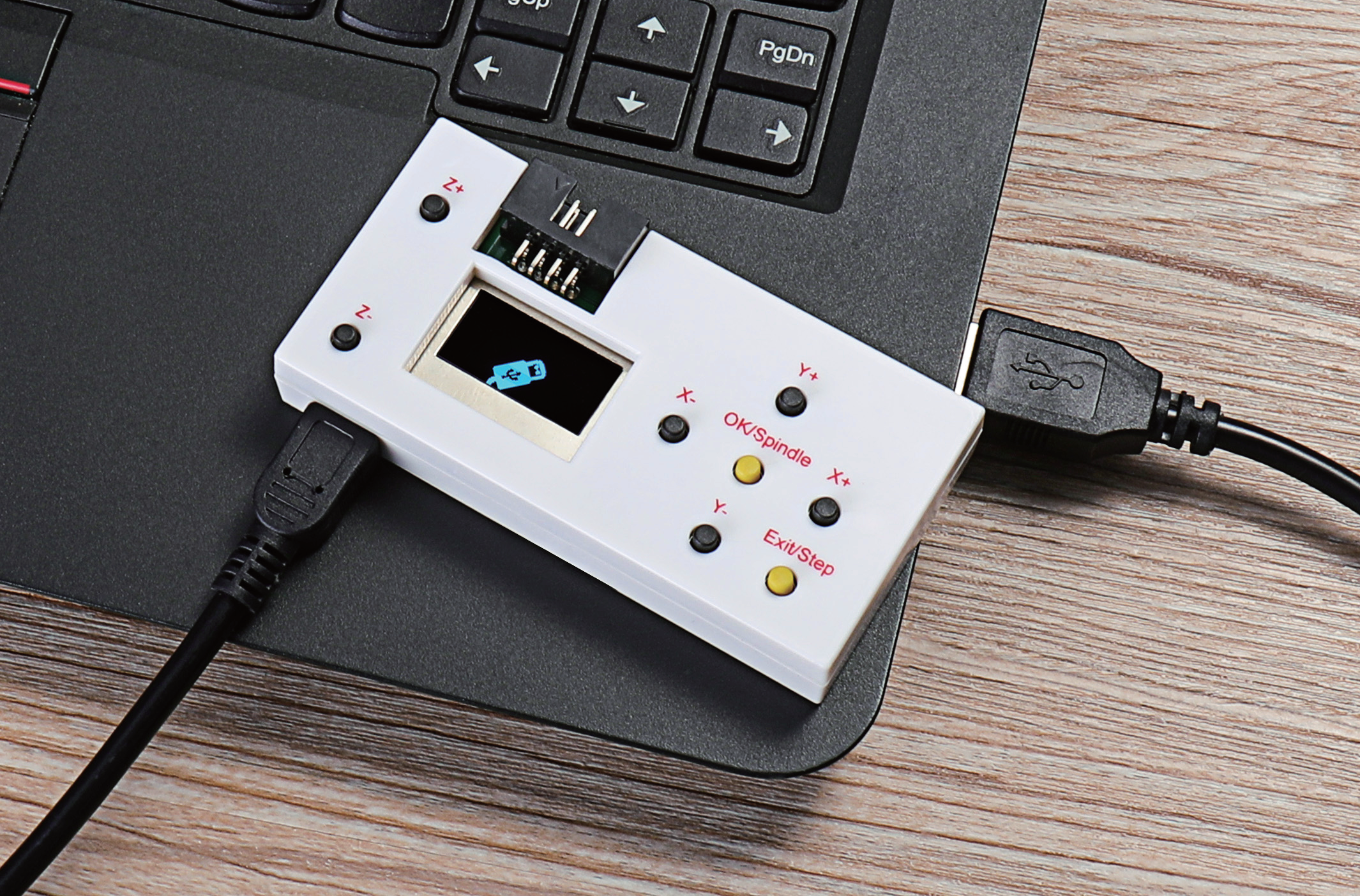
1.Connect offline controller to computer via USB cable(
can not connect offline
)
controller line
Note: Use USB cable to transfer files, don’t insert SD card into card reader to transfer, it is
easy to crash.
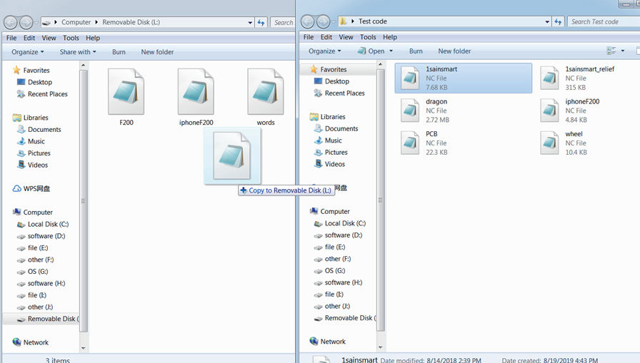
2.Copy the NC file to offline controller
18
Install
The easiest way to flash the firmware is to solder 4 wires to SWD pads.
They are located at the top right corner of the PCB underside.
The order is (from the corner) GND, SWDCLK, SWDIO, +5V (see schematic above).
The PlatformIO project is configured to use stlink.
OpenOCD will be configured with no flash size autodetection to allow more than 64k firmware on 64k MCU.
Other SWD programmers like J-Link or Blackmagic Probe will work as well, though extra configuration should be made to allow >64k firmware to be flashed.
I have no idea how to tell these programmers to do so. If you do, please let me know.
Due to non-standard configuration used for >64k firmware, if you need to debug the firmware, you first need to upload it via upload command.
This way, the programmer packages are downloaded and installed.
Original backup firmware from my controller can be found here.

Updated 2 years ago
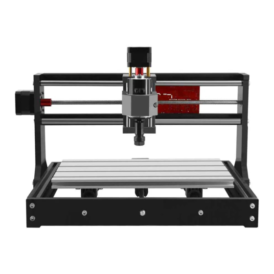
Sold as part of a bundle or separately for the Genmitsu 3018 Pro, an offline controller can be used as an alternative to the traditional method of operating your GRBL based CNC through your computer. Through use of your offline controller you can control the router, move to and set the home, origin position etc. and to send the contents of the files directly to the router without needing a PC connected to it via a USB cable.
To get files from your computer, must take your offline controller, and load files onto its internal storage by connecting it to your PC via USB.
The offline controller is powered from the Router Motherboard, no batteries or other power supply is needed. Plug the cable into the offline controller and the Router motherboard. Connect the router to the 24V external power supply and turn it on.
NOTE: The router cannot be connected to the Offline Controller and by a USB cable at the same time! Before connecting the Offline Controller disconnect the USB cable from the router and vice versa.
Supported Files:
- File Names: While files with long names are supported, please note that only 19 characters, including the extension, will be displayed on the offline controller.
- File Extension/Formatting: The Offline Controller will process a file regardless of the file extension but it must contain only valid G-Code with each line separated by a CR/LF (Carriage Return/Line Feed) Files generated by some software only separates the lines of G-Code by a single Line Feed character, before using they must be converted to standard files using a CR/LF sequence to separate each line.
- File Location on SD Card: While it is fine to have other files and folders on the Micro SD card, only files placed directly in the root directory will be visible and usable. If you do not see your file listed on the offline controller, you will need to remove the micro SD card move the file from your computer, and then re-insert it into the offline controller.
Step 1: Connect your Offline Controller to Your Computer Through USB
Step 2: Drag & Drop Your File to the Offline Controller
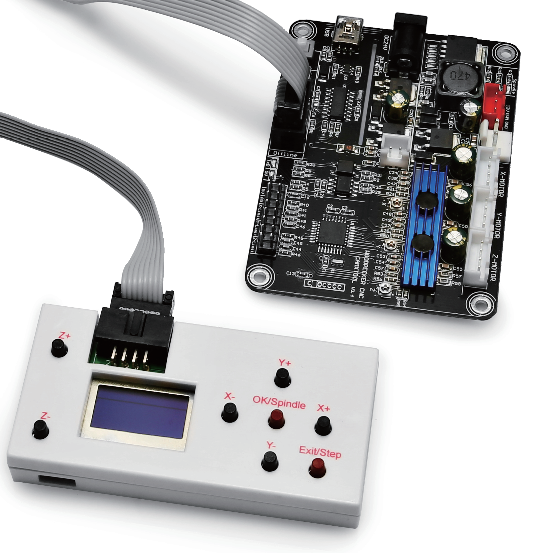
Step 3: Disconnect Offline Controller from PC & Connect it to your CNC Controller
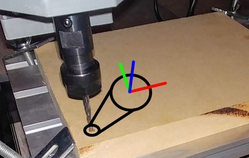
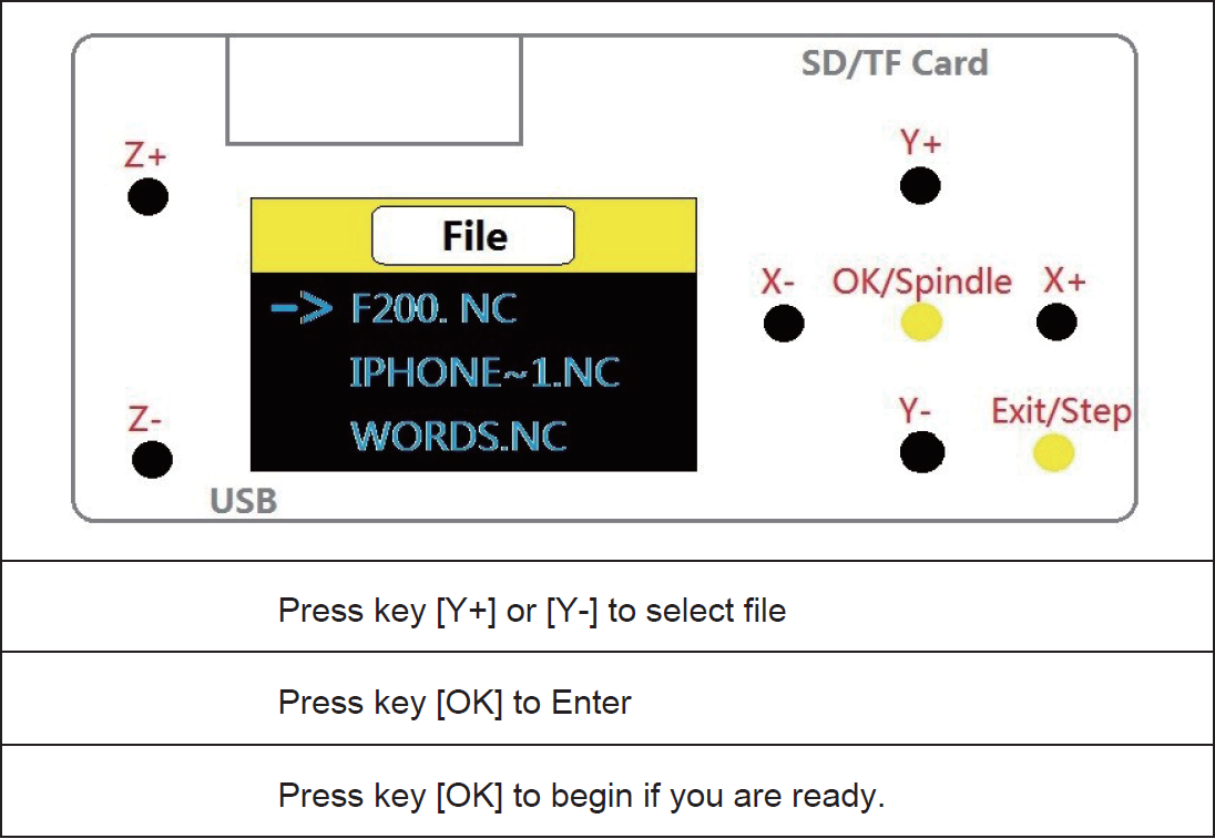
Step 4: Use the [X+/X-/Y+/Y-/Z+/Z-] keys to move the spindle to the machine origin, select the engraving file, click the [OK]
key to start engraving.
Offline Controller User Interface Map: Main Page
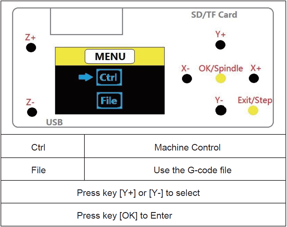
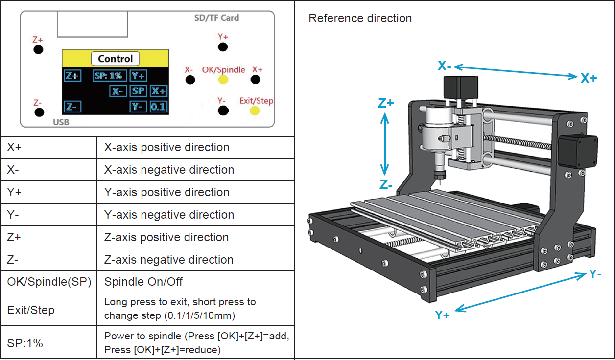
Offline Controller User Interface Map: Ctrl Page
Offline Controller User Interface Map: File Page
How did we do?
- Manuals
- Brands
- CNC Manuals
- Industrial Equipment
- 3018-PRO
- User manual
-
Contents
Table of Contents -
Bookmarks
Quick Links
Related Manuals for CNC 3018-PRO
Summary of Contents for CNC 3018-PRO
-
Page 2: Table Of Contents
Contents Parts list························································· 1 Machine Installation·········································· 4 Grblcontrol···················································· 11 Getting Started··············································· 14 Lasergrbl······················································ 15 Offline controller·············································18 Common Problem············································21…
-
Page 3: Parts List
Parts list Serial Name Type Picture number working desk 15*180*300mm Aluminum 20*40*290mm Aluminum 20*20*290mm X Linear guide Φ10*360mm Y Linear guide Φ10*290mm X screw T8(365mm) Y screw T8(295mm) Bakelite Stepper motor 42*34mm Spindle 775ER100w8000rmp X Z-Parts Y-Axis slider 10mm…
-
Page 4
Y-Axis nut seat T8-4 Milling Cutter Φ3.175mm20°.1mm Spindle wires 60mm Stepper wires 60mm Offline controller(Optional) Power Supply 24V5A Control Board USB Cable 1.5m Plate Clamp Winding Tube U Disk Allen Wrench 2.5mm… -
Page 5
Bolt M5*10mm M5*16mm M4*14mm Copper Nut T Nut M5*20 Slider Nut M5*30 Spring 0.8*12*30mm Coupling& Set Screw 5*8mm ER Wrench 13*87*2mm 17*88*2mm Brush Rolled Strip… -
Page 6: Machine Installation
Machine Installation Bakelite: STEP1 Base Installation…
-
Page 7
Step2 Table Installation Note: First fix one end of the coupling to the 42 stepper motor, and then fix the 42 stepper motor to the aluminum profile Completed… -
Page 8
Step3 Base & Bakelite-C Installation Note: the distance between Bakelite-C and 2040 aluminum profile is 37.5mm, and Bakelite-C should be kept at 90° from the bottom Tips: First put the T-nut in the gap of 4040 aluminum profile, corresponding to the hole, and then tighten the screw Completed… -
Page 9
Step4 X-Z Axis Assembly Installation Note: 1. First fix the coupling to the 42 stepper motor, and then fix the 42 stepper motor to the bakelite-C. 2. First fully insert the spring and brass nut into the Z-X axis assembly, and then tighten the X screw. Step5 Bakelite-D Installation… -
Page 10
Completed Step6 Spindle Installation… -
Page 11
Note: The screw M4*30mm here requires a 3mm hexagon wrench. When connecting the spindle motor cable, observe the direction of spindle rotation and turn clockwise to indicate that the connection is correct. Otherwise, change the connection position. Step7 Control Board Installation Note: only need to fix the screws in the upper row… -
Page 12
Step8 Wiring Diagram… -
Page 13: Grblcontrol
Grblcontrol 1 、Install the driver(software->Drive->CH340SER.exe) Note: You need to exit the anti-virus software before installing the driver 2、Determine your Machine’s COM port: Windows XP: Right click on «My Computer», select «Properties», select «Device Manager». Windows 7: Click «Start» -> Right click «Computer» -> Select «Device Manager» -> «Ports (COM & …
-
Page 14
3、Open GrblControl software(software -> Grblcontrol -> grblControl.exe) Tips: Right-click «Send to», select «Desktop Shortcut», and then you can open it directly on the desktop. ●Console window print ” [CTRL+X] < Grbl 1.1f [‘$’ for help]” If the connection is successful. ●Console window print ”… -
Page 15
Grblcontrol Use Toll setting Note: When performing knife setting, when the moving knife just touches the object, click «Zero xy» and… -
Page 16: Getting Started
«Zero z», and finally click «Send». Getting Started After the machine is assembled, you can perform basic machine tests. The following is the recommended start up sequence for the system: 1.Confirm that the USB cable of the control board is plugged into your computer, and then start the computer. 2.Start the Candle software and verify in the status window that no errors are displayed.
-
Page 17: Lasergrbl
Lasergrbl 1.Install lasergrbl software: Before installing the software, we have to install the CH340SER driver on the computer , Then use the USB cable to connect to the computer (don’t plug it offline), open the Lasergrbl software (laser->Lasergrbl) and install ●…
-
Page 18
3.RASTER IMAGE IMPORT Raster import allows you to load an image of any kind in LaserGRBL and turn it GCode instructions without the need of other software. LaserGRBL supports photos, clip art, pencil drawings, logos, icons and try to do the best with any kind of image. It can be recalled from “File, Open File”… -
Page 19
Click this button to start if use the computer control. Notice: speed and S value are different with material,it is recommended that the speed of engraving mode is 500~1000, the power is 500~800, the speed of cutting mode is 50~300, and the power is 900~1000. Tips: Enter «$32=1 in the control window ,It can be set to M4 laser mode for better engraving effect. -
Page 20: Offline Controller
Offline controller 1.Connect offline controller to computer via USB cable( can not connect offline controller line Note: Use USB cable to transfer files, don’t insert SD card into card reader to transfer, it is easy to crash. 2.Copy the NC file to offline controller…
-
Page 21
3.Offline control connected to the control board Note: When using offline controller, you need to unplug the USB cable from the computer, because offline and computer cannot be used together. 4.Press the [X+/X-/Y+/Y-/Z+/Z-] key to move the spindle to the machine origin (tool setting method: the cutter just touches the object, press the [Exit] key), select the engraving file and click [ok ] Key to start carving… -
Page 22
B. Ctrl Page C. File Page… -
Page 23: Common Problem
Support Gcode files of nc, ncc, ngc, tap, txt 2.What file formats does the Lasergrbl software support? Support nc, cnc, tap, gcode, ngc, bmp, png, jpg, gif, svg 3.What should I do if the control board cannot be connected? Exit the software, unplug the wire, and reconnect it. Or update the firmware.
CNC инструкция по эксплуатации
1. Сборка станка.
Пожалуйста, обратитесь к «Инструкции по сборке» для сборки станка (скачать можно в данном разделе https://minichpu.ru/page/1279409).
2. Отладка (для начала скачайте «Полный пакет» в разделе https://minichpu.ru/page/1279409).
Для начала необходимо подключить плату к сети с помощью болка питания, а также соединить плату с компьютером (ноутбуком) с помощью кабеля USB, входящего в комплект.
— Установить драйвер CH340SER (путь- /driver/).
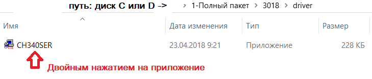
— Открываем двойным нажатием, появляется сообщение
«Разрешить этому приложению вносить изменения на вашем устройстве?»
Нажимаем – ДА!
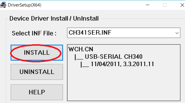
Появляется окно:
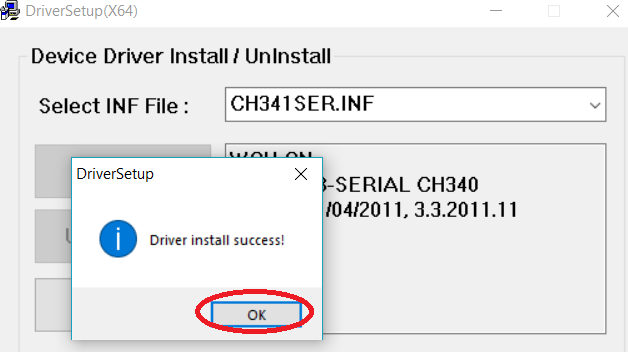
Нажимаем INSTALL, драйвер устанавливается, и появляется окно, что успешно установлен (Driverinstallsuccess!), нажимаем ОК. И закрываем окно.
Определение COM-порта компьютера (для инфо):
- Windows XP: Щелкните правой кнопкой мыши на «мой компьютер», выберите «Свойства», выберите «Диспетчер устройств».
- Windows 7: Нажмите «Пуск» -> щелкните правой кнопкой мыши «компьютер» -> выберите «Управление» -> выберите «Диспетчер устройств» из левой панели.
- В дереве разверните «порты (COM & LPT)»
- Ваш станок будет USB последовательный порт (СОМХ), где “X” представляет собой номер COM порта, например СОМ6.
- Если есть несколько USB-портов, щелкните каждый из них и проверить производителя, станок будет «CH340».
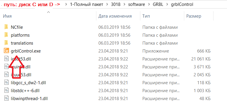
3. Раскройте контрольную программу grblControl.exe, чтобы соединить станок и выбрать правильный порт:
— Открываем двойным нажатием, (станок должен быть подключен и в сеть и через USB).
— Выбираем в меню Сервис ->Настройки, далее Порт (обновляем, и из выплывающего меню выбираем другой порт), нажимаем ОК. Статус меняется на ГОТОВ.
(изначально Статус – Нет соединения)
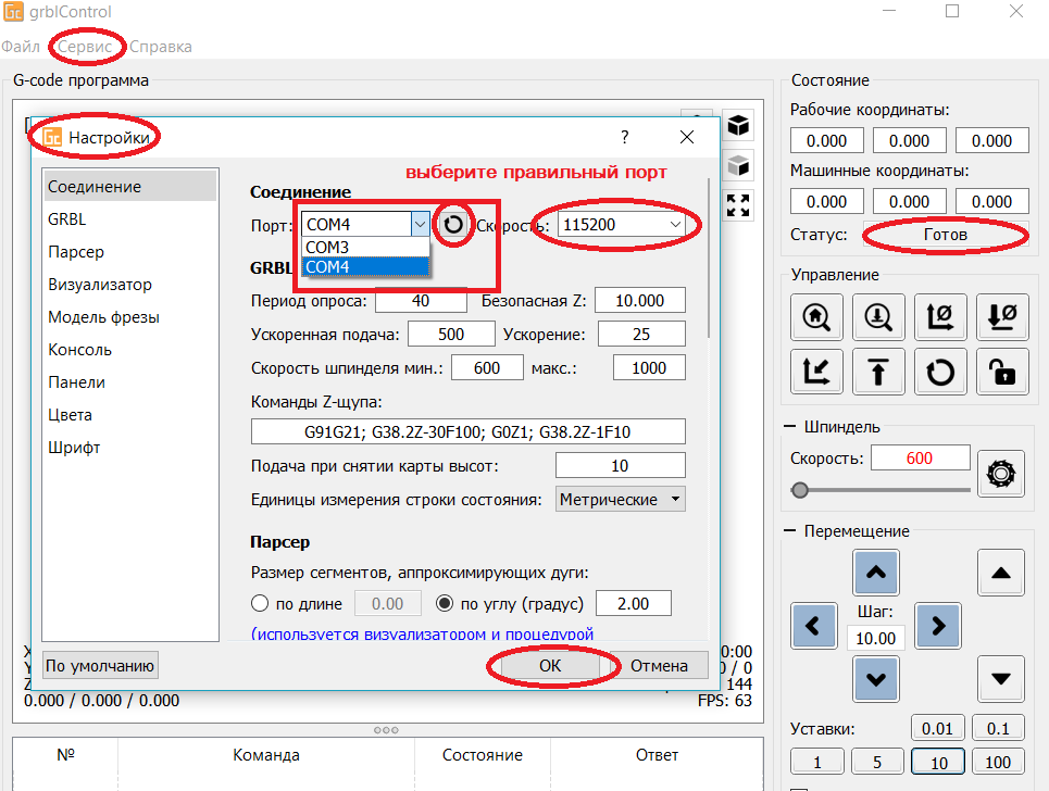
В консоле (внизу): Соединение успешно установлено:[CTRL+X] < Grbl 0.9j [‘$’ forhelp]
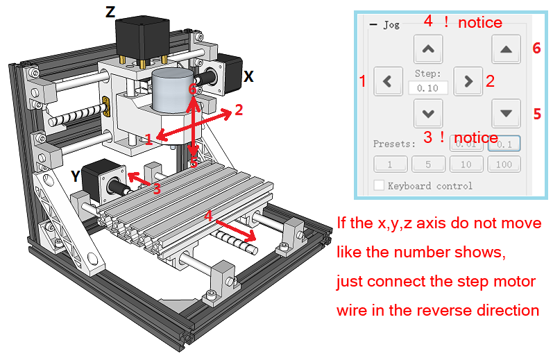
4. Проверить направление оси XYZ:
Если ось x, y, z не двигается, как показано на рисунке, просто подключите провод шагового двигателя в обратном направлении.
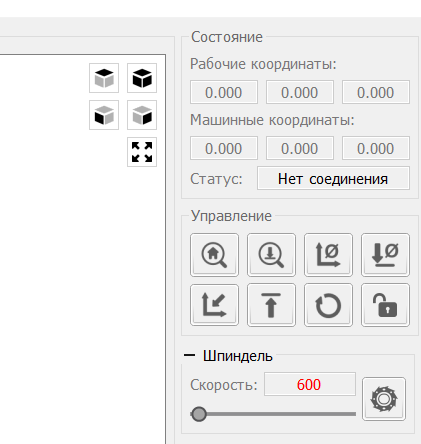
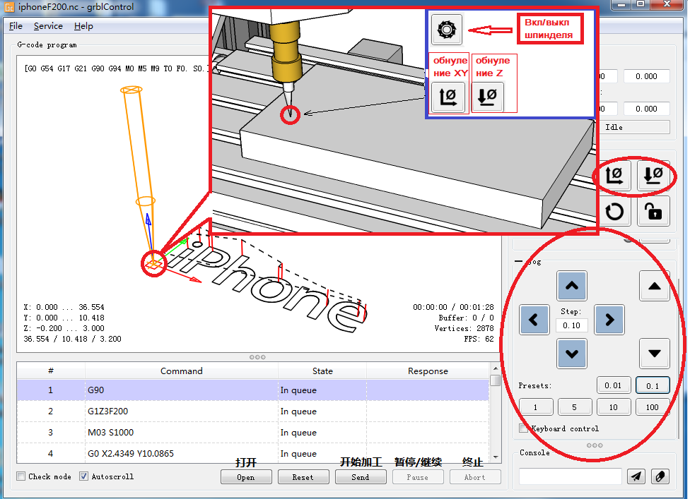
Как обнулить положение гравера:
5. После установки станка, откройте файл гравировки — приложение «grblControl.exe» (путь- 3018/software/GRBL/grblControl). В правом верхнем углу статус должен быть ГОТОВ. Необходимо определить, где будет находится нулевая точка. Обычно в левом нижнем углу заготовки.
Сначала подведите шпиндель в левый нижний угол заготовки (с помощью кнопок перемещения X и Y), затем опустите фрезу по оси Z. Замедлить движение можно уменьшив шаг, нажатием кнопок 0,01; 0,1; 1; 5; 10 (расположенные ниже стрелок перемещения).
Когда резец будут приближаться к заготовке, аккуратно подведите его к поверхности заготовки.
Важно! После соприкосновения резца с поверхностью, нажмите в разделе управление кнопки «Обнулить XY» и «Обнулить Z«.
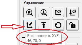
Подсказка: лучше всего опробовать станок на работоспособность без заготовки. Для вращения шпинделя нажмите кнопку «Вкл/Выкл шпиндель», также можно изменять скорость вращения. Произведите перемещение по всем осям. Для возвращения в нулевую точку необходимо нажать кнопку в управлении «Восстановить XYZ«.
Проверьте станок, прежде чем начать официальную гравировку.
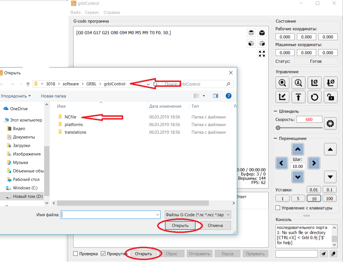
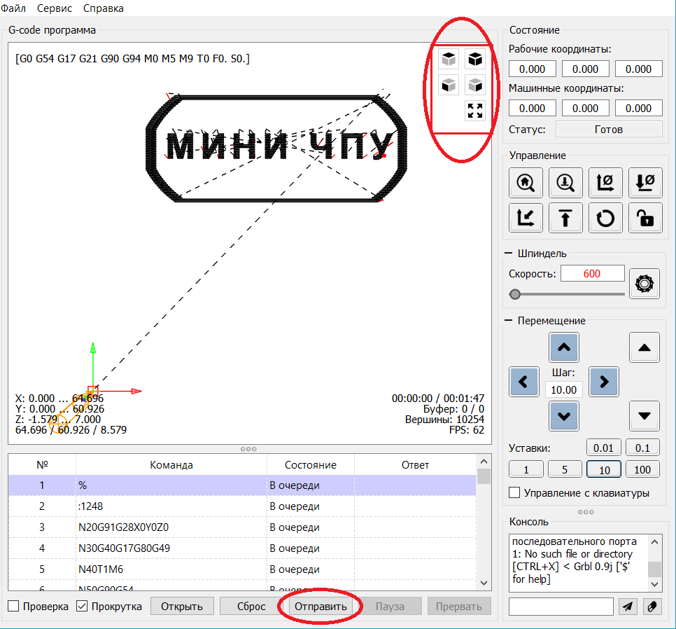
6. Загрузка файла в управляющую программу grblControl.
Затем вы можете нажать кнопку «Открыть» в нижнем углу, выбрать из папки «NCfile» готовый файл (с расширением *.nc), чтобы выгравировать.
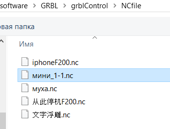
7. В папке хранятся готовые файлы.
Этапы работы станков с ЧПУ:
1) формируется модель с помощью специальных графических программ (ArtCam и т.д.) на компьютере.
2) с помощью специальной программы для станка с ЧПУ готовая модель отцифровывается в управляющую программу с расширением *.nc.
3) потом файл открывают управляющей программой «grblControl.exe» и вносят в память ЧПУ. И станок приступает к работе.
Изучайте графическую программу ArtCam, создавайте модели и реализовывайте их с помощью станка CNC 3018.
Подготовлено при участии магазина МИНИ ЧПУ https://minichpu.ru
positron96 / cnc3018-offline-controller
Goto Github
PK
View Code? Open in Web Editor
NEW
41.0
10.0
798 KB
Open-source firmware for popular cnc3018 stm32-based offline controller
License: MIT License
C 0.53%
Shell 0.12%
Contributors


cnc3018-offline-controller’s Issues
*** [upload] Error 3221225477
Any idea why this error?
Building in release mode
Checking size .piobuildcontrollerfirmware.elf
Advanced Memory Usage is available via «PlatformIO Home > Project Inspect»
RAM: [===== ] 46.3% (used 9484 bytes from 20480 bytes)
Flash: [===== ] 51.9% (used 68040 bytes from 131072 bytes)
Configuring upload protocol…
AVAILABLE: blackmagic, cmsis-dap, dfu, jlink, serial, stlink
CURRENT: upload_protocol = stlink
Uploading .piobuildcontrollerfirmware.elf
xPack OpenOCD x86_64 Open On-Chip Debugger 0.11.0+dev (2021-10-16-21:19)
Licensed under GNU GPL v2
For bug reports, read
http://openocd.org/doc/doxygen/bugs.html
debug_level: 1
0x20000
hla_swd
*** [upload] Error 3221225477
Original firmware backup
I want to try this firmware on my offline controller that came with an STM32 clone, but st-info reports 0kb of flash size. I’m guessing the flash is locked and I would need to unlock it, but I want to make a backup of the original firmware before flashing yours.
Did your controller come with locked flash?
Feedrate when running file
Is it possible or add an option to change feed rate when running the program? I always start slow and adjust feedrate to make it run smooth
[Question] Another offline-contorller from AliExpress
Hey guys,
I also recently bought a 3018 CNC. An offline controller was also included. But this one has an STM32F103RBT6. That means I shouldn’t try this firmware, right?
regards maxl95
Hex for download
Could you please publish your resulting hex file for downloading.
Impossible to flash GD32F103C8T6 chip
Hi,
When i flash the .hex firmware with a st link usb key v2, all seems to be OK but at the verification step , i have this error : Programming error @ 0x08010000!
Is it due to the problem of short memory of the GD32F103C8T6 chip ?
Do you have the same firmware but lighter ?
smaller controller
Hello,
great job with this firmware. Thank you.
Just an Information:
My most recent GRBL Offline Controller has no real STM Chip on it, but an GD32F103C8T6.
This chip has only 64k, so the verify step of the programmer fails because the code is too large to fit.
I plan to replace the chip by a STM32F103 with 128k, as soon as they are available again.
Impossible to flash APM32F103RBT6 chip
Hi,
My hardware is APM32F103RBT6.


Thank you.
Same issue as #5 from vinpinto — Reopen
I am having the same issue with the same offline controller (ST32 based, same as you project photos) and the same CNC board (woodpecker cnc v3.3).
Looking at the schematics for Woodpecker CNC v3.3 it does not look like there is any connection to pin 8 of the offline controller jack
1 — 5v
2 — Gnd
3 — 5v
4 — Gnd
5 — TX
6 — Rst
7 — RX
8 — NC
When I connect the USB to the computer and use Putty to watch the out put I get
Detected GRBL device
GrblDRO::onButton(1,1)
GrblDRO::onButton(1,0)
GrblDRO::onButton(0,1)
GrblDRO::onButton(0,0)
GrblDRO::onButton(5,1)
GrblDRO::onButton(5,0)
GrblDRO::onButton(6,1)
GrblDRO::onButton(6,0)
GrblDRO::onButton(3,1)
GrblDRO::onButton(3,0)
GrblDRO::onButton(2,1)
GrblDRO::onButton(2,0)
 > (f 15,128) ''(len 0)
 > (f 15,128) 'Grbl 1.1h ['$' for help]'(len 24)
Msg '[MSG:'$H'|'$X' to unlock]'
 > (f 15,128) '[MSG:'$H'|'$X' to unlock'(len 25)
GrblDRO::onButton(1,1)
GrblDRO::onButton(1,0)
GrblDRO::onButton(0,1)
GrblDRO::onButton(0,0)
GrblDRO::onButton(5,1)
GrblDRO::onButton(5,0)
GrblDRO::onButton(6,1)
GrblDRO::onButton(6,0)
GrblDRO::onButton(3,1)
GrblDRO::onButton(3,0)
GrblDRO::onButton(2,1)
GrblDRO::onButton(2,0)
Pressing the buttons will show as above but pressing [Exit/Step], selecting Reset (Ctrl-X), and [OK/Spindle] does not show any output on the Putty screen. If I press the reset button on the CNC the I will get the little bit of output shown in the middle (lines that start with > (f 15,128) ) and the display changes to add a line below «x Idle» that says «‘$H’|’$X’ to unlock» but the buttons and menu selection still do do not produce any output.
I tried connecting a UART directly to the offline controller and when I sent «[VER:1.1f.20170801:]» after I saw «$I» in the terminal window the display will change to the «x Idle» screen but pressing any buttons does not get any output. I tried sending the «[OPT:V,15,128]» and «ok» as well but it did not change the behavior.
Above vinpinto «Thanks man, that got everything solved, I’m still not sure why both states X and padlock are dependent on this, but removing this feature made everything work» Do you know what he removed to make it work? Any other thing I might look at?
Below are pics of the offline controller and CNC board I’m working with.


Originally posted by @mppkll in #5 (comment)
No comunication after baudrate is set
Hardware:
-Offline Controller based on SMT32F (same as shown in the developer pictures)
-CNC Controller is woodpecker v3.3 with grbl firmware v1.1
What Works:
-Serial probing cycle for baudrate seems to work
-Controller shows interface,.
-All menu entries are shown and can be selected.
What doesn’t work:
-The only serial output from the offline controller is the $I sent in different baud rates to probe for the correct baud rate.
Test made:
-With a serial probe in tx rx terminals to check for comms, the behavior is as follows:
-A few $I are sent by the offline controller in different baud rates.
-The machine responses with [VER:1.1f.20170801:] [OPT:V,15,128] ok
-The offline controller understands the response and stops sending any further comunication.
The offline controller only shows the machine as X idle or sometimes Lockpad Idle, but no further comand comes out of the offline controller, not with a SD card file, not with the DRO, or any other entry on the menu.
FR: Add UI for feed overrides
First mentioned in #8
Love the firmware but
It doesn’t work with Vcarve. What could be a problem? When it tries to change the z-axis I have to press unlock to continue. I used firmware.hex from the release section with STM32 mcu. Everything works when I switched back to the original firmware that I saved.
No communication after baudrate is set
Hardware:
-Offline Controller based on SMT32F (same as shown in the developer pictures)
-CNC Controller is woodpecker v3.3 with grbl firmware v1.1
What Works:
-Serial probing cycle for baudrate seems to work
-Controller shows interface,.
-All menu entries are shown and can be selected.
What doesn’t work:
-The only serial output from the offline controller is the $I sent in different baud rates to probe for the correct baud rate.
Test made:
-With a serial probe in tx rx terminals to check for comms, the behavior is as follows:
-A few $I are sent by the offline controller in different baud rates.
-The machine responses with [VER:1.1f.20170801:] [OPT:V,15,128] ok
-The offline controller understands the response and stops sending any further comunication.
The offline controller only shows the machine as X idle or sometimes Lockpad Idle, but no further comand comes out of the offline controller, not with a SD card file, not with the DRO, or any other entry on the menu.
Recommend Projects
-

ReactA declarative, efficient, and flexible JavaScript library for building user interfaces.
-
Vue.js🖖 Vue.js is a progressive, incrementally-adoptable JavaScript framework for building UI on the web.
-
TypescriptTypeScript is a superset of JavaScript that compiles to clean JavaScript output.
-
TensorFlowAn Open Source Machine Learning Framework for Everyone
-
DjangoThe Web framework for perfectionists with deadlines.
-
LaravelA PHP framework for web artisans
-
D3Bring data to life with SVG, Canvas and HTML. 📊📈🎉
Recommend Topics
-
javascript
JavaScript (JS) is a lightweight interpreted programming language with first-class functions.
-
web
Some thing interesting about web. New door for the world.
-
server
A server is a program made to process requests and deliver data to clients.
-
Machine learning
Machine learning is a way of modeling and interpreting data that allows a piece of software to respond intelligently.
-
Visualization
Some thing interesting about visualization, use data art
-
Game
Some thing interesting about game, make everyone happy.
Recommend Org
-
FacebookWe are working to build community through open source technology. NB: members must have two-factor auth.
-
MicrosoftOpen source projects and samples from Microsoft.
-
GoogleGoogle ❤️ Open Source for everyone.
-
AlibabaAlibaba Open Source for everyone
-
D3Data-Driven Documents codes.
-
TencentChina tencent open source team.
Open-source firmware for an STM32-based «cnc3018 offline controller»
Video demonstration:

This popular chineese (most probably) controller is frequently sold with 3018-type CNC machines.
The machines themselves run GRBL on ATmega328 MCUs, while the controller uses STM32F103 MCU.
The stock firmware is somewhat lacking in features (no DROs, no spindle speed, for example).
The goal of this project is to make an alternative firmware to control a CNC machine.
The information provided can be also useful for those who want to turn this controller into something else
(a small gaming console, a controller for other equipment).
The firmware is written for Arduino framework and PlatformIO build system.
VS Code IDE is used for development.
|
❗ |
This firmware is for a controller with an OLED display and a full-sized SD card. |
|
❗ |
There is no USB bootloader on the MCU, no access to BOOT pins, so flashing must be done via SWD. |
Goals of the project:
-
Reverse-engineer the schematic of the board (to the required extent)
-
Make custom firmware with these features:
-
Move axes via buttons, display coordinates on screen, etc.
-
Send gcode from files on SD card.
-
Stream gcode from USB.
-
Backlog
-
✓ Jogging
-
✓ Spindle control (with 1% option for laser «pointer»)
-
✓ File chooser UI
-
❏ Job control (pause/cancel)
-
✓ Grbl state tracking (alarm, error)
-
✓ Menu
-
✓ Change work offsets (set zero to current position). Only G54 supported.
-
✓ Homing ($H), unlocking ($X)
-
✓ Grbl reset (Ctrl+X)
-
-
✓ Display coordinates in WCS (done, but not intuitively for now)
-
❏ Bridge GRBL and USB UART
-
✓ Detection of GRBL USB connection via dedicated pin (works to some extent)
-
❏ Improve continuous jogging
Schematic and hardware


The schematic reversing is complete to the necessary degree.
Everything that’s needed to interface with MCU (pins, interfaces) is discovered.
The board features:
-
STM32F103C8T6 MCU.
64K Flash, 20K RAM. As usual, 128k is usable. -
128×64 OLED display with SSD1306 IC.
2-color, 16 rows are yellow, the rest is cyan.
Connected via 4-wire software SPI. -
Mini USB (no external crystal, so not datasheet-compliant).
-
Full size SD card socket.
Connected to MCU via SPI interface. -
8-pin IDC connector for CNC machine.
Has 5V, GND, UART and USB detection pin
(when the CNC is connected to PC via its own USB-UART, the controller detects that and does not send data over UART). -
8 buttons.
Buttons short MCU pin to ground, internal pullup required. -
An unpopulated SWD socket


Build & Install
Build
Use PlatformIO.
It will install everything required to build the firmware.
You can also download the precompiled binaries (elf and hex) on Releases page.
Install
The easiest way to flash the firmware is to solder 4 wires to SWD pads.
They are located at the top right corner of the PCB underside.
The order is (from the corner) GND, SWDCLK, SWDIO, +5V (see schematic above).
The PlatformIO project is configured to use stlink.
OpenOCD will be configured with no flash size autodetection to allow more than 64k firmware on 64k MCU.
Other SWD programmers like J-Link or Blackmagic Probe will work as well, though extra configuration should be made to allow >64k firmware to be flashed.
I have no idea how to tell these programmers to do so. If you do, please let me know.
Due to non-standard configuration used for >64k firmware, if you need to debug the firmware, you first need to upload it via upload command.
This way, the programmer packages are downloaded and installed.
Original backup firmware from my controller can be found here.
Links
-
SSD1306 datasheet (old): https://cdn-shop.adafruit.com/datasheets/SSD1306.pdf
-
On SSD1306 connection: https://vivonomicon.com/2018/04/20/diy-oled-display-boards-ssd1306-and-ssd1331/
-
3018 CNC board (Woodpecker v3.3) schematic: http://s3.amazonaws.com/s3.image.smart/download/101-60-280/Schematic_CAMTOOL%20CNC-V3.3.pdf
Contributors