-
Драйверы
21
-
Инструкции по эксплуатации
34
Языки:

Gigabyte GA-G31M-ES2C инструкция по эксплуатации
(72 страницы)
- Языки:Венгерский, Греческий, Испанский, Итальянский, Немецкий, Польский, Португальский, Русский, Турецкий, Французский, Чешский
-
Тип:
PDF -
Размер:
18.6 MB -
Описание:
Installation Guidebook


На NoDevice можно скачать инструкцию по эксплуатации для Gigabyte GA-G31M-ES2C. Руководство пользователя необходимо для ознакомления с правилами установки и эксплуатации Gigabyte GA-G31M-ES2C. Инструкции по использованию помогут правильно настроить Gigabyte GA-G31M-ES2C, исправить ошибки и выявить неполадки.
Посмотреть инструкция для Gigabyte GA-G31M-ES2C бесплатно. Руководство относится к категории материнские платы, 6 человек(а) дали ему среднюю оценку 8.2. Руководство доступно на следующих языках: английский. У вас есть вопрос о Gigabyte GA-G31M-ES2C или вам нужна помощь? Задайте свой вопрос здесь
Не можете найти ответ на свой вопрос в руководстве? Вы можете найти ответ на свой вопрос ниже, в разделе часто задаваемых вопросов о Gigabyte GA-G31M-ES2C.
Какая ширина Gigabyte GA-G31M-ES2C?
Какая толщина Gigabyte GA-G31M-ES2C?
Инструкция Gigabyte GA-G31M-ES2C доступно в русский?
Не нашли свой вопрос? Задайте свой вопрос здесь
На этой странице вы можете совершенно бесплатно скачать Руководство по эксплуатации GIGABYTE GA-G31M-ES2C (rev. 2.3).
У документа PDF Руководство по эксплуатации 84 страниц, а его размер составляет 4.53 Mb.
Читать онлайн Материнские платы GIGABYTE GA-G31M-ES2C (rev. 2.3) Руководство по эксплуатации

Скачать файл PDF «GIGABYTE GA-G31M-ES2C (rev. 2.3) Руководство по эксплуатации» (4.53 Mb)
Популярность:
1614 просмотры
Подсчет страниц:
84 страницы
Тип файла:
Размер файла:
4.53 Mb
Прочие инструкции GIGABYTE GA-G31M-ES2C (rev. 2.3)

Прочие инструкции GIGABYTE Материнские платы


Прочие инструкции GIGABYTE


GA-G31M-ES2L/
GA-G31M-ES2C
TM
LGA775 socket motherboard for Intel® Core
Intel® Pentium® processor family/Intel® Celeron® processor family
User’s Manual
Rev. 2001
12ME-G31MES2L-2001R
processor family/

May 19, 2009
GA-G31M-ES2L/GA-G31M-ES2C
Motherboard
May 19, 2009
Motherboard
GA-G31M-ES2L/
GA-G31M-ES2C
Copyright
© 2009 GIGA-BYTE TECHNOLOGY CO., LTD. All rights reserved.
The trademarks mentioned in this manual are legally registered to their respective owners.
Disclaimer
Information in this manual is protected by copyright laws and is the property of GIGABYTE.
Changes to the specifications and features in this manual may be made by GIGABYTE without prior
notice. No part of this manual may be reproduced, copied, translated, transmitted, or published in any
form or by any means without GIGABYTE’s prior written permission.
Documentation Classifications
In order to assist in the use of this product, GIGABYTE provides the following types of documentations:
For detailed product information, carefully read the User’s Manual.
For instructions on how to use GIGABYTE’s unique features, read or download the information
on/from the Support&DownloadsMotherboardT echnology Guide page on our website.
For product-related information, check on our website at:
http://www.gigabyte.com.tw
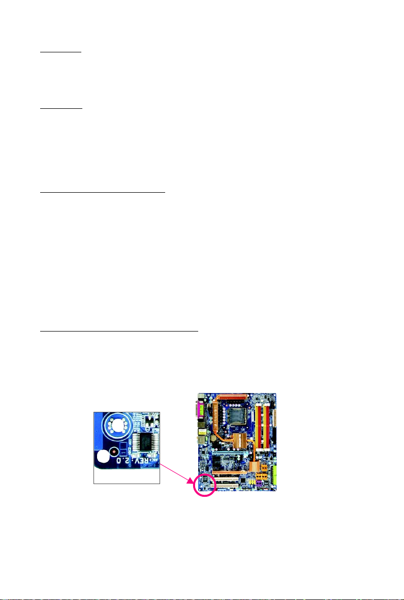
Identifying Your Motherboard Revision
The revision number on your motherboard looks like this: «REV: X.X.» For example, «REV: 1.0»
means the revision of the motherboard is 1.0. Check your motherboard revision before updating
motherboard BIOS, drivers, or when looking for technical information.
Example:

Table of Contents
Box Contents ………………………………………………………………………………………………….. 6
Optional Items………………………………………………………………………………………………….. 6
GA-G31M-ES2L/GA-G31M-ES2C Motherboard Layout ………………………………………… 7
Block Diagram…………………………………………………………………………………………………. 8
Chapter 1 Hardware Installation ………………………………………………………………………… 9
1-1 Installation Precautions …………………………………………………………………………. 9
1-2 Product Specifications ………………………………………………………………………… 10
1-3 Installing the CPU and CPU Cooler …………………………………………………….. 13
1-3-1 Installing the CPU ……………………………………………………………………………………13
1-3-2 Installing the CPU Cooler ……………………………………………………………………….. 15
1- 4 Installing the Memory …………………………………………………………………………. 16
1-4-1 Dual Channel Memory Configuration ………………………………………………………. 16
1-4-2 Installing a Memory………………………………………………………………………………… 17
1- 5 Installing an Expansion Card ………………………………………………………………. 1 8
1- 6 Back Panel Connectors ……………………………………………………………………… 1 9
1- 7 Internal Connectors ……………………………………………………………………………. 21
Chapter 2 BIOS Setup……………………………………………………………………………………. 31
2-1 Startup Screen…………………………………………………………………………………… 32
2- 2 The Main Menu …………………………………………………………………………………. 3 3
2- 3 Standard CMOS Features ………………………………………………………………….. 3 5
2-4 Advanced BIOS Features …………………………………………………………………… 37
2-5 Integrated Peripherals …………………………………………………………………………. 40
2- 6 Power Management Setup ………………………………………………………………….. 43
2- 7 PnP/PCI Configurations……………………………………………………………………… 45
2- 8 PC Health Status ………………………………………………………………………………. 4 6
2- 9 MB Intelligent Tweaker(M.I.T.)…………………………………………………………….. 47
2-10 Load Fail-Safe Defaults……………………………………………………………………….. 50
2- 1 1 Load Optimized Defaults ……………………………………………………………………… 50
2-12 Set Supervisor/User Password…………………………………………………………… 51
2-13 Save & Exit Setup…………………………………………………………………………….. 52
2-14 Exit Without Saving …………………………………………………………………………… 52
— 4 —

Chapter 3 Drivers Installation ………………………………………………………………………….. 53
3- 1 Installing Chipset Drivers ……………………………………………………………………. 53
3- 2 Application Software …………………………………………………………………………… 54
3-3 Technical Manuals……………………………………………………………………………… 54
3-4 Contact…………………………………………………………………………………………….. 55
3-5 System……………………………………………………………………………………………..55
3- 6 Download Center……………………………………………………………………………….. 56
Chapter 4 Unique Features…………………………………………………………………………….. 57
4- 1 Xpress Recovery2 …………………………………………………………………………….. 57
4-2 BIOS Update Utilities…………………………………………………………………………. 60
4-2-1 Updating the BIOS with the Q-Flash Utility ……………………………………………… 60
4-2-2 Updating the BIOS with the @BIOS Utility ………………………………………………. 63
4- 3 EasyTune 6………………………………………………………………………………………. 64
4-4 Easy Energy Saver ………………………………………………………………………….. 65
4-5 Q-Share …………………………………………………………………………………………… 67
4-6 Time Repair ………………………………………………………………………………………. 68
Chapter 5 Appendix ………………………………………………………………………………………. 69
5-1 Configuring Audio Input and Output……………………………………………………….. 69
5-1-1 Configuring 2/4/5.1/7.1-Channel Audio …………………………………………………… 69
5-1-2 Installing the S/PDIF Out Cable (Optional) ………………………………………………. 72
5-1-3 Configuring Microphone Recording …………………………………………………………. 74
5-1-4 Using the Sound Recorder ……………………………………………………………………… 76
5-2 Troubleshooting ………………………………………………………………………………….. 77
5-2-1 Frequently Asked Questions ………………………………………………………………….. 77
5-2-2 Troubleshooting Procedure …………………………………………………………………….. 78
5-3 Regulatory Statements ……………………………………………………………………….. 80
— 5 —
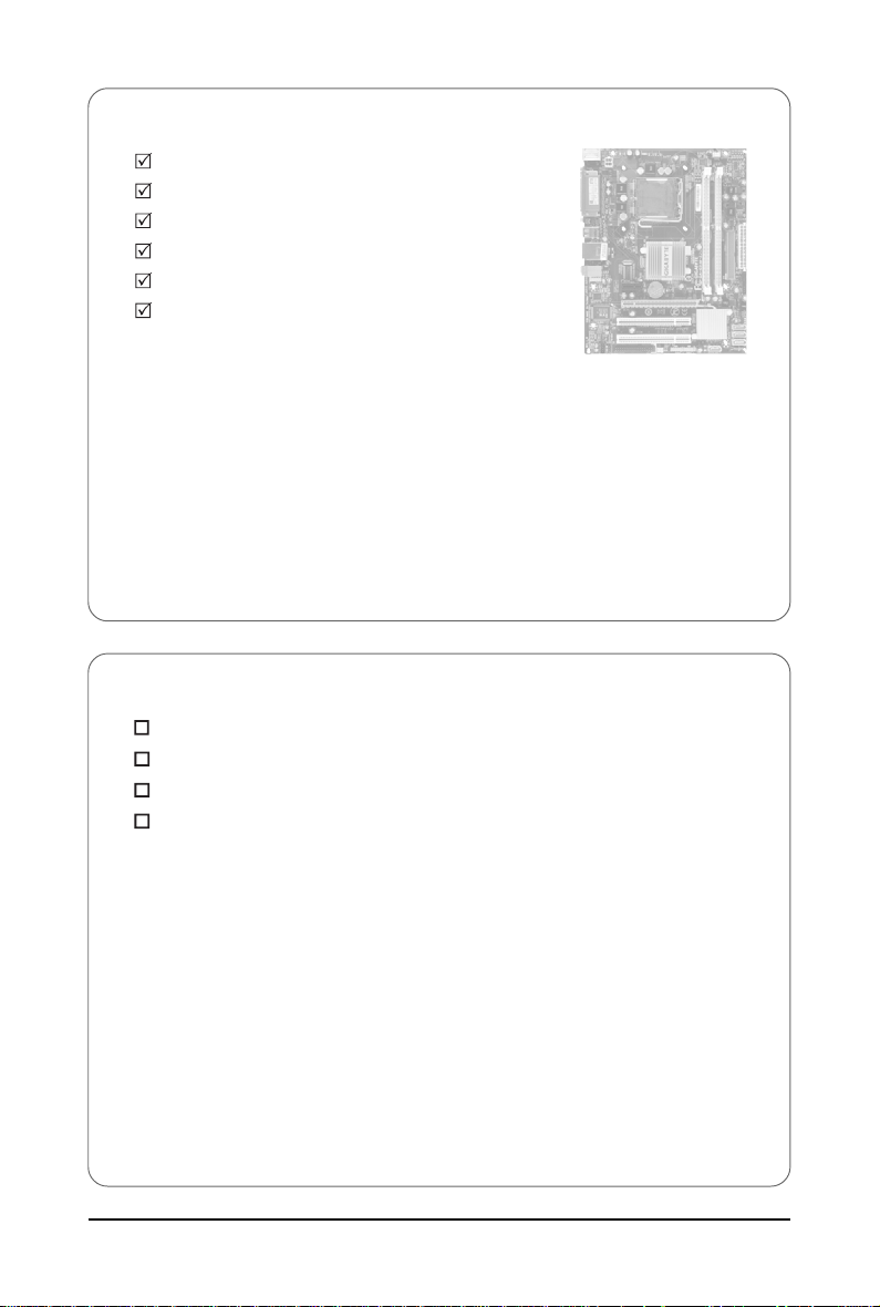
Box Contents
GA-G31M-ES2L or GA-G31M-ES2C motherboard
Motherboard driver disk
User’s Manual
One IDE cable
Two SATA 3Gb/s cables
I/O Shield
• The box contents above are for reference only and the actual items shall depend on product package you obtain.
The box contents are subject to change without notice.
• The motherboard image is for reference only.
Optional Items
Floppy disk drive cable (Part No. 12CF1-1FD001-7*R)
2-port USB 2.0 bracket (Part No. 12CR1-1UB030-5*R)
2-port SATA power cable (Part No. 12CF1-2SERPW-0*R)
S/PDIF out cable (Part No. 12CR1-1SPOUT-0*R)
— 6 —
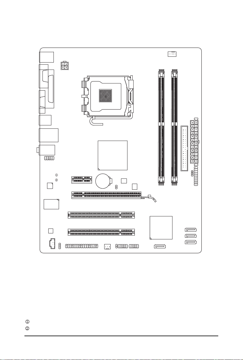
GA-G31M-ES2L/GA-G31M-ES2C Motherboard Layout
KB_MS
ATX_12V
LGA775
COMA
LPT
VGA
CPU_FAN
R_USB
USB
AUDIO
AR8131
AR8132
CODEC
IT8718
CD_IN
LAN
F_AUDIO
SPDIF_O
FDD
PCIE_1
PCIE_16
PCI1
PCI2
Intel® G31
BAT
SYS_FAN
B_BIOS
CLR_CMOS
CI
F_USB1
F_USB2
ATX
IDE
GA-G31M-ES2L/GA-G31M-ES2C
DDRII1
M_BIOS
DDRII2
Intel® ICH7
SATAII0
PWR_LED
SATAII3
SATAII2
SATAII1
F_PANEL
Only for GA-G31M-ES2L.
Only for GA-G31M-ES2C.
— 7 —
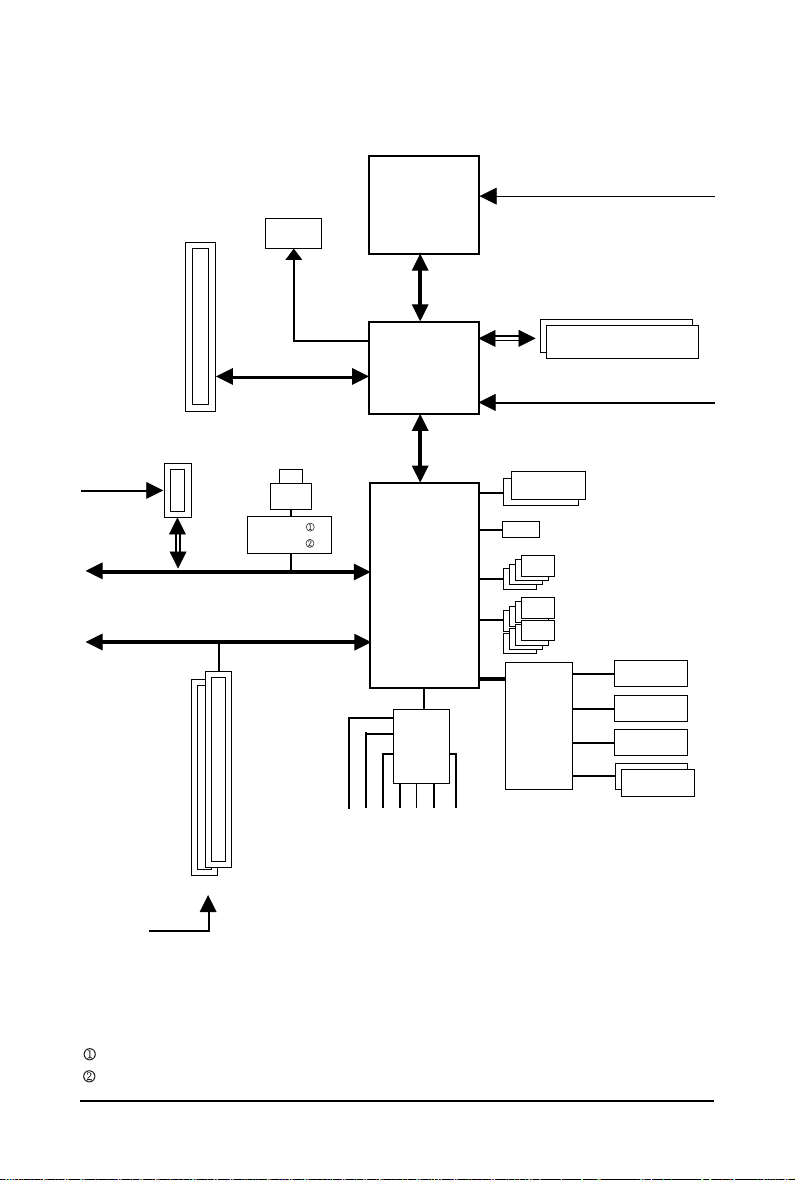
Block Diagram
1 PCI Express x1
PCIe CLK
(100 MHz)
PCIe CLK
(100 MHz)
PCI Express x16
x1
PCI Express Bus
PCI Bus
D-Sub
LAN
RJ45
AR8131
AR8132
LGA775
CPU
Interface
Intel® G31
®
Intel
ICH7
CODEC
Host
CPU CLK+/-
(333/266/200 MHz)
DDR2 800/667 MHz
Dual Channel Memory
GMCH CLK
(333/266/200 MHz)
Dual BIOS
ATA-100/66/33 IDE Channel
4 SATA 3Gb/s
8 USB Ports
Floppy
IT8718
LPT Port
COM Port
2 PCI
PCI CLK
(33 MHz)
Only for GA-G31M-ES2L.
Only for GA-G31M-ES2C.
MIC
Line In
Line Out
S/PDIF Out
Side Speaker Out
Surround Speaker Out
Center/Subwoofer Speaker Out
— 8 —
PS/2 KB/Mouse

Chapter 1 Hardware Installation
1-1 Installation Precautions
The motherboard contains numerous delicate electronic circuits and components which can become
damaged as a result of electrostatic discharge (ESD). Prior to installation, carefully read the user’s
manual and follow these procedures:
• Prior to installation, do not remove or break motherboard S/N (Serial Number) sticker or
warranty sticker provided by your dealer. These stickers are required for warranty validation.
• Always remove the AC power by unplugging the power cord from the power outlet before
installing or removing the motherboard or other hardware components.
• When connecting hardware components to the internal connectors on the motherboard,
make sure they are connected tightly and securely.
• When handling the motherboard, avoid touching any metal leads or connectors.
• It is best to wear an electrostatic discharge (ESD) wrist strap when handling electronic
components such as a motherboard, CPU or memory. If you do not have an ESD wrist strap,
keep your hands dry and first touch a metal object to eliminate static electricity.
• Prior to installing the motherboard, please have it on top of an antistatic pad or within an
electrostatic shielding container.
• Before unplugging the power supply cable from the motherboard, make sure the power supply
has been turned off.
• Before turning on the power, make sure the power supply voltage has been set according to
the local voltage standard.
• Before using the product, please verify that all cables and power connectors of your hardware
components are connected.
• T o prevent damage to the motherboard, do not allow screws to come in contact with the
motherboard circuit or its components.
• Make sure there are no leftover screws or metal components placed on the motherboard or
within the computer casing.
• Do not place the computer system on an uneven surface
• Do not place the computer system in a high-temperature environment.
• Turning on the computer power during the installation process can lead to damage to system
components as well as physical harm to the user.
• If you are uncertain about any installation steps or have a problem related to the use of the
product, please consult a certified computer technician.
.
Hardware Installation— 9 —

1-2 Product Specifications
TM
CPU Support for an Intel® Core
Intel® Core
TM
2 Quad processor/Intel® Core
Intel® Pentium® processor/Intel® Celeron® processor in the LGA 775 package
(Go to GIGABYTE’s website for the latest CPU support list.)
L2 cache varies with CPU
Front Side Bus 1333/1066/800 MHz FSB
Chipset North Bridge: Intel® G31 Express Chipset
South Bridge: Intel® ICH7
Memory 2 x 1.8V DDR2 DIMM sockets supporting up to 4 GB of system memory
Dual channel memory architecture
Support for DDR2 800/667 MHz memory modules
(Go to GIGABYTE’s website for the latest memory support list.)
Onboard Graphics Integrated in the North Bridge
Audio Realtek ALC883 codec
High Definition Audio
2/4/5.1/7.1-channel
Support for S/PDIF Out
Support for CD In
LAN AR8131 chip (10/100/1000 Mbit)
AR8132 chip (10/100 Mbit)
Expansion Slots 1 x PCI Express x16 slot
1 x PCI Express x1 slot
2 x PCI slots
Storage Interface South Bridge:
— 1 x IDE connector supporting ATA-100/66/33 and up to 2 IDE devices
— 4 x SATA 3Gb/s connectors supporting up to 4 SATA 3Gb/s devices
iTE IT8718 chip:
— 1 x floppy disk drive connector supporting up to 1 floppy disk drive
USB Integrated in the South Bridge
Up to 8 USB 2.0/1.1 ports (4 on the back panel, 4 via the USB brackets
connected to the internal USB headers)
2 Extreme processor/
(Note 2)
TM
2 Duo processor/
(Note 1)
Only for GA-G31M-ES2L.
Only for GA-G31M-ES2C.
GA-G31M-ES2L/ES2C Motherboard — 10 —

Internal Connectors 1 x 24-pin ATX main power connector
1 x 4-pin ATX 12V power connector
1 x floppy disk drive connector
1 x IDE connector
4 x SATA 3Gb/s connectors
1 x CPU fan header
1 x system fan header
1 x front panel header
1 x front panel audio header
1 x CD In connector
1 x S/PDIF Out header
2 x USB 2.0/1.1 headers
1 x chassis intrusion header
1 x power LED header
Back Panel 1 x PS/2 keyboard port
Connectors 1 x PS/2 mouse port
1 x parallel port
1 x serial port
1 x D-Sub port
4 x USB 2.0/1.1 ports
1 x RJ-45 port
3 x audio jacks (Line In/Line Out/Microphone)
I/O Controller iTE IT8718 chip
Hardware Monitor System voltage detection
CPU temperature detection
CPU/System fan speed detection
CPU overheating warning
CPU/System fan fail warning
CPU fan speed control
(Note 3)
BIOS 2 x 4 Mbit flash
Use of licensed AWARD BIOS
Support for DualBIOS
TM
PnP 1.0a, DMI 2.0, SM BIOS 2.4, ACPI 1.0b
Hardware Installation— 11 —

Unique Features Support for @BIOS
Support for Q-Flash
Support for Xpress BIOS Rescue
Support for Download Center
Support for Xpress Install
Support for Xpress Recovery2
Support for EasyTune
Support for Easy Energy Saver
(Note 4)
(Note 5)
Support for Time Repair
Support for Q-Share
Bundled Software Norton Internet Security (OEM version)
Operating System Support for Microsoft® Windows® Vista/XP
Form Factor Micro ATX form factor; 24.4cm x 19.4cm
(Note 1) Based on standard PC architecture, a certain amount of memory is reserved for system usage
and therefore the actual memory size is less than the stated amount. For example, 4 GB of
memory size will instead be shown as 3.xx GB during system startup.
(Note 2) To configure 7.1-channel audio, you need connect with the port of HD Audio standard via
front panel and enable the multi-channel audio feature through the audio driver.
(Note 3) Whether the CPU fan speed control function is supported will depend on the CPU you install.
(Note 4) Available functions in EasyTune may differ by motherboard model.
(Note 5) Due to the hardware limitation, you must install the Intel® Core
TM
Core
2 Duo/ Pentium Dual-Core/ Celeron Dual-Core/ Celeron 400 Series CPU to enable
TM
2 Extreme/ Core
TM
2 Quad/
support for Easy Energy Saver.
GA-G31M-ES2L/ES2C Motherboard — 12 —
1-3 Installing the CPU and CPU Cooler
Read the following guidelines before you begin to install the CPU:
• Make sure that the motherboard supports the CPU.
(Go to GIGABYTE’s website for the latest CPU support list.)
• Always turn off the computer and unplug the power cord from the power outlet before
installing the CPU to prevent hardware damage.
• Locate the pin one of the CPU. The CPU cannot be inserted if oriented incorrectly. (Or you
may locate the notches on both sides of the CPU and alignment keys on the CPU socket.)
• Apply an even and thin layer of thermal grease on the surface of the CPU.
• Do not turn on the computer if the CPU cooler is not installed, otherwise overheating and
damage of the CPU may occur.
• Set the CPU host frequency in accordance with the CPU specifications. It is not recommended that the system bus frequency be set beyond hardware specifications since it
does not meet the standard requirements for the peripherals. If you wish to set the frequency beyond the standard specifications, please do so according to your hardware
specifications including the CPU, graphics card, memory, hard drive, etc.
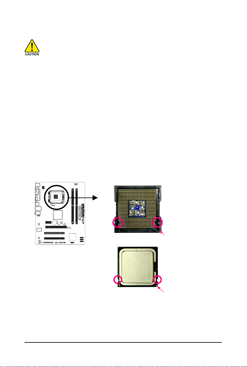
1-3-1 Installing the CPU
A. Locate the alignment keys on the motherboard CPU socket and the notches on the CPU.
LGA775 CPU Socket
Alignment Key
Alignment Key
Pin One Corner of the CPU Socket
LGA 775 CPU
NotchNotch
Triangle Pin One Marking on the CPU
Hardware Installation— 13 —
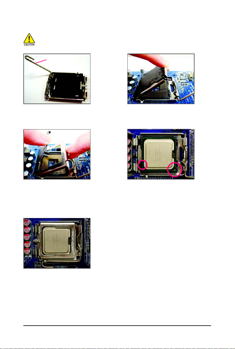
B. Follow the steps below to correctly install the CPU into the motherboard CPU socket.
Before installing the CPU, make sure to turn off the computer and unplug the power
cord from the power outlet to prevent damage to the CPU.
CPU Socket Lever
Step 1:
Completely raise the CPU socket lever.
Step 3:
Remove the protective socket cover from the
load plate. (To protect the CPU socket, always
replace the protective socket cover when the
CPU is not installed.)
Step 5:
Once the CPU is properly inserted, replace
the load plate and push the CPU socket lever
back into its locked position.
Step 2:
Lift the metal load plate from the CPU socket.
(DO NOT touch socket contacts.)
Step 4:
Hold the CPU with your thumb and index
fingers. Align the CPU pin one marking (triangle)
with the pin one corner of the CPU socket (or
you may align the CPU notches with the socket
alignment keys) and gently insert the CPU
into position.
GA-G31M-ES2L/ES2C Motherboard — 14 —
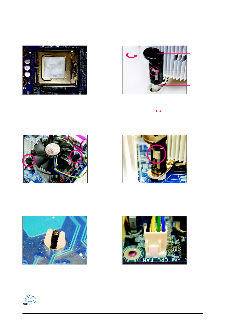
1-3-2 Installing the CPU Cooler
Follow the steps below to correctly install the CPU cooler on the motherboard. (The following procedure
uses Intel® boxed cooler as the example cooler.)
Male
Direction of
the Arrow Sign
on the Male
Push Pin
Push Pin
The Top
of Female
Push Pin
Female
Push Pin
Step 1:
Apply an even and thin layer of thermal grease
on the surface of the installed CPU.
Step 3:
Place the cooler atop the CPU, aligning the
four push pins through the pin holes on the
motherboard. Push down on the push pins
diagonally.
Step 2:
Before installing the cooler, note the direction
of the arrow sign on the male push pin.
(Turning the push pin along the direction of
arrow is to remove the cooler, on the contrary,
is to install.)
Step 4:
You should hear a «click» when pushing down each
push pin. Check that the Male and Female push pins
are joined closely. (Refer to your CPU cooler installation manual for instructions on installing the cooler.)
Step 5:
After the installation, check the back of the
motherboard. If the push pin is inserted as the
picture above, the installation is complete.
Step 6:
Finally, attach the power connector of the CPU
cooler to the CPU fan header (CPU_FAN) on
the motherboard.
Use extreme care when removing the CPU cooler because the thermal grease/tape between
the CPU cooler and CPU may adhere to the CPU. Inadequately removing the CPU cooler may
damage the CPU.
Hardware Installation— 15 —
1-4 Installing the Memory
Read the following guidelines before you begin to install the memory:
• Make sure that the motherboard supports the memory. It is recommended that memory of
the same capacity, brand, speed, and chips be used.
(Go to GIGABYTE’s website for the latest memory support list.)
• Always turn off the computer and unplug the power cord from the power outlet before
installing the memory to prevent hardware damage.
• Memory modules have a foolproof design. A memory module can be installed in only one
direction. If you are unable to insert the memory, switch the direction.
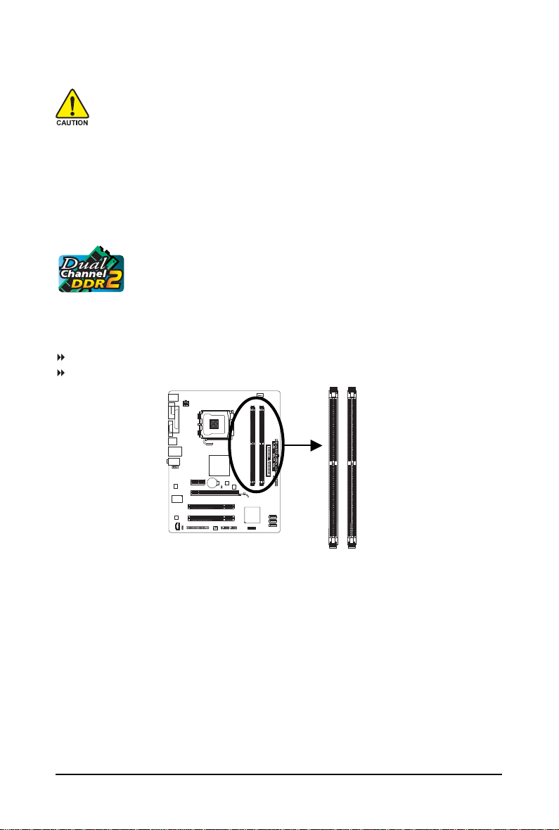
1-4-1 Dual Channel Memory Configuration
This motherboard provides two DDR2 memory sockets and supports Dual Channel
Technology. After the memory is installed, the BIOS will automatically detect the
specifications and capacity of the memory. Enabling Dual Channel memory mode
will double the original memory bandwidth.
The two DDR2 memory sockets are divided into two channels and each channel has one memory
socket as following:
Channel 0: DDRII1
Channel 1: DDRII2
DDRII1
DDRII2
Due to chipset limitation, read the following guidelines before installing the memory in Dual Channel mode.
1. Dual Channel mode cannot be enabled if only one DDR2 memory module is installed.
2. When enabling Dual Channel mode with two memory modules, it is recommended that
memory of the same capacity, brand, speed, and chips be used.
GA-G31M-ES2L/ES2C Motherboard — 16 —
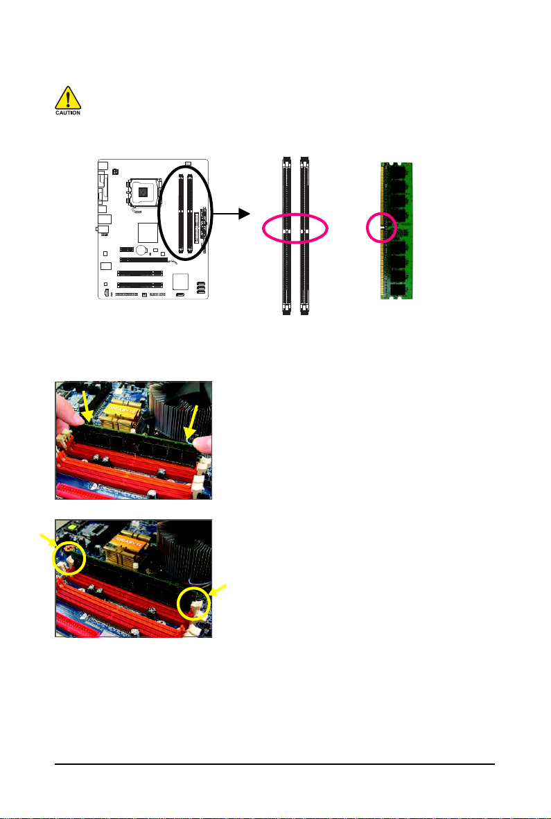
1-4-2 Installing a Memory
Before installing a memory module , make sure to turn off the computer and unplug
the power cord from the power outlet to prevent damage to the memory module.
DDR2 DIMMs are not compatible to DDR DIMMs. Be sure to install DDR2 DIMMs on
this motherboard.
Notch
DDR2 DIMM
A DDR2 memory module has a notch, so it can only fit in one direction. Follow the steps below to
correctly install your memory modules in the memory sockets.
Step 1:
Note the orientation of the memory module. Spread the retaining
clips at both ends of the memory socket. Place the memory
module on the socket. As indicated in the picture on the left,
place your fingers on the top edge of the memory, push down
on the memory and insert it vertically into the memory socket.
Step 2:
The clips at both ends of the socket will snap into place when
the memory module is securely inserted.
Hardware Installation— 17 —
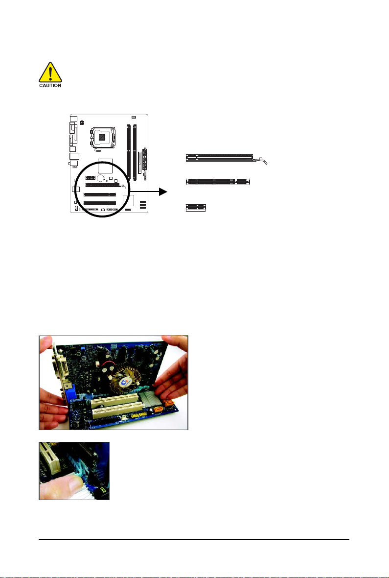
1-5 Installing an Expansion Card
Read the following guidelines before you begin to install an expansion card:
• Make sure the motherboard supports the expansion card. Carefully read the manual that
came with your expansion card.
• Always turn off the computer and unplug the power cord from the power outlet before
installing an expansion card to prevent hardware damage.
PCI Express x16 Slot
PCI Slot
PCI Express x1 Slot
Follow the steps below to correctly install your expansion card in the expansion slot.
1. Locate an expansion slot that supports your card. Remove the metal slot cover from the chassis back panel.
2. Align the card with the slot, and press down on the card until it is fully seated in the slot.
3. Make sure the metal contacts on the card are completely inserted into the slot.
4. Secure the card’s metal bracket to the chassis back panel with a screw.
5. After installing all expansion cards, replace the chassis cover(s).
6. Turn on your computer. If necessary, go to BIOS Setup to make any required BIOS changes for
your expansion card(s).
7. Install the driver provided with the expansion card in your operating system.
Example: Installing and Removing a PCI Express x16 Graphics Card:
• Installing a Graphics Card:
Gently push down on the top edge of the card
until it is fully inserted into the PCI Express x16
slot. Make sure the card is securely seated in
the slot and does not rock.
• Removing the Card:
Gently push back on the lever on the slot and then lift the card straight out
from the slot.
GA-G31M-ES2L/ES2C Motherboard — 18 —
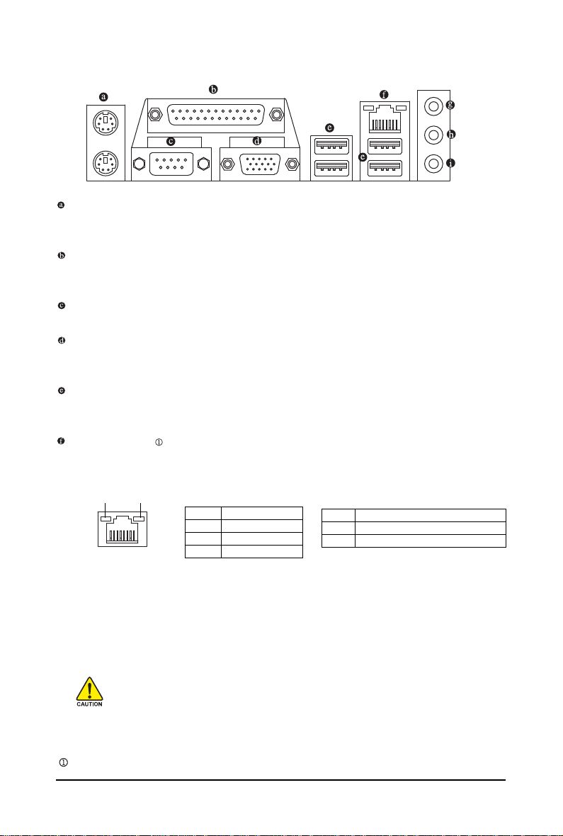
1-6 Back Panel Connectors
PS/2 Keyboard and PS/2 Mouse Port
Use the upper port (green) to connect a PS/2 mouse and the lower port (purple) to connect a PS/2
keyboard.
Parallel Port
Use the parallel port to connect devices such as a printer, scanner and etc. The parallel port is also
called a printer port.
Serial Port
Use the serial port to connect devices such as a mouse, modem or other peripherals.
D-Sub Port
The D-Sub port supports a 15-pin D-Sub connector. Connect a monitor that supports D-Sub
connection to this port.
USB Port
The USB port supports the USB 2.0/1.1 specification. Use this port for USB devices such as an
USB keyboard/mouse, USB printer, USB flash drive and etc.
RJ-45 LAN Port
The Gigabit Ethernet LAN port provides Internet connection at up to 1 Gbps data rate. The following
describes the states of the LAN port LEDs.
Connection/
Speed LED
LAN Port
Activity LED
Connection/Speed LED:
State Description
Orange 1 Gbps data rate
Green 100 Mbps data rate
Off 10 Mbps data rate
Activity LED:
State Description
Blinking Data transmission or receiving is occurring
Off No data transmission or receiving is occurring
• When removing the cable connected to a back panel connector, first remove the cable
from your device and then remove it from the motherboard.
• When removing the cable, pull it straight out from the connector. Do not rock it side to side
to prevent an electrical short inside the cable connector.
Only for GA-G31M-ES2L.
Hardware Installation— 19 —
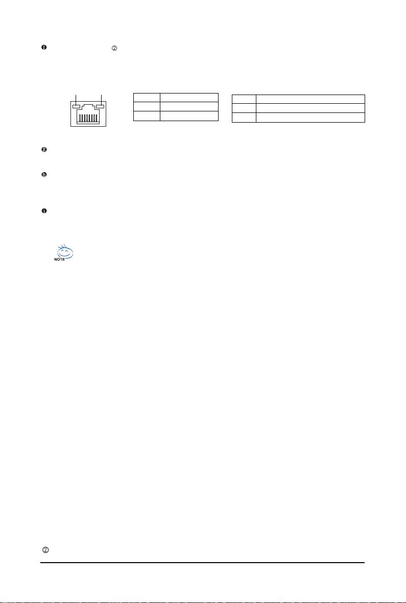
RJ-45 LAN Port
The Fast Ethernet LAN port provides Internet connection at up to 100 Mbps data rate. The following
describes the states of the LAN port LEDs.
Connection/
Speed LED
LAN Port
Activity LED
Connection/Speed LED:
State Description
Green 100 Mbps data rate
Off 10 Mbps data rate
Activity LED:
State Description
Blinking Data transmission or receiving is occurring
Off No data transmission or receiving is occurring
Line In Jack (Blue)
The default line in jack. Use this audio jack for line in devices such as an optical drive, walkman, etc.
Line Out Jack (Green)
The default line out jack. Use this audio jack for a headphone or 2-channel speaker. This jack can
be used to connect front speakers in a 4/5.1-channel audio configuration.
Mic In Jack (Pink)
The default Mic in jack. Microphones must be connected to this jack.
To configure 7.1-channel audio, you need connect with the port of HD Audio standard via
front panel and enable the multi-channel audio feature through the audio driver. Refer to the
instructions on setting up a 2/4/5.1/7.1-channel audio configuration in Chapter 5, «Configuring 2/4/5.1/7.1-Channel Audio.»
Only for GA-G31M-ES2C.
GA-G31M-ES2L/ES2C Motherboard — 20 —
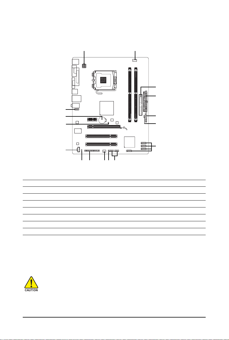
1-7 Internal Connectors
3
6
2
11
9
15
12
1) ATX_12V
2) AT X
3) CPU_FAN
4) SYS_FAN
5) FDD
6) IDE
7) SATAII0 / 1 / 2 / 3
 PWR_LED
5 14
161413
9) BAT
10) F_PANEL
11) F_AUDIO
12) CD_IN
13) SPDIF_O
14) F_USB1 / F_USB2
15) CLR_CMOS
16) CI
10
8
7
Read the following guidelines before connecting external devices:
• First make sure your devices are compliant with the connectors you wish to connect.
• Before installing the devices, be sure to turn off the devices and your computer. Unplug the
power cord from the power outlet to prevent damage to the devices.
• After installing the device and before turning on the computer, make sure the device cable
has been securely attached to the connector on the motherboard.
Hardware Installation— 21 —
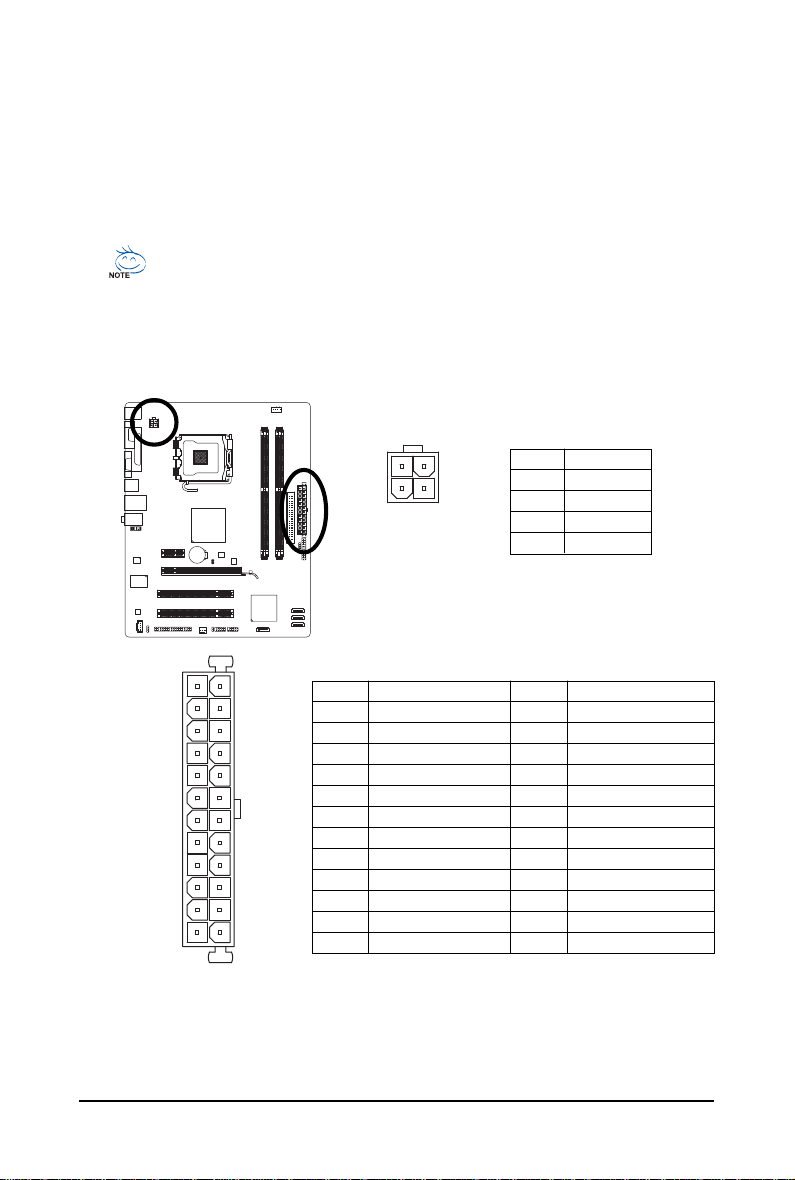
1/2) ATX_12V/ATX (2×2 12V Power Connector and 2×12 Main Power Connector)
With the use of the power connector, the power supply can supply enough stable power to all the
components on the motherboard. Before connecting the power connector, first make sure the
power supply is turned off and all devices are properly installed. The power connector possesses
a foolproof design. Connect the power supply cable to the power connector in the correct orientation.
The 12V power connector mainly supplies power to the CPU. If the 12V power connector is not
connected, the computer will not start.
• To meet expansion requirements, it is recommended that a power supply that can withstand
high power consumption be used (500W or greater). If a power supply is used that does not
provide the required power, the result can lead to an unstable or unbootable system.
• The main power connector is compatible with power supplies with 2×10 power
connectors. When using a 2×12 power supply, remove the protective cover from the
main power connector on the motherboard. Do not insert the power supply cable into pins
under the protective cover when using a 2×10 power supply.
ATX_12V :
3
1
ATX_12V
4
2
Pin No. Definition
1 GND
2 GND
3 +12V
4 +12V
12
24
131
ATX
ATX :
Pin No. Definition
1 3.3V
2 3.3V
3 GND
4 +5V
5 GND
6 +5V
7 GND
8 Power Good
9 5V SB(stand by +5V)
10 +12V
11 +12V (Only for 2×12-pin ATX)
12 3.3V (Only for 2×12-pin ATX)
GA-G31M-ES2L/ES2C Motherboard — 22 —
Pin No. Definition
13 3.3V
14 -12V
15 GND
16 PS_ON(soft On/Off)
17 GND
18 GND
19 GND
20 -5V
21 +5V
22 +5V
23 +5V (Only for 2×12-pin ATX)
24 GND (Only for 2×12-pin ATX)
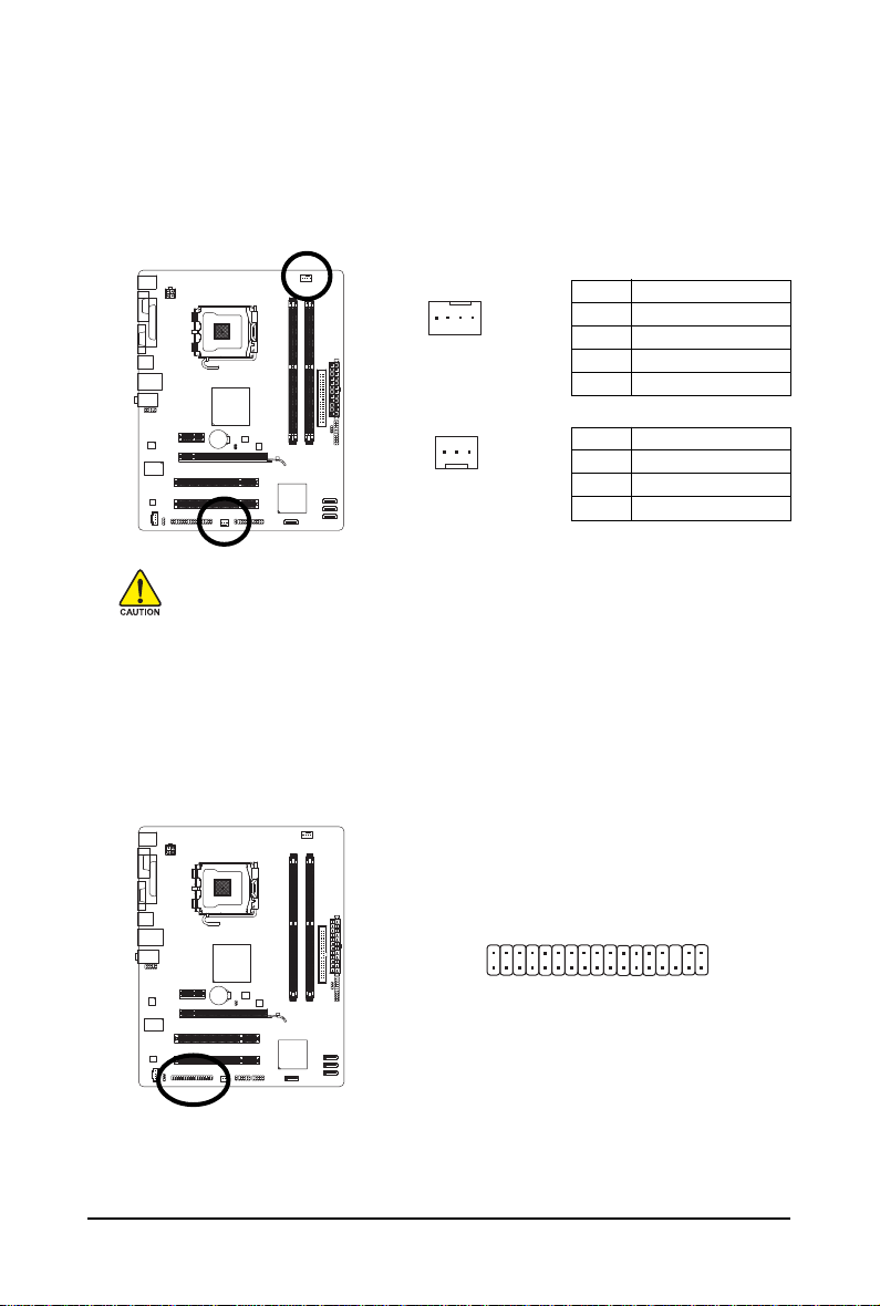
3/4) CPU_FAN/SYS_F AN (Fan Headers)
The motherboard has a 4-pin CPU fan header (CPU_FAN) and a 3-pin (SYS_FAN) system fan
header. Most fan headers possess a foolproof insertion design. When connecting a fan cable, be
sure to connect it in the correct orientation (the black connector wire is the ground wire). The
motherboard supports CPU fan speed control, which requires the use of a CPU fan with fan speed
control design. For optimum heat dissipation, it is recommended that a system fan be installed
inside the chassis.
CPU_FAN :
Pin No. Definition
1
CPU_FAN
1
SYS_FAN
1 GND
2 +12V/Speed Control
3 Sense
4 Speed Control
SYS_FAN :
Pin No. Definition
1 GND
2 +12V
3 Sense
• Be sure to connect fan cables to the fan headers to prevent your CPU and system from
overheating. Overheating may result in damage to the CPU or the system may hang.
• These fan headers are not configuration jumper blocks. Do not place a jumper cap on the
headers.
5) FDD (Floppy Disk Drive Connector)
This connector is used to connect a floppy disk drive. The types of floppy disk drives supported
are: 360 KB, 720 KB, 1.2 MB, 1.44 MB, and 2.88 MB. Before connecting a floppy disk drive, be
sure to locate pin 1 of the connector and the floppy disk drive cable. The pin 1 of the cable is
typically designated by a stripe of different color.
33
34
1
2
Hardware Installation— 23 —
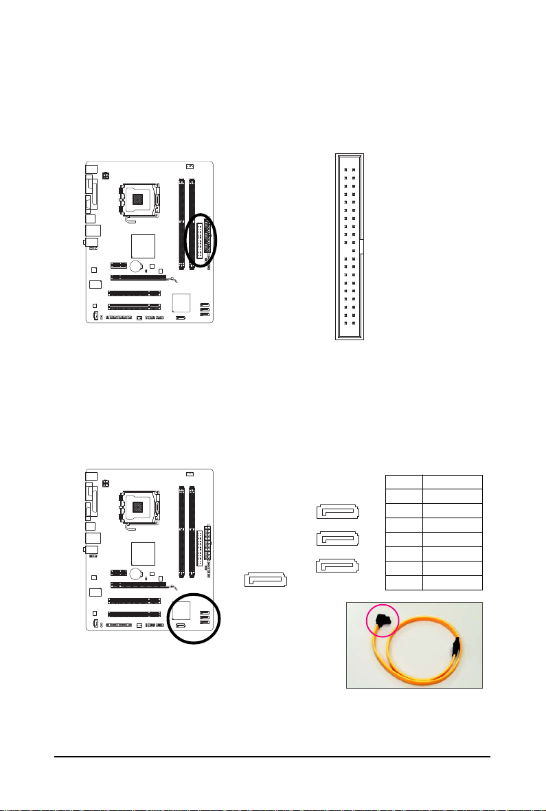
6) IDE (IDE Connector)
The IDE connector supports up to two IDE devices such as hard drives and optical drives. Before
attaching the IDE cable, locate the foolproof groove on the connector. If you wish to connect two IDE
devices, remember to set the jumpers and the cabling according to the role of the IDE devices (for
example, master or slave). (For information about configuring master/slave settings for the IDE
devices, read the instructions from the device manufacturers.)
3940
12
7) SATAII0/1/2/3 (SATA 3Gb/s Connectors)
The SATA connectors conform to SATA 3Gb/s standard and are compatible with SATA 1.5Gb/s
standard. Each SATA connector supports a single SATA device.
7
SATAII0
GA-G31M-ES2L/ES2C Motherboard — 24 —
Pin No. Definition
1 GND
1
1
1
2 TXP
3 TXN
4 GND
5 RXN
6 RXP
7 GND
7
SATAII3
7
SATAII2
7
1
SATAII1
Please connect the L-shaped end
of the SATA 3Gb/s cable to your
SATA hard drive.
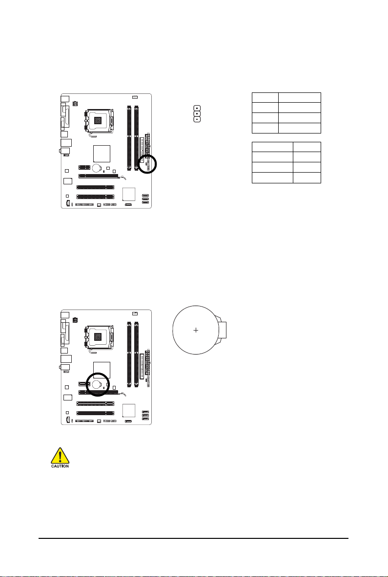
PWR_LED (System Power LED Header)
This header can be used to connect a system power LED on the chassis to indicate system power
status. The LED is on when the system is operating. The LED keeps blinking when the system is
in S1 sleep state. The LED is off when the system is in S3/S4 sleep state or powered off (S5).
Pin No. Definition
1 MPD+
2 MPD-
1
3 MPD-
System Status LED
S0 On
S1 Blinking
S3/S4/S5 Off
9) BAT (BATTERY)
The battery provides power to keep the values (such as BIOS configurations, date, and time
information) in the CMOS when the computer is turned off. Replace the battery when the battery
voltage drops to a low level, or the CMOS values may not be accurate or may be lost.
You may clear the CMOS values by removing the battery:
1. Turn off your computer and unplug the power cord.
2. Gently remove the battery from the battery holder and wait for one minute.
(Or use a metal object like a screwdriver to touch the positive and
negative terminals of the battery holder, making them short for 5 seconds.)
3. Replace the battery.
4. Plug in the power cord and restart your computer.
• Always turn off your computer and unplug the power cord before replacing the battery.
• Replace the battery with an equivalent one. Danger of explosion if the battery is replaced
with an incorrect model.
• Contact the place of purchase or local dealer if you are not able to replace the battery by
yourself or uncertain about the battery model.
• When installing the battery, note the orientation of the positive side (+) and the negative
side (-) of the battery (the positive side should face up).
• Used batteries must be handled in accordance with local environmental regulations.
Hardware Installation— 25 —
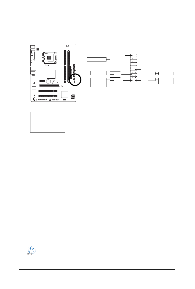
10) F_PANEL (Front Panel Header)
Connect the power switch, reset switch, speaker and system status indicator on the chassis front
panel to this header according to the pin assignments below. Note the positive and negative pins
before connecting the cables.
19
PWMSG-
20
NC
RES+
RES-
HD-
HD+
12
Speaker Connector
Power Switch
Message LED/
Power/
Sleep LED
SPEAK-
SPEAK+
PW+
MSG+
• MSG (Message/Power/Sleep LED):
System Status LED
S0 On
S1 Blinking
S3/S4/S5 Off
Connects to the power status indicator o n the chassis front panel. The
LED is on when the system is operating. The LED keeps blinking when
the system is in S1 sleep state. The LED is off when the system is in
S3/S4 sleep state or powered off (S5).
• PW (Power Switch):
Connects to the power switch on the chassis front panel. You may configure the way to turn off
your system using the power switch (refer to Chapter 2, «BIOS Setup,» «Power Management
Setup,» for more information).
• SPEAK (Speaker):
Connects to the speaker on the chassis front panel. The system reports system startup status
by issuing a beep code. One single short beep will be heard if no problem is detected at system
startup. If a problem is detected, the BIOS may issue beeps in different patterns to indicate the
problem. Refer to Chapter 5, «Troubleshooting,» for information about beep codes.
• HD (IDE Hard Drive Activity LED)
Connects to the hard drive activity LED on the chassis front panel. The LED is on when the hard
drive is reading or writing data.
• RES (Reset Switch):
Connects to the reset switch on the chassis front panel. Press the reset switch to restart the
computer if the computer freezes and fails to perform a normal restart.
• NC:
No connection
Reset Switch
IDE Hard Disk
Active LED
The front panel design may differ by chassis. A front panel module mainly consists of
power switch, reset switch, power LED, hard drive activity LED, speaker and etc. When
connecting your chassis front panel module to this header, make sure the wire assignments and the pin assignments are matched correctly.
GA-G31M-ES2L/ES2C Motherboard — 26 —
 Loading…
Смотреть руководство для Gigabyte GA-G31M-ES2C ниже. Все руководства на ManualsCat.com могут просматриваться абсолютно бесплатно. Нажав кнопку «Выбор языка» вы можете изменить язык руководства, которое хотите просмотреть.

MANUALSCAT | RU
Вопросы и ответы
У вас есть вопрос о Gigabyte GA-G31M-ES2C, но вы не можете найти ответ в пользовательском руководстве? Возможно, пользователи ManualsCat.com смогут помочь вам и ответят на ваш вопрос. Заполните форму ниже — и ваш вопрос будет отображаться под руководством для Gigabyte GA-G31M-ES2C. Пожалуйста, убедитесь, что вы опишите свои трудности с Gigabyte GA-G31M-ES2C как можно более детально. Чем более детальным является ваш вопрос, тем более высоки шансы, что другой пользователь быстро ответит на него. Вам будет автоматически отправлено электронное письмо, чтобы проинформировать вас, когда кто-то из пользователей ответит на ваш вопрос.
Задать вопрос о Gigabyte GA-G31M-ES2C
- Бренд:
- Gigabyte
- Продукт:
- материнские платы
- Модель/название:
- GA-G31M-ES2C
- Тип файла:
- Доступные языки:
- английский