- Manuals
- Brands
- Gigabyte Manuals
- Motherboard
- GA-A320M-H
- User manual
-
Contents
-
Table of Contents
-
Bookmarks
Quick Links
GA-A320M-H
User’s Manual
Rev. 3001
For more product details, please visit GIGABYTE’s website.
To reduce the impacts on global warming, the packaging materials of this product
are recyclable and reusable. GIGABYTE works with you to protect the environment.
Related Manuals for Gigabyte GA-A320M-H
Summary of Contents for Gigabyte GA-A320M-H
-
Page 1
GA-A320M-H User’s Manual Rev. 3001 For more product details, please visit GIGABYTE’s website. To reduce the impacts on global warming, the packaging materials of this product are recyclable and reusable. GIGABYTE works with you to protect the environment. -
Page 2
Information in this manual is protected by copyright laws and is the property of GIGABYTE. Changes to the specifications and features in this manual may be made by GIGABYTE without prior notice. No part of this manual may be reproduced, copied, translated, transmitted, or published in any form or by any means without GIGABYTE’s prior written permission. -
Page 3: Table Of Contents
Table of Contents GA-A320M-H Motherboard Layout ………………4 Chapter 1 Hardware Installation ………………5 Installation Precautions ………………5 1-2 Product Specifications ………………6 Installing the CPU ……………….. 9 Installing the Memory ………………9 Installing an Expansion Card …………….. 10 Back Panel Connectors ……………… 10 Internal Connectors ………………
-
Page 4: Ga-A320M-H Motherboard Layout
GA-A320M-H Motherboard Layout ATX_12V CPU_FAN KB_MS Socket AM4 HDMI R_USB30_1 R_USB30_2 SYS_FAN1 USB_LAN GA-A320M-H M_BIOS AUDIO M2F_32G PCIEX16 SATA3 Realtek ® PCIEX1_1 GbE LAN AMD SATA3 A320 CODEC ® PCIEX1_2 Super I/O F_USB30 F_AUDIO SPEAKER SPDIF_O F_USB2 CLR_CMOS F_USB1 F_PANEL…
-
Page 5: Chapter 1 Hardware Installation
Chapter 1 Hardware Installation Installation Precautions The motherboard contains numerous delicate electronic circuits and components which can become damaged as a result of electrostatic discharge (ESD). Prior to installation, carefully read the user’s manual and follow these procedures: • Prior to installation, make sure the chassis is suitable for the motherboard. • Prior to installation, do not remove or break motherboard S/N (Serial Number) sticker or warranty sticker provided by your dealer.
-
Page 6: 1-2 Product Specifications
Š S upport for ECC Un-buffered DIMM 1Rx8/2Rx8 memory modules (operate in Š non-ECC mode) Support for non-ECC Un-buffered DIMM 1Rx8/2Rx8/1Rx16 memory modules Š Support for Extreme Memory Profile (XMP) memory modules Š (Go to GIGABYTE’s website for the latest supported memory speeds and memory modules.) Onboard Integrated Graphics Processor: Š 1 x DVI-D port, supporting a maximum resolution of 1920×1200@60 Hz Graphics * The DVI-D port does not support D-Sub connection by adapter.
-
Page 7
Internal 1 x 24-pin ATX main power connector Š Connectors 1 x 8-pin ATX 12V power connector Š 1 x CPU fan header Š 1 x system fan header Š 1 x M.2 Socket 3 connector Š 4 x SATA 6Gb/s connectors Š… -
Page 8
Micro ATX Form Factor; 24.4cm x 19.5cm Š * GIGABYTE reserves the right to make any changes to the product specifications and product-related information without prior notice. Please visit the SupportUtility List Please visit GIGABYTE’s website for support lists of CPU, memory page on GIGABYTE’s website to modules, SSDs, and M.2 devices. download the latest version of apps. — 8 -… -
Page 9: Installing The Cpu
• Memory modules have a foolproof design. A memory module can be installed in only one direction. If you are unable to insert the memory, switch the direction. Please visit GIGABYTE’s website for details on hardware installation. — 9 -…
-
Page 10: Installing An Expansion Card
Dual Channel Memory Configuration This motherboard provides two memory sockets and supports Dual Channel Technology. After the memory is installed, the BIOS will automatically detect the specifications and capacity of the memory. Enabling Dual Channel memory mode will double the original memory bandwidth. The two DDR4 memory sockets are divided into two channels and each channel has one memory socket as following: Channel A: DDR4_2 Channel B: DDR4_1 Due to CPU limitations, read the following guidelines before installing the memory in Dual Channel mode. Dual Channel mode cannot be enabled if only one memory module is installed. When enabling Dual Channel mode with two memory modules, it is recommended that memory of the same capacity, brand, speed, and chips be used. Installing an Expansion Card Read the following guidelines before you begin to install an expansion card: • Make sure the motherboard supports the expansion card. Carefully read the manual that came with your expansion card.
-
Page 11
Line Out/Front Speaker Out Mic In/Center/Subwoofer Speaker Out Front Panel Line Out/Side Speaker Out To configure 7.1-channel audio, you need to open the audio software and select Device advanced settings > Playback Device to change the default setting first. • When removing the cable connected to a back panel connector, first remove the cable from your device and then remove it from the motherboard. • When removing the cable, pull it straight out from the connector. Do not rock it side to side to prevent an electrical short inside the cable connector. Please visit GIGABYTE’s website for details on configuring the audio software. — 11 -… -
Page 12: Internal Connectors
Internal Connectors ATX_12V F_AUDIO SPEAKER CPU_FAN F_USB30 SYS_FAN1 F_USB1/F_USB2 SATA3 0/1/2/3 M2F_32G SPDIF_O F_PANEL CLR_CMOS Read the following guidelines before connecting external devices: • First make sure your devices are compliant with the connectors you wish to connect. • Before installing the devices, be sure to turn off the devices and your computer. Unplug the power cord from the power outlet to prevent damage to the devices.
-
Page 13
1/2) ATX_12V/ATX (2×4 12V Power Connector and 2×12 Main Power Connector) With the use of the power connector, the power supply can supply enough stable power to all the components on the motherboard. Before connecting the power connector, first make sure the power supply is turned off and all devices are properly installed. The power connector possesses a foolproof design. Connect the power supply cable to the power connector in the correct orientation. -
Page 14
3/4) CPU_FAN/SYS_FAN1 (Fan Headers) All fan headers on this motherboard are 4-pin. Most fan headers possess a foolproof insertion design. When connecting a fan cable, be sure to connect it in the correct orientation (the black connector wire is the ground wire). The motherboard supports CPU fan speed control, which requires the use of a CPU fan with fan speed control design. For optimum heat dissipation, it is recommended that a system fan be installed inside the chassis. -
Page 15
6) M2F_32G (M.2 Socket 3 Connector) The M.2 connector supports M.2 SATA SSDs or M.2 PCIe SSDs and supports SATA RAID configuration. Please note that an M.2 PCIe SSD cannot be used to create a RAID array. Refer to Chapter 3, «Configuring a RAID Set,» for instructions on configuring a RAID array. Follow the steps below to correctly install an M.2 SSD in the M.2 connector. Step 1: Use a screw driver to unfasten the screw and standoff from the motherboard. Locate the proper mounting hole for the M.2 SSD to be installed and then screw the standoff first. Step 2: Slide the M.2 SSD into the connector at an angle. Step 3: Press the M.2 SSD down and then secure it with the screw. Select the proper hole for the M.2 SSD to be installed and refasten the screw and standoff. Installation Notices for the M.2 Connector: Supports only M.2 SATA SSDs when using an AMD 7th Generation A-series or Athlon processor. Refer ™… -
Page 16
 F_PANEL (Front Panel Header) Connect the power switch, reset switch, and system status indicator on the chassis to this header according to the pin assignments below. Note the positive and negative pins before connecting the cables. • PLED (Power LED): Power LED Power Switch Connects to the power status indicator on the System Status LED…
 -
Page 17
10) SPEAKER (Speaker Header) Connects to the speaker on the chassis front panel. The system reports system startup status by issuing a beep code. One single short beep will be heard if no problem is detected at system startup. Pin No. Definition SPK- 11) F_USB30 (USB 3.1 Gen 1 Header) The header conforms to USB 3.1 Gen 1 and USB 2.0 specification and can provide two USB ports. For… -
Page 18
13) TPM (Trusted Platform Module Header) You may connect a TPM (Trusted Platform Module) to this header. Pin No. Definition Pin No. Definition LCLK LAD0 LFRAME No Pin LRESET SB3V SERIRQ DEBUG LAD3 PORT LAD2 VCC3 LAD1 14) BAT (Battery) The battery provides power to keep the values (such as BIOS configurations, date, and time information) in the CMOS when the computer is turned off. Replace the battery when the battery voltage drops to a low level, or the CMOS values may not be accurate or may be lost. You may clear the CMOS values by removing the battery: 1. -
Page 19
15) CI (Chassis Intrusion Header) This motherboard provides a chassis detection feature that detects if the chassis cover has been removed. This function requires a chassis with chassis intrusion detection design. Pin No. Definition Signal 16) CLR_CMOS (Clear CMOS Jumper) Use this jumper to clear the BIOS configuration and reset the CMOS values to factory defaults. To clear the CMOS values, use a metal object like a screwdriver to touch the two pins for a few seconds. -
Page 20: Chapter 2 Bios Setup
When the power is turned off, the battery on the motherboard supplies the necessary power to the CMOS to keep the configuration values in the CMOS. To access the BIOS Setup program, press the <Delete> key during the POST when the power is turned on. To upgrade the BIOS, use either the GIGABYTE Q-Flash or @BIOS utility. Q-Flash allows the user to quickly and easily upgrade or back up BIOS without entering the operating system. •…
-
Page 21
M.I.T. Whether the system will work stably with the overclock/overvoltage settings you made is dependent on your overall system configurations. Incorrectly doing overclock/overvoltage may result in damage to CPU, chipset, or memory and reduce the useful life of these components. This page is for advanced users only and we recommend you not to alter the default settings to prevent system instability or other unexpected results. -
Page 22
& AMD Cool&Quiet function Enabled L ets the AMD Cool’n’Quiet driver dynamically adjust the CPU clock and VID to reduce heat output from your computer and its power consumption. (Default) Disabled Disables this function. & SVM Mode Virtualization enhanced by Virtualization Technology will allow a platform to run multiple operating systems and applications in independent partitions. With virtualization, one computer system can function as multiple virtual systems. (Default: Disabled) & C6 Mode (Note 1) Allows you to determine whether to let the CPU enter C6 mode in system halt state. When enabled, the CPU core frequency will be reduced during system halt state to decrease power consumption. -
Page 23
` Advanced Memory Settings & Extreme Memory Profile (X.M.P.) , System Memory Multiplier, Memory Frequency(Mhz) (Note 2) The settings above are synchronous to those under the same items on the Advanced Frequency Settings menu. & Memory Timing Mode Manual and Advanced Manual allows the Channel Interleaving, Rank Interleaving, and memory timing settings below to be configurable. Options are: Auto (default), Manual, Advanced Manual. -
Page 24
` Smart Fan 5 Settings & Monitor Allows you to select a target to monitor and to make further adjustment. (Default: CPU FAN) & Fan Speed Control Allows you to determine whether to enable the fan speed control function and adjust the fan speed. Allows the fan to run at different speeds according to the temperature. You can adjust Normal the fan speed with System Information Viewer based on your system requirements. -
Page 25: System
System This section provides information on your motherboard model and BIOS version. You can also select the default language used by the BIOS and manually set the system time. & System Language Selects the default language used by the BIOS. &…
-
Page 26: Bios
A password is required for booting the system and for entering the BIOS Setup System program. (Default) & Full Screen LOGO Show Allows you to determine whether to display the GIGABYTE Logo at system startup. Disabled skips the GIGABYTE Logo when the system starts up. (Default: Enabled) — 26 -…
-
Page 27
& Fast Boot Enables or disables Fast Boot to shorten the OS boot process. Ultra Fast provides the fastest bootup speed. (Default: Disabled) & SATA Support All Sata Devices A ll SATA devices are functional in the operating system and during the POST. Last Boot HDD Only E xcept for the previous boot drive, all SATA devices are disabled before the OS boot process completes. (Default) This item is configurable only when Fast Boot is set to Enabled or Ultra Fast. &… -
Page 28
& Other PCI Device ROM Priority Allows you to select whether to enable the UEFI or Legacy option ROM for the PCI device controller other than the LAN, storage device, and graphics controllers. Disabled Disables option ROM. UEFI Only Enables UEFI option ROM only. (Default) Enables legacy option ROM only. Legacy Only This item is configurable only when CSM Support is set to Enabled. & Network Stack Disables or enables booting from the network to install a GPT format OS, such as installing the OS from the Windows Deployment Services server. (Default: Disabled) & Ipv4 PXE Support Enables or disables IPv4 PXE Support. This item is configurable only when Network Stack is enabled. &… -
Page 29: Peripherals
Peripherals & AMD CPU fTPM Enables or disables the TPM 2.0 function integrated in the AMD CPU. (Default: Disabled) & Initial Display Output (Note) Specifies the first initiation of the monitor display from the installed PCI Express graphics card or the onboard graphics. IGD Video Sets the onboard graphics as the first display. Sets the graphics card on the PCIEX16 slot as the first display. (Default) PCIe 1 Slot & Legacy USB Support Allows USB keyboard/mouse to be used in MS-DOS. (Default: Enabled) & XHCI Hand-off Determines whether to enable XHCI Hand-off feature for an operating system without XHCI Hand-off support. (Default: Enabled) &…
-
Page 30: Chipset
& HD Audio Controller Enables or disables the onboard audio function. (Default: Enabled) If you wish to install a 3rd party add-in audio card instead of using the onboard audio, set this item to Disabled. & Above 4G Decoding Enables or disables 64-bit capable devices to be decoded in above 4 GB address space (only if your system supports 64-bit PCI decoding). Set to Enabled if more than one advanced graphics card are installed and their drivers are not able to be launched when entering the operating system (because of the limited 4 GB memory address space). (Default: Disabled)
-
Page 31
& UMA Frame Buffer Size (Note) Frame buffer size is the total amount of system memory allocated solely for the onboard graphics controller. MS-DOS, for example, will use only this memory for display. Options are: Auto (default), 32M, 64M, 128M, 256M, 512M, 1G, 2G. & SATA Mode Enables or disables RAID for the SATA controllers integrated in the Chipset or configures the SATA controllers to AHCI mode. RAID Enables RAID for the SATA controller. AHCI C onfigures the SATA controllers to AHCI mode. Advanced Host Controller Interface (AHCI) is an interface specification that allows the storage driver to enable advanced Serial ATA features such as Native Command Queuing and hot plug. (Default) & NVMe RAID mode (M2F_32G Connector) Allows you to determine whether to use your M.2 NVMe PCIe SSDs to configure RAID. (Default: Disabled) & APU SATA Port Enable (M2F_32G Connector) Enables or disables the SATA controller integrated in the CPU. (Default: Enabled) &… -
Page 32: Power
Power & AC BACK Determines the state of the system after the return of power from an AC power loss. The system returns to its last known awake state upon the return of the AC power. Memory Always On The system is turned on upon the return of the AC power. Always Off T he system stays off upon the return of the AC power. (Default) & Power On By Keyboard Allows the system to be turned on by a PS/2 keyboard wake-up event.
-
Page 33
& ErP Determines whether to let the system consume least power in S5 (shutdown) state. Note: When this item is set to Enabled, the following functions will become unavailable: Resume by Alarm, power on by mouse, and power on by keyboard. & Soft-Off by PWR-BTTN Configures the way to turn off the computer in MS-DOS mode using the power button. Instant-Off Press the power button and then the system will be turned off instantly. (Default) P ress and hold the power button for 4 seconds to turn off the system. If the power Delay 4 Sec. button is pressed for less than 4 seconds, the system will enter suspend mode. & Resume by Alarm Determines whether to power on the system at a desired time. (Default: Disabled) If enabled, set the date and time as following: Wake up day: Turn on the system at a specific time on each day or on a specific day in a month. -
Page 34: Save & Exit
Save & Exit & Save & Exit Setup Press <Enter> on this item and select Yes. This saves the changes to the CMOS and exits the BIOS Setup program. Select No or press <Esc> to return to the BIOS Setup Main Menu. & Exit Without Saving Press <Enter> on this item and select Yes. This exits the BIOS Setup without saving the changes made in BIOS Setup to the CMOS. Select No or press <Esc> to return to the BIOS Setup Main Menu. &…
-
Page 35: Chapter 3 Appendix
Chapter 3 Appendix 3-1 Configuring a RAID Set RAID Levels RAID 0 RAID 1 RAID 10 Minimum Number of ≥2 Hard Drives Number of hard drives * (Number of hard drives/2) * Array Capacity Size of the smallest drive Size of the smallest drive Size of the smallest drive Fault Tolerance Before you begin, please prepare the following items: • At least two SATA hard drives or M.2 SATA SSDs. (To ensure optimal performance, it is recommended that you use two hard drives with identical model and capacity).
-
Page 36
3. Insert the USB thumb drive and then browse to the location of the driver. The location of the driver is as follows: Hw10RAIDx64 4. Select AMD-RAID Bottom Device first and click Next to load the driver. Then select AMD-RAID Controller and click Next to load the driver. Finally, continue the OS installation. Please visit GIGABYTE’s website for details on configuring a RAID array. — 36 -… -
Page 37: Drivers Installation
Run.exe program.) «Xpress Install» will automatically scan your system and then list all of the drivers that are recommended to install. You can click the Xpress Install button and «Xpress Install» will install all of the selected drivers. Or click the arrow icon to individually install the drivers you need. Please visit GIGABYTE’s website for Please visit GIGABYTE’s website for more software information. more troubleshooting information. — 37 -…
-
Page 38: Regulatory Statements
Contravention will be prosecuted. We believe that the information contained herein was accurate in all respects at the time of printing. GIGABYTE cannot, however, assume any responsibility for errors or omissions in this text. Also note that the information in this document is subject to change without notice and should not be construed as a commitment by GIGABYTE.
-
Page 39
FCC Notice (U.S.A. Only) This equipment has been tested and found to comply with the limits for a Class B digital device, pursuant to Part 15 of the FCC Rules. These limits are designed to provide reasonable protection against harmful interference in a residential installation. This equipment generates, uses, and can radiate radio frequency energy and, if not installed and used in accordance with the instructions, may cause harmful interference to radio communications. -
Page 40: Contact Us
Contact Us GIGA-BYTE TECHNOLOGY CO., LTD. Address: No.6, Baoqiang Rd., Xindian Dist., New Taipei City 231, Taiwan TEL: +886-2-8912-4000, FAX: +886-2-8912-4005 Tech. and Non-Tech. Support (Sales/Marketing) : https://esupport.gigabyte.com WEB address (English): https://www.gigabyte.com WEB address (Chinese): https://www.gigabyte.com/tw GIGABYTE eSupport • To submit a technical or non-technical (Sales/Marketing) question, please link to: https://esupport.gigabyte.com — 40 -…
Для ознакомления с инструкцией необходимо нажать на ссылку «ЗАГРУЗИТЬ», чтобы скачать pdf файл. Если есть кнопка «ПРОСМОТР», то можно просто посмотреть документ онлайн.
Для удобства, Вы можете сохранить данную страницу с файлом руководства по эксплуатации в свой список «избранное» прямо на сайте (доступно для зарегистрированных пользователей).
Смотрите инструкцию для похожих моделей:

Вы можете задать вопрос посетителям сайта по модели GIGABYTE GA-A320M-H. Если Вы являетесь её пользователем, то пожалуйста оставьте, по возможности развёрнутый отзыв:
Посмотреть инструкция для Gigabyte GA-A320M-H бесплатно. Руководство относится к категории материнские платы, 1 человек(а) дали ему среднюю оценку 7.1. Руководство доступно на следующих языках: английский. У вас есть вопрос о Gigabyte GA-A320M-H или вам нужна помощь? Задайте свой вопрос здесь
Не можете найти ответ на свой вопрос в руководстве? Вы можете найти ответ на свой вопрос ниже, в разделе часто задаваемых вопросов о Gigabyte GA-A320M-H.
Какая ширина Gigabyte GA-A320M-H?
Какая толщина Gigabyte GA-A320M-H?
Инструкция Gigabyte GA-A320M-H доступно в русский?
Не нашли свой вопрос? Задайте свой вопрос здесь

To reduce the impacts on global warming, the packaging materials of this product
are recyclable and reusable. GIGABYTE works with you to protect the environment.
For more product details, please visit GIGABYTE’s website.
GA-A320M-H
User’s Manual
Rev. 1001
Copyright
© 2018 GIGA-BYTE TECHNOLOGY CO., LTD. All rights reserved.
The trademarks mentioned in this manual are legally registered to their respective owners.
Disclaimer
Information in this manual is protected by copyright laws and is the property of GIGABYTE.
Changes to the specications and features in this manual may be made by GIGABYTE without prior notice.
No part of this manual may be reproduced, copied, translated, transmitted, or published in any form or
by any means without GIGABYTE’s prior written permission.
In order to assist in the use of this product, carefully read the User’s Manual.
For product-related information, check on our website at: https://www.gigabyte.com
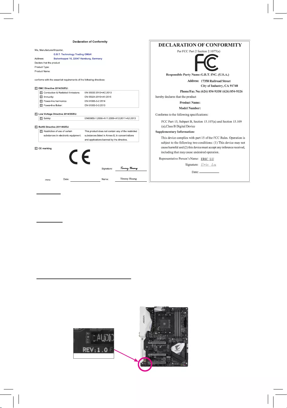
Identifying Your Motherboard Revision
The revision number on your motherboard looks like this: «REV: X.X.» For example, «REV: 1.0″ means
the revision of the motherboard is 1.0. Check your motherboard revision before updating motherboard
BIOS, drivers, or when looking for technical information.
Example:
Motherboard
GA-A320M-H
Sept. 7, 2018
Sept. 7, 2018
Motherboard
GA-A320M-H

— 3 —
Table of Contents
GA-A320M-H Motherboard Layout ………………………………………………………………………. 4
Chapter 1 Hardware Installation ………………………………………………………………………….5
1-1 Installation Precautions ………………………………………………………………………… 5
1-2 ProductSpecications ………………………………………………………………………….. 6
1-3 Installing the CPU ……………………………………………………………………………….. 9
1-4 Installing the Memory …………………………………………………………………………… 9
1-5 Installing an Expansion Card ………………………………………………………………. 10
1-6 Back Panel Connectors ………………………………………………………………………. 10
1-7 Internal Connectors ……………………………………………………………………………. 12
Chapter 2 BIOS Setup ……………………………………………………………………………………..20
2-1 Startup Screen ………………………………………………………………………………….. 20
2-2 M.I.T. ……………………………………………………………………………………………….. 21
2-3 System …………………………………………………………………………………………….. 25
2-4 BIOS ………………………………………………………………………………………………… 26
2-5 Peripherals ……………………………………………………………………………………….. 29
2-6 Chipset …………………………………………………………………………………………….. 30
2-7 Power ………………………………………………………………………………………………. 32
2-8 Save & Exit ……………………………………………………………………………………….. 34
Chapter 3 Appendix …………………………………………………………………………………………35
3-1 ConguringaRAIDSet ………………………………………………………………………. 35
3-2 DriversInstallation ……………………………………………………………………………… 37
RegulatoryStatements …………………………………………………………………………………. 38
Contact Us …………………………………………………………………………………………………. 40
— 4 —
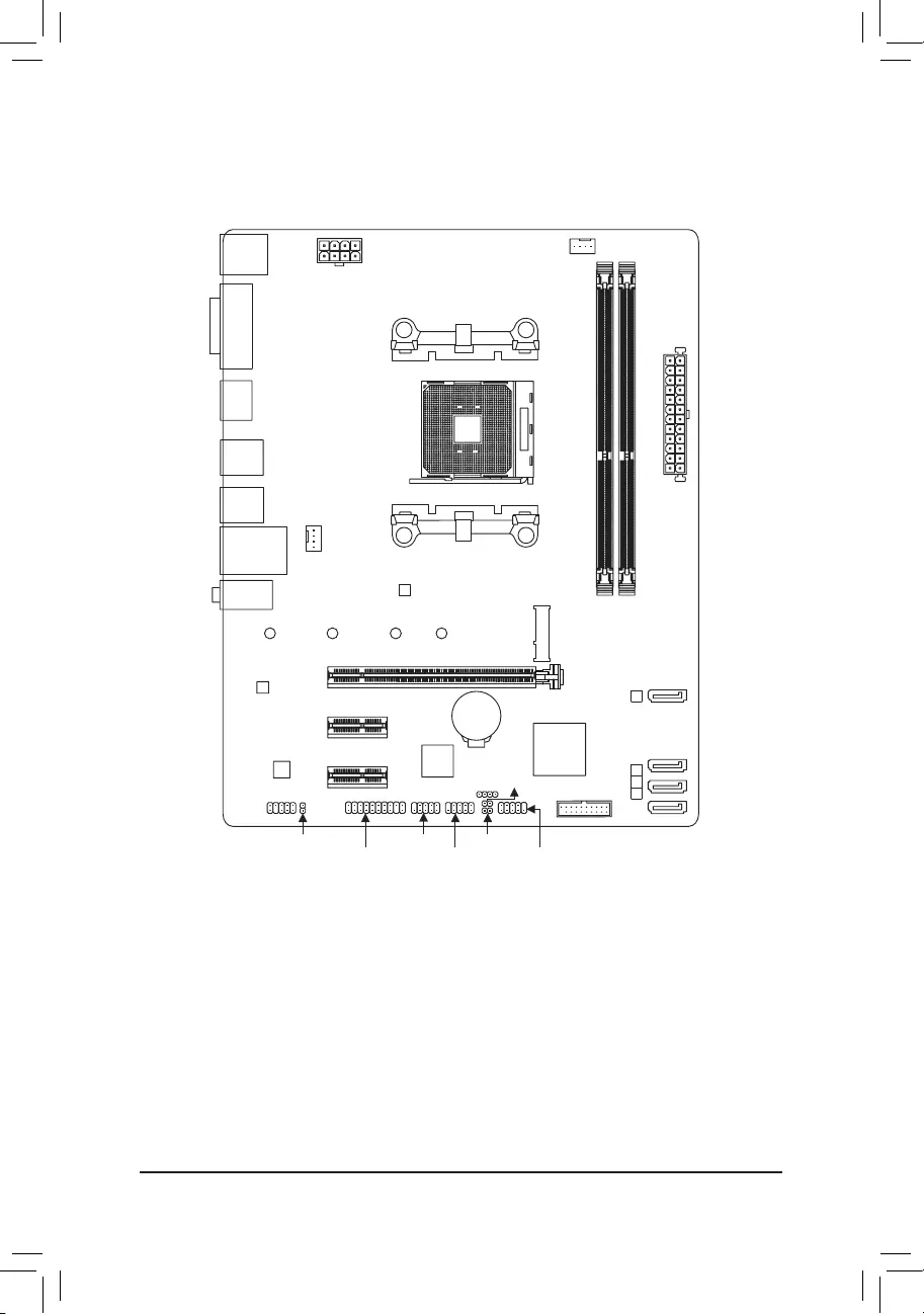
GA-A320M-H Motherboard Layout
* The box contents above are for reference only and the actual items shall depend on the product package you obtain.
The box contents are subject to change without notice.
Box Contents
5GA-A320M-H motherboard 5Two SATA cables
5Motherboard driver disk 5I/O Shield
5User’s Manual
KB_MS CPU_FAN
SYS_FAN1
ATX
GA-A320M-H
AUDIO
DDR4_2
DDR4_1
BAT
ATX_12V
AMD
A320
R_USB30_1
HDMI
CODEC
M_BIOS
DVI
PCIEX16
PCIEX1_1
PCIEX1_2 iTE®
Super I/O
Realtek®
GbE LAN
F_USB30
CI
SPEAKER
F_USB1 F_PANEL
F_USB2SPDIF_O
SATA3
012
USB_LAN
Socket AM4
R_USB30_2
3
CLR_CMOS
TPM
F_AUDIO
M2F_32G
80 60 42110
SATA3

Chapter 1 Hardware Installation
1-1 Installation Precautions
The motherboard contains numerous delicate electronic circuits and components which can become
damagedasaresultofelectrostaticdischarge(ESD).Priortoinstallation,carefullyreadtheuser’s
manual and follow these procedures:
•Prior to installation, make sure the chassis is suitable for the motherboard.
•Priortoinstallation,donotremoveorbreakmotherboardS/N(SerialNumber)stickeror
warranty sticker provided by your dealer. These stickers are required for warranty validation.
•Always remove the AC power by unplugging the power cord from the power outlet before
installing or removing the motherboard or other hardware components.
•When connecting hardware components to the internal connectors on the motherboard, make
sure they are connected tightly and securely.
•When handling the motherboard, avoid touching any metal leads or connectors.
•It is best to wear an electrostatic discharge (ESD) wrist strap when handling electronic
componentssuchasamotherboard,CPUormemory.IfyoudonothaveanESDwriststrap,
keepyourhandsdryandrsttouchametalobjecttoeliminatestaticelectricity.
•Prior to installing the motherboard, please have it on top of an antistatic pad or within an
electrostatic shielding container.
•Before connecting or unplugging the power supply cable from the motherboard, make sure
the power supply has been turned off.
•Before turning on the power, make sure the power supply voltage has been set according to
the local voltage standard.
•Before using the product, please verify that all cables and power connectors of your hardware
components are connected.
•To prevent damage to the motherboard, do not allow screws to come in contact with the
motherboard circuit or its components.
•Make sure there are no leftover screws or metal components placed on the motherboard or
within the computer casing.
•Donotplacethecomputersystemonanunevensurface.
•Donotplacethecomputersysteminahigh-temperatureorwetenvironment.
•Turning on the computer power during the installation process can lead to damage to system
components as well as physical harm to the user.
•If you are uncertain about any installation steps or have a problem related to the use of the
product,pleaseconsultacertiedcomputertechnician.
•If you use an adapter, extension power cable, or power strip, ensure to consult with its installation
and/or grounding instructions.
— 5 —
1-2 ProductSpecications
CPU AM4 Socket:
- AMDRyzen™ processor
- AMD7thGenerationA-series/Athlon™ processors
(GotoGIGABYTE’swebsiteforthelatestCPUsupportlist.)
Chipset AMDA320
Memory 2xDDR4DIMMsocketssupportingupto32GBofsystemmemory
Dualchannelmemoryarchitecture
SupportforDDR42667(Note1)/2400/2133MHzmemorymodules
SupportforECCUn-bufferedDIMM 1Rx8/2Rx8memorymodules(operate in
non-ECCmode)
Supportfornon-ECCUn-bufferedDIMM1Rx8/2Rx8/1Rx16memorymodules
SupportforExtremeMemoryProle(XMP)memorymodules
(Go to GIGABYTE’s website for the latest supported memory speeds and memory
modules.)
Onboard
Graphics
Integrated Graphics Processor:
- 1xDVI-Dport,supportingamaximumresolutionof1920×1200@60Hz
* TheDVI-DportdoesnotsupportD-Subconnectionbyadapter.
- 1xHDMIport,supportingamaximumresolutionof4096×2160@24Hz
* SupportforHDMI1.4version.
Maximum shared memory of 2 GB
Audio Realtek® ALC887 codec
HighDenitionAudio
2/4/5.1/7.1-channel
* Tocongure7.1-channelaudio,youhavetouseanHDfrontpanelaudiomodule
and enable the multi-channel audio feature through the audio driver.
SupportforS/PDIFOut
LAN Realtek®GbELANchip(10/100/1000Mbit)
Expansion Slots 1 x PCI Express x16 slot, running at x16 (Note1)
(ThePCIEX16slotconformstoPCIExpress3.0standard.)
2 x PCI Express x1 slots
(ThePCIExpressx1slotsconformtoPCIExpress2.0standard.)
Storage Interface 1 x M.2 connector (Socket 3, M key, type 2242/2260/2280/22110 SATA and PCIe
x4/x2 (Note2)SSDsupport)
4 x SATA 6Gb/s connectors
SupportforRAID0,RAID1,andRAID10
* Referto»1-7InternalConnectors,»fortheinstallationnoticesfortheM.2connector.
USB Chipset:
— 2 x USB 3.1 Gen 1 ports available through the internal USB header
— 6 x USB 2.0/1.1 ports (2 ports on the back panel, 4 ports available through
theinternalUSBheaders)
CPU:
— 4 x USB 3.1 Gen 1 ports on the back panel
(Note1) ActualsupportmayvarybyCPU.
(Note2) SupportsonlyM.2SATASSDswhenusinganAMD7thGenerationA-seriesorAthlon™ processor.
— 6 —
Internal
Connectors
1 x 24-pin ATX main power connector
1 x 8-pin ATX 12V power connector
1 x CPU fan header
1 x system fan header
1 x M.2 Socket 3 connector
4 x SATA 6Gb/s connectors
1 x front panel header
1 x front panel audio header
1xS/PDIFOutheader
1 x USB 3.1 Gen 1 header
2 x USB 2.0/1.1 headers
1xTrustedPlatformModule(TPM)header(2×10pin,fortheGC-TPM2.0moduleonly)
1 x speaker header
1 x Clear CMOS jumper
1 x chassis intrusion header
Back Panel
Connectors
1 x PS/2 keyboard port
1 x PS/2 mouse port
1xDVI-Dport
1xHDMIport
4 x USB 3.1 Gen 1 ports
2 x USB 2.0/1.1 ports
1xRJ-45port
3 x audio jacks
I/O Controller iTE® I/O Controller Chip
Hardware
Monitor
Voltage detection
Temperature detection
Fan speed detection
Overheating warning
Fan fail warning
Fan speed control
* Whether the fan speed control function is supported will depend on the cooler you
install.
BIOS 1x128Mbitash
Use of licensed AMI UEFI BIOS
PnP1.0a,DMI2.7,WfM2.0,SMBIOS2.7,ACPI5.0
— 7 —
Unique Features Support for APP Center
* Available applications in APP Center may vary by motherboard model. Supported
functionsofeachapplicationmayalsovarydependingonmotherboardspecications.
- @BIOS
- 3DOSD
— AutoGreen
— Cloud Station
— EasyTune
— Fast Boot
— Game Boost
— ON/OFF Charge
— Smart Backup
— Smart Keyboard
— Smart TimeLock
— System Information Viewer
— USB Blocker
Support for Q-Flash
Support for Xpress Install
Bundled
Software
Norton®InternetSecurity(OEMversion)
cFosSpeed
Operating
System
Support for Windows 10 64-bit
Support for Windows 7 64-bit
* Pleasedownloadthe«WindowsUSBInstallationTool»fromGIGABYTE’swebsite
and install it before installing Windows 7.
Form Factor Micro ATX Form Factor; 24.4cm x 19.5cm
* GIGABYTEreservestherighttomakeanychangestotheproductspecicationsandproduct-relatedinformationwithout
prior notice.
Please visit GIGABYTE’s website
for support lists of CPU, memory
modules,SSDs,andM.2devices.
Please visit the SupportUtility List
page on GIGABYTE’s website to
download the latest version of apps.
— 8 —
1-3 Installing the CPU
ReadthefollowingguidelinesbeforeyoubegintoinstalltheCPU:
•Make sure that the motherboard supports the CPU.
(GotoGIGABYTE’swebsiteforthelatestCPUsupportlist.)
•Always turn off the computer and unplug the power cord from the power outlet before installing the
CPU to prevent hardware damage.
•Locate the pin one of the CPU. The CPU cannot be inserted if oriented incorrectly.
•Apply an even and thin layer of thermal grease on the surface of the CPU.
•DonotturnonthecomputeriftheCPUcoolerisnotinstalled,otherwiseoverheatinganddamage
of the CPU may occur.
•SettheCPUhostfrequencyinaccordancewiththeCPUspecications.Itisnotrecommended
thatthesystembusfrequencybesetbeyondhardwarespecicationssinceitdoesnotmeetthe
standard requirements for the peripherals. If you wish to set the frequency beyond the standard
specications,pleasedosoaccordingtoyourhardwarespecicationsincludingtheCPU,graphics
card, memory, hard drive, etc.
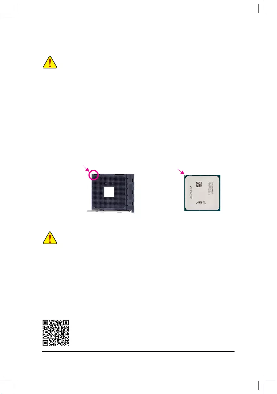
Installing the CPU
Locatethepinone(denotedbyasmalltriangle)oftheCPUsocketandtheCPU.
AM4 Socket
A Small Triangle
MarkingDenotesPin
One of the Socket AM4 CPU
A Small Triangle
MarkingDenotes
CPU Pin One
1-4 Installing the Memory
Readthefollowingguidelinesbeforeyoubegintoinstallthememory:
•Make sure that the motherboard supports the memory. It is recommended that memory of the
same capacity, brand, speed, and chips be used.
(GotoGIGABYTE’swebsiteforthelatestsupportedmemoryspeedsandmemorymodules.)
•Always turn off the computer and unplug the power cord from the power outlet before installing the
memory to prevent hardware damage.
•Memory modules have a foolproof design. A memory module can be installed in only one direction.
If you are unable to insert the memory, switch the direction.
Please visit GIGABYTE’s website for details on hardware installation.
— 9 —
1-5 Installing an Expansion Card
Readthefollowingguidelinesbeforeyoubegintoinstallanexpansioncard:
•Make sure the motherboard supports the expansion card. Carefully read the manual that came
with your expansion card.
•Always turn off the computer and unplug the power cord from the power outlet before installing an
expansion card to prevent hardware damage.
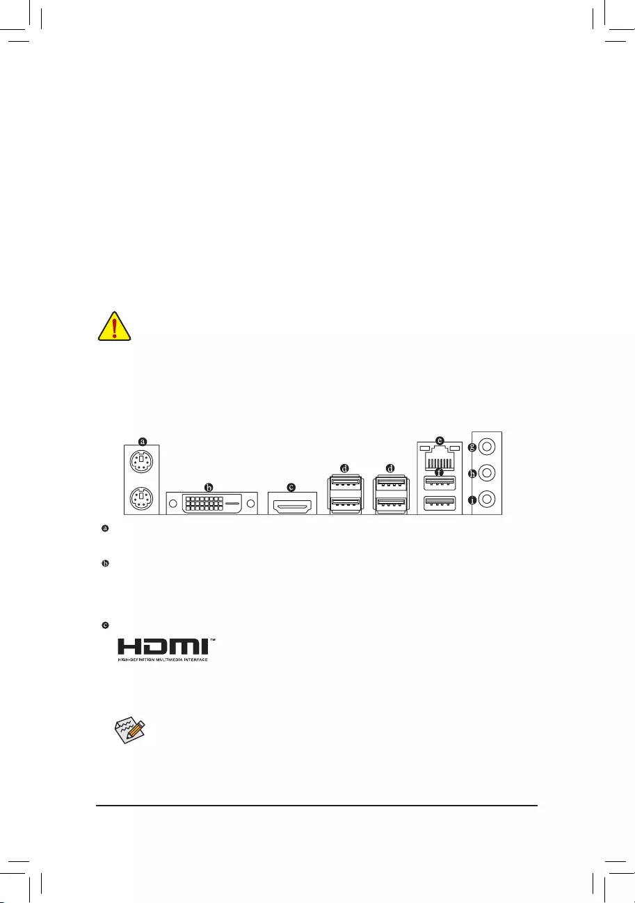
1-6 Back Panel Connectors
PS/2 Keyboard and PS/2 Mouse Port
Usetheupperport(green)toconnectaPS/2mouseandthelowerport(purple)toconnectaPS/2keyboard.
DVI-D Port (Note)
TheDVI-DportconformstotheDVI-Dspecicationandsupportsamaximumresolutionof1920×1200@60Hz
(theactualresolutionssupporteddependonthemonitorbeingused).Connectamonitorthatsupports
DVI-Dconnectiontothisport.
HDMI Port
TheHDMIportisHDCPcompliantandsupportsDolbyTrueHDandDTSHD
MasterAudio formats.It also supports upto 192KHz/24bit 8-channel LPCM
audiooutput.YoucanusethisporttoconnectyourHDMI-supportedmonitor.Themaximumsupported
resolutionis4096×2160@24 Hz, buttheactual resolutions supportedaredependent on themonitor
being used.
AfterinstallingtheHDMIdevice,makesuretosetthedefaultsoundplaybackdevicetoHDMI.(The
itemnamemaydifferdependingonyouroperatingsystem.)
(Note) TheDVI-DportdoesnotsupportD-Subconnectionbyadapter.
DualChannelMemoryConguration
ThismotherboardprovidestwomemorysocketsandsupportsDualChannelTechnology.Afterthememory
isinstalled,theBIOSwillautomaticallydetectthespecicationsandcapacityofthememory.EnablingDual
Channel memory mode will double the original memory bandwidth.
ThetwoDDR4memorysocketsaredividedintotwochannelsandeachchannelhasonememorysocketas
following:
ChannelA:DDR4_2
ChannelB:DDR4_1
DuetoCPUlimitations,readthefollowingguidelinesbeforeinstallingthememoryinDualChannelmode.
1. DualChannelmodecannotbeenabledifonlyonememorymoduleisinstalled.
2. WhenenablingDualChannelmodewithtwomemorymodules,itisrecommendedthatmemoryof
the same capacity, brand, speed, and chips be used.
— 10 —
USB 2.0/1.1 Port
TheUSBportsupportstheUSB2.0/1.1specication.UsethisportforUSBdevices.
Line In/Rear Speaker Out (Blue)
The line in jack. Use this audio jack for line in devices such as an optical drive, walkman, etc.
Line Out/Front Speaker Out (Green)
The line out jack.
Mic In/Center/Subwoofer Speaker Out (Pink)
The Mic in jack.
Tocongure7.1-channelaudio,youhavetouseanHDfrontpanelaudiomoduleandenablethe
multi-channel audio feature through the audio driver.
•Whenremovingthecableconnectedtoabackpanelconnector,rstremovethecablefromyour
device and then remove it from the motherboard.
•Whenremovingthecable,pullitstraightoutfromtheconnector.Donotrockitsidetosideto
prevent an electrical short inside the cable connector.
ActivityLED
Connection/
SpeedLED
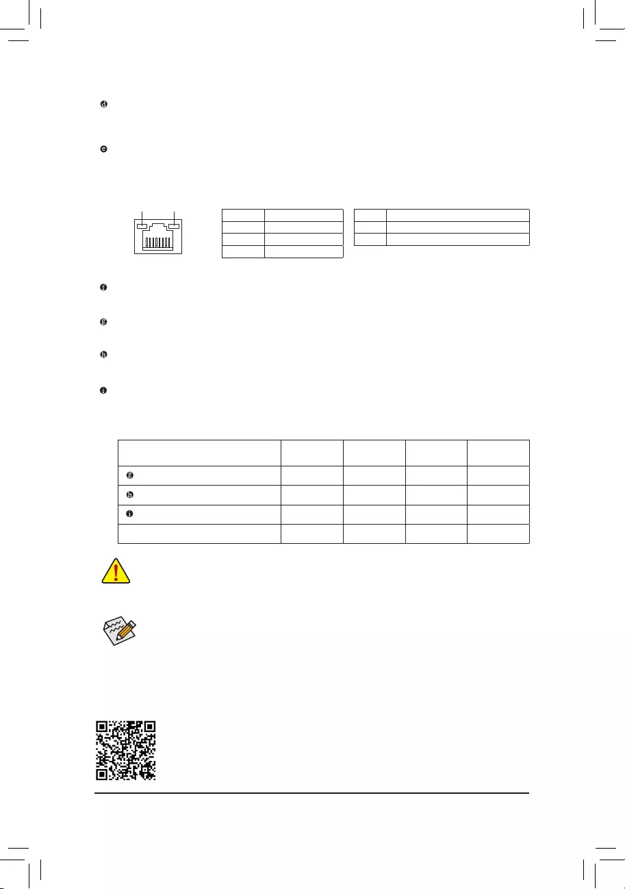
LAN Port
ActivityLED:Connection/SpeedLED:
State Description
Orange 1 Gbps data rate
Green 100 Mbps data rate
Off 10 Mbps data rate
State Description
Blinking Datatransmissionorreceivingisoccurring
Off No data transmission or receiving is occurring
USB 3.1 Gen 1 Port
TheUSB3.1Gen1portsupportstheUSB3.1Gen1specicationandiscompatibletotheUSB2.0
specication.UsethisportforUSBdevices.
RJ-45 LAN Port
The Gigabit Ethernet LAN port provides Internet connection at up to 1 Gbps data rate. The following
describesthestatesoftheLANportLEDs.
AudioJackCongurations:
Jacks Headphone/
2-channel 4-channel 5.1-channel 7.1-channel
LineIn/RearSpeakerOut a a a
Line Out/Front Speaker Out a a a a
Mic In/Center/Subwoofer Speaker Out a a
Front Panel Line Out/Side Speaker Out a
PleasevisitGIGABYTE’swebsitefordetailsonconguringtheaudiosoftware.
— 11 —
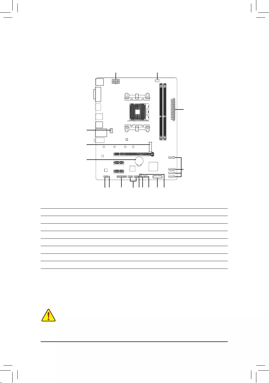
1-7 Internal Connectors
Readthefollowingguidelinesbeforeconnectingexternaldevices:
•First make sure your devices are compliant with the connectors you wish to connect.
•Before installing the devices, be sure to turn off the devices and your computer. Unplug the power
cord from the power outlet to prevent damage to the devices.
•After installing the device and before turning on the computer, make sure the device cable has
been securely attached to the connector on the motherboard.
1) ATX_12V
2) ATX
3) CPU_FAN
4) SYS_FAN1
5) SATA3 0/1/2/3
6) M2F_ 32G
7) SPDIF_O
 F_PANEL
9) F_AUDIO
10) SPEAKER
11) F_USB30
12) F_USB1/F_USB2
13) TPM
14) BAT
15) CI
16) CLR_CMOS
1
2
3
11
14
712
913
6
4
5
8 101615
— 12 —
131
2412
ATX
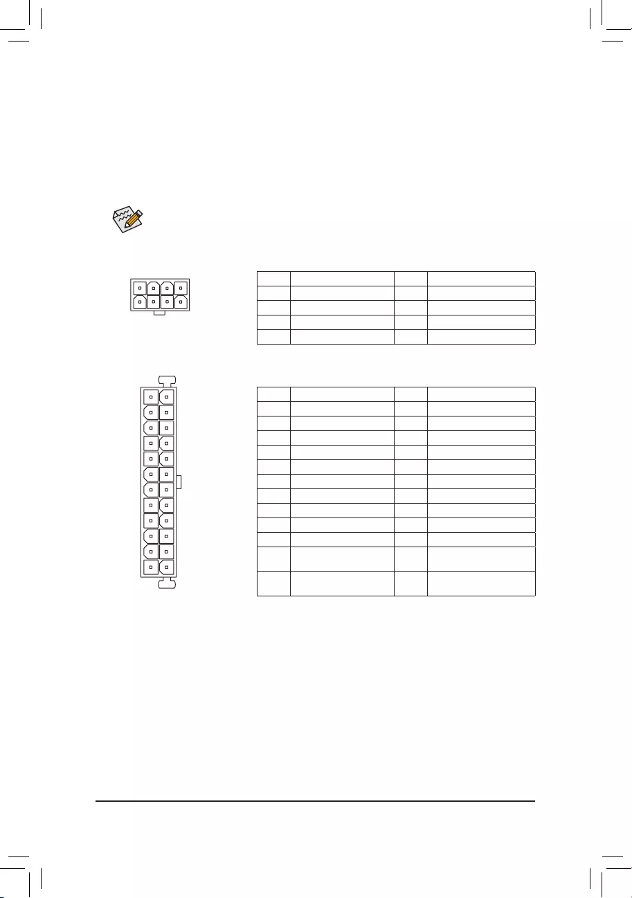
1/2) ATX_12V/ATX (2×4 12V Power Connector and 2×12 Main Power Connector)
With the use of the power connector, the power supply can supply enough stable power to all the components
onthemotherboard.Beforeconnectingthepowerconnector,rstmakesurethepowersupplyisturned
off and all devices are properly installed. The power connector possesses a foolproof design. Connect the
power supply cable to the power connector in the correct orientation.
The 12V power connector mainly supplies power to the CPU. If the 12V power connector is not connected,
the computer will not start.
To meet expansion requirements, it is recommended that a power supply that can withstand high
powerconsumptionbeused(500Worgreater).Ifapowersupplyisusedthatdoesnotprovidethe
required power, the result can lead to an unstable or unbootable system.
ATX:
Pin No. Denition Pin No. Denition
1 3.3V 13 3.3V
2 3.3V 14 -12V
3GND 15 GND
4 +5V 16 PS_ON(softOn/Off)
5GND 17 GND
6 +5V 18 GND
7GND 19 GND
8 Power Good 20 NC
95VSB(standby+5V) 21 +5V
10 +12V 22 +5V
11 +12V (Only for 2×12-pin
ATX)
23 +5V(Onlyfor2×12-pinATX)
12 3.3V (Only for 2×12-pin
ATX)
24 GND(Onlyfor2×12-pinATX)
ATX_12V:
Pin No. Denition Pin No. Denition
1GND(Onlyfor2×4-pin12V) 5+12V(Onlyfor2×4-pin12V)
2GND(Onlyfor2×4-pin12V) 6+12V(Onlyfor2×4-pin12V)
3GND 7 +12V
4GND 8 +12V
ATX_12V
58
14
— 13 —
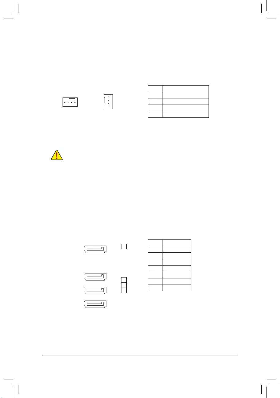
5) SATA3 0/1/2/3 (SATA 6Gb/s Connectors)
The SATA connectors conform to SATA 6Gb/s standard and are compatible with SATA 3Gb/s and SATA
1.5Gb/s standard. Each SATA connector supports a single SATA device. The SATA connectors support
RAID0,RAID1,andRAID10.RefertoChapter3,»ConguringaRAIDSet,»forinstructionsonconguring
aRAIDarray.
Pin No. Denition
1GND
2 TXP
3 TXN
4GND
5RXN
6RXP
7GND
•Be sure to connect fan cables to the fan headers to prevent your CPU and system from
overheating. Overheating may result in damage to the CPU or the system may hang.
•Thesefanheadersarenotcongurationjumperblocks.Donotplaceajumpercapontheheaders.
3/4) CPU_FAN/SYS_FAN1 (Fan Headers)
All fan headers on this motherboard are 4-pin. Most fan headers possess a foolproof insertion design.
When connecting a fan cable, be sure to connect it in the correct orientation (the black connector wire
isthegroundwire).ThemotherboardsupportsCPUfanspeedcontrol,whichrequirestheuseofaCPU
fan with fan speed control design. For optimum heat dissipation, it is recommended that a system fan be
installed inside the chassis.
CPU_FAN
1
SYS_FAN1
1
SATA3
2
1
0
Pin No. Denition
1GND
2 Voltage Speed Control
3 Sense
4 PWM Speed Control
71
71
71
71
3
— 14 —
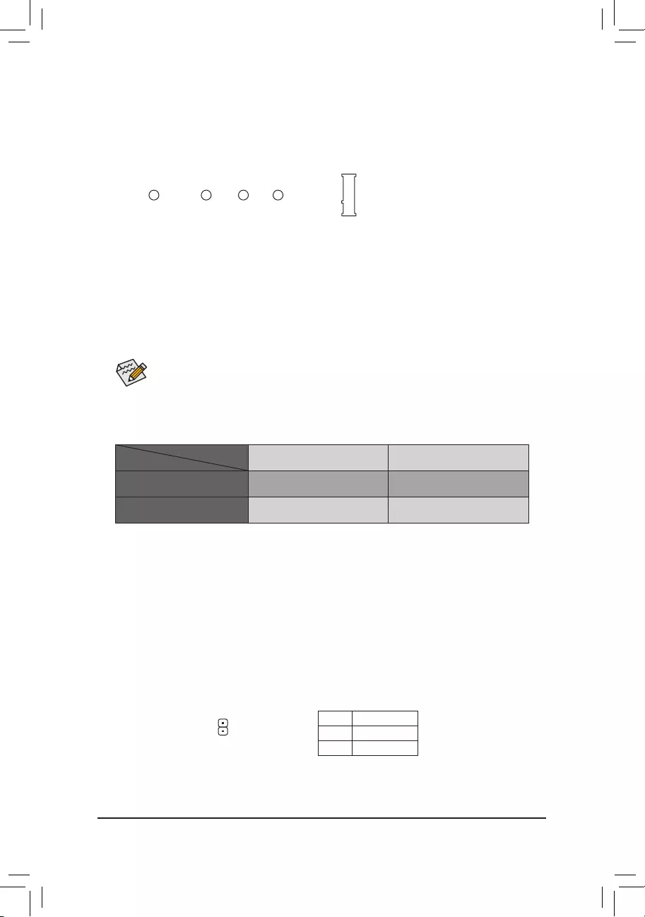
6) M2F_32G (M.2 Socket 3 Connector)
TheM.2connectorsupportsM.2SATASSDsorM.2PCIeSSDsandsupportsSATARAIDconguration.
PleasenotethatanM.2PCIeSSDcannotbeusedtocreateaRAIDarray.RefertoChapter3,»Conguring
aRAIDSet,»forinstructionsonconguringaRAIDarray.
FollowthestepsbelowtocorrectlyinstallanM.2SSDintheM.2connector.
Step 1:
Use a screw driver to unfasten the screw and standoff from the motherboard. Locate the proper mounting
holefortheM.2SSDtobeinstalledandthenscrewthestandoffrst.
Step 2:
SlidetheM.2SSDintotheconnectoratanangle.
Step 3:
PresstheM.2SSDdownandthensecureitwiththescrew.
SelecttheproperholefortheM.2SSDtobeinstalledandrefastenthescrewandstandoff.
F_USB30 F_U
B_
F_ F_
_
B
BS_
B
SB_
B
_S
S_
_
B
_U
_
B
S
123
123
123
123
1
1
1
1
BSS
S
_S
SSU
1 2 3
S3 BSSS
U
__ 3
F_USB3F
S _
S _
S _
SF
B_
B_
F
_0
S
S
_0F
_F
_
_
__B
U
S _S
_ SF_
USB0_B
B_ F_USB3
F_USB303
_
_3U
S_
80110 60 42
7) SPDIF_O (S/PDIF Out Header)
ThisheadersupportsdigitalS/PDIFOutandconnectsaS/PDIFdigitalaudiocable(providedbyexpansion
cards)fordigitalaudiooutputfromyourmotherboardtocertainexpansioncardslikegraphicscardsand
soundcards.Forexample,somegraphicscardsmayrequireyoutouseaS/PDIFdigitalaudiocablefor
digitalaudiooutputfromyourmotherboardtoyourgraphicscardifyouwishtoconnectanHDMIdisplay
tothegraphicscardandhavedigitalaudiooutputfromtheHDMIdisplayatthesametime.Forinformation
aboutconnectingtheS/PDIFdigitalaudiocable,carefullyreadthemanualforyourexpansioncard.
Pin No. Denition
1SPDIFO
2GND
1
Installation Notices for the M.2 Connector:
SupportsonlyM.2SATASSDswhenusinganAMD7thGenerationA-seriesorAthlon™processor.Refer
to the following table for details.
M.2PCIeSSD M.2SATASSD
Ryzen™ processor a a
7th Generation A-series/Athlon™ processors
ra
a: Available, r: Not available
CPU
TypeofM.2SSD
— 15 —
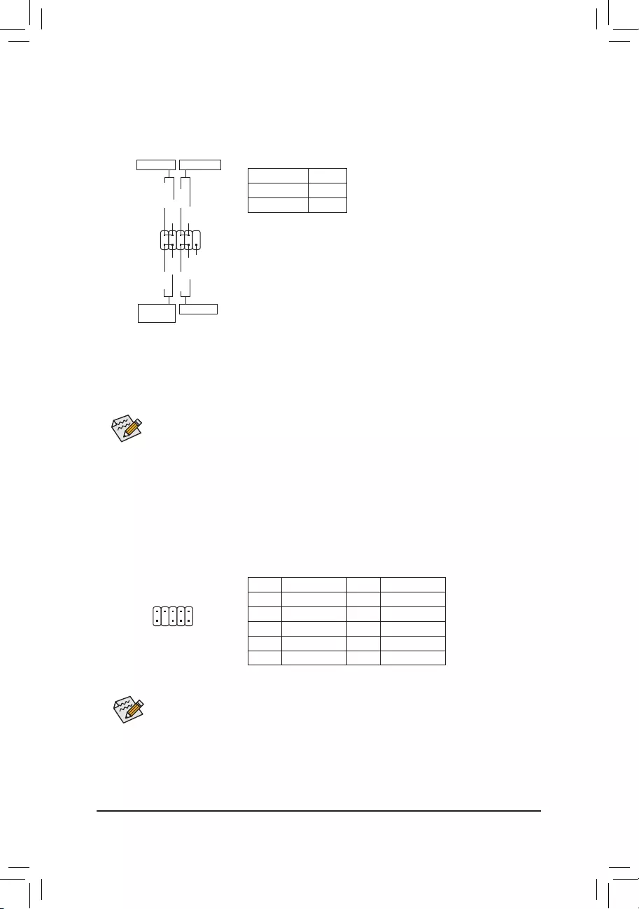
9) F_AUDIO (Front Panel Audio Header)
ThefrontpanelaudioheadersupportsHighDenitionaudio(HD).Youmayconnectyourchassisfront
panel audio module to this header. Make sure the wire assignments of the module connector match the
pin assignments of the motherboard header. Incorrect connection between the module connector and the
motherboard header will make the device unable to work or even damage it.
Some chassis provide a front panel audio module that has separated connectors on each wire
instead of a single plug. For information about connecting the front panel audio module that has
different wire assignments, please contact the chassis manufacturer.
Pin No. Denition Pin No. Denition
1 MIC2_L 6 Sense
2GND 7FAUDIO_JD
3MIC2_R 8 No Pin
4 NC 9 LINE2_L
5LINE2_R 10 Sense
1
2
9
10
F_PANEL (Front Panel Header)
Connect the power switch, reset switch, and system status indicator on the chassis to this header according
to the pin assignments below. Note the positive and negative pins before connecting the cables.
•PW(PowerSwitch):
Connectstothepowerswitchonthechassisfrontpanel.Youmaycongure
the way to turn off your system using the power switch (refer to Chapter
2,»BIOSSetup,»»Power,»formoreinformation).
•HD(HardDriveActivityLED):
ConnectstotheharddriveactivityLEDonthechassisfrontpanel.The
LEDisonwhentheharddriveisreadingorwritingdata.
•RES(ResetSwitch):
Connects to the reset switch on the chassis front panel. Press the reset
switchtorestartthecomputerifthecomputerfreezesandfailstoperform
a normal restart.
•NC: No connection.
•PLED(PowerLED):
System Status LED
S0 On
S3/S4/S5 Off
Connects to the power status indicator on the
chassisfront panel. The LED is on when the
systemis operating.TheLEDisoffwhenthe
system is in S3/S4 sleep state or powered
off(S5).
The front panel design may differ by chassis. A front panel module mainly consists of power switch, reset switch,
powerLED,harddriveactivityLEDandetc.Whenconnectingyourchassisfrontpanelmoduletothisheader,
make sure the wire assignments and the pin assignments are matched correctly.
1
2
9
10
NC
PLED-
PW-
PLED+
PW+
HD-
RES+
HD+
RES-
PowerLED Power Switch
HardDrive
ActivityLED
ResetSwitch
— 16 —
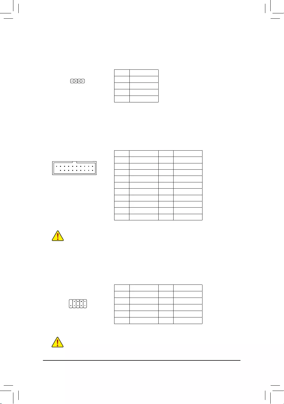
Pin No. Denition Pin No. Denition
1 VBUS 11 D2+
2SSRX1- 12 D2-
3SSRX1+ 13 GND
4GND 14 SSTX2+
5 SSTX1- 15 SSTX2-
6 SSTX1+ 16 GND
7GND 17 SSRX2+
8D1- 18 SSRX2-
9D1+ 19 VBUS
10 NC 20 No Pin
11) F_USB30 (USB 3.1 Gen 1 Header)
TheheaderconformstoUSB3.1Gen1andUSB2.0specicationandcanprovidetwoUSBports.For
purchasingtheoptional3.5″frontpanelthatprovidestwoUSB3.1Gen1ports,pleasecontactthelocal
dealer.
F_USB30 F_U
B_
F_ F_
_
B
BS_
B
SB_
B
_S
S_
_
B
_U
_
B
S
123
123
123
123
1
1
1
1
BSS
S
_S
SSU
1 2 3
S3 BSSS
U
__ 3
F_USB3F
S _
S _
S _
SF
B_
B_
F
_0
S
S
_0F
_F
_
_
__B
U
S _S
_ SF_
USB0_B
B_ F_USB3
F_USB303
_
_3U
S_
10
11
1
20
10) SPEAKER (Speaker Header)
Connects to the speaker on the chassis front panel. The system reports system startup status by issuing
a beep code. One single short beep will be heard if no problem is detected at system startup.
Pin No. Denition
1 VCC
2 NC
3 NC
4 SPK-
1
Prior to installing the USB front panel, be sure to turn off your computer and unplug the power cord
from the power outlet to prevent damage to the USB front panel.
12) F_USB1/F_USB2 (USB 2.0/1.1 Headers)
TheheadersconformtoUSB2.0/1.1specication.EachUSBheadercanprovidetwoUSBportsviaan
optional USB bracket. For purchasing the optional USB bracket, please contact the local dealer.
Pin No. Denition Pin No. Denition
1Power(5V) 6USBDY+
2Power(5V) 7GND
3USBDX- 8GND
4USBDY— 9 No Pin
5USBDX+ 10 NC
•DonotplugtheIEEE1394bracket(2×5-pin)cableintotheUSB2.0/1.1header.
•Prior to installing the USB bracket, be sure to turn off your computer and unplug the power cord
from the power outlet to prevent damage to the USB bracket.
10
9
2
1
— 17 —
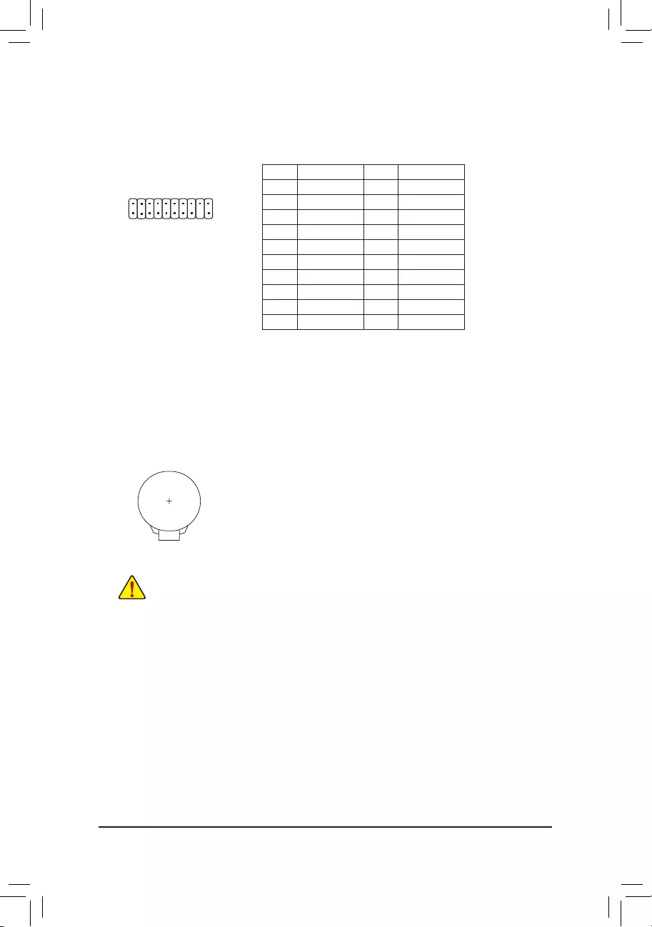
13) TPM (Trusted Platform Module Header)
YoumayconnectaTPM(TrustedPlatformModule)tothisheader.
20
19
2
1
Pin No. Denition Pin No. Denition
1 LCLK 11 LAD0
2GND 12 GND
3LFRAME 13 NC
4 No Pin 14 NC
5LRESET 15 SB3V
6 NC 16 SERIRQ
7LAD3 17 GND
8LAD2 18 NC
9 VCC3 19 NC
10 LAD1 20 NC
14) BAT (Battery)
Thebatteryprovidespowertokeepthevalues(suchasBIOScongurations,date,andtimeinformation)
intheCMOSwhenthecomputeristurnedoff.Replacethebatterywhenthebatteryvoltagedropstoalow
level, or the CMOS values may not be accurate or may be lost.
You may clear the CMOS values by removing the battery:
1. Turn off your computer and unplug the power cord.
2. Gently remove the battery from the battery holder and wait for one minute. (Or
use a metal object like a screwdriver to touch the positive and negative terminals
ofthebatteryholder,makingthemshortfor5seconds.)
3. Replacethebattery.
4. Plug in the power cord and restart your computer.
•Always turn off your computer and unplug the power cord before replacing the battery.
•Replacethebatterywithanequivalentone.Damagetoyourdevicesmayoccurifthebatteryis
replaced with an incorrect model.
•Contact the place of purchase or local dealer if you are not able to replace the battery by yourself
or uncertain about the battery model.
•Wheninstallingthebattery,notetheorientationofthepositiveside(+)andthenegativeside(-)
ofthebattery(thepositivesideshouldfaceup).
•Used batteries must be handled in accordance with local environmental regulations.
— 18 —
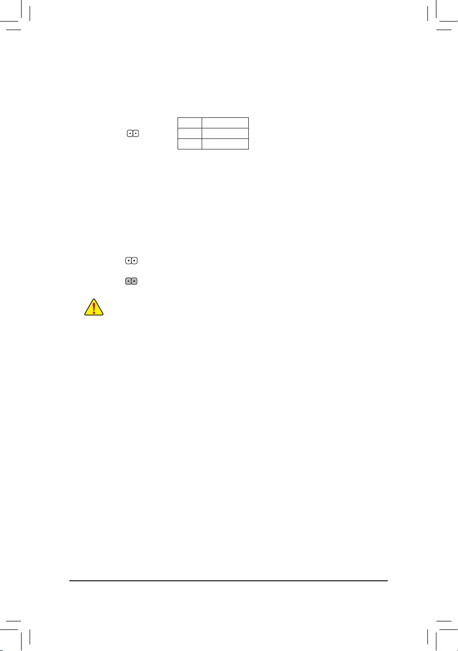
16) CLR_CMOS (Clear CMOS Jumper)
UsethisjumpertocleartheBIOScongurationandresettheCMOSvaluestofactorydefaults.Toclear
the CMOS values, use a metal object like a screwdriver to touch the two pins for a few seconds.
•Always turn off your computer and unplug the power cord from the power outlet before clearing
the CMOS values.
•Aftersystemrestart,gotoBIOSSetuptoloadfactorydefaults(selectLoadOptimizedDefaults)or
manuallyconguretheBIOSsettings(refertoChapter2,«BIOSSetup,»forBIOScongurations).
Open: Normal
Short: Clear CMOS Values
15) CI (Chassis Intrusion Header)
This motherboard provides a chassis detection feature that detects if the chassis cover has been removed.
This function requires a chassis with chassis intrusion detection design.
1
Pin No. Denition
1 Signal
2GND
— 19 —
Chapter 2 BIOS Setup
BIOS(Basic Input and Output System) records hardware parameters of the system in theCMOS on the
motherboard.ItsmajorfunctionsincludeconductingthePower-OnSelf-Test(POST)duringsystemstartup,
saving system parameters and loading operating system, etc. BIOS includes a BIOS Setup program that allows
theusertomodifybasicsystemcongurationsettingsortoactivatecertainsystemfeatures.
When the power is turned off, the battery on the motherboard supplies the necessary power to the CMOS to
keepthecongurationvaluesintheCMOS.
ToaccesstheBIOSSetupprogram,pressthe<Delete>keyduringthePOSTwhenthepoweristurnedon.
ToupgradetheBIOS,useeithertheGIGABYTEQ-Flashor@BIOSutility.
•Q-Flash allows the user to quickly and easily upgrade or back up BIOS without entering the operating system.
•@BIOSisaWindows-basedutilitythatsearchesanddownloadsthelatestversionofBIOSfromtheInternet
and updates the BIOS.
•BecauseBIOSashingispotentiallyrisky,ifyoudonotencounterproblemsusingthecurrentversionofBIOS,
itisrecommendedthatyounotashtheBIOS.ToashtheBIOS,doitwithcaution.InadequateBIOSashing
may result in system malfunction.
•Itisrecommendedthatyounotalterthedefaultsettings(unlessyouneedto)topreventsysteminstabilityorother
unexpected results. Inadequately altering the settings may result in system’s failure to boot. If this occurs, try to
cleartheCMOSvaluesandresettheboardtodefaultvalues.(Refertothe»LoadOptimizedDefaults»sectionin
thischapterorintroductionsofthebattery/clearCMOSjumperinChapter1forhowtocleartheCMOSvalues.)
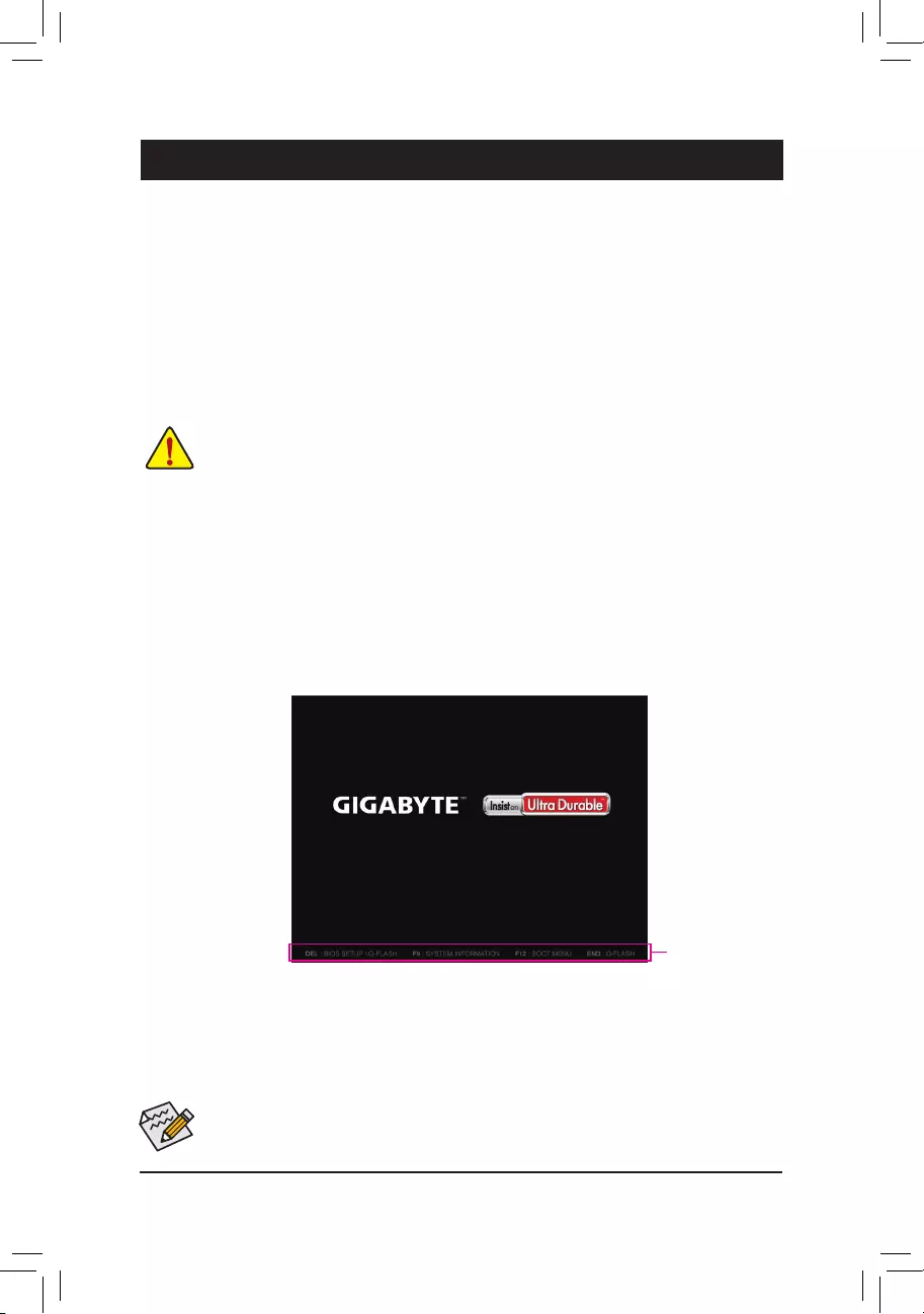
2-1 Startup Screen
The following startup Logo screen will appear when the computer boots.
(SampleBIOSVersion:F10d)
•When the system is not stable as usual, select the Load Optimized Defaults item to set your system to its defaults.
•The BIOS Setup menus described in this chapter are for reference only and may differ by BIOS version.
Function Keys
TherearetwodifferentBIOSmodesasfollowsandyoucanusethe<F2>keytoswitchbetweenthetwomodes.
The Classic Setup mode provides detailed BIOS settings. You can press the arrow keys on your keyboard to move
amongtheitemsandpress<Enter>toacceptorenterasub-menu.Oryoucanuseyourmousetoselectthe
item you want. Easy Mode allows users to quickly view their current system information or to make adjustments
foroptimumperformance.InEasyMode,youcanuseyourmousetomovethroughcongurationitems.
— 20 —
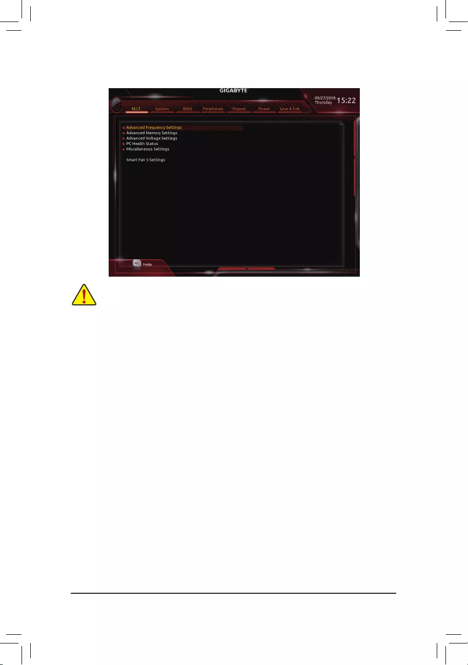
2-2 M.I.T.
Whether the system will work stably with the overclock/overvoltage settings you made is dependent on your overall
systemcongurations.Incorrectlydoingoverclock/overvoltagemayresultindamagetoCPU,chipset,ormemory
and reduce the useful life of these components. This page is for advanced users only and we recommend you not to
alter the default settings to prevent system instability or other unexpected results. (Inadequately altering the settings
mayresultinsystem’sfailuretoboot.Ifthisoccurs,cleartheCMOSvaluesandresettheboardtodefaultvalues.)
`Advanced Frequency Settings
&Host Clock Value
DisplaysthecurrentoperatingHostClockfrequency.
&CPU Clock Ratio
Allows you to alter the clock ratio for the installed CPU. The adjustable range is dependent on the CPU
being installed.
&CPU Frequency
DisplaysthecurrentoperatingCPUfrequency.
`Advanced CPU Core Settings
&CPU Clock Ratio, CPU Frequency
The settings above are synchronous to those under the same items on the Advanced Frequency Settings
menu.
&Core Performance Boost (Note)
Allowsyou to determine whether to enable theCore Performance Boost (CPB) technology,a CPU
performance-boosttechnology.(Default:Auto)
&Core Performance Boost Ratio (Note)
Allows you alter the ratio for the CPB. The adjustable range is dependent on the CPU being installed.
(Default:Auto)
&Turbo Performance Boost Ratio (Note)
AllowsyoutodeterminewhethertoimproveCPUperformance.(Default:Disabled)
(Note) ThisitemispresentonlywhenyouinstallaCPUthatsupportsthisfeature.
— 21 —

(Note1) ThisitemispresentonlywhenyouinstallaCPUthatsupportsthisfeature.
(Note2) ThisitemispresentonlywhenyouinstallaCPUandamemorymodulethatsupportthisfeature.
&AMD Cool&Quiet function
Enabled LetstheAMDCool’n’QuietdriverdynamicallyadjusttheCPUclockandVIDto
reduceheatoutputfromyourcomputeranditspowerconsumption.(Default)
Disabled Disablesthisfunction.
&SVM Mode
VirtualizationenhancedbyVirtualizationTechnologywillallowaplatformtorunmultipleoperatingsystems
andapplicationsinindependentpartitions.Withvirtualization,onecomputersystemcanfunctionasmultiple
virtualsystems.(Default:Disabled)
&C6 Mode
(Note 1)
Allows you to determine whether to let the CPU enter C6 mode in system halt state. When enabled, the
CPU core frequency will be reduced during system halt state to decrease power consumption. The C6
stateisamoreenhancedpower-savingstatethanC1.(Default:Enabled)
&Global C-state Control
(Note 1)
Allows you to determine whether to let the CPU enter C states. When enabled, the CPU core frequency
willbereducedduringsystemhaltstatetodecreasepowerconsumption.(Default:Enabled)
&Power Supply Idle Control
Enables or disables Package C6 State.
TypicalCurrentIdle Disablesthisfunction.
Low Current Idle Enables this function.
Auto LetstheBIOSautomaticallycongurethissetting. (Default)
&Opcache Control
(Note 1)
Enables or disables Opcache. AutoletstheBIOSautomaticallycongurethissetting.(Default:Auto)
&Downcore Control
(Note 1)
AllowsyoutoselectthenumberofCPUcorestoenable(thenumberofCPUcoresmayvarybyCPU).
AutoletstheBIOSautomaticallycongurethissetting.(Default:Auto)
&SMT Mode
(Note 1)
Allows you to enable or disable the CPU Simultaneous Multi-Threading technology. This feature only works
for operating systems that support multi-processor mode. AutoletstheBIOSautomaticallycongurethis
setting.(Default:Auto)
&ExtremeMemoryProle(X.M.P.)(Note 2)
AllowstheBIOStoreadtheSPDdataonXMPmemorymodule(s)toenhancememoryperformancewhen
enabled.
Disabled Disablesthisfunction.(Default)
Prole1 UsesProle1settings.
Prole2(Note2) UsesProle2settings.
&System Memory Multiplier
Allows you to set the system memory multiplier. Auto setsmemorymultiplieraccordingtomemorySPD
data.(Default:Auto)
&Memory Frequency (MHz)
Therstmemoryfrequencyvalueisthenormaloperatingfrequencyofthememorybeingused;thesecond
is the memory frequency that is automatically adjusted according to the System Memory Multiplier settings.
— 22 —

`Advanced Memory Settings
&
ExtremeMemoryProle(X.M.P.)
(Note
2
)
, System Memory Multiplier, Memory Frequency(Mhz)
The settings above are synchronous to those under the same items on the Advanced Frequency Settings
menu.
&Memory Timing Mode
Manual and Advanced Manual allows the Channel Interleaving, Rank Interleaving, and memory timing
settingsbelowtobecongurable.Optionsare:Auto(default),Manual,AdvancedManual.
&ProleDDRVoltage
When using a non-XMP memory module or ExtremeMemoryProle(X.M.P.) is set to Disabled, the value
isdisplayedaccordingtoyourmemoryspecication.WhenExtremeMemoryProle(X.M.P.) is set to
Prole1 or Prole2,thevalueisdisplayedaccordingtotheSPDdataontheXMPmemory.
` Standard Timing Control, Advanced Timing Control, CAD Bus Setup Timing, CAD Bus
DriveStrength,DataBusConguration
Thesesectionsprovidememorytimingsettings.Therespectivetimingsettingscreensarecongurable
only when Memory Timing Mode is set to Manual. Note: Your system may become unstable or fail to boot
after you make changes on the memory timings. If this occurs, please reset the board to default values by
loadingoptimizeddefaultsorclearingtheCMOSvalues.
`Advanced Voltage Settings
This sub-menu allows you to set CPU, chipset and memory voltages.
`PC Health Status
&Reset Case Open Status
Disabled Keepsorclearstherecordofpreviouschassisintrusionstatus.(Default)
Enabled Clears the record of previous chassis intrusion status and the Case Openeldwill
show»No»atnextboot.
&Case Open
DisplaysthedetectionstatusofthechassisintrusiondetectiondeviceattachedtothemotherboardCI
header.Ifthesystemchassiscoverisremoved,thiseldwillshow«Yes»,otherwiseitwillshow«No».To
clear the chassis intrusion status record, set Reset Case Open Status to Enabled, save the settings to
the CMOS, and then restart your system.
& CPU Vcore/CPU VDDP/DRAM Channel A/B Voltage/+3.3V/+5V/+12V/VCORE SOC
Displaysthecurrentsystemvoltages.
`Miscellaneous Settings
&PCIeSlotConguration
Allows you to set the operation mode of the PCI Express slots to Gen 1, Gen 2, or Gen 3. Actual operation
modeissubjecttothehardwarespecicationofeachslot.AutoletstheBIOSautomaticallycongurethis
setting.(Default:Auto)
&3DMark01 Enhancement
Allowsyoutodeterminewhethertoenhancesomelegacybenchmarkperformance.(Default:Disabled)
— 23 —

`Smart Fan 5 Settings
&Monitor
Allowsyoutoselectatargettomonitorandtomakefurtheradjustment.(Default:CPUFAN)
&Fan Speed Control
Allows you to determine whether to enable the fan speed control function and adjust the fan speed.
Normal Allows the fan to run at different speeds according to the temperature. You can adjust
the fan speed with System Information Viewer based on your system requirements.
(Default)
Silent Allows the fan to run at slow speeds.
Manual Allows you to control the fan speed in the curve graph.
Full Speed Allows the fan to run at full speeds.
&Fan Control Use Temperature Input
Allows you to select the reference temperature for fan speed control.
&Temperature Interval
Allows you to select the temperature interval for fan speed change.
&Fan Control Mode
Auto Lets the BIOS automatically detect the type of fan installed and sets the optimal control
mode.(Default)
Voltage Voltage mode is recommended for a 3-pin fan.
PWM PWM mode is recommended for a 4-pin fan.
&Temperature
Displaysthecurrenttemperatureoftheselectedtargetarea.
&Fan Speed
Displayscurrentfanspeeds.
&Flow Rate
Displaystheowrateofyourwatercoolingsystem.
&Temperature Warning
Sets the warning threshold for temperature. When temperature exceeds the threshold, BIOS will emit
warningsound.Optionsare:Disabled(default),60oC/140oF, 70oC/158oF, 80oC/176oF, 90oC/194oF.
&Fan Fail Warning
Allows the system to emit warning sound if the fan is not connected or fails. Check the fan condition or fan
connectionwhenthisoccurs.(Default:Disabled)
— 24 —
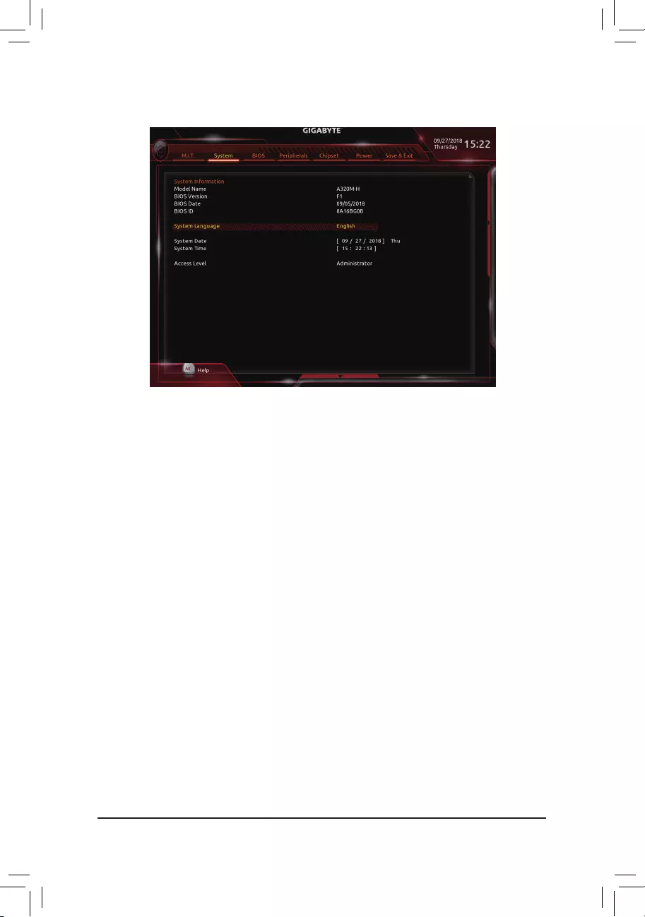
2-3 System
This section provides information on your motherboard model and BIOS version. You can also select the default
language used by the BIOS and manually set the system time.
&System Language
Selects the default language used by the BIOS.
&System Date
Setsthesystemdate.Thedateformatisweek(read-only),month,date,andyear.Use<Enter>toswitch
betweentheMonth,Date,andYeareldsandusethe<PageUp>or<PageDown>keytosetthedesired
value.
&System Time
Sets the system time. The time format is hour, minute, and second. For example, 1 p.m. is 13:00:00. Use
<Enter>toswitchbetweentheHour,Minute,andSecondeldsandusethe<PageUp>or<PageDown>
key to set the desired value.
&Access Level
Displaysthecurrentaccessleveldependingonthetypeofpasswordprotectionused.(Ifnopasswordis
set, the default will display as Administrator.)TheAdministratorlevelallowsyoutomakechangestoall
BIOS settings; the User level only allows you to make changes to certain BIOS settings but not all.
— 25 —
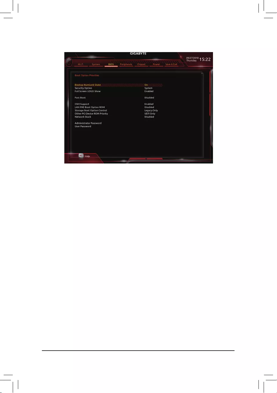
&Boot Option Priorities
Speciestheoverallbootorderfromtheavailabledevices.RemovablestoragedevicesthatsupportGPT
formatwillbeprexedwith«UEFI:»stringonthebootdevicelist.Tobootfromanoperatingsystemthat
supportsGPTpartitioning,selectthedeviceprexedwith»UEFI:»string.
Or if you want to install an operating system that supports GPT partitioning such as Windows 10 64-bit,
selecttheopticaldrivethatcontainstheWindows1064-bitinstallationdiskandisprexedwith«UEFI:»
string.
&Hard Drive/CD/DVD ROM Drive/Floppy Drive/Network Device BBS Priorities
Speciesthebootorderforaspecicdevicetype,suchasharddrives,opticaldrives,oppydiskdrives,
anddevicesthatsupportBootfromLANfunction,etc.Press<Enter>onthisitemtoenterthesubmenuthat
presents the devices of the same type that are connected. This item is present only if at least one device
for this type is installed.
&Bootup NumLock State
EnablesordisablesNumlockfeatureonthenumerickeypadofthekeyboardafterthePOST.(Default:On)
&Security Option
Specieswhetherapasswordisrequiredeverytimethesystemboots,oronlywhenyouenterBIOSSetup.
Afterconguringthisitem,setthepassword(s)undertheAdministrator Password/User Password item.
Setup A password is only required for entering the BIOS Setup program.
System A password is required for booting the system and for entering the BIOS Setup
program.(Default)
&Full Screen LOGO Show
Allows you to determine whether to display the GIGABYTE Logo at system startup. Disabled skips the
GIGABYTELogowhenthesystemstartsup.(Default:Enabled)
2-4 BIOS
— 26 —

&Fast Boot
Enables or disables Fast Boot to shorten the OS boot process. Ultra Fast provides the fastest bootup
speed.(Default:Disabled)
&SATA Support
AllSataDevices AllSATAdevicesarefunctionalintheoperatingsystemandduringthePOST.
LastBootHDDOnly Exceptforthepreviousbootdrive,allSATAdevicesaredisabledbeforetheOS
bootprocesscompletes.(Default)
ThisitemiscongurableonlywhenFast Boot is set to Enabled or Ultra Fast.
&VGA Support
Allows you to select which type of operating system to boot.
Auto EnableslegacyoptionROMonly.
EFIDriver EnablesEFIoptionROM.(Default)
ThisitemiscongurableonlywhenFast Boot is set to Enabled or Ultra Fast.
&USB Support
Disabled AllUSBdevicesaredisabledbeforetheOSbootprocesscompletes.
Full Initial All USB devices are functional in the operating system and during the POST.
(Default)
Partial Initial Part of the USB devices are disabled before the OS boot process completes.
ThisitemiscongurableonlywhenFast Boot is set to Enabled. This function is disabled when Fast Boot
is set to Ultra Fast.
&PS2 Devices Support
Disabled AllPS/2devicesaredisabledbeforetheOSbootprocesscompletes.
Enabled All PS/2 devices are functional in the operating system and during the POST.
(Default)
ThisitemiscongurableonlywhenFast Boot is set to Enabled. This function is disabled when Fast Boot
is set to Ultra Fast.
&NetWork Stack Driver Support
Disabled Disablesbootingfromthenetwork.(Default)
Enabled Enables booting from the network.
ThisitemiscongurableonlywhenFast Boot is set to Enabled or Ultra Fast.
&CSM Support
EnablesordisablesUEFICSM(CompatibilitySupportModule)tosupportalegacyPCbootprocess.
Enabled EnablesUEFICSM.(Default)
Disabled DisablesUEFICSMandsupportsUEFIBIOSbootprocessonly.
&LAN PXE Boot Option ROM
AllowsyoutoselectwhethertoenablethelegacyoptionROMfortheLANcontroller.(Default:Disabled)
ThisitemiscongurableonlywhenCSM Support is set to Enabled.
&Storage Boot Option Control
AllowsyoutoselectwhethertoenabletheUEFIorlegacyoptionROMforthestoragedevicecontroller.
Disabled DisablesoptionROM.
UEFIOnly EnablesUEFIoptionROMonly.
LegacyOnly EnableslegacyoptionROMonly.(Default)
ThisitemiscongurableonlywhenCSM Support is set to Enabled.
— 27 —

&Other PCI Device ROM Priority
AllowsyoutoselectwhethertoenabletheUEFIorLegacyoptionROMforthePCIdevicecontrollerother
than the LAN, storage device, and graphics controllers.
Disabled DisablesoptionROM.
UEFIOnly EnablesUEFIoptionROMonly.(Default)
LegacyOnly EnableslegacyoptionROMonly.
ThisitemiscongurableonlywhenCSM Support is set to Enabled.
&Network Stack
DisablesorenablesbootingfromthenetworktoinstallaGPTformatOS,suchasinstallingtheOSfrom
theWindowsDeploymentServicesserver.(Default:Disabled)
&Ipv4 PXE Support
EnablesordisablesIPv4PXESupport.ThisitemiscongurableonlywhenNetwork Stack is enabled.
&Ipv4 HTTP Support
EnablesordisablesHTTPbootsupportforIPv4.ThisitemiscongurableonlywhenNetwork Stack is
enabled.
&Ipv6 PXE Support
EnablesordisablesIPv6PXESupport.ThisitemiscongurableonlywhenNetwork Stack is enabled.
&Ipv6 HTTP Support
EnablesordisablesHTTPbootsupportforIPv6.ThisitemiscongurableonlywhenNetwork Stack is
enabled.
&IPSECCerticate
Enablesordisables Internet Protocol Security.Thisitem is congurable onlywhen Network Stack is
enabled.
&Administrator Password
Allowsyoutocongureanadministratorpassword.Press<Enter>onthisitem,typethepassword,and
thenpress<Enter>.Youwillberequestedtoconrmthepassword.Typethepasswordagainandpress
<Enter>.Youmustentertheadministratorpassword(oruserpassword)atsystemstartupandwhenentering
BIOSSetup.Differingfromtheuserpassword,theadministratorpasswordallowsyoutomakechangesto
all BIOS settings.
&User Password
Allowsyoutocongureauserpassword.Press<Enter>onthisitem,typethepassword,andthenpress
<Enter>.Youwillberequestedtoconrmthepassword.Typethepasswordagainandpress<Enter>.
Youmustentertheadministratorpassword(oruserpassword)atsystemstartupandwhenenteringBIOS
Setup. However, the user password only allows you to make changes to certain BIOS settings but not all.
Tocancelthepassword,press<Enter>onthepassworditemandwhenrequestedforthepassword,enter
thecorrectonerst.Whenpromptedforanewpassword,press<Enter>withoutenteringanypassword.
Press<Enter>againwhenpromptedtoconrm.
NOTE:BeforesettingtheUserPassword,besuretosettheAdministratorPasswordrst.
&Secure Boot
AllowsyoutoenableordisableSecureBootandcongurerelatedsettings.Thisitemiscongurableonly
when CSM Support is set to Disabled.
— 28 —
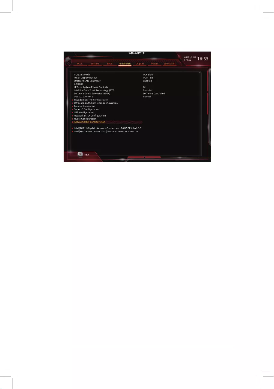
2-5 Peripherals
&AMD CPU fTPM
EnablesordisablestheTPM2.0functionintegratedintheAMDCPU.(Default:Disabled)
&Initial Display Output (Note)
SpeciestherstinitiationofthemonitordisplayfromtheinstalledPCIExpressgraphicscardortheonboard
graphics.
IGDVideo Setstheonboardgraphicsastherstdisplay.
PCIe1Slot SetsthegraphicscardonthePCIEX16slotastherstdisplay.(Default)
&Legacy USB Support
AllowsUSBkeyboard/mousetobeusedinMS-DOS.(Default:Enabled)
&XHCI Hand-off
Determineswhether toenable XHCIHand-offfeature foran operatingsystem withoutXHCI Hand-off
support.(Default:Enabled)
&EHCI Hand-off
Determineswhether toenable EHCIHand-offfeature foran operatingsystem withoutEHCI Hand-off
support.(Default:Disabled)
&Port 60/64 Emulation
Enables or disables emulation of I/O ports 64h and 60h. This should be enabled for full legacy support
forUSBkeyboards/miceinMS-DOSorinoperatingsystemthatdoesnotnativelysupportUSBdevices.
(Default:Disabled)
&USB Mass Storage Driver Support
EnablesordisablessupportforUSBstoragedevices.(Default:Enabled)
&USB Storage Devices
DisplaysalistofconnectedUSBmassstoragedevices.ThisitemappearsonlywhenaUSBstoragedevice
is installed.
(Note) ThisitemispresentonlywhenyouinstallaCPUthatsupportsthisfeature.
— 29 —
&HD Audio Controller
Enablesordisablestheonboardaudiofunction.(Default:Enabled)
If you wish to install a 3rd party add-in audio card instead of using the onboard audio, set this item to
Disabled.
&Above 4G Decoding
Enables or disables 64-bit capable devices to be decoded in above 4 GB address space (only if your system
supports64-bitPCIdecoding).SettoEnabledifmorethanoneadvancedgraphicscardareinstalledand
their drivers are not able to be launched when entering the operating system (because of the limited 4 GB
memoryaddressspace).(Default:Disabled)
`Trusted Computing
EnablesordisablesTrustedPlatformModule(TPM).
`AMD CBS
Thissub-menuprovidesAMDCBS-relatedcongurationoptions.
`Realtek PCIe GBE Family Controller
Thissub-menuprovidesinformationonLANcongurationandrelatedcongurationoptions.
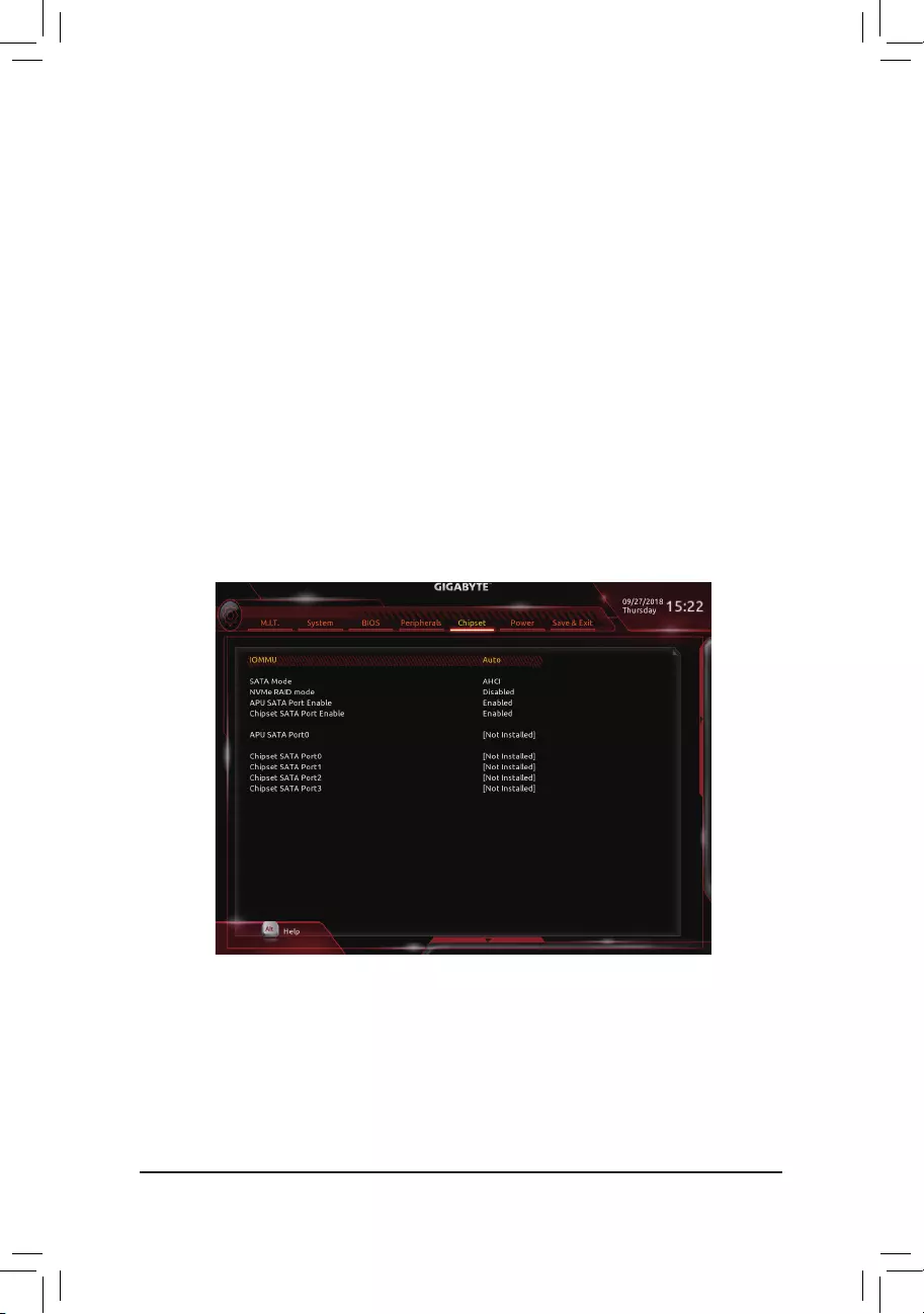
2-6 Chipset
&IOMMU
EnablesordisablesAMDIOMMUsupport.(Default:Auto)
&Integrated Graphics (Note)
Enables or disables the onboard graphics function.
Auto The BIOS will automatically enable or disable the onboard graphics depending on the
graphicscardbeinginstalled.(Default)
Disabled Disablestheonboardgraphics.
(Note) ThisitemispresentonlywhenyouinstallaCPUthatsupportsthisfeature.
— 30 —

(Note) ThisitemispresentonlywhenyouinstallaCPUthatsupportsthisfeature.
&UMA Frame Buffer Size (Note)
Framebuffersizeisthetotalamountofsystemmemoryallocatedsolelyfortheonboardgraphicscontroller.
MS-DOS,forexample,willuseonlythismemoryfordisplay.Optionsare:Auto(default),32M,64M,128M,
256M, 512M, 1G, 2G.
&SATA Mode
EnablesordisablesRAIDfortheSATAcontrollersintegratedintheChipsetorcongurestheSATAcontrollers
to AHCI mode.
RAID EnablesRAIDfortheSATAcontroller.
AHCI CongurestheSATAcontrollerstoAHCImode.AdvancedHostControllerInterface
(AHCI)isaninterfacespecicationthatallowsthestoragedrivertoenableadvanced
SerialATAfeaturessuchasNativeCommandQueuingandhotplug.(Default)
&NVMe RAID mode (M2F_32G Connector)
AllowsyoutodeterminewhethertouseyourM.2NVMePCIeSSDstocongureRAID.(Default:Disabled)
&APU SATA Port Enable (M2F_32G Connector)
EnablesordisablestheSATAcontrollerintegratedintheCPU.(Default:Enabled)
&Chipset SATA Port Enable (SATA3 0, 1, 2, 3 Connectors)
EnablesordisablestheSATAcontrollerintegratedintheChipset.(Default:Enabled)
&APU SATA Port 0 (M2F_32G Connector)
DisplaystheinformationoftheconnectedM.2SATAdevice.TheinformationappearsonlywhenanM.2
SATA device is installed.
&Chipset SATA Port 0/1/2/3 (SATA3 0, 1, 2, 3 Connectors)
DisplaystheinformationoftheconnectedSATAdevice(s).
— 31 —
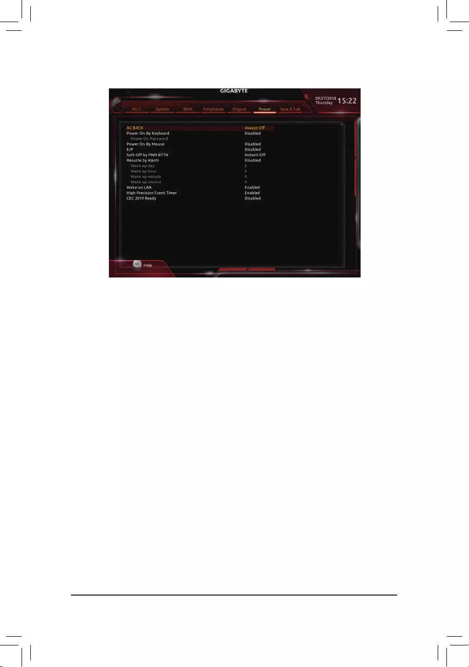
&AC BACK
DeterminesthestateofthesystemafterthereturnofpowerfromanACpowerloss.
Memory The system returns to its last known awake state upon the return of the AC power.
Always On The system is turned on upon the return of the AC power.
AlwaysOff ThesystemstaysoffuponthereturnoftheACpower.(Default)
&Power On By Keyboard
Allows the system to be turned on by a PS/2 keyboard wake-up event.
Note: To use this function, you need an ATX power supply providing at least 1A on the +5VSB lead.
Disabled Disablesthisfunction.(Default)
Password Set a password with 1~5 characters to turn on the system.
Keyboard98 PressPOWERbuttonontheWindows98keyboardtoturnonthesystem.
Any key Press any key to turn on the system.
&Power On Password
Set the password when Power On By Keyboard is set to Password.
Press<Enter>onthisitemandsetapasswordwithupto5charactersandthenpress<Enter>toaccept.
Toturnonthesystem,enterthepasswordandpress<Enter>.
Note:Tocancelthepassword,press<Enter>onthisitem.Whenpromptedforthepassword,press<Enter>
again without entering the password to clear the password settings.
&Power On By Mouse
Allows the system to be turned on by a PS/2 mouse wake-up event.
Note: To use this function, you need an ATX power supply providing at least 1A on the +5VSB lead.
Disabled Disablesthisfunction.(Default)
Move Move the mouse to turn on the system.
DoubleClick Doubleclickonleftbuttononthemousetoturnonthesystem.
2-7 Power
— 32 —

&ErP
DetermineswhethertoletthesystemconsumeleastpowerinS5(shutdown)state.Note:Whenthisitem
is set to Enabled,thefollowingfunctionswillbecomeunavailable:ResumebyAlarm,poweronbymouse,
and power on by keyboard.
&Soft-Off by PWR-BTTN
ConguresthewaytoturnoffthecomputerinMS-DOSmodeusingthepowerbutton.
Instant-Off Pressthepowerbuttonandthenthesystemwillbeturnedoffinstantly.(Default)
Delay4Sec. Pressandholdthepowerbuttonfor4secondstoturnoffthesystem.Ifthepower
button is pressed for less than 4 seconds, the system will enter suspend mode.
&Resume by Alarm
Determineswhethertopoweronthesystematadesiredtime.(Default:Disabled)
If enabled, set the date and time as following:
Wakeupday:Turnonthesystemataspecictimeoneachdayoronaspecicdayinamonth.
Wake up hour/minute/second: Set the time at which the system will be powered on automatically.
Note: When using this function, avoid inadequate shutdown from the operating system or removal of the
AC power, or the settings may not be effective.
&Wake on LAN
EnablesordisablesthewakeonLANfunction.(Default:Enabled)
&High Precision Event Timer
EnablesordisablesHighPrecisionEventTimer(HPET)intheoperatingsystem.(Default:Enabled)
&CEC 2019 Ready
Allows you to select whether to allow the system to adjust power consumption when it is in shutdown, idle,
orstandbystateinordertocomplywiththeCEC(CaliforniaEnergyCommission)2019Standards.(Default:
Disabled)
— 33 —
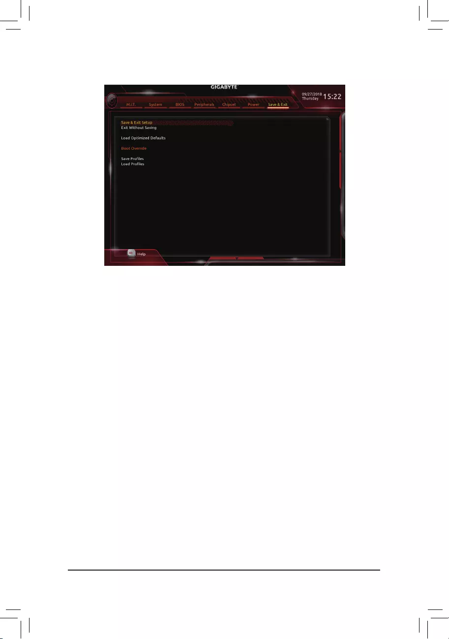
2-8 Save & Exit
&Save & Exit Setup
Press<Enter>onthisitemandselectYes. This saves the changes to the CMOS and exits the BIOS Setup
program. Select Noorpress<Esc>toreturntotheBIOSSetupMainMenu.
&Exit Without Saving
Press<Enter>onthisitemandselectYes. This exits the BIOS Setup without saving the changes made
in BIOS Setup to the CMOS. Select Noorpress<Esc>toreturntotheBIOSSetupMainMenu.
&Load Optimized Defaults
Press<Enter>onthisitemandselectYes to load the optimal BIOS default settings. The BIOS defaults
settingshelpthesystemtooperateinoptimumstate.AlwaysloadtheOptimizeddefaultsafterupdating
the BIOS or after clearing the CMOS values.
&Boot Override
Allowsyoutoselectadevicetobootimmediately.Press<Enter>onthedeviceyouselectandselectYes
toconrm.Yoursystemwillrestartautomaticallyandbootfromthatdevice.
&SaveProles
ThisfunctionallowsyoutosavethecurrentBIOSsettingstoaprole.Youcancreateupto8prolesand
saveasSetupProle1~SetupProle8.Press<Enter>tocomplete.OryoucanselectSelect File in
HDD/FDD/USBtosavetheproletoyourstoragedevice.
&LoadProles
If your system becomes unstable and you have loaded the BIOS default settings, you can use this function
toloadtheBIOSsettingsfromaprolecreatedbefore, withoutthehasslesofreconguringtheBIOS
settings.Firstselecttheproleyouwishtoloadandthenpress<Enter>tocomplete.YoucanselectSelect
File in HDD/FDD/USBtoinputtheprolepreviouslycreatedfromyourstoragedeviceorloadtheprole
automatically created by the BIOS, such as reverting the BIOS settings to the last settings that worked
properly(lastknowngoodrecord).
— 34 —
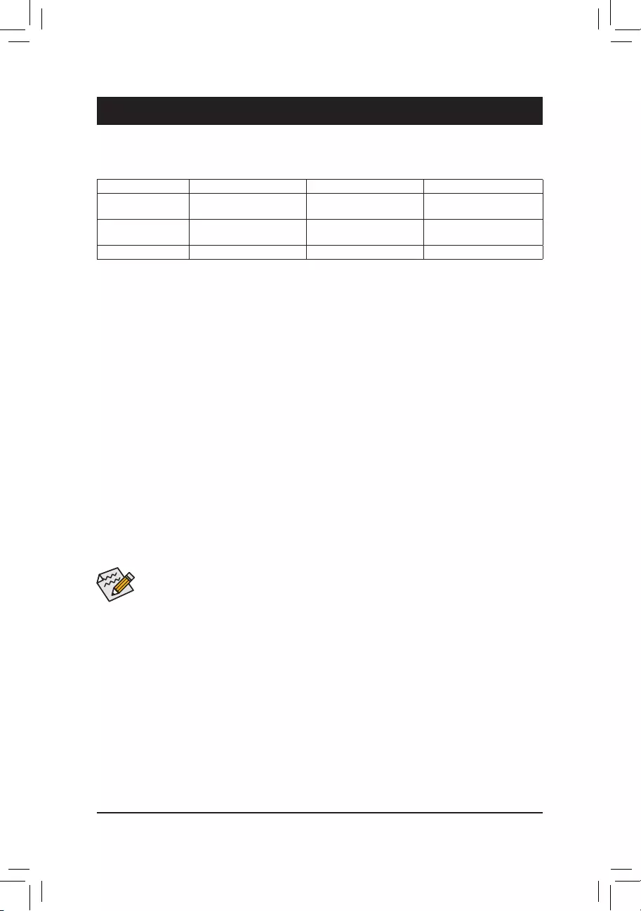
Chapter 3 Appendix
3-1 ConguringaRAIDSet
RAID Levels
Before you begin, please prepare the following items:
•AtleasttwoSATAharddrivesorM.2SATASSDs.(Toensureoptimalperformance,itisrecommendedthat
youusetwoharddriveswithidenticalmodelandcapacity).
•Windows setup disk.
•Motherboard driver disk.
•A USB thumb drive.
ConguringtheOnboardSATAController
A. Installing SATA hard drive(s) in your computer
Installtheharddrives/SSDsintheSATA/M.2connectorsonthemotherboard.Thenconnectthepowerconnectors
from your power supply to the hard drives.
B.ConguringSATAcontrollermodeinBIOSSetup
MakesuretoconguretheSATAcontrollermodecorrectlyinsystemBIOSSetup.
Steps:
1. Turnonyourcomputerandpress<Delete>toenterBIOSSetupduringthePOST(Power-OnSelf-Test).
Under Chipset, ensure APU SATA Port Enable and Chipset SATA Port Enable are enabled. Set SATA
Mode to RAID. Then save the settings and restart your computer.
2. IfyouwanttocongureUEFIRAID,followthestepsin«C-1.»ToenterthelegacyRAIDROM,savethe
settingsandexitBIOSSetup.Referto»C-2″formoreinformation.
The BIOS Setup menus described in this section may differ from the exact settings for your motherboard.
The actual BIOS Setup menu options you will see shall depend on the motherboard you have and
the BIOS version.
RAID 0 RAID 1 RAID 10
Minimum Number of
HardDrives ≥2 2 4
Array Capacity Number of hard drives *
Sizeofthesmallestdrive Sizeofthesmallestdrive (Numberofharddrives/2)*
Sizeofthesmallestdrive
Fault Tolerance No Yes Yes
C-1.UEFIRAIDConguration
OnlyWindows1064-bitsupportsUEFIRAIDconguration.
Steps:
1. In BIOS Setup, go to BIOS and set CSM Support to Disabled. Save the changes and exit BIOS Setup.
2. After the system reboot, enter BIOS Setup again. Then enter the PeripheralsRAIDXpert2Conguration
Utility sub-menu.
3. On the RAIDXpert2CongurationUtilityscreen,press<Enter>on Array Management to enter the Create
Array screen. Then, select a RAID level.RAIDlevelssupportedincludeRAID0(Stripe),RAID1(Mirror),
andRAID10(theselectionsavailabledependonthenumberoftheharddrivesbeinginstalled).Next,press
<Enter>onSelect Physical Disks to enter the Select Physical Disks screen.
— 35 —

C-2.ConguringLegacyRAIDROM
EnterthelegacyRAIDBIOSsetuputilitytocongureaRAIDarray.Skipthisstepandproceedwiththeinstallation
ofWindowsoperatingsystemforanon-RAIDconguration.
Steps:
1. After the POST memory test begins and before the operating system boot begins, look for a message which
says«Press<Ctrl-F>toenterRAIDOptionROMUtility».Press<Ctrl>+<R>toentertheRAIDBIOSsetuputility.
2. Tocreateanewarray,press<Enter>ontheCreateArrayoption.
3. The selection bar will move to the Disks section on the right of the screen. Select the hard drives to be
includedintheRAIDarray.Usetheupordownarrowkeytoselectaharddriveandpress<Insert>.The
selectedharddrivewillbeshowningreen.Tousealloftheharddrives,simplypress<A>toselectall.Then
press<Enter>andtheselectionbarwillmovetotheUser Input section on the left bottom of the screen.
4. First,selectaRAIDmodeandpress<Enter>.Theselectionsavailabledependonthenumberoftheharddrives
beinginstalled.Thenfollowtheon-screeninstructionstospecifythearraysize.YoucanselectAll available
spacetousethemaximumsizeallowedorusetheupordownarrowkeytoadjustthesizeandpress<Enter>.
5. Selectacachingmode.OptionsincludeRead/Write,ReadOnly,andNone.Thenpress<Enter>toproceed.
6. Finally,amessagewhichsays«ConrmCreationofArray»willappear.Press<C>toconrmor<Esc>to
return to the previous screen.
7. Whencompleted,youwillseethenewarrayonthemainscreen.ToexittheRAIDBIOSutility,press<Esc>
andthenpress<C>toconrm.
Installing the SATA RAID/AHCI Driver and Operating System
With the correct BIOS settings, you are ready to install the operating system.
Installing the Operating System
AssomeoperatingsystemsalreadyincludeSATARAID/AHCIdriver,youdonotneedtoinstallseparateRAID/
AHCI driver during the Windows installation process. After the operating system is installed, we recommend
thatyouinstallallrequireddriversfromthemotherboarddriverdiskusing«XpressInstall»toensuresystem
performance and compatibility. If the operating system to be installed requires that you provide additional SATA
RAID/AHCIdriverduringtheOSinstallationprocess,pleaserefertothestepsbelow:
1. Copy the Hw10 folder under the Boot folder in the driver disk to your USB thumb drive.
2. Boot from the Windows setup disk and perform standard OS installation steps. When the screen requesting
you to load the driver appears, select Browse.
3. Insert the USB thumb drive and then browse to the location of the driver. The location of the driver is as
follows:
Hw10RAIDx64
4. Select AMD-RAID Bottom DevicerstandclickNext to load the driver. Then select AMD-RAID Controller
and click Next to load the driver. Finally, continue the OS installation.
PleasevisitGIGABYTE’swebsitefordetailsonconguringaRAIDarray.
4. On the Select Physical Disksscreen,selecttheharddrivestobeincludedintheRAIDarrayandsetthem
to Enabled. Next, use the down arrow key to move to Apply Changesandpress<Enter>.Thenreturnto
the previous screen and set the Array Size, Array Size Unit, Read Cache Policy and Write Cache Policy.
5. After setting the capacity, move to Create Arrayandpress<Enter>tobegin.
6. After completing, you’ll be brought back to the Array Management screen. Under Manage Array Properties
youcanseethenewRAIDvolumeandinformationonRAIDlevel,arrayname,arraycapacity,etc.
— 36 —
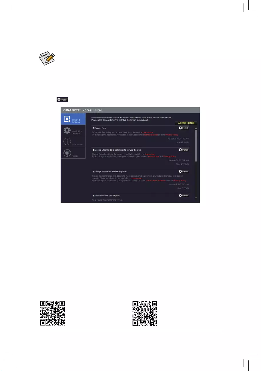
Please visit GIGABYTE’s website for
more software information.
•Beforeinstalling thedrivers, rst install the operating system. (The following instructions use
Windows10astheexampleoperatingsystem.)
•After installing the operating system, insert the motherboard driver disk into your optical drive. Click
onthemessage»Taptochoosewhathappenswiththisdisc»onthetop-rightcornerofthescreen
andselect»RunRun.exe.»(OrgotoMyComputer,double-clicktheopticaldriveandexecutethe
Run.exeprogram.)
3-2 Drivers Installation
«XpressInstall»willautomaticallyscanyoursystemandthenlistallofthedriversthatarerecommendedto
install. You can click the Xpress Installbuttonand«XpressInstall»willinstallalloftheselecteddrivers.Orclick
the arrow icon to individually install the drivers you need.
Please visit GIGABYTE’s website for
more troubleshooting information.
— 37 —
Regulatory Statements
Regulatory Notices
This document must not be copied without our written permission, and the contents there of must not be imparted to a
thirdpartynorbeusedforanyunauthorizedpurpose.
Contravention will be prosecuted. We believe that the information contained herein was accurate in all respects at the
time of printing. GIGABYTE cannot, however, assume any responsibility for errors or omissions in this text. Also note
that the information in this document is subject to change without notice and should not be construed as a commitment
by GIGABYTE.
Our Commitment to Preserving the Environment
Inadditiontohigh-efciencyperformance,allGIGABYTEmotherboardsfulllEuropeanUnionregulationsforRoHS
(RestrictionofCertainHazardousSubstancesinElectricalandElectronicEquipment)andWEEE(WasteElectricaland
ElectronicEquipment)environmentaldirectives,aswellasmostmajorworldwidesafetyrequirements.Topreventreleases
ofharmfulsubstancesintotheenvironmentandtomaximizetheuseofournaturalresources,GIGABYTEprovidesthe
followinginformationonhowyoucanresponsiblyrecycleorreusemostofthematerialsinyour»endoflife»product.
Restriction of Hazardous Substances (RoHS) Directive Statement
GIGABYTEproductshavenotintendedtoaddandsafefromhazardoussubstances(Cd,Pb,Hg,Cr+6,PBDEand
PBB).ThepartsandcomponentshavebeencarefullyselectedtomeetRoHSrequirement.Moreover,weatGIGABYTE
are continuing our efforts to develop products that do not use internationally banned toxic chemicals.
Waste Electrical & Electronic Equipment (WEEE) Directive Statement
GIGABYTEwillfulllthenationallawsasinterpretedfromthe2002/96/ECWEEE(WasteElectricalandElectronic
Equipment)directive.TheWEEEDirectivespeciesthetreatment,collection,recyclinganddisposalofelectricand
electronicdevicesandtheircomponents.UndertheDirective,usedequipmentmustbemarked,collectedseparately,
and disposed of properly.
WEEE Symbol Statement
The symbol shown below is on the product or on its packaging, which indicates that this product must
not be disposed of with other waste. Instead, the device should be taken to the waste collection centers
for activation of the treatment, collection, recycling and disposal procedure. The separate collection and
recycling of your waste equipment at the time of disposal will help to conserve natural resources and ensure
that it is recycled in a manner that protects human health and the environment. For more information about where you
candropoffyourwasteequipmentforrecycling,pleasecontactyourlocalgovernmentofce,yourhouseholdwaste
disposal service or where you purchased the product for details of environmentally safe recycling.
Whenyourelectricalorelectronicequipmentisnolongerusefultoyou,«takeitback»toyourlocalorregionalwaste
collection administration for recycling.
Ifyouneedfurtherassistanceinrecycling,reusinginyour«endoflife»product,youmaycontactusattheCustomer
Care number listed in your product’s user’s manual and we will be glad to help you with your effort.
Finally, we suggest that you practice other environmentally friendly actions by understanding and using the energy-saving
featuresofthisproduct(whereapplicable),recyclingtheinnerandouterpackaging(includingshippingcontainers)this
product was delivered in, and by disposing of or recycling used batteries properly. With your help, we can reduce the
amountofnaturalresourcesneededtoproduceelectricalandelectronicequipment,minimizetheuseoflandllsfor
thedisposalof«endoflife»products,andgenerallyimproveourqualityoflifebyensuringthatpotentiallyhazardous
substances are not released into the environment and are disposed of properly.
Battery Information
EuropeanUnion—Disposalandrecyclinginformation
GIGABYTERecyclingProgram(availableinsomeregions)
This symbol indicates that this product and/or battery should not be disposed of with household waste. You must use
the public collection system to return, recycle, or treat them in compliance with the local regulations.
— 38 —

FCC Notice (U.S.A. Only)
This equipment has been tested and found to comply with the limits for a Class B digital device, pursuant to Part
15oftheFCCRules.Theselimitsaredesignedtoprovidereasonableprotectionagainstharmfulinterference
in a residential installation. This equipment generates, uses, and can radiate radio frequency energy and, if not
installed and used in accordance with the instructions, may cause harmful interference to radio communications.
However, there is no guarantee that interference will not occur in a particular installation. If this equipment does
cause harmful interference to radio or television reception, which can be determined by turning the equipment
off and on, the user is encouraged to try to correct the interference by one or more of the following measures:
Reorientorrelocatethereceivingantenna.
Increase the separation between the equipment and receiver.
Connect the equipment into an outlet on a circuit different from that to which the receiver is connected.
Consult a dealer or experienced TV/radio technician for help.
Canada, Industry Canada (IC) Notices / Canada, avis d’Industry Canada (IC)
ThisClassBdigitalapparatuscomplieswithCanadianICES-003andRSS-210.
Operationissubjecttothefollowingtwoconditions:(1)thisdevicemaynotcauseinterference,and(2)this
device must accept any interference, including interference that may cause undesired operation of the device.
CetappareilnumériquedeclasseBestconformeauxnormescanadiennesICES-003etRSS-210.
Sonfonctionnement est soumis aux deux conditions suivantes: (1)cet appareilne doit pas causer
d’interférenceet(2)cetappareildoitacceptertouteinterférence,notammentlesinterférencesquipeuvent
affecter son fonctionnement.
— 39 —
Contact Us
GIGA-BYTE TECHNOLOGY CO., LTD.
Address:No.6,BaoqiangRd.,XindianDist.,NewTaipeiCity231,Taiwan
TEL: +886-2-8912-4000, FAX: +886-2-8912-4005
Tech.andNon-Tech.Support(Sales/Marketing):https://esupport.gigabyte.com
WEBaddress(English):https://www.gigabyte.com
WEBaddress(Chinese):https://www.gigabyte.com/tw
•GIGABYTE eSupport
Tosubmitatechnicalornon-technical(Sales/Marketing)question,pleaselinkto:
https://esupport.gigabyte.com
— 40 —
|
Код: 116663 Извините, товара сейчас нет в наличии
Бесплатная доставка
Извините, товара сейчас нет в наличии Сравнить Новости интернет-магазина «Лаукар»:28.03.2023 22.02.2023 13.02.2023 Дополнительная информация в категории Материнская плата:Таблица Авторизованных сервисных центров по брендам. Описание Инструкция Отзывы (0) В интернет-магазине бытовой техники «Лаукар» Вы можете скачать инструкцию к товару Материнская плата GIGABYTE GA-A320M-H (rev. 1.1) совершенно бесплатно. Все инструкции, представленные на сайте интернет-магазина бытовой техники «Лаукар», предоставляются производителем товара. Для того чтобы скачать инструкцию, Вам необходимо нажать на ссылку «скачать инструкцию», расположенную ниже, а в случае, если ссылки нет, Скачать инструкцию Смотреть инструкцию
Фирма-производитель оставляет за собой право на внесение изменений в конструкцию, дизайн и комплектацию товара: Материнская плата GIGABYTE GA-A320M-H (rev. 1.1). Пожалуйста, сверяйте информацию о товаре с информацией на |