-
Драйверы
44
-
Инструкции по эксплуатации
12
Языки:

Gigabyte GA-H61M-S2PV инструкция по эксплуатации
(72 страницы)
- Языки:Венгерский, Греческий, Испанский, Итальянский, Немецкий, Польский, Португальский, Русский, Турецкий, Французский, Чешский
-
Тип:
PDF -
Размер:
18.6 MB -
Описание:
Installation Guidebook


На NoDevice можно скачать инструкцию по эксплуатации для Gigabyte GA-H61M-S2PV. Руководство пользователя необходимо для ознакомления с правилами установки и эксплуатации Gigabyte GA-H61M-S2PV. Инструкции по использованию помогут правильно настроить Gigabyte GA-H61M-S2PV, исправить ошибки и выявить неполадки.
-
Contents
-
Table of Contents
-
Bookmarks
Quick Links
GA-H61M-S2PV
User’s Manual
Rev. 2101
12ME-61M2PV-2101R
Related Manuals for Gigabyte GA-H61M-S2PV
Summary of Contents for Gigabyte GA-H61M-S2PV
-
Page 1
GA-H61M-S2PV User’s Manual Rev. 2101 12ME-61M2PV-2101R… -
Page 2: Identifying Motherboard Revision
Information in this manual is protected by copyright laws and is the property of GIGABYTE. Changes to the specifications and features in this manual may be made by GIGABYTE without prior notice. No part of this manual may be reproduced, copied, translated, transmitted, or published in any form or by any means without GIGABYTE’s prior written permission.
-
Page 3: Table Of Contents
Table of Contents GA-H61M-S2PV Motherboard Layout …………….4 GA-H61M-S2PV Motherboard Block Diagram …………..5 Chapter 1 Hardware Installation ………………6 Installation Precautions ………………6 Product Specifications ………………7 Installing the CPU ……………….. 9 Installing the Memory ………………9 Installing an Expansion Card …………….. 10 Back Panel Connectors ………………
-
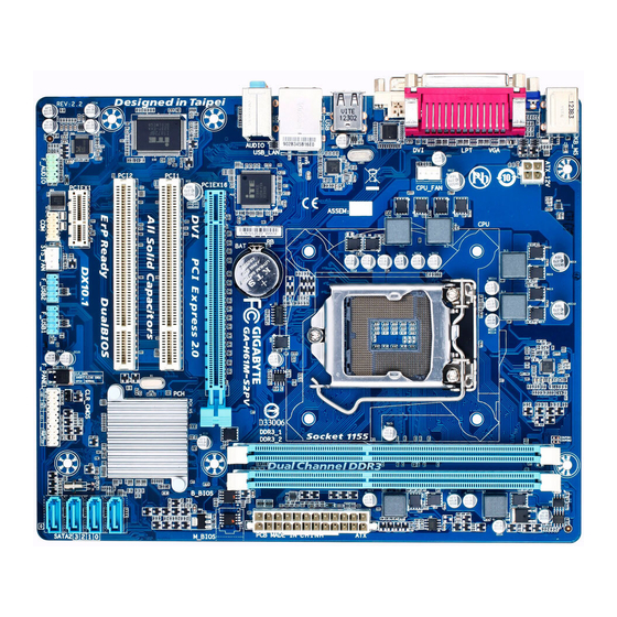
Page 4: Ga-H61M-S2Pv Motherboard Layout
GA-H61M-S2PV Motherboard Layout KB_MS ATX_12V LGA1155 CPU_FAN R_USB Realtek GbE LAN USB_LAN PCIe to PCI GA-H61M-S2PV AUDIO Bridge PCIEX16 PCI1 Intel ® PCI2 SATA2 CODEC PCIEX1 CLR_CMOS F_USB2 F_USB1 F_AUDIO F_PANEL SYS_FAN Box Contents 5 GA-H61M-S2PV motherboard 5 Motherboard driver disk…
-
Page 5: Ga-H61M-S2Pv Motherboard Block Diagram
GA-H61M-S2PV Motherboard Block Diagram 1 PCI Express x16 CPU CLK+/- (100 MHz) LGA1155 DDR3 1333/1066/800 MHz PCIe CLK Dual Channel Memory (100 MHz) PCI Express Bus Dual BIOS D-Sub DVI-D 4 SATA 3Gb/s PCI Express Bus Intel ® 8 USB 2.0/1.1…
-
Page 6: Chapter 1 Hardware Installation
Chapter 1 Hardware Installation Installation Precautions The motherboard contains numerous delicate electronic circuits and components which can become damaged as a result of electrostatic discharge (ESD). Prior to installation, carefully read the user’s manual and follow these procedures: • Prior to installation, make sure the chassis is suitable for the motherboard. •…
-
Page 7: 1-2 Product Specifications
Support for Extreme Memory Profile (XMP) memory modules Š * To support XMP memory, you must install an Intel 22nm (Ivy Bridge) CPU. (Go to GIGABYTE’s website for the latest supported memory speeds and memory modules.) Onboard Integrated Graphics Processor: Š…
-
Page 8
Micro ATX Form Factor; 24.4cm x 20cm Š * GIGABYTE reserves the right to make any changes to the product specifications and product-related information without prior notice. * Please visit the Support & DownloadsUtility page on GIGABYTE’s website to check the supported operating system(s) for the software listed in the «Unique Features»… -
Page 9: Installing The Cpu
• Make sure that the motherboard supports the memory. It is recommended that memory of the same capacity, brand, speed, and chips be used. (Go to GIGABYTE’s website for the latest supported memory speeds and memory modules.) • Always turn off the computer and unplug the power cord from the power outlet before installing the memory to prevent hardware damage.
-
Page 10: Installing An Expansion Card
Installing an Expansion Card Read the following guidelines before you begin to install an expansion card: • Make sure the motherboard supports the expansion card. Carefully read the manual that came with your expansion card. • Always turn off the computer and unplug the power cord from the power outlet before installing an expansion card to prevent hardware damage.
-
Page 11: Internal Connectors
Line Out Jack (Green) The default line out jack. Use this audio jack for a headphone or 2-channel speaker. This jack can be used to connect front speakers in a 4/5.1/7.1-channel audio configuration. Mic In Jack (Pink) The default Mic in jack. Microphones must be connected to this jack. To configure 7.1-channel audio, you have to use an HD front panel audio module and enable the multi-channel audio feature through the audio driver.
-
Page 12: Cpu_Fan/Sys_Fan Fan Headers
1/2) ATX_12V/ATX (2×2 12V Power Connector and 2×12 Main Power Connector) With the use of the power connector, the power supply can supply enough stable power to all the components on the motherboard. Before connecting the power connector, first make sure the power supply is turned off and all devices are properly installed.
-
Page 13
DEBUG PORT DEBUG PORT 5) SATA2 0/1/2/3 (SATA 3Gb/s Connectors) The SATA connectors conform to SATA 3Gb/s standard and are compatible with SATA 1.5Gb/s standard. Each SATA connector supports a single SATA device. SATA2 Pin No. Definition 6) F_PANEL (Front Panel Header) Connect the power switch, reset switch, speaker, and system status indicator on the chassis to this header according to the pin assignments below. -
Page 14
7) F_AUDIO (Front Panel Audio Header) The front panel audio header supports Intel High Definition audio (HD) and AC’97 audio. You may connect your chassis front panel audio module to this header. Make sure the wire assignments of the module connector match the pin assignments of the motherboard header. -
Page 15: Chapter 2 Bios Setup
To access the BIOS Setup program, press the <Delete> key during the POST when the power is turned on. To upgrade the BIOS, use either the GIGABYTE Q-Flash or @BIOS utility. Q-Flash allows the user to quickly and easily upgrade or back up BIOS without entering the operating system.
-
Page 16: Startup Screen
Startup Screen The following startup Logo screen will appear when the computer boots. (Sample BIOS Version: F1b) Function Keys On the main menu of the BIOS Setup program, press arrow keys to move among the items and press <Enter> to accept or enter a sub-menu. Or you can use your mouse to select the item you want. •…
-
Page 17: Cpu Clock Ratio
` M.I.T. Current Status This screen provides information on CPU/memory frequencies/parameters. ` Advanced Frequency Settings & CPU Clock Ratio Allows you to alter the clock ratio for the installed CPU. The adjustable range is dependent on the CPU being installed. &…
-
Page 18: Dram Timing Selectable
& C3/C6 State Support (Note) Allows you to determine whether to let the CPU enter C3/C6 mode in system halt state. When enabled, the CPU core frequency and voltage will be reduced during system halt state to decrease power consumption. The C3/C6 state is a more enhanced power-saving state than C1.
-
Page 19: Rank Interleaving
& Rank Interleaving Enables or disables memory rank interleaving. Enabled allows the system to simultaneously access different ranks of the memory to increase memory performance and stability. Auto lets the BIOS automatically configure this setting. (Default: Auto) ` Channel A/B Timing Settings This sub-menu provides memory timing settings for each channel of memory.
-
Page 20: System
& System Fan Speed Control Allows you to determine whether to enable the system fan speed control function and adjust the fan speed. Allows the system fan to run at different speeds according to the system temperature. Normal You can adjust the fan speed with EasyTune based on your system requirements. (Default) Allows the system fan to run at slow speeds.
-
Page 21: Bios Features
& System Time Sets the system time. The time format is hour, minute, and second. For example, 1 p.m. is 13:0:0. Use <Enter> to switch between the Hour, Minute, and Second fields and use the <Page Up> or <Page Down> key to set the desired value.
-
Page 22: Bootup Numlock State
Enables or disables Numlock feature on the numeric keypad of the keyboard after the POST. (Default: Enabled) & Full Screen LOGO Show Allows you to determine whether to display the GIGABYTE Logo at system startup. Disabled skips the GIGABYTE Logo when the system starts up. (Default: Enabled) & PCI ROM Priority Allows you to determine which Option ROM to launch.
-
Page 23: Peripherals
Peripherals & LAN PXE Boot Option ROM Allows you to decide whether to activate the boot ROM integrated with the onboard LAN chip. (Default: Disabled) & SATA Controller(s) Enables or disables the integrated SATA controllers. (Default: Enabled) & SATA Mode Selection Allows you to decide whether to configure the SATA controller integrated in the Chipset to AHCI mode.
-
Page 24: Power Management
& DVMT Total Memory Size Allows you to allocate the DVMT memory size of the onboard graphics. Options are: 128M, 256M, MAX. (Default: MAX) & Legacy USB Support Allows USB keyboard/mouse to be used in MS-DOS. (Default: Enabled) & EHCI Hand-off Determines whether to enable EHCI Hand-off feature for an operating system without EHCI Hand-off support.
-
Page 25: Resume By Alarm
Always On The system is turned on upon the return of the AC power. Always Off The system stays off upon the return of the AC power. (Default) & Power On By Keyboard Allows the system to be turned on by a PS/2 keyboard wake-up event. Note: To use this function, you need an ATX power supply providing at least 1A on the +5VSB lead.
-
Page 26: Save & Exit
Save & Exit & Save & Exit Setup Press <Enter> on this item and select Yes. This saves the changes to the CMOS and exits the BIOS Setup program. Select No or press <Esc> to return to the BIOS Setup Main Menu. &…
-
Page 27: Chapter 3 Drivers Installation
Chapter 3 Drivers Installation • Before installing the drivers, first install the operating system. • After installing the operating system, insert the motherboard driver disk into your optical drive. The driver Autorun screen is automatically displayed which looks like that shown in the screen shot below.
-
Page 28: Regulatory Statements
Contravention will be prosecuted. We believe that the information contained herein was accurate in all respects at the time of printing. GIGABYTE cannot, however, assume any responsibility for errors or omissions in this text. Also note that the information in this document is subject to change without notice and should not be construed as a commitment by GIGABYTE.
-
Page 29
— 29 -… -
Page 30
— 30 -… -
Page 31
— 31 -… -
Page 32
Tech. and Non-Tech. Support (Sales/Marketing) : http://ggts.gigabyte.com.tw WEB address (English): http://www.gigabyte.com WEB address (Chinese): http://www.gigabyte.tw You may go to the GIGABYTE website, select your language in the language list on the top right corner of the website. GIGABYTE Global Service System •…
В представленном списке руководства для конкретной модели Материнской платы — GIGABYTE GA-H61M-S2PV (rev. 2.1). Вы можете скачать инструкции к себе на компьютер или просмотреть онлайн на страницах сайта бесплатно или распечатать.
- Инструкции и файлы
- Характеристики
- Основные поломки
- Сервисы по ремонту
В случае если инструкция на русском не полная или нужна дополнительная информация по этому устройству, если вам нужны
дополнительные файлы: драйвера, дополнительное руководство пользователя (производители зачастую для каждого
продукта делают несколько различных документов технической помощи и руководств), свежая версия прошивки, то
вы можете задать вопрос администраторам или всем пользователям сайта, все постараются оперативно отреагировать
на ваш запрос и как можно быстрее помочь. Ваше устройство имеет характеристики:Socket: LGA1155, Поддерживаемые процессоры: Intel Core i7/Core i5/Core i3/Pentium/Celeron, Поддержка многоядерных процессоров: есть, Чипсет: Intel H61, BIOS: Award c возможностью аварийного восстановления, Поддержка EFI: есть, полные характеристики смотрите в следующей вкладке.
Для многих товаров, для работы с GIGABYTE GA-H61M-S2PV (rev. 2.1) могут понадобиться различные дополнительные файлы: драйвера, патчи, обновления, программы установки. Вы можете скачать онлайн эти файлы для конкретнй модели GIGABYTE GA-H61M-S2PV (rev. 2.1) или добавить свои для бесплатного скачивания другим посетителями.
Если вы не нашли файлов и документов для этой модели то можете посмотреть интсрукции для похожих товаров и моделей, так как они зачастую отличаются небольшим изменениями и взаимодополняемы.
Обязательно напишите несколько слов о преобретенном вами товаре, чтобы каждый мог ознакомиться с вашим отзывом или вопросом. Проявляйте активность что как можно бльше людей смогли узнать мнение настоящих людей которые уже пользовались GIGABYTE GA-H61M-S2PV (rev. 2.1).

Алплпрдр
Нет запуска плата новая
Нет запуска плата новая
Валерий
2019-11-12 03:04:09
Очень надежная плата. 7 лет безотказной работы с core i5.
Валерий
2019-11-12 03:04:10
Очень надежная плата. 7 лет безотказной работы с core i5.
Владимир
2020-07-06 15:45:07
Перестал включаться. Подсоединил новый БП,- результат тот же. Проверяю действие кнопки включения. Нужно скачать руководство.
Владимир
2020-07-06 15:46:58
Отзыв добавил, скачать руководство не могу : -(
Основные и самые важные характеристики модели собраны из надежных источников и по характеристикам можно найти похожие модели.
| Процессор | |
| Socket | LGA1155 |
| Поддерживаемые процессоры | Intel Core i7/Core i5/Core i3/Pentium/Celeron |
| Поддержка многоядерных процессоров | есть |
| Чипсет | |
| Чипсет | Intel H61 |
| BIOS | Award c возможностью аварийного восстановления |
| Поддержка EFI | есть |
| Поддержка SLI/CrossFire | нет |
| Память | |
| Память | DDR3 DIMM, 800 — 1333 МГц |
| Количество слотов памяти | 2 |
| Поддержка двухканального режима | есть |
| Максимальный объем памяти | 16 Гб |
| Дисковые контроллеры | |
| IDE | нет |
| SATA | количество разъемов SATA 3Gb/s: 4 |
| Слоты расширения | |
| Слоты расширения | 1xPCI-E x16, 1xPCI-E x1, 2xPCI |
| Поддержка PCI Express 2.0 | есть |
| Поддержка PCI Express 3.0 | есть |
| Аудио/видео | |
| Звук | 7.1CH, HDA, на основе Realtek ALC887 |
| Сеть | |
| Ethernet | 1000 Мбит/с, на основе Realtek 8111F |
| Подключение | |
| Наличие интерфейсов | 8 USB, 1xCOM, D-Sub, DVI, Ethernet, PS/2 (клавиатура), PS/2 (мышь), LPT |
| Разъемы на задней панели | 4 USB, D-Sub, DVI, Ethernet, PS/2 (клавиатура), PS/2 (мышь), LPT |
| Основной разъем питания | 24-pin |
| Разъем питания процессора | 4-pin |
| Тип системы охлаждения | пассивное |
| Дополнительные параметры | |
| Форм-фактор | microATX |
Здесь представлен список самых частых и распространенных поломок и неисправностей у Материнских плат. Если у вас такая поломка то вам повезло, это типовая неисправность для GIGABYTE GA-H61M-S2PV (rev. 2.1) и вы можете задать вопрос о том как ее устранить и вам быстро ответят или же прочитайте в вопросах и ответах ниже.
| Название поломки | Описание поломки | Действие |
|---|---|---|
| Разрыв Печатных Проводников | ||
| Обрыв Конденсаторов Или Резисторов | ||
| Короткое Замыкание В Электрических Цепях | ||
| Разрушение Разъемов И Слотов | ||
| Поломка Процессорного Разъема | ||
| Выгорание Портов | ||
| Микротрещины В Плате | ||
| Выход Из Строя Сетевого Адаптера | ||
| Перегрев Компонентов | ||
| Не Запускается При Включении | При Включении Не Загружается. В Биос Не Входит. Пост Код — А3 | |
| Какой Компонент | Подскажите Марку Траyзистора Q46? | |
| Не Работает Ps/2 | Сначала Отвалилась Клавиатура, А Через Некоторое Время 6 Коротких Гудков И Не Запускается | |
| Подключить Переднюю Панель | Не Могу Подключить Переднюю Панель | |
| Судя По Всему Отвал Биоса | Материнка Стартует Секунд На 5,Кулер Процессора Берет Обороты И Останавливается.и Так-Циклически,Без Остановок.запуск Невозможен.вечером Либо Завтра Буду Пытаться Его Восстановить,Потом Может Дополню | |
| Пропал Звук На Материнке | Пропал Звук На Материнке, Отображается Только Nvidia Hdmi. Переустановка Драйверов С Офсайта Не Помогла. | |
| Биос | При Старте Звук Через Промежетки Времени Примерно В 1-3 Мин Три Сигнала Потом Стартует Винда , Недавно Вообще Написал Cmos Setting Wrong И C7, Жму Del Меняется На B2 Чтоб Воити В Биос Три Сигнала По Одному Через Промеежутки Времени 1-3 Мин И Черный Экра | |
| Asus M2A-Vm Hdmi | Не Запускается Процессор Phenom Ii X4 945 Rev. C3, На Socket-Ам 3, Нет Даже Сигнала, Черный Экран | |
| Не Включается | После Замены Конденсаторов С34 И С35 Не Включается | |
| Черный Экран | Все Уже Перепробовал И Озу Менял И Переставлял И Ластиком Чистил, И Батарейку Вынимал И Измерял, И Видеокарту С Бп На Заведомо Годную Ставил Исход Один, Черный Экран И Speaker Издает 1 Длинный 2 Коротких, Если Я Не Путаю. | |
| Неправильно Отображается Память | При Установленной Памяти 4 Гигабайта В Биосе Отображается 8. Установил Одну Планку 2 Гига — Отображается 4 | |
В нашей базе сейчас зарегестрированно 18 353 сервиса в 513 города России, Беларусии, Казахстана и Украины.

RSS
⭐
⭐
⭐
⭐
⭐
Адресс:
ул. Верхняя Масловка, д.2
Телефон:
74952762211
Сайт:
n/a
Время работы
Будни: с 0900 до 2100
Суббота: с 1000 до 1800
Воскресенье: выходной
ПРИНТЕРЫ-КОМПЬЮТЕРЫ
⭐
⭐
⭐
⭐
⭐
Адресс:
2-й Автозаводский проезд, д. 3а
Телефон:
74957809503
Сайт:
n/a
Время работы
Время работы не указано
РОССЕРВИС-АЙТИ
⭐
⭐
⭐
⭐
⭐
Адресс:
Большой знаменский переулок, дом 2, строение 7
Телефон:
74956416530
Сайт:
n/a
Время работы
Будни: с 0800 до 2300
Суббота: с 0800 до 2300
Воскресенье: с 1000 до 2100
RSS
⭐
⭐
⭐
⭐
⭐
Адресс:
1-й Гончарный пер., д. 4, стр. 3
Телефон:
74952762211
Сайт:
n/a
Время работы
Будни: с 0900 до 2100
Суббота: с 1000 до 1800
Воскресенье: выходной
СЕРВИС ЦЕНТР MUSIC-FIX MUSIC-FIX.RU
⭐
⭐
⭐
⭐
⭐
Адресс:
Южнопортовая 7
Телефон:
74993905854
Сайт:
n/a
Время работы
Будни: с 1000 до 2100
Суббота: с 1400 до 1900
Воскресенье: с 1400 до 1900
#Полный Обзор Материнской Платы Gigabyte GA-H61M-S1//Full Review Motherboard Gigabyte GA-H61M-S1
6:33
Очень доволен
хочу
авпваы
Хочу купить
ирлдоьвап ькеьпрлджыкеь дзьакерджь щзрбкежбрь апкыезрбкыеджрбеджр щзапбкерл
Только приобрела,а инструкции нет
Только приобрела,а инструкции нет
Отвалился распрыскиватель
-
Contents
-
Table of Contents
-
Bookmarks
Quick Links
GA-H61M-S2PV
User’s Manual
Rev. 2101
12ME-61M2PV-2101R
Related Manuals for Gigabyte GA-H61M-S2PV
Summary of Contents for Gigabyte GA-H61M-S2PV
-
Page 1
GA-H61M-S2PV User’s Manual Rev. 2101 12ME-61M2PV-2101R… -
Page 2: Identifying Motherboard Revision
Information in this manual is protected by copyright laws and is the property of GIGABYTE. Changes to the specifications and features in this manual may be made by GIGABYTE without prior notice. No part of this manual may be reproduced, copied, translated, transmitted, or published in any form or by any means without GIGABYTE’s prior written permission.
-
Page 3: Table Of Contents
Table of Contents GA-H61M-S2PV Motherboard Layout …………….4 GA-H61M-S2PV Motherboard Block Diagram …………..5 Chapter 1 Hardware Installation ………………6 Installation Precautions ………………6 Product Specifications ………………7 Installing the CPU ……………….. 9 Installing the Memory ………………9 Installing an Expansion Card …………….. 10 Back Panel Connectors ………………
-
Page 4: Ga-H61M-S2Pv Motherboard Layout
GA-H61M-S2PV Motherboard Layout KB_MS ATX_12V LGA1155 CPU_FAN R_USB Realtek GbE LAN USB_LAN PCIe to PCI GA-H61M-S2PV AUDIO Bridge PCIEX16 PCI1 Intel ® PCI2 SATA2 CODEC PCIEX1 CLR_CMOS F_USB2 F_USB1 F_AUDIO F_PANEL SYS_FAN Box Contents 5 GA-H61M-S2PV motherboard 5 Motherboard driver disk…
-
Page 5: Ga-H61M-S2Pv Motherboard Block Diagram
GA-H61M-S2PV Motherboard Block Diagram 1 PCI Express x16 CPU CLK+/- (100 MHz) LGA1155 DDR3 1333/1066/800 MHz PCIe CLK Dual Channel Memory (100 MHz) PCI Express Bus Dual BIOS D-Sub DVI-D 4 SATA 3Gb/s PCI Express Bus Intel ® 8 USB 2.0/1.1…
-
Page 6: Chapter 1 Hardware Installation
Chapter 1 Hardware Installation Installation Precautions The motherboard contains numerous delicate electronic circuits and components which can become damaged as a result of electrostatic discharge (ESD). Prior to installation, carefully read the user’s manual and follow these procedures: • Prior to installation, make sure the chassis is suitable for the motherboard. •…
-
Page 7: 1-2 Product Specifications
Support for Extreme Memory Profile (XMP) memory modules Š * To support XMP memory, you must install an Intel 22nm (Ivy Bridge) CPU. (Go to GIGABYTE’s website for the latest supported memory speeds and memory modules.) Onboard Integrated Graphics Processor: Š…
-
Page 8
Micro ATX Form Factor; 24.4cm x 20cm Š * GIGABYTE reserves the right to make any changes to the product specifications and product-related information without prior notice. * Please visit the Support & DownloadsUtility page on GIGABYTE’s website to check the supported operating system(s) for the software listed in the «Unique Features»… -
Page 9: Installing The Cpu
• Make sure that the motherboard supports the memory. It is recommended that memory of the same capacity, brand, speed, and chips be used. (Go to GIGABYTE’s website for the latest supported memory speeds and memory modules.) • Always turn off the computer and unplug the power cord from the power outlet before installing the memory to prevent hardware damage.
-
Page 10: Installing An Expansion Card
Installing an Expansion Card Read the following guidelines before you begin to install an expansion card: • Make sure the motherboard supports the expansion card. Carefully read the manual that came with your expansion card. • Always turn off the computer and unplug the power cord from the power outlet before installing an expansion card to prevent hardware damage.
-
Page 11: Internal Connectors
Line Out Jack (Green) The default line out jack. Use this audio jack for a headphone or 2-channel speaker. This jack can be used to connect front speakers in a 4/5.1/7.1-channel audio configuration. Mic In Jack (Pink) The default Mic in jack. Microphones must be connected to this jack. To configure 7.1-channel audio, you have to use an HD front panel audio module and enable the multi-channel audio feature through the audio driver.
-
Page 12: Cpu_Fan/Sys_Fan Fan Headers
1/2) ATX_12V/ATX (2×2 12V Power Connector and 2×12 Main Power Connector) With the use of the power connector, the power supply can supply enough stable power to all the components on the motherboard. Before connecting the power connector, first make sure the power supply is turned off and all devices are properly installed.
-
Page 13
DEBUG PORT DEBUG PORT 5) SATA2 0/1/2/3 (SATA 3Gb/s Connectors) The SATA connectors conform to SATA 3Gb/s standard and are compatible with SATA 1.5Gb/s standard. Each SATA connector supports a single SATA device. SATA2 Pin No. Definition 6) F_PANEL (Front Panel Header) Connect the power switch, reset switch, speaker, and system status indicator on the chassis to this header according to the pin assignments below. -
Page 14
7) F_AUDIO (Front Panel Audio Header) The front panel audio header supports Intel High Definition audio (HD) and AC’97 audio. You may connect your chassis front panel audio module to this header. Make sure the wire assignments of the module connector match the pin assignments of the motherboard header. -
Page 15: Chapter 2 Bios Setup
To access the BIOS Setup program, press the <Delete> key during the POST when the power is turned on. To upgrade the BIOS, use either the GIGABYTE Q-Flash or @BIOS utility. Q-Flash allows the user to quickly and easily upgrade or back up BIOS without entering the operating system.
-
Page 16: Startup Screen
Startup Screen The following startup Logo screen will appear when the computer boots. (Sample BIOS Version: F1b) Function Keys On the main menu of the BIOS Setup program, press arrow keys to move among the items and press <Enter> to accept or enter a sub-menu. Or you can use your mouse to select the item you want. •…
-
Page 17: Cpu Clock Ratio
` M.I.T. Current Status This screen provides information on CPU/memory frequencies/parameters. ` Advanced Frequency Settings & CPU Clock Ratio Allows you to alter the clock ratio for the installed CPU. The adjustable range is dependent on the CPU being installed. &…
-
Page 18: Dram Timing Selectable
& C3/C6 State Support (Note) Allows you to determine whether to let the CPU enter C3/C6 mode in system halt state. When enabled, the CPU core frequency and voltage will be reduced during system halt state to decrease power consumption. The C3/C6 state is a more enhanced power-saving state than C1.
-
Page 19: Rank Interleaving
& Rank Interleaving Enables or disables memory rank interleaving. Enabled allows the system to simultaneously access different ranks of the memory to increase memory performance and stability. Auto lets the BIOS automatically configure this setting. (Default: Auto) ` Channel A/B Timing Settings This sub-menu provides memory timing settings for each channel of memory.
-
Page 20: System
& System Fan Speed Control Allows you to determine whether to enable the system fan speed control function and adjust the fan speed. Allows the system fan to run at different speeds according to the system temperature. Normal You can adjust the fan speed with EasyTune based on your system requirements. (Default) Allows the system fan to run at slow speeds.
-
Page 21: Bios Features
& System Time Sets the system time. The time format is hour, minute, and second. For example, 1 p.m. is 13:0:0. Use <Enter> to switch between the Hour, Minute, and Second fields and use the <Page Up> or <Page Down> key to set the desired value.
-
Page 22: Bootup Numlock State
Enables or disables Numlock feature on the numeric keypad of the keyboard after the POST. (Default: Enabled) & Full Screen LOGO Show Allows you to determine whether to display the GIGABYTE Logo at system startup. Disabled skips the GIGABYTE Logo when the system starts up. (Default: Enabled) & PCI ROM Priority Allows you to determine which Option ROM to launch.
-
Page 23: Peripherals
Peripherals & LAN PXE Boot Option ROM Allows you to decide whether to activate the boot ROM integrated with the onboard LAN chip. (Default: Disabled) & SATA Controller(s) Enables or disables the integrated SATA controllers. (Default: Enabled) & SATA Mode Selection Allows you to decide whether to configure the SATA controller integrated in the Chipset to AHCI mode.
-
Page 24: Power Management
& DVMT Total Memory Size Allows you to allocate the DVMT memory size of the onboard graphics. Options are: 128M, 256M, MAX. (Default: MAX) & Legacy USB Support Allows USB keyboard/mouse to be used in MS-DOS. (Default: Enabled) & EHCI Hand-off Determines whether to enable EHCI Hand-off feature for an operating system without EHCI Hand-off support.
-
Page 25: Resume By Alarm
Always On The system is turned on upon the return of the AC power. Always Off The system stays off upon the return of the AC power. (Default) & Power On By Keyboard Allows the system to be turned on by a PS/2 keyboard wake-up event. Note: To use this function, you need an ATX power supply providing at least 1A on the +5VSB lead.
-
Page 26: Save & Exit
Save & Exit & Save & Exit Setup Press <Enter> on this item and select Yes. This saves the changes to the CMOS and exits the BIOS Setup program. Select No or press <Esc> to return to the BIOS Setup Main Menu. &…
-
Page 27: Chapter 3 Drivers Installation
Chapter 3 Drivers Installation • Before installing the drivers, first install the operating system. • After installing the operating system, insert the motherboard driver disk into your optical drive. The driver Autorun screen is automatically displayed which looks like that shown in the screen shot below.
-
Page 28: Regulatory Statements
Contravention will be prosecuted. We believe that the information contained herein was accurate in all respects at the time of printing. GIGABYTE cannot, however, assume any responsibility for errors or omissions in this text. Also note that the information in this document is subject to change without notice and should not be construed as a commitment by GIGABYTE.
-
Page 29
— 29 -… -
Page 30
— 30 -… -
Page 31
— 31 -… -
Page 32
Tech. and Non-Tech. Support (Sales/Marketing) : http://ggts.gigabyte.com.tw WEB address (English): http://www.gigabyte.com WEB address (Chinese): http://www.gigabyte.tw You may go to the GIGABYTE website, select your language in the language list on the top right corner of the website. GIGABYTE Global Service System •…
-
Драйверы
44
-
Инструкции по эксплуатации
12
Языки:
Gigabyte GA-H61M-S2PV инструкция по эксплуатации
(72 страницы)
- Языки:Венгерский, Греческий, Испанский, Итальянский, Немецкий, Польский, Португальский, Русский, Турецкий, Французский, Чешский
-
Тип:
PDF -
Размер:
18.6 MB -
Описание:
Installation Guidebook
На NoDevice можно скачать инструкцию по эксплуатации для Gigabyte GA-H61M-S2PV. Руководство пользователя необходимо для ознакомления с правилами установки и эксплуатации Gigabyte GA-H61M-S2PV. Инструкции по использованию помогут правильно настроить Gigabyte GA-H61M-S2PV, исправить ошибки и выявить неполадки.
Download
Table of Contents
Add to my manuals
Bookmark this page
Manual will be automatically added to «My Manuals»
Print this page
- Manuals
- Brands
- Gigabyte Manuals
- Motherboard
- GA-H61M-S2PV
- User manual
Gigabyte — ultra durable 4 classic ga-h61m-s2pv desktop motherboard
Hide thumbs
Also See for GA-H61M-S2PV:
- User manual (40 pages)
- User manual (32 pages)
,
1
2
3
5
6
7
8
9
10
11
12
13
14
15
16
17
18
19
20
21
22
23
24
25
26
27
28
29
30
31
32
33
34
35
36
37
38
39
40
-
Contents
-
Table of Contents
-
Bookmarks
Quick Links
5
Ga-H61M-S2Pv Motherboard Layout
-
Identifying Motherboard Revision
-
Table of Contents
-
GA-H61M-S2PV Motherboard Layout
-
GA-H61M-S2PV Motherboard Block Diagram
-
Chapter 1 Hardware Installation
-
Installation Precautions
-
Product Specifications
-
Installing the CPU
-
Installing the Memory
-
Installing an Expansion Card
-
Back Panel Connectors
-
Internal Connectors
-
SATA 3Gb/S Connectors
-
Fan Headers
-
Front Panel Heade
-
Front Panel Header
-
USB 2.0/1.1 Headers
-
Front Panel Audio Header
-
Battery
-
-
-
Chapter 2 BIOS Setup
-
Startup Screen
-
The Main Menu
-
MB Intelligent Tweaker(M.I.T.)
-
Cpu Clock Ratio
-
Cpu Frequency
-
-
Standard CMOS Features
-
Advanced BIOS Features
-
Integrated Peripherals
-
Power Management Setup
-
PC Health Status
-
Load Fail-Safe Defaults
-
Load Optimized Defaults
-
Set Supervisor/User Password
-
Save & Exit Setup
-
Exit Without Saving
-
-
Chapter 3 Drivers Installation
-
Regulatory Statements
-
GA-H61M-S2PV
User’s Manual
Rev. 1001
12ME-61M2PV-1001R
Table of Contents
Previous Page
Next Page
- 1
- 2
- 3
- 4
- 5
Related Manuals for Gigabyte GA-H61M-S2PV
-
Motherboard Gigabyte GA-H61M-DS2V User Manual
Manual (40 pages)
-
Motherboard Gigabyte GA-H61M-S2PV User Manual
Motherboard (32 pages)
-
Motherboard Gigabyte GA-H61M-DS2 DVI User Manual
Manual (44 pages)
-
Motherboard Gigabyte GA-H61M-DS2 User Manual
Gigabyte — ga-h61m-ds2 desktop motherboard (40 pages)
-
Motherboard Gigabyte GA-H61M-S2P-B3 User Manual
(40 pages)
-
Motherboard Gigabyte GA-H61M-S2P-B3 User Manual
Intel h61 express chipset (40 pages)
-
Motherboard Gigabyte GA-H61M-S2V-B3 User Manual
Lga1155 socket motherboard (44 pages)
-
Motherboard Gigabyte GA-H61M-S2H User Manual
(44 pages)


-
Motherboard Gigabyte GA-H61M-S2-B3 User Manual
(44 pages)
-
Motherboard Gigabyte GA-H61M-S1 User Manual
Manual (40 pages)
-
Motherboard Gigabyte GA-H61M-S1 User Manual
(40 pages)
-
Motherboard Gigabyte GA-H61M-S2PH User Manual
Manual (32 pages)
-
Motherboard Gigabyte GA-H61M-S User Manual
Manual (32 pages)
-
Motherboard Gigabyte GA-H61M-S2PT User Manual
Motherboard gigabyte (32 pages)
-
Motherboard Gigabyte GA-H61M-S2P-R3 User Manual
Micro atx motherboard (32 pages)
-
Motherboard Gigabyte GA-H61M-USB3-B3 User Manual
Motherboard (44 pages)


Related Products for Gigabyte GA-H61M-S2PV
- Gigabyte GA-H61M-S2P-B3
- Gigabyte GA-H61M-S2V-B3
- Gigabyte GA-H61M-S2H
- Gigabyte GA-H61M-S2-B3
- Gigabyte GA-H61M-S1
- Gigabyte GA-H61M-S2PH
- Gigabyte GA-H61M-S2P
- Gigabyte GA-H61M-S
- Gigabyte GA-H61M-S2PT
- Gigabyte GA-H61M-S2P-R3
- Gigabyte GA-H61M-D2H
- Gigabyte GA-H61M-DS2V
- Gigabyte GA-H61M-USB3H
- Gigabyte GA-H61M-USB3V
- Gigabyte GA-H61MA-D3V
- Gigabyte GA-H61M-DS2H
This manual is also suitable for:
Ga-h61m-ds2
Table of Contents
 Loading…
![]()
GA-H61M-S2PV
User’s Manual
Rev. 2101 12ME-61M2PV-2101R

Motherboard
GA-H61M-S2PV
Motherboard
GA-H61M-S2PV
Dec. 9, 2011
Dec. 9, 2011
Copyright
© 2012 GIGA-BYTE TECHNOLOGY CO., LTD. All rights reserved.
The trademarks mentioned in this manual are legally registered to their respective owners.
Disclaimer
Information in this manual is protected by copyright laws and is the property of GIGABYTE.
ChangestothespecificationsandfeaturesinthismanualmaybemadebyGIGABYTEwithoutpriornotice.
No part of this manual may be reproduced, copied, translated, transmitted, or published in any form or by any means without GIGABYTE’s prior written permission.
In order to assist in the use of this product, carefully read the User’s Manual.
For product-related information, check on our website at: http://www.gigabyte.com
Identifying Your Motherboard Revision
The revision number on your motherboard looks like this: «REV: X.X.» For example, «REV: 1.0» means the revision of the motherboard is 1.0. Check your motherboard revision before updating motherboard BIOS,
drivers, or when looking for technical information. Example:

Table of Contents
|
GA-H61M-S2PV Motherboard Layout…………………………………………………………………… |
4 |
|
|
GA-H61M-S2PV Motherboard Block Diagram……………………………………………………….. |
5 |
|
|
Chapter 1 Hardware Installation………………………………………………………………………….. |
6 |
|
|
1-1 |
Installation Precautions…………………………………………………………………………. |
6 |
|
1-2 |
Product Specifications………………………………………………………………………….. |
7 |
|
1-3 |
Installing the CPU………………………………………………………………………………… |
9 |
|
1-4 |
Installing the Memory……………………………………………………………………………. |
9 |
|
1-5 Installing an Expansion Card……………………………………………………………….. |
10 |
|
|
1-6 |
Back Panel Connectors………………………………………………………………………. |
10 |
|
1-7 |
Internal Connectors……………………………………………………………………………. |
11 |
|
Chapter 2 BIOS Setup……………………………………………………………………………………… |
15 |
|
|
2-1 |
Startup Screen…………………………………………………………………………………… |
16 |
|
2-2 |
M.I.T…………………………………………………………………………………………………. |
16 |
|
2-3 |
System……………………………………………………………………………………………… |
20 |
|
2-4 |
BIOS Features…………………………………………………………………………………… |
21 |
|
2-5 |
Peripherals………………………………………………………………………………………… |
23 |
|
2-6 |
Power Management……………………………………………………………………………. |
24 |
|
2-7 |
Save & Exit……………………………………………………………………………………….. |
26 |
|
Chapter 3 Drivers Installation……………………………………………………………………………. |
27 |
|
|
Regulatory Statements…………………………………………………………………………………. |
28 |
— 3 —

GA-H61M-S2PV Motherboard Layout
|
KB_MS |
|
|
ATX_12V |
|
|
VGA |
|
|
LPT |
|
|
DVI |
CPU_FAN |
R_USB
Realtek
GbE LAN
USB_LAN
|
PCIe to PCI |
BAT GA-H61M-S2PV |
|
Bridge |
|
|
PCIEX16 |
PCI1
PCI2
|
DDR3 1 |
DDR3 2 B BIOS M BIOS |
|
Intel® H61 |
SATA2 |
|
CODEC |
PCIEX1 |
0 |
|||
|
1 |
|||||
|
CLR_CMOS |
2 |
||||
|
F_AUDIO |
F_USB2 F_USB1 |
3 |
|||
|
F_PANEL |
|||||
|
COM |
SYS_FAN |
||||
|
Box Contents |
|||||
|
55 |
GA-H61M-S2PV motherboard |
||||
|
55 |
Motherboard driver disk |
55 |
Two SATA cables |
||
|
55 |
User’s Manual |
55 |
I/O Shield |
The box contents above are for reference only and the actual items shall depend on the product package you obtain. The box contents are subject to change without notice.
— 4 —

GA-H61M-S2PV Motherboard Block Diagram
1 PCI Express x16
PCIe CLK
(100 MHz)
|
PCI Express Bus |
x16 |
|||||||||||||||||||||||||||
|
D-Sub |
||||||||||||||||||||||||||||
|
DVI-D |
||||||||||||||||||||||||||||
|
PCI Express Bus |
||||||||||||||||||||||||||||
|
PCIe CLK |
x1 |
x1 |
x1 |
|||||||||||||||||||||||||
|
(100 MHz) |
Realtek |
PCIe to PCI |
||||||||||||||||||||||||||
|
GbE LAN |
Bridge |
|||||||||||||||||||||||||||
|
1 PCI |
Express |
x1 |
RJ45 |
|||||||||||||||||||||||||
|
LAN |
||||||||||||||||||||||||||||
|
PCI Bus |
||||||||||||||||||||||||||||
|
CPU CLK+/- (100 MHz) |
||||||||
|
LGA1155 |
DDR3 1333/1066/800 MHz |
|||||||
|
CPU |
||||||||
|
Dual Channel Memory |
||||||||
|
Dual BIOS |
|||||||||||||||||||
|
Intel® H61 |
4 SATA 3Gb/s |
||||||||||||||||||
|
8 USB 2.0/1.1 |
|||||||||||||||||||
|
LPC |
iTE |
LPT |
|||||||||||||||||
|
Bus |
|||||||||||||||||||
|
COM |
|||||||||||||||||||
|
Super I/O |
|||||||||||||||||||
|
CODEC |
PS/2 KB/Mouse |
||||||||||||||||||
|
(Center/Subwoofer |
(Front |
|
Out)Speaker |
Out)Speaker Out)Speaker |
|
MIC |
(Rear |
|
Line |
|
|
In |
|
|
Out |
|
|
Line |

 For detailed product information/limitation(s), refer to «1-2 Product Specifications.»
— 5 —

Chapter 1 Hardware Installation
1-1 Installation Precautions
The motherboard contains numerous delicate electronic circuits and components which can become damaged as a result of electrostatic discharge (ESD). Prior to installation, carefully read the user’s manual and follow these procedures:
•• Prior to installation, make sure the chassis is suitable for the motherboard.
•• Prior to installation, do not remove or break motherboard S/N (Serial Number) sticker or warranty sticker provided by your dealer. These stickers are required for warranty validation.
•• Always remove the AC power by unplugging the power cord from the power outlet before installing or removing the motherboard or other hardware components.
•• When connecting hardware components to the internal connectors on the motherboard, make sure they are connected tightly and securely.
•• When handling the motherboard, avoid touching any metal leads or connectors.
•• It is best to wear an electrostatic discharge (ESD) wrist strap when handling electronic components such as a motherboard, CPU or memory. If you do not have an ESD wrist strap, keep your hands dry and first touch a metal object to eliminate static electricity.
•• Prior to installing the motherboard, please have it on top of an antistatic pad or within an electrostatic shielding container.
•• Before unplugging the power supply cable from the motherboard, make sure the power supply has been turned off.
•• Before turning on the power, make sure the power supply voltage has been set according to the local voltage standard.
•• Before using the product, please verify that all cables and power connectors of your hardware components are connected.
•• To prevent damage to the motherboard, do not allow screws to come in contact with the motherboard circuit or its components.
•• Make sure there are no leftover screws or metal components placed on the motherboard or within the computer casing.
•• Do not place the computer system on an uneven surface.
•• Do not place the computer system in a high-temperature environment.
•• Turning on the computer power during the installation process can lead to damage to system components as well as physical harm to the user.
•• If you are uncertain about any installation steps or have a problem related to the use of the product, please consult a certified computer technician.
— 6 —

|
1-2 |
Product Specifications |
|||
|
CPU |
Support for Intel® Core™ i7 processors/Intel® Core™ i5 processors/ |
|||
|
Intel® Core™ i3 processors/Intel® Pentium® processors/Intel® Celeron® processors |
||||
|
in the LGA1155 package |
||||
|
(Go to GIGABYTE’s website for the latest CPU support list.) |
||||
|
L3 cache varies with CPU |
||||
|
Chipset |
Intel® H61 Express Chipset |
|||
|
Memory |
2 x 1.5V DDR3 DIMM sockets supporting up to 16 GB of system memory |
|||
|
* Due to a Windows 32-bit operating system limitation, when more than 4 GB of physical |
||||
|
memory is installed, the actual memory size displayed will be less than the size of |
||||
|
the physical memory installed. |
||||
|
Dual channel memory architecture |
||||
|
Support for DDR3 1333/1066/800 MHz memory modules |
||||
|
Support for non-ECC memory modules |
||||
|
Support for Extreme Memory Profile (XMP) memory modules |
||||
|
* To support XMP memory, you must install an Intel 22nm (Ivy Bridge) CPU. |
||||
|
(Go to GIGABYTE’s website for the latest supported memory speeds and memory |
||||
|
modules.) |
||||
|
Onboard |
Integrated Graphics Processor: |
|||
|
Graphics |
— |
1 x D-Sub port |
||
|
— |
1 x DVI-D port, supporting a maximum resolution of 1920×1200 |
|||
|
* The DVI-D port does not support D-Sub connection by adapter. |
||||
|
Audio |
Realtek ALC887 codec |
|||
|
High Definition Audio |
||||
|
2/4/5.1/7.1-channel |
*To configure 7.1-channel audio, you have to use an HD front panel audio module and enable the multi-channel audio feature through the audio driver.
|
LAN |
Realtek GbE LAN chip (10/100/1000 Mbit) |
||
|
Expansion Slots |
1 x PCI Express x16 slot, running at x16 |
||
|
(The PCI Express x16 slot conforms to PCI Express 3.0 standard.) |
|||
|
* Whether PCI Express 3.0 is supported depends on CPU and graphics card compat- |
|||
|
ibility. |
|||
|
1 x PCI Express x1 slot |
|||
|
(The PCI Express x1 slot conforms to PCI Express 2.0 standard.) |
|||
|
2 x PCI slots |
|||
|
Storage Interface |
Chipset: |
||
|
— |
4 x SATA 3Gb/s connectors supporting up to 4 SATA 3Gb/s devices |
||
|
USB |
Chipset: |
||
|
— |
Up to 8 USB 2.0/1.1 ports (4 ports on the back panel, 4 ports available through |
||
|
the internal USB headers) |
1 x 24-pin ATX main power connector1 x 4-pin ATX 12V power connector4 x SATA 3Gb/s connectors
1 x CPU fan header1 x system fan header1 x front panel header
— 7 —

|
Internal |
1 x front panel audio header |
|
|
Connectors |
2 x USB 2.0/1.1 headers |
|
|
1 x Clear CMOS jumper |
 Back Panel
Connectors
1 x PS/2 keyboard port1 x PS/2 mouse port1 x parallel port
1 x D-Sub port1 x DVI-D port
4 x USB 2.0/1.1 ports1 x RJ-45 port
3 x audio jacks (Line In/Line Out/Microphone)
|
I/O Controller |
iTE I/O Controller Chip |
||
|
Hardware |
System voltage detection |
||
|
Monitor |
CPU/System temperature detection |
||
|
CPU/System fan speed detection |
|||
|
CPU overheating warning |
|||
|
CPU/System fan fail warning |
|||
|
CPU/System fan speed control |
|||
|
* Whether the CPU/system fan speed control function is supported will depend on the |
|||
|
CPU/system cooler you install. |
|||
|
BIOS |
2 x 32 Mbit flash |
||
|
Use of licensed AMI EFI BIOS |
|||
|
Support for DualBIOS™ |
|||
|
PnP 1.0a, DMI 2.0, SM BIOS 2.6, ACPI 2.0a |
|||
|
Unique Features |
Support for @BIOS |
||
|
Support for Q-Flash |
|||
|
Support for Xpress Recovery2 |
|||
|
Support for EasyTune |
|||
|
* Available functions in EasyTune may differ by motherboard model. |
|||
|
Support for ON/OFF Charge |
|||
|
Bundled |
Norton Internet Security (OEM version) |
||
|
Software |
|||
|
Operating |
Support for Microsoft® Windows 8/7/Vista/XP |
||
|
System |
|||
|
Form Factor |
Micro ATX Form Factor; 24.4cm x 20cm |
*GIGABYTE reserves the right to make any changes to the product specifications and product-related information without prior notice.
*Please visit the Support & DownloadsUtility page on GIGABYTE’s website to check the supported operating system(s) for the software listed in the «Unique Features» and «Bundled Software» columns.
—8 —

|
1-3 |
Installing the CPU |
|
|
Read the following guidelines before you begin to install the CPU: |
||
|
•• |
Make sure that the motherboard supports the CPU. |
|
|
•• |
(Go to GIGABYTE’s website for the latest CPU support list.) |
|
|
Always turn off the computer and unplug the power cord from the power outlet before installing the |
||
|
CPU to prevent hardware damage. |
||
|
•• |
Locate the pin one of the CPU. The CPU cannot be inserted if oriented incorrectly. (Or you may |
|
|
locate the notches on both sides of the CPU and alignment keys on the CPU socket.) |
||
|
•• |
Apply an even and thin layer of thermal grease on the surface of the CPU. |
|
|
•• |
Do not turn on the computer if the CPU cooler is not installed, otherwise overheating and damage |
|
|
of the CPU may occur. |
||
|
•• |
Set the CPU host frequency in accordance with the CPU specifications. It is not recommended |
|
|
that the system bus frequency be set beyond hardware specifications since it does not meet the |
||
|
standard requirements for the peripherals. If you wish to set the frequency beyond the standard |
||
|
specifications, please do so according to your hardware specifications including the CPU, graphics |
||
|
card, memory, hard drive, etc. |
Installing the CPU
Locate the alignment keys on the motherboard CPU socket and the notches on the CPU.
|
LGA1155 CPU Socket |
LGA1155 CPU |
||
|
Alignment Key |
Alignment Key |
Notch |
Notch |
|
Pin One Corner of the CPU Socket |
Triangle Pin One Marking on the CPU |
1-4 Installing the Memory
Read the following guidelines before you begin to install the memory:
•• Make sure that the motherboard supports the memory. It is recommended that memory of the same capacity, brand, speed, and chips be used.
(Go to GIGABYTE’s website for the latest supported memory speeds and memory modules.)
•• Always turn off the computer and unplug the power cord from the power outlet before installing the memory to prevent hardware damage.
•• Memory modules have a foolproof design. A memory module can be installed in only one direction. If you are unable to insert the memory, switch the direction.
Dual Channel Memory Configuration
This motherboard provides two DDR3 memory sockets and supports Dual Channel Technology. After the memory is installed, the BIOS will automatically detect the specifications and capacity of the memory. Enabling Dual
Channel memory mode will double the original memory bandwidth.
The two DDR3 memory sockets are divided into two channels and each channel has one memory socket as following:
Channel A: DDR3_1Channel B: DDR3_2
Due to CPU limitations, read the following guidelines before installing the memory in Dual Channel mode.
1.Dual Channel mode cannot be enabled if only one DDR3 memory module is installed.
2.When enabling Dual Channel mode with two memory modules, it is recommended that memory of the same capacity, brand, speed, and chips be used for optimum performance.
—9 —

1-5 Installing an Expansion Card
Read the following guidelines before you begin to install an expansion card:
•• Make sure the motherboard supports the expansion card. Carefully read the manual that came with your expansion card.
•• Always turn off the computer and unplug the power cord from the power outlet before installing an expansion card to prevent hardware damage.
1-6 Back Panel Connectors
PS/2 Keyboard and PS/2 Mouse Port
Use the upper port (green) to connect a PS/2 mouse and the lower port (purple) to connect a PS/2 keyboard.
Parallel Port
Use the parallel port to connect devices such as a printer, scanner and etc. The parallel port is also called a printer port.
D-Sub Port
The D-Sub port supports a 15-pin D-Sub connector. Connect a monitor that supports D-Sub connection to this port.
DVI-D Port (Note)
The DVI-D port conforms to the DVI-D specification and supports a maximum resolution of 1920×1200
(the actual resolutions supported depend on the monitor being used). Connect a monitor that supports DVI-D connection to this port.
USB 2.0/1.1 Port
The USB port supports the USB 2.0/1.1 specification. Use this port for USB devices such as a USB keyboard/mouse, USB printer, USB flash drive and etc.
RJ-45 LAN Port
The Gigabit Ethernet LAN port provides Internet connection at up to 1 Gbps data rate. The following describes the states of the LAN port LEDs.
|
Connection/ |
Connection/Speed LED: |
Activity LED: |
|||||||||||||||||
|
Speed LED |
Activity LED |
||||||||||||||||||
|
State |
Description |
State |
Description |
||||||||||||||||
|
Orange |
1 Gbps data rate |
Blinking |
Data transmission or receiving is occurring |
||||||||||||||||
|
Green |
100 Mbps data rate |
Off |
No data transmission or receiving is occurring |
||||||||||||||||
|
Off |
10 Mbps data rate |
||||||||||||||||||
|
LAN Port |
|||||||||||||||||||
Line In Jack (Blue)
The default line in jack. Use this audio jack for line in devices such as an optical drive, walkman, etc.
(Note) The DVI-D port does not support D-Sub connection by adapter.
•• When removing the cable connected to a back panel connector, first remove the cable from your device and then remove it from the motherboard.
•• When removing the cable, pull it straight out from the connector. Do not rock it side to side to prevent an electrical short inside the cable connector.
— 10 —
GIGABYTE
GA-H61M-S2PV (rev. 2.0) Инструкция по применению
Популярность:
1677 просмотры
Подсчет страниц:
40 страницы
Тип файла:
Размер файла:
12.15 Mb