Exterior Appearance
2
Model Code
5
Model Line-Up
6
Front View
7
Rear View
8
Side View
9
Tire & Disc Wheel
10
Interior
11
Instrument Panel
12
Steering Wheel
13
Steering Pad Switch Function
13
Front Seat
14
Rear Seat
15
Luggage
15
Deck under Tray
17
Luggage Cover
17
Equipment
18
Multi Display
18
Navigation System
18
Trip Information
18
Audio System
19
Head Unit Specifications
19
Speaker’s Specification
19
Audio System Location
20
Multi-Information Display
20
Air Conditioner System
22
Power Heater System
22
Windshield & Door Glass
23
Rear Sunshade
24
Power Outlet
24
Wiper System
24
Performance
25
Power Train
25
Transaxle
26
Chassis
27
Front Suspension
27
Rear Suspension
27
Brake
27
Safety
28
SRS (Supplemental Restraint System) Airbag System
28
Dimensions
29
Equipment List
30
Major Technical Specifications
33
Electronic Circuit Inspection Procedure
51
Resistance Measuring Condition of Electronic Parts
51
Handling of Connector
51
Connector Checking Points
51
Repair Method of Connector Terminal
52
Handling of Wire Harness
52
Check Open Circuit
52
Check the Continuity
53
Check Short Circuit
54
Check and Replace ECU
55
How to Troubleshoot ECU Controlled Systems
56
For Using Hand-Held Tester
56
Table of Contents
56
Introduction – How to Troubleshoot Ecu Controlled
57
Customer Problem Analysis
59
Symptom Confirmation and Diagnostic Trouble Code
60
ABS with EBD System
60
Symptom Simulation
62
Diagnostic Trouble Code Chart
64
Problem Symptoms Table
65
Circuit Inspection
66
How to Use this Manual
67
Vehicle Identification and Serial Numbers
70
Identification Information
70
Repair Instruction
71
Jacking up and Supporting Vehicle
72
Bolts, Nuts, Screws and Fuses
72
Clips
73
Removal and Installation of Vacuum Hoses
74
For Vehicles Equipped with SRS Airbag and Seat Belt Pretensioner
75
Torque When Using Torque Wrench with Extension Tool
75
Spiral Cable
76
Horn Button Assembly (with Airbag)
76
Instrument Panel Passenger Airbag Assembly
77
Front Seat Airbag Assembly
78
Instrument Panel Lower Airbag Assembly
79
Curtain Shield Airbag Assembly
79
Seat Belt Pretensioner
80
Battery Terminal Removal and Installation
81
Airbag Sensor Assembly
81
SRS Wire Harness and Connector
81
Fuel Control Parts Removal and Installation
82
Engine Intake Parts Removal and Installation
82
Handling of Electronic Parts
82
Handling of Hose Clamps
83
For Vehicles Equipped with Mobile Communication Systems
83
For Vehicles Equipped with Traction Control (TRC) System
83
For Vehicles Equipped with Catalytic Converter
84
Vehicle Lift and Support Locations
85
Notice for Using Swing Arm Type Lift
86
Abbreviations Used in this Manual
87
Glossary of SAE and Toyota Terms
92
Preparation — Audio and Visual System
95
Preparation — Automatic Transmission/Trans
96
Preparation — Brake
100
Preparation — Clutch
102
Preparation — Communication System
103
Preparation — Cooling
104
Preparation — Diagnostics
106
ABS with EBD & BA & TRC & VSC System
107
Preparation — Drive Shaft / Propeller Shaft
108
Preparation — Engine Control System
112
Preparation — Engine Hood/Door
113
Preparation — Engine Mechanical
114
Preparation — Exhaust
123
Preparation — Exterior/Interior Trim
124
Preparation — Front Suspension
125
Preparation — Fuel
126
Preparation — Heater and Air Conditioner
129
Preparation — Ignition
134
Preparation — Instrument Panel/Meter
135
Intake Preparation
136
Preparation — Lubrication
137
Preparation — Manual Transmission/Transaxle
140
Preparation — Parking Brake
143
Preparation — Power Steering
144
Preparation — Rear Suspension
146
Preparation — Seat
148
Preparation — Sliding Roof/Convertible
149
Preparation — Starting and Charging
150
Preparation — Steering Column
151
Preparation — Supplemental Restraint System
152
Preparation — Tire and Wheel
154
Preparation — Vehicle Control System
155
Preparation — Windshield/Window Glass/Mirror
156
Preparation — Wiper and Washer
157
Audio and Visual System Torque Specification
158
Automatic Transmission/Transaxle Service Data
159
Brake Service Data
166
Clutch Service Data
168
Communication System Torque Specification
170
Cooling Service Data
171
Drive Shaft/Propeller Shaft/Axle Service Data
174
Emission Control Service Data
176
Engine Control System Service Data
177
Engine Hood/Door Torque Specification
180
Engine Mechanical Service Data
182
Exhaust Service Data
191
Exterior/Interior Trim Torque Specification
193
Front Suspension Service Data
194
Fuel Service Data
196
Heater and Air Conditioning Service Data
199
Ignition Service Data
201
Instrument Panel/Meter Torque Specification
203
Intake Service Data
204
Lighting Torque Specification
206
Lubrication Service Data
207
Manual Transmission/Transaxle Service Data
210
Parking Brake Service Data
213
Power Steering Service Data
215
Rear Suspension Service Data
217
Seat Torque Specification
219
Seat Belt Torque Specification
220
Sliding Roof/Convertible Torque Specification
221
Standard Bolt — How to Determine Bolt Strength
222
How to Determine Nut Strength
223
Specified Torque for Standard Bolts
224
Starting and Charging Service Data
225
Steering Column Service Data
227
Supplemental Restraint System Torque Specification
229
Tire and Wheel Service Data
230
Windshield/Window Glass/Mirror Torque Specification
231
Wiper and Washer Torque Specification
232
Accelerator Pedal Assy (1AZ–FSE/1CD–FTV) Replacement
233
Camshaft Position Sensor (1CD–FTV) Replacement
234
Crankshaft Position Sensor (1CD–FTV) Replacement
235
Crankshaft Position Sensor (1CD–FTV) Inspection
236
Inspect Mass Air Flow Meter
236
Inspect Intake Shutter Assy
236
Inspect Diesel Engine Coolant Temperature Sensor
237
Inspect Injection or Supply Pump Assy
237
Inspect Diesel Turbo Inlet Air Temperature Sensor
237
Inspect Crankshaft Position Sensor
238
Inspect Camshaft Position Sensor
238
Inspect EDU Relay
238
Inspect EFI Main Relay
239
Inspect Accelerator Pedal Relay
239
ECD System (1CD–FTV) On-Vehicle Inspection
240
Inspect Intake Shutter
240
Inspect Accelerator Pedal Position Sensor
241
ECM Replacement
242
Intake Shutter Assy (1CD–FTV) Components
243
Intake Shutter Assy Removal, Installation, Disassembly, Reassembly
244
Knock Sensor Components
246
Knock Sensor Replacement
250
Knock Sensor (1AZ–FE) Components
253
Knock Sensor (1AZ–FE) Replacement
257
Knock Sensor (1AZ–FSE) Components
260
Knock Sensor (1AZ–FSE) Replacement
265
Knock Sensor (1ZZ–FE/3ZZ–FE) Replacement
267
SFI System Inspection
268
Inspect Throttle Position Sensor
269
Inspect Engine Coolant Temperature Sensor
270
Inspect Knock Sensor
270
Inspect EFI Relay
270
Inspect Circuit Opening Relay
271
SFI System (1AZ–FE) On-Vehicle Inspection
272
Inspect Power Steering Oil Pressure Sensor
272
Inspect Idle Air Control Valve
273
SFI System (1AZ–FSE)
274
Inspect Camshaft Timing Oil Control Valve Assy
274
Inspect Throttle Body Assy
274
SFI System (1AZ–FSE) On-Vehicle Inspection
277
Inspect Throttle Body
278
SFI System (1ZZ–FE/3ZZ–FE) Inspection
279
SFI System (1ZZ–FE/3ZZ–FE) On-Vehicle Inspection
283
Throttle Body Assy (1AZ–FE) Components
285
Throttle Body Assy (1AZ–FE) Removal/Installation/Disassembly
287
Throttle Body Assy (1AZ–FSE)
291
Throttle Body Assy (1AZ–FSE) Replacement
293
Throttle Body Assy (1ZZ–FE) Components
296
Throttle Body Assy (1ZZ–FE) Removal, Installation, Disassembly
298
Throttle Body Assy (3ZZ–FE) Components
302
Throttle Body Assy (3ZZ–FE) Removal, Installation, Disassembly
304
Common Rail Assy (1CD–FTV) Components
306
Common Rail Assy (1CD–FTV) Replacement
308
Fuel Filter Assy (1CD–FTV) Replacement
312
Fuel Injector Assy Components
314
Fuel Injector Assy Replacement
316
Fuel Injector Assy (1AZ–FSE) Components
319
Fuel Injector Assy (1ZZ–FE/3ZZ–FE) Components
324
Fuel Injector Assy (1ZZ–FE/3ZZ–FE) Replacement
325
Fuel Pressure Pulsation Damper Assy Replacement
329
Fuel Pump Assy Components
330
Fuel Pump Assy Replacement
333
Fuel Pump Assy (Gasoline) Components
337
Fuel Pump Assy (Gasoline) Replacement
338
Fuel Pump Assy (Gasoline) Inspection
342
Fuel System On-Vehicle Inspection
344
Check Fuel Pressure
344
Check Fuel Pump Operation and Fuel Tank
345
Fuel System (1AZ–FE) Precaution
347
Fuel System (1CD–FTV) Inspection
351
Fuel System (1ZZ–FE/3ZZ–FE) Inspection
353
Fuel System (1ZZ–FE/3ZZ–FE) On-Vehicle Inspection
355
Fuel System (1ZZ–FE/3ZZ–FE) Precaution
358
Fuel System (1AZ–FSE) Inspection
362
Fuel System (1AZ–FSE) Precaution
366
Fuel Tank Assy (Diesel) Components
369
Fuel Tank Assy (Diesel) Removal, Installation, Disassembly
372
Fuel Tank Assy (Gasoline) Components
379
Fuel Tank Assy (Gasoline) Removal, Installation, Disassembly
383
Injection or Supply Pump Assy (1CD–FTV) Components
391
Injection or Supply Pump Assy (1CD–FTV) Replacement
394
Injector Assy (1CD–FTV) Components
401
Injector Assy (1CD–FTV) Replacement
403
Emission Control
409
EGR System (1CD–FTV) Inspection
409
EGR System (1CD–FTV) On-Vehicle Inspection
411
Emission Control System (1AZ–FE) Inspection
412
Inspect Charcoal Canister Assy
412
Inspect Ventilation Valve Sub-Assy
412
Inspect Fuel Tank Cap Assy
412
Inspect Vacuum Switching Valve Assy No.1
413
Inspect Air Fuel Ratio Sensor
413
Inspect Heated Oxygen Sensor
414
Emission Control System (1AZ–FE) On-Vehicle Inspection
415
Inspect Air-Fuel Ratio Compensation System
415
Inspect Fuel Cut off RPM
415
Inspect Evaporative Emission Control System
415
Emission Control System (1AZ–FSE)
417
Emission Control System (1AZ–FSE) On-Vehicle Inspection
420
Emission Control System (1CD–FTV) On-Vehicle Inspection
422
Emission Control System (1ZZ–FE/3ZZ–FE) Inspection
423
Intake Air Control System (1AZ–FSE) Inspection
428
Inspect Intake Air Control Valve Assy
428
Intercooler Assy (1CD–FTV) Replacement
430
Turbo Charger System (1CD–FTV) Inspection
432
Turbo Charger System (1CD–FTV) Precaution
435
Turbocharger Sub-Assy (1CD–FTV) Components
437
Turbocharger Sub-Assy (1CD–FTV) Replacement
440
Camshaft (1AZ–FE) Components
447
Camshaft (1AZ–FE) Replacement
450
Camshaft (1AZ–FSE) Components
457
Camshaft (1AZ–FSE) Replacement
460
Camshaft (1CD–FTV) Components
466
Camshaft (1CD–FTV) Replacement
470
Camshaft (1ZZ–FE/3ZZ–FE) Components
478
Camshaft (1ZZ–FE/3ZZ–FE) Replacement
482
Chain Sub-Assy (1AZ–FE) Components
494
Chain Sub-Assy (1AZ–FE) Replacement
498
Chain Sub-Assy (1AZ–FSE) Components
526
Chain Sub-Assy (1ZZ–FE/3ZZ–FE) Components
530
Crankshaft Seal (1CD–FTV) Replacement
534
Cylinder Head Gasket (1AZ–FE) Components
537
Cylinder Head Gasket (1AZ–FE) Replacement
544
Cylinder Head Gasket (1AZ–FSE) Replacement
552
Cylinder Head Gasket (1CD–FTV) Components
561
Cylinder Head Gasket (1CD–FTV) Replacement
567
Cylinder Head Gasket (1ZZ–FE/3ZZ–FE) Components
577
Cylinder Head Gasket (1ZZ–FE/3ZZ–FE) Replacement
582
Drive Belt (1CD–FTV) Replacement
597
Engine (1AZ–FE) Inspection
598
Engine (1AZ–FSE) Inspection
602
Engine (1CD–FTV) Inspection
606
Engine (1ZZ–FE/3ZZ–FE) Inspection
609
Engine Rear Oil Seal (1AZ–FE) Replacement
613
Engine Rear Oil Seal (1AZ–FSE) Replacement
614
Engine Rear Oil Seal (1CD–FTV) Replacement
615
Engine Rear Oil Seal (1ZZ–FE/3ZZ–FE) Replacement
617
Fan and Generator V Belt (1AZ–FE) Replacement
620
Fan and Generator V Belt (1AZ–FSE) Replacement
621
Fan and Generator V Belt (1ZZ–FE/3ZZ–FE) Replacement
622
Partial Engine Assy (1AZ–FE) Components
623
Partial Engine Assy (1AZ–FE) Replacement
633
Partial Engine Assy (1CD–FTV) Components
647
Partial Engine Assy (1CD–FTV) Replacement
656
Partial Engine Assy (1ZZ–FE/3ZZ–FE) Components
675
Partial Engine Assy (1ZZ–FE/3ZZ–FE) Replacement
683
Timing Belt (1CD–FTV) Components
701
Timing Belt (1CD–FTV) Replacement
703
Timing Gear Cover Oil Seal (1ZZ–FE/3ZZ–FE) Replacement
710
Timing Gear Case or Timing Chain Case Oil Seal (1AZ–FE) Replacement
712
Timing Gear Case or Timing Chain Case Oil Seal (1AZ–FSE) Replacement
714
Valve Clearance (1AZ–FE) Adjustment
716
Valve Lifter Selection Chart (Intake)
718
Valve Lifter Selection Chart (Exhaust)
719
Valve Clearance (1ZZ–FE/3ZZ–FE) Adjustment
721
1ZZ-FE, 3ZZ-FE: Valve Lifter Selection Chart (Intake)
727
1ZZ-FE, 3ZZ-FE: Valve Lifter Selection Chart (Exhaust)
728
Exhaust Pipe Assy (1AZ–FE/1AZ–FSE) Components
734
Exhaust Pipe Assy (1AZ–FE/1AZ–FSE) Removal, Disassembly
735
Exhaust Pipe Assy (1CD–FTV) Components
737
Exhaust Pipe Assy (1CD–FTV) Removal, Installation, Disassembly
738
Exhaust Assy (1ZZ–FE/3ZZ–FE) Components
741
Exhaust Assy (1ZZ–FE/3ZZ–FE) Removal, Installation, Disassembly
742
Water Pump Assy (1ZZ–FE/3ZZ–FE) Inspection
746
Cylinder Block (1ZZ–FE/3ZZ–FE) Components
747
Cylinder Block (1ZZ–FE/3ZZ–FE) Overhaul
748
Cylinder Head Assy (1ZZ–FE/3ZZ–FE) Components
763
Cylinder Head Assy (1ZZ–FE/3ZZ–FE) Overhaul
764
Partial Engine Assy (1ZZ–FE/3ZZ–FE) Overhaul
777
Terms (1ZZ–FE/3ZZ–FE)
800
How to Use this Manual (1ZZ–FE/3ZZ–FE)
805
Repair Instruction (1NZ–FE/2NZ–FE)
811
Oil Pump Assy (1ZZ–FE/3ZZ–FE) Components
814
Oil Pump Assy (1ZZ–FE/3ZZ–FE) Overhaul
815
Generator Assy (1ZZ–FE/3ZZ–FE) Components
840
Generator Assy (1ZZ–FE/3ZZ–FE) Overhaul
841
Starter Assy (1ZZ–FE/3ZZ–FE) Components
847
Starter Assy (1ZZ–FE/3ZZ–FE) Overhaul
848
Cooling Fan System (1AZ–FE) On-Vehicle Inspection
855
Cooling Fan System (1AZ–FE) Inspection
856
Cooling Fan System (1AZ–FSE) On-Vehicle Inspection
857
Cooling Fan System (1AZ–FSE) Inspection
858
Cooling Fan System (1CD–FTV) On-Vehicle Inspection
859
Cooling Fan System (1CD–FTV) Inspection
860
Cooling Fan System (1ZZ–FE/3ZZ–FE) On-Vehicle Inspection
862
Cooling Fan System (1ZZ–FE/3ZZ–FE) Inspection
863
Radiator Assy (1ZZ–FE/3ZZ–FE) Replacement
864
Cooling System (1AZ–FE) On-Vehicle Inspection
866
Cooling System (1AZ–FE) Inspection
868
Cooling System (1AZ–FSE) On-Vehicle Inspection
870
Cooling System (1AZ–FSE) Inspection
872
Cooling System (1CD–FTV) On-Vehicle Inspection
874
Cooling System (1CD–FTV) Inspection
876
Cooling System (1ZZ–FE/3ZZ–FE) On-Vehicle Inspection
878
Cooling System (1ZZ–FE/3ZZ–FE) Inspection
880
Engine Coolant (1AZ–FE) Replacement
882
Engine Coolant (1AZ–FSE) Replacement
884
Engine Coolant (1CD–FTV) Replacement
886
Engine Coolant (1ZZ–FE/3ZZ–FE) Replacement
888
Radiator Assy (1AZ–FE) Replacement
890
Radiator Assy (1AZ–FSE) Replacement
891
Radiator Assy (1CD–FTV)
892
Thermostat (1AZ–FSE) Replacement
895
Thermostat (1CD–FTV) Replacement
896
Thermostat (1ZZ–FE/3ZZ–FE) Replacement
897
Thermostat (1AZ–FE) Replacement
898
Water Pump Assy (1AZ–FE) Replacement
899
Water Pump Assy (1AZ–FSE) Replacement
901
Water Pump Assy (1CD–FTV) Replacement
903
Water Pump Assy (1ZZ–FE/3ZZ–FE) Replacement
907
Lubrication System (1AZ–FE) On-Vehicle Inspection
908
Lubrication System (1AZ–FSE) On-Vehicle Inspection
910
Lubrication System (1CD–FTV) On-Vehicle Inspection
912
Lubrication System (1ZZ–FE/3ZZ–FE) On-Vehicle Inspection
914
Oil Cooler Assy (1CD–FTV) Replacement
916
Oil Filter Sub-Assy (1AZ–FE) Replacement
917
Oil Filter Sub-Assy (1AZ–FSE) Replacement
918
Oil Filter Sub-Assy (1CD–FTV) Replacement
919
Oil Filter Sub-Assy (1ZZ–FE/3ZZ–FE) Replacement
921
Oil Pump Assy (1AZ–FE) Replacement
923
Oil Pump Assy (1AZ–FSE) Replacement
927
Oil Pump Assy (1CD–FTV) Replacement
931
Oil Pump Assy (1ZZ–FE/3ZZ–FE) Replacement
939
Camshaft Position Sensor (1AZ–FE/1AZ–FSE) Replacement
940
Camshaft Position Sensor (1ZZ–FE/3ZZ–FE) Replacement
941
Crankshaft Position Sensor (1AZ–FE/1AZ–FSE) Replacement
942
Crankshaft Position Sensor (1ZZ–FE/3ZZ–FE) Replacement
943
Ignition System (1AZ–FE) On-Vehicle Inspection
944
Ignition System (1AZ–FE) Inspection
946
Ignition System (1AZ–FSE) On-Vehicle Inspection
949
Ignition System (1AZ–FSE) Inspection
951
Inspect Spark Plug
951
Ignition System (1ZZ–FE/3ZZ–FE) On-Vehicle Inspection
953
Ignition System (1ZZ–FE/3ZZ–FE) Inspection
955
Charging System (1AZ–FE) Precautions
957
Charging System (1AZ–FE) On-Vehicle Inspection
958
Check Battery Electrolyte Level
958
Check Battery Voltage
958
Inspect Drive Belt
958
Inspect Charging Circuit
959
Charging System (1AZ–FSE) Precaution
960
Charging System (1AZ–FSE) On-Vehicle Inspection
961
Charging System (1CD–FTV) Precaution
963
Charging System (1CD–FTV) On-Vehicle Inspection
964
Charging System (1ZZ–FE/3ZZ–FE) Precaution
967
Charging System (1ZZ–FE/3ZZ–FE) On-Vehicle Inspection
968
Generator Assy Replacement
970
Glow Plug Assy Replacement
974
Pre-Heating System On-Vehicle Inspection
975
Pre-Heating System Inspection
977
Starter Assy Replacement
978
Starting System Inspection
982
Front Shock Absorber with Coil Spring Overhaul
990
Dispose of Shock Absorber Assy Front LH
995
Front Suspension Components
996
Front Suspension Arm Sub-Assy Lower No.1 LH Replacement
1000
Front Suspension System Problem Symptoms Table
1008
Front Wheel Adjustment
1009
Measure Vehicle Height
1009
Inspect Toe-In
1009
Adjust Toe-In
1009
Inspect Wheel Angle
1010
Inspect Camber, Caster and Steering Axis Inclination
1010
Adjust Camber
1011
Lower Ball Joint Assy Front LH Replacement
1013
Stabilizer Bar Front Replacement
1015
Lower Control Arm Assy LH Replacement
1018
Rear Shock Absorber with Coil Spring Ovehaul
1021
Dispose of Shock Absorber Assy Rear LH
1027
Rear Suspension Components
1028
Rear Suspension Arm Assy No. 1 LH Overhaul
1030
Rear Suspension System Problem Symptoms Table
1039
Rear Wheel Adjustment
1040
Stabilizer Bar Rear Replacement
1044
Upper Control Arm Assy Replacement
1046
Wheel and Tire System Inspection
1048
Drive Shaft, Propeller Shaft, Axle Problem Symptoms Table
1050
Drive Shaft, Propeller Shaft, Axle On-Vehicle Inspection
1051
Front Axle Hub Sub-Assy LH Components
1052
Front Axle Hub Sub-Assy LH Replacement
1053
Front Axle LH Hub Bolt Replacement
1060
Front Drive Shaft Components
1061
Rear Axle Carrier Sub-Assy LH Components
1064
Rear Axle Carrier Sub-Assy LH Replacement
1065
Rear Axle LH Hub Bolt Replacement
1070
Brake Actuator Assy (W/ VSC) On-Vehicle Inspection
1071
Brake Actuator Assy Replacement
1073
Brake Booster Assy On-Vehicle Inspection
1075
Brake Booster Assy Components
1076
Brake Booster Assy Replacement
1077
Brake Fluid Bleeding
1091
Brake Master Cylinder Sub-Assy Components
1093
Brake Master Cylinder Sub-Assy Replacement
1095
Brake Pedal Sub-Assy Adjustment
1099
Brake Pedal Sub-Assy Components
1101
Brake Pedal Sub-Assy Replacement
1102
Brake System Precaution
1104
Brake System Problem Symptoms Table
1105
Front Brake Components
1107
Front Brake Overhaul
1108
Rear Disc Brake Components
1113
Rear Disc Brake Overhaul
1114
Skid Control Sensor Replacement
1120
Speed Sensor Front LH Replacement
1122
Steering Sensor Replacement
1124
Vacuum Pump Assy On-Vehicle Inspection
1127
Vacuum Pump Assy Components
1128
Vacuum Pump Assy Overhaul
1129
Yawrate Sensor Replacement
1134
Parking Brake Assy Components
1138
Parking Brake Assy Overhaul
1139
Parking Brake Cable Assy No.1 Components
1145
Parking Brake Cable Assy No.1 Replacement
1146
Parking Brake Cable Assy No.3 Components
1148
Parking Brake Cable Assy No.3 Replacement
1149
Parking Brake Lever Sub-Assy Components
1152
Parking Brake Lever Sub-Assy Replacement
1153
Parking Brake System Problem Symptoms Table
1155
Parking Brake System Adjustments
1156
Floor Shift Shift Lever Assy Components
1157
Floor Shift Shift Lever Assy Replacement
1158
Front Differential Oil Seal Replacement
1160
Manual Transaxle Assy Components
1164
Manual Transaxle Assy Replacement
1166
Manual Transaxle Oil On-Vehicle Inspection
1185
Manual Transaxle System Problem Symptoms Table
1186
Transmission Control Cable Assy Replacement
1187
Clutch Accumulator Assy Components
1190
Clutch Accumulator Assy Replacement
1191
Clutch Master Cylinder Assy Components
1192
Clutch Master Cylinder Assy Replacement
1193
Clutch Pedal Sub-Assy Adjustment
1196
Clutch Pedal Sub-Assy Components
1198
Clutch Pedal Sub-Assy Replacement
1200
Clutch Release Cylinder Assy Components
1206
Clutch Release Cylinder Assy Overhaul
1207
Clutch System Problem Symptoms Table
1211
Clutch Unit Componets
1212
Clutch Unit Overhaul
1215
Steering Column
1219
Power Steering ECU Assy Replacement
1219
Steering Column Assy Components
1222
Electric Power Steering Diagram
1224
Steering Column Assy Overhaul
1226
Steering System Precaution
1237
Steering System Problem Symptoms Table
1238
Electric Power Steering
1239
Steering System On-Vehicle Inspection
1240
Power Steering System Precaution
1241
Power Steering System Problem Symptoms Table
1242
Power Steering System On-Vehicle Inspection
1244
Rack and Pinion Power Steering Gear Assy Components
1248
Rack and Pinion Power Steering Gear Assy Overhaul
1250
Steering Gear Assy Components
1260
Steering Gear Assy Overhaul
1261
Vane Pump Assy Components
1267
Vane Pump Assy Overhaul
1268
Vane Pump Assy (AZ Series) Components
1276
Vane Pump Assy (AZ Series) Overhaul
1277
Air Conditioning Control Assy Components
1286
Air Conditioning Control Assy Overhaul
1288
Air Conditioning Radiator Assy Components
1291
Air Conditioning System Precaution
1293
Air Conditioning System On-Vehicle Inspection
1295
Air Conditioning System Problem Symptoms Table
1298
Air Conditioning System Problem Inspection
1299
Blower Assy Components
1305
Blower Assy Overhaul
1306
Combustion Type Power Heater System On-Vehicle Inspection
1310
Combustion Type Power Heater System Diagnostic Trouble Code Chart
1312
Combustion Type Power Heater System Inspection
1314
Inspect Heater Assy
1314
Inspect Heater Switch Assy
1315
Combustion Type Power Heater System Problem Symptoms Table
1317
Heater Assy Replacement
1321
Hot Gas Type Power Heater System On-Vehicle Inspection
1323
Hot Gas Type Power Heater System Inspection
1324
Refrigerant On-Vehicle Inspection
1325
Inspect Refrigerant Volume
1332
Inspect Refrigerant Pressure with Manifold Gauge Set
1333
Refrigerant Replacement
1339
Refrigerant Line Components
1340
V (Cooler Compressor to Crankshaft Pulley) Belt No.1 Replacement
1347
W/Pulley Compressor Assy On-Vehicle Inspection
1349
W/Pulley Compressor Assy Replacement
1350
W/Receiver Condenser Assy On-Vehicle Inspection
1370
W/Receiver Condenser Assy Components
1371
W/Receiver Condenser Assy Overhaul
1373
Supplemental Restraint System
1390
Air Bag Sensor Assy Center Components
1390
Air Bag Sensor Assy Center Replacement
1391
Air Bag Sensor Front LH Components
1392
Air Bag Sensor Front LH Replacement
1393
Air Bag Sensor Rear LH Components
1394
Air Bag Sensor Rear LH Replacement
1395
Curtain Shield Air Bag Assy LH Components
1396
Curtain Shield Air Bag Assy LH Replacement
1398
Curtain Shield Air Bag Assy LH Disposal
1401
Front Seat Airbag Assy LH Disposal
1407
Steering Wheel Assy Components
1413
Steering Wheel Assy Replacement
1414
Horn Button Assy Disposal
1416
Instrument Panel Air Bag Assy Components
1423
Instrument Panel Air Bag Assy Replacement
1424
Instrument Panel Air Bag Assy Disposal
1425
Instrument Panel Passenger Air Bag Assy Components
1431
Instrument Panel Passenger Air Bag Assy Replacement
1432
Instrument Panel Passenger Air Bag Assy Disposal
1433
Seat Position Air Bag Sensor Components
1439
Seat Position Air Bag Sensor Replacement
1440
Side Air Bag Sensor Assy LH Components
1441
Side Air Bag Sensor Assy LH Replacement
1442
Spiral Cable Sub-Assy Replacement
1443
Supplemental Restraint System Precaution
1445
Audio System
1446
SRS Connectors
1447
Supplemental Restraint System On-Vehicle Inspection
1455
Seat Belts
1460
Front Seat Belt Precautions
1460
Front Seat Belt Components
1461
Front Seat Belt Replacement
1462
Front Seat Belt Disposal
1464
Rear Seat Belt (Liftback Models) Components
1469
Rear Seat Belt (Liftback Models) Replacement
1470
Rear Seat Belt (Sedan Models) Components
1473
Rear Seat Belt (Sedan Models) Replacement
1474
Rear Seat Belt (Wagon Models) Components
1478
Rear Seat Belt (Wagon Models) Replacement
1479
Seat Belt Warning System Location
1482
Seat Belt Warning System Symptoms Table
1483
Seat Belt Warning System Inspection
1484
Center Stop Lamp Assy Replacement
1486
Fog Lamp Assy LH Replacement
1487
Fog Lamp Assy LH Adjustment
1488
Headlamp Dimmer Switch Assy Replacement
1489
Headlamp Leveling ECU Assy Replacement
1490
Headlamp Unit LH Components
1491
Headlamp Unit LH Replacement
1492
Headlamp Unit LH Adjustment
1495
Height Control Sensor Sub-Assy FR RH Replacement
1497
Height Control Sensor Sub-Assy Rear RH Replacement
1498
License Plate Lamp Assy Replacement
1499
Lighting System Precaution
1500
Headlight System Problem Symptoms Table
1501
Illuminated Entry System
1502
Lighting System On-Vehicle Inspection
1504
Headlamp Auto Levering Operation Check
1506
Headlamp Dimmer Switch Assy Inspection
1508
Hazard Warning Signal Switch Assy Inspection
1508
Front Door Courtesy Lamp Switch Assy Check
1509
Rear Door Courtesy Lamp Switch Assy Check
1509
Back Door Lock Assy Check
1509
Relays Check
1510
Transponder Key Amplifier Check
1510
Map Lamp Assy Check
1511
Room Lamp Assy No.2 Check
1511
Glove Box Lamp Assy Check
1511
LH Visor Assy Check
1511
Headlamp Leveling Switch Check
1512
Stop Lamp Switch Assy (W/O Cruise Control) Check
1512
Back up Lamp Switch Assy Check
1512
Height Control Sensor Sub-Assy FR RH Check
1513
Height Control Sensor Sub-Assy Rear RH Check
1513
Rear Combination Lamp Assy LH Replacement
1514
Side Turn Signal Lamp Assy LH Replacement
1515
Headlamp Washer Actuator Sub-Assy LH Replacement
1516
Rain Sensor Replacement
1517
Rear Wiper Motor Assy Replacement
1519
Rear Wiper Rubber Replacement
1521
Washer Nozzle Sub-Assy Adjustment
1523
Windshield Wiper Motor Assy Replacement
1525
Windshield Wiper Switch Assy Replacement
1529
Wiper and Washer System Precaution
1530
Wiper and Washer System Problem Symptoms Table
1531
Wiper and Washer System On-Vehicle Inspection
1533
Wiper and Washer System Inspection
1535
Wiper Rubber LH Replacement
1542
Amplifier Antenna Assy Replacement
1543
Navigation System
1544
Antenna Cord Sub-Assy Replacement
1550
Antenna Cord Sub-Assy No.3 Replacement
1551
Audio and Visual System Precaution
1554
Audio and Visual System Components
1555
Cigarette Lighter Assy Replacement
1558
Front No.1 Speaker Assy Replacement
1561
Front No.2 Speaker Assy Replacement
1563
Multi-Display (CRT Display) Replacement
1564
Navigation Antenna Assy Replacement
1568
Navigation ECU Replacement
1569
Power Point Socket Assy Replacement
1570
Radio Receiver Assy Replacement
1571
Rear Speaker Assy Replacement
1572
Rear Speaker Assy No.2 Replacement
1574
Window Glass (Antenna Wire) Repair
1575
Power Source Location
1576
High Pitched Horn Assy Replacement
1583
Horn System Location
1584
Horn System Problem Symptoms Table
1585
Horn System Inspection
1586
Low Pitched Horn Assy Replacement
1587
Back Door Glass Components
1588
Back Door Glass Replacement
1589
Inner Rear View Mirror Assy Replacement
1607
Outer Rear View Mirror Assy LH Replacement
1608
Power Mirror Control System On-Vehicle Inspection
1609
Power Mirror Control System Location
1611
Power Mirror Control System Problem Symptoms Table
1612
Power Mirror Control System Inspection
1613
Power Mirror Control System Reset
1630
Quarter Window Assy LH Components
1631
Quarter Window Assy LH Replacement
1632
Window Defogger System Location
1636
Window Defogger System Problem Symptom Table
1639
Window Defogger System Inspection
1640
Windshield Glass Components
1645
Windshield Glass Replacement
1646
Combination Meter Problem Symptoms Table
1653
Combination Meter On-Vehicle Inspection
1655
Inspect Speedometer
1655
Inspect Output Signal of Vehicle Speed
1655
Inspect Tachometer
1656
Inspect Fuel Receiver Gauge
1656
Inspect Fuel Level Warning
1656
Inspect Coolant Temperature Receiver Gauge Warning Light
1656
Inspect Seat Belt Warning Light and Buzzer
1657
Inspect Low Oil Pressure Warning Light
1657
Inspect Brake Warning Light
1657
Inspect Brake Fluid Level Warning Switch
1657
Inspect Key Reminder Warning Buzzer
1658
Combination Meter Assy Overhaul
1659
Instrument Panel/Meter Components
1660
Instrument Panel Sub-Assy Lower Precaution
1663
Multi-Display (CRT Display) Display Replacement
1664
Front Power Seat Control System Location
1665
Front Power Seat Control System Problem Symptoms Table
1667
Front Power Seat Control System On-Vehicle Inspection
1668
Front Power Seat Control System Inspection
1670
Driver Side
1670
Front Seat Assembly LH (Manual Seat Type) Components
1674
Front Seat Assembly LH (Manual Seat Type) Overhaul
1675
Front Seat Assembly (Power Seat Type) Components
1678
Front Seat Assembly (Power Seat Type) Overhaul
1679
Rear Seat Assy (40/60 Folding Flip-Up Cushion) Components
1683
Rear Seat Assy (40/60 Folding Flip-Up Cushion) Overhaul
1685
Rear Seat Assy (40/60 Folding) Components
1689
Rear Seat Assy (40/60 Folding) Overhaul
1691
Rear Seat Assy (United Fixed) Components
1695
Rear Seat Assy (United Fixed) Overhaul
1696
Seat Heater System Location
1698
Seat Heater System Problem Symptoms Table
1700
Seat Heater System Inspection
1701
Fuel Lid Opener System Location
1704
Fuel Lid Opener System Problem Symptoms Table
1706
Fuel Lid Opener System Inspection
1707
Key Reminder Warning System On-Vehicle Inspection
1708
Power Door Lock Control System On-Vehicle Inspection
1709
Power Door Lock Control System Inspection
1711
Theft Deterrent System On-Vehicle Inspection
1722
Active Arming Mode
1723
Forced Door Lock Control
1725
Alarm Memory Function
1725
Security Indicator Output
1725
Intrusion (Theft Warning) Sensor
1726
Theft Warning (Self-Power) Siren
1726
Transmitter Battery Replacement
1727
Transmitter Sub-Assy Module Set Door Control Replacement
1728
Transmitter Sub-Assy Module Set Door Control Inspection
1729
Register Recognition Code
1731
Flow Chart of Recognition Code Registration
1732
Wireless Door Lock Control System Precaution
1736
Wireless Door Lock Control System On-Vehicle Inspection
1737
Sliding Roof Components
1739
Sliding Roof Replacement
1746
Sliding Roof System Location
1747
Sliding Roof System On-Vehicle Inspection
1749
Sliding Roof System Problem Symptoms Table
1751
Sliding Roof System Problem Inspection
1752
Reset Sliding Roof Motor
1753
Back Door Components
1754
Back Door Adjustment
1755
Back Door Overhaul
1757
Back Door Stay Replacement
1764
Back Door Stay Disposal
1765
Front Door Components
1766
Front Door Adjustment
1768
Front Door Overhaul
1770
Hood Components
1780
Hood Adjustment
1781
Luggage Compartment Door Components
1783
Luggage Compartment Door Adjustment
1784
Luggage Door Hinge Torsion Bar Replacement
1786
Backdoor Garnish Sub-Assy Outside Replacement
1788
Front Bumper Components
1790
Front Bumper Replacement
1792
Front Floor Footrest Replacement
1794
Fuel Lid Lock Control Assy Components
1796
Fuel Lid Lock Control Assy Replacement
1799
Luggage Compartment Door Garnish Sub-Assy Outside Replacement
1802
Name Plate Replacement
1803
Outside Moulding LH Replacement
1807
Rear Bumper Components
1809
Rear Bumper Replacement
1810
Rear Door Belt Moulding Assy LH Replacement
1815
Rear Spoiler Replacement
1816
Rocker Panel Moulding LH Replacement
1818
Roof Drip Side Finish Moulding Center LH Replacement
1819
Roof Handling Assy Components
1820
Roof Handling Assy Replacement
1823
Ignition or Starter Switch Assy Replacement
1848
Ignition or Starter Switch Assy Inspection
1849
Manual B — How to Use
1851
Troubleshooting
1860
Voltage Check
1860
Continuity and Resistance Check
1860
Finding a Short Circuit
1861
Disconnection of Male and Female Connectors
1861
How to Replace Terminal
1862
Abbreviations
1865
Glossary of Terms and Symbols
1866
Relay Locations
1868
Engine Compartment
1868
Electrical Wiring Routing
1880
Power Source
1906
Starting
1909
Charging
1910
Ignition
1912
Engine Control
1913
Engine Immobiliser System
1926
Engine Immobiliser System Electrical Diagram
1944
Multiplex Communication System (Communication Bus) Electrical Diagram
1945
Multiplex Communication System (RHD) Electrical Diagram
1946
Headlight (W/ Daytime Running Light) Electrical Diagram
1957
Headlight (W/O Daytime Running Light) Electrical Diagram
1961
Front Fog Light Electrical Diagram
1963
Rear Fog Light Electrical Diagram
1964
Taillight Electrical Diagram
1965
Turn Signal and Hazard Warning Light
1967
Stop Light Electrical Diagram
1969
Back–Up Light Electrical Diagram
1970
Illumination Electrical Diagram
1971
Interior Light (RHD) Electrical Diagram
1976
Headlight Beam Level Control (W/ HID) Electrical Diagram
1980
Headlight Beam Level Control (W/O HID) Electrical Diagram
1982
Headlight Cleaner (W/ HID) Electrical Diagram
1984
Headlight Cleaner (W/O HID) Electrical Diagram
1985
Key Reminder and Light Reminder Electrical Diagram
1986
Seat Belt Warning Electrical Diagram
1988
ECT and A/T Indicator Electrical Diagram
1990
Cruise Control Electrical Diagram
2004
VSC Electrical Diagram
2012
ABS Electrical Diagram
2018
SRS Electrical Diagram
2022
EPS Electrical Diagram
2026
Door Lock Control (RHD) and Theft Deterrent Electrical Diagram
2028
Wireless Door Lock Control (RHD) Electrical Diagram
2037
Double Locking Electrical Diagram
2041
Power Window (RHD) Electrical Diagram
2046
Front Wiper and Washer (W/ Auto Wiper System) Electrical Diagram
2050
Front Wiper and Washer (W/O Auto Wiper System) Electrical Diagram
2052
Rear Wiper and Washer Electrical Diagram
2054
Moon Roof Electrical Diagram
2055
Shift Lock Electrical Diagram
2057
Horn Electrical Diagram
2058
Fuel Lid Opener Electrical Diagram
2059
Fuel Heater Electrical Diagram
2060
Automatic Glare – Resistant EC Mirror Electrical Diagram
2061
Cigarette Lighter Electrical Diagram
2062
Power Outlet Electrical Diagram
2063
Front Window Deicer Electrical Diagram
2064
Rear Window Defogger Electrical Diagram
2065
Mirror Heater Electrical Diagram
2067
Remote Control Mirror Electrical Diagram
2068
Power Seat Electrical Diagram
2069
Seat Heater Electrical Diagram
2071
Navigation System (Map Type) Electrical Diagram
2073
Multi–Display (W/O Navigation System Map Type) Electrical Diagram
2077
Radio and Player Electrical Diagram
2079
Combination Meter
2081
Radiator Fan and Condenser Fan Electrical Diagram
2087
Air Conditioner (Automatic A/C) Electrical Diagram
2090
Power Heater (Hot Gas Type Automatic A/C) Electrical Diagram
2091
Power Heater (Hot Gas Type Manual A/C) Electrical Diagram
2097
Heater Electrical Diagram
2098
Power Heater (Electrical Type) Electrical Diagram
2101
Power Heater (Combustion Type) Electrical Diagram
2103
Ground Point
2104
Power Source (Current Flow Chart)
2111
Driver Side J/B
2113
Engine Room R/B No.1 (1CD–FTV)
2116
Engine Room R/B No.1 (Gasoline)
2117
Engine Room R/B No.2
2118
Engine Room R/B No.3
2118
Engine Room R/B No.4
2119
Fuse Block
2120
Connector List
2123
Part Number of Connectors
2137
Overall Electrical Wiring Diagram
2143
Сборник руководств на английском языке по техническому обслуживанию и ремонту автомобиля Toyota Avensis 1998-2002 годов выпуска.
- Автор: —
- Издательство: Toyota Motor Corporation
- Год издания: —
- Страниц: —
- Формат: PDF
- Размер: 651,2 Mb

Сборник руководств на английском языке по техническому обслуживанию и ремонту автомобиля Toyota Avensis 2003-2009 годов выпуска.
- Автор: —
- Издательство: Toyota Motor Corporation
- Год издания: —
- Страниц: —
- Формат: PDF, ISO
- Размер: 659,3 Mb

Руководство по техническому обслуживанию и ремонту автомобиля Toyota Avensis 1998-2003 годов выпуска.
- Автор: —
- Издательство: Алфамер
- Год издания: —
- Страниц: 336
- Формат: —
- Размер: —
Руководство по эксплуатации и техническому обслуживанию автомобиля Toyota Avensis 2005 года выпуска.
- Автор: —
- Издательство: Toyota Motor Corporation
- Год издания: 2004
- Страниц: 364
- Формат: PDF
- Размер: 66,4 Mb
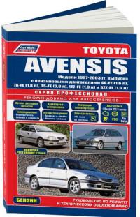
Руководство по эксплуатации, техническому обслуживанию и ремонту + каталог расходных запчастей автомобиля Toyota Avensis 1997-2003 годов выпуска с бензиновыми двигателями объемом 1,6/1,8/2,0 л.
- Автор: —
- Издательство: Легион-Автодата
- Год издания: —
- Страниц: 456
- Формат: —
- Размер: —
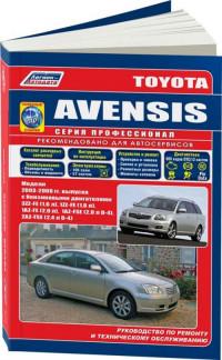
Руководство по эксплуатации, техническому обслуживанию и ремонту + каталог расходных запчастей автомобиля Toyota Avensis 2003-2008 годов выпуска с бензиновыми двигателями объемом 1,6/1,8/2,0/2,4 л.
- Автор: —
- Издательство: Легион-Автодата
- Год издания: —
- Страниц: 456
- Формат: —
- Размер: —

Руководство по эксплуатации, техническому обслуживанию и ремонту автомобиля Toyota Avensis с 2003 года выпуска.
- Автор: —
- Издательство: Монолит
- Год издания: —
- Страниц: 268
- Формат: —
- Размер: —
Руководство по эксплуатации и ремонту автомобилей Toyota Avensis с 2003 года выпуска с бензиновыми и дизельными двигателями.
- Автор: —
- Издательство: Гуси-Лебеди
- Год издания: —
- Страниц: 404
- Формат: —
- Размер: —

Руководство по эксплуатации и ремонту автомобиля Toyota Avensis с 2009 года выпуска с бензиновыми и дизельными двигателями.
- Автор: —
- Издательство: Монолит
- Год издания: —
- Страниц: 428
- Формат: —
- Размер: —
Руководство по эксплуатации и техническому обслуживанию автомобиля Toyota Avensis с 2002 года выпуска.
- Автор: —
- Издательство: MoToR
- Год издания: —
- Страниц: 372
- Формат: —
- Размер: —

Ознакомьтесь с правилами эксплуатации вашего автомобиля Toyota, изучив электронную версию руководства.
На данной странице представлены следующие типы руководств:
- Общее руководство для владельца
- Руководство по мультимедиа и навигации
- Руководство по вождению в условиях бездорожья
Сборник руководств на английском языке по техническому обслуживанию и ремонту автомобиля Toyota Avensis 1998-2002 годов выпуска.
- Автор: —
- Издательство: Toyota Motor Corporation
- Год издания: —
- Страниц: —
- Формат: PDF
- Размер: 651,2 Mb
Сборник руководств на английском языке по техническому обслуживанию и ремонту автомобиля Toyota Avensis 2003-2009 годов выпуска.
- Автор: —
- Издательство: Toyota Motor Corporation
- Год издания: —
- Страниц: —
- Формат: PDF, ISO
- Размер: 659,3 Mb
Руководство по техническому обслуживанию и ремонту автомобиля Toyota Avensis 1998-2003 годов выпуска.
- Автор: —
- Издательство: Алфамер
- Год издания: —
- Страниц: 336
- Формат: —
- Размер: —
Руководство по эксплуатации и техническому обслуживанию автомобиля Toyota Avensis 2005 года выпуска.
- Автор: —
- Издательство: Toyota Motor Corporation
- Год издания: 2004
- Страниц: 364
- Формат: PDF
- Размер: 66,4 Mb
Руководство по эксплуатации, техническому обслуживанию и ремонту + каталог расходных запчастей автомобиля Toyota Avensis 1997-2003 годов выпуска с бензиновыми двигателями объемом 1,6/1,8/2,0 л.
- Автор: —
- Издательство: Легион-Автодата
- Год издания: —
- Страниц: 456
- Формат: —
- Размер: —
Руководство по эксплуатации, техническому обслуживанию и ремонту + каталог расходных запчастей автомобиля Toyota Avensis 2003-2008 годов выпуска с бензиновыми двигателями объемом 1,6/1,8/2,0/2,4 л.
- Автор: —
- Издательство: Легион-Автодата
- Год издания: —
- Страниц: 456
- Формат: —
- Размер: —
Руководство по эксплуатации, техническому обслуживанию и ремонту автомобиля Toyota Avensis с 2003 года выпуска.
- Автор: —
- Издательство: Монолит
- Год издания: —
- Страниц: 268
- Формат: —
- Размер: —
Руководство по эксплуатации и ремонту автомобилей Toyota Avensis с 2003 года выпуска с бензиновыми и дизельными двигателями.
- Автор: —
- Издательство: Гуси-Лебеди
- Год издания: —
- Страниц: 404
- Формат: —
- Размер: —
Руководство по эксплуатации и ремонту автомобиля Toyota Avensis с 2009 года выпуска с бензиновыми и дизельными двигателями.
- Автор: —
- Издательство: Монолит
- Год издания: —
- Страниц: 428
- Формат: —
- Размер: —
Руководство по эксплуатации и техническому обслуживанию автомобиля Toyota Avensis с 2002 года выпуска.
- Автор: —
- Издательство: MoToR
- Год издания: —
- Страниц: 372
- Формат: —
- Размер: —
Steering Pad Switch Function
13
Head Unit Specifications
19
Speaker’s Specification
19
Multi-Information Display
20
Air Conditioner System
22
Windshield & Door Glass
23
SRS (Supplemental Restraint System) Airbag System
28
Major Technical Specifications
33
Electronic Circuit Inspection Procedure
51
Resistance Measuring Condition of Electronic Parts
51
Connector Checking Points
51
Repair Method of Connector Terminal
52
Handling of Wire Harness
52
How to Troubleshoot ECU Controlled Systems
56
For Using Hand-Held Tester
56
Introduction – How to Troubleshoot Ecu Controlled
57
Customer Problem Analysis
59
Symptom Confirmation and Diagnostic Trouble Code
60
Diagnostic Trouble Code Chart
64
Problem Symptoms Table
65
How to Use this Manual
67
Vehicle Identification and Serial Numbers
70
Identification Information
70
Jacking up and Supporting Vehicle
72
Bolts, Nuts, Screws and Fuses
72
Removal and Installation of Vacuum Hoses
74
For Vehicles Equipped with SRS Airbag and Seat Belt Pretensioner
75
Torque When Using Torque Wrench with Extension Tool
75
Horn Button Assembly (with Airbag)
76
Instrument Panel Passenger Airbag Assembly
77
Front Seat Airbag Assembly
78
Instrument Panel Lower Airbag Assembly
79
Curtain Shield Airbag Assembly
79
Seat Belt Pretensioner
80
Battery Terminal Removal and Installation
81
Airbag Sensor Assembly
81
SRS Wire Harness and Connector
81
Fuel Control Parts Removal and Installation
82
Engine Intake Parts Removal and Installation
82
Handling of Electronic Parts
82
Handling of Hose Clamps
83
For Vehicles Equipped with Mobile Communication Systems
83
For Vehicles Equipped with Traction Control (TRC) System
83
For Vehicles Equipped with Catalytic Converter
84
Vehicle Lift and Support Locations
85
Notice for Using Swing Arm Type Lift
86
Abbreviations Used in this Manual
87
Glossary of SAE and Toyota Terms
92
Preparation — Audio and Visual System
95
Preparation — Automatic Transmission/Trans
96
Preparation — Communication System
103
Preparation — Cooling
104
Preparation — Diagnostics
106
ABS with EBD & BA & TRC & VSC System
107
Preparation — Drive Shaft / Propeller Shaft
108
Preparation — Engine Control System
112
Preparation — Engine Hood/Door
113
Preparation — Engine Mechanical
114
Preparation — Exhaust
123
Preparation — Exterior/Interior Trim
124
Preparation — Front Suspension
125
Preparation — Heater and Air Conditioner
129
Preparation — Ignition
134
Preparation — Instrument Panel/Meter
135
Preparation — Lubrication
137
Preparation — Manual Transmission/Transaxle
140
Preparation — Parking Brake
143
Preparation — Power Steering
144
Preparation — Rear Suspension
146
Preparation — Sliding Roof/Convertible
149
Preparation — Starting and Charging
150
Preparation — Steering Column
151
Preparation — Supplemental Restraint System
152
Preparation — Tire and Wheel
154
Preparation — Vehicle Control System
155
Preparation — Windshield/Window Glass/Mirror
156
Preparation — Wiper and Washer
157
Audio and Visual System Torque Specification
158
Automatic Transmission/Transaxle Service Data
159
Communication System Torque Specification
170
Drive Shaft/Propeller Shaft/Axle Service Data
174
Emission Control Service Data
176
Engine Control System Service Data
177
Engine Hood/Door Torque Specification
180
Engine Mechanical Service Data
182
Exterior/Interior Trim Torque Specification
193
Front Suspension Service Data
194
Heater and Air Conditioning Service Data
199
Ignition Service Data
201
Instrument Panel/Meter Torque Specification
203
Lighting Torque Specification
206
Lubrication Service Data
207
Manual Transmission/Transaxle Service Data
210
Parking Brake Service Data
213
Power Steering Service Data
215
Rear Suspension Service Data
217
Seat Torque Specification
219
Seat Belt Torque Specification
220
Sliding Roof/Convertible Torque Specification
221
Standard Bolt — How to Determine Bolt Strength
222
How to Determine Nut Strength
223
Specified Torque for Standard Bolts
224
Starting and Charging Service Data
225
Steering Column Service Data
227
Supplemental Restraint System Torque Specification
229
Tire and Wheel Service Data
230
Windshield/Window Glass/Mirror Torque Specification
231
Wiper and Washer Torque Specification
232
Accelerator Pedal Assy (1AZ–FSE/1CD–FTV) Replacement
233
Camshaft Position Sensor (1CD–FTV) Replacement
234
Crankshaft Position Sensor (1CD–FTV) Replacement
235
Crankshaft Position Sensor (1CD–FTV) Inspection
236
Inspect Mass Air Flow Meter
236
Inspect Intake Shutter Assy
236
Inspect Diesel Engine Coolant Temperature Sensor
237
Inspect Injection or Supply Pump Assy
237
Inspect Diesel Turbo Inlet Air Temperature Sensor
237
Inspect Crankshaft Position Sensor
238
Inspect Camshaft Position Sensor
238
Inspect EFI Main Relay
239
Inspect Accelerator Pedal Relay
239
ECD System (1CD–FTV) On-Vehicle Inspection
240
Inspect Intake Shutter
240
Inspect Accelerator Pedal Position Sensor
241
Intake Shutter Assy (1CD–FTV) Components
243
Intake Shutter Assy Removal, Installation, Disassembly, Reassembly
244
Knock Sensor Components
246
Knock Sensor Replacement
250
Knock Sensor (1AZ–FE) Components
253
Knock Sensor (1AZ–FE) Replacement
257
Knock Sensor (1AZ–FSE) Components
260
Knock Sensor (1AZ–FSE) Replacement
265
Knock Sensor (1ZZ–FE/3ZZ–FE) Replacement
267
SFI System Inspection
268
Inspect Throttle Position Sensor
269
Inspect Engine Coolant Temperature Sensor
270
Inspect Circuit Opening Relay
271
SFI System (1AZ–FE) On-Vehicle Inspection
272
Inspect Power Steering Oil Pressure Sensor
272
Inspect Idle Air Control Valve
273
Inspect Camshaft Timing Oil Control Valve Assy
274
Inspect Throttle Body Assy
274
SFI System (1AZ–FSE) On-Vehicle Inspection
277
Inspect Throttle Body
278
SFI System (1ZZ–FE/3ZZ–FE) Inspection
279
SFI System (1ZZ–FE/3ZZ–FE) On-Vehicle Inspection
283
Throttle Body Assy (1AZ–FE) Components
285
Throttle Body Assy (1AZ–FE) Removal/Installation/Disassembly
287
Throttle Body Assy (1AZ–FSE)
291
Throttle Body Assy (1AZ–FSE) Replacement
293
Throttle Body Assy (1ZZ–FE) Components
296
Throttle Body Assy (1ZZ–FE) Removal, Installation, Disassembly
298
Throttle Body Assy (3ZZ–FE) Components
302
Throttle Body Assy (3ZZ–FE) Removal, Installation, Disassembly
304
Common Rail Assy (1CD–FTV) Components
306
Common Rail Assy (1CD–FTV) Replacement
308
Fuel Filter Assy (1CD–FTV) Replacement
312
Fuel Injector Assy Components
314
Fuel Injector Assy Replacement
316
Fuel Injector Assy (1AZ–FSE) Components
319
Fuel Injector Assy (1ZZ–FE/3ZZ–FE) Components
324
Fuel Injector Assy (1ZZ–FE/3ZZ–FE) Replacement
325
Fuel Pressure Pulsation Damper Assy Replacement
329
Fuel Pump Assy Components
330
Fuel Pump Assy Replacement
333
Fuel Pump Assy (Gasoline) Components
337
Fuel Pump Assy (Gasoline) Replacement
338
Fuel Pump Assy (Gasoline) Inspection
342
Fuel System On-Vehicle Inspection
344
Check Fuel Pump Operation and Fuel Tank
345
Fuel System (1AZ–FE) Precaution
347
Fuel System (1CD–FTV) Inspection
351
Fuel System (1ZZ–FE/3ZZ–FE) Inspection
353
Fuel System (1ZZ–FE/3ZZ–FE) On-Vehicle Inspection
355
Fuel System (1ZZ–FE/3ZZ–FE) Precaution
358
Fuel System (1AZ–FSE) Inspection
362
Fuel System (1AZ–FSE) Precaution
366
Fuel Tank Assy (Diesel) Components
369
Fuel Tank Assy (Diesel) Removal, Installation, Disassembly
372
Fuel Tank Assy (Gasoline) Components
379
Fuel Tank Assy (Gasoline) Removal, Installation, Disassembly
383
Injection or Supply Pump Assy (1CD–FTV) Components
391
Injection or Supply Pump Assy (1CD–FTV) Replacement
394
Injector Assy (1CD–FTV) Components
401
Injector Assy (1CD–FTV) Replacement
403
EGR System (1CD–FTV) Inspection
409
EGR System (1CD–FTV) On-Vehicle Inspection
411
Emission Control System (1AZ–FE) Inspection
412
Inspect Charcoal Canister Assy
412
Inspect Ventilation Valve Sub-Assy
412
Inspect Fuel Tank Cap Assy
412
Inspect Vacuum Switching Valve Assy No.1
413
Inspect Air Fuel Ratio Sensor
413
Inspect Heated Oxygen Sensor
414
Emission Control System (1AZ–FE) On-Vehicle Inspection
415
Inspect Air-Fuel Ratio Compensation System
415
Inspect Fuel Cut off RPM
415
Inspect Evaporative Emission Control System
415
Emission Control System (1AZ–FSE)
417
Emission Control System (1AZ–FSE) On-Vehicle Inspection
420
Emission Control System (1CD–FTV) On-Vehicle Inspection
422
Emission Control System (1ZZ–FE/3ZZ–FE) Inspection
423
Intake Air Control System (1AZ–FSE) Inspection
428
Inspect Intake Air Control Valve Assy
428
Intercooler Assy (1CD–FTV) Replacement
430
Turbo Charger System (1CD–FTV) Inspection
432
Turbo Charger System (1CD–FTV) Precaution
435
Turbocharger Sub-Assy (1CD–FTV) Components
437
Turbocharger Sub-Assy (1CD–FTV) Replacement
440
Camshaft (1AZ–FE) Components
447
Camshaft (1AZ–FE) Replacement
450
Camshaft (1AZ–FSE) Components
457
Camshaft (1AZ–FSE) Replacement
460
Camshaft (1CD–FTV) Components
466
Camshaft (1CD–FTV) Replacement
470
Camshaft (1ZZ–FE/3ZZ–FE) Components
478
Camshaft (1ZZ–FE/3ZZ–FE) Replacement
482
Chain Sub-Assy (1AZ–FE) Components
494
Chain Sub-Assy (1AZ–FE) Replacement
498
Chain Sub-Assy (1AZ–FSE) Components
526
Chain Sub-Assy (1ZZ–FE/3ZZ–FE) Components
530
Crankshaft Seal (1CD–FTV) Replacement
534
Cylinder Head Gasket (1AZ–FE) Components
537
Cylinder Head Gasket (1AZ–FE) Replacement
544
Cylinder Head Gasket (1AZ–FSE) Replacement
552
Cylinder Head Gasket (1CD–FTV) Components
561
Cylinder Head Gasket (1CD–FTV) Replacement
567
Cylinder Head Gasket (1ZZ–FE/3ZZ–FE) Components
577
Cylinder Head Gasket (1ZZ–FE/3ZZ–FE) Replacement
582
Drive Belt (1CD–FTV) Replacement
597
Engine (1AZ–FE) Inspection
598
Engine (1AZ–FSE) Inspection
602
Engine (1CD–FTV) Inspection
606
Engine (1ZZ–FE/3ZZ–FE) Inspection
609
Engine Rear Oil Seal (1AZ–FE) Replacement
613
Engine Rear Oil Seal (1AZ–FSE) Replacement
614
Engine Rear Oil Seal (1CD–FTV) Replacement
615
Engine Rear Oil Seal (1ZZ–FE/3ZZ–FE) Replacement
617
Fan and Generator V Belt (1AZ–FE) Replacement
620
Fan and Generator V Belt (1AZ–FSE) Replacement
621
Fan and Generator V Belt (1ZZ–FE/3ZZ–FE) Replacement
622
Partial Engine Assy (1AZ–FE) Components
623
Partial Engine Assy (1AZ–FE) Replacement
633
Partial Engine Assy (1CD–FTV) Components
647
Partial Engine Assy (1CD–FTV) Replacement
656
Partial Engine Assy (1ZZ–FE/3ZZ–FE) Components
675
Partial Engine Assy (1ZZ–FE/3ZZ–FE) Replacement
683
Timing Belt (1CD–FTV) Components
701
Timing Belt (1CD–FTV) Replacement
703
Timing Gear Cover Oil Seal (1ZZ–FE/3ZZ–FE) Replacement
710
Timing Gear Case or Timing Chain Case Oil Seal (1AZ–FE) Replacement
712
Timing Gear Case or Timing Chain Case Oil Seal (1AZ–FSE) Replacement
714
Valve Clearance (1AZ–FE) Adjustment
716
Valve Lifter Selection Chart (Intake)
718
Valve Lifter Selection Chart (Exhaust)
719
Valve Clearance (1ZZ–FE/3ZZ–FE) Adjustment
721
1ZZ-FE, 3ZZ-FE: Valve Lifter Selection Chart (Intake)
727
1ZZ-FE, 3ZZ-FE: Valve Lifter Selection Chart (Exhaust)
728
Exhaust Pipe Assy (1AZ–FE/1AZ–FSE) Components
734
Exhaust Pipe Assy (1AZ–FE/1AZ–FSE) Removal, Disassembly
735
Exhaust Pipe Assy (1CD–FTV) Components
737
Exhaust Pipe Assy (1CD–FTV) Removal, Installation, Disassembly
738
Exhaust Assy (1ZZ–FE/3ZZ–FE) Components
741
Exhaust Assy (1ZZ–FE/3ZZ–FE) Removal, Installation, Disassembly
742
Water Pump Assy (1ZZ–FE/3ZZ–FE) Inspection
746
Cylinder Block (1ZZ–FE/3ZZ–FE) Components
747
Cylinder Block (1ZZ–FE/3ZZ–FE) Overhaul
748
Cylinder Head Assy (1ZZ–FE/3ZZ–FE) Components
763
Cylinder Head Assy (1ZZ–FE/3ZZ–FE) Overhaul
764
Partial Engine Assy (1ZZ–FE/3ZZ–FE) Overhaul
777
Terms (1ZZ–FE/3ZZ–FE)
800
How to Use this Manual (1ZZ–FE/3ZZ–FE)
805
Repair Instruction (1NZ–FE/2NZ–FE)
811
Oil Pump Assy (1ZZ–FE/3ZZ–FE) Components
814
Oil Pump Assy (1ZZ–FE/3ZZ–FE) Overhaul
815
Generator Assy (1ZZ–FE/3ZZ–FE) Components
840
Generator Assy (1ZZ–FE/3ZZ–FE) Overhaul
841
Starter Assy (1ZZ–FE/3ZZ–FE) Components
847
Starter Assy (1ZZ–FE/3ZZ–FE) Overhaul
848
Cooling Fan System (1AZ–FE) On-Vehicle Inspection
855
Cooling Fan System (1AZ–FE) Inspection
856
Cooling Fan System (1AZ–FSE) On-Vehicle Inspection
857
Cooling Fan System (1AZ–FSE) Inspection
858
Cooling Fan System (1CD–FTV) On-Vehicle Inspection
859
Cooling Fan System (1CD–FTV) Inspection
860
Cooling Fan System (1ZZ–FE/3ZZ–FE) On-Vehicle Inspection
862
Cooling Fan System (1ZZ–FE/3ZZ–FE) Inspection
863
Radiator Assy (1ZZ–FE/3ZZ–FE) Replacement
864
Cooling System (1AZ–FE) On-Vehicle Inspection
866
Cooling System (1AZ–FE) Inspection
868
Cooling System (1AZ–FSE) On-Vehicle Inspection
870
Cooling System (1AZ–FSE) Inspection
872
Cooling System (1CD–FTV) On-Vehicle Inspection
874
Cooling System (1CD–FTV) Inspection
876
Cooling System (1ZZ–FE/3ZZ–FE) On-Vehicle Inspection
878
Cooling System (1ZZ–FE/3ZZ–FE) Inspection
880
Engine Coolant (1AZ–FE) Replacement
882
Engine Coolant (1AZ–FSE) Replacement
884
Engine Coolant (1CD–FTV) Replacement
886
Engine Coolant (1ZZ–FE/3ZZ–FE) Replacement
888
Radiator Assy (1AZ–FE) Replacement
890
Radiator Assy (1AZ–FSE) Replacement
891
Radiator Assy (1CD–FTV)
892
Thermostat (1AZ–FSE) Replacement
895
Thermostat (1CD–FTV) Replacement
896
Thermostat (1ZZ–FE/3ZZ–FE) Replacement
897
Thermostat (1AZ–FE) Replacement
898
Water Pump Assy (1AZ–FE) Replacement
899
Water Pump Assy (1AZ–FSE) Replacement
901
Water Pump Assy (1CD–FTV) Replacement
903
Water Pump Assy (1ZZ–FE/3ZZ–FE) Replacement
907
Lubrication System (1AZ–FE) On-Vehicle Inspection
908
Lubrication System (1AZ–FSE) On-Vehicle Inspection
910
Lubrication System (1CD–FTV) On-Vehicle Inspection
912
Lubrication System (1ZZ–FE/3ZZ–FE) On-Vehicle Inspection
914
Oil Cooler Assy (1CD–FTV) Replacement
916
Oil Filter Sub-Assy (1AZ–FE) Replacement
917
Oil Filter Sub-Assy (1AZ–FSE) Replacement
918
Oil Filter Sub-Assy (1CD–FTV) Replacement
919
Oil Filter Sub-Assy (1ZZ–FE/3ZZ–FE) Replacement
921
Oil Pump Assy (1AZ–FE) Replacement
923
Oil Pump Assy (1AZ–FSE) Replacement
927
Oil Pump Assy (1CD–FTV) Replacement
931
Oil Pump Assy (1ZZ–FE/3ZZ–FE) Replacement
939
Camshaft Position Sensor (1AZ–FE/1AZ–FSE) Replacement
940
Camshaft Position Sensor (1ZZ–FE/3ZZ–FE) Replacement
941
Crankshaft Position Sensor (1AZ–FE/1AZ–FSE) Replacement
942
Crankshaft Position Sensor (1ZZ–FE/3ZZ–FE) Replacement
943
Ignition System (1AZ–FE) On-Vehicle Inspection
944
Ignition System (1AZ–FE) Inspection
946
Ignition System (1AZ–FSE) On-Vehicle Inspection
949
Ignition System (1AZ–FSE) Inspection
951
Ignition System (1ZZ–FE/3ZZ–FE) On-Vehicle Inspection
953
Ignition System (1ZZ–FE/3ZZ–FE) Inspection
955
Charging System (1AZ–FE) Precautions
957
Charging System (1AZ–FE) On-Vehicle Inspection
958
Check Battery Electrolyte Level
958
Check Battery Voltage
958
Inspect Charging Circuit
959
Charging System (1AZ–FSE) Precaution
960
Charging System (1AZ–FSE) On-Vehicle Inspection
961
Charging System (1CD–FTV) Precaution
963
Charging System (1CD–FTV) On-Vehicle Inspection
964
Charging System (1ZZ–FE/3ZZ–FE) Precaution
967
Charging System (1ZZ–FE/3ZZ–FE) On-Vehicle Inspection
968
Generator Assy Replacement
970
Glow Plug Assy Replacement
974
Pre-Heating System On-Vehicle Inspection
975
Pre-Heating System Inspection
977
Starter Assy Replacement
978
Starting System Inspection
982
Front Shock Absorber with Coil Spring Overhaul
990
Dispose of Shock Absorber Assy Front LH
995
Front Suspension Components
996
Front Suspension Arm Sub-Assy Lower No.1 LH Replacement
1000
Front Suspension System Problem Symptoms Table
1008
Front Wheel Adjustment
1009
Measure Vehicle Height
1009
Inspect Camber, Caster and Steering Axis Inclination
1010
Lower Ball Joint Assy Front LH Replacement
1013
Stabilizer Bar Front Replacement
1015
Lower Control Arm Assy LH Replacement
1018
Rear Shock Absorber with Coil Spring Ovehaul
1021
Dispose of Shock Absorber Assy Rear LH
1027
Rear Suspension Components
1028
Rear Suspension Arm Assy No. 1 LH Overhaul
1030
Rear Suspension System Problem Symptoms Table
1039
Rear Wheel Adjustment
1040
Stabilizer Bar Rear Replacement
1044
Upper Control Arm Assy Replacement
1046
Wheel and Tire System Inspection
1048
Drive Shaft, Propeller Shaft, Axle Problem Symptoms Table
1050
Drive Shaft, Propeller Shaft, Axle On-Vehicle Inspection
1051
Front Axle Hub Sub-Assy LH Components
1052
Front Axle Hub Sub-Assy LH Replacement
1053
Front Axle LH Hub Bolt Replacement
1060
Front Drive Shaft Components
1061
Rear Axle Carrier Sub-Assy LH Components
1064
Rear Axle Carrier Sub-Assy LH Replacement
1065
Rear Axle LH Hub Bolt Replacement
1070
Brake Actuator Assy (W/ VSC) On-Vehicle Inspection
1071
Brake Actuator Assy Replacement
1073
Brake Booster Assy On-Vehicle Inspection
1075
Brake Booster Assy Components
1076
Brake Booster Assy Replacement
1077
Brake Fluid Bleeding
1091
Brake Master Cylinder Sub-Assy Components
1093
Brake Master Cylinder Sub-Assy Replacement
1095
Brake Pedal Sub-Assy Adjustment
1099
Brake Pedal Sub-Assy Components
1101
Brake Pedal Sub-Assy Replacement
1102
Brake System Precaution
1104
Brake System Problem Symptoms Table
1105
Front Brake Components
1107
Front Brake Overhaul
1108
Rear Disc Brake Components
1113
Rear Disc Brake Overhaul
1114
Skid Control Sensor Replacement
1120
Speed Sensor Front LH Replacement
1122
Steering Sensor Replacement
1124
Vacuum Pump Assy On-Vehicle Inspection
1127
Vacuum Pump Assy Components
1128
Vacuum Pump Assy Overhaul
1129
Yawrate Sensor Replacement
1134
Parking Brake Assy Components
1138
Parking Brake Assy Overhaul
1139
Parking Brake Cable Assy No.1 Components
1145
Parking Brake Cable Assy No.1 Replacement
1146
Parking Brake Cable Assy No.3 Components
1148
Parking Brake Cable Assy No.3 Replacement
1149
Parking Brake Lever Sub-Assy Components
1152
Parking Brake Lever Sub-Assy Replacement
1153
Parking Brake System Problem Symptoms Table
1155
Parking Brake System Adjustments
1156
Floor Shift Shift Lever Assy Components
1157
Floor Shift Shift Lever Assy Replacement
1158
Front Differential Oil Seal Replacement
1160
Manual Transaxle Assy Components
1164
Manual Transaxle Assy Replacement
1166
Manual Transaxle Oil On-Vehicle Inspection
1185
Manual Transaxle System Problem Symptoms Table
1186
Transmission Control Cable Assy Replacement
1187
Clutch Accumulator Assy Components
1190
Clutch Accumulator Assy Replacement
1191
Clutch Master Cylinder Assy Components
1192
Clutch Master Cylinder Assy Replacement
1193
Clutch Pedal Sub-Assy Adjustment
1196
Clutch Pedal Sub-Assy Components
1198
Clutch Pedal Sub-Assy Replacement
1200
Clutch Release Cylinder Assy Components
1206
Clutch Release Cylinder Assy Overhaul
1207
Clutch System Problem Symptoms Table
1211
Clutch Unit Componets
1212
Clutch Unit Overhaul
1215
Power Steering ECU Assy Replacement
1219
Steering Column Assy Components
1222
Electric Power Steering Diagram
1224
Steering Column Assy Overhaul
1226
Steering System Precaution
1237
Steering System Problem Symptoms Table
1238
Electric Power Steering
1239
Steering System On-Vehicle Inspection
1240
Power Steering System Precaution
1241
Power Steering System Problem Symptoms Table
1242
Power Steering System On-Vehicle Inspection
1244
Rack and Pinion Power Steering Gear Assy Components
1248
Rack and Pinion Power Steering Gear Assy Overhaul
1250
Steering Gear Assy Components
1260
Steering Gear Assy Overhaul
1261
Vane Pump Assy Components
1267
Vane Pump Assy Overhaul
1268
Vane Pump Assy (AZ Series) Components
1276
Vane Pump Assy (AZ Series) Overhaul
1277
Air Conditioning Control Assy Components
1286
Air Conditioning Control Assy Overhaul
1288
Air Conditioning Radiator Assy Components
1291
Air Conditioning System Precaution
1293
Air Conditioning System On-Vehicle Inspection
1295
Air Conditioning System Problem Symptoms Table
1298
Air Conditioning System Problem Inspection
1299
Blower Assy Components
1305
Blower Assy Overhaul
1306
Combustion Type Power Heater System On-Vehicle Inspection
1310
Combustion Type Power Heater System Diagnostic Trouble Code Chart
1312
Combustion Type Power Heater System Inspection
1314
Inspect Heater Switch Assy
1315
Combustion Type Power Heater System Problem Symptoms Table
1317
Heater Assy Replacement
1321
Hot Gas Type Power Heater System On-Vehicle Inspection
1323
Hot Gas Type Power Heater System Inspection
1324
Refrigerant On-Vehicle Inspection
1325
Inspect Refrigerant Volume
1332
Inspect Refrigerant Pressure with Manifold Gauge Set
1333
Refrigerant Replacement
1339
Refrigerant Line Components
1340
V (Cooler Compressor to Crankshaft Pulley) Belt No.1 Replacement
1347
W/Pulley Compressor Assy On-Vehicle Inspection
1349
W/Pulley Compressor Assy Replacement
1350
W/Receiver Condenser Assy On-Vehicle Inspection
1370
W/Receiver Condenser Assy Components
1371
W/Receiver Condenser Assy Overhaul
1373
Supplemental Restraint System
1390
Air Bag Sensor Assy Center Components
1390
Air Bag Sensor Assy Center Replacement
1391
Air Bag Sensor Front LH Components
1392
Air Bag Sensor Front LH Replacement
1393
Air Bag Sensor Rear LH Components
1394
Air Bag Sensor Rear LH Replacement
1395
Curtain Shield Air Bag Assy LH Components
1396
Curtain Shield Air Bag Assy LH Replacement
1398
Curtain Shield Air Bag Assy LH Disposal
1401
Front Seat Airbag Assy LH Disposal
1407
Steering Wheel Assy Components
1413
Steering Wheel Assy Replacement
1414
Horn Button Assy Disposal
1416
Instrument Panel Air Bag Assy Components
1423
Instrument Panel Air Bag Assy Replacement
1424
Instrument Panel Air Bag Assy Disposal
1425
Instrument Panel Passenger Air Bag Assy Components
1431
Instrument Panel Passenger Air Bag Assy Replacement
1432
Instrument Panel Passenger Air Bag Assy Disposal
1433
Seat Position Air Bag Sensor Components
1439
Seat Position Air Bag Sensor Replacement
1440
Side Air Bag Sensor Assy LH Components
1441
Side Air Bag Sensor Assy LH Replacement
1442
Spiral Cable Sub-Assy Replacement
1443
Supplemental Restraint System Precaution
1445
Supplemental Restraint System On-Vehicle Inspection
1455
Front Seat Belt Precautions
1460
Front Seat Belt Components
1461
Front Seat Belt Replacement
1462
Front Seat Belt Disposal
1464
Rear Seat Belt (Liftback Models) Components
1469
Rear Seat Belt (Liftback Models) Replacement
1470
Rear Seat Belt (Sedan Models) Components
1473
Rear Seat Belt (Sedan Models) Replacement
1474
Rear Seat Belt (Wagon Models) Components
1478
Rear Seat Belt (Wagon Models) Replacement
1479
Seat Belt Warning System Location
1482
Seat Belt Warning System Symptoms Table
1483
Seat Belt Warning System Inspection
1484
Center Stop Lamp Assy Replacement
1486
Fog Lamp Assy LH Replacement
1487
Fog Lamp Assy LH Adjustment
1488
Headlamp Dimmer Switch Assy Replacement
1489
Headlamp Leveling ECU Assy Replacement
1490
Headlamp Unit LH Components
1491
Headlamp Unit LH Replacement
1492
Headlamp Unit LH Adjustment
1495
Height Control Sensor Sub-Assy FR RH Replacement
1497
Height Control Sensor Sub-Assy Rear RH Replacement
1498
License Plate Lamp Assy Replacement
1499
Lighting System Precaution
1500
Headlight System Problem Symptoms Table
1501
Illuminated Entry System
1502
Lighting System On-Vehicle Inspection
1504
Headlamp Auto Levering Operation Check
1506
Headlamp Dimmer Switch Assy Inspection
1508
Hazard Warning Signal Switch Assy Inspection
1508
Front Door Courtesy Lamp Switch Assy Check
1509
Rear Door Courtesy Lamp Switch Assy Check
1509
Back Door Lock Assy Check
1509
Transponder Key Amplifier Check
1510
Room Lamp Assy No.2 Check
1511
Glove Box Lamp Assy Check
1511
Headlamp Leveling Switch Check
1512
Stop Lamp Switch Assy (W/O Cruise Control) Check
1512
Back up Lamp Switch Assy Check
1512
Height Control Sensor Sub-Assy FR RH Check
1513
Height Control Sensor Sub-Assy Rear RH Check
1513
Rear Combination Lamp Assy LH Replacement
1514
Side Turn Signal Lamp Assy LH Replacement
1515
Headlamp Washer Actuator Sub-Assy LH Replacement
1516
Rain Sensor Replacement
1517
Rear Wiper Motor Assy Replacement
1519
Rear Wiper Rubber Replacement
1521
Washer Nozzle Sub-Assy Adjustment
1523
Windshield Wiper Motor Assy Replacement
1525
Windshield Wiper Switch Assy Replacement
1529
Wiper and Washer System Precaution
1530
Wiper and Washer System Problem Symptoms Table
1531
Wiper and Washer System On-Vehicle Inspection
1533
Wiper and Washer System Inspection
1535
Wiper Rubber LH Replacement
1542
Amplifier Antenna Assy Replacement
1543
Antenna Cord Sub-Assy Replacement
1550
Antenna Cord Sub-Assy No.3 Replacement
1551
Audio and Visual System Precaution
1554
Audio and Visual System Components
1555
Cigarette Lighter Assy Replacement
1558
Front No.1 Speaker Assy Replacement
1561
Front No.2 Speaker Assy Replacement
1563
Multi-Display (CRT Display) Replacement
1564
Navigation Antenna Assy Replacement
1568
Navigation ECU Replacement
1569
Power Point Socket Assy Replacement
1570
Radio Receiver Assy Replacement
1571
Rear Speaker Assy Replacement
1572
Rear Speaker Assy No.2 Replacement
1574
Window Glass (Antenna Wire) Repair
1575
Power Source Location
1576
High Pitched Horn Assy Replacement
1583
Horn System Location
1584
Horn System Problem Symptoms Table
1585
Horn System Inspection
1586
Low Pitched Horn Assy Replacement
1587
Back Door Glass Components
1588
Back Door Glass Replacement
1589
Inner Rear View Mirror Assy Replacement
1607
Outer Rear View Mirror Assy LH Replacement
1608
Power Mirror Control System On-Vehicle Inspection
1609
Power Mirror Control System Location
1611
Power Mirror Control System Problem Symptoms Table
1612
Power Mirror Control System Inspection
1613
Power Mirror Control System Reset
1630
Quarter Window Assy LH Components
1631
Quarter Window Assy LH Replacement
1632
Window Defogger System Location
1636
Window Defogger System Problem Symptom Table
1639
Window Defogger System Inspection
1640
Windshield Glass Components
1645
Windshield Glass Replacement
1646
Combination Meter Problem Symptoms Table
1653
Combination Meter On-Vehicle Inspection
1655
Inspect Output Signal of Vehicle Speed
1655
Inspect Fuel Receiver Gauge
1656
Inspect Fuel Level Warning
1656
Inspect Coolant Temperature Receiver Gauge Warning Light
1656
Inspect Seat Belt Warning Light and Buzzer
1657
Inspect Low Oil Pressure Warning Light
1657
Inspect Brake Warning Light
1657
Inspect Brake Fluid Level Warning Switch
1657
Inspect Key Reminder Warning Buzzer
1658
Combination Meter Assy Overhaul
1659
Instrument Panel/Meter Components
1660
Instrument Panel Sub-Assy Lower Precaution
1663
Multi-Display (CRT Display) Display Replacement
1664
Front Power Seat Control System Location
1665
Front Power Seat Control System Problem Symptoms Table
1667
Front Power Seat Control System On-Vehicle Inspection
1668
Front Power Seat Control System Inspection
1670
Front Seat Assembly LH (Manual Seat Type) Components
1674
Front Seat Assembly LH (Manual Seat Type) Overhaul
1675
Front Seat Assembly (Power Seat Type) Components
1678
Front Seat Assembly (Power Seat Type) Overhaul
1679
Rear Seat Assy (40/60 Folding Flip-Up Cushion) Components
1683
Rear Seat Assy (40/60 Folding Flip-Up Cushion) Overhaul
1685
Rear Seat Assy (40/60 Folding) Components
1689
Rear Seat Assy (40/60 Folding) Overhaul
1691
Rear Seat Assy (United Fixed) Components
1695
Rear Seat Assy (United Fixed) Overhaul
1696
Seat Heater System Location
1698
Seat Heater System Problem Symptoms Table
1700
Seat Heater System Inspection
1701
Fuel Lid Opener System Location
1704
Fuel Lid Opener System Problem Symptoms Table
1706
Fuel Lid Opener System Inspection
1707
Key Reminder Warning System On-Vehicle Inspection
1708
Power Door Lock Control System On-Vehicle Inspection
1709
Power Door Lock Control System Inspection
1711
Theft Deterrent System On-Vehicle Inspection
1722
Forced Door Lock Control
1725
Alarm Memory Function
1725
Security Indicator Output
1725
Intrusion (Theft Warning) Sensor
1726
Theft Warning (Self-Power) Siren
1726
Transmitter Battery Replacement
1727
Transmitter Sub-Assy Module Set Door Control Replacement
1728
Transmitter Sub-Assy Module Set Door Control Inspection
1729
Register Recognition Code
1731
Flow Chart of Recognition Code Registration
1732
Wireless Door Lock Control System Precaution
1736
Wireless Door Lock Control System On-Vehicle Inspection
1737
Sliding Roof Components
1739
Sliding Roof Replacement
1746
Sliding Roof System Location
1747
Sliding Roof System On-Vehicle Inspection
1749
Sliding Roof System Problem Symptoms Table
1751
Sliding Roof System Problem Inspection
1752
Reset Sliding Roof Motor
1753
Back Door Components
1754
Back Door Adjustment
1755
Back Door Stay Replacement
1764
Back Door Stay Disposal
1765
Front Door Components
1766
Front Door Adjustment
1768
Luggage Compartment Door Components
1783
Luggage Compartment Door Adjustment
1784
Luggage Door Hinge Torsion Bar Replacement
1786
Backdoor Garnish Sub-Assy Outside Replacement
1788
Front Bumper Components
1790
Front Bumper Replacement
1792
Front Floor Footrest Replacement
1794
Fuel Lid Lock Control Assy Components
1796
Fuel Lid Lock Control Assy Replacement
1799
Luggage Compartment Door Garnish Sub-Assy Outside Replacement
1802
Name Plate Replacement
1803
Outside Moulding LH Replacement
1807
Rear Bumper Components
1809
Rear Bumper Replacement
1810
Rear Door Belt Moulding Assy LH Replacement
1815
Rear Spoiler Replacement
1816
Rocker Panel Moulding LH Replacement
1818
Roof Drip Side Finish Moulding Center LH Replacement
1819
Roof Handling Assy Components
1820
Roof Handling Assy Replacement
1823
Ignition or Starter Switch Assy Replacement
1848
Ignition or Starter Switch Assy Inspection
1849
Manual B — How to Use
1851
Continuity and Resistance Check
1860
Finding a Short Circuit
1861
Disconnection of Male and Female Connectors
1861
How to Replace Terminal
1862
Glossary of Terms and Symbols
1866
Electrical Wiring Routing
1880
Engine Immobiliser System
1926
Engine Immobiliser System Electrical Diagram
1944
Multiplex Communication System (Communication Bus) Electrical Diagram
1945
Multiplex Communication System (RHD) Electrical Diagram
1946
Headlight (W/ Daytime Running Light) Electrical Diagram
1957
Headlight (W/O Daytime Running Light) Electrical Diagram
1961
Front Fog Light Electrical Diagram
1963
Rear Fog Light Electrical Diagram
1964
Taillight Electrical Diagram
1965
Turn Signal and Hazard Warning Light
1967
Stop Light Electrical Diagram
1969
Back–Up Light Electrical Diagram
1970
Illumination Electrical Diagram
1971
Interior Light (RHD) Electrical Diagram
1976
Headlight Beam Level Control (W/ HID) Electrical Diagram
1980
Headlight Beam Level Control (W/O HID) Electrical Diagram
1982
Headlight Cleaner (W/ HID) Electrical Diagram
1984
Headlight Cleaner (W/O HID) Electrical Diagram
1985
Key Reminder and Light Reminder Electrical Diagram
1986
Seat Belt Warning Electrical Diagram
1988
ECT and A/T Indicator Electrical Diagram
1990
Cruise Control Electrical Diagram
2004
VSC Electrical Diagram
2012
ABS Electrical Diagram
2018
SRS Electrical Diagram
2022
EPS Electrical Diagram
2026
Door Lock Control (RHD) and Theft Deterrent Electrical Diagram
2028
Wireless Door Lock Control (RHD) Electrical Diagram
2037
Double Locking Electrical Diagram
2041
Power Window (RHD) Electrical Diagram
2046
Front Wiper and Washer (W/ Auto Wiper System) Electrical Diagram
2050
Front Wiper and Washer (W/O Auto Wiper System) Electrical Diagram
2052
Rear Wiper and Washer Electrical Diagram
2054
Moon Roof Electrical Diagram
2055
Shift Lock Electrical Diagram
2057
Horn Electrical Diagram
2058
Fuel Lid Opener Electrical Diagram
2059
Fuel Heater Electrical Diagram
2060
Automatic Glare – Resistant EC Mirror Electrical Diagram
2061
Cigarette Lighter Electrical Diagram
2062
Power Outlet Electrical Diagram
2063
Front Window Deicer Electrical Diagram
2064
Rear Window Defogger Electrical Diagram
2065
Mirror Heater Electrical Diagram
2067
Remote Control Mirror Electrical Diagram
2068
Power Seat Electrical Diagram
2069
Seat Heater Electrical Diagram
2071
Navigation System (Map Type) Electrical Diagram
2073
Multi–Display (W/O Navigation System Map Type) Electrical Diagram
2077
Radio and Player Electrical Diagram
2079
Radiator Fan and Condenser Fan Electrical Diagram
2087
Air Conditioner (Automatic A/C) Electrical Diagram
2090
Power Heater (Hot Gas Type Automatic A/C) Electrical Diagram
2091
Power Heater (Hot Gas Type Manual A/C) Electrical Diagram
2097
Heater Electrical Diagram
2098
Power Heater (Electrical Type) Electrical Diagram
2101
Power Heater (Combustion Type) Electrical Diagram
2103
Power Source (Current Flow Chart)
2111
Engine Room R/B No.1 (1CD–FTV)
2116
Engine Room R/B No.1 (Gasoline)
2117
Engine Room R/B No.2
2118
Engine Room R/B No.3
2118
Engine Room R/B No.4
2119
Part Number of Connectors
2137
Overall Electrical Wiring Diagram
2143

On the pages of this book you will find only useful information:
A step-by-step guide to the repair of various components and assemblies of the car.
Self-service and care instructions.
Valuable information on vehicle design and how to prevent malfunctions.
Catalog of consumables for maintenance.
Content of the manual:
- Daily checks and troubleshooting
- Car operation in winter
- Operation and maintenance manual
- Precautions and safety rules when working on a car
- Basic tools, measuring devices and methods of working with them
- Petrol engines
- Diesel Engines
- Engine management and power supply system
- Lubrication system
- Cooling system
- Intake and exhaust system
- Manual Transmission
- Variable speed drive
- Drive shafts
- Chassis
- Brake system
- Steering
- Body
- Passive safety system
- Heating, ventilation and air conditioning system
- Electrical equipment and electrical systems
- Wiring diagrams
Toyota Avensis 1997, sedan, 1st generation, T220
1.6 l, 101 hp, gasoline, manual transmission, front-wheel drive 1587 4A-FE
1.6 l, 101 hp, gasoline, automatic transmission, front-wheel drive 1587 4A-FE
1.6 l, 110 hp, gasoline, manual transmission, front-wheel drive 1587 4A-FE
1.8 l, 110 hp, gasoline, manual transmission, front-wheel drive 1762 7A-FE
1.8 l, 110 hp, gasoline, automatic transmission, front-wheel drive 1762 7A-FE
2.0 l, 90 hp, diesel, manual transmission, front-wheel drive 1975 2C-TE
2.0 l, 110 hp, diesel, manual transmission, front-wheel drive 1995 1CD-FTV
2.0 l, 128 hp, gasoline, manual transmission, front-wheel drive 1998 3S-FE
2.0 l, 128 HP, gasoline, automatic transmission, front-wheel drive 1998 3S-FE
Toyota Avensis 2000, sedan, 1st generation, T220
1.6 l, 110 hp, gasoline, manual transmission, front-wheel drive 1598 3ZZ-FE
1.8 l, 128 hp, gasoline, manual transmission, front-wheel drive 1794 1ZZ-FE
1.8 l, 128 hp, gasoline, automatic transmission, front-wheel drive 1794 1ZZ-FE
2.0 l, 110 hp, diesel, manual transmission, front-wheel drive 1995 1CD-FTV
2.0 l, 150 HP, gasoline, manual transmission, front-wheel drive 1998 1AZ-FSE
2.0 l, 150 HP, gasoline, automatic transmission, front-wheel drive 1998 1AZ-FSE
2.0 l, 128 hp, gasoline, manual transmission, front-wheel drive 1998 3S-FE
2.0 l, 128 HP, gasoline, automatic transmission, front-wheel drive 1998 3S-FE
Toyota Avensis 2003, station wagon, 2nd generation, T250
1.6 l, 110 hp, gasoline, manual transmission, front-wheel drive 1598 3ZZ-FE
1.8 l, 129 hp, gasoline, manual transmission, front-wheel drive 1794 1ZZ-FE
1.8 l, 129 hp, gasoline, automatic transmission, front-wheel drive 1794 1ZZ-FE
2.0 l, 116 hp, diesel, manual transmission, front-wheel drive 1995 1CD-FTV
2.4 l, 163 HP, gasoline, automatic transmission, front-wheel drive 2362 2AZ-FSE
Toyota Avensis 2006, sedan, 2nd generation, T250
1.6 l, 110 hp, gasoline, manual transmission, front-wheel drive 1598 3ZZ-FE
1.8 l, 129 hp, gasoline, manual transmission, front-wheel drive 1794 1ZZ-FE
1.8 l, 129 hp, gasoline, automatic transmission, front-wheel drive 1794 1ZZ-FE
2.0 l, 129 hp, diesel, manual transmission, front-wheel drive 1995 1CD-FTV
2.0 l, 147 hp, gasoline, manual transmission, front-wheel drive 1998 1AZ-FSE
2.0 l, 147 HP, gasoline, automatic transmission, front-wheel drive 1998 1AZ-FSE
2.2 l, 150 hp, diesel, manual transmission, front-wheel drive 2231 2AD-FTV
2.2 l, 177 hp, diesel, manual transmission, front-wheel drive 2231 2AD-FHV
2.4 l, 163 HP, gasoline, automatic transmission, front-wheel drive 2362 2AZ-FSE
Toyota Avensis 2008, sedan, 3rd generation, T270
1.6 l, 132 hp, gasoline, manual transmission, front-wheel drive 1598 1ZR-FAE
1.8 l, 147 hp, gasoline, manual transmission, front-wheel drive 1797 2ZR-FAE
1.8 L, 147 HP, petrol, variator (CVT), front wheel drive 1797 2ZR-FAE
2.0 l, 152 hp, gasoline, manual transmission, front-wheel drive 1986 3ZR-FAE
2.0 L 152 HP Gasoline CVT Front Wheel Drive 1986 3ZR-FAE
2.0 l, 126 hp, diesel, manual transmission, front-wheel drive 1998 1AD-FTV
2.2 l, 150 hp, diesel, manual transmission, front-wheel drive 2231 2AD-FTV
2.2 l, 150 hp, diesel, automatic transmission, front-wheel drive 2231 2AD-FTV
2.2 l, 177 hp, diesel, manual transmission, front-wheel drive 2231 2AD-FHV
Toyota Avensis 2005 Service Repair Manual Download
2001-2007 Toyota Avensis Verso / Picnic Service Manual Download
2002-2007 Toyota Avensis Chassis and Body Repair Manual (RM1018E) Download
Download Toyota Avensis 2003-05 Body Repair Manual (BRM118E) Download
1ZZ–FE,3ZZ–FE Engine Repair Manual Online PDF Download
2002-2007 Toyota Avensis Engine Repair Manual Download
Engine Repair Manual 1ZZ-FE, 3ZZ-FE Download
Toyota Avensis 1997-2003 Service Manual Download
Toyota Avensis 1998 Service Manual Download
Toyota Avensis 1998-2002 Repair Manual Download
Toyota Avensis 2003 Service Manual Download
Toyota Avensis 2003-2009 Service Information Library Download
Toyota Avensis Verso 2001 Service Manual Download
Toyota Avensis Verso 2001-2007 Service Information Library Download
2002-2007 Toyota Avensis Wiring Diagram Download
2002-07 Toyota Avensis Wiring Diagram (EWD526E) Download
Toyota Avensis AZT250,ZZT250,ZZT251,CDT250 Wiring Diagram 526 & 625 Download
Toyota Avensis 2003-2009 EWD 526E Wiring Diagrams Download
TOYOTA AVENSIS 2008 INTRODUCTION Download
TOYOTA AVENSIS 2008 PREPARATION Download
TOYOTA AVENSIS 2008 SERVICE SPECIFICATIONS Download
TOYOTA AVENSIS 2008 DIAGNOSTICS Download
TOYOTA AVENSIS 2008 ENGINE CONTROL SYSTEM Download
TOYOTA AVENSIS 2008 ENGINE MECHANICAL Download
TOYOTA AVENSIS 2008 COOLING Download
TOYOTA AVENSIS 2008 SUPPLEMENTAL RESTRAINT SYSTEM Download
TOYOTA AVENSIS 2008 INSTRUMENT PANEL/METER Download
TOYOTA AVENSIS INTRODUCTION SERVICE MANUAL Download
TOYOTA AVENSIS PREPARATION SERVICE MANUAL Download
TOYOTA AVENSIS SERVICE SPECIFICATIONS SERVICE MANUAL Download
TOYOTA AVENSIS DIAGNOSTICS SERVICE MANUAL Download
TOYOTA AVENSIS ENGINE CONTROL SYSTEM SERVICE MANUAL Download
TOYOTA AVENSIS FUEL SYSTEM SERVICE MANUAL Download
TOYOTA AVENSIS EMISSION CONTROL SERVICE MANUAL Download
TOYOTA AVENSIS INTAKE SERVICE MANUAL Download
TOYOTA AVENSIS ENGINE MECHANICAL SERVICE MANUAL Download
TOYOTA AVENSIS EXHAUST SERVICE MANUAL Download
TOYOTA AVENSIS COOLING SERVICE MANUAL Download
TOYOTA AVENSIS LUBRICATION SERVICE MANUAL Download
TOYOTA AVENSIS IGNITION SERVICE MANUAL Download
TOYOTA AVENSIS STARTING & CHARGING SERVICE MANUAL Download
TOYOTA AVENSIS FRONT SUSPENSION SERVICE MANUAL Download
TOYOTA AVENSIS TIRE & WHEEL SERVICE MANUAL Download
TOYOTA AVENSIS DRIVE SHAFT / PROPELLER SHAFT SERVICE MANUAL Download
TOYOTA AVENSIS BRAKE SERVICE MANUAL Download
TOYOTA AVENSIS AUTOMATIC TRANSMISSION / TRANS SERVICE MANUAL Download
TOYOTA AVENSIS HEATER & AIR CONDITIONER SERVICE MANUAL Download
ABBREVIATIONS Download
RELAY LOCATIONS Download
ELECTRICAL WIRING ROUTING Download
CONNECTOR LIST Download
PART NUMBER OF CONNECTORS Download
OVERALL ELECTRICAL WIRING DIAGRAM Download
INTRODUCTION Download
PREPARATION Download
SERVICE SPECIFICATIONS Download
DIAGNOSTICS Download
CLUTCH Download
C50, C250 MANUAL TRANSAXLE Download
E351 MANUAL TRANSAXLE Download
S54, S55 MANUAL TRANSAXLE Download
A246E AUTOMATIC TRANSAXLE Download
U240E AUTOMATIC TRANSAXLE Download
SUSPENSION AND AXLE Download
BRAKE Download
STEERING Download
BODY ELECTRICAL Download
BODY Download
AIR CONDITIONING Download
(BRM075) BODY PANEL REPLACEMENT Download
(BRM075) BODY PANEL CONSTRUCTION Download
(BRM075) PLASTIC BODY PARTS Download
(BRM075) ANTI-RUST TREATMENT Download
(BRM075) BODY DIMENSIONS Download
-
nekesha
- Администратор
- Сообщения: 1668
- Зарегистрирован: 17 дек 2014, 03:43
- Благодарил (а): 2 раза
- Поблагодарили: 6 раз
Toyota Avensis 1997-2003 / Тайота Авенсис 1997-2003
Руководство по эксплуатации, техобслуживанию и ремонту Toyota Avensis / Тайота Авенсис
Operation, Maintenance and Repair Manual Toyota Avensis

- Года выпуска: 1997-2003
Бензиновые двигатели: 4A-FE, 7A-FE, 3S-FE, 1ZZ-FE, 3Z-FE
Year of release: 1997-2003
Gasoline engines: 4A-FE, 7A-FE, 3S-FE, 1ZZ-FE, 3Z-FE
- Язык: Русский
Формат: PDF
Размер: 187,7 Мб
Russian language
Format: PDF
Size: 187.7 MB
Скачать документацию Toyota Avensis / Тайота Авенсис
Download the documentation of Toyota Avensis
для распаковки используйте пароль — avtoproblem-net.ru
use the password to unpack — avtoproblem-net.ru

- Manuals
- Brands
- Toyota Manuals
- Automobile
- Avensis ZZT251 2003
- Service and repair manual
-
Contents
-
Table of Contents
-
Troubleshooting
-
Bookmarks
Quick Links
Related Manuals for Toyota Avensis ZZT251 2003
Summary of Contents for Toyota Avensis ZZT251 2003
-
Page 2
MO-2 NEW MODEL OUTLINE EXTERIOR APPEARANCE 4-Door Sedan 240MO01 240MO02 http://vnx.su… -
Page 3
MO-3 NEW MODEL OUTLINE 5-Door Liftback 240MO03 240MO04 http://vnx.su… -
Page 4
MO-4 NEW MODEL OUTLINE 5-Door Wagon 240MO05 240MO06 http://vnx.su… -
Page 5: Model Code
MO-5 NEW MODEL OUTLINE MODEL CODE ZZT250 L – A E M N K W BASIC MODEL CODE GEAR SHIFT TYPE ZZT250 : With 3ZZ FE Engine M : 5 Speed Manual, Floor ZZT251 : With 1ZZ FE Engine P : 4 Speed Automatic, Floor AZT250 : With 1AZ FSE Engine : With 1AZ FE Engine GRADE…
-
Page 6
MO-6 NEW MODEL OUTLINE MODEL LINE-UP EUROPE TRANSAXLE BODY BODY ENGINE GRADE 5-Speed Manual TYPE TYPE C250 E354 E357 ENTRY ZZT250L(R)-AEMNKW — — — Sedan MID TECHNICAL ZZT250L-AEMEKW — — — 3ZZ-FE MID ELEGANT ZZT250L-AEMGKW — — — Liftback ENTRY ZZT250L(R)-ALMNKW —… -
Page 7: Front View
MO-7 NEW MODEL OUTLINE EXTERIOR Front View D The front view is dynamically expressive, with innovative headlights and a front bumper design that has a sense of stability with upper and lower thickness. D The headlight low beams feature projectors and have an innovative shape. Sedan and Liftback Models 240MO07 Headlight…
-
Page 8: Rear View
MO-8 NEW MODEL OUTLINE Rear View D The rear combination lens features an elegant, innovative shape. D The luggage compartment door and back door were given a greater sense of volume for a high-quality feel. 4-Door Sedan Taillight Stop Light 240MO11 Back Up or Turn Signal Light…
-
Page 9: Side View
MO-9 NEW MODEL OUTLINE Side View D The side view communicates a sense of balance, with a large cabin structure that expresses a sense of stability and elegance. D The side view has an elegant and dynamic shape thanks to two character lines. 4-Door Sedan 240MO16 5-Door Liftback…
-
Page 10
MO-10 NEW MODEL OUTLINE Tire & Disc Wheel Tire Size 195 / 65 R15 205 / 55 R16 Size 15 x 6 J 16 x 6 1 / 2 J 16 x 6 1 / 2 JJ Disc Wheel Material Steel Steel Aluminum… -
Page 11
MO-11 NEW MODEL OUTLINE INTERIOR 240MO24 Sedan Model 240MO25 240MO26 Liftback Model Wagon Model http://vnx.su… -
Page 12
MO-12 NEW MODEL OUTLINE Instrument Panel D The instrument panel’s design, composed of smooth curving lines, expresses the cabin’s spaciousness. D The use of painted, surface-treated, and chrome plated parts, as well as the greatest possible minimization of openings and break lines, express a sense of quality. Chrome plated parts Painted parts and surface-treated parts… -
Page 13: Steering Wheel
MO-13 NEW MODEL OUTLINE Steering Wheel D ENTRY grade models feature a urethane 4-spoke type steering wheel, and MID TECHNICAL and MID ELEGANT grade models feature a leather 4-spoke type steering wheel. D Europe models feature a steering pad switch that enables drivers to operate the audio system, switch to trip information display, and turn the navigation system’s voice recognition function on and off without removing their hands from the steering wheel.
-
Page 14: Front Seat
MO-14 NEW MODEL OUTLINE Seat D The seat features a high-quality finish with an elegant stitch. D Leather seats are available as an option for MID TECHNICAL and MID ELEGANT grade with the 1AZ-FSE or 1CD-FTV engine models. 240MO34 Front Seat D Power seats are available as a set option with leather seats.
-
Page 15: Rear Seat
MO-15 NEW MODEL OUTLINE Rear Seat D ENTRY grade sedans feature a fixed seat; other models feature seats with a 60:40 separate seat back. D Liftback and wagon models feature a 60:40 separate seat. 240MO40 240MO41 240MO43 Fixed Seat 60:40 Separate Seat Back 60:40 Separate Seat D CRS (Child Restraint System) ISO-FIX bar and CRS tether anchor bracket for securing child seats have been provided on all the vehicle.
-
Page 16
MO-15 NEW MODEL OUTLINE Rear Seat D ENTRY grade sedans feature a fixed seat; other models feature seats with a 60:40 separate seat back. D Liftback and wagon models feature a 60:40 separate seat. 240MO40 240MO41 240MO43 Fixed Seat 60:40 Separate Seat Back 60:40 Separate Seat D CRS (Child Restraint System) ISO-FIX bar and CRS tether anchor bracket for securing child seats have been provided on all the vehicle. -
Page 17: Luggage Cover
MO-16 NEW MODEL OUTLINE 5-Door Wagon The luggage room features an abundance of items for ease of use. Grocery Bag Hook (Both Side) Auxiliary Box Tie-down Hook (Right / Left) Deck Under Tray Tool Box Tie-down Hook Auxiliary Box CRS Tether Anchor Bracket Auxiliary Box CRS Tether…
-
Page 18: Trip Information
MO-17 NEW MODEL OUTLINE EQUIPMENT Multi Display A multi display is available as an option for MID TECHNICAL and MID ELEGANT grade Europe models. Navigation and trip information can be displayed on the multi display. Navigation System D Through the use of the GPS (Global Positioning System) and map data in a DVD (Digital Versatile Disc), the navigation system analyzes the position of the vehicle and indicates that position on the map that is displayed on this screen.
-
Page 19: Audio System
MO-18 NEW MODEL OUTLINE Audio System D The audio system has a head unit with three built-in functions: CD player, cassette player, and radio. D By adopting new digital sound processing program, this unit can emphasize sound faithfully without phase distortion, and produce extremely clear and powerful sound. Figure for image No distortion Original…
-
Page 20
MO-19 NEW MODEL OUTLINE Location Front Door Speaker Front Tweeter Glass Antenna Rear Tweeter Rear Door Speaker Rear Door Speaker Rear Tweeter Front Door Speaker 240MO69 Sedan Model Glass Antenna Glass Antenna 240MO70 240MO71 Liftback Model Wagon Model Multi-information Display D A multi-information display is standard equipment on MID TECHNICAL and MID ELEGANT grade Europe models… -
Page 21
MO-19 NEW MODEL OUTLINE Location Front Door Speaker Front Tweeter Glass Antenna Rear Tweeter Rear Door Speaker Rear Door Speaker Rear Tweeter Front Door Speaker 240MO69 Sedan Model Glass Antenna Glass Antenna 240MO70 240MO71 Liftback Model Wagon Model Multi-information Display D A multi-information display is standard equipment on MID TECHNICAL and MID ELEGANT grade Europe models… -
Page 22: Air Conditioner System
MO-20 NEW MODEL OUTLINE Air Conditioner System D A manual air conditioner is standard equipment on ENTRY grade models and an automatic air conditioner on MID TECHNICAL and MID ELEGANT grade models. 240MO95 240MO96 Manual Air Conditioner Control Panel Automatic Air Conditioner Control Panel for LHD model for LHD model D The automatic air conditioner employs a left/right independent temperature control system.
-
Page 23
MO-21 NEW MODEL OUTLINE Windshield & Door Glass Dark gray privacy glass is available as an option for the rear door glass, rear quarter glass, and back door glass of wagon models. Windshield Back Window Front Door Glass Glass Glass Rear Door 240MO73 240MO74… -
Page 24: Rear Sunshade
MO-22 NEW MODEL OUTLINE Rear Sunshade A hand-operated rear sun shade is available as an option for Europe sedans and liftback models and is standard equipment on General Countries sedan models. 240MO82 240MO81 Sedan Model Liftback Model Power Outlet The back surface of the console is equipped with a 12V-120W power outlet for MID TECHNICAL and MID ELEGANT grade only.
-
Page 25
MO-23 NEW MODEL OUTLINE PERFORMANCE Power Train Engine Engine 240MO100 Type 1ZZ-FE 3ZZ-FE Valve Mechanism 16-Valve DOHC with VVT-i 16-Valve DOHC with VVT-i Displacement 1794 cm (109.5 cu. in.) 1598 cm (97.5 cu. in.) Max. Output 95 kW / 6000 rpm 81 kW / 6000 rpm Max. -
Page 26
MO-24 NEW MODEL OUTLINE Transaxle 240MO101 Transaxle Manual Transaxle Type C250 E354 E357 Combination with Engine 3ZZ-FE 1ZZ-FE 1AZ-FE & 1AZ-FSE 1CD-FTV Gear Ratio 1st 3.545 3.545 3.538 3.538 1.904 1.904 2.045 1.913 1.310 1.310 1.333 1.258 0.969 1.031 1.028 0.918 0.815 0.815… -
Page 27
MO-25 NEW MODEL OUTLINE Chassis Front Suspension Rear Suspension MacPhason Strut Type Double Wishbone Type Type Type Type Independent Suspension Type Suspension 240MO99 EPS Model Steering EPS (Electoronic Power Steering) (for 1ZZ-FE and 3ZZ-FE) Type Ty e Hydraulic Type Power Steering (for 1AZ-FSE, 1AZ-FE and 1CD-FTV) Brake for 15-inch Wheel (for 1ZZ-FE, 3ZZ-FE and 1AZ-FE) Front Brake Type… -
Page 28
MO-26 NEW MODEL OUTLINE SAFETY SRS (Supplemental Restraint System) Airbag System D A newly developed SRS knee airbag is standard equipment for the driver’s seat on the new Avensis. D The SRS knee airbag is positioned in the lower part of the instrument panel on the driver’s side to receive the impact of the driver’s lower body when he or she shifts forward in the event of a frontal collision, contributing to prevention of secondary impact to the lower body. -
Page 29
MO-27 NEW MODEL OUTLINE DIMENSIONS mm (in.) 4-Door Sedan 1760 1480 2700 1025 Front: 1505* , 1515* Rear: 1500* , 1515* 240MO92 5-Door Liftback 1760 1480 2700 1025 Front: 1505* , 1515* Rear: 1500* , 1515* 240MO93 5-Door Wagon 1760 1525 2700 1095… -
Page 30
MO-28 NEW MODEL OUTLINE EQUIPMENT LIST F: Standard OP: Option Europe General General Countries ENTRY TECHNICAL ELEGANT Exterior Rear Spoiler Wagon — Side Protection Moulding Windshield Green — Front Side Green Green Glass Glass Rear Side & Back Rear Side & Back Wagon Privacy —… -
Page 31
MO-29 NEW MODEL OUTLINE F: Standard OP: Option Europe General General Countries ENTRY TECHNICAL ELEGANT Body Electrical Projector Headlight Headlight HID (High lntensity Discharge) — — Manual — Headlight Beam Level Control System Automatic — — Headlight Cleaner System — Except for 1AZ-FE —… -
Page 32
MO-30 – MEMO – http://vnx.su… -
Page 33
AP-2 APPENDIX MAJOR TECHNICAL SPECIFICATIONS Area EUROPE Item Body Type 4-Door Sedan Vehicle Grade ENTRY MID TECHNICAL MID ELEGANT Model Code ZZT250R-AEMNKW ZZT250L-AEMNKW ZZT250L-AEMEKW ZZT250L-AEMGKW 4630 (182.3) 4630 (182.3) 4630 (182.3) 4630 (182.3) Length mm (in.) Overall Width mm (in.) 1760 (69.3) 1760 (69.3) 1760 (69.3) -
Page 34
AP-3 APPENDIX EUROPE 4-Door Sedan ENTRY MID TECHNICAL ZZT251R-AEMNKW ZZT251L-AEMNKW ZZT251R-AEPNKW ZZT251L-AEPNKW ZZT251R-AEMEKW ZZT251L-AEMEKW 4630 (182.3) 4630 (182.3) 4630 (182.3) 4630 (182.3) 4630 (182.3) 4630 (182.3) 1760 (69.3) 1760 (69.3) 1760 (69.3) 1760 (69.3) 1760 (69.3) 1760 (69.3) 1480 (58.3) 1480 (58.3) 1480 (58.3) 1480 (58.3) -
Page 35
AP-4 APPENDIX Area EUROPE Item Body Type 4-Door Sedan Vehicle Grade MID TECHNICAL MID ELEGANT Model Code ZZT251R-AEPEKW ZZT251L-AEPEKW ZZT251R-AEMGKW ZZT251L-AEMGKW 4630 (182.3) 4630 (182.3) 4630 (182.3) 4630 (182.3) Length mm (in.) Overall Width mm (in.) 1760 (69.3) 1760 (69.3) 1760 (69.3) 1760 (69.3) Height… -
Page 36
AP-5 APPENDIX EUROPE 4-Door Sedan MID ELEGANT MID TECHNICAL MID ELEGANT ZZT251R-AEPGKW ZZT251L-AEPGKW AZT250L-AEMEKW AZT250L-AEPEKW AZT250L-AEMGKW AZT250L-AEPGKW 4630 (182.3) 4630 (182.3) 4630 (182.3) 4630 (182.3) 4630 (182.3) 4630 (182.3) 1760 (69.3) 1760 (69.3) 1760 (69.3) 1760 (69.3) 1760 (69.3) 1760 (69.3) 1480 (58.3) 1480 (58.3) 1480 (58.3) -
Page 37
AP-6 APPENDIX Area EUROPE Item Body Type 4-Door Sedan Vehicle Grade MID TECHNICAL Model Code AZT250R-AEMEHW AZT250L-AEMEHW AZT250R-AEPEHW AZT250L-AEPEHW 4630 (182.3) 4630 (182.3) 4630 (182.3) 4630 (182.3) Length mm (in.) Overall Width mm (in.) 1760 (69.3) 1760 (69.3) 1760 (69.3) 1760 (69.3) Height mm (in.) -
Page 38
AP-7 APPENDIX EUROPE 4-Door Sedan MID ELEGANT ENTRY AZT250R-AEMGHW AZT250L-AEMGHW AZT250R-AEPGHW AZT250L-AEPGHW CDT250R-AEMNYW CDT250L-AEMNYW 4630 (182.3) 4630 (182.3) 4630 (182.3) 4630 (182.3) 4630 (182.3) 4630 (182.3) 1760 (69.3) 1760 (69.3) 1760 (69.3) 1760 (69.3) 1760 (69.3) 1760 (69.3) 1480 (58.3) 1480 (58.3) 1480 (58.3) 1480 (58.3) -
Page 39
AP-8 APPENDIX Area EUROPE Item Body Type 4-Door Sedan Vehicle Grade MID TECHNICAL MID ELEGANT Model Code CDT250R-AEMEYW CDT250L-AEMEYW CDT250R-AEMGYW CDT250L-AEMGYW 4630 (182.3) 4630 (182.3) 4630 (182.3) 4630 (182.3) Length mm (in.) Overall Width mm (in.) 1760 (69.3) 1760 (69.3) 1760 (69.3) 1760 (69.3) Height… -
Page 40
AP-9 APPENDIX EUROPE 5-Door Liftback ENTRY ZZT250R-ALMNKW ZZT250L-ALMNKW ZZT251R-ALMNKW ZZT251L-ALMNKW ZZT251R-ALPNKW ZZT251L-ALPNKW 4630 (182.3) 4630 (182.3) 4630 (182.3) 4630 (182.3) 4630 (182.3) 4630 (182.3) 1760 (69.3) 1760 (69.3) 1760 (69.3) 1760 (69.3) 1760 (69.3) 1760 (69.3) 1480 (58.3) 1480 (58.3) 1480 (58.3) 1480 (58.3) 1480 (58.3) -
Page 41
AP-10 APPENDIX Area EUROPE Item Body Type 5-Door Liftback Vehicle Grade MID TECHNICAL Model Code ZZT251R-ALMEKW ZZT251L-ALMEKW ZZT251R-ALPEKW ZZT251L-ALPEKW 4630 (182.3) 4630 (182.3) 4630 (182.3) 4630 (182.3) Length mm (in.) Overall Width mm (in.) 1760 (69.3) 1760 (69.3) 1760 (69.3) 1760 (69.3) Height mm (in.) -
Page 42
AP-11 APPENDIX EUROPE 5-Door Liftback MID ELEGANT MID TECHNICAL ZZT251R-ALMGKW ZZT251L-ALMGKW ZZT251R-ALPGKW ZZT251L-ALPGKW AZT250R-ALMEHW AZT250L-ALMEHW 4630 (182.3) 4630 (182.3) 4630 (182.3) 4630 (182.3) 4630 (182.3) 4630 (182.3) 1760 (69.3) 1760 (69.3) 1760 (69.3) 1760 (69.3) 1760 (69.3) 1760 (69.3) 1480 (58.3) 1480 (58.3) 1480 (58.3) 1480 (58.3) -
Page 43
AP-12 APPENDIX Area EUROPE Item Body Type 5-Door Liftback Vehicle Grade MID TECHNICAL MID ELEGANT Model Code AZT250R-ALPEHW AZT250L-ALPEHW AZT250R-ALMGHW AZT250L-ALMGHW 4630 (182.3) 4630 (182.3) 4630 (182.3) 4630 (182.3) Length mm (in.) Overall Width mm (in.) 1760 (69.3) 1760 (69.3) 1760 (69.3) 1760 (69.3) Height… -
Page 44
AP-13 APPENDIX EUROPE 5-Door Liftback MID ELEGANT ENTRY MID TECHNICAL AZT250R-ALPGHW AZT250L-ALPGHW CDT250R-ALMNYW CDT250L-ALMNYW CDT250R-ALMEYW CDT250L-ALMEYW 4630 (182.3) 4630 (182.3) 4630 (182.3) 4630 (182.3) 4630 (182.3) 4630 (182.3) 1760 (69.3) 1760 (69.3) 1760 (69.3) 1760 (69.3) 1760 (69.3) 1760 (69.3) 1480 (58.3) 1480 (58.3) 1480 (58.3) -
Page 45
AP-14 APPENDIX Area EUROPE Item Body Type 5-Door Liftback 5-Door Wagon Vehicle Grade MID ELEGANT ENTRY Model Code CDT250R-ALMGYW CDT250L-ALMGYW ZZT250L-AWMNKW ZZT251R-AWMNKW 4630 (182.3) 4630 (182.3) 4700 (185.0) 4700 (185.0) Length mm (in.) Overall Width mm (in.) 1760 (69.3) 1760 (69.3) 1760 (69.3) 1760 (69.3) Height… -
Page 46
AP-15 APPENDIX EUROPE 5-Door Wagon ENTRY MID TECHNICAL MID ELEGANT ZZT251L-AWMNKW ZZT251L-AWPNKW ZZT251R-AWMEKW ZZT251L-AWMEKW ZZT251L-AWPEKW ZZT251R-AWMGKW 4700 (185.0) 4700 (185.0) 4700 (185.0) 4700 (185.0) 4700 (185.0) 4700 (185.0) 1760 (69.3) 1760 (69.3) 1760 (69.3) 1760 (69.3) 1760 (69.3) 1760 (69.3) 1525 (60.0) 1525 (60.0) 1525 (60.0) -
Page 47
AP-16 APPENDIX Area EUROPE Item Body Type 5-Door Wagon Vehicle Grade MID ELEGANT MID TECHNICAL MID ELEGANT Model Code ZZT251L-AWMGKW ZZT251L-AWPGKW AZT250L-AWPEKW AZT250L-AWPGKW 4700 (185.0) 4700 (185.0) 4700 (185.0) 4700 (185.0) Length mm (in.) Overall Width mm (in.) 1760 (69.3) 1760 (69.3) 1760 (69.3) 1760 (69.3) -
Page 48
AP-17 APPENDIX EUROPE 5-Door Wagon MID TECHNICAL MID ELEGANT AZT250R-AWMEHW AZT250L-AWMEHW AZT250R-AWPEHW AZT250L-AWPEHW AZT250R-AWMGHW AZT250L-AWMGHW 4700 (185.0) 4700 (185.0) 4700 (185.0) 4700 (185.0) 4700 (185.0) 4700 (185.0) 1760 (69.3) 1760 (69.3) 1760 (69.3) 1760 (69.3) 1760 (69.3) 1760 (69.3) 1525 (60.0) 1525 (60.0) 1525 (60.0) 1525 (60.0) -
Page 49
AP-18 APPENDIX Area EUROPE Item Body Type 5-Door Wagon Vehicle Grade MID ELEGANT ENTRY Model Code AZT250R-AWPGHW AZT250L-AWPGHW CDT250R-AWMNYW CDT250L-AWMNYW 4700 (185.0) 4700 (185.0) 4700 (185.0) 4700 (185.0) Length mm (in.) Overall Width mm (in.) 1760 (69.3) 1760 (69.3) 1760 (69.3) 1760 (69.3) Height mm (in.) -
Page 50
AP-19 APPENDIX EUROPE GENERAL COUNTRIES 5-Door Wagon 4-Door Sedan MID TECHNICAL MID ELEGANT ENTRY CDT250L-AWMEYW CDT250L-AWMGYW AZT250L-AEMNK AZT250R-AEPNK AZT250L-AEPNK 4700 (185.0) 4700 (185.0) 4630 (182.3) 4630 (182.3) 4630 (182.3) 1760 (69.3) 1760 (69.3) 1760 (69.3) 1760 (69.3) 1760 (69.3) 1525 (60.0) 1525 (60.0) 1480 (58.3) 1480 (58.3) -
Page 51
The connector with a lock should be securely con- nected until it makes a ”click” sound. When checking the connector with a Toyota electri- WRONG cal tester, check it from the backside (harness side) of the connector using a mini test lead. -
Page 52
01–33 INTRODUCTION – HOW TO TROUBLESHOOT ECU CONTROLLED SYSTEMS Checking of the contact pressure of the terminal: Prepare a spare male terminal. Insert it into a female terminal, check the engaged condition and sliding resistance. Same terminal as a male terminal D25088 REPAIR METHOD OF CONNECTOR TERMINAL If there is on the contact point, clean the contact… -
Page 53
01–34 INTRODUCTION – HOW TO TROUBLESHOOT ECU CONTROLLED SYSTEMS Check the continuity. Fig. 2 Disconnect connectors A and C and measure the resistance between them. Resistance: 1 f or less HINT: Sensor Measure the resistance while lightly shaking the wire harness vertically and horizontally. -
Page 54
01–35 INTRODUCTION – HOW TO TROUBLESHOOT ECU CONTROLLED SYSTEMS CHECK SHORT CIRCUIT Fig. 5 If the wire harness is ground shorted as shown in Fig. 5, C SHORT locate the section by conducting a continuity check with the body ground in step (b). Z17008 Check the continuity with the body ground. -
Page 55
01–36 INTRODUCTION – HOW TO TROUBLESHOOT ECU CONTROLLED SYSTEMS CHECK AND REPLACE ECU NOTICE: Start an inspection of the connector from the back- side of the connector on the wire harness side with the connector connected to the ECU. When no measurement condition is specified, per- form the inspection with the engine stopped and also the ignition switch ON. -
Page 56: Table Of Contents
01–21 INTRODUCTION – HOW TO TROUBLESHOOT ECU CONTROLLED SYSTEMS HOW TO TROUBLESHOOT ECU CONTROLLED SYSTEMS 010B6–13 GENERAL INFORMATION There are many ECU controlled systems used in the AVENSIS. In general, ECU controlled system are con- sidered to be very intricate and require a high level of technical knowledge and expert skill to troubleshoot. The fact is, however, that if you proceed by inspecting the circuits one by one, troubleshooting of these sys- tems is not complex.
-
Page 57: Introduction – How To Troubleshoot Ecu Controlled
01–22 INTRODUCTION – HOW TO TROUBLESHOOT ECU CONTROLLED SYSTEMS 010B7–13 HOW TO PROCEED WITH TROUBLESHOOTING HINT: Carry out troubleshooting in accordance with the procedures on the following page. Here, only the basic procedures are shown. Details are provided in the Diagnostics Section, showing the most effective methods for each circuit.
-
Page 58
01–23 INTRODUCTION – HOW TO TROUBLESHOOT ECU CONTROLLED SYSTEMS Confirmation test After completing repairs, confirm that the problem has been solved (If the problem does not recur, per- form a confirmation test under the same conditions and in the same environment as when it occurred for the first time). -
Page 59
01–24 INTRODUCTION – HOW TO TROUBLESHOOT ECU CONTROLLED SYSTEMS CUSTOMER PROBLEM ANALYSIS HINT: In troubleshooting, the problem symptoms must be confirmed accurately, meaning that all preconcep- tions must be set aside in order to make an accurate judgement. To ascertain what the problem symp- toms are, it is extremely important to ask the customer about the problem and conditions when it oc- curred. -
Page 60: Abs With Ebd System
01–25 INTRODUCTION – HOW TO TROUBLESHOOT ECU CONTROLLED SYSTEMS SYMPTOM CONFIRMATION AND DIAGNOSTIC TROUBLE CODE HINT: The diagnostic system in AVENSIS has various functions. The first function is the Diagnostic Trouble Code (DTC) Check, in which a malfunction in the signal circuits to the ECU is stored in code form in the ECU memory.
-
Page 61
01–26 INTRODUCTION – HOW TO TROUBLESHOOT ECU CONTROLLED SYSTEMS Symptoms exist No symptoms exist Go to step 5 Simulation test using the symptom simulation methods DTC check DTC displayed Normal code displayed Troubleshooting of problem indicated by DTC Symptom confirmation No symptoms exist Symptoms exist If a DTC is displayed in the initial DTC check, it indicates that… -
Page 62
01–27 INTRODUCTION – HOW TO TROUBLESHOOT ECU CONTROLLED SYSTEMS SYMPTOM SIMULATION HINT: The most difficult case in troubleshooting is when no symptoms occurs. In such cases, a thorough customer problem analysis must be carried out. Then the same or similar conditions and environment in which the problem occurred in the customer’s vehicle should be simulated. -
Page 63
01–28 INTRODUCTION – HOW TO TROUBLESHOOT ECU CONTROLLED SYSTEMS Do not apply heat directly to the parts in the ECU. WATER SPRINKLING METHOD: When the malfunc- tion seems to occur on a rainy day or in high–humid- ity. Sprinkle water onto the vehicle and check if the malfunc- tion occurs. -
Page 64
01–29 INTRODUCTION – HOW TO TROUBLESHOOT ECU CONTROLLED SYSTEMS DIAGNOSTIC TROUBLE CODE CHART The inspection procedures are shown in the table below. This table allows efficient and accurate trouble- shooting using the diagnostic trouble codes displayed in the diagnostic trouble code chart. Proceed with troubleshooting in accordance with the inspection procedures listed in the diagnostic chart corresponding to the diagnostic trouble codes displayed. -
Page 65
01–30 INTRODUCTION – HOW TO TROUBLESHOOT ECU CONTROLLED SYSTEMS PROBLEM SYMPTOMS TABLE The suspected circuits or parts for each problem symptom are shown in the table below. Use this table to troubleshoot the problem when a Normal code is displayed in the diagnostic trouble code chart but the prob- lem is still occurring. -
Page 66: Circuit Inspection
01–31 INTRODUCTION – HOW TO TROUBLESHOOT ECU CONTROLLED SYSTEMS CIRCUIT INSPECTION How to read and use each page is shown below. Y Circuit Description Y Inspection Procedures The major role and, operation of the circuit Use the inspection procedures to determine and its component parts are explained.
-
Page 67
01–1 INTRODUCTION – HOW TO USE THIS MANUAL HOW TO USE THIS MANUAL 010B2–13 GENERAL INFORMATION GENERAL DESCRIPTION This manual is made in accordance with SAE J2008. Generally, repair operations can be separated in the following 3 main processes: 1. Diagnosis 2. -
Page 68
01–2 INTRODUCTION – HOW TO USE THIS MANUAL Tightening torque, grease application area, and non–reusable parts are described as important points in the procedures. NOTICE: There are cases where such information can only be explained by using an illustration. In these cases, all the information such as torque, oil, etc. -
Page 69
01–3 INTRODUCTION – HOW TO USE THIS MANUAL SI UNIT The units given in this manual are primarily expressed according to the SI UNIT (International System of Units), and alternately expressed in the metric system and in the English System. Example: Torque: 30 N m (310 kgf cm, 22 ft lbf) AVENSIS REPAIR MANUAL (RM1018E) -
Page 70: Identification Information
01–4 INTRODUCTION – IDENTIFICATION INFORMATION IDENTIFICATION INFORMATION 010LE–01 VEHICLE IDENTIFICATION AND SERIAL NUMBERS VEHICLE IDENTIFICATION NUMBER The vehicle identification number is stamped in the en- gine compartment, as shown in the illustration. This num- ber has also been stamped on the manufacturer’s plate. D30402 ENGINE SERIAL NUMBER AND TRANSAXLE SERIAL NUMBER…
-
Page 71
01–5 INTRODUCTION – REPAIR INSTRUCTION REPAIR INSTRUCTION 010LF–01 PRECAUTION BASIC REPAIR HINT HINTS ON OPERATIONS D25016 Y Always wear a clean uniform. Looks Y Hat and safety shoes must be worn. Y Set a grill cover, fender cover, seat cover and floor mat before starting operation. Vehicle protection Y When working with 2 or more persons, be sure to check the safety of one another. -
Page 72
01–6 INTRODUCTION – REPAIR INSTRUCTION JACKING UP AND SUPPORTING VEHICLE Care must be taken when jacking up and supporting the vehicle. Be sure to lift and support the vehicle at the proper locations (See page 01–19). PRECOATED PARTS Precoated parts such as bolts, nuts, etc., are coated with a seal lock adhesive at the factory. -
Page 73
01–7 INTRODUCTION – REPAIR INSTRUCTION CLIPS The removal and installation methods of typical clips used in body parts are shown in the table below. HINT: If the clip is damaged during the operation, always replace it with a new clip. Shape (Example) Removal/Installation Clip… -
Page 74
01–8 INTRODUCTION – REPAIR INSTRUCTION Shape (Example) Removal/Installation Removal Installation Removal Installation V00012 REMOVAL AND INSTALLATION OF VACUUM HOSES To disconnect vacuum hoses, pull them by holding the end, not the middle of the hose. CORRECT WRONG D25063 When disconnecting vacuum hoses, use tags to identify where they should be reconnected. -
Page 75
01–9 INTRODUCTION – REPAIR INSTRUCTION TORQUE WHEN USING TORQUE WRENCH WITH EX- TENSION TOOL When the torque wrench is combined with SST or an extension tool to extend the length, and you tighten until the torque wrench reads the specified torque value, the actual torque becomes excessive. -
Page 76
01–10 INTRODUCTION – REPAIR INSTRUCTION Even in the case of a minor collision where the SRS does not deploy, the horn button assembly, instrument panel passenger airbag assembly and seat belt pretensioner should be inspected (See pages 60–19, 60–19 61–9). Never use the SRS related parts from another vehicle. -
Page 77
01–11 INTRODUCTION – REPAIR INSTRUCTION When disposing the vehicle or the horn button assembly alone, the airbag should be inflated us- ing an SST before disposal (See page 60–19). Perform the operation in a safe place away from electrical noise. Example: CORRECT WRONG… -
Page 78
01–12 INTRODUCTION – REPAIR INSTRUCTION Example: Z13951 FRONT SEAT AIRBAG ASSEMBLY Always store a removed or new front seat airbag assembly with the airbag inflating direction fac- ing upward. Placing the airbag assembly with the airbag inflation direction facing downward could cause a serious accident if the airbag inflates. -
Page 79
01–13 INTRODUCTION – REPAIR INSTRUCTION INSTRUMENT PANEL LOWER AIRBAG ASSEMBLY Always store a removed or new instrument panel lower airbag assembly with the airbag inflating direction facing upward. Placing the airbag assembly with the airbag inflation direction facing downward could cause a serious accident if the airbag inflates. -
Page 80
01–14 INTRODUCTION – REPAIR INSTRUCTION Grease should not be attached to the curtain shield airbag assembly, and the surface should not be cleared with detergents of any kind. Store the airbag assembly where the ambient temperature remains below 93°C (200°F), without high humidity and away from electrical noise. -
Page 81
01–15 INTRODUCTION – REPAIR INSTRUCTION Oil or water should not be put on the front seat outer belt and the front seat outer belt should be cleaned with the appropriate detergents. Example: D26613 AIRBAG SENSOR ASSEMBLY Never reuse the airbag sensor assembly involved in a collision where the SRS has deployed. The connectors to the airbag sensor assembly should be connected or disconnected with the sensor mounted on the floor. -
Page 82
01–16 INTRODUCTION – REPAIR INSTRUCTION (–) terminal cable is disconnected. If necessary, be sure to initialize the system. HANDLING OF ELECTRONIC PARTS Do not open the cover or case of the ECU unless absolutely necessary (If the IC terminals are touched, the IC may be rendered inoperative by static electricity). -
Page 83
01–17 INTRODUCTION – REPAIR INSTRUCTION HANDLING OF HOSE CLAMPS Spring Type Clamp Before removing the hose, check the depth of the insert- ing portion and the clamp position to restore it surely. Change a deformed or dented clamp for a new one. In case of reusing a hose, attach the clamp on the clamp track portion of the hose. -
Page 84
01–18 INTRODUCTION – REPAIR INSTRUCTION NOTICE: Confirm that the VSC warning light blinks. VSC system will be reset when the engine is re- started. Fasten the vehicle with lock chains. NOTICES OF RELATED OPERATIONS TO VSC Do not carry out unnecessary installation and re- moval as it might disorder the adjustment of related parts to VSC. -
Page 85
01–19 INTRODUCTION – REPAIR INSTRUCTION 010B5–11 VEHICLE LIFT AND SUPPORT LOCATIONS NOTICE ABOUT VEHICLE CONDITION WHEN JACKING UP As a rule, the vehicle must be unloaded when jacking up. Never jack up or lift up the vehicle loaded with things of heavy weight. When removing any parts of heavy weight like the engine and transmission, the center of gravity of the vehicle moves. -
Page 86
01–20 INTRODUCTION – REPAIR INSTRUCTION NOTICE FOR USING SWING ARM TYPE LIFT Follow the instruction manual of the lift for a safe operation. Use a cradle with a rubber attachment, as shown in the illustration. Set in the vehicle so as to make its center of gravity as close as possible to the center of the lift. (”L” becomes short.) Place the vehicle horizontally by adjusting the height of the cradle, and match the groove of the cradle and the safety stand support location accurately. -
Page 87
01–37 INTRODUCTION – TERMS TERMS 010B9–11 ABBREVIATIONS USED IN THIS MANUAL Abbreviations Meaning Anti–Lock Brake System Air Conditioner Alternating Current Accessory ACIS Acoustic Control Induction System ACSD Automatic Cold Start Device A.D.D. Automatic Disconnecting Differential Air–Fuel Ratio Active Height Control Suspension Automatic Locking Retractor Alternator Amplifier… -
Page 88
01–38 INTRODUCTION – TERMS Abbreviations Meaning Defogger Deflector DIFF. Differential DIFF. LOCK Differential Lock D/INJ Direct Injection Data Link Connector Distributorless Ignition DOHC Double Overhead Camshaft Dash Pot Dead Soak Digital Signal Processor Diagnostic Trouble Code Digital Versatile Disc Electric Brake Force Distribution ECAM Engine Control And Measurement System Electronic Controlled Diesel… -
Page 89
01–39 INTRODUCTION – TERMS Abbreviations Meaning H–FUSE High Current Fuse High High Intensity Discharge (Head Lamp) Housing Hard Top Heated Windshield System Integrated Circuit Indirect Diesel Injection Independent Front Suspension Ignition Integrated Ignition Assembly Intake (Manifold, Valve) Intermittent Instrument Panel Independent Rear Suspension Idle Speed Control Junction Block… -
Page 90
Special Service Tools Standard Cold–Start Fuel Injection Switch System Transaxle TACH Tachometer Throttle Body Electronic Fuel Injection Turbocharger TCCS TOYOTA Computer–Controlled System Timing Control Valve Top Dead Center TEMP. Temperature TEMS TOYOTA Electronic Modulated Suspension AVENSIS REPAIR MANUAL (RM1018E) http://vnx.su… -
Page 91
INTRODUCTION – TERMS Abbreviations Meaning Toyota Free–Tronic Total Information System For Vehicle Development Transmission TOYOTA Motor Corporation TMMK TOYOTA Motor Manufacturing Kentucky, Inc. Traction Control System TURBO Turbocharge Three–Way Catalyst Underdrive Undersize Vacuum Control Valve VENT Ventilator Vehicle Identification Number… -
Page 92
– TERMS 010BA–14 GLOSSARY OF SAE AND TOYOTA TERMS This glossary lists all SAE–J1930 terms and abbreviations used in this manual in compliance with SAE rec- ommendations, as well as their TOYOTA equivalents. TOYOTA TERMS SAE TERMS ABBREVIATIONS ( )––ABBREVIATIONS… -
Page 93
01–43 INTRODUCTION – TERMS HO2S Heated Oxygen Sensor Heated Oxygen Sensor (HO Idle Air Control Idle Speed Control (ISC) Intake Air Temperature Intake or Inlet Air Temperature Ignition Control Module – Indirect Fuel Injection Indirect Injection (IDL) Inertia Fuel–Shutoff – Idle Speed Control –… -
Page 94
01–44 INTRODUCTION – TERMS Transmission Control Module Transmission ECU, ECT ECU Throttle Position Throttle Position Transmission Range – Bimetallic Vacuum Switching Valve (BVSV) Thermal Vacuum Valve Thermostatic Vacuum Switching Valve (TVSV) Three–Way Catalytic (TWC) Three–Way Catalytic Converter Manifold Converter TWC+OC Three–Way + Oxidation Catalytic Converter + CCo Volume Air Flow… -
Page 95
02–55 PREPARATION – AUDIO & VISUAL SYSTEM AUDIO & VISUAL SYSTEM 022KX–01 PREPARATION Recomended Tools 09042–00010 Torx Socket T30 NAVIGATION ANTENNA ASSY 09042–00030 Torx Socket T20 CIGARETTE LIGHTER ASSY 09050–00032 Air Drill FRONT NO.1 SPEAKER ASSY REAR SPEAKER ASSY Chuck Set FRONT NO.1 SPEAKER ASSY (09050–00210) REAR SPEAKER ASSY… -
Page 96
02–36 PREPARATION – AUTOMATIC TRANSMISSION / TRANS AUTOMATIC TRANSMISSION / TRANS 022L4–02 PREPARATION 07110–58060 Air Conditioner Service Tool Set TRANSMISSION CONTROL CABLE ASSY (07117–58060) Refrigerant Drain Service Valve TRANSMISSION CONTROL CABLE ASSY (07117–58070) T–Joint TRANSMISSION CONTROL CABLE ASSY Quick Disconnect Adapter TRANSMISSION CONTROL CABLE (07117–58080) ASSY… -
Page 97
02–37 PREPARATION – AUTOMATIC TRANSMISSION / TRANS (09316–00011) Replacer Pipe FRONT DIFFERENTIAL SEAL(U241E) TOYOTA Automatic Transmission TORQUE CONVERTER CLUTCH 09350–32014 Tool Set AND DRIVE PLATE(ATM) AUTOMATIC TRANSAXLE ASSY(U241E) AUTOMATIC TRANSAXLE ASSY(U341E) (09351–32010) One–way Clutch Test Tool TORQUE CONVERTER CLUTCH AND DRIVE PLATE(ATM) -
Page 98
02–38 PREPARATION – AUTOMATIC TRANSMISSION / TRANS (09726–02041) Replacer FRONT DIFFERENTIAL SEAL(U341E) Drive Shaft Nut Chisel AUTOMATIC TRANSAXLE 09930–00010 ASSY(U241E) AUTOMATIC TRANSAXLE ASSY(U341E) FRONT DIFFERENTIAL SEAL(U341E) 09950–70010 Handle Set FRONT DIFFERENTIAL SEAL(U241E) FRONT DIFFERENTIAL SEAL(U341E) (09951–07150) Handle 150 FRONT DIFFERENTIAL SEAL(U241E) Handle 200 FRONT… -
Page 99
02–39 PREPARATION – AUTOMATIC TRANSMISSION / TRANS 09090–04020 Engine Sling Device AUTOMATIC TRANSAXLE ASSY(U241E) AUTOMATIC TRANSAXLE ASSY(U341E) Gas Leak Detector TRANSMISSION CONTROL CABLE 95416–00140 (Halogen Leak Detector) ASSY (DENSO Part No.) Belt Tension Gauge AUTOMATIC TRANSAXLE 09216–00021 ASSY(U151E/U151F) 08833–00080 Adhesive 1344 TRANSMISSION WIRE(U241E) THREE BOND 1344 TRANSMISSION… -
Page 100
02–33 PREPARATION – BRAKE BRAKE 022KS–01 PREPARATION 09023–00100 Union Nut Wrench 10 mm BRAKE FLUID BRAKE MASTER CYLINDER SUB–ASSY FRONT BRAKE REAR BRAKE BRAKE BOOSTER ASSY(LHD) BRAKE BOOSTER ASSY(RHD) BRAKE ACTUATOR ASSY(W/ VSC) BRAKE ACTUATOR ASSY(W/O VSC) Union Nut Wrench 14mm BRAKE FLUID 09023–38400 BRAKE… -
Page 101
02–34 PREPARATION – BRAKE Equipment Micrometer Dial indicator w/ magnetic base Brake drum gauge Slide calipers Torque wrench Lubricant Item Capacity Classification Brake fluid – SAE J1704 or FMVSS No. 116 DOT4 AVENSIS REPAIR MANUAL (RM1018E) http://vnx.su… -
Page 102
02–43 PREPARATION – CLUTCH CLUTCH 022KZ–01 PREPARATION 09023–00100 Union Nut Wrench 10 mm CLUTCH ACCUMULATOR ASSY(1CD–FTV) CLUTCH RELEASE CYLINDER ASSY(MTM) CLUTCH MASTER CYLINDER ASSY(MTM) 09301–00220 Clutch Guide Tool CLUTCH UNIT(MTM) 09333–00013 Universal Joint Bearing Remover CLUTCH UNIT(MTM) & Replacer Recomended Tools Hexagon Wrench Set CLUTCH PEDAL SUB–ASSY(MTM) 09040–00011… -
Page 103
02–56 PREPARATION – COMMUNICATION SYSTEM COMMUNICATION SYSTEM 022L2–01 PREPARATION Recomended Tools 09082–00050 TOYOTA Electrical Tester Set HORN SYSTEM AVENSIS REPAIR MANUAL (RM1018E) http://vnx.su… -
Page 104
02–18 PREPARATION – COOLING COOLING 022KA–01 PREPARATION 09023–12700 Union Nut Wrench 17mm WATER PUMP ASSY(1CD–FTV) 09213–54015 Crankshaft Pulley Holding Tool WATER PUMP ASSY(1CD–FTV) (90105–08076) Bolt WATER PUMP ASSY(1CD–FTV) Torque Wrench Adaptor WATER PUMP ASSY(1AZ–FE) 09249–63010 THERMOSTAT(1AZ–FE) WATER PUMP ASSY(1AZ–FSE) THERMOSTAT(1AZ–FSE) Companion Flange Holding Tool WATER PUMP ASSY(1CD–FTV) 09330–00021… -
Page 105
WATER PUMP ASSY(1CD–FTV) Coolant Item Capacity Classification Engine coolant (3ZZ–FE) TOYOTA long life coolant Left–hand drive vehicles 5.8 liters (6.1 US qts, 5.1 lmp. qts) Right–hand drive vehicles 5.9 liters (6.2 US qts, 5.2 lmp. qts) Engine coolant (1ZZ–FE) TOYOTA long life coolant Left–hand drive vehicles… -
Page 106
POWER STEERING SYSTEM SUPPLEMENTAL RESTRAINT SYSTEM SFI SYSTEM(1AZ–FE) ECD SYSTEM(1CD–FTV) SFI SYSTEM(1ZZ–FE/3ZZ–FE) 09992–00242 Turbocharger Pressure Gauge ECD SYSTEM(1CD–FTV) Recomended Tools TOYOTA Electrical Tester COMBINATION METER 09082–00040 SFI SYSTEM(1AZ–FE) SFI SYSTEM(1AZ–FSE) ECD SYSTEM(1CD–FTV) SFI SYSTEM(1ZZ–FE/3ZZ–FE) ELECTRONIC CONTROLLED AUTOMATIC TRANSAXLE [ECT](U241E(1AZ–FE)) ELECTRONIC… -
Page 107: Abs With Ebd & Ba & Trc & Vsc System
TRANSAXLE [ECT](U241E(1AZ–FE)) ELECTRONIC CONTROLLED AUTOMATIC TRANSAXLE [ECT](U241E(1AZ–FSE)) ELECTRONIC CONTROLLED AUTOMATIC TRANSAXLE [ECT](U341E) 09082–00050 TOYOTA Electrical Tester Set POWER DOOR LOCK CONTROL SYSTEM Test Lead Set AIR CONDITIONING SYSTEM (09083–00150) ABS WITH EBD SYSTEM ELECTRONIC MOTOR POWER STEERING SYSTEM MULTIPLEX COMMUNICATION…
-
Page 108
02–29 PREPARATION – DRIVE SHAFT / PROPELLER SHAFT DRIVE SHAFT / PROPELLER SHAFT 022KL–01 PREPARATION 09240–00020 Wire Gauge Set FRONT DRIVE SHAFT 09520–00031 Rear Axle Shaft Puller FRONT AXLE HUB SUB–ASSY LH 09520–01010 Drive Shaft Remover Attachment FRONT DRIVE SHAFT Differential Side Gear Shaft FRONT DRIVE SHAFT 09520–24010… -
Page 109
02–30 PREPARATION – DRIVE SHAFT / PROPELLER SHAFT 09610–20012 Pitman Arm Puller REAR AXLE CARRIER SUB–ASSY Ball Joint Puller REAR AXLE LH HUB BOLT 09628–10011 FRONT AXLE LH HUB BOLT Boll Joint Puller FRONT AXLE HUB SUB–ASSY LH 09628–62011 REAR AXLE CARRIER SUB–ASSY FRONT DRIVE SHAFT 09710–04081 Base… -
Page 110
02–31 PREPARATION – DRIVE SHAFT / PROPELLER SHAFT (09955–04061) Claw No.6 FRONT AXLE HUB SUB–ASSY LH Attachment FRONT AXLE HUB SUB–ASSY LH (09957–04010) Holder (J) FRONT AXLE HUB SUB–ASSY LH (09958–04010) 09950–60010 Replacer Set FRONT AXLE HUB SUB–ASSY LH (09951–00370) Replacer 37 FRONT AXLE HUB SUB–ASSY LH (09951–00600) -
Page 111
02–32 PREPARATION – DRIVE SHAFT / PROPELLER SHAFT 09040–00011 Hexagon Wrench Set FRONT AXLE HUB SUB–ASSY LH FRONT DRIVE SHAFT Socket Hexagon Wrench 6 FRONT AXLE HUB SUB–ASSY LH (09043–20060) FRONT DRIVE SHAFT Expander Set FRONT DRIVE SHAFT 09904–00010 (09904–00050) No. -
Page 112
PREPARATION – ENGINE CONTROL SYSTEM ENGINE CONTROL SYSTEM 022J5–01 PREPARATION 09268–21010 Fuel Hose Puller KNOCK SENSOR(1AZ–FE) Recomended Tools 09082–00040 TOYOTA Electrical Tester SFI SYSTEM(1AZ–FE) SFI SYSTEM(1AZ–FSE) SFI SYSTEM(1ZZ–FE/3ZZ–FE) (09083–00150) Test Lead Set SFI SYSTEM(1AZ–FE) SFI SYSTEM(1AZ–FSE) SFI SYSTEM(1ZZ–FE/3ZZ–FE) Equipment Ohmmeter… -
Page 113
02–61 PREPARATION – ENGINE HOOD/DOOR ENGINE HOOD/DOOR 022K8–01 PREPARATION 09812–00010 Door Hinge Set Bolt Wrench FRONT DOOR 09812–00020 Door Hinge Set Bolt Wrench FRONT DOOR Recomended Tools 09042–00010 Torx Socket T30 FRONT DOOR REAR DOOR 09042–00020 Torx Socket T40 FRONT DOOR REAR DOOR LUGGAGE COMPARTMENT DOOR BACK DOOR(LIFTBACK MODELS) -
Page 114
02–8 PREPARATION – ENGINE MECHANICAL ENGINE MECHANICAL 022KB–01 PREPARATION 09023–00100 Union Nut Wrench 10 mm PARTIAL ENGINE ASSY(1CD–FTV) 09023–12700 Union Nut Wrench 17mm VALVE CLEARANCE(1CD–FTV) CAMSHAFT(1CD–FTV) CYLINDER HEAD GASKET(1CD–FTV) PARTIAL ENGINE ASSY(1CD–FTV) 09023–12900 Union Nut Wrench 19mm VALVE CLEARANCE(1AZ–FSE) PARTIAL ENGINE ASSY(1AZ–FSE) CHAIN SUB–ASSY(1AZ–FSE) CAMSHAFT(1AZ–FSE) CYLINDER… -
Page 115
02–9 PREPARATION – ENGINE MECHANICAL (91651–60855) Bolt PARTIAL ENGINE ASSY(1AZ–FE) CHAIN SUB–ASSY(1AZ–FE) CYLINDER HEAD GASKET(1AZ–FE) ENGINE REAR OIL SEAL(1AZ–FE) TIMING GEAR CASE OR TIMING CHAIN CASE OIL SEAL(1AZ–FE) PARTIAL ENGINE ASSY(1AZ–FSE) CHAIN SUB–ASSY(1AZ–FSE) CYLINDER HEAD GASKET(1AZ–FSE) ENGINE REAR OIL SEAL(1AZ–FSE) TIMING GEAR CASE OR TIMING CHAIN CASE OIL SEAL(1AZ–FSE) 09223–15020… -
Page 116
02–10 PREPARATION – ENGINE MECHANICAL 09249–63010 Torque Wrench Adaptor GENERATOR BELT(1AZ–FE) CHAIN SUB–ASSY(1AZ–FE) CYLINDER HEAD GASKET(1AZ–FE) TIMING GEAR CASE OR TIMING CHAIN CASE OIL SEAL(1AZ–FE) GENERATOR BELT(1AZ–FSE) CHAIN SUB–ASSY(1AZ–FSE) CYLINDER HEAD GASKET(1AZ–FSE) TIMING GEAR CASE OR TIMING CHAIN CASE OIL SEAL(1AZ–FSE) 09268–21010 Fuel Hose Puller CYLINDER… -
Page 117
02–11 PREPARATION – ENGINE MECHANICAL (09330–00030) PARTIAL ENGINE ASSY(1AZ–FE) PARTIAL ENGINE ASSY(1AZ–FSE) Drive Shaft Remover Attachment ENGINE REAR OIL SEAL(1CD–FTV) 09520–01010 Differential Side Gear Shaft ENGINE REAR OIL SEAL(1CD–FTV) 09520–24010 Puller (09520–32040) Shocker Set ENGINE REAR OIL SEAL(1CD–FTV) 09628–62011 Boll Joint Puller ENGINE REAR OIL SEAL(1CD–FTV) PARTIAL ENGINE ASSY(1CD–FTV) PARTIAL… -
Page 118
02–12 PREPARATION – ENGINE MECHANICAL 09950–50013 Puller C Set CHAIN SUB–ASSY(1AZ–FE) CYLINDER HEAD GASKET(1AZ–FE) TIMING GEAR CASE OR TIMING CHAIN CASE OIL SEAL(1AZ–FE) CHAIN SUB–ASSY(1AZ–FSE) CYLINDER HEAD GASKET(1AZ–FSE) TIMING GEAR CASE OR TIMING CHAIN CASE OIL SEAL(1AZ–FSE) TIMING BELT(1CD–FTV) CAMSHAFT(1CD–FTV) CYLINDER HEAD GASKET(1CD–FTV) -
Page 119
02–13 PREPARATION – ENGINE MECHANICAL (09953–05020) Center Bolt 150 CHAIN SUB–ASSY(1AZ–FE) CYLINDER HEAD GASKET(1AZ–FE) TIMING GEAR CASE OR TIMING CHAIN CASE OIL SEAL(1AZ–FE) CHAIN SUB–ASSY(1AZ–FSE) CYLINDER HEAD GASKET(1AZ–FSE) TIMING GEAR CASE OR TIMING CHAIN CASE OIL SEAL(1AZ–FSE) TIMING BELT(1CD–FTV) CAMSHAFT(1CD–FTV) CYLINDER HEAD GASKET(1CD–FTV) -
Page 120
02–14 PREPARATION – ENGINE MECHANICAL (09962–01000) Variable Pin Wrench Arm Assy TIMING BELT(1CD–FTV) CAMSHAFT(1CD–FTV) CYLINDER HEAD GASKET(1CD–FTV) CRANKSHAFT SEAL(1CD–FTV) PARTIAL ENGINE ASSY(1CD–FTV) PARTIAL ENGINE ASSY(1ZZ–FE/3ZZ–FE) CHAIN SUB–ASSY(1ZZ–FE/3ZZ–FE) CYLINDER HEAD GASKET(1ZZ–FE/3ZZ–FE) TIMING CHAIN OR BELT COVER OIL SEAL(1ZZ–FE/3ZZ–FE) ENGINE REAR SEAL(1ZZ–FE/3ZZ–FE) Pin 10 TIMING BELT(1CD–FTV) (09963–01000) -
Page 121
02–15 PREPARATION – ENGINE MECHANICAL Recomended Tools Socket Wrench 30 mm ENGINE REAR OIL SEAL(1CD–FTV) 09011–12301 PARTIAL ENGINE ASSY(1CD–FTV) PARTIAL ENGINE ASSY(1ZZ–FE/3ZZ–FE) ENGINE REAR SEAL(1ZZ–FE/3ZZ–FE) Deep Socket Wrench 12 mm PARTIAL ENGINE ASSY(1CD–FTV) 09017–38120 09040–00011 Hexagon Wrench Set PARTIAL ENGINE ASSY(1ZZ–FE/3ZZ–FE) Socket Hexagon Wrench 5 PARTIAL… -
Page 122
02–16 PREPARATION – ENGINE MECHANICAL Vernier calipers Tire pressure gauge Alignment tester Toe–in gauge OBD II scan tool Deep socket wrench 24 mm Slide calipers Sand paper (#400) Wooden block Chain block Spark plug cleaner Angle gauge Universal engine lifter 08826–00080 Seal Packing Black or equivalent VALVE CLEARANCE(1AZ–FE) -
Page 123
02–17 PREPARATION – EXHAUST EXHAUST 022J7–01 PREPARATION Equipment Torque wrench Vernier calipers Wooden block AVENSIS REPAIR MANUAL (RM1018E) http://vnx.su… -
Page 124
02–62 PREPARATION – EXTERIOR/INTERIOR TRIM EXTERIOR/INTERIOR TRIM 022KP–01 PREPARATION Recomended Tools 09070–20010 Moulding Remover FRONT DOOR BELT MOULDING ASSY LH REAR DOOR BELT MOULDING ASSY LH ROOF HEADLINING ASSY(LIFTBACK MODELS) ROOF HEADLINING ASSY(SEDAN MODELS) ROOF HEADLINING ASSY(WAGON MODELS) Equipment Adhesive tape To avoid surface damage. -
Page 125
02–25 PREPARATION – FRONT SUSPENSION FRONT SUSPENSION 022KF–01 PREPARATION 09628–62011 Boll Joint Puller LOWER BALL JOINT ASSY FRONT STABILIZER BAR FRONT FRONT SUSPENSION SUB–ASSY LOWER NO.1 LH(ATM) 09727–30021 Coil Spring Compressor FRONT SHOCK ABSORBER WITH COIL SPRING 09729–22031 Front Spring Upper Seat Holder FRONT SHOCK ABSORBER WITH COIL SPRING 09930–00010… -
Page 126
02–4 PREPARATION – FUEL FUEL 022J6–01 PREPARATION 09023–12700 Union Nut Wrench 17mm INJECTOR ASSY(1CD–FTV) INJECTION OR SUPPLY PUMP ASSY(1CD–FTV) COMMON RAIL ASSY(1CD–FTV) 09213–54015 Crankshaft Pulley Holding Tool INJECTION SUPPLY PUMP ASSY(1CD–FTV) (90105–08076) Bolt INJECTION SUPPLY PUMP ASSY(1CD–FTV) Fuel Filter Wrench FUEL FILTER ASSY(1CD–FTV) 09228–64030 Fuel Hose Puller… -
Page 127
02–5 PREPARATION – FUEL 09808–14010 Fuel Sender Gauge Tool Assy FUEL TANK ASSY(DIESEL) FUEL PUMP ASSY(GASOLINE) FUEL TANK ASSY(GASOLINE) Wire ”H” EFI Inspection FUEL SYSTEM(1AZ–FE) 09842–30080 FUEL SYSTEM(1ZZ–FE/3ZZ–FE) Puller C Set INJECTION OR SUPPLY PUMP 09950–50013 ASSY(1CD–FTV) (09951–05010) Hanger 150 INJECTION OR SUPPLY PUMP ASSY(1CD–FTV) (09952–05010) -
Page 128
02–6 PREPARATION – FUEL 09082–00040 TOYOTA Electrical Tester FUEL SYSTEM(1CD–FTV) FUEL SYSTEM(1ZZ–FE/3ZZ–FE) Test Lead Set FUEL SYSTEM(1AZ–FE) (09083–00150) FUEL SYSTEM(1AZ–FSE) FUEL SYSTEM(1ZZ–FE/3ZZ–FE) Water Pump Pliers FUEL FILTER ASSY(1CD–FTV) 09130–00150 09216–00021 Belt Tension Gauge INJECTION OR SUPPLY PUMP ASSY(1CD–FTV) Equipment Clip… -
Page 129
02–47 PREPARATION – HEATER & AIR CONDITIONER HEATER & AIR CONDITIONER 022KJ–01 PREPARATION 07110–58060 Air Conditioner Service Tool Set REFRIGERANT CONDITIONING RADIATOR ASSY W/RECEIVER CONDENSER ASSY W/PULLEY COMPRESSOR ASSY(1AZ–FE) W/PULLEY COMPRESSOR ASSY(1AZ–FSE) W/PULLEY COMPRESSOR ASSY(1CD–FTV) W/PULLEY COMPRESSOR ASSY(1ZZ–FE) W/PULLEY COMPRESSOR ASSY(2AZ–FSE) W/PULLEY COMPRESSOR… -
Page 130
02–48 PREPARATION – HEATER & AIR CONDITIONER (07117–58080) Quick Disconnect Adapter REFRIGERANT CONDITIONING RADIATOR ASSY W/RECEIVER CONDENSER ASSY W/PULLEY COMPRESSOR ASSY(1AZ–FE) W/PULLEY COMPRESSOR ASSY(1AZ–FSE) W/PULLEY COMPRESSOR ASSY(1CD–FTV) W/PULLEY COMPRESSOR ASSY(1ZZ–FE) W/PULLEY COMPRESSOR ASSY(2AZ–FSE) W/PULLEY COMPRESSOR ASSY(3ZZ–FE) Quick Disconnect Adapter REFRIGERANT (07117–58090) CONDITIONING RADIATOR… -
Page 131
02–49 PREPARATION – HEATER & AIR CONDITIONER (07117–88060) Refrigerant Charging Hose REFRIGERANT CONDITIONING RADIATOR ASSY W/RECEIVER CONDENSER ASSY W/PULLEY COMPRESSOR ASSY(1AZ–FE) W/PULLEY COMPRESSOR ASSY(1AZ–FSE) W/PULLEY COMPRESSOR ASSY(1CD–FTV) W/PULLEY COMPRESSOR ASSY(1ZZ–FE) W/PULLEY COMPRESSOR ASSY(2AZ–FSE) W/PULLEY COMPRESSOR ASSY(3ZZ–FE) Refrigerant Charging Hose REFRIGERANT (07117–88070) CONDITIONING RADIATOR… -
Page 132
02–50 PREPARATION – HEATER & AIR CONDITIONER 09870–00025 A/C Quick Joint Puller No.2 CONDITIONING RADIATOR ASSY Puller C Set CONDITIONING RADIATOR 09950–50013 ASSY BLOWER ASSY Hanger 150 CONDITIONING RADIATOR (09951–05010) ASSY BLOWER ASSY (09952–05010) Slide Arm CONDITIONING RADIATOR ASSY BLOWER ASSY (09953–05020) Center Bolt 150 CONDITIONING… -
Page 133
02–51 PREPARATION – HEATER & AIR CONDITIONER 95416–00140 Gas Leak Detector REFRIGERANT (Halogen Leak Detector) CONDITIONING RADIATOR (DENSO Part No.) ASSY W/PULLEY COMPRESSOR ASSY(1AZ–FE) W/PULLEY COMPRESSOR ASSY(1AZ–FSE) W/PULLEY COMPRESSOR ASSY(1CD–FTV) W/PULLEY COMPRESSOR ASSY(1ZZ–FE) W/PULLEY COMPRESSOR ASSY(2AZ–FSE) W/PULLEY COMPRESSOR ASSY(3ZZ–FE) Equipment Voltmeter Anmeter Ohmmeter… -
Page 134
PREPARATION – IGNITION IGNITION 022J8–01 PREPARATION 09249–63010 Torque Wrench Adaptor CRANKSHAFT POSITION SENSOR (1AZ–FE/1AZ–FSE) Recomended Tools 09082–00040 TOYOTA Electrical Tester IGNITION SYSTEM(1AZ–FE) IGNITION SYSTEM(1AZ–FSE) IGNITION SYSTEM (1ZZ–FE/3ZZ–FE) (09083–00150) Test Lead Set IGNITION SYSTEM(1AZ–FE) IGNITION SYSTEM(1AZ–FSE) IGNITION SYSTEM (1ZZ–FE/3ZZ–FE) 09200–00010 Engine Adjust Kit IGNITION SYSTEM(1AZ–FE) -
Page 135
Center Bolt 150 INSTRUMENT PANEL SUB–ASSY (09953–05020) LOWER Claw No.2 INSTRUMENT PANEL SUB–ASSY (09954–05021) LOWER Recomended Tools 09082–00040 TOYOTA Electrical Tester COMBINATION METER (09083–00150) Test Lead Set COMBINATION METER Torx Driver T30 INSTRUMENT PANEL SUB–ASSY 09041–00030 LOWER Torx Socket T30 INSTRUMENT PANEL SUB–ASSY… -
Page 136
PREPARATION – INTAKE INTAKE 022KR–01 PREPARATION 09992–00242 Turbocharger Pressure Gauge TURBO CHARGER SYSTEM (1CD–FTV) Recomended Tools 09082–00040 TOYOTA Electrical Tester TURBO CHARGER SYSTEM (1CD–FTV) (09083–00150) Test Lead Set TURBO CHARGER SYSTEM (1CD–FTV) Equipment Vacuum gauge Voltmeter Ohmmeter Service wire harness… -
Page 137
02–20 PREPARATION – LUBRICATION LUBRICATION 022K9–01 PREPARATION 09023–12900 Union Nut Wrench 19mm OIL PUMP ASSY(1AZ–FSE) 09032–00100 Oil Pan Seal Cutter OIL PUMP ASSY(1AZ–FE) OIL PUMP ASSY(1AZ–FSE) OIL PUMP ASSY(1CD–FTV) 09213–54015 Crankshaft Pulley Holding Tool OIL PUMP ASSY(1AZ–FE) OIL PUMP ASSY(1AZ–FSE) OIL PUMP ASSY(1CD–FTV) Bolt OIL PUMP ASSY(1CD–FTV) -
Page 138
02–21 PREPARATION – LUBRICATION 09330–00021 Companion Flange Holding Tool OIL PUMP ASSY(1AZ–FE) OIL PUMP ASSY(1AZ–FSE) OIL PUMP ASSY(1CD–FTV) Puller C Set OIL PUMP ASSY(1AZ–FE) 09950–50013 OIL PUMP ASSY(1AZ–FSE) OIL PUMP ASSY(1CD–FTV) Hanger 150 OIL PUMP ASSY(1AZ–FE) (09951–05010) OIL PUMP ASSY(1AZ–FSE) OIL PUMP ASSY(1CD–FTV) (09952–05010) Slide Arm… -
Page 139
02–22 PREPARATION – LUBRICATION Seal Packing Black or equivalent OIL PUMP ASSY(1CD–FTV) 08826–00080 (FIPG) Lubricant Item Capacity Classification Oil grade (gasoline engine) API grade SJ ”Energy–Conserving”, SL ”Energy– – Conserving” multigrade engine oil or ILSAC multi- grade engine oil Oil grade (Diesel engine) ACEA B1, API CF–4 or CF –… -
Page 140
02–40 PREPARATION – MANUAL TRANSMISSION/TRANSAXLE MANUAL TRANSMISSION/TRANSAXLE 022KY–01 PREPARATION 09023–00100 Union Nut Wrench 10 mm MANUAL TRANSAXLE ASSY(1CD–FTV) 09023–12700 Union Nut Wrench 17mm MANUAL TRANSAXLE ASSY(1AZ–FE/1AZ–FSE) MANUAL TRANSAXLE ASSY(1CD–FTV) 09308–00010 Oil Seal Puller FRONT DIFFERENTIAL SEAL(C50/C250) FRONT DIFFERENTIAL SEAL(E354/E357) Drive Shaft Remover Attachment MANUAL TRANSAXLE 09520–01010… -
Page 141
02–41 PREPARATION – MANUAL TRANSMISSION/TRANSAXLE 09608–32010 Steering Knuckle Oil Seal FRONT DIFFERENTIAL Replacer SEAL(E354/E357) Boll Joint Puller MANUAL TRANSAXLE 09628–62011 ASSY(1AZ–FE/1AZ–FSE) MANUAL TRANSAXLE ASSY(1CD–FTV) MANUAL TRANSAXLE ASSY(1ZZ–FE/3ZZ–FE) FRONT DIFFERENTIAL SEAL(C50/C250) FRONT DIFFERENTIAL SEAL(E354/E357) 09670–00010 Front Crossmember Guide Tool MANUAL TRANSAXLE ASSY(1AZ–FE/1AZ–FSE) MANUAL TRANSAXLE… -
Page 142
02–42 PREPARATION – MANUAL TRANSMISSION/TRANSAXLE Equipment Torque wrench Hexagon wrench (6 mm) Lubricant Item Capacity Classification C50, C250 API GL–4 or GL–5 Manual Transaxle oil 1.9 litters (2.0 US qts, 1.7 Imp. qts) SAE 75W–90 (w/ Differential oil) E354, E357 API GL–4 or GL–5 Manual Transaxle oil 2.5 litters (2.6 US qts, 2.2 Imp. -
Page 143
02–35 PREPARATION – PARKING BRAKE PARKING BRAKE 022JT–01 PREPARATION 09718–00010 Shoe Hold Down Spring Driver PARKING BRAKE ASSY PARKING BRAKE CABLE ASSY NO.3 Recomended Tools 09070–20010 Moulding Remover PARKING BRAKE CABLE ASSY NO.1 PARKING BRAKE LEVER SUB–ASSY Equipment Torque wrench Slide calipers AVENSIS REPAIR MANUAL (RM1018E) http://vnx.su… -
Page 144
02–45 PREPARATION – POWER STEERING POWER STEERING 022KE–01 PREPARATION 09023–12700 Union Nut Wrench 17mm RACK & PINION POWER STEERING GEAR ASSY VANE PUMP ASSY(1CD–FTV) 09249–63010 Torque Wrench Adaptor VANE PUMP ASSY(AZ Series) 09521–24010 Rear Axle Shaft Puller STEERING GEAR ASSY RACK &… -
Page 145
02–46 PREPARATION – POWER STEERING Recomended Tools Torque Wrench (30 kgf–cm) STEERING GEAR ASSY 09025–00010 RACK & PINION POWER STEERING GEAR ASSY VANE PUMP ASSY(1CD–FTV) VANE PUMP ASSY(AZ Series) 09090–04020 Engine Sling Device STEERING GEAR ASSY RACK & PINION POWER STEERING GEAR ASSY Snap Ring No.1 Expander VANE PUMP ASSY(1CD–FTV) -
Page 146
02–26 PREPARATION – REAR SUSPENSION REAR SUSPENSION 022L8–01 PREPARATION 09610–20012 Pitman Arm Puller REAR SUSPENSION ARM ASSY NO.1 LH LOWER CONTROL ARM ASSY LH 09628–62011 Boll Joint Puller REAR SUSPENSION ARM ASSY NO.1 LH 09632–36010 Steering Vane Pump Bearing REAR SUSPENSION ARM ASSY Replacer NO.1 LH Coil Spring Compressor… -
Page 147
02–27 PREPARATION – REAR SUSPENSION (09955–04051) Claw No.5 REAR SUSPENSION ARM ASSY NO.1 LH Attachment REAR SUSPENSION ARM ASSY (09957–04010) NO.1 LH Holder REAR SUSPENSION ARM ASSY (09958–04011) NO.1 LH Recomended Tools 09040–00011 Hexagon Wrench Set REAR SHOCK ABSORBER WITH COIL SPRING REAR SUSPENSION ARM ASSY NO.1 LH… -
Page 148
02–59 PREPARATION – SEAT SEAT 022L6–01 PREPARATION Recomended Tools 09082–00050 TOYOTA Electrical Tester Set FRONT POWER SEAT CONTROL SYSTEM SEAT HEATER SYSTEM 09082–00040 TOYOTA Electrical Tester FRONT POWER SEAT CONTROL SYSTEM SEAT HEATER SYSTEM Equipment Hog ring Hog ring pliers… -
Page 149
02–60 PREPARATION – SLIDING ROOF/CONVERTIBLE SLIDING ROOF/CONVERTIBLE 022KO–01 PREPARATION Recomended Tools 09041–00020 Torx Driver T25 SLIDING ROOF 09082–00040 TOYOTA Electrical Tester SLIDING ROOF SYSTEM Equipment Torque wrench AVENSIS REPAIR MANUAL (RM1018E) http://vnx.su… -
Page 150
– STARTING & CHARGING STARTING & CHARGING 022J9–01 PREPARATION 09249–63010 Torque Wrench Adaptor GENERATOR ASSY(1AZ–FE/1AZ–FSE) Recomended Tools 09082–00040 TOYOTA Electrical Tester STARTING SYSTEM(1AZ–FE) STARTING SYSTEM(1AZ–FSE) STARTING SYSTEM (1ZZ–FE/3ZZ–FE) (09083–00150) Test Lead Set STARTING SYSTEM(1AZ–FE) STARTING SYSTEM(1AZ–FSE) STARTING SYSTEM (1ZZ–FE/3ZZ–FE) 09216–00021 Belt Tension Gauge GENERATOR ASSY(1CD–FTV) -
Page 151
02–44 PREPARATION – STEERING COLUMN STEERING COLUMN 022JS–01 PREPARATION 09616–00011 Steering Worm Bearing Adjusting STEERING COLUMN ASSY Socket 09950–50013 Puller C Set STEERING COLUMN ASSY (09951–05010) Hanger 150 STEERING COLUMN ASSY Slide Arm STEERING COLUMN ASSY (09952–05010) Center Bolt 150 STEERING COLUMN ASSY (09953–05020) (09954–05021) -
Page 152
02–52 PREPARATION – SUPPLEMENTAL RESTRAINT SYSTEM SUPPLEMENTAL RESTRAINT SYSTEM 022L5–01 PREPARATION 09082–00700 SRS Airbag Deployment Tool HORN BUTTON ASSY CURTAIN SHIELD AIR BAG ASSY LH FRONT SEAT AIRBAG ASSY LH INSTRUMENT PANEL PASSENGER AIR BAG ASSY INSTRUMENT PANEL ASSY Airbag Deployment Wire FRONT SEAT AIRBAG ASSY LH 09082–00750 Sub–harness No.3… -
Page 153
02–53 PREPARATION – SUPPLEMENTAL RESTRAINT SYSTEM Recomended Tools Torx Socket T30 HORN BUTTON ASSY 09042–00010 SPIRAL CABLE SUB–ASSY Moulding Remover AIR BAG SENSOR ASSY CENTER 09070–20010 Equipment Torque wrench Bolt Length: 35.0 mm (1.378 in.) Pitch: 1.0 mm (0.039 in.) Airbag disposal Diam.: 6.0 mm (0.236 in.) Tire… -
Page 154
02–28 PREPARATION – TIRE & WHEEL TIRE & WHEEL 022KG–01 PREPARATION Equipment Tire pressure gauge Dial indicator with magnetic base Wheel balancer AVENSIS REPAIR MANUAL (RM1018E) http://vnx.su… -
Page 155
02–63 PREPARATION – VEHICLE CONTROL SYSTEM VEHICLE CONTROL SYSTEM 022L3–01 PREPARATION Recomended Tools 09082–00040 TOYOTA Electrical Tester IGNITION OR STARTER SWITCH ASSY 09082–00050 TOYOTA Electrical Tester Set IGNITION OR STARTER SWITCH ASSY AVENSIS REPAIR MANUAL (RM1018E) http://vnx.su… -
Page 156
02–57 PREPARATION – WINDSHIELD/WINDOWGLASS/MIRROR WINDSHIELD/WINDOWGLASS/MIRROR 022L7–01 PREPARATION Recomended Tools 09070–20010 Moulding Remover WINDSHIELD GLASS 09082–00040 TOYOTA Electrical Tester POWER WINDOW CONTROL SYSTEM WINDOW DEFOGGER SYSTEM POWER MIRROR CONTROL SYSTEM (09083–00150) Test Lead Set POWER WINDOW CONTROL SYSTEM (09083–00350) AC/DC 400 A Probe… -
Page 157
Diagnosis Check Wire No.2 WIPER AND WASHER SYSTEM Recomended Tools 09042–00010 Torx Socket T30 WINDSHIELD WIPER MOTOR ASSY 09082–00040 TOYOTA Electrical Tester WIPER AND WASHER SYSTEM (09083–00150) Test Lead Set WIPER AND WASHER SYSTEM Equipment Torque wrench AVENSIS REPAIR MANUAL (RM1018E) -
Page 158
03–67 SERVICE SPECIFICATIONS – AUDIO & VISUAL SYSTEM AUDIO & VISUAL SYSTEM 031HB–01 TORQUE SPECIFICATION Part Tightened kgf cm ft lbf Amplifier antenna assy x Body 62 in. lbf Antenna cord sub–assy x Body 62 in. lbf Antenna cord sub–assy No.3 x Body 62 in. -
Page 159
03–45 SERVICE SPECIFICATIONS – AUTOMATIC TRANSMISSION / TRANSAXLE AUTOMATIC TRANSMISSION / TRANSAXLE 030A9–10 SERVICE DATA U341E (RHD) Line pressure (Wheel locked) Engine idling D range 370 – 410 kPa (3.8 – 4.2 kgf@cm , 54 – 60 psi) R range 540 –… -
Page 160
03–46 SERVICE SPECIFICATIONS – AUTOMATIC TRANSMISSION / TRANSAXLE Shift schedule D range (Throttle valve fully opened) 53 – 59 km/h (33 – 37 mph) 100 – 108 km/h (62 – 67 mph) 156 – 165 km/h (97 – 103 mph) 119 –… -
Page 161
03–47 SERVICE SPECIFICATIONS – AUTOMATIC TRANSMISSION / TRANSAXLE Shift schedule D range (Throttle valve fully opened) 53 – 62 km/h (33 – 39 mph) 102 – 111 km/h (63 – 69 mph) 158 – 173 km/h (98 – 108 mph) 150 –… -
Page 162
03–48 SERVICE SPECIFICATIONS – AUTOMATIC TRANSMISSION / TRANSAXLE Shift schedule(When kick down switch turns ON) D range (Throttle valve fully opened) 53 – 62 km/h (33 – 39 mph) 102 – 111 km/h (63 – 69 mph) 158 – 173 km/h (98 – 108 mph) 150 –… -
Page 163
03–49 SERVICE SPECIFICATIONS – AUTOMATIC TRANSMISSION / TRANSAXLE U241E (1AZ–FE) (LHD) Line pressure (Wheel locked) Engine idling D range 372 – 412 kPa (3.8 – 4.2 kgf@cm , 53 – 60 psi) R range 672 – 742 kPa (6.9 – 7.6 kgf@cm , 97 –… -
Page 164
03–50 SERVICE SPECIFICATIONS – AUTOMATIC TRANSMISSION / TRANSAXLE 030AA–10 TORQUE SPECIFICATION U341E Part Tightened kgf cm ft lbf Park/neutral position switch x Transaxle Bolt 48 in. lbf 61 in. lbf Control shaft lever x Park/neutral position switch Battery carrier x Body Engine hanger x Engine Drain plug x Oil pan Transaxle x Engine… -
Page 165
03–51 SERVICE SPECIFICATIONS – AUTOMATIC TRANSMISSION / TRANSAXLE U241E Part Tightened kgf cm ft lbf Park/neutral position switch x Transaxle Bolt 48 in. lbf 61 in. lbf Control shaft lever x Park/neutral position switch Battery carrier x Body Engine hanger x Engine Drain plug x Oil pan Transaxle x Engine Bolt A:… -
Page 166
03–41 SERVICE SPECIFICATIONS – BRAKE BRAKE 030MU–02 SERVICE DATA Brake pedal height (from asphalt sheet) RHD: 142.5 – 152.5 mm (5.610 – 6.004 in.) LHD: 148.1 – 158.1 mm (5.831 – 6.224 in.) 149.9 – 159.9 mm (5.902 – 6.295 in.) Brake Pedal free play 1 –… -
Page 167
03–42 SERVICE SPECIFICATIONS – BRAKE 030MV–02 TORQUE SPECIFICATION Part Tightened kgf cm ft lbf Wheel nut 1,050 Brake line union nut 10 mm 14 mm Brake booster clevis lock nut Brake master cylinder sub–assy x Brake booster assy Charcoal canister bracket x Body 48 in. -
Page 168
03–55 SERVICE SPECIFICATIONS – CLUTCH CLUTCH 030L1–03 SERVICE DATA Pedal height from asphalt sheet LHD steering position type 1CD–FTV engine type w/ intercooler 154.0 – 164.0 mm (6.063 – 6.457 in.) Others 139.6 – 149.6 mm (5.496 – 5.890 in.) Pedal height from asphalt sheet RHD steering position type 1CD–FTV engine type w/ intercooler… -
Page 169
03–56 SERVICE SPECIFICATIONS – CLUTCH 030L2–04 TORQUE SPECIFICATION Part Tightened kgf cm ft lbf Clutch pedal support x Stopper bolt Clutch pedal sub–assy x Clutch pedal support Clutch pedal support x Body Clutch pedal support x Clutch start switch assy Clutch master cylinder push rod clevis lock nut Clutch master cylinder x Flexible hose tube Clutch master cylinder x Body… -
Page 170
03–68 SERVICE SPECIFICATIONS – COMMUNICATION SYSTEM COMMUNICATION SYSTEM 031HJ–01 TORQUE SPECIFICATION Part Tightened kgf cm ft lbf HIGH PITCHED HORN ASSY High pitched horn assy x Body LOW PITCHED HORN ASSY Low pitched horn assy x Body AVENSIS REPAIR MANUAL (RM1018E) http://vnx.su… -
Page 171
03–24 SERVICE SPECIFICATIONS – COOLING COOLING 031H3–01 SERVICE DATA 1ZZ–FE/3ZZ–FE: Thermostat Valve opening temperature 86 to 90YC (187 to 198YF) Valve lift at 95YC (203YF) 10 mm (0.394 in.) or more Radiator cap sub–assy Standard opening pressure 74 to 103 kPa (0.75 to 1.05 kgf/cm2, 10.7 to 14.9 psi) Minimum opening pressure 59 kPa (0.6 kgf/cm2, 8.6 psi) Cooling fan… -
Page 172
03–25 SERVICE SPECIFICATIONS – COOLING Cooling fan Standard amperage at 20YC (68YF) 5.2 to 8.2 A (M/T) 8.3 to 11.3 (A/T) Standard amperage (No.2 (With Air Conditioner)) at 20YC (68YF) 5.2 to 8.2 A (M/T) 8.3 to 11.3 (A/T) Cooling fan relay Specified condition Between terminals 1 and 2 Continuity… -
Page 173
03–26 SERVICE SPECIFICATIONS – COOLING 031H4–01 TORQUE SPECIFICATION 1ZZ–FE/3ZZ–FE: Part Tightened kgf cm ft lbf Radiator drain plug Water pump x Cylinder block Bolt A 8.0 in.lbf Bolt B Water inlet x Cylinder block sub–assy Radiator x Radiator support upper 1AZ–FE: Part Tightened kgf cm… -
Page 174
03–39 SERVICE SPECIFICATIONS – DRIVE SHAFT / PROPELLER SHAFT / AXLE DRIVE SHAFT / PROPELLER SHAFT / AXLE 030KB–05 SERVICE DATA Front axle hub bearing Backlash Maximum: 0.05 mm (0.0020 in.) Front axle hub sub–assy Deviation Maximum: 0.05 mm (0.0020 in.) Rear axle hub &… -
Page 175
03–40 SERVICE SPECIFICATIONS – DRIVE SHAFT / PROPELLER SHAFT / AXLE 030KC–06 TORQUE SPECIFICATION Part Tightened kgf cm ft lbf Front wheel set nut 1,050 Rear wheel set nut 1,050 Manual transaxle oil drain plug C50/C250: E354/E357: Lower ball joint assy front x Suspension arm sub–assy lower No.1 Tie rod end sub–assy x Steering knuckle Flexible hose and speed sensor front x Shock absorber assy front Speed sensor front x Steering knuckle… -
Page 176: Emission Control
03–10 SERVICE SPECIFICATIONS – EMISSION CONTROL EMISSION CONTROL 031FP–01 SERVICE DATA 1ZZ–FE/3ZZ–FE: Heated oxygen sensor Resistance Bank 1 sensor 1 5 to 10 ( at 20YC (68YF) 1 (HT1A) – 2 (+B) 1 (HT1A) – 4 (E1) No continuity Heated oxygen sensor Resistance Bank 1 sensor 2 5 to 10 ( at 20YC (68YF)
-
Page 177
03–4 SERVICE SPECIFICATIONS – ENGINE CONTROL SYSTEM ENGINE CONTROL SYSTEM 031DY–01 SERVICE DATA 1ZZ–FE/3ZZ–FE: Power steering oil pressure switch Voltage EMPS – E2 Not spin the steering wheel at engine idling 8 to 14 V 0 to 1.5 V Spin the steering wheel at engine idling Idle air control valve Half open @ fully close @ fully open @ half open Movement… -
Page 178
03–5 SERVICE SPECIFICATIONS – ENGINE CONTROL SYSTEM 1CD–FTV: Mass air flow meter Resistance 2 (THA) – 1 (E2) at –20YC (–4YF) 12.5 to 16.9 kW at 20YC (68YF) 2.19 to 2.67 kW at 60YC (140YF) 0.50 to 0.68 kW Intake shutter assy Resistance at 20YC (68YF) 18 to 22 W… -
Page 179
03–6 SERVICE SPECIFICATIONS – ENGINE CONTROL SYSTEM 031DZ–02 TORQUE SPECIFICATION 1ZZ–FE/3ZZ–FE: Part Tightened kgf cm ft lbf Throttle position sensor x Throttle body assy 18 in. lbf ISC valve x Throttle body assy 33 in. lbf Accelerator control cable bracket x Throttle body assy Throttle body assy x Intake manifold Throttle body bracket x Cylinder block sub–assy (1ZZ–FE) Manifold stay No. -
Page 180
03–73 SERVICE SPECIFICATIONS – ENGINE HOOD/DOOR ENGINE HOOD/DOOR 031GG–01 TORQUE SPECIFICATION Part Tightened kgf@cm ft@lbf HOOD Hood hinge x Hood Hood hinge x Body 49 in.@lbf Hood lock x Hood 71 in.@lbf FRONT DOOR Door check x Body Door check x Door panel 46 in.@lbf Door frame sub–assy rear lower x Door panel 71 in.@lbf… -
Page 181
03–74 SERVICE SPECIFICATIONS – ENGINE HOOD/DOOR Part Tightened kgfVcm ftVlbf Back door stay sub–assy x Door panel Center stop lamp assy x Door panel 49 in.Vlbf AVENSIS REPAIR MANUAL (RM1018E) http://vnx.su… -
Page 182
03–13 SERVICE SPECIFICATIONS – ENGINE MECHANICAL ENGINE MECHANICAL 031H1–01 SERVICE DATA 1ZZ–FE/3ZZ–FE: Ignition timing w/ Terminal TC and CG of DLC3 connected 8 to 12YBTDC W/ Terminal TC and CG of DLC3 disconnected 10 to 18YBTDC (1ZZ–FE) 3.5 to 11.5YBTDC (3ZZ–FE) Idle speed 600 to 700 rpm Compression… -
Page 183
03–14 SERVICE SPECIFICATIONS – ENGINE MECHANICAL 1CD–FTV: New drive belt deflection Pressing force: 98 N (10 kgf, 22 lbf) For vane pump V belt (A/C equipped) 9.5 to 11.5 mm (0.37 to 0.45 in.) For vane pump V belt (A/C not equipped) 10 to 12 mm (0.39 to 0.47 in.) Used drive belt deflection Pressing force: 98 N (10 kgf, 22 lbf) -
Page 184
03–15 SERVICE SPECIFICATIONS – ENGINE MECHANICAL 031H2–01 TORQUE SPECIFICATION 1ZZ–FE/3ZZ–FE: Part Tightened kgf cm ft lbf Camshaft bearing cap No. 3 x Cylinder head sub–assy Camshaft bearing cap No. 1 x Cylinder head sub–assy Camshaft timing gear or sprocket x Camshaft No. 2 Chain tensioner assy No. -
Page 185
03–16 SERVICE SPECIFICATIONS – ENGINE MECHANICAL Part Tightened kgf cm ft lbf Floor panel brace front x Body Battery carrier x Body 12.8 Battery x Body 44 in. lbf Air cleaner case x Body 44 in. lbf Air cleaner case x Transverse engine engine mounting bracket LH 44 in. -
Page 186
03–17 SERVICE SPECIFICATIONS – ENGINE MECHANICAL Part Tightened kgf cm ft lbf Engine mounting bracket x No, 2 RH x Transverse engine engine mounting insulator 1,152 Clutch release cylinder x manual transaxle Bolt A Bolt B 80 in. lbf Bolt C 44 in. -
Page 187
03–18 SERVICE SPECIFICATIONS – ENGINE MECHANICAL Part Tightened kgf cm ft lbf Knock sensor x Cylinder block Engine oil pressure switch assy x Cylinder head Water by–pass pipe No.1 x Cylinder block 80 in. lbf Drive shaft bearing bracket x Cylinder block Oil level gauge guide x Cylinder block 80 in. -
Page 188
03–19 SERVICE SPECIFICATIONS – ENGINE MECHANICAL Part Tightened kgf cm ft lbf Camshaft timing sprocket x Camshaft Camshaft bearing cap No. 1 x Cylinder head Camshaft bearing cap No. 2 x Cylinder head Camshaft bearing cap No. 3 x Cylinder head 80 in. -
Page 189
03–20 SERVICE SPECIFICATIONS – ENGINE MECHANICAL Part Tightened kgf cm ft lbf Injection pipe, Fuel inlet pipe x Common rail Used pipe using SST Used pipe not using SST New pipe using SST New pipe not using SST Injection pipe x Injector Used pipe using SST Used pipe not using SST New pipe using SST… -
Page 190
03–21 SERVICE SPECIFICATIONS – ENGINE MECHANICAL Part Tightened kgf cm ft lbf Air cleaner assy x Body x Engine mounting bracket LH 62 in. lbf Engine cover No.1 x Cylinder head cover sub–assy 71 in. lbf Engine cover No. 1 x Intake manifold 71 in. -
Page 191
03–22 SERVICE SPECIFICATIONS – EXHAUST EXHAUST 031E2–02 SERVICE DATA 1ZZ–FE/3ZZ–FE: Compression spring Free length Minimum Front x Manifold 41.5 mm (1.634 in.) Front x Tail 38.5 mm (1.516 in.) 1AZ–FE/1AZ–FSE: Compression spring Free length Minimum Front x Manifold 41.5 mm (1.634 in.) Center x Tail 38.5 mm (1.516 in.) 1CD–FTV:… -
Page 192
03–23 SERVICE SPECIFICATIONS – EXHAUST 031E3–02 TORQUE SPECIFICATION 1ZZ–FE/3ZZ–FE: Part Tightened kgf cm ft lbf Exhaust pipe assy front x Exhaust manifold Exhaust pipe assy front x Exhaust pipe assy tail Heated oxygen sensor x Exhaust pipe assy front Floor panel brace front x Body 1AZ–FE/1AZ–FSE: Part Tightened kgf cm… -
Page 193
03–75 SERVICE SPECIFICATIONS – EXTERIOR/INTERIOR TRIM EXTERIOR/INTERIOR TRIM 031GY–01 TORQUE SPECIFICATION Part Tightened kgf cm ft lbf FUEL LID CONTROL ASSY Fuel lid control assy x Body 71 in. lbf REAR BUMPER COVER Rear bumper cover x Body 49 in. lbf Rear bumper reinforcement No. -
Page 194
03–34 SERVICE SPECIFICATIONS – FRONT SUSPENSION FRONT SUSPENSION 0313B–05 SERVICE DATA Vehicle height (Normal package) Front: A – B 92 mm (3.62 in.) Rear: D – C 61 mm (2.40 in.) (Rough road package) Front: A – B 72 mm (2.83 in.) Rear: D –… -
Page 195
03–35 SERVICE SPECIFICATIONS – FRONT SUSPENSION 0313A–05 TORQUE SPECIFICATION Part Tightened kgf cm ft lbf Tie rod end lock nut Steering knuckle x Shock absorber 2,240 Hub nut 1,050 Suspension support x Piston rod Suspension support x Body Suspension crossmember sub–assy x Body 1,360 Suspension crossmember sub–assy x Engine mounting insulator Suspension crossmember sub–assy x Center member… -
Page 196
03–7 SERVICE SPECIFICATIONS – FUEL FUEL 031E0–01 SERVICE DATA GASOLINE: Compression spring Free length Minimum Front x Manifold (1ZZ–FE/3ZZ–FE) 41.5 mm (1.634 in.) Front x Tail (1ZZ–FE/3ZZ–FE) 38.5 mm (1.516 in.) Center x Tail (1AZ–FE/1AZ–FSE) 38.5 mm (1.516 in.) AVENSIS REPAIR MANUAL (RM1018E) http://vnx.su… -
Page 197
03–8 SERVICE SPECIFICATIONS – FUEL 031E1–02 TORQUE SPECIFICATION 1ZZ–FE/3ZZ–FE: Part Tightened kgf cm ft lbf Fuel delivery pipe sub–assy x Cylinder head sub–assy Bolt A Bolt B 80 in. lbf 1AZ–FE: Part Tightened kgf cm ft lbf Fuel delivery pipe sub–assy x Cylinder head sub–assy Fuel pressure pulsation damper assy x Fuel delivery pipe sub–assy 80 in. -
Page 198
03–9 SERVICE SPECIFICATIONS – FUEL Part Tightened kgf cm ft lbf Injection pipe clamp No. 2 x Intake manifold 44 in. lbf Fuel inlet pipe sub–assy x Common rail assy Used pipe using SST Used pipe not using SST New pipe using SST New pipe not using SST Fuel inlet pipe sub–assy x Injection pump assy Used pipe using SST… -
Page 199: Heater And Air Conditioning
03–61 SERVICE SPECIFICATIONS – HEATER AND AIR CONDITIONING HEATER AND AIR CONDITIONING 031HH–01 SERVICE DATA Standard: 440 x 30 g (15.51 x 1.06 oz.) Refrigerant charge volume Belt deflection New belt: 11 – 13 mm (0.43 – 0.51 in.) Used belt: 13.5 –…
-
Page 200
03–62 SERVICE SPECIFICATIONS – HEATER AND AIR CONDITIONING 031HI–01 TORQUE SPECIFICATION Part Tightened kgf cm ft lbf V (COOLER COMPRESSOR TO CRANKSHAFT PULLEY) BELT NO. 1 Tighten 22 in. lbf Fully tighten AIR CONDITIONER RADIATOR ASSY Air conditioning tube assy x Cooler evaporator sub–assy No. 1 30 in. -
Page 201
03–30 SERVICE SPECIFICATIONS – IGNITION IGNITION 031E4–01 SERVICE DATA 1ZZ–FE/3ZZ–FE: Spark plug Recommended spark plug DENSO made K16R–U11 NGK made BKR5EYA11 Electrode gap K16R–U11, BKR5EYA11 1.0 to 1.1 mm (0.039 to 0.043 in.) Camshaft position sensor 835 to 1,400 f Resistance Cold 1,060 to 1,645 f… -
Page 202
03–31 SERVICE SPECIFICATIONS – IGNITION 031E5–01 TORQUE SPECIFICATION 1ZZ–FE/3ZZ–FE: Part Tightened kgf cm ft lbf Spark plug x Cylinder head Ignition coil (with igniter) x Cylinder head cover 80 in. lbf Camshaft position sensor x Cylinder head sub–assy 80 in. lbf Crankshaft position sensor x Timing chain cover sub–assy 80 in. -
Page 203
03–70 SERVICE SPECIFICATIONS – INSTRUMENT PANEL/METER INSTRUMENT PANEL/METER 031I3–01 TORQUE SPECIFICATION Part Tightened kgf@cm ft@lbf Instrument Panel Reinforcement Passenger Airbag AVENSIS REPAIR MANUAL (RM1018E) http://vnx.su… -
Page 204
03–11 SERVICE SPECIFICATIONS – INTAKE INTAKE 031FQ–01 SERVICE DATA 1AZ–FSE: Vacuum switching valve assy No. 1 at 20YC (68 YF) 33 to 39 f Resistance 1CD–FTV: Turbocharging pressure Standard pressure 15 to 45 kPa (0.15 to 0.46 kgf/cm , 2.2 to 6.5 psi) Turbo pressure sensor Voltage 3 (VC) –… -
Page 205
03–12 SERVICE SPECIFICATIONS – INTAKE 031FR–02 TORQUE SPECIFICATION 1CD–FTV: Part Tightened kgf cm ft lbf Turbo water pipe sub–assy No.1 x Turbocharger sub–assy Turbocharger sub–assy x Exhaust manifold Turbo oil outlet pipe x Turbocharger sub–assy Manifold converter sub–assy x Turbocharger sub–assy 71 in. -
Page 206
03–65 SERVICE SPECIFICATIONS – LIGHTING LIGHTING 031HC–01 TORQUE SPECIFICATION Part Tightened kgf cm ft lbf Height control sensor sub–assy Fr RH x Body 70 in. lbf Height control sensor sub–assy Fr RH x Stabilizer bar rear 51 in. lbf Height control sensor sub–assy Rr RH x Suspension menber 70 in. -
Page 207
03–27 SERVICE SPECIFICATIONS – LUBRICATION LUBRICATION 031H5–01 SERVICE DATA 1ZZ–FE/3ZZ–FE: Oil pressure at idle speed 29 kPa (0.3 kgf cm , 4.2 psi) or more at 3,000 r/min 294 to 539 kPa (3.0 to 5.5 kgf cm , 43 to 78 psi) or more Adhesive Part No. -
Page 208
03–28 SERVICE SPECIFICATIONS – LUBRICATION 031H6–01 TORQUE SPECIFICATION 1ZZ–FE/3ZZ–FE: Part Tightened kgf cm ft lbf Oil pressure switch x Cylinder head Oil pan drain plug x Oil pan Oil pump x Cylinder block 80 in. lbf 1AZ–FE: Part Tightened kgf cm ft lbf Oil pressure switch x Cylinder head Oil pan drain plug x Oil pan… -
Page 209
03–29 SERVICE SPECIFICATIONS – LUBRICATION Part Tightened kgf cm ft lbf Crankshaft position sensor x Oil pump assy 78 in. lbf Oil pan sub–assy x Cylinder block Bolt A Bolt B Bolt C Bolt D Oil pan insulator x Oil pan sub–assy 66 in. -
Page 210
03–52 SERVICE SPECIFICATIONS – MANUAL TRANSMISSION / TRANSAXLE MANUAL TRANSMISSION / TRANSAXLE 030NC–02 SERVICE DATA C50, C250 9.9 x 0.3 mm (0.390 x 0.012 in.) Transmission case oil seal drive in depth 1.9 x 0.3 mm (0.075 x 0.012 in.) Transaxle case oil seal drive in depth E354, E357 3.5 x 0.5 mm (0.138 x 0.020 in.) -
Page 211
03–53 SERVICE SPECIFICATIONS – MANUAL TRANSMISSION / TRANSAXLE 030ND–02 TORQUE SPECIFICATION Part Tightened kgf cm ft lbf FLOOR SHIFT TRANSMISSION CONTROL CABLE ASSY Floor shift transmission control cable assy x Body 44 in. lbf Front floor heat insulator No.1 x Body 49 in. -
Page 212
03–54 SERVICE SPECIFICATIONS – MANUAL TRANSMISSION / TRANSAXLE Part Tightened kgf cm ft lbf Battery carrier x Body Battery clamp sub–assy x Body Bolt: 44 in. lbf Nut: 31 in. lbf Air cleaner assy x Body 44 in. lbf Engine cover sub–assy No.1 x Engine 80 in. -
Page 213
03–43 SERVICE SPECIFICATIONS – PARKING BRAKE PARKING BRAKE 031FV–01 SERVICE DATA Parking brake lever travel at 196 N (20 kgf, 44.1 lbf): 6 – 9 clicks Rear brake disc inside diameter Standard 173 mm (6.81 in.) Maximum 174 mm (6.85 in.) Parking brake shoe lining thickness Standard 3.5 mm (0.138 in.) -
Page 214
03–44 SERVICE SPECIFICATIONS – PARKING BRAKE 031FW–01 TORQUE SPECIFICATION Part Tightened kgf cm ft lbf Wheel nut 1,050 Parking brake lock nut 44 in. lbf Parking brake lever sub–assy x Body Front floor heat insulator No.2 x Body 49 in. lbf Front floor heat insulator No.1 x Body 49 in. -
Page 215
03–59 SERVICE SPECIFICATIONS – POWER STEERING POWER STEERING 030G6–04 SERVICE DATA POWER STEERING FLUID Fluid level rise Maximum 5 mm (0.20 in.) Fluid pressure at idle speed with valve closed AZ Series: 8,300 to 9,000 kPa (85 to 92 kgf/cm , 1,204 to 1,305 psi) 1CD–FTV: 8,800 to 9,500 kPa (90 to 97 kgf/cm… -
Page 216
03–60 SERVICE SPECIFICATIONS – POWER STEERING 030G7–04 TORQUE SPECIFICATION Part tightened kgf cm ft lbf VANE PUMP ASSY (AZ Series) Vane pump housing sub–assy rear x Vane pump housing sub–assy front Power steering oil pressure switch Pressure port union sub–assy Power steering suction port union set bolt Vane pump assy x Pump bracket rear Vane pump assy set bolt… -
Page 217
03–36 SERVICE SPECIFICATIONS – REAR SUSPENSION REAR SUSPENSION 031HF–01 SERVICE DATA Toe–in (total) 0Y18’ x 12’ (0.3Y x 0.2Y, 3.0 x 2.0 mm, 0.12 x 0.08 in.) Normal package: 0Y18’ x 12’ (0.3Y x 0.2Y, 3.0 x 2.0 mm, 0.12 x 0.08 in.) Rough road package: Rear wheel align- Camber… -
Page 218
03–37 SERVICE SPECIFICATIONS – REAR SUSPENSION 031HG–01 TORQUE SPECIFICATION Part Tightened kgf cm ft lbf Hub nut 1,050 Piston rod set nut Shock absorber x Body Shock absorber x Rear suspension arm 1,632 Parking brake cable set bolt 44 in. lbf Skid control sensor wire harness bracket set bolt 44 in. -
Page 219
03–71 SERVICE SPECIFICATIONS – SEAT SEAT 031HN–01 TORQUE SPECIFICATION Part Tightened kgf cm ft lbf FRONT SEAT Seat Inner belt assy x Seat adjuster assy Seatback cover bracket x Seat adjuster assy (w/ Side airbag) 53 in. lbf Seat assy x Body Seat position airbag sensor x Seat adjuster assy 71 in. -
Page 220: Seat Belt
03–64 SERVICE SPECIFICATIONS – SEAT BELT SEAT BELT 031H8–01 TORQUE SPECIFICATION Part Tightened kgf cm ft lbf FRONT SEAT BELT Front seat outer belt assy RH (Upper bolt) x Body 76.5 66 in. lbf Front seat outer belt assy RH (Lower bolt) x Body Front seat inner belt assy RH x Front seat assy Front shoulder belt anchor adjuster assy x Body Front seat outer belt (Floor anchor side) x Body…
-
Page 221
03–72 SERVICE SPECIFICATIONS – SLIDING ROOF/CONVERTIBLE SLIDING ROOF/CONVERTIBLE 031GX–01 TORQUE SPECIFICATION Part Tightened kgf@cm ft@lbf Sliding roof glass assembly Drive cable 35 in.@lbf Sliding roof housing sub–assy Body Bolt 44 in.@lbf 49 in.@lbf AVENSIS REPAIR MANUAL (RM1018E) http://vnx.su… -
Page 222
03–1 SERVICE SPECIFICATIONS – STANDARD BOLT STANDARD BOLT 030LK–05 HOW TO DETERMINE BOLT STRENGTH Bolt Type Hexagon Head Bolt Class Stud Bolt Weld Bolt Normal Recess Bolt Deep Recess Bolt No Mark No Mark No Mark w/ Washer w/ Washer B06431 AVENSIS REPAIR MANUAL (RM1018E) http://vnx.su… -
Page 223
03–3 SERVICE SPECIFICATIONS – STANDARD BOLT 030LM–05 HOW TO DETERMINE NUT STRENGTH Nut Type Old Standard Hexagon Nut Present Standard Class Hexagon Nut Cold Forging Nut Cutting Processed Nut No Mark 5N (4T) No Mark (w/ Washer) No Mark (w/ Washer) No Mark 7N (5T) 10N (7T) -
Page 224
03–2 SERVICE SPECIFICATIONS – STANDARD BOLT 030LL–05 SPECIFIED TORQUE FOR STANDARD BOLTS Specified torque Diameter Pitch Class Hexagon head bolt Hexagon flange bolt N·m kgf·cm ft·lbf N·m kgf·cm ft·lbf 48 in.·lbf 52 in.·lbf 1.25 12.5 1.25 1.25 1,150 – – –… -
Page 225
03–32 SERVICE SPECIFICATIONS – STARTING & CHARGING STARTING & CHARGING 031E6–01 SERVICE DATA 1ZZ–FE/3ZZ–FE: Starter assy Rated voltage and output power 12 V 1.3 kW Specified current 85 A or less at 11.5 V Starter relay Specified condition 1 – 2 Continuity 3 –… -
Page 226
03–33 SERVICE SPECIFICATIONS – STARTING & CHARGING 031E7–03 TORQUE SPECIFICATION 1ZZ–FE/3ZZ–FE: Part Tightened kgf cm ft lbf Starter assy x Transaxle housing Starter wire x Starter assy Generator assy x Transverse engine engine mounting bracket Generator assy x Cylinder block sub–assy Generator wire x Generator assy Lead wire of field coil x Terminal C 52 in. -
Page 227
03–57 SERVICE SPECIFICATIONS – STEERING COLUMN STEERING COLUMN 031FX–01 SERVICE DATA STEERING SYSTEM Steering wheel freeplay Maximum 30 mm (1.18 in.) AVENSIS REPAIR MANUAL (RM1018E) http://vnx.su… -
Page 228
03–58 SERVICE SPECIFICATIONS – STEERING COLUMN 031FZ–01 TORQUE SPECIFICATION Part Tightened kgf cm ft lbf Steering intermediate shaft assy No. 2 x Oil pressure power steering column assy (LHD steering positoin type) Steering sliding yoke sub–assy x Oil pressure power steering column assy (RHD steering positoin type) Steering intermediate shaft assy No. -
Page 229
03–63 SERVICE SPECIFICATIONS – SUPPLEMENTAL RESTRAINT SYSTEM SUPPLEMENTAL RESTRAINT SYSTEM 031HM–01 TORQUE SPECIFICATION Part Tightened kgf cm ft lbf Horn button assy x Steering wheel assy 78 in. lbf Steering wheel assy x Steering column assy Instrument panel passenger airbag assy x Instrument panel reinforcement 31 in. -
Page 230
03–38 SERVICE SPECIFICATIONS – TIRE & WHEEL TIRE & WHEEL 0313C–05 SERVICE DATA Engine type: 3ZZ–FE, 1ZZ–FE, 1AZ–FE Front Rear Tire size kPa (kgf/cm , psi) kPa (kgf/cm , psi) 195/65R16 91V: 205/55R16 91V: 220 (2.2, 32) 220 (2.2, 32) with 4 or less occupants 240 (2.4, 35) 240 (2.4, 35) -
Page 231
03–69 SERVICE SPECIFICATIONS – WINDSHIELD/WINDOWGLASS/MIRROR WINDSHIELD/WINDOWGLASS/MIRROR 031HO–01 TORQUE SPECIFICATION Part Tightened kgf cm ft lbf OUTER REAR VIEW MIRROR ASSY LH Outer rear view mirrror assy x Front door AVENSIS REPAIR MANUAL (RM1018E) http://vnx.su… -
Page 232
03–66 SERVICE SPECIFICATIONS – WIPER & WASHER WIPER & WASHER 031HA–01 TORQUE SPECIFICATION Part Tightened kgf cm ft lbf Wiper motor x Wiper link 66 in. lbf Wiper link x Body 49 in. lbf Wiper arm x Wiper link Rear wiper motor x Body 49 in. -
Page 233
10–66 ENGINE CONTROL SYSTEM – ACCELERATOR PEDAL ASSY (1AZ–FSE/1CD–FTV) ACCELERATOR PEDAL ASSY (1AZ–FSE/1CD–FTV) 100FM–02 REPLACEMENT REMOVE ACCELERATOR PEDAL Using a clip remover, remove the clip. Open the floor carpet. A78489 Disconnect the accelerator position sensor connector. Remove the 2 bolts, and then remove the accelerator pedal. -
Page 234
10–63 ENGINE CONTROL SYSTEM – CAMSHAFT POSITION SENSOR (1CD–FTV) CAMSHAFT POSITION SENSOR (1CD–FTV) 100FP–01 REPLACEMENT SEPARATE RETURN TUBE SUB–ASSY Remove the bolt and separate the return tube sub–assy. A79139 REMOVE CAMSHAFT POSITION SENSOR Remove the bolt and disconnect the wire harness. Disconnect the connector, remove the bolt and the cam- shaft position sensor. -
Page 235
10–64 ENGINE CONTROL SYSTEM – CRANKSHAFT POSITION SENSOR (1CD–FTV) CRANKSHAFT POSITION SENSOR (1CD–FTV) 100FQ–01 REPLACEMENT REMOVE ENGINE UNDER COVER RH REMOVE CRANKSHAFT POSITION SENSOR Disconnect the connector, remove the bolt and the crank- shaft position sensor. A79142 INSTALL CRANKSHAFT POSITION SENSOR Torque: 8.8 N m (90 kgf cm, 78 in. -
Page 236
10–56 ENGINE CONTROL SYSTEM – ECD SYSTEM (1CD–FTV) 100F0–02 INSPECTION INSPECT MASS AIR FLOW METER Output voltage inspection. Apply battery voltage across terminals 3 (+B) and 4 (E2G) Using a voltmeter, connect the positive (+) tester probe to terminal VG, and negative (–) tester probe to terminal E2G. -
Page 237
10–57 ENGINE CONTROL SYSTEM – ECD SYSTEM (1CD–FTV) INSPECT DIESEL ENGINE ENGINE COOLANT Ohmmeter TEMPERATURE SENSOR Resistance inspection. Using an ohmmeter, measure the resistance be- tween each terminal. Resistance: Approx. 20YC (68YF) 2.32 to 2.59 kf Approx. 80YC (176YF) 0.310 to 0.326 kf NOTICE: Acceptable In case of checking the water temperature sensor in the wa-… -
Page 238
10–58 ENGINE CONTROL SYSTEM – ECD SYSTEM (1CD–FTV) INSPECT CRANKSHAFT POSITION SENSOR Resistance inspection. NE– Using an ohmmeter, measure the resistance be- tween terminals. Resistance: at cold 1630 to 2740 f at hot 2065 to 3225 f NOTICE: ”Cold” and ”Hot” in the following sentences express the A56277 temperature of the sensor itself. -
Page 239
10–59 ENGINE CONTROL SYSTEM – ECD SYSTEM (1CD–FTV) INSPECT EFI MAIN RELAY Inspect the relay continuity. Using an ohmmeter, check that there is continuity between terminals 1 and 2. Specified condition: Continuity Check that there is no continuity between terminals 3 and 5. -
Page 240
10–54 ENGINE CONTROL SYSTEM – ECD SYSTEM (1CD–FTV) ECD SYSTEM (1CD–FTV) 100EZ–02 ON–VEHICLE INSPECTION INSPECT MASS AIR FLOW METER If you have hand–held tester: Inspect for operation Connect the hand–held tester to the DLC3. Turn the ignition switch ON. Blow air into the MAF meter, and check that the air flow fluctuates (MAF) of the CURRENT DATA shown the standard value. -
Page 241
10–55 ENGINE CONTROL SYSTEM – ECD SYSTEM (1CD–FTV) Inspect the air assist system. Start the engine and check that the CHK ENG does not light up. Allow the engine to warm up to normal operating temperature. Turn the A/C compressor ON to OFF, and check the idle speed. Idle speed (Transmission in neutral): 800 x 50 rpm NOTICE: Perform inspection under condition without electrical load. -
Page 242
10–65 ENGINE CONTROL SYSTEM – 100FR–01 REPLACEMENT HINT: 1CD–FTV Engine Type: Each injector assembly has a characteristic fuel injecting behavior. The ECM stores compensation codes which are used to optimize fuel injection for the injectors. When replacing the ECM, the compensation codes must be set to the new ECM. -
Page 243
10–60 ENGINE CONTROL SYSTEM – INTAKE SHUTTER ASSY (1CD–FTV) INTAKE SHUTTER ASSY (1CD–FTV) 100FN–01 COMPONENTS Clip Retainer 8.0 (82, 71 in. lbf) Engine Cover No. 1 Radiator Support Opening Cover 30 to 40 (31 to 41 , 27 to 35 in. lbf) 5.0 (51, 44 in. -
Page 244
10–61 ENGINE CONTROL SYSTEM – INTAKE SHUTTER ASSY (1CD–FTV) 100FO–01 Removal & Installation and Disassembly & Reassembly REMOVE RADIATOR SUPPORT OPENING COVER REMOVE ENGINE COVER NO.1 Remove the 5 nuts and the engine cover. REMOVE BATTERY REMOVE AIR HOSE NO.4 Loosen the 2 hose clamps. -
Page 245
10–62 ENGINE CONTROL SYSTEM – INTAKE SHUTTER ASSY (1CD–FTV) Tighten the hose clamp as shown in the illustration. Torque: 6.0 N m (61 kgf cm, 53 in. lbf) Front Clamp Bolt A64007 INSTALL ENGINE COVER NO.1 Install the engine cover with the 5 nuts. Torque: 8.0 N m (82 kgf cm, 71 in. -
Page 246
10–30 ENGINE CONTROL SYSTEM – KNOCK SENSOR (1AZ–FE) KNOCK SENSOR (1AZ–FE) 100FK–01 COMPONENTS Clip Engine Room Cover Side Clip Retainer Radiator Support Opening Cover 7.0 (71, 62 in. lbf) Engine Cover Sub–assy No. 1 Fuel Vapor Feed Hose Connector Mass Air Flow Meter Connector Air Cleaner Cap Sub–assy… -
Page 247
10–31 ENGINE CONTROL SYSTEM – KNOCK SENSOR (1AZ–FE) Accelerator Control Cable Assy ISC Valve Connector 13 (129, 9) 30 (306, 22) Throttle Position Sensor Connector Fuel Pipe Support Throttle Body Assy Fuel Tube Sub–assy Water By–pass Hose Y Throttle Body Gasket Water By–pass Hose No. -
Page 248
10–32 ENGINE CONTROL SYSTEM – KNOCK SENSOR (1AZ–FE) Fuel Injector Connector 20 (204, 15) Fuel Delivery Pipe Sub–assy EFI Fuel Pipe Clamp Delivery Pipe No. 1 Spacer Fuel Tube Sub–assy Y Injector Vibration Insulator Ventilation Hose No. 2 N·m (kgf·cm, ft·lbf) : Specified torque Y Non–reusable part A78453 AVENSIS REPAIR MANUAL (RM1018E) -
Page 249
10–33 ENGINE CONTROL SYSTEM – KNOCK SENSOR (1AZ–FE) Charcoal Canister Outlet Hose No. 1 5.0 (51, 44 in. lbf) LHD Steering Position Type, Leaded Gasoline: Variable Resister Variable Resister Connector Y Intake Manifold Fuel Hose to Head Gasket No. 1 Charcoal Canister Assy 30 (306, 22) Intake Manifold… -
Page 250
10–34 ENGINE CONTROL SYSTEM – KNOCK SENSOR (1AZ–FE) 100FL–01 REPLACEMENT DISCHARGE FUEL SYSTEM PRESSURE (See page 11–15) REMOVE ENGINE ROOM COVER SIDE (See page 10–26) REMOVE RADIATOR SUPPORT OPENING COVER (See page 10–26) ENGINE COOLANT (See page 16–19) REMOVE ENGINE COVER SUB–ASSY NO.1 (See page 10–26) REMOVE AIR CLEANER CAP SUB–ASSY… -
Page 251
10–35 ENGINE CONTROL SYSTEM – KNOCK SENSOR (1AZ–FE) REMOVE INTAKE MANIFOLD LHD: RHD: Disconnect the union to connector tube hose. A77920 Remove the wire harness clamp. Remove the 5 bolts and 2 nuts, and then remove the in- take manifold. Remove the gasket from the intake manifold. -
Page 252
10–36 ENGINE CONTROL SYSTEM – KNOCK SENSOR (1AZ–FE) INSTALL INTAKE MANIFOLD INSULATOR NO.1 INSTALL INTAKE MANIFOLD Install a new gasket to the intake manifold. Install the intake manifold with the 5 bolts and 2 nuts. Torque: 30 N m (306 kgf cm, 22 ft lbf) Install the wire harness clamp. -
Page 253
10–30 ENGINE CONTROL SYSTEM – KNOCK SENSOR (1AZ–FE) KNOCK SENSOR (1AZ–FE) 100FK–01 COMPONENTS Clip Engine Room Cover Side Clip Retainer Radiator Support Opening Cover 7.0 (71, 62 in. lbf) Engine Cover Sub–assy No. 1 Fuel Vapor Feed Hose Connector Mass Air Flow Meter Connector Air Cleaner Cap Sub–assy… -
Page 254
10–31 ENGINE CONTROL SYSTEM – KNOCK SENSOR (1AZ–FE) Accelerator Control Cable Assy ISC Valve Connector 13 (129, 9) 30 (306, 22) Throttle Position Sensor Connector Fuel Pipe Support Throttle Body Assy Fuel Tube Sub–assy Water By–pass Hose Y Throttle Body Gasket Water By–pass Hose No. -
Page 255
10–32 ENGINE CONTROL SYSTEM – KNOCK SENSOR (1AZ–FE) Fuel Injector Connector 20 (204, 15) Fuel Delivery Pipe Sub–assy EFI Fuel Pipe Clamp Delivery Pipe No. 1 Spacer Fuel Tube Sub–assy Y Injector Vibration Insulator Ventilation Hose No. 2 N·m (kgf·cm, ft·lbf) : Specified torque Y Non–reusable part A78453 AVENSIS REPAIR MANUAL (RM1018E) -
Page 256
10–33 ENGINE CONTROL SYSTEM – KNOCK SENSOR (1AZ–FE) Charcoal Canister Outlet Hose No. 1 5.0 (51, 44 in. lbf) LHD Steering Position Type, Leaded Gasoline: Variable Resister Variable Resister Connector Y Intake Manifold Fuel Hose to Head Gasket No. 1 Charcoal Canister Assy 30 (306, 22) Intake Manifold… -
Page 257
10–34 ENGINE CONTROL SYSTEM – KNOCK SENSOR (1AZ–FE) 100FL–01 REPLACEMENT DISCHARGE FUEL SYSTEM PRESSURE (See page 11–15) REMOVE ENGINE ROOM COVER SIDE (See page 10–26) REMOVE RADIATOR SUPPORT OPENING COVER (See page 10–26) ENGINE COOLANT (See page 16–19) REMOVE ENGINE COVER SUB–ASSY NO.1 (See page 10–26) REMOVE AIR CLEANER CAP SUB–ASSY… -
Page 258
10–35 ENGINE CONTROL SYSTEM – KNOCK SENSOR (1AZ–FE) REMOVE INTAKE MANIFOLD LHD: RHD: Disconnect the union to connector tube hose. A77920 Remove the wire harness clamp. Remove the 5 bolts and 2 nuts, and then remove the in- take manifold. Remove the gasket from the intake manifold. -
Page 259
10–36 ENGINE CONTROL SYSTEM – KNOCK SENSOR (1AZ–FE) INSTALL INTAKE MANIFOLD INSULATOR NO.1 INSTALL INTAKE MANIFOLD Install a new gasket to the intake manifold. Install the intake manifold with the 5 bolts and 2 nuts. Torque: 30 N m (306 kgf cm, 22 ft lbf) Install the wire harness clamp. -
Page 260
10–47 ENGINE CONTROL SYSTEM – KNOCK SENSOR (1AZ–FSE) KNOCK SENSOR (1AZ–FSE) 100F9–01 COMPONENTS Clip Engine Room Cover Side Clip Retainer Radiator Support Opening Cover 7.0 (71, 62 in. lbf) Engine Cover Sub–assy No. 1 Fuel Vapor Feed Hose 1.5 (15, 13 in. lbf) Connector Mass Air Flow Meter Connector… -
Page 261
10–48 ENGINE CONTROL SYSTEM – KNOCK SENSOR (1AZ–FSE) Throttle Motor Connector Throttle Body Assy 9.0 (90, 80 in. lbf) Y Throttle Body Gasket Water By–pass Hose No. 2 Water By–pass Hose No. 1 Throttle Body Bracket 21 (210, 15) Ground Terminal 8.4 (86, 74 in. -
Page 262
10–49 ENGINE CONTROL SYSTEM – KNOCK SENSOR (1AZ–FSE) Fuel Tube Sub–assy Y Gasket Fuel Pipe Clamp Y Gasket 25 (255, 18) 33 (331, 24) Fuel Pressure Pulsation Fuel Pump Assy Y Fuel Pump Damper Assy Insulator 30 (306, 22) Fuel pipe Sub–assy No. 1 9.0 (92, 80 in. -
Page 263
10–50 ENGINE CONTROL SYSTEM – KNOCK SENSOR (1AZ–FSE) 30 (306, 22) Union to Connector Tube Hose 30 (306, 22) Vacuum Hose Intake Manifold Intake Manifold Insulator No. 1 30 (306, 22) Y Gasket Intake Air Control Valve Assy Y Gasket 9.5 (97, 84 in. -
Page 264
10–51 ENGINE CONTROL SYSTEM – KNOCK SENSOR (1AZ–FSE) Knock Sensor 20 (204, 15) N·m (kgf·cm, ft·lbf) : Specified torque A79833 AVENSIS REPAIR MANUAL (RM1018E) http://vnx.su… -
Page 265
10–52 ENGINE CONTROL SYSTEM – KNOCK SENSOR (1AZ–FSE) 100FA–01 REPLACEMENT DISCHARGE FUEL SYSTEM PRESSURE (See page 11–30) REMOVE RADIATOR SUPPORT OPENING COVER (See page 18–16) REMOVE ENGINE ROOM COVER SIDE (See page 18–17) REMOVE ENGINE COVER SUB–ASSY NO.1 (See page 10–44) DRAIN ENGINE COOLANT (See page… -
Page 266
10–53 ENGINE CONTROL SYSTEM – KNOCK SENSOR (1AZ–FSE) INSTALL ENGINE ROOM COVER SIDE INSTALL RADIATOR SUPPORT OPENING COVER AVENSIS REPAIR MANUAL (RM1018E) http://vnx.su… -
Page 267
10–17 ENGINE CONTROL SYSTEM – KNOCK SENSOR (1ZZ–FE/3ZZ–FE) KNOCK SENSOR (1ZZ–FE/3ZZ–FE) 100FF–01 REPLACEMENT REMOVE ENGINE UNDER COVER SUB–ASSY NO.1 Remove the 5 clips, 2 screws and bolt, and then remove the engine under cover. A78505 REMOVE KNOCK SENSOR Disconnect the knock sensor connector. Remove the nut, and then remove the knock sensor. -
Page 268
10–20 ENGINE CONTROL SYSTEM – SFI SYSTEM (1AZ–FE) 100G7–02 INSPECTION INSPECT MASS AIR FLOW METER Output voltage inspection. Apply battery voltage across terminals 1 (+B) and 2 (E2G). Using a voltmeter, connect the positive (+) tester probe to terminal 3 (VG), and negative (–) tester probe to terminal 2 (E2G). -
Page 269
10–21 ENGINE CONTROL SYSTEM – SFI SYSTEM (1AZ–FE) Adjust the throttle stop screw. NOTICE: The throttle stop screw adjusting is very, so adjust it only when the adjusting is really needed. Loosen the locknut and loosen the screw until it de- taches the lever. -
Page 270
10–22 ENGINE CONTROL SYSTEM – SFI SYSTEM (1AZ–FE) INSPECT ENGINE COOLANT TEMPERATURE SENSOR Resistance inspection. Using an ohmmeter, measure the resistance be- tween each terminal. Resistance: Approx. 20YC (68YF) 2.32 to 2.59kW Approx. 80YC (176YF) 0.310 to 0.326kW NOTICE: In case of checking the water temperature sensor in the wa- ter, be careful not to allow water to go into the terminals, and after checking, wipe out the sensor. -
Page 271
10–23 ENGINE CONTROL SYSTEM – SFI SYSTEM (1AZ–FE) INSPECT CIRCUIT OPENING RELAY Inspect the relay continuity. Using an ohmmeter, check that there is continuity between terminals 1 and 2. Specified condition: Continuity Check that there is no continuity between terminals 3 and 5. -
Page 272
10–18 ENGINE CONTROL SYSTEM – SFI SYSTEM (1AZ–FE) SFI SYSTEM (1AZ–FE) 100G6–02 ON–VEHICLE INSPECTION INSPECT MASS AIR FLOW METER If you have hand–held tester: Inspect for operation Connect the hand–held tester to the DLC3. Turn the ignition switch ON. Blow air into the MAF meter, and check that the air flow fluctuates (MAF) of the ”DIAGNOSIS / OBD/ MOBD / DATA LIST / ALL”… -
Page 273
10–19 ENGINE CONTROL SYSTEM – SFI SYSTEM (1AZ–FE) INSPECT IDLE AIR CONTROL VALVE NOTICE: Open Close It is impossible to check the resister value and the op- eration of ISCV by itself, because the ISCV has an IC circuit inside it, which transforms the duty signal from the ECM to the derive signal. -
Page 274
10–39 ENGINE CONTROL SYSTEM – SFI SYSTEM (1AZ–FSE) 100G9–02 INSPECTION INSPECT MASS AIR FLOW METER Output voltage inspection. Apply battery voltage across terminals 1 (+B) and 2 (E2G). Using a voltmeter, connect the positive (+) tester probe to terminal 3 (VG), and negative (–) tester probe to terminal 2 (E2G). -
Page 275
10–40 ENGINE CONTROL SYSTEM – SFI SYSTEM (1AZ–FSE) INSPECT ENGINE COOLANT TEMPERATURE SENSOR Resistance inspection. Using an ohmmeter, measure the resistance be- tween each terminal. Resistance: Approx. 20YC (68YF) 2.32 to 2.59kW Approx. 80YC (176YF) 0.310 to 0.326kW NOTICE: In case of checking the water temperature sensor in the wa- ter, be careful not to allow water to go into the terminals, and after checking, wipe out the sensor. -
Page 276
10–41 ENGINE CONTROL SYSTEM – SFI SYSTEM (1AZ–FSE) INSPECT CIRCUIT OPENING RELAY Inspect the relay continuity. Using an ohmmeter, check that there is continuity between terminals 1 and 2. Specified condition: Continuity Check that there is no continuity between terminals 3 and 5. -
Page 277
10–37 ENGINE CONTROL SYSTEM – SFI SYSTEM (1AZ–FSE) SFI SYSTEM (1AZ–FSE) 100G8–02 ON–VEHICLE INSPECTION INSPECT MASS AIR FLOW METER If you have hand–held tester: Inspect for operation Connect the hand–held tester to the DLC3. Turn the ignition switch ON. Blow air into the MAF meter, and check that the air flow fluctuates (MAF) of the CURRENT DATA shown the standard value. -
Page 278
10–38 ENGINE CONTROL SYSTEM – SFI SYSTEM (1AZ–FSE) INSPECT POWER STEERING OIL PRESSURE SEN- Using a voltmeter, measure the voltage between termi- nals PSW and E2. Voltage: Condition Voltage (V) Not spin the steering wheel at engine idling 9 to 14 Spin the steering wheel at engine idling 0 to 3 A53763… -
Page 279
10–3 ENGINE CONTROL SYSTEM – SFI SYSTEM (1ZZ–FE/3ZZ–FE) 100EY–02 INSPECTION INSPECT MASS AIR FLOW METER Output voltage inspection. Apply battery voltage across terminals 1 (+B) and 2 (E2G). Connect the positive (+) tester probe to terminal 3 (VG), and negative (–) tester probe to terminal 2 (E2G). -
Page 280
10–4 ENGINE CONTROL SYSTEM – SFI SYSTEM (1ZZ–FE/3ZZ–FE) INSPECT THROTTLE BODY ASSY 1ZZ–FE: Check throttle body. Throttle Stop Screw Check that throttle valve shaft is not rickety. No clearance Check that each port is not stopped up. Check that throttle valve opens and closes smooth- Check that there is no clearance between the throttle stop screw and throttle lever at the throttle Throttle Lever… -
Page 281
10–5 ENGINE CONTROL SYSTEM – SFI SYSTEM (1ZZ–FE/3ZZ–FE) INSPECT ENGINE COOLANT TEMPERATURE SENSOR Resistance inspection. Using an ohmmeter, measure the resistance be- tween terminals. Resistance: 2.32 to 2.59 kW at 20YC (68YF) 0.310 to 0.326 kW at 80YC (176YF) NOTICE: In case of checking the water temperature sensor in the wa- ter, be careful not to allow water to go into the terminals, and after checking, wipe out the sensor. -
Page 282
10–6 ENGINE CONTROL SYSTEM – SFI SYSTEM (1ZZ–FE/3ZZ–FE) INSPECT CIRCUIT OPENING RELAY Inspect the relay continuity. Using an ohmmeter, check that there is continuity between terminals 1 and 2. Specified condition: Continuity Check that there is no continuity between terminals 3 and 5. -
Page 283
10–1 ENGINE CONTROL SYSTEM – SFI SYSTEM (1ZZ–FE/3ZZ–FE) SFI SYSTEM (1ZZ–FE/3ZZ–FE) 100EX–02 ON–VEHICLE INSPECTION INSPECT MASS AIR FLOW METER If you have hand–held tester: Inspect for operation Connect the hand–held tester to the DLC3. Turn the ignition switch ON. Blow air into the MAF meter, and check that the air flow fluctuates (MAF) of the ”DIAGNOSIS / OBD/ MOBD / DATA LIST / ALL”… -
Page 284
10–2 ENGINE CONTROL SYSTEM – SFI SYSTEM (1ZZ–FE/3ZZ–FE) INSPECT IDLE AIR CONTROL VALVE 1ZZ–FE: NOTICE: VaIve It is impossible to check the resister value and the op- eration of ISCV by itself, because the ISCV has an IC Open circuit inside it, which transforms the duty signal from the ECM to the derive signal. -
Page 285
10–24 ENGINE CONTROL SYSTEM – THROTTLE BODY ASSY (1AZ–FE) THROTTLE BODY ASSY (1AZ–FE) 100FG–01 COMPONENTS Clip Engine Room Cover Side Clip Retainer Radiator Support Opening Cover 7.0 (71, 62 in. lbf) Engine Cover Sub–assy No. 1 Fuel Vapor Feed Hose Connector Mass Air Flow Meter Connector… -
Page 286
10–25 ENGINE CONTROL SYSTEM – THROTTLE BODY ASSY (1AZ–FE) ISC Valve Y ISC Valve Gasket Throttle Position Sensor Fuel Vapor Feed Hose ISC Valve Connector 30 (306, 22) 13 (129, 9) Accelerator Control Cable Throttle Position Sensor Assy Connector Fuel Pipe Support Throttle Body Assy Fuel Tube Sub–assy Water By–pass Hose… -
Page 287
10–26 ENGINE CONTROL SYSTEM – THROTTLE BODY ASSY (1AZ–FE) 100FH–01 Removal & Installation and Disassembly & Reassembly REMOVE ENGINE ROOM COVER SIDE Remove the retainer and 4 clips. Unfasten the 5 claws and remove the radiator support opening cover. 5 Claws A77897 REMOVE RADIATOR SUPPORT OPENING COVER Remove the 2 clips, and then remove the engine room… -
Page 288
10–27 ENGINE CONTROL SYSTEM – THROTTLE BODY ASSY (1AZ–FE) REMOVE AIR CLEANER CAP SUB–ASSY Disconnect the mass air flow meter connector. Disconnect the VSV connector. Remove the 2 wire harness clamps. Disconnect the ventilation hose. Disconnect the fuel vapor feed hose No. 1. Disconnect the fuel vapor feed hose N0. -
Page 289
10–28 ENGINE CONTROL SYSTEM – THROTTLE BODY ASSY (1AZ–FE) REMOVE THROTTLE BODY ASSY Disconnect the throttle position sensor connector. Disconnect the ISC valve connector. Disconnect the water by–pass hose No. 2. Disconnect the water by–pass hose. Remove the fuel tube from the fuel pipe support. A77875 Remove the 3 bolts, and then remove the fuel pipe sup- port and the throttle body. -
Page 290
10–29 ENGINE CONTROL SYSTEM – THROTTLE BODY ASSY (1AZ–FE) INSTALL THROTTLE POSITION SENSOR Make sure that throttle valve is fully closed. With the throttle position sensor rotated 45Y counter- clockwise about the fully closed position of the throttle valve, install the throttle position sensor to the throttle body. -
Page 291
10–42 ENGINE CONTROL SYSTEM – THROTTLE BODY ASSY (1AZ–FSE) THROTTLE BODY ASSY (1AZ–FSE) 100FI–01 COMPONENTS Clip Engine Room Cover Side Clip Retainer Radiator Support Opening Cover 7.0 (71, 62 in. lbf) Engine Cover Sub–assy No. 1 Fuel Vapor Feed Hose 1.5 (15, 13 in. -
Page 292
10–43 ENGINE CONTROL SYSTEM – THROTTLE BODY ASSY (1AZ–FSE) Throttle Motor Connector Throttle Body Assy 9.0 (90, 80 in. lbf) Y Throttle Body Gasket Water By–pass Hose No. 2 Water By–pass Hose No. 1 Throttle Body Bracket 21 (210, 15) Ground Terminal 8.4 (86, 74 in. -
Page 293
10–44 ENGINE CONTROL SYSTEM – THROTTLE BODY ASSY (1AZ–FSE) 100FJ–01 REPLACEMENT REMOVE ENGINE ROOM COVER SIDE (See page 10–26) REMOVE RADIATOR SUPPORT OPENING COVER (See page 10–26) DRAIN ENGINE COOLANT (See page 16–31) REMOVE ENGINE COVER SUB–ASSY NO.1 Remove the 2 nuts, and then remove the engine cover No. -
Page 294
10–45 ENGINE CONTROL SYSTEM – THROTTLE BODY ASSY (1AZ–FSE) Remove the bolt, and then remove the ground terminal. Remove the 4 bolts, and then remove the throttle body bracket. A78511 Disconnect the throttle motor connector. Remove the 4 bolts, and then remove the throttle body. Remove the gasket from the intake manifold. -
Page 295
10–46 ENGINE CONTROL SYSTEM – THROTTLE BODY ASSY (1AZ–FSE) INSTALL RADIATOR SUPPORT OPENING COVER AVENSIS REPAIR MANUAL (RM1018E) http://vnx.su… -
Page 296
10–7 ENGINE CONTROL SYSTEM – THROTTLE BODY ASSY (1ZZ–FE) THROTTLE BODY ASSY (1ZZ–FE) 100FB–01 COMPONENTS Clip Engine Room Cover Side Clip Retainer Radiator Support Opening Cover Clip 7.0 (71, 62 in.·lbf) Cylinder Head Cover No.2 Accelerator Control Fuel Cable Assy Vapor Feed Hose No.1 13 (129, 9) Connector… -
Page 297
10–8 ENGINE CONTROL SYSTEM – THROTTLE BODY ASSY (1ZZ–FE) Ventilation Hose 13 (133, 10) Throttle Body Assy M/T: 30 (306, 22) Manifold Stay No.2 Throttle Position Sensor Connector Water By–pass Hose No.2 Y Throttle Body Gasket Water By–pass Hose ISC Valve Connector Throttle Body Bracket 30 (306, 22) 2.0 (20, 18 in.·lbf) -
Page 298
10–9 ENGINE CONTROL SYSTEM – THROTTLE BODY ASSY (1ZZ–FE) 100FC–01 Removal & Installation and Disassembly & Reassembly REMOVE RADIATOR SUPPORT OPENING COVER Remove the retainer and 4 clips. Unfasten the 5 claws and remove the radiator support opening cover. 5 Claws A78457 REMOVE ENGINE ROOM COVER SIDE Remove the 2 clips, and then remove the engine room… -
Page 299
10–10 ENGINE CONTROL SYSTEM – THROTTLE BODY ASSY (1ZZ–FE) REMOVE AIR CLEANER CAP SUB–ASSY Disconnect the mass air flow meter connector. Disconnect the VSV connector. Remove the 2 wire harness clamps. Disconnect the fuel vapor feed hose No. 1. Disconnect the fuel vapor feed hose No. 3. Remove the accelerator control cable from the accelera- tor control cable support No. -
Page 300
10–11 ENGINE CONTROL SYSTEM – THROTTLE BODY ASSY (1ZZ–FE) REMOVE ACCELERATOR CONTROL CABLE BRACKET Remove the 2 bolts, and then remove the accelerator control cable bracket. A78464 REMOVE ISC VALVE Remove the 3 screws, and then remove the ISC valve. Remove the gasket from the throttle body. -
Page 301
10–12 ENGINE CONTROL SYSTEM – THROTTLE BODY ASSY (1ZZ–FE) INSTALL THROTTLE BODY ASSY Install a new gasket to the intake manifold. Install the throttle body and the throttle body bracket with the 3 bolts and 2 nuts. (A/T) Torque: 30 N m (306 kgf cm, 22 ft lbf) for bolt and nut A Install the throttle body and the throttle body bracket with the 5 bolts and 2 nuts. -
Page 302
10–13 ENGINE CONTROL SYSTEM – THROTTLE BODY ASSY (3ZZ–FE) THROTTLE BODY ASSY (3ZZ–FE) 100FD–01 COMPONENTS Clip Engine Room Cover Side Clip Retainer Radiator Support Opening Cover Clip 7.0 (71, 62 in.·lbf) Cylinder Head Cover No.2 Accelerator Control Fuel Cable Assy Vapor Feed Hose No.1 13 (129, 9) Connector… -
Page 303
10–14 ENGINE CONTROL SYSTEM – THROTTLE BODY ASSY (3ZZ–FE) Accelerator Control Cable Bracket 30 (306, 22) Ventilation Hose Throttle Position Y Throttle Body Gasket Sensor Connector Water By–pass Hose No.2 Water By–pass Hose Throttle Body Assy 30 (306, 22) ISC Valve Connector 2.0 (20, 18 in.·lbf) Throttle Position Sensor… -
Page 304
10–15 ENGINE CONTROL SYSTEM – THROTTLE BODY ASSY (3ZZ–FE) 100FE–01 Removal & Installation and Disassembly & Reassembly REMOVE RADIATOR SUPPORT OPENING COVER (See page 10–9) REMOVE ENGINE ROOM COVER SIDE (See page 10–9) DRAIN ENGINE COOLANT (See page 16–7) REMOVE CYLINDER HEAD COVER NO.2 (See page 10–9) REMOVE AIR CLEANER CAP SUB–ASSY… -
Page 305
10–16 ENGINE CONTROL SYSTEM – THROTTLE BODY ASSY (3ZZ–FE) REMOVE THROTTLE POSITION SENSOR Remove the 2 screws, and then remove the throttle posi- tion sensor. A78501 INSTALL THROTTLE POSITION SENSOR 30Y to 45Y Make sure that the throttle valve is fully closed. With the throttle position sensor rotated 30Y to 45Y coun- terclockwise about the fully closed position of the throttle valve, install the throttle position sensor to the throttle… -
Page 306
11–76 FUEL – COMMON RAIL ASSY (1CD–FTV) COMMON RAIL ASSY (1CD–FTV) 110UB–01 COMPONENTS Clip Ratainer 8.0 (82, 71 in. lbf) Radiator Support Opening Cover Engine Cover No. 1 6.0 (61, 53 in. lbf) Radiator Reserve Tank Assy N·m (kgf·cm, ft·lbf) : Specified torque A79437 AVENSIS REPAIR MANUAL (RM1018E) http://vnx.su… -
Page 307
11–77 FUEL – COMMON RAIL ASSY (1CD–FTV) * 31 (316, 23) 34 (347, 25) 5.0 (51, 44 in. lbf) Injection Pipe Clamp No. 2 Y Injection Pipe Sub–assy Y Fuel Inlet Pipe Sub–assy * 31 (316, 23) 34 (347, 25) * 31 (316, 23) 34 (347, 25) Intake Manifold… -
Page 308
11–78 FUEL – COMMON RAIL ASSY (1CD–FTV) 110UC–01 REPLACEMENT DRAIN ENGINE COOLANT (See page 16–44) REMOVE RADIATOR SUPPORT OPENING COVER REMOVE ENGINE COVER NO.1 Remove the 5 nuts and the engine cover. REMOVE RADIATOR RESERVE TANK ASSY (See page 16–50) REMOVE FUEL INLET PIPE SUB–ASSY NOTICE: After removing the fuel inlet pipe, cover the common rail… -
Page 309
11–79 FUEL – COMMON RAIL ASSY (1CD–FTV) REMOVE INJECTION PIPE SUB–ASSY NO.4 09023–12700 HINT: Perform the same procedures as injection pipe No. 1. DISCONNECT FUEL HOSE NO.4 Disconnect the fuel hose from the common rail. REMOVE INTAKE MANIFOLD INSULATOR NO.1 (See page 11–69) REMOVE COMMON RAIL ASSY… -
Page 310
11–80 FUEL – COMMON RAIL ASSY (1CD–FTV) Using SST, tighten the nut of the injection pipe to the com- mon rail side. 09023–12700 Torque: 42 N m (428 kgf cm, 31 ft lbf) for a used pipe using SST 46 N m (469 kgf cm, 34 ft lbf) for a used pipe not using 31 N m (316 kgf cm, 23 ft lbf) for a new pipe using SST 34 N m (347 kgf cm, 25 ft lbf) for a new pipe not using HINT:… -
Page 311
11–81 FUEL – COMMON RAIL ASSY (1CD–FTV) INSTALL FUEL INLET PIPE SUB–ASSY NOTICE: 30 cm In case of having the common rail replaced, must re- (11.81 in.) place fuel inlet pipe, too. When assembling the pipe, perform the operation with the engine cold under room temperature. Temporarily install the fuel inlet pipe. -
Page 312
11–82 FUEL – FUEL FILTER ASSY (1CD–FTV) FUEL FILTER ASSY (1CD–FTV) 110UD–01 REPLACEMENT REMOVE AIR CLEANER ASSY Disconnect the connector. Remove the air cleaner cap with the air cleaner hose. Remove the air cleaner filter element. Remove the 3 bolts and the air cleaner case. REMOVE FUEL FILTER ASSY Disconnect the 2 fuel hose from the fuel filter. -
Page 313
11–83 FUEL – FUEL FILTER ASSY (1CD–FTV) INSTALL LEVEL WARNING SWITCH Install a new O–ring to the level warning switch. Apply fuel to the O–ring of the level warning switch. Install the level warning switch to the fuel filter by hand. INSTALL FUEL FILTER ASSY Torque: 18 N m (178 kgf cm, 13 ft lbf) INSTALL AIR CLEANER ASSY… -
Page 314
11–24 FUEL – FUEL INJECTOR ASSY (1AZ–FE) FUEL INJECTOR ASSY (1AZ–FE) 110U0–01 COMPONENTS 7.0 (71, 62 in. lbf) Engine Cover Sub–assy No. 1 Fuel Vapor Feed Hose Connector Mass Air Flow Meter Connector Air Cleaner Cap Sub–assy Fuel Vapor Feed Hose No. -
Page 315
11–25 FUEL – FUEL INJECTOR ASSY (1AZ–FE) Y Fuel Injector O–ring Fuel Injector Connector Fuel Injector Assy 20 (204, 15) Fuel Delivery Pipe Sub–assy EFI Fuel Pipe Clamp Delivery Pipe No. 1 Spacer Fuel Tube Sub–assy Y Injector Vibration Insulator Ventilation Hose No. -
Page 316
11–26 FUEL – FUEL INJECTOR ASSY (1AZ–FE) 110U1–01 REPLACEMENT DISCHARGE FUEL SYSTEM PRESSURE (See page 11–15) REMOVE ENGINE COVER SUB–ASSY NO.1 (See page 10–26) REMOVE AIR CLEANER CAP SUB–ASSY (See page 10–26) DISCONNECT FUEL TUBE SUB–ASSY Remove the fuel pipe clamp. Using SST, disconnect the fuel tube. -
Page 317
11–27 FUEL – FUEL INJECTOR ASSY (1AZ–FE) Remove the 2 wire harness clamps. Disconnect the 4 fuel injector connectors. A77910 Remove the 2 bolts, and then remove the fuel delivery pipe together with the 4 fuel injectors. NOTICE: Be careful not to drop the fuel injectors when removing the delivery pipe. -
Page 318
11–28 FUEL – FUEL INJECTOR ASSY (1AZ–FE) Apply a light coat of spindle oil or gasoline on the place Turn where a fuel delivery pipe contacts the O–ring. Push Push the fuel injector while twisting it back and forth to install it to the fuel delivery pipe. -
Page 319
11–37 FUEL – FUEL INJECTOR ASSY (1AZ–FSE) FUEL INJECTOR ASSY (1AZ–FSE) 110TC–01 COMPONENTS Clip Engine Room Cover Side Clip Retainer Radiator Support Opening Cover 7.0 (71, 62 in. lbf) Engine Cover Sub–assy No. 1 Fuel Vapor Feed Hose 1.5 (15, 13 in. lbf) Connector Mass Air Flow Meter Connector… -
Page 320
11–38 FUEL – FUEL INJECTOR ASSY (1AZ–FSE) Throttle Motor Connector Throttle Body Assy 9.0 (90, 80 in. lbf) Y Throttle Body Gasket Water By–pass Hose No. 2 Water By–pass Hose No. 1 Throttle Body Bracket 21 (210, 15) Ground Terminal 8.4 (86, 74 in. -
Page 321
11–39 FUEL – FUEL INJECTOR ASSY (1AZ–FSE) Fuel Tube Sub–assy Y Gasket Fuel Pipe Clamp Y Gasket 25 (255, 18) 33 (331, 24) Fuel Pressure Pulsation Fuel Pump Assy Y Fuel Pump Damper Assy Insulator 30 (306, 22) Fuel Pipe Sub–assy No. 1 9.0 (92, 80 in. -
Page 322
11–40 FUEL – FUEL INJECTOR ASSY (1AZ–FSE) 30 (306, 22) Union to Connector Tube Hose 30 (306, 22) Vacuum Hose Intake Manifold Intake Manifold Insulator No. 1 30 (306, 22) Y Gasket Intake Air Control Valve Assy Y Gasket 9.5 (97, 84 in. lbf) 9.8 (100, 7) Intake Manifold Insulator No. -
Page 323
11–41 FUEL – FUEL INJECTOR ASSY (1AZ–FSE) Y E–ring Y O–ring Y Fuel Injector Back–up Ring No. 1 Y Fuel Injector Back–up Ring No. 3 Y Fuel Injector Back–up Ring No. 2 Y Gasket Injector Assy Y Fuel Injector Seal 13 (127, 9) Fuel Delivery Pipe Sub–assy… -
Page 324
11–10 FUEL – FUEL INJECTOR ASSY (1ZZ–FE/3ZZ–FE) FUEL INJECTOR ASSY (1ZZ–FE/3ZZ–FE) 110TY–01 COMPONENTS 1ZZ–FE: Y Fuel Injector O–Ring Fuel Injector Assy 3ZZ–FE: Clip Y Fuel Injector O–Ring Y Fuel Injector Grommet 7.0 (71, 62 in.·lbf) Fuel Injector Assy 19 (189, 14) Cylinder Head Cover No. -
Page 325
11–11 FUEL – FUEL INJECTOR ASSY (1ZZ–FE/3ZZ–FE) 110TZ–01 REPLACEMENT DISCHARGE FUEL SYSTEM PRESSURE (See page 11–1) REMOVE CYLINDER HEAD COVER NO.2 (See page 10–9) SEPARATE FUEL TUBE SUB–ASSY Remove the fuel pipe clamp. Using SST, disconnect the fuel tube. Retainer (at 4 places) 09268–21010 Assemble SST to the connection of the fuel tube as… -
Page 326
11–12 FUEL – FUEL INJECTOR ASSY (1ZZ–FE/3ZZ–FE) Disconnect the 4 fuel injector connectors. Remove the 3 wire harness clamps. A78473 Remove the 3 bolts, and then remove the fuel delivery pipe together with the 4 fuel injectors. NOTICE: Be careful not to drop the fuel injectors when removing the fuel delivery pipe. -
Page 327
11–13 FUEL – FUEL INJECTOR ASSY (1ZZ–FE/3ZZ–FE) INSTALL FUEL INJECTOR ASSY 1ZZ–FE: Install new grommets to each fuel injector. (3ZZ–FE) Apply a light coat of spindle oil or gasoline to new O–rings, and install them to each fuel injector. New O–ring A78477 3ZZ–FE: New O–ring… -
Page 328
11–14 FUEL – FUEL INJECTOR ASSY (1ZZ–FE/3ZZ–FE) CONNECT FUEL TUBE SUB–ASSY Fuel Pipe Push in the connector to the pipe until it makes ”click” Clamp sound. NOTICE: Push Check if there is any damage or foreign objects on the connected part. After connecting, check if the connector and the pipe are securely connected by pulling on them. -
Page 329
11–29 FUEL – FUEL PRESSURE PULSATION DAMPER ASSY (1AZ–FE) FUEL PRESSURE PULSATION DAMPER ASSY (1AZ–FE) 110U2–01 REPLACEMENT DISCHARGE FUEL SYSTEM PRESSURE (See page 11–15) REMOVE ENGINE COVER SUB–ASSY NO.1 (See page 10–26) REMOVE AIR CLEANER CAP SUB–ASSY (See page 10–26) DISCONNECT FUEL TUBE SUB–ASSY (See page 11–26) -
Page 330
11–49 FUEL – FUEL PUMP ASSY (1AZ–FSE) FUEL PUMP ASSY (1AZ–FSE) 110TA–01 COMPONENTS Clip Engine Room Cover Side Clip Retainer Radiator Support Opening Cover 7.0 (71, 62 in. lbf) Engine Cover Sub–assy No. 1 Fuel Vapor Feed Hose 1.5 (15, 13 in. lbf) Connector Mass Air Flow Meter Connector… -
Page 331
11–50 FUEL – FUEL PUMP ASSY (1AZ–FSE) Throttle Motor Connector Throttle Body Assy 9.0 (90, 80 in. lbf) Y Throttle Body Gasket Water By–pass Hose No. 2 Water By–pass Hose No. 1 Throttle Body Bracket 21 (210, 15) Ground Terminal 8.4 (86, 74 in. -
Page 332
11–51 FUEL – FUEL PUMP ASSY (1AZ–FSE) Fuel Tube Sub–assy Y Gasket Fuel Pipe Clamp Y Gasket 25 (255, 18) 33 (331, 24) Fuel Pressure Pulsation Fuel Pump Assy Y Fuel Pump Damper Assy Insulator 30 (306, 22) Fuel pipe Sub–assy No. 1 9.0 (92, 80 in. -
Page 333
11–52 FUEL – FUEL PUMP ASSY (1AZ–FSE) 110TB–01 REPLACEMENT DISCHARGE FUEL SYSTEM PRESSURE (See page 11–30) REMOVE RADIATOR SUPPORT OPENING COVER (See page 18–16) REMOVE ENGINE COVER SUB–ASSY NO.1 (See page 10–44) REMOVE AIR CLEANER CAP SUB–ASSY (See page 10–44) REMOVE ENGINE COVER BRACKET Remove the bolt and the engine cover bracket. -
Page 334
11–53 FUEL – FUEL PUMP ASSY (1AZ–FSE) Remove the 2 bolts first, then remove the fuel pipe sub– assy No. 1 from the fuel delivery pipe sub–assy. NOTICE: Be careful not to damage both the sealing surfaces of the fuel delivery pipe and the fuel pump when removing the fuel pipe No.1. -
Page 335
11–54 FUEL – FUEL PUMP ASSY (1AZ–FSE) INSTALL FUEL PIPE SUB–ASSY NO.1 Attach a new O–ring, fuel injector back–up ring No. 1, No. 2 and No. 3 to the fuel pipe sub–assy No.1. Apply a small amount of fuel on the O–ring and install the fuel pipe sub–assy No. -
Page 336
11–55 FUEL – FUEL PUMP ASSY (1AZ–FSE) INSTALL ENGINE COVER BRACKET Install the engine cover bracket with the bolt. Torque: 38 N m (388 kgf cm, 28 ft lbf) INSTALL AIR CLEANER CAP SUB–ASSY (See page 10–44) CHECK FOR FUEL LEAKS INSTALL ENGINE COVER SUB–ASSY NO.1 Torque: 7.0 N m (71 kgf cm, 62 in. -
Page 337
11–84 FUEL – FUEL PUMP ASSY (GASOLINE) FUEL PUMP ASSY (GASOLINE) 110U3–01 COMPONENTS Seat Fixed Type: Rear Seat Cushion Assembly Rear Floor Service Hole Cover 1AZ–FSE: Fuel Pump Connector Fuel Tank Return Tube Fuel Tank Main Tube Sub–assy Y Fuel Pump Gauge Retainer Fuel Evaporation Tube Sub–assy No. -
Page 338
11–85 FUEL – FUEL PUMP ASSY (GASOLINE) 110U4–01 REPLACEMENT DISCHARGE FUEL SYSTEM PRESSURE HINT: 1ZZ–FE/3ZZ–FE: 11–1 1AZ–FE: 11–15 1AZ–FSE: 11–30 REMOVE REAR SEAT CUSHION ASSY (SEAT FIXED TYPE) (See page 72–32) REMOVE REAR FLOOR SERVICE HOLE COVER Remove the 4 screws, and then remove the rear floor ser- vice hole cover. -
Page 339
11–86 FUEL – FUEL PUMP ASSY (GASOLINE) DISCONNECT FUEL TANK MAIN TUBE SUB–ASSY Pinch the tube connector and pull out the fuel tank main tube. Pinch NOTICE: Check if there is any dirt or mud around the connector before this operation and remove the dirt as neces- sary. -
Page 340
11–87 FUEL – FUEL PUMP ASSY (GASOLINE) Remove the fuel pump gauge retainer. Remove the fuel suction w/ pump & gage tube. NOTICE: Be careful that the arm of the fuel sender gage should not be bent. Remove the gasket from the tank. A78447 INSTALL FUEL SUCTION W/PUMP &… -
Page 341
11–88 FUEL – FUEL PUMP ASSY (GASOLINE) CONNECT FUEL EVAPORATION TUBE SUB–ASSY NO.2 Push in the fuel tube connector to the pipe until it makes ”click” sound. NOTICE: Check if there is any damage or foreign objects on the connected part. After connecting, check if the fuel tube connector and Push the pipe are securely connected by pulling on them. -
Page 342
11–22 FUEL – FUEL SYSTEM (1AZ–FE) 110UY–01 INSPECTION INSPECT FUEL INJECTOR ASSY Inspect injector resistance Using an ohmmeter, measure the resistance be- tween the terminals. Resistance: 13.4 to 14.2 ( at 20YC (68YF) If the resistance is not as specified, replace the injector. Inspect injector inspection CAUTION: This test involves high–pressure fuel and electricity. -
Page 343
11–23 FUEL – FUEL SYSTEM (1AZ–FE) Connect SST (wire) to the injector and the battery for 15 seconds, and measure the injection volume with a graduated cylinder. Test each injector 2 or 3 times. 09842–30080 Injection volume: Injection volume Difference between each injector 60 to 73 cm (3.6 to 4.5 cu in.) 13 cm… -
Page 344
11–19 FUEL – FUEL SYSTEM (1AZ–FE) 110UX–01 ON–VEHICLE INSPECTION CHECK FUEL PRESSURE Fuel Tube Connector Discharge the pressure in the fuel system and take pre- cautions for possible fuel spillage.(See page 11–15) Check that the battery voltage is above 12 V. Disconnect the negative (–) battery cable. -
Page 345
11–20 FUEL – FUEL SYSTEM (1AZ–FE) Install SST (pressure gauge) and a fuel tube connector using SST as shown in the illustration. 09268–41047(95336–08070),09268–45014 (Clip) (09268–41250, 09268–41200, 09268–41220) Wipe up any gasoline. SST (T joint) Reconnect the negative (–) battery cable. No.1 Fuel Pipe Connect the hand–hand tester to the DLC3. -
Page 346
11–21 FUEL – FUEL SYSTEM (1AZ–FE) When not using hand–held tester Connect the positive (+) lead form the battery to ter- minal 4 of the connector and connect the negative (–) lead to terminal 5. Check that the pump operates. Battery A75342 AVENSIS REPAIR MANUAL (RM1018E) -
Page 347
11–15 FUEL – FUEL SYSTEM (1AZ–FE) FUEL SYSTEM (1AZ–FE) 110UW–01 PRECAUTION PRECAUTION Before working on fuel system, disconnect negative (–) battery cable. Do not smoke or work near fire when handling the fuel system. Keep gasoline away from rubber or leather parts. DISCHARGE FUEL SYSTEM PRESSURE CAUTION: Do not disconnect any part of the fuel system until… -
Page 348
11–16 FUEL – FUEL SYSTEM (1AZ–FE) Observe the following precautions when removing and CORRECT New O–ring installing fuel injectors. NOTICE: Never reuse the O–ring. Delivery Pipe When installing a new O–ring to the injector, be careful not to damage the injector. Coat the new O–ring with grease or gasoline before WRONG installing. -
Page 349
11–17 FUEL – FUEL SYSTEM (1AZ–FE) Turn SST, align the retainers inside the connector with SST chamfered parts and insert SST into the connector. Slide SST and the connector together towards the fuel tube assembly. Retainer (at 4 places) Insert A50705 Observe these following precautions when disconnecting the fuel tube connector (quick type). -
Page 350
11–18 FUEL – FUEL SYSTEM (1AZ–FE) Observe these precautions when connecting the fuel tube connectors (Quick Type): Check that there is no damage or foreign objects in the connected part of the pipe. Match the axis of the connector with the axis of the pipe, and push into the connector until the connec- tor makes a ”click”… -
Page 351
11–56 FUEL – FUEL SYSTEM (1CD–FTV) FUEL SYSTEM (1CD–FTV) 110CX–02 INSPECTION INJECTION OR SUPPLY PUMP ASSY Resistance inspection. Using an ohmmeter, measure the resistance be- tween the terminals. Resistance: 1.5 to 2.3 ( at 20YC (68YF) A75346 INJECTOR ASSY Resistance inspection. Using an ohmmeter, measure the resistance between the terminals. -
Page 352
11–57 FUEL – FUEL SYSTEM (1CD–FTV) LEVEL WARNING SWITCH Continuity inspection. Using an ohmmeter, check that there is continuity between terminals. Specified condition: There is continuity when raising a float. There is no continuity when letting a float down. FUEL TEMPERATURE SENSOR Resistance inspection. -
Page 353
11–8 FUEL – FUEL SYSTEM (1ZZ–FE/3ZZ–FE) 110UV–01 INSPECTION FUEL INJECTOR ASSY Inspect injector resistance Using an ohmmeter, measure the resistance be- tween the terminals. Resistance: Engine Rersistance Condition 13.4 to 14.2 f 20 YC (68 YF) 1ZZ–FE 13.8 to 15.2 f 20 YC (68 YF) 3ZZ–FE If the resistance is not as specified, replace the injector. -
Page 354
11–9 FUEL – FUEL SYSTEM (1ZZ–FE/3ZZ–FE) Connect SST (wire) to the injector and the battery for 15 seconds, and measure the injection volume with a graduated cylinder. Test each injector 2 or 3 times. 09842–30080 Injection volume: Difference between each Engine Injection volume injector… -
Page 355
11–5 FUEL – FUEL SYSTEM (1ZZ–FE/3ZZ–FE) 110UU–01 ON–VEHICLE INSPECTION CHECK FUEL PRESSURE Fuel Tube Connector Discharge the pressure in the fuel system and take pre- cautions for possible fuel spillage. (See page 11–1) Check that the battery voltage is above 12 V. Disconnect the negative (–) battery cable. -
Page 356
11–6 FUEL – FUEL SYSTEM (1ZZ–FE/3ZZ–FE) Install SST (pressure gauge) and a fuel tube connector using SST as shown in the illustration. 09268–41047(95336–08070),09268–45014 (Clip) (09268–41250, 09268–41200, 09268–41220) Wipe up any gasoline. SST (T joint) Reconnect the negative (–) battery cable. No.1 Fuel Pipe Connect the hand–hand tester to the DLC3. -
Page 357
11–7 FUEL – FUEL SYSTEM (1ZZ–FE/3ZZ–FE) When not using the hand–held tester Connect the positive (+) lead form the battery to ter- minal 4 of the connector and connect the negative (–) lead to terminal 5. Check that the pump operates. Battery A75342 AVENSIS REPAIR MANUAL (RM1018E) -
Page 358
11–1 FUEL – FUEL SYSTEM (1ZZ–FE/3ZZ–FE) FUEL SYSTEM (1ZZ–FE/3ZZ–FE) 110UT–01 PRECAUTION PRECAUTION Before working on fuel system, disconnect negative (–) battery cable. Do not smoke or work near fire when handling the fuel system. Keep gasoline away from rubber or leather parts. DISCHARGE FUEL SYSTEM PRESSURE CAUTION: Do not disconnect any part of the fuel system until… -
Page 359
11–2 FUEL – FUEL SYSTEM (1ZZ–FE/3ZZ–FE) Observe the following precautions when removing and CORRECT O–ring installing fuel injectors. NOTICE: Never reuse the O–ring. When installing a new O–ring on the injector, be Injector Delivery Pipe careful not to damage the injector. WRONG Coat the new O–ring with grease or gasoline before installing. -
Page 360
11–3 FUEL – FUEL SYSTEM (1ZZ–FE/3ZZ–FE) Assemble SST to the connection of fuel pipe as shown in the illustration. 09268–21010 A60818 Turn SST, align the retainers inside the connector with SST chamfered parts and insert SST into the connector. Slide SST and the connector together towards the fuel tube assembly. -
Page 361
11–4 FUEL – FUEL SYSTEM (1ZZ–FE/3ZZ–FE) To prevent the disconnected pipe and connector from being damaged and foreign objects from being Vinyl Bag or plastic Bag introduced, cover them with a vinyl or plastic bag. A82344 Observe these precautions when connecting the fuel tube connectors (Quick Type): Check that there is no damage or foreign objects in the connected part of the pipe. -
Page 362
11–36 FUEL – FUEL SYSTEM (1AZ–FSE) 110V1–01 INSPECTION INSPECT FUEL INJECTOR ASSY NOTICE: This inspection aims at inspecting the fuel injectors for open or short, because the fuel injectors of this vehicle are high–pressure type and do not allow to inspect fuel injection volume. Inspect injector resistance Using an ohmmeter, measure the resistance between the terminals. -
Page 363
11–33 FUEL – FUEL SYSTEM (1AZ–FSE) 110V0–01 ON–VEHICLE INSPECTION CHECK FUEL PRESSURE Fuel Tube Connector Discharge the pressure in the fuel system and take pre- cautions for possible fuel spillage. (See page 11–30) Check that the battery voltage is above 12 V. Disconnect the negative (–) battery cable. -
Page 364
11–34 FUEL – FUEL SYSTEM (1AZ–FSE) Install SST (pressure gauge) and a fuel tube connector using SST as shown in the illustration. 09268–41047(95336–08070),09268–45014 (Clip) (09268–41250, 09268–41200, 09268–41220) Wipe up any gasoline. SST (T joint) Reconnect the negative (–) battery cable. No.1 Fuel Pipe Connect the hand–hand tester to the DLC3. -
Page 365
11–35 FUEL – FUEL SYSTEM (1AZ–FSE) When not using the hand–held tester Connect the positive (+) lead form the battery to ter- minal 4 of the connector and connect the negative (–) lead to terminal 5. Check that the pump operates. Battery CHECK FUEL PUMP OPERATION (HIGH PRESSURE) Remove the No. -
Page 366
11–30 FUEL – FUEL SYSTEM (1AZ–FSE) FUEL SYSTEM (1AZ–FSE) 110UZ–01 PRECAUTION PRECAUTION Before working on fuel system, disconnect negative (–) battery cable. Do not smoke or work near fire when handling the fuel system. Keep gasoline away from rubber or leather parts. DISCHARGE FUEL SYSTEM PRESSURE CAUTION: Do not disconnect any part of the fuel system until… -
Page 367
11–31 FUEL – FUEL SYSTEM (1AZ–FSE) Observe the following precautions when removing and installing fuel injectors. NOTICE: Never reuse the O–ring. When installing a new O–ring to the injector, be careful not to damage the injector. Coat the new O–ring with grease or gasoline before installing. -
Page 368
11–32 FUEL – FUEL SYSTEM (1AZ–FSE) Observe these precautions when connecting the fuel tube connectors (Quick Type): Check that there is no damage or foreign objects in the connected part of the pipe. Match the axis of the connector with the axis of the pipe, and push into the connector until the connec- tor makes a ”click”… -
Page 369
11–101 FUEL – FUEL TANK ASSY (DIESEL) FUEL TANK ASSY (DIESEL) 110UE–01 COMPONENTS Rear Seat Cushion Assy Rear Floor Service Hole Cover Fuel Pump Gauge Retainer Fuel and Evaporation Vent Tube Sub–assy Y Fuel Suction Tube Set Gasket Exhaust Pipe Assy Front 43 (440, 32) Compression Spring Y Gasket… -
Page 370
11–102 FUEL – FUEL TANK ASSY (DIESEL) Fuel Tank to Filler Pipe Hose Breather Tube Fuel Hose Fuel Tank Band Fuel Tank Protector No. 1 Fuel Tank Band 40 (400, 29) 5.4 (55, 48 in. lbf) Parking Brake Cable Assy No. 2 5.4 (55, 48 in. -
Page 371
11–103 FUEL – FUEL TANK ASSY (DIESEL) Fuel Evaporation Tube Sub–assy No. 2 Fuel Tank Return Tube Fuel Tank Main Tube Sub–assy Fuel Tank Assy A78269 AVENSIS REPAIR MANUAL (RM1018E) http://vnx.su… -
Page 372
11–104 FUEL – FUEL TANK ASSY (DIESEL) 110UF–01 Removal & Installation and Disassembly & Reassembly REMOVE REAR SEAT CUSHION ASSY (See page 72–27) REMOVE REAR FLOOR SERVICE HOLE COVER Remove the 4 screws and the rear floor service hole cover. Disconnect the connector. -
Page 373
11–105 FUEL – FUEL TANK ASSY (DIESEL) DISCONNECT FUEL EVAPORATION TUBE SUB–ASSY NO.2 Pinch the quick connector then pull out the fuel evapora- tion tube sub–assy No. 2. NOTICE: Check if there is any dirt or mud around the connector before this operation and remove the dirt as neces- sary. -
Page 374
11–106 FUEL – FUEL TANK ASSY (DIESEL) REMOVE PARKING BRAKE CABLE ASSY NO.2 Remove the 2 set bolts of the parking brake cable. A77884 REMOVE PARKING BRAKE CABLE ASSY NO.3 Remove the 2 set bolts of the parking brake cable. A77885 DISCONNECT BREATHER TUBE FUEL HOSE Loosen the hose clamp and disconnect the fuel tank… -
Page 375
11–107 FUEL – FUEL TANK ASSY (DIESEL) DISCONNECT FUEL TANK MAIN TUBE SUB–ASSY Pinch the tab of the retainer to remove the lock claws and pull down it as shown in the illustration. Pull out the fuel tank main tube. NOTICE: Check if there is any dirt or mud around the connector before this operation and remove the dirt as neces-… -
Page 376
11–108 FUEL – FUEL TANK ASSY (DIESEL) REMOVE FUEL TANK MAIN TUBE SUB–ASSY Unfasten the 4 claws, and remove the fuel tank main tube from the fuel tank. INSTALL FUEL TANK MAIN TUBE SUB–ASSY A77892 INSTALL FUEL EVAPORATION TUBE SUB–ASSY Upper NO.2 Install the hose clamp as shown in the illustration. -
Page 377
11–109 FUEL – FUEL TANK ASSY (DIESEL) INSTALL FUEL AND EVAPORATION VENT TUBE SUB–ASSY Align the arrow marks of the fuel pump bracket and the fuel tank. Temporarily install the retainer. Mark A63379 Mount SST to the retainer. 09808–14010 A62989 Tighten the retainer until the arrow mark located on the re- tainer is positioned within the area shown in the illustra- tion. -
Page 378
11–110 FUEL – FUEL TANK ASSY (DIESEL) CONNECT FUEL TANK RETURN TUBE Connect the fuel tank return tube with the tube joint clip. NOTICE: Check that there is no scratch or foreign objects on the connecting parts. Check that the connector is inserted securely. Check that the clip of the tube joint is on the collar of the connector. -
Page 379
11–89 FUEL – FUEL TANK ASSY (GASOLINE) FUEL TANK ASSY (GASOLINE) 110U6–01 COMPONENTS Seat Fixed Type: Rear Seat Cushion Assembly Rear Floor Service Hole Cover 1AZ–FSE: Fuel Pump Connector Fuel Tank Return Tube Fuel Tank Main Tube Sub–assy Y Fuel Pump Gauge Retainer Fuel Evaporation Tube Sub–assy No. -
Page 380
11–90 FUEL – FUEL TANK ASSY (GASOLINE) 1ZZ–FE/3ZZ–FE: w/o HID Sensor: RHD: Y Exhaust Pipe Clip Front Floor Footrest Gasket Floor Carpet Assy Front Y Exhaust Pipe Gasket 43 (440, 32) Compression Spring Exhaust Pipe Assy Front Floor Panel Brace Front Y Exhaust Pipe Gasket 30 (302, 22) -
Page 381
11–91 FUEL – FUEL TANK ASSY (GASOLINE) Fuel Tank to Filler Pipe Hose Fuel Hose No. 1 Fuel Tank Assy Fuel Tank Band Sub–assy No. 1 40 (400, 29) 40 (400, 29) Fuel Tank Band Sub–assy No. 1 LH Fuel Tank Protector No. -
Page 382
11–92 FUEL – FUEL TANK ASSY (GASOLINE) 1AZ–FSE: Fuel Evaporation Tube Sub–assy Fuel Tank Return Tube No. 2 Fuel Tank Main Tube Sub–assy Fuel Tank Assy A77882 AVENSIS REPAIR MANUAL (RM1018E) http://vnx.su… -
Page 383
11–93 FUEL – FUEL TANK ASSY (GASOLINE) 110U5–01 Removal & Installation and Disassembly & Reassembly DISCHARGE FUEL SYSTEM PRESSURE HINT: 1ZZ–FE/3ZZ–FE: 11–1 1AZ–FE: 11–15 1AZ–FSE: 11–30 REMOVE REAR SEAT CUSHION ASSY (SEAT FIXED TYPE) (See page 72–32) REMOVE COVER, RR FLOOR SERVICE HOLE (See page 11–85) DISCONNECT FUEL TANK RETURN TUBE (1AZ–FSE ENGINE TYPE) -
Page 384
11–94 FUEL – FUEL TANK ASSY (GASOLINE) Remove the 4 bolts and 4 compression springs. Remove the exhaust pipe front from the 2 exhaust pipe supports. Remove each gasket from the exhaust manifold and the exhaust pipe front. A78518 AVENSIS REPAIR MANUAL (RM1018E) http://vnx.su… -
Page 385
11–95 FUEL – FUEL TANK ASSY (GASOLINE) REMOVE EXHAUST PIPE ASSY CENTER (1AZ–FE/1AZ–FSE ENGINE TYPE) Remove the 4 bolts and 2 compression springs. Remove the exhaust pipe center and the gasket from the 2 exhaust pipe supports. Remove the gasket from the exhaust pipe center. A78519 REMOVE FUEL TANK PROTECTOR NO.1 Remove the 4 bolts, and then remove the fuel tank pro-… -
Page 386
11–96 FUEL – FUEL TANK ASSY (GASOLINE) REMOVE PARKING BRAKE CABLE ASSY NO.3 Remove the 2 set bolts of the parking brake cable. A77885 DISCONNECT BREATHER TUBE FUEL HOSE Loosen the hose clamp and disconnect the fuel tank breather hose. A77886 DISCONNECT FUEL TANK TO FILLER PIPE HOSE Loosen the hose clamp and disconnect the fuel tank to fill-… -
Page 387
11–97 FUEL – FUEL TANK ASSY (GASOLINE) DISCONNECT FUEL TANK MAIN TUBE SUB–ASSY Pinch the tab of the retainer to remove the lock claws and Pinch pull down it as shown in the illustration. Pull out the fuel tank main tube. NOTICE: Check if there is any dirt or mud around the connector Pinch… -
Page 388
11–98 FUEL – FUEL TANK ASSY (GASOLINE) REMOVE FUEL TANK RETURN TUBE (1AZ–FSE ENGINE TYPE) Unfasten the 5 claws and remove the fuel tank return tube from the fuel tank. A77894 REMOVE FUEL EVAPORATION TUBE SUB–ASSY NO.2 Unfasten the 4 claws and remove the fuel evaporation tube from the fuel tank. -
Page 389
11–99 FUEL – FUEL TANK ASSY (GASOLINE) CONNECT FUEL TANK MAIN TUBE SUB–ASSY Push in the fuel tube connector to the pipe until it makes ”click” sound, and then push up the retainer to the claws Push lock. NOTICE: Check if there is any damage or foreign objects on the connected part. -
Page 390
11–100 FUEL – FUEL TANK ASSY (GASOLINE) Install a new gasket to the the exhaust pipe center (ex- New Gasket haust pipe tail side) as shown in the illustration. Install a new gasket (exhaust pipe front side) and the ex- haust pipe center to the 2 exhaust pipe supports. -
Page 391
11–66 FUEL – INJECTION OR SUPPLY PUMP ASSY (1CD–FTV) INJECTION OR SUPPLY PUMP ASSY (1CD–FTV) 110U9–01 COMPONENTS Clip Engine Room Cover Side 8.0 (82, 71 in. lbf) 5.0 (51, 44 in. lbf) Clip Retainer Injector Driver V (Cooler Compressor Radiator Support to Crankshaft Pulley) Opening Cover Belt No. -
Page 392
11–67 FUEL – INJECTION OR SUPPLY PUMP ASSY (1CD–FTV) * Gasket Timing Chain Cover Plate Timing Belt No. 2 Cover Timing Belt Seal Washer 7.4 (76, 66 in.·lbf) 9.0 (92, 80 in.·lbf) Transverse Engine Engine Mounting Bracket 37 (375, 27) 21 (214, 15) Timing Belt Tensioner… -
Page 393
11–68 FUEL – INJECTION OR SUPPLY PUMP ASSY (1CD–FTV) * 42 (428, 31) 46 (469, 34) 5.0 (51, 44 in. lbf) Injection Pipe Clamp No. 2 Injection Pipe Sub–assy * 31 (316, 23) 34 (347, 25) * 42 (428, 31) 46 (469, 34) * 31 (316, 23) 34 (347, 25) -
Page 394
11–69 FUEL – INJECTION OR SUPPLY PUMP ASSY (1CD–FTV) 110UA–01 REPLACEMENT REMOVE FRONT WHEEL RH DRAIN ENGINE COOLANT (See page 16–44) REMOVE ENGINE UNDER COVER SUB–ASSY NO.1 REMOVE ENGINE UNDER COVER RH REMOVE RADIATOR SUPPORT OPENING COVER REMOVE ENGINE ROOM COVER SIDE REMOVE AIR CLEANER ASSY (See page 11–60) -
Page 395
11–70 FUEL – INJECTION OR SUPPLY PUMP ASSY (1CD–FTV) REMOVE FUEL INLET PIPE SUB–ASSY NOTICE: After removing the fuel inlet pipe, cover the common rail and injection pump with vinyl tape to prevent dust from be- ing introduced. Remove the wire bracket and slide the engine wire. Using SST, remove the fuel inlet pipe from the common rail. -
Page 396
11–71 FUEL – INJECTION OR SUPPLY PUMP ASSY (1CD–FTV) REMOVE INTAKE MANIFOLD INSULATOR NO.1 Remove the 2 bolts and the intake manifold insulator. A79150 REMOVE OIL LEVEL GAGE SUB–ASSY REMOVE OIL LEVEL GAGE GUIDE (See page 17–22) REMOVE WATER INLET (See page 16–50) DISCONNECT INJECTION PUMP TO FUEL PIPE FUEL… -
Page 397
11–72 FUEL – INJECTION OR SUPPLY PUMP ASSY (1CD–FTV) Using SST, remove the injection pump drive pulley. 09950–50013 (09951–05010, 09952–05010, 09953–05020, 09954–05021) A62779 REMOVE INJECTION OR SUPPLY PUMP ASSY Remove the 2 nuts and the injection pump. A79153 INSTALL INJECTION OR SUPPLY PUMP ASSY Torque: 21 N m (210 kgf cm, 15 ft lbf) INSTALL INJECTION PUMP DRIVE PULLEY Using SST, install the pulley nut. -
Page 398
11–73 FUEL – INJECTION OR SUPPLY PUMP ASSY (1CD–FTV) Using SST, tighten the nut of the injection pipe to the com- Fulcrum mon rail side. Length 09023–12700 30 cm Torque: 42 N m (428 kgf cm, 31 ft lbf) for a used pipe using SST 46 N m (469 kgf cm, 34 ft lbf) for a used pipe not using 31 N m (316 kgf cm, 23 ft lbf) for a new pipe using SST 34 N m (347 kgf cm, 25 ft lbf) for a new pipe not using… -
Page 399
11–74 FUEL – INJECTION OR SUPPLY PUMP ASSY (1CD–FTV) INSTALL FUEL INLET PIPE SUB–ASSY NOTICE: 30 cm In case of having the injection pump replaced, must (11.81 in.) replace the fuel inlet pipe, too. When assembling the pipe, perform the operation with the engine cold under room temperature. -
Page 400
11–75 FUEL – INJECTION OR SUPPLY PUMP ASSY (1CD–FTV) INSTALL TIMING BELT GUIDE (See page 14–307) INSTALL TIMING BELT NO.1 COVER (See page 14–307) INSTALL TIMING BELT NO.2 COVER (See page 14–307) INSTALL IDLER PULLEY SUB–ASSY Torque: 40 N m (408 kgf cm, 30 ft lbf) INSTALL CRANKSHAFT PULLEY (See page 14–307) -
Page 401
11–58 FUEL – INJECTOR ASSY (1CD–FTV) INJECTOR ASSY (1CD–FTV) 110U7–01 COMPONENTS Radiator Support Opening Cover Clip Retainer 8.0 (82, 71 in. lbf) Engine Cover No. 1 Vacuum Reservoir Sub–assy 8.3 (85, 73 in. lbf) Union To Connector Tube Hose Air Cleaner Cap w/ Hose Air Cleaner Element 25 (255, 18) 7.0 (71, 62 in. -
Page 402
11–59 FUEL – INJECTOR ASSY (1CD–FTV) 13 (135, 9.7) Y Nozzle Holder Seal Cylinder Head Cover Sub–assy Gasket 5.0 (51, 44 in.·lbf) 22 (224, 16) Nozzle Leakage Y Gasket Pipe Assy Y Gasket 18 (184, 13) Injection Pipe Clamp No. 2 31 (316, 23) 34 (347, 25) 27 (270, 20) -
Page 403
11–60 FUEL – INJECTOR ASSY (1CD–FTV) 110U8–01 REPLACEMENT HINT: Each injector assembly has a characteristic fuel injecting behavior. The ECM stores compensation codes which are used to optimize fuel injection for the injectors. When replacing the injector assembly, a compensa- tion code for the new injector assembly must be set to the ECM. -
Page 404
11–61 FUEL – INJECTOR ASSY (1CD–FTV) REMOVE NOZZLE HOLDER SEAL Using a screwdriver, pry out the 4 nozzle holder seals. A09656 REMOVE CYLINDER HEAD COVER SUB–ASSY Remove the 10 bolts and the cylinder head cover. A79144 REMOVE NOZZLE LEAKAGE PIPE ASSY Remove the union bolt and the 4 hollow screws, then re- move the nozzle leakage pipe and the 5 gaskets. -
Page 405
11–62 FUEL – INJECTOR ASSY (1CD–FTV) Install new back–up rings and O–rings to each injector. Apply a light coat of engine oil onto the O–rings on each Back–up ring injector. Install the injector to the cylinder head. NOTICE: Fit the injectors to the nozzle seat. O–ring A79187 Install the nozzle holder clamp as shown in the illustration. -
Page 406
11–63 FUEL – INJECTOR ASSY (1CD–FTV) Install the bolt, the nozzle leakage No. 2 pipe and the gasket to the cylinder head with SST. 09280–00010 Torque: 8.8 N m (90 kgf cm, 79 in. lbf) for bolt 21 N m (214 kgf cm, 15 ft lbf) for SST Apply a light coat of soapy water (any fluid to detect fuel leakage) on the nozzle leakage pipe No. -
Page 407
11–64 FUEL – INJECTOR ASSY (1CD–FTV) INSTALL NOZZLE HOLDER SEAL Install new 4 nozzle holder seals. INSTALL TIMING BELT NO.2 COVER (See page 14–307) INSTALL INJECTION PIPE SUB–ASSY NO.1 NOTICE: 30 cm In case of having the injectors replaced, must replace (11.81 in.) the injection pipes, too. -
Page 408
11–65 FUEL – INJECTOR ASSY (1CD–FTV) INSTALL INJECTION PIPE SUB–ASSY NO.2 09023–12700 HINT: Perform the same procedures as injection pipe No. 1. INSTALL INJECTION PIPE SUB–ASSY NO.3 09023–12700 HINT: Perform the same procedures as injection pipe No. 1. INSTALL INJECTION PIPE SUB–ASSY NO.4 09023–12700 HINT: Perform the same procedures as injection pipe No. -
Page 409
12–18 EMISSION CONTROL – EGR SYSTEM (1CD–FTV) 1209J–02 INSPECTION INSPECT VACUUM REGULATING VALVE ASSY Inspect E–VRV for open circuit Ohmmeter Using an ohmmeter, measure resistance between the terminals. Resistance: 10 to 14 f at 20®C (68®F) Resistance A77127 Inspect E–VRV for ground Using an ohmmeter, check that there is no continu- Ohmmeter ity between each terminal and the body. -
Page 410
12–19 EMISSION CONTROL – EGR SYSTEM (1CD–FTV) INSPECT EGR VALVE ASSY EGR3 EGR4 Using an ohmmeter, measure the resistance between the terminals. EGR2 EGR1 Resistance at 20 -C (68 -F) Terminal 19.6 ( 1.4 f +B1 – EGR1 19.6 ( 1.4 f +B1 –… -
Page 411
12–17 EMISSION CONTROL – EGR SYSTEM (1CD–FTV) EGR SYSTEM (1CD–FTV) 1209I–02 ON–VEHICLE INSPECTION HINT: In a malfunction where the EGR system is always on, black smoke or white smoke may be emitted from the exhaust pipe. If this occurs, inspect the EGR system as well. INSPECT SEATING OF EGR VALVE Start the engine and check that it starts and runs at idle. -
Page 412
12–8 EMISSION CONTROL – EMISSION CONTROL SYSTEM (1AZ–FE) 1209F–02 INSPECTION INSPECT CHARCOAL CANISTER ASSY Inspect charcoal canister operation. Port C Check the charcoal canister operation according to Port A the table below. 09992–00242 Inspection: Checking method Result Close ports B and C, then apply vacuum Port B No leaks to port A… -
Page 413
12–9 EMISSION CONTROL – EMISSION CONTROL SYSTEM (1AZ–FE) INSPECT VACUUM SWITCHING VALVE ASSY NO.1 Ohmmeter Inspect VSV for open circuit. Using an ohmmeter, measure resistance between the terminals. Resistance: 26 to 30 f at 20YC (68YF) If the resistance is not as specified, replace the VSV. Resistance A77115 Inspect the VSV for ground. -
Page 414
12–10 EMISSION CONTROL – EMISSION CONTROL SYSTEM (1AZ–FE) Bank 2 Sensor 1: Bank 2 Sensor 1: Using an ohmmeter, measure the resistance be- tween the terminals. Resistance: Terminal No. Resistance 1.8 to 3.4 f at 20 YC (68 YF) 1 (HT) – 2 (+B) 5.0 to 7.5 f at 500 YC (932 YF) 1 (HT) –… -
Page 415
12–6 EMISSION CONTROL – EMISSION CONTROL SYSTEM (1AZ–FE) EMISSION CONTROL SYSTEM (1AZ–FE) 1209E–02 ON–VEHICLE INSPECTION INSPECT AIR–FUEL RATIO COMPENSATION SYS- HINT: You can also check the system by choosing ”DATA MONITOR/ SENSOR OUTPUT VOLTAGE” on the monitor of the hand– held tester. -
Page 416
12–7 EMISSION CONTROL – EMISSION CONTROL SYSTEM (1AZ–FE) VISUALLY INSPECT HOSES, CONNECTIONS AND GASKETS Check for cracks, leaks or damage. B11449 AVENSIS REPAIR MANUAL (RM1018E) http://vnx.su… -
Page 417
12–13 EMISSION CONTROL – EMISSION CONTROL SYSTEM (1AZ–FSE) 1209H–02 INSPECTION INSPECT CHARCOAL CANISTER ASSY Inspect charcoal canister operation. Port C Check the charcoal canister operation according to Port A the table below. 09992–00242 Checking method Result Close ports B and C, then apply vacuum No leaks to port A Port B… -
Page 418
12–14 EMISSION CONTROL – EMISSION CONTROL SYSTEM (1AZ–FSE) INSPECT VACUUM SWITCHING VALVE ASSY NO.1 Ohmmeter Inspect VSV for open circuit. Using an ohmmeter, measure resistance between the terminals. Resistance: 26 to 30 f at 20YC (68YF) If the resistance is not as specified, replace the VSV. Resistance A77115 Inspect the VSV for ground. -
Page 419
12–15 EMISSION CONTROL – EMISSION CONTROL SYSTEM (1AZ–FSE) Bank 2 Sensor 2: Bank 2 Sensor 2: Using an ohmmeter, measure the resistance be- tween the terminals. Resistance: Terminal No. Resistance 11 to 16 f at 20 YC (68 YF) 1 (HT) – 2 (+B) 1 (HT) –… -
Page 420
12–11 EMISSION CONTROL – EMISSION CONTROL SYSTEM (1AZ–FSE) EMISSION CONTROL SYSTEM (1AZ–FSE) 1209G–02 ON–VEHICLE INSPECTION INSPECT AIR–FUEL RATIO COMPENSATION SYS- HINT: You can also check the system by choosing ”DATA MONITOR/ SENSOR OUTPUT VOLTAGE” on the monitor of the hand– held tester. -
Page 421
12–12 EMISSION CONTROL – EMISSION CONTROL SYSTEM (1AZ–FSE) VISUALLY INSPECT HOSES, CONNECTIONS AND GASKETS Check for cracks, leaks or damage. B11449 AVENSIS REPAIR MANUAL (RM1018E) http://vnx.su… -
Page 422
12–16 EMISSION CONTROL – EMISSION CONTROL SYSTEM (1CD–FTV) EMISSION CONTROL SYSTEM (1CD–FTV) 1203V–03 ON–VEHICLE INSPECTION VISUALLY INSPECT HOSES, CONNECTIONS AND GASKETS Check for cracks, leak or damage. HINT: Separation of the engine oil dipstick, oil filler cap, PCV hose, etc. may cause the engine to run improperly. Disconnection, looseness or cracks in the parts of the air induction system be- tween the throttle body and cylinder head will allow air suction and cause the engine to run improperly. -
Page 423
12–3 EMISSION CONTROL – EMISSION CONTROL SYSTEM (1ZZ–FE/3ZZ–FE) 1209D–02 INSPECTION INSPECT CHARCOAL CANISTER ASSY Inspect charcoal canister operation. Port C Check the charcoal canister operation according to Port A the table below. 09992–00242 Inspection: Checking method Result Close ports B and C, then apply vacuum Port B No leaks to port A… -
Page 424
12–4 EMISSION CONTROL – EMISSION CONTROL SYSTEM (1ZZ–FE/3ZZ–FE) Apply battery voltage across the terminals. Check that air flows from port E to port F. If operation is not as specified, replace the VSV. Battery A77118 INSPECT VENTILATION VALVE SUB–ASSY Cylinder Head Side Blow air into the cylinder head side, and check that air passes through easily. -
Page 425
12–5 EMISSION CONTROL – EMISSION CONTROL SYSTEM (1ZZ–FE/3ZZ–FE) INSPECT FUEL TANK CAP ASSY Visually check if the cap or gasket is deformed or dam- aged. Gasket B04812 AVENSIS REPAIR MANUAL (RM1018E) http://vnx.su… -
Page 426
12–1 EMISSION CONTROL – EMISSION CONTROL SYSTEM (1ZZ–FE/3ZZ–FE) EMISSION CONTROL SYSTEM (1ZZ–FE/3ZZ–FE) 1209C–02 ON–VEHICLE INSPECTION INSPECT AIR–FUEL RATIO COMPENSATION SYS- HINT: You can also check the system by choosing ”DATA MONITOR/ SENSOR OUTPUT VOLTAGE” on the monitor of the hand– held tester. -
Page 427
12–2 EMISSION CONTROL – EMISSION CONTROL SYSTEM (1ZZ–FE/3ZZ–FE) VISUALLY INSPECT HOSES, CONNECTIONS AND 1ZZ–FE GASKETS Check for cracks, leaks or damage. HINT: Separation of the engine oil dipstick, oil filler cap, PCV hose, etc. may cause the engine to run improperly. Disconnection, looseness or cracks in the parts of the air induction system be- 3ZZ–FE tween the throttle body and cylinder head will allow air suction… -
Page 428
13–2 INTAKE – INTAKE AIR CONTROL SYSTEM (1AZ–FSE) 1306S–02 INSPECTION INSPECT INTAKE AIR CONTROL VALVE ASSY With 34.7 kPa (260 mm Hg, 10.2 in. Hg) of vacuum ap- plied to the actuator, check that the actuator rod moves. One minute after applying the vacuum, check that the ac- tuator rod does not return. -
Page 429
13–1 INTAKE – INTAKE AIR CONTROL SYSTEM (1AZ–FSE) INTAKE AIR CONTROL SYSTEM (1AZ–FSE) 1302G–03 ON–VEHICLE INSPECTION INSPECT INTAKE AIR CONTROL SYSTEM Using a 3–way connector, connect vacuum gauge to the Vacuum Gage actuator hose. Connect the hand–held tester to the DLC 3. Start the engine. -
Page 430
13–18 INTAKE – INTERCOOLER ASSY (1CD–FTV) INTERCOOLER ASSY (1CD–FTV) 13070–01 REPLACEMENT REMOVE FRONT BUMPER COVER (See page 76–3) REMOVE INTERCOOLER COOLING AIR DUCT SUB–ASSY Remove the 2 bolts and the cooling air duct. A79168 REMOVE INTERCOOLER ASSY Disconnect the vacuum hose, the air hose No. 2 and No. 3 from the intercooler. -
Page 431
13–19 INTAKE – INTERCOOLER ASSY (1CD–FTV) Tighten the hose clamps as shown in the illustration. Torque: 6.0 N m (61 kgf cm, 53 in. lbf) Clamp Front Bolt A64007 INSTALL INTERCOOLER COOLING AIR DUCT SUB–ASSY Torque: 5.0 N m (51 kgf cm, 44 in. lbf) INSTALL FRONT BUMPER COVER (See page 76–3) -
Page 432
13–7 INTAKE – TURBO CHARGER SYSTEM (1CD–FTV) 13030–02 INSPECTION VACUUM SWITCHING VALVE ASSY NO.1 Inspect VSV for open circuit. Using an ohmmeter, check that the there is continu- ity between the terminals. Resistance: 37 – 44 f at 20YC (68YF) A60591 Inspect VSV for ground. -
Page 433
13–5 INTAKE – TURBO CHARGER SYSTEM (1CD–FTV) 1302Z–03 ON–VEHICLE INSPECTION INSPECT INTAKE AIR SYSTEM Check for leakage or clogging between the air cleaner housing and turbocharger inlet and between the turbo- charger outlet and cylinder head. Clogged air cleaner…Clean or replace element Hoses collapsed or deformed…Repair or replace Leakage from connections…Check each connec- tion and repair… -
Page 434
13–6 INTAKE – TURBO CHARGER SYSTEM (1CD–FTV) Inspect supply power Turn the ignition switch ON. Disconnect the vacuum hose from the turbo pres- sure sensor. Connect a voltmeter to terminals 35 (PIM) and 28 (E2) of the ECM and measure the output voltage under atmospheric pressure. -
Page 435
If necessary, replace the oil pipe too. Thoroughly remove old gasket sticking to the lubrication oil pipe flange and the turbocharger oil flange. If replacing the bolt(s) or nut(s), must use Toyota genuine parts to prevent breakage or deformation. A77120 If replacing the turbocharger, put 20 cm (1.2 cu in.) of… -
Page 436
13–4 INTAKE – TURBO CHARGER SYSTEM (1CD–FTV) Since the turbine wheels runs at an extremely high speed, if the engine is running without the air cleaner, case cover and hose, damage to the turbine wheel will result by introduced foreign particle. A77122 AVENSIS REPAIR MANUAL (RM1018E) http://vnx.su… -
Page 437
13–8 INTAKE – TURBOCHARGER SUB–ASSY (1CD–FTV) TURBOCHARGER SUB–ASSY (1CD–FTV) 1306Y–01 COMPONENTS Clip Retainer 8.0 (82, 71 in. lbf) Radiator Support Opening Cover Engine Cover No. 1 Air Cleaner Cap w/ Hose Air Cleaner Element 7.0 (71, 62 in. lbf) Air Cleaner Case Engine Under Cover Sub–assy No. -
Page 438
13–9 INTAKE – TURBOCHARGER SUB–ASSY (1CD–FTV) Union To Connector Tube Hose Vacuum Reservoir Sub–assy 7.5 (76, 66 in. lbf) w/ Cold Area: 8.3 (85, 73 in. lbf) Heater Bracket w/ Cold Area: 25 (255, 18) Heater Pump Assy 18 (178, 13) Fuel Filter Assy 7.5 (76, 66 in. -
Page 439
13–10 INTAKE – TURBOCHARGER SUB–ASSY (1CD–FTV) Turbo Insulator No. 1 20 (204, 15) 20 (204, 15) Exhaust Manifold Heat Insulator No. 2 12 (122, 8.9) 12 (122, 8.9) 20 (204, 15) Turbo Insulator No. 2 Turbocharger Stay 53 (540, 39) 56 (571, 41) Y Gasket Turbocharger Sub–assy… -
Page 440
13–11 INTAKE – TURBOCHARGER SUB–ASSY (1CD–FTV) 1306Z–01 REPLACEMENT REMOVE ENGINE UNDER COVER SUB–ASSY NO.1 DRAIN ENGINE COOLANT (See page 16–44) REMOVE RADIATOR SUPPORT OPENING COVER REMOVE ENGINE COVER NO.1 Remove the 5 nuts and the engine cover. REMOVE VACUUM RESERVOIR SUB–ASSY Disconnect the 2 vacuum hoses and the connector. -
Page 441
13–12 INTAKE – TURBOCHARGER SUB–ASSY (1CD–FTV) REMOVE HEATER BRACKET (W/ COLD AREA) Remove the bolt and the heater bracket. A79159 REMOVE FLOOR PANEL BRACE FRONT (See page 15–10) REMOVE EXHAUST PIPE ASSY FRONT (See page 15–10) REMOVE EXHAUST PIPE ASSY (W/ COLD AREA) Remove the 2 nuts. -
Page 442
13–13 INTAKE – TURBOCHARGER SUB–ASSY (1CD–FTV) REMOVE TURBO INSULATOR NO.1 Remove the 2 bolts and nut, and then remove the turbo insulator. A79161 REMOVE EXHAUST MANIFOLD HEAT INSULATOR NO.2 Remove the 2 bolts and the exhaust manifold heat insula- tor. A79162 REMOVE MANIFOLD STAY NO.2 Remove the bolt and nut and then remove the manifold… -
Page 443
13–14 INTAKE – TURBOCHARGER SUB–ASSY (1CD–FTV) REMOVE TURBOCHARGER STAY Remove the 2 bolts and 2 nuts, and then remove the turbocharger stay. A79165 DISCONNECT TURBO WATER HOSE NO.1 A79166 DISCONNECT TURBO WATER HOSE NO.2 A79167 SEPARATE TURBO OIL INLET PIPE SUB–ASSY Remove the 2 nuts, the turbo oil pipe and the gasket. -
Page 444
13–15 INTAKE – TURBOCHARGER SUB–ASSY (1CD–FTV) REMOVE TURBO WATER PIPE SUB–ASSY NO.1 Remove the 2 nuts, the turbo water pipe and the gasket. B13096 INSTALL TURBO WATER PIPE SUB–ASSY NO.1 Install a new gasket and the turbo water pipe with the 2 nuts. Torque: 13 N m (135 kgf cm, 9.7 ft lbf) INSTALL TURBOCHARGER SUB–ASSY Install a new gasket and the turbocharger with the 3 nuts. -
Page 445
13–16 INTAKE – TURBOCHARGER SUB–ASSY (1CD–FTV) Install a new gasket and the manifold converter, and tem- porarily tighten bolts A and bolts B while pushing the up- per portion of the converter toward the turbocharger. Torque: 8.0 N m (82 kgf cm, 71 in. lbf) Tighten the 3 nuts. -
Page 446
13–17 INTAKE – TURBOCHARGER SUB–ASSY (1CD–FTV) INSTALL INTERCOOLER AIR HOSE Install the air hose and hose clamps as shown in the il- lustration. 2 to 7 mm 0 to 2 mm A64328 Tighten the hose clamps as shown in the illustration. Torque: 6.0 N m (61 kgf cm, 53 in. -
Page 447
14–168 ENGINE MECHANICAL – CAMSHAFT (1AZ–FE) CAMSHAFT (1AZ–FE) 141BG–01 COMPONENTS Engine Room Cover Side 7.0 (71.62, in. lbf) 7.0 (71.62, in. lbf) Engine Cover Sub–assy No. 1 Radiator Support Opening Cover Engine Under Cover RH N·m (kgf·cm, ft·lbf) : Specified torque A77322 AVENSIS REPAIR MANUAL (RM1018E) http://vnx.su… -
Page 448
14–169 ENGINE MECHANICAL – CAMSHAFT (1AZ–FE) 9.0 (90, 80 in. lbf) Ignition Coil Assy 14 (143, 10) 11 (115, 8.0) Ventilation Hose No. 2 Ventilation Hose No. 2 11 (115, 8.0) Cylinder Head Cover Sub–assy Y Gasket N·m (kgf·cm, ft·lbf) : Specified torque Y Non–reusable part A77320 AVENSIS REPAIR MANUAL (RM1018E) -
Page 449
14–170 ENGINE MECHANICAL – CAMSHAFT (1AZ–FE) Leaded Gasoline type: 54 (551, 40) Crankshaft Timing Geaer or Sprocket 30 (301, 22) 30 (301, 22) 9.0 (92, 80 in. lbf) Bearing Cap No. 3 Bearing Cap No. 1 Bearing Cap No. 2 Camshaft Unleaded Gasoline type: No. -
Page 450
14–171 ENGINE MECHANICAL – CAMSHAFT (1AZ–FE) 141BK–01 REPLACEMENT REMOVE RADIATOR SUPPORT OPENING COVER REMOVE ENGINE ROOM COVER SIDE REMOVE ENGINE UNDER COVER RH REMOVE ENGINE COVER SUB–ASSY NO.1 Remove the 2 nuts and the engine cover No. 1. A77281 REMOVE IGNITION COIL ASSY Remove 4 bolts and the ignition coils. -
Page 451
14–172 ENGINE MECHANICAL – CAMSHAFT (1AZ–FE) Check that each timing mark of the camshaft timing gears Unleaded Gasoline is aligned with each timing mark located on the No. 1 and Timing No. 2 bearing caps as shown in the illustration. Marks If not, turn the crankshaft 1 revolution (360Y) and align the marks as above. -
Page 452
14–173 ENGINE MECHANICAL – CAMSHAFT (1AZ–FE) Raising the No. 2 camshaft, remove the set bolt. Remove the camshaft timing gear from the No. 2 cam- shaft with the timing chain wrapped. Remove the camshaft timing gear from the timing chain. A52473 REMOVE CAMSHAFT Using several steps, loosen and remove the 10 camshaft… -
Page 453
14–174 ENGINE MECHANICAL – CAMSHAFT (1AZ–FE) Put air pressure into the oil port with 150 kpa (1.5 kgf/cm 21 psi), and turn the camshaft timing gear to the advance direction (counterclockwise) by hand. CAUTION: Cover the paths with shop rag to avoid oil splashing. HINT: Depending on the air pressure, the camshaft timing gear will turn to the advance angle side without applying force by hand. -
Page 454
14–175 ENGINE MECHANICAL – CAMSHAFT (1AZ–FE) INSTALL CAMSHAFT Turn the crankshaft pulley, and align its groove with timing mark 0 of the timing chain cover. Install the timing chain on the camshaft timing gear, with the painted links aligned with the timing marks on the camshaft timing gear. -
Page 455
14–176 ENGINE MECHANICAL – CAMSHAFT (1AZ–FE) Check that the match marks on the timing chain and the Unleaded Gasoline camshaft timing gears are positioned as shown in the il- Timing lustration. Marks Timing Marks Leaded Gasoline Timing Marks Timing Marks A77285 INSTALL CHAIN TENSIONER ASSY NO.1 Release the ratchet pawl, fully push in the plunger and ap-… -
Page 456
14–177 ENGINE MECHANICAL – CAMSHAFT (1AZ–FE) Turn the crankshaft counterclockwise, and check that the pin is disengaged from the hook. Disconnect Hook Turn A77396 Turn the crankshaft clockwise, and check the plunger is extended. INSTALL CYLINDER HEAD COVER SUB–ASSY Remove any old seal packing (FIPG) material. Plunger Push Turn… -
Page 457
14–237 ENGINE MECHANICAL – CAMSHAFT (1AZ–FSE) CAMSHAFT (1AZ–FSE) 141BP–01 COMPONENTS Engine Room Cover Side 7.0 (71, 62 in. lbf) 7.0 (71, 62 in. lbf) Engine Cover Sub–assy No. 1 Radiator Support Opening Cover Engine Under Cover RH N·m (kgf·cm, ft·lbf) : Specified torque A77322 AVENSIS REPAIR MANUAL (RM1018E) http://vnx.su… -
Page 458
14–238 ENGINE MECHANICAL – CAMSHAFT (1AZ–FSE) Fuel Pipe Sub–assy No. 1 Fuel Pressure 25 (255, 18) Pulsation Damper 9.0 (90, 80 in. lbf) Y Gasket Assy 33 (331, 24) Y Gasket Ignition Control Fuel Tube Sub–assy Fuel Pump Assy 9.0 (90, 80 in. lbf) 30 (306, 22) Y Gasket 14 (143, 10) -
Page 459
14–239 ENGINE MECHANICAL – CAMSHAFT (1AZ–FSE) 30 (301, 22) 30 (301, 22) 9.0 (92, 80 in. lbf) Bearing Cap No. 3 Bearing Cap No. 1 Bearing Cap No. 2 Camshaft Unleaded Gasoline type: No. 2 Camshaft Camshaft Timing Gear Assy 54 (551, 40) 54 (551, 40) Camshaft Timing Gear… -
Page 460
14–240 ENGINE MECHANICAL – CAMSHAFT (1AZ–FSE) 141BQ–01 REPLACEMENT DISCHARGE FUEL SYSTEM PRESSURE (See page 11–30) REMOVE RADIATOR SUPPORT OPENING COVER REMOVE ENGINE ROOM COVER SIDE REMOVE ENGINE UNDER COVER RH REMOVE ENGINE COVER SUB–ASSY NO.1 Remove the 2 nuts and the engine cover No. 1. A77339 REMOVE IGNITION COIL ASSY Remove the 4 bolts and the ignition coils. -
Page 461
14–241 ENGINE MECHANICAL – CAMSHAFT (1AZ–FSE) Check that each timing mark of the camshaft timing gears Timing is aligned with each timing mark located on the No. 1 and Marks No. 2 bearing caps as shown in the illustration. If not, turn the crankshaft 1 revolution (360Y) and align the marks as above. -
Page 462
14–242 ENGINE MECHANICAL – CAMSHAFT (1AZ–FSE) REMOVE CAMSHAFT Using several steps, loosen and remove the 10 camshaft bearing cap bolts uniformly in the sequence shown in the illustration. Remove 5 camshaft bearings. Remove the camshaft. A77309 Tie the timing chain as shown in the illustration. NOTICE: Be careful not to drop anything inside the timing chain cover. -
Page 463
14–243 ENGINE MECHANICAL – CAMSHAFT (1AZ–FSE) Remove a fringe bolt of camshaft timing gear. NOTICE: Be sure not to remove the other 4 bolts. If reusing the camshaft timing gear, release the straight pin lock first, and then install the gear. A32639 INSTALL CAMSHAFT TIMING GEAR ASSY Straight… -
Page 464
14–244 ENGINE MECHANICAL – CAMSHAFT (1AZ–FSE) Raising the No. 2 camshaft, tighten the set bolt temporari- A52473 Examine the from marks and numbers and tighten the Bearing Cap No. 2 Bearing Cap No. 3 bolts in the sequence shown in the illustration. Torque: Bearing cap No. -
Page 465
14–245 ENGINE MECHANICAL – CAMSHAFT (1AZ–FSE) Install a new gasket chain tensioner No. 1 with 2 nuts. Torque: 9.0 N m (92 kgf cm, 80 in. lbf) NOTICE: If the hook is disengaged while installing, apply the hook again, and then resume the installation. Engine Front A77395… -
Page 466
14–314 ENGINE MECHANICAL – CAMSHAFT (1CD–FTV) CAMSHAFT (1CD–FTV) 141C7–01 COMPONENTS Clip Engine Room Cover Side Clip Retainer V (Cooler 8.0 (82, 71 in. lbf) Radiator Support Opening Cover Compressor to Crankshaft Pulley) Belt No. 1 72 (734, 53) Engine Cover No. 1 39 (398, 29) Power Steering Idle Pulley Bracket… -
Page 467
14–315 ENGINE MECHANICAL – CAMSHAFT (1CD–FTV) Engine Mounting Insulator Sub–assy RH 52 (530, 38) 52 (530, 38) 5.0 (51, 44 in.·lbf) 8.3 (85, 73 in.·lbf) Vacuum Reservoir Sub–assy Injector Driver Union To Connector Tube Hose 52 (530, 38) 25 (255, 18) Air Tube No. -
Page 468
14–316 ENGINE MECHANICAL – CAMSHAFT (1CD–FTV) * Gasket Timing Chain Cover Plate Timing Belt No. 2 Cover Timing Belt Seal Washer 7.4 (76, 66 in.·lbf) 9.0 (92, 80 in.·lbf) Transverse Engine Engine Mounting Bracket 37 (375, 27) 21 (214, 15) Timing Belt Tensioner Generator V belt… -
Page 469
14–317 ENGINE MECHANICAL – CAMSHAFT (1CD–FTV) 13 (135, 9.7) 22 (224, 16) Y Nozzle Holder Seal 27 (270, 20) Y Gasket 18 (184, 13) Y Gasket Cylinder Head Cover Sub–assy Nozzle Leakage Vacuum Pump Assy Pipe Assy Washer Gasket Injector Assy 21 (214, 15) Fuel Injector Nozzle Holder Clamp… -
Page 470
14–318 ENGINE MECHANICAL – CAMSHAFT (1CD–FTV) 141C8–01 REPLACEMENT REMOVE FRONT WHEEL RH REMOVE ENGINE UNDER COVER SUB–ASSY NO.1 ENGINE UNDER COVER RH REMOVE RADIATOR SUPPORT OPENING COVER REMOVE ENGINE ROOM COVER SIDE REMOVE ENGINE COVER NO.1 Remove the 5 nuts and the engine cover. REMOVE AIR CLEANER ASSY (See page 11–60) -
Page 471
14–319 ENGINE MECHANICAL – CAMSHAFT (1CD–FTV) REMOVE INJECTION PIPE SUB–ASSY NO.1 (See page 11–60) Remove the 2 nuts and 2 upper infection pipe clamps from the intake manifold. Using SST, remove the injection pipe from the common rail side. 09023–12700 Using SST, remove the injection pipe from the injector side. -
Page 472
14–320 ENGINE MECHANICAL – CAMSHAFT (1CD–FTV) REMOVE NOZZLE LEAKAGE PIPE ASSY (See page 11–60) REMOVE INJECTOR ASSY (See page 11–60) HINT: Since each injector assembly has a characteristic fuel injecting behavior, store them in correct order so that they can be returned to the original locations when re–assembling. REMOVE CAMSHAFT OIL SEAL RETAINER Remove the 4 bolts. -
Page 473
14–321 ENGINE MECHANICAL – CAMSHAFT (1CD–FTV) SET NO. 1 CYLINDER TO TDC/COMPRESSION TDC Mark Using the crankshaft pulley bolt, turn the crankshaft to set the dot mark of the crankshaft timing pulley at the position of 90Y BTDC. NOTICE: If the timing belt is disengaged, having the crankshaft tim- Dot Mark ing pulley at wrong angle can cause the piston head and valve head to come into contact with each other. -
Page 474
14–322 ENGINE MECHANICAL – CAMSHAFT (1CD–FTV) Install the camshaft bearing caps. Seal Packing Remove any oil packing (FIPG) material from the No. 5 camshaft bearing cap. Apply seal packing to the No. 5 camshaft bearing cap as shown in the illustration. Seal packing: Part No. -
Page 475
14–323 ENGINE MECHANICAL – CAMSHAFT (1CD–FTV) Install the oil seal retainer with the 4 bolts. Tighten the 4 bolts uniformly in several steps. Torque: 8.8 N m (90 kgf cm, 78 in. lbf) INSTALL CAMSHAFT TIMING PULLEY Install the pulley set key to the groove of the camshaft. Align the keyway of the timing pulley with the key located on the camshaft, slide the pulley into place. -
Page 476
14–324 ENGINE MECHANICAL – CAMSHAFT (1CD–FTV) Using SST, tighten the nut of the injection pipe to the com- Fulcrum mon rail side. Length 09023–12700 30 cm Torque: 42 N m (428 kgf cm, 31 ft lbf) for a used pipe using SST 46 N m (469 kgf cm, 34 ft lbf) for a used pipe not using 31 N m (316 kgf cm, 23 ft lbf) for a new pipe using SST 34 N m (347 kgf cm, 25 ft lbf) for a new pipe not using… -
Page 477
14–325 ENGINE MECHANICAL – CAMSHAFT (1CD–FTV) INSTALL TIMING CHAIN COVER PLATE (See page 14–307) INSTALL TRANSVERSE ENGINE ENGINE MOUNTING BRACKET (See page 14–307) INSTALL TIMING BELT GUIDE (See page 14–307) INSTALL TIMING BELT NO.1 COVER (See page 14–307) INSTALL TIMING BELT NO.2 COVER (See page 14–307) INSTALL IDLER PULLEY SUB–ASSY… -
Page 478
14–60 ENGINE MECHANICAL – CAMSHAFT (1ZZ–FE/3ZZ–FE) CAMSHAFT (1ZZ–FE/3ZZ–FE) 141CJ–01 COMPONENTS Clip Engine Room Side Cover RH Clip Retainer Radiator Cover Assy Clip Engine Under Cover RH Engine Under Cover No. 1 Clip A79321 AVENSIS REPAIR MANUAL (RM1018E) http://vnx.su… -
Page 479
14–61 ENGINE MECHANICAL – CAMSHAFT (1ZZ–FE/3ZZ–FE) Fan and Generator V Belt 52 (530, 38) Clip 7.0 (71, 62 in. lbf) Engine Mounting Insulator RH 52 (530, 38) Cylinder Head Cover No. 2 N·m (kgf·cm, ft·lbf) : Specified torque A76710 AVENSIS REPAIR MANUAL (RM1018E) http://vnx.su… -
Page 480
14–62 ENGINE MECHANICAL – CAMSHAFT (1ZZ–FE/3ZZ–FE) 9.0 (92, 80 in. lbf) 9.0 (92, 80 in. lbf) Engine Wire 9.0 (92, 80 in. lbf) Ignition Coil Assy Ventilation Hose No. 2 9.0 (92, 80 in. lbf) 11 (112,Seal Washer 11 (112,
11 (112,
Clamp Bracket…
-
Page 481
14–63 ENGINE MECHANICAL – CAMSHAFT (1ZZ–FE/3ZZ–FE) Camshaft Bearing Cap No. 3 13 (133, 10) 23 (235, 17) Camshaft Bearing Cap No. 1 Camshaft No. 2 Camshaft Timing Gear Camshaft or Sprocket 54 (551, 40) Camshaft Timing Gear Assy 54 (551, 40) 9.0 (92, 80 in. -
Page 482
14–64 ENGINE MECHANICAL – CAMSHAFT (1ZZ–FE/3ZZ–FE) 141CK–01 REPLACEMENT REMOVE RADIATOR SUPPORT OPENING COVER (See page 14–27) REMOVE ENGINE UNDER COVER RH (See page 14–27) REMOVE CYLINDER HEAD COVER NO.2 Remove and the 2 screw and 2 clips and detach the en- gine under cover No.2. -
Page 483
14–65 ENGINE MECHANICAL – CAMSHAFT (1ZZ–FE/3ZZ–FE) DISCONNECT VENTILATION HOSE NO.2 Disconnect the ventilation hose from the cylinder head cover. A64058 REMOVE CYLINDER HEAD COVER SUB–ASSY Remove the 9 bolts, 2 seal washers, 2 nuts, and 3 clamp brackets. Remove the cylinder head cover. REMOVE ENGINE UNDER COVER SUB–ASSY NO.1 (See page 14–27) -
Page 484
14–66 ENGINE MECHANICAL – CAMSHAFT (1ZZ–FE/3ZZ–FE) SET NO. 1 CYLINDER TO TDC/COMPRESSION Turn the crankshaft pulley to align the timing notch with Mark Mark timing mark ”0” of the timing chain cover. Check that the point marks of the camshaft timing sprock- et and VVT timing sprocket are in straight line on the tim- ing chain cover surface as shown in the illustration. -
Page 485
14–67 ENGINE MECHANICAL – CAMSHAFT (1ZZ–FE/3ZZ–FE) Hold the camshaft with a wrench, loosen the camshaft Hold timing gear set bolt. Tighten NOTICE: Be careful not to damage the valve lifter. A62187 Using several steps, loosen the camshaft bearing cap bolts on No. 2 camshaft in the sequence shown in the il- lustration. -
Page 486
14–68 ENGINE MECHANICAL – CAMSHAFT (1ZZ–FE/3ZZ–FE) Tie the timing chain with a string as shown in the illustra- tion. NOTICE: Be careful not to drop anything inside the timing chain cov- A32556 INSPECT CAMSHAFT TIMING GEAR ASSY Retard Side Check the lock of camshaft timing gear. Path Clamp the camshaft in a vice, and confirm the cam- shaft timing gear is locked. -
Page 487
14–69 ENGINE MECHANICAL – CAMSHAFT (1ZZ–FE/3ZZ–FE) Confirm if the camshaft timing gear assembly re- Retard Advanced volves in the timing advance direction when weak- Side Path Side Path ening the air pressure of the timing retard path. HINT: When the lock pin is released, the camshaft timing gear re- volves in the advance direction. -
Page 488
14–70 ENGINE MECHANICAL – CAMSHAFT (1ZZ–FE/3ZZ–FE) Put air pressure into two broken paths (the advance side Retard Advanced path and the retard side path) with about 150 kPa {1.5 Side Path Side Path kgf cm}. CAUTION: Cover the paths with shop rag to avoid oil splashing. A62191 Confirm if the camshaft timing gear assembly revolves in Retard… -
Page 489
14–71 ENGINE MECHANICAL – CAMSHAFT (1ZZ–FE/3ZZ–FE) Check that there is no clearance between the gear’s fringe and the camshaft. Tighten the fringe bolt with the camshaft timing gear fixed. Torque: 54 N m (551 kgf cm 40 ft lbf) Check that the camshaft timing gear assembly can move to the retard angle side (the right angle) and is locked at the most retarded position. -
Page 490
14–72 ENGINE MECHANICAL – CAMSHAFT (1ZZ–FE/3ZZ–FE) Examine the front marks and numbers and tighten the bolts in the sequence shown in the illustration. Torque: 13 N m (133 kgf cm, 10 ft lbf) Install the bearing cap No. 1. Torque: 23 N m (235 kgf cm, 17 ft lbf) A62198 Hold the camshaft with a wrench, tighten the camshaft Hold… -
Page 491
14–73 ENGINE MECHANICAL – CAMSHAFT (1ZZ–FE/3ZZ–FE) Apply engine oil to the chain tensioner and install it with the 2 nuts. Torque: 9.0 N m (92 kgf cm, 80 in lbf) NOTICE: If the hook released the plunger during installation, re– Push hook the plunger by the hook to fix it. -
Page 492
14–74 ENGINE MECHANICAL – CAMSHAFT (1ZZ–FE/3ZZ–FE) INSTALL CYLINDER HEAD COVER SUB–ASSY Seal Packing Remove any old packing (FIPG) material. Apply seal packing to the 2 locations as shown in the il- lustration. Seal packing: Part No. 08826–00080 or equivalent NOTICE: Remove any oil from the contact surface. -
Page 493
14–75 ENGINE MECHANICAL – CAMSHAFT (1ZZ–FE/3ZZ–FE) Install the engine wire with the 2 nuts. Torque: 9.0 N m (92 kgf cm, 80 in. lbf) A76713 INSTALL CYLINDER HEAD COVER NO.2 Install the cylinder head cover with the 2 nuts and 2 clips. Torque: 7.0 N m (71 kgf cm, 62 in. -
Page 494
14–135 ENGINE MECHANICAL – CHAIN SUB–ASSY (1AZ–FE) CHAIN SUB–ASSY (1AZ–FE) 141B7–01 COMPONENTS Engine Room Cover Side 7.0 (71, 62 in. lbf) 7.0 (71, 62 in. lbf) Engine Cover Sub–assy No. 1 Radiator Support Opening Cover Fan and Generator V Belt Engine Under Cover RH Engine Under Cover LH N·m (kgf·cm, ft·lbf) : Specified torque… -
Page 495
14–136 ENGINE MECHANICAL – CHAIN SUB–ASSY (1AZ–FE) Cooler Refrigerant Suction Hose No. 1 (LHD (w/ Air Conditioner) 5.0 (51, 44 in. lbf) Cooler Bracket Steering Position Type) (LHD (w/ Air Conditioner) 7.0 (71, 62 in. lbf) Steering Position Type) 5.0 (51, 44 in. lbf) 7.0 (71, 62 in. -
Page 496
14–137 ENGINE MECHANICAL – CHAIN SUB–ASSY (1AZ–FE) 9.0 (90, 80 in. lbf) Ignition Coil Assy 14 (143, 10) 11 (115, 8.0) Ventilation Hose No. 2 Ventilation Hose 11 (115, 8.0) Cylinder Head Cover Sub–assy Y Gasket N·m (kgf·cm, ft·lbf) : Specified torque Y Non–reusable part A77320 AVENSIS REPAIR MANUAL (RM1018E) -
Page 497
14–138 ENGINE MECHANICAL – CHAIN SUB–ASSY (1AZ–FE) 9.0 (90, 80 in. lbf) 43 (440, 32) Y Gasket Chain Tensioner Assy No. 1 V–ribbed Belt Tensioner Assy Timing Chain or Belt Cover 43 (440, 32) Sub–assy 60 (610, 44) 60 (610, 44) Crankshaft Position 43 (440, 32) Sensor… -
Page 498
14–139 ENGINE MECHANICAL – CHAIN SUB–ASSY (1AZ–FE) 141B8–01 REPLACEMENT REMOVE FRONT WHEEL RH REMOVE RADIATOR SUPPORT OPENING COVER REMOVE ENGINE ROOM COVER SIDE REMOVE ENGINE UNDER COVER RH REMOVE ENGINE UNDER COVER LH DRAIN ENGINE OIL Install a new gasket and the drain plug after draining the engine oil. Torque: 25 N m (255 kgf cm, 18 ft lbf) REMOVE ENGINE COVER SUB–ASSY NO.1 Remove the 2 nuts and the engine cover No. -
Page 499
14–140 ENGINE MECHANICAL – CHAIN SUB–ASSY (1AZ–FE) SEPARATE COOLER REFRIGERANT SUCTION HOSE NO.1 (LHD(W/ AIR CONDITIONER) STEERING POSITION TYPE) Remove the 2 nuts and separate the suction hose. A77303 SEPARATE VANE PUMP OIL RESERVOIR ASSY NOTICE: Do not disconnect the 2 hoses. REMOVE OIL RESERVOIR BRACKET NO.1 Remove the 2 bolts and the oil pump reservoir bracket No. -
Page 500
14–141 ENGINE MECHANICAL – CHAIN SUB–ASSY (1AZ–FE) REMOVE ENGINE SERVICE COVER BRACKET RH (RHD(W/ AIR CONDITIONER) STEERING POSITION TYPE) Remove the bolt and the engine service cover bracket RH. REMOVE IGNITION COIL ASSY Remove the 4 bolts and 4 ignition coils. REMOVE CYLINDER HEAD COVER SUB–ASSY Disconnect the 2 PCV hoses from the cylinder head cov- Remove the 8 bolts and 2 nuts, and then remove the cylin-… -
Page 501
14–142 ENGINE MECHANICAL – CHAIN SUB–ASSY (1AZ–FE) REMOVE ENGINE MOUNTING BRACKET NO.2 RH Place the jack underneath the engine, and put a wooden block on the jack. A61184 Remove the 2 bolts and 2 nuts, and then detach the mounting bracket No. 2 RH. A66202 REMOVE TRANSVERSE… -
Page 502
14–143 ENGINE MECHANICAL – CHAIN SUB–ASSY (1AZ–FE) REMOVE CHAIN TENSIONER ASSY NO.1 Remove the 2 nuts, the chain tensioner No. 1 and gasket. NOTICE: Do not turn the crankshaft. Push A77286 REMOVE CRANKSHAFT POSITION SENSOR REMOVE OIL PAN SUB–ASSY Remove the 12 bolts and 2 nuts. A64641 Insert the blade of SST between the crank case, timing chain cover and oil pan, cut off applied sealer and remove… -
Page 503
14–144 ENGINE MECHANICAL – CHAIN SUB–ASSY (1AZ–FE) REMOVE TIMING CHAIN OR BELT COVER SUB–ASSY Remove the 14 bolts and 2 nuts. Using a screwdriver, pry between the timing chain cover and cylinder head or cylinder block. Remove the timing chain cover. NOTICE: Be careful not to damage the contact surface of the timing chain cover, cylinder head and cylinder block. -
Page 504
14–145 ENGINE MECHANICAL – CHAIN SUB–ASSY (1AZ–FE) REMOVE NO.2 CHAIN SUB–ASSY Turn the crankshaft counterclockwise 90Y, and align an adjusting hole of the oil pump drive shaft gear with the Groove groove of the oil pump. A77382 Put a 4 mm diameter bar in the adjusting hole of the oil pump drive shaft gear to lock in position, and remove the nut. -
Page 505
14–146 ENGINE MECHANICAL – CHAIN SUB–ASSY (1AZ–FE) Align the mark links (yellow colored links) with the timing Mark Link marks of each gear as shown in the illustration. Timing Mark Install the gears to the crankshaft and oil pump shaft with the chain wrapped. -
Page 506
14–147 ENGINE MECHANICAL – CHAIN SUB–ASSY (1AZ–FE) INSTALL CRANKSHAFT TIMING GEAR OR SPROCKET SET NO. 1 CYLINDER TO TDC/COMPRESSION Unleaded Gasoline Turn the camshafts with a wrench on the hexagonal lobe, Timing and align the timing marks of the camshaft timing gear Marks with each timing mark located on the No. -
Page 507
14–148 ENGINE MECHANICAL – CHAIN SUB–ASSY (1AZ–FE) Align the mark links (gold or yellow colored links) with Mark Links Timing Mark Timing Marks each timing mark located on the camshaft timing gears, and install the chain. A77389 INSTALL TIMING CHAIN GUIDE Torque: 9.0 N m (92 kgf cm, 80 in. -
Page 508
14–149 ENGINE MECHANICAL – CHAIN SUB–ASSY (1AZ–FE) Apply a continuous bead (Diameter 3 to 4 mm (0.118 to Seal Packing 0.157 in.)) of seal packing as shown in the illustration. Seal packing: Part No. 08826 – 00080 or equivalent 2.5 mm f 3 to 4 mm A77391 Install the timing chain cover with the 14 bolts and 2 nuts. -
Page 509
14–150 ENGINE MECHANICAL – CHAIN SUB–ASSY (1AZ–FE) INSTALL OIL PAN SUB–ASSY NOTICE: Remove any oil from the contact surface. Install the oil pan within 3 minutes after applying seal packing. Do not start the engine within 2 hours after installing. Remove any old packing (FIPG) material and be careful not to drop any oil on the contact surface of the cylinder block and oil pan. -
Page 510
14–151 ENGINE MECHANICAL – CHAIN SUB–ASSY (1AZ–FE) Install a new gasket chain tensioner with the 2 nuts. Torque: 9.0 N m (92 kgf cm, 80 in. lbf) NOTICE: If the hook is released wile inserting, apply the hook again, and insert the chain tensioner. Engine Front A77395… -
Page 511
14–152 ENGINE MECHANICAL – CHAIN SUB–ASSY (1AZ–FE) Apply seal packing to the 2 locations as shown in the il- Seal Packing lustration. Seal Packing: Part No. 08826–00080 or equivalent NOTICE: Remove any oil from the contact surface. Install the cylinder head cover within 5 minutes after applying seal packing. -
Page 512
14–139 ENGINE MECHANICAL – CHAIN SUB–ASSY (1AZ–FE) 141B8–01 REPLACEMENT REMOVE FRONT WHEEL RH REMOVE RADIATOR SUPPORT OPENING COVER REMOVE ENGINE ROOM COVER SIDE REMOVE ENGINE UNDER COVER RH REMOVE ENGINE UNDER COVER LH DRAIN ENGINE OIL Install a new gasket and the drain plug after draining the engine oil. Torque: 25 N m (255 kgf cm, 18 ft lbf) REMOVE ENGINE COVER SUB–ASSY NO.1 Remove the 2 nuts and the engine cover No. -
Page 513
14–140 ENGINE MECHANICAL – CHAIN SUB–ASSY (1AZ–FE) SEPARATE COOLER REFRIGERANT SUCTION HOSE NO.1 (LHD(W/ AIR CONDITIONER) STEERING POSITION TYPE) Remove the 2 nuts and separate the suction hose. A77303 SEPARATE VANE PUMP OIL RESERVOIR ASSY NOTICE: Do not disconnect the 2 hoses. REMOVE OIL RESERVOIR BRACKET NO.1 Remove the 2 bolts and the oil pump reservoir bracket No. -
Page 514
14–141 ENGINE MECHANICAL – CHAIN SUB–ASSY (1AZ–FE) REMOVE ENGINE SERVICE COVER BRACKET RH (RHD(W/ AIR CONDITIONER) STEERING POSITION TYPE) Remove the bolt and the engine service cover bracket RH. REMOVE IGNITION COIL ASSY Remove the 4 bolts and 4 ignition coils. REMOVE CYLINDER HEAD COVER SUB–ASSY Disconnect the 2 PCV hoses from the cylinder head cov- Remove the 8 bolts and 2 nuts, and then remove the cylin-… -
Page 515
14–142 ENGINE MECHANICAL – CHAIN SUB–ASSY (1AZ–FE) REMOVE ENGINE MOUNTING BRACKET NO.2 RH Place the jack underneath the engine, and put a wooden block on the jack. A61184 Remove the 2 bolts and 2 nuts, and then detach the mounting bracket No. 2 RH. A66202 REMOVE TRANSVERSE… -
Page 516
14–143 ENGINE MECHANICAL – CHAIN SUB–ASSY (1AZ–FE) REMOVE CHAIN TENSIONER ASSY NO.1 Remove the 2 nuts, the chain tensioner No. 1 and gasket. NOTICE: Do not turn the crankshaft. Push A77286 REMOVE CRANKSHAFT POSITION SENSOR REMOVE OIL PAN SUB–ASSY Remove the 12 bolts and 2 nuts. A64641 Insert the blade of SST between the crank case, timing chain cover and oil pan, cut off applied sealer and remove… -
Page 517
14–144 ENGINE MECHANICAL – CHAIN SUB–ASSY (1AZ–FE) REMOVE TIMING CHAIN OR BELT COVER SUB–ASSY Remove the 14 bolts and 2 nuts. Using a screwdriver, pry between the timing chain cover and cylinder head or cylinder block. Remove the timing chain cover. NOTICE: Be careful not to damage the contact surface of the timing chain cover, cylinder head and cylinder block. -
Page 518
14–145 ENGINE MECHANICAL – CHAIN SUB–ASSY (1AZ–FE) REMOVE NO.2 CHAIN SUB–ASSY Turn the crankshaft counterclockwise 90Y, and align an adjusting hole of the oil pump drive shaft gear with the Groove groove of the oil pump. A77382 Put a 4 mm diameter bar in the adjusting hole of the oil pump drive shaft gear to lock in position, and remove the nut. -
Page 519
14–146 ENGINE MECHANICAL – CHAIN SUB–ASSY (1AZ–FE) Align the mark links (yellow colored links) with the timing Mark Link marks of each gear as shown in the illustration. Timing Mark Install the gears to the crankshaft and oil pump shaft with the chain wrapped. -
Page 520
14–147 ENGINE MECHANICAL – CHAIN SUB–ASSY (1AZ–FE) INSTALL CRANKSHAFT TIMING GEAR OR SPROCKET SET NO. 1 CYLINDER TO TDC/COMPRESSION Unleaded Gasoline Turn the camshafts with a wrench on the hexagonal lobe, Timing and align the timing marks of the camshaft timing gear Marks with each timing mark located on the No. -
Page 521
14–148 ENGINE MECHANICAL – CHAIN SUB–ASSY (1AZ–FE) Align the mark links (gold or yellow colored links) with Mark Links Timing Mark Timing Marks each timing mark located on the camshaft timing gears, and install the chain. A77389 INSTALL TIMING CHAIN GUIDE Torque: 9.0 N m (92 kgf cm, 80 in. -
Page 522
14–149 ENGINE MECHANICAL – CHAIN SUB–ASSY (1AZ–FE) Apply a continuous bead (Diameter 3 to 4 mm (0.118 to Seal Packing 0.157 in.)) of seal packing as shown in the illustration. Seal packing: Part No. 08826 – 00080 or equivalent 2.5 mm f 3 to 4 mm A77391 Install the timing chain cover with the 14 bolts and 2 nuts. -
Page 523
14–150 ENGINE MECHANICAL – CHAIN SUB–ASSY (1AZ–FE) INSTALL OIL PAN SUB–ASSY NOTICE: Remove any oil from the contact surface. Install the oil pan within 3 minutes after applying seal packing. Do not start the engine within 2 hours after installing. Remove any old packing (FIPG) material and be careful not to drop any oil on the contact surface of the cylinder block and oil pan. -
Page 524
14–151 ENGINE MECHANICAL – CHAIN SUB–ASSY (1AZ–FE) Install a new gasket chain tensioner with the 2 nuts. Torque: 9.0 N m (92 kgf cm, 80 in. lbf) NOTICE: If the hook is released wile inserting, apply the hook again, and insert the chain tensioner. Engine Front A77395… -
Page 525
14–152 ENGINE MECHANICAL – CHAIN SUB–ASSY (1AZ–FE) Apply seal packing to the 2 locations as shown in the il- Seal Packing lustration. Seal Packing: Part No. 08826–00080 or equivalent NOTICE: Remove any oil from the contact surface. Install the cylinder head cover within 5 minutes after applying seal packing. -
Page 526
14–218 ENGINE MECHANICAL – CHAIN SUB–ASSY (1AZ–FSE) CHAIN SUB–ASSY (1AZ–FSE) 141BC–01 COMPONENTS Engine Room Cover Side 7.0 (71, 62 in. lbf) 7.0 (71, 62 in. lbf) Engine Cover Sub–assy No. 1 Radiator Support Opening Cover Fan and Generator V Belt Engine Under Cover RH Engine Under Cover LH N·m (kgf·cm, ft·lbf) : Specified torque… -
Page 527
14–219 ENGINE MECHANICAL – CHAIN SUB–ASSY (1AZ–FSE) Cooler Bracket (LHD Steering Position Type) Cooler Refrigerant Suction Hose No. 1 (LHD Steering Position Type) 5.0 (51, 44 in. lbf) 7.0 (71, 62 in. lbf) 5.0 (51, 44 in. lbf) 7.0 (71, 62 in. lbf) 7.0 (71, 62 in. -
Page 528
14–220 ENGINE MECHANICAL – CHAIN SUB–ASSY (1AZ–FSE) Fuel Pipe Sub–assy No. 1 Fuel Pressure 25 (255, 18) Pulsation Damper 9.0 (90, 80 in. lbf) Y Gasket Assy 33 (331, 24) Y Gasket Ignition Control Fuel Tube Sub–assy Fuel Pump Assy 9.0 (90, 80 in. -
Page 529
14–221 ENGINE MECHANICAL – CHAIN SUB–ASSY (1AZ–FSE) 9.0 (90, 80 in. lbf) 43 (440, 32) Y Gasket Chain Tensioner Assy No. 1 V–ribbed Belt Tensioner Assy Timing Chain or Belt Cover 43 (440, 32) Sub–assy 60 (610, 44) 60 (610, 44) Crankshaft Position 43 (440, 32) Sensor… -
Page 530
14–45 ENGINE MECHANICAL – CHAIN SUB–ASSY (1ZZ–FE/3ZZ–FE) CHAIN SUB–ASSY (1ZZ–FE/3ZZ–FE) 141CH–01 COMPONENTS Clip Engine Room Side Cover RH Clip Retainer Radiator Cover Assy Clip Engine Under Cover RH Engine Under Cover No. 1 Clip A79321 AVENSIS REPAIR MANUAL (RM1018E) http://vnx.su… -
Page 531
14–46 ENGINE MECHANICAL – CHAIN SUB–ASSY (1ZZ–FE/3ZZ–FE) Fan and Generator V Belt 25 (255, 18) 39.2 (400, 29) V–Ribbed Idler Assy No. 1 Terminal Cap Tube No. 1 Generator Assy 9.8 (100, 7) Clip 54 (551, 40) 7.0 (71, 62 in. lbf) 52 (530, 38) Cylinder Head Cover No. -
Page 532
14–47 ENGINE MECHANICAL – CHAIN SUB–ASSY (1ZZ–FE/3ZZ–FE) 9.0 (92, 80 in. lbf) 9.0 (92, 80 in. lbf) Engine Wire 9.0 (92, 80 in. lbf) Ignition Coil Assy Ventilation Hose No. 2 Seal Washer 9.0 (92, 80 in. lbf) 11 (112,11 (112,
11 (112,
Clamp Bracket…
-
Page 533
14–48 ENGINE MECHANICAL – CHAIN SUB–ASSY (1ZZ–FE/3ZZ–FE) Transverse Engine Engine Mounting Bracket 47 (479, 35) Chain Tensioner Assy No. 1 29 (296, 21) 9.0 (92, 80 in. lbf) Timing Chain or V–ribbed Belt Belt Cover Sub–assy Tensioner Assy 13 (133, 10) 69 (704, 51) 13 (133, 10) (M6) 19 (194, 14) (M8) -
Page 534
14–342 ENGINE MECHANICAL – CRANKSHAFT SEAL (1CD–FTV) CRANKSHAFT SEAL (1CD–FTV) 141CB–01 REPLACEMENT DRAIN ENGINE OIL Install a new gasket and the drain plug after draining engine oil. Torque: 34 N m (350 kgf cm, 25 ft lbf) REMOVE FRONT WHEEL RH REMOVE ENGINE UNDER COVER RH REMOVE RADIATOR SUPPORT OPENING COVER REMOVE ENGINE ROOM COVER SIDE… -
Page 535
14–343 ENGINE MECHANICAL – CRANKSHAFT SEAL (1CD–FTV) REMOVE TIMING BELT (See page 14–307) REMOVE CRANKSHAFT TIMING PULLEY If the timing pulley cannot be removed by hand, use SST to remove the pulley. 09950–50013 (09951–05010, 09952–05010, 09953–05010, 09953–05020, 09954–05021) A09582 REMOVE CRANKSHAFT SEAL Using a knife, cut off the oil seal lip. -
Page 536
14–344 ENGINE MECHANICAL – CRANKSHAFT SEAL (1CD–FTV) INSTALL TRANSVERSE ENGINE ENGINE MOUNTING BRACKET (See page 14–307) INSTALL TIMING BELT GUIDE (See page 14–307) INSTALL TIMING BELT NO.1 COVER (See page 14–307) INSTALL TIMING BELT NO.2 COVER (See page 14–307) INSTALL IDLER PULLEY SUB–ASSY (See page 14–307) INSTALL CRANKSHAFT PULLEY… -
Page 537
14–153 ENGINE MECHANICAL – CYLINDER HEAD GASKET (1AZ–FE) CYLINDER HEAD GASKET (1AZ–FE) 141BA–01 COMPONENTS Engine Room Cover Side 7.0 (71, 62 in. lbf) 7.0 (71, 62 in. lbf) Engine Cover Sub–assy No. 1 Radiator Support Opening Cover Fan and Generator V Belt Engine Under Cover RH Engine Under Cover LH N·m (kgf·cm, ft·lbf) : Specified torque… -
Page 538
14–154 ENGINE MECHANICAL – CYLINDER HEAD GASKET (1AZ–FE) Cooler Refrigerant Suction Hose No. 1 (LHD (w/ Air Conditioner) 5.0 (51, 44 in. lbf) Cooler Bracket Steering Position Type) (LHD (w/ Air Conditioner) 7.0 (71, 62 in. lbf) Steering Position Type) 5.0 (51, 44 in. -
Page 539
14–155 ENGINE MECHANICAL – CYLINDER HEAD GASKET (1AZ–FE) Accelerator Control Cable Sub–assy 30 (305, 22) 30 (305, 22) 30 (305, 22) Throttle Body Assy Y Gasket Heater Inlet Water Hose Union To Connector Tube Hose Fuel Tube Sub–assy Fuel Pipe Clamp Radiator Hose Inlet 5.0 (51, 44 in. -
Page 540
14–156 ENGINE MECHANICAL – CYLINDER HEAD GASKET (1AZ–FE) 9.0 (90, 80 in. lbf) Ignition Coil Assy 14 (143, 10) 11 (115, 8.0) Ventilation Hose No. 2 Ventilation Hose 11 (115, 8.0) Cylinder Head Cover Sub–assy Y Gasket N·m (kgf·cm, ft·lbf) : Specified torque Y Non–reusable part A77320 AVENSIS REPAIR MANUAL (RM1018E) -
Page 541
14–157 ENGINE MECHANICAL – CYLINDER HEAD GASKET (1AZ–FE) 43 (440, 32) Y Gasket 9.0 (90, 80 in. lbf) Chain Tensioner Assy No. 1 Timing Chain or Belt Cover Sub–assy V–ribbed Belt Tensioner 43 (440, 32) Sub–assy 60 (610, 44) 60 (610, 44) 43 (440, 32) Crank Position Sensor Y Oil Seal… -
Page 542
14–158 ENGINE MECHANICAL – CYLINDER HEAD GASKET (1AZ–FE) 30 (306, 22) Intake Manifold 30 (306, 22) Y Gasket 12 (122, 9.0) Intake Manifold Insulator No. 1 12 (122, 9.0) 12 (122, 9.0) Unleaded type: Manifold Converter Insulator No. 1 Y Gasket 37 (378, 27) Leaded Gasoline type: 44 (449, 32) -
Page 543
14–159 ENGINE MECHANICAL – CYLINDER HEAD GASKET (1AZ–FE) 30 (301, 22) 30 (301, 22) 9.0 (92, 80 in. lbf) Bearing Cap No. 1 Bearing Cap No. 3 Bearing Cap No. 2 Camshaft No. 2 Camshaft 1st: 79 (800, 58) Camshaft Timing 2nd: Turn 90®… -
Page 544
14–160 ENGINE MECHANICAL – CYLINDER HEAD GASKET (1AZ–FE) 141BB–01 REPLACEMENT DISCHARGE FUEL SYSTEM PRESSURE (See page 11–15) REMOVE FRONT WHEEL RH REMOVE RADIATOR SUPPORT OPENING COVER REMOVE ENGINE ROOM COVER SIDE REMOVE ENGINE UNDER COVER RH REMOVE ENGINE UNDER COVER LH DRAIN COOLANT (See page 16–19) -
Page 545
14–161 ENGINE MECHANICAL – CYLINDER HEAD GASKET (1AZ–FE) SEPARATE COOLER REFRIGERANT SUCTION HOSE NO.1 (LHD(W/ AIR CONDITIONER) STEERING POSITION TYPE) Remove the 2 nuts and separate the suction hose. A77303 SEPARATE VANE PUMP OIL RESERVOIR ASSY NOTICE: Do not disconnect the 2 hoses. REMOVE OIL RESERVOIR BRACKET NO.1 Remove the 2 bolts and the oil reservoir bracket No. -
Page 546
14–162 ENGINE MECHANICAL – CYLINDER HEAD GASKET (1AZ–FE) REMOVE ENGINE SERVICE COVER BRACKET RH (RHD(W/ AIR CONDITIONER) STEERING POSITION TYPE) Remove the bolt and the engine service cover bracket RH. REMOVE CYLINDER HEAD COVER SUB–ASSY (See page 14–139) SET NO. 1 CYLINDER TO TDC/COMPRESSION (See page 14–139) REMOVE ENGINE MOUNTING BRACKET NO.2 RH… -
Page 547
14–163 ENGINE MECHANICAL – CYLINDER HEAD GASKET (1AZ–FE) REMOVE THROTTLE BODY ASSY (See page 10–26) REMOVE INTAKE MANIFOLD Remove the 5 bolts and 2 nuts, then remove the intake manifold and gasket. A56446 REMOVE INTAKE MANIFOLD INSULATOR NO.1 REMOVE MANIFOLD CONVERTER INSULATOR NO.1 Disconnect the oxygen sensor connector. -
Page 548
14–164 ENGINE MECHANICAL – CYLINDER HEAD GASKET (1AZ–FE) REMOVE CAMSHAFT BEARING NO.2 A32664 SUPPORT ENGINE ASSEMBLY WITH TRANSAXLE Install the oil pan sub–assy. Set the jack under the engine assembly w/ transaxle, and place a wooden block on the jack. Remove the chain block and sling devise. -
Page 549
14–165 ENGINE MECHANICAL – CYLINDER HEAD GASKET (1AZ–FE) INSTALL CYLINDER HEAD GASKET Place a new cylinder head gasket on the cylinder block Lot No. surface with the Lot No. stamp upward. NOTICE: Remove any oil from contact surface. Be careful of the installation direction. Place the cylinder head gently in order not to damage the gasket with the bottom part of the head. -
Page 550
14–166 ENGINE MECHANICAL – CYLINDER HEAD GASKET (1AZ–FE) INSTALL CAMSHAFT TIMING OIL CONTROL VALVE ASSY (W/ VVT–i) Install a light coat of the engine oil to the new O–ring and install it to the oil control valve. Install the oil control valve with the bolt. Torque: 9.0 N m (92 kgf cm, 79 in. -
Page 551
14–167 ENGINE MECHANICAL – CYLINDER HEAD GASKET (1AZ–FE) INSTALL CHAIN VIBRATION DAMPER NO.1 Torque: 9.0 N m (92 kgf cm, 80 in. lbf) INSTALL CHAIN SUB–ASSY (See page 14–139) INSTALL TIMING CHAIN GUIDE Torque: 9.0 N m (92 kgf cm, 80 in. lbf) INSTALL CHAIN TENSIONER SLIPPER Torque: 19 N m (195 kgf cm, 15 ft lbf) INSTALL CRANKSHAFT POSITION SENSOR PLATE NO.1… -
Page 552
14–254 ENGINE MECHANICAL – CYLINDER HEAD GASKET (1AZ–FSE) 141BO–01 REPLACEMENT DISCHARGE FUEL SYSTEM PRESSURE (See page 11–15) REMOVE FRONT WHEEL RH REMOVE RADIATOR SUPPORT OPENING COVER REMOVE ENGINE ROOM COVER SIDE REMOVE ENGINE UNDER COVER RH REMOVE ENGINE UNDER COVER LH DRAIN COOLANT (See page 16–19) -
Page 553
14–255 ENGINE MECHANICAL – CYLINDER HEAD GASKET (1AZ–FSE) SEPARATE RETURN TUBE SUB–ASSY Remove the 3 bolts and separate the return tube shown in the illustration. A77299 SEPARATE COOLER REFRIGERANT SUCTION HOSE NO.1 (LHD STEERING POSITION TYPE) Remove the 2 nuts and separate the suction hose. A77303 SEPARATE VANE PUMP OIL RESERVOIR ASSY REMOVE OIL RESERVOIR BRACKET NO.1… -
Page 554
14–256 ENGINE MECHANICAL – CYLINDER HEAD GASKET (1AZ–FSE) REMOVE COOLER BRACKET (LHD STEERING POSITION TYPE) Remove the bolt and the cooler bracket. A77340 REMOVE ENGINE SERVICE COVER BRACKET RH (RHD STEERING POSITION TYPE) Remove the bolt and the engine service cover bracket RH. REMOVE CYLINDER HEAD COVER SUB–ASSY (See page 14–222) -
Page 555
14–257 ENGINE MECHANICAL – CYLINDER HEAD GASKET (1AZ–FSE) Raise a clamp up, and slide it toward the air cleaner cap, then remove the air cleaner cap from its case. Remove the air cleaner element. Remove the 4 bolts and the air cleaner case. A77302 DISCONNECT RADIATOR HOSE INLET DISCONNECT UNION TO CONNECTOR TUBE HOSE… -
Page 556
14–258 ENGINE MECHANICAL – CYLINDER HEAD GASKET (1AZ–FSE) REMOVE EXHAUST MANIFOLD CONVERTER SUB–ASSY Remove the 2 bolts and 2 nuts, and then detach the No. 1 and No. 2 exhaust manifold stay. Disconnect the 3 oxygen sensor connectors. A77350 Remove the 5 nuts, the exhaust manifold and gasket. A52497 REMOVE NO.2 CAMSHAFT (See page… -
Page 557
14–259 ENGINE MECHANICAL – CYLINDER HEAD GASKET (1AZ–FSE) REMOVE CYLINDER HEAD SUB–ASSY Using several steps, loosen the 10 cylinder head bolts, with 10 mm bi–hexagon wrench uniformly in the se- quence shown in the illustration. Remove 10 cylinder head bolts and plate washers. NOTICE: Be careful not to drop washers into the cylinder head. -
Page 558
14–260 ENGINE MECHANICAL – CYLINDER HEAD GASKET (1AZ–FSE) Apply a continuous bead (Diameter 2.5 to 3 mm (0.098 to 0.118 in.)) of seal packing as shown in the illustration. Seal packing: Part No. 08826–00080 or equivalent NOTICE: Cylinder Head Remove any oil from contact surface. Install the cylinder head within 3 minutes after apply- f 2.5 to 3 mm Cylinder… -
Page 559
14–261 ENGINE MECHANICAL – CYLINDER HEAD GASKET (1AZ–FSE) INSTALL EXHAUST MANIFOLD CONVERTER SUB–ASSY Install a new gasket and the exhaust manifold with the 5 nuts. Torque: 37 N m (378 kgf cm, 27 ft lbf) A77332 Install the No. 1 and No. 2 exhaust manifold stays with the 2 bolts and 2 nuts. -
Page 560
14–262 ENGINE MECHANICAL – CYLINDER HEAD GASKET (1AZ–FSE) INSTALL CYLINDER HEAD COVER SUB–ASSY (See page 14–222) INSTALL COOLER BRACKET (LHD STEERING POSITION TYPE) Torque: 9.0 N m (92 kgf cm, 80 in. lbf) INSTALL ENGINE SERVICE COVER BRACKET RH (RHD STEERING POSITION TYPE) Torque: 9.0 N m (92 kgf cm, 80 in. -
Page 561
14–326 ENGINE MECHANICAL – CYLINDER HEAD GASKET (1CD–FTV) CYLINDER HEAD GASKET (1CD–FTV) 141C9–01 COMPONENTS Clip Engine Room Cover Side Clip V (Cooler Retainer Compressor to 8.0 (82, 71 in. lbf) Radiator Support Opening Cover Crankshaft Pulley) Belt No. 1 72 (734, 53) Engine Cover No. -
Page 562
14–327 ENGINE MECHANICAL – CYLINDER HEAD GASKET (1CD–FTV) Engine Mounting Insulator 52 (530, 38) 8.3 (85, 73 in. lbf) Sub–assy RH Union To Connector Tube Hose 52 (530, 38) Vacuum Reservoir Sub–assy 5.0 (51, 44 in. lbf) 7.5 (76, 66 in. lbf) Injector Driver w/ Cold Area: Heater Bracket… -
Page 563
14–328 ENGINE MECHANICAL – CYLINDER HEAD GASKET (1CD–FTV) Turbo Insulator No. 1 20 (204, 15) 20 (204, 15) Exhaust Manifold Heat Insulator No. 2 12 (122, 8.9) 12 (122, 8.9) 20 (204, 15) Turbo Insulator No. 2 Turbocharger Stay 53 (540, 39) 56 (571, 41) Y Gasket Turbocharger Sub–assy… -
Page 564
14–329 ENGINE MECHANICAL – CYLINDER HEAD GASKET (1CD–FTV) * Gasket Timing Chain Cover Plate Timing Belt No. 2 Cover Timing Belt Seal Washer 7.4 (76, 66 in.·lbf) 9.0 (92, 80 in.·lbf) Transverse Engine Engine Mounting Bracket 37 (375, 27) 21 (214, 15) Timing Belt Tensioner Generator V belt… -
Page 565
14–330 ENGINE MECHANICAL – CYLINDER HEAD GASKET (1CD–FTV) * 42 (428, 31) 46 (469, 34) 5.0 (51, 44 in. lbf) Injection Pipe Clamp No. 2 Injection Pipe Sub–assy * 31 (316, 23) 34 (347, 25) * 42 (428, 31) 46 (469, 34) Common Rail Assy * 31 (316, 23) 34 (347, 25) -
Page 566
14–331 ENGINE MECHANICAL – CYLINDER HEAD GASKET (1CD–FTV) 13 (135, 9.7) 22 (224, 16) 27 (270, 20) z Nozzle Holder Seal z Gasket 18 (184, 13) z Gasket Cylinder Head Cover Sub–assy Nozzle Leakage Pipe Assy Washer Gasket Injector Assy Fuel Injector Nozzle Holder Clamp Back–up Ring No. -
Page 567
14–332 ENGINE MECHANICAL – CYLINDER HEAD GASKET (1CD–FTV) 141CA–01 REPLACEMENT REMOVE FRONT WHEEL RH REMOVE ENGINE UNDER COVER LH REMOVE ENGINE UNDER COVER SUB–ASSY NO.1 REMOVE ENGINE UNDER COVER RH DRAIN ENGINE COOLANT (See page 16–44) DRAIN ENGINE OIL (See page 14–342) REMOVE RADIATOR SUPPORT OPENING COVER REMOVE ENGINE ROOM COVER SIDE… -
Page 568
14–333 ENGINE MECHANICAL – CYLINDER HEAD GASKET (1CD–FTV) REMOVE EXHAUST MANIFOLD HEAT INSULATOR NO.2 (See page 13–11) REMOVE MANIFOLD STAY NO.2 (See page 13–11) REMOVE MANIFOLD STAY (See page 13–11) REMOVE EXHAUST MANIFOLD CONVERTER SUB–ASSY (See page 13–11) REMOVE TURBOCHARGER STAY (See page 13–11) REMOVE TURBO WATER HOSE NO.1… -
Page 569
14–334 ENGINE MECHANICAL – CYLINDER HEAD GASKET (1CD–FTV) REMOVE INJECTION PIPE SUB–ASSY NO.4 09023–12700 HINT: Perform the same procedures as injection pipe No. 1. REMOVE VACUUM PUMP ASSY (See page 14–318) REMOVE NOZZLE HOLDER SEAL Using a screwdriver, pry out the 4 nozzle holder seals. A09656 REMOVE CYLINDER HEAD COVER SUB–ASSY Remove the 10 bolts, the cylinder head cover and the… -
Page 570
14–335 ENGINE MECHANICAL – CYLINDER HEAD GASKET (1CD–FTV) Lift the cylinder head from the dowels on the cylinder block, and place the cylinder head on wooden blocks on a work bench. NOTICE: Be careful not to damage the contact surfaces of the cylin- der head and cylinder block. -
Page 571
14–336 ENGINE MECHANICAL – CYLINDER HEAD GASKET (1CD–FTV) Measure a protrusion height of the piston head for Front each cylinder at 2 places as shown in the illustra- tion. (Total of 8 measurements.) Record the highest protrusion height from the 2 measurements at each cylinder. -
Page 572
14–337 ENGINE MECHANICAL – CYLINDER HEAD GASKET (1CD–FTV) INSTALL CYLINDER HEAD SUB–ASSY HINT: The cylinder head bolts are tightened in 4 successive steps (steps (c), (e), (f) and (g)). If the cylinder head bolt is broken or deformed, replace it with a new bolt. -
Page 573
14–338 ENGINE MECHANICAL – CYLINDER HEAD GASKET (1CD–FTV) INSTALL CAMSHAFT OIL SEAL RETAINER (See page 14–318) INSTALL CAMSHAFT TIMING PULLEY (See page 14–318) 09960–10010 (09962–01000, 09963–01000) INSTALL CAMSHAFT POSITION SENSOR (See page 10–64) INSTALL INJECTOR ASSY (See page 11–60) INSTALL NOZZLE LEAKAGE PIPE ASSY (See page 11–60) 09992–00242… -
Page 574
14–339 ENGINE MECHANICAL – CYLINDER HEAD GASKET (1CD–FTV) Using SST, tighten the nut of the injection pipe to the com- Fulcrum mon rail side. Length 09023–12700 30 cm Torque: 42 N m (428 kgf cm, 31 ft lbf) for a used pipe using SST 46 N m (469 kgf cm, 34 ft lbf) for a used pipe not using 31 N m (316 kgf cm, 23 ft lbf) for a new pipe using SST 34 N m (347 kgf cm, 25 ft lbf) for a new pipe not using… -
Page 575
14–340 ENGINE MECHANICAL – CYLINDER HEAD GASKET (1CD–FTV) INSTALL FUEL INLET PIPE SUB–ASSY NOTICE: In case of having the cylinder head gasket replaced, must replace fuel inlet pipe, too. When assembling the pipe, perform the operation with the engine cold under room temperature. Temporarily install the new fuel inlet pipe. -
Page 576
14–341 ENGINE MECHANICAL – CYLINDER HEAD GASKET (1CD–FTV) INSTALL TURBO INSULATOR NO.1 (See page 13–11) INSTALL TURBO INSULATOR NO.2 (See page 13–11) INSTALL EXHAUST PIPE ASSY (W/ COLD AREA) (See page 13–11) INSTALL EXHAUST PIPE ASSY FRONT (See page 15–10) INSTALL FLOOR PANEL BRACE FRONT (See page 15–10) -
Page 577
14–76 ENGINE MECHANICAL – CYLINDER HEAD GASKET (1ZZ–FE/3ZZ–FE) CYLINDER HEAD GASKET (1ZZ–FE/3ZZ–FE) 141CL–01 COMPONENTS Clip Engine Room Side Cover RH Clip Retainer Radiator Cover Assy Clip Engine Under Cover RH Engine Under Cover No. 1 Clip A79321 AVENSIS REPAIR MANUAL (RM1018E) http://vnx.su… -
Page 578
14–77 ENGINE MECHANICAL – CYLINDER HEAD GASKET (1ZZ–FE/3ZZ–FE) Fan and Generator V Belt 25 (255, 18) 39 (400, 29) V–ribbed idler Assy No. 1 Terminal Cap Tube No. 1 Generator Assy 9.8 (100, 7) Clip 54 (551, 40) 7.0 (71, 62 in. lbf) 52 (530, 38) Engine Mounting… -
Page 579
14–78 ENGINE MECHANICAL – CYLINDER HEAD GASKET (1ZZ–FE/3ZZ–FE) 9.0 (92, 80 in. lbf) 9.0 (92, 80 in. lbf) Engine Wire 9.0 (92, 80 in. lbf) Ignition Coil Assy Ventilation Hose No. 2 9.0 (92, 80 in. lbf) 11 (112,Seal Washer 11 (112,
11 (112,
-
Page 580
14–79 ENGINE MECHANICAL – CYLINDER HEAD GASKET (1ZZ–FE/3ZZ–FE) Transverse Engine Engine Mounting Bracket 47 (479, 35) Chain Tensioner Assy No. 1 29 (296, 21) 9.0 (92, 80 in. lbf) Timing Chain or V–ribbed Belt Belt Cover Sub–assy Tensioner Assy 13 (133, 10) 69 (704, 51) 13 (133, 10) (M6) 19 (194, 14) (M8) -
Page 581
14–80 ENGINE MECHANICAL – CYLINDER HEAD GASKET (1ZZ–FE/3ZZ–FE) Camshaft Bearing Cap No. 1 13 (133, 10) 23 (235, 17) Camshaft Bearing Cap No. 3 Camshaft No. 2 Camshaft See page 14–81 1st 49 (500, 36) 2nd Turn 90_ Cylinder Head Sub–assy Plate Washer z O–ring Camshaft Timing… -
Page 582
14–81 ENGINE MECHANICAL – CYLINDER HEAD GASKET (1ZZ–FE/3ZZ–FE) 141CM–01 REPLACEMENT DISCHARGE FUEL SYSTEM PRESSURE (See page 11–1) REMOVE RADIATOR SUPPORT OPENING COVER (See page 14–27) REMOVE ENGINE ROOM COVER SIDE (See page 14–27) REMOVE FRONT WHEEL RH REMOVE ENGINE UNDER COVER SUB–ASSY NO.1 (See page 14–27) REMOVE ENGINE UNDER COVER RH… -
Page 583
14–82 ENGINE MECHANICAL – CYLINDER HEAD GASKET (1ZZ–FE/3ZZ–FE) DISCONNECT FUEL TUBE SUB–ASSY (See page 11–11) 09268–21010 DISCONNECT UNION TO CONNECTOR TUBE HOSE Disconnect the union to connector tube hose from the hose to hose tube. DISCONNECT RADIATOR HOSE INLET Disconnect radiator hose inlet from the cylinder head. DISCONNECT HEATER INLET WATER HOSE Disconnect the heater inlet water hose from the cylinder head. -
Page 584
14–83 ENGINE MECHANICAL – CYLINDER HEAD GASKET (1ZZ–FE/3ZZ–FE) DISCONNECT VENTILATION HOSE Disconnect the ventilation hose from the cylinder head cover. A65078 DISCONNECT VENTILATION HOSE NO.2 Disconnect the ventilation hose from the cylinder head cover. A64058 REMOVE INTAKE MANIFOLD Disconnect the 2 water hoses from the throttle body. Disconnect the ventilation hose and ventilation hose No. -
Page 585
14–84 ENGINE MECHANICAL – CYLINDER HEAD GASKET (1ZZ–FE/3ZZ–FE) REMOVE CAMSHAFT TIMING OIL CONTROL VALVE ASSY Remove the bolt and the camshaft timing oil control valve. SEPARATE EXHAUST PIPE ASSY FRONT Remove the 2 bolts and 2 compression springs which are used to secure the front side of exhaust pipe. -
Page 586
14–85 ENGINE MECHANICAL – CYLINDER HEAD GASKET (1ZZ–FE/3ZZ–FE) REMOVE CYLINDER HEAD COVER SUB–ASSY Remove the 9 bolts, 2 seal washers, 2 nuts and 3 clamp brackets. Remove the cylinder head cover. A64856 SET NO. 1 CYLINDER TO TDC/COMPRESSION Turn the crankshaft pulley to align the timing notch with Mark Mark the timing mark ”0”… -
Page 587
14–86 ENGINE MECHANICAL – CYLINDER HEAD GASKET (1ZZ–FE/3ZZ–FE) REMOVE TRANSVERSE ENGINE ENGINE MOUNTING BRACKET Remove the 3 bolts and the transverse engine engine mounting bracket. A12816 REMOVE CRANKSHAFT POSITION SENSOR Remove the 2 bolts which are used to secure the crank- shaft position sensor. -
Page 588
14–87 ENGINE MECHANICAL – CYLINDER HEAD GASKET (1ZZ–FE/3ZZ–FE) REMOVE CHAIN SUB–ASSY Remove the timing chain by prying the crankshaft timing gear using screwdrivers as shown in the illustration. NOTICE: Put shop rag to protect the engine. In case of revolving the camshafts with the chain off the sprockets, turn the crankshaft 1/4 revolution counterclockwise to prevent the valves from touch- ing the pistons. -
Page 589
14–88 ENGINE MECHANICAL – CYLINDER HEAD GASKET (1ZZ–FE/3ZZ–FE) INSTALL CYLINDER HEAD SUB–ASSY HINT: The cylinder head bolts are tightened in 2 successive steps. Apply a light coat of engine oil on the threads of the cylin- der head bolts. Using several steps, install and tighten the 10 cylinder head bolts and plate washers with a 10 mm hexagon wrench uniformly in the sequence shown in the illustra- tion. -
Page 590
14–89 ENGINE MECHANICAL – CYLINDER HEAD GASKET (1ZZ–FE/3ZZ–FE) Using a crankshaft pulley bolt, turn the crankshaft Set Key Upward and set the set key on the crankshaft upward. A62170 Install the timing chain on the crankshaft timing sprocket Yellow with the yellow color link and the timing mark on the crank- Color Link shaft timing sprocket aligned. -
Page 591
14–90 ENGINE MECHANICAL – CYLINDER HEAD GASKET (1ZZ–FE/3ZZ–FE) INSTALL TIMING GEAR COVER OIL SEAL Apply MP grease to a new oil seal lip. Using SST, tap in the oil seal until its surface is flush with the timing chain cover edge. 09223–22010 NOTICE: Keep the lip free of foreign objects. -
Page 592
14–91 ENGINE MECHANICAL – CYLINDER HEAD GASKET (1ZZ–FE/3ZZ–FE) Install the timing chain cover with the 11 bolts and nut. Torque: 13 N m (133 kgf cm, 10 ft lbf) for A 19 N m (194 kgf cm, 14 ft lbf) for B Using a torx wrench socket (E8), install the stud bolt. -
Page 593
14–92 ENGINE MECHANICAL – CYLINDER HEAD GASKET (1ZZ–FE/3ZZ–FE) INSTALL TRANSVERSE ENGINE ENGINE MOUNTING BRACKET Install the transverse engine engine mounting bracket with the 3 bolts. Torque: 47 N m (479 kgf cm, 35 ft lbf) INSTALL WATER PUMP ASSY (See page 16–9) A12816 INSTALL V–RIBBED BELT TENSIONER ASSY… -
Page 594
14–93 ENGINE MECHANICAL – CYLINDER HEAD GASKET (1ZZ–FE/3ZZ–FE) INSTALL CYLINDER HEAD COVER SUB–ASSY Seal Packing Remove any old packing (FIPG) material. Apply seal packing to the 2 locations as shown in the il- lustration. Seal packing: Part No. 08826–00080 or equivalent NOTICE: Remove any oil from the contact surface. -
Page 595
14–94 ENGINE MECHANICAL – CYLINDER HEAD GASKET (1ZZ–FE/3ZZ–FE) INSTALL MANIFOLD STAY Install the manifold stay with the 3 bolts. Torque: 37 N m (377 kgf cm, 27 ft lbf) for Bolt A 49 N m (500 kgf cm, 36 ft lbf) for Bolt B A76720 INSTALL MANIFOLD STAY NO.2 Install the manifold stay with the 3 bolts. -
Page 596
14–95 ENGINE MECHANICAL – CYLINDER HEAD GASKET (1ZZ–FE/3ZZ–FE) INSTALL IGNITION COIL ASSY Install the 4 ignition coils with the 4 bolts. Torque: 9.0 N m (92 kgf cm, 80 in. lbf) A64023 Install the engine wire with the 2 nuts. Torque: 9.0 N m (92 kgf cm, 80 in. -
Page 597
14–269 ENGINE MECHANICAL – DRIVE BELT (1CD–FTV) DRIVE BELT (1CD–FTV) 141C1–01 REPLACEMENT REMOVE RADIATOR SUPPORT OPENING COVER REMOVE ENGINE ROOM COVER SIDE REMOVE ENGINE UNDER COVER RH REMOVE (COOLER COMPRESSOR CRANKSHAFT PULLEY) BELT NO.1 Loosen nut A and bolt B. Remove the V–ribbed belt. -
Page 598
14–101 ENGINE MECHANICAL – ENGINE (1AZ–FE) ENGINE (1AZ–FE) 140D1–02 INSPECTION INSPECT COOLANT (See page 16–13) INSPECT ENGINE OIL (See page 17–6) INSPECT BATTERY Standard specific gravity: 1.25 to 1.29 at 20_C (68_F) INSPECT AIR CLEANER FILTER ELEMENT SUB–ASSY INSPECT SPARK PLUG (See page 18–9) INSPECT V–RIBBED BELT… -
Page 599
14–102 ENGINE MECHANICAL – ENGINE (1AZ–FE) Disconnect terminals 13 (TC) and 4 (CG) of DLC3. Inspect ignition timing at idle. Ignition timing: 5 to 15_ BTDC Confirm that ignition timing to go advanced angle side when the engine rpm is increased. Remove the timing light. -
Page 600
14–103 ENGINE MECHANICAL – ENGINE (1AZ–FE) While cranking the engine, measure the compres- sion pressure. Compression pressure: 1,300 kPa (13.3 kgf/cm , 189 psi) Minimum pressure: 1000 kPa (10.2 kgf/cm , 145 psi) Difference between each cylinder: 100 kPa (1.0 kgf/cm , 14 psi) NOTICE: Always use a fully charged battery to obtain engine… -
Page 601
14–104 ENGINE MECHANICAL – ENGINE (1AZ–FE) Problems Causes 1. Faulty ignitions: Y Incorrect timing Y Fouled, shorted or improperly gapped plugs Normal High Rough idle 2. Incorrect valve clearance 3. Leaks in intake and exhaust valves 4. Leaks in cylinders 1. -
Page 602
14–181 ENGINE MECHANICAL – ENGINE (1AZ–FSE) ENGINE (1AZ–FSE) 141CP–01 INSPECTION INSPECT COOLANT (See page 16–25) INSPECT ENGINE OIL(See page 17–13) INSPECT BATTERY Standard specific gravity: 1.25 to 1.29 at 20_C (68_F) INSPECT AIR CLEANER FILTER ELEMENT SUB–ASSY INSPECT SPARK PLUG (See page 18–14) INSPECT V–RIBBED BELT… -
Page 603
14–182 ENGINE MECHANICAL – ENGINE (1AZ–FSE) Inspect ignition timing at idle. Ignition timing: 5 to 23_ BTDC Confirm that ignition timing to go advanced angle side when the engine rpm is increased. Remove the timing light. INSPECT ENGINE IDLE SPEED Warm up engine. -
Page 604
14–183 ENGINE MECHANICAL – ENGINE (1AZ–FSE) Inspect cylinder compression pressure. 09992–00500 Insert a compression gauge into the spark plug hole. Fully open the throttle. While cranking the engine, measure the compres- sion pressure. Compression pressure: 1,300 kPa (13.3 kgf/cm , 189 psi) A79033 Minimum pressure: 1000 kPa (10.2 kgf/cm… -
Page 605
14–184 ENGINE MECHANICAL – ENGINE (1AZ–FSE) Problems Causes 1. Faulty ignitions: Y Incorrect timing Y Fouled, shorted or improperly gapped plugs Normal High Rough idle 2. Incorrect valve clearance 3. Leaks in intake and exhaust valves 4. Leaks in cylinders 1. -
Page 606
14–266 ENGINE MECHANICAL – ENGINE (1CD–FTV) ENGINE (1CD–FTV) 140DD–03 INSPECTION INSPECT COOLANT (See page 16–37) INSPECT ENGINE OIL (See page 17–20) INSPECT BATTERY (See page 19–26) INSPECT AIR CLEANER FILTER ELEMENT SUB–ASSY INSPECT DRIVE BELT Inspect vane pump V belt. Measure the belt deflection A/C equipped Pressing force: 98 N m (10 kgf 22 lbf) -
Page 607
14–267 ENGINE MECHANICAL – ENGINE (1CD–FTV) INSPECT ENGINE IDLE SPEED Using SST, connect a tachometer test prove to terminal 9 (TAC) of DLC3. 09843–18040 Check the idle speed. Idle speed: 750 to 850 rpm NOTICE: Check the idle speed with the cooling fan OFF. Switch off all accessories and air conditioning before A52006 connecting the test prove to the terminal. -
Page 608
14–268 ENGINE MECHANICAL – ENGINE (1CD–FTV) Connect SST (compression gauge) to the SST (at- tachment). Compression Gauge 09992–00025 (09992–00211) Fully open the throttle valve, and start the engine. While cranking the engine, measure the compres- sion pressure. NOTICE: Always use a fully charged battery to obtain engine speed of 250 rpm or more. -
Page 609
14–1 ENGINE MECHANICAL – ENGINE (1ZZ–FE/3ZZ–FE) ENGINE (1ZZ–FE/3ZZ–FE) 140KR–02 INSPECTION INSPECT COOLANT (See page 16–1) INSPECT ENGINE OIL (See page 17–1) INSPECT BATTERY (See page 19–5) INSPECT AIR CLEANER FILTER ELEMENT SUB–ASSY INSPECT SPARK PLUG (See page 18–3) INSPECT FAN AND GENERATOR V BELT HINT: You don’t need to check the belt deflection because auto tensioner is adopted. -
Page 610
14–2 ENGINE MECHANICAL – ENGINE (1ZZ–FE/3ZZ–FE) Inspect ignition timing at idle. Ignition timing: 8 to 12_BTDC NOTICE: When checking the ignition timing, shift the transmission to the neutral position. HINT: Run the engine at 1,000 to 1,300 rpm for 5 seconds, check that the engine rpm returns to the idle speed. -
Page 611
14–3 ENGINE MECHANICAL – ENGINE (1ZZ–FE/3ZZ–FE) While cranking the engine, measure the compres- sion pressure. Compression pressure 1,300 kPa (13.3 kgf cm , 189 psi) Minimum pressure: 1,000 kPa (10.2 kgf cm , 145 psi) Difference between each cylinder: 100 kPa (1.0 kgf cm , 14 psi) NOTICE: Always use a fully charged battery to obtain engine… -
Page 612
14–4 ENGINE MECHANICAL – ENGINE (1ZZ–FE/3ZZ–FE) Problems Causes 1. Faulty ignitions: Y Incorrect timing Y Fouled, shorted or improperly gapped plugs Normal High Rough idle 2. Incorrect valve clearance 3. Leaks in intake and exhaust valves 4. Leaks in cylinders 1. -
Page 613
14–180 ENGINE MECHANICAL – ENGINE REAR OIL SEAL (1AZ–FE) ENGINE REAR OIL SEAL (1AZ–FE) 141BI–01 REPLACEMENT REMOVE MANUAL TRANSAXLE ASSY (M/T TRANSAXLE) (See page 41–24) REMOVE AUTOMATIC TRANSAXLE ASSY (A/T TRANSAXLE) (See page 40–25) REMOVE CLUTCH COVER ASSY (M/T TRANSAXLE) (See page 42–26) REMOVE DRIVE PLATE AND RING GEAR OR FLYWHEEL… -
Page 614
14–265 ENGINE MECHANICAL – ENGINE REAR OIL SEAL (1AZ–FSE) ENGINE REAR OIL SEAL (1AZ–FSE) 141BS–01 REPLACEMENT REMOVE MANUAL TRANSAXLE ASSY (M/T TRANSAXLE) (See page 41–24) REMOVE AUTOMATIC TRANSAXLE ASSY (A/T TRANSAXLE) (See page 40–25) REMOVE CLUTCH COVER ASSY (M/T TRANSAXLE) (See page 42–26) REMOVE DRIVE PLATE AND RING GEAR OR FLYWHEEL… -
Page 615
14–345 ENGINE MECHANICAL – ENGINE REAR OIL SEAL (1CD–FTV) ENGINE REAR OIL SEAL (1CD–FTV) 141CC–01 REPLACEMENT REMOVE MANUAL TRANSAXLE ASSY (See page 41–33) 09930–00010, 09628–62011, 09520–01010, 09520–24010 (09520–32040) REMOVE CLUTCH COVER ASSY (See page 42–26) REMOVE CLUTCH DISC ASSY (See page 42–26) REMOVE FLYWHEEL SUB–ASSY Hold the crankshaft with SST. -
Page 616
14–346 ENGINE MECHANICAL – ENGINE REAR OIL SEAL (1CD–FTV) INSTALL FLYWHEEL SUB–ASSY Hold the crankshaft with SST. 09213–54015 (90105–08076), 09330–00021 Clean the bolt and the bolt hole. Apply Adhesive to the bolts. Adhesive: Part No. 08833–00070, THREE BOND or equivalent A61186 Using several steps, install and tighten the 8 screws with a torx socket wrench (T55) uniformly in the sequence… -
Page 617
14–98 ENGINE MECHANICAL – ENGINE REAR OIL SEAL (1ZZ–FE/3ZZ–FE) ENGINE REAR OIL SEAL (1ZZ–FE/3ZZ–FE) 141CO–01 REPLACEMENT REMOVE MANUAL TRANSAXLE ASSY (M/T TRANSAXLE) (See page 41–15) REMOVE AUTOMATIC TRANSAXLE ASSY (A/T TRANSAXLE) (See page 40–11) REMOVE CLUTCH COVER ASSY (M/T TRANSAXLE) (See page 42–26) REMOVE CLUTCH DISC ASSY (M/T TRANSAXLE) -
Page 618
14–99 ENGINE MECHANICAL – ENGINE REAR OIL SEAL (1ZZ–FE/3ZZ–FE) INSTALL FLYWHEEL SUB–ASSY (M/T TRANSAXLE) Fix the crankshaft with SST. 09960–10010 (09962–01000, 09963–01000) A62838 Clean the bolt and bolt hole. Apply adhesive to the bolts. Adhesive: Part No. 09330–00070, THREE BOND or equivalent. Using several steps, Install and tighten the 8 bolts uni- formly in the sequence shown in the illustration. -
Page 619
14–100 ENGINE MECHANICAL – ENGINE REAR OIL SEAL (1ZZ–FE/3ZZ–FE) INSTALL MANUAL TRANSAXLE ASSY (M/T TRANSAXLE) (See page 41–15) INSTALL AUTOMATIC TRANSAXLE ASSY (A/T TRANSAXLE) (See page 40–11) AVENSIS REPAIR MANUAL (RM1018E) http://vnx.su… -
Page 620
14–105 ENGINE MECHANICAL – FAN AND GENERATOR V BELT (1AZ–FE) FAN AND GENERATOR V BELT (1AZ–FE) 141B5–01 REPLACEMENT REMOVE RADIATOR SUPPORT OPENING COVER REMOVE ENGINE ROOM COVER SIDE REMOVE ENGINE UNDER COVER RH REMOVE FAN AND GENERATOR V BELT Using SST, loosen the V–ribbed belt tensioner arm clock- wise, and remove the fan and generator V belt. -
Page 621
14–185 ENGINE MECHANICAL – FAN AND GENERATOR V BELT (1AZ–FSE) FAN AND GENERATOR V BELT (1AZ–FSE) 141BJ–01 REPLACEMENT REMOVE RADIATOR SUPPORT OPENING COVER REMOVE ENGINE ROOM COVER SIDE REMOVE ENGINE UNDER COVER RH REMOVE FAN AND GENERATOR V BELT Using SST, loosen the V–ribbed belt tensioner arm clock- wise, and remove the fan and generator V belt. -
Page 622
14–5 ENGINE MECHANICAL – FAN AND GENERATOR V BELT (1ZZ–FE/3ZZ–FE) FAN AND GENERATOR V BELT (1ZZ–FE/3ZZ–FE) 141CD–01 REPLACEMENT REMOVE RADIATOR SUPPORT OPENING COVER (See page 14–27) REMOVE ENGINE ROOM COVER SIDE (See page 14–27) REMOVE ENGINE UNDER COVER SUB–ASSY NO.1 (See page 14–27) REMOVE FAN AND GENERATOR V BELT… -
Page 623
14–111 ENGINE MECHANICAL – PARTIAL ENGINE ASSY (1AZ–FE) PARTIAL ENGINE ASSY (1AZ–FE) 141B9–01 COMPONENTSCOMPONENTS Engine Room Cover Side 7.0 (71, 62 in. lbf) 7.0 (71, 62 in. lbf) Engine Cover Sub–assy No. 1 Radiator Support Opening Cover Fan and Generator V Belt Engine Under Cover RH Engine Under Cover LH A77310… -
Page 624
14–112 ENGINE MECHANICAL – PARTIAL ENGINE ASSY (1AZ–FE) 52 (530, 38) 21 (214, 16) Cooler Refrigerant Suction Hose No. 1 (RHD (w/ Air Conditioning) 19 (194, 14) Generator ASSY Steering Position Type) 9.8 (100, 7.2) Radiator Hose Inlet 19 (194, 14) Radiator ASSY Radiator Hose Outlet 7.0 (71, 62 in. -
Page 625
14–113 ENGINE MECHANICAL – PARTIAL ENGINE ASSY (1AZ–FE) 5.0 (51, 44 in. lbf) Radiator Reserve Tank Sub–assy 5.0 (51, 44 in. lbf) Vane Pump Oil Reservoir Assy 8.0 (82, 44 in. lbf) Fuel Tube Sub–assy Fuel Pipe Clamp 8.0 (82, 44 in. lbf) Return Tube Accelerator Control Sub–assy… -
Page 626
14–114 ENGINE MECHANICAL – PARTIAL ENGINE ASSY (1AZ–FE) Cooler Bracket (LHD (w/ Air Conditioner) Steering Position Type) 5.0 (51, 44 in. lbf) Heater Outlet Water Hose 7.0 (71, 62 in. lbf) Oil Reservoir Heater Inlet Water Hose Bracket No. 1 Steering Intermediate 5.0 (51, 44 in. -
Page 627
14–115 ENGINE MECHANICAL – PARTIAL ENGINE ASSY (1AZ–FE) A/T: Clip Transmission Control Cable Assy 12 (122, 8.9) M/T: M/T: Transmission Control Clutch Release Cable Assy Cylinder Assy 5.0 (51, 44 in. lbf) 5.0 (51, 44 in. lbf) 12 (120, 9.0) Clip 9.0 (92, 80 in. -
Page 628
14–116 ENGINE MECHANICAL – PARTIAL ENGINE ASSY (1AZ–FE) 113 (1,152, 83) 52 (530, 38) 52 (530, 38) Engine Mounting Bracket No. 2 RH Transverse Engine Engine Mounting Insulator 87 (887, 64) 52 (530, 38) 52 (530, 38) 52 (530, 38) 52 (530, 38) Front Suspension Brace RH Front Suspension… -
Page 629
14–117 ENGINE MECHANICAL – PARTIAL ENGINE ASSY (1AZ–FE) M/T: Engine Assy 34 (347, 25) Drive Shaft Bearing Bracket 44 (440, 32) 130 (1327, 96) 19 (194, 14) Wire Clamp Bracket Flywheel Sub–Assy Clutch Disc Assy Clutch Cover Assy 64 (650, 47) 46 (470, 34) Manual Transaxle Assy 46 (470, 34) -
Page 630
14–118 ENGINE MECHANICAL – PARTIAL ENGINE ASSY (1AZ–FE) A/T: Engine Assy 34 (347, 25) 41 (420, 32) Drive Shaft Bearing Bracket Hole Plug 98 (1,000, 72) 41 (418, 30) Drive Plate & Ring Gear Automatic Transaxle Sub–Assy Wire Clamp Bracket 46 (469, 34) 64 (653, 47) 46 (469, 34) -
Page 631
14–119 ENGINE MECHANICAL – PARTIAL ENGINE ASSY (1AZ–FE) 9.0 (92, 80 in. lbf) 30 (306, 22) 30 (306, 22) Intake Manifold Ignition Coil 30 (306, 22) Y Gasket Intake Manifold Insulator No. 1 Ventilation Hose No. 2 Ventilation Hose 12 (122, 9.0) V–ribbed Belt Tensioner ASSY 12 (122, 9.0) -
Page 632
14–120 ENGINE MECHANICAL – PARTIAL ENGINE ASSY (1AZ–FE) 19 (194, 14) 19 (194, 14) Fuel Delivery Pipe w/ Injector Y Gasket Spacer Engine Oil Pressure Switch Assy 9.0 (92, 79 in. lbf) 15 (153, 11) 20 (204, 15) Oil Control Valve Knock Control Sensor Water Temperature Sensor 20 (204, 15) -
Page 633
14–121 ENGINE MECHANICAL – PARTIAL ENGINE ASSY (1AZ–FE) 141BF–01 REPLACEMENT DISCHARGE FUEL SYSTEM PRESSURE (See page 11–19) REMOVE FRONT WHEELS REMOVE RADIATOR SUPPORT OPENING COVER REMOVE ENGINE ROOM COVER SIDE REMOVE ENGINE UNDER COVER RH REMOVE ENGINE UNDER COVER LH DRAIN COOLANT (See page 16–19) -
Page 634
14–122 ENGINE MECHANICAL – PARTIAL ENGINE ASSY (1AZ–FE) REMOVE BATTERY REMOVE AIR CLEANER ASSEMBLY WITH HOSE Disconnect 2 connectors. Disconnect the air cleaner hose from the throttle body. Raise a clamp up, and slide it toward the air cleaner cap, then remove the air cleaner cap from its case. -
Page 635
14–123 ENGINE MECHANICAL – PARTIAL ENGINE ASSY (1AZ–FE) REMOVE OIL RESERVOIR BRACKET NO.1 Remove 2 bolts and the oil reservoir bracket No. 1. A77308 SEPARATE COOLER REFRIGERANT SUCTION HOSE NO.1 (LHD(W/ AIR CONDITIONER) STEERING POSITION TYPE) Remove 2 nuts and separate the suction hose. A77303 REMOVE ENGINE SERVICE COVER BRACKET RH (W/O AIR CONDITIONING) Remove a bolt and the service cover bracket RH. -
Page 636
14–124 ENGINE MECHANICAL – PARTIAL ENGINE ASSY (1AZ–FE) REMOVE FRONT AXLE HUB RH NUT 09330–00030 HINT: Perform the same procedure as above on the opposite side. SEPARATE TIE ROD END SUB–ASSY LH (See page 51–36) SEPARATE TIE ROD END SUB–ASSY RH HINT: Perform the same procedure as above on the opposite side. -
Page 637
14–125 ENGINE MECHANICAL – PARTIAL ENGINE ASSY (1AZ–FE) SEPARATE ENGINE ROOM RELAY BLOCK NO.2 Remove the nut and disconnect the connector as shown in the illustration. A77338 SEPARATE ENGINE WIRE Remove the bolt and separate the grand terminal. A77337 Separate the grand terminal connector. Remove the glove compartment door panel. -
Page 638
14–126 ENGINE MECHANICAL – PARTIAL ENGINE ASSY (1AZ–FE) REMOVE ENGINE MOUNTING BRACKET NO.2 RH Set the engine lifter. Remove 2 bolts and 2 nuts, and then remove the mount- ing bracket No. 2. A77401 REMOVE TRANSVERSE ENGINE ENGINE MOUNTING INSULATOR Remove 3 bolts and the engine mounting insulator. -
Page 639
14–127 ENGINE MECHANICAL – PARTIAL ENGINE ASSY (1AZ–FE) SEPARATE VANE PUMP ASSY Disconnect the PS oil pressure switch connector. Remove the 2 bolts and separate the vane pump from the engine. REMOVE STARTER ASSY (See page 19–12) REMOVE FRONT SUSPENSION CROSSMEMBER W/CENTER MEMBER Remove the through bolt and nut from the engine mounting insulator FR. -
Page 640
14–128 ENGINE MECHANICAL – PARTIAL ENGINE ASSY (1AZ–FE) REMOVE EXHAUST MANIFOLD CONVERTER SUB–ASSY Remove the 3 bolts and 2 nuts, and then detach the No. 1 and No. 2 exhaust manifold stays. A60067 Remove the 5 nuts, and then remove the exhaust man- ifold converter and gasket. -
Page 641
14–129 ENGINE MECHANICAL – PARTIAL ENGINE ASSY (1AZ–FE) REMOVE KNOCK SENSOR Remove the nut and the knock sensor. REMOVE ENGINE COOLANT TEMPERATURE SENSOR Using SST, remove the engine coolant temperature sensor. 09817–33190 REPLACE PARTIAL ENGINE ASSY INSTALL ENGINE COOLANT TEMPERATURE SENSOR Install a new gasket to the engine coolant temperature sensor. -
Page 642
14–130 ENGINE MECHANICAL – PARTIAL ENGINE ASSY (1AZ–FE) Install the No. 1 and No. 2 exhaust manifold stays with the 2 bolts and 2 nuts. Torque: 44 N m (449 kgf cm, 32 ft lbf) A52499 105. INSTALL MANIFOLD CONVERTER INSULATOR NO.1 Torque: 12 N m (122 kgf cm, 9.0 ft lbf) 106. -
Page 643
14–131 ENGINE MECHANICAL – PARTIAL ENGINE ASSY (1AZ–FE) Install the drive plate. (A/T) Clean the bolt and bolt hole. Apply adhesive to the bolts. Using several steps, install and tighten the 8 bolts uniformly in the sequence shown in the illustration. Torque: 98 N m (1,000 kgf cm, 72 ft lbf) Install the flywheel. -
Page 644
14–132 ENGINE MECHANICAL – PARTIAL ENGINE ASSY (1AZ–FE) 120. INSTALL TRANSVERSE ENGINE ENGINE MOUNTING INSULATOR Torque: 87 N m (887 kgf cm, 64 ft lbf) A77304 121. INSTALL TRANSVERSE ENGINE ENGINE MOUNTING INSULATOR Torque: 52 N m (530 kgf cm, 38 ft lbf) A77305 122. -
Page 645
14–133 ENGINE MECHANICAL – PARTIAL ENGINE ASSY (1AZ–FE) 128. INSTALL FRONT AXLE ASSY LH Torque: 294 N m (3,000 kgf cm, 217 ft lbf) 129. INSTALL FRONT AXLE ASSY RH Torque: 294 N m (3,000 kgf cm, 217 ft lbf) 130. -
Page 646
14–134 ENGINE MECHANICAL – PARTIAL ENGINE ASSY (1AZ–FE) 155. INSTALL RADIATOR ASSY (See page 16–24) 156. INSTALL RADIATOR RELAY BLOCK Torque: 5.0 N m (51 kgf cm, 44 in. lbf) 157. INSTALL ENGINE COVER SUB–ASSY NO.1 Torque: 7.0 N m (71 kgf cm, 62 in. lbf) 158. -
Page 647
14–277 ENGINE MECHANICAL – PARTIAL ENGINE ASSY (1CD–FTV) PARTIAL ENGINE ASSY (1CD–FTV) 141C3–01 COMPONENTS Clip Engine Room Relay Block No. 3 Engine Room Cover Side Clip Radiator Support Opening Cover 8.0 (82, 71 in. lbf) 5.3 (54, 47in. lbf) Retainer 19 (194, 14) Radiator Support Upper Engine Cover No. -
Page 648
14–278 ENGINE MECHANICAL – PARTIAL ENGINE ASSY (1CD–FTV) Vacuum Reservoir Sub–assy Heater Outlet Water Hose Heater Inlet Water Hose 5.0 (51, 44 in. lbf) Union To Connector Tube Hose Injector Driver 8.3 (85, 73 in. lbf) 18 (178, 13) 25 (255, 18) Air Tube No. -
Page 649
14–279 ENGINE MECHANICAL – PARTIAL ENGINE ASSY (1CD–FTV) Glove Compartment Door Assy V (Cooler Compressor to Crankshaft pulley) Belt No. 1 Steering Intermediate Transmission Control Shaft Assy No. 2 Cable Assy Clip Clutch Accumulator Assy 35 (357, 26) Clip Clip Column Hole Cover Silencer Sheet Front Stabilizer Link Assy LH 74 (755, 55) -
Page 650
14–280 ENGINE MECHANICAL – PARTIAL ENGINE ASSY (1CD–FTV) 25 (255, 18) 52 (530, 38) Air Tube No. 1 52 (530, 38) 25 (255, 18) Engine Mounting Insulator Sub–assy RH 52 (530, 38) 87 (887, 64) 80 (816, 59) 52 (530, 38) 72 (734, 53) Front Suspension Crossmember Sub–assy… -
Page 651
14–281 ENGINE MECHANICAL – PARTIAL ENGINE ASSY (1CD–FTV) 64 (653, 47) Drive Shaft Bearing Bracket 88 (897, 65) 64 (653, 47) 19 (195, 14) Flywheel Sub–assy Clutch Disc Assy Clutch Cover Assy Starter Assy Manual Transaxle 37 (377, 27) N·m (kgf·cm, ft·lbf) : Specified torque A79421 AVENSIS REPAIR MANUAL (RM1018E) http://vnx.su… -
Page 652
14–282 ENGINE MECHANICAL – PARTIAL ENGINE ASSY (1CD–FTV) Turbo Insulator No. 1 20 (204, 15) 20 (204, 15) Exhaust Manifold Heat Insulator No. 2 12 (122, 8.9) 12 (122, 8.9) 20 (204, 15) Turbo Insulator No. 2 Turbocharger Stay 53 (540, 39) 56 (571, 41) Y Gasket Turbocharger Sub–assy… -
Page 653
14–283 ENGINE MECHANICAL – PARTIAL ENGINE ASSY (1CD–FTV) * Gasket Timing Chain Cover Plate Timing Belt No. 2 Cover Timing Belt Seal Washer 7.4 (76, 66 in.·lbf) 9.0 (92, 80 in.·lbf) Transverse Engine Engine Mounting Bracket 21 (214, 15) 37 (375, 27) Timing Belt Tensioner Generator V belt… -
Page 654
14–284 ENGINE MECHANICAL – PARTIAL ENGINE ASSY (1CD–FTV) * 31 (316, 23) 34 (347, 25) 5.0 (51, 44 in. lbf) Injection Pipe Clamp No. 2 Y Injection Pipe Sub–assy * 31 (316, 23) 34 (347, 25) * 31 (316, 23) 34 (347, 25) Fuel Inlet Pipe Sub–assy Common Rail Assy… -
Page 655
14–285 ENGINE MECHANICAL – PARTIAL ENGINE ASSY (1CD–FTV) Vacuum Pump Oil Pipe Fuel Filter To Injection Pump Union Bolt 45 (454, 33) Fuel Pipe Y O–ring 21 (214, 15) Oil Cooler Assy 8.8 (90, 65 in. lbf) Y O–ring Turbo Oil Outlet Pipe No. 2 59 (600, 43) Generator Assy 8.8 (90, 6.5 in. -
Page 656
14–286 ENGINE MECHANICAL – PARTIAL ENGINE ASSY (1CD–FTV) 141C4–01 REPLACEMENT REMOVE FRONT WHEELS REMOVE ENGINE UNDER COVER LH REMOVE ENGINE UNDER COVER SUB–ASSY NO.1 REMOVE ENGINE UNDER COVER RH REMOVE RADIATOR SUPPORT OPENING COVER REMOVE ENGINE ROOM COVER SIDE DRAIN ENGINE COOLANT (See page 16–44) DRAIN ENGINE OIL… -
Page 657
14–287 ENGINE MECHANICAL – PARTIAL ENGINE ASSY (1CD–FTV) SEPARATE TRANSMISSION CONTROL CABLE ASSY Remove the 2 clips and 2 washers, separate the control cable assy. REMOVE INJECTOR DRIVER Remove the 2 nuts which is used to secure the injector driver. Disconnect the injector driver connector and the harness clamp. -
Page 658
14–288 ENGINE MECHANICAL – PARTIAL ENGINE ASSY (1CD–FTV) SEPARATE RETURN TUBE SUB–ASSY Remove the 2 clamp bolts and separate the return tube sub–assy. A79140 SEPARATE VANE PUMP OIL RESERVOIR ASSY REMOVE FRONT AXLE HUB LH NUT (See page 30–6) 09930–00010 HINT: Perform the same procedure as above on the opposite side. -
Page 659
14–289 ENGINE MECHANICAL – PARTIAL ENGINE ASSY (1CD–FTV) Set the engine lifter. Remove the 3 bolts, 3 nuts and the engine mounting insu- lator sub–assy RH. A79179 Remove the through bolt and nut, detach the engine mounting insulator LH from the vehicle. A61177 Remove the 8 bolts and the front suspension member brace rear RH and LH. -
Page 660
14–290 ENGINE MECHANICAL – PARTIAL ENGINE ASSY (1CD–FTV) Attach the engine sling and hang the engine with the chain block. REMOVE FRONT SUSPENSION CROSSMEMBER SUB–ASSY Remove the through bolt and nut, detach the engine mounting insulator FR from the engine mounting bracket. A62711 Remove the through bolt, detach the engine mounting in- sulator RR from the suspension crossmember. -
Page 661
14–291 ENGINE MECHANICAL – PARTIAL ENGINE ASSY (1CD–FTV) REMOVE IDLER PULLEY SUB–ASSY (See page 14–307) REMOVE TIMING BELT NO.2 COVER (See page 14–307) REMOVE TIMING BELT NO.1 COVER (See page 14–307) REMOVE TIMING BELT GUIDE REMOVE TRANSVERSE ENGINE ENGINE MOUNTING BRACKET (See page 14–307) SET NO. -
Page 662
14–292 ENGINE MECHANICAL – PARTIAL ENGINE ASSY (1CD–FTV) REMOVE EGR PIPE SUB–ASSY NO.1 Remove the bolt and 4 nut, and then detach the EGR pipe and the 2 gaskets. REMOVE EXHAUST MANIFOLD Remove the 8 nuts, the exhaust manifold and the gasket. A80118 REMOVE OIL COOLER ASSY (See page… -
Page 663
14–293 ENGINE MECHANICAL – PARTIAL ENGINE ASSY (1CD–FTV) REMOVE NOZZLE LEAKAGE PIPE NO.2 Remove the check valve and bolt, and then detach the leakage pipe and the gasket. A79194 REMOVE FUEL INLET PIPE SUB–ASSY Using SST, remove the fuel inlet pipe from the common rail side. -
Page 664
14–294 ENGINE MECHANICAL – PARTIAL ENGINE ASSY (1CD–FTV) REMOVE INTAKE MANIFOLD INSULATOR NO.1 Remove the 2 bolts and the intake manifold insulator. A79150 REMOVE COMMON RAIL ASSY (See page 11–78) REMOVE POWER STEERING IDLE PULLEY BRACKET Remove the 3 bolts and the idle pulley bracket. A61175 REMOVE INTAKE MANIFOLD Remove the 2 bolts and the wiring harness clamp bracket. -
Page 665
14–295 ENGINE MECHANICAL – PARTIAL ENGINE ASSY (1CD–FTV) 106. REMOVE CRANKSHAFT POSITION SENSOR Remove the bolt and the crankshaft position sensor. 107. REMOVE CAMSHAFT POSITION SENSOR Remove the bolt and the camshaft position sensor. 108. REMOVE ENGINE COOLANT TEMPERATURE SENSOR 109. -
Page 666
14–296 ENGINE MECHANICAL – PARTIAL ENGINE ASSY (1CD–FTV) 123. INSTALL POWER STEERING IDLE PULLEY BRACKET Install the idle w/ bracket pulley with the 3 bolts. Torque: 72 N m (734 kgf cm, 53 ft lbf) for bolt A 39 N m (398 kgf cm, 29 ft lbf) for bolt B A61175 124. -
Page 667
14–297 ENGINE MECHANICAL – PARTIAL ENGINE ASSY (1CD–FTV) Using SST, tighten the nut of the injection pipe to the injec- tor side. 09023–12700 Torque: 42 N m (428 kgf cm, 31 ft lbf) for a used pipe using SST 46 N m (469 kgf cm, 34 ft lbf) for a used pipe not using 31 N m (316 kgf cm, 23 ft lbf) for a new pipe using SST 34 N m (347 kgf cm, 25 ft lbf) for a new pipe not using HINT:… -
Page 668
14–298 ENGINE MECHANICAL – PARTIAL ENGINE ASSY (1CD–FTV) Using SST, tighten the nut of the fuel inlet pipe to the com- Fulcrum mon rail side. Length 09023–12700 30 cm Torque: 42 N m (428 kgf cm, 31 ft lbf) for a used pipe using SST 46 N m (469 kgf cm, 34 ft lbf) for a used pipe not using 31 N m (316 kgf cm, 23 ft lbf) for a new pipe using SST 34 N m (347 kgf cm, 25 ft lbf) for a new pipe not using… -
Page 669
14–299 ENGINE MECHANICAL – PARTIAL ENGINE ASSY (1CD–FTV) 132. INSTALL VACUUM PUMP ASSY New O–Ring Install 2 new O–rings to the vacuum pump. Align the key of the vacuum pump with the keyway of the exhaust camshaft, insert the vacuum pump into place. Secure the pump with the 2 bolts. -
Page 670
14–300 ENGINE MECHANICAL – PARTIAL ENGINE ASSY (1CD–FTV) 147. INSTALL OIL FILTER BRACKET SUB–ASSY Install a new gasket and oil filter bracket with the bolt and 2 nuts. Torque: 34 N m (347 kgf cm, 25 ft lbf) 148. INSTALL V–RIBBED BELT TENSIONER ASSY Torque: 31 N m (316 kgf cm, 23 ft lbf) 149. -
Page 671
14–301 ENGINE MECHANICAL – PARTIAL ENGINE ASSY (1CD–FTV) Using several steps, install and tighten the 8 screws with a torx socket wrench (T55) uniformly in the sequence shown in the illustration. Torque: 71 N m (720 kgf cm, 52 ft lbf) A79183 166. -
Page 672
14–302 ENGINE MECHANICAL – PARTIAL ENGINE ASSY (1CD–FTV) Install the front suspension crossmember with the 2 bolts and 2 nuts. Torque: 45 N m (459 kgf cm, 33 ft lbf) for bolt A 133 N m (1,356 kgf cm, 98 ft lbf) for nut B A59792 Install the front suspension member brace LH and RH with the 8 bolts. -
Page 673
14–303 ENGINE MECHANICAL – PARTIAL ENGINE ASSY (1CD–FTV) 184. INSTALL AIR TUBE NO.1 Install the new air hose No. 1 and new hose clamp as shown in the illustration. 0 to 2 mm 2 to 7 mm A64328 Tighten the hose clamp as shown in the illustration. Torque: 6.0 N m (61 kgf cm, 53 in. -
Page 674
14–304 ENGINE MECHANICAL – PARTIAL ENGINE ASSY (1CD–FTV) 191. INSTALL AIR CLEANER ASSY Torque: 7.0 N m (71 kgf cm, 62 in. lbf) 192. INSTALL ENGINE COVER NO.1 Torque: 8.0 N m (82 kgf cm, 71 in. lbf) 193. BLEED CLUTCH PIPE LINE (See page 42–17) 194. -
Page 675
14–19 ENGINE MECHANICAL – PARTIAL ENGINE ASSY (1ZZ–FE/3ZZ–FE) PARTIAL ENGINE ASSY (1ZZ–FE/3ZZ–FE) 141CF–01 COMPONENTS Clip Engine Room Cover Side Clip Retainer Radiator Support Upper 19 (194, 14) Radiator Suport Opening Cover Oil Cooler Clip Outlet Tube No.1 7.0 (71, 62 in. lbf) Oil Cooler Inlet Tube No.1 5.0 (51, 44) 19 (194, 14) -
Page 676
14–20 ENGINE MECHANICAL – PARTIAL ENGINE ASSY (1ZZ–FE/3ZZ–FE) Union to Connector Tube Hose Heater Inlet Water Hose Heater Outlet Water Hose Fuel Tube Sub–assy Fuel Pipe Clamp Accelerator Control Cable Assy Oil Cooler Inlet Hose Oil Cooler Outlet Hose VSV Connector 5.0 (51, 44 in. -
Page 677
14–21 ENGINE MECHANICAL – PARTIAL ENGINE ASSY (1ZZ–FE/3ZZ–FE) Fan and Generator V Belt A/T: Clip Floor Shift Transmission Control Cable Assy 25 (255, 18) 12 (122, 9) Terminal Cap No. 1 Generator Assy 9.8 (100, 7) 54 (551, 40) 29 (296, 21) Cooler Compressor Assy 25 (255, 18) 25 (255, 18) -
Page 678
14–22 ENGINE MECHANICAL – PARTIAL ENGINE ASSY (1ZZ–FE/3ZZ–FE) Front Door Scuff Plate RH Cowl Side Trim Board RH Clip Grove Compartment Door Assy Instrument Panel Under Cover Sub–assy No. 2 Front Floor Footrest (RHD) Steering Intermediate Shaft 35 (357, 26) Clip Column Hole Cover Silencer Sheet Front Stabilizer Link Assy LH… -
Page 679
14–23 ENGINE MECHANICAL – PARTIAL ENGINE ASSY (1ZZ–FE/3ZZ–FE) 52 (530, 38) Engine Mounting Insulator RH Engine Assembly with Transaxle 80 (816, 59) 52 (530, 38) Front Suspension Member Brace RH Front Suspension Member Brace RH 80 (816, 59) 133 (1,356, 98) 45 (459, 33) 133 (1,356, 98) 80 (816, 59) -
Page 680
14–24 ENGINE MECHANICAL – PARTIAL ENGINE ASSY (1ZZ–FE/3ZZ–FE) Flywheel Sub–assy 47 (479, 35) Clutch Disk Assy Clutch Cover Assy 64 (653, 47) Starter Assy See page 14–27 9.8 (100, 7) 1st 49 (500, 36) 37 (377, 27) 2nd Turn 90_ 37 (377, 27) 19 (194, 14) A/T:… -
Page 681
14–25 ENGINE MECHANICAL – PARTIAL ENGINE ASSY (1ZZ–FE/3ZZ–FE) 9.0 (92, 80 in. lbf) 19 (194, 14) Fuel Delivery Pipe Sub–assy No. 1 Spacer Water By–pass Pipe No. 1 9.0 (92, 80 in. lbf) Ignition Coil Assy 9.0 (92, 80 in. lbf) 29 (296, 21) Y Gasket Camshaft Position Sensor… -
Page 682
14–26 ENGINE MECHANICAL – PARTIAL ENGINE ASSY (1ZZ–FE/3ZZ–FE) Clamp Bracket V–Ribbed Idler Assy No. 1 9.0 (92, 80 in. lbf) Water By–pass Hose No. 2 Radiator Hose Inlet 39.2 (400, 29) Y Gasket Engine Coolant Temperature Sensor 20 (204, 15) Tube 10 (102, 7) Radio Setting Condenser… -
Page 683
14–27 ENGINE MECHANICAL – PARTIAL ENGINE ASSY (1ZZ–FE/3ZZ–FE) 141CG–01 REPLACEMENT DISCHARGE FUEL SYSTEM PRESSURE (See page 11–1) REMOVE RADIATOR SUPPORT OPENING COVER Remove the retainer and the 4 clips. Unfasten the 5 claws, and remove the radiator support opening cover. 5 Claws A78457 REMOVE ENGINE ROOM COVER SIDE… -
Page 684
14–28 ENGINE MECHANICAL – PARTIAL ENGINE ASSY (1ZZ–FE/3ZZ–FE) REMOVE ENGINE UNDER COVER RH Remove the 6 screws and 3 clips, then detach the engine under cover. A78516 DRAIN ENGINE COOLANT (See page 16–7) DRAIN ENGINE OIL Install a new gasket and the drain plug after draining engine oil. Torque: 37 N m (377 kgf cm, 27 ft lbf) DRAIN MANUAL TRANSAXLE OIL (M/T TRANSAXLE) (See page… -
Page 685
14–29 ENGINE MECHANICAL – PARTIAL ENGINE ASSY (1ZZ–FE/3ZZ–FE) REMOVE RADIATOR ASSY Remove the 2 bolts and the relay block. Disconnect the connector and the 2 harness clamps. Remove the 2 bolts, the 2 radiator support upper and the radiator. REMOVE BATTERY REMOVE BATTERY TRAY A76724 REMOVE BATTERY CARRIER… -
Page 686
14–30 ENGINE MECHANICAL – PARTIAL ENGINE ASSY (1ZZ–FE/3ZZ–FE) SEPARATE FLOOR SHIFT CABLE TRANSMISSION CONTROL SELECT (M/T TRANSAXLE) (See page 41–15) SEPARATE FLOOR SHIFT CABLE TRANSMISSION CONTROL SHIFT (M/T TRANSAXLE) (See page 41–15) SEPARATE FLOOR SHIFT CABLE TRANSMISSION CONTROL SHIFT (A/T TRANSAXLE) (See page 40–11) SEPARATE CLUTCH RELEASE CYLINDER ASSY (M/T TRANSAXLE) -
Page 687
14–31 ENGINE MECHANICAL – PARTIAL ENGINE ASSY (1ZZ–FE/3ZZ–FE) REMOVE GENERATOR ASSY (See page 19–7) SEPARATE COMPRESSOR AND MAGNETIC CLUTCH (W/ AIR CONDITIONING) HINT: Secure the compressor and hoses off to the side instead of discharging the A/C system. 1ZZ–FE (See page 55–74) 3ZZ–FE (See page… -
Page 688
14–32 ENGINE MECHANICAL – PARTIAL ENGINE ASSY (1ZZ–FE/3ZZ–FE) Remove the through bolt and nut, detach the engine mounting insulator from the vehicle. A76715 Remove the 2 bolts and 2 nuts as shown in the illustration. A76717 Remove the 8 bolts and the front suspension member brace rear RH and LH. -
Page 689
14–33 ENGINE MECHANICAL – PARTIAL ENGINE ASSY (1ZZ–FE/3ZZ–FE) REMOVE FRONT SUSPENSION CROSSMEMBER W/CENTER MEMBER Remove the through bolt and nut, detach the engine mounting insulator FR from the engine mounting bracket. A76718 Remove the through bolt, detach the engine mounting in- sulator RR from the suspension crossmember. -
Page 690
14–34 ENGINE MECHANICAL – PARTIAL ENGINE ASSY (1ZZ–FE/3ZZ–FE) Remove the 2 nuts which are used to secure the engine wire. A76713 Remove the 4 bolts and the 4 ignition coils. REMOVE FUEL DELIVERY PIPE SUB–ASSY (See page 11–11) A64023 REMOVE INTAKE MANIFOLD Disconnect the 2 water hoses from the throttle body. -
Page 691
14–35 ENGINE MECHANICAL – PARTIAL ENGINE ASSY (1ZZ–FE/3ZZ–FE) REMOVE WATER BY–PASS PIPE NO.1 Disconnect the knock sensor cramp. Remove the 2 bolts and 2 nuts, then detach the water by– pass pipe and the gasket. A64027 REMOVE WATER INLET Remove the 2 nuts and the water inlet. REMOVE THERMOSTAT REMOVE ENGINE OIL PRESSURE SWITCH ASSY (See page… -
Page 692
14–36 ENGINE MECHANICAL – PARTIAL ENGINE ASSY (1ZZ–FE/3ZZ–FE) REMOVE V–RIBBED IDLER ASSY NO.1 Remove the nut, bolt, tube and the idler. A79324 REMOVE V–RIBBED BELT TENSIONER ASSY Remove the bolts, nut and the V–ribbed belt tensioner. A64059 REMOVE TRANSVERSE ENGINE ENGINE MOUNTING BRACKET Remove the 3 bolts and the transverse engine mounting… -
Page 693
14–37 ENGINE MECHANICAL – PARTIAL ENGINE ASSY (1ZZ–FE/3ZZ–FE) REMOVE EXHAUST MANIFOLD HEAT INSULATOR NO.1 Disconnect the heated oxygen sensor connector. Remove the 3 bolts and the nut, and then remove the ex- haust manifold heat insulator. A76722 REMOVE EXHAUST MANIFOLD Remove the 5 nuts, then remove the exhaust manifold and the gasket. -
Page 694
14–38 ENGINE MECHANICAL – PARTIAL ENGINE ASSY (1ZZ–FE/3ZZ–FE) INSTALL ENGINE COOLANT TEMPERATURE SENSOR Install a new gasket to the engine coolant temperature sensor. Using SST, install the engine coolant temperature sensor. 09817–33190 Torque: 20 N m (204 kgf cm, 15 ft lbf) A64033 INSTALL EXHAUST MANIFOLD Install a new gasket and the exhaust manifold with the 5… -
Page 695
14–39 ENGINE MECHANICAL – PARTIAL ENGINE ASSY (1ZZ–FE/3ZZ–FE) INSTALL TRANSVERSE ENGINE ENGINE MOUNTING BRACKET Install the transverse engine mounting bracket with the bolts. Torque: 47 N m (479 kgf cm, 35 ft lbf) A64060 100. INSTALL V–RIBBED BELT TENSIONER ASSY Install the V–ribbed belt tensioner with the bolt and nut. -
Page 696
14–40 ENGINE MECHANICAL – PARTIAL ENGINE ASSY (1ZZ–FE/3ZZ–FE) 107. INSTALL WATER INLET Install the water inlet with the 2 nuts. Torque: 11 N m (112 kgf cm, 8 ft lbf) A64028 108. INSTALL WATER BY–PASS PIPE NO.1 Install a new gasket and water by–pass pipe with the 2 nuts and 2 bolts. -
Page 697
14–41 ENGINE MECHANICAL – PARTIAL ENGINE ASSY (1ZZ–FE/3ZZ–FE) Install the engine wire with the 2 nuts. Torque: 9.0 N m (92 kgf cm, 80 in. lbf) A76713 113. INSTALL FLYWHEEL SUB–ASSY (M/T TRANSAXLE) Hold the crankshaft with SST. 09960–10010 (09962–01000, 09963–01000) A62838 Clean the bolt and bolt hole. -
Page 698
14–42 ENGINE MECHANICAL – PARTIAL ENGINE ASSY (1ZZ–FE/3ZZ–FE) Clean the bolt and bolt hole. Apply adhesive to the bolts. Adhesive: Part No. 09330–00070, THREE BOND or equivalent. Using several steps, install and tighten the 8 bolts uni- formly in the sequence shown in the illustration. Torque: 88 N m (897 kgf cm, 65 ft lbf) A62204 115. -
Page 699
14–43 ENGINE MECHANICAL – PARTIAL ENGINE ASSY (1ZZ–FE/3ZZ–FE) Tighten the 2 bolts and 2 nuts. Torque: 45 N m (459 kgf cm, 33 ft lbf) for Bolt A 133 N m (1,356 kgf cm, 98 ft lbf) for Nut B A76717 Install the front suspension member brace LH and RH with the 8 bolts. -
Page 700
14–44 ENGINE MECHANICAL – PARTIAL ENGINE ASSY (1ZZ–FE/3ZZ–FE) 137. INSTALL BATTERY CARRIER Install the battery carrier and bracket with the 4 bolts. Torque: 12.8 N m (131 kgf cm, 9 ft lbf) A76714 138. INSTALL BATTERY Torque: 5.0 N m (51 kgf cm, 44 in. lbf) 139. -
Page 701
14–305 ENGINE MECHANICAL – TIMING BELT (1CD–FTV) TIMING BELT (1CD–FTV) 141C5–01 COMPONENTS Clip Engine Room Cover Side 8.0 (82, 71 in. lbf) Clip Retainer 5.0 (51, 44 in. lbf) Radiator Support V (Cooler Injector Driver Opening Cover Compressor to Crankshaft Pulley) Belt No. -
Page 702
14–306 ENGINE MECHANICAL – TIMING BELT (1CD–FTV) * Gasket Timing Chain Cover Plate Timing Belt No. 2 Cover Timing Belt Seal Washer 7.4 (76, 66 in.·lbf) 9.0 (92, 80 in.·lbf) Transverse Engine Engine Mounting Bracket 37 (375, 27) 21 (214, 15) Timing Belt Tensioner Generator V belt… -
Page 703
14–307 ENGINE MECHANICAL – TIMING BELT (1CD–FTV) 141C6–01 REPLACEMENT REMOVE FRONT WHEEL RH REMOVE ENGINE UNDER COVER SUB–ASSY NO.1 REMOVE ENGINE UNDER COVER RH REMOVE RADIATOR SUPPORT OPENING COVER REMOVE ENGINE ROOM COVER SIDE REMOVE ENGINE COVER NO.1 Remove the 5 nuts and the engine cover. REMOVE INJECTOR DRIVER (See page 14–286) -
Page 704
14–308 ENGINE MECHANICAL – TIMING BELT (1CD–FTV) Using SST, remove the pulley. 09950–50013 (09951–05010, 09952–05010, 09953–05020, 09954–05031) A61183 REMOVE IDLER PULLEY SUB–ASSY Remove the bolt and washer, and then remove the pulley. REMOVE TIMING BELT NO.2 COVER Remove the 7 bolts and 7 seal washers, and then remove the timing belt cover. REMOVE TIMING BELT NO.1 COVER Remove the 5 bolts and 5 seal washers, and then remove the timing belt cover. -
Page 705
14–309 ENGINE MECHANICAL – TIMING BELT (1CD–FTV) REMOVE TIMING BELT HINT: If re–use the timing belt, draw an arrow on the belt which indi- cates the engine revolution direction and put match marks on the pulleys and the belt before removing. This operation will be very helpful when re–installing the timing belt. -
Page 706
14–310 ENGINE MECHANICAL – TIMING BELT (1CD–FTV) Install the timing belt in the following order: 1. Camshaft timing pulley 2. Supply pump drive pulley 3. Water pump pulley 4. Crankshaft timing pulley 5. No. 2 idler pulley 6. Oil pump pulley 7. -
Page 707
14–311 ENGINE MECHANICAL – TIMING BELT (1CD–FTV) Check that each timing mark of the pulleys is aligning with the timing marks of the engine assembly as shown in the illustration. If the timing marks are not aligned, remove the timing belt and reinstall it. -
Page 708
14–312 ENGINE MECHANICAL – TIMING BELT (1CD–FTV) Install the No. 1 timing belt cover and the gasket with the 5 bolts and 5 seal washers. Torque: 7.4 N m (75 kgf cm, 65 in. lbf) After installing the belt cover, check that there is no peel- ings of the gasket. -
Page 709
14–313 ENGINE MECHANICAL – TIMING BELT (1CD–FTV) INSTALL INJECTOR DRIVER (See page 14–286) INSTALL ENGINE COVER NO.1 Torque: 8.0 N m (82 kgf cm, 71 in. lbf) INSTALL FRONT WHEEL RH Torque: 103 N m (1,050 kgf cm, 76 ft lbf) AVENSIS REPAIR MANUAL (RM1018E) http://vnx.su… -
Page 710
14–96 ENGINE MECHANICAL – TIMING CHAIN OR BELT COVER OIL SEAL (1ZZ–FE/3ZZ–FE) TIMING GEAR COVER OIL SEAL (1ZZ–FE/3ZZ–FE) 141CN–01 REPLACEMENT REMOVE FRONT WHEEL RH (See page 14–27) REMOVE ENGINE UNDER COVER SUB–ASSY NO.1 (See page 14–27) REMOVE ENGINE UNDER COVER RH (See page 14–27) REMOVE RADIATOR SUPPORT OPENING COVER… -
Page 711
14–97 ENGINE MECHANICAL – TIMING CHAIN OR BELT COVER OIL SEAL (1ZZ–FE/3ZZ–FE) REMOVE TIMING GEAR COVER OIL SEAL Using a knife, cut off the oil seal lip. Cut Position Using a screwdriver with the tip wrapped in tape, pry out the oil seal. -
Page 712
14–178 ENGINE MECHANICAL – TIMING GEAR CASE OR TIMING CHAIN CASE OIL SEAL (1AZ–FE) TIMING GEAR CASE OR TIMING CHAIN CASE OIL SEAL (1AZ–FE) 141BH–01 REPLACEMENT REMOVE FRONT WHEEL RH REMOVE RADIATOR SUPPORT OPENING COVER REMOVE ENGINE ROOM COVER SIDE REMOVE ENGINE UNDER COVER RH REMOVE ENGINE COVER SUB–ASSY NO.1 Remove the 2 nuts and the engine cover No. -
Page 713
14–179 ENGINE MECHANICAL – TIMING GEAR CASE OR TIMING CHAIN CASE OIL SEAL (1AZ–FE) REMOVE TIMING GEAR CASE OR TIMING CHAIN CASE OIL SEAL Using a screwdriver with tip wrapped in the tape, pry out the oil seal. HINT: After removal, check if the crankshaft is not damaged. If it is damaged, smooth the surface with 400–grit sandpaper. -
Page 714
14–263 ENGINE MECHANICAL – TIMING GEAR CASE OR TIMING CHAIN CASE OIL SEAL (1AZ–FSE) TIMING GEAR CASE OR TIMING CHAIN CASE OIL SEAL (1AZ–FSE) 141BR–01 REPLACEMENT REMOVE FRONT WHEEL RH REMOVE RADIATOR SUPPORT OPENING COVER REMOVE ENGINE ROOM COVER SIDE REMOVE ENGINE UNDER COVER RH REMOVE ENGINE COVER SUB–ASSY NO.1 Remove the 2 nuts and the engine cover No. -
Page 715
14–264 ENGINE MECHANICAL – TIMING GEAR CASE OR TIMING CHAIN CASE OIL SEAL (1AZ–FSE) REMOVE TIMING GEAR CASE OR TIMING CHAIN CASE OIL SEAL Using a screwdriver with tip wrapped in the tape, pry out the oil seal. HINT: After removal, check if the crankshaft is not damaged. If it is damaged, smooth the surface with 400–grit sandpaper. -
Page 716
14–106 ENGINE MECHANICAL – VALVE CLEARANCE (1AZ–FE) VALVE CLEARANCE (1AZ–FE) 141B6–01 ADJUSTMENT REMOVE RADIATOR SUPPORT OPENING COVER REMOVE ENGINE ROOM COVER SIDE REMOVE ENGINE UNDER COVER RH REMOVE ENGINE COVER SUB–ASSY NO.1 Remove 2 nuts and the engine cover No. 1. A77281 REMOVE IGNITION COIL ASSY Remove 4 bolts and the ignition coils. -
Page 717
14–107 ENGINE MECHANICAL – VALVE CLEARANCE (1AZ–FE) ADJUST VALVE CLEARANCE NOTICE: Be sure not to turn the crankshaft without the chain ten- sioner. Set the No. 1 cylinder to TDC/compression. (See page 14–171) Remove the chain tensioner. (See page 14–171) Remove the camshafts. -
Page 718
14–108 ENGINE MECHANICAL – VALVE CLEARANCE (1AZ–FE) A77296 AVENSIS REPAIR MANUAL (RM1018E) http://vnx.su… -
Page 719
14–109 ENGINE MECHANICAL – VALVE CLEARANCE (1AZ–FE) A77297 AVENSIS REPAIR MANUAL (RM1018E) http://vnx.su… -
Page 720
14–110 ENGINE MECHANICAL – VALVE CLEARANCE (1AZ–FE) Install the camshafts. (See page 14–171) Install the chain tensioner. (See page 14–171) INSTALL CYLINDER HEAD COVER SUB–ASSY (See page 14–171) INSTALL IGNITION COIL ASSY Torque: 9.0 N m (92 kgf cm, 80 in. lbf) CHECK FOR ENGINE OIL LEAKS INSTALL ENGINE COVER SUB–ASSY NO.1 Torque: 7.0 N m (71 kgf cm, 62 in. -
Page 721
14–6 ENGINE MECHANICAL – VALVE CLEARANCE (1ZZ–FE/3ZZ–FE) VALVE CLEARANCE (1ZZ–FE/3ZZ–FE) 141CE–01 ADJUSTMENT REMOVE RADIATOR SUPPORT OPENING COVER (See page 14–27) REMOVE ENGINE ROOM COVER SIDE (See page 14–27) REMOVE CYLINDER HEAD COVER NO.2 Remove the 2 nuts and 2 clips and detach cylinder head cover No.2. -
Page 722
14–7 ENGINE MECHANICAL – VALVE CLEARANCE (1ZZ–FE/3ZZ–FE) DISCONNECT VENTILATION HOSE NO.2 Disconnect the ventilation hose from the cylinder head cover. A64058 REMOVE CYLINDER HEAD COVER SUB–ASSY Remove the 9 bolts, 2 seal washers, 2 nuts, 3 clamp brackets and cylinder head cover. REMOVE ENGINE UNDER COVER SUB–ASSY NO.1 REMOVE ENGINE UNDER COVER RH A64856… -
Page 723
14–8 ENGINE MECHANICAL – VALVE CLEARANCE (1ZZ–FE/3ZZ–FE) Turn the crankshaft 1 revolution (360 Y) and set No. 4 cyl- inder to TDC/compression. Check the valves indicated in the illustration. Using a feeler gauge, measure the clearance be- tween the valve lifter and camshaft. Record the out–of specification valve clearance measurements. -
Page 724
14–9 ENGINE MECHANICAL – VALVE CLEARANCE (1ZZ–FE/3ZZ–FE) REMOVE V–RIBBED BELT TENSIONER ASSY Remove the bolt and nut, then remove the V–ribbed belt tensioner. HINT: Jack up and down to remove the bolt. A11858 ADJUST VALVE CLEARANCE Paint Mark NOTICE: Be sure not to revolve the crankshaft without the chain ten- sioner. -
Page 725
14–10 ENGINE MECHANICAL – VALVE CLEARANCE (1ZZ–FE/3ZZ–FE) Using several steps, loosen the camshaft bearing cap bolts on the No. 2 camshaft in the sequence shown in the illustration and remove the bearing caps. A62188 Remove the camshaft timing gear as shown in the illustra- tion. -
Page 726
14–11 ENGINE MECHANICAL – VALVE CLEARANCE (1ZZ–FE/3ZZ–FE) Remove the valve lifters. Using a micrometer, measure the thickness of the re- moved lifter. Calculate the thickness of a new lifter so that the valve clearance comes within the specified value. Thickness of new lifter Thickness of used lifter Measured valve clearance Valve clearance:… -
Page 727
14–12 ENGINE MECHANICAL – VALVE CLEARANCE (1ZZ–FE/3ZZ–FE) A79322 AVENSIS REPAIR MANUAL (RM1018E) http://vnx.su… -
Page 728
14–13 ENGINE MECHANICAL – VALVE CLEARANCE (1ZZ–FE/3ZZ–FE) A79323 AVENSIS REPAIR MANUAL (RM1018E) http://vnx.su… -
Page 729
14–14 ENGINE MECHANICAL – VALVE CLEARANCE (1ZZ–FE/3ZZ–FE) Install the timing chain on the camshaft timing gear with Painted Link the painted links aligned with the timing marks on the camshaft timing sprocket as shown in the illustration. Timing Mark A62195 Examine the front marks and numbers and tighten the bolts in the sequence shown in the illustration. -
Page 730
14–15 ENGINE MECHANICAL – VALVE CLEARANCE (1ZZ–FE/3ZZ–FE) Hold the camshaft with a wrench, tighten the camshaft Hold timing gear set bolt. Tighten Torque: 54 N m (551 kgf cm, 40 ft lbf) NOTICE: Be careful not damage the valve lifter. A62187 Check the match marks on the 2 camshaft sprockets are aligned with each other and aligned with the painted links… -
Page 731
14–16 ENGINE MECHANICAL – VALVE CLEARANCE (1ZZ–FE/3ZZ–FE) Turn the crankshaft counterclockwise, and take the hook off the knock pin to release the plunger. Disconnect Hook Turn A62180 Turn the crankshaft clockwise, and check that the plunger is extended. HINT: If the plunger does not be extended, press the slipper into the chain tensioner using a screwdriver so that the hook is took off from the knock pin and let the plunger can be extended. -
Page 732
14–17 ENGINE MECHANICAL – VALVE CLEARANCE (1ZZ–FE/3ZZ–FE) INSTALL CYLINDER HEAD COVER SUB–ASSY Seal Packing Remove any old packing (FIPG) material. Apply seal packing to the 2 locations as shown in the il- lustration. Seal packing: Part No. 08826–00080 or equivalent NOTICE: Remove any oil from the contact surface. -
Page 733
14–18 ENGINE MECHANICAL – VALVE CLEARANCE (1ZZ–FE/3ZZ–FE) Install the engine wire with the 2 nuts. Torque: 9.0 N m (92 kgf cm, 80 in. lbf) A76713 INSTALL CYLINDER HEAD COVER NO.2 Install the cylinder head cover with the 2 nuts and 2 clips. Torque: 7.0 N m (71 kgf cm, 62 in. -
Page 734
15–6 EXHAUST – EXHAUST PIPE ASSY (1AZ–FE/1AZ–FSE) EXHAUST PIPE ASSY (1AZ–FE/1AZ–FSE) 1509U–01 COMPONENTS 1AZ–FE (Leaded Gasoline) 1AZ–FSE: Exhaust Pipe Assy Center Y Exhaust Pipe Gasket Exhaust Pipe Assy Center Exhaust Pipe Assy Front Y Exhaust Pipe Gasket Y Exhaust Pipe Gasket Floor Panel Brace Front 43 (440, 32) 30 (302, 22) -
Page 735
15–7 EXHAUST – EXHAUST PIPE ASSY (1AZ–FE/1AZ–FSE) 1509V–01 Removal & Installation and Disassembly & Reassembly REMOVE FLOOR PANEL BRACE FRONT (See page 15–2) REMOVE EXHAUST PIPE ASSY TAIL (See page 15–2) REMOVE EXHAUST PIPE ASSY CENTER Remove the 2 bolts. Remove the exhaust pipe center and the gasket from the 2 exhaust pipe supports. -
Page 736
15–8 EXHAUST – EXHAUST PIPE ASSY (1AZ–FE/1AZ–FSE) INSTALL EXHAUST PIPE ASSY FRONT Compression spring inspection Using vernier calipers, measure the free length of the compression spring. Minimum length: 41.5 mm (1.634 in.) If the free length is less than minimum, replace the compression spring. -
Page 737
15–9 EXHAUST – EXHAUST PIPE ASSY (1CD–FTV) EXHAUST PIPE ASSY (1CD–FTV) 1509W–01 COMPONENTS Y Gasket Exhaust Pipe Assy Front Floor Panel Brace Front Y Gasket 43 (440, 32) 30 (302, 22) Compression Spring Exhaust Pipe Assy Tail Compression Spring 43 (440, 32) N·m (kgf·cm, ft·lbf) : Specified torque Y Non–reusable part A79443… -
Page 738
15–10 EXHAUST – EXHAUST PIPE ASSY (1CD–FTV) 1509X–01 Removal & Installation and Disassembly & Reassembly REMOVE FLOOR PANEL BRACE FRONT Remove the 2 nuts and the floor panel brace front. REMOVE EXHAUST PIPE ASSY TAIL Remove the 2 bolts and 2 compression springs. Disconnect the 3 exhaust pipe supports and remove the exhaust pipe tail. -
Page 739
15–11 EXHAUST – EXHAUST PIPE ASSY (1CD–FTV) REMOVE EXHAUST PIPE ASSY FRONT Remove the 2 bolts and 2 compression springs. Disconnect the 2 exhaust pipe supports and remove the exhaust pipe front. Remove the gasket from the manifold converter. A78272 INSTALL EXHAUST PIPE ASSY FRONT Using vernier calipers, measure the free length of the compression spring. -
Page 740
15–12 EXHAUST – EXHAUST PIPE ASSY (1CD–FTV) INSTALL EXHAUST PIPE ASSY TAIL Using vernier calipers, measure the free length of the compression spring. Minimum Length: 38.5 mm (1.515 in.) If the minimum length is less than minimum, replace the com- pression spring. -
Page 741
15–1 EXHAUST – EXHAUST PIPE ASSY (1ZZ–FE/3ZZ–FE) EXHAUST PIPE ASSY (1ZZ–FE/3ZZ–FE) 1509S–01 COMPONENTS w/o HID Sensor: RHD: Clip Front Floor Footrest Y Exhaust Pipe Gasket Floor Carpet Assy Front w/ HID Sensor: Heated Oxygen Sensor Heated Oxygen Sensor 44 (449, 33) 44 (449, 33) Exhaust Pipe Assy Front Floor Panel Brace Front… -
Page 742
15–2 EXHAUST – EXHAUST PIPE ASSY (1ZZ–FE/3ZZ–FE) 1509T–01 Removal & Installation and Disassembly & Reassembly REMOVE FRONT FLOOR FOOTREST (W/O HID SENSOR) (See page 76–32) REMOVE HEATED OXYGEN SENSOR (W/O HID SENSOR) Using a clip remover, remove the 2 clips. Open the floor carpet. -
Page 743
15–3 EXHAUST – EXHAUST PIPE ASSY (1ZZ–FE/3ZZ–FE) REMOVE FLOOR PANEL BRACE FRONT Remove the 2 nuts, and then remove the floor panel brace front. A77865 REMOVE EXHAUST PIPE ASSY TAIL Remove the 2 bolts and 2 compression springs. Remove the exhaust pipe tail from the 3 exhaust pipe supports. -
Page 744
15–4 EXHAUST – EXHAUST PIPE ASSY (1ZZ–FE/3ZZ–FE) REMOVE EXHAUST PIPE ASSY FRONT Remove the 2 bolts and 2 compression springs. Remove the exhaust pipe front from the 2 exhaust pipe supports. Remove the gasket from the exhaust manifold. A78492 INSTALL EXHAUST PIPE ASSY FRONT Compression spring inspection Using vernier calipers, measure the free length of the compression spring. -
Page 745
15–5 EXHAUST – EXHAUST PIPE ASSY (1ZZ–FE/3ZZ–FE) INSTALL EXHAUST PIPE ASSY TAIL Compression spring inspection Using vernier calipers, measure the free length of the compression spring. Minimum length: 38.5 mm (1.516 in.) If the free length is less than minimum, replace the compression spring. -
Page 746
16–1 COOLING – WATER PUMP ASSY (1ZZ–FE/3ZZ–FE) WATER PUMP ASSY (1ZZ–FE/3ZZ–FE) 160AO–01 INSPECTION INSPECT WATER PUMP ASSY Visually check the drain hole for coolant leakage. Hole B10233 1ZZ–FE,3ZZ–FE ENGINE REPAIR MANUAL (RM923E) http://vnx.su… -
Page 747
14–38 ENGINE MECHANICAL – CYLINDER BLOCK (1ZZ–FE/3ZZ–FE) CYLINDER BLOCK (1ZZ–FE/3ZZ–FE) 140KO–01 COMPONENTS Compression Ring No.1 Compression Ring No.2 Oil Ring (Side Rail) Oil Ring (Expander) _ Snap Ring Piston _ Snap Ring Piston Pin _ Bush Connecting Rod Connecting Rod Bearing 5.0 (51, 44 in. -
Page 748
14–39 ENGINE MECHANICAL – CYLINDER BLOCK (1ZZ–FE/3ZZ–FE) 140KP–01 OVERHAUL INSPECT CONNECTING ROD THRUST CLEARANCE Using a dial indicator, measure the thrust clearance while moving the connecting rod back and forth. Standard thrust clearance: 0.160 – 0.342 mm (0.063 – 0.0135 in.) Maximum thrust clearance: 0.342 mm (0.0135 in.) A01155 INSPECT CONNECTING ROD BEARING OIL… -
Page 749
14–40 ENGINE MECHANICAL – CYLINDER BLOCK (1ZZ–FE/3ZZ–FE) Apply a light coat of engine oil on the threads and under the heads of the connecting rod cap bolts. Using SST, tighten the bolts in several passes by the spe- cified torque. 09205–16010 Torque: 20 N m (204 kgf cm, 15 ft lbf) A01163… -
Page 750
14–41 ENGINE MECHANICAL – CYLINDER BLOCK (1ZZ–FE/3ZZ–FE) REMOVE CONNECTING ROD BEARING Remove the connecting rod bearing from the connecting rod and crankshaft. REMOVE PISTON RING SET HINT: Take care not to misplace the piston rings on both the match with the piston and the direction of the rings. Using a piston ring expander, remove the 2 compression rings. -
Page 751
14–42 ENGINE MECHANICAL – CYLINDER BLOCK (1ZZ–FE/3ZZ–FE) REMOVE CRANKSHAFT BEARING CAP SUB ASSY Remove the 10 bearing cap bolts. Uniformly loosen the 10 bearing cap sub–assy bolts, in several passes, in the sequence shown in the illustration. 09011–38121 A62801 Using a screwdriver, remove the bearing cap sub–assem- bly by prying the indicated portions between the cylinder block and bearing cap sub–assembly. -
Page 752
14–43 ENGINE MECHANICAL – CYLINDER BLOCK (1ZZ–FE/3ZZ–FE) INSPECT CYLINDER BLOCK FOR FLATNESS Using a precision straight edge and feeler gauge, mea- sure the surface contacting the cylinder head gasket for warpage. Maximum warpage: 0.05 mm (0.0020 in.) A01169 INSPECT CYLINDER BORE Using a cylinder gauge, measure the cylinder bore diame- ter at positions A, B and C in the thrust and axial direc- tions. -
Page 753
14–44 ENGINE MECHANICAL – CYLINDER BLOCK (1ZZ–FE/3ZZ–FE) INSPECT PISTON OIL CLEARANCE Subtract the piston diameter measurement from the cylinder bore diameter measurement. Standard oil clearance: 1ZZ–FE 0.065 – 0.088 mm (0.0026 – 0.0035 in.) 3ZZ–FE 0.035 – 0.058 mm (0.0014 – 0.0023 in.) Maximum oil clearance: 1ZZ–FE 0.088 mm (0.0035 in.) 3ZZ–FE 0.058 mm (0.0023 in.) -
Page 754
14–45 ENGINE MECHANICAL – CYLINDER BLOCK (1ZZ–FE/3ZZ–FE) Using a feeler gauge, measure the end gap. Standard end gap: No. 1 0.25 – 0.35 mm (0.0098 – 0.0138 in.) No. 2 0.35 – 0.50 mm (0.0138 – 0.0197 in.) Maximum end gap: No. -
Page 755
14–46 ENGINE MECHANICAL – CYLINDER BLOCK (1ZZ–FE/3ZZ–FE) Using a micrometer, measure the diameter of each crank pin at the points shown in the illustration. Diameter: 43.992 – 44.000 mm (1.7320 – 1.7323 in.) Check each crank pin for taper and out–of–round as shown. -
Page 756
14–47 ENGINE MECHANICAL – CYLINDER BLOCK (1ZZ–FE/3ZZ–FE) Measure the Plastigage at its widest point. Standard oil clearance: 0.013 – 0.030 mm (0.0005 – 0.0012 in.) Minimum oil clearance: 0.05 mm (0.0020 in.) NOTICE: Completely remove the plastigage A11781 If replacing a bearing, select a new one having the same No. -
Page 757
14–48 ENGINE MECHANICAL – CYLINDER BLOCK (1ZZ–FE/3ZZ–FE) INSTALL STUD BOLT Install the 9 stud bolt to the cylinder block. Torque: Stud bolt A, B and C 5.0 N m (51 kgf cm, 44 in. lbf) Stud bolt D 11 N m (112 kgf cm, 8 ft lbf) Upper side: Lower side: Intake side:… -
Page 758
14–49 ENGINE MECHANICAL – CYLINDER BLOCK (1ZZ–FE/3ZZ–FE) INSTALL STRAIGHT PIN Using a plastic hammer, install the 9 straight pins to the cylinder block. Standard protrusion: Straight pin A 5 mm (0.20 in.) Straight pin B 7.5 mm (0.30 in.) Straight pin C 8 mm (0.31 in.) Straight pin D 12 mm (0.47 in.) Lower side: Front side:… -
Page 759
14–50 ENGINE MECHANICAL – CYLINDER BLOCK (1ZZ–FE/3ZZ–FE) Using SST and a press, press into the small end bushing. 09222–30010 After installing the bushing, check that the oil hole of the connecting rod is aligned with the hole of the small end bushing and that the oil clearance measured on both sides of connecting rod are equal. -
Page 760
14–51 ENGINE MECHANICAL – CYLINDER BLOCK (1ZZ–FE/3ZZ–FE) INSTALL PISTON RING SET Cord Mark HINT: In case of reusing the piston rings, install them to the matched pistons with the surfaces faced correctly. Install the oil ring expander and 2 side rails by hand. Using a piston ring expander, install the 2 compression rings with the code mark facing upward. -
Page 761
14–52 ENGINE MECHANICAL – CYLINDER BLOCK (1ZZ–FE/3ZZ–FE) Install the 2 thrust washers under the No. 3 journal posi- tion of the cylinder block with the oil grooves facing out- ward. Apply engine oil to upper bearing and install the crank- shaft on the cylinder block. -
Page 762
14–53 ENGINE MECHANICAL – CYLINDER BLOCK (1ZZ–FE/3ZZ–FE) INSTALL CONNECTING ROD SUB–ASSY Front Mark Apply engine oil to the cylinder walls, the pistons, and the surfaces of connecting rod bearings. Check the position of the piston ring ends. Using a piston ring compressor, push the correctly num- bered piston and connecting rod assemblies into each cylinder with the front mark of the piston facing forward. -
Page 763
14–27 ENGINE MECHANICAL – CYLINDER HEAD ASSY (1ZZ–FE/3ZZ–FE) CYLINDER HEAD ASSY (1ZZ–FE/3ZZ–FE) 140KM–01 COMPONENTS Valve Lifter Valve Spring Retainer Lock Valve Lifter Valve Spring Retainer Valve Spring Retainer Lock Inner Compression Spring Valve Spring Retainer Y Valve Stem Oil O Seal or Ring Valve Spring Seat Inner Compression Spring Y Valve Stem Oil O Seal or Ring… -
Page 764
14–28 ENGINE MECHANICAL – CYLINDER HEAD ASSY (1ZZ–FE/3ZZ–FE) 140KN–01 OVERHAUL REMOVE W/HEAD TAPER SCREW PLUG NO.2 Using a socket hexagon wench 10, remove the taper screw plug and gasket. REMOVE VALVE LIFTER Remove the 16 valve lifters from the cylinder head. REMOVE INNER COMPRESSION SPRING Using SST, compress the valve spring and remove the 2 keepers, the retainer, and the spring seat. -
Page 765
14–29 ENGINE MECHANICAL – CYLINDER HEAD ASSY (1ZZ–FE/3ZZ–FE) INSPECT CYLINDER HEAD FOR FLATNESS Using a precision straight edge and a feeler gauge, mea- sure the surface contacting the cylinder block and the manifolds for warpage. Maximum warpage: Cylinder block side 0.05 mm (0.0020 in.) Intake manifold side 0.10 mm (0.0040 in.) -
Page 766
14–30 ENGINE MECHANICAL – CYLINDER HEAD ASSY (1ZZ–FE/3ZZ–FE) Subtract the valve stem diameter measurement from the guide bushing inside diameter measurement. Standard oil clearance: Intake 0.025 – 0.060 mm (0.0010 – 0.0024 in.) Exhaust 0.030 – 0.065 mm (0.0012 – 0.0026 in.) Maximum oil clearance: Intake 0.08 mm (0.0031 in.) Exhaust 0.01 mm (0.0039 in.) -
Page 767
14–31 ENGINE MECHANICAL – CYLINDER HEAD ASSY (1ZZ–FE/3ZZ–FE) INSPECT INTAKE VALVE Using a vernier calipers, check the valve overall length. Standard overall length: 88.65 mm (3.4902 in.) Minimum overall length: 88.35 mm (3.4784 in.) EM2534 Using a vernier calipers, check the valve head margin thickness. -
Page 768
14–32 ENGINE MECHANICAL – CYLINDER HEAD ASSY (1ZZ–FE/3ZZ–FE) If blue appears 360Y around the valve seat, the guide and face are concentric. If not, resurface the seat. Check that the seat contact is in the middle of the valve face with the width between 1.0 – 1.4 mm (0.039 –… -
Page 769
14–33 ENGINE MECHANICAL – CYLINDER HEAD ASSY (1ZZ–FE/3ZZ–FE) INSPECT CAMSHAFT THRUST CLEARANCE Install the 2 camshafts. Using a dial indicator, measure the thrust clearance while moving the camshaft back and forth. Standard thrust clearance: 0.040 – 0.095 mm (0.0016 – 0.0037 in.) Maximum thrust clearance: 0.110 mm (0.0043 in.) If the thrust clearance is greater than maximum, replace the cylinder head. -
Page 770
14–34 ENGINE MECHANICAL – CYLINDER HEAD ASSY (1ZZ–FE/3ZZ–FE) INSTALL STUD BOLT AND RING PIN Install the 11 stud bolts to cylinder head, Torque: Stud bolt A, D and E 9.5 N m (97, 84 in. lbf) Stud bolt B and C 5.0 N m (51, 44 in. lbf) Using a plastic hammer, install the new 2 ring pins to the cylinder head. -
Page 771
14–35 ENGINE MECHANICAL – CYLINDER HEAD ASSY (1ZZ–FE/3ZZ–FE) INSTALL UNION 14 mm Mark the standard position away from the edge, onto the water hose union as shown in the illustration. 25 mm 9 mm A62791 Apply adhesive to the water hose union hole of the cylin- Adhesive der head. -
Page 772
14–36 ENGINE MECHANICAL – CYLINDER HEAD ASSY (1ZZ–FE/3ZZ–FE) INSTALL VALVE STEM OIL O SEAL OR RING Mark Intake Exhaust ”NOK” Apply a light coat of engine oil on the valve stem oil seals. NOTICE: Be very careful to assemble the oil seal for intake and ex- haust. -
Page 773
14–37 ENGINE MECHANICAL – CYLINDER HEAD ASSY (1ZZ–FE/3ZZ–FE) INSTALL W/HEAD TAPER SCREW PLUG NO.2 Using a socket hexagon wrench 10, install the taper screw plug with a new gasket. Torque: 44 N m (449 kgf cm, 33 ft lbf) 1ZZ–FE,3ZZ–FE ENGINE REPAIR MANUAL (RM923E) http://vnx.su… -
Page 774
14–1 ENGINE MECHANICAL – PARTIAL ENGINE ASSY (1ZZ–FE/3ZZ–FE) PARTIAL ENGINE ASSY (1ZZ–FE/3ZZ–FE) 140KJ–01 COMPONENTS Oil Filler Cap Sub–assy Gasket 11 (112,9.0 (92, 80 in. lbf) Ventilation Valve Seal Washer Sub–assy 9.0 (92, 80 in. lbf) 9.0 (92, 80 in. lbf) Cylinder Head Cover Sub–assy Gasket…
-
Page 775
14–2 ENGINE MECHANICAL – PARTIAL ENGINE ASSY (1ZZ–FE/3ZZ–FE) 13 (133, 10) 23 (235, 17) Camshaft Bearing Cap No. 3 Camshaft Bearing Cap No. 1 Camshaft No.2 Camshaft Timing Gear or Sprocket Camshaft 54 (551, 40) 54 (551, 40) Camshaft Timing Gear Assy Chain Sub–assy Chain Tensioner Slipper… -
Page 776
14–3 ENGINE MECHANICAL – PARTIAL ENGINE ASSY (1ZZ–FE/3ZZ–FE) See page 14–4 1st 49 (500, 36) 2nd Turn 90_ Plate Washer Cylinder Head Sub–assy z O–ring Oil Control Valve Filter z Gasket Camshaft Timing Oil Control Valve Assy 30 (306, 22) 9.0 (92, 80 in. -
Page 777
14–4 ENGINE MECHANICAL – PARTIAL ENGINE ASSY (1ZZ–FE/3ZZ–FE) 140KL–01 OVERHAUL REMOVE OIL FILLER CAP SUB–ASSY Remove the oil filler cap from the cylinder head cover. REMOVE OIL FILLER CAP GASKET Remove the gasket from the oil filler cap. REMOVE VENTILATION VALVE SUB–ASSY Remove the ventilation valve from the cylinder head cover. -
Page 778
14–5 ENGINE MECHANICAL – PARTIAL ENGINE ASSY (1ZZ–FE/3ZZ–FE) Using SST, remove the pulley bolt. 09960–10010 (09962–01000, 09963–01000) Remove the crankshaft pulley from the crankshaft. A62837 REMOVE CHAIN TENSIONER ASSY NO.1 Remove the 2 nuts and chain tensioner. NOTICE: Be sure not to revolve the crank shaft without the chain tensioner. REMOVE TIMING CHAIN OR BELT COVER SUB–ASSY Remove the 11 bolts and nuts. -
Page 779
14–6 ENGINE MECHANICAL – PARTIAL ENGINE ASSY (1ZZ–FE/3ZZ–FE) REMOVE CHAIN SUB–ASSY Using screwdrivers, ply out the timing chain with the crankshaft timing gear as shown in the illustration. NOTICE: Put shop rag to protect the engine. In case of revolving the camshafts with the chain off the sprockets, turn the crankshaft 1/4 revolution for valves not to touch the pistons. -
Page 780
14–7 ENGINE MECHANICAL – PARTIAL ENGINE ASSY (1ZZ–FE/3ZZ–FE) Put air pressure into two broken paths (the advance Retard Advanced side path and the retard side path) with about 150 Side Path Side Path kPa {1.5 kgf cm}. CAUTION: Cover the pathes with shop rag to avoid oil splashing. A62191 Confirm if the camshaft timing gear assembly re- Retard… -
Page 781
14–8 ENGINE MECHANICAL – PARTIAL ENGINE ASSY (1ZZ–FE/3ZZ–FE) REMOVE CAMSHAFT TIMING GEAR ASSY Retard Side Path Grip the camshaft with a vice, and confirm that the gear is locked. CAUTION: Advance Be careful not to damage the camshaft. Side Path Cover 4 oil paths of cam journal with vinyl tape as shown in the illustration. -
Page 782
14–9 ENGINE MECHANICAL – PARTIAL ENGINE ASSY (1ZZ–FE/3ZZ–FE) Remove the fringe bolt of camshaft timing gear assembly. NOTICE: Be sure not to remove the other 4 bolts. Fringe Bolt In case of reusing the camshaft timing gear, release the strait pin locking first, and then install the gear. Straight Pin A62193 REMOVE CAMSHAFT TIMING OIL CONTROL VALVE ASSY… -
Page 783
14–10 ENGINE MECHANICAL – PARTIAL ENGINE ASSY (1ZZ–FE/3ZZ–FE) REMOVE OIL FILTER SUB–ASSY Using SST, remove the oil filter. 09228–06501 A62817 REMOVE OIL FILTER UNION Using a socket hexagon wrench 12, remove the oil filter union. REMOVE ENGINE REAR OIL SEAL Cut Position Using a knife, cut off the oil seal lip. -
Page 784
14–11 ENGINE MECHANICAL – PARTIAL ENGINE ASSY (1ZZ–FE/3ZZ–FE) REMOVE OIL STRAINER SUB–ASSY Remove the bolt, 2 nuts, oil strainer and gasket. REMOVE CYLINDER BLOCK WATER DRAIN COCK SUB–ASSY Remove the cylinder block water drain cock from the cylinder block. INSPECT CHAIN TENSIONER ASSY NO.1 Raise Check that the plunger moves smoothly when the ratchet Move… -
Page 785
14–12 ENGINE MECHANICAL – PARTIAL ENGINE ASSY (1ZZ–FE/3ZZ–FE) INSPECT CRANKSHAFT TIMING GEAR OR SPROCKET Wrap the chain around the timing sprocket. Using a vernier calipers, measure the timing sprocket di- ameter with the chain. NOTICE: Vernier calipers must contact the chain rollers for the mea- suring. -
Page 786
14–13 ENGINE MECHANICAL – PARTIAL ENGINE ASSY (1ZZ–FE/3ZZ–FE) INSPECT CAMSHAFT Inspect camshaft for runout. Place the camshaft on V–blocks. Using a dial indicator, measure the circle runout at the center journal. Maximum circle runout: 0.03 mm (0.0012 in.) EM1628 Inspect cam lobes. Using a micrometer, measure the cam lobe height. -
Page 787
14–14 ENGINE MECHANICAL – PARTIAL ENGINE ASSY (1ZZ–FE/3ZZ–FE) INSTALL OIL PAN SUB–ASSY Seal Packing Remove any old packing material from the contact sur- face. Apply seal packing in the shape of bead (Diameter 3.5 mm – 4.5 mm(0.1379–0.177in)) consequently as shown in the illustration. -
Page 788
14–15 ENGINE MECHANICAL – PARTIAL ENGINE ASSY (1ZZ–FE/3ZZ–FE) INSTALL OIL PUMP ASSY Engage the spline teeth of the oil pump drive rotor with the large teeth of the crankshaft, and side the oil pump. Install the oil pump with the 5 bolts. Torque: 9.0 N m (92 kgf cm, 80 in. -
Page 789
14–16 ENGINE MECHANICAL – PARTIAL ENGINE ASSY (1ZZ–FE/3ZZ–FE) INSTALL CAMSHAFT TIMING OIL CONTROL VALVE ASSY Install a new O–ring to the camshaft timing oil control valve. Install the camshaft timing oil control valve with the bolt. Torque: 9.0 N m (92 kgf cm, 80 in. lbf) INSTALL CAMSHAFT TIMING GEAR ASSY Straight Pin Put the camshaft timing gear assembly and the camshaft… -
Page 790
14–17 ENGINE MECHANICAL – PARTIAL ENGINE ASSY (1ZZ–FE/3ZZ–FE) Examine the front marks and numbers and tighten the bolts in the order shown in the illustration. Torque: Bearing cap No. 1 23 N m (235 kgf cm, 17 ft lbf) Bearing cap No. 3 13 N m (133 kgf cm, 10 ft lbf) A62825 INSTALL CHAIN SUB–ASSY Set No. -
Page 791
14–18 ENGINE MECHANICAL – PARTIAL ENGINE ASSY (1ZZ–FE/3ZZ–FE) Install the timing chain on the camshaft timing sprockets Yellow Color Mark with the yellow color links aligned with the timing marks on the camshaft timing sprockets. Timing Mark A62173 INSTALL CHAIN VIBRATION DAMPER NO.1 Install the chain vibration damper with the 2 bolts. -
Page 792
14–19 ENGINE MECHANICAL – PARTIAL ENGINE ASSY (1ZZ–FE/3ZZ–FE) Apply seal packing in the shape of bead (Diameter 3.5 Chain Cover mm – 4.5 mm(0.1379–0.177in)) consequently as shown Groove in the illustration. Seal packing: Water pump part part No. 08826–00100 or equivalent Other part part No. -
Page 793
14–20 ENGINE MECHANICAL – PARTIAL ENGINE ASSY (1ZZ–FE/3ZZ–FE) INSTALL CRANKSHAFT PULLEY Align the pulley set key with the key groove of the pulley, and slide on the pulley. Using SST, install the pulley bolt. 09960–10010 (09962–01000, 09963–01000) Torque: 138 N m (1,407 kgf cm, 102 ft lbf) A62837 Turn the crankshaft counterclockwise, and disconnect the plunger knock pin from the hook. -
Page 794
14–21 ENGINE MECHANICAL – PARTIAL ENGINE ASSY (1ZZ–FE/3ZZ–FE) INSPECT VALVE CLEARANCE Set No. 1 cylinder to TDC/compression. Mark Mark Turn the crankshaft pulley, and align its groove with timing mark ”0” of the timing chain cover. Check that the point marks of the camshaft timing sprocket and VVT timing sprocket are in straight line on the timing chain cover surface as shown in the illustration. -
Page 795
14–22 ENGINE MECHANICAL – PARTIAL ENGINE ASSY (1ZZ–FE/3ZZ–FE) ADJUST VALVE CLEARANCE NOTICE: Be sure not to revolve the crankshaft without the chain ten- sioner. Set the No. 1 cylinder to the TDC/compression. Place match marks on the timing chain and camshaft tim- Paint Mark ing sprockets. -
Page 796
14–23 ENGINE MECHANICAL – PARTIAL ENGINE ASSY (1ZZ–FE/3ZZ–FE) Remove the camshaft with holding the timing chain. A32125 Tie the timing chain with a string as shown in the illustra- tion. NOTICE: Be careful not to drop anything inside the timing chain cov- Remove the valve lifters. -
Page 797
14–24 ENGINE MECHANICAL – PARTIAL ENGINE ASSY (1ZZ–FE/3ZZ–FE) Examine the front marks and numbers and tighten the bolts in the order shown in the illustration. Torque: 13 N m (133 kgf cm, 10 ft lbf) A62196 Put the camshaft No.2 on the cylinder head with the Painted Link painted links of the chain aligned with the timing mark on the camshaft timing sprockets. -
Page 798
14–25 ENGINE MECHANICAL – PARTIAL ENGINE ASSY (1ZZ–FE/3ZZ–FE) Check the match marks on the timing chain and camshaft timing sprockets, and then the alignment of the pulley Mark Mark groove with timing mark of the chain cover as shown in the illustration. -
Page 799
14–26 ENGINE MECHANICAL – PARTIAL ENGINE ASSY (1ZZ–FE/3ZZ–FE) Turn the crankshaft clockwise, and check that the slipper is pushed by the plunger. Plunger Push Turn A62181 HINT: If the plunger does not spring out, press the slipper into the chain tensioner with a screwdriver or your finger so that the hook is released from the knock pin and the plunger springs out. -
Page 800
01–7 INTRODUCTION – TERMS (1ZZ–FE/3ZZ–FE) TERMS (1ZZ–FE/3ZZ–FE) 010BJ–01 ABBREVIATIONS USED IN THIS MANUAL Abbreviations Meaning Anti–Lock Brake System Air Conditioner Alternating Current Accessory ACIS Acoustic Control Induction System ACSD Automatic Cold Start Device A.D.D. Automatic Disconnecting Differential Air–Fuel Ratio Active Height Control Suspension Automatic Locking Retractor Alternator Amplifier… -
Page 801
01–8 INTRODUCTION – TERMS (1ZZ–FE/3ZZ–FE) Abbreviations Meaning DIFF. Differential DIFF. LOCK Differential Lock D/INJ Direct Injection Data Link Connector Distributorless Ignition DOHC Double Overhead Cam Dash Pot Dead Soak Digital Signal Processor Diagnostic Trouble Code ECAM Engine Control And Measurement System Electronic Controlled Diesel ECDY Eddy Current Dynamometer… -
Page 802
01–9 INTRODUCTION – TERMS (1ZZ–FE/3ZZ–FE) Abbreviations Meaning Integrated Circuit Indirect Diesel Injection Independent Front Suspension Ignition Integrated Ignition Assembly Intake (Manifold, Valve) Intermittent Instrument Panel Independent Rear Suspension Idle Speed Control Junction Block Junction Connector Kick–Down Local Area Network Liftback Liquid Crystal Display Light Emitting Diode Left–Hand… -
Page 803
TEMP. Temperature TEMS TOYOTA Electronic Modulated Suspension Toyota Free–Tronic Total Information System For Vehicle Development Transmission TOYOTA Motor Corporation TMMK TOYOTA Motor Manufacturing Kentucky, Inc. Traction Control System TURBO Turbocharge Three–Way Catalyst Underdrive Undersize 1ZZ–FE,3ZZ–FE ENGINE REPAIR MANUAL (RM923E) http://vnx.su… -
Page 804
01–11 INTRODUCTION – TERMS (1ZZ–FE/3ZZ–FE) Abbreviations Meaning Vacuum Control Valve VENT Ventilator Vehicle Identification Number Variable Power Steering Vehicle Skid Control Vacuum Switching Valve Vacuum Transmitting Valve VVT–i Variable Valve Timing–intelligent With Wagon Wire Harness Without First Second Two Wheel Drive Vehicle (4 x 2) Third Fourth Four Wheel Drive Vehicle (4 x 4) -
Page 805
01–1 INTRODUCTION – HOW TO USE THIS MANUAL (1ZZ–FE/3ZZ–FE) HOW TO USE THIS MANUAL (1ZZ–FE/3ZZ–FE) 010BH–01 GENERAL INFORMATION GENERAL DESCRIPTION This manual is made in accordance with SAE J2008. Generally repair operations can be separated in the following 3 main processes: 1. -
Page 806
01–2 INTRODUCTION – HOW TO USE THIS MANUAL (1ZZ–FE/3ZZ–FE) Tightening torque, oil applying position, and non–reusable parts are described as important points in the procedure. NOTICE: There are cases where such information can only be indicated by an illustration. In that case, all the information such as torque, oil, etc. -
Page 807
01–3 INTRODUCTION – HOW TO USE THIS MANUAL (1ZZ–FE/3ZZ–FE) SI UNIT The UNITS given in this manual are primarily expressed according to the SI UNIT (International Sys- tem of Unit), and alternately expressed in the metric system and in the English System. Example: Torque: 30 N m (310 kgf cm, 22 ft lbf) 1ZZ–FE,3ZZ–FE ENGINE REPAIR MANUAL… -
Page 808
TERMS (1ZZ–FE/3ZZ–FE) 010BK–01 GLOSSARY OF SAE AND TOYOTA TERMS This glossary lists all SAE–J1930 terms and abbreviations used in this manual in compliance with SAE rec- ommendations, as well as their TOYOTA equivalents. TOYOTA TERMS SAE TERMS ABBREVIATIONS ( )––ABBREVIATIONS… -
Page 809
01–13 INTRODUCTION – TERMS (1ZZ–FE/3ZZ–FE) HO2S Heated Oxygen Sensor Heated Oxygen Sensor (HO Idle Air Control Idle Speed Control (ISC) Intake Air Temperature Intake or Inlet Air Temperature Ignition Control Module – Indirect Fuel Injection Indirect Injection (IDL) Inertia Fuel–Shutoff –… -
Page 810
01–14 INTRODUCTION – TERMS (1ZZ–FE/3ZZ–FE) Transmission Control Module Transmission ECU, ECT ECU Throttle Position Throttle Position Transmission Range – Bimetallic Vacuum Switching Valve (BVSV) Thermal Vacuum Valve Thermostatic Vacuum Switching Valve (TVSV) Three–Way Catalytic (TWC) Three–Way Catalytic Converter Manifold Converter TWC+OC Three–Way + Oxidation Catalytic Converter + CCo… -
Page 811
01–4 INTRODUCTION – REPAIR INSTRUCTION (1NZ–FE/2NZ–FE) REPAIR INSTRUCTION (1NZ–FE/2NZ–FE) 010BI–01 PRECAUTION TO PREVENT FROM ENTERING FOREIGN SUBSTANCES. When foreign substances such as dust, grain of sand or metallic dust enter inside of engine, it often causes functional failure of the engine. Precaution before disassembly. -
Page 812
01–5 INTRODUCTION – REPAIR INSTRUCTION (1NZ–FE/2NZ–FE) NOTICE: Do the torque checking with the lower limit value of the torque tolerance. Depending on the seal lock agent to apply, there may be a case where it is necessary to leave it for a specified time until it hardens. Gaskets: When necessary, use a sealer on gaskets to prevent leaks. -
Page 813
01–6 INTRODUCTION – REPAIR INSTRUCTION (1NZ–FE/2NZ–FE) Never use any electric equipment like an electric motor or a working light as they may cause spark or high temperature. Never use an iron hammer as it may cause spark. Dispose the shop lag separately from any fuel deposit. REMOVAL AND INSTALLATION OF ENGINE INTAKE PARTS If any metal tip is mixed in the inlet pass, that may give a… -
Page 814
17–1 LUBRICATION – OIL PUMP ASSY (1ZZ–FE/3ZZ–FE) OIL PUMP ASSY (1ZZ–FE/3ZZ–FE) 1706D–01 COMPONENTS Oil Pump relief Valve Plug 37 (377, 27) 10 (102, 7) Oil Pump Relief Valve Spring Oil Relief Valve Oil Pump Cover Oil Pump Drive Rotor Oil Pump Driven Rotor Oil Pump Body N·m (kgf·cm, ft·lbf) : Specified torque A62218… -
Page 815
17–2 LUBRICATION – OIL PUMP ASSY (1ZZ–FE/3ZZ–FE) 1700D–03 OVERHAUL REMOVE OIL PUMP DRIVE AND DRIVEN ROTORS Remove the 3 screws and oil pump cover. Remove the oil pump drive and driven rotors from the oil pump. REMOVE VALVE, OIL PUMP RELIEF Remove the plug, spring and valve from the oil pump. -
Page 816
17–3 LUBRICATION – OIL PUMP ASSY (1ZZ–FE/3ZZ–FE) INSPECT BODY CLEARANCE Using a feeler gauge, measure the clearance between the driven rotor and oil pump body. Standard body clearance: 0.260 – 0.325 mm (0.0102 – 0.0128 in.) Maximum body clearance: 0.325 mm (0.0128 in.) A32177 INSTALL OIL PUMP RELIEF VALVE Coat the oil pump relief valve with engine oil, and insert oil pump relief valve and spring to the valve… -
Page 817
02–1 PREPARATION – ENGINE MECHANICAL ENGINE MECHANICAL 0214A–01 PREPARATION 09011–38121 12 mm Socket Wrench for 12 CYLINDER BLOCK Pointed Head (1ZZ–FE/3ZZ–FE) 09032–00100 Oil Pan Seal Cutter PARTIAL ENGINE ASSY (1ZZ–FE/3ZZ–FE) 09201–01055 Valve Guide Bushing Remover & CYLINDER HEAD ASSY Replacer 5.5 (1ZZ–FE/3ZZ–FE) Valve Guide Bushing Remover &… -
Page 818
02–2 PREPARATION – ENGINE MECHANICAL 09950–70010 Handle Set PARTIAL ENGINE ASSY (1ZZ–FE/3ZZ–FE) CYLINDER HEAD ASSY (1ZZ–FE/3ZZ–FE) Handle 100 PARTIAL ENGINE ASSY (09951–07100) (1ZZ–FE/3ZZ–FE) CYLINDER HEAD ASSY (1ZZ–FE/3ZZ–FE) Variable Pin Wrench Set PARTIAL ENGINE ASSY 09960–10010 (1ZZ–FE/3ZZ–FE) (09962–01000) Variable Pin Wrench Arm Assy PARTIAL ENGINE ASSY (1ZZ–FE/3ZZ–FE) (09963–01000) -
Page 819
02–3 PREPARATION – ENGINE MECHANICAL 08833–00070 ”Adhesive 1324,” CYLINDER HEAD ASSY THREE BOND 1324 or equivalent (1ZZ–FE/3ZZ–FE) CYLINDER BLOCK (1ZZ–FE/3ZZ–FE) Equipment Wooden block Spring tension gauge Vernier calipers V–block Dial indicator Micrometer Torque wrench Heater Precision straight edge Feeler gauge Caliper gauge Steel square Plastigage… -
Page 820
02–4 PREPARATION – LUBRICATION LUBRICATION 02149–01 PREPARATION Equipment Feeler gauge Precision straight edge Torque wrench 1ZZ–FE,3ZZ–FE ENGINE REPAIR MANUAL (RM923E) http://vnx.su… -
Page 821
02–1 PREPARATION – ENGINE MECHANICAL ENGINE MECHANICAL 0214A–01 PREPARATION 09011–38121 12 mm Socket Wrench for 12 CYLINDER BLOCK Pointed Head (1ZZ–FE/3ZZ–FE) 09032–00100 Oil Pan Seal Cutter PARTIAL ENGINE ASSY (1ZZ–FE/3ZZ–FE) 09201–01055 Valve Guide Bushing Remover & CYLINDER HEAD ASSY Replacer 5.5 (1ZZ–FE/3ZZ–FE) Valve Guide Bushing Remover &… -
Page 822
02–2 PREPARATION – ENGINE MECHANICAL 09950–70010 Handle Set PARTIAL ENGINE ASSY (1ZZ–FE/3ZZ–FE) CYLINDER HEAD ASSY (1ZZ–FE/3ZZ–FE) Handle 100 PARTIAL ENGINE ASSY (09951–07100) (1ZZ–FE/3ZZ–FE) CYLINDER HEAD ASSY (1ZZ–FE/3ZZ–FE) Variable Pin Wrench Set PARTIAL ENGINE ASSY 09960–10010 (1ZZ–FE/3ZZ–FE) (09962–01000) Variable Pin Wrench Arm Assy PARTIAL ENGINE ASSY (1ZZ–FE/3ZZ–FE) (09963–01000) -
Page 823
02–3 PREPARATION – ENGINE MECHANICAL 08833–00070 ”Adhesive 1324,” CYLINDER HEAD ASSY THREE BOND 1324 or equivalent (1ZZ–FE/3ZZ–FE) CYLINDER BLOCK (1ZZ–FE/3ZZ–FE) Equipment Wooden block Spring tension gauge Vernier calipers V–block Dial indicator Micrometer Torque wrench Heater Precision straight edge Feeler gauge Caliper gauge Steel square Plastigage… -
Page 824
Alternator Pulley Set Nut 22 mm GENERATOR ASSY (09820–06020) Wrench (1ZZ–FE/3ZZ–FE) Recomended Tools Socket Wrench for 29 mm . GENERATOR ASSY 09011–12291 (1ZZ–FE/3ZZ–FE) 09082–00040 TOYOTA Electrical Tester STARTER ASSY (1ZZ–FE/3ZZ–FE) GENERATOR ASSY (1ZZ–FE/3ZZ–FE) (09083–00150) Test Lead Set STARTER ASSY (1ZZ–FE/3ZZ–FE) GENERATOR ASSY (1ZZ–FE/3ZZ–FE) -
Page 825
03–4 SERVICE SPECIFICATIONS – ENGINE MECHANICAL ENGINE MECHANICAL 0300O–02 SERVICE DATA Chain sub–assy Length at 16 links Maximum 112.6 mm (4.433 in.) Camshaft timing gear or sprocket Diameter (w/ chain) Minimum 97.3 mm (3.831 in.) Crankshaft timing gear or sprocket Diameter (w/ chain) Minimum 51.6 mm (2.032 in.) Chain tensioner slipper… -
Page 826
03–5 SERVICE SPECIFICATIONS – ENGINE MECHANICAL Valve lifter Diameter 30.966 – 30.976 mm (1.2191 – 1.2195 in.) Bore diameter 31.000 – 31.025 mm (1.2205 – 1.2215 in.) Oil clearance Standard 0.024 – 0.059 mm (0.0016 – 0.0037 in.) Maximum 0.1 mm (0.0039 in.) Straight pin Protrusion height 5 mm (0.20 in.) -
Page 827
03–6 SERVICE SPECIFICATIONS – ENGINE MECHANICAL Straight pin Timing chain or belt cover sub–assy x cylinder block sub–assy length 15 mm (0.59 in.) 5 mm (0.20 in.) length 12 mm (0.47 in.) 6 mm (0.24 in.) Transaxle housing x Cylinder block sub–assy 12 mm (0.47 in.) Cylinder head sub–assy x Cylinder block sub–assy 7 mm (0.28 in.) -
Page 828
03–7 SERVICE SPECIFICATIONS – ENGINE MECHANICAL 0300P–02 TORQUE SPECIFICATION Part Tightened kgf cm ft lbf Cylinder block water drain cock sub–assy x Cylinder block sub–assy Oil strainer sub–assy x Cylinder block sub–assy 80 in. lbf Oil pan sub–assy x Cylinder block sub–assy 80 in. -
Page 829
03–1 SERVICE SPECIFICATIONS – STANDARD BOLT STANDARD BOLT 030K5–01 HOW TO DETERMINE BOLT STRENGTH Bolt Type Hexagon Head Bolt Class Stud Bolt Weld Bolt Normal Recess Bolt Deep Recess Bolt No Mark No Mark No Mark w/ Washer w/ Washer B06431 1ZZ–FE,3ZZ–FE ENGINE REPAIR MANUAL (RM923E) -
Page 830
03–3 SERVICE SPECIFICATIONS – STANDARD BOLT 030K7–01 HOW TO DETERMINE NUT STRENGTH Nut Type Old Standard Hexagon Nut Present Standard Class Hexagon Nut Cold Forging Nut Cutting Processed Nut No Mark 5N (4T) No Mark (w/ Washer) No Mark (w/ Washer) No Mark 7N (5T) 10N (7T) -
Page 831
03–8 SERVICE SPECIFICATIONS – LUBRICATION LUBRICATION 0300L–02 SERVICE DATA Rotor tip clearance Standard 0.040 – 0.160 mm (0.0016 – 0.0063 in.) Maximum 0.160 mm (0.0063 in.) Rotor side clearance Standard 0.025 – 0.071 mm (0.0010 – 0.0028 in.) Maximum 0.071 mm (0.0028 in.) Body clearance Standard 0.260 –… -
Page 832
03–9 SERVICE SPECIFICATIONS – LUBRICATION 0300K–02 TORQUE SPECIFICATION Part Tightened kgf cm ft lbf Oil pump relief valve plug x Oil pump body Oil pump cover x Oil pump body 1ZZ–FE,3ZZ–FE ENGINE REPAIR MANUAL (RM923E) http://vnx.su… -
Page 833
03–4 SERVICE SPECIFICATIONS – ENGINE MECHANICAL ENGINE MECHANICAL 0300O–02 SERVICE DATA Chain sub–assy Length at 16 links Maximum 112.6 mm (4.433 in.) Camshaft timing gear or sprocket Diameter (w/ chain) Minimum 97.3 mm (3.831 in.) Crankshaft timing gear or sprocket Diameter (w/ chain) Minimum 51.6 mm (2.032 in.) Chain tensioner slipper… -
Page 834
03–5 SERVICE SPECIFICATIONS – ENGINE MECHANICAL Valve lifter Diameter 30.966 – 30.976 mm (1.2191 – 1.2195 in.) Bore diameter 31.000 – 31.025 mm (1.2205 – 1.2215 in.) Oil clearance Standard 0.024 – 0.059 mm (0.0016 – 0.0037 in.) Maximum 0.1 mm (0.0039 in.) Straight pin Protrusion height 5 mm (0.20 in.) -
Page 835
03–6 SERVICE SPECIFICATIONS – ENGINE MECHANICAL Straight pin Timing chain or belt cover sub–assy x cylinder block sub–assy length 15 mm (0.59 in.) 5 mm (0.20 in.) length 12 mm (0.47 in.) 6 mm (0.24 in.) Transaxle housing x Cylinder block sub–assy 12 mm (0.47 in.) Cylinder head sub–assy x Cylinder block sub–assy 7 mm (0.28 in.) -
Page 836
03–2 SERVICE SPECIFICATIONS – STANDARD BOLT 030K6–01 SPECIFIED TORQUE FOR STANDARD BOLTS Specified torque Diameter Pitch Class Hexagon head bolt Hexagon flange bolt N·m kgf·cm ft·lbf N·m kgf·cm ft·lbf 48 in.·lbf 52 in.·lbf 1.25 12.5 1.25 1.25 1,150 – – –… -
Page 837
03–10 SERVICE SPECIFICATIONS – STARTING & CHARGING STARTING & CHARGING 0300Q–02 SERVICE DATA Starter armature assy Circle runout Maximum 0.05 mm (0.0020 in.) Commutator diameter Standard 28 mm (1.102 in.) Minimum 27 mm (1.063 in.) Undercut depth Standard 0.6 mm (0.024 in.) Minimum 0.2 mm (0.008 in.) Starter yoke assy… -
Page 838
03–11 SERVICE SPECIFICATIONS – STARTING & CHARGING 0300R–02 TORQUE SPECIFICATION Part Tightened kgf cm ft lbf Starter commutator end frame assy x Starter brush holder assy 13 in. lbf Starter yoke assy x Starter drive housing assy 52 in. lbf Magnet starter switch assy x Starter drive housing assy 73 in. -
Page 839
03–7 SERVICE SPECIFICATIONS – ENGINE MECHANICAL 0300P–02 TORQUE SPECIFICATION Part Tightened kgf cm ft lbf Cylinder block water drain cock sub–assy x Cylinder block sub–assy Oil strainer sub–assy x Cylinder block sub–assy 80 in. lbf Oil pan sub–assy x Cylinder block sub–assy 80 in. -
Page 840
19–9 STARTING & CHARGING – GENERATOR ASSY (1ZZ–FE/3ZZ–FE) GENERATOR ASSY (1ZZ–FE/3ZZ–FE) 190A9–01 COMPONENTS Washer Generator Drive End Frame Terminal Insulator Generator Rotor Assy 111 (1,132, 82) 2.9 (30, 26 in. lbf) Generator Pulley 4.4 (45, 39 in. lbf) Generator Brush Cover 3.9 (40, 35 in. -
Page 841
19–10 STARTING & CHARGING – GENERATOR ASSY (1ZZ–FE/3ZZ–FE) 190AA–01 OVERHAUL REMOVE GENERATOR PULLEY 1 – A 1 – B 09820–63010 (09820–06010, 09820–06020) HINT: SST1 – A, B 09820–06010 SST2 09820–06020 Hold SST 1 – A with a torque wrench, and tighten SST 1 –… -
Page 842
19–11 STARTING & CHARGING – GENERATOR ASSY (1ZZ–FE/3ZZ–FE) REMOVE GENERATOR BRUSH HOLDER ASSY Remove the nut and terminal insulator. Remove the screw, nut and terminal plate. Remove the 2 nuts and rear end cover. Remove the brush cover from the brush holder. Remove the 2 screw and brush holder. -
Page 843
19–12 STARTING & CHARGING – GENERATOR ASSY (1ZZ–FE/3ZZ–FE) INSPECT GENERATOR ROTOR ASSY Slip Ring Using an ohmmeter, check that there is continuity be- tween the slip rings. Standard resistance: 2.1 – 2.5 f at 20YC (68YF) A62758 Using an ohmmeter, check that there is no continuity be- Rotor tween the slip ring and rotor. -
Page 844
19–13 STARTING & CHARGING – GENERATOR ASSY (1ZZ–FE/3ZZ–FE) INSTALL GENERATOR ROTOR ASSY Install the rotor to the drive end frame. B00219 Using a socket wrench 29 and press, slowly press in the Socket Wrench rectifier end frame. B00211 Install the cord clip and 4 nuts. Torque: Nut A 4.5 N m (46 kgf cm, 40 in. -
Page 845
19–14 STARTING & CHARGING – GENERATOR ASSY (1ZZ–FE/3ZZ–FE) Install the rear end cover with the 2 nuts. Torque: 4.4 N m (45 kgf cm, 39 in. lbf) Install the terminal plate with the screw and nut. Torque: Bolt 3.9 N m (40 kgf cm, 35 in. lbf) Nut 4.4 N m (45 kgf cm, 39 in. -
Page 846
19–15 STARTING & CHARGING – GENERATOR ASSY (1ZZ–FE/3ZZ–FE) Turn SST 1 – B, and remove SST 1 – A, B. Turn the pulley, and check that the pulley moves smooth- 1 – A 1 – B A62756 1ZZ–FE,3ZZ–FE ENGINE REPAIR MANUAL (RM923E) http://vnx.su… -
Page 847
19–1 STARTING & CHARGING – STARTER ASSY (1ZZ–FE/3ZZ–FE) STARTER ASSY (1ZZ–FE/3ZZ–FE) 190A8–01 COMPONENTS Starter Yoke Assy Starter Commutator End Frame Assy Starter Armature Assy 5.9 (60, 52 in. lbf) Starter Brush Holder Assy 1.5 (15, 13 in. lbf) Starter Drive Housing Assy 8.3 (85, 73 in. -
Page 848
19–2 STARTING & CHARGING – STARTER ASSY (1ZZ–FE/3ZZ–FE) 1900P–02 OVERHAUL REMOVE MAGNET STARTER SWITCH ASSY Remove the nut, and disconnect the lead wire from the magnetic switch terminal. Loosen the 2 nuts holding the magnetic switch to the starter housing. Pull the magnetic switch and while lifting the front part of the magnetic switch, release the plunger hook from the driver lever, then release the magnetic switch. -
Page 849
19–3 STARTING & CHARGING – STARTER ASSY (1ZZ–FE/3ZZ–FE) REMOVE STARTER CLUTCH SUB–ASSY Remove drive lever and starter clutch with shock absorb- er from starter housing. ST0741 Using a screwdriver, tap in the stop collar towards the starter clutch. A33589 Using a screwdriver, pry off the snap ring. Remove the stop collar and starter clutch from the plane- tary shaft. -
Page 850
19–4 STARTING & CHARGING – STARTER ASSY (1ZZ–FE/3ZZ–FE) Check the commutator for dirty and burn on surface. If the surface is dirty or burnt, correct it with sandpaper (No. 400) or a lathe. Place the commutator on V – blocks. Using a dial indicator, measure the circle runout. -
Page 851
19–5 STARTING & CHARGING – STARTER ASSY (1ZZ–FE/3ZZ–FE) Using an ohmmeter, check that there is no continuity be- tween the field coil end and field frame. A62224 INSPECT BRUSH Using a vernier calipers, measure the brush length. Standard length: 14 mm (0.551 in.) Minimum length: 9 mm (0.354 in.) A37017 INSPECT STARTER BRUSH HOLDER ASSY… -
Page 852
19–6 STARTING & CHARGING – STARTER ASSY (1ZZ–FE/3ZZ–FE) Using an ohmmeter, check that there is continuity be- Terminal C tween terminals 50 and C. Terminal 50 A62226 Using an ohmmeter, check that there is continuity be- Switch Body tween terminals 50 and the switch body. Terminal 50 A62227 INSTALL STARTER CLUTCH SUB–ASSY… -
Page 853
19–7 STARTING & CHARGING – STARTER ASSY (1ZZ–FE/3ZZ–FE) Apply grease to the drive lever touching the starter pivot Grease part of the drive lever. Install the drive lever to the starter clutch. ST0741 Align the protrusion of the shock absorber with the cutout Cutout of the starter housing and install them. -
Page 854
19–8 STARTING & CHARGING – STARTER ASSY (1ZZ–FE/3ZZ–FE) INSTALL STARTER YOKE ASSY Protrusion Cutout Align the cutout of the field frame with the protrusion of the shock absorber. A62229 Install the field frame and armature assembly with the 2 through bolts. Torque: 5.9 N m (60 kgf cm, 52 in. -
Page 855
16–17 COOLING – COOLING FAN SYSTEM (1AZ–FE) COOLING FAN SYSTEM (1AZ–FE) 1600R–13 ON–VEHICLE INSPECTION HINT: It is normal that the cooling fan sometime rotates when the ignition switch is turned from ACC to ON. CHECK COOLING FAN OPERATION WITH LOW TEMPERATURE (Below 77YC (171YF)) Turn the ignition switch ON. -
Page 856
16–18 COOLING – COOLING FAN SYSTEM (1AZ–FE) 160N3–01 INSPECTION INSPECT COOLING FAN RELAY Continuity inspection. Using an ohmmeter, check for continuity between each terminal. Specified condition: Terminal No. Specified condition 1 – 2 Continuity No continuity 3 – 5 Continuity E34090 (Apply battery voltage terminals 1 and 2) INSPECT COOLING FAN RELAY NO.2… -
Page 857
16–29 COOLING – COOLING FAN SYSTEM (1AZ–FSE) COOLING FAN SYSTEM (1AZ–FSE) 1600R–12 ON–VEHICLE INSPECTION HINT: It is normal that the cooling fan sometime rotates when the ignition switch is turned from ACC to ON. CHECK COOLING FAN OPERATION WITH LOW TEMPERATURE (Below 83YC (181YF)) Turn the ignition switch ON. -
Page 858
16–30 COOLING – COOLING FAN SYSTEM (1AZ–FSE) 160N0–01 INSPECTION INSPECT COOLING FAN RELAY Continuity inspection. Using an ohmmeter, check for continuity between each terminal. Specified condition: Terminal No. Specified condition 1 – 2 Continuity No continuity 3 – 5 Continuity E34090 (Apply battery boltage terminals 1 and 2) INSPECT COOLING FAN RELAY NO.2… -
Page 859
16–41 COOLING – COOLING FAN SYSTEM (1CD–FTV) COOLING FAN SYSTEM (1CD–FTV) 1606N–03 ON–VEHICLE INSPECTION CHECK COOLING FAN OPERATION WITH LOW TEMPERATURE (Below 83YC (181YF)) Turn the ignition switch ON. Check that the cooling fan stops. Disconnect the temperature detect switch connector. Connect the terminals on the temperature detect switch connector. -
Page 860
16–42 COOLING – COOLING FAN SYSTEM (1CD–FTV) 160N8–01 INSPECTION INSPECT COOLING FAN RELAY Continuity inspection. Using an ohmmeter, check for continuity between each terminal. Specified condition: Terminal No. Specified condition 1 – 2 Continuity No continuity 3 – 5 Continuity A35654 (Apply battery voltage terminals 1 and 2) INSPECT COOLING FAN RELAY NO.2… -
Page 861
16–43 COOLING – COOLING FAN SYSTEM (1CD–FTV) INSPECT TEMPERATURE DETECT SWITCH NO.2 Using an ohmmeter, check that there is continuity be- tween the terminals when the coolant temperature is above 93YC (199YF). Ohmmeter Specified condition: Continuity Using an ohmmeter, check that there is no continuity be- tween the terminals when the coolant temperature is be- low 83YC (181YF). -
Page 862
16–5 COOLING – COOLING FAN SYSTEM (1ZZ–FE/3ZZ–FE) COOLING FAN SYSTEM (1ZZ–FE/3ZZ–FE) 1600R–14 ON–VEHICLE INSPECTION HINT: It is normal that the cooling fan sometime rotates when the ignition switch is turned from ACC to ON. CHECK COOLING FAN OPERATION WITH LOW TEMPERATURE (Below 94.5YC (202YF)) Turn the ignition switch ON. -
Page 863
16–6 COOLING – COOLING FAN SYSTEM (1ZZ–FE/3ZZ–FE) 1600S–11 INSPECTION INSPECT COOLING FAN RELAY Continuity inspection. Using an ohmmeter, check for continuity between each terminal. Specified condition: Terminal No. Specified condition 1 – 2 Continuity No continuity 3 – 5 Continuity E34090 (Apply battery voltage terminals 1 and 2) INSPECT COOLING FAN RELAY NO.2… -
Page 864
16–11 COOLING – RADIATOR ASSY (1ZZ–FE/3ZZ–FE) RADIATOR ASSY (1ZZ–FE/3ZZ–FE) 160MK–01 REPLACEMENT REMOVE RADIATOR SUPPORT OPENING COVER (See page 14–27) REMOVE ENGINE ROOM COVER SIDE (See page 14–27) ENGINE UNDER COVER SUB–ASSY NO.1 (See page 14–27) DRAIN ENGINE COOLANT (See page 16–1) DISCONNECT RADIATOR HOSE INLET Disconnect the radiator hose inlet from the radiator. -
Page 865
16–12 COOLING – RADIATOR ASSY (1ZZ–FE/3ZZ–FE) INSTALL RADIATOR ASSY Upper Hook Align the 2 keyways of the fan shroud with the 2 keys lo- cated on the lower bottom of the radiator and fit them. Install the fan should to the radiator with the 2 upper hooks. -
Page 866
CHECK ENGINE COOLANT LEVEL AT RESERVOIR The engine coolant should be between the ”LOW” and ”FULL” lines, when the engine is cold. If low, check for leaks and add ”Toyota Long Life Coolant” or equivalent up to the ”FULL” line. CHECK ENGINE COOLANT QUALITY Remove the radiator cap. -
Page 867
16–14 COOLING – COOLING SYSTEM (1AZ–FE) INSPECT FINS BLOCKAGE If fins are clogged, wash them with water or a steam cleaner and dry with compressed air. NOTICE: If the distance between the steam cleaner and the core is too close, there is a possibility of damaging the fins, so keep the following injection distance. -
Page 868
16–15 COOLING – COOLING SYSTEM (1AZ–FE) 160N2–01 INSPECTION INSPECT THERMOSTAT HINT: The thermostat is numbered with the valve opening tempera- ture. P13560 Immerse the thermostat in water and gradually heat the water. Check the valve opening temperature of the thermostat. Valve opening temperature: 80 to 84_C (176 to 183_F) If the valve opening temperature is not as specified, replace the… -
Page 869
16–16 COOLING – COOLING SYSTEM (1AZ–FE) Using a radiator cap tester, slowly pump the tester and check that air is coming from the vacuum valve. Radiator Cap Tester Pump speed: 1 push / 3 seconds or more NOTICE: Push the pump at a constant speed. 30_ or more If air is not coming from the vacuum valve, replace the radiator cap. -
Page 870
CHECK ENGINE COOLANT LEVEL AT RESERVOIR The engine coolant should be between the ”LOW” and ”FULL” lines, when the engine is cold. If low, check for leaks and add ”Toyota Long Life Coolant” or equivalent up to the ”FULL” line. CHECK ENGINE COOLANT QUALITY Remove the radiator cap. -
Page 871
16–26 COOLING – COOLING SYSTEM (1AZ–FSE) INSPECT FINS BLOCKAGE If fins are clogged, wash them with water or a steam cleaner and dry with compressed air. NOTICE: If the distance between the steam cleaner and the core is too close, there is a possibility of damaging the fins, so keep the following injection distance. -
Page 872
16–27 COOLING – COOLING SYSTEM (1AZ–FSE) 160MZ–01 INSPECTION INSPECT THERMOSTAT HINT: The thermostat is numbered with the valve opening tempera- ture. P35001 Immerse the thermostat in water an gradually heat the water. Check the valve opening temperature of the thermostat. Valve opening temperature: 86 to 90_C (187 to 198_F) If the valve opening temperature is not as specified, replace the… -
Page 873
16–28 COOLING – COOLING SYSTEM (1AZ–FSE) Using a radiator cap tester, slowly pump the tester and check that air is coming from the vacuum valve. Radiator Cap Tester Pump speed: 1 push / 3 seconds or more NOTICE: Push the pump at a constant speed. 30_ or more If air is not coming from the vacuum valve, replace the radiator cap. -
Page 874
CHECK ENGINE COOLANT LEVEL AT RESERVOIR The engine coolant should be between the ”LOW” and ”FULL” lines, when the engine is cold. If low, check for leaks and add ”Toyota Long Life Coolant” or equivalent up to the ”FULL” line. CHECK ENGINE COOLANT QUALITY Remove the radiator cap. -
Page 875
16–38 COOLING – COOLING SYSTEM (1CD–FTV) INSPECT FINS BLOCKAGE If fins are clogged, wash them with water or a steam cleaner and dry with compressed air. NOTICE: If the distance between the steam cleaner and the core is too close, there is a possibility of damaging the fins, so keep the following injection distance. -
Page 876
16–39 COOLING – COOLING SYSTEM (1CD–FTV) 160N7–01 INSPECTION INSPECT THERMOSTAT HINT: The thermostat is numbered with the valve opening tempera- ture. B08008 Immerse the thermostat in water and gradually heat the water. Check the valve opening temperature of the thermostat. Valve opening temperature: 80 to 84_C (176 to 183_F) If the valve opening temperature is not as specified, replace the… -
Page 877
16–40 COOLING – COOLING SYSTEM (1CD–FTV) Using a radiator cap tester, slowly pump the tester and Reserve tank Cap Radiator Cap Tester check that air is coming from the vacuum valve. Pump speed: 1 push / 3 seconds or more NOTICE: Push the pump at a constant speed. -
Page 878
CHECK ENGINE COOLANT LEVEL AT RESERVOIR The engine coolant level should be between the ”LOW” and ”FULL” lines, when the engine is cold. If low, check for leaks and add ”Toyota Long Life Coolant” or equivalent up to the ”FULL” line. CHECK ENGINE COOLANT QUALITY Remove the radiator cap. -
Page 879
16–2 COOLING – COOLING SYSTEM (1ZZ–FE/3ZZ–FE) INSPECT FINS BLOCKAGE If fins are clogged, wash them with water or a steam cleaner and dry with compressed air. NOTICE: If the distance between the steam cleaner and the core is too close, there is a possibility of damaging the fins, so keep the following injection distance. -
Page 880
16–3 COOLING – COOLING SYSTEM (1ZZ–FE/3ZZ–FE) 160N5–01 INSPECTION INSPECT THERMOSTAT HINT: The valve opening temperature is inscribed on the thermostat. P13560 Immerse the thermostat in water and gradually heat the water. Check the valve opening temperature. Valve opening temperature: 80 to 84_C (176 to 183_F) If the valve opening temperature is not as specified, replace the thermostat. -
Page 881
16–4 COOLING – COOLING SYSTEM (1ZZ–FE/3ZZ–FE) Using a radiator cap tester, slowly pump the tester and check that air is coming from the vacuum valve. Radiator Cap Tester Pump speed: 1 push / 3 seconds or more NOTICE: Push the pump at a constant speed. 30_ or more If air is not coming from the vacuum valve, replace the radiator cap. -
Page 882
16–19 COOLING – ENGINE COOLANT (1AZ–FE) ENGINE COOLANT (1AZ–FE) 160MV–01 REPLACEMENT DRAIN ENGINE COOLANT CAUTION: To avoid the danger of being burned, do not remove the ra- diator cap while the engine and radiator are still hot, as fluid and steam can be blown out under pressure. Remove the radiator cap. -
Page 883
HINT: Use of improper coolants may damage engine cooling system. Use ”Toyota Long Life Coolant” or equivalent and mix it with plain water according to the manufactur- er’s directions. Using of coolant with includes more than 50 % (freezing protection down to –35_C (–31_F)) or 60 % (freezing protection down to –50_C (–58_F)) of ethylene–glycol is recommended but not more than… -
Page 884
16–31 COOLING – ENGINE COOLANT (1AZ–FSE) ENGINE COOLANT (1AZ–FSE) 160MU–01 REPLACEMENT DRAIN ENGINE COOLANT CAUTION: To avoid the danger of being burned, do not remove the ra- diator cap while the engine and radiator are still hot, as fluid and steam can be blown out under pressure. Remove the radiator cap. -
Page 885
HINT: Use of improper coolants may damage engine cooling system. Use ”Toyota Long Life Coolant” or equivalent and mix it with plain water according to the manufactur- er’s directions. Using of coolant with includes more than 50 % (freezing protection down to –35_C (–31_F)) or 60 % (freezing protection down to –50_C (–58_F)) of ethylene–glycol is recommended but not more than… -
Page 886
HINT: Use of improper coolants may damage engine cooling system. A63951 Use ”Toyota Long Life Coolant” or equivalent and mix it with plain water according to the manufacturer’s instruc- tion. Using of coolant which includes more than 50 % (freezing protection down to –35_C (–31_F)) or 60 % (freezing… -
Page 887
16–45 COOLING – ENGINE COOLANT (1CD–FTV) CHECK FOR ENGINE COOLANT LEAKS Fill the radiator with coolant and attach a radiator cap tester. Pump it to 137 kPa (1.4 kgf/cm 19.9 psi), and check that the pressure does not drop. AVENSIS REPAIR MANUAL (RM1018E) http://vnx.su… -
Page 888
HINT: Use of improper coolants may damage engine cooling system. Use ”Toyota Long Life Coolant” or equivalent and mix it with plain water according to the manufactur- er’s instruction. Using of coolant with includes more than 50 % (freezing protection down to –35_C (–31_F)) or 60 % (freezing protection down to –50_C (–58_F)) of ethylene–glycol is recommended but not more than… -
Page 889
16–8 COOLING – ENGINE COOLANT (1ZZ–FE/3ZZ–FE) Warm up the engine until the thermostat valve begins to open. HINT: Press the radiator inlet and outlet hose several times by hand during the warming up. Stop the engine and wait until the coolant temperature gets cold. Then remove the radiator cap to check the coolant level. -
Page 890
16–24 COOLING – RADIATOR ASSY (1AZ–FE) RADIATOR ASSY (1AZ–FE) 160MX–01 REPLACEMENT DRAIN COOLANT (See page 16–19) REMOVE RADIATOR SUPPORT OPENING COVER REMOVE ENGINE ROOM COVER SIDE REMOVE ENGINE UNDER COVER RH DISCONNECT RADIATOR HOSE INLET DISCONNECT RADIATOR HOSE OUTLET REMOVE RADIATOR SUPPORT UPPER Disconnect the fan w/ motor wire harness, connector and the horn connector. -
Page 891
16–36 COOLING – RADIATOR ASSY (1AZ–FSE) RADIATOR ASSY (1AZ–FSE) 160MS–01 REPLACEMENT DRAIN COOLANT (See page 16–31) REMOVE RADIATOR SUPPORT OPENING COVER REMOVE ENGINE ROOM COVER SIDE REMOVE ENGINE UNDER COVER RH DISCONNECT RADIATOR HOSE INLET DISCONNECT RADIATOR HOSE OUTLET REMOVE RADIATOR SUPPORT UPPER Disconnect the fan w/ motor wire harness, connector and the horn connector. -
Page 892
16–51 COOLING – RADIATOR ASSY (1CD–FTV) RADIATOR ASSY (1CD–FTV) 160MG–01 REPLACEMENT DRAIN ENGINE COOLANT (See page 16–44) REMOVE RADIATOR SUPPORT OPENING COVER REMOVE ENGINE ROOM COVER SIDE REMOVE RADIATOR RESERVE TANK ASSY (See page 16–50) DISCONNECT RADIATOR HOSE INLET DISCONNECT RADIATOR HOSE OUTLET REMOVE RADIATOR ASSY Remove the 2 bolts and separate the relay box. -
Page 893
16–11 COOLING – RADIATOR ASSY (1ZZ–FE/3ZZ–FE) RADIATOR ASSY (1ZZ–FE/3ZZ–FE) 160MK–01 REPLACEMENT REMOVE RADIATOR SUPPORT OPENING COVER (See page 14–27) REMOVE ENGINE ROOM COVER SIDE (See page 14–27) ENGINE UNDER COVER SUB–ASSY NO.1 (See page 14–27) DRAIN ENGINE COOLANT (See page 16–1) DISCONNECT RADIATOR HOSE INLET Disconnect the radiator hose inlet from the radiator. -
Page 894
16–12 COOLING – RADIATOR ASSY (1ZZ–FE/3ZZ–FE) INSTALL RADIATOR ASSY Upper Hook Align the 2 keyways of the fan shroud with the 2 keys lo- cated on the lower bottom of the radiator and fit them. Install the fan should to the radiator with the 2 upper hooks. -
Page 895
16–35 COOLING – THERMOSTAT (1AZ–FSE) THERMOSTAT (1AZ–FSE) 160MQ–01 REPLACEMENT DRAIN COOLANT (See page 16–31) REMOVE RADIATOR SUPPORT OPENING COVER REMOVE ENGINE ROOM COVER SIDE REMOVE ENGINE UNDER COVER RH REMOVE FAN AND GENERATOR V BELT (See page 14–185) 09249–63010 REMOVE GENERATOR ASSY (See page 19–20) REMOVE WATER INLET… -
Page 896
16–50 COOLING – THERMOSTAT (1CD–FTV) THERMOSTAT (1CD–FTV) 160MF–01 REPLACEMENT REMOVE RADIATOR SUPPORT OPENING COVER REMOVE ENGINE ROOM COVER SIDE DRAIN ENGINE COOLANT (See page 16–44) REMOVE RADIATOR RESERVE TANK ASSY Disconnect the water by–pass hose No. 1 and water by–pass hose No. 2. Remove the 2 bolts and the reserve tank assembly. -
Page 897
16–10 COOLING – THERMOSTAT (1ZZ–FE/3ZZ–FE) THERMOSTAT (1ZZ–FE/3ZZ–FE) 160MJ–01 REPLACEMENT REMOVE RADIATOR SUPPORT OPENING COVER (See page 14–27) ENGINE ROOM COVER SIDE (See page 14–27) REMOVE ENGINE UNDER COVER SUB–ASSY NO.1 (See page 14–27) DRAIN ENGINE COOLANT (See page 16–1) REMOVE FAN AND GENERATOR V BELT (See page 14–5) REMOVE GENERATOR ASSY… -
Page 898
16–23 COOLING – THERMOSTAT (1AZ–FE) THERMOSTAT (1AZ–FE) 160MT–01 REPLACEMENT DRAIN COOLANT(See page 16–19) REMOVE RADIATOR SUPPORT OPENING COVER REMOVE ENGINE ROOM COVER SIDE REMOVE ENGINE UNDER COVER RH REMOVE FAN AND GENERATOR V BELT (See page 14–105) 09249–63010 REMOVE GENERATOR ASSY (See page 19–20) REMOVE WATER INLET… -
Page 899
16–21 COOLING – WATER PUMP ASSY (1AZ–FE) WATER PUMP ASSY (1AZ–FE) 160MW–01 REPLACEMENT DRAIN COOLANT (See page 16–19) REMOVE RADIATOR SUPPORT OPENING COVER REMOVE ENGINE ROOM COVER SIDE REMOVE ENGINE UNDER COVER RH REMOVE FAN AND GENERATOR V BELT (See page 14–105) 09249–63010 REMOVE GENERATOR ASSY… -
Page 900
16–22 COOLING – WATER PUMP ASSY (1AZ–FE) INSTALL WATER PUMP ASSY Remove any old packing (FIPG) material from the con- tact surface. Apply seal packing to the water pump as shown in the il- lustration. Seal packing: Part No. 08826 – 00100 or equivalent Install a nozzle that has been cut to a 2.2 to 2.5 mm (0.09 to 0.10 in.) opening. -
Page 901
16–33 COOLING – WATER PUMP ASSY (1AZ–FSE) WATER PUMP ASSY (1AZ–FSE) 160MR–01 REPLACEMENT DRAIN COOLANT (See page 16–31) REMOVE RADIATOR SUPPORT OPENING COVER REMOVE ENGINE ROOM COVER SIDE REMOVE ENGINE UNDER COVER RH REMOVE FAN AND GENERATOR V BELT (See page 14–185) 09249–63010 REMOVE GENERATOR ASSY… -
Page 902
16–34 COOLING – WATER PUMP ASSY (1AZ–FSE) INSTALL WATER PUMP ASSY Remove any old packing (FIPG) material from the contact surface. Apply seal packing to the water pump as shown in the il- lustration. Seal packing: Part No. 08826 – 00100 or equivalent Install a nozzle that has been cut to a 2.2 to 2.5 mm (0.09 to 0.10 in.) opening. -
Page 903
16–46 COOLING – WATER PUMP ASSY (1CD–FTV) WATER PUMP ASSY (1CD–FTV) 160ME–01 REPLACEMENT REMOVE RADIATOR SUPPORT OPENING COVER REMOVE ENGINE ROOM COVER SIDE DRAIN ENGINE COOLANT (See page 16–44) REMOVE FRONT WHEEL RH REMOVE ENGINE UNDER COVER SUB–ASSY NO.1 REMOVE ENGINE UNDER COVER RH REMOVE ENGINE COVER NO.1 Remove the 5 nuts and the engine cover. -
Page 904
16–47 COOLING – WATER PUMP ASSY (1CD–FTV) REMOVE INJECTION PUMP DRIVE PULLEY (See page 11–69) 09960–10010 (09962–01000, 09963–01000), 09950–50013 (09951–05010, 09952–05010, 09953–05020, 09954–05021) REMOVE INJECTION OR SUPPLY PUMP ASSY (See page 11–69) REMOVE TIMING BELT IDLER SUB–ASSY NO.1 8 mm Using an 8 mm hexagon wrench, remove the idler pulley Hexagon shaft, the idler pulley and the plate washer. -
Page 905
16–48 COOLING – WATER PUMP ASSY (1CD–FTV) INSTALL INTAKE MANIFOLD INSULATOR NO.1 (See page 11–69) INSTALL FUEL INLET PIPE SUB–ASSY NOTICE: In case of having the water pump replaced, must re- place fuel inlet pipe, too. When assembling the pipe, perform the operation with the engine cold under room temperature. -
Page 906
16–49 COOLING – WATER PUMP ASSY (1CD–FTV) SET NO. 1 CYLINDER TO TDC/COMPRESSION 09960–10010 (09962–01000, 09963–01000) INSTALL TIMING BELT (See page 14–307) CHECK VALVE TIMING (See page 14–307) INSTALL TIMING CHAIN COVER PLATE (See page 14–307) INSTALL TRANSVERSE ENGINE ENGINE MOUNTING BRACKET (See page 14–307) INSTALL TIMING BELT GUIDE… -
Page 907
16–9 COOLING – WATER PUMP ASSY (1ZZ–FE/3ZZ–FE) WATER PUMP ASSY (1ZZ–FE/3ZZ–FE) 160MI–01 REPLACEMENT REMOVE RADIATOR SUPPORT OPENING COVER (See page 14–27) REMOVE ENGINE ROOM COVER SIDE (See page 14–27) REMOVE ENGINE UNDER COVER SUB–ASSY NO.1 (See page 14–27) REMOVE ENGINE UNDER COVER RH (See page 14–27) DRAIN ENGINE COOLANT… -
Page 908
17–6 LUBRICATION – LUBRICATION SYSTEM (1AZ–FE) LUBRICATION SYSTEM (1AZ–FE) 1700F–09 ON–VEHICLE INSPECTION CHECK ENGINE OIL LEVEL After warm up the engine and then 5 minutes after the engine stop, oil level should be between the low level and full level marks of the dipstick. If low, check for leakage and add oil up to the full level mark. -
Page 909
17–7 LUBRICATION – LUBRICATION SYSTEM (1AZ–FE) CHECK OIL PRESSURE Oil pressure: At idle 29 kPa (0.3 kgf/cm , 4.3 psi) or more At 3,000 rpm 245 to 539 kPa (2.5 to 5.5 kgf/cm , 36 to 78 psi) or more REMOVE OIL PRESSURE GAUGE INSTALL OIL PRESSURE SWITCH ASSY Apply adhesive to 2 or 3 threads of the oil pressure switch. -
Page 910
17–13 LUBRICATION – LUBRICATION SYSTEM (1AZ–FSE) LUBRICATION SYSTEM (1AZ–FSE) 1700E–07 ON–VEHICLE INSPECTION CHECK ENGINE OIL LEVEL After warm up the engine and then 5 minutes after the engine stop, oil level should be between the low level and full level marks of the dipstick. If low, check for leakage and add oil up to the full level mark. -
Page 911
17–14 LUBRICATION – LUBRICATION SYSTEM (1AZ–FSE) CHECK OIL PRESSURE Oil pressure: At idle 29 kPa (0.3 kgf/cm , 4.3 psi) or more At 3,000 rpm 245 to 539 kPa (2.5 to 5.5 kgf/cm , 36 to 78 psi) or more REMOVE OIL PRESSURE GAUGE INSTALL OIL PRESSURE SWITCH ASSY Apply adhesive to 2 or 3 threads of the oil pressure switch. -
Page 912
17–20 LUBRICATION – LUBRICATION SYSTEM (1CD–FTV) LUBRICATION SYSTEM (1CD–FTV) 17045–03 ON–VEHICLE INSPECTION CHECK ENGINE OIL LEVEL After warm up the engine and then 5 minutes after the engine stop, oil level should be between the low level and full level marks of the dipstick. If low, check for leakage and add oil up to the full level mark. -
Page 913
17–21 LUBRICATION – LUBRICATION SYSTEM (1CD–FTV) CHECK OIL PRESSURE Oil pressure: At idle 29 kPa (0.3 kgf/cm , 4.3 psi) or more At 4,500 rpm 245 to 588 kPa (2.5 to 6.0 kgf/cm , 36 to 85 psi) or more REMOVE OIL PRESSURE GAUGE INSTALL OIL PRESSURE SWITCH ASSY Adhesive… -
Page 914
17–1 LUBRICATION – LUBRICATION SYSTEM (1ZZ–FE/3ZZ–FE) LUBRICATION SYSTEM (1ZZ–FE/3ZZ–FE) 1700F–10 ON–VEHICLE INSPECTION CHECK ENGINE OIL LEVEL After warm up the engine and then 5 minutes after the engine stop, oil level should be between the low level and full level marks of the dipstick. If low, check for leakage and add oil up to the full level mark. -
Page 915
17–2 LUBRICATION – LUBRICATION SYSTEM (1ZZ–FE/3ZZ–FE) CHECK OIL PRESSURE Oil pressure: At idle 29 kPa (0.3 kgf/cm , 4.3 psi) or more At 3,000 rpm 294 to 539 kPa (3.0 to 5.5 kgf/cm , 43 to 78 psi) or more REMOVE OIL PRESSURE GAUGE INSTALL OIL PRESSURE SWITCH ASSY Apply adhesive to 2 or 3 threads of the oil pressure switch. -
Page 916
17–32 LUBRICATION – OIL COOLER ASSY (1CD–FTV) OIL COOLER ASSY (1CD–FTV) 170FQ–01 REPLACEMENT DRAIN ENGINE COOLANT (See page 16–44) DRAIN ENGINE OIL (See page 17–30) REMOVE ENGINE UNDER COVER LH REMOVE OIL COOLER ASSY Disconnect the 2 cooler hoses from the oil cooler. Remove the union bolt and the oil cooler. -
Page 917
17–12 LUBRICATION – OIL FILTER SUB–ASSY (1AZ–FE) OIL FILTER SUB–ASSY (1AZ–FE) 170FW–01 REPLACEMENT CAUTION: Prolonged and repeated contact with mineral oil will result in the removal of natural fats from the skin, leading to dryness, irritation and dermatitis. In addition, used engine oil contains po- tentially harmful contaminants which may cause skin cancer. -
Page 918
17–19 LUBRICATION – OIL FILTER SUB–ASSY (1AZ–FSE) OIL FILTER SUB–ASSY (1AZ–FSE) 170FV–01 REPLACEMENT CAUTION: Prolonged and repeated contact with mineral oil will result in the removal of natural fats from the skin, leading to dryness, irritation and dermatitis. In addition, used engine oil contains po- tentially harmful contaminants which may cause skin cancer. -
Page 919
17–30 LUBRICATION – OIL FILTER SUB–ASSY (1CD–FTV) OIL FILTER SUB–ASSY (1CD–FTV) 170FO–01 REPLACEMENT NOTICE: Prolonged and repeated contact with engine oil will result in the removal of natural oils from the skin, leading to dryness, irritation and dermatitis. In addition, used engine oil contains po- tentially harmful contaminants which may cause skin cancer. -
Page 920
17–31 LUBRICATION – OIL FILTER SUB–ASSY (1CD–FTV) Fill with fresh engine oil. Capacity: With the oil filter replacement: 5.9 liters (6.2 US qts, 5.2 lmp. qts) Without the oil filter replacement: 5.3 liters (5.6 US qts, 4.7 lmp. qts) Dry fill: 6.7 liters (7.1 US qts, 5.9 lmp. qts) Install the oil filler cap. -
Page 921
17–4 LUBRICATION – OIL FILTER SUB–ASSY (1ZZ–FE/3ZZ–FE) OIL FILTER SUB–ASSY (1ZZ–FE/3ZZ–FE) 170FS–01 REPLACEMENT CAUTION: Prolonged and repeated contact with engine oil will result in the removal of natural oils from the skin, leading to dryness, irritation and dermatitis. In addition, used engine oil contains po- tentially harmful contaminants which may cause skin cancer. -
Page 922
17–5 LUBRICATION – OIL FILTER SUB–ASSY (1ZZ–FE/3ZZ–FE) INSTALL OIL PAN DRAIN PLUG Clean and install the oil pan drain plug with a new gasket. Torque: 37 N m (377 kgf cm, 27 in. lbf) ADD ENGINE OIL Capacity: With oil filler replacement: 3.7 liters (3.9 US qts, 3.3 lmp. qts) Without oil filler replacement: 3.5 liters (3.7 US qts, 3.1 lmp. -
Page 923
17–8 LUBRICATION – OIL PUMP ASSY (1AZ–FE) OIL PUMP ASSY (1AZ–FE) 170FU–01 REPLACEMENT DISCHARGE FUEL SYSTEM PRESSURE (See page 11–15) REMOVE FRONT WHEEL RH REMOVE RADIATOR SUPPORT OPENING COVER REMOVE ENGINE ROOM COVER SIDE REMOVE ENGINE UNDER COVER RH REMOVE ENGINE UNDER COVER LH DRAIN ENGINE OIL Install a new gasket and drain plug after draining engine oil. -
Page 924
17–9 LUBRICATION – OIL PUMP ASSY (1AZ–FE) REMOVE CRANKSHAFT PULLEY (See page 14–139) 09213–54015 (91651–60855), 09330–00021, 09950–50013 (09951–05010, 09952–05010, 09953–05020, 09954–05021) REMOVE CHAIN TENSIONER ASSY NO.1 (See page 14–139) REMOVE CRANKSHAFT POSITION SENSOR (See page 18–16) REMOVE OIL PAN SUB–ASSY Remove 12 bolts and 2 nuts. -
Page 925
17–10 LUBRICATION – OIL PUMP ASSY (1AZ–FE) SET NO. 1 CYLINDER TO TDC/COMPRESSION (See page 14–139) INSTALL CHAIN VIBRATION DAMPER NO.1 Torque: 9.0 N m (92 kgf cm, 80 in. lbf) INSTALL CHAIN SUB–ASSY (See page 14–139) INSTALL TIMING CHAIN GUIDE Torque: 9.0 N m (92 kgf cm, 80 in. -
Page 926
17–11 LUBRICATION – OIL PUMP ASSY (1AZ–FE) INSTALL ENGINE WIRE Torque: 7.0 N m (71 kgf cm, 62 in. lbf) INSTALL OIL RESERVOIR BRACKET NO.1 Torque: 8.0 N m (82 kgf cm, 71 in. lbf) INSTALL COOLER REFRIGERANT SUCTION HOSE NO.1 (LHD(W/ AIR CONDITIONER) STEERING POSITION TYPE) Torque: 9.0 N m (92 kgf cm, 80 in. -
Page 927
17–15 LUBRICATION – OIL PUMP ASSY (1AZ–FSE) OIL PUMP ASSY (1AZ–FSE) 170FX–01 REPLACEMENT DISCHARGE FUEL SYSTEM PRESSURE (See page 11–30) REMOVE FRONT WHEEL RH REMOVE RADIATOR SUPPORT OPENING COVER REMOVE ENGINE ROOM COVER SIDE REMOVE ENGINE UNDER COVER RH REMOVE ENGINE UNDER COVER LH DRAIN ENGINE OIL Install a new gasket and drain plug after draining engine oil. -
Page 928
17–16 LUBRICATION – OIL PUMP ASSY (1AZ–FSE) REMOVE CRANKSHAFT PULLEY (See page 14–222) 09213–54015 (91651–60855), 09330–00021, 09950–50013 (09951–05010, 09952–05010, 09953–05020, 09954–05021) REMOVE CHAIN TENSIONER ASSY NO.1 (See page 14–139) REMOVE CRANKSHAFT POSITION SENSOR (See page 18–17) REMOVE OIL PAN SUB–ASSY Remove 12 bolts and 2 nuts. -
Page 929
17–17 LUBRICATION – OIL PUMP ASSY (1AZ–FSE) SET NO. 1 CYLINDER TO TDC/COMPRESSION (See page 14–139) INSTALL CHAIN VIBRATION DAMPER NO.1 Torque: 9.0 N m (92 kgf cm, 80 in. lbf) INSTALL CHAIN SUB–ASSY (See page 14–139) INSTALL TIMING CHAIN GUIDE Torque: 9.0 N m (92 kgf cm, 80 in. -
Page 930
17–18 LUBRICATION – OIL PUMP ASSY (1AZ–FSE) INSTALL OIL RESERVOIR BRACKET NO.1 Torque: 8.0 N m (82 kgf cm, 71 in. lbf) INSTALL COOLER REFRIGERANT SUCTION HOSE NO.1 (LHD STEERING POSITION TYPE) Torque: 9.0 N m (92 kgf cm, 80 in. lbf) INSTALL RETURN TUBE SUB–ASSY Torque: 8.0 N m (82 kgf cm, 71 in. -
Page 931
17–22 LUBRICATION – OIL PUMP ASSY (1CD–FTV) OIL PUMP ASSY (1CD–FTV) 170FP–01 REPLACEMENT DRAIN ENGINE OIL (See page 17–30) REMOVE RADIATOR SUPPORT OPENING COVER REMOVE ENGINE ROOM COVER SIDE REMOVE FRONT WHEEL RH REMOVE ENGINE UNDER COVER RH REMOVE ENGINE UNDER COVER SUB–ASSY NO.1 REMOVE ENGINE COVER NO.1 Remove the 5 nuts and the engine cover. -
Page 932
17–23 LUBRICATION – OIL PUMP ASSY (1CD–FTV) REMOVE OIL LEVEL GAGE GUIDE Remove the bolt which is used to secure the oil level gage guide to the cylinder block. Pull out the oil level gage guide together with the oil level gage from the No. -
Page 933
17–24 LUBRICATION – OIL PUMP ASSY (1CD–FTV) REMOVE OIL PAN INSULATOR Remove the bolt and the oil pan insulator. B08009 REMOVE OIL PAN SUB–ASSY Remove the 19 bolts and 3 nuts. A56697 Using a screwdriver, remove the oil pan by prying be- tween the cylinder block and the No. -
Page 934
17–25 LUBRICATION – OIL PUMP ASSY (1CD–FTV) INSTALL CRANKSHAFT SEAL Using SST and a hammer, tap in a new oil seal until its sur- face is flush with the oil pump edge. 09316–60011 (09316–00011, 09316–00021) A56700 INSTALL OIL PUMP ASSY Remove any old packing (FIPG) and be careful not to drop any oil on the contact surfaces of the oil pump and the cylinder block. -
Page 935
17–26 LUBRICATION – OIL PUMP ASSY (1CD–FTV) Install the oil pump with the 9 bolts. Torque: 31 N m (320 kgf cm, 23 ft lbf) A57099 Measure the oil pump rotating torque. Check that the pump rotates smoothly without noise. Using a torque wrench, check the pump rotating torque. -
Page 936
17–27 LUBRICATION – OIL PUMP ASSY (1CD–FTV) Apply a seal packing to the No. 1 oil pan as shown in the illustration. Seal packing: Part No. 08826–00080 or equivalent Install a nozzle that has been cut to a 4 to 7 mm (0.16 to 0.28 in.) opening. -
Page 937
17–28 LUBRICATION – OIL PUMP ASSY (1CD–FTV) Using a non–residue solvent, clean both the sealing surfaces. NOTICE: Do not use a solvent, which will affect the painted surfaces. Apply a seal packing to the oil pan as shown in the illustra- tion. -
Page 938
17–29 LUBRICATION – OIL PUMP ASSY (1CD–FTV) INSTALL CRANKSHAFT TIMING PULLEY Align the keyway of the timing pulley with the key located Inward on the camshaft, slide the pulley into place. Using SST and a hammer, tap in the timing pulley with the angle sensor facing inward. -
Page 939
17–3 LUBRICATION – OIL PUMP ASSY (1ZZ–FE/3ZZ–FE) OIL PUMP ASSY (1ZZ–FE/3ZZ–FE) 170FR–01 REPLACEMENT DRAIN ENGINE OIL Remove the oil pan drain plug and drain engine oil. REMOVAL & INSTALLATION CHAIN SUB–ASSY (See page 14–49) REMOVE CHAIN VIBRATION DAMPER NO.1 Remove the 2 bolts and the chain vibration damper No. 1. REMOVE OIL PUMP ASSY Remove the 5 bolts. -
Page 940
18–16 IGNITION – CAMSHAFT POSITION SENSOR (1AZ–FE/1AZ–FSE) CAMSHAFT POSITION SENSOR (1AZ–FE/1AZ–FSE) 1807K–01 REPLACEMENT REMOVE RADIATOR SUPPORT OPENING COVER (See page 10–26) REMOVE CAMSHAFT POSITION SENSOR Disconnect the camshaft position sensor connector. Remove the bolt, and then remove the camshaft position sensor. -
Page 941
18–5 IGNITION – CAMSHAFT POSITION SENSOR (1ZZ–FE/3ZZ–FE) CAMSHAFT POSITION SENSOR (1ZZ–FE/3ZZ–FE) 1807I–01 REPLACEMENT REMOVE RADIATOR SUPPORT OPENING COVER (See page 10–9) REMOVE CYLINDER HEAD COVER NO.2 (See page 10–9) REMOVE CAMSHAFT POSITION SENSOR Disconnect the camshaft position sensor connector. Remove the bolt, and then remove the camshaft position sensor. -
Page 942
18–17 IGNITION – CRANKSHAFT POSITION SENSOR (1AZ–FE/1AZ–FSE) CRANKSHAFT POSITION SENSOR (1AZ–FE/1AZ–FSE) 1807L–01 REPLACEMENT REMOVE ENGINE UNDER COVER LH (See page 19–20) REMOVE ENGINE UNDER COVER RH (See page 19–20) REMOVE RADIATOR SUPPORT OPENING COVER (See page 10–26) REMOVE ENGINE ROOM COVER SIDE (See page 10–26) REMOVE FAN AND GENERATOR V BELT… -
Page 943
18–6 IGNITION – CRANKSHAFT POSITION SENSOR (1ZZ–FE/3ZZ–FE) CRANKSHAFT POSITION SENSOR (1ZZ–FE/3ZZ–FE) 1807J–01 REPLACEMENT REMOVE ENGINE UNDER COVER LH (See page 19–20) REMOVE ENGINE UNDER COVER SUB–ASSY NO.1 (See page 10–17) REMOVE ENGINE UNDER COVER RH (See page 19–20) REMOVE RADIATOR SUPPORT OPENING COVER (See page 10–9) REMOVE ENGINE ROOM COVER SIDE… -
Page 944
18–7 IGNITION – IGNITION SYSTEM (1AZ–FE) IGNITION SYSTEM (1AZ–FE) 1807M–01 ON–VEHICLE INSPECTION NOTICE: ”Cold” and ”Hot” in this section mean the temperature of the coils themselves.”Cold” is from –10_C (14_F) to 50 _C (122 _F) and ”Hot” is from 50 _C (122 _F) to 100 _C (212 _F). INSPECT IGNITION COIL (WITH IGNITER) AND SPARK TEST Check for DTCs. -
Page 945
18–8 IGNITION – IGNITION SYSTEM (1AZ–FE) Using a 16 mm (0.63 in.) plug wrench, install the spark plugs. Torque: 19 N m (194 kgf cm, 14 ft lbf) Install the ignition coil with igniter. Torque: 9.0 N m (92 kgf cm, 80 in. lbf) Install the cylinder head cover No. -
Page 946
18–9 IGNITION – IGNITION SYSTEM (1AZ–FE) 1807N–01 INSPECTION INSPECT SPARK PLUG (EXCEPT EUROPE) Clean the spark plugs. If the electrode has traces of wet carbon, clean the electrode with a spark plug cleaner then dry it. Air pressure: Below 588 kPa (6kg/cm , 85 psi) Duration: 20 seconds or less A50033… -
Page 947
18–10 IGNITION – IGNITION SYSTEM (1AZ–FE) Alternative inspection: Quickly accelerate the engine to 4,000 rpm 5 times. Remove the spark plug. Visually check the spark plug. If the electrode is dry…OK. If the electrode is wet…Proceed to step (C). Reinstall the spark plug. B01301 Check the spark plug for any damage on its thread and insulator. -
Page 948
18–11 IGNITION – IGNITION SYSTEM (1AZ–FE) INSPECT CRANKSHAFT POSITION SENSOR Using an ohmmeter, measure the resistance between the terminals. RESISTANCE: 985 to 1,600 W at cold 1,265 to 1,890 W at hot NOTICE: ”Cold” and ”Hot” mean the temperature of the coils themselves.”Cold” is from – 10_C (14_F) to 50 _C (122 _F) and ”Hot”… -
Page 949
18–12 IGNITION – IGNITION SYSTEM (1AZ–FSE) IGNITION SYSTEM (1AZ–FSE) 1807Q–01 ON–VEHICLE INSPECTION NOTICE: ”Cold” and ”Hot” in this section mean the temperature of the coils themselves.”Cold” is from –10_C (14_F) to 50 _C (122 _F) and ”Hot” is from 50 _C (122 _F) to 100 _C (212 _F). INSPECT IGNITION COIL (WITH IGNITER) AND SPARK TEST Check for DTCs. -
Page 950
18–13 IGNITION – IGNITION SYSTEM (1AZ–FSE) Using a 16 mm (0.63 in.) plug wrench, install the spark plugs. Torque: 19 N m (194 kgf cm, 14 ft lbf) Install the ignition coil with igniter. Torque: 9.0 N m (92 kgf cm, 80 in. lbf) Install the cylinder head cover No. -
Page 951
18–14 IGNITION – IGNITION SYSTEM (1AZ–FSE) 1807R–01 INSPECTION INSPECT SPARK PLUG NOTICE: Do not use a wire brush for cleaning. Do not attempt to adjust the electrode gap of a used spark plug. Spark plug should be replaced every 100,000 km (60,000 miles). -
Page 952
18–15 IGNITION – IGNITION SYSTEM (1AZ–FSE) Check the spark plug electrode gap. Maximum electrode gap for used spark plug: 1.3 mm (0.051 in.) If the gap is greater than maximum, replace the spark plug. Correct electrode gap for new spark plug: 1.0 to 1.1 mm (0.039 to 0.043 in.) 1.0 to 1.1 mm A78640… -
Page 953
18–1 IGNITION – IGNITION SYSTEM (1ZZ–FE/3ZZ–FE) IGNITION SYSTEM (1ZZ–FE/3ZZ–FE) 1807O–01 ON–VEHICLE INSPECTION NOTICE: ”Cold” and ”Hot” in this section mean the temperature of the coils themselves.”Cold” is from –10_C (14_F) to 50 _C (122 _F) and ”Hot” is from 50 _C (122 _F) to 100 _C (212 _F). INSPECT IGNITION COIL (WITH IGNITER) AND SPARK TEST Check for DTCs. -
Page 954
18–2 IGNITION – IGNITION SYSTEM (1ZZ–FE/3ZZ–FE) Using a 16 mm (0.63 in.) plug wrench, install the spark plugs. Torque: 18 N m (184 kgf cm, 13 ft lbf) Install the ignition coil with igniter. Torque: 9.0 N m (92 kgf cm, 80 in. lbf) Install the cylinder head cover No. -
Page 955
18–3 IGNITION – IGNITION SYSTEM (1ZZ–FE/3ZZ–FE) 1807P–01 INSPECTION INSPECT SPARK PLUG Clean the spark plugs. If the electrode has traces of wet carbon, clean the electrode with a spark plug cleaner then dry it. Air pressure: Below 588 kPa (6kg/cm , 85 psi) Duration: 20 seconds or less A50033… -
Page 956
18–4 IGNITION – IGNITION SYSTEM (1ZZ–FE/3ZZ–FE) INSPECT CRANKSHAFT POSITION SENSOR Using an ohmmeter, measure the resistance between the terminals. RESISTANCE: 1,630 to 2,740 ( at cold 2,065 to 3,225 ( at hot NOTICE: ”Cold” and ”Hot” mean the temperature of the coils themselves.”Cold” is from – 10YC (14YF) to 50 YC (122 YF) and ”Hot”… -
Page 957
19–14 STARTING & CHARGING – CHARGING SYSTEM (1AZ–FE) CHARGING SYSTEM (1AZ–FE) 190NV–01 PRECAUTION Check that the battery cables are connected to the correct terminals. Disconnect the battery cables when the battery is given a quick charge. Do not perform tests with a high voltage insulation resistance tester. Never disconnect the battery while the engine is running. -
Page 958
19–15 STARTING & CHARGING – CHARGING SYSTEM (1AZ–FE) 190NW–01 ON–VEHICLE INSPECTION CHECK BATTERY ELECTROLYTE LEVEL Check the electrolyte quantity of each cell. If the electrolyte is under the low level, replace the battery (or add distilled water if possible) and check the charging system. -
Page 959
19–16 STARTING & CHARGING – CHARGING SYSTEM (1AZ–FE) Check that it fits properly in the ribbed grooves. HINT: Check with your hand to confirm that the belt has not slipped out of the groove on the bottom of the pulley. B00540 VISUALLY CHECK GENERATOR WIRING Check that the wiring is in good condition. -
Page 960
19–17 STARTING & CHARGING – CHARGING SYSTEM (1AZ–FSE) CHARGING SYSTEM (1AZ–FSE) 190NS–01 PRECAUTION Check that the battery cables are connected to the correct terminals. Disconnect the battery cables when the battery is given a quick charge. Do not perform tests with a high voltage insulation resistance tester. Never disconnect the battery while the engine is running. -
Page 961
19–18 STARTING & CHARGING – CHARGING SYSTEM (1AZ–FSE) 190NT–01 ON–VEHICLE INSPECTION CHECK BATTERY ELECTROLYTE LEVEL Check the electrolyte quantity of each cell. If the electrolyte is under the low level, replace the battery (or add distilled water if possible) and check the charging system. -
Page 962
19–19 STARTING & CHARGING – CHARGING SYSTEM (1AZ–FSE) Check that it fits properly in the ribbed grooves. HINT: Check with your hand to confirm that the belt has not slipped out of the groove on the bottom of the pulley. B00540 VISUALLY CHECK GENERATOR WIRING Check that the wiring is in good condition. -
Page 963
19–25 STARTING & CHARGING – CHARGING SYSTEM (1CD–FTV) CHARGING SYSTEM (1CD–FTV) 190NM–01 PRECAUTION Check that the battery cables are connected to the correct terminals. Disconnect the battery cables when the battery is given a quick charge. Do not perform tests with a high voltage insulation resistance tester. Never disconnect the battery while the engine is running. -
Page 964
19–26 STARTING & CHARGING – CHARGING SYSTEM (1CD–FTV) 190NN–01 ON–VEHICLE INSPECTION CHECK BATTERY ELECTROLYTE LEVEL Check the electrolyte quantity of each cell. If the electrolyte is under the low level, replace the battery (or add distilled water if possible) and check the charging system. -
Page 965
19–27 STARTING & CHARGING – CHARGING SYSTEM (1CD–FTV) INSPECT DRIVE BELT Visually check the belt for excessive wear, frayed cords etc. HINT: If any defect found, replace the drive belt. Cracks on the rib side of a belt are considered acceptable. If the belt has chunks missing from the ribs, it should be replaced. -
Page 966
19–28 STARTING & CHARGING – CHARGING SYSTEM (1CD–FTV) HINT: If the voltmeter reading is more than standard voltage, re- place the voltage regulator. If the voltmeter reading is less than the standard voltage, check the voltage regulator and generator as follows: INSPECT CHARGING CIRCUIT WITH LOAD Keep the engine speed at 2,000 rpm, turn on the high beam headlights and turn the heater blower switch to the ”HI”… -
Page 967
19–4 STARTING & CHARGING – CHARGING SYSTEM (1ZZ–FE/3ZZ–FE) CHARGING SYSTEM (1ZZ–FE/3ZZ–FE) 190NP–01 PRECAUTION Check that the battery cables are connected to the correct terminals. Disconnect the battery cables when the battery is given a quick charge. Do not perform tests with a high voltage insulation resistance tester. Never disconnect the battery while the engine is running. -
Page 968
19–5 STARTING & CHARGING – CHARGING SYSTEM (1ZZ–FE/3ZZ–FE) 190NQ–01 ON–VEHICLE INSPECTION CHECK BATTERY ELECTROLYTE LEVEL Check the electrolyte quantity of each cell. If the electrolyte is under the low level, replace the battery (or add distilled water if possible) and check the charging system. -
Page 969
19–6 STARTING & CHARGING – CHARGING SYSTEM (1ZZ–FE/3ZZ–FE) Check that it fits properly in the ribbed grooves. HINT: Check with your hand to confirm that the belt has not slipped out of the groove on the bottom of the pulley. B00540 VISUALLY CHECK GENERATOR WIRING Check that the wiring is in good condition. -
Page 970
19–20 STARTING & CHARGING – GENERATOR ASSY (1AZ–FE/1AZ–FSE) GENERATOR ASSY (1AZ–FE/1AZ–FSE) 190NK–01 REPLACEMENT REMOVE ENGINE UNDER COVER LH Remove the 6 screws and 5 clips, and then remove the engine under cover. A78515 REMOVE ENGINE UNDER COVER RH Remove the 6 screws and the 3 clips, and then remove the engine under cover. -
Page 971
19–21 STARTING & CHARGING – GENERATOR ASSY (1AZ–FE/1AZ–FSE) Remove the 2 bolts, and then remove the generator. A77905 Remove the bolt, and then remove the wire harness clamp bracket. A77906 INSTALL GENERATOR ASSY Install the wire harness clamp bracket wire the bolt. Torque: 8.4 N m (86 kgf cm, 74 in. -
Page 972
19–29 STARTING & CHARGING – GENERATOR ASSY (1CD–FTV) GENERATOR ASSY (1CD–FTV) 190O1–01 REPLACEMENT REMOVE FRONT WHEEL RH REMOVE RADIATOR SUPPORT OPENING COVER REMOVE ENGINE ROOM COVER SIDE REMOVE ENGINE UNDER COVER SUB–ASSY NO.1 REMOVE ENGINE UNDER COVER RH REMOVE V (COOLER COMPRESSOR TO CRANKSHAFT PULLEY) BELT NO.1 (See page 14–269) REMOVE GENERATOR V BELT… -
Page 973
19–7 STARTING & CHARGING – GENERATOR ASSY (1ZZ–FE/3ZZ–FE) GENERATOR ASSY (1ZZ–FE/3ZZ–FE) 190NI–01 REPLACEMENT REMOVE ENGINE UNDER COVER SUB–ASSY NO.1 (See page 10–17) REMOVE RADIATOR SUPPORT OPENING COVER (See page 10–9) REMOVE ENGINE ROOM COVER SIDE (See page 10–9) REMOVE FAN AND GENERATOR V BELT (See page 14–5) REMOVE GENERATOR ASSY… -
Page 974
19–33 STARTING & CHARGING – GLOW PLUG ASSY (1CD–FTV) GLOW PLUG ASSY (1CD–FTV) 190O2–01 REPLACEMENT REMOVE ENGINE COVER NO.1 Remove the 5 nuts and the engine cover. REMOVE GLOW PLUG ASSY Remove the 5 grommets. Remove the 5 nuts and the glow plug connector. Remove the 4 glow plugs. -
Page 975
19–30 STARTING & CHARGING – PRE–HEATING SYSTEM (1CD–FTV) PRE–HEATING SYSTEM (1CD–FTV) 190JE–02 ON–VEHICLE INSPECTION NOTICE: Turn the ignition switch OFF for 60 seconds before performing the following inspections. INSPECT LIGHTING DURATION OF GLOW INDICA- (sec.) Light Lightning Time TOR LIGHT Turn the ignition switch ON, and measure the lighting duration. -
Page 976
19–31 STARTING & CHARGING – PRE–HEATING SYSTEM (1CD–FTV) INSPECT GLOW PLUGS Ohmmeter Using an ohmmeter, check that there is continuity be- tween the glow plug terminal and ground. Standard resistance: Approx. 0.72 f at 20_C (68_F) NOTICE: Be careful not to damage the glow plug pipes as it Continuity could cause an open circuit or shorten life of the glow plugs. -
Page 977
19–32 STARTING & CHARGING – PRE–HEATING SYSTEM (1CD–FTV) 190JF–02 INSPECTION INSPECT GLOW PLUG RELAY ASSY Using an ohmmeter, check for continuity between each terminal. Specified condition: No continuity 1 – 2 Continuity (Apply battery voltage terminals 3 and 4) A34838 AVENSIS REPAIR MANUAL (RM1018E) http://vnx.su… -
Page 978
19–12 STARTING & CHARGING – STARTER ASSY (1AZ–FE/1AZ–FSE) STARTER ASSY (1AZ–FE/1AZ–FSE) 190NJ–01 REPLACEMENT REMOVE RADIATOR SUPPORT OPENING COVER (See page 10–26) REMOVE BATTERY CLAMP SUB–ASSY REMOVE BATTERY REMOVE BATTERY TRAY REMOVE BATTERY CARRIER Remove the 4 bolts, and then remove the battery carrier. A77898 REMOVE STARTER ASSY Terminal Cap Cover… -
Page 979
19–13 STARTING & CHARGING – STARTER ASSY (1AZ–FE/1AZ–FSE) INSTALL STARTER ASSY Install the wire harness clamp bracket with the bolt. Torque: 8.4 N m (86 kgf cm, 74 in. lbf) Install the starter with the 2 bolts. Torque: 37 N m (380 kgf cm, 28 ft lbf) Connect the starter connector. -
Page 980
19–24 STARTING & CHARGING – STARTER ASSY (1CD–FTV) STARTER ASSY (1CD–FTV) 190O0–01 REPLACEMENT DRAIN ENGINE COOLANT (See page 16–44) REMOVE RADIATOR SUPPORT OPENING COVER REMOVE RADIATOR RESERVE TANK ASSY (See page 16–50) REMOVE AIR CLEANER ASSY (See page 14–286) REMOVE BATTERY REMOVE STARTER ASSY Remove the nut and disconnect terminal 30. -
Page 981
19–3 STARTING & CHARGING – STARTER ASSY (1ZZ–FE/3ZZ–FE) STARTER ASSY (1ZZ–FE/3ZZ–FE) 190NH–01 REPLACEMENT REMOVE ENGINE UNDER COVER SUB–ASSY NO.1 (See page 10–17) REMOVE STARTER ASSY Terminal Disconnect the starter connector. Cap Cover Open the terminal cap cover. Remove the nut and disconnect the starter wire. A78485 Remove the 2 bolts, and then remove the starter. -
Page 982
19–8 STARTING & CHARGING – STARTING SYSTEM (1AZ–FE) STARTING SYSTEM (1AZ–FE) 190NU–01 INSPECTION INSPECT STARTER ASSY Terminal 50 NOTICE: These tests must be performed within 3 to 5 seconds to avoid burning out the coil. Do pull–in test Disconnect the field coil lead wire from terminal C. Connect the battery to the magnetic switch as shown in the illustration on the left. -
Page 983
19–9 STARTING & CHARGING – STARTING SYSTEM (1AZ–FE) Do no–load performance test Terminal 30 Connect the field coil lead wire to terminal C. Make sure that the lead is not grounded. Torque: 5.9 N m (60 kgf cm, 52 in lbf) Clamp the starter in a vise. -
Page 984
19–10 STARTING & CHARGING – STARTING SYSTEM (1AZ–FSE) STARTING SYSTEM (1AZ–FSE) 190NR–01 INSPECTION INSPECT STARTER ASSY Terminal 50 NOTICE: These tests must be performed within 3 to 5 seconds to avoid burning out the coil. Do pull–in test Disconnect the field coil lead wire from terminal C. Connect the battery to the magnetic switch as shown in the illustration on the left. -
Page 985
19–11 STARTING & CHARGING – STARTING SYSTEM (1AZ–FSE) Do no–load performance test Terminal 30 Connect the field coil lead wire to terminal C. Make sure that the lead is not grounded. Torque: 5.9 N m (60 kgf cm, 52 in lbf) Clamp the starter in a vise. -
Page 986
19–22 STARTING & CHARGING – STARTING SYSTEM (1CD–FTV) STARTING SYSTEM (1CD–FTV) 190NL–01 INSPECTION INSPECT STARTER ASSY NOTICE: Terminal 50 These tests must be performed within 3 to 5 seconds to avoid burning out the coil. Do pull–in test Disconnect the field coil lead wire from terminal C. Connect the battery to the magnetic switch as shown in the illustration on the left. -
Page 987
19–23 STARTING & CHARGING – STARTING SYSTEM (1CD–FTV) Do no–load performance test Terminal 30 Connect the field coil lead wire to terminal C. Make Terminal 50 sure that the lead is not grounded. Torque: 5.9 N m (60 kgf cm, 52 in lbf) Clamp the starter in a vise. -
Page 988
19–1 STARTING & CHARGING – STARTING SYSTEM (1ZZ–FE/3ZZ–FE) STARTING SYSTEM (1ZZ–FE/3ZZ–FE) 190NO–01 INSPECTION INSPECT STARTER ASSY NOTICE: These tests must be performed within 3 to 5 seconds to avoid burning out the coil. Do pull–in test Disconnect the field coil lead wire from terminal C. Connect the battery to the magnetic switch as shown in the illustration on the left. -
Page 989
19–2 STARTING & CHARGING – STARTING SYSTEM (1ZZ–FE/3ZZ–FE) Do no–load performance test Connect the field coil lead wire to terminal C. Make sure that the lead is not grounded. Torque: 5.9 N m (60 kgf cm, 52 in lbf) Clamp the starter in a vise. Connect the battery and an ammeter to the starter as shown in the illustration. -
Page 990
26–10 FRONT SUSPENSION – FRONT SHOCK ABSORBER WITH COIL SPRING FRONT SHOCK ABSORBER WITH COIL SPRING 2600M–04 OVERHAUL HINT: COMPONENTS: See page 26–2 This procedure is provided for the overhaul on the LH side. Overhaul the other side by the same proce- dure as the LH side. -
Page 991
26–11 FRONT SUSPENSION – FRONT SHOCK ABSORBER WITH COIL SPRING FIX FRONT SHOCK ABSORBER WITH COIL SPRING Install 2 nuts and a bolt to the bracket at the lower side of the shock absorber and secure it in a vise. 28mm F44963 REMOVE FRONT SUSPENSION SUPPORT DUST COVER LH… -
Page 992
26–12 FRONT SUSPENSION – FRONT SHOCK ABSORBER WITH COIL SPRING INSPECT SHOCK ABSORBER ASSY FRONT LH Compress and extend the shock absorber rod and check that there is no abnormal resistance or unusual sound during operation. If there is any abnormality, replace the shock absorber with a new one. -
Page 993
26–13 FRONT SUSPENSION – FRONT SHOCK ABSORBER WITH COIL SPRING INSTALL FRONT SUSPENSION SUPPORT LH DUST SEAL Install a new dust seal. INSTALL FRONT SUSPENSION SUPPORT SUB–ASSY LH INSTALL FRONT SUPPORT TO FRONT SHOCK ABSORBER LH NUT Using SST to hold the suspension support, install a new nut. -
Page 994
26–14 FRONT SUSPENSION – FRONT SHOCK ABSORBER WITH COIL SPRING Install the flexible hose and ABS speed sensor wire har- ness bracket with the bolt. Torque: 19 N m (192 kgf cm, 14 ft lbf) C80880 INSTALL FRONT STABILIZER LINK ASSY LH Install the stabilizer bar link with the nut. -
Page 995
26–15 FRONT SUSPENSION – FRONT SHOCK ABSORBER WITH COIL SPRING 2600N–04 DISPOSAL HINT: Dispose the RH side by the same procedures as the LH side. DISPOSE OF SHOCK ABSORBER ASSY FRONT LH Fully extend the shock absorber rod. Using a drill, make a hole in the cylinder as shown in the illustration to discharge the gas inside. -
Page 996
26–2 FRONT SUSPENSION – FRONT SUSPENSION FRONT SUSPENSION 260DP–01 COMPONENTS 39 (398, 29) Front Shock Absorber with Coil Spring Front Stabilizer Link Assy LH Front Suspension Support Dust Cover LH 74 (755, 55) 19 (194, 14) Front Suspension Support Sub–assy LH 47 (479, 35) Front Suspension 220 (2,240, 162) -
Page 997
26–3 FRONT SUSPENSION – FRONT SUSPENSION 49 (500, 36) Rack & Pinion Power Steering Gear Assy Engine Mounting Member Sub–assy Center Tie Rod End Sub–assy LH Transverse Engine Engine Mounting Insulator Front Stabilizer Link Assy RH Front Stabilizer Link Assy LH Front Suspension Crossmember Sub–assy Front Suspension… -
Page 998
26–4 FRONT SUSPENSION – FRONT SUSPENSION 220 (2,240, 162) Front Shock Absorber with Coil Spring Speed Sensor Front LH Front Drive Shaft Assy LH 8 (82, 71 in. lbf) Cotter Pin 49 (500, 36) 102 (1,040, 75) Tie Rod End Sub–assy LH Cotter Pin Front Disc… -
Page 999
26–5 FRONT SUSPENSION – FRONT SUSPENSION 49 (500, 36) w/ HID: 49 (500, 36) 5.4 (55, 48 in. lbf) Rack & Pinion 19 (194, 14) Power Steering Gear Assy Tie Rod End HID Height Sub–assy LH Control Sensor 19 (194, 14) Front Stabilizer 19 (194, 14) Bracket No.1 LH… -
Page 1000
26–16 FRONT SUSPENSION – FRONT SUSPENSION ARM SUB–ASSY LOWER NO.1 LH (ATM) FRONT SUSPENSION ARM SUB–ASSY LOWER NO.1 LH (ATM) 260DQ–01 REPLACEMENT HINT: COMPONENTS: See page 26–2 Replace the RH side (Engine: 1AZ) by the same procedures as the LH (ATM) side. Replace the RH side (Engine: 1ZZ) by the same procedures as the LH (MTM) side. -
Page 1001
26–17 FRONT SUSPENSION – FRONT SUSPENSION ARM SUB–ASSY LOWER NO.1 LH (ATM) REMOVE FRONT SUSPENSION MEMBER BRACE REAR LH Support the front suspension crossmember sub–assy with a transmission jack. Remove the 4 bolts and front suspension member brace rear LH. Remove the front suspension member body mounting stopper rear from the front suspension member brace rear LH.
2. Эксплуатация автомобиля
Сиденья с электроприводом
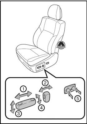
1. Переключатель продольного положения сиденья 2. Регулятор угла наклона спинки сиденья 3. Регулятор угла наклона подушки сиденья (переднего) 4. Регулятор высоты сиденья 5. Регулятор поясничной опоры (со стороны водителя)
Сиденье с ручными регулировками
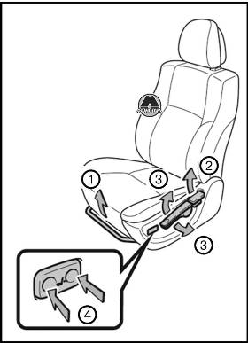
1. Рычаг регулировки положения сиденья 2. Рычаг регулировки угла наклона спинки сиденья 3. Рычаг регулировки высоты сиденья (со стороны водителя) 4. Регулятор поясничной опоры (при наличии, со стороны водителя)
Система запоминания положения водителя
Наиболее предпочтительное положение при вождении (положение сиденья водителя и рулевого колеса) можно ввести в память компьютера и вызывать нажатием кнопки.
В памяти компьютера сохраняются данные о двух различных положениях водителя.
Ввод положения водителя в память
Автомобили с интеллектуальной системой входа и запуска: поверните переключатель «ENGINE START STOP» в положение IGNITION ON.
Автомобили без интеллектуальной системы входа и запуска: поверните переключатель двигателя в положение «ON».
Установите сиденье водителя и рулевое колесо в нужные положения.
Удерживая нажатой кнопку «SET», в течение 3 секунд нажмите кнопку «1» или «2» и удерживайте ее нажатой, пока не прозвучит звуковой сигнал.
Если для выбранной кнопки значение уже задано, то ранее записанные данные положения водителя удаляются.
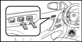
Автомобили с интеллектуальной системой входа и запуска
— Сохраняемое в памяти положение водительского сиденья может быть активировано в течение 180 с после открытия водительской двери даже в том случае, если переключатель «ENGINE START STOP» переходит в режим «OFF».
— Сохраняемое в памяти положение водительского сиденья может быть вызвано в течение 60 с после закрытия водительской двери даже в том случае, если переключатель «ENGINE START STOP» переходит в режим «OFF».
Автомобили без интеллектуальной системы входа и запуска
— Сохраняемое в памяти положение водительского сиденья может быть активировано в течение 180 с после открытия водительской двери даже в том случае, если переключатель двигателя переходит в положение «LOCK».
— Сохраняемое в памяти положение водительского сиденья может быть вызвано в течение 60 с после закрытия водительской двери даже в том случае, если переключатель двигателя переходит в положение отключения.
Для отмены вызова положения, сохраненного в памяти
Выполните одну из следующих операций.
— Нажмите кнопку «SET».
— Нажмите кнопку «1» или «2».
— Настройте сиденье с помощью переключателей (отменяется только вызов из памяти положения сиденья).
ВНИМАНИЕ
Меры предосторожности при регулировке сиденья
При настройке положения сиденья следите за тем, чтобы оно не ударило сидящего сзади пассажира или не прижало Вас к рулевому колесу.
Открывание крышки заливной горловины топливного бака
Чтобы открыть крышку заливной горловины топливного бака, выполните следующие действия.
Перед заправкой автомобиля
Автомобили с интеллектуальной системой входа и запуска.
Переведите переключатель «ENGINE START STOP» в положение OFF и убедитесь, что закрыты все двери и окна.
Автомобили без интеллектуальной системы входа и запуска
Поверните переключатель двигателя в положение «LOCK» и убедитесь в том, что все двери и окна закрыты.
Открывание крышки горловины топливного бака
Нажмите кнопку открывания крышки лючка заливной горловины топливного бака.
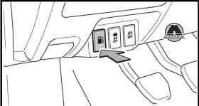
— Осторожно откройте крышку заливной горловины топливного бака.
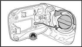
— Повесьте крышку заливной горловины топливного бака на обратную сторону крышки лючка.
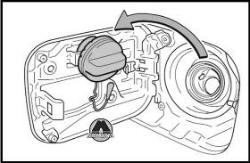
Закрывание крышки заливной горловины топливного бака
Закрывая крышку заливной горловины топливного бака, заворачивайте ее, пока не послышится характерный щелчок.
После того как крышка будет отпущена, она слегка повернется в противоположном направлении.
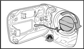
Высококачественный неэтилированный бензин «Premium», октановое число по исследовательскому методу не менее 95.
| Двигатель/каталитический конвертер | Тип |
| Двигатель 1ADFTV без каталитического конвертера с дизельным фильтром микрочастиц (DPF) | Дизельное топливо с содержанием серы не выше 500 частей на миллион и цетановым числом не ниже 48 |
| Двигатель 1AD-FTV с каталитическим конвертером с дизельным сажевым фильтром (DPF), двигатели 2ADFTV и 2AD-FHV | Дизельное топливо с содержанием серы не выше 50 частей на миллион и цетановым числом не ниже 48 |
Использование бензина, смешанного со спиртом, в бензиновом двигателе
Toyota разрешает использовать бензин, смешанный со спиртом, если содержание спирта составляет до 10%. Убедитесь в том, что подлежащий использованию бензин, смешанный со спиртом, имеет октановое число по исследовательскому методу, соответствующее приведенному выше.
Емкость топливного бака: Приблизительно 60 л.
Если не работает кнопка лючка заливной горловины топливного бака
Медленно потяните рычаг назад (не вбок), как показано на иллюстрации.
Если крышка лючка заливной горловины топливного бака не открывается с помощью внутреннего выключателя из-за разрядки аккумуляторной батареи или по иной причине, воспользуйтесь этим рычагом.
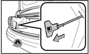
Выполняйте все приведенные ниже меры предосторожности перед заправкой автомобиля.
Невыполнение этих требований может стать причиной тяжелой травмы или смертельного исхода. Коснитесь автомобиля или другой металлической поверхности для снятия статического заряда. Искры от разряда статического электричества могут стать причиной возгорания паров топлива.
— Обязательно держитесь за специальные ручки на крышке горловины топливного бака и откручивайте пробку осторожно.
При откручивании крышки заливной горловины топливного бака можно услышать шипящий звук. Подождите, пока не прекратится звук, и только затем полностью снимите крышку. В жаркую погоду топливо под давлением может выплеснуться из заливной горловины бака и стать причиной травмы.
— Не разрешайте человеку, не снявшему статический заряд, приближаться к открытому топливному баку.
— Не вдыхайте пары топлива.
Топливо содержит вредные для организма вещества.
— Не курите во время заправки автомобиля. Курение может стать причиной возгорания топлива и пожара.
— Не возвращайтесь к автомобилю и не касайтесь других людей или предметов со статическим зарядом. Возникающий разряд может стать причиной возгорания топлива.
При установке на место крышки заливной горловины топливного бака Пользуйтесь только оригинальной пробкой бака Toyota, предназначенной для Вашего автомобиля. Невыполнение этого требования может стать причиной пожара или другого несчастного случая, который может привести к тяжелой травме или смертельному исходу.
ВНИМАНИЕ
Не проливайте топливо при заправке. Невыполнение этого требования может нанести повреждения автомобилю, например деталям топливной системы или окрашенной поверхности автомобиля.
Рычаг экстренного открывания дверцы топливного бака:
— Не тяните за рычаг с силой.
— Не используйте рычаг в иных случаях, кроме экстренных.
При обнаружении взлома система подает звуковые сигналы и мигает огнями.
Срабатывание сигнализации
Противоугонная сигнализация срабатывает в приведенных ниже случаях.
— Запертую дверь отпирают или открывают способом, отличным от использования интеллектуальной системы входа и запуска или пульта дистанционного управления. (Двери снова автоматически запираются.)
— Открывают капот при запертом автомобиле.
— Датчик вторжения (при его наличии) реагирует на движение внутри автомобиля. (Кто-либо проник в автомобиль.)
Постановка на сигнализацию
Закройте двери, багажник/заднюю дверь и капот, затем заприте все двери. Система включится автоматически через 30 с.
При постановке на сигнализацию индикатор перестает гореть постоянно и начинает мигать.
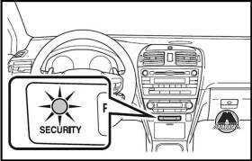
Отключение противоугонной сигнализации или выключение ее сигнала
Для отключения противоугонной сигнализации или выключения ее сигнала выполните любую из нижеперечисленных процедур.
— Отоприте двери, багажник или заднюю дверь с помощью интеллектуальной системы входа и запуска или пульта.
Датчик вторжения (при наличии)
Датчик вторжения выявляет проникновение в автомобиль или движение внутри автомобиля. Датчик вторжения можно отключить с помощью выключателя. Эта система предназначена для предотвращения угона автомобиля, но не гарантирует полной безопасности против любого вторжения.
Отключение датчика вторжения
Поверните переключатель «ENGINE START STOP» в положение OFF и нажмите выключатель датчика вторжения.
Поверните переключатель двигателя в положение «LOCK» и нажмите выключатель датчика вторжения.
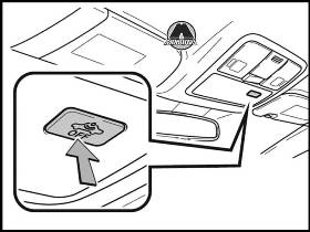
Повторное нажатие выключателя снова включает датчик вторжения.
Выполняйте необходимые операции для отключения датчика вторжения каждый раз, когда требуется отключить датчик.
Что нужно проверить перед запиранием автомобиля
Во избежание неожиданного срабатывания сигнализации и похищения автомобиля убедитесь в следующем.
— В автомобиле никого нет.
— Перед постановкой на сигнализацию окна закрыты.
— В автомобиле не осталось ценных или личных вещей.
Отключение и автоматическое повторное включение датчика вторжения
— Даже если датчик вторжения отключен, противоугонная сигнализация все еще включена.
— Автомобили с интеллектуальной системой входа и запуска: после того как датчик вторжения отключен, нажатие переключателя «ENGINE START STOP» или отпирание дверей с помощью интеллектуальной системы входа и запуска или пульта дистанционного управления снова включает датчик вторжения.
Автомобили без интеллектуальной системы входа и запуска: после того как датчик вторжения отключен, поворот переключателя двигателя в положение «LOCK» или отпирание дверей с помощью пульта дистанционного управления снова включает датчик вторжения.
— Датчик вторжения автоматически снова включается при отключении системы противоугонной сигнализации.
Противоугонная сигнализация может срабатывать в приведенных ниже случаях.
(Выключение сигнала отключает сигнализацию.)
— Отпирание дверей ключом.
— Человек, находящийся внутри автомобиля, открывает дверь или капот.
— Отсоединение аккумуляторной батареи.
Условия срабатывания датчика вторжения
Датчик может вызвать срабатывание сигнализации в следующих ситуациях.
— Внутри автомобиля находятся люди или домашние животные.
Автомобиль припаркован в месте, подверженном воздействию сильной вибрации или шума, например на крытой парковке.
С автомобиля счищают лед или снег, так что автомобиль подвергается многократному механическому воздействию или вибрации (ветер или другое воздействие смещает ледяную корку).
— В салоне автомобиля находятся подвижные предметы, например подвесные аксессуары или одежда на крючках вешалки.
— Открыто окно.
— Автомобиль находится внутри автоматической машинной мойки или мойки высокого давления.
— Автомобиль подвергается ударам, например града, молнии или другим видам механических воздействий или вибрации.
Компоненты системы подушек безопасности
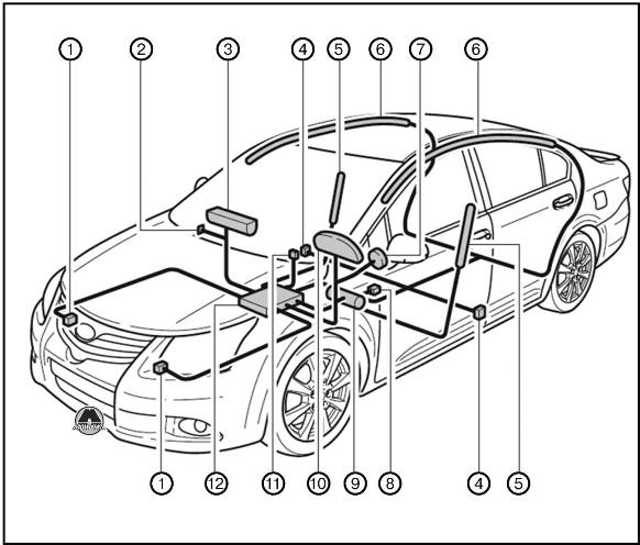
1. Датчик безопасности 2. Ручной выключатель подушки безопасности 3. Подушка безопасности переднего пассажира 4. Датчик боковой подушки безопасности и боковой шторки безопасности 5. Боковая подушка безопасности 6. Боковая шторка безопасности 7. Подушка безопасности водителя 8. Выключатель замка ремня безопасности водителя 9. Подушка безопасности на уровне колен 10. Предупреждающий индикатор SRS 11. Индикатор «PASSENGER AIRBAG» 12. Узел датчика подушки безопасности
На рисунке показаны основные компоненты системы подушек безопасности SRS. Система подушек безопасности SRS управляется узлом датчиков подушек безопасности. Узел датчиков подушек безопасности состоит из датчика безопасности и датчика подушек безопасности.
При определенных типах сильных передних и боковых ударов система подушек безопасности SRS запускает надувающие устройства.
Химическая реакция, проходящая в надувающих устройствах, стремительно наполняет подушки безопасности нетоксичным газом для сдерживания смещения людей, находящихся в автомобиле.
При срабатывании (надувании) подушек SRS
— В результате контакта с подушкой безопасности SRS при срабатывании (надувании) возможны небольшие ушибы или ссадины.
— При срабатывании слышен громкий хлопок и вылетает белый порошок.
— Части модуля подушек безопасности (втулка рулевого колеса, крышка подушки безопасности и насос), а также передние сиденья, передняя стойка и боковой обвязочный брус крыши кузова могут оставаться сильно нагретыми в течение нескольких минут. Сама подушка безопасности также может быть горячей.
— Может растрескаться ветровое стекло.
Условия срабатывания (передние подушки безопасности)
Передние подушки безопасности SRS раскрываются, если сила воздействия превышает расчетный предельный уровень, соответствующий лобовому столкновению на скорости около 30 км/ч с неподвижной преградой, которая не смещается и не деформируется. Однако эта пороговая скорость будет значительно выше в случае столкновения автомобиля с таким объектом, как, например, припаркованный автомобиль или дорожный знак, который может сдвинуться или деформироваться от удара, или же если автомобиль подминается во время столкновения (например, когда передок автомобиля «подныривает» под платформу грузовика и т.п.).
— При некоторых столкновениях, в которых сила переднего торможения автомобиля очень близка к расчётному предельному уровню, могут сработать только подушки безопасности SRS или только механизмы преднатяжения ремней безопасности.
Условия срабатывания (боковые подушки безопасности и боковые шторки безопасности)
Боковые подушки безопасности SRS и боковые шторки безопасности сконструированы для срабатывания при сильном боковом ударе в зоне пассажирского салона.
Обстоятельства, при которых подушки безопасности могут срабатывать (надуваться) не вследствие столкновения
Передние подушки безопасности SRS могут раскрыться, если нижняя часть автомобиля подвергается сильному удару.
— Удар о бордюр, кромку тротуара или о твердую поверхность.
— Падение в глубокую яму или перескакивание через нее.
— Жесткое приземление или падение автомобиля и типы столкновений, при которых подушки безопасности SRS (передние подушки) могут не сработать.
Срабатывание передних подушек безопасности SRS в случае удара сбоку или сзади, при переворачивании автомобиля, а также в случае переднего столкновения на малой скорости в принципе не предусмотрено. Тем не менее, всегда, когда столкновение любого типа вызывает достаточное замедление движения автомобиля в поступательном направлении, может произойти раскрытие передних подушек безопасности SRS.
— Боковое столкновение.
— Удар сзади.
— Переворачивание автомобиля.
Типы столкновений, при которых могут не срабатывать подушки безопасности SRS (боковые подушки безопасности и боковые шторки безопасности)
Система боковых подушек безопасности и боковых шторок безопасности SRS может не сработать, если автомобиль подвергся боковому удару под определенным углом, или боковому удару в корпус автомобиля, но вне зоны пассажирского салона.
— Боковой удар в корпус автомобиля вне зоны пассажирского салона.
— Боковое столкновение под углом.
Срабатывание боковых подушек безопасности SRS и боковых шторок безопасности в случае удара спереди или сзади, при переворачивании автомобиля, а также в случае бокового столкновения на малой скорости в принципе не предусмотрено.
— Удар спереди.
Меры предосторожности при обращении с подушками безопасности SRS
Соблюдайте нижеприведенные меры предосторожности при обращении с подушками безопасности SRS.
Невыполнение этих требований может стать причиной серьезной травмы вплоть до летального исхода.
— Водитель и все пассажиры автомобиля должны правильно пристегивать ремни безопасности.
— Подушки безопасности SRS являются дополнительными устройствами, использующимися вместе с ремнями безопасности.
— Подушка безопасности SRS водителя разворачивается со значительной силой, что может привести к серьезной травме вплоть до летального исхода, в особенности, если водитель находится очень близко к подушке.
Поскольку опасная зона при надувании подушки безопасности водителя составляет первые 50-75 мм, Вы будете в безопасности, если расположитесь в 250 мм от нее. Это расстояние измеряется от центра рулевого колеса до Вашей грудины. Если Вы сидите менее чем в 250 мм от рулевого колеса, то перед началом движения Вы можете изменить положение тела несколькими способами:
— Сдвиньте Ваше сиденье как можно дальше назад, но так, чтобы Вам было удобно пользоваться педалями.
— Слегка наклоните спинку сиденья.
Хотя конструкции автомобилей отличаются друг от друга, многие водители могут установить расстояние в 250 мм даже тогда, когда сиденье водителя полностью сдвинуто вперед, просто немного отклонив спинку сиденья. Если наклон спинки сиденья ухудшает обзор, подложите устойчивую, нескользкую подушку, или поднимите сиденье, если в Вашем автомобиле предусмотрена такая функция.
— Если положение рулевого колеса в Вашем автомобиле можно регулировать, наклоните его вниз. Это позволит направить подушку безопасности на Вашу грудь, а не на голову или шею. Сиденье следует регулировать в соответствии с приведенными выше рекомендациями, сохраняя контроль над педалями, рулевым колесом и обеспечивая хороший обзор органов управления на панели приборов.
— Подушка безопасности SRS переднего пассажира также разворачивается со значительной силой и может стать причиной серьезной травмы, вплоть до смертельного исхода, особенно если пассажир находится очень близко от нее. Сиденье переднего пассажира должно располагаться как можно дальше от подушки безопасности, в то время как спинку сиденья следует отрегулировать так, чтобы пассажир сидел прямо.
— Неправильно посаженные и/или пристегнутые младенцы и дети могут погибнуть или получить серьезные травмы от раскрывающихся подушек безопасности. Если младенец или ребенок еще слишком мал для того, чтобы использовать ремень безопасности, он должен быть правильно закреплен с помощью системы безопасности для детей. Toyota настоятельно рекомендует, чтобы все младенцы и дети находились в автомобиле на заднем сиденье и были надежно зафиксированы на своих местах. Заднее сиденье является наиболее безопасным для детей.
— Не сидите на краю сиденья и не прислоняйтесь к приборной доске.
— Не позволяйте ребенку стоять перед подушкой безопасности SRS переднего пассажира или сидеть на коленях переднего пассажира.
— Не осуществляйте движение автомобиля, если на коленях водителя или пассажира находятся какие-либо предметы.
— Не прислоняйтесь к двери, боковому обвязочному брусу крыши кузова, а также к передней, средней или задней стойке.
— Не разрешайте никому стоять на коленях на пассажирских сиденьях лицом к двери или высовывать голову или руки из автомобиля.
— Ничего не прикрепляйте и не прислоняйте к приборной доске или вблизи нее, к колонке рулевого колеса или к нижней части панели приборов. Эти предметы могут действовать как метательный снаряд при срабатывании подушек безопасности SRS водителя, переднего пассажира и подушек безопасности на уровне коленей.
— Не прикрепляйте никакие предметы к двери, ветровому стеклу, стеклам дверей, передней, средней и задней стойкам, боковому обвязочному брусу крыши кузова или к дополнительной ручке.
— Не вешайте на крючки вешалки плечики для одежды или другие твердые предметы. При срабатывании подушек безопасности SRS все эти предметы превращаются в метательные снаряды и могут серьезно травмировать или убить Вас.
— Автомобили без интеллектуальной системы входа и запуска: не прикрепляйте к ключу какие-либо тяжелые, острые или твердые предметы, например другие ключи или аксессуары. Эти предметы могут воспрепятствовать надуванию подушки безопасности SRS на уровне колен или быть выброшены в зону сиденья водителя силой срабатывающей подушки, что может представлять опасность.
— Если в месте срабатывания подушки безопасности SRS на уровне колен установлена виниловая крышка, не забудьте снять ее.
— Не используйте аксессуары для сидений, экранирующие области срабатывания подушек безопасности SRS, поскольку они могут помешать надуванию подушек.
— Не стучите и не надавливайте на места, где находятся подушки безопасности SRS. Это может стать причиной неправильной работы подушек безопасности SRS.
— Не касайтесь никаких компонентов системы сразу после срабатывания (раздувания) подушек безопасности SRS, поскольку они могут быть горячими.
— Если Вам трудно дышать после срабатывания подушки безопасности SRS, откройте дверь или окно, чтобы обеспечить приток свежего воздуха, или выйдите из автомобиля, если это не опасно. При первой возможности смойте с себя остатки материалов от срабатывания подушек для предотвращения раздражения кожи.
— Если повреждены или треснуты отделения, где хранятся подушки безопасности, например втулка рулевого колеса, или отделка передней и задней стоек, обратитесь к дилеру Toyota для их замены.
Модификация и утилизация компонентов системы подушек безопасности SRS
Не утилизируйте свой автомобиль и не вносите модификаций без предварительной консультации с дилером Toyota.
Подушки безопасности SRS могут случайно сработать (надуться) и стать причиной серьезной травмы вплоть до летального исхода.
— Установка, снятие, разборка и ремонт подушек безопасности.
— Ремонт, модификация, снятие или замена рулевого колеса, приборного щитка, панели приборов, сидений или обивки сидений, передней, средней и задней стоек или бокового обвязочного бруса крыши.
— Ремонт или модификация переднего крыла, переднего бампера или боковое части салона.
— Установка снегоочистителей, лебедок и т.п. на переднюю решетку (защитные дуги, «кенгурятники» и т.п.).
— Модификация системы подвески автомобиля.
— Установка электронных приборов, например портативных радиостанций или проигрывателей компакт-дисков.
Вождение в дождливую погоду
— При вождении автомобиля в дождь соблюдайте осторожность, поскольку в плохую погоду ухудшается видимость, возможно запотевание стекол и дорога становится скользкой.
— Будьте особенно осторожны, когда дождь только начался, так как в это время дорога особенно скользкая.
— Во время дождя не следует двигаться по автомагистралям с высокой скоростью, так как при этом между колесами и поверхностью дороги может образоваться водяная пленка, резко снижающая эффективность рулевого управления и тормозов.
Обкатка нового автомобиля Toyota
Для продления срока службы автомобиля, рекомендуется соблюдать следующие меры предосторожности:
На протяжении первых 300 км: избегайте резкого торможения.
На протяжении первых 800 км: не буксируйте прицеп.
На протяжении первой 1000 км:
— не эксплуатируйте автомобиль на слишком высокой скорости;
— избегайте резких ускорений;
— не двигайтесь слишком долго на низких передачах;
— не двигайтесь подолгу с постоянной скоростью.
Индикатор вождения в режиме Есо (если предусмотрен)
Эта система отслеживает работу педали акселератора с целью обнаружения излишнего ускорения автомобиля. Система рассчитывает состояние движения (использование режима Есо/неиспользование режима Есо) в соответствии с работой педали акселератора и уведомляет водителя о состоянии движения путем включения/выключения индикатора. Таким образом, следуя показаниям индикатора, водитель может управлять педалью акселератора, обеспечивая экологически чистое вождение (эффективное в отношении расхода топлива).
Кроме того, индикатор не загорится, если вождение осуществляется в следующих условиях:
— Рычаг коробки передач находится не в положении «D».
— Вождение автомобиля осуществляется в режиме «SPORT».
— Если используется тумблер коробки передач (при его наличии), когда рычаг коробки передач находится в положении «D».
Время работы на холостом ходу перед остановкой двигателя (дизельный двигатель)
Во избежание повреждения турбонагнетателя после движения с высокой скоростью или преодоления подъема дайте двигателю поработать на холостом ходу.
| Условия движения | Время работы на холостом ходу | |
| Обычное движение в городе | Не требуемся | |
| Движение с высокой скоростью | Движение с постоянной скоростью прибл. 80 км/ч | Прибл. 20 с |
| Движение с постоянной скоростью прибл. 100 км/ч | Прибл. 1 мин | |
| Преодоление крутого подъема или движение с постоянной скоростью 100 км/ч или более (по гоночной трассе и т.п.) | Прибл. 2 мин |
При эксплуатации автомобиля
— Не приступайте к вождению автомобиля, если Вы не знакомы с расположением педалей тормоза и акселератора, чтобы не нажать неправильную педаль.
— Случайное нажатие на педаль акселератора вместо педали тормоза приведет к резкому ускорению, которое, в свою очередь, может привести к столкновению, в результате которого возможен смертельный исход или серьезные травмы.
— Когда при движении задним ходом водитель поворачивается назад, это затрудняет использование педалей. Используйте педали правильно.
— Придерживайтесь правильного положения водителя при движении, даже очень медленном, что позволит правильно нажимать педаль тормоза и акселератора.
— Нажимайте педаль тормоза правой ногой. Нажатие педали тормоза левой ногой может привести к замедлению реакции в аварийной ситуации и к дорожно-транспортному происшествию.
— Не подъезжайте близко и не останавливайтесь около огнеопасных материалов. Выхлопная система и выхлопные газы могут быть очень горячими. Это может стать причиной возгорания при наличии поблизости огнеопасных материалов.
— Автомобили с Multidrive или автоматической трансмиссией: не позволяйте автомобилю катиться назад, когда рычаг коробки передач находится в положении движения, или катиться вперед, когда рычаг коробки передачи находится в положении «R». Это может привести к остановке двигателя или к ухудшению работоспособности тормозной системы, а в результате — к столкновению или повреждению автомобиля.
— Если в салоне автомобиля чувствуется запах выхлопных газов, откройте окна и убедитесь в том, что дверь багажника или задняя дверь закрыта. Высокое содержание выхлопных газов в салоне автомобиля может вызвать сонливость водителя и привести к аварии и, в результате, к смерти или серьезному ущербу для здоровья. Незамедлительно произведите осмотр автомобиля у дилера Toyota.
— Ни при каких обстоятельствах не переключайте рычаг коробки передач в положение «Р» (автомобили с Multidrive или автоматической трансмиссией) или «R» при движении автомобиля. Это может привести к серьезному повреждению трансмиссии с лотерей контроля над автомобилем.
— Не переводите рычаг коробки передачи в положение «N» при движении автомобиля. Это может привести к неправильной работе функции торможения двигателем и, как результат, к столкновению.
— Не выключайте двигатель во время движения. При выключенном двигателе система усилителя рулевого управления и усилителя тормозов не работают должным образом.
— Используйте торможение двигателем (переключение на более низкую передачу), чтобы поддержать безопасную скорость при движении вниз по крутому склону.
— Продолжительное использование тормозов может повлечь за собой перегрев тормозов и потерю их эффективности.
— При остановке на склоне используйте педаль тормоза и стояночный тормоз, чтобы предотвратить качение автомобиля назад или вперед, которое может привести к столкновению.
— Не регулируйте положение рулевого колеса, сиденья или внутренних и наружных зеркал заднего вида во время движения. Это может привести к потере контроля над автомобилем, что, в свою очередь, чревато столкновением, в результате которого возможен смертельный исход или серьезные травмы.
— Постоянно следите за тем, чтобы пассажиры не высовывали руки, голову или другие части тела за пределы автомобиля, поскольку это может привести к смертельному исходу или серьезным травмам.
При движении по скользкой дороге
— Резкое торможение, ускорение или поворот руля могут вызвать скольжение колес и затруднить управление автомобилем, что, в свою очередь, может привести к аварии.
— Резкое изменение оборотов двигателя, например, во время торможения двигателем при переходе на повышенную или пониженную передачу, может вызвать занос автомобиля и привести к аварии.
— После проезда через лужу слегка нажмите на педаль тормоза, чтобы убедиться в надежной работе тормозов. При влажных тормозных колодках эффективность торможения может снизиться. Если намокли и недостаточно эффективно работают тормоза только с одной стороны, это может повлиять на работу рулевого управления и привести к аварии.
При переключении передач (автомобили с Multidrive или автоматической трансмиссией)
Будьте внимательны, не перемещайте рычаг коробки передач при нажатой педали акселератора. Это может привести к неожиданно резкому ускорению автомобиля, которое может повлечь за собой столкновение и привести к смертельному исходу или I тяжелым травмам.
Когда автомобиль остановлен
— Не допускайте превышения оборотов двигателя. Если включена любая передача, кроме «Р» (автомобили с Multidrive или автоматической трансмиссией) или «N», автомобиль может внезапно и неожиданно ускориться, что чревато столкновением.
— Не оставляйте автомобиль на долгое время с включенным двигателем. Если этой ситуации не избежать, припаркуйте автомобиль на открытой площадке и проследите за тем, чтобы выхлопные газы не проникали в салон автомобиля.
— Автомобили с Multidrive или автоматической трансмиссией: при работающем двигателе всегда держите ногу на педали тормоза, чтобы предотвратить столкновение вследствие перемещения автомобиля.
— При остановке на склоне используйте педаль тормоза или стояночный тормоз во избежание качения автомобиля, которое может привести к аварии.
Когда автомобиль припаркован
Не оставляйте очки, зажигалки, баллончики с аэрозолем или жестяные банки с напитками в автомобиле, когда паркуете его на солнце. Это чревато следующими последствиями:
— Из зажигалки или баллончика с аэрозолем может просочиться газ, что может привести к пожару.
— Температура внутри автомобиля может стать причиной деформации или раскалывания пластмассовых линз и пластмассовых элементов очков.
— Жестяные банки с напитками могут лопнуть, вызывая распыление содержимого по салону автомобиля, и, кроме того, напитки могут вызвать короткое замыкание в электрических элементах автомобиля.
— Следует обязательно включать стояночный тормоз, переводить рычаг коробки передач в положение «Р» (автомобили с Multidrive или автоматической трансмиссией), глушить двигатель и запирать автомобиль.
Не оставляйте автомобиль без присмотра при работающем двигателе.
— Не трогайте выхлопную трубу при работающем двигателе или сразу после его выключения. Это может вызвать ожоги.
— Не оставляйте автомобиль с работающим двигателем около сугробов или в снежную погоду. Если вокруг автомобиля с работающим двигателем вырастает сугроб, выхлопные газы могут накапливаться и проникать в салон автомобиля. Это может привести к смерти или серьезному ущербу здоровью.
Выхлопные газы содержат опасный угарный газ (СО), не имеющий цвета и запаха. Вдыхание выхлопных газов может привести к смерти или серьезному ущербу здоровью.
— Если автомобиль находится в плохо проветриваемой зоне, затушите двигатель. В закрытой зоне, например в гараже, выхлопные газы могут накапливаться и проникать в салон автомобиля. Это может привести к смерти или серьезному ущербу здоровью.
— Выхлопную систему следует периодически проверять. При наличии отверстий или трещин, вызванных коррозией, поврежденного соединения или повышенного шума выхлопа обязательно проверьте и отремонтируйте автомобиль у дилера Toyota. В противном случае выхлопные газы могут проникать в салон автомобиля и, в результате, привести к смерти или серьезному ущербу здоровью.
На время короткого сна в автомобиле
Обязательно выключайте двигатель. В противном случае Вы можете случайно переместить рычаг коробки передач или нажать на педаль акселератора, что может привести к столкновению или к пожару вследствие перегрева двигателя. Кроме того, если автомобиль припаркован в плохо проветриваемой зоне, выхлопные газы могут накапливаться и проникать в салон автомобиля, приводя к смерти или серьезному ущербу здоровью.
Когда тормоза влажные, ведите автомобиль более осторожно.
При влажных тормозах тормозной путь увеличивается, и, кроме того, автомобиль может тормозить неравномерно с разных сторон. Стояночный тормоз также может ненадежно удерживать автомобиль.
— Если усилитель тормозов не работает, не приближайтесь к другим транспортным средствам и избегайте спусков или резких поворотов, требующих эффективного торможения. В этом случае торможение все еще возможно, но может потребоваться более сильное, чем обычно, нажатие на педаль. Тормозной путь также может увеличиться.
— Не накачивайте педаль тормоза, если двигатель заглох. При каждом нажатии на педаль расходуется оставшийся резерв усилителя тормозов.
— Тормозная система состоит из 2 отдельных гидравлических контуров: если один из контуров выходит из строя, другой продолжает работать. В этом случае на педаль тормоза следует нажимать сильнее, чем обычно, а тормозной путь становится более длинным. Не эксплуатируйте автомобиль только с одним работающим тормозным контуром. Немедленно отремонтируйте тормоза.
Автомобили с Multidrive или автоматической трансмиссией
Для удержания автомобиля на склоне не используйте педаль акселератора и не нажимайте одновременно на педали акселератора и тормоза.
Автомобили с ручной трансмиссией
Во избежание повреждения педали сцепления, коробки передач и передаточного механизма соблюдайте следующие меры предосторожности.
— Не переключайте передачи, если педаль сцепления нажата не полностью.
— После переключения передачи не отпускайте педаль сцепления слишком резко.
— Не держите ногу на педали сцепления во время движения.
— При трогании с места и начале движения вперед не используйте какие-либо иные передачи, кроме первой передачи.
— Не используйте сцепление для удержания автомобиля при остановке на подъеме.
— Не переключайтесь на передачу «R», когда автомобиль продолжает движение.
При парковке автомобиля (автомобили с Multidrive или автоматической трансмиссией)
Всегда переводите рычаг коробки передач в положение «Р». Несоблюдение этого указания может привести к несанкционированному перемещению автомобиля или, при случайном нажатии на педаль акселератора, к внезапному его ускорению.
Во избежание повреждения элементов автомобиля
— Не поворачивайте рулевое колесо до упора в том или ином направлении и не удерживайте его в крайних положениях в течение длительного времени. Это может вызвать повреждение электродвигателя усилителя рулевого управления.
— При движении по ухабистой дороге ведите автомобиль настолько медленно, насколько это возможно, чтобы избежать повреждения колес, днища кузова и т.д.
— Только дизельный двигатель: после движения с высокой скоростью или преодоления подъема обязательно дайте двигателю поработать на холостом ходу. Заглушите двигатель только после того, как охладится турбонагнетатель. В противном случае можно повредить турбонагнетатель.
Если слышен визг или скрежет (признаки износа тормозных колодок)
Как можно скорее обратитесь к дилеру Toyota для проверки и замены тормозных колодок.
Если вовремя не заменить колодки, это может привести к повреждению тормозного диска.
Если превышены предельные значения износа тормозных колодок и/или тормозных дисков, эксплуатировать автомобиль опасно.
Если во время движения сдувается шина
Спущенная или поврежденная шина может стать причиной перечисленных ниже ситуаций. Крепко удерживайте рулевое колесо и плавно нажимайте на педаль тормоза, чтобы замедлить автомобиль.
— Управление автомобилем может быть затруднено.
— Автомобиль будет издавать ненормальный звук.
— Автомобиль будет вести себя необычно. Замените спущенную шину новой
Не следует двигаться по дорогам, затопленным после сильных дождей и т.п. В противном случае автомобиль может получить следующие серьезные повреждения.
— Остановка двигателя.
— Короткое замыкание электрических систем.
— Повреждение двигателя из-за попадания в него воды.
Если в результате движения по затопленной дороге произошло затопление автомобиля, обязательно проверьте у дилера Toyota следующее.
— Работу тормозов.
— Изменение количества и качества масла и жидкостей, используемых в двигателе, трансмиссии и т.д.
— Состояние смазки подшипников и шарниров подвески (где возможно), а также работу всех шарниров, подшипников и т.п.
Переключатель двигателя (зажигания) (автомобили с интеллектуальной системой входа и запуска)
Расположение переключателя «ENGINE START STOP»
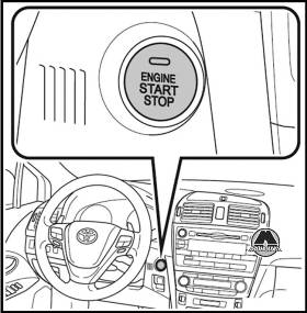
Выполнение приведенных ниже действий при условии, что электронный ключ находится при Вас, запускает двигатель или изменяет режимы переключателя «ENGINE START STOP».
Проследите за тем, чтобы был включен стояночный тормоз.
Проследите за тем, чтобы рычаг коробки передач находился в положении «Р» .
Займите сиденье водителя и полностью нажмите педаль тормоза до упора. Цвет индикатора «ENGINE START STOP» меняется на зеленый.
Нажмите переключатель «ENGINE START STOP».
Двигатель может быть запущен из любого режима.
Продолжайте нажимать педаль тормоза, пока не завершится запуск двигателя. Двигатель проворачивается стартером до тех пор, пока он не заведется, но не более 30 с.
Только дизельный двигатель: загорается индикатор.
Запуск двигателя начинается после выключения этого индикатора.
Проследите за тем, чтобы рычаг коробки передач находился в положении «N».
Займите сиденье водителя и полностью нажмите на педаль сцепления. Цвет индикатора «ENGINE START STOP» меняется на зеленый.
Продолжайте нажимать педаль сцепления, пока не завершится запуск двигателя. Двигатель проворачивается стартером до тех пор, пока он не заведется, но не более 30 с.
Запуск двигателя наминается после выключения этого индикатора.
Изменение режима переключателя «ENGINE START STOP»
Режимы можно изменить, нажимая переключатель «ENGINE START STOP» при отпущенной педали тормоза (автомобили с Multidrive или автоматической трансмиссией) или педали сцепления (автомобили с ручной трансмиссией). Режим изменяется при каждом нажатии переключателя.
— OFF (ВЫКЛ.)*
Может использоваться аварийная сигнализация.
— Режим ACCESSORY
Можно пользоваться некоторыми электрическими приборами, например аудиосистемой.
Цвет индикатора «ENGINE START STOP» меняется на янтарный.
— Режим IGNITION ON
Можно пользоваться всеми электрическими приборами. Цвет индикатора «ENGINE START STOP» меняется на янтарный.
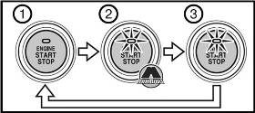
*: В автомобилях с Multidrive или автоматической трансмиссией, если при выключении двигателя рычаг коробки передач находится в любом положении, кроме «Р», переключатель «ENGINE START STOP» повернется в положение режима ACCESSORY, а не OFF.
Если двигатель не запускается
Возможно, не был отключен иммобилайзер двигателя.
Если не удается освободить фиксатор рулевого колеса
Мигает зеленый индикатор на переключателе «ENGINE START STOP».
Для высвобождения нажмите переключатель «ENGINE START STOP», слегка поворачивая рулевое колесо в любом направлении.
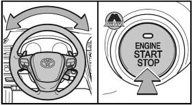
Если индикатор переключателя «ENGINE START STOP» мигает янтарным
Система может работать со сбоями. Незамедлительно произведите осмотр автомобиля у дилера Toyota.
Функция автоматического выключения питания
Если автомобиль остается в режиме ACCESSORY более часа с рычагом коробки передач в положении «Р», переключатель «ENGINE START STOP» автоматически выключается (OFF).
Если автомобиль остается в режиме ACCESSORY более часа, переключатель «ENGINE START STOP» автоматически выключается (OFF).
ВНИМАНИЕ
При запуске двигателя Всегда запускайте двигатель, находясь на сиденье водителя. Ни при каких обстоятельствах не нажимайте на педаль акселератора при запуске двигателя. Это может привести к столкновению, в результате которого возможен смертельный исход или серьезные травмы.
Выключение двигателя в экстренных ситуациях
Если требуется выключить двигатель в экстренных ситуациях при движении автомобиля, нажмите переключатель «ENGINE START STOP» и удерживайте его нажатым не менее 3 с.
Однако прикасаться к выключателю «ENGINE START STOP» во время движения следует только в экстренных ситуациях. Остановка двигателя во время движения может привести к аварии.
ВНИМАНИЕ
Предотвращение разрядки аккумулятора
Не оставляйте переключатель «ENGINE START STOP» в режиме ACCESSORY или IGNITION ON в течение длительного времени при неработающем двигателе.
— Не допускайте высоких оборотов двигателя, пока он не прогрелся.
— Если возникают трудности при запуске двигателя или он часто глохнет, немедленно проверьте двигатель.
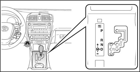
Автомобили с интеллектуальной системой входа и запуска: когда переключатель «ENGINE START STOP» находится в положении режима IGNITION ON, нажмите педаль тормоза и переместите рычаг коробки передач.
Автомобили без интеллектуальной системы входа и запуска: когда переключатель двигателя находится в положении «ON», нажмите педаль тормоза и переместите рычаг коробки передач.
Выбор положения рычага коробки передач
| Положение рычага коробки передач | Функция |
| Р | Парковка автомобиля или запуск двигателя |
| R | Задний ход |
| N | Нейтральное положение |
| D | Обычное движение*1 или временное движение с выбором передачи*2 |
| М | Движение в режиме «М» |
*1: Чтобы уменьшить расход топлива и шумность, переведите рычаг коробки передачи в положение «D» для обычного движения.
*2: Выбирая передачу подрулевыми переключателями (при их наличии), можно контролировать эффективность торможения двигателем.
Нажмите выключатель. Для уверенного, «мощного» ускорения и движения в гористой местности.
Для возврата в обычный режим нажмите этот выключатель еще раз.
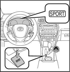
Если рычаг коробки передач установлен в положение «D», автоматически выбирается передаточное отношение, оптимальное для текущих условий движения.
Подрулевые переключатели передач (при наличии)
Когда рычаг коробки передач находится в положение «D», можно контролировать эффективность торможения двигателем, временно переключая передачи.
Если не использовать подрулевые переключатели передач, на приборном щитке отображается фиксированная передача.
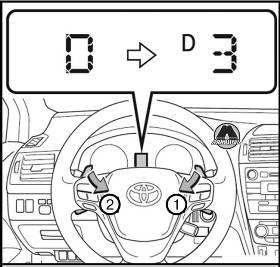
1. Переключение на более высокую передачу 2. Переключение на более низкую передачу
Однако когда рычаг переключения передач находится в положении «D», передачи будут автоматически переключаться, если обороты двигателя становятся слишком высокими или низкими.
Переведя рычаг переключения передач в положение «М», можно переключаться между 7 ступенями коробки передач.
Если не использовать подрулевые переключатели передач (при наличии), на приборном щитке отображается фиксированная передача.
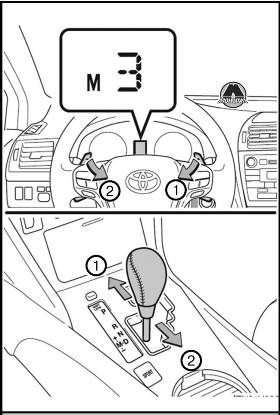
Однако даже когда рычаг переключения передач находится в положении «М», передачи будут автоматически переключаться, если обороты двигателя становятся слишком высокими или низкими.
Подрулевой переключатель передач (при наличии)
При использовании подрулевого переключателя передач в положении «D» передача выбирается автоматически в соответствии со скоростью автомобиля и условиями движения.
Автоматическое отключение выбора передачи в положении «D»
Выбор передачи в положении «D» отключается в следующих ситуациях:
— В течение некоторого времени удерживается нажатым подрулевой переключатель передач «+».
— При остановке автомобиля.
— Если педаль газа удерживается нажатой дольше определенного времени в пределах одной передачи.
Предупреждающий звуковой сигнал ограничения переключения на пониженную передачу
В целях повышения безопасности движения и улучшения характеристик управляемости иногда переключение на пониженную передачу может быть запрещено. В некоторых случаях переключение на пониженную передачу невозможно даже при изменении положения рычага переключения передач или использовании подрулевых переключателей передач (при наличии). (Предупреждающий звуковой сигнал подается два раза.)
При движении с включенной системой круиз-контроля
Во время выбора передачи в положении «D» или «М» торможение двигателем не происходит даже при переключении вниз на 6, 5 или 4 передачу.
Автоматическое отключение спортивного режима
Автомобили с интеллектуальной системой входа и запуска
Если переключатель «ENGINE START STOP» устанавливается в положение OFF после движения в спортивном режиме, этот режим автоматически отключается.
Если переключатель двигателя устанавливается в положение «LOCK» после движения в спортивном режиме, этот режим автоматически отключается.
Если рычаг коробки передач не может быть выведен из положения «Р»
Если после установки рычага переключения передач в положение «М» не отображается индикатор «М».
Если в описанной выше ситуации на дисплее не появляется индикация «М», это может указывать на неисправность трансмиссии. Незамедлительно произведите осмотр автомобиля у дилера Toyota.
Автоматическая коробка передач
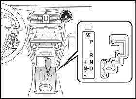
Нажмите выключатель. Для уверенного, «мощного» ускорения и движения в гористой местности. Для возврата в обычный режим нажмите этот выключатель еще раз.
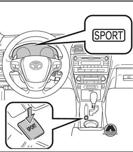
Если рычаг коробки передач установлен в положение «D», автоматически выбирается передача, оптимальная для текущих условий движения.
Изменение диапазонов передач позволяет запретить использование высших передач, что исключает ненужный переход на высшие передачи и позволяет выбирать величину тормозного усилия при торможении двигателем.
Переведя рычаг переключения передач в положение «М», можно переключаться между 6 ступенями коробки передач.
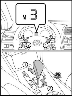
Однако в следующих ситуациях даже при нахождении рычага в положении «М» коробка передач переключится автоматически:
— При снижении скорости автомобиля (только с понижением передачи).
— При чрезвычайно высокой температуре масла для автоматических коробок передач (только с повышение передачи).
При нажатии подрулевого переключатель передач в положении «D» автоматически выбирается диапазон переключения передач. Наивысшая передача в первом диапазоне передач будет на одну ниже, чем при обычном движении в положении «D».
Автоматическое отключение диапазона передач в положении «D»
Выбор диапазона передач в положении «D» отключается в следующих ситуациях.
— Если педаль газа удерживается нажатой дольше определенного времени в пределах одной передачи.
Предупреждающий звуковой сигнал ограничения переключения на пониженную передачу
В целях повышения безопасности движения и улучшения характеристик управляемости иногда переключение на пониженную передачу может быть запрещено. В некоторых случаях переключение на пониженную передачу невозможно даже при изменении положения рычага переключения передач или использовании подрулевых переключателей передач (при наличии). (Предупреждающий звуковой сигнал подается два раза.)
При движении с включенной системой круиз-контроля (или динамического радарного круиз-контроля)
Во время выбора диапазона передач в положении «D» торможение двигателем не происходит даже при переключении вниз в диапазон 5 или 4 передачи.
Если рычаг коробки передач не может быть выведен из положения «Р».
Если после установки рычага переключателя передач в положение «М» не отображается индикатор «М»
Автомобили с интеллектуальной системой входа и запуска: в течение нескольких секунд после поворота переключателя «ENGINE START STOP» в положение IGNITION ON трансмиссия не переходит в режим «М» при переводе рычага переключения передач в положение «М».
Автомобили без интеллектуальной системы входа и запуска: в течение нескольких секунд после поворота переключателя двигателя в положение «ON» трансмиссия не переходит в режим «М» при переводе рычага переключения передач в положение «М».
Это связано с выполнением проверки системы. В таком случае немного подождите и попробуйте перевести рычаг коробки передач в положение «М» еще раз.
Если на дисплее не появляется индикация «М» в ситуациях, отличных от указанных выше, это может указывать на неисправность трансмиссии. Незамедлительно произведите осмотр автомобиля у дилера Toyota.
Автоматический выбор передачи
При остановке автомобиля трансмиссия автоматически переключается вниз, чтобы можно было начать движение на первой передаче.
При отображении предупреждающего сообщения о температуре автоматической трансмиссии
Если во время движения отображается предупреждающее сообщение о температуре масла для автоматических коробок передач, перейдите к вождению с положением рычага в нормальном положении «D» и сбросьте скорость, отпустив педаль газа. Остановите автомобиль в безопасном месте, переведите рычаг в положение «Р» и позвольте двигателю поработать на холостом ходу до исчезновения предупреждающего сообщения. После исчезновения предупреждающего сообщения автомобиль вновь может двигаться. Если предупреждающее сообщение не исчезает даже через некоторое время, предоставьте автомобиль на проверку дилеру Toyota.
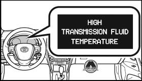
Высокая температура трансмиссионной жидкости
Функция AI-SHIFT автоматически включает оптимальную передачу в соответствии с манерой езды водителя и условиями движения.
Функция AI-SHIFT автоматически включается при установке рычага переключения передач в положение «D». (При переводе рычага переключения передач в положение «М» эта функция отключается.)
Рычаг указателей поворота
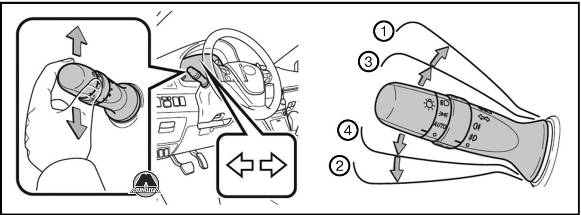
1. Правый поворот 2. Левый поворот 3. Для подачи сигнала об изменении полосы движения переведите рычаг приблизительно на половину его хода и придержите его там. Указатели правого поворота будут мигать до тех пор, пока Вы не отпустите рычаг 4. Для подачи сигнала об изменении полосы движения переведите рычаг приблизительно на половину его хода и придержите его там. Указатели левого поворота будут мигать до тех пор, пока Вы не отпустите рычаг.
Указатели поворота могут использоваться, когда переключатель «ENGINE START STOP» находится в режиме IGNITION ON.
Переключатель двигателя находится в положении «ON». Если указатели поворота мигают быстрее, чем обычно Проверьте, не перегорела ли лампа в передних или задних указателях поворота.
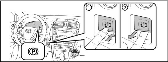
1. Нажмите переключатель для постановки в случае непредвиденной ситуации и необходимости включения стояночного тормоза во время движения нажмите и удерживайте нажатым переключатель стояночного тормоза.
2. Потяните за переключатель для снятия.
Управление стояночным тормозом
Если переключатель «ENGINESTART STOP» не находится в режиме IGNITON ON , автомобиль невозможно снять со стояночного тормоза с помощью переключателя стояночного тормоза.
Если переключатель двигателя не находится в положении «ON», автомобиль невозможно снять со стояночного тормоза с помощью переключателя стояночного тормоза.
Автоматическое снятие со стояночного тормоза (автомобили с ручной трансмиссией)
Если при трогании с места педаль акселератора и педаль сцепления работают, а стояночный тормоз не отпущен, стояночный тормоз будет отпущен автоматически, облегчая таким образом трогание с места.
Звук работы стояночного тормоза
При срабатывании стояночного тормоза может быть слышен звук работы электродвигателя (жужжание). Это не является признаком неисправности.
Система может стать временно недоступной с целью предотвращения перегрева, вызванного постоянным ненужным ее переключением.
В этом случае дайте системе некоторое время остыть, и ее нормальная работа вскоре возобновится.
В случае неисправности системы
Горит или мигает предупредительный индикатор.
ВНИМАНИЕ
При парковке автомобиля
Перед тем как покинуть автомобиль, поставьте его на стояночный тормоз, переведите рычаг коробки передач в состояние «Р». (Multidrive или автоматическая трансмиссия), «1» или «R» (ручная трансмиссия) и убедитесь в том, что автомобиль не двигается.
Если невозможно снять автомобиль со стояночного тормоза из-за неисправности
Вручную снимите автомобиль со стояночного тормоза с помощью инструмента снятия со стояночного тормоза. Езда на автомобиле, стоящем на стояночном тормозе, приведет к перегреву деталей тормозной системы, что может отрицательно повлиять на эффективность торможения и увеличить износ тормозов.
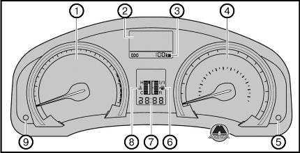
1. Тахометр (Отображает скорость вращения двигателя в оборотах в минуту) 2. Многофункциональный дисплей 3. Одометр и маршрутный счетчик (Одометр — показывает общий пробег автомобиля. Маршрутный счетчик — показывает пробег автомобиля с момента последнего обнуления счетчика. Счетчики А и В можно использовать для записи и отображения различных расстояний независимо друг от друга) 4. Спидометр (Показывает скорость автомобиля) 5. Кнопка «DISP» управления подсветкой панели приборов (Нажать: включается многофункциональный дисплей. Повернуть: настройка яркости подсветки панели приборов.) 6. Указатель уровня топлива (Показывает количество топлива, остающегося в баке) 7. Часы (Показывают время) 8. Указатель температуры охлаждающей жидкости (Показывает температуру охлаждающей жидкости двигателя) 9. Одометр/маршрутный счетчик и кнопка обнуления маршрутного счетчика (Служит для переключения между показаниями одометра и маршрутного счетчика. Если при отображении маршрутного счетчика нажать эту кнопку и удерживать ее нажатой, показания счетчика сбрасываются на ноль)
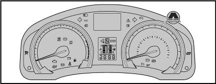
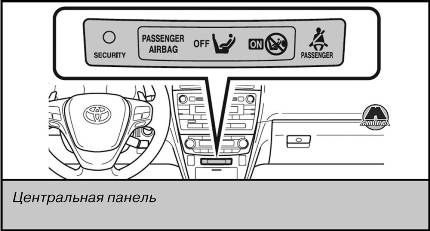
Индикаторы информируют водителя о рабочем состоянии различных систем автомобиля.
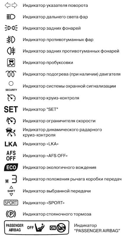
Контрольные лампы информируют водителя о сбоях в работе различных систем автомобиля.
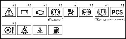
*1 Эти индикаторы включаются, когда переключатель «ENGINE START STOP» переведен в режим «IGNITION ON» (автомобили с интеллектуальной системой входа и запуска двигателя) или переключатель двигателя переведен в положение «ON» (автомобили без интеллектуальной системы входа и запуска двигателя), для указания на выполнение проверки системы. Они гаснут после запуска двигателя или по прошествии нескольких секунд. Если какие-то индикаторы не включаются или не выключаются, соответствующая система может быть неисправной. Для выяснения причин произведите осмотр автомобиля у дилера Toyota.
ВНИМАНИЕ
Если не загорается контрольная лампа одной из систем обеспечения безопасности движения.
Если при запуске двигателя не включается контрольная лампа какой-либо из систем обеспечения безопасности движения (например, ABS или SRS), это может означать, что соответствующая система находится в неработоспособном состоянии. Следовательно, она не сможет защитить Вас при столкновении, что может привести к смертельному исходу или тяжелым травмам. Незамедлительно произведите осмотр автомобиля у дилера Toyota.
Многофункциональный дисплей
Показывает расстояние до дозаправки, расход топлива и прочую информацию, относящуюся к данной поездке.
Показывает и позволяет настроить дату.
Индикация температуры наружного воздуха
Показывает температуру наружного воздуха.
Предупреждающие сообщения
Сообщения появляются автоматически при сбое в работе одной из систем автомобиля.
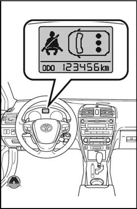
Индикация даты и температуры наружного воздуха
Показывает дату и температуру наружного воздуха. Отображение температуры возможно в диапазоне от -40°С до 50°С.
Мгновенный расход топлива
Показывает мгновенный расход топлива.
Показывает средний расход топлива с момента последнего перезапуска функции. Показания можно обнулить, нажав при отображении среднего расхода топлива кнопку «DISP.» Или переключатель «DISP» в течение более 1 с.
Показывает расчетное максимальное расстояние, которое автомобиль может пройти на топливе, имеющемся в баке.
— Это расстояние определяется на основании среднего расхода топлива. Соответственно, действительное расстояние, которое может пройти автомобиль, может отличиться от показываемого на дисплее.
— При добавлении в бак небольшого количество топлива показания могут не обновляться.
Средняя скорость автомобиля
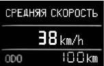
Показывает среднюю скорость автомобиля с момента запуска двигателя или с момента последнего перезапуска функции.
Показания можно обнулить, нажав при отображении средней скорости автомобиля кнопку «DISP.» Или переключатель «DISP» в течение более 1 с.

Показывает истекшее время с момента запуска двигателя или с момента последнего перезапуска функции.
Показания можно обнулить, нажав при отображении прошедшего времени кнопку «DISP.» Или переключатель «DISP» в течение более 1 с.
Индикатор напоминания о ремнях безопасности пассажиров на заднем сиденье
Индикатор зоны экологичного вождения (при наличии)
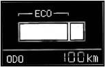
Отображается коэффициент текущего нажатия акселератора по отношению к верхнему пределу нажатия акселератора при вождении в режиме Есо.
Экологичный диапазон ускорения (экологичное вождение) отображается наряду с текущим значением ускорения. Если педаль акселератора нажата слишком сильно и превышен предел экологичного вождения, правая часть столбчатой диаграммы начинает мигать.
Кроме того, индикатор не отображается, если вождение осуществляется в следующих условиях.
— Если используются подрулевые переключатели передач (при их наличии), когда рычаг коробки передач находится в положении «D».
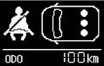
Звуковой сигнал напоминания о ремне безопасности заднего пассажира
Звуковой сигнал напоминания о ремне безопасности заднего пассажира напоминает заднему пассажиру о том, что его/ее ремень не пристегнут. Сигнал звучит в течение 30 с после того, как автомобиль достигает скорости 20 км/ч. Затем, если ремень безопасности все еще не пристегнут, звуковой сигнал звучит в другой тональности в течение следующих 90 с.
Температура наружного воздуха
— В следующих ситуациях правильная наружная температура может не отображаться или изменение показаний может происходить дольше, чем обычно.
— При торможении или движении на низкой скорости (менее 20 км/ч).
— При резком изменении наружной температуры (при въезде в гараж, туннель и т.п. или выезде из них).
Если отображается символ «-» это может означать неисправность системы. Покажите автомобиль дилеру Toyota.
Жидкокристаллический дисплей
На дисплее могут быть видны небольшие темные или светлые точки. Это явление характерно для жидкокристаллических дисплеев и не препятствует Дальнейшей эксплуатации дисплея.
ВНИМАНИЕ
Работа многофункционального дисплея при низкой температуре
Перед использованием жидкокристаллического информационного дисплея сначала прогрейте салон автомобиля. В условиях чрезвычайно низких температур экран дисплея может реагировать на команды достаточно медленно, и смена информации на дисплее будет происходить с задержкой.
Переключатель фар головного освещения
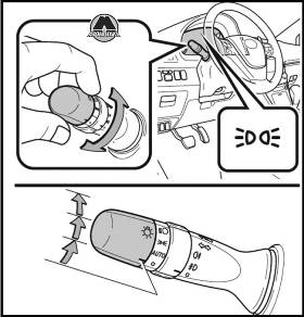
Включение передних габаритных и задних фонарей, фонарей освещения номерного знака и подсветки панели приборов.
Включение фар и всех вышеупомянутых огней.
AUTO — Фары и все (при наличии) перечисленные выше огни включаются и выключаются автоматически.
Автомобили с системой интеллектуального входа и запуска: Когда переключатель «ENGINE START STOP» находится в режиме IGNITION ON.
Автомобили без системы интеллектуального входа и запуска: Когда переключатель двигателя находится в положении «ON».
Включение фар дальнего света
Чтобы перейти на дальний свет при включенных фарах, переведите рычаг вперед. Для выключения дальнего света верните рычаг в среднее положение.
Чтобы включить дальний свет, потяните рычаг на себя. Чтобы выключить его, отпустите рычаг. Сигнализировать дальним светом фар можно как при включенных, так и при выключенных фарах.
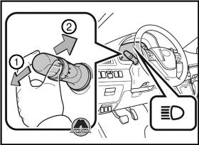
Система AFS (автомобили с газоразрядными фарами)
Адаптивная система переднего освещения (AFS) улучшает видимость при проезде через перекрестки и при прохождении кривых участков дороги за счет автоматической регулировки наклона света фар в соответствии со скоростью автомобиля и углом наклона колес. Система управляется с помощью данных, поступающих от системы рулевого управления.
Для отключения системы AFS нажмите переключатель.
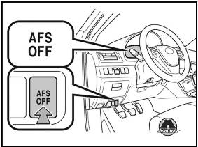
Ручной регулятор высоты света фар (автомобили с галогенными фарами)
Высоту света фар можно регулировать в зависимости от количества пассажиров и загрузки автомобиля.
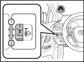
1. Подъем луча света фар
2. Опускание луча света фар
Датчик может работать неправильно, если на нем лежит предмет, или что-нибудь, прикрепленное к ветровом стеклу, блокирует датчик. Эти помехи влияют на работу датчика, определяющего интенсивность окружающего освещения, и могут вызвать неполадки в автоматической системе регулировки фар.
Система автоматического отключения фар
Автомобили без интеллектуальной системы доступа без ключа
Фары и задние габаритные фонари автоматически выключаются, если повернуть ключ в замке зажигания в положение АСС или выключить зажигание и открыть дверь водителя. Чтобы снова включить фары, поверните ключ в замке зажигания в положение ON или поставьте переключатель фар в выключенное положение, а затем верните его в положение. Если открыта какая-либо дверь или крышка багажника, то фары выключатся автоматически через 20 минут.
Автомобили с интеллектуальной системой доступа без ключа
Фары и задние габаритные фонари автоматически выключаются, если перевести переключатель ENGINE START STOP в режим ACCESSOR или выключенное положение и открыть дверь водителя. Чтобы снова включить фары, переведите переключатель ENGINE START STOP в режим IGNITION ON или установите переключатель фар в выключенное положение, а затем верните его в положение. Если открыта какая-либо дверь или крышка багажника, то фары выключатся автоматически через 20 минут.
Автоматическая система регулировки угла наклона фар (автомобили с газоразрядными фарами)
Положение фар автоматически регулируется в соответствии с количеством пассажиров и параметрами загрузки автомобиля при условии, что свет фар не мешает другим участникам движения. Если мигает индикатор AFS OFF (автомобили с газоразрядными фарами), это может означать наличие неполадок в системе. Обратитесь к дилеру Toyota.
Переключатель противотуманных фар
Противотуманные фары улучшают видимость в затрудненных дорожных условиях, например при движении в дождь или в туман.
Противотуманные фары можно использовать, когда включены фары или передние габаритные фонари. (Для автомобилей с выключателем противотуманных фар и задних противотуманных фонарей последние могут использоваться при включенных противотуманных фарах.)
Переключатель противотуманных фар и задних противотуманных фонарей
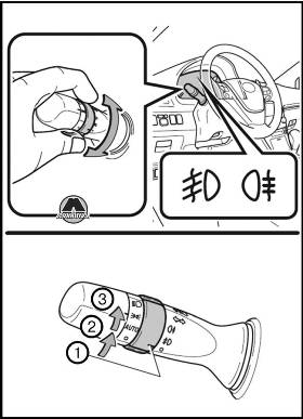
1. Выкл. 2. Включаются противотуманные фары 3. Одновременно включаются противотуманные фары и задние противотуманные фонари (Дальнейшее вращение кольцевого переключателя выключает только задние противотуманные фонари.)
Если переключатель отпустить, то кольцо вернется в положение. После выключения света фар задние противотуманные фонари не включаются даже при повторном включении фар.
Переключатель задних противотуманных фонарей
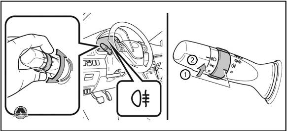
1. Выкл. 2. Задние противотуманные фонари включены
Очистители и омыватель ветрового стекла
Стеклоочиститель с функцией прерывистой очистки и регулировкой интервалов
При работе стеклоочистителя в прерывистом режиме интервалы очистки можно регулировать (при выборе 5)
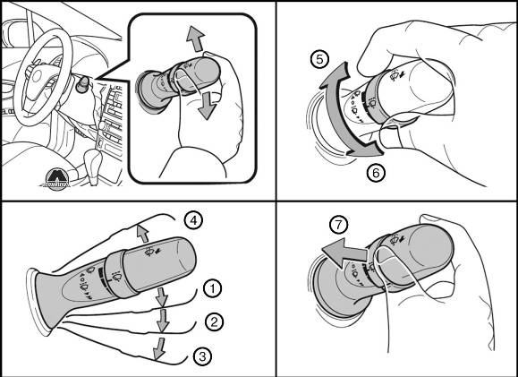
1. Работа стеклоочистителя в прерывистом режима 2. Работа очистителя с низкой скоростью 3. Работа очистителя с высокой скоростью 4. Разовая очистка 5. Частота работы очистителя в прерывистом режиме повышается 6. Частота работы очистителя в прерывистом режиме снижается 7. Работа стеклоочистителя и омывателя. Стеклоочистители включаются автоматически.
Очиститель и омыватель ветрового стекла можно использовать, когда переключатель «ENGINE START STOP» находится в режиме IGNITION ON.
Переключатель двигателя находится в положении «ON».
Датчик дождя (автомобили с очистителями ветрового стекла, реагирующими на дождь)
Датчик дождя оценивает количество капель дождя.
Если переключатель стеклоочистителя переводится в положение «AUTO», когда переключатель «ENGINE START STOP» находится в режиме IGNITION ON, стеклоочиститель однократно срабатывает, показывая, что режим «AUTO» активирован.
Если чувствительность стеклоочистителей установлена на более высокий уровень, стеклоочистители могут сработать один раз для указания на изменение чувствительности.
Если переключатель стеклоочистителя переводится в положение «AUTO», когда переключатель двигателя находится в положении «ON», стеклоочиститель однократно срабатывает, показывая, что режим «AUTO» активирован.
Если из омывателя ветрового стекла не поступает жидкость.
Если в бачке омывателя ветрового стекла есть омывающая жидкость, проверьте, не засорены ли форсунки омывателя.
Функции стеклоочистителя ветрового стекла
При работе стеклоочистителей автоматически включается обогрев заднего стекла и наружных зеркал заднего вида.
ВНИМАНИЕ
Меры предосторожности в связи с использованием очистителей ветрового стекла в режиме «AUTO»
В режиме «AUTO» очистители ветрового стекла могут неожиданно начать работать, если дотронуться до датчика, или при вибрации ветрового стекла. Следите за тем, чтобы пальцы или другие части тела не были защемлены очистителями ветрового стекла.ВНИМАНИЕ
Когда ветровое стекло сухое
Не используйте стеклоочистители, так как они могут повредить ветровое стекло.
Когда из форсунок не поступает омывающая жидкость
Если потянуть рычаг стеклоочистителей на себя и долго удерживать в этом положении, это может привести к повреждению насоса омывающей жидкости.
Переключатель очистителя фар
Омывающая жидкость может использоваться для очистки фар. Для очистки фар нажмите этот переключатель
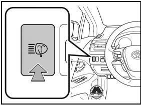
Когда может работать очиститель фар
Переключатель «ENGINE START STOP» находится в режиме IGNITION ON, и переключатель фар включен.
Если автомобиль оборудован переключателем света фар, то он находится в положении «AUTO», а фары горят.
Переключатель двигателя находится в положении «ON», и переключатель фар включен.
Если автомобиль оборудован переключателем света фар, то он находится в положении «AUTO», а фары горят.
ВНИМАНИЕ
Когда бачок омывающей жидкости пуст
Не используйте эту функцию, когда бачок омывающей жидкости пуст. Это может привести к перегреву насоса омывателя.
Используйте круиз-контроль, чтобы поддерживать заданную скорость движения, не нажимая на педаль газа.
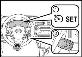
1. Индикаторы.
2. Переключатель круиз-контроля.
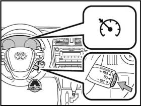
— Чтобы включить круиз-контроль, нажмите кнопку ON-OFF.
Загорится индикатор круиз-контроля.
— Чтобы выключить круиз-контроль, снова нажмите эту кнопку.
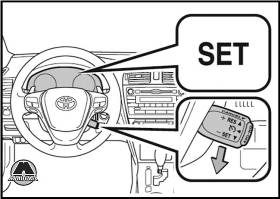
— Ускорьте или замедлите автомобиль до нужной скорости и нажмите рычаг вниз, чтобы задать скорость. Индикатор SET загорится. Скорость автомобиля в момент отпускания рычага становится заданной скоростью.
Настройка заданной скорости
Чтобы изменить заданную скорость, манипулируйте рычагом до тех пор, пока не будет достигнута желаемая скорость.
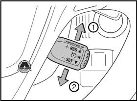
1. Увеличить скорость.
2. Уменьшить скорость.
Точная настройка: кратковременно переместите рычаг в нужном направлении.
Грубая настройка: удерживайте рычаг в нужном направлении.
Отмена и возобновление режима поддержания скорости
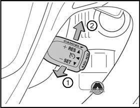
1. Чтобы отменить режим поддержания скорости, потяните рычаг на себя. Настройки скорости отменяются также при использовании тормозов.
2. Чтобы возобновить режим поддержания скорости, передвиньте рычаг вверх.
Возобновление режима возможно при движении автомобиля со скоростью, превышающей примерно 40 км/ч.
Круиз-контроль можно установить в следующих случаях
— Рычаг переключения передач находится в положении D, или выбран диапазон 4 или выше положения S.
— Скорость автомобиля превышает 40 км/ч.
Ускорение после настройки скорости автомобиля
Автомобиль можно ускорять как обычно. После ускорения автомобиль возвращается к заданной скорости. Даже без отмены круиз-контроля заданную скорость можно увеличить, сначала разогнав автомобиль до желаемой скорости, а затем нажав на рычаг, чтобы установить новую скорость.
Автоматическая отмена круиз-контроля
Круиз-контроль прекращает поддерживать скорость автомобиля в следующих случаях:
— Фактическая скорость автомобиля уменьшается более чем на 16 км/ч по сравнению с предустановленной скоростью. В этом случае записанная в памяти заданная скорость не сохраняется.
— Фактическая скорость автомобиля меньше 40 км/ч. Активированы режимы VSC.
ВНИМАНИЕ
Чтобы избежать использования системы круиз-контроля по ошибке
Если круиз-контроль не используется, выключите его кнопкой ON-OFF.
Ситуации, не подходящие для использования системы круиз-контроля
Не используйте круиз-контроль в перечисленных ниже случаях. Это может привести к потере управления и стать причиной аварии со смертельным исходом или серьезными травмами.
При интенсивном движении.
На дорогах с крутыми поворотами.
На извилистых дорогах.
На скользких дорогах, например, покрытых водой, снегом или льдом.
На крутых склонах.
При аварийной буксировке автомобиля.
Скорость автомобиля может превысить установленное значение во время движения вниз по крутому спуску.
Круиз-контроль с динамическим радаром
Движение в режиме контроля расстояния между автомобилями
В этом режиме радар используется для обнаружения следующих впереди автомобилей на расстоянии до 120 м и для определения расстояния между вашим автомобилем и автомобилем, находящимся перед вами. Обратите внимание, что при движении по длинным спускам расстояние между автомобилями будет уменьшаться.
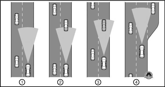
1. Пример движения с постоянной скоростью
Если впереди нет автомобилей, то автомобиль движется со скоростью заданной водителем. Можно также задать расстояние между автомобилями с помощью соответствующего переключателя.
2. Пример движения с замедлением
Если находящийся впереди автомобиль движется со скоростью, которая ниже заданной.
Если впереди на той же полосе обнаружен другой автомобиль, система автоматически замедляет ваш автомобиль. Если требуется более быстрое замедление, система использует тормозную систему. Если система не может обеспечить достаточное замедление для предотвращения сближения с находящимся впереди автомобилем, подается предупредительный звуковой сигнал.
3. Пример следования за автомобилем
Если скорость находящегося впереди автомобиля ниже заданной скорости.
Система продолжает следовать за находящимся впереди автомобилем, подстраиваясь под изменение его скорости для поддержания заданного расстояния между автомобилями.
4. Пример ускорения
Если на вашей полосе движения больше нет автомобилей, движущихся со скоростью, которая ниже заданной скорости. Когда движущийся перед вами автомобиль перестраивается в другую полосу, система постепенно увеличивает скорость движения до заданной. После этого система переходит в режим поддержания заданной скорости.
Предупреждение о сближении
Если ваш автомобиль слишком сблизился с движущимся впереди автомобилем и система круиз-контроля не может обеспечить достаточное автоматическое замедление, для предупреждения водителя начинает мигать дисплей и подается звуковой сигнал. Например, такая ситуация может возникнуть, если кто-то встраивается между вашим автомобилем и автомобилем, за которым вы следуете. Нажмите на тормоз для сохранения безопасного расстояния между автомобилями.
Автоматическое возобновление работы
Каждый раз, когда переключатель «ENGINE START STOP» переключается в положение IGNITION ON, включается режим поддержания расстояния между автомобилями и устанавливается большое расстояние.
Каждый раз, когда переключатель двигателя переключается в положение «ON», включается режим поддержания расстояния между автомобилями и устанавливается большое расстояние.
Предупреждающие индикаторы и сообщения системы динамического радарного круиз-контроля
Предупреждающие индикаторы и сообщения используются для индикации неполадки системы или предупреждения водителя о необходимости соблюдения осторожности при вождении.
Если используется режим поддержания расстояния между автомобилями, переключение в режим поддержания постоянной скорости невозможно. Также невозможно переключение из режима поддержания постоянной скорости в режим поддержания постоянного расстояния между автомобилями. Выключите систему, нажав кнопку «ON-OFF», затем снова включите ее.
Включение режима динамического радарного круиз-контроля возможно при следующих условиях
— Рычаг переключения передач находится в положении «D». Однако включение невозможно, если с помощью подрулевых переключателей передач (при их наличии) выбран любой из диапазонов 1 — 3.
— Скорость автомобиля превышает прибл. 50 км/ч.
Автомобиль можно разгонять обычным образом. После ускорения автомобиль возобновляет движение с заданной скоростью.
Автоматическая отмена режима поддержания постоянного расстояния между автомобилями
Режим поддержания постоянного расстояния между автомобилями автоматически отключается в указанных ниже ситуациях.
— Фактическая скорость автомобиля падает ниже приблизительно 40 км/ч.
— Активизирована система VSC+.
— Стеклоочиститель работает на высокой скорости.
— Датчик не работает должным образом, так как он чем-то закрыт.
Если режим поддержания постоянного расстояния между автомобилями автоматически отменяется по любой другой причине, возможно, что система неисправна. Обратитесь к дилеру Toyota.
Автоматическая отмена режима поддержания постоянной скорости
Движение с заданной скоростью автоматически отменяется в следующих ситуациях.
— Фактическая скорость автомобиля падает больше, чем на 16 км/ч ниже заданной скорости. В этом случае заданное значение скорости не сохраняется.
— Фактическая скорость автомобиля падает ниже 40 км/ч.
— Активизирована система VSC+.
Настройки расстояния между автомобилями
Выберите расстояние из приведенной ниже таблицы. Обратите внимание что указанные расстояния относятся к движению со скоростью 80 км/ч. Расстояние между автомобилями увеличивается/уменьшается в зависимости от скорости автомобиля
Датчик радара и декоративная крышка
Для обеспечения правильной работы системы поддержания постоянного расстояния между автомобилями содержите датчик и декоративную крышку в чистоте. (Некоторые препятствия, такие как снег, лед и пластиковые предметы, не обнаруживаются датчиком препятствий.) При обнаружении любого препятствия режим поддержания постоянного расстояния между автомобилями отменяется.
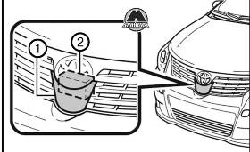
1. Декоративная крышка
2. Датчик радара
В следующих ситуациях возможно, что предупреждение о сближении не загорается, даже если расстояние между автомобилями уменьшается:
— Если скорость едущего впереди автомобиля равна или превышает скорость Вашего автомобиля.
— Если скорость едущего впереди автомобиля очень мала.
— Сразу же после задания скорости в системе круиз-контроля.
— В момент нажатия на педаль газа.
Перед использованием системы динамического радарного круиз-контроля
Не следует полностью полагаться на систему поддержания постоянного расстояния между автомобилями.
Помните о заданной скорости автомобиля. При неадекватном автоматическом замедлении/ускорении контролируйте скорость автомобиля и расстояние между своим автомобилем и автомобилем перед вами с помощью тормозов и т. д. Во избежание случайного включения системы динамического радарного круиз-контроля. Когда система не используется, держите кнопку «ON-OFF» в выключенном положении.
Ситуации, неподходящие для использования динамического радарного круиз-контроля
Не пользуйтесь динамическим радарным круиз-контролем в любой из перечисленных ниже ситуаций.
В противном случае из-за неправильного выбора скорости возможна серьезная авария вплоть до смертельного исхода.
— В условиях интенсивного движения
— На дорогах с крутыми поворотами.
— На извилистых дорогах.
— На дорогах со скользким покрытием, например, мокрых, обледенелых или покрытых снегом.
— На крутых склонах с резкими переходами между крутыми подъемами и спусками.
— На крутом спуске скорость автомобиля может превышать заданную.
— На въезде на автостраду.
— При плохих погодных условиях, которые могут повлиять на правильность работы датчиков (туман, снег, метель и т. д.).
— Если часто подается звуковой сигнал опасного сближения.
— При буксировке прицепа.
ВНИМАНИЕ
Ситуации, в которых датчик радара может неправильно обнаруживать находящийся впереди автомобиль.
В случае появления перед вами автомобилей в перечисленных ниже ситуациях нажмите на тормоз. Так как датчик может оказаться не в состоянии обнаружить подобные автомобили, предупреждение о сближении может не сработать, что может привести к аварии.
— Внезапно перестраивающиеся автомобили.
— Автомобили, движущиеся с низкой скоростью.
— Стоящие автомобили.
— Транспортные средства с небольшой задней частью (прицепы без нагрузки и т. д.).
— Мотоциклы, движущиеся по той же полосе.
Условия, в которых система поддержания постоянного расстояния между автомобилями может работать неправильно
В перечисленных ниже условиях при необходимости пользуйтесь тормозами, так как датчик радара может неправильно определить находящийся впереди автомобиль, что может привести к аварии.
— Если работе датчика радара препятствуют вода или снег, летящие из-под окружающих автомобилей.
— Если ваш автомобиль наклонен вверх (из-за тяжелого груза в багажнике и т. п.).
— Если дорога поворачивает или имеет узкие полосы.
— Если поворачивается рулевое колесо или положение автомобиля в пределах полосы нестабильно.
— Если следующий впереди автомобиль внезапно замедляется.ВНИМАНИЕ
Для обеспечения правильной работы датчика радара
Соблюдайте перечисленные ниже правила обращения с датчиком и декоративной крышкой, так как их несоблюдение может привести к неправильной работе датчика и, как следствие, к аварии.
— Ничего не приклеивайте и не прикрепляйте к ним.
— Не допускайте их загрязнения.
— Не разбирайте и не подвергайте их сильным ударам.
— Не модифицируйте и не красьте их.
— Не используйте для замены детали других производителей.
Обращение с датчиком радара
— Для обеспечения эффективной работы системы круиз-контроля соблюдайте следующие правила.
— Всегда содержите датчик и переднюю решетку в чистоте.
— Очищайте датчик и переднюю решетку мягкой тканью, чтобы не поцарапать и не повредить их.
— Не допускайте сильных ударов по датчику или по зоне вокруг него.
— В случае даже небольшого смещения датчика система может работать неправильно. В случае сильного удара по датчику или зоне вокруг него произведите осмотр и настройку у дилера Toyota.
— Не разбирайте датчик.
— Не устанавливайте на датчик, декоративную крышку или зону вокруг них никакие аксессуары или наклейки.
— Не модифицируйте и не красьте датчик и декоративную крышку.
Система помощи следование по полосе (LKA)
При движении по автомагистрали или шоссе с разметкой полос данная система распознает полосы с помощью камеры и помогает водителю оставаться в пределах своей полосы. В системе LKA предусмотрены две функции.
— Функция предупреждения о выходе за пределы полосы.
Если система обнаруживает, что автомобиль может выйти за пределы полосы, она предупреждает водителя частыми звуковыми сигналами, индикаторами на многофункциональном дисплее и сенсорным предупреждением (подается небольшое кратковременное управляющее усилие в направлении центра полосы), подаваемым через рулевое колесо.
Функция помощи в удержании в пределах полосы
Эта функция включается, если включен круиз-контроль в режиме поддержания постоянного расстояния между автомобилями с заданной скоростью свыше 75 км/ч и работает функция предупреждения о выходе за пределы полосы. Когда включена функция помощи в удержании автомобиля в пределах полосы, на рулевое управление подается небольшое управляющее усилие, помогающее водителю удерживать автомобиль в центре полосы.
Когда работает функция помощи в удержании в пределах полосы, сенсорное предупреждение не подается.
Временная отмена функций системы LKA
В любой из перечисленных ниже ситуаций функции системы LKA временно отменяются. Работа функций возобновляется после восстановления необходимых условий работы.
— Нажат рычаг сигнала поворота.
— Рулевое колесо повернуто на угол, необходимый для смены полос.
— Нажата педаль тормоза. Работа функции помощи в удержании на полосе не возобновляется даже после отпускания педали тормоза, так как при ее нажатии отменяется работа динамического радарного круиз-контроля.
— Скорость автомобиля выходит за пределы рабочего диапазона функций системы LKA. (При отмене функции помощи в удержании на полосе подаются два звуковых сигнала.)
— Когда направляющие линии не могут быть распознаны во время движения. (При отмене функции помощи удержания на полосе звуковой сигнал звучит дважды.)
— Включена низкая или высокая скорость работы стеклоочистителей. (При отмене функции помощи в удержании на полосе подаются два звуковых сигнала.)
— Звуковой сигнал может не прозвучать во время отмены функций системы LKA, поскольку уведомление об отмене динамического радарного круиз-контроля имеет приоритет над системой LKA и отменяет функцию.
— При включенной функции помощи в удержании в пределах полосы включается предупреждение об отсутствии рук на руле. (Этот сигнал подается дважды.)
Предупреждение о вождении без управления рулевым колесом
Если рулевое колесо не работает в течение приблизительно 15 секунд на прямом участке дороги или приблизительно 5 секунд на закругляющемся участке дороги, звуковой сигнал прозвучит дважды, индикаторы на многофункциональном дисплее загорятся, а функция помощи удержания на полосе будет временно отменена. Если при вождении автомобиля Вы слегка касаетесь рулевого колеса, система может расценить это как вождение без управления рулевым колесом.
При парковке автомобиля на солнце
Функции системы LKA могут быть недоступны некоторое время после начала движения. В таких случаях отключите систему LKA и включите ее вновь после установления нормальной температуры. Когда температура в кабине снижается и температура среды вокруг датчика камеры принимает рабочее значение, функции начинают работать.
ВНИМАНИЕ
Перед использованием системы LKA
Не следует полностью полагаться на систему LKA для удержания в пределах полосы. Система LKA не предназначена для обеспечения движения без участия водителя. Для поддержания правильного положения на полосе водитель должен пользоваться рулевым управлением. Во время вождения обязательно соблюдайте осторожность.ВНИМАНИЕ
Ситуации, неподходящие для использования системы LKA
Использование системы LKA в любой из следующих ситуаций может привести к неправильной работе системы и, как результат, к аварии, которая может явиться причиной летального исхода или серьезной травмы. Отключите систему LKA при вождении в одной из следующих ситуаций.
— Если разметка полос плохо различима, так как она загрязнена или стерта.
— Если разметка плохо видна из-за дождя, снега, тумана или яркого света.
— Если фары светят недостаточно ярко из-за загрязнения рассеивателей или неправильной регулировки.
— В случае отсутствия разметки, например перед контрольными постами на автостраде.
— Если постоянно и резко изменяется уровень освещенности.
— При наличии мешающих линий, например теней, снежных наносов, колеи со скопившейся в ней водой или линий, оставшихся после ремонта дороги.
— При движении по полосам, отличных от полос движения или полос обгона на магистралях или шоссе.
— В случае наличия закрытых из-за ремонта полос или при движении по полосе перестроения.
— Если полосы очень узкие или широкие.
— Если расстояние до едущего впереди автомобиля очень мало.
— Если автомобиль сильно наклонен на одну сторону из-за большой загрузки или неправильного давления в шинах.
— При движении по извилистым или неровным дорогам.
— При движении по дорогам со скользким покрытием, например, мокрым, обледенелым или покрытым снегом.
— Произведена замена шин (включая зимние шины), или заменена подвески.
— При буксировке прицепа.
Системы облегчения вождения
Для повышения безопасности движения и динамических характеристик автоматически включаются в работу следующие системы, реагирующие на различные дорожные ситуации. Однако помните, что эти системы являются вспомогательными, и нельзя полностью полагаться на них при эксплуатации автомобиля.
Антиблокировочная тормозная система (ABS)
Помогает предотвратить блокировку колес при внезапном торможении или торможении на скользкой дороге.
Усилитель экстренного торможения
Создает повышенное тормозное усилие после нажатия на педаль тормоза, когда система определяет ситуацию экстренного торможения.
Система курсовой устойчивости (VSC+) (при наличии)
Помогает водителю контролировать пробуксовку колес при внезапном маневре в сторону или прохождении поворота на скользкой дороге.
Антипробуксовочная система (TRC)
Сохраняет тяговое усилие и предотвращает пробуксовку передних колес при трогании или ускорении автомобиля на скользкой дороге.
Электрический усилитель рулевого управления (EPS)
Использует электродвигатель для уменьшения усилия, необходимого для поворота рулевого колеса.
Сигнал аварийного торможения (при наличии)
В случае резкого торможения стоп-сигналы начинают автоматически мигать, чтобы предупредить водителя движущегося следом автомобиля.
ВНИМАНИЕ
Любое из этих условий может привести к аварии и, в результате, к смертельному исходу и тяжелым травмам:
ABS не работает эффективно, когда
— Превышены предельные значения сцепления шин с дорожным полотном.
— Возникает эффект аквапланирования автомобиля при движении с высокой скоростью по влажной или скользкой дороге.
Тормозной путь, когда система ABS работает при движении по влажной или скользкой дороге.
Система ABS не предназначена для сокращения тормозного пути. Всегда поддерживайте безопасную дистанцию до впереди идущего автомобиля в следующих ситуациях:
— При движении по ухабистым, гравийным или заснеженным дорогам.
— При движении с цепями противоскольжения.
— При движении по ухабистой дороге.
— При движении по дорогам с выбоинами или неровным дорожным покрытием.
Система TRC не может работать эффективно в следующих случаях:
При движении по скользким дорогам контроль за направлением движения и тягой может быть потерян даже несмотря на работу системы TRC. Не следует двигаться на автомобиле в условиях, в которых могут быть потеряны стабильность движения и тяга.
Пои активизированной системе VSC+
Мигает индикатор пробуксовывания, и звучит соответствующий сигнал. Обязательно соблюдайте осторожность при вождении автомобиля. Невнимательное вождение может привести к аварии. Будьте особенно внимательны, когда мигает индикатор и звучит соответствующий сигнал.
Если системы TRC и VSC+ отключены
Будьте особенно внимательны и соблюдайте скоростной режим, соответствующий дорожным условиям. Поскольку эти системы обеспечивают устойчивость автомобиля и силу тяги, не отключайте системы TRC и VSC без необходимости.
Следите за тем, чтобы все шины имели одинаковый размер, марку, рисунок протектора и грузоподъемность. Кроме того, следите за тем, чтобы давление в шинах соответствовало норме.
Если на автомобиль установлены разные шины, системы ABS и VSC+ не будут работать надлежащим образом.
За дополнительной информацией по замене шин или колес обратитесь к дилеру Toyota.
Обращение с шинами и подвеской
Использование шин с каким-либо дефектом или изменение конструкции подвески влияют на работу систем облегчения движения и могут вызвать сбои в работе системы.
Обратите внимание на следующую информацию о размещении груза, предельной вместимости и допустимой массе груза:
— По возможности кладите груз и багаж в багажник.
— Убедитесь, что все предметы надежно закреплены.
— Чтобы не нарушать сбалансированности автомобиля во время движения, размещайте багаж внутри багажного отделения равномерно.
— В целях экономии топлива не перевозите в автомобиле ненужный груз.
ВНИМАНИЕ
Указанные ниже предметы могут вызвать пожар, если они загружены в багажник:
Емкости с бензином. Аэрозольные баллоны.
Меры безопасности при хранении
Соблюдайте следующие меры предосторожности. Пренебрежение ими может привести к смерти или тяжелым травмам.
— Автомобили со складывающимися задними сиденьями: чтобы предотвратить соскальзывание предметов вперед во время торможения, размещайте багаж и груз таким образом, чтобы его высота не превышала высоту спинки сиденья. Груз и багаж следует размещать как можно ближе к полу.
— Автомобили со складывающимися задними сиденьями: когда задние сиденья сложены, не размещайте длинные предметы непосредственно позади передних сидений.
— Автомобили со складывающимися задними сиденьями: пассажиру запрещается находиться в увеличенном (после складывания задних сидений) багажном отделении во время движения автомобиля. Оно не предназначено для пассажиров. Пассажиры должны сидеть на сидении и быть пристегнутыми ремнями безопасности. В противном случае повышается вероятность получения серьезной или смертельной травмы при экстренном торможении, резком повороте или аварии.
— Не помещайте груз или багаж в указанные ниже места автомобиля, так как предметы могут попасть под педаль тормоза или газа и препятствовать их правильной работе, а также затруднить обзор, травмировать водителя или пассажира и стать причиной аварии:
— под ноги водителя;
— на сиденье переднего пассажира или задние сиденья (незакрепленные предметы);
— в отделение для мелких вещей;
— на приборную панель;
— на переднюю панель.
Закрепите все предметы, находящиеся в пассажирском отсеке, поскольку они могут сдвинуться с места и стать причиной травмы в случае экстренного торможения, резкого поворота или аварии.
Нагрузка и ее распределение
— Не допускайте перегрузки автомобиля.
— Следите за равномерностью распределения нагрузки. Неправильное распределение нагрузки может вызвать повреждение рулевого управления и тормозной системы, что может стать причиной серьезных травм или смерти.
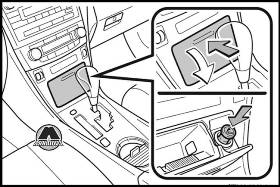
— Нажмите на крышку, чтобы открыть ее, затем нажмите на прикуриватель.
Использование прикуривателя
— Автомобили без интеллектуальной системы доступа без ключа: ключ в замке зажигания находится в положении АСС или ON.
— Автомобили с интеллектуальной системой доступа без ключа: переключатель ENGINE START STOP находится в режиме ACCESSORY или IGNITION ON.
ВНИМАНИЕ
Не дотрагивайтесь до металлических деталей прикуривателя.
Не удерживайте прикуриватель в нажатом положении. Это может привести к его перегреву и пожару.
Не вставляйте в гнездо прикуривателя ничего, кроме штатного прикуривателя. Это может деформировать гнездо прикуривателя, из-за чего прикуриватель будет выскакивать или его будет тяжело вынуть.
Держите пепельницу закрытой. В случае экстренного торможения может произойти несчастный случай, если пассажир ударится об открытую пепельницу или из нее вылетит пепел. Прикуриватель вернется в исходное положение, когда будет готов к использованию.
Розетки для электроприборов
Розетку можно использовать для электроприборов, работающих при напряжении 12 V (В) и силе тока не более 10 А. На автомобилях с двумя розетками для электроприборов электроприборы с напряжением 12 V (В) не должны в сумме превышать 10 А, когда используются обе розетки.
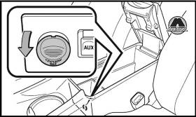
Использование розетки для электроприборов
ВНИМАНИЕ
Чтобы избежать повреждения разъема питания, закрывайте крышку розетки для электроприборов, когда она не используется.
Посторонние предметы или жидкости, попавшие в розетку для электроприборов, могут вызвать короткое замыкание.
Для предотвращения перегорания предохранителей не используйте устройства, потребляющие более 12 V (В), и 10 А. На автомобилях с двумя розетками для электроприборов электроприборы с напряжением 12 V (В) не должны в сумме превышать 10 А, когда используются обе розетки.
Чтобы предотвратить разряд аккумулятора, не используйте электрическую розетку при отключенном двигателе дольше, чем это необходимо.
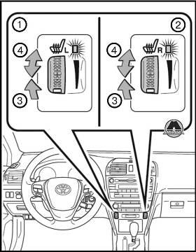
1. Для сиденья водителя 2. Для сиденья переднего пассажира 3. Вкл. (Включается индикатор) 4. Регулировка температуры сиденья
Чем дальше регулятор повернут вверх, тем выше температура сиденья.
Использование обогревателей сидений
— Автомобили без интеллектуальной системы доступа без ключа: ключ в замке зажигания установлен в положение ON.
— Автомобили с интеллектуальной системой доступа без ключа: переключатель ENGINE START STOP находится в режиме IGNITION ON.
Впереди: полностью сдвиньте регулятор вниз. Контрольная лампа погаснет.
Сзади: выключите подогрев сиденья.
ВНИМАНИЕ
Чтобы избежать возможных ожогов, будьте внимательны, усаживая на сиденье с включенным обогревателем следующие категории пассажиров:
Младенцы, маленькие дети, пожилые люди, больные и инвалиды.
Люди с чувствительной кожей.
Уставшие люди.
Нетрезвые люди, люди, принимавшие лекарства, вызывающие сонливость (снотворное, лекарство от простуды и т. д.).
Не накрывайте сиденье с включенным подогревом каким-либо материалом. Одновременное использование подогрева сиденья и одеяла или подушки может повысить температуру сиденья и привести к перегреву. Не используйте подогрев дольше, чем это необходимо. Это может привести к перегреву или ожогам у пассажиров.
ВНИМАНИЕ
Чтобы предотвратить повреждение обогревателя сиденья, не кладите на сиденье тяжелые предметы с неровной поверхностью, не протыкайте сиденье острыми предметами (иглами, гвоздями и т. д.).
Чтобы предотвратить разряд аккумулятора, выключайте подогрев сидений при неработающем двигателе.