 Инструкция по применению/эксплуатации бензореза Stihl TS 420.
Техника безопасности:
Запрещается применять пильные диски, твердосплавные, спасательные, дереворежущие или иные зубчатые инструменты – опасность получения смертельной травмы!
Одежда должна соответствовать цели применения и не должна мешать при работе. Рекомендуется плотно прилегающая одежда – комбинезон, а не рабочий халат!
Чтобы уменьшить угрозу травмирования глаз, следует надевать плотно прилегающие защитные очки. Следить за правильным положением очков.
При возможном возникновении паров или дыма (например, при резке многослойных материалов) следует носить респиратор.
Заправка топливом:
Перед заправкой выключить двигатель;
Не заправлять топливом, пока двигатель не охладится полностью – топливо может перелиться – опасность пожара!
Крышку бака открывать осторожно, чтобы избыточное давление понижалось медленно и топливо не могло выбрызгиваться.
Абразивно-отрезные круги:
Абразивно-отрезные круги должны быть допущены для выполнения ими резки вручную. Запрещается применять другие абразивные инструменты и дополнительные устройства – опасность несчастного случая!
Абразивно-отрезные круги пригодны дляразличных материалов: обратить внимание на маркировку отрезных кругов.
Ни в коем случае не применять растрескавшиеся, раскрошившиеся или изогнутые абразивно-отрезные круги по возможности не работать с верхней четвертью абразивно-
отрезного круга.
Избегать заклинивания, отрезанный элемент не должен замедлять вращения абразивно-отрезного круга
Монтаж абразивно-отрезных кругов:
Осмотреть шпиндель абразивно-отрезного устройства, не эксплуатировать абразивно-отрезное устройство с поврежденным шпинделем – опасность несчастного случая!
При применении абразивно-отрезных кругов с алмазным напылением соблюдать указанное стрелкой направление вращения.
Установить переднюю нажимную шайбу – затянуть до отказа натяжной болт – абразивно-отрезной круг.
Перед запуском:
Проверить топливную систему на герметичность, особенно видимые детали, например, замок бака, шланговые соединения, ручной топливный насос.
Комбинированный переключатель /комбинированный рычаг / переключатель остановки должен легко устанавливаться в позицию STOP или 0.
Проверить пригодность абразивно-отрезного круга дляразрезаемого материала, атакже исправность и правильность монтажа круга (направление вращения, плотность посадки).
Запуск двигателя:
Только на ровной поверхности, следить за устойчивостью положения агрегата, агрегат прочно удерживать – абразивно-отрезной круг не должен касаться ни земли ни каких-либо предметов, а также не находиться в разрезе.
После запуска двигателя абразивно-отрезной круг может сразу же начать вращаться.
Мотор не запускать из руки – запуск производить согласно указаниям в инструкции по эксплуатации.
Как держать и вести агрегат
Абразивно-отрезное устройство должно использоваться толькодля резки вручную или с установкой на направляющей тележке STIHL.
Резка вручную
Агрегат следует всегда удерживать обеими руками: правая рука на задней рукоятке – это правило действует также и для левшей. Для надежного управления бензопилой трубчатуюрукоятку ирукоятку плотно обхватить большими пальцами. Обрабатываемое изделие должно быть надежно уложено, агрегат следует всегда подводить к – ни в коем случае не наоборот.
Во время работы:
При угрожающей опасности или в аварийном случае немедленно остановите двигатель – комбинированный переключатель / комбинированный рычаг / переключатель остановки установите в положение STOP или 0.
Обратить внимание на безупречную работу холостого хода двигателя, чтобы отрезной круг при отпускании рычага газа больше не вращался и остановился.
Очистить участок проведенияработ– обратить внимание на препятствия, ямы и канавы.
Будьте осторожны при гололедице, влажности, на снегу, на льду, на склонах, на неровной местности – опасность скольжения!
Запрещаетсяработать на приставной лестнице – на неустойчивых участках – выше плеча – одной рукой – опасность несчастного случая!
Не работать в одиночку – обязательно соблюдать расстояние слышимости к другим людям, которые могут оказать помощь в аварийном случае.
-
Contents
-
Table of Contents
-
Troubleshooting
-
Bookmarks
Quick Links
{
Working safely with cut-off machines
Related Manuals for Stihl TS 420
Summary of Contents for Stihl TS 420
-
Page 1
Working safely with cut-off machines… -
Page 3: Table Of Contents
Sample applications STIHL cut-off machines. Cutting wheels The chapter «Main parts of the machine» Composite resin cutting wheels shows the TS 420 cut-off machine as an Diamond cutting wheels example. Other cut-off machines may Maintenance and Care have different controls.
-
Page 4: Techniques
The machine may only be operated by by STIHL for this machine or which are precautions may cause people who are fit, in good physical technically equivalent. Contact a dealer serious or even fatal health and in good mental condition.
-
Page 5
Clean the machine Ensure that there are no flammable immediately if fuel is spilled. Change deposits (chips, fuel, oil, etc.) on the STIHL can supply a comprehensive your clothes immediately if they are clothing. range of protective clothing and contaminated with fuel. -
Page 6
Observe the cutting wheel diamond cutting wheels can shimmy codes. during cutting. This shimmying can STIHL generally recommends wet cause such diamond cutting wheels to cutting. be abruptly braked or become stuck in the cut – Danger of kickback! -
Page 7
The machine is operated by only one – Check that the deflector is secure — person. There should not be any other consult a STIHL servicing dealer if it person within the working area, not even When a cut-off machine with rotating is loose cutting wheel is moved in the direction of when starting the machine. -
Page 8
Have the machine repaired by The machine must not be used near poorly ventilated areas, a STIHL servicing dealer if the cutting inflammable substances or gases. even if your model is wheel continues to turn nevertheless. -
Page 9
English Never leave the machine unattended with the engine running. Switch off the engine before leaving the machine (e. g., for a break). Before putting the cut-off machine down on the ground: – Switch off engine – Wait until the cutting wheel has come to a standstill or brake the Kickback occurs when the cut-off –… -
Page 10
– – Low outside temperatures After that, do not change the cutting e. g., use STIHL water attachment. direction. Avoid knocks and bumps with – Amount of gripping force (holding Use dry cutting when using composite… -
Page 11: Sample Applications
– Bind dust inspect antivibration elements STIHL recommends the use of genuine The cutting wheel must be supplied with periodically. STIHL spare parts. Such parts have at least 0.6 l/min of water.
-
Page 12
English Use composite resin cutting wheels – Water attachment on the machine Cut in several passes for all types of water supplies with or without water – depending on version – Pressurized water tank 10 l for binding dust Depending on version, composite resin –… -
Page 13
English Cutting plates Shaping pipe Secure the plate on a non-slip surface Make curves in multiple operations – make certain that the cutting wheel does not tilt Mark a cutting line Cutting round and hollow bodies Manual cutting along this line Grind a guide groove (A) along the requires particular caution and line marked… -
Page 14: Cutting Wheels
Cutting wheels are exposed to extremely high loads especially during freehand cutting. The cutting wheels, which have been developed by STIHL in cooperation with renowned manufacturers of abrasive wheels, are of high quality and tailored precisely to the respective intended use as well as the engine performance of the cut-off machine.
-
Page 15: Diamond Cutting Wheels
– Clay pipe diamond cutting wheel. STIHL diamond cutting wheels are not Using the cutting wheel on a cut-off suitable for cutting metal. machine with a faulty spindle bearing can lead to deviations in radial and axial run-out.
-
Page 16
Breakdowns or tears in the parent wheel Overloading use a new cutting wheel and segment Undercut Cutting in the wrong material use new cutting wheel; observe separat- ing layers of various materials STIHL recommends STIHL servicing dealers Working safely with cut-off machines… -
Page 17
English Undercut – when cutting extremely hard materials, e. g., granite – with incorrect handling, e. g., excessive feed effort – if excessively large cross-sections are cut without pendulum cutting (movement back and forth in the cutting plane) Built-up edges increase vibration, reduce cutting performance, and cause Do not cut into the base course formation of sparks. -
Page 18: Maintenance And Care
English Maintenance and Care The following maintenance intervals apply in normal operating conditions. The specified intervals must be shortened accordingly when working for longer than normal or under difficult cutting conditions (extensive dust, etc.). Visual inspection (condition, leaks) Complete machine Clean Operating elements Check operation…
-
Page 19
Antivibration elements Have them replaced by a specialist dealer test, check Abrasive wheel Replace test, check Supports/rubber buffers (underneath the machine) Replace Safety information sticker Replace STIHL recommends STIHL servicing dealers present only in some countries Working safely with cut-off machines… -
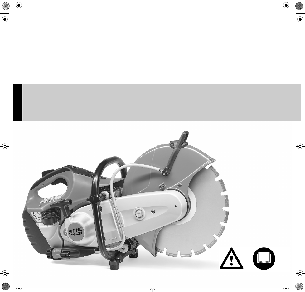
Page 20: Main Parts
English Main Parts Rear handle Throttle trigger interlock Throttle trigger Slide control Starter grip Carburetor adjusting screws Filler cap Water attachment Tensioning nut 10 Adjusting lever 11 Cutting wheel 12 Front thrust washer 13 Deflector 14 Muffler 15 Spark arresting screen (present only in some countries) 16 Handlebar 17 Decompression valve…
-
Page 21
English Working safely with cut-off machines… -
Page 22
English Working safely with cut-off machines… -
Page 24
0457-186-0121 englisch www.stihl.com *04571860121* 0457-186-0121…
(скачивание инструкции бесплатно)
Формат файла: PDF
Доступность: Бесплатно как и все руководства на сайте. Без регистрации и SMS.
Дополнительно: Чтение инструкции онлайн
{
STIHL TS 410, 420
Инструкция по эксплуатации
Страница:
(1 из 52)
навигация

1

2

3

4

5

6

7

8

9

10

11

12

13

14

15

16

17

18

19
20

21

22

23

24

25

26

27

28

29

30

31

32

33

34

35

36

37

38

39

40

41

42

43

44

45

46

47

48

49

50

51

52
Оглавление инструкции
- Страница 1 из 53
{ STIHL TS 410, 420 Инструкция по эксплуатации - Страница 2 из 53
- Страница 3 из 53
pyccкий © ANDREAS STIHL AG & Co. KG, 2011 0458-370-1821-E. VA1.J11. 0000001456_004_RUS Напечатано на отбеленной бумаге не содержащей хлора. Краски для печати содержат растительные масла, бумага подлежит вторичной переработке. Оригинальная инструкция по эксплуатации Содержание К данной инструкции по - Страница 4 из 53
pyccкий К данной инструкции по эксплуатации Символы на картинках Все символы на картинках, которые нанесены на устройство, объясняются в данной инструкции по эксплуатации. Обозначение разделов текста Предупреждение об опасности несчастного случая и травмы для людей а также тяжёлого материального - Страница 5 из 53
pyccкий отдельные типы кардиостимуляторов не удается исключить полностью. Во избежание риска для здоровья STIHL рекомендует обратиться за советом к лечащему врачу и изготовителю кардиостимулятора. Работа с устройством после употребления алкоголя, лекарств, снижающих способность реагирования, или - Страница 6 из 53
pyccкий Носите защитную каску, при наличии опасности ушиба падающими вниз предметами, защитную маску и обязательно защитные очки – опасность травмы завихренными или отбрасываемыми в сторону предметами. Защитная маска не является достаточной защитой для глаз. Во время работы могут образоваться пыль - Страница 7 из 53
pyccкий Замок топливного бака с винтовой нарезкой После заправки топливом затяните, по возможности, до отказа резьбовой замок бака. Благодаря этому снижается опасность отвинчивания замка бака из-за вибраций мотора и, в результате этого, опасность вытекания топлива. Абразивно-отрезное устройство, - Страница 8 из 53
pyccкий Складское хранение абразивноотрезных дисков Абразивно-отрезные диски храните в сухом месте без влияния морозов, на ровной поверхности, при равномерной температуре – опасность поломки и растрескивания! Абразивно-отрезные диски предохраняйте постоянно от резкого соприкосновения с землей или - Страница 9 из 53
pyccкий Если абразивно-отрезное устройство при вращающемся абразивноотрезном диске передвигается вперед в направлении стрелки, то возникает сила, которая пытается опрокинуть устройство. Обрабатываемое изделие должно быть уложено прочно, устройство ведите всегда в направлении к изделию – и никогда - Страница 10 из 53
pyccкий При работе мотоустройства выделяются ядовитые отработавшие газы, как только двигатель запустится. Данные газы могут не иметь запаха и быть невидимыми, а также содержать углеводороды и бензол. Никогда не работайте мотоустройством в закрытых или плохо проветриваемых помещениях – также при - Страница 11 из 53
– – защемляется в разрезе – прежде всего, в верхней четверти, – сильно притормаживается в результате трения о твердый предмет. Снижение опасности возникновения обратной отдачи – Работайте обдуманно, применяя правильную технику работы, – Абразивно-отрезное устройство удерживайте обеими руками и - Страница 12 из 53
pyccкий Абразивно-отрезные диски с алмазным напылением: при снижении производительности контролируйте абразивно-отрезной диск с алмазным напылением, при необходимости, подточите. Для этого произведите резку в абразивном материале, как например, песчаник, газобетон или асфальт. 002BA059 KN Не - Страница 13 из 53
pyccкий Общепринятая продолжительность пользования устройством не может быть установлена, так как это зависит от многих факторов. Длительность пользования устройством увеличивается благодаря следующим мерам: – защита рук (теплые перчатки); – перерывы в работе. Длительность пользования сокращается - Страница 14 из 53
pyccкий Примеры применения Отрезные шлифовальные круги с алмазным напылением предназначены только для влажной резки С помощью отрезных шлифовальных кругов из искусственной смолы выполнять сухую либо влажную резку – в зависимости от модификации После работы отрезного шлифовального круга для удаления - Страница 15 из 53
pyccкий При необходимости, оставьте небольшую перемычку, удерживающую отрезаемую часть в ее позиции. Данную перемычку отломите позднее. Перед окончательным отрезанием части установите: – вес отрезаемой части, – каким образом отрезаемая часть может перемещаться после отрезания, – находится ли - Страница 16 из 53
pyccкий отрезной шлифовальный круг не перекашивайте, а устанавливайте заново, при необходимости, оставьте небольшую перемычку, удерживающую отрезаемую часть в ее позиции. Данную перемычку отломите позднее N Кривые вырезайте за несколько рабочих подходов – следите за тем, чтобы отрезной шлифовальный - Страница 17 из 53
pyccкий Отрезные шлифовальные круги – Отрезные шлифовальные круги не храните вблизи агрессивных жидкостей. При работе отрезные шлифовальные круги подвергаются большим нагрузкам, особенно при ручной резке. – Отрезные шлифовальные круги храните не подвергая воздействию мороза Отрезные шлифовальные - Страница 18 из 53
pyccкий Алмазные отрезные шлифовальные круги Краткие обозначения эффективного функционирования отрезного шлифовального круга с алмазным напылением. Применение отрезного шлифовального круга на абразивноотрезном станке с неудовлетворительной установкой шпинделя на подшипниках может привести к - Страница 19 из 53
pyccкий Устранение неполадок в работе Отрезной шлифовальный круг Неисправность Загрязненные кромки или поверхности резки, увод разреза Сильный износ на сторонах сегмента Загрязненные кромки, увод разреза, режущая способность круга отсутствует, искрообразование Плохая режущая способность, высокий - Страница 20 из 53
pyccкий Износ сердечника При разрезке дорожного полотна не проникайте в несущий слой (часто щебень) – при этом может возникнуть чрезмерный износ сердечника – проникновение отрезного шлифовального круга в щебень можно распознать по светлой пыли – опасность поломки! Нарост на режущих кромках, заточка - Страница 21 из 53
pyccкий Когда мотор работает, устройство электронного управления подачей воды может включаться либо выключаться и количество воды регулироваться. Устройство электронного управления подачи воды обеспечивает подачу к абразивно-отрезному устройству оптимального количества воды. В режиме холостого хода - Страница 22 из 53
pyccкий 2 N Снять (1) соединительную втулку муфты N «Подключение к водопроводу с фильтром» (2) выкрутить и почистить под проточной водой – фильтр остаётся на подключении к водопроводу На заводе «Соединительная деталь с защитой» монтируется на внутренней стороне. N Подсоединение для воды (2) со - Страница 23 из 53
pyccкий «Соединительную деталь с защитой» подготовьте для наружного монтажа Снять натяжение клинового ремня N Ослабить гайки (1) – не выкручивать N Стяжную гайку (2) с помощью комбинированного ключа поверните против часовой стрелки – приблизительно на 1/4 оборота, до упора = 0. 1 Поликлиновой - Страница 24 из 53
pyccкий «Соединительную деталь с защитой» монтируйте – защита на наружной стороне «Соединительную деталь с защитой» поверните таким образом, чтобы защита находилась на наружной стороне N Установите упор (5) – отверстие в упоре с отверстием в соединительной детали привести к кожуху N Ввинтите болт - Страница 25 из 53
pyccкий Проверка области регулировки защиты Монтируйте подсоединение для подачи воды N N N Более длинный полый болт (1) продеть через штуцер (2) на подсоединении для подачи воды – соблюдать положение штуцера Штуцер с более длинным полым болтом установить на регулирующем рычаге (3) – завинтить полый - Страница 26 из 53
pyccкий Проверка области регулировки защиты N Ввинтите упорный болт (3) и затяните N Монтируйте регулировочный рычаг N Монтируйте «Соединительную деталь с защитой» – защита на внутренней стороне N Монтируйте ременную защиту N Монтируйте подсоединение для подачи воды 1 1 1 A N Защиту повернуть как - Страница 27 из 53
pyccкий Клиновой ремень натягивается автоматически под действием усилия пружины. Натяжная гайка подпружинена, – удерживайте прочно комбинированный гаечный ключ!. N N Натяжную гайку поверните по часовой стрелке приблизительно на 1/8 оборота, – на натяжную гайку начинает воздействовать усилие - Страница 28 из 53
pyccкий Демонтаж абразивно-отрезного диска применении динамометрического ключа момент затяжки см. «Технические Данные» Установка абразивно-отрезного диска N Выньте стержень из ременной защиты Никогда не применяйте одновременно два абразивноотрезных диска на основе синтетических смол – опасность - Страница 29 из 53
pyccкий Бензин Соотношение смеси Мотор должен работать на топливной смеси из бензина и моторного масла. Применяйте только марочный бензин с минимальным октановым число 90 ROZ – содержащий или не содержащий тетраэтилсвинец. Моторное масло STIHL для двухтактных моторов 1:50; 1:50 = 1 часть масла + 50 - Страница 30 из 53
pyccкий N Перед заправкой канистру с топливной смесью тщательно взболтайте. Заправка топливом Открытие запорного устройства топливного бака 1. N Топливный бак и канистру время от времени очищать. Остатки топлива и жидкость, использованную для очистки, утилизируйте согласно предписаниям и без ущерба - Страница 31 из 53
pyccкий Топливную всасывающую головку заменяйте ежегодно Закрытие запорного устройства топливного бака Пуск / остановка мотора 1. 370BA018 KN 2. N Запорное устройство нажмите рукой вниз, поверните в направлении вращения часовой стрелки (около 1/8 оборота) до фиксации устройства. TS 410, TS 420 1 2 - Страница 32 из 53
pyccкий или какими-либо предметами – в зоне поворота абразивноотрезного устройства не должны находиться посторонние лица 4 Ch 5 ok 370BA055 KN e Рычаг клапана запуска (4) отрегулировать в зависимости от температуры мотора c При холодном моторе e При прогретом моторе (также если мотор уже работает, - Страница 33 из 53
pyccкий Как только мотор начнет работать N Нажмите рычаг газа и мотор оставьте прогреться при полном газе в течение около 30 секунд. После фазы прогревания – рычаг клапана запуска установить на e 3 START N 370BA058 KN N Дальнейшие указания при пуске Комбинированная задвижка (3) при нажатии рычага - Страница 34 из 53
pyccкий Применяйте только высококачественные воздушные фильтры, чтобы предохранить мотор от попадания в него абразивной пыли. Замена воздушного фильтра Только при заметном падении мощности мотора. 3 STIHL рекомендует применение только оригинальных воздушных фильтров марки STIHL. Высокий стандарт - Страница 35 из 53
pyccкий N N N Проверьте искрозащитную решетку в глушителе (имеется только в зависимости от страны назначения) – при необходимости, очистите или замените. Отрезной шлифовальный круг вращается совместно на холостом ходу N Произведите стандартную настройку. Главный регулировочный винт (Н) поверните - Страница 36 из 53
pyccкий При настройке на слишком сильно обедненную горючую смесь существует опасность повреждения приводного механизма вследствие недостаточной смазки и перегрева! Искрозащитная решетка в глушителе Контроль свечи зажигания В некоторых странах глушители оснащены искрозащитной решеткой. При - Страница 37 из 53
pyccкий У всех свечей зажигания Возможные причины загрязнения: – избыток моторного масла в топливе, – загрязненный воздушный фильтр, – неблагоприятные условия эксплуатации. N Свечу зажигания заменяйте после 100 часов работы, – при сильном обгорании электродов уже раньше. – Применяйте только - Страница 38 из 53
pyccкий N Трос запуска с помощью отвертки вытянуть из ручки запуска N Удалить остатки троса из катушки троса и ручки запуска N Насадить на ось шайбу (4) N Пружинный зажим (3) с помощью отвертки или подходящих щипцов запрессовать на ось и цапфу собачки – пружинный зажим должен указывать в - Страница 39 из 53
pyccкий проворачиваться еще на полоборота. Если это оказывается невозможным, то пружина натянута слишком сильно – опасность поломки! Снимите с катушки один виток троса Модификация без прикрученного болтами корпуса пружины Демонтируйте катушку троса – см. раздел «Замена порванного троса запуска» - Страница 40 из 53
pyccкий 10 6 10 1 1 370BA037 KN 1 5 0 N Гайки (1) отвинтите. N Натяжную гайку (2) с помощью комбинированного гаечного ключа поверните против часовой стрелки, – приблизительно на 1/4 оборота, до упора = 0. 1 370BA062 KN 2 1 1 N Вывинтите гайки (1). N Снимите крышку пускового устройства (5). N - Страница 41 из 53
pyccкий Направляющая тележка Хранение устройства 376BA039 KN При перерывах в работе более 3 месяцев Абразивно-отрезное устройство может монтироваться на направляющей тележке STIHL FW 20 (специальные принадлежности) всего лишь за несколько приемов. N Топливный бак опорожните на хорошо проветриваемом - Страница 42 из 53
pyccкий X Очистка Органы управления Всасывющая головка в топливном баке Функциональное испытание X при неисправности раз в год ежемесячно ежедневно после каждой заправки топливом X Контроль X Замена X X Клиновой ремень Очистка / Дополнительное натяжение X X Замена X Присоединение для подвода воды X - Страница 43 из 53
Доступные винты и гайки (кроме регулировочных винтов) Подтягивание Контроль Антивибрационные элементы Отрпезной шлифовальный круг X X X X X X X Замена X X X Опора / Резиновый буфер (нижняя сторона устройства) Контроль Замена X Предупреждающие наклейки Замена X 1) Фирма STIHL рекомендует торгового - Страница 44 из 53
pyccкий Минимизация износа, а также избежание повреждений Соблюдение заданных величин, указанных в данной инструкции по эксплуатации, поможет избежать преждевременный износ и повреждение устройства. Эксплуатация, техническое обслуживание и хранение устройства должны осуществляться так тщательно, - Страница 45 из 53
pyccкий Важные комплектующие 1 2 3 4 5 6 10 4 2 1 5 3 7 8 9 10 11 12 13 14 15 9 6 11 7 8 16 17 18 16 13 17 18 19 14 19 20 21 # 20 15 Задняя рукоятка Стопор рычага газа Рычаг газа Комбинированная задвижка Ручка запуска Регулировочные болты карбюратора Замок бака Подсоединение для подачи воды Стяжная - Страница 46 из 53
pyccкий Система зажигания Абразивно-отрезные круги Бесконтактное магнето с электронным управлением Свеча зажигания (с защитой от помех): Bosch WSR 6 F Зазор между электродами: 0,5 мм Предусмотренное максимально допустимое рабочее число оборотов абразивно-отрезного круга не должно превышать или быть - Страница 47 из 53
pyccкий Абразивно-отрезные круги на основе синтетических смол Минимальный наружный диаметр упорной шайбы:1) 2) 103 мм Максимальная глубина 125 мм реза:3) 1) Для Японии 118 мм 2) Для Австралии 118 мм 3) При применении упорных шайб с наружным диаметром 118 мм максимальная глубина реза уменьшается до - Страница 48 из 53
pyccкий Указания по ремонту Пользователи данного устройства могут осуществлять только те работы по техническому обслуживанию и уходу, которые описаны в данной инструкции по эксплуатации. Остальные виды ремонтных работ могу осуществлять только специализированные дилеры. Фирма STIHL рекомендует - Страница 49 из 53
pyccкий 000BA025 LÄ Сертификат качества Вся продукция производства компании STIHL отвечает самым высоким требованиям по качеству. С помощью сертификации независимой организацией компания STIHL получила подтверждение, что все продукты компании, что касается разработок продукции, закупок материалов, - Страница 50 из 53
pyccкий 48 TS 410, TS 420 - Страница 51 из 53
- Страница 52 из 53
0458-370-1821-E russisch R www.stihl.com *04583701821E* 0458-370-1821-E - Страница 53 из 53
Документы — бензорез Stihl TS 420 42380112810 (350 мм)
Арт. X188236
5.0
3

Найти аналог
Нет в наличии
12 месяцев гарантии
Арт. X188236
5.0
3
Характеристики
|
Производитель |
|
|
Вес, кг |
9.6 |
|
Антивибрационная система |
Да |
|
Макс. глубина реза, мм |
125 |
|
Частота вращения шпинделя, об/мин |
9000 |
|
Емкость топливного бака, л |
0.71 |
|
Тактность двигателя |
двухтактный |
|
Объем двигателя, см³ |
66.7 |
Все характеристики
Найти аналог
Нет в наличии
12 месяцев гарантии
С этим товаром смотрят
180 ₽
5.0
Ключ гаечный комбинированный Sitomo (14×14 мм, оксидированный) SIT
260 ₽
5.0
Ключ гаечный комбинированный Sitomo (19×19 мм, оксидированный) SIT
653 ₽
940 ₽
5.0
Топливная канистра AVS TPK-Z (тёмно-зелёная, 20 л)
-
-287 ₽
990 ₽
4.5
Удлинитель шнека для бензобура Extension (50 см) ADA А00238
2 290 ₽
2 810 ₽
4.7
Масло минеральное 2t двухтактное 1л Stihl
-
-520 ₽
25 ₽
5.0
Трикотажные перчатки х/б с ПВХ, 10 класс, 5 нитей, (пара)
85 ₽
5.0
Трикотажные перчатки Зубр Мастер 11459-К10 (пара)
5 279 ₽
6 280 ₽
5.0
Диск по железобетону Diam Master Line 000503 (диаметр 350 мм, толщина 3 мм, посадочный 25,4 мм, вес 2 кг)
-
-1 001 ₽
32 ₽
4.0
Отрезной круг по металлу (150×1,6×22 мм)
Нет в наличии
5.0
Бутылка для смеси Stihl 1л., 00008819411
Смотреть
Нет в наличии
4.0
Переходник Stihl 1″*20*9,5 к TS 00007084200
Смотреть
Нет в наличии
5.0
Масло моторное минеральное для двух тактных двигателей Stihl HP, 100мл
Смотреть
Описание
Характеристики и комплектация
Документы
Рейтинги и отзывы
-
-
Инструкция Stihl TS 420 42380112810
Инструкция.pdf 3.09 МБ
-

- Manuals
- Brands
- Stihl Manuals
- Cut-off machines
- TS 420
- Manual
-
Contents
-
Table of Contents
-
Troubleshooting
-
Bookmarks
Quick Links
STIH)
STIHL TS 410, 420
2007-09
Related Manuals for Stihl TS 420
Summary of Contents for Stihl TS 420
-
Page 1
STIH) STIHL TS 410, 420 2007-09… -
Page 2: Table Of Contents
Studs for securing the cast arm with guard Rewind starter General Removal and installation Pawl Rope rotor Starter rope / starter grip Tensioning the rewind spring Replacing the rewind spring © ANDREAS STIHL AG & Co. KG, 2007 TS 410, TS 420…
-
Page 3
Tank vent 12.7.1 Testing 12.7.2 Removal and installation 12.7.3 Manual fuel pump 12.8 Fuel Intake 12.8.1 Pickup body 12.8.2 Fuel hoses 12.8.3 Fuel tank filler cap 12.9 Tank housing, removal and installation Special tools Servicing accessories TS 410, TS 420… -
Page 4: Introduction
«Special Servicing Tools» of this procedures for this power tool. manual. Use the part numbers to identify the tools in the STIHL Refer to the illustrated spare parts Special Tools manual. lists during all repair work. These…
-
Page 5
The cast arm with guard must be removed first. Always use original STIHL replacement parts. They can be identified by the STIHL part number, the STIH) logo and the parts symbol ( The symbol may appear alone on small parts. -
Page 6: Safety Precautions
Do not bring any fire, flame, spark or other source of heat near the fuel. All work with fuel must be performed outdoors only. Spilled fuel must be wiped away immediately. Always test for leaks after working on the fuel system and shortblock. TS 410, TS 420…
-
Page 7: Specifications
Electrode gap: 0.5 mm Cutting wheels TS 410 Composite and diamond cutting wheels Diameter 300 mm Cutting depth approx. 100 mm TS 420 Composite and diamond cutting wheels Diameter 350 mm Cutting depth approx. 125 mm TS 410, TS 420…
-
Page 8: Tightening Torques
Clamping lever / cast arm Bolt M 3×20 Hose clamp, manifold / cylinder M 8×1 Starter cup / crankshaft 33.0 Bolt M 8×53 Stud / crankcase 21.0 Bolt P 6×50 Support / clamp / handlebar / tank housing TS 410, TS 420…
-
Page 9
Screwdriver speed when used in plastic material: DG and P screws max. 500 rpm. Do not use an impact wrench to release or tighten screw connections. Screws with and without locking serration must not be confused. TS 410, TS 420… -
Page 10: Troubleshooting
Clutch springs stretched or fatigued Replace all tension springs Grooved ball bearing on poly V-belt Replace grooved ball bearing pulley / clutch drum damaged Clutch shoe retainer broken Replace retainer Clutch shoes and carrier worn Install new clutch TS 410, TS 420…
-
Page 11: Cast Arm With Guard
Replace tension springs Cutting wheel runs dry although Shut-off cock or connector for hose Check and clean shut-off cock / shutoff cock is open is clogged connector, replace if necessary Nozzles are clogged Clean nozzles, replace if necessary TS 410, TS 420…
-
Page 12: Rewind Starter
Coat rewind spring with a little becomes viscous at very low standard solvent-based degreasant outside temperatures (spring (containing no chlorinated or windings stick together) halogenated hydrocarbons), then pull rope carefully several times until normal action is restored TS 410, TS 420…
-
Page 13: Ignition System
/ ignition module, replace if necessary Check operation of spark plug Clean the spark plug or replace if necessary If the engine runs roughly, this may also be due to problems in the carburetor or shortblock. TS 410, TS 420…
-
Page 14
Check short circuit wire and switch, short circuit wire or short circuit replace switch if necessary switch Break or damaged insulation in Check ignition lead, replace if ignition lead necessary Ignition module defective Replace ignition module TS 410, TS 420… -
Page 15: Carburetor
Inlet needle sticking to valve seat Remove inlet needle, clean and refit Diaphragm gasket leaking Replace diaphragm gasket Metering diaphragm damaged or Replace metering diaphragm shrunk Manifold damaged Replace manifold Impulse hose damaged or kinked Straighten or replace impulse hose TS 410, TS 420…
-
Page 16
Clean the carburetor Low speed adjusting screw «too Correct setting of low speed rich» or «too lean» adjusting screw L Setting of idle speed screw Correct setting of idle speed incorrect – throttle shutter screw LA completely closed TS 410, TS 420… -
Page 17
Check lever, rod and air valve, adjust, clean or replace if necessary Engine idles erratically – too lean Air valve does not close completely Check lever, rod and air valve, adjust, clean or replace if necessary TS 410, TS 420… -
Page 18: Engine
Decompression valve does not Replace decompression valve close Engine overheating Insufficient cylinder cooling. Thoroughly clean all cooling air Air inlet openings in fan cover openings and the cylinder fins. clogged or cooling fins on cylinder severely fouled. TS 410, TS 420…
-
Page 19: Cast Arm With Guard
(3) in the connector : Remove screw (1) (arrow) and turn the connector – STIHL Press Fluid makes it down. : Guide the adjusting lever (2) over easier to fit the sealing rings, the lift-off lugs (arrow) with a b 14.
-
Page 20: Cast Arm With Guard
– Take out the banjo bolt on the guard and remove the connector with water hose. : Remove the cast arm with guard (1). : Take the hose (1) out of the guides (arrows). TS 410, TS 420…
-
Page 21
– Press the rubber ring (1) into the : Block the belt pulley (arrow). hole in the guard until it lies flush. : Unscrew the nut (left-hand thread) and remove the washer. – Pull off the belt pulley (1). TS 410, TS 420… -
Page 22
(2). – Slide the cast arm into the rubber bearing. : Drive the ball bearing out of the cast arm with press arbor (1) 4224 893 7200. Always use new grooved ball bearings. TS 410, TS 420… -
Page 23
(1) on the shaft. – Fit the axial clamping ring. : Insert the screws with sleeves and springs in the holes (arrows) and position the parts. – Insert and tighten down the screws. – Tightening torques, b 3.5. TS 410, TS 420… -
Page 24
: Press the hose (1) into the guides (arrows), but do not tighten them (arrows). down yet. – Tightening torques, b 3.5. – Tension the ribbed poly V-belt, b 5.5. – Screw all three collar nuts tight. TS 410, TS 420… -
Page 25: Testing Radial And Axial
– Remove the test equipment after testing. : Fit a test wheel (1). : Fit the thrust washer so that the lugs (1) engage the grooves (arrows) in the shaft. TS 410, TS 420…
-
Page 26: Test Sequence
Incorrect handling, use of Replace spindle (shaft) force Tangible radial backlash in Grooved ball bearings Replace spindle and the bearing seat → spindle damaged by dust and/or grooved ball bearings bearing faulty bearing seat worn at the spindle TS 410, TS 420…
-
Page 27: Ribbed Poly V-Belt
(2) and turn the pulley (2) to draw the belt onto the pulley. : Take the ribbed poly V-belt (1) off : Pull the hose (1) out of the guides the front belt pulley (arrow). (arrows). TS 410, TS 420…
-
Page 28: Tensioner
: Take out the screws (arrows). : Hook the spring of the : Turn the hexagon (1) on the tensioner into the hole (arrow) in tensioner clockwise. the lever (1). – Fit the cover. TS 410, TS 420…
-
Page 29: Starter Cup
: Push the locking strip (1) 0000 893 5903 as far as possible into the cylinder. : Remove the screw (arrow). – Fit the piston. Screw remains in cap. – Remove the cap (1) with screw. TS 410, TS 420…
-
Page 30
(2) of the clutch. – Slide the starter cup into place and screw on the nut. – Block the piston and screw the nut tight. – Tightening torques, b 3.5. – Reassemble remaining parts in reverse order. TS 410, TS 420… -
Page 31: Clutch
(1) to the clutch shoes. : Slip the retainers (1) onto the clutch shoes. : Use the hook (2) 5910 890 2800 to attach the other end of the spring and press it firmly into the clutch shoe. TS 410, TS 420…
-
Page 32: Belt Pulley
– Remove the clutch drum (1). hexagon (arrow) can be seen. – Block the piston, b 5.7. : Drive out the ball bearing with the drift pin (1) 4119 893 7200. TS 410, TS 420…
-
Page 33: Studs For Securing The Cast Arm With Guard
– Slide the clutch drum (1) into – Tightening torques, b 3.5. place. – Reassemble remaining parts in : Slip on the ring (arrow). reverse order. – Tightening torques, b 3.5. – Reassemble remaining parts in reverse order. TS 410, TS 420…
-
Page 34: Shortblock
: Examine and clean the mating – Insert the screws (arrows) and surfaces (arrows), b 14. tighten them down. – Tightening torques, b 3.5. : Remove the exhaust gasket (1) and cooling plate (2). TS 410, TS 420…
-
Page 35: Leak Testing
The spark plug (2) must be screwed internal counterpressure. tight. – Remove the carburetor, b 12.2. This kind of fault can be detected by testing with pump 0000 850 1300. TS 410, TS 420…
-
Page 36: Pressure Test
20 seconds, the crankcase pump. is airtight. – Continue with pressure test, – If the pressure drops, the leak b 7.2.3. must be located and the defective part replaced. TS 410, TS 420…
-
Page 37: Oil Seals
14. : Apply the puller (1) – Reassemble remaining parts in 5910 890 4400 with jaws (profile reverse order. No. 3.1) 0000 893 3706. – Clamp the puller arms. – Pull out the oil seal. TS 410, TS 420…
-
Page 38: Removing And Installing
1 minute. – Reassemble remaining parts in reverse order. – Tightening torques, b 3.5. : Take out the screws (arrows). : Unhook the throttle rod (1) from the throttle trigger (2). – Remove the filter cover (1). TS 410, TS 420…
-
Page 39
(arrow) until it is fully b 7.4. home. : Slide the switch (1) with retainer into the mount (arrow). : Insert and tighten down the screws (arrows). TS 410, TS 420… -
Page 40: Cylinder
– Take off the spark plug boot and remove the spark plug, b 5.7. – Remove the fan cover, b 7.3. – Remove the carburetor, b 12.2. : Remove the cylinder gasket (1). – Remove the muffler, b 7.1. TS 410, TS 420…
-
Page 41
Screws and cover on the cylinder protrude beyond the piston wall. are due to production and must not be removed; simply loosening the screws can cause problems in the form of leaks. TS 410, TS 420… -
Page 42: Crankshaft
– Remove the cylinder, b 7.5. – Tighten the screws down – Remove the piston, b 7.7. crosswise. Always fit new grooved ball – Tightening torques, b 3.5. bearings and oil seals when removing the crankshaft. TS 410, TS 420…
-
Page 43
17.3 Assembly tools without holes «21» can be reworked with 5.5 mm holes as illustrated. : Remove the gasket (1). The drilled plate is shown from above in the illustration. Dimensions are given in millimeters. TS 410, TS 420… -
Page 44
– Check the two halves of the crankcase and the grooved ball bearing, replace if necessary, b 7.6.2. TS 410, TS 420… -
Page 45
The makes contact. mating surfaces must not be damaged in any way whatsoever. The crankcase must be fitted rapidly, as the heat is transmitted to the crankshaft stub and the inner bearing race contracts. TS 410, TS 420… -
Page 46
(arrow) always faces upwards towards the cylinder. – Remove the installing tool. : Place the threaded sleeve (1) over the thread (2) of the cylindrical crankshaft stub and screw it on. TS 410, TS 420… -
Page 47: Grooved Ball Bearing / Crankcase
– Reassemble remaining parts in reverse order. – Heat the area around the bearing seat to approx. 150 °C (300 °F). The bearing (1) drops out of its own accord when this temperature is reached. TS 410, TS 420…
-
Page 48: Piston
– Install the oil seals, b 7.3. The assembly drift can be inserted – Reassemble remaining parts in through the fitted snap ring. reverse order. : Examine and clean the crankcase, replace if necessary. – Tightening torques, b 3.5. TS 410, TS 420…
-
Page 49: Installation
(needle cage) and secure the : Attach the snap ring (1) to the piston. magnet (2) and align it so that the snap ring gap is on the flat side (arrow). TS 410, TS 420…
-
Page 50
– Tightening torques, b 3.5. tool shank home until the snap ring slips into the groove. The tool must be precisely aligned in axial direction of the piston pin. TS 410, TS 420… -
Page 51: Piston Rings
– Fit the decompression valve by hand and screw it in. – Screw the decompression valve tight. – Tightening torques, b 3.5. – Reassemble remaining parts in reverse order. TS 410, TS 420…
-
Page 52: Ignition System
: Take out the screws (arrows). The ignition module accommodates all the components required to – Remove the connector tag (1) control ignition timing. There are and ignition module (2). two electrical connections on the coil body: TS 410, TS 420…
-
Page 53
: Position the ignition module (1) and insert the screw (arrow), but do not tighten it down yet. : Reconnect the short circuit wire and ground wire (1) and fit the wiring harness in the retainers (arrows). TS 410, TS 420… -
Page 54: Ignition Timing
High voltage – risk of electrocution. : Crank the engine quickly with the rewind starter and check sparkover in the window (2) of the ignition system tester. The engine may start and accelerate during the test. TS 410, TS 420…
-
Page 55: Spark Plug Boot
– Unhook the torsion spring from the ignition lead. – Pull the boot off the ignition lead. – Use a pointed tool to pierce the center of the lead’s insulation about 15 mm from the end of the ignition lead. TS 410, TS 420…
-
Page 56: Flywheel
8.1.1. – Reassemble remaining parts in reverse order. : Uniformly screw the screws of the puller (1) 1135 890 4500 as far as possible into the holes in the flywheel until the puller makes contact. TS 410, TS 420…
-
Page 57: Short Circuit Wire / Switch
: Disconnect the ground wire (1) spark plug and ignition lead with and short circuit wire (2). spark plug boot are in order. – Remove the fan cover, b 7.3. : Disconnect the short circuit wire (1). TS 410, TS 420…
-
Page 58
: Press the ignition lead (1) into the necessary. cable guides (arrows). – Plug in the spark plug boot. Installation : Connect the ground wire (1) and short circuit wire (2) and insert them in the cable guide (arrow). TS 410, TS 420… -
Page 59: Troubleshooting, Ignition System
– Spark plug boot damaged? – Replace spark plug boot and/or torsion spring if necessary, b 8.4. Check ignition: with ZAT 3 or ZAT 4 (use ZAT 3 as main spark gap, see TI 32.94), b 8.3. TS 410, TS 420…
-
Page 60
– Spark plug boot: holes / cracks? – Resistance of spark plug boot to ground: required: 1.5…12 kΩ – Check resistance of ignition lead: value required < 10 Ω – Replace spark plug boot and/or ignition lead if necessary, b 8.4. TS 410, TS 420… -
Page 61
8.1.1. Engine runs Engine runs smoothly, – Look for fault in fuel or troubleshooting procedure carburetor system completed – Check power unit for leaks – Check position of flywheel on crankshaft, b 7.2, b 8.5. TS 410, TS 420… -
Page 62: Rewind Starter
– Tighten down the screws. care when removing the spring. – Tightening torques, b 3.5. – Clean all parts, b 14. – Slide a new pawl into the hole (arrow) and grease the peg (1), b 14. TS 410, TS 420…
-
Page 63: Rope Rotor
: Pull out the starter rope (1) – Remove the spring and pull out approx. 30 cm, then hold the rope the pawl, b 9.3. rotor (2) steady. The recess (arrow) must point towards the rope guide. TS 410, TS 420…
-
Page 64: Starter Rope / Starter Grip
– Remove any remaining rope from the rope rotor if necessary. The starter rope must not be shortened. Do not shorten the starter rope. – Remove the rope rotor, b 9.4. TS 410, TS 420…
-
Page 65: Tensioning The Rewind Spring
9.4, b 9.6. Hold the tensioned rope rotor firmly, – Install the starter cover, b 9.2. as the rewind spring will be damaged if it jumps back suddenly. – Tightening torques, b 3.5. TS 410, TS 420…
-
Page 66: Replacing The Rewind Spring
(arrows). – Before installation, coat the rewind spring and washer with The rewind spring may pop out. a few drops of STIHL special lubricant, b 14. TS 410, TS 420…
-
Page 67
9.6. – Reassemble remaining parts in reverse order. – Arrange the spring (1) as shown in the illustration. – Tightening torques, b 3.5. : Position the anchor loop in the fixture (arrow) in the spring housing. TS 410, TS 420… -
Page 68: Repairing The Av System
– Tightening torques, b 3.5. – Remove the muffler, b 7.1. : Remove the screw (arrow). : Fit the AV spring with handlebar support (arrow) on the handlebar : Remove the AV spring (1). and hold it in position. TS 410, TS 420…
-
Page 69: Av Spring In The Support
The AV spring is prevented from twisting. The AV spring must be screwed in as far as possible. : Push the bearing plug into the mount (arrow) and hold it in position. TS 410, TS 420…
-
Page 70: Av Spring On The Carburetor
: Remove the clamp (1). : Remove the screw (arrow). The AV spring must be screwed in as far as possible. : Push the bearing plug into the mount (arrow) and hold it in : Remove the screw (arrow). position. TS 410, TS 420…
-
Page 71
(arrow) and hold it in screw (2). : Push the AV spring (1) into the position. handlebar so that the tab (2) The peg (arrow) must engage in the engages in the notch (arrow). hose. TS 410, TS 420… -
Page 72: Rubber Buffers / Support
: Take out the screws (arrows). – Remove the rubber buffers (1). – Remove the AV spring (2), b 10.2. : Insert and tighten down the screws (arrows). – Check the various parts and replace if necessary. TS 410, TS 420…
-
Page 73
– Remove the filter cover, b 12.1. air baffle and into the lateral guide on the tank housing (arrows). : Remove the screw (arrow). – Then press the support foot (1) – Lift the air baffle (1). into the retainers. TS 410, TS 420… -
Page 74: Actuating Levers
(arrows). – Position k = Hot start: for – Check the various parts and starting the hot engine replace if necessary. – Position j = Engine is running, has reached operating temperature. TS 410, TS 420…
-
Page 75: Throttle Trigger / Trigger Interlock, Removal And Installation
: Lay the leaf spring (1) on the cams of the switch shaft and – Insert and tighten down the press it into the mount (arrow). screw. – Hook the torsion spring into the – Tightening torques, b 3.5. trigger interlock. TS 410, TS 420…
-
Page 76
: Press the trigger interlock (1) into (arrow). the bearing points (arrows) until it clicks into place. : Guide the throttle trigger (1) past the switch shaft (arrow) and place it in the shroud with the torsion spring. TS 410, TS 420… -
Page 77: Choke Lever / Holder, Removal And Installation
(arrow). : Apply a screwdriver to the edge (arrow) and pry out the holder (1). – Remove the manual fuel pump, b 12.7.3. – Examine the choke lever, leaf spring and holder, replace if necessary. TS 410, TS 420…
-
Page 78: Fuel System
: Turn the carburetor to the side slightly and disconnect the fuel hose (1) from the connector (arrow). : Disconnect the fuel and compensator hose from the – Examine the carburetor and connectors (arrows). repair or replace it if necessary. TS 410, TS 420…
-
Page 79
– Reassemble remaining parts in – Insert and tighten down screws in reverse order. the flange of the manifold. – Check correct functioning. – Check correct functioning and easy movement of the choke – Tightening torques, b 3.5. shutter. TS 410, TS 420… -
Page 80: Leakage Testing
(arrow). – Install the carburetor, b 12.2. – Reassemble remaining parts in reverse order. – Tightening torques, b 3.5. TS 410, TS 420…
-
Page 81: Inlet Needle
(1) are installed. : Align the gasket (1) and metering diaphragm (2) so that the small holes (arrows) face the oblong hole (3). – Remove the metering diaphragm, b 12.3.1. : Remove the screw (arrow). TS 410, TS 420…
-
Page 82: Fixed Jet
– Install the metering diaphragm, : Remove the screw (arrow). b 12.3.1. – Reassemble remaining parts in : The inlet needle must be reverse order. replaced if a circular indentation (arrow) is visible on the tip of its sealing cone. TS 410, TS 420…
-
Page 83
The diaphragm material is subjected to continuous alternating stresses and eventually shows signs of fatigue. In other words, the diaphragm distorts and swells and must be replaced. TS 410, TS 420… -
Page 84: Air Valve
– Unhook the rod (1). – Throttle shutter between idle Torsion springs (arrows) must be speed and full throttle – air valve pre-tensioned and attached to the is between closed and open levers. wide TS 410, TS 420…
-
Page 85
(arrow) on the air valve shaft so that the number is no longer visible. : Hook the leg of the torsion spring into the connector (arrow) on the – Insert and tighten down the air valve housing. screw. TS 410, TS 420… -
Page 86: Choke Shaft / Choke Shutter
: Turn the choke shaft a little and must be located in the hole. take out the choke shutter (1). : Fit the E-clip (2). – Check correct functioning and easy movement. – Reassemble remaining parts in reverse order. TS 410, TS 420…
-
Page 87
– Examine the choke shaft (1), ring (2), sealing ring (3) and torsion spring (4), replace if necessary. – Note the installed position (arrow) when installing the torsion spring. : Install the E-clip (1) and let go of the choke shaft. TS 410, TS 420… -
Page 88: Throttle Shaft / Throttle Shutter
– Remove the pump diaphragm, b 12.3.4. : Pull the throttle shaft (1) out towards the adjusting screws, unhooking and relieving the torsion spring (2) at the same time. – Clean the throttle shaft and guides, b 14. TS 410, TS 420…
-
Page 89
(1). (arrow) with a suitable tool and – Insert and tighten down the push the throttle shaft through screw. – Check the various parts and further. replace if necessary. – Reassemble parts in reverse order. TS 410, TS 420… -
Page 90: Adjusting Screws
Always fit a new limiter cap. – Remove the carburetor, b 12.2. – Hold the throttle shaft in this pre- tensioned position. – See also troubleshooting on the : Attach the rod (1). carburetor, b 4.5. TS 410, TS 420…
-
Page 91: Carburetor Adjustment
L in as far as possible. – Continue with the high speed adjusting screw. : Examine the setting cone (1) for signs of damage or wear. Fit a new high speed adjusting screw if necessary. TS 410, TS 420…
-
Page 92: Standard Setting
– Switch off engine. – Carefully turn the high speed screw H counterclockwise as far as possible (max. ¾ turn). – Carefully turn the low speed screw L clockwise as far as possible, then back off 1 turn. TS 410, TS 420…
-
Page 93: Choke Rod And Throttle Rod
– Check correct functioning. order. – Turn the high speed screw H – Reassemble remaining parts in clockwise (leaner), but no further – Check correct functioning. reverse order. than the stop. – Tightening torques, b 3.5. TS 410, TS 420…
-
Page 94: Intake Elbow, Removal And Installation
: Press the upper elbow (1) into the flange (2) until it encloses the upper hole completely. : Take out the screws (arrows) and open the hose clips completely. – Check and clean the intake fitting (arrows) on the cylinder, b 14. TS 410, TS 420…
-
Page 95: Impulse Hose
The impulse hose must not display any signs of damage, otherwise it must be replaced. – Use STIHL Press Fluid to ease – Fit the air guide shroud (1). installation, b 14. : Insert and tighten down the : Push the intake elbow (1) as far screws (arrows).
-
Page 96: Tank Vent
: Connect the fuel hose (1) of the manual fuel pump to the connector (arrow). – Reassemble remaining parts in reverse order. : Connect a separate fuel hose (1) to the connector (arrow) and seal it. TS 410, TS 420…
-
Page 97: Removal And Installation
: Push the new tank vent (2) as far as possible into the grommet. : Connect the fuel hose (1) to the – Reassemble remaining parts in short connector (arrow) on the reverse order. new fuel pump. – Tightening torques, b 3.5. TS 410, TS 420…
-
Page 98: Fuel Intake
1. : Connect the fuel hose (1) to the connector (arrow). – Install the choke lever, b 11.2.1. – Check correct functioning. – Reassemble remaining parts in reverse order. – Tightening torques, b 3.5. TS 410, TS 420…
-
Page 99: Fuel Hoses
– Coat with STIHL Press Fluid, b 14. : Pull the fuel hose (1+2) off the connector (arrows). : Pull the fuel hose (1) off the connector (2).
-
Page 100: Fuel Tank Filler Cap
12.2. – Reassemble remaining parts in reverse order. – Check that the hose is correctly seated: the hose (arrows) must enclose the opening completely – Tightening torques, b 3.5. on the flywheel side. TS 410, TS 420…
-
Page 101
– Hold the tank housing (1). – Position the tank housing (1) on the crankcase from below. : Draw the hose (2) through the opening (arrow) in the tank housing with the tab. – Hold the tank housing (1). TS 410, TS 420… -
Page 102: Special Tools
Remove oil seal(s) Installing sleeve 1118 893 4602 Protect oil seal on clutch side Assembly drift 1110 893 4700 Remove and install the piston pin Installing tool, 10 5910 890 2210 Fit hookless snap rings in piston TS 410, TS 420…
-
Page 103
Screwdriver T27x150 5910 890 2400 IS-P screws (4 mm) Pliers A10 0811 611 8200 Remove and install external retaining rings Pliers C19 0811 641 8380 Remove and install internal retaining rings Remarks: 1) Use only for releasing. TS 410, TS 420… -
Page 104: Servicing Accessories
(Loctite 270) Very high-strength thread-locking 0786 111 2117 adhesive (Loctite 648) Standard solvent-based Cleaning sealing faces and the carburetor, degreasant not containing any cleaning the crankshaft stub and tapers in chlorinated or halogenated flywheel hydrocarbons TS 410, TS 420…
-
Page 105
TS 410, TS 420… -
Page 106
englisch / english 0455 370 0123. M0. K7. Printed in Germany…
This manual is also suitable for:
Ts 410