-
Contents
-
Table of Contents
-
Bookmarks
Quick Links
2
TM
MicroScanner
Cable Verifier
Users Manual
January 2007, Rev. 2 8/2016
©2007, 2015, 2016 Fluke Corporation
All product names are trademarks of their respective companies.
Related Manuals for Fluke MicroScanner 2
Summary of Contents for Fluke MicroScanner 2
-
Page 1
MicroScanner Cable Verifier Users Manual January 2007, Rev. 2 8/2016 ©2007, 2015, 2016 Fluke Corporation All product names are trademarks of their respective companies. -
Page 2
Fluke Networks warrants that software will operate substantially in accordance with its functional specifications for 90 days and that it has been properly recorded on non-defective media. Fluke Networks does not warrant that software will be error free or operate without interruption. -
Page 3: Table Of Contents
Table of Contents Title Page Introduction …………………………….1 Registration …………………………….. 1 Contacting Fluke Networks …………………………2 Symbols ………………………………2 Safety Information …………………………… 3 MicroScanner Features ………………………….. 6 Display Features …………………………….8 Auto Shutoff …………………………….9 Changing the Length Units …………………………9 Using the Wiremap Adapter and Remote ID Locators …………………..
-
Page 4
MicroScanner Cable Verifier Users Manual Crossed Wires …………………………..13 Crossed Pairs …………………………..14 Split Pair ……………………………. 15 Telephone Voltages Detected ……………………..16 Bridge Tap Detected …………………………. 17 Ethernet Port Detected ……………………….18 Viewing Individual Results ……………………….. 20 Using Multiple Remote ID Locators ……………………..22 Connecting to Telephone Networks Wired in Star Topologies ………………. -
Page 5
Table of Contents Using the IntelliTone Cable Map Function (optional IP200 probe required) …………..36 Calibrating Length Measurements ……………………….38 Setting the NVP to a Specified Value ……………………… 38 Determining a Cable’s Actual NVP ……………………..38 Maintenance …………………………….39 Cleaning …………………………….40 Battery Life, Status, and Replacement ……………………. -
Page 6
MicroScanner Cable Verifier Users Manual Crossed Pairs …………………………….. 47 Short ………………………………48 Index ……………………………….. 49… -
Page 7
List of Figures Figure Title Page High Voltage Display Example ……………………5 MicroScanner Features ……………………..6 Display Features ……………………….. 8 Connecting a Remote ID Locator in a Confined Area or to an RJ11 Jack……….. 10 Connecting to Twisted Pair Network Cabling ………………..11 Open on Twisted Pair Cabling …………………… -
Page 8
MicroScanner Cable Verifier Users Manual Using Multiple Remote ID Locators………………….. 23 Connecting to a Telephone Network Wired in a Star Topology …………..25 Connecting to a Telephone Network Wired in a Bus Topology…………..27 Connecting to Coaxial Cabling ……………………28 Coaxial Results ………………………… -
Page 9: Introduction
To register, Displays wiremap, cable length, proportional distance fill out the online registration form on the Fluke Networks to opens, and the remote ID number all on one screen. website at www.flukenetworks.com/registration. …
-
Page 10: Contacting Fluke Networks
MicroScanner Cable Verifier Users Manual Contacting Fluke Networks Table 1. Symbols www.flukenetworks.com Warning or Caution: risk of damage or support@flukenetworks.com destruction to equipment or software. See explanations in the manual. +1-425-446-5500 Australia: 61 (2) 8850-3333 or 61 (3) 9329 0244 On the tester’s display this symbol indicates a…
-
Page 11: Safety Information
Use only replacement parts that are approved by notice of it. This equipment is intended for Fluke Networks. use in business environments and is not to be used in homes. …
-
Page 12
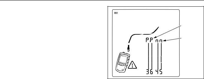
MicroScanner Cable Verifier Users Manual voltage polarities ( ) when it detects high Batteries contain hazardous chemicals that can voltage. Disconnect the tester if cause burns or explode. If exposure to chemicals appear. Figures 1 and 11 show examples of this occurs, clean with water and get medical aid. -
Page 13: High Voltage Display Example
Safety Information Do not disassemble or crush battery cells and battery packs. Do not put battery cells and battery packs near Positive heat or fire. Do not put in sunlight. Do not operate the Product with covers removed or the case open.
-
Page 14: Microscanner 2 Features
MicroScanner Cable Verifier Users Manual MicroScanner Features egk01.eps Figure 2. MicroScanner Features…
-
Page 15
MicroScanner Features On/off key. LCD display with backlight. F-connector for connecting to 75 coaxial cable. : Navigates through screens and changes settings. In toner mode, these keys cycle through the Modular jack for connecting to telephone and twisted IntelliTone and analog toner songs. -
Page 16: Display Features
MicroScanner Cable Verifier Users Manual Tester icon Display Features Detail screen indicator. See page 20. Indicates which port is active, the RJ45 port ( ) or the coaxial port ( Tone mode indicator. See page 32. …
-
Page 17: Auto Shutoff
Auto Shutoff Wiremap diagram. For opens, the number of segments Changing the Length Units lit for the wire pair indicates the approximate distance Hold down while turning on the tester. to the fault. The rightmost segments indicate the shield.
-
Page 18: Using The Wiremap Adapter And Remote Id Locators
MicroScanner Cable Verifier Users Manual Using the Wiremap Adapter and Remote ID Locators Terminating twisted pair cabling with the standard Universal adapter wiremap adapter or optional remote ID locators lets the (8-pin and 4-pin) tester detect all types of wiremap faults. Without this termination, the tester cannot detect crossed wires or crossed pairs.
-
Page 19: Testing Twisted Pair Cabling
Testing Twisted Pair Cabling Testing Twisted Pair Cabling Turn on the tester. If the tester is already on and in coaxial test mode ( press to switch to twisted pair test mode ( Patch panel Connect the tester and wiremap adapter or ID locator to the cabling as shown in Figures 5 through 17.
-
Page 20: Twisted Pair Test Results
MicroScanner Cable Verifier Users Manual Twisted Pair Test Results The following figures show typical test results for twisted pair cabling. Open on Twisted Pair Cabling Figure 6 shows an open on wire 4. Notes If only one wire in a pair is open and a wiremap adapter or remote ID locator is not connected, both wires are shown as open.
-
Page 21: Short On Twisted Pair Cabling
Testing Twisted Pair Cabling Short on Twisted Pair Cabling Crossed Wires Figure 7 shows a short between wires 5 and 6. The shorted Figure 8 shows that wires 3 and 4 are crossed. The the pin wires flash to indicate the fault. The cable length is 75.4 m. numbers flash to indicate the fault.
-
Page 22: Crossed Pairs
MicroScanner Cable Verifier Users Manual Crossed Pairs Figure 9 shows that pairs 1,2 and 3,6 are crossed. The pin numbers flash to indicate the fault. This crossed pair is likely caused by mixing 568A and 568B cabling. Detection of crossed pairs requires a far-end adapter. egk09.eps Figure 9.
-
Page 23: Split Pair
Testing Twisted Pair Cabling Split Pair Figure 10 shows a split pair on 3,6 and 4,5. The split pair flashes to indicate the fault. The cable length is 75.4 m. In a split pair, continuity from end to end is correct, but is made with wires from different pairs.
-
Page 24: Telephone Voltages Detected
MicroScanner Cable Verifier Users Manual Telephone Voltages Detected Telephone Figure 11 shows that telephone voltage is detected on pair voltage icon 4,5. Length is not shown because the voltage interferes with length measurements. Positive wire (tip) Warning Negative The tester is not intended to be connected to wire (ring) active telephone inputs, systems, or equipment,…
-
Page 25: Bridge Tap Detected
Testing Twisted Pair Cabling Bridge Tap Detected Figure 12 shows a bridge tap detected at about 53.2 m. Only the first bridge tap detected is reported. The distance to a bridge tap is approximate because multiple reflections from the bridge tap interfere with length measurements. Note Bridge taps more than 328 ft (100 m) from the tester or taps less than 16 ft (5 m) long may not be…
-
Page 26: Ethernet Port Detected
MicroScanner Cable Verifier Users Manual Cable length. Dashes are shown if the tester cannot Ethernet Port Detected measure the length. This can occur if the port does not The tester can detect active and inactive Ethernet ports, as produce reflections. shown in Figure 13.
-
Page 27: Ethernet Port Detected
Testing Twisted Pair Cabling Active Ethernet port Inactive Ethernet port egk13.eps Figure 13. Ethernet Port Detected…
-
Page 28: Viewing Individual Results
MicroScanner Cable Verifier Users Manual Short on pair 1,2 at 29.8 m. Viewing Individual Results To see individual results for each wire pair, use ; to Notes move among the screens. On the individual results screens, shorts are shown only when they are between wires in a pair.
-
Page 29: Results Screens For Individual Wire Pairs
Testing Twisted Pair Cabling egk14.eps Figure 14. Results Screens for Individual Wire Pairs…
-
Page 30: Using Multiple Remote Id Locators
MicroScanner Cable Verifier Users Manual Using Multiple Remote ID Locators Caution Using multiple remote ID locators helps you identify Do not use multiple far end adapters in star or multiple network connections at a patch panel, as shown in bus topologies.
-
Page 31: Using Multiple Remote Id Locators
Testing Twisted Pair Cabling Patch panel Locator # 2 Locator # 3 Remote ID locators connected to wall outlets Locator # 4 Locator # 5 egk04.eps Figure 15. Using Multiple Remote ID Locators…
-
Page 32: Connecting To Telephone Networks Wired In Star Topologies
MicroScanner Cable Verifier Users Manual The tester cannot measure length past the bridge tap Connecting to Telephone Networks Wired in because reflections from the bridge tap connections Star Topologies interfere with measurements. Telephone cables wired in a star topology (Figure 16) are connected together at a bridge tap at the distribution If you connect the tester to the bridge tap, the tester center.
-
Page 33: Connecting To A Telephone Network Wired In A Star Topology
Testing Twisted Pair Cabling Distribution center Common connection RJ11 patch Wall to bridge tap cord outlets RJ11 patch cord Wiremap adapter Note: For a correct length reading, connect the tester and wiremap adapter as shown. See “Connecting to Star Topologies” for details. egk16.eps Figure 16.
-
Page 34: Connecting To Telephone Networks Wired In Bus Topologies
MicroScanner Cable Verifier Users Manual If you are unsure which outlet is the last in the bus, do the Connecting to Telephone Networks Wired in Bus following: Topologies Telephone cables wired in a bus topology (Figure 17) Connect the wiremap adapter or ID locator to the connect the wall outlets in series.
-
Page 35: Connecting To A Telephone Network Wired In A Bus Topology
Testing Twisted Pair Cabling Distribution center Connection to bus Wall outlets RJ11 patch cord RJ11 patch cord Wiremap adapter Note: Locations of the tester and wiremap adapter may be swapped. egk17.eps Figure 17. Connecting to a Telephone Network Wired in a Bus Topology…
-
Page 36: Testing Coaxial Cabling
MicroScanner Cable Verifier Users Manual Testing Coaxial Cabling Turn on the tester; then press to switch to coaxial Connection to test mode ( service Connect the tester and wiremap adapter or ID locator to the cabling as shown in Figure 18. For cabling not terminated with an F-connector, use an adapter or hybrid patch cord to connect to the cabling.
-
Page 37: Coaxial Results
Testing Coaxial Cabling Coaxial Results Open on Coaxial Cabling Figure 20 shows an open 12.1 m from the tester. Figure 19 shows a good coaxial cable 38.4 m long and terminated with remote ID number 3. egk21.eps Figure 20. Open on Coaxial Cabling egk20.eps Figure 19.
-
Page 38: Short On Coaxial Cabling
MicroScanner Cable Verifier Users Manual Short on Coaxial Cabling Unknown Termination on Coaxial Cabling Figure 21 shows a short 12.1 m from the tester. Figure 22 shows a cable connected to a device at the far end, such as a television, CATV service, VCR, DVD player, satellite dish, splitter, or antenna.
-
Page 39: Detecting Power Over Ethernet
Detecting Power Over Ethernet Detecting Power Over Ethernet The tester can detect PoE voltage from 802.3af sources. To select PoE mode, press until appears on the display, as shown in Figure 23 ( In PoE mode, the tester solicits PoE power on pairs 1,2-3,6 and 4,5-7,8.
-
Page 40: Using The Toner
Refer to Figures 24 and 25. locate cables in bundles, at patch panels, or behind walls. Connect the tester to the cable. Use the tester’s IntelliTone mode with an optional Fluke ™ Networks IP100 or IP200 tone probe. The digital IntelliTone …
-
Page 41: Intellitone Toner Mode Display
Using the Toner Notes If you cannot locate the IntelliTone signal on 2-conductor cables, the cable may be shorted. Use the tester to check for shorts. See pages 11 and 13. Turn the probe’s rotary switch to (isolate). Use the probe to isolate the tone source in the cable bundle or at the patch panel.
-
Page 42: Using The Toner In Intellitone Mode
MicroScanner Cable Verifier Users Manual Locating Cables Isolating Cables Wall outlet Volume control egk24.eps Figure 25. Using the Toner in IntelliTone Mode…
-
Page 43: Analog Toner Mode (Optional Tone Probe Required)
Using the Toner Analog Toner Mode (optional tone probe required) Refer to Figure 26. Connect the tester to the cable. Press to select twisted pair or coaxial cable. Press until appears on the display ( ); then …
-
Page 44: Using The Smarttone Function
MicroScanner Cable Verifier Users Manual Using the SmartTone Function Using the IntelliTone Cable Map Function (optional IP200 probe required) Use the SmartTone function when you have trouble ™ locating a cable. This function changes the toner’s song The tester’s IntelliTone function works with an optional when you short a wire pair in the cable connected to the IP200 probe’s cable map function to verify wiring at the far tester.
-
Page 45: Using The Toner With The Ip200 Intellitone Cable Map Function
Using the IntelliTone Cable Map Function (optional IP200 probe required) Note Normally, the probe’s SYNC LED lights to indicate reception of the IntelliTone signal. You may change the LED’s function to indicate shield continuity. See the probe’s documentation for details. LEDs show the wiremap.
-
Page 46: Calibrating Length Measurements
MicroScanner Cable Verifier Users Manual Calibrating Length Measurements Setting the NVP to a Specified Value To enter the NVP value specified by the manufacturer: The tester uses an NVP value (nominal velocity of propagation) and the signal delay through the cable to …
-
Page 47: Maintenance
Use only specified replacement parts for user- To save the setting and exit NVP mode, turn the tester replaceable items. off then on again. Use only Fluke Networks authorized service centers.
-
Page 48: Cleaning
MicroScanner Cable Verifier Users Manual You can use the following types of AA (IEC LR6) batteries in Cleaning the tester: Clean the display with glass cleaner and a soft, lint-free cloth. Clean the case with a soft cloth dampened with …
-
Page 49: Checking The Tester’s Version And Serial Number
to scroll through the screens: If Table 2 does not help you solve a problem with the tester, contact Fluke Networks for additional help. If possible, have : Software version the tester’s version and serial number.
-
Page 50: Options And Accessories
MicroScanner Cable Verifier Users Manual Options and Accessories See Table 3. For the latest list of options and accessories visit the Fluke Networks website at www.flukenetworks.com. Table 3. Options and Accessories Option or Accessory Fluke Networks Model Number Remote ID Locator Kit, numbers 2-7…
-
Page 51: Specifications
Specifications Specifications Specifications apply at 23 C (73 F), unless otherwise noted. Environmental Specifications 32 °F to 113 °F (0 C to 45 Operating temperature -4 °F to +140 °F (-20 C to +60 Storage temperature 90 % (50 °F to 95 °F; 10 C to 35 Operating relative humidity 75 % (95 °F to 113 °F;…
-
Page 52: General Specifications
MicroScanner Cable Verifier Users Manual General Specifications Shielded 8-pin modular jack accepts 8-pin modular (RJ45) and 4-pin modular (RJ11) plugs. Test connectors F-connector for coaxial cable. Battery type: 2 AA (NEDA 15A, IEC LR6) alkaline batteries Power Battery life: 20 hours of typical use Other compatible battery types: 2 AA photo lithium, NIMH, NICAD 3 in x 6.4”…
-
Page 53: Performance Specifications
The wiremap is drawn with proportional length to visually indicate the approximate location of faults. Detects the advertised speed of 802.3 Ethernet ports. Port detection Supports toning and cable mapping with a Fluke Networks digital IntelliTone probe. ™ Tone generator Generates four tones compatible with typical analog probes.
-
Page 54: Regulatory Information
MicroScanner Cable Verifier Users Manual Regulatory Information This equipment generates, uses, and can radiate radio frequency energy, and, if not installed and used in accordance with the manual, may cause interference to radio communications. It has been tested and found to comply with the limits for a Class A digital device pursuant to Part 15, Subpart J of the FCC rules, which are designed to provide reasonable protection against such interference…
-
Page 55: Appendix A: Diagnosing Wiremap Faults
Appendix A: Diagnosing Wiremap Faults Appendix A lists the typical causes of wiremap failures. Split Pair Wires connected to wrong pins at connector or punchdown Open block. Wires connected to wrong pins at connector or punchdown blocks Reversed Pairs …
-
Page 56: Short
MicroScanner Cable Verifier Users Manual Short Damaged connector Damaged cable Conductive material stuck between pins at connector. Improper connector termination Wrong application for cable…
-
Page 57: Index
Index cable tests Symbols coaxial cabling, 28 «?» on coaxial screen, 30 twisted pair, 11 cleaning, 40 –A– coaxial accessories, 42 connections, 28 analog toner, 35 open, 29, 30 auto shutoff, 9 short, 30 –B– unknown termination, 30 connections batteries, 40 coaxial, 28 bridge tap, 17 twisted pair, 11…
-
Page 58
MicroScanner Cable Verifier Users Manual customer support –K– contacting Fluke Networks, 2 keys, 7 problem with the tester, 41 –L– –E– length calibration, 38 Ethernet port detected, 18 –M– –F– maintenance, 39 Fluke Networks, 2 –N– –H– NVP, 38 help contacting Fluke Networks, 2 –O–… -
Page 59
Index testing –R– coaxial cabling, 28 registration, 1 twisted pair cabling, 11 remote ID locator, 10, 22 toner, 32 replacement parts, 42 analog mode, 35 RJ11 jack, 10 IntelliTone mode, 32 SmartTone function, 35, 36 –S– troubleshooting safety information, 3, 39 cabling faults, 47 serial number, 41 the tester, 41… -
Page 60
MicroScanner Cable Verifier Users Manual split pair, 15 telephone voltages, 16 –U– universal adapter, 10 –V– version information, 41 voltage detection, 5, 16 –W– wiremap adapter, 10…

Технические данные
Устройство проверки кабелей MicroScanner
2
Проверка кабелей на профессиональном уровне
Полный обзор кабелей для передачи голоса/данных/видео
В течение более чем десяти лет специалисты по
прокладке и обслуживанию кабелей используют
MicroScanner как надежный инструмент
тестирования и устранения неисправностей
и перебоев. После внедрения первоначального
варианта MicroScanner в мире кабельных
сетей многое изменилось. Экономические
условия отрасли требуют быстрой, точной
и безошибочной установки сети. Технологии
объединенной передачи голоса, данных и видео
породили новые требования к тестированию
сервисов и поддержке мультимедиа.
MicroScanner
2
учитывает эти тенденции и
представляет долгожданное революционное
решение в области методов тестирования.
Оно позволяет оптимизировать все аспекты
тестирования. От простого, экономящего время
интерфейса пользователя до расширенных
возможностей проверки – MicroScanner
2
дает
специалистам возможность выполнять свою
работу быстрее и точнее, чем раньше.
Мощные визуальные средства для проверки
кабелей и сервисов для передачи голоса/данных/
видео. Доверьтесь Network SuperVision™.
Доверьтесь Fluke Networks.
Сокращение времени тестирования
и уменьшение количества ошибок пользователя
При использовании кабельных тестеров предыдущего
поколения пользователям приходится постоянно
переключаться между различными режимами
(до четырех), чтобы просмотреть все результаты
тестирования. Это не только замедляет процесс
тестирования, но также запутывает пользователя
и приводит к ошибкам. MicroScanner
2
изменил эту
процедуру, отображая на одном экране все результаты
тестирования – графическую схему разводки,
длину пар, расстояние до места неисправности,
идентификатор кабеля и удаленные устройства.
Исключение адаптеров из процесса
тестирования
Устали от постоянно теряющихся и ломающихся
адаптеров для тестирования различных кабелей
передачи голоса, данных и видео? Благодаря тестеру
MicroScanner
2
, поддерживающему разъемы RJ11, RJ45
и коаксиальные порты, эти неудобные адаптеры уходят
в прошлое. Для тестирования новых телефонных
разъемов, разъемов Ethernet и розеток кабельного
телевидения можно использовать как главный модуль,
так и удаленные идентификаторы.
Быстрое устранение проблем, связанных
с обслуживанием
У современных сетевых специалистов гораздо
больше проблем, чем просто поиск и устранение
неисправностей кабелей. Они должны исключить
целый ряд потенциальных проблем с кабелем или
предоставляемым сервисом, перед тем как выяснить
причину проблемы с подключением к сети. Есть ли
напряжение от телефонной сети? Какова полярность?
Есть ли на другом конце коммутатор? Доступно ли PoE?
MicroScanner
2
предоставляет сетевым специалистам
мощные визуальные средства для проверки самых
распространенных современных сервисов передачи
голоса, данных и видео.
Определение местоположения труднодоступных
кабелей за считанные секунды
MicroScanner
2
обладает встроенной системой
генерации цифровых и аналоговых тональных сигналов
IntelliTone, которая позволяет точно обнаруживать
местоположение практически любого кабеля или
пары проводов независимо от типа рабочей среды.
Используйте цифровой режим для обнаружения
высокочастотных кабелей передачи данных
(кат. 5е/6/6а) в жгутах, коммутаторах, патч-панелях
или стенных розетках. Используйте аналоговый
режим в кабельных системах для передачи голоса
(категория 3 и ниже), а также в коаксиальных системах,
системах охраны/сигнализации и оповещения.
![]()
MicroScanner2TM
Cable Verifier
Users Manual
January 2007 Rev. 1 7/07
©2007 Fluke Corporation. All rights reserved.
All product names are trademarks of their respective companies.
LIMITED WARRANTY AND LIMITATION OF LIABILITY
Each Fluke Networks product is warranted to be free from defects in material and workmanship under normal use and service. The warranty period for the mainframe is one year and begins on the date of purchase. Parts, accessories, product repairs and services are warranted for 90 days, unless otherwise stated. Ni-Cad, Ni-MH and Li-Ion batteries, cables or other peripherals are all considered parts or accessories. The warranty extends only to the original buyer or end user customer of a Fluke Networks authorized reseller, and does not apply to any product which, in Fluke Networks’ opinion, has been misused, abused, altered, neglected, contaminated, or damaged by accident or abnormal conditions of operation or handling. Fluke Networks warrants that software will operate substantially in accordance with its functional specifications for 90 days and that it has been properly recorded on non-defective media. Fluke Networks does not warrant that software will be error free or operate without interruption.
Fluke Networks authorized resellers shall extend this warranty on new and unused products to end-user customers only but have no authority to extend a greater or different warranty on behalf of Fluke Networks. Warranty support is available only if product is purchased through a Fluke Networks authorized sales outlet or Buyer has paid the applicable international price. Fluke Networks reserves the right to invoice Buyer for importation costs of repair/replacement parts when product purchased in one country is submitted for repair in another country.
Fluke Networks warranty obligation is limited, at Fluke Networks option, to refund of the purchase price, free of charge repair, or replacement of a defective product which is returned to a Fluke Networks authorized service center within the warranty period.
To obtain warranty service, contact your nearest Fluke Networks authorized service center to obtain return authorization information, then send the product to that service center, with a description of the difficulty, postage and insurance prepaid (FOB destination). Fluke Networks assumes no risk for damage in transit. Following warranty repair, the product will be returned to Buyer, transportation prepaid (FOB destination). If Fluke Networks determines that failure was caused by neglect, misuse, contamination, alteration, accident or abnormal condition of operation or handling, or normal wear and tear of mechanical components, Fluke Networks will provide an estimate of repair costs and obtain authorization before commencing the work. Following repair, the product will be returned to the Buyer transportation prepaid and the Buyer will be billed for the repair and return transportation charges (FOB Shipping point).
THIS WARRANTY IS BUYER’S SOLE AND EXCLUSIVE REMEDY AND IS IN LIEU OF ALL OTHER WARRANTIES, EXPRESS OR IMPLIED, INCLUDING BUT NOT LIMITED TO ANY IMPLIED WARRANTY OR MERCHANTABILITY OR FITNESS FOR A PARTICULAR PURPOSE. FLUKE NETWORKS SHALL NOT BE LIABLE FOR ANY SPECIAL, INDIRECT, INCIDENTAL OR CONSEQUENTIAL DAMAGES OR LOSSES, INCLUDING LOSS OF DATA, ARISING FROM ANY CAUSE OR THEORY.
Since some countries or states do not allow limitation of the term of an implied warranty, or exclusion or limitation of incidental or consequential damages, the limitations and exclusions of this warranty may not apply to every buyer. If any provision of this Warranty is held invalid or unenforceable by a court or other decision-maker of competent jurisdiction, such holding will not affect the validity or enforceability of any other provision.
4/04
Fluke Networks
PO Box 777
Everett, WA 98206-0777
USA
Table of Contents
|
Title |
Page |
|
Introduction …………………………………………………………………………………………………………………………………………………….. |
1 |
|
Registration ……………………………………………………………………………………………………………………………………………………… |
2 |
|
Contacting Fluke Networks ……………………………………………………………………………………………………………………………….. |
2 |
|
Unpacking ……………………………………………………………………………………………………………………………………………………….. |
3 |
|
MicroScanner2 Professional Kit (MS2-KIT) …………………………………………………………………………………………………….. |
3 |
|
MicroScanner2 Cable Verifier (MS2-100) ………………………………………………………………………………………………………. |
3 |
|
Safety Information ……………………………………………………………………………………………………………………………………………. |
4 |
|
MicroScanner2 Features …………………………………………………………………………………………………………………………………….. |
6 |
|
Display Features ……………………………………………………………………………………………………………………………………………….. |
8 |
|
Auto Shutoff ……………………………………………………………………………………………………………………………………………………. |
9 |
|
Changing the Length Units ……………………………………………………………………………………………………………………………….. |
9 |
|
Using the Wiremap Adapter and Remote ID Locators …………………………………………………………………………………………. |
10 |
|
Testing Twisted Pair Cabling ……………………………………………………………………………………………………………………………… |
11 |
|
Twisted Pair Test Results …………………………………………………………………………………………………………………………….. |
12 |
|
Open on Twisted Pair Cabling ………………………………………………………………………………………………………………. |
12 |
|
Short on Twisted Pair Cabling ………………………………………………………………………………………………………………. |
13 |
|
Crossed Wires ………………………………………………………………………………………………………………………………………. |
13 |
|
Crossed Pairs ……………………………………………………………………………………………………………………………………….. |
14 |
i

|
MicroScanner2 Cable Verifier |
|
|
Users Manual |
|
|
Split Pair ……………………………………………………………………………………………………………………………………………… |
15 |
|
Telephone Voltages Detected ……………………………………………………………………………………………………………….. |
16 |
|
Bridge Tap Detected …………………………………………………………………………………………………………………………….. |
17 |
|
Ethernet Port Detected …………………………………………………………………………………………………………………………. |
18 |
|
Viewing Individual Results …………………………………………………………………………………………………………………………… |
20 |
|
Using Multiple Remote ID Locators ……………………………………………………………………………………………………………… |
22 |
|
Connecting to Telephone Networks Wired in Star Topologies ……………………………………………………………………….. |
24 |
|
Connecting to Telephone Networks Wired in Bus Topologies ……………………………………………………………………….. |
26 |
|
Testing Coaxial Cabling ……………………………………………………………………………………………………………………………………… |
28 |
|
Coaxial Results ……………………………………………………………………………………………………………………………………………. |
29 |
|
Open on Coaxial Cabling ………………………………………………………………………………………………………………………. |
29 |
|
Short on Coaxial Cabling ………………………………………………………………………………………………………………………. |
30 |
|
Unknown Termination on Coaxial Cabling …………………………………………………………………………………………….. |
30 |
|
Detecting Power Over Ethernet …………………………………………………………………………………………………………………………. |
31 |
|
Using the Toner ………………………………………………………………………………………………………………………………………………… |
32 |
|
Toning in IntelliTone Mode (optional IntelliTone probe required) …………………………………………………………………. |
32 |
|
Analog Toner Mode (optional tone probe required) …………………………………………………………………………………….. |
35 |
|
Using the SmartTone Function …………………………………………………………………………………………………………………….. |
36 |
|
Using the IntelliTone Cable Map Function (optional IP200 probe required) ………………………………………………………….. |
36 |
|
Calibrating Length Measurements ……………………………………………………………………………………………………………………… |
38 |
|
Setting the NVP to a Specified Value ……………………………………………………………………………………………………………. |
38 |
|
Determining a Cable’s Actual NVP ……………………………………………………………………………………………………………….. |
38 |
|
Maintenance …………………………………………………………………………………………………………………………………………………….. |
39 |
|
Cleaning …………………………………………………………………………………………………………………………………………………….. |
40 |
|
Battery Life, Status, and Replacement ………………………………………………………………………………………………………….. |
40 |
|
Checking the Tester’s Version and Serial Number …………………………………………………………………………………………. |
41 |
|
If Something Seems Wrong ……………………………………………………………………………………………………………………………….. |
41 |
|
Options and Accessories …………………………………………………………………………………………………………………………………….. |
42 |
ii

|
Table of Contents |
|
|
Specifications ……………………………………………………………………………………………………………………………………………………. |
43 |
|
Environmental Specifications ………………………………………………………………………………………………………………………. |
43 |
|
General Specifications ………………………………………………………………………………………………………………………………… |
44 |
|
Test Modes ………………………………………………………………………………………………………………………………………………… |
44 |
|
Performance Specifications …………………………………………………………………………………………………………………………. |
45 |
|
Regulatory Information ………………………………………………………………………………………………………………………………. |
46 |
|
Appendix A: Diagnosing Wiremap Faults …………………………………………………………………………………………………………… |
47 |
|
Open …………………………………………………………………………………………………………………………………………………………. |
47 |
|
Split Pair ……………………………………………………………………………………………………………………………………………………. |
47 |
|
Reversed Pairs ……………………………………………………………………………………………………………………………………………. |
47 |
|
Crossed Pairs ………………………………………………………………………………………………………………………………………………. |
47 |
|
Short …………………………………………………………………………………………………………………………………………………………. |
48 |
|
Index ……………………………………………………………………………………………………………………………………………………………….. |
49 |
iii

MicroScanner2 Cable Verifier
Users Manual
iv
List of Figures
|
Figure |
Title |
Page |
|
1 |
High Voltage Display Example ………………………………………………………………………………………………………. |
5 |
|
2 |
MicroScanner2 Features ………………………………………………………………………………………………………………… |
6 |
|
3 |
Display Features …………………………………………………………………………………………………………………………… |
8 |
|
4 |
Connecting a Remote ID Locator in a Confined Area or to an RJ11 Jack…………………………………………… |
10 |
|
5 |
Connecting to Twisted Pair Network Cabling …………………………………………………………………………………. |
11 |
|
6 |
Open on Twisted Pair Cabling……………………………………………………………………………………………………….. |
12 |
|
7 |
Short on Twisted Pair Cabling ……………………………………………………………………………………………………….. |
13 |
|
8 |
Crossed Wires ………………………………………………………………………………………………………………………………. |
13 |
|
9 |
Crossed Pairs ………………………………………………………………………………………………………………………………… |
14 |
|
10 |
Split Pair………………………………………………………………………………………………………………………………………. |
15 |
|
11 |
Telephone Voltages Detected ……………………………………………………………………………………………………….. |
16 |
|
12 |
Bridge Tap Detected …………………………………………………………………………………………………………………….. |
17 |
|
13 |
Ethernet Port Detected…………………………………………………………………………………………………………………. |
19 |
|
14 |
Results Screens for Individual Wire Pairs ………………………………………………………………………………………… |
21 |
|
15 |
Using Multiple Remote ID Locators………………………………………………………………………………………………… |
23 |
|
16 |
Connecting to a Telephone Network Wired in a Star Topology……………………………………………………….. |
25 |
|
17 |
Connecting to a Telephone Network Wired in a Bus Topology………………………………………………………… |
27 |
|
18 |
Connecting to Coaxial Cabling ………………………………………………………………………………………………………. |
28 |
v

|
MicroScanner2 Cable Verifier |
||
|
Users Manual |
||
|
19 |
Coaxial Results ……………………………………………………………………………………………………………………………… |
29 |
|
20 |
Open on Coaxial Cabling ………………………………………………………………………………………………………………. |
29 |
|
21 |
Short on Coaxial Cabling……………………………………………………………………………………………………………….. |
30 |
|
22 |
Unknown Termination on Coaxial Cabling……………………………………………………………………………………… |
30 |
|
23 |
PoE Display…………………………………………………………………………………………………………………………………… |
31 |
|
24 |
IntelliTone Toner Mode Display …………………………………………………………………………………………………….. |
33 |
|
25 |
Using the Toner in IntelliTone Mode ……………………………………………………………………………………………… |
34 |
|
26 |
Analog Toner Mode Display ………………………………………………………………………………………………………….. |
35 |
|
27 |
Using the Toner with the IP200 IntelliTone Cable Map Function ……………………………………………………… |
37 |
|
28 |
Replacing the Tester’s Batteries……………………………………………………………………………………………………… |
40 |
vi
MicroScanner2 Cable Verifier
Introduction
The MicroScanner2 Cable Verifier is a hand-held test instrument that lets you verify and troubleshoot the wiring of twisted pair and coaxial cables and detect network services.
The tester does the following:
•Measures length up to 1500 ft (457 m) and detects opens and shorts on twisted pair and coaxial cabling.
•Detects split pairs on twisted pair cabling.
•Detects Ethernet ports on twisted pair cabling and reports the port speed.
•Detects PoE (Power over Ethernet) and telephone voltages on twisted pair cabling.
•IntelliTone™ function works with an optional Fluke Networks IntelliTone probe to help you locate and isolate cables behind walls, at patch panels, or in bundles. The analog toner works with standard analog probes and includes the SmartTone™ function for positive identification of cables in bundles.
•Displays wiremap, cable length, proportional distance to opens, and the remote ID number all on one screen.
1

MicroScanner2 Cable Verifier
Users Manual
Registration
Registering your product with Fluke Networks gives you access to valuable information on product updates, troubleshooting tips, and other support services. To register, fill out the online registration form on the Fluke Networks website at www.flukenetworks.com/registration.
Contacting Fluke Networks
www.flukenetworks.com
support@flukenetworks.com
+1-425-446-4519
•Australia: 61 (2) 8850-3333 or 61 (3) 9329 0244
•Beijing: 86 (10) 6512-3435
•Brazil: 11 3044 1277
•Canada: 1-800-363-5853
•Europe: +44-(0)1923 281 300
•Hong Kong: 852 2721-3228
•Japan: 03-3434-0510
•Korea: 82 2 539-6311
•Singapore: +65-6799-5566
•Taiwan: (886) 2-227-83199
•USA: 1-800-283-5853
Visit our website for a complete list of phone numbers.
2
![]()
Unpacking
Unpacking
The tester comes with the accessories listed below. If something is damaged or missing, contact the place of purchase immediately.
MicroScanner2 Professional Kit (MS2-KIT)
•MicroScanner2 tester with detachable wiremap adapter
•2 AA alkaline batteries
•ITK200 IntelliTone probe
•9 V alkaline battery
•Six remote ID adapters (numbers 2 through 7)
•Two shielded patch cords, 8-pin modular plug to 8-pin modular plug (RJ45 to RJ45), 2 m
•Two patch cords, 4-pin modular plug to 4-pin modular plug (RJ11 to RJ11), 15 cm
•Coaxial patch cord, F-connector to F-connector, 75 Ω, with push-on adapters, 1.8 m
•Test lead, 8-pin modular plug (RJ45) to 8 alligator clips
•Wrist strap
•Carrying case
•Folding pouch for accessories
•MicroScanner2 Getting Started Guide
•IntelliTone Quick Reference Guide
•CD-ROM with MicroScanner2 manuals
•CD-ROM with IntelliTone manuals
MicroScanner2 Cable Verifier (MS2-100)
•MicroScanner2 tester with detachable wiremap adapter
•2 AA alkaline batteries
•Carrying pouch
•MicroScanner2 Getting Started Guide
•CD-ROM with MicroScanner2 manuals
3

MicroScanner2 Cable Verifier
Users Manual
Safety Information |
WWarningX |
Table 1 describes the international electrical symbols used on the tester and in this manual.
Table 1. International Electrical Symbols
Warning or Caution: risk of damage or destruction to equipment or software. See
Wexplanations in the manual.
On the tester’s display this symbol indicates a cable fault or voltage on the cable.
XWarning: Risk of electric shock.
This equipment not for connection to public j communications networks, such as active
telephone systems.
Do not put products containing circuit boards ~ into the garbage. Dispose of circuits boards in
accordance with local regulations.
To avoid possible fire, electric shock, or personal injury:
•Do not open the case; no user-serviceable parts are inside.
•Do not modify the tester.
•Do not use the tester if it is damaged. Inspect the tester before use.
•If this equipment is used in a manner not specified by the manufacturer, the protection provided by the equipment may be impaired.
•The tester is not intended to be connected to active telephone inputs, systems, or equipment, including ISDN devices. Prolonged exposure to the voltages applied by these interfaces may
damage the tester. The tester shows a warning symbol (W) and the voltage polarities when it detects high voltage. Figures 1 and 11 show examples of this display.
4
Safety Information
•Before using the optional IntelliTone probe, read the safety information in the probe’s
documentation provided on the IntelliTone manuals CD.
Positive
• Do not use the tester if it operates abnormally.
Protection may be impaired.
Negative
WCaution
To ensure maximum accuracy of test results replace the batteries as soon as the low battery indicator appears (see «Battery Life, Status, and Replacement» on page 40).
egk29.eps
Figure 1. High Voltage Display Example
5

MicroScanner2 Cable Verifier
Users Manual
MicroScanner2 Features
egk01.eps
Figure 2. MicroScanner2 Features
6

MicroScanner2 Features
A On/off key.
B E, D: Navigates through screens and changes settings. In toner mode, these keys cycle through the IntelliTone and analog toner songs.
C Y: Selects the RJ45 or coaxial connector as the active port.
D M: Cycles through the cable test, toner, and PoE detect modes.
For additional modes, hold down keys while turning the tester on:
•Y+ E: Lets you calibrate length measurements and
select meters or feet as the length unit.
•M+ D: Activates a demonstration mode where the
tester shows examples of test result screens.
Note
Auto shutoff is disabled in demonstration mode.
•E+ D: Displays the version and serial number
screens.
E LCD display with backlight.
F F-connector for connecting to 75 Ω coaxial cable.
GModular jack for connecting to telephone and twisted pair network cable. The jack accepts 8-pin modular (RJ45) and
6-pin modular (RJ11) connectors.
HWiremap adapter with F-connector and 8-pin modular jack. See page 10.
IOptional remote ID locator with F-connector and 8-pin modular jack. See page 10.
7
MicroScanner2 Cable Verifier
Users Manual
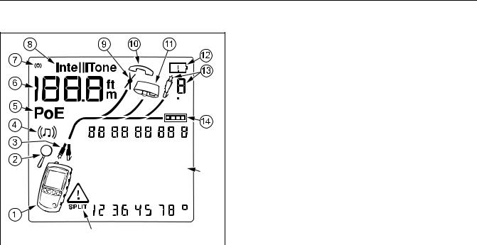
Display Features |
A Tester icon |
|
B Detail screen indicator. See page 20. |
|
|
C Indicates which port is active, the RJ45 port (U) or the |
|
|
coaxial port (T). |
D Tone mode indicator. See page 32.
E Power over Ethernet mode indicator. See page 31.
F Numeric display with feet/meters indicator.
G Test activity indicator, which is animated when a test is running.
|
H IntelliTone appears when the toner is in IntelliTone |
||||||||||||
|
O |
mode. See pages 32 and 36. |
|||||||||||
|
I Indicates a short on the cable. See pages 13 and 30. |
||||||||||||
|
J Telephone voltage indicator. See page 16. |
||||||||||||
|
K Indicates a wiremap adapter is connected to the far |
||||||||||||
|
end of the cable. |
||||||||||||
|
P |
L Low battery indicator. See page 40. |
|||||||||||
|
M Indicates an ID locator is connected to the far end of |
||||||||||||
|
egk02.eps |
||||||||||||
|
Figure 3. Display Features |
the cable and shows the locator’s number. |
|||||||||||
|
N Ethernet port indicator. See page 18. |
8

Auto Shutoff
OWiremap diagram. For opens, the number of segments lit for the wire pair indicates the approximate distance to the fault. The rightmost segments indicate the shield. See pages 12 through 15.
PThe WIndicates a fault or high voltage on the cable. SPLIT appears when the fault is a split pair. See page 15.
Auto Shutoff
The tester turns off after 10 minutes if no keys are pressed and nothing changes at the tester’s connectors.
Note
Auto shutoff is disabled in toner and demonstration modes.
Changing the Length Units
1Hold down Yand Ewhile turning on the tester.
2Press Mto switch between meters and feet.
3Turn the tester off then on to return to testing mode.
9
MicroScanner2 Cable Verifier
Users Manual
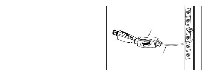
Using the Wiremap Adapter and Remote
ID Locators
Terminating twisted pair cabling with the standard wiremap adapter or optional remote ID locators lets the tester detect all types of wiremap faults. Without this termination, the tester cannot detect crossed wires or crossed pairs. For a wire pair with one wire open, termination is required to detect which wire is open. Without termination, the tester shows both wires as open.
Using multiple remote ID locators helps you identify connections at patch panels. The tester shows the number of the locator connected to the far end of the cabling, as shown on page 23.
Universal adapter (8-pin and 4-pin)
Remote ID
locator
8-pin or 4-pin modular patch cord
egk15.eps
To connect a remote ID locator to a modular (RJ) jack in a confined area or to a 4-pin modular jack (RJ11), use the optional universal adapter and a patch cord, as shown in Figure 4.
Figure 4. Connecting a Remote ID Locator in a Confined Area or to an RJ11 Jack
10