
i
Благодарим вас
за покупку одного из лучших подвесных двигателей. Вы сделали разумное вложение, которое
позволит вам получать удовольствие от катания на лодке. Ваш подвесной двигатель изготовлен
компанией «Mercury Marine», которая с 1939 года является мировым лидером в области морских
технологий и судостроения. В течение всех этих лет работы нашей целью всегда оставался выпуск
изделий самого высокого качества. Благодаря этому компания «Mercury Marine» заслужила
репутацию организации, обеспечивающей строгий контроль качества, совершенство,
долговечность, длительное сохранение эксплуатационных параметров двигателей и
предоставляющей самую лучшую послепродажную поддержку.
Прежде чем начать эксплуатацию подвесного двигателя, внимательно прочитайте, пожалуйста,
настоящую инструкцию. Она написана для того, чтобы помочь вам в эксплуатации и безопасном
использовании вашего двигателя и уходе за ним.
Все сотрудники нашей компании горды тем, что участвовали в изготовлении этого подвесного
двигателя, и мы желаем вам приятного и безопасного катания на лодке в течение многих лет.
Еще раз благодарим за доверие, оказанное компании «Mercury Marine».
Правила ЕРА относительно выхлопа
Подвесные двигатели компании Mercury Marine в США сертифицированы Агентством
Соединенных Штатов по защите окружающей среды (ЕРА) как соответствующие требованиям
правил по контролю за загрязнением воздуха, создаваемым новыми подвесными двигателями.
Эта сертификация действительна при условии, что определенные регулировки выполняются в
соответствии с заводскими стандартами. По этой причине следует строго соблюдать заводскую
методику обслуживания изделия и там, где это практично, возвращаться к первоначальному
конструктивному намерению. Техническое обслуживание, ремонт или замена устройств и систем
контроля выхлопа могут выполняться любой организацией или любым лицом, производящими
ремонт судовых двигателей.
Двигатели имеют маркировку в виде ярлыка с информацией о контроле выхлопа, что представляет
собой постоянное свидетельство о сертификации EPA.
!
ПРЕДУПРЕЖДЕНИЕ
В выхлопе у данного двигателя содержатся химические соединения, которые в штате
Калифорния признаны вызывающими онкологические заболевания, патологии родов и другие
нарушения репродуктивной функции.
Заявление о гарантии
Изделие, которое Вы приобрели, поставляется с ограниченной гарантией компании «Mercury
Marine», а условия гарантии изложены в разделе Информация о гарантии данного руководства.
Положение о гарантии содержит описание случаев, которые подпадают и которые не подпадают
под действие гарантии, продолжительность действия, как лучше всего обеспечить
распространение гарантии, важные случаи отрицаний и ограничения по повреждениям, а также
другую соответствующую информацию. Изучите эту важную информацию.
Описание и технические данные, приведенные в данном руководстве, имели силу на момен
подписания к печати. Компания «Mercury Marine», которая постоянно работает над
совершенствованием своей продукции, сохраняет за собой права на прекращение выпуска
моделей в любое время, изменение технических характеристик, конструкции, методов или
технологических процессов без направления предварительного извещения и не принимая никаких
обязательств.
Mercury Marine, Fond du Lac, Wisconsin U.S.A.
Litho in U.S.A.
© 2009, Mercury Marine
© 2010 г., Mercury Marine
4/5
90-10264S81 110
 05:32
05:32
Лодочный мотор Mercury 5M
 03:22
03:22
Обзор и тест: лодочный мотор Mercury 5 M
 07:36
07:36
Mercury Меркури 5 (4) л.с. 2 такта обзор и выйдет ли на глиссирование он же тохатсу 5 лодочный мотор
 03:07
03:07
Обзор: лодочный мотор Mercury 5M
 04:09
04:09
Лодка ПВХ Kingfish TS 370 мотор Mercury 5M 2-х такт Тест
 02:18
02:18
Как запустить лодочный мотор с первого раза (лодочный мотор mercury 5m)&Первый пуск лодочного мотора
 05:54
05:54
Обзор мотора Mercury 5M
 06:56
06:56
МЕРКУРИ-5 и РЕКА-340. Замер скорости
i Благодарим вас за покупку одного из лучших подвесных двига…
Благодарим вас, Правила ера относительно выхлопа, Заявление о гарантии
- Изображение
- Текст
- Содержание
i
Благодарим вас
за покупку одного из лучших подвесных двигателей. Вы сделали разумное вложение, которое
позволит вам получать удовольствие от катания на лодке. Ваш подвесной двигатель изготовлен
компанией «Mercury Marine», которая с 1939 года является мировым лидером в области морских
технологий и судостроения. В течение всех этих лет работы нашей целью всегда оставался выпуск
изделий самого высокого качества. Благодаря этому компания «Mercury Marine» заслужила
репутацию организации, обеспечивающей строгий контроль качества, совершенство,
долговечность, длительное сохранение эксплуатационных параметров двигателей и
предоставляющей самую лучшую послепродажную поддержку.
Прежде чем начать эксплуатацию подвесного двигателя, внимательно прочитайте, пожалуйста,
настоящую инструкцию. Она написана для того, чтобы помочь вам в эксплуатации и безопасном
использовании вашего двигателя и уходе за ним.
Все сотрудники нашей компании горды тем, что участвовали в изготовлении этого подвесного
двигателя, и мы желаем вам приятного и безопасного катания на лодке в течение многих лет.
Еще раз благодарим за доверие, оказанное компании «Mercury Marine».
Правила ЕРА относительно выхлопа
Подвесные двигатели компании Mercury Marine в США сертифицированы Агентством
Соединенных Штатов по защите окружающей среды (ЕРА) как соответствующие требованиям
правил по контролю за загрязнением воздуха, создаваемым новыми подвесными двигателями.
Эта сертификация действительна при условии, что определенные регулировки выполняются в
соответствии с заводскими стандартами. По этой причине следует строго соблюдать заводскую
методику обслуживания изделия и там, где это практично, возвращаться к первоначальному
конструктивному намерению. Техническое обслуживание, ремонт или замена устройств и систем
контроля выхлопа могут выполняться любой организацией или любым лицом, производящими
ремонт судовых двигателей.
Двигатели имеют маркировку в виде ярлыка с информацией о контроле выхлопа, что представляет
собой постоянное свидетельство о сертификации EPA.
!
ПРЕДУПРЕЖДЕНИЕ
В выхлопе у данного двигателя содержатся химические соединения, которые в штате
Калифорния признаны вызывающими онкологические заболевания, патологии родов и другие
нарушения репродуктивной функции.
Заявление о гарантии
Изделие, которое Вы приобрели, поставляется с ограниченной гарантией компании «Mercury
Marine», а условия гарантии изложены в разделе Информация о гарантии данного руководства.
Положение о гарантии содержит описание случаев, которые подпадают и которые не подпадают
под действие гарантии, продолжительность действия, как лучше всего обеспечить
распространение гарантии, важные случаи отрицаний и ограничения по повреждениям, а также
другую соответствующую информацию. Изучите эту важную информацию.
Описание и технические данные, приведенные в данном руководстве, имели силу на момен
подписания к печати. Компания «Mercury Marine», которая постоянно работает над
совершенствованием своей продукции, сохраняет за собой права на прекращение выпуска
моделей в любое время, изменение технических характеристик, конструкции, методов или
технологических процессов без направления предварительного извещения и не принимая никаких
обязательств.
Mercury Marine, Fond du Lac, Wisconsin U.S.A.
Litho in U.S.A.
© 2009, Mercury Marine
© 2010 г., Mercury Marine
4/5
90-10264S81 110

ii
«Mercury», «Mercury Marine», «MerCruiser», «Mercury MerCruiser», «Mercury Racing», «Mercury Precision
Parts», «Mercury Propellers», «Mariner», «Quicksilver», «#1 On The Water», «Alpha», «Bravo», «Pro Max»,
«OptiMax», «Sport-Jet», «K-Planes», «MerCathode», «RideGuide», «SmartCraft», «Zero Effort», «M» с
логотипом «Waves», «Mercury» с логотипом «Waves» и логотип «SmartCraft» являются
зарегистрированными торговыми марками корпорации «Brunswick Corporation». Логотип «Mercury
Product Protection» является зарегистрированным знаком обслуживания корпорации «Brunswick
Corporation».
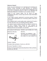
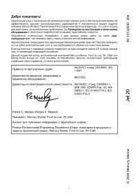
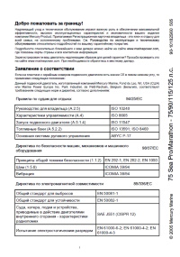
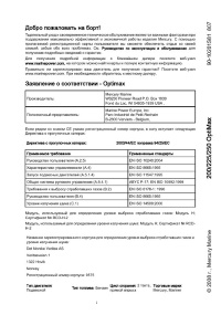
Заявление о соответствии — стандартный 2-тактный подвесной
двигатель
Изготовитель:
Tohatsu Marine Corporation (TMC)
Совместное предприятие «Mercury Marine»
Shimodaira 4495-9, Komagane-City,
Nagano, Japan (Япония) 399-4101
Уполномоченный представитель:
Brunswick Marine in EMEA Inc.
Parc Industrial de Petit-Rechain
B-2800 Verviers, Belgium (Бельгия)
Директива о безопасности машинного оборудования
98/37/EC
Принципы обеспечения безопасности (1.1.2)
ISO 12100-1; ISO 12100-2; EN 1050
Шум (1.5.8)
ICOMIA 39/94
Вибрация (1.5.9)
ICOMIA 38/94
Тип двигателя: Подвесной двигатель
Тип топлива: Бензин
Цикл сгорания: 2-тактный
Ответственность за издание настоящего заявления лежит исключительно на Mercury Marine и Brunswick
Marine in EMEA Inc.
Фамилия / должность:
Марк Д. Шваберо (Mark D. Schwabero)
Президент, Mercury Marine, Fond du Lac, WI USA (США)
Дата и место выпуска:
20 ноября 2008 года
Mercury Marine, Fond du Lac, WI USA (США)
Контакт для получения информации о европейских нормах:
Отдел нормативов и безопасности продукции
Mercury Marine, Fond du Lac, WI USA (США)


Благодарим вас, Правила ера относительно выхлопа, Заявление о гарантии
Страница 6
- Изображение
- Текст
vi

Информация о гарантии, Передача гарантии, Регистрация гарантии в соединенных штатах и канаде
Страница 7
- Изображение
- Текст
ИНФОРМАЦИЯ О ГАРАНТИИ
1
Передача гарантии
Ограниченная гарантия может быть передана следующему покупателю, но только на оставшийся
неиспользованным период ограниченной гарантии. Это не относится к изделиям, используемым в
коммерческих целях.
Чтобы передать гарантию следующему владельцу, отошлите факсом в Отдел гарантийного учета
«Mercury Marine» копию чека на проданный товар или соглашение о покупке, имя нового владельца, адрес
и серийный номер двигателя. В Соединенных Штатах Америки и Канаде отправлять по адресу:
Mercury Marine
Attn: Warranty Registration Department
W6250 W. Pioneer Road
P.O. Box 1939
Fond du Lac, WI 54936-1939
920-929-5054
Факс 920-929-5893
После обработки данных, связанных с передачей гарантии, «Mercury Marine» вышлет по почте новому
владельцу изделия подтверждение о регистрации.
Это – бесплатная услуга.
В отношении изделий, приобретенных за пределами США и Канады, необходимо обратиться к
дистрибьютору в вашей стране или в ближайший сервисный центр «Marine Power».
Регистрация гарантии в Соединенных Штатах и Канаде
1.
Вы можете изменить свой адрес в любой момент, в том числе при подаче гарантийной претензии,
позвонив в «Mercury Marine» или отправив письмо или факс с указанием своей фамилии, старого
адреса, нового адреса и серийного номера двигателя в адрес отдела регистрации гарантии
«Mercury Marine». Ваш дилер также может оформить это изменение информации.
Мercury Marine
Attn: Warranty Registration Department
W6250 Pioneer Road
P.O. Box 1939
Fond du Lac, WI 54936-1939
920-929-5054
Факс 920-929-5893
ПРИМЕЧАНИЕ: Mercury Marine и любой дилер должны вести списки регистрации изделий для судов,
продаваемых в Соединенных Штатах, на случай, если в соответствии с Федеральным законом о
безопасности (Federal Safety Act) потребуется дать извещение о несоответствии изделия.
2.
Чтобы изделие подпадало под действие гарантии, оно должно быть зарегистрировано в Mercury
Marine. Во время продажи дилер должен заполнить регистрацию гарантии и незамедлительно
направить ее в Mercury Marine через сеть MercNET, по электронной почте или обычной почтой.
По получении этой регистрации гарантии Mercury Marine выполнит регистрацию.
3.
После обработки регистрации гарантии Mercury Marine пошлет по почте покупателю изделия
подтверждение регистрации. Если это подтверждение регистрации не будет получено в течение
30 дней, пожалуйста, немедленно обратитесь к дилеру, продавшему Вам изделие. Действие
гарантии начинается только после того, как изделие будет зарегистрировано в Mercury Marine.
Регистрация гарантии за пределами Соединенных Штатов и
Канады
1.
Важно, чтобы дилер, который продал вам подвесной двигатель, полностью заполнил «Карточку
регистрации гарантии» (Warranty Registration Card) и выслал ее дистрибютору или в сервис-
центр Marine Power Service Center, ответственный за администрирование программы регистрации
гарантий и гарантийных претензий по вашему региону.
2.
В «Карточке регистрации гарантии» указаны ваша фамилия и адрес, модель и серийные номера
двигателя, дата продажи, вид использования, а также номер кода, фамилия и адрес
дистрибютора/дилера, продавшего двигатель. Дистрибютор/дилер также удостоверяет, что вы
являетесь первым покупателем и пользователем этого двигателя.

ИНФОРМАЦИЯ О ГАРАНТИИ
2
3.
Копия «Карточки регистрации гарантии», которая называется «Копия покупателя» (Purchaser’s
Copy), ДОЛЖНА быть выдана вам немедленно после того, как дистрибютор/дилер, продавший
вам двигатель, полностью заполнит «Карточку регистрации гарантии». Эта карточка представляет
собой документ, удостоверяющий заводскую регистрацию вашего двигателя, и вы должны
хранить ее для будущего использования при необходимости. Если вам когда-либо потребуется
провести гарантийное обслуживание этого изделия, ваш дилер может попросить вас предъявить
«Карточку регистрации гарантии», чтобы проверить дату покупки и использовать содержащуюся
в карточке информацию для подготовки форм(ы) гарантийной претензии.
4.
В некоторых странах сервис-центр Marine Power Service Center выдаст вам постоянную
(пластмассовую) «Карточку регистрации гарантии» в течение 30 дней после получения от Вашего
дистрибютора/дилера «Заводской копии» (Factory Copy) «Карточки регистрации гарантии». Если
вы получите пластмассовую «Карточку регистрации гарантии», вы можете выбросить «Копию
покупателя», которую вы получили от дистрибютора/дилера при покупке двигателя. Спросите
вашего дистрибютора/дилера, относится ли к вам эта программа пластмассовых карточек.
ВАЖНАЯ ИНФОРМАЦИЯ: В некоторых странах законодательство требует, чтобы завод-изготовитель
и дилер вели списки регистрации. Мы хотим, чтобы ВСЕ изделия были зарегистрированы на заводе-
изготовителе на случай, если когда-либо будет необходимо связаться с вами. Убедитесь в том, что ваш
дилер/дистрибютор немедленно заполнил карточку регистрации гарантии и выслал заводскую копию в
международный сервис-центр Marine Power International Service Center для вашего региона.
5.
Дальнейшая информация относительно «Карточки регистрации гарантии» и ее отношения к
обработке гарантийных претензий — см. параграф «Международная гарантия».
Ограниченная гарантия на 4-тактные подвесные двигатели в США,
Канаде, Европе и СНГ
За пределами Соединенных Штатов Америки, Канады, Европы и СНГ- выясните у вашего местного
дистрибьютора.
ЧТО ПОКРЫВАЕТ ГАРАНТИЯ: Компания «Mercury Marine» гарантирует в течение описанного ниже
периода, что ее новые изделия не имеют дефектов материалов и качества изготовления.
ПРОДОЛЖИТЕЛЬНОСТЬ ГАРАНТИЙНОГО ПОКРЫТИЯ: Настоящая ограниченная гарантия
предоставлена на два (2) года с более раннего из следующих двух дней: даты первой продажи изделия
розничному покупателю, приобретшему его для активного отдыха, и даты ввода изделия в эксплуатацию.
Коммерческие потребители этих изделий получают гарантийное покрытие на один (1) год от более
ранней из следующих двух дат: даты первой продажи изделия розничному покупателю и даты ввода
изделия в эксплуатацию. Использование в коммерческих целях определяется как любое использование
изделия, связанное с работой, или любое другое использование изделия, создающее доход, в течение
любой части гарантийного срока, даже если изделие используется в этих целях только эпизодически.
Ремонт или замена деталей или проведение технического обслуживания по настоящей гарантии не
продлевает гарантийного периода сверх первоначально установленной даты. Гарантийное покрытие,
срок которого еще не истек, может быть передано от одного покупателя, использующего подвесной
двигатель для отдыха, следующему покупателю, использующему подвесной двигатель для отдыха,
после надлежащей перерегистрации данного изделия. Гарантийное покрытие, срок которого еще не
истек, не может передаваться между покупателями, если хотя бы один из них использует изделие в
коммерческих целях. Действие гарантии может быть прекращено для использованного или
перепроданного изделия; для купленного на аукционе изделия, для изделия со склада или из страховой
компании.
УСЛОВИЯ, КОТОРЫЕ НЕОБХОДИМО УДОВЛЕТВОРИТЬ ДЛЯ ПОЛУЧЕНИЯ ГАРАНТИЙНОГО
ПОКРЫТИЯ: Гарантийное покрытие предоставляется только розничным покупателям, которые покупают
изделие у Дилера, уполномоченного компанией «Mercury Marine» продавать это изделие в стране, в
которой имела место продажа, и только после того, как выполнен и документирован предписанный
компанией «Mercury Marine» процесс предпродажной проверки. Гарантийное покрытие становится
доступным для пользователя после надлежащей регистрации изделия уполномоченным дилером. Для
сохранения гарантийного покрытия необходимо своевременно проводить техническое обслуживание в
соответствии с настоящим руководством. «Mercury Marine» сохраняет за собой право ставить условием
гарантийного покрытия представление доказательства проведения надлежащего технического
обслуживания.

ИНФОРМАЦИЯ О ГАРАНТИИ
3
ЧТО СДЕЛАЕТ КОМПАНИЯ «MERCURY»: Единственная и исключительная обязанность компании
«Mercury» по настоящей гарантии ограничивается, по нашему выбору, ремонтом дефектной детали,
заменой такой детали или деталей новыми деталями или сертифицированными компанией «Mercury
Marine» заново отремонтированными деталями или возмещением покупной цены изделия «Mercury».
Mercury Marine сохраняет за собой право время от времени улучшать или модифицировать изделия без
принятия на себя обязательств модифицировать ранее изготовленные изделия.
КАК ПОЛУЧИТЬ ГАРАНТИЙНОЕ ПОКРЫТИЕ: Покупатель должен дать компании «Mercury Marine»
резонную возможность отремонтировать изделие и приемлемый доступ к изделию для выполнения
гарантийного обслуживания. Гарантийные претензии следует предъявлять путем доставки изделия для
проверки дилеру «Mercury Marine», уполномоченному обслуживать это изделие. Если покупатель не
может доставить изделие такому дилеру, он должен уведомить об этом в письменной форме компанию
«Mercury Marinе». После этого наша компания организует осмотр и гарантийный ремонт изделия. В этом
случае покупатель несет все транспортные расходы и/или расходы, связанные с потерей времени на
поездку. Если предоставленная услуга не покрывается настоящей гарантией, покупатель оплачивает
работу, связанную с ее предоставлением и израсходованные при этом материалы, а также несет любые
расходы, связанные с предоставлением этой услуги. Покупатель не должен отправлять изделие или его
детали непосредственно компании «Mercury Marine», за исключением случаев, когда компания «Mercury
Marine» попросит об этом. Для того, чтобы получить гарантийное покрытие, необходимо в момент
обращения за гарантийным обслуживанием предоставить дилеру доказательство зарегистрированного
обладания.
ЧТО НЕ ПОКРЫВАЕТ ГАРАНТИЯ: Настоящая ограниченная гарантия не покрывает детали, подлежащие
замене при текущем техническом обслуживании; наладки; регулировки; нормальный износ и
срабатывание; повреждения в результате неправильного обращения, неправильной эксплуатации;
использование гребного винта или передаточного отношения, которые не позволяют двигателю
работать с рекомендуемой скоростью вращения при полностью открытой дроссельной заслонке (см.
«Руководство по эксплуатации и техническому обслуживанию»); эксплуатацию изделия не в
соответствии с разделом «Рекомендуемый рабочий цикл» «Руководства по эксплуатации и техническому
обслуживанию»; небрежность; аварии; затопление; неправильную установку (технические требования и
методы правильной установки изложены в инструкции по установке двигателя); неправильный сервис;
использование принадлежности или детали, изготовленной или проданной не нами; крыльчатку и втулки
струйного насоса; эксплуатацию с использованием топлив, масел или смазок, которые непригодны для
использования с данным изделием (см. «Руководство по эксплуатации и техническому обслуживанию»);
изменение или снятие деталей; попадание в двигатель воды через топливозаборник, воздухозаборник
или выхлопную систему; или повреждение изделия из-за недостаточного количества охлаждающей воды
вследствие закупорки системы охлаждения посторонними предметами; работу двигателя вне воды;
слишком высокую установку двигателя на транце; или плавание на катере со слишком большим
дифферентом двигателя «из воды». Использование данного изделия в любое время, даже предыдущим
владельцем изделия, для гонок или другой соревновательной деятельности или эксплуатация с коробкой
передач гоночного типа делает настоящую гарантию недействительной.
Настоящая гарантия не покрывает расходы, связанные с вытаскиванием из воды, спуском на воду,
буксированием, хранением, телефонные расходы, арендную плату, неудобство, плату за пользование
стапелем, стоимость страхового покрытия, платы по займам, потерю времени, потерю дохода или любые
другие виды предвидимых или косвенных убытков. Кроме того, настоящая гарантия не распространяется
на расходы, связанные со снятием и/или заменой лодочных переборок или материалов с целью
получения доступа, затрудненного конструкцией лодки, к изделию.
Компания «Mercury Marine» не дала никакому лицу или организации, включая уполномоченных дилеров
«Mercury Marine», права делать какие-либо заявления, репрезентации или давать гарантии относительно
данного изделия, за исключением тех, которые содержатся в настоящей ограниченной гарантии, а если
такие заявления, репрезентации или гарантии даны, они не будут иметь исковую силу против компании
«Mercury Marine».
Для дополнительной информации относительно событий и обстоятельств, покрываемых и не
покрываемых настоящей гарантией, см. раздел «Гарантийное покрытие» «Руководства по эксплуатации
и техническому обслуживанию», включенный в настоящую гарантию путем отсылки.

ИНФОРМАЦИЯ О ГАРАНТИИ
4
ОТКАЗЫ И ОГРАНИЧЕНИЯ:
НАСТОЯЩИМ ПРЯМО ОТРИЦАЮТСЯ ПОДРАЗУМЕВАЕМЫЕ ГАРАНТИИ ПРИГОДНОСТИ ДЛЯ
ПРОДАЖИ И СООТВЕТСТВИЯ КАКОЙ-ЛИБО КОНКРЕТНОЙ ЦЕЛИ. ЧТО КАСАЕТСЯ ТАКИХ
ПОДРАЗУМЕВАЕМЫХ ГАРАНТИЙ, ОТРИЦАТЬ СУЩЕСТВОВАНИЕ КОТОРЫХ НЕВОЗМОЖНО, ИХ
ДЕЙСТВИЕ ОГРАНИЧИВАЕТСЯ СРОКОМ ДЕЙСТВИЯ НАШЕЙ ВПРЯМУЮ СФОРМУЛИРОВАННОЙ
ГАРАНТИИ. ДАННАЯ ГАРАНТИЯ НЕ ПРЕДУСМАТРИВАЕТ ПОКРЫТИЯ КАКИХ-ЛИБО
ДОПОЛНИТЕЛЬНЫХ И КОСВЕННЫХ УБЫТКОВ. ЗАКОНЫ, ДЕЙСТВУЮЩИЕ В НЕКОТОРЫХ
СТРАНАХ, ШТАТАХ И ПРОВИНЦИЯХ, НЕ ДОПУСКАЮТ СФОРМУЛИРОВАННЫХ ВЫШЕ ОТКАЗОВ,
ОГРАНИЧЕНИЙ И ИСКЛЮЧЕНИЙ. КАК СЛЕДСТВИЕ, ЭТИ ОТКАЗЫ, ОГРАНИЧЕНИЯ И
ИСКЛЮЧЕНИЯ МОГУТ НА ВАС НЕ РАСПРОСТРАНЯТЬСЯ. НАСТОЯЩАЯ ГАРАНТИЯ
ПРЕДОСТАВЛЯЕТ ВАМ ОПРЕДЕЛЕННЫЕ ЮРИДИЧЕСКИЕ ПРАВА, И ВЫ МОЖЕТЕ ОБЛАДАТЬ
ДРУГИМИ ЮРИДИЧЕСКИМИ ПРАВАМИ, КОТОРЫЕ РАЗЛИЧНЫ В РАЗЛИЧНЫХ СТРАНАХ, ШТАТАХ
И ПРОВИНЦИЯХ.
Ограниченная гарантия на 4-тактные подвесные двигатели
(Ближний Восток и Африка)
НА ЧТО РАСПРОСТРАНЯЕТСЯ ГАРАНТИЯ: Компания Mercury Marine гарантирует в течение описанного
ниже периода, что ее новые подвесные двигатели и двигатели с водометным приводом не имеют
дефектов материалов и качества изготовления.
ПРОДОЛЖИТЕЛЬНОСТЬ ДЕЙСТВИЯ: Настоящая ограниченная гарантия предоставлена на один (1) год
с более раннего из следующих двух дней: даты первой продажи изделия розничному покупателю,
приобретшему его для активного отдыха, и даты ввода изделия в эксплуатацию. Коммерческие
потребители этих изделий получают гарантийное покрытие на один (1) год от более ранней из следующих
двух дат: даты первой продажи изделия розничному покупателю и даты ввода изделия в эксплуатацию.
Использование в коммерческих целях определяется как любое использование изделия, связанное с
работой, или любое другое использование изделия, создающее доход, в течение любой части
гарантийного срока, даже если изделие используется в этих целях только эпизодически. Ремонт или
замена деталей или проведение технического обслуживания по настоящей гарантии не продлевает
гарантийного периода сверх первоначально установленной даты. Гарантийное покрытие, срок которого
еще не истек, может быть передано от одного покупателя, использующего изделие для отдыха,
следующему покупателю, использующему изделие для отдыха, после надлежащей перерегистрации
данного изделия. Гарантийное покрытие, срок которого еще не истек, не может передаваться между
покупателями, если хотя бы один из них использует изделие в коммерческих целях.
УСЛОВИЯ, КОТОРЫЕ НЕОБХОДИМО УДОВЛЕТВОРИТЬ ДЛЯ ПОЛУЧЕНИЯ ГАРАНТИЙНОГО
ПОКРЫТИЯ: Гарантийное покрытие предоставляется только розничным покупателям, которые покупают
изделие у Дилера, уполномоченного компанией Mercury Marine продавать это изделие в стране, в
которой имела место продажа, и только после того, как выполнен и документирован предписанный
компанией Mercury Marine процесс предпродажной проверки. Гарантийное покрытие становится
доступным для пользователя после надлежащей регистрации изделия уполномоченным дилером. Для
сохранения гарантийного покрытия необходимо своевременно проводить техническое обслуживание в
соответствии с настоящим руководством. Mercury Marine сохраняет за собой право ставить условием
гарантийного покрытия представление доказательства выполнения надлежащего технического
обслуживания.
ЧТО СДЕЛАЕТ КОМПАНИЯ MERCURY: Единственная и исключительная обязанность компании Mercury
Marine по настоящей гарантии ограничивается, по нашему выбору, ремонтом дефектной детали,
заменой такой детали или деталей новыми деталями или сертифицированными компанией Mercury
Marine заново отремонтированными деталями или возмещением покупной цены изделия Mercury.
Mercury Marine сохраняет за собой право время от времени улучшать или модифицировать изделия без
принятия на себя обязательств модифицировать ранее изготовленные изделия.

Комментарии
О нас
Официальный дилер ПЛМ Mercury в Москве. Осуществляем доставку по всей России. Предоставляем гарантии, заботимся о каждом клиенте!
![]()
Обратная связь
Не дозвонились? Задайте любые вопросы или оставьте пожелания заполнив данную форму:
Лодочные моторы Mercury
Ни у кого нет модельного ряда подвесных двигателей, которые были бы надежнее, мощнее и экономичнее двигателей Mercury: Optimax, Verado, SeaPro, двухтактные, четырехтактные, водометные.
Подвесные двигатели Mercury, за которыми стоят десятилетия инноваций и лидерства, созданы для надежной службы и славятся своими характеристиками, опирающимися на передовые технологии.
Условные обозначения
| М — ручной пуск | EFI — электрон. впрыск топлива |
| Е — электрический пуск | SW — для соленой воды |
| L — длина корп. прив. вала 508мм | F — четырехтактный мотор |
| XL — длина корп. прив. вала 635 мм | SeaPro — для коммерч. использования |
| нет L, XL — длина корп. прив. вала 381 мм | Sail — доп. мотор на яхтах |
| O — автомат. смеш. масла с бенз. | BF — груз. редуктор для тяж. судов |
| PT — электрический гидроподъем | OptiMax — прямой впрыск топлива |
| C — обратное вращение винта |

Инструкция по эксплуатации и техническому обслуживанию подвесных лодочных моторов Mercury мощностью 2,5/3,3 л.с.
- Год издания: 1999
- Страниц: 63
- Формат: PDF
- Размер: 701 Kb
Инструкция по эксплуатации и техническому обслуживанию подвесных лодочных моторов Mercury мощностью 4/5 л.с.
- Год издания: 1999
- Страниц: 69
- Формат: PDF
- Размер: 823 Kb
Инструкция по эксплуатации и техническому обслуживанию подвесных лодочных моторов Mercury мощностью 6/8/9.9/10/15 л.с.
- Год издания: 1999
- Страниц: 90
- Формат: PDF
- Размер: 1,0 Mb
Руководство на английском языке по эксплуатации и техническому обслуживанию подвесных лодочных моторов Mercury Marphon мощностью 6/8/9.9/10/15 л.с. и Mercury Sea Pro мощностью 10/15 л.с.
- Год издания: 2004
- Страниц: 94
- Формат: PDF
- Размер: 4,3 Mb

Руководство на английском языке по техническому обслуживанию и ремонту подвесных лодочных моторов Mercury мощностью 6/8/9,9/10/15 л.с.
- Год издания: 2003
- Страниц: 149
- Формат: PDF
- Размер: 2,5 Mb
Инструкция по эксплуатации и техническому обслуживанию подвесных лодочных моторов Mercury Jet 20.
- Год издания: 2004
- Страниц: 60
- Формат: PDF
- Размер: 3,8 Mb

Инструкция по эксплуатации и техническому обслуживанию подвесных лодочных моторов Mercury Maraphon и Mercury Sea Pro мощностью 20/25 л.с.
- Год издания: 2001
- Страниц: 56
- Формат: PDF
- Размер: 9,5 Mb
Инструкция по эксплуатации и техническому обслуживанию подвесных лодочных моторов Mercury мощностью 30/40 л.с.
- Год издания: 1999
- Страниц: 102
- Формат: PDF
- Размер: 1,2 Mb

Инструкция по эксплуатации и техническому обслуживанию подвесных лодочных моторов Mercury Sea Pro и Mercury Maraphon мощностью 30/40 л.с.
- Год издания: 2001
- Страниц: 66
- Формат: PDF
- Размер: 8,8 Mb
Руководство на английском языке по эксплуатации и техническому обслуживанию подвесных лодочных моторов Mercury Marphon мощностью 30/40 л.с. и Mercury Sea Pro мощностью 40 л.с.
- Год издания: 2004
- Страниц: 81
- Формат: PDF
- Размер: 5,3 Mb

Инструкция по эксплуатации и техническому обслуживанию подвесных лодочных моторов Mercury мощностью 40/50 л.с.
- Год издания: 1999
- Страниц: 97
- Формат: PDF
- Размер: 1,1 Mb
Инструкция по эксплуатации и техническому обслуживанию подвесных лодочных моторов Mercury Sea Pro и Mercury Maraphon мощностью 55/60 л.с.
- Год издания: 2001
- Страниц: 63
- Формат: PDF
- Размер: 9,8 Mb
Инструкция по эксплуатации и техническому обслуживанию подвесных лодочных моторов Mercury мощностью 60 л.с.
- Год издания: 1999
- Страниц: 92
- Формат: PDF
- Размер: 969 Kb
Инструкция по эксплуатации и техническому обслуживанию подвесных лодочных моторов Mercury Jet 65/80.
- Год издания: 2004
- Страниц: 69
- Формат: PDF
- Размер: 3,9 Mb
Инструкция по эксплуатации и техническому обслуживанию подвесных лодочных моторов Mercury мощностью 75/90/115/125 л.с.
- Год издания: 1999
- Страниц: 94
- Формат: PDF
- Размер: 1,0 Mb
Инструкция по эксплуатации и техническому обслуживанию подвесных лодочных моторов Mercury OptiMax мощностью 75/90/115 л.с.
- Год издания: 2006
- Страниц: 98
- Формат: PDF
- Размер: 8,2 Mb
Сборник руководств на английском языке по эксплуатации и техническому обслуживанию подвесных лодочных моторов Mercury Optimax мощностью 75/90/115 л.с.
- Год издания: 2007/2008
- Страниц: 121/133
- Формат: PDF
- Размер: 10,2 Mb
Инструкция по эксплуатации и техническому обслуживанию подвесных лодочных моторов Mercury Sea Pro мощностью 75 л.с. и Mercury Maraphon мощностью 75/90/115/125 л.с.
- Год издания: 2005
- Страниц: 81
- Формат: PDF
- Размер: 4,7 Mb

Руководство на английском языке по техническому обслуживанию и ремонту подвесных лодочных моторов Mercury OptiMax мощностью 115/135/150/175 л.с.
- Год издания: 2000
- Страниц: 522
- Формат: PDF
- Размер: 13,2 Mb
Инструкция по эксплуатации и техническому обслуживанию подвесных лодочных моторов Mercury OptiMax мощностью 115/135/150 л.с.
- Год издания: 1999
- Страниц: 112
- Формат: PDF
- Размер: 1,5 Mb
Руководство на английском языке по эксплуатации и техническому обслуживанию подвесных лодочных моторов Mercury Optimax мощностью 135/150/175 л.с.
- Год издания: 2004
- Страниц: 60
- Формат: PDF
- Размер: 2,5 Mb

Инструкция по эксплуатации и техническому обслуживанию подвесных лодочных моторов Mercury мощностью 140/150/200 л.с.
- Год издания: 2004
- Страниц: 70
- Формат: PDF
- Размер: 3,4 Mb
Сборник инструкций по эксплуатации и техническому обслуживанию подвесных лодочных моторов Mercury OptiMax мощностью 200/225/250 л.с.
- Год издания: 1999/2008
- Страниц: 112/101
- Формат: PDF
- Размер: 5,1 Mb
Инструкция по эксплуатации и техническому обслуживанию подвесных лодочных моторов Mercury объемом 3,0 литра и мощностью 225/250 л.с.
- Год издания: 1999
- Страниц: 90
- Формат: PDF
- Размер: 1,0 Mb
Руководство на английском языке по эксплуатации и техническому обслуживанию подвесных лодочных моторов Mercury Optimax 300XS.
- Год издания: 2006
- Страниц: 108
- Формат: PDF
- Размер: 4,2 Mb
Руководство на английском языке по эксплуатации и техническому обслуживанию подвесного лодочного мотора Mercury SST120 (S2000).
- Год издания: 2000
- Страниц: 62
- Формат: PDF
- Размер: 439 Kb

Руководство на английском языке по эксплуатации и техническому обслуживанию подвесных лодочных моторов Mercury XR2 и XR2 SS.
- Год издания: 1996
- Страниц: 64
- Формат: PDF
- Размер: 702 Kb
-
Contents
-
Table of Contents
-
Bookmarks
Related Manuals for Mercury 5 SERIES
Summary of Contents for Mercury 5 SERIES
-
Page 2
Service Manual Outline Important Information Section 1 — Important Information A — Specifications B — Maintenance Electrical C — General Information D — Outboard Installation Section 2 — Electrical A — Ignition Fuel System B — Charging & Starting System C — Timing, Synchronizing &… -
Page 3
Mercury Marine, that they have been trained in the recommended servicing procedures of these products which in- cludes the use of mechanics’ common hand tools and the special Mercury Marine or recom- mended tools from other suppliers. -
Page 4: Cleanliness And Care Of Outboard Motor
It is important to note, during any maintenance procedure replacement fasteners must have the same measurements and strength as those removed. Numbers on the heads of the met- ric bolts and on the surfaces of metric nuts indicate their strength. American bolts use radial lines for this purpose, while most American nuts do not have strength markings.
-
Page 5
SPECIFICATIONS IMPORTANT INFORMATION Section 1A — Specifications Table of Contents Specifications ……1A-1 Propeller Information Charts . -
Page 6
SPECIFICATIONS Type Capacitor Discharge Ignition Spark Plug: Type NGK DCPR6E 0.035 in. (0.9 mm) Hex Size 5/8 in. (16 mm) Torque 13 lb-ft. (17.5 Nm) Firing Order IGNITION Ignition Timing: (Fixed) 1 B.T.D.C. SYSTEM 95 — 134 Ω (WHT — BLK/RED) Capacitor Charge Coil Resistance Readings taken @ 149 — 243 Ω… -
Page 7
SPECIFICATIONS Fuel Pump Type External (Plunger/Diaphragm) Fuel Pump: FUEL Pressure 2.5 — 5.0 psi (17 — 35 kPa) SYSTEM Plunger Stroke 0.059 in. (1.5 mm) Diaphragm Stroke 0.059 in. (1.5 mm) Fuel Tank Capacity 3.2 US Gallons Type 4 Stroke Cycle – Over Head Valve CYLINDER Displacement 7.5 cu. -
Page 8
SPECIFICATIONS Less than 0.002 in. (0.05 mm) Crankshaft Runout 1.179 — 1.177 in. Diameter of Crank Pin (A) (29.94 — 29.91 mm) Outer Diameter of Crankshaft in Oil 0.983 — 0.982 in. Pan Bearing (B) (24.98 — 24.96 mm) CRANKSHAFT Camshaft Dimensions Intake/Exhaust “A”… -
Page 9
SPECIFICATIONS Free Length (Intake/Exhaust) “a” Tilt Limit “b” (Intake/Exhaust) 4/5 (1999) a = 1.260 in. (32.0 mm) b = 0.044 in. (1.12 mm) 4/5/6 (2000 & Newer) a = 1.378 in. (35.0 mm) b = 0.044 in. (1.12 mm) VALVE SPRING Compressed Pressure (Installed) Intake/Exhaust: Closed Height 0.965 in. -
Page 10
SPECIFICATIONS Valve/Valve Seat/Valve Guides: Valve Clearance (cold) Intake 0.002 — 0.005 in. (0.06 — 0.14 mm) Exhaust 0.004 — 0.007 in. (0.11 — 0.19 mm) Valve Dimensions: “A” Head Diameter Intake 0.980 — 0.988 in. (24.9 — 25.1 mm) Exhaust 0.941 — 0.949 in. -
Page 11
SPECIFICATIONS Pump Type Trochoid Engine Oil Pressure* (Warm Engine): @ 1300 rpm 4.0 psi (0.03 MPa) Minimum @ 5000 rpm 21.0 psi (0.15 MPa) Minimum Engine Oil Pan Capacity 0.95 pt (450 ml) Oil Pump Clearance: Inner Rotor to Outer Rotor “A” 0.006 in. -
Page 12
SPECIFICATIONS Propeller Information Charts Mercury/Mariner 4 (4-Stroke) Wide Open Throttle RPM : 5000-6000 Recommended Transom Heights : 15”, 20” Right Hand Rotation Standard Gear Reduction : 2.15:1 Approx. Approx. Speed No. of Gross Boat Boat Range Propeller Diameter Pitch Blades Material Wgt. -
Page 13: Table Of Contents
MAINTENANCE IMPORTANT INFORMATION Section 1B — Maintenance Table of Contents Table of Contents ……1B-1 Lubrication Points .
-
Page 14
MAINTENANCE Quicksilver Lubricant/Sealant 1. Quicksilver Anti-Corrosion Grease P/N 92-850735A1 2. 2-4-C Marine Lubricant with Teflon P/N 92-850736A1 3. SAE 10-30W Motor Oil P/N 92-802833A1 4. Quicksilver Gear Lubricant P/N 92-19007A24 Page 1B-2 90-857138R1 MAY 2000… -
Page 15: Before Each Use
MAINTENANCE Inspection and Maintenance Schedule Before Each Use 1. Check engine oil level. 2. Visually inspect the fuel system for deterioration or leaks. 3. Check outboard for tightness on transom. 4. Check propeller blades for damage. After Each Use 1. Flush out the outboard cooling system if operating in salt or polluted water. 2.
-
Page 16: Flushing The Cooling System
MAINTENANCE Flushing The Cooling System Flush the internal water passages of the outboard with fresh water after each use in salt, polluted, or muddy water. This will help prevent a buildup of deposits from clogging the inter- nal water passages. NOTE: Do not run the engine while flushing the cooling system.
-
Page 17: Corrosion Control Anode
MAINTENANCE Corrosion Control Anode Your outboard has a corrosion control anode installed to the gear case. An anode helps pro- tect the outboard against galvanic corrosion by sacrificing its metal to be slowly eroded in- stead of the outboard metals. The anode requires periodic inspection especially in salt water which will accelerate the ero- sion.
-
Page 18: Lubrication Points
MAINTENANCE Lubrication Points Lubricate Points 1 thru 5 with Quicksilver 2-4-C with Teflon Marine Lubricant or Spe- cial Lubricant 101. 1. Co-Pilot – Lubricate threads. 2. Swivel Bracket – Lubricate fitting. 3. Transom Clamp Screws – Lubricate threads. NOTE: Lubricating points 4 and 5 require disassembly of the product. These points should be lubricated at least once a year by an authorized dealer.
-
Page 19
MAINTENANCE Lubricate Point 6 with Light Weight Oil 6. Tilt Pivot. Lubricate Point 7 with Quicksilver Anti-Corrosion Grease or 2-4-C with Teflon Marine Lubricant. 7. Propeller Shaft – Refer to Propeller Replacement for removal and installation of the pro- peller. Coat the entire propeller shaft with lubricant to prevent the propeller hub from cor- roding to the shaft. -
Page 20: Changing Engine Oil
MAINTENANCE Changing Engine Oil ENGINE OIL CAPACITY 15 fl oz. (450 mL) OIL CHANGING PROCEDURE 1. Place outboard in an upright slightly tilted position. 2. Turn the steering on the outboard to gain access to the drain plug. Remove drain plug and drain engine oil into an appropriate container.
-
Page 21: Gear Case Lubrication
MAINTENANCE Gear Case Lubrication Gear Case Lubricant Capacity Gear Case Ratio Capacity 2.15:1 6.6 fl oz. (195 mL) When adding or changing gear case lubricant, visually check for the presence of water in the lubricant. If water is present, it may have settled to the bottom and will drain out prior to the lubricant, or it may be mixed with the lubricant, giving it a milky colored appearance.
-
Page 22: Checking Lubricant Level And Refilling Gear Case
MAINTENANCE Checking Lubricant Level and Refilling Gear case 1. Place outboard in a vertical operating position. 2. Remove vent plug. 3. Place lubricant tube into the fill hole and add lubricant until it appears at the vent hole. 4. Stop adding lubricant. Install the vent plug and sealing washer before removing the lubri- cant tube.
-
Page 23: Protecting Internal Engine Components
MAINTENANCE Protecting Internal Engine Components NOTE: Before performing Steps 1 and 2, make sure the fuel system has been prepared for storage. 1. Change the engine oil. 2. Place the outboard in water or connect flushing attachment for circulating cooling water. Start the engine and let it run in neutral to warm up.
-
Page 24
GENERAL INFORMATION IMPORTANT INFORMATION Section 1C — GENERAL INFORMATION Table of Contents Serial Number Location ……1C-2 Propeller Selection . -
Page 25: Serial Number Location
30% relative humidity at 77 F (25 C) tempera- ture and a barometric pressure of 29.61 inches of mercury. Page 1C-2…
-
Page 26: Boat
GENERAL INFORMATION Summer Conditions of high temperature, low barometric pressure and high humidity all combine to reduce the engine power. This, in turn, is reflected in decreased boat speeds—as much as 2 or 3 miles-per-hour (3 or 5 Km per-hour) in some cases. (Refer to previous chart.) Nothing will regain this speed for the boater, but the coming of cool, dry weather.
-
Page 27
GENERAL INFORMATION 1. Hook: Exists when bottom is concave in fore-and-aft direction when viewed from the side. When boat is planing, “hook” causes more lift on bottom near transom and allows bow to drop, thus greatly increasing wetted surface and reducing boat speed. “Hook” frequently is caused by supporting boat too far ahead of transom while hauling on a trailer or during storage. -
Page 28: Engine
GENERAL INFORMATION Engine DETONATION Detonation in a 4-cycle engine resembles the “pinging” heard in an automobile engine. It can be otherwise described as a tin-like “rattling” or “plinking” sound. Detonation is an explosion of an unburned portion of the fuel/air charge after the spark plug has fired.
-
Page 29: Following Complete Submersion
GENERAL INFORMATION Following Complete Submersion Submerged While Running (Special Instructions) When an engine is submerged while running, the possibility of internal engine damage is greatly increased. If, after engine is recovered and with spark plugs removed, engine fails to turn over freely when turning flywheel, the possibility of internal damage (bent connecting rod and/or bent crankshaft) exists.
-
Page 30: Propeller Selection
GENERAL INFORMATION Propeller Selection For in-depth information on marine propellers and boat performance — written by marine en- gineers — see your Authorized Dealer for the illustrated “What You Should Know About Quicksilver Propellers…and Boat Performance Information” (Part No. 90-86144). For best all around performance from your outboard/boat combination, select a propeller that allows the engine to operate in the upper half of the recommended full throttle rpm range with the boat normally loaded (refer to Specifications).
-
Page 31: Propeller Removal/Installation
GENERAL INFORMATION Propeller Removal/Installation WARNING If the propeller shaft is rotated while the engine is in gear, there is the possibility that the engine will crank over and start. To prevent this type of accidental engine start- ing and possible serious injury caused from being struck by a rotating propeller, always shift outboard to neutral position and remove spark plug leads when you are servicing the propeller 1.
-
Page 32
GENERAL INFORMATION 5. Pull propeller straight off shaft. If propeller is seized to the shaft and cannot be removed, have the propeller removed by an authorized dealer. Propeller Propeller Nut 6. Coat the propeller shaft with Quicksilver Anti-Corrosion Grease or 2-4-C Marine Lubri- cant with Teflon. -
Page 33: Compression Check
GENERAL INFORMATION Compression Check 1. Remove spark plugs. 2. Install compression gauge in spark plug hole. 3. Hold throttle plate at W.O.T. 4. Crank the engine over until the compression reading peaks on the gauge. Record the reading. 5. Check and record compression of cylinder. A reading below 36 psi might indicate a total engine wear problem.
-
Page 34: Cylinder Leakage Testing
GENERAL INFORMATION Cylinder Leakage Testing NOTE: Cylinder leakage testing*, along with compression testing, can help the mechanic pinpoint the source of a mechanical failure by gauging the amount of leakage in an engine cylinder. Refer to the manufactures tester instructions for proper testing procedures. * Courtesy of Snap-On-Tools Cylinder Leakage Tester (Snap-On-Tools MT324) NOTE: Spark plug hole is a 12 mm diameter.
-
Page 35: Painting Procedures
7. Allow a minimum of one hour drying time and no more than one week before top coating assemblies. 8. Use Ditzler Urethane DU9000 for Mercury Black, DU34334 for Mariner Grey, and DU35466 for Force Charcoal, and DU33414M for Sea Ray White. Catalyze all four col- ors with Ditzler DU5 catalyst mixed 1:1 ratio.
-
Page 36: Decal Application
GENERAL INFORMATION CAUTION Be sure to comply with instructions on the label for ventilation and respirators. Us- ing a spray gun, apply one half to one mil even film thickness. Let dry, flash off for five minutes and apply another even coat of one half to one mil film thickness. This urethane paint will dry to the touch in a matter of hours, but will remain sensitive to scratches and abrasions for a few days.
-
Page 37
GENERAL INFORMATION NOTE: Leave protective masking, if present, on the face of decal until final steps of decal installation. This will ensure that the vinyl decal keeps it’s shape during installation. 2. Place the decal face down on a clean work surface and remove the paper backing from “adhesive side”… -
Page 38
OUTBOARD MOTOR INSTALLATION IMPORTANT INFORMATION Section 1D — Outboard Motor Installation Table of Contents Notice to Installer and Owner ….1D-2 Tilt Pin Adjustment . -
Page 39: Notice To Installer And Owner
Mercury Marine Quicksilver accessories are available from Mercury Marine dealers. Some accessories not manufactured or sold by Mercury Marine are not designed to be safe- ly used with your outboard or outboard operating system. Acquire and read the installation, operation, and maintenance manuals for all your selected accessories.
-
Page 40: Installing Outboard
OUTBOARD MOTOR INSTALLATION Installing Outboard 1. Measure the transom height of your boat. The boat bottom should be aligned or be within 1 in. (25 mm) above the anti-ventilation plate of the outboard. 1-2 in. (25 — 50 mm) Anti-Ventilation Plate 2.
-
Page 41: Fastening Security Line
OUTBOARD MOTOR INSTALLATION Fastening Security Line WARNING If the length of security line being used is long enough to allow the outboard to dis- engage off the boat transom but is too short to not allow the outboard to submerge behind the boat and stop running, the outboard could continue running and propel itself back into the boat with the propeller rotating under power.
-
Page 42: Engine Over-Speed Protection System
OUTBOARD MOTOR INSTALLATION Engine Over-Speed Protection System The system is activated if the engine speed should ever exceed the maximum allowable lim- it. This will protect the engine from mechanical damage. Anytime the engine over-speed system is activated, the system will automatically reduce the engine speed to within the allowable limit.
-
Page 43: Installation Drawings
OUTBOARD MOTOR INSTALLATION Installation Drawings – 17-1/2 in. (444.5 mm) – 8-17/64 in. (209.9 mm) – 10-7/16 in. (265.1 mm) – 12-51/64 in. (325 mm) – 12-63/64 in. (329.8 mm – 14-11/64 in. (360 mm) – 13-49/64 in. (349.7 mm) –…
-
Page 44
IGNITION SYSTEM ELECTRICAL Section 2A — Ignition System Table of Contents Specifications ……2A-1 Ignition Coil . -
Page 45
IGNITION SYSTEM Special Tools 1. Strap Wrench (91-24937A1) 2. Spark Gap Tester (91-63998A1) 3. Magneto Analyzer Model 9800 (91-76032) Page 2A-2 90-857138R1 MAY 2000… -
Page 46
IGNITION SYSTEM 4. Flywheel Puller (91-83164M) 5. Multi-Meter/DVA Tester (91-99750) or DMT 2000 Digital Tachometer/Multi-Meter (91-854009A1) Multi-Meter/DVA Tester 91-99750 DMT 2000 Digital Tachometer/Multi-Meter 91-854009A1 6. Flywheel Holder/Puller (91-804552) 57518 90-857138R1 MAY 2000 Page 2A-3… -
Page 47: Electrical Components
IGNITION SYSTEM Electrical Components Page 2A-4 90-857138R1 MAY 2000…
-
Page 48
IGNITION SYSTEM Electrical Components TORQUE REF. QTY. DESCRIPTION lb-in. lb-ft WASHER FLYWHEEL CLAMP SCREW Drive Tight EXCITER COIL SCREW IGNITION COIL BOOT BOLT (M6 x 20mm) REAR DAMPER CD UNIT (4/5 H.P.) CD UNIT (6 H.P.) FRONT DAMPER SLEEVE CLAMP SCREW Drive Tight WARNING LAMP… -
Page 49
IGNITION SYSTEM Description A single cylinder capacitor discharge ignition (CDI) system is utilized on this model. Major components of this system are the flywheel/magneto, capacitor charging coil, CDI unit, igni- tion coil and a spark plug. A stop switch is provided which shorts the trigger coil to ground preventing ignition from taking place. -
Page 50
IGNITION SYSTEM Trigger Coil CAUTION DO NOT rotate flywheel during test or damage to meter may result. 1. Use an ohmmeter to perform the following test. 149-223Ω 2. If meter readings are other than specified, replace trigger coil. Refer to “Ignition Compo- nents Removal and Installation,”… -
Page 51
IGNITION SYSTEM B. RESISTANCE TEST 1. Use an ohmmeter to perform the following primary winding test. 0.02-0.38Ω 2. Use an ohmmeter to perform the following secondary winding test. NOTE: High tension cables must have spark plug cap removed before testing. Cap contains 5k ohm resistor. -
Page 52
IGNITION SYSTEM 3500 — 5200Ω 55853 3000-4400Ω 3. If meter readings are other than specified, replace ignition coil. Refer to “Ignition Compo- nent Removal Installation,” following. 90-857138R1 MAY 2000 Page 2A-9… -
Page 53
IGNITION SYSTEM C. POWER TEST — OPTIONAL IMPORTANT: A model 9800 Merc-o-tronic Magneto Analyzer (91-76032) with coil se- lector switch set on “CDI” must be used for test C thru E. 1. Connect magneto analyzer test leads to ignition coil. Black Analyzer Test Leads — Connected to Ignition Coil Ground Red Analyzer Test Lead — Connected to Spade Connector of Ignition Coil Large Red Analyzer Test Lead — Connected to High Tension Spark Plug Lead… -
Page 54
IGNITION SYSTEM E. SURFACE INSULATION TEST — OPTIONAL CAUTION Complete this test as rapidly as possible, as it is a severe test on the coil. 1. Remove large red test lead from high tension spark plug lead. 2. Plug insulation test probe into “Probe Test” jack on analyzer. 3. -
Page 55
IGNITION SYSTEM Ignition Components Removal and Installation Flywheel NOTE: Flywheel assembly may be removed through the use of a Strap Wrench (91-24937A1) or Flywheel Holder/Puller (91-804552) REMOVAL – STRAP WRENCH METHOD 1. Remove rewind starter. Refer to Section 8. CAUTION Do not strike flywheel with a hard object, as flywheel damage could occur. -
Page 56
IGNITION SYSTEM 3. Use puller to pull flywheel. 4. Remove puller, flywheel nut, washer, flywheel and key. 57524 91-83164M Puller INSTALLATION 1. Install flywheel key. 2. Install flywheel, washer and nut onto end of crankshaft. 56280 57522 Flywheel Key Flywheel Washer 90-857138R1 MAY 2000 Page 2A-13… -
Page 57
IGNITION SYSTEM INSTALLATION – Continued 1. Install starter pulley and three bolts and lockwashers. Torque to 70 lb-in. (8 Nm). 2. Hold starter pulley with strap wrench. Torque nut to 40 lb-ft (54.0 Nm). 56278 57523 91-24937A1 Starter Pulley Bolts/Lockwashers (3) Starter Pulley Strap Wrench 3. -
Page 58
IGNITION SYSTEM 3. Secure flywheel holder to flywheel with 3 bolts. Loosen flywheel nut until nut is flush with end of crankshaft. Do not remove nut at this time. 91-804552 57521 Flywheel Holder Bolts (3) 4. Thread flywheel puller into flywheel holder. While holding flywheel, tighten puller against crankshaft until flywheel loosens. -
Page 59
IGNITION SYSTEM INSTALLATION 1. Install flywheel key. 2. Install flywheel, washer and nut onto end of crankshaft. 56280 57522 Flywheel Key Flywheel Washer 3. Secure flywheel holder to flywheel with 3 bolts. 4. Torque flywheel nut to 40 lb-ft (54.0 Nm) 57520 Flywheel Holder Bolts (3) -
Page 60
IGNITION SYSTEM Capacitor Charging Coil REMOVAL 1. Remove flywheel. Refer to “Flywheel” — “Removal” preceding. 2. Remove screw and clamp. 3. Disconnect BLACK/RED and WHITE coil leads from CDI unit leads. 4. Remove screws securing capacitor charging coil, then remove coil. 56284 Screw Screws (2) -
Page 61
IGNITION SYSTEM Trigger Coil REMOVAL 1. Disconnect RED/WHITE coil lead from CDI unit. 2. Remove 2 screws and pull trigger coil from housing. 56286 Screws (2) Trigger Coil INSTALLATION 1. Route coil leads through rubber grommet and connect RED/WHITE coil lead to CDI unit lead. -
Page 62
IGNITION SYSTEM Ignition Coil REMOVAL 1. Disconnect BLACK/YELLOW CDI unit lead from coil. 2. Disconnect high tension plug lead from spark plug. 3. Remove bolts, and washers and remove coil while disconnecting BLACK ground wires. 57522 BLACK/YELLOW CDI Lead Coil Bolts (2) Washers (2) BLACK Ground Wires… -
Page 63
IGNITION SYSTEM CDI Unit REMOVAL 1. Disconnect 4 CDI unit lead bullet connectors, BLACK/YELLOW CDI unit lead at ignition coil and BLACK CDI unit ground lead from ignition coil mounting bolt. 2. Slide CDI unit out of rubber brackets. 57522 Bullet Connectors BLACK/YELLOW CDI Lead BLACK CDI Ground Lead… -
Page 64
CHARGING SYSTEM ELECTRICAL Section 2B — Charging System Table of Contents Specifications ……2B-1 Removal . -
Page 65
CHARGING SYSTEM Special Tools 1. Multi-Meter/DVA Tester (91-99750) 2. DMT 2000 Digital Tachometer/Multi-meter (91-854009A1) Page 2B-2 90-857138R1 MAY 2000… -
Page 66
CHARGING SYSTEM Test Procedures IMPORTANT: When using an ohmmeter for any resistance test, always zero meter movement whenever scales are changed. Lighting Coil CAUTION DO NOT rotate flywheel during test or damage to meter may result. 1. Use an ohmmeter to perform the following test. 0.31 — 0.47 Ω… -
Page 67
CHARGING SYSTEM Lighting Coil Removal and Installation Removal 1. Remove manual starter. Refer to Section 8. 2. Remove flywheel. Refer to Section 2A. 3. Remove screw and clamp. 4. Disconnect both YELLOW/RED coil leads. 5. Remove screws securing lighting coil, then remove coil. 56284 Screw Screws (2) -
Page 68
CHARGING SYSTEM Rectifier (Battery Charging) Installation 1. This rectifier kit provides DC current for battery charging, and must be installed in con- junction with Alternator Kit. 2. Secure rectifier to crankcase cover, as shown. 57352 57353 Threaded Boss Alternator Leads Rectifier Screw and Lockwasher Clamp… -
Page 69
CHARGING SYSTEM 3. Remove and discard rubber plug from bottom cowl. 4. Refer to Wiring Diagram “A” and route extension harness thru opening in bottom cowl. 57354 57355 Plug Harness Clamp (existing) Grommet (provided) 5. Push rubber grommet of extension harness, into opening in bottom cowl. 57356 Rubber Grommet Page 2B-6… -
Page 70: Battery Connections
CHARGING SYSTEM 6. Make all wiring connections, as shown in wiring diagram “A”. WIRING DIAGRAM “A” Rectifier Kit Installation Alternator Kit (16837A2) Rectifier Fuse Holder with 10 Amp Fuse Extension Harness — 22 in. (56 cm) Long Battery Harness — 69 in. (175 cm) Long Battery Battery Connections CAUTION…
-
Page 71
TIMING AND SYNCHRONIZATION ELECTRICAL Section 2C — Timing and Synchronization Table of Contents Specifications ……2C-1 TDC Timing Mark Alignment . -
Page 72
TIMING AND SYNCHRONIZATION Special Tools 1. Dial Indicator Gauge Kit (91-58222A1) 2. Dial Indicator Adaptor Kit (91-83155) 3. Timing Light (91-99379) Page 2C-2 90-857138R1 MAY 2000… -
Page 73
TIMING AND SYNCHRONIZATION 4. Multi-Meter/DVA Tester (91-99750) 5. DMT 2000 Digital Tachometer/Multi-Meter (91-854009A1) 90-857138R1 MAY 2000 Page 2C-3… -
Page 74: Ignition Timing
TIMING AND SYNCHRONIZATION Ignition Timing TDC Timing Mark Alignment IMPORTANT: As this ignition system is fixed, no adjustment to ignition timing is pos- sible. If ignition timing is not within specifications, refer to “Test Procedures” follow- ing to locate faulty component(s). 1.
-
Page 75
TIMING AND SYNCHRONIZATION Check Timing 1. Connect timing light (91-99379) to engine. 2. Start engine and allow it to warm up to normal operating temperature. 3. Throttle engine back to idle and shift into “Forward” gear. 4. With engine idling in “Forward” gear, use timing light and check flywheel timing mark alignment. -
Page 76
WIRING DIAGRAM ELECTRICAL Section 2D — Wiring Diagram Table of Contents Wiring Diagram ……2D-2 90-857138R1 MAY 2000 Page 2D-1… -
Page 77: Wiring Diagram
WIRING DIAGRAM Wiring Diagram BLK = Black BLU = Blue BRN = Brown GRY = Gray GRN = Green ORN = Orange PNK = Pink – PUR = Purple RED = Red TAN = Tan WHT = White YEL = Yellow LIGHT — GRN YEL -RED YEL -RED…
-
Page 78
FUEL PUMP & INTREGAL FUEL TANK FUEL SYSTEM Section 3A — Fuel Pump & Integral Fuel Tank Table of Contents Specifications ……3A-1 Fuel Pump Disassembly . -
Page 79: Fuel Pump
FUEL PUMP & INTREGAL FUEL TANK Fuel Pump Page 3A-2 90-857138R1 MAY 2000…
-
Page 80
FUEL PUMP & INTREGAL FUEL TANK Fuel Pump TORQUE REF. QTY. DESCRIPTION lb-in. lb-ft PUMP COVER STOP — CHECK VALVE (CLEAR PLASTIC) CHECK VALVE PLATE SCREW GASKET DIAPHRAGM SPRING PUMP BODY SCREW (M3x5) SPRING PLUNGER O-RING SEAL HOSE CLAMP OUTLET HOSE INLET HOSE FILTER FUEL CONNECTOR… -
Page 81
FUEL PUMP & INTREGAL FUEL TANK Fuel Pump Removal and Installation REMOVAL 1. Remove the fuel hoses from the fuel pump. 2. Remove the two mounting screws and remove the fuel pump. INSTALLATION 1. Place O-ring seal on the back side of the fuel pump and install the pump. Tighten screws to the specified torque. -
Page 82
FUEL PUMP & INTREGAL FUEL TANK Fuel Pump Disassembly 1. Remove screws and separate the pump cover from the pump body. Pump Cover Gasket Pump Body Screw (4) 2. Remove diaphragm by pushing in the plunger while turning the diaphragm 90 clock- wise or counterclockwise. -
Page 83
FUEL PUMP & INTREGAL FUEL TANK 3. Remove screws and plate from pump cover to inspect check valve. Stop — Check Valve (Clear Plastic) Check Valve Plate Screw (2) 4. Inspect check valve, gasket, and diaphragm. Replace if damaged. 5. Replace plunger if tip is worn or grooved. Check Valve Diaphragm Gasket… -
Page 84
FUEL PUMP & INTREGAL FUEL TANK Fuel Pump Reassembly 1. Align the recess in the stop, check valve and plate with the projection on the pump cover. Check Valve Plate Align Recess On Back Side of Plate With Projection Screws (2) 2. -
Page 85
FUEL PUMP & INTREGAL FUEL TANK 5. Install the pump body to the pump cover with four screws. Pump Cover Gasket Pump Body Screws (4) Page 3A-8 90-857138R1 MAY 2000… -
Page 86
FUEL PUMP & INTREGAL FUEL TANK Integral Fuel Tank (4 HP Models Only) Disassembly/Assembly 1. Turn fuel cock knob to off position. 2. Disconnect fuel hose from fuel cock. 3. Remove nuts, washers, rubber mounts, spacers and screws and lift fuel tank from it’s mounts. -
Page 87
FUEL PUMP & INTREGAL FUEL TANK INTEGRAL FUEL TANK (4 HP MODELS ONLY) Page 3A-10 90-857138R1 MAY 2000… -
Page 88
FUEL PUMP & INTREGAL FUEL TANK INTEGRAL FUEL TANK (4 HP MODELS ONLY) REF. QTY. DESCRIPTION FUEL TANK FUEL TANK (BODENSEE) FUEL CAP FUEL CAP (BODENSEE) GASKET SEAL SCREW WASHER RUBBER MOUNT SPACER BOLT SCREW CLAMP RUBBER MOUNT BRACKET BRACKET TUBING (9-7/8 IN.) CLIP TUBING (14 IN.) -
Page 89
CARBURETOR FUEL SYSTEM Section 3B — Carburetor Table of Contents Specifications ……3B-1 Carburetor Removal and Installation . -
Page 90
CARBURETOR Special Tools 1. Carburetor Scale P/N 91-36392 55847 WARNING FIRE AND EXPLOSION HAZARD. Observe fire prevention rules, particularly NO SMOKING. Before servicing any part of the fuel system, disconnect electrical system at the battery. Drain the fuel sys- tem completely. Use an approved container to collect and store fuel. Wipe up any spillage immediate- ly. -
Page 91
CARBURETOR Notes: 90-857138R1 MAY 2000 Page 3B-3… -
Page 92
CARBURETOR Fuel System Page 3B-4 90-857138R1 MAY 2000… -
Page 93
CARBURETOR Fuel System TORQUE REF. QTY. DESCRIPTION lb-in. lb-ft CARBURETOR (4 H.P.) CARBURETOR (5 H.P.) CARBURETOR (6 H.P.) STOP SCREW SPRING PILOT JET (4 H.P.) PILOT JET (5 H.P.) PILOT JET (6 H.P.) PILOT SCREW SET MAIN NOZZLE (4 H.P.) MAIN NOZZLE (5 H.P.) MAIN NOZZLE (6 H.P.) MAIN JET (4 H.P.) -
Page 94: Carburetor Adjustments
CARBURETOR Carburetor Adjustments Idle Speed — Initial Setting Pilot (Idle Mixture) Screw 1. Turn pilot mixture screw in (clockwise) until lightly seated than back out to an initial set- ting of 3 1/2 turns. 2. Start engine and run at slow/idle speed in forward gear. Turn pilot screw in until engine starts to lose rpm, than back out 1/4 turn and adjust for best performance.
-
Page 95
CARBURETOR Carburetor Removal and Installation REMOVAL 1. Disconnect fuel supply from engine. 2. Remove the rewind starter. 3. Disconnect the fuel hose and breather hose. 4. Remove the two bolts securing the flame trap and carburetor to the intake manifold. 5. -
Page 96: Carburetor Disassembly
CARBURETOR Carburetor Disassembly 1. Remove drain screw and drain the carburetor before disassembly. 2. Remove the float bowl. 3. Remove the idle stop screw and pilot jet. Drain Screw Pilot Jet O-Ring Seal Idle Stop Screw Float Bowl Spring Gasket Pilot Screw Screw (2) Spring…
-
Page 97
CARBURETOR 5. Remove the main jet. 6. Remove the main nozzle. The nozzle should drop out. If not, carefully push the nozzle out as shown. Main Jet Main Nozzle Inspection 1. Clean the main jet, main nozzle, pilot jet and pilot screw thoroughly with compressed air before installation. -
Page 98: Carburetor Reassembly
CARBURETOR Carburetor Reassembly 1. Install the needle valve assembly onto the metal tab. 2. Install the float. Inlet Needle Assembly Float Float Pin Inserting Direction 3. Check the float lever using a carburetor scale. Adjust float level by bending the metal tab to which the inlet needle is installed.
-
Page 99
CARBURETOR 4. Reassemble the carburetor. Drain Screw-M5 x 6 mm Main Nozzle Gasket-Drain Screw Idle Screw Screws (4) M4 x 12 mm Spring Float Bowl Pilot Jet Gasket -Float Bowl Pilot Screw Main Jet Spring 90-857138R1 MAY 2000 Page 3B-11… -
Page 100
EMISSIONS FUEL SYSTEM Section 3C – Emissions Table of Contents Exhaust Emissions Standards … . 3C-2 Stratified Charge ….. 3C-5 What Are Emissions? . -
Page 101: Exhaust Emissions Standards
EMISSIONS Exhaust Emissions Standards Through the Environmental Protection Agency (EPA), the federal government has estab- lished exhaust emissions standards for all new marine engines sold in the U.S. What Are Emissions? Emissions are what comes out of the exhaust system in the exhaust gas when the engine is running.
-
Page 102: Stoichiometric (14.7:1) Air/Fuel Ratio
EMISSIONS Stoichiometric (14.7:1) Air/Fuel Ratio In the search to control pollutants and reduce exhaust emissions, engineers have discov- ered that they can be reduced effectively if a gasoline engine operates at an air/fuel ratio of 14.7:1. The technical term for this ideal ratio is stoichiometric. An air/fuel ratio of 14.7:1 provides the best control of all three elements in the exhaust under almost all conditions.
-
Page 103: Stratified Vs Homogenized Charge
EMISSIONS STRATIFIED VS HOMOGENIZED CHARGE At certain operating conditions, DFI engines use a stratified charge inside the combustion chamber to aid in reducing emissions. All other models exclusively use a homogenized charge. The difference between the two is: Homogenized Charge A homogenized charge has the air/fuel particles mixed evenly throughout the cylinder.
-
Page 104: Stratified Charge
EMISSIONS Stratified Charge A stratified charge engine only pulls air through the transfer system. The fuel required for combustion is forced into the cylinder through an injector placed in the top of the cylinder (head). The injector sprays an air/fuel mixture in the form of a cloud into the cylinder. Sur- rounding this cloud is air supplied by the transfer system.
-
Page 105: Emissions Information
EMISSIONS Emissions Information Manufacturer’s Responsibility Beginning with 1998 model year engines, manufacturers of all marine propulsion engines must determine the exhaust emission levels for each engine horsepower family and certify these engines with the United States Environmental Protection Agency (EPA). A certifica- tion decal/emissions control information label, showing emission levels and engine specifi- cations directly related to emissions, must be placed on each engine at the time of manufac- ture.
-
Page 106: Epa Emission Regulations
EMISSIONS EPA Emission Regulations All new 1998 and later outboards manufactured by Mercury Marine are certified to the United States Environmental Protection Agency as conforming to the requirements of the regulations for the control of air pollution from new outboard motors. This certification is con- tingent on certain adjustments being set to factory standards.
-
Page 107: Manufacturer’s Certification Label
Month and Year of Production Valve Clearance (Four Stroke engines only) Recommended spark plug for best engine performance Timing specifications when adjustable FEL: Represents (Mercury Marine) statement of the maximum emissions output for the engine family Family example Y M9X M1596 2 G 0…
-
Page 108: Service Replacement Certification Label
EMISSIONS Service Replacement Certification Label IMPORTANT: By federal law, it is required that all 1998 and newer Mercury Marine out- boards have a visible and legible emission certification label. If this label is missing or damaged, replacement labels can be obtained from Mercury Marine.
-
Page 109
CYLINDER HEAD POWERHEAD Section 4A — Cylinder Head Table of Contents Specifications ……4A-1 Cylinder Head Disassembly . -
Page 110
CYLINDER HEAD 4/5 = 5 (1999 & 2000) 6 = 6 (2000) 4/5/6 = 6 (2001) CYLINDER HEAD IDENTIFICATION Valve Dimensions “C” “B” “D” “A” Margin Thickness Seat Width Head Diameter Face Width Valve/Valve Seat/Valve Guides: Valve Clearance (cold) Intake 0.002 — 0.005 in. -
Page 111
CYLINDER HEAD Special Tools 1. Valve Seat Cutter Kit (Obtain Locally). 55848 Quicksilver Lubricants and Service Aids Part No. Description 92-802878-57 Quicksilver Power Tune 90-857138R1 MAY 2000 Page 4A-3… -
Page 112
CYLINDER HEAD Cylinder Block ‘ 4 Cycle Oil (92-828000A12) Page 4A-4 90-857138R1 MAY 2000… -
Page 113
CYLINDER HEAD Cylinder Block TORQUE REF. QTY. DESCRIPTION lb-in. lb-ft CYLINDER BLOCK OIL SEAL BALL BEARING FILLER CAP O RING GASKET BOLT BREATHER TUBE WASHER TUBING CLAMP CYLINDER HEAD (4/5 H.P.) CYLINDER HEAD (6 H.P.) GASKET DOWEL PIN GASKET THERMOSTAT COVER GASKET THERMOSTAT 126 degrees F (52 degrees C) BOLT (M8 x 90 mm) -
Page 114
CYLINDER HEAD Intake/Exhaust Valves Loctite 271 (92-809820) 4 Cycle Oil (92-828000A12) Page 4A-6 90-857138R1 MAY 2000… -
Page 115
CYLINDER HEAD Intake/Exhaust Valves TORQUE REF. QTY. DESCRIPTION lb-in. lb-ft CAMSHAFT (4 H.P.) CAMSHAFT (5 H.P.) CAMSHAFT (6 H.P.) LIFTER PUSH ROD PLATE PIVOT BOLT 24.5 ROCKER ARM PIVOT EXHAUST VALVE INTAKE VALVE SEAT SPRING RETAINER VALVE KEEPER 90-857138R1 MAY 2000 Page 4A-7… -
Page 116: Valve Clearance
CYLINDER HEAD Adjustments Valve Clearance IMPORTANT: Make all valve adjustments while engine temperature is cool. NOTE: Inspect cover gasket for cuts or tears. Replace gasket if damaged. 1. Remove cylinder cover and spark plug. 57252 Cylinder Head Cover Cover Gasket Spark Plug 2.
-
Page 117
CYLINDER HEAD 3. Rotate flywheel until raised mark on camshaft is visible through fuel pump hole and notched mark on flywheel aligns with TDC mark on block casting. Piston is now at top dead center and valve clearance may now be checked with feeler gauge. Raised Mark on Camshaft Notched Mark on Flywheel TDC Mark… -
Page 118
CYLINDER HEAD 5. If valve clearance adjustment is necessary, hold pivot and loosen lock nut. 6. Insert feeler gauge between rocker arm and valve. 7. Adjust the valve clearance by turning the pivot. 8. When proper clearance is achieved, hold pivot and tighten lock nut. Torque lock nut to 90 lb-in. -
Page 119
CYLINDER HEAD Cylinder Head Removal Refer to Section 4B for cylinder head removal procedures. Cylinder Head Disassembly IMPORTANT: Note the location of valve train components for reassembly in their orig- inal location. 1. Loosen lock nuts. 57250 Lock nuts (2) 2. -
Page 120
CYLINDER HEAD 4. Place a rag under the cylinder head to support the valves. Using a suitable box end wrench, depress valve spring to release valve keepers. Remove keepers (2), valve spring retainer, valve spring and valve spring seat. 57338 Box End Wrench 57246 Keepers (2) per Valve… -
Page 121
CYLINDER HEAD Cleaning and Inspection Cylinder Head 1. Inspect the cylinder head for mineral deposit blockage/corrosion in the water passage ways, clean any deposits/corrosion observed. 2. Inspect the cylinder head for carbon deposits In combustion chamber (use round scrap- er to clean away deposits). Be careful not to scratch or remove material. 57255 Water Passages Combustion Chamber… -
Page 122
CYLINDER HEAD Cylinder Head Resurfacing 1. Place 400-600 grit wet sandpaper on flat surface. 2. Resurface the head using a figure eight motion until within the specifications. NOTE: Rotate the head several times during the resurfacing procedure to avoid removing to much material from one side. -
Page 123
CYLINDER HEAD VALVE SEAT RECONDITIONING Clean the carbon deposits from the combustion chambers and valve seats and check for pitting. Several different types of equipment are available for reseating valve seats. Follow the equipment manufacturer’s instructions. Measure valve seat width. Resurface the valve seat if not in specification. 55799 Valve Seat Width Valve Seat Width Specification “a”… -
Page 124
CYLINDER HEAD NOTE: If resurfacing the valve seats is required, resurface the valve seats to the specified angle shown in chart. 55798 Valve Seat Angle Specifications CORRECT VALVE SEAT POSITION 55800 Standard Value “a” Limit that needs Repair Intake Valve 0.031 in. -
Page 125
CYLINDER HEAD VALVE SEAT POSITIONS AND CORRECTIONS Condition: The valve seat is centered on valve face but it is too wide. 55799 Valve Seat Cutter Set Desired Results 15 Cutter To reduce valve seat To reduce valve seat Lightly width 60 Cutter Condition: The valve seat is in the middle of the valve face but it is too narrow. -
Page 126
CYLINDER HEAD Condition: Valve seat is too narrow and is located near the bottom edge of the valve face. 55802 Valve Seat Cutter Set Desired Results 60 Cutter, First To center the seat and to increase To center the seat and to increase its width 45 Cutter Valves… -
Page 127
CYLINDER HEAD 4. Check the margin thickness (a) of the valves after the valves have been ground. Any valve with a margin thickness of less than the specification, should be replaced. 55809 Margin Thickness “a” Intake Valve 0.028 — 0.047 in. 0.028 0.047 in. -
Page 128
CYLINDER HEAD Valve Springs 1. Check each spring under load on a spring tester. Replace any weak springs. 55796 Valve Spring Compressed Pressure (Installed) Closed Height 0.965 in. (24.4 mm) 4/5 (1999 & 2000) 17 lbf. (7.7 kgf) 6 (2000) 24 lbf. -
Page 129
CYLINDER HEAD Valve Spring Tilt Specification “a” Less than 0.044 in. (1.12 mm) 90-857138R1 MAY 2000 Page 4A-21… -
Page 130
CYLINDER HEAD Cylinder Head Reassembly IMPORTANT: Reassemble valve train components in their original location. 1. Install valves, lower seats, springs,spring retainers and keepers. NOTE: Compress valve springs using a suitable box end wrench. 4-Stroke Outboard Oil (92-828000A12) 57246 Keepers (2) per Valve Valve Spring Retainer Valve Spring Valve Spring Seat… -
Page 131
CYLINDER HEAD 3. Install rocker arm plate and 2 pivot bolts. Torque pivot bolts to 18 lb-ft (24.4 Nm). 57247 Guide Plate Pivot Bolts [Torque to 18 lb-ft (24.5 Nm)] Guide Plate Tabs Face UP 4. Install rocker arms, pivots and lock nuts. IMPORTANT: Do not tighten pivots and lock nuts. -
Page 132
CYLINDER HEAD Cylinder Head Installation Refer to Section 4B for proper cylinder head installation procedures with torque specifica- tions and sequences. 1. Perform valve clearance adjustment at the beginning of this section. 2. Install cylinder head cover with new gasket. 3. -
Page 133
CYLINDER BLOCK AND CRANKCASE POWERHEAD Section 4B — Cylinder Block and Crankcase Table of Contents Specifications ……4B-1 Powerhead Removal . -
Page 134
CYLINDER BLOCK AND CRANKCASE Oil Clearance (Big End) 0.002 — 0.003 in. (0.053 — 0.079 mm) Side Clearance (Big End) 0.008 — 0.016 in. CONNECTING (0.20 — 0.40 mm) Small End Inside Diameter 0.6303 in. (16.01 mm) Less than 0.002 in. (0.05 mm) Crankshaft Runout 1.179 — 1.177 in. -
Page 135
CYLINDER BLOCK AND CRANKCASE Valve Opening Temperature 122 F — 129 F (50 C — 54 C) THERMOSTAT Full Open Temperature 145 F — 153 F (63 C — 67 C) Valve Lift (Minimum) 0.12 in. (3 mm) Pump Type Trochoid Engine Oil Pressure* (Warm Engine): @ 1300 rpm… -
Page 136
CYLINDER BLOCK AND CRANKCASE Special Tools 1. Piston Ring Expander (P/N 91-24697). 2. Puller Assembly (P/N 91-83165M) 3. Driver (P/N 91-84529M) NLA 4. Mandrel (P/N 91-83272M) NLA 5. Piston Ring Compressor (P/N FT 2997) Page 4B–4 90-857138R1 MAY 2000… -
Page 137
CYLINDER BLOCK AND CRANKCASE Quicksilver Lubricants and Service Aids Part No. Description 92-809819 Loctite 271 92-809822 Loctite Pipe Sealant w/Teflon-567 92-828000A12 4-Cycle Outboard Oil Powerhead — General Information Powerhead “Disassembly” and “Reassembly” instructions are printed in a sequence that should be followed to assure best results when removing or replacing powerhead compo- nents. -
Page 138
CYLINDER BLOCK AND CRANKCASE Cylinder Block 4 Cycle Oil (92-828000A12) Page 4B–6 90-857138R1 MAY 2000… -
Page 139
CYLINDER BLOCK AND CRANKCASE Cylinder Block TORQUE REF. QTY. DESCRIPTION lb-in. lb-ft CYLINDER BLOCK OIL SEAL BALL BEARING FILLER CAP O RING GASKET BOLT BREATHER TUBE WASHER TUBING CLAMP CYLINDER HEAD (4/5 H.P.) CYLINDER HEAD (6 H.P.) GASKET DOWEL PIN GASKET THERMOSTAT COVER GASKET… -
Page 140
CYLINDER BLOCK AND CRANKCASE Crankshaft 4 Cycle Oil (92-828000A12) Page 4B–8 90-857138R1 MAY 2000… -
Page 141
CYLINDER BLOCK AND CRANKCASE Crankshaft TORQUE REF. QTY. DESCRIPTION lb-in. lb-ft CRANKSHAFT WASHER CONNECTING ROD BOLT PISTON PIN E RING PISTON (STANDARD) (4/5 H.P.) PISTON (.05 MM O/S) (4/5 H.P.) PISTON (STANDARD) (6 H.P.) PISTON (.05 MM O/S) (6 H.P.) PISTON RING-TOP (STANDARD) PISTON RING-TOP (.05 MM O/S) PISTON RING-SECOND (STANDARD) -
Page 142
CYLINDER BLOCK AND CRANKCASE Oil Pan Loctite 271 (92-809820) Loctite PST Pipe Sealant (92-809822) 2-4-C With Teflon (92-825407A12) 4 Cycle Oil (92-828000A12) Page 4B–10 90-857138R1 MAY 2000… -
Page 143
CYLINDER BLOCK AND CRANKCASE Oil Pan TORQUE REF. QTY. DESCRIPTION lb-in. lb-ft SCREW (M5 x 16 mm) STOPPER TUBING SEAL SCREW (M5 x 16 mm) WASHER STRAINER HOUSING STRAINER DOWEL PIN LEAD WIRE OIL PRESSURE SWITCH GROMMET BOLT (M6 x 20 mm) EXHAUST PLATE GASKET OIL PAN… -
Page 144
CYLINDER BLOCK AND CRANKCASE Torque Sequence Oil Pan Cylinder Block Identification Mark NOTE: 2000 model year outboards have hp located on cylinder block. 4, 5 or 6 Page 4B–12 90-857138R1 MAY 2000… -
Page 145
CYLINDER BLOCK AND CRANKCASE Powerhead Removal 1. Drain out the engine oil. 2. Remove or disconnect the following components: a. Starter lock rod. b. Choke wire c. Throttle Cables d. Stop switch, oil warning light and oil pressure wire connections e. -
Page 146: Powerhead Disassembly
CYLINDER BLOCK AND CRANKCASE Powerhead Disassembly 1. Remove bolts from seal housing. 2. Use soft face hammer to loosen oil seal housing. Oil Seal Housing Bolt (2) M6 x 20 mm Gasket 3. Use puller 91- 83165M to remove seals from the oil seal housing. 91-83165M Oil Seal Spacer…
-
Page 147
CYLINDER BLOCK AND CRANKCASE 4. Remove the 9 bolts that fasten the oil pan to the cylinder block and cylinder head. 5. Break the oil pan seal. Pry up the oil pan at pry tab and in the open space beneath the oil pan. -
Page 148
CYLINDER BLOCK AND CRANKCASE 7. Disassemble the oil pan. Screw M5 x 16 mm Cover Clamp Seat Pipe O-Ring Seal Screw (2) M5 x 16 mm Spring Washer Plunger Seal (2) Grommet Body Oil Pressure Sensor Strainer Exhaust Plate with Gasket Bolt (3) M6 x 20 mm Bolt M6 x 16 mm Page 4B–16… -
Page 149
CYLINDER BLOCK AND CRANKCASE 8. Disassemble the oil pump Bolt (2) M6 x 20 mm Cover O-Ring Seal Rotor — Outer Rotor — Inner 9. Pull out the lower oil seal. Lower Oil Seal 90-857138R1 MAY 2000 Page 4B–17… -
Page 150
CYLINDER BLOCK AND CRANKCASE 10. Pull out the camshaft and remove both valve lifters. NOTE: Keep intake and exhaust valve components separate and reinstall in original loca- tion. Camshaft Valve Lifters 11. Remove the Cylinder Head Assembly. Cylinder Head Push Rods (2) Cylinder Head Cover Thermostat Intake Manifold… -
Page 151
CYLINDER BLOCK AND CRANKCASE 12. Remove piston assembly from the crankshaft. Connecting Rod Bolt (2) Piston Pin Clip (2) Piston 13. Press the crankshaft out of the cylinder block. Press Flywheel Nut — Thread Onto End of Crankshaft Crankshaft Washer 90-857138R1 MAY 2000 Page 4B–19… -
Page 152
CYLINDER BLOCK AND CRANKCASE 14. Pry out the upper oil seal. Upper Oil Seal 15. If the replacement of the upper ball bearing is necessary, use puller 91-83165M and pull out the bearing. 91-83165M Upper Ball Bearing Puller 91-83165M Page 4B–20 90-857138R1 MAY 2000… -
Page 153
CYLINDER BLOCK AND CRANKCASE 16. Remove the breather cap. Screw (2) Breather Cap Gasket 17. Remove the breather tubes and wave washers. Breather Tube (2) Wave Washer (2) 90-857138R1 MAY 2000 Page 4B–21… -
Page 154
CYLINDER BLOCK AND CRANKCASE Inspection Measuring Cylinder Bore 1. Measure the cylinder bore diameter “d” at three locations in both X and Y axis. 2. If the cylinder bore is beyond the limits listed in the tables below, it will be necessary to bore or replace the cylinder block. -
Page 155
CYLINDER BLOCK AND CRANKCASE Measuring Outer Diameter of Piston Pin Standard Value Out of the Limit 0.6299 in. (16 mm) If 0.6287 in. (15.97 mm) or less requires replacement Measuring Diameter of the Piston Pin Hole Standard Value Out of the Limit 0.6300 in. -
Page 156
CYLINDER BLOCK AND CRANKCASE Measuring Piston Ring End Gap Standard Value Out of the Limit 0.006 — 0.014 in. (0.15 – 0.35 mm) If 0.020 in. (0.5 mm) or more requires replacement Second 0.012 — 0.020 in. (0.30 – 0.50 mm) If 0.028 in. -
Page 157
CYLINDER BLOCK AND CRANKCASE Measuring Diameter of Crank Pin “A” Standard Value Out of the Limit 1.179 in. (29.94 mm) If 1.177 in. (29.91 mm) or less requires replacement Measuring Outer Diameter of Crankshaft in the Oil Pan Bearing “B” Standard Value Out of the Limit 0.983 in. -
Page 158
CYLINDER BLOCK AND CRANKCASE Measuring Camshaft Lobe Height “A” Intake/Exhaust NOTE: 2000 model year outboards have hp mark located on cam gear as shown below. For 2001 model year, all will have 6 hp camshaft. Standard Value Out of the Limit 4 hp — 0.993 in. -
Page 159
CYLINDER BLOCK AND CRANKCASE Measuring Inside Diameter of Oil Pan Bearing — Camshaft Standard Value Out of the Limit 0.5515 in. (14.01 mm) Depends of clearance Clearance Between the Oil Pan Bearing and Camshaft Standard Value Out of the Limit 0.0008 — 0.002 in. -
Page 160
CYLINDER BLOCK AND CRANKCASE Measuring Depth of Oil Pump Body Standard Value Out of the Limit 0.236 in. (6.0 mm) If 0.238 in. (6.06 mm) or more requires replacement Measuring Inside Diameter of Oil Pump Body Standard Value Out of the Limit 0.909 in. -
Page 161
CYLINDER BLOCK AND CRANKCASE Measuring Clearance Between Inner and Outer Rotors “A” Standard Value Out of the Limit 0.006 in. (0.15 mm) or less If 0.008 in. (0.20 mm) or more requires replacement Measure Clearance Between Outer Rotor and Body “B” Standard Value Out of the Limit 0.005 — 0.008 in. -
Page 162
CYLINDER BLOCK AND CRANKCASE Measuring/Testing Thermostat 1. Inspect thermostat, replace if stuck or damaged. 2. Use Measurement Test following to measure: a. Valve opening temperature. b. Valve lift. MEASUREMENT TEST 1. Tie a piece of thread (or other non-conductive material) onto the thermostat. 2. -
Page 163
CYLINDER BLOCK AND CRANKCASE Powerhead Reassembly General Before proceeding with powerhead reassembly, be sure that all parts to be reused have been carefully cleaned and thoroughly inspected as outlined in “Cleaning and Inspection,” preceding. Parts, which have not been properly cleaned (or which are questionable), can severely damage an otherwise perfectly good powerhead within the first few minutes of operation. -
Page 164
CYLINDER BLOCK AND CRANKCASE 2. Install the breather tubes and wave washers. Breather Tube (2) Wave Washer (2) 3. Install the breather cap. Screw (2) Breather Cap Gasket Breather Cap Screw Torque 70 lb-in. (8 Nm) Page 4B–32 90-857138R1 MAY 2000… -
Page 165
CYLINDER BLOCK AND CRANKCASE 4. Press the top bearing into housing using a suitable mandrel (numbered side of bearing facing oil pan). Press only on bearing outer race and until the bearing is fully seated in the housing. 4-Stroke Outboard Oil (92-828000A12) Top Bearing –… -
Page 166
CYLINDER BLOCK AND CRANKCASE 7. Assemble connecting rod to piston, secure with piston pin and new piston pin clips. NOTE: Make sure the connecting rod is orientated correctly for reassembling (3H6 mark must face the oil pan). NOTE: Reassemble the piston so that the arrow faces the camshaft. NOTE: 4/5 hp has flat top piston. -
Page 167
CYLINDER BLOCK AND CRANKCASE CAUTION Eye protection must be worn while installing piston rings. IMPORTANT: Do Not mistake the top and second piston rings. The rings are different and must be installed in correct order. NOTE: The piston ring end gaps must be staggered as shown to avoid alignment with the piston pin. -
Page 168
CYLINDER BLOCK AND CRANKCASE 12. Lubricate piston, rings, connecting rod journals and cylinder bore with engine oil. 13. Use Piston Ring Compressor (FT 2997) to compress rings. 14. Position mark 3H6 towards oil pan. 15. Position the direction arrow < towards the cam shaft. 16. -
Page 169
CYLINDER BLOCK AND CRANKCASE 17. Install the lifters at this time. 18. Reassemble the camshaft. Align the mark on the camshaft with the mark on the timing gear. CAM ID 4 (1999 & 2000) 5 (1999 & 2000) 6 (2000) 4/5/6 (2001) 4-Stroke Outboard Oil (92-828000A12) Lifters… -
Page 170
CYLINDER BLOCK AND CRANKCASE 20. Reinstall covers and intake manifold to the cylinder head. Covers and Intake Manifold Bolt Torque (a) Thermostat Cover Bolts: 70 lb-in. (8 Nm) (g) Intake Manifold Bolts: 70 lb-in. (8 Nm) (k) Cylinder Head Cover Bolts: 70 lb-in. (8 Nm) Bolt (2) M6 x 40 mm Intake Manifold Throttle Cable Bracket… -
Page 171
CYLINDER BLOCK AND CRANKCASE 21. Reinstall the parts shown to the oil pan. Covers and Intake Manifold Bolt Torque (a) Clamp Screw: 31 lb-in. (3.5 Nm) (d) Oil Pump Body Bolt: 31 lb-in. (3.5 Nm) (j) Oil Pressure Relief Valve Bolt: 70 lb-in. (8 Nm) (s) Exhaust Plate Bolt: 70 lb-in. -
Page 172
CYLINDER BLOCK AND CRANKCASE 22. Install new oil seal in the oil pan using a suitable mandrel. Oil Seal 23. Install the oil pan. Torque bolts following torque sequence. Oil Pan Gasket — Oil Pan Gasket — Cylinder Head Washer — Place on Crankshaft Bolt with Washers (6) M8 40 mm Bolt with Washers (3) M6… -
Page 173
CYLINDER BLOCK AND CRANKCASE 24. Reinstall the oil pump. 25. Prime the oil pump by pouring approximately 1 fl oz. (30 ml) of engine oil into the oil pump inlet side. 4-Stroke Outboard Oil (92-828000A12) Bolt (2) M6 X 16 mm Cover O-Ring Seal Rotor — Outer… -
Page 174
CYLINDER BLOCK AND CRANKCASE 26. Support oil seal housing and install two seals and spacer. Use driver and mandrel as shown. 91 84529M 91 83172M Seal Spacer Driver Mandrel 27. Reinstall the oil seal housing. Oil Seal Housing Bolt (2) M6 x 20 mm Gasket Oil Seal Housing Bolt Torque 70 lb-in. -
Page 175
CYLINDER BLOCK AND CRANKCASE Powerhead Installation 1. Secure powerhead (with new gasket) onto drive shaft housing using 6 bolts. Torque bolts to 70 lb-in. (8 Nm). Powerhead Mounting Bolt Torque 70 lb-in. (8 Nm) 56327 Powerhead Mounting Bolts with Washers (6) M6 x 30 mm 2. -
Page 176
MID-SECTION MID-SECTION Section 5 Table of Contents Quicksilver Lubricants and Service Aids ..Reassembly ……Driveshaft Housing . -
Page 177: Driveshaft Housing
MID-SECTION Driveshaft Housing Loctite 271 (92-809820) 2-4-C With Teflon (92-825407A12) Page 5-2 90-857138R1 MAY 2000…
-
Page 178
MID-SECTION Driveshaft Housing TORQUE REF. QTY. DESCRIPTION lb-in. lb-ft DRIVESHAFT HOUSING (SHORT) DRIVESHAFT HOUSING (LONG) BUSHING EXHAUST PLUG GASKET DOWEL PIN BOLT WATER PLUG GASKET GROMMET GROMMET HOUSING BUSHING (LONG) RETAINER SCREW (SHORT) SCREW (LONG) 90-857138R1 MAY 2000 Page 5-3… -
Page 179: Clamp Brackets
MID-SECTION Clamp Brackets 2-4-C With Teflon (92-825407A12) Page 5-4 90-857138R1 MAY 2000…
-
Page 180
MID-SECTION Clamp Brackets TORQUE REF. QTY. DESCRIPTION lb-in. lb-ft STARBOARD CLAMP BRACKET PORT CLAMP BRACKET BOLT WASHER WASHER DISTANCE PLATE SCREW SPRING TILT STOPPER GRIP BOLT SET PLATE BUSHING CLAMP SCREW KIT WASHER THRUST ROD SPRING SPRING WASHER SCREW SWIVEL BRACKET A SWIVEL BRACKET B THRUST PLATE BUSHING–UPPER… -
Page 181: Cowling
MID-SECTION Cowling Page 5-6 90-857138R1 MAY 2000…
-
Page 182
MID-SECTION Cowling REF. QTY. DESCRIPTION TOP COWL (BLACK) TOP COWL (SILVER) SEAL GROMMET BOTTOM COWL GROMMET GROMMET GROMMET BOLT WASHER GROMMET COVER HOOK BOLT WASHER WAVE WASHER BUSHING SEAL RING HOOK LEVER FLUSH PLUG TOOL KIT ROPE DECAL-EPA INFO(1999)(SEE NOTE) DECAL-EPA INFO(2000)(SEE NOTE) NOTE: THE EPA LABEL HAS IMPORTANT INFORMATION ON EPA EMISSION REGULATIONS. -
Page 183: Disassembly
MID-SECTION Disassembly Refer to parts view on page 5A-4 and disassemble mid-section components as required. Reassembly Clamp Bracket/Swivel Bracket 1. Install tilt lever spring over tilt lever. 2. Place tilt lever/spring in pocket of swivel bracket. 56370 56371 Tilt Lever Spring Tilt Lever Nylon Bushing Halves (2);…
-
Page 184
MID-SECTION 5. Secure clamp brackets to swivel bracket. 56374 56373 Swivel Bracket Bolt; Installed from Port Side Clamp Bracket (Port) Washers (2); Coat with 2-4-C w/Teflon Marine Lubricant Clamp Bracket (Starboard) Tilt Lever Indexed in Starboard Clamp Bracket 56375 56376 Tilt Lever Indexed in Port Clamp Bracket Washer Nut;… -
Page 185
MID-SECTION 56379 Tie Bar Screws (2); Torque Screws to 36 lb-in. (4 Nm) 56377 Nylon Bushing Halves Rubber Mount — Upper Rubber Mount — Lower Friction Plate Page 5-10 90-857138R1 MAY 2000… -
Page 186: Drive Shaft Housing
MID-SECTION Drive Shaft Housing 1. Apply a thin coat of 2-4-C w/Teflon Marine Lubricant to both inside and outside diameters of rubber mounts. 2. Install rubber mounts and nylon bushing halves onto drive shaft housing. 56378 Nylon Bushing Halves (2); Coat with 2-4-C w/Teflon Marine Lubricant Rubber Mount — Upper (Marked “Up”) Rubber Mount — Lower 3.
-
Page 187: Bottom Cowling
MID-SECTION 7. Install tilt lock pin. 8. Secure reverse lock hook onto bosses of swivel bracket. 56382 56381 Tilt Lock Pin Reverse Lock Hook Spring — Port Spring — Starboard Bolts (2); Torque Bolts to 70 lb-in. (8 Nm) Bottom Cowling 1.
-
Page 188: Water Tube
MID-SECTION Water Tube 1. Install water tube into drive shaft housing, as shown. 56385 56384 Water Tube Water Tube Seal Guide Plate Screw (2) 2. Install shift linkage, as outlined in Section 8 “Shift Linkage.” 3. Install powerhead, as outlined in Section 4A “Powerhead.” 4.
-
Page 189
GEAR HOUSING GEAR HOUSING Section 6 Table of Contents Specifications ……Forward, Reverse and Pinion Gears . -
Page 190: Special Tools
GEAR HOUSING Special Tools 1. Lower Drive Shaft Bearing Drive (91-17351) NLA 2. Puller (91-27780) 3. Puller Assembly (91-83165M) 4. Mandrel (91-83174M) NLA Page 6-2 90-857138R1 MAY 2000…
-
Page 191: Quicksilver Lubricants And Service Aids
GEAR HOUSING 5. Driver Rod (91-84529M) NLA 6. Mandrel (91-84530M) NLA 7. Mandrel (91-84532M) NLA 8. Mandrel (91-84536M) NLA Quicksilver Lubricants and Service Aids Part No. Description 92-13872A1 Special Lubricant 101 92-19007A24 Quicksilver Gear Lubricant 92-34227-1 Perfect Seal 92-825407A12 2-4-C with Teflon Marine Lubricant 90-857138R1 MAY 2000 Page 6-3…
-
Page 192: Gear Housing (Drive Shaft)
GEAR HOUSING Gear Housing (Drive Shaft) Loctite 271 (92-809820) Super Duty Gear Lubricant (92-13783A24) 2-4-C With Teflon (92-825407A12) Page 6-4 90-857138R1 MAY 2000…
-
Page 193
GEAR HOUSING Gear Housing (Drive Shaft) TORQUE REF. QTY. DESCRIPTION lb-in. lb-ft – GEAR HOUSING (SHORT) – GEAR HOUSING (LONG) GEAR HOUSING (BASIC) BEARING PLUG GASKET BOLT WASHER PINION GEAR WATER STRAINER SCREW BOLT WASHER DRIVESHAFT (SHORT) DRIVESHAFT (LONG) BEARING GASKET SHIM (0.1) SHIM (0.15) -
Page 194: Gear Housing (Prop Shaft)
GEAR HOUSING Gear Housing (Prop Shaft) 46 47 Super Duty Gear Lubricant (92-13783A24) Anti-Corrosion Grease (92-78376A6) 2-4-C With Teflon (92-825407A12) Page 6-6 90-857138R1 MAY 2000…
-
Page 195
GEAR HOUSING Gear Housing (Prop Shaft) TORQUE REF. QTY. DESCRIPTION lb-in. lb-ft – GEAR HOUSING (SHORT) – GEAR HOUSING (LONG) GEAR HOUSING-BASIC BEARING SHIM (0.1) SHIM (0.15) FORWARD GEAR PUSH ROD RETAINER CLUTCH SPRING PROPELLER SHAFT WASHER REVERSE GEAR BEARING OIL SEAL O RING BEARING CARRIER… -
Page 196: Draining And Inspecting Gear Housing Lubricant
GEAR HOUSING Draining and Inspecting Gear Housing Lubricant 1. Remove “OIL” (fill) plug and “OIL LEVEL” (vent) plug. Let gear housing lubricant drain into clean drain pan. NOTE: 2000 model year and later outboards have upper and lower water drain holes. 56387 Fill Plug Vent Plug…
-
Page 197: Gear Housing Removal
GEAR HOUSING 3. Remove nut, washer, propeller and thrust hub. 56390 Washer Propeller Thrust Hub Gear Housing Removal WARNING To prevent accidental engine starting, remove (and isolate) spark plug lead from spark plug BEFORE removing gear housing. 1. Remove (and isolate) spark plug lead from spark plug. 2.
-
Page 198: Gear Housing Disassembly
GEAR HOUSING 6. Remove bolts with washers. 7. Guide gear housing from drive shaft housing. 56306 56393 Bolts with Washers Gear Housing Disassembly Bearing Carrier 1. Remove two bolts that secures bearing carrier. CAUTION Make sure to keep gear housing from falling when bearing carrier loosens. 2.
-
Page 199
GEAR HOUSING 3. Pull propeller shaft from bearing carrier. Retain cam follower with propeller shaft. 4. Remove O-ring. 56396 56397 Propeller Shaft Cam Follower O-ring IMPORTANT: Propeller shaft bearing is damaged during removal. Do not remove bearing unless replacement is necessary. Refer to “Cleaning and Inspection,” follow- ing. -
Page 200: Propeller Shaft
GEAR HOUSING Propeller Shaft 1. Remove reverse gear and washer. 2. Remove cam follower and guide. 56400 56401 Reverse Gear Washer Cam Follower Guide 3. Using a punch, tap cross pin from sliding clutch. Leave punch in hole to retain spring at this time.
-
Page 201: Water Pump Housing And Impeller
GEAR HOUSING 5. Remove spring. 6. Remove sliding clutch. 56405 56404 Spring Sliding Clutch Water Pump Housing and Impeller 1. Remove 4 bolts with flat washers. 2. Remove water pump housing components and drive pin from drive shaft. 56407 56406 Bolts (4) Drive Pin 3.
-
Page 202: Water Pump Base And Shift Shaft
GEAR HOUSING 5. Remove water pickup seal. 6. Remove water pump impeller. 56411 56410 Water Pick-up Seal Water Pump Impeller 7. Remove insert. 56412 Insert Water Pump Base and Shift Shaft 1. Remove gasket. 2. Remove plate and gasket. 56413 56414 Gasket Plate…
-
Page 203
GEAR HOUSING 3. Remove bolt, washer and retainer plate. 4. Remove shift shaft assembly and bushing. 56416 56415 Bolt Washer Retainer Plate Shift Shaft Assembly Bushing 5. Remove O-ring. 6. Remove water pump base. 56418 56417 O-ring Water Pump Base 90-857138R1 MAY 2000 Page 6-15… -
Page 204
GEAR HOUSING 7. Remove gasket. 8. Support water pump in a vise and remove drive shaft oil seal using puller assembly with suitable jaws. 91-83265M 56419 56420 Gasket Drive Shaft Oil Seal Puller Assembly Suitable Jaws 9. Remove water pickup tube seal. 56421 Water Pick-up Tube Seal Page 6-16… -
Page 205: Drive Shaft
GEAR HOUSING Drive Shaft IMPORTANT: Retain shim(s) for reassembly. 1. Remove shim(s). 2. Remove drive shaft assembly and pinion gear. 56422 56423 Shims Drive Shaft Assembly Pinion Gear Forward Gear and Bearing 1. To remove forward gear, strike open end of gear housing on a block of wood as shown, dislodging gear from bearing.
-
Page 206: Lower Drive Shaft Needle Bearing
GEAR HOUSING Lower Drive Shaft Needle Bearing 1. Drive lower drive shaft needle bearing from gear housing, using bearing removal/instal- lation tool. 91-17351 56427 Lower Drive Shaft Needle Bearing Collar: Installed on End of Driver Rod Driver Rod Guide Bushing: Seated in Water Pump Base Cavity of Gear Housing Zinc Anode 1.
-
Page 207: Water Pickup Screen
GEAR HOUSING Water Pickup Screen 1. Remove screw and water pickup screen. 56429 Screw Water Pick-up Screen Cleaning and Inspection Gear Housing/Bearing Carrier Castings 1. Thoroughly clean gear housing/bearing carrier castings. Be sure all old gasket material is removed from mating surfaces and that carbon deposits have been removed from ex- haust passages.
-
Page 208: Forward, Reverse And Pinion Gears
GEAR HOUSING 4. Lubricate ball bearing with Quicksilver Gear Lube. Rotate inner bearing race. Bearing should have smooth action. If ball bearing sounds or feels rough or has catches, remove and discard bearing. Refer to “Disassembly” preceding. 56430 NEEDLE BEARING 1.
-
Page 209: Propeller Shaft
GEAR HOUSING Propeller Shaft 1. Replace propeller shaft if any of the following conditions exist: a. Splines are twisted or worn. b. Oil seal surfaces are deeply grooved; allowing water to enter gear housing. c. Sliding clutch slot worn. d. Propeller nut threads stripped, damaged or excessively worn. 56433 2.
-
Page 210: Drive Shaft
GEAR HOUSING Drive Shaft 1. Replace drive shaft if any of the following conditions exist: a. Splines are twisted or worn. b. Lower drive shaft needle bearing race surfaces are pitted or worn. Replace corre- sponding bearing as well. c. Oil seal surfaces are deeply grooved or pitted allowing grease to wash off crankshaft splines or water to enter gear housing.
-
Page 211: Forward Gear Bearing
GEAR HOUSING 2. Drive lower drive shaft needle bearing into gear housing, using bearing removal/installa- tion tool. 91-17351 56438 Lower Drive Shaft Needle Bearing: Installed on End of Driver Rod Guide Bushing: Seated in Water Pump Cavity of Gear Housing Driver Rod: Tap in with Hammer Until Head of Driver Rod Seats Against Guide Bushing Forward Gear Bearing…
-
Page 212: Forward Gear
GEAR HOUSING Forward Gear 1. Install shim(s) removed during disassembly on forward gear. 2. Install forward gear into bearing, using propeller shaft and bearing carrier as a guide. 56441 56440 Shims Forward Gear Propeller Shaft Bearing Carrier Pinion Gear and Drive Shaft NOTE: Rotate drive shaft when installing to align splines with pinion gear.
-
Page 213: Water Pump Base And Shift Shaft
GEAR HOUSING Water Pump Base and Shift Shaft IMPORTANT: Seal should be installed flush with water pump base as shown. 1. Push new oil seal into water pump base using rod and mandrel. 2. Lubricate seal lip with 2-4-C w/Teflon Marine Lubricant. 91-84529M 91-84530M 56443…
-
Page 214
GEAR HOUSING IMPORTANT: Make sure taper of cam is opposite to bend in shift shaft as shown. 5. Secure cam to shift shaft with roll pin and install (center) pin in shaft. 6. Lubricate O-ring with 2-4-C w/Teflon Marine Lubricant and install into water pump base. 56444 2-4-C With Teflon (92-825407A12) 56417… -
Page 215: Propeller Shaft
GEAR HOUSING 9. Install retainer plate, washer and bolt. Torque bolt to 70 lb-in. (8 Nm). 10. Install water pickup tube seal and apply 2-4-C w/Teflon Marine Lubricant to I.D. of seal. 56415 56446 2-4-C With Teflon (92-825407A12) Retainer Plate Washer Bolt Seal…
-
Page 216
GEAR HOUSING 3. Mount a suitable screwdriver or drift punch in a vise. Tool must 1) fit into end of propeller shaft and 2) compress spring as shown. 4. Compress spring beyond cross pin hole and insert punch thru cross pin holes to retain spring as shown. -
Page 217: Bearing Carrier
GEAR HOUSING Bearing Carrier 1. Install propeller shaft oil seal into bearing carrier using driver rod and mandrel. 2. Lubricate lip of oil seal using 2-4-C w/Teflon Marine Lubricant. CAUTION Press only on bearing outer race when installing. 3. Press propeller shaft bearing (from numbered side) into carrier using mandrel. 91-84529M 91-84536M 91-83174M…
-
Page 218: Impeller And Water Pump Housing
GEAR HOUSING 6. Install bearing carrier and propeller shaft assembly into gear housing. 7. Secure carrier assembly with 2 bolts and washers. Torque bolts to 70 lb-in. (8 Nm). 56452 56394 Bolts (2) Impeller and Water Pump Housing 1. Install gasket and plate. 2.
-
Page 219
GEAR HOUSING 3. Install water pump insert into water pump housing making sure to position locating tab of insert into slot of housing. 4. Install water pick-up tube seal. Lubricate I.D. of seal with 2-4-C w/Teflon Marine Lubricant. 56412 56410 2-4-C With Teflon (92-825407A12) Water Pump Insert Locating Tab… -
Page 220
GEAR HOUSING 7. Lubricate drive pin with 2-4-C w/Teflon Marine Lubricant and place into flat of shaft as shown. Install water pump impeller over drive pin. 2-4-C With Teflon (92-825407A12) 56454 Drive Pin Water Pump Impeller 8. Apply a light coat of 2-4-C w/Teflon Marine Lubricant to the inside of the water pump im- peller insert. -
Page 221: Zinc Anode
GEAR HOUSING Zinc Anode 1. Secure zinc anode with bolt. Torque bolt to 70 lb-in. (8 Nm). 56428 Zinc Anode (1999) Bolt Zinc Anode (2000 and Later) Water Pickup Screen 1. Secure pick-up screen using screw. 56429 Pick-up Screen Screw Gear Housing Installation WARNING To prevent accidental engine starting remove (and isolate) spark plug lead from…
-
Page 222
GEAR HOUSING IMPORTANT: Both gear housing and outboard shift lever must be shifted into reverse when installing gear housing to enable the shift shaft to align with clamp. 3. Shift outboard shift lever to “Reverse.” 4. While rotating propeller shaft, push down on shift shaft to place gear housing into “Re- verse”… -
Page 223: Propeller Installation
GEAR HOUSING Propeller Installation CAUTION To prevent accidental engine starting remove (and isolate) spark plug lead from spark plug. Put a block of wood between anti-ventilation plate and propeller blade. 1. Coat propeller shaft with one of the following Quicksilver products: a.
-
Page 224: Filling Gear Housing With Lubricant
GEAR HOUSING Filling Gear Housing with Lubricant IMPORTANT: DO NOT use automotive lubricant in gear housing. Use only Quicksilver Gear Lube. 1. Remove any old gasket material from “OIL” and “OIL LEVEL” plugs and from around plug openings of gear housing. 2.
-
Page 225
SHIFT LINKAGE CONTROLS Section 7A — Shift Linkage Table of Contents Shift Components ……7A-2 Removal/Disassembly . -
Page 226
SHIFT LINKAGE Shift Components 2-4-C With Teflon (92-825407A12) Page 7A-2 90-857138R1 MAY 2000… -
Page 227
SHIFT LINKAGE Shift Components TORQUE REF. QTY. DESCRIPTION lb-in. lb-ft SHIFT LEVER BALL SPRING O RING COTTER PIN BOLT Drive Tight SHIFT ROD LEVER SHIFT ROD (SHORT) SHIFT ROD (LONG) WASHER JOINT (SET) SCREW Drive Tight 90-857138R1 MAY 2000 Page 7A-3… -
Page 228
SHIFT LINKAGE Removal/Disassembly 1. Remove powerhead referring to Section 4A “Powerhead” Also remove gear housing referring to Section 6, “Gear Housing.” 2. Remove screw and slide lever off shaft of shift lever. 3. Remove upper shift shaft and lever assembly. 57235 57236 Screw… -
Page 229
SHIFT LINKAGE 5. Remove shift lever. 6. Remove detent ball and spring. 57239 57238 Shift Lever Detent Ball Spring Reassembly/Installation 1. Lubricate detent spring and ball with 2-4-C with Teflon Marine Lubricant and install ball and spring in cavity as shown. 2. -
Page 230
SHIFT LINKAGE 3. Install starter lock rod and secure with snap. 56990 Starter Lock Rod Snap 4. Install upper shift shaft assembly into drive shaft housing. 5. Secure lever on shaft of shift lever with screw as shown. Tighten screw securely. 57236 57235 Shift Shaft Assembly… -
Page 231
TILLER HANDLE CONTROLS Section 7B — Tiller Handle Table of Contents Steering Handle ……7B-2 Disassembly . -
Page 232: Steering Handle
TILLER HANDLE Steering Handle 2-4-C With Teflon (92-825407A12) Page 7B-2 90-857138R1 MAY 2000…
-
Page 233: Steering Handle
TILLER HANDLE Steering Handle TORQUE REF. QTY. DESCRIPTION lb-in. lb-ft – STEERING HANDLE KIT STEERING HANDLE RIVET THROTTLE SHAFT BRACKET SCREW DRIVE TIGHT ADJUSTING SCREW WASHER FRICTION PIECE SCREW DRIVE TIGHT GRIP SHAFT-RUBBER BUSHING DECAL STUD TIGHT WASHER SPACER BUSHING BUMPER STOPPER LOCKWASHER…
-
Page 234: Removal
TILLER HANDLE Removal 1. Remove J-Clip Screw. 2. Remove throttle drum retaining bolt. 3. Loosen throttle cable adjustment nuts and remove cables from drum. 57230 J-Clip Screw Bolt Nuts (2) 4. Remove 2 nuts and lockwashers securing retaining plate. 57010 Nuts (2) Lockwashers (2) Retaining Plate…
-
Page 235: Disassembly
TILLER HANDLE 5. Remove cable ends from pulley of throttle shaft and remove tiller handle from bottom cowl. 57011 Cable Ends Retainer Plate Inner Bushing Outer Bushing Sleeve Nylon Washer Disassembly 1. Slide outer bushing, sleeve and nylon washer (hidden) from handle. 57009 Outer Bushing Sleeve…
-
Page 236
TILLER HANDLE 2. Remove screw from handle grip. 3. Remove handle grip from handle. 56613 56614 Screw Handle Grip Handle 4. Remove rubber spacer and nylon bushing from throttle shaft. 5. Remove screw and plate from handle. Then pull throttle shaft from handle. 56615 56616 Rubber Spacer… -
Page 237: Reassembly
TILLER HANDLE Reassembly 1. Slide friction block over throttle shaft and secure adjustment screw to block, using wash- er and nut. 2. Install throttle shaft into handle and secure with screw and plate. 56616 56617 Friction Block Throttle Shaft Adjustment Screw Washer Screw Plate…
-
Page 238
TILLER HANDLE 5. Pushing handle grip against rubber spacer, to align holes and secure grip to end of throttle shaft, using screw. 6. Apply 2-4-C Marine Lubricant to handle and install nylon washer, spacer and outer bush- ing onto tiller handle. 2-4-C With Teflon (92-825407A12) 56613 Screw… -
Page 239: Installation
TILLER HANDLE Installation 1. Install inner bushing in bottom cowl. Lubricate bushing with 2-4-C w/Teflon Marine Lubri- cant. 2-4-C With Teflon (92-825407A12) 57500 Inner Bushing 2. Insert throttle cables through plate and inner bushing. 57499 Cables Retainer Plate 90-857138R1 MAY 2000 Page 7B-9…
-
Page 240
TILLER HANDLE 3. Install nylon washer, spacer and outer bushing onto tiller handle. 57502 Nylon Washer Spacer Outer Bushing 4. Connect throttle cables to cable drum in tiller handle and (while keeping throttle cables in their respective locating pockets) install tiller handle assembly onto bottom cowl. Se- cure tiller arm with 2 nuts and lockwashers. -
Page 241
TILLER HANDLE 5. Route throttle cables to carburetor and secure with j-clip. 6. Slide throttle cable ends into throttle drum. Secure throttle drum with bolt. 7. Place end of throttle cable jackets into retaining bracket. 8. With throttle arm of carburetor against idle speed screw, remove slack from throttle cables with adjustment nuts. -
Page 242
MANUAL STARTER MANUAL STARTER Section 8 Table of Contents Recoil Starter ……Disassembly . -
Page 243: Recoil Starter
MANUAL STARTER Recoil Starter Loctite 271 (92-809820) 2-4-C With Teflon (92-825407A12) Page 8-2 90-857138R1 MAY 2000…
-
Page 244
MANUAL STARTER Recoil Starter TORQUE REF. QTY. DESCRIPTION lb-in. lb-ft – RECOIL STARTER ASSEMBLY STARTER HOUSING SPRING SET REEL RETURN SPRING FRICTION SPRING RATCHET FRICTION PLATE BOLT SEAL PLATE STARTER ROPE STARTER HANDLE ROPE ANCHOR STARTER PULLEY BOLT ROD SNAP STARTER LOCK ROD STARTER LOCK CAM SCREW… -
Page 245
MANUAL STARTER Removal 1. Remove top cowl. 2. Disconnect interlock link rod. 3. Remove three bolts and lift manual starter assembly. 56489 57229 — Link Rod — Bolts (3) Installation 1. Install rewind assembly, using bolts and lockwashers. Torque bolts to 70 lb-in. (8 Nm). Reconnect interlock link rod. -
Page 246
MANUAL STARTER Disassembly WARNING When disassembling rewind starter, SAFETY GLASSES must be worn, in case spring should uncoil. CAUTION Starter sheave must be firmly held against spring tension to prevent spring from unwinding. 1. Pull starter rope until rope is fully unwound from sheave. Hold sheave in this position, complete steps 2 and 3. -
Page 247
MANUAL STARTER 5. Remove bolt. 6. Lift starter sheave assembly from housing. 7. Disassemble components as shown. 57225 57224 — Bolt 8. Lift spring housing and coiled spring out of starter housing. 9. If necessary, remove rope guide. 56469 57226 — Spring Housing and Coiled Spring — Starter Housing — Rope Guide… -
Page 248
MANUAL STARTER 10. Remove starter interlock screw, lockwasher, flat washer, spring, collar (hidden) and cam. 11. Remove screw, washer, spring, collar, and starter lock. — Starter Interlock Screw — Screw — Lockwasher — Washer — Flat Washer — Spring — Spring — Collar — Collar (hidden) — Starter Lock… -
Page 249
MANUAL STARTER Reassembly CAUTION When reassembling rewind starter, safety glasses must be worn in case spring should uncoil out of housing. 1. Apply a small amount of 2-4-C Marine Lubricant in starter housing as shown. 56655 2-4-C With Teflon (92-825407A12) — 2-4-C Marine Lubricant 2. -
Page 250
MANUAL STARTER 5. Apply a small amount of 2-4-C Marine Lubricant in starter housing and install sheave. 6. Install ratchet pawls, and pawl springs into starter sheave as shown. 57226 2-4-C With Teflon (92-825407A12) 57224 — Pawl Springs (2) — Ratchet Pawls (2) 7. -
Page 251
MANUAL STARTER 8. Install rope guide if previously removed. Install interlock components, if removed, as shown. Apply Loctite 271 to threads on screw (a) and screw (g) and tighten securely. Loctite 271 (92-809820) 57227 — Screw — Lockwasher — Flat Washer — Spring — Collar (hidden) — Interlock Cam… -
Page 252
MANUAL STARTER 9. Tie knot as shown, thread rope thru retainer and handle. 10. Thread starter rope thru rope guide, starter housing and starter sheave. Tie knot in end of rope as shown in inset and pull knot tight. 56500 56535 — Knot — Retainer… -
Page 253
COLOR DIAGRAMS COLOR DIAGRAMS Table of Contents 4/5/6 (4-Stroke) Wiring Diagram … Page 9-3 4/5/6 (4-Stroke) Oil Flow Diagram ..Page 9-7 4/5/6 (4-Stroke) Water Flow Diagram . -
Page 254
COLOR DIAGRAMS Page 9-2 90-857138R1 MAY 2000… -
Page 255
COLOR DIAGRAMS 4/5/6 (4-STROKE) WIRING DIAGRAM 90-857138R1 MAY 2000 Page 9-3… -
Page 256
4/5/6 (4-Stroke) Wiring Diagram 1. Lighting Coil (Optional) 2. Crank Position Sensor 3. Light Extension Harness (Optional) 4. Connection To 12 Volt Battery (Optional) 5. Rectifier (Optional) 6. Fuse –10 Amp (Optional) 7. Ignition Coil 8. CDI Unit 9. Stop Switch 10. -
Page 257
COLOR DIAGRAMS 4/5/6 (4-STROKE) WATER FLOW DIAGRAM 90-857138R1 MAY 2000 Page 9-5… -
Page 258
4/5/6 (4-Stroke) Water Flow Diagram… -
Page 259
COLOR DIAGRAMS 4/5/6 (4-STROKE) OIL FLOW DIAGRAM 90-857138R1 MAY 2000 Page 9-7… -
Page 260
4/5/6 (4-Stroke) Oil Flow Diagram Pressurized Oil Splash Oil 58556…